Copyright © 2007 Ramez Elmasri and Shamkant B. Navathe Slide 7- 1

2. Lectures Chapter7
Dec 24, 2015
fvghukjl
Welcome message from author
This document is posted to help you gain knowledge. Please leave a comment to let me know what you think about it! Share it to your friends and learn new things together.
Transcript

Copyright © 2007 Ramez Elmasri and Shamkant B. Navathe Slide 7- 1

Chapter 7
Relational Database Design by ER-Relational Database Design by ER-and EER-to-Relational Mapping
Copyright © 2007 Ramez Elmasri and Shamkant B. Navathe

Chapter OutlineChapter OutlineER-to-Relational Mapping Algorithm
Step 1: Mapping of Regular Entity TypesStep 2: Mapping of Weak Entity TypesStep 3: Mapping of Binary 1:1 Relation TypesStep 4: Mapping of Binary 1:N Relationship Types.Step 5: Mapping of Binary M:N Relationship Types.Step 6: Mapping of Multivalued attributes.Step 7: Mapping of N-ary Relationship Types.
Mapping EER Model Constructs to Relations Step 8: Options for Mapping Specialization or Generalization.Step 9: Mapping of Union Types (Categories).
Copyright © 2007 Ramez Elmasri and Shamkant B. Navathe Slide 7- 3

Copyright © 2007 Ramez Elmasri and Shamkant B. Navathe Slide 7- 4
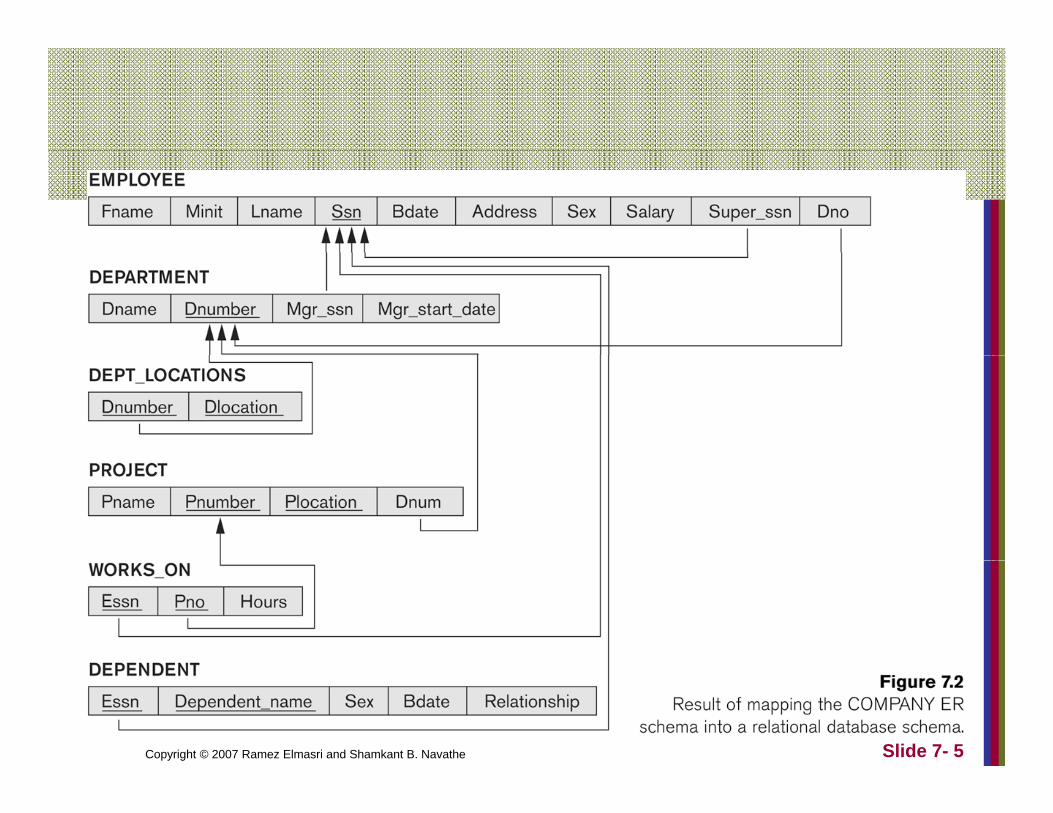
Copyright © 2007 Ramez Elmasri and Shamkant B. Navathe Slide 7- 5
ER to Relational Mapping AlgorithmER-to-Relational Mapping AlgorithmStep 1: Mapping of Regular Entity Types.
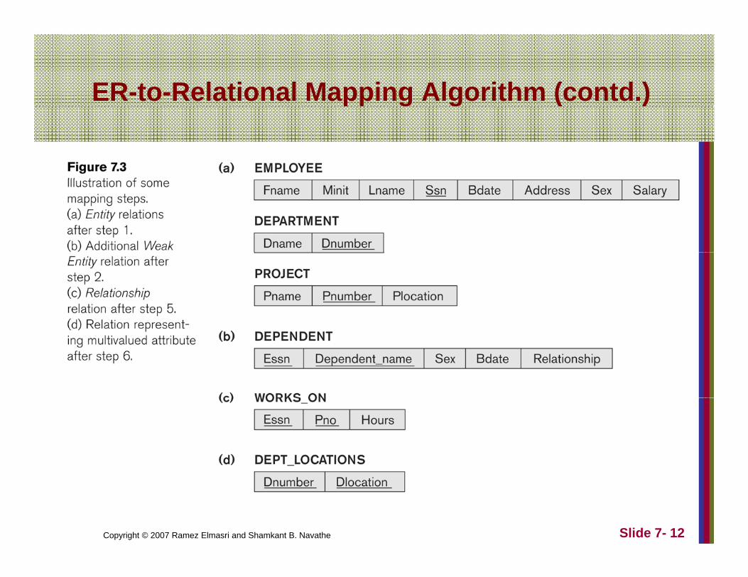
For each regular (strong) entity type E in the ER schema, create a relation R that includes all the simple attributes of E.Choose one of the key attributes of E as the primary key forChoose one of the key attributes of E as the primary key for R.If the chosen key of E is composite, the set of simple attributes that form it will together form the primary key of Rattributes that form it will together form the primary key of R.
Example: We create the relations EMPLOYEE, DEPARTMENT, and PROJECT in the relational schema corresponding to the regular entities in the ER diagram.corresponding to the regular entities in the ER diagram.
SSN, DNUMBER, and PNUMBER are the primary keys for the relations EMPLOYEE, DEPARTMENT, and PROJECT as shown.
Copyright © 2007 Ramez Elmasri and Shamkant B. Navathe Slide 7- 6

ER-to-Relational Mapping Algorithm (contd.)
Step 2: Mapping of Weak Entity TypesStep 2: Mapping of Weak Entity TypesFor each weak entity type W in the ER schema with owner entity type E, create a relation R & include all simple attributes (or simple components of composite attributes) of W as attributes of RR.Also, include as foreign key attributes of R the primary key attribute(s) of the relation(s) that correspond to the owner entity type(s).The primary key of R is the combination of the primary key(s) of the owner(s) and the partial key of the weak entity type W, if any.
Example: Create the relation DEPENDENT in this step to correspond to the weak entity type DEPENDENTcorrespond to the weak entity type DEPENDENT.
Include the primary key SSN of the EMPLOYEE relation as a foreign key attribute of DEPENDENT (renamed to ESSN). The primary key of the DEPENDENT relation is the combination
Copyright © 2007 Ramez Elmasri and Shamkant B. Navathe Slide 7- 7
e p a y ey o t e e at o s t e co b at o{ESSN, DEPENDENT_NAME} because DEPENDENT_NAME is the partial key of DEPENDENT.
ER t R l ti l M i Al ith ( td )ER-to-Relational Mapping Algorithm (contd.)
Step 3: Mapping of Binary 1:1 Relation TypesF h bi 1 1 l ti hi t R i th ER h id tif thFor each binary 1:1 relationship type R in the ER schema, identify the relations S and T that correspond to the entity types participating in R.
There are three possible approaches:1. Foreign Key approach: Choose one of the relations-say S-and include g y pp y
a foreign key in S the primary key of T. It is better to choose an entity type with total participation in R in the role of S.
Example: 1:1 relation MANAGES is mapped by choosing the participating entity type DEPARTMENT to serve in the role of S, because its participation in the MANAGES relationship type is totalin the MANAGES relationship type is total.
2. Merged relation option: An alternate mapping of a 1:1 relationship type is possible by merging the two entity types and the relationship into a single relation. This may be appropriate when both participations are total.total.
3. Cross-reference or relationship relation option: The third alternative is to set up a third relation R for the purpose of cross-referencing the primary keys of the two relations S and T representing the entity types.
Copyright © 2007 Ramez Elmasri and Shamkant B. Navathe Slide 7- 8
ER t R l ti l M i Al ith ( td )ER-to-Relational Mapping Algorithm (contd.)
Step 4: Mapping of Binary 1:N Relationship Types.p pp g y p ypFor each regular binary 1:N relationship type R, identify the relation S that represent the participating entity type at the N-side of the relationship type. p ypInclude as foreign key in S the primary key of the relation T that represents the other entity type participating in R. Include any simple attributes of the 1:N relation type asInclude any simple attributes of the 1:N relation type as attributes of S.
Example: 1:N relationship types WORKS_FOR, CONTROLS and SUPERVISION in the figureCONTROLS, and SUPERVISION in the figure.
For WORKS_FOR we include the primary key DNUMBER of the DEPARTMENT relation as foreign key in the EMPLOYEE relation and call it DNO
Copyright © 2007 Ramez Elmasri and Shamkant B. Navathe Slide 7- 9
EMPLOYEE relation and call it DNO.
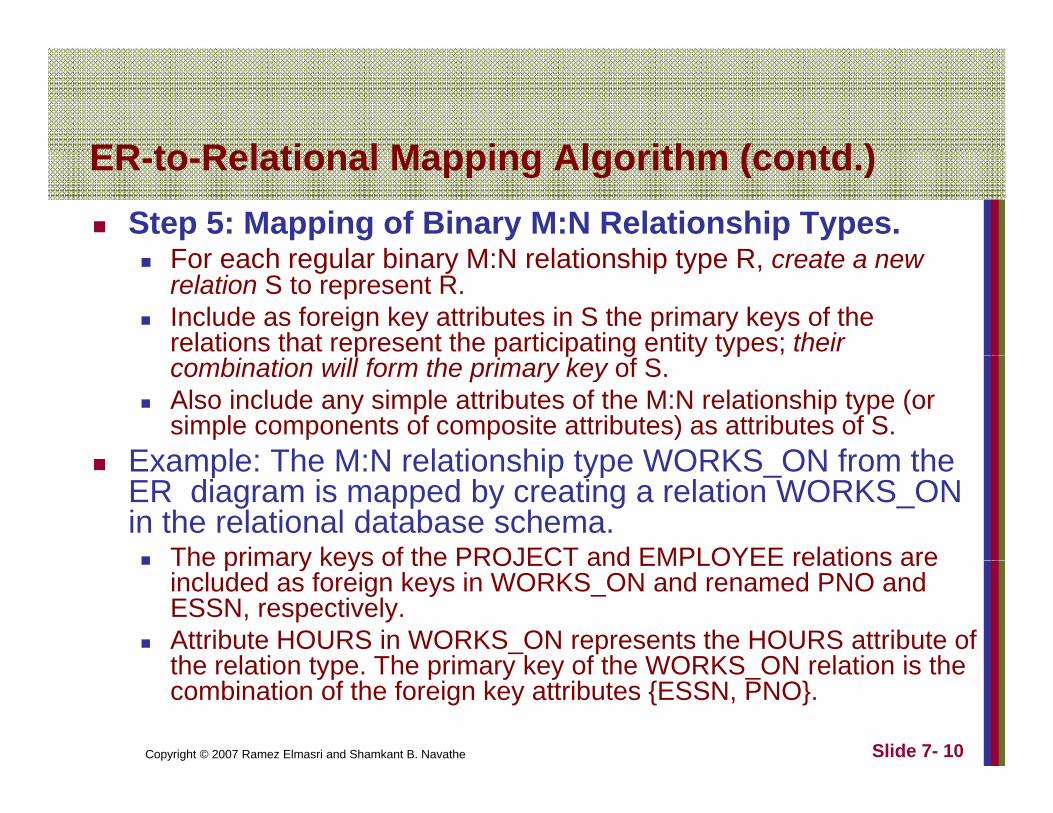
ER t R l ti l M i Al ith ( td )ER-to-Relational Mapping Algorithm (contd.)Step 5: Mapping of Binary M:N Relationship Types.
F h l bi M N l ti hi t R tFor each regular binary M:N relationship type R, create a new relation S to represent R. Include as foreign key attributes in S the primary keys of the relations that represent the participating entity types; their p p p g y ypcombination will form the primary key of S. Also include any simple attributes of the M:N relationship type (or simple components of composite attributes) as attributes of S.
Example: The M:N relationship type WORKS ON from theExample: The M:N relationship type WORKS_ON from the ER diagram is mapped by creating a relation WORKS_ON in the relational database schema.
The primary keys of the PROJECT and EMPLOYEE relations areThe primary keys of the PROJECT and EMPLOYEE relations are included as foreign keys in WORKS_ON and renamed PNO and ESSN, respectively. Attribute HOURS in WORKS_ON represents the HOURS attribute of the relation type The primary key of the WORKS ON relation is the
Copyright © 2007 Ramez Elmasri and Shamkant B. Navathe Slide 7- 10
the relation type. The primary key of the WORKS_ON relation is the combination of the foreign key attributes {ESSN, PNO}.
ER-to-Relational Mapping Algorithm (contd.)
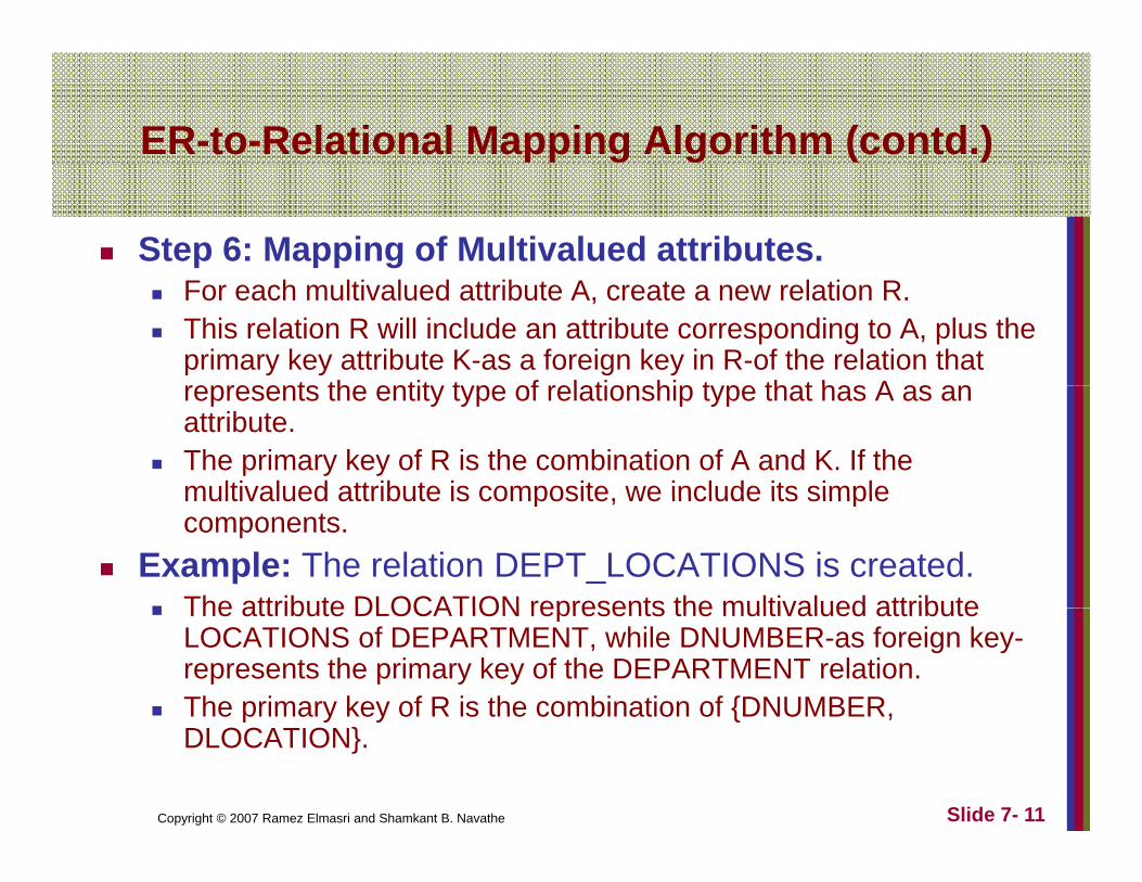
Step 6: Mapping of Multivalued attributes.For each multivalued attribute A, create a new relation R. This relation R will include an attribute corresponding to A, plus the primary key attribute K-as a foreign key in R-of the relation that represents the entit t pe of relationship t pe that has A as anrepresents the entity type of relationship type that has A as an attribute. The primary key of R is the combination of A and K. If the multivalued attribute is composite we include its simplemultivalued attribute is composite, we include its simple components.
Example: The relation DEPT_LOCATIONS is created. The attribute DLOCATION represents the multivalued attributeThe attribute DLOCATION represents the multivalued attribute LOCATIONS of DEPARTMENT, while DNUMBER-as foreign key-represents the primary key of the DEPARTMENT relation.The primary key of R is the combination of {DNUMBER,
Copyright © 2007 Ramez Elmasri and Shamkant B. Navathe Slide 7- 11
p y y { ,DLOCATION}.
ER-to-Relational Mapping Algorithm (contd.)
Copyright © 2007 Ramez Elmasri and Shamkant B. Navathe Slide 7- 12
ER-to-Relational Mapping Algorithm (contd.)
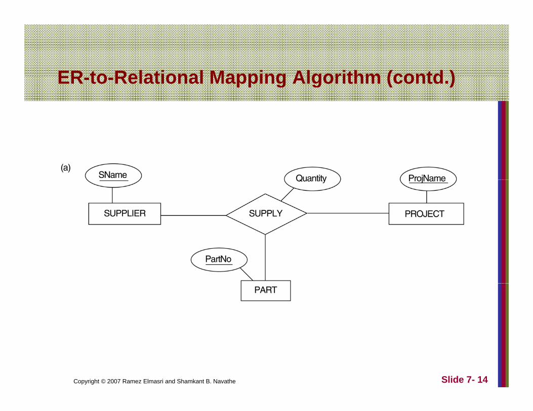
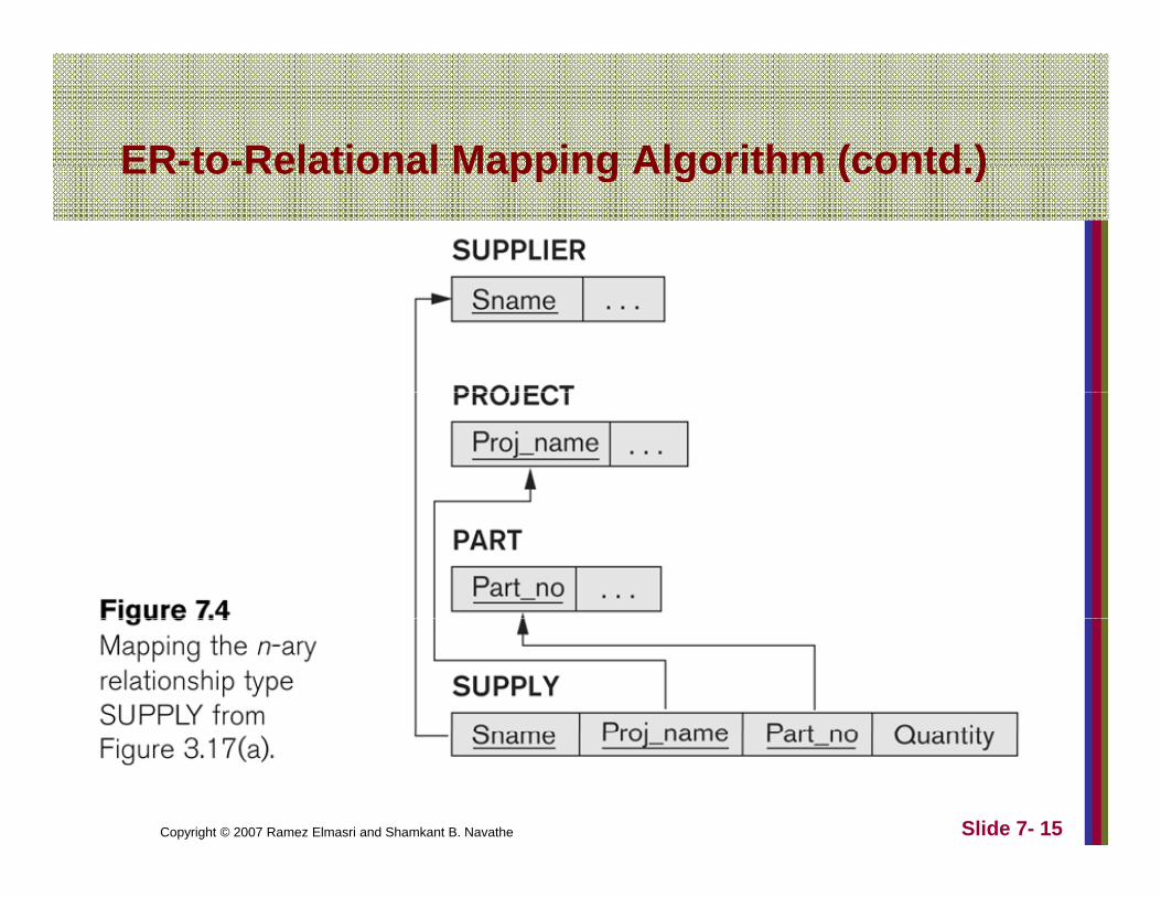
Step 7: Mapping of N-ary Relationship Types.For each n-ary relationship type R, where n>2, create a new relationship S to represent R.Include as foreign key attributes in S the primary keys of the g y p y yrelations that represent the participating entity types. Also include any simple attributes of the n-ary relationship type (or simple components of composite attributes) as attributes of S.
Example: The relationship type SUPPLY in the ER on the next slide.
This can be mapped to the relation SUPPLY shown in the relational schema, whose primary key is the combination of the three foreign keys {SNAME, PARTNO, PROJNAME}
Copyright © 2007 Ramez Elmasri and Shamkant B. Navathe Slide 7- 13
ER to Relational Mapping Algorithm (contd )ER-to-Relational Mapping Algorithm (contd.)
Copyright © 2007 Ramez Elmasri and Shamkant B. Navathe Slide 7- 14
ER-to-Relational Mapping Algorithm (contd )ER to Relational Mapping Algorithm (contd.)
Copyright © 2007 Ramez Elmasri and Shamkant B. Navathe Slide 7- 15

Summary of Mapping constructs and constraints
Table 7.1 Correspondence between ER and Relational Models
ER Model Relational ModelEntity type “Entity” relation1:1 or 1:N relationship type Foreign key (or “relationship” relation)M:N relationship type “Relationship” relation and two foreign keysn ary relationship type “Relationship” relation and n foreign keysn-ary relationship type “Relationship” relation and n foreign keysSimple attribute AttributeComposite attribute Set of simple component attributesMultivalued attribute Relation and foreign keyValue set DomainKey attribute Primary (or secondary) key
Copyright © 2007 Ramez Elmasri and Shamkant B. Navathe Slide 7- 16

Mapping EER Model Constructs to RelationsRelations
Step8: Options for Mapping Specialization or p p pp g pGeneralization.
Convert each specialization with m subclasses {S1, S2 Sm} and generali ed s perclass C here theS2,….,Sm} and generalized superclass C, where the attributes of C are {k,a1,…an} and k is the (primary) key, into relational schemas using one of the four f ll i tifollowing options:
Option 8A: Multiple relations-Superclass and subclassesOption 8B: Multiple relations-Subclass relations onlyOption 8C: Single relation with one type attributeOption 8D: Single relation with multiple type
Copyright © 2007 Ramez Elmasri and Shamkant B. Navathe Slide 7- 17
Option 8D: Single relation with multiple type attributes

Mapping EER Model Constructs to RelationsMapping EER Model Constructs to Relations
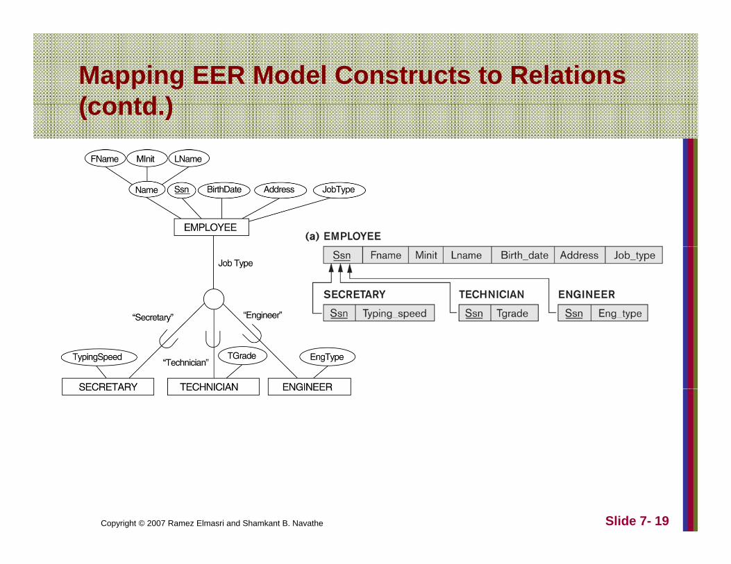
Option 8A: Multiple relations-Superclass andOption 8A: Multiple relations Superclass and subclasses
Create a relation L for C with attributes Attrs(L) = ( ){k,a1,…an} and PK(L) = k. Create a relation Li for each subclass Si, 1 < i < m, with the attributesAttrs(Li) = {k} U {attributes of Si} andattributesAttrs(Li) = {k} U {attributes of Si} and PK(Li)=k. This option works for any specialization (total or partial, disjoint or over-lapping).
Copyright © 2007 Ramez Elmasri and Shamkant B. Navathe Slide 7- 18
Mapping EER Model Constructs to Relations (contd )(contd.)
Copyright © 2007 Ramez Elmasri and Shamkant B. Navathe Slide 7- 19
Mapping EER Model Constructs to Relations ( td )(contd.)
Option 8B: Multiple relations-SubclassOption 8B: Multiple relations Subclass relations only
Create a relation Li for each subclass Si, 1 < i < m, with the attributes Attr(Li) = {attributes of Si} U {k,a1…,an} and PK(Li) = k. This option only works for a specialization whose subclasses are total (everya specialization whose subclasses are total (every entity in the superclass must belong to (at least) one of the subclasses).
Copyright © 2007 Ramez Elmasri and Shamkant B. Navathe Slide 7- 20
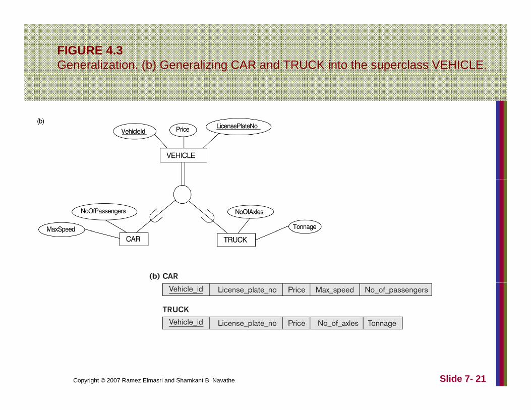
FIGURE 4.3Generalization. (b) Generalizing CAR and TRUCK into the superclass VEHICLE.
Copyright © 2007 Ramez Elmasri and Shamkant B. Navathe Slide 7- 21
Mapping EER Model Constructs to Relations (contd.)(contd.)
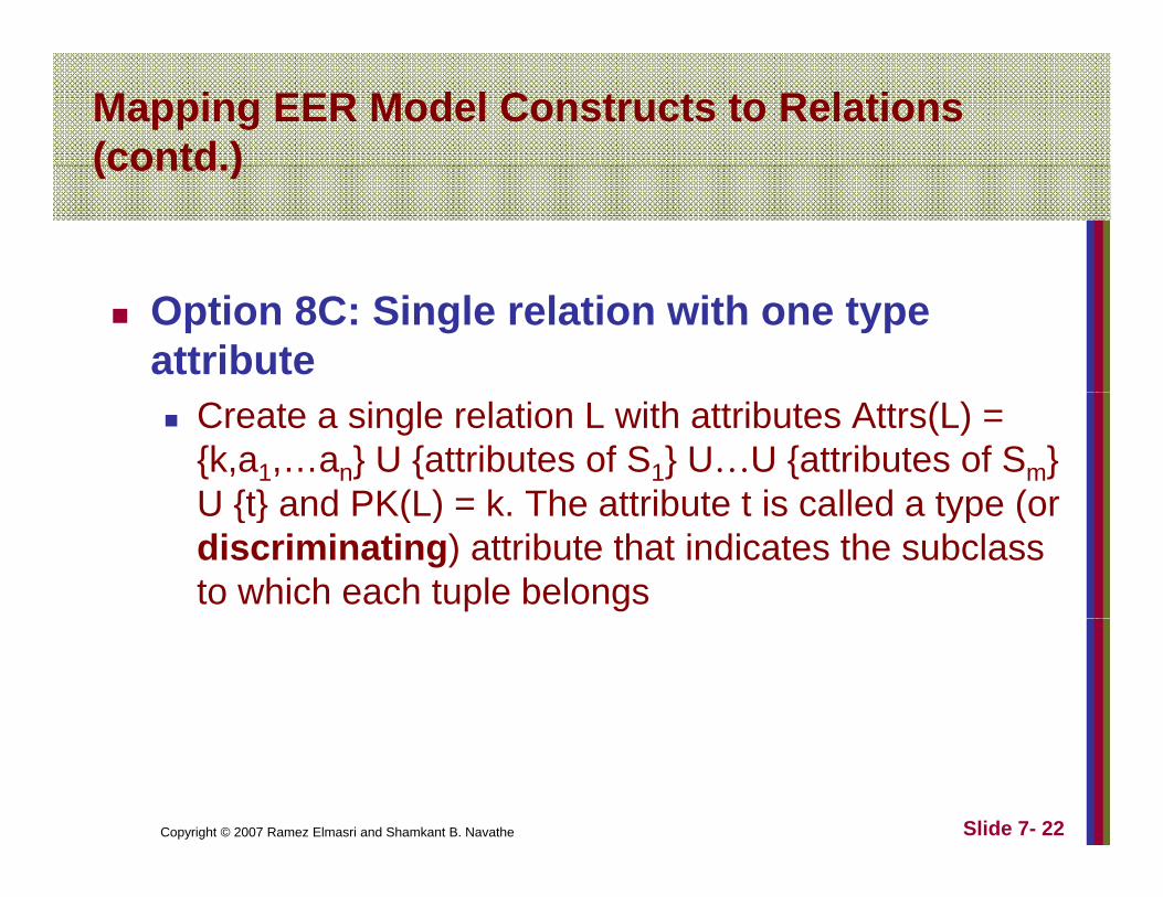
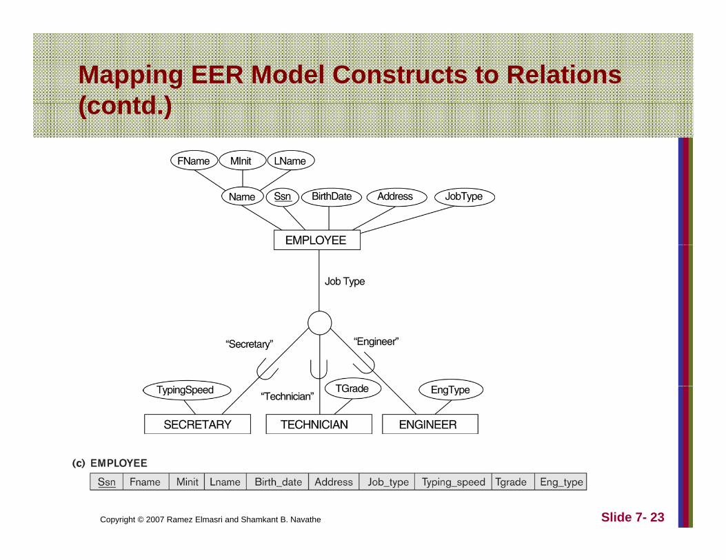
Option 8C: Single relation with one type attribute
Create a single relation L with attributes Attrs(L) = {k,a1,…an} U {attributes of S1} U…U {attributes of Sm} U {t} and PK(L) = k The attribute t is called a type (orU {t} and PK(L) = k. The attribute t is called a type (or discriminating) attribute that indicates the subclass to which each tuple belongs
Copyright © 2007 Ramez Elmasri and Shamkant B. Navathe Slide 7- 22
Mapping EER Model Constructs to Relations (contd )(contd.)
Copyright © 2007 Ramez Elmasri and Shamkant B. Navathe Slide 7- 23
Mapping EER Model Constructs to Relations (contd.)(contd.)
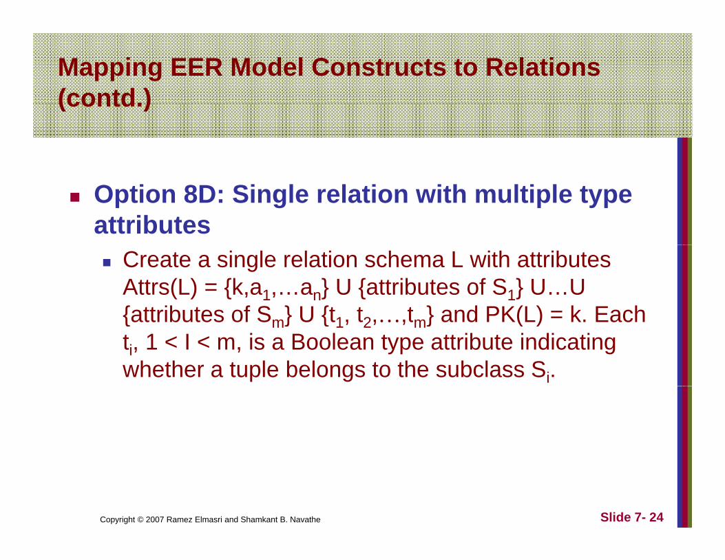
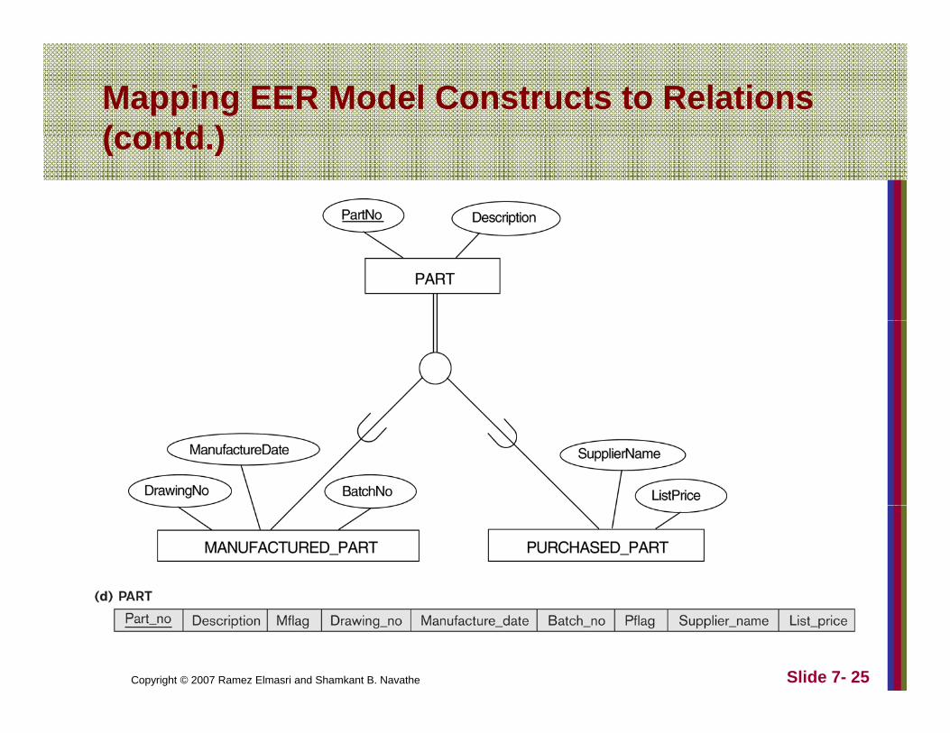
Option 8D: Single relation with multiple type attributes
Create a single relation schema L with attributes Attrs(L) = {k,a1,…an} U {attributes of S1} U…U {attributes of S } U {t t t } and PK(L) = k Each{attributes of Sm} U {t1, t2,…,tm} and PK(L) = k. Each ti, 1 < I < m, is a Boolean type attribute indicating whether a tuple belongs to the subclass Si.
Copyright © 2007 Ramez Elmasri and Shamkant B. Navathe Slide 7- 24
Mapping EER Model Constructs to Relations (contd )(contd.)
Copyright © 2007 Ramez Elmasri and Shamkant B. Navathe Slide 7- 25
Mapping EER Model Constructs to Relations ( td )(contd.)
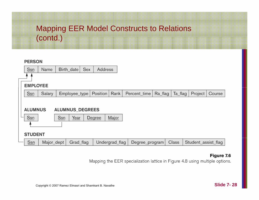
Mapping of Shared Subclasses (Multiple pp g ( pInheritance)
A shared subclass, such as STUDENT ASSISTANT i b l f lSTUDENT_ASSISTANT, is a subclass of several classes, indicating multiple inheritance. These classes must all have the same key attribute; otherwise, the shared subclass would be modeled as a category.We can apply any of the options discussed in StepWe can apply any of the options discussed in Step 8 to a shared subclass. Below both 8C and 8D are used for the shared class STUDENT_ASSISTANT.
Copyright © 2007 Ramez Elmasri and Shamkant B. Navathe Slide 7- 26

Mapping EER Model Constructs to Relations (contd )(contd.)
Copyright © 2007 Ramez Elmasri and Shamkant B. Navathe Slide 7- 27
Mapping EER Model Constructs to Relations (contd )(contd.)
Copyright © 2007 Ramez Elmasri and Shamkant B. Navathe Slide 7- 28
Mapping EER Model Constructs to Relations ( td )(contd.)
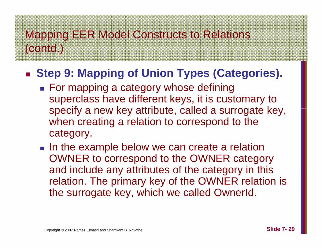
Step 9: Mapping of Union Types (Categories).p pp g yp ( g )For mapping a category whose defining superclass have different keys, it is customary to specify a new key attribute called a surrogate keyspecify a new key attribute, called a surrogate key, when creating a relation to correspond to the category. In the example below we can create a relation OWNER to correspond to the OWNER category and include any attributes of the category in thisand include any attributes of the category in this relation. The primary key of the OWNER relation is the surrogate key, which we called OwnerId.
Copyright © 2007 Ramez Elmasri and Shamkant B. Navathe Slide 7- 29

Mapping EER Model Constructs to Relations (contd )(contd.)
Copyright © 2007 Ramez Elmasri and Shamkant B. Navathe Slide 7- 30
Related Documents