
Welcome message from author
This document is posted to help you gain knowledge. Please leave a comment to let me know what you think about it! Share it to your friends and learn new things together.
Transcript


2
2 Energy Revolution

3
3 Energy Revolution
Thank you for purchasing Energy Revolution Generator.
While your choices are valuable to us, we appreciate your trust in our product
and we are confident that you will be more than satisfied.
Free energy technology is here, now. It offers the world pollution-free energy
abundance for everyone, everywhere.

4
4 Energy Revolution
Table of contents
Table of contents ............................................................................................................. 4
Chapter 1 - Introduction ................................................................................................... 5
1.1 VRIL Technology – From Myth to Energy Revolution ......................................................................... 6
1.2 Energy Revolution Generator - Means of operation .......................................................................... 7
1.3 Applications ....................................................................................................................................... 10
1.4 Advantages ........................................................................................................................................ 10
Chapter 2 - Tools and parts needed .............................................................................. 11
2.1 List of tools ........................................................................................................................................ 11
2.2 List of components ............................................................................................................................ 12
2.3 List of supply components websites ................................................................................................. 14
Chapter 3 - Building Process ......................................................................................... 15
3.1 Building Units .................................................................................................................................... 15
3.2 Construction of coils ......................................................................................................................... 16
3.3 Construction of the rotor .................................................................................................................. 19
3.4 Construction of stators ..................................................................................................................... 22
3.5 Assembling Building Units ................................................................................................................. 25
3.6 Checking the connections and securing cables................................................................................. 33
3.7 Connection of the filtering unit and power unit. .............................................................................. 35
Chapter 4 - Testing our generator ................................................................................. 36
4.1 Means of operation .......................................................................................................................... 36
4.2 Testing ............................................................................................................................................... 36
5
5 Energy Revolution
Chapter 1 - Introduction
In the modern world, energy is needed for almost everything. It's almost
impossible to imagine life without electric lights, without televisions, cell
phones, laptop and desktop computers and more. Energy is consumed by
almost every device that makes your life easier and more comfortable. It is
also needed by lifesaving devices, such as heart defibrillators, nebulizers and
an uncountable host of other things.
Energy is most often used in the context of energy resources, their
development, consumption, depletion, and conservation. Since economic
activities such as manufacturing and transportation can be energy intensive,
energy efficiency, energy dependence, energy security and price are key
concerns.
In short, without energy, modern life would be impossible. However, all of
that energy comes at a cost. The environment pays dearly for our energy
generation, as do the animals and plants that share this world with us. In
addition, energy generation comes at a financial cost to you – constantly
mounting electric bills are another hallmark of the "modern age."
What if there was a way to offset those costs?
What if there was a source of free energy?
The battle to give people the right to live with free energy has been going on
for a long time.
It is not yet certain for everyone if free energy is really possible. People are
skeptic and somehow afraid to try new devices. But the increasing prices of
fossil fuels and the general awareness about the fact that the Earth is actually
running out of this resource sooner than we thought, might bring the change.
The fact remains that Free Energy Devices provide a quantity of dependable
and great ways to procure enough energy to satisfy the requirements of the
household, without having to pay monthly power bills.

6
6 Energy Revolution
1.1 VRIL Technology – From Myth to Energy Revolution
Today, the existence of the VRIL Society is yet to be recognized. Supposedly, it
was founded as "The All German Society for Metaphysics" in 1921 to explore
the origins of the Aryan race. Members of the Vril Society are said to have
included Adolf Hitler, Alfred Rosenberg, Heinrich Himmler, Hermann Göring,
and Hitler's personal physician, Dr. Theodor Morell.
In 1922, Vril Society constructed Germany's first flight disc, the JFM
(Jenseitsflugmaschine) or "Other World Flight Machine", in Munich. They
allegedly received official state backing for continued disc development
programs aimed at both spaceflight and possibly a war machine.
In in 1937, after Vril bought the fallow land surrounding the Arado-
Brandenburg aircraft facility. RFZ discs 1, 2, 3, 4, and 6 were constructed there
by Vril. Additionally, with help from the special SS technical branch unit E-IV,
they were tasked with developing alternative energies. Research claims that
at the core of these new technologies for alternative energy is the realization
of the dynamic union of the world.
Thus technology has been moved from mechanics to dynamics. This is the
most formidable and momentous revolution in all areas that humanity ever
experienced. Mastering dynamics subdues all matter and all its inherent
energies to man. These discoveries represent nothing more and nothing less
than the primal force that is the mother force of all matter and energy and
which keeps the world internally together.
We are talking about a basically cost-free energy supply that has the power to
revolutionize the world of energy. In order to produce the indicated effects it
is necessary to construct a technical apparatus in which the primal force may
be produced and permanently sustained as connective conductor between
Earth and the atmosphere.
This apparatus is relatively simple. It is basically nothing else but the
translation of the natural flow of power in all organisms into the technological
7
7 Energy Revolution
realm. And it’s as real as it can be. If any, all your doubts will vanish in just a
moment, when you’ll be able to generate unimaginable amounts of energy.
1.2 Energy Revolution Generator - Means of operation
Throughout time, man has always tried to find the easiest ways of producing
energy. Now, on the basis of all discoveries, the principle is the following: one
unit/force that sets a mechanism in motion (a wheel/piston/magnet),
generates motion which is then sent to a motor that binds to a consumer. In
other words, any motion is a possible generator producing energy.
In order to produce electricity, we have a few options at this point:
- Mechanically (any set of gears connected to an engine can produce
electricity)
- Using magnets (magnetic induction, based on the principle of
attraction/repulsion of the magnetic poles generates movement)
- Using fossil fuels (coal, oil) - wind energy, atomic energy and
photovoltaic energy (based on chemical reactions).
The first devices of this kind were those that used water power (old mill) and
wind (windmills). Then there were the steam and electrical ones, followed by
the fossil fuel, then nuclear and solar.
Magnetic power was a concern less explored and less developed in the
glorious years of the Industrial Revolution, because the electricity principles
were not properly formulated and the materials for the magnets composition
were not very well known. Actually, considering mankind’s development at
the time, people weren’t concerned with discovering any alternatives.
However, it was those years that laid the foundation of what we know today.
People like Nikola Tesla, Howard Johnson, Karl Schappeller, Albert Einstein
were the pioneers of principles that we are trying to put into practice
8
8 Energy Revolution
nowadays to ensure the cleanest future for the coming generations. Their
vision for the future is our source of inspiration and progress.
One of the revolutionary devices that had the power to change science and
history was THIS Generator. We will now discuss the means of operation for
this apparatus.
Energy Revolution Generator is based on magnetic force to generate motion.
The magnets greatest difficulty consists of "controlling" the way they
attract/repel each other to create motion.
Combining the magnetic induction of the electric current, generated by a
group of coils with magnetism, scientists managed to create a device
characterized by the fact that controlling the magnetic field generates a
predictable motion that can later be used as an energy source. Basically, this
generator produces 120% electricity.
The components of our device are: a mother stator, a rotor, a father stator,
the “ignition” and maintenance compartment of the electric current necessary
for the induction, the filtering compartment of the electric current and the
consumers.
The larger our device’s dimensions (given by the number of coils used on the
stators), the stronger will be the magnetic field and thus the final power of the
device will increase. For the construction of this apparatus we will use 7 coils
on the stator and 8 magnets on the rotor.

9
9 Energy Revolution
Here is a unit diagram of the device:
The mother stator contains an odd number of coils (7 on each side) and the
temporization and recovery of the current (on the other side).
The rotor contains an even number of permanent magnets (8 pieces).
The father stator contains an odd number of coils (also 7, mounted
symmetrically to those on the mother stator) and the support for the optical
sensors that control the magnetic field. The optical sensors will be linked to
the temporization unit. This is obviously a modern adaptation, since the initial
temporization circuit was made by german enginers using sizeable electrical
components.

10
10 Energy Revolution
The "ignition" compartment is actually a source of electricity, necessary for
the magnetic induction created by the coils from the stator. Like I said, this
device requires power, but it generates 20% more energy than you consume
at the other end.
The filtering compartment provides a steady current on output, thus
eliminating the risks of fluctuations which might have determined an
uncontrollable manner of utilizing the energy.
The consumers are the last unit, which can be: a bank of batteries to store
energy or any kind of electrical consumer. Depending on how much power
you’re producing, you can connect one simple bulb or all the appliances inside
your home. You can also use it as a portable generator.
1.3 Applications
The various applications of this generator make it one of the most versatile
(though obscure) devices ever invented. Nowadays, the components
miniaturization, the power of the magnets (super magnets), but also
inventions such as electrically controlled optical units (sensors) allow this
generator to be utilized on a large scale.
Therefore, it can be used as a power generator (to power a house), a portable
generator (the perfect replacement for the old gasoline/diesel generators) or
it can charge a group of batteries (which were discharged for later use), and
even an antenna.
1.4 Advantages
This generator is constructed of lightweight but solid materials and it requires
extremely small circuits in size and cost.
It is also the perfect choice for a cleaner and healthier future for our children,
since it doesn’t involve any smoke or noise.

11
11 Energy Revolution
The low cost, the light weight, no noise and no pollution make this generator a
strong competitor for any device currently known. Then, the obvious question
occurs: why isn’t it built on a large scale? Perhaps for the same reason why
dozens of other extraordinary inventions and patents have ended up inside
locked drawers, never to see the light of day, because of Big Energy Fat Cats.
A device like this is one of the solutions for a cleaner and safer future. I think
you already know how many of oil companies are investing in alternative
energy... It is our duty to be informed and do everything we can in order to
ensure a better future for our children and grandchildren.
So thank you once again for accepting the challenge to become energy
independent.
Chapter 2 - Tools and parts needed
After this brief overview, it's time to get to work. Since everything is safe and
simple, you are free to involve other family members or friends in this project.
My friend Joe helped me do the videos and I want to thank him for this.
Hopefully, you won’t be bothered by some of the “sudden zooms”.
2.1 List of tools
a. Pliers with insulated handles - normal and beak
b. Screwdrivers
c. Fixed wrenches set
d. Adjustable wrench
e. Table vise (for accuracy and ease)
f. Beak pincers
g. Shears

12
12 Energy Revolution
h. Drill
I. Drill Bits Set
j. Saw
k. Plastic container
l. Stripping pliers
m. Tape measure, ruler and protractor
n. Multimeter
o. Markers
p. Cutter
q. Caliper
2.2 List of components
The components used for this project will be divided into categories:
Electrical components:
a. MOSFETs IRFP3710 ... 100V/57A;
b. Fairchild QVE00112 OptoLOGIC Optical Interrupter Switch;
c. Deep Cycle v. 12V Lead Acid Batteries;
d. Heavy Duty Battery changeover relay;
e. Bridge rectifiers;
f. Electrolytic capacitors;
g. Heat sinks;
13
13 Energy Revolution
h. Circuit board with microcontroller;
i. LCD and LEDs (if you want to use a display and make it more complex);
Mechanical components:
a. Bearings – 2 pieces;
b. Threaded rod (diameter ᶲ 0.23inch);
c. Bolts and nuts of various diameters;
Other types of components:
a. Insulating Tape;
b. PVC tube;
c. Epoxy resin for manufacturing core coils made of two components;
d. Plastic pad for winding coils;
e. Spatula for mixing iron oxide with resin;
f. Two-component adhesive for bonding various components (depending on
the material used, plexiglass or plywood);
g. Magnetite - Fine Powder 350 Mesh 97 % pure;
h. 8 Neodymium Magnets N45, 1" diameter x ½" thick;
i. Electrical cables of different colors (for easy identification while wiring);
j. 500 feet of AWG # 12 Magnet Wire - 2 spools;
k. Clips or zip ties of different sizes used for fixing cables in the final part;
l. Cable lugs for better conductivity and ease of wiring;
14
14 Energy Revolution
m. Plexiglass or plywood timber for building the rotor and stator. This
material must be a very good electrical insulator;
2.3 List of supply components websites
These parts can be purchased at incredible prices on these websites:
Magnets:
http://apexmagnets.com/, http://www.magnet4less.com/,
http://www.kjmagnetics.com/
Batteries:
http://www.batcap.net/, http://www.dcbattery.com/index.html,
http://www.osibatteries.com/s-386-generator-batteries.aspx
Powder:
http://www.iron-powder.com/default.asp?count=1
Electronics:
http://parts.nowcomponents.com/, www.ebay.com,
http://www.radioshack.com/category/index.jsp?categoryId=2032230,
http://www.newark.com/, http://www.newark.com/,
http://www.digikey.com/, http://www.allelectronics.com/
Fastening & Joining:
http://www.mcmaster.com/#
Magnet Wire:
http://www.bulkwire.com/, http://www.bulkwire.com/,

15
15 Energy Revolution
http://www.enameledwire.net/product.html?gclid=CNuXo8HN47kCFQ1L3go
dpxAA8Q,
http://www.planetengineers.com/default.asp?cat=Wire%2C+Magnet
Adhesives:
https://www.fiberglasswarehouse.com/index.php,
http://www.fibreglass-resin-sales.com.au/
Chapter 3 - Building Process
3.1 Building Units
As mentioned in Chapter 1 – Means of operation, the device looks like a
sandwich (stator, rotor, stator), externally completed by the power source and
the filtering unit.
Here's a picture of a set (at a larger scale – for powering a house):
On the father stator (upper side) you can observe the arrangement of the
optical sensors required for the temporization circuit.
The following illustration shows the device including magnetic part (observe
the spiral coils arrangement required for the device in this size).
Here is a horizontal side view (the entire device):

16
16 Energy Revolution
And another view showing the arrangement and dimensions of the parts:
3.2 Construction of coils

17
17 Energy Revolution
Here’s the data for the project on a large scale (30 coils):
For the front device we will use only 7 coils on each stator (14 in total).
Coil size:
PVC tube core length - 0.98 inch
Coil (protection wall) diameter - 2.16 inch
Coil width - 0.90 inch
After measurement, we will use a saw to cut the PVC tube (a table vise is very
helpful here).
Warning: Be careful when using the saw.
Next step is preparing of the interior coil. We will use the amounts specified in
the parts list. Epoxy resin is used as follows: equal parts of each component in
a proportion of 1-4 to the amount of magnetite you’re using. Stir until you get
a smooth mixture.

18
18 Energy Revolution
Put the PVC tube (that you cut earlier) on paper or any other place than the
table on which you’re working. Put the paste you obtained by mixing inside
the PVC tube. The mixture will be added with care, avoiding bubbles on its
final compaction. We proceed similarly for all 14 coils required.
The time required to consolidate the mixture is 24h! Avoid temperatures
below 32°F or above 86°F.
You can either remove the PVC coating or you can use with it on.
We will start winding on the plastic pad (the first winding has 14 spires and
by following the diagram we’ll get to 52 spires; winding begins from the rotor
part - which from now on we’ll call interior)
Remember to start spiraling from the inside out. The wires left outside will be
marked with different colors at the end of the project to provide easier wiring.
Collect each spire carefully.
For the large-scale project we will use the arrangement presented in the
images above.
For the small-scale project, we will wind each spire smoothly. The final
winding will be performed opposite the interior side. We will then glue the
different colored wires (either by twisting them or by soldering, in which case
you will need a soldering gun). It’s better for the colors to be chosen in pairs of
coils for an easier identification during the connectivity.
After gluing, we will isolate the coil we obtained with 2-3 rows of duct tape to
secure everything on the plastic pad.
The magnetite core will be stuck to the pad with a two-component adhesive
(mix 2 equal parts until you get a uniform paste) that is not electrically
conductive. You can clean the adhesive, but the excess is not a problem. Allow
around 10 minutes for sticking.

19
19 Energy Revolution
Another option (less recommended especially in large projects) is the
mechanical one, by pressing the core with the plastic coating inside the plastic
pad.
We have now obtained one of the 14 coils required for this project. We
proceed similarly for the others. Remember to choose different colors for the
coil ends, but in pairs for a better identification during the connectivity.
3.3 Construction of the rotor
For this project, we will use plexiglass as constructive material (you can use
any size but it is recommended one of at least 0.19 inch). The rotor diameter is
7.87 inch and in the center we drilled an 0.31 inch hole to avoid friction with
the 0.23 inch axis on which it is mounted. We will also use an even number of
magnets (8 pieces).
For the large-scale project, a solid support is recommended. Therefore, we
will use a piece of plywood 0.39 inch thick with 16 magnets, arranged as
shown below:

20
20 Energy Revolution
The poles are in pink and green (north-south) and underneath are the coils on
the stator.
The exact dimensions and how to trace the lines where the magnets will be
placed are shown in the diagram below:
For arrangement of magnets we will divide the circle into 2, then 4 and then 8,
using a protractor.
Here’s a diagram of this arrangement. The gap is necessary for a better control
of the degree of rotation, due to induction generated by the coils.
Rotor rotation will be done clockwise.
After taking the correct circle sectors, we will place the magnets to 0.8 inches,
with their center on the sectors outlined above.
For sticking, we will use the same two-part adhesive as in the case of
magnetite on the plastic pad, but please pay attention to the alternating north-

21
21 Energy Revolution
south. The magnets are very inexpensive and can be purchased online. We will
stick all 8 magnets.
For the large-scale rotor, here is the data for mounting bearings and the
necessary support for its immense power rotation:
22
22 Energy Revolution
3.4 Construction of stators
For this project we will use two plexiglass plates of 0.19 inch, on which the
coils are placed as shown in the diagram above (with 8 magnets).
On the father stator we will arrange the coils in odd number (7 coils as shown
in diagram below). Observe that they have lugs at the bottom side of the
cables, for better connectivity.
On the reverse side, we will place the support for the optical connectors,
necessary for controlling (temporization) of the magnetic field generated by
the coils.
We will drill a hole in the middle in order to put a small ball bearing - 1 inch -
and in the corners we will use a ᶲ 0.31 inch drill bit for stiffening rod and
support.
The rod is divided into four equal parts of 7.87 inch each. On their ends we
will use some threaded on the inside, in order to later place the covers. The
plexiglass plate is bolted on both sides.
The mother stator is created similarly to the one we already presented, with 7
coils arranged identically on the father stator. Note the central axis already
fixed inside the bearing for rigidity.
On the reverse side, we can see the 5 recovery bridges placed side by side and
stuck with adhesive on the same support and then on the plexiglass . The
temporization plate is screwed to ensure a minimum distance necessary to
preserve the sticking on the reverse side of the temporization circuit. Both
bridge rectifiers and temporization circuit can be ordered online from
www.newcomponents.com, at extremely low costs.
For the large-scale project, soldering will be done with tin soldering and
soldering gun.
The diagram of the stator (large scale) for coil arrangement is as follows:

23
23 Energy Revolution
You can see the size of the holes as well as the angles necessary for a correct
and accurate arrangement.
Also see below the arrangement and dimensions of optical sensors and their
technical characteristics on the father stator (large scale project):

24
24 Energy Revolution
Furthermore, we have the disk for temporization (father stator):

25
25 Energy Revolution
3.5 Assembling Building Units
Next you need to assembly the building units.
The mother stator, rotor and father stator will form a sandwich. In the end, we
will add the filtering unit and power as well as connections necessary when
testing with consumers.
We will first place the rotor at 1.5 inch from the stator. It will be secured on
the central axis with 2 nuts and 2 washers. Make sure the screws are properly
tightened.
We will then measure the distance required for father stator fixation (the
distance is equal to that between the stator and mother rotor) and we will
first secure the bearing inside the father stator. Stator coils are perfectly
overlapped, with extra care at the coils connection (inside - outside).
Next we will check again, using a caliper, if the rotor is placed midway
between the two states. Also check if the rotor moves freely after placing the
father stator.
Note the practical choice of threaded rods which in this case allow fair and
fine adjustment of the device. For the large-scale device, use special
articulated threaded and rigid rods.
We will then secure the screws at the stator’s ends. Do not over tighten the
screws or you’ll crack the plexiglass plate.
Next, secure on the axis the spacers required for placing the gear which
provides the optical control. Then secure this with the respective screw.
The next step requires maximum attention. You will connect the coils. As you
can see, they are placed face to face with a lug on one end and the other one is
open. We will start linking them, two by two. Now you can see why it was
important to choose colors in pairs and how easy it is to perform this
connection. Connections will be kept simple, but they will be isolated from the

26
26 Energy Revolution
outside, both for protection and for stiffening. The other ends, jacked, will be
connected to the AC terminals of the bridge.
KEEP IN MIND:
Each pair of coils corresponds to a bridge rectifier, and 2 pairs to the comand
modules. The order in which they are connected to the bridge rectifiers is
given only by the coil wire length.
As mentioned in coil construction chapter, we have attached one connector to
each of the outer ends of the coils (which will help us to connect them
properly or you can also use the color codes). The inner sides were left off.
The coils will be connected 2 by 2, joining the insides and leaving the outsides
off, except the excitation coils which are connected to the control modules.
After making the connection, insulate with insulating tape. For the large scale
project, we will either use wired circuits and tin soldering or female-male
connectors.
One by one, we will connect the coils insides, leaving the outsides off. Make
sure you don’t obstruct the movement of the rotor, when connecting the coils.
The coils outsides will be connected to the 5 bridges rectifiers (we will show
this immediately) and to the two control modules.
Also, here’s how to make a correct connector coupling. You just strip the
wire’s end and tighten with the crimping pliers.
Following is connecting the excitation coils (located on both sides of the stator
according to the documentation), with ends deliberately left without
connectors. In this tutorial, they were "knotted” for an easier orientation
during connectivity.
The outer ends of the excitation coils will be joined on the C symbol (coil) of
the control boards, while the insides the interiors are also joined together, like
the others.

27
27 Energy Revolution
After making the connection to the control boards, we need to connect the
boards between each other. Select 2 wires, the ends of which will be stripped
and gently twist them. At the end of the negative (-) wire we’ll attach a
connector like the one you see in the picture. We will prepare two of such wire
pairs, using brown for the positive (+) and blue for the negative (-).
For the negative (-) pin: connect the ends without connectors between each
other. Then, connect them on the negative (-) pin of one of the control boards.
The other end will also be connected to the control board on the negative (-)
pin. The coupled end will be connected to the negative (-) pin installed on the
generator cover.
For the positive (+) pin: The brown pair will be connected to the positive (+)
pin from one of the control boards and the other end will connect the two
modules (analog as the negative (-) pin).
Now it’s time to put the negative (-) and positive (+) pins on the cover of the
device, marking each of them with a marker.

28
28 Energy Revolution
The positive and negative terminals will be left open for subsequent
connection of consumers.
Now move to the next pair of coils and do the same: tie same color interiors,
isolate and connect exteriors to the AC side of the bridge.
We'll do exactly the same for all pairs of coils.
Make sure the cables are secured and the isolation has been done properly.
Pay attention to the bridge rectifier connection. It is an iterative process that
does not involve any difficulty, but it requires extra care.
I will show you how to connect all 7 pairs. It may seem very complicated when
you see the bundle of wires, but it’s actually pretty simple, provided you’re
very careful.
OK. It's time for a short recap:
Two stators and one rotor, forming a sandwich.
On the upper stator we have the optical sensors controlled by a gear.
On the lower stator we have the bridge rectifiers, on which we have connected
the coil ends and temporization control unit on the AC.
The rotor is placed at equal distance between the stators and it should be able
to move freely.
Case construction
We will build this case for better wiring protection and for a cleaner look. It
will be made using a cover where I previously drilled the ᶲ 12mm hole for the
switch, at 1cm from the plexiglass sheet edges.

29
29 Energy Revolution
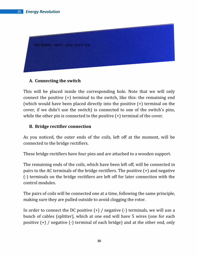
The side panels will be set outside the ᶲ 6mm holes made for the threaded
rods at 1 cm from the edges. We will use a two component adhesive for this
job, as shown in the pictures. Make sure you don’t clog the holes for the bar
support and glue the edges smoothly. Remove excess glue and let it dry.
The plexiglass dimensions are also included below:
30
30 Energy Revolution
A. Connecting the switch
This will be placed inside the corresponding hole. Note that we will only
connect the positive (+) terminal to the switch, like this: the remaining end
(which would have been placed directly into the positive (+) terminal on the
cover, if we didn’t use the switch) is connected to one of the switch’s pins,
while the other pin is connected to the positive (+) terminal of the cover.
B. Bridge rectifier connection
As you noticed, the outer ends of the coils, left off at the moment, will be
connected to the bridge rectifiers.
These bridge rectifiers have four pins and are attached to a wooden support.
The remaining ends of the coils, which have been left off, will be connected in
pairs to the AC terminals of the bridge rectifiers. The positive (+) and negative
(-) terminals on the bridge rectifiers are left off for later connection with the
control modules.
The pairs of coils will be connected one at a time, following the same principle,
making sure they are pulled outside to avoid clogging the rotor.
In order to connect the DC positive (+) / negative (-) terminals, we will use a
bunch of cables (splitter), which at one end will have 5 wires (one for each
positive (+) / negative (-) terminal of each bridge) and at the other end, only
31
31 Energy Revolution
one wire for an easier connection to the generator terminals. We used this
trick to avoid unnecessarily cluttering during connectivity.
First connect the bridges rectifiers’ negative (-) (purple color) and then the
remaining end will be coupled with a connector and connected to the negative
(-) pin of the generator cover.
Do the same for the positive (+) terminal, in this case using a brown wire.
C. Assembly Ergonomics
This will be done by providing a zip tied cable set-up, without pulling them
excessively. Make sure the wiring is done so that the rotor can move freely
and all paths are clear for connectivity. The ends of the zip ties will be
removed.
D. Optical sensor positioning
Before we fully assemble the generator, we will place the optical sensors on
the other stator, in order to connect it to the control modules.
For this we will use two "pieces" of plexiglass for supports. They will be glued
onto the stator’s support using adhesive. We'll start with the wheel assembly
which performs timing on the rotor shaft, checking if the distance is correct.
We will check the wheel’s placement after attaching the optical sensors’
supports. We will mark the place where they will be assembled (as suggested
in the diagram from the documentation).
Now we can place the sensors supports and glue them with adhesive. After
hardening, we can insert the optical sensors into the holes of the supports,
using screws.
Next, we need to connect the optical sensors to the control modules. As shown
before, there are 3 pins for the optical sensors and these pins are numbered.
The connection will be made as follows:
32
32 Energy Revolution
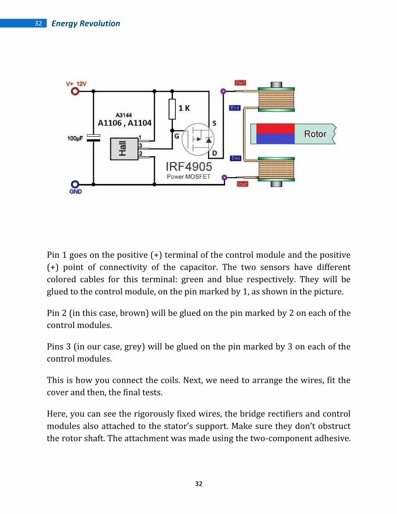
Pin 1 goes on the positive (+) terminal of the control module and the positive
(+) point of connectivity of the capacitor. The two sensors have different
colored cables for this terminal: green and blue respectively. They will be
glued to the control module, on the pin marked by 1, as shown in the picture.
Pin 2 (in this case, brown) will be glued on the pin marked by 2 on each of the
control modules.
Pins 3 (in our case, grey) will be glued on the pin marked by 3 on each of the
control modules.
This is how you connect the coils. Next, we need to arrange the wires, fit the
cover and then, the final tests.
Here, you can see the rigorously fixed wires, the bridge rectifiers and control
modules also attached to the stator’s support. Make sure they don’t obstruct
the rotor shaft. The attachment was made using the two-component adhesive.

33
33 Energy Revolution
Note that the rotor moves freely, no obstruction from the wires or other
building units.
The cover will fit on the top side of the device and is attached smoothly with
screws. On the opposite side, to protect the assembly, we can also put a cover,
but not having so many wires, we opted for a simple side.
This is our generator. Note that the stators are placed "face to face" with the
rotor between them. The optical sensors from one of the stators are connected
to the control modules that provide the regular rotation of the rotor.
3.6 Checking the connections and securing cables
We now need to check the connections.
Now that’s a pretty Afro look, isn’t it? :)
For everything to be in order, we must follow this diagram and check if all the
connections have been made properly.

34
34 Energy Revolution
You can also see how the temporization circuit ensures a continuous rotation
and sufficient to produce energy.
Because we need these cables to be well secured, a proper functioning of the
rotor as well as a good looking project, we will secure them with clamps, being
careful not to force connections with the bridge rectifiers.
Surpluses retaining clamps will be cut with scissors.
We will avoid securing on the components terminals from the temporization
board not to have malfunctioning due to circuit outage.
Also in this phase of the project, we will connect the optical sensors.
They will be secured on the supports that have been already soldered on the
stator as you see in the image. The disc must pass near the optical sensor.
We will use a screwdriver to secure the optical sensor and in case we need
better access, use beak pliers.
The optical sensors will be connected to the temporization circuit according to
this diagram:

35
35 Energy Revolution
Hint: it's a good time to test the abilities and skills of your children.
That's it.
See how the disc goes through the "mouth" of the sensors without being
obstructed. It will be controlled by the temporization circuit on the reverse
side of the mother stator. Also notice the connection to the control circuit.
The connection thus made, we will stiffen the bundle of cables for optical
sensors with the cables that we have previously secured. Now check all the
connections again.
Because of the voltage thus created, the connectors may not be connected
properly, so be very careful.
In the end, we will try to use 2 covers to prevent bundles of cables to stand
out. We will use 2 pieces of old plywood timber, which have been drilled on
each end to be secured at the bars terminals. The only concern will be not to
block or hinder the free movement of the rotor.
Tip: In order to make this generator look nice, you can create a box for it, but
at this point, for transparency, we have only put these covers to ensure
minimal protection.
3.7 Connection of the filtering unit and power unit.
We have reached the last stage of this project: we need to connect the filtering
unit provided by the two electrolytic capacitors, 65,000 MFD/25 VDC to
Energy Revolution Generator.
Each capacitor has a positive terminal and a negative one. On the end where
they are connected to the generator, these terminals have a bunch of seven
links, some for the positive side on the bridge rectifiers that have been left
open and the others for the negative.

36
36 Energy Revolution
We chose this type of construction to avoid having another 14 wires to
complicate the device. The other end of the filtering unit will power the
battery bank used for testing and the testing consumers respectively.
Chapter 4 - Testing our generator
4.1 Means of operation
As mentioned at the beginning of this project, this generator needs power (in
this case a 12V battery) to generate current for the coils on the stator, which
then turns into a magnetic field controlled by the temporization circuit, thus
leading to the rotation of the rotor.
You will notice that after connecting the battery terminals, the rotor will have
an accelerating rotating motion and at some point it will stabilize at a constant
value. On the generator’s output we will also attach three batteries to test the
load and then we will connect the consumers (12V bulbs). These two
applications (charger and portable generator) are the most important ones for
Energy Revolution Generator.
4.2 Testing
It’s time for the result. Ready?
Connect the first terminals to the battery. You will notice that the generator is
set into motion and then stabilizes at a constant speed.
According to the theory, this device generates between 112% and 120%,
which means that the 12.10 V initially measured on the test batteries
terminals will translate into values between 12.25 to 12.38 V on the charging
bench of Energy Revolution Generator output.
Also note that if we put the bulbs on the generator’s output (in this case the
capacitor terminals), they illuminate.
This is indisputable evidence of the functionality of this device.

37
37 Energy Revolution
That’s it. We went through all the stages nice and easy, until we have built this
amazing generator.
This is the expected result. With this device you can generate 450 HP or the
equivalent 4KW for your home. I am currently completely energy independent
and you will be too after building this generator.
You’ve seen how easy but at the same time very efficient are the principles,
means of operation and assembly of this device. They reflect the personality of
a man who lived for one goal and one goal only : that one day all of us can
enjoy free energy. Energy is the vital element, the force that drives us forward.
Thank you for allowing us to offer you the perfect solution for a free energy
lifestyle. We appreciate your trust and support and we are confident that you
will get the best results with our projects.
Energy Revolution Generator Team
Related Documents


![Biomass Energy: An Overview of Biomass Sources, Energy ... · Nowadays, Southeast Asia is fast becoming an attractive market for developing biomass as an energy source [6] and biomass](https://static.cupdf.com/doc/110x72/606d77b3718feb129b61cbc5/biomass-energy-an-overview-of-biomass-sources-energy-nowadays-southeast-asia.jpg)


