Pak. J. Engg. & Appl. Sci. Vol. 13, July, 2013 ( p. 1-7) 1 Failure Analysis of a Compressed Natural Gas Storage Cylinder Liaqat Ali 1 , Khalid M. Ghauri 1 and Faiz ul Hasan 1 1. Metallurgical and Materials Engineeri ng Department, Unive rsity of Engineering & Technology, Lahore, Pakistan. Email” liaqat_kasuri@hot mail.com Abstract In this work the rupture of an 80 liters capacity CNG storage cylinder installed at a CNG sales station was investigat ed. It was reported that the cylinder had ruptured only a few months after installation. During the initial investigation, the material of the cylinder was found to be in compliance with the specifications of composition and mechanical properties. However, thorough visual examination of the ruptured surfaces indicated the presence of multiple crack initiation sites within a rusted region on the inner surface of cylinder. This observation indicated the potential for stress corrosion cracking. Further macro-examinati on of the crack established this feature. Metallographic examination of areas adjacent to the fractured surfaces showed the presence of deep draw-marks almost everywhere and a longitudinal fold of unusual depth. These defects might have acted as stress raisers to assist stress corrosion cracking. It is suggested that the defects were present in the failed cylinder due to improper inspection procedures. Key Words: Rupture, Gas Storage Cylinder, Stress Corrosion Cracking, Surface Folds, Draw- Marks 1. Introduction This work describes the findings of the examination of an 80 liter capacity natural gas storage cylinder that had ruptured during service at a gas filling station in the eastern part of Lahore Pakistan in November 2006. The following background information was also provided along with the two pieces of the ruptured cylinder. That the cylinders at this gas station were installed in a horizontal position. That the longitudinal rupture opening corresponded with 6 o’clock position on the horizontally mounted cylinder. That the cylinder had ruptured after only a few months of use. In addition, the following data relating to the mechanical and the operating parameters of the cylinder was also supplied. Cylinder Diameter (outside) 265 mm Cylinder Length 1.72 meters Material and Heat Treatment Cr-Mo steel ‘VCL’, Hardened & Tempered Hardness 350±10 Brinell Yield/UTS/Elon gation 990 MPa min. / 1100-1220 MPa / 12% min. Normal Operating Pressure 250 bars Test Pressure 350 bars Wall Thickness 7.5 mm 2. Mechanical Testing & Material Analysis The chemical composition and the hardness of the ruptured cylinder were tested in the laboratory. The material was found to be in compliance with the specifications, indicating that the failure of the cylinder was not caused by any shortcoming in the material. 3. Visual Examination Photographs of the ruptured cylinder are shown in Fig. 1. Visual examination of the fractured surface has shown that the rupture was initiated by the formation of longitudinal cracks on the inside surface of the cylinder, at about the 6 o’clock position on the horizontally mounted cylinder. The region of crack initiation is indicated by an arrowhead in Fig. 1.

Welcome message from author
This document is posted to help you gain knowledge. Please leave a comment to let me know what you think about it! Share it to your friends and learn new things together.
Transcript
8/13/2019 2-ART-1
http://slidepdf.com/reader/full/2-art-1 1/7
Pak. J. Engg. & Appl. Sci. Vol. 13, July, 2013 ( p. 1-7)
1
Failure Analysis of a Compressed Natural Gas Storage Cylinder Liaqat Ali1, Khalid M. Ghauri1 and Faiz ul Hasan1
1. Metallurgical and Materials Engineering Department, University of Engineering & Technology, Lahore,
Pakistan. Email” [email protected]
Abstract
In this work the rupture of an 80 liters capacity CNG storage cylinder installed at a CNG sales
station was investigated. It was reported that the cylinder had ruptured only a few months after
installation. During the initial investigation, the material of the cylinder was found to be in
compliance with the specifications of composition and mechanical properties. However, thorough
visual examination of the ruptured surfaces indicated the presence of multiple crack initiation sites
within a rusted region on the inner surface of cylinder. This observation indicated the potential for
stress corrosion cracking. Further macro-examination of the crack established this feature.
Metallographic examination of areas adjacent to the fractured surfaces showed the presence of deep
draw-marks almost everywhere and a longitudinal fold of unusual depth. These defects might have
acted as stress raisers to assist stress corrosion cracking. It is suggested that the defects were present
in the failed cylinder due to improper inspection procedures.
Key Words: Rupture, Gas Storage Cylinder, Stress Corrosion Cracking, Surface Folds, Draw-Marks
1. Introduction
This work describes the findings of the
examination of an 80 liter capacity natural gas
storage cylinder that had ruptured during service at a
gas filling station in the eastern part of Lahore
Pakistan in November 2006. The following
background information was also provided alongwith the two pieces of the ruptured cylinder.
That the cylinders at this gas station were
installed in a horizontal position.
That the longitudinal rupture opening
corresponded with 6 o’clock position on the
horizontally mounted cylinder.
That the cylinder had ruptured after only a few
months of use.
In addition, the following data relating to the
mechanical and the operating parameters of the
cylinder was also supplied.
Cylinder Diameter
(outside)
265 mm
Cylinder Length 1.72 meters
Material and Heat
Treatment
Cr-Mo steel ‘VCL’,
Hardened & Tempered
Hardness 350±10 Brinell
Yield/UTS/Elongation 990 MPa min. / 1100-1220
MPa / 12% min.
Normal Operating
Pressure
250 bars
Test Pressure 350 bars
Wall Thickness 7.5 mm
2. Mechanical Testing & MaterialAnalysis
The chemical composition and the hardness of
the ruptured cylinder were tested in the laboratory.
The material was found to be in compliance with the
specifications, indicating that the failure of the
cylinder was not caused by any shortcoming in the
material.
3. Visual Examination
Photographs of the ruptured cylinder are shown
in Fig. 1. Visual examination of the fractured surface
has shown that the rupture was initiated by the
formation of longitudinal cracks on the inside surface
of the cylinder, at about the 6 o’clock position on the
horizontally mounted cylinder. The region of crack
initiation is indicated by an arrowhead in Fig. 1.

8/13/2019 2-ART-1
http://slidepdf.com/reader/full/2-art-1 2/7
Pak. J. Engg. & Appl. Sci. Vol.13, July, 2013
2
Fig.1(a & b) Photographs of the ruptured cylinder indicating (with an arrowhead) the region of crack initiation,
as well as the rusted portions on the inside surface.
(a) Stain
marks
(b) Stain
marks
(a)
(b)
8/13/2019 2-ART-1
http://slidepdf.com/reader/full/2-art-1 3/7
Failure Analysis of a Compressed Natural Gas Storage Cylinder
3
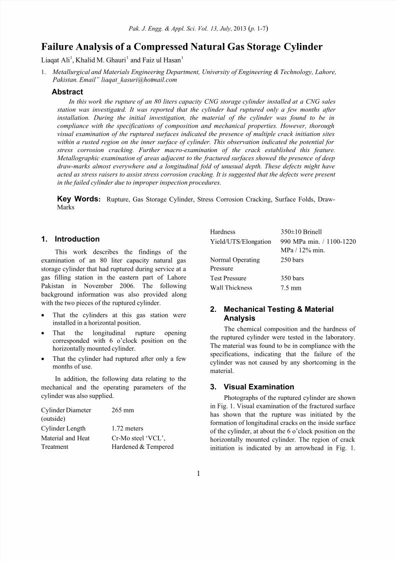
A close examination of this region showed that
the cracking had actually initiated at many different
points, as indicated by ‘chevron’ markings. As many
as eight points of origin could be clearly identified
within a distance of about 200 mm along the
fractured cylinder wall. The remaining part of the
fractured surface showed the typical slant ductileoverload fracture.
The area around the 6 o’clock position on the
inside surface of the cylinder was visibly ‘rusted’
when compared with the rest of the internal surface
of the cylinder. Further examination of this area,
shown in Figs. 1 and 2, indicated that the rusting had
been caused by the collection and stagnation of some
liquid (presumably water or some condensate) inside
the cylinder while it was lying in the horizontal
orientation. The rusted region which was about 100
mm wide ran along the entire length of the cylinder,
indicating that approximately 2 liters of the stagnant
liquid may have been present in the cylinder at the
time of rupture. A detailed macroscopic examination
of the rusted region also showed signs of sporadic
pitting corrosion in these areas (Fig. 2b and c) which
indicated that the liquid / water that had been present
in the cylinder was of corrosive character.
Unfortunately, no sample of the liquid collected from
Fig.2 (a &b) Photographs showing the stains caused by the stagnant liquid (presumably water) inside the
horizontally mounted cylinder. It was estimated that about 2 liters of liquid was present in the cylinder
at the time of rupture. (c) Showing the extent of corrosioncaused by the stagnant water. The arrowhead
points at the embedded oxide (dark-grey) inside a longitudinal draw-mark.
(a) (b)
Stain
Mark
Embedded oxideinside a draw-mark

8/13/2019 2-ART-1
http://slidepdf.com/reader/full/2-art-1 4/7
Pak. J. Engg. & Appl. Sci. Vol.13, July, 2013
4
one of the cylinders at the affected CNG station was
available for analysis.
4. Examination of the CrackA macroscopic examination of the entire
fractured surface showed that the cracking had
initiated in an approximately 200 mm long region ofthe cylinder-wall. This region, as indicated in Fig. 1,
was oriented parallel to the axis of the cylinder. It
should be noted in Fig. 1 that the initial cracks had
formed at the edge of the rusted region on the inside
surface of the cylinder. Macro-photographs taken
from this region are shown in Fig. 3, from which it is
evident that a number of cracks had separately
nucleated on the inside surface of the cylinder (Fig.3a)
The longitudinal cracks that had initiated the fracture
were oriented parallel to the axis of the cylinder and
perpendicular to the cylinder wall. These cracks had
formed at different planes in close proximity to each
other. As many as 8-10 separate longitudinal cracks
were present within a length of about 200 mm,
indicating that multiple cracking had taken place. Itshould be noted that when the ruptured cylinder was
first examined, about 24 hours after its rupture, there
were no signs of any oxidation or corrosion on the
surface of the crack.
It was noted that the fracture cracks had formed
within the ‘rusted’ region on the inside surface of the
cylinder and along a line that was very close to the
(a)
8.0 mm
(b)
8.0 mm
Fig.3 (a &b) Macro-Photographs of the fractured surface showing the points of crack initiation on the inside
surface of the cylinder.
(b)
(a)
8/13/2019 2-ART-1
http://slidepdf.com/reader/full/2-art-1 5/7
Failure Analysis of a Compressed Natural Gas Storage Cylinder
5
edge of the rusted portion of the cylinder surface.
This observation suggests that corrosion due to
stagnant liquid may have played a role in the
initiation of the crack. Considering a hoop stress of
45% (hoop stress 445 MPa, calculated according
tot Pd hoop
2 [1], P = pressure, d = diameter
and t = thickness) of the yield stress (990 MPa) at the
operating pressure of 250 bars in the presence of a
corrosive environment, the possibility of stress
corrosion cracking (or SCC) appears highly likely
[2]. Multiple sites of crack nucleation, as seen in Fig.
3a, are also indicative of stress corrosion cracking
[3].
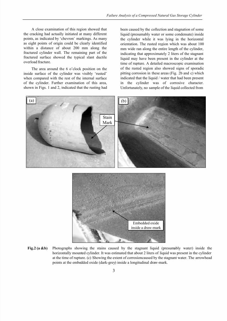
5. Metallography
In order to examine whether any further stress-
corrosion cracks were present in the areas close to the
fracture surface, samples were cut for metallographic
examination with surfaces perpendicular to both the
plane of the crack and the longitudinal axis of thecylinder; corresponding micrographs are shown in
Fig. 4. It can be seen in Fig. 4a that there was a
profusion of deep draw-marks on the inside surface
of the cylinder. In addition to the draw-marks, a
longitudinal ‘fold’ or ‘overlap’ (Fig. 4b), was present
very close to the line of the fracture.
Fig.4 Microphotographs taken from the transverse sections showing the depth of the draw marks (a and c) as well
as a surface ‘fold’ or ‘overlap’ in (b). It may be noted that no stress -corrosion cracking could be observed tohave started at the roots of the draw marks at this stage. (d) Schematic showing the depth and radius of the
notch for the calculation of stress concentration factor under tensile force [5].
(c)
(a) (b)
(d)

8/13/2019 2-ART-1
http://slidepdf.com/reader/full/2-art-1 6/7
Pak. J. Engg. & Appl. Sci. Vol.13, July, 2013
6
The depth of the draw-marks, as observed on the
sectioned samples (see Fig. 4c), was between 0.35
and 0.4 mm. The observed width of these draw marks
was in the range of 0.1-0.16. Such draw-marks can
cause stress concentration of sufficient magnitude to
become the source of either stress-corrosion-
cracking, or fatigue/corrosion-fatigue [3-4]. Thestress concentration (SC) factor for some of the draw
marks has been calculated according to [5]:
2
1
1
max
max
ca (1)
where = crack length (Fig. 4d), = radius of
crack tip (see Fig. 4d) and 0.5 for tension.
The calculated SC factor values for some of
these draw marks are between 2.0 and 2.2, which are
in the high range. At this point it can be argued, on
the basis of SC factor values, that a high amount of
stress can accumulate at the tips of these draw marks
and this stress concentration can actively contribute
to stress corrosion cracking (SCC)/corrosion-fatigue.
A photograph of the draw-marks as seen on the
un-rusted areas is given in Fig. 5. The number
(population) and the apparent depth of these draw-
marks as seen in Fig. 5 cannot be regarded as a
normal and acceptable feature of the deep drawn high
pressure cylinders [4].
The ‘fold’ or ‘overlap’ shown in Fig. 4b, can
also be seen in Fig. 6 as it appears on the inside
surface of the cylinder. This fold, which is more than
1 mm deep, extends along almost the entire length of
the cylinder. A fold of such depth can act as a highly
effective ‘stress raiser’ in high pressure applications
like a CNG cylinder [4-6]. For this fold, the stress
concentration (SC) factor has also been calculated
using Eq. (1) and the value is > 3.5. This value of SC
factor is very high, indicating severe stress
concentration with such a fold at the operating
pressure. This fault could not have been produced
during the deep drawing, but was inherently present
in the metal blank that was used for making this
particular cylinder [7] and should have been detected
during the inspection and quality control stages of
manufacturing.
Fig.5 (a) Photograph showing the longitudinal draw-marks on the inside surface of the cylinder. The apparent
depth and the sharpness of some of these draw-marks cannot be regarded as a normal feature of deep drawn
cylinders to be used for high-pressure applications. (b) A magnified view of the draw marks.
(a)
20 mm
(b)
10 mm
(b)(a)

8/13/2019 2-ART-1
http://slidepdf.com/reader/full/2-art-1 7/7
Failure Analysis of a Compressed Natural Gas Storage Cylinder
7
Fig.6 (b&c) Photographs showing the surface fold
(or overlap) on the inside surface of the
cylinder. Fig. 6a is the same as Fig. 4b.
6. Conclusions
The primary cause of the rupture was the presence of corrosive environments inside the
cylinder due to the accumulation and stagnation of
the water that must have been acidic in character. The
rupture is believed to have been caused through
‘Stress Corrosion Cracking’ initiated at the
longitudinal draw-marks on the inside surface of the
cylinder.
The stress corrosion cracking was greatly
assisted by the longitudinal draw-marks, which were
deep enough to have acted as very effective ‘stress
raisers’. In the ruptured cylinder, the observed draw-
marks could not be regarded as a normal feature of
the deep drawn cylinders meant for high pressure
usage. The presence of a surface fold clearly suggeststhat the inspection of the cylinder was negligent. It
appears from the findings that quality checks at key
manufacturing stages have been ignored by the
manufacturer in the CNG cylinders lot
supplied/imported for use.
7 References
[1] Mechanical Metallurgy, Dieter G. E., A
McGraw Hill Book, SI Metric Edition, 1988.
[2] Fracture Mechanics Analysis of NGV Fuel
Cylinders. Part 1: Steel Cylinders, Connolly M.
P., Hudak S. J., Roy S., Topical Report, Aug.
1989 - Feb. 1993, Southwest Research Inst., San
Antonio, TX. Materials and Mechanics
Department.
[3] Influence of Interaction Between Multiple
Cracks on Stress Corrosion Crack Propagation,
Masayuki Kamaya, Nobuo Totsuka, Corrosion
Science, Volume 44, Issue 10, October 2002,
Pages 2333-2352.
[4] Failure of Engineering Components Due to
Environmentally Assisted Cracking , S.P. Lynch,
ASM International , PFANF8 (2003) 5: Pages
33-42.
[5] Materials selection in Mechanical Design,
Ashby M. F., A Butterworth Heinemann Book,
2nd
Edition, 1999.
[6] Failures of Structures and Components by
Environmentally Assisted Cracking , S.P. Lynch,
Engineering Failure Analysis, Volume 1, Issue2, June 1994, Pages 77-90.
[7] Failure of Components and Products by
‘Engineered -in’ Defects: Case Studies, C.R.
Gagg., Engineering Failure Analysis, Volume
12, Issue 6, December 2005, Pages 1000-1026.
(b)
(a)
(c)
Related Documents