2. Analogue Theory and Circuit Analysis 2.1 Steady-State (DC) Circuits 2.2 Time-Dependent Circuits DeSiaMore Powered by DeSiaMore 1

2. Analogue Theory and Circuit Analysis 2.1 Steady-State (DC) Circuits 2.2 Time-Dependent Circuits DeSiaMorePowered by DeSiaMore1.
Dec 26, 2015
Welcome message from author
This document is posted to help you gain knowledge. Please leave a comment to let me know what you think about it! Share it to your friends and learn new things together.
Transcript

2. Analogue Theory and Circuit Analysis
2.1 Steady-State (DC) Circuits2.2 Time-Dependent Circuits
DeSiaMore Powered by DeSiaMore 1

Electrical systems have two main objectives:
• To gather, store, process, transport, and present information
• To distribute and convert energy between various forms
DeSiaMore Powered by DeSiaMore 2

Electrical Engineering Subdivisions
• Communication systems
• Computer systems• Control systems• Electromagnetics
• Electronics• Power systems• Signal processing
DeSiaMore Powered by DeSiaMore 3

Electrical Current
Electrical current is the time rate of flow of electrical charge through a conductor or circuit element. The units are amperes (A), which are equivalent to coulombs per second (C/s).
DeSiaMore Powered by DeSiaMore 4

Electrical Current
t
t
tqdttitq
dt
tdqti
0
)()()(
)()(
0
DeSiaMore Powered by DeSiaMore 5

Direct Current Alternating Current
When a current is constant with time, we say that we have direct current, abbreviated as dc. On the other hand, a current that varies with time, reversing direction periodically, is called alternating current, abbreviated as ac.
DeSiaMore Powered by DeSiaMore 6

.
DeSiaMore Powered by DeSiaMore 7

Voltages
The voltage associated with a circuit element is the energy transferred per unit of charge that flows through the element. The units of voltage are volts (V), which are equivalent to joules per coulomb (J/C).
DeSiaMore Powered by DeSiaMore 8

Transients
The time-varying currents and voltages resulting from the sudden application of sources, usually due to switching, are called transients. By writing circuit equations, we obtain integrodifferential equations.
DeSiaMore Powered by DeSiaMore 9

DC STEADY STATE
The steps in determining the forced response for RLC circuits with dc sources are:
1. Replace capacitances with open circuits.
2. Replace inductances with short circuits.
3. Solve the remaining circuit.
DeSiaMore Powered by DeSiaMore 10

CAPACITANCE
cc
dvi C
dt
cv
ci
C [Farads]
CSS
dIn DC Steady State; 0
dti 0 Open Circuit
DeSiaMore Powered by DeSiaMore 11

CAPACITANCE
Cvq
dt
dvCi
0
0
tqdttitqt
t
0
0
1tvdtti
Ctv
t
t
DeSiaMore Powered by DeSiaMore 12
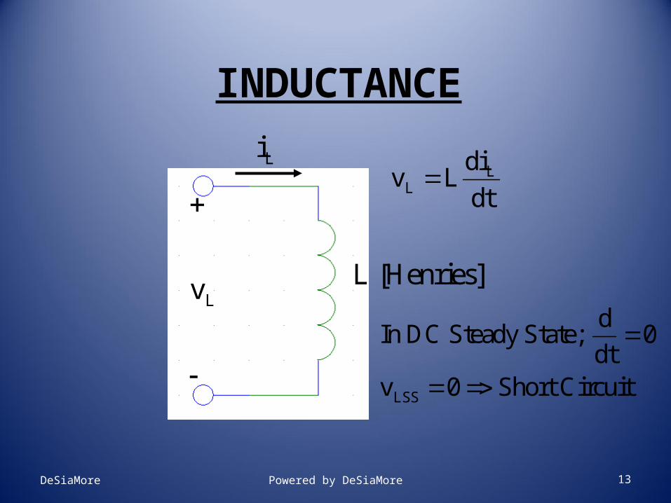
INDUCTANCE
LL
div L
dt
L [Henries]Lv
Li
LSS
dIn DC Steady State; 0
dtv 0 Short Circuit
DeSiaMore Powered by DeSiaMore 13

INDUCTANCE
dt
diLtv
0
0
1tidttv
Lti
t
t
tLitw 2
2
1
DeSiaMore Powered by DeSiaMore 14

SWITCHED CIRCUITS
• Circuits that Contain Switches
• Switches Open or Close at t = t0
• to = Switching Time
• Often choose to = 0
• Want to Find i’s and v’s in Circuit Before and After Switching Occurs
• i(to-), v(t0
-); i(to+), v(t0
+)
• Initial Conditions of CircuitDeSiaMore Powered by DeSiaMore 15

INITIAL CONDITIONS
• C’s and L’s Store Electrical Energy
• vC Cannot Change Instantaneously
• iL Cannot Change Instantaneously
• In DC Steady State; C => Open Circuit
• In DC Steady State; L => Short Circuit
• Use to Find i(to-), v(t0
-); i(to+), v(t0
+)
• Let’s do an ExampleDeSiaMore Powered by DeSiaMore 16

EXAMPLE
12 V2 4
2 1 F
Cv
1iSwitch Opens at t 0
Assume Switch has been Closed
for a long time before t 0
2v
1 v
2i
3 v 3i
+
Find Initial Conditions
i's and v's at t 0 and t 0
Ci
DeSiaMore Powered by DeSiaMore 17

EXAMPLE
12 V
2
2 4
At t 0 :3i
3v (0 ) 0
3 v 1i
2i
1 2
12i (0 ) i (0 ) 3 A
2 2
1 v
1 2v (0 ) v (0 ) 3x2 6 V
2v
Cv
C 2 3v (0 ) v (0 ) v (0 ) 6 V
C
Open Ckt
Switch ClosedCi
Ci (0 ) 0 3i (0 ) 0
DC Steady State
DeSiaMore Powered by DeSiaMore 18

EXAMPLE
12 V2
2
4
Cv
At t 0 :
C Cv (0 ) v (0 ) 6 V
1 F
1 1i (0 ) 0 v (0 )
2i
3 Ci i
2 3 C
6i (0 ) i (0 ) i (0 ) 1 A
4 2
2v
3 v
2v (0 ) 2x1 2 V 3v (0 ) 4x( 1) 4 V
1 v 1i
Switch Open
DeSiaMore Powered by DeSiaMore 19

EXAMPLEInitial Conditions
t 0
1
2
3
C
1
2
3
C
i 3 A
i 3 A
i 0 A
i 0 A
v 6 V
v 6 V
v 0 V
v 6 V
t 0
1
2
3
C
1
2
3
C
i 0 A
i 1 A
i 1 A
i 1 A
v 0 V
v 2 V
v 4 V
v 6 V
DeSiaMore Powered by DeSiaMore 20

1ST ORDER SWITCHED DC CIRCUITS
st
st
Will Look at 1 Order Circuits (Circuits with
1 C or 1 L) with Switched DC Inputs Tomorrow
Will Use Initial Conditions to Help Us Solve the
1 Order Differential Equation Relating the
st
Output to the Input
Today We Will Look at a 1 Order Circuit using
PSpice
DeSiaMore Powered by DeSiaMore 21

ACTIVITY 13-1
100 V
R
20 nF Cv
DeSiaMore Powered by DeSiaMore 22

ACTIVITY 13-1
• Charge a 20 nF Capacitor to 100 V thru a Variable Resistor, Rvar:
• Let’s Use a Switch that Closes at t = 0
• Rvar = 250k, 500k, 1 M
• Circuit File Has Been Run:• C:/Files/Desktop/CE-Studio/Circuits/act_5-
2.dat
• But Let’s Practice Using Schematics and Take a Quick LookDeSiaMore Powered by DeSiaMore 23

ACTIVITY 13-1
Circuit File
v 1 0 dc 100
R 1 2 {R}
C 2 0 20n ic=0
.param R=250k
.step param R list 250k 500k 1meg
.tran .1 .1 uic
.probe
.endDeSiaMore Powered by DeSiaMore 24

ACTIVITY 13-1
CPrint Graphs of v vs. time
Fill in Table for Activity 13-1
Hand In for Grading
DeSiaMore Powered by DeSiaMore 25

Transient Behaviour Introduction Charging Capacitors and Energising Inductors Discharging Capacitors and De-energising Inductors Response of First-Order Systems Second-Order Systems Higher-Order Systems
DeSiaMore Powered by DeSiaMore 26

Introduction So far we have looked at the behaviour of systems
in response to:– fixed DC signals– constant AC signals
We now turn our attention to the operation of circuits before they reach steady-state conditions– this is referred to as the transient response
We will begin by looking at simple RC and RL circuits
DeSiaMore Powered by DeSiaMore 27

Charging Capacitors and Energising Inductors
• Capacitor Charging Consider the circuit shown here
– Applying Kirchhoff’s voltage law
– Now, in a capacitor
– which substituting gives
VviR
tv
Cidd
Vvtv
CR dd
DeSiaMore Powered by DeSiaMore 28

The above is a first-order differential equation with constant coefficients
Assuming VC = 0 at t = 0, this can be solved to give
Since i = Cdv/dt this gives (assuming VC = 0 at t = 0)
– where I = V/R
)e1()e1( t-
CRt
-VVv
t-
CRt
-IIi ee
DeSiaMore Powered by DeSiaMore 29

Thus both the voltage and current have an exponential form
DeSiaMore Powered by DeSiaMore 30

• Inductor energising A similar analysis of this circuit gives
where I = V/R–
t-
LRt-
VVv ee
)e1()e1( t-
LRt-
IIi
DeSiaMore Powered by DeSiaMore 31

Thus, again, both the voltage and current have an exponential form
DeSiaMore Powered by DeSiaMore 32

Discharging Capacitors and De-energising Inductors
• Capacitor discharging Consider this circuit for
discharging a capacitor– At t = 0, VC = V
– From Kirchhoff’s voltage law
– giving
0viR
0dd vtv
CR
DeSiaMore Powered by DeSiaMore 33

Solving this as before gives
– where I = V/R
–
t-
CRt
-VVv ee
t-
CRt
-IIi ee
DeSiaMore Powered by DeSiaMore 34

In this case, both the voltage and the current take the form of decaying exponentials
DeSiaMore Powered by DeSiaMore 35

• Inductor de-energising A similar analysis of this
circuit gives
– where I = V/R– see Section 18.3.1
for this analysis
t-
LRt-
VVv ee
t-
LRt-
IIi ee
DeSiaMore Powered by DeSiaMore 36

And once again, both the voltage and the current take the form of decaying exponentials
DeSiaMore Powered by DeSiaMore 37

A comparison of the four circuits
DeSiaMore Powered by DeSiaMore 38

Response of First-Order Systems Initial and final value formulae
– increasing or decreasing exponential waveforms (for either voltage or current) are given by:
– where Vi and Ii are the initial values of the voltage and current– where Vf and If are the final values of the voltage and current– the first term in each case is the steady-state response– the second term represents the transient response– the combination gives the total response of the arrangement
DeSiaMore Powered by DeSiaMore 39

• The input voltage to the following CR network undergoes a step change from 5 V to 10 V at time t = 0. Derive an expression for the resulting output voltage.
•
DeSiaMore Powered by DeSiaMore 40

• Here the initial value is 5 V and the final value is 10 V. The time constant of the circuit equals CR = 10 103 20 10-6 = 0.2s. Therefore, from above, for t 0
•volts e510
e)105(10
e)(
2.0/
2.0/
/
t
t
tfif VVVv
DeSiaMore Powered by DeSiaMore 41

• The nature of exponential curves
DeSiaMore Powered by DeSiaMore 42

• Response of first-ordersystems to a squarewaveform
DeSiaMore Powered by DeSiaMore 43

• Response of first-ordersystems to a squarewaveform of differentfrequencies
DeSiaMore Powered by DeSiaMore 44

Key Points The charging or discharging of a capacitor, and the energising
and de-energising of an inductor, are each associated with exponential voltage and current waveforms
Circuits that contain resistance, and either capacitance or inductance, are termed first-order systems
The increasing or decreasing exponential waveforms of first-order systems can be described by the initial and final value formulae
Circuits that contain both capacitance and inductance are usually second-order systems. These are characterised by their undamped natural frequency and their damping factor
DeSiaMore Powered by DeSiaMore 45
Related Documents