A PUBLICATION O R THE RADIO AMA EUR ESPECIALLY COVERING VHF UHF AND MICROWAVES VOLUME No SUMMER 2 977 O 4 .50 M T UR RADIO on Ih 3 CIT d

Welcome message from author
This document is posted to help you gain knowledge. Please leave a comment to let me know what you think about it! Share it to your friends and learn new things together.
Transcript
7/27/2019 2-77.pdf
http://slidepdf.com/reader/full/2-77pdf 1/68
A PUBLICATION FOR THE RADIO AMATEURESPECIALLY COVERING VHF, UHF AND MICROWAVES
VOLUME No.9 SUMMER 2/1977 OM 4.50
AMATEUR RADIO
on Ih 3 CIT' d

7/27/2019 2-77.pdf
http://slidepdf.com/reader/full/2-77pdf 2/68
VHFCOMMUN ICATIONS
....- ' -8 by:
V- ' -g UKW..aEJUCHTE . . . . . J DoNu. oHG ...Mlt. . . . . ,. . D-e23 BAlERSOORF
Fed Reo of GennMy T ~ (0 " 331155. 1M
' W I ~T. 8'ttan. H DoNUI
EdItore :
T-"y D, Blrtan, 0 3NO I OJ0 eo. .-pontibit ' lo t h ".1
Robett E, lentz. Ol 3 WR. t'MPOMIbllI tor h ~ COFI'-ttl
VHF COMMUNICATtONI,
t.... International Idltlol 'l 01 lhtl o.m- publlc:llllon UKW·BEFIICHTE. II • qUlnetly .",.leYr
radiO maliluf,... nptClally C81enng lor I"'" VHF/UHF/SHF *hnology . II '1 pubilihed ,n
Spnng, Summer, Aulurnt'l . and Wint , . " . subtc:nphOfl prlC:e" OM le ,oo Ot "abona! "Qui l l l·
len, pet )'Mr. indIVIdual coplM . ~ lIab. . I ' OM • .50, Of equ/y . . . . .l Men . SubIctlpllon. .
on:\Ilrs 01 IndiVIdual C09IM. purchaM of P.C. ~ r c l . Ind ~ h " d 1 P e C 1 ~ c : o m ~ l "~ I M m e n l l and contributIOn' to rh I mag a l _ ahoulcl be ~ , . . . . . 10 ,, , . " " I ~ repr.
..,..1.11 .....
• Vartav UKW-8fRIQfTE l i n
AIt r lghtl ~ Reprlnta. t,MI6I;bOnt Of" Pl fKt I only WIth l/'IIi wnn.n ~ of t....
pUbhilMf.
YEIITRETU NOEN :
--=--. .- . .
- . ..................-....--. .......uu · .... e-..
Yo ""
R E PRE S EN TAllY ES :
_JO""c. "'. . " . . . . ~ .... I_'.._ flO ... ,. ~ \IIC..J'" T ......
. . . . . . . I " " 4 ' ' ' ' ' ' ' ' ' ' ' ' ' . 'iii " '0" '1 . 'O' l 1lOO-1OlQST-JtOCP
-....._ .01 TLX. QI . . . . . . l) l t IIIlfdITJO, , . . . . . . . ,
__~ .w..'.IM. . . .
--wteo LM'IIII"'JlOofTI H,DoI-.IHI1_ " .o-.n .....1"1OOf'I'. ' t I l0l1»-M6.IM~ I I I I I P ·_--.JD<I .......e--_ ........ UO-"M .o .u_ . . . . . . . . . . . , . . . ••.,., _a..IOAOAl"- ........ . ~ ' . ~ . ~ 1.U . . . .
I "-. • II,1(1"."0 aoo 121.II WOlIUJrt .100. , . '7"""" ' "11'1" t ( I ' OUlVIII ~ II. 1-101" WIl...oIoHO. 'til lOll '" tIIl . eo . . Con'l'ott:ll. . . . ... .... U 1 CWo'-'llUClILAHGI. ' -"--_"0Of1.IoIZIoow ' : : .hn., AQQ, ,-0, MU8I'OIID.T i l ' "-..... """' . . . . 'to, 70. ,.. L'I'IAQ". . . . . . ...... 1 '1 0001.... ... , . . ."O .IIilM IIIIII . . . .T- . . -a - '..". , . , ." .....--. Col. """OSSIl-ll.e.- c.... . . . . . . , . ,1'1 ..
....- . ... ,0'fT,. •....... ~ ~ , t I l XI":eo
,...,.....,.•..- ~ ~ """-- ~ ........... . ....- .ZQIIICIII .......~ • ""-- e>-. OLOCCSI'lOOk CISI' UI
_ "C" * - . ''POII I I ' . - . . . . . . . " II • na. , "'-- WI uc:z.II...... , . . , . ... 1'9 I ......... \ ' ' ' ' . T . " ' ....
.,..e - - . vu...--oooo. ~ .

7/27/2019 2-77.pdf
http://slidepdf.com/reader/full/2-77pdf 3/68
A PUBLICATION FORTHE RADIO AMATEURESPECIALLY COVERING VHF. UHF AND MICROWAVES
VOLUME No. 9 SUMMER EDITION· 2/1977
B. Heubusch, DC 5ex IntrOduct ion to Microwave Tech niques and 66 - 70Dt .lng .A.Hock. DC 0 MY • Descr iption 01 • 10 GHl T,. ".celv.r
H.Knaul ,DC 5CY
W. R_heA eoaxlal-Line Powe, Amplifier for 70 em
,,
- "C 8 NA Equipped with the 4 ex 250 B
J. Nilaaon Home·M ade Finger Stoc k ,,- ••5M 6 FHI
J. Dahms An Ab.arption Way.metar 90· '7Dea DA lot 70 MHz to 1350 MHz
H.J. Franke Zener Diode Noise in Oscillator .. - ..
OK t PN and Multiplier Ci rCUlI .E. SchmItzer StabiUzing the Opera llng Point 01Transislor. 100 · 103OJ4 SG with Directly Grounded Emitter
I. Sengme'sle" OJ7OH The 70 em FMTransceiver U M 70. ~ 108HJ , Franke , OK 1 PN Part 1; Introduction, Bloek Diagraml , Vetle tlona
H. aenUvoglio. OJ0 FW
E. Berberich A Spect rum Analyzer for Amaleur Applications 109 · 120
OL8ZX
H.J. Ehrke A Triangular.Wava Generator 121 · 123DC7LE
A VHF COMMUNI CATIONS 2/ 1977 · 65 ·

7/27/2019 2-77.pdf
http://slidepdf.com/reader/full/2-77pdf 4/68
INTRODUCTION TO MICROWAVE TECHNIQUES AND
A DESCRIPTION OF A 10 GHz TRANSCEIVER
by B. HIUbusch, DC !5 ex • Dr.lng. A.Hock, DC 0 MT · H. Knauf, DC 5 CV
Dr. o ain Evans's leeturs on the Munich VHF·UHF Convention In 1916 led to 8 large amoun t 01
&K perimantation and activity on the 106Hz band in Southern Germany. Microwave tech
nology Is extremely Intsresting. and is relat lvlly easy to handle. Dillieul! metal work II usually
not requhed . This article Is 10 gin an introduction to waveguide pr inci ples in the form 01 •
co nstruc tio nal d8$criptlo n of ou r 10 GHZ l ranscaiver, which we hope wil l help other amateurs
to become aClive on the 10 GHz band (10.0 to 10.5 6 Hz, correspondi ng 10 app rox . 3 em).
1. FUNDAMENTALS
1.1. Wn l guld••
Virtually only wavegu idas can be used lor transm itting energy in the Iraquancy range 01
10 GHz, since coax ial lines possess very high enenuetrcn, and bring dil l icultias in the inter
lace be tween different types 01 teeoer. f or vario us reasons, only rectangular waveguides 01
type WA 90 (1) are sui table. The operation 01 a wavegu ide can be explained as tcuows:
A waveguide usual ly consists 01 a rectangular tube with meta llic j conductive) walls: also
round, elliptical , as well as other shapes are possible . f lgur. 1 shows a rectangular wave
guide and Indicates the most Important d imensions. In order to be able to understand what
happens in a wavegu ide. let us assume that a metal pin or a small metal ball Is p laced in thecentre 01 a wavegu ide aperture and a DC-voltage III connected between this and the metall ic
surlace 01 the waveguide (• • • FIgur. 2). Electrlcal lield linn will now be present in the wave
guide wh ich, lor physical reasons. always leave the l ir51 surtece and arrive 8t the eeccna sur
face vertically. The vol tage is continuously reduced along such a l ield line. unti l It becomes
zero at the wall 01 the cavity. The electricallield strength also becomes weaker and weaker in
the direction of the waveguide 8xls, which la Indicated by the linea 01equal pote ntial (in other
word s equal volla ge. or equi-potential lines) given In f igure 2. 1/ an AC-voltage 15 connected
between the metal ball and. waveguide sur/ace Instead 01 the oc-vcnece. the alect rical lieldwill vary toge ther with the Irequ enoy. According to the magnetic flux laws. magnelic l ield
nnee will be generated that are sim ilar to that shown In f igure 3,
....Fig. 1:Rectangular wlvltgu lde
t
Fill. 2:II!laetrlcllllleld IIn l l
In the waveguidewith DC-vollage
t\' VHF COMMUNICATIONS 2/1977

7/27/2019 2-77.pdf
http://slidepdf.com/reader/full/2-77pdf 5/68
,.-, ,,..,............,
" " - ' ' 4 10 1.0<__ , _. . .. . '
_.,- ,....
f ig . 3:( Iwrlul .nd ""l In.11C II. ld .
In th gu .d•
• 'l h AC· oN.I I .
The magnet ic fieldl generl led In thil mlnner lito Il ler wilh time. Ind Iddl tionl' elec lriCl1
field lines will be gene riled Iccordlng 10 the theOry 01 induction, which mean. thai the elec
trical fie ld is concen.lrlled in Ihe exll 01 Ihe wl veguide. • nd II lorced more .nd more Inlo it .
II will c le. rly be seen when comp.ring Figure 2 and 3, This eflect beCOmes IIronger and
s tronger on Increas ing lhe Irequency, .nd the I,eld Wll stretch lurther and lurther inlO lhe
waveguide. However , II still rep resenls I quasl-slltlonary held, thl l only converters reactive
powe r, and Is nol ab'e to tr. nsport energy . II the frequency il lncreased more and more. a
poln l will flOafly be reached wh. r. Ihil 11 ld r. l ch. a Infinity. Th. frequency al thll point la
called the limit lrequency of the waveguide . On incr.asing
the~
lurther. th.f
l. ld willbe r. l• • sed lrom 11'1••nerglling metal ball , Ind the w..... will be passed along 11'1. way.;u ld•
• nd be able to trl nl port .n . rgy. All typea of w. veguides have l uch • lower limit frequency,
Which Is de pendenl on ilS Ihlpe Ind dim.nlionl , Ind it il unlbl. 10 trlnaport w. vn below
thll frequ .ncy. It can ther.tore b••ssumed Ih.t • w. v.guld. PO".'NS som. thlng .i mlli r '0a high-pa ss IiIter charlct. riltic.
In practic. , lhe re I r. Iny number 01wlv.'orm, In Ihe w....egu ld. , Since lh. r. ar. very many
types of waveguid• • , even more possibilltiea 01 Input co upling , .nd 1110 a large number 01
oper. ting frequenc ie• . In orde r to . chiev. cleer operating condition,. It il th.r. 'or. necessary
for a matching w. veguid. to be used lo r each Irequency ri nge. Fo r amateur radio appli·
ca lion• • th is will be • rect. ngul. r wl veguld. which 11 operated wilh the WIV. mode H,... Thi.is a very Siab le w......form which is ahown In Flgur. 4
fig . 4:
f l . ld. ollh. H,. · .
'n • rK l Inl lula r lIuld .
Th••Iectrlcal field Unel run Irom on. of th. longn t . ides to lhe Olher. where• • Ihe m.gn.tic
field Unes ereu pa rallel to Ihem. The limit w. .....l....glh ia ). . 21. In lhe rl nge trom ). • 21 10app roximately ). • I , Ihe Hww. v. il Ihe only wavetcrm Ih. 1can eKlat In Ihis w. vegu lde. This
means Ihat clear ope raling relat ionahips eKISI .
A VHFCOMMUNICATIONS 2/19 77 - 67 -

7/27/2019 2-77.pdf
http://slidepdf.com/reader/full/2-77pdf 6/68
II • > ). i ' v.lld. il is pOSSlbl. lo r lhe H,a·w..... 10 be conv,n*, 10 • d, ll....nl w. v. IOIm . 1 .ny
tnl.ri.r.nee in !he w•...eguid. (poor lIang• • Iltt.... cutput coupl ing . tc.). Thi' will ha'itl .n
,nl. ri. rence .fleet on the oper.l lon of lhe wholoe -rstem n.. H,. .w..... 1fI the w . ~ u t d e h• •• w.....lenglh or
ThIS meln l thlt It is grul... Ih.n the w.....length tn fr.. space. The Impedanc. of • w.v. .
guide II both t ~ u e n c y In<! w.....lorm cMpencMnl. The followi ng" v.lId fOl lhe H,a-w,'itI :
m
S inc. AF currents llOw In lhe w.vegulde (... Agur . 4). lhe w.vegulcM Ihould be tT'\lIcM Irom
• lI.t . good conducllve tT'\lIl,n.l. The 1n<lIVldull w.vegu icM MOm.ntl .r. Connecl*' log.lh,rwllh 11'1. lid 01 Ilinges . wh ich mUll be clNn .f'<! smoolh. otherwi.. conlld.tlble Ioues will
occur . It II ImpOrtant thai ~ . r. !tUlh-mounted fo r lhe sam. rlNlO/'ll. SUCh . fl. ng. "
shown In Flgu ,. 5. • n<! Figur . I glV" th ," .ndlrd dimenSion, lo r 1 '1. 10 GHz b.n<!.
' 1.5
L G- s.••' ."r'-=-- _ .:::..JL.l
•
", , :
11 Itd . reIft.,.. kwrKlani",I., 11 OH.I: wnegulde.
1.2. CORNERS AND BENDS
No . brupl changes 01 d irection should be m.cM in 11'1. w. veguld' . since Ihi' wou ld eeu..
conlld.t lbl, reuectron• . For Ihll reuon . CUrled plec.s of w.veguid . (so-c.lled compenuled
corne r piec:n) .re used . A" ,n l io n musl .Iways be paid Ih.1 11'1. Inner lu ri.C' 01 Ih. w. v.
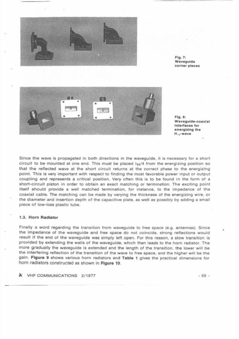
guide II smooth .nd .lh.1 no r..ldU"solder. or c r .cks.re pr 'Mn!. Flgure 7 showl Mv,,,1
types 01 corner pieces.
n,• •nerglzing 01 • wa.... Is .chlevtld ...lty by ,"clling .iltler the .lectr1ea1 wave Clp8Icll lv ,ty.
or lhe mlgne lic w. ve inc::luctlvely. Flgure • shows such unl,riacea. It Is allO posaibl, 10rrtlrM lhe PfOCeU 10 tMiI energy can be taken lrom lhe waveguide In the ume manner.
.. .
7/27/2019 2-77.pdf
http://slidepdf.com/reader/full/2-77pdf 7/68
Fig. 7:
WI"'lI"ldec o r ~ pl.ee.
~• • • •~• • • • "g. I :
WI " . g" lde-eo•• ll tInlerf-e.1 l or
'" ' '1III.lng th.H,••• , , , ,
Since the wave i l propagated in bolh direcllon l in tne waveguide, it is necessary lo r I snort
ci rcuit to be mou nted at one end . Thil mUl t be placed 'til. Ir om the energizing posi tion 10
Ih at the rel lecled W ve It Ihe I hort ci rcuit returns at the correc t phase to the energi zing
po in t. Thl l i l ....ry Impor tant wilh respect to l inding the mO t fl vor l ble power input or ou tpu t
coupling Ind reprehnts I critiCl 1 pol iUon. Very ol ten th ll II to be lound in the lorm Of a
shOrt-ci rcui t piston In orde, to obtain I n ell aci mltching or termination. The I llciting point
nseu I ho uld prov ide I wen matched termination, lor iM tance , 10 the impedance ot the
coad al cable . The matching can be madl by varying the thickne. . 01 the .nerglzlng wir• . or
the diameter and insertion dep th 0 1 the capacitive pl ate, IS well I I possibly by Idding I I mall
piece 0 1 low -loss plastic tube.
1.3. Hor" RadIator
Finally a word regarding the transition trom wI "eguide to I,ee space (e.g antlnnlS) . Since
Ihe Impedance 01 the wl veguide Ind Iree space do not coin cide. sl rong rellections wou ld
result if the end 01 the wl vegulde was l imply IeM open , For th is reason, al low Ifanli tion il
p rovided by ell tending the wall, 01 the waveguide, wh ich then lead, to the horn radiator. The
mora gradually the waveguide Is elllended Ind Ihe length 01 the transition , the lower will be
tha interfering rlIliect ion of Ihe transition 01 the wa" . 10 fr.. space . and the higher will be the
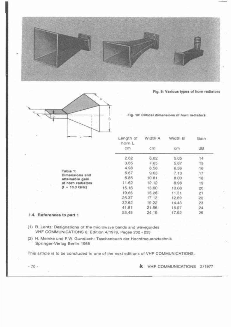
gain . FlgUf. lil shOws vanous hOfn fadialors and Tabla 1 gi,," the practical dimension, lor
hom rad lato,. conltructed as shown In Flgu r. 10,
A VHF COMMUN ICATIONS 2/1977 - 69 -
7/27/2019 2-77.pdf
http://slidepdf.com/reader/full/2-77pdf 8/68
1" --'-L - -
II--
r . ~ 1:~ . 1 0 f l end
. f t . l " . ~ " Inoj "om l .d l,tO,.
(I . U G ~
1.4. A'.r.nce. 10 p.rt 1
•
Ag. • : Vl rtoul typN of ftom 'Ielllilorl
Length 01 Width A Wid'h e Ol in
hOrnL
em em em dB
262 ' .62 ..
".65 765 5157
".. '58 '36 16
6.67 963 7.13 17
8.85 10.81 .00 16
11.62 12.12 e.se "5,16 13.60 10.08 2019.66 15.26 11.31 21
25.37 17.13 1289 2232.62 19.22 "u3 23
.' .81 21.56 1!U7
"3.45 24.19 17.92
"(I) R. Lenu :Dellgnltlon. ol in , mIcrowave band . ,nd w . ~ u l d "
VHF COMMUNICATIONS 8, Edition 4/1976. Peg" 232 .233
(2) H. M, ink. und F,W. Guncl i lch " rllChenbuch der Hochlrequ.nzlechn,k
Springer-V«lag Berlin 1968
Thi, er t lel, l, to be concluded in on. 01 It' l l n e ~ 1 ed ition, 01VHFCOMMUNICATIONS,
• 70 • ~ VHF COMMUNICATIONS 2/1917

7/27/2019 2-77.pdf
http://slidepdf.com/reader/full/2-77pdf 9/68
A COAXIAL·LINE POWER AMPLIFIER FOR 70 CMEQUIPPED WITH THE 4 CX 250 B
by W. Rah. , DC. NR
There I re vi rtually only IwO fam ili es 01 tubes that allow higher ou tpull 10 be obtained on
70 em Inexpensl....ly : The 2 C 39 and 4 X 150J• ex 250 types.
Several 70 em power ampli l lart eqUIpped with tt l . lube 2 C 39 h..... been published in (1), and
(2). Th is article is to descr ibe I higher powered Imp lilier equ ipped with . 4 ex250 e , Asimilar amplifier was described aeveral years ago in (3/ 5). Howev. r , 'tl'a amplifier pouelSed I
number Of disadvantaoes: the construction wa. rathe r dl fli cul l due to the UN 01many lathed
pa r t . , which Is p robably the r.ason why such power amphlllrt have nol been 100 popula' In
the pasl. In 'act, I 4 ex 250 amplifier po. . . . . . . wi th 14 10 16 dB . conalde r'bty higher gain
lhan a 2C39 amplifier 110 10 11 dB). This meant that approximately lou, lim•• Ihe output
power will be provided by the 4 ex 250 ampli fie r for Ihe ume dr ive power . Since bOth tube
types requ ire forced·air cooling. It II only the power l upply Ihat 11more extenl lve due 10 the
higher voltaO " . larger translormer and the required Icreen grid vol taoe. The amoun t 01
mechan ica l construction i l approxima tely the ..me lor both typn . The poM t amplifier
shown In AgUtlil t can be conlt rueted relatively e.l i ly : il poUUIl!lS a number 01 lpecial
'ealures WhiCh are to be described In mote detail
Fig. 1: A 70 empower 8mpltfl8r equlpjMd wttl'I th8 tUM ' ex: 250 fI
t. SELECTION OF THE TUBE
There are M\/ef81 difl erent types 01 the 04 X 150 A l ubes a c c o r d l ~ 10 the manu lacturer .
Normalty. fh il tube Is constrUcled In a metalil'aas ' echnology, but there are alao versions
with a ceramic base and wi thI lmple or double linl 01 the anode r8diator. The lOCket con -nec tions are Iden tical , and the main di llerenc. I I In Ihe heator vol18gO 01 6 v or 28 V. and In
the plate dissipation power 01 150 W or 250 W.
~ VHF COMMUNICATIONS 2/1971 • 71 •

7/27/2019 2-77.pdf
http://slidepdf.com/reader/full/2-77pdf 10/68
In addi tion 10 Ih is there Is the Iype 4 X 150 G which possesses coaxial tube erectrodee etmuer
10 Ihe 2 C 39 in order to keep tne ecnnecnce indUC l ance l as low al possible.
Due to Ihe metal-ceramic con struction , a higher maximum plate temperature 01 25O"C I, per.
m lSSlble lo r the tUbel 4 ex 250 B/F/R (250 W plale dl..lpalionj, in con lrasl 10 2OO"C lor Ih e
gla ss types. This means thaI it i l not necessary tor them 10 be COO led 10 inlensively. The limIt
values lor the plale and screen grid vollage 01 2000V and 400V respectively should. however.
not be al\ceeded with ellher type , AI can be Men In Figura 2. the gain ol lhe 4 X 150 startl 10
' all at rower lrequencies Ihan wll h Ihe 4 ex 250. Figure 3 gives Ihe mal\imum permlSllble
input al the limil valun . and the atta inable output pOwer al a l unC lon of Irequency. A cern
parlton 01 lheM tubes was given In (3). With the el\Ceptlon 01 Ihe '" e x 250 A. aU types ara
available ine l\penSlvaly on Ihe surplu s market.
II dl I . ,,,-JC8HR
1I
"I I
IUd '
,.UI •
1100'-
~ltd''.,SdlU. .,.,oo .
.. I • .. SOt ... . lID ..1'10·2 :Power ga'n as a functloll oll...-quellCr.Cia. . "8" groullded catholM circuit
Fig. J:11lput end Dlltput pow., ..a t...nctIo ll DI treq....llCr
During Ihe last lew years. a who le &erlel o t more modern tUbel has been developed in thll
power ca legory, but thei r prices are usually too high l or teem to be used lo r amaleur rad io
app ticatlons, Such s lube Is Ihe STC-tetrods '" KC 1 160 M wllh speclllcallons I lmllar 10 Ihat
01 the 4 e x 250 B. Thi' lube I, ccntect coo led U lng an Insulated, but good heal-conduct ing
block 01 beryllium ol\ ide mounled on I heal l ink. ThiS Is also the cale wllh Ih e Elmac tube
8813. The two other tubes of th il N rles 8814 and 8815 are 'arced-air coo led simila r 10 Iha
<I ex 250 (6). The addi tional output capacitance of a eemect coo led tube with beryllium oKlde
blOCk I I In 11'18 order 01 6 to 10 pF. This musl be l aken Into conliderallon on designing Ihe
anode cucun .
2. ELECTRICAL CONSTRUCTION
The l etrode tuba operales In a grounded calhode cecuu. The ~ cirCUit dIag ram Is given in
Figure 4, as ate the bMe connections ol lhe lubti . The 435MHZ drive power Is led via coa ..ial
soc ket 1 ~ th e input cou pling L 1 10 Ihe )J 2 hne circuli L 2 . Thll il COn ll rucl&d in Ihe lorm
0 ' • helica l ci rcuit The choke e h 1 leeds Ihe negalive bias vollag. lor Ih. ecntrcr grid t- 55 Vlo r linear cpereucn. or - 90 V lor cla l l Cj ; l his il made in Ih. vicinity 01 Ih. point 01
maximum currant.
A VHF COMMUNICATIONS 2/1g77

7/27/2019 2-77.pdf
http://slidepdf.com/reader/full/2-77pdf 11/68
Bul
Iu.,
~ a I ChS 016,
I'lg. 4: a. .1e clre,,11 ol th , 70 em pow" .mpllllll
Ou, to ttl e 'a rQl' c . ~ c l t i v e shortening 0 ' Ih . CtfCUlt (input cap.Ctl.nce 18.S pF) Ih" pOint i t
al r" dy w ith in the tube. It it , 01 to\ l ra . possible lor the Input coupllnt;} 10 M mad. cap,cl lI -
y,ly vi , . pp rOJum. tely 8 pF 10 Iha grid conn-e l,on .
The ec r.." grid " by-passed With , Mee t to HF IreQuancif t ulmg the built-In by-pass CIop.ci·
tor C 17 p l'O'tidid In tn. lube lOCket. Thee q u ~
at.blllzed ICrHn grid YOII.
01 350 V~ u . r l l d lor c las AS , I1near o ~ r ' l o O n t I l ild '11&cho ke Ctl 2 to pin 1 01 the IOCk , l .
The nea le , ' l ' O 1 ~ of 60 V ' I le<t to pin 3 01 the tuDe SOCket VI' chotle Ctl 4 Ttn, vOlI'Qe
'1.1.... may IMm atrange. . .nee Irte hUlet' w o l ~ I ' ulUIIIIV r.cluced In the cae Of UHF
operatIOn In Ofdtr 10 compenNte tot' IhI unwantlld rtNllng , ffeet cauMd by tINting of ,he
Cl lhOde by .-ctrons not captured by the pIal . In con t ra l to clUl C operahon , thl ' compen
..lion , . nol J1IQuir.ct In the l inN' mode ••nc. Ih" , IlKI ""'In be ~ f Y 1mI1l .
The lube il at th8 high voltag. poin t Of It... pia ' . ci rC Uit (L 3) ; the O1J lput coupling (L 4, and
the plat . voltage leed (Ch 3) a r . a l the poln l 01maximum cur renl ~ r capaCito r C 15 II
prOVided 10 compensa te IOf Ih. rue tlv ' compotllln i 01 L 4 The ca.xla' lnocH Ci rCUl i II llSOJJ2 long I nd il tuned 10 resonanca wllh I ham.-made lubUlar trImmer IC 16) I t the other end
0 the IIna Irom the lube {also at lhe polnl 01 maximum ' t O l ~ g ' Thll type 01 conllruchon... , . . Ihe u.. Ol lha by-pus capacllor thai would be req l"Irlld With U4 Cl rC1ll1I
Oua 10 Ihl O1Jlpul capacilanca 01 Ih. lube (4.5 pF). Irlmmer C 16, .nd thl In.voidabla I lr.y
capacitances , the anode clrcuil II mechanic. lly sho r1e r th.n ';,;2. Such an arrang. mant wilh •
round inn.r conductor and a round, or Iquare oule r conduclor complelely l urroundlng Ihe
Inner conducior II usually called a coaxl. t line clrcul!. The mOlt lavorable 0 lor IhI' circuli,
a nd thua the lowest loss wilt be provided . 1 a ral lo 01 Old . pprox. 3.5. Thil a ~ t ra"o
corrHpond. 10 an impedance 01 75 0 1h1' hlghl 'r Ih. capaCllivl load oi lhi' euccn. ' ' '1 low.r
Will be the moat fa't()(abIa Impedance . The pla l l hne CircUIt dHCnbed "a , . poua IM I an
Impedanca 01approximalely 55 Q .
- ' VHF COMMUN ICATIONS 2/HIn • 73 •

7/27/2019 2-77.pdf
http://slidepdf.com/reader/full/2-77pdf 12/68
The band w idth of coaxial lina ClrCUltl decreases on increasing the Ii". length in mu lt ip les 01)J 4 if tha impedance il kept constant. Thi l mean. thal the b.ind width 01 I lJ2 ci rCUit i. only
apprOXimaTely half thal 01 the band width 01 a lJ. CrCUIt. This meanl tha i power amplifierl
equipped wllh 1.J2 CirCUits may nol be SU llable fo r a wideband ccereuon. luch as lor "TV,
3. MECHANICAL CONSTRUCTION
Figura 5 ahOW! me compact. and uncomplicated ccnetrucncn of the power amplifier . The
mechanical construction ia ex lremely almple lo r a power amplifier 01 th is cia... alnce mainly
already allailable tubular malerial i l used.
The ou te r conducto r of the plate coaxial line With the Internal d imensiOns Of 100 mm x
100 mm la first ly bent from 1 mm thick bra.. plate. Of course, II i l alao poil ib le fOf th i l part
to be eeteeree together from l uitabla metal platea . Howltl/er, II II nol recommended thal I
sc rewed cOflSlruct ion is used al Ihia poin t, since a poor electrical contacl In the high-current
pathl .....ould be extremely un tlllorable . It il on ly the COlier tha t II mounted in thia manner .
Th il Is fo llowed by soldering the lube and metal platea Into pos il ion : the plate .....i lh the
56mm hole In the centre Is lor mounllng the tube locket . and the other with the hole lo r the
Ihalt o f the capacitor e 16 and a large number of 6 mm dia, holes for exi t 01 the cooling air .
The other holea In the plate line ci rcu it (cooling air input. socket mounting . cover mounting ,
plate lIoltage Input. cerami c IUpport lor Ihe Inner conductor Ind output coup ling) .hould be
made a. shown in Figure 5 and need not be described in deta il . Since the output coupling i l
at 10.... impedance (high current, 10.... lIoltage) a 'Pac ing 01 0.75mm il sufficient for trlmme'
C 15.
The inner conductor 01 Ihe coaxial line c ircuit compr i... a 2 mm th ick copper lube 01
185mm in length and .. mm diameter. Bra.. lube can allO tilt used . but II not 10 lavorabledue 10 i l l higher heat reaistance. Aluminium lube should alao be lIery suitable If II can be wan
c lamped to lhe anode radia tor (heat ecetucrent A[W/grd x cm I : copper • 3.8: alum inium
- 2.1; b ra" • 1.1).
Since the plale radiato r ol l h e . ex 250 B POSsesse l a d iameter 01approximately . 1,2 mm , il
is necessary lor the copper tube 10 be lathed 10 thia diameTer. Finally, the lube Is provided
..... ith slot. 01 20 10 25 mm in length at Ih is posit ion. Th•• ex 250 B and the l ube 01 the inner
conductor should have a lit lightly. II necesury, a lubular c lamp cl n also be used (_ Rg .7).
In order to avoid lath ing, al re ldy IvaUab le bru s tube 01 • • mm / t mm .....a. first ly uae<l fo r
the plale inner conductor . Howevar , It was lound that l uch a tUbe poua...s considerab lemechanical lensions .....hich were nOllceable as creckli ng IOUnd l on he.ting , In addi tion to
thi . , the st. b lli ty and the he.1 conduction ......re inlerlor.
The plete circuit I' supported .1 one end by the tube and .1 Ih. o ther by • cer. mlc support .
Thill l imple construction allowl Ihe lube to be repl.ced qu ickly .
The plate trimmer C 16 con l lsl s of e readily .v .il.ble . lumlnlum knob 01 30 mm diameter and
15 mm In lenglh (Flgur. 8). It i l screwed emo a 48 mm length 01 6 mm br.ss rod that has
been prOll ided With a l in. lot8 IhrNd to e length of 30 mm. Tha thruded rod I. placed
th rough e gu ide lor l ingle-hole mount ing that po....... In lot 8 line thrud on lhe inaide.
- 7" • . . VHF COMMUNICATIONS 2/19n

7/27/2019 2-77.pdf
http://slidepdf.com/reader/full/2-77pdf 13/68
,
1
2,•
•
165
-
-
-
-
4
basqua
e
coso
66mm
DC8NR
•
•
[h
/
Camicspr•
•
75
-
20
t-
-+--
Conwh
raafa
Hgeofeho
.S
-4-
----245---
---
--;
o
so
.0
~
"<:
'0
.3mm
100
Arvs
Fg5euo
.-d~.o.....eSOPAtoMH

7/27/2019 2-77.pdf
http://slidepdf.com/reader/full/2-77pdf 14/68
I., ,,
,fill'''' " " '~ ~
C'tCllllC l . .pporl
Fig . ' : Anode clreult tun1nli
In order to obtain 'his, It II necessary lor ,he diameter 016 mm to be reduced to 8pptOllima ·
'ely 4.5 mm which can be done by acld" ring a I lJ ltable lube (6 mm I 0.75 mm) lnlo pllee . In
order to enlUte, tha i the l ine thread II net damaged by Ihe mounting screwl 01 Ih . knob. the
rod II lathed dOwnto 4 mm d ilmeter I ' on. end lor " length 018 mm.01 co ur••, it 'a also possible lor the lun ing 01 the anode etreuu 10 be mad. in I dllle ,ent
manner , lor instanca, uling two opPOsite plate capacllors .. can be seen in Flgur. 7. Th.
adv.n tage of thll 'I thaI the grid and anode ci rCUl I are aCceMibl. ',om Ihll Ironi panel. The
disadvantage at. Ihe considerably Ilrg., dlmenl ions 01Ihe powe, , mphl"" , Furthermor. , l he
two plate capacilo,.. must be luned 10 the u me capaci tance vafue. in order to ensure th. t asymmetric lield prevail •. Otherwise, it would not be possible to obtein the mulmum output
power .
The constructiOn 01 the gr id ci rcuit and tunmg is shown In Figu re • . which also . how. the
connections 01 the tube socket. The Inner conductor (L 2) 01 the helical CIrcui t I. con.truc te<!
from 2 mm th ick, .iI....r·plate<! copper wire 01 apprOllimately 90 mm in length , and the
coupling link L 1 tr cm 1mm diameter . lIver-plafed copper wire. In orde r not to capac ltlvely
load the ci rcui t more than necessary. the tun ing I . made With an air. .paced l t lmmer (C 1.)
having a low llnal capaci tance (max. 2 pF). Since .uch trimmera are normally not available ,
the plates 01 a higher capacitance trimmer I re removed until two . tationary and one moving
plale remain. The gr id ci rcuit can be aligned Irom the front pane l using a Ilexib le coupling
and gear.
·76 · A VHF COMMUNICATIONS 2/1977

7/27/2019 2-77.pdf
http://slidepdf.com/reader/full/2-77pdf 15/68
M3
6mm shaft
Fig. I : Th, grid circu it
.Ug,Brass t ube
1.5x1mm
Ug,
Flex ible coupling
The outer conductor 0 1 the errwn I , lormed by a "0 mm length 0 1 " 5 mm I 1 mm diamc!l1ar
l ube Ihal Is placed over the tube sockel and screwed With it al lour po int '. In order to do lhi ' ,
M 3 nut l ahould be soldered into place on Ihe IOCkel Ollllr the hoi.. provided . In order lo r the
lube to be placed compiele ly over lhe IOCkel, it is neceuary lor ,Iota 10 be made al the
required poaitions (Figure 8 ). The live celhode conneclion, 0 1 Ihe tube are soldered using
ahort pieces 0 1 wir e to the in'ide o l t h . IOCkel as cen be IMn In Figure 8. FIgure ' ahow, a
pho tograph 01 the grid side or the powe r ampli lier.
Fig. 10: Output coupling
The output coupling comprising L" end C 15 ia shown in Agur• • 10 and 1 ' .
' " VHF COMMUNICATIONS 2/ 1977 • 71 •

7/27/2019 2-77.pdf
http://slidepdf.com/reader/full/2-77pdf 16/68
4. COOLING
Tube s wIth the anode on Ihe oulslde such as Ihe 4 ex250 B are designed l or lorced-alr
cooling . The cooling air is normally blown in Irom the grid side since Ihe eleclrode connec l·
ions also requ ire cooling. It Is necessary lor Ihe pin ecnnecucee tc be coole d even when onlythe heating is on. The coo li ng air then Iiow l along Ihe envelope 01 the tube wilh Ihe aid 01a
ce ramic chimney, I lowl thr ough Ihe plale cooling ' Ina and escapes. A reduolion In pressure
resul ls due to vortex and eddies. The 4
ex250 B requlrel approxi mately 0.6 ml/mln, at the
full pla te diSSipation power 01250 W and when uSing Ihe matching aockel and chimney.
A preaaure 01 1.6 mbar i l required. The pressure drop cen, however , be conllderably tllgner
due 10 . n unf.vorable .Ir /low. 10 th. t Ihe air Ilow I I non-exlltent With an unlult.bla Ian .
MOl t axla' lana provide sultlclenl quantifies 01 . ,r , even I I low lpeed. and are lu fllciently
qu iel. However, lhey .re not able to operate againll any noliceable pr8Nure drop . Radial 'ana
are bette r in Ih is respecl. bUI are louder, and are u lually nol powerful enough In the types
usually used by radio amateurs (8). Experlmenl l made, feeding tha cooling air Irom a radial
Ian trcm Ihe grid aide, brougn l the expecled negative rel ult : all er 10 I 01 contl nuOUI c.rrier,
the oUlput powitr dropped 10 more than 50 % ol lhe commencement v.lue and Ihe solde r onthe pl.le capac itor al Ihe end of Ihe anode lube (Figure 7) melled. Thll mean. lh.1 Ihe per-
m issable anode lemperalure 01 25O"C wal moat certaInly exceeded. Since no damage to the
lu be w" noticed during the rel.llvely long experimental proce.s. Ihll goel to .now how
robull the cona lruction 01 Ihe lube ia. Due 10 tI l glesl envelope. the 4 X 150 would nol be
able 10 I I.nd lIUCh In o....r lo.d condition .
In Ihe case 01 the power amplifier descrIbed here. Ine cooling air la blown into Ine plate
cavity In Ihe viCinity ol lhe l ube anode using. rel.U....ly weak .xlal lan u anown in Figure 15.
The ai r Ihen flowa wll hool any considerable preaaure drop along the plata lube 10 In .1
l u i licien t he.1 I I dissipated in thia m.nner. A small portion 01 the cooling air la led in Inil
manner via the eocxet and the electrical connections and la eXiled 'II. Ihe grid circu l i . A
Chimney should nOI be used here.
. 78- A. VHF COMMUNICATIONS 2/ 1vn

7/27/2019 2-77.pdf
http://slidepdf.com/reader/full/2-77pdf 17/68
f)g . 15: PftOlogropn . I th . power o",plll••, with 10"
The mos t Importanl polnl wh. n Ul ing this eoncept I I Ih l t • lullici.nlly ll rg . Imounl of ait II
moved and that hard ly any pr.ssur. drop occurs on the large ccollng surface 01 the plale
tube . The shown axia l fan with Ihe dimenllon l 88 mm x 88 mm x 50 mm was lound 10 be
suitable lor SSB opera tion up 10 power levell of Ipp roximalely 500W Input. For higher power
levels, a radial fan is more favorable wh ich shou ld be mounted IS shown in Figure S,
The air Inlakes of bo lh types or Il nl Ihould be kepi Ir.. lor a dil tance of I I I .all 3 10 .. em.
The air Inlake 01 the eneee chamber Ihould be pro ...ided wllh I" e ccersest possIble ae,eening
(spacing S to 6 mm). Brass nelling can be sold.red in lo place ,
5. POWER SUPPlY
Figure 12 shows tne ci rCUit diagram of Ih. l impl. power lupply . The reqUired high pillevOltage of 1500 10 2000 V ,equ ired in order to obtain the highest possible linesrity is oblained
with the aid 01 voltage doubling (Delon-circult). Thi. sa..... an . xpan.i.... high-I.n.ion Irani
lormer; the output voltage is lu fflciently Itable . A series connecucn of cheap eleclrolyhC
capac itors replaces the large , and expensive melal poper capaci tors (whose reUobllily II how
evar grealer). The rasisto l'S connected In parallel with the electrolytic capaci lOrs ecmpeneete
th. leakage currents and discharge Ihe capaci tor chain on I witching 011 . It i l Ih.refore
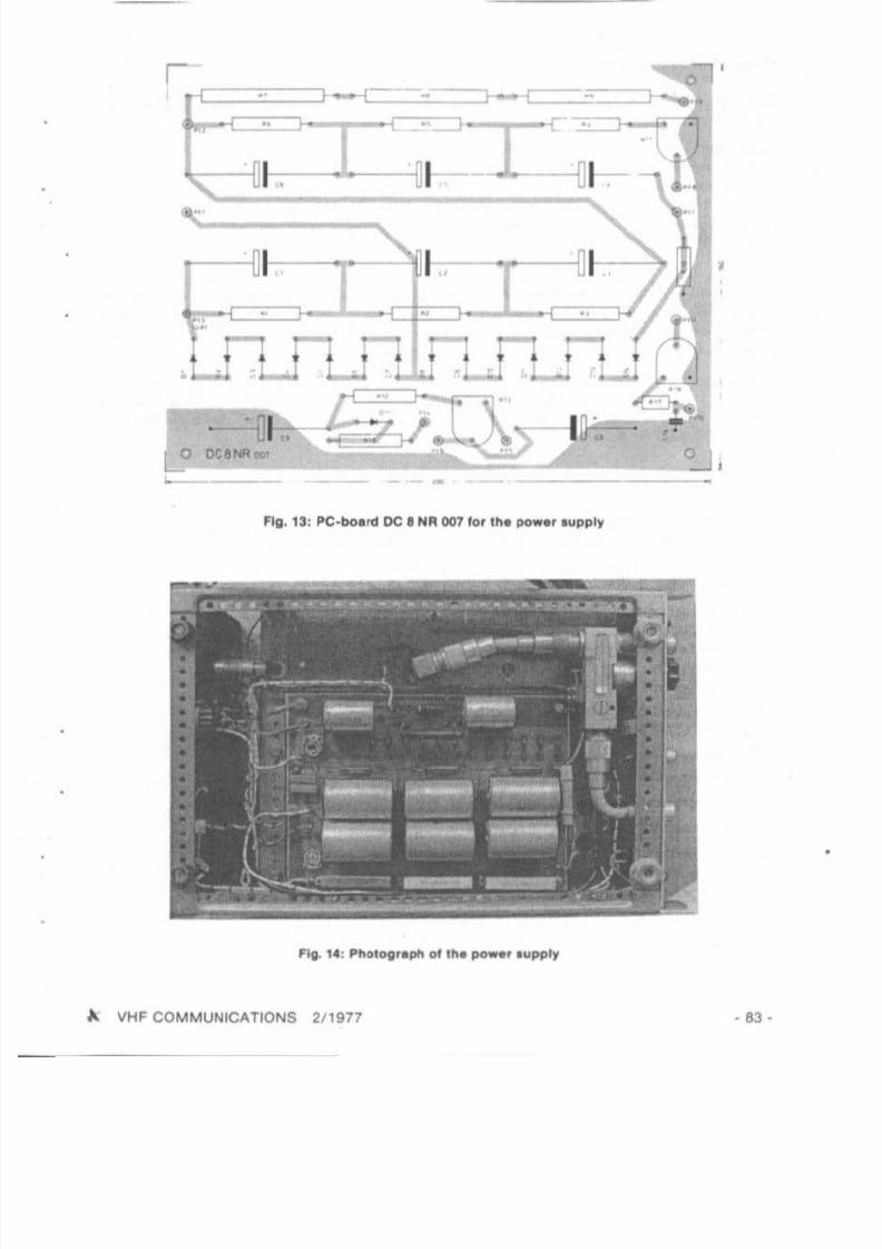
po l slb le for the whole po_ r l upply to be accommodal .d on a PC-board. Fig , 13 I hOWI thil
PC-board wh ich has bean daalgnaled DC8 NR 007, Cheap recli fier diodes can be used: me
IWO diode chai ns could , howev.r, be rep laced by two lingle diodes (inverse voUag. 3 kV;
I • 3 A). The dropper resillo l'S R 7 10 R 9 01 lhe ltabUizer chain oenerata a conl ldarableheal. For this l1lason, Ihey Should be aplced somewhal Irom Ihe pc-bolrd , Caplcilor C 7 ia
not 10 be lound on the PC-boord, but II connected in the vicinity 01 the high-tension leed
Ih rough .
In the linear mode, IhI tube reQuir.. I IllbUlzed aeraen grid voltloe 01 350 V. II a la ilur. 01
the anode voltage .hOuld occur, thlaeraen grid with its mlximum dissipation power 01 12 W
is endano.red , Since it witl then work aa pla te and will a!lempt to ICcepl lh. high anode
cu rrent. The screen grid curr.n t can become negalive al low anode currenls. For Ih l' reo, on ,
It I , favorob le fo r the screen grid supply to be made Wth the aid of neon Itablllze" which
limi t the avanable power 10 11 W. Thll enaures thaI no overload condllion can occur , The
bial voltage IOUrce lor Ihe conl rol gr id can be I t high Impedance I inee no grid current wil l
be drawn In thl l inear mode.
A VHF COMMUNICATIONS 2/1977 - 79 •

7/27/2019 2-77.pdf
http://slidepdf.com/reader/full/2-77pdf 18/68
The m. t.r tw, ICh S 3 connecta all curr.nll and ...oltaO" 01 Int.rnt to the m.t.r I 1. Th•
....Iues of the Shunt resiators R to. R 1t , R 14, and R 15 ~ d on the meter used, andahoYld be recalcul.ted If nec. . . . ry.
The or....n ....Iues . r.....11d 10' • met.. . ha""ng 60 " '" .nd an i m ~ . n e e ot 2.5 kO.
n . . 250 rMIalor R 11 Wl the power I t ~ ,a nol .bsotulety nec. . . . .ry, It la onty p r ~ 10
ensu re lhat the tr.nSlent cun.nt peak on aw,tchlng on doee not .cluat. the power lone I UM
(10 A). SWIlch S 2 bridges th. res,ator aM.r lhe ~ r o l y t l C capacItOrs a,. lulty charged all.r
.ppro..,m. t.ry 1 a. and lhe tr.naformer will rKelve the lull pow.' hne voltaQ'8_
Alt. r aWl tchlng on, the hN I.r, control Orld and pl. te ...oltAge r .m"n connected to Ih. tube
.... soon as the ,u ",h.ry con t'C I r t 01 th. anlenna r. I• ., ,a opened In the rec...... mod. , the
full negallve grid tMaa vollag. 01 110 V Will blOCk the tube . If lhe driver ia not keyed . thla
neg. l l.......ot tage can be used in the CWmOd. lor keyIng ,
The power ampllfl., can be aWltched to class C oper.llon wllh lhe a'd of two change-o....rt w,tches that . , . not ahOwn in FlQur. 12. The control grid bI.a YOltag. it Increased h om
-55V 10 -90V , and Ih. sc reen grid "'O l l 'g. reduced Irom 350 10 250V. In th ll ccsmcn. ahigher pla t••fflciency 101more th. n 50 %) ia posslbl• . howeY.r, Ih. g.m will be Iow.r. Thlt
mod. can be used lor FM and CW; how..... r. It ia .aal.r 10 ute Ih. Un.ar clan A8 ' mod. alao
lor th... modulation mod... When oper . llng wllh low. r pl. t....oUag" 01 I... than 1500 V, It
WIll be nee. . . . ry lor Ih. sc reen grid ...oUaoe alto to be rllduced to 250 10 300 V,
e, COMPONENT DETAILS
700 - 800 V. 600 mA lfor 1700 - 2'000VDC und.r Ic.d)Secondary 2: 75 V 120 mASecondary 3 60 V 12 6 A
IM t. ..t (1 N "007 or Slmll.r)
1 N "007
1 N .,.e or IimlW
6.0 kO /O ,S W
60 0 / 0.5W
1 kD trimmer pet.
100 k0 / 0.5 W
330 /0 .5 W25Q /m'n .5W
R 14:
R 15:
R 16:
R 17:
R,.
R t9
100 I&f 1 550 V
ceramIC d.sk caPfiCllor .70 pF 13 kV
25I&F 1 350 V
500 pF 1 500 V IMdthrough c a ~ l for l e r " moynllng0,.·2 pF (1M le..n1SpF (... t. ..u0.3 - 6 pF (see le..l)
10 .. 10 mm mounted on insula ted feedt hrough apaced 20 mm Irom L 3
220 pF c . ramic dilk ca pacllor
l00k0 / 2W
8.2 kO / 11 W (be tt.r 15 WI
0.8 kO Wre-wound r,,"10r I '" 1."1150 0 trimmer potentlom.l.r
2.7k0 /2 Wto kO trrmm.r polentlomeler
Tranalorm8f Tr 1:
01 - 0 ,.
015:
016 :
C 1 - C 6C7
C6 , C9 ,
Cl t ·C13C , . :
C 15:
C 16:C 17:C 16:
R l -R 6 :
R 7 - R 9.
R 10:
R 11:
R 12R 13.
· 00 · ~ VHF COMMUNtCATlONS 2/ t in

7/27/2019 2-77.pdf
http://slidepdf.com/reader/full/2-77pdf 19/68
Tr1
S
2SA
0-",-.~~
I
I
:uee
I
.nI I I I
~
-+-
Il '
pD6D11.
P7
o-
R
O
·UJ2
•
5-
5
:0-0
0
,
~:
p-1I
0
R<
,,
.SOV.
, ,
R
R
P9
11
C1R1
Ct
.\
C2::R2
R5
R
s
C3
R&
R
Pl1
P2
P8
R&
P<
0
R
-5VtnV.
R
P&
CrP5rDC8NR
1ester
rn
C0 '"

7/27/2019 2-77.pdf
http://slidepdf.com/reader/full/2-77pdf 20/68
Gearmg
Rad ial Ian (Airflow 26 8TM)
Axial fan (Papal type 3050 With capacuor motor :Dimensions: BBx 88 x 50mm. 90 m'l h, 220 V 1 50 Hz)
All chokes are made from )J4 lenglh (17.2 em) 01enamelled copper wire wound in Iheform
01a COil :
c- I , e h 2,Ch 5 : 0.3 mm enamel led copper Wre, 3 mm dlamele,
Ch 3: 0.8 mm enamelled copper Wfe, 7 mm dIamete r
Ch 4 : 0.8 mm enamelled copper WI' e, 4 mm diame ter
Ceramic support, 28 mm long , wil h two melal caps with M 3 thread
Ceramic h lgh-Ienslon 'eedthrough
Aluminium knob
Flexible coupling
6 mm diameter shall support
6 mm extene.cn shaft
7. CONNECTION AND ALIGNMENT
The power supp ly shou ld hrslly be IMled , Thi l is 'ollowed by checking Ih . operation 01 Ih e
an lenna relay . With relay ecn tect
r1 closed,
Ivol
lage0 1 approx imately - 55 V should
be
alig ned at Pt6 wllh Ihe aid 0 1 R 13. All er Ihi , . tne power amplifier can be ccnnectec 10 Ihe
operating vol lages and connecled 10 a load (anlenna or dummy-load). Normally. it is recom
mended thl ! Ihe prelim inary allgnmenl 0 1 l uch a high-power ampliller to be made al reduced
sc reen g rid and plate voltage, and 10 inc rease IheM vOltages atle r Ihls preliminary alignmenl.
AlthOugh Ih i l melhod is 10 be recommended, practical dlMicu lli.. lake place in our appli
cation (power lupply) . Thil I I alao not abaolutely necessary if the tenOWing procedure I Icarried out:
Switch on the power supply and allow a warm-up period 01 1 mlnule : place I wllch 5 2 inlO
the anode cu rrent posi tion , Switch on the power amplifIer and adJus R 13 to obtaIn aquiesce nl plate current 0 1 100 mA, Ellablish whelher tne l inear amphller Is opera"ng atabily :
increase the anode cu rren l lemporarily wll h R 13 to 200 rnA and rotale the grid and plate
crrccn trimmers. No output po wer should be indicated, and the indicaled plale current Ihould
nol change .
Connect an exci ter wilh an oulput power 0 1 approximately 3 to 4 W. and pl ace the coupling
Ir lmmer C 15 10 il l mInimum capaci tance polillon . Ali gn the grid circui t lor maximum plale
current. Br lnll th' pU le ci rcui l to resonance wi lh Ihe aid 0 1 C 16. where a clear dip 0 1 Ihe
anode current Should appear, Align Ihe oulpu l coupling trimmer and the plate tuning aller
nately l or m... imum output power . The alignment II comple led by carefully bending Ihe
cou pling link L 1. The pcsrucn and lpacing of the oulput coupling link L 4 to Ihe pille clrcuil
as shown In Figure 10 should be mosl favorable. By lh e way. the lI_bilizer chain presenl l agood visual Indica tion lor Ihe correct tun ing ol lhe power ampli fier, The screen grid cu rrents
will fa ll no ticeably I t resonance.
Al ler Ih is. i t il poSSible lor Ihe dr ive power 10 be increased, Approximalaly 7 to 8 W will be
required lor full d n ~ accordmg to the plale vollage whi ch means that the , • • MHz - .32 MHz
l r .nl vert.r with the EC 8020 in lh e power amphlier (9) il suitable. The contror grid cu rrent
can be used al cri terion l or the drive limi t : The grid current should be ze,o In linea r ope ra·
l ion, Large Inlermodulation producla wil l be generated wnen driving Ihe ampli fier Inlo the
gr id cu rren l region, which wiU cause the l ignal band width 10 Incr.... and Ihe powerampli lier wi ll splaner , No neulral izatlon hal been lound necessary with all the Unear ampli·
' Iers constructed unW now,
- 82 - A VHF COMMUNICATIONS 2/1977
7/27/2019 2-77.pdf
http://slidepdf.com/reader/full/2-77pdf 21/68
~r ; "- -..-....j ll - - . . - - - - ' i l
"
o oc eNR CWl'
•Fig. 13: PC·be.ret DC. NR007 lor Ill. po••' .Ilpply
" VHF COMMUNICATIONS 2/1977 , B3 '
7/27/2019 2-77.pdf
http://slidepdf.com/reader/full/2-77pdf 22/68
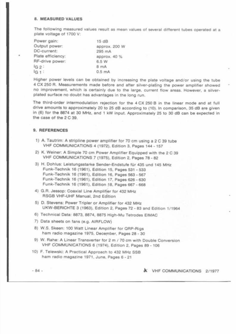
• . MUSURED VALUES
~ 10010w lng measured ....Iu.. result u mean values 01. . . . . .1d,ff.,ent tubes OPe rated at a
plat . volUlge 01 t 700 V
POWtf ' gain:
OutPUI power:
OC-eur rent .Plate eHlc*'<:)':
AF-dri.... poww:
'G,'G 1 ,
15 eeappro 200 W
295 ......approx. 40%
6,$ W
. ......
0.5 rnA
t"ligher power Ievela can be obtained by mer...ng Ihe plale voll.ge . nd/o r USing Ihe tube
4 ex 250 R. Meauremenll made belore and aMer S1 lve, ·pl . lIng the POW" amplilier I howed
no improvement.. which i . cer t. inly due to the I. rge. current Ilow . r.... However" a Illver.
plaled aurla ce no doubt ha. advanlages In the long fl.m ,
The third-order inlermodulation reJ&CllOn lor the • e x 2$0 8 in the linear mode and . t full
dr i.... emounts to epproxim.tely 20 to ~ dB accord ing to (10). In comparison, 3$ dB .re gIven
In (6) lo r the 6874 at 30 MHz, and 1 kW Input. Approx im.tely 2$ to 30 dB c.n be expected ln
the case of the 2C 39.
t " REfERENCES
t } A. hu t rim : A . tnpli.... power amplIfier for 70 cm u' lng. 2C 39 tube
VHF COMMUNtCAllONS • (1972). Ed,l lon 3. Pag.. ' ' '4.1$72) K. Weiner : A SJmp'e 70 cm Power Amplil,er EqUipped WIlh the 2C39
VHF COMMUNtCATIONS 7 (1975). EdItion 2. Paoet 78· 82
3) H, Oohlua: ~ I t u n g ..tarke s.ncMr·Endltule!Ur 43$ und ' .$ MHz
Funk·TecM lk 18 ( lM l). EditIon 1$. Pages 531· S33
Funk·Ted1nik 1&( tM l ). EdItIon 1&. Pages 5&3. 567
Funk·Ted1nik 1&( lM1). Edmon 17. Pages &26. 630
Funk·Technlk 1& 1''''1). Edition 18. Pages ee1 • 668
4) G,R. Jeuop: eoa.i.1Li.... Amphl , ., 10f' 432 MHZRSGB VHF-UHFManuel. 2nd Edition
$) D, Steven.: Power Tripier or Amplll18r lor 432 MHZUKW·BEAICHTE 3 1' Q63} Edit ion 2. Pages 72. 83 and Edition 1/1964
&} Techn ical Dela ' 8873. 881." 8815 Hlgh·Mu Tetf'Odn EIMAC
7) Data . heets on fan. (e g. AIRFLOW)
8) W.S. Skeen: 100Watt Line. , Amplifier l or ORP.R,gs
hem radio magazine 197$, Decembtir. Pag" 28·30
9) W. Aahe: A Linear Tranaverter 'or 2 m ' 70 cm With Double ConYeAlo"
VHF COMMUNICATIONS 6 (1974). Edilion 2, Pages 89 .105
10j F, re lewskl: A Practical Approach to 432 MHz SSBham radIOmagazl.... " '1 . June, Pages e . 21
... A VHF COMMUNtCAllONS 2,19n

7/27/2019 2-77.pdf
http://slidepdf.com/reader/full/2-77pdf 23/68
HOME-MADE F I N G E R S T O C K
by J . Nllnon, SM I FHI
A 1001 lor manufacturing l inger alo ck it to ~ described 11'\11 can ~ . . . .Iy made al hOme . A
typical appliClltion IOf such conlact strip ' is shown in Flg\lre 1 whet. It Is uMCl as contactbetween the &I'lOlH strip line circu il 01 • 70 em amphfler and • 2 C 38 lubtl . The 1001 co m ·
pri.... piece of right-angla iron pro l , " and • mod lhed saw blade which ia u.ually placed
into a vice .1 shown In Flgu,.. 2.
fig . 2: Tool 101' ",anufaefllriftO CO/IlK1llrlp.
~ VHF COMMUNICATIONS 2 H n · 85 ·

7/27/2019 2-77.pdf
http://slidepdf.com/reader/full/2-77pdf 24/68
1. MANUFACTURE OF THE TOOL
1.1. S. ..
The iron prolile for tne base 01 Ihe tool can btl 01.ny size. Dimensions 0140 II 40 II 5 mm ar.
I....or .bl . , and apprOllimalely a 150 mm long piece will be requi red. In Ihe middle 01 the ho ri·
zonia i l u rl lce , a slOI is lawn exac ll y perpendicular to the longlludlnal axil , Th is mull bemade very care lully since the 1101must have a conslanl widlh and may net be curved. 1I1hil
stet eannct be made using a machine. II II advlaab le l or II 10 btl cui wilh a completely new
saw blade 01 Ihe lame type used later lor the cult)ng 1001. The widl h of Ihe slOI Ihould be
onry just a l wid e a. Ihal Ol lh l cunlng 100 1. If lhe ,101 is wider Ihan l he 1001 lise ll, irregularl·
t ie. w ill be present al Itle cut edg .. and the 1001will nOI work ..tl i lactority.
After Ih il , lot has been complelttd. IhI elllern.r surface of the ho rizontal pan i, smoolhened.
Allent io n Ihould be paid Ihal lhe edQ81 01 the 1101 are nOI rounded. The Imoolhing and
polishing process can best be mede using emery Clolh (sand pape r) wr. pped around. I ll e or
u l ing • u ndlng diSC in conjunc tion wllh an electr ic drill . 01 COUrle, It would be bene r 10 use
an automenc milhng mach ine.
1.2. Bur lng
Th. be. r lng onlo whi ch the mQdllied aaw blade Is mounled I, made Irom a 50 mm long piece
01 rec langu lar steel having Ihe dlmen, lon l 10 x 8 mm or , Imllar. A erct i, aawn a lone end
tha l ia aa dee p as th e u wtooth II wide. AI in Ille cne 01 I lle ba .., Ihe 1101 w id th mu ll cor -
respond to the th ickness 01 the CU lling 1001. II is imponant that Ihe slo l 1, eucUy perpen -
d icul. r to Ihe ou t. r edge, in ol her wo ,da In the u me di rec tion " the slo t in the base pan . II
Ih i, la nOI lhe cue, Ihe cul ling 1001w ill be under tension and can br.ak.
A hoi. I, now drilled In Ihe I ioned end lor moun lmg the plvol . The diameter depend, on Ihe
. ize o l l he ho le In Ihe NW blade tn. , i l 10 be used. In Ihe case 01 a .. mm hole, a .. mm dia ,
bolt , ho uld be used and Ihe hole In me bearing is slighll y l . rger 10 thai the boll can be
pushed Ih rough with a ' lighl reslslance. The boll shou ld not be 100 sl il f since II will be
necessary lor lhe cutti ng tool 10 bl exchanged Irom l ime 10 l ime. A piece 01 round hardened
, teel I hould be used as bo ll. A Icrew I ' net tc be recommended, ,Ince a groove wHl be worn
inlo it Gulckly due to the movemenl 01the ..w blade.
Two ho le, 01 " .2 mm diameler ara now drill ed inlo Ihe unsloned part of Ihe bea ring so Ihal II
ca n be mounled on to Ihe base portion. Th i, I , done by mounting lhe saw blade in lO Ihe
beari ng With the leelh lacing In upward di rec tion and ho 'ding 11'111 in the be.. part 10 that the
lUtW bl ad. la in lhe ,101and JUI I viaible on Ih. Inl ide . In Ih i, position . Ille two mounhng hole.
, hould be ma r1l.ed on the ba.. po rtion. 3.2 mm dia. hole, 'hou ld now be drilled and provided
w ith an M .. Ihread.
1.3. Guide lor Ihe Contact Str ip
The be.. po rtiOn shou ld now be provided wil h a guide lor the co ntact I trip . Thi, can elthe,
be m illed 10 a deplh 010.6 mm a, W'Iown In the pho log rapha, or two 0.7 mm Ih ick llee l al rip,
can be sc ,awed into place. Th i, second pouibllity I . more lavourable Since II I , possible l or
l he gu ide I I rlps to be made va riable by providing adJultment , loll. Thl, allows the leng th 01
the cu t In lhe con tact I I rlp, 10 be varied , and , lmp'II,. l he ,equ l, ed sharpening 01 Iha
cutting too l delc:ribed lal e, . Both per t l of tha guiding Iyslem , hould be plana and I mOOh
and acrewed securely 10 the base pert,
• 86 · A. VHF COMMUNICATIONS 211 977

7/27/2019 2-77.pdf
http://slidepdf.com/reader/full/2-77pdf 25/68
1.4. Cutting Tool
As ha, been previoully mentioned. a uw blade il used el cutting 100 1. A lu t "eel blade 01
the highest Guality lo r cutting Iron Ihould be used. but need not be new. l ince Ihe cunlng
teeth are nol uNd. The uw blade II mounted with tha teeth 'ac ing In an upward direct ion
into the bearing which Is already mounted on the base part, and adjusled 10 thai it l edge II
just villble on the inside 01 the base.
The contours Ihown in Figure 3 are then drawn onto the u w blade 10 that Ihe l leep lower
edge of tha cunlng triangle Is lpaced 3 mm lrom Ihe guide. Thll enauras Ihal Ihe cc ruect
strips are not oul through completely, bul 3 mm remains lor mounting. The saw blade il
removed again lrom Ihe bearing and the required contours are sawn out. Only the minimum
01 melerlal required should be removed In order to ensure that the resulting cutti ng 1001 is
nol too weak . It Is now possib le for the teelh of Il le u w blade 10 be removed and shOrtened to
a handy length of u y 100 mm.
The cutling loot Is nowmoun ted again and lested Ul ing .0 .2 mm thick piece 0' phOl phorbronze. It II pouible Ihal a few corrections mUlt be made. Alter it is working satisfactorily ,
the cutting edQeI of the 1001 are sharpened with Ihe l id 0' a _I atone. The surface I hould
be smooth and tile edge. ahould be aharp. A pieca 01 plalt ic tube can be used as grip. or the
saw blade can be wound with Inl ulal ing tape.
I
-fi ---[.JI
SM6 FHI
fi g . :I; A l a. b"de modi fied • • cunl ng 1001
1.5. Stop
In order 10 ensure that the conta ct strip Is not accidentally cut through, and to enlure lhat
the cu t, are equally deep, a stop should be provldad. The author uses an adjuslabla I IOp,
that can be seen In Figure 2. A lIat Iron plale is mounted using space, . below the bale plale
and i, provided with aM " threed . and I long screw which II Ihen able 10 SlOp the cut llng
tool at Ihe correct po lition . 01 course. the slop can ellO be in the lorm 01 a large dil C that II
held with a screw and covers the I iol l rom below,
1.6. Strip Holder
In order to ensure that the conta ct I I rlp il held In poli tion and il not lifted after each cul long
preens. a I tr ip hOlder Is provided. This holder II I haped like . luning fork and comprise s
~ VHF COMMUNICATIONS 2/ 1977 · 87 ·

7/27/2019 2-77.pdf
http://slidepdf.com/reader/full/2-77pdf 26/68
two pieces 01 s,<uare SlHI that have been sawn Irom the same mate rial as the bearing The
special shape 01 the right hand half o t the ho lder is shown clearly in Flgur. .. The Iront 01
the rig ht-hand pIeCe Is removed except lor a 1 mm WIde tongue. 11 th . edO. 01each hnoer 01
the con tact st rip Coincides Wllh thi s tonoue, th is WIll ensure a constanl SpaCIng bl!twHn each
01the contact tongues, and WIll provid e prolesslonal looking slnps . The cuts . r . 0,6 mm WIde
(standard thi ckness 01saw bladesland are sp.ced 1.6 mm lrom another.
2. MANUFACTlJRE OF THE CONTACT STRIPS
The most suitable meted . , lor manulacturing lhe contacl strips is 0.2 mm th ick ptIosphOt
bronze plate that Is .vailabl. in strips 01 150 mm In width . This is jusl lhe r ight size l or th .
anode contacts 01 a 2 C 39, Longer cont.c t I trlps at. cut oN in long ltudm. l d,recUon Ir om
th is metal plate. 10 mm wid. I t r ips are ..t,slaclory, . nd 7 mm deep cul l can be provided . II
the cuts are deeper . the remain ing strip 01 3 mm will not be sulllc !ent and the ccntect strip
will bend during the punching process. It in th. r. lor. more lavorable to I. ave ectnctent
mater ial dur ing the culUng prcc and remove th is al1erwarde.
A burr will be present . t the b 01 . ach cuI. bul thi s Is in.void.b l. when using such.simple tool. The sharpe r lhe cutlmO tool. the amell.r will be the burr. 0 1cour... the burr c.n
be 1I.Uened w ilh Ihe use 01 a hammer, or Ih. burr (.In be bent in th . directi on 01 lh . sold. r
side .
.... A VHF COMMUNICATIONS 2119n

7/27/2019 2-77.pdf
http://slidepdf.com/reader/full/2-77pdf 27/68
3. NOTES
The bronze plate can be easily cut wilh the aid o f a normal pair 01 scissors, Alt er punching.
the contact strip should be bent In the lorm shown in Figure I. It should be noted that t t ns
mate rial easily breaks which means thai sharp bending edges should be avoided.
It is now necessary lo r the contact stri p to be bent in the lorm 01 a nng_This is made by
pulling it around an edge Ihat is 1'101 too sharp. In order to ensure Ihat no sharp bents reeun.
this process shOuld not be mede in one power/ul pull. but the strip should be drawn several
t imes over the edge SO thaI it becomes rounder and rounder until the required radiu s Is
ob lained, Do nol lorgel 10 ensure that the burr is on the outSide, Low-radiUS contact ring s
should be bani wit h the aid of a round pair 01 pliers and Ihe narrow radiUS I hou ld also be
ob tained here by gradually obtaining Ihe reGuired radiu s. 0 1 course, some practice i lreGuired at hrst , and il is advisable to l irstly make somewhal more centect stri ps than actually
reGuired.
If the con tact IIrips ara not to be bent in a round lorm but used. tor roereoee. lo r making an
RF proof contact, a grealer spacing can be selected between the individual contact Imgers,For such applications, the author uses a spacing 01 approximately 5 mm.
By the way, the bronze plate should be sct t soldered . since it will lose l is spring charac
ter istics il hard soldering Is used .
The condi tion 01 the tool should be checked at regular intervals. The most Important Ihing is
a sharp edge of the cuning tool since burrs would otherwise result , and the punching
process wi ll not be easy. Clean cuts wil l only be provided when a good guiding 01 the actual
cutting too l Is provided through the ccntect slr ip holder and when maintaining the vert ical
arrangement between cutting tool and base, With gOOd espertence a 150 mm long strip Ismade In 2-3 minutes when using 8 spacing 0 1 1.75 mm (apprOJl. 85 steps),
NEWI NEW!
POLARISATIONS SWITCHING UNIT lor 2m CROSSED VAGIS
a eecs-tc-ccerere as described In VHF COMMUNICATIONS, Complete in cabinet with mree
BNC connec to rs Especielly desig ned lor use wilh crossed yagls mounted as an . X., and led
wi th equa l-Ienglh l eaders, Followll'lg SIX polarlsatlons can be eetectec : Vertical, horizontal.
cloc kwise ci rcular. eencrccewee ci rcular , slant 45' and slant 135·,
VSWR: max. 1,2
Power: 100 W carrier
Dimen sions : 216 by t32 by 80 mm.
Insertion loss: 0.1 to 0.3 dB
Phase error : approx 1°
U K W - T E C H N I K . Hans Dohlus oHG0-8523 BAIERSDORF . JahnstraBe 14
Telephone (09133) - 855 , 856 . Telex: 629 887Bankaccounts: PostSCheck Nurnber; JO ' 55 - 858
CommllflbBflk Ertanglln 820-1154
~ VHF COMMUNICATIONS 2/ 1977 - 89 ·

7/27/2019 2-77.pdf
http://slidepdf.com/reader/full/2-77pdf 28/68
AN ABSORPTION WAVEMETER FOR 70 MHz to 1350 MHz
It '1 of Ian very dltflCull when constructing local otellia lo r eN ml and lranllTlil mix . , . 10 check
and I llgn the ....flOU.
' '-0 - 10 ,he r.,qU lr.c1. and not 'he unwanted lrlquet ' lC. .. . The
(Jlpmel., . available on I '" market usually only t i l .... In upper frequency IImll 0120CI MHz. and
lhe ..nl lllY1tv I I their upper frequency limit II usually poor . Tn'l .rhcle il to dncrlbe an
abtorphon w......-nt!ler deliOned by OJ 2 HF. wtllcn a rlOwt the lrlquency ot I o w ~ RF
YOU.;" 10 be mN$U ted In 1M "lIQuency fa,. from approlllmalely 10 MHz 10 950 MHz. The
complete unit compn.... control unit (I tAb,hzed po-. . . supply. tuning polenllOmll1er , metar)
and • ~ r . W pl'obe lo r M en 01 th e . . . frequency rl"QM The protlM ca n be femotitly
conn « te<l 10 th e control unit USIng two t c r - ' l d e-bloes " " ",. , to .. tape . .corClerubI . aF1d
can be 01 any reqUired lenglh . Th ll mun l Ihal II '1 pou lbl. lor me&lUrltmet\ll 10 be mlde in
."'lllng eqUIpment which would nol be pou lbl. when USing .. d ,pmetar , A photograph o l lhe
ec ntrc t ven and two prObes. r .
Ihown In Flgur. t .
'1
• • •. ._ __ ~
•
-
)
' Io ,
OlDo On
lJ 11
-
olJ,S
' 0
fig . 1; .. .... ~ • • •- .e . . wtth _ ...,..... ,..... tor 70 fa 1UG "HI
• go . . \ VHF COMMUNICATIONS 2119n
7/27/2019 2-77.pdf
http://slidepdf.com/reader/full/2-77pdf 29/68
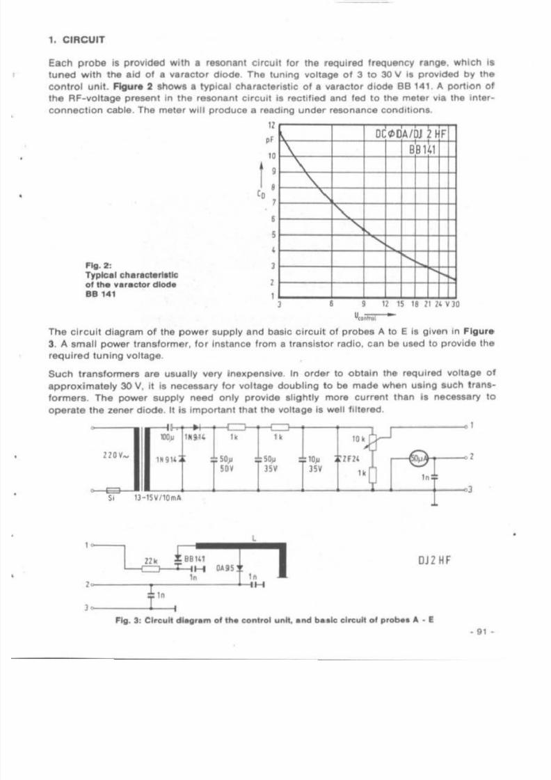
1. CIRCUIT
Each p robe is provided with a ruonanl circuit lo r the requir.c l Irequency range. which I'
luned wit h the aid 01 a varac tor diode. The lunmg vo llaoe of 3 to 30 V ia provided by the
control un it. f igure 2 showa a typlCIII chl ,aclerlatic of a varactor d iode BB 141. 14. portion 01
the RF-voltaoe present in the retonan l cirCUit is re<:tltied and led 10 the meter via the Inter
connec tion cable . The meter will produce a reading under resonen ce condltlonl.
s 12 15 " 21 14 n o~
•
11, D C ~ A / 2HF
" I \ 88141
, \
I '\
,, I,
,•I
I
I
Ag .2 :Typlc.1 ch.,aewfl.11e
ol lha .... r.ctor dlod.
88 141
•
110
The circuit d iagram 01 the po wer l upply and bu ic circ ui t 01 probes 14. to E ia given in Fig ure
3. A small power tran slormer . lor instance Irom a transistor rad io. can be used to provide the
required tun ing vol lage.
Such translormers are usua lly very inexpensive. In order to ob lain the required vol lage 01
approximately 30 V. il ia necessary lor vol lage doubling to be made when using auch Irans
lormer a. The power supply need only provide slightly more current than la neceSSlry to
ope rale tne zener diode . It is impOrtant that the ...ollage is well fi ltered.
,\.-J
I.., IMil4 h .. ".,
r - .I 1. 914 SO, ~ 10, lFl'
I'" '" '" .. " - ',.
-1SvmlllA
I
' - - - - , m r;;141L.8---L:H DAiS
1ft InI H
DJZ HF
1_.__ T ~Fig. 3: Clreu lt dlav'."" 01 fh.a con trol unit, .nd b• •1e cireult 01 ~ A • E
- 91 •

7/27/2019 2-77.pdf
http://slidepdf.com/reader/full/2-77pdf 30/68
The luning YQttIige can be vaned Wth the aid 01 a o n ~ 1 O f t a 1 cartx>n polenllomeler having
a hnN r Cnar.ct.r, 'IIC. The mel., for ,ndlcallon 01 1M rectIfied RF-vonage Ihould be ... . . ,.. tlV. . . jXIUlble (SO 10 100 " " ). ConnectIOn' 1. 2. and 3 ar. led 10 a thr..-pin lape
recorder-type IOCkel. Pin t prOVides Ihe I",nlng VOltAge lor lhe vereclO' d l ~ pin 2 prOVldet
the reclitled RF-vOllage Irorn lhe dIode prObe. and pin 3 Ml'WIS . . common ground
connechon.
In the eUlhor', prOIOtype, Ihe ,mell po ......r supply. meter, polenilomelftl' , end DIN sockel .re
mounted In a home-made cabinel con,tructlKl l rom epoky board (FIgure 4). The potenne
meter ' he l l la provided with a knob end polhl.r , and the HI«tea voll.ga I , measured al
connection, 1 and 3 using a h igh ·lmped.nce (i: 100 kQ) voltmeler, The ma..ured v.lu.. ara
then traced in • calibratIOn ~
- 92 - • VHF COMMUNICATlONS 2/1 in
7/27/2019 2-77.pdf
http://slidepdf.com/reader/full/2-77pdf 31/68
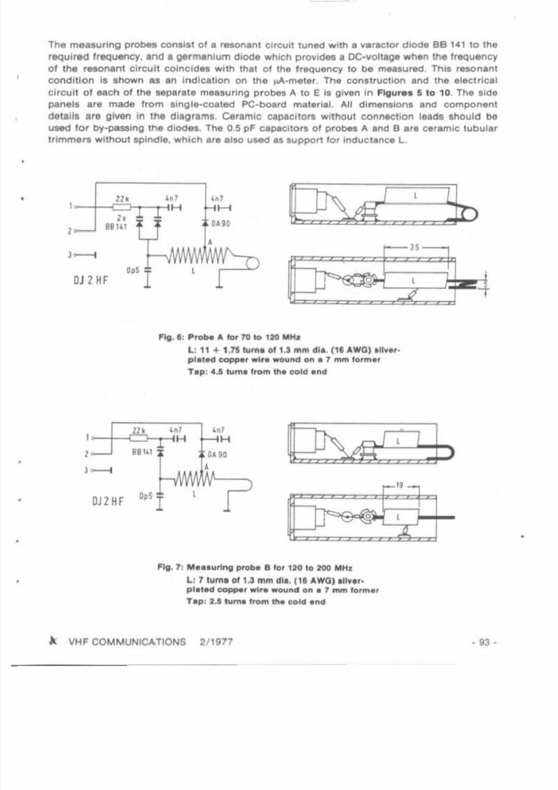
The measuring probes COfl,i, t Of a resonanl circuit tuned with a varaetor d iode BB 141 10 the
required Ir equency. and a gerrntlnium diode which provides a DC-vollage when lh e l requency
01 Ihe resonant circuit co incide. with that 01 the l requency to be measured. This resonant
condi ti on i . $hOwn a , an Indication on the ~ - m e l e r The construc tion and the elect rical
circu it 01 each 01 the ..parate measuring probe. A to E i' given In Flgurea 5 to 10, The ,Ide
panel. are made Irom , ingle ·coated PC-oo. rd material. All dimen,lon. and component
de lall. a, e given in Iha diagram• . Ceram ic Cf,pacitOfl without connectton leada should beused lor by-passing the diodes. The 0.5 pF Cf,pecitOfl 01 probes A and B a,e ceramic tubulI '
I rimme f l Without spindle. which a,e also ul8d a. 'upport for Inductance l .
I I
t" '"-JS-
o
,,'H
DAn•
0" IJ2HF
Flg . I : ProN A tor 70 10 120 MHI
l : 11 + 1.75 1\1'"1 011.J ",," d i'. l l ' AWOll
n•• , pl.l.cl CClPP'I' w i , . _ltd on • 1 11'I'" 10"""
Tap: 4.5 N,."I I.om ttl. cold . nd
n'41
'"HOUD
•OJ2HF 0" 1
Fig. 1: M'''IIr1ng proo. 1110 ' 120 10 200Mtu:
L: 1 III"'" 01 1.3 "'11'I dl• . (11 AWOIIU• •r_
plat.cl copperwi,. _lid on I 1 11'III'I10".,.,r Ip : 2.1 tum. ,_ ~ Cold .nd
A VHF COMMUNICATIONS 2/ 1977 - 93 -

7/27/2019 2-77.pdf
http://slidepdf.com/reader/full/2-77pdf 32/68
B9141 ! I I" 0.&95H
I l '",
1 1"IH
,' 1 OJ1HF
~ \ I115 r-"
I..{.- --
~ <,~ , . - , .
-t3/ 10 15
fig. ': " •••urlng p ~ C for 1to 10 )40 " HI
&8 141 DA95
m T I ,, ----c::J-l-<H
"' -- . - - - -..J....jH
"OJ 1HF
' Ig . • : . . . ....rI,.. ptobe 0 lor Ha 10 100 "H I
"'2100' j 89141%
lnlH In H
•
10
.J....., I r·o.... ,,-.1
...
J: "
1-. - -,--L:-.
OJ1HF
~ VHFCOMUUNICATlONS 211in

7/27/2019 2-77.pdf
http://slidepdf.com/reader/full/2-77pdf 33/68
u.o
.
c
•
' - '•
'"•
<
...
'"'"c
-- J
A VHF COMMUNICATIONS 2 / 1917
8
-
••
IfiJ
i
I
· 95·

7/27/2019 2-77.pdf
http://slidepdf.com/reader/full/2-77pdf 34/68
The indlYidu.1 c.l ibr. llon curw• •rgl....n In Flgur. 11 TheM ..... . r. pt()Ylded by OJ 2 HF l or
the me'lUrmg probel he d"lgned . The ,ulnor, and olher im , lw r t m.nul.Clured probel
Irom Ih... dIagram., and wef••urpnMd al 1 " - good COincidence .....111'1 1 " - gl..-etl cu.......
Thl' m.an. thai II i . not abIolulety nec. . . . ry lor 1 " - measunng p'obM 10 be calobraled on a
". . . . .urmg I y Sl em . Of C O U r H . II I ' noecft.Nry IOf Ihe gIven componenll and Inductance
dlmen'lon. 10 be malnlalned
2, OPERATtON
Dunno ',.quency measur..-nenl, the probe Ihould be ~ coupled to lhe In l ob,.el so
NI Ihe resonance condilron II.. In lhe lU I Ihlrd 01 the uA-mel.r rang. nil, ""In enlUr . Ihal
a very .harp teIOnance Indicaiion "" til be prOVIded II, lor malanc., e fr"Quency of 404 MHz I '
to be m...ured on a transmit mi ..er trom 28 MHz to . 32 MHz. the coupling .hould nol be too
tIght, o th . rwlM lhe 404 MHz ..gnal .....111 be o....rloaded by lhe lar higher 1....1 01 lhe nommal
freQu.ncy 432 MHZ.
3. II!:XTENDI NG THE FREQUENCY RANGE TO 1350 MHz
The aulhor deyeloped • fu rl h. r m. . . .unng probe Ihal is able 10 pr OY lde r., iable reson.nce
mdicatio ns up 10 and Includi ng Ihe 23 cm amaleur band. Thi, measurmg probe F I, given in
Flgur. 12 A Schottky diOde hp 2800 (or .lmlla r) i . u.ed tn Ih. . probe •• ""ell a . in probe E;
Ihl' I' 10 enaur. sulliclen i aen'I llVtty Also m a ...mllar m. nnar to probe E. Ih. resonant line . .
m Ih. form 0 1 • jJ2 CIrCUl i which prOV ld. . . bel l . ' reprOdUCibIlity and hig..,.r Q In order 10
obilin the lowest possIble commencement nlua of lhe luning c e ~ C l t a t ' I C •. Iii. NlCelNry 10
Connecl • dIsk ~ c l i o r Of 1.5 pF In ..rl" ""l lh I " " y. rac1Of diode BS ' .1 The C11l1brallon
cu ...... I ' gl1f8n In Flgur. 13
l A l l
In
HP 1800
np1800
OC<tlO A
I11PS
A {4
Or Ti f.C. In\H 1n l H~
l In
J o ~ -
SS 141
....
~ Ma..uring p roOf ' tor aoo to 1350MHz; iJ. cl'talla: 7. ' e' " 8f\."'aIlH cappa, . ' .a,
apptOl . , . . " " " cs q.m AWOl _ftd Of! a ...... tor....r.l : .1'''-ilIa'" copper .1.
A VHF COMMUNICATIONS 2fU177

7/27/2019 2-77.pdf
http://slidepdf.com/reader/full/2-77pdf 35/68
MHZ300100
•
110000000
86
4DC<1JDA
1 f
119 I t-:
611687f-7
4
11151/
;;r-0
V
V864 I ---
1
o800
1
V
10
18
Fl; . 13: C.llbri l ion ,,,,n 101 ", . .."rl ng plob. F
MEMORY KEYER
MK 1024
Memory key. ' with four Ind. ·penden t memorl• • 0' 256 Bit
..en. Cen be combined toob leln I memory 'ength 01
1024 Bit.
•
-
-Pushbutton, 101 ..1":;1'0" 01m_ r y ,no ""1, ,..., ,na -,op
• SQ""l' method or M"" · .utom.l't• BUil l , " " 0.t,II"0 r .... lh v'fOlbl . ~ ,nd Vo l" .....• BUl lt - ,n IOud"pt• •• • I t ......11 .. IO(: k" 10 ' • • t . ~• BUllt · ,n lll " " " o r Of aWltc n,ng• M" , , w,lehlnOpow., Trln" " OImod' ISO V I 2 A. R moO. 100 V I 0 5 "
• Ope. 'Mg von.ge 220 ·2"0 "AC. D. 8 · 14V b.ll. ry• O......".'on. l otO mm ' 60 mm . 185 mm• We,gh! 2 3 . g
" VHF COMMUNICATIONS 2/1977 ·97 •
7/27/2019 2-77.pdf
http://slidepdf.com/reader/full/2-77pdf 36/68
ZENER DIODE NOISE IN OSCILLATOR
AND MULTIPLIER CIRCUITS
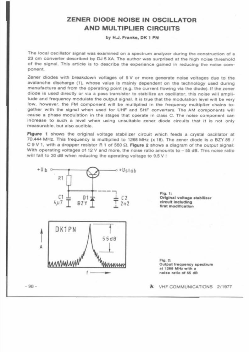
TN toea' OSClI"tor S10NiIwa• • • ami,*, on a apec:trum analyZer dunng the ConstructIOn 0' •
23 em C(H'IWf1er cseacrrbecl by OJ 5 XA. TM . u l ~ was .... rpnMd I ' Ih I htgh ~ .. threshold
01 the SIgnal , Thl' artICle ' I 10 dMcnbe the • •peMnCe g&lned In reducing the I'IOtM com--,Z ~ dlOdet With bfNlldown YOlggn 01 5 V or mora ~ r . l . no'" voltages dIM to the
a.... lanche dltcharge (1). whoM .... IUII '1 main ly cMpw.cs.n1 on the technology used dur ing
manufacture ancIlrom lhe oper.t lng potnt (I.g_ the currenl flOW ing vi. the diOde). If the l en l '
diode 'a ul4lCl directly or vi a . pass ,rlnl 'llor to 1,_biliZI In oscillatOr , Ihia nol.. will ampli
tud e and frequency mOdulate the output ligna t. It 'a true Ihllt the modulation la...el will be very
low , how .....r, the FM componenl will be multiplied In 1M frequency multiplier chainl to-
gelhe, wll h the aignal whlln used lor UHF and SHF con.....r1. r•. The AM component, will
cause . phase mOdulation in the IIlg•• that Operate In clau C. The noise component can
increase 10 such a level when using unsuitable zener diode cirCUits that II is not only
measurable, bul also audIble.
Figur. 1 showl the origmal vollag. slabllizer CirCUIt which fMds a cryslal oscillator a'
10.444 MHz. This frequency .s mull,plied to 1268 MHz ( It 18). T ~ z_r d,ode is a Bl Y 85 ,
C 9 V 1, wll h a dropper resiSlor R 1 of 560 O. FIg...r . 2 shows a diagram 01 the OUlput Signal :
With operallng VOltages 01 12 V and mor• . the noi.. ral,O amo...nts lo _ S5dB Th,s no,.. rat iO
will 'all 10 30 ee when reduc'ng t ~ ~ a l l n g lIO«ag. to 9 5 V ,
-Ub +Usl ab
11
( 1 ---1 (1 "'1 :01 one,"11 .ofl.. Pablt t , . ,
4 ~ 1I SlY T ln l
eIre,," Inclucllng
~ .1- flBt IftOCftftcltton
OK1 PN
A
....
1'"111. 2:Output I•.-qu.rtey . p « 1 ....m
.112.. "H , _ tItl l
no l• • '. 110of 15 dB
). VHF COMMUNICATIONS 2' 1911

7/27/2019 2-77.pdf
http://slidepdf.com/reader/full/2-77pdf 37/68
Thi ' poor value Shows that the operahng po in t 01 the zener d iode should not be brought In
lhe vic in ity 01 the bend in the characteri stic . This means Ihat the dropper resist or A 1 should
hava a varu. 10 Ihat su lhcien, curr.nt (Mv.ra l mAl l Iowl through th . zener diode even at 11'1.
lowe,t operating vol tage .
tn o rde r to inc rease the noise ratio , a ceramic disc capacitor 01 2,2nF was connec ted In
par all e t (shown as a dashed l ine In Figure 1). This increased the noise ratio trom 55 10 60dB ,
Th is was lollowed by repl acing the z.n.r diode BZY 85 / C 9 II 1 (dl l fusion di ode) lo r a planar
diode BZX 85 / C 9 II 1, arn:l tha resulll were measured. ullng variOuS values fo r the dropper
reaistor R 1 at Ub • 12 II and Without parallel capaci l or C 2;
R 1 (0) Noise ratio Zener diode curran t
' 000500
333
45 dB
52 dB
54 dB
2.9 mA
5.8 mA
8.7 mA
Surp ri.ing ly enough, tha noise value. lo r Ihe modern diode were somewhat worM ; howe ...er ,the noise was lound to be nol so dense on the Spectrum analyzer as when using a diode 01
tha eZY series; on experimen ling With an operating vol tage 01 9.5 II, it was found that the
parall el capacito r 01 2.2 nF wa. immediat.ty able 10 Improve Ihe noiM raho Irom 30 dB '0
OO dB.
The experience gai ned In this manner led to the debign 01 the c ircuit given in Figure 3 whi ch
was , ubsequently measured , The noise ratio 01 thil ci rcuit amounts '0 mo re than 70 dB 'Furthermor e, a reduct ion 01 1 '1. operating vo l lag. Irom 15 II down to 611 does not have any
ettect on the noise rauo. ev.n wh.n vol tag. ltabiJizalion c. a....
f ig. 3:
Voltag . st ablllzarclreu" with flItaring
of Iha nGl.. 'O'oltaga
Rl
470
01
811
100
No euect 01 ,he tranlisto r tvp. on th . nOIM raho cou ld be ObH rved when ellpeflm.nt lng With
Iransiltor . Be 107 and 2 N 918. 11 was allO lound that a ceramic eececnoe connecled be
tween .m iller and ground had no e!fect l ince the stabillz. r circuit '1 very low -Impedanc . at
8t th is position,
REFERENCES
{ 11 Mac. k , Dr.O.: Z-Dloden. EiganlCha llen und Anwendunoen
Si.menl, Technical Componenllnlo rmalion . September t9 7S. Order-NO. B 1593
A VHF COMMUNICATIONS 2/ lgn - 99-

7/27/2019 2-77.pdf
http://slidepdf.com/reader/full/2-77pdf 38/68
STABILIZING THE OPERATING POINT OF TRANSISTORS
WITH DIRECTLY GROUNDED EMITTER
by E. Schmitzer, OJ" BO
1. OENERAL
s...r.. amph'!ef .tages ~ been cs.c:nbe(llOl th e UHF/SHF baMa where 1M em,n . , of Itle
transistor i . d l ~ t y grounded n lll type 01 Circuit bnng. ~ r . aetYantagft I ' higher Ir. .
Quent in. howeYef, it I' neceuary for special ~ u r " 10 be mada 10 IIsbdlze 1M operallng
poinl aoainst lempefllfu,. Iluctu_lIon • . If Ihis II not done - .. wa. 1M c.. . With the conve,
'er givln in the "'erencel - operation will only be possible wilhin room ambiant temperature
r.nges . The follOwing measured cu ,.,.. will show that i l \IIOOYld be impoalble 10 use II for
portable or mob.11OJ)t'r.t,on .
Ther. 'a an extremely Simple method 01 Ilabi llzing the operahng po in t 01aueh ClrCUlll , wtllch
Ihould be ~ r . l l y known. The amount 01 cirCUitry requlrkl 'a virtually negl igIble. Som. 01
Ihl lIaOI. 01 the 13 em converta' dlttCribed In (1) ar. to be uHd al l)tampla lor Ihe erreun
technology and lor Ih, mla,urlmanla.
2. CIRCUITS
The .... perimental clrcu.tsare gIven in FIgure t : F l g u ~ t a Ihows lhe DC-p,Itnl of th e Original
ci rcu.t 01 the converter. FIgure t b the rnodifllld circ.uit tor the IIf.t RF·amplilllt!' With an
operating point 01 9 V 13 mAoFlgu,.. t c IhoM th e rnodl"ec1 circuli Of the MCond RF-ampli·her wllh an operallng poinl of 6 V 16 mAo A Y O I ~ 'eedbKk II now effective here II the
eeneerce current Increan Wllh temperalur• • the coliector"""l"e, v o l ~ Wi ll drop due 10
the voltag. drop across the DC-dropp8f r " lltor Re. and Ihul will a llO ~ u c e the baM blal
voltage. Thit ITlMM thai the ~ N S i n g CUrfltl'lt will be partly compenu.tecl. Prerequill te lor
th l l I' th at a considerable part 01 the 0¥ItI'a1l operating volt'lge . . droc>c>ecl acro u the
col lector r..iltor . nUl retu ltl In a htgh DC l'elldual gain and a I/,IfftC.."lIy htgn feedbaCk
lactor Flgu'" t d show'I a recommended Circul i lor stablhzlng the ooeratlng po int 0 ' the
mUle,
OHBG ' Il Y oilY oIly ol1 f
h I , lS. I ,
'"h
,., .., h. ..,
-<fI,
~ ,, 1",1 h ,1 h h ,h "'"
"Ib j
" " j
• 100 • A VHF COMMUNICATIONS 2/19n
7/27/2019 2-77.pdf
http://slidepdf.com/reader/full/2-77pdf 39/68
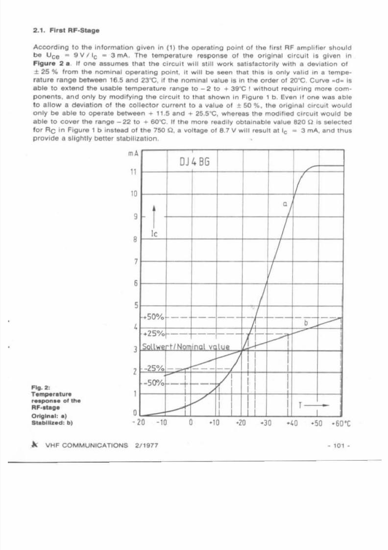
2.1. Firat RF.Stage
Acco rding 10 the in lo rmation given in (1) the ope rating point 01 the Ilrt t AF ampli fier should
be Uce • 9 V I 'c • 3 rnA. The temperatu re response 01 the original circuil il given in
Figur. 2 a Jl one Issumel tnet me circuit Will It i ll work ..ll l laCIOrily With I deviatIon o f
:t 25 % from lhe nominal operaling po in l , II will be Men Ihat thi l I I on ly valid In a tempe
ra tu re rang. between 16.5 and 23"C. I l lhe nomina l value la In the order 01 2O"C. Cu,.."e -d. laable to elllend Ihe usable temperalure range 10 _ 2 10 + 39"C ! wilhout requiring more cernpo nents. and only by modifying lhe circuit 10 Ihat I hown in Figure 1 b. Even it one wal able
to enow a deviation 01 lhe col lector cu rrent 10 a value 01 :t 50 %. the original CirCUit would
only be able 10 operate between + 11.5 and + 25.5'C , whereas the modil led CIrCUli wou ld be
able to cover Ihe range - 22 to + 6O'C . If the more read ily obtainable value 820 C il l elec ted
for RC in Figure 1 b inslead 01 the 750 C. a voltaoe 018.7 V will reluUallc • 3 rnA. and IhUI
p rovide a slightly belief etebunencn.
·50 · 60·C403020
9
4
OJ 48G I I I I/
a
I,
/1! /
5/
+50% - - - - - - - I - f--- - --V-+25% -- ---- 1tVi
:---
I NM "nnl V " ".
_" 0; ' ~ V LJ I i ,
·5(1"/0I'-- -V I II- t I
1I
-f V I I I"
6
2
o• 20 · 10
11
8
3
rn A
10
FIg. 2:
T ~ t l t u ' ."l-pOfla. olll'le
R'·ateg.
Original: alI lI blHtld: bl
A VHF COMMUNICATIONS 2/ 1977 • 101 •

7/27/2019 2-77.pdf
http://slidepdf.com/reader/full/2-77pdf 40/68
2.2. S. cond AF-Ampltfl . ,
According to (1) Ih . operatIng poinl 01 Ihe MCond RF·llage Ihould be Uce • 6 V l ie.
6 rnA. The temperalure respon$ll 01 the col lector currenl 01 Ih . orig inal circuit i l lhen as
given In curve a 01 Figure 3. II a permissible deviation 01 .:t 25 '" i l aHumed , this r..ul l l ina working range between ... 14.5 and ...25.5'"C, The l Iag. will go Into laluralion al approxi·
mately 37"C. wh iCh means that Ihe g lin and Ihul Ihe lens,t,v ,ty will no longer be available.The use of the DC·leedback a. shown in Figure 1 c resulll in a collector currant response esshown by cu rve b In Figure 3. This result s in a ulable temperature range between - 30 and70 C I
10ZBJOU U0 10
• IJ< BGR"lJllJl
, l 1' ) , ' 1 ~ 4
/
~V
~ 1, ,04
1
..---..---:;17'
..--- ..---,- I-. . . . . . . .
•
•
,
,
10 10
•OJ 4BG
1 I1
0
• I• "11:0 - -- - -f --I - - f--,I I--e-
oSOI I••rt' . . . . ,...,. .kll
I
---- II ~ ~ - - -j I
I II
/ I II
I I1
,..--- I I 1_,. . . .,:0 10
•
•
f ig. J :T a ~ r a l u r a Nspon••
of the ..cone!AI' . .tage'1g .4 :T a " , ~ r a " ' ra.pon. .
of ttle ", I• • , l id )
2.3. MI• • t
Since the mi_e, ia to be aligned 10 that only a lew IlA !low without rocet Olcilla lo r l ignal ,
whereas several mA flow when thi l local O cil la tor aignal II provided, the voltage leedback
circuit wil l nOt be posllble. A good I labilllaUon 01 the col lector current i l possible by Uling
an additlonal l i l icon diode (Figure 1 d) . Any IOW-l ignal ailicon diode I UCh aa BAW 76, 1N 914,
or 1 N 4148 i l auitable_II it i l seen that the diode prov idu too Iowa voltage wtlen aligning
th i l stage, in ottler words il the ml.er cannol be opened. u will be necessary to prov ide a
small dropper reailtor I hown In ttle diagram al Rd-
This resialor ia Itlen able to increa,. the DC-polenUel, but will deleriorale Ihe lemperature
compensation noticeably IS Can be seen in the curvel given in Flgur. ..
• 102 - ~ VHF COMMUNICATIONS 2/1917
7/27/2019 2-77.pdf
http://slidepdf.com/reader/full/2-77pdf 41/68
Even though, the eeuectoe currenl il I tlll lar leu temperalure dependent than the original
ci rCUli without compensahon. In addi tion to this, the mixer i l dri ....n bel l .r by th. osc illa torvo ltage 10 that correc t opere llon II 10 be .xpected o...er the whoht temperature rl ng e to b.
expected ,
3. SUMMARY
II has been seen thlt the 13 cm tran sistor con...erte r described by DC 0 DA can be modil ied
easily, as can s.mller slages. so thet the DC-operat ing points of the transistors cen b .
stabili Zed and can be used over a Wid. ambient temper l tur. range 0 1 course. there are more
extensive cirCUits thai can be used that provide an even beller I labilization: however, the
targel 01 Ih l l artic le was 10 show how easy u i. 10 slabil iz. the operallng point 01 tranSlllo r
ci rc ul ls uSing . d.recll y grounded emi ller,
At can be aeen in Figure 3 0 1 ( 1). II II po.I lble lor the recommended moclil icalions 10 be
made on Ih . DC0 DA 13 cm converter without dillicuit ies, and without I l lecling th. RF.
circu its.
4. REFERENCES
( 1) J. Dahms: A Converte r lor the 13 cm Band Equipped With two Pr.ampli l ler Stages
and an Act...... Mixer
VHF COMMUNICATIONS 8 (1978). Edition 4, Pages 194 - 201
LINEAR AMPLIFIERS for 2 m and 70 em
Clean linear operalion due to
optimum biasing and use 0 1
CTC transislors BM 70· 12 or
CM 40- 12 reeo.
Band 145 MHz 432 MHz
OUlput 80w 40 WInpu t 10 W 10 W
Current 10 A 6 A
Size (mm) 130 II 58 x 200
Oealerl enquiries wetccme to
UKW·TECHNU( Jahnstr ,14
0 -8523 Baiersdorl(W ,Germany)
U K W • TEe H N I K • Hans Oahlus aHG
0-8523 BAIERSOORF . JahnslraBe 14Telephone (09133) .855,856 ' Telex: 629 887
Elarlk ac oounlt : Pe-llCheck Niirnber; 30 455 . ll5II
C o m l M r z ~ " k Erlange" 820-11S<l
A. VHF COMMUNICATIONS 2/1977 - 103 ·

7/27/2019 2-77.pdf
http://slidepdf.com/reader/full/2-77pdf 42/68
THE 70 cm FM TRANSCEIVER »ULM 70»
Part 1: Introduction, Block Diagrams, Variations
by I, Sangmelatat , OJ 7 OH · H.J. Franke, 0 1( 1 PH ' H. 8anllvogllo, OJ 0 FW
1. CONCEPT
Required waa an .Hlel.nl, easy- lo-conSlrVCI 70 em Iransceiver 10 forward 70 em actlvlly in
the UlM ar•• 01West Germany . The baSIC requir.menls wer••e follows :
• Inexpensive: uSing. surplus 10.7 MHz cry"alIIU.r
• Stable, cryala l-controlled operation lor local communications
• Posalbllity 01 frequency variable operation, al long a. this can be .chi....ed at lOwallpenH
• Good sensitivity
• Output power In the order Of 1 W 10 that i i 's poDlbi. 10 use • buill-in accumulator
• Modular conStruction to simplify cona lruCllon and modif icat ion 01 the unU
• Use 01 standard components
01 course . the lollowing modules ar. not only luilab le lo r use tcr loca l eemmoneencn but
can be extended as required to lorm even rll!'let sophisticated equipment 01 the lour
versions . only ....rsions A, B, Ind 0 Ire to be described in deta il:
A: Two-channel using 2 transmit and 2 rKtlivtl crystal,
B: 16-channel unit wi th VXO using lou r crystal, each in transmitter Ind receIVer
C: 3O-ehannel unit (uling wider range VXO)
0 : l()().channel unit equipped with a synthesizer
FUll ccnetructcn de taill are to be given lor version B.
The synthesizer for version 0 wilt be deSCribed later .
Figure. 1 a to 1 d 'hOW the slmpli lied block diag rams 01 the lour verslonl . The stages eccemodated on • common board are designated using the same symbols In the corner 01 the
block.
The normal version consists 01 Iwo equally wide PC-boards having the dlmen. lon s 90 mm x
134 mm, and 90 mm II 120 mm. These bOlrds are mounted back-to-back. (The receive board
is accessible from above, and the transmit board trom below). This means that both bolrds
are easily accessible. Sufficient room II provided In the cue lo r accommodation 01 a relaU
vely large accumu lator, Inspite 01 the use 01 normal-sized components nol mounted ....rtl cally
to the board , it Is poulbie lor the transce iver to be mounted in a case having the dlmenlionl
140 mm x 185mm x 67 mm high. There II al lo aurtic lent room lor accommodation 01 I syn
thesi zer above the receive boa rd . The .yntheslzer board also has the dlmenslon l 01 90 mm II
134 mm.
The distribution 01 the Itages onto the varioul PC-boards was mainly determined by the
dimension,. The complete tran, mil ler II iCcommoda 'ed on 'he shortest 01 the PC-bolrds .
and su fficient room Is provi ded l o r the' whole of the ludio lIages. The voltage I I lbilizer andelectronic transmit-receive switching lo r the operating voltages is allO 10 be lound on the
transmit bOard.
- t04 - " VHF COMMUNICATIONS 2/ t911
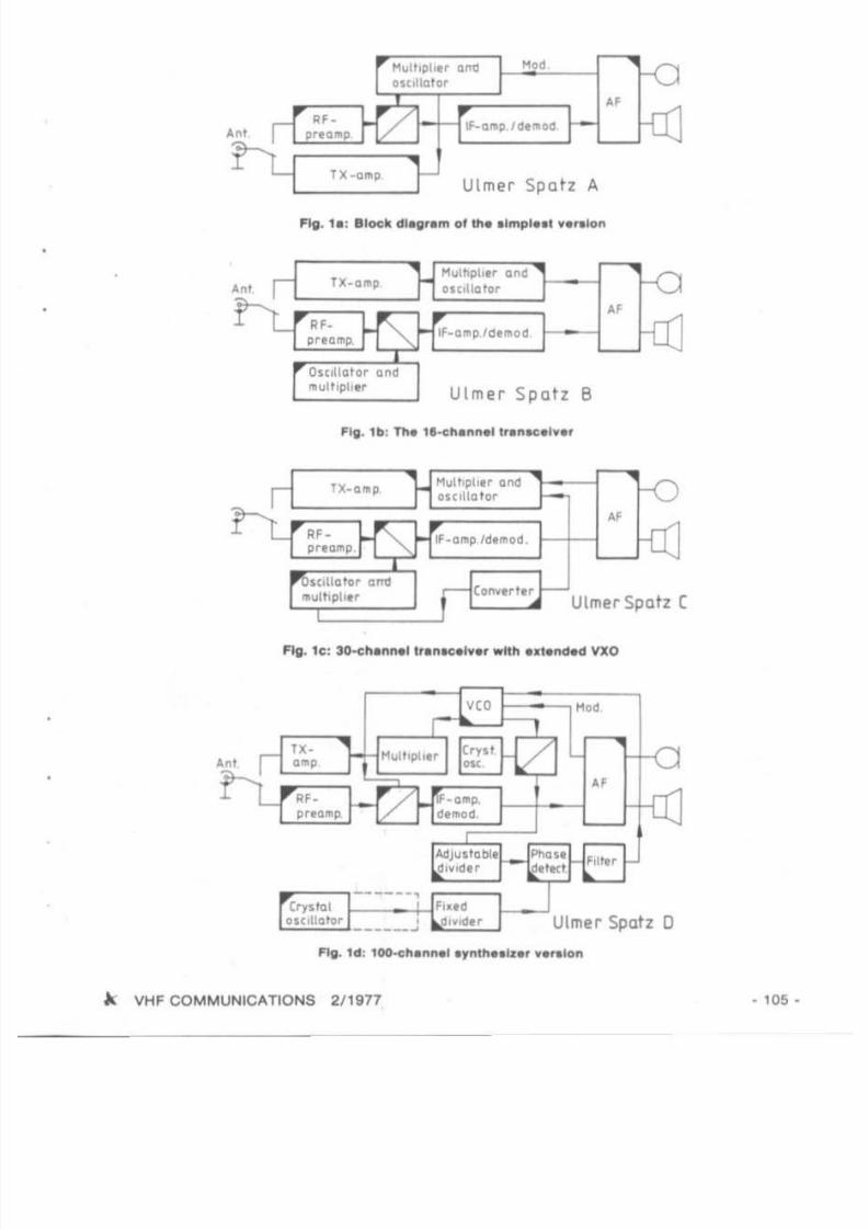
7/27/2019 2-77.pdf
http://slidepdf.com/reader/full/2-77pdf 43/68
'"
Ulmer Spa tz A
IF-amll la , .. od
Ulmer Spatz B
!'lul1ophtr and
o'Cllla tor
Ulme r Spatz (
Fig. te : 30-chlllll4lJ tr.nte.I....' _"" utended VXO
'"
alc,llo tor _ _ _ _ J
'"
A VHF COMMUNICATIONS 2/ 1977 • 105 ·

7/27/2019 2-77.pdf
http://slidepdf.com/reader/full/2-77pdf 44/68
•
N'SOu'r
F:---- ' - - - - ~ ~" , ' ... ..
• 106 • A VHF COMMUNICATIONS 211977

7/27/2019 2-77.pdf
http://slidepdf.com/reader/full/2-77pdf 45/68
The anlenn . relay is pal1 o f the .ddlllon.1 mod ule . H. rmon ic FlIter. wh ich Is moun ted
direct ly adJ.cent 10 th e BNC IOCkel on Ih. r• • r Plin.1. Thti long.r boa rd .ccommod.l.s Ih.
whol. rec. iver up 10 Ih . 100 mV . udio oulpul , Th. strlpUn . ci rCUIIS.." Ih . RF· . mphl l. r sl . ges
lake up a larg. amount 01the l urface ol lh ll PC·board .
A mar. del ailed block d iagram 01 version B is shown in Figur. 3; Ihe preyloully m\7l1l!on..<J
dls l rlbullon 01 Ihe slages 10 the ...arious modu les c .n be IMn cl.arly . Th. r. C. i....r IIn.·up I Ias fol lows: TWO-Slag. RF amphtrer equ ipped wl lh Ih a wall-pro ...ee strlpllne transisior AF 279.B mixer equipped wilh the Inexpensi...e 1.2 GHz slUcon Iranslslor 2 N 5179, An inl . rmediat.
frequency 01 10.7 MHz was • •I .CI&d . Inc. me maJo rily 01 surplus FM cryslal IIUers . re ..... .1
ecre l or Ih is Irequency. Th• • elect ion Or lhis r. lali .... ly lOw interm. d l.l . IreQu.ncy lor a 70 cm
transceiver simphlles Ih . r. st 01 the circuilry : wit h Ih••xcepncn 01 Ih . matchi ng I tag.
equ ipp.d wilh a dual 'i!a le MOSFET ••t is only rntCeuary l or the em....rsa l in teg r . ted IF c.rCUlt
CA 3089 to be used . 0 1 cours• . an Int. rmediat. Irequ. ncy 01 21.4 MHz would provide a better
im. ge reJ ct ion . how .....t , It would be necessary lot . du. l-eon.... rsion Sy l l .m to be used to •
lowe r second int .rmedl.t. frequency In Ord .r 10 aYOld an . xpensi.... 2 t .4 MHz Crysl.1 I.ll ar.
PrOvision i . mada lo r conn.ct ing an S-M8t.r . an adju.table squelch, and an . xtern.1 VFO
The VFO co nnection is eleclron ical ly SWitched l og. th.r w.lh Ihe crystal••0 that It is poss.bl.
for tne coaxial cable to r.main co nnected.
The use 0 1 three IreQuency multipliers in Ih . rocet oscillato r chain ol th. r. c. ive r seem. to be
in cantra ll to the requ i r.m.nt lor an In. xpensi v. con ltruc tion: how.....r , Ihil m.thod is
simpler. and nol mora .xpensive than when uSing a high. r Irequ.ncy osc.llator, The crystals
cscntete in a Irequency range where Ih. y are le. st . Xpen.I .... . How. .... r. the ..parate eecn-
latOr frequency chai n lOr Ihe tran.m ltt. r co uld be avoided . Thi. r. sults In the ch.aper .... rsion. A.. whi ch uses a common frequ.ncy plan lor Iransm.tt. r . nd recei...er. and .s aUllab l. lorrwo-cnannet use. Th. d. lailed b lock diagram 01 thi a varsion is g iven In Figura 2 Th. sam.
PC·boards . re used ' 1 In .... r. ion . B. , howev.r , the eecutatcr and mu lt lpll. r parts 0 1 the
transmit bo.rd . r . not equ ipped . It should be noted, Ih.t the SWitching and pu lling 01 the
crystals. • s w.1I . s the tuning 01 the mult ipilar. is . impler when .ach board i ' comple tely
equipped and can be .' igned Individually.
The thre.·stag. tran ,m lner prOv ldes en oulpul power 01 approximately 1W. All AF-stage. are
integr.ted in • lour· , t. g. operat ion.1 amplll l . r . nd considerably . impli lled With re. pect to
previous designs, Even Ihough . Ih . Iranscel....r I ' pro"'lded with a Clipper .nd acl lv. low-pa"
f ilter • • s is to be .xpecled trcm a modern I r .nscei .... r.
A detailed b lOCk diagr. m 01 a Ir.nscel....r eqUiPped wll h ••imple synthes.zer l or 100 chann. ls
i' . hown in Flgur•• . CB-equi pment has shown that , ynthesizars need nol only be lound in
. xpensl.... equipment . Of course. som. deler iOratlon 01 the techn ical spec.llc_lIons cou ld be
accepted ; lor lnstanc• • Ih . spec trel purity 01 Ih. VCO aignal Is deterior.ted by tr ipling the
I requency tw ice. The Con nl iona i errangement using _ VCO osc illating at the Iln .1 frequ.ncy
togeth.r with an ECL·dl id.r wou ld h..... I.d to an un . ccep lably high currenl drain. The
currenl dr.ln 0 1 the 48 MHz I ynthesl z. r onl y .moun ts to 28 mA at 12 V. Th. mu ltiplier I lag.,
. nd Ih . cryst.1 cacm. tOt requ ire .pprox im. ta ly 1$ mAo
•
A , peci. 1 le.llJre of lhe . ynlh. , ize' is Iha use01the cheap CoMOS-IC CD 4017 wh iCh can be
directly connec ted 10 • norm . 1 tolary I w.tch. The ph... d. tector is • sample·hold- type which
means thai the VCO l ign. 1 I . Itee 0 1 inlerf. ring noiM . ...-.n Without .ny speci.1 mea.ur...
Th. PC·bo.rd 01 the I ynthe.lzer i . nOI so t lgh l ly packed aa the other boa rd., .nd the com
ponent coat i. somewh. t lowe ' .
. . VHF COMMUNICATIONS 2/ 1977 - 107-

7/27/2019 2-77.pdf
http://slidepdf.com/reader/full/2-77pdf 46/68
The conltructlOn detatls to be described in the nell.t « lI l ion. of VHF COMMUNICATIONS, do
not only describe the PC·board modu. . . . but also 1M oy.,all ll'llnscei..."
FlO. I : Phot01l rapfl 01 t1'1. llIlhof" l prototype
• 108 • A VHF COMMUNICATIONS 2/1977

7/27/2019 2-77.pdf
http://slidepdf.com/reader/full/2-77pdf 47/68
A SPECTRUM ANALYZER FOR AMATEUR APPLICATIONS
by E, e l r t l.riCh, DL I IX
Due to their versati li ty and wide range 01 applications, it would be dltllcul1 to Im.glna a pro-
lesslonal laboratory or ~ n I larger workahop without ••peclrum analyzer , In the narrowband mode, it is possible 10 easily indiCale Ihe noise aidebenda, modulation depth and
characteristics. as ~ I l as drive-dependent distortions lueh as IntermoduleUon etc. In Ihe
wid.band mode. spurious and harmonic WIV" can be shown simull.neaualy OYlr I wide If.'quency and level range. This aliOwl both. quick and claar Iv,luallon , and rapid Illgomenl.
In spIte 01 Iha greal di ll_renee In price, lpec lrum analyzers havi beCome much more popular
lhan the weU-established selective voltmeter. etc.
Spectrum analyzers are greatly respected by radiO amateur. , l ince they allow a clear repre
eentauon 01 all required and unwanted l ignall that ara generated In a Iranlminer In the
oscillator , and frequency multiplier stagel. Thi l meanl lha l lhole amaleurs that have access10 a lpectrum analyzer have distinct advanlages.
Home construcnce 01 a spec trum analyzer is most certainly poSSible II certain compromisesare made With respect to f requency and dynamic range. and measuring accuracy. Thil article
is to describe means 01 actueving this aim ,
..7 I,,,..
"
1. MEA SURING PRINCIPLE
The amp lituda of an electrica' oscli ialion can be displayed on a lpectrum InllYler In two
ways : AI a function ot lime (lIme domlln measurement) ullng In osclllolCOpe, or a l Itunctrcn 01 trequency ( l r ~ u e n c y domain meawrement). Figur. 1 Ihowi hOw bolh lypel 01
display work. The Ilmplesl lorm 0' spectrum Inatyzer would b e . relOnant CirCUli Wth l ub " -
quent recti lier who.. resonanc. c.n be luned over Ihe Irequency range 01 interest. Thll
would have to made in Iynchronoul wllh the dellectlon voltage 01 the oscllloicope used lo r
indication. Due to lhe lOw luning range . lOw selectivity. and lince ..Ieclivi ly and mltching
cannot be kept conetent over the tuning range. lhl. approach IS not satis factory and more
elilenlive circuitry II requi red.
In principle. scectrum analyzers are epl Irequency. luperhel r.celv.,.. wilh a highly ..tee-live IF circuit which Is used a l recel window, The amplllude IS dilplayed on Ihe scrMn 01 a
CRT or drawn on a ploner.
,k VHF COMMUNICATIONS 2/1977 • 109 -

7/27/2019 2-77.pdf
http://slidepdf.com/reader/full/2-77pdf 48/68
Fig . 2: Prin eiple 01 I IpKlrum
2. PRINCIPLE OF OPERATION
Flgur. 2 shows the basic princ iple 01 a spectrum analy zer: Single-conversion luperhet with
calibrated altenuator Ind low-pan ' liter I t the mput . The local oscil lator Irequency II tuned
.croas the ' ange 01 in leres t using. aawtooth voltage, This vol tage is allO uNd lor the X·
de llechon 01 the display Unit which then runs synchronously . Such equipment II UIUIUy
known as a pano ramic receiver. AI measuring unit. a spec trum analyze, should at least 11.11111
tne follOW ing minimum reqUirements:
Calibrated display 01 the amplitude (Y-plane) In both a linear and logarllhmlc eeete
Adjustable display width in the frequency a ~ i s (X-plane) With frequency ml rkers.
Selec table fil ler bandwidth in the IF circuit to allOw variOUl resolu tlon l.
Var iable . calib rated attenuato' In Ir ont 01 the measuri ng signal Input which must
have a de llned, rea l impedance over the whole range 01 Interes t,
It i l in the l irsl point abOve that l he lpec trum analyzer differs greatly Irom I panoramic
receive' . wh ich usually onl y uses a cont,olled IF·ampl ifier wil h all ia con trol ume-cce etent
problems. The u n c o ~ log arithmic IF ampli lier lorma the hea" olthia description ,
The ampli tude range displayed in the Y·plan. amounts to approximately 100 dB In the case 01
modern prolessional spec trum analyzers . Thia dynamic ,ange cannot ulually be uUli zed
du ring the display of l requency apect ruml , I ince the Intermodutltlon 01 the l irat mixer cannot
normally be brought below 70 dB. However. Ihe dynamic range II increased by use 01 the
calibrated attenuator. The calibrated I ttenu l lo r 1110 allowl any overload 01 the mixer to be
seen: II. lor Instance. the attenuation I I Incni ased by 10 dB I nd the l pectrl l lin. Is decreased
by more than 10 dB. then an ove,load condi tio n I I p' esent. Any lpectral l in.. caused by ov. r·
load condi tions with in the measuring Iys lem itself wi ll alwaYI be non-linear.
The requ ired Il ro- frequency range ot a lpectrum analyze r makel it rmpou ibla to use a
tUned circui t belo,e the uret mixer ci rcuit. One way out I I to place lhe Ilrs l intermediate Ire
quency above the hlghes' InP\l t f requency (about tw ice the frequency). and 10 1.1" a low-pal l
l ilt er at Ihe inpu t 10 ' uppress IpuriOUl recep l ion point , . Thll leadl 10 a clear spectrum dl l ·
p lay. The subsequent mixer use. a 50 C wldeband ring mixer.
• 110 - ' " VHF COMMUNICATIONS 2/ 1977

7/27/2019 2-77.pdf
http://slidepdf.com/reader/full/2-77pdf 49/68
It II necessary to Ule muiliple conn,.iOn 10 obtain Ihe r.-qUlred selectivity when using luch a
high IF. Crystallllta,. can be used with advan taoa 10 obtain the main IF-selectivity . However,
l ince each 01 lhe spectral l inel run. through the panband r lnge 01 the Illler or Idter• .
lpec ial attenuen mUlt be paid to the transient behiv iour. The narrowar and . teeper the ' literl
srcpes. the slower will have to be Ihe sweep.
3. A SPECTRUM ANALYZER FOR AMATEUR APPLICATIONS
The following conlideralions were made during lhe concephon at an amaleur spectrum
analyzer:
The mai n requIrements are In the Irequency range 010.5 to 60 MHz and 120 10 lao MHz. Mal l
01 l he amateu r bandl, oscillator Ind intermediate Ir.-quenciel Ire within th l l range . The UHF
bands can be converted to one 01 these IwO bands.
If an IF 0160 MHz is selecled. il would be poulble to cover 0 1060 MHz (lower sideband) and
120 to lao MHz (upper sideband) wll h jUlt one local oaclllator rlnge 01 60 10 120MHz. The
required sideband range Is selec ted by placing a mult l" l ge highpass or lowpau tiller in IranI
01 tne input. The rejectio n 01 thi l I il ler delerminel the image rejec tion.
In order to use Ine ll:pensive 10.7 MHz crySlal l ille, . , Ihe spectrum analyzer WIS designed as
double conversion aupemel ( F 1 ~ u , . 31, When uling a second IF 01 10.7MHz, both os<: ilialo r
frequenc ies of 70.7 and -49.3 MHz would be poSSible. Since the later 'ails within a range of
interest. 70.7MHz was selected .
A 10.7 MHz FM crystal filter with I bandwidth 01 15 kHz i l used in narrow band IF ci rcu it. II
req uired, a narrower bandwidth can be oblalned by placing an SSB crystal ' liter with a band w idth of 2.1 kHz In IIries with Ihe f M- flllar . Tha increase In loss can be compensated for In
an addi tional amplifier . The crystal IiIter i. bypassed In the wideband mode.
rCl .. ; nu; 1
" Iu . ' ...nl ;1'1II_ , ~
Dl i IX
1"1 ' 10"
lDO d
..,
-Of '"
f - " ' - - - - - - - - - - - - j , , ; .
A VHF COMMUNICATIONS 2 /1977 - 111 -

7/27/2019 2-77.pdf
http://slidepdf.com/reader/full/2-77pdf 50/68
The resol ution bandwidth is limited due to the residual FM 01the local cecutetc r signal. In the
case 01 very narrow band measurements, it would ~ possible 10 lock in Ihe l irst local c sen
rater every 1 MHz ana to sweep lhe leCond oscillator by :t 0.5MHz.
Screened metal cans WBre used lor the mechanical eenstrucnoo. This is necessary in orde, to
obtain the lull selectivity oHered by the crystal l iller. In this manner II was possible to elimi
nate all but one spurious reception point: twice me l irst IF (21.4 MHz) and even this Is more
than 100 dB down on the mexrmum level to be Indicated. The heart 01 the spectrum analyzer
is the logarithmic amplilier which is accommodated on a PC-board. This module is to be
described In greater deta il to allow home construction.
3,1, Circuli Description
Due to the complexity, the various modules 01 the spectrum an,lyzer are to be described
individ ually . However, the display unit and Its amplifiers. the sawtooth generator and the
power supply are not to be discussed in detail.
3.1.1. Input Circu it
The Input circui t comprises a calibrated attenuator jswitchable or continuously variable). a
towpass l ilter with a cutoff-Irequency 0160 MHz, a bandpasa IiIter 01 12Q.1BO MHz, a two-pole
Changeover switch, and a wld eband Schotlky ring mixer. The circuit diagram 01 this module
is Show n in FIgure 4 In contrast to the basic concept, I bandpass liller is used in order to
suppress any interference Irom harmonics. It is Important that all three connections of the
ring mix er are terminated by • real impedance. The termmauen er the IF output 01 the mixetis at h igh impedance lor the Intermediate frequency. This Is obtained by providi ng a parallel
resonant ci rcuit whi ch Isolates the actual IF Irom the 58 Q terminating resislor , The gain ot
the required lrequencies ls theret cre higher. The output coupling to Ihe next module Is in the
form of a series resonance ci rcuit and thus selective. Either two read-relays or minia lure
relays RH-12 can be used lor switching the Input IiI ler.
OlBIXLo.- po \ l ~ MI'II, 0 4 . . . . Goll
1,1....plOI.G lOPP" U..n ",I!> co. .
- 112 - ~ VHF COMMUNICATIONS 2/ 1977

7/27/2019 2-77.pdf
http://slidepdf.com/reader/full/2-77pdf 51/68
..
"
f" ..
H t - r - ·11_ I 't'l0}
T T ,.T
,.~ , ~ ' h . ~ " ' ~ I '1 I ' ,.• " ' I i I '11' ,,,,p tor I14 i't<I
10' ' no, + IJal l ')(·1QI 1 1-....
1 " ~ , •.+".L -1~ l m ~ p llVft.l.
... I '
J J 11" 10 n. ~ H D,OdU 8A III ~H 01 ,.... P'O " t iF " '" l l . L 1 0 D ) I ,i T Ito
. .I. . . . plol. d IOPtl'f. " " ~"lC6......1'"9 ' . .. "' LOll to
21140510 Sf n. 41. 1 n. ••7 ~ p• • u l,Q
H f"H
.'. H
•.0 I ' I '~ ~ : - L . . . t - +...""9"""·>al.... t
7-"
H i
OL8ZX
.L .1111J-IH
3.t.z. f lra ' lnterm.cllale Frequency, Second MI•• r, end Crys lal FlIt. r
The circ ui t d iagram of thi s modu le II shown In Flgur. 5. The fi rat IF of 60 MHz ia led via a
lowpass filler with a cutofl lrequency 01sUghlty over 60 MHz. A tra p II provided lor the image
frequen cy 01 81.4 MHz (60 MHz + 2 II 2nd IF). This 'a formed by the r. sonance al tha tnouc
lances with the 66 pF capaci to,... whi ch inCrease the suppression 01 this cri lical Irequency 10more than 40 dB. A hei lCliI bandpau litter Is now provided , whOl e bandwidth I I aligned to
1MHz with the aid of the capac ll ive coupUng. If the prev iously mentioned narrowband mode
sweeping the aecond local otema to r i l not required, it II possible lor the' helical liller to be
aUgnlKt to a bandwidth 01 approx imately 200 kHz. Thll wilt reduce the danger 01 intermodu-
lahon products being fonned In the second mi xer.
A dual -gate MOSFET la used as secoM mixer, whose h o m p a d ~ inpu t allows a IUght
upward tr ansfonnat ion 01 the IIrS! IF algnal. The coaxial connec tion Irom the second cecu-lator I I tenn in8led with • 5& 0 resil tor 10 that the CIIble length i l not critical. Thia resl l tor
also makes gate 2 low ·imped ance lor the aecon<l IF In order 10 avoid feedback. The bestln temodulatlon characterlst ica were obtain ed with the given o.cltlator level 01 0.5 V (rma)
and a sourcem lstor 01 10 O.
The second IF of 10.7 MHz II flIt ered out In the drain etrcun and lranalormed to the requiredImpedance lor the cry.ta' Ilit er (In pur case 2 kO). Either the crystal IIIter or enother li l te r are
switched Into ci rcui t using a diode switch, Only a wideband choke used to obtain the di ode
currents is shown In the' circuit d iagram; however, a mu lt iple I tage type with , lor instance, a
bandw id th 01 100 kHz can be used . In the author ' l prototype, the I I lectlvlly 0 the 10-stage IF
ampUli er Is used.
It Is Impor tant. thai the ultimate aalectivlty 01 100dB I I nol deterloraled by an unfavourable
cOl"lltructlon or by the dioc:le switch, For Ih is r88lOn, the crys tal ' liter lhould be accommo-
dated In a screened metal box. The dloc:les Ire BA 182 types, which ara ul ld .. swllchlng
~ VHF COMMUNICATIONS 2/1977 • 113 -

7/27/2019 2-77.pdf
http://slidepdf.com/reader/full/2-77pdf 52/68
dIodes for range switching 0 1 eand lit TV t u ~ , . Thay ara manulaClurwd by aimMI all Euro
pean Mmiconduc tor manufacture,. . The DC IOf the dlodel mUlt nol be led via lhe crystal
Illter Iince the toroid lransformer In tn . f il l. r wou ld procluca non ·linearll. . . u soon a . 11
goeI InlO Ntu ...tlOtl. Fo r Ihil reason. IpprO.Im- lely 100..,.. cho k.. IhOu ld be used In the
COfY'eCtlDna 10 the dIOdeS.
The d,fl.rence in ineertion lou befWMl'l the dIfferent lilt.,.. II compenuled lor u ~ n g I MrieI
~ (In our caM 56 0 ). A lwilchab!e Cllpetl10f tin our ea . 4 7 pF) II uMd 10 fin...,,. that
the dra in CUCUlt l i not detunecl .
I f..
1. IOlt JJD
..
CUll
lI'"
......j " .U'
S. . . . , .... •..........._ "
" , O ' · · " j. . . .0101" CO ,",C . . . . . ._ I." ' i· . ". ,toll V1 "',n "". WIll ...,
11 ' _ .. ...,I I",,' c•• toG -. . .
n ••~
_II' L) .... ~ "'- . . . . . 10<1~ .. [r<4 IftI ~ . " ,
,.. I : The vee tor 10 . . t 20 MM '
The cir cu l i ot the li,.t local oscilialOf il Ihown in Figur . • nltl oscillltor i. ~ I by lhe
uwtOOlh defleCtion VOltage Irom lhe d ispl l y unit , In order 10 oou.in lhe r«:luired tuning range
Of 1 : 2 (eo to 120 MHz ). it is nee....ry 'or lhe oeclllator circuli 10 be deaigned wllh lhe Iowfll
pou ible COfT'llTW'lCemenI capacitlnca II wu 'oond Ihal Ihil wt(Se frequency ra"9" could be
.wept by paratlel connection of tfln UHF-lun ing vlraCIO,. BB 105. F t e q u e n c y ~ n tcotr'Ktlon cltallfa __ provided In the leedbac k path in o rd.r 10 keep Ihe amphtu<'e as
conatant as ~ b " A field..Hecl lranallior In common gil . configurllion was found 10 be
luitable bolh With respect 10 Ireq uency lIabillly Ind noise. n I, Importanl Ihal In noise and
hum voltlges mUl t I Upprnaed . lince I r..ldual vollage of onty 330 I,lV II req uired to cause a
frequency vl riatiOn 01 1 kHz.
The ac tuat otemator il followed by two amplifier I tag... The voltage amp"fler . tage I, galva
nically coupled to In. subsequenl Impedanca conver'l.r . A 10 C resl,tor il provided 10
tuppr... any tenoency to UHF oscillation The IowpIiIl flll..- 1'111 In impecllnca 0' appro. i·
mal.,y 50 a and . cu loff frequency ollOlTlewhal over 120 MHz.
• 114 . . . VHF COMMUNICATIONS 2/19n

7/27/2019 2-77.pdf
http://slidepdf.com/reader/full/2-77pdf 53/68
Ttle second oleillator is crys tal-contrOlled . but can be converted 10 a lr..-runnlng LC-olcil
lalo r if It le narrowband mode Wlttl S_ pl second olelllator II reQuired. A 70.7 MHz crylta' is
exc ited at ill th ird overtone u l ing a Buller-circuil eQuipped with FEr l (I" Figure 7). Ttlis
ci rcu l i cen be used luccesslully uplo 200 MHz. It il . t l ~ e nec. . . . ry 10 neulral ize Ihe
capacitance 01 lhe cryslal holder, and LN I I pro...lded tor Ihll reuon . The local-oaclllator
l ignal I, led to the second mixer ...i•• buller ampliller . nd bandp• •1 IlI ler, . A. ...oltage 010.5 V
. t 50 0 i l . ...allable .1 th l. point. The bandpa.. I illers are aligned lor a bandw idth 01 1MHz.
' Iu'"' 0.", .. 'ha"'III'd IOPP l r .J S.... CO,. o,I'lOf O Y h ~ ,n douolltan. POfaHl l 0"1 (0.1 . . . .
I I.
'"
..
Ul l l
1001
"
"
O. II
'10
••
.,
Scrunt<l 10,11
In .l1 $
Gil)
11 ! 101
"' ""'II orIa.tool" '>'0111111'
•l l · II
nil.DL BII
In lhe nerrowband mode. the l eries·resonance Impedance 01Ihe cryst.1 I, replaced by a 30 Q
resi. tor wh ich I ' switChed Into ci rcui t u. lng . wi tching diodes . It i l th.n pouibl e to tune the
dr.in ci rcuit u,ing . .... r.ctor diode. II the I .wtooth voUage il too lal t lor meJlluremenl l on
narrowband IF 11Iler1 with I teep . 10pe• . II i l po l i lble lor Ihl . to be made manu ally wilh theaid 01 a potentiometer. Of ccvrse. In th il c. . . either . ploller or long-persiltence CRT mUl t
be used ,
3.1.5. Logarithmic IF Amplll ie r
The IF . mpl if ier and Its gain ecnncr j l one 01 the moal Important modulel . not only lor the
application in queslion. Nearly e .mateur compl ain l .bout the error 01 hll S-meler . A
logarithmic indication wou ld be ideal . wh ich could then be directly calibrated in dB, In many
rece ....er . , th ll I I attempted in Ihe AGC-clrcui l. In the ca.. 01 dynamically-tuned equipment.
l uch al lpectrum-an. lyzer1. Ih i, I I dlU.cult due 10 the tranSient ellee t l 01 the control CirCUlI.
These pr ob lems . re Ivoided II a so-ca lled successive-detection amph". , i l used in the IF
ci rcu it. Thil principle I ' wen·known in mealur lng lechnology . The .u thor hal developed a
~ VHF COMMUNICA O N ~ 2/H177 - -

7/27/2019 2-77.pdf
http://slidepdf.com/reader/full/2-77pdf 54/68
DL BIX
len.,tage amplifier lor 10.7 MHz according to thil principle I". Figure I I Thll amplifier
comprises ten identical I tagel with a defined , adjustable oain. Each IndiVidual I tage
possesse, a NIlecllve circuit fo r 10.7 MHz and an AF-de tector circuit (a.. Floute II . Tha gain
01each Ilage i l adjulted to alta ctly t o ea.
The logarithmic charactarii t ici ara obtained by addlUon of the rect llied currentl !tom Iha Ian
amplifier I lagea. If ona assumal thai no recltticahon tak.. placa under nO- l ignal conditions(eltcluding noise). Ihe Indicallon will be zero . II an AF-voltlge I I now led to Ihe circuit Ih l l il
above tha noise threlhold (apprOlt , t ",V), the tenlh I laga will commence recnuceucn. On in
creasing the j'nput vol laoe , the recl if led cur renl will Inc rea.. to apprOltlma lely t o ,.A where
the atage goes into saturation and the current wil l remain constanl .
l i t Dutput
ua-II· .. .l
1l1;..",!pIl1
" "'," "' "'
""' "'
ValtGGt· lmtG'.utpu l
Pt ') . 11 ....
>-l F.. l l l h r o u ~ h foll.r
OL BZX ~'Ie
U"\ :1> ~>'1
t", poi .'IOOfI"! L1
Ilf_ l"pul IN
'"~
4061] "" ".. ""
'1 rsc 8...1118
!A{18 '"n, ..,- 1oon i.
IlF_oulpUI
'"DC-ou tput 2
'"lX-aul flu l l
'"
• l t6 · ~ VHF COMMUNICATIONS 2/1977

7/27/2019 2-77.pdf
http://slidepdf.com/reader/full/2-77pdf 55/68
In the meantIme, tfl e ninth Itage will be generallng a direc t cunen t which will Increase on In·
creasi ng the RF-volt. ge until the mntn stage .Iso goes in to satu rallon at app roxima lely 10 ,.;.II the Input vol tage I I increaNd in 10dB aleps cere 300 mV at the input P11 , each 01 the
detect cra will p rovide ~ The l en individual currenlS ate added in an opera tional amph_
fier; the resulting output sig nal is passed through an active l ilt er for noise supp ressio n and
fed to the Y-plane ampli li er 01 th e d isplay unu or prctter . A hnear -dB scale can be used " • •
Figur. 10)
"."
,I Dl8 IXI, <,
(....::::::, , ,I
" " ' p " I , t r ! . ~<, ~
I
, < , < ,
I "pi' '''•C9I ' ~ < ,
,
,",,
J II ll llltlDO I J 10 10 IlICIlDO
_ J/ w I . , I
~ ~ ' , U UUl.I,.1..1.1I i I " I I' I I I
Fig. 11: RKt i l l" (:\1".. "" 01 twoInd.vld....II! ' 11111.'
The successi ve detect or amplil ier posse"es both a logarithmic and linear ou tput. which
allows either of these modes to be selec ted , In o rder to d isplay the vol tage- linear Indicallon .
the DC- vol tage ot the IF-Itage alill operah ng In its linear mode is selec ted With the aid o t a
ro tary swi tCh. To ensure th at the linear outputs are always loaded . a MCOfld water i l provided
on the selector I w itc h Ihat ahorta01,11 eu unused outputs. It 'hi a meal ur. waa not l aken,
ampl itude errors would occur in the logarithmic ci rCUlt due to Ihe .oad variations on the
selecto r sw itch.
ApprOlC lmately 20 dB are·displayed linearly on the plot ler or d laplay un it In order to obtain an
exactl y vOltag&-linear diaplay. il ia possible lo r the cha rlc te tlstic 01 Ihe d iode to be e Q u a l i l ~However, it la easier to mak e a corresponding scale . The orig inal scale 01a 100 ...V meier can
be used in the lOgarithmic mode. Figur. 11 shOWI the d irect cu rrenll 01 two stagel as a
funct ion 01 the RF-Input 'IOItage. Thew curvn are typIcal lor all 10 stages ,
The IF ampli lier can be accommoda ted on Ihe 260 mm by 60 mm l i n g ! e c o a t ~ PC-bOlrd
oL S ZX 003. Figur. 12 showl Pl r t 01 th is PC-board, Th. conductor l ines and components 01
each 01 Ihe ten stagn are Ide ntical. The RF-output 01 each stage i l connec ted to the input
(Pt !) 01 the subseQuen t lIaO_ using a short wire btldge on the conductor "de , The two OC
outputs lor the lOgarithmic and li near ou tpul l . and the ope rallng 'o'Ol l -on ot each stage ar .
led via feedthrough capacitors that are soldared Int o position in Ihe 30 mm hIgh sc 'eenlng
panel. , Figure 13 shoWi a photograph 01 part 01 the authors prototype.The PC·boa'd is
so ldered into pl ace about 10 mm 'rom the bottom ot Ihe screen,no penel . Due to the co n
strucncn snd use 01 screened inductancel , no screening pane ls are necessary between the
IndIvIdual stages. The oain 01 .ach I lage can be adjusted With the aid 01 Irim mer reais tors;
Ihe trimmer resillOrs lor Ih. DC-ou tputs are no t accommodated on this board
A VHF COMMUNICATIONS 211971 • 117 •

7/27/2019 2-77.pdf
http://slidepdf.com/reader/full/2-77pdf 56/68
fig . 12: p c · ~ r d wlttl l;ompoM"tllcK,t\orI pl," 01 the logJlI l\. •f ,,,,,lItl .r DL' ZJl003
3.2.1. Specie ' Components
Transistors : 3 N 140, 40841, 40673 or other l imilar dual -ga'e MOSFET (ACA)
Diodes (4 pieces per It.ge) : BAV t8 (In , TI. Philip. ) , BAW 76 (Siemenl) or 1 N 4151
The rmistor: t5 kQ (PhiliPS) (last switching diode)
Inductance : 2.1..,H (lor to.7 MHz and 100 pF)Screening can 7.5 mm by 7.5 mm by 12 mm high
• 118 · ~ VHF COMMUNICATIONS 2119n

7/27/2019 2-77.pdf
http://slidepdf.com/reader/full/2-77pdf 57/68
Trimmer potentiome ters lo r gain adjustment : 25 kU, spacing 12.5/10 mm. preferably ceramiC
All resi stors: composite carbon types
All capacitore: ceramIC disc types
Selecto r SWitch : Waler 1: 26 positions
Waler 2: 26 pOl ,t,ona all shorted eltcept one
(Type 58 SO. In-Germany)
3.2.2. AlIgnlMflt
The OC-outputs 01 the Il'Idlvldual amp lil ier Itag81 work into very low impedance conaumers
(virt uall y 0 0). For alignment It is necessary for these condi tio ns to be simulated bygrounding all logarithmic and linear oUtputl. The gain control tr imme re (500 11.0 . 250 11.0 ) are
set to apprOlllmately mid range. The RF-Input (PI 1) la now terminated with 50 nand
connec ted to a signal gene rator (or 10.7 MHz osc illato r [RF-Ughtj via a calibrated anenultor ).
1. Conn ect the operating voltage of 12 V. The current drain should be app rOllimately 80 mA
but can dif fer considerably. Adjust the gain controls 10 that apprOlllmat ely 1 V can be
measured at G 2 (High Impedanc. voltm.ter) .
2. In ject a signal 01 JOO mV (tml) al 10.7 MHz . The l irel l Iage . hould go into I8turahon al
th iS 1... . 1.
3. Connecl a VTVM (dig ital voltmeter or osc illoscope with OC-input) Wth an input impe
dan ce 01 at least 10MO to the 100 pF charg. capac itor 01 the recllll .r In th . Ilr. t lIage.
Align the resonant c ircui t lor maximum r.ad lng . AdjUI l the tnrnmer pe tenncmeter 10 thaI
10 V are present acrOIl the capecitor.4. Reduce the RF·level by 10 dB (voltage divided by 3.16). Connect VTVM 10 second stage
(100 pF capacitor) and repeat aUgnm.nt a. described in 3.
5. Repeat aUgnment as described in 3. and 4. lor each of the I.n stag.s. R. peat Ihe aUgn
men t and then leave the tr immer potentlomel.re In th is position .
6. Connect the Iogerlthmlc outpu ts to the in....rted Input 01 Ihe opetational ampli'ler, andthe VTVM 10 the output olth l, op . amp li l ier .
7. Select a oc.vonage lor the 0 dB poin t. lor Inl l i nce 10 V OC • Full scal. lor 300 mV
input vol tage.
a. Adjust the signal generator lor 10 ...V output.9. Align the 500 kU tr imme r resiator at the logarithm iC output ol atag. 10 10 that Ihe metar
indicates 1/1011'1 of the vol18g. selecl.d l or 0 dB ; 1 V In our . ..mple.10. Increase !he oulput vol lage ol l he signal generalo r by 10 dB (10 apprOIl. 32 IlV).
11. Align the trimmer al the log . outpul 01 , tag. 9ao tha l lhe m.ter indlcal., 2/ 10 1 '1 ol l heoea vol lage (e.g. 2 V).
12. Carry out alignment sleps 10. and 1,. lor aU stage• .
. . VHF COMMUNICATIONS 2/1977 - 119·

7/27/2019 2-77.pdf
http://slidepdf.com/reader/full/2-77pdf 58/68
13. R . ~ t thit . I ~ n m e n l 'rom liege II onwardl and check lhe IlnMrJty of lhe !oQerllhmic
.cal • . A dB-hnMr seele Ihould reMllt, and the .rror &hOu1d be . . . . then .t. 1 dBI10 dB . "'1
lOw input IeWII the . r ro, . will be grNI.r due to the rMid1ie1 noM . The not.. should not
be gr.aler then 4 dB .
14. Connect the Ii,....r outpull to the two wat., . 0' the rotary IWllch IMleclor and Ihon
circuit wa""') . Connecl Ih. wIper 0' Ih. Mlector wal., . to the Inpul ot lhe Olh.r op.
amph' . . r IItn apptOll . 0 0 ). and connect lhe ~ I e r 10 thil OUlput.
1S. SWIICh the Nleclor twitCh Irom positIOn 1 to 10 and change the Ievet by 10 dB lor Neh
st .p The indlClted OUlpul VOlt9 ahould nol cNng 8 Any variations can be compen
..led Ullng the 250 11.0 Irlmmers. S ~ 9 and 10 will Ihow notM c o m ~ l s al the
hne.lr OUtput.
The voltage lI,....nty II. 01 COY ...... limIted dlA 10 the u.. 0 ' Silicon dIode rKtlliel'S. However .
lhe hnearlty IhoUId be sufficienlly good wllhin lhe 10 dB range.
OiOO.. having idenhcal efficiency WQYld improve Ihe lCale linearity over the varloua I laO" .
The Ilmple circUli lhown in Agur . 14 II luilable ' or selectIon 0 1 luitable diod... The ratio 01
C 1 10 C 2 lhould amount to 1 : 10. The ,elOnanl Circuli II aUgned 10 lhe nominal frequency .
Fig. ' 4:Circuit lort,II'ng dlod..
4. REFEAENCf:S
IT.t v, : 'J r.-."
1 L'~ t I
(1) SChlell.r, W D.: "'uto.u un<! "'nwendung von Spektrumll""lyNlortf'l
AppllUhon Not. 6. ~ n · P a c k a " ,(2) Zltw,k. I ( Filter tur SpektNma""tyutoren
Nttu.. von Rohde un<!Schwarz 11171 Nr. 111 . Seltl 25 - 2tI
(3) K..uer. J,: Malching CirCUIIIIor SChollky Ring MinI'S
VHF COMMUNICATIONS 8. Edlllon 111978. Pages 13 - 18
OSCAR AMATEUR RADIO SATELL ITES
by S, Caramanohl
Engll.h editIon with 202 pegel of Informeu.... reading. illuitratloni. lormula• • labln et c.
Includel : Inlormallon on nalu ral and artl lic lal IIlellll.. and Iheir orbili . II well al lundamen·
lal, 0 1 lelecommun ica tion, via .alelhlel. Furlhermore . delailed lnlormaiion i . Ol..en on PilI
and lulur. OSCAR satellil" . ....... il.bl. trom Ihe pubhshers of VHF COMMUNICATIONS
Anllclpated pr lca Incl. postag_ DM 22.-
- t20 - " VHF COMMUNICATlONS 2/19 n

7/27/2019 2-77.pdf
http://slidepdf.com/reader/full/2-77pdf 59/68
A TRIANGULAR·WAVE GENERATOR
by H.J. Ehrke, DC 7 LE
A spect rum analyul' lor .m. t.... r applicatio n. i . described by Eugen Berberich In th ll edi tion.
A triangular-wave generator lor feed ing l uch • speclrum analyH ' . pano ramic rec. i....r orsweep generator il 10 be described in thi, , rUeI• .
A simple ci rcuit il to be described thai generates lhe del l&<:l loo vol taoe lor the oscilloscope
and ecntrc r VOltage lor Ih . YO lll08 con troll ed oat ,U l lo r (VCOI at Ih. ..me lime . An automatic
deflection wit h Ihe aid 01 • tr iangu lar lIo lla oe is 10 be provided . Since Ihe VOltage ia Iymme ·
trical in ccnrrast tc that 01• u wtooth yol tage, any distortion caused by too high . ceuecucn
I f. t;u. ncy will be immed iately visible, • .g. as double passband curve. or spec lral Un• • .
1. CHARACTERISTICS
The deflec l ion Ire<;uency. sweep devi. lion and cen1er Ire c;uency I re adjustable In the manual
de llecti on mode. it II poulbl . lor Ille Ir. Gu. ney 01 th. veo 10 be varied manually, and Ih.
curve h aced on the osc il loscope will be Identical 10 tha i made In tile aulometlc mode. II a
Ir . Gu. ncy counter i. connected to the output 0 1 the veo. it I. pouibl . 10 ' pa••band corv••and Ind ividual spectral Un.. 10 be m.asured . lIBcll y. This m.ans Ihat a Ir . Gu. ncy mar ker
g. nerato r will no longer be '.Gulred, and lhat IreGuetlcy m. asuremenlS will be more
accu rate.
"
"
..,.., " .
lusn [ j ~ ". ,
_+:11 •'"
/l 1 1U --'t 'l?'- /1114
•, .., ..,
• ",. .,
'"'" '" - '".I-
eu ,t S ,,1. ' t l PIt J, ""t, Pil l ,,10C1l£ nQ '",us
•".Il\'. 11Y ·lly .m or
, I I .l I " t4_1 ~ " " U I " ' . " " O
OtllKhlWll, . . , . .-q 1I...... " t , O I '1-1/1_,
tJ I ~ "I ...,.... h ~ ~11\ h. s.... .. ' . M . .m . IlY M O-IS'l1l
, , " g " ,u...." 4 .... ' , "H " ("", , , h ' h lOCY
Fig. , : Trlangula,.wne aa.,a,elo,. da"KtI o" "equency,• • • • p ""Iello." .tId eenla, ' ,equa tlC:y er e ell adlu.,abla
~ VHF COMMUNICATIONS 2 / ' ~ 7 7 • 12 1 •

7/27/2019 2-77.pdf
http://slidepdf.com/reader/full/2-77pdf 60/68
2. CIRCUIT
The circuli d.agr.m 01 Itle tri.ngul.r-wav. gener.tor i l g,ven in ' ~ u r . 1 A trllngul.r wive
yollage it generlled in .n inlerlJr.led CirCUit NE 566, which is amplll..a In Itle two operatton.1
amplifl '" 12 and 13 to the re<;u,red oulput 1heI , The resisl.nCe vl l ,* g'"", In th e circu.t
. r . lor or.."U1tlOn and .,. '1"''* IUllablti lor u.. wIth .....p gwoIf'lIor .nd oaclllolcope
HAMEG HM 207 and • SImple veo The _ l l o r t dMlgNted With • • • Will prooabfy ha.... to
be ch'nged to lUll the OSCilloscope .nd veo uted
· u0
• DC HE
I I
NE SUJ1. j" "
.. . r e- o c-1
1
,~J.
2.1. Oper. t lon of the HE 568
The interlJtIIled circuit NE 566 m.nul.ctured by SIGNETtCS r I • ' t 0 1 I ~ t r o l l e d oscill.tor
With • I G U ' ~ ' ' ' ' ' and tri.ngul.r ·w..... outpul. The operatiOn 01 th'l lnlerlJr.led c,rcult IS 10
be ellpl.lt\ttd WIth the aid 0' the block diagram gIven in Figure 2, TM! capacitor C is chargedand ditcharged via resistor R .nd the ",oltag<e-conlroUed current .curce ••• The char; .
v O I ~ 01 Ihis CIIPKito r . . prlMOl II the inpul 01 the Schm,n.tngoer .b . which IWltC,," lhe
cu rrenl IOUre. (from cha rge to dllCharge .nd vie. "'. . . . . ), Since lhe charge and dISCh.,;.
current a r . conlt.n t .nd 'Gu.l, the curv. 01 the vOlt.g_ ac ron C is linear and pounaM •
tri.ng ul.r ch. rac t.ristic . Thl, Yolt.g. il I. d "'II a bu II .r amplilllr 10 output. and ia used in
the d. scribed circuit. The ou tpu t (Iwitching) VOl tag. 01 the Sch mitt-trigger i•• Iao a",aHable
",I•• butler I t ou tpu t 3.
The m'llimum ' ' 'Guency 01 lhe VCO ,••pprollimll.ly 1 '-'HI:, .nd 's dllIrminld by Ucontrol .
A .nd C,
Fu rther technical dat••nd calcullhons, Including inlorml tion on uling thil lnllfgralld CirCUlI
lor phase-locked lOOps are gi",en in (1).net (2).
• 122· ~ VHF COMMUNICATIONS 2/19n

7/27/2019 2-77.pdf
http://slidepdf.com/reader/full/2-77pdf 61/68
3. CONSTRUCTION
The del cr lbed triangular gen"rltor il accomodaled on a pc-boa rd of 95 mm by 55 mm. The
componen t locat lonl and conductor I ln " l of Ih ll board . which hn been designaled
DC 7 l E 001, I ' Shown In Flgu r. 3 T M components and const ruct ion are not critical. The
integrated CIrcUit NE S66 is manu factured by SIGNETlCS, whereas the _ 1 I ·known operatIonal
ampli fier 7A1 i l manu factured by a large number er companies; lhe Siemen l designallon ilT8A 221 B.
"
~ - - - - - - "
o 0 0~ '18
- - - - - - .1
4. REFERENCES
(1) SIGNETICS Data Book. 1974
(2) SIGNETICS Apptia t lonl . 1974
FOURTH FRENCH EDITION OF VHF COMMUNICATIONS
There are no w lou r FrenCh edl t lo n l Of VHF COMMUNICATIONS available . Please con tac t the
pub l i lh e r l or our FrenCh represenl8l1velor more d e l' ll l -
•Mtte. C hri l U l n. MICHEL Lei P,ttes F·89117 PARLY (France)
Please In lo rm your French speakmg 'r len d, 01 these omn ibus ed,tlonl 01 VHF COMMUNI·
CATIONS.
~ VHF COMMUNICATIONS 2/19n - 123 ·

7/27/2019 2-77.pdf
http://slidepdf.com/reader/full/2-77pdf 62/68
MATER IAL P R I C E L I S T O F E Q U I P M E N T
described In Edition 2/1977 01 VHF COMMUNICATIONS
D c a NROO7
PC·bo. rd
DLIZXOO3
PC·board
DC 7 LE 001
PC· board
Min ikit
KII
POWEA SUPPLY 'or TUBE 4 ex250DC 8 NR 007 (with pr inted pl.n )
LOGARITHMIC IF·AMPLIFIER for SPECTRUM ANALYZERS
DL 8 ZX 003 (with printed pl.n)
TRIANGULAR WAVE GENERATOR
DC 7 LE 001 (with printed plan)
DC 7 LE 001 (3 IC'• • 5 electrolytiC'. 1 ceramic cap,)
DC 7 LE 001 "'tth .boy. P'lrtI
Ed. 2/ 1117
OM 18.-
Ed. 2/1117
OM 17.-
Ed. 2/11177
OM 10.
OM 27.
OM 36.-
II
INTERDIGITAL BANDPASS FILTER FOR 23 cm
Sim i l . r 10 that described in Itd il ion 317t VHF COMMUNICATIONS
,r:
...•
I \I IIII
I \·
--, - ~ ......•. ".,
" - ,
The advantages 01 ln lerdigl l al ' .ller t ,. well know n: High stopband 8" ,nu . llon and lowInsert ion loss. The CUPIe and inH rt lOn lou values ar . virtua lly Independen t Of the m. tchlng(the I ilter can be shorted Or haye en open erreun wl1.n an Isolation 01 . 1 leas t 6 dB e _lllllbetween thl, point and the filler ).
Pr ice with BNC lOCkets . . . . . . . . . . . . . . . . . . . . . . . . . . . . . . . . . . . . . . . . . . . . . . . . . . . . . . OM 92 .00Price without lOCkets . . . . . . . . . • . . . . . . . . . . . . . . . . . . • • . . . OM &6 .50
U K W • T E C H N I K . Hans Dohlus oHG
0·8523 BAIERSDORF . JahnslraBe 14Telephone (09133) · S55, 856 . Telex: 629 SS7
Bank account ,: POlItac:hKk NiirnM rg 30 "55 · 8se
Comrnerzbln k Erll nQI n 820-11 Sot
• 12" • A. VHF COMMUNICATIONS 2/ 1977

7/27/2019 2-77.pdf
http://slidepdf.com/reader/full/2-77pdf 63/68
.HGlaFbHecAe
foMoeaFxSaoOpao
~
(81m
8
.
.
~
To
.CeeF.....n
.--
~
"
""
W
M
CZ <>
HF·"OBILE
0
AT
S
z
T.o
HW-3
'5
'.M
11S2
1
232
25X1
S"eBa
HW0
,2
'ODD
'5
'2
~
SneBM
HW1
1
22
5
zo'2
c
.
HW2O
2
.,
'5
'8
.
HW'"
.'0
'0
'5
'8
.
HW'"
eo
3
5
3
'8
.
HW....
eo
3
e
3
2
HIGHPOMACMOBILA
S
.
OW2O
2
.,2
'8
.
OW..
.'0
'0
2
18
.
OW..
eo
3
'"
2
2
HCLDPOLANS
.
HWO2O
2
.eo
'5
3
.
HWOO
.'0
'0
'5
50
.
HWOB
eo
3
'"
3
5
A
orin;MetMHWMg
b
"QeMemo
WneNI
GemRlOHWU1
;
UKW-TEeHNIK•HaOuH
08BE
•J
aB1

7/27/2019 2-77.pdf
http://slidepdf.com/reader/full/2-77pdf 64/68
U K W • T E C H N I K . Hans Oohlus oHG0-8523 BAIERSOORF · JahnstraBe 14
MINIATURII! 'ItIF ·UHF RECEIVERS AND I CANN(IIII
Bank account, : t l C ~ Nurnbefg 30 ~ 858
eom....1'Monk Ertano-n ~ 1 1 S 4" - VHF COMMUNICATIONS 211977
SlftIJIo",,, 0' ti l l m' ' '. . ' 11<:,'.'" 0 ' 0' , I 20 dB S,'"
D,.I I ,b"I O' 1tIQ"",1I CO"'.o
MINIATURE VHF-UHF RECEIVERSand Scanners for Both Professional
and Amateur Applications
UIliW12 AM 12 ell ."". . mIN. I.." , ._"ll f le.i" , .
l.4C\Oul. r,o" m o d i '" FrIQ..a"cy ""11I 108 · lJe MHI0, ........011' 112mm. "mm .33mmAce_ . . . . .....11" .. . . N ~ M i l ..., ~UItW 12 F'" 12 eh , nn. l ml" ,. I.... VHF·F t,II ' lC.i, ,"
Mocl..Il100'' mode '" F. ItQ. . ."ey,1"II'I 7 ~ MHI. IMl·110 MHI
O'......"IlO"lI 112mm.ll l l ...... . 33 .....
I\eeftto".. .....l Inn' , N.-pI'lOnI, M il ..... CII. .ger
UItW 2 2 cII. ,,". .........," .. VHF· ' ' ' ' _ ......
Mocl"' . ' ,()rI _
'" FrIQ.....cy . . . . 700811 MOll . lMl·110MOlIO,m.".,o". 12Omm.SOmm.22"""
Aec lUo"" Anll""' NrpI\orII. ll. tI . . , cIl. ' II"F•., ..... IOoM .Di, " 01 ,nll. II,"O _ ,_ MIIC" ... ca ll
UItW 4 • ell ,"n.l VH' ·'" lcan n'foIK.i" , .
Mod.. I. "on _
'"F'IQUlflCy'arIOI 7O-M MOll . ItO-170 MHI
O,.......fO"l. " 2 mm • "m m • 32 '" '"Aecn a o , _" " " " "• . NIJ)ftOrl. , 1l.,lIry cIl. ' II"
UH' l 1 c" . n" . ' UH'·'M mln.l.I. . . . 'K . i , ,"Moclullhon _
'" F t t o Q " ' f l C y r ~ 3SO, "2MHIO,m.n.,o". 120 mm • SOm", . 22 '" '"A(Clleo"• • """M'.1Irpl'l_.1l.II.r y cll, ,1t"F... . . . . . A1eo"."eQIa" I...O-Chan .... ,__
PQs"b, hlr 01 ",,'- 'Io" l l_ -tonl NlIet,... c.lI,
11'1_ ".... ~ ~ O ' I I " " __ '.. .. . . . . cry. III..conIIOIlo,ltQu,pPl'd ,'I'IIQ....,cl'l.ncI.11 , ..pp l..o ..."n 'ICII,'ge.1l1l NC_ II, 'nc1
b.ll1'ry cl'l••(III' SOm. Iypil l (UIliW·2 .nc1 UHF. ' ) C n III ltQu,1'1'Id 'or",,"0·10'" Mllel, '" ce ll N t ,n l lnn. and N' I ' I ' I_ . . . p'_ .•nd . 1111<:. . . . . . . . ', 1Q"'pped ... ,Ift , b " ,'I-lII IOudlpill" . '
AI P ' " , " 1 ,lie loIlO"""1I ' IC""" . , , .".,I.ll!I F..nlle' __ ,". . . . . .unodl. lMP,,1!opmIrl1 $ole. ., mo6I-I. e l l ' II I . . .- '0 e... I__ ",.
celoO". ,I " ' ' 'oe_1 Q . . . . ."h..... , .q, , ' ' Id
w. oU 1'oOIe M 0' ""n" 'UII. II.noy VH' ,nd UHF 'IC""'"...II,cII ", ~ lor . , . .,,,,.., of ,pph c e l _ 11'1I , _ . . . . , . ••• 10
tIft. 1I '"l! II'Iiy 1,1 lII ' tII,r!·POC".I , .no . ' . II. .dly lI,ge, . h a n . PIC" 0'c'II."U"', 4ecol'll'''O 10 1)'01 . l ll . ,.e.,...., .'....."&!ll. '0 ' ' l C ~ h o n on'III • • flOU' VHF and UHF bind. bolll 10< '1oll1O and Pf1;l' ' '_ , U-. The _ . . . . . '" , 10< . . . .'ane., .u ,IItJol1 '0 ' PlII ,ng
._"... ,,, ....I<nll '1oll1O " " " ' 0 ' ' '. 0 ' . . .m. 1I mon'IO""lI 11<:11"'"fo r Tr.nlPOrt CamPln. . .. pollC' . 'ot• ...... ' e e I . •mQuI.fIC. M"" C" . ICTI'II" , . " .o ' . . - t 10< IIIe . ,rtlIIncI 1'I"QI"00'l loe to 138 I,IHI. ...II,cl'I. . .u,l.bla 10< rnon ' lor '"II 11'1I IOeII lower 'lIq_r . U _ f g e "CJ
'_'.11. ••.-..., '0' I... gl'da' and b. llon _OII.ry g ' o u ~ , . ,... ,1., moun,.,n ~ ...... '« 'I I1C
UIliW12 AM
UIliW 12'M
UlliW4
UlliW2
UH' l
. 126 ·

7/27/2019 2-77.pdf
http://slidepdf.com/reader/full/2-77pdf 65/68
COMNI R · l01O1120 Channel VHF Alrband Receiver with Synthe sizer
FEATURES :
• 1120 channel, for NAVICOM with 2S kHz spacing
• Exact frequency selec tion Of MHz and kHz
• Electronic digi tal readoul
• Small and handy
• Extremely senlll' .... double superhet
• For AC and balt ery operation (Connection cables proYlded)
S PECIFICATIO NS :
Frequency range:
Receive channels:
Channal spacing:Modu lation mode :SensiUvity:
Bandwidth:Intermediate frequencies:
Osc illaton.:
Spurious and image rejection :Control time (AGe) :
Bullt · ln effective noi.. blanker:Input connector:Temperalure range:Audio output:BullHn loudspeaker :Operating voltages:DC-<:urrent drain:Dimensions:
Weight:
Supplied aCC'Ne)fl":
~ VHF COMMUNICATIONS 2/1977
108.000 · 135.975 MHz
1120
25 kHz
AM (A3 )
< O.SIlV / 20 ee IS + N)/N
15 kHz10.695 MHz I 455 kHz
te t : PPL·aynlh" 'zer, 2nd : cryalal
Beller Ihan - 60 dB0 ,1 · 0 .5 a
Eapeelall y deSigned for mobile use
50 0 , SO 239
- 2trC 10 • 60"C:> 1,5 W I < 5 % distortion80 , approx _60 mm dia .
13.8 V :t 15 '" I 220 VAC 50 Hz
0.8A160 x 56 x 250mm
app rox . 3 kg
Power tme cable , banery cable ,telea<:ope anlen na. mob il. mount.
• 127 ·

7/27/2019 2-77.pdf
http://slidepdf.com/reader/full/2-77pdf 66/68
00-480 MHz
eo· m MHz
U dB /}. /4
SODSCOWV.rticalSO 239 In .....Ier prool caM
< 1.5 : 1
>kg /eight : 1.00 mOiameler: 1,30 m
Aluminium
2 mao' '''m. . ."'. 'dod I
WIDEBAND OMNIDIRECTIONAL DISCONE ANTENNA,• F..-qu.nqt range.
• Gain :• I m ~ a n c e• Power ,. lIng :• Polarisation:
• C o n ~ i O n :• VSWR :• Weto"t :• Dimensions:
• Ma'erlal:
• MoYnlrng .
Hottzon l . ' RotIIlof KA400
tohg" precision rotlilor
'or 50 Hz
• Long II'•
• Reliabl. operatIOn
K.'"200 .g198 Nm ' )
40 Nm OJ
38-63mmeo,"0'ewi,..
220 Vl50 Hz 50 VA
270.,80 0.aSkg
K.5OO
ca . 400 kg
191 Nm 0'40 Nm ')
32- 43 mm
38 ·63mm
'"80" ( + 5")6w ' ' ' '
220 VlSOHz 30 VA
4,5 kg
V.rtlul Rotlllof KR 500
Especially designed for
vertical Iilling ot an ' ,"""tor EME, OSCAR etc.
T,..Load
Brak. torqu.
Torqu.
Horlz . lube diam .
""uldl.mel.,5pMd (1 19V.)
Rotahorl angleControl C&bIti
Line vo1taoe
Weight
T,..LoodB ~ k ' I O r Q u eTorqueMast dlamet.r
Speed (1 rev ,)
ROlation angleControl cab leLine voll.g.Dimension. (mm)
Weight
°11 Iq)m Q i .81 Nm
Both rotators designed 'o r 50 Hz o ~ r . t
• 128 · A. VHF COMMUNICATIONS 211977

7/27/2019 2-77.pdf
http://slidepdf.com/reader/full/2-77pdf 67/68
NEW SEMIPROFESSIONAL ANTENNAS
FROM U KW • TEe H N I K
Callnes, Antennas fo, 2 m snd 70 em
eoan.ar e 5 /2,.. CotinN' C • , 70em
No.Elements: •• >J2 NoEIemenII ' 15 " L'2Oaln: UdBd Ollft : 7.8dBd
11 .$5 dB 1114 l ' .55dB / L'''
Impedance : 500 l m ~ . 500
Power Aallng : 250W Power R I i ' I ~ 250W
lMtglh : • .00 m Long," 3.201'1
W ~ 3.2 kg W-.gI'I1. Ukg
Wind L ~ at W ind Ll»d II
USO Ilm/ l'!: 10.1 kg leo Ilm /l'! ; 10,0 kg
Po" riNllon: VanlClI Pol.,iuUon: VertlCIII
Freq\Mncy : t .... • 148 MHl Freq uen cy: 430· 440 MHz
Vertical VllrtlCal
BMmwidth; 2· BNmwkJlt'I : ,.T ~ o n 50 Q 'N' Type Ta rmlnation : 50 0 "N' TyPl'
Soc ket
Sock"Shroud: O. . . . .' lbre ........ O. . . . . !ltn•
MountIng: 2TypeJ8l2l12 MC:M,"hng 2TypeJ8L2i12
S. . . .e . - S I " ' C l a m ~V.SW ,A.: < 1.$ : 1 VSWR < 1.5 ' 1
The follOwtng enlWIf\U aN aj., aYallab6e In Mmi-prol . - .on. l QlHlhty on ly ' ,om the UKW·
TEQiNII( OUtt.ta:
ParabMtM PSM 1012m and PSM './2 m CrouY&9' 10 XY/2 m,
TheM . n len , . . . , . . IUN'''ed .!1p. and oN .. . the lolloMng advanlllQM ~ , 1M standardmodel. :
• 1/2- al.,.,.,ts from " '1'11... tubIng• Pro l...1onal ~ With PSM 10/2 m HP and PSM ' 4/2 m HP
• Semiprot...1ontI1balun wllh 10 XYI2 m HP
The standard f\'lOlMS01 Ihne a n l ~ n .. ~ m a l n avaUable.
U K W • TEe H N I K . Hans Doh/us oHG0-8523 BAIERSDORF • Jahnst,aBe 14
Telephone (09133) • 855, sse • Telex: 8:ZV 887e ..__ ~ , . I l e ~ t I e e I o N U m t l e r V 3 0 . ~ . "
CGi.u'.U.olI E"- 'gen 1 2 O - 1 t ~

7/27/2019 2-77.pdf
http://slidepdf.com/reader/full/2-77pdf 68/68
i] !il\ C R Y S T A L FILTERS O S C I L L A T O R CRYSTALS
dmllJ SYNONYMOUS FOR QUALITYy ~ 1 7 AND ADVANCED TECHNOLOGY
NEW STANDARD FILTERS
CW-FILTER XE-9NB ••• table
SWITCHABLE SSB FILTERSfor I fixed cerner frequency of 9.000 MHzI
XF-9B 01 XF-9B021l9!llr.5 kHz for LSB 9001.5 kHz for USB
See XF·9B lor all other specificationsThe carrier crystal XF 900 Is provided
FIIWType XF . . . . x. X-OC X « l X' -of X, _
-- sse sse '" '" ... CW,........Number of a y t la l l
, • • • • •3 dB bel ldwidth 2.41cH1 2.3. . . . .1etcH, UIIHJ 11.151lt41 0.4 kHl
............. 11 . . . . 2.. kHz 3.75kHz ...... 110kHz 0.15 kHz
R. . . . < , ... < ' ' ' ' c a'" < ' ' ' ' < ' ' ' ' < O,5 dB
,- -<, '" < 3.5 d8 < 3.5 dB < 3.lI dS < U dB < U dB
' i 500 . 500 . 500 . 500 . 1200. 500 .,..--C 30pF 30pF 30pF 30pF 30pF 30pF
......- (&llOdB) 1.7 UU IO dB) U 18:fIOd9l 1.8 (eeodB) 1,e (&eOdEl) 1.8 (8:80dB)2.2
(8:fIOdB) 2.2 (fUIOdB) 2.2 (llflOdBl 2.2 (8:80dBJ2.2 (8:fIOdB) " .0
Related Documents


