Welcome message from author
This document is posted to help you gain knowledge. Please leave a comment to let me know what you think about it! Share it to your friends and learn new things together.
Transcript

ei NICATIONS .. •
OLOGY rr th€; (Y: tf y nf (.; it )1 s' (-•\/ I ' • • ' n(Pr.•
•
2141t»le
Satellites and • systems reliability
Page 20
, .
• , ..•(m
hr
Reaching for the information society Page 63


NOW MINI-HUB OFFERS THE ONLY PROVEN OFF-PREMISES, STAR-SWITCHED CABLE SYSTEMS IN A SMALL WAY, OR IN A BIG WAY.
Others are trying, but only Times Fiber Communications has successfully designed and field-tested off-premises installations. And now the original, full-scale Mini-Hub System has spun off a practical solution for all system operators—Mini-Hub II "A . Now you can get the benefits of one-way star-switched technology at about half the price. And at the same time reduce and simplify your cable plant.
With Mini-Hub II, you can build or rebuild any system to meet your present needs. And with fully integrated and modularized increments, you can meet future needs on a cost-effective basis.
Whether your system is high or low density, aerial or underground, you can now install it and upgrade it cost effectively. And you'll have all of the obvious advantages of the only proven star-switched system: reduction of cable plant, lowering of maintenance costs, elimination of theft-of-service and theft of in-house equipment.
Whether you are building or rebuilding, your analysis of maximum ROI really should include examination of the exclusive Mini-Hub family of systems from TFC. For more information, write or call: Times Fiber Com-munications, Inc., P.O. Box 384, Wallingford, CT 06492, (203) 265-8479.
MINI-HUB "
irFC TIMES FIBER COMMUNICATIONS, INC. CABLE TELEVISION DIVISION
The right technology for today.
See us at the NCTA Show—Booth 340.
Las Vegas Convention Center.

CDNTENTSUIIIIfflIHfflHIJIIIIfflIfflHHIHJH
Departments
Publisher's Letter 6
News 9 National Show to be forum for new product offerings; Zenith updates name; contract signings reported.
Construction Techniques 13 Tony DeMgr's discusses the factors involved in laying underground cable and different methods to use.
System Economy McCourt Cable Systems' time-saving technique for underground construction is presented.
Product News 94 New equipment offerings on Ku-band antennas, receivers, amplifiers, modulators and accessories.
Random Noise 97 The lighter side of signal leakage.
Keeping Track 99 Moves and promotions of cable industry personnel.
Preventive Maintenance 102 How to use MTBF (mean time between failure) data for periodic maintenance
Calendar 104
Ad Index 104
Luff Speaks Out 106 The accuracy of proof-of-performance tests is discussed.
SCTE Interval 51 Steve Cox, executive vice president, urges members to create new chapters. Highlighted is a new handbook on ASTI (avoidance/suppression of terrestrial interference).
MBI process 19
59 dBmv
Noise = 59 + G + F Noise = 59 + F + 3 dB Noise - 59 + G + F + 3 dB
Reliability 20
Chapter III 46
111111111111111111111
Features
SCTE reliability conference papers 20
Originally presented at the SCTE's Cable-Tek Expo in Nashville, Tenn., this month's issue of CT features various aspects of reliability.
Retrofitting with multiple beam feeds 37
Gary Shearer of Raytek explains how to upgrade for multiple feeds
Technical handbook for CATV systems 46 Chapter Ill—Random noise in CATV systems—of the Ken Simons' technical primer.
Wiring the campus of the future 63 Moving from an industrial society to an information society will require universities to broaden information availability.
The evolution of CATV in a 2-way addressable switched network 67 Times Fiber's Bill Girgis examines cable's role as an efficient video, voice and data network.
Data communications via CATV: The required technology
This follow-up story by Pioneer Communications describes various techniques and control strategies for transmission methods.
Signal leakage: A hands-on view
Dave Large of Gillcable explains how his company deals with signal leakage.
73
77
National Show technical abstracts 81
Cover Illustration of satellite provided by Hughes Satellite Communications. Leonardo da Vinci's Virtruvian man depicts today's university in its reach for the information society.
1984 by Commurucauons Technology Pubhcauons Corp All rIghts reserved Commurucatrons Technology Is pubhshed monthly by CommunlcatIons Technology Pubhcations Corp . 7600 E Arapahoe Rd . Surte 305. Englewood. Colo 80112 or P 0 Box 3208 Englewood. Colo 80155 June 1984 Volume 1. Number 4 ThIrd Class postage bard at Englewood Colo POSTMASTER Please send form 3579 (address change) to 7600 E Arapahoe Rd . Surte 305. Englewood. Colo 80112
4 JUNE 1 984 COMMUNICATIONS TECHNOLOGY

1.1111•11ffli
FROM JERROLD A MEGALEAP IN
DISTRIBUTION AMPLIFIER TECHNOLOGY STARLINE X SERIES, THE FIRST ALL NEU/ AMPLIFIER IN 10 YEARS
• Advanced technology for lower system cost Starline X matches technology to your system needs. The most advanced conventional hybrid amplifiers for most system applications; power doubling for larger system reach applications. Only Jerrold offers both... and with years of field proven reliability and with a design that has an eye on the future.
• Falisaferm redundancy Your signal is never lost.
Starline X FAILSAFETm redundancy backed by station bypass means you need never lose your signal. Even ¡fan amplifier module should fail, the redundant back up module is there. And behind that is auto-matic station bypass. Your signal is truly protected.
• Starline X reduces operating costs. Our switching power supplies save you energy costs. And Jerrold System Commander e status monitoring and control systems can save you even more. Command a station into bypass. Switch off a noisy feeder Maintenance can be scheduled during normal working hours, reducing expen-sive overtime.
• Easier to install, costs less to maintain. Starline X Series Amplifiers are designed to include pedestal mounting. Right angle entry ports simplify installation. Double hinged housings always open to the roadside. No need for acrobatics.
• 550 MHz can save you millions. Do you really need a dual cable plant? Starline X can deliver 80 channels. Think about it.
Don't risk paying more and getting less. Call our system engineering team to show you how Jerrold can put you dollars ahead.
Call 1-800-523-6678, (in PA l-800-562-6965) or write General Instrument Corporation, Jerrold Division, 2200 Byberry Road, Hatboro, PA 19040.
JERROLD Amplifier Systems MATCHING YOUR NEEDS • RIGHT TO THE BOTTOM LINE
GENERAL INSTRUMENT
See us at the NCTA Show at Booth 501.

PUBLISHER'S LETTER IIIIIIIIIIIIIIIIIIIIIIIIIIIIIIIIIIIIIIIIIIIIIIIIIIIIIIIII
Shows and woes Again we find ourselves on a convention
eve—this time the National. It's gratifying for all of us in the cable industry to see the growth and sophistication that we've achieved over the years, and the National Show is seen by many as the yearly culmination of our indus-try's achievements.
This year, the National Cable Television Association expects more than 15,000 con-ventiongoers to attend this event, which runs from June 3-6 in Las Vegas, Nev. There will be 200,000 square feet of exhibits to investigate, as well as dozens of sessions/seminars. In-cluded in this issue of CT are the abstracts of technical papers to be presented at the show (page 81).
The short-term hero Anyone who has worked in the cable indus-
try for any length of time recognizes the pre-sent economic climate is nothing new. The growth pattern of CATV has been a history of up-swings and down-swings. Construction has slowed, money is tight and everyone is busy tightening their purse strings to make sure they make the best deals possible. With the general U.S. economy also being down, some manufacturers, outside the CATV indus-try, have begun to look into the possibility of manufacturing CATV products. The story today is that purchasing depart-
ments of some of the major MSOs are buying products based on lowest price quoted. This is not hard to understand because every pur-chasing agent wants to point to his depart-ment with pride and say, "Look how much money the purchasing department saved for our company this year!"
This effort to save money is certainly worthwhile—unless carried to the extreme!
Engineers and technicians should recog-nize this attitude at corporate level and should cooperate in the effort. But, just how often should the decisions on product acceptance be left with a purchasing department? It is the general nature of the CATV business that purchasing and engineering should be at the opposite poles. Basically, purchasing de-partments wish to purchase products at the lowest possible price. Engineering depart-ments wish to purchase products with the highest possible quality. Management should attempt to ensure that an even compromise occur between the purchasing department and the engineering department. A radical win for the engineers could mean the initial costs of construction might possibly be higher than management desired. However, a rad-ical win for the purchasing department could mean the initial costs for products might be low—but, because the lowest-priced product or services were ordered, future maintenance
costs would soar. The short-term "hero" there-fore would be the purchasing agent who pur-chased the lowest priced items with which to build the system. Since the inevitable price wars seem to
occur when business is "bad," engineers in CATV have a duty to pay increasing attention to the quality of products being supplied. Companies that have a history of good
quality and superior service should have some advantage over companies that have no history in either area. Remember—some-one can always make a product cheaper. And there are a number of ways to camouflage potential defects in products.
If you don't give credence to the value of past history in quality and service, at least you should require that new products undergo continual testing in the field. Are they easy to install and maintain; are their electrical and mechanical qualities up to spec; and is the manufacturer sincere about you and the CATV industry?
If a salesman or company representative recognizes a pattern in buying, whereby the purchasing agent or approving engineer simply makes a decision based on testing one sample product, the purchasing company may tempt the salesman to supply test samples that will pass all tests required. But, what is shipped into the field is not equal in quality to those products tested and ap-proved at corporate headquarters. Corporate headquarters may be con-
gratulating themselves on how much money they saved on a project while the poor engi-neer or technician wonders, at the same time, why the products in the field ever received approval at corporate. Even after discovery of poor quality in pro-
ducts shipped to the projects, there have been instances of timidity on the part of the technicians, who fail to report these problems back to their supervisors for fear of creating discord. Failures or defects in the field should be reported immediately. Good engineers, who recognize quality, should be as de-mandant in receiving that quality as the pur-chasing agent is in receiving the lowest pos-sible price.
After all, it's not the purchasing agent who is going to go out into the cold, dark winters' night to put the system back on the air. And it's not the purchasing department personnel who will be held accountable for product fail-ure after construction. A product that fails, two or three years after completion of the project, is worse than one that fails upon installation. At the point of two or three years, it's just you and the system. Everyone else is busy on another one.
This situation is, of course, not something
that is new. John Ruskin (an English essayist, critic and reformer who lived from 1819-1900) wrote the following piece entitled "Prices."
"It's unwise to pay too much, but it's worse to pay too little. "When you pay too much, you loose a little
money, that is all. When you pay too little, you sometimes lose everything, because the thing you bought was incapable of doing the thing it was bought to do. The common law of busi-ness balances prohibits paying a little and getting a lot. It can't be done. If you deal with the lowest bidder it is well to add something for the risks you run. "And if you do that, you will have enough to
pay for something better. "There is hardly anything in the world that
someone can't make a little worse and sell a little cheaper. And people who consider prices alone are this man's lawful prey."
6 JUNE 1 984 COMMUNICATIONS TECHNOLOGY

TWO TOOLS IN ONE!! CORES DIELECTRIC AND STRIPS ALUMINUM SHEATH
IN ONE OPERATION
COrePfkipm The World's Next Generation
Dielectric Coring Tool
111
gill Makita Model 6010DW
10mm (3/8") Cordless Drill/Screwdriver
SUBSIDIARY OF RMS ELECTRONICS, INC.
20 ANTIN PLACE, BRONX, N.Y., 10462 TO FREE: (800) 221-8857 (Continental U.S.A., Puerto Rico, U.S. Virgin Islands) • CALL COLLECT: (212) 829-1070 (N.Y. State Only) WESTERN OPERATIONS: 2901 W. GARRY AVE., SANTA ANA, CALIF., 92704 TEL. (714) 662-1041 (800) 247-8435—in Calif. only: (800) 624-2511—Continental USA, Puerto Rico, US Virgin Islands, Alaska and Hawaii.
•
COMPLETE WITH STORAGE CASE
QUICK OPERATION FOR FIVE (5) COAXIAL CABLE SIZES: .412", .500", .625", .750", AND .875" O.D. (ONE TOOL ONLY)
• DC clutch handle for easier and faster manual operation
• Chuck adapter provided for power drill operation. • CorePrep — head adjusts to five cable sizes without
changing basic tool.
• Self cleaning and non-clog design speeds cable prep time by 50, • Accommodates today's .412"..500. and .750'' 0.0. cables plus the
next generation .625" and .875" 0.D. coaxial cables. 85° more affordable. • Cutting blades are made of alloyed steel that holds edge far longer than
carbon steel. There is no flat cutting edge to dull as cutting edge is built-into the helix.
SEPARATE MODEL AVAILABLE FOR 1" 0.D. COAXIAL CABLE
See us at the NCTA Show at Booth 114
co ***
. . . THE FIRST TIME!!!
AERIAL CONSTRUCTION
UNDERGROUND
STRAND MAPPING
SYSTEM DESIGN
56 BROAD ST. • MILFORD, CT. • (203) 874 -5421
COMMUNICATIONS
TECHNOLOGY
Paul R. Levine Publisher
James G. Trevathan Comptroller
Sherwood S. Sumner Vice President-Sales (New York)
Toni I. Barnett Vice President-Editorial
Wayne H. Lastey Managing Editor
Rob Stuehrk Account Executive
Robert D. Tensing Design Director
Sharon F. Lesley Art Director
Pam K. Macy Production Coordinator
Sherri R. Green Office Manager
Denver: Communications Technology Publications Corp 7600 E Arapahoe Road. Suite 305. Englewood. Colo 80112-9989 — or —P 0 Box 3208. Englewood, Colo 80155. (303) 779-9717 New York: 1641 3rd Avenue. Suite 2K Fa,- New vi-irk NY 10128. (212) 599-0209
Advisory Board Frank Bias Viacom intern., ur
Dr. Peter Bingham Magnavox CAT'.' Systems Inc
Richard Covell C COR Electronics Inc
Gunther Metes RMS Electronics Inc
Len Ecker Consultant to CATV Industry
Michael Jeffers General Instrument Broadband Engineering Group
Robert Luff United Artists Cablesystems
Clifford Schrock C-COR Labs Inc
&H. Sonnenscheln Hughes Aircraft Co' ' wave Communications Pro -1,rts
Raleigh B. Stella III re, p
Board of Directors
At Large Directors
Richard Covell C-COR Electronics Inc
James Emerson AM Cable E-Com
Richard Kreiger Selkirk Communications Inc
Thomas Polls Communications Construction Group Inc
Regional Directors
Robert Vogel Region 1 Director Raychem Corp
Sally Kinsman Region 2 Director Kinsman Design Associates
Michael Cowley Region 3 Director Cowley & Associates
Gerald Mameil Region 4 Director Tribune Company Cable
J. Glyndell Moore Region 5 Director Storer Communications
John S. Warner Region 6 Director Service Electric Cable TV
W.A. Devereaux Region 7 Director American Cablesystems
John Kurpinski Region 8 Director Cable Services Co
Roger V. Barth
Barret; Hanna Daly & Gaspar
Society of Cable Television Engineers Inc P 0 West Chester. Pa 19380. (215) 692-7870
SCIE
Box 2389
L3 JUNE 1 984 COMMUNICATIONS TECHNOLOGY

NEWS 11 11 11 111 11 11 11111 1111111111
NCTA convention debuts new products LAS VEGAS, Nev.—This year's 33rd annual NCTA convention, to be held June 3-6, will feature a host of new products from various manufacturers.
Mycro-Tek will show its new Mycro-Vision Max, a high-resolution. low-cost character generator. This stand-alone device uses 32K of non-volatile, RAM storage, and has a built-in product-life battery that retains its memory, even if power is interrupted. Magnavox CATV will preview its Parallel
Power Doubling advanced systems ampli-fier product. This new unit utilizes two power doubling hybrids developed by Magnavox
NCTA directors elected WASHINGTON—The National Cable Television Association has elected four district directors to its 30-member board of directors. Chosen by mail ballot were Craig McCaw, president and chief executive officer, McCaw Communications, Bellevue, Wash.. District 1; John Evans, president, Ar lington Cable Partners, Arlington, Va., District 6; Frank Scarpa, president, Community Cable Associates and owner/operator of cable systems in New Jersey and Pennsylvania, Vine-land, N.J., District 8; and Charles Dolan, chairman, Cablevision Systems Corp. Partners Committee, Woodbury. N.Y., District 9.
11111 1111 1111111
The single hybrids are in a parallel con-figuration to provide increased output levels Currently operating at 450 MHz, the company is planning future upgrades to 550 MHz for Parallel Power Doubling trunk, bridger and line extender models. Synchronous Communications will be in-
troducing several new products at the National: a tunable TV demodulator that util-izes a product detector for envelope and synchronous detection; a fixed 4.5 MHz audio carrier demodulator and video processor; a remote headend controller; an FM transmitter receiver; and an IF/RF switch system. New from Blonder-Tongue is the Guards-
man cable channel scrambling system for premium programming. The system features a built-in broadband amplifier and can be used with either a CATV set-top converter or cable-ready TV set. The company also will feature its Mark VI pay-per-view system for use in non-addressable cable systems. This system consists of a permanent base/decode unit and an event addressable electronic ticket. Also on display will be new distribution amplifiers, modulators and channel con-verters.
Anixter Communications will demonstrate its on-line materials management service live in the company's booth. The booth will be equipped with a computer terminal, linked to Anixter's on-line real time Business Infor-mation System.
For more on the National Show, see page 81 for the abstracts of technical papers to be presented.
Tribune Cable to use Texscan's TRACS PHOENIX, Ariz. —Texscan Corp. recently announced that an agreement which is esti-mated to be worth $40 million, has been final-ized with Tribune Cable Communications for Texscan to supply its remote addressable converter system (TRACS) to Tribune's Mont-gomery County, Md., cable system. The agreement also includes provisions for Tex-scan to supply a comprehensive package of 450 MHz transmission electronics, status monitoring measurement control systems (vital signs), field test instruments, integrated tests and training centers, and the textural and graphics generation equipment for both the locally originated and municiple access channels. The Montgomery County system rep-
resents the largest single commitment for Texscan's TRAC system. When completed, the system is projected to comprise more than 2,500 miles of dual 60-channel cable plant that will pass in excess of 225,000 potential subscribers.
The complete package represents a sub-stantial commitment to each of Texscan's four manufacturing divisions. Textural and graphics generation equipment is manu-factured by the MSI Compuvid Division in Salt Lake City, Utah; test instruments and vital signs are manufactured by the division in Indianapolis, Ind.; and the transmission elec-tronics in TRACS are manufactured in both Phoenix, Ariz., and Juarez, Mexico.
New company formed for engineering NORTH BRANCH, Mich - J. David Giesy and Gary Greene announced the formation of Line Techs, an engineering and construction company specializing in system technical evaluations, rebuild and rebuild analysis and system proof of performance.
Line Techs' offices will be located at 6276 Falkenbury Rd., North Branch, Mich. 48461; phone, (313) 793-6935.
*LONG DISTANCE*RADIO
Zenith's lineage as traced through logo's from the 1920s. '30s, '40s and today.
Zenith name change reflects diversification GLENVIEW, Ill. —The stockholders of Zenith Radio Corp. recently voted to change the name of the company to Zenith Electronics Corp.
At the company's annual meeting, Zenith stockholders approved a board of directors resolution to amend the company's Certificate of Incorporation to implement the name change.
Jerry Pearlman, president and chief ex-ecutive officer, said, "The company's new name describes more appropriately today's Zenith and its major business groups."
In 1978, Zenith initiated a diversification program aimed at broadening the company's product areas beyond television and related consumer electronics products, which then represented nearly all corporate revenues.
"Zenith has been a household name for more than six decades, and consumer elec-tronics is still the principal product area," Pearlman said. "Today, however, those con-sumer products are video, not radio products."
In addition to consumer electronics, Zenith is a manufacturer of addressable cable tele-vision decoders; desktop computers and pe-ripherals; and magnetic components, display devices and packaged subsystems for other manufacturers.
COMMUNICATIONS TECHNOLOGY JUNE 1 984 9
Zenith, Rogers sign multimillion agreement GLENVIEVV, lu --A multimillion-dollar agree-ment between Rogers Cablesystems Inc. and Zenith paves the way for what will be the world's largest two-way interactive cable tele-vision system, according to Zenith officials
In its initial order, Rogers has agreed to purchase more than $10 million worth of Ze-nith addressable cable television decoders and two-way interactive hardware for its sys-tem in San Antonio, Texas. The new system— incorporating Z-TAC (Zenith's tiered ad-dressable converters) and Z-View, a unique new interactive cable technology—will offer San Antonio subscribers impulse pay-per-view programming and opinion polling capabilities. "We are pleased to join Zenith in bringing
state-of-the-art cable technology to our San Antonio subscribers," said Robert Classen, Rogers' vice president of operations. "For the first time in the industry, we'll be able to offer pay-per-view programming that's truly afford-able to us and to our subscribers," he said.
Nick Hamilton Percy, Rogers' vice presi-dent of engineering, called the agreement, "a major step toward the cable systems of the 1990s. The Z-TAC/Z-View system provides extensive programming flexibility and excel-lent consumer convenience. . . And, of course. Zenith's advanced signal scrambling techniques provide a very high level of pro-tection against the would-be pay TV pirate." James Faust, newly promoted president of
Zenith Cable Products, said Z-View two-way cable technology was developed "to offer cable operators a cost-effective way to offer pay-per-view programming and simple opin-ion polling with a rugged system design that requires very little maintenance. With this new installation, Rogers' subscribers in San An-tonio are at the forefront of new cable tele-vision technology."
TCA places TOCOM order DALLAS—TOCOM Inc., manufacturer of cable communications systems, announced recently that it has received equipment orders totaling $224,000 from TCA Cable TV. TOCOM has contracted for 1,500 Model 5503 addressable baseband converters with re-mote control, an ACS-1000 addressable con-trol system and related headend video pro cessing equipment to be delivered to TCA .s cable TV system in New Iberia, La. The New Iberia system, which is scheduled
to begin operation in July 1984, is one of two new TCA Louisiana systems. TOCOM also will supply 5503 converters and headend equip-ment to TCA's Lafayette, La., system. The Lafayette system will come on-line this month. Baseband signal security, marketing advan-tages offered with the remote control units, and product reliability were cited by TCA as the primary factors in choosing TOCOM equipment,. During the past two years, TOCOM has installed TOCOM Plus address-
able equipment in three additional TCA sys-tems located in Plainview, Conroe and Na-cogdoches, Texas. The new order brings the total dollar amount of equipment ordered from TCA to more than $16 million.
Cable TV Industries reports results for year LOS ANGELES—Cable TV Industries an-nounced that sales for the 12 months ended Jan. 31, 1984, were $29,694,000 compared to $32,258,000 for the 12 months ended a year ago. Net income was $501,000, or $0.17 per share, compared to $446,000, or $0.15 per share last year.
Sales for the three months ended Jan. 31, 1984, were $6,885,000 compared to $6,540,000 in the same quarter last year. Net income was $92,000, or $0.03 per share, compared to $169,000, or $0.06 per share last year. Net income in last year's com-parable fourth quarter was higher on fewer sales because of an accounting change in last year's fourth quarter that increased net income by $170,000. The weighted average of common shares outstanding in all periods was 3,000,000.
C-COR reports third quarter earnings STATE COLLEGE, Pa.—James Palmer, chairman and CEO of C-COR Electronics, announced sales and earnings for its third quarter ended March 31, 1984. C-COR re-ports a net income of $339,000 on sales of $6,488,000. This compares to $909,000 net income on $6,038,000 sales for the third quar-ter of the previous year. Earnings per share for the quarter ended March 31, 1984, were $0.11 compared to $0.26 for the same quarter of the previous year. C-COR's fiscal year ends June 30. On Feb. 17, 1984, C-COR closed on the
acquisition of Condor Communications Inc. in Anaheim, Calif. The acquisition is a part of C-COR's plan to broaden its product base, and will enable the company to offer a wide range of powering equipment to be used in the cable television and data communications industries.
Microdyne awarded government contracts OCALA, Ha. Microoyne Corp. has an-nounced the awarding of two contracts by the U.S. government totaling $2.7 million for the company's 1200-MR general purpose tele-metry receivers and related products. An order for $1.5 million was received from
Vandenberg Air Force Base, Western Space and Missile Center, for missile range update to remotely control range data receivers and diversity combiners. In addition, a $1.2 million order was received from the U.S. Army, White Sands Missile Range, for overall range update.
S-A receives contract from Naval Command ATLANTA—Scientific-Atlanta Inc. has received a $5 million contract from the Naval Sea Systems Command to produce 155 AN/ WCQ-6 sonar acoustic communications sys-tems to be installed on surface ships and submarines. The AN/WCO-6 was developed jointly by
the Naval Ocean Systems Center in San Di-ego and S-A's Government Products Division, a major supplier of sonar detection and classi-fication systems to the United States Navy. The equipment will be built and tested in accordance with newly developed NAVSEA screening and reliability standards imposed by NAVMAT Instruction P9492. S-A is the manufacturer of the present AN/WOO-5 acoustic communications systems, which will be replaced by the new equipment.
Superior Satellite steps up multibeam production ROSEVILLE, Calif.—Superior Satellite Engi-neers has commenced full production of its Model MBF 2-3 multiple-beam satellite anten-na feed systems. SSE's development and testing includes more than 200 installations worldwide on antennas ranging from 4.6 to 10 meters, and with F/D ratios in the 0.3 to 0.43 range. Full technical data is available in-cluding side lobe and adjacent carrier inter-ference studies. According to SSE President Doyle Catlett,
the patented, simplified design allows for in-dividual adjustment of each feed coupler around four separate axes for maximum sig-nal reception. Average installation is 2-4 hours, with actual downtime only about one-half hour. Of particular interest is the suc-cessful adaptation of large aperture (7-11 meters) antenna systems.
Times Fiber's first quarter results WALLINGFORD, Conn.—Times Fiber Com-munications announced that sales for the first quarter ended March 31, 1984, were $29,728,000 compared to $31,333,000 for the same period of 1983. Net income for the quar-ter was $943,000 or 23 percent lower than the $1,228,000 the year before and earnings per share (on an increased number of shares) were $0.10 versus $0.14.
In his comments on the business, Times Fiber Chairman Lawrence DeGeorge said, "Even though sales declined 5 percent in the first quarter compared to the same period of 1983, we have maintained our operating mar-gins at the same level. In the first quarter of 1983, we had a substantial amount of start-up license revenues from our overseas li-censees. The absence of this revenue in 1984 is the major reason for the decline in earnings year to year. Our operating controls have been effective, and the management of our working capital has enabled us to reduce our bank borrowings by $5 million in the quarter."
10 JUNE 1984 COMMUNICATIONS TECHNOLOGY
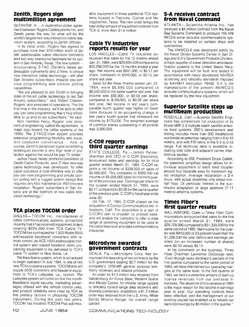
Sure,you've seen Head End Cable before, but not like this...
Solid Silver-Plated Polyethylene Solid Copper Dielectric Conductor
34 AWG Tinned --Copper Braid
Black Polyvinylchloride Jacket
Aluminum Laminated
Bonded Tape
34 AWG Tinned Copper Braid
Comm/Scope's new S59 We're making it...better!
Better because we're building in two exclusive features:
SILVER-PLATED SOLID COPPER center con-ductor, 22 AWG (.0253" dia.) Gives you better
signal transmission than the usual silver-plated copper-covered steel.
BONDED ALUMINUM TAPE SHIELD: laminated alumi-num tape bonds to the polyethylene dielectric and to itself,
to give an extra 100% shield. Plus two layers of 34 AWG tinned copper braid, each with 95% coverage. The tough but
flexible PVC black jacket is clearly marked for easy identification.
ADDED CONVENIENCE: now order all your cable needs from the one complete quality source —Comm/Scope. In 500 foot and 1000
foot reels. Make the better Head End connection... Ale.f,_
order your S59 HEC from Comm/Scope today CABLE HOME GROUP COMM/SCOPE Coaxial Cable Products
P.O. Box 1729, Hickory, NC 28603 Phone: 800/438-3331, 704/324-2200 Telex. 802-166
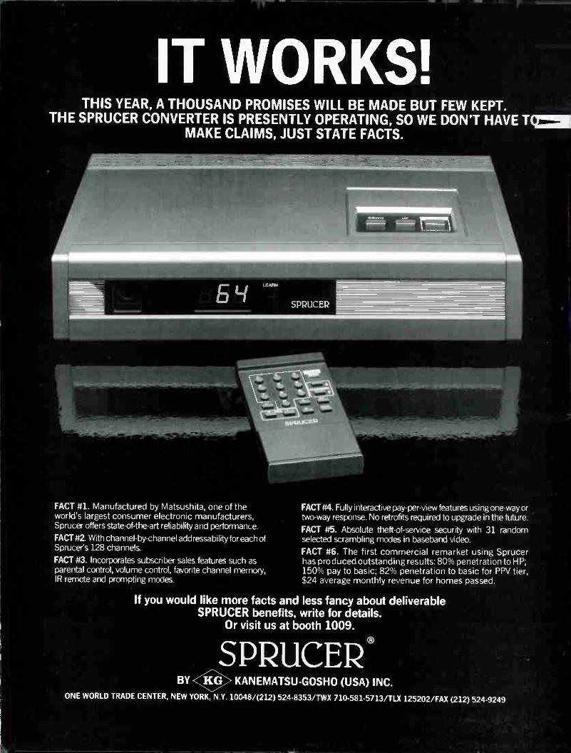
IT WORKS! THIS YEAR, A THOUSAND PROMISES WILL BE MADE BUT FEW KEPT.
THE SPRUCER CONVERTER IS PRESENTLY OPERATING, SO WE DON'T HAVE RE= MAKE CLAIMS, JUST STATE FACTS.
FACT #1. Manufactured by Matsushita, one of the world's largest consumer electronic manufacturers, Sprucer offers state-of-the-art reliability and performance.
FACT #2. With channel-by-channel addressability for each of Sprucer's 128 channels.
FACT #3. Incorporates subscriber sales features such as parental control, volume control, favorite channel memory, IR remote and prompting modes.
FACT #4. Fully interactive pay-per-view features using one-way or two-way response. No retrofits required to upgrade in the future.
FACT #5. Absolute theft-of-service security with 31 random selected scrambling modes in baseband video.
FACT #6. The first commercial remarket using Sprucer has produced outstanding results: 80% penetration to HP; 150% pay to basic; 82% penetration to basic for PPV tier, $24 average monthly revenue for homes passed.
If you would like more facts and less fancy about deliverable SPRUCER benefits, write for details.
Or visit us at booth 1009.
SPRUCER® BY <K9> KANEMATSU-GOSHO (USA) INC.
ONE WORLD TRADE CENTER, NEW YORK, N.Y. 10048/(212) 524-8353/TWX 710-581-5713/TLX 125202/FAX (212) 524-9249

CONSTRUCTION TECHNIQUES I 1111111111111111111111111111111
What the groundhog sees that you can't Part 1 By Anthony DeNigris
Miles of underground CATV plant are in existence across the country now, and there are quite a few "new-build" miles yet to be placed during the upcoming years. But, of all the already existing plant, does anyone really know the condition of their underground (UG) cable, or what potential hazards may exist that could cause a future problem to those cables? I believe there is only one way to approach any kind of an answer to that ques-tion; and that is by saying that unless all the proper steps have been taken to prevent fu-ture problems at the time of the initial in-stallation itself, what happens to the under-ground plant down the road is anybody's guess.
Multiple considerations Considering that most aerial plant is put up
in pretty much the same way, and that any physical problems are easily discernible and quite readily repaired, when it comes to bur-ied cables, the situation is quite the opposite. In analyzing the complexities of UG builds, it must be understood that numerous factors have to be addressed in order to arrive at the best practical method for building an under-ground system. Most notable are the following:
1. Ground conditions—sandy, rocky or backfilled.
2 Annual rainfall or varying ground water levels.
3 Proximity of other buried utilities, which includes one commonly overlooked point: sprinkler system lines.
4 Integrity of the surrounding area—the degree of restoration necessary to achieve a finished product that blends in.
5. Financial budget. I'm sorry to say that item 5 (financial bud-
get), is most of the time the only determinant in deciding which type of UG construction will actually be implemented. Properly placed "long term" UG plant is expensive, and I am a firm believer that if you don't spend "X" dollars up front for the proper system, you are going to pay "XX plus" dollars in the end. As an example of this type of thinking, look at a cable system that contains varying ground conditions with a great deal of backfilled and rocky areas. Trenching would be the right way to go with possible conduit placement or sand
fill under and over the cables. However, be-cause the placement costs of "vibrating the cable in" seem far less expensive than the previously mentioned method, vibratory plow-ing is chosen.
After a short time, say six months or so, some problems start appearing that indicate that perhaps the initial analysis might have been done with a little more concern during the planning and budgeting stage. A small system outage occurs and the trouble is traced to Mr. Jones' front yard where he had decided to plant a rose bush and apparently cut into the cable (non-armored of course) with his shovel. The technician easily finds the problem area and isolates the fault with a TDR (time domain reflectometer). He discovers the fault is under the newly planted rose bush; but he also finds out at that time that the cable is only buried five inches deep, and that is the reason it was able to be cut in the first place.
It is further discovered that the reason the cable is only five inches deep is because it is laying on a ledge out-cropping and there really was no way to vibrate it in deeper during the initial construction. Note: It must be understood at this point that plowing can only give the depth when the depth is there to be had. In situations like the above mentioned, plows bounce all over the place but mostly "out of the ground" when they ride up and over a ledge out-cropping. Now the technician has to put in an expensive burial splice and the system takes its first "hacking up." After a few years of assorted problems, the system oper-ator may be forced to rebuild the plant. At that time, the cost would certainly be higher for the rebuild than for original construction; but when coupled with the cost of the original build, it becomes very evident what the effect of improper method consideration has on the system now.
Methods—One vs. the other When evaluating techniques of under-
ground cable placement, it comes down to two basic methods—vibratory plowing and trenching. Expanding upon the first and simplest technique mentioned above, vi-bratory plowing should only be implemented under specific and "proper" conditions, and then only with stringent controls, as should be realized from the previous example. A vi-bratory plow is a machine that has a long, narrow vertical blade in front. This blade has a chute attached to its rear side. When the blade is dropped into the ground, it will re-
COMMUNICATIONS TECHNOLOGY
—
'... if you don't spend "X" dollars up front...you are going to pay "XX plus" dollars in the end'
ciprocate (vibrate) and the drive of the ma-chine will push it along actually cutting a slot in the earth as it goes. The cable will be fed through the chute on the blade and into the slot in the ground. The finished product is usually the neatest, most easily restored in-stallation possible, but personally, that is all I can say about it. No one, and I mean no one, knows how the
cable looks in the ground. Even in pure sand there is no guarantee that the cable isn't dam-aged. This is because it is impossible to know what is happening at the end of the chute. Should there by any type of sharp object in the ground that comes in contact with the cable, it could be forced into cutting the cable. One other point, the chute itself could damage the cable. This could be due to improper feeding of the cable into the chute by the operator or other reasons, or if the chute is not the proper chute for the radius of the selected cable. My own opinion as to the usage of a vibratory plow is to limit it to drop burials; but then, to each his own.
Trenching, however, is much more com-plex and expensive because of the various phases of the operation that may or "must" be taken into account, as well as the man hours involved. What I mean here is how much de-bris from the trench is to be removed, how much or if any, sand is to be brought in, how much clean up is necessary, whether or not the restoration will involve sodding and the list of the various phases of the total trenching and cabling operation goes on and on. Bear in mind, however, that trenching, no matter what is encompassed, has its own slew of problems. There are numerous ways to accomplish
what is called trenching: using trenching ma-
JUNE 1964 13
RT/KATEICis a classic example of the whole being greater than the sum of the parts.
e
full-service regional repair centers
services they previously offered. , unexcelled factory authorized
organizations combining to otter much more than twice the
You know Katek for its *,,,, «Neli-RT/KATEK COMMUNICATIONS GROUP is the result of the merger of Katek, Inc. and RT Cable Corpora tion — and a perfect example of two
repair of Jerrold, Hamlin, RCA, Pioneer and GTE/Texscan con verters with
residential, MDU and commercial
at five strategic locations na tionwide. You know RT Cable for its turnkey efókee 2;/., ;
installation and system maintenance services, with an unmatched record of more than 1,400,000 installs to date.
The extensive capabilities of both companies are now combined to meet your cable needs. But the new RTK offers much more than capabilities — it offers experience! The two parts that make up the whole have been deeply involved in cable for more than a decade. Think of them as pioneers. RT Cable pioneered turnkey
drops. Katek pioneered converter upgrading, addressable converter repair and the 6-month converter service guarantee. Just four cases among many of now the new RT/KATEK has the total capability to upgrade the profitability of your operations.
For more information on converter services, call (201) 356-8940; for information on installation services, call (201) 678-2083.
ammar
IMM AMM, ana IMIS AM.
1M" MI OW MI IM MIN NW 'Mk
WIMI/ IM 11M
RT/ICATEK COMMUNICATIONS GROUP Installation Services Division Converter Services Division
TM
See us at the NCTA Show at Booth 1057B.
chines, earth saws, back hoes and, finally, good old muscle power and a pick and shovel. The type of trenching that can be practically allowed also is governed by vari-ous conditions. When one thinks of a trencher, one envisions a large machine that looks simi-lar to a back hoe, but instead of the usual arm and bucket, it has a huge chain saw at that end. And this is basically the case. The right trencher can, under proper conditions (here we go with conditions again), dig quite quickly, a narrow and open trench to varying depths but commonly to about 24 inches or as required by various specs. The resultant "open trench" enables placement of whatever the cable operator wants in the trench. This may also encompass multiple cables or con-duits, and/or sand filling, or even shared us-age with other utilities or services, which could end up becoming a cost-sharing ad-vantage as well.
Most operators know that laying cables in an open trench is the preferred method; but how to achieve open trenching is many times a problem in itself. The weight and design of some of these digging machines may pose a problem to the integrity of the grounds they work on. Many times I have seen beautiful grass chewed up by the big tires on a back hoe; and then the restoration gets expensive. Many trenchers themselves throw dirt over a pretty wide area and it becomes costly to clean up. Some places are almost inac-cessable to certain digging machines and fences have to be torn down. Also, everyone is afraid of a trencher pulling up a power line, cutting into an existing gas pipe or damaging an existing sprinkler line. Bear in mind once more, however, that the same fears are there when it comes to vibrating cables, but with one added thought—you may not readily see the damage you could have caused. Back to trenching. Sometimes, the only way to go is by hand work with pick and shovel to be safe: again, very costly.
All in all it does become very obvious why some
operators like the apparent cost savings of vibrating cable as compared to trenching, but should the conditions stack up too high, it is going to cost more in the long run to plow cable and the near-term problems may not be avoided in any case.
Boring forgotten? Not at all. To tie boring into all of this is a
project in itself, and boring is a necessary evil in all underground applications no matter what method is employed. This facet will be explored in part two, next month. The one thing to emphasize though, is that there is absolutely no room for error, and especially not guesswork in UG planning and con-struction. And to make it happen with future life in mind, I can only say three things: con-trol, control and control. The next part of this article will outline the
do's and don'ts of vibrating, trenching and cable placement including conduits, ped-estals and burial vaults.
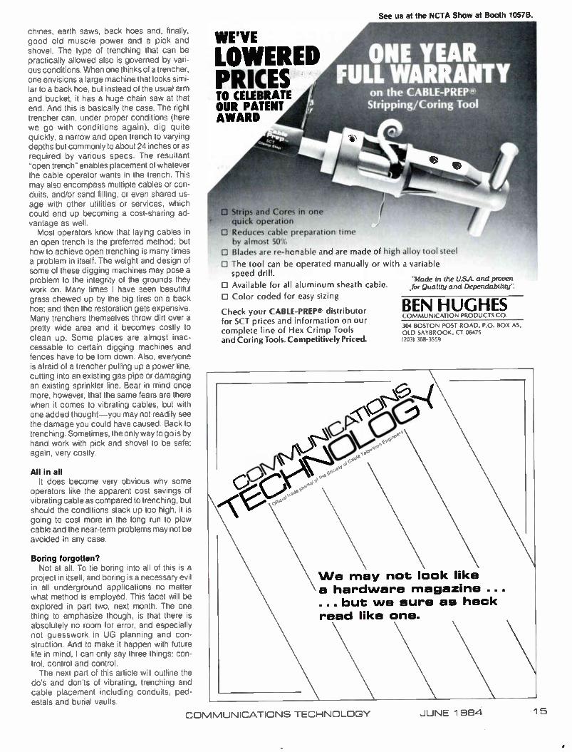
LOWERED PRICES TO CELEBRATE OUR PATENT AWARD
ONE YEAR FULL WARRANTY
on the CABLE-PREP n' Stripping/Coring Tool
ei%-*ezNI O Strips and Cores in one
quick operation
El Reduces cable preparation time by almost 50%
• Blades are re-honable and are made of high
D The tool can be operated manually or with speed drill.
CI Available for all aluminum sheath cable.
C Color coded for easy sizing
Check your CABLE-PREP?' distributor for SCT prices and information on our complete line of Hex Crimp Tools and Coring Tools. Competitively Priced.
alloy tool steel
a variable
"Made in the U.S.A. and proven .for Quality and Dependability".
BEN HUGHES COMMUNICATION PRODUC Is c 0
304 BOSTON POST ROAD, P.O. BOX AS. OLD SAYBROOK. CT 06475 12031 388-3559
We may not look like a hardware magazine ... ... but we sure as heck read like one.
COMMUNICATIONS TECHNOLOGY JUNE 1984 15
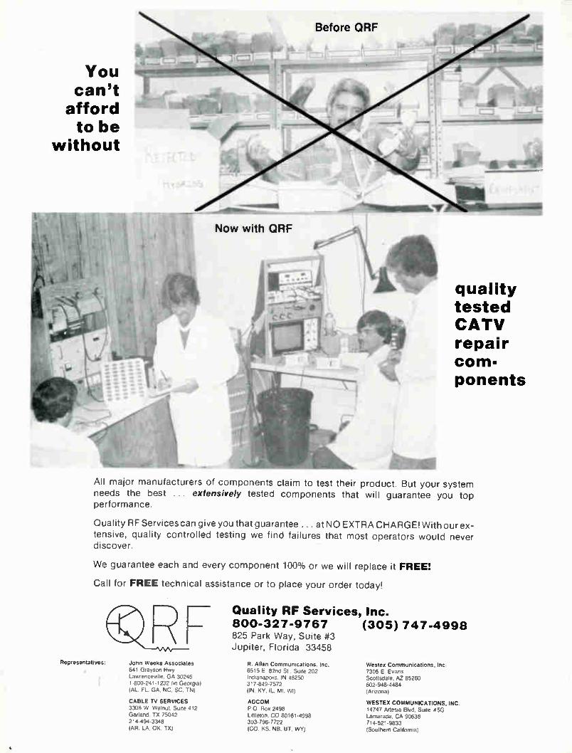
You can't
afford to be
without
quality tested CATV repair com-ponents
All major manufacturers of components claim to test their product. But your system needs the best ... extensively tested components that will guarantee you top performance.
Quality RF Services can give you that guarantee ... at NO EXTRA CHARGE! With our ex-tensive, quality controlled testing we find failures that most operators would never discover.
We guarantee each and every component 100% or we will replace it FREE!
Call for FREE technical assistance or to place your order today!
John Weeks Associates 641 Grayson Hwy Lawrenceville, GA 30245 1-800-241-1232 (in Georgia) (AL. FL, GA. NC. SC. TN)
Representatives:
Quality RF Services, Inc. 800-327-9767 (305) 747-4998 825 Park Way, Suite #3 Jupiter, Florida 33458
R. Allan Communications, Inc. Wesley Communications. Inc 6515 E 82nd St . Suite 202 7305 E Evans Indianapolis. IN 46250 Scottsdale, AZ 85260 317-849-7572 602-948-4484 (IN. KY. IL. MI. WI) (Arizona)
CABLE TV SERVICES ADCOM WESTEX COMMUNICATIONS, INC. 3306 W Walnut. Suite 412 P 0 Box 2498 14747 Artesia Blvd. Suite 06G Garland, TX 75042 Littleton, CO 80161-4998 Lamarada, CA 90638 214-494-3348 303-796-7722 714-521-9833 (AR. LA. OK. TX) (CO, KS. NB, UT. WY) (Southern California)
•

SYSTEM ECONOMY 11 1 111111111111111111111111111111111111111111111 111111111111
Cutting costs from the start By Frank Kerr Schofield E. Co
In the past, underground construction of the cable plant, especially in urban environ-ments, has been a costly and time-consuming endeavor. New refinements in both products and techniques have helped to alleviate the problems. The primary contractor building Boston's
cable television system credits a new under-ground construction technique and the versa-tility of pre-sheathed flexible cable for the build being ahead of schedule. The president of McCourt Cable Systems
Inc., David McCourt, said the combination has enabled his firm to reduce building time more than 40 percent and to cut costs a minimum of 25 percent on the citywide project for Cablevision of Boston. The entire system is now expected to be completed almost three full years ahead of schedule. The 210-channel, quad-trunk network is
considered the toughest build in the industry to date because of its size, complexity and urban environment. At a cost of $100 million and involving nearly 800 miles of under-ground and aerial cable, the system will serve the city's 240,000 households, as well as businesses and nonprofit institutions.
McCourt's underground construction pro-cess, known as "McCourt Boston Integral" (MBI), is viewed as a major economic breakthrough for the industry. It is now being studied by MSOs and contractors across the U.S. and from Great Britain. Eleven com-panies from the U.K. alone have visited Bos-ton in recent months to examine MBI in actual use. The MBI process involves extensive use of
what the industry now commonly calls CinC —for cable in conduit. For the majority of the Boston build, McCourt is installing a pro-duct named Comm-Duct, produced by Tam-aqua Cable Products. Basically, it is poly-ethelene duct extruded directly over cable in long, continuous lengths.
"We're impressed with the quality of the product and especially Tamaqua's respon-siveness," McCourt said. "When we need product in 24 hours, they work around the clock to make sure we have it on time." The MBI method integrates into a single
process a variety of state-of-the-art tech-nologies ranging from equipment to mate-rials. The actual method of laying the under-ground cable is done by cutting a narrow trench a few inches wide and about 18 inches deep with a self-propelled "rock saw," placing cables already enveloped in conduits in the cut, then encasing them with a specially de-veloped concrete and capping it off with bituminous concrete that is infrared treated.
For the trunk lines in Boston, McCourt is installing either quad .625 coax within 21/2 -inch conduit or dual .875 in 21/2 -inch. Dual .625 coax within 2-inch conduit is being used for the feeders.
Traditional building methods still employed throughout the industry simply borrow an as-sortment of techniques and equipment in general construction use. The process nor-mally consists of digging a deep, wide trench, placing plastic conduits that connect at 10- or 20-foot intervals, encasing the ducts in con-crete, refilling the trench with gravel, patching it with bituminous concrete, and then pulling cables through the conduits. The MBI process "involves more innovation
than invention, and most of the technology is available to any system operator or contractor willing to invest the time and expense to in-tegrate its components," said McCourt.
Industry experts see the MBI technique, or a close variation, as a solution to soaring construction costs that have curtailed and even halted urban builds. The problem is so serious that trade and general press pub-lications have questioned cable's future in major cities. "When we started the Boston project on
October 17, 1982, it soon became clear that traditional building methods would price cable right out of the big cities," McCourt said. "We knew we had to find an economically viable solution for the industry and, quite frankly, for our own future as well. So we blended the best of old methods with the lastest technology, including Tamaqua's Comm-Duct, to arrive at our process." A sharp reduction in construction costs is
just one of the process' economic benefits. The adage "that time is money is especially
true in the cable industry where system oper-ators must invest millions in construction be-fore they realize a cent of revenue. By cutting building time in half, we enable them to begin generating income twice as fast "
A rock saw is used by McCourt Cable Sys-tems as part of the CATV construction process that reduced underground build-ing time in Boston nearly 50 percent.
Before introducing the MBI construction process in Boston. McCourt Cable Systems employed the traditional building method of digging deep. wide trenches. emplacing short conduits, then pulling the cable through the ducts.
COMMUNICATIONS TECHNOLOGY JUNE 1 994 19

. . the current state of technology doesn't allow for repair of
failed components in space'
Satellite reliability: Methods and applications By Norman Weinhouse
Inc
Commercial use of satellites for com-munication purposes is a business that is only 20 years old, but one that has grown by leaps and bounds bringing benefit to virtually all segments of society. The cable industry has made extensive use of domestic communica-tions satellites for approximately eight years. There are many in the industry who feel that satellites are the major technological catalyst in the development of cable, allowing the diversity of programming to exploit the wide-band potential of cable. The commercial success of communication
satellites can be attributed in large measure to the fact that they are reliable. This record of reliability is not a "statistical freak." Since the current state of technology doesn't allow re-pair of failed components in space, a highly
refined reliabilityquality control system is employed in the design and manufacturer of the satellites. On the other hand, there are some who would say that satellite reliability is a natural outgrowth from the fact that it is out of the reach of "maintenance men."
Satellite reliability history Consider Figure 1, which is a graphic pre-
sentation of one satellite manufacturer's (Hughes Aircraft Co.) experience with com-mercial satellites. The chart shows the evolu-tion in the physical size of commercial sat-ellites. Along with the physical size, although not shown, is a concomitant evolution in the communications capacity.
Secondly, what can be seen is an evolu-tionary commitment to the design life of the satellites. Those satellites that were designed and launched in the 1960s (Intelsat 1 and Intelsat 2) were developmental in nature to
Figure 1: Commercial satellite performance (Hughes)
Intelsat I Intelsat II Intelsat IV Anik A Westar Intelsat IVA Marisat Comstar Palapa-A SSS Westar Anik D Anik C Palapa B Galaxy Telstar 3
84 - — — •
'fun
ctio
n
— — —
82
80
78
-
-
-
-
-
•
Fill
Ir
el " d.
c•a
1
..., ,
fir
cl (:) '
(-)
Mr
C0
1 Jan
-i- 7-
1984
7
c•
76
74
72
— _ _
_
_
_
- Apogee Motor Ma
go e., Li- '5
ts. . 4. Lf
111 -1 11:e <
II c,i
- =
F-1 MINE
F-2 WNW
F-4
IIM
Vehicle
Failure F-3 I
F-6
eg •-• Li. Li.
en . LL.
el tià
N "' a a
CV
'-' '' .,
am Operational V Design Life
o Service Period 0 Retired
0 Re-entered Atmosphere
or Lost
70
68I
6e
64
_
-
-
—
-
1 11
0 ,4n Li.
u:
F-2
II
F-i
Launch Vehicle
Launch
iiiiiiii
ELi JUNE 1 984 COMMUNICATIONS TECHNOLOGY
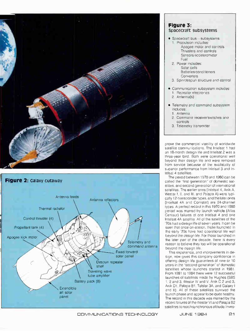
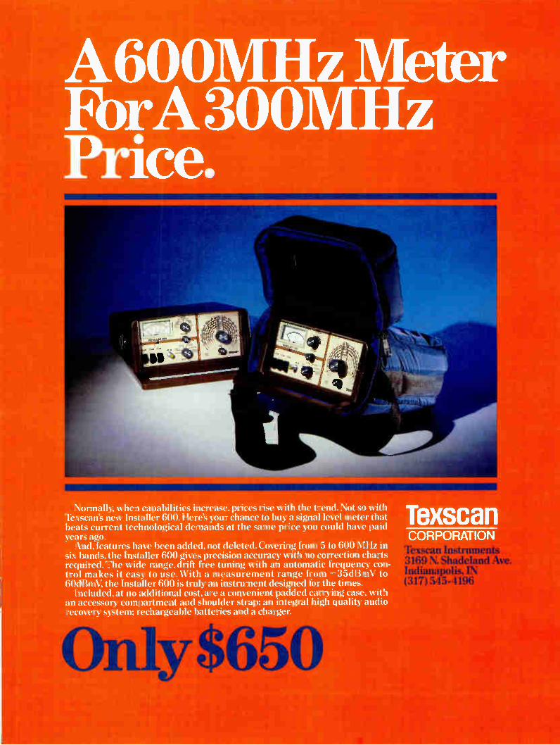
Figure 2: Galaxy cutaway
Antenna feeds
Thermal radiator
Control thruster (4)
Propellant tank (4)
Apogee kick motor
Antenna reflectors
Telemetry and command antenna
• Fixed forward solar panel
Despun repeater shelf
Traveling wave tube amplifier
Battery pack (8)
Extendible aft solar panel
Figure 3: Spacecraft subsystems
• Spacecraft bus -- subsystems 1. Propulsion includes:
Apogee motor and controls Thrusters and controls Sensors/accelerometer Fuel
2 Power includes: Solar cells Batteries/conditioners Converters
3. Spin/despun structure and control
• Communication subsystem includes: 1. Repeater electronics 2. Antenna(s)
• Telemetry and command subsystem includes: 1. Antenna 2. Command receiver/switches and
controls 3. Telemetry transmitter
prove the commercial viability of worldwide satellite communications. The Intelsat 1 had an 18-month design life and Intelsat 2 was a three-year bird. Both were operational well beyond their design life and were removed from service because of the availability of superior performance from Intelsat 3 and In-telsat 4 satellites. The period between 1970 and 1980 can be
called the "first generation" of domestic sat-ellites, and second generation of international satellites. The earlier ones (Intelsat 4, Anik A, Westar I, II, and Ill, and Palapa A) were typi-cally 12-transponder types, and the later ones (Intelsat 4A and Comstar) are 24-channel types. A perfect record in this 1970 and 1980 period was marred by launch vehicle (Atlas Centaur) failures of one Intelsat 4 and one Intelsat 4A satellite. All of the satellites of the '70s had a design life of seven years. It can be seen that once on-station, those launched in the early '70s have had operational life well beyond the design life. For those launched in the later part of the decade, there is every reason to believe they too will be operational beyond the design life.
This experience, and improvements in de-sign. now gives this company confidence in offering design life guarantees of nine or 10 years in the "second generation" of domestic satellites whose launches started in 1981. From 1981 to 1984 there were 12 successful launches of satellites made by Hughes (SBS 1. 2 and 3. Westar IV and V, Anik C 2 and 3. Anik D1, Palapa B1, Telstar 3A, and Galaxy I and II). All of these satellites survived the launch phase and appear to be quite healthy. The record in this decade was marred by the recent failures of the Westar VI and Palapa B2 satellites to reach synchronous altitude. Inves-
COMMUNICATIONS TECHNOLOGY JUNE 1 984 21

newer addressable converters in the repair pipeline is 18 or 19. It also said that the per-centage of older converters in the pipeline is even higher. What a terrible price the operator pays for this: service calls, repair costs, cus-tomer even disconnects. How many service calls are due to poor connectors and/ or drop cable at the subscriber's house? In my own case, a technician who came to my home to fix an ingress problem was not aware of the availability of sleeved connectors and quad shield cable. I fixed it myself once the tech-nician proved that the problem was in the drop. Had my drop been radiating beyond legal limits? I believe the cause of these problems to be
in the way cable evolved in this country. In the past, and to a very large extent today, speci-fications and standards were established by suppliers and vendors to the cable industry. Since the supply side of the industry is in-tensely competitive, short cuts are taken in products' design and manufacture. I also can fault the operators for false economy in the selection of hardware. Is the cable industry ready for change? I think it is. I already see changes in the area of technical performance. However, little is being done in the area of reliability.
Recommendations The following recommendations are offered
as a start toward enhanced reliability. On the surface, they may appear costly. However, it is my firm conviction that they will prove to be cost effective in the long run. 1. Operators, large or small, start a
reliablity/product assurance activity. This activity should fit your needs and have the unwavering support of the highest level of management.
2. The reliability organization should par-ticipate in all procurements. As a mini-mum, vendors should include in their quotes and proposals a written descrip-tion of their quality assurance activity. The operator can then have another dim-ension by which to make judgments in the purchasing process. Once suppliers realize that the buyer is serious about reliability, they will respond accordingly. The operators should monitor the sup-plier to assure that the supplier adheres to his own system.
3. Include reliability money incentives in all procurement contracts. Objective tar-gets should be established in the nego-tiation for purchases. Penalties also should be included for poor reliability. This will entail a good deal of record keeping and discipline on cable oper-ators, but is an effective process.
In the case of Hughes commercial sat-ellites, this is a major source of revenue. In some contracts, Hughes had made more money from incentive payments than on the initial manufacture of the satellites. Both buyer and seller are therefore happy. It results in follow-on business and a lasting relationship between buyer and seller.
.. if a data signal occupies 1/10 of a TV channel, it should be allocated Yio of the power'
System reliability requirements for two-way data transmission By Robert V.C. Dickinson
LcILJUfdtünt, L.),,u/1 AM Cable TV Inclustnes
System reliability is an old subject, which has fostered many important CATV industry stan-dards. There are very few things regarding the operation of a high-quality CATV system which are unknown to cable operators. Each system has its own standards and "book of rules" which, if followed, assures high-quality trouble-free CATV entertainment. However, time brings changes. Various new non-entertainment services are being added to cable systems. Their growth has been slow but steady. Many of these new services in-volve data transmission and offer increased service to the subscribers as well as new revenues to cable operators. These in-creased services bring additional technical sophistication while increased revenues de-mand reliability and high performance.
Data transmission The "data transmission" most often en-
countered is "digital data transmission." More often than not digital data is carried on CATV systems in some format other than standard TV visual or audio information. This implies data transmission carriers with non-TV fre-quency allocations, often narrower channel assignments and two-way data transmission for interactive services. Digital data trans-mission on cable can be implemented with a wide variety of modulations, bandwidths, formats, etc. To a greater or lesser degree all of these variations require similar environ-ments for satisfactory performance.
In TV transmission a low carrier-to-noise ratio (C/N) results in a snowy picture. This effect is first noticed at someting less than 40 dB C/N. In most data transmission systems 40 dB C/N is adequate for very high per-formance. At lower C/N data errors begin to occur, however the exact threshold depends upon the modulation system and other fac-tors. Further decrease in the C/N below the threshold gives rise to rapidly increasing error rates over only a few dB change. In general the performance of data under white noise conditions on a cable system should be quite good since the C/N ratio required for good video pictures is higher than that required for good data.
On the other hand, impulse noise in a CATV system will cause small "tears" in the TV pic-tures. Impulse noise includes those "spikes" generated by leaky power lines, auto ignition, etc. These tears are often tolerable to the average viewer. Impulse noise of significant amplitude can be guaranteed to cause data errors. As a matter of fact, impulses normally cause loss of blocks of data which can cause serious disruption of the data stream. In this context impulse noise can be described as more damaging to data than to video.
Distortion (crossmod, intermod, etc.) will cause beats and other viewing disturbances in the video channels. Data has more tol-erance to intermod products than video ex-cept in the case of very low level data signals where small TV intermod products may pro-duce an unacceptable carrier-to-interference ratio. Data signals in the presence of dis-tortion also generate intermod products which may be the cause of visual impairments in the video channels. Fortunately, a system that delivers clean video can deliver clean data. There is no reason, therefore, why well kept CATV systems should not be excellent conduits for data signals. One of the most critical elements in CATV
data carriage is the upstream path. The up-stream path is not generally involved in TV service to the subscribers. Noise collected in the upstream path can interfere with the up-stream data channels and yet not be seen in the delivered TV pictures. Maintaining this upstream path is one of the more difficult tasks in providing a good data network. It is very difficult to determine the source of inter-fering signals (usually ingress) in the up-stream path due to the tree-like structure of the cable system. The reverse signals flow from the "tips of the branches" toward the root combining with other branches, limbs, and the trunk on the way. Signals producing inter-ference in the data channels can be observed at the headend but their sources are totally unknown and the location of these sources presents a unique maintenance problem.
This brings up one of the more important subjects of this decade: signal leakage. As you can see this is a two-edge sword. That which leaks in degrades signals within the cable system (upstream and downstream) and that which leaks out interferes with over-
24 JUNE 1 984 COMMUNICATIONS TECHNOLOGY
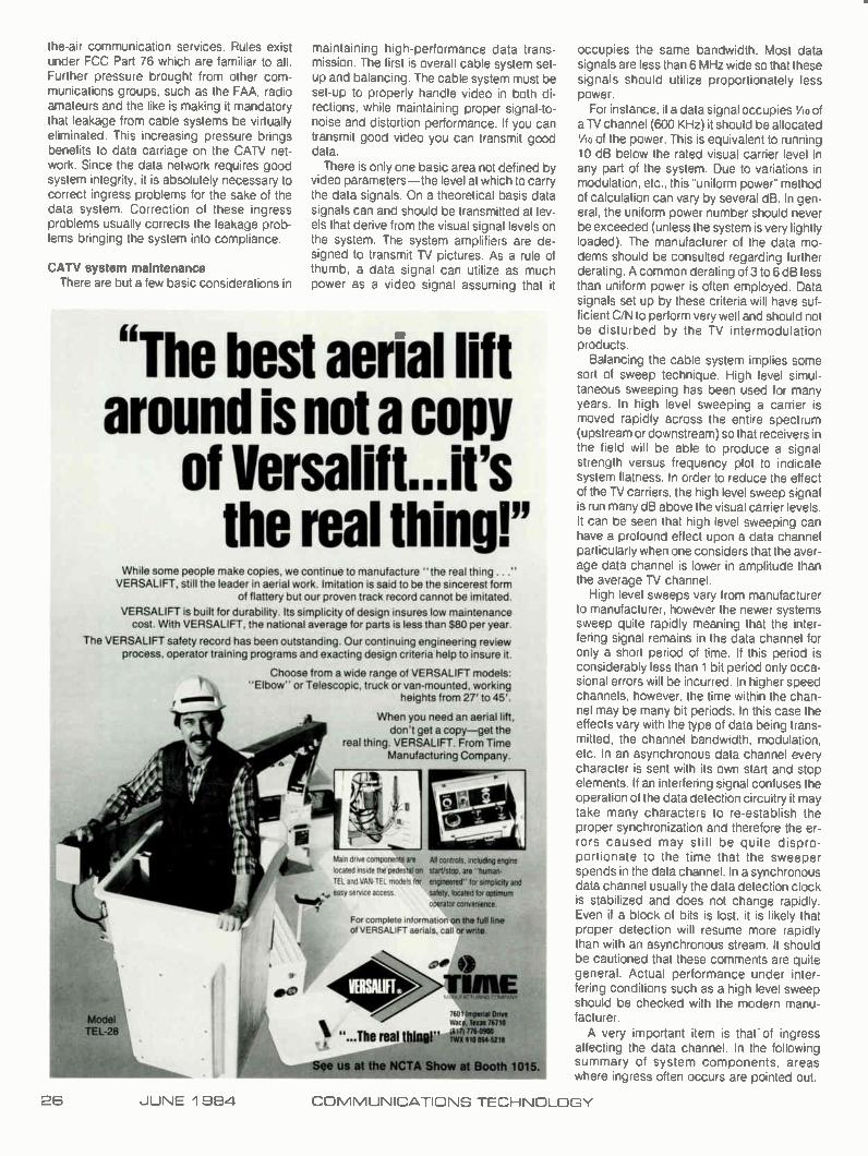
A600MHz Meter FbrA 300MHz Price.
Normally, when capabilities increase, prices rise with the trend. Not so with Texscan's new Installer 600. Here's your chance to buy a signal level meter that beats current technological demands at the same price you could have paid years ago. And, features have been added, not deleted. Covering from 5 to 600 MHz in
six bands, the Installer 600 gives precision accuracy with no correction cha required. The wide range, drift free tuning with an automatic frequency co trol makes it easy to use. With a measurement range from —35dBmV to 60dBmV, the Installer 600 is truly an instrument designed for the times.
Included, at no additional cost, are a convenient padded carrying case, with an accessory compartment and shoulder strap; an integral high quality audio recovery system; rechargeable batteries and a charger.
Texscan CORPORATION xsean — en
3169 N. Shadeland Ave. Indianapolis, IN (317) 545-4196
All controls, including engine start/stop. are "human-
engineered" for simplicity and
safety. located for optimum
operator convenience
the-air communication services. Rules exist under FCC Part 76 which are familiar to all. Further pressure brought from other com-munications groups, such as the FAA, radio amateurs and the like is making it mandatory that leakage from cable systems be virtually eliminated. This increasing pressure brings benefits to data carriage on the CATV net-work. Since the data network requires good system integrity, it is absolutely necessary to correct ingress problems for the sake of the data system. Correction of these ingress problems usually corrects the leakage prob-lems bringing the system into compliance.
CATV system maintenance There are but a few basic considerations in
maintaining high-performance data trans-mission. The first is overall cable system set-up and balancing. The cable system must be set-up to properly handle video in both di-rections, while maintaining proper signal-to-noise and distortion performance. If you can transmit good video you can transmit good data. There is only one basic area not defined by
video parameters—the level at which to carry the data signals. On a theoretical basis data signals can and should be transmitted at lev-els that derive from the visual signal levels on the system. The system amplifiers are de-signed to transmit TV pictures. As a rule of thumb, a data signal can utilize as much power as a video signal assuming that it
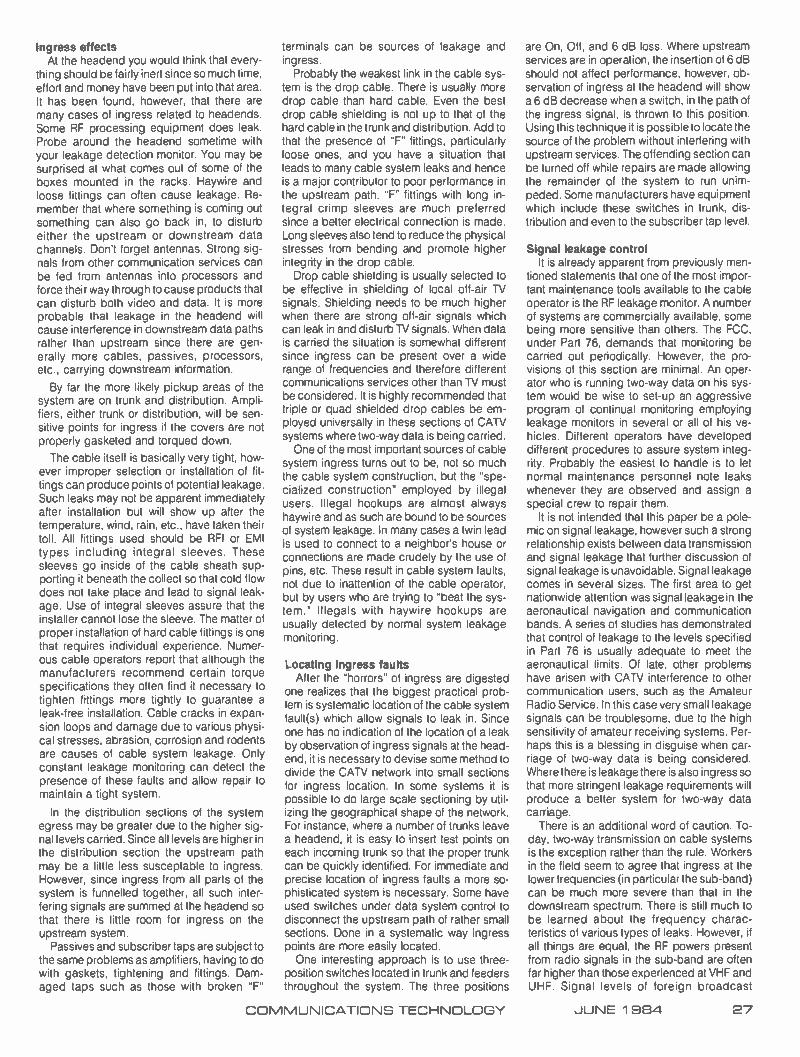
"The best aerial lift around is not a copy
of Versalift...it's the real thing!"
While some people make copies, we continue to manufacture the real thing ... VERSALIFT, still the leader in aerial work. Imitation is said to be the sincerest form
of flattery but our proven track record cannot be imitated.
VERSALIFT is built for durability. Its simplicity of design insures low maintenance cost. With VERSALIFT, the national average for parts is less than $80 per year.
The VERSALIFT safety record has been outstanding. Our continuing engineering review process, operator training programs and exacting design criteria help to insure it.
Choose from a wide range of VERSALIFT models: "Elbow" or Telescopic, truck or van-mounted, working
heights from 27' to 45'.
When you need an aerial lift, don't get a copy—get the
real thing. VERSALIFT. From Time Manufacturing Company.
7601 imperial Onve War e, Texas 76710 el/1776-0900 TM 910 8945218
86
Man drive components ale
located inside the pedestal on
TEL and VAN-TEL models for
easy service access
For complete information on the full fine
of VERSALIFT aerials, call or write.
lbh "...The real thine!"
us at the NCTA Show at Booth 1015. _MEL
occupies the same bandwidth. Most data signals are less than 6 MHz wide so that these signals should utilize proportionately less power.
For instance, if a data signal occupies VIO of a TV channel (600 KHz) it should be allocated 1/,0 of the power. This is equivalent to running 10 dB below the rated visual carrier level in any part of the system. Due to variations in modulation, etc., this "uniform power" method of calculation can vary by several dB. In gen-eral, the uniform power number should never be exceeded (unless the system is very lightly loaded). The manufacturer of the data mo-dems should be consulted regarding further derating. A common derating of 3 to 6 dB less than uniform power is often employed. Data signals set up by these criteria will have suf-ficient C/N to perform very well and should not be disturbed by the TV intermodulation products.
Balancing the cable system implies some sort of sweep technique. High level simul-taneous sweeping has been used for many years. In high level sweeping a carrier is moved rapidly across the entire spectrum (upstream or downstream) so that receivers in the field will be able to produce a signal strength versus frequency plot to indicate system flatness. In order to reduce the effect of the TV carriers, the high level sweep signal is run many dB above the visual carrier levels. It can be seen that high level sweeping can have a profound effect upon a data channel particularly when one considers that the aver-age data channel is lower in amplitude than the average TV channel.
High level sweeps vary from manufacturer to manufacturer, however the newer systems sweep quite rapidly meaning that the inter-fering signal remains in the data channel for only a short period of time. If this period is considerably less than 1 bit period only occa-sional errors will be incurred. In higher speed channels, however, the time within the chan-nel may be many bit periods. In this case the effects vary with the type of data being trans-mitted, the channel bandwidth, modulation, etc. In an asynchronous data channel every character is sent with its own start and stop elements. If an interfering signal confuses the operation of the data detection circuitry it may take many characters to re-establish the proper synchronization and therefore the er-rors caused may still be quite dispro-portionate to the time that the sweeper spends in the data channel. In a synchronous data channel usually the data detection clock is stabilized and does not change rapidly. Even if a block of bits is lost, it is likely that proper detection will resume more rapidly than with an asynchronous stream. It should be cautioned that these comments are quite general. Actual performance under inter-fering conditions such as a high level sweep should be checked with the modern manu-facturer. A very important item is that of ingress
affecting the data channel. In the following summary of system components, areas where ingress often occurs are pointed out.
26 JUNE 1 984 COMMUNICATIONS TECHNOLOGY
Ingress effects At the headend you would think that every-
thing should be fairly inert since so much time, effort and money have been put into that area. It has been found, however, that there are many cases of ingress related to headends. Some RF processing equipment does leak. Probe around the headend sometime with your leakage detection monitor. You may be surprised at what comes out of some of the boxes mounted in the racks. Haywire and loose fittings can often cause leakage. Re-member that where something is coming out something can also go back in, to disturb either the upstream or downstream data channels. Don't forget antennas. Strong sig-nals from other communication services can be fed from antennas into processors and force their way through to cause products that can disturb both video and data. It is more probable that leakage in the headend will cause interference in downstream data paths rather than upstream since there are gen-erally more cables, passives, processors, etc., carrying downstream information.
By far the more likely pickup areas of the system are on trunk and distribution. Ampli-fiers, either trunk or distribution, will be sen-sitive points for ingress if the covers are not properly gasketed and torqued down.
The cable itself is basically very tight, how-ever improper selection or installation of fit-tings can produce points of potential leakage. Such leaks may not be apparent immediately after installation but will show up after the temperature, wind, rain, etc., have taken their toll. All fittings used should be RFI or EMI types including integral sleeves. These sleeves go inside of the cable sheath sup-porting it beneath the collect so that cold flow does not take place and lead to signal leak-age. Use of integral sleeves assure that the installer cannot lose the sleeve. The matter of proper installation of hard cable fittings is one that requires individual experience. Numer-ous cable operators report that although the manufacturers recommend certain torque specifications they often find it necessary to tighten fittings more tightly to guarantee a leak-free installation. Cable cracks in expan-sion loops and damage due to various physi-cal stresses, abrasion, corrosion and rodents are causes of cable system leakage. Only constant leakage monitoring can detect the presence of these faults and allow repair to maintain a tight system.
In the distribution sections of the system egress may be greater due to the higher sig-nal levels carried. Since all levels are higher in the distribution section the upstream path may be a little less susceptable to ingress. However, since ingress from all parts of the system is funnelled together, all such inter-fering signals are summed at the headend so that there is little room for ingress on the upstream system.
Passives and subscriber taps are subject to the same problems as amplifiers, having to do with gaskets, tightening and fittings. Dam-aged taps such as those with broken "F"
terminals can be sources of leakage and ingress.
Probably the weakest link in the cable sys-tem is the drop cable. There is usually more drop cable than hard cable. Even the best drop cable shielding is not up to that of the hard cable in the trunk and distribution. Add to that the presence of "F" fittings, particularly loose ones, and you have a situation that leads to many cable system leaks and hence is a major contributor to poor performance in the upstream path. "F" fittings with long in-tegral crimp sleeves are much preferred since a better electrical connection is made. Long sleeves also tend to reduce the physical stresses from bending and promote higher integrity in the drop cable. Drop cable shielding is usually selected to
be effective in shielding of local off-air TV signals. Shielding needs to be much higher when there are strong off-air signals which can leak in and disturb TV signals. When data is carried the situation is somewhat different since ingress can be present over a wide range of frequencies and therefore different communications services other than TV must be considered. It is highly recommended that triple or quad shielded drop cables be em-ployed universally in these sections of CATV systems where two-way data is being carried. One of the most important sources of cable
system ingress turns out to be, not so much the cable system construction, but the "spe-cialized construction" employed by illegal users. Illegal hookups are almost always haywire and as such are bound to be sources of system leakage. In many cases a twin lead is used to connect to a neighbor's house or connections are made crudely by the use of pins, etc. These result in cable system faults, not due to inattention of the cable operator, but by users who are trying to "beat the sys-tem." Illegals with haywire hookups are usually detected by normal system leakage monitoring.
Locating ingress faults After the "horrors" of ingress are digested
one realizes that the biggest practical prob-lem is systematic location of the cable system fault(s) which allow signals to leak in. Since one has no indication of the location of a leak by observation of ingress signals at the head-end, it is necessary to devise some method to divide the CATV network into small sections for ingress location. In some systems it is possible to do large scale sectioning by util-izing the geographical shape of the network. For instance, where a number of trunks leave a headend, it is easy to insert test points on each incoming trunk so that the proper trunk can be quickly identified. For immediate and precise location of ingress faults a more so-phisticated system is necessary. Some have used switches under data system control to disconnect the upstream path of rather small sections. Done in a systematic way ingress points are more easily located. One interesting approach is to use three-
position switches located in trunk and feeders throughout the system. The three positions
are On, Off, and 6 dB loss. Where upstream services are in operation, the insertion of 6 dB should not affect performance, however, ob-servation of ingress at the headend will show a 6 dB decrease when a switch, in the path of the ingress signal, is thrown to this position. Using this technique it is possible to locate the source of the problem without interfering with upstream services. The offending section can be turned off while repairs are made allowing the remainder of the system to run unim-peded. Some manufacturers have equipment which include these switches in trunk, dis-tribution and even to the subscriber tap level.
Signal leakage control It is already apparent from previously men-
tioned statements that one of the most impor-tant maintenance tools available to the cable operator is the RF leakage monitor. A number of systems are commercially available, some being more sensitive than others. The FCC. under Part 76, demands that monitoring be carried out periodically. However, the pro-visions of this section are minimal. An oper-ator who is running two-way data on his sys-tem would be wise to set-up an aggressive program of continual monitoring employing leakage monitors in several or all of his ve-hicles. Different operators have developed different procedures to assure system integ-rity. Probably the easiest to handle is to let normal maintenance personnel note leaks whenever they are observed and assign a special crew to repair them.
It is not intended that this paper be a pole-mic on signal leakage, however such a strong relationship exists between data transmission and signal leakage that further discussion of signal leakage is unavoidable. Signal leakage comes in several sizes. The first area to get nationwide attention was signal leakage in the aeronautical navigation and communication bands. A series of studies has demonstrated that control of leakage to the levels specified in Part 76 is usually adequate to meet the aeronautical limits. Of late, other problems have arisen with CATV interference to other communication users, such as the Amateur Radio Service. In this case very small leakage signals can be troublesome, due to the high sensitivity of amateur receiving systems. Per-haps this is a blessing in disguise when car-riage of two-way data is being considered. Where there is leakage there is also ingress so that more stringent leakage requirements will produce a better system for two-way data carriage.
There is an additional word of caution. To-day, two-way transmission on cable systems is the exception rather than the rule. Workers in the field seem to agree that ingress at the lower frequencies (in particular the sub-band) can be much more severe than that in the downstream spectrum. There is still much to be learned about the frequency charac-teristics of various types of leaks. However, if all things are equal, the RF powers present from radio signals in the sub-band are often far higher than those experienced at VHF and UHF. Signal levels of foreign broadcast
COMMUNICATIONS TECHNOLOGY JUNE 1 984 27

Wilk's modular standby power supply-As easy as
Wilk Power and Video's CATV standby power supply features a unique, totally modular compact design which allows easy plug-in installation of components when-ever you wish. This simply means that if you pal are not ready for standby power now,
to0 you can invest in the power supply today, WO any time later simply add a plug-in t‘--1 standby power module, and
when you're ready for Status Monitoring, just plug in Wilk's Status
Monitoring Module.
This modularity also means that all parts are readily accessible for ease of maintenance, and yet this rugged heavy-duty unit offers long-term reliability with power to spare. The unique composite ferro-resonant transformer design regulates voltage in both utility and standby modes, sustaining the output voltage within 3% of the 60V nominal.
And, only Wilk offers the Standby Power Status Monitoring System to continuously poll up to 1000 power supplies on critical parameters. It even has the capability to interrogate a specific power supply to obtain supplementary information.
Only Wilk's totally modular standby power supply lets you put off until tomorrow what you can't do today.
With our unique design features and reliable performance, we supply power when you need it. For more information call toll free: (800) 782-9455.
Tie 0-mum - - WM al
=—
Power and Video Inc.
U.S. Corporate Offices: 16255 Ventura Blvd., Suite 1001. Encino, CA 91436 (818) 788-2338 Toll Free: 800-782-9455
Eastern Regional Offices: 12 Terhune St., Oakland, NJ 07436 (201) 337-8158 Toll Free: 800-782-9455

stations very often reach very high levels and are seen in many ingress problems. These high levels can be dwarfed by a local amateur or other communications transmitter oper-ating with multi-kilowatt output often with a directional antenna. There are several ways to hedge your bets
in this area of concern. One is to avoid as-signment of data channels in these critical frequency bands. This is, more than likely, a short-term solution since hopefully services involving two-way transmission will increase and revenues along with them. Careful sur-veys of a local area may locate sources of high power RF energy and, in certain cases, it may be possible to isolate that section by
trapping certain feeders or the like without impacting the data service. The more general and surely the ultimate requirement is simply a tight. well-maintained, constantly monitored cable plant. The whole matter of leakage is also a legal
matter, therefore in addition to good engineer-ing practice, good records should be kept in case the FCC decides to check up on your system for one reason or another. Records should include when a leak is detected. its approximate amplitude, when and how it was repaired and, of course, its cause. This infor-mation integrated over a period of time can be very helpful to the overall maintenance pro-gram. Some operators are already benefiting
from historical and test data by its use in selecting better system components from the manufacturers. Leakage at this point is a big bugaboo in the
cable business and will probably continue to grow for sometime. Amplifier signatures. loose fittings, pulled out cables, failing power supplies, bad drops, and a host of others were major problems which the cable industry has lived through and conquered. When sig-nal leakage has been conquered cable sys-tems will be able to handle all kinds of two-way data. deliver better TV product, produce more revenues, and be at peace with other com-munications services by running what cable ought to be—a "truly closed system."
Reliability in broadband data communications By James H. Crocker Manager New Business Development. Burnup and Sims Cable Products Group
One of the most promising and yet unfulfilled cable service is two-way. For years it has eluded widespread application. It has been a technology in search of a market. Home se-curity, pay-per-view and meter reading have all failed to achieve acceptance and profit-ability. This may not continue to be the case, however, because of fundamental changes now occuring in the structure of both private and public communication services. In the case of both local and long distance voice and data services, who supplies the service and how it is delivered is rapidly changing.
These changes and the unique position of CATV systems to assist in providing services to meet the new requirements could provide the long-awaited market. These services will only be acceptable, however, if the reliability of the CATV plant is acceptable and the cost versus performance is competitive with the available alternatives. To meet these needs CATV engineers must understand the nature of the emerging systems and the problems to be encountered.
Communication systems history To understand the dynamics of the emer-
ging technologies it is important to know why things are as they are. Communication sys-tems had their start in the telegraph networks of the 18005. This was one of the first appli-cations of the work of Ampere, Henry, Ohm and the other pioneers of electrical theory. Telegraph provided city-to-city com-munications. Later, the telephone was intro-duced to provide voice communications in-side the urban cities. Both telephone and telegraph utilize twisted pair technology. While twisted pair has provided outstanding service over the years, its inherent limited bandwidth has made it difficult to provide more advanced services such as high-speed data. The large installed base of twisted pair, however, has spurred major developments to utilize this existing facility. Data rates of first 300. 1200 and now 9600 bits/sec are avail-
Figure 1: U.S. local area networks
1985
Total $165 million
Source: Frost & Sullivan
Broadband (67%)
Total: $5.7 million
1989
Total: $838 million
COMMUNICATIONS TECHNOLOGY JUNE 1 984 29

Figure 2: ISO-OSI reference model
Committees
7
6
5
4
3
2
1
Application
Presentation
Session
Transport
Network
Link
Physical
Link layer 2
Physical layer 1
802 1 Companion document
802.2 Logical link control
802.3 CSMA/CD
—
Notes: CSMA/CD = carner-sense multiple access/collision detection MAN = Metropolitan area network ISO = International Standards Organization
Within the IEEE-802 Standards Committee, four working groups deal with the ISO physical-layer protocols, including CSMA/CD, token bus, token ring and metropolitan-area network. Working Group 802.2 concentrates on the ISO link layer protocols. Structured as an overview group rather than a standards group, 802.1 Companion Document Working Group aims at smoothly interfacing the lower two ISO layers with the upper five.
802.4 Token " bus
802.5 Token — ring
802 6 MAN
1. . LANs are being developed to handle the vast amounts of
interoffice needs...several
alternate technologies are competing for this
marketplace. . . '
able on the PSN (public switched network). In the past, this facility and AT&T had a
monopoly on communications in the United States. Now several factors are emerging which could change both who and how these communication services are delivered.
Deregulation of AT&T has resulted in open-ing this multibillion dollar communications business to competition. This is a very stra-tegic time for cable systems located in major urban markets. Alternatives to AT&T long lines for voice and data between cities already exist. These alternates—MCI. Sprint, Cylix, etc. —currently use the local telephone ex-change from their long distance lines to their customers. In the past. the cost of local lines was held low and subsidized by long distance to help everyone afford basic telephone ser-vice. Deregulation will result in increases in local telephone exchange access charges. This is jeopardizing the ability of the alternate carriers to economically reach their cus-tomers. Since necessity is the mother of inven-tion, more than a dozen competing tech-nologies are emerging to provide the capa-bility to bypass the local telephone exchange. They include: 1) digital microwave: 2) cellular radio telephone: and 3) two-way cable TV. Other less attractive technologies include: 4) direct broadcast satellite; 5) FM-SCA and paging: and 6) digital termination systems. Of the competing bypass alternatives, only cable TV systems have the same franchise as the local phone company to use city right-of-ways. The others must use the increasingly crowded over-the-air frequency spectrum. Of those competitors to the telcos. only cable TV companies have the infrastructure in place to sell, service and support the end user.
Cable's role in bypass If cable TV is to play an important part in
bypass, it must help to provide the transport necessary to meet the needs of the alternate carriers. This can be done in several ways. A Ti carrier is the simplest and is already being employed to provide large users connection into the long distance network and point-to-point local service. The largest and best op-portunity, however, exists in providing not only connection to long distance carriers and point-to-point but in providing local switched virtual circuits using packet switching tech-niques. The use of packet techniques allows both current and advanced services not now available from the local phone company to be implemented.
Just as telephone systems grew in the ur-ban areas that could support them, local area networks (LAN)—the forerunners of cable-based metro area networks (MAN)— are be-ing developed to handle the vast amounts of interoffice data needs. While several alternate technologies are competing for this market-place including baseband, broadband and fiberoptics, broadband has begun to emerge as the medium of choice (Figure 1). Broad-band LANs using standard CAN equipment and hardware have many advantages in-cluding easy extension, low cost, proven technology, and familiar technology. These networks can provide for the connection of numerous devices throughout a facility. Many of the concepts developed for broadband LANs are applicable to cable-based metro area networks.
Metro area networks The need for bypass capability, along with
30 JUNE 1 984 COMMUNICATIONS TECHNOLOGY

ARCOM Traps
Stack Up... against the competition
•Superior long-term stability
'Superior moisture proofing
•Superior security-rolled case prevents subscriber tampering
'Superior RF radiation shielding
Traps Shown
Actual
Size
SPECIAL OFFER $4 • 99 Tv2u.p0cRsDF.R Positive Traps
Channels 2 thru I
June 1, 1984 - June 30, 1984
IN N.Y. STATE CALL COLLECT 315-463-8433
(800)448-1655
2 Pole Series
4 Pole Series
6 Pole Series
ílNorthErn catv sales, inc. See us at the NCTA Show at Booth 367.
8 Pole Series

See us at the NCTA Show at Booth 1730.
Where is the Feedforward?
Its in the1000 Series! For more information please contact:
its Lindsay America Inc.
AV 1202B West,19th Street, Panama City, Florida 32405 Tel. 904-769-2321
the desire to connect the high-speed LANs to other distant LANs, is creating the need for a link that the CATV system can fill. But there are problems and very competitive technologies. The phone company won't be using twisted pair forever. All of the players in this new world of communication bring different back-grounds and experience. Telephone com-panies bring marketing and operation experi-ence. CATV brings analogue experience, LAN manufacture brings high-speed data on small area broadband networks and MCI and Sprint bring high-speed long distance point-to-point. But there are some key concepts basic to MANs that need to be explored. The most basic is the selection of an access scheme for use on cable. Only by adopting a universal CATV standard can cable hope to compete with alternate technologies. The IEEE 802 MAN standard could be the choice. At least three different fundamental access schemes are available. These include carrier sense multiple access with collision detection (CSMA/CD), and token passing and polling. Polling is not addressed as it is assumed most CATV engineers are familiar with this technique. The CSMA/CD algorithm was developed by
Bill Medcalf for the Xerox Ethernet. The sys-tem originally utilized a single baseband co-axial cable. The algorithm is simple but effec-tive. To access the channel, a modem begins to transmit and listens for a collision with any other modem trying to access the channel,
much the same way a group of people interact to see who has the floor. If a collision is detec-ted the modems back off in a random fashion and retry until one modem clearly has the channel. When the other modems, which are listening, detect the finish they can attempt to gain the channel in the same way. As the advantages of broadband began to emerge, most LAN manufacturers using CSMA simply adapted their products to broadband by fre-quency division multiplexing of the baseband channels. Token passing algorithms allow access to
the channel in a more deterministic way. A token is passed from modem to modem and only the modem with the token can talk on the channel. They can, of course, listen. Token passing was first developed for use in ring networks where the token was passed around the ring in sequence. Recently the token con-cept has been extended to the bus (tree) topologies as many of the added compexities of the bus cable have been solved. These include procedures if a token is lost due to noise, a node in the logical ring fails or a new node is activated. These problems were not difficult, but until the advent of economical high-speed microprocessors, the problems could not be solved in real time. Token pass-ing algorithms are also being standardized by the IEEE 802 committee. Many problems are yet to be resolved with
the application of either CSMA or token to MAN networks. In the case of CSMA, large
systems result in increased propagation de-lay. A modem must wait until it is assured that time has sufficiently passed for it to hear a collision with the furthest node in the system. This delay is further affected by the practice of looping through the headend so that all mo-dems talk and listen on the same frequency. This results in a severe speed/distance limi-tation. Increasing the network data rate for a given cable length increases the probability of collision. These signal collisions can further affect the network by causing inter-modulation, which could affect other CATV services.
In contrast, token passing overcomes this problem by using its more deterministic method. Token-access networks require no collision detection and therefore do not have the accompanying problems. While even the token scheme suffers from degradation in larger systems, the effect is small compared to CSMA and does not increase with network loading as is the case with CSMA. The token scheme is receiving even more consideration since IBM began planning to use it in its LANs.
Other access problems related more to the hardware than the algorithm include fre-quency agility, frequency translators, band-width efficiency and noise ingress.
OSI reference model The underlying set of protocols that allow
communications on a network are the rules by which one communicates on that network. The International Standards Organization has proposed a reference model called the open system interconnect or the ISO-OSI or simply the OSI Reference Model. The model pro-vides end-to-end transport as well as network control. Most broadband local area networks use this model at least to certain levels. The ISO reference model contains seven layers:
• Application • Presentation • Session e Transport • Network • Link • Physical
At the lowest level is the physical trans-mission media, the actual broadband chan-nel. This is analogous to the RS-232 standard, which includes both physical and electrical specifications. Next are the link protocols. These rules manage a device access to the physical link. Tasks such as framing and error detection occur at this level. Many vendors use standard HDLC framing and error detec-tion methods. The network protocols are re-sponsible for packet transfer. Routing occurs at this level. This can be between channels on the same broadband system or between sep-arate systems by bridges or links. The packet is forwarded to the end user usually by means of internal routing tables maintained at this level. Delivery guarantees are the respon-sibility of the transport layer. This layer pro-vides the virtual connections between nodes. At this level the flow of data is controlled to ensure a sender will not be flooded beyond its
32 JUNE 1 984 COMMUNICATIONS TECHNOLOGY
See us at the NCTA Show at Booth 1730.
processing capacity. This is the heart of the effectiveness of networks allowing many users to share a single medium but appear to have virtual connections. The session pro-tocol provides extended addressing to the port level. The presentation level services provide the support for ASCII, bisync and other user protocols. Finally the application level, the user specified level, performs the user's designed function, i.e., datagram ac-cess, DMA. These packet protocols provide the rules to
allow the user device to access only points inside or outside the network in a controlled way. It is an important concept in the emer-ging MAN era. There are many technical challenges fac-
ing the application of two-way CATV tech-nology as applied to MANs. While two-way has been slow to develop in the past, this can be traced to the market environment. The change in this environment brought about by the deregulation of the telephone industry and the advent of bypass technology may be the market force necessary to implement active two-way. Unlike the past, however, where each system implemented a different scheme, common standards must be de-veloped to assure reliability and market suc-cess. Only by understanding the develop-ment in local area networks and their promise and limitations in cable-based metro area networks can CATV system operators hope to compete.
e Take the guesswork
out of antennas
For the largest assortment of high quality, reliable and
rugged receive and transmit antennas...
make Lindsay your only choice.
Lindsay offers FREE-NO OBLIGATION antenna surveys.
For more information please contact:
Sts Lindsay America Inc. UV 1202B West,19th Street,
Panama City, Florida 32405 Tel. 904-769-2321
Successful implementation of CATV teletext By Gary W. Stanton Sateiiite Syndicated Systems Inc
The first vertical interval transmission to the cable television industry was conducted at the National Cable Television Association convention in Las Vegas, Nev., in 1979. This demonstration, although only partially suc-cessful, showed that data could be transmit-ted on the vertical blanking interval of a sat-ellite signal. Since that time, knowledge has been obtained on the various parameters that affect successful vertical blanking interval transmission to and through the cable en-vironment. During the last four years, various stan-
dards have evolved, equipment has been designed and services implemented using vertical blanking interval technology. Numer-ous degradation factors peculiar to satellite television transmission and to the cable envi-ronment have been identified. To offset these factors, error-correcting techniques have been developed that give several orders of magnitude improvement in data integrity. With these improvements, home teletext is suitable not only for video display, but also for elec-tronic mail and downloading of computer soft-ware and games.
History It is generally acknowledged that the first
commercial use of vertical blanking interval technology was by the British Broadcasting Co. The BBC Ceefax system, which was de-signed specifically for the 625-line PAL tele-vision system in use in Great Britain, was not usable in the United States without significant changes. Two of the most significant differences are
data rate and screen format. The 625-line system utilizes a data rate of 6.9375 Mbitsi sec, which is faster than can be used in the NTSC system. The second difference is screen format. In the Ceefax system, there is a fixed relation between the data byte's position in the transmit line and its position on the video display. In Great Britain, 40 usable data bytes are transmitted on each vertical blanking interval line, which corresponds to a video screen format of a 40-character width. De-pending on data rate, only 36 or 37 usable bytes can be transmitted in the NTSC system. In order to use a version of the Ceefax system in the United States, these two parameters needed to be modified to fit the NTSC system. The basic incentive for using the Ceefax sys-tem is the availability of LSI chips from several sources, which make teletext decoders re-liable and economically practical.
At the NCTA convention in 1979. Southern Satellite Systems displayed a primitive im-plementation with a data rate of approxi-mately 3.2 Mbits/sec using two vertical blank-
ing interval lines for one display line. By late 1980, a data rate of 5.554 Mbits/sec was in use and the screen was formatted with a 40-character by 20-row display. The mapping technique used was formulated by Mullard Labs.' In early 1983. the data rate was in-creased to 5.7272 Mbits/sec to be compatible with the proposed broadcast standard.' At the same time, the video screen format was improved to allow the display of 24 rows of text instead of 20 rows. The 24-row by 40-charac-ter format is considered the maximum pos-sible using the NTSC television system.
Customer services The initial services provided were the de-
livery of two news services to cable television headends. The equipment utilized was a vid-eo-in/video-out commercial quality teletext receiver. It was packaged in a rack mount chassis and specifically designed for direct interface to a satellite receiver. At this point in time, only the problems inherent in satellite transmission and satellite receivers had been addressed.
Shortly thereafter, a teletext transmission format was developed and a receiver de-signed featuring a data output rather than the video output. The data output featured the universal RS-232C interface plus a current loop. The initial purpose was to provide an interface between the vertical blanking inter-
COMMUNICATIONS TECHNOLOGY JUNE 1 984 33
val and a character generator at a cable tele-vision headend. This provided the operator the opportunity to use his sophisticated character generator for both a national alpha-numeric news channel and for locally gene-rated text or weather information. As is the case with the video output unit, the data out-put unit was packaged in a rack-mount chas-sis with an interface specifically designed to interface with a satellite receiver. Both of these units were designed for installation at a cable television headend or other commercial location where a baseband video signal was available.
Home teletext Recently. Southern Satellite Systems has
introduced Keyfax, a home teletext service. This service utilizes a version of the BBC Ceefax standard which was proposed to the Federal Communications Commission.2 It is the same standard being used by television stations in Cincinnati and Chicago for off-air teletext transmission. The service features over 100 video pages of text from which the viewer can select. This service is presently being transmitted on the vertical blanking interval of WTBS, which is on Satcom IIIR, transponder 6. To implement this service, a set-top teletext
decoder was necessary. Two manufacturers have designed compatible converter/de-coders. Both designs feature a full 54-channel cable converter with infrared remote control, a built-in teletext decoder, and a channel three or four demodulator. These de-coders can be used to replace existing con-verters in non-scrambled systems or as an add-on unit where scrambling is used. As a companion to the above teletext de-
coder, a similar unit is being designed that has a standard RS-232C data interface. This will be ideal for downloading information to printers and home computers. Its address-able function will allow specific users to get only the data to which they subscribe. The RS-232 interface decoder, combined
with vertical blanking interval technology, offers the ability to deliver one-way data from a central point to thousands of locations simul-taneously. This feature is particularly useful to the news services, commodity services, and financial information industries. It is presently being used by customers in these industries to deliver information to cable television hr;adends and to home subscribers.
The cable television system There are numerous factors in the cable
environment that affect teletext performance. The headend, the earth station, satellite receiver and the cable modulator all affect performance. In the cable plant, the micro-wave system or FM cable link, the line ampli-fiers and the drops can also affect per-formance.
1. Receive earth station—The quality of data received is directly proportional to the signal-to-noise performance of the receive earth station. A typical 3.6-meter dish with a 100 degree LNA in the central United States
produced an error performance of one error per million bits transmitted without using any error-correction methods. For some data ap-plications, this error rate may not be ade-quate. A larger receive dish would be necessary to lessen the number of bit errors. A 4.5-meter dish appears suitable for most applications. For Keyfax, this error rate is generally acceptable.
2. Terrestrial interference—One of the common problems that plague many receive locations is interference from terrestrial microwave sources. Unless the interference is obnoxiously bad, it is frequently ignored. Unfortunately, with teletext it cannot be ig-nored as it produces the same effect as if the system was operating at threshold. The best solution is shielding the receive dish from the interfering signal.
If shielding is not possible, filters are com-mercially available that have produced ac-ceptable results in many applications. The filter is placed in the IF of the receiver and is either a 60 MHz or an 80 MHz center fre-quency filter, depending on whether the offending carrier is 10 MHz below or 10 MHz above the desired signal. The filter chosen needs to be optimized to remove just enough of the offending signal to provide optimum data reception. A filter with too deep a notch will cause as much degradation as no filter at all, The best filters are those in which the depth of the notch can be varied. Usually, some improvement can be made by trial and error, but a spectrum analyzer is very desir-able. This allows one to see the interfering signal and the effects of the filter.
3. Satellite Receivers—The quality of the satellite receiver is one of the most important items affecting the performance of a teletext system. Of extreme importance is the IF bandwidth of the receiver. Tests indicate that a bandwidth of 30 MHz or greater is required for successful teletext operation. Many of the home quality receivers have an IF bandwidth of 25 MHz or less; usually to improve apparent video threshold. The lower bandwidth will dis-tort the data by limiting the frequency re-sponse of the system. This limiting will se-verely round the data pulses and cause both positive and negative overshoots of individual data pulses. On one receiver tested, the negative data overshoot exceeded 20 IRE units with the result being that the television receiver's sync circuitry became erratic. The test instrument required to measure
and observe this effect is a full-function wave-form monitor, such as a Tektronics 1480. Alternately, a 50 MHz oscilloscope can be used if it features a television sync horizontal trigger. A typical scope is the Tektronics 564B option 05.
Most commercial quality satellite receivers that have been used in the cable industry over the last five years meet the 30 MHz re-quirement. However, due to cost pressure, several major manufacturers have been con-sidering lower bandwidth products to be competitive with the home satellite offerings. Also, a few receivers tested did not meet published specifications. These lower band-
width units will not deliver a recoverable data signal. A second factor in satellite receivers is the
video filtering. It is common practice today to incorporate a bandpass filter on the video output which limits the bandwidth to 4.2 MHz. The portion of the band above 4.2 MHz con-tains the aural carrier at 6.8 MHz and most often numerous other subcarriers and/or noise. All receivers are equipped with either a 6.8 MHz notch filter or the low pass filter. However, those older receivers with only a 6.8 MHz filter will pass the energy of the additional subcarriers manifesting itself as video noise. If an older receiver is to be used, an external low pass filter is recommended if the teletext decoding is to be accomplished at the cable television headend. An equalized filter is de-sirable. For decoding on a cable system, the filter may not be required, as some modu-lators can provide the filtering. A third factor is the characteristics of the
video clamp circuit. Some otherwise excellent receivers have clamp characteristics which create the same effect as if there were inad-equate IF bandwidth, i.e., data pulses of non-uniform amplitudes. This generally will not make the data signal unrecoverable at the headend; however, after 20 amplifiers, the lower decoding margin will show up with un-acceptable performance. A fourth factor is unstable sync per-
formance of the receiver. This results in higher error rates in data performance. As the eye is very forgiving, one would not notice a few microseconds shift in a TV line. However, this shift disrupts the data timing which needs to be extremely accurate. If a standard oscil-loscope has trouble locking to the video sig-nal or shows horizontal instability, it is prob-able the sync stability is not adequate. The fifth factor is decreased gain at high
frequencies. This is important as the teletext signal is rich in high frequency components, which, when eliminated, will decrease de-coding margin. Examination of the multiburst signal on a scope or waveform monitor will be necessary to determine if this is a problem. The fifth burst, which is 3.58 MHz, should be as high in amplitude as the low frequency burst.
4. Modulators—The cable television modu-lator can damage the vertical blanking inter-val data. Fortunately, it is the adjustment of the modulator that is most often the problem, rather than the modulator itself. Of particular importance is preventing video overmodula-tion as well as maintaining the aural level at -15 to -19 dB with respect to the main carrier. It is equally important to correctly maintain the aural level on the next adjacent lower carrier.
Modulators that do not have bandpass fil-ters can allow harmonics to pass into the system. This is typical of the strip amp variety used in some older cable systems and most frequently used in apartment buildings, hotels and other institutional systems. This type of installation frequently can be improved by adding filters or replacing the modulator be-ing used for the channel carrying teletext.
5. Signal transportation systems—There
34 JUNE 1984 COMMUNICATIONS TECHNOLOGY
are three common ways of relaying the signal from a headend to a second distribution point: AML microwave, FM microwave, and FM cable link. The latter two methods are also used for signal transportation from a satellite dish facility to an AM modulation hub.
There have been no reported problems with FM microwave systems. The investigation of one reported problem with an AML system indicated the system was badly out of manu-facturer's tolerances. Numerous other oper-ators have successfully passed the vertical blanking interval data over AML microwave systems. It can be concluded that a properly operating AML system will not affect teletext data. The FM cable link gives one some op-portunity for messing up the signal. As the link must be properly equalized for the type and length of cable, there are numerous adjust-ments to be made which, if incorrectly done, will alter the received signal. Use of the multi-burst test signal is critical in properly aligning an FM cable link.
6. The cable plant—A properly adjusted cable plant will correctly pass the vertical blanking interval. Typical problem areas are malfunctioning AGC (automatic gain control) amplifiers, DC power supplies with high AC ripple, and leaks in the cable system. The leakage is extremely significant for on-channel operation of off-air signals with tele-text. The leakage generates the same effect as multipath reflections, except the weaker signal is before the desired signal rather than after it. In some systems, channels 18 and 19 (E and F) are susceptible to two-way radio interference. This interference will destroy the integrity of teletext data. A third cable plant problem is that of poor
quality drops. This frequently results in inad-equate levels. Teletext reliability is enhanced with a strong drop signal, typically between 5 and 10 dBmV. Installations subjected to high levels of RFI also may be unreliable.
It has been observed in conventional cable plants that certain channels are cleaner than others. This is generally a function of the many combinations that result from the addition and subtraction of the carriers and their harmon-ics. A spectrum analyzer is generally required to track this phenomenon, however, changing to a different channel is often the easiest solu-tion and may solve the problem.
7. Test equipment—The equipment used to test a cable plant can have an adverse effect on teletext performance. Of particular importance is the high level sweep equipment used on many systems. This type of sweep equipment will completely destroy teletext in-tegrity. The newer, low level sweep tech-niques can co-exist with teletext data; how-ever, some degradation has been observed.
8. System maintenance—Proper main-tenance and adjustment of the system is critical if low error rates are expected, as is maintaining the proper levels between sat-ellite receiver and modulator, and the correct modulation levels for both the visual and aural of all channels. It is common to find improper levels due to either misadjustment or sub-sequent unterminated or double terminated
equipment. Care in headend setup and main-tenance is mandatory for success in teletext transmission.
Error performance and improvements Several techniques have been developed
to improve data integrity. The basic code structure provides for parity checks on all data bytes. The decoder replaces a known erroneous character with a blank rather than display an incorrect character. On a second transmission of the page, the blank is filled in to complete the page. The address codes are further protected by Hamming codes. This is a code in which a single bit error in a byte will be corrected and a double error will be de-tected. These methods are in current use.
For data requiring a higher level of integrity, a method of multiple transmission has been developed. For the video type of teletext de-coder, the second transmission overwrites the original transmission; however, if a parity error is detected in any given byte, the byte from the first transmission is left on the dis-play. This technique gives a significant im-provement in data integrity and is used for critical transmissions. The same technique has been used for the
data output teletext unit. A control code is transmitted that tells the decoder whether it is receiving the first or second transmission of the identical data. Tests have shown that this technique generates 100 times improvement in data integrity. Another technique usable on the data out-
put type decoders is that of longitudinal parity check (LPC). In this technique, a byte is transmitted at the end of each vertical blank-ing interval line, which is the result of cal-culating parity on a bit by bit basis. From the LPC byte, a single byte error can be corrected in any given vertical blanking interval line. The improvement is almost as good as the mul-tiple transmission method when basic error rates of less than 1 x 10⁶ exist. This improve-ment diminishes for worse error rates and improves at better error rates. Of significant importance is the added overhead of only 3 percent rather than the 100 percent required in the multiple transmission technique. The use of the vertical blanking interval for
delivery of information to the cable television headend and to the homeowner is now feasi-ble and practicable. Reliable equipment is available at reasonable costs. A well-maintained cable system will be able to pass the vertical blanking interval information suc-cessfully. Small changes in other systems may be required, most often in the main-tenance practices.
References G. O. Crowther, "Teletext and Viewdata
Systems and Their Possible Extension to Europe and USA," IEEE Transactions on Con-sumer Electronics, July 1979 Volume CE-25 Number 3. 2United Kingdom Teletext Industry Group
petition for rulemaking before the Federal Communications Commission, March 26, 1981.
COMMUNICATIONS TECHNOLOGY JUNE 1984 35

Comband Update #3: Field Test In Hattiesburg, Mississippi,,
Before our premiere in Hattiesburg, catch our preview in Vegas.
The Test The Contest. Our show at NCTA in Las 'gas promises to
be one of the best. But the real blockbuster will be opening in
Hattiesburg, Mississippi. Until now, the fully addressable Comband-system has been tested in the lab. Now, were taking it on the road.
In July wee putting Comband on-line at General Electric's Hattiesburg system. Not only is this big step right on schedule, but ve fully expect to expand testing to other cable systems during the first quarter of 1985.
Stop by our booth in Las Vegas for a full demon-stration of the Comband system that adds chan-nels not cable. We'll even give you an on-the-spot computer analysis of how the Comband system can save money in your own upgrade plans.
GENERAL
We'll have 8 TV sets in our booth. On one or more of the sets a Comband processed signal will be displayed. The others will display standard, off-air NTSC signals.
All you'll have to do is pick the Comband picture(s). If you guess correctly, your name will be included in the drawing for a free 25" console color television. There will be a TV given away every day of the show
So stop by Booth 537 in Las Vegas. Get the big picture of our Hattiesburg field test and judge
Comband's picture qual-ity for yourself.
Ask for more infor-mation, by writing to Ron Polomsky,General Electric Company, Video & Audio Business Operations, Mail Drop #1Z Portsmouth, VA 23705 or you can call (804) 483-5064.
ELECTRIC
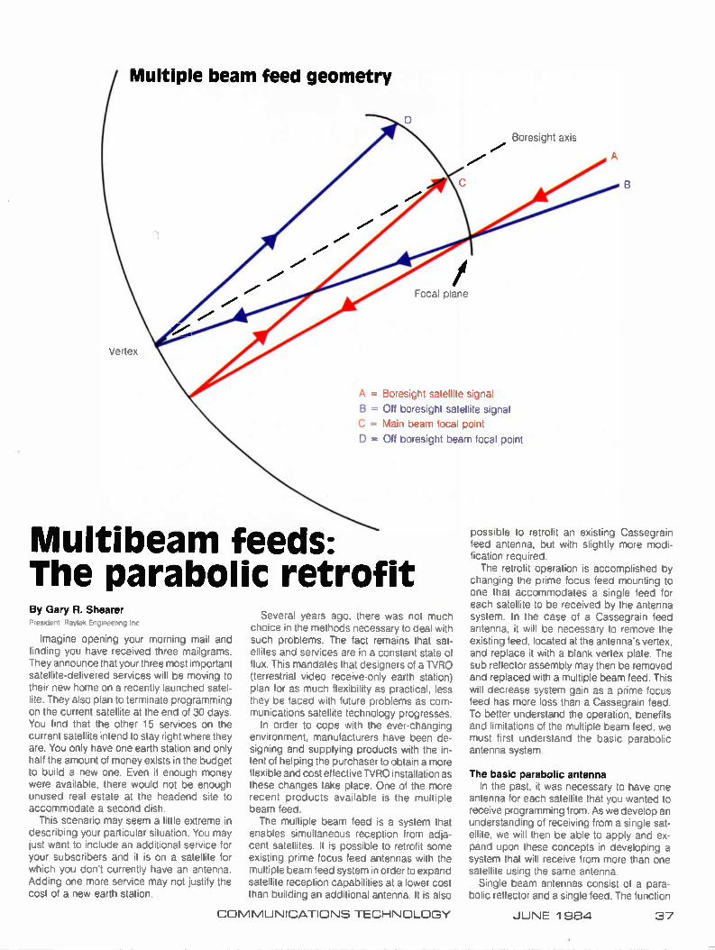
Multiple beam feed geometry
Boresight axis
Focal plane
A = Boresight satellite signal
B = Off boresight satellite signal
C = Main beam focal point
D = Off boresight beam focal point
Multibeam feeds: The parabolic retrofit By Gary R. Shearer
• Raytek Eng,n-
Imagine opening your morning mail and finding you have received three mailgrams. They announce that your three most important satellite-delivered services will be moving to their new home on a recently launched satel-lite. They also plan to terminate programming on the current satellite at the end of 30 days. You find that the other 15 services on the current satellite intend to stay right where they are. You only have one earth station and only half the amount of money exists in the budget to build a new one. Even if enough money were available, there would not be enough unused real estate at the headend site to accommodate a second dish.
This scenario may seem a little extreme in describing your particular situation. You may just want to include an additional service for your subscribers and it is on a satellite for which you don't currently have an antenna. Adding one more service may not justify the cost of a new earth station.
Several years ago, there was not much choice in the methods necessary to deal with such problems. The fact remains that sat-ellites and services are in a constant state of flux. This mandates that designers of a TVRO (terrestrial video receive-only earth station) plan for as much flexibility as practical, less they be faced with future problems as com-munications satellite technology progresses.
In order to cope with the ever-changing environment, manufacturers have been de-signing and supplying products with the in-tent of helping the purchaser to obtain a more flexible and cost effective TVRO installation as these changes take place. One of the more recent products available is the multiple beam feed. The multiple beam feed is a system that
enables simultaneous reception from adja-cent satellites. It is possible to retrofit some existing prime focus feed antennas with the multiple beam feed system in order to expand satellite reception capabilities at a lower cost than building an additional antenna. It is also
possible to retrofit an existing Cassegrain feed antenna, but with slightly more modi-fication required. The retrofit operation is accomplished by
changing the prime focus feed mounting to one that accommodates a single feed for each satellite to be received by the antenna system. In the case of a Cassegrain feed antenna, it will be necessary to remove the existing feed, located at the antenna's vertex, and replace it with a blank vertex plate. The sub reflector assembly may then be removed and replaced with a multiple beam feed. This will decrease system gain as a prime focus feed has more loss than a Cassegrain feed. To better understand the operation, benefits and limitations of the multiple beam feed, we must first understand the basic parabolic antenna system.
The basic parabolic antenna In the past, it was necessary to have one
antenna for each satellite that you wanted to receive programming from. As we develop an understanding of receiving from a single sat-ellite, we will then be able to apply and ex-pand upon these concepts in developing a system that will receive from more than one satellite using the same antenna.
Single beam antennas consist of a para-bolic reflector and a single feed. The function
COMMUNICATIONS TECHNOLOGY JUNE 1984 37
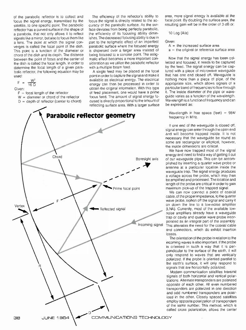
The efficiency of the reflector's ability to focus the signal is directly related to the ac-curacy of the parabolic surface. As the Sur-face deviates from being perfectly parabolic, the efficiency of its focusing ability dimin-ishes. The decreased focusing ability is due in part to the astigmatic effect of an imperfect parabolic surface where the focused energy is dispersed over a larger area instead of being focused to a concise point. The astig-matic effect becomes a more important con-sideration as we utilize the parabolic reflector with a multiple beam feed. A single feed may be placed at the focal
point in order to capture the signal and make it available as electrical energy. The electrical energy can then be processed in order to obtain the original information. With this type of feed placement, one would have a prime focus feed. The amount of signal energy fo-cused is directly proportional to the amount of reflecting surface area. With a larger surface
Parabolic reflector geometry
of the parabolic reflector is to collect and focus the signal energy, transmitted by the satellite, to one specific point. The parabolic reflector has a curved surface in the shape of a parabola, that not only allows it to reflect signals like a mirror, but also to focus them like a lens. The point at which the signal con-verges is called the focal point of the dish. This point is a function of the diameter or chord of the dish and its depth. The distance between the point of focus and the center of the dish is called the focal length. In order to determine the focal length of a given para-bolic reflector, the following equation may be used:
F = w2
16 D Given: F = focal length of the reflector W = diameter or chord of the reflector D = depth of reflector (center to chord)
Vertex
38 JUNE 1 984
Boresight axis
Prime focal point
«gleam Reflected signal
Incoming signal
area, more signal energy is available at the focal point. By doubling the surface area, the resulting gain will be in the order of 3 dB or:
10 Log (A/a)
Given: A = the increased surface area a = the original or reference surface area
Now that the signal energy has been col-lected and focused, it needs to be captured by the feed. The signal energy can be cap-tured with a piece of microwave waveguide that has one end closed off. Waveguide is nothing more than a piece of pipe, of the appropriate size, which allows signals of a particular band of frequencies to flow through it. The inside diameter of the pipe or wave-guide varies as a function of the wavelength. Wavelength is a function of frequency and can be expressed as:
Wavelength in free space (feet) = 984/ frequency in MHz.
If one end of the waveguide is closed off, signal energy can enter through the open end and will become trapped inside. It is not necessary that the waveguide be round as some are rectangular or elliptical, however, the inside dimensions are critical. We have now trapped most of the signal
energy and need to find a way of getting it out of our waveguide pipe. This can be accom-plished by inserting a quarter wave probe or antenna at a particular location inside the waveguide trap. The signal energy produces a voltage across the probe, which may then be amplified and processed. The location and length of the probe are critical in order to gain maximum pick-up of the trapped signal. We can now connect a piece of coaxial
cable, of the proper impedance, to the quarter wave probe, siphon off the signal and carry it on down the line to a low-noise amplifier (LNA). Currently, most of the available low-noise amplifiers already have a waveguide trap or cavity and quarter wave probe incor-porated as an integral part of the assembly. This alleviates the need for the coaxial cable and connectors, which do exhibit insertion losses. The orientation of the probe in relation to the
incoming waves is also important. If the probe is oriented in such a way that it is per-pendicular to the surface of the earth, it will only respond to waves that are vertically polarized. If the probe is oriented parallel to the earth's surface, it will only respond to signals that are horizontally polarized. Modern communication satellites transmit
signals of both horizontal and vertical polar-izations. Alternate transponders are polarized opposite of each other. All even numbered transponders are polarized in one direction and odd numbered transponders are polar-ized in the other. Closely spaced satellites employ opposite polarization of transponders of the same number. This method, which is called cross polarization, allows the center
COMMUNICATIONS TECHNOLOGY
frequency of each transponder to be spaced more closely together than a single tran-sponders bandwidth. Cross polarization al-lows more transponders per satellite and more satellites per degree of geo-synchronous arc without one interfering with the other.
Interference reduction We will now examine how the cross polar-
ization of closely spaced adjacent satellites will assist in the reduction of interference when a multiple beam feed is utilized. These bandwidth and arc savings are due to the fact that the quarter wave probe only responds efficiently to incoming waves that are polar-ized in the direction of probe orientation. It is a simple matter to change the orientation of the probe inside the waveguide cavity or rotate cavity, probe and all to allow the same probe to work both horizontal and vertical polar-izatons. The only limitation to the method is that we can not receive both horizontal and vertical polarizations at the same time. To overcome this limitation, two flanges are
provided on the same waveguide cavity and the flanges are oriented 90 degrees from each other. This allows one to bolt on an LNA and probe assembly for the horizontally polar-ized signals and another LNA for the vertically polarized ones. The assembly that allows simultaneous reception of both polarizations is called an orthomode coupler. The polarization of specific signals do not
arrive at any given earth station aimed at a
particular satellite at an angle exactly parallel or perpendicular to the earth's surface. Vari-ables that introduce this difference of polar-ization angle are as follows: satellite position within the geosynchronous arc, TVRO posi-tion on the earth's surface, and the accuracy of orientation of the satellite's transmitting antenna. With all of these variables con-sidered, rotation of the entire feed system about the parabolic reflector's boresight axis must be possible in order to enable any TVRO to receive every satellite when each TVRO could possibly be located anywhere within each satellite's footprint.
Considering that a given satellite's horizon-tally and vertically polarized transponders are almost exactly 90 degrees apart, rotation of the entire feed assembly will enaole one to accurately accomplish polarization adjust-ments necessary to obtain maximum transfer of signal energy to the quarter wave probe. The polarization variable problem will be compounded as we add more feeds in order to receive other satellites simultaneously.
Proper feed positioning A line beginning at the exact center of the
parabolic reflector, projected through the prime focus point, and extending into space is defined as the reflector's boresight axis. This axis is perpendicular to the chord of the dish. The prime focal point will contain the maxi-mum amount of signal energy when the re-flector's boresight axis is in a direct line with the satellite transmitting the desired signal. As
the satellite moves off the boresight axis of the parabolic reflector, or the boresight axis of the reflector moves off the satellite, a feed located at the prime focal point will receive proportion-ately less signal. This happens because the focal point of the beam will then be moving off the boresight axis and the signal energy will be missing the feed. We will later see how this problem may be used to our advantage in developing a multiple beam feed. The most efficient position for placing a
single feed, in order to obtain the maximum transfer of signal energy, would be to locate it at the reflector's prime focus point. A feed located anywhere else would be subject to the astigmatic effect of energy dispersion and would not be as efficient. Feed placement is accomplished in prime focus parabolic an-tenna systems by installing the feed on a tripod or pipe that locates it directly over the center of the dish. It also spaces the feed exactly the distance of the reflector's focal length from the center. Feed mountings of the pipe variety commonly have an adjustment in order to vary this distance and enable one to ensure exact feed placement at the focal point. The focal length adjustment enables the
feed to be used with antennas exhibiting vari-ous F/D ratios. If the feed is placed closer to the reflector surface than the focal point it will not receive the full amount of signal energy available, because much of the signal will be going past the edges of the feed. In this situ-ation, the feed will be said to be over-illumi-
It's easy!
Cable Advertising Wests ide Sports orSfalg NEST ODOM STREET
COME TV SUPER SPECIALS
• Coleman P Stove f • Sierra Sleeping Rog S • Club-Safe Golf Rag S • Pro-80 Tennis Racket 1 • Soft-Skin emboli lleve S
[Open Every Might 'tal g P.M.
• Graphic Character Generators • L.O. and Commercial Insertion • Graphic Libraries • Advertising Consulting and Services
See us at the NCTA booths 1140, 1141 and CATA-CCOS '84 booth 405
• • •
Can nmy be a regular income source for any cable system.
At Cable Graphics, we've taken the cost and hassles out of cable advertising. By creating microcomputer-based graphic systems that are guaranteed to be at least a generation ahead of contemporary character generators. Unmatched for reliability, flexibility and cost.
Complete Systems under $3000.
Cable Graphic Sciences 2939 LARKIN AVENUE • CLOVIS, CA 93612 • PHONE (209) 292-0246
COMMUNICATIONS TECHNOLOGY JUNE 1 984 39
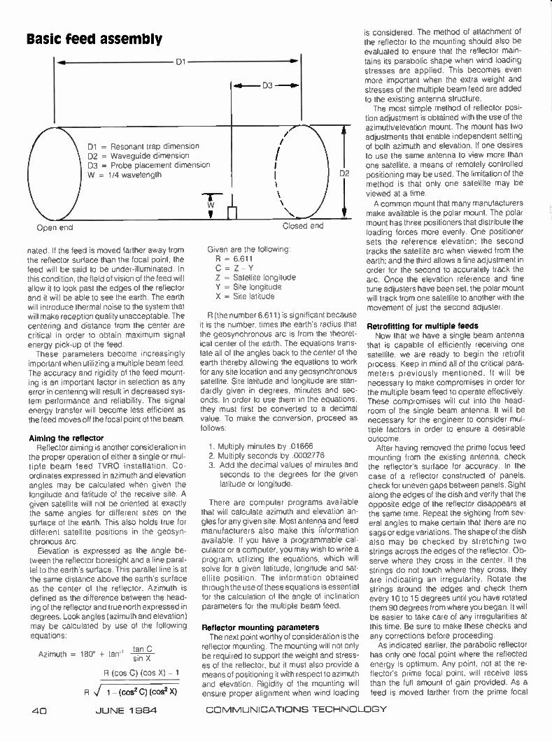
Open end
Basic feed assembly
D1
Alb- D3 --le
D1 = Resonant trap dimension D2 = Waveguide dimension D3 = Probe placement dimension W = 1/4 wavelength
V fil Closed end
nated. If the feed is moved farther away from the reflector surface than the focal point, the feed will be said to be under-illuminated. In this condition, the field of vision of the feed will allow it to look past the edges of the reflector and it will be able to see the earth. The earth will introduce thermal noise to the system that will make reception quality unacceptable. The centering and distance from the center are critical in order to obtain maximum signal energy pick-up of the feed. These parameters become increasingly
important when utilizing a multiple beam feed. The accuracy and rigidity of the feed mount-ing is an important factor in selection as any error in centering will result in decreased sys-tem performance and reliability. The signal energy transfer will become less efficient as the feed moves off the focal point of the beam.
Aiming the reflector Reflector aiming is another consideration in
the proper operation of either a single or mul-tiple beam feed TVRO installation. Co-ordinates expressed in azimuth and elevation angles may be calculated when given the longitude and latitude of the receive site. A given satellite will not be oriented at exactly the same angles for different sites on the surface of the earth. This also holds true for different satellite positions in the geosyn-chronous arc.
Elevation is expressed as the angle be-tween the reflector boresight and a line paral-lel to the earth's surface. This parallel line is at the same distance above the earth's surface as the center of the reflector. Azimuth is defined as the difference between the head-ing of the reflector and true north expressed in degrees. Look angles (azimuth and elevation) may be calculated by use of the following equations:
tan C Azimuth = 180° + tan- sin X
R (cos C) (cos X) 1
R 1 (cos2 C) (cos2 X)
Given are the following: R = 6.611 C = Z - Y Z = Satellite longitude Y = Site longitude X = Site latitude
R (the number 6.611) is significant because it is the number, times the earth's radius that the geosynchronous arc is from the theoret-ical center of the earth. The equations trans-late all of the angles back to the center of the earth thereby allowing the equations to work for any site location and any geosynchronous satellite. Site latitude and longitude are stan-dardly given in degrees, minutes and sec-onds. In order to use them in the equations, they must first be converted to a decimal value. To make the conversion, proceed as follows:
1. Multiply minutes by .01666 2. Multiply seconds by .0002776 3 Add the decimal values of minutes and
seconds to the degrees for the given latitude or longitude.
There are computer programs available that will calculate azimuth and elevation an-gles for any given site. Most antenna and feed manufacturers also make this information available. If you have a programmable cal-culator or a computer, you may wish to write a program, utilizing the equations, which will solve for a given latitude, longitude and sat-ellite position. The information obtained through the use of these equations is essential for the calculation of the angle of inclination parameters for the multiple beam feed.
Reflector mounting parameters The next point worthy of consideration is the
reflector mounting. The mounting will not only be required to support the weight and stress-es of the reflector, but it must also provide a means of positioning it with respect to azimuth and elevation. Rigidity of the mounting will ensure proper alignment when wind loading
is considered. The method of attachment of the reflector to the mounting should also be evaluated to ensure that the reflector main-tains its parabolic shape when wind loading stresses are applied. This becomes even more important when the extra weight and stresses of the multiple beam feed are added to the existing antenna structure. The most simple method of reflector posi-
tion adjustment is obtained with the use of the azimuth/elevation mount. The mount has two adjustments that enable independent setting of both azimuth and elevation. If one desires to use the same antenna to view more than one satellite, a means of remotely controlled positioning may be used. The limitation of the method is that only one satellite may be viewed at a time. A common mount that many manufacturers
make available is the polar mount. The polar mount has three positioners that distribute the loading forces more evenly. One positioner sets the reference elevation; the second tracks the satellite arc when viewed from the earth; and the third allows a fine adjustment in order for the second to accurately track the arc. Once the elevation reference and fine tune adjusters have been set, the polar mount will track from one satellite to another with the movement of just the second adjuster.
Retrofitting for multiple feeds Now that we have a single beam antenna
that is capable of efficiently receiving one satellite, we are ready to begin the retrofit process. Keep in mind all of the critical para-meters previously mentioned. It will be necessary to make compromises in order for the multiple beam feed to operate effectively. These compromises will cut into the head-room of the single beam antenna. It will be necessary for the engineer to consider mul-tiple factors in order to ensure a desirable outcome.
After having removed the prime focus feed mounting from the existing antenna, check the reflector's surface for accuracy. In the case of a reflector constructed of panels. check for uneven gaps between panels. Sight along the edges of the dish and verify that the opposite edge of the reflector disappears at the same time. Repeat the sighting from sev-eral angles to make certain that there are no sags or edge variations. The shape of the dish also may be checked by stretching two strings across the edges of the reflector. Ob-serve where they cross in the center. If the strings do not touch where they cross, they are indicating an irregularity. Rotate the strings around the edges and check them every 10 to 15 degrees until you have rotated them 90 degrees from where you began. It will be easier to take care of any irregularities at this time. Be sure to make these checks and any corrections before proceeding. As indicated earlier, the parabolic reflector
has only one focal point where the reflected energy is optimum. Any point, not at the re-flector's prime focal point, will receive less than the full amount of gain provided. As a feed is moved farther from the prime focal
40 JUNE 1 9E14 COMMUNICATIONS TECHNOLOGY
Since 1974 S.A.L. Cable Communications has provided the nation's cable television industry with over $100,000,000 worth of pro-ducts.... from tools and taps... to satellite receivers and prepackaged head-end systems. Because S.A.L. is more than just hardware, we're everything a cable system could ever need. We have more than 3800 items and four major on-line com-puter linked distribution centers.
And with S.A.L., one toll-free call gets your order on its way in 24 hours or less anywhere in the United States. What's more, our Customer
Representatives are experienced CATV people, with the background and expertise to help you meet your CATV needs. No wonder that more and more
CATV developers, operators and construction companies across the
country continue to rely on S.A.L. for their com-plete systems needs:
including drop materials, passive devices, modulators, converters and all the component parts for replace-ment or upgrading of a total head-end system. So remember, for outstanding
service, competitive pricing and a world of quality products, we're more than hardware, we're S.A.L.
Supplying you complete cable needs since 1974.
See us at the NCTA Show at Booth 1622.
S.A.L. CABLE COMMUNICATIONS, INC. Northeast: New York (800) 645-9062 • (In New York State) 516/694-7110
Southeast: Atlanta (800) 241-0992 • (In Georgia) 404/981-0050 • West: Los Angeles (800) 423-5463 (In California) 800/382-5616 • Midwest: Indianapolis (800) 428-3268 • (In Indiana) 317/244-2477
Executive Offices: 5 Hub Drive, Melville, NY 11747

point, gain decreases exponentially. The rapid decrease is due in part to the astigmatic effect of the parabolic reflector. It limits the number of feeds that will provide adequate signal levels for proper signal reception on one reflector. This is true because successive feeds must be placed farther from the prime focal point.
Alignment of boresights Observing multiple satellites from a single
parabolic reflector requires precise alignment of off boresight feeds. As the wavelength of frequencies in the 4 GHz region approaches three inches, misalignment of the feed by one inch would result in a substantial loss of signal energy transfer. It is extremely important to verify the correct centering of the feed tray assembly after construction and installation. The verification may be accomplished by measuring from the center of the feed tray to the edge of the reflector. The process should be repeated every 90 to 120 degrees around the reflector. All measurements must match exactly in order for the feed tray to be perfectly centered, which holds true only if the reflector has first been checked to assure accuracy of the parabolic surface. Because the reflector acts as a mirror, it
reverses the reflected image. Signals arriving from the right side of the boresight will be reflected to the left side. It will be necessary to place the off boresight feed on the opposite side of the boresight axis than the satellite appears in space.
Feed tray placement The plane of the satellite arc is aligned
perpendicular to the poles of the earth. The curvature of the earth's surface causes the satellite arc to be perceived as slanted when referenced to horizontal at a given point on the earth. Boresight alignment will require differ-ent settings of elevation as the reflector is moved horizontally from one satellite to an-other. Placing a feed the proper distance off boresight only accomplishes horizontal align-ment of the secondary satellite signal beam. To correct for perceived arc slant, the feed
tray must be able to be rotated about the reflector's boresight axis, which will allow it to accomplish vertical alignment with the sat-ellite arc. Rotating the feed tray also will skew the horizontal alignment that will require re-adjustment as the tray is moved. The angle at which the feed tray aligns with the satellite arc is called the angle of inclination. The angle of inclination may be calculated
by the use of the following formula:
Where a = angle of inclination and difference refers to the difference in degrees of the an-gles of azimuth and elevation for two desired adjacent satellites.
tangent a — difference in elevation difference in azimuth
In order to solve for angle a, the equation may be balanced as follows:
difference in elevation a = arctangent
difference in azimuth
This angle is measured from vertical with 90 degrees being parallel to the horizon. The angle of inclination will be different on a re-flector facing east than it would be on a re-flector facing west. Knowing only the angle of inclination is of little help in the actual position-ing process. No simple device is available to directly and accurately measure the angle. Finding a point along the outer edge of the dish or feed assembly ring, if the multibeam feed has one, enables you to aim the axis of the feed tray at the point and accomplish the desired positioning adjustment. To establish the point, proceed as follows.
Measure the diameter or chord of the re-flector. Find the circumference of the dish by using the following equation:
Circumference = 3.14159 D
Divide the circumference by 360 to deter-mine the number of inches per degree. Multi-ply this figure by the value calculated for the angle of inclination. Use a flexible tape to measure the distance around the reflector from the top reference point and place a mark at the calculated distance. Now, by sighting along the center line of the feed tray, aim it at the mark you made along the edge of the reflector. As satellite spacing is decreased, feed
spacing decreases proportionately. When satellite spacing approaches 2 degrees, sca-lar feeds, which are the most commonly used feeds in multiple beam feed systems, are physically incapable of moving closely enough together without overlapping. The scalar feed has a series of concentric rings around the outside of the feed's throat. The rings serve as modifier devices that change the flow of signal currents entering the feed. Some manufacturers cut off a portion of the scalar rings in order to achieve closer spac-ing. This leaves the outside few scalar rings looking like the letter "C." Other manu-facturers reduce the size of feed assembly. The distance between feed placements varies as a function of the F/D (focal length to diameter) ratio and the spacing between de-sired satellites. The F/D ratio can be found by dividing the
focal length of the reflector by the diameter or chord. Manufacturers who produce feeds to retrofit other manufacturer's reflectors often place limitations on the F/D ratio of the re-flector to be retrofitted in order to ensure that the feed performs to published specifications.
If feeds are moved too far off boresight, signal energy transfer decreases to a point where C/N (carrier-to-noise ratio) is no longer within acceptable limits. C/N limits required depend on the size and gain of the reflector, the gain and efficiency of the feed, the noise temperature, gain and noise figure of the LNA or LNC (low-noise converter), feedline and power divider losses as well as the threshold of the receiver to be used. It would be wise to calculate the C/N ratio for each satellite to be received, taking into account the EIRP (effec-tive isotropic radiated power) of each satellite and feed losses respective to position along
the reflector's focal plane as well as the gains and losses mentioned previously. Some multibeam feeds will allow a feed placement of as much as 7 degrees off boresight. Losses at this extreme may become quite high and prove unacceptable for reliable operation. Any method used to reduce the passive losses after the LNA or LNC will only help to increase the C/N ratio of the receiving system.
Maintaining design features After setting acceptable limits for the se-
lected feed, it will be necessary to ensure the final design remains within these points. Re-ceiving a satellite as much as 4 degrees off of boresight could be considered an average expectation of most multibeam feeds. It is necessary to verify that the feed is adjustable to these limits and that the C/N ratio achieved will provide the desired results. When using a multiple beam feed system,
the boresight of the reflector may be aligned with a particular satellite or between two adja-cent ones. Some satellites have a higher EIRP contour in a specific area than others. This affords the designer the ability of gain balan-cing, provided the feed mounting allows the latitude of feed spacing necessary to accom-plish the objective. Some feed mountings do not have the horizontal latitude to move a feed the amount necessary to receive a satellite 4 degrees off boresight. In this case, it will be necessary to aim the reflector's boresight be-tween the satellites in order to receive both. The focal plane of the parabolic reflector is
the two dimensional area along which all feeds will properly focus. With the reflecting process and curve of the reflecting surface, the focal plane takes the shape of a curve. The focal plane curve is the inverse of the curve of the parabolic reflecting surface. In con-struction of various feed mountings, some manufacturers take the focal plane curve into account and some do not. If the feed does not conform to this curve, it will introduce focus and illumination errors for off boresight feeds.
The aiming process The final operation required before the
antenna may be returned to service is the aiming of the reflector and all feeds. Test equipment required for the aiming process would consist of a satellite receiver with C/N meter, a power meter to check the IF (inter-mediate frequency) monitor test point or a voltmeter to monitor the AGC (automatic gain control) voltage, and a video monitor or a modulator and RF receiver. During the aiming process it will be
necessary to turn the satellite receiver's AGC off. Even if you are using a voltmeter to monitor AGC voltage, the AGC voltage will still be present and will change with the level of the incoming signal. If the AGC is on, it will mask the picture variations in the monitor that occur during the aiming process. Be certain to check the satellite receiver's operating man-ual in regard to the proper AGC operating voltage as it varies from one receiver to another. A power meter connected to the receiver's
42 JUNE 1 984 COMMUNICATIONS TECHNOLOGY
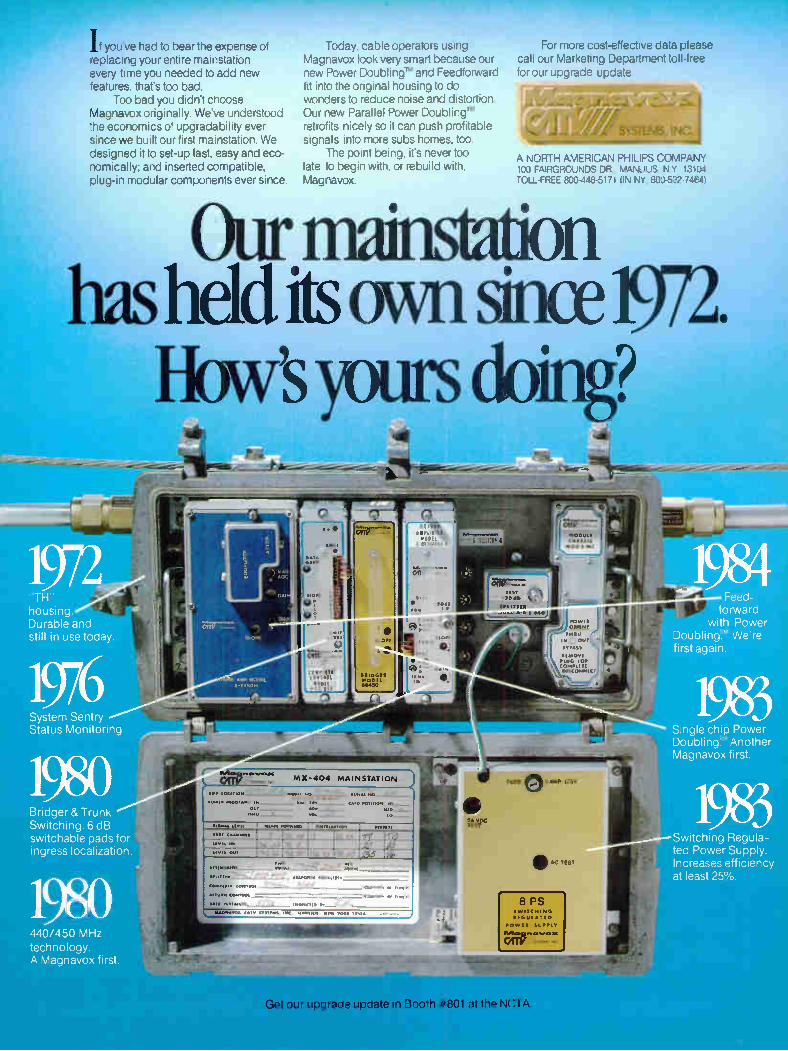
If you've had to bear the expense of replacing your entire mainstation every time you needed to add new features, that's too bad.
Too bad you didn't choose Magnavox originally. We've understood the economics of upgradability ever since we built our first mainstation. We designed it to set-up fast, easy and eco-nomically; and inserted compatible, plug-in modular components ever since.
Today, cable operators using Magnavox look very smart because our new Power Doubling' and Feedforward fit into the original housing to do wonders to reduce noise and distortion. Our new Parallel Power Doubling' retrofits nicely so it can push profitable signals into more subs homes, too.
The point being, it's never too late to begin with, or rebuild with, Magnavox.
•e• 7777 1MMIM
For more cost-effective data please call our Marketing Department toll -free for our upgrade update.
(7- '77-7 '7 7
(71-1 I f/77-
A NORTH AMERICAN PHILIPS COMPANY 100 FAIRGROUNDS DR MANLIUS, N Y 13104 TOLL-FREE 800-448-5171 (IN NY. KX)-522-7464)
Our mainstation has held its own since 1972.
How's yours doing?
TH' housing Durable and still in use today.
System Sentry Status Monitoring
Bridger & Trunk Switching 6 dB switchable pads for ingress localization
440/450 MHz technology. A Magnavox first
MOP YODEL
8-145054
MX-404 MAINSTATION
•Are Loe•T .."»*“.° .
•Ow. • 1.104•A. IN_
0411 •Or
TWO
<A10 POSITION
011.0011.1 IOW( I Ile --
3/deh'
I 3233'34
op 21 SOC TEST
MOM
CHASSIS
44(
POW",
°RUNT
HRU
'P. OUT
•YRASS
PLUG FOR CO/A•LI CIISCPMNI,
FUSE 0 50AP 1.52
0111> AC TES .
SWITCHING
REGUL•TED
POWER SUPPLY
Get our upgrade update in Booth #801 at the NCTA
Feed-forward
with Power Doubling"' We're first again
Single chip Power Doubling' Another Magnavox first
Switching Regula-ted Power Supply Increases efficiency at least 25%.
IF monitor test point is a better alternative to the voltmeter method, however, it is more expensive and difficult to obtain. A video monitor would be preferred to a modulator and RF receiver. The monitor method is not prone to the errors and interference intro-duced by the modulation/demodulation process. To begin the mechnical adjustment portion
of the aiming procedure, set the azimuth and elevation of the reflector to the values pro-vided by the calculation result of the equa-tions presented earlier. If the antenna is cur-rently viewing one of the desired satellites, it may be possible to bypass the above step. Next, set the distance off boresight of each feed to the values provided by the feed manu-facturer. Set the feed tray angle of inclination to the previously calculated values. Set the polarization of each feed as closely as pos-sible to a position parallel and perpendicular to the earth's surface. If the feed focus is adjustable, set it to the recommended or cal-culated value. Connect the test equipment to the satellite
receiver and monitor the feed closest to or on boresight. Adjust elevation, azimuth and polarization, in order, for maximum received signal. Focus may now be adjusted if appli-cable. Feed tray rotation may also be required if the feed being aimed is off boresight. Re-peat the adjustment process until each ad-
justment is at its optimum position for best signal reception. Only after the above men-tioned feed is completely peaked for maxi-mum performance should you proceed with the alignment of the second feed.
At this point, the azimuth and elevation ad-justers should be locked as further adjust-ment most likely will not be required. If it is necessary to readjust the azimuth or elevation after this point, it will be necessary to readjust all previously aimed feeds. Connect the satellite receiver to the second
feed. Adjust the feed tray angle of inclination, feed spacing and polarization for maximum signal. Now, monitor the first feed and re-adjust angle of inclination and polarization. If possible, monitor both feeds or switch back and forth between feeds to verify they are balanced in performance. It may be neces-sary to make some compromises in optimum alignment in order for both feeds to perform equally well.
The antenna should now be capable of simultaneous reception of adjacent satellites and may be placed into service.
In summary, the multiple beam feed is not a cure all or end all to the multiple satellite reception problem. It is, however, a tool avail-able to the system design engineer that may offer a useful and workable solution to the problems encountered. Multiple factors must be considered and weighed as to importance
related to the design situation. These factors are as follows:
• F/D ratio of existing antenna • Existing antenna gain over isotropic • Parabolic reflector surface accuracy • Rigidity of reflector and support structure • Available site real estate • Required C/N ratio • Effects of multiple feed on antenna side-lobe performance • Insertion loss of proposed feed • Spacing between desired satellites • Number of satellites to be received • Mechanical stability of proposed multiple feed • Cost difference of multiple feed versus mul-tiple antennas • Shape of feed mounting tray related to re-flector focal plane • Amount of modification required for ex-isting reflector • Feed tray adjustment limitations • Down time required for retrofit operation • Budget available for project
Armed with a working knowledge of the multiple beam feed system, its limitations and the necessary compromises required, you will know the right questions to ask in order to obtain the data required to make the correct decision for your system.
How Much Quality Can We Put in a Cube? \\\ 00 0„,0
A 10 Just guess how many nigh quality Signal Vision F-boots are in the cube at our NCTA Las Vegas booth #933 and we'll give you $500 in cash.
Finally, there is an F-boot formulated to withstand the toughest rigors of Mother Nature. The new Signal Vision F-boot is constructed of a revolutionary special compound that features: * Ozone protection * Ultraviolet stabilization * Special inhibitors for highly corrosive atmosphere * Tapered shank for multiple cable sizes * Pre-siliconing for easy installation. You get weatherproofing and strain relief without the common' cracking, splitting and rapid deterioration.
Only 2C more for a product that lasts lour times as long as conventional F-boots Made in USA.
of the new
22732-B Granite Way, Laguna Hills, Calif. 92653 714/586-3196
44 JUNE 1984 COMMUNICATIONS TECHNOLOGY
We love it when a plan comes together, too.
effiteen% fot__tetet‘o-iteutet: coe \bce
Beefs" ee ire . cot pces‘ 30-5
e \N" 3'\Ç‘q 9111 tie 119-9/
(5çe
OS Veç e19-91\fee.
\i'xce
,Noodvent sees 9<e9d599-0209
Rce 5"ee ecut\\J 1,\-7 £1,
(50-5 ctve cv fn°e)
pel\' ‘3rote 1 coe
eve° e tose' ok
see '\ St
Ciee (0 to
. to 051%re Pçe ceeseten
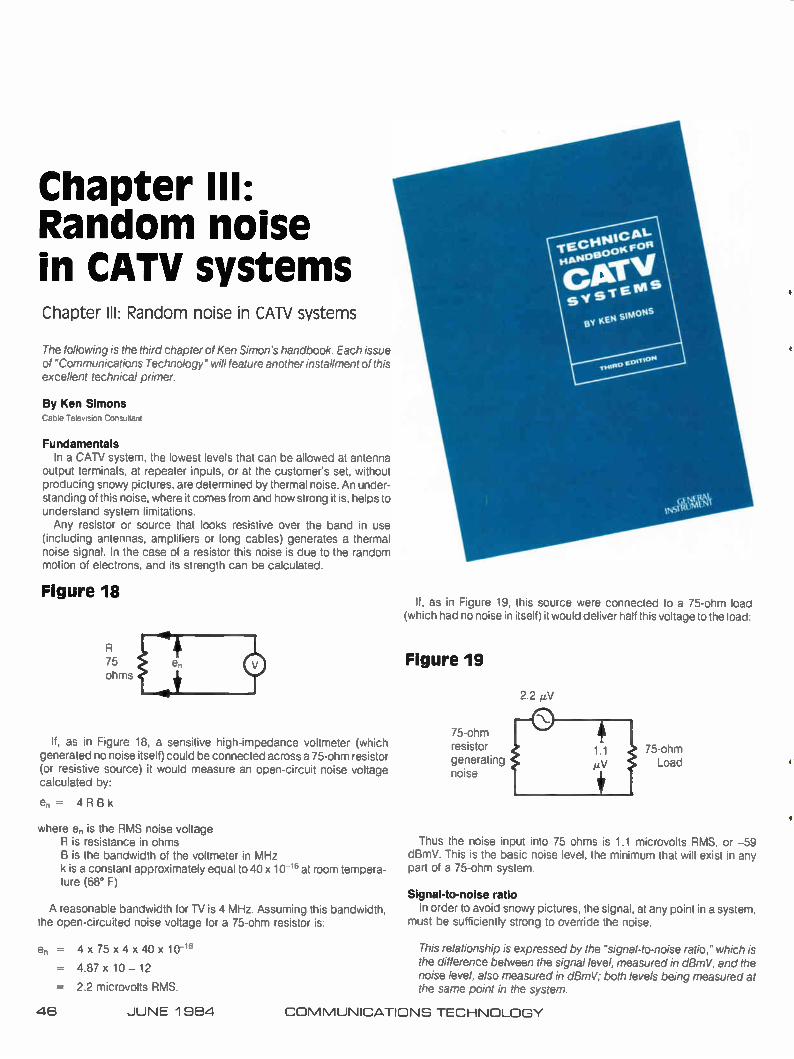
Chapter III: Random noise in CATV systems Chapter III: Random noise in CATV systems
The following is the third chapter of Ken Simon's handbook. Each issue of "Communications Technology" will feature another installment of this excellent technical primer.
By Ken Simons Cable Television Consultant
Fundamentals In a CATV system, the lowest levels that can be allowed at antenna
output terminals, at repeater inputs, or at the customer's set, without producing snowy pictures, are determined by thermal noise. An under-standing of this noise, where it comes from and how strong it is, helps to understand system limitations. Any resistor or source that looks resistive over the band in use
(including antennas, amplifiers or long cables) generates a thermal noise signal. In the case of a resistor this noise is due to the random motion of electrons, and its strength can be calculated.
Figure 18
75 ohms
If, as in Figure 18, a sensitive high-impedance voltmeter (which generated no noise itself) could be connected across a 75-ohm resistor (or resistive source) it would measure an open-circuit noise voltage calculated by:
en = 4 RBk
where en is the RMS noise voltage R is resistance in ohms B is the bandwidth of the voltmeter in MHz k is a constant approximately equal to 40 x 10 16 at room tempera-ture (68° F)
A reasonable bandwidth for TV is 4 MHz. Assuming this bandwidth, the open-circuited noise voltage for a 75-ohm resistor is:
en = 4 x 75 x 4 x 40 x 10 -16
= 4.87 x 10 — 12
= 2.2 microvolts RMS.
If, as in Figure 19, this source were connected to a 75-ohm load (which had no noise in itself) it would deliver half this voltage to the load:
Figure 19
2.2 I.LV
75-ohm resistor generating noise
75-ohm Load
Thus the noise input into 75 ohms is 1.1 microvolts RMS, or —59 dBmV. This is the basic noise level, the minimum that will exist in any part of a 75-ohm system.
Signal-to-noise ratio In order to avoid snowy pictures, the signal, at any point in a system,
must be sufficiently strong to override the noise.
This relationship is expressed by the "signal-to-noise ratio," which is the difference between the signal level, measured in dBmV, and the noise level, also measured in dBmV; both levels being measured at the same point in the system.
48 JUNE 1984 COMMUNICATIONS TECHNOLOGY

We put the cable industry on its own pedestal
While others were adapting telephone pedestals for cable television applications, CWY was designing pedestals exclusively for
the cable industry...a complete line of pedestals built to
your specifications ...not someone else's.
For example, CWY pedestals feature
16- and 18-gauge T2 alum-inized steel construction, which tests show outlasts
BAKE1) ENAMEL unpainted galvanized steel ' M. sea at least five-to-one. Plus, the rec-
tangular design assures ease of instal-lation and maximum use of interior space.
CWY pedestals are easier to service, too; the positive, secure, hingeless cover removal system allows the
front cover and top to lift off as one unit, giving you full exposure of the pedestal interior.
RfPLACEADI.E WASP ( lice)
And while other manufacturers bend out a piece of steel and call it a hasp, CWY pedestals feature tough, 11-gauge plated steel hasps that are rugged and fully replaceable.
Multiple knockouts for ease and flexibility in equipment mounting...interior lid guides for extra security...an innovative stake lock that keeps the pedestal right where you planted it...and a whole lot more. All at prices you'll find very competitive. So why buy pedestals
made for someone else? CWY designed them just for you. For more information about CWY's complete line of pedestals and other cable TV solutions, call or write today.
Standard sizes: 4"x5", 5"x8", 7"x7", 6"x9", 10"x 14". Call with muilIPLE specifications for custom sizes. KNOcKCUTS
Not just supplies. Solutions.
CWY mrmrm
NINCIELESS COVER REMOVAL.
P.O. Box 4519—Lafayette, IN 47903—Call Toll Free: 1-800-428-7596—Indiana: 1-800-382-7526
See us at the NCTA Show at Booth 1215 and 1216.
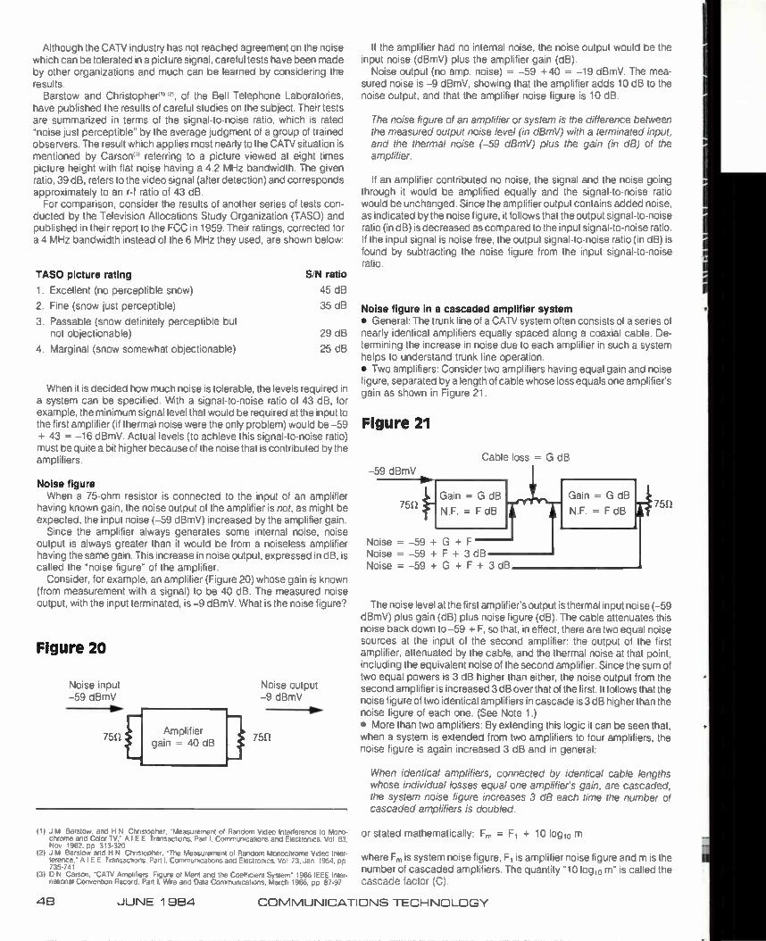
Although the CATV industry has not reached agreement on the noise which can be tolerated in a picture signal, careful tests have been made by other organizations and much can be learned by considering the results.
Barstow and Christopher'" '2', of the Bell Telephone Laboratories, have published the results of careful studies on the subject. Their tests are summarized in terms of the signal-to-noise ratio, which is rated "noise just perceptible" by the average judgment of a group of trained observers. The result which applies most nearly to the CATV situation is mentioned by Carson'' referring to a picture viewed at eight times picture height with flat noise having a 4.2 MHz bandwidth. The given ratio, 39 dB, refers to the video signal (after detection) and corresponds approximately to an r-f ratio of 43 dB.
For comparison, consider the results of another series of tests con-ducted by the Television Allocations Study Organization (TASO) and published in their report to the FCC in 1959. Their ratings, corrected for a 4 MHz bandwidth instead of the 6 MHz they used, are shown below:
TASO picture rating
1. Excellent (no perceptible snow)
2. Fine (snow just perceptible)
3. Passable (snow definitely perceptible but not objectionable)
4. Marginal (snow somewhat objectionable)
S/N ratio
45 dB
35 dB
29 dB
25 dB
When it is decided how much noise is tolerable, the levels required in a system can be specified. With a signal-to-noise ratio of 43 dB, for example, the minimum signal level that would be required at the input to the first amplifier (if thermal noise were the only problem) would be -59 + 43 = -16 dBmV. Actual levels (to achieve this signal-to-noise ratio) must be quite a bit higher because of the noise that is contributed by the amplifiers.
Noise figure When a 75-ohm resistor is connected to the input of an amplifier
having known gain, the noise output of the amplifier is not, as might be expected, the input noise (-59 dBmV) increased by the amplifier gain.
Since the amplifier always generates some internal noise, noise output is always greater than it would be from a noiseless amplifier having the same gain. This increase in noise output, expressed in dB, is called the "noise figure" of the amplifier.
Consider, for example, an amplifier (Figure 20) whose gain is known (from measurement with a signal) to be 40 dB. The measured noise output, with the input terminated, is -9 dBmV. What is the noise figure?
Figure 20
Noise input -59 dBmV
75S/
Noise output -9 dBmV
75S2
(1) J M Barstow. and H N Christopher. "Measurement of Random Video Interference to Mono-chrome and Color TV." AIEE Transactions, Part I. Communications and Electronics. Vol 63. Nov 1962. pp 313-320
(2) J M Barstow and H N Christopher. The Measurement of Random Monochrome Video Inter-ference." AIEE Transactions. Part I. Communications and Electronics. Vol 73. Jan 1954. pp 735-741
(3) D N Carson, -CATV Amplifiers Figure of Merit and the Coefficient System" 1966 IEEE Inter-national Convention Record. Part I. Wre and Data Communications. March 1966. pp 87-97
S in = G dB
If the amplifier had no internal noise, the noise output would be the input noise (dBmV) plus the amplifier gain (dB).
Noise output (no amp. noise) = -59 +40 = -19 dBmV. The mea-sured noise is -9 dBmV, showing that the amplifier adds 10 dB to the noise output, and that the amplifier noise figure is 10 dB.
The noise figure of an amplifier or system is the difference between the measured output noise level (in dBmV) with a terminated input, and the thermal noise (-59 dBmV) plus the gain (in dB) of the amplifier.
If an amplifier contributed no noise, the signal and the noise going through it would be amplified equally and the signal-to-noise ratio would be unchanged. Since the amplifier output contains added noise, as indicated by the noise figure, it follows that the output signal-to-noise ratio (in dB) is decreased as compared to the input signal-to-noise ratio. If the input signal is noise free, the output signal-to-noise ratio (in dB) is found by subtracting the noise figure from the input signal-to-noise ratio.
Noise figure in a cascaded amplifier system • General: The trunk line of a CATV system often consists of a series of nearly identical amplifiers equally spaced along a coaxial cable. De-termining the increase in noise due to each amplifier in such a system helps to understand trunk line operation. • Two amplifiers: Consider two amplifiers having equal gain and noise figure, separated by a length of cable whose loss equals one amplifier's gain as shown in Figure 21.
Figure 21
Cable loss = G dB
-59 dBmV
751 NN.F.= F dB
Noise = -59 + G + F Noise = -59 + F + 3 dB Noise = -59 + G + F + 3 dB
a
Gain = G dB
N.F. = F dB 75f!
The noise level at the first amplifier's output is thermal input noise (-59 dBmV) plus gain (dB) plus noise figure (dB). The cable attenuates this noise back down to -59 + F, so that, in effect, there are two equal noise sources at the input of the second amplifier: the output of the first amplifier, attenuated by the cable, and the thermal noise at that point, including the equivalent noise of the second amplifier. Since the sum of two equal powers is 3 dB higher than either, the noise output from the second amplifier is increased 3 dB over that of the first. It follows that the noise figure of two identical amplifiers in cascade is 3 dB higher than the noise figure of each one. (See Note 1.) • More than two amplifiers: By extending this logic it can be seen that, when a system is extended from two amplifiers to four amplifiers, the noise figure is again increased 3 dB and in general:
When identical amplifiers, connected by identical cable lengths whose individual losses equal one amplifier's gain, are cascaded, the system noise figure increases 3 dB each time the number of cascaded amplifiers is doubled.
or stated mathematically: F, = F, + 10 logic) m
where Fm is system noise figure, F, is amplifier noise figure and m is the number of cascaded amplifiers. The quantity "10 log 10 m" is called the cascade factor (C).
4E1 JUNE 1 984 COMMUNICATIONS TECHNOLOGY
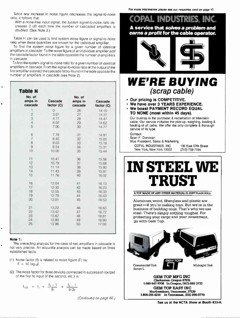
For more information please see our response card on page 17.
Since any increase in noise figure decreases the signal-to-noise ratio, it follows that:
With a noise-free input signal, the system signal-to-noise ratio de-creases 3 dB each time the number of cascaded amplifiers is doubled. (See Note 2.)
Table H can be used to find system noise figure or signal-to-noise ratio when these quantities are known for the individual amplifier. To find the system noise figure for a given number of identical
amplifiers in cascade: To the noise figure of an individual amplifier add the cascade factor found in the table opposite the number of amplifiers in cascade. To find the system signal-to-noise ratio for a given number of identical
amplifiers in cascade: From the signal-to-noise ratio at the output of the first amplifier subtract the cascade factor found in the table opposite the number of amplifiers in cascade (see Note 2),
Table H No. of No. of amps in Cascade amps in Cascade cascade factor (C) cascade factor (C)
1 0 26 14.15
2 3.01 27 14.31 3 4.77 28 14.47 4 6.02 29 14.62 5 7.00 30 14.77
6 7.78 31 14.91 7 8.45 32 15.05 8 9.03 33 15.18 9 9.54 34 15.31 10 10.00 35 15.44
11 10.41 36 15.56 12 10.79 37 15.68 13 11.14 38 15.80 14 11.43 39 15.91 15 11.76 40 16.02
16 12.04 41 16.13 17 12.30 42 16.23 18 12.55 43 16.33 19 12.79 44 16.43 20 13.01 45 16.53
21 13.22 46 16.63 22 13.42 47 16.72 23 13.62 48 16.81 24 13.80 49 16.90 25 13.98 50 17.00
Note 1: The preceding analysis for the case of two amplifiers in cascade is
not very precise. An accurate analysis can be made based on three established facts:
(1) Noise factor (f) is related to noise figure (F) by: F = 10 log,of
(2) The noise factor for three devices connected in succession (output of the first to input of the second, etc.) is:
- 1 f123 = +
f3 - 1
g, gig2
. NDST b) -• A service that solves a problem and earns a profit for the cable operator.
WE'RE BUYING (scrap cable)
• Our pricing is COMPETITIVE. • We have over 3 YEARS EXPERIENCE.
• We boast PAYMENT RECORD EQUAL TO NONE (most within 45 days).
Our businss is the purchase & reclamation of television cable. Our service includes the pick-up, weighing, loading & hauling of all cable. We offer the only complete & thorough service of its type.
Contact: Sean F. Donovan Vice President, Sales & Marketing
COPAL INDUSTRIES, INC. 136 East 57th Street New York, New York 10022 (212) 759-7164
IN STEEL WE TRUST
A TOP MADE OF ANY OTHER MATERIAL IS JUST PLAIN BULL.
Aluminum,wood, fiberglass and plastic are great-if you're making toys. But we're in the business of building too/s. That's why we use steel. There's simply nothing tougher. For protecting your cargo and your investment, go with Gem Top.
Commercial Unit Midnight Unit Series L
GEM TOP MFG INC Clackamas, Oregon 97015
1-800-547-9706 In Oregon, (503)659-3733
GEM TOP EAST INC Murfreesboro, Tennessee, 37130
1-800-251-4214 In Tennessee, (615) 890-0770 (Continued on page 60.)
See us at the NCTA Show at Booth 833-H.

THE NAM S OF THE LEADING MANUFACTURERS OF CABLE-TV PRODUCTS ARE IN OUR COMPUTER..
HARR-Its kitertIFIc Aluiroè . pica .00,001.‘i
m,A-cops cong SCOPE • RELIRRE fltelicmsRos istueeuetil
JERROLD - MICRODTRR - ssolca imunt
REGAL - CATEL • 'LONDE* rOsia • KUM TIOLI
MARK ANTEntin - smityLARD IPECIALry • mum. zu
SASH'. IN - PREFORM • TOPKO - alms sla • Ruh% of»
JACKSON TooLs - hunt sires - Dome - Pa» • six
STARIDARD cOpoCRENTS - PtN mum Ras
•
+4,
Anixter brings you t e pro • ucts of the leading Cable-TV manufacturers through the most modern Business Information System available. Using a network of AT&T leased lines, the most powerful and modern IBM hardware, and Anixter's own software, customers are assured of receiving Cable-TV products where and when they need them.
©1984 Anixter Bros., Inc.
MUM
OU DS
AND THEIR PRODUCTS ARE IN
ENT S • UT N ntrol ve ories, ass • 'du ail • d on-
delivery, Anixter has linked its distribution centers and sales offices thru an "online" real time network that includes 650 terminals.
maglamnte
LIILIAL11.211
• .AlkiltilL
Ulm./
•••••••
11••
•
COMMUNICATIONS FOR AN ANIXTER DISTRIBUTION CENTER NEAREST YOU, CALL TOLL FREE
1-800-323-0436 In Illinois call 1-800-942-0905
e HANG ON!
with the
SACHS CABLE SUSPENSION TEAM
SC-02* (PAT) Non-messengered Cable Drop Clamp
SC-03 (PAT.) Single or Double Pigtail Hook Span Clamps
SC-02M (PAT.) Messenger Wire Holder Drop Clamps
.... Quad Cable size immediately available I _..)
• The SC-02, SC-02M and SC-02D series are available for RG-59, RG-06, RG-11, messen-gered or non-messengered coaxial cables, single or dual.
• Ask for our free documentation on product specifications, comparative charts and cost
analysis studies. 514-636-6560
SACHIS Communications Inc., 30 West Service Road Champlain N Y 12919-9703 In Canada: 2095 Chartier Avenue Dorval Due H9P 1H3
WHEN CONFIDENCE COUNTS
•MIMM
Pat Tlioi n )sot I Co. CABLE TELEVISION BROKERS 14292 EAST EVANS AVE. AURORA, CO. 80014
(303) 337-4707
Simons handbook (Continued from page 49.)
Where: f 1, f2 and f3 are the noise factor of the first, second and third device respectively.
gl and g2 are the power gain of the first and second device, respectively.
(3) The power "gain" of an attenuating device is the ratio output power, input power
a number less than one. The noise factor of an attenuating device is the reciprocal of its power gain. To apply these facts to the analysis of a cascade of two amplifiers
assume that:
Device #1 is an amplifier. fl = fa, 91 = ga Device #2 is a length of cable whose loss is equal to the amplifier's gain
1 1 so g192 = 9a92 = 1, 92 = — and 12 = — = ga
ga g2
Device #3 is an amplifier identical to #1 so f3 = fa, g3 = ga
Substituting these alues in equation (2)
fl f2 - 1 + f3 - 1 _ la ga - 1 + fa - 1 _
91 9192 ga 1
1 1 fi + 1 - —+ fa - 1, so f123 = 2 fa —
ga ga
which says that the noise factor of two identical amplifiers in cascade is equal to twice the noise factor of one amplifier, less the reciprocal of its power gain. With noise factors of about 10 x (10 dB) and power gains of about 100 x (20 dB) it is apparent that the effect of the second term is negligible, so f123 = 2 fa or, in logarithmic terms, the noise figure of two identical amplifiers in cascade is 3 dB higher than the noise figure of each.
Note 2: The "system signal-to-noise ratio" (in dB) is the difference (in dB)
between the system's noise output level (in dBmV) with the input terminated, and the operating signal level at the output terminals (in dBmV). Where the input signal is not noise-free, the noise it contains can be
taken into account to find a total effective signal-to-noise ratio. This can be done for usual conditions by assuming that the total noise power output is the sum of two components: the noise power input increased by the system gain, and the noise power output of the system with its input terminated. In dB terms this is done by:
1 Take the difference between the S/N ratio (in dB) of the input signal at the first cascaded amplifier and the S/N ratio (also in dB) of the cascaded amplifier system.
2 Use Chart P3 or Table P9 to find the number of dBs to be subtracted from the smaller of the two ratios to find the total effective S/N ratio.
Example: System S/N ratio = 43 dB; Input S/N ratio = 47 dB; Differ-ence = 47 - 43 = 4 dB; From Table P9 opposite 4 dB find 1.46 dB. Thus total effective S/N ratio is: 43- 1.46 = 41.4 dB.
This chapter of the "Technical Handbook for CATV Systems" is being reprinted courtesy of the General Instrument Corp.'s Jerrold Division. To obtain one complete copy of the "Technical Handbook," send $10 plus $1.50 for postage and handling to: Technical Handbook Order, Customer Service Department, General Instrument/Jerrold Division, 2200 Byberry Rd., Hatboro, Pa. 19040. Jerrold customers may place orders with their customer service rep. (Make checks payable to Gen-eral Instrument/Jerrold Division.)
60 JUNE 1 984 COMMUNICATIONS TECHNOLOGY
to ,,2,5>CCe\oCet-\\eçèsefe\sz‘
a cz.v Y 1 ov çez. „,,,t,toj,,,,,,,,,es, zooPooece ,\e creotox . ) e„
teeee\c\ie''çr\ex\,.\e .,\q\''''•es\SC2,cts Ni\ie ao \'t ee
we,çç , es %,05,,,,%,,(0,\,c,, :elo.vc 5
, e\e,, (.2, _ .„ \e"
1)0 `I'l çee‘ ede
0.0 See e re‘tfetee"S'ee"
n see& • e \I\le e 'De% çoce\Ox\ece
stço'ç\-eç'oçec\se ç)(5.s.3ç.e
`0\.'\\•Çe çS\C\ e - s'eçe \>a\.M
e,.\Noç\e' ce"eseds .2'ct°ç/ „ cxeces \e \teç\
• 2se tes 0,1e \so 0\ex eÓ,e,
Ceççevi;\Ç;\Sç'teo eote sYste` C%%5\essecO\lee • oç \t•ie reiees• se. \c\ellci-eHee • C2,\‘..ç\ \)5et.%\çe":
So , çe ve-eee • kiY\e'c'e 3 Se \ • \)1.?
9325 Bay Plaza Blvd. Suite 209
19 TarnPa. FloridaFlo • 336 623_1 - - (813) 721
Corporate Headquarters 1023 State Street
Schenectady, New York 12301
1-800-382-BRAD in NY 1-518-382-8000
CABLE ELECTRONICS INC
4630 Pacific Hwy. East Suite B-7
Fife. Washington 98424 (206) 922-9011
THE CCINVF -RTER MARKETPLACE

EIA TV Stereo Revolution? It Can with the Studioline System Built by Learning Industries With the recent FCC decision. television stereo sound
must be carried in your system. Right now you can solve your EIA signal problems and cash in on cable TV stereo with the Studioline set-top converter and head- end equipment from Leaming Industries. Offer Up to 69 Channels You can now offer up to 52 channels of stereo television
and 17 premium audio channels on your system. All this, with sound quality unaffected by cable noise and transmitted 25db below video carrier so they will not overload your system.
With the revolutionary set-top converter from Studioline, combined with the advanced Leaming head-end equipment. you provide the cleanest, brightest sound ever offered - quality superior to any other transmission system. While, at the same time, you offer EVERY TV channel in stereo. All EIA signals are transmitted in true stereo, and monaural signals are automatically converted to synthesized stereo so your subscribers will perceive all television audio in stereo. Addressable and Tierable The Studioline system is both addressable for
security and tierable for flexibility. No one can steal your signal because only the Studioline converter can decode it. And with remote control tiering, your subs receive only the premium channels they pay for. You can even provide pay-per-listen services with remote tiering. Head-End Equipment Leaming Industries builds Studioline stereo
processors for off-the-air TV channels, satellite-delivered channels, local origination TV, Studioline premium audio, and other stereo program services. Solve your EIA stereo-audio problems before they occur, and cash in on the cable TV stereo revolution To arrange for this premium stereo service, call Leaming Industries today and learn how everyone profits with stereo.
See us at the NCTA Show at Booth 1256. 180 McCormick Avenue, Costa Meso, CA 92626
Telephone: (714) 979-4511

60 buildings on a fiberoptic backbone
ACADEMIC PROGRAMS
..1 411., ad‘yrfrO1 • 4,1„„...-4r-, +- • -ti!. 4:••••,. •••• :°*"
re. -e-f • •11-r .; , e 1-1
,
University seeks way to wire future campus By Ray L. Steele Assistant Provo,' versity of Pittsburgh
The character and nature of higher edu-cation in this country has been maintained through the diversity of its learning insti-tutions. It is difficult for practitioners in the complex world of American higher education to describe the campus of today with any great degree of acceptable accuracy. There-fore, attempting to describe the campus of the future in George Orwell's "benchmark" year, 1984, is a task not only filled with irony, but with risks.
However, there has not been a more pro-pitious moment in the recent history of higher education for such an undertaking. As a mat-ter of fact, we may be facing what Pogo refer-
red to as an "insurmountable opportunity." As a society we are in the midst of a rapid
evolution, if not a revolution, from the century old industrial and mass manufacturing age to a service, technology and information age. Toeffler suggests this society will become less oriented to the needs of the masses and more capable of responding to the special-ized needs of the subsets of those masses.
With every major societal change has come an opportunity for education to provide sig-nificant assistance for the population in understanding the transition from one age to another. Education has also traditionally pro-vided the access route for the next wave of active participants who are destined to make the new society work.
Therefore, with this opportunity in mind,
DORMITORIES
what would the campus of the future need to be in order to meet these roles in the rapidly changing technology and information based society? Obviously, no single definition or de-scription can respond completely to such a complex question, yet some limited definition is essential if we are to understand each other. The campus of the future, in its broadest
sense, is one of the most significant insti-tutional homes of information workers in this society. It must be dedicated to the creation of democratic information access within sys-tems that can adapt to rapid changes in tech-nology and access opportunities. It also must be dedicated to improving productivity for learners, professional information users and information developers within a finite resource base. This entails some recognition of the special problems when access is being in-itially addressed. As with all democratic processes within a
diverse society both rights and respon-sibilities must be considered in systems de-signed for information access. Three key issues must be considered in designing the campus of the future.
COMMUNICATIONS TECHNOLOGY JUNE 1 984 63

First: Information selection The first is the accumulation problem which
some information workers struggle with today and may find even more difficult in the future. Simply put, "my ego forces me to want access to everything all the time whether I can justify it, let alone use it." John Naisbitt in Megatrends, suggests that
the trend in information use can be generally described as "... a shift from supply to selection." He goes on to describe the problem as
follows: "With the coming of the information society, we have for the first time, an economy based on a key resource that is not only re-newable, but self generating. Running out of it is not a problem, but drowning in it is."
Therefore, the campus of the future must be prepared to educate users to maximize intel-ligent selection and not supply of information in the decisions regarding access. This en-tails a new approach to training for literacy; information literacy rather than computer lit-eracy becomes the goal.
Second: Local access The second major and related issue is de-
termining the needs for information access at the most localized level in the campus. More and more the old maxim, "information
is power," becomes important in a democratic system. No campus of the future can be democratic and encourage freedom in the pursuit of ideas while allowing excessive ex-clusivity in access to information. Yet, the issue of selectivity regarding availability of various information access points is one that must be addressed initially due to finite re-sources and, finally, due to the complex con-cerns of members of various professions re-garding differential access to certain kinds of information, usually expressed in terms of security.
Third: Access cost After the issues of training for selection as
opposed to accumulation and a decentral-ized process for determining needs or criteria for access are addressed, the third issue is costing for access.
Naisbitt in Mega(rends, concludes that, "If users, through information utilities, can locate
inlormation they need. t ey will pay for it." If we accept this prediction and add oi- 17765rf ization of finite resources in higher education today, we can see how important it will be for any system to provide user access point costing, no matter what method of payment for information services is established.
In summary, the key elements in the de-scription of the campus of the future are train-ing for selection as opposed to accumulation, democratic access to information based upon informed locally determined needs, and cost accountability tied to users. The proposed campus of the future at the
University of Pittsburgh would provide infor-mation workers and their students with ef-ficient scanning of current research and in-formation in whatever their field of study. This group of people could research any problem
and solve it quickly, having learned how to quickly, selectively and effectively tap the latest available information on their problem in their field. They needn't be computer special-ists, however, they will understand how to make computers work to serve their needs as information specialists. That is what the cam-pus of the future must provide in order to lead in the adventure of the information age.
Computer literacy on campus Campuses across America are facing sig-
nificant issues with providing education to students, services to faculty and in managing campuses in both rural and urban settings. The institutions are diverse in type and in their approach to the issue, but many of the issues are the same.
In dealing with students, higher education institutions are concerned with keeping cur-rent in educational offerings. That now means some kind of attention to computers and in-formation literacy. Educators also are con-cerned with remaining competitive at a time in which the potential student population is shrinking. They must be concerned with in-creasing learner productivity, thereby using the learner's time most effectively by pro-viding efficient access to information.
In dealing with faculty, universities must be concerned with the application of technology to relieve needlessly repetitive tasks; to pro-mote the most up-to-date access to infor-mation and technology, both for research and scholarship, and to continuously provide a means for faculty development. Recognizing the need for student computer and infor-mation literacy matters little if the most central campus resource, the faculty, is overlooked.
If the systems are not flexible and available for experimentation with new applications and interconnections, the faculty can hardly be expected to respond flexibly, in spite of in-effective campus systems. Campus operating costs continue to grow
as access to library resources, computing services and video services is improved. Se-curity, heating, utilities and telephone ser-vices continue to take a larger chunk from the campus financial pie each year.
The Pittsburgh opportunity While the campus of the future, as a model
research and development project could be located in a number of places across the country, there are some compelling reasons why the city of Pittsburgh and the campus of the University of Pittsburgh are especially appealing.
Pittsburgh is one of the most visible exam-ples of a major "industrial age" city going through the process of change to a service, technology and information age economy. The recession has had a major impact on
this area's population through unemployment and the permanent elimination of major seg-ments of industry. A shift toward high tech-nology for workers is underway in a dramatic fashion, recently highlighted by President Reagan's very public visit.
Pittsburgh has realistic problems based in
the industrial age, yet it represents a climate in which the transition to the information age is embraced by workers and corporate leaders alike. There is an unusual cooperative re-lationship between corporate, government and educational institutions. Important things can happen more readily within such an en-vironment.
It is also a city rich in communications his-tory dating back to voice transmission, KDKA and the first radio station, and continuing with the introduction of Warner Cable of Pittsburgh and the somewhat tentative QUBE system. The environment is good for an information
age model for broad application and national attention. The University of Pittsburgh, while primarily
located in an urban environment, also has four rural campuses and thus the potential for experimentation and resulting applications that can be used at both urban and rural campus settings.
Object: Wire the campus The purpose of this project is to improve the
productivity of learners and information workers by creating an integrated information system that allows full and improved access to data, voice and video sources through a completely wired campus. It should also en-hance the cost effectiveness of various opera-tions on campus. Some specific objectives are as follows: a.) Provide expanded remote job entry (RJE)
connections to the Cathedral of. Learning building for expanded access to aca-demic computing.
b.) Interconnect all libraries for data and video information access and provide numerous faculty and student access points capable of contacting all points, thereby creating a campus community information center from what were stand-alone libraries.
c.) Provide a communication system between all key administrative offices and the deans and departmental offices for vari-ous data exchanges, including electronic mail.
d.) Provide within the system, a subsystem interconnecting the Health Sciences schools and the hospitals for data and video communication.
e.) Provide video receive capacity to numer-ous classrooms and conference rooms throughout campus, as well as video send-ing capability from a number of selected locations.
f.) Provide hard-wired, high-speed data ac-cess points in a number of faculty office locations.
g.) Provide specially designed extended classrooms, capable of sending class-room video to other campus sites and off-campus sites, by using unobtrusive tele-vision devices in the classrooms.
h.) Provide selected sites wired for video con-ference reception and a limited number of sites wired for rapid connection to either a portable uplink, or a loop to a permanent satellite uplink site that currently exists.
i.) Wire various campus buildings and gar-
64 JUNE 1 964 COMMUNICATIONS TECHNOLOGY

Goals of the campus of the future project
Special elements of the campus of the future Three things should be emphasized regarding the uniqueness of this project and the
prospects for new information that can result. First, this is as much a culture and behavior change project as it is a technology
project. We are involved with learning about and improving the environment for a diversified group of information workers. Second, it is, to our knowledge, the first information integration project of this size
involving voice, data and video information over the same transport system. Third, the project will create a working model that will become a living laboratory for
research on various information transport, machine interface and related machine and human factor issues. It also incorporates the development of a new academic program to capitalize on the teaching, service and scholarship opportunities that only a project of this magnitude can uniquely provide for both faculty and students.
Specific tasks and activities • Technical design of fiberoptic backbone system with over 10,000 voice stations, various high-speed and low-speed data switching and transport needs, video appli-cations for on campus and beyond.
• Multi-level needs assessment and analysis of a 60 building, 40,000 member community.
• Introduction of a new high-speed data transport system.
• The system is committed to an open architecture and the machine interfaces, some that exist and some that we will be jointly developing.
• The early introduction and use of various personal work stations.
• Software development projects.
• Video information delivery projects involving video discs, video conferencing, etc.
• A library automation project for 18 campus libraries also is underway with all of the electronic "knowledge transfer" mplications associated with such a project.
• Instructional delivery projects such as extended classrooms, machine supported instruction, etc.
• Specialized switching design and applications work, especially relating to video.
age sites for video/utility monitoring for the wiring project. devices.
j.) Wire athletic sites for video send and receive capability.
k.) Facilitate access to off-campus inter-connections in Pittsburgh and elsewhere, accommodating remote access to various data bases, with the capacity for individual user accountability on campus.
Wiring the campus The project is a broad one but it has the
distinct advantage of being phased over a period of time. What follows is a reasonably complete list of elements comprising the cam-pus of the future project. Needs assessment: A broad-based
preliminary-campus data, video and voice needs analysis has already been completed and specific building and unit needs have been identified. Refinements and additions to these results will become necessary as the project proceeds. however, we have enough information to begin the system design work
Design: Pitt needs professional design as-sistance for both a short-term and long-term campus wiring project. RJE sites for access to academic computing capacity must be in-creased, and both a campus libraries network and an on-line campus access to library in-formation must be created. Initial video ac-cess, while not quite as pressing as the other elements, should proceed where possible, at the same time. For the longer run, the design of a wired campus that provides data, video and voice communication between most loca-tions on campus for the full range of in-tegrated uses must be completed. Physical wiring: A two- or three-phase
physical wiring project to meet the needs of short-term and long-term data, video and voice communication should be completed, including local networks within buildings (primarily a horizontal distribution wiring pro-ject) and building-to-building (a vertical point-to-point project) wiring. This is the backbone for other elements of the campus of the future
project. Fiberoptics may be used for this backbone.
Training process: A special campus-wide, unit-by-unit, information literacy project should be undertaken in two parts. Since Pitt has "Trainer" on-line in the system, the limited uses of this data base access training system should be broadened to include represen-tatives from the various schools and depart-ments, beginning with faculty. A careful data-access needs-assessment should com-mence with each of the units. As information literacy grows, the local unit criteria for justify-ing access to various information sources can be refined and costing mechanisms can be determined. Experiment development: Specific experi-
ments within distinctive units, such as the health care schools (a data based diagnostic system is currently under development by medical researchers here), the Graduate School of Business (which is moving into a new building already designed for office-to-off ice electronic communication), the ex-tended classroom project connecting Pitt to various corporate locations as well as other campuses (employing unobtrusive television based upon the picture phone room design) and others in video conferencing and infor-mation management and access.
Equipping: As needs, wiring and desirable lead information/communication experiments are identified, the addition of required com-munication equipment for demonstration purposes, as well as experimentation will be necessary. This can result in both the de-velopment of a better sense of user-based criteria for selection, as well as equipment appropriateness and functionality demon-strations.
Evaluation and adjustment: As with any good research and development effort, an evaluation of the campus of the future should be conducted. Any resulting adjustments should be possible within the system's flexible design, to continue productively meeting the information access and technology appli-cation needs of the information workers at Pitt. The most critical elements for immediate
attention involve the needs, design and wiring elements. Once these commitments to the campus of the future project are made the other elements can be added.
Design and wiring help needed We hope that there is sufficient mutual ben-
efit in such a research and development pro-ject to interest your organization in making a significant commitment to creating the cam-pus of the future with the University of Pittsburgh. The New York Times quoted Uhric Weil, an
analyst with the Wall Street investment house of Morgan Stanley and Co., as saying, "What is in the universities today will be in industry tomorrow." It is clearly in everyone's interest for organizations such as Pitt, and com-munications and cable companies to cooper-ate in assuring that information workers move into the information age with ease and with an eye to productivity.
COMMUNICATIONS TECHNOLOGY JUNE 1 984 65
COME BY OUR BOOTH AT THE NCTA CONVENTION AND:
WIN AN IBM Pee
ri Drawing will be held June 6th, 11:00 AM at the NCTA Convention.
0 Pick up your entry blank at Booth #830 at the NCTA Convention or send us your entry if you cannot attend.
11., Need not be present to win.
NEW PRODUCTS TO BE INTRODUCED
AT THE NCTA CONVENTION:
1) TUNABLE TV DEMODULATOR — model IFDM utilizes a product detector for envelope and synchronous detection.
2) AUDIO SUBCARRIER DEMODULATOR — the model SCDM-45 is a fixed 4.5 MHz audio carrier demodulator and video processor that can be used to produce superior baseband audio and video signals from a composite video audio signal.
The model SCDM is a tunable subcarrier demodulator that demodulates carriers from 4.5 to 6.8 MHz.
3) REMOTE HEADEND CONTROLLER — the model RHC-1000 is a micro-processor based controller that can control and monitor headend switching functions. The RHC-1000 is tied to any central based computer via an RS-232 part.
4) FM TRANSMITTER /RECEIVER — Model FMVT-4000 and the model FMVR-4000 together form an FM video system.
5) IF/RF SWITCH SYSTEM — Model RFS-100 and IFS-100 are high isolation switches available in 2, 4, 6, or 8 switch configurations.
noun COMMUNICATIONS, INC.
1701 FORTUNE • ,N JOSE CA 95131 • t408, 262-0541
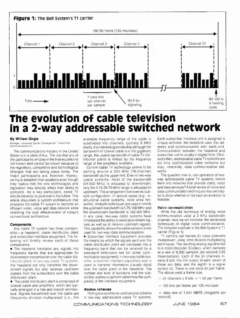
Figure 1: The Bell System's T1 carrier
7 data bits per channel per sample
Bit 8 for signaling
Bit 193 is a framing code
The evolution of cable television in a 2-way addressable switched network By William Girgis Mandyer. )esterr, Ue,,e,,prrer,;f uer Communications Inc
The communications industry in the United States is in a state of flux. The role that any of the participants will play in the final equation is not known and cannot be known because of the regulatory, competitive and technological changes that are taking place today. The major participants are, however, maneu-vering to establish their positions even though they realize that the new technologies and legislation may directly affect their ability to compete. As a key participant, cable TV should develop its potential to the fullest. This article discusses a system architecture that prepares the cable TV system to become an efficient video, voice and data network while retaining the cost effectiveness of today's conventional architecture.
Components Any cable TV system has three compon-
ents—a headend, cable distribution plant and subscriber interface equipment. The fol-lowing will briefly review each of these components. • The headend translates any signals into frequency bands that are appropriate for downstream transmission over the cable dis-tribution plant. In two-way cable TV systems, the headend not only transmits the down-stream signals but also receives upstream signals from the subscribers over the cable distribution plant. • The cable distribution plant is comprised of coaxial cable and amplifiers, which are typi-cally arranged in a tree and branch architec-ture. Signals transmitted over the cable are frequency-division-multiplexed (i.e., the
available frequency range of the cable is subdivided into channels, typically 6 MHz each). It is interesting to note that although the bandwidth of coaxial cable is in the gigahertz range, the usable bandwidth of cable TV dis-tribution plants is limited by the frequency range of the amplifiers available.
Current cable TV technology seems to be settling around a 550 MHz (78-channel) bandwidth as the upper limit. Even in two-way cable systems, most of the bandwidth (54-550 MHz) is allocated to downstream; only the 5.75-29.75 MHz range is allocated to upstream. This arrangement is known as sub-split configuration. In special cases (e.g., in-stitutional cable systems, local area net-works), midsplit techniques are used in which the upstream bandwidth is 5.75-108 MHz and the downstream bandwidth is 162-300 MHz. In any case, two-way cable systems have introduced the ability to send downsteam sig-nals as well as to receive upstream signals. This capability allows the cable network to be used for two-way data communications. • Subscriber interface equipment provides the means by which the signals sent over the cable distribution plant are translated into a frequency band that can be received by a standard television set (or other com-munication equipment). In two-way cable sys-tems, subscriber interface equipment also is used to transmit information (usually data) over the cable plant to the headend. The number and kind of functions that the sub-scriber wishes to perform determine the com-plexity of the interface equipment.
Access schemes Polling is a commonly used access scheme
in two-way addressable cable TV systems.
Each subscriber interface unit is assigned a unique address; the headend uses this ad-dress and communicates with each unit. Communication between the headend and subscriber unit is usually in digital form. Obvi-ously then, addressable cable TV systems are not only sophisticated video networks but also, inherently, data communication net-works. The question now is, can operators of two-
way addressable cable TV systems evolve them into networks that provide video, voice and data services? A brief review of voice and data communication techniques may be help-ful to show whether or not such an evolution is feasible.
Voice communication While the old technique of analog voice
communication used a 3 KHz bandwidth channel, here we will consider the advanced techniques of digital voice communication. The simplest example is the Bell System's Ti carrier (Figure 1).
Ti carriers can handle 24 voice channels multiplexed using time-division-multiplexing techniques. The resulting analog signal is fed to a coder/decoder (Codec), which samples at a rate of 8,000 samples per second (125 msec/sample). Each of the 24 channels in-serts 8 bits into the output stream; seven of these are data, and the eighth is a signal control bit. There is one extra bit per frame. The above yield a frame size
= 24 channels x 8 bits + 1 bit per frame
= 193 bits per frame per 125 microsec
= data rate of 1.544 MBPS (megabits per second).
COMMUNICATIONS TECHNOLOGY JUNE 1 964 67
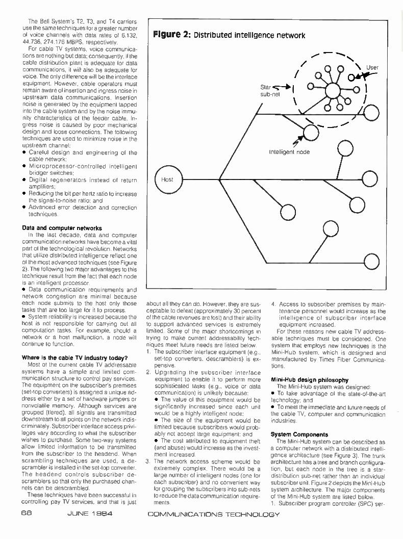
The Bell System's 12, T3, and T4 carriers use the same techniques for a greater number of voice channels with data rates of 6.132 44.736, 274.176 MBPS, respectively.
For cable TV systems, voice communica-tions are nothing but data; consequently, if the cable distribution plant is adequate for data communications, it will also be adequate for voice. The only difference will be the interface equipment. However, cable operators must remain aware of insertion and ingress noise in upstream data communications. Insertion noise is generated by the equipment tapped into the cable system and by the noise immu-nity characteristics of the feeder cable. In-gress noise is caused by poor mechanical design and loose connections. The following techniques are used to minimize noise in the upstream channel: • Careful design and engineering of the
cable network; • Microprocessor-controlled intelligen
bridger switches; • Digital regenerators instead of return
amplifiers: • Reducing the bit per hertz ratio to increase
the signal-to-noise ratio: and • Advanced error detection and correction
techniques_
Data and computer networks the last decade, data and computer
communication networks have become a vital part of the technological revolution. Networks that utilize distributed intelligence reflect one of the most advanced techniques (see Figure 2). The following two major advantages to this technique result from the fact that each node is an intelligent processor. • Data communication requirements and network congestion are minimal because each node submits to the host only those tasks that are too large for it to process. • System reliability is increased because the host is not responsible for carrying out all computation tasks. For example, should a network or a host malfunction, a node will continue to function.
Where is the cable TV industry today? Most of the current cable TV addressable
systems have a simple and limited com-munication structure to control pay services. The equipment on the subscriber's premises (set-top converters) is assigned a unique ad-dress either by a set of hardware jumpers or nonvolatile memory. Although services are grouped (tiered), all signals are transmitted downstream to all points on the network indis-criminately. Subscriber interface access privi-leges vary according to what the subscriber wishes to purchase. Some two-way systems allow limited information to be transmitted from the subscriber to the headend. When scrambling techniques are used, a de-scrambler is installed in the set-top converter. The headend controls subscriber de-scramblers so that only the purchased chan-nels can be descrambled. These techniques have been successful in
controlling pay TV services, and that is just
about all they can do. However, they are sus-ceptable to defeat (approximately 30 percent of the cable revenues are lost) and their ability to support advanced services is extremely limited. Some of the major shortcomings in trying to make current addressability tech-niques meet future needs are listed below. 1. The subscriber interface equipment (e.g..
set-top converters, descramblers) is ex-pensive.
2 Upgrading the subscriber interface equipment to enable it to perform more sophisticated tasks (e.g., voice or data communication) is unlikely because: • The value of this equipment would be significantly increased since each unit would be a highly intelligent node; e The size of the equipment would be limited because subscribers would prob-ably not accept large equipment: and • The cost attributed to equipment theft (and abuse) would increase as the invest-ment increased.
3. The network access scheme would be extremely complex. There would be a large number of intelligent nodes (one for each subscriber) and no convenient way for grouping the subscribers into sub-nets to reduce the data communication require-ments.
4. Access to subscriber premises by main-tenance personnel would increase as the intelligence of subscriber interface equipment increased. For these reasons new cable TV address-
able techniques must be considered. One system that employs new techniques is the Mini-Hub system, which is designed and manufactured by Times Fiber Communica-tions.
Mini-Hub design philosophy •'le Mini-Hub system was designed:
• I o take advantage of the state-of-the-art technology; and • To meet the immediate and future needs of the cable TV, computer and communication industries.
System Components
The Mini-Hub system can be described as a computer network with a distributed intelli-gence architecture (see Figure 3). The trunk architecture has a tree and branch configura-tion. but each node in the tree is a star-distribution sub-net rather than an individual subscriber unit. Figure 2 depicts the Mini-Hub system architecture. The major components of the Mini-Hub system are listed below. 1. Subscriber program controller (SPC) ser-
68 JUNE 1 964 COMMUNICATIONS TECHNOLOGY

On the Blink!
Whatever converter problem you're having, we can fix it. Because ATI performs complete precision repairs on all makes and models of converters.
State of the art test equipment combined with the latest computer technology. And our logging and reporting systems mean ATI has the most advanced converter repair facilities in the country. Our repair staff of technicians are experienced and professional. A group of highly trained problem solvers
know how to immediately find the source of trouble. And tell you exactly what went wrong. We also supply a computerized report of which parts were replaced.
But at ATI, we don't just stop at solving prob-lems. We can upgrade and modify your present converters. And we also stock and sell a whole line of converters and accessories. We're open 24 hours a day. Our highly competent staff of field service reps are here to serve all your needs.
So if your converters have been on the blink, call All at 800 554-3436. We can stop converter downtime from putting the dollar squeeze on you • Reliable Turn Around Time • Fast, Courteous Service • Engineering Back Up • Six Month Warranty • Field Service Representatives. • Pick Up and Delivery
ATI First in service and converter repair.
3061-A Kingston Court, Marietta, Georgia 30067(404) 953-4849 Outside Georgia (800) 554-3436
A Tomberlin Company
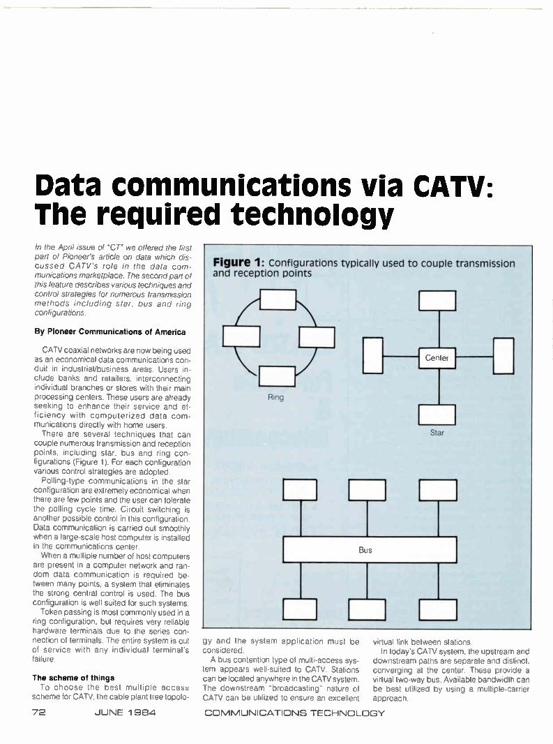
Data communications via CATV: The required technology In the April issue of "CT" we offered the first part of Pioneer's article on data which dis-cussed CATV's role in the data com-munications marketplace. The second part of this feature describes various techniques and control strategies for numerous transmission methods including star, bus and ring configurations.
By Pioneer Communications of America
CATV coaxial networks are now being used as an economical data communications con-duit in industrial/business areas. Users in-clude banks and retailers, interconnecting individual branches or stores with their main processing centers. These users are already seeking to enhance their service and ef-ficiency with computerized data com-munications directly with home users. There are several techniques that can
couple numerous transmission and reception points, including star, bus and ring con-figurations (Figure 1). For each configuration various control strategies are adopted.
Polling-type communications in the star configuration are extremely economical when there are few points and the user can tolerate the polling cycle time. Circuit switching is another possible control in this configuration. Data communication is carried out smoothly when a large-scale host computer is installed in the communications center. When a multiple number of host Computers
are present in a computer network and ran-dom data communication is required be tween many points, a system that eliminates the strong central control is used. The bus configuration is well suited for such systems. Token passing is most commonly used in a
ring configuration, but requires very reliable hardware terminals due to the series con-nection of terminals. The entire system is out of service with any individual terminal's failure.
The scheme of things To choose the best multiple access
scheme for CATV, the cable plant tree topolo-
Figure 1: Configurations typically used to couple transmission and reception points
gy and the system application must be considered. A bus contention type of multi-access sys-
tem appears well-suited to CATV. Stations can be located anywhere in the CATV system. The downstream "broadcasting" nature of CATV can be utilized to ensure an excellent
v,Nua ilK ueteen stations. In today's CATV system, the upstream and
downstream paths are separate and distinct, converging at the center. These provide a virtual two-way bus. Available bandwidth can be best utilized by using a multiple-carrier approach.
72 JUNE 1 984 COMMUNICATIONS TECHNOLOGY
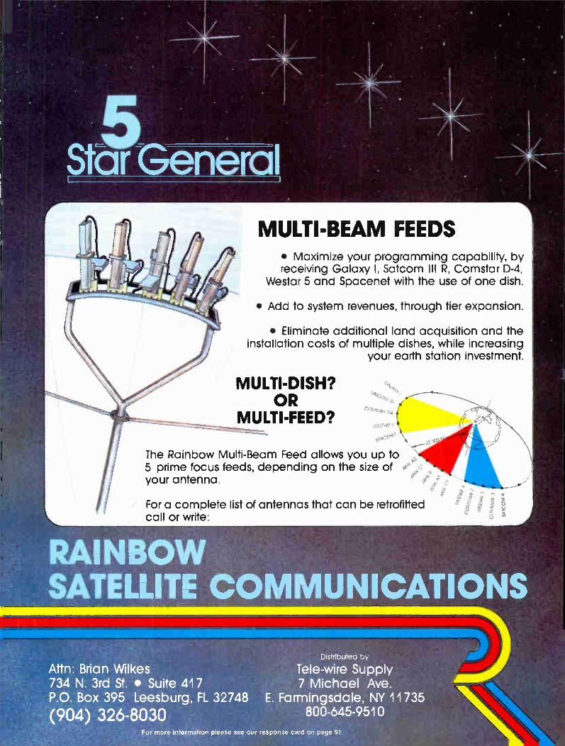
MULTI-BEAM FEEDS • Maximize your programming capability, by receiving Galaxy I, Satcom Ill R, Comstar D-4,
Westar 5 and Spacenet with the use of one dish.
• Add to system revenues, through tier expansion.
• Eliminate additional land acquisition and the installation costs of multiple dishes, while increasing
your earth station investment.
MULTI-DISH? OR
MULTI-FEED?
The Rainbow Multi-Beam Feed allows you up to 5 prime focus feeds, depending on the size of e „c your antenna. e -
$ °
For a complete list of antennas that can be retrofitted call or write:
RAINBOW SATELLITE COMMUNICATIONS
Attn: Brian Wilkes 734 N. 3rd St. • Suite 417 P.O. Box 395 Leesburg, FL 32748
(904) 326-8030
Distributed by
Tele-wire Supply 7 Michael Ave.
E. Farmingsdale, NY 11735 800-645-9510
For more information please see our response card on page 91.

One key to the successful operation of small scale, non-CATV baseband bus ap-proaches like the Ethernet system is a very short transmission time. This minimizes col-lisions and transmission delays due to crowd-ing. The packet format is standardized con-taining address ID of sender and receiver, status reports and control commands. The stations that have prepared the packets to be sent wait for a transmission chance and, when this chance arrives, they start transmitting the packet. After the packet has been transmit-ted. the channel is quickly freed for further use.
In a CATV application, each station trans-mits data to the upstream bus and receives data from the downstream bus. Because of the physical size of a CATV system, pro-pagation delay time becomes a major factor. Although data communications systems
will no doubt adopt methods that are sub-divided into a certain number of hubs, it will probably be necessary to accommodate trunklines reaching 30 to 40 miles from the center of each hub. In this situation, the worst case propagation delay will be between 350 and 500 microseconds. The problem of ingress and noise in the
upstream signal path is evident to all who are involved in two-way CATV. Bridger gating, the common CAN method of eliminating noise under control of the center, is an obstacle. One workable approach places a high per-
formance translator at the center. Its function is to demodulate received signals, verify that those signals are valid data and not just burst noise, then regenerate signals for re-transmission downstream noise-free. The de-vice must be very sophisticated in order to remain stable in the face of noise and level fluctuations. It must also perform very impor-tant error checking functions to filter out burst noise without creating a great deal of delay.
Pioneer is developing a multiple-access data communication system, based on this approach, which complements the attributes of a CATV system. The functional system con-sists of three elements: (1) network interface units, (2) center repeater and (3) data monitor (Figure 2).
Network interface unit The NIU is connected to the CATV network
like a subscriber converter or TV. It translates the data format between user device and the communication line.
Its functionality, in terms of the International Standards Organization (ISO) standard model for systems interconnection, is illus-trated in Figure 3. The main task of the NIU is to reformat the data from a user device into packets and send the packets upstream to be "turned around" by the center and "broad-
'CATV's... attributes... make it a natural contender as a conduit for... data services'
Figure 2: system configuration of data communications system
Center repeater
Data monitor
NIU
Micro computer
Two-way cable bus
NIU
User device
NIU
User device
Figure 4: NIU block diagram
From
/to CATV
Transmitter (PLL)
Data
Control
Receiver (PLL)
Data
Main controller
NIU
User device
1 To user device A
(RS-232C)
To user device B
Power supply
Figure 5: Repeater block diagram
120 VAC
Transmitter (PLL)
Data
Control
Receiver (PLL)
Data
Baseband interface
Power supply
120 VAC
74 JUNE 1984 COMMUNICATIONS TECHNOLOGY

Figure 3: NIU functionality in terms of ISO standard model layers
User application
Program data file etc.
User interface layer
Data link layer
Physical layer
Command interpreter Message TX/RX Interconnection control etc.
Data packeting Link control Channel control Error control etc.
Data encode/decode Transmit/receive etc.
User application
User interface layer
Data link laye
Physical layer
Two-way CAN distribution system
cast" downstream data, identifying data packets addressed to it, transferring the as-sociated data to the user device. A block diagram of the NIU is shown in Figure 4.
Center repeater The center repeater is the device that re-
transmits downstream data received up-stream from one NIU. In part, the center re-peater is a frequency converter. It also elimin-ates upstream noise by regenerating the received data. Figure 5 shows the repeater block diagram.
Data monitor The data monitor simply "watches" all of the
data "turned around" by the center, gener-ating an ongoing log of packets retransmitted: source and destination address of packets, packet length, packet type. etc. The com-plexity of this device can vary depending on the number of subscribers. It can serve as a security device, allowing only valid addresses to access the system: a billing computer, totalling transactions for a certain time period: and a monitor, for monitoring system failures. A typical data communications exchange
between two subscribers equipped with the system is shown in Figure 6.
Pioneer's effort is one of several in the CATV marketplace hoping to provide the broad-band coaxial cable data communications hardware to serve this emerging industry. CATV's broadband, closed circuit attributes, combined with its presence now in most major cities, make it a natural contender as a con-duit for the new, high-speed data services expected to flourish as the "Information Age" continues to unfold. CD
Figure 6: Typical communication exchange
Center repeater
B sends acknowledgement packet to A
A sends data packet to B
Data packet NIU A
o
B receives data packet from A
o
o Downstream
pr_J Upstream
NIU A
NIU
A receives acknowledgement packet from B and communication is complete
NIU A
NIU
COMMUNICATIONS TECHNOLOGY JUNE 1 984 75

Imagine The Features That Will Answer Your Present And Future Needs
... Then Call Di-Tech
We also man-ufacture a com-plete line of termin-al equipment, video detectors, touch tone control systems, audio monitor amplifiers and a 7 day computer controller.Our
audio, video and pulse distribution amplifiers feature looping inputs with 6 outputs and can be intermixed within the same mounting frame. The model # 101 frame is 1.75" high and mounts up to 3 mod-ules; the model # 103 frame is 5.25" high and mounts up to 10 modules
Audio/video routing switchers come in many different shapes and sizes, offering a variety of features. Since
your requirements change from year to year, shouldn't you select the one that fits today's budget AND can meet your present and future
needs? Then try Di-Tech. We've got that small 4 x 1 matrix switcher and the 200 x 200 stvitchers. We've even got a se-lection of in-between sizes for audio
only, video only or audio follow video with 1, 2 or 3 channels
of audio per input
al_ Sr "I" I "S" I a-4te
7- •
•:•
&Jawlike& _
Whatever your present or future needs are, call Di-Tech for the high quality, reliable, easy-to-operate answer.
di-tech our NEW, bigger location:
48 JEFRYN BOULEVARD DEER PARK, N.Y. 11729 TEL. e (516) 667-6300
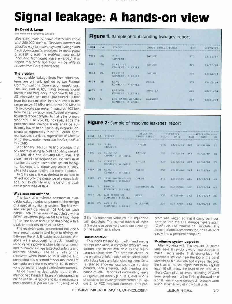
Signal leakage: A hands-on view By David J. Large Vice President. Engineering Gilicable
With 4,300 miles of active distribution cable and 200,000 outlets. Gil!cable needed an effective way to monitor system leakage and track down specific problems. In seven years of wrestling with the problem many useful tools and techniques have emerged. It is hoped that other operators will be able to benefit from Gill's experiences.
The problem Acceptable leakage limits from cable sys-
tems are primarily defined by two Federal Communications Commission regulations. The first, Part 76.605, limits external signal levels in the frequency range 54-216 MHz to 20 microvolts per meter (measured 10 feet from the transmission line) and levels in the range below 54 MHz and above 220 MHz to 15 microvolts per meter (measured 100 feet from the transmission line). Absent any speci-fic interference complaints that is the primary standard. Part 76.613. however, adds the provision that leakage levels shall be suf-ficiently low as to not "seriously degrade. ob-struct or repeatedly interrupt" other com-munications services, regardless of whether or not the operator meets the levels specified in 76.605.
Additionally. section 76.610 provides that any operator using aircraft frequency ranges. 108-136 MHz and 225-400 MHz, must first clear use of the frequencies. He then must monitor the entire distribution system for sig-nal leakage and repair any leaks quickly, while fully documenting the entire process.
In Gill's case. it was desired to be able to detect not only the presence of excess leak-age, but to identify which side of the dual. cable plant was at fault.
Wide area surveillance The lack of a suitable commercial dual-
cable leakage detector prompted the design of a special monitoring system. The first ver-sion utilized carriers at 108 MHz on each cable. Each carrier was FM modulated with a DTMF waveform (equivalent to a touch-tone -1" on one cable and "3" on the other) with a peak-to-peak deviation of 10 KHz. The receivers were fix tuned and included a
level meter, speaker and logic to distinguish between the A & B cable modulations. Ver-sions were produced for truck mounting. using vehicle power-and an external antenna, and for hand-held use (attached antenna and internal battery). The sensitivity of the receivers when mounted in a vehicle and connected to a standard fender-mounted FM car radio antenna was around 10-15 micro-volts per meter, though it varied considerably. Aside from the dual-cable feature, this
method had the advantages of not depending on the use of FM radios and quite reasonable cost (about $50 per receiver for parts). All of
Figure 1: Sample of 'outstanding leakages' report
LOGS MA STREET
4001 26 7 TH COMMENT:
4002 26 FIRST ST COMMENT: A CABLE
4003 26 FIRSTST COMMENT: A CABLE
4004 28 KING
COMMENT: A CABLE
4009 9 LATIMER
COMMENT: LT CABLE
4Utu LOS GATOS ALMADEN COMMENT: A CABLE
.... CROSS STREET/BLOCK
TAYLOR
TAYLOR
FAYLOR
MCKEE
DUNSTER
HARWOOD
TECH REPORTED
375 03/01/84
329
329 03/22/84
357 03/02/84
376 03/21/84
339 03/21/84
Figure 2: Sample of 'resolved leakages' report
LOGi MA STREET
4001 26 7 TM COMMENT:
FIRST SI COMMENT: A CABLE
4003 26 FIRSTS! COMMENT: A CALLE
4004 28 KING
COMMENT. A CABLE
4005 19 12E10 SANTOMAS AU COMMENT; ET CABLE
4006 11 RINCON COMMENT: Or CABLE
4007 25 628 TENTH SO COMMENT: B CABLE
4008 25 469 11TH
COMMENT: A CABLE
BLOCK OR --REPORTED CROSS STREET TECH DATE
------- -
TAYLOR 375
TAYLOR 329
TAYLOR 329
MCKEE 357
CAREO 316
SAN TOMAS AU 362
REED 357
WILLIAMS 325
RESOLVED TECH DATE CC
03/01/84 343
03/22/84 343
03/22/84 343
03/02/84 343
03/14/84 316
03/14/84 362
03/20/84 343
03/14/84 343
03/30/84 25
03/20,134 25
03/30/84 25
03/30/84
03/30/84 63
03/30/84 63
03/30/84 25
03/30/84 25
Gill's maintenance vehicles are equipped with detectors. The normal travels of these technicians assures very complete coverage of the system as a whole.
Documentation To support the monitoring effort and assure
prompt resolution, a computer program was written and made available to the main-tenance dispatcher. The program allows for the entering of information on detected leaks into a data base and later clearing them. Data is retained showing location, date in, date cleared, tech entering, tech clearing and cause of leak. Reports of outstanding leaks are generated weekly (Figure 1) and reports of resolved leaks are generated monthly (Fig-ure 2) for FCC required archives. This pro-
gram was written so that it could be incor-porated into the Gill Management System (GMS) on-line trouble call module. The amount of data is small enough, however, to fit easily into a personal computer.
Monitoring system upgrades After working with this system for some
time, several revisions were incorporated to make it more useful. First, strong local FM broadcast stations near the top of the band sometimes hid low-leakage egress. Second, the level of the test signal had to be kept at least 10 dB below the level of the 109 MHz Theta-Corn pilot to avoid affecting AGCed trunk amplifiers, further limiting the available signal. Finally, considerable differences were found in sensitivity of individual units.
COMMUNICATIONS TECHNOLOGY JUNE 1 984 77

After receiving clearance from the FCC the units were modified for 116.9 MHz. This al-lowed full video carrier power and avoided FM interference. An RF attenuator was added to set sensitivity. With these modifications the system is a good survey tool for major leaks.
'Significant' interference The full impact of the additional re-
quirements of Part 76.613 of the FCC rules was made very clear to Gill in one recent case in which egress was affecting the operations of an amateur radio operator. The amateur in question was operating a repeater station on the 220 MHz band in his home. The repeater's input frequency was nearly coincident with the channel K video frequency. which is in use in both cables in his area. The FCC field engineer, on two different occasions, found a leak whose level exceeded the 76.605 spec. In each case. however, repairing the fault made only a minor difference to the inter-ference. Based on a preliminary finding by the field engineer that leakage still constituted a "significant" interference (despite being un-measurable on the FCC's equipment), we set out to determine what was necessary to make the signals virtually undetectable, even to the 0.1-0.2 microvolt sensitive repeater. The re-sults, after 350 plus hours of field work and substantial equipment investment, have shed considerable light on this thorny problem.
Sensitive leakage locator It was clear that we needed not only greater.
sensitivity detection equipment, but fairly precise direction finding as well. It was found that the combination of a high-gain Vagi an-tenna, attenuator. amateur radio 220 MHz transceiver and oscilloscope worked quite well (Figure 3). The transceiver was modified to bring out the wideband discriminator signal for oscilloscope observation. This allowed both easy identification of the video sync sig-nal and relative amplitude of received carrier. The attenuator was used as a coarse gain setting to keep the transceiver from limiting. Using a KLM Model 220-14 antenna in the test van (14.2 dB gain) gave a sensitivity of about 0.08 microvolts or -129 dBm, repeatable am-plitude measurements and an azimuth ac-curacy of about 10 degrees. This sensitivity is 31 dB below that specified in 76.605. Triangu-lation allowed leaks to be pinpointed to within a few feet.
For future use, we have also added a 144 MHz transceiver (channel E), a lower gain antenna for smaller vehicles and omni-directional antennas for survey work.
Field results When the sensitive equipment just de-
scribed was taken to the site of the repeater station, signals could be detected at several azimuths. the strongest being some 20 dB above threshold. Over a period of days the following leaks were repaired in an area roughly a mile in diameter:
• Trunk and distribution system Cracked or damaged cable 2
Corroded tap fittings prevent good ground contact while broken fittings prevent in-stallation of terminators.
Fittings Loose or damaged taps 8 Missing terminators 1
• Drop and premises Television sets modified 4 Customer damaged drop cable 3 Bad drop cable 1 Loose or damaged F fittings 12 NB switch faulty 2 Set leakage eliminated by using
direct 75 ohm input 4 Illegal connections . 3
Several other residences were identified to be leaking signals but technicians were un-able to get access to investigate. From this list, it immediately becomes apparent that premise problems are the dominant factor R. this signal level.
While the system faults were simple to cied, with, television sets were quite another matter. The problem arises because Gill uses con-verters only for premium customers. while basic customers have an NB switch. This means that the full bandwidth of cable signals is present at the back of the set. Many tele-vision sets, unfortunately, use a twin lead be-tween the back of the set and the tuner. which makes a marvelous antenna. To confirm this Gill paid TV service shops to
modify several of these radiating sets (with
Gnawed cable is a source of signal leakage.
The Gillcable 'SWAT van' with high-gain 220 MHz a
owner's permission) and in every case the leak was solved. It is, of course, not practical to do that on a widespread basis, but we felt that the data gained was worth it in this case. The cumulative detectable leakage level at the conclusion of these tests was reduced by nearly 20 dB and was just detectable above squelch minimum.
78 JUNE 1 984 COMMUNICATIONS TECHNOLOGY
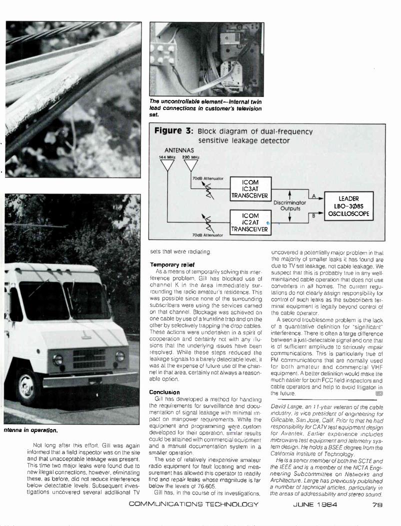
ntenna in operation.
Not long after this effort. Gill was again informed that a field inspector was on the site and that unacceptable leakage was present. This time two major leaks were found due to new illegal connections, however, eliminating these, as before, did not reduce interference below detectable levels. Subsequent inves-tigations uncovered several additional TV
The uncontrollable element—Internal twin lead connections in customer's television set.
Figure 3: Block diagram of dual-frequency sensitive leakage detector
ANTENNAS 144 MHz 220 MHz
70dB Attenuator
70dB Attenuator ICOM IC3AT
TRANSCEIVER Discriminator
Outputs
A _ LEADER
LBO-308S
OSCILLOSCOPE
sets that were radiating.
Temporary relief As a means of temporarily solving this inter-
ference problem, Gill has blocked use of channel K in the area immediately sur-rounding the radio amateur's residence. This was possible since none of the surrounding subscribers were using the services carried on that channel. Blockage was achieved on one cable by use of a trunkline trap and on the other by selectively trapping the drop cables. These actions were undertaken in a spirit of cooperation and certainly not with any illu-sions that the underlying issues have been resolved. While these steps reduced the leakage signals to a barely detectable level, it was at the expense of future use of the chan-nel in that area, certainly not always a reason-able option.
Conclusion Gill has developed a method for handling
the requirements for surveillance and docu-mentation of signal leakage with minimal im-pact on manpower requirements. While the equipment and programming we.re.costom developed for their operation, similar results could be attained with commercial equipment and a manual documentation system in a smaller operation. The use of relatively inexpensive amateur
radio equipment for fault locating and mea-surement has allowed this operator to readily find and repair leaks whose magnitude is far below the levels of 76.605.
Gill has. in the course of its investigations,
uncovered a potentially major problem in that the majority of smaller leaks it has found are due to TV set leakage. not cable leakage. We suspect that this is probably true in any well-maintained cable operation that does not use converters in all homes. The current regu-lations do not clearly assign responsibility for control of such leaks as the subscribers ter-minal equipment is legally beyond control of the cable operator. A second troublesome problem is the lack
of a quantitative definition for "significant" interference There is often a large difference between a just-detectable signal and one that is of sufficient amplitude to seriously impair communications. This is particularly true of FM communications that are normally used for both amateur and commercial VHF equipment. A better definition would make life much easier for both FCC field inspectors and cable operators and help to avoid litigaton in the future.
David Large, an 11-year veteran of the cable industry, is vice president of engineering for Gil!cable, San Jose. Calif. Prior to that he had responsibility for CA TV test equipment design for Avantek. Earlier experience includes microwave test equipment and telemetry sys-tem design. He holds a BSEE degree from the California Institute of Technology. He is a senior member of both the SCTE and
the IEEE and is a member of the NCTA Engi-neering Subcommittee on Networks and Architecture. Large has previously published a number of technical articles, particularly in the areas of addressability and stereo sound.
COMMUNICATIONS TECHNOLOGY JUNE 1 984 79
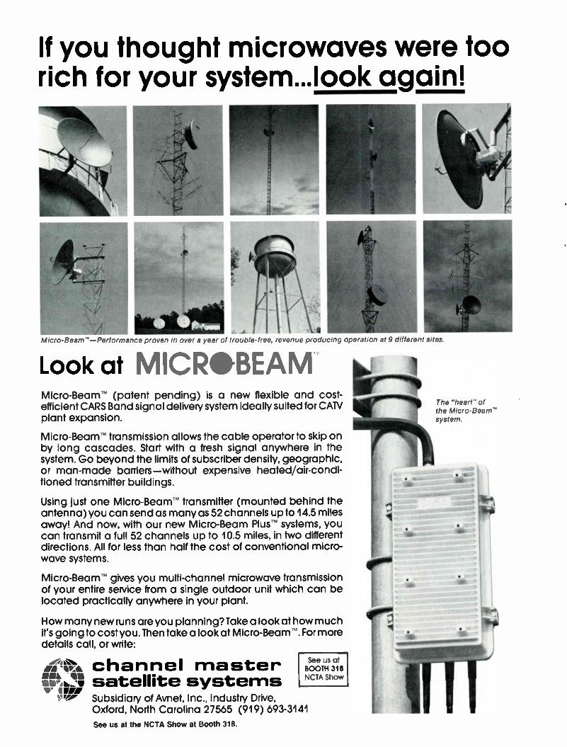
If you thought microwaves were too rich for your system...look again!
Micro-Beam"—Performance proven in over a year of trouble-free, revenue producing operation at 9 different sites.
Look at M CeGBEAM Micro-Beam (patent pending) is a new flexible and cost-efficient CARS Band signal delivery system ideally suited for CATV plant expansion.
Micro-Beam transmission allows the cable operator to skip on by long cascades. Start with a fresh signal anywhere in the system. Go beyond the limits of subscriber density, geographic, or man-made barriers—without expensive heated air-condi-tioned transmitter buildings.
Using just one Micro-Beam transmitter (mounted behind the antenna) you can send as many as 52 channels up to 14.5 miles away! And now, with our new Micro-Beam Plus systems, you can transmit a full 52 channels up to 10.5 miles, in two different directions. All for less than half the cost of conventional micro-wave systems.
Micro-Beam gives you multi-channel microwave transmission of your entire service from a single outdoor unit which can be located practically anywhere in your plant.
How many new runs are you planning? Take a look at how much it's going to cost you. Then take a look at Micro-Beam For more details call, or write:
MI channel master Ae4It\
Oak Ia. satellite systems Ireie Subsidiary of Avnet, Inc., Industry Drive,
Oxford, North Carolina 27565 (919) 693-3141
See us at the NCTA Show at Booth 318.
See us at BOOTH 318 NCTA Show
e"
The "heart" of the Micro-Beam" system
cABLF>Ç4_ National show technical abstracts The following are the abstracts of papers to be presented during the technical sessions at the National Cable Television Association convention.
Commercial insertion: No pain no gain Monday, June 4, 2-3:30 p.m , Room B
Automatic commercial insertion equipment for the unattended insertion of local advertising
By Bill Killion President, Channeimatic Inc
This paper will discuss the many types of equipment and systems Channelmatic manu-factures for automatic inserton and related functions. Much of that described has been introduced in just the past few months. Sev-eral projects are in engineering currently, but are in very early stages and are not men-tioned. Much research and software engi-neering time and effort has been spent on an elaborate Traffic Control and Accounting Sys-tem, which is described briefly in this paper.
The evolution of the commercial insertion business
By Ernest 0. Tunmann President, Tele-Engineering Corp.
Considered by many the most important non-subscriber revenue producer of the 1980s, the business of commercial insertion is discussed along with its evolutionary mile-stones of the past two years. Since the in-sertion of spot commercials depends upon the smooth interaction of technical, operation, marketing and production personnel, it is im-portant that both hardware and software of the commercial insertion equipment satisfies a complex number of desirable features. This paper presents a look at commercial insertion hardware and software from the viewpoint of features. Features are grouped by pro-duction, insertion, random access, pro-gramming, logging, fail safe, remote opera-tion, expansion, automated billing and man-agement information. Tele-Engineering's
family of commercial insert equipment, the AD Machine"- the AD CUE 84'm and the AD CUE 10(re systems are then compared to these features to make the user aware of the differences
Local commercial insertion: A partnership of the cable operator. programming service and manufacturer
By Paul E. Olivier American Television and Communications Corp.
Local commercial insertion is becoming an increasingly important revenue resource for the cable operator. Program services, cable operators and equipment manufacturers must work together in coordinating the de-velopment of commercial insertion equip-ment, program services signaling procedures and methods to ensure continued growth in local advertising sales. Procedures and guidelines for signaling methods, pre-roll times and signal measuring must be estab-lished. Local availabilities are important to the cable operator, and the lack of sensitivity by some program suppliers and manufacturers is of paramount concern. Operators are sometimes forced into buying automated equipment not capable of handling the task at hand. The challenge of handling the problems inherent in local commercial insertion touches all of those involved in our industry. A close examination of these problems, discussions and solutions will ensure the success of cable operators, program servirps and the equip-ment manufacturers
Tests and measurements Monday, June 4, 2-3:30 p.m., Room D
Noise figure measurements on distribution systems
By Donald E. Groff General Instrument. Jerrold Division
A technique for measuring the noise figure of a CATV distribution system is discussed, as an alternative to conventional methods of de-termining carrier-to-noise ratio. The advan-
tages and disadvantages of both types of measurement are discussed. Suitable instru-mentation for noise figure measurement is considered, as well as calibration techniques. Some possible sources of error are identified and analyzed.
Measurement of intermodulation products generated by corroded or loose connections in CATV systems
By Bradford S. Kellar Raychem Corp.
Metal-to-metal junctions can exhibit non-linear characteristics as a result of corrosion or low contact pressure. The non-linearity can be seen on a V-I curve tracer and has been implicated in causing intermodulation inter-ference, especially in the 5-30 MHz band. The junction behavior at RF under actual oper-ating conditions cannot be accurately pre-dicted from the low frequency V-I curve, how-ever. Measurements have been made of the actual level of third order intermodulation products generated at RF by a variety of con-nections. The results are reported here, with a description of the factors found to influence the junction's behavior.
RF modem specifications . . . testing between the lines
Kenneth C. Crandall Program Manager, RF Modems, Zeta Laboratories Inc, a subsidiary of CCTC
The RF modem, used for both voice and data communications on CATV systems, is becoming an important tool for increasing cable operators' revenues. However, any new device added to the network must be tested to see that it meets its specifications. It also must meet certain unwritten specifications that guarantee that it reliably operate under a vari-ety of real work impairments known to exist; such as mechanical shock, frequency trans-lator drift and intermodulation distortion. Simple tests are presented that help identify a potentially poor performing device and keep it from eroding into those higher revenues gained by offering voice and data communi-cations services
Signal purity considerations for frequency synthesized headend equipment
By David L. Kelma General Instrument, Jerrold Division
As cable television system bandwidths in-crease and frequency plans proliferate, more manufacturers are turning to synthesized fre-quency agile headend channel converters. With this new approach using phased locked loops and dual conversion come spurious signals and noise sources not encountered before in crystal controlled channel con-verters. Important characteristics of these headend converters including phase noise,
COMMUNICATIONS TECHNOLOGY JUNE 1 984 81
spurious signals generated by the com-parison frequency, and residual frequency and phase modulation, are evaluated for their subjective impact on the output signal to the cable. Data is presented that shows the cor-relation between subjective picture de-gradation and measured headend syn-thesizer noise contribution.
A new active CATV system echo testing technology
By Warren L. Braun President, ComSonics Inc.
Various attempts have been made to quan-tify the transient or "echo" performance of CATV systems. Most of the testing done to date has dealt with the echo level tolerance following the limits devised by P. Mertz. Re-cent subjective tests by Bell Laboratories have shown that the Mertz's curve is too sim-plistic to define chrominance visual de-gradation since the Mertz subjective tests were conducted with monochrome sources. The recent criteria require a CATV system testing technology beyond that developed to date. The author's firm has developed appar-atus capable of highly refined CATV system echo testing, which when applied to existing systems and hardware, unveils new distortion factors not previously quantified in CATV systems.
Cable revolutionaries: scanning the new blue skies Tuesday, June 5, 9-10 a m , Room B
Cable TV transmission up to 900 MHz
By Georg Luettgenau RF Devices Division, TRW Electronic Component Group
Increased system bandwidth has been a technological trend for a number of years. Present-day amplifiers can handle full chan-nel loading up to 550 MHz. There exist a number of requirements and possibilities that make an even wider frequency range desir-able. Direct UHF distribution, as practiced and contemplated in Europe (and the U.S.) is one case. The thought of placing reverse transmissions into the higher frequency range has also been entertained. Obviously there are applications in MATV and similar systems. Hybrids suitable for the range from 40 through 900 MHz have become available. This paper relates these devices to specific applications. Conventional performance characteristics are given and compared to "Noise-in-the-Slot" behavior, which is a most revealing cri-terion for ultra wideband systems. The feasi-bility of feedforward realizations based on these hybrids is discussed.
New technology for cable television
By Frank Marlow RCA Laboratories
Four new technologies are presented. They are: digital television, multiplexed analog components, high-definition television and CCD cameras. Each of these new tech-nologies is explained and its application to cable television is described.
A 'perfect picture' service for cable
By Israel (Sruki) Switzer Cable Television Engineering
The American cable television system has been optimized for medium quality trans-mission of a very large number of television signals. It has been generally assumed that these cable systems would be ideal media for the distribution of high-resolution. wide bandwidth images. This is not necessarily so. Present S/N of VSB/AM transmission of 525 line NTSC signals is barely adequate. The increased bandwidth of high-resolution iir-ages implies reduced S/N in present cable systems. Bandwidth reduction techniques and/or improved noise immunity in new image transmission techniques will be required. as well as reduced cable system noise. FM video transmission, with or without improved color encoding techniques, is proposed as the best means of providing high quality transmission of 525 line video.
Thanks to the memories: Teledelivery. downloading and their roles in cable TV
By Gary H. Arlen President, Arlen Communications inc.
Teledistribution of video and data software will become an increasingly important part of the cable TV and communications industry. Video-on-demand systems, including hybrid facilities, are being introduced and tested. This paper describes downloading services as well as ones that use constant cycling of data or video, to be retrieved via a home terminal/receiver. Newly installed address-able cable equipment and headend compu-ter/control devices will accelerate the growth of teledistribution, as cable operators seek ways to use facilities for revenue-generating services. This paper also reviews broad-casting and telephone industry activities to develop teledistribution services, notably for games and information. The success of tele-delivery depends on a trade-off between the cost of communications versus the cost of memory. As memory and storage devices drop in price, teledistribution becomes more feasible.
Modification to satellite modulation
By L.W. "Bill" Johnson United Video Inc.
The NCTA has recently completed exten-sive testing to determine the worst usable C/I ratio for cable television TVRO receivers. With the modulation techniques used in cable-oriented video services today, the acceptable limit appears to be 18 dB. This paper pro-poses a possible modification to the modu-lation techniques which may improve the TVRO's tolerance to poor C/I ratios. This pro-posal concerns the video sync pulses and energy dispersal waveform (EDW). After de-emphasis, video sync pulses cause approxi-mately 2-3 MHz of deviation. During video, EDW normally causes 0.5 to 1 MHz of devi-ation. This recommendation would require that a nationwide and joint-corporate venture of satellite operators and users "genlock" these two signals on all transponders. Synchronizing the deviation of all tran-sponders in this manner would result in fewer cases of two adjacent carriers occupying the same spectral segment simultaneously—a major cause of cross-pole interference.
Advances in signal relay via satellite, microwave Tuesday , June 5, 9-10 a m , Room D
LNAs for multichannel microwave receivers
By T.M. Straus and I. Rabowsky Hughes Aircraft Co., Microwave Communications Products
The fade margin of any microwave path can be extended by reducing the noise figure of the receiver. Low-noise Ku band gallium ar-senide FET amplifiers and image reject filters have been developed specifically for multi-channel microwave receiver application in the 12.7-13.2 GHz band. Incorporation of the amplifier into such receivers either as a retrofit or in new designs generally requires built-in AGC circuitry to control the signal level and optimize performance. Without AGC ahead of the LNA, the third order distortions can build up to unacceptably large levels during un-faded conditions. Performance tradeoffs of various typical system configurations are examined. These tradeoffs illustrate the re-gimes in which AGC utilization is required.
Use of hybrid CARS microwave cable for multisite local-area networking
By Jamul Sarraf and Irving Rabowsky, P.E. Hughes Microwave Communications Products
In this paper, we first review the new role of CATV coaxial cable systems in supporting point-to-point voice/data networks and their inherent capacity to work as broadband local-area networks for distributed data communi-cations. Then, the use of CATV-compatible AML microwave links to interconnect dis-persed LAN systems is discussed.
82 JUNE 1984 COMMUNICATIONS TECHNOLOGY
Domestic satellite communications—The impact of recent advances
By Dom Stasi Warner Amex Satellite Entertainment Co.
Cable television embraced communication satellites as a distribution method as early as 1975. In the ensuing years sweeping changes have altered both mediums, and as with most emerging technology based businesses, many of the changes were revolutionary. The FCC ruling, following a body of cable industry research, which allowed use of small aperture (4.5 m) receive antennas is an example of one such revolutionary change. Today both cable TV and satellite communication are mature industries, and as is characteristic of mature industries, what changes do occur are usually of the more subtle evolutionary nature. De-velopments of the last year, however, have belied that reasoning, and a considerable degree of radical alteration of our delivery medium is again in the offing. Consider for example that higher power and solid state transponders are already on orbit. Several encryption schemes have been developed, some or all of which will be deployed on cable-oriented services. New modulation formats such as multiplexed analogue com-ponent (MAC) or video FDMA are under seri-ous consideraton by programmers, and sat-ellite delivery is the medium that will no doubt be first to convey extended high-definition television. Interleaved with these develop-ments comes the use at 'C' band of very small aperture, very low-cost receive systems de-signed to operate at carrier-to-noise levels reduced well beyond those considered feasi-ble as recently as one year ago. This paper will review these developments from an ob-server's perspective and attempt some objec-tive evaluations of their performance from a largely imperical point of view.
New developments in satellite television scrambling
By Dr. Jerrold A. Heller M/A-COM Linkabit Inc.
Satellite delivery of television signals to cable affiliates is now the industry norm. To protect these signals from unauthorized re-ception, an extremely secure scrambling sys-tem is needed that provides high quality audio and video at an affordable cost. In fact, the need for such a scrambling system has in-creased significantly with the dramatic growth in private TVRO installations. This paper will discuss M/A-COM's line of VideoCipheCe, satellite television scrambling systems, which use the Data Encryption Standard (DES) al-gorithm of the National Bureau of Standards for the highest level of security protection.
Audio: The new playing field Tuesday, June 5, 10:30-noon, Room B
_CAB
An equipment scenario for delivering stereo sound on CATV systems
By J.W. Wonn Group W Cable Inc
NCTA studies indicate that off-air TV sig-nals carrying stereo sound are likely to cause problems in certain CATV distribution equip-ment. To ignore this issue in a CATV plant may result in unacceptable picture and/or sound quality. This paper describes an alternative approach that permits delivering CATV stereo sound in a way that is advantageous to both the subscriber and the cable operator. The scenario is to simulcast stereo sound in a special off-channel frequency band. This ap-proach permits the customer to receive stereo sound with conventional audio equipment rather than a special TV set, and is compatible with most existing set-top terminal equipment. In addition, this approach provides a sys-tematic migration path from present CATV configurations to stereo delivery, and also could provide some attractive subscriber fea-ture enhancements.
Digital audio and data transmission system for CATV lines
By Yasuhiro Hideshima, Masakatsu Toyoshima, Etsumi Fujita and Yuichi Kojima AudioNideo Technology Center, Sony Corp.
There is an increasing need for a digital data transmission system using CATV lines today. Wth the above in mind, we have de-veloped a system that is able to transmit digi-tal data of approximately 7.4 MBPS using a frequency bandwidth of 6 MHz (equivalent to one arbitrary TV channel) and which can also be connected to currently used CATV sys-tems without any alteration. Two-level VSB transmission method is employed for this sys-tem because of its suitability for the various characteristics of CATV systems and sim-plicity of instrumentation in particular at the receiving side. The system is also provided with a very flexible data formal, enabling a wide application in designing the system. The system is able to simultaneously transmit four ultra-high-fidelity stereo audio programs. as well as computer and game software. fac-simile data. still picture, etc.. to all or specified subscribers.
Prospects for standardization in cable audio
By Dennis P Waters President, Waters & Co.
Several forces are converging to swing the
COMMUNICATIONS TECHNOLOGY
attention of the cable industry toward high quality stereo audio. These include TV multi-4 channel sound, digital audio as an encryption ••• technique, the new pay audio services, and compact disc digital audio in the consumer marketplace. Several incompatible systems have been proposed for transmitting high quality stereo audio over cable plants. Since each has been optimized for its own particular purposes, selecting one as a standard in-volves a complex set of trade-offs.
A digital audio system for broadcast. cable and satellite delivery media
By C.C. Todd and K.J Gundry Dolby Laboratories
The requirements for a digital audio system to be used for broadcast, cable and satellite delivery media differ from those for recording in that the major economic consideration is the cost of the playback circuitry. This fact has been utilized in the digital audio system to be described. The system offers high quality sound at a relatively low data rate (on the order of 200-350 k bits/sec) and the option of audio scrambling. No precision components are required in the decoder minimizing cost. The performance, cost and data rate advan-tages are achieved by placing more sophisti-cated circuitry in the encoder. Applications being pursued include DBS, cable, pay-TV and terrestrial broadcast systems.
Automated bit error rate testing
By Charles C.W. Wong Staff Engineer, Oak Communications Inc.
An automated bit error rate (BER) test sys-tem has been developed for an environment that requires repetitive testing. This system acquires data by the IEEE 488 interface, per-forms all BER and CNR calculations, and plots and stores the results for further processing and references. An important usage of such an automated system is to monitor the receiver's performance over a prolonged period of time to record its response to the varying transmission characteristics of the channel
(Re)Building for cable's future
Tuesday, June 5, 10:30-noon, Room D
Guide to plant analysis: Increasing channel capacity of a CATV system
By Paul D. Brooks General Electric Cablevision
The major technical considerations of in-creasing channel capacity are outlined. Pri-orities are indicated with respect to per-formance and cost factors, and a guide to decision making is presented. This dis-cussion is limited to the section of the plant
JUNE 1 984 83

between the headend and the subscribers' tap port.
The evolution of audio video system facilities at Warner Amex metropolitan cable television systems
By Neil Neubert Director, AudioNideo Engineering, Warner Amex Cable Communications
This paper traces and illustrates the evolu-tion in the design of audio/video systems at Warner Amex Cable Communications. It dis-cusses early approaches based on broad-cast techniques followed by the introduction of automation to master control transmission centers. It concludes by describing latest de-signs based on operating efficiency and economy in edit suites and TV studio control rooms as well as modern master control transmission centers.
Composite second order distortions
By Norman J. Slater and Douglas J. McEwen Cablesystems Engineering
The last few years have seen cable tele-vision technology leap from 300 MHz, 35-channel capacity to 450 MHz, 60-channel capacity and beyond. New technologies which use two amplifiers in the post amplifier stage are now being used to reduce the level of composite triple beat in extended band-width systems. The two amplifiers are ar-ranged in parallel or in a feedforward con-figuration and reduce post-amplifier com-posite triple beat levels by 5 dB and 18 dB respectively. Test results are presented that show that second order distortion can be the limiting distortion in a system carrying more than 50 channels. An analysis is then per-formed to confirm that second order distortion should be of very real concern to designers of both amplifiers and systems. This analysis also shows that active equipment using paral-lel or feedforward post amplifiers give a dis-appointing improvement in second order dis-tortion performance.
Limitations and characteristics of broadband feedforward amplifiers
By Joseph P. Preschutti Vice President-Engineering, C-COR Electronics Inc.
The nature of critical multichannel broad-band system design parameters using feed-forward technology is strikingly different from previously existing technologies. Several sys-tem design procedures taken for granted prior to using feedforward circuits must be re-evaluated. The unique characteristics and limitations of feedforward circuits regarding output capability, gain compression, tem-perature stability, noise figure, flatness, cross modulation and delay line technology are presented. The effects of these on system
design considerations are discussed.
mils the interconnection to the outside world at any point along the cable system and en-ables the operator to transform his coaxial cable network into a telephone bypass and teleport delivery network for the transmission
• • • of high-speed data. Automated network con-trol, automated coaxial cable maintenance and automated billing systems are presented as necessary ingredients to assure profitable operation.
Data communications Tuesday, June 5, 3:30-5 p.m., Room B
Applications of data on cable systems
By Leo J. Shane General Instrument, Jerrold Division
The use of coaxial cable for business and municipal communications is increasing at an extremely rapid rate. It has been estimated that by 1985, three-fourths of all businesses will use non-telco services for at least part of their communication needs. Many will turn to CATV technology to provide this service. Mu-nicipalities also view cable as a means to provide reliable, cost effective com-munication for civic needs. Applications using cable for business and municipal com-munications are in operation but little docu-mentation exists on what has been done and the reasons for its implementation. This paper will review three actual applications where CATV technology is used in the applications of: 1) Videoconferencing earth station links; 2) Municipal medical information network; and 3) Business communications.
Metropolitan data network standards
By Dr. James F. Mollenauer Codex Corp.
The CATV system holds great potential for high-speed data communication. Equipment standards in this area will accelerate de-velopment, lower costs, and will make inter-connection of franchises much easier. Such standards are now evolving under the IEEE Project 802, originally formed to standardizu local area networks on a smaller geographic scale. Participation by cable operators and users is needed in order to ensure that the standards will provide the equipment and services that customers want.
Data on cable for profit
By Ernest O. Tunmann President, Tele-Engineering Corp.
This paper reviews the technical standards for international packet switching networks as well as the bus access methods applicable to local area networks (LAN) and cable tele-vision wide-band area networks (WAN). The Lantec'-' 8400 token passing, packet switch-ing data communication system for resi-dential and institutional cable systems per-
Will cable ever be ready to deliver data?
By Lee R. Greenhouse E.F. Hutton & Co. Inc.
Cable has long held promise as a medium for two-way data services. E.F. Hutton & Co. considered the use of cable for delivering Huttonline, its two-way electronic information service for clients. However, cable was not selected for a variety of reasons. First, there are few two-way cable systems available nationwide. Second, cable does not generally offer the ability to connect the user to a variety of information services beyond the headend host computer. And finally, cable has not taken steps to exploit the popularity of the personal computer as a home terminal
The brighter side of television: Delivery of information in the VBI
By Eric Rayman Staff Counsel, Time Video Group and
William C. Schneck Associate, Kay Collyer & Boose
This article will attempt to describe the VBI to (and by) non-engineers, discuss some of the issues raised by the FCC's rulemaking and consider, in light of WGN v. United Video, the effect of the copyright laws on VBI teletext.
Distribution system Concepts Tuesday, June 5, 3:30-5 p.m., Room D
Fiberoptic video supertrunking FM vs. digital transmission
By Robert J. Hoss and F. Ray McDevitt Warner Amex Cable Communications Co.
The rapidly evolving technology of fi-beroptics is providing many new options to the CATV systems integrator. For many years within the broadcast and CATV industry, fi-beroptics has provided short, single channel per fiber links for interference-free broadcast quality transmission. Not until recently has fiberoptics become economical for video supertrunking. The ability to frequency and wavelength multiplex large groups of chan-nels on a single fiber for repeaterless trans-mission beyond 10 miles has made fiber cost-competitive with coaxial supertrunk in certain systems. Advances in the fiber technology.
84 JUNE 1 984 COMMUNICATIONS TECHNOLOGY

THE PEOIFORIVIeCE KIT \ •
Patent pending
Mea • Ov • Pe
erglass coverelotec all\electronks ed* multibeam s ellite antenna performanceit 3° 00 installations world-wide, including most majó
rmance kits available for these antennas: tific-Atlanta All models
All models mtech 5 meter ughes All models nixter-Mark 5. meter
Fort Worth Tower All models
*Patterns available for all these antennas
(916)1914315
4.5 meter All models 4.5 meter All models 5.6 meter

maintenance program. will keen a cable TV system running well.
RF shielding measurements using the UACC RF chamber
By Jody Shields Southern Division Engineer. United Artists Cablesystems Corp.
Due to the increasing concern for RF shield-ing, UACC Engineering sought some means of shielding evaluation of the products used in the field. Devices are available to make these measurements in a lab environment on alu-minum and drop cables, such as the Belden SEED, but similar devices to test other CATV system components including amplifiers. subscriber taps, system passives and drop passives are not commercially available at a reasonable price. Therefore, UACC En-ginering designed and built a device very similar to but much larger than the Belden SEED to measure the RF shielding of CATV components other than cable. The original purpose of the chamber was to determine relative values of RF shielding from product to product. However, it has also revealed great differences in RF shielding between various models of CATV components allowing UACC to set minimum RF shielding specifications for approved products. Additional research has been done to determine correlation factors of RF shielding measurement to signal leakage levels measured in actual operating con-
The final link: Today's home terminals Wednesday, June 6, 9-10 am, Room D
A user's guide to home terminal units
By Delbert H. Heller Viacom Cablevision
The home terminal unit (HTU). in its many varieties, has made possible the reception of a multitude of special cable-delivered pro-grams to our subscribers. With the advent of addressable HTUs, an entirely new approach to providing and controlling subscriber ser-vices is now available. The additional com-plexity of the addressable system warrants a careful consideration of its total impact on cable system operations. The addressable product presents a new set of technical chal-lenges, as well as inheriting some of the shortcomings of older generation HTUs. Fin-ally, there is on the horizon the potential for greatly reducing the costs of addressable HTUs with the work being done on Cable Compatible Television Receivers by a joint EIA/NCTA Engineering Committee.
Baseband terminals applied to CATV
By John D. Schilling General Instrument Corp.
• • •
The possibilities with baseband CATV ter-minals are significant, but implementation must be tempered with caution. While the advantages are certainly attractive, imple-mentation is not problem free and before one considers the advantages it is wise to reflect on the fundamental purpose, define the cri-teria for that purpose and ensure that the purpose is met. The fundamental purpose is acceptable television entertainment: criteria is that a baseband terminal shall not create any subscriber detectable degradation when compared to a traditional RF terminal. The above definition may appear vague. The in-tent is not to demonstrate that a baseband terminal does not create additional de-gradation. But, the additional degradation is controllable within acceptable limits and is transparent to the subscriber.
Video scrambling—An overview
By V. Bhaskaran and M. Davidov Corporate Research and Development. OAK Industries Inc.
In this paper, an overview of video scram-bling techniques is provided. Each technique is assessed in terms of its scrambling depth (degree to which recognizability of an image is destroyed). security (degree to which the technique resists pirating), residual effects in descrambled video and coexistence with other scrambling schemes—in selected cases, computer simulation results are in-cluded to demonstrate the efficacy of the scrambling technique. Cost-performance tradeoffs for each scrambling technique and future trends in scrambling are also discussed.
Operational characteristics of modern set-top terminals
By James O. Farmer Scientific-Atlanta Inc.
A brief history of set-top converters is pre-sented. along with notation of the techniques commonly employed in modern teminals. The digital architecture of a modern terminal is shown. Key RF characteristics are presented. followed by cursory exploration of one class of scrambling techniques. Finally, some infor-mation concerning the compatibility between scrambling and stereo is presented. Most of the material is intended to be generic, but where particular techniques are referred to the system described is that used by the Scientific-Atlantic Series 8500 set-top terminal.
Addressability: Coming of age Wednesday, June 6, 3:30-5 p m , Room B
The keys to efficient introduction of one-way addressability
By J. Curt Hockemeier National Cable Television Association
From the outset one-way addressable equipment manufacturers misunderstood the principal importance of their product to cable operators. The assumptions they made—that one-way pay-per-view would be wildly suc-cessful among cable viewers, and that re-venues from pay-per-view would easily offset the products higher cost —turned out to be a not insignificant leap of faith from early SW experience. This of course. has not yet been shown to be true. The future of this new source of revenue is still unclear: however, there do appear to be economically attractive reasons to implement addressability if approached properly. whether or not the pay-per-view promise ever materializes. The results of Cox Cable's studies of the technology, as applied to its own cable systems. suggest a formula for both making the addressable decision and guidelines for getting the greatest economic benefit from addressability.
Active trap technology and addressability
By Ray St. Louis Ray St. Louis Associates
The concept of the active trap is an exten-sion of the technology used for many years in the negative trap. The active trap is a two pole, phase cancelling device with one pole fixed-tuned to the video carrier of the channel and the second pole tuned by voltage applied to a varactor diode. This square wave voltage causes the varactor-tuned pole to pass through the frequency to which the fixed pole is tuned. Each time this happens (47.118 times per second). maximum attenuation of the video carrier will occur. When the poles are not tuned to the same frequency, the video carrier attenuation will be at its mini-mum. The difference in attenuation of the vid-eo carrier between the electronically tuned, then de-tuned condition of the active trap results in a 99.6 percenAM modulation of the video carrier with the 47 KHz scramble signal. This scramble causes a permanent -over-write" of the video intelligence and sync signal on the channel
Hybrid addressability —A hybrid combination of off-premises and set-top addressable equipment
By Graham S. Stubbs Vice President, Design Engineering, Oak Communications Inc. and
88 JUNE 1 984 COMMUNICATIONS TECHNOLOGY

etirufeE--TOMORROW'S TECHNOLOGY TODAY •
Satellite receivers by
Futurex' — the full-featured
JFX 1000A' and the JFX
1000B - video receivers —
are products of today's high-
est quality engineering. The
JFX 1000A offers external
tuning and signals required
by RF Industry engineers;
the JFX 10008 allows you to
select any video channel
where constant access to
tuning and controls is not
needed.
Both receivers offer an
array of flexibilities required
for versatile RF Industry
headend functions.
Longer cable runs with
less expensive coaxial cable
because of block-down
conversion of satellite signal
frequency at the dish.
I> No need to stockpile
audio subcarrier boards to
accommodate various
frequencies. Internal selecta-
ble tuning switch ranges
Futurex Communication Systems "
from 5.2MHz to 8.7MHz.
I> Easy exterior access to
terrestrial IF trapping at
250MHz.
Full filtering and shielding
allows multiple receiver
installation and prevents
electronic interaction.
I> Low 30 watt power
consumption.
I> Built-in pin connector for
remote computer controlled
channel selection.
A Division of Jones Futurex - Inc.
9700 Fair Oaks Boulevard • Fair Oaks, California 95628 • 916/966-6836 • 404/458-4118

John Holobinko Product Line Manager, Mini-Hub Systems, Times Fiber Communications Inc.
Cable systems in metropolitan areas re-quire addressable technology that satisfies the requirements for secure distribution of pay TV signals simultaneously to both high-density areas and to individual residences. To date these differing needs have been filled separately by off-premises equipment (for high-density areas) and addressable home terminals (for individual residences). This paper describes the system considerations for a hybrid addressable system optimized for both environments. Several alternative hybrid system arrangements are described, and based on discussion of their relative merits, a specific hybrid system is proposed. The pro-posed system merges the best operational and security features of both home-terminal and off-premises systems.
The cooperative development of an off-premises addressable system: An MSO's story of product and process
By Robert M. Rast, Walter S. Ciciora Ph.D. and W. Sherwood Campbell American Television and Communications
A new off-premises addressable system is introduced. Discussions will include the pro-duct and its features; the systems approach
taken; an MSO's research and development initiative and contributions; and cooperative development between the cable and con-sumer electronics industries.
Cable distribution plant Wednesday, June 6, 330-5 p.m., Room D
Two-way cable plant characteristics
By Richard Cilla and Dennis Mutzabaugh Zenith Electronics Corp.
Two-way cable plant characteristics, speci-fically of the return plant, are needed to aid cable operators and cable engineers in understanding the problems encountered in a return plant. This is extremely important with the advent of two-way interactive services being included in franchise contracts. Data from 12 operating two-way plants was gath-ered and correlated, resulting in a "com-posite" or typical return plant. From this "composite," five major characteristics were constructed and analyzed. These five charac-teristics are: white noise floor, the tunneling effect; ingress, unwanted external signals: common mode distortion, the different pro-ducts resulting from forward plant rectification; impulse noise, specifically 60 Hz power line contributions; and amplifier nonlinearities.
II W SAHARA AVE
C.Alit(SION IILVD
3 MILES
Las Vegas
î
NCTA HOTEl. LOCATOR MAI'
A. Aladdin B. Cesar% Palace C Dcscrt Inn D. Flaming', !lilt( in • E. Landmark Howl / F. I.as Vigas I Elton -
I Cr. MGM Grand ' I H. RI% icra
I. Royal Las Vcc..c I J. Sahara
K. Sands 2 MILES
•
1 MILE
-,ARA
; • g
LAS VEGAS I CONVENTION CENTER
The effects of single ended, push-pull and feedforward distribution systems on high-speed data and video signals
By Ronald J. Hranac Western Division Engineer, Jones Intercable
Field testing was conducted to investigate the effects of cable television system electro-nics on downstream video and high-speed data transmission. Three system con-figurations were used for the testing: a 15-year-old single ended 12-channel plant; a 3-year-old 35-channel push-pull plant; and a 1-year-old 54-channel feedforward plant. Various RF, video and digital tests and mea-surements were performed to determine if a relationship exists between typical cable tele-vision system operating characteristics and the performance of video and high-speed data signals on these systems.
Staffing performance standards for metropolitan cable TV operations
By F. Ray McDevitt and Peter J. Alden Warner Amex Cable Communications Inc.
Demand maintenance, customer service and preventative maintenance are examples of operation areas where the staffing levels are a function of plant miles, number of sub-scribers and the ability of the operations staff to achieve various levels of efficiency in per-forming their tasks. This paper reviews these areas and others to define the staffing and performance criteria for determining the size of the operating group in cable TV systems
Technical audits for large metropolitan cable television systems
By Roy F. Thompson Warner Amex Cable Communications Inc.
As CATV operators secured franchises in large metropolitan cities, it became apparent that the services promised would provide an enormous technical and organizational chal-lenge. In the initial stages of the system build, the over-riding focus is the construction of facilities and outside plant while equilibrium in operations is struggling to emerge. During this period, technical quality is sometimes compromised by underqualified and transient personnel, lack of interdepartmental com-munications, absence of standardized prac-tices and procedures, as well as a non-uniform understanding of the overall goals of the system. The system operator will eventu-ally move out of this construction mode and into the real day-to-day operations of a large system, but by this time there will be many technical problems and non-standard pro-cedures that have become part of the daily operations. A technical audit at this time can stabilize operations, reduce technical prob-lems and solidify the communications be-tween system personnel and corporate engineering.
90 JUNE 1 984 COMMUNICATIONS TECHNOLOGY

Diamond provides all of d drop hardware needs
DIAMOND DOES IT with superior time-saving designs — cutting time for your man on the line.
Drop Hardware? DIAMOND DOES IT with quality galvanized steel for long product life.
Pedestals? DIAMOND DOES IT with light weight corrosion-proof fiberglass — ABOVE AND BELOW GROUND.
Pole Line Hardware?
8 IT ALL! ot!r' tiltside plant IUL IN ONE PLACE.
CALL TODAY FOR FREE LITERATURE
AND INFORMATION ON DIAMOND'S EXCLUSIVE
PRODUCT LINE
(201) 789-1400
For your next construction job DO IT! — THE DIAMOND WAY.
dcP DIAMOND COMMUNICATION PRODUCTS, INC. 500 NORTH AVENUE, GARWOOD. N EW JERSEY 07027 • 201/ 789-1400
For more information please see our response card on page 91.

PRODUCT NEWSI11111111111111111111111111111111111111111111111111111111111111111111111111111
Off-premises tap system An addressable off-premises pre-
mium channel system that uses a new approach to secure up to five indi-vidual pay TV services has been intro-duced by Ortech Electronics Inc. Called the Oracle addressable tap, the system features a signal-obliterating technique that ensures premium channel signals secured off premises can never be reconstituted or de-coded in the home. The system is compatible with
cable-ready TV sets and all cable con-verters, according to Ortech. The unit is a negative-type security device that allows a system using negative traps to add addressability without entering the subscriber's home. Because of its relatively low-power consumption, the Oracle can be added to an existing system without major changes in the system design.
For those systems using scrambling for security, the Oracle can be phased in without changing the channel
lineup. Another highlight of the system is a subscriber on/off feature that en-ables all services to be connected or disconnected. Using an IBM personal computer as a controller for the tap, service can be controlled for 65,535 four-subscriber taps (or 262,140 sub-scribers when fully loaded).
For further information, contact Robert Geissler or Carmine D'Elio, Or-tech Electronics, 297 Talmadge Rd., Edison, N.J. 08817, (201) 287-2992.
Ku-band antennas Harris Corp.'s Satellite Communications
Division recently introduced two Ku-band antennas: the 11-meter Model 5363 and 8.1-meter Model 5349. Both antennas meet the 2° satellite spacing per FCC Docket 81-704. The Model 5363, which provides 60.4 dB
gain at 12 GHz and 61.7 dB gain at 14 GHz, features all-metal construction with an azimuth/elevation steel kingpost pedestal that provides exceptional stiffness and pointing accuracy for Ku-Band operation. It is de-signed for orbital arc coverage of 120° con-tinuous azimuth and 85° of continuous elev-ation travel. The Model 5349, designed for receive-only
and transmit/receive applications, provides 57.8 dB gain at 12 GHz and 59.1 dB gain at 14 GHz. It features an all-aluminum reflector that incorporates precision doubly contoured formed panels, with matched radials and hub assembly for ease of field assembly. The re-flector coupled with an azimuth/elevation steel kingpost pedestal provides the stiffness and pointing accuracy required for Ku-Band operations. The system is designed for full domestic orbital arc coverage. Switchover between any two U.S. domestic satellites is allowed in 60 seconds or less at most U.S. locations.
For complete details, contact Harris Sat-ellite Communications, P.O. Box 1700, Mel-bourne, Fla. 32901, (305) 724-3174.
Super-band modulator Microdyne Corp.'s single-channel tele-
vision modulator now offers super-band channels J through W and IF loop-through as options. The 1000-LCM television modulator provides cable and SMATV operators with a high-quality, low-cost vestigial sideband tele-vision signal. Individual output converter cards can be user installed to provide VHF channels 2 through 13, mid-band channels A through I, and super-band channels J through W.
Full specifications are available from Microdyne Corp., P.O. Box 7213, Ocala, Fla. 32672, (904) 687-4633.
Video receiver Avantek Inc. is now offering the AR2000
Simulchannell* satellite earth station video receiving system designed for studio-quality reception of primary and standby channels of satellite relayed programming. This rack-mounted system features triple redundancy
to assure uninterrupted operation in the event of failure of the horizontal or vertical LNC in the primary antenna installation, loss of video sig-nal from the primary satellite program chan-nel. Each digitally tuned IF receiver module in-
corporates downconversion to a 300 MHz second IF, IF filtering, IF gain control with automatic gain control (AGC), baseband demodulation, dual audio subcarrier demod-ulators and audio and video signal pro-cessing. The antenna mounted LNCs convert the 3.7-4.2 GHz signals to a 940-1440 MHz IF frequency band, which was chosen because it lies outside the UHF television broadcast band in a region occupied only by medium power off-the-air signals.
For more information, contact Avantek STS&I Sales Department, 481 Cottonwood Dr., Milpitas, Calif. 95035, or call Bill LeDoux at (408) 943-7637.
Amplifiers Scientific-Atlanta Inc. has introduced sev-
eral new amplifier models. The Model 6822 amplifier is designed for local area network (LAN) data applications requiring the reliable distribution of voice, video or data signals. It is designed for transmission of high-quality sig-nals in such areas as businesses, campuses or airports.
Available in bandwidths to 450 MHz, the 6822 amplifier features 115 VAC switching regulated power supply, selection of three forward/reverse frequency splits and optional AGC/thermal compensation. Packaging has been designed for the indoor environment and includes all mounting hardware. Scientific-Atlanta's exclusive use of discrete pads and equalizers helps eliminate the possibility of unauthorized tampering and ad-justment. Modular construction ensures ease of maintenance.
Model 6501 and 6502 distribution ampli-fiers are designed for such diverse appli-cations as bridgerless systems for sparse rural areas and supertrunking between pockets of subscribers, as well as for con-ventional line extender applications. The dual hybrid reverse amplifiers provide 30 dB of gain for institutional mid/high-split systems and local area networks. These amplifiers are available with two for-
ward gains, the selection of three reverse splits and an extended bandwidth to 450 MHz. The Model 6501 serves as a high-performance line extender companion for the Series 6500 450 MHz trunk station. The Model 6502 distribution amplifier features higher forward gain and optional piloted AGC. The 6501 and 6502 amplifiers are available with optional switching-regulated power supply and thermal compensation.
For more information, contact Scientific-Atlanta Inc., 1 Technology Parkway, Box 105600. Atlanta. Ga. 30348, (404) 441-4000.
94 JUNE 1 984 COMMUNICATIONS TECHNOLOGY
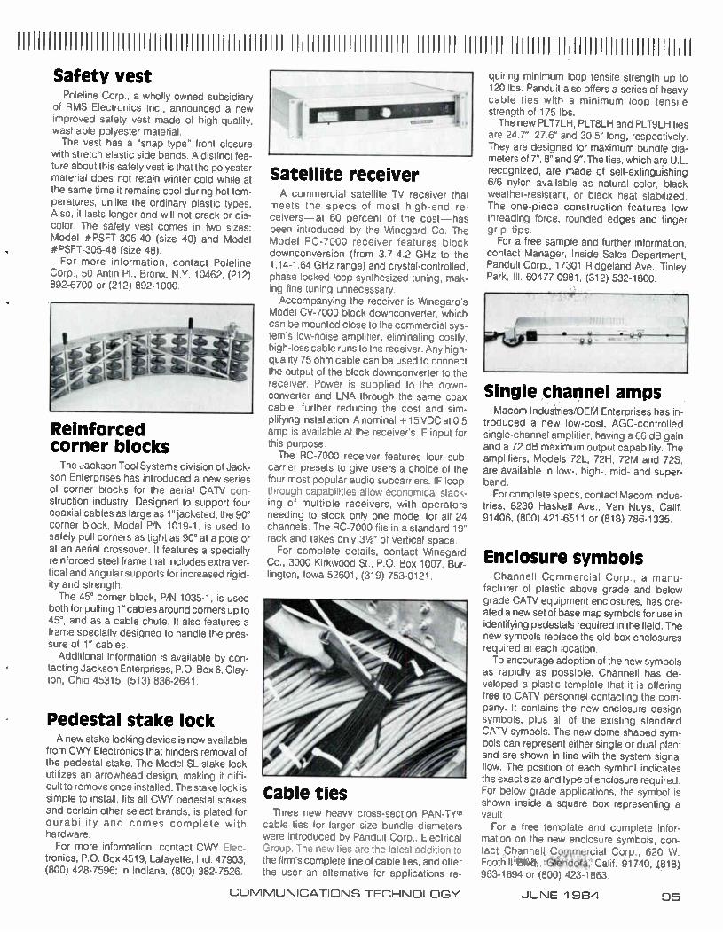
111111111 111111111111111111111111111111111111111111111111111111111111111111111111111111111111111111111111111111111111111111111111 Safety vest
Poleline Corp., a wholly owned subsidiary of RMS Electronics Inc., announced a new improved safety vest made of high-quality. washable polyester material. The vest has a "snap type" front closure
with stretch elastic side bands. A distinct fea-ture about this safety vest is that the polyester material does not retain winter cold while at the same time it remains cool during hot tem-peratures, unlike the ordinary plastic types. Also, it lasts longer and will not crack or dis-color. The safety vest comes in two sizes: Model #PSFT-305-40 (size 40) and Model #PSFT-305-48 (size 48). For more information, contact Poleline
Corp., 50 Antin Pl., Bronx, N.Y. 10462, (212) 892-6700 or (212) 892-1000.
Reinforced corner blocks The Jackson Tool Systems division of Jack-
son Enterprises has introduced a new series of corner blocks for the aerial CATV con-struction industry. Designed to support four coaxial cables as large as 1" jacketed, the 90° corner block, Model P/N 1019-1, is used to safely pull corners as tight as 90° at a pole or at an aerial crossover. It features a specially reinforced steel frame that includes extra ver-tical and angular supports for increased rigid-ity and strength.
The 45° corner block, P/N 1035-1, is used both for pulling 1" cables around corners up to 45°, and as a cable chute. It also features a frame specially designed to handle the pres-sure of 1" cables.
Additional information is available by con-tacting Jackson Enterprises, P.O. Box 6, Clay-ton, Ohio 45315, (513) 836-2641.
Pedestal stake lock A new stake locking device is now available
from CWY Electronics that hinders removal of the pedestal stake. The Model SL stake lock utilizes an arrowhead design, making it diffi-cult to remove once installed. The stake lock is simple to install, fits all CWY pedestal stakes and certain other select brands, is plated for durability and comes complete with hardware.
For more information, contact CWY Elec-tronics, P.O. Box 4519, Lafayette, Ind. 47903, (800) 428-7596; in Indiana, (800) 382-7526.
Satellite receiver A commercial satellite TV receiver that
meets the specs of most high-end re-ceivers—at 60 percent of the cost—has been introduced by the Winegard Co. The Model RC-7000 receiver features block downconversion (from 3.7-4.2 GHz to the 1.14-1.64 GHz range) and crystal-controlled, phase-locked-loop synthesized tuning, mak-ing fine tuning unnecessary. Accompanying the receiver is Winegard's
Model CV-7000 block downconverter, which can be mounted close to the commercial sys-tem's low-noise amplifier, eliminating costly. high-loss cable runs to the receiver. Any high-quality 75 ohm cable can be used to connect the output of the block downconverter to the receiver. Power is supplied to the down-converter and LNA through the same coax cable, further reducing the cost and sim-plifying installation. A nominal + 15 VDC at 0.5 amp is available at the receiver's IF input for this purpose. The RC-7000 receiver features four sub-
carrier presets to give users a choice of the four most popular audio subcarriers. IF loop-through capabilities allow economical stack-ing of multiple receivers, with operators needing to stock only one model for all 24 channels. The RC-7000 fits in a standard 19" rack and takes only 31/2" of vertical space.
For complete details. contact Winegard Co., 3000 Kirkwood St., P.O. Box 1007, Bur-lington, Iowa 52601, (319) 753-0121.
Cable ties Three new heavy cross-section PAN-TY'
cable ties for larger size bundle diameters were introduced by Panduit Corp., Electrical Group. The new ties are the latest addition to the firm's complete line of cable ties, and offer the user an alternative for applications re-
quiring minimum loop tensile strength up to 120 lbs. Panduit also offers a series of heavy cable ties with a minimum loop tensile strength of 175 lbs. The new PLT7LH, PLT8LH and PLT9LH ties
are 24.7", 27.6" and 30.5" long, respectively. They are designed for maximum bundle dia-meters of 7", 8" and 9". The ties, which are U.L. recognized, are made of self-extinguishing 6/6 nylon available as natural color, black weather-resistant, or black heat stabilized. The one-piece construction features low threading force, rounded edges and finger grip tips.
For a free sample and further information, contact Manager, Inside Sales Department, Panduit Corp., 17301 Ridgeland Ave., Tinley Park, III. 60477-0981, (312) 532-1800.
Single channel amps Macom Industries/OEM Enterprises has in-
troduced a new low-cost, AGC-controlled single-channel amplifier, having a 66 dB gain and a 72 dB maximum output capability. The amplifiers, Models 72L, 72H, 72M and 72S, are available in low-, high-, mid- and super-band.
For complete specs, contact Macom Indus-tries, 8230 Haskell Ave., Van Nuys, Calif. 91406, (800) 421-6511 or (818) 786-1335.
Enclosure symbols Channell Commercial Corp., a manu-
facturer of plastic above grade and below grade CATV equipment enclosures, has cre-ated a new set of base map symbols for use in identifying pedestals required in the field. The new symbols replace the old box enclosures required at each location. To encourage adoption of the new symbols
as rapidly as possible, Channell has de-veloped a plastic template that it is offering free to CATV personnel contacting the com-pany. It contains the new enclosure design symbols, plus all of the existing standard CAN symbols. The new dome shaped sym-bols can represent either single or dual plant and are shown in line with the system signal flow. The position of each symbol indicates the exact size and type of enclosure required. For below grade applications, the symbol is shown inside a square box representing a vault.
For a free template and complete infor-mation on the new enclosure symbols, con-tact Channell Cpmmercial Corp., 620 W.
'Gleddrà, Calif. 91740, ..(818), 963-1694 or (800) 423-1863.
COMMUNICATIONS TECHNOLOGY JUNE 1 984 95
Stationmaster stands alone.
PM-•
See us at Booth 523 at the NCTA Show.
Stationmaster. The completely automatic system
for inserting and verifying commercials on cable television.
Stationmaster is the only equipment you need to insert commer-cials as well as verify for the client that his advertising ran when he directed. And when we say Stationmaster stands alone, we mean it. HANDS OFF! Stationmaster operates by itself 24 hours a day year after year DON'T CALL US, WE'LL CALL YOU. TV Watch calls its Stationmaster accounts once a month just to "check in." Otherwise, we might never hear from them. HI-TECH. Stationmaster's secrets are in the software. It comes with a built-in verifier Secret: CMOS chip
technology Every Stationmaster is custom-programmed for the individual cable system. Secret: EPROM (Electronically Program-mable Read Only Memory) circuitry All operating components are on Printed Circuit boards.
Stationmaster is totally software-based. When Stationmaster arrives, we will be there to hook you up and we won't leave until we have trained your technical personnel. Get more information today. Call or write: TV Watch, 1819 Peachtree Road, N.E., Atlanta, GA 30309. (800) 554-1155. In Georgia, (404) 355-0100.
INSERTION EQUIPMENT LOCAL ADVERTISING SALES
An affiliate of United Media Enterprises. a Scripps-Howard Company
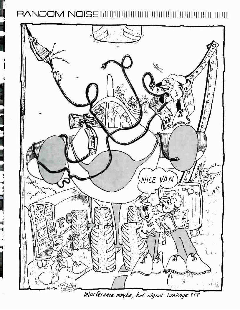
RANDOM NDISEIIIIIIIIIIIIIIIIIIIIIIIIIIIIIIIIIIIIIIIIIIIIIIIIIIIIIIIIIIIIIIIIIIIIIIIIII
lolerferefice nzgyhe, ho signal leakage ???
HAVE IT YOUR WAY
It has never been easier. Reason: S.A.L has everything you want in cable electronics—exactly the way you want it.
You can select components on prepackaged Head-End systems from a wide variety of top quality manufacturers. All our suppliers
are names you know and respect such as Phasecom. DX, and Jerrold. At S.A.L. having it your way means more than getting
the most advanced electronic equipment at N'ery competitive prices. Also means:
Expert advice for all electronic products from our service teams before, during and after installation.
A nationwide network of computer-linked distribution centers to assure on delivery of more than 3800 products
to meet .your construction schedules
A decade of commitment to amrtesr and service that has made SAL an industry leader in the cable communications market.
Put it together and there's only one way to go. Call S.A.L. today.
Have it your way in cable electronics S.A.L. CABLE COMMUNICATIONS, INC.
Northeast: New York (800) 645-9062 • (In New York State) 516 694-7110 Southeast: Atlanta (800) 241-0992 • (In Georgia) 404/981-0050. West: Los Angeles (800) 423-5463
(In California) 800 382-5616 • Midwest: Indianapolis (800) 428-3268 (In Indiana) 317 244-2477

KEEPING TRACK111111111111111111 111111111111 1111 1111111 1111111111 1111111111111111
Van Wagner
Hirsh
Bob Collins has been ap-pointed vice president of service for Anixter's distribution groups. In his new position Collins will be responsible for the day-to-day service levels of Anixter's Wire and Cable and Communications Supply businesses. Most recent-ly, Collins was corporate mate-rials manager, involved in setting up Anixter's materials manage-ment contract with PacTel Com-munications. Scott Van Wagner has been appointed district man-ager CATV - Northwest. Van Wag-ner was most recently sales man-ager for Anixter Communications' Denver-based CATV National Accounts group. In his new posi-tion he will be responsible for di-recting CATV sales in Wash-ington, Oregon, Idaho and Mon-tana. Van Wagner will be based out of Anixter's Seattle office. Everett Hirsh also has been ap-pointed vice president, CATV-West for Anixter. In his new posi-tion Hirsh will direct CATV sales in Arizona, California, Hawaii, Idaho, Montana, New Mexico, Nevada, Oregon, Washington and Utah. Hirsh will be based out of Anixter's
Walnut Creek, Calif., offices. Con-tact: 4711 Golf Rd., One Con-course Plaza, Skokie, III. 60076, (312) 677-2600.
The Drop Shop West Ltd. an-nounced the appointment of Ro-ger Fallihee as a Western re-gional sales representative. Prior to this appointment, Fallihee was Western regional sales manager for Cable TV Supply Co. Contact: P.O. Box 284, Roselle, N.J 07203, (800) 227-0700.
Scientific-Atlanta announced the appointment of Stan Sands as national sales manager for commercial accounts. Sands, who is based in Atlanta, will man-age the dealer and distribution network for commercial accounts, which include all SMATV appli-cations, satellite networking and local area networks. Sands has been with S-A for four years and has been promoted to national sales manager from his position as broadband communications products Southwest regional sales manager. Contact: One Technology Pkwy., Box 105600, Atlanta, Ga. 30348, (404) 441-4000.
Lysek
Poleline Corp.. a wholly owned subsidiary of RMS Electronics, announced the appointment of Matthew Lysek Sr. to the position of regional sales manager for its Eastern operations. Lysek has been in the cable industry for the past 17 years. During that time he worked in various management positions. He was vice president of sales/marketing for Magnavox, product manager for AM Cable TV Industries, and was president
of his own CATV manufacturing and distributing business. Con-tact: 50 Antin Pl., Bronx, N.Y. 10462. (212) 892-6700.
Jones
Loose
David Jones has been named manager, marketing communica-tions for Magnavox CATV Sys-tems Inc. In this position Jones will be responsible for coordi-nating the marketing communica-tions activities, including adver-tising and product publicity, pub-lic relations, trade shows and marketing research. Stan Loose has been promoted to the position of Eastern regional sales man-ager for Magnavox. In his new position, Loose will be responsi-ble for coordinating the promotion and selling of the company's CATV products throughout his re-gion. Contact: 100 Fairgrounds Dr., Manlius, N.Y. 13104. (315) 682-9105.
JVC Co. of America has ap-pointect Joe Klym sales engineer for the East Coast region. Klym's responsibilities include trouble-shooting for both customers and the sales staff. detecting potential
product difficulties, aiding author-ized JVC dealers with problems they might encounter and ser-vicing equipment at video trade shows. Contact: 41 Slater Dr., Elmwood Park. N.J. 07407. (201) 794-3900.
Winegard Co. recently an-nounced additional regional CATV sales personnel and office locations. The expanded CATV sales staff, headed up by Peter Hasse, national sales manager, Colmar. Pa.. consists of Dave Johnson, Amherst. N H. Darryn Roasa. Gahanna, Ohio John Jordahl. Burlington, Iowa: Thom-as Schulte Shawnee Mission, Kan.: Rus Heerdt Evergreen, Colo.: Rick Coursey Dallas: Ben Hedges Carson. Calif.: and Lynne Hood, Colmar, Pa. Con-tact: 3000 Kirkwood St.. P.O. Box 1007, Burlington, Iowa 52601. (319) 753-0121.
Daves
Baker
James Daves has joined the Jerrold Division of General In-strument as an account represen-tative for the Southeast sales re-gion. He will be responsible for
COMMUNICATIONS TECHNOLOGY JUNE 1 984 99
Look What You Get For Under
$3000. Everything you need in a character
generator. PLUS non-volatile page storage ...portability...and a "product life bat-tery." Think about that — 120 pages of mem-
ory that's almost impossible to lose. Even if the power goes off. The battery back-up is built-in...not added-on.
If you want or need portability — My-cro-VisionTM MAX gives it to you. Move it to another room, even take it to another location — you won't lose a word. And at 20 pounds it's as easy to move as it is to operate.
In the "high resolution" debate there's no question who has the last word — MAX at 70 nanoseconds. Compare that to 100 and 120 for our competitors. MAX does it all...and then some: 8 col-
ors...4 text style displays...graphics...4 user definable regions...weather station interface...stock and news wire posts... plus...plus...plus...and it's under $3000.
If you want the most for your money — put your money on MAX! It's one mag-nificent machine. See it at NAB and NCTA — or write today for more information.
Mycro-Tek P.O. Box 47068 / Wichita, Kansas 67201
Toll Free (800) 835-2055
Mycro-VisionTM MAX
Another Magnificent Machine from Mycro-Tek.
accounts in the state of Georgia, in addition to providing as-sistance on several key accounts. Before joining Jerrold, Daves was with Scientific-Atlanta, most re-cently serving as an affiliate sales representative responsible for broadcast equipment sales Robert (Mike) Baker also was appointed account executive for the Jerrold Division. He will be responsible for Jerrold accounts in the Pacific Northwest, including the states of Washington, Oregon, Idaho and Alaska. Reporting to Steve Wagner, Western region sales manager, Baker will be based in Seattle. Contact: 2200 Byberry Rd., Hatboro, Pa. 19040. (215) 674-4800.
Crawford
Davis
Pico Products has announced the promotion of David Crawford to the position of national sales manager of Pico Satellite Inc. Crawford's previous position with Pico was district sales manager for the Southeast United States. The company also has named Cullen Davis as district sales manager for the Southeast United States. Davis will have sales re-sponsibility for OTAS address-
able systems as well as standard products including traps. filters and encode/decode systems. Contact: 103 Commerce Blvd.. Liverpool. N.Y. 13088. (315) 451-7700.
Isaacson
Broadband Engineering has announced ee appointment of Peggy Isaacilon to the position of marketing coordinator. Isaacson was previously marketing/adver-tising coordinator for Vitek Elec-tronics. She will be responsible for developing Broadband's market-ing program and coordinating the firm's advertising and sales efforts. Her duties will include marketing research and analysis as well as the formulation of mar-keting strategies. Contact: P.O. Box 1247, Jupiter, Fla. 33458 (305) 747-5000.
Mucciardi
RMS Electronics has an-nounced the appointment of Fred Mucciardi as purchasing director for the company. He has been in the purchasing field for the last 20 years, and specifically connected with the cable industry for the last 10 years. Contact: 50 Antin Pl., Bronx, N.Y. 10462, (212) 892-6700.
°AXIAL 1TH P n.' ILE. E
General Cables MC2 ble Is revolutionary because of what's inside. Nothing...but air. That's right, air. And everybody, especially your competition, an tell you that with
air, power loss is at a minimum.
THE EASY HANDLER
Just as important, MC2 is more flexible, more bondable than Cid Ill cable, for instance. That's be-cause we've designed our new spacer discs to keep it from kink-ing and breaking. But don't just take our word for this We have tests that demonstrate MC2 su-periority in flexural stiffness, in torque measurements, and in a reverse bend fatigue test.
KEEPS YOU MILES AHEAD
Our patented design of using air instead of foam means less at-tenuation. YOU save money on installations, connections, labor and on the cable itself
MC2 IS THE NEW STANDARD OF RELIABILITY
No other cable can stand up to its environment better than the new MC? Because all of its com-ponents are bonded together for maximum flexibility with mini-mum signal loss. And that's with a signal load of 77 channels' Also, MC2 is extremely resistant to moisture ingress and migration because each cell is an hermeti-cally sealed compartment.
MC2 OUT-PERFORMED THE COMPETITION HANDS DOWN AND WE'LL BE HAPPY TO SHOW YOU THE RESULTS ANYTIME.
Visit Us At Booth 901-F At The NCTA
16.
General Cable
A un. co The Per, Ce.“,e :;(ergeet
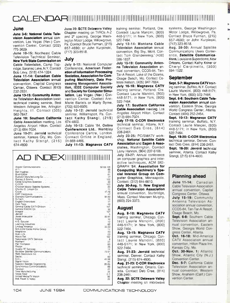
CALENDARI11111111111111111111111111111111111111111111111111111111111111111111111111111111111111 June June 3-6: National Cable Tele-vision Association annual con-vention, Las Vegas (Nev.) Con-vention Center. Contact (202) 775-3629. June 10-15: Northeast Cable Television Technical Seminar, New York State Commission on Cable Television, Camp Top-ridge, Saranac Lake, N.Y. Contact Bob Levy, (518) 474-1324. June 11-14: Canadian Cable Television Association annual convention, Capital Congress Center, Ottawa. Contact (613) 232-2631. June 13-15: Community Anten-na Television Association basic technical training seminar, Best Western Arlington Inn, Arlington Heights, Ill. Contact (305) 562-7847. June 19: Southern California Cable Association meeting, Los Angeles Airport Hilton. Contact (213) 684-7024. June 19-21: Jerrold technical seminar, Kansas City, Mo. Con-tact Kathy Stangl, (215) 674-4800.
June 20: SCTE Delaware Valley Chapter meeting on TVROs A-Z and 2° spacing, George Wash-ington Motor Lodge, Willowgrove, Pa. Contact Bruce Furman, (215) 657-4690; or John Kurpinski, (717) 323-8518.
July July 9-12: National Computer Conference, American Feder-ation of Information Processing Societies, Association for Com-puting Machinery, Data Pro-cessing Management Associa-tion, IEEE Computer Society and Society for Computer Simu-lation, Las Vegas (Nev.) Con-vention Center. Contact Ann-Marie Bartels or Marty Byrne, (703) 620-8926. July 10-12: Jerrold technical seminar, Williamsport, Pa. Con-tact Kathy Stangl, (215) 674-4800. July 10-12: Cable '84, Online Conferences Ltd.. Wembley Conference Centre, London. Contact Online in England, 01-868-4466. July 11-13: Magnavox CATV
AD INDEXIIIIIIIIIIIIIIIIIIIIIIIIIII Anixter Communications A T I Ben Hughes Brad Cable Burkeen Manufacturing Co Burnup & Simms Cable Graphics Sciences C-COR Channel Master Satellite Systems Charles 0 Larson Co Copal CVVY Electronics Diamond Communications Di-Tech English Enterprises Gem Tops General Cable CAN Division General Electric Co Integral Jerrold Jones Intercable Katek K G Sprucer Learning Industries Lindsay America M A-COM Cable Home Group Magnavox Multi-Link • Mycro-Tek Nationwide CATV Services Northern Pat Thompson Photon Quality RF Services Rainbow Satellite Communications RMS Electronics Inc Sachs SAL Signal Vision Superior Satellite Engineering Synchronous Communications Texscan Time Manufacturing Times Fiber United Media/TV Watch Wilk Power 8 Video
50-59.108 69 15 61 17
105 39 103 80 71
17.49 47
91.93 76 17 49
101 36 107 5
89.91 16 12 62
32.33
43 23 102 8
31 60 35 14
73.91 7
60 41.98
44 85-86
66 25
26 2-3 96 28
training seminar, Portland, Ore. Contact Laurie Mancini, (800) 448-5171; in New York, (800) 522-7464. July 12-14: Montana Cable Television Association annual convention, Big Sky, Mont. Con-tact Tom Glendenning,' (406) 586-1837 July 15-19: Community Anten-na Television Association an-nual convention, CCOS-84, Tan-Tar-A Resort, Lake of the Ozarks, Osage Beach, Mo. Contact Ce-leste Nelson. (405) 947-7664. July 16-18: Magnavox CATV training seminar, Portland, Ore. Contact Laurie Mancini, (800) 448-5171; in New York, (800) 522-7464. July 17: Southern California Cable Association meeting, Los Angeles Airport Hilton. Contact (213) 684-7024. July 17-19: C-COR Electronics technical seminar, Albany, N.Y. Contact Deb Cree, (814) 238-2461. July 23-25: PC/SMATV work-shop. National Satellite Cable Association and Eagan & Asso-ciates, Washington. Contact Larry Hannon, (904) 237-6106. July 23-27: Annual conference on computer graphics and inter-active techniques, ACM SIG-GRAPH '84, Association for Computing Machinery's Spe-cial Interest Group on Com-puter Graphics. Minneapolis. Contact: (312) 644-6610. July 30-Aug. 1: New England Cable Television Association annual convention, Sturbridge, Mass. Contact Maureen Murphy, (603) 224-3373.
August Aug. 8-10: Magnavox CATV training seminar, Chicago. Con-tact Laurie Mancini, (800) 448-5171; in New York, (800) 522-7464. Aug. 13-15: Magnavox CATV training seminar. Chicago. Con-tact Laurie Mancini, (800) 448-5171; in New York, (800) 522-7464. Aug. 21-23: Jerrold technical seminar, Denver. Contact Kathy Stangl, (215) 674-4800. Aug. 21-23: C-COR Electronics technical seminar, Ontario, Can-ada. Contact Deb Cree, (814) 238-2461. Aug. 22: SCTE Delaware Valley Chapter meeting on microwave
systems, George Washington Motor Lodge, Willowgrove, Pa. Contact Bruce Furman, (215) 657-4690; or John Kurpinski, (717) 323-8518. Aug. 28-30: Annual Satellite Communications Users Confer-ence, Satellite Communica-tions, Louisiana Superdome, New Orleans. Contact Kathy Kriner or Cheryl Carpinello, (303) 694-1522.
September Sept. 5-7: Magnavox CATV train-ing seminar, Buffalo, N.Y. Contact Laurie Mancini, (800) 448-5171; in New York, (800) 522-7464. Sept. 6-8: Southern Cable Tele-vision Association annual con-vention, Eastern Show, Georgia World Congress Center, Atlanta. Contact (404) 252-2454. Sept. 10-12: Magnavox CATV training seminar, Buffalo, N.Y. Contact Laurie Mancini, (800) 448-5171; in New York, (800) 522-7464. Sept. 18-20: C-COR Electronics technical seminar, Denver. Con-tact Deb Cree, (814) 238-2461. Sept. 18-20: Jerrold technical seminar, Atlanta. Contact Kathy Stangl, (215) 674-4800.
Planning ahead June 11-14: Canadian Cable Television Association annual convention, Capital Congress Center, Ottawa. July 15-19: Community Antenna Television As-sociation annual convention, CCOS-84, Tan-Tar-A Resort, Osage Beach, Mo. Sept. 6-8: Southern Cable Television Association an-nual convention, Eastern Show, Georgia World Con-gress Center, Atlanta. Oct. 16-18: Mid-America CATV Association annual convention, Hilton Plaza Inn, Kansas City, Mo. Oct. 30-Nov. 1: Atlantic Show, Atlantic City (N.J.) Convention Center. Dec. 5-7: California Cable Television Association an-nual convention, Western Show, Anaheim (Calif.) Con-vention Center.
1 04 JUNE 1984 COMMUNICATIONS TECHNOLOGY
REACH. Not every animal in the jungle
can reach everything it needs. Capscan has built a reputation for
stretching its imagination just a little further to come up with product solutions other cable manufacturers can't match. Our new CD 7000 drop cable
is the latest example of the "extra reach" made possible by Capscan's
advanced cable design and manu-facturing technology. When RG-6 won't do and RG-11 is too expen-sive, CD 7000 fits the bill. Whatever your trunk or drop cable
needs are, the experts at Capscan can satisfy them. Give us a call today and challenge us with your toughest problem. At Capscan, filling tall orders is our specialty.
u BURNUP & SIMS
CAPSCAN
National Office/Southeast Region: (404) 451-5522 Capscan/Northeast Region: (800) 222-5388 Midwest Region: (906) 542-6231 Southwest Region: (817) 599-6241 Western Region: (206) 824-2448

LUFF SPEAKS OUTIIIIIIIIIIIIIIIIIIIIIIIIIIIIIIIIIIIIIIIIIIIIIIIIIIIIIIIIIIIIIIIIII
Proof-of-performance tests: Fact or fiction? By Bob Luff Vice President Engineering United Artists Cablesystems Corp
Are your Federal Communications Com-mission annual proof-of-performance test re-ports fact or fiction? I believe we should be concerned that too often they are fiction — fiction, insofar as they are forced showings of system compliance with the FCC technical requirements and as such not truly represen-tative of the system's actual, overall day-to-day technical performance. It should be noted that if the proof results are not reason-ably representative of the system's actual technical rule compliance, but implied to be via the proof report, the system may be back-ing into a case of misrepresentation and tur-bulent regulatory waters.
Performance test guidelines review As an industry, and in the interests of pro-
fessional integrity of the technical community, we should uphold to the highest standards of truthfulness and accuracy during the proof process. Nearly everyone knows the actual 13 FCC minimum technical performance para-meters that are to be measured, recorded and compared for compliance during the proof process. (They are listed in 76.605 Technical Standards of the Rules.) But, the section defi-ning the overall governing guidelines for the annual proof tests is less read. A review of this section, 76.601— Performance Tests, of Subpart K points out how far we may have drifted away from the past and present intent of the proof test and report.
First, section 76.601 (a) clearly indicates that the FCC intends the CAN annual proof to be an accurate, unforced showing "that the system does, in fact, comply with the rules." And, again in 76.601 (c) the FCC states, "The performance tests shall be directed at deter-mining the extent to which the system com-plies with all the technical standards set forth in 76.605." System practices of forcing proofs in specially-groomed staging areas or at hand-picked test points fly directly in the face of the FCC's clearly stated intent and expecta-tion of a proof.
Forced proofs By forced proof, it is not implied conscious,
or deliberate dishonesty, but we should agree that there is a fine line between unconsciously polishing up certain areas of the system just prior to running and recording the official an-nual proof tests results or perhaps worse, hand picking or continuous tweeking of the
three "representative test points and bor-derline misrepresentation or deliberate dis-honesty to a government agency.
Deliberate dishonesty to a federal agency is a very serious matter and should not be taken lightly. But an equally important con-cern is that forced proof results cause an internal false sense of comfortable system performance to the system operator and technical staff. If the system's short comings are not accurately measured, reported, and elevated to visible priority, how can we expect to ever properly address the direct or under-lying conditions. Engineering departments are heard to be constantly complaining of receiving inadequate resources to do the pro-fessional, day-to-day system maintenance up-keep job they feel is required to assure comfortable rule compliance, quality signals and reliability and subscriber satisfaction. Yet, time after time, on the most important technical test of the year, these same tech-nical departments seem to bend over back-wards to represent the system's performance like a happy fairy tale.
Let us not forget that minimum system technical performance requirements are not a matter of individual cable company or system choice to be emphasized or de-emphasized as budget or whim dictates. The FCC regu-lates CATV minimum technical performance parameters (76.605) and its daily compliance is seen by them as equally important as with any other FCC technical rule.
Further, since these performance re-quirements are considered well below today's industry state-of-the-art capabilities and sub-scriber acceptability, most systems have adopted a more strict internal set of system minimum technical performance parameters. If the FCC proof-of-performance levels are not comfortably met, the system's own per-formance parameters are being violated as well.
...technical performance requirements are not a matter of...choice to be emphasized or de-emphasized as budget or whim dictates'
Also, most, if not all, of the CATV franchises key system technical performance ob-ligations to the FCC technical rules. Day-to-day compliance with the FCC technical re-quirements is essential to conform to these important franchise requirements.
A call for system proof policy review It is time for the industry to carefully review
and amend its FCC system proof practices to ensure full compliance with the commission's most basic requirement: honesty. Appropri-ate system policymakers should develop specific internal proof procedures that of course, provide for the best representation of the system's actual performance, but strictly within the bounds of technical pro-fessionalism and integrity. Such strict self-imposed procedures will
undoubtedly eventually result in failed proofs. According to FCC spokespersons, if the situ-ation cannot be immediately corrected, a writ-ten plan to correct the problem should be attached to the proof as part of the proof. The system or company is then obligated to follow through with the specified written plan. If the situation cannot be corrected in a reasonable period of time, a formal request for waiver of the rules involved must be submitted to the FCC. It is further suggested that if the official system proof results in a finding that FCC requirements are being met but higher inter-nal system requirements are not, the same type of written plan or request of internal wai-ver be filed at the appropriate system or com-pany level. The focus of the FCC and system proof-of-
performance requirements is not the test itself but the honest assurance that the com-mission's and system's basic minimum tech-nical performance parameters are, in fact, being comfortably met throughout the sys-tem. Forcing the results violates the principle, the value and the law.
1
106 JUNE 1984 COMMUNICATIONS TECHNOLOGY

Celebrate faster pulls, earlier revenues. Use Integral's Cablecon. MSOs everywhere are beating installation deadlines and going on-line sooner by using Coax-Cablecon to carry CATV Trunk, Drop and Feeder cables in their underground systems.
If you're looking for the safest, surest cable installation with a built-in, cost-efficient path for future modification, Integral's Cablecon offers unique benefits.
Proven technology: Cablecon is Integral's tradename for a preassembled cable-in-duct system that is being used in utility underground distribution; airport, street, parking lot and highway lighting; irrigation power and control cable; traffic signal loop and CATV applications.
Coax-Cablecon is manufactured specifically for the CATV Industry.
In the short 1982-1983 period, MSOs used 1,000 + miles of Coax-Cablecon in their projects.
Easy Installation: Cables are preinstalled at the factory. Then, Cablecon is delivered to your job site on reels, ready to plow or lay in an open trench. After manufacture, the cable is not touched until it is spliced.
Cablecon protects your cable during shipping, and protects against rocks, rodents and chemicals in the ground.
Versatility: Cablecon is a polyethylene duct extruded to diameters and lengths you specify: it can handle any communications cable, including current fiberoptic cables, and provides an easy path for future modification.
Low installed cost: In-field comparisons show Cablecon to be easier and faster to install than PVC duct systems.
National Sales Representative: Channel Commercial Corporation Call Toll Free 1-800-423-1863 In California (213)-963-1694
Integral Corporation P.O. Box 11269 Dallas, Texas 75223 (214)-826-0590
e 1984 Integral Corp 5655
06 integral 9-ege Corporation
Our 24th year"

ThermoCrimem Connectors run rings around everything else.
We found a way to make tne most reliable, easy-to-install CATV connector. And we did it with small, simple rings.
Raychem and Anixter bring you the ThermoCrimp' Connector, a revolutionary new product that relies on heat-shrinkable rings to make electrical connections. These rings solve the problem of loose coupling nuts caused by vibration, temper-ature change and improper installation.
To achieve precise, reliable connections time after time, use ThermoCrimp"' Con-nectors. They're in stock now at Anixter. Call 1-800-323-0436.
Raychem C 0 eP I IM U lC aT
Related Documents