เอกสารประกอบการสอนรวบรวมโดย นายรัชศักดิ์ สารนอก เอกสารประกอบการสอน รหัสวิชา EIT3702 ชื่อวิชา อิเล็กทรอนิกส์กาลัง (Power Electronics) 3(2-2-5) รวบรวมโดย อาจารย์รัชศักดิ์ สารนอก ภาคเรียนที่ 2 ปีการศึกษา 2555 สาขาวิชาเทคโนโลยีไฟฟ้าอุตสาหกรรม คณะเทคโนโลยีอุตสาหกรรม มหาวิทยาลัยราชภัฏสวนสุนันทา

Welcome message from author
This document is posted to help you gain knowledge. Please leave a comment to let me know what you think about it! Share it to your friends and learn new things together.
Transcript

เอกสารประกอบการสอนรวบรวมโดย นายรัชศักดิ์ สารนอก
เอกสารประกอบการสอน รหัสวิชา EIT3702
ชื่อวิชา อิเล็กทรอนิกสก์ าลัง (Power Electronics) 3(2-2-5)
รวบรวมโดย อาจารย์รัชศักดิ์ สารนอก
ภาคเรียนที่ 2 ปีการศึกษา 2555 สาขาวิชาเทคโนโลยีไฟฟ้าอุตสาหกรรม
คณะเทคโนโลยีอตุสาหกรรม มหาวิทยาลัยราชภัฏสวนสุนันทา

เอกสารประกอบการสอนรวบรวมโดย นายรัชศักดิ์ สารนอก
บทท่ี 1 ความรูเ้บื้องต้นเกี่ยวกับวงจรอิเล็กทรอนิกส์ก าลัง
(Introduction to Power Electronic Circuit)
อิเล็กทรอนิกส์ก ำลัง (Power Electronics) เป็นกำรแปลงแหล่งจ่ำยไฟฟ้ำที่มีอยู่โดยใช้อุปกรณ์
อิเล็กทรอนิกส์ในกำรเปลี่ยนแปลงและกำรควบคุมให้เป็นแหล่งจ่ำยระบบไฟฟ้ำตำมควำมต้องกำรใช้งำนของโหลด (Load) [1] อุปกรณ์อิเล็กทรอนิกส์ที่น ำมำใช้กับวงจรระบบไฟฟ้ำก ำลัง ได้แก่ ไดโอดก ำลัง เอสซีอำร์ ทรำนซิสเตอร์ก ำลังแบบสองรอยต่อและแบบมอสเฟต ไอจีบีที จีทีโอ เป็นต้น ซึ่งพัฒนำมำจำกอุปกรณ์อิเล็กทรอนิกส์ที่ใช้งำนทั่วไป แต่จะสำมำรถทนต่อกระแสและแรงดันได้สูงกว่ำเพื่อให้เหมำะสมกับระบบไฟฟ้ำก ำลัง ดังนั้นจึงเรียกอุปกรณ์ที่น ำมำใช้นี้ว่ำ อุปกรณ์อิเล็กทรอนิกส์ก ำลัง โดยทั่วไปหลักกำรท ำงำนของวงจรอิเล็กทรอนิกส์ก ำลังจะมีวงจรอิเล็กทรอนิกส์ก ำลังท ำหน้ำที่เหมือนเปลี่ยนแปลงและควบคุมระบบไฟฟ้ำก ำลังจำกแหล่งจ่ำยไฟฟ้ำที่มีอยู่ ดังรูปที่ 1.1
รูปที่ 1.1 แสดงแผนภำพกำรท ำงำนของวงจรอิเล็กทรอนิกส์ก ำลัง
อุปกรณ์หรือเคร่ืองใช้ไฟฟ้ำมีกำรพัฒนำให้สอดคล้องกับควำมต้องกำรมำกมำยหลำยรูปแบบ ทั้งในชีวิตประจ ำวัน โรงงำนอุตสำหกรรม กำรคมนำคมหรือใช้เป็นเคร่ืองมือเคร่ืองจักรในกำรประกอบอำชีพต่ำง ๆ แต่อย่ำงไรก็ตำม ในกำรหำแหล่งจ่ำยเพื่อป้อนให้กับอุปกรณ์หรือเคร่ืองมือเคร่ืองจักรตำมที่กล่ำวมำนั้นก็มีข้อจ ำกัด ดังน้ัน จึงจ ำเป็นต้องสร้ำงอุปกรณ์หรือวงจรอย่ำงหนึ่งมำควบคุมเพื่อให้อุปกรณ์เหล่ำนั้นสำมำรถใช้พลังงำนไฟฟ้ำตำมแหล่งจ่ำยไฟฟ้ำที่มีอยู่ได้ ซึ่งอุปกรณ์หรือวงจรนั้นก็คือ วงจรอิเล็กทรอนิกส์ก ำลัง
Converter
By
Semiconductor devices
Control Input
Power Input Power Output

เอกสารประกอบการสอนรวบรวมโดย นายรัชศักดิ์ สารนอก
ดังนั้น สรุปได้ว่ำ อิเล็กทรอนิกส์ก ำลังหมำยถึง กำรควบคุมและหรือกำรเปลี่ยนแปลงระบบไฟฟ้ำก ำลัง (Electrical Power) จำกระบบหนึ่งไปเป็นอีกระบบหนึ่งด้วยกำรใช้อุปกรณ์อิเล็กทรอนิกส์ (Power Semiconductor devices) แหล่งจ่ายไฟฟ้า
กำรแปลงแหล่งจ่ำยไฟฟ้ำหรือระบบไฟฟ้ำในงำนอิเล็กทรอนิกส์ก ำลัง มีระบบแหล่งจ่ำยไฟฟ้ำอยู่ 2 ระบบ คือระบบไฟฟ้ำกระแสตรงและระบบไฟฟ้ำกระแสสลับ
ระบบไฟฟ้ำกระแสตรง (Direct Current) ระบบไฟฟ้ำกระแสตรง อิเล็กตรอนจะมีทิศทำงกำรไหลของกระแสไฟฟ้ำไปในทิศทำงเดียว ซึ่ง
ระดับแรงดันอำจจะคงที่ หรือมีกำรเปลี่ยนแปลงเพิ่มขึ้นหรือลดลงก็ได้ แต่กำรเปลี่ยนแปลของระดับแรงดันจะต้องไม่เปลี่ยนจำกบวกเป็นลบ หรือจำกลบเป็นบวก หรือระดับแรงดันจะไม่เปลี่ยนแปลงผ่ำนค่ำศูนย์ [3] ซึ่งมีลักษณะรูปคลื่นดังรูปที่ 2 โดยทั่วไปแล้วมักต้องกำรแหล่งจ่ำยไฟฟ้ำกระแสตรงที่มีขนำดคงที่หรือเรียบที่สุด เช่น แบตเตอร่ี ถ่ำนไฟฉำย เป็นต้น แต่แหล่งจ่ำยไฟฟ้ำเหล่ำนี้ก็มีข้อจ ำกัดในด้ำนระยะเวลำกำรใช้พลังงำนไฟฟ้ำที่อำจจะไม่สำมำรถใช้งำนติดต่อกันอย่ำงต่อเน่ือง รวมทั้งขนำดพิกัดของกระแสและแรงดันที่อำจไม่ตรงกับพิกัดของโหลด ดังนั้นจึงอำจแปลงจำกแหล่งจ่ำยไฟฟ้ำที่สำมำรถจ่ำยก ำลังไฟฟ้ำได้ต่อเนื่อง ซึ่งจะสำมรถลดข้อจ ำกัดด้ำนระยะเวลำกำรใช้งำนได้ แต่กำรจะแปลงระบบไฟฟ้ำด้วงอุปกรณ์อิเล็กทรอนิกส์ก ำลังให้มีรูปคลื่นเหมือนกับแหล่งจ่ำยจำกแบตเตอร่ีก็มีข้อจ ำกัดคือไม่สำมำรถท ำให้เรียบหรือคงที่ได้ แต่ก็ยังสำมำรถน ำไปใช้งำนกับเคร่ืองใช้บำงอย่ำงที่ไม่ต้องกำรรูปคลื่นที่คงที่มำกนัก ระดับแรงดันที่เพิ่มขึ้นและลดลงเล็กน้อยเช่นน้ีเรียกว่ำค่ำริปเปิ้ล (Ripple)
ในกำรแปลงแหล่งจ่ำยไฟฟ้ำก ำลังบำงอย่ำง เช่นกำรแปลงไฟกระแสสลับให้เป็นไฟกระแสตรงด้วย ตัวเรียงกระแสแบบบริดจ์ แม้ว่ำจะได้รูปคลื่นเป็นระบบไฟฟ้ำกระแสตรงแต่ไฟที่ได้ยังไม่เรียบและไม่เหมำะที่จะใช้กับวงจร อิเล็กทรอนิกส์ ซึ่งอำจจะปรับปรุงให้เรียบขึ้นได้โดยกำรต่อตัวเก็บประจุ (Capacitor) เข้ำไป

เอกสารประกอบการสอนรวบรวมโดย นายรัชศักดิ์ สารนอก
Steady DC from a battery or regulated power supply, this is ideal for electronic circuits
Smooth DC from a smoothed power supply,this is suitable for some electronics. * ระดับแรงดันที่เพิ่มขึ้นและลดลงเล็กน้อยเช่นน้ีเรียกว่ำค่ำริปเปิ้ล (Ripple)
Varying DC from a power supply without smoothing, this is not suitable for electronics
รูปที่ 1.2 รูปคลื่นสัญญำณระบบไฟฟ้ำกระแสตรง
ระบบไฟฟ้ำกระแสสลับ ระบบไฟฟ้ำกระแสสลับ (Alternating Current) อิเล็กตรอนจะมีทิศทำงกำรไหลสลับกันไปมำ
ต่อเนื่อง ระดับแรงดันจะมีกำรเปลี่ยนแปลจำกบวกเป็นลบ หรือจำกลบเป็นบวก หรือระดับแรงดันจะมีกำร เปลี่ยนแปลงผ่ำนค่ำศูนย์ [3] ซึ่งมีลักษณะรูปคลื่นดังรูปที่ 3 รูปคลื่นสัญญำณระบบไฟฟ้ำกระแสสลับ โดยอัตรำกำรเปลี่ยนแปลงค่ำระดับแรงดันจะเรียกว่ำ ควำมถี่ (Frequency) มีหน่วยเป็น Hertz (Hz) ส ำหรับประเทศไทยระบบไฟฟ้ำกระแสสลับจะใช้ควำมถี่ขนำด 50 Hz

เอกสารประกอบการสอนรวบรวมโดย นายรัชศักดิ์ สารนอก
AC from a power supply This shape is called a sine wave
This triangular signal is AC because it changes between positive (+) and negative (-).
รูปที่ 1.3 รูปคลื่นสัญญำณระบบไฟฟ้ำกระแสสลับ
ประเภทของวงจรอิเล็กทรอนิกส์ก าลัง
ในกำรแปลงแหล่งจ่ำยไฟฟ้ำระบบไฟฟ้ำที่มีอยู่โดยใช้อุปกรณ์อิเล็กทรอนิกส์ในกำรเปลี่ยนแปลงและกำรควบคุมให้เป็นแหล่งจ่ำยระบบไฟฟ้ำตำมควำมต้องกำรใช้งำนของโหลด โดยใช้วงจรอิเล็กทรอนิกส์ก ำลังนั้น มีวงจรกำรท ำงำนพื้นฐำนอยู่ 4 ประเภท ดังนี ้[2]
1. AC-to-DC conversion (Rectifier)
AC/DC converters (rectifiers) are used every time an electronic device is connected to the mains (computer, television and etc) 2. DC-to-AC conversion (Inverter)
DC/AC converters (inverters) are used primarily in UPS or emergency light. During normal electricity condition, the electricity will charge the DC battery. During blackout time, the DC battery will be used to produce AC electricity at its output to power up the appliances.
3. DC-to DC conversion (Chopper)

เอกสารประกอบการสอนรวบรวมโดย นายรัชศักดิ์ สารนอก
DC/DC converters are used in most mobile devices (mobile phone, pda and etc) to maintain the voltage at a fixed value whatever the charge level of the battery is. These converters are also used for electronic isolation and power factor correction.
4. AC-to-AC conversion. (Cycloconverter) AC/AC converters are used to change either the voltage level or the frequency
(international power adapters, light dimmer). In power distribution networks AC/ AC converters may be used to exchange power between utility frequency 50 Hz and 60 Hz power grids
อุปกรณ์อิเล็กทรอนิกส์ก าลัง
เทคโนโลยีด้ำนอิเล็กทรอนิกส์ก ำลังและกำรขับเคลื่อนด้วยไฟฟ้ำมีกำรพัฒนำอย่ำงมำกมำยกว้ำงตลอดระยะเวลำที่ผ่ำนมำ สิ่งประดิษฐ์หลำยอย่ำง เช่น อุปกรณ์ (Devices) ชิ้นส่วน (Components) วงจร (Circuits) ระบบควบคุมต่ำง ๆ ถูกสร้ำงขึ้นมำกมำยในช่วงระยะเวลำไม่นำนก่อนหน้ำนี้ซึ่งเกี่ยวข้องกับอิเล็กทรอนิกส์ก ำลัง และแนวโน้มในอนำคตก็ยังจะมีกำรพัฒนำไปอย่ำงต่อเน่ือง โดยเห็นได้จำกมีกำรพัฒนำอุปกรณ์สำรกึ่งตัวน ำแต่ละชนิดให้มีกำรท ำงำนที่มีประสิทธิภำพสูงและมีควำมหลำกหลำยเพื่อให้เกิดควำมเหมำะสมในกำรน ำไปใช้งำน
อุปกรณ์อิเล็กทรอนิกส์ก ำลังมักจะท ำหน้ำที่เหมือนกับเป็นสวิทช์ ดังนั้นกำรท ำงำนจึงจะมีอยู่ 2 สถำนะดังนี ้ Fully on
- i.e Switch closed - Conducting state
Fully off - i.e Switch opened - Blocking state
แต่อย่ำงไรก็ตำมแม้ว่ำจะท ำหน้ำที่เหมือนสวิทช์เปิด-ปิด แต่อุปกรณ์อิเล็กทรอนิกส์ก ำลงัไม่สำมำรถท ำงำนในสภำวะคงที่ (Linear Mode)
อุปกรณ์อิเล็กทรอนิกส์ก ำลัง สำมำรถแบ่งออกเป็นกลุ่มตำมลักษณะกำรควบคุมกำรท ำงำนดังน้ี Uncontrolled: Diode Semi-controlled: Thyristor

เอกสารประกอบการสอนรวบรวมโดย นายรัชศักดิ์ สารนอก
SCR , GTO, Triac Fully controlled: Power transistors:
BJT, MOSFET, IGBT, GTO, IGCT
ตำรำงที่ 1.1 แสดงกำรเปรียบเทียบคุณลักษณะของอุปกรณ์
1) Power Diode

เอกสารประกอบการสอนรวบรวมโดย นายรัชศักดิ์ สารนอก
รูปที่ 1.4 Power diode (a) Symbol (b) v-i Characteristic TYPES OF POWER DIODE
ชนิดของไดโอดก าลัง
2) GTO – Gate Turn Off Thyristor GTO (Gate Turn Off Thyristor)
• Behave like normal thyristor, but can be turned off using gate signal • However turning off is difficult. Need very large reverse gate current (normally 1/5 of
anode current) • Gate drive design is very difficult due to very large reverse gate current at turn off.

เอกสารประกอบการสอนรวบรวมโดย นายรัชศักดิ์ สารนอก
• Ratings: Highest power ratings switch - Voltage: Vak < 5kV - Current: Ia < 5kA - Frequency: f < 5KHz
รูปที่ 1.5 GTO (a) Symbol and (b) v-i characteristic 125
3) TRIAC • Semiconductor device that electrically equivalent to two SCRs, connected anti parallel, although
internal structure are not exactly the same as that two SCRs • Behave like normal thyristor, but can be turned off using gate signal • However turning off is difficult. Need very large reverse gate current (normally 1/5 of anode
current)

เอกสารประกอบการสอนรวบรวมโดย นายรัชศักดิ์ สารนอก
รูปที่ 1.6 TRIAC (a) Symbol (b) v-i characteristic 4) IGBT – Insulated Gate Bipolar Transistor
• Combination of BJT and MOSFET characteristics. - Gate behaviour similar to MOSFET ,easy to turn on and off. - Low losses like BJT due to low on-state Collector- Emitter voltage (2-3V).
• Ratings: - Voltage: VCE<3.3kV - Current,: IC<1.2kA currently available. - Latest: HVIGBT4.5kV/1.2kA.
• Switching frequency up to 100KHz. Typical applications: 20-50KHz.
รูปที่ 1.7 IGBT (a) Symbol (b) v-i characteristic
5) DIAC • The construction of a diac is similar to an open base NPN transistor. • The diac is similar to having two parallel Shockley diodes turned in opposite directions

เอกสารประกอบการสอนรวบรวมโดย นายรัชศักดิ์ สารนอก
• The bidirectional transistor-like structure exhibits a high-impedance blocking state up to a voltage breakover point (VBO) above which the device enters a negative- resistance region.
• These basic diac characteristics produce a bidirectional pulsing oscillator in a resistor- capacitor AC circuit.
• Since the diac is a bidirectional device, it makes a good economical trigger for firing triacs in phase control circuits such as light dimmers and motor speed controls.
(a)
(b)

เอกสารประกอบการสอนรวบรวมโดย นายรัชศักดิ์ สารนอก
รูปที่ 1.8 DIAC (a) Symbol (b) v-i characteristic of bilateral trigger DIAC
6) PUT – PROGRAMMABLE UNIJUNCTION TRANSISTOR • The PUT is actually a type of thyristor • It can replace the UJT in some applications. • It is more similar to an SCR (four-layer device) except that its anode-to-gate voltage can be used
to both turn on and turn off the device. • Notice that the gate is connected to the n region adjacent to the anode. • The gate is always biased positive with respect to the cathode. • When VA - VG > 0.7 V, the PUT turns on. • The characteristic plot of VAK versus IA is similar to the VE versus IE plot of the UJT.

เอกสารประกอบการสอนรวบรวมโดย นายรัชศักดิ์ สารนอก
รูปที่ 1.9 PUT (a) Basic construction (b) Symbol and biasing
7) SCR • If the forward break over voltage (Vbo) is exceeded, the SCR “self-triggers” into the conducting
state. • The presence of gate current will reduce Vbo. • “Normal” conditions for thyristors to turn on:
- The device is in forward blocking state (i.e Vak is positive) - A positive gate current (Ig) is applied at the gate
• Once conducting, the anode current is latched. Vak collapses to normal forward volt- drop, typically 1.5-3V.
• In reverse -biased mode, the SCR behaves like a diode. • Thyristor cannot be turned off by applying negative gate current.
- It can only be turned off if Ia goes negative (reverse) - This happens when negative portion of the of sine-wave occurs (natural commutation)
• Another method of turning off is known as “forced commutation” - The anode current is “diverted” to another circuitry.
เอกสารประกอบการสอนรวบรวมโดย นายรัชศักดิ์ สารนอก
รูปที่ 1.10 SCR (Thyristor) (a) Symbol (b) v-i characteristic
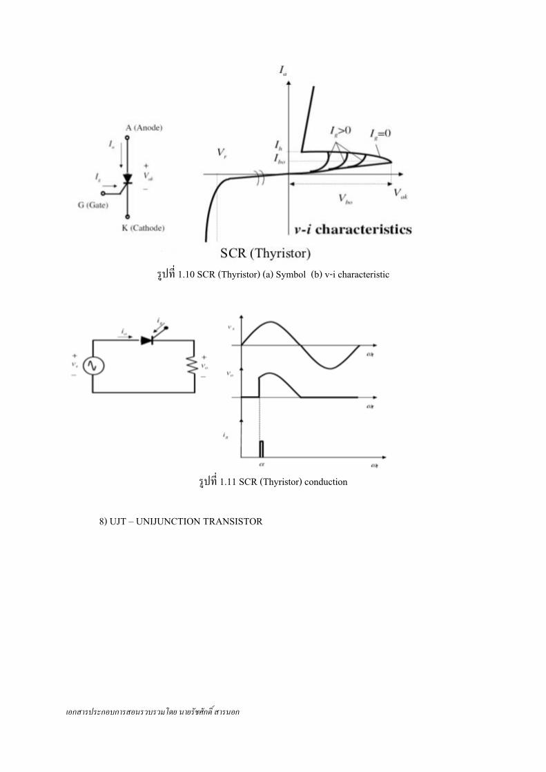
รูปที่ 1.11 SCR (Thyristor) conduction
8) UJT – UNIJUNCTION TRANSISTOR

เอกสารประกอบการสอนรวบรวมโดย นายรัชศักดิ์ สารนอก
รูปที่ 1.12 UJT (a) Symbol (b) Equivalent circuit (c) v-i characteristic ตัวอย่างการประยุกต์ใช้งานวงจรเพำเวอร์อิเล็กทรอนิกส์ ปัจจุบันมีกำรพัฒนำทำงด้ำนเทคโนโลยีอย่ำงรวดเร็วและกว้ำงขวำง ทั้งในด้ำนชีวิตประจ ำวัน ด้ำนอุตสำหกรรม และกำรอนุรักษ์พลังงำนต่ำง ๆ กำรประยุกต์โดยน ำวงจรเพำเวอร์อิเล็กทรอนิกส์ไปใช้งำนถือเป็นส่วนส ำคัญในกำรพัฒนำเทคโนโลยีเหล่ำนั้น ซึ่งแสดงให้เห็นได้จำกตัวอย่ำงกำรใช้งำนดังต่อไปนี้ [4] (a) Residential
Refrigeration and freezers Space heating

เอกสารประกอบการสอนรวบรวมโดย นายรัชศักดิ์ สารนอก
Air conditioning Cooking Lightning Electronics (personal computers, other entertainment equipment)
(b) Commercial
Heating, ventilating, and air conditioning Central refrigeration Lighting Computers and office equipment Uninterruptible power supplies (UPSs) Elevators
(c)Industrial Pumps Compressors Blowers and fans Machine tools (robots) Arc furnaces, induction furnaces Lighting Industrial lasers Induction heating Welding
(d) Transportation Traction control of electric vehicles Battery chargers for electric vehicles Electric locomotives Street cars, trolley buses Subways Automotive electronics including engine controls
(e) Utility systems High-voltage dc transmission (HVDC) Static var compensation (SVC)

เอกสารประกอบการสอนรวบรวมโดย นายรัชศักดิ์ สารนอก
Supplemental energy sources (wind, photovoltaic), fuel cells Energy storage systems Induced-draft fans and boiler feed water pumps
(f) Aerospace Space shuttle power supply systems satellite power systems Aircraft power systems
(g)Telecommunications Battery chargers Power supplies (dc and UPS)
นอกจำกตัวอย่ำงกำรน ำวงจรเพำเวอร์อิเล็กทรอนิกส์ไปใช้งำนต่ำง ๆ ตำมที่กล่ำวมำแล้ว ในกำรน ำวงจรไปใช้งำนต่ำง ๆ นั้น ถือเป็นส่วนส ำคัญในกำรน ำไปใช้เป็นส่วนประกอบหรือขั้นตอนกำรท ำงำน ดังตัวอย่ำงต่อไปนี้
1. A computer system needs various power supplies and the total cost of a computer is at present 1/3 power supplies. Figure right shows a power system employing one DC supply created from the mains and distributed individual power supplies for each sub-system.
2. The cable that is plugged into the aircraft that is waiting at the gate. In general terms the power conversion provides the following.

เอกสารประกอบการสอนรวบรวมโดย นายรัชศักดิ์ สารนอก
1 W < P < 10 MW: 107 W range The more Electric Aircraft initiative intelligently applies new, innovative electrically driven smart power sub-system technologies for aircraft secondary power which traditionally use hydraulic, pneumatic, mechanical and electrical components.
3. Renewable energy conversion from wind
4. Submarine Power System – US Navy

เอกสารประกอบการสอนรวบรวมโดย นายรัชศักดิ์ สารนอก
5. Conventional vs Electric Vehicle (EV)
6. Power Electronic Building Block (PEBB)-Based Power System

เอกสารประกอบการสอนรวบรวมโดย นายรัชศักดิ์ สารนอก
เอกสำรอ้ำงอิง [1] http://www.slideshare.net/mkazree/chapter-6-power-electronicdevices [2] Daniel W.Hart, “Introduction To Power Electronics,” Prentice-Hell,Inc.,USA.,1997 [3] http://www.kpsec.freeuk.com/acdc.htm#props [4] http://protorit.blogspot.com/2011/06/applications-of-power-electronics.html
Related Documents