Motor-drive mechanism, type BUL2 Technical guide 1ZSC000562-ABD en

Welcome message from author
This document is posted to help you gain knowledge. Please leave a comment to let me know what you think about it! Share it to your friends and learn new things together.
Transcript
Motor-drive mechanism, type BUL2Technical guide
1ZSC000562-ABD en
Original instruction
The information provided in this document is intended to be general and does not cover all possible applications. Any specific application not covered should be referred directly to ABB or its authorized representative.
ABB makes no warranty or representation and assumes no liability for the accuracy of the information in this document or for the use of such information. All information in this document is subject to change without notice.
This document must not be copied without our written permission, and the contents thereof must not be imparted to a third party nor be used for any unauthorized purpose. Contravention will be prosecuted.
ContentGeneral information ................................................................................................. 5
Applications ....................................................................................................... 5Design ............................................................................................................... 5Cabinet .............................................................................................................. 5Type tests .......................................................................................................... 5Ambient air temperature...................................................................................... 7Connection of motor-drive mechanism to tap-changers ........................................ 7Rating plate ........................................................................................................ 7
Mechanical arrangements ........................................................................................ 8Drive arrangement .............................................................................................. 8Hand crank ....................................................................................................... 8One-turn shaft .................................................................................................... 8Position indicator ................................................................................................ 8Mechanical end-stops......................................................................................... 8Electrical end-stops ............................................................................................ 8Brake ................................................................................................................. 8Indicator flag ...................................................................................................... 9Operation counter .............................................................................................. 9Holding, interlocking and auxiliary contacts .......................................................... 9Multi-position switches ....................................................................................... 9
Position transmitter (S14), potentiometer ....................................................... 9Continuation contact (S15) ............................................................................. 9Auxiliary contacts .......................................................................................... 9
Drive mechanism equipment .............................................................................. 10
Principles of operation ............................................................................................. 14Raise operation with local control ........................................................................ 14Lower operation with local control ....................................................................... 14Through-positions .............................................................................................. 14Remote control ................................................................................................... 14Step-by-step-operation....................................................................................... 14Protection against run-through ............................................................................ 14Contact timing .................................................................................................... 14Circuit diagram ................................................................................................... 14Contact timing diagram ....................................................................................... 16
Standard version ..................................................................................................... 17Control ............................................................................................................... 17Protection .......................................................................................................... 17Indication ........................................................................................................... 17Wiring ................................................................................................................ 17Maintenance ...................................................................................................... 17Design options ................................................................................................... 17Multi-position switches ....................................................................................... 17Technical data .................................................................................................... 18Dimensions ........................................................................................................ 19

1ZSC000562-ABD en | Technical guide BUL2 5
General information
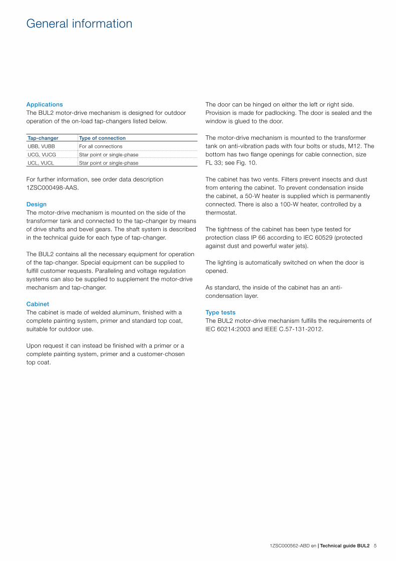
ApplicationsThe BUL2 motor-drive mechanism is designed for outdoor operation of the on-load tap-changers listed below.
Tap-changer Type of connection
UBB, VUBB For all connections
UCG, VUCG Star point or single-phase
UCL, VUCL Star point or single-phase
For further information, see order data description 1ZSC000498-AAS.
DesignThe motor-drive mechanism is mounted on the side of the transformer tank and connected to the tap-changer by means of drive shafts and bevel gears. The shaft system is described in the technical guide for each type of tap-changer.
The BUL2 contains all the necessary equipment for operation of the tap-changer. Special equipment can be supplied to fulfill customer requests. Paralleling and voltage regulation systems can also be supplied to supplement the motor-drive mechanism and tap-changer.
CabinetThe cabinet is made of welded aluminum, finished with a complete painting system, primer and standard top coat, suitable for outdoor use.
Upon request it can instead be finished with a primer or a complete painting system, primer and a customer-chosen top coat.
The door can be hinged on either the left or right side. Provision is made for padlocking. The door is sealed and the window is glued to the door.
The motor-drive mechanism is mounted to the transformer tank on anti-vibration pads with four bolts or studs, M12. The bottom has two flange openings for cable connection, size FL 33; see Fig. 10.
The cabinet has two vents. Filters prevent insects and dust from entering the cabinet. To prevent condensation inside the cabinet, a 50-W heater is supplied which is permanently connected. There is also a 100-W heater, controlled by a thermostat.
The tightness of the cabinet has been type tested for protection class IP 66 according to IEC 60529 (protected against dust and powerful water jets).
The lighting is automatically switched on when the door is opened.
As standard, the inside of the cabinet has an anti-condensation layer.
Type testsThe BUL2 motor-drive mechanism fulfills the requirements of IEC 60214:2003 and IEEE C.57-131-2012.

6 Technical guide BUL2 | 1ZSC000562-ABD en
134
135
132
135
E3
130
S8
S9
Q1
F2 F1
104
S1
S2
133
135
133
131
131
Fig. 1. Cabinet layout. The position numbers refer to Table 1.
1ZSC000562-ABD en | Technical guide BUL2 7
Oil test according to IEC 60422 2005.
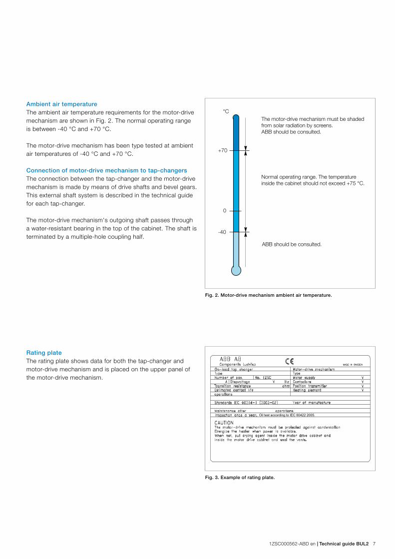
Rating plateThe rating plate shows data for both the tap-changer and motor-drive mechanism and is placed on the upper panel of the motor-drive mechanism.
Fig. 3. Example of rating plate.
Ambient air temperatureThe ambient air temperature requirements for the motor-drive mechanism are shown in Fig. 2. The normal operating range is between -40 °C and +70 °C.
The motor-drive mechanism has been type tested at ambient air temperatures of -40 °C and +70 °C.
Connection of motor-drive mechanism to tap-changersThe connection between the tap-changer and the motor-drive mechanism is made by means of drive shafts and bevel gears. This external shaft system is described in the technical guide for each tap-changer.
The motor-drive mechanism's outgoing shaft passes through a water-resistant bearing in the top of the cabinet. The shaft is terminated by a multiple-hole coupling half.
Fig. 2. Motor-drive mechanism ambient air temperature.
The motor-drive mechanism must be shaded from solar radiation by screens.ABB should be consulted.
Normal operating range. The temperature inside the cabinet should not exceed +75 °C.
ABB should be consulted.
°C
+70
0
-40
8 Technical guide BUL2 | 1ZSC000562-ABD en
Mechanical arrangements
This chapter refers to Figs. 4–7 and Table 1.
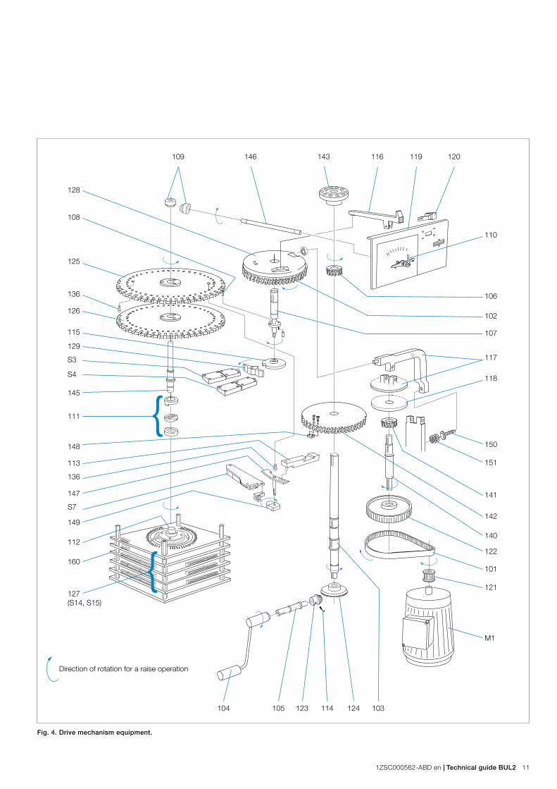
Drive arrangementThe drive mechanism motor M1 with its pulley 121 drives, with a ratio of 4.5:1, pulley 122 on the intermediate shaft 140 via a toothed belt 101. On the intermediate shaft is a pinion with helical teeth 141, which with a ratio of 5:1, drives the helical gear 142 on the outgoing shaft 103. The outgoing shaft is then directly connected via multiple-hole coupling 143 to the shaft system of the tap-changer. The outgoing shaft turns 5 revolutions per operation.
The mechanism is mounted on a support of cast aluminum, 144.
Hand crank The mechanism can be manually operated by means of a hand crank 104. The hand crank is placed on the crank shaft 105, which through the bevel pinion 123, with a ratio of 3:1, drives the bevel gear 124 on the outgoing shaft. The direction of operation is clockwise for a raise operation and 15 revolutions are needed per operation.
When the hand crank is placed on the crank shaft, the interlocking switch S5 breaks the operating circuit of the motor thus preventing electrical operation.
With manual operation, the mechanism must be put at an exact position. If the mechanism is left between two positions or in a through-position when under power, the mechanism starts directly upon removal of the hand crank.
One-turn shaftA helical pinion 106 on the outgoing shaft drives, with a ratio of 5:1, the helical gear 102 placed on the one-turn shaft 107. This shaft drives two Geneva wheels 125 and 126 with a ratio of 36:1. The drive pin 108 for the upper Geneva wheel 125 shall in the normal position be in the slot of the Geneva wheel whereas the lower Geneva wheel 126 is locked by the circumference of the one-turn shaft.
Position indicatorThe lower Geneva wheel 126 is pinned to the Geneva shaft 145, which through a bevel gear 109, with a ratio of 1:1, operates the position indicator shaft 146, on which the position indicator pointer 110 is mounted. On the position indicator shaft, drag-hands are also mounted for indication of the maximum and minimum positions. Those drag-hands can be manually reset. The position indicator is visible through a window in the door.
Mechanical end-stopsThe upper Geneva wheel 125 is supported by the Geneva shaft and turns independently of the shaft, controlled by the upper drive pin 108 on the one-turn shaft. On the Geneva wheel, two screws 136 are fitted which at the end-positions operate the mechanical end-stop 113 via arm 147. Extra screws could be placed between the screws 136 if a decreased tap-change range is desired.
After the end-position has been reached, the mechanical end-stop is pressed out to obstruct knob 148 under the helical gear 142, which prevents further movement of the outgoing shaft in that direction.
When the mechanism is returned to the end-position by manual cranking, the mechanical end-stop will be pressed back by springs, which also keeps it positioned in all normal tap-change positions.
The breakpin 114 in the bevel pinion 123 on the crank shaft 105 prevents overloading of the end-stops by hand cranking.
Electrical end-stopsOn the lower end of the shaft for arm 147, cam curve 149 is mounted. When the mechanism is at an end-position, this cam curve operates limit switches S6 and S7, which break the operating circuit of the motor and two phases of the motor supply. Electrical operation beyond the end-positions is thus impossible.
In event of faulty limit switches, the motor is stopped by the mechanical end-stop and disconnected when the thermal overcurrent protection trips the motor protective switch Q1; see the circuit diagram on page 15.
BrakeOn the upper end of the one-turn shaft 107 is cam disc 128, which controls brake 117 working against brake disc 118 on top of the intermediate shaft 140. This brake makes sure that the motor-drive mechanism stops at the correct position after each tap-change. The brake can be adjusted by screw 150, which presses against the spring 151 that closes the brake.
1ZSC000562-ABD en | Technical guide BUL2 9
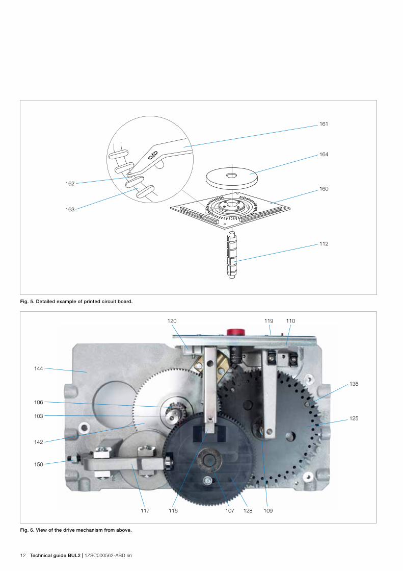
Multi-position switchesThe lower end of the Geneva shaft 145 is via coupling 111 connected to the multi-position switch shaft 112. The multi-position switch thus moves 1/36 of a turn, 10°, per tap-change step.
The multi-position switch 127 is made up of up to 8 different printed circuit boards, 160. Each board has a contact arm, 161. A slot in the multi-position switch shaft 112 transfers rotation to a knob on the contact arm. The contacts 162 on the arm are solid silver rivets and the contact surfaces 163 on the circuit boards are gold plated. Before delivery, all boards are insulation tested at 2 kV to ground.
The contacts on each board are protected against dust by transparent cover 164.
Position transmitter (S14), potentiometer As standard, the contact device is supplied with a potentiometer transmitter, which has 10 Ω, 0.6 W resistors between each position. Other resistors can be supplied upon request.
Upon request, a suitable measuring amplifier for moving-coil instruments can be supplied. The instrument for remote position indication in the control room can also be included upon request.
Continuation contact (S15)In cases when the tap-changer has two or more positions with the same voltage, a continuation contact is supplied. Only one of the positions is the service position; the others are through-positions that are passed automatically during an electrical operation. See the description of operation on page 14.
Auxiliary contactsAuxiliary contacts, break-before-make or make-before-break, as well as odd-even switches for parallel control, can be supplied upon request.
Indicator flagThe indicator flag is placed at the end of the indicator arm 116, which is operated by the cam disc 128. The flag is visible through a slot in the front plate 119. When the mechanism is in position, the white part of the flag is visible, and during a tap change the red part is shown.
The indicator flag is also visible through the window in the door.
Operation counterA seven-digit mechanical operation counter 120 is also operated by the indicator arm 116. The counter cannot be reset and will register the total number of operations carried out by the motor-drive mechanism. The counter is mounted on the front plate 119 and is also visible through the window in the door.
Holding, interlocking and auxiliary contactsAt the lower end of the one-turn shaft is another cam disc, 115, which via lever 129 operates two sets of contacts, S3 and S4. S3 is affected during raise operations and S4 during lower operations.
The cam disc does not release the lever and the contacts before the tap-change operation is completed. Before the start impulse ends, the holding contact 33-34 (see Fig. 9) closes another feed to the contactor K2 or K3 and thus keeps the motor running until the operation is completed. After possible interruption of the supply voltage during an operation, this contact will also enable completion of the operation when the supply voltage returns.
The interlocking contacts 41-42 (see Fig. 9) opens the circuit to the contactor for operation in the opposite direction. Unintentional change of direction is thus prevented. This contact also prevents operation in case motor rotation should be incorrect due to incorrect phase sequence.
The contacts 13-14 and 21-22 (see Fig. 9) are auxiliary contacts. They can be used for signals to the control room or remote interlocking during tap-change operation.
10 Technical guide BUL2 | 1ZSC000562-ABD en
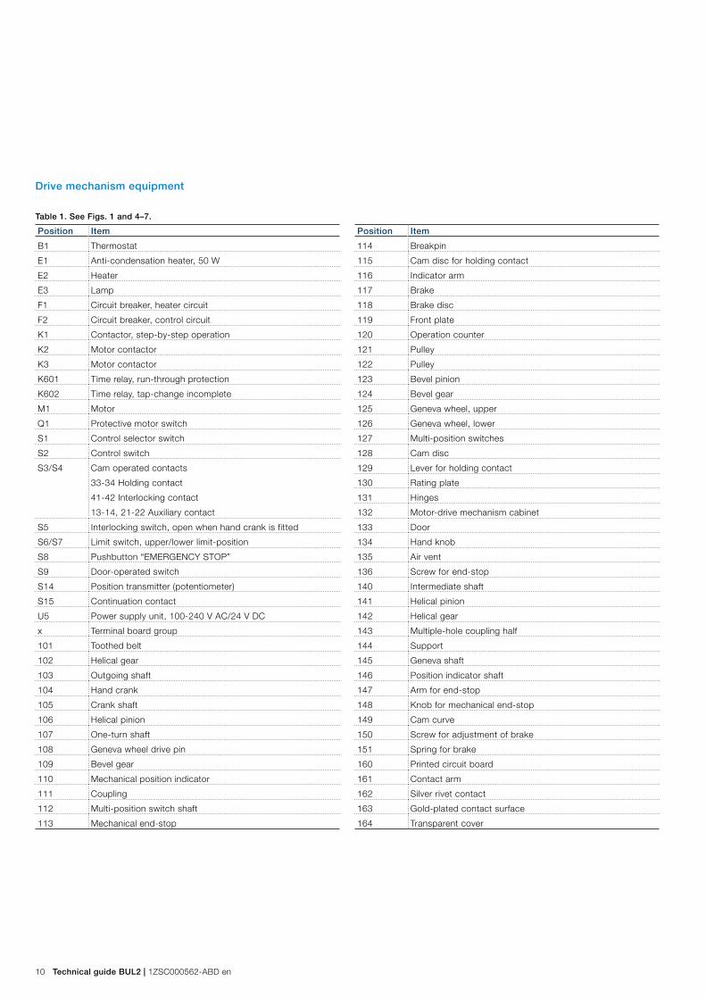
Drive mechanism equipment
Table 1. See Figs. 1 and 4–7.
Position Item
B1 Thermostat
E1 Anti-condensation heater, 50 W
E2 Heater
E3 Lamp
F1 Circuit breaker, heater circuit
F2 Circuit breaker, control circuit
K1 Contactor, step-by-step operation
K2 Motor contactor
K3 Motor contactor
K601 Time relay, run-through protection
K602 Time relay, tap-change incomplete
M1 Motor
Q1 Protective motor switch
S1 Control selector switch
S2 Control switch
S3/S4 Cam operated contacts
33-34 Holding contact
41-42 Interlocking contact
13-14, 21-22 Auxiliary contact
S5 Interlocking switch, open when hand crank is fitted
S6/S7 Limit switch, upper/lower limit-position
S8 Pushbutton “EMERGENCY STOP”
S9 Door-operated switch
S14 Position transmitter (potentiometer)
S15 Continuation contact
U5 Power supply unit, 100-240 V AC/24 V DC
x Terminal board group
101 Toothed belt
102 Helical gear
103 Outgoing shaft
104 Hand crank
105 Crank shaft
106 Helical pinion
107 One-turn shaft
108 Geneva wheel drive pin
109 Bevel gear
110 Mechanical position indicator
111 Coupling
112 Multi-position switch shaft
113 Mechanical end-stop
Position Item
114 Breakpin
115 Cam disc for holding contact
116 Indicator arm
117 Brake
118 Brake disc
119 Front plate
120 Operation counter
121 Pulley
122 Pulley
123 Bevel pinion
124 Bevel gear
125 Geneva wheel, upper
126 Geneva wheel, lower
127 Multi-position switches
128 Cam disc
129 Lever for holding contact
130 Rating plate
131 Hinges
132 Motor-drive mechanism cabinet
133 Door
134 Hand knob
135 Air vent
136 Screw for end-stop
140 Intermediate shaft
141 Helical pinion
142 Helical gear
143 Multiple-hole coupling half
144 Support
145 Geneva shaft
146 Position indicator shaft
147 Arm for end-stop
148 Knob for mechanical end-stop
149 Cam curve
150 Screw for adjustment of brake
151 Spring for brake
160 Printed circuit board
161 Contact arm
162 Silver rivet contact
163 Gold-plated contact surface
164 Transparent cover
1ZSC000562-ABD en | Technical guide BUL2 11
{
{
Direction of rotation for a raise operation
Fig. 4. Drive mechanism equipment.
145
S4
S3
129
115
126
136
125
108
128
111
148
113
136
147
S7
149
112
160
127(S14, S15)
106
109 146
104 105 123 114 124 103
143 116 119 120
102
107
117
118
150
151
141
142
140
122
101
121
M1
110
12 Technical guide BUL2 | 1ZSC000562-ABD en
Fig. 5. Detailed example of printed circuit board.
Fig. 6. View of the drive mechanism from above.
162
103
144
106
150
163
142
164
136
161
120 119 110
160
125
112
117 116 107 128 109
1ZSC000562-ABD en | Technical guide BUL2 13
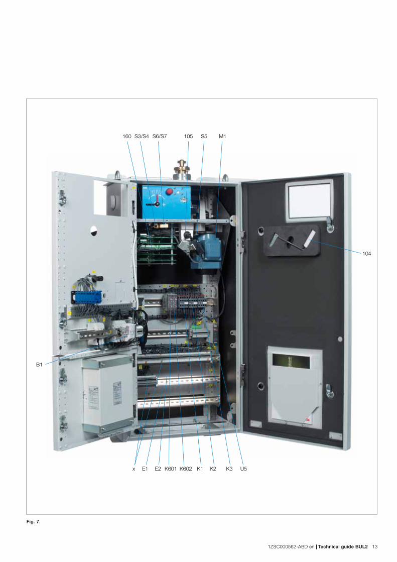
Fig. 7.
B1
160
E1x E2 K601 K602 K1 K2 K3 U5
S3/S4 S6/S7 105 S5 M1
104
14 Technical guide BUL2 | 1ZSC000562-ABD en
Principles of operation
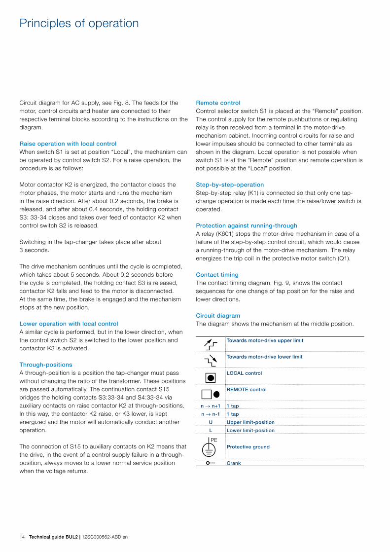
Circuit diagram for AC supply, see Fig. 8. The feeds for the motor, control circuits and heater are connected to their respective terminal blocks according to the instructions on the diagram.
Raise operation with local controlWhen switch S1 is set at position “Local”, the mechanism can be operated by control switch S2. For a raise operation, the procedure is as follows:
Motor contactor K2 is energized, the contactor closes the motor phases, the motor starts and runs the mechanism in the raise direction. After about 0.2 seconds, the brake is released, and after about 0.4 seconds, the holding contact S3: 33-34 closes and takes over feed of contactor K2 when control switch S2 is released.
Switching in the tap-changer takes place after about 3 seconds.
The drive mechanism continues until the cycle is completed, which takes about 5 seconds. About 0.2 seconds before the cycle is completed, the holding contact S3 is released, contactor K2 falls and feed to the motor is disconnected. At the same time, the brake is engaged and the mechanism stops at the new position.
Lower operation with local controlA similar cycle is performed, but in the lower direction, when the control switch S2 is switched to the lower position and contactor K3 is activated.
Through-positionsA through-position is a position the tap-changer must pass without changing the ratio of the transformer. These positions are passed automatically. The continuation contact S15 bridges the holding contacts S3:33-34 and S4:33-34 via auxiliary contacts on raise contactor K2 at through-positions. In this way, the contactor K2 raise, or K3 lower, is kept energized and the motor will automatically conduct another operation.
The connection of S15 to auxiliary contacts on K2 means that the drive, in the event of a control supply failure in a through-position, always moves to a lower normal service position when the voltage returns.
Remote controlControl selector switch S1 is placed at the “Remote” position. The control supply for the remote pushbuttons or regulating relay is then received from a terminal in the motor-drive mechanism cabinet. Incoming control circuits for raise and lower impulses should be connected to other terminals as shown in the diagram. Local operation is not possible when switch S1 is at the “Remote” position and remote operation is not possible at the “Local” position.
Step-by-step-operationStep-by-step relay (K1) is connected so that only one tap-change operation is made each time the raise/lower switch is operated.
Protection against running-throughA relay (K601) stops the motor-drive mechanism in case of a failure of the step-by-step control circuit, which would cause a running-through of the motor-drive mechanism. The relay energizes the trip coil in the protective motor switch (Q1).
Contact timingThe contact timing diagram, Fig. 9, shows the contact sequences for one change of tap position for the raise and lower directions.
Circuit diagramThe diagram shows the mechanism at the middle position.
Towards motor-drive upper limit
Towards motor-drive lower limit
LOCAL control
REMOTE control
n → n+1 1 tap
n → n-1 1 tap
U Upper limit-position
L Lower limit-position
PEProtective ground
Crank

1ZSC000562-ABD en | Technical guide BUL2 15
Fig. 9. Circuit diagram.
UPPER LIMIT
ITEM F2 OFF
LOWER LIMIT CLOSED AT UPPER LIMIT
SUPPLY FOR MOTOR SUPPLY FOR HEATER SUPPLY FOR CONTROL CONTACT
HOLDING CIRCUIT INITIATIONPREPARED FOR
PROTECTION RELAYREMOTE TRIPPING
PR
EPA
RE
D F
OR
OU
TLE
T. S
EE
SE
PAR
ATE
D
IAG
RA
M W
HE
N O
UTL
ET
IS O
RD
ER
ED
.
CIRCUIT BREAKER OFF
1) CONTINUATION CONTACT INCLUDED ONLY WHEN OLTC HAS THROUGH-POSITIONS. CLOSED WHEN OLTC IS AT THROUGH-POSITIONS.
2) REMOVE CONNECTION X4:1-2 TO DISABLE STEP-BY-STEP FUNCTION AND X3:11-12 TO DISABLE THE RELAY K601 (RUN-THROUGH PROTECTION).
CONTACTS OPEN TOWARDS
TAP-CHANGE IN PROGRESS
CLOSED AT LOWER LIMIT
ITEM Q1 ON
ITEM Q1 OFF / RUN-THROUGH ALARM
ITEM Q1 OFF
STEP-BY-STEP IN OPERATION
TAP-CHANGE INCOMPLETE
STEP-BY-STEP DE-ENERGIZED
REMOTE
REMOTE
0
0
LOCAL
LOCAL

16 Technical guide BUL2 | 1ZSC000562-ABD en
(S14)
(S15)
Contact timing diagram
Fig. 9. Example of contact timing diagram.
TURNS ON HAND CRANK OF MOTOR-DRIVE MECHANISM
CONTACT
(MBB)
(BBM)
UPPER LIMIT-POS.
POS. POS. POS. POS.
LOWER LIMIT-POS.
TAP-CHANGE OPERATION
1ZSC000562-ABD en | Technical guide BUL2 17
Standard version
Control – Control selector switch, Local-0-Remote. – Control switch, Raise-0-Lower. – Hand crank for manual operation.
Protection – Circuit breaker in heater + control circuit – Protective switch for the motor with thermal overload
release and magnetic overcurrent release. – Limit switches – in both control and motor circuits. – Mechanical end-stops. – Interlocking contact in the control circuit to prevent
electrical operation during manual operation. – Interlocking contacts in raise and lower control circuits to
prevent operation in incorrect direction of rotation (with incorrect phase sequence).
– Motor contactors are electrically interlocked. – Protection against run-through in case of a failure of the
step-by-step control circuit. – Emergency stop pushbutton.
Indication – Mechanical position indicator – Drag-hands for max. and min. position indication. – Red flag for indication of tap-changer in progress. – Operation counter.
(The four items above are visible through the window in the cabinet door.)
– Position transmitter, potentiometer, for remote position indication.
WiringThe wiring is executed with grey polyvinylchloride-insulated, stranded wire. Each wire is marked with numbers corresponding to terminal numbers. All external connections are made with thermosetting resin. For type and data, see Technical data.
No fuses are required for the motor, as the motor protective switch has magnetic overcurrent release.
MaintenanceAll bearings in the motor-drive mechanism type BUL2 have rubber seals and are permanently lubricated. Certain gears and moving parts are made of self-lubricating material. No lubrication is necessary during the lifetime of the motor-drive mechanism under normal operating conditions.
The motor-drive mechanism should be inspected once yearly.
For correct inspection and maintenance procedures, consult the appropriate maintenance guide.
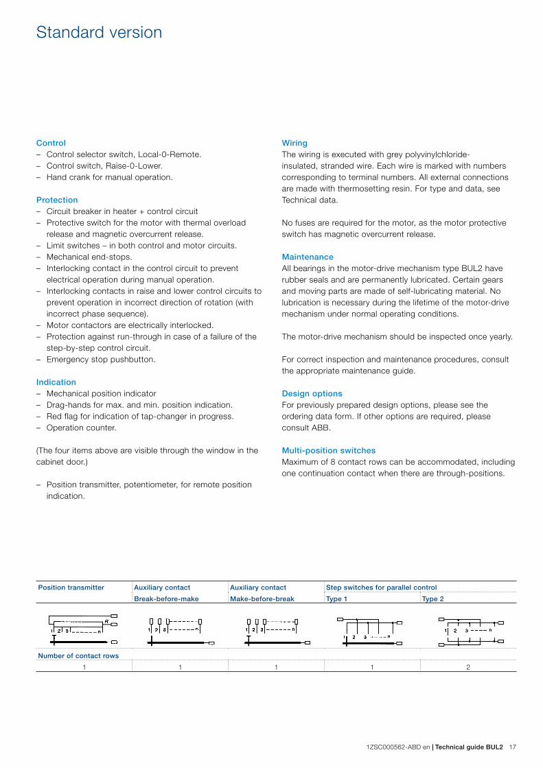
Design optionsFor previously prepared design options, please see the ordering data form. If other options are required, please consult ABB.
Multi-position switchesMaximum of 8 contact rows can be accommodated, including one continuation contact when there are through-positions.
Position transmitter Auxiliary contact
Break-before-make
Auxiliary contact
Make-before-break
Step switches for parallel control
Type 1 Type 2
Number of contact rows
1 1 1 1 2
18 Technical guide BUL2 | 1ZSC000562-ABD en
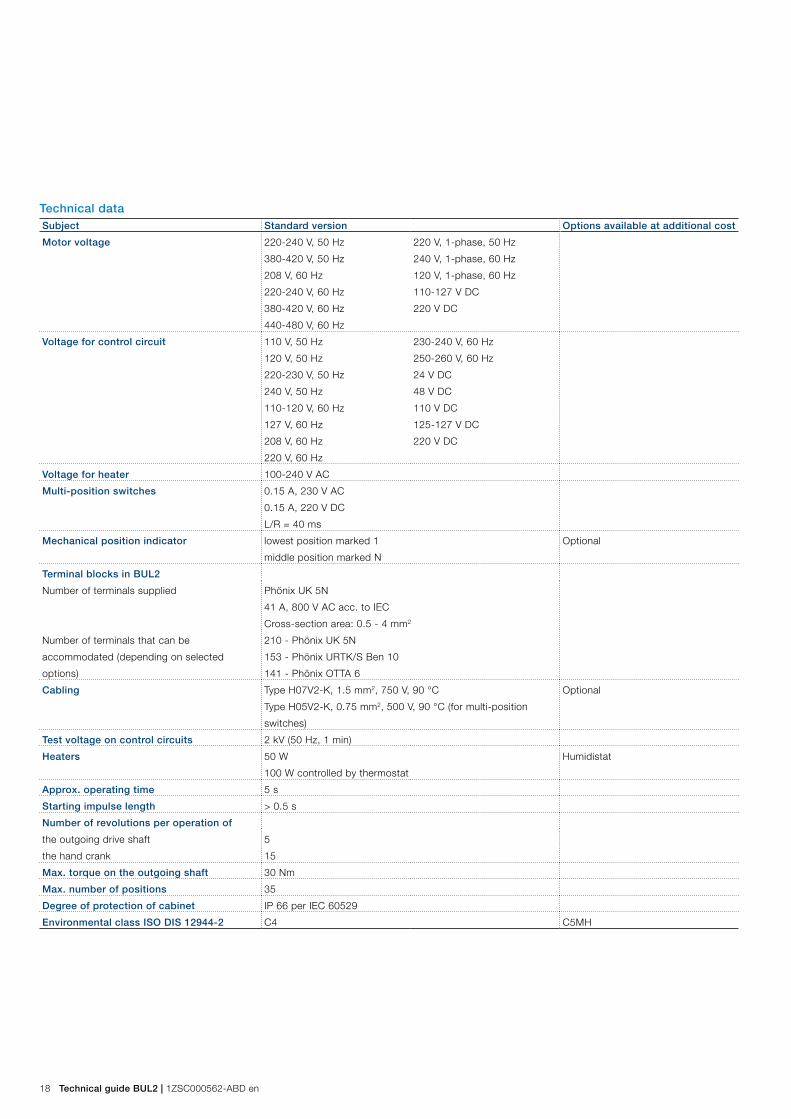
Technical dataSubject Standard version Options available at additional cost
Motor voltage 220-240 V, 50 Hz
380-420 V, 50 Hz
208 V, 60 Hz
220-240 V, 60 Hz
380-420 V, 60 Hz
440-480 V, 60 Hz
220 V, 1-phase, 50 Hz
240 V, 1-phase, 60 Hz
120 V, 1-phase, 60 Hz
110-127 V DC
220 V DC
Voltage for control circuit 110 V, 50 Hz
120 V, 50 Hz
220-230 V, 50 Hz
240 V, 50 Hz
110-120 V, 60 Hz
127 V, 60 Hz
208 V, 60 Hz
220 V, 60 Hz
230-240 V, 60 Hz
250-260 V, 60 Hz
24 V DC
48 V DC
110 V DC
125-127 V DC
220 V DC
Voltage for heater 100-240 V AC
Multi-position switches 0.15 A, 230 V AC
0.15 A, 220 V DC
L/R = 40 ms
Mechanical position indicator lowest position marked 1
middle position marked N
Optional
Terminal blocks in BUL2
Number of terminals supplied Phönix UK 5N
41 A, 800 V AC acc. to IEC
Cross-section area: 0.5 - 4 mm2
Number of terminals that can be
accommodated (depending on selected
options)
210 - Phönix UK 5N
153 - Phönix URTK/S Ben 10
141 - Phönix OTTA 6
Cabling Type H07V2-K, 1.5 mm2, 750 V, 90 °C
Type H05V2-K, 0.75 mm2, 500 V, 90 °C (for multi-position
switches)
Optional
Test voltage on control circuits 2 kV (50 Hz, 1 min)
Heaters 50 W
100 W controlled by thermostat
Humidistat
Approx. operating time 5 s
Starting impulse length > 0.5 s
Number of revolutions per operation of
the outgoing drive shaft
the hand crank
5
15
Max. torque on the outgoing shaft 30 Nm
Max. number of positions 35
Degree of protection of cabinet IP 66 per IEC 60529
Environmental class ISO DIS 12944-2 C4 C5MH

1ZSC000562-ABD en | Technical guide BUL2 19
Weight: 95 kg
Dimensions
408
49
1274 1197
45
79
384
146
8034
4536.591.5
292475
6 x Ø 12.5
6
2 x FL 33
Ground connection M12
1212
37
21560
626
475
33
75
202
213
352.5
550
293
36
30
Ø 75
M12
A
A
A - A
A A
Anti-vibration pad
Max 120°
Fig. 10. Dimensions.
Contact us
© C
opyr
ight
201
2 A
BB
, A
ll rig
hts
rese
rved
.
1ZS
C00
0562
-AB
D e
n, 2
012-
11-1
5ABB AB ComponentsSE-771 80 Ludvika, Sweden Phone: +46 240 78 20 00 Fax: +46 240 121 57 E-Mail: [email protected] www.abb.com/electricalcomponents
Related Documents