MNS & MNS iS Motor Control Centres MService based Condition Monitoring V7.7 User Manual

Welcome message from author
This document is posted to help you gain knowledge. Please leave a comment to let me know what you think about it! Share it to your friends and learn new things together.
Transcript

MNS & MNS iS Motor Control Centres MService based Condition Monitoring V7.7 User Manual
MService User Manual General 1
MNS and MNS iS a registered trademark.
Microsoft, Windows 2008, Windows 7, and Windows 8 are registered trademarks of Microsoft Corporation.
Product names of other products are registered trademarks of their manufacturers.
This document relates to the MService Release 7.7.
The information in this document is subject to change without notice and should not be construed as a commitment by ABB.
ABB assumes no responsibility for any errors that may appear in this document.
In no event shall ABB be liable for direct, indirect, special, incidental, or consequential damages of any nature or kind arising from the use of this document, nor shall ABB be liable for incidental or consequential damages arising from use of any software or hardware described in this document.
This document and parts thereof must not be reproduced or copied without ABB's written permission, and the contents thereof must not be imparted to a third party nor be used for any unauthorized purpose. The software described in this document is furnished under a license and may be used, copied, or disclosed only in accordance with the terms of such license.
All rights reserved.
Copyright © 2015 ABB Automation Products GmbH, Ladenburg, Germany

MService User Manual Content
1TGC910104M0201 – MService V7.7 3
1 General ................................................................................................................................ 7
1.1 Target Group .................................................................................................................... 7
1.2 Use of Warning, Caution, Information and Tip icon .......................................................... 7
1.3 Terminology ...................................................................................................................... 8
1.4 References ....................................................................................................................... 9
2 System Overview .............................................................................................................. 10
2.1 Product Concept ............................................................................................................. 10
2.2 Supported Functions ...................................................................................................... 11
2.3 Hardware characteristics ................................................................................................ 12
2.4 Technical Data ................................................................................................................ 15
3 Installation and Commissioning ..................................................................................... 16
3.1 Commissioning Workflow Overview ............................................................................... 16
3.2 MService mounting in MNS and MNS iS Cubicle ........................................................... 17
3.3 MService in MNS and MNS iS network .......................................................................... 18
3.3.1 Client PC requirements and configuration recommendations ................................ 19
3.3.2 Switchgear network and client/plant network .......................................................... 22
3.3.3 Switchgear network and client/plant network with commissioning laptop ............... 23
3.3.4 Time synchronization via NTP ................................................................................ 23
3.4 MService commissioning ................................................................................................ 27
3.4.1 MService configuration via MNavigate ................................................................... 27
3.4.2 MService Basic configuration ................................................................................. 28
3.4.3 OPC server parameters .......................................................................................... 30
3.4.4 CAM (Condition Assessment Module) parameters ................................................. 31
3.4.5 User management and language settings .............................................................. 32
3.4.6 Installation of a language pack for MService .......................................................... 33
3.4.7 Activation of MService configuration ....................................................................... 35
3.5 Update of System Firmware ........................................................................................... 40
4 Getting started .................................................................................................................. 41
4.1 Login ............................................................................................................................... 41
4.2 User Interface ................................................................................................................. 42
4.2.1 Menu bar ................................................................................................................. 43
4.2.2 Message list ............................................................................................................ 44
4.2.3 Cubicle view / Device view ..................................................................................... 45

Content MService User Manual
4 1TGC910104M0201 – MService V7.7
4.2.4 Tree view ................................................................................................................. 45
4.3 Autoconfigurator .............................................................................................................. 47
4.3.1 Preparation of Autoconfiguration: Switchgear commissioning status ...................... 47
4.3.2 Adding and removing modules to be monitored by MService ................................. 48
5 Message Archive ............................................................................................................... 53
5.1 Configuration area ........................................................................................................... 53
5.1.1 On using text filter ................................................................................................... 56
5.2 Listing area ...................................................................................................................... 57
6 Trend Display .................................................................................................................... 61
6.1 Display options ................................................................................................................ 61
6.2 Selection of Process Items and Layout Configuration .................................................... 63
6.3 Graphs characteristics .................................................................................................... 66
6.3.1 Graph controls ......................................................................................................... 66
6.3.2 Legend .................................................................................................................... 71
6.3.3 Statistics .................................................................................................................. 72
7 Value Export ...................................................................................................................... 74
7.1 Export of data from MService .......................................................................................... 74
7.2 Import of the data into Microsoft Excel™ ........................................................................ 75
8 Configuration ..................................................................................................................... 79
8.1 Summary ......................................................................................................................... 79
8.2 Autoconfigurator .............................................................................................................. 80
8.3 Alarming and Reporting .................................................................................................. 80
8.4 Backup / Restore ............................................................................................................. 82
8.4.1 Backup .................................................................................................................... 82
8.4.2 Restore .................................................................................................................... 83
9 MService Report module .................................................................................................. 84
9.1 Condition Report ............................................................................................................. 84
9.2 Energy Report ................................................................................................................. 88
10 MService Link Page .......................................................................................................... 90
11 Data view area ................................................................................................................... 91
11.1 Cubicle overview ............................................................................................................. 91

MService User Manual Content
1TGC910104M0201 – MService V7.7 5
11.1.1 Color coding ............................................................................................................ 92
11.2 Cubicle Online Power-loss Supervision .......................................................................... 93
11.3 Power Module view ........................................................................................................ 95
11.3.1 Power Module schematic ........................................................................................ 96
11.3.2 Tab “Online” ............................................................................................................ 97
11.3.3 Tab “Info” .............................................................................................................. 103
11.3.4 Tab “Operating Trend” .......................................................................................... 111
11.3.5 Tab “Diagnostics Trend” ....................................................................................... 112
11.3.6 Tab “GPI” - General Purpose Input ....................................................................... 113
11.3.7 Tab “Reset” ........................................................................................................... 114
11.3.8 Tab ‘User Note’ ..................................................................................................... 115
11.4 MLink view .................................................................................................................... 116
11.4.1 MLink configuration data ....................................................................................... 116
11.4.2 MLink critical state signals .................................................................................... 117
11.4.3 Redundant MLink configuration ............................................................................ 119
11.5 MService view .............................................................................................................. 120
12 Message list details ........................................................................................................ 121
13 Trouble Shooting ............................................................................................................ 123
13.1 MService Boot sequence and front LED feedback ....................................................... 123
13.2 Issues indicated via front LED ...................................................................................... 125
13.3 Issues using the web-interface ..................................................................................... 126

Content MService User Manual
6 1TGC910104M0201 – MService V7.7
MService User Manual General 1
1TGC910104M0201 – MService V7.7 7
1 General
1.1 Target Group MService is the embedded Condition Monitoring device for ABB Low Voltage Switchgears. Audiences of this manual are service technicians and switchgear operators on site.
The document describes how to get the device installed in a switchgear network, and how to operate it using the web based user interface.
The reader shall be familiar with the terms and concept of ABB MNS Low Voltage Switchgear.
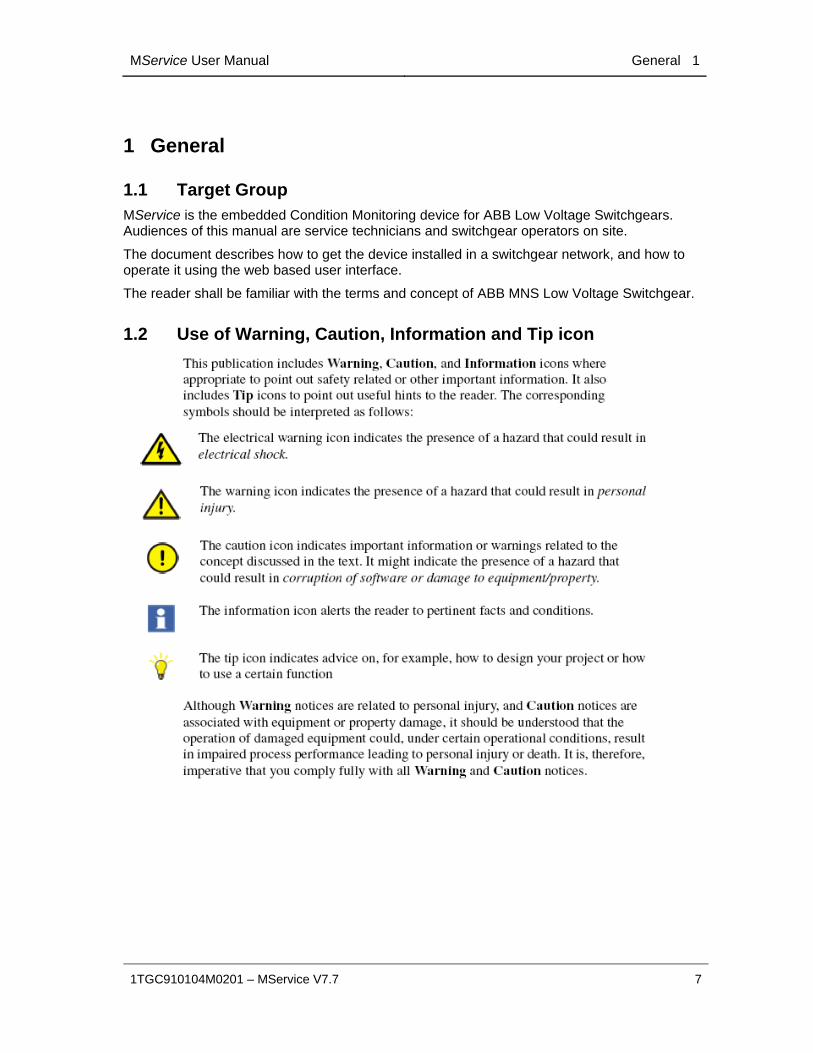
1.2 Use of Warning, Caution, Information and Tip icon

1 General MService User Manual
8 1TGC910104M0201 – MService V7.7
1.3 Terminology List of the terms, acronyms, abbreviations and definitions, the document uses.
Abbreviation Term Description
Eth. Ethernet Ethernet is a local area network (LAN) technology. The Ethernet standard specifies the physical medium, access control rules and the message frames.
HMI /
WebHMI
Human Machine Interface
Hard- and Software which implements the user interface. A WebHMI is a SW providing the HMI in an Internet web browser
LVS Low voltage switchgear
Low voltage switchgear assembly built in accordance with IEC 61439-1
MCC Motor Control Centre
Common term for switchgear used for motor control and protection.
MNS Modular Low Voltage Switchgear family from ABB
UMC /
M10x
Universal Motor
Controller
An intelligent motor controller for 3-phase AC induction
motors combining the two classical functions of motor
protection and motor management in a single device plus
offering diagnostic and fieldbus communication
MTQ22-EFB The MTQ22-FBP Ethernet adapter module allows the
connection of FBP devices to Ethernet
MNS iS The integrated intelligent switchgear solution from ABB
MStart MFeed MControl MConnect MSpeed MLink MView MNavigate
MNS iS components integrated in the switchgear, see the MNS iS System Guide for technical details
OPC The industrial de-facto standard for exchange of information between components and process supervision and monitoring applications using TCP/IP based networks.
OPC ID OPC Network identifier
The OPC ID configured for MLink devices and for the OPC Server defines, which MLink devices are

MService User Manual General 1
1TGC910104M0201 – MService V7.7 9
communicating to which OPC server. This defines a kind of logical sub-net within a certain IP network.
TCP/IP Transmission Control Protocol / Internet Protocol
TCP/IP is a high-level connection oriented, reliable, full duplex communication protocol developed for networked integration of the heterogeneous computer systems.
NAMUR NAMUR is an international user association of automation technology in process industries.
1.4 References [1] 1TGC910001B0204 MNS iS System Guide
[2] 1TGC910232M0201 OPC Server Interface Manual V7.7
[3] 1TGC910221M0201 MNS iS Interface Manual Web Interface_Rel_7.0
[4] NE107 (2006-02-10)NAMUR Recommendation Self-Monitoring and Diagnosis of Field Devices

2 System Overview MService User Manual
10 1TGC910104M0201 – MService V7.7
2 System Overview
2.1 Product Concept The MService device implements an innovative approach to condition monitoring: The supervision of the performance and health status of a MNS and MNS iS switchgear are made possible with a small-scale and easy-to-use embedded industrial PC.
The MService implements the whole condition monitoring concept from collecting field level real-time data to performing assessment algorithms. Based on that, it is possible to work out a prognosis of developing situations and prompting the operator for action. However, if the situation continues and results in a tripping or failure, the MService offers clear diagnosis for fast problem resolution.
Fig. 1: MService device
MService targets two main application scenarios:
Customer’s staff can use the device for performance analysis and continuous support of maintenance planning for MNS and MNS iS system, with MService installed as permanent part of the switchgear.
ABB’s service personnel uses the device to place it in a customer’s switchgear to support customer decisions in keeping the switchgear in good condition by collecting data for a certain time and derive an assessment on the switchgear performance and operational status.
To fit to these scenarios, the MService employs a small-scale, compact approach to enable fast commissioning and ease of use.

MService User Manual System Overview 2
1TGC910104M0201 – MService V7.7 11
2.2 Supported Functions MService Condition Monitoring covers the following main functions:
Collection of operational data of the supervised modules
Collection of all alarms and trips generated in the supervised modules
Collection of maintenance warnings derived from additional assessment logic related to the supervised modules.
Display of the MNS or MNS iS system structure highlighting modules signaling problems
Display of historical data in trend displays
Detailed information on the identification, location, and type of supervised modules
Online supervision of temperature or power loss related problems within individual cubicles.
MService can supervise all modules in MNS and MNS iS, which are connected to the internal switchgear communication bus. This includes:
Motor starter and feeder modules (all sizes), which are equipped with measuring and communication electronic device MControl
Motor starter and feeder modules (all sizes), which are equipped with intelligent device, UMC and M10x, communicates to MLink.
Circuit breakers connected to the switchgear communication with the interface MConnect
Circuit breakers connected to the switchgear communication with the interface MLink
Excluded from supervision in MService are all modules not connected to the internal switchgear communication such as MSpeed (Variable Speed drives in MNS iS) and conventional modules.
In general, MService supports all types of modules which are also accessible in MView.
MService firmware version 7.7 is extended to MNS - Intelligent Switchgear, UMC100/UMC100.3/M10x-M/Emax/Emax2 connects to MLink. In order to configure MService to MNS – Intelligent Switchgear, MNS Engineer, MNavigate and MNavigate Plus version release 7.7 onwards shall be used. See more details in 1TGA710500 INSUM Upgrade Guideline UMC100 and 1TGA710501 INSUM Upgrade Guideline M10x.

2 System Overview MService User Manual
12 1TGC910104M0201 – MService V7.7
2.3 Hardware characteristics
Fig. 2: MService interfaces
All interfaces of the MService devices are located in the front plate. The following interfaces are relevant for the operation of the device:
Power connector 24 DC connection
Reset button If pressed < 5s, an operating system reboot is initiated.
If pressed > 5s, an immediate hardware restart is executed.
CF-Card slot The compact flash card is used to transfer configuration data to the device. For proper operation of the device a compact flash card must be inserted. To enforce this, the CF-Card slot is covered by a latch, which is locked by the power connector.
Network interfaces
LAN1 1GB/s autosensing interface free to use for any network
LAN2 1GB/s autosensing interface free to use for any network. Primary interface to connect switchgear network and MNavigate.

MService User Manual System Overview 2
1TGC910104M0201 – MService V7.7 13
LAN3 1GB/s autosensing interface with fixed IP-configuration used for point-to-point connection to a PC running MNavigate for initial configuration download or maintenance access.
The autosensing capability does not require using a cross-over cable to connect
To avoid IP-Address conflicts, this interface must not be connected to a network switch.
USB connectors Used to attach an external hard drive for Backup/Restore of database.
The following interfaces are not used by regular operation:
Serial port 1 and 2 Not used
The LEDs on the front plate have the following indicator function.
Please see sec. 13.2 for more information how to address certain problem indications.
LED 1 - Green This LED is signaling the general status of MService.
Off – Software components are not yet started: System is initializing
Blinking 2Hz – Firmware update running
Blinking 1Hz - SCADA system starting
On – System components are up & running
LED 2 - Red This LED is signaling a problem
Off – No error
On – Software component failure: SCADA or OPC components are not yet fully initialized or not running as expected
Blinking 2Hz– Problem with LAN2 (switchgear connection)
LED 3 - Green This LED is signaling status of OPC components
On – OPC is running correctly
Blinking – Not all of OPC processes are running.
LED 4 - Orange This LED is signaling a recommended regular backup.
Blinking 4Hz: An MService backup is recommended.
Note: The LED is activated every 90days for a duration of 7 days.

2 System Overview MService User Manual
14 1TGC910104M0201 – MService V7.7
LED 5 - Green This LED is signaling status of LAN communication
On – LAN1 or LAN2 communication is up
Blinking 2Hz – LAN3 communication is up
Off – no LAN communication
LED 6 - Orange Blinking 2Hz – Problem with CF-Card.
Blinking 1Hz – Low RAM situation
LED 7 - Green 24V Power is connected and available – always on
LED 8 - Green This LED represents life signal – it blinks twice each 20 seconds

MService User Manual System Overview 2
1TGC910104M0201 – MService V7.7 15
2.4 Technical Data
Electrical Data
Power Supply 24V DC (19 – 31V DC)
Power Consumption Typical 800mA, Maximum 1000mA
Mechanical Data
Weight 2.5 kg
Dimensions H x W x D 140 x 160 x 165 mm
Environmental Data
Storage Temperature -20°C to +70°C
Operating Temperature 0°C to +55°C
Degree of Protection IP 51
MTBF (Mean Time Between Failures) 46 years @ 40°C
System behavior
Boot time of operating system 1 min
Start-up of SCADA and OPC packages 2min
+ SCADA Startup Delay (s)
+ (45s per connected MLink)
+ 5 min, if no MLink is available in network
Configuration time 30s per supervised MNS iS module/device

3 Installation and Commissioning MService User Manual
16 1TGC910104M0201 – MService V7.7
3 Installation and Commissioning
3.1 Commissioning Workflow Overview The following workflow outlines the necessary steps to setup an MService device. Details for the individual items are found in the subsequent sections.
Step Description
1 Mechanical installation and electrical connection.
See section 3.2
2 Planning of network parameters within the switchgear network. See Sec. 3.3
3 Update the MService firmware with latest fixes available from the BU LPLS Support Database. See Sec. 3.5
4 Configuring network settings and other parameters in MNavigate.
See section 3.4.1
5 Copy / Download initial configuration to MService See section 3.4.7
6 Connect MService to switchgear network
7 Power on
In order to have a correct start of the communication between the MService and the MLink devices it is essential to configure and connect first the switchgear LAN, and boot the device afterwards.
8 Complete the configuration using the ‘Autoconfigurator Wizard’
See section 4.3

MService User Manual Installation and Commissioning 3
1TGC910104M0201 – MService V7.7 17
3.2 MService mounting in MNS and MNS iS Cubicle The MService device is placed in the control compartment of a MNS iS switchboard. The device is mechanically held by means of a device support (single support 300mm for MService only, double support 400mm for MLink/MService combinations).
The electrical power (24V DC) is typically taken from the control voltage distribution bar in the same compartment.
Fig. 3a: Example of MService placement in MNS iS switchboard
The MService is installed on a MLink mounting kit which is housed in an 8E withdrawable module compartment of the MNS cubicle. The MLink mounting kit is capable to support mounting for two MLink and one MService within an 8E compartment. The installation instruction and the required part of the mounting kit can be found in the “1TNA810039 -- Manufacture Instruction – Installation of MService and MLink”
Fig. 3b: MLink mounting kit
If the MService device is placed alongside of a MLink device, it is recommended to use the left position for the MService.

3 Installation and Commissioning MService User Manual
18 1TGC910104M0201 – MService V7.7
3.3 MService in MNS and MNS iS network MService collects the operational data from the switchgear using the built-in OPC Server. Therefore the device has to be connected to the switchgear network. All MService and MLink devices have to be configured appropriately.
Different possibilities exist, how to set up the network, the most common are depicted in the following sections.
Do not connect several MService devices to the same network before the correct networks settings are downloaded and activated. A failure of the network communication may be result if ignoring this.
Since the design of computer networks is in most cases governed by company rules on site, ABB provides the required network equipment only on special request.
The network sketches in the following sections always assume, that all devices are connected to a network switch forming a local area network (LAN) depicted by the grey line.

MService User Manual Installation and Commissioning 3
1TGC910104M0201 – MService V7.7 19
3.3.1 Client PC requirements and configuration recommendations
The MService WebHMI uses standard web technologies limiting the software requirements on the client PC to a minimum. To use the web interface of the MService device a standard PC is needed with the following minimum characteristics:
Hardware
CPU Min. Intel Atom 1.6GHz
RAM 1 GB
Network interface 100 MBit / 1 GBit
Display Recommended resolution: 1280x1024 pixel
Software
Operating system
Windows XP / Windows 7 / Window 8 and corresponding server variants
Internet Browser Microsoft Internet Explorer, Version 8, 9, 10, 11 (see below remarks)
Java Runtime environment, Version 6u24 or higher (see below remarks)
Microsoft Internet Explorer 9 & 10
Using Internet Explorer Version 9 or 10 requires the following settings to be made:
Show ‘Command bar’

3 Installation and Commissioning MService User Manual
20 1TGC910104M0201 – MService V7.7
From the ‘Tools’ menu, enable ‘Compatibility View’
Microsoft Internet Explorer 11
Using version 11 of Internet Explorer requires Java Runtime Environment to be upgraded to at least Version 7 update 55.
Java Runtime Environment
The main display of the MService WebHMI is implemented as Java applet. Starting with Java 7, Oracle introduced a security check, asking the user to run the applet. The Java runtime shows a dialog, asking for permission to run the applet. The Java applet is digitally signed and the user can select to accept the signature. If the certificate is accepted, the security dialog is not shown again for this MService and on this PC.
MService User Manual Installation and Commissioning 3
1TGC910104M0201 – MService V7.7 21
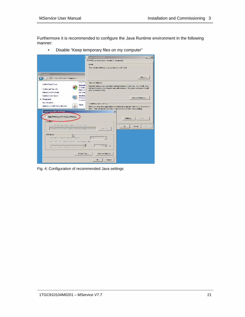
Furthermore it is recommended to configure the Java Runtime environment in the following manner:
• Disable “Keep temporary files on my computer”
Fig. 4: Configuration of recommended Java settings

3 Installation and Commissioning MService User Manual
22 1TGC910104M0201 – MService V7.7
3.3.2 Switchgear network and client/plant network
The MService may be connected to both the Client (Plant) network and the Switchgear Network.
Connection to Client Network is via LAN1 and the Switchgear Network via LAN2.
Fig. 5: MService network example LAN1 & LAN2

MService User Manual Installation and Commissioning 3
1TGC910104M0201 – MService V7.7 23
3.3.3 Switchgear network and client/plant network with commissioning laptop
The special purpose LAN connection LAN3 can be used to create a point-to-point connection. This is used in the commissioning phase to upload the initial base configuration to the device.
Fig. 6: MService LAN3 connection
LAN3 has a fixed network configuration, which is the same on all MService devices. It is set by factory and not configurable by any user. Therefore this port must not be connected to a network switch. Otherwise the function of the device is not possible and the whole network may fail to work.
3.3.4 Time synchronization via NTP
MService collects alarms and events from several sources such as MLink and MControl/UMC /M10x devices. The built-in logic uses real-time operational data to assess certain conditions and creates maintenance alarms on its own.
In order to have a coordinated message archive, where all messages are placed with their real time of occurrence it is crucial to synchronize all MLink and MService devices in the switchgear network.
All MLink and MService devices use the Network Time Protocol (NTP) to get the date & time from a single source, the time master.
There are several scenarios how to distribute the time in the switchgear network. Two of them use dedicated hardware or one of the MLink as described below. Other architectures are possible, such as using network bridges to synchronize several IT-networks in a plant.
Redundant time master are currently not supported in MNS iS and MService

3 Installation and Commissioning MService User Manual
24 1TGC910104M0201 – MService V7.7
3.3.4.1 PC as time master
In a common scenario a standard PC or server located in the switchgear network is configured as NTP server for all MNS & MNS iS devices.
Fig. 7: Time synchronization with standard PC as NTP server
All MLink and MService devices have to be configured to use this clock master as NTP server. This is done using the MNavigate tool. For details how to achieve this see the MNavigate Help.
NTP Server configuration with standard PC, instruction is provided in 1TGE098081 – NTP Basic for MNS iS work instructions.
MService User Manual Installation and Commissioning 3
1TGC910104M0201 – MService V7.7 25
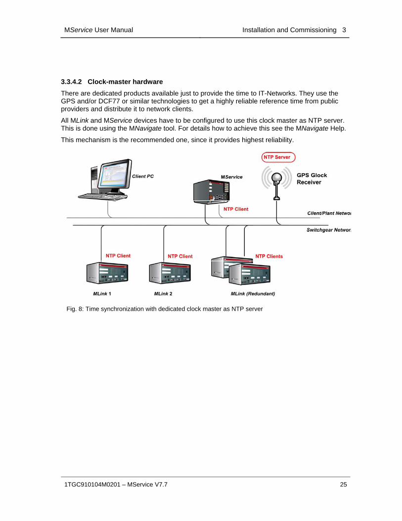
3.3.4.2 Clock-master hardware
There are dedicated products available just to provide the time to IT-Networks. They use the GPS and/or DCF77 or similar technologies to get a highly reliable reference time from public providers and distribute it to network clients.
All MLink and MService devices have to be configured to use this clock master as NTP server. This is done using the MNavigate tool. For details how to achieve this see the MNavigate Help.
This mechanism is the recommended one, since it provides highest reliability.
Fig. 8: Time synchronization with dedicated clock master as NTP server
3 Installation and Commissioning MService User Manual
26 1TGC910104M0201 – MService V7.7
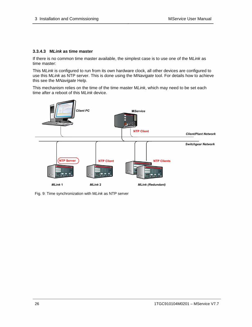
3.3.4.3 MLink as time master
If there is no common time master available, the simplest case is to use one of the MLink as time master:
This MLink is configured to run from its own hardware clock, all other devices are configured to use this MLink as NTP server. This is done using the MNavigate tool. For details how to achieve this see the MNavigate Help.
This mechanism relies on the time of the time master MLink, which may need to be set each time after a reboot of this MLink device.
Fig. 9: Time synchronization with MLink as NTP server

MService User Manual Installation and Commissioning 3
1TGC910104M0201 – MService V7.7 27
3.4 MService commissioning
3.4.1 MService configuration via MNavigate
In MNavigate, one or multiple MService nodes appear if MService devices are found in the switchgear configuration.
Fig. 10: Appearance of MService devices in MNavigate
The access to MService configuration dialogs is organized in the same manner as for all other devices.
The following MService configuration settings need to be parameterized in MNavigate.
3 Installation and Commissioning MService User Manual
28 1TGC910104M0201 – MService V7.7
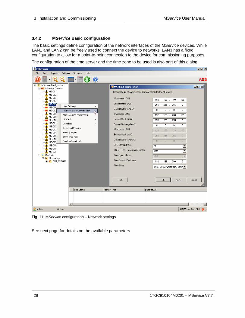
3.4.2 MService Basic configuration
The basic settings define configuration of the network interfaces of the MService devices. While LAN1 and LAN2 can be freely used to connect the device to networks, LAN3 has a fixed configuration to allow for a point-to-point connection to the device for commissioning purposes.
The configuration of the time server and the time zone to be used is also part of this dialog.
Fig. 11: MService configuration – Network settings
See next page for details on the available parameters

MService User Manual Installation and Commissioning 3
1TGC910104M0201 – MService V7.7 29
MService basic configuration: available parameters
IP Address (LAN1,2) IP-Address relevant for the corresponding LAN interface
Subnet Mask (LAN1,2)
Subnet mask relevant for the corresponding LAN interface
Default Gateway Defines the gateway used enable network communication in other IP-networks. There shall be only one gateway set, either for LAN1 or for LAN2
OPC Startup Delay
Delays the start of the SCADA and OPC Components after the MService system start. This allows for fine tuning the system start sequence to give the MLink devices time to power up and initialize their communication components.
TCP/IP Port Data Communication
For future use in complex network environments.
Time Sync Method Fixed parameter: MService always uses NTP based synchronization
Time Server IP- Address
IP Address of the clock master or clock relay server.
Time Zone Time zone used on MService. This influences the display of the timestamps of the messages.

3 Installation and Commissioning MService User Manual
30 1TGC910104M0201 – MService V7.7
3.4.3 OPC server parameters
The OPC server running in the MService needs to be configured to match the OPC Server network set up.
Namely the OPC ID has to be set correctly to allow for correct communication to the MLink devices. See [2] for a detailed discussion of the OPC ID.
The OPC Refresh time can be used to fine tune the CPU load on the MService.
Detailed information on parameters, value ranges, default values etc. are available via the MNavigate Online Help.
Fig. 12a: MService configuration – OPC parameters

MService User Manual Installation and Commissioning 3
1TGC910104M0201 – MService V7.7 31
Fig. 13b: MLink configuration – OPC parameters
3.4.4 CAM (Condition Assessment Module) parameters
An OPC server running on the MService includes a special module to run certain condition assessment logic. Various algorithms use the operational data from the MControl/UMC100/UMC100.3/M10x-M devices to derive maintenance alarms. These algorithms are parameterized as part of the OPC parameterization dialog.
Starting with MNavigate 7.4.11, the parameters are split into few, which are globally defined per MService device, and a majority, which is defined on each power module individually.
Fig. 14: MService configuration – Condition Assessment Module: Global parameters (left) and individual parameters (right)
Detailed information on parameters, value ranges, default values etc. are available via the MNavigate Online Help.

3 Installation and Commissioning MService User Manual
32 1TGC910104M0201 – MService V7.7
3.4.5 User management and language settings
The access right to the MService device is governed by MNavigate user management. The language of the MService User Interface is also associated with the individual user definition.
Every user is associated with a role, which defines the access level to the different device classes in the switchgear. MService defines four access levels
No Access User associated with this role do not have access to this MService
Read only This access level allows simple observation
Read & Write
In addition to ‘Read’ level, this access level allows acknowledgement of alarms, trips and condition messages.
Additionally adding of comments is possible.
Administration In addition to ‘Read & Write’ level, this access level allows changing system configuration.
With MService R7.4 acknowledging trips does no longer include the automatic reset command being sent to the corresponding devices!
Fig. 15: MService configuration –Role definitions and creation of users
All user/role definition made for one device can be transferred to other devices in the same MNavigate project using the ‘Assign to MLink/MService command.

MService User Manual Installation and Commissioning 3
1TGC910104M0201 – MService V7.7 33
Fig. 16: MService configuration – Transfer user settings to other devices
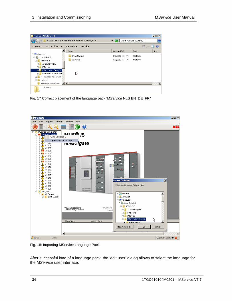
3.4.6 Installation of a language pack for MService
Contact the local ABB service organization if a language other than English is required.
A new language pack can be installed using the context menu ‘Import Language Package’ from the ‘MService Devices’ object in MNavigate.
The language pack has to be copied or extracted from archive file to the following location:
C:\ABB MNS iS\
If this folder does not exist on the PC, it has to be created.
Do not use any special characters in the folder name!
As an example, the following picture shows the correct placement of the language pack ‘MService NLS EN_DE_FR”.
3 Installation and Commissioning MService User Manual
34 1TGC910104M0201 – MService V7.7
Fig. 17 Correct placement of the language pack ‘MService NLS EN_DE_FR”
Fig. 18: Importing MService Language Pack
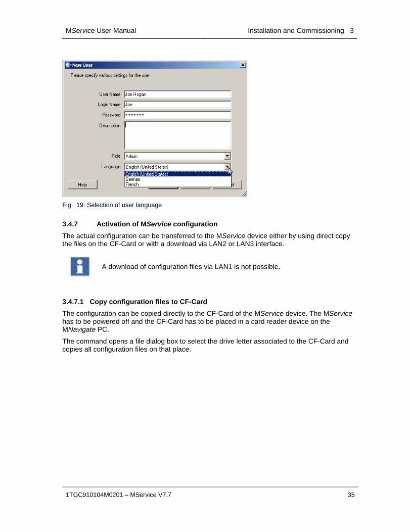
After successful load of a language pack, the ‘edit user’ dialog allows to select the language for the MService user interface.
MService User Manual Installation and Commissioning 3
1TGC910104M0201 – MService V7.7 35
Fig. 19: Selection of user language
3.4.7 Activation of MService configuration
The actual configuration can be transferred to the MService device either by using direct copy the files on the CF-Card or with a download via LAN2 or LAN3 interface.
A download of configuration files via LAN1 is not possible.
3.4.7.1 Copy configuration files to CF-Card
The configuration can be copied directly to the CF-Card of the MService device. The MService has to be powered off and the CF-Card has to be placed in a card reader device on the MNavigate PC.
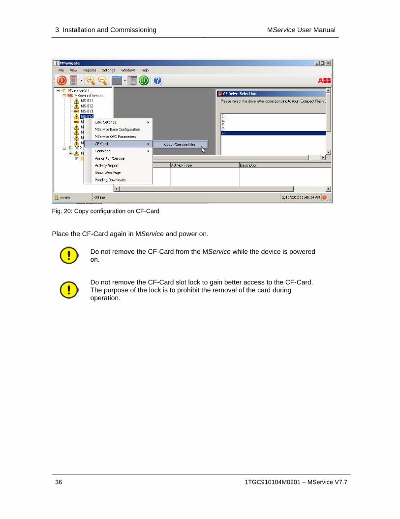
The command opens a file dialog box to select the drive letter associated to the CF-Card and copies all configuration files on that place.
3 Installation and Commissioning MService User Manual
36 1TGC910104M0201 – MService V7.7
Fig. 20: Copy configuration on CF-Card
Place the CF-Card again in MService and power on.
Do not remove the CF-Card from the MService while the device is powered on.
Do not remove the CF-Card slot lock to gain better access to the CF-Card. The purpose of the lock is to prohibit the removal of the card during operation.

MService User Manual Installation and Commissioning 3
1TGC910104M0201 – MService V7.7 37
3.4.7.2 Configuration download via LAN3 ‘Service port’
The LAN3 port is used for point-to-point connections to the MService device. This is useful for situations, where no CF-Card reader is available and the device is not yet configured to communicate via the switchgear network.
Fig. 21: Connect MNavigate PC to MService via LAN3 ‘Service Port’
After the initial download of a configuration and the subsequent connection to the switchgear network, a reboot is required to complete the activation of the new configuration.
The MNavigate PC has to be prepared by the following two steps:
Connect a network interface of the PC directly to the LAN3 port of the MService. There is no need to use a cross-over cable as the Ethernet port will detect the cable type.
Configure this network interface on the PC as shown in the picture.

3 Installation and Commissioning MService User Manual
38 1TGC910104M0201 – MService V7.7
Fig. 22: Settings for network interface of MNavigate PC for access to MService via LAN3
Fig. 23: Download configuration via LAN3 ‘Service Port’

MService User Manual Installation and Commissioning 3
1TGC910104M0201 – MService V7.7 39
3.4.7.3 Download via LAN2 ‘Switchgear LAN’
Once the initial MService configuration is done either with CF-Card or Service Port LAN3, the MService is accessible for further changes via the switchgear network connected to LAN2.
Fig. 24: Download configuration via LAN2 ‘Switchgear Network’
3 Installation and Commissioning MService User Manual
40 1TGC910104M0201 – MService V7.7
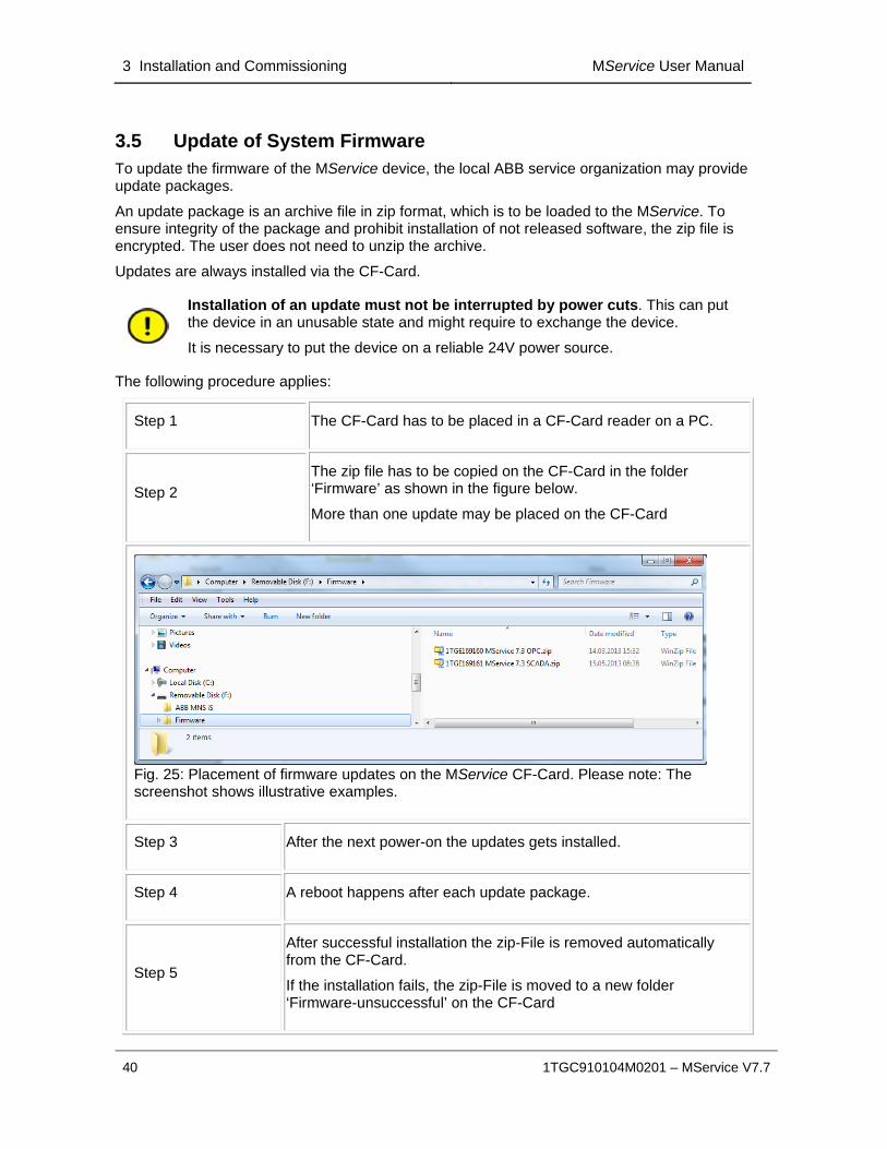
3.5 Update of System Firmware To update the firmware of the MService device, the local ABB service organization may provide update packages.
An update package is an archive file in zip format, which is to be loaded to the MService. To ensure integrity of the package and prohibit installation of not released software, the zip file is encrypted. The user does not need to unzip the archive.
Updates are always installed via the CF-Card.
Installation of an update must not be interrupted by power cuts. This can put the device in an unusable state and might require to exchange the device.
It is necessary to put the device on a reliable 24V power source.
The following procedure applies:
Step 1 The CF-Card has to be placed in a CF-Card reader on a PC.
Step 2
The zip file has to be copied on the CF-Card in the folder ‘Firmware’ as shown in the figure below.
More than one update may be placed on the CF-Card
Fig. 25: Placement of firmware updates on the MService CF-Card. Please note: The screenshot shows illustrative examples.
Step 3 After the next power-on the updates gets installed.
Step 4 A reboot happens after each update package.
Step 5
After successful installation the zip-File is removed automatically from the CF-Card.
If the installation fails, the zip-File is moved to a new folder ‘Firmware-unsuccessful’ on the CF-Card
MService User Manual Getting started 4
1TGC910104M0201 – MService V7.7 41
4 Getting started
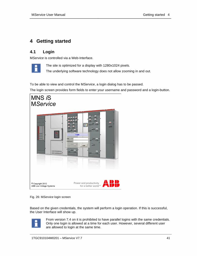
4.1 Login MService is controlled via a Web-Interface.
The site is optimized for a display with 1280x1024 pixels.
The underlying software technology does not allow zooming in and out.
To be able to view and control the MService, a login dialog has to be passed.
The login screen provides form fields to enter your username and password and a login-button.
Fig. 26: MService login screen
Based on the given credentials, the system will perform a login operation. If this is successful, the User Interface will show up.
From version 7.4 on it is prohibited to have parallel logins with the same credentials. Only one login is allowed at a time for each user. However, several different user are allowed to login at the same time.
4 Getting started MService User Manual
42 1TGC910104M0201 – MService V7.7
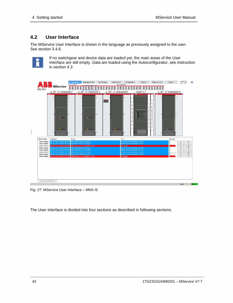
4.2 User Interface The MService User Interface is shown in the language as previously assigned to the user. See section 3.4.6.
If no switchgear and device data are loaded yet, the main areas of the User Interface are still empty. Data are loaded using the Autoconfigurator, see instruction in section 4.3
Fig. 27: MService User Interface – MNS iS
The User Interface is divided into four sections as described in following sections.

MService User Manual Getting started 4
1TGC910104M0201 – MService V7.7 43
4.2.1 Menu bar
The Menu bar is the main navigation tool.
It delivers quick access to the most frequently needed information and operations.
Overview The Overview page is always shown directly after the login. This page contains the menu bar, the cubicle view and the message list.
Message Archive The Message Archive is opened in a new window and gives detailed access to all messages recorded in the system.
See chapter 5.
Trend Display The Trend Display allows graphical display of recorded data.
See chapter 6.
Value Export Measurement data can be exported to the client PC.
See chapter 7
Configuration The configuration page allows reviewing the settings of the device and modifying the condition monitoring setup.
See chapter 8
Reports The Reports page allows creation of different reports created for the whole switchgear or a selected range of modules. Those reports can be viewed online or created as pdf file for download and print-out
See chapter 9
MService Links The link page shows other MService devices found in the same network and allows quick navigation to them.
See chapter 10
Logout Click on logout closes the connection to the MService and redirects the user back to the MService login screen.

4 Getting started MService User Manual
44 1TGC910104M0201 – MService V7.7
The Logout button may get replaced with a button ‘reboot required’
This indicates that there are configuration changes, which cannot be activated dynamically, such as changing the time zone of the MService.
Please see sec. 11.5 for details how to re-boot the device from the WebHMI.
The ‘reboot required’ button disappears after next login to the WebHMI and the ‘Logout’ button becomes available again.
4.2.2 Message list
The Message list shows events colored according to their severity (latest events on top). The view changes dynamically always showing only the messages related to the actually chosen device view. For every entry, a timestamp, device name, description, a severity bar is shown.
Further on, links to the Knowledge Base ( ) as well as the Detailed View of the device ( ) are accessible. Messages can be acknowledged individually or group-wise. For details, see chapter 12.
Fig. 28: Message list
MService User Manual Getting started 4
1TGC910104M0201 – MService V7.7 45
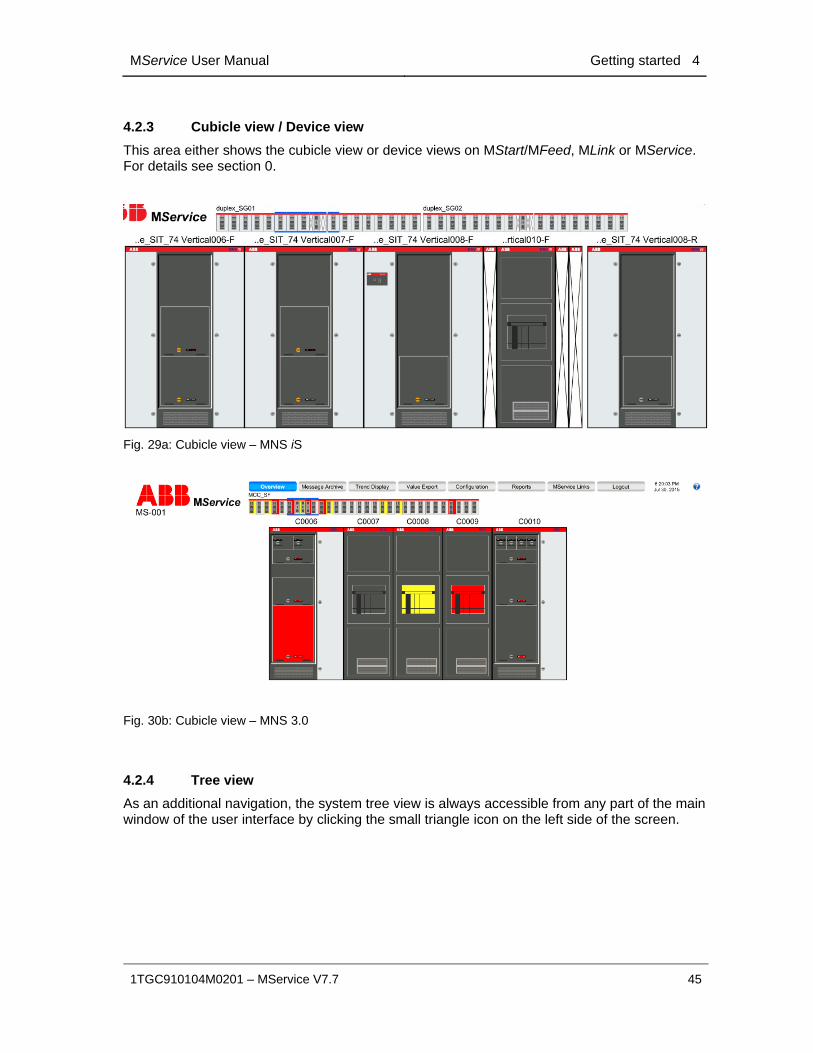
4.2.3 Cubicle view / Device view
This area either shows the cubicle view or device views on MStart/MFeed, MLink or MService. For details see section 0.
Fig. 29a: Cubicle view – MNS iS
Fig. 30b: Cubicle view – MNS 3.0
4.2.4 Tree view
As an additional navigation, the system tree view is always accessible from any part of the main window of the user interface by clicking the small triangle icon on the left side of the screen.
4 Getting started MService User Manual
46 1TGC910104M0201 – MService V7.7
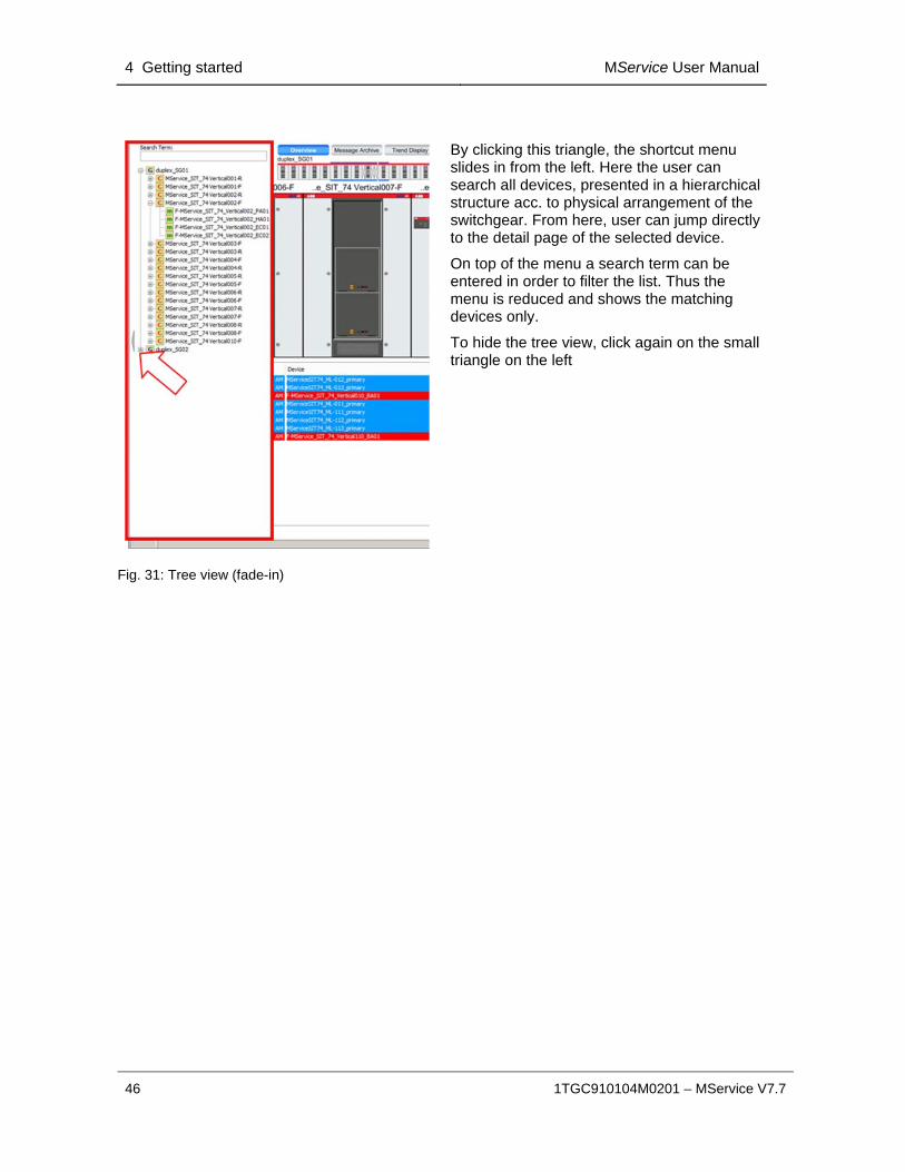
By clicking this triangle, the shortcut menu slides in from the left. Here the user can search all devices, presented in a hierarchical structure acc. to physical arrangement of the switchgear. From here, user can jump directly to the detail page of the selected device.
On top of the menu a search term can be entered in order to filter the list. Thus the menu is reduced and shows the matching devices only.
To hide the tree view, click again on the small triangle on the left
Fig. 31: Tree view (fade-in)
MService User Manual Getting started 4
1TGC910104M0201 – MService V7.7 47
4.3 Autoconfigurator If the MService is used for the first time and no device data are configured, the user configures the MService using the Autoconfigurator. Alternatively, the Autoconfigurator is also used to update the device data after a configuration changes in MNS & MNS iS switchgear at site (e.g. adding of new devices etc.)
The Autoconfigurator reads the switchgear structure and device data based on the OPC network configuration. With this, devices can be added or excluded from the condition monitoring.
4.3.1 Preparation of Autoconfiguration: Switchgear commissioning status
The shown system topology and device data depends on the commissioning status of the switchgear.
The MService detects only those parts of the switchgear, where the communication from the MLink to the OPC server within MService device is established.
For such MLink devices, the Autoconfigurator only shows those power modules, for which the configuration files are available.
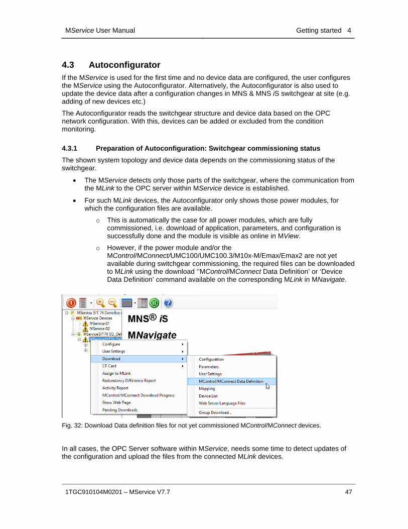
o This is automatically the case for all power modules, which are fully commissioned, i.e. download of application, parameters, and configuration is successfully done and the module is visible as online in MView.
o However, if the power module and/or the MControl/MConnect/UMC100/UMC100.3/M10x-M/Emax/Emax2 are not yet available during switchgear commissioning, the required files can be downloaded to MLink using the download ‘’MControl/MConnect Data Definition’ or ‘Device Data Definition’ command available on the corresponding MLink in MNavigate.
Fig. 32: Download Data definition files for not yet commissioned MControl/MConnect devices.
In all cases, the OPC Server software within MService, needs some time to detect updates of the configuration and upload the files from the connected MLink devices.
4 Getting started MService User Manual
48 1TGC910104M0201 – MService V7.7
4.3.2 Adding and removing modules to be monitored by MService
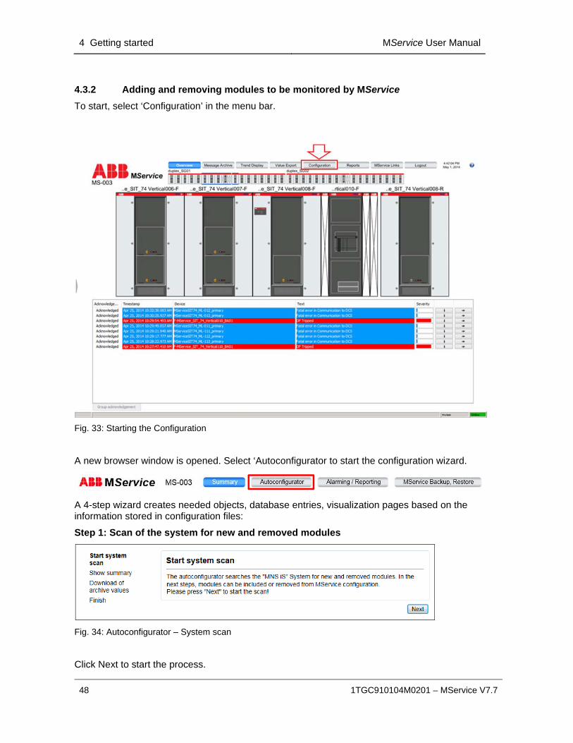
To start, select ‘Configuration’ in the menu bar.
Fig. 33: Starting the Configuration
A new browser window is opened. Select ‘Autoconfigurator to start the configuration wizard.
A 4-step wizard creates needed objects, database entries, visualization pages based on the information stored in configuration files:
Step 1: Scan of the system for new and removed modules
Fig. 34: Autoconfigurator – System scan
Click Next to start the process.
MService User Manual Getting started 4
1TGC910104M0201 – MService V7.7 49
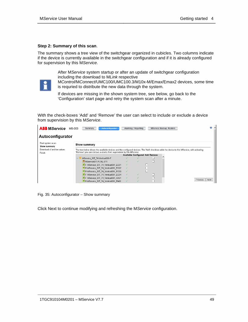
Step 2: Summary of this scan.
The summary shows a tree view of the switchgear organized in cubicles. Two columns indicate if the device is currently available in the switchgear configuration and if it is already configured for supervision by this MService.
After MService system startup or after an update of switchgear configuration including the download to MLink respective MControl/MConnect/UMC100/UMC100.3/M10x-M/Emax/Emax2 devices, some time is requried to distribute the new data through the system.
If devices are missing in the shown system tree, see below, go back to the ‘Configuration’ start page and retry the system scan after a minute.
With the check-boxes ‘Add’ and ‘Remove’ the user can select to include or exclude a device from supervision by this MService.
Fig. 35: Autoconfigurator – Show summary
Click Next to continue modifying and refreshing the MService configuration.

4 Getting started MService User Manual
50 1TGC910104M0201 – MService V7.7
Step 3 (only for deletion): Download of archive values.
This page shows up only in case modules are selected for deletion.
Here user can download the history values as CSV-file analog to the value export in the main menu bar in order to archive measurement data from these devices.
Fig. 36: Autoconfigurator – Download of archive values
Click ‘Next’ when ready.
Step 4: Confirmation
Before the Autoconfigurator starts loading/modifying the configuration, step 4 asks to confirm this action. If modules/devices have been selected for deletion, all the history values for this device are deleted.
Fig. 37: Autoconfigurator – Finish
Click ‘Finish’ to start the Autoconfiguration.

MService User Manual Getting started 4
1TGC910104M0201 – MService V7.7 51
After clicking finish, the wizard starts the automatic configuration and gives feedback on the progress.
Fig. 38: Autoconfigurator – Configuration progress
New or modified switchgear data are now being made available and user can start using MService functionality.
Fig. 39: Autoconfigurator – Configuration done
Click Next to return to the configuration overview page.

4 Getting started MService User Manual
52 1TGC910104M0201 – MService V7.7
Step 5: Reload WebHMI
After Autoconfiguration it is required to reload the WebHMI in order to see the changed configuration. Depending on the settings of the client PC, it might be necessary to close down all windows of the internet browser.
Modules not selected during the configuration are excluded from MService supervision. Such modules are greyed out in the visualisation and in the tree view. If a complete MLink and its MControl/UMC100/UMC100.3/M10x-M/Emax/Emax2 devices are excluded, the related cubicles are not shown at all.
Fig. 40: Excluded modules are displayed in light grey. No detail display is available for them
.
MService User Manual Message Archive 5
1TGC910104M0201 – MService V7.7 53
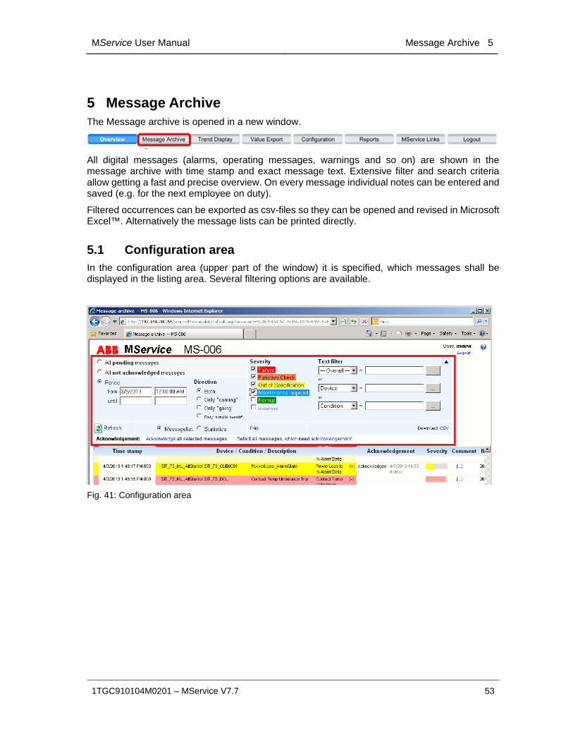
5 Message Archive The Message archive is opened in a new window.
All digital messages (alarms, operating messages, warnings and so on) are shown in the message archive with time stamp and exact message text. Extensive filter and search criteria allow getting a fast and precise overview. On every message individual notes can be entered and saved (e.g. for the next employee on duty).
Filtered occurrences can be exported as csv-files so they can be opened and revised in Microsoft Excel™. Alternatively the message lists can be printed directly.
5.1 Configuration area In the configuration area (upper part of the window) it is specified, which messages shall be displayed in the listing area. Several filtering options are available.
Fig. 41: Configuration area

5 Message Archive MService User Manual
54 1TGC910104M0201 – MService V7.7
Generic functions
Help Opens the online help.
/ Collapse / expand filter The filter area will be collapsed respectively expanded.
Refresh The display is updated with the settings made in the configuration area.
Print The current list (with optional filter applied) is printed.
Download CSV The list is downloaded as csv file, which should be saved first and then opened e.g. in Microsoft Excel™.
Filter Settings
All pending messages All currently active messages are displayed.
All not acknowledged messages
All not yet acknowledged messages are displayed. The amount between brackets displays how many not acknowledged messages exist in the system currently.
Period All messages which appeared in a specified selected period are displayed.
Selection of period for frequency analysis of messages.
Direction For messages related to a certain state, the user can select to show the activating (‘coming’) or deactivating (‘going’) event.
Priority Selection of the severity class of a message. Multiple selections are possible.
The classes are shown in that color, which is also used for the messages in the listing area below.
Text filter Here a text filter can be entered. See sec. 5.1.1 for details and an example on how to use text filter

MService User Manual Message Archive 5
1TGC910104M0201 – MService V7.7 55
Display Options for Listing area
Message list All messages are displayed as a list sorted by date and time in descending order.
Statistics User can choose this option only if Period is marked. Thereby the actual list of messages is analyzed on
the frequency of occurrence (counter) the period the average period the percentage period
The entries of the list can be sorted by clicking on the headings:
Message text Counter Period
Clicking once more the sorting is reversed.
Group Acknowledgement
Select all messages, which need acknowledgement
All messages which need acknowledgement are selected in the data sheet.
Acknowledge all selected messages
All marked messages are acknowledged.

5 Message Archive MService User Manual
56 1TGC910104M0201 – MService V7.7
5.1.1 On using text filter
A single message contains three textual attributes:
The device name,
the condition,
and a description
The text filter offers to set three criteria, which are used to select the messages to be shown.
Based on the selection in the drop-down box, each text filter acts individually on either
‘Device’: the device name
‘Condition’: the condition
’ -- Overall –‘: all three attributes device name, condition and description in parallel
Each entered filter text may contain placeholders to broaden the filter:
‘*’ stands for multiple characters
‘?’ stand for a single character.
Example:
Assuming the following power modules are configured in MService
1KHZ3LBA
1KHYY3LSA10
A0-1KH1LSA20
The following filter on ‘Device’ would have the corresponding effect
Filter Show messages for device(s)
1KH* 1KHZ3LBA 1KHY3LSA10
1KH?3* 1KHZ3LBA
*1KH* 1KHZ3LBA 1KHY3LSA10 A0-1KH1LSA20
*LSA?0 1KHYY3LSA10 A0-1KH1LSA20

MService User Manual Message Archive 5
1TGC910104M0201 – MService V7.7 57
5.2 Listing area In the Listing Area (lower part of the window) the messages are listed according to the filter criteria defined in the configuration area. The color is equivalent to the color of the message type.
The message list is automatically updated every 60 s and/or with every change of the filter settings. Manual update is possible utilizing the “Refresh” button.
If more than 500 messages according to the selected filter criteria have come up, the display is separated into several pages. At the bottom of the message list, user finds links to switch between the several pages.
Fig. 42: Listing area

5 Message Archive MService User Manual
58 1TGC910104M0201 – MService V7.7
Explanation of list headings
Timestamp This is the point of time, the message appears.
Device/Condition/
Description
The message text gives information on the device the message refers to.
Background color
Color corresponds to the message severity acc. to NAMUR recommendation. For the definition see section 11.1
Color shade
The active message has a dark color shade and the inactive a bright shade.
Blinking
Not acknowledged messages are blinking.
Acknowledgement In this column, messages are marked as acknowledged/ not acknowledged.
User can set check boxes and thereby acknowledge groups of messages by clicking on Acknowledge all selected messages.
Severity The length of the bar equates to the severity of the message.
Comment By clicking the squared brackets at Comment a window is opened, allowing the user to add a free notation on each particular incident.
This comment applies to this particular event only.
This is different from the notations (e.g. instructions) in the Knowledge base which refer generally to messages
No. Consecutive number of the message.
All messages receive a unique counter number in the sequence of arriving in the system. This number can also be used to sort the message list in an exported csv file in case no time stamp is available in MNS & MNS iS

MService User Manual Message Archive 5
1TGC910104M0201 – MService V7.7 59
Quick Filter
A “quick filter” mechanism allows for immediate selecting events limited to certain criteria: Device, Condition, Description, or Direction (coming/going).
The “quick filter” is applied using the mouse hovering over a message line and clicking on the appearing ‘lock’ symbol.
Fig. 43: Application of a “Quick Filter”
The result is shown as follows:
Fig. 44: “Quick filter” applied on Device Name
Multiple ‘quick filters’ can be applied at one time.
Fig. 45: Multiple “Quick filters” applied on Device Name and Condition

5 Message Archive MService User Manual
60 1TGC910104M0201 – MService V7.7
Statistics
With the aid of the statistics option in the Configuration Area, the frequency of occurrence of messages during a certain time period can be evaluated. Total duration and average duration of single messages are calculated, the percentage duration is displayed graphically as a bar graph. The list can be sorted according to different criteria.
Fig. 46: Frequency analysis
MService User Manual Trend Display 6
1TGC910104M0201 – MService V7.7 61
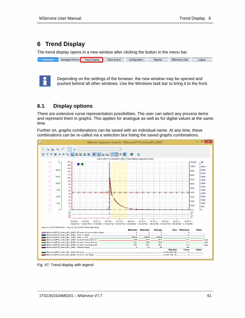
6 Trend Display The trend display opens in a new window after clicking the button in the menu bar.
Depending on the settings of the browser, the new window may be opened and pushed behind all other windows. Use the Windows task bar to bring it to the front.
6.1 Display options There are extensive curve representation possibilities. The user can select any process items and represent them in graphs. This applies for analogue as well as for digital values at the same time.
Further on, graphs combinations can be saved with an individual name. At any time, these combinations can be re-called via a selection box listing the saved graphs combinations.
Fig. 47: Trend display with legend

6 Trend Display MService User Manual
62 1TGC910104M0201 – MService V7.7
Trend display options available:
Selection of process values
Selection of single process values from system structure or selection of user-defined value (graphs) combinations
Display mode
Selection between display modes e.g. time series, frequency analysis or live data recorder
Legend
Fade in of process item names related to defined graphs. Legend can be extended by user-defined titles.
Time intervals
Time axis is configured, either via explicit setting of the time range or via pre-defined range settings. Options for navigation and zooming are given.
Data aggregation level
Access to the various pre-defined levels of data aggregation, e.g. fifteen minutes average
Diagram options
Options like crosshair, line graph, bar graph. Optional fade in of extreme values, limits, single data points. Print the current view.
MService User Manual Trend Display 6
1TGC910104M0201 – MService V7.7 63
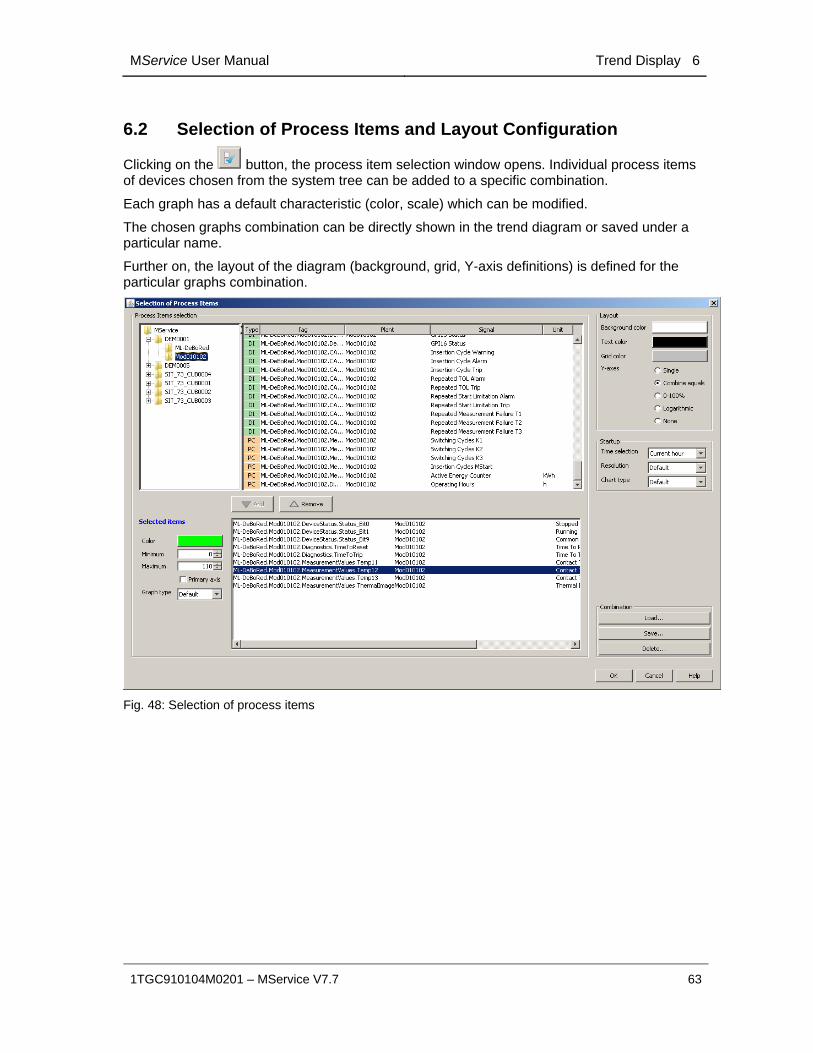
6.2 Selection of Process Items and Layout Configuration
Clicking on the button, the process item selection window opens. Individual process items of devices chosen from the system tree can be added to a specific combination.
Each graph has a default characteristic (color, scale) which can be modified.
The chosen graphs combination can be directly shown in the trend diagram or saved under a particular name.
Further on, the layout of the diagram (background, grid, Y-axis definitions) is defined for the particular graphs combination.
Fig. 48: Selection of process items
6 Trend Display MService User Manual
64 1TGC910104M0201 – MService V7.7
Process Items selection
Selection of process item to be displayed in a graph.
Add Adds the selected process item to the combination in the lower window.
Remove Deletes the marked process item from the combination in the lower window.
Selected items
The properties of the selected process items can be changed here.
Color Specifies the color to be used for the graph of the selected process item. A standard color selection dialog is used.
Minimum Defines the lowest value of process item to be shown in the graph.
Maximum For items of type “AI” (i.e. analog measurements), this value defines the highest value of process item to be shown in the graph.
For items of type “PC” (e.g. switching cycles counter), this value defines the maximum in the 1h aggregate display. In other aggregation levels the y-axis is adjusted automatically based on this value.
Primary Axis The item marked as ‘primary axis’ determines the horizontal grid lines of the trend.
Graph Type Type of Graph (Line, Bar, Area) for this individual item.
Layout
Layout options for the actual graphs combination.
Background color
Background color of the graphs combination.
Text color Text color of the legend of the graphs combination.
Grid color Color of the grid lines

MService User Manual Trend Display 6
1TGC910104M0201 – MService V7.7 65
Y-axes Single For each displayed graph a separate Y-axis is shown.
Combine equals
Y-axes with the same scale are displayed only once (default).
0-100% On the right and left side one Y-axis with a scale from 0 to 100% is shown (for all graphs of the combination).
Logarithmic Y-axis is represented with a logarithmic scaling (for all graphs of the combination).
None No Y-axis is shown.
Startup
Startup options for the actual graphs combination.
Time selection Initial range of time-axis (current hour, day, month, year) ‘Default’ is ‘current day’
Resolution Initial data aggregation (raw values, aggregated values 15min, 1h, 1d, 1m) ‘Default’ is ‘Raw values’
Chart Type Initial type of graph (Line, bar, or area diagram) ‘Default’ is ‘Line diagram’
Combinations
A combination of different process items and presentation options is saved under one graphs combination name and can be recalled at any time.
Load Opens a dialog listing all available graphs combinations. Desired graph combination can be selected and opened with OK.
Save Saves a graphs combination under a specified name.
Option “Public”: The graphs combination can be opened and seen by all users accessing this MService.
Delete Deletes an available graphs combination. Graphs combination to be deleted is selected in the list and deleted with OK.

6 Trend Display MService User Manual
66 1TGC910104M0201 – MService V7.7
6.3 Graphs characteristics After the definition of the process values for the graphs combination, the trend is shown with default characteristic: archive values of current day, shown in a line diagram.
If analog values in the chosen time period are out of the parameterized scale, an arrow will be drawn in up or down direction in the color of the variable.
Fig. 49: Trend display example
6.3.1 Graph controls
Graphs characteristics can be modified using the following options:
Display mode
Depending on the selection of the display mode, the remaining toolbar varies.
Archive Values In order to calculate the graphs, archived values
from the MService database are used.
The graph is updated with the latest values depending on the selected data aggregation level.
Archive Values with Time Comparison
See archive values.
2 graphs to be compared are shown with a time offset which can be defined. See time selection.
Frequency Analysis The frequency of occurrence of analog measured
values is displayed with a bar graph.
With selection of this option, the classes buttons become visible:

MService User Manual Trend Display 6
1TGC910104M0201 – MService V7.7 67
With the number of classes the measuring range of the selected process item is partitioned along the x-axis. The higher the number of classes, the finer the resolution of the frequency analysis.
XY-Presentation With the XY-Presentation a measured value is
shown in dependence of another value, e.g. the power input of a pump as a function of the differential pressure of this pump. With selection of this option, the list box for the selection of the X-axis becomes visible:
Pen recorder The live values of the selected process items are
written directly in a line graph.
Legend on/off Legend is shown or hidden, see sec. 6.3.2
Selection of Process Items
See Selection of process items, sec. 6.2
Graphs Combinations Via this dropdown field, a graphs combination can be selected and shown.
Time Intervals
Time Selection Definition of the time period, the graphs are shown
for.

6 Trend Display MService User Manual
68 1TGC910104M0201 – MService V7.7
Date and hour can be entered freely or selected directly by clicking the buttons. (Today, current week, current month).
If the mode archive values with time comparison is active, the following dialog box comes up. Time offset for the comparison of 2 graphs is defined. The offset curve is dotted.
Today Current day is indicated as time period.
Current Week Current week is indicated as time period.
Current Month Current month is indicated as time period.
Scroll Back With Scroll back the current time period is moved
back half of the current selected time period.
Scroll Forward With Scroll forward the current time period is moved
forward half of the current selected time period.
Zoom out The current time period is zoomed out into the next larger
one.

MService User Manual Trend Display 6
1TGC910104M0201 – MService V7.7 69
Zoom in A certain time period is marked with the left mouse button hold. Thus the marked time period will be displayed in a larger scale.
Aggregation
Raw values Archived raw values are displayed.
15 min aggregation
Archived 15-minutes-values are displayed.
1 hour aggregation Archived hours-values are displayed.
1 day aggregation Archived days-values are displayed.
1 month aggregation
Archived months-values are displayed.
Diagram options
Crosshair Activation of crosshair enables the user to read out
coordinates of a specific point in the diagram.
Depending on the position of the crosshair, the corresponding data are displayed in the legend.
Statistics
A certain time period can be marked with the crosshair (left click into the diagram, drag mouse along the x-axis). Thus the legend is extended by statistical data for this time period, see sec. 6.3.3
Crosshair “freezing”
This function is only available in the archive- and time comparison modes. With right mouse click into the diagram, it is possible to "freeze" the mouse pointer (e.g. for a print-out). After "freezing", the crosshair can be moved with pressed mouse button.

6 Trend Display MService User Manual
70 1TGC910104M0201 – MService V7.7
Line chart Values are shown in a line chart.
Bar chart Values are shown in a bar chart.
Area chart Values are shown in an area diagram.
Measured Value marker on/off
There are 2 different marker types for measured values:
A dot signals: Measured value is within range.
A cross signals: Measured value is out of range. In the legend the value is indicated in red.
In case of an OPC failure, no value is displayed.
Min/Max-Display on/off
The extreme values (minimum and maximum) of each indicated graph in the diagram are marked with a horizontal line. The extreme values are identified with date and time.
Limits on/off Option not used
Grid Lines on/off Background grid lines are shown or hidden.
Print Opens a print dialog to print out the current view.
Microsoft XPS printer may not be supported on Windows 7 client PCs.
MService User Manual Trend Display 6
1TGC910104M0201 – MService V7.7 71
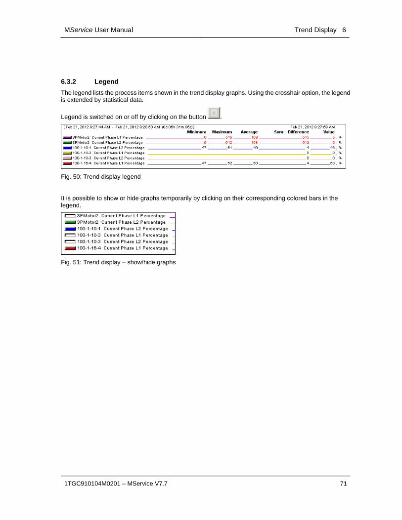
6.3.2 Legend
The legend lists the process items shown in the trend display graphs. Using the crosshair option, the legend is extended by statistical data.
Legend is switched on or off by clicking on the button .
Fig. 50: Trend display legend
It is possible to show or hide graphs temporarily by clicking on their corresponding colored bars in the legend.
Fig. 51: Trend display – show/hide graphs

6 Trend Display MService User Manual
72 1TGC910104M0201 – MService V7.7
6.3.3 Statistics
With activated crosshair a statistics options can be used.
A certain time period is marked with the crosshair (left click into the diagram, drag mouse along the x-axis). The selected range is colored in yellow. The legend is extended by statistical data for this time period.
Fig. 52: Selection of range for statistics
With a further left mouse-click the selected range is fixed. A left mouse-click at the left or right border next to the y-axis removes the selection.
If the mouse points directly to the border of the selection, the mouse-pointer changes into a double arrow. Thus the selected range can be modified.
With double-click on the double arrow, a dialog box opens to specify the exact time.
Fig. 53: Selection of range for statistics graphically (left) and directly (right)

MService User Manual Trend Display 6
1TGC910104M0201 – MService V7.7 73
The legend shows the following information on statistics:
Value Indication of the value for the position of the crosshair.
Difference If the mouse pointer is placed between 2 measurement points, the value difference is shown.
Sum All values within the selected area are summed up.
Sum is only calculated for counters like switch cycles, insertion cycles etc.
Average Average of values within the selected area is displayed.
Maximum Highest value within the selected area is displayed.
Minimum Smallest value within the selected area is displayed.
The following values are only displayed in case a digital signal is available in the graphs:
Duration Display of time how long a digital signal has been in signal state 1 (high) within the selected area.
Count Display of amount of starting attempts (rising edge) of the digital signal within the selected area.
7 Value Export MService User Manual
74 1TGC910104M0201 – MService V7.7
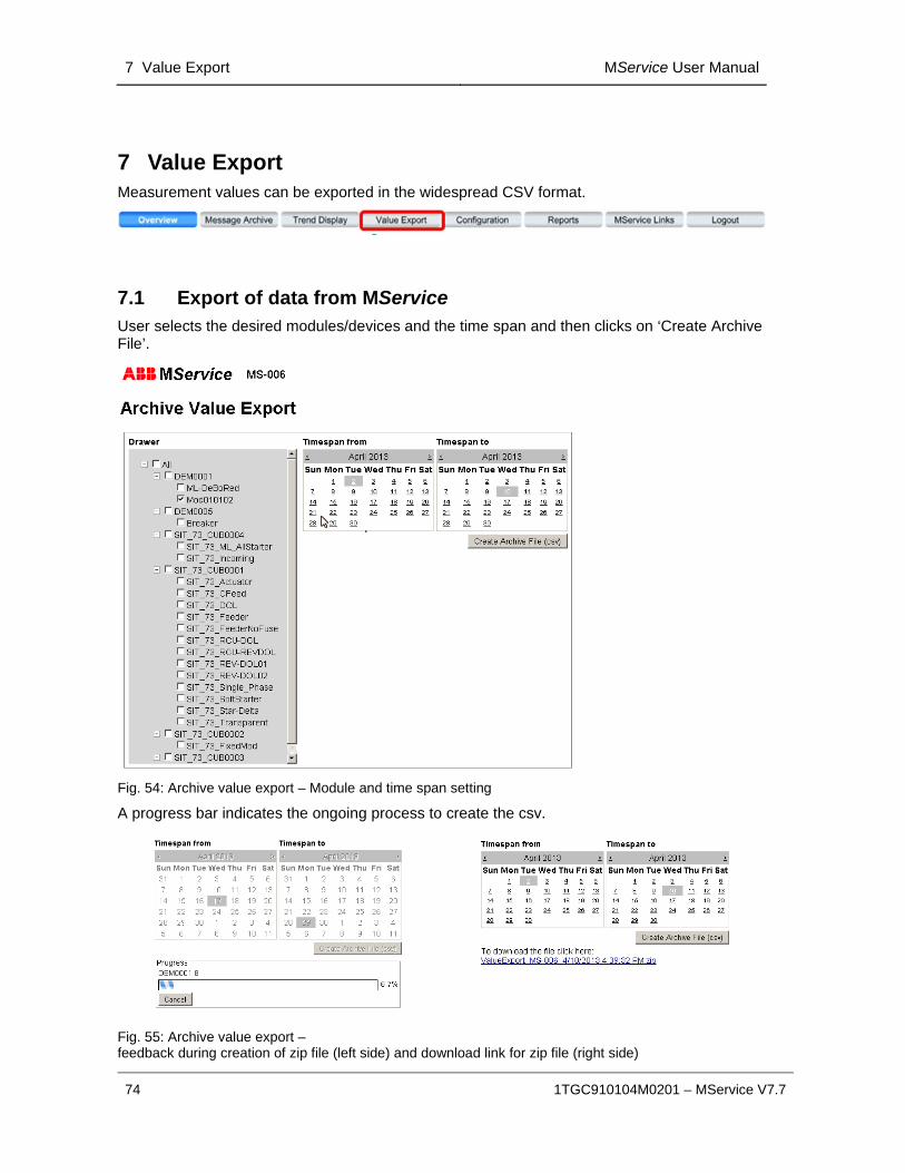
7 Value Export Measurement values can be exported in the widespread CSV format.
7.1 Export of data from MService User selects the desired modules/devices and the time span and then clicks on ‘Create Archive File’.
Fig. 54: Archive value export – Module and time span setting
A progress bar indicates the ongoing process to create the csv.
Fig. 55: Archive value export – feedback during creation of zip file (left side) and download link for zip file (right side)

MService User Manual Value Export 7
1TGC910104M0201 – MService V7.7 75
The created compressed archive (zip) contains one embedded zip with multiple csv files per selected device:
Archive values: List of analog values
Message archive: List of status messages and alarms (Message archive is only available, if there are messages in the selected time span)
The file structure presents every data record in a separate line with timestamp, message text, acknowledgement status, priority, comment and number separated by semicolons.
Export files containing more than 65.000 lines are separated to different files.
Fig. 56: Archive value export – file export
7.2 Import of the data into Microsoft Excel™
The formatting of the csv data depends on the regional settings of the current user exporting the data. E.g. if the user’s language is ‘English’, the date format is Month/Day/Year and the decimal separator is ‘.’
If the data is to be imported into Microsoft Excel™, the user’s regional settings of Windows temporarily have to be adjusted to match the regional settings of the exporting MService user.

7 Value Export MService User Manual
76 1TGC910104M0201 – MService V7.7
1 Open “Control Panel Region and Language”, to prepare the csv import matching the export settings.
(Example shown for US-English)
2 In Excel, open a workbook and use the ‘Data’ menu to import the csv file.
(Example shown for Excel 2010)
3 Locate and Select the csv file.

MService User Manual Value Export 7
1TGC910104M0201 – MService V7.7 77
4 Text import wizard:
Set Data type to ‘Delimited’.
5 Text import wizard :
Set delimiter to ‘semicolon’ only.
6 Text import wizard :
Select where the data should be placed within the Excel document.
7 Reset the regional settings to the previous state

7 Value Export MService User Manual
78 1TGC910104M0201 – MService V7.7
The result shall look similar to the following:
Fig. 57: Example of exported csv data in Microsoft Excel
MService User Manual Configuration 8
1TGC910104M0201 – MService V7.7 79
8 Configuration
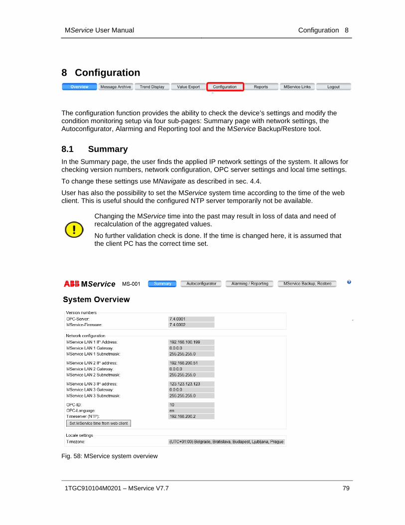
The configuration function provides the ability to check the device’s settings and modify the condition monitoring setup via four sub-pages: Summary page with network settings, the Autoconfigurator, Alarming and Reporting tool and the MService Backup/Restore tool.
8.1 Summary In the Summary page, the user finds the applied IP network settings of the system. It allows for checking version numbers, network configuration, OPC server settings and local time settings.
To change these settings use MNavigate as described in sec. 4.4.
User has also the possibility to set the MService system time according to the time of the web client. This is useful should the configured NTP server temporarily not be available.
Changing the MService time into the past may result in loss of data and need of recalculation of the aggregated values.
No further validation check is done. If the time is changed here, it is assumed that the client PC has the correct time set.
Fig. 58: MService system overview
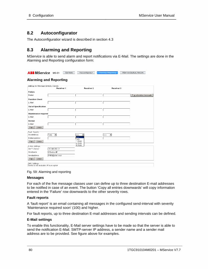
8 Configuration MService User Manual
80 1TGC910104M0201 – MService V7.7
8.2 Autoconfigurator The Autoconfiguratior wizard is described in section 4.3
8.3 Alarming and Reporting MService is able to send alarm and report notifications via E-Mail. The settings are done in the Alarming and Reporting configuration form:
Fig. 59: Alarming and reporting
Messages
For each of the five message classes user can define up to three destination E-mail addresses to be notified in case of an event. The button ‘Copy all entries downwards’ will copy information entered in the ‘Failure’ row downwards to the other severity rows.
Fault reports
A ‘fault report’ is an email containing all messages in the configured send-interval with severity ‘Maintenance required soon’ (100) and higher.
For fault reports, up to three destination E-mail addresses and sending intervals can be defined.
E-Mail settings
To enable this functionality, E-Mail server settings have to be made so that the server is able to send the notification E-Mail. SMTP-server IP address, a sender name and a sender mail address are to be provided. See figure above for examples.
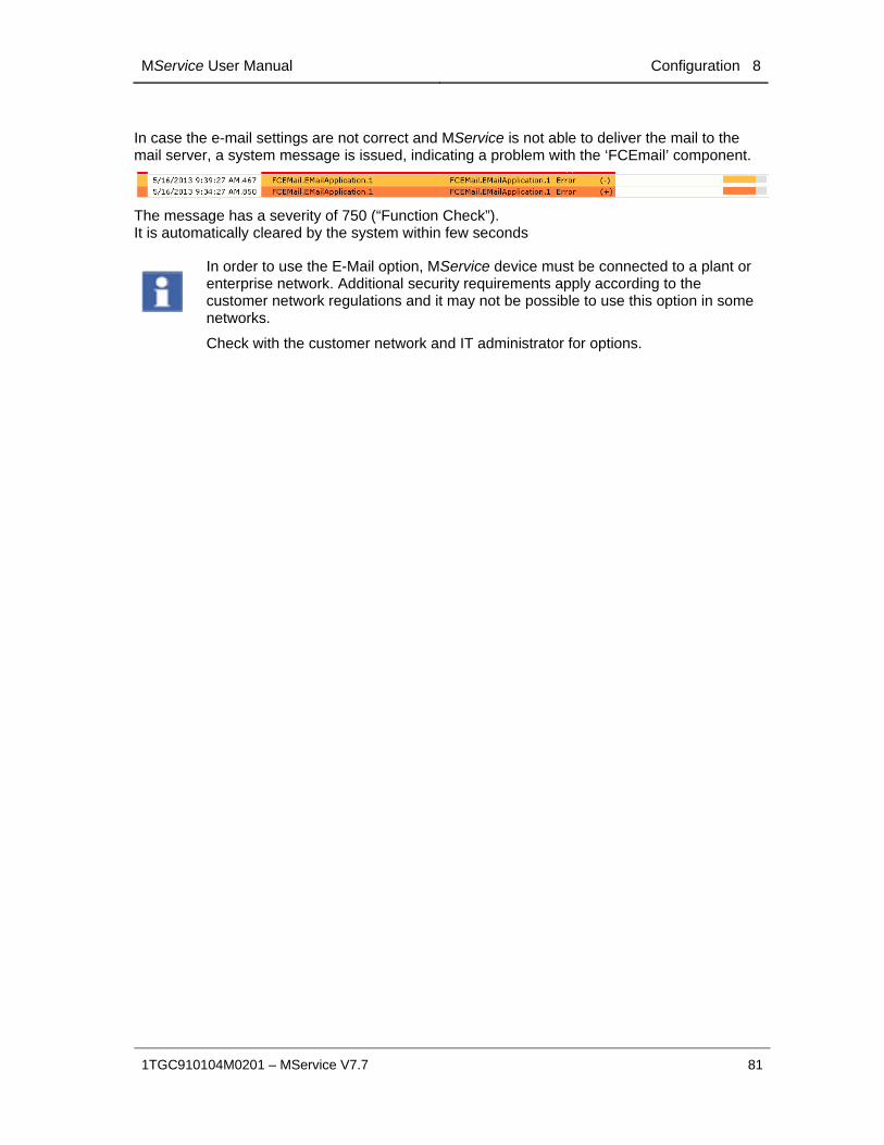
MService User Manual Configuration 8
1TGC910104M0201 – MService V7.7 81
In case the e-mail settings are not correct and MService is not able to deliver the mail to the mail server, a system message is issued, indicating a problem with the ‘FCEmail’ component.
The message has a severity of 750 (“Function Check”). It is automatically cleared by the system within few seconds
In order to use the E-Mail option, MService device must be connected to a plant or enterprise network. Additional security requirements apply according to the customer network regulations and it may not be possible to use this option in some networks.
Check with the customer network and IT administrator for options.
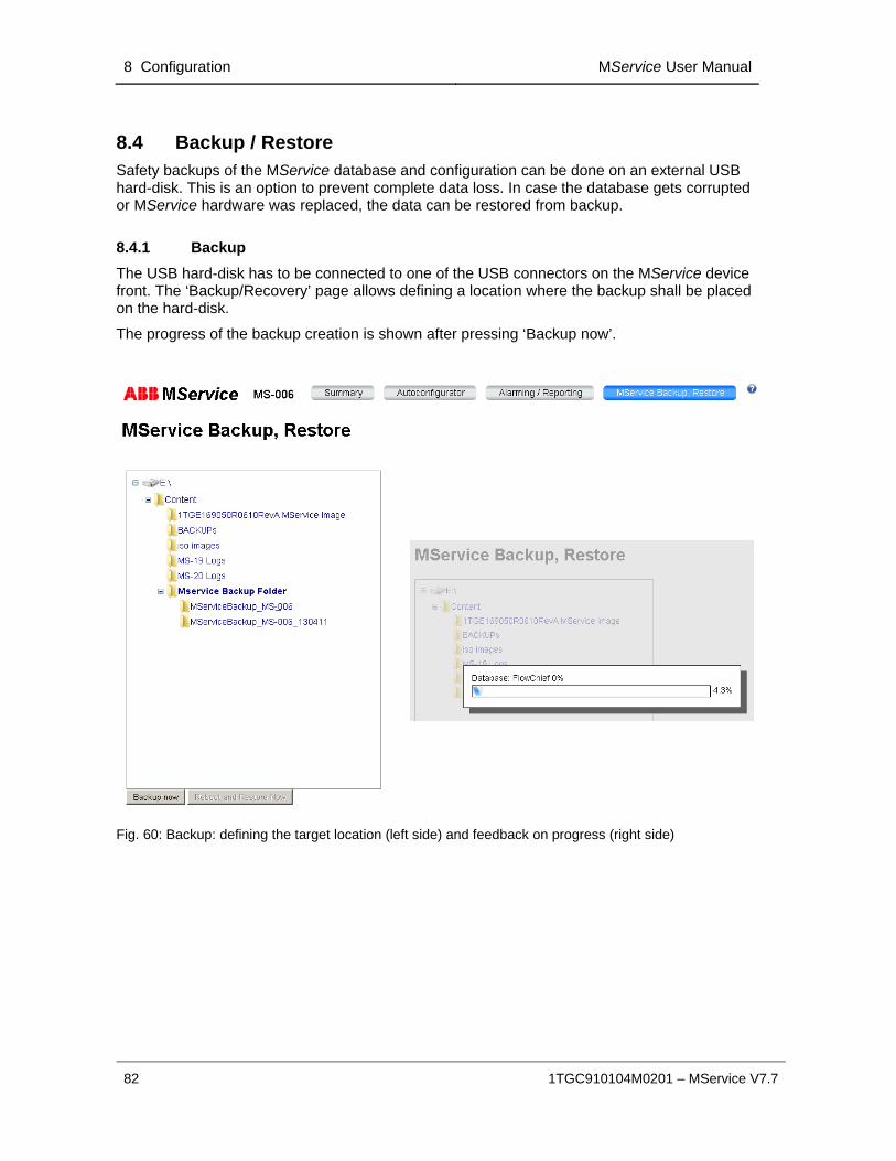
8 Configuration MService User Manual
82 1TGC910104M0201 – MService V7.7
8.4 Backup / Restore Safety backups of the MService database and configuration can be done on an external USB hard-disk. This is an option to prevent complete data loss. In case the database gets corrupted or MService hardware was replaced, the data can be restored from backup.
8.4.1 Backup
The USB hard-disk has to be connected to one of the USB connectors on the MService device front. The ‘Backup/Recovery’ page allows defining a location where the backup shall be placed on the hard-disk.
The progress of the backup creation is shown after pressing ‘Backup now’.
Fig. 60: Backup: defining the target location (left side) and feedback on progress (right side)
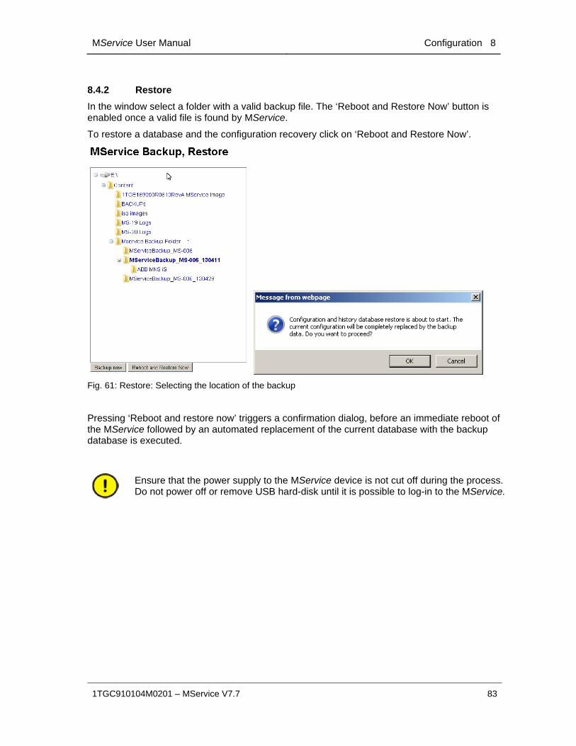
MService User Manual Configuration 8
1TGC910104M0201 – MService V7.7 83
8.4.2 Restore
In the window select a folder with a valid backup file. The ‘Reboot and Restore Now’ button is enabled once a valid file is found by MService.
To restore a database and the configuration recovery click on ‘Reboot and Restore Now’.
Fig. 61: Restore: Selecting the location of the backup
Pressing ‘Reboot and restore now’ triggers a confirmation dialog, before an immediate reboot of the MService followed by an automated replacement of the current database with the backup database is executed.
Ensure that the power supply to the MService device is not cut off during the process. Do not power off or remove USB hard-disk until it is possible to log-in to the MService.

9 MService Report module MService User Manual
84 1TGC910104M0201 – MService V7.7
9 MService Report module The creation of reports allows to collect operational and maintenance status information into a document to be exported from MService device for further use such as documentation purposes.
The Reporting Module starts with a selection dialog similar to the Value Export. It allows for a selection of the report type and the time period to be reported.
9.1 Condition Report This type of report collects and displays all the operational and condition data available for the power modules in the switchgear
Fig. 62: The entry page of the Report module
The time selection allows for daily, monthly and yearly reports.
Condition summaries are created on three levels:
o Switchgear level: Shows a summary over all monitored devices and cubicles
o Cubicle level: Shows the collected data on the power loss and temperature supervision status within the cubicle
o Device level: Shows the summary of collected data and events for individual devices.
The system tree offers the possibility to select which items are to be included in the report.
o The check box in front of a named item (switchgear, cubicle, or device) select the corresponding summary page to be created.
o The check box ‘All’ selects all devices below.
Reports can be generated for online display or as pdf-File to be downloaded.

MService User Manual MService Report module 9
1TGC910104M0201 – MService V7.7 85
The generated report starts with a summary page showing the main plant and contact information along with the list of selected switchgears, cubicles and devices.
Fig. 63: First page of Condition Report showing site and contact information
The switchgear overview level shows per alarm severity class, for which device and how many alarms were triggered within the reporting period.
Fig. 64: Switchgear overview page of Condition Report

9 MService Report module MService User Manual
86 1TGC910104M0201 – MService V7.7
The cubicle overview level collects all information on the online power loss supervision.
Fig. 65: Cubicle overview page of Condition Report
The device condition level finally shows statistical information on the devices usage in the reporting period, as well as a summary list of all alarms occurred on the device.
Fig. 66: Power module page of Condition Report

MService User Manual MService Report module 9
1TGC910104M0201 – MService V7.7 87
The value tables are organized in three areas: the current reporting period, the corresponding previous period and a difference area.
For the measurement values, in each area the minimum and maximum values are shown and in the middle the average value for the measurement. To limit CPU load and creation time the minimum and maximum values are taken from the next lower aggregation level.
Daily Report
Min (hourly avg)
Max (hourly avg)
Minimum is the lowest hourly average on that day
Maximum is the highest hourly average on that day
Monthly Report
Min (daily avg)
Max (daily avg)
Minimum is the lowest daily average in that month
Maximum is the highest daily average in that month
Yearly Report
Min (monthly avg)
Max (monthly avg)
Minimum is the lowest monthly average on that year
Maximum is the highest monthly average on that year
For counter values, each area shows the start and end value and the change of the value during the reported period. The last column shows the difference of the change values of current and previous period.
Daily Report
Change Difference between ‘end’ and ‘begin’ value.
This is for example the energy consumption on that day
Daily Change Difference between ‘current day change’ and ‘previous day change’.
This is for example the change of the energy consumption reported day and previous day.
Monthly Report
Change Difference between ‘end’ and ‘begin’ value.
Monthly Change Difference between ‘current month change’ and ‘previous month change’.
Yearly Report
Change Difference between ‘end’ and ‘begin’ value.
Yearly Change Difference between ‘current year change’ and ‘previous year change’.

9 MService Report module MService User Manual
88 1TGC910104M0201 – MService V7.7
9.2 Energy Report The energy report is available per switchgear and collects for each contained cubicle the recorded values for power loss and active energy counter.
Fig. 67: The entry page of the Report module for the energy report
The time selection allows for daily, monthly and yearly reports.
Energy report is always created for all configured modules of a switchgear
Reports can be generated for online display or as pdf-File to be downloaded.
The shown total sum includes only the measurements from the power modules configured for supervision.
The real totals include of course all power modules, including also the conventional modules which do not provide any operational data to the MService.
The generated report starts with a summary page showing the main plant and contact information along with the list of selected switchgears, cubicles and devices.
Fig. 68: First page of Energy Report showing site and contact information

MService User Manual MService Report module 9
1TGC910104M0201 – MService V7.7 89
The switchgear overview page summarizes the recorded power loss and energy consumption numbers.
Fig. 69: Switchgear overview page of energy report
The cubicle detail page shows the power loss and energy consumption values per supervised module within the cubicle.
Fig. 70: Cubicle detail page of Energy Report
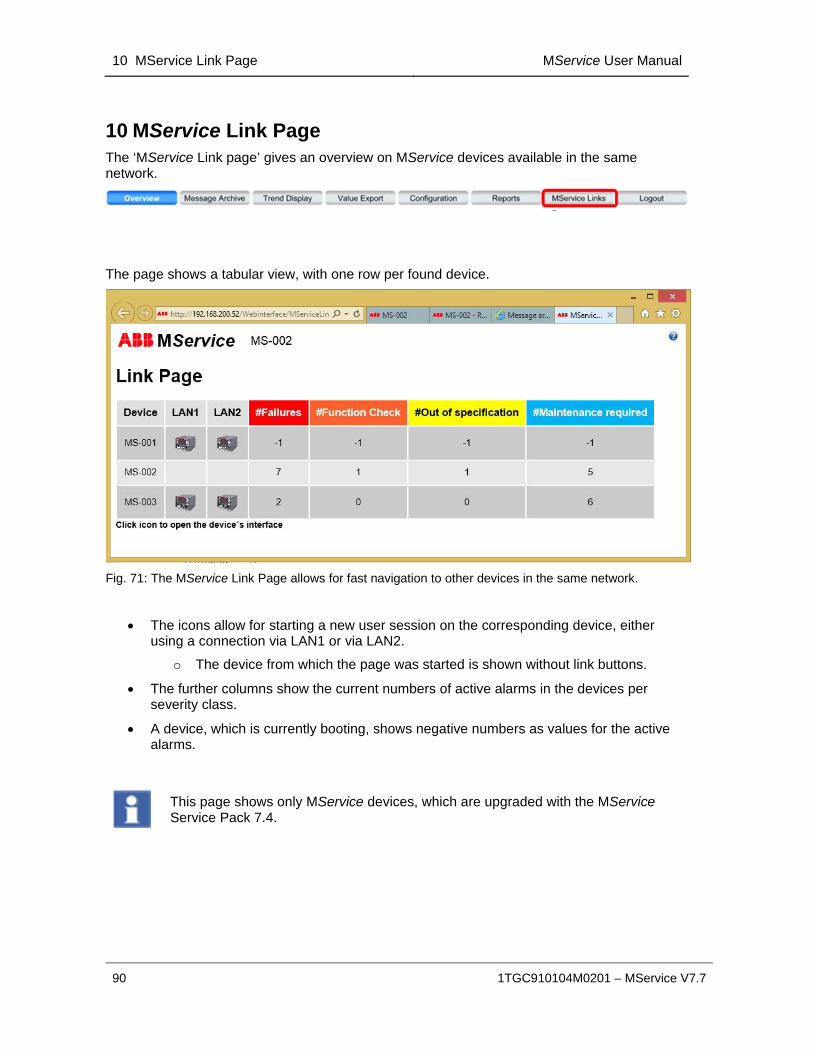
10 MService Link Page MService User Manual
90 1TGC910104M0201 – MService V7.7
10 MService Link Page The ‘MService Link page’ gives an overview on MService devices available in the same network.
The page shows a tabular view, with one row per found device.
Fig. 71: The MService Link Page allows for fast navigation to other devices in the same network.
The icons allow for starting a new user session on the corresponding device, either using a connection via LAN1 or via LAN2.
o The device from which the page was started is shown without link buttons.
The further columns show the current numbers of active alarms in the devices per severity class.
A device, which is currently booting, shows negative numbers as values for the active alarms.
This page shows only MService devices, which are upgraded with the MService Service Pack 7.4.

MService User Manual Data view area 11
1TGC910104M0201 – MService V7.7 91
11 Data view area The data view occupies the middle part of the MService display. It contains either an overview on the system or detailed pages for the various devices or the cubicles.
11.1 Cubicle overview In the cubicle view a detailed display of up to 5 cubicle is presented.
A thumbnail list of all cubicles configured in the MService is shown above. Clicking with the left button on the thumbnails allows for switching to the desired cubicle in the main view. Using the right button, the option to open the view in a new window is shown.
Fig. 72: Cubicle view
Cubicles of the same switchgear are shown in the same sequence as in the physical switchgear installation. In case of a duplex configuration, front and rear are separated by small gap.
Switchgears are separated by grey line between the cubicles and a space between the thumbnails.
Every module is displayed in its configured location within the equipment compartment of the cubicle.
The MLink is shown according to its location specified in the configuration. If the location of MLink is not specified then it is displayed in the first of its associated cubicles having a control compartment.
MService devices are not shown in this overview.
Devices which are included in the MService configuration are shown in dark grey and are colored according to the operational status.
Devices which are shown as part of a cubicle but are not configured for supervision are indicated in light grey color without a background picture of the device.
Devices can be clicked to jump to the detailed view.
Devices in status ‘running’ or ‘closed’ are shown with a small orange circle. Devices with an active alarm or trip are shown in yellow (alarm) or red (trip).

11 Data view area MService User Manual
92 1TGC910104M0201 – MService V7.7
11.1.1 Color coding
The cubicle thumbnails are colored if one of their modules has an active alarm/trip state. The color coding is according to the NAMUR recommendation [4].
Following table describes the color and meaning.
Severity Sub-Condition Description
1 - 99 Normal
Motor is available. Status is ‘normal”.
Asset functionality is fully available. No maintenance is required.
100 -399 Maintenance required
Motor is available. Status is ‘maintenance required (soon)”.
Asset functionality fully available but maintenance required soon to avoid functional restrictions, e.g. caused by a nearly exhausted wear reserve or operating conditions.
400 -749 Out of Specification
Motor is still available. Status is ‘out of specification”.
Asset functionality available but decreased due to operating conditions outside the specified limits.
750 – 899 Function Check
Motor has been stopped. Operation is not possible. Status is ‘function check”.
Asset functionality might be temporarily restricted, due to on-going work on the asset, e.g. as local operation, maintenance (main-switch off), simulation or a function check (test-position).
900 – 1000 Failure
Motor has been stopped. Status is ‘failure”.
Asset Functionality lost due to malfunction of its peripherals or due to operating conditions.
Fig. 73: Colors in cubicle view
The colors are predefined and cannot be changed by the user.
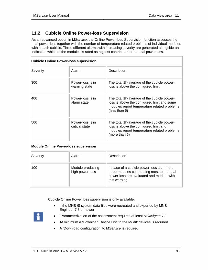
MService User Manual Data view area 11
1TGC910104M0201 – MService V7.7 93
11.2 Cubicle Online Power-loss Supervision As an advanced option in MService, the Online Power-loss Supervision function assesses the total power-loss together with the number of temperature related problems of individual modules within each cubicle. Three different alarms with increasing severity are generated alongside an indication which of the modules is rated as highest contributor to the total power loss.
Cubicle Online Power-loss supervision
Severity Alarm Description
300 Power-loss is in warning state
The total 1h-average of the cubicle power-loss is above the configured limit
400 Power-loss is in alarm state
The total 1h-average of the cubicle power-loss is above the configured limit and some modules report temperature related problems (less than 5)
500 Power-loss is in critical state
The total 1h-average of the cubicle power-loss is above the configured limit and modules report temperature related problems (more than 5)
Module Online Power-loss supervision
Severity Alarm Description
100 Module producing high power-loss
In case of a cubicle power-loss alarm, the three modules contributing most to the total power-loss are evaluated and marked with this warning
Cubicle Online Power loss supervision is only available,
if the MNS iS system data files were recreated and exported by MNS Engineer 7.3.or newer
Parameterization of the assessment requires at least MNavigate 7.3
At minimum a ‘Download Device List’ to the MLink devices is required
A ‘Download configuration’ to MService is required
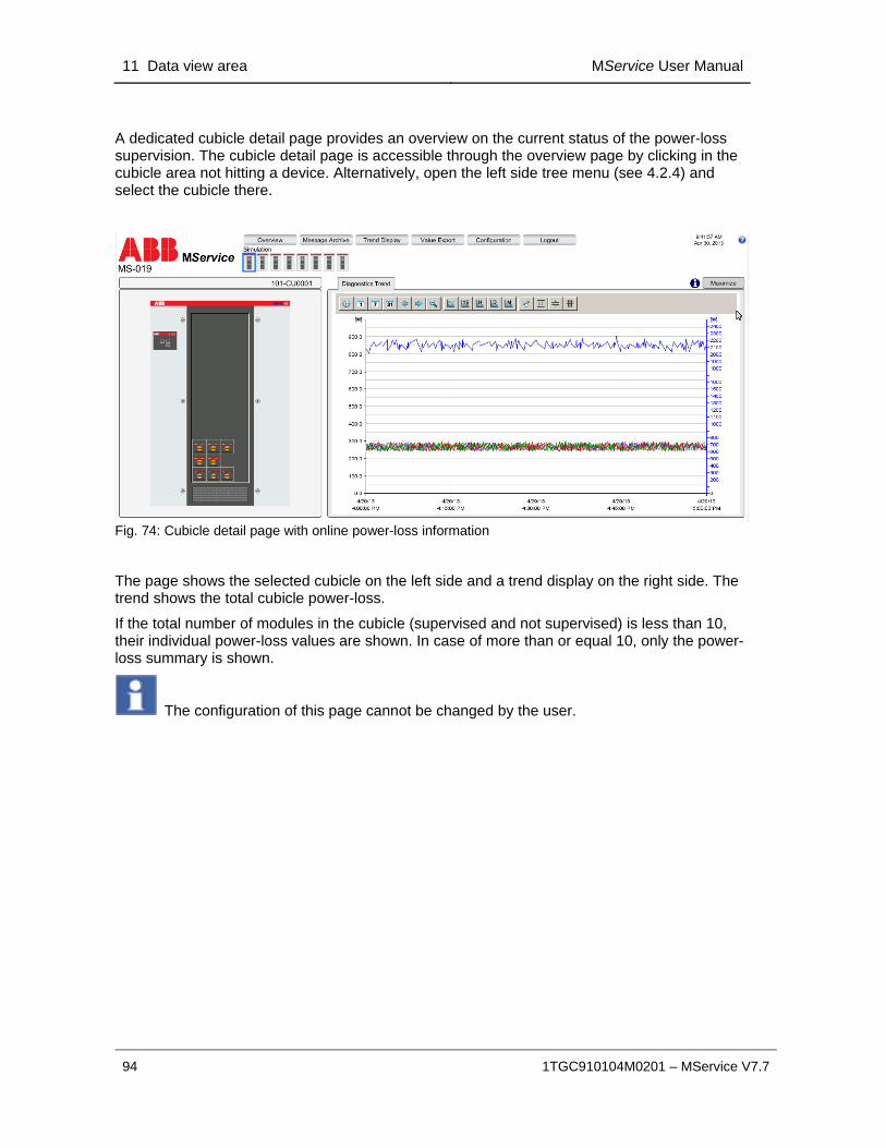
11 Data view area MService User Manual
94 1TGC910104M0201 – MService V7.7
A dedicated cubicle detail page provides an overview on the current status of the power-loss supervision. The cubicle detail page is accessible through the overview page by clicking in the cubicle area not hitting a device. Alternatively, open the left side tree menu (see 4.2.4) and select the cubicle there.
Fig. 74: Cubicle detail page with online power-loss information
The page shows the selected cubicle on the left side and a trend display on the right side. The trend shows the total cubicle power-loss.
If the total number of modules in the cubicle (supervised and not supervised) is less than 10, their individual power-loss values are shown. In case of more than or equal 10, only the power-loss summary is shown.
The configuration of this page cannot be changed by the user.

MService User Manual Data view area 11
1TGC910104M0201 – MService V7.7 95
11.3 Power Module view The detailed view of an MStart/MFeed/UMC100/UMC100.3M10x-M modules or Circuit Breaker is opened by clicking the device in the Cubicle view. Another option to open the detailed view is via the “detail view”-button ( ) in the Message list (see 5.2) or via the left side tree menu (see 4.2.4).
On the left side a simplified MStart/MFeed or Circuit Breaker schematic is shown whereas on the right side detailed information and control options are available in a tab-separated area. The lower part of the window shows the alarm and event list, filtered for the selected module.
Fig. 75: Power Module view example: MStart

11 Data view area MService User Manual
96 1TGC910104M0201 – MService V7.7
11.3.1 Power Module schematic
The Power Module view on the left side shows a simplified schematic of the device’s electrical structure with the device and cubicle name on top.
Individual parts of a module, which are with a fault or require maintenance action, are colored according to the color of the associated message’s priority (see also 11.1.1).
Additional status information is provided and indicated when active.
Fig. 76: Power Module schematic example: MStart and Circuit Breaker

MService User Manual Data view area 11
1TGC910104M0201 – MService V7.7 97
11.3.2 Tab “Online”
This area shows the live values available for the device. This is useful for directly monitoring actual electrical and maintenance values.
MStart / MFeed connected through MControl
Fig. 77a: Power Module view - Online values for MStart

11 Data view area MService User Manual
98 1TGC910104M0201 – MService V7.7
The following values are available (depending on motor, load or module type)
MStart / MFeed
Current Current for up to 3 phases in [A]
Voltage Phase to phase Voltage for up to 3 phases in [V]
Residual Current Residual Current in [A]
Active power Active power in [W]
Reactive Power Reactive Power in [W]
Cos Power factor
Contact Temperature Temperature of the outgoing contacts for up to 3 phases in [°C]
Active energy counter Current value of energy counter calculated by MControl in [kWh]
Power loss Module’s current power loss in [W]
Switch Cycles Count of switching operations for up to 3 contactors
Insertion cycles Count of Power Module insertions
Operating Hours Count of operational time of load in hours
Measured Motor Start Time Start-up time of the motor in [s]
Thermal Image Motor temperature profile showing the thermal load level in [%]
Time to Trip Expected time to trip due to thermal overload in [s]
Time to Reset Expected time to wait until TOL trip reset is possible [s]
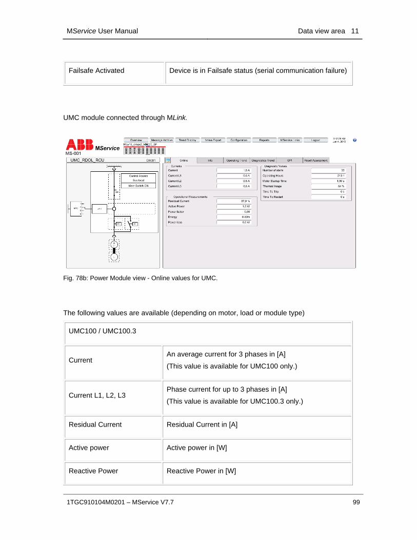
MService User Manual Data view area 11
1TGC910104M0201 – MService V7.7 99
Failsafe Activated Device is in Failsafe status (serial communication failure)
UMC module connected through MLink.
Fig. 78b: Power Module view - Online values for UMC.
The following values are available (depending on motor, load or module type)
UMC100 / UMC100.3
Current An average current for 3 phases in [A]
(This value is available for UMC100 only.)
Current L1, L2, L3 Phase current for up to 3 phases in [A]
(This value is available for UMC100.3 only.)
Residual Current Residual Current in [A]
Active power Active power in [W]
Reactive Power Reactive Power in [W]

11 Data view area MService User Manual
100 1TGC910104M0201 – MService V7.7
Active energy counter Current value of energy counter calculated by UMC100 or UMC100.3 in [kWh]
Power loss Module’s current power loss in [W]
Number of Starts Process value shown the maintenance counters for Number of Starts
Operating Hours Count of operational time of load in hours
Measured Motor Start Time Start-up time of the motor in [s]
Thermal Image Motor temperature profile showing the thermal load level in [%]
Time to Trip Expected time to trip due to thermal overload in [s]
Time to Reset Expected time to wait until TOL trip reset is possible [s]
M10x module connected through MLink.
Fig. 79c: Power Module view - Online values for M10x.
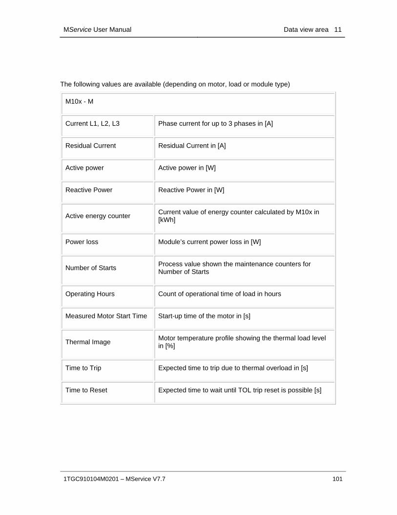
MService User Manual Data view area 11
1TGC910104M0201 – MService V7.7 101
The following values are available (depending on motor, load or module type)
M10x - M
Current L1, L2, L3 Phase current for up to 3 phases in [A]
Residual Current Residual Current in [A]
Active power Active power in [W]
Reactive Power Reactive Power in [W]
Active energy counter Current value of energy counter calculated by M10x in [kWh]
Power loss Module’s current power loss in [W]
Number of Starts Process value shown the maintenance counters for Number of Starts
Operating Hours Count of operational time of load in hours
Measured Motor Start Time Start-up time of the motor in [s]
Thermal Image Motor temperature profile showing the thermal load level in [%]
Time to Trip Expected time to trip due to thermal overload in [s]
Time to Reset Expected time to wait until TOL trip reset is possible [s]

11 Data view area MService User Manual
102 1TGC910104M0201 – MService V7.7
Circuit Breaker
Fig. 80: Power Module view - Online values for Circuit Breaker
Circuit Breaker
Current Absolute current for 3 phases and neutral current in [A]
Voltage Line to line voltages in [V]
Power Total active, reactive, and apparent power in [W]
Energy Total active, reactive and apparent energy in [kWh], [kvarh], resp. [kVAh]
Frequency Measured Frequency in [Hz]
Total Power factor Power factor (Cos Phi)

MService User Manual Data view area 11
1TGC910104M0201 – MService V7.7 103
11.3.3 Tab “Info”
Here, detailed hardware information of the device can be found. This is useful to identify a device, the connected plant component (e.g. motor or load) and the device main parameters (e.g. serial number)
.
MStart / MFeed connected through MControl
Fig. 81a: Power Module view – Device Information for MStart / MControl
The following information is available:
Labels
Device Name 1, 2, 3 Device Identifier for Motor Starter or Feeder module as in MNavigate
Location
Switchgear Switchgear name where the device is located
Cubicle Cubicle name where the device is located
Level The row where the device is installed in the cubicle
Position The column where the device is installed in the cubicle
MLink

11 Data view area MService User Manual
104 1TGC910104M0201 – MService V7.7
Device Name Name of the MLink to which the device is connected to through the internal serial communication.
Clicking on the link opens the detail page for that MLink
MView
Open MView web page
Clicking on this link opens a new web browser with the MView web page of the related device. The attempt is based on the current MService user.
This function is limited to networks, where the MService client is connected to the same subnet as the MLink.
Power Module Info (MStart / MFeed)
Identnumber ABB Identification number of the Power Module
Size Mechanical size of MStart / MFeed (6E4, 6E2, .. 72E)
Nominal Current Maximum current of the Power Module
Serial Number Serial number identifying the Power Module
Power Module Functions
Power Module Type Starter/Feeder type
Application type Configured software application
MControl / MConnect
Identnumber ABB Identification number of the MControl device as originally engineered.

MService User Manual Data view area 11
1TGC910104M0201 – MService V7.7 105
UMC module connected through MLink
Fig. 82b: Power Module view – Device Information for UMC100 or UMC100.3
The following information is available:
Labels
Device Name 1, 2, 3 Device Identifier for Motor Starter or Feeder module as in MNavigate
Location
Switchgear Switchgear name where the device is located
Cubicle Cubicle name where the device is located
Level The row where the device is installed in the cubicle
Position The column where the device is installed in the cubicle
MLink
Device Name Name of the MLink to which the device is connected to through the internal serial communication.
Clicking on the link opens the detail page for that MLink
MView
Open MView web page
Clicking on this link opens a new web browser with the MView web page of the related device. The attempt is based on the current MService user.
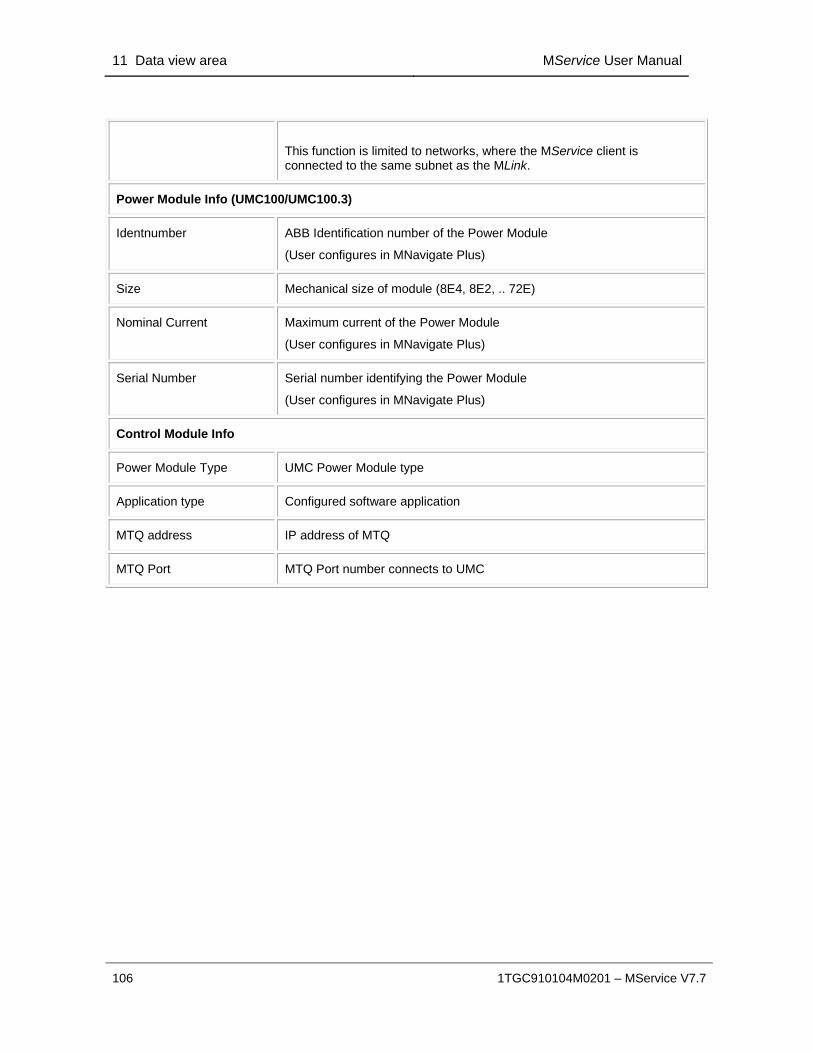
11 Data view area MService User Manual
106 1TGC910104M0201 – MService V7.7
This function is limited to networks, where the MService client is connected to the same subnet as the MLink.
Power Module Info (UMC100/UMC100.3)
Identnumber ABB Identification number of the Power Module
(User configures in MNavigate Plus)
Size Mechanical size of module (8E4, 8E2, .. 72E)
Nominal Current Maximum current of the Power Module
(User configures in MNavigate Plus)
Serial Number Serial number identifying the Power Module
(User configures in MNavigate Plus)
Control Module Info
Power Module Type UMC Power Module type
Application type Configured software application
MTQ address IP address of MTQ
MTQ Port MTQ Port number connects to UMC

MService User Manual Data view area 11
1TGC910104M0201 – MService V7.7 107
M10x module connected through MLink
Fig. 83c: Power Module view – Device Information for M101 / M102
The following information is available:
Labels
Device Name 1, 2, 3 Device Identifier for Motor Starter or Feeder module as in MNavigate
Location
Switchgear Switchgear name where the device is located
Cubicle Cubicle name where the device is located
Level The row where the device is installed in the cubicle
Position The column where the device is installed in the cubicle
MLink
Device Name Name of the MLink to which the device is connected to through the internal serial communication.
Clicking on the link opens the detail page for that MLink
MView

11 Data view area MService User Manual
108 1TGC910104M0201 – MService V7.7
Open MView web page
Clicking on this link opens a new web browser with the MView web page of the related device. The attempt is based on the current MService user.
This function is limited to networks, where the MService client is connected to the same subnet as the MLink.
Power Module Info (M10x)
Identnumber ABB Identification number of the Power Module
(User configures in MNavigate Plus)
Size Mechanical size of module (8E4, 8E2, .. 72E)
Nominal Current Maximum current of the Power Module
(User configures in MNavigate Plus)
Serial Number Serial number identifying the Power Module
(User configures in MNavigate Plus)
Control Module Info
Power Module Type M10x Power Module type
Application type Configured software application
Device Number Slave number
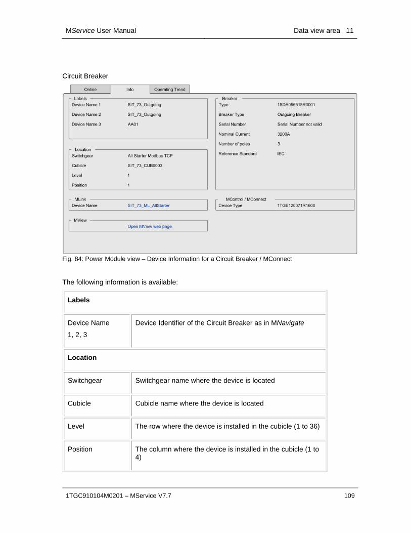
MService User Manual Data view area 11
1TGC910104M0201 – MService V7.7 109
Circuit Breaker
Fig. 84: Power Module view – Device Information for a Circuit Breaker / MConnect
The following information is available:
Labels
Device Name
1, 2, 3
Device Identifier of the Circuit Breaker as in MNavigate
Location
Switchgear Switchgear name where the device is located
Cubicle Cubicle name where the device is located
Level The row where the device is installed in the cubicle (1 to 36)
Position The column where the device is installed in the cubicle (1 to 4)

11 Data view area MService User Manual
110 1TGC910104M0201 – MService V7.7
MLink
Device Name Name of the MLink to which the device is connected to through the internal serial communication.
Clicking on the link opens the detail page for that MLink.
MView
Open MView web page
Clicking on this link opens a new web browser with the MView web page of the related device. The attempt is based on the current MService user.
This function is limited to networks, where the MService client is connected to the same subnet as the MLink
Breaker Info
Identnumber ABB Identification number of the circuit breaker.
Breaker Type Incoming / Outgoing / Bus-Tie circuit breaker
Serial Number Serial number of the circuit breaker
Nominal Current Nominal current of the breaker as engineered
Number of Poles 3 / 4 pole application as engineered
Reference standard Relevant standard the device conforms to (IEC)
MControl / MConnect
Identnumber ABB Identification number of the MConnect device as originally engineered.

MService User Manual Data view area 11
1TGC910104M0201 – MService V7.7 111
11.3.4 Tab “Operating Trend”
The Operating Trend is available for MStart / MFeed / UMC / M10x and Circuit Breaker.
This is a graph view plotting operational data (e.g. current and voltage) for the selected device into a diagram. Function and usage is similar to the Trend Display (see 6), but the graphs combination is predefined for Operating Trend.
Fig. 85: Power Module view – Operating Trend
With a click on the “info” icon , a detailed legend pops up in a new window. Here user finds the color and description for every curve in the graph.
Fig. 86: Power Module view – Operating Trend Legend

11 Data view area MService User Manual
112 1TGC910104M0201 – MService V7.7
Clicking on the “Maximize” button , the trend display opens in a new window with all capabilities of the trend display (see also description of trend display in chapter 6.).
Fig. 87: Maximized trend display
11.3.5 Tab “Diagnostics Trend”
The Diagnostic Trend is only available for MStart / MFeed / UMC / M10x.
This is a graph view plotting diagnostic data (e.g. contact temperature, thermal image, time to trip, time to reset) for the device. The content is predefined for Diagnostic Trend.
Fig. 88: Power Module view – Diagnose Trend
The legend, opening when clicking on the “info” icon , has the same functionality as in Operating Trend. (See 11.3.4)

MService User Manual Data view area 11
1TGC910104M0201 – MService V7.7 113
11.3.6 Tab “GPI” - General Purpose Input
The tab is only available for MStart / MFeed / UMC / M10x modules.
Each module has up to 16 digital input channels (General Purpose Input – GPI) which are individual customizable according to the application need.
The text shown is configured in MNavigate using the ‘Settings Mass edit display text’ commands.
If a GPI is active (high), the associated diagnostic lamp in this view is blue.
Fig. 89: Power Module view – General Purpose Inputs (GPI)

11 Data view area MService User Manual
114 1TGC910104M0201 – MService V7.7
11.3.7 Tab “Reset”
The tab is only available for MStart / MFeed.
Several condition assessment algorithms are running within the OPC server and parameterized via MNavigate. See sec. 0
A few of them are related to some maintenance action, which cannot be monitored automatically from data coming from the devices. Therefore these assessment algorithms have to be reset manually using this tab.
Fig. 90: Power Module view – Reset function
For UMC and M10x module, only Operation and TOL Supervision condition assessment algorithms are available.
Reset options:
Assessment:
Advanced Insertion Cycles
The MStart / MFeed supervises the numbers of its insertion cycles and an alarm is shown on MView. MService has implemented an additional supervision, which raises an alarm each 100 cycles. The severity is increased in two steps from ‘Maintenance required’ until ‘Failure’.
It is recommended to disable the MStart/MFeed alarm in MNavigate if the function is used in MService
Assessment:
Repeated Alarms / Trips
A frequency of occurrence of alarm / trips is supervised for ‘Start Limitation’ and ‘TOL protection’ by MControl / UMC / M10x-M respective. ‘DCS communication error’ in MLink. A special condition is raised, if such an event happens more as specified.

MService User Manual Data view area 11
1TGC910104M0201 – MService V7.7 115
The limit and period of assessment is to be specified in MNavigate.
11.3.8 Tab ‘User Note’
Clicking on the ‘User Note’ icon, a new window is opened to enter general notes specific for this power module.
User Notes are stored with creation date and user name.
User Notes are shown in reversed time order (newest on top).
User Notes can be hidden to allow for periodization of the shown notes.

11 Data view area MService User Manual
116 1TGC910104M0201 – MService V7.7
11.4 MLink view By selecting one particular MLink in the cubicle view or alternatively in the left side tree menu, all its details are presented.
11.4.1 MLink configuration data
On the left side the user can see the MLink configuration data.
Fig. 91: MLink configuration data
Global Global configuration parameters
Cubicle Name of the cubicle
Device Name 1, 2 Names of the MLink
Gateway Type Fieldbus protocol
Identnumber ABB identification number of the MLink device
Location Cubicle Cubicle location identifier
Location Level Row in this cubicle (1 to 36)
Location Position Column in this cubicle (1, 3)

MService User Manual Data view area 11
1TGC910104M0201 – MService V7.7 117
LAN 1, 2 Configuration of primary and secondary LAN interface
IP address Network IP address
Gateway Gateway IP address
Subnetmask Network subnet mask
Open MView web page Clicking on this link opens a new web browser with the MView web page of the related device. The attempt is based on the current MService user.
This function is limited to networks, where the MService client is connected to the same subnet as the MLink
11.4.2 MLink critical state signals
On the right side a schematic view of the device is shown with warning lamps signaling the critical states listed hereunder. If the OPC connection is lost (Com state alarm), a red frame around the MLink appears.
Fig. 92: MLink critical state signals
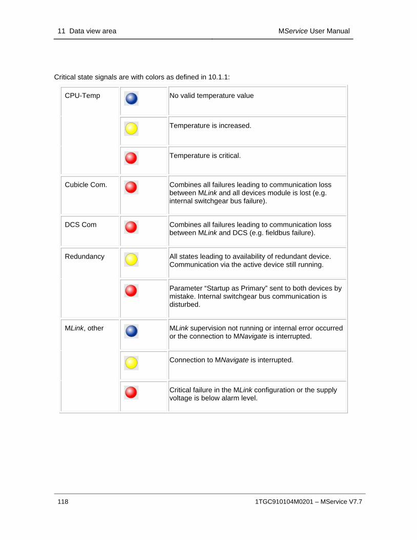
11 Data view area MService User Manual
118 1TGC910104M0201 – MService V7.7
Critical state signals are with colors as defined in 10.1.1:
CPU-Temp
No valid temperature value
Temperature is increased.
Temperature is critical.
Cubicle Com.
Combines all failures leading to communication loss between MLink and all devices module is lost (e.g. internal switchgear bus failure).
DCS Com
Combines all failures leading to communication loss between MLink and DCS (e.g. fieldbus failure).
Redundancy
All states leading to availability of redundant device. Communication via the active device still running.
Parameter “Startup as Primary” sent to both devices by mistake. Internal switchgear bus communication is disturbed.
MLink, other
MLink supervision not running or internal error occurred or the connection to MNavigate is interrupted.
Connection to MNavigate is interrupted.
Critical failure in the MLink configuration or the supply voltage is below alarm level.

MService User Manual Data view area 11
1TGC910104M0201 – MService V7.7 119
11.4.3 Redundant MLink configuration
In a redundant MLink configuration both the primary and backup MLink are shown in the same view.
The active MLink device (currently communicating top a DCS master) has a green border.
Fig. 93: Redundant MLink configuration
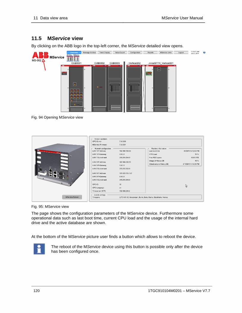
11 Data view area MService User Manual
120 1TGC910104M0201 – MService V7.7
11.5 MService view By clicking on the ABB logo in the top-left corner, the MService detailed view opens.
Fig. 94 Opening MService view
Fig. 95: MService view
The page shows the configuration parameters of the MService device. Furthermore some operational data such as last boot time, current CPU load and the usage of the internal hard drive and the active database are shown.
At the bottom of the MService picture user finds a button which allows to reboot the device.
The reboot of the MService device using this button is possible only after the device has been configured once.
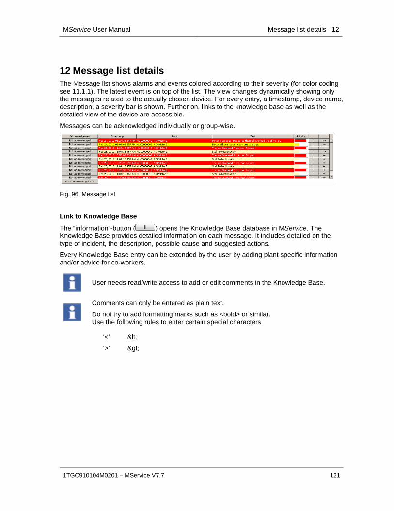
MService User Manual Message list details 12
1TGC910104M0201 – MService V7.7 121
12 Message list details The Message list shows alarms and events colored according to their severity (for color coding see 11.1.1). The latest event is on top of the list. The view changes dynamically showing only the messages related to the actually chosen device. For every entry, a timestamp, device name, description, a severity bar is shown. Further on, links to the knowledge base as well as the detailed view of the device are accessible.
Messages can be acknowledged individually or group-wise.
Fig. 96: Message list
Link to Knowledge Base
The “information”-button ( ) opens the Knowledge Base database in MService. The Knowledge Base provides detailed information on each message. It includes detailed on the type of incident, the description, possible cause and suggested actions.
Every Knowledge Base entry can be extended by the user by adding plant specific information and/or advice for co-workers.
User needs read/write access to add or edit comments in the Knowledge Base.
Comments can only be entered as plain text.
Do not try to add formatting marks such as <bold> or similar. Use the following rules to enter certain special characters
‘<’ <
‘>’ >
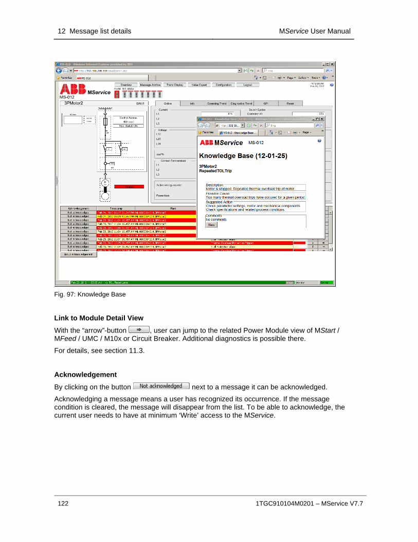
12 Message list details MService User Manual
122 1TGC910104M0201 – MService V7.7
Fig. 97: Knowledge Base
Link to Module Detail View
With the “arrow”-button , user can jump to the related Power Module view of MStart / MFeed / UMC / M10x or Circuit Breaker. Additional diagnostics is possible there.
For details, see section 11.3.
Acknowledgement
By clicking on the button next to a message it can be acknowledged.
Acknowledging a message means a user has recognized its occurrence. If the message condition is cleared, the message will disappear from the list. To be able to acknowledge, the current user needs to have at minimum ‘Write’ access to the MService.

MService User Manual Trouble Shooting 13
1TGC910104M0201 – MService V7.7 123
13 Trouble Shooting Following chapter contains some hints and recommendation when facing trouble during commissioning or operation of MService.
Warranty seal
The MService device housing must never be opened. A warranty seal is applied on the housing.
Warranty is void if seal is broken!
13.1 MService Boot sequence and front LED feedback After power up the MService runs its system initialization. The user can follow the process based on the feedback given on the front LEDs.
Boot process with connected and configured switchgear
Power On
LED 7 is power (24V) indicator
LED control starting
All LED are lightened once in a cycle
Check for / installation of
Firmware update
LED 1 blinking with 2Hz
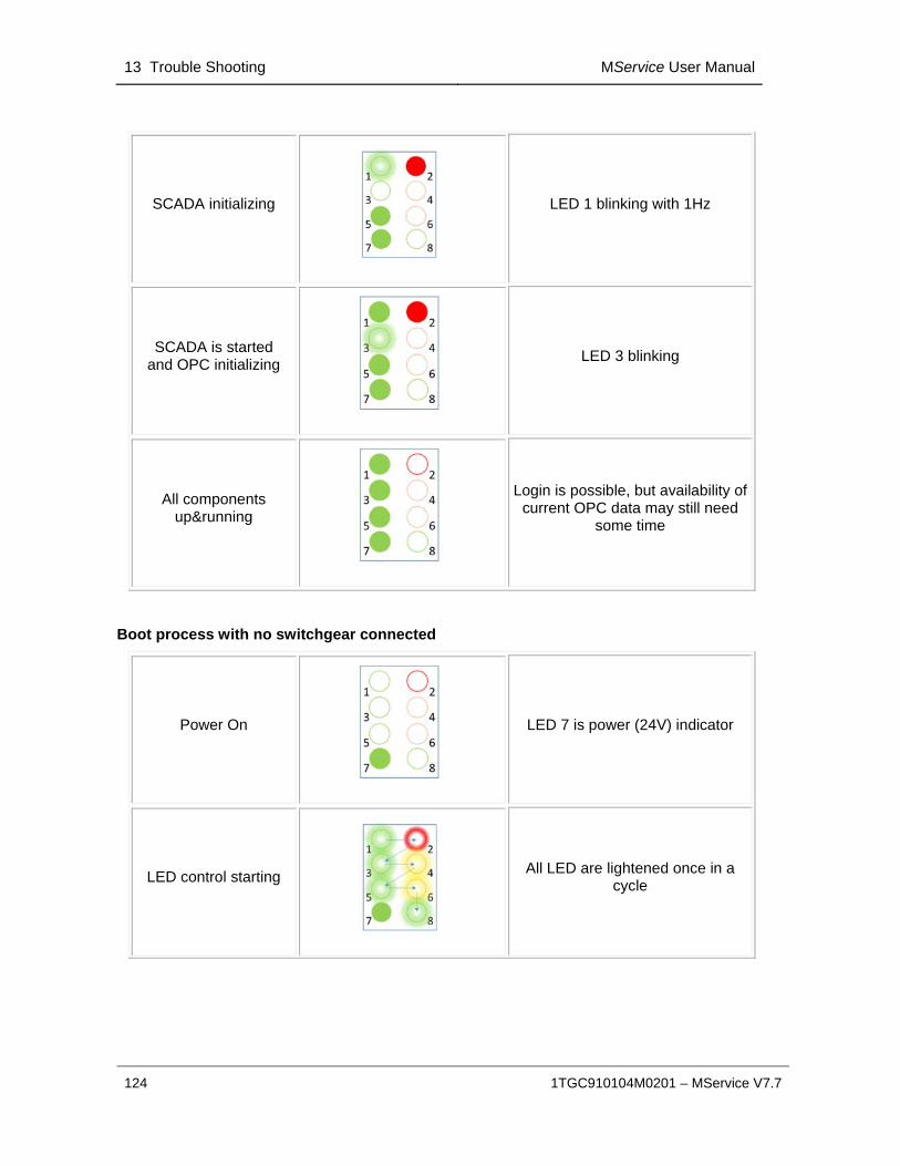
13 Trouble Shooting MService User Manual
124 1TGC910104M0201 – MService V7.7
SCADA initializing
LED 1 blinking with 1Hz
SCADA is started and OPC initializing
LED 3 blinking
All components up&running
Login is possible, but availability of current OPC data may still need
some time
Boot process with no switchgear connected
Power On
LED 7 is power (24V) indicator
LED control starting
All LED are lightened once in a cycle

MService User Manual Trouble Shooting 13
1TGC910104M0201 – MService V7.7 125
Check for / installation of
Firmware update
No LAN connection:
LED 1 blinking with 2Hz
LED 5 is off
SCADA initializing
LED 1 is blinking with 1HZ
LED 2 is blinking with 0.5Hz
SCADA initialized, but no LAN
connection available
LED 1 is on,
LED 2 is blinking with 0.5Hz
LED 3 indicates missing OPC Server processes.
13.2 Issues indicated via front LED The front LEDs indicate the status of some components of the MService device. Some of the problem indications can be addressed by the user. If not, please contact ABB Support.
LED 5 is off: ‘No LAN communication’
Check if cables to LAN 1 or LAN 2 are properly connected.
Check also connection to the switch
Make sure, that no IP-Address conflict
LED 2 is blinking: ‘Problem with LAN 2’
Check if cables to LAN 2 are properly connected.
Check also connection to the switch
Make sure, that no IP-Address conflict
LED 4 blinking
Creating a data backup is recommended. Use the ‘backup facility’, see sec. 8.4.1
The status indication will be active every 90 days for 7 days.

13 Trouble Shooting MService User Manual
126 1TGC910104M0201 – MService V7.7
LED 6 blinking 2Hz
‘Problem with CF-Card
Check, if the CF-Card is properly inserted before power on of MService
Try to open the CF-Card in a card reader on a PC/Laptop and correct any issues reported by Windows, e.g. choose ‘Scan and fix’ if this dialog is shown:
LED 6 blinking 1Hz
‘Low RAM situation’
This can happen temporarily during report generation. If the status persist, try to remove devices from the configuration
13.3 Issues using the web-interface
Internet Explorer does not show changed system configuration
When the Autoconfigurator wizard completed successfully, the user session has to be restarted. Depending on the settings of the web browser it might be necessary to close the browser and all its windows in order to clean up current session and restart the Java engine cleanly.
Boot of MService device without connected network
If the MService is booted but not connected to any switchgear network, the communication components close down after a while. All configured devices are shown as ‘not connected’.
If the switchgear network is connected later on, the MService device is still not able to re-establish the communication to the MLink devices.
In this case a reboot of the MService is required with connected switchgear network.
Configured MLink does not show live values after reboot of MService
If the MService was booted, but a single MLink was not available at that time, the communication could not be established.
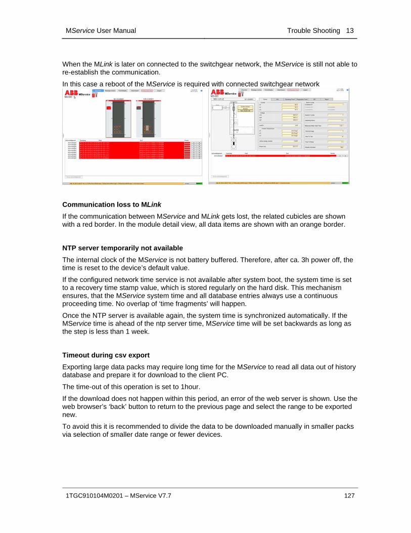
MService User Manual Trouble Shooting 13
1TGC910104M0201 – MService V7.7 127
When the MLink is later on connected to the switchgear network, the MService is still not able to re-establish the communication.
In this case a reboot of the MService is required with connected switchgear network
Communication loss to MLink
If the communication between MService and MLink gets lost, the related cubicles are shown with a red border. In the module detail view, all data items are shown with an orange border.
NTP server temporarily not available
The internal clock of the MService is not battery buffered. Therefore, after ca. 3h power off, the time is reset to the device’s default value.
If the configured network time service is not available after system boot, the system time is set to a recovery time stamp value, which is stored regularly on the hard disk. This mechanism ensures, that the MService system time and all database entries always use a continuous proceeding time. No overlap of ‘time fragments’ will happen.
Once the NTP server is available again, the system time is synchronized automatically. If the MService time is ahead of the ntp server time, MService time will be set backwards as long as the step is less than 1 week.
Timeout during csv export
Exporting large data packs may require long time for the MService to read all data out of history database and prepare it for download to the client PC.
The time-out of this operation is set to 1hour.
If the download does not happen within this period, an error of the web server is shown. Use the web browser’s ‘back’ button to return to the previous page and select the range to be exported new.
To avoid this it is recommended to divide the data to be downloaded manually in smaller packs via selection of smaller date range or fewer devices.

13 Trouble Shooting MService User Manual
128 1TGC910104M0201 – MService V7.7
Failure in sending E-mail
In case the e-mail settings are not correct or there is no network connection to a mail server and MService is not able to deliver the mail to the mail server, a system message is issued, indicating a problem with the ‘FCEmail’ component.
The message has a severity of 750 (“Function Check”) and is automatically cleared by the system within a few seconds.
Review and correct the settings as described in sec. 8.3
If the problem persists, ask the IT administrator of the mail server to check its configuration as well.
Computer client
MService firmware version 7.4 backwards does not support for JAVA8 and Windows 8. Windows 2008 and Windows 7 running with JAVA 7 shall be used when MService is running firmware version 7.4.
MService firmware version 7.7 is implemented for JAVA8 and Windows 8.
MService TCP/IP Port Data Communication
There is an error message shown when ABB computer connects to MService. The default of MService TCP/IP Port Data Communication from MNavigate is 8080. This port is occupied by other ABB Application so that the error message is issued.
Solution is to change the MService TCP/IP Port Data Communication from 8080 to 20202 in MNavigate and complete download into MService. See below picture.
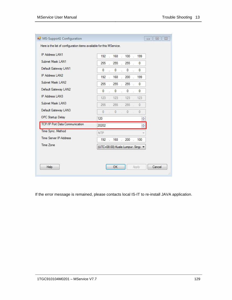
MService User Manual Trouble Shooting 13
1TGC910104M0201 – MService V7.7 129
If the error message is remained, please contacts local IS-IT to re-install JAVA application.
Contact us ABB Low Voltage Systems Publication Editor: ABB Automation Products GmbH Ladenburg, Germany Local Contacts on www.abb.com/mns
Copyright© 2015 ABB All rights reserved. Publication No. 1TGC910104M0201
Related Documents