Realization of Morphing Wings: A Multidisciplinary Challenge Srinivas Vasista, ∗ Liyong Tong, † and K. C. Wong ‡ University of Sydney, Sydney, New South Wales 2006, Australia DOI: 10.2514/1.C031060 Morphing-wing research is growing in significance, as it is driven by the need to improve aircraft performance. There are many aspects to consider when designing a morphing wing, making the task a multidisciplinary challenge. This has led to a multitude of approaches to morphing-wing research. This paper provides an overview of the field, drawing together these different approaches. Morphing wings can be classified in terms of shape parameters (what to morph), performance benefits (why morph), and enabling technologies (how to morph). Regarding the structural system, the majority of morphing-wing concepts have consisted of distinguishable substructure, skin, and actuator components. However, these components need to be integrated to such a level that all share the functions of carrying loads and changing shape, thus blurring the distinction between these components. The trends include shifts from using conventional mechanisms and actuators to smart-material-based systems to topology-optimized compliant- mechanism designs. Furthermore, concepts found in nature may offer potential morphing solutions, and the working principles of muscles and plants may be emulated in a morphing wing. The focus of this paper is on morphing for traditionally fixed-wing aircraft and on the structural system in particular. Nomenclature C L = coefficient of lift c = chord n z = normal load factor q = dynamic pressure S = wing reference area I. Introduction A MORPHING wing is a wing that changes shape in flight in a controlled manner to improve aircraft performance. Although there exists a multitude of morphing-wing concepts throughout literature, there is no formal definition as to what constitutes a morphing wing and classifying morphing-wing concepts can be Received 8 April 2010; revision received 30 January 2011; accepted for publication 31 January 2011. Copyright © 2011 by the American Institute of Aeronautics and Astronautics, Inc. All rights reserved. Copies of this paper may be made for personal or internal use, on condition that the copier pay the $10.00 per-copy fee to the Copyright Clearance Center, Inc., 222 Rosewood Drive, Danvers, MA 01923; include the code 0021-8669/12 and $10.00 in correspondence with the CCC. ∗ Ph.D. Student, School of Aerospace, Mechanical and Mechatronic Engineering. Student Member AIAA. † Professor, School of Aerospace, Mechanical and Mechatronic Engineering. ‡ Senior Lecturer, School of Aerospace, Mechanical and Mechatronic Engineering. Senior Member AIAA. Srinivas Vasista is a Ph.D. Student at the School of Aerospace, Mechanical and Mechatronic Engineering at the University of Sydney and is a recipient of an Australian Postgraduate Award and the R. W. McKenzie Supplementary Scholarship for Aeronautical Sciences and Technologies. He completed his B.E. degree in aeronautical (space) engineering at the University of Sydney in 2008. His main research interests include the design, analysis, and testing of morphing wings, aircraft structures, and smart materials, as well as the development of computational tools such as finite element analysis and structural optimization algorithms. Liyong Tong is a Professor in the School of Aerospace, Mechanical and Mechatronic Engineering at the University of Sydney. He received B.E. and M.E. degrees from Dalian University of Technology in 1982 and 1985 and a Ph.D. from Beijing University of Aeronautics and Astronautics in 1988. Before joining the University of Sydney in 1995, he worked as a Senior Research Engineer at the Cooperative Research Center for Aerospace Structures, Ltd. His primary research interests include computational and experimental methods related to 1) analysis, testing, and design of composite and smart structures; 2) structural stress analysis, vibration, and stability; and 3) optimization and morphing of aerospace structures. Dr. K. C. Wong is a Senior Lecturer of Aerospace Engineering at the University of Sydney, where he leads a small team undertaking research on unmanned aircraft systems (UAS), with particular interests in multidisciplinary and morphing airframe design, instrumentation, control, and system integration. He completed his B.E. in aeronautical engineering and his Ph.D. at the University of Sydney. UAS airframes designed and developed in his group have been used by several industry collaborative research projects. Having a strong passion to promote and develop indigenous UAS capabilities within Australia, he has worked on many national projects to explore and promote UAS technologies and applications. Since 2009, Dr. Wong has been the President of the Association for Unmanned Vehicle Systems—Australia (AUVS-Australia). JOURNAL OF AIRCRAFT Vol. 49, No. 1, January–February 2012 11 Downloaded by WICHITA STATE UNIVERSITY on May 23, 2013 | http://arc.aiaa.org | DOI: 10.2514/1.C031060

1.c031060
Oct 20, 2015
Review of Material over Morphing Shape Aircarft
Welcome message from author
This document is posted to help you gain knowledge. Please leave a comment to let me know what you think about it! Share it to your friends and learn new things together.
Transcript
Realization of Morphing Wings: A Multidisciplinary Challenge
Srinivas Vasista,∗ Liyong Tong,† and K. C. Wong‡
University of Sydney, Sydney, New South Wales 2006, Australia
DOI: 10.2514/1.C031060
Morphing-wing research is growing in significance, as it is driven by the need to improve aircraft performance.
There aremany aspects to consider when designing amorphingwing, making the task amultidisciplinary challenge.
This has led to a multitude of approaches to morphing-wing research. This paper provides an overview of the field,
drawing together these different approaches.Morphingwings can be classified in terms of shape parameters (what to
morph), performance benefits (why morph), and enabling technologies (how to morph). Regarding the structural
system, the majority of morphing-wing concepts have consisted of distinguishable substructure, skin, and actuator
components. However, these components need to be integrated to such a level that all share the functions of carrying
loads and changing shape, thus blurring the distinction between these components. The trends include shifts from
using conventional mechanisms and actuators to smart-material-based systems to topology-optimized compliant-
mechanismdesigns. Furthermore, concepts found in naturemay offer potentialmorphing solutions, and theworking
principles of muscles and plants may be emulated in a morphing wing. The focus of this paper is on morphing for
traditionally fixed-wing aircraft and on the structural system in particular.
Nomenclature
CL = coefficient of liftc = chordnz = normal load factorq = dynamic pressureS = wing reference area
I. Introduction
A MORPHING wing is a wing that changes shape in flight in acontrolled manner to improve aircraft performance. Although
there exists a multitude of morphing-wing concepts throughoutliterature, there is no formal definition as to what constitutes amorphing wing and classifying morphing-wing concepts can be
Received8April 2010; revision received30 January 2011; accepted for publication 31 January 2011.Copyright©2011 by theAmerican Institute ofAeronauticsand Astronautics, Inc. All rights reserved. Copies of this paper may bemade for personal or internal use, on condition that the copier pay the $10.00 per-copy fee tothe Copyright Clearance Center, Inc., 222 Rosewood Drive, Danvers, MA 01923; include the code 0021-8669/12 and $10.00 in correspondence with the CCC.
∗Ph.D. Student, School of Aerospace, Mechanical and Mechatronic Engineering. Student Member AIAA.†Professor, School of Aerospace, Mechanical and Mechatronic Engineering.‡Senior Lecturer, School of Aerospace, Mechanical and Mechatronic Engineering. Senior Member AIAA.
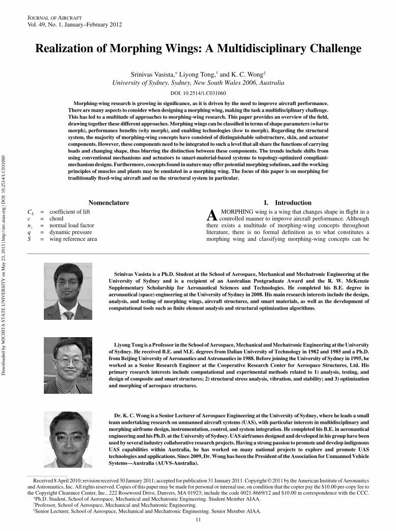
Srinivas Vasista is a Ph.D. Student at the School of Aerospace, Mechanical and Mechatronic Engineering at the
University of Sydney and is a recipient of an Australian Postgraduate Award and the R. W. McKenzie
Supplementary Scholarship for Aeronautical Sciences and Technologies. He completed his B.E. degree in
aeronautical (space) engineering at the University of Sydney in 2008. His main research interests include the design,
analysis, and testing of morphing wings, aircraft structures, and smart materials, as well as the development of
computational tools such as finite element analysis and structural optimization algorithms.
LiyongTong is a Professor in the School ofAerospace,Mechanical andMechatronic Engineering at theUniversity
of Sydney. He received B.E. and M.E. degrees from Dalian University of Technology in 1982 and 1985 and a Ph.D.
fromBeijing University of Aeronautics andAstronautics in 1988. Before joining the University of Sydney in 1995, he
worked as a Senior Research Engineer at the Cooperative Research Center for Aerospace Structures, Ltd. His
primary research interests include computational and experimental methods related to 1) analysis, testing, and
design of composite and smart structures; 2) structural stress analysis, vibration, and stability; and 3) optimization
and morphing of aerospace structures.
Dr. K. C.Wong is a Senior Lecturer of Aerospace Engineering at the University of Sydney, where he leads a small
team undertaking research on unmanned aircraft systems (UAS), with particular interests in multidisciplinary and
morphing airframe design, instrumentation, control, and system integration. He completed his B.E. in aeronautical
engineering andhis Ph.D. at theUniversity of Sydney. UAS airframes designed and developed in his group have been
used by several industry collaborative research projects. Having a strong passion to promote and develop indigenous
UAS capabilities within Australia, he has worked on many national projects to explore and promote UAS
technologies and applications. Since 2009,Dr.Wonghas been the President of theAssociation forUnmannedVehicle
Systems—Australia (AUVS-Australia).
JOURNAL OF AIRCRAFT
Vol. 49, No. 1, January–February 2012
11
Dow
nloa
ded
by W
ICH
ITA
ST
AT
E U
NIV
ER
SIT
Y o
n M
ay 2
3, 2
013
| http
://ar
c.ai
aa.o
rg |
DO
I: 1
0.25
14/1
.C03
1060

approached in many ways. The general perception of morphing isthat of smooth and continuous shape change, flexibility, and the “art”ofmimicking birds. Thus, traditional shape changemechanisms suchas flaps and ailerons lie outside the realm of morphing. The termmorphing wing has often been used synonymously with smart wing,adaptive wing, activewing, and reconfigurable wing: smart, becausethe wing may incorporate smart materials and has the ability to senseexternal stimuli (pressure, velocity, density, temperature, etc.) [1];adaptive, because the wing adapts to better suit the operatingconditions; active, because the wing can be actively controlled viaactuators; and reconfigurable because the wing geometry can be setinto different configurations. Furthermore, morphing has beentermed as real-time adaptation to enable multipoint optimizedperformance [2] to broaden what morphing includes.
A number of reviewpapers exist in literature [1–5], each reviewingand classifying morphing wings in a particular way. This paper aimsto synthesize these various approaches into a more comprehensiveset of classifications and to compare the designs of selectedmorphing-wing concepts in literature. The multidisciplinary natureofmorphing-wing research is introduced first. The shape parameters,morphing benefits, structural system and enabling technologies arethen classified and a chronological listing of morphing-wingconcepts is presented. Selected morphing-wing concepts are com-pared based on a set of criteria and the trends, challenges, and bench-marks are discussed. Biological concepts that may be mimicked inmorphing wings have been suggested, as well as the possible futureresearch paths. This paper focuses on morphing concepts for fixed-wing aircraft and on the structural system in particular.
II. Morphing Wings: A Multidisciplinary Field
Conventional aircraft design requires consideration of manydifferent disciplines, such as flight mechanics and control, aero-dynamics, structures andmaterials, and power, as shown in Fig. 1 [6].Flight performance largely depends on aerodynamic and inertialcharacteristics. The aircraft structure and its constituent materials,which are subjected to loading, provides and maintains the requiredaerodynamic shapes. The engines or powerplants generate thrust andsupply power to other systems for sensing, actuation, and control, forexample. The design of a morphing aircraft will require even greater
interdisciplinary considerations. Morphing adds a degree ofdynamism to the function of the aircraft and thus results in changingparameters across all disciplines. Aerodynamic and structuralanalyses will need to be performed simultaneously, as there is aclosed loop effect between aerodynamic forces and structuraldisplacements, and combined with overall aircraft performancestudies, as considered by [7–14].
Formorphing,flightmechanics and aerodynamicsmay be thoughtof as the disciplines in which the morphing target shapes can bedetermined. Structures, materials, and power may be thought of asthe disciplines inwhich theways to deliver the required shapes can bedetermined.
One crucial problem of morphing-wing design is the design of thestructural system. The function of the structural system is to provideand maintain the desired deflection while carrying the external airloads. Herein lies the problem: providing the shape change implieslarge deflection and low stiffness while maintaining the shape andcarrying the loads implies high stiffness and small deformation [15].Figure 2 illustrates this required structural function using amorphingairfoil section as an example.
The ideal morphing wing shall have the following characteristics(refer to Sec. VI.D for benchmark values): large shape change,smooth shape change, high loadability, good aeroelastic character-istics, multiple shape changes, low energy requirement, low weight,high frequency, high control authority, good scalability, fewcomponents, and good fatigue/wear characteristics.
III. Classifications
There are several different research approaches, as the morphing-wing research field involves multiple disciplines. This sectionsynthesizes the different approaches and classifies the shape param-eters (i.e., what to morph), benefits (i.e., why morph), and structuralsystem and enabling technologies of morphing wings (i.e., how tomorph).
A. Classification of Shape Parameters
The shape of a wing is crucial to an aircraft’s function and per-formance; therefore, by altering the wing’s shape, different functionand performance can be achieved. The wing shape param-eters can be classified in terms of 1) in-plane parameters and 2)out-of-plane parameters, following a similar classification scheme toSofla et al. [5]. The in-plane parameters are geometries pertaining tothe X–Y plane �DX;DY; RZ� and the out-of-plane parameters aregeometries that involve Z-direction changes �DZ;RX; RY�, asshown in Fig. 3. This classification scheme is presented in Tables 1and 2, along with the performance benefits of either increasing ordecreasing the shape parameters.
The parameters chord length, camber, thickness, leading-edgeradius, and bump comprise the airfoil section shape, which isparticularly crucial to aircraft performance. In addition, morphing ofthese parameters can be considered as being large, medium, or smallin scale [19]. Scale in this context refers to the percentage change ofwing geometry with respect to overall baseline wing geometry or, inother words, whether large, medium, or small changes are made to
Flight Mechanics &
Control
Aero-dynamics
Structures & Materials
Power D
Fig. 1 Multidisciplinary nature of morphing-wing research. Adapted
from [6].
Fig. 2 Required structural function in unmorphed and morphed phases.
12 VASISTA, TONG, ANDWONG
Dow
nloa
ded
by W
ICH
ITA
ST
AT
E U
NIV
ER
SIT
Y o
n M
ay 2
3, 2
013
| http
://ar
c.ai
aa.o
rg |
DO
I: 1
0.25
14/1
.C03
1060

the wing geometry. Changes in wing area, aspect ratio, span length,chord length, sweep angle, taper ratio, wing location, dihedral angle,and spanwise camber may constitute large-scale morphing, changesin camber, thickness, and twist may constitute medium-scalemorphing; localized changes inwing geometry, such as leading-edgeradius and bump profile, may constitute small-scale morphing.Section VI.D provides a quantification of large-scale shape change.
B. Classification of the Benefits of Morphing
Morphing wings offer significant potential benefits over conven-tional rigid wings. It has been suggested [1] that the reasons forapplying morphing technology can be divided into four categories:
1) Improve aircraft performance to expand its flight envelope.2) Replace conventional control surfaces for flight control.3) Reduce drag to improve range.4) Reduce vibration or control flutter to improve comfort and
safety and to reduce fatigue.This performance benefit categorization can be expanded as
follows:1) Enable multirole capacity by making radical changes in wing
shape, including planform area, sweep angle, aspect ratio, spanlength, thickness, dihedral/anhedral angle, wing location on thefuselage, and taper.
2) Improve maneuverability as follows:a) Increase control surface effectiveness by replacing
conventional control surfaces with smooth continuous controlsurfaces that twist.
b) Increase the maximum load factor for the same wing-rootbending moment by shifting the load distribution inboard by
Fig. 3 Aircraft axes.
Table 1 In-plane shape parameters and performance benefits [3,16]
Benefits due to changes in parameter
Parameter Increasing Decreasing
Wing area �DX;DY� Increased lift, decreased wing loading,takeoff speed, turn radius
Increased speed, decreased drag
Aspect ratio �DX;DY� Increased spanwise efficiency,range, loiter time,turn rate, decreased induced drag
Improved ride comfort in turbulence, increasedspeed, decreased parasitic drag, wing weighta,wing-root bending moment
Chord length (DX) Increased wing area, decreased aspect ratio Increased aspect ratio, decreased wing areaSpan length (DY) Increased wing area, aspect ratio Decreased wing area, aspect ratioSweep angle (RZ) Increased critical mach number, maximum speed,
dihedral effect, spiral mode stability, longitudinal stability,decreased compression drag, strength of shock wavesIn Supersonic Flight
Increased lift-curve slope, lateral controlb,decreased pitch attitude while landing,aeroelastic effects, structural massa
Taper ratio �ct=cr� (DX) Improved tip stall performance, increasedwing fuel volumea
Increased spanwise efficiency when usedin conjunction with twistc, decreasedstructural massa
aApplicable to rigid-wing aircraft design only.bFor aft sweep only, as tip stall is prevented. Forward-swept wings perform better than straight wings in tip stall.cBecause of an elliptical spanwise lift distribution. This distribution offers the lowest drag-due-to-lift (induced drag), due to a constant downwash angle throughout the span.
Table 2 Out-of-plane shape parameters and performance benefits [3,16]
Benefits due to changes in parameter
Parameter Increasing Decreasing
Cambera �DZ;RY� Increased lift Decreased dragThickness (DZ) Increased lift, improved low-speed performance Improved high-speed performance, decreased drag,
chance of flow separationWing locationb (DZ) High wing: increased dihedral effect, spiral mode stability Low wing: decreased landing gear length
(for wing-mounted landing gears)c
Mid-mounted wings: decreased interference dragDihedral angled (RX) Increased dihedral effect, spiral mode stability Increased Dutch-roll mode stability,
maneuverabilitySpanwise camber (RX) Increased L=D for high angles of attack [17] Increased L=D for low angles of attack [17]Twist (RY) Wash-in: increased lift Wash-out: increased efficiency,e improved tip stall
performance, decreased wing-root bending momentTaper (DZ) Increased wing fuel volumec Decreased wing-root bending momentLE radius �DX;DZ� Improved low-speed performance Improved high-speed performanceBump (DZ) Improved transonic performance [18] Improved subsonic performance [18]Winglet cant angle (RX) Increased lift, improved low-speed performance,
decreased engine requirements during landingand takeoff, noise during landing
Increased spanwise lift efficiency
aA common way of increasing camber is to deflect the leading and trailing edges down. Lift and drag characteristics are highly sensitive to changes in camber.bOperational concerns such as loading cargo, cabin space, and viewing requirements from inside the cabin also affect wing location.cApplicable to rigid-wing aircraft design only.dPositive dihedral angle typically used in low-mounted-wing aircraft; negative dihedral (anhedral) angle typically used in high-mounted-wing aircraft.eBecause of an elliptical spanwise lift distribution.
VASISTA, TONG, ANDWONG 13
Dow
nloa
ded
by W
ICH
ITA
ST
AT
E U
NIV
ER
SIT
Y o
n M
ay 2
3, 2
013
| http
://ar
c.ai
aa.o
rg |
DO
I: 1
0.25
14/1
.C03
1060

replacing conventional control surfaces with smooth surfaces thattwist.3) Improve range, fuel efficiency, and speed as follows:
a) Optimize aerodynamic efficiency over the operating range ofCL values by varying airfoil section properties: in particular, bymaking use of variable camber by leading- and trailing-edgedeflection devices.
b) Reduce drag by eliminating gaps and discontinuities in wingshape created by conventional control surfaces by replacing themwith smoothly varying gapless control surfaces.
c) Reduce drag by eliminating actuation mechanisms ofconventional control surfaces that protrude outside the wingcontour by using internally actuated control surfaces.
d) Reduce weight by replacing conventional heavy systemswith light new systems (depending on structural configuration andmaterials used).
e) Reduce structural weight by tailoring shape to allow loadmanipulation/alleviation (e.g., spanwise twist for wing-rootbending-moment reduction).
f) Reduce compression drag by preventing the formation oftransonic shock waves by using bump profiles.4) Reduce vibrations/aeroelastic effects as follows:
a) Reduce turbulent flow created by gaps and discontinuities inwing shape created by conventional control surfaces by usingsmoothly varying gapless control surfaces.
b) Control local flow by making small adjustments to the wingsurface.Morphing may also lead to the following operational and
maintenance benefits:1) Reduce operational costs by eliminating the requirement of
multiple different single-role aircraft by using a single multiroleaircraft [4].
2) Reduce maintenance costs by reducing wear and the number ofparts by eliminating moving parts by using technologies such ascompliant mechanisms.
C. Classification of the Structural System and Enabling Technologies
The structural system of most morphing-wing concepts has beencomposed of three distinct subsystems: 1) substructure, 2) skin, and3) actuator.
1. Shape Change in Substructure and Skin Subsystems
There have been two approaches to achieving shape change insubstructure and skin: using conventional mechanisms or enablingcompliant (smooth) change. These are termed differently throughoutliterature, such as robotic versus organic [3] and mechatronic versusstructronic [15], but they will be referred to as conventionalmechanisms versus compliant in this paper.
Conventional mechanisms feature relative rotation/sliding of rigidsegments/linkages with locking mechanisms. For compliant shapechange, there are two further approaches: compliant materialsfollowing the classification scheme of Thill et al. [1], or compliantmechanisms. Compliant materials have been classified as follows:
1) Stretchable materials (elastomeric [20], auxetic [1]).2) Deployable materials (rollable, collapsible, foldable, inflatable,
and stacked) are primarily for the alteration of the wing area.3) Materials with directional stiffness tailoring include extreme
anisotropic material [1], bi/multistable composites [21–25],segmented structures [19], folded inner skins [19], and multilayeredskins [19].
4) Materials with variable stiffness include shape memory alloys(SMAs) [26], shape memory polymers [27,28], shape memorycomposites [27], elastic memory composites [1], shape memorytextiles [1], magnetic shape memory materials [29], flexible matrixcomposites [30–32], and fluidic flexible matrix composites [33].
5) Active substructures and/or skin typically consist of flexiblematerials with embedded active smart materials. Compliant mecha-nisms can be classified into lumped compliance (via pseudo-rigid-body modeling and analysis) or distributed compliance (viatopology-optimization techniques).
2. Actuation Subsystem
The actuation subsystem has been either conventional- or smart-materials-based. Conventional actuation includes technologies suchas electrical, hydraulic, pneumatic, passive, and hand-operatedactuators. Smart-material-based actuators include shape memoryalloys [26,34], piezoelectric materials [26,34,35], piezohydraulicpumps [36–39], ultrasonic motors [40], thermopolymer actuators[41], magnetostrictive actuators [34,42], shape memory magneticactuators [29], electroactive polymers [43], electrorheological fluid[26], magnetorheological fluid [26], nastic actuators [44–50], andpneumatic artificial muscles [51].
3. Integrated Design
The integrated design can be a combination of conventionalmechanisms and/or compliant materials and/or compliant mech-anisms for the substructure and skin with conventional and/or smartactuators.
IV. Morphing-Wing Concept Listing,Timeline, and Classification
This section lists the morphing-wing concepts chronologically, asshown in Table 3. These concepts are classified based on shapeparameters and technologies used in the three structural subsystems,as outlined in Sec. III. The notations in Table 3 are defined in Table 4.
V. Comparison of Selected Morphing Concepts
This section provides detail of selected morphing-wing conceptsfrom Table 3 in terms of aircraft application, wing size/aircraft scale,working principle, materials, actuation systems and performancebenefits. The selected concepts are also compared based on requiredand resultant: shape changes and magnitude, loading, frequency andactuation rate, and power input, as shown in Tables 5–12. Theselected concepts are grouped as either radically morphing wings orleading/trailing-edge morphing.
A. Radical Shape Change
1. Lockheed Martin Morphing Unmanned Air Vehicle
(IP1;2;3;4;5, OP3, and Su1 Sk2;9 A1;2)
This morphing concept was intended for an unmanned air vehicle(UAV) application. The intended full-scale dimensions (unfolded/folded configurations) were a span length of 41:3=24:1 ft, height of8:1=8:7 ft, wing area of 600=215:5 ft2, andweight of 21,455 lb [41].The wind-tunnel test model featured a span of 9 ft 7.4 in (unfolded,baseline) [87] and a weight of 1450 lb [109]. The working principlewas as follows:
Each wing is folded in a Z-shaped manner (looking aft/forward)about two wing-fold joints parallel with the streamwise direction.Once folded, the leading-edge (LE) segment of the inboard sectionalso folded to close the gap between the fuselage and the folded wing[41]. The wing-fold joints used an embedded actuator, a skin coverand a “knuckle joint” that was fingerlike so that the joint could rotatewhile furnishing a smooth exterior surface for thewing fold [109]. Inaddition, the design used a vacuum pump to draw the skin into acavity to prevent it from bunching up or otherwise interfering withthe joint folding operation [109]. In terms of materials, shapememory polymers and an elastomeric-reinforced silicone skin wereconsidered for the wing-fold joint skin with graphite/epoxy fingerhinges. In terms of the actuation systems, Thermopolymer andpiezoelectric materials were tested for use as actuators [41].
Linear thermopolymer actuators were intended for the streamwisewing folds, but electrical rotary motors were used in the wind-tunneltest. Piezoelectric stack actuators were intended for the LE flap fold,but a linear thermopolymer actuator was used in the wind-tunneltest [41].
The following performance benefits were anticipated. A multirolecapacity can be enabled by making radical changes in wing shape,including planform area, wetted area, sweep angle, aspect ratio, spanlength, and wing location on the fuselage. A 22% mission radius
14 VASISTA, TONG, ANDWONG
Dow
nloa
ded
by W
ICH
ITA
ST
AT
E U
NIV
ER
SIT
Y o
n M
ay 2
3, 2
013
| http
://ar
c.ai
aa.o
rg |
DO
I: 1
0.25
14/1
.C03
1060
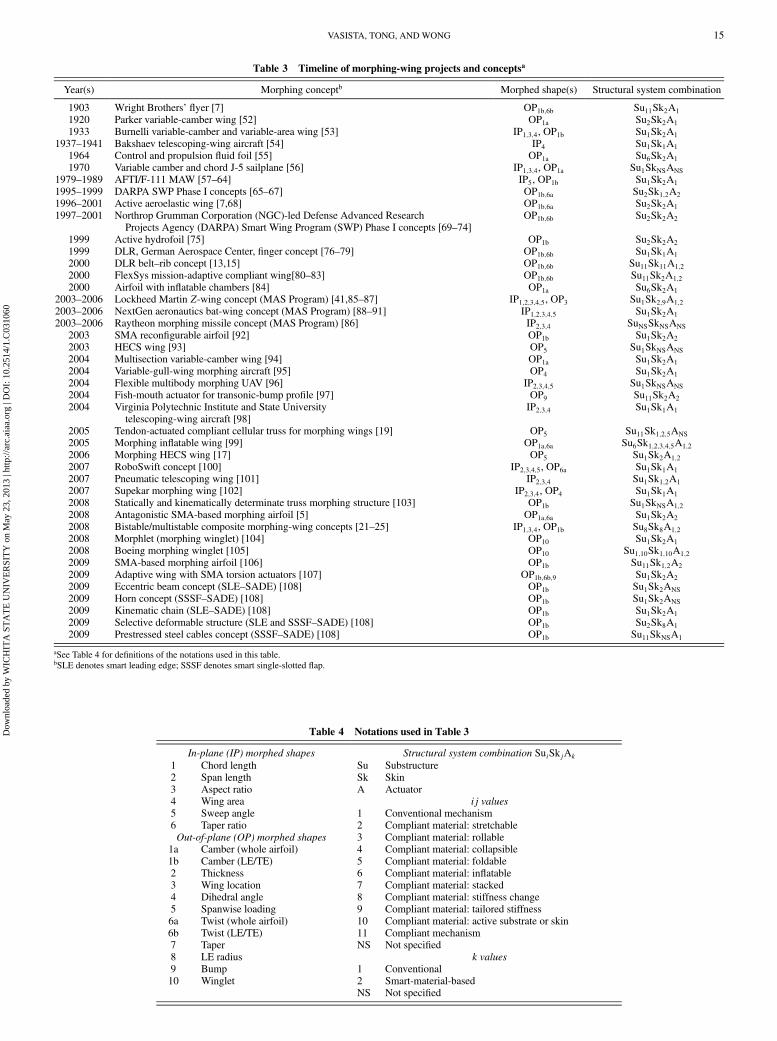
Table 3 Timeline of morphing-wing projects and conceptsa
Year(s) Morphing conceptb Morphed shape(s) Structural system combination
1903 Wright Brothers’ flyer [7] OP1b;6b Su11Sk2A1
1920 Parker variable-camber wing [52] OP1a Su2Sk2A1
1933 Burnelli variable-camber and variable-area wing [53] IP1;3;4, OP1b Su1Sk2A1
1937–1941 Bakshaev telescoping-wing aircraft [54] IP4 Su1Sk1A1
1964 Control and propulsion fluid foil [55] OP1a Su6Sk2A1
1970 Variable camber and chord J-5 sailplane [56] IP1;3;4, OP1a Su1SkNSANS
1979–1989 AFTI/F-111 MAW [57–64] IP5, OP1b Su1Sk2A1
1995–1999 DARPA SWP Phase I concepts [65–67] OP1b;6a Su2Sk1;2A2
1996–2001 Active aeroelastic wing [7,68] OP1b;6a Su2Sk2A1
1997–2001 Northrop Grumman Corporation (NGC)-led Defense Advanced ResearchProjects Agency (DARPA) Smart Wing Program (SWP) Phase I concepts [69–74]
OP1b;6b Su2Sk2A2
1999 Active hydrofoil [75] OP1b Su2Sk2A2
1999 DLR, German Aerospace Center, finger concept [76–79] OP1b;6b Su1Sk1A1
2000 DLR belt–rib concept [13,15] OP1b;6b Su11Sk11A1;2
2000 FlexSys mission-adaptive compliant wing[80–83] OP1b;6b Su11Sk2A1;2
2000 Airfoil with inflatable chambers [84] OP1a Su6Sk2A1
2003–2006 Lockheed Martin Z-wing concept (MAS Program) [41,85–87] IP1;2;3;4;5, OP3 Su1Sk2;9A1;2
2003–2006 NextGen aeronautics bat-wing concept (MAS Program) [88–91] IP1;2;3;4;5 Su1Sk2A1
2003–2006 Raytheon morphing missile concept (MAS Program) [86] IP2;3;4 SuNSSkNSANS
2003 SMA reconfigurable airfoil [92] OP1b Su1Sk2A2
2003 HECS wing [93] OP5 Su1SkNSANS
2004 Multisection variable-camber wing [94] OP1a Su1Sk2A1
2004 Variable-gull-wing morphing aircraft [95] OP4 Su1Sk2A1
2004 Flexible multibody morphing UAV [96] IP2;3;4;5 Su1SkNSANS
2004 Fish-mouth actuator for transonic-bump profile [97] OP9 Su11Sk2A2
2004 Virginia Polytechnic Institute and State Universitytelescoping-wing aircraft [98]
IP2;3;4 Su1Sk1A1
2005 Tendon-actuated compliant cellular truss for morphing wings [19] OP5 Su11Sk1;2;5ANS
2005 Morphing inflatable wing [99] OP1a;6a Su6Sk1;2;3;4;5A1;2
2006 Morphing HECS wing [17] OP5 Su1Sk2A1;2
2007 RoboSwift concept [100] IP2;3;4;5, OP6a Su1Sk1A1
2007 Pneumatic telescoping wing [101] IP2;3;4 Su1Sk1;2A1
2007 Supekar morphing wing [102] IP2;3;4, OP4 Su1Sk1A1
2008 Statically and kinematically determinate truss morphing structure [103] OP1b Su1SkNSA1;2
2008 Antagonistic SMA-based morphing airfoil [5] OP1a;6a Su1Sk2A2
2008 Bistable/multistable composite morphing-wing concepts [21–25] IP1;3;4, OP1b Su8Sk8A1;2
2008 Morphlet (morphing winglet) [104] OP10 Su1Sk2A1
2008 Boeing morphing winglet [105] OP10 Su1;10Sk1;10A1;2
2009 SMA-based morphing airfoil [106] OP1b Su11Sk1;2A2
2009 Adaptive wing with SMA torsion actuators [107] OP1b;6b;9 Su1Sk2A2
2009 Eccentric beam concept (SLE–SADE) [108] OP1b Su1Sk2ANS
2009 Horn concept (SSSF–SADE) [108] OP1b Su1Sk2ANS
2009 Kinematic chain (SLE–SADE) [108] OP1b Su1Sk2A1
2009 Selective deformable structure (SLE and SSSF–SADE) [108] OP1b Su2Sk8A1
2009 Prestressed steel cables concept (SSSF–SADE) [108] OP1b Su11SkNSA1
aSee Table 4 for definitions of the notations used in this table.bSLE denotes smart leading edge; SSSF denotes smart single-slotted flap.
Table 4 Notations used in Table 3
In-plane (IP) morphed shapes Structural system combination SuiSkjAk
1 Chord length Su Substructure2 Span length Sk Skin3 Aspect ratio A Actuator4 Wing area ij values5 Sweep angle 1 Conventional mechanism6 Taper ratio 2 Compliant material: stretchableOut-of-plane (OP) morphed shapes 3 Compliant material: rollable
1a Camber (whole airfoil) 4 Compliant material: collapsible1b Camber (LE/TE) 5 Compliant material: foldable2 Thickness 6 Compliant material: inflatable3 Wing location 7 Compliant material: stacked4 Dihedral angle 8 Compliant material: stiffness change5 Spanwise loading 9 Compliant material: tailored stiffness6a Twist (whole airfoil) 10 Compliant material: active substrate or skin6b Twist (LE/TE) 11 Compliant mechanism7 Taper NS Not specified8 LE radius k values9 Bump 1 Conventional10 Winglet 2 Smart-material-based
NS Not specified
VASISTA, TONG, ANDWONG 15
Dow
nloa
ded
by W
ICH
ITA
ST
AT
E U
NIV
ER
SIT
Y o
n M
ay 2
3, 2
013
| http
://ar
c.ai
aa.o
rg |
DO
I: 1
0.25
14/1
.C03
1060

advantage can be achieved over the best conventional aircraft thatmeets the gross weight and root chord requirements. For a conven-tional aircraft tomeet the performance of themorphingUAV, itwouldneed to be unreasonably large and heavy [41]. Furthermore, differentlift and drag characteristics were predicted for different flight
regimes: the unfolded configuration (loiter configuration), had a 52%higher L=Dmax than the folded configuration (dash configuration),and the folded configuration had 25% less drag than the un-folded configuration at sea level, due to a smaller wettedarea [41].
Table 5 Specifications of the Lockheed Martin Z-wing morphing unmanned combat air vehicle [41,87]
Criteria Requirements Results
Shape changes and magnitude 130 deg wing-fold angle resulting in the followingchanges: span length: 41.3–24.1 ft (42% decrease);height: 8.1–8.7 ft (7% increase); area: 600–215:5 ft2
(64% decrease); aspect ratio: 2.84–2.70 (5% decrease);effective wing sweep change at 0:4c: 30 deg
Required shape changes achieved for scaled-model tests
Loading Wind-tunnel test: 1 g (2700 lb per wing for scaled model) 1 g load sustainedFrequency and actuation rate Low bandwidth Folding (130 deg) in 75 s (1:73 deg =s); unfolding in 75 s
(1:73 deg =s)Power input None specified None specified
Table 6 Specifications of the NextGen aeronautics morphing UAV [88,90]
Requirements Results
Shape changes and magnitude Realize large geometry changes Wind-tunnel test model: area: 15–24 ft2 (60% increase); half-spanlength: 7–10 ft (43% increase); sweep angle change: 30 deg
Flight-test model MFX-1: area change of 40%; span change of30%; sweep variation from 15 to 35 deg
Loading Wind-tunnel test: establish structural integrity at2.5 g loading, morph at 1 g load
Wind-tunnel model: morphing at 1 g load achieved
Frequency and actuation rate None specified Flight-test model: morphing in under 15 sPower input None specified None specified
Table 7 Specifications of the AFTI/F-111 mission-adaptive wing [59,63,64]
Requirements Results
Deflection None specified LE: �1:07 deg =� 20:63 deg; TE: IB �1:08 deg =� 17:87 deg; MS:�0:69 deg =� 19:74 deg; OB: �0:71 deg =� 19:59 deg; sweep: 16–58 deg
Loading None specified LE q limit: 1800 psf; TE q limit: 1800 psf, maximum deflection up to 850 psfFrequency and actuation rate None specified LE: 10 deg =s
TE: IB 30 deg =s; MS: 40 deg =s; OB: 40 deg =sPower input None specified Refer to Sec. V.B.1
Table 8 Specifications of the DLR finger concept [77,79]
Requirements Results
Deflection �15 deg (0.5–1 of flap c, 840 mm cambering length,185 mm tip deflection)
Aluminium model constructed: shapes (without load):circular, beam, inverse beam; requirements achievedfor no-load deflection
Loading Maximum aerodynamic load for inner section of flap forthe maneuver load case: 42; 452 N=mm2 (refer to[79] for loading diagram)
None specified
Frequency and actuation rate None specified None specifiedPower input None specified None specified
Table 9 Specifications of the DLR belt–rib concept [13,15]
Requirements Results
Deflection �5 deg (0.6–1 of flap c, 600 mm cambering length,50 mm tip deflection)
�5 deg
Loading Maximum static strength design (1.5 times aerodynamicload during maneuver) at the representative flapsection: 21; 947 N=m2 (refer to [15] for loadingdiagram)
335 kg load at the tip (strength test)
Frequency and actuation rate None specified None specifiedPower input None specified None specified
16 VASISTA, TONG, ANDWONG
Dow
nloa
ded
by W
ICH
ITA
ST
AT
E U
NIV
ER
SIT
Y o
n M
ay 2
3, 2
013
| http
://ar
c.ai
aa.o
rg |
DO
I: 1
0.25
14/1
.C03
1060
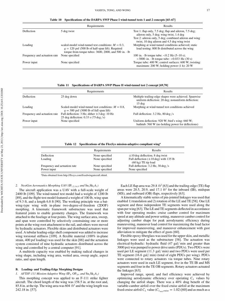
2. NextGen Aeronautics Morphing UAV (IP1;2;3;4;5 and Su1Sk2A1)
The aircraft application was a UAV with a full-scale weight of2400 lb [109]. The wind-tunnel test model had a weight of 1200 lb[89], and the flight-test model featured a weight of 100 lb, wing spanof 9.3 ft, and a length 6.8 ft [90]. The working principle was a bat-wing-type wing with in-plane two-degree-of-freedom (2DOF)morphing. A kinematic framework substructure was used thatfeatured joints to enable geometry changes. The framework wasattached to the fuselage at four points. Thewing surface area, sweep,and span were controlled by selectively constraining one or morepoints at the wing-root attachment to the rail, and others were movedby hydraulic actuators. Flexible skins and distributed actuators wereused. A tubular leading-edge shell component was added to increasewing torsional stiffness [109]. A flexible material (100% in-planestrain, 400 psf loading) was used for the skin [88] and the actuationsystem consisted of nine hydraulic actuators distributed across thewing and controlled by a central computer [91].
A multirole capacity was enabled by making radical changes inwing shape, including wing area, wetted area, sweep angle, aspectratio, and span length.
B. Leading- and Trailing-Edge Morphing Designs
1. AFTI/F-111 Mission-Adaptive Wing (IP5, OP1b, and Su1Sk2A1)
This morphing concept was applied to an F-111 strike fighteraircraft. The chord length of the wing was 158.5 in. at the root and,85.8 in. at the tip. Thewing areawas 604 ft2 and thewing length was242.18 in. [57].
Each LE flap area was 29:8 ft2 [63] and the trailing-edge (TE) flapareas were 20.5, 20.9, and 17:1 ft2 for the inboard (IB), midspan(MS), and outboard (OB) flaps, respectively [63].
A kinematically stable series of pin-jointed linkages was used thatenabled 1) translation and 2) rotation of the LE and TE [58]. One LEsegment and three independent TE segments were used along thespan perwing [63]. The LE andTE segments deflected in accordancewith four operating modes: cruise camber control for maximumspeed at any altitude and power setting, maneuver camber control foradjusting camber shape for peak aerodynamic efficiency duringmaneuvering, maneuver load control for maximizing the load factorfor improved maneuvering, and maneuver enhancement with gustalleviation to mitigate the effect of gusts [60].
Flexible epoxy fiberglass was used for the upper skin, andmetalliclinkages were used as the substructure [58]. The actuation waselectrical-hydraulic: hydraulic fluid (47 gal=min and greater than3000 psi) was pumped to power drive units (PDUs). Two PDUswereused per LE segment (11:3 gal=min) and two PDUs were used perTE segment (16:6 gal=min) (total of eight PDUs per wing). PDUswere connected to rotary actuators via torque tubes. Nine rotaryactuators were used in each LE segment, five in the TE IB and MSsegments and four in the TEOB segments. Rotary actuators actuatedthe linkages [63].
Improved range, speed, and fuel efficiency were achieved byoptimizing aerodynamic efficiency over operating CL values bychanging the airfoil shape. There was a 40% drag benefit of thevariable-camber airfoil over the fixed cruise airfoil at the maximumfixed cruise airfoilCL value (CLmaxcruise
� 1:02) [60] and asmuch as a
Table 10 Specifications of the DARPA SWP Phase I wind-tunnel tests 1 and 2 concepts [65–67]
Requirements Results
Deflection 5 deg twist Test 1: flap only, 7.5 deg; flap and aileron, 7.5 deg;aileron only, 5 deg; wing twist, 1.4 deg
Test 2: aileron only, 5 deg; combined aileron and wingtwist, 10 deg aileron and 4.5 deg wing twist
Loading scaled-model wind-tunnel test conditions:M� 0:3,q� 120 psf (500 lb of half-span lift). Requiredtorque from torque tubes: 3600, 2000, and 500 in: � lb
Morphing at wind-tunnel conditions achieved; staticload testing: 800 lb distributed across the wing
Frequency and actuation rate None specified 100 in: � lb torque tube: <0:2 Hz (5–10 s);>3000 -in: � lb torque tube: <0:033 Hz (30 s)
Power input None specified Torque tube: 400 W; control surfaces: 600 W; twisting:maximum: 200 W; holding power (1 h): 20 W
Table 11 Specifications of DARPA SWP Phase II wind-tunnel test 2 concept [69,70]
Requirements Results
Deflection 25 deg down Multiple trailing-edge shapes were achieved. Spanwiseuniform deflection: 20 deg; nonuniform deflection:15 deg
Loading Scaled-model wind-tunnel test conditions:M� 0:8,q� 300 psf (3000 lb of full span lift)
Morphing at wind-tunnel test conditions achieved
Frequency and actuation rate Full deflection: 3 Hz; dither �3 deg: 10 Hz25 deg deflection: 0.33 s (75 deg =s)
Full deflection: 3.2 Hz, 80 deg =s
Power input None specified Uniform deflection: 920 W; bird’s wing: 660 W;bathtub: 560 W (no holding power for deflections)
Table 12 Specifications of the FlexSys mission-adaptive compliant winga
Requirements Results
Deflection None specified �10 deg deflection; 8 deg twistLoading None specified Full deflection (�10 deg) with 135 lb
(60 kg) TE tip loadFrequency and actuation rate None specified Full deflection: 3.2 Hz, 30 deg =sPower input None specified None specified
aData obtained from http://flxsys.com/fixedwingaircraft.shtml.
VASISTA, TONG, ANDWONG 17
Dow
nloa
ded
by W
ICH
ITA
ST
AT
E U
NIV
ER
SIT
Y o
n M
ay 2
3, 2
013
| http
://ar
c.ai
aa.o
rg |
DO
I: 1
0.25
14/1
.C03
1060

100% improvement in L=D (with respect to a fixed-wing aircraft)could be attained by using variable camber at a Mach number of 0.8and altitude of 44,000 ft [60]. Furthermore, maneuverability wasimproved by increasing the maximum load factor for the samewing-root bending moment by shifting the load distribution inboard byreplacing conventional control surfaces with smooth surfaces thattwist. The wing-root bending moment could be reduced by 10–20%for the same load factor and other structural loads (wing-box shear,wing-box torsion, upper pivot plate strain, etc.) could be reduced by5–15% [60]. Conversely, the maximum load factor could beincreased for the samewing-root bendingmoment from4 to 5 g (25%increase in load factor) [60].
2. DLR Finger Concept (OP1b;6b and Su1Sk1A1)
This morphing concept was intended for the Airbus A340-300outboard Fowler flap. The dimensions include a flap chord length(inboard section) of 1680 mm flap span length of 10,210 mm and arear spar height of 151 mm [79].
Pin-jointed rib elements were used that translated and rotatedrelative to each other via revolute and prismatic joints, analogous tohuman finger anatomy. The skin was allowed to slide on the ribsusing roller bearings [79]. An all aluminum or all-carbon-fiberconstruction was possible. The carbon-fiber design resulted in lowerweight for the same stiffness [79].
Linear electrical motors were used for two actuation schemes:1) one actuator per rib connected to the first and second ribelements and 2) one actuator connected to a transmission beam andwedge [79].
Improved range, speed, and fuel efficiency were expected byoptimizing aerodynamic efficiency over operating CL values bychanging the airfoil shape. A 3–10%L=D improvement over a rangeof CL values and a possible CL increase of 12% were expected [79].In addition, the expected 12–15% reduction in wing-root bendingmoment could lead to improved maneuverability or reduced systemweight (for the same original maximum load factor).
3. DLR Belt–Rib Concept (OP1b;6b and Su11Sk11A1;2)
Similar to the DLR finger concept, the belt–rib concept wasintended for an Airbus A340-300 outboard Fowler flap. The flapchord length at the representative section was 1500 mm and, like thefinger concept, the flap span length and rear spar height were 10,210and 151mm, respectively [15]. The experimentalmodelwas 500mmwide [15].
The concept was intended as a replacement for the conventionalaircraft wing rib. It was a closed shell belt reinforced by in-planespokes. The spokes were connected to the belt by solid-state-compliant hinges [15].
A standard lightweight material could be used for the belt–ribstructural frame. High-strength materials (steel and carbon fiber)may be used for highly loaded components (belt–spar connectionand actuator anchor points) [15]. For the experimental model, acarbon-fiber/epoxy structure was used with metallic hinges for thespoke–belt connection [15].
A conventional or smart system could be used. Linear actuatorscould be arranged in a truss like manner between the spars, a rotaryactuator could be used at the belt–spar connections, or actuatorscould be embedded in the trailing-edge skin [15]. For theexperimental model, external actuation was used where a hand-driven eccentric cam loaded the belt–rib with a force between thefront spar and the front-bearing spoke [15].
The anticipated performance benefits were the same as the DLRfinger concept (Sec. V.B.2).
4. NGC-Led DARPA SWP Phase I (OP1b;6a and Su2Sk1;2A2)
The application for this concept was a 16% F/A-18 fighter attackaircraft scaled model. The dimensions were as follows: root chordlength of 32 in., wing length of 37 in. [65], wing thickness of 1.60 in.(root) and 0.375 in. (tip), flap chord length 8.382 in. (IB) and
4.712 in. (OB), and aileron chord length 4.712 in. (IB) and 3.030 in.(OB) [110].
SMA torque tubes were used to twist the wing, and SMA wireswere used to deflect the flap and aileron control surfaces after aninitial prestrain and heating [65]. In test 1, one SMA torque tube wasconnected from root rib to midspan rib and another SMA torque tubewas connected frommidspan rib to tip rib. In test 2, one SMA torquetube was connected from root rib to tip rib [65]. The SMA torquetubes for tests 1 and 2 were machined from a single SMA solidcircular rodmaterial using electrical dischargemachining. Nichromewires were wrapped around torque tubes [67]. For the controlsurfaces (flap and aileron), in test 1 binary SMA wires, a room-temperature vulcanization (RTV) core/ RTV face-sheet combinationand a Torlon® trailing-edge tip were used. In test 2, K-aslloy SMAwires, an aluminum Flex-Core/ RTV face-sheet combination, and analuminum trailing-edge tip were used [65]. In terms of actuation, intest 1 a 1-in.-diam torque tube delivered 1200 in: � lb of torque and a0.5-in.-diam torque tube delivered 600 in: � lb of torque [65,66]. Intest a 1.25-in.-diam torque tube delivered 3600 in: � lb of torque[65,66].
Maneuverability was improved by increasing control surfaceeffectiveness by replacing conventional control surfaceswith smoothcontinuous control surfaces that twist. A 7.5 deg deflection of the flapand aileron together resulted in improvements of 17.6% in lift and17.1% in rolling moment and 5 deg wing twist resulted inimprovements of 11.5% in lift and 15.6% in rolling moment [65].
5. NGC-Led DARPA SWP Phase II (OP1b;6b and Su2Sk2A2)
The application for this concept was a 30%-scaled UAV model.The span length was 110.57 in., length was 98.73 in., and modelweight was approximately 600 lb [69]. In test 1 an SMA-actuatedtrailing edge and outboard leading edge were used [74]. In test 2 afixed leading edge and an ultrasonic motor-eccentuator-driventrailing edge were used. The eccentuators were bent beams thattransmitted rotary motion into linear displacement at the tip. Tenindividual trailing segments were driven by eccentuators. Thesubstructure was a flexible honeycomb core [70].
The wind-tunnel test model was constructed from aluminumlongerons, bulkheads, spars, and ribs, and glass/epoxy skins [69] forthe control surface test 2, the design featured a flexible silicone skin,flexible honeycomb core (Flex-Core), aluminum tip and centerlaminate [70]. Several actuators were considered, including activelycooled SMAs, electroactive polymers, piezohydraulic pumps,piezoelectric inchworm motors, and magnetostrictive-based actu-ators. The final choice was a Shinsei SPL-801 piezodriven ultrasonicmotor (rated torque of 9:375 in: � lb, rated speed of 210 rpm, poweroutput of 23.3W,weight of 0.54 lb, lifetime of 100 h, and dimensionsof 2:6 � 2:6 � 1 in: [70].
The actuator was connected to a gear box, and one motor and gearbox were used per trailing-edge segment [70].
Maneuverability was improved by increasing control surfaceeffectiveness by replacing conventional control surfaceswith smoothcontinuous control surfaces that twist. The roll performanceimprovement of the smart trailing edge over the conventional hingedtrailing edge was 17% at 15 deg deflection and the pitching androlling moments also increased [74]. An improved pressure distri-bution [74] could also improve range, speed, and fuel efficiency.
6. FlexSys Mission-Adaptive Compliant Wing (OP1b;6b and Su11Sk2A1;2)
The intended applications for this concept are fixed-wing aircraftand rotorcraft. Four models were created: three wind-tunnel testmodels and one flight-test model. The span lengths were 48§ and50 in. [83] for the wind-tunnel and flight-test models, respectively.The chord length for all models was 30 in. [83]. In terms of theworking principle, traditional rigid ribs were replaced by monolithictopology-optimized compliant-mechanism ribs.
The substructure could be made from a variety of materials(aluminum, titanium, carbon-fiber-reinforced polymers, glass-fiber-
§Data obtained from http://flxsys.com/fixedwingaircraft.shtml.
18 VASISTA, TONG, ANDWONG
Dow
nloa
ded
by W
ICH
ITA
ST
AT
E U
NIV
ER
SIT
Y o
n M
ay 2
3, 2
013
| http
://ar
c.ai
aa.o
rg |
DO
I: 1
0.25
14/1
.C03
1060

reinforced polymers, and metal-matrix composites) [82]. The upper-surface skin was constructed from aluminum and a polymer. Thelower-surface skin material was the same as the upper surface, butwith an additional composite-reinforced panel added, extendingfrom 65 to 75% of themodel chord, allowing the panel to expand andcontract during flap deflection. The leading edgewasmachined from7075-T6 aluminum [83]. A variety of actuators (electrical, smartmaterials, etc.) could be used [82].
Performance benefits of improved range, speed, and fuel effi-ciency could be achieved by optimizing aerodynamic efficiency overoperating CL values by changing the airfoil shape. A 51% L=Dimprovement for 6 deg LE deflection, a 25% increase in CL, and alow drag envelope (aCD value of 0.006 forCL values ranging from 0to 1.5) were achieved [80]. For rotorcraft, morphing the leading edgeof a rotor blade once per revolution can result in 12–15% gain inspeed and maneuverability and a 10% increase in payload [81].Furthermore, weight and maintenance costs could be saved, due tothe monolithic design of the substructure.
The details of the morphing-aircraft concepts provided in thissection are discussed in terms of benchmarks in the followingsection.
VI. Discussion
A. Historical Trends
Wingmorphing dates back to the origin of aviation in 1903, as theWright brothers flyer used wing warping (twist) for control. In 1920Parker [52] designed a variable-camber wing that featured a flexiblesteel and wood construction that morphed passively under aero-dynamic loads. By the mid-1930s, aircraft payload and speedrequirements increased and the flexible wing was superseded by astiff structure for withstanding large forces and for the prevention ofaeroelastic phenomena [7]. Control surfaces thus became thediscrete, mechanical, and discontinuous devices that are used today.Attempts at morphing from the 1930s to the 1990s were conven-tionally mechanical in nature, such as the Bakshaev telescopingwing, Republic XF-91 Thunderceptor, and B-1 Lancer [3].
There has been a large effort in the last 15 years to achieve smoothshape change. The paradigm shifted from using conventionalactuators and substructures, as in the AFTI/F-111 Mission AdaptiveWing (MAW) program (1979–1989) [57–64], to using lightweighthigh-energy-density smart materials as actuators. This becameevident in the DARPA SWP Phases I and II (1995–2001) [65–67]where smart materials were developed and implemented in scaled-model aircraft wings. This also continued into theDARPAMorphingAircraft Structures (MAS) Program (2003–2006). There is still alarge ongoing research effort around the world today in the devel-opment of smart materials and their implementation in morphingwings.
Another trend in the last decade trend has been to use topology-optimized compliant mechanisms in morphing wings, such as in theFlexSys mission-adaptive compliant wing [80]. This is discussedfurther in Sec. VI.C.
B. Aircraft Type/Scale and Shape Parameters
Morphing has been attempted on amultitude of aircraft types fromwide-bodied airliners to miniature UAVs. Morphing in airlinerapplications includes leading- and trailing-edge deflections and twist(A340-300 outboard Fowler-flap used in the DLR finger [77,79] andbelt–rib concepts [13,15] and smart leading-edge and smart single-slotted Fowler-flap concepts in the SADE (Smart High Lift DevicesforNextGenerationWings) program [108]), transonic-bumpprofiles(DLR fish-mouth actuator [97]), and winglet morphing (Boeing andAirbus concepts). Morphing in strike fighter applications includesleading- and trailing-edge morphing in the AFTI/F-111 MAW [57–64] and wing twist, flap, and aileron deflection in the DARPA SWPPhase I (F/A-18) [65–67]. Morphing in UAV applications includesleading- and trailing-edge morphing in Phase II of the DARPA SWP[69–74,110], as well as making changes in sweep, aspect ratio, area,wing location, and span in the DARPA MAS concepts. Radical
morphing has been attempted on UAVs, rather than strike fighters orairliners, possibly due to the smaller size and weight of UAVaircraft.In addition, there have been recent attempts to morph to non-traditional shapes such as the hyperelliptic cambered-span (HECS)wing [17,19,95]. Radical morphing has also been applied tominiature UAVs, such as in the variable-gull-wing aircraft and theUniversity of Florida’s high-bandwidth morphing demonstrator[111]. Furthermore, a vast amount of research has been conducted inmorphing rotor blades for rotorcraft applications, particularly onhigh-frequency trailing-edge morphing [34,112].
It is clear that the magnitude of morphing (in terms of percent ofwing size) is smaller in larger aircraft and morphing is limited tosmall portions of thewing as opposed tomaking changes to the entirewing. It is easier to make larger shape changes as the aircraftapplication decreases in size.
Out of all the wing shape parameters, morphing of the camber hasbeen the most attempted and has been most commonly achieved bymaking trailing and leading-edge deflections. There are manyreasons for this trend:
1) A significant challenge exists for achieving out-of-plane shapechanges; thus, research is required.
2) Variable camber can result in significant performance benefits;in particular, L=D optimization.
3) The major load bearing structure in the wing is the central wingbox, rather than the leading- and trailing-edge structures.
4) The leading and trailing edges are relatively free fromconstraints such as fuel tanks, wing stores, engine mounts, etc.
5) Traditional rigid leading- and trailing-edge ribs can be replacedby adaptive wing ribs and independent nonuniform morphing ofthese ribs can result in twist.
6) Smoothly morphing leading and trailing edges can be used asmore effective control surfaces in comparison with currentsegmented discrete ailerons, flaps, elevators, rudders, etc.
7)Morphing of the leading- and trailing-edge ribs can be restrictedto 2-D planar motion, thus simplifying the ensuing analysis.
For these reasons, variable camber by morphing leading andtrailing edges has been the most feasible shape parameter to morph.
Making in-plane shape changes is possibly more feasible thanmaking out-of-plane changes, which is evident by the fact that in-plane variable sweep designs date back to the 1950s. Themajor wingload is the transverse lift load, and thus out-of-plane changes wouldneed to work against these large forces, requiring powerful actuatorsand a strong structure.
C. Enabling Technologies
The use of smart materials in morphing wings is prevalentthroughout literature: in particular, shape memory alloys andpiezoelectricmaterials. Shapememory alloys as standalone actuatorsare most commonly used in wire (tendon) and torque tube form,shape memory polymers have been tested in sheet form as wing skinmaterial, and piezoelectric materials are more commonly used inhigh-frequency applications such as rotary-wing aircraft and forcontrolling local flow. However, at the current state of smartmaterials, they offer limited potential as standalone actuators, due tolimited scalability, force-deflection characteristics, and requiredpower. Shape memory alloys generally have low-frequency char-acteristics, due to heating and cooling times (as in, for example, theDARPASWPPhase I tests [70]). In the cyclic testing of theLockheedMartin Z-wing model, breaking of the nichrome wires surroundingthe shapememory polymer skin led to an elastomeric skin being usedinstead [41]. Aside from this, they are still being implemented as inthe case of the SMA-actuated winglet [105]. Piezoelectric actuatorstypically have small deflections (�m) and require a high voltage(hundreds to thousands of volts) [26]. For comparisons of theperformance of smart materials and a critique on their current state,refer to works such as [34,112]. Smart materials, however, offergreater potential when used as components of actuation schemes.Examples include piezohydraulic actuators where piezoelectricmaterials can beused as pumpsorvalves andultrasonicmotors drivenby rings of piezoelectric wafers. In addition, it is likely that
VASISTA, TONG, ANDWONG 19
Dow
nloa
ded
by W
ICH
ITA
ST
AT
E U
NIV
ER
SIT
Y o
n M
ay 2
3, 2
013
| http
://ar
c.ai
aa.o
rg |
DO
I: 1
0.25
14/1
.C03
1060
transmission systems or gearswill be required to achieve the requiredforce-displacement values. Examples include the gearboxes andeccentuator beams used in the DARPA SWP Phase II [70], as well asthe transmissionbeamandwedgeused intheDLRfingerconcept [79].
Inspecting Table 3, common structural system combinationsinclude using a flexible elastomeric skin with a conventionalmechanical substructure with either smart or conventional actuators.Inmost cases, a smoothly contouredmorphingwingwas achieved bysimply using a stretchable elastomeric material as the wing skin tomaintain a smooth aerodynamic cover. Thill et al. [1] state that theimportance of a compliant and stiff morphing skin has beenrecognized but not many satisfactory solutions have been proposed.Gandhi and Anusonti-Inthra [113] suggest that ideal morphing skinswill be highly anisotropic.
Compliant-mechanism design is being pursued in order toeliminate backlash, wear, weight, and maintenance problems asso-ciated with conventional mechanisms. Compliant-mechanismdesign can be classified as either lumped or distributed in com-pliance. Lumped compliant mechanisms tend to be more intuitive indesign, such as the use of solid-state hinges in the DLR belt–ribconcept [15]. However, topology-optimization techniques and finiteelement analyses are generally required to achieve highly distributedcompliance. Topology optimization has been approached in twogeneral ways: the load-path approach using a framework of beamelements [114] or the continuous-density-based approach (SIMP[115–117] and level-set methods [118–120]).
Biomimetics is growing in popularity as more researchers areturning to nature to find effective ways of morphing. As mentionedpreviously, morphing wings can be considered as biologicallyinspired flight; researchers have identified the different shapes thatbirds can change their wings into and have tried to imitate this.However, research in biomimetics has gone deeper to determine howorganisms change their shape, such as throughmuscles, tendons, andligaments in animals and cell pressure in plants. This is discussedfurther in Sec. VII.
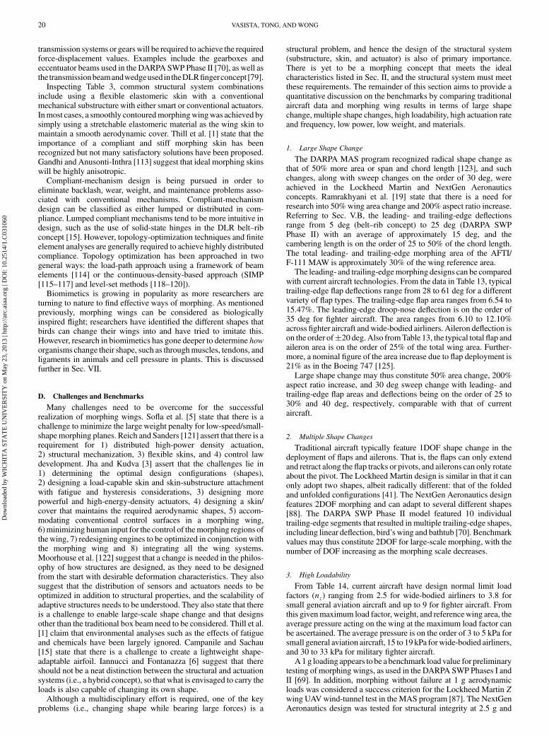
D. Challenges and Benchmarks
Many challenges need to be overcome for the successfulrealization of morphing wings. Sofla et al. [5] state that there is achallenge to minimize the large weight penalty for low-speed/small-shapemorphing planes. Reich and Sanders [121] assert that there is arequirement for 1) distributed high-power density actuation,2) structural mechanization, 3) flexible skins, and 4) control lawdevelopment. Jha and Kudva [3] assert that the challenges lie in1) determining the optimal design configurations (shapes),2) designing a load-capable skin and skin-substructure attachmentwith fatigue and hysteresis considerations, 3) designing morepowerful and high-energy-density actuators, 4) designing a skin/cover that maintains the required aerodynamic shapes, 5) accom-modating conventional control surfaces in a morphing wing,6)minimizing human input for the control of themorphing regions ofthe wing, 7) redesigning engines to be optimized in conjunction withthe morphing wing and 8) integrating all the wing systems.Moorhouse et al. [122] suggest that a change is needed in the philos-ophy of how structures are designed, as they need to be designedfrom the start with desirable deformation characteristics. They alsosuggest that the distribution of sensors and actuators needs to beoptimized in addition to structural properties, and the scalability ofadaptive structures needs to be understood. They also state that thereis a challenge to enable large-scale shape change and that designsother than the traditional box beam need to be considered. Thill et al.[1] claim that environmental analyses such as the effects of fatigueand chemicals have been largely ignored. Campanile and Sachau[15] state that there is a challenge to create a lightweight shape-adaptable airfoil. Iannucci and Fontanazza [6] suggest that thereshould not be a neat distinction between the structural and actuationsystems (i.e., a hybrid concept), so that what is envisaged to carry theloads is also capable of changing its own shape.
Although a multidisciplinary effort is required, one of the keyproblems (i.e., changing shape while bearing large forces) is a
structural problem, and hence the design of the structural system(substructure, skin, and actuator) is also of primary importance.There is yet to be a morphing concept that meets the idealcharacteristics listed in Sec. II, and the structural system must meetthese requirements. The remainder of this section aims to provide aquantitative discussion on the benchmarks by comparing traditionalaircraft data and morphing wing results in terms of large shapechange, multiple shape changes, high loadability, high actuation rateand frequency, low power, low weight, and materials.
1. Large Shape Change
The DARPA MAS program recognized radical shape change asthat of 50% more area or span and chord length [123], and suchchanges, along with sweep changes on the order of 30 deg, wereachieved in the Lockheed Martin and NextGen Aeronauticsconcepts. Ramrakhyani et al. [19] state that there is a need forresearch into 50% wing area change and 200% aspect ratio increase.Referring to Sec. V.B, the leading- and trailing-edge deflectionsrange from 5 deg (belt–rib concept) to 25 deg (DARPA SWPPhase II) with an average of approximately 15 deg, and thecambering length is on the order of 25 to 50% of the chord length.The total leading- and trailing-edge morphing area of the AFTI/F-111 MAW is approximately 30% of the wing reference area.
The leading- and trailing-edgemorphing designs can be comparedwith current aircraft technologies. From the data in Table 13, typicaltrailing-edge flap deflections range from 28 to 61 deg for a differentvariety of flap types. The trailing-edge flap area ranges from 6.54 to15.47%. The leading-edge droop-nose deflection is on the order of35 deg for fighter aircraft. The area ranges from 6.10 to 12.10%across fighter aircraft andwide-bodied airliners. Aileron deflection ison the order of�20 deg. Also fromTable 13, the typical totalflap andaileron area is on the order of 25% of the total wing area. Further-more, a nominal figure of the area increase due to flap deployment is21% as in the Boeing 747 [125].
Large shape change may thus constitute 50% area change, 200%aspect ratio increase, and 30 deg sweep change with leading- andtrailing-edge flap areas and deflections being on the order of 25 to30% and 40 deg, respectively, comparable with that of currentaircraft.
2. Multiple Shape Changes
Traditional aircraft typically feature 1DOF shape change in thedeployment of flaps and ailerons. That is, the flaps can only extendand retract along the flap tracks or pivots, and ailerons can only rotateabout the pivot. The Lockheed Martin design is similar in that it canonly adopt two shapes, albeit radically different: that of the foldedand unfolded configurations [41]. The NextGen Aeronautics designfeatures 2DOF morphing and can adapt to several different shapes[88]. The DARPA SWP Phase II model featured 10 individualtrailing-edge segments that resulted in multiple trailing-edge shapes,including linear deflection, bird’s wing and bathtub [70]. Benchmarkvalues may thus constitute 2DOF for large-scale morphing, with thenumber of DOF increasing as the morphing scale decreases.
3. High Loadability
From Table 14, current aircraft have design normal limit loadfactors (nz) ranging from 2.5 for wide-bodied airliners to 3.8 forsmall general aviation aircraft and up to 9 for fighter aircraft. Fromthis givenmaximum load factor, weight, and referencewing area, theaverage pressure acting on the wing at the maximum load factor canbe ascertained. The average pressure is on the order of 3 to 5 kPa forsmall general aviation aircraft, 15 to 19 kPa forwide-bodied airliners,and 30 to 33 kPa for military fighter aircraft.
A 1g loading appears to be a benchmark load value for preliminarytesting of morphing wings, as used in the DARPA SWP Phases I andII [69]. In addition, morphing without failure at 1 g aerodynamicloads was considered a success criterion for the Lockheed Martin Zwing UAVwind-tunnel test in the MAS program [87]. The NextGenAeronautics design was tested for structural integrity at 2.5 g and
20 VASISTA, TONG, ANDWONG
Dow
nloa
ded
by W
ICH
ITA
ST
AT
E U
NIV
ER
SIT
Y o
n M
ay 2
3, 2
013
| http
://ar
c.ai
aa.o
rg |
DO
I: 1
0.25
14/1
.C03
1060
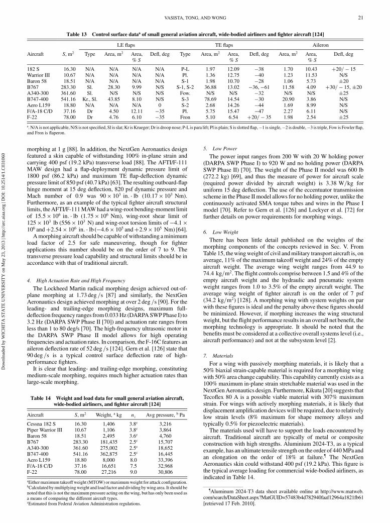
morphing at 1 g [88]. In addition, the NextGen Aeronautics designfeatured a skin capable of withstanding 100% in-plane strain andcarrying 400 psf (19.2 kPa) transverse load [88]. The AFTI/F-111MAW design had a flap-deployment dynamic pressure limit of1800 psf (86.2 kPa) and maximum TE flap-deflection dynamicpressure limit of 850 psf (40.7 kPa) [63]. The resulting outboard-flaphinge moment at 15 deg deflection, 820 psf dynamic pressure andMach number of 0.9 was 90 � 103 in: � lb (10:17 � 103 Nm).Furthermore, as an example of the typical fighter aircraft structurallimits, theAFTI/F-111MAWhad awing-root bending-moment limitof 15:5 � 106 in: � lb (1:75 � 106 Nm), wing-root shear limit of125 � 103 lb (556 � 103 N) and wing-root torsion limits of �4:1 �106 and�2:54 � 106 in: � lb (�4:6 � 105 and�2:9 � 105 Nm) [64].
Amorphing aircraft should be capable ofwithstanding aminimumload factor of 2.5 for safe maneuvering, though for fighterapplications this number should be on the order of 7 to 9. Thetransverse pressure load capability and structural limits should be inaccordance with that of traditional aircraft.
4. High Actuation Rate and High Frequency
The Lockheed Martin radical morphing design achieved out-of-plane morphing at 1:73 deg =s [87] and similarly, the NextGenAeronautics design achieved morphing at over 2 deg =s [90]. For theleading- and trailing-edge morphing designs, maximum full-deflection frequency ranges from0.033Hz (DARPASWPPhase I) to3.2 Hz (DARPA SWP Phase II [70]) and actuation rate ranges fromless than 1 to 80 deg/s [70]. The high-frequency ultrasonic motor inthe DARPA SWP Phase II model allows for high operatingfrequencies and actuation rates. In comparison, the F-16C features anaileron deflection rate of 52 deg =s [124]. Gern et al. [126] state that90 deg =s is a typical control surface deflection rate of high-performance fighters.
It is clear that leading- and trailing-edge morphing, constitutingmedium-scale morphing, requires much higher actuation rates thanlarge-scale morphing.
5. Low Power
The power input ranges from 200 W with 20 W holding power(DARPA SWP Phase I) to 920 W and no holding power (DARPASWP Phase II) [70]. The weight of the Phase II model was 600 lb(272.2 kg) [69], and thus the measure of power for aircraft scale(required power divided by aircraft weight) is 3:38 W=kg foruniform 15 deg deflection. The use of the eccentuator transmissionscheme in the Phase II model allows for no holding power, unlike thecontinuously activated SMA torque tubes and wires in the Phase Imodel [70]. Refer to Gern et al. [126] and Lockyer et al. [72] forfurther details on power requirements for morphing wings.
6. Low Weight
There has been little detail published on the weights of themorphing components of the concepts reviewed in Sec. V. FromTable 15, thewingweight of civil andmilitary transport aircraft is, onaverage, 11% of the maximum takeoff weight and 24% of the emptyaircraft weight. The average wing weight ranges from 44.9 to74:4 kg=m2. The flight controls comprise between 1.5 and 4% of theempty aircraft weight and the hydraulic and pneumatic systemweight ranges from 1.0 to 3.5% of the empty aircraft weight. Theaverage wing weight of fighter aircraft is on the order of 7 psf(34:2 kg=m2) [128]. A morphing wing with system weights on parwith these figures is ideal and the penalty above these figures shouldbe minimized. However, if morphing increases the wing structuralweight, but the flight performance results in an overall net benefit, themorphing technology is appropriate. It should be noted that thebenefits must be considered at a collective overall systems level (i.e.,aircraft performance) and not at the subsystem level [2].
7. Materials
For a wing with passively morphing materials, it is likely that a50% biaxial strain-capable material is required for a morphing wingwith 50% area change capability. This capability currently exists as a100% maximum in-plane strain stretchable material was used in theNextGenAeronautics design. Furthermore, Kikuta [20] suggests thatTecoflex 80 A is a possible viable material with 307% maximumstrain. For wings with actively morphing materials, it is likely thatdisplacement amplification devices will be required, due to relativelylow strain levels (8% maximum for shape memory alloys andtypically 0.5% for piezoelectric materials).
The materials used will have to support the loads encountered byaircraft. Traditional aircraft are typically of metal or compositeconstruction with high strengths. Aluminium 2024-T3, as a typicalexample, has an ultimate tensile strength on the order of 440MPa andan elongation on the order of 18% at failure.¶ The NextGenAeronautics skin could withstand 400 psf (19.2 kPa). This figure isthe typical average loading for commercial wide-bodied airliners, asindicated in Table 14.
Table 13 Control surface dataa of small general aviation aircraft, wide-bodied airliners and fighter aircraft [124]
LE flaps TE flaps Aileron
Aircraft S, m2 Type Area, m2 Area,% S
Defl, deg Type Area, m2 Area,% S
Defl, deg Area, m2 Area,% S
Defl, deg
182 S 16.30 N/A N/A N/A N/A P-L 1.97 12.09 �38 1.70 10.43 �20= � 15Warrior III 10.67 N/A N/A N/A N/A Pl. 1.36 12.75 �40 1.23 11.53 N/SBaron 58 18.51 N/A N/A N/A N/A S-1 1.98 10.70 �28 1.06 5.73 �20B767 283.30 Sl. 28.30 9.99 N/S S-1, S-2 36.88 13.02 �36, �61 11.58 4.09 �30= � 15, �20A340-300 361.60 Sl. N/S N/S N/S Fow. N/S N/S �32 N/S N/S �25B747-400 541.16 Kr., Sl. 43.85 8.10 N/S S-3 78.69 14.54 �30 20.90 3.86 N/SAero L159 18.80 N/A N/A N/A 0 S-2 2.68 14.26 �44 1.69 8.99 N/SF/A-18 C/D 37.16 Dr 4.50 12.11 �35 Pl. 5.75 15.47 �47 2.27 6.11 N/SF-22 78.00 Dr 4.76 6.10 �35 Fron 5.10 6.54 �20= � 35 1.98 2.54 �25a. N/A is not applicable, N/S is not specified, Sl is slat; Kr is Krueger;Dr is droop nose; P-L is para lift; Pl is plain; S is slotted flap,�1 is single,�2 is double,�3 is triple, Fow is Fowler flap,and Fron is flaperon.
Table 14 Weight and load data for small general aviation aircraft,wide-bodied airliners, and fighter aircraft [124]
Aircraft S, m2 Weight, a kg nz Avg pressure, b Pa
Cessna 182 S 16.30 1,406 3.8c 3,216Piper Warrior III 10.67 1,106 3.8c 3,864Baron 58 18.51 2,495 3.6c 4,760B767 283.30 181,435 2.5c 15,707A340-300 361.60 275,002 2.5c 18,652B747-400 541.16 362,875 2.5c 16,445Aero L159 18.80 8,000 8.0 33,396F/A-18 C/D 37.16 16,651 7.5 32,968F-22 78.00 27,216 9.0 30,806
aEither maximum takeoff weight (MTOW) or maximumweight for attack configuration.bCalculated bymultiplyingweight and load factor and dividing bywing area. It should benoted that this is not themaximum pressure acting on thewing, but has only been used asa means of comparing the different aircraft types.cEstimated from Federal Aviation Administration regulations.
¶Aluminum 2024-T3 data sheet available online at http://www.matweb.com/search/DataSheet.aspx?MatGUID=57483b4d782940faaf12964a1821fb61[retrieved 17 Feb. 2010].
VASISTA, TONG, ANDWONG 21
Dow
nloa
ded
by W
ICH
ITA
ST
AT
E U
NIV
ER
SIT
Y o
n M
ay 2
3, 2
013
| http
://ar
c.ai
aa.o
rg |
DO
I: 1
0.25
14/1
.C03
1060

Shape memory alloy and polymer frequency and actuationcharacteristics need to be improved (current level of less than 1Hz) tomeet actuation rate and frequency benchmarks. This challenge isbeing addressed by researchers as, for example, ADATechnologies,Inc., is aiming to increase heat transfer and thermal conductivity ofshape memory polymers by using nanoparticle-reinforced shapememory polymers [129]. In addition, the voltage requirements ofpiezoelectric actuators need to be reduced for successful integrationinto aircraft.
VII. Biological Inspirations
It is prudent to take inspiration from nature to address the currentchallenges. Muscles and plants possess properties that are highlydesired in morphing-wing designs and these principles are discussedin this section.
A. Muscle Function and Design
1. How Muscles Work
Macroscopic changes in muscle length result from accumulatedmicroscopic changes. Skeletal muscles are bundles of muscle cellfibers and each muscle fiber contains many cylindrical-shapedstructures called myofibrils. A myofibril consists of two differenttypes of protein filaments: myosin (thick) filaments and actin (thin)filaments. A unit of alternating thick and thin elements is called a“sarcomere,”which can be considered as the basic building block of amuscle. The thick and thin filaments are arranged in a comblikemanner in the longitudinal direction of the myofibril, and many thinfilaments surround the thick filaments to form the cross section of thesarcomere [130]. Contraction occurs according to the sliding-filament theory [131,132], where golf-club-shaped cross-bridgesform from thick myosin filaments and attach to thin actin elements,pulling (sliding) the filaments past each other. Although this processoccurs on the microscopic level (the sarcomere length is typically2–3 �m, and the stroke of the cross-bridge is typically 6–7 nm), themultiple cross-bridges forming and detaching quickly overthe millions of individual sarcomeres results in macroscopic change.The formation and detachment of cross-bridges is a chemical processinvolving calcium ions, and muscle contraction occurs in threemodes (concentric, isometric, and eccentric). The four basic require-ments for successful locomotion are power generation, stability,maneuverability, and energy conservation [130].
2. Muscle Design
There is a large variety of muscle designs to meet differentrequirements. As such, there is a broad range in force generating andshortening capabilities in muscles: maximum strain varies from 2 to200%, maximum isometric stress varies from 8 to 2200 kN=m2,maximum contraction speed varies from 0.35 to 38 muscle lengthsper second, and frequency varies from less than 1 to 1000 Hz [130].Body size influences muscle function, as larger animals tend to havelower-frequency requirements than smaller animals. There are twobasic design options: 1) modify the design of sarcomeres and2) modify the arrangement of sarcomeres.
3. Design of Sarcomeres
Sarcomere design varies among animals in terms of length and theratio of actin to myosin filaments. Sarcomere length varies from2–3 �m (squid tentacles and most vertebrates) to 20 �m (crabclawmuscles). The ratio of actin to myosin filaments varies from 2:1to 7:1 [130].
Force production depends on length of sarcomere and velocity ofcontraction. The force due to length is determined by the amount ofactin and myosin filament overlap in which the maximum cross-bridges are formed for this length. The force due to velocity isdetermined by the probabilities for cross-bridge attachment anddetachment. Together, force-length and force-velocity relationshipsdetermine the maximum output work and power [130].
4. Arrangement of Sarcomeres
Sarcomeres are arranged to meet functional demands whileaccounting for volume and length constraints set by skeletaldimensions. Sarcomeres are arranged in both series and parallel andthe force-deflection characteristics for both arrangements are shownin Fig. 4. There is a force advantage with a parallel arrangementand a deflection (and contraction rate) advantage with a seriesarrangement [130].
Furthermore, skeletal muscles are attached to the skeleton byelastic tendons and the ratio of muscle (active) length to elastictendon (passive) length also affects output characteristics.
5. Neural Control
Muscles are composed of several different motor units withdifferent functions. A motor neuron via its axon innervates a distinctset of muscle fibers. All muscle fibers belonging to a single unit havean identical biochemical makeup. Individual motor units are classedin terms of size, contraction rate, and fatigue resistance. A typicalmuscle contains a mix of different motor units and the centralnervous system tailors function to demand, i.e., specific motor units,each for a different purpose, are controlled individually. For example,during slow incremental loading tasks, slow, small, and fatigue-resistant motor units are called first, followed by faster, larger, andless-fatigue-resistant motor units [130]. In addition, muscle functionis influenced by amplitude and phase of neural control input. Forexample, frog’s legs use phase relationships between controlinput (signal) and movement (kinematics) to yield optimal poweroutput [130].
Table 15 Component weights of small jet transport, large jet transport, and military transport aircraft [127]
Wing weight Flight controls Hydraulic and pneumatic
Aircraft S, m2 MTOW, kg Empty, kg kg % MTOW % empty Avg, a kg=m2 kg % empty kg % empty
F-28 76.4 28,123 15,198 3,414 12.1 22.5 44.9 637 4.2 184 1.2BAC-111 93.2 45,200 23,479 4,453 9.9 19.0 47.8 751 3.2 631 2.7737-200 125.0 47,174 26,060 5,064 10.7 19.4 40.5 1,055 4.0 379 1.5707-320 280.0 141,521 56,779 12,994 9.2 22.9 46.4 970 1.7 706 1.2L-1011 321.1 195,045 103,879 21,501 11.0 20.7 67.0 2,299 2.2 1,996 1.9747 541.2 351,534 151,303 40,252 11.5 26.6 74.4 3,123 2.1 2,298 1.5C-133B 248.3 129,727 54,624 12,276 9.5 22.5 49.4 628 1.2 692 1.3C-141A 300.0 143,381 58,350 15,541 10.8 26.6 51.8 1,564 2.7 981 1.7C-5A 576.0 330,215 146,355 37,096 11.2 25.3 64.4 3,146 2.1 1,958 1.3
aWing weight per unit wing area.
Fig. 4 Force-deflection characteristics of sarcomeres arranged in
parallel and series. Adapted from [130].
22 VASISTA, TONG, ANDWONG
Dow
nloa
ded
by W
ICH
ITA
ST
AT
E U
NIV
ER
SIT
Y o
n M
ay 2
3, 2
013
| http
://ar
c.ai
aa.o
rg |
DO
I: 1
0.25
14/1
.C03
1060

6. Muscle Robustness
As a final note to muscle systems, biological materials are toughand use energy-release mechanisms to avoid crack propagation inwhich individual sarcomeres are sacrificed. As a result, only brokensarcomeres need to be replaced and not the whole structure [130].
B. Plant Movement
Plants possess many qualities that are required by morphingstructures. Plants can bear large loads (they can remain uprightagainst their own weight) and are capable of movement (sunflowerscan bend toward the light, and Venus Flytraps can snap shut). Likemuscles, these abilities are explained at the cellular level and areprimarily due to pressure contained within plant cells [133]. Pressurein plant cells provides structural stiffness, much like an inflatablestructure, thus enabling the plant to support large loads. Unevenchange in pressure among adjacent cells causes the plant to move.For example, pressurized fluid causes the cells to swell, andnonuniform expansion causes the plant to distort its shape [45].Although each cell deformation is small, there is a multitude of cellsand the cumulative result is large shape change. The ability of plantcells to take in and release fluid in the cells is a result of biochemicalactive ionic transportation processes.
C. Relevance to Morphing Wings
It is clear that animals and plants feature highly sophisticated andefficient ways of enabling motion and bearing loads, and theirworking principles may provide a solution to the current morphingchallenges. Muscles possess many characteristics that are sought bythe morphing-wing designer. Through their modular designs,muscles 1) are highly distributed actuation systems, 2) are scalablebecause they appear throughout the animal kingdom and have abroad range in force generating and shortening capabilities, 3) haveextremely high control authority, 4) can perform multiple functionsthrough tailored muscle fibers and motor units, 5) can be repairedeasily, 6) have similar basic requirements as morphing wings (powergeneration, stability, maneuverability, and energy conservation),7) have similar body-size-based frequency-deflection requirementsto morphing wings, 8) have evolved and grow and function aroundvolume and length constraints (morphing-wing structures also haveconstraints such as fuel tank space, engine location, etc.), and 9) areintegrated and work efficiently with passive elastic structures such astendons, and thus the system is a combination of passive and activeelements.
Furthermore, the structural system of plants consists of highlyintegrated and almost indistinguishable substructure and actuatorsubsystems, as thefluid provides stiffness (thus having a substructurefunction) and movement (thus having an actuation function). Thisdual functionality is highly desired in a morphing wing.
Researchers have tried tomimicmuscles throughmaterials such aselectroactive polymers [43] and actuators such as pneumatic artificialmuscles [1]. The principles of plant movement have been used byresearchers in the field of adaptive structures. Philen et al. [32]developed aflexiblematrix composite actuator that actuated based oninternal fluid pressure and was controlled by an electroosmotictransport mechanism. Shan et al. [33] have designed fluidic flexiblematrix composites in which fluid is allowed to flow in and out of atube made from a flexible matrix composite material. When the tubeis full of fluid the system has a high stiffness and when the tube isempty the system has a low stiffness, thusmaking the tube a variable-stiffness structure. A closed/open (high/low)modulus ratio as high as56 times was achieved [33]. Researchers in the field of nasticstructures are aiming to mimic the biological processes that enablethe transportation of water in and out of plant cells with the aim ofdesigning high-energy-density actuators [44–50]. Maute et al. [134]developed a two-level macro/micro optimization procedure in whichon the macroscopic level the integration of nastic material in thestructure is optimized and on the microscopic level the layout of thevascular fluid channels is optimized to tailor the stress and straingeneration to the desired macroscopic properties. In addition, Higgset al. [135] conducted buckling analyses of pneumatically stiffened,
reinforced composite beams. Furthermore, unit-cell designs havebeen explored as Ramrakhyani et al. [19] developed a tendon-actuated morphing unit cell and Lin et al. [136] developed amorphing trailing-edge substructure using a compliant-mechanismunit-cell approach.
VIII. Future Research Paths
To summarize the preceding sections, the current problems werestated, the target morphing values were suggested, and it wasproposed that the challenges may be overcome and the benchmarkvalues may be attained through the use of biological concepts. Thissection describes the research required to realize this idea into afunctional morphing wing. The suggestions for applying muscle-function and plant-movement principles to morphing wings areoutlined as follows:
1) Use fluid/air pressure to control stiffness of the structure andvary pressure to change shape.
2) Use a modular unit-cell design with basic building blocks thatenable work output.
3) Use topology optimization or other optimization schemes todetermine the design of building blocks and arrangement of buildingblocks to meet required functions.
4) Enable multifunctionality by using muscle-fiber/motor-unitequivalents for a combination of, say, large slow deflection and smallfast deflection. These are elaborated in the remainder of this section.
It is envisaged that the design of the unit cell will be achievedthrough a topology-optimization compliant-mechanism synthesisfor pressure input loads to harness the omnidirectional nature ofpressure into a desired output. The optimization scheme will mostlikely have to account for solid, fluid, and void regions (such as athree-phase optimization scheme [137,138]) in a 3-D design domain.The appropriate objective function(s) will have to be determined,such as maximizing a single output displacement, mechanicalefficiency, mechanical advantage, geometric advantage, minimizingdisplacement error, etc. Using a combination of unit cells withdesigns obtained via different objective functions may lead tomultifunctionality. The appropriate valve type and locationmust alsobe determined. Valve type depends on the size of the cell, and formicrocells, biochemical transport gates or microelectromechanicalsystem (MEMS) valveswill be required. Thevalve locationwill needto be optimized such that the fluid flow and cell expansion/contraction complement each other. This will require multi-disciplinary optimization considering fluid–structure interactions. Itis important that the valve is not “parasitic” to the cell.
The arrangement of the cells will have to be optimized also. Thismay be achieved by determining equivalent properties (Young’smodulus, deflection, output force, etc.) of the unit cells (once theyhave been designed) and implementing them into an optimizationalgorithm with constraints such as number of cells, volume, weight,etc. Determination of the arrangement can be thought of as topologyoptimization on one level above unit-cell optimization.
A suitable pump component needs to be ascertained. Possibleoptions include piezoelectric and magnetostrictive-based pumps,MEMS pumps and biochemical pumps (for the microscale). Theoverall hydraulic system architecture needs to be determined. Asuitable working fluid also needs to be determined: one that is lightand has high incompressibility. The incompressibility associatedwith liquids may lead to higher efficiency, though there may be aweight penalty. Conversely, air suffers from higher levels ofcompressibility, but is light and can be extracted from compressedengine air, as in [84]. Furthermore, a system is required that controlsthe valves and pumps, thus allowing fluid to flow in and out of thespecific cells required to create the desired shape change.
Application of muscle-function and plant-movement principles inmorphing wings involve significant materials and structuralchallenges. Traditionally, material design and structural design havebeen undertaken as separate disciplines. Materials are designed tomeet certain criteria such as modulus of elasticity, ultimate tensilestrength, elongation before failure, etc., and the structural designerchooses and uses certain materials of a particular form (rod, tube,
VASISTA, TONG, ANDWONG 23
Dow
nloa
ded
by W
ICH
ITA
ST
AT
E U
NIV
ER
SIT
Y o
n M
ay 2
3, 2
013
| http
://ar
c.ai
aa.o
rg |
DO
I: 1
0.25
14/1
.C03
1060
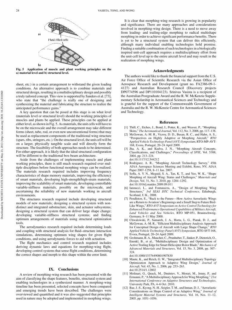
sheet, etc.) in a certain arrangement to withstand the given loadingconditions. An alternative approach is to combine materials andstructural design, resulting in amultidisciplinary design and possiblya truly tailored concept. This view is supported by Sanders et al. [73],who state that “the challenge is really one of designing andsynthesizing the material and fabricating the structure to realize theanticipated performance gains.”
A key question that can be posed at this stage is on what level(materials level or structural level) should the working principles ofmuscles and plants be applied. These principles can be applied ateither level, as shown in Fig. 5.Asmaterials, the unit cellswill have tobe on the microscale and the overall arrangement may take differentforms (sheet, tube, rod, or even new unconventional forms) that maybe used as replacement components of the traditional wing structure(spars, ribs, stringers, etc.). On the structural level, the unit cell will beon a larger, physically tangible scale and will directly form thestructure. The feasibility of both approaches needs to be determined.For either approach, it is likely that the ideal structural configurationwill be different to the traditional box-beam architecture.
Aside from the challenges of implementing muscle and plantworking principles, there is still much research required over mul-tiple disciplines before functional morphing wings can be realized.The materials research required includes improving frequencycharacteristics of shape memory materials, improving the efficiencyof smart materials, developing high-strength/high-strain materials,improving the scalability of smart materials, developing controllablevariable-stiffness materials, possibly on the microscale, andascertaining the reliability of new materials working in aircraftenvironments.
The structures research required include developing structuralmodels of new materials; designing a structural system with non-distinct and integrated substructure, skin, and actuator subsystems;designing a structural system that can deliver large shape change;developing variable-stiffness structural systems; and findingoptimum arrangements of materials using structural optimizationtools.
The aerodynamics research required include determining loadsand coupling with structural analysis for fluid–structure interactionsimulations, determining optimum wing shapes for given flightconditions, and using aerodynamic forces to aid with actuation.
The flight mechanics and control research required includesderiving dynamic laws and equations for morphing-wing flight,developing control systems that sense flight conditions, determiningthe correct shapes and morph to this shape within the error limit.
IX. Conclusions
A review of morphing-wing research has been presented with theaim of classifying the shape features, benefits, structural system andenabling technologies in a synthesized manner. A morphing-wingtimeline has been presented, selected concepts have been comparedand emerging trends have been described. The challenges wereoverviewed and quantified and it was also suggested that principlesused in nature may be adopted and implemented in morphing wings.
It is clear that morphing-wing research is growing in popularityand significance. There are many approaches and considerationsinvolved in morphing-wing design. There is a need to move awayfrom leading- and trailing-edge morphing to radical multishapemorphing in order to achieve significant performance benefits. Thereis yet to be a structural system that can deliver this efficiently,although many individual enabling technologies hold promise.Finding a suitable combination of such technologies in a biologicallyinspired unit-cell approach requires a multidisciplinary effort fromthe unit-cell level up to the entire aircraft level and may result in therealization of morphing wings.
Acknowledgments
The authors would like to thank thefinancial support from theU.S.Air Force Office of Scientific Research via the Asian Office ofAerospace Research and Development (grant no. FA2386-09-1-4127) and Australian Research Council (Discovery projectsDP0774596 and DP110104123). Srinivas Vasista is a recipient ofthe Australian Postgraduate Award and the R.W.McKenzie Supple-mentary Scholarship in Aeronautical Sciences and Technology andis grateful for the support of the Commonwealth Government ofAustralia and the R. W. McKenzie Centre for Aeronautical Sciencesand Technology.
References
[1] Thill, C., Etches, J., Bond, I., Potter, K., and Weaver, P., “MorphingSkins,”TheAeronautical Journal, Vol. 112, No. 3, 2008, pp. 117–138.
[2] McGowan, A.-M. R., Vicroy, D. D., Busan, R. C., and Hahn, A. S.,“Perspectives on Highly Adaptive or Morphing Aircraft,” RTO
Applied Vehicle Technology Panel (AVT) Symposium, RTO-MP-AVT-168, Evora, Portugal, 20–24 April 2009.
[3] Jha, A. K., and Kudva, J. N., “Morphing Aircraft Concepts,Classifications, and Challenges,” Proceedings of SPIE, Vol. 5388,2004, pp. 213–224.doi:10.1117/12.544212
[4] Rodriguez, A. R., “Morphing Aircraft Technology Survey,” 45thAIAA Aerospace Sciences Meeting and Exhibit, Reno, NV, AIAAPaper 2007-1258, 8–11 Jan. 2007.
[5] Sofla, A. Y. N., Meguid, S. A., Tan, K. T., and Yeo, W. K., “ShapeMorphing of Aircraft Wing: Status and Challenges,” Materials and
Design, Vol. 31, No. 3, 2010, pp. 1284–1292.doi:10.1016/j.matdes.2009.09.011
[6] Iannucci, L., and Fontanazza, A., “Design of Morphing WingStructures,” 3rd SEAS DTC Technical Conference, Edinburgh,Scotland, U.K., 2008.
[7] Pendleton, E., “Back to the Future—How Active Aeroelastic Wingsare a Return to Aviation’s Beginnings and a Small Step to Future Bird-LikeWings,” RTO AVT Symposium on Active Control Technology for
Enhanced Performance Operational Capabilities of Military Aircraft,
Land Vehicles and Sea Vehicles, RTO MP-051, Braunschweig,Germany, 8–11 May 2000.
[8] Chwalowski, P., Samareh, J. A., Horta, L. G., Piatak, D. J., andMcGowan, A.-M. R., “Efficient Multidisciplinary Analysis Approachfor Conceptual Design of Aircraft with Large Shape Change,” RTO
Applied Vehicle Technology Panel (AVT) Symposium, RTOAVT-168,Evora, Portugal, 20–24 April 2009.
[9] Grohmann,B.A.,Maucher,C., Prunhuber, T., Jänker, P.,Dieterich,O.,Enenkl, B., et al., “Multidisciplinary Design and Optimization ofActive Trailing Edge for Smart Helicopter Rotor Blade,”Mechanics of
Advanced Materials and Structures, Vol. 15, No. 3, 2008, pp. 307–324.doi:10.1080/15376490801907830
[10] Maute, K., and Reich, G. W., “Integrated Multidisciplinary TopologyOptimization Approach to Adaptive Wing Design,” Journal of
Aircraft, Vol. 43, No. 1, 2006, pp. 253–263.doi:10.2514/1.12802
[11] Molinari, G., Quack, M., Dmitriev, V., Morari, M., Jenny, P., andErmanni, P., “AMultidisciplinaryApproach forWingMorphing,” 21stInternational Conference on Adaptive Structures and Technologies,University Park, PA, 4–6 Oct. 2010.
[12] Bae, J.-S., Kyong, N.-H., Seigler, T.M., and Inman, D. J., “AeroelasticConsiderations on Shape Control of an Adaptive Wing,” Journal of
Intelligent Material Systems and Structures, Vol. 16, Nos. 11–12,2005, pp. 1051–1056.
Fig. 5 Application of muscle and plant working principles on the
a) material level and b) structural level.
24 VASISTA, TONG, ANDWONG
Dow
nloa
ded
by W
ICH
ITA
ST
AT
E U
NIV
ER
SIT
Y o
n M
ay 2
3, 2
013
| http
://ar
c.ai
aa.o
rg |
DO
I: 1
0.25
14/1
.C03
1060
doi:10.1177/1045389X05059965[13] Campanile, L. F., and Anders, S., “Aerodynamic and Aeroelastic
Amplification in Adaptive Belt-Rib Airfoils,” Aerospace Science andTechnology, Vol. 9, No. 1, 2005, pp. 55–63.doi:10.1016/j.ast.2004.07.007
[14] Raulli, M., and Maute, K., “Optimization of Fully CoupledElectrostatic-Fluid-Structure Interaction Problems,” Computers and
Structures, Vol. 83, Nos. 2–3, 2005, pp. 221–233.doi:10.1016/j.compstruc.2004.08.003
[15] Campanile, L. F., and Sachau, D., “The Belt-Rib Concept: AStructronic Approach to Variable Camber,” Journal of Intelligent
Material Systems and Structures, Vol. 11, No. 3, 2000, pp. 215–224.doi:10.1106/6H4B-HBW3-VDJ8-NB8A
[16] Roskam, J., “Airplane Design—Part III: Layout Design of Cockpit,Fuselage, Wing and Empennage: Cutaways and Inboard Profiles,”Airplane Design, Vol. 3, DARcorporation, Lawrence, KS, 2002.
[17] Manzo, J. E., “Analysis and Design of a Hyper-Elliptical CamberedSpan Morphing Aircraft Wing,” M.S. Thesis, Cornell University,Ithaca, NY, 2006.
[18] Barbarino, S., Ameduri, S., Lecce, L., and Concilio, A., “Wing ShapeControl through and SMA-Based Device,” Journal of Intelligent
Material Systems and Structures, Vol. 20, No. 3, 2008, pp. 283–296.doi:10.1177/1045389X08093825
[19] Ramrakhyani, D. S., Lesieutre, G. A., Frecker, M., and Bharti, S.,“Aircraft Structural Morphing Using Tendon-Actuated CompliantCellular Trusses,” Journal of Aircraft, Vol. 42, No. 6, 2005, pp. 1615–1621.doi:10.2514/1.9984
[20] Kikuta, M. T., “Mechanical Properties of Candidate Materials forMorphing Wings,” M.S., Thesis Virginia Polytechnic Institute andState University, Blacksburg, VA, 2003.
[21] Friswell,M. I., and Inman, D. J., “Morphing Concepts for UAVs,” 21stInternational Unmanned Air Vehicles Systems Conference, Bristol,England, U.K., 2006.
[22] Mattioni, F., Gatto, A.,Weaver, P.M., Friswell,M. I., and Potter, K. D.,“The Application of Residual Stress Tailoring of Snap-ThroughComposites for Variable Sweep Wings,” 47th AIAA/ASME/ASCE/AHS/ASC Structures, Structural Dynamics, and Materials Confer-ence, AIAA Paper 2006-1972, Newport, RI, 1–4 May 2006.
[23] Mattioni, F., Weaver, P. M., Potter, K. D., and Friswell, M. I., “TheAnalysis of Cool-Down and Snap-Through of Cross-Ply LaminatedUsed as Multistable Structures,” Twentieth ABAQUS UK User Group
Conference, Manchester, England, U.K., 2006.[24] Mattioni, F., Weaver, P. M., Potter, K. D., and Friswell, M. I., “The
Application of Thermally Induced Multistable Composites toMorphing Aircraft Applications,” Proceedings of SPIE, Vol. 6930,2008, Paper 693012.doi:10.1117/12.776226
[25] Diaconu, C. G., Weaver, P. M., and Mattioni, F., “Concepts forMorphing Airfoil Sections Using Bi-Stable Laminated CompositeStructures,” Thin-Walled Structures, Vol. 46, 2008, pp. 689–701.doi:10.1016/j.tws.2007.11.002
[26] Srinivasan, A. V., andMcFarland, M., Smart Structures: Analysis andDesign, Cambridge University Press, New York, 2001.
[27] Ratna, D., andKarger-Kocsis, J., “Recent Advances in ShapeMemoryPolymers and Composites: A Review,” Journal of Materials Science,Vol. 43, No. 1, 2008, pp. 254–269.doi:10.1007/s10853-007-2176-7
[28] Liu, C., Qin, H., and Mather, P. T., “Review of Progress in Shape-Memory Polymers,” Journal of Materials Chemistry, Vol. 17, No. 16,2007, pp. 1543–1558.doi:10.1039/b615954k
[29] Kiang, J., and Tong, L., “Modelling of Magneto-MechanicalBehaviour of Ni-Mn-Ga Single Crytals,” Journal of Magnetism and
Magnetic Materials, Vol. 292, 2005, pp. 394–412.doi:10.1016/j.jmmm.2004.11.481
[30] Ocalan, M., “High Flexibility Rotorcraft Driveshafts Using FlexibleMatrix Composites and Active Bearing Control,” M.S. Thesis,Pennsylvania State University, University Park, PA, 2002.
[31] Shan, Y., Philen, M., Bakis, C. E., Wang, K. W., and Rahn, C. D.,“Nonlinear-Elastic Finite Axisymmetric Deformation of FlexibleMatrix Composite Membranes Under Internal Pressure and AxialForce,”Composites Science and Technology, Vol. 66, 2006, pp. 3053–3063.doi:10.1016/j.compscitech.2006.01.002
[32] Philen, M., Shan, Y., Prakash, P., Wang, K. W., Rahn, C. D., Zydney,A. L., and Bakis, C. E., “Fibrillar Network Adaptive Structure withIon-Transport Actuation,” Journal of Intelligent Material Systems and
Structures, Vol. 18, No. 4, 2007, pp. 323–334.
doi:10.1177/1045389X06066097tions[33] Shan, Y., Philen,M., Lotfi, A., Suyi Li, Bakis, C. E., Rahn, C. D., et al.,
“Variable Stiffness Structures Utilizing Fluidic Flexible MatrixComposites,” Journal of Intelligent Material Systems and Structures,Vol. 20, No. 4, 2009, pp. 443–456.doi:10.1177/1045389X08095270
[34] Chopra, I., “Review of State of Art of Smart Structures and IntegratedSystems,” AIAA Journal, Vol. 40, No. 11, 2002, pp. 2145–2187.doi:10.2514/2.1561
[35] Niezrecki, C., Brei, D., Balakrishnan, S., and Moskalik, A.,“Piezoelectric Actuation: State of the Art,” Shock and Vibration
Digest, Vol. 33, No. 4, 2001, pp. 269–280.doi:10.1177/058310240103300401
[36] Mauck, L. D., and Lynch, C. S., “Piezoelectric Hydraulic PumpDevelopment,” Journal of Intelligent Material Systems and
Structures, Vol. 11, No. 10, 2000, pp. 758–764.doi:10.1106/HC2A-ABR9-21H8-2TJB
[37] Keller, C. A., “Novel Concepts in Piezohydraulic Pump Design,”M.S., Thesis Georgia Institute of Technology, Atlanta, 2004.
[38] Chapman, E. G., Herdic, S. L., Keller, C. A., and Lynch, C. S.,“Development ofMiniaturized Piezo-Hydraulic Pumps,”Proceedingsof SPIE, Vol. 5762, 2005, pp. 299–310.doi:10.1117/12.605967
[39] Yoo, J.-H., Sirohi, J., Wereley, N. M., and Chopra, I., “AMagnetorheological Hydraulic Actuator Driven by a Piezopump,”Proceedings of SPIE, Vol. 5056, 2003, pp. 444–456.doi:10.1117/12.483497
[40] Lih, S.-S., Bar-Cohen,Y., andGrandia,W., “RotaryUltrasonicMotorsActuated by Traveling Flexural Waves,” Proceedings of SPIE,Vol. 3041, 1997, pp. 912–917.doi:10.1117/12.275717
[41] Bye, D. R., andMcClure, P. D., “Design of aMorphing Vehicle,” 48thAIAA/ASME/ASCE/AHS/ASC Structures, Structural Dynamics, andMaterials Conference, AIAA Paper 2007-1728, Honolulu, HI, 23–26 April 2007.
[42] CEDRAT Technologies, “Magnetostrictive Actuators” [onlinearticle], 2007 http://www.cedrat.com/fileadmin/user_upload/cedrat_groupe/Technologies/Actuators/Magnetic%20actuators%20&%20motors/fiche_AMA/Magnetostrictive_Actuators.pdf [retrieved1 March 2010].
[43] Bar-Cohen, Y., Electroactive Polymer (EAP) Actuators as Artificial
Muscles: Reality, Potential, and Challenges, SPIE, Bellingham, WA,2004.
[44] Homison, C., “Coupled Transport/Hyperelastic Model for HighEnergy Density Nastic Materials,” M.S. Thesis, University ofPittsburgh, Pittsburgh, PA, 2006.
[45] Matthews, L., Sundaresan, V. B., Giurgiutiu, V., and Leo, D.,“Bioenergetics and Mechanical Actuation Analysis with MembraneTransport Experiments for Use in Biomimetic Nastic Structures,”Journal of Materials Research, Vol. 21, No. 8, 2006, pp. 2058–2067.doi:10.1557/jmr.2006.0250
[46] Sundaresany, V. B., and Leo, D. J., “Chemo-Mechanical Model forActuation Based on Biological Membranes,” Journal of Intelligent
Material Systems and Structures, Vol. 17, No. 10, 2006, pp. 863–870.doi:10.1177/1045389X06061129
[47] Sundaresan, V. B., Homison, C., Weiland, L. M., and Leo, D. J.,“Biological Transport Processes for Microhydraulic Actuation,”Sensors and Actuators B (Chemical), Vol. 123, No. 2, 2007, pp. 685–695.doi:10.1016/j.snb.2006.10.009
[48] Sundaresan, V. B., and Leo, D. J., “Controlled Fluid Transport UsingATP-Powered Protein Pumps,” Smart Materials and Structures,Vol. 16, No. 2, 2007, pp. S207–S213.doi:10.1088/0964-1726/16/2/S02
[49] Freeman, E., and Weiland, L. M., “High Energy Density NasticMaterials: Parameters for Tailoring Active Response,” Journal of
Intelligent Material Systems and Structures, Vol. 20, No. 2, 2009,pp. 233–243.doi:10.1177/1045389X08092276
[50] Piyasena, M. E., Newby, R., Miller, T. J., Shapiro, B., and Smela, E.,“Electroosmotically Driven Microfluidic Actuators,” Sensors and
Actuators B (Chemical), Vol. 141, No. 1, 2009, pp. 263–269.doi:10.1016/j.snb.2009.05.014
[51] Davis, S., Tsagarakis, N., Canderle, J., and Caldwell, D. G.,“EnhancedModelling and Performance in Braided Pneumatic MuscleActuators,” International Journal of Robotics Research, Vol. 22,Nos. 3–4, 2003, pp. 213–227.doi:10.1177/0278364903022003006
VASISTA, TONG, ANDWONG 25
Dow
nloa
ded
by W
ICH
ITA
ST
AT
E U
NIV
ER
SIT
Y o
n M
ay 2
3, 2
013
| http
://ar
c.ai
aa.o
rg |
DO
I: 1
0.25
14/1
.C03
1060

[52] Parker, H. F., “The Parker Variable Camber Wing,” NACA, Rept. 77,1920.
[53] Burnelli, V. J., “Aircraft,” U.S. Patent, 1,917,428, 11 July 1933.[54] Shavrov, V. B., The History of Aircraft Construction in the USSR,
Mashinostroenie, Moscow, 1994.[55] Kiceniuk, T., “Control and Propulsion Fluid Foil,” U.S. Patent,
3,118,639, 21 Jan. 1964.[56] Stinton, D., The Design of the Airplane, AIAA, Reston, VA, 2001.[57] Painter, W. D., and Caw, L. J., “Design and Physical Characteristics of
the Transonic Aircraft Technology (TACT) Research Aircraft,”NASA, TM-56048, Jan. 1979.
[58] Statkus, F. D., “Continuous Skin, Variable Camber Airfoil EdgeActuating Mechanism,” U.S. Patent, 4,351,502, 28 Sept. 1982.
[59] Larson, R. R., “AFTI/F-111 MAW Flight Control System andRedundancy Management Description,” NASA, TM-88267,Feb. 1987.
[60] “AFTI/F-111 Mission Adaptive Wing Briefing to Industry,” U.S. AirForce Wright Aeronautical Labs., Rept. AFWAL-TR-88-3082,Wright-Patterson AFB, OH, Oct. 1988.
[61] Webb, L. D., McCain, W. E., and Rose, L. A., “Measured andPredicted Pressure Distributions on the AFTI/F-111Mission AdaptiveWing,” NASA, TM-100443, Nov. 1988.
[62] Powers, S. G., Webb, L. D., Friend, E. L., and Lokos, W. A., “FlightTest Results from a SupercriticalMissionAdaptiveWingwith SmoothVariable Camber,” NASA, TM-4415, Nov. 1992.
[63] Smith, J. W., Lock, W. P., and Payne, G. A., “Variable-CamberSystems Integration and Operational Performance of the AFTI/F-111Mission Adaptive Wing,” NASA, TM-4370, April 1992.
[64] Thornton, S.V., “Reduction of Structural LoadsUsingManeuverLoadControl on the Advanced Fighter Technology Integration (AFTI)/F-111 Mission Adaptive Wing,” NASA, TM-4526, Sept. 1993.
[65] Kudva, J. N., Martin, C. A., Scherer, L. B., Jardine, A. P., McGowan,A. R., Lake, R. C., Sendeckyj, G., and Sanders, B., “Overview of theDARPA/AFRL/NASA Smart Wing Program,” Proceedings of SPIE,Vol. 3674, 1999, pp. 237–248.doi:10.1117/12.351562
[66] Martin, C. A., Bartley-Cho, J., Flanagan, J., and Carpenter, B. F.,“Design and Fabrication of SmartWingWind TunnelModel and SMAContoured Surfaces,” Proceedings of SPIE, Vol. 3674, 1999, pp. 237–248.doi:10.1117/12.351562
[67] Jardine,A. P., Bartley-Cho, J., andFlanagan, J., “ImprovedDesign andPerformance of the SMA Torque Tube for the DARPA Smart WingProgram,” Proceedings of SPIE, Vol. 3674, 1999, pp. 260–269.doi:10.1117/12.351564
[68] Pendleton, E., Bessette, D., Field, P. B., and Miller, G. D., “ActiveAeroelastic Wing Flight Research Program: Technical Program andModel Analytical Development,” Journal of Aircraft, Vol. 37, No. 4,2000, pp. 554–561.doi:10.2514/2.2654
[69] Kudva, J. N., “Overview of the DARPA SmartWing Project,” Journalof Intelligent Material Systems and Structures, Vol. 15, No. 4, 2004,pp. 261–267.doi:10.1177/1045389X04042796
[70] Bartley-Cho, J. D.,Wang, D. P., Martin, C. A., Kudva, J. N., andWest,M. N., “Development of High-rate, Adaptive Trailing Edge ControlSurface for the Smart Wing Phase 2 Wind Tunnel Model,” Journal ofIntelligent Material Systems and Structures, Vol. 15, No. 4, 2004,pp. 279–291.doi:10.1177/1045389X04042798
[71] Martin, C. A., Hallam, B. J., Flanagan, J. S., and Bartley-Cho, J.,“Design, Fabrication and Testing of a Scaled Wind Tunnel Model forthe Smart Wing Project,” Journal of Intelligent Material Systems and
Structures, Vol. 15, No. 4, 2004, pp. 269–278.doi:10.1177/1045389X04042797
[72] Lockyer, A. J., Martin, C. A., Lindner, D. K., Walia, P. S., andCarpenter, B. F., “Power Systems and Requirements for Integration ofSmart Structures into Aircraft,” Journal of Intelligent Material
Systems and Structures, Vol. 15, No. 4, 2004, pp. 305–315.doi:10.1177/1045389X04042800
[73] Sanders, B., Crowe, R., and Garcia, E., “Defense Advanced ResearchProjects agency—Smart Materials and Structures DemonstrationProgram Overview,” Journal of Intelligent Material Systems and
Structures, Vol. 15, No. 4, 2004, pp. 227–233.doi:10.1177/1045389X04042793
[74] Scherer, L. B., Martin, C. A., Sanders, B., West, M., Florance, J.,Wieseman, C., Burner, A., and Fleming, G., “DARPA/AFRL SmartWing Phase 2 Wind Tunnel Test Results,” Proceedings of SPIE,Vol. 4698, 2002, pp. 64–75.
doi:10.1117/12.475104[75] Lagoudas, D. C., Garner, L. J., Rediniotis, O. K., and Wilson, N.,
“Modeling and Experiments of the Hysteretic Response of an ActiveHydrofoil Actuated by SMA Line Actuators,” Proceedings of the
NATO Advanced Research Workshop on Smart Structures: Require-
ments and Potential Applications in Mechanical and Civil
Engineering, Kluwer Academic, Dordrecht, The Netherlands, 1999,pp. 153–162.
[76] Heyland, D., Rosemann, H., Sachau, D., Strohmeyer, D., and Voß, R.,“The Adaptive Wing Project (DLR): Survey on Targets and RecentResults from Active/Adaptive Structures Viewpoint,” Proceedings ofthe Tenth International Conference on Adaptive Structures and Tech-
nologies, Technomic Publishing, Lancaster, PA, 1999, pp. 178–185.[77] Monner, H. P., Sachau, D., and Breitbach, E., “Realization of a
Spanwise Differential and Constant Camber Variation for an AdaptiveWing,” Proceedings of the Tenth International Conference on
Adaptive Structures and Technologies, Technomic, Lancaster, PA,1999, pp. 186–193.
[78] Anhalt, C., Breitbach, E., and Sachau, D., “A Concept of aShapevariable Fowler Flap on Transport Aircraft,” RTO AVT
Symposium on Active Control Technology for Enhanced Performance
Operational Capabilities of Military Aircraft, Land Vehicles and Sea
Vehicles, Braunschweig, Germany, 8–11 May 2000.[79] Monner, H. P., “Realization of an optimized wing camber by using
formvariable flap structures,” Aerospace Science and Technology,Vol. 5, No. 7, 2001, pp. 445–455.doi:10.1016/S1270-9638(01)01118-X
[80] Kota, S., Hetrick, J., Osborne, R. F., Paul, D., Pendleton, E., Flick, P.,and Tilmann, C., “Design and Application of Compliant Mechanismsfor Morphing Aircraft Structures,” Proceedings of SPIE, Vol. 5054,2003, pp. 24–33.doi:10.1117/12.483869
[81] SBIR/STTR, “Air Force SBIR/STIR Innovation Story: MissionAdaptive Compliant Wing,” U.S. Air Force Research Labs.,Rept. AFRL/VAO-06-418, 2006.
[82] Kota, S., and Hetrick, J., “Adaptive Compliant Wing and RotorSystem,” U.S. Patent 7384016 B2, 10 June 2008.
[83] Kota, S., Osborne, R. F., Jr., Ervin, G., Maric, D., Flick, P., and Paul,D., “Mission Adaptive Compliant Wing—Design, Fabrication andFlight Test,” RTO Applied Vehicle Technology Panel (AVT)
Symposium, RTO MP-AVT-168, Evora, Portugal, 20–24 April 2009.[84] Dorsett, K. M., and Stewart, C. S., “Inflatable Structures to Control
Aircraft,” U.S. Patent, 6,015,115, 18 Jan. 2000.[85] Love, M. H., Zink, P. S., Stroud, R. L., Bye, D. R., and Chase, C.,
“Impact ofActuationConcepts onMorphingAircraft Structures,” 45thAIAA/ASME/ASCE/AHS/ASC Structures, Structural Dynamics andMaterials Conference, AIAA Paper 2004-1724, Palm Springs, CA,19–22 April 2004.
[86] Weisshaar, T. A., “Morphing Aircraft Technology—New Shapes forAircraft Design,” Multifunctional Structures/Integration of Sensors
and Antennas Meeting, RTO MP-AVT-141, Vilnius, Lithuania, 2–4 Oct. 2006.
[87] Ivanco, T. G., Scott, R. C., Love,M. H., Zink, S., andWeisshaar, T. A.,“Validation of the Lockheed Martin Morphing Concept with WindTunnel Testing,” 48th AIAA/ASME/ASCE/AHS/ASC Structures,Structural Dynamics, and Materials Conference, AIAA Paper 2007-2235, Honolulu, 23–26 April 2007.
[88] Bowman, J., Sanders, B., Cannon, B., Kudva, J. N., Joshi, S., andWeisshaar, T., “Development of Next Generation Morphing AircraftStructures,” 48th AIAA/ASME/ASCE/AHS/AC Structures, Struc-tural Dynamics and Materials Conference, AIAA Paper 2007-1730,Honolulu, 23–26 April 2007.
[89] Andersen, G. R., Cowan, D. L., and Piatak, D. J., “AeroelasticModeling, Analysis and Testing of a Morphing Wing Structure,” 48thAIAA/ASME/ASCE/AHS/ASC Structures, Structural Dynamics andMaterials Conference, AIAA Paper 2007-1734, Honolulu, 23–26 April 2007.
[90] Flanagan, J. S., Strutzenberg, R. C., Myers, R. B., and Rodrian, J. E.,“Development and Flight Testing of aMorphingAircraft, theNextGenMXF-1,” 48th AIAA/ASME/ASCE/AHS/ASC Structures, StructuralDynamics, and Materials Conference, AIAA Paper 2007-1707,Honolulu, 23–26 April 2007.
[91] Gandhi, N., Jha, A. K., Monaco, J., Seigler, T. M., Ward, D., andInman, D. J., “Intelligent Control of aMorphingAircraft,” 48thAIAA/ASME/ASCE/AHS/ASC Structures, Structural Dynamics, andMaterials Conference, AIAA Paper 2007-1716, Honolulu, 23–26 April 2007.
[92] Strelec, J. K., Lagoudas, D. C., Khan, M. A., and Yen, J., “Design andImplementation of a Shape Memory Actuated Reconfigurable
26 VASISTA, TONG, ANDWONG
Dow
nloa
ded
by W
ICH
ITA
ST
AT
E U
NIV
ER
SIT
Y o
n M
ay 2
3, 2
013
| http
://ar
c.ai
aa.o
rg |
DO
I: 1
0.25
14/1
.C03
1060

Airfoil,” Journal of Intelligent Material Systems and Structures,Vol. 14, Nos. 4–5, 2003, pp. 257–273.doi:10.1177/1045389X03034687
[93] Wiggins, L. D., III, “Structural Design and Analysis of a KinematicMechanism for a Morphing Hyper-Elliptic Cambered Span (HECS)Wing,” M.S. Thesis, Virginia Polytechnic Institute and StateUniversity, Blacksburg, VA, 2003.
[94] Poonsong, P., “Design and Analysis of Multi-Section VariableCamber Wing,” M.S. Thesis, University of Maryland, College Park,MD, 2004.
[95] Abdulrahim, M., and Lind, R., “Flight Testing and ResponseCharacteristics of a Variable Gull-Wing Morphing Aircraft,” AIAAGuidance, Navigation, and Control Conference and Exhibit, AIAAPaper 2004-5113, Providence, RI, 16–19 Aug. 2004.
[96] Hong, C. H., Cheplak, M., Choi, J. Y., and Mavris, D. N., “FlexibleMulti-Body Design of a Morphing UCAV,” AIAA 3rd UnmannedUnlimited Technical Conference, Workshop and Exhibit, AIAAPaper 2004-6595, Chicago, 20–23 Sept. 2004.
[97] Campanile, L. F., Keimer, R., and Breitbach, E., “The Fish-MouthActuator—Design Issues and Test Results,” Journal of Intelligent
Material Systems and Structures, Vol. 15, Nos. 9–10, 2004, pp. 711–719.doi:10.1177/1045389X04044452
[98] Mason, W. H., Robertshaw, H. H., and Inman, D. J., “RecentExperiments in Aerospace and Design Engineering Education,” 42ndAIAA Aerospace Sciences Meeting and Exhibit, AIAA Paper 2004-0415, Reno, NV, 5–8 Jan. 2004.
[99] Jacob, J. D., and Smith, S., “Design and Flight Testing of InflatableWings with Warping,” SAE Transactions, Vol. 2005-01, Society ofAutomotive Engineers, New York, 2005, pp. 1306–1315.
[100] “Morphing Wings Make for Swift Flight,” Control and Automation,Vol. 18, No. 4, 2007, p. 2.
[101] Samuel, J. B., and Pines, D., “Design and Testing of a PneumaticTelescoping Wing for Unmanned Aerial Vehicles,” Journal of
Aircraft, Vol. 44, No. 4, 2007, pp. 1088–1099.doi:10.2514/1.22205
[102] Supekar, A. H., “Design, Analysis and Development of a MorphableWing Structure for Unmanned Aerial Vehicle PerformanceAugmentation,” M.S. Thesis, University of Texas at Arlington,Arlington, TX, 2007.
[103] Baker, D., and Friswell, M. I., “Determinate Structures for WingCamber Control,” Smart Materials and Structures, Vol. 18, No. 3,2009, Paper 035014.doi:10.1088/0964-1726/18/3/035014
[104] Ursache, N. M., Melin, T., Isikveren, A. T., and Friswell, M. I.,“Technology Integration for Active Poly-Morphing WingletsDevelopment,” ASME Conference on Smart Materials, AdaptiveStructures and Intelligent Systems, Ellicott City, MD, ASMEInternational, Paper 2008-496, 28–30 Oct. 2008.
[105] Sankrithi, M. M. K. V., and Frommer, J. B., “Controllable Winglets,”U.S. Patent 2008/0308983 A1, 18 Dec. 2008.
[106] Barbarino, S., Pecora, R., Lecce, L., Concilio, A., Ameduri, S., andCalvi, E., “A Novel SMA-Based Concept for Airfoil StructuralMorphing,” Journal of Materials Engineering and Performance,Vol. 18, No. 5, 2009, pp. 696–705.doi:10.1007/s11665-009-9356-3
[107] Icardi, U., and Ferrero, L., “Preliminary Study of an Adaptive Wingwith ShapeMemory Alloy Torsion Actuators,”Materials and Design,Vol. 30, No. 10, 2009, pp. 4200–4210.doi:10.1016/j.matdes.2009.04.045
[108] Monner, H. P., “SADE (Smart High Lift Devices for Next GenerationWings) News” [online article], 2009, http://www.smr.ch/sade/sade_public/Publications_files/SADE_Newsletter_2009_1.0.pdf [re-trieved 25 Feb. 2010].
[109] Weisshaar, T. A., “New Aircraft Systems Concepts—Towards NewHorizons in Aeroelasticity” [online article], Purdue University, WestLafayette, IN, 2008, https://engineering.purdue.edu/AAE/Academics/Courses/aae556/2008/aircraft%20systems%20concepts [retrieved25 Feb. 2010].
[110] Sanders, B., Cowan, D., and Scherer, L., “Aerodynamic Performanceof the Smart Wing Control Effectors,” Journal of Intelligent Material
Systems and Structures, Vol. 15, No. 4, 2004, pp. 293–303.doi:10.1177/1045389X04042799
[111] Voracek, D., “Adaptive Structures,” Aerospace America, Vol. 45,No. 12, Dec. 2007, p. 74.
[112] Barlas, T. K., and van Kuik, G. A. M., “Review of State of the Art inSmart Rotor Control Research for Wind Turbines,” Progress in
Aerospace Sciences, Vol. 46, No. 1, 2010, pp. 1–27.doi:10.1016/j.paerosci.2009.08.002
[113] Gandhi, F., and Anusonti-Inthra, P., “Skin Design Studies for VariableCamber Morphing Airfoils,” Smart Materials and Structures, Vol. 17,No. 1, 2008, Paper 015025.doi:10.1088/0964-1726/17/01/015025
[114] Lu, K. J., and Kota, S., “Design of Compliant Mechanisms forMorphing Structural Shapes,” Journal of Intelligent Material Systems
and Structures, Vol. 14, No. 6, 2003, pp. 379–391.doi:10.1177/1045389X03035563
[115] Rozvany, G. I. N., Zhou, M., and Birker, T., “Generalized ShapeOptimization Without Homogenization,” Structural and Multi-
disciplinary Optimization, Vol. 4, No. 3, 1992, pp. 250–252.doi:10.1007/BF01742754
[116] Sigmund, O., “On the Design of Compliant Mechanisms UsingTopology Optimization,” Mechanics of Structures and Machines,Vol. 25, No. 4, 1997, pp. 493–524.doi:10.1080/08905459708945415
[117] Bendsoe, M. P., and Sigmund, O., Topology Optimization: Theory,
Methods, and Applications, Springer–Verlag, Berlin, 2003.[118] Allaire, G., Jouve, F., and Toader, A.-M., “Structural Optimization
Using Sensitivity Analysis and a Level-Set Method,” Journal of
Computational Physics, Vol. 194, No. 1, 2004, pp. 363–393.doi:10.1016/j.jcp.2003.09.032
[119] Wang, M. Y., Wang, X., and Guo, D., “A Level Set Method forStructural Topology Optimization,” Computer Methods in Applied
Mechanics and Engineering, Vol. 192, Nos. 1–2, 2003, pp. 227–246.doi:10.1016/S0045-7825(02)00559-5
[120] Luo, Z., Tong, L., Wang, M. Y., and Wang, S., “Shape and TopologyOptimization of Compliant Mechanisms Using a ParameterizationLevel Set Method,” Journal of Computational Physics, Vol. 227,No. 1, 2007, pp. 680–705.doi:10.1016/j.jcp.2007.08.011
[121] Reich, G. W., and Sanders, B., “Introduction to Morphing AircraftResearch,” Journal of Aircraft, Vol. 44, No. 4, 2007, p. 1059.doi:10.2514/1.28287
[122] Moorhouse, D., Sanders, B., von Spakovsky, M., and Butt, J.,“Benefits andDesign Challenges of Adaptive Structures forMorphingAircraft,” The Aeronautical Journal, Vol. 110, No. 3, 2006, pp. 157–162.
[123] Wilson, J. R., “Morphing UAVs Change the Shape of Warfare,”Aerospace America, Vol. 42, No. 2, Feb. 2004, pp. 28–29.
[124] “Jane’s All the World’s Aircraft 2005-2006,” Jane’s All the World’s
Aircraft, 96th ed., Jane’s Information Group, Surrey, England, U.K.,2005.
[125] Jenkins, D. R., Boeing 747-100/200/300/SP, Airliner Tech Series,Vol. 6, Specialty Press, North Branch, MN, 2000.
[126] Gern, F. H., Inman, D. J., and Kapania, R. K., “Computation ofActuation Power Requirements for Smart Wings with MorphingAirfoils,” AIAA Journal, Vol. 32, No. 12, 2006, pp. 2481–2486.doi:10.2514/1.20367
[127] Kroo, I., and Shevell, R., “Sample Aircraft Weight Statements,”Aircraft Design: Synthesis and Analysis [online textbook],Stanford Univ., Stanford, CA, 2006 http://adg.stanford.edu/aa241/AircraftDesign.html [retrieved 17 Feb. 2010].
[128] Brandt, S. A., Stiles, R. J., Bertin, J. J., and Whitford, R., “Sizing,”Introduction to Aeronautics: A Design Perspective, 2nd ed., AIAA,Reston, VA, 2004, p. 348.
[129] “ADASelected forUAVWingsResearch” [online article]United PressInternational, 3 Feb. 2010, http://www.upi.com/Business_News/Security-Industry/2010/02/03/ADA-selected-for-UAV-wings-research/UPI-78241265236265/ [retrieved 15 March 2010].
[130] Meijer, K., Moreno, J. C., and Savelberg, H. H. C. M., “BiologicalMechanisms as Models for Mimicking: Sarcomere Design, Arrange-ment and Muscle Function,” Biomimetics: Biologically Inspired
Technologies, CRC Press, Boca Raton, FL, 2006, pp. 41–56.[131] Huxley, A. F., and Niedergerke, R., “Interference Microscopy of
Living Muscle Fibers,” Nature, Vol. 173, 1954, pp. 971–973.doi:10.1038/173971a0
[132] Huxley, A. F., and Hanson, J., “Changes in Cross-Striations of MuscleDuring Contraction and Stretch and Their Structural Interpretation,”Nature, Vol. 173, 1954, pp. 973–976.doi:10.1038/173973a0
[133] Stahlberg, R., and Taya, M., “Nastic Structures: the Enacting andMimicking of Plant Movements,” Biomimetics: Biologically InspiredTechnologies, CRC Press, Boca Raton, FL, 2006, pp. 473–493.
[134] Maute, K., Dunn, M. L., Bischel, R., Howard, M., and Pajot, J. M.,“Multiscale Design of Vascular Plates,” Proceedings of the
International Mechanical Engineering Congress and Exposition,ASME International, New York, 2005, pp. 365–374.
VASISTA, TONG, ANDWONG 27
Dow
nloa
ded
by W
ICH
ITA
ST
AT
E U
NIV
ER
SIT
Y o
n M
ay 2
3, 2
013
| http
://ar
c.ai
aa.o
rg |
DO
I: 1
0.25
14/1
.C03
1060
[135] Higgs, W. A. J., Tong, L., and Steven, G. P., “Lateral BucklingBehavior of Pneumatically Stiffened, Reinforced Composite Beams inBending,” AIAA Journal, Vol. 39, No. 2, 2001, pp. 303–307.doi:10.2514/2.1305
[136] Lin, J., Tong, L., Wong, K. C., and Kiang, J., “Designing AdaptiveWing Structure Using Unit Cell Design Approach via TopologyOptimization,” 2009 APISAT Asia-Pacific International Symposium
on Aerospace Technology, JSASS Paper 2009-5611, Gifu, Japan, 4–6 Nov. 2009.
[137] Sigmund, O., and Clausen, P. M., “Topology Optimization Using aMixed Formulation: An Alternative Way to Solve Pressure LoadProblems,” Computer Methods in Applied Mechanics and Engineer-
ing, Vol. 196, Nos. 13–16, 2007, pp. 1874–1889.doi:10.1016/j.cma.2006.09.021
[138] Panganiban, H., Jang, G.-W., and Chung, T.-J., “TopologyOptimization of Pressure-Actuated Compliant Mechanisms,” Finite
Elements in Analysis and Design, Vol. 46, No. 3, 2010, pp. 238–246.doi:10.1016/j.finel.2009.09.005
28 VASISTA, TONG, ANDWONG
Dow
nloa
ded
by W
ICH
ITA
ST
AT
E U
NIV
ER
SIT
Y o
n M
ay 2
3, 2
013
| http
://ar
c.ai
aa.o
rg |
DO
I: 1
0.25
14/1
.C03
1060
Related Documents


![1 1 1 1 1 1 1 ¢ 1 , ¢ 1 1 1 , 1 1 1 1 ¡ 1 1 1 1 · 1 1 1 1 1 ] ð 1 1 w ï 1 x v w ^ 1 1 x w [ ^ \ w _ [ 1. 1 1 1 1 1 1 1 1 1 1 1 1 1 1 1 1 1 1 1 1 1 1 1 1 1 1 1 ð 1 ] û w ü](https://static.cupdf.com/doc/110x72/5f40ff1754b8c6159c151d05/1-1-1-1-1-1-1-1-1-1-1-1-1-1-1-1-1-1-1-1-1-1-1-1-1-1-w-1-x-v.jpg)
![1 ¢ Ù 1 £¢ 1 £ £¢ 1 - Narodowy Bank Polski · 1 à 1 1 1 1 \ 1 1 1 1 ¢ 1 1 £ 1 £ £¢ 1 ¢ 1 ¢ Ù 1 à 1 1 1 ¢ à 1 1 £ ï 1 1. £¿ï° 1 ¢ 1 £ 1 1 1 1 ] 1 1 1 1 ¢](https://static.cupdf.com/doc/110x72/5fc6757af26c7e63a70a621e/1-1-1-1-narodowy-bank-polski-1-1-1-1-1-1-1-1-1-1-1.jpg)