1999 Jett XC Owner's Manual

Welcome message from author
This document is posted to help you gain knowledge. Please leave a comment to let me know what you think about it! Share it to your friends and learn new things together.
Transcript

1999 Jett XC Owner's Manual

PN 950-001827-00, REV A PAGE 3PAGE 2 PN 950-001827-00, REV A
At A Glance Maintenance Interval Checklist
Check the following for each maintenance interval. For further details see page 10.
EVERY RIDE (INSPECT) EVERY 8 HOURS OF RIDING EVERY 100 HOURS OF RIDING
Front wheel Clean upper tubes Clean and grease spring stacks
Quick release Oil upper tubes Inspect spring system for compression set
Check for damage Check crown bolts Clean and grease bushings and Resi-wiper
Cable routing Check brake posts Clean upper tubes and inspect for damage
Brake pads Clean fork boots
Brake levers
Headset
IMPORTANT: TO MAINTAIN HIGH PERFORMANCE, SAFETY AND LONG LIFE, PERIODICMAINTENANCE IS REQUIRED. PERFORM MAINTENANCE MORE OFTEN IF YOU RIDE INEXTREME CONDITIONS.
Table of Contents
Introduction . . . . . . . . . . . . . . . . . . . . . . . . . . . . . . . . . . . . . . . . . . . . . . . . . . . . . . . . . . . 4
Features . . . . . . . . . . . . . . . . . . . . . . . . . . . . . . . . . . . . . . . . . . . . . . . . . . . . . . . . . . . . . . . 5
Consumer Safety Instructions . . . . . . . . . . . . . . . . . . . . . . . . . . . . . . . . . . . . . . . . . . . . . . 6
Installation . . . . . . . . . . . . . . . . . . . . . . . . . . . . . . . . . . . . . . . . . . . . . . . . . . . . . . . . . . . . 7
Tuning . . . . . . . . . . . . . . . . . . . . . . . . . . . . . . . . . . . . . . . . . . . . . . . . . . . . . . . . . . . . . . . 8
Maintenance . . . . . . . . . . . . . . . . . . . . . . . . . . . . . . . . . . . . . . . . . . . . . . . . . . . . . . . . . . . 10
Service . . . . . . . . . . . . . . . . . . . . . . . . . . . . . . . . . . . . . . . . . . . . . . . . . . . . . . . . . . . . . . . . 13
Glossary of Terms . . . . . . . . . . . . . . . . . . . . . . . . . . . . . . . . . . . . . . . . . . . . . . . . . . . . . . . 14
Exploded Diagram . . . . . . . . . . . . . . . . . . . . . . . . . . . . . . . . . . . . . . . . . . . . . . . . . . . . . . 16
Warranty . . . . . . . . . . . . . . . . . . . . . . . . . . . . . . . . . . . . . . . . . . . . . . . . . . . . . . . . . . . . . . 17
International Distributor List . . . . . . . . . . . . . . . . . . . . . . . . . . . . . . . . . . . . . . . . . . . . . . 17
PAGE 4 PN 950-001827-00, REV A
Jett XC Features
• One-Piece lower tube assembly
• Single coil springs, dual sides
• New and Improved Resi-wiper seals
• New HydraCoil damping system (free valve), based on Boxxer Technology, improves small bump ride
STANDARD EQUIPMENT PACKAGES
63/75mm travel
(2) Medium coil springs (63mm) or
(1 each) Soft and Medium coil spring (75mm)
(2) Spring spacers
RockShox Extra light Oil (85cc's in each leg)
1oz. New and Improved Judy Butter
OPTIONAL EQUIPMENT
Soft, Medium and Firm Coil Spring Kits
75mm Long Travel Kit
INTENDED USE
Jett is designed for recreational off-road use, including fire roads, double track and single track. It is not
intended to be raced downhill.
PN 950-001827-00, REV A PAGE 5
CONGRATULATIONS! YOU HAVE PURCHASED THE BEST
IN SUSPENSION COMPONENTS. ROCKSHOX PRODUCTS
ARE MADE OF LIGHTWEIGHT, HIGH-STRENGTH
MATERIALS, AND ARE DESIGNED TO BALANCE HIGH PERFORMANCE WITH
EASE OF MAINTENANCE. THIS MANUAL CONTAINS IMPORTANT INFORMATION
ABOUT THE SAFE INSTALLATION, OPERATION, AND MAINTENANCE OF YOUR
PURCHASE. WE URGE YOU TO READ IT CAREFULLY, BECOME FAMILIAR WITH
ITS CONTENTS, AND FOLLOW OUR RECOMMENDATIONS TO HELP MAKE YOUR
BICYCLING EXPERIENCE ENJOYABLE AND TROUBLE FREE.
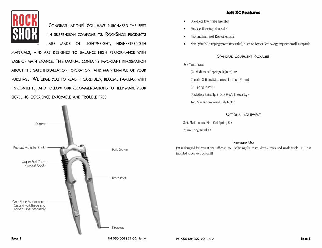
Steerer
Preload Adjuster Knob
Upper Fork Tube(w/dust boot)
One Piece MonocoqueCasting Fork Brace andLower Tube Assembly
Fork Crown
Brake Post
Dropout

Consumer Safety Information
Riding a bike is dangerous. Not properly maintaining or inspecting your bike is even more dangerous. It’s
also dangerous not to read these instructions.
1. Before riding the bicycle, be sure the brakes are properly installed and adjusted. If the brakes don’twork properly, the rider could suffer serious and/or fatal injuries.
2. Use this fork with cantilever-type brakes mounted to the existing mounting posts. Forks with hangerlessstyle braces were only designed for ‘V’- style or hydraulic cantilever brakes. Do not use any cantileverbrake other than those intended by the brake manufacturer to work with a hangerless brace. Do notroute the front brake cable and/or cable housing through the stem or any other mounts or cable stops.Do not use a front brake cable leverage device mounted to the brace. Do not use disc-style brakesmounted to the outer lower tube. The lower tubes were not designed to sustain the stresses such brakescould place on them, and structural failure to the fork may result if any devices or types of brakes otherthan a cantilever are mounted on the fork. Structural failure could result in loss of control of thebicycle with possible serious and/or fatal injuries.
3. Use extreme caution not to tilt the bicycle to either side when mounting the bicycle to a carrier by thefork drop-outs (front wheel removed). The fork legs may suffer structural damage if the bicycle is tiltedwhile the drop-outs are in the carrier. Make sure the front fork is fastened down with a quick release.Make sure the rear wheel is fastened down when using ANY bike carrier that secures the fork’s drop-outs. Not securing the rear can allow the bike’s mass to side-load the drop-outs, causing them to breakor crack. If the bicycle tilts or falls out of its carrier, do not ride the bicycle until the fork is properlyexamined for possible damage. Return the fork to your dealer for inspection or call RockShox if there isany question of possible damage (See International Distributors listed by country on Page 17). A forkleg or drop-out failure could result in loss of control of the bicycle with possible serious and/or fatalinjuries.
4. If the fork ever loses oil or if it makes sounds of excessive topping out, stop riding the bicycleimmediately and have the fork inspected by a dealer or call RockShox. Continuing to ride with the forkin either of these conditions could result in loss of control of the bicycle with possible serious and/orfatal injuries.
5. Always use genuine RockShox parts. Use of after-market replacement parts voids the warranty andcould cause structural failure to the fork. Structural failure could result in loss of control of the bicyclewith possible serious and/or fatal injuries.
IMPORTANT: ROCKSHOX FORKS ARE DESIGNED FOR COMPETITIVE OFF-ROAD RIDING AND DO NOT COME WITH
THE PROPER REFLECTORS FOR ON-ROAD USE. YOUR DEALER SHOULD INSTALL PROPER REFLECTORS TO MEET
THE CONSUMER PRODUCT SAFETY COMMISSION’S (CPSC) REQUIREMENTS FOR BICYCLE STANDARDS IF THE
FORK IS GOING TO BE USED ON PUBLIC ROADS AT ANY TIME.
Installation Instructions
It is extremely important that your RockShox Jett XC fork is installed correctly by a qualified technician with
proper tools. Improperly installed forks are extremely dangerous and can result in severe and/or fatal injuries.
1. Remove the existing fork and lower headset race from the bicycle. Measure the length of the forksteerer tube diameter against the length of the RockShox steerer. The RockShox steerer tube may needcutting to the proper length. On threadless steerers (Aheadset design), make sure there is sufficientlength to properly clamp the stem (refer to stem manufacturer’s instructions). Remember to measuretwice and cut once.
IMPORTANT: DO NOT ADD THREADS TO ROCKSHOX STEERERS. THE STEERER TUBE CROWN ASSEMBLY IS A
ONE-TIME PRESS FIT. REPLACEMENT OF THE ASSEMBLY MUST BE DONE TO CHANGE LENGTH, DIAMETER, OR
HEADSET TYPE (THREADED OR THREADLESS). DO NOT REMOVE OR REPLACE THE STEERER TUBE, THIS COULD
RESULT IN LOSS OF CONTROL OF THE BICYCLE WITH POSSIBLE SERIOUS AND/OR FATAL INJURIES.
2. Install the headset race (26.4 mm for 1" steerers, 29.9mm for 1-1/8" steerers) firmly against the top ofthe fork crown. Install the fork assembly on the bike. Make sure there are sufficient threads to properlylock the headset in place. On threadless steerers (Aheadset design), make sure there is sufficient lengthto properly clamp the stem (refer to stem manufacturer’s instructions). Adjust the headset so you feelno play or drag.
3. Install the brakes according to the manufacturer’s instructions and adjust brake pads properly. Use thefork only with cantilever-type brakes mounted to the existing mounting posts or disc style brakesmounted to the tabs provided.
4. On threaded steerers, insert stem to a minimum depth according to CPSC and JISstandards. The stem must be inserted to a minimum engaging length not lessthan 2.5 times the stem diameter from the lowest end of the stem, not the wedge(see Fig. 1).
5. Fit a brake cable to the RockShox fork brace mount. Forks with hangerless stylebraces were designed for V-type, hydraulic cantilever brakes or disc style brakesmounted to the tabs provided. Do not use any cantilever brake other than thoseintended by the brake manufacturer to work with a hangerless brace. Do notroute the cable through the stem or any other mounts or cable stops! The cable should make a directroute from the brake lever to the RockShox fork brace mount and be able to freely move up and downwith the suspension movement. It may be necessary to install a whole new cable.
NOTE: THE DISTANCE FROM THE TOP OF THE BRAKE CABLE HANGER TO THE BOTTOM OF THE BRACE CABLE
HOUSING STOP MUST BE A MINIMUM OF 12 MM WITH THE BRAKES APPLIED. AN IMPROPERLY INSTALLED FRONT
BRAKE CABLE COULD RESULT IN LOSS OF CONTROL OF THE BICYCLE WITH POSSIBLE SERIOUS AND/OR FATAL
INJURIES.
6. Adjust the front wheel quick release to clear the dropout’s counter bore. The quick release nut must betightened after the wheel is properly seated into the dropouts counter bore. Make sure four or morethreads are engaged in the quick release nut when it is closed. Orient the quick release lever in front ofand parallel to the lower tube in the locked position.
7. Keep in mind tire clearance as you choose tires. Maximum tire size is 2.2" wide or 335mm radius. Besure to check this radius whenever you change tires. To do this, remove the spring stack (per instructionson following pages), and compress fork completely to make sure at least 5 mm of clearance exists betweenthe top of the tire and the bottom of the crown. Exceeding this maximum will cause the tire to jamagainst the crown when the forks are fully compressed. The upper tubes must always be fully engaged in
PN 950-001827-00, REV A PAGE 7PAGE 6 PN 950-001827-00, REV A
Fig.1
the crown. The upper tubes, on clamp type crowns, must not extend above the crown more than 1mm.
8. Hangerless Reflector Bracket Installation: Orient black reflector bracket to the front of thefork with the 90 degree bend under the fork brace. Place the .040" thick flat washers onto the hex boltand insert this assembly through the lowest oval hole in the bracket and through hole in brace. Placestar washer and thread nut onto bolt at back of brace. Torque to 60 in-lb. (6.8Nm). Hangered Reflector Bracket Installation: Orient the black reflector bracket with the hookof the bracket facing up and to the fork brace. Place the star washer onto the hex bolt and insert thebolt, with star washer, through the rear hole on the hook of the bracket. Thread the bolt through thehole on fork brace. Torque to 20in-lb. (2.3Nm).
Tuning Your Fork RockShox Jett XC forks can be tuned to your particular weight, riding style, and terrain. Our forks are set up
for the 140 to 180lb (65 to 80kg), all-around rider who spends equal time riding every off-road terrain
imaginable. Because you’re probably not that rider, you can benefit by making tuning adjustments to suit
your specific needs. For maximum tuning flexibility spring tuning kits are available.
When tuning suspension, always make one change at a time and write it down. Keeping a record lets you know
what changes you have tried and suggests what changes you might try. Ask a shop or local riders what they
have found works well. These resources are typically your best bet, but don’t hesitate to call RockShox about
specific tuning needs. A list of phone numbers is on Page 17.
RIDE HEIGHT AND SPRING PRELOAD ADJUSTMENT
Jett XC is designed to compress (sag) when you are sitting on the bike. This sag allows the front wheel to stay
in contact with the ground when braking and cornering over rough and uneven terrain. The optimum
settings are12 to 16mm sag for 63mm travel and14 to 18mm for 75mm travel.
Changing the preload alters the sag and firmness of the initial fork movement. To measure sag, slide the fork
boot up out of the way and install a zip tie on the upper tube so that it is flush against the Resi-wiper seal; sit
on the bike with normal riding apparel; then step off your bike and measure the bottom of the zip tie to the
top of the wiper. This measurement is the amount of sag. For example, heavier more aggressive riders need
more spring preload to maintain proper ride height and allow more of the fork’s travel to be used during bump
impact.
To Change Preload: The top cap adjustment knob on each leg adjusts the sag of the fork (the preload on the
spring stack). When the adjustment knobs are turned full clockwise, the fork will sag the least and be the
firmest. Turning the adjustment knobs full counterclockwise makes the fork sag the most and be the softest.
IMPORTANT: DO NOT TURN THE PRELOAD ADJUSTERS PAST THEIR LIMIT STOPS. THERE ARE APPROXIMATELY
FIVE FULL TURNS FROM MINIMUM TO MAXIMUM PRELOAD. FAILURE TO OBSERVE THIS INSTRUCTION COULD
RESULT IN PREMATURE FAILURE OF THE PRELOAD ADJUSTER CAP ASSEMBLY.
Quick Tip: Right and left side is determined when straddling the bicycle frame facing forward
OVERALL SPRING RATE ADJUSTMENT
You want the fork to occasionally bottom out. If you are bottoming out too often or not using all the available
travel then the overall spring rate should be changed.
CHANGING THE COIL SPRING RATE
Change the coil springs with ones of a higher or lower rate to alter the overall spring rate. The table below
indicates rider weights and the recommended spring kits for those weights. You may purchase kits through
your dealer.
TO CHANGE COIL SPRINGS:
1. Unscrew the top cap assemblies using a 24mm open-end wrench or socket.
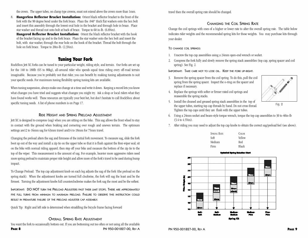
2. Compress the fork fully and slowly remove the spring stack assemblies (top cap, spring spacer and coilspring). See Fig. 2.
IMPORTANT: TAKE CARE NOT TO LOSE OIL. KEEP THE FORK UP-RIGHT.
3. Remove the spring spacer from the coil spring. To do this, pull the coilspring from the spring spacer. Inspect the o-ring on the spacer andreplace if necessary.
4. Replace the springs with softer or firmer rated coil springs andreassemble the spring stacks.
5. Install the cleaned and greased spring stack assemblies in the top ofthe upper tubes, starting top cap threads by hand. Do not cross thread.Tighten the top caps until they are flush with the upper tubes.
6. Using a 24mm socket and beam-style torque wrench, torque the top cap assemblies to 30 to 40in-lb(3.4 to 4.5Nm).
7. After riding you may need to adjust the top cap knobs to obtain the correct sag/preload feel (see above).
SPRING RATE COLOR
Soft YellowMedium RedFirm Black
PN 950-001827-00, REV A PAGE 9
Fig. 2
PAGE 8 PN 950-001827-00, REV A
CHANGING OIL IN THE HYDRACOIL SYSTEM
Changing the weight of oil in your fork can alter the rebound. Your fork is designed to use RockShox Extra
Light weight oil. If the rebound is too quick, you may need to put a heavier weight oil into the fork. We
recommend RockShox Heavy Weight oil. To change the oil follow the procedure under "Every Year or One
Hundred Hours of Riding".
Maintenance As long as moving parts are exposed to the elements, moisture and contamination can reduce performance.
Jett XC forks are designed to be easy to maintain. To maintain high performance, safety, and long life, periodic
maintenance is required. RockShox forks are engineered for easy service to help you keep the fork clean,
greased, and performing like new. Performing maintenance more often is necessary if you ride in extreme
conditions. The recommended tools and intervals for maintenance are listed below.
IMPORTANT: ALWAYS WEAR SAFETY GLASSES WHEN WORKING ON ROCKSHOX FORKS.
MAINTENANCE TOOLS
Safety glasses
Plastic face mallet
24mm socket
3/8" drive ratchet for socket
Long (6" minimum) 3/8" drive socket
Long (6" minimum) 6mm hex 3/8" drive socket (6" + of hex wrench protruding from socket)
3/8" drive beam style torque wrench
small straight blade screw driver
1 cm diameter 2 foot dowel
LUBRICANTS AND CLEANERS:
Degreaser
RockShox Extra Light oil
New and Improved Judy Butter or high quality Teflon fortified grease (no lithium grease)
IMPORTANT: FOR BEST PERFORMANCE, AVOID LITHIUM-BASED GREASES. SOME LITHIUM GREASES CAN BECOME
STICKY, TURN GRAY AND CAKE UP WHEN USED TO LUBRICATE THE BUSHINGS. SMOOTH FORK ACTION IS GREATLY
LIMITED AND PERFORMANCE IS GREATLY REDUCED WHEN THIS HAPPENS. IF YOU USE LITHIUM GREASE, CHECK
GREASE QUALITY AND CONDITION AT EACH 25-HOUR SERVICE INTERVAL TO ENSURE GREASE IS PERFORMING
PROPERLY. TRY USING ANOTHER TYPE OF LUBRICANT IF YOU EXPERIENCE PROBLEMS.
TORQUE TIGHTENING VALUES
Top Cap Assemblies 30 to 40 in-lb (3.4 to 4.5Nm)
Brake Posts 60in-lb (6.8Nm)
Plunger bolts 80in-lb (9Nm)
Regular MaintenanceBEFORE EVERY RIDE
Before every ride, inspect the following parts:
1. Front wheel and quick release for proper installation and adjustment
2. Fork for any obvious damage (crown, brace, upper tubes, lower tubes, and dropouts)
3. Front brake cable for proper routing
4. Front brake pads for proper contact with the rim
5. Front brake lever for proper adjustment
6. Headset for proper function and adjustment
After every ride clean and dry the fork, taking care not to get water in the fork at the upper tube/lower tube
junction.
AFTER EVERY WEEK OR EIGHT HOURS OF RIDING
After every week or eight hours of riding, clean and oil the upper tubes and check fasteners for proper torque.
Follow this procedure:
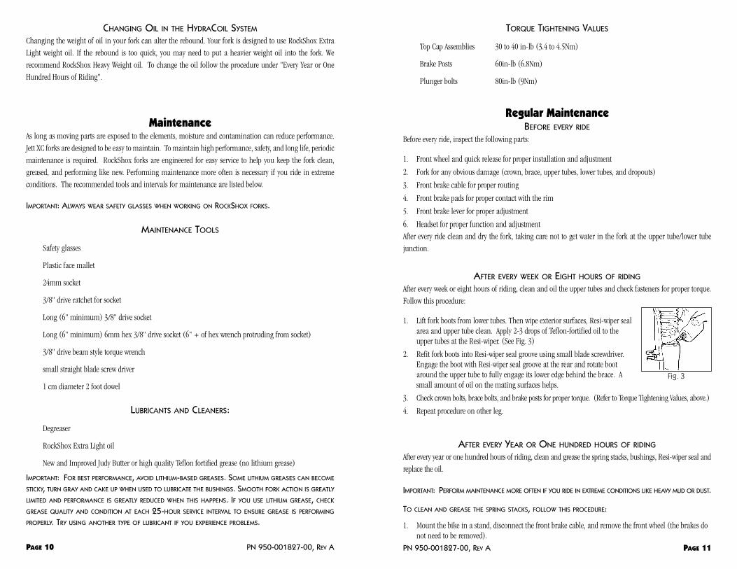
1. Lift fork boots from lower tubes. Then wipe exterior surfaces, Resi-wiper sealarea and upper tube clean. Apply 2-3 drops of Teflon-fortified oil to theupper tubes at the Resi-wiper. (See Fig. 3)
2. Refit fork boots into Resi-wiper seal groove using small blade screwdriver.Engage the boot with Resi-wiper seal groove at the rear and rotate bootaround the upper tube to fully engage its lower edge behind the brace. Asmall amount of oil on the mating surfaces helps.
3. Check crown bolts, brace bolts, and brake posts for proper torque. (Refer to Torque Tightening Values, above.)
4. Repeat procedure on other leg.
AFTER EVERY YEAR OR ONE HUNDRED HOURS OF RIDING
After every year or one hundred hours of riding, clean and grease the spring stacks, bushings, Resi-wiper seal and
replace the oil.
IMPORTANT: PERFORM MAINTENANCE MORE OFTEN IF YOU RIDE IN EXTREME CONDITIONS LIKE HEAVY MUD OR DUST.
TO CLEAN AND GREASE THE SPRING STACKS, FOLLOW THIS PROCEDURE:
1. Mount the bike in a stand, disconnect the front brake cable, and remove the front wheel (the brakes donot need to be removed).
PN 950-001827-00, REV A PAGE 11PAGE 10 PN 950-001827-00, REV A
Fig. 3

and allow to dry.
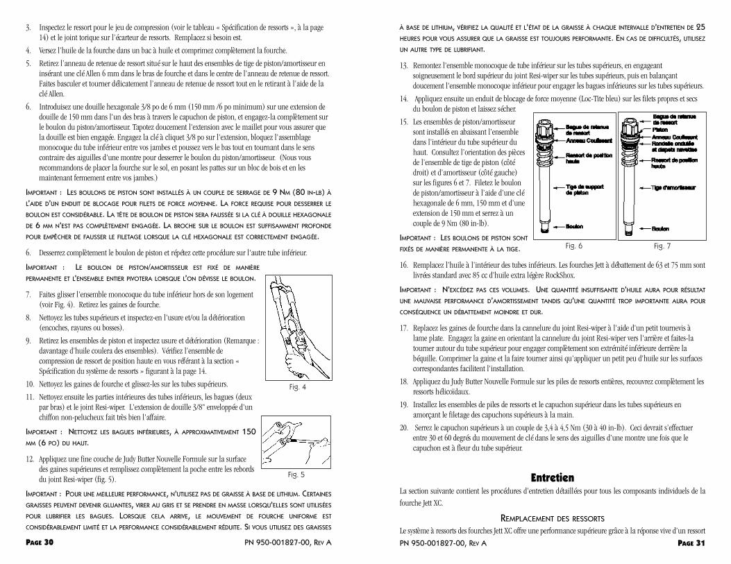
15. The plunger/damper assemblies areinstalled by dropping the assemblydown inside the upper tube from thetop. See figures 6 and 7 for orientationof parts for both the plunger (right side)and damper rod assembly (left side).Thread plunger/damper bolt with a 6",6mm hex wrench and 6" extension andtorque to 80in-lb (9Nm).
IMPORTANT: THE PLUNGER ROD BOLTS ARE
PERMANENTLY FIXED TO THE ROD.
16. Replace oil inside the lower tubes. Both63 and 75mm travel Jett's come standard with 85cc's of RockShox Extra Light oil.
IMPORTANT: DO NOT EXCEED THESE VOLUMES. TOO LITTLE OIL WILL RESULT IN POOR DAMPING
PERFORMANCE AND TOO MUCH OIL WILL RESULT IN LESS TRAVEL AND A HARSH BOTTOM OUT.
17. Refit fork boots into Resi-wiper seal groove using a small blade screwdriver. Engage boot with Resi-wiperseal groove at the rear and rotate boot around the upper tube to fully engage its lower edge behind thebrace. Compressing the boot and twisting as well as applying a small amount of oil on the matingsurfaces helps.
18. Apply New and Improved Judy Butter to the entire spring stacks, completely cover the coil springs.
19. Install spring stack assemblies and top cap in upper tubes, starting top cap threads by hand.
20. Torque top cap to 30 to 40 in-lb (3.4 to 4.5 Nm). This should be between 30 and 60 degrees ofclockwise wrench movement after cap is flush with upper tube.
ServiceThe following section contains detailed service procedures for all individual components of the Jett XC fork.
SPRING REPLACEMENT
The spring system in Jett XC forks provide cutting edge performance with the lively action of a coil spring. However,
over time the springs can wear out, compromising performance. This is evident in compression set, when the coil
springs are shorter in a resting state than they were when new. Use the table listed below as a guide to know when
to replace the springs. Follow the directions found in the Maintenance procedures, "After Every Year or One
Hundred Hours of Riding," page12, for removal and installation.
SPRING SYSTEM SPECIFICATION
Travel Optimum Coil Replace Coil Optimum Top-out Spring Replace Top-out Spring
63mm 165mm 156mm 25mm 22mm75mm 165mm 156mm 25mm 22mm
2. Unscrew the top cap using 24mm wrench or socket wrench. Remove the spring stack assembly andclean the stack with degreaser. Wipe dry.
3. Inspect the spring for compression set (see "Spring Specification" table, page 14) and o-ring on thespring spacer. Replace as needed.
4. Pour the oil from the fork into an oil pan and compress the fork fully.
5. Remove the spring retainer located on the top of the plunger/damper rod assemblies by inserting a6mm allen wrench in the fork leg and into the center of the spring retainer. Gently rock and turn thespring retainer back and forth while pulling it up with the allen wrench.
6. Insert a long (6" minimum) 6mm hex 3/8" drive socket on 6" long extension in one leg throughplunger cap and engage hex completely in broach of plunger/damper bolt. Gently tap on extensionwith mallet to ensure engagement. Install 3/8" drive ratchet in extension, stabilize one-piece lower tubeassembly between your feet and legs, push down while turning counterclockwise to breakplunger/damper bolt free. (We recommend putting the fork on the floor, resting the drop-outs on ablock of wood, and holding firmly between your feet and legs.)
IMPORTANT: THE PLUNGER BOLTS ARE INSTALLED TO 80IN-LB WITH MEDIUM THREAD LOCKING COMPOUND.THE FORCE REQUIRED TO LOOSEN THE BOLT IS SIGNIFICANT. THE PLUNGER BOLT
HEAD WILL STRIP IF THE 6MM HEX SOCKET IS NOT FULLY ENGAGED. THE BROACH ON
THE BOLT IS DEEP TO PREVENT STRIPPING WHEN THE HEX IS PROPERLY ENGAGED.
6. Loosen plunger bolt completely and repeat procedure on other lower tube
IMPORTANT: THE PLUNGER/DAMPER BOLT IS PERMANENTLY FIXED TO THE
PLUNGER/DAMPER ASSEMBLY AND WHEN YOU UNSCREW THE BOLT THE WHOLE
ASSEMBLY WILL SPIN.
7. Slide off one-piece lower tube assembly (see Fig. 4). Remove fork boots.
8. Thoroughly clean upper tubes and inspect for wear and/or damage (nicks,scratches, or dings).
9. Remove plunger assemblies and inspect for wear or damage(Note: more oilwill drain from the assemblies). Check compression set of top out spring byreferencing "Spring System Specification" on page 14.
10. Clean fork boots and slide onto uppers.
11. Then clean internals of lower tubes, bushings (two per leg), and Resi-wiperseal. A long 3/8" drive socket extension wrapped in a lint-free rag works well.
IMPORTANT: CLEAN LOWER BUSHINGS, APPROXIMATELY 6" (150MM) FROM TOP.
12. Apply a thin layer of New and Improved Judy Butter to the surface of theupper bushings and fill the pocket between the lips of the Resi-wiper seal completely (Fig. 5).
IMPORTANT: FOR BEST PERFORMANCE, AVOID LITHIUM-BASED GREASES. SOME LITHIUM GREASES CAN BECOME
STICKY, TURN GRAY AND CAKE UP WHEN USED TO LUBRICATE THE BUSHINGS. SMOOTH FORK ACTION IS GREATLY
LIMITED AND PERFORMANCE IS GREATLY REDUCED WHEN THIS HAPPENS. IF YOU USE LITHIUM GREASE, CHECK
GREASE QUALITY AND CONDITION AT EACH TWENTY-FIVE HOUR SERVICE INTERVAL TO ENSURE GREASE IS
PERFORMING PROPERLY. TRY USING ANOTHER TYPE OF LUBRICANT IF YOU EXPERIENCE PROBLEMS.
13. Install one-piece lower tube assembly onto upper tubes, carefully engage upper Resi-wiper seal lip withthe upper tubes, and gently rock the one-piece lower assembly to engage the lower bushings with theupper tubes.
14. Next, place medium strength locking compound (blue Loc-tite) on clean, dry threads of plunger bolt
PN 950-001827-00, REV A PAGE 13PAGE 12 PN 950-001827-00, REV A
Fig. 4
Fig. 5
Fig. 6 Fig. 7

CHANGING TRAVEL
The suspension travel on Jett forks can be changed by installing a different plunger/damper kit. Follow the
procedure titled, "After Every Year or One Hundred Hours of Riding," to remove one-piece lower tube assembly.
Exchange standard plungers with the longer units included in the kit. Also exchange spring stack parts (coil
spring and spring spacers) with matching parts form the kit. Follow the procedures under "After Every Year or
One Hundred Hours of Riding," to complete the assembly.
BUSHING REPLACEMENT
The high quality bushings in RockShox forks are designed to last many months of hard riding. Protective
boots, a clean fork, and timely greasing are the keys to high performance and long bushing life. However, like
all moving parts, bushings will eventually wear and need replacement. Increased fore and aft movement of
upper tubes in lower tubes (similar to a loose headset) and/or slow action, even after a fresh greasing, signal
the need to remove and replace the bushings.
IMPORTANT: THIS SERVICE REQUIRES ROCKSHOX SPECIALTY TOOLS. WE RECOMMEND THIS LEVEL OF SERVICE
BE DONE BY A QUALIFIED BIKE SHOP MECHANIC FAMILIAR WITH OUR PRODUCTS AND THIS PROCEDURE.
Glossary of Terms Bottoming Out – the condition when all suspension travel has been used up.
Compression Stroke – the "upward" motion of a fork which is moving in response to a bump impact.
Damping Force – the force required to move a shock absorber/damper (general oil) at any given speed.
Forged – a metal forming process which optimizes material structure using very large forces acting on adie mold in which material to formed is placed.
Geometry – Descriptive term for the lengths and angles used in a bicycle design.
Head angle – Angle the steering axis leans back from vertical.
HydraCoil –
Oil bath – oil reservoir system used for lubricating internal parts in the fork.
One piece – unitized lower leg assembly with both fork legs and fork brace cast as one piece.
Preload – The amount either in pounds or inches, a spring is compressed when fitted to an extendedshock absorber.
Rebound – The extension or return direction of the shocks or suspension.
Sag – compression of the suspension caused by the rider’s weight.
Spring rate – The amount of force required to deflect a spring a given distance.
Tapered – varying wall thickness of a tube. A design to optimize placement of material, allowing mostefficient design considering the loads.
Topping out – the position of the fork at the "top" of the travel, or when the fork is fully extended. Theaction of complete extension of the fork.
Follow the NORBA Code
• I will yield the right of way to other non-motorized recreationalists.
• I will use caution when overtaking another and will make my presence be known well in advance.
• I will maintain control of my speed at all times.
• I will stay on designated trails.
• I will not disturb wildlife or livestock.
• I will not litter
• I will respect public and private property.
• I will always be self sufficient.
• I will not travel solo when bikepacking in remote areas.
• I will observe the practice of minimum impact bicycling
• I will always wear a helmet whenever riding.
USED WITH THE PERMISSION OF THE NATIONAL OFF ROAD BICYCLE ASSOCIATION.
PN 950-001827-00, REV A PAGE 15PAGE 14 PN 950-001827-00, REV A

1 Reflector Bracket Nut
2 Reflector Bracket Lockwasher
3 Reflector Bracket, Hangerless
4 Reflector Bracket Bolt
5 Brake Post
6 Decal, Right
7 Seal
8 Upper Bushing
9 Lower Bushing
10 Bottom Bumper
11 Lower Tube, 1-piece Hangerless
12 Decal, Left
13 Fork Boot
14 Plunger Assebmly
15 Spring Retainer
16 Glide Ring
17 Damper Assembly
18 Crown/Steerer/Upper Tube Assembly
19 Coil Spring
20 Spring Spacer
21 O-ring
22 Top Cap
23 Reflector Bracket, Hangered
24 Lower Tube, Hangered
Warranty ROCKSHOX, INC. WARRANTS ITS PRODUCTS FOR A PERIOD OF ONE YEAR FROM ORIGINAL DATE OF PURCHASE
TO BE FREE FROM DEFECTS IN MATERIALS OR WORKMANSHIP. ANY ROCKSHOX PRODUCT THAT IS RETURNED
TO THE FACTORY AND IS FOUND BY ROCKSHOX TO BE DEFECTIVE IN MATERIALS OR WORKMANSHIP WILL BE
REPAIRED OR REPLACED AT THE OPTION OF ROCKSHOX, INC. THIS WARRANTY IS THE SOLE AND EXCLUSIVE
REMEDY. ROCKSHOX SHALL NOT BE HELD LIABLE FOR ANY INDIRECT, SPECIAL, OR CONSEQUENTIAL DAMAGES.
THE WARRANTY DOES NOT APPLY TO PRODUCTS WHICH HAVE NOT BEEN PROPERLY INSTALLED AND ADJUSTED
ACCORDING TO ROCKSHOX INSTALLATION INSTRUCTIONS. THE WARRANTY DOES NOT COVER ANY PRODUCT
THAT HAS BEEN SUBJECT TO MISUSE OR WHOSE SERIAL NUMBER HAS BEEN ALTERED, DEFACED OR REMOVED.THIS WARRANTY DOES NOT COVER PAINT DAMAGE OR MODIFICATIONS TO THE PRODUCT. PROOF OF
PURCHASE IS REQUIRED.
WARRANTY REPAIR
IF FOR ANY REASON IT SHOULD BE NECESSARY TO HAVE WARRANTY WORK DONE, RETURN THE PRODUCT TO
THE PLACE OF PURCHASE. IN THE USA, DEALERS SHOULD CALL FOR A RETURN AUTHORIZATION NUMBER
(RA#) PRIOR TO RETURNING PRODUCT. PRODUCTS RETURNED FOR INSPECTION MUST BE SENT FREIGHT PREPAID TO:
RockShox, Inc.
401 Charcot Ave. FAX 408.428.9757
San Jose, CA 95131
www.rockshox.com
e-mail us at [email protected]
Toll-Free Technical Support in the USA 800.677.7177
Customers in countries other than the USA should contact their local dealer or distributor.
International Distributor List
PN 950-001827-00, REV A PAGE 17PAGE 16 PN 950-001827-00, REV A
'99 Jett XC
ArgentinaBroni S.A.Phone: 54 12 92 3000FAX: 54 12 92 4453
AustraliaBell Sports AustraliaPhone: 61 2 9700 1655FAX: 61 2 9700 1656
AustriaBarisitz-AustriaPhone: 43 512 39 22 87FAX: 43 512 39 45 19
BelgiumVertex Cycle Systems BVPhone: 31 23 57 18184FAX: 31 23 57 18606
BrazilPacific Bicycle CompanyPhone: 55 11 816 2249FAX: 55 11 816 0544
CanadaBell Sports CanadaPhone: 514 378 0452FAX: 514 378 9934
ChileBicicletas Belda LimitadaPhone: 56 32 881799FAX: 56 32 978799
ColombiaDisandina Ltda.Phone: 5763 205369/205370FAX: 5763 204816
Costa RicaSPC BicicletasPhone: 506 296 3383FAX: 506 289 7013
Czech RepublicVelo Gepard Ltd.Phone: 4202 243 15631FAX: 4202 243 16189
DenmarkETTOL/Sport ApSPhone: 45 8699 2000FAX: 45 8699 2038
EcuadorBici SportPhone 5932 248737FAX: 5932 253691

Liste de vérification aide-mémoire d’intervalles de maintenance
Vérifiez les points suivants à chaque intervalle de maintenance. Pour de plus amples détails, consultez la page 27.
APRÈS CHAQUE APRÈS 8 HEURES APRÈS 100 HEURES
RANDONNÉE (INSPECTEZ) DE RANDONNÉE DE RANDONNÉE
Roue avant Nettoyez les tubes supérieurs Nettoyez et graissez les piles de ressorts
Manette de blocage Huilez les tubes supérieurs Inspectez le système à ressorts pour jeu de compression
Vérifiez détérioration Vérifiez les boulons de tête Nettoyez et graissez les bagues et le Resi-wiper
Acheminement des câbles Vérifiez les tiges de freins Nettoyez les tubes supérieurs et inspectez les détériorations
Patins de freins Nettoyez gaines de fourche
Leviers de freins
Jeu de direction
IMPORTANT : POUR MAINTENIR UN HAUT NIVEAU DE PERFORMANCE, DE SÉCURITÉ ETDE LONGÉVITÉ, UNE MAINTENANCE PÉRIODIQUE EST NÉCESSAIRE. N’OUBLIEZ PASQU’UNE MAINTENANCE FRÉQUENTE EST INDISPENSABLE LORSQUE L’ON UTILISE UNEBICYCLETTE DANS DES CONDITIONS EXTRÊMES.
PN 950-001827-00, REV A PAGE 19
EstoniaEstonian UnidreamPhone 372 223 2976FAX: 372 223 2976
FinlandMr. Cool OYPhone: 358 9 320817FAX: 358 9 320609
FrancePhilamy S.A.Phone: 33 492 70 9700FAX: 33 492 72 6070
GermanySport Import GmbHPhone: 49 44 05 9280 0FAX: 49 44 05 9280 49
GreeceGatsoulis Stefanos ImportsPhone: 30 12512 779FAX: 30 12533 960
GuatemalaBYS Importaciones S.A.Phone: 502 366 7709FAX: 502 366 7708
HollandVertex Cycle Systems BVPhone: 31 23 57 18184FAX: 31 23 57 18606
Hong KongFlying Ball Bicycle CompanyPhone: 852 23813661FAX: 852 23974406
HungaryKerekparCentrum KFTPhone 361 131 3184FAX: 361 131 3184
IcelandOrninnPhone: 354 588 9892FAX: 354 588 9896
ItalyMotorqualityPhone: 39 2 249511FAX: 39 2 22476420
JapanYoshigai CorporationPhone: 81 729 88 5461FAX: 81 729 88 5463
KoreaKS SportsPhone: 822 548 5408FAX: 822 512 3230
LuxembourgVertex Cycle Systems BVPhone: 31 23 57 18184FAX: 31 23 57 18606
MexicoGrupo ScandiPhone: 52 52 81 14 39FAX: 52 52 81 27 21
New ZealandW.H. Whorrall & Co. Ltd.Phone: 64 9 6303901FAX: 64 9 6303839
NorwayFoss SyklerPhone: 47 22382636FAX: 47 22382644
PanamaDistribuidora Rali S.A.Phone: 507 261 3755FAX: 507 261 9123
PeruRojo SportsPhone: 51 11 816 2249FAX: 51 11 816 0544
PolandGiant Polska S.P. ZOOPhone: 48 22 645 14 34FAX: 48 22 645 14 36
PortugalBicimaxPhone: 351 44 553276FAX: 351 44 553187
RussiaSportexPhone: 7 095 288 68 88FAX: 7 095 288 68 88
St. MaartenTri-Sport InternationalPhone: 5995 43462FAX: 5995 43928
SingaporeTreknology Bikes 3Phone: 65 455 0551FAX: 65 441 2967
SlovakiaVelo Gepard Ltd.Phone: 4202 243 15631FAX: 4202 243 16189
SloveniaProloco TradePhone: 386 64 224090FAX: 386 64 212169
South AfricaCoolheat (SA) (PTY) Ltd.Phone: 27 11 493 7430FAX: 27 13 493 1794
SpainK. Motor Dealer S.L.Phone: 34 1 637 70 97FAX: 34 1 637 72 64
SwedenHallman SportsPhone: 46 18 56 16 00FAX: 46 18 13 24 26
SwitzerlandMTB Cycletech AGPhone: 41 31 972 5672FAX: 41 31 972 3566
TaiwanBiketech Co. Ltd.Phone: 886 22 694 5808FAX: 886 22 694 6133
ThailandProbike Co. Ltd.Phone: 662 254 1077FAX: 662 254 1078
TurkeyEBSATPhone 90 212 514 0525FAX: 90 212 511 5171
United KingdomCaratti Sport Ltd.Phone: 44 1 454 201700FAX: 44 1 454 202600
UruguayInternational SportePhone: 5982 782498FAX: 5982 622532
VenezuelaBike SportsPhone 582 751 9709FAX: 582 751 9730
PAGE 18 PN 950-001827-00, REV A

FÉLICITATIONS ! VOUS VENEZ D’ACQUÉRIR CE QU’IL Y A
DE MIEUX EN MATIÈRE DE COMPOSANTS DE
SUSPENSION. LES PRODUITS ROCKSHOX SONT
CONSTITUÉS DE MATÉRIAUX LÉGERS ET DE HAUTE
RÉSISTANCE, ET CONÇUS POUR CONJUGUER HAUTE
PERFORMANCE ET FACILITÉ DE MAINTENANCE. CE
MANUEL CONTIENT DES INFORMATIONS IMPORTANTES EN CE QUI CONCERNE
LA SÉCURITÉ DE L'INSTALLATION, L'OPÉRATION ET LA MAINTENANCE DE
VOTRE ACHAT. NOUS VOUS INCITONS À EN LIRE ATTENTIVEMENT LE
CONTENU, À EN RETENIR LES DÉTAILS, ET À SUIVRE NOS RECOMMANDATIONS
POUR VOUS AIDER À RENDRE VOTRE EXPÉRIENCE DE VÉLO TOUT TERRAIN
AGRÉABLE ET SANS PROBLÈME.
PN 950-001827-00, REV A PAGE 21PAGE 20 PN 950-001827-00, REV A
Table des Matières
Introduction . . . . . . . . . . . . . . . . . . . . . . . . . . . . . . . . . . . . . . . . . . . . . . . . . . . . . . . . . . . 21
Caractèristiques . . . . . . . . . . . . . . . . . . . . . . . . . . . . . . . . . . . . . . . . . . . . . . . . . . . . . . . . . 22
Consignes de Sécurité . . . . . . . . . . . . . . . . . . . . . . . . . . . . . . . . . . . . . . . . . . . . . . . . . . . . 23
Instuctions pour l’Installation . . . . . . . . . . . . . . . . . . . . . . . . . . . . . . . . . . . . . . . . . . . . . 24
Réglage de la Fourche . . . . . . . . . . . . . . . . . . . . . . . . . . . . . . . . . . . . . . . . . . . . . . . . . . . . 25
Maintenance . . . . . . . . . . . . . . . . . . . . . . . . . . . . . . . . . . . . . . . . . . . . . . . . . . . . . . . . . . . 27
Entretien . . . . . . . . . . . . . . . . . . . . . . . . . . . . . . . . . . . . . . . . . . . . . . . . . . . . . . . . . . . . . . 31
Glossaire des Termes . . . . . . . . . . . . . . . . . . . . . . . . . . . . . . . . . . . . . . . . . . . . . . . . . . . . . 32
Vue Éclatée . . . . . . . . . . . . . . . . . . . . . . . . . . . . . . . . . . . . . . . . . . . . . . . . . . . . . . . . . . . . 16
Garantie . . . . . . . . . . . . . . . . . . . . . . . . . . . . . . . . . . . . . . . . . . . . . . . . . . . . . . . . . . . . . . . 33
Liste Internationale des Distributeurs . . . . . . . . . . . . . . . . . . . . . . . . . . . . . . . . . . . . . . . . . 17
Tube pivot
Bouton de réglage de précharge
Tube de fourche supériere(avec garde-boue)
Assemblage
Tête de fourche
Tige de frein
Patte

Consignes de sécurité à l’usage de l’acheteur MONTER À BICYCLETTE EST DANGEREUX. NE PAS ENTRETENIR OU INSPECTER VOTRE BICYCLETTE L'EST ENCORE
DAVANTAGE. IL EST ÉGALEMENT DANGEREUX DE NE PAS LIRE CES INSTRUCTIONS.
1. Avant de monter sur votre bicyclette, assurez-vous que les freins sont correctement montés et réglés. Siles freins ne fonctionnent pas correctement, le cycliste peut être gravement, ou même fatalement,blessé.
2. Utilisez cette fourche avec des freins à cantilever montés sur les tiges de fixation existantes. Les fourchesavec des béquilles sans brides sont conçues uniquement pour des freins en V ou des freins à cantileverhydrauliques. Ne vous servez pas de freins à cantilever autres que ceux conçus spécialement pourfonctionner avec une béquille sans bride. Ne faites pas passer le câble du frein avant et/ou la gaine decâble à travers la potence ou les autres attaches ou arrêts de câble. N'utilisez pas de dispositif de levierde câble de frein avant monté sur la béquille. N'utilisez pas de freins à disques montés sur le tubeinférieur extérieur. Les tubes inférieurs ne sont pas conçus pour supporter les tensions exercées par cetype de freins et risqueraient de céder si un dispositif quelconque ou un type de frein autre quecantilever était monté sur la fourche. Une telle défaillance pourrait entraîner la perte de contrôle duvélo et provoquer des blessures graves, voire fatales.
3. Faites preuve d'extrême prudence et ne penchez la bicyclette ni d'un côté ni de l'autre lorsque vous lafixez sur un porte-vélos par les pattes de la fourche (la roue avant ayant été démontée). Les bras de lafourche risquent d'être sérieusement endommagés si la bicyclette est penchée alors que les pattes de lafourche se trouvent dans le porte-vélos. Assurez-vous que la roue avant est bien fixée avec la manette deblocage. Assurez-vous que la roue arrière est bien fixée lors de l'utilisation de TOUT porte-vélos quimaintient les pattes de fourche. Il est également essentiel de bien fixer la roue arrière, faute de quoi lamasse de la bicyclette risquerait de balancer latéralement et de peser sur les pattes, les amenant à casserou à se fendre. Si la bicyclette est déstabilisée ou si elle tombe de son porte-vélos, ne montez pas dessusavant d'avoir effectué un examen approfondi de la fourche pour repérer d'éventuels dommages. En casde doute de détérioration éventuelle, apportez immédiatement la fourche à votre revendeur pourinspection ou contactez RockShox (reportez-vous à la Liste des distributeurs internationaux par paysfigurant à la page 17). Une défaillance du bras ou de la patte de fourche pourrait entraîner la perte decontrôle du vélo et provoquer des blessures graves, voire fatales.
4. Si la fourche perd de l'huile ou si vous pouvez entendre un bruit de trop-plein, descendezimmédiatement de bicyclette et faites inspecter la fourche par votre revendeur ou appelez RockShox.Continuer de rouler avec la fourche dans l'une ou l'autre de ces conditions risquerait d'entraîner uneperte de contrôle de la bicyclette et de provoquer des blessures graves, voire fatales.
5. N'utilisez que des pièces RockShox authentiques. L’utilisation de pièces détachées d'occasion ou enrattrapage non RockShox annule la garantie et risque de provoquer une défaillance structurale de lafourche. Une telle défaillance pourrait entraîner la perte de contrôle du vélo et provoquer des blessuresgraves, voire fatales.
IMPORTANT : LES FOURCHES ROCKSHOX SONT CONÇUES POUR LA RANDONNÉE TOUT-TERRAIN ET NE SONT
PAS ÉQUIPÉES DES RÉFLECTEURS NÉCESSAIRES À L'UTILISATION SUR ROUTE. SI LA FOURCHE DEVAIT ÊTRE
UTILISÉE SUR ROUTE POUR UNE RAISON QUELCONQUE, VOTRE REVENDEUR DEVRA INSTALLER LES RÉFLECTEURS
CORRESPONDANT AUX NORMES DE LA COMMISSION DE LA SÉCURITÉ DES PRODUITS DE CONSOMMATION
(CPSC) SUR LES BICYCLETTES.
PN 950-001827-00, REV A PAGE 23
Caractéristiques Jett XC
• Ensemble de tube inférieur monocoque.
• Ressorts hélicoïdaux simples, double face
• Joints Resi-wiper Nouvelle Formule
• Nouveau système d’amortissement HydraCoil (soupape libre), basé sur la technologie de la fourche Boxxer, améliore la tenue de route sur les petites bosses
ENSEMBLES D’ÉQUIPEMENT STANDARD
Débattement de 63/75 mm
(2) Ressorts hélicoïdaux moyens (63 mm) ou
(1 de chaque) Ressort hélicoïdal souple et moyen (75 mm)
(2) Écarteurs de ressorts
Huile extra légère RockShox (85 cc dans chaque bras)
28 g / 1 oz. Judy Butter Nouvelle Formule
ÉQUIPEMENT FACULTATIF
Kits de ressorts hélicoïdaux souples, moyens et fermes
Kit de débattement long de 75 mm
Utilisation prévueJett est conçue pour s’amuser sur du tout terrain, y compris chemins forestiers de défense, piste double et piste
simple. Jett n’est pas conçue pour faire de la course de descente.
PAGE 22 PN 950-001827-00, REV A

7. N'oubliez pas de tenir compte du dégagement des pneus lorsque vous les choisissez. La largeurmaximum des pneus est de 2,2 pouces ou 342 mm de rayon. Assurez-vous de vérifier le rayon lorsquevous changez de pneus. Pour ce faire, retirez la pile de ressort (selon les instructions des pagessuivantes), et comprimez complètement la fourche pour vous assurer qu'il existe au moins 5 mm dedégagement entre le haut du pneu et le bas de la tête. En deçà, le pneu viendra buter contre la têtelorsque les fourches seront complètement comprimées. Les tubes supérieurs doivent toujours êtreentièrement engagés dans la tête. Les tubes supérieurs, sur les têtes de type à pince, ne doivent pasdépasser de la tête de plus d'1 mm.
8. Installation du support de catadioptre sans bride : Orientez le support de catadioptrenoir vers l’avant de la fourche avec un angle de 90 degrés sous la béquille de fourche. Placez lesrondelles plates de 10,16 mm / 0,040 po sur le boulon hexagonal et insérez cet ensemble par le trouovale le plus inférieur dans le support et par le trou situé dans la béquille. Placez la rondelle à dents etfiletez l’écrou sur le boulon au dos de la béquille. Serrez à un couple de 6,8 Nm (60 in-lb)
Installation du support de catadioptre à bride : Orientez le support de catadioptre noirde sorte que le crochet du support soit dirigé vers le haut et la béquille de fourche. Placez la rondelle àdents sur le boulon hexagonal et insérez le boulon, avec la rondelle à dents, par le trou arrière sur lecrochet du support. Filetez le boulon par le trou sur la béquille de fourche. Serrez à un couple de 2,3Nm (20 in-lb.).
Réglage de la fourche Les fourches RockShox Jett XC peuvent être ajustées à votre poids, votre comportement cycliste et au terrain.Nos
fourches sont réglées pour le cycliste moyen de 65 à 80 kg, qui passe son temps à explorer toutes sortes de
terrains hors route. Parce que vous n'êtes sans doute pas ce cycliste, vous pouvez trouver avantage à procéder
à des ajustages correspondant à vos besoins spécifiques.Pour un maximum de flexibilité dans l’ajustage,
procurez-vous des kits de réglage de ressorts.
Lorsque vous réglez votre suspension, ne procédez qu'à un changement à la fois et notez-le systématiquement.
Vos notes vous permettront de savoir quels changements vous avez essayés et de déterminer ceux que vous
pouvez avoir envie d'opérer. Demandez à un revendeur ou à des cyclistes de la région ce qui marche bien pour
eux. Ces ressources sont généralement les meilleures que vous puissiez trouver, mais n'hésitez pas à appeler
RockShox à propos de vos besoins de réglage particuliers. Vous trouverez une liste de numéros de téléphone à
la page 17.
HAUTEUR D’ASSISE ET AJUSTAGE DE LA PRÉCHARGE DU RESSORT
Jett XC est conçue pour se comprimer (s’affaisser) quand vous vous asseyez sur la bicyclette. Cet affaissement
permet à la roue avant de rester en contact avec le sol quand vous freinez et tournez sur des terrains rudes et
accidentés. Les meilleurs réglages sont de 12 à 16 mm d’affaissement pour un débattement de 63 mm et de
14 à 18 mm pour un débattement de 75 mm.
Changer la précharge modifie l'affaissement et la fermeté du mouvement initial de la fourche. Pour mesurer
l’affaissement, dégagez la gaine de fourche en la faisant glisser et installez une attache zippée sur le tube
supérieur de manière à être à fleur du joint Resi-wiper ; asseyez-vous sur la bicyclette avec votre équipement
habituel puis descendez de la bicyclette et mesurez la longueur du bas de l’attache au haut du Resi-wiper.
Cette mesure indiquera le montant d'affaissement. Les cyclistes plus lourds ou plus agressifs apprécient
PN 950-001827-00, REV A PAGE 25
Instructions d’installationIl est extrêmement important que votre fourche RockShox Jett XC soit installée correctement par un technicien
qualifié disposant des outils appropriés. Les fourches mal installées sont extrêmement dangereuses et risquent
de provoquer des blessures graves, voire fatales.
1. Retirez la fourche existante et abaissez la bague du jeu de direction de la bicyclette. Mesurez lalongueur du tube pivot de fourche par rapport à la longueur du tube pivot RockShox. Il sera peut-êtrenécessaire de couper le tube pivot RockShox à la longueur voulue. Sur les tubes pivots non filetés(conception Aheadset), assurez-vous qu'il y a suffisamment de longueur pour serrer correctement lapotence (reportez-vous aux instructions du fabricant). N'oubliez pas de mesurer deux fois et de necouper qu’une seule fois.
IMPORTANT : N'AJOUTEZ PAS DE FILETAGE AUX TUBES PIVOTS ROCKSHOX. L'AJUSTAGE DE L'ASSEMBLAGE
TÊTE-TUBE PIVOT SE FAIT À LA FABRICATION. IL EST NÉCESSAIRE DE PROCÉDER AU REMPLACEMENT DE
L'ASSEMBLAGE POUR CHANGER LA LONGUEUR, LE DIAMÈTRE OU LE TYPE DE DIRECTION (FILETÉE OU NON).NE RETIREZ NI NE REMPLACEZ LE TUBE PIVOT, CELA RISQUERAIT D'ENTRAÎNER UNE PERTE DE CONTRÔLE DE LA
BICYCLETTE ET DE PROVOQUER DES BLESSURES GRAVES, VOIRE FATALES.
2. Installez la bague de jeu de direction (diamètre intérieur de 26,4 mm pour des tubes pivots de 1 po,diamètre intérieur de 29,9 mm pour des tubes pivots de 1-1/8 po) fermement contre le haut de la têtede fourche. Installez l'assemblage de fourche sur la bicyclette. Assurez-vous qu'il y a suffisamment defiletage pour bloquer correctement le jeu de direction en place. Sur les tubes pivots non filetés(conception Aheadset), assurez-vous qu'il y a suffisamment de longueur pour serrer correctement lapotence (reportez-vous aux instructions du fabricant). Réglez le jeu de direction afin de ne sentir nijeu ni frottement.
3. 3. Installez les freins selon les instructions du fabricant et réglez les patins defreins correctement. N'utilisez la fourche qu'avec des freins à cantilever montéssur les tiges de fixation existantes ou des freins à disque sur les jupes fournies.
4. Sur les tubes pivots filetés, introduisez une longueur minimum de potence enaccord avec les normes CPSC et JIS. La potence doit pénétrer le tube d'unelongueur au moins égale à 2,5 fois le diamètre de la potence à son extrémitéinférieure, pas celle en biseau (voir Fig. 1).
5. Ajustez un câble de frein à l'attache de béquille de la fourche RockShox. Les fourches à béquille sansbride sont conçues pour des freins en V, des freins à cantilever hydrauliques ou des freins à disquesmontés sur les jupes fournies. Ne vous servez pas de freins à cantilever autres que ceux conçusspécialement pour fonctionner avec une béquille sans bride. Ne faites pas passer le câble par la potenceou toute autre attache ou tout autre arrêt de câble ! Le câble devrait aller directement du levier de freinà l'attache de béquille de la fourche RockShox et être capable de bouger librement de haut en bas avecle mouvement de la suspension. Il peut être nécessaire d'installer un câble neuf.
REMARQUE : LA DISTANCE ENTRE LE HAUT DE LA BRIDE DE SUSPENSION DU CÂBLE DE FREIN ET LE BAS DE LA
BUTÉE DE GAINE DE CÂBLE DE BÉQUILLE DOIT ÊTRE D'AU MOINS 12 MM LORSQUE LES FREINS SONT APPLIQUÉS.UN CÂBLE DE FREIN AVANT MAL INSTALLÉ RISQUE D'ENTRAÎNER LA PERTE DE CONTRÔLE DE LA BICYCLETTE ET
DE PROVOQUER DES BLESSURES GRAVES VOIRE FATALES.
6. Ajustez l'écrou de manette de blocage de la roue avant pour dégager le contre-alésage des pattes.L'écrou de manette de blocage doit être serré après que la roue soit correctement assise dans le contre-alésage des pattes. Assurez-vous qu'au moins quatre tours de filetage sont engagés dans l'écrou demanette de blocage quand il est refermé. Orientez le levier de manette de blocage vers l'avant etparallèle au tube inférieur en position fermée.
PAGE 24 PN 950-001827-00, REV A
Fig.1

6. A l’aide d’une clé à douilles ou d’une clé dynamométrique de style lecture directe de 24 mm, serrez lesensembles de capuchons supérieurs à un couple de 3,4 à 4,5 Nm (30 à 40 in-lb).
7. Après une randonnée, il vous faudra peut-être ajuster les boutons de capuchons supérieurs pour obtenirla même sensation d’affaissement/de précharge (voir ci-dessus).
Tension de ressort Couleur
Souple Jaune
Moyen Rouge
Ferme Noir
CHANGER L’HUILE DANS LE SYSTÈME HYDRACOIL
Changer le poids de l’huile dans votre fourche risque d’altérer le rebond. Votre fourche est conçue pour utiliser
de l’huile extra légère RockShox. Si le rebond est trop rapide, il vous faudra peut-être mettre de l’huile plus
lourde dans la fourche. Nous vous recommandons d’utiliser de l’huile lourde RockShox. Pour changer
l’huile, suivez la procédure figurant dans la section « Chaque année ou Après 100 heures de randonnée ».
MaintenanceComme à chaque fois que des parties en mouvement sont exposées aux éléments, humidité et contamination
peuvent affecter la performance. Les fourches Jett XC sont conçues pour n’exiger qu’une maintenance réduite.
Pour maintenir un haut niveau de performance, de sécurité et de longévité, une maintenance périodique est
nécessaire. Les fourches RockShox sont conçues pour une maintenance facile, vous permettant de garder la
fourche propre, graissée et capable de fonctionner comme au premier jour. N'oubliez pas qu'une maintenance
fréquente est indispensable lorsque l'on utilise une bicyclette dans des conditions extrêmes. Les outils
nécessaires et les intervalles recommandés entre chaque maintenance sont indiqués ci-dessous.
PN 950-001827-00, REV A PAGE 27
généralement une précharge plus élevée, qui permet de maintenir une hauteur d'assise appropriée tout en
autorisant un débattement de fourche plus important à l'impact des bosses.
Pour modifier la précharge : Le bouton de réglage situé sur le capuchon supérieur de chaque bras
ajuste l'affaissement de la fourche (la précharge sur la pile de ressort). Lorsque les boutons de réglage sont
tournés à fond dans le sens des aiguilles d'une montre, la fourche s'affaissera le moins et sera donc la plus
ferme. Plus les boutons de réglage sont tournés dans le sens contraire des aiguilles d'une montre, plus la
fourche s'affaissera et plus elle sera souple.
IMPORTANT : NE TOURNEZ PAS LES AJUSTEURS DE PRÉCHARGE AU-DELÀ DE LEURS ARRÊTS DE LIMITE. IL Y
A ENVIRON CINQ TOURS COMPLETS DE LA PRÉCHARGE MINIMALE À LA PRÉCHARGE MAXIMALE. NE PAS SUIVRE
CES INSTRUCTIONS RISQUERAIT D'ENTRAÎNER UNE DÉFAILLANCE PRÉMATURÉE DE L'ENSEMBLE DE CAPUCHON DE
RÉGLAGE DE PRÉCHARGE.
Conseil rapide : Le côté droit et le côté gauche sont définis par la position normale du cycliste par
rapport au cadre.
RÉGLAGE DE LA TENSION GLOBALE DES RESSORTS
Il est bon de laisser la fourche toucher le fond de temps en temps. Si vous touchez le fond trop souvent, ou si
vous n'utilisez pas tout le débattement disponible, vous devriez modifier la tension globale des ressorts.
CHANGER LA TENSION DES RESSORTS HÉLICOÏDAUX
Changez les ressorts hélicoïdaux par des ressorts d’une tension supérieure ou inférieure pour modifier la
tension globale des ressorts. Le tableau ci-dessous indique les poids de cyclistes ainsi que les kits de ressorts
recommandés pour ces poids. Ces kits sont disponibles auprès de votre distributeur.
POUR CHANGER LES RESSORTS HÉLICOÏDAUX :1. Dévissez l’ensemble de capuchon supérieur en utilisant une clé plate ou à douilles de 24 mm.
2. Comprimez complètement la fourche et retirez lentement les ensembles de piles de ressorts (capuchonsupérieur, écarteur de ressort et ressort hélicoïdal). Voir Fig. 2.
IMPORTANT : VEILLEZ À NE PAS PERDRE D’HUILE. CONSERVEZ LA FOURCHE
EN POSITION VERTICALE.
3. Retirez l’écarteur de ressort du ressort hélicoïdal. Pour ce faire, retirez leressort hélicoïdal de l’écarteur de ressort. Inspectez le joint torique surl’écarteur et remplacez-le si besoin est.
4. Remplacez les ressorts par des ressorts hélicoïdaux plus souples ou plusfermes et remontez les piles de ressorts.
5. Installez les ensembles de piles de ressorts nettoyés et graissés par le haut des tubes supérieurs, enamorçant le filetage des capuchons supérieurs à la main. Veillez à ne pas les engager de travers. Serrezles capuchons supérieurs jusqu’à ce qu’ils soient à fleur des tubes supérieurs.
PAGE 26 PN 950-001827-00, REV A
Fig. 2

Maintenance périodiqueAVANT DE MONTER À BICYCLETTE
AVANT DE MONTER SUR VOTRE BICYCLETTE, INSPECTEZ LES PIÈCES SUIVANTES :
1. La roue avant et la manette de blocage pour leur bonne installation et leur bon réglage.
2. La fourche pour tout dommage apparent (tête, béquille, tubes supérieurs, tubes inférieurs et pattes).
3. Le câble de frein avant pour son bon cheminement.
4. Les patins de freins avant pour leur bon contact avec la jante.
5. Le levier de frein avant, pour son bon réglage.
6. Le jeu de direction pour son fonctionnement et son réglage
APRÈS CHAQUE RANDONNÉE, NETTOYEZ ET SÉCHEZ LA FOURCHE, EN PRENANT SOIN DE NE PAS LAISSER D’EAU
S’INFILTRER DANS LA FOURCHE À LA JONCTION DU TUBE SUPÉRIEUR ET DU TUBE INFÉRIEUR.
CHAQUE SEMAINE OU APRÈS 8 HEURES DE RANDONNÉE
CHAQUE SEMAINE, OU APRÈS 8 HEURES DE RANDONNÉE, NETTOYEZ ET HUILEZ LES TUBES SUPÉRIEURS ET
VÉRIFIEZ QUE LE COUPLE DE SERRAGE DES FIXATIONS EST CORRECT. SUIVEZ LA PROCÉDURE SUIVANTE :
1. Sortez les gaines de fourche des tubes inférieurs. Puis essuyez les surfacesexternes, la zone du joint Resi-wiper et le tube supérieur. Appliquez 2 à 3gouttes d'huile fortifiée au Téflon sur les tubes supérieurs, au niveau duResi-wiper. Voir Fig. 3.
2. Replacez les gaines de fourches dans la cannelure du joint Resi-wiper àl'aide d'un petit tournevis à lame plate. Engagez la gaine en orientant lacannelure du joint Resi-wiper vers l'arrière et faites-la tourner autour dutube supérieur pour engager complètement son extrémité inférieure derrièrela béquille. Une petite quantité d'huile sur les surfaces correspondantes facilite la tâche.
3. Vérifiez que le couple de serrage des boulons de tête, boulons de béquille, boulons de tiges de freins estcorrect (Reportez-vous aux valeurs de couple de serrage ci-dessus).
4. Répétez la procédure sur l'autre bras.
CHAQUE ANNÉE OU APRÈS 100 HEURES DE RANDONNÉE
CHAQUE ANNÉE OU APRÈS 100 HEURES DE RANDONNÉE, NETTOYEZ ET GRAISSEZ LES PILES DE RESSORTS, LES
BAGUES, LE JOINT RESI-WIPER ET REMPLACEZ L’HUILE.
IMPORTANT : UNE MAINTENANCE FRÉQUENTE EST INDISPENSABLE LORSQUE L’ON UTILISE UNE BICYCLETTE DANS
DES CONDITIONS EXTRÊMES, TELLES QUE DANS LA BOUE OU LA POUSSIÈRE.
POUR NETTOYER ET GRAISSER LES PILES DE RESSORTS, SUIVEZ LA PROCÉDURE SUIVANTE :
1. Installez la bicyclette sur un support, déconnectez le câble du frein avant, et retirez la roue avant. (Iln'est pas nécessaire de retirer les freins.)
2. Dévissez le capuchon supérieur à l’aide d’une clé ou d’une clé à douille de 24 mm. Retirez l'ensemblede pile de ressorts et nettoyez le tout avec un dégraissant. Séchez avec un chiffon.
PN 950-001827-00, REV A PAGE 29
IMPORTANT : PORTEZ TOUJOURS DES LUNETTES DE SÉCURITÉ LORSQUE VOUS TRAVAILLEZ SUR DES FOURCHES
ROCKSHOX.
OUTILS DE MAINTENANCE
Lunettes de sécurité
Maillet à tête en plastique
Clé à douille de 24 mm
Clé à cliquet 3/8" pour clé à douille
Prise d’entraînement 3/8" longue (150 mm minimum)
Prise d’entraînement 3/8" hexagonale 6 mm longue (15 cm minimum) (15 cm ou + de cléhexagonale sortant de la douille)
Clé dynamométrique de style lecture directe 3/8"
Petit tournevis à lame plate
Goujon 60 cm de 1 cm de diamètre
LUBRIFIANTS ET NETTOYANTS :
Dégraisseur
Huile extra légère RockShox
Judy Butter Nouvelle Formule ou graisse fortifiée au Téflon de haute qualité (pas de graisse aulithium)
IMPORTANT : POUR UNE MEILLEURE PERFORMANCE, N'UTILISEZ PAS DE GRAISSE À BASE DE LITHIUM. CERTAINES
GRAISSES PEUVENT DEVENIR GLUANTES, VIRER AU GRIS ET SE PRENDRE EN MASSE LORSQU'ELLES SONT UTILISÉES
POUR LUBRIFIER LES BAGUES. LORSQUE CELA ARRIVE, LE MOUVEMENT DE FOURCHE UNIFORME EST
CONSIDÉRABLEMENT LIMITÉ ET LA PERFORMANCE CONSIDÉRABLEMENT RÉDUITE. SI VOUS UTILISEZ DES GRAISSES
À BASE DE LITHIUM, VÉRIFIEZ LA QUALITÉ ET L'ÉTAT DE LA GRAISSE À CHAQUE INTERVALLE D’ENTRETIEN DE 25HEURES POUR VOUS ASSURER QUE LA GRAISSE EST TOUJOURS PERFORMANTE. EN CAS DE DIFFICULTÉS, UTILISEZ
UN AUTRE TYPE DE LUBRIFIANT.
VALEURS DE COUPLE DE SERRAGE
Ensembles de capuchons supérieurs 3,4 à 4,5 Nm (30 à 40 in-lb)
Tiges de freins 6,8 Nm (60 in-lb)
Boulons de piston 9 Nm (80 in-lb)
PAGE 28 PN 950-001827-00, REV A
Fig. 3
À BASE DE LITHIUM, VÉRIFIEZ LA QUALITÉ ET L'ÉTAT DE LA GRAISSE À CHAQUE INTERVALLE D’ENTRETIEN DE 25HEURES POUR VOUS ASSURER QUE LA GRAISSE EST TOUJOURS PERFORMANTE. EN CAS DE DIFFICULTÉS, UTILISEZ
UN AUTRE TYPE DE LUBRIFIANT.
13. Remontez l'ensemble monocoque de tube inférieur sur les tubes supérieurs, en engageantsoigneusement le bord supérieur du joint Resi-wiper sur les tubes supérieurs, puis en balançantdoucement l'ensemble monocoque inférieur pour engager les bagues inférieures sur les tubes supérieurs.
14. Appliquez ensuite un enduit de blocage de force moyenne (Loc-Tite bleu) sur les filets propres et secsdu boulon de piston et laissez sécher.
15. Les ensembles de piston/amortisseursont installés en abaissant l’ensembledans l’intérieur du tube supérieur duhaut. Consultez l’orientation des piècesde l’ensemble de tige de piston (côtédroit) et d’amortisseur (côté gauche)sur les figures 6 et 7. Filetez le boulonde piston/amortisseur à l’aide d’une cléhexagonale de 6 mm, 150 mm et d’uneextension de 150 mm et serrez à uncouple de 9 Nm (80 in-lb).
IMPORTANT : LES BOULONS DE PISTON SONT
FIXÉS DE MANIÈRE PERMANENTE À LA TIGE.
16. Remplacez l’huile à l’intérieur des tubes inférieurs. Les fourches Jett à débattement de 63 et 75 mm sontlivrées standard avec 85 cc d’huile extra légère RockShox.
IMPORTANT : N’EXCÉDEZ PAS CES VOLUMES. UNE QUANTITÉ INSUFFISANTE D’HUILE AURA POUR RÉSULTAT
UNE MAUVAISE PERFORMANCE D’AMORTISSEMENT TANDIS QU’UNE QUANTITÉ TROP IMPORTANTE AURA POUR
CONSÉQUENCE UN DÉBATTEMENT MOINDRE ET DUR.
17. Replacez les gaines de fourche dans la cannelure du joint Resi-wiper à l'aide d'un petit tournevis àlame plate. Engagez la gaine en orientant la cannelure du joint Resi-wiper vers l'arrière et faites-latourner autour du tube supérieur pour engager complètement son extrémité inférieure derrière labéquille. Comprimer la gaine et la faire tourner ainsi qu'appliquer un petit peu d'huile sur les surfacescorrespondantes facilitent l'installation.
18. Appliquez du Judy Butter Nouvelle Formule sur les piles de ressorts entières, recouvrez complètement lesressorts hélicoïdaux.
19. Installez les ensembles de piles de ressorts et le capuchon supérieur dans les tubes supérieurs enamorçant le filetage des capuchons supérieurs à la main.
20. Serrez le capuchon supérieurs à un couple de 3,4 à 4,5 Nm (30 à 40 in-lb). Ceci devrait s’effectuerentre 30 et 60 degrés du mouvement de clé dans le sens des aiguilles d’une montre une fois que lecapuchon est à fleur du tube supérieur.
EntretienLa section suivante contient les procédures d’entretien détaillées pour tous les composants individuels de la
fourche Jett XC.
REMPLACEMENT DES RESSORTS
Le système à ressorts des fourches Jett XC offre une performance supérieure grâce à la réponse vive d’un ressort
PN 950-001827-00, REV A PAGE 31
3. Inspectez le ressort pour le jeu de compression (voir le tableau « Spécification de ressorts », à la page14) et le joint torique sur l’écarteur de ressorts. Remplacez si besoin est.
4. Versez l’huile de la fourche dans un bac à huile et comprimez complètement la fourche.
5. Retirez l’anneau de retenue de ressort situé sur le haut des ensembles de tige de piston/amortisseur eninsérant une clé Allen 6 mm dans le bras de fourche et dans le centre de l’anneau de retenue de ressort.Faites basculer et tourner délicatement l’anneau de retenue de ressort tout en le retirant à l’aide de laclé Allen.
6. Introduisez une douille hexagonale 3/8 po de 6 mm (150 mm /6 po minimum) sur une extension dedouille de 150 mm dans l'un des bras à travers le capuchon de piston, et engagez-la complètement surle boulon du piston/amortisseur. Tapotez doucement l'extension avec le maillet pour vous assurer quela douille est bien engagée. Engagez la clé à cliquet 3/8 po sur l'extension, bloquez l'assemblagemonocoque du tube inférieur entre vos jambes et poussez vers le bas tout en tournant dans le senscontraire des aiguilles d'une montre pour desserrer le boulon du piston/amortisseur. (Nous vousrecommandons de placer la fourche sur le sol, en posant les pattes sur un bloc de bois et en lesmaintenant fermement entre vos jambes.)
IMPORTANT : LES BOULONS DE PISTON SONT INSTALLÉS À UN COUPLE DE SERRAGE DE 9 NM (80 IN-LB) ÀL’AIDE D’UN ENDUIT DE BLOCAGE POUR FILETS DE FORCE MOYENNE. LA FORCE REQUISE POUR DESSERRER LE
BOULON EST CONSIDÉRABLE. LA TÊTE DE BOULON DE PISTON SERA FAUSSÉE SI LA CLÉ À DOUILLE HEXAGONALE
DE 6 MM N’EST PAS COMPLÈTEMENT ENGAGÉE. LA BROCHE SUR LE BOULON EST SUFFISAMMENT PROFONDE
POUR EMPÊCHER DE FAUSSER LE FILETAGE LORSQUE LA CLÉ HEXAGONALE EST CORRECTEMENT ENGAGÉE.
6. Desserrez complètement le boulon de piston et répétez cette procédure sur l'autre tube inférieur.
IMPORTANT : LE BOULON DE PISTON/AMORTISSEUR EST FIXÉ DE MANIÈRE
PERMANENTE ET L’ENSEMBLE ENTIER PIVOTERA LORSQUE L’ON DÉVISSE LE BOULON.
7. Faites glisser l'ensemble monocoque du tube inférieur hors de son logement(voir Fig. 4). Retirez les gaines de fourche.
8. Nettoyez les tubes supérieurs et inspectez-en l'usure et/ou la détérioration(encoches, rayures ou bosses).
9. Retirez les ensembles de piston et inspectez usure et détérioration (Remarque :davantage d’huile coulera des ensembles). Vérifiez l’ensemble decompression de ressort de position haute en vous référant à la section «Spécification du système de ressorts » figurant à la page 14.
10. Nettoyez les gaines de fourche et glissez-les sur les tubes supérieurs.
11. Nettoyez ensuite les parties intérieures des tubes inférieurs, les bagues (deuxpar bras) et le joint Resi-wiper. L'extension de douille 3/8" enveloppée d'unchiffon non-pelucheux fait très bien l'affaire.
IMPORTANT : NETTOYEZ LES BAGUES INFÉRIEURES, À APPROXIMATIVEMENT 150MM (6 PO) DU HAUT.
12. Appliquez une fine couche de Judy Butter Nouvelle Formule sur la surfacedes gaines supérieures et remplissez complètement la poche entre les rebordsdu joint Resi-wiper (fig. 5).
IMPORTANT : POUR UNE MEILLEURE PERFORMANCE, N'UTILISEZ PAS DE GRAISSE À BASE DE LITHIUM. CERTAINES
GRAISSES PEUVENT DEVENIR GLUANTES, VIRER AU GRIS ET SE PRENDRE EN MASSE LORSQU'ELLES SONT UTILISÉES
POUR LUBRIFIER LES BAGUES. LORSQUE CELA ARRIVE, LE MOUVEMENT DE FOURCHE UNIFORME EST
CONSIDÉRABLEMENT LIMITÉ ET LA PERFORMANCE CONSIDÉRABLEMENT RÉDUITE. SI VOUS UTILISEZ DES GRAISSES
PAGE 30 PN 950-001827-00, REV A
Fig. 4
Fig. 5
Fig. 6 Fig. 7

Angle de tête – Angle contre lequel s’appuie l’axe de direction de la verticale.
Bain d’huile – Système de réservoir à huile utilisé pour lubrifier les parties internes de la fourche.
Monocoque – Un assemblage de bras inférieur unique autoporteur avec les deux bras de fourche et laarceau sans arrêt de gaine de fourche moulés d’une seule pièce.
Précharge – Le montant de contrainte (soit en livres soit en pouces) auquel un ressort est comprimélorsqu’il est adapté sur un amortisseur détendu.
Rebond – L’extension ou la direction de retour de l’amortisseur ou du système de suspension.
Affaissement – Compression de la suspension provoquée par le poids du cycliste.
Tension de ressort – Le montant de force requis pour infléchir un ressort d’une certaine distance.
Conique – Épaisseur de paroi variable d’un tube. Une conception visant à optimiser le placement dumatériau, permettant ainsi la plus efficace des conceptions en rapport avec les charges.
Position haute – La position de la fourche en « haut » de sa course, ou lorsque la fourche estcomplètement étendue. L’action de l’extension complète de la fourche.
GarantieROCKSHOX, INC. GARANTIT SES PRODUITS CONTRE TOUS DÉFAUTS DE MAIN D’ŒUVRE OU DE MATIÈRES
PREMIÈRES POUR UNE DURÉE D’UN AN À COMPTER DE LA DATE D’ACHAT. TOUT PRODUIT ROCKSHOX RETOURNÉ
À L’USINE ET COMPORTANT DES DÉFAUTS DE MAIN D’ŒUVRE OU DE MATIÈRE PREMIÈRE SERA REMPLACÉ OU
RÉPARÉ, SELON LA DÉCISION DE ROCKSHOX, INC. CETTE GARANTIE CONSTITUE L’UNIQUE RECOURS.ROCKSHOX NE PEUT ÊTRE TENU RESPONSABLE DES DOMMAGES ENCOURUS DE FAÇON INDIRECTE, SPÉCIALE OU
CONSÉCUTIVE.
CETTE GARANTIE NE COUVRE PAS LES PRODUITS QUI N’ONT PAS ÉTÉ INSTALLÉS ET AJUSTÉS CORRECTEMENT,SELON LES INSTRUCTIONS DE ROCKSHOX. CETTE GARANTIE NE COUVRE PAS LES PRODUITS SOUMIS À UN
MAUVAIS USAGE, OU DONT LE NUMÉRO DE SÉRIE A ÉTÉ MODIFIÉ, ENDOMMAGÉ OU EFFACÉ. CETTE GARANTIE
NE COUVRE PAS LES DOMMAGES À LA PEINTURE OU LES MODIFICATIONS APPORTÉES AU PRODUIT. UNE PREUVE
D’ACHAT EST EXIGÉE.
RÉPARATION SOUS GARANTIE
SI, POUR UNE RAISON QUELCONQUE, VOTRE PRODUIT NÉCESSITE UN SERVICE COUVERT PAR LA GARANTIE,RAPPORTEZ-LE À VOTRE REVENDEUR. LES REVENDEURS OPÉRANT SUR LE SOL AMÉRICAIN DOIVENT CONTACTER
ROCKSHOX POUR OBTENIR UN NUMÉRO D’AUTORISATION DE RENVOI (RA#) AVANT DE RENVOYER LE PRODUIT.AUX ÉTATS-UNIS, LES PRODUITS RENVOYÉS POUR INSPECTION DOIVENT ÊTRE EXPÉDIÉS EN PORT PAYÉ À :
RockShox, Inc.
401 Charcot Ave. Télécopie : 408.428.9757
San Jose, CA 95131
www.RockShox.com
Adressez votre courrier électronique à [email protected]
Assistance technique en appel gratuit aux États-Unis : 800.677.7177
PN 950-001827-00, REV A PAGE 33
hélicoïdal. Cependant, avec le temps, les ressorts peuvent s'user et compromettre la performance de
l'ensemble. Ceci apparaît clairement dans l'ensemble de compression, quand les ressorts hélicoïdaux sont
plus courts en position de repos qu'ils ne l'étaient à l'état neuf. Reportez-vous au tableau ci-dessous pour
savoir quand remplacer les ressorts. Suivez les directions figurant dans les procédures de maintenance, «
Chaque année ou Après 100 heures de randonnée » à la page 12, pour dépose et installation.
SPÉCIFICATION DE SYSTÈME À RESSORTS
Débattement Ressort Remplacez Ressort de position Remplacez ressort optimum ressort hélicoïdal haute optimum de position haute
63 mm 165 mm 156 mm 25 mm 22 mm
75 mm 165 mm 156 mm 25 mm 22 mm
CHANGER LE DÉBATTEMENT
Le débattement de suspension sur les fourches Jett peut être changé en installant un kit de piston/amortisseur
différent. Suivez la procédure intitulée « Chaque année ou Après 100 heures de randonnée » pour retirer
l’ensemble de tube inférieur monocoque. Remplacez les pistons standard par les unités plus longues fournies
dans le kit. Remplacez également les pièces de pile de ressort (ressort hélicoïdal et écarteurs de ressort) par les
pièces correspondantes dans le kit. Suivez les procédures figurant dans la section « Chaque année ou Après
100 heures de randonnée » pour finir l’assemblage.
REMPLACEMENT DES BAGUES
Les bagues de haute qualité à l'intérieur des fourches RockShox sont conçues pour résister à de nombreux
mois d'utilisation intense. Des gaines de protection, une fourche propre et un graissage opportun sont les clés
des meilleures performances et de la longévité des bagues. Cependant, comme toute pièce en mouvement, les
bagues vont s'user à la longue et devoir être remplacées. L'amplification du mouvement des tubes supérieurs
dans les tubes inférieurs (semblable à un jeu de direction mal serré) et/ou une réaction lente, même juste
après un graissage, sont les signes qu'il faut retirer et remplacer les bagues.
Important : Le remplacement des bagues nécessite les outils spéciaux RockShox. Nous recommandons que ce
niveau d’entretien soit effectué par des revendeurs de cycles ou des mécaniciens qualifiés, connaissant bien nos
produits et cette procédure.
Glossaire des termes Débattement – La condition lorsque le débattement de suspension a été complètement utilisé.
Mouvement de compression – Le mouvement "ascendant" d’une fourche qui se déplace en réponseà un impact de bosse.
Force d’amortissement – La force requise pour déplacer un amortisseur (huile générale) à n’importequelle vitesse donnée.
Forgé – Un processus de formage en métal qui optimise la structure de matériau en utilisant de trèsgrandes forces agissant sur un moule de matrice dans lequel le matériau à former est placé.
Géométrie – Terme descriptif relatif aux longueurs et aux angles utilisés dans la conception d’une bicyclette.
PAGE 32 PN 950-001827-00, REV A
HERZLICHEN GLÜCKWUNSCH! SIE HABEN EINE DER
BESTEN FEDERUNGS-KOMPONENTEN DER WELT
ERWORBEN. GABELN VON ROCKSHOX BESTEHEN AUS
LEICHTEN, HOCHFESTEN MATERIALIEN UND VEREINEN
HOHE LEISTUNG MIT WARTUNGSFREUNDLICHKEIT. DIESE
ANLEITUNG ENTHÄLT WICHTIGE INFORMATIONEN ZUM SICHEREN EINBAU,
BEDIENUNG UND WARTUNG IHRER NEUEN GABEL. LESEN SIE DIE
ANLEITUNG SORGFÄLTIG DURCH, UND BEFOLGEN SIE UNSERE
EMPFEHLUNGEN, DAMIT IHNEN IHR MOUNTAINBIKE LANGE UND
PROBLEMFREI FREUDE BEREITET.
PN 950-001827-00, REV A PAGE 35
Wartungsintervalle auf einen BlickFühren Sie die folgende Überprüfung bei der entsprechenden Wartung durch. Weitere Einzelheiten finden Sie
auf Seite 42.
Vor jeder Fahrt Nach je 8 Stunden Fahrt Nach je 100 Stunden Fahrt(prüfen)
Vorderrad Säubern Sie die oberen Rohre Säubern und fetten Sie die Federgruppen
Schnellspanner Ölen Sie die oberen Rohre Überprüfen Sie, ob sich das Federsystem gesetzt hat
Überprüfen Sie Überprüfen Sie die Säubern und fetten Sie die Lagerhülsen auf Schäden Gabelkopf-Schrauben und die Resi-Wiper Dichtungen
Kabelführung Überprüfen Sie die Säubern Sie die oberen Rohre und Montagesockel für die Bremsen überprüfen Sie sie auf Beschädigungen
Bremsklötze Säubern Sie die Gabelboots
Bremshebel
Steuersatz
WICHTIG: UM EINE HOHE LEISTUNGSFÄHIGKEIT, SICHERHEIT UND LANGE LEBENSDAUER ZU GARANTIEREN,MUß DIE GABEL REGELMÄßIG GEWARTET WERDEN. WARTEN SIE IHRE GABEL HÄUFIGER, WENN SIE UNTER
EXTREMEN BEDINGUNGEN FAHREN.
PAGE 34 PN 950-001827-00, REV A
Inhaltsverzeichnis
Einführung . . . . . . . . . . . . . . . . . . . . . . . . . . . . . . . . . . . . . . . . . . . . . . . . . . . . . . . . . . . . . 35
Merkmale . . . . . . . . . . . . . . . . . . . . . . . . . . . . . . . . . . . . . . . . . . . . . . . . . . . . . . . . . . . . . . . 36
Sicherheitsinformationen . . . . . . . . . . . . . . . . . . . . . . . . . . . . . . . . . . . . . . . . . . . . . . . . . . . 36
Einbau . . . . . . . . . . . . . . . . . . . . . . . . . . . . . . . . . . . . . . . . . . . . . . . . . . . . . . . . . . . . . . . . . 37
Einstellen der Gabel . . . . . . . . . . . . . . . . . . . . . . . . . . . . . . . . . . . . . . . . . . . . . . . . . . . . . . . 39
Wartung . . . . . . . . . . . . . . . . . . . . . . . . . . . . . . . . . . . . . . . . . . . . . . . . . . . . . . . . . . . . . . . . 41
Service (Überholen der Gabel) . . . . . . . . . . . . . . . . . . . . . . . . . . . . . . . . . . . . . . . . . . . . . . . 45
Glossar . . . . . . . . . . . . . . . . . . . . . . . . . . . . . . . . . . . . . . . . . . . . . . . . . . . . . . . . . . . . . . . . . 47
Garantie . . . . . . . . . . . . . . . . . . . . . . . . . . . . . . . . . . . . . . . . . . . . . . . . . . . . . . . . . . . . . . . . 47
Explosionsdarstellung . . . . . . . . . . . . . . . . . . . . . . . . . . . . . . . . . . . . . . . . . . . . . . . . . . . . . 16
Liste der internationalen Vertragshändler . . . . . . . . . . . . . . . . . . . . . . . . . . . . . . . . . . . . . . 17
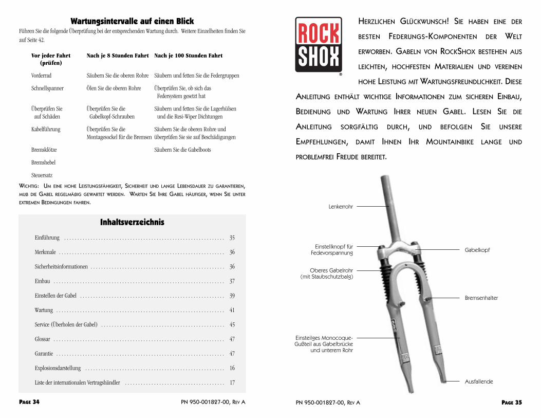
Lenkerrohr
Einstellknopf fürFedevorspannung
Oberes Gabelrohr (mit Staubschutzbalg)
Einsteilges Monocoque-Gußteil aus Gabelbrücke
und unterem Rohr
Gabelkopf
Bremsenhalter
Ausfallende
dafür vorgesehen sind. Der Vorderbremszug und/oder die Kabelhülle dürfen nicht durch den Vorbau,andere Befestigungen oder Seilzughalterungen geführt werden. Es darf keine Vorderbremszug-Hebelvorrichtung verwendet werden, die an der Gabelbrücke angebracht ist. Es dürfen keine amäußeren unteren Rohr angebrachten Scheibenbremsen verwendet werden. Die unteren Rohre sind nichtfür die Belastungen ausgelegt, die durch solche Bremsen entstehen. Die Gabel kann versagen, wennandere Bremsen und Vorrichtungen als eine Cantileverbremse an der Gabel angebracht werden. Defektekönnen zum Verlust der Kontrolle über das Fahrrad führen, wodurch ernsthafte und/oderlebensgefährliche Verletzungen verursacht werden können.
3. Wenn das Fahrrad mit den Ausfallenden (Vorderrad entfernt) an einer Trägervorrichtung befestigt wird,darf das Fahrrad auf keinen Fall zur Seite geneigt werden. Wird das Fahrrad geneigt, während sich dieAusfallenden in der Trägervorrichtung befinden, können die Gabelbeine brechen. Das Vorderrad mußsicher mit einem Schnellspanner befestigt werden. Bei Verwendung eines Fahrradträgers, in dem dieGabel-Ausfallenden befestigt werden, muß auch das Hinterrad gesichert werden. Wenn das Hinterradnicht befestigt wird, können die Gabel-Ausfallenden durch das Gewicht des Fahrrads einseitig belastetwerden, wodurch sie brechen oder reißen können. Sollte das Fahrrad umkippen oder aus derTrägervorrichtung fallen, darf es erst wieder gefahren werden, nachdem die Gabel fachgerecht aufmögliche Schäden überprüft worden ist. Falls ein Schaden vermutet wird, lassen Sie die Gabel vonIhrem Fachhändler überprüfen, oder wenden Sie sich an RockShox (siehe die Internationale Liste derVertragshändler nach Ländern auf Seite 17). Defekte am Gabelbein oder an den Ausfallenden könnenzum Verlust der Kontrolle über das Fahrrad führen, wodurch ernsthafte und/oderlebensgefährliche Verletzungen verursacht werden können.
4. Sollten jemals Öl aus der Gabel austreten oder Geräusche auftreten, die aufhäufiges Auftreffen auf den oberen Anschlag hinweisen, dürfen Sie das Fahrradnicht mehr fahren. Lassen Sie die Gabel in diesem Fall von Ihrem Fachhändlerüberprüfen oder wenden Sie sich an RockShox. Wenn Sie mit dem Fahrradfahren, obwohl die Gabel diese Mängel aufweist, können Sie die Kontrolle überdas Fahrrad verlieren und schwere und/oder tödliche Verletzungen erleiden.
5. Verwenden Sie immer Originalteile von RockShox. Durch die Verwendung von anderen Teilen, dienicht von RockShox stammen, wird die Garantie ungültig. Außerdem kann dies zum Versagen derGabel führen. Defekte können zum Verlust der Kontrolle über das Fahrrad führen, wodurch ernsthafteund/oder lebensgefährliche Verletzungen verursacht werden können.
WICHTIG: GABELN VON ROCKSHOX SIND FÜR OFFROAD-WETTBEWERBE VORGESEHEN UND VERFÜGEN NICHT
ÜBER DIE VORGESCHRIEBENEN REFLEKTOREN ZUM FAHREN AUF ÖFFENTLICHEN STRAßEN. WENN SIE PLANEN,DIE GABELN AUF ÖFFENTLICHEN STRAßEN ZU VERWENDEN, SOLLTE DER HÄNDLER DIE VORGESCHRIEBENEN
REFLEKTOREN ANBRINGEN, UM DIE ENTSPRECHENDEN VORSCHRIFTEN ZU ERFÜLLEN.
EinbauEs ist extrem wichtig, daß die RockShox Jett XC Gabel vorschriftsmäßig von einem Fachmann mit den
richtigen Werkzeugen eingebaut wird. Falsch eingebaute Gabeln stellen eine beträchtliche Gefahr dar und
können zu schweren oder tödlichen Verletzungen führen.
1. Entfernen Sie die vorhandene Gabel und den unteren Steuersatz-Lagerkonus vom Fahrrad. VergleichenSie die Länge des Gabelschaftrohrs der alten Gabel mit der der RockShox-Gabel. Es kann erforderlichsein, das Gabelschaftrohr der RockShox-Gabel auf die richtige Länge zu kürzen. Bei Lenkern ohneGewinde (Aheadset-Ausführung) muß sichergestellt werden, daß eine ausreichende Länge zumBefestigen des Vorbaus vorhanden ist (siehe die Anweisungen des Herstellers des Vorbaus). Messen Sie
PN 950-001827-00, REV A PAGE 37
Merkmale der Jett XC
• Einteilige untere Rohreinheit
• Einfache Stahlfedern auf beiden Seiten
• Weiterentwickelte Resi-Wiper Dichtungen
• Neue HydraCoil Dämpfung (freies Ventil), basiert auf der Boxxer Technologie und verbessert das Ansprechen auf kleine Unebenheiten
SERIENMÄßIGE AUSSTATTUNG
63/75 mm Federweg
(2) Mittelharte Schraubenfedern (63 mm) oder
(je 1) Weiche und mittelharte Schraubenfeder (75 mm)
(2) Feder-Distanzscheiben
RockShox Extra Light Öl (85 ml je Gabelbein)
28 gr. New and Improved Judy Butter
ZUSÄTZLICH ERHÄLTLICH
Weiche, mittelharte und harte Stahlfeder-Kits
75 mm Long Travel Kit
Vorgesehene VerwendungDie Jett ist für Freizeitsportler gedacht, die im Gelände fahren, z. B. auf Waldwegen und im Single Track. Sie
ist nicht für Downhill Rennen gedacht.
Sicherheitshinweise Fahrrad fahren ist mit Gefahren verbunden. Wenn das Fahrrad nicht einwandfrei gewartet und in gutem
Zustand erhalten wird, erhöht sich das Gefahrenpotential. Es ist weiterhin gefährlich, diese Anleitung nicht
zu lesen.
1. Vergewissern Sie sich vor dem Fahren mit dem Fahrrad, daß die Bremsen ordnungsgemäß angebrachtund eingestellt sind. Wenn die Bremsen nicht richtig funktionieren, kann der Fahrer ernsthafte oderlebensgefährliche Verletzungen erleiden.
2. Die Gabel darf nur zusammen mit Cantileverbremsen verwendet werden, die an den vorhandenenBremssockeln montiert sind. Gabeln mit Gabelbrücken ohne Bremskabelaufhängung sind nur für V-Bremsen oder hydraulische Cantileverbremsen geeignet. Mit einer Gabelbrücke ohneBremszughalterung dürfen nur die Cantileverbremsen verwendet werden, die vom Hersteller der Bremse
PAGE 36 PN 950-001827-00, REV A
Abb. 1

Wenn dieser Abstand unterschritten wird, berührt der Reifen den Gabelkopf, wenn die Gabel vollständigzusammengedrückt wird. Die oberen Rohre müssen immer vollständig im Gabelkopf sitzen. BeiGabelköpfen mit einer Klemmung für die oberen Rohre dürfen die oberen Rohre nicht mehr als 1 mmüber den Gabelkopf hervorstehen.
8. Montage der Halterung für den Reflektor bei Gabelbrücken ohneBremskabelaufhängung: Richten Sie die schwarze Halterung für den Reflektor so aus, daß die90° Biegung unter der Gabelbrücke liegt. Schieben Sie die 1 mm dicke Unterlegscheibe auf dieSchraube und schieben Sie diese durch das unterste ovale Loch in der Halterung und durch das Loch inder Gabelbrücke. Plazieren Sie die gezahnte Unterlegscheibe und die Mutter hinter der Halterung aufdie Schraube und ziehen Sie die Mutter fest. Ziehen Sie die Mutter mit 6,8 Nm an.
Montage der Halterung für den Reflektor bei Gabeln mit Bremszughalterung:Richten Sie die schwarze Halterung für den Reflektor so aus, daß der Haken der Halterung nach obenund zur Gabelbrücke hin weist. Plazieren Sie die gezahnte Unterlegscheibe auf die Inbus-Schraubeund schieben Sie die Schraube mit der Unterlegscheibe durch das Loch hinten am Haken derHalterung. Schrauben Sie die Schraube in das Loch an der Gabelbrücke. Ziehen Sie die Schraube mit2,3 Nm an.
Individuelles Abstimmen Ihrer Gabel Sie können die RockShox Jett XC Gabel auf Ihr Gewicht, Ihren Fahrstil und das Gelände einstellen. Unsere
Gabeln werden ab Werk für einen Allround-Fahrer (65 bis 80 kg) eingestellt, der seine Zeit zu gleichen Teilen
in allen denkbaren Offroad-Geländen verbringt. Aber da Sie wahrscheinlich nicht dieser Fahrer sind, sollten
Sie die Gabel auf Ihre persönlichen Erfordernisse abstimmen. Zur optimalen Abstimmung der Gabel sind
Feder Tuning Kits erhältlich.
Beim Abstimmen der Federung sollte jeweils immer nur eine Änderung vorgenommen und diese notiert
werden. Dann wissen Sie, welche Änderungen Sie bereits ausprobiert haben, und welche Einstellungen Sie
noch versuchen sollten. Erkundigen Sie sich bei Ihrem Fachhändler oder bei anderen Fahrern, welche
Einstellungen sich in Ihrer Gegend bewährt haben. Hier erhalten Sie in den meisten Fällen die besten
Informationen, aber bei speziellen Fragen zur Abstimmung versuchen wir gerne zu helfen. Eine Liste mit
Telefonnummern finden Sie auf Seite 17.
EINSTELLEN DER BODENFREIHEIT UND DER VORSPANNUNG DER FEDERN
Die Jett XC Gabel ist so konstruiert, daß sie unter Ihrem Gewicht ein wenig einfedert, wenn Sie sich auf das
Fahrrad setzen. Dieser “negative” Federweg bewirkt, daß Ihr Vorderrad auch beim Bremsen und in Kurven
auf unebenem Gelände nicht den Bodenkontakt verlieren. Der optimale Wert für das Einfedern unter dem
Gewicht des Fahrers ist 12 bis 16 mm bei einem Federweg von 63 mm und 14 bis 18 mm bei einem Federweg
von 75 mm.
Wenn Sie die Vorspannung einstellen, ändert sich das Einfedern unter dem Gewicht des Fahrers ebenso wie das
Ansprechen der Gabel. Um das Einfedern unter dem Fahrergewicht zu messen, ziehen Sie den Boot
(Gummibalg) nach oben und befestigen Sie einen Kabelbinder auf dem oberen Rohr, so daß er plan mit der
Resi-Wiper Dichtung sitzt. Setzen Sie sich in Ihrer normalen Fahrradkleidung auf das Fahrrad. Steigen Sie
nun ab und messen Sie den Abstand von der Unterkante des Kabelbinders zur Oberkante der Resi-Wiper
PN 950-001827-00, REV A PAGE 39
zweimal, um dann richtig zu schneiden.
WICHTIG: IN ROCKSHOX-GABELSCHAFTROHRE DÜRFEN KEINE GEWINDE GESCHNITTEN WERDEN. DIE
GABELSCHAFTROHR-GABELKOPFEINHEIT IST EINE EINMAL-PREßPASSUNG. DIE EINHEIT MUß AUSGEWECHSELT
WERDEN, UM DIE LÄNGE, DEN DURCHMESSER ODER DIE STEUERSATZART (MIT ODER OHNE GEWINDE) ZU
ÄNDERN. DAS GABELSCHAFTROHR DARF NICHT ENTFERNT ODER AUSGETAUSCHT WERDEN; DIES KANN ZUM
VERLUST DER KONTROLLE ÜBER DAS FAHRRAD MIT SCHWEREN UND/ODER TÖDLICHEN VERLETZUNGEN ALS
MÖGLICHE FOLGE FÜHREN.
2. Pressen Sie den Steuersatz-Lagerkonus (26,4 mm Innendurchmesser für 25,4 mm (1 Zoll)Gabelschäfte, 29,9 mm Innendurchmesser für 28,6 mm (1 1/8 Zoll) Gabelschäfte) fest auf die Oberseitedes Gabelkopfs. Montieren Sie dann die Gabel am Fahrrad. Vergewissern Sie sich, daß genugGewindewindungen zum einwandfreien Anziehen des Steuersatzes vorhanden sind. BeiGabelschaftrohren ohne Gewinde (Aheadset-Ausführung) muß sichergestellt werden, daß eineausreichende Länge zum Befestigen des Vorbaus vorhanden ist (siehe die Anweisungen des Herstellersdes Vorbaus). Stellen Sie den Steuersatz so ein, daß kein Spiel oder Widerstand fühlbar ist.
3. Bringen Sie die Bremsen gemäß den Anweisungen des Herstellers an, und stellen Sie die Bremsklötzerichtig ein. Die Gabel ist nur zur Verwendung mit Cantileverbremsen, die an den vorhandenenHalterungen angebracht sind, oder Scheibenbremsen, die an den mitgeliefertenScheibenbremsenbefestigungen angebracht sind, vorgesehen.
4. Bei Gabelschaftrohren mit Gewinde müssen Sie den Vorbau bis zu einer minimalen Tiefe entsprechendden Vorschriften der CPDC- und JIS-Normen einschieben. Die Einschubtiefe des Vorbaus mußmindestens das 2,5-fache des Durchmessers des Vorbaus betragen, gemessen vom unteren Ende desVorbaus, nicht des Keils (siehe Abb. 1)
5. Bringen Sie den Bremszug an der Halterung der RockShox-Gabelbrücke an. Gabeln ohneBremskabelhalterung an der Gabelbrücke sind für V-Brakes, hydraulische Cantilever-Bremsen oderScheibenbremsen vorgesehen, die an den entsprechenden Montage-Sockeln befestigt werden. Für eineGabelbrücke ohne Bremszughalterung dürfen nur die Cantileverbremsen verwendet werden, die vomHersteller der Bremse dafür vorgesehen sind. Der Seilzug darf nicht durch den Vorbau oder andereBefestigungen oder Seilzughalterungen geführt werden! Der Bremszug muß direkt vom Bremshebel zurHalterung an der RockShox-Gabelbrücke verlaufen und muß sich mit der Federungsbewegungungehindert nach oben und unten bewegen können. Es kann erforderlich sein, einen völlig neuenBremszug einzubauen.
BEACHTEN SIE: DER ABSTAND VON DER OBERSEITE DES QUERJOCHS FÜR DEN BREMSZUG ZUR UNTERSEITE
DES BREMSZUGHÜLLEN-BEFESTIGUNGSPUNKTS AN DER GABELBRÜCKE MUß MINDESTENS 12 MM BETRAGEN,WENN DIE BREMSEN BETÄTIGT SIND. EIN FALSCH ANGEBRACHTER VORDERBREMSZUG KANN ZUM VERLUST DER
KONTROLLE ÜBER DAS FAHRRAD MIT SCHWEREN UND/ODER TÖDLICHEN VERLETZUNGEN ALS MÖGLICHER
FOLGE FÜHREN.
6. Stellen Sie den Vorderrad-Schnellspanner so ein, daß er Vertiefungen in den Ausfallenden nicht berührt.Die Schnellspannermutter muß angezogen werden, nachdem das Rad richtig in den Vertiefungen derAusfallenden sitzt. Die Schnellspannermutter muß im angezogenen Zustand mindestens vierUmdrehungen weit aufgeschraubt sein. Richten Sie den Schnellspannerhebel im verriegelten Zustandvor dem und parallel zum unteren Rohr aus.
7. Bei der Wahl der Reifen muß der Abstand vom Reifen zur Gabel berücksichtigt werden. Die maximaleReifengröße ist 2,2 Zoll (56 mm) in der Breite und 335 mm im Radius. Bei der Wahl der Reifen mußdieser Radius unbedingt beachtet werden. Entfernen Sie dafür die Federgruppe (nach den Anweisungenauf den folgenden Seiten), und drücken Sie die Gabel vollständig zusammen. Dann muß zwischen derOberseite des Reifens und der Unterseite des Gabelkopfes ein Freiraum von mindestens 5 mm bleiben.
PAGE 38 PN 950-001827-00, REV A

7. Nach der ersten Fahrt ist es unter Umständen nötig, die Einstellknöpfe auf den oberen Abdeckkappen zuverstellen, um das gleiche Einfedern unter dem Fahrergewicht/Vorspannung zu erhalten (siehe oben).
Federhärte Farbe
weich Gelb
mittel Rot
hart Schwarz
ÖL WECHSELN IM HYDRACOIL SYSTEM
Wenn Sie schwereres oder leichteres Öl verwenden, kann sich die Zugstufe (Dämpfung beim Ausfedern) Ihrer
Gabel ändern. Ihre Gabel ist zur Verwendung mit RockShox Extra Light Öl vorgesehen. Falls die Gabel zu
schnell ausfedert, sollten Sie wahrscheinlich das Öl in der Gabel gegen ein schwereres Öl wechseln. Wir
empfehlen hierzu RockShox Heavy Weight Öl. Um das Öl zu wechseln, folgen Sie der Anleitung “Einmal im
Jahr oder nach 100 Stunden Fahrt”.
WartungWo bewegliche Teile der Natur ausgesetzt sind, können Feuchtigkeit und Verschmutzungen die
Leistungsfähigkeit beeinträchtigen. Die Jett XC Gabel ist extrem wartungsfreundlich konzipiert. Um die hohe
Leistungsfähigkeit, Sicherheit und Langlebigkeit zu erhalten, muß die Gabel regelmäßig gewartet werden.
Gabeln von RockShox sind wartungsfreundlich konstruiert, so daß sie einfach gereinigt und gefettet werden
können, um stets die Leistung wie im Neuzustand zu erbringen. Kürzere Wartungsabstände sind beim Fahren
unter extremen Bedingungen notwendig. Nachstehend sind die empfohlenen Werkzeuge und
Wartungsabstände angegeben.
WICHTIG: TRAGEN SIE IMMER EINE SCHUTZBRILLE, WENN SIE AN ROCKSHOX PRODUKTEN ARBEITEN.
PN 950-001827-00, REV A PAGE 41
Dichtung. So weit ist die Gabel unter Ihrem Gewicht eingefedert. Beispielsweise benötigen schwerere,
offensivere Fahrer mehr Federvorspannung, damit die Gabel die richtige Bauhöhe aufweist und den Federweg
voll ausnutzt.
So stellen Sie die Vorspannung ein: Der Einstellknopf an der Verschlußkappe an jedem Gabelbein
regelt die Nachgiebigkeit der Gabel (die Vorspannung an der Federgruppe). Wenn die Einstellknöpfe bis zum
Anschlag im Uhrzeigersinn gedreht werden, gibt die Gabel am wenigsten nach und ist am härtesten. Werden
die Einstellknöpfe bis zum Anschlag entgegen dem Uhrzeigersinn gedreht, gibt die Gabel am meisten nach
und ist am weichsten.
WICHTIG: DREHEN SIE DIE VORSPANNUNG-EINSTELLER AUF KEINEN FALL WEITER ALS ZUM ANSCHLAG. ZWISCHEN
HÖCHSTER UND GERINGSTER VORSPANNUNG LIEGEN CA. 5 GANZE UMDREHUNGEN. NICHTBEACHTUNG DIESES
HINWEISES KANN ZU VORZEITIGEM AUSFALL DER VORSPANNUNG-EINSTELLEREINHEIT FÜHREN.
TIP: RECHTS UND LINKS WERDEN BESTIMMT, WENN SIE ÜBER DEM FAHRRAD STEHEN UND NACH VORNE SEHEN.
EINSTELLEN DER GESAMT-FEDERHÄRTE
Die Gabel sollte hin und wieder bis zum Anschlag einfedern . Wenn die Gabel zu oft durchschlägt oder wenn
der verfügbare Federweg nicht ausgenutzt wird, sollte die Gesamtfederhärte geändert werden.
ÄNDERN DER FEDERHÄRTE DER STAHLFEDER
Wechseln Sie die Stahlfedern gegen härtere oder weichere aus, um die Gesamt-Federhärte zu ändern. Die
folgende Tabelle zeigt, welche Feder-Kits für welches Fahrergewicht empfohlen werden. Sie können die
Federkits bei Ihrem Fachhändler erhalten.
SO WECHSELN SIE DIE STAHLFEDERN AUS:
1. Lösen Sie die Baugruppen der oberen Abdeckkappen mit einem 24 mmMaulschlüssel.
2. Drücken Sie die Gabel bis zum Anschlag zusammen und ziehen Sie dieFedergruppen (obere Abdeckkappe, Feder-Distanzscheibe undStahlfeder) langsam heraus. S. Abb. 2.
WICHTIG: ACHTEN SIE DARAUF, DAß KEIN ÖL AUSLÄUFT. HALTEN SIE DIE GABEL SENKRECHT.
3. Entfernen Sie die Feder-Distanzscheibe von der Stahlfeder. Ziehen Sie hierzu die Stahlfeder von derFeder-Distanzscheibe ab. Überprüfen Sie die O-Ring Dichtung auf der Distanzscheibe und ersetzen Siesie, falls nötig.
4. Tauschen Sie die Federn gegen weichere oder härtere aus und bauen Sie die Federgruppen wiederzusammen.
5. Setzen Sie die gereinigten und gefetteten Federgruppen wieder in die oberen Rohre ein, wobei Sie dieVerschlußkappen zunächst mit der Hand einschrauben. Achten Sie darauf, daß Sie die Gewinde nichtverkanten. Schrauben Sie die oberen Abdeckkappen fest, bis sie plan mit der Oberkante der oberenRohre liegen.
6. Ziehen Sie die oberen Verschlußkappen mit einer 24 mm Nuß und einem Drehmomentschlüssel und3,4 bis 4,5 Nm an.
PAGE 40 PN 950-001827-00, REV A
Abb. 2

2. Gabel auf sichtbare Schäden (Kopf, Brücke, obere Rohre, untere Rohre und Ausfallenden) 3.
3. Vorderbremszug auf richtige Führung
4. Vordere Bremsklötze auf einwandfreien Kontakt mit Felgen
5. Vordere Bremshebel auf einwandfreie Einstellung.
6. Steuersatz auf einwandfreie Funktion und Einstellung
SÄUBERN UND TROCKNEN SIE DIE GABEL NACH JEDER FAHRT. ACHTEN SIE DABEI DARAUF, DAß AN DER
VERBINDUNG ZWISCHEN DEN OBEREN UND UNTEREN ROHREN KEIN WASSER IN DIE GABEL EINTRITT.
EINMAL PRO WOCHE ODER NACH JE 8 STUNDEN FAHRT
EINMAL IN DER WOCHE ODER NACH ACHT STUNDEN FAHREN SOLLTEN DIE OBEREN ROHRE GEREINIGT UND
GEÖLT UND DIE ANZUGSMOMENTE DER VERSCHRAUBTEN TEILE ÜBERPRÜFT WERDEN. GEHEN SIE DABEI WIE
FOLGT VOR:
1. Lösen Sie die Gabel-Boots (Gummibälge) von den unteren Rohren. WischenSie dann die Außenflächen, den Bereich der Resi-Wiper Dichtung und dasobere Rohr ab. Geben Sie 2 bis 3 Tropfen Öl mit Teflonzusatz im Bereich derResi-Wiper auf die oberen Rohre. (S. Abb. 3)
2. Setzen Sie die Gabel-Boots mit einem kleinen flachen Schraubenzieherwieder in die Rillen der Resi-Wiper Dichtung ein. Stecken Sie den Boot ander Rückseite in die Rille der Resi-Wiper Dichtung, und drehen Sie den Bootum das obere Rohr, so daß sein unterer Rand vollständig hinter dieGabelbrücke in der Rille greift. Dabei hilft etwas Öl an den Kontaktflächen.
3. Überprüfen Sie das Anzugsmoment der Gabelkopfschrauben, Gabelbrückenschrauben und Bremssockel.(Siehe die oben angeführten Anzugsmomente.)
4. Wiederholen Sie den Vorgang für das andere Gabelbein.
EINMAL IM JAHR ODER NACH 100 STUNDEN FAHRT
EINMAL IM JAHR ODER NACH 100 STUNDEN FAHRT SÄUBERN UND FETTEN SIE DIE FEDERGRUPPEN, DIE
LAGERHÜLSEN, DIE RESI-WIPER DICHTUNG UND WECHSELN SIE DAS ÖL.
WICHTIG: WARTEN SIE IHRE GABEL ÖFTER, WENN SIE HÄUFIG UNTER EXTREMEN BEDINGUNGEN WIE TIEFEM
SCHLAMM ODER STAUB FAHREN.
UM DIE FEDERGRUPPEN ZU REINIGEN UND ZU FETTEN, FOLGEN SIE DIESER ANLEITUNG:
1. Spannen Sie das Fahrrad in einen Montier-Ständer, lösen Sie den Vorderbremszug, und entfernen Siedas Vorderrad (Ausbauen der Bremsen ist nicht erforderlich).
2. Lösen Sie die obere Abdeckkappe mit einem 24 mm Maulschlüssel oder einer Nuß. Entfernen Sie dieFedergruppe, und reinigen Sie sie mit Entfettungsmittel. Wischen Sie sie anschließend trocken.
3. Überprüfen Sie, ob sich die Feder gesetzt hat (siehe die Tabelle “Spezifikationen der Federn”, S. 14),und ob sich die O-Ring Dichtung auf der Feder-Distanzscheibe in einwandfreiem Zustand befindet.Tauschen Sie die Bauteile aus, falls nötig.
4. Gießen Sie das Öl aus der Gabel in einen Behälter und drücken Sie die Gabel bis zum Anschlagzusammen.
5. Entfernen Sie die Feder-Halterung, die sich oben auf der Baugruppe des Kolben/Dämpfer-Stabs befindet,
PN 950-001827-00, REV A PAGE 43
WERKZEUGE ZUR WARTUNG
Schutzbrille
Kunststoffhammer
24 mm Nuß
Ratsche
Lange (mind. 15 cm) Verlängerung für Ratsche
Langer (mind. 15 cm) 6 mm Inbus für Ratsche (mind. 15 cm des Inbus müssen aus der Ratschehervorragen)
Drehmomentschlüssel
kleiner flacher Schraubenzieher
Holzzapfen, 1 cm Durchmesser, 60 cm lang
SCHMIER- UND REINIGUNGSMITTEL:
Entfettungsmittel
RockShox Extra Light Öl
New and Improved Judy Butter oder hochwertiges Fett mit Teflonzusatz (kein Fett auf Lithium-Basis)
WICHTIG: UM OPTIMALE LEISTUNGEN ZU ERREICHEN, SOLLTEN SIE KEIN LITHIUMHALTIGES SCHMIERMITTEL
VERWENDEN. EINIGE LITHIUMHALTIGE SCHMIERMITTEL WERDEN KLEBRIG, GRAU ODER KLUMPIG, WENN SIE ZUM
SCHMIEREN DER LAGERHÜLSEN VERWENDET WERDEN. DIES KANN DAS WEICHE ANSPRECHEN UND DIE
LEISTUNGSFÄHIGKEIT DER GABEL BEEINTRÄCHTIGEN. WENN EIN LITHIUMHALTIGES SCHMIERMITTEL VERWENDET
WIRD, SOLLTE SEIN ZUSTAND BEI JEDER 25-STUNDEN-WARTUNG ÜBERPRÜFT WERDEN, UM EINE EINWANDFREIE
SCHMIERUNG ZU GEWÄHRLEISTEN. FALLS PROBLEME AUFTRETEN, SOLLTEN SIE EIN ANDERES SCHMIERMITTEL
VERWENDEN.
ANZUGSMOMENTE
Obere Abdeckkappen 3,4 bis 4,5 Nm
Montagesockel für die Bremsen 6,8 Nm
Kolben-Schrauben 9 Nm
Regelmäßige WartungVOR JEDER FAHRT
ÜBERPRÜFEN SIE VOR JEDER FAHRT DIE FOLGENDEN TEILE:
1. Vorderrad und Schnellspanner auf einwandfreie Installation und Einstellung
PAGE 42 PN 950-001827-00, REV A
Abb. 3

GEWÄHRLEISTEN. FALLS PROBLEME AUFTRETEN, SOLLTEN SIE EIN ANDERES SCHMIERMITTEL VERWENDEN.
13. Bringen Sie die einteilige untere Rohreinheit an die oberen Rohre an, setzen Sie die obere Lippe derResi-Wiper Dichtung vorsichtig auf die oberen Rohre, und rütteln Sie die einteilige untere Einheitvorsichtig, um die unteren Lagerhülsenmit den oberen Rohren in Eingriff zubringen.
14. Tragen Sie anschließendSchraubensicherungsmittel mittlererStärke (blaues Loc-tite) auf das Gewindeder Kolbenschraube auf, und lassen Siees trocknen.
15. Montieren Sie die Baugruppen derKolben/Dämpfer, indem Sie sie von obenin die oberen Rohre rutschen lassen.Auf Abb. 6 und 7 sehen Sie dieAusrichtung der Bauteile sowohl für denKolben (rechte Seite) und dieBaugruppe des Dämpfer-Stabs (linkeSeite). Schrauben Sie den Kolben/Dämpfer-Bolzen mit einem 15 cm langen 6 mm Inbus-Schlüsselund einer 15 cm langen Verlängerung hinein. Ziehen Sie ihn mit 9 Nm an.
WICHTIG: DIE KOLBENSCHRAUBEN SIND UNLÖSBAR MIT DEM STAB VERBUNDEN.
16. Wechseln Sie das Öl in den unteren Rohren. Die Jett Gabeln mit 63 mm und mit 75 mm Federweg sindmit 85 ml RockShox Extra Light Öl gefüllt.
WICHTIG: FÜLLEN SIE NICHT ZU VIEL ÖL EIN. ZU WENIG ÖL VERURSACHT UNGENÜGENDE DÄMPFUNG,WÄHREND ZU VIEL ÖL DEN FEDERWEG VERRINGERT UND HARTES DURCHSCHLAGEN VERURSACHT.
17. Setzen Sie den Gabel-Boot mit einem kleinen flachen Schraubenzieher wieder in die Rille der Resi-Wiper Dichtung ein. Stecken Sie den Boot an der Rückseite in die Rille der Resi-Wiper Dichtung, unddrehen Sie den Boot um das obere Rohr, so daß sein unterer Rand vollständig hinter die Gabelbrücke inder Rille greift. Dabei ist es hilfreich, den Boot zusammenzudrücken, zu drehen und an denKontaktflächen zu ölen.
18. Tragen Sie New and Improved Judy Butter auf die gesamte Federgruppe auf, wobei Sie die Stahlfedernvöllig mit Fett bedecken.
19. Montieren Sie die Federgruppen und die Abdeckkappen in den oberen Rohren, wobei Sie die oberenAbdeckkappen erst mit der Hand hineindrehen.
20. Ziehen Sie die oberen Abdeckkappen mit 3,4 bis 4,5 Nm an. Hierzu sollten Sie den Schraubenschlüsselzwischen 30 und 60° drehen müssen, nachdem die Abdeckkappe plan mit dem oberen Rohr liegt.
Überholen der GabelDer folgende Abschnitt erläutert ausführlich die Wartung für alle Einzelteile der Jett XC Gabel.
AUSTAUSCH DER FEDERN
Das Federsystem der Jett XC bietet modernste Höchstleistung mit dem lebhaften Ansprechen einer Stahlfeder.
Im Verlauf der Zeit altern die Federn jedoch, wodurch die Leistung abnimmt. Dies macht sich deutlich
PN 950-001827-00, REV A PAGE 45
indem Sie einen 6 mm Inbus-Schlüssel in das Gabelbein und in die Mitte der Feder-Halterung schieben.Wackeln Sie vorsichtig an der Feder-Halterung und drehen Sie sie, während Sie sie mit dem Inbus-Schlüssel nach oben ziehen.
6. Stecken Sie einen langen (mindestens 10 cm) 6 mm Inbusschlüssel auf der 15 cm Verlängerung durchden Kolbendeckel in ein Gabelbein, und stecken Sie den Inbus vollständig in die Sechskantöffnung derKolbenschraube. Klopfen Sie mit dem Hammer leicht auf die Verlängerung, um einen sicheren Eingriffzu gewährleisten. Stecken Sie die Ratsche auf die Verlängerung, halten Sie die untere Gabelrohreinheitzwischen Ihren Beinen, und drücken Sie das Werkzeug nach unten, während Sie es entgegen demUhrzeigersinn drehen, um die Kolbenschraube zu lösen. (Wir empfehlen hierzu, die Gabel auf denBoden zu legen, wobei Sie die Ausfallenden auf einen Holzblock legen und die Gabel zwischen IhrenBeinen und Füßen festklemmen.)
WICHTIG: DIE KOLBENSCHRAUBEN SIND MIT 9 NM ANGEZOGEN UND MIT EINEM MITTELSTARKEN
GEWINDESICHERUNGSMITTEL GESICHERT. BETRÄCHTLICHE KRAFT IST NÖTIG, UM DIE SCHRAUBEN ZU LÖSEN.WENN DER 6 MM INBUS NICHT VÖLLIG IM KOPF DER KOLBENSCHRAUBE GREIFT, DREHT SICH DIE
SECHSKANTPASSUNG AUS. UM DIES ZU VERHINDERN, IST DIE SECHSKANTPASSUNG IN DER KOLBENSCHRAUBE
BESONDERS TIEF AUSGEFÜHRT.
6. Drehen Sie die Kolbenschraube vollständig heraus, und wiederholen Sie dann den Vorgang für dasandere untere Rohr.
WICHTIG: DER KOLBEN/DÄMPFER BOLZEN IST UNLÖSBAR AN DER BAUGRUPPE AUS
KOLBEN UND DÄMPFER MONTIERT. WENN SIE DEN BOLZEN LÖSEN, DREHT SICH DIE
GANZE BAUGRUPPE.
7. Ziehen Sie die einteilige untere Rohreinheit ab (siehe Abb. 4) Entfernen Sie dieGabel-Boots.
8. Reinigen Sie die oberen Rohre, und überprüfen Sie sie auf Verschleiß und/oderSchäden (Beulen, Kratzer oder Dellen).
9. Entfernen Sie die Baugruppen der Kolben und untersuchen Sie sie aufAbnutzung oder Schäden (Beachten Sie: Weiteres Öl läuft aus den Baugruppenaus). Überprüfen Sie, ob sich die Federn gesetzt haben. Richten Sie sich nachder Tabelle “Spezifikationen des Federsystems” auf Seite 14.
10. Reinigen Sie die Gabel-Boots, und schieben Sie sie auf die oberen Rohre.
11. Reinigen Sie dann das Innere der unteren Rohre, die Lagerhülsen (zwei proGabelbein) und die Resi-Wiper Dichtung. Eine lange 1 cmSchlüsselverlängerung, die mit einem fusselfreien Tuch umwickelt wurde, istfür diesen Zweck gut geeignet.
WICHTIG: SÄUBERN SIE DIE UNTEREN LAGERHÜLSEN, DIE SICH CA. 150 MM TIEF IM
ROHR BEFINDEN.
12. Tragen Sie New and Improved Judy Butter auf die Oberfläche der oberenLagerhülsen auf und füllen Sie die Rille zwischen den Lippen der Resi-Wiper Dichtung vollständig mitJudy Butter (Abb. 5).
WICHTIG: VERWENDEN SIE KEIN LITHIUMHALTIGES SCHMIERMITTEL, UM OPTIMALE LEISTUNGEN ZU ERZIELEN.EINIGE LITHIUMHALTIGE SCHMIERMITTEL WERDEN KLEBRIG, GRAU ODER KLUMPIG, WENN SIE ZUM SCHMIEREN
DER LAGERHÜLSEN VERWENDET WERDEN. DIES KANN DAS WEICHE ANSPRECHEN UND DIE LEISTUNGSFÄHIGKEIT
DER GABEL BEEINTRÄCHTIGEN. WENN EIN LITHIUMHALTIGES SCHMIERMITTEL VERWENDET WIRD, SOLLTE SEIN
ZUSTAND BEI JEDER 25-STUNDEN-WARTUNG ÜBERPRÜFT WERDEN, UM EINE EINWANDFREIE SCHMIERUNG ZU
PAGE 44 PN 950-001827-00, REV A
Abb. 4
Abb. 5
Abb. 6 Abb. 7

StichwortverzeichnisDurchschlagen – Wenn der gesamte Federweg ausgenutzt ist und die Gabel auf dem unteren Anschlag aufsitzt.
Einfedern – wenn die Gabel durch das Auftreffen auf ein Hindernis zusammengedrückt wird.
Dämpfung - Die Kraft, die benötigt wird, um einen Stoßdämpfer zu bewegen.
Geschmiedet - ein Metallverarbeitungsprozeß, bei dem die Materialstruktur optimiert wird, indem dasBauteil in einer Form mit extrem großen Kräften in die endgültige Form gepreßt wird.
Geometrie - Die Längen der Rahmenrohre und Winkel der Rohre untereinander.
Steuerrohrwinkel - Der Winkel, um den die Lenkachse nach hinten geneigt ist.
Ölbad - ein Ölvorrat, der zum Schmieren der inneren Bauteile einer Gabel dient.
Einteilig - die beiden unteren Gabelrohre und die Gabelbrücke sind als ein Bauteil gegossen.
Vorspannung - Die Distanz (in mm), um die eine Feder zusammengedrückt wird, wenn sie in einFederelement im Ruhezustand montiert wird.
Zugstufe - Das Auseinanderziehen der Federelemente beim Ausfedern.
Federhärte - Die Kraft, die benötigt wird, um die Feder um eine gewisse Länge zu verformen.
Konifiziert - die Wandstärke eines Rohrs variiert. Diese Bauart optimiert die Plazierung des Materialsdort, wo die höchsten Belastungen auftreten, während an anderen Stellen Gewicht gespart wird.
Oberer Anschlag - die Position der Gabel, wenn die Gabel völlig auseinandergezogen ist. Das Verhalten,wenn die Gabel völlig ausgezogen ist.
GARANTIEROCKSHOX, INC. GIBT AUF SEINE PRODUKTE EIN JAHR GARANTIE AB DEM ERSTKAUFDATUM AUF SCHÄDEN IN
MATERIAL ODER VERARBEITUNG. JEDES ROCKSHOX PRODUKT, DAS AN DAS WERK ZURÜCKGEGEBEN WIRD UND
AN DEM ROCKSHOX MÄNGEL IN MATERIAL ODER VERARBEITUNG FESTSTELLT, WIRD NACH ERMESSEN VON
ROCKSHOX, INC. REPARIERT ODER ERSETZT. DIESE GARANTIE STELLT DAS ALLEINIGE RECHTSMITTEL DAR.ROCKSHOX IST NICHT HAFTBAR FÜR INDIREKTE, BESONDERE ODER FOLGESCHÄDEN. DIE GARANTIE GILT NICHT
FÜR PRODUKTE, DIE NICHT RICHTIG GEMÄSS DEN EINBAUANWEISUNGEN VON ROCKSHOX EINGEBAUT UND
EINGESTELLT WURDEN. DIE GARANTIE ERSTRECKT SICH NICHT AUF PRODUKTE, DIE UNSACHGEMÄSS VERWENDET
ODER DEREN SERIENNUMMER GEÄNDERT, UNKENNTLICH GEMACHT ODER ENTFERNT WURDEN.BESCHÄDIGUNGEN ODER VERÄNDERUNGEN AN DER LACKIERUNG DER GABELN FALLEN NICHT UNTER DIESE
GARANTIE. EIN KAUFBELEG MUSS VORGELEGT WERDEN.
REPARATUREN AUF GARANTIEFALLS ARBEITEN UNTER DIESER GARANTIE NOTWENDIG WERDEN, WENDEN SIE SICH AN DAS GESCHÄFT, IN DEM
DIE GABEL ERWORBEN WURDE. IN DEN USA MÜSSEN GESCHÄFTE SICH TELEFONISCH EINE RÜCKGABE-BERECHTIGUNGSNUMMER GEBEN LASSEN, BEVOR SIE DAS PRODUKT EINSENDEN. PRODUKTE, DIE ZUR
ÜBERPRÜFUNG EINGESCHICKT WERDEN, SIND FRACHTFREI ZU SENDEN AN:
RockShox, Inc. e-mail us at [email protected]
401 Charcot Ave. www.RockShox.com
FAX 408.428.9757
San Jose, CA 95131
PN 950-001827-00, REV A PAGE 47
bemerkbar, wenn die Schraubenfedern im Ruhezustand kürzer sind, als sie es im Neuzustand waren. Die
nachstehende Tabelle gibt Anhaltspunkte, wann die Federn ausgewechselt werden sollten. Folgen Sie der
Anleitung in den Wartungsanweisungen unter “Einmal im Jahr oder nach 100 Stunden Fahrt,” S.12, zum
Aus- und Einbau der Federn.
SPEZIFIKATIONEN DES FEDERSYSTEMS
Federweg Optimum f. Austausch d. Optimum f. Feder Austausch d. Feder Stahlfeder Stahlfeder bei am oberen Anschlag am oberen Anschlag
63 mm 165 mm 156 mm 25 mm 22 mm
75 mm 165 mm 156 mm 25 mm 22 mm
ÄNDERN DES FEDERWEGS
Der Federweg der Jett Gabeln kann geändert werden, indem ein anderes Kolben/Dämpfer-Kit montiert wird.
Folgen Sie der Anleitung “Einmal im Jahr oder nach 100 Stunden Fahrt”, um die einteilige Baugruppe der
unteren Rohre auszubauen. Tauschen Sie die serienmäßigen Kolben gegen die längeren Kolben aus dem Kit
aus. Tauschen Sie auch die Federgruppen (Schraubenfedern und Feder-Distanzscheiben) mit den
entsprechenden Teilen aus dem Kit aus. Folgen Sie der Anleitung “Einmal im Jahr oder nach 100 Stunden
Fahrt”, um die Gabel wieder zu montieren.
AUSTAUSCH DER LAGERHÜLSEN
Die qualitativ hochwertigen Lagerhülsen der RockShox Gabeln sind für anspruchvolles Fahren über viele
Monate hinweg vorgesehen. Die Gabel-Boots, eine saubere Gabel und regelmäßiges Schmieren sind die
Voraussetzungen für hohe Leistungsfähigkeit und lange Lebensdauer der Lagerhülsen. Aber wie alle
beweglichen Teile unterliegen Lagerhülsen dem Verschleiß und müssen irgendwann ausgewechselt werden.
Wenn die oberen Rohre in den unteren Rohren mehr Spiel als zuvor haben (ähnlich einem lockeren
Steuersatz) und/oder die Gabel langsam anspricht, obwohl Sie sie gerade geschmiert haben, müssen Sie
wahrscheinlich die Lagerhülsen auswechseln.
WICHTIG: FÜR DIESE WARTUNGSARBEIT SIND SPEZIALWERKZEUGE VON ROCKSHOX ERFORDERLICH. WIR
EMPFEHLEN DAHER, DIESE WARTUNG VON EINEM QUALIFIZIERTEN FAHRRAD-MECHANIKER DURCHFÜHREN ZU
LASSEN, DER MIT UNSEREN PRODUKTEN UND DIESER WARTUNG VERTRAUT IST.
PAGE 46 PN 950-001827-00, REV A

CONGRATULAZIONI! AVETE ACQUISTATO I COMPONENTI
AMMORTIZZATI MIGLIORI SUL MERCATO. I PRODOTTI
ROCKSHOX SONO COSTRUITI IN MATERIALI LEGGERI AD
ALTA RESISTENZA E SONO PROGETTATI PER FORNIRE ALTE
PRESTAZIONI E FACILITÀ DI MANUTENZIONE. QUESTO
MANUALE CONTIENE INFORMAZIONI IMPORTANTI PER IL CORRETTO
MONTAGGIO, USO E MANUTENZIONE DEL VOSTRO ACQUISTO. VI INVITIAMO A
LEGGERLO ATTENTAMENTE, A PRENDERE DIMESTICHEZZA CON IL SUO
CONTENUTO E A SEGUIRE LE NOSTRE RACCOMANDAZIONI, CHE VI AIUTERANNO
A RENDERE INDIMENTICABILE E SENZA PROBLEMI LA VOSTRA ESPERIENZA CON
LA MOUNTAIN BIKE.
PN 950-001827-00, REV A PAGE 49
Lista di controllo rapida per gli intervalli di manutenzioneControllare i seguenti punti per ogni intervallo di manutenzione. Per ulteriori informazioni vedere pagina 55.
Ad ogni sessione Ogni 8 ore di guida Ogni 100 ore di guidadi guida (ispezioni)
Ruota anteriore Pulire i tubi superiori Pulire ed ingrassare i gruppi molle
Sgancio rapido Oliare i tubi superiori Ispezionare il gruppo di compressione del sistema molle
Controllare eventuali Controllare i bulloni Pulire ed ingrassare le boccole e la danni della testa guarnizione Resi-wiper
Instradamento del cavo Controllare i supporti freno Pulire i tubi superiori e controllare che non siano danneggiati
Pattini freno Pulire i parapolvere della forcella
Leve freno
Serie sterzo
IMPORTANTE: PER MANTENERE ELEVATE PRESTAZIONI, SICUREZZA E LUNGA DURATA,E’ NECESSARIA UNA MANUTENZIONE PERIODICA. ESEGUIRE LA MANUTENZIONE PIU’FREQUENTEMENTE SE SI GUIDA IN CONDIZIONI ESTREME.
PAGE 48 PN 950-001827-00, REV A
Indice
Introduzione . . . . . . . . . . . . . . . . . . . . . . . . . . . . . . . . . . . . . . . . . . . . . . . . . . . . . . . . . . . . . 49
Caratteristiche . . . . . . . . . . . . . . . . . . . . . . . . . . . . . . . . . . . . . . . . . . . . . . . . . . . . . . . . . . . . 50
Informazioni per la sicurezza dell’utente . . . . . . . . . . . . . . . . . . . . . . . . . . . . . . . . . . . . . . . 50
Installazione . . . . . . . . . . . . . . . . . . . . . . . . . . . . . . . . . . . . . . . . . . . . . . . . . . . . . . . . . . . . . 51
Regolazione della forcella . . . . . . . . . . . . . . . . . . . . . . . . . . . . . . . . . . . . . . . . . . . . . . . . . . . 53
Manutenzione . . . . . . . . . . . . . . . . . . . . . . . . . . . . . . . . . . . . . . . . . . . . . . . . . . . . . . . . . . . . 55
Assistenza tecnica . . . . . . . . . . . . . . . . . . . . . . . . . . . . . . . . . . . . . . . . . . . . . . . . . . . . . . . . . 59
Glossario tecnico . . . . . . . . . . . . . . . . . . . . . . . . . . . . . . . . . . . . . . . . . . . . . . . . . . . . . . . . . . 60
Diagrammi esplosi . . . . . . . . . . . . . . . . . . . . . . . . . . . . . . . . . . . . . . . . . . . . . . . . . . . . . . . . 16
Garanzia . . . . . . . . . . . . . . . . . . . . . . . . . . . . . . . . . . . . . . . . . . . . . . . . . . . . . . . . . . . . . . . . 60
Elenco dei distributori internazionali . . . . . . . . . . . . . . . . . . . . . . . . . . . . . . . . . . . . . . . . . . 17
Stelo di sterzo
Manopola di regolazionedel precario
Tubo superiore dellaforcella (con manicotto)
Gruppo tubo inferioree braccio della forcella
monoblocco
Corona della forcella
Attacco del freno
Finale

esterno. I tubi inferiori non sono progettati per resistere al carico trasmesso da tali freni e possonoverificarsi cedimenti strutturali alla forcella se si montano su di essa freni diversi da quelli cantilever. Icedimenti strutturali possono far perdere il controllo della bicicletta con rischio di incidenti gravi e/omortali.
3. Usare la massima attenzione per evitare di inclinare lateralmente la bicicletta quando la si monta sulcavalletto mediante i forcellini (dopo aver rimosso la ruota anteriore). I foderi della forcella possonosubire danni strutturali, se la bicicletta viene inclinata mentre i forcellini sono nel cavalletto.Assicurarsi di bloccare la forcella anteriore con un sistema a sgancio rapido. Assicurarsi che la ruotaposteriore sia fissata quando si usa un tipo QUALSIASI di cavalletto che blocca i forcellini. Se non sifissa la ruota posteriore, il peso della bicicletta potrebbe causare carichi laterali sui forcellini,provocando crepe o rotture. Se la bicicletta si inclina o cade dal cavalletto, non guidarla prima diaverla esaminata per il riscontro di eventuali danni alla forcella. In caso di dubbi sugli eventualidanni, fare ispezionare la forcella dal proprio rivenditore o chiamare la RockShox (vedere a pag. 17l’elenco dei distributori internazionali). La rottura di un fodero della forcella o il cedimento di unforcellino può far perdere il controllo della bicicletta con rischi di incidenti gravi e/o mortali.
4. Se la forcella perde olio oppure batte eccessivamente sul fine corsa, a giudicare dal rumore, scendere disella immediatamente e farla ispezionare da un rivenditore oppure chiamare la RockShox. L’utilizzocontinuato della forcella in queste condizioni può far perdere il controllo della bicicletta con rischio diincidenti gravi e/o mortali.
5. Utilizzare sempre ricambi originali RockShox. L’uso di ricambi after-market fa decadere la garanzia epotrebbe provocare il cedimento strutturale della forcella. I cedimenti strutturali possono far perdere ilcontrollo della bicicletta con rischio di incidenti gravi e/o mortali.
IMPORTANTE: LE FORCELLE ROCKSHOX SONO STATE PROGETTATE PER USO AGONISTICO FUORISTRADA E NON
SONO DOTATE DEI CATARIFRANGENTI OBBLIGATORI PER L’USO SU STRADA. SE LA FORCELLA VERRÀ USATA
QUALCHE VOLTA SU STRADA, IL RIVENDITORE DEVE INSTALLARE GLI APPOSITI CATARIFRANGENTI SECONDO I
REQUISITI STABILITI DALLA COMMISSIONE PER LA SICUREZZA DEL CONSUMATORE (CPSC) IN MERITO ALLE
NORME SULLA BICICLETTA.
Istruzioni per l’installazioneE’ estremamente importante che la forcella RockShox Jett XC sia installata correttamente da personale
qualificato e con gli attrezzi adatti. Una forcella non installata correttamente è molto pericolosa e può causare
incidenti gravi e/o mortali.
1. Rimuovere dalla bicicletta la forcella esistente e il cono inferiore della serie sterzo. Misurare lalunghezza del cannotto di sterzo della forcella e confrontarla con la lunghezza del cannotto di sterzoRockShox. Potrà essere necessario tagliare il cannotto RockShox per adattarlo alla lunghezza richiesta.Sui cannotti di sterzo non filettati (tipo Aheadset), accertarsi che vi sia lunghezza sufficiente perbloccare correttamente l’attacco manubrio (consultare le istruzioni del produttore dell’attaccomanubrio). Ricordarsi di effettuare la misura due volte e il taglio una volta.
IMPORTANTE: NON FILETTARE I CANNOTTI DI STERZO ROCKSHOX. IL GRUPPO TESTA DEL CANNOTTO DI
STERZO È BLOCCATO ALLA PRESSA IN MODO PERMANENTE. PER VARIARE LA LUNGHEZZA, IL DIAMETRO O IL
TIPO DI SERIE STERZO (FILETTATO O NON FILETTATO) È NECESSARIO SOSTITUIRE IL GRUPPO. NON RIMUOVERE
O SOSTITUIRE IL CANNOTTO DI STERZO, CIÒ POTREBBE FAR PERDERE IL CONTROLLO DELLA BICICLETTA CON
RISCHIO DI INCIDENTI GRAVI E/O MORTALI!
2. Installare il cono della serie sterzo (diametro interno di 26,4 mm per cannotti di sterzo da 25,4 mm, e
PN 950-001827-00, REV A PAGE 51
Caratteristiche Jett XC
• Gruppo monoblocco foderi-archetto.
• Molle elicoidali singole, lati doppi
• Nuove e migliorate guarnizioni Resi-wiper
• Nuovo sistema ammortizzante HydraCoil (valvola libera), basata su tecnologia Boxxer, migliora la guida sui piccoli dossi
PACCHETTI STANDARD
Escursione 63 / 75 mm
(2) Molle elicoidali medie (63 mm) o
(1 cd.) Molla elicoidale morbida e media (75 mm)
(2) Distanziali molle
Olio RockShox Extra light (85cc in ogni fodero)
1 oz.(28 g) Nuovo e migliorato grasso Judy Butter
PACCHETTO OPZIONALE
Kit molle elicoidali morbide, medie e dure
Kit lunga escursione 75 mm
Destinazione d’usoJett è studiata per uso fuoristradistico ricreativo, compresi “fire road”, “double-track” e “single-track”. Non è
destinata all’uso nelle corse di discesa libera.
Informazioni per la sicurezza del consumatoreGuidare la bicicletta è pericoloso. Non effettuare un’appropriata manutenzione o ispezione della bicicletta è
ancor più pericoloso. Ed è anche pericoloso non leggere queste istruzioni.
1. Prima di andare in bicicletta, accertarsi che i freni siano installati e regolati correttamente. Se i freninon funzionano correttamente, il ciclista può andare incontro ad incidenti gravi e/o mortali.
2. Usare la forcella solo con freni cantilever montati sugli attacchi esistenti. Le forcelle del tipo conarchetti senza fermaguaina sono state progettate solo per i freni a V o per i freni cantilever idraulici.Non usare freni cantilever diversi da quelli indicati dal produttore dei freni come idonei per gli archettisenza fermaguaina. Non far passare il cavo del freno anteriore e/o la guaina del cavo attraversol’attacco manubrio o qualsiasi altro supporto o reggicavo. Non usare un comando a leva del cavo delfreno anteriore montato sull’archetto della forcella. Non usare freni a disco montati sul tubo inferiore
PAGE 50 PN 950-001827-00, REV A

sul gancio della staffa. Avvitare il bullone nel foro sull’archetto forcella. Serrare con 2,3 Nm.
Taratura della forcellaLe forcelle RockShox Jett XC possono essere tarate in base al peso particolare e allo stile di guida del biker
nonché al terreno di guida preferito. Le nostre forcelle sono regolate all’origine per un ciclista-tipo del peso
di 65-80 kg che vada in misura uguale su tutti i tipi di terreno fuoristrada. Per adeguare la bicicletta al proprio
peso e al proprio stile di guida, effettuare le regolazioni in base alle proprie esigenze. Per garantire il massimo
della flessibilità nella taratura, sono disponibili kit di taratura molle.
Durante la taratura delle sospensioni, effettuare sempre una modifica alla volta ed annotare il valore scelto.
Conservando i dati delle regolazioni effettuate è possibile sapere quali sono le modifiche già apportate e quali
quelle da provare eventualmente in futuro. Chiedere ad un rivenditore o ad altri biker della propria zona quali
modifiche hanno individuato e quali funzionano meglio. Queste sono in genere le migliori fonti di
informazione, ma non esitate a contattare la RockShox per specifici problemi di taratura. A pag. 17 è
riportato un elenco di numeri telefonici.
REGOLAZIONE DELL’ALTEZZA DI GUIDA E DEL PRECARICO MOLLE
La Jett XC è studiata per comprimersi (abbassarsi, sag) quando si monta in sella. Tale abbassamento permette
di mantenere la ruota anteriore a contatto col terreno durante le frenate e le curve sui terreni impervi e
gobbosi. Le impostazioni ottimali sono di abbassamento fra 12 e 16 mm per un’escursione di 63 mm e di
abbassamento fra 14 e 18 mm per un’escursione di 75 mm.
Modificando il precarico si varia l’abbassamento e la rigidità del movimento iniziale della forcella. Per
misurare l’abbassamento, togliere il parapolvere della forcella ed installare una fascetta sul tubo superiore in
modo che sia a livello con la guarnizione Resi-wiper; montare in bicicletta con la normale attrezzatura
ciclistica, quindi scendere e misurare la distanza fra il fondo della fascetta e la sommità della guarnizione.
Questa è la misura dell’abbassamento. Per esempio, i ciclisti più pesanti e dalla guida grintosa necessitano di
un maggiore precarico per mantenere un’altezza di guida corretta e per poter sfruttare una parte maggiore
della corsa della forcella durante l’impatto con i dossi.
Per modificare il precarico: La manopola di regolazione sul tappo superiore di ciascun fodero della
forcella regola l’abbassamento della forcella (il precarico del gruppo molle). Quando le manopole di
regolazione vengono ruotate completamente in senso orario, la forcella ha l’abbassamento minimo e la
rigidità massima. Ruotando le manopole di regolazione completamente in senso antiorario, la forcella
presenta l’abbassamento massimo e la maggiore elasticità.
IMPORTANTE: NON RUOTARE I REGOLATORI DI PRECARICO OLTRE GLI ARRESTI DI FINE CORSA. VI SONO CIRCA
CINQUE GIRI INTERI FRA IL PRECARICO MINIMO E QUELLO MASSIMO. LA MANCATA OSSERVANZA DI QUESTE
ISTRUZIONI PUÒ CAUSARE LA ROTTURA ANTICIPATA DEL GRUPPO DEL TAPPO DEL REGOLATORE DI PRECARICO.
CONSIGLIO RAPIDO: I LATI DESTRO E SINISTRO SI RIFERISCONO AL CICLISTA SULLA BICICLETTA.
PN 950-001827-00, REV A PAGE 53
di 29,9 mm per cannotti di sterzo da 28,6 mm) saldamente sulla sommità della testa forcella.Installare il gruppo forcella sulla bicicletta. Accertarsi che vi siano filetti sufficienti per bloccare inmodo appropriato la serie sterzo. Sui cannotti di sterzo non filettati (tipo Aheadset), accertarsi che visia lunghezza sufficiente per bloccare correttamente l’attacco manubrio (consultare le istruzioni delproduttore dell’attacco manubrio). Regolare la serie sterzo in modo che scorra liberamente senza chesi avverta gioco o trascinamento.
3. Montare i freni secondo le istruzioni del produttore e regolare correttamente ipattini. Usare la forcella solo con freni cantilever montati sugli attacchi esistentio con freni a disco montati sulle linguette predisposte.
4. Sui cannotti di sterzo filettati, inserire l’attacco manubrio fino alla profonditàminima indicata dalle norme CPSC e JIS. L’attacco manubrio deve essereinserito ad una profondità di innesto minima non inferiore a 2,5 volte ildiametro dell’estremità inferiore dell’attacco manubrio, non il cuneo (vederefig.1).
5. Inserire un cavo per freni nell’attacco sull’archetto della forcella RockShox. Le forcelle con archettisenza fermaguaine sono state progettate per i freni a V, i freni cantilever idraulici o i freni a discomontati sulle linguette predisposte. Non usare freni cantilever diversi da quelli indicati dal produttoredei freni come idonei per gli archetti senza fermaguaina. Non far passare il cavo attraverso l’attaccomanubrio o altri attacchi o ferma cavi! Il cavo deve andare direttamente dalla leva del freno all’attaccosull’archetto della forcella RockShox e deve essere libero di muoversi su e giù seguendo il movimentodelle sospensioni. Può essere necessario installare un intero nuovo cavo del freno.
NOTA: VERIFICARE CHE LA DISTANZA FRA LA PARTE SUPERIORE DEL FERMAGUAINA DEL CAVO DEL FRENO E LA
PARTE INFERIORE DEL FERMO DELLA GUAINA DEL CAVO SULL’ARCHETTO SIA DI ALMENO 12 MM QUANDO SI
AZIONANO I FRENI. UN’INSTALLAZIONE ERRATA DEL CAVO DEL FRENO ANTERIORE PUÒ FAR PERDERE IL
CONTROLLO DELLA BICICLETTA CON RISCHIO DI INCIDENTI GRAVI E/O MORTALI.
6. Regolare lo sgancio rapido della ruota anteriore in modo che il recesso del forcellino sia libero. Il dadodello sgancio rapido deve essere serrato dopo aver inserito correttamente la ruota nel recesso delforcellino. Assicurarsi che almeno quattro filetti siano avvitati sul dado di sgancio rapido quandoquesto è nella posizione di chiusura. Orientare la levetta di sgancio rapido di fronte e parallelamente altubo inferiore nella posizione di chiusura.
7. Quando si sostituiscono i pneumatici tenere conto del gioco del pneumatico. Le dimensioni massimedei pneumatici sono di 56 mm di larghezza o 335 mm di raggio. Quando si sostituiscono ipneumatici, accertarsi di controllare questo raggio. A tale scopo, rimuovere il gruppo molle (seguendole istruzioni delle pagine seguenti) e comprimere completamente la forcella per garantire che vi sianoalmeno 5 mm tra la parte superiore del pneumatico e la parte inferiore della testa della forcella. Se ladistanza è inferiore, può verificarsi il bloccaggio del pneumatico contro la testa della forcella quando laforcella è completamente compressa. I tubi superiori devono essere sempre completamente innestatinella testa della forcella. I tubi superiori, nelle teste del tipo a morsetto, non devono uscire dalla partesuperiore della corona per più di 1 mm.
8. Installazione della staffa del catarifrangente senza fermaguaina: Orientare la staffanera del catarifrangente verso la parte anteriore della forcella con la piega a 90 gradi al di sottodell’archetto della forcella. Collocare le rosette di appoggio di spessore .040” sul bullone esagonale edinserire questo gruppo nella staffa passando per il foro ovale più basso e per il foro nell’archetto.Collocare la rosetta a stella ed avvitare il dado sul bullone, sul retro dell’archetto. Serrare con 6,8 Nm.
Installazione della staffa del catarifrangente con fermaguaina: Orientare la staffanera del catarifrangente con il gancio della staffa rivolto verso l’alto e verso l’archetto della forcella.Collocare la rosetta a stella sul bullone esagonale, con la rosetta, passando attraverso il foro posteriore
PAGE 52 PN 950-001827-00, REV A
Fig.1

Rigidità Colore
Morbida Giallo
Media Rosso
Dura Nero
CAMBIO DELL’OLIO NEL SISTEMA HYDRACOIL
Il cambio del peso dell’olio nella forcella può alterare il ritorno. La forcella è studiata per essere utilizzata con
l’olio RockShox Extra Light. Se il ritorno è troppo rapido, può essere necessario introdurre un olio più pesante
(denso) nella forcella. Consigliamo l’olio RockShox Heavy Weight. Per cambiare l’olio seguire la procedura
descritta nella sezione “Ogni anno oppure ogni cento ore di guida”.
ManutenzioneNella misura in cui le parti in movimento sono esposte agli agenti atmosferici, lo sporco e l’umidità ne
possono ridurre le prestazioni. Le forcelle Jett XC sono studiate per una facile manutenzione. Per mantenere
inalterate nel tempo le elevate prestazioni e la sicurezza, e per garantire una lunga durata, è necessaria una
manutenzione periodica. Le forcelle RockShox sono state progettate in modo da poter essere pulite e
lubrificate facilmente, mantenendo così inalterate le prestazioni originali. Se si guida spesso la bicicletta in
condizioni ambientali estreme, effettuare più spesso la manutenzione. Gli strumenti da utilizzare e gli
intervalli di manutenzione sono indicati di seguito.
IMPORTANTE: INDOSSARE SEMPRE OCCHIALI DI PROTEZIONE QUANDO SI LAVORA SULLE FORCELLE ROCKSHOX.
ATTREZZI PER LA MANUTENZIONE
Occhiali di protezione
Mazzuolo in plastica
Chiave a tubo da 24 mm
Cricchetto 3/8” per chiave a tubo
Chiave a tubo lunga (150 mm min.) con punta da 3/8”
Chiave a tubo lunga (150 mm min.) con punta 3/8” e brugola da 6 mm (150 mm o più dellabrugola sporgono dalla chiave a tubo)
Chiave torsiometrica 3/8”
Cacciavite piccolo a lama diritta
Perno 61 cm., 1 cm diametro
PN 950-001827-00, REV A PAGE 55
REGOLAZIONE DELLA RIGIDITÀ TOTALE
Si desidera che la forcella raggiunga il fine corsa solo occasionalmente. Se si va a fondo corsa troppo spesso o
se non si sfrutta tutta l’escursione disponibile, allora si deve modificare la rigidità totale.
MODIFICA DELLA RIGIDITÀ DELLE MOLLE ELICOIDALI
Per modificare la rigidità totale sostituire le molle elicolidali con altre molle di rigidità maggiore o minore.
La tabella sottostante indica i pesi dei biker e i kit molle consigliati per quei pesi. I kit sono in vendita presso
i rivenditori.
SOSTITUZIONE DELLE MOLLE ELICOIDALI:
1. Svitare il gruppo del tappo superiore usando una chiave fissa o a tuboda 22 o 24 mm.
2. Comprimere la forcella completamente e rimuovere lentamente igruppi molle (coperchio superiore, distanziale e molla elicoidale).Vedere Fig. 2.
IMPORTANTE: FARE ATTENZIONE A NON PERDERE OLIO. TENERE LA FORCELLA DIRITTA.
3. Togliere il distanziale dalla molla elicoidale. A tale scopo, estrarre la molla elicoidale dal distanziale.Ispezionare l’o-ring sul distanziale e sostituirlo, se necessario.
4. Sostituire le molle con molle elicoidali più morbide o più dure e riassemblare i gruppi molle.
5. Installare il gruppo molle pulito ed ingrassato nella parte alta dei tubi superiori, iniziando ad avvitare amano il tappo superiore. Fare attenzione a non avvitare il tappo tenendolo obliquo. Serrare i tappisuperiori finché non siano a livello con i tubi superiori.
6. Usando una chiave a tubo da 24 mm ed una chiave torsiometrica, serrare i gruppi dei tappi superioricon una coppia compresa fra 3,4 e 4,5 Nm.
7. Dopo aver guidato la bicicletta, può essere necessario regolare le manopole sui tappi superiori perottenere la corretta sensazione di abbassamento / precarico (vedere sopra).
PAGE 54 PN 950-001827-00, REV A
Fig. 2

2. Reinserire i parapolvere della forcella nella scanalatura della guarnizione Resi-wiper usando un piccolocacciavite a punta piatta. Innestare il parapolvere sulla scanalatura della guarnizione nella zonaposteriore e ruotarlo intorno al tubo superiore per inserirne completamente la parte inferiore dietrol’archetto. L’applicazione di un po’ d’olio sulle superfici a contatto facilita l’operazione.
3. Controllare che i dadi della testa, i bulloni dell’archetto e gli attacchi dei freni siano serrati con lacorretta coppia di serraggio. (Consultare la sezione precedente “Valori della coppia di serraggio.”)
4. Ripetere l’operazione sull’altro fodero.
OGNI ANNO OPPURE OGNI CENTO ORE DI GUIDA
OGNI ANNO OPPURE OGNI CENTO ORE DI GUIDA, PULIRE ED INGRASSARE I GRUPPI MOLLE, LE BOCCOLE, LA
GUARNIZIONE RESI-WIPER, E CAMBIARE L’OLIO.
IMPORTANTE: ESEGUIRE LA MANUTENZIONE PIÙ FREQUENTEMENTE SE SI GUIDA IN CONDIZIONI ESTREME, COME
NEL FANGO DENSO O NELLA POLVERE.
PER PULIRE ED INGRASSARE I GRUPPI MOLLE, PROCEDERE NEL MODO SEGUENTE:
1. Mettere la bicicletta su un cavalletto, staccare il cavo del freno anteriore, togliere la ruota anteriore(non è necessario togliere i freni).
2. Svitare il tappo superiore usando una chiave fissa o a tubo da 22 o 24 mm. Rimuovere il gruppo mollee pulirlo con un prodotto sgrassante. Asciugare.
3. Ispezionare il gruppo di compressione della molla (vedere la tabella “Specifiche molle”, a pagina 14) el’o-ring sul distanziale. Sostituire secondo necessità.
4. Versare l’olio della forcella in un recipiente apposito e comprimere completamente la forcella.
5. Togliere il fermo della molla situato sulla sommità del gruppo pistone/stelo ammortizzatore inserendouna chiave Allen da 6 mm nel fodero della forcella e nel centro del fermo molla. Scuoteredelicatamente ed estrarre con la chiave Allen il fermo molla, ruotandolo delicatamente avanti eindietro.
6. Inserire una punta da 3/8” con brugola da 6 mm (lunghezza minima di 150 mm) su una prolunga da150 mm in un fodero attraverso il tappo a pistone e innestarla completamente sulla broccia del bullonepistone/ammortizzatore. Battere delicatamente sulla prolunga con un mazzuolo in plastica in modo dagarantire l’innesto della chiave. Inserire un cricchetto da 3/8” sulla prolunga, tenendo il gruppomonoblocco foderi-archetto fra i piedi e le gambe, e premere verso il basso girando in senso antiorarioper liberare il bullone pistone/ammortizzatore. (Consigliamo di mettere a terra la forcella,appoggiando i forcellini su un blocco di legno e reggendola saldamente fra i piedi e le gambe.)
IMPORTANTE: I BULLONI A PISTONE SONO INSTALLATI CON UNA COPPIA DI 9 NM
CON UN COMPOSTO DI BLOCCAGGIO FILETTI MEDIO. LA FORZA NECESSARIA PER
ALLENTARE I BULLONI È NOTEVOLE. LA TESTA DEL BULLONE A PISTONE SI STRAPPERÀ
SE LA CHIAVE A TUBO ESAGONALE DA 6 MM NON È COMPLETAMENTE INNESTATA.LA BROCCIA SUL BULLONE È PROFONDA IN MODO DA IMPEDIRE LA ROTTURA,QUANDO LA CHIAVE È IMPEGNATA IN MODO APPROPRIATO.
6. Liberare completamente il bullone a pistone e ripetere la procedura sull’altrotubo inferiore.
IMPORTANTE: IL BULLONE STANTUFFO/AMMORTIZZATORE È FISSATO IN MODO
PERMANENTE AL GRUPPO STANTUFFO/AMMORTIZZATORE E QUANDO SI SVITA IL
BULLONE, L’INTERO GRUPPO RUOTERÀ.
PN 950-001827-00, REV A PAGE 57
LUBRIFICANTI E DETERGENTI
Sgrassante
Olio RockShox Extra Light
Nuovo e migliorato grasso Judy Butter o grasso al teflon di alta qualità (non usare grasso al litio)
IMPORTANTE: PER I MIGLIORI RISULTATI, EVITARE DI USARE GRASSI AL LITIO. ALCUNI DI QUESTI PRODOTTI
POSSONO DIVENTARE APPICCICOSI, GRIGI O AMMASSARSI SE USATI PER LUBRIFICARE LE BOCCOLE. QUANDO
CIÒ SI VERIFICA, IL FUNZIONAMENTO REGOLARE DELLA FORCELLA RISULTA FORTEMENTE LIMITATO E LE
PRESTAZIONI SONO NOTEVOLMENTE RIDOTTE. SE SI USA GRASSO AL LITIO, VERIFICARE LA QUALITÀ E LE
CONDIZIONI DEL GRASSO OGNI 25 ORE DI UTILIZZO PER ASSICURARSI CHE IL GRASSO STIA FUNZIONANDO IN
MANIERA ADEGUATA. SE SI HANNO PROBLEMI, PROVARE UN ALTRO TIPO DI LUBRIFICANTE.
VALORI DELLA COPPIA DI SERRAGGIO
Gruppi tappo superiore da 3,4 a 4,5 Nm
Supporti freno 6,8 Nm
Bulloni pistone 9 Nm
Manutenzione ordinariaOGNI VOLTA CHE SI GUIDA LA BICICLETTA
OGNI VOLTA CHE SI SALE IN BICICLETTA, VERIFICARE I SEGUENTI PUNTI:
1. La corretta installazione e regolazione della ruota anteriore e dello sgancio rapido
2. Eventuali danni visibili alla forcella (testa, archetto, tubi superiori e inferiori, forcellini)
3. Il corretto posizionamento del cavo dei freni anteriori
4. Il contatto corretto dei pattini freno anteriori col cerchio della ruota
5. La corretta regolazione della leva del freno anteriore
6. L’appropriato funzionamento e regolazione della serie sterzo
DOPO OGNI SESSIONE DI GUIDA, PULIRE ED ASCIUGARE LA FORCELLA, FACENDO ATTENZIONE CHE L’ACQUA
NON PENETRI NELLA FORCELLA ATTRAVERSO LA GIUNZIONE FRA IL TUBO SUPERIORE E IL TUBO INFERIORE.
OGNI SETTIMANA OPPURE OGNI 8 ORE DI GUIDA
DOPO 1 SETTIMANA O DOPO 8 ORE DI UTILIZZO, PULIRE E OLIARE I TUBI SUPERIORI
E CONTROLLARE CHE I COLLEGAMENTI ABBIANO LA CORRETTA COPPIA DI
SERRAGGIO. SEGUIRE QUESTA PROCEDURA:
1. Sollevare i parapolvere della forcella dai tubi inferiori. Pulire le superficiesterne e l’area della guarnizione Resi-wiper e del tubo superiore. Applicareda due a tre gocce di olio addizionato al teflon all’altezza della guarnizioneResi-wiper dei tubi superiori. Vedere Fig. 3.
PAGE 56 PN 950-001827-00, REV A
Fig. 3 Fig. 4

17. Riposizionare il parapolvere della forcella sulla scanalatura della guarnizione Resi-wiper usando unpiccolo cacciavite a punta piatta. Impegnare il parapolvere nella scanalatura della guarnizione Resi-wiper nella parte posteriore e ruotarlo attorno al tubo superiore per impegnarne completamente ilbordo inferiore dietro l’archetto. La compressione e la torsione del parapolvere e l’applicazione di unapiccola quantità di olio sulle superfici a contatto facilitano l’operazione.
18. Applicare il nuovo e migliorato grasso Judy Butter all’intero gruppo molle, coprendo completamente laMCU e la molla elicoidale.
19. Installare i gruppi molle e il tappo superiore nei tubi superiori, iniziando ad avvitare i tappi a mano.
20. Serrare i tappi superiori con una coppia da 3,4 a 4,5 Nm. Ciò dovrebbe corrispondere ad unmovimento della chiave in senso orario compreso fra 30 e 60 gradi dalla posizione in cui il coperchio èa livello con il tubo superiore.
Assistenza Tecnica La sezione seguente contiene le procedure di assistenza tecnica dettagliate per tutti i singoli componenti della
forcella Jett XC.
SOSTITUZIONE DELLE MOLLE
Il sistema molle delle forcelle Jett XC offre prestazioni all’avanguardia grazie all’azione brillante di una molla
elicoidale. Col tempo, tuttavia, le molle si usurano, e le prestazioni si riducono. Ciò appare evidente nel
gruppo di compressione, quando le molle elicoidali risultano più corte a riposo di quanto non fossero quando
erano nuove. Seguire la tabella riportata di seguito come guida per determinare quando sostituire le molle.
Seguire le istruzioni riportate nelle procedure di manutenzione, “Ogni anno oppure ogni cento ore di guida,”
a pagina 12, per la rimozione e l’installazione.
SPECIFICHE DEL SISTEMA MOLLE
Escursione Molla Molla di Molla ottimale Molla di ricambio elicoidale ricambio di estensione di estensione ottimale massima massima
63 mm 165 mm 156 mm 25 mm 22 mm
75 mm 165 mm 156 mm 25 mm 22 mm
MODIFICA DELL’ESCURSIONE
L’escursione della sospensione sulle forcelle Jett può essere modificata installando un diverso kit
pistone/ammortizzatore. Seguire la procedura intitolata “Ogni anno oppure ogni cento ore di guida,” per
rimuovere il gruppo monoblocco foderi-archetto. Sostituire i pistoni standard con le unità più lunghe fornite
nel kit. Sostituire anche le parti del gruppo molle (molla elicoidale e distanziali) con le parti corrispondenti
contenute nel kit. Seguire le procedure riportate nella sezione “Ogni anno oppure ogni cento ore di guida”
per completare il montaggio.
PN 950-001827-00, REV A PAGE 59
7. Sfilare il gruppo monoblocco foderi-archetto (vedere Fig. 4). Togliere i parapolvere della forcella.
8. Pulire a fondo i tubi superiori e controllare eventuali danni o usura (graffi, colpi o ammaccature).
9. Togliere i gruppi pistone e verificare che non siano usurati o danneggiati (Nota: dai gruppi siscaricherà una maggior quantità di olio). Controllare il gruppo di compressione della molla diestensione massima secondo la procedura descritta nella sezione “Specifiche del sistema molle” apagina 14.
10. Pulire i parapolvere della forcella ed infilarli nei tubi superiori.
11. Pulire internamente i tubi inferiori, le boccole (due per fodero), e la guarnizione Resi-wiper. Unostraccio senza peluzzi avvolto su una lunga chiave a bussola da 3/8” servirà allo scopo.
IMPORTANTE: PULIRE LE BOCCOLE INFERIORI, CIRCA 150 MM DALLA SOMMITÀ.
12. Applicare un sottile strato di nuovo e migliorato grasso Judy Butter sullasuperficie delle boccole superiori e riempire completamente la tasca fra ibordi della guarnizione Resi-wiper (fig. 5).
IMPORTANTE: PER I MIGLIORI RISULTATI, EVITARE DI USARE GRASSI AL LITIO. ALCUNI
DI QUESTI PRODOTTI POSSONO DIVENTARE APPICCICOSI, GRIGI O AMMASSARSI SE
USATI PER LUBRIFICARE LE BOCCOLE. QUANDO CIÒ SI VERIFICA, IL FUNZIONAMENTO REGOLARE DELLA
FORCELLA RISULTA FORTEMENTE LIMITATO E LE PRESTAZIONI SONO NOTEVOLMENTE RIDOTTE. SE SI USA GRASSO
AL LITIO, VERIFICARE LA QUALITÀ E LE CONDIZIONI DEL GRASSO OGNI 25 ORE DI UTILIZZO PER ASSICURARSI
CHE IL GRASSO STIA FUNZIONANDO IN MANIERA ADEGUATA. SE SI HANNO PROBLEMI, PROVARE UN ALTRO
TIPO DI LUBRIFICANTE.
13. Installare il gruppo monoblocco foderi-archetto sui tubi superiori, facendo attenzione ad accoppiare ilbordo della guarnizione Resi-wiper superiore con i tubi superiori, e scuotere delicatamente il gruppomonoblocco foderi-archetto per impegnare le boccole inferiori con i tubi superiori.
14. Successivamente, passare del composto di bloccaggio medio (Loc-tite blu) sui filetti del bullone apistone e lasciare asciugare.
15. I gruppi pistone/ammortizzatorevengono installati inserendo il gruppodall’alto all’interno del tubo superiore.Vedere le figure 6 e 7 per l’orientamentodelle parti per il gruppo pistone (latodestro) e stelo ammortizzatore (latosinistro). Avvitare il bullonepistone/ammortizzatore con una chiavea brugola da 6 mm lunga 150 mm euna prolunga da 150 mm e serrare con9 Nm.
IMPORTANTE: I BULLONI DELLO STELO
AMMORTIZZATORE SONO FISSATI IN MODO
PERMANENTE ALLO STELO.
16. Cambiare l’olio all’interno dei tubi inferiori. Le forcelle Jett, sia con escursione 63 che 75 mm, hannodi serie 85cc di olio RockShox Extra Light.
IMPORTANTE: NON SUPERARE QUESTI VOLUMI. UNA QUANTITÀ DI OLIO INSUFFICIENTE PRODURRÀ UNO
SCARSO EFFETTO AMMORTIZZANTE, MENTRE UNA QUANTITÀ ECCESSIVA DI OLIO AVRÀ COME RISULTATO UNA
MINORE ESCURSIONE E UN AFFONDAMENTO BRUSCO.
PAGE 58 PN 950-001827-00, REV A
Fig. 5
Fig. 6 Fig. 7

LA GARANZIA NON SI APPLICA AI PRODOTTI CHE NON SIANO STATI INSTALLATI E REGOLATI CORRETTAMENTE
SECONDO LE ISTRUZIONI ROCKSHOX. LA GARANZIA NON COPRE I PRODOTTI SOTTOPOSTI AD UN USO
IMPROPRIO O QUELLI CON NUMERO DI SERIE ALTERATO, ILLEGGIBILE O CANCELLATO. QUESTA GARANZIA NON
COPRE I DANNI ALLA VERNICIATURA NÉ EVENTUALI MODIFICHE AL PRODOTTO. SI RICHIEDE LA PROVA DI
ACQUISTO.
RIPARAZIONI IN GARANZIASE PER QUALSIASI RAGIONE FOSSE NECESSARIO EFFETTUARE RIPARAZIONI IN GARANZIA, RISPEDIRE IL
PRODOTTO AL PUNTO DI VENDITA. NEGLI USA, PRIMA DI RESTITUIRE IL PRODOTTO IL RIVENDITORE DEVE
RICHIEDERE UN NUMERO DI AUTORIZZAZIONE PER LA RESA (NUM. RA). OGNI PRODOTTO INVIATO PER UN
CONTROLLO DEVE ESSERE SPEDITO A CARICO DEL MITTENTE AL SEGUENTE INDIRIZZO:
RockShox, Inc.
401 Charcot Ave. FAX 408.428.9757
San Jose, CA 95131
USA
www.rockshox.com
e-mail: [email protected]
NUM. VERDE ASSISTENZA TECNICA NEGLI USA 800-677.7177
I clienti non residenti negli USA devono contattare il loro rivenditore o distributore locale
PN 950-001827-00, REV A PAGE 61
SOSTITUZIONE DELLE BOCCOLE
Le boccole ad alta qualità inserite nelle forcelle RockShox sono costruite per durare molti mesi in condizioni
estreme. I parapolvere protettivi, una forcella pulita e l’ingrassaggio periodico consentono alte prestazioni ed
una lunga vita delle boccole. Comunque, come ogni parte mobile, la boccola si usura e alla fine va sostituita.
Un eccessivo gioco in avanti o all’indietro dei tubi superiori in quelli inferiori (come di una serie sterzo
allentata) e/o un’azione non pronta, anche dopo un recente ingrassaggio, sono indici che è tempo di sostituire
le boccole.
IMPORTANTE: QUEST’OPERAZIONE RICHIEDE ATTREZZI SPECIALI DELLA ROCKSHOX. RACCOMANDIAMO CHE
QUESTO LIVELLO DI ASSISTENZA TECNICA SIA EFFETTUATO IN UN’OFFICINA PER BICICLETTE DA UN MECCANIDO
QUALIFICATO CHE CONOSCA I NOSTRI PRODOTTI E LE NOSTRE PROCEDURE.
GlossarioFondo Corsa affondamento (bottoming out) – la condizione in cui è stata sfruttata tutta
l'escursione della sospensione.
Fase di compressione – il movimento "verso l'alto" di una forcella che si sposta in reazioneall'impatto con un dosso.
Forza di Ammortizzazione – la forza necessaria per spostare un ammortizzatore / respingente (oliogenerale) ad una data velocità.
Fucinatura – Un processo di modellatura dei metalli che ottimizza la struttura del materiale facendoagire forze elevate su uno stampo su cui è posto il materiale da modellare.
Geometria – Termine che descrive le lunghezze e gli angoli usati nel progetto di una bicicletta.
Angolo di sterzo – Angolo descritto fra il tubo di sterzo e la verticale.
Bagno d’olio – Sistema di riserva d’olio usato per lubrificare le parti interne della forcella.
Monoblocco – Gruppo foderi-archetto (monoscocca) che incorpora in un’unica fusione i due foderi dellaforcella e l’archetto.
Precarico – La compressione della molla, espressa in pollici o once, quando è installata in unammortizzatore esteso.
Ritorno – L’estensione o la direzione di ritorno degli ammortizzatori o delle sospensioni (rebound).Abbassamento (sag) – La compressione della sospensione prodotta dal peso del biker.
Rigidità – La forza necessaria a produrre la deformazione unitaria di una molla.
Rastrematura – lo spessore variabile della parete di un tubo. Si tratta di un progetto volto ad ottimizzarela distribuzione del materiale, per realizzare una progettazione ideale che tenga conto dei carichi.
Fine corsa estensione (topping-out) – La posizione della forcella all’"inizio" dell’escursione, oquando la forcella è completamente estesa. L'azione di estensione completa della forcella.
GARANZIAROCKSHOX, INC. GARANTISCE I SUOI PRODOTTI PER IL PERIODO DI UN ANNO DALLA DATA DI ACQUISTO PER
OGNI DIFETTO DI MATERIALI O DI LAVORAZIONE. OGNI PRODOTTO ROCKSHOX RISPEDITO IN FABBRICA E
TROVATO DA ROCKSHOX DIFETTOSO SARÀ RIPARATO O SOSTITUITO, A SCELTA INSINDACABILE DELLA
ROCKSHOX, INC. TALE GARANZIA È L’UNICA APPLICABILE. ROCKSHOX DECLINA OGNI RESPONSABILITÀ IN
CASO DI DANNI INDIRETTI, SPECIALI O CONSEGUENTI.PAGE 60 PN 950-001827-00, REV A

ENHORABUENA. HA ADQUIRIDO LO MEJOR EN
COMPONENTES DE SUSPENSIÓN. LAS HORQUILLAS
ROCKSHOX ESTÁN FABRICADAS CON MATERIALES
LIGEROS DE ALTA RESISTENCIA, Y HAN SIDO DISEÑADAS
PARA CONSEGUIR UN EQUILIBRIO ENTRE ALTAS
PRESTACIONES Y FACILIDAD DE MANTENIMIENTO. ESTE MANUAL CONTIENE
INFORMACIÓN IMPORTANTE PARA INSTALAR, UTILIZAR Y MANTENER LAS
HORQUILLAS CON SEGURIDAD. LE RECOMENDAMOS QUE LO LEA
DETENIDAMENTE, SE FAMILIARICE CON SU CONTENIDO Y SIGA LAS
RECOMENDACIONES EN ÉL CONTENIDAS, PUES ELLO CONTRIBUIRÁ A QUE LA
UTILIZACIÓN DE SU BICICLETA DE MONTAÑA LE RESULTE AGRADABLE Y SEGURA.
PN 950-001827-00, REV A PAGE 63
Lista rápida de comprobación de intervalos de mantenimientoEn cada intervalo de mantenimiento, realice las siguientes comprobaciones. En la página 69 encontrará
información más detallada.
Cada vez que vaya Cada 8 horas de uso Cada 100 horas de uso a montar (Inspección) de la bicicleta de la bicicleta
Rueda delantera Limpie los tubos superiores Limpie y engrase los grupos de muelles
Dispositivo de desmontaje Engrase los tubos superiores Inspeccione el grupo de compresión rápido de la rueda (“abrefácil”) del sistema de muelles
Compruebe si presenta daños Compruebe los pernos Limpie y engrase los rodamientos y la de la corona junta autolubricada Resi-wiper
Tendido del cable Compruebe los pasadores Limpie los tubos superiores y de freno compruebe si presentan daños
Pastillas de freno Limpie los guardapolvos de la horquilla
Manetas de freno
Juego de dirección
IMPORTANTE: PARA MANTENER UN ELEVADO RENDIMIENTO, GARANTIZAR LASEGURIDAD Y PROLONGAR LA VIDA ÚTIL DE ESTOS ELEMENTOS, ES NECESARIO UNMANTENIMIENTO PERIÓDICO. AUMENTE LA FRECUENCIA DE MANTENIMIENTO SIMONTA EN CONDICIONES EXTREMAS.
PAGE 62 PN 950-001827-00, REV A
Potencia
Caperuza Ajustadorade Precarga
Tubo Superior de laHorquilla (con fuelle
guaardapolvos)
Conjunto Monopiezadel Tubo Inferior y
Puente de la Horquilla
Corona de la horquilla
Pasador de Freno
Punteras
Indice
Introduccíon . . . . . . . . . . . . . . . . . . . . . . . . . . . . . . . . . . . . . . . . . . . . . . . . . . . . . . . . . . . . . 63
Características . . . . . . . . . . . . . . . . . . . . . . . . . . . . . . . . . . . . . . . . . . . . . . . . . . . . . . . . . . . . 64
Instucciones de Seguridad . . . . . . . . . . . . . . . . . . . . . . . . . . . . . . . . . . . . . . . . . . . . . . . . . . . 64
Instalación . . . . . . . . . . . . . . . . . . . . . . . . . . . . . . . . . . . . . . . . . . . . . . . . . . . . . . . . . . . . . . 65
Ajuste . . . . . . . . . . . . . . . . . . . . . . . . . . . . . . . . . . . . . . . . . . . . . . . . . . . . . . . . . . . . . . . . . . 67
Mantenimiento . . . . . . . . . . . . . . . . . . . . . . . . . . . . . . . . . . . . . . . . . . . . . . . . . . . . . . . . . . . 69
Servicio Técnico . . . . . . . . . . . . . . . . . . . . . . . . . . . . . . . . . . . . . . . . . . . . . . . . . . . . . . . . . . 73
Glosario de Términos . . . . . . . . . . . . . . . . . . . . . . . . . . . . . . . . . . . . . . . . . . . . . . . . . . . . . . 74
Diagrama Esquemático . . . . . . . . . . . . . . . . . . . . . . . . . . . . . . . . . . . . . . . . . . . . . . . . . . . . . 16
Garantía . . . . . . . . . . . . . . . . . . . . . . . . . . . . . . . . . . . . . . . . . . . . . . . . . . . . . . . . . . . . . . . . 75
Lista de Distribuidores en Todo el Mundo . . . . . . . . . . . . . . . . . . . . . . . . . . . . . . . . . . . . . . . 17

freno delantero montados en el puente. No emplee frenos de disco montados en la parte exterior deltubo inferior. Los tubos inferiores no han sido diseñados para soportar la tensión que este tipo de frenospuede ejercer sobre ellos, y si se montan en la horquilla dispositivos o tipos de frenos que no seancantilever podría producirse un fallo estructural de la horquilla que ocasionase la pérdida del controlde la bicicleta y provocase lesiones graves o incluso mortales.
3. Tenga mucho cuidado de no inclinar la bicicleta hacia ningún lado si la sujeta a un portabicicletas porlas punteras de la horquilla (una vez retirada la rueda delantera). Los brazos de la horquilla podríansufrir daños estructurales si la bicicleta se inclina estando colocadas las punteras de la horquilla en elportabicicletas. Asegúrese de que la horquilla delantera esté sujeta con un dispositivo de desmontajerápido. Cerciórese que la rueda trasera esté bloqueada al utilizar CUALQUIER portabicicletas queinmovilice las punteras de la horquilla. Si no lo hace, la rueda trasera podría provocar cargas lateralesen las punteras de la horquilla debido al peso de la bicicleta, rompiéndolas o fisurándolas. Si labicicleta se inclina o se cae del portabicicletas, no monte en ella hasta haber examinadoadecuadamente la horquilla para detectar posibles daños. Lleve la horquilla a su proveedor para que lainspeccione o póngase en contacto con RockShox en caso de duda (Consulte la lista de DistribuidoresInternacionales por países en la página 17). Un fallo en los brazos o en las punteras de la horquillapodría ocasionar la pérdida de control de la bicicleta y provocar lesiones graves o incluso mortales.
4. Si la horquilla pierde aceite o produce ruidos que indican que se sale con excesiva frecuencia, bájeseinmediatamente de la bicicleta y lleve la horquilla a un taller especializado para que la revisen, opóngase en contacto con RockShox. Si continúa montando con la horquilla en esas condiciones,podría perder el control de la bicicleta y sufrir lesiones graves o incluso mortales.
5. Utilice siempre piezas originales RockShox. La utilización de repuestos no originales anula la garantíay podría ocasionar un fallo estructural de la horquilla que hiciese perder el control de la bicicleta yprovocase lesiones graves o incluso mortales.
IMPORTANTE: LAS HORQUILLAS ROCKSHOX ESTÁN DISEÑADAS PARA USO TODO TERRENO EN COMPETICIÓN,Y NO SE SUMINISTRAN EQUIPADAS CON LOS REFLECTANTES NECESARIOS PARA CIRCULAR POR CARRETERA. SI
VA A UTILIZAR ESTA HORQUILLA PARA CIRCULAR POR VÍAS PÚBLICAS, SU PROVEEDOR PODRÁ INSTALARLE UNOS
REFLECTANTES CONFORMES CON LA NORMA “CONSUMER PRODUCT SAFETY COMMISSION’S (CPSC)REQUIREMENTS FOR BICYCLES” (REQUISITOS PARA BICICLETAS DE LA COMISIÓN DE SEGURIDAD DE PRODUCTOS
DE CONSUMO).
Instrucciones de instalaciónEs muy importante que su horquilla RockShox Judy sea instalada correctamente por un técnico cualificado
que disponga de las herramientas necesarias. Las horquillas mal instaladas resultan extremadamente
peligrosas y pueden provocar lesiones graves o incluso mortales.
1. Desmonte la horquilla y la pista de rodadura inferior del juego de dirección de la bicicleta. Mida lalongitud del tubo de dirección de la horquilla comparándola con la longitud del tubo de direcciónRockShox. Quizás necesite recortar el tubo de dirección RockShox para que tenga una longitudadecuada. Para tubos de dirección sin rosca (diseño Aheadset), compruebe que la longitud seasuficiente para sujetar la potencia (consulte las instrucciones del fabricante de este componente). Noolvide hacer la medición dos veces y cortar en una sola vez.
IMPORTANTE: NO PRACTIQUE ROSCAS EN LOS TUBOS DE DIRECCIÓN ROCKSHOX. EL CONJUNTO DE LA
CORONA DEL TUBO DE DIRECCIÓN SE ENCAJA A PRESIÓN DE UNA SOLA VEZ. SI DESEA MODIFICAR LA
LONGITUD, EL DIÁMETRO O EL TIPO DE JUEGO DE DIRECCIÓN (CON ROSCA O SIN ELLA), DEBERÁ REEMPLAZAR
EL CONJUNTO. NO RETIRE NI SUSTITUYA EL TUBO DE DIRECCIÓN, YA QUE ELLO PODRÍA OCASIONAR LA
PN 950-001827-00, REV A PAGE 65
Características de la Jett XC
• Conjunto de tubo inferior monopieza
• Muelles helicoidales simples a ambos lados
• Nuevas juntas Resi-wiper mejoradas
• Nuevo sistema de amortiguación HydraCoil (válvula libre), basado en tecnología Boxxer, quemejora la respuesta ante baches pequeños
EQUIPAMIENTO ESTÁNDAR
Recorrido de 63/75 mm
(2) Muelles helicoidales de rigidez media (63 mm) o
(1 de cada) Muelles helicoidales de rigidez baja (Soft) y media (Medium) (75 mm)
(2) Espaciadores de muelles
Aceite ultraligero RockShox Extra Light (85 cc en cada brazo)
28 gr New and Improved Judy Butter
EQUIPAMIENTO OPTATIVO
Kits de muelles helicoidales de rigidez baja (Soft), media (Medium) y alta (Firm)
Kit de largo recorrido de 75 mm
Utilización previstaLa Jett ha sido diseñada para su utilización recreativa en pistas no asfaltadas, como cortafuegos o caminos de
doble o simple carril. No está indicada para carreras de descenso.
Información de seguridad para el consumidor Montar en bicicleta es peligroso. Pero no mantener o inspeccionar adecuadamente la bicicleta lo es aún más.
También es peligroso no leer estas instrucciones.
1. Antes de montarse en la bicicleta, asegúrese de que los frenos estén bien instalados y ajustados. Si losfrenos no funcionan como es debido, podrían provocar lesiones graves o incluso mortales para elciclista.
2. Utilice esta horquilla únicamente con frenos cantilever instalados en los pasadores de montaje queincorpora. Las horquillas con puente sin percha están diseñadas exclusivamente para frenos en V,cantilever hidráulicos o frenos de disco. No utilice frenos cantilever que no sean los que el fabricantehaya diseñado para funcionar con un puente sin percha. No pase el cable del freno delantero ni sufunda a través de la potencia ni de otras piezas o topes de cable. No utilice dispositivos de maneta de
PAGE 64 PN 950-001827-00, REV A

con su gancho apuntando hacia arriba y hacia el puente de la horquilla. Coloque la arandela en estrellaen el perno hexagonal e inserte el perno, con la arandela, a través del orificio posterior del gancho delsoporte. Enrosque el perno en el orificio del puente de la horquilla. Aplíquele un par de 2,3 Nm.
Ajuste de la horquilla Las horquillas RockShox Jett XC pueden ajustarse al peso, estilo de conducción y terrenos de uso más frecuente
de cada ciclista. Nuestras horquillas están configuradas para ciclistas versátiles de entre 65 y 80Kg que
dediquen más o menos el mismo tiempo a cada uno de los tipos de terreno posibles. Dado que probablemente
ese no es su caso, puede realizar ajustes para adaptar las horquillas a sus necesidades concretas. Para
conseguir la máxima flexibilidad de ajuste, se dispone de kits de ajuste de muelles.
Cuando ajuste la suspensión, realice las modificaciones de una en una y anótelas. Manteniendo un registro
de modificaciones, podrá saber qué cambios ha probado y deducir cuáles debería probar. Pregunte en su
tienda, o a los aficionados locales, con qué ajustes han obtenido buenos resultados. Normalmente esa será la
mejor fuente de información para usted, pero no dude en llamar a RockShox para consultarnos sobre sus
necesidades concretas de ajuste. En la página 17 de este manual encontrará una lista de números de teléfono.
AJUSTE DE LA ALTURA DE CONDUCCIÓN Y LA PRECARGA DE MUELLES
La Jett XC está diseñada para adquirir una cierta compresión (hundimiento) cuando el ciclista se monta en
la bicicleta. Gracias a esa compresión, la rueda delantera permanece en contacto con el suelo durante las
frenadas y los giros por terrenos desiguales y accidentados. El ajuste óptimo se obtiene con un hundimiento
de entre 12 y 16 mm para 63 mm de recorrido y de entre 14 y 18 mm para 75 mm de recorrido.
Al modificar la precarga varían la compresión y la dureza del movimiento inicial de la horquilla. Para medir
el hundimiento, pliegue totalmente el guardapolvos para dejar espacio y coloque una cinta-cremallera de
plástico en el tubo superior para dejarlo nivelado con la junta Resi-wiper; súbase a la bicicleta con la
indumentaria que utilice habitualmente; a continuación, bájese y mida la distancia desde el extremo inferior
de la cinta-cremallera al extremo superior de la junta. El resultado representa el grado de compresión. Por
ejemplo, los ciclistas con más peso y con un estilo más agresivo precisan una precarga mayor, para mantener
una altura de conducción adecuada y reservar la mayor parte del desplazamiento de la horquilla para las
sacudidas causadas por los baches.
Para modificar la precarga: El regulador de la tapa superior de cada brazo permite graduar el grado
de hundimiento de la horquilla (la precarga del grupo de muelle). Cuando los reguladores estén totalmente
girados en sentido horario, el hundimiento de la horquilla será mínimo y su firmeza máxima. Con los
reguladores totalmente girados en sentido contrario a las agujas del reloj, el hundimiento será máximo y la
firmeza mínima.
IMPORTANTE: NO GIRE LOS AJUSTADORES DE PRECARGA MÁS ALLÁ DE SUS TOPES. ENTRE LA PRECARGA
MÍNIMA Y LA MÁXIMA HAY APROXIMADAMENTE CINCO VUELTAS COMPLETAS. NO SEGUIR ESTA INDICACIÓN
PODRÍA OCASIONAR UN FALLO PREMATURO DEL CONJUNTO DEL CONJUNTO DEL REGULADOR DE AJUSTE DE
PRECARGA.
PN 950-001827-00, REV A PAGE 67
PÉRDIDA DE CONTROL DE LA BICICLETA Y PROVOCAR LESIONES GRAVES O INCLUSO MORTALES.
2. Instale el anillo de rodadura de la dirección (26,4 mm para tubos de dirección de 1”, 29,9 mm paratubos de dirección de 1-1/8”) presionándolo firmemente contra la parte superior de la corona de lahorquilla. Instale el conjunto de la horquilla en la bicicleta. Asegúrese de que haya suficientes roscaspara afianzar bien la dirección. Para tubos de dirección sin rosca (diseño Aheadset), compruebe quela longitud sea suficiente para sujetar la potencia (consulte las instrucciones del fabricante de estecomponente). Ajuste el juego de dirección hasta que no se deslice ni tenga juego.
3. Instale los frenos de acuerdo con las instrucciones del fabricante, y ajuste correctamente las pastillas.Utilice la horquilla exclusivamente con frenos cantilever instalados en los pasadores de montaje queincorpora o con frenos de disco instalados en las lengüetas que se suministran.
4. Para tubos de dirección con rosca, introduzca la potencia a una profundidadmínima conforme con la CPSC y las normas JIS. La potencia debe encajarseintroduciéndola no menos de 2,5 veces su diámetro, medido desde el extremoinferior de la potencia, no del de la cuña ( ver Fig. 1).
5. Coloque un cable de freno en el soporte del puente de la horquilla RockShox.Las horquillas con puentes sin percha están diseñadas para frenos cantileverhidráulicos en V, o para frenos de disco instalados en las lengüetas que incorpora.No utilice frenos cantilever que no sean los que el fabricante haya diseñado para funcionar con unpuente sin percha. No pase el cable a través de la potencia ni de otras piezas o topes de cable. El cableha de ir directamente desde la maneta de freno hasta el conjunto del puente de la horquilla RockShox,y debe poder moverse libremente hacia arriba y abajo siguiendo el movimiento de la suspensión.Quizás necesite instalar un cable completamente nuevo.
NOTA: LA DISTANCIA DESDE LA PARTE SUPERIOR DE LA PERCHA DEL CABLE DE FRENO HASTA LA PARTE INFERIOR
DEL TOPE DE LA FUNDA DE ESE MISMO CABLE HA DE SER, COMO MÍNIMO, DE 12 MM CON LOS FRENOS
ACCIONADOS. UNA INSTALACIÓN DEFECTUOSA DEL CABLE DE FRENO DELANTERO PODRÍA PROVOCAR LA
PÉRDIDA DE CONTROL DE LA BICICLETA, Y POSIBLEMENTE LESIONES GRAVES O INCLUSO MORTALES.
6. Ajuste el dispositivo de desmontaje rápido (“abrefácil”) de la rueda delantera para dejar al descubiertolas cavidades escariadas de la puntera de la horquilla. La tuerca de desmontaje rápido debe apretarseuna vez asentada correctamente la rueda en las cavidades escariadas de las punteras de la horquilla.Compruebe que con la tuerca de desmontaje rápido cerrada queden engranados en ella cuatro o máspasos de rosca. Oriente la tuerca de desmontaje rápido de forma que en su posición de bloqueo quedeenfrentada y paralela al tubo inferior.
7. Cuando elija neumáticos, tenga presente la holgura. Los neumáticos han de tener, como máximo, 2,2”[5,6 cm] de anchura o 342 mm de radio. Siempre que cambie de neumático, compruebe que secumple esta limitación de tamaño. Para ello, retire el grupo de muelle (siguiendo las instrucciones delas páginas siguientes) y comprima completamente la horquilla. Compruebe entonces que queden almenos 5 mm de holgura entre la parte superior del neumático y la parte inferior de la corona. Si laholgura es menor, el neumático rozará con la corona cuando las horquillas estén totalmentecomprimidas. Los tubos superiores deben estar siempre totalmente engranados en la corona. En lascoronas con anclaje, los tubos superiores no deben sobresalir más de 1 mm de la corona.
8. Instalación del soporte para reflectante: Oriente el soporte de reflectante negro hacia laparte delantera de la horquilla, con la esquina de 90 grados por debajo del puente de la horquilla.Inserte las arandelas planas de 0,040” de grosor en el perno hexagonal e inserte a su vez este conjuntoa través del orificio ovalado inferior de la horquilla y en el orificio que atraviesa el puente. Coloque laarandela en estrella y enrosque la tuerca en el perno por la parte trasera del puente. Apriételo con unpar de 6,8 Nm.
Instalación del soporte de reflectante con percha: Oriente el soporte de reflectante negro
PAGE 66 PN 950-001827-00, REV A
Fig.1
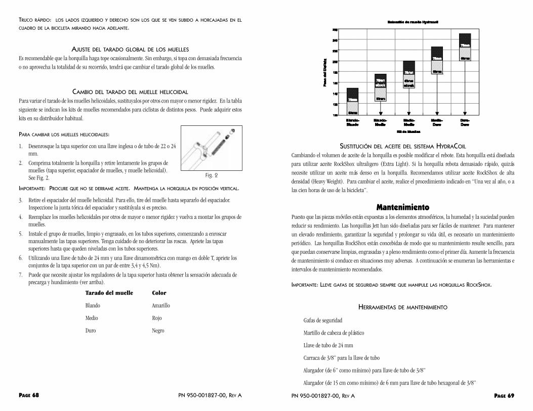
SUSTITUCIÓN DEL ACEITE DEL SISTEMA HYDRACOIL
Cambiando el volumen de aceite de la horquilla es posible modificar el rebote. Esta horquilla está diseñada
para utilizar aceite RockShox ultraligero (Extra Light). Si la horquilla rebota demasiado rápido, quizás
necesite utilizar un aceite más denso en la horquilla. Recomendamos utilizar aceite RockShox de alta
densidad (Heavy Weight). Para cambiar el aceite, realice el procedimiento indicado en “Una vez al año, o a
las cien horas de uso de la bicicleta”.
MantenimientoPuesto que las piezas móviles están expuestas a los elementos atmosféricos, la humedad y la suciedad pueden
reducir su rendimiento. Las horquillas Jett han sido diseñadas para ser fáciles de mantener. Para mantener
un elevado rendimiento, garantizar la seguridad y prolongar su vida útil, es necesario un mantenimiento
periódico. Las horquillas RockShox están concebidas de modo que su mantenimiento resulte sencillo, para
que puedan conservarse limpias, engrasadas y a pleno rendimiento como el primer día. Aumente la frecuencia
de mantenimiento si conduce en situaciones muy adversas. A continuación se enumeran las herramientas e
intervalos de mantenimiento recomendados.
IMPORTANTE: LLEVE GAFAS DE SEGURIDAD SIEMPRE QUE MANIPULE LAS HORQUILLAS ROCKSHOX.
HERRAMIENTAS DE MANTENIMIENTO
Gafas de seguridad
Martillo de cabeza de plástico
Llave de tubo de 24 mm
Carraca de 3/8” para la llave de tubo
Alargador (de 6” como mínimo) para llave de tubo de 3/8”
Alargador (de 15 cm como mínimo) de 6 mm para llave de tubo hexagonal de 3/8”
PN 950-001827-00, REV A PAGE 69
TRUCO RÁPIDO: LOS LADOS IZQUIERDO Y DERECHO SON LOS QUE SE VEN SUBIDO A HORCAJADAS EN EL
CUADRO DE LA BICICLETA MIRANDO HACIA ADELANTE.
AJUSTE DEL TARADO GLOBAL DE LOS MUELLES
Es recomendable que la horquilla haga tope ocasionalmente. Sin embargo, si topa con demasiada frecuencia
o no aprovecha la totalidad de su recorrido, tendrá que cambiar el tarado global de los muelles.
CAMBIO DEL TARADO DEL MUELLE HELICOIDAL
Para variar el tarado de los muelles helicoidales, sustituyalos por otros con mayor o menor rigidez. En la tabla
siguiente se indican los kits de muelles recomendados para ciclistas de distintos pesos. Puede adquirir estos
kits en su distribuidor habitual.
PARA CAMBIAR LOS MUELLES HELICOIDALES:
1. Desenrosque la tapa superior con una llave inglesa o de tubo de 22 o 24mm.
2. Comprima totalmente la horquilla y retire lentamente los grupos demuelles (tapa superior, espaciador de muelles, y muelle helicoidal). See Fig. 2.
IMPORTANTE: PROCURE QUE NO SE DERRAME ACEITE. MANTENGA LA HORQUILLA EN POSICIÓN VERTICAL.
3. Retire el espaciador del muelle helicoidal. Para ello, tire del muelle hasta separarlo del espaciador.Inspeccione la junta tórica del espaciador y sustitúyala si es preciso.
4. Reemplace los muelles helicoidales por otros de mayor o menor rigidez y vuelva a montar los grupos demuelles.
5. Instale el grupo de muelles, limpio y engrasado, en los tubos superiores, comenzando a enroscarmanualmente las tapas superiores. Tenga cuidado de no deteriorar las roscas. Apriete las tapassuperiores hasta que queden niveladas con los tubos superiores.
6. Utilizando una llave de tubo de 24 mm y una llave dinamométrica con mango en doble T, apriete losconjuntos de la tapa superior con un par de entre 3,4 y 4,5 Nm).
7. Puede que necesite ajustar los reguladores de la tapa superior hasta obtener la sensación adecuada deprecarga y hundimiento (ver arriba).
Tarado del muelle Color
Blando Amarillo
Medio Rojo
Duro Negro
PAGE 68 PN 950-001827-00, REV A
Fig. 2
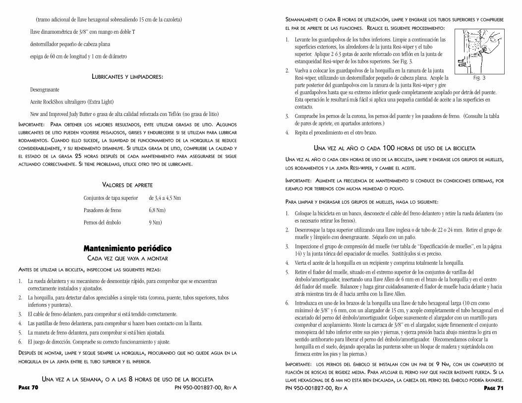
SEMANALMENTE O CADA 8 HORAS DE UTILIZACIÓN, LIMPIE Y ENGRASE LOS TUBOS SUPERIORES Y COMPRUEBE
EL PAR DE APRIETE DE LAS FIJACIONES. REALICE EL SIGUIENTE PROCEDIMIENTO:
1. Levante los guardapolvos de los tubos inferiores. Limpie a continuación lassuperficies exteriores, los alrededores de la junta Resi-wiper y el tubosuperior. Aplique 2 ó 3 gotas de aceite reforzado con teflón en la junta deestanqueidad Resi-wiper de los tubos superiores. See Fig. 3.
2. Vuelva a colocar los guardapolvos de la horquilla en la ranura de la juntaResi-wiper, utilizando un destornillador pequeño de cabeza plana. Acople laparte posterior del guardapolvos con la ranura de la junta Resi-wiper y gireel guardapolvos hasta que su extremo inferior quede completamente acoplado por detrás del puente.Esta operación le resultará más fácil si aplica una pequeña cantidad de aceite a las superficies encontacto.
3. Compruebe los pernos de la corona, los pernos del puente y los pasadores de freno. (Consulte la tablade pares de apriete, en apartados anteriores.)
4. Repita el procedimiento en el otro brazo.
UNA VEZ AL AÑO O CADA 100 HORAS DE USO DE LA BICICLETA
UNA VEZ AL AÑO O CADA CIEN HORAS DE USO DE LA BICICLETA, LIMPIE Y ENGRASE LOS GRUPOS DE MUELLES,LOS RODAMIENTOS Y LA JUNTA RESI-WIPER, Y CAMBIE EL ACEITE.
IMPORTANTE: AUMENTE LA FRECUENCIA DE MANTENIMIENTO SI CONDUCE EN CONDICIONES EXTREMAS, POR
EJEMPLO POR TERRENOS CON MUCHA HUMEDAD O POLVO.
PARA LIMPIAR Y ENGRASAR LOS GRUPOS DE MUELLES, HAGA LO SIGUIENTE:
1. Coloque la bicicleta en un banco, desconecte el cable del freno delantero y retire la rueda delantera (noes necesario retirar los frenos).
2. Desenrosque la tapa superior utilizando una llave inglesa o de tubo de 22 o 24 mm. Retire el grupo demuelle y límpielo con desengrasante. Séquelo con un paño.
3. Inspeccione el grupo de compresión del muelle (ver tabla de “Especificación de muelles”, en la página14) y la junta tórica del espaciador de muelles. Sustitúyalos si es preciso.
4. Vierta el aceite de la horquilla en un recipiente y comprima totalmente la horquilla.
5. Retire el fiador del muelle, situado en el extremo superior de los conjuntos de varillas delémbolo/amortiguador, insertando una llave Allen de 6 mm en el brazo de la horquilla y en el centrodel fiador del muelle. Balancee y haga girar cuidadosamente el fiador de muelle hacia delante y haciaatrás mientras tira de él hacia arriba con la llave Allen.
6. Introduzca en uno de los brazos de la horquilla una llave de tubo hexagonal larga (10 cm comomínimo) de 3/8” y 6 mm, con un alargador de 15 cm, y acople completamente el tubo hexagonal en elescariado del perno del émbolo/amortiguador. Golpee suavemente el alargador con un martillo paracomprobar el acoplamiento. Monte la carraca de 3/8” en el alargador, sujete firmemente el conjuntomonopieza del tubo inferior entre sus pies y piernas, y ejerza presión hacia abajo mientras lo gira ensentido antihorario para liberar el perno del émbolo/amortiguador. (Recomendamos colocar lahorquilla en el suelo, dejando apoyadas las punteras sobre un bloque de madera y sujetándola confirmeza entre los pies y las piernas.)
IMPORTANTE: LOS PERNOS DEL ÉMBOLO SE INSTALAN CON UN PAR DE 9 NM, CON UN COMPUESTO DE
FIJACIÓN DE ROSCAS DE RIGIDEZ MEDIA. PARA AFLOJAR EL PERNO HAY QUE HACER BASTANTE FUERZA. SI LA
LLAVE HEXAGONAL DE 6 MM NO ESTÁ BIEN ENCAJADA, LA CABEZA DEL PERNO DEL ÉMBOLO PODRÍA RAYARSE.PN 950-001827-00, REV A PAGE 71
(tramo adicional de llave hexagonal sobresaliendo 15 cm de la cazoleta)
llave dinamométrica de 3/8” con mango en doble T
destornillador pequeño de cabeza plana
espiga de 60 cm de longitud y 1 cm de diámetro
LUBRICANTES Y LIMPIADORES:
Desengrasante
Aceite RockShox ultraligero (Extra Light)
New and Improved Judy Butter o grasa de alta calidad reforzada con Teflón (no grasa de litio)
IMPORTANTE: PARA OBTENER LOS MEJORES RESULTADOS, EVITE UTILIZAR GRASAS DE LITIO. ALGUNOS
LUBRICANTES DE LITIO PUEDEN VOLVERSE PEGAJOSOS, GRISES Y ENDURECERSE SI SE UTILIZAN PARA LUBRICAR
RODAMIENTOS. CUANDO ELLO SUCEDE, LA SUAVIDAD DE FUNCIONAMIENTO DE LA HORQUILLA SE REDUCE
CONSIDERABLEMENTE, Y SU RENDIMIENTO DISMINUYE. SI UTILIZA GRASA DE LITIO, COMPRUEBE LA CALIDAD Y
EL ESTADO DE LA GRASA 25 HORAS DESPUÉS DE CADA MANTENIMIENTO PARA ASEGURARSE DE SIGUE
ACTUANDO CORRECTAMENTE. SI TIENE PROBLEMAS, UTILICE OTRO TIPO DE LUBRICANTE.
VALORES DE APRIETE
Conjuntos de tapa superior de 3,4 a 4,5 Nm
Pasadores de freno 6,8 Nm)
Pernos del émbolo 9 Nm)
Mantenimiento periódicoCADA VEZ QUE VAYA A MONTAR
ANTES DE UTILIZAR LA BICICLETA, INSPECCIONE LAS SIGUIENTES PIEZAS:
1. La rueda delantera y su mecanismo de desmontaje rápido, para comprobar que se encuentrancorrectamente instalados y ajustados.
2. La horquilla, para detectar daños apreciables a simple vista (corona, puente, tubos superiores, tubosinferiores y punteras).
3. El cable de freno delantero, para comprobar si está tendido correctamente.
4. Las pastillas de freno delanteras, para comprobar si hacen buen contacto con la llanta.
5. La maneta de freno delantera, para comprobar si está bien ajustada.
6. El juego de dirección. Compruebe su correcto funcionamiento y ajuste.
DESPUÉS DE MONTAR, LIMPIE Y SEQUE SIEMPRE LA HORQUILLA, PROCURANDO QUE NO QUEDE AGUA EN LA
HORQUILLA EN LA JUNTA ENTRE EL TUBO SUPERIOR Y EL INFERIOR.
UNA VEZ A LA SEMANA, O A LAS 8 HORAS DE USO DE LA BICICLETA
PAGE 70 PN 950-001827-00, REV A
Fig. 3

hexagonal de 6”, 6 mm y un alargador de 6”, y aplíquele un par de 9 Nm.
IMPORTANTE: LOS PERNOS DE LA VARILLA DEL ÉMBOLO ESTÁN FIJOS A LA VARILLA.
16. Reponga el aceite de los tubos inferiores. Tanto el modelo Jett de 63 mm de recorrido como el de 75mm traen de fábrica 85 cc de aceite RockShox ultraligero (Extra Light).
IMPORTANTE: NO EXCEDA ESOS VOLÚMENES. SI HAY DEMASIADO POCO ACEITE, EL RENDIMIENTO DE
AMORTIGUACIÓN SERÁ PEOR, PERO SI HAY DEMASIADO EL RECORRIDO SERÁ MÁS CORTO Y LA HORQUILLA
HARÁ TOPE CON MÁS BRUSQUEDAD.
17. Vuelva a encajar el fuelle de la horquilla en la ranura de la junta autolubricada Resi-wiper, utilizandoun destornillador pequeño de cabeza plana. Acople la parte posterior del fuelle con la ranura de lajunta Resi-wiper, y gírelo alrededor del tubo superior hasta que su extremo inferior encaje totalmentepor detrás del puente. Esta operación le resultará más fácil si comprime y hace girar el fuelle y aplicauna pequeña cantidad de aceite sobre las superficies en contacto.
18. Aplique New and Improved Judy Butter a todo el grupo de muelle, cubriendo completamente losmuelles helicoidales.
19. Instale los conjuntos de muelles helicoidales y la tapa superior en los tubos superiores, empezando aenroscar la tapa superior a mano.
20. Apriete las tapas superiores con un par de entre 3,4 y 4,5 Nm. Esto corresponde a un ángulo demovimiento de la llave de entre 30 y 60 grados en sentido horario desde el punto en que la tapa quedanivelada con el tubo superior.
Servicio técnicoEn la sección siguiente se describen con detalle los procedimientos de mantenimiento aplicables a cada una
de las piezas de la horquilla Jett XC.
SUSTITUCIÓN DEL MUELLE
El sistema de muelles de las horquillas Jett XC combina un extraordinario rendimiento con el dinamismo de
un muelle helicoidal. Sin embargo, con el paso del tiempo los muelles pueden desgastarse y empeorar el
rendimiento. Ello se manifiesta en el grupo de compresión, donde la longitud del muelle helicoidal será
menor en estado de reposo que cuando las piezas eran nuevas. Utilice la siguiente tabla como guía para saber
cuándo ha de sustituir el sistema de muelles. Siga las instrucciones indicadas en los procedimientos de
mantenimiento “Una vez al año o a las cien horas de uso de la bicicleta”, en la página 12, para todo lo relativo
al desmontaje e instalación.
ESPECIFICACIÓN DEL SISTEMA DE MUELLES
Travel Muelle óptimo Sustitución Muelle de Sustituir muelle del muelle tope óptimo de tope
63 mm 165 mm 156 mm 25 mm 22 mm
75 mm 165 mm 156 mm 25 mm 22 mm
PN 950-001827-00, REV A PAGE 73
EL ESCARIADO DEL PERNO ES BASTANTE PROFUNDO PARA EVITAR QUE SE RAYE SI LA LLAVE HEXAGONAL ESTÁ
BIEN ENCAJADA..
6. Afloje el perno del émbolo completamente y repita el procedimiento en el otro tubo inferior.
IMPORTANTE: EL PERNO DEL ÉMBOLO/AMORTIGUADOR ESTÁ FIJADO AL CONJUNTO
ÉMBOLO/AMORTIGUADOR, POR LO QUE AL DESENROSCAR EL PERNO GIRARÁ TODO EL CONJUNTO.
7. Deslice hacia afuera el conjunto monopieza del tubo inferior (consulte la Fig.Retire los guardapolvos de la horquilla.
8. Limpie los tubos superiores y compruebe si presentan desgaste o desperfectos(muescas, rayaduras o golpes).
9. Retire los conjuntos del émbolo y compruebe si presentan signos de desgaste odeterioro (Nota: se derramará más aceite de los conjuntos). Compruebe elgrupo de compresión del muelle de tope superior, según se indica en lasección “Especificación del sistema de muelles”, en la página 14.
10. Limpie los fuelles e insértelos en los tubos superiores.
11. Después, limpie el interior de los tubos inferiores, casquillos (dos por brazo) yla junta de estanqueidad Resi-wiper. Para esta operación resulta útil unalargador de llave de tubo de 3/8” envuelto en un paño que no deje pelusa.
IMPORTANTE: LIMPIE LOS RODAMIENTOS INFERIORES EN UN ÁREA DE UNOS 150 MM DESDE ARRIBA.
12. Aplique New and Improved Judy Butter a la superficie de los rodamientossuperiores y rellene completamente la cavidad de cada junta Resi-wiper.
IMPORTANTE: PARA OBTENER MEJORES RESULTADOS, EVITE UTILIZAR GRASAS DE
LITIO. ALGUNOS LUBRICANTES DE LITIO PUEDEN VOLVERSE PEGAJOSOS, GRISES Y
ENDURECERSE SI SE UTILIZAN PARA LUBRICAR RODAMIENTOS. CUANDO ELLO
SUCEDE, LA SUAVIDAD DE FUNCIONAMIENTO DE LA HORQUILLA SE REDUCE
CONSIDERABLEMENTE, Y SU RENDIMIENTO DISMINUYE. SI UTILIZA GRASA DE LITIO, COMPRUEBE LA CALIDAD Y
EL ESTADO DE LA GRASA EN CADA INTERVALO DE MANTENIMIENTO CADA 25 HORAS, PARA ASEGURARSE DE
SIGUE ACTUANDO CORRECTAMENTE. SI TIENE PROBLEMAS, UTILICE OTRO TIPO DE LUBRICANTE.
13. Instale el conjunto de tubo inferior monopieza en los tubos superiores, acople cuidadosamente el bordesuperior de la junta de estanqueidad Resi-wiper a los tubos superiores, y deslice suavemente el conjuntode tubo inferior monopieza para acoplar los casquillos inferiores con los tubos superiores.
14. A continuación, coloque un compuestode fijación de roscas de resistenciamedia (Loc-tite azul) en las roscas delperno del émbolo, que deben estarlimpias y secas, y déjelo secar.
15. Los conjuntos émbolo/amortiguador seinstalan dejando caer desde arriba elconjunto por dentro del tubo superior.En las figuras 6 y 7 se muestra laorientación de las piezas tanto para elémbolo (lado derecho) como para elconjunto de la varilla del amortiguador(lado izquierdo). Enrosque el perno delémbolo/amortiguador con una llave
PAGE 72 PN 950-001827-00, REV A
Fig. 4
Fig. 5
Fig. 6 Fig. 7

Rebote - la extensión o recuperación de los amortiguadores o la suspensión.
Recorrido de compresión - movimiento ascendente de un horquilla que se desplaza como reacciónal impacto de un bache.
Tarado de muelle - la cantidad de fuerza necesaria para desviar un muelle a una distancia dada.
Garantía ROCKSHOX, INC. GARANTIZA SUS PRODUCTOS DURANTE UN PERÍODO DE UN AÑO A PARTIR DE LA FECHA DE
COMPRA ORIGINAL. LA GARANTÍA CUBRE LOS DEFECTOS EN LOS MATERIALES Y EN EL PROCESO DE
FABRICACIÓN. TODO PRODUCTO ROCKSHOX QUE SEA DEVUELTO A FÁBRICA Y QUE, TRAS EXAMEN POR PARTE
DE ROCKSHOX, REVELE DEFECTOS MATERIALES O DE FABRICACIÓN, SERÁ SUSTITUIDO O REPARADO, A CRITERIO
DE ROCKSHOX, INC. LA RESPONSABILIDAD ACEPTADA POR ROCKSHOX SE LIMITA ÚNICA Y EXCLUSIVAMENTE
A ESTA GARANTÍA. ROCKSHOX DECLINA TODA RESPONSABILIDAD POR DAÑOS INDIRECTOS, EMERGENTES O
CUANTIFICABLES DERIVADOS DEL USO DE SUS PRODUCTOS.
LA GARANTÍA NO SERÁ APLICABLE A AQUELLOS PRODUCTOS QUE NO HAYAN SIDO INSTALADOS Y AJUSTADOS
CORRECTAMENTE DE ACUERDO CON LAS INSTRUCCIONES DE INSTALACIÓN DE ROCSHOX, A LOS UTILIZADOS
DE FORMA INCORRECTA, NI A AQUELLOS CUYO NÚMERO DE SERIE SE HAYA ALTERADO, CAMUFLADO O
RETIRADO. ESTA GARANTÍA TAMPOCO CUBRE LOS DAÑOS EN LA PINTURA DEL PRODUCTO NI LAS
MODIFICACIONES A LAS QUE ÉSTE PUEDA HABER SIDO SOMETIDO. SE EXIGIRÁN JUSTIFICANTES DE COMPRA.
REPARACIÓN EN PERÍODO DE GARANTÍA
SI POR ALGÚN MOTIVO NECESITASE RECURRIR A LA GARANTÍA, DEVUELVA EL PRODUCTO AL ESTABLECIMIENTO
DONDE LO ADQUIRIÓ. EN ESTADOS UNIDOS, LOS CONCESIONARIOS HAN DE SOLICITAR UN NÚMERO DE
AUTORIZACIÓN DE DEVOLUCIÓN (RA#) ANTES DE DEVOLVER EL PRODUCTO. EL ENVÍO DE PRODUCTOS
DEVUELTOS PARA INSPECCIÓN HA DE EFECTUARSE A PORTES PAGADOS, A LA SIGUIENTE DIRECCIÓN:
RockShox, Inc.
401 Charcot Ave. FAX 408.428.9757
San Jose, CA 95131
www.rockshox.com
correo electrónico: [email protected]
Llamada gratuita al servicio técnico en EE.UU. 800.77.7177
Fuera de EE.UU., los clientes han de ponerse en contacto con su concesionario o distribuidor local.
PN 950-001827-00, REV A PAGE 75
VARIACIÓN DEL RECORRIDO
El recorrido de la suspensión de las horquillas Jett puede variarse instalando un kit de émbolo/amortiguador
diferente. Siga el procedimiento indicado en la sección “Una vez al mes o cada 25 horas de uso de la bicicleta”
para retirar el conjunto de tubo inferior monopieza. Sustituya los émbolos de origen por las unidades más
largas que vienen incluidas en el kit. Sustituya también las piezas del grupo de muelles (muelle helicoidal y
espaciadores de muelles) por las piezas correspondientes del kit. Siga las instrucciones de la sección “Una vez
al mes o cada 25 horas de uso de la bicicleta” para terminarlo de montar.
SUSTITUCIÓN DE RODAMIENTOS
Los rodamientos de alta calidad con que están equipadas las horquillas RockShox están diseñados para resistir
muchos meses de utilización exigente. La utilización de guardapolvos protectores, la limpieza de la horquilla
y el cumplimiento de los intervalos de engrase son factores clave para una dilatada vida útil y un alto
rendimiento de los rodamientos. Sin embargo, como sucede con todas las piezas móviles, acabarán por
desgastarse y habrán de sustituirse. La necesidad de esta operación vendrá indicada por un aumento del
movimiento de cabeceo de los tubos superiores e inferiores (con síntomas similares a los de una dirección
floja) y/o la lentitud de respuesta, incluso recién engrasados.
IMPORTANTE: ESTA OPERACIÓN DE MANTENIMIENTO PRECISA HERRAMIENTAS ESPECIALES ROCKSHOX.RECOMENDAMOS CONFIAR ESTE TIPO DE MANTENIMIENTO A UN MECÁNICO DE BICICLETAS FAMILIARIZADO CON
NUESTROS PRODUCTOS Y CON ESTE PROCEDIMIENTO.
GlosarioÁngulo de cabeza - ángulo que resulta de la desviación del eje de la dirección respecto a la vertical.
Baño de aceite - sistema de depósito de aceite empleado para lubricar las piezas internas de lahorquilla.
Estrechamiento - variación del grosor de la pared de un tubo. Se trata de un diseño que optimiza ladistribución del material, lo que permite aumentar la eficacia del diseño en función de las cargas.
Extensión total - la posición de la horquilla en la parte superior del recorrido, o cuando la horquillaqueda totalmente extendida. La acción de extensión total de la horquilla.
Forjado - proceso de conformación de metales que proporciona la estructura de material óptimamediante fuerzas muy intensas aplicadas en un molde en el que se colocan los materiales que se van aconformar.
Fuerza de amortiguación - la fuerza necesaria para mover un amortiguador ordinario (de aceite, porlo general) genérico a una velocidad dada.
Geometría - término descriptivo para las longitudes y los ángulos empleados en el diseño de bicicletas.
Hacer tope - llegar al límite del recorrido de la suspensión.
Hundimiento - compresión de la suspensión ocasionada por el peso del ciclista.
Monopieza - conjunto de brazo inferior en bloque en el que los dos brazos de la horquilla y el puente dela horquilla forman una sola pieza.
Precarga - la medida, en libras o pulgadas, en que se comprime un muelle cuando se instala en unamortiguador en reposo.
PAGE 74 PN 950-001827-00, REV A

PAGE 76 PN 950-001827-00, REV A
Related Documents