Welcome message from author
This document is posted to help you gain knowledge. Please leave a comment to let me know what you think about it! Share it to your friends and learn new things together.
Transcript
©1999-2002 Dynojet Research, Inc. All Rights Reserved.
Eddy Current Brake Installation Guide For Motorcycle Dynamometers.
This manual is copyrighted by Dynojet Research, Inc., hereafter referred to as Dynojet, and all rights are reserved. This manual is furnished under license and may only be used or copied in accordance with the terms of such license. This manual is furnished for informational use only, is subject to change without notice, and should not be construed as a commitment by Dynojet. Dynojet assumes no responsibility or liability for any error or inaccuracies that may appear in this manual. Except as permitted by such license, no part of this manual may be reproduced, stored in a retrieval system, or transmitted, in any form or by any means, electronic, mechanical, recording, or otherwise, without the prior written permission of Dynojet.
The Dynojet logo is a trademark of Dynojet Research, Inc.
Any trademarks, trade names, service marks, or service names owned or registered by any other company and used in this guide are the property of their respective companies.
Dynojet Research, Inc., 2191 Mendenhall Drive, North Las Vegas, Nevada 89031, USA.
Printed in USA.
Part Number: 98226100 Version 8 (03/02)

TABLE OF CONTENTS
List of Figures. . . . . . . . . . . . . . . . . . . . . . . . . . . . . . . . . . . . . . . . . . . iii
Chapter 1 Eddy Current Brake InstallationConventions . . . . . . . . . . . . . . . . . . . . . . . . . . . . . . . . . . . . . . . . . . . . . . . . . .1-1Technical Support . . . . . . . . . . . . . . . . . . . . . . . . . . . . . . . . . . . . . . . . . . . . .1-1Parts List . . . . . . . . . . . . . . . . . . . . . . . . . . . . . . . . . . . . . . . . . . . . . . . . . . . . .1-2Preparation . . . . . . . . . . . . . . . . . . . . . . . . . . . . . . . . . . . . . . . . . . . . . . . . . .1-3
Unpacking the Eddy Current Brake . . . . . . . . . . . . . . . . . . . . . . . . . . . . . .1-3Removing the Dyno Hood . . . . . . . . . . . . . . . . . . . . . . . . . . . . . . . . . . . . .1-4
Air Brake and Manual Brake Removal . . . . . . . . . . . . . . . . . . . . . . . . . . . . .1-5Removing the Air Brake . . . . . . . . . . . . . . . . . . . . . . . . . . . . . . . . . . . . . . .1-5Removing the Manual Brake . . . . . . . . . . . . . . . . . . . . . . . . . . . . . . . . . . .1-7Removing the Brake Caliper Assembly . . . . . . . . . . . . . . . . . . . . . . . . . . . .1-8
Eddy Current Brake . . . . . . . . . . . . . . . . . . . . . . . . . . . . . . . . . . . . . . . . . . . .1-9Adjusting the Brake for Right Side Installations . . . . . . . . . . . . . . . . . . . . . .1-9Installing the Connecting Arms . . . . . . . . . . . . . . . . . . . . . . . . . . . . . . . . .1-9Installing the Dyno Shaft Coupler . . . . . . . . . . . . . . . . . . . . . . . . . . . . . .1-11Connecting the Eddy Current Brake . . . . . . . . . . . . . . . . . . . . . . . . . . . . .1-12Aligning the Eddy Current Brake . . . . . . . . . . . . . . . . . . . . . . . . . . . . . . .1-13Coupling the Eddy Current Brake . . . . . . . . . . . . . . . . . . . . . . . . . . . . . . .1-14Securing the Eddy Current Brake . . . . . . . . . . . . . . . . . . . . . . . . . . . . . . .1-14
Theta Controller . . . . . . . . . . . . . . . . . . . . . . . . . . . . . . . . . . . . . . . . . . . . .1-15Adjusting the Power . . . . . . . . . . . . . . . . . . . . . . . . . . . . . . . . . . . . . . . .1-15Drilling the Mounting Holes . . . . . . . . . . . . . . . . . . . . . . . . . . . . . . . . . . .1-18Installing the Theta Controller—Left Side . . . . . . . . . . . . . . . . . . . . . . . . .1-20Installing the Theta Controller—Right Side . . . . . . . . . . . . . . . . . . . . . . .1-22Wiring . . . . . . . . . . . . . . . . . . . . . . . . . . . . . . . . . . . . . . . . . . . . . . . . . . .1-23Replacing the Fuse . . . . . . . . . . . . . . . . . . . . . . . . . . . . . . . . . . . . . . . . . .1-24Changing the Input Power Cable Plug . . . . . . . . . . . . . . . . . . . . . . . . . . .1-26Verifying the Eddy Current Brake Wiring Configuration . . . . . . . . . . . . . .1-26
Hood Upgrade . . . . . . . . . . . . . . . . . . . . . . . . . . . . . . . . . . . . . . . . . . . . . . .1-27Assembling the Hood . . . . . . . . . . . . . . . . . . . . . . . . . . . . . . . . . . . . . . .1-27Installing the Hood . . . . . . . . . . . . . . . . . . . . . . . . . . . . . . . . . . . . . . . . .1-28
Eddy Current Brake Installation Guidei

TA B L E O F C O N T E N T S
Appendix A Red Head Anchor InstallationWarnings . . . . . . . . . . . . . . . . . . . . . . . . . . . . . . . . . . . . . . . . . . . . . . . . . . . .A-1Contact Information for ITW Ramset/Red Head . . . . . . . . . . . . . . . . . . . . .A-1Installation . . . . . . . . . . . . . . . . . . . . . . . . . . . . . . . . . . . . . . . . . . . . . . . . . . .A-2
Appendix B High Inertia Drum—Older Dyno InstallationConnecting the Eddy Current Brake . . . . . . . . . . . . . . . . . . . . . . . . . . . . . .B-1
Appendix C Theta Controller—Internal FuseReplacing the Internal Fuse . . . . . . . . . . . . . . . . . . . . . . . . . . . . . . . . . . . . .C-1
Appendix D Mounting Templates
Eddy Current Brake Installation Guideii

LIST OF FIGURES
Figure 1-1: Remove the Brake Cover and Hood Keepers . . . . . . . . . . . . . .1-3
Figure 1-2: Remove the Eddy Current Brake from the Crate . . . . . . . . . . .1-4
Figure 1-3: Remove the Hood. . . . . . . . . . . . . . . . . . . . . . . . . . . . . . . . . . . .1-4
Figure 1-4: Remove the Air Brake Solenoid Wires . . . . . . . . . . . . . . . . . . . .1-5
Figure 1-5: Remove the Brake Wires from the Breakout Board . . . . . . . . .1-5
Figure 1-6: Air Brake—Remove the Springs. . . . . . . . . . . . . . . . . . . . . . . . .1-6
Figure 1-7: Air Brake—Remove the Master Cylinder. . . . . . . . . . . . . . . . . .1-6
Figure 1-8: Air Brake—Remove the Air Cylinder . . . . . . . . . . . . . . . . . . . . .1-7
Figure 1-9: Remove the Manual Brake . . . . . . . . . . . . . . . . . . . . . . . . . . . . .1-7
Figure 1-10: Remove the Brake Caliper Assembly. . . . . . . . . . . . . . . . . . . .1-8
Figure 1-11: Right Side Installation Set-up . . . . . . . . . . . . . . . . . . . . . . . . .1-9
Figure 1-12: Remove the Connecting Arm Bolts. . . . . . . . . . . . . . . . . . . . .1-9
Figure 1-13: Install the Connecting Arms . . . . . . . . . . . . . . . . . . . . . . . . .1-10
Figure 1-14: Replace the Coupler Set Screws . . . . . . . . . . . . . . . . . . . . . .1-11
Figure 1-15: Install the Dyno Shaft Coupler . . . . . . . . . . . . . . . . . . . . . . .1-11
Figure 1-16: Remove the Connecting Bolts from the Dyno. . . . . . . . . . .1-12
Figure 1-17: Connect the Eddy Current Brake . . . . . . . . . . . . . . . . . . . . .1-12
Figure 1-18: Align the Eddy Current Brake . . . . . . . . . . . . . . . . . . . . . . . .1-13
Figure 1-19: Secure the Couplers . . . . . . . . . . . . . . . . . . . . . . . . . . . . . . . .1-14
Figure 1-20: Secure the Brake to the Ground . . . . . . . . . . . . . . . . . . . . . .1-14
Figure 1-21: Theta Controller—Metal Plug . . . . . . . . . . . . . . . . . . . . . . . .1-15
Figure 1-22: Theta Controller—North America 120 VAC Dip Switch Settings . . . . . . . . . . . . . . . . . . . . . . . . . . . . . . . .1-16
Eddy Current Brake Installation Guideiii

L I S T O F F I G U R E S
Figure 1-23: Theta Controller—Europe and Australia 240 VAC
Dip Switch Settings . . . . . . . . . . . . . . . . . . . . . . . . . . . . . . . .1-17
Figure 1-24: Theta Controller—Drill Mounting Holes on Left Side . . . . .1-18
Figure 1-25: Theta Controller—Drill Mounting Holes on Right Side. . . .1-19
Figure 1-26: Theta Controller—Install on Left Side. . . . . . . . . . . . . . . . . .1-20
Figure 1-27: Theta Controller—Routing the Cables on Left Side . . . . . .1-21
Figure 1-28: Theta Controller—Install on Right Side . . . . . . . . . . . . . . . .1-22
Figure 1-29: Theta Controller—Routing the Cables on Right Side . . . . .1-22
Figure 1-30: Theta Controller—Remove the Breakout Board Cover . . . .1-23
Figure 1-31: Theta Controller—Breakout Board Wiring and Jumper Settings . . . . . . . . . . . . . . . . . . . . . . . . . . . . . . . . . . .1-23
Figure 1-32: Theta Controller—Replace the Fuse . . . . . . . . . . . . . . . . . . .1-24
Figure 1-33: Theta Controller—Determine the Type . . . . . . . . . . . . . . . .1-25
Figure 1-34: Theta Controller—Input Power Cable Plug . . . . . . . . . . . . .1-26
Figure 1-35: Theta Controller —Eddy Current Brake Wiring . . . . . . . . . .1-26
Figure 1-36: Dyno Hood Side Panel . . . . . . . . . . . . . . . . . . . . . . . . . . . . . .1-27
Figure 1-37: Secure Eddy Current Brake Cover to Dyno Hood . . . . . . . .1-27
Figure 1-38: Install the New Dyno Hood . . . . . . . . . . . . . . . . . . . . . . . . . .1-28
Figure 1-39: Secure the Hood Clamps and Brake Cover . . . . . . . . . . . . .1-28
Figure A-1: Red Head Anchor—Drill the Hole . . . . . . . . . . . . . . . . . . . . . . .A-2
Figure A-2: Red Head Anchor—Insert the Anchor. . . . . . . . . . . . . . . . . . . .A-2
Figure A-3: Red Head Anchor—Drive the Anchor Flush . . . . . . . . . . . . . . .A-3
Figure A-4: Red Head Anchor—Expand the Anchor . . . . . . . . . . . . . . . . . .A-3
Figure B-1: High Inertia Drum—Measure the Axle . . . . . . . . . . . . . . . . . . .B-1
Figure B-2: High Inertia Drum—Remove Nuts and Washers . . . . . . . . . . .B-2
Figure B-3: High Inertia Drum—Connect Brake . . . . . . . . . . . . . . . . . . . . .B-2
Figure C-1: Theta Controller—Replace Internal Fuse . . . . . . . . . . . . . . . . .C-1
Eddy Current Brake Installation Guideiv

C H A P T E R
1EDDY CURRENT BRAKE INSTALLATION
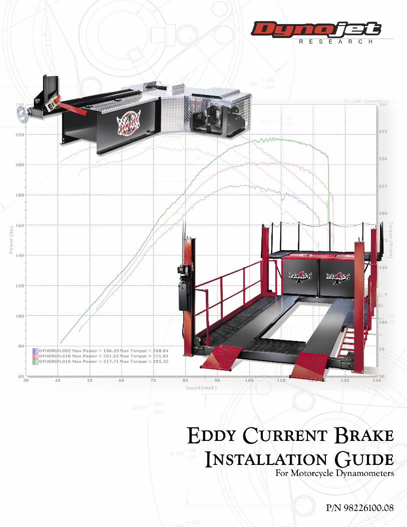
This document provides instructions for installing the Eddy Current Brake (retarder) optional hardware to Dynojet’s Model 150 and 200 Motorcycle Dynamometers. To ensure safety and accuracy in the procedures, perform the procedures as they are described.
Document Part Number: 98226100
Version 8
Last Updated: 03-29-02
CONVENTIONSThe conventions used in this manual are designed to protect both the user and the equipment.
TECHNICAL SUPPORTFor assistance, please contact Dynojet Technical Support at 1-800-992-3525, or write to Dynojet at 2191 Mendenhall Drive, North Las Vegas, NV 89031.
Visit us on the World Wide Web at www.dynojet.com where Dynojet provides state of the art technical support, on-line shopping, 3D visualizations, and press releases about our latest product line.
example of convention description
The Caution icon indicates a potential hazard to the dynamometer equipment. Follow all procedures exactly as they are described and use care when performing all procedures.
The Warning icon indicates potential harm to the person performing a procedure and/or the dynamometer equipment.
Eddy Current Brake Installation Guide1-1

C H A P T E R 1Parts List
. . . . . . . . . . . . . . . . . . . . . . . . . . . . . . . . . . .PARTS LIST
The following table lists all of the parts included in the Eddy Current Brake Installation kit. Check your kit against the parts listed to make sure you have received all of the parts. If any part is missing, contact Dynojet Technical Support.
part number description quantity
197104130 4" Zip Tie 4
25111310 Clamp, Retarder Hood 2
61229101 Hood Assembly, M/C Retarder 1
62992001
Or
62992002
Retarder-Generic
Or
Retarder-Generic, European
1
29250001 Mod-Key, 1/2 x 7/16 x 2" 1
29250002 Key, 3/8 x 3/8 x 2" (installed) 1
32431332 Male Coupler, mounted on eddy current brake (with male coupler hub, P/N 32431330, installed)
1
32431333 Female Coupler Assembly with four set screws (with female coupler hub, P/N 32431331, installed)
1
36488101 Nut, 3/8-16, Hex, W/Tlok 5
36581270 Bolt, 3/8-16 x 3/4", W/Tlok 28
36581670 Bolt, 3/8-16 x 1", W/Tlok (for right side installation) 4
43312200 Grommet, 1-5/8OD x 1-3/8ID (one is installed) 2
61329105 Connecting Rod Sub-Assembly 2
66411002
Or
66411003
Theta-2 Controller-120V
Or
Theta-2 Controller-240V
1
66952004 Power Cable, M/C Retarder Sub-Assembly 1
DC100-104 Pendant and Cable 1
DM150-002-007 5/16" Flat Washer 8
DM150-033 Rubber Grommet 1
Red Head Anchor Kit 1
Theta Controller Mounting Hole Drill Template For Left Side Mounting 1
Theta Controller Mounting Hole Drill Template For Right Side Mounting 1
The following part number should be used when replacing all of the coupler pieces:
78122002 Coupler Kit
Eddy Current Brake Installation Guide1-2
E D D Y C U R R E N T B R A K E I N S T A L L A T I O NPreparation
. . . . . . . . . . . . . . . . . . . . . . . . . . . . . . . . . . .PREPARATION
This section describes how to unpack the eddy current brake and remove the hood from your dyno.
UNPACKING THE EDDY CURRENT BRAKE
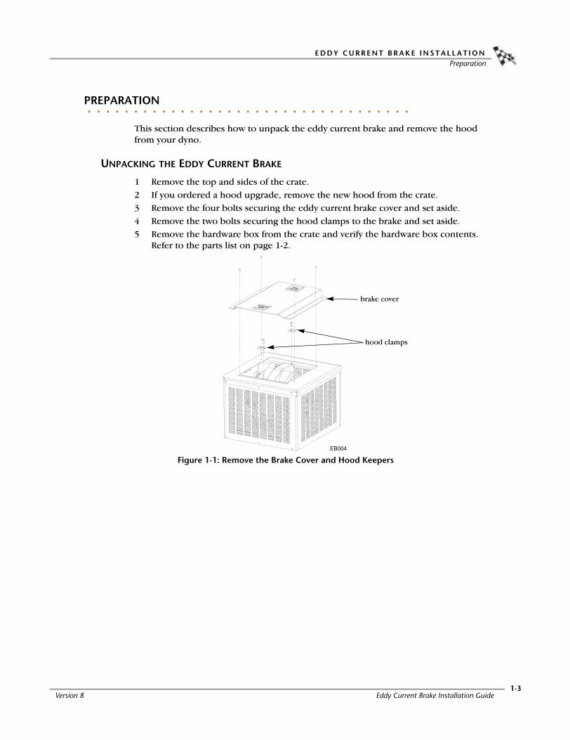
1 Remove the top and sides of the crate.2 If you ordered a hood upgrade, remove the new hood from the crate.3 Remove the four bolts securing the eddy current brake cover and set aside.4 Remove the two bolts securing the hood clamps to the brake and set aside.5 Remove the hardware box from the crate and verify the hardware box contents.
Refer to the parts list on page 1-2.
Figure 1-1: Remove the Brake Cover and Hood Keepers
brake cover
hood clamps
Version 8 Eddy Current Brake Installation Guide1-3

C H A P T E R 1Preparation
6 Remove the eddy current brake from the crate.
Note: Dynojet recommends using a continuous nylon loop style strap to lift the eddy current brake from the crate.
6a Remove the bolts securing the eddy current brake to the crate.
6b Place the nylon loop strap around the top of the brake frame making sure it crosses as shown in Figure 1-2.
6c Using the nylon loop strap, remove the eddy current brake from the crate and place it near the dyno.
Figure 1-2: Remove the Eddy Current Brake from the Crate
REMOVING THE DYNO HOOD
1 Remove the four bolts securing the hood to the dyno and set aside. Prop up the hood.
2 If present, disconnect the wires to the key switch.3 Remove the hood from the dyno and set aside.4 Disconnect all battery wires.
Figure 1-3: Remove the Hood
key switch
Eddy Current Brake Installation Guide1-4
E D D Y C U R R E N T B R A K E I N S T A L L A T I O NAir Brake and Manual Brake Removal
. . . . . . . . . . . . . . . . . . . . . . . . . . . . . . . . . . .AIR BRAKE AND MANUAL BRAKE REMOVAL
This section describes how to remove both the air brake and the manual brake, the brake caliper assembly, and the rotor.
If you are mounting the eddy current brake on the right side of your dyno, you do not need to remove the air or manual brake.
Note: Safety requirements of your local country may require that both brakes are installed. Be sure to follow the safety requirements specific to your country.
REMOVING THE AIR BRAKE
1 Disconnect all air lines from the dyno.2 Disconnect the brake electrical wires.
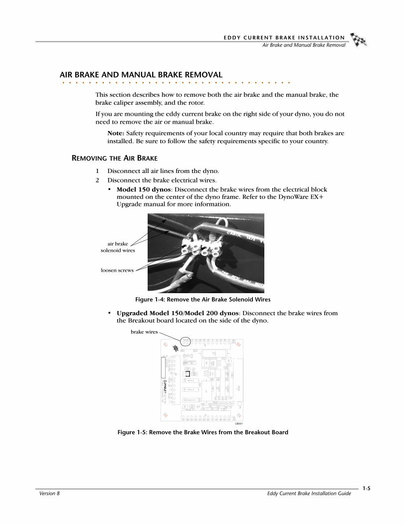
• Model 150 dynos: Disconnect the brake wires from the electrical block mounted on the center of the dyno frame. Refer to the DynoWare EX+ Upgrade manual for more information.
Figure 1-4: Remove the Air Brake Solenoid Wires
• Upgraded Model 150/Model 200 dynos: Disconnect the brake wires from the Breakout board located on the side of the dyno.
Figure 1-5: Remove the Brake Wires from the Breakout Board
loosen screws
air brake solenoid wires
brake wires
Version 8 Eddy Current Brake Installation Guide1-5

C H A P T E R 1Air Brake and Manual Brake Removal
3 Remove the jam nuts, adjuster nuts, retainers, and springs.
The springs are compressed. Use caution when removing the springs.
4 Disconnect the brake line from the master cylinder to the caliper.Note: Make sure you have disconnected all air lines and released the tension in the springs before disconnecting the brake line.
Figure 1-6: Air Brake—Remove the Springs
5 Remove the two bolts securing the master cylinder to the air cylinder using a 3/16-inch allen wrench. Remove the master cylinder.
Figure 1-7: Air Brake—Remove the Master Cylinder
spring
retainer
adjuster nut
jam nut
cut away view of dyno side panel
bolts
master cylinder
Eddy Current Brake Installation Guide1-6

E D D Y C U R R E N T B R A K E I N S T A L L A T I O NAir Brake and Manual Brake Removal
6 Remove the bolt securing the spring bolt mounting plate.7 Remove the mounting plate and the air cylinder from the dyno frame.
Figure 1-8: Air Brake—Remove the Air Cylinder
REMOVING THE MANUAL BRAKE
1 Disconnect the brake line from the master cylinder to the caliper.2 Remove the four bolts, lock washers, and flat washers that secure the master
cylinder and foot pedal.
The bolts run from the inside, through the master cylinder, and into the foot pedal mounting plate.
Figure 1-9: Remove the Manual Brake
boltair cylinder
mounting plate
foot pedal
master cylinder
Version 8 Eddy Current Brake Installation Guide1-7

C H A P T E R 1Air Brake and Manual Brake Removal
REMOVING THE BRAKE CALIPER ASSEMBLY
1 Remove the four bolts and washers that secure the caliper assembly.2 Loosen the brake pads and remove the assembly.
Note: Do not put the bolts back into the dyno frame. The holes will be used to mount the eddy current brake to the dyno.
3 Loosen the set screw above the keyway in the drum axle using a 3/16-inch allen wrench.
4 Remove the three 5/16-inch bolts in the lock collar and insert these bolts in the three threaded holes in the lock collar. Tighten the bolts until the collar comes loose.
5 Slide the rotor and lock collar off the drum axle and remove the key.
Figure 1-10: Remove the Brake Caliper Assembly
caliper assembly
key waylock collar
Eddy Current Brake Installation Guide1-8

E D D Y C U R R E N T B R A K E I N S T A L L A T I O NEddy Current Brake
. . . . . . . . . . . . . . . . . . . . . . . . . . . . . . . . . . .EDDY CURRENT BRAKE
The eddy current brake can be installed on either the left or right side of the dyno. Be sure to check the dyno drum axle for damage or rust and carefully file any marks flush with the axle.
ADJUSTING THE BRAKE FOR RIGHT SIDE INSTALLATIONS
Make the following adjustments to the eddy current brake only if the brake will be mounted on the right side of the dyno.
1 Move the coupler and key to the other side of the brake.2 Move the sensor temperature cable and power cable to the other side of the
brake.
Figure 1-11: Right Side Installation Set-up
INSTALLING THE CONNECTING ARMS
Attach the upper and lower connecting arms on the corresponding side of the eddy current brake. The connecting arms are identical and interchangeable.
1 Remove the eight 3/8-inch bolts and washers from the side of the eddy current brake.
Figure 1-12: Remove the Connecting Arm Bolts
power cable
temp sensor cable
coupler
remove
Version 8 Eddy Current Brake Installation Guide1-9
C H A P T E R 1Eddy Current Brake
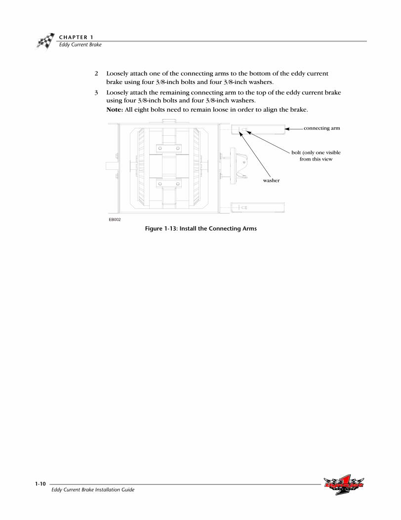
2 Loosely attach one of the connecting arms to the bottom of the eddy current brake using four 3/8-inch bolts and four 3/8-inch washers.
3 Loosely attach the remaining connecting arm to the top of the eddy current brake using four 3/8-inch bolts and four 3/8-inch washers.Note: All eight bolts need to remain loose in order to align the brake.
Figure 1-13: Install the Connecting Arms
connecting arm
bolt (only one visible from this view
washer
Eddy Current Brake Installation Guide1-10

E D D Y C U R R E N T B R A K E I N S T A L L A T I O NEddy Current Brake
INSTALLING THE DYNO SHAFT COUPLER
1 Replace the existing set screw in the key way of each coupler with the thread-lock set screws provided.Note: Replace the dyno shaft coupler set screw before installing the coupler on the shaft.
Figure 1-14: Replace the Coupler Set Screws
2 Insert the key into the keyway.3 Slide the coupler over the key on the axle.
Note: Do not tighten the set screw in the coupler.
Figure 1-15: Install the Dyno Shaft Coupler
dyno shaft coupler
key waykey way
eddy current brake coupler
set screw
set screw
coupler
key way
Version 8 Eddy Current Brake Installation Guide1-11
C H A P T E R 1Eddy Current Brake
CONNECTING THE EDDY CURRENT BRAKE
The following instructions and figures show the eddy current brake mounting to the left side of the dyno; however, the instructions are the same for both left and right side installations.
Use the following instructions to install the eddy current brake to both the standard and high inertia drums. If you have a high inertia drum, refer to Appendix B for installation details.
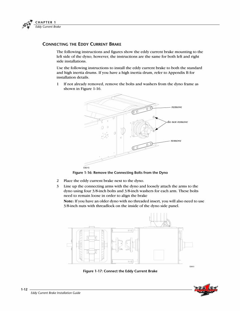
1 If not already removed, remove the bolts and washers from the dyno frame as shown in Figure 1-16.
Figure 1-16: Remove the Connecting Bolts from the Dyno
2 Place the eddy current brake next to the dyno.3 Line up the connecting arms with the dyno and loosely attach the arms to the
dyno using four 3/8-inch bolts and 3/8-inch washers for each arm. These bolts need to remain loose in order to align the brakeNote: If you have an older dyno with no threaded insert, you will also need to use 3/8-inch nuts with threadlock on the inside of the dyno side panel.
Figure 1-17: Connect the Eddy Current Brake
remove
do not remove
remove
Eddy Current Brake Installation Guide1-12

E D D Y C U R R E N T B R A K E I N S T A L L A T I O NEddy Current Brake
ALIGNING THE EDDY CURRENT BRAKE
Eddy current brake and coupler alignment is very important. You must follow these instructions very carefully to ensure proper alignment and function. Dynojet will not warranty any coupler that is damaged due to improper installation.
1 Place a straight edge with a notch across the apex of the drum with the notch across the eddy current brake.
2 Using the straight edge as a guide, measure the distance to the collars on the axle shaft of the eddy current brake (not the black bearing lock collars).
3 Place shims between the floor and the eddy current brake or dyno until the collars are 7 19/32-inch (19.288 cm), +/- 1/16-inch (1.58 mm), down from the top of the drum on the dyno.
4 Torque all the bolts securing the connecting arms to the dyno and to the eddy current brake to 33 ft. lb. (45 N-m). Verify the height and make sure nothing has moved.
Figure 1-18: Align the Eddy Current Brake
7 19/32 inches (19.288 cm)
eddy current brake
collars on axle shaft
straight edge with notch
connecting arms
drum
Version 8 Eddy Current Brake Installation Guide1-13

C H A P T E R 1Eddy Current Brake
COUPLING THE EDDY CURRENT BRAKE
Coupler alignment is very important. You must follow these directions very carefully to ensure proper alignment and function. Dynojet will not warranty any coupler that is damaged due to improper installation.
1 Slide the dyno coupler over the eddy current brake coupler so the three holes in each of the couplers line up.
2 Secure the couplers together using three 3/8-inch bolts and tighten to 33-37 ft. lb. (45-50 N-m).
3 Verify the key has not moved laterally.4 Tighten the set screws in the couplers to 24 ft. lb. (29-33 N-m).
Figure 1-19: Secure the Couplers
SECURING THE EDDY CURRENT BRAKE
Note: Dynojet recommends you anchor the dyno to the floor in your dyno room as well.
1 Install the Red Head Anchors. Refer to Appendix A for Red Head Anchor installation instructions.
2 Secure the eddy current brake to the ground.
Figure 1-20: Secure the Brake to the Ground
set screws
bolts
Eddy Current Brake Installation Guide1-14
E D D Y C U R R E N T B R A K E I N S T A L L A T I O NTheta Controller
. . . . . . . . . . . . . . . . . . . . . . . . . . . . . . . . . . .THETA CONTROLLER
This section describes how to install the Theta Controller, make power adjustments, and replace the fuses.
ADJUSTING THE POWER
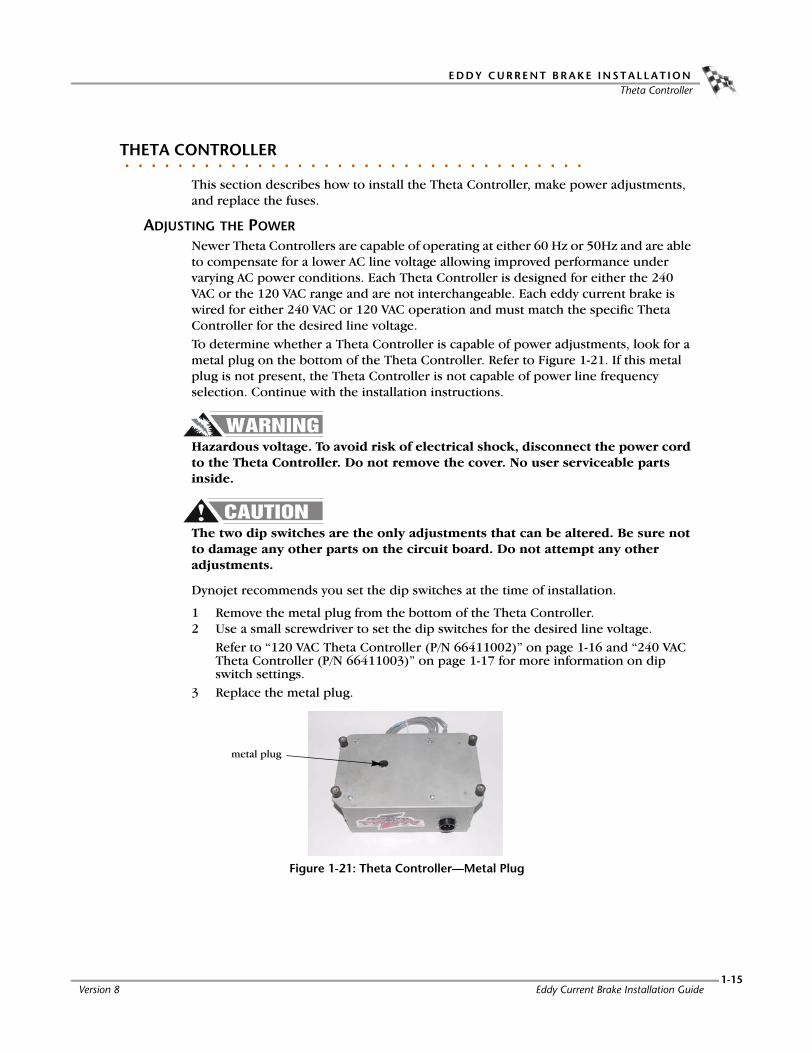
Newer Theta Controllers are capable of operating at either 60 Hz or 50Hz and are able to compensate for a lower AC line voltage allowing improved performance under varying AC power conditions. Each Theta Controller is designed for either the 240 VAC or the 120 VAC range and are not interchangeable. Each eddy current brake is wired for either 240 VAC or 120 VAC operation and must match the specific Theta Controller for the desired line voltage.To determine whether a Theta Controller is capable of power adjustments, look for a metal plug on the bottom of the Theta Controller. Refer to Figure 1-21. If this metal plug is not present, the Theta Controller is not capable of power line frequency selection. Continue with the installation instructions.
Hazardous voltage. To avoid risk of electrical shock, disconnect the power cord to the Theta Controller. Do not remove the cover. No user serviceable parts inside.
The two dip switches are the only adjustments that can be altered. Be sure not to damage any other parts on the circuit board. Do not attempt any other adjustments.
Dynojet recommends you set the dip switches at the time of installation.
1 Remove the metal plug from the bottom of the Theta Controller.2 Use a small screwdriver to set the dip switches for the desired line voltage.
Refer to “120 VAC Theta Controller (P/N 66411002)” on page 1-16 and “240 VAC Theta Controller (P/N 66411003)” on page 1-17 for more information on dip switch settings.
3 Replace the metal plug.
Figure 1-21: Theta Controller—Metal Plug
metal plug
Version 8 Eddy Current Brake Installation Guide1-15
C H A P T E R 1Theta Controller
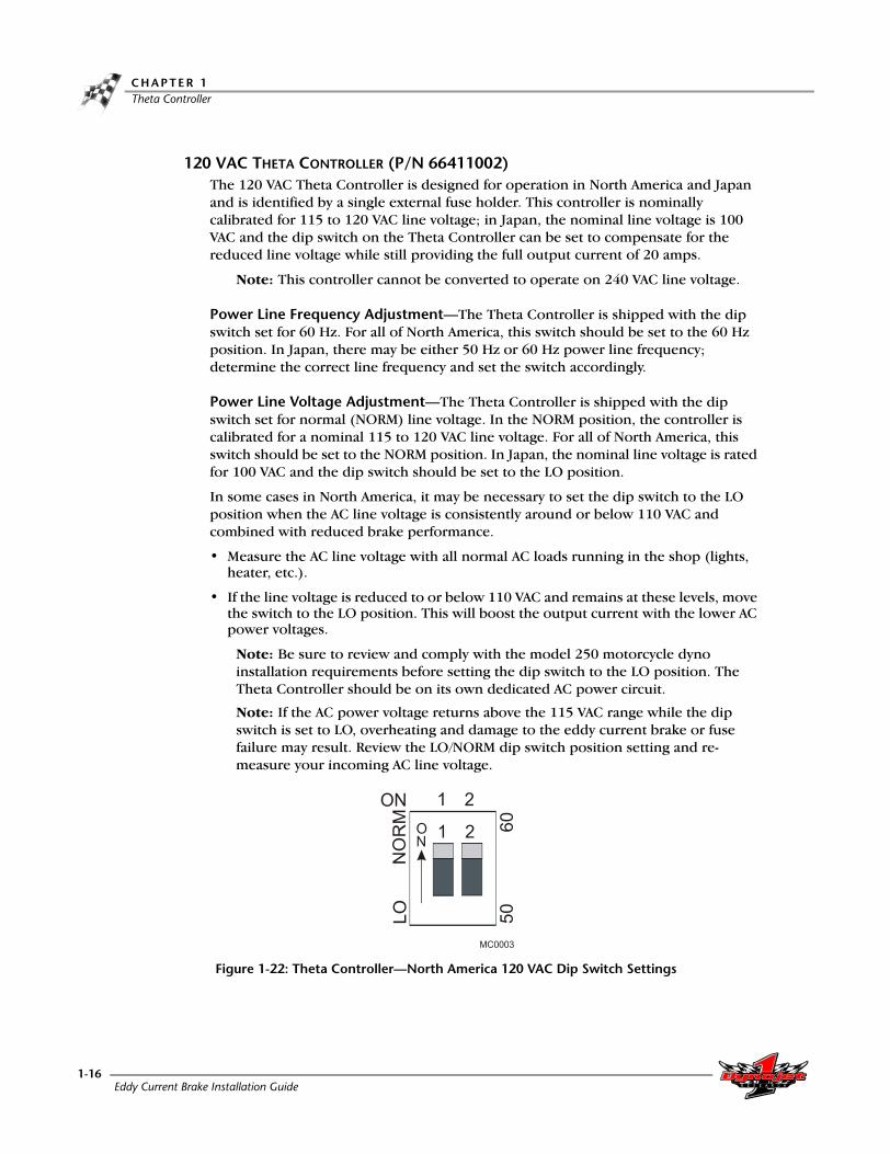
120 VAC THETA CONTROLLER (P/N 66411002)The 120 VAC Theta Controller is designed for operation in North America and Japan and is identified by a single external fuse holder. This controller is nominally calibrated for 115 to 120 VAC line voltage; in Japan, the nominal line voltage is 100 VAC and the dip switch on the Theta Controller can be set to compensate for the reduced line voltage while still providing the full output current of 20 amps.
Note: This controller cannot be converted to operate on 240 VAC line voltage.
Power Line Frequency Adjustment—The Theta Controller is shipped with the dip switch set for 60 Hz. For all of North America, this switch should be set to the 60 Hz position. In Japan, there may be either 50 Hz or 60 Hz power line frequency; determine the correct line frequency and set the switch accordingly.
Power Line Voltage Adjustment—The Theta Controller is shipped with the dip switch set for normal (NORM) line voltage. In the NORM position, the controller is calibrated for a nominal 115 to 120 VAC line voltage. For all of North America, this switch should be set to the NORM position. In Japan, the nominal line voltage is rated for 100 VAC and the dip switch should be set to the LO position.
In some cases in North America, it may be necessary to set the dip switch to the LO position when the AC line voltage is consistently around or below 110 VAC and combined with reduced brake performance.
• Measure the AC line voltage with all normal AC loads running in the shop (lights, heater, etc.).
• If the line voltage is reduced to or below 110 VAC and remains at these levels, move the switch to the LO position. This will boost the output current with the lower AC power voltages.
Note: Be sure to review and comply with the model 250 motorcycle dyno installation requirements before setting the dip switch to the LO position. The Theta Controller should be on its own dedicated AC power circuit.
Note: If the AC power voltage returns above the 115 VAC range while the dip switch is set to LO, overheating and damage to the eddy current brake or fuse failure may result. Review the LO/NORM dip switch position setting and re-measure your incoming AC line voltage.
Figure 1-22: Theta Controller—North America 120 VAC Dip Switch Settings
Eddy Current Brake Installation Guide1-16

E D D Y C U R R E N T B R A K E I N S T A L L A T I O NTheta Controller
240 VAC THETA CONTROLLER (P/N 66411003)
The 240 VAC Theta Controller is identified by the two external fuse holders. The 240 VAC Theta Controller is calibrated for a nominal 230 to 240 VAC line voltage; in certain countries, line voltages of 210 to 220 VAC may be encountered and the dip switch can be set to provide full output current of 10 amps even with the reduced line voltage.
Note: This controller cannot be converted to operate on 120 VAC line voltage.
Power Line Frequency Adjustment—The Theta Controller is shipped with the dip switch set for 50 Hz. Determine the correct line frequency and set the switch accordingly.
Power Line Voltage Adjustment—The Theta Controller is shipped with the dip switch set for normal (NORM) line voltage. In the NORM position, the controller is calibrated for a nominal 235 to 240 VAC line voltage.
In some cases in Europe, it may be necessary to set the dip switch to the LO position when the AC line voltage is consistently around or below 225 VAC and combined with reduced brake performance.
• Measure the AC line voltage with all normal AC loads running in the shop (lights, heater, etc.).
• If the line voltage is reduced to or below 225 VAC and remains at these levels, move the switch to the LO position. This will boost the output current with the lower AC power voltages.
Note: Be sure to review and comply with the model 250 motorcycle dyno installation requirements before setting the dip switch to the LO position. The Theta Controller should be on its own dedicated AC power circuit.
Note: If the AC power voltage returns above the 230 VAC range while the dip switch is set to LO, overheating and damage to the eddy current brake or fuse failure may result. Review the LO/NORM dip switch position setting and re-measure your incoming AC line voltage.
Figure 1-23: Theta Controller—Europe and Australia 240 VAC Dip Switch Settings
Version 8 Eddy Current Brake Installation Guide1-17

C H A P T E R 1Theta Controller
DRILLING THE MOUNTING HOLES
Depending on the age of your dyno, you may need to drill the holes needed to mount the Theta Controller. If your dyno already has the required holes, skip these steps and continue with the installation.
LEFT SIDE INSTALLATION
1 Locate the template for left side installations included with the control box.
This template can also be found in Appendix D.
2 Locate the large hole on the left side of the dyno. This hole should have four smaller holes around it.
3 Place the template on the dyno. Line the template up using the large hole and the four smaller holes around it.
4 Mark and drill the four mounting holes to 3/16-inch (5 mm).Note: Make sure no metal chips come in contact with the electrical components.
Figure 1-24: Theta Controller—Drill Mounting Holes on Left Side
large hole
template
Eddy Current Brake Installation Guide1-18
E D D Y C U R R E N T B R A K E I N S T A L L A T I O NTheta Controller
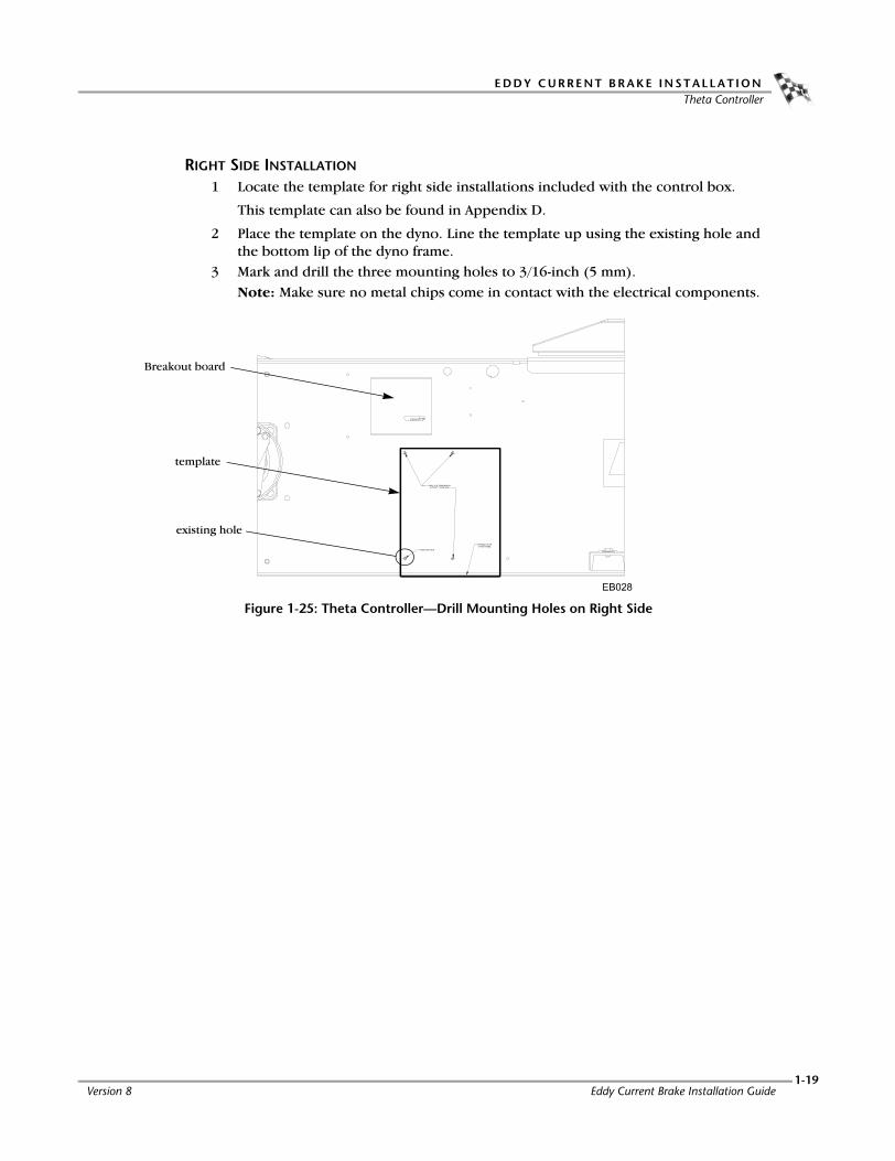
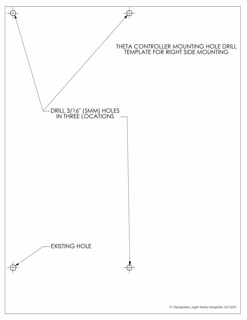
RIGHT SIDE INSTALLATION
1 Locate the template for right side installations included with the control box.
This template can also be found in Appendix D.
2 Place the template on the dyno. Line the template up using the existing hole and the bottom lip of the dyno frame.
3 Mark and drill the three mounting holes to 3/16-inch (5 mm).Note: Make sure no metal chips come in contact with the electrical components.
Figure 1-25: Theta Controller—Drill Mounting Holes on Right Side
existing hole
template
Breakout board
Version 8 Eddy Current Brake Installation Guide1-19
C H A P T E R 1Theta Controller
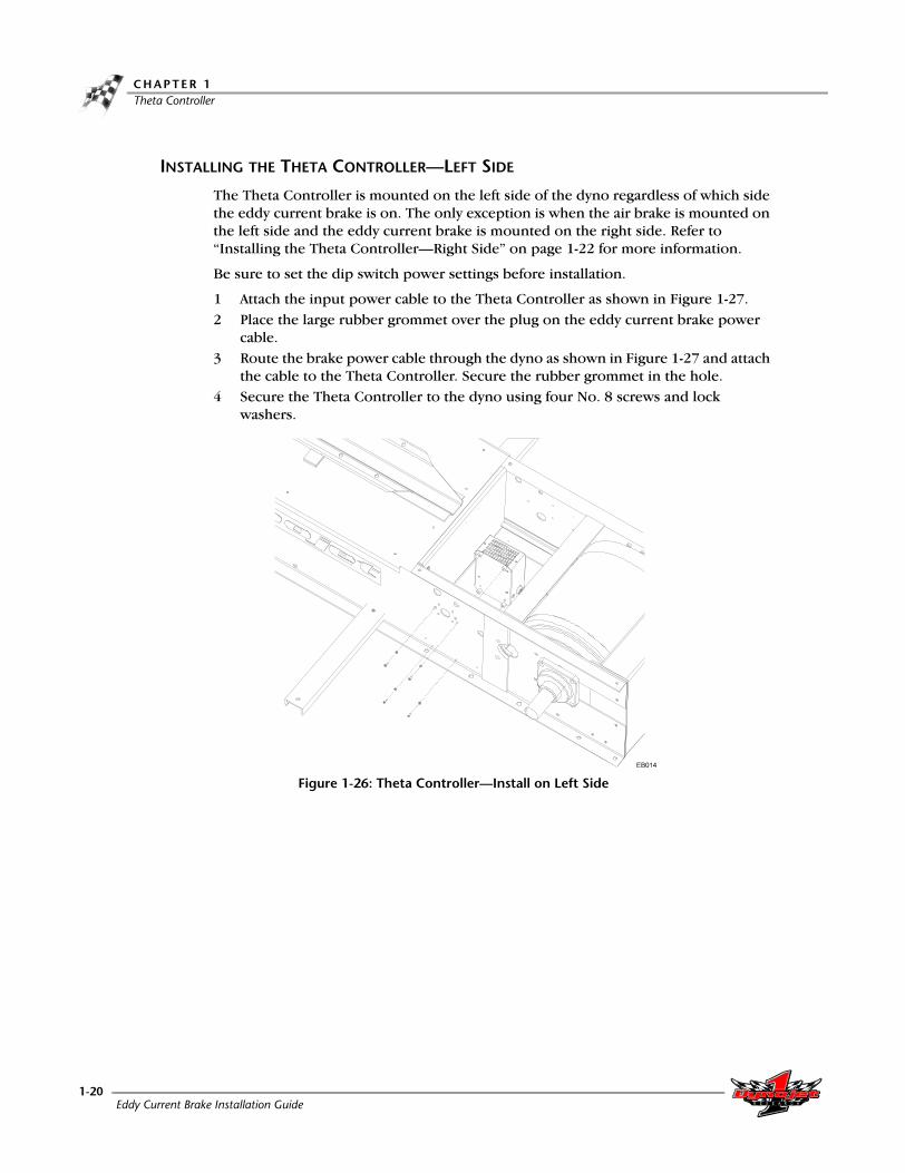
INSTALLING THE THETA CONTROLLER—LEFT SIDE
The Theta Controller is mounted on the left side of the dyno regardless of which side the eddy current brake is on. The only exception is when the air brake is mounted on the left side and the eddy current brake is mounted on the right side. Refer to “Installing the Theta Controller—Right Side” on page 1-22 for more information.
Be sure to set the dip switch power settings before installation.
1 Attach the input power cable to the Theta Controller as shown in Figure 1-27.2 Place the large rubber grommet over the plug on the eddy current brake power
cable.3 Route the brake power cable through the dyno as shown in Figure 1-27 and attach
the cable to the Theta Controller. Secure the rubber grommet in the hole.4 Secure the Theta Controller to the dyno using four No. 8 screws and lock
washers.
Figure 1-26: Theta Controller—Install on Left Side
Eddy Current Brake Installation Guide1-20

E D D Y C U R R E N T B R A K E I N S T A L L A T I O NTheta Controller
5 Route the input power cable under and out the front of the dyno.
6 Insert the smaller rubber grommet as shown in Figure 1-27.7 Route the temperature sensor cable from the eddy current brake through the
dyno to the Breakout board.8 Route the control cable from the Theta Controller to the Breakout board.
Figure 1-27: Theta Controller—Routing the Cables on Left Side
temp sensor cable
brake power cable
control cable
input power cable
Breakout board
small grommet
large grommet
Version 8 Eddy Current Brake Installation Guide1-21

C H A P T E R 1Theta Controller
INSTALLING THE THETA CONTROLLER—RIGHT SIDE
1 Install the Theta Controller using four No. 8 screws and washers. The screws will mount from the inside of the dyno.
Figure 1-28: Theta Controller—Install on Right Side
2 Attach the input power cable to the Theta Controller and route the input power cable along the side of the dyno.
3 Attach the eddy current brake cable to the Theta Controller.Note: Make sure the brake power cable is clear of the coupler.
4 Attach the temperature sensor cable from the eddy current brake to the Breakout board.
5 Attach the control cable from the Theta Controller to the Breakout board.
Figure 1-29: Theta Controller—Routing the Cables on Right Side
input power cable
brake power cable
temp sensor cable
control cable
Breakout board
Eddy Current Brake Installation Guide1-22
E D D Y C U R R E N T B R A K E I N S T A L L A T I O NTheta Controller
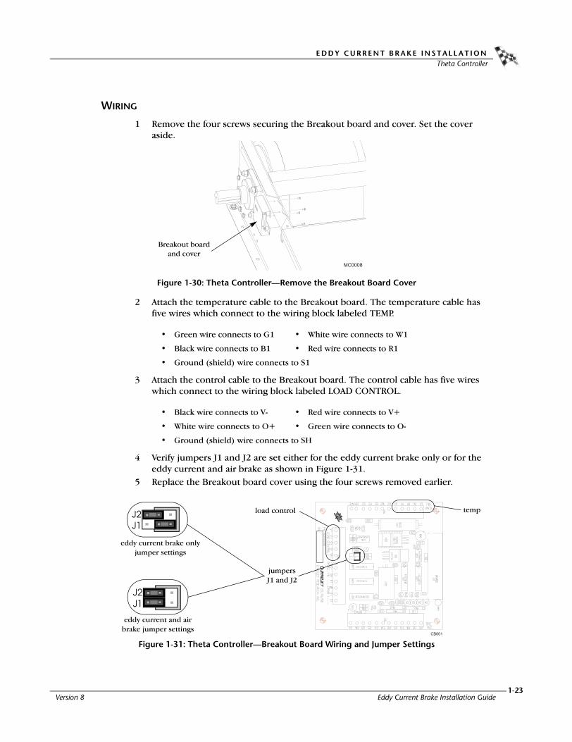
WIRING
1 Remove the four screws securing the Breakout board and cover. Set the cover aside.
Figure 1-30: Theta Controller—Remove the Breakout Board Cover
2 Attach the temperature cable to the Breakout board. The temperature cable has five wires which connect to the wiring block labeled TEMP.
3 Attach the control cable to the Breakout board. The control cable has five wires which connect to the wiring block labeled LOAD CONTROL.
4 Verify jumpers J1 and J2 are set either for the eddy current brake only or for the eddy current and air brake as shown in Figure 1-31.
5 Replace the Breakout board cover using the four screws removed earlier.
Figure 1-31: Theta Controller—Breakout Board Wiring and Jumper Settings
• Green wire connects to G1 • White wire connects to W1
• Black wire connects to B1 • Red wire connects to R1
• Ground (shield) wire connects to S1
• Black wire connects to V- • Red wire connects to V+
• White wire connects to O+ • Green wire connects to O-
• Ground (shield) wire connects to SH
Breakout board and cover
tempload control
jumpers J1 and J2
eddy current brake only jumper settings
eddy current and air brake jumper settings
Version 8 Eddy Current Brake Installation Guide1-23

C H A P T E R 1Theta Controller
REPLACING THE FUSE
Older Theta Controllers have an internal fuse. Refer to Appendix C for more information on replacing an internal fuse.
Hazardous voltage. To avoid risk of electrical shock, disconnect the power cord to the Theta Controller before replacing the fuse. Do not remove the cover. No user serviceable parts inside.
1 Remove the Theta Controller from the dyno. Refer to Figure 1-26 or Figure 1-28.2 Gently push the fuse holder slightly inward and rotate counterclockwise to
remove. 3 Replace the fuse. Refer to the table on page 1-25 for fuse replacement types.
For continued protection against risk of fire, replace only with a fuse of the same type and having the same electrical rating.
Figure 1-32: Theta Controller—Replace the Fuse
Eddy Current Brake Installation Guide1-24

E D D Y C U R R E N T B R A K E I N S T A L L A T I O NTheta Controller
To determine whether you have a 120 volt or 240 volt Theta Controller, look at the serial number/fuse(s) on the Theta Controller. If the serial number begins with an “E”, and the control box has dual fuses, then it is a 240 volt unit; if the serial number does not begin with an “E” and the control box has a single fuse, then it is a 120 volt unit.
Figure 1-33: Theta Controller—Determine the Type
Note: Changing the fuse rating to the higher or lower specification does not allow you to use the Theta Controller with an eddy current brake that was wired for 120 volt or 240 volt originally. Refer to “Verifying the Eddy Current Brake Wiring Configuration” on page 1-26.
Note: If the eddy current brake has been rewired to a different voltage, you will need a different Theta Controller. The original Theta Controller will not work.
Theta Controller replacement fuse
240 volt Buss P/N BAF-15, 15A FuseLittle Fuse, KLK 15Fast Blow, Dynojet P/N 54211201
120 volt Buss P/N BAF-25, 25A FuseLittle Fuse, KLK 25Fast Blow, Dynojet P/N 54202501
120 volt, single fuseNorth America
240 volt, dual fusesEurope/Australia
Version 8 Eddy Current Brake Installation Guide1-25

C H A P T E R 1Theta Controller
CHANGING THE INPUT POWER CABLE PLUG
If the input power cable is not provided with a power plug, you must install the correct power plug for your country. The input power cable plug must connect to a properly grounded outlet and be easily accessible so that it may be disconnected. Do not wire the input power cable directly into the power panel. Refer to Figure 1-34 for individual wire descriptions.
Note: The eddy current brake is set up to run on 120 volts/20 amps/60 Hz for North America and 240 volts/10 amps/50 Hz for Europe/Australia.
Note: The voltage source and power plug must be capable of handling a minimum of 20 amps for North America and 10 amps for Europe/Australia.
Figure 1-34: Theta Controller—Input Power Cable Plug
VERIFYING THE EDDY CURRENT BRAKE WIRING CONFIGURATION
Refer to Figure 1-35 to determine whether the eddy current brake is currently wired for 120 or 240 volt operation.
Figure 1-35: Theta Controller —Eddy Current Brake Wiring
neutral—clear or white insulation wire
hot—black insulation wire
ground—bare or green wire
120 volt wiring, North America 240 volt wiring, Europe/Australia
Eddy Current Brake Installation Guide1-26

E D D Y C U R R E N T B R A K E I N S T A L L A T I O NHood Upgrade
. . . . . . . . . . . . . . . . . . . . . . . . . . . . . . . . . . .HOOD UPGRADE
Use the following instructions to assemble and install the hood upgrade or to attach the eddy current brake cover to your existing hood.
ASSEMBLING THE HOOD
1 Verify that the dyno hood side panel is on the correct side for your eddy current brake. You may have to remove the side panel and move it to the opposite side for your particular installation.
Figure 1-36: Dyno Hood Side Panel
2 Place the eddy current brake cover in position next to the dyno hood.Note: Place the front and rear flanges of the eddy current brake cover on the inside of the dyno hood. Place the top flange of the eddy current brake cover on top of the dyno hood.
3 Secure the eddy current brake cover to the dyno hood using the six 1/4-inch button head screws and locking nuts.
Figure 1-37: Secure Eddy Current Brake Cover to Dyno Hood
dyno hood set up for left side installation
eddy current brake cover flange on top of the dyno hood
eddy current brake cover flange on the inside of the dyno hood
eddy current brake cover
dyno hood
Version 8 Eddy Current Brake Installation Guide1-27

C H A P T E R 1Hood Upgrade
INSTALLING THE HOOD
1 Verify the bolts and the set screws on the couplers are tight.2 Connect the battery.3 Carefully place the hood on the dyno leaving it propped up. Secure the key
switch, if present.4 Lower and secure the hood using the four bolts removed earlier.
Verify the hood is not pinching or contacting any cables or wires.
Figure 1-38: Install the New Dyno Hood
5 Secure the hood clamps to the brake using the two bolts you removed earlier.6 Secure the brake cover using the four bolts you removed earlier.
Never operate the dyno with this cover removed.
7 Plug the input power cable into a wall outlet.
Figure 1-39: Secure the Hood Clamps and Brake Cover
brake cover
hood clamps
Eddy Current Brake Installation Guide1-28
A P P E N D I X
ARED HEAD ANCHOR INSTALLATION
This appendix contains instructions for installing the Red Head Multi-Set™II Anchors. The anchors will be used to secure the dyno to concrete. To ensure safety and accuracy in the procedures, perform the procedures as they are described. Be sure to read and understand the warnings included in this appendix.
WARNINGS
Always wear safety glasses and other necessary protective devices or apparel when installing or working with anchors.
ITW Ramset/Red Head Multi-Set II Anchors are designed to operate properly only when installed with ITW Ramset/Red Head brand Setting Tools.
The use of a 24 to 40 ounce hammer is recommended for expanding Multi-Set II anchors.
The use of carbide drill bits manufactured with ANSI B94. 12-77 drill bit diameter requirements is recommended for installation of this anchor.
Not recommended for use in lightweight masonry material such as block or brick.
Use of core drills is not recommended to drill holes for use with this anchor.
Not recommended for use in new concrete which has not had sufficient time to cure.
Anchor spacing and edge distance requirements (anchor installation locations) are the responsibility of the engineer of record.
CONTACT INFORMATION FOR ITW RAMSET/RED HEADContact ITW Ramset/Red Head at 1-630-350-0370, or 1300 North Michael Drive, Wood Dale, IL 60191.
Eddy Current Brake Installation GuideA-1

A P P E N D I X AInstallation
. . . . . . . . . . . . . . . . . . . . . . . . . . . . . . . . . . .INSTALLATION
Use the table below to determine the catalog number, drill bit size, minimum hole depth, and setting tool catalog number.
Use the following instructions to install the Red Head anchors.
1 Drill the hole in the concrete the same outside diameter as the anchor being used to any depth exceeding minimum embedment.
Figure A-1: Red Head Anchor—Drill the Hole
2 Insert the anchor.
Figure A-2: Red Head Anchor—Insert the Anchor
catalog number drill bit size minimum hole depthsetting tool catalog number
Carbon SteelRM-38/RL-38 (9.5 mm)
1/2-inch 1 5/8-inch (41.2 mm) RT-138
anchor
Eddy Current Brake Installation GuideA-2

R E D H E A D A N C H O R I N S T A L L A T I O NInstallation
3 Using a hammer, drive the anchor flush with the surface of the concrete, or below
the surface if the hole depth exceeds minimum embedment.
Figure A-3: Red Head Anchor—Drive the Anchor Flush
4 Using a hammer, expand the anchor with the setting tool. The anchor is properly expanded when the shoulder of the setting tool is flush with the top of the anchor.Note: Use only Ramset/Red Head setting tools to insure proper installtion.
Figure A-4: Red Head Anchor—Expand the Anchor
setting tool
Version 8 Eddy Current Brake Installation GuideA-3

A P P E N D I X
BHIGH INERTIA DRUM—OLDER
DYNO INSTALLATION
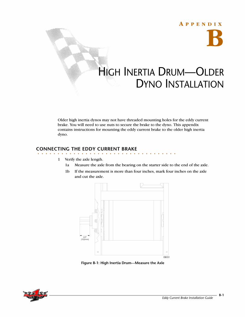
Older high inertia dynos may not have threaded mounting holes for the eddy current brake. You will need to use nuts to secure the brake to the dyno. This appendix contains instructions for mounting the eddy current brake to the older high inertia dyno.
. . . . . . . . . . . . . . . . . . . . . . . . . . . . . . . . . . .CONNECTING THE EDDY CURRENT BRAKE
1 Verify the axle length.1a Measure the axle from the bearing on the starter side to the end of the axle.
1b If the measurement is more than four inches, mark four inches on the axle and cut the axle.
Figure B-1: High Inertia Drum—Measure the Axle
Eddy Current Brake Installation GuideB-1

A P P E N D I X B
2 If not already removed, remove the four bolts in the dyno frame from the
positions shown in Figure B-2.3 Remove the four nuts and washers from the positions shown in Figure B-2 leaving
the bolts in place.
Figure B-2: High Inertia Drum—Remove Nuts and Washers
4 Slip the connecting arms over the four existing bolts on the dyno frame and loosely attach the arms using the four washers and nuts removed earlier. These nuts need to remain loose in order to align the brake
5 Loosely attach the connecting arms using the four 3/8-inch bolts and 3/8-inch washers removed earlier. These bolts need to remain loose in order to align the brake
6 Continue with “Aligning the Eddy Current Brake” on page 1-13.
Figure B-3: High Inertia Drum—Connect Brake
remove bolts
do not remove
remove nuts and washers
remove nuts and washers
remove bolts
Eddy Current Brake Installation GuideB-2

A P P E N D I X
CTHETA CONTROLLER—INTERNAL FUSE
Older Theta Controllers have the fuse located inside the theta control box. This appendix contains instructions to replace the internal fuse.
. . . . . . . . . . . . . . . . . . . . . . . . . . . . . . . . . . .REPLACING THE INTERNAL FUSE
Hazardous voltage. To avoid risk of electrical shock, disconnect the power cord to the Theta Controller before replacing the fuse.
1 Remove the six screws that secure the cover to the base of the Theta Controller.
There are two screws on top and two on each side of the cover.
2 Remove the theta control cover and set it aside.3 Remove the blown fuse and replace it. Refer to the table below for fuse
replacement types.4 Replace the theta control cover.
Figure C-1: Theta Controller—Replace Internal Fuse
Eddy Current Brake Installation GuideC-1

A P P E N D I X C
For continued protection against risk of fire, replace only with a fuse of the same type and having the same electrical rating.
To determine whether you have a 120 volt or 240 volt early style Theta Controller, look at the serial number on the Theta Controller. If it begins with an “E”, then it is a 240 volt unit; if it does not begin with an “E”, then it is a 120 volt unit.
Note: Changing the fuse rating to the higher or lower specification does not allow you to use the Theta Controller with an eddy current brake that was wired for 120 volt or 240 volt originally. Refer to “Verifying the Eddy Current Brake Wiring Configuration” on page 1-26.
Note: If the eddy current brake has been rewired to a different voltage, you will need a different Theta Controller. The original Theta Controller will not work.
Theta Controller replacement fuse
240 volt Buss P/N FNQ-15, 15A TIme Delayed Fuse
120 volt Buss P/N FNQ-25, 25A Time Delayed Fuse
Eddy Current Brake Installation GuideC-2

A P P E N D I X
DMOUNTING TEMPLATES
Depending on the age of your dyno, you may need to drill the holes needed to mount the Theta Controller. This appendix contains the templates needed to locate and place the mounting holes for both left and right side installations.
This appendix contains the following templates:
• Theta Controller Mounting Hole Drill Template For Left Side Mounting
• Theta Controller Mounting Hole Drill Template For Right Side Mounting
Eddy Current Brake Installation GuideD-1

(222mm
) 8.75IN
(102mm
) 4.00IN
EXISTING
HOLES
DRILL
3/16" (5mm
)4 PLA
CES
THETA C
ON
TROLLER M
OUN
TING
HOLE D
RILLTEM
PLATE FO
R LEFT SIDE M
OUN
TING
P:\Templates\ Left Theta tem
plate 12/13/01
UP
EXISTING HOLE
DRILL 3/16" (5MM) HOLESIN THREE LOCATIONS
THETA CONTROLLER MOUNTING HOLE DRILLTEMPLATE FOR RIGHT SIDE MOUNTING
P:\Templates\ right theta template 12/13/01
Related Documents