1998 Mercedes-benz SLK230 Submodel: | Engine Type: L4 | Liters: 2.3 Fuel Delivery: FI | Fuel: GAS Before servicing any vehicle, please be sure to read all of the following precautions, which deal with personal safety, prevention of component damage and important points to take into consideration when servicing a motor vehicle: Never open, service or drain the radiator or cooling system when the engine is hot; serious burns can occur from the steam and hot coolant. Observe all applicable safety precautions when working around fuel. Whenever servicing the fuel system, always work in a well-ventilated area. Do not allow fuel spray or vapors to come in contact with a spark, open flame or excessive heat (a hot drop light, for example). Keep a dry chemical fire extinguisher near the work area. Always keep fuel in a container specifically designed for fuel storage; also, always properly seal fuel containers to avoid the possibility of fire or explosion. Refer to the additional fuel system precautions later in this section. Fuel injection systems often remain pressurized, even after the engine has been turned OFF. The fuel system pressure must be relieved before disconnecting any fuel lines. Failure to do so may result in fire and/or personal injury. Brake fluid often contains polyglycol ethers and polyglycols. Avoid contact with the eyes and wash your hands thoroughly after handling brake fluid. If you do get brake fluid in your eyes, flush your eyes with clean, running water for 15 minutes. If eye irritation persists, or if you have taken brake fluid internally, seek medical assistance IMMEDIATELY. The EPA warns that prolonged contact with used engine oil may cause a number of skin disorders, including cancer. You should make every effort to minimize your exposure to used engine oil. Protective gloves should be worn when changing oil. Wash your hands and any other exposed skin areas as soon as possible after exposure to used engine oil. Soap and water, or waterless hand cleaner should be used. All new vehicles are now equipped with an air bag system. The system must be disabled before performing service on or around system components, steering column, instrument panel components, wiring and sensors. Failure to follow safety and disabling procedures could result in accidental air bag deployment, possible personal injury and unnecessary system repairs. Always wear safety goggles when working with, or around, the air bag system. When carrying a non-deployed air bag, be sure the bag and trim cover are pointed away from your body. When placing a non-deployed air bag on a work surface, always face the bag and trim cover upward, away from the surface. This will reduce the motion of the module if it is accidentally deployed. Refer to the additional air bag system precautions later in this section. Clean, high quality brake fluid from a sealed container is essential to the safe and proper operation of the brake system. You should always buy the correct type of brake fluid for your vehicle. If the brake fluid becomes contaminated, completely flush the system with new fluid. Never reuse any brake fluid. Any brake fluid that is removed from the system should be discarded. Also, do not allow any brake fluid to come in contact with a painted surface; it will damage the paint. Never operate the engine without the proper amount and type of engine oil; doing so will result in severe engine damage. Timing belt maintenance is extremely important. Many models utilize an interference-type, non-freewheeling engine. If the timing belt breaks, the valves in the cylinder head may strike the pistons, causing potentially serious (also time-consuming and expensive) engine damage. Refer to the maintenance interval charts in the front of this manual for the recommended replacement interval for the timing belt and to the timing belt section for belt replacement and inspection. Disconnecting the negative battery cable on some vehicles may interfere with the functions of the on-board computer system(s) and may require the computer to undergo a relearning process once the negative battery cable is reconnected. When servicing drum brakes, only disassemble and assemble one side at a time, leaving the remaining side intact for reference. Only an MVAC-trained, EPA-certified automotive technician should service the air conditioning system or its components.

1998 Mercedes Benz SLK230 Workshop Manual
Oct 26, 2014
Welcome message from author
This document is posted to help you gain knowledge. Please leave a comment to let me know what you think about it! Share it to your friends and learn new things together.
Transcript

1998 Mercedes-benz SLK230
Submodel: | Engine Type: L4 | Liters: 2.3Fuel Delivery: FI | Fuel: GAS
Before servicing any vehicle, please be sure to read all of the following precautions, which deal with personal safety, prevention of component damage and important points to take intoconsideration when servicing a motor vehicle:
Never open, service or drain the radiator or cooling system when the engine is hot; serious burns can occur from the steam and hot coolant.Observe all applicable safety precautions when working around fuel. Whenever servicing the fuel system, always work in a well-ventilated area. Do not allow fuel spray or vapors tocome in contact with a spark, open flame or excessive heat (a hot drop light, for example). Keep a dry chemical fire extinguisher near the work area. Always keep fuel in a containerspecifically designed for fuel storage; also, always properly seal fuel containers to avoid the possibility of fire or explosion. Refer to the additional fuel system precautions later in thissection.Fuel injection systems often remain pressurized, even after the engine has been turned OFF. The fuel system pressure must be relieved before disconnecting any fuel lines. Failureto do so may result in fire and/or personal injury.Brake fluid often contains polyglycol ethers and polyglycols. Avoid contact with the eyes and wash your hands thoroughly after handling brake fluid. If you do get brake fluid in youreyes, flush your eyes with clean, running water for 15 minutes. If eye irritation persists, or if you have taken brake fluid internally, seek medical assistance IMMEDIATELY.The EPA warns that prolonged contact with used engine oil may cause a number of skin disorders, including cancer. You should make every effort to minimize your exposure to usedengine oil. Protective gloves should be worn when changing oil. Wash your hands and any other exposed skin areas as soon as possible after exposure to used engine oil. Soap andwater, or waterless hand cleaner should be used.All new vehicles are now equipped with an air bag system. The system must be disabled before performing service on or around system components, steering column, instrumentpanel components, wiring and sensors. Failure to follow safety and disabling procedures could result in accidental air bag deployment, possible personal injury and unnecessarysystem repairs.Always wear safety goggles when working with, or around, the air bag system. When carrying a non-deployed air bag, be sure the bag and trim cover are pointed away from yourbody. When placing a non-deployed air bag on a work surface, always face the bag and trim cover upward, away from the surface. This will reduce the motion of the module if it isaccidentally deployed. Refer to the additional air bag system precautions later in this section.Clean, high quality brake fluid from a sealed container is essential to the safe and proper operation of the brake system. You should always buy the correct type of brake fluid for yourvehicle. If the brake fluid becomes contaminated, completely flush the system with new fluid. Never reuse any brake fluid. Any brake fluid that is removed from the system should bediscarded. Also, do not allow any brake fluid to come in contact with a painted surface; it will damage the paint.Never operate the engine without the proper amount and type of engine oil; doing so will result in severe engine damage.Timing belt maintenance is extremely important. Many models utilize an interference-type, non-freewheeling engine. If the timing belt breaks, the valves in the cylinder head maystrike the pistons, causing potentially serious (also time-consuming and expensive) engine damage. Refer to the maintenance interval charts in the front of this manual for therecommended replacement interval for the timing belt and to the timing belt section for belt replacement and inspection.Disconnecting the negative battery cable on some vehicles may interfere with the functions of the on-board computer system(s) and may require the computer to undergo a relearningprocess once the negative battery cable is reconnected.When servicing drum brakes, only disassemble and assemble one side at a time, leaving the remaining side intact for reference.Only an MVAC-trained, EPA-certified automotive technician should service the air conditioning system or its components.

1998 Mercedes-benz SLK230
Submodel: | Engine Type: L4 | Liters: 2.3Fuel Delivery: FI | Fuel: GAS
A basic vehicle cooling system consists of a radiator, water pump, thermostat, electric or engine-driven cooling fan, and hoses. Electric cooling fans are common on today's vehicles due toengine compartment space limitations or engine layout. Electric cooling fans operate in either a pusher or a puller capacity. A pusher type fan is typically mounted on the front of the radiatorassembly and forces air through the radiator, whereas a puller type fan is mounted on the engine side of the radiator and draws air through the grill and radiator assembly. Vehicles thatutilize a transversely-mounted engine will always be equipped with at least one electric cooling fan (most having two), because none of the engine pulleys are inline with the radiator air-flow.
Typical dual fan set-up, showing common cooling fan systemcontrol components used on many vehicles with A/C
There are generally two types of electric cooling fans: primary cooling fans and secondary cooling fans. Primary cooling fans are typically of the puller style. Vehicles that do not incorporatean engine-driven mechanical cooling fan will utilize a primary cooling fan. The secondary cooling fan, also known as a A/C condenser fan or auxiliary cooling fan by certain manufacturers,could be of either a pusher or a puller style. Vehicles equipped with A/C will either utilize the radiator cooling fan or a separate fan as the A/C condenser cooling fan (which performs thesame function as an auxiliary cooling fan on vehicles with a primary mechanical fan). The engine control computer that receives inputs from various sensors in the engine compartmentcommonly controls electric cooling fans. The engine control computer receives inputs from the engine coolant temperature sensors and A/C system pressure switches, then actuates thenecessary cooling fan relays to engage the applicable cooling fan for the condition. On models equipped with only one electric primary cooling fan, the fan can operate at two speeds: lowspeed and high speed. The low speed condition is enabled when the engine begins to heat up or when the A/C is engaged. As the engine demands more cooling, the cooling fan will bestepped-up to high speed.

1998 Mercedes-benz SLK230
Submodel: | Engine Type: L4 | Liters: 2.3Fuel Delivery: FI | Fuel: GAS
Puller Type
NOTE: It may be simpler to remove the cooling fan(s) with the radiator as an assembly.
1. Disconnect the negative battery cable.2. Inspect the cooling fan and take note of any wires, hoses or A/C lines which may hamper fan removal. Also at this time, decide whether it is necessary to remove the fan along
with the radiator or not.3. Position aside all wires, hoses and A/C lines for fan removal. It may not always be possible to create enough clearance for fan removal by simply moving these obstructions
aside; often they must be disconnected. If any cooling system lines must be disconnected, drain and recycle the engine coolant. If any of the A/C lines must be disconnected, theA/C system will need to be discharged and evacuated by a MVAC-trained technician using an approved recovery machine.
Exploded view of a typical dual cooling fan set-up and relatedcooling system components
4. Disengage the cooling fan wiring harness connector.5. If the fan can be removed without the radiator, perform the following:
A. Loosen the mounting fasteners. Usually there are two nuts or bolts along the top edge of the cooling fan shroud and either two retaining clips or bolts along thebottom edge.
B. Carefully lift the fan up and out of the engine compartment, making sure that no wires or hoses get hung up on it.6. If it is necessary to remove the radiator for fan removal, perform the following:
A. Disconnect all cooling system hoses from it after draining the cooling system.B. Locate all of the radiator mounting fasteners (usually two or more nuts or bolts along the top, possibly two along the bottom).
NOTE: Quite a few radiators are secured along the bottom by two posts which fit into rubber grommets. The rubber grommets help isolatethe radiator from harsh vibrations in the frame. If no nuts or bolts can be located along the bottom of the radiator, chances are that theradiator is secured with the posts and grommets.
C. Lift the radiator and cooling fan up and out of the engine compartment together.D. Separate the cooling fan from the radiator by removing the attaching fasteners.
To remove a puller type cooling fan, first detach any braces(1), wires (2) or other obstructions...
... including cooling system hoses, to allow fan removal

Disengage the fan wiring connector(s)...
... and loosen all fan mounting fasteners
Separate the fan from the radiator...
..., then lift the fan up and out of the engine compartment
To install:

7. If applicable, install the cooling fan on the radiator.8. Install the cooling fan and shroud assembly (also the radiator if necessary). Tighten the fan shroud mounting bolts.9. Reattach all wires, hoses and A/C lines as applicable. If the A/C lines were detached, the system must be evacuated and recharged by a MVAC-trained technician.
10. If drained, refill and bleed the cooling system.11. Reattach the cooling fan electrical harness connector.12. Connect the negative battery cable.13. Start the engine and check for leaks.14. Verify the operation of the cooling fan(s).
Typical mounting of a puller type cooling fan assemblyutilizing retaining clips and screws — note that this particular
model uses a dual puller fan setup
Notice the slots in the bottom of the radiator, in which the fanhousing posts rest — common mounting of a puller type
cooling fan.
This fan mounts to the fan shroud, then the shroud mounts tothe radiator — molded clips in the radiator hold the bottom in
place and screws at the top.
Typically the cooling fan is rubber mounted to isolate vibrationand noise — usually the rubber grommets are located at the
mount, verify their position before installation

Pusher Type
Vehicles that utilize the pusher type of electric cooling fan, may require the removal of the grilles and/or upper radiator shroud in order to gain access the fasteners that mount the fanassembly in the vehicle.
1. Disconnect the negative battery cable.2. Access the cooling fan.3. Label and disconnect the cooling fan electrical harness.
NOTE: It may be necessary to loosen the mounting bolts for the A/C condenser to the body4. Remove the fasteners that mount the cooling fan to the A/C condenser or radiator.5. Lift the cooling fan out of the vehicle.
After removal of the grill assembly, the pusher type of coolingfan can be removed
It may be necessary to remove the grill assembly to accessthe A/C condenser cooling fan — pusher type
To install: 6. Insert the cooling fan into the vehicle.7. Mount the cooling fan to the A/C condenser or radiator8. Connect the cooling fan electrical harness.9. If removed, install any shrouding or grills.
10. Connect the negative battery cable.

1998 Mercedes-benz SLK230
Submodel: | Engine Type: L4 | Liters: 2.3Fuel Delivery: FI | Fuel: GAS
When diagnosing an inoperative cooling fan it may be necessary to use a diagnostic scan tool to monitor engine coolant temperature and the engine control computer.
1. Perform a visual inspection of the cooling fan. If the fan does not turn with ease, the fan motor is seized and needs to be replaced.2. Check all the fuses and fusible links related to the cooling fan circuit.3. Check the integrity of the electrical connections related to the cooling fan circuit.4. Check the cooling fan motor.5. Check the relays associated with the cooling fan circuit.6. Using a scan tool, determine if the engine control computer is calling for the fan to activate.
Cooling Fan Motor
1. Disconnect the negative battery cable.2. Disengage the cooling fan motor connector.3. Identify and label the ground and the power terminals of the cooling fan connector using the wiring diagrams provided.4. Using jumper leads with a fuse in series, apply battery voltage to the appropriate terminals of the cooling fan.5. The cooling fan should operate. If not, replace the cooling fan.
If the cooling fan functions properly during this test, proceed to the cooling fan relay test.
Cooling Fan Relay
1. Turn the ignition OFF.2. Remove the relay.3. Locate the two terminals on the relay, which are connected to the coil windings. Check the relay coil for continuity. Connect the common meter lead to terminal 85 and positive
meter lead to terminal 86. There should be continuity. If not, replace the relay.
Use an ohmmeter to check for circuit continuity of the coil inthe relay
4. Check the operation of the internal relay contacts.
A. Connect the meter leads to terminals 30 and 87. Meter polarity does not matter for this step.B. Apply positive battery voltage to terminal 86 and ground to terminal 85. The relay should click as the contacts are drawn toward the coil and the meter should
indicate continuity. Replace the relay if your results are different.
If the relay functions properly during this test, inspect the coolant temperature sensor and the cooling fan system wiring for defects.
Terminal identification of the most common types of relays.Diodes and resistors in the relay prevent voltage spikesinduced when the current is removed from the coil from
damaging electronic components

DIA. 42 - 1997–01 Mercedes-Benz C220 / C280 2.2L / 2.8L
DIA. 43 - 1997–01 Mercedes-Benz E320 / E420 3.2L / 4.2L

DIA. 44 - 1997–01 Mercedes-Benz S320 / S420 / S501 3.2L/ 4.2L / 5.0L

1998 Mercedes-benz SLK230
Submodel: | Engine Type: L4 | Liters: 2.3Fuel Delivery: FI | Fuel: GAS
An oxygen (O2S) sensor is an input device used by the engine control computer to monitor the amount of oxygen in the exhaust gas stream. The information is used by the computer, alongwith other inputs, to fine-tune the air/fuel mixture so that the engine can run with the greatest efficiency in all conditions. The O2S sensor sends this information to the computer in the form ofa 100–900 millivolt (mV) reference signal. The signal is actually created by the O2S sensor itself through chemical interactions between the sensor tip material (zirconium dioxide in almostall cases) and the oxygen levels in the exhaust gas stream and ambient atmosphere gas. At operating temperatures, approximately 1100°F (600°C), the element becomes asemiconductor. Essentially, through the differing levels of oxygen in the exhaust gas stream and in the surrounding atmosphere, the sensor creates a voltage signal that is directly andconsistently related to the concentration of oxygen in the exhaust stream. Typically, a higher than normal amount of oxygen in the exhaust stream indicates that not all of the availableoxygen was used in the combustion process, because there was not enough fuel (lean condition) present. Inversely, a lower than normal concentration of oxygen in the exhaust streamindicates that a large amount was used in the combustion process, because a larger than necessary amount of fuel was present (rich condition). Thus, the engine control computer cancorrect the amount of fuel introduced into the combustion chambers.
Since the control computer uses the O2S sensor output voltage as an indication of the oxygen concentration, and the oxygen concentration directly affects O2S sensor output, the signalvoltage from the sensor to the computer fluctuates constantly. This fluctuation is caused by the nature of the interaction between the computer and the O2S sensor, which follows a generalpattern: detect, compare, compensate, detect, compare, compensate, etc. This means that when the computer detects a lean signal from the O2S sensor, it compares the reading withknown parameters stored within its memory. It calculates that there is too much oxygen present in the exhaust gases, so it compensates by adding more fuel to the air/fuel mixture. This, inturn, causes the O2S sensor to send a rich signal to the computer, which, then compares this new signal, and adjusts the air/fuel mixture again. This pattern constantly repeats itself: detectrich, compare, compensate lean, detect lean, compare, compensate rich, etc. Since the O2S sensor fluctuates between rich and lean, and because the lean limit for sensor output is 100mV and the rich limit is 900 mV, the proper voltage signal from a normally functioning O2S sensor consistently fluctuates between 100–300 and 700–900 mV.
NOTE: The sensor voltage may never quite reach 100 or 900 mV, but it should fluctuate from at least below 300 mV to above 700 mV, and the mid-point of thefluctuations should be centered around 500 mV.
To improve O2S sensor efficiency, newer O2S sensors were designed with a built-in heating element, and were called Heated O2S (HO2S) sensors. This heating element was incorporatedinto the sensor so that the sensor would reach optimal operating temperature quicker, meaning that the O2S sensor output signal could be used by the engine control computer sooner.Because the sensor reaches optimal temperature quicker, modern vehicles enjoy improved driveability and fuel economy even before the engine reaches normal operating temperature.
On-Board Diagnostics second generation (OBD-II), an updated system based on the former OBD-I, calls for additional O2S sensors to be used after the catalytic converter, so that catalyticconverter efficiency can be measured by the vehicle's engine control computer. The O2S sensors mounted in the exhaust system after the catalytic converters are not used to affect air/fuelmixture; they are used solely to monitor catalytic converter efficiency.
A cut away view of a Heated Oxygen (HO2S) sensor
O2S sensor output voltage vs. mixture ratio

1998 Mercedes-benz SLK230
Submodel: | Engine Type: L4 | Liters: 2.3Fuel Delivery: FI | Fuel: GAS
When testing or servicing an Oxygen (O2S) sensor you will need to start and warm the engine to operating temperature in order to either perform the necessary testing procedures or toeasily remove the sensor from its fitting. This will create a situation in which you will be working around a HOT exhaust system. The following is a list of precautions to consider during thisservice:
Do not pierce any wires when testing an O2S sensor, as this can lead to wiring harness damage. Backprobe the connector, when necessary.While testing the sensor, be sure to keep out of the way of moving engine components, such as the cooling fan. Refrain from wearing loose clothing that may become tangled inmoving engine components.Safety glasses must be worn at all times when working on or near the exhaust system. Older exhaust systems may be covered with loose rust particles that can shower you whendisturbed. These particles are more than a nuisance and can injure your eye.Be cautious when working on and around the hot exhaust system. Painful burns will result if skin is exposed to the exhaust system pipes or manifolds.The O2S sensor may be difficult to remove when the engine temperature is below 120°F (48°C). Excessive force may damage the threads in the exhaust manifold or pipe, thereforealways start the engine and allow it to reach normal operating temperature prior to removal.Since O2S sensors are usually designed with a permanently attached wiring pigtail (this allows the wiring harness and sensor connectors to be positioned away from the hot exhaustsystem), it may be necessary to use a socket or wrench that is designed specifically for this purpose. Before purchasing such a socket, be sure that you can't save some money byusing a box end wrench for sensor removal.
1998 Mercedes-benz SLK230
Submodel: | Engine Type: L4 | Liters: 2.3Fuel Delivery: FI | Fuel: GAS
The best, and most accurate method to test the operation of an Oxygen (O2S) sensor is with the use of either an oscilloscope or a Diagnostic Scan Tool (DST), following their specificinstructions for testing. It is possible, however, to test whether the O2S sensor is functioning properly within general parameters using a Digital Volt-Ohmmeter (DVOM), also referred to as aDigital Multi-Meter (DMM). Newer DMM's are often designed to perform many advanced diagnostic functions. Some are constructed to be used as an oscilloscope. Two in-vehicle testingprocedures, and 1 bench test procedure, will be provided for the common zirconium dioxide O2S sensor. The first in-vehicle test makes use of a standard DVOM with a 10 megohmsimpedance, whereas the second in-vehicle test presented necessitates the usage of an advanced DMM with MIN/MAX/Average functions. Both of these in-vehicle test procedures are likelyto set Diagnostic Trouble Codes (DTC's) in the engine control computer. Therefore, after testing, be sure to clear all DTC's before retesting the sensor, if necessary.
These are some of the common DTC's which may be set during testing:
Open in the O2S sensor circuitConstant low voltage in the O2S sensor circuitConstant high voltage in the O2S sensor circuitOther fuel system problems could set a O2S sensor code
NOTE: Because an improperly functioning fuel delivery and/or control system can adversely affect the O2S sensor voltage output signal, testing only the O2S sensoris an inaccurate method for diagnosing an engine driveability problem.
If after testing the sensor, the sensor is thought to be defective because of high or low readings, be sure to check that the fuel delivery and engine management system is working properlybefore condemning the O2S sensor. Otherwise, the new O2S sensor may continue to register the same high or low readings.
Often, by testing the O2S sensor, another problem in the engine control management system can be diagnosed. If the sensor appears to be defective while installed in the vehicle, performthe bench test. If the sensor functions properly during the bench test, chances are that there may be a larger problem in the vehicle's fuel delivery and/or control system.
Many things can cause an O2S sensor to fail, including old age, antifreeze contamination, physical damage, prolonged exposure to overly-rich exhaust gases, and exposure to siliconesealant fumes. Be sure to remedy any such condition prior to installing a new sensor, otherwise the new sensor may be damaged as well.
NOTE: Perform a visual inspection of the sensor. Black sooty deposits may indicate a rich air/fuel mixture, brown deposits may indicate an oil consumption problem,and white gritty deposits may indicate an internal coolant leak. All of these conditions can destroy a new sensor if not corrected before installation.
Oxygen (O2S) Sensor Terminal Identification
The easiest method for determining sensor terminal identification is to use a wiring diagram for the vehicle and engine in question. However, if a wiring diagram is not available there is amethod for determining terminal identification. Throughout the testing procedures, the following terms will be used for clarity:
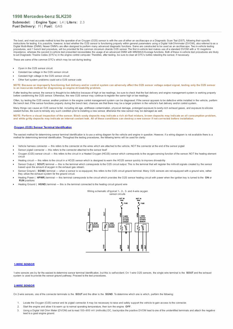
Vehicle harness connector — this refers to the connector on the wires which are attached to the vehicle, NOT the connector at the end of the sensor pigtailSensor pigtail connector — this refers to the connector attached to the sensor itselfOxygen (O2S) sensor circuit — this refers to the circuit in a Heated Oxygen (HO2S) sensor which corresponds to the oxygen-sensing function of the sensor; NOT the heating elementcircuitHeating circuit — this refers to the circuit in a HO2S sensor which is designed to warm the HO2S sensor quickly to improve driveabilitySensor Output ( SOUT) terminal — this is the terminal which corresponds to the O2S circuit output. This is the terminal that will register the millivolt signals created by the sensorbased upon the amount of oxygen in the exhaust gas stream.Sensor Ground ( SGND) terminal — when a sensor is so equipped, this refers to the O2S circuit ground terminal. Many O2S sensors are not equipped with a ground wire, ratherthey utilize the exhaust system for the ground circuit.Heating Power ( HPWR) terminal — this terminal corresponds to the circuit which provides the O2S sensor heating circuit with power when the ignition key is turned to the ON or RUN positionsHeating Ground ( HGND) terminal — this is the terminal connected to the heating circuit ground wire
Wiring schematic of typical 1-, 2-, 3- and 4-wire oxygensensor circuits
1-WIRE SENSOR
1-wire sensors are by far the easiest to determine sensor terminal identification, but this is self-evident. On 1-wire O2S sensors, the single wire terminal is the SOUT and the exhaustsystem is used to provide the sensor ground pathway. Proceed to the test procedures.
2-WIRE SENSOR
On 2-wire sensors, one of the connector terminals is the SOUT and the other is the SGND. To determine which one is which, perform the following:
1. Locate the Oxygen (O2S) sensor and its pigtail connector. It may be necessary to raise and safely support the vehicle to gain access to the connector.2. Start the engine and allow it to warm up to normal operating temperature, then turn the engine OFF.3. Using a Digital Volt Ohm Meter (DVOM) set to read 100–900 mV (millivolts) DC, backprobe the positive DVOM lead to one of the unidentified terminals and attach the negative
lead to a good engine ground.

CAUTION While the engine is running, keep clear of all moving and hot components. Do not wear loose clothing. Otherwise severe personal injury or death may occur.
4. Have an assistant restart the engine and allow it to idle.5. Check the DVOM for voltage.6. If no voltage is evident, check your DVOM leads to ensure that they are properly connected to the terminal and engine ground. If still no voltage is evident at the first terminal,
move the positive meter lead to backprobe the second terminal.7. If voltage is now present, the positive meter lead is attached to the SOUT terminal. The remaining terminal is the SGND terminal. If still no voltage is evident, either the O2S
sensor is defective or the meter leads are not making adequate contact with the engine ground and terminal contacts; clean the contacts and retest. If still no voltage is evident,the sensor is defective.
8. Have your assistant turn the engine OFF.9. Label the sensor pigtail SOUT and SGND terminals.
10. Proceed to the test procedures.
3-WIRE SENSOR
NOTE: 3-wire sensors are HO2S sensors.
On 3-wire sensors, one of the connector terminals is the SOUT, one of the terminals is the HPWR and the other is the HGND. The SGND is achieved through the exhaust system, aswith the 1-wire O2S sensor. To identify the 3 terminals, perform the following:
1. Locate the O2S sensor and its pigtail connector. It may be necessary to raise and safely support the vehicle to gain access to the connector.2. Disengage the sensor pigtail connector from the vehicle harness connector.3. Using a Digital Volt Ohm Meter (DVOM) set to read 12 volts, attach the DVOM ground lead to a good engine ground.4. Have an assistant turn the ignition switch ON without actually starting the engine.5. Probe all 3 terminals in the vehicle harness connector. One of the terminals should exhibit 12 volts of power with the ignition key ON; this is the HPWR terminal.
A. If the HPWR terminal was identified, note which of the sensor harness connector terminals is the HPWR, then match the vehicle harness connector to the sensorpigtail connector. Label the corresponding sensor pigtail connector terminal with HPWR.
B. If none of the terminals showed 12 volts of power, locate and test the heater relay or fuse. Then, perform Steps 3–6 again.6. Start the engine and allow it to warm up to normal operating temperature, then turn the engine OFF.7. Have your assistant turn the ignition OFF.8. Using the DVOM set to measure resistance (ohms), attach one of the leads to the HPWR terminal of the sensor pigtail connector. Use the other lead to probe the 2 remaining
terminals of the sensor pigtail connector, one at a time. The DVOM should show continuity with only one of the remaining unidentified terminals; this is the HGND terminal. Theremaining terminal is the SOUT.
A. If continuity was found with only one of the 2 unidentified terminals, label the HGND and SOUT terminals on the sensor pigtail connector.B. If no continuity was evident, or if continuity was evident from both unidentified terminals, the O2S sensor is defective.
9. All 3-wire terminals should now be labeled on the sensor pigtail connector. Proceed with the test procedures.
4-WIRE SENSOR
NOTE: 4-wire sensors are HO2S sensors.
On 4-wire sensors, one of the connector terminals is the SOUT, one of the terminals is the SGND, one of the terminals is the HPWR and the other is the HGND. To identify the 4terminals, perform the following:
1. Locate the O2S sensor and its pigtail connector. It may be necessary to raise and safely support the vehicle to gain access to the connector.2. Disengage the sensor pigtail connector from the vehicle harness connector.3. Using a Digital Volt Ohm Meter (DVOM) set to read 12 volts, attach the DVOM ground lead to a good engine ground.4. Have an assistant turn the ignition switch ON without actually starting the engine.5. Probe all 4 terminals in the vehicle harness connector. One of the terminals should exhibit 12 volts of power with the ignition key ON; this is the HPWR terminal.
A. If the HPWR terminal was identified, note which of the sensor harness connector terminals is the HPWR, then match the vehicle harness connector to the sensorpigtail connector. Label the corresponding sensor pigtail connector terminal with HPWR.
B. If none of the terminals showed 12 volts of power, locate and test the heater relay or fuse. Then, perform Steps 2–6 again.6. Have your assistant turn the ignition OFF.7. Using the DVOM set to measure resistance (ohms), attach one of the leads to the HPWR terminal of the sensor pigtail connector. Use the other lead to probe the 3 remaining
terminals of the sensor pigtail connector, one at a time. The DVOM should show continuity with only one of the remaining unidentified terminals; this is the HGND terminal.
A. If continuity was found with only 1 of the 2 unidentified terminals, label the HGND terminal on the sensor pigtail connector.B. If no continuity was evident, or if continuity was evident from all unidentified terminals, the O2S sensor is defective.C. If continuity was found at 2 of the other terminals, the sensor is probably defective. However, the sensor may not necessarily be defective, because it may have
been designed with the 2 ground wires joined inside the sensor in case one of the ground wires is damaged; the other circuit could still function properly. Though,this is highly unlikely. A wiring diagram is necessary in this particular case to know whether the sensor was so designed.
8. Reattach the sensor pigtail connector to the vehicle harness connector.9. Start the engine and allow it to warm up to normal operating temperature, then turn the engine OFF.
10. Using a DVOM set to read 100–900 mV (millivolts) DC, backprobe the negative DVOM lead to one of the unidentified terminals and the positive lead to the other unidentifiedterminal.
CAUTION While the engine is running, keep clear of all moving and hot components. Do not wear loose clothing. Otherwise severe personal injury or death may occur.
11. Have an assistant restart the engine and allow it to idle.12. Check the DVOM for voltage.
A. If no voltage is evident, check your DVOM leads to ensure that they are properly connected to the terminals. If still no voltage is evident at either of the terminals,either the terminals were accidentally marked incorrectly or the sensor is defective.
B. If voltage is present, but the polarity is reversed (the DVOM will show a negative voltage amount), turn the engine OFF and swap the 2 DVOM leads on theterminals. Start the engine and ensure that the voltage now shows the proper polarity.
C. If voltage is evident and is the proper polarity, the positive DVOM lead is attached to the SOUT and the negative lead to the SGND terminals.13. Have your assistant turn the engine OFF.14. Label the sensor pigtail SOUT and SGND terminals.
In-Vehicle Tests
WARNING Never apply voltage to the O2S circuit of the sensor, otherwise it may be damaged. Also, never connect an ohmmeter (or a DVOM set on the ohm function) to both of the O2S circuitterminals (

SOUT and
SGND) of the sensor pigtail connector; it may damage the sensor.
Test 1 makes use of a standard DVOM with a 10 megohms impedance, whereas Test 2 necessitates the usage of an advanced Digital Multi-Meter (DMM) with MIN/MAX/Averagefunctions or a sliding bar graph function. Both of these in-vehicle test procedures are likely to set Diagnostic Trouble Codes (DTC's) in the engine control computer. Therefore, after testing, besure to clear all DTC's before retesting the sensor, if necessary. The third in-vehicle test is designed for the use of a scan tool or oscilloscope. The 4th test (Heating Circuit Test) is designedto check the function of the heating circuit in a HO2S sensor.
NOTE: If the O2S sensor being tested is designed to use the exhaust system for the SGND, excessive corrosion between the exhaust and the O2S sensor may affectsensor functioning.
The in-vehicle tests may be performed for O2S sensors located in the exhaust system after the catalytic converter. However, the O2S sensors located behind the catalytic converter will notfluctuate like the sensors mounted before the converter, because the converter, when functioning properly, emits a steady amount of oxygen. If the O2S sensor mounted after the catalyticconverter exhibits a fluctuating signal (like other O2S sensors), the catalytic converter is most likely defective.
To test the O2S sensor, locate it and its connector (inset),which should be positioned away from the exhaust system to
prevent heat damage.
TEST 1 — DIGITAL VOLT-OHMMETER
This test will not only verify proper sensor functioning, but is also designed to ensure the engine control computer and associated wiring is functioning properly as well.
1. Start the engine and allow it to warm up to normal operating temperature.
NOTE: If you are using the opening of the thermostat to gauge normal operating temperature, be forewarned: a defective thermostat can open too earlyand prevent the engine from reaching normal operating temperature. This can cause a slightly rich condition in the exhaust, which can throw the O2Ssensor readings off slightly.
2. Turn the ignition switch OFF, then locate the O2S sensor pigtail connector.3. Perform a visual inspection of the connector to ensure it is properly engaged and all terminals are straight, tight and free from corrosion or damage.4. Disengage the sensor pigtail connector from the vehicle harness connector.5. On sensors equipped with a SGND terminal (sensors which do not use the exhaust system for the sensor ground pathway), connect a jumper wire to the SGND terminal and to
a good, clean engine ground (preferably the negative terminal of the battery).6. Using a Digital Volt Ohm Meter (DVOM) set to read DC voltage, attach the positive lead to the SOUT terminal of the sensor pigtail connector, and the DVOM negative lead to a
good engine ground.
CAUTION While the engine is running, keep clear of all moving and hot components. Do not wear loose clothing. Otherwise severe personal injury or death may occur.
7. Have an assistant start the engine and hold it at approximately 2000 rpm. Wait at least 1 minute before commencing with the test to allow the O2S sensor to sufficiently warmup.
8. Using a jumper wire, connect the SOUT terminal of the vehicle harness connector to a good engine ground. This will fool the engine control computer into thinking it isreceiving a lean signal from the O2S sensor,, therefore, the computer will richen the air/fuel ratio. With the SOUT terminal so grounded, the DVOM should register at least 800mV, as the control computer adds additional fuel to the air/fuel ratio.
9. While observing the DVOM, disconnect the vehicle harness connector SOUT jumper wire from the engine ground. Use the jumper wire to apply slightly less than 1 volt to the SOUT terminal of the vehicle harness connector. One method to do this is by grasping and squeezing the end of the jumper between your forefinger and thumb of one hand whiletouching the positive terminal of the battery post with your other hand. This allows your body to act as a resistor for the battery positive voltage, and fools the engine controlcomputer into thinking it is receiving a rich signal. Or, use a mostly-drained AA battery by connecting the positive terminal of the AA battery to the jumper wire and the negativeterminal of the battery to a good engine ground. (Another jumper wire may be necessary to do this.) The computer should lean the air/fuel mixture out. This lean mixture shouldregister as 150 mV or less on the DVOM.
10. If the DVOM did not register millivoltages as indicated, the problem may be either the sensor, the engine control computer or the associated wiring. Perform the following todetermine which is the defective component:
A. Remove the vehicle harness connector SOUT jumper wire.B. While observing the DVOM, artificially enrich the air/fuel charge using propane. The DVOM reading should register higher than normal millivoltages. (Normal
voltage for an ideal air/fuel mixture is approximately 450–550 mV DC). Then, lean the air/fuel intake charger by either disconnecting one of the fuel injector wiringharness connectors (to prevent the injector from delivering fuel) or by detaching 1 or 2 vacuum lines (to add additional non-metered air into the engine). The DVOMshould now register lower than normal millivoltages. If the DVOM functioned as indicated, the problem lies elsewhere in the fuel delivery and control system. If theDVOM readings were still unresponsive, the O2S sensor is defective; replace the sensor and retest.
NOTE: Poor wire connections and/or ground circuits may shift a normal O2S sensor's millivoltage readings up into the rich range or downinto the lean range. It is a good idea to check the wire condition and continuity before replacing a component that will not fix the problem. Avoltage drop test between the sensor case and ground which reveals 14–16 mV or more, indicates a probable bad ground.
11. Turn the engine OFF, remove the DVOM and all associated jumper wires. Reattach the vehicle harness connector to the sensor pigtail connector. If applicable, reattach the fuelinjector wiring connector and/or the vacuum line(s).
12. Clear any DTC's present in the engine control computer memory, as necessary.
TEST 2 — DIGITAL MULTI-METER
This test method is a more straight-forward O2S sensor test, and does not test the engine control computer's response to the O2S sensor signal. The use of a DMM with theMIN/MAX/Average function or sliding bar graph/wave function is necessary for this test. Don't forget that the O2S sensor mounted after the catalytic converter (if equipped) will not fluctuatelike the other O2S sensor(s) will.
1. Start the engine and allow it to warm up to normal operating temperature.
NOTE: If you are using the opening of the thermostat to gauge normal operating temperature, be forewarned: a defective thermostat can open too earlyand prevent the engine from reaching normal operating temperature. This can cause a slightly rich condition in the exhaust, which can throw the O2Ssensor readings off slightly.

2. Turn the ignition switch OFF, then locate the O2S sensor pigtail connector.3. Perform a visual inspection of the connector to ensure it is properly engaged and all terminals are straight, tight and free from corrosion or damage.4. Backprobe the O2S sensor connector terminals. Attach the DMM positive test lead to the SOUT terminal of the sensor pigtail connector. Attach the negative lead to either the
SGND terminal of the sensor pigtail connector (if equipped, refer to the terminal identification procedures earlier in this section for clarification) or to a good, clean engine ground.5. Activate the MIN/MAX/Average or sliding bar graph/wave function on the DMM.
CAUTION While the engine is running, keep clear of all moving and hot components. Do not wear loose clothing. Otherwise severe personal injury or death may occur.
6. Have an assistant start the engine and wait a few minutes before commencing with the test to allow the O2S sensor to sufficiently warm up.7. Read the minimum, maximum and average readings exhibited by the O2S sensor or observe the bar graph/wave form. The average reading for a properly functioning O2S
sensor is be approximately 450–550 mV DC. The minimum and maximum readings should vary more than 300–600 mV. A typical O2S sensor can fluctuate from as low as100 mV to as high as 900 mV; if the sensor range of fluctuation is not large enough, the sensor is defective. Also, if the fluctuation range is biased up or down in the scale. Forexample, if the fluctuation range is 400 mV to 900 mV the sensor is defective, because the readings are pushed up into the rich range (as long as the fuel delivery system isfunctioning properly). The same goes for a fluctuation range pushed down into the lean range. The mid-point of the fluctuation range should be around 400–500 mV. Finally, if theO2S sensor voltage fluctuates too slowly (usually the voltage wave should oscillate past the mid-way point of 500 mV several times per second) the sensor is defective. (Whenan O2S sensor fluctuates too slowly, it is referred to as being "lazy.")
NOTE: Poor wire connections and/or ground circuits may shift a normal O2S sensor's millivoltage readings up into the rich range or down into the leanrange. It is a good idea to check the wire condition and continuity before replacing a component that will not fix the problem. A voltage drop test betweenthe sensor case and ground which reveals 14–16 mV or more, indicates a probable bad ground.
8. Using the propane method, richen the air/fuel mixture and observe the DMM readings. The average O2S sensor output signal voltage should rise into the rich range.9. Lean the air/fuel mixture by either disconnecting a fuel injector wiring harness connector or by disconnecting a vacuum line. The O2S sensor average output signal voltage
should drop into the lean range.10. If the O2S sensor did not react as indicated, the sensor is defective and should be replaced.11. Turn the engine OFF, remove the DMM and all associated jumper wires. Reattach the vehicle harness connector to the sensor pigtail connector. If applicable, reattach the fuel
injector wiring connector and/or the vacuum line(s).12. Clear any DTC's present in the engine control computer memory, as necessary.
TEST 3 — OSCILLOSCOPE
This test is designed for the use of an oscilloscope to test the functioning of an O2S sensor.
NOTE: This test is only applicable for O2S sensors mounted in the exhaust system before the catalytic converter.
1. Start the engine and allow it to reach normal operating temperature.2. Turn the engine OFF, and locate the O2S sensor connector. Backprobe the scope lead to the O2S sensor connector SOUT terminal. Refer to the manufacturer's instructions for
more information on attaching the scope to the vehicle.3. Turn the scope ON.4. Set the oscilloscope amplitude to 200 mV per division, and the time to 1 second per division. Use the 1:1 setting of the probe, and be sure to connect the scope's ground lead to
a good, clean engine ground. Set the signal function to automatic or internal triggering.5. Start the engine and run it at 2000 rpm.6. The oscilloscope should display a wave form, representative of the O2S sensor switching between lean (100–300 mV) and rich (700–900 mV). The sensor should switch
between rich and lean, or lean and rich (crossing the mid-point of 500 mV) several times per second. Also, the range of each wave should reach at least above 700 mV andbelow 300 mV. However, an occasional low peak is acceptable.
7. Force the air/fuel mixture rich by introducing propane into the engine, then observe the oscilloscope readings. The fluctuating range of the O2S sensor should climb into the richrange.
8. Lean the air/fuel mixture out by either detaching a vacuum line or by disengaging one of the fuel injector's wiring connectors. Watch the scope readings; the O2S sensor waveform should drop toward the lean range.
9. If the O2S sensor's wave form does not fluctuate adequately, is not centered around 500 mV during normal engine operation, does not climb toward the rich range when propaneis added to the engine, or does not drop toward the lean range when a vacuum hose or fuel injector connector is detached, the sensor is defective.
10. Reattach the fuel injector connector or vacuum hose.11. Disconnect the oscilloscope from the vehicle.
An oscilloscope wave form of a typical good O2S sensor as itfluctuates from rich to lean
HEATING CIRCUIT TEST
The heating circuit in an O2S sensor is designed only to heat the sensor quicker than a non-heated sensor. This provides an advantage of increased engine driveability and fuel economywhile the engine temperature is still below normal operating temperature, because the fuel management system can enter closed loop operation (more efficient than open loop operation)sooner.
Therefore, if the heating element goes bad, the O2S sensor may still function properly once the sensor warms up to its normal temperature. This will take longer than normal and may causemild driveability-related problems while the engine has not reached normal operating temperature.
If the heating element is found to be defective, replace the O2S sensor without wasting your time testing the O2S circuit. If necessary, you can perform the O2S circuit test with the newO2S sensor and save yourself some time.
1. Locate the O2S sensor pigtail connector.

The heating circuit of the O2S sensor can be tested with aDMM set to measure resistance
2. Perform a visual inspection of the connector to ensure it is properly engaged and all terminals are straight, tight and free from corrosion or damage.3. Disengage the sensor pigtail connector from the vehicle harness connector.4. Using a DVOM set to read resistance (ohms), attach 1 DVOM test lead to the HPWR terminal, and the other lead to the HGND terminal, of the sensor pigtail connector, then
observe the resistance readings.
A. If there is no continuity between the HPWR and HGND terminals, the sensor is defective. Replace it with a new one and retest.B. If there is continuity between the 2 terminals, but the resistance is greater than approximately 20 ohms, the sensor is defective. Replace it with a new one and
retest.
NOTE: For the following step, the HO2S sensor should be approximately 75°F (23°C) for the proper resistance values.C. If there is continuity between the 2 terminals and it is less than 20 ohms, the sensor is probably not defective. Because of the large diversity of engine control
systems used in vehicles today, O2S sensor heating circuit resistance specifications change often. Generally, the amount of resistance an O2S sensor heatingcircuit should exhibit is between 2–9 ohms. However, some manufacturer's O2S sensors may show resistance as high as 15–20 ohms. As a rule of thumb, 20ohms of resistance is the upper limit allowable.
5. Turn the engine OFF, remove the DVOM and all associated jumper wires. Reattach the vehicle harness connector to the sensor pigtail connector.6. Clear any DTC's present in the engine control computer memory, as necessary.
Bench Test
NOTE: Utilize one of the in-vehicle tests before performing this test.
This test is designed to test an O2S sensor which does not seem to fluctuate fully beyond 400–700 mV. The sensor is to be secured in a table-mounted vise.
CAUTION This test can be very dangerous. Take the necessary precautions when working with a propane torch. Ensure that all combustible substances are removed from the work area and have afire extinguisher ready at all times. Be sure to wear the appropriate protective clothing as well.
1. Remove the O2S sensor.
NOTE: Perform a visual inspection of the sensor. Black sooty deposits may indicate a rich air/fuel mixture, brown deposits may indicate an oilconsumption problem, and white gritty deposits may indicate an internal coolant leak. All of these conditions can destroy a new sensor if not correctedbefore installation.
2. Position the sensor in a vise so that the vise holds the sensor by the hex portion of its case.3. Attach 1 lead of a DVOM set to read DC millivoltages to the sensor case and the other lead to the SOUT terminal of the sensor pigtail connector.4. Carefully use a propane torch to heat the tip (and ONLY the tip) of the sensor. Once the sensor reaches close to normal operating temperature range, alternately heat the sensor
up and allow it to cool down; the sensor output voltage signal should change with the temperature change.
NOTE: This may also clean a sensor covered with a heavy coat of carbon.5. If the sensor voltage does not change with the fluctuation in temperature, replace the sensor with a new one. Install the new sensor and perform one of the in-vehicle tests to rule
out additional fuel management system faults.

1998 Mercedes-benz SLK230
Submodel: | Engine Type: L4 | Liters: 2.3Fuel Delivery: FI | Fuel: GAS
1. Start the engine and allow it to reach normal operating temperature, then turn the ignition switch OFF.2. Disconnect the negative battery cable.3. Open the hood and locate the Oxygen (O2S) sensor connector. It may be necessary to raise and safely support the vehicle for access to the sensor and its connector.
NOTE: On a few models, it may be necessary to remove the passenger seat and lift the carpeting in order to access the connector for a downstream O2Ssensor.
Since sensor locations vary between vehicles, the first stepin removal is to locate the O2S sensors (arrows)...
... and the sensor connector (2), which is usually near theO2S sensor (1), but removed enough from the heat of the
exhaust system
Disengage the sensor pigtail connector half from the vehicleharness connector half
For flange type sensors, loosen the hold-down fasteners...

... which happen to be nuts in this particular case — somemodels may use bolts rather than nuts
Then, pull the sensor out of the exhaust component
For screw-in type sensors (arrow)...
... either use a box end wrench to loosen the sensor or asocket designed expressly for this purpose...
..., then remove the sensor from the exhaust component

4. Disengage the O2S sensor pigtail connector from the vehicle harness connector.
NOTE: There are generally 2 methods used to mount an O2S sensor in the exhaust system: either the O2S sensor is threaded directly into the exhaustcomponent (screw-in type) or the O2S sensor is retained by a flange and 2 nuts or bolts (flange type).
WARNING To prevent damaging a screw-in type O2S sensor, if excessive force is needed to remove the sensor lubricate it with penetrating oil prior to removal. Also, be sure to protectthe tip of the sensor. O2S sensor tips are very sensitive and may be easily damaged if allowed to strike or come in contact with other objects.
5. Remove the sensor, as follows:
Screw-in type sensors — O2S sensors are usually designed with a permanently attached wiring pigtail. This allows the wiring harness and sensor connectors to bepositioned away from the hot exhaust system. It may be necessary to use a socket or wrench that is designed specifically for this purpose. Before purchasing such asocket, be sure that you can't save some money by using a box end wrench for sensor removal.Flange type sensors — Loosen the hold-down nuts or bolts and pull the sensor out of the exhaust component. Be sure to remove and discard the old sensor gasket, ifequipped. You will need a new gasket for installation.
6. Perform a visual inspection of the sensor. Black sooty deposits may indicate a rich air/fuel mixture, brown deposits may indicate an oil consumption problem, and white grittydeposits may indicate an internal coolant leak. All of these conditions can destroy a new sensor if not corrected before installation.
To install: 7. Install the sensor, as follows:
NOTE: A special anti-seize compound is used on most screw-in type O2S sensor threads, and is designed to ease O2S sensor removal. New sensorsusually have the compound already applied to the threads. However, if installing the old O2S sensor or the new sensor did not come with compound,apply a thin coating of electrically-conductive anti-seize compound to the sensor threads.
WARNING Be sure to prevent any of the anti-seize compound from coming in contact with the O2S sensor tip. Also, take precautions to protect the sensor tip from physical damageduring installation.
Screw-in type sensors — Install the sensor in the mounting boss, then tighten it securely.Flange type sensors — Position a new sensor gasket on the exhaust component and insert the sensor. Tighten the hold-down fasteners securely and evenly.
8. Reattach the sensor pigtail connector to the vehicle harness connector.9. Lower the vehicle.
10. Connect the negative battery cable.11. Start the engine and ensure no Diagnostic Trouble Codes (DTC's) are set.

1998 Mercedes-benz SLK230
Submodel: | Engine Type: L4 | Liters: 2.3Fuel Delivery: FI | Fuel: GAS
There are different locations in the exhaust system where O2S sensors are positioned. The locations have been given numbers and will be used in the accompanying charts to identify thepositions of O2S sensors in most vehicles.
Due to mid-year production changes or factory inconsistencies, all models may not be covered. If a vehicle being serviced is not covered in the charts, inspect the exhaust system (whilecold!) in the general locations to find the applicable O2S sensors.
NOTE: If equipped with dual exhaust systems, there may be up to 4 or 5 O2S sensors in the exhaust system. Be sure to locate all of them before commencing with anytesting or service.
Location No. 1 — down pipe or exhaust manifold
Location No. 1 — typical O2S sensor located in the exhaustmanifold
Location No. 2 — left and right banks of a V-type engine
Location No. 3 — exhaust collector (where more than one pipejoins together)
Location No. 4 — outlet of the catalytic converter

Location No. 5 — inlet and outlet of the catalytic converter
Fig. 1: Location No. 6 — front, rear, left and right banks of a V-type engine
Fig. 2: Location No. 7 — front, rear, inlet and outlet of thecatalytic converter


1998 Mercedes-benz SLK230
Submodel: | Engine Type: L4 | Liters: 2.3Fuel Delivery: FI | Fuel: GAS
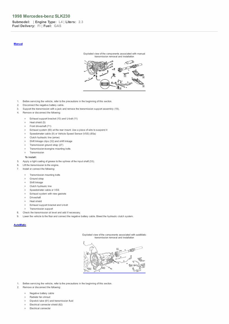
Manual
Exploded view of the components associated with manualtransmission removal and installation
1. Before servicing the vehicle, refer to the precautions in the beginning of this section.2. Disconnect the negative battery cable.3. Support the transmission with a jack and remove the transmission support assembly (19).4. Remove or disconnect the following:
Exhaust support bracket (10) and U-bolt (11)Heat shield (5)Front driveshaft (71)Exhaust system (60) at the rear mount. Use a piece of wire to suspend itSpeedometer cable (9) or Vehicle Speed Sensor (VSS) (85a)Clutch hydraulic line (arrow)Shift linkage clips (32) and shift linkageTransmission ground strap (27)Transmission-to-engine mounting boltsTransmission
To install: 5. Apply a light coating of grease to the splines of the input shaft (33).6. Lift the transmission to the engine.7. Install or connect the following:
Transmission mounting boltsGround strapShift linkageClutch hydraulic lineSpeedometer cable or VSSExhaust system with new gasketsDriveshaftHeat shieldExhaust support bracket and U-boltTransmission support
8. Check the transmission oil level and add if necessary.9. Lower the vehicle to the floor and connect the negative battery cable. Bleed the hydraulic clutch system.
AutoMatic
Exploded view of the components associated with autoMatictransmission removal and installation
1. Before servicing the vehicle, refer to the precautions in the beginning of this section.2. Remove or disconnect the following:
Negative battery cableRadiator fan shroudDipstick tube (61) and transmission fluidElectrical connector shield (62)Electrical connector

Park interlock cable (80)
NOTE: Be sure the transmission selector lever is in PARK before removing the cable.3. Remove or disconnect the following:
Torque converter cover (81)Torque converter-to-flexplate boltsOil cooler linesShift rod (63)Exhaust mounting bracket (64)Exhaust system (94)Rear transmission mount (65)Front half of rear driveshaft (66)Transfer case driveshaft if equipped with 4-MATICGround strap (46)Transmission-to-engine mounting boltsTransmission
To install: 4. Position the transmission on the engine and install the mounting bolts.5. Install or connect the following:6. Ground strap7. Front half of rear driveshaft8. Transfer case driveshaft if equipped with 4-MATIC9. Rear transmission mount
10. Exhaust system11. Exhaust mounting bracket12. Shift rod13. Oil cooler lines14. Torque converter-to-flexplate bolts to 31 ft. lbs. (42 Nm)15. Torque converter cover16. Park interlock cable17. Electrical connector and shield18. Transmission dipstick tube19. Fan shroud20. Negative battery cable21. Transmission fluid

1998 Mercedes-benz SLK230
Submodel: | Engine Type: L4 | Liters: 2.3Fuel Delivery: FI | Fuel: GAS
All clutch release mechanisms are hydraulic, no periodic adjustment is necessary.

1998 Mercedes-benz SLK230
Submodel: | Engine Type: L4 | Liters: 2.3Fuel Delivery: FI | Fuel: GAS
1. Before servicing the vehicle, refer to the precautions in the beginning of this section.2. Remove or disconnect the following:
Transmission assemblyPressure plate (6) mounting bolts (9)
3. Inspect the pilot bearing, release bearing (7), release fork (8) and flywheel. Replace as necessary.
To install: 4. Deglaze the flywheel with coarse abrasive cloth.5. Install or connect the following:
Clutch disc using a line-up tool (012)Pressure plate. Torque the mounting bolts to 18 ft. lbs. (25 Nm)
6. Lightly grease the friction surfaces (arrows) on the release fork. Install the transmission assembly lower the vehicle and check operation.
Exploded view of the clutch assembly

1998 Mercedes-benz SLK230
Submodel: | Engine Type: L4 | Liters: 2.3Fuel Delivery: FI | Fuel: GAS
1. Before servicing the vehicle, refer to the precautions in the beginning of this section.2. Fill the reservoir with brake fluid. Do not allow brake fluid to contact painted surfaces.3. Have a helper push the clutch pedal down and hold it.4. Attach a clear plastic hose to the bleeder valve. Place the other end of the hose in a container to catch the brake fluid.5. Open the bleeder valve on the release cylinder to expel air, then close the bleeder valve. Do not release the clutch pedal until the bleeder valve is closed.6. Repeat the procedure until clear fluid flows out of the bleeder valve.

1998 Mercedes-benz SLK230
Submodel: | Engine Type: L4 | Liters: 2.3Fuel Delivery: FI | Fuel: GAS
1. Before servicing the vehicle, refer to the precautions in the beginning of this section.2. Drain the fluid and remove the exhaust brackets. Suspend the exhaust with a piece of wire.3. Remove or disconnect the following:
Driveshaft shieldCase bracketCase vibration damperFront half of rear driveshaft
4. Support the transmission and remove the engine support along with the rear engine mount. Lower the assembly slightly.5. Remove or disconnect the following:
Front driveshaftTransfer case bolts
6. Remove the transfer case and drain the residual oil.
To install: 7. Install or connect the following:
Transfer case with new gasket. Torque the bolts to 22 ft. lbs. (30 Nm)Rear engine support. Torque the bolts to 30 ft. lbs. (40 Nm)Driveshafts. Torque the bolts to 18 ft. lbs. (25 Nm)Case vibration damperDriveshaft shieldExhaust brackets

1998 Mercedes-benz SLK230
Submodel: | Engine Type: L4 | Liters: 2.3Fuel Delivery: FI | Fuel: GAS
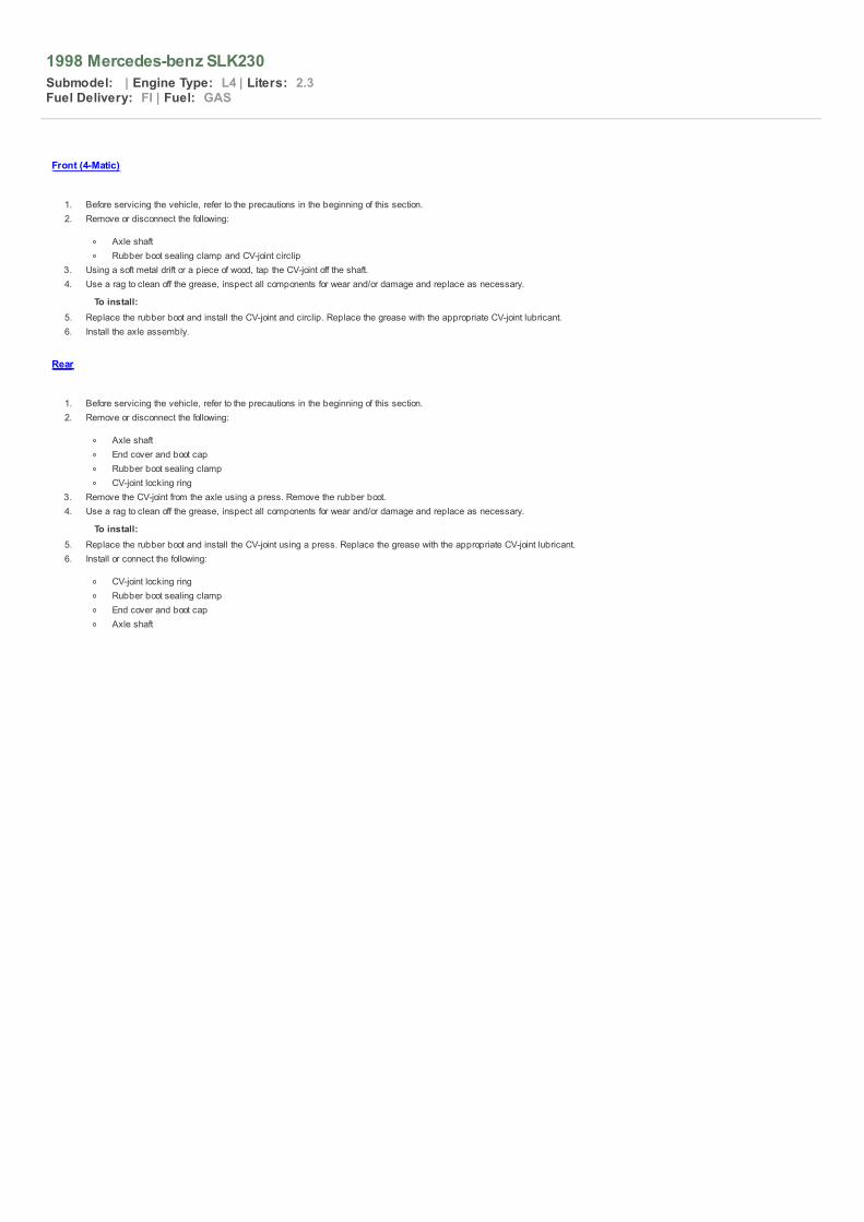
Front (4-Matic)
1. Before servicing the vehicle, refer to the precautions in the beginning of this section.2. Remove or disconnect the following:
Negative battery cableFront wheel12-pointed axle nut (61)Engine undercoverBrake hose bracket (arrow)Stabilizer bar brackets (22b)Headlight leveling linkage (80)Lower ball joint (7) from the steering knuckle (5).Shock absorber (11) from the lower control arm (4)Lower control arm mounting boltsHalfshaft
To install: 3. Install or connect the following:
HalfshaftLower ball jointShock absorberHeadlight leveling linkageStabilizer bar bracketsBrake hose bracketEngine undercover12-pointed axle nut. Torque the nut to 162 ft. lbs. (220 Nm)Front wheelNegative battery cable
Exploded view of the front halfshaft mounted — 4-Matic
Rear
1. Before servicing the vehicle, refer to the precautions in the beginning of this section.2. Remove or disconnect the following:
WheelCenter axle hold-down bolt (in hub)Brake caliper. Suspend it with a wire
3. Drain the differential oil and support the differential housing.4. Remove or disconnect the following:
Differential housing coverAxle lock ringAxle shaft. If necessary, loosen the shock absorber
To install: 5. Install or connect the following:
Axle shaft. Torque the nut to 148–175 ft. lbs. (200240 Nm)Axle lock ringDifferential housing coverBrake caliperCenter axle hold down boltWheel
6. Fill the axle with oil. New radial seal rings are used on all models. Lubricate the outside diameter of radial sealing rings with hypoid gear lubricant prior to installation.
NOTE: Check end-play of the lock ring in the groove. If necessary, install a thicker lock ring or spacer to eliminate all end-play, while still allowing the

lock ring to rotate. Do not allow the joints in the axle shaft to hang free or the joint bearing may be damaged.
1998 Mercedes-benz SLK230
Submodel: | Engine Type: L4 | Liters: 2.3Fuel Delivery: FI | Fuel: GAS
Front (4-Matic)
1. Before servicing the vehicle, refer to the precautions in the beginning of this section.2. Remove or disconnect the following:
Axle shaftRubber boot sealing clamp and CV-joint circlip
3. Using a soft metal drift or a piece of wood, tap the CV-joint off the shaft.4. Use a rag to clean off the grease, inspect all components for wear and/or damage and replace as necessary.
To install: 5. Replace the rubber boot and install the CV-joint and circlip. Replace the grease with the appropriate CV-joint lubricant.6. Install the axle assembly.
Rear
1. Before servicing the vehicle, refer to the precautions in the beginning of this section.2. Remove or disconnect the following:
Axle shaftEnd cover and boot capRubber boot sealing clampCV-joint locking ring
3. Remove the CV-joint from the axle using a press. Remove the rubber boot.4. Use a rag to clean off the grease, inspect all components for wear and/or damage and replace as necessary.
To install: 5. Replace the rubber boot and install the CV-joint using a press. Replace the grease with the appropriate CV-joint lubricant.6. Install or connect the following:
CV-joint locking ringRubber boot sealing clampEnd cover and boot capAxle shaft

1998 Mercedes-benz SLK230
Submodel: | Engine Type: L4 | Liters: 2.3Fuel Delivery: FI | Fuel: GAS
Front (4-Matic)
1. Before servicing the vehicle, refer to the precautions in the beginning of this section.2. Remove or disconnect the following:
Steering knuckleAxle shaft flange using an appropriate pullerBearing circlipBearing using appropriate removal tool
To install: 3. Install or connect the following:
Bearing using appropriate installation toolBearing circlipAxle shaft flange using appropriate installation toolSteering knuckle
Rear
1. Before servicing the vehicle, refer to the precautions in the beginning of this section.2. Remove or disconnect the following:
Axle shaftDisc brake rotorAxle shaftWheel bearing locking ringWheel bearing using an appropriate puller
To install: 3. Install or connect the following:
Wheel bearing using appropriate installation toolWheel bearing locking ringAxle shaft flange using appropriate installation toolDisc brake rotorAxle shaft

1998 Mercedes-benz SLK230
Submodel: | Engine Type: L4 | Liters: 2.3Fuel Delivery: FI | Fuel: GAS
Exploded view of the components associated with the frontdrive pinion (4-MATIC)
Front (4-Matic)
1. Before servicing the vehicle, refer to the precautions in the beginning of this section.2. Remove or disconnect the following:
Axle shaftDrive pinion with bearing cover
3. Mark the bearing cover relative to the front axle drive housing.4. Remove or disconnect the following:
Rubber O-ringPinion seal
To install: 5. Coat the pinion seal lip and the rubber O-ring with clean hypoid transmission oil.6. Install or connect the following:
Pinion sealO-ringBearing cover. Torque the bolts to 26 ft. lbs. (35 Nm)Drive pinion and flange with new self-locking hexagon collar nut. Torque the nut to 350 ft. lbs. (475 Nm).Axle shaft.
Rear
1. Before servicing the vehicle, refer to the precautions in the beginning of this section.2. Remove or disconnect the following:
Exhaust systemDriveshaftFuel pump coverDriveshaft intermediate bearingDriveshaft at differentialRear axle shafts at connecting flange12-point hexagon collared nutPinion flange using appropriate pullerRubber O-ringPinion seal
To install: 3. Coat the pinion seal lip and the rubber O-ring with clean hypoid transmission oil.4. Install or connect the following:
Pinion sealRubber O-ringDrive pinion and flange with new self-locking hexagon collared nut. Torque the nut to 133 ft. lbs. (180 Nm)
5. Install or connect the following:
Rear axle shaftsDriveshaft at differentialDriveshaft intermediate bearing. Torque the bolts to 22 ft. lbs. (30 Nm)Fuel pump coverExhaust system

1998 Mercedes-benz SLK230
Submodel: | Engine Type: L4 | Liters: 2.3Fuel Delivery: FI | Fuel: GAS
Front (4-Matic)
1. Before servicing the vehicle, refer to the precautions in the beginning of this section.2. Remove or disconnect the following:
Electrical connectionsAxle shaftsShock absorbers and front springsSteering knuckles
3. Support the engine and remove the front mount. Drain the power steering fluid.4. Remove or disconnect the following:
Feed line from reservoir if equipped with level controlSteering shaftPower steering lines at steering gearHeadlamp leveling wiring harnessFront axle carrier boltsFront axle assembly from vehicle
To install: 5. Install or connect the following:
Axle assembly. Torque the carrier bolts to 96 ft. lbs. (130 Nm)Headlamp leveling wiring harnessPower steering lines at steering gearSteering shaftFeed line from reservoir if equipped with level controlEngine mount. Torque the bolt to 26 ft. lbs. (35 Nm)Axle shaftsSteering knucklesShock absorbers and front springsElectrical connections
Rear
1. Before servicing the vehicle, refer to the precautions in the beginning of this section.2. Drain the differential oil.3. Remove or disconnect the following:
Axle shaftsExhaust systemDriveshaft intermediate bearingDriveshaft
4. Support the rear axle housing assembly5. Remove or disconnect the following:
Axle housing suspension mountingsAxle housing assembly
To install: 6. Install or connect the following:
Axle housing assemblyAxle housing suspension mountingsDriveshaftDriveshaft intermediate bearing. Torque the bolts to 22 ft. lbs. (30 Nm)Exhaust systemAxle shafts

1998 Mercedes-benz SLK230
Submodel: | Engine Type: L4 | Liters: 2.3Fuel Delivery: FI | Fuel: GAS
2.8L, 3.2L and 3.6L (104) Engines
1. Before servicing the vehicle, refer to the precautions in the beginning of this section.2. Properly recover the air conditioning system refrigerant.3. Properly relieve the fuel system pressure.4. Drain the engine coolant and engine oil.5. Remove or disconnect the following:
Negative battery cableExhaustSteering damperAutoMatic transmission cooling linesCoolant expansion reservoirCooling fan and radiator
6. Cover the air conditioning condenser using a piece of sheet metal, plywood or plastic.7. Remove or disconnect the following:
Charge air pipesAir cleaner housingPower steering linesPower steering pumpFuel linesEngine wiring harness and vacuum linesThrottle cableCoolant hosesRear engine mountDriveshaftPark lock interlock cableAutoMatic transmission control unit connectorTransmission linkageFront engine mounts
8. Raise the engine sufficiently until bolts of air conditioning compressor are accessible9. Remove or disconnect the following:
Air conditioning compressorEngine assembly
To install: 10. Install or connect the following:
Engine assemblyEngine mounts. Torque the bolts to 41 ft. lbs. (55 Nm)Air conditioning compressorTransmission linkageAutoMatic transmission control unit connectorPark lock interlock cableDriveshaftCoolant hosesThrottle cableEngine wiring harness and vacuum linesFuel linesPower steering pump and linesAir cleaner housingCharge air pipes
11. Remove the air conditioning condenser guard12. Install or connect the following:
Cooling fan and radiatorCoolant expansion reservoirAutoMatic transmission cooling linesSteering damperExhaustNegative battery cableCoolantTransmission fluidRefrigerant
2.2L and 2.3L (111) Engines
1. Before servicing the vehicle, refer to the precautions in the beginning of this section.2. Properly recover the air conditioning system refrigerant.3. Properly relieve the fuel system pressure.4. Drain the engine coolant, engine and transmission oil.

5. Remove or disconnect the following:
Negative battery cableEngine under coverFan shroud, clutch and fan assemblyRadiatorHeater hosesOil cooler linesMAF sensor and air intake assemblyCharge air pipes if equipped with a superchargerAccessory drive belts
6. Cover the air conditioning condenser using a piece of sheet metal, plywood or plastic.7. Remove or disconnect the following:
Engine wiring harness, ground straps and electrical connectionsVacuum hosesFuel lines
8. Drain the power steering fluid from the reservoir.9. Remove or disconnect the following:
AutoMatic transmission electrical connections if equippedAccelerator and transmission linkagePower steering pump hosesAir conditioning compressor. Position it aside, leaving the hoses attachedFront halfshafts if equipped with 4-MATICSlave cylinder clutch line if equippedExhaust systemDriveshaft
10. Ensure that all electrical and mechanical connections are detached from the autoMatic transmission11. Support the engine and transmission. Disconnect the mounts, and lift the engine and transmission out of the vehicle as one assembly.
To install: 12. Position the engine/transmission assembly and install the mounts. Torque the bolts as follows:
Transmission mount-to-crossmember bolts: 18 ft. lbs. (25 Nm)Transmission crossmember-to-body bolts: 30 ft. lbs. (40 Nm)Transmission mount-to-transmission nut: 52 ft. lbs. (70 Nm)Engine mount-to-subframe mounting bolt: 30 ft. lbs. (40 Nm)
13. Install or connect the following:
DriveshaftExhaust systemSlave cylinder clutch lineFront halfshaftsAir conditioning compressorPower steering hosesAccelerator and transmission linkageAutoMatic transmission electrical connectionsFuel linesVacuum hosesEngine wiring harness, ground straps and electrical connections
14. Remove the air conditioning condenser guard and fill the power steering reservoir.15. Install or connect the following:
Accessory drive beltsCharge air pipesMAF sensor and air intake assemblyRadiator and coolant hosesOil cooler linesFan clutch, fan and shroudNegative battery cableCoolantEngine oilTransmission fluidRefrigerant
3.2L (112), 4.3L (113) and 4.2L, 5.0L (119) Engines
1. Before servicing the vehicle, refer to the precautions in the beginning of this section.2. Properly relieve the fuel system pressure.3. Drain the engine coolant and engine oil.4. Remove or disconnect the following:
Negative battery cableEngine under coverFan shroud, clutch and fan assembly
5. Cover the air conditioning condenser using a piece of sheet metal, plywood or plastic.6. Remove or disconnect the following:
Air cleaner housingResonance pipe and bodyCoolant hoses and radiatorAutoMatic transmission dipstick guide tube

7. Drain the power steering fluid and detach the lines from the pump. Plug the lines.8. Remove or disconnect the following:
AutoMatic transmission fluid linesFuel linesWiring, vacuum and cable connectionsAccessory drive belts
9. Unbolt the air conditioning compressor and position it aside with the hoses attached.10. Remove or disconnect the following:
Exhaust system and bracketDriveshaft vibration damperDriveshaftTransmission linkageFront wheelsFront halfshafts if equipped with 4-MATICRear engine crossmember at transmissionStarter assemblyFront engine mounts
11. Support the transmission assembly and lift the engine out of the vehicle.
To install: 12. Install or connect the following:
Engine assemblyFront engine mounts. Torque the bolts to 41 ft. lbs. (55 Nm)Starter assemblyRear engine crossmember at transmission. Torque the bolts to 30 ft. lbs. (40 Nm)Front halfshaftsTransmission linkageDriveshaftDriveshaft vibration damperExhaust system and bracketAir conditioning compressorAccessory drive beltsWiring, vacuum and cable connectionsFuel linesAutoMatic transmission fluid linesAutoMatic transmission dipstick guide tubeCoolant hoses and radiatorResonance pipe and bodyAir cleaner housing
13. Remove the air conditioning condenser guard and fill the power steering reservoir.14. Install or connect the following:
Fan shroud, clutch and fan assemblyNegative battery cableCoolantEngine oilTransmission fluid
6.0L (120) Engine
1. Before servicing the vehicle, refer to the precautions in the beginning of this section.2. Properly relieve the fuel system pressure.3. Drain the engine coolant, and engine oil.4. Remove or disconnect the following:
Negative battery cableEngine under coverAir cleanerRadiator and coolant hosesAutoMatic transmission fluid lines
5. Cover the air conditioning condenser using a piece of sheet metal, plywood or plastic.6. Remove or disconnect the following:
Fan shroud, clutch and fan assemblyAccessory drive beltsFuel linesWiring, vacuum and cable connectionsPower steering pumpOil cooler lines
7. Remove the air conditioning compressor and position it aside with the lines attached.8. Remove or disconnect the following:
Oil pressure switchExhaust systemStarterDriveshaftTransmission linkageFront and rear engine mountsRear engine crossmember

9. Support the transmission assembly and lift the engine out of the vehicle.
To install: 10. Position the engine assembly into the vehicle and install the mounts. Torque the bolts to 18 ft. lbs. (25 Nm)11. Install or connect the following:
Rear engine crossmember. Torque the bolts to 30 ft. lbs. (40 Nm)Transmission linkageDriveshaftStarterExhaust systemOil pressure switchAir conditioning compressorOil cooler linesPower steering pumpWiring, vacuum and cable connectionsFuel linesFuel linesAccessory drive beltsFan shroud, clutch and fan assembly
12. Remove the air conditioning condenser guard and fill the power steering reservoir.13. Install or connect the following:
AutoMatic transmission fluid linesRadiator and coolant hosesAir cleanerNegative battery cableCoolantEngine oilTransmission fluid

1998 Mercedes-benz SLK230
Submodel: | Engine Type: L4 | Liters: 2.3Fuel Delivery: FI | Fuel: GAS
All Models
1. Before servicing the vehicle, refer to the precautions in the beginning of this section.2. Disconnect the negative battery cable and drain the cooling system.3. Remove or disconnect the following:
Fan clutch, fan and shroudEngine cover if equippedAccessory drive belt and tensionerSecondary air injection switchover valve if equippedPower steering pump. Position the pump aside, leaving the hoses attachedWater pump coolant hosesOil-to-water heat exchanger coolant hoses if equippedBelt pulleyWater pump mounting boltsWater pump
4. Clean all gasket material from the sealing surfaces.
Exploded view of the water pump mounting — 3.2L (112) and4.3L (113) engines
Exploded view of the water pump mounting — 2.2L and 2.3L(111) engine
Exploded view of the water pump mounting — 2.8L and 3.2L,(104) engines in the SL
Exploded view of the water pump mounting — 2.8L, 3.2L and3.6L (104) engine in the C and E Class models
Exploded view of the water pump mounting — 4.2L and 5.0L

(119) engines
Water pump mounting bolt identification — 4.2L and 5.0L(119) engines
To install: 5. Install the water pump and gasket. Torque the bolts as follows:
2.8L, 3.2L, 3.6L (104) and 4.2L, 5.0L (119) engines: 15 ft. lbs. (21 Nm)2.2L and 2.3L (111) engines: M6 bolts to 88 inch lbs. (10 Nm). M8 bolts to 18 ft. lbs. (25 Nm)3.2L (112) and 4.3 (113) engines: M6 bolts to 88 inch lbs. (10 Nm). M8 bolts to 15 ft. lbs. (20 Nm)6.0L (120) engine: M6 bolts to 88 inch lbs. M8 bolts to 15 ft. lbs. (21 Nm)
6. Install or connect the following:
Belt pulley. Torque the mounting bolts to 88 inch lbs. (10 Nm)Oil-to-water heat exchanger coolant hosesWater pump coolant hosesPower steering pumpSecondary air injection switchover valveAccessory drive belt and tensionerFan clutch, fan and shroudEngine coverCoolantNegative battery cable

1998 Mercedes-benz SLK230
Submodel: | Engine Type: L4 | Liters: 2.3Fuel Delivery: FI | Fuel: GAS
2.8L, 3.2L and 3.6L (104) Engine
NOTE: Cylinder head tightening illustrations are located in Section 1 of this manual. The illustrations follow the Torque Charts.
1. Before servicing the vehicle, refer to the precautions in the beginning of this section.2. Properly relieve the fuel system pressure and drain the engine coolant.3. Position the No. 1 cylinder at TDC.4. Remove or disconnect the following:
Negative battery cableCoolant hosesUpper timing cover
5. Matchmark the camshaft sprocket to the timing chain, and remove the pin (1) for the timing chain guide with a threaded extractor.6. Remove or disconnect the following:
Guide sprocket (left-hand thread)Bearing assemblyTiming chain from the camshaft sprockets. Wire the chain aside
NOTE: Be sure the chain is securely wired so it will not slide into the engine.7. Remove or disconnect the following:
Vacuum hoses and electrical connectorsExhaust systemSecondary air injection pipe if equippedDipstick tube support bracketCrankcase breather hoseFuel linesDipstick tubeThrottle, kickdown and cruise control cables
8. Loosen the head bolts in stages in the reverse order of the illustrated sequence.
CAUTION Never use a prybar between the head and the block.
9. Remove the cylinder head and clean all gasket material from the sealing surfaces. Be sure the cylinder head locating dowels are positioned correctly in the engine block.10. Inspect length of the cylinder head bolt shaft. New bolt length is 6.30 inches (160mm), and the maximum permissible length is 6.44 inches (163.5mm). Replace bolts that
measure greater than the maximum permissible length.
To install:
NOTE: The head will not be watertight until the engine reaches operating temperature. Do not pressure test the cooling system until the engine hasreached operating temperature.
Cylinder head gasket identification — 2.8L 3.2L and 3.6L(104) Engines
11. Rotate the camshafts so that the bottom edge of the holes in the camshaft flange, are level with the top edge of the cylinder head.
Verify the correct position of the camshafts for cylinder headinstallation using a 4mm pin (1) — 2.8L 3.2L and 3.6L (104)
Engines
12. Verify the TDC position of the No. 1 cylinder. Clean the head bolt threads, and then apply clean engine oil to the thread and head contact surfaces.13. Install the head gasket and cylinder head.14. Torque the head bolts using the illustrated sequence to 41 ft. lbs. (55 Nm) plus 90 degrees, then an additional 90 degrees.15. Install or connect the following:
Timing chain and upper timing chain guide
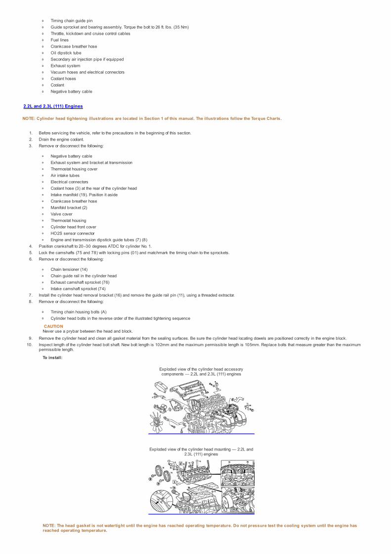
Timing chain guide pinGuide sprocket and bearing assembly. Torque the bolt to 26 ft. lbs. (35 Nm)Throttle, kickdown and cruise control cablesFuel linesCrankcase breather hoseOil dipstick tubeSecondary air injection pipe if equippedExhaust systemVacuum hoses and electrical connectorsCoolant hosesCoolantNegative battery cable
2.2L and 2.3L (111) Engines
NOTE: Cylinder head tightening illustrations are located in Section 1 of this manual. The illustrations follow the Torque Charts.
1. Before servicing the vehicle, refer to the precautions in the beginning of this section.2. Drain the engine coolant.3. Remove or disconnect the following:
Negative battery cableExhaust system and bracket at transmissionThermostat housing coverAir intake tubesElectrical connectorsCoolant hose (3) at the rear of the cylinder headIntake manifold (19). Position it asideCrankcase breather hoseManifold bracket (2)Valve coverThermostat housingCylinder head front coverHO2S sensor connectorEngine and transmission dipstick guide tubes (7) (8)
4. Position crankshaft to 20–30 degrees ATDC for cylinder No. 1.5. Lock the camshafts (75 and 78) with locking pins (01) and matchmark the timing chain to the sprockets.6. Remove or disconnect the following:
Chain tensioner (14)Chain guide rail in the cylinder headExhaust camshaft sprocket (76)Intake camshaft sprocket (74)
7. Install the cylinder head removal bracket (16) and remove the guide rail pin (11), using a threaded extractor.8. Remove or disconnect the following:
Timing chain housing bolts (A)Cylinder head bolts in the reverse order of the illustrated tightening sequence
CAUTION Never use a prybar between the head and block.
9. Remove the cylinder head and clean all gasket material from the sealing surfaces. Be sure the cylinder head locating dowels are positioned correctly in the engine block.10. Inspect length of the cylinder head bolt shaft. New bolt length is 102mm and the maximum permissible length is 105mm. Replace bolts that measure greater than the maximum
permissible length.
To install:
Exploded view of the cylinder head accessorycomponents — 2.2L and 2.3L (111) engines
Exploded view of the cylinder head mounting — 2.2L and2.3L (111) engines
NOTE: The head gasket is not watertight until the engine has reached operating temperature. Do not pressure test the cooling system until the engine hasreached operating temperature.

11. Verify the TDC position of the No. 1 cylinder. Clean the head bolt threads and apply clean engine oil to the thread and head contact surfaces.12. Install or connect the following:
Head gasket and cylinder head. Torque the head bolts using the illustrated sequence to 41 ft. lbs. (55 Nm) plus 90 degrees, then an additional 90 degreesTiming chain housing boltsGuide rail pin
13. Remove the cylinder head removal bracket.14. Install or connect the following:
Intake and exhaust camshaft sprocketsGuide railChain tensioner
15. Remove the camshaft locking pins and verify timing mark alignment.16. Install or connect the following:
Engine oil and transmission dipstick guide tubesHO2S sensorCylinder head front coverThermostat housingValve coverCylinder head coolant hoseCrankcase breather hoseIntake manifoldElectrical connectorsThermostat housing cover and air intake tubesExhaust system and bracketCoolantNegative battery cable
3.2L (112) and 4.3L (113) Engines
NOTE: Cylinder head tightening illustrations are located in Section 1 of this manual. The illustrations follow the Torque Charts.
1. Before servicing the vehicle, refer to the precautions in the beginning of this section.2. Properly relieve the fuel system pressure and drain the engine coolant. Place a guard plate behind the radiator/condenser to protect it from damage.3. Remove or disconnect the following:
Negative battery cableFan clutch, fan and shroudEngine coverAir cleaner housing, resonance pipe and bodyFuel lineIgnition coilsCylinder head covers
NOTE: The intake manifold system must not be disassembled.4. Remove or disconnect the following:
Intake manifoldVacuum switchover valveCamshaft Position (CMP) sensor
5. Lock the autoMatic belt tensioner by rotating the tensioner counterclockwise until a 5mm drift or pin fits through the tensioner, and then remove the serpentine belt.6. Remove or disconnect the following:
Power steering pump. Position it aside leaving the hoses attachedSerpentine beltHeater hose at the firewallExhaust system
7. Rotate the engine clockwise to position the crankshaft 40 degrees ATDC.
WARNING The engine must not be rotated backwards.
8. Lock the camshafts using camshaft locking tools.9. Remove or disconnect the following:
GeneratorTiming chain tensionerCamshaft gears. Attach to the chain with a cable tieCamshaft bearing bridgesCamshaftsTiming case-to-cylinder head boltsCylinder head bolts in the reverse order of the illustrated sequence
CAUTION Never use a prybar between the head and block.
10. Remove the cylinder head and clean all gasket material from the sealing surfaces. Be sure the cylinder head locating dowels are positioned in the engine block.11. Inspect length of the cylinder head bolt shaft. New bolt length is 141.5mm and the maximum permissible length is 144.5mm. Replace bolts that measure greater than the
maximum permissible length.
Exploded view of the cylinder head accessorycomponents — 3.2L (112) engine shown

Exploded view of the cylinder head removal — 3.2L (112)engine shown
To install: 12. Clean the head bolt threads and apply clean engine oil to the thread and head contact surfaces.13. Install the cylinder head gasket and head. Torque the head bolts according to the illustrated sequence as follows:
Step 1: 15 ft. lbs. (20 Nm)Step 2: 37 ft. lbs. (50 Nm)Step 3: 60–70 degreesStep 4: Additional 60–70 degrees
14. Install or connect the following:
Timing case-to-cylinder head bolts. Torque to 15 ft. lbs. (20 Nm)CamshaftsCamshaft bearing bridgesCamshaft gear. Torque the mounting bolt to 37 ft. lbs. (50 Nm) plus an additional 90 degreesTiming chain tensioner with new gasket. Torque to 59 ft. lbs. (80 Nm)Generator
15. Remove the camshaft locking plates.16. Install or connect the following:
Exhaust system. Torque mounting nuts to 15 ft. lbs. (20 Nm)Heater hosePower steering pumpSerpentine beltCMP sensorVacuum switchover valveIntake manifoldCylinder head covers. Torque the bolts to 88 inch lbs. (10 Nm)Ignition coils. Torque the mounting bolts to 70 inch lbs. (8 Nm)Fuel lineAir cleaner housing, resonance pipe and bodyEngine coverFan clutch, fan and shroud
17. Remove the guard plate from the radiator/condenser.18. Fill the cooling system, connect the negative battery cable, start the engine and check for leaks.
4.2L and 5.0L (119) Engines
NOTE: Cylinder head tightening illustrations are located in Section 1 of this manual. The illustrations follow the Torque Charts.
1. Before servicing the vehicle, refer to the precautions in the beginning of this section.2. Drain the engine coolant.3. Remove or disconnect the following:
Negative battery cableEngine coverFront covers
4. Crank the No. 1 piston of the engine to 45 degrees BTDC. Look for the 4/5 on the timing indicator.5. Mark all 4 camshaft timing gears and timing chain with colored dots at about 11 o'clock for the right outer and left inner camshaft sprocket and 1 o'clock for the right inner and left
outer camshaft sprocket.6. Remove or disconnect the following:
Timing chain tensioner and top guide rails

Camshaft gears and adjustersElectrical wiring, hoses and cablesIntake manifoldDipstick guide tubeExhaust pipes and manifoldsCylinder head covers
NOTE: Be sure the engine is cold before removing cylinder head bolts. On the "close-deck" crankcase, the cylinder head bolts have different lengths.7. Loosen the cylinder head bolts in the reverse order of the illustrated tightening sequence.8. Remove the cylinder head and clean all gasket material from the sealing surfaces. Be sure the cylinder head locating dowels are positioned in the engine block.9. Inspect length of the cylinder head bolts. New bolt length is 160mm and the maximum permissible length is 163.5mm. Replace bolts that measure greater than the maximum
permissible length.
To install:
NOTE: The head gasket is not watertight until the engine has reached operating temperature. Do not pressure test the cooling system until the engine hasreached operating temperature.
10. Clean the head bolt threads, and then apply clean engine oil to the thread and head contact surfaces.11. Install the cylinder head gasket and head. Torque the bolts in sequence, as follows:
41 ft. lbs. (55 Nm)+ 90 degrees+ additional 90 degreesTorque the M8 bolts near the timing sprockets to 18 ft. lbs. (25 Nm)
NOTE: Bolts that are screwed into the front of the cylinder head must be coated with sealant when installed.12. Install or connect the following:
Cylinder head coversExhaust pipes and manifoldsDipstick guide tubeIntake manifoldWiring, hoses and cablesCamshaft gears and adjustersTiming chain tensioner and top guide railsFront coversEngine coverCoolantEngine oilNegative battery cable
6.0L (120) Engines
NOTE: Cylinder head tightening illustrations are located in Section 1 of this manual. The illustrations follow the Torque Charts.
1. Before servicing the vehicle, refer to the precautions in the beginning of this section.2. Drain the cooling system.3. Remove or disconnect the following:4. Negative battery cable5. Intake manifold6. Engine assembly on S models7. Exhaust pipes and bracket on SL models8. Valve covers9. Rotate the crankshaft to 30 degrees ATDC.
10. Matchmark the camshaft sprockets to the timing chain as illustrated.
Matchmark the timing chain and sprockets forinstallation — 6.0L (120) engines
11. Remove or disconnect the following:
Timing chain tensionerTiming chain from camshaft sprocketsLeft head ventilation tubeTransmission dipstick tubeOil dipstick tubeTiming chain guide railsSecondary air injection linesExhaust manifold on S modelsCoolant hose at the rear of the head
12. Loosen the head bolts in stages, in the reverse of the tightening sequence. Remove the cylinder heads with the exhaust manifolds attached. Clean all gasket material from thesealing surfaces. Be sure the cylinder head locating dowels are positioned in the engine block.
13. Measure the cylinder head bolts. New bolts are 168mm long, and the maximum allowable length is 171mm. Replace any bolts that exceed the maximum length.
To install:

NOTE: The head gasket is not watertight until the engine has reached operating temperature. Do not pressure test the cooling system until the engine hasreached operating temperature.
14. Install the cylinder head gasket and head. Torque the bolts in sequence, as follows:
41 ft. lbs. (55Nm).+ 90 degrees.+ another 90 degrees.
15. Install or connect the following:
Coolant hoseExhaust manifold on S modelsSecondary air injection linesTiming chain guide railsOil dipstick tubeTransmission dipstick tubeVentilation tube
16. Align the matchmarks and install the timing chain.17. Install or connect the following:
Timing chain tensioner. Verify the correct valve timingValve coversEngine assembly on S modelsFor SL models, connect the exhaust pipes to the manifolds and connect the exhaust pipe bracket to the transmissionIntake manifoldEngine oilCoolantNegative battery cable

1998 Mercedes-benz SLK230
Submodel: | Engine Type: L4 | Liters: 2.3Fuel Delivery: FI | Fuel: GAS
All engines except the 112 and 113 are not equipped with rocker arms/shafts. The camshaft(s) act directly on valve tappets. On the 112 and 113 engines, the rocker arm/shaft is part of thecamshaft bearing cap assembly and is called the camshaft bearing bridge. This procedure is for removing and installing the camshaft bearing bridge.
3.2L (112) and 4.3L (113) Engines
1. Before servicing the vehicle, refer to the precautions in the beginning of this section.2. Remove or disconnect the following:
Negative battery cableCylinder head cover
3. Rotate the engine clockwise to position the crankshaft 40 degrees after top dead center.
WARNING The engine must not be rotated backwards.
4. Remove or disconnect the following:
GeneratorTiming chain tensioner
5. Cable tie the timing chain to the camshaft sprockets and remove the sprockets.6. Loosen the camshaft bearing bridge bolts in reverse of the illustrated sequence.
NOTE: The camshaft bearing bridge must not be disassembled. If damage exists at the valve gear or at the top half of the camshaft bearing journal, thecomplete cylinder head should be replaced.
To install: 7. Lubricate the camshaft bearing journals.8. Install or connect the following:
Camshaft bearing bridge. Torque the bolts to 11 ft. lbs. (15 Nm) in sequence as illustratedCamshaft sprocketsTiming chain tensioner with new gasket. Torque to 59 ft. lbs. (80 Nm)Cylinder head covers. Torque to 88 inch lbs. (10 Nm)
9. Connect the negative battery cable, start the vehicle and check operation.

1998 Mercedes-benz SLK230
Submodel: | Engine Type: L4 | Liters: 2.3Fuel Delivery: FI | Fuel: GAS
1. Before servicing the vehicle, refer to the precautions in the beginning of this section.2. Drain the engine coolant.3. Remove or disconnect the following:
Intake air assembly. Plug supercharger openingsSensor block coverElectromagnetic clutch connectorCoolant hose, radiator to water pumpCoolant return hoseFan and shroudSupercharger drive beltSupercharger pressure connectionsSupercharger
To install:
NOTE: Install the bottom securing bolt in the supercharger before installing.4. Install or connect the following:
Supercharger. Torque the mounting bolts to 16 ft. lbs. (21 Nm)Pressure connections with new sealsDrive beltFan and shroudCoolant hosesElectromagnetic clutch connectorSensor block cover
5. Remove the plug from the inlet of the supercharger and install the intake air assembly.6. Fill the cooling system, start the engine and check operation.

1998 Mercedes-benz SLK230
Submodel: | Engine Type: L4 | Liters: 2.3Fuel Delivery: FI | Fuel: GAS
2.8L 3.2L and 3.6L (104) Engines
1. Before servicing the vehicle, refer to the precautions in the beginning of this section.2. Properly relieve the fuel system pressure.3. Remove or disconnect the following:
Negative battery cableVacuum, electrical and cable connectorsFuel rail with the injectorsResonance intake manifold (throttle body). Clean the gasket surfacesIntake manifold
To install:
Exploded view of the intake manifold mounting and relatedcomponents — 2.8L, 3.2L and 3.6L (104) engines
4. Clean all gasket material from the sealing surfaces. Install intake manifold gaskets and manifold. Torque the mounting bolts to 18 ft. lbs. (25 Nm).5. Install or connect the following:
Resonance intake manifold with new gasketsFuel rail with new injector sealsVacuum, electrical and cable connectors
6. Check and adjust the throttle linkage.7. Connect the negative battery cable, start the engine and check for leaks.
2.2L and 2.3L (111) Engines
1. Before servicing the vehicle, refer to the precautions in the beginning of this section.2. Properly relieve the fuel system pressure.3. Remove or disconnect the following:
Negative battery cableIntake air cross pipeIgnition coils if necessaryPower steering pump bracket mounting bolt if necessaryFuel rail with injectorsIntake manifold support bracketVacuum, electrical and cable connectorsManifold mounting nuts and boltsIntake manifold
To install:
Exploded view of the intake manifold mounting and relatedcomponents — 1997–00 2.2L and 2.3L (111) engines

4. Clean all gasket material from the sealing surfaces. Install the manifold gaskets and intake manifold. Torque the mounting bolts and nuts to 15 ft. lbs. (20 Nm).5. Install or connect the following:
Vacuum, electrical and cable connectorsIntake manifold support bracketFuel rail with new injector sealsPower steering pump bracket mountingIgnition coilsIntake air cross pipe
6. Check and adjust the throttle linkage.7. Connect the negative battery cable, start the engine and check for leaks.
3.2L (112) and 4.3L (113) Engines
1. Before servicing the vehicle, refer to the precautions in the beginning of this section.2. Remove or disconnect the following:
Negative battery cableCylinder head coverMAF sensor with intake pipe
3. Properly relieve the fuel system pressure.4. Remove or disconnect the following:
Fuel rail with injectorsVacuum, electrical and cable connectorsEGR valveCombination valveManifold mounting boltsIntake manifold
Exploded view of the intake manifold mounting and relatedcomponents — 3.2L (112) engine shown.
To install: 5. Clean all gasket material from the sealing surfaces. Install the new intake manifold gasket. Verify the secondary air injection passage opening in the gasket and install the intake
manifold. Torque the mounting bolts to 15 ft. lbs. (20 Nm).6. Install or connect the following:
Combination valve. Torque the bolts to 15 ft. lbs. (20 Nm)EGR valveVacuum, electrical and cable connectorsFuel rail with new injector sealsMAF sensor with the air intake pipeCylinder head cover. Torque the bolts to 88 inch lbs. (10 Nm)
7. Reconnect the negative battery cable, start the vehicle and check for leaks.
4.2L and 5.0L (119) Engines
Exploded view of the intake manifold mounting and relatedcomponents — 4.2L and 5.0L (119) engines
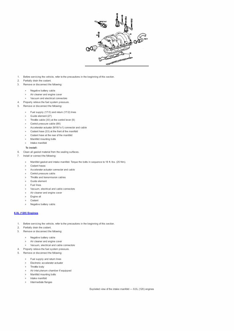
1. Before servicing the vehicle, refer to the precautions in the beginning of this section.2. Partially drain the coolant.3. Remove or disconnect the following:
Negative battery cableAir cleaner and engine coverVacuum and electrical connectors
4. Properly relieve the fuel system pressure.5. Remove or disconnect the following:
Fuel supply (17/3) and return (17/2) linesGuide element (27)Throttle cable (30) at the control lever (9)Control pressure cable (98)Accelerator actuator (M16/1x1) connector and cableCoolant hose (33) at the front of the manifoldCoolant hose at the rear of the manifoldManifold mounting boltsIntake manifold
To install: 6. Clean all gasket material from the sealing surfaces.7. Install or connect the following:
Manifold gasket and intake manifold. Torque the bolts in sequence to 18 ft. lbs. (25 Nm).Coolant hosesAccelerator actuator connector and cableControl pressure cableThrottle and transmission cablesGuide elementFuel linesVacuum, electrical and cable connectorsAir cleaner and engine coverEngine oilCoolantNegative battery cable
6.0L (120) Engines
1. Before servicing the vehicle, refer to the precautions in the beginning of this section.2. Partially drain the coolant.3. Remove or disconnect the following:
Negative battery cableAir cleaner and engine coverVacuum, electrical and cable connectors
4. Properly relieve the fuel system pressure.5. Remove or disconnect the following:
Fuel supply and return linesElectronic accelerator actuatorThrottle bodyAir inlet plenum chamber if equippedManifold mounting boltsIntake manifoldIntermediate flanges
Exploded view of the intake manifold — 6.0L (120) engines

To install: 6. Replace the shaped rubber seals and install the intermediate flanges with new gaskets.7. Clean all gasket material from the sealing surfaces.8. Install or connect the following:
Manifold gasket and intake manifoldAir intake plenum chamberThrottle bodyElectronic accelerator actuatorFuel linesVacuum, electrical and cable connectorsAir cleaner and engine coverEngine oilCoolantNegative battery cable

1998 Mercedes-benz SLK230
Submodel: | Engine Type: L4 | Liters: 2.3Fuel Delivery: FI | Fuel: GAS
Inline 4- and 6-Cylinder Engines
1. Before servicing the vehicle, refer to the precautions in the beginning of this section.2. Remove or disconnect the following:
Negative battery cableExhaust pipeTransmission exhaust support if equippedAir injection tube if equippedManifold retaining bolts and manifold
To install:
Exploded view of the mounting — 4-cylinder shown, inline 6-cylinder similar
3. Install or connect the following:
Manifold gasket and exhaust manifold. Torque the bolts in an even patternAir injection tubeTransmission exhaust supportExhaust pipe with new self-locking nuts. Torque to 25 ft. lbs. (34 Nm)Negative battery cable
V6, V8, and 12-Cylinder Engines
1. Before servicing the vehicle, refer to the precautions in the beginning of this section.2. Properly relieve the fuel system pressure.3. Remove or disconnect the following:
Negative battery cableEngine undercoverExhaust pipesFan shroud.Engine mount for the manifold being servicedFuel supply and return pipes if removing left manifoldSelf-locking bolts and exhaust manifold
To install: 4. Inspect the rivet nuts in the manifold and replace as needed.5. Install or connect the following:
Manifold gasket and exhaust manifold. Torque the mounting bolts to 23 ft. lbs. (30 Nm)Fuel lines if removedEngine mountsFan shroud.Exhaust pipesEngine under cover
6. Connect the negative battery cable, start the engine and check for leaks.

1998 Mercedes-benz SLK230
Submodel: | Engine Type: L4 | Liters: 2.3Fuel Delivery: FI | Fuel: GAS
2.8L, 3.2L and 3.6L (104) Engines
1. Before servicing the vehicle, refer to the precautions in the beginning of this section.2. Disconnect the negative battery cable and position the No. 1 cylinder 30 degrees BTDC.3. Remove or disconnect the following:
Valve coverTiming chain tensioner (1)Upper front cover (30) and top guide rail (42)
4. Matchmark the timing chain (6) to the camshaft sprockets (3 and 5).5. Remove or disconnect the following:
Exhaust camshaft sprocket (3)Timing chain from the intake camshaft (5)
6. Hold the camshafts so that the lobes of the cams of cylinder No. 2 press on the middle of the buckets. Unbolt the camshaft bearing caps 1, 4, 6 and 7 of the exhaust camshaft(14) and 8, 11, 13 and 14 of the intake camshaft (13). Loosen the remaining bearing cap bolts 1 turn at a time until there is no counterpressure.
7. Remove or disconnect the following:
CamshaftsBucket tappets
Position the crankshaft as shown to prevent piston-to-valvecontact — 2.8L, 3.2L and 3.6L (104) engines
Remove the indicated bearing caps first — 2.8L, 3.2L and3.6L (104) engines
To install: 8. Install the bucket tappets and oil the camshaft journals and lobes. Install the camshafts at 30 degrees BTDC for cylinder No. 1. The lobes of the cams must be facing on the
middle of the buckets for cylinder No. 2.
Be sure to install the indicated bearing caps first — 2.8L, 3.2Land 3.6L (104) engines
9. Bearing caps 2, 3 and 5 for the exhaust camshaft and 9, 10 and 12 for the intake camshaft. Torque to 15 ft. lbs. (21 Nm). Hold the camshafts so that the lobes of the cams ofcylinder No. 2 press on the middle of the buckets. Install the remaining bearing caps. Torque to 16 ft. lbs. (22 Nm).

10. Install or connect the following:11. Timing chain12. Exhaust camshaft sprocket13. Align the matchmarks and install the sprocket. Torque to the following specification:
M7 13.5mm T30 Torx® bolt: 13 ft. lbs. (18 Nm)M7 13.5mm T40 Torx® bolt: 16 ft. lbs. (22 Nm)M7 13mm T30 Torx® bolt: 15 ft. lbs. (20 Nm) plus 60 degrees
14. Install or connect the following:
Front cover and top guide railTiming chain tensionerValve coverNegative battery cable
2.2L and 2.3L (111) Engines
1. Before servicing the vehicle, refer to the precautions in the beginning of this section.2. Disconnect the negative battery cable and position the No. 1 cylinder 30 degrees ATDC.3. Remove or disconnect the following:
Valve coverFront timing cover
4. Matchmark the timing chain (73) to the camshaft sprockets (75 and 76).5. Remove or disconnect the following:
Timing chain tensioner (14)Exhaust camshaft sprocket (76)Timing chain from the intake camshaft (75)
6. Using a wrench (1), rotate the camshafts (77 and 78) so the base circle of the cams are resting against the bucket tappets.7. Remove or disconnect the following:
Camshaft bearing capsCamshaftsBucket tappets
To install:
Exploded view of the camshaft mounting components andpositioning — 2.2L and 2.3L (111) engines
8. Install the bucket tappets and oil the camshaft journals and lobes. Position the base circle of the camshafts so they are resting against the bucket tappets.9. Install or connect the following:
Camshaft bearing caps. Torque to 44 inch lbs. (5 Nm) plus 90 degreesTiming chainExhaust camshaft sprocket. Align matchmarks and torque to 15 ft. lbs. (20 Nm) plus 90 degreesFront cover and top guide railTiming chain tensionerValve coverNegative battery cable
3.2L (112) and 4.3L (113) Engines
1. Before servicing the vehicle, refer to the precautions in the beginning of this section.2. Disconnect the negative battery cable and remove the cylinder head cover. Rotate the engine clockwise to position the crankshaft 40 degrees ATDC.
WARNING The engine must not be rotated backwards.
3. Remove or disconnect the following:
GeneratorTiming chain tensioner (2)Camshaft Position Sensor (CMP) (1)
4. Cable-tie the timing chain to the camshaft sprocket (5). Lock the camshafts using camshaft locking (3) tools.5. Remove or disconnect the following:
Camshaft gearsCamshaft bearing bridge (4)Camshafts
Exploded view of the camshaft mounting, showing relatedcomponents — 3.2L (112) and 4.3L (113) engines

To install: 6. Apply clean engine oil to the camshaft contact surfaces.7. Install or connect the following:
CamshaftsCamshaft bearing bridge
NOTE: The camshafts can be rotated 40 degrees after top dead center of the No. 1 cylinder without the valves touching the pistons.8. Position the camshaft so that the groove points towards the contact surface of the cylinder head cover, then attach the camshaft fixing plate. Repeat this step for the other
camshaft.9. Install or connect the following:
Camshaft sprockets. Torque the bolt to 37 ft. lbs. (50 Nm) plus 90–100 degreesTiming chainCMP sensor. Torque the mounting bolt to 70 inch lbs. (8 Nm)Timing chain tensioner with new gasket. Torque to 59 ft. lbs. (80 Nm)GeneratorCylinder head cover
10. Connect the negative battery cable, start the engine and check operation.
4.2L and 5.0L (119) Engines
1. Before servicing the vehicle, refer to the precautions in the beginning of this section.2. Disconnect the negative battery cable and position the No. 1 cylinder 45 degrees BTDC.3. Remove or disconnect the following:
Valve coversUpper front covers (10 and 12)
4. Matchmark the timing chain to the camshaft sprockets.5. Remove or disconnect the following:
Timing chain tensioner (13)Timing chain top slide rails (1, 1a, 2 and 2a)Timing chain from the camshaft sprockets
6. Rotate the camshafts so the base circle of the cams are resting against the bucket tappets.7. Remove or disconnect the following:
Camshaft bearing cap boltsCamshaft bearing capsCamshafts with sprocketsBucket tappets
To install:
Exploded view of the camshaft mounting and relatedcomponents — 4.2L and 5.0L (119) engine
8. Install the bucket tappets and oil the camshaft journals and lobes.9. Install or connect the following:
Left intake and exhaust camshaftsTiming chain on left cylinder head, aligning the matchmarksLeft side bearing caps. Torque to 88 inch lbs. (10 Nm)Right intake and exhaust camshaftsTiming chain on right cylinder head, aligning the matchmarksRight side bearing caps. Torque to 88 inch lbs. (10 Nm)Timing chain top slide railsTiming chain tensionerUpper front coversValve covers
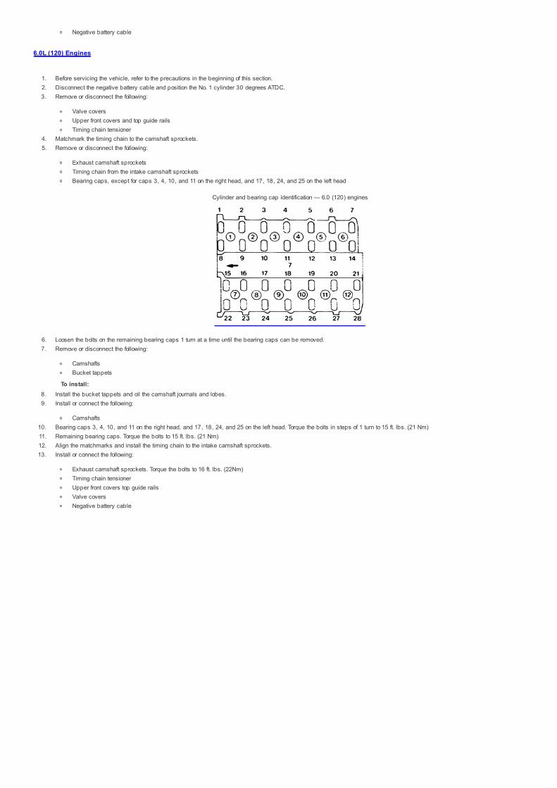
Negative battery cable
6.0L (120) Engines
1. Before servicing the vehicle, refer to the precautions in the beginning of this section.2. Disconnect the negative battery cable and position the No. 1 cylinder 30 degrees ATDC.3. Remove or disconnect the following:
Valve coversUpper front covers and top guide railsTiming chain tensioner
4. Matchmark the timing chain to the camshaft sprockets.5. Remove or disconnect the following:
Exhaust camshaft sprocketsTiming chain from the intake camshaft sprocketsBearing caps, except for caps 3, 4, 10, and 11 on the right head, and 17, 18, 24, and 25 on the left head
Cylinder and bearing cap identification — 6.0 (120) engines
6. Loosen the bolts on the remaining bearing caps 1 turn at a time until the bearing caps can be removed.7. Remove or disconnect the following:
CamshaftsBucket tappets
To install: 8. Install the bucket tappets and oil the camshaft journals and lobes.9. Install or connect the following:
Camshafts10. Bearing caps 3, 4, 10, and 11 on the right head, and 17, 18, 24, and 25 on the left head. Torque the bolts in steps of 1 turn to 15 ft. lbs. (21 Nm)11. Remaining bearing caps. Torque the bolts to 15 ft. lbs. (21 Nm)12. Align the matchmarks and install the timing chain to the intake camshaft sprockets.13. Install or connect the following:
Exhaust camshaft sprockets. Torque the bolts to 16 ft. lbs. (22Nm)Timing chain tensionerUpper front covers top guide railsValve coversNegative battery cable

1998 Mercedes-benz SLK230
Submodel: | Engine Type: L4 | Liters: 2.3Fuel Delivery: FI | Fuel: GAS
All Mercedes-Benz engines use hydraulic valve lifters. There is no provision for valve clearance adjustments.

1998 Mercedes-benz SLK230
Submodel: | Engine Type: L4 | Liters: 2.3Fuel Delivery: FI | Fuel: GAS
Exploded view of the oil pan mounting and relatedcomponents — Inline engines
Lower the front subframe by removing the mountingbolts — except 3.2L (112) and 4.3L (113) engines
Exploded view of the oil pan mounting and relatedcomponents — Inline engines
Exploded view of the mounting of the upper oil pan andrelated components — 3.2L (112) and 4.3L (113) engines
Exploded view of the mounting of the lower oil pan and relatedcomponents — 3.2L (112) and 4.3L (113) engines

2.8L, 3.2L, 3.6L (104) and 2.2L, 2.3L (111) Engines
ALL MODELS EXCEPT E320 (210)
1. Before servicing the vehicle, refer to the precautions in the beginning of this section.2. Disconnect the negative battery cable and drain the engine oil.3. Remove or disconnect the following:
Fan shroudEngine harness coverExhaustExhaust bracket at transmissionOil level sensor connectionAutoMatic transmission oil pipes if equippedDrag linkFront torsion barEngine mountsRear engine carrier
4. Using a suitable engine support tool, support the weight of the engine. Raise the engine to access the oil pan mounting bolts.
NOTE: It may be necessary to tap on the oil pan with a rubber mallet to dislodge it from the engine block.5. Remove the mounting bolts and the oil pan. Clean all gasket material from the sealing surfaces.
To install: 6. Install or connect the following:
Oil pan with a new gasket. Torque the M6 bolts to 88 inch lbs. (9 Nm). Torque the M8 bolts to 15 ft. lbs. (21 Nm). Torque the M10 bolts to 30 ft. lbs. (40 Nm).Rear engine carrierEngine mounts. Torque the bolts to 41 ft. lbs. (55 Nm)Front torsion barDrag linkAutoMatic transmission oil pipesOil level sensor connectionExhaust bracket at transmissionExhaustEngine harness coverFan shroud
7. Fill the crankcase with oil, connect the negative battery cable, start the engine and check for leaks.
E320 (210)
1. Before servicing the vehicle, refer to the precautions in the beginning of this section.2. Remove or disconnect the following:
Negative battery cableEngine oilFan shroudPower steering linesFront springsBottom engine mountSteering coupling
3. Support the front sub frame and remove mounting bolts. Lower the subframe to access the oil pan mounting bolts.
NOTE: It may be necessary to tap on the oil pan with a rubber mallet to dislodge it from the engine block.4. Remove the mounting bolts and the oil pan. Clean all gasket material from the sealing surfaces.
To install: 5. Install or connect the following:
Oil pan with a new gasket. Torque the M6 bolts to 88 inch lbs. (9 Nm). Torque the M8 bolts to 15 ft. lbs. (21 Nm). Torque the M10 bolts to 30 ft. lbs. (40 Nm).Front sub frame. Torque the bolts to 88 ft. lbs. (120 Nm)Steering coupling. Torque the bolt to 18 ft. lbs. (25 Nm)

Engine mount. Torque the bolts to 41 ft. lbs. (55 Nm)Front springsPower steering linesFan shroudEngine oilNegative battery cable
3.2L (112) and 4.3L (113) Engines
1. Before servicing the vehicle, refer to the precautions in the beginning of this section.2. Remove or disconnect the following:
Negative battery cableEngine oilCoolantEngine under coverFan clutch and shroudEngine upper coverCoolant hose at thermostatCoolant hose at water pump
NOTE: It may be necessary to tap on the oil pan with a rubber mallet to dislodge it from the engine block.3. Remove the mounting bolts and the oil pan. Clean all gasket material from the sealing surfaces.
To install: 4. Install or connect the following:
Oil pan with a new gasket. Torque the oil pan bolts to 84 inch lbs. (10 Nm).Coolant hose at water pumpCoolant hose at thermostatFan clutch and shroudEngine upper coverCoolantEngine oilNegative battery cable
4.2L and 5.0L (119) Engines
1. Before servicing the vehicle, refer to the precautions in the beginning of this section.2. Remove or disconnect the following:
Negative battery cableEngine oilCoolantFan clutch and shroudDrive belt and tensioner with bracketDipstick guide tube at air pump bracket
3. Remove the air conditioning compressor and position it aside with the lines attached.4. Remove or disconnect the following:
Alternator and bracketDipstick guide tubeEngine mountsFront springs and shock absorbersSteering coupling
5. Using a suitable engine support tool, support the weight of the engine.6. Support the front sub frame and remove mounting bolts. Lower to access the oil pan mounting bolts.
NOTE: It may be necessary to tap on the oil pan with a rubber mallet to dislodge it from the engine block.7. Remove the mounting bolts and the oil pan. Clean all gasket material from the sealing surfaces.
To install: 8. Install or connect the following:
Oil pan with a new gasket. Torque the M6 bolts to 97 inch lbs. (11 Nm). Torque the M8 bolts to 18 ft. lbs. (25 Nm). Torque the M10 bolts to 30 ft. lbs. (40 Nm).Sub frame. Torque the bolts to 30 ft. lbs. (40 Nm)Steering couplingFront springs and shock absorbersEngine mounts. Torque the mounting bolts to 18 ft. lbs. (25 Nm)Dipstick guide tube at oil pumpAlternator and bracket. Torque the bracket mounting bolts to 15 ft. lbs. (21 Nm)Air conditioning compressor and bracket. Torque the bracket mounting bolts to 15 ft. lbs. (21 Nm)Dipstick guide tube at air pump bracketDrive belt and tensioner with bracket. Torque the bracket mounting bolts to 15 ft. lbs. (21 Nm)Fan clutch and shroudEngine oilNegative battery cable
6.0L (120) Engine
1. Before servicing the vehicle, refer to the precautions in the beginning of this section.2. Remove or disconnect the following:

Negative battery cableEngine oilEngine assemblyAlternatorOil pressure sensor wire connectionDipstick guide tubeVibration damperSecondary air injection lineOil pan end cover
NOTE: It may be necessary to tap on the oil pan with a rubber mallet to dislodge it from the engine block.3. Remove the mounting bolts and the oil pan. Clean all gasket material from the sealing surfaces.
To install: 4. Install or connect the following:
Oil pan with a new gasket. Torque the M6 bolts to 88 inch lbs. (9 Nm). Torque the M8 bolts to 15 ft. lbs. (21 Nm). Torque the M10 bolts to 30 ft. lbs. (40 Nm).Oil pan end coverSecondary air injection lineVibration damperDipstick guide tubeAlternatorEngine assemblyEngine oilNegative battery cable

1998 Mercedes-benz SLK230
Submodel: | Engine Type: L4 | Liters: 2.3Fuel Delivery: FI | Fuel: GAS
2.8L, 3.2L, 3.6L (104), 2.2L, 2.3L (111), 3.2L (112) and 4.3L (113) Engines
Exploded view of the oil pump mounting and relatedcomponent — except 3.2L (112) and 4.3L (113) engines
1. Before servicing the vehicle, refer to the precautions in the beginning of this section.2. Remove or disconnect the following:
Oil panOil pump drive gearOil pump mounting boltsOil pump
To install:
NOTE: Be sure to replace any O-rings or seals between the oil pump and engine block.3. Install the oil pump and tighten the mounting bolts as follows:
M6 bolts: 88 inch lbs. (9 Nm)M8 bolts: 15 ft. lbs. (21 Nm)
4. Install or connect the following:
Oil pump drive gear. Torque the bolt to 24 ft. lbs. (32 Nm)Oil panEngine oil
Exploded view of the oil pump mounting and relatedcomponent — 3.2L (112) and 4.3L (113) engines
4.2L and 5.0L (119) Engines
1. Before servicing the vehicle, refer to the precautions in the beginning of this section.2. Remove or disconnect the following:
Ground strapsAutoMatic transmission oil line bracketOil level control hoseOil panOil pump drive gearOil pump
NOTE: Be sure to replace any O-rings or seals between the oil pump and engine block.
To install: 3. Install or connect the following:
Oil pump. Torque the mounting bolts to 15 ft. lbs. (21 Nm)Oil pump drive gear. Torque the mounting bolt to 24 ft. lbs. (28 Nm)Oil panOil level control hoseAutoMatic transmission oil line bracketGround strapsEngine oil
6.0L (120) Engine
1. Before servicing the vehicle, refer to the precautions in the beginning of this section.2. Remove or disconnect the following:
Negative battery cableEngine oilOil panOil pump drive gearOil pump mounting boltsOil pump
NOTE: Be sure to replace any O-rings or seals between the oil pump and engine block.
To install: 3. Install or connect the following:
Oil pump. Torque the M6 bolts to 88 inch lbs. (9 Nm) and the M8 bolts to 15 ft. lbs. (21 Nm)Oil pump drive gear with curved face towards pump. Torque the mounting bolt to 24 ft. lbs. (28 Nm)Oil panEngine oil

1998 Mercedes-benz SLK230
Submodel: | Engine Type: L4 | Liters: 2.3Fuel Delivery: FI | Fuel: GAS
All Models
NOTE: All engines use a 1 piece radial seal.
1. Before servicing the vehicle, refer to the precautions in the beginning of this section.2. Remove or disconnect the following:
Negative battery cableTransmission assemblyFlywheel or flexplateRear main seal using a suitable prying tool
To install: 3. Coat the inner lip of the seal with engine oil. Using a seal driver, install the seal into the retainer.4. Install or connect the following:
Flywheel or flexplateTransmission assemblyNegative battery cable

1998 Mercedes-benz SLK230
Submodel: | Engine Type: L4 | Liters: 2.3Fuel Delivery: FI | Fuel: GAS
2.8L, 3.2L, 3.6L (104) Engines
1. Before servicing the vehicle, refer to the precautions in the beginning of this section.2. Remove or disconnect the following:
CoolantNegative battery cableAlternator and bracketEngine cover, air cleaner and intake scoopFan clutch, belt and pulleysWiring and hoses
3. Remove the upper timing cover and mark the timing chain and sprockets.4. Remove or disconnect the following:
Timing chain and tensionerAccessories as needed, referring to the illustration for the specific modelCrankshaft Position Sensor (CKP)Crankshaft pulley
5. Remove the timing cover. Make sure to clean all gasket material from the sealing surfaces.
To install: 6. Install or connect the following:
Timing cover with new gasket. Torque the M6 bolts to 84 inch lbs. (10 Nm). Torque the M8 bolts to 15 ft. lbs. (21 Nm).Crankshaft pulleyCKP sensorAccessoriesTiming chain and tensionerWiring and hosesFan clutch, belt and pulleysAlternator and bracketEngine cover, air cleaner and intake scoopNegative battery cableCoolant
2.2L, 2.3L (111) Engines
1. Before servicing the vehicle, refer to the precautions in the beginning of this section.2. Remove or disconnect the following:
CoolantNegative battery cableLeft charge air pipeOil filterOil panFan clutch and shroudAccessory drive beltAir conditioning compressor. Position it aside with the lines attachedAlternator and bracketAccessory drive belt tensionerCylinder head front coverWater pumpPower steering pump pulley
3. Position crankshaft to 20–30 degrees ATDC for cylinder No. 1.4. Lock the camshafts with locking pins and matchmark the timing chain to the sprockets.5. Remove or disconnect the following:
Timing chain tensionerCamshaft sprocketsIntake camshaft with adjusterVibration damper and pulley
6. Remove the timing cover. Make sure to clean all gasket material from the sealing surfaces.
To install: 7. Install or connect the following:
Timing cover with new gasket. Torque the mounting bolts to 18 ft. lbs. (25 Nm).Vibration damper and pulleyIntake camshaft with adjusterCamshaft sprockets. Torque the mounting bolts to 15 ft. lbs. (20 Nm), plus an additional 90 degreesTiming chain tensioner
8. Remove the camshaft locking pins and verify timing mark alignment.9. Install or connect the following:

Power steering pump pulleyWater pumpCylinder head front cover. Torque the mounting bolts to 18 ft. lbs. (25 Nm)Accessory drive belt tensionerAlternator and bracketAir conditioning compressorAccessory drive beltFan clutch and shroudOil panOil filterLeft charge air pipeNegative battery cableCoolant
3.2L (112) and 4.3L (113) Engines
1. Before servicing the vehicle, refer to the precautions in the beginning of this section.2. Remove or disconnect the following:
CoolantNegative battery cableFan clutch and shroud
3. Cover the air conditioning condenser using a piece of sheet metal, plywood or plastic.4. Remove or disconnect the following:
Accessory drive beltsCylinder head and engine coversCoolant hoses at water pump and thermostatOil pan assemblyAccessory drive belt tensionerAir conditioning compressor. Position it aside with the lines attached.Power steering pumpAir pump if equippedCoolant temperature sensor wireTiming cover. Make sure to clean all gasket material from the sealing surfaces.
To install: 5. Install or connect the following:
Timing cover with new gasket. Torque the mounting bolts to 15 ft. lbs. (20 Nm).Coolant temperature sensor wireAir pumpPower steering pumpAir conditioning compressorAccessory drive belt tensionerOil pan assemblyCoolant hoses at water pump and thermostatCylinder head and engine coverAccessory drive beltsFan clutch and shroud
6. Remove the protective cover from the air conditioning compressor.7. Connect the negative battery cable, refill the engine with coolant, start the engine and check for leaks.
4.2L and 5.0L (119) Engines
1. Before servicing the vehicle, refer to the precautions in the beginning of this section.2. Remove or disconnect the following:
CoolantNegative battery cableFan clutch and shroudEngine coverUpper timing covers
3. Position crankshaft to 40 degrees BTDC for cylinder No. 1.4. Lock the camshafts with locking pins and matchmark the timing chain to the sprockets.5. Remove or disconnect the following:
Alternator and bracketTiming chain tensioner and guidesCamshaft adjustersCoolant hoses at radiator and thermostat housingWater pump pulleyAir pump and bracket if equippedVibration damper and pulleyVibration damper hubFront cover oil sealWater pumpAir conditioning compressor and bracket. Position it aside with the lines attachedOil panDipstick guide tubeTiming cover. Make sure to clean all gasket material from the sealing surfaces. Replace the timing case cover O-rings.

To install: 6. Install or connect the following:
Timing cover with new gasket. Torque the mounting bolts to 15 ft. lbs. (21 Nm).Dipstick guide tubeOil panAir conditioning compressor and bracket. Torque the mounting bolts to 15 ft. lbs. (21 Nm)Water pump. Torque the mounting bolts to 15 ft. lbs. (21 Nm)Front cover oil sealVibration damper hubVibration damper and pulleyAir pump and bracketWater pump pulleyCoolant hoses at radiator and thermostat housingCamshaft adjustersTiming chain tensioner and guides
7. Remove the camshaft locking pins and verify timing mark alignment.8. Install or connect the following:
Alternator and bracket. Torque the mounting bolts to 15 ft. lbs. (21 Nm)Upper timing covers. Torque the mounting bolts to 15 ft. lbs. (21 Nm)Engine coverFan clutch and shroudNegative battery cableCoolant
6.0L (120) Engine
1. Before servicing the vehicle, refer to the precautions in the beginning of this section.2. Remove or disconnect the following:
CoolantNegative battery cableFan clutch and shroudAir cleanerMAF sensorWater pumpAir pump and bracket if equippedAlternator and bracket
3. Position crankshaft to 30 degrees ATDC for cylinder No. 1.4. Lock the camshafts with locking pins and matchmark the timing chain to the sprockets.5. Remove or disconnect the following:
Power steering pump and bracket. Position it aside with the lines attachedTDC sensorsSecondary air pump air cleaner and bracketTiming chain tensionerSecondary air injection line if equippedOil pan bottom coverRemove the timing cover. Make sure to clean all gasket material from the sealing surfaces. Replace the timing case cover O-rings.
To install: 6. Install or connect the following:
Timing cover with new gasket. Torque the M6 bolts to 88 inch lbs. (9 Nm), the M8 bolts to 15 ft. lbs. (21 Nm), and the M8 bolts to 18 ft. lbs. (25 Nm).Oil pan bottom coverSecondary air injection lineTiming chain tensionerSecondary air pump air cleaner and bracketTDC sensorsPower steering pump and bracket
7. Remove the camshaft locking pins and verify timing mark alignment.8. Install or connect the following:
Alternator and bracketAir pump and bracket if equippedWater pumpMAF sensorAir cleanerFan clutch and shroudNegative battery cableCoolant
Exploded view of the lower timing cover mounting and relatedcomponents — 2.8L and 3.2L (104) engine in the SL Class
(129)

Exploded view of the lower timing cover mounting and relatedcomponents — 2.8L and 3.2L (104) engine in the S Class
(140)
Exploded view of the lower timing cover mounting and relatedcomponents — 2.8L, 3.2L and 3.6L (104) engine in the C
Class (202) and E Class (210) models
Exploded view of the lower timing cover mounting and relatedcomponents — 2.2L and 2.3L (111) engines in the E Class
(210) models
Exploded view of the lower timing cover mounting and related components — 3.2L (112) and 4.3L (113) engines in the C Class (202) and E Class (210) models
Exploded view of the lower timing cover mounting and related

components — 4.2L and 5.0L (119) engines
Exploded view of the lower timing cover mounting and relatedcomponents — 6.0L (120) engines

1998 Mercedes-benz SLK230
Submodel: | Engine Type: L4 | Liters: 2.3Fuel Delivery: FI | Fuel: GAS
All Models
NOTE: An endless timing chain is used on production engines, but a split chain with a connecting link is used for service. The endless chain can be separated with a"chain breaker". Only 1 master link (connecting link) should be used on a chain.
1. Before servicing the vehicle, refer to the precautions in the beginning of this section.2. Remove or disconnect the following:
Negative battery cableSpark plugsValve cover(s)Engine timing covers
3. Clamp the chain to the camshaft gear and cover the opening of the timing chain case.4. Separate the chain with a chain breaker.
To install:
Replacing the timing chain — 104 engine shown
5. Attach a new timing chain (5) to the old chain (4) with a master link (6), center plate (7) and end plate (8). Using a socket wrench on the crankshaft, slowly rotate the engine in thedirection of normal rotation. Simultaneously, pull the old chain through until the master link is uppermost on the camshaft sprocket (9). Be sure to keep tension on the chainthroughout this procedure.
6. Disconnect the old timing chain and connect the ends of the new chain with the master link. Insert the new connecting link from the rear so the lockwashers can be seen from thefront.
7. Rotate the engine until the timing marks align. Check the valve timing.8. Install or connect the following:
Engine timing coversValve coversSpark plugsNegative battery cable
9. Start the engine and check operation.

1998 Mercedes-benz SLK230
Submodel: | Engine Type: L4 | Liters: 2.3Fuel Delivery: FI | Fuel: GAS
Cylinder identification and piston identifications must agree(see arrows)
Install pistons so the code (5) next to the piston pin and groupnumber (6) are pointing in the direction of travel, and the
identification (9) on the connecting rod is facing to the outsideof the engine.
Ring positioning

1998 Mercedes-benz SLK230
Submodel: | Engine Type: L4 | Liters: 2.3Fuel Delivery: FI | Fuel: GAS
NOTE: In all cases, Mercedes-Benz engines and transmissions are removed as a unit.
1. Before servicing the vehicle, refer to the precautions in the beginning of this section.2. Remove or disconnect the following:
CoolantEngine oilTransmission fluidHoodBatteryHeater hoses and oil cooler linesFan shroud and radiatorAir cleanerFuel, vacuum and oil hosesFan clutch and fanAccelerator linkageGround straps and electrical connectionsGearshift linkageExhaust pipes
3. Loosen the steering relay arm and move it aside, along with the center steering rod and hydraulic steering damper.4. Remove or disconnect the following:
Hydraulic engine shock absorberTransmission oil line connectorsExhaust pipe bracket
5. Support the bell housing or place a cable sling under the oil pan to support the engine. On turbocharged models, disconnect the exhaust pipes at the turbocharger. Mark theposition of the rear engine support and unbolt the 2 outer bolts. Remove the top bolt at the transmission and pull the support out.
6. Remove or disconnect the following:
Speedometer cableFront driveshaft U-joint. Push the driveshaft back and wire it asideEngine mounts
7. Unbolt the power steering fluid reservoir and move it aside. Using a chain hoist and cable, lift the engine and transmission upward and outward.
To install: 8. Install or connect the following:
Engine and transmission assemblyEngine mounts. Torque the bolts to 30 ft. lbs. (40 Nm)Front driveshaft U-jointSpeedometer cableExhaust pipes and bracketRear engine supportExhaust pipe bracketExhaust pipes at the turbocharger if equipped. Torque the bolts to 25 ft. lbs. (34 Nm)Transmission oil line connectorsHydraulic engine shock absorber
9. Torque the steering relay arm to 15 ft. lbs. (20 Nm). Connect the steering damper to the steering linkage.10. Install or connect the following:
Gearshift linkage and exhaust pipes. Torque the manifold bolts to 25 ft. lbs. (34 Nm).Ground straps and electrical connectionsAccelerator linkageFan clutch and fanFuel, vacuum and oil hosesAir cleanerRadiator and fan shroudHeater hoses and oil cooler linesBatteryCoolantEngine oilTransmission fluid

1998 Mercedes-benz SLK230
Submodel: | Engine Type: L4 | Liters: 2.3Fuel Delivery: FI | Fuel: GAS
1. Before servicing the vehicle, refer to the precautions in the beginning of this section.2. Remove or disconnect the following:
Negative battery cableFan clutch, fan and shroudWater pump pulleyHex nuts and magnet bodyWater pump housing
NOTE: The magnet carrier is glued to the water pump housing and should not be pulled off.
To install:
Exploded view of the water pump housingassembly — Diesel engines
3. Install or connect the following:
Water pump housing and gasket. Torque combination screws to 90 inch lbs. (10 Nm)Magnet body and hex nutsWater pump pulley. Torque the screws to 90 inch lbs. (10 Nm)Fan clutch, fan and shroudCoolantNegative battery cable

1998 Mercedes-benz SLK230
Submodel: | Engine Type: L4 | Liters: 2.3Fuel Delivery: FI | Fuel: GAS
The glow plugs are located on the left side of the cylinder head.
1. Before servicing the vehicle, refer to the precautions in the beginning of this section.2. Remove or disconnect the following:
Negative battery cableGlow plug electrical connectorsGlow plugs
To install: 3. Apply anti-seize compound to the glow plug threads.4. Install or connect the following:
Glow plugs. Torque to 15 ft. lbs. (20 Nm)Glow plug electrical connector. Torque the retaining nut to 35 inch lbs. (4 Nm)Negative battery cable

1998 Mercedes-benz SLK230
Submodel: | Engine Type: L4 | Liters: 2.3Fuel Delivery: FI | Fuel: GAS
NOTE: Use care to ensure that the valve timing is not disturbed.
1. Before servicing the vehicle, refer to the precautions in the beginning of this section.2. Drain the engine coolant.3. Remove or disconnect the following:
Negative battery cableHoses and wiresCamshaft coverThrottle linkageCamshaft sprocket nuts
4. Mark the chain, sprocket and cam for ease of assembly. Remove the sprocket and chain and wire it aside. Unbolt the manifolds and exhaust header pipe and set them aside.
NOTE: Be sure the chain is securely wired so it will not slide into the engine.5. Remove or disconnect the following:
Cylinder head bolts in the reverse order of the illustrated sequence.Cylinder head
6. Clean all gasket material from the sealing surfaces. Be sure the cylinder head locating dowels are positioned in the engine block.
WARNING All Diesel engines utilize cylinder head stretch bolts. These bolts undergo a permanent stretch each time they are tightened. When a maximum length is reached, they mustbe replaced with new bolts. Before tightening the head bolts on these engines, refer to the illustration for the specific length of the bolts.
Be sure to replace bolts that are beyond maximumlength — Diesel engines
To install: 7. Install the cylinder head and gasket. Torque the cylinder head bolts in sequence as follows:
11 ft. lbs. (15 Nm)20 ft. lbs. (35 Nm)+ 90 degreeswait 10 minutes+ additional 90 degrees
8. Install or connect the following:
Manifolds and exhaust header pipe. Torque the pipe fasteners to 24 ft. lbs. (34 Nm)Sprocket and chainCamshaft sprocket nutsTrowel linkageCamshaft coverHoses and wiresCoolantNegative battery cable

1998 Mercedes-benz SLK230
Submodel: | Engine Type: L4 | Liters: 2.3Fuel Delivery: FI | Fuel: GAS
The Diesel engine does not use rocker arms. The camshafts act directly on the hydraulic valve tappets.

1998 Mercedes-benz SLK230
Submodel: | Engine Type: L4 | Liters: 2.3Fuel Delivery: FI | Fuel: GAS
1. Before servicing the vehicle, refer to the precautions in the beginning of this section.2. Remove or disconnect the following:
Negative battery cableAir filterTemperature switch electrical cableAir filter to compressor housing hose clampVacuum line and crankcase breather pipeAir intake ductTurbocharger oil lineAir filter mounting bracketTurbocharger exhaust flangeTransmission pipe bracket. Push the pipe rearwardIntermediate flange mounting bracketTurbochargerIntermediate flange and turbocharger oil return line
To install: 3. Install or connect the following:
Oil return line and intermediate flangeFlange gasket between the turbocharger and exhaust manifold with the reinforcing bead toward the exhaust manifold. Use only heat-proof nuts and bolts.Intermediate flange mounting bracketTransmission pipe bracketTurbocharger exhaust flangeAir filter mounting bracketTurbocharger oil lineAir intake ductVacuum line and crankcase breather pipeAir filter-to-compressor housing hose clampTemperature switch electrical cableAir filter
1 ⁄ 4 pint of engine oil through the oil supply into a new turbocharger
Negative battery cable

1998 Mercedes-benz SLK230
Submodel: | Engine Type: L4 | Liters: 2.3Fuel Delivery: FI | Fuel: GAS
1. Before servicing the vehicle, refer to the precautions in the beginning of this section.2. Remove or disconnect the following:
Negative battery cableEngine ventilation tubesElectrical wiring, cables and hosesManifold retaining bolts and manifold.
To install: 3. Clean the gasket mating surfaces and install a new gasket.4. Install or connect the following:
Manifold and bolts. Torque bolts to 18 ft. lbs. (25 Nm), working from the middle outwardElectrical wiring, cables and hosesEngine ventilation tubesNegative battery cable

1998 Mercedes-benz SLK230
Submodel: | Engine Type: L4 | Liters: 2.3Fuel Delivery: FI | Fuel: GAS
1. Before servicing the vehicle, refer to the precautions in the beginning of this section.2. Remove or disconnect the following:
Negative battery cableExhaust pipeManifold retaining bolts and manifold
To install: 3. Clean the gasket mating surfaces and install a new gasket.4. Install or connect the following:
Manifold and bolts. Torque bolts to 18 ft. lbs. (25 Nm), working from the middle outwardExhaust pipeNegative battery cable

1998 Mercedes-benz SLK230
Submodel: | Engine Type: L4 | Liters: 2.3Fuel Delivery: FI | Fuel: GAS
1. Before servicing the vehicle, refer to the precautions in the beginning of this section.2. Remove or disconnect the following:
Negative battery cableCylinder head cover
3. Set crankshaft to TDC of No. 1 cylinder. Remove the timing chain tensioner and mark the camshaft timing gears and timing chain in relation to each other.4. Remove or disconnect the following:
Camshaft timing gearsPressure oil pump if equipped with level control. Place aside leaving the lines connected.Camshaft bearing capsCamshaftsValve tappets using a lifter tool.
To install: 5. Insert the circlip for axial locating into the cylinder head. Lubricate and install the valve tappets and camshafts.6. Install or connect the following:
Camshaft bearing caps opposite of the loosening sequence. Torque bearing caps to 18 ft. lbs. (25 Nm)Camshaft timing gears. Torque the fastening screw to 48 ft. lbs. (65 Nm)Timing chain tensionerPressure oil pumpCylinder head coverNegative battery cable

1998 Mercedes-benz SLK230
Submodel: | Engine Type: L4 | Liters: 2.3Fuel Delivery: FI | Fuel: GAS
Diesel engines use hydraulic valve lifters. There is no provision for valve clearance adjustments.

1998 Mercedes-benz SLK230
Submodel: | Engine Type: L4 | Liters: 2.3Fuel Delivery: FI | Fuel: GAS
1. Before servicing the vehicle, refer to the precautions in the beginning of this section.2. Remove or disconnect the following:
Negative battery cableStarter wires and bracketStarter mounting boltsStarter assembly
To install: 3. Install or connect the following:
Starter assembly. Torque the mounting bolts to 31 ft. lbs. (42 Nm)Starter wires and bracketNegatives battery cableStart the vehicle and check for proper operation.

1998 Mercedes-benz SLK230
Submodel: | Engine Type: L4 | Liters: 2.3Fuel Delivery: FI | Fuel: GAS
1. Before servicing the vehicle, refer to the precautions in the beginning of this section.2. Disconnect the negative battery cable and drain the engine oil.3. Using a suitable engine support tool, support the weight of the engine.4. Support the front subframe and remove the mounting bolts. Lower to access the oil pan mounting bolts.5. Remove the mounting bolts and the oil pan. Clean all gasket material from the sealing surfaces.
To install:
Exploded view of the oil pan mounting and related removaland installation components — Diesel engines
6. Install or connect the following:
Oil pan with new gasketOil pan mounting bolts in crisscross patternFront subframeEngine oilNegative battery cable
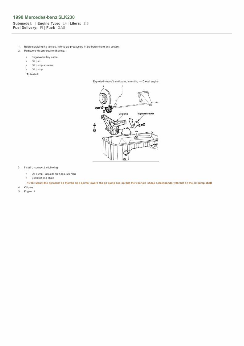
1998 Mercedes-benz SLK230
Submodel: | Engine Type: L4 | Liters: 2.3Fuel Delivery: FI | Fuel: GAS
1. Before servicing the vehicle, refer to the precautions in the beginning of this section.2. Remove or disconnect the following:
Negative battery cableOil panOil pump sprocketOil pump
To install:
Exploded view of the oil pump mounting — Diesel engine
3. Install or connect the following:
Oil pump. Torque to 18 ft. lbs. (25 Nm).Sprocket and chain
NOTE: Mount the sprocket so that the rise points toward the oil pump and so that the trochoid shape corresponds with that on the oil pump shaft.4. Oil pan5. Engine oil

1998 Mercedes-benz SLK230
Submodel: | Engine Type: L4 | Liters: 2.3Fuel Delivery: FI | Fuel: GAS
NOTE: All engines use a 1-piece radial seal.
1. Before servicing the vehicle, refer to the precautions in the beginning of this section.2. Remove or disconnect the following:
Negative battery cableTransmission assemblyFlywheel or flexplateRear main seal using a suitable prying tool
To install: 3. Coat the inner lip of the seal with engine oil.4. Install or connect the following:
Seal into the retainerFlywheel or flexplateTransmission assemblyNegative battery cable

1998 Mercedes-benz SLK230
Submodel: | Engine Type: L4 | Liters: 2.3Fuel Delivery: FI | Fuel: GAS
1. Before servicing the vehicle, refer to the precautions in the beginning of this section.2. Remove or disconnect the following:
CoolantNegative battery cableEngine undercoverSerpentine beltFan shroud and radiatorFan clutch and fanCrankshaft pulleySerpentine belt tensionerVacuum pumpPower steering pumpSelf-leveling suspension hydraulic pumpAlternator
3. Cover the air conditioning condenser using a piece of sheet metal, plywood or plastic.4. Remove or disconnect the following:
Cylinder head cover and charge air pipeOil dipstick tubeTDC sensor, marking its position
5. Support the engine and remove the engine mounts. Raise the engine to gain access.6. Remove the timing cover bolts and carefully remove the cover from the engine. Be careful not to damage the oil pan and cylinder head gaskets.
To install: 7. Install or connect the following:
Timing cover. Torque the bolts to 18 ft. lbs. (25 Nm)Engine mountsTDC sensorOil dipstick tubeCylinder head cover and charge air pipe
8. Remove the air conditioning condenser guard9. Install or connect the following:
AlternatorSelf-leveling suspension hydraulic pumpPower steering pumpVacuum pumpSerpentine belt tensionerCrankshaft pulleyFan clutch and fanRadiator and fan shroudSerpentine beltEngine undercoverNegative battery cableCoolant

1998 Mercedes-benz SLK230
Submodel: | Engine Type: L4 | Liters: 2.3Fuel Delivery: FI | Fuel: GAS
1. Before servicing the vehicle, refer to the precautions in the beginning of this section.2. Remove or disconnect the following:
Negative battery cableCylinder head coverInjection nozzlesChain tensionerFan and shroudEngine timing cover
3. Clamp the chain to the camshaft gear and cover the opening of the timing chain case.4. Separate the chain with a chain breaker.
To install: 5. Attach a new timing chain to the old chain with a master link. Using a socket wrench on the crankshaft, slowly rotate the engine in the direction of normal rotation. Simultaneously,
pull the old chain through until the master link is uppermost on the camshaft sprocket. Be sure to keep tension on the chain throughout this procedure.
NOTE: Use only a rivet-type connecting link. Do not use connecting link that uses a retaining spring.6. Disconnect the old timing chain and connect the ends of the new chain with the master link. Insert the new connecting link from the rear so the lockwashers can be seen from the
front.7. Install the timing chain tensioner. Rotate the engine until the timing marks align. Check the valve timing.8. Install or connect the following:
Engine timing cover. Torque the bolts to 18 ft. lbs. (25 Nm)Cylinder head cover. Torque to 90 inch lbs. (10 Nm)Fan and fan shroudInjection nozzlesNegative battery cable

1998 Mercedes-benz SLK230
Submodel: | Engine Type: L4 | Liters: 2.3Fuel Delivery: FI | Fuel: GAS
Cylinder identification and piston identifications must agree(see arrows)
Install pistons so the code (5) next to the piston pin and groupnumber (6) are pointing in the direction of travel, and the
identification (9) on the connecting rod is facing to the outsideof the engine.
Ring positioning

1998 Mercedes-benz SLK230
Submodel: | Engine Type: L4 | Liters: 2.3Fuel Delivery: FI | Fuel: GAS
Although different maintenance intervals are given by each manufacturer, it is a good rule of thumb to inspect the drive belts every 15,000 miles (24,000 km) or 12 months (whicheveroccurs first). Determine the belt tension at a point half-way between the pulleys by pressing on the belt with moderate thumb pressure. The belt should deflect about 1 ⁄ 4 – 1 ⁄ 2 in. (6–13mm) at this point. Note that "deflection" is not play, but the ability of the belt, under actual tension, to stretch slightly and give.
Inspect the belts for the following signs of damage or wear: glazing, cracking, fraying, crumbling or missing chunks. A glazed belt will be perfectly smooth from slippage, while a good beltwill have a slight texture of fabric visible. Cracks will usually start at the inner edge of the belt and run outward. A belt that is fraying will have the fabric backing de-laminating itself from thebelt. A belt that is crumbling or missing chunks will have voids in the cross-section of the belt, some times the section missing chunks will be in the pulley groove and not easily seen. Allworn or damaged drive belts should be replaced immediately. It is best to replace all drive belts at one time, as a preventive maintenance measure.
Although, it is generally easier on the component to have the belt too loose than too tight, a very loose belt may place a high impact load on a bearing due to the whipping or snapping actionof the belt. A belt that is slightly loose may slip, especially when component loads are high. This slippage may be hard to identify. For example, the generator belt may run okay during theday, then slip at night when the headlights are turned ON. Slipping belts wear quickly not only due to the direct effect of slippage but also because of the heat the slippage generates.Extreme slippage may even cause a belt to burn. A very smooth, glazed appearance on the belt's sides, as opposed to the obvious pattern of a fabric cover, indicates that the belt hasbeen slipping.
An example of a healthy drive belt
Deep cracks in this belt will cause flex, building up heat thatwill eventually lead to belt failure
The cover of this belt is worn, exposing the critical reinforcingcords to excessive wear
Installing too wide a belt can result in serious belt wear and/orbreakage


1998 Mercedes-benz SLK230
Submodel: | Engine Type: L4 | Liters: 2.3Fuel Delivery: FI | Fuel: GAS
CAUTION On vehicles with an electric cooling fan, disable the power to the fan by disengaging the fan motor wiring connector or removing the negative battery cable before replacing or adjusting thedrive belts. Otherwise, the fan may engage even though the ignition is
OFF.
Belt tension can be checked by pressing on the belt at the center point of its longest straight span. The belt should give approximately 1 ⁄ 4 – 1 ⁄ 2 in. (6–13mm). If the belt is loose it willslip, whereas if the belt is too tight it will damage the bearings in the driven unit.
For the purposes of V-belt tensioning, there are generally three types of mounting for the various components driven by the drive belt. The first method, referred to as pivoting type withoutadjuster, is designed so that the component is secured by at least 2 bolts. One of the bolts is a pivoting bolt and the other is the lockbolt. When both bolts are loosened so that thecomponent may move, the component pivots on the pivoting bolt. The lockbolt passes through the component and a slotted bracket, so that when the lockbolt's nut is tightened thecomponent is held in that position. There are no automatic adjusting mechanisms used with this type of mounting.
The second method of component mounting, referred to as pivoting type with adjuster, is almost identical except for the addition of an adjuster of some sort. Usually, the adjuster iscomposed of a bracket attached to the component and a threaded adjusting bolt. After loosening the pivoting and lockbolts, the adjusting bolt can be tightened or loosened to increase ordecrease the drive belt's tension. With this type of mounting, you do not have to hold the component in a tensioned position and tighten the pivoting and lockbolts; the adjusting bolt does thejob for you.
Some versions of this method of mounting use an adjuster which is built into one of the components mounting braces. The brace attaches the component to the engine and incorporates athreaded adjuster in its mid-span, so that when the threaded adjuster is turned the brace shortens or lengthens. This in turn increases or decreases the amount of tension on the component.
The third type of mounting, referred to as stationary type, is designed so that the component is mounted on its brackets. There are no pivoting or lockbolts, and the component is notdesigned to be moved. Rather, this type of mounting uses an extra tensioner idler pulley assembly. The drive belt is tensioned by adjusting the position of the idler pulley, usuallyaccomplished by turning the adjuster bolt on the idler mechanism.
A typical pivoting accessory with an adjusting bolt
An accessory that is fixed will have an adjustablepulley — notice the square slot to aid the adjustment
Pivoting Type
WITHOUT ADJUSTER
1. Disconnect the negative battery cable.2. Loosen the component's lockbolt and pivoting bolt only enough for the component to move.3. Using a prytool, move the component either closer to, or farther away from the engine, to provide the correct tension on the belt.
WARNING If using a metal prytool, always wrap the end with a rag or towel to prevent accidentally damaging the component from undue stress.
4. Once the proper amount of tension is applied to the drive belt, hold the prytool with one hand while tightening the lockbolt securely with the other hand.5. Release the pressure from the prytool and tighten the pivoting bolt securely.
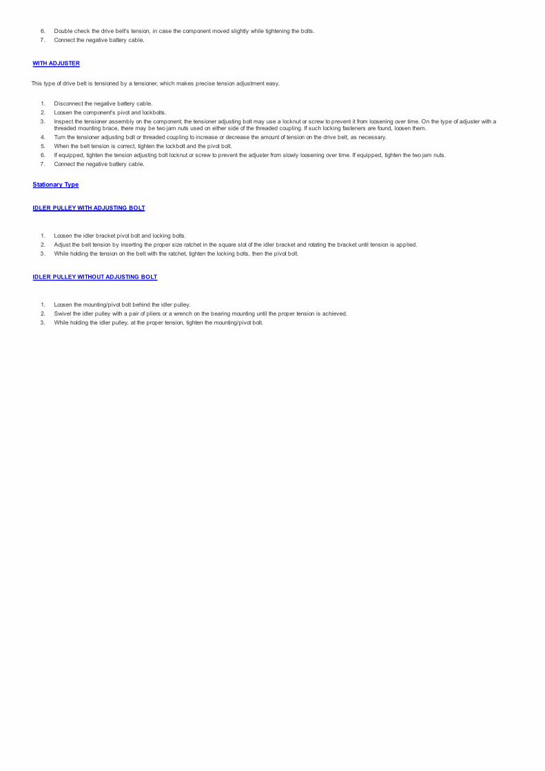
6. Double check the drive belt's tension, in case the component moved slightly while tightening the bolts.7. Connect the negative battery cable.
WITH ADJUSTER
This type of drive belt is tensioned by a tensioner, which makes precise tension adjustment easy.
1. Disconnect the negative battery cable.2. Loosen the component's pivot and lockbolts.3. Inspect the tensioner assembly on the component; the tensioner adjusting bolt may use a locknut or screw to prevent it from loosening over time. On the type of adjuster with a
threaded mounting brace, there may be two jam nuts used on either side of the threaded coupling. If such locking fasteners are found, loosen them.4. Turn the tensioner adjusting bolt or threaded coupling to increase or decrease the amount of tension on the drive belt, as necessary.5. When the belt tension is correct, tighten the lockbolt and the pivot bolt.6. If equipped, tighten the tension adjusting bolt locknut or screw to prevent the adjuster from slowly loosening over time. If equipped, tighten the two jam nuts.7. Connect the negative battery cable.
Stationary Type
IDLER PULLEY WITH ADJUSTING BOLT
1. Loosen the idler bracket pivot bolt and locking bolts.2. Adjust the belt tension by inserting the proper size ratchet in the square slot of the idler bracket and rotating the bracket until tension is applied.3. While holding the tension on the belt with the ratchet, tighten the locking bolts, then the pivot bolt.
IDLER PULLEY WITHOUT ADJUSTING BOLT
1. Loosen the mounting/pivot bolt behind the idler pulley.2. Swivel the idler pulley with a pair of pliers or a wrench on the bearing mounting until the proper tension is achieved.3. While holding the idler pulley, at the proper tension, tighten the mounting/pivot bolt.

1998 Mercedes-benz SLK230
Submodel: | Engine Type: L4 | Liters: 2.3Fuel Delivery: FI | Fuel: GAS
If a belt must be replaced, the driven unit or idler pulley must be loosened and moved to its extreme loosest position, generally by moving it toward the center of the motor. After removingthe old belt, check the pulleys for dirt or built-up material which could affect belt contact. Carefully install the new belt, remembering that it is new and unused; it may appear to be just alittle too small to fit over the pulley flanges. Fit the belt over the largest pulley (usually the crankshaft pulley at the bottom center of the motor) first, then work on the smaller one(s). Gentlepressure in the direction of rotation is helpful. Some belts run around a third, or idler pulley, which acts as an additional pivot in the belt's path. It may be possible to loosen the idler pulleyas well as the main component, making your job much easier. Depending on which belt(s) you are changing, it may be necessary to loosen or remove other interfering belts to get at theone(s) you want.
When buying replacement belts, remember that the fit is critical according to the length of the belt ("diameter"), the width of the belt, the depth of the belt and the angle or profile of the Vshape or the ribs. The belt shape should match the shape of the pulley exactly; belts that are not an exact match can cause noise, slippage and premature failure.
After the new belt is installed, draw tension on it by moving the driven unit or idler pulley away from the motor and tighten its mounting bolts. This is sometimes a three or four-handed job;you may find an assistant helpful. Be sure that all the bolts you loosened get retightened and that any other loosened belts also have the correct tension. A new belt can be expected tostretch a bit after installation so be prepared to readjust your new belt, if needed, within the first two hundred miles of use.
Pivoting Type
CAUTION On vehicles with an electric cooling fan, disable the power to the fan by disengaging the fan motor wiring connector or removing the negative battery cable before replacing or adjusting thedrive belts. Otherwise, the fan may engage even though the ignition is
OFF.
WITHOUT ADJUSTER
1. Disconnect the negative battery cable.2. Loosen the accessory's slotted adjusting bracket bolt. If the hinge bolt is excessively tight, it too will have to be loosened.3. Push the component toward the engine to provide enough slack in the belt so that it will slide over one of the accessory drive pulleys. Remove the drive belt from the accessory
drive pulleys and from the vehicle.
To install: 4. Position the new drive belt over the component pulleys. Be sure that it is routed correctly.5. Adjust the tension of the belt, as described earlier in this section.6. Connect the negative battery cable.
WITH ADJUSTER
1. Disconnect the negative battery cable.2. Loosen the component's pivot and lockbolts.3. Inspect the tensioner assembly on the component; the tensioner adjusting bolt may use a locknut or screw to prevent it from loosening over time. On the type of adjuster with a
threaded mounting brace, there may be two jam nuts used on either side of the threaded coupling. If such locking fasteners are found, loosen them.4. Turn the tensioner adjusting bolt or threaded coupling to relieve all tension from the drive belt.5. Slip the belt off of the accessory pulley, then remove it from the other pulleys. Remove the belt from the vehicle.
To install: 6. Route the new belt on the component pulleys. Make certain that it is routed correctly; incorrect routing could cause components to spin backward, possibly damaging it.7. Once the belt is correctly positioned on all of the pulleys, adjust the tension as described earlier in this section.8. Connect the negative battery cable.
Stationary Type
IDLER PULLEY WITH ADJUSTING BOLT
1. Disconnect the negative battery cable.2. Loosen the idler bracket pivot bolt and locking bolts.3. Move the idler pulley until the most amount of slack is gained.4. Remove the drive belt from the accessory pulley, then from the other applicable pulleys.
To install: 5. Position the new belt over the crankshaft pulley, the idler pulley and the accessory pulley. Make certain that it is correctly routed, otherwise it could cause the accessory to be
rotated backwards. This could cause damage to the accessory.6. Adjust the belt tension, as described earlier in this section.7. While holding the tension on the belt with the ratchet, tighten the locking bolts, then the pivot bolt.8. Connect the negative battery cable.
IDLER PULLEY WITHOUT ADJUSTING BOLT
1. Disconnect the negative battery cable.2. Loosen the mounting/pivot bolt behind the idler pulley.3. Remove the drive belt from the accessory pulley, then from the other applicable pulleys.
To install: 4. Position the new belt over the crankshaft pulley, the idler pulley and the accessory pulley. Make certain that it is correctly routed, otherwise it could cause the accessory to be
rotated backwards. This could cause damage to the accessory.5. Swivel the idler pulley with a pair of pliers or a wrench on the bearing mounting until the proper tension is achieved.

6. While holding the idler pulley, at the proper tension, tighten the mounting/pivot bolt.7. Connect the negative battery cable.
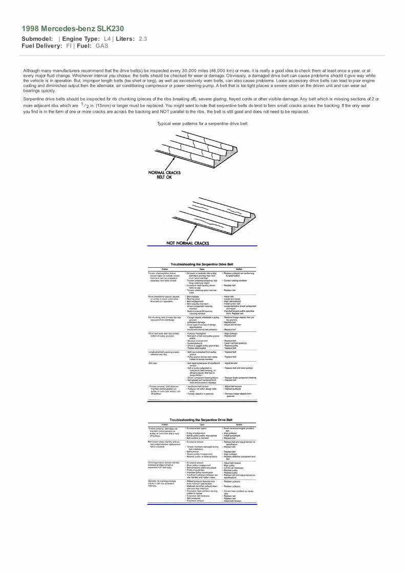
1998 Mercedes-benz SLK230
Submodel: | Engine Type: L4 | Liters: 2.3Fuel Delivery: FI | Fuel: GAS
Although many manufacturers recommend that the drive belt(s) be inspected every 30,000 miles (48,000 km) or more, it is really a good idea to check them at least once a year, or atevery major fluid change. Whichever interval you choose, the belts should be checked for wear or damage. Obviously, a damaged drive belt can cause problems should it give way whilethe vehicle is in operation. But, improper length belts (too short or long), as well as excessively worn belts, can also cause problems. Loose accessory drive belts can lead to poor enginecooling and diminished output from the alternator, air conditioning compressor or power steering pump. A belt that is too tight places a severe strain on the driven unit and can wear outbearings quickly.
Serpentine drive belts should be inspected for rib chunking (pieces of the ribs breaking off), severe glazing, frayed cords or other visible damage. Any belt which is missing sections of 2 ormore adjacent ribs which are 1 ⁄ 2 in. (13mm) or longer must be replaced. You might want to note that serpentine belts do tend to form small cracks across the backing. If the only wearyou find is in the form of one or more cracks are across the backing and NOT parallel to the ribs, the belt is still good and does not need to be replaced.
Typical wear patterns for a serpentine drive belt

1998 Mercedes-benz SLK230
Submodel: | Engine Type: L4 | Liters: 2.3Fuel Delivery: FI | Fuel: GAS
Periodic drive belt tensioning is not necessary, because an automatic spring-loaded tensioner is used with these belts to maintain proper adjustment at all times. The tensioner is alsouseful as a wear indicator. When the belt is properly installed, the arrow on the tensioner housing must point within the acceptable range lines on the tensioner's face. If the arrow fallsoutside the range, either an improper belt has been installed or the belt is worn beyond its useful life span. In either case, a new belt must be installed immediately to assure proper engineoperation and to prevent possible accessory damage.
Typical drive belt automatic tensioner wear indicator

1998 Mercedes-benz SLK230
Submodel: | Engine Type: L4 | Liters: 2.3Fuel Delivery: FI | Fuel: GAS
Because serpentine belts use a spring loaded tensioner for adjustment, belt replacement tends to be somewhat easier than it used to be on engines where accessories were pivoted andbolted in place for tension adjustment. Basically, all belt replacement involves is to pivot the tensioner to loosen the belt, then slide the belt off of the pulleys. The two most important pointsare to pay CLOSE attention to the proper belt routing (since serpentine belts tend to be "snaked" all different ways through the pulleys) and to be sure the V-ribs are properly seated in allthe pulleys.
Although belt routing diagrams have been included in this section, the first places you should check for proper belt routing are the labels in your engine compartment. These should includea belt routing diagram which may reflect changes made during a production run.
1. Disconnect the negative battery cable for safety. This will help assure that no one mistakenly cranks the engine over with your hands between the pulleys, and that the coolingfan cannot activate while servicing the belt(s).
NOTE: Take a good look at the installed belt and make a note of the routing. Before removing the belt, be sure the routing matches that of the belt routinglabel or one of the diagrams in this book. If for some reason a diagram does not match (you may not have the original engine or it may have beenmodified), carefully note the changes on a piece of paper.
2. For tensioners equipped with a 1 ⁄ 2 in. (13mm) square hole, insert the drive end of a large breaker bar into the hole. Use the breaker bar to pivot the tensioner away from thedrive belt. For tensioners not equipped with this hole, use the proper-sized socket and breaker bar (or a large handled wrench) on the tensioner idler pulley center bolt to pivotthe tensioner away from the belt. This will loosen the belt sufficiently that it can be pulled off of one or more of the pulleys. It is usually easiest to carefully pull the belt out fromunderneath the tensioner pulley itself.
3. Once the belt is off one of the pulleys, gently pivot the tensioner back into position. DO NOT allow the tensioner to snap back, as this could damage the tensioner's internalparts.
4. Now finish removing the belt from the other pulleys and remove it from the engine.
To install: 5. While referring to the proper routing diagram (which you identified earlier), begin to route the belt over the pulleys, leaving whichever pulley you first released it from for last.6. Once the belt is mostly in place, carefully pivot the tensioner and position the belt over the final pulley. As you begin to allow the tensioner back into contact with the belt, run
your hand around the pulleys and be sure the belt is properly seated in the ribs. If not, release the tension and seat the belt.7. Once the belt is installed, take another look at all the pulleys to double check your installation.8. Connect the negative battery cable, then start and run the engine to check belt operation.9. Once the engine has reached normal operating temperature, turn the ignition OFF and check that the belt tensioner arrow is within the proper adjustment range.
Often the underhood label will display the serpentine drivebelt routing
Relieve the belt tension by pivoting the automatic tensioneraway from the belt, then remove the belt
Verifying serpentine belt alignment in the pulley

Fig. 1 Serpentine drive belt routing — Mercedes-Benz 2.8L,3.2L, 4.2L, 4.3L, 5.0L and 6.0L engines
Fig. 2 Serpentine drive belt routing — Mercedes-Benz 2.2L,2.3L (non-supercharged) and 3.0L Diesel engines

Fig. 3 Serpentine drive belt routing — Mercedes-Benz 2.3Lsupercharged engines

1998 Mercedes-benz SLK230
Submodel: | Engine Type: L4 | Liters: 2.3Fuel Delivery: FI | Fuel: GAS
Behr Style
1. Disconnect the negative battery cable.2. Drain the cooling system into a clean container for reuse.3. Remove or disconnect the following:
Hoses from the heater supply and return pipes. Using compressed air, blow the residual coolant from the heater coreInstrument panelUpper heater box cover-to-heater box screws, the 6 clips and the coverHeater supply pipe-to-chassis clamp in the engine compartmentHeater supply and return pipes-to-heater core screws from the top of the heater box and swing the pipes away from the heater boxPull the heater core from the top of the heater box
4. Clean any spilled coolant from inside the heater box.
View of the heater box and related components — BEHRstyle — 300D Turbo, 300E, 300CE, 300TE, 300E, 4Matic,
300TE 4Matic
To install: 5. Install or connect the following:
Heater core into the heater boxHeater supply and return pipes to the heater box using 3 new sealing ringsHeater supply pipe-to-chassis clamp in the engine compartmentUpper cover to the heater box, the 6 clips and the screwsInstrument panelHoses to the heater supply and return pipes
6. Refill the cooling system.7. Connect the negative battery cable.8. Operate the engine to normal operating temperatures; then, check the climate control operation and check for leaks.
Valeo Style
1. Disconnect the negative battery cable.2. Drain the cooling system into a clean container for reuse.3. Remove or disconnect the following:
Hoses from the heater supply and return pipes. Using compressed air, blow the residual coolant from the heater coreInstrument panel and the center consolePull off the temperature sensor heat exchanger, the left and right 2-pole couplings from the lower front of the heater boxPull the air ducts from the bottom of the heater boxCrossmember and strut from the front of the heater boxBracket from under the heater boxLoosen the ignition switch housing-to-steering column bolt. Turn the ignition key to position 1, press the ignition switch housing locking button and pull the steering lockfrom the steering columnPull the air ducts from both sides of the heater boxHeater box-to-chassis nuts and pull the heater box from the firewallElectrical connectors and clip from the blower motor. Disconnect the main air flap control cable from the heater boxHeater box retaining clips and pull the front case from the rear case. Remove the heater core from the heater caseHeater supply and return pipes-to-heater core screws and the pipes from the heater core
4. Clean any spilled coolant from inside the heater box.
View of the heater box and related components — VALEOstyle — 300D Turbo, 300E, 300CE, 300TE, 300E, 4Matic,
300TE 4Matic

Exploded view of the heater box and relatedcomponents — VALEO style — 300D Turbo, 300E, 300CE,
300TE, 300E, 4Matic, 300TE 4Matic
To install: 5. Install or connect the following:
Heater supply and return pipes to the heater box using 3 new sealing ringsHeater core into the heater box; make sure the rubber pipe grommets are seated properlyFront case onto the heater box and secure with the clipsMain air flap control cable to the heater box. Connect the electrical connectors and clip to the blower motorPosition the heater box against the firewall (using a new seal) and install the heater box-to-chassis nuts.Air ducts to both sides of the heater boxSlide the steering lock into the steering column and tighten the boltBracket under the heater boxCrossmember and strut at the front of the heater boxAir ducts to the bottom of the heater boxTemperature sensor heat exchanger, the left and right 2-pole couplings at the lower front of the heater box
6. Refill the cooling system.7. Connect the negative battery cable.8. Operate the engine to normal operating temperatures; then, check the climate control operation and check for leaks.
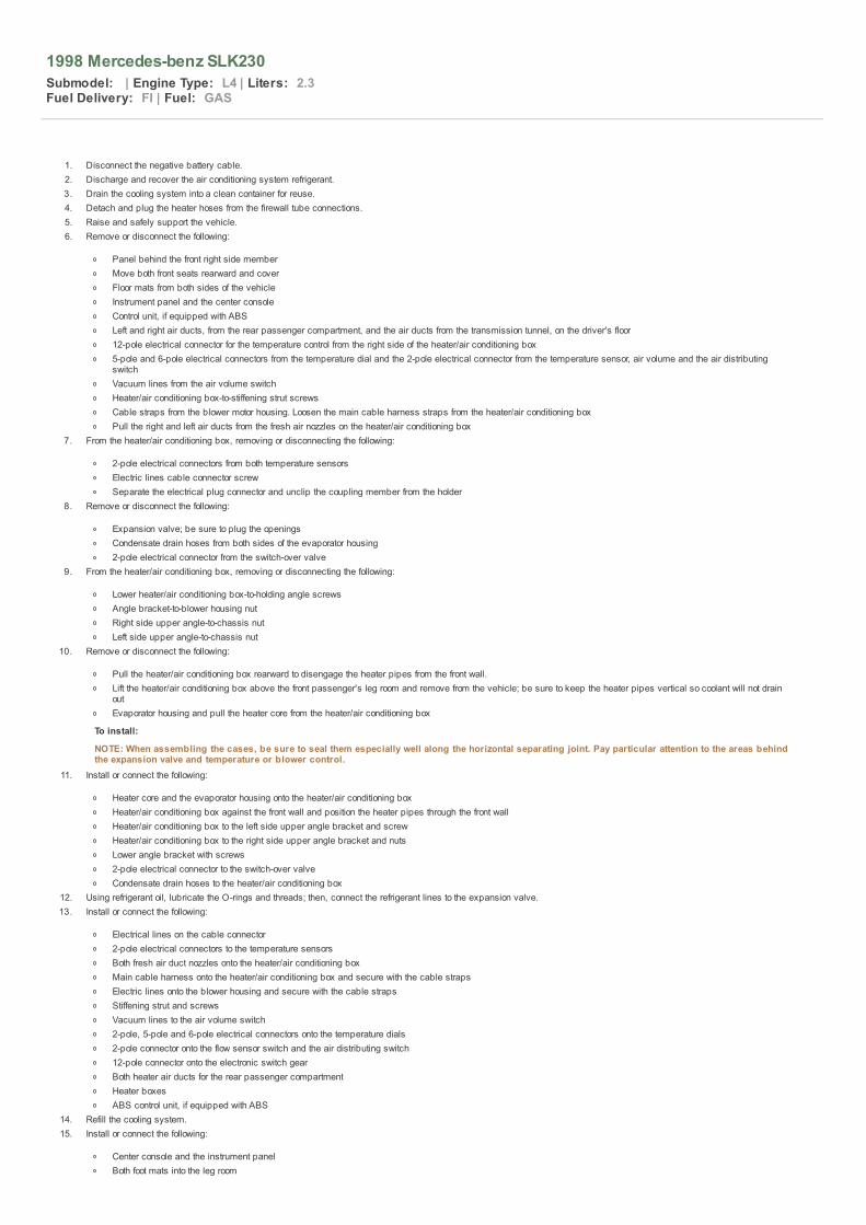
1998 Mercedes-benz SLK230
Submodel: | Engine Type: L4 | Liters: 2.3Fuel Delivery: FI | Fuel: GAS
1. Disconnect the negative battery cable.2. Discharge and recover the air conditioning system refrigerant.3. Drain the cooling system into a clean container for reuse.4. Detach and plug the heater hoses from the firewall tube connections.5. Raise and safely support the vehicle.6. Remove or disconnect the following:
Panel behind the front right side memberMove both front seats rearward and coverFloor mats from both sides of the vehicleInstrument panel and the center consoleControl unit, if equipped with ABSLeft and right air ducts, from the rear passenger compartment, and the air ducts from the transmission tunnel, on the driver's floor12-pole electrical connector for the temperature control from the right side of the heater/air conditioning box5-pole and 6-pole electrical connectors from the temperature dial and the 2-pole electrical connector from the temperature sensor, air volume and the air distributingswitchVacuum lines from the air volume switchHeater/air conditioning box-to-stiffening strut screwsCable straps from the blower motor housing. Loosen the main cable harness straps from the heater/air conditioning boxPull the right and left air ducts from the fresh air nozzles on the heater/air conditioning box
7. From the heater/air conditioning box, removing or disconnecting the following:
2-pole electrical connectors from both temperature sensorsElectric lines cable connector screwSeparate the electrical plug connector and unclip the coupling member from the holder
8. Remove or disconnect the following:
Expansion valve; be sure to plug the openingsCondensate drain hoses from both sides of the evaporator housing2-pole electrical connector from the switch-over valve
9. From the heater/air conditioning box, removing or disconnecting the following:
Lower heater/air conditioning box-to-holding angle screwsAngle bracket-to-blower housing nutRight side upper angle-to-chassis nutLeft side upper angle-to-chassis nut
10. Remove or disconnect the following:
Pull the heater/air conditioning box rearward to disengage the heater pipes from the front wall.Lift the heater/air conditioning box above the front passenger's leg room and remove from the vehicle; be sure to keep the heater pipes vertical so coolant will not drainoutEvaporator housing and pull the heater core from the heater/air conditioning box
To install:
NOTE: When assembling the cases, be sure to seal them especially well along the horizontal separating joint. Pay particular attention to the areas behindthe expansion valve and temperature or blower control.
11. Install or connect the following:
Heater core and the evaporator housing onto the heater/air conditioning boxHeater/air conditioning box against the front wall and position the heater pipes through the front wallHeater/air conditioning box to the left side upper angle bracket and screwHeater/air conditioning box to the right side upper angle bracket and nutsLower angle bracket with screws2-pole electrical connector to the switch-over valveCondensate drain hoses to the heater/air conditioning box
12. Using refrigerant oil, lubricate the O-rings and threads; then, connect the refrigerant lines to the expansion valve.13. Install or connect the following:
Electrical lines on the cable connector2-pole electrical connectors to the temperature sensorsBoth fresh air duct nozzles onto the heater/air conditioning boxMain cable harness onto the heater/air conditioning box and secure with the cable strapsElectric lines onto the blower housing and secure with the cable strapsStiffening strut and screwsVacuum lines to the air volume switch2-pole, 5-pole and 6-pole electrical connectors onto the temperature dials2-pole connector onto the flow sensor switch and the air distributing switch12-pole connector onto the electronic switch gearBoth heater air ducts for the rear passenger compartmentHeater boxesABS control unit, if equipped with ABS
14. Refill the cooling system.15. Install or connect the following:
Center console and the instrument panelBoth foot mats into the leg room

Side member panel (located under the vehicle), if removed16. Connect the negative battery cable.17. Evacuate, charge and leak test the air conditioning system.18. Operate the engine to normal operating temperatures; then, check the climate control operation and check for leaks.
1998 Mercedes-benz SLK230
Submodel: | Engine Type: L4 | Liters: 2.3Fuel Delivery: FI | Fuel: GAS
1. Disconnect the negative battery.2. Drain the cooling system into a clean container for reuse.3. Discharge and recover the air conditioning system refrigerant.4. Remove or disconnect the following:
Air inlet coverWater collectorSeries resistor for the heater blowerLoosen the clamps on the hot water supply and return hoses and pull off the hoses. Seal off the openingsInstrument panelCenter consoleLeft and right floor coveringFront passenger airbag unit, if equippedJacket tubeCable duct screws and loosen the cable ductBracket screws and bracketTraverse pipe attaching the bolts and nuts and remove the traverse pipeElectrical cables at the ground pointOpen the cable tie and remove the left and right rear air ductsVacuum lines at the cockpit separation pointRight ground strapPlug connection for the blower motorAir ducts to the left and right side outletsHeater boxScrews and clips and remove the coverScrews and loosen the guide for the hot water supply pipeScrews and loosen the hot water return pipeRetaining clip for the hot water supply pipeHeat core together with the hot water pipesHot water pipe attaching screws and remove the pipes
To install: 5. Install or connect the following:
Heater coreHot water pipe and screwsHeat core together with the hot water pipesRetaining clip for the hot water supply pipeHot water return pipe and the screwsGuide and the screws for the hot water supply pipeCover and the screws and clipsHeater boxAir ducts to the left and right side outletsPlug connection for the blower motorRight ground strapVacuum lines at the cockpit separation pointLeft and right rear air ductsElectrical cables at the ground pointTraverse pipe, the bolts and nutsBracket and screwsCable duct and the cable duct screwsJacket tubeFront passenger air bag unit, if equippedLeft and right floor coveringCenter consoleInstrument panelReturn hoses and the hoses to the hot water supplySeries resistor for the heater blowerWater collectorAir inlet cover
6. Evacuate, charge and leak test the air conditioning system.7. Refill the cooling system.8. Connect the negative battery.9. Operate the engine to normal operating temperatures; then, check the climate control operation and check for leaks.

1998 Mercedes-benz SLK230
Submodel: | Engine Type: L4 | Liters: 2.3Fuel Delivery: FI | Fuel: GAS
2.8L, 3.2L, 3.6L (104), 2.2L, 2.3L (111), 3.2L (112) and 4.3L (113) Engines
1. Before servicing the vehicle, refer to the precautions in the beginning of this section.2. Remove or disconnect the following:
Negative battery cableAccessory drive beltEngine under coverAlternator electrical wires
3. Remove the alternator from the bottom.
To install: 4. Install the alternator assembly. Torque the mounting bolts to 31 ft. lbs. (42 Nm).5. Install or connect the following:
Alternator electrical wiresEngine under coverAccessory drive beltConnect the negative battery cable
6. Start the engine and check for proper operation.
4.2L and 5.0L (119) Engines
1. Before servicing the vehicle, refer to the precautions in the beginning of this section.2. Remove or disconnect the following:
Negative battery cableViscous fan coupling if equipped with ball-type alternatorAccessory drive beltAlternator electrical connectionsAlternator mounting boltsAlternator
To install: 3. Install or connect the following:
Alternator assemblyElectrical connectionsAccessory drive beltViscous fan couplingNegative battery cable
4. Start the engine and check for proper operation.
6.0L (120) Engine
1. Before servicing the vehicle, refer to the precautions in the beginning of this section.2. Remove or disconnect the following:
Negative battery cableAccessory drive beltAlternator electrical connectionsAutoMatic transmission coolant pipeEngine under coverRight torsion bar and spring leaf rockersAlternator mounting bolts
3. Remove the alternator from the bottom.
To install: 4. Install or connect the following:
Alternator assemblyRight torsion bar and spring leaf rockers. Torque bolts to 44 ft. lbs. (60 Nm)AutoMatic transmission coolant pipeAlternator electrical connectionsEngine under coverNegative battery cableAccessory drive belt
5. Start the engine and check for proper operation.

1998 Mercedes-benz SLK230
Submodel: | Engine Type: L4 | Liters: 2.3Fuel Delivery: FI | Fuel: GAS
All engines except the 4.2L and 5.0L engines are equipped with a Distributorless Ignition System (DIS). No adjustment is necessary. The 4.2L and 5.0L timing is controlled by the ElectronicIgnition with Anti-Knock Retard (EZL/ARK) control unit. No ignition timing adjustment is possible.
1998 Mercedes-benz SLK230
Submodel: | Engine Type: L4 | Liters: 2.3Fuel Delivery: FI | Fuel: GAS
All Models
1. Before servicing the vehicle, refer to the precautions in the beginning of this section.2. Turn the steering wheel to full left position to gain access if necessary.3. Remove or disconnect the following:
Negative ground cableEngine under coverStarter electrical connectionsRear engine mount if necessaryStarter mounting boltsStarter assembly
To install: 4. Install or connect the following:
Starter assembly. Torque the mounting bolts to 31 ft. lbs. (42 Nm)Rear engine mount. Torque the bolts to 41 ft. lbs. (55 Nm)Starter electrical connectionsNegative ground cable
5. Start the engine and check for proper operation.

1998 Mercedes-benz SLK230
Submodel: | Engine Type: L4 | Liters: 2.3Fuel Delivery: FI | Fuel: GAS
1. Before servicing the vehicle, refer to the precautions in the beginning of this section.2. Remove or disconnect the following:
Negative battery cableAccessory drive beltEngine under coverAlternator electrical wiresAlternator from the bottom of the vehicle
To install: 3. Install or connect the following:
Alternator. Torque the mounting bolts to 31 ft. lbs. (42 Nm).Alternator electrical wiresEngine under coverAccessory drive beltConnect the negative battery cable
4. Start the engine and check for proper operation.

1998 Mercedes-benz SLK230
Submodel: | Engine Type: L4 | Liters: 2.3Fuel Delivery: FI | Fuel: GAS
Safety is the most important factor when performing not only fuel system maintenance but also any type of maintenance. Failure to conduct maintenance and repairs in a safe manner mayresult in serious personal injury or death. Maintenance and testing of the vehicle's fuel system components can be accomplished safely and effectively by adhering to the following rules andguidelines.
To avoid the possibility of fire and personal injury, always disconnect the negative battery cable unless the repair or test procedure requires that battery voltage be applied.Always relieve the fuel system pressure prior to disconnecting any fuel system component (injector, fuel rail, pressure regulator, etc.), fitting or fuel line connection. Exercise extremecaution whenever relieving fuel system pressure, to avoid exposing skin, face and eyes to fuel spray. Please be advised that fuel under pressure may penetrate the skin or any partof the body that it contacts.Always place a shop towel or cloth around the fitting or connection prior to loosening to absorb any excess fuel due to spillage. Ensure that all fuel spillage (should it occur) is quicklyremoved from engine surfaces. Ensure that all fuel soaked cloths or towels are deposited into a suitable waste container.Always keep a dry chemical (Class B) fire extinguisher near the work area.Do not allow fuel spray or fuel vapors to come into contact with a spark or open flame.Always use a back-up wrench when loosening and tightening fuel line connection fittings. This will prevent unnecessary stress and torsion to fuel line piping.Always replace worn fuel fitting O-rings with new. Do not substitute fuel hose or equivalent, where fuel pipe is installed.

1998 Mercedes-benz SLK230
Submodel: | Engine Type: L4 | Liters: 2.3Fuel Delivery: FI | Fuel: GAS
1. Before servicing the vehicle, refer to the precautions in the beginning of this section.2. Disconnect the negative battery cable.3. Connect a fuel pressure gauge with a pressure release valve to the service port on the fuel supply rail.4. Place the fuel release tube into a container and open the valve.5. Remove the fuel pressure gauge from the service port on the fuel supply rail.

1998 Mercedes-benz SLK230
Submodel: | Engine Type: L4 | Liters: 2.3Fuel Delivery: FI | Fuel: GAS
1. Before servicing the vehicle, refer to the precautions in the beginning of this section.2. Properly relieve the fuel system pressure.3. Remove or disconnect the following:
Cover boxGas capFuel pump coverPressure hosesFuel filter
4. Remove the connecting plug from the old filter and install it on a new filter using a new gasket.
To install: 5. Install or connect the following:
Fuel filterAttaching screwsPressure hosesFuel pump coverGas capCover box and check for proper sealing
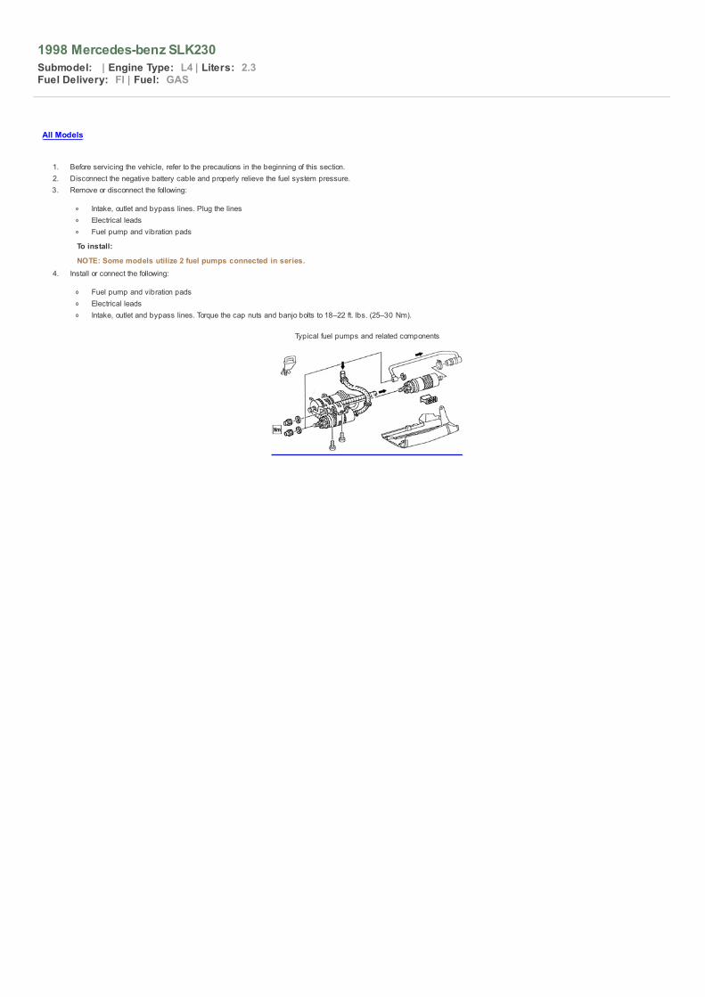
1998 Mercedes-benz SLK230
Submodel: | Engine Type: L4 | Liters: 2.3Fuel Delivery: FI | Fuel: GAS
All Models
1. Before servicing the vehicle, refer to the precautions in the beginning of this section.2. Disconnect the negative battery cable and properly relieve the fuel system pressure.3. Remove or disconnect the following:
Intake, outlet and bypass lines. Plug the linesElectrical leadsFuel pump and vibration pads
To install:
NOTE: Some models utilize 2 fuel pumps connected in series.4. Install or connect the following:
Fuel pump and vibration padsElectrical leadsIntake, outlet and bypass lines. Torque the cap nuts and banjo bolts to 18–22 ft. lbs. (25–30 Nm).
Typical fuel pumps and related components

1998 Mercedes-benz SLK230
Submodel: | Engine Type: L4 | Liters: 2.3Fuel Delivery: FI | Fuel: GAS
All Models
1. Before servicing the vehicle, refer to the precautions in the beginning of this section.2. Properly relieve the fuel system pressure.3. Remove or disconnect the following:
Negative battery cableBrake servo vacuum hosePressure regulator vacuum hosePCV hoseFuel feed pipeFuel system electrical connectionsLeft side ignition coil covers if necessaryFuel rail with the injectors attachedInjector-to-fuel rail locking clipInjectors
To install: 4. Install or connect the following:
Injectors with new O-rings on the fuel railInjector-to-fuel rail locking clipFuel rail/injector assemblyLeft side ignition coil coversFuel system electrical connectionsFuel feed pipePCV hosePressure regulator vacuum hoseBrake servo vacuum hoseNegative battery cable

1998 Mercedes-benz SLK230
Submodel: | Engine Type: L4 | Liters: 2.3Fuel Delivery: FI | Fuel: GAS
Safety is the most important factor when performing not only fuel system maintenance but any type of maintenance. Failure to conduct maintenance and repairs in a safe manner may resultin serious personal injury or death. Maintenance and testing of the vehicle's fuel system components can be accomplished safely and effectively by adhering to the following rules andguidelines.
To avoid the possibility of fire and personal injury, always disconnect the negative battery cable unless the repair or test procedure requires that battery voltage be applied.Please be advised that fuel under pressure may penetrate the skin or any part of the body that it contacts.Always place a shop towel or cloth around the fitting or connection prior to loosening to absorb any excess fuel due to spillage. Ensure that all fuel spillage (should it occur) is quicklyremoved from engine surfaces. Ensure that all fuel soaked cloths or towels are deposited into a suitable waste container.Always keep a dry chemical (Class B) fire extinguisher near the work area.Do not allow fuel spray or fuel vapors to come into contact with a spark or open flame.Always use a back-up wrench when loosening and tightening fuel line connection fittings. This will prevent unnecessary stress and torsion to fuel line piping.Always replace worn fuel fitting O-rings with new. Do not substitute fuel hose or equivalent, where fuel pipe is installed.

1998 Mercedes-benz SLK230
Submodel: | Engine Type: L4 | Liters: 2.3Fuel Delivery: FI | Fuel: GAS
These engines have electronically controlled idle speed, using a solenoid connected to the control unit. Idle speed and mixture adjustments are not recommended.

1998 Mercedes-benz SLK230
Submodel: | Engine Type: L4 | Liters: 2.3Fuel Delivery: FI | Fuel: GAS
1. Before servicing the vehicle, refer to the precautions in the beginning of this section.2. Loosen the center bolt while holding the filter cartridge. Remove cartridge.3. Lubricate the gasket on the new filter cartridge.4. Install the new cartridge, washer, O-ring and bolt.
NOTE: These Diesel engines utilize a self-bleeding fuel pump, therefore the priming pump has been eliminated. There is no need to bleed the system.
Fuel filter assembly — Diesel engines

1998 Mercedes-benz SLK230
Submodel: | Engine Type: L4 | Liters: 2.3Fuel Delivery: FI | Fuel: GAS
1. Before servicing the vehicle, refer to the precautions in the beginning of this section.
NOTE: The central fastening bolt uses left-hand threads.2. Disconnect the negative battery cable. Remove the cover and loosen the central fastening bolt while holding the crankshaft with a socket wrench. Position the crankshaft pulley at
15 degrees ATDC. Fix the camshaft gear and injection pump in place with a cable strap.3. Remove or disconnect the following:
Timing chain tensionerFuel linesIdle Speed Control (ISC) solenoid vacuum lines and electrical connectorControl rod travel sensor and actuator electrical cablesPump control lever throttle linkageVacuum control valve
4. Remove the injection pump sprocket bolt while holding the crankshaft in place. The bolt is a left-hand thread.5. Remove or disconnect the following:
Sprocket boltPump mounting boltsInjection pump while holding the timing device in place
To install: 6. Be sure the crankshaft is still at 15 degrees ATDC.7. Remove the timing plug from the pump.8. Using special tool 601 589 00 08 00 (serrated wrench) turn the pump until the lug of the governor is visible through the hole.9. Install the special tool 601 589 05 21 00 (locking bolt) in the timing plug hole to prevent the pump from turning while it is being installed.
10. Install the pump on the engine. Torque the injection lines to 84 inch lbs.–15 ft. lbs. (10–20 Nm), mounting bolts to 15–18 ft. lbs. (20–25 Nm) and the central bolt to 30–36 ft. lbs.(40–50 Nm).
11. Remove the locking bolt from the side of the injection pump.12. Install or connect the following:
Vacuum control valvePump control lever throttle linkageControl rod travel sensor and actuator electrical cablesISC solenoid vacuum lines and electrical connectorTiming chain tensioner
13. Crank the engine 1 revolution and recheck the TDC mark of the crankshaft and camshaft. Check the start of injector (injector pump timing) delivery with a digital tester.
Install the locking bolt tool (023) to prevent the pump fromturning during installation — Diesel engines

1998 Mercedes-benz SLK230
Submodel: | Engine Type: L4 | Liters: 2.3Fuel Delivery: FI | Fuel: GAS
1. Before servicing the vehicle, refer to the precautions in the beginning of this section.2. Disconnect the negative battery cable and properly relieve the fuel system pressure.3. Remove or disconnect the following:
Resonance intake pipeFuel linesInjection pipes at nozzlesInjection nozzles
To install: 4. Install or connect the following:
Injectors with new O-rings. Torque to 30 ft. lbs. (40 Nm)Injection pipes at nozzles. Torque to 17 ft. lbs. (23 Nm)Fuel linesResonance intake pipeNegative battery cable
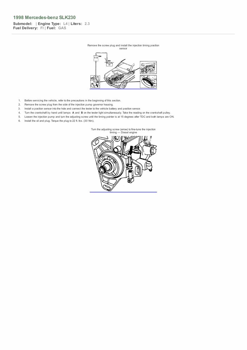
1998 Mercedes-benz SLK230
Submodel: | Engine Type: L4 | Liters: 2.3Fuel Delivery: FI | Fuel: GAS
Remove the screw plug and install the injection timing positionsensor
1. Before servicing the vehicle, refer to the precautions in the beginning of this section.2. Remove the screw plug from the side of the injection pump governor housing.3. Install a position sensor into the hole and connect the tester to the vehicle battery and position sensor.4. Turn the crankshaft by hand until lamps A and B on the tester light simultaneously. Take the reading on the crankshaft pulley.5. Loosen the injection pump and turn the adjusting screw until the timing pointer is at 15 degrees after TDC and both lamps are ON.6. Install the oil and plug. Torque the plug to 22 ft. lbs. (30 Nm).
Turn the adjusting screw (arrow) to fine-tune the injectiontiming — Diesel engine

1998 Mercedes-benz SLK230
Submodel: | Engine Type: L4 | Liters: 2.3Fuel Delivery: FI | Fuel: GAS

1997 2.2L engine Firing order: 1–3–4–2 Distributorlessignition system
Mercedes-Benz 2.3L engine Firing order: 1–3–4–2Distributorless ignition system (coil on cylinder)
Mercedes-Benz 3.2L engine Firing order: 1–4–3–6–2–5Distributorless ignition system (coil on each cylinder–2 spark
plugs per cyl.)
Mercedes-Benz 4.3L and 5.0L engines Firing order: 1–5–4–2–6–3–7–8 Distributorless ignition system (coil on each
cylinder–2 spark plugs per cyl.)


Intake manifold bolt tightening sequence — 4.2L and 5.0L(119) engines
Cylinder head bolt tightening sequence — 2.8L and 3.2L(104) Engines

Cylinder head bolt removal sequence — 2.2L and 2.3L (111)engines
Cylinder head bolt removal sequence — 3.2L (112) engine
Cylinder head bolt removal sequence — 4.3L (113) engine
Cylinder head bolt tightening sequence — 3.2L (112) engine
Cylinder head bolt tightening sequence — 4.3L (113) engine

Tightening sequence — 6.0L (120) engines
Cylinder head bolt tightening sequence — 6-cylinder Dieselengines


1998 Mercedes-benz SLK230
Submodel: | Engine Type: L4 | Liters: 2.3Fuel Delivery: FI | Fuel: GAS
Several precautions must be observed when handling the inflator module to avoid accidental deployment and possible personal injury.
Never carry the inflator module by the wires or connector on the underside of the module.When carrying a live inflator module, hold securely with both hands and ensure that the bag and trim cover are pointed away.Place the inflator module on a bench or other surface with the bag and trim cover facing up.With the inflator module on the bench, never place anything on or close to the module, which may be thrown in the event of an accidental deployment.

1998 Mercedes-benz SLK230
Submodel: | Engine Type: L4 | Liters: 2.3Fuel Delivery: FI | Fuel: GAS
To avoid personal injury when working on vehicles equipped with an air bag, the negative battery cable must be disconnected and insulated before working on the system. Failure to do somay result in accidental deployment of the air bag.

1998 Mercedes-benz SLK230
Submodel: | Engine Type: L4 | Liters: 2.3Fuel Delivery: FI | Fuel: GAS
To rearm the air bag system, reattach the battery cable(s).
1998 Mercedes-benz SLK230
Submodel: | Engine Type: L4 | Liters: 2.3Fuel Delivery: FI | Fuel: GAS
ALL MODELS
1. Before servicing the vehicle, refer to the precautions in the beginning of this section.2. Disconnect the negative battery cable.3. Drain the power steering fluid.4. Remove or disconnect the following:
Fan clutch, fan and shroudAccessory drive beltPower steering lines at pumpOil cooler lines if equippedPower steering pumpReservoir
To install: 5. Install or connect the following:
ReservoirPower steering pump. Torque the mounting bolts to 18 ft. lbs. (25 Nm)Power steering linesOil cooler lines if equippedAccessory drive beltFan clutch, fan and shroud
6. Refill the reservoir with fresh fluid. Start the engine and turn the steering wheel from lock-to-lock several times. The system will bleed autoMatically. Check for leaks.

1998 Mercedes-benz SLK230
Submodel: | Engine Type: L4 | Liters: 2.3Fuel Delivery: FI | Fuel: GAS
1. Before servicing the vehicle, refer to the precautions in the beginning of this section.2. Disconnect the negative battery cable.3. Center the steering wheel and turn the key to the lock position. Remove the key from the ignition switch.4. Drain the power steering reservoir.5. Remove or disconnect the following:
Fluid level feed line if equipped with level controlTie rod endsPressure and return linesSteering gear return lineSteering coupling heat shieldSteering couplingControl valve connector if equipped with speed sensitive steeringSteering gear retainer bolts (23g)Steering gear
To install: 6. Install or connect the following:
Steering gear with new locking nuts. Torque to 36 ft. lbs. (50 Nm)Control valve connectorControl valve coupling. Torque the bolt to 15 ft. lbs. (20 Nm)Steering gear return linePressure and return lines with new O-rings. Torque the fittings to 30 ft. lbs. (40 Nm)Heat shieldTie rod ends with new nuts. Torque the nuts to 44 ft. lbs. (60 Nm)Fluid level feed lineNegative battery cable
7. Refill the reservoir with fresh fluid. Start the engine and turn the steering wheel from lock-to-lock several times. The system will bleed autoMatically. Check for leaks.8. Check the front wheel alignment and adjust if necessary.
Exploded view of the rack and pinion steering gearmounting — E Class (210)

1998 Mercedes-benz SLK230
Submodel: | Engine Type: L4 | Liters: 2.3Fuel Delivery: FI | Fuel: GAS
Exploded view of the worm and sector steering gear mounting
1. Before servicing the vehicle, refer to the precautions in the beginning of this section.2. Disconnect the negative battery cable.3. Center the steering wheel and turn the key to the lock position. Remove the key from the ignition switch.4. Drain the power steering fluid reservoir5. Remove or disconnect the following:
Trim panel if necessaryDrag link and tie rodExhaust crossover pipeSteering gear heat shieldPressure and return linesSteering shaftSteering gear mounting boltsSteering gear
To install: 6. Center the steering gear by lining up the mark on the sector shaft with the mark on the housing.
CAUTION New stretch bolts must be used when installing the steering box and tightening the coupling.
Align the mark on the shaft with the one on the housing tocenter the steering gear — worm and sector steering gear
7. Install or connect the following:
Steering gearSteering shaft. Torque the new stretch bolts to 52–59 ft. lbs. (70–80 Nm)Coupling bolt. Torque the bolt to 18 ft. lbs. (25 Nm)Pressure and return lines. Torque the pressure line to 18 ft. lbs. (25 Nm) and the return line to 26–30 ft. lbs. (35–40 Nm)Heat shieldExhaust crossover pipeDrag link and tie rod with new self-locking nutsTrim panelNegative battery cable
8. Refill the reservoir with fresh fluid. Start the engine and turn the steering wheel from lock-to-lock several times. The system will bleed autoMatically. Check for leaks.

1998 Mercedes-benz SLK230
Submodel: | Engine Type: L4 | Liters: 2.3Fuel Delivery: FI | Fuel: GAS
Front
SL CLASS (129)
1. Before servicing the vehicle, refer to the precautions in the beginning of this section.2. Remove the front wheel.3. Support the lower control arm.4. Using a spring compressor, compress the spring to relieve the pressure on the lower control arm.
NOTE: Convertible models have a vibration damper mounted on top of the left strut mount. Installation of the nut is possible only with the use of socket124 589 00 09 00 and torque wrench 001 589 67 21 00.
5. Remove or disconnect the following:
Upper mounting nut while holding the piston rod with a hex wrenchABS sensor wireLower strut mounting boltsStrut assembly
WARNING Do not allow the knuckle assembly to hang by the brake hose, ABS wire or brake pad sensor wire.
6. Remove the upper nut and remove the strut from the vehicle.
To install: 7. If installing a new strut, transfer all components from the old strut to the new one.8. Clean the strut mounting surface of the knuckle.9. Install or connect the following:
Strut assembly. Torque the lower bolts only until the heads make contactUpper mounting bolt with washer and new self-locking nut. Torque until the surface of the knuckle makes contact with the strut
10. Torque the 2 lower mounting bolts to 81 ft. lbs. (110 Nm), then tighten the upper bolt to 147 ft. lbs. (200 Nm).11. Install the upper mount. Torque a new hex nut to 45 ft. lbs. (60 Nm). On convertible models, be sure the 0.008 inch (0.2mm) thick steel washer is installed below the self-locking
nut.12. Release the tension from the spring compressor. Be sure the upper and lower ends of the spring are properly seated.
Exploded view of the front strut and related components — SLmodels
Rear
E320 WAGON (210)
1. Before servicing the vehicle, refer to the precautions in the beginning of this section.2. Remove the upper strut mounting with the vehicle on the floor.3. Remove or disconnect the following:
Level control line if equippedSpring link coverStrut assembly
To install: 4. Install or connect the following:
Strut assembly. Torque the lower self-locking nut to 41 ft. lbs. (55 Nm)Level control line. Torque to 18 ft. lbs. (25 Nm)Upper strut mounting nut. Torque to 22 ft. lbs. (30 Nm)

1998 Mercedes-benz SLK230
Submodel: | Engine Type: L4 | Liters: 2.3Fuel Delivery: FI | Fuel: GAS
Front
ALL MODELS — EXCEPT E CLASS (210) 4-MATIC
1. Before servicing the vehicle, refer to the precautions in the beginning of this section.2. Remove the front wheel.3. Support the lower control arm with a jack. Raise the jack slightly to release the tension on the shock absorber.4. Remove or disconnect the following:
Upper mountingLower mounting boltShock absorber
To install: 5. Install or connect the following:
Shock absorberLower mounting bolt. Torque the bolt to 74 ft. lbs. (100 Nm).Upper mounting. Torque the lower nut to 11–13 ft. lbs. (15–18 Nm) and the upper nut to 22 ft. lbs. (30 Nm)Front wheel
Front shock absorber mounting — S Class (A), C and EClass (B)
E CLASS (210) 4-MATIC
1. Before servicing the vehicle, refer to the precautions in the beginning of this section.2. Remove or disconnect the following:
Front wheelAxle shaft 12-point nutBrake hose bracketSpeed sensor and brake lining sensor wiresTie rod endSupporting joint
3. Pull the steering knuckle outward and move the front axle out of the axle shaft flange.4. Separate the follower joint from the steering knuckle. Use wire to support the knuckle assembly.5. Remove or disconnect the following:
Engine undercoverAxle shaftStabilizer bar bracketStabilizer bar end bushing
6. Compress the coil spring and remove the upper shock absorber mounting.7. Remove or disconnect the following:
Lower shock absorber mountingShock absorberCoil spring
To install: 8. Place the coil spring into position on the shock absorber.
WARNING All suspension fasteners that pass through a rubber bushing, should be tightened while the vehicle is at normal ride height. Premature bushing failure may occur if thefasteners are tightened while the suspension is hanging.
9. Install or connect the following:
Shock absorber upper and lower mounting. On the upper mounting, torque the bottom nut to 11–13 ft. lbs. (15–18 Nm) and the upper nut to 22 ft. lbs. (30 Nm). Torquethe new self-locking nut on the lower mounting to 136 ft. lbs. (185 Nm)Stabilizer bar. Torque the bracket bolts to 15 ft. lbs. (20 Nm)Axle shaftEngine undercover

NOTE: Ensure that the axle shaft is in the proper position before connecting the follower joint.10. Install or connect the following:
Follower joint with new self-locking nut. Torque nut to 33 ft. lbs. (45 Nm)Supporting joint with new self-locking nut. Torque nut to 77 ft. lbs. (105 Nm)Tie rod end with new self-locking nut. Torque nut to 44 ft. lbs. (60 Nm)Speed and brake lining sensor wiresBrake hose bracketNew axle shaft 12-point nut. Torque to 162 ft. lbs. (220 Nm). Secure the nut with caulk (nut lock) so there is no gap between the groove and locking tabFront wheel
Exploded view of the front shock absorber/coil springmounting — 210 4-MATIC
Rear
ALL MODELS
1. Before servicing the vehicle, refer to the precautions in the beginning of this section.2. Support the lower control arm.
WARNING Be sure that the piston rod does not turn when the removing the nut. The mount for the operating piston may loosen and release the gas and oil from the shock absorber.
3. Remove or disconnect the following:
Upper shock absorber mounting nutsRollover bar switch on convertible modelsLower control arm coverLower shock absorber mounting boltShock absorber
To install: 4. Install or connect the following:
Shock absorberLower mounting bolt. Torque to 40 ft. lbs. (55 Nm)Lower control arm coverRollover bar switch
5. Lower the vehicle and install the spacer, upper bushing, washer and new self-locking nuts. Torque the bottom nut to 11–13 ft. lbs. (15–18 Nm) and the upper nut to 22 ft. lbs. (30Nm).

1998 Mercedes-benz SLK230
Submodel: | Engine Type: L4 | Liters: 2.3Fuel Delivery: FI | Fuel: GAS
Front
ALL MODELS — EXCEPT 4-MATIC
1. Before servicing the vehicle, refer to the precautions in the beginning of this section.2. Remove the front wheel.3. Compress the coil spring with an internal spring compressor.4. Remove the spring and upper seat towards the front of the vehicle.
To install: 5. Clean the spring mounting area on the lower control arm.6. Compress the spring and position the spring on the control arm with the upper seat.7. Carefully release the spring compressor until the spring is installed in the correct position.8. Install the front wheel.
E CLASS (210) 4-Matic
Refer to the shock absorber removal and installation procedure for coil spring service.
Rear
ALL MODELS
1. Before servicing the vehicle, refer to the precautions in the beginning of this section.2. Remove or disconnect the following:
Rear wheelRollover bar switch on the SL ClassLower control arm coverCross braceBrake lining sensor wire
3. Jack up the lower control arm until the axle shaft is horizontal. Be careful not to raise the vehicle off the lift.4. Compress the spring with an internal spring compressor. Do not use air tools to compress the spring.5. Loosen the bolt securing the lower control arm to the axle carrier. Remove the spring with the lower mount.
To install: 6. Clean the spring mounting surface.7. Position the spring on the lower control arm and release the spring compressor.8. Remove the jack from the lower control arm.9. Install or connect the following:
Brake lining sensor wireCross braceLower control arm coverRollover bar switchRear wheel
10. Torque the lower control arm-to-axle carrier nut to 52 ft. lbs. (70 Nm).

1998 Mercedes-benz SLK230
Submodel: | Engine Type: L4 | Liters: 2.3Fuel Delivery: FI | Fuel: GAS
Front
ALL MODELS
1. Before servicing the vehicle, refer to the precautions in the beginning of this section.2. Remove or disconnect the following:
Torsion bar bracketsSpring swiveling lever and mounting plate if equippedTorsion bar
To install: 3. Install or connect the following:
Torsion bar and brackets with new bushings. Torque the bracket bolts as follows:Control arm bracket self- locking nuts: 15 ft. lbs. (20 Nm)Top spring swiveling lever bracket self-locking nuts: 30 ft. lbs. (40 Nm)Bottom spring swiveling lever bracket self-locking nuts: 15 ft. lbs. (20 Nm)Torsion bar-to-frame bracket self-locking bolts: 44 ft. lbs. (60 Nm)
Rear
ALL MODELS
1. Before servicing the vehicle, refer to the precautions in the beginning of this section.2. Properly relieve the fuel system pressure on SL Class vehicles.3. Remove or disconnect the following:
Rear axle housing assemblyTorsion bar connecting rodsTorsion bar bracketsFuel-tank-to-pump hose on SL ClassIntermediate leverTorsion bar
To install: 4. Install or connect the following:
Torsion bar and brackets with new bushings. Torque the bracket nuts to 15 ft. lbs. (20 Nm)Intermediate lever. Torque the self-locking nuts to 84 inch lbs. (10 Nm)Fuel-tank-to-pump hoseTorsion bar connecting rods. Torque the self-locking nuts to 30 ft. lbs. (40 Nm)Rear axle housing assembly
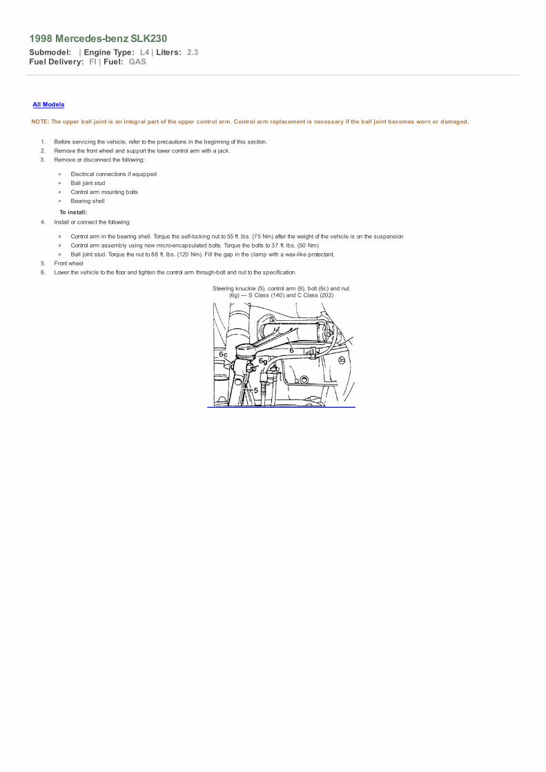
1998 Mercedes-benz SLK230
Submodel: | Engine Type: L4 | Liters: 2.3Fuel Delivery: FI | Fuel: GAS
All Models
NOTE: The upper ball joint is an integral part of the upper control arm. Control arm replacement is necessary if the ball joint becomes worn or damaged.
1. Before servicing the vehicle, refer to the precautions in the beginning of this section.2. Remove the front wheel and support the lower control arm with a jack.3. Remove or disconnect the following:
Electrical connections if equippedBall joint studControl arm mounting boltsBearing shell
To install: 4. Install or connect the following:
Control arm in the bearing shell. Torque the self-locking nut to 55 ft. lbs. (75 Nm) after the weight of the vehicle is on the suspensionControl arm assembly using new micro-encapsulated bolts. Torque the bolts to 37 ft. lbs. (50 Nm)Ball joint stud. Torque the nut to 88 ft. lbs. (120 Nm). Fill the gap in the clamp with a wax-like protectant.
5. Front wheel6. Lower the vehicle to the floor and tighten the control arm through-bolt and nut to the specification.
Steering knuckle (5), control arm (6), bolt (6c) and nut(6g) — S Class (140) and C Class (202)

1998 Mercedes-benz SLK230
Submodel: | Engine Type: L4 | Liters: 2.3Fuel Delivery: FI | Fuel: GAS
C Class (202), CLK (208), S Class (140) and SLK 230 (170)
1. Before servicing the vehicle, refer to the precautions in the beginning of this section.2. Remove or disconnect the following:
Front wheelDisc brake rotor securing bolt and backing plate boltBall joint nutBall joint-to-steering knuckle nutBall joint
To install: 3. Install or connect the following:
Ball joint. Torque the control arm nut to 74 ft. lbs. (100 Nm) and the knuckle nut to 104 ft. lbs. (140 Nm).Backing plate bolt. Torque to 72 inch lbs. (8 Nm)Brake rotor bolt. Torque the bolt to 84 inch lbs. (10 Nm)Front wheel
Common ball joint — C Class (202) and S Class (140)
Sl Class (129) and E class (210) — Except 4-Matic
NOTE: The ball joint on vehicles with engines 104 and 119 cannot be pressed out of the control arm. They have been welded in place. In this case, replace the controlarm assembly.
1. Before servicing the vehicle, refer to the precautions in the beginning of this section.2. Remove or disconnect the following:
Front wheelCoil springStabilizer bar and bracketLower control arm-to-frame nuts and boltsBall joint pinch bolt and nutLower control armBall joint using a press
To install: 3. Install or connect the following:
Ball joint using a pressControl arm. Temporarily tighten the control arm-to-frame nutsBall joint pinch bolt and nut. Torque the nut to 92 ft. lbs. (125 Nm)Stabilizer bar bracket. Torque the bolts to 15 ft. lbs. (20 Nm)Coil springFront wheel
4. Lower the vehicle to the floor. Torque the control arm-to-frame nuts to 88 ft. lbs. (120 Nm).
E Class 4-Matic (210)
1. Before servicing the vehicle, refer to the precautions in the beginning of this section.2. Remove or disconnect the following:
Front wheelAxle shaft 12-point nut (61)Ball joint nut. Press the ball joint out of the steering knuckle (5)
3. Pull the steering knuckle outward and remove the axle shaft (60) from the flange.4. Support the knuckle assembly by placing a block of wood (arrow) between the coil spring and the knuckle.5. Position the axle shaft out of the way using a piece of wire.6. Remove the nut and press the ball joint (7) out of the lower control arm (4).
To install:

7. Install or connect the following:
Ball joint. Torque a new self-locking nut to 77 ft. lbs. (105 Nm)Axle shaftBall joint to the steering knuckle with a new self-locking nut. Torque the nut to 77 ft. lbs. (105 Nm)12-point axle nut. Torque to 162 ft. lbs. (220 Nm)Front wheel
Lower ball joint mounting — E Class 4-Matic (210)

1998 Mercedes-benz SLK230
Submodel: | Engine Type: L4 | Liters: 2.3Fuel Delivery: FI | Fuel: GAS
Front
1. Before servicing the vehicle, refer to the precautions in the beginning of this section.2. Remove the front wheel and support the lower control arm with a jack.3. Remove or disconnect the following:
Electrical connections if equippedBall joint studControl arm mounting bolts
To install: 4. Install or connect the following:
Control arm assembly using new bolts. Torque the bolts to 37 ft. lbs. (50 Nm)Ball joint stud. Torque the nut to 88 ft. lbs. (120 Nm).Electrical connections
5. Front wheel6. Lower the vehicle to the floor and tighten the control arm bolt and nut.

1998 Mercedes-benz SLK230
Submodel: | Engine Type: L4 | Liters: 2.3Fuel Delivery: FI | Fuel: GAS
Front
1. Before servicing the vehicle, refer to the precautions in the beginning of this section.2. Remove the front wheel and support the lower control arm with a jack.3. Remove or disconnect the following:
Upper control armSteel spacer washers
4. Using appropriate removal tool, remove the bushings from the control arm.
To install: 5. Install the bushings using appropriate installation tool.6. Install or connect the following:
Steel spacer washersUpper control arm

1998 Mercedes-benz SLK230
Submodel: | Engine Type: L4 | Liters: 2.3Fuel Delivery: FI | Fuel: GAS
C Class (202), CLK (208), S Class (140) and SLK 230 (170)
1. Before servicing the vehicle, refer to the precautions in the beginning of this section.2. Remove or disconnect the following:
Front wheelDisc brake rotor securing bolt and backing plate boltBall joint nutBall joint-to-steering knuckle nutControl arm
To install: 3. Install or connect the following:
Control arm assembly. Torque the control arm nut to 74 ft. lbs. (100 Nm) and the knuckle nut to 104 ft. lbs. (140 Nm).Backing plate bolt. Torque to 72 inch lbs. (8 Nm)Brake rotor bolt. Torque the bolt to 84 inch lbs. (10 Nm)Front wheel
SL Class (129) and E class (210) — Except 4-Matic
1. Before servicing the vehicle, refer to the precautions in the beginning of this section.2. Remove or disconnect the following:
Front wheelCoil springStabilizer bar and bracketLower control arm-to-frame nuts and boltsBall joint pinch bolt and nutLower control arm
To install: 3. Install or connect the following:
Control arm. Temporarily tighten the control arm-to-frame nutsBall joint pinch bolt and nut. Torque the nut to 92 ft. lbs. (125 Nm)Stabilizer bar bracket. Torque the bolts to 15 ft. lbs. (20 Nm)Coil springFront wheel
4. Lower the vehicle to the floor. Torque the control arm-to-frame nuts to 88 ft. lbs. (120 Nm).
E Class 4-Matic (210)
1. Before servicing the vehicle, refer to the precautions in the beginning of this section.2. Remove or disconnect the following:
Front wheelAxle shaft 12-point nutBall joint nut. Press the ball joint out of the steering knuckleAxle shaft from the flange
3. Support the knuckle assembly by placing a block of wood between the coil spring and the knuckle.4. Position the axle shaft out of the way using a piece of wire.5. Remove the lower control arm assembly
To install: 6. Install or connect the following:
Ball joint. Torque a new self-locking nut to 77 ft. lbs. (105 Nm)Axle shaftBall joint to the steering knuckle with a new self-locking nut. Torque the nut to 77 ft. lbs. (105 Nm)12-point axle nut. Torque to 162 ft. lbs. (220 Nm)Front wheel

1998 Mercedes-benz SLK230
Submodel: | Engine Type: L4 | Liters: 2.3Fuel Delivery: FI | Fuel: GAS
1. Before servicing the vehicle, refer to the precautions in the beginning of this section.2. Remove or disconnect the following:
Lower control arm3. Using appropriate removal tool, remove the bushings from the control arm.
To install: 4. Install the bushings using appropriate installation tool.5. Install the lower control arm assembly

1998 Mercedes-benz SLK230
Submodel: | Engine Type: L4 | Liters: 2.3Fuel Delivery: FI | Fuel: GAS
1. Before servicing the vehicle, refer to the precautions in the beginning of this section.2. Support the lower control arm assembly.3. Remove or disconnect the following:
Rear wheelElectrical connections if equippedShock absorberLower control arm
To install: 4. Install or connect the following:
Lower control arm. Torque the bolts to 40 ft. lbs. (54 Nm).Shock absorber. Torque the mounting nut to 52 ft. lbs. (70 Nm)Electrical connectionsRear wheel

1998 Mercedes-benz SLK230
Submodel: | Engine Type: L4 | Liters: 2.3Fuel Delivery: FI | Fuel: GAS
1. Before servicing the vehicle, refer to the precautions in the beginning of this section.2. Remove or disconnect the following:
Rear wheelLower control arm
3. Using a press, remove the rubber mount from the spring link.
To install: 4. Install the rubber mounts using a press.5. Install or connect the following:
Lower control armRear wheel

1998 Mercedes-benz SLK230
Submodel: | Engine Type: L4 | Liters: 2.3Fuel Delivery: FI | Fuel: GAS
Front
ALL MODELS EXCEPT E CLASS 4-MATIC (210)
1. Before servicing the vehicle, refer to the precautions in the beginning of this section.2. Remove the front wheel.3. Install 1 wheel bolt (48a) in the flange on the opposite side of the locking bolt.4. Push the brake pads into the caliper until they are clear of the rotor.5. Remove the grease cap (9e).6. Loosen the bolt (9i) and tighten the clamping nut (9d) while turning the rotor until all bearing play is eliminated.7. Loosen the clamping nut until play is detectable.8. Mount a dial indicator (022) on the hub with the measuring tip on the end of the spindle.9. Turn the clamping nut to adjust the play while pulling and pushing on the rotor to measure the bearing play. Correct bearing play should be 0.0004–0.0008 inches (0.01
–0.02mm).10. Torque the bolt on the clamping nut to 96 inch lbs. (12 Nm) and recheck the bearing play again. If the play is within specification, assemble the wheel. If not, repeat the
procedure.
Mount a dial indicator on the rotor to measure the bearingplay — except E Class 4-Matic
E CLASS 4-MATIC (210)
The front wheel bearings on the 4-Matic are not adjustable. If the bearings become loose or make noise, they must be replaced.

1998 Mercedes-benz SLK230
Submodel: | Engine Type: L4 | Liters: 2.3Fuel Delivery: FI | Fuel: GAS
Front
ALL MODELS EXCEPT E CLASS 4-MATIC
1. Before servicing the vehicle, refer to the precautions in the beginning of this section.2. Remove or disconnect the following:
Front wheelBrake caliper and rotorGrease capClamping nut and washerWheel hubGrease sealBearing
To install: 3. Install or connect the following:
BearingGrease sealWheel hubWasher and clamping nut
4. Adjust bearing play. Torque the clamp bolt to 96 inch lbs. (12 Nm)5. Fill the grease cap to the flared edge with high temperature roller bearing grease and install the cap.6. Install or connect the following:
Rotor and caliperFront wheel
Exploded view of the front wheel bearing assembly — SClass (140), SLK 230 (170), C Class (202), CLK 320 (208)
and E Class (210)
E CLASS 4-MATIC (210)
Steering knuckle and related components — E Class 4-Matic(210)
1. Before servicing the vehicle, refer to the precautions in the beginning of this section.2. Remove or disconnect the following:
Front wheel12-point axle nut (61)Front axle distributor connectorSpeed and brake lining sensor wires. Position out of the wayBrake disc (34)Splash shield (35)Speed sensor and bracket (5f)Tie rod end (10a)Ball joint (7)Follower joint (8)

Steering knuckleAxle flangeSnapringBearing assembly using a press
To install: 3. Press a new bearing into the knuckle and install the snapring.4. Press the axle flange into the bearing.5. Install or connect the following:
Steering knuckleFollower joint. Torque the nut to 33 ft. lbs. (45 Nm)Ball joint. Torque the nut to 77 ft. lbs. (105 Nm)Tie rod end. Torque the nut to 16 ft. lbs. (22 Nm)Speed sensor and bracketSplash shieldBrake discSensor wiringAxle distributor connector12-point axle nut. Torque the nut to 162 ft. lbs. (220 Nm)Front wheel
Rear
ALL MODELS
1. Before servicing the vehicle, refer to the precautions in the beginning of this section.2. Remove or disconnect the following:
Rear wheelExhaust if necessaryCable guide railLevel sensor control rod if equipped12-point axle nutAxle shaft to differential flange attaching boltsAxle shaftBrake discParking brake shoesAxle flangeSnap ringBearing using a pullerAxle shaft flange race using a puller
To install: 3. Press the new bearing (8) into the axle carrier.4. Install or connect the following:
Snapring (9)Axle flange (10)Parking brake shoesBrake discAxle shaft. Torque the M10 bolts to 52 ft. lbs. (70 Nm) and the M12 bolts to 74 ft. lbs. (100 Nm)12-point axle nut. Torque the nut to 236 ft. lbs. (320 Nm) on the 140 model or 162 ft. lbs. (220) on the remaining modelsLevel sensor control rodCable guideExhaust systemRear wheel
Exploded view of the rear wheel bearing assembly — allmodels
Related Documents