i \t �-�I ( \-1 �\ l£i0' Slope Stability during Rapid Drawdown James M. DUllca,,(l), Stephen G. Wright ( 2 ) alld Ka; S. WOllg (3 ) INTRODUCTION The wters had the great pleasure of working with Professor Seed on the resech derid in this paפr. He played an active le in the studies, which we gun in the ely 1980s (Wong, Duncan and Seed, 1983), and continued later under a contract for the U. S. Ay Corps of Engineers (Wright and Duncan, 1987). We pleased to acknowledge Profesr Seed's gat influence on and conꭐbution to this work, and to dedicate this paפr to his memo. RAPID DRAWDOWN SLOPE STABILITY PROBLEMS When the water level outside a slo פdrops, the stabilizing influence of the water pressure on the slope is lost. If the water level subsides rapidly that the re pressures within the slo פdo not have time change in equilibrium with the drop in exteal water level. the slo פis de less stable. Many failures of dam slopes and natural slopes have cued during rapid drawdown. These include, for example, Pil⌒itos D uth of San Francisco (W. A. Wahler & Asias, 1970), Walter Bouldin D in Alaba (Whiteside, 1976), d a numr of ver k sloפs ong the Rio Monto in Pe ee d Duncan, (975). Rapid drawdown imses ve vere loading on sloפs, and is uently the design condition that cls steepss of upsam sloפs of dams. Analysis of rapid drawdown is therefore imnam consideration for design of dams, and for design of other sloפs that will submerged d subject to drawdown. (I) UniversilY Dislinguish ofess. Virgin PolylÌhc InstilC d Se University. Blksrg, V A (2) Ashley H. Priy Cennnl Pre of Ci vil Engierg. University of Tex, Austin, As Profess of Civil Engieng, Nyg Thnogillnstitu, Sing. 253 .

(1991 Duncan & Wright) Slope stability during rapid drawdown
Nov 26, 2015
(1991 Duncan & Wright) Slope stability during rapid drawdown
Welcome message from author
This document is posted to help you gain knowledge. Please leave a comment to let me know what you think about it! Share it to your friends and learn new things together.
Transcript

i
\t �-�I ( \-1
�\ l£i'10'
Slope Stability during Rapid Drawdown
James M. DUllca,,(l), Stephen G. Wright(2) alld Ka; S. WOllg(3)
INTRODUCTION
The writers had the great pleasure of working with Professor Seed on the research described in this paper. He played an active role in these studies, which were begun in the early 1980s (Wong, Duncan and Seed, 1983), and continued later under a contract for the U. S. Anny Corps of Engineers (Wright and Duncan, 1987). We are pleased to acknowledge Professor Seed's great influence on and conuibution to this work, and to dedicate this paper to his memory.
RAPID DRAWDOWN SLOPE STABILITY PROBLEMS
When the water level outside a slope drops, the stabilizing influence of the water pressure on the slope is lost. If the water level subsides so rapidly that the pore pressures within the slope do not have time to change in equilibrium with the drop in external water level. the slope is made less stable.
Many failures of dam slopes and natural slopes have occurred during rapid drawdown. These include, for example, Pilarcitos Dam south of San Francisco (W. A. Wahler & Associates, 1970), Walter Bouldin Dam in Alabama (Whiteside, 1976), and a number of river bank slopes along the Rio Montaro in Peru (Lee and Duncan, (975). Rapid drawdown imposes very severe loading on slopes, and is frequently the design condition that controls the steepness of the upstream slopes of dams. Analysis of rapid drawdown is therefore an imponam consideration for design of dams, and for design of other slopes that will be submerged and subject to drawdown.
(I) UniversilY Dislinguished Professor. Virginia PolylCChruc InstillllC and Suue University. Blacksburg, V A (2) Ashley H. Priddy Cenltnnial ProCessor of Civil Engineering. University of Texas, Austin, TX (3) Associalt Professor of Civil Engineering, Nanyang Technologicallnstitult, Singapore.
253
H i
I,
f) ... f
l r t J
. I
•• 254 Dunc�nt Wri&ht and Wona
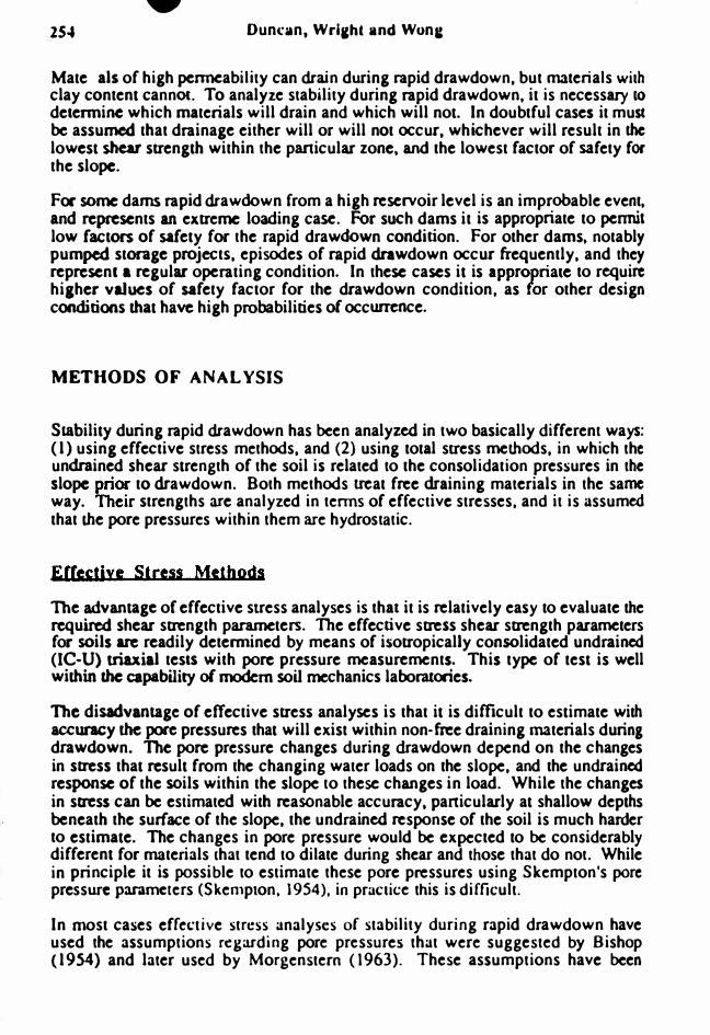
Materials of high penneability can drain during rapid drawdown. but materials with clay content cannOl. To analyze stability during rapid drawdown, it is necessary to delennine which materials will drain and which will not. In doubtful cases it must be assumed that drainage either will or will not occur, whichever will result in the lowest shear strength within the particular zone, and the lowest factor of safety for the slope.
For some dams rapid drawOOwn from a high reservoir level is an improbable event, and represents an extreme loading case. For such dams it is appropriate to pennit low factors of safety for the rapid drawdown condition. For other dams, notably pumped storage projectS, episodes of rapid drawdown occur frequently, and they represent a regular operating condition. In these cases it is appropriate to require higher values of safety factor for the drawdown condition. as for other design conditions that have high probabilities of occurrence.
METHODS OF ANALYSIS
Stability during rapid drawdown has been analyzed in two basically different ways: (I) using effective stress methods, and (2) using total stress methods. in which the undrained shear strength of the soil is related to the consolidation pressures in the slope prior to drawdown. Both methods treat free draining materials in the same way. Their strengths are analyzed in tenns of effective stresses. and it is assumed that the pore pressures within them are hydrostatic.
Effectiye Stress Methods The advantage of effective stress analyses is thai it is relatively easy to evaluate the required shear strength parameters. The effective stress shear strength parameters for soils are readily detennined by means of isotropically consolidated undrained (IC-U) triaxial teslS with pore pressure measurements. This type of test is well within the capability of modem soil mechanics laboratories.
The disadvantage of effective stress analyses is that it is difficult to estimate with accuracy the pore pressures that will exist within non-free draining materials during drawdown. The pore pressure changes during drawdown depend on the changes in stress that result from the changing water loads on the slope. and the undrained response of the soils within the slope to these changes in load. While the changes in stress can be estimated with reasonable.accuracy, panicularly at shallow depths beneath the surface of the slope. the undrained response of the soil is much harder to estimate. The changes in pore pressure would be expected to be considerably different for materials that tend to dilate during shear and those that do not. While in principle it is possible to estimate these pore pressures using Skempton's pore pressure parameters (Skempton. 1954). in practice this is difficult.
In most cases effective stress analyses of stability during rapid drawdown have used the assumptions regarding pore pressures that were suggested by Bishop (1954) and later used by Morgenstern (1963). These assumptions have been
sankat
Sticky Note
Marked set by sankat
sankat
Sticky Note
Marked set by sankat
sankat
Sticky Note
Marked set by sankat
sankat
Sticky Note
Marked set by sankat
sankat
Sticky Note
Marked set by sankat
sankat
Sticky Note
Marked set by sankat
sankat
Sticky Note
Marked set by sankat
sankat
Sticky Note
Marked set by sankat

• • Rapid Drawdown 2SS
justified on the basis of the fact that they are conservative in most cases. They have been found to result in reasonable values of factor of safety for dams that suffered rapid drawdown failures: Won,. el aI. (1983) found tha, the values of safety factor calculated using Morgenstern's assumption were F = 1.2 for Pilarcitos Dam and F ::: 1.0 for Walter Bouldin Dam. both of which failed.
It seems likely that Bishop and Morgenstern's assumptions for pore pressures during drawdown may be more accurate for soils that do not tend to dilate during shear than for those that do tend to dilate. Thus, although these assumptions may show reasonable correspondence with failures of slopes in materials that are not densely compacted and do not tend to dilate during shear. they are likely to be unduly conservative for bettcr-compacted materials that do tend to dilate during shear. Use of effective stress analrses based on the Bishop and Morgenstern assumptions would treal all fill matenals alike with respect to pore pressures during drawdown, regardless of how well they are compacted or how strongly they might tend to dilate during shear. Terzaghi and Peck (1967) suggested that pore pressures during drawdown in wellcompacted silty sands could be estimated using flow nets. Several investigators (Browzin, 1961; Brahma and Harr. 1963; Newlin and Rossier, 1967; Desai and Shennan, 1971; Desai, 1972; Desai, 1977) used theoretical methods to analyze the non-steady flow conditions following drawdown. Like the Bishop and Morgenstern pore pressure assumptions. these methods do not consider the behavior of the soil with regard to dilatancy, and are thus not capable of representing all of the important factors that control the pore pressures during drawdown.
Svano and Nordal (1987) and Wright and Duncan (1987) used procedures for estimating pore pressures dwing drawdown that reflect the influence of dilatancy on the pore pressure changes. Svano and Nordal used two-stage stability analyses and iterated to achieve consistency between the calculated factor of safety and the values of the pore pressures. Wright and Duncan used finite element analyses to estimate the stress changes during drawdown. and Skempton's pore pressure parameters to calculate the pore pressures. These studies indicate that it is possible to estimate realistic pore pressures for effective stress analyses, but it is more cumbersome and difficult than using total stress analyses as described in the following sections.
Terzaghi and Peck (1967) summarized the problems in estimating pore pressures during drawdown in these words:
" . .. in order to determine the pore pressure conditions for the drawdown state, all the following factors need to be known: the location of the boundaries between materials with significantly different properties; the permeability and consolidation characteristics of each of these materials; and the anticipated maximum rate of drawdown. In addition, the pore pressures induced by the changes in the shearing stresses themselves ...... .
need to be taken into consideration. In engineering practice, few of these factors can be reliably detennined. The gaps in the available infonnation must be filled by the most unfavorable assumptions compatible with the known faclS."
sankat
Sticky Note
Marked set by sankat
sankat
Sticky Note
Marked set by sankat
sankat
Sticky Note
Marked set by sankat

256 Duncan, Wrieht and Wone
By using undrained, total stress analyses as described in the following sections, many of the problems associated with estimating pore pressures (or effective sttess analyses can be avoided. and the accuracy o( rapid drawdown stability analyses can be very considerably improved.
Cocps or Epcioeecs Method The Corps o( Engineers method (Corps o( Engineers, 1970) is a two-stage analysis procedure. The fllSt stage, which analyzes conditions before drawdown, is used to determine values of consolidation pressure along the slip surface. These consolidation pressures are used to detennine undrained shear strength values (or the second stage analysis, with the reservoir drawn down.
The undrained shear strength values (or the second stage are determined from the toW stress IC-U strength envelope, as shown in Fig. 1. At low stresses, where the total stress envelope lies above the effective stress drained strength envelope, the drained strength envelope is used to determine strengths (or the second stale analysis.
,t.o CD .r:::. CJ)
Either drained or Ie - U envelope is used. whichever gives lower strength.
Normal stress = effect Ive stress on base of slice before drawdown.
Normal Stress - (J"
Fig. 1 - Strength Envelope Used in Corps of Engineers Method
The justification (or using the drained strength envelope allow stresses is to avoid relying on shear strength that results from negative pore pressures, which could noc be mobilized should these pore pressures disappear as a resuh of cavitation or drainage. The use o( the drained envelope is overly conservative. however.
• Rapid Drawdown
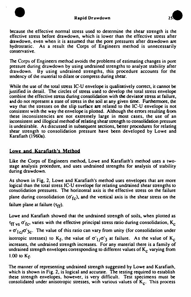
because the effective nonnal stress used to determine the shear strength is the effective stress before drawdown. which is lower than the effective stress after drawdown. even when it is assumed that the pore pressures after drawdown are hydrostatic. As a result the Corps of Engineers method is unnecessarily conservative.
The Corps of Engineers method avoids the problems of estimating changes in pore pressure during drawdown by using undrained strengths to analyze stability after drawdown. By using undrained strengths. this procedure accounts for the tendency of the material to dilate or compress during shear.
While the use of the total stress IC-U envelope is qualitatively correCt. it cannot be justified in detail. The circles of stress used to develop the total stress envelope combine the effective stress during consolidation with the deviator stress at failure. and do not represent a state of stress in the soil at any given time. Furthermore. the way that the stresses on the slip surface are related to the IC-U envelope is not consistent with the way the envelope is plotted. Although the errors resulting from these inconsistencies are not extremely large in most cases, the use of an inconsistent and illogical method of relating shear strength to consolidation pressure is undesirable. As discussed in subsequent sections. better procedures for relating shear strength to consolidation pressure have been developed by Lowe and Karafiath (1960a).
Lowe and Karafiatb's Method
Like the Corps of Engineers method. Lowe and Karafiath's method uses a twostage analysis procedure. and uses undrained strengths for analysis of stability during drawdown.
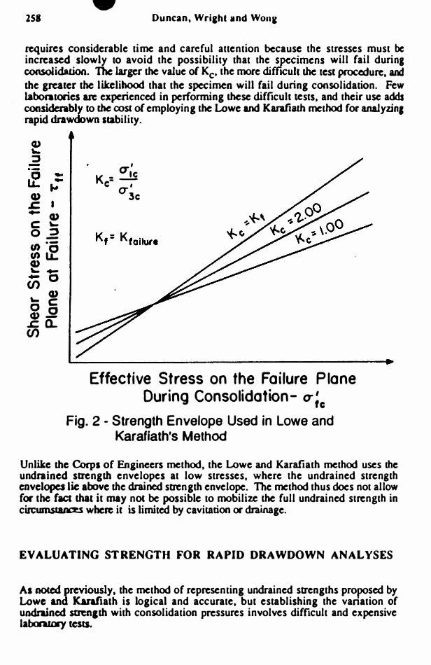
As shown in Fig, 2, Lowe and Karafiath's method uses envelopes that are more logical than the total stress IC-U envelope for relating undrained shear strengths to consolidation pressures. The horizontal axis is the effective stress on the failure
plane during consolidation (o'fc)' and the vertical axis is the shear stress on the
failure plane at failure (tff).
Lowe and Karafiath showed that the undrained strength of soils. when plotted as
'tff vs 0' fc' varies with the effective principal stress ratio during consolidation. Kc
= o'l c"o'3c' The value of this ratio can vary from unity (for consolidation under
isotropic stresses) to Kf' the value of 0'1/0'3 at failure. As the value of Kc increases. the undrained strength increases. For any material there is a family of undrained strength envelopes corresponding to different values of Kc varying from 1.00 to Kf.
The manner of representing undrained strength suggested by Lowe and Karafiath, which is shown in Fig. 2. is logical and accurate. The testing required to establish these strength envelopes, however, is very difficult. Test specimens must be consolidated under anisotropic stresses, with various values of Kc' This process
• lS8 Duncan. Wriehl lind Wone
requires considerable time and careful attention because the stresses must be increased slowly to avoid the possibility that the specimens will fail during consolidation. The larger the value of Kc. the more diffacuil lhe test procedure. and the greater the likelihood that the specimen will fail during consolidation. Few laboratories arc experienced in performing these difficult tests, and their use adds considerably to the cost of employing the Lowe and Karafiath method for analyzin. rapid drawdown stability.
u .c. +-u C '
o ::J -
�� U '- +-
000 '- u OC cu.2 .s:::.o..
(/)
, CT' K - .:.!S c- CT'
3c
Effective Stress on the Failure Plane During Consolidation- CT;c
Fig. 2 - Strength Envelope Used in Lowe and Karafiath's Method
Unlike the Corps of Engineers method, the Lowe and Karafiath method uses the undrained strength envelopes at low stresses, where the undrained strength envelopes lie above the drained strength envelope. The method thus does not allow (or the (act that it may nOl be possible to mobilize the full undrained strength in circumstanCeS where it is limited by cavitation or drainage.
EVALUATING STRENGTH FOR RAPID DRAWDOWN ANALYSES
As noted previously, the method of representing undrained strengths proposed by Lowe and Karafialh is logical and accurate, but establishing the vanation of undrained stren&th with consolidation pressures involves difficult and expensive laboratory tests.
re Rapid Drawdown
Because of the diffICulties involved in performing AC-U ttiaxial tests, a number of invcstipcors have suggcsted procedures for estimating the results of AC-U teslS from the results of IC-U tests. The benefits of beinl able to do this arc considerable: IC-U tests are the easiest to perform of any consolidated-undrained triaxial tests. The specimens canDOl fail durin, consolidation because they are DOl subjected to shear stteSSCS. The COIlSOIidation stresses can be applied in a single increment. and little operator attention is required.
AcconIin,ly. methods of esrimatin, AC-U stmlgths from the resulcs of IC-U teSlS have bcca sugcsted by Taylor (1948). Lowe and Kanfiath (196Ob). and Noorany and Seed (196S). These methods were studied by Won, ct aI. (1983), with the foIIowinl conclusions:
- the method sullesteel by Taylor (1948) results in reasonable estimates of the AC-U SU'eftldls. but is cumbersome because it �uires graphical construction and involves processing pore pressure data for many stagcs during the leSt. .
- the method suggested by Lowe and Karafiath (l96Ob) results in ulVeasonabie estimates of AC-U strength envelopes for some values of "c. - the method suuested by Seed and Noorany (I96S) results in reasonable AC-U strength envelopes.
The studies performed by Wong. et at. (1983) showed that it is also possible to estimate AC-U strength envelopes from IC-U strength test results by simple linear interpolation. The envelope corresponding to Kc lIS 1.00 in Fi,. 2 is the IC-U
envelope, and is es .. bUshed by plOUin, values of 'Cft vs (f'fc' The envelope corresponding to Kc :: Kf is simply lhe effective stress strength envelope,
established by plotting values o( 1ff VI CJ' ff. All of the requiml stresses (1ff. CJ' fc.
and (J'ff) can be computed (rom the results of an IC-U triaxial test with pore pressure measurements. Envelopes for values of ICc intcnncdiate between 1.00 and Kf can be established by interpolating linearly betWCCA the envelopes (or Kc =
1.00 and Kc - K(. This procedure makes the usc of AC-U SlI'Cngms much easier and more practical. because it eliminates the necessity of perfonnin& difficult AC·U tests. Accordingly. it is recommended thaa AC-U envelopes of the type shown in fig. 2 be established by linear incerpolation. using the results of IC-U tests.
NEW METHOD FOR EVALUATING STABILITY DURING RAPID ORA WDOWN
At the current state of the art of anaIyzin, stability durin, rapid drawdown. it is possible to combine the best features of tbe methods that have been developed. and to devise a new method that is accurate and easy to use:

260 •
Duncan, Wrieht and Wong
- Like the Corps of Engineers method and Lowe and Karafiath's melhoc( the new method uses undrained shear strengths to avoid the complications and inaccuncies involved in estimating undrained pore pressure durin, drawdown.
- Like Lowe and Karafiath's method. it uses the more accurate tff vs a'fc envelope, with AC-U sU'engths varying with the value of Kc'
- Following the findings of Won, et al. (1983). the AC-U strengths are estimated by linear interpolation usmg the results of IC-U tests.
- To avoid using undrained strengths hiJher than drained strengths. which cannot be mobilized if cavitation or drainage occurs. drained sttengths arc used wherever they are smaller than the undrained strengths. This procedure is different from the one involved in the Corps of Engineers' method. In the Corps of Engineen' Method the effective stress envelope is used with the effective stress before dnwdown to detennine the shear strenath. In the new procedure the effective stress AfW: drawdown is used. which is more logical. Use of the effective stress after drawdown requires I 3-stage analysis. The first two stages are the same as the Lowe and Karafiath method. In the third stage the drained strength is used for sections of the slip surface where the drained strength is smaller than the undrained strength.
The new procedure is believed to combine the best features of the methods thaI have been used previously for analysis of rapid drawdown stability. In addition, it incorporates two new features: (I) It simplifies the task of estimating AC-U Strenlths by usinl linear interpolation. and (2) it uses a more accurate and less conservative method of accounting (or possible reduction of undrained strengths It low presswes due to cavitation or drainage.
The specific steps involved in the method are these:
(1) Determine. tor each soil in the cross-section. whether drainage will occur during dnwdown. The most logical means of making this detennination is to estimate the value of ahe dimensionless time factor T. given by the following expression:
(1)
in which Cv • coefficient of consolidation. t = time for drawdown. and 0 = length of drainale path. If the calculated value of T is greater than or equal to 3.0, the dissipation of excess pore pressures during drawdown will be 90 percenl or more. and it is IUSOnable to b"Cat the material as fully drained.
Values of Cv can be calculated using data for the time rate of consolidation during. triaxial tests. Approximate values for various types of compacted soils are listed in Table 1.

• Rapid Drawdown
Table 1. Approximate Values of Cv for Various Soils
Type of Soil
Coarse sand
Fine sand
Silty sand
Silt
Compacted clay
Soft clay
Values of cv
> 10,000 ft2/day
100 to 10,000 ft2/day
10 to l(XX) ft2/day
0.5 to 100 ft2/daY
0.05 to 5 ft2/day
< 0.2 ft2/day
If the value of T calculated using equation (I) is less than 3.0. the undrained strength should be considered. The following steps assure that the undrained strength used in the stability analyses will not be larger than the drained strength. It is thus conservative to assume that the material is undrained in those cases where there is doubt whether or not complete drainage will occur.
(2) Establish the strength envelopes required for the analyses. For materials that drain during drawdown. only the drained strength envelope is required. For materials that are undrained during drawdown. both the drained envelope (tff vs a'ff) and the undrained envelope (tff vs a'fc) are required. The required envelopes for values of Kc between 1.0 and Kf can be detennined by linear interpolation, as discussed previously.
(3) For a selected slip surface, calculate the factor of safety after drawdown by a 3-step procedure:
(i) Perfonn an analysis of stability before drawdown using drained strength parameters for all materials, to detennine the effective nonnal stress (a' fc) on the base of each slice. and the value of Kc for each slice. Values of Kc are detennined in the manner suggested by Lowe and Karafiath. based on the assumption of no reorientation of principal stresses during drawdown. These values are used to determine undrained strength values for the materials that do not drain freely during drawdown.
(ii) Perfonn an analysis of stability after drawdown using undrained strengths for materials that do not drain freely. and drained strengths for materials thaI do drain during drawdown. To this stage the method is the same as Lowe and Karafiath's method. except for the use of linear interpolation to estimate AC-U strength values.

III 262
• Duncan, \Vri�ht and W()n�
(iii) Detemline if the drJined strength for any sl ice is lower than the undrained strength used in SICP (ii). The drained strength is detennincd using the total stresses on the bases of the slices from step (ii) and pore pressures for the drained condition. If for any slice the drained s trength is lower than the undrained strength. pafonn another analysis using drained rather than undrained strengths for slices where the drained slfl:ngths are lower.
(4) Repeat the 3-step proced ure for other slip surfaces to locate the one with the lowest factor of safelY following drawdown.
The computations involved in the method are quite lengthy, and a computer program is a practical necessity to do all of the computations necessary to sean.:h for critical slip surfaces. The analyses discussed in the following sections were performed with the computer program UTEXAS3. which incorporates the new method for rapid drawdown stability analyses.
EXAMPLES
The methods of analysis descritx!d previously have been used 10 analyze three dams. as discussed in this section. The first two of these dams, Pilarcitos and Walter Bouldin. suffered slides due to rapid drawdown. The third is a hypothetical dam for a pumped storage project. The dam is considered to be subject 10 large drawdowns as a nomlal operating condition for the pumped storage project. Accordingly. reliable estimates of the stability during drawdown are especially important for this embankment. and the required factor of safety is higher than for embankments for which rapid drawdown is a relatively unlikely occurrence.
Pjlarcitos Dam Pilarcitos Dam . shown in Fig. 3, is a homogeneous rolled earthfill embankment. The crest of the dam is about 78 feet above the upstream toe. The upstream slope is inclined at 2.5 on I for the lower 58 ft. (to El. 678), and at 3 on 1 from this point to the crest (El. 698). When the water level was lowered from El. 692 to El. 657 between October 7 and November 19, 1969. a slide occurred. During the twO
9 Before Orawdown - EI 692 EI. 698
9 After-E1.657
Sandy Cloy - CL LL::: 45 PL::: 22 RC::: 94% Calif. Method
- - - - - - Y m ::: 135 pc t '-- Observed slip sur face
Fig. 3 - Pillarcitos Dam Cross-Section
• • Rapid Drawdown 263
weeks prior to the failure. the drawdown rale was nearly constant at about 1.7 feel per day. The approximate location of the failure surface found in an exploratory trench is shown In Fig. 3.
W. A. Wahler & Associales of Palo Alto. California was COnlraCled by the San Francisco Water Department 10 pedorm field investigations. laboratory tests and analyses. and to recommend remedial measures. The infonnation regarding
. Pillarcitos Dam presented in this paper was obtained from the Wabler and Associates repon (W. A. Wahler and Associales. 1970). The material comprising the upsuum slope is classified as a sandy clay (cr.) with 60 to 70 percent passing the number 200 sieve. and a permeability of about 4 x 10-* em/sec. The liquid limit is 45 pen:ent and the plastic limit is 23 percent. The average field compaction was approxinwely 94 percent of die laboratoJy maximum density obIained using 20.000 ft·lbItt' cornpaaive effort (the California Method).
The bilinear failure envelope used in the Corps of Engineers procedure is shown in the upper part of Fig. 4, and the envelopes used in Lowe and Karafiath's and the three-stage procedure are shown in the lower part of Fig. 4.
As shown in Fig. S. the factor of safety calculated by the Corps of Engineers' procedure was 0.82. The factors of safety calculated by Lowe and Karafiath's procedure and the new procedure are both 1.05. The critical circles are very nearly the same for all wee methods. as can be seen in Fig. S. Because it uses drained strengths where they are lower than undrained strengths. the new method always results in factors of safety that are the same as or lower than the factors of safety calculalCd by the Lowe and Karafiath procedwe. In the case of Pillarcitos Dam. there were no slices where the drained strengths we� lower than the undrained strength, and the factors of safety calculated using Lowe and Karafiath's method and the new method were therefore the same.
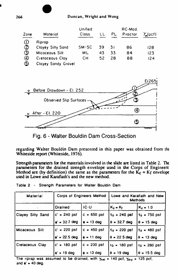
Walter Bouldin Dam Walter Bouldin Dam is a roUed eanhfiU embankment. In the section that failed, the dam is approximalely 60 feet high. resdnl 00 80 feet of clayey sand and gravel; the underlying bedrock is schist. As shown in Fi,. 6. the lower �nion of the embankment is a clayey sandy gravel that was DOl mvolved in the slide. Overlying die gravel are a layer of creraceous clay. a zone of micaceous silt. and a clayey silty sand layer that blankets the slope. The upper portion of the upstream slope is blanketed with riprap. The upstream slope is 2 on 1 above Elev. 245 and l.S on I below Elev.l45.
The slide occurred on February 10, 1975 during an extremely rapid drawdown of 32 feet in 5.S hours that OCCUlTed as a result of a piping failure in another pan of the dam. The slide extended for a length of about 32 feet along the slope. The slip surface extended about 10 feet below the surface of the slope near the edges of the slide where it was excavated, and possibly reached a greater depth near the center of !be slide mass where it was DOC excavated. A detailed study of the failure was :llried out by Stephen L. Whiteside at Stanford University. The information
t ,
, 1

•
� I
fI) en CD 0.5 � ...
CJ) ...
o Q)
s::; CJ)
Duncan. Wrilht and Wonl
Se9fT\ent
(I)
(2)
Envelope
Drained
IC-U
Intercept Angle
o 450
60psf 230
Corps of Engineers' Method
o L-______________ � ______________ �.
cu_ � -... :3f1) :: � 0-LL. .. ..
o 0.5 1.0
Normal Stress - (T (ksf)
� �0.5 ... '
c � 0 :3 -fI)"-fl)o Q)LL. � ... Uic ... Q) CC (1).2
s::;� en o ----------------�--------------� o 0.5 1.0
Effective Stress on the Failure Plane During Consolidation - (jf� (ksf)
Fig. 4 - Strength Envelope for Pillarcitos Dam

•
" Before Orowdown
" Af ter
" Before Orowdown
After
" Before Orowdown
" After
Rapid Drawdown
Corps of Enqineers Criticol CircJe.FaO.82
- - - - - - .. "L Observed Slip Surfoce
Lowe and KOtofioth Criticol Circle.Fat05
- - - - - - .... � Observed Slip Surface
New Method Criticol Circle. F II 1.05
- - - - - .... � Observed Slip Sur foce
Pig. 5... Results of Stability Calculations for Pillarcitos Dam
• 265
. '
i .
..
. . . f
• 266 Duncan, Wright and Wong
Unified Zone Materiol Closs.
<D Riprop
(2) Cloyey Silty Sand SM-SC
C> Micoceous Silt ML
@ Cretoceaus Cloy CH
@ Clayey Sandy Grovel
Q Before Drawdown - E I. 252
Observed Slip Surfoces
RC-Mod. LL PL P roctor Ym(pcf)
39 31 86 128 43 33 84 123 52 28 88 124
®
Fig. 6 - Walter Bouldin Dam Cross-Section
regarding Walter Bouldin Dam presented in this paper was obtained from the Whiteside repon (Whiteside, 1976).
Strength parameters for the materials involved in the slide are listed in Table 2. The parameters for the drained strength envelope used in the Corps of Engineers' Method are (by definition) the same as the parameters for the Kc = Kf envelope used in Lowe and Karafiath's and the new method.
Table 2 • Strength Parameters for Walter Bouldin Dam
Material Corps ot Engineers Method Lowe and Karatiath and New Methods
D rained IC·U Ke. Kr Ke. 1.0
Clayey Silty Sand c' • 240 pst c • 650 pst to • 240 ps' to • 750 pst
.' • 32.7 deg • • 13 deg a • 32.7 deg 9. 15 deg
Micaceous Silt c' • 220 pst c • 450 pst to • 220 pst to • 480 pSf
.' - 22.5 deg • • 11 deg a .22.5 deg a - 13 deg
Cretaceous Clay c' • 180 pst c • 230 pst 'to • 180 psf 'to • 280 pst
.' • 19 deg • • 13 deg a.19deg a. 15.5 deg
The nprap was assumed to be dr ained . WIth 1 •• , • 140 pct. Y4'1 • 125 pct, and.'. 40 deg.

• Rapid Drawdown
As shown in Fig. 7, the factor of safely calculated by the Corps of Engineers' procedure was 0.93. The factor of safety calculated by Lowe and Karafiath's procedure was 1.09, and the value calculated using the new procedure was 1.04. The critical circles for aU three mechods were nearly the same. as may be seen in Fig. 7.
Pumped Storace Project Dam The dam for this example is shown in Fig. 8. The embankment has a wide, densely compacted. silty clay cocc. The lower portion of the upstream slope is a random zone with the same strength properties as the core. The upper ponion of the upstream slope and all of the downstream slope is a free-draining rockfill.
Before
Before
v Before
Corps of EnQineers Criticol Circl., F &0.93
Lowe ond Korofioth Criticol Circle. F = 1.09
Observed Slip SUtfoc"
Observed Slip Surfoces
Fig. 7 - Results of Stability Calculations for Walter Bouldin Dam

-
268 •
Duncan, Wrighl and Wong
Zone Materlol
CD Compacted Rockflil
® Silty Cloy Core
G) Silty Cloy Random Zone
Q Before Drawdawn - EI 545
Ym(pcf )
142 140 140
Fig. 8 - Hypothetical Pumped Storage Project Dam Cross-Section
Strength parameters for the materials in the dam are listed in Table 3. The significant (2000 pst) cohesion intercept for the IC-U envelope is indicative of a highly dilatant material. The drained strength of this material is lower than the undrained strength in the range of stresses below the point where the two envelopes cross, at an effective consolidation stress of approximately 5000 psf. This corresponds approximately to a depth of 40 feet for a drained slope and 80 feet for a submerged slope.
The rocldill. filter and drainage zones are free draining materials, and all have the same propenies. The dry and saturated unit weights are 128 and 142 pef, respectively. Dry unit weights were used for portions of these materials above reservoir level. and saturated unit weights were used for those ponions below reservoir level.
Table 3 . Strength Parameters tor Hypothetical Pumped Storage Project Dam
Material Corps ot Engineers' Method Lowe & Karatiath and New Methods
Drained IC-U (R) Ke· K, Ke. 1.0 Compacted Rockt;1I c' • 0 NA. to • 0 NA and Filters " . 37 deg 8 - 37 deg
Silty Clay Core c' • 0 c • 2000 pst to • 0 to • 2250 pst
.,' & 36 deg ., • 18 OOg 9. 36 deg 9 - 20 OOg
Silty Clay Random c· • 0 c • 2000 pst to • 0 to - 2250 psI
Zone .' • 36 deg •• 18 OOg 9. 36 deg 9 - 20 OOg
• Rapid Drawdown
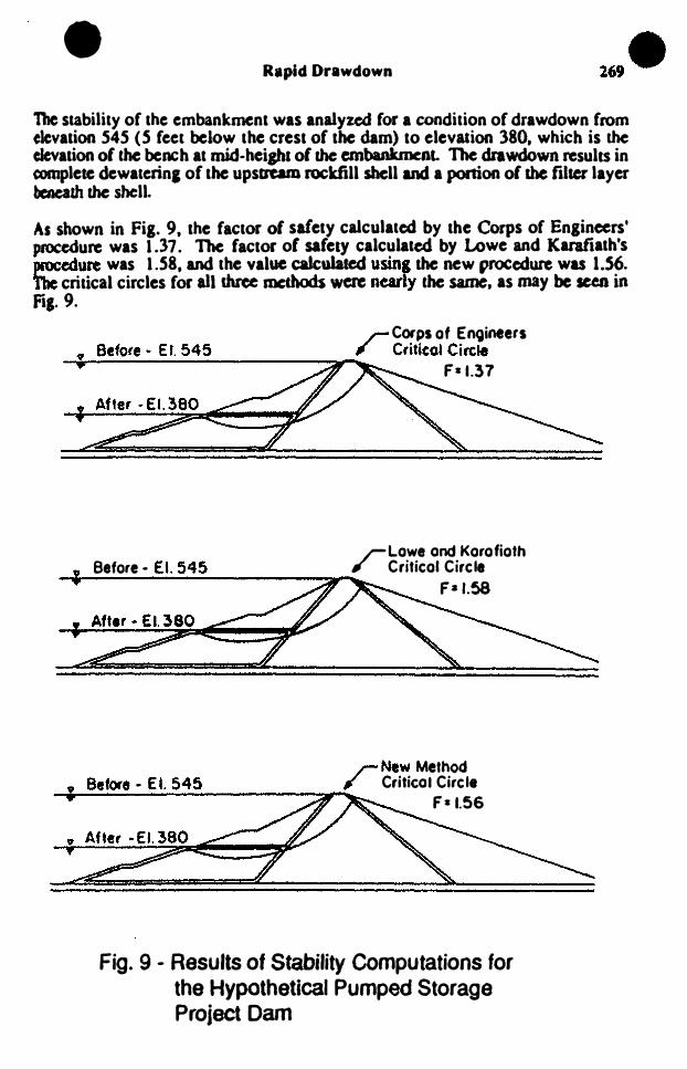
The stability of the embankment was analyzed for a condition of drawdown from elevation S4S (5 feet below tbe crest of the dam) to elevation 380, which is the elevation of the bench at mid-beiJlu of the embankment. The drawdown results in complete dewaterinl of the upstream rockfill shell and a portion of me filler layer beneath the shell.
As shown in Fig. 9, the factor of safety calculated by the Corps of Engineers' procedure was 1.37. The factor of safelY calculated by Lowe and Karafiath's procedure was 1.58. and tbe value calculated using the new procedure was 1.56. the critical circles for aU three methods W� nearly the same. as may be seen in Fi,.9.
r Corps of El\9ineers Before· Et 545 ; CriticOl Circle �������----------� F-1.37
r Lowe and Korofioth Before· £1. 545 Critico. Circle --------��--------��� F-J.58
r New Method Betore • Ea. 545 Critical Circle ---;....;;..�-�;...-.-------� F-1.56
Fig. 9 - Results of Stability Computations for the Hypothetical Pumped Storage Project Dam
-I
I �,

II 27() J)unt'an, Wri�ht and W()I1�
Concl usjons The new method for analyzing slope stability during rapid drawdown described in the previous pages combines what are believed to be the best features of the methods that have been used previously.
It avoids the problems associated with estimating pore pressures in undrained materials for the after-drawdown condition by using undrained strengths, and correctly reflects the strengths of materials that tend to dilate during shear. It uses the most accurate representation of undrained strengths (values of 'Tff that vary wilh
the values of (J'fc and Kc)' but it avoids the necessity for difficult AC-U strength testing by using linear interJX)lalion of strength values from IC-U teSts.
By using drained strength values where these are smaller than undrained strengths, the method avoids reliance on strengths due to negative pore pressures, which cannot be mobilized if cavitation or drainage occurs. The procedure for eliminating strengths due to negative pore pressures is more accurate, and less conservative, than the procedure used in the Corps of Engineers method.
The new method is somewhat more conservative than Lowe and Karafiath's method, and provides a reliable estimate of stability following drawdown that is believed to be as accurate as possible at the current Slate of the an.
For the three examples described, the factors of safety calculated using the new method are 15 percent to 30 percent higher than values calculated using the Corps of Engineers method, and zero to 5 percent lower than values calculated using Lowe and Karafiath's method.
Although the values of safety factor calculated using the new method are only slightly smaller than values calculated using Lowe and Karafiath's method for the examples considered, it is imponant that the new method is conservative because it does not rely on strengths resulting from negative pore pressures, whereas Lowe and Karafiath's method does rely on these strengths.
Thus, while the new method offers the same reliability with respecl to strengths due to negative pore pressures as the Corps of Engineers method, it uses a more accurate evaluation of strength, and results in values of safety factor only slightly lower than Lowe and Karafiath's method. The method thus is reliably conservative with regard to undrained strengths, but does not involve excessively conservative approximations.
ACKNOWLEDGEMENT
The writers wish to express their appreciation to Harding Lawson Associates and Nikken Sekkei Ltd., who provided suppon for the early phases of this study, and to the U. S. Anny Engineers Waterways Experiment Slation, who supported the later phases. Dick Volpe provided infonnation regarding Pilarcitos Dam, and Wayne Clough and Stephen Whiteside provided infonnation regarding Walter

• • Rapid Drawdown 27.
Bouldin Dam. Earl Edris of WES and Ed Luurel of Duke Power made a number of helpful suggestions and provided the writers with an opponunity to study the characteristics of the method under practical conditions. The writers gratefully acknowledge all of these valuable contributions to the studies that have led to development of the method described in the paper. Mary Duncan typed the text and Sandy Jordan drafted the figures.
REFERENCES
Bishop. A. W. (1954). 'The Use of Pore Pressure Coefficients in Practice." Geotechnique. Vol. 4, No.4. December. 1954. pp. 148-152.
Brahma. S. P. and Han, M. E. (1963), "Transient Development of the Free Surface in a Homogeneous Eanh Dam," Geotechnique, Vol. 12. No. 4, �be� 1963.pp.283-�
Browzin. B. S. (1961), "Non-Steady Flow in Homogeneous Eanh Dams after Rapid Drawdown," Proccedinp of the 5th Int. Conf. on Soil Mech. and Found. Eng .• Paris. Vol. 2, pp. 551-554.
Corps of Engineers (1970). "Engineering and Design - Stability of Eanh and RockFill Dams." Engineering Manual EM 1110-2-1902. Depanment of the Anny. Corps of Engineers, OffICe of the Chief of Engineers, April. 1970.
Desai, C. S. and Sherman. W. S. (1971), "Unconfined Transient Seepage in Slopin, Banks. " Journal of the Soil Mech. and Found. Div., ASCE. Vol. 97, No. SM2. February, 1971. pp. 357-373.
Desai. C. S. (1972), "Seepage Analysis of Earth Banks Under Drawdown." Journal of the Soil Mech. and Found. Div .• ASCE. Vol. 98. No. SM l l . November. 1972, pp. 1143-1162.
Desai, C. S. (1977). Drawdown Analysis of Slopes by Numerical Method." Journal of the Geotech. En,. Div .• ASCE. Vol. 103. No. OT1. July, 1977. pp. 667-676.
Lee. K. L. and Duncan, J. M. (1975), "Landslide of April 25. 1974 on the Mantam River, Peru," Report to the Conunittee on Natural Disasters. Commission on Sociotechnical Systems. National Research Council. National Academy of Sciences. Washington. D. C.
Lowe, J. III. and Karafiath. L. (196Oa), "Stability of Earth Dams Upon Drawdown." Proc. l st PanAm Conf. on Soil Mech. and Found. Eng .• Mexico City. Vo�. 2, pp. 537-552.
Lowe. J. III. and Karafiath, L. ( l960b). "Effect of Anisoaopic Consolidation on the Shear Strength of Compacted Clays." Research Conf. on the Shear Strength of Cohesive Soils, ASCE, Boulder, Colorado. pp. 837-858.

•
272 Duncan, Wright and Wong
Morgenstern. N. R. (1963), "Stability Charts for Earth Slopes During Rapid Drawdown," Geotechnique, Vol. 13. No.2. June, 1963, pp. 121-131.
Noorany, I., and Seed, H. B. (1965), "(n Situ Strength Characteristics of Soft Clays," Journal of the Soil Mech. and Found. Div., ASCE, Vol. 91, No. SM2, March, 1965, pp. 49-80.
Skempton, A. W. (1954), "The Pore Pressure Coefficients A and B," Geotechnique, Vol. 4, No.4, December, 1954, pp. 143-147.
Svano, G. and Nordal, S. (1987), "Undrained Effective Stress Stability Analysis," Proceedings of the IX European Conference on Soil Mechanics and Foundation Engineering, Dublin. Also, Bulletin 22 of the Geotechnical Division, Norwegian Institute of Technology, University of Trondheim, 1989.
Taylor, D. W. (1948), "Fundamentals of Soil Mechanics," John Wiley and Sons, New York.
Terzaghi, K. and Peck, R. B. (1967), "Soil Mechanics in Engineering Practice," Second Edition, John Wiley and Sons.
Wahler, W. A. and Associates (1970), "Upstream Slope Drawdown Failure Investigation and Remedial Measures, Pilarcitos Dam, It A report to the San Francisco Water Department, June 1970.
Whiteside, S. L. (1976), lOA Study of the Rapid Drawdown Failure in the Walter Bouldin Dam," Technical Report CE-211, Stanford University. August. 1976.
Wong. K. S., Duncan, J. M., and Seed, H. B. (1983), "Comparison of Methods of Rapid Drawdown Stability Analysis," Report No. UCB/GT/82-05, Department of Civil Engineering, University of California, Berkeley, December, 1982, revised July. 1983.
Wright, S. G. and Duncan, J. M. (1987), "An Examination of Slope Stability Computation Procedures for Sudden Drawdown," Miscellaneous Paper GL-87-25, Geotechnical Laboratory, U. S. Army Engineer Waterways Experiment Station. Vicksburg. Mississippi.
Related Documents