Overview of an Ammonia Plant Reformer Revamp An ammonia plant plagued by design deficiencies in the primary reformer was successfully revamped by in-house expertise and achieved remarkable improvement in capacity utilization. Ajay Misra and D.K. Bhatt Indian Farmers Fertiliser Cooperative Limited, Phulpur Unit, Allahabad, India IFFCO's 900 MT/day ammonia plant located at Phulpur is based on naphtha as feedstock and has been designed and engineered by MW Kellogg, USA. The plant went on-stream in October 1980 and has been 1n operation since then. The primary reformer 1s of Kellogg design, top-fired, using the ICI steam-naphtha process with ICI catalysts 46-ls and 46-4s. There are 336 catalyst tubes arranged in 8 vertical harps of 42 tubes each, connected to 336 inlet pigtails at the top and to 8 outlet manifolds at the bottom located inside the reformer radiant box. The original catalyst tubes were of HK-40 material, 81.3mm I.D. x 16.7mm MSW, unmachined bore. Although guarantee tests of the ammonia plant were successfully conducted, IFFCO could not operate the plant at its design capacity on a consistent basis because of Inherent design deficiencies 1n the primary reformer. The reformer was designed to process naphtha containing a maximum of 20% aromatics, but In actual experience it was found that, in case the plant was operated above 90% load even with 12-15% aromatics in feed naphtha, the pressure drop across tubes as well as aromatics slip from the reformer started Increasing after four to six months of operation. The design pressure drop across the primary reformer at 100% plant load was 4.7 bar but in actual practice this had been observed to vary between 4.2 - 8 bar, depending on the age, condition of catalyst, plant load, etc. There was a gradual increase in pressure drop during the initial 4-6 months of a fresh catalyst charge, even at 90% load. The rate of Increase In pressure drop was much higher with plant loads greater than 90%. Therefore, after 5-6 months operation at 88-90% load, when the pressure drop reached a value of about 7.5 - 8.5 bar, the plant had to be shut down for steaming of the catalyst. This steaming of the catalyst had to be repeated after short intervals of 4-6 weeks and a maximum of 4-5 steaming operations could be carried out before a catalyst change was required. The aromatics slip from the reformer also exhibited the same characteristic gradual Increase during the initial 4-6 months period and accelerated 1n the latter half of the year, towards the end of the catalyst run, typical of the pressure drop across the reformer. Performance of the reformer during a 12 months run 1s depicted in Figure 1 and this had been the typical behaviour of the reformer in each of the catalyst charges. Also, the tubeskin temperatures exhibited a general upward trend after few months of operation with random pattern of hot tubes attaining temperatures between 920-950°C against the design tube metal temperature of 916°C. This reformer bottleneck forced IFFCO to operate the ammonia plant at an average load of about 90% with the aim of extending the period before increased pressure drop restricted production more severely, necessitating steaming or ultimately a catalyst changeout. A catalyst change was necessary every 12 months because, towards the end of the year it was not possible to improve catalyst activity or reduce pressure drop even with repeated/prolonged steaming. Identification of the problem Lack of operating data on steam-naphtha reformers operating with high aromatic feed resulted 1n a lot of 127

Welcome message from author
This document is posted to help you gain knowledge. Please leave a comment to let me know what you think about it! Share it to your friends and learn new things together.
Transcript

Overview of an Ammonia PlantReformer Revamp
An ammonia plant plagued by design deficiencies in the primaryreformer was successfully revamped by in-house expertise andachieved remarkable improvement in capacity utilization.
Ajay Misra and D.K. BhattIndian Farmers Fertiliser Cooperative Limited, Phulpur Unit, Allahabad, India
IFFCO's 900 MT/day ammonia plant located at Phulpur isbased on naphtha as feedstock and has been designedand engineered by MW Kellogg, USA. The plant wenton-stream in October 1980 and has been 1n operationsince then.
The primary reformer 1s of Kellogg design, top-fired,using the ICI steam-naphtha process with ICI catalysts46-ls and 46-4s. There are 336 catalyst tubesarranged in 8 vertical harps of 42 tubes each,connected to 336 inlet pigtails at the top and to 8outlet manifolds at the bottom located inside thereformer radiant box. The original catalyst tubeswere of HK-40 material, 81.3mm I.D. x 16.7mm MSW,unmachined bore.
Although guarantee tests of the ammonia plant weresuccessfully conducted, IFFCO could not operate theplant at its design capacity on a consistent basisbecause of Inherent design deficiencies 1n the primaryreformer. The reformer was designed to processnaphtha containing a maximum of 20% aromatics, but Inactual experience it was found that, in case the plantwas operated above 90% load even with 12-15% aromaticsin feed naphtha, the pressure drop across tubes aswell as aromatics slip from the reformer startedIncreasing after four to six months of operation.
The design pressure drop across the primary reformerat 100% plant load was 4.7 bar but in actual practicethis had been observed to vary between 4.2 - 8 bar,depending on the age, condition of catalyst, plantload, etc. There was a gradual increase in pressuredrop during the initial 4-6 months of a fresh catalystcharge, even at 90% load. The rate of Increase In
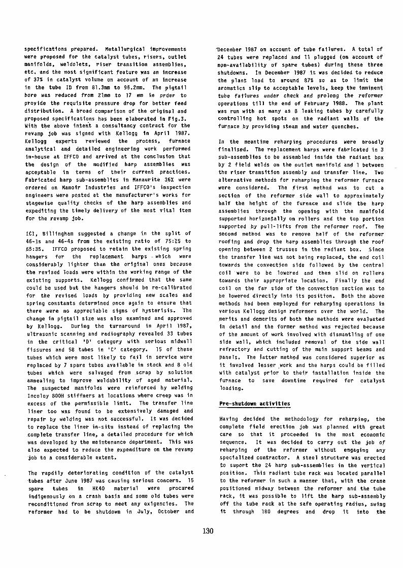
pressure drop was much higher with plant loads greaterthan 90%. Therefore, after 5-6 months operation at88-90% load, when the pressure drop reached a value ofabout 7.5 - 8.5 bar, the plant had to be shut down forsteaming of the catalyst. This steaming of thecatalyst had to be repeated after short intervals of4-6 weeks and a maximum of 4-5 steaming operationscould be carried out before a catalyst change wasrequired. The aromatics slip from the reformer alsoexhibited the same characteristic gradual Increaseduring the initial 4-6 months period and accelerated1n the latter half of the year, towards the end of thecatalyst run, typical of the pressure drop across thereformer. Performance of the reformer during a 12months run 1s depicted in Figure 1 and this had beenthe typical behaviour of the reformer in each of thecatalyst charges. Also, the tubeskin temperaturesexhibited a general upward trend after few months ofoperation with random pattern of hot tubes attainingtemperatures between 920-950°C against the design tubemetal temperature of 916°C.
This reformer bottleneck forced IFFCO to operate theammonia plant at an average load of about 90% with theaim of extending the period before increased pressuredrop restricted production more severely,necessitating steaming or ultimately a catalystchangeout. A catalyst change was necessary every 12months because, towards the end of the year it was notpossible to improve catalyst activity or reducepressure drop even with repeated/prolonged steaming.Identification of the problem
Lack of operating data on steam-naphtha reformersoperating with high aromatic feed resulted 1n a lot of
127

delay in identifying the real problem. IFFCO triedvarious changes in operating conditions as advised byKellogg and ICI like: Increase 1n steam-carbon ratio,changes in mixed-feed temperature, increase in hydrogenpartial pressure, etc. The split of catalysts 46-lsand 46-4s was changed from the originally specified50:50 to 75:25 on the recommendations of ICI. However,the above changes did not yield any significantImprovement in plant performance and about 3 yearselapsed In this endeavour.
At this point of time, around October 1983, an in-housestudy was initiated and a survey of all thenaphtha-based reformers 1n India was conducted by IFFCOin order to collect pertinent data Identifying theproblem at Phulpur. On compilation of the above data,one fact was abundantly clear - the "catalyst loading",i.e, the amount of naphtha to be reformed per hour perunit volume of catalyst, was the highest at IFFCOPhulpur. The catalyst loading for other similarreformers in India was in the range of 0.7-0.9kg/hr/litre for design exit temperatures in thevicinity of 780°C as compared to a catalyst loading of1.04 kg/hr/litre for a design exit temperature of812°C at IFFCO Phulpur. The C.F.L., Vizag. AmmoniaPlant, also of Kellogg design, had a catalyst loading(1.00) almost similar to ours. However, it had neveroperated with aromatics 1n feed naphtha exceeding 9%.IFFCO decided to compare its design and operating datawith that of ICI(India), Kanpur which was operatingthree 415 MT/day Ammonia plants on similar higharomatic naphtha with reformers of ICI design usingICI catalysts and had performed reasonably well. Theonly significant difference observed in the tworeformers was in respect of the catalyst loading whichwas much lower (0.82) at ICI(India). Presumably, theanticipated favourable conditions for steam-naphthareforming promoted by the use of smaller size catalystand higher exit temperature at IFFCO Phulpur, was morethan offset by the unfavourable influence of higharomatics in feed naphtha, resulting in aninsufficient catalyst volume in the reformer. It wasapparent that ICI had provided a comfortable margin incatalyst volume at ICI(India), Kanpur over the volumecalculated by theoretical correlations to take care ofvariations in naphtha quality. This was precisely thearea where our reformer was lacking. Typical naphthafeedstock characterisitcs at IFFCO Phulpur have beentabulated in Table 1.Initiation of tube failures
On inspection of the reformer catalyst tubes duringthe plant turnaround in April 1984, a ruptured tubewas discovered. This was the first tube failure inthe history of the reformer with a run of approximately30,000 hours. The failure was a typical longitudinalstress rupture associated with overheating. Evidence ofthe first tube failure In less than 30,000 hours againsta design life of 100,000 hours was a cause for graveconcern, prompting initiation of appropriate action.There was a marked tendency for the end tubes in each
harp, farthest from the feed inlet, to run hotter thanthe others. This was attributed to non-uniform feeddistribution through the inlet pigtails.
Since every tube failure would me'an costly plantshutdowns, it was decided to initiate a tube retirementprogramme, firstly to replace failed or suspect tubes onan individual basis and secondly, to schedule the majorreformer revamp at an appropriate time. For the tuberetirement programme, it was decided to utilise theservices of a specialised inspection agency to conductultrasonic scanning, in-situ metallography andradiography of all the catalyst tubes to monitor midwallcreep fissures which, alongwith tubeskin temperaturerecords were expected to yield reliable predictionsregarding imminent tube failures so that suspect tubescould be replaced in a timely manner during plannedturnarounds. It was also decided to cut-off/trim archburners at suitable locations to minimise temperatureexcursions in 'hot' tubes beyond design limits. Forscheduling the reformer revamp at an opportune time itwas necessary to predict, with reasonable accuracy,the remaining tube life. In June 1984, a study of thetypical failure pattern of catalyst tubes in similarreformers was carried out which projected a conservativeestimate of remaining tube life between 25000-30000hours, i.e, the average population of existing tubescould be expected to last till March 1988. It wasdecided to constitute an in-house task force withrepresentatives from various disciplines like designengineering, process engineering, maintenance,inspection, operation, etc. to study the scope of thereformer revamp job in its entirety and prepare acomprehensive report on the strategies to be adoped.
Strategies for revamp
The revamp task force immediately got down to the jobof evolving strategies to achieve the following broadobjectives:
a) Increase catalyst volumeb) Improve metallurgyc) Improve feed distribution by resizing pigtails.d) Review size and split of catalystse) Investigate resultant effect of modifications
on operating parameters, downstream equipmentsand overall performance.
f) Repair/replace transfer lineg) Replace/recalibrate springs
Various alternatives to increase catalyst volume whichwere initially proposed were:
a) using internally machined tubesb) increasing ID of tubes by use of superior
material, keeping OD constant.c) increasing OD & ID of tubes keeping pitch
constantd) addition of extra rows of tubes by modifying
existing furnace or providing a parallel reformer
128

Of the five alternatives proposed, the latter threewere considered less attractive because, as a result ofthe modifications Involved, a complete redesign of thereformer furnace would be required on account of theheat flux distribution pattern being affected. Theformer two alternatives were considered more attractivebecause the heat flux and catalyst tube configurationwould remain unaltered, thereby minimising the efforton furnace redesign.
In the meantime, the possibility of replacing the oldHK-40 tubes with improved HP-SO(mod) alloy tubes wasexamined. Calculations with the original designconditions Indicated that an increase of 37-46% incatalyst volume was possible using Internally-machined,thinner-walled H?-50(mod) tubes of the same outsidediameter in place of the as-cast HK-40 tubes. Inorder to come at par with the catalyst loading atICI(Indla), Kanpur (0.82) an increase of only 28% wasrequired and hence the preliminary calculations hadshown that it would be feasible to enhance catalystvolume suitably to overcome the reformer bottleneck.
In October 1984, another ruptured tube was detected butthe reformer continued to operate with the rupturedtube for about 6 months before the plant was shutdownfor annual turnaround in March 1985. This second tubefailure occured after total run of only 34,500 hours,which was an Indication of the rapidly deterioratingcondition of the catalyst tubes.
Collecting feedbacks of similar revamps
After preliminary investigations by IFFCO, Kellogg andICI and receipt of feedbacks from various plantsworldwide, it was decided to evolve a framework withinwhich further engineering work would be carried out toarrive at the final replacement tube specifications.Revamps very similar to ours had been executed at UKF,Pernis, Holland 1n 1973, UKF, Ijmuiden, Holland In 1975and CIL, Ontario, Canada in 1981 wherein reformersoriginally having HK-40 tubes had been retubed withManaurite 36X effecting an increase in catalyst volumemore than 30%. EI Du Pont de Nemours, Beaumont, USAtoo retubed their reformer in 1976 with Manaurite 36Xeffecting an increase of 20% in catalyst volume. Allthe above reformers were of Kellogg .design.
In May 1985, IFFCO's General Manager visited theammonia plant at UKF, Pernis to obtain first handfeedback of the performance of their revampedreformer. An increase in catalyst volume by 32% anduse of smaller size catalyst resulted In improvedcatalyst performance and a reduction of 50-55°C intubeskin temperatures. The revamped reformer had beenin operation at 125% of its design capacity and hadnot experienced any tube failures in a periodexceeding 12 years. The material of the outletmanifolds had also been changed from the originalwrought Incoloy 800H to centrifugally cast Manaurite900 or equivalent.
Accelerating tube failures - Planning for retublng
In December 1985, there was a severe rupture in theend portion of outlet manifold of row f 3 towardsconvection section which resulted in a fire and crashshutdown of the plant. The failure was preceded bycircumferential creep beyond permissible limit.Henceforth it was decided to monitor circumferentialcreep of the manifolds and replace portions havingcreep in excess of 3%.
During the turnaround in March 1986, the complete lotof tubes were examined ultrasonically and creepmeasurement of the manifolds was carried out. 4 tubeswere classified in the critical 'D' category whichwere Immediately replaced and 8 tubes in 'C' categorywere Identified for close surveillance. The endportion of manifold # 2 had a rupture similar to theone experienced 1n manifold f 3 earlier. Portions ofmanifolds # 1, 6, 7 which exhibited creep beyondpermissible limits alongwlth the ruptured manifold # 2were promptly replaced.
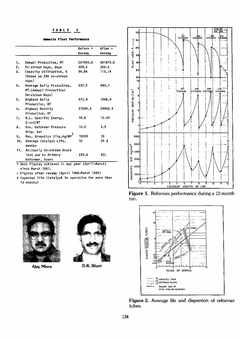
The marked deterioration in the condition of the tubesand outlet manifolds necessitated re-assessment of theremaining tube life so as to schedule the reformerrevamp optimally. Reference may be made to Figure 2which is a plot of the failures of reformer tubesversus service life. The history of tube failures atIFFCO Phulpur fitted a statistical trend whichprompted IFFCO to judiciously plan for completeretubing after 7.5 years, I.e. around March 1988 toavoid any embarrassing shutdowns of the ammonia plant.
It was decided to study the possibility ofsubstituting the original wrought Incoloy 800 Hmanifolds with centrlfugally cast manifolds of similarcomposition, possessing higher creep-rupture strengthto overcome the problem of excessive circumferentialcreep experienced with the original manifolds.
At this stage it was decided to carry out in-house atIFFCO Phulpur, detailed engineering of the modifiedreformer harp assemblies, pigtails, spring supports,etc. with a view to lay down accurate purchasespecifications for all the hardware required for thereformer revamp job. However, it was decided toengage a competent consultant who would firstly checkthe process and design calculations, drawings,specifications, etc. developed by IFFCO. Secondly,he would provide specialised services for overseasstagewise Inspection of reformer harp assemblies andthirdly, he would assist IFFCO in balancing of harpassemblies during the most critical phase of thefield erection work. This strategy was adoptedkeeping IFFCO's in-house capability in view andbecause it was expected to yield considerable savingsof valuable foreign exchange.Final calculations for the modified reformer harpassemblies were carried out and detailed drawingswere carried out and detailed drawings and purchase
129
specifications prepared. Metallurgical improvementswere proposed for the catalyst tubes, risers, outletmanifolds, weldolets, riser transition assemblies,etc. and the most significant feature was an Increaseof 37X in catalyst volume on account of an Increase1n the tube ID from 81.3mm to 95.2mm. The pigtailbore was reduced from 21mm to 17 mm in order toprovide the requisite pressure drop for better feeddistribution. A broad comparison of the original andproposed specifications has been elaborated 1n Fig.3.With the above intent a consultancy contract for therevamp job was signed with Kellogg 1n April 1987.Kellogg experts reviewed the process, furnaceanalytical and detailed engineering work performedin-house at IFFCO and arrived at the conclusion thatthe design of the modified harp assemblies wasacceptable in terms of their current practices.Fabricated harp sub-assemblies in Manaurite 36X wereordered on Manoir Industries and IFFCO's inspectionengineers were posted at the manufacturer's works forstagewise quality checks of the harp assemblies andexpediting the timely delivery of the most vital itemfor the revamp job.
ICI, Billingham suggested a change in the split of46-ls and 46-4s from the existing ratio of 75:25 to65:35. IFFCO proposed to retain the existing springhangers for the replacement harps • which wereconsiderably lighter than the original ones becausethe revised loads were within the working range of theexisting supports. Kellogg confirmed that the samecould be used but the hangers should be re-calibratedfor the revised loads by providing new scales andspring constants determined once again to ensure thatthere were no appreciable signs of hysterisls. Thechange in pigtail size was also examined and approvedby Kellogg. During the turnaround in April 1987,ultrasonic scanning and radiography revealed 33 tubesin the critical 'D' category with serious midwallfissures and 58 tubes in 'C' category. 15 of thesetubes which were most likely to fail in service werereplaced by 7 spare tubes available in stock and 8 oldtubes which were salvaged from scrap by solutionannealing to improve weldability of aged material.The suspected manifolds were reinforced by weldingIncoloy 800H stiffners at locations where creep was inexcess of the permissible limit. The transfer Uneliner too was found to be extensively damaged andrepair by welding was not successful. It was decidedto replace the liner in-situ instead of replacing thecomplete transfer line, a detailed procedure for whichwas developed by the maintenance department. This wasalso expected to reduce the expenditure on the revampjob to a considerable extent.
The rapdily deteriorating condition of the catalysttubes after June 1987 was causing serious concern. 15spare tubes in HK40 material were procuredindigenously on a crash basis and some old tubes werereconditioned from scrap to meet any exigencies. Thereformer had to be shutdown in July, October and
December 1987 on account of tube failures. A total of24 tubes were replaced and 11 plugged (on account ofnon-availability of spare tubes) during these threeshutdowns. In December 1987 it was decided to reducethe plant load to around 87% so as to limit thearomatics slip to acceptable levels, keep the imminenttube failures under check and prolong the reformeroperations till the end of February 1988. The plantwas run with as many as 8 leaking tubes by carefullycontrolling hot spots on the radiant walls of thefurnace by providing steam and water quenches.
In the meantime reharping procedures were broadlyfinalised. The replacement harps were fabricated in 3sub-assemblies to be assembled inside the radiant boxby 2 field welds on the outlet manifold and 1 betweenthe riser transition assembly and transfer line. Twoalternative methods for reharping the reformer furnacewere considered. The first method was to cut asection of the reformer side wall to approximatelyhalf the height of the furnace and slide the harpassemblies through the opening with the manifoldsupported horizontally on rollers and the top portionsupported by pull-lifts from the reformer roof. Thesecond method was to remove half of the reformerroofing and drop the harp assemblies through the roofopening between 2 trusses in the radiant box. Sincethe transfer line was not being replaced, the end coiltowards the convection side followed by the centralcoil were to be lowered and then slid on rollerstowards their appropriate location. Finally the endcoil on the far side of the convection section was tobe lowered directly into its position. Both the abovemethods had been employed for reharping operations invarious Kellogg design reformers over the world. Themerits and demerits of both the methods were evaluatedin detail and the former method was rejected becauseof the amount of work involved with dismantling of oneside wall, which included removal of the side wallrefractory and cutting of the main support beams andpanels. The latter method was considered superior asit involved lesser work and the harps could be filledwith catalyst prior to their installation inside thefurnace to save downtime required for catalystloading.
Pre-shutdown activities
Having decided the methodology for reharping, thecomplete field erection job was planned with greatcare so that it proceeded in the most economicsequence. It was decided to carry out the job ofreharping of the reformer without engaging anyspecialized contractor. A steel structure was erectedto suport the 24 harp sub-assemblies in the verticalposition. This radiant tube rack was located parallelto the reformer in such a manner that, with the cranepositioned midway between the reformer and the tuberack, it was possible to lift the harp sub-assemblyoff the tube rack at the safe operating radius, swingit through 180 degrees and drop it into the
130

appropriate location inside the radiant box throughthe roof without having to lower/raise the boom ormarch the crane. The above erection sequence is wellappreciated by referring to Figure 4.
Harp lifting beams, tracks for roller assembly,suspended platforms for arch insulation, screw jacksfor bottom support and a spring calibration rig werefabricated by the maintenance workforce well 1nadvance. Platforms around the reformer penthouse wereextended to make available extra working and storagespace. 2 winches were provided for safe and speedyhandling of materials, to and from the penthouse.Additional welding outlets and lighting points werealso provided for facilitating the field erectionwork.
The job was scheduled for a normal 3 week turnaroundof 7 workdays per week. The complete job was brokendown into activities and a detailed bar chart wasprepared (See Figure 5). The manhour involvement ofeach craft for the various activities was preciselyestimated. All the activities were planned keepingsafety in view. The plan called for two 12-hourshifts. Mock-up tests of the complete rigging systemwere conducted to check out any bugs in the systemdesign. Critical resources like skilled/unskilledmanpower, cranes, welding machines, etc. werecarefully analysed and the requirements summarised sothat the activities on the critical path could bemanaged effectively. A presentation of specificprecautions to be observed 1n the reharping operationswas made to promote safe working conditions inspite ofthe high degree of worker density while also copingwith the hazards of a major elevation differencebetween the penthouse and the furnace floor and amultiplicity of different tasks within the total plan.
Reharping Operation
The ammonia plant was shutdown in the early hours ofthe morning on February 29, 1988 and entry permit intothe reformer radiant box was available at 8 am onMarch 1, 1988. Before entry into the reformer, thefollowing activities were completed: screw jacks wereplaced under the furnace floor; . insulation andgratings over preheat air ducts were removed; andasbestos-cement sheeting over half of the penthouseroof was removed. Once entry permit was available,the first order of business centred on the following:
a) Removal of tunnel and arch burnersb) Removal of tunnel and floor refractoryc) Locking of catalyst tube and transfer line spring
supportsd) Draining of water from transfer line jackete) Removal of pigtailsf) Installation of suspended platforms below arch
roofg) Laying of tracks on the furnace floor
The next series of activities involved cutting of theoutlet manifolds, cutting of the riser jacket andpressure shell field welds, jacking up of themanifolds wih the help of hydraulic jacks and placingthem on wooden blocks so as to release the load onspring hangers, removal of arch panels and ceramicfibre arch insulation on either side of the harpassemblies. The arch panels and Insulation supportedbelow the preheat air ducts were left undis'turbed inorder to minimise the arch roof Insulation work. Thenext major activity was the removal of spring hangersalongwith the associated hardware like support rods,turnbuckles, clevis, clamps, etc. The spring hangerswere lowered to the ground safely with the help of thewinches whilst all the associated hardware was stored1n an orderly manner on the temporary storage platforminstalled over the preheat air ducts on the convectionside of the reformer. The dismantled spring hangerswere immediately taken for testing and re-calibration,subsequent to which they were painted and kept readyfor installation. During the above phases of work,penthouse traffic, movement of materials, safeboarding over arch openings and walkway acceessibilitywere strictly controlled as per plan. Good housekeeping was maintained by assigning a team ofmaintenance personnel over the entire period of therevamp job to clean up waste materials on a continuousbasis. The safety engineer was assigned theresponsibility of field surveillance to assurecompliance with planned safety precautions.
Removal of the first harp assembly was started onMarch 2, 1888 within 30 hours of the entry into thereformer radiant box. The end coil in each row on thefar side of the convection section was the first harpsub-assembly to be lifted out of the radiant boxwithout any difficulty. The central and end coilswere jacked up slightly, lowered onto the rollercarriage and moved towards the end wall of thereformer. The top portion of the harp assembly wasguided between the preheat air ducts at the penthouseelevation during movement of the coils. It wasdecided to remove one row of harp assemblies at atime, stack them on the radiant tube rack and installthe new set of harp assemblies before proceeding withthe removal of the next. This procedure was preferredbecause it afforded better time management. Levellingand alignment work on the new harps could commenceimmediately, opening a "front" for the welding ofpigtails, manifolds, risers, etc. and installation ofspring supports. With one row of tubes completelyremoved from the radiant box, installation of new harpsub-assemblies was taken up.
With the 3 harp sub-assemblies 1n each row locatedinside the furnace, supported on wooden blocks, workwas started on installing the recalibrated springhangers in the locked position. After the outletmanifold field joints were accurately aligned, weldingwork on the outlet manifold was started. Whilstalignment and welding work on one row of harp
131

assemblies was 1n progress, removal and Installationof harp assemblies 1n other rows was carried out as aparallel activity. All the new harp assemblies werelowered Inside the furnace by March 5, 1988, I.e. theentire rigging job of removal and Installation of allthe harps was completed 1n less than 64 hours.Once the welding of outlet manifold was completed, theentire harp assembly was jacked up by 6 hydraulicjacks till the required gap for the riser pressureshell welding was achieved. Then the spring hangerturnbuckles were tightened till all the jacks wereunloaded and the harp load was uniformly distributedon all the hangers. Before making the riser pressureshell weld joint 1t was necessary to ensure that thetransfer line supported only the riser weight. Aspecially designed clamp was fixed just below theriser transition assembly and the calculated riserweight was supported by this clamp resting on 2 springsupports fixed to the furnace steel. The level of theoutlet manifold and its clearance above the floorplate was precisely ascertained so that there was novariation from design. Lastly, the water jacket weldjoint was made with the transfer line water jacket tocomplete the riser assembly.
Half of the damaged liner of the transfer Une wasreplaced in-sltu with a liner of improved metallurgy(Incoloy 800 H) and balance replacement was plannedfor the next turnaround. A sample piece was cut fromthe carbon steel (A-106 Gr B) inlet manifold andsubjected to extensive metallurgical examination anddestructive testing to reveal signs of graphitlzation,if any. The microstructure and ductility of the testpiece was found to be satisfactory and it wasconcluded by the metallurgical laboratory that theinlet manifold could be safely used for at least 5years.
The job progressed in the above sequence row by rowtill all the welding work was completed. All the weldjoints made in the field were examined by appropriatenon-destructive techniques like- liquid penetrantexamination and radiography. The loads on all thespring hangers were distributed uniformly by finaladjustment of the turnbuckles and the spring settingswere checked and certified by the furnace expert fromKellogg. All the jobs were completed at midnight onMarch 16, 1988 in a duration of 16 days and thereformer furnace was handed over one week ahead ofschedule (Ref Figure 5). The sequence of activitiesand the required manpower were planned so accuratleythat the entire gamut of activities proceeded withclockwork precision without a lost time accident.
Start-up
The reformer was lighted on March 18, 1988 and afterthe initial phase of refractory dry-out and catalystreduction, naphtha feed was cut-in on March 21, 1988.Ammonia production commenced on March 22, 1988resulting 1n a net downtime of 23 days for the
reformer revamp which is comparable, if not betterthan similar revamps carried out in more developedcountries.
The plant load was gradually increased and on March26, 1988 it was back on-stream at 100% load. Theplant has been in continuous operation since then atloads averaging 105% and the reformer appears to be inexcellent condition with the tubes running black.
Expenditure
The gross expenditure Incurred on the reformer revampjob amounted to US $ 4.7 million including consultancyfees to Kellogg for engineering, inspection and fieldservices (US $ 0.15 million), cost of all materialsforming a permanent part of the revamped reformer,tools, tackles, hardware, consumables, etc. (US $ 2.4million), contract labour for field erection (US $0.05 million) and taxes/duties (US $ 2.1 million).
Plant performance after Revamp
A marked Improvement in the uniformity of tubeskintemperature has bee'n observed as a result of re-sizingof the inlet pigtails, About 150 out of a total of162 arch burners are normally kept in service asagainst the earlier constraint of a large number ofburners being cut-off to limit the temperatureexcursions. Important process parameters like mixedfeed temperature, steam superheat temperature, fluegas temperature, etc. have all been achieved aspredicted by process calculations.
There has been a reduction of approximately 45-50°C inthe tubeskin temperature. The pressure drop acrossthe reformer has remained in the range of 3-3.5 barwithout exhibiting the earlier trend of gradualincrease over a period of 4-6 months. As a result ofthe reduction in pressure drop across the reformer, ahigher pressure is available downstream of thereformer which implies lower syngas compressor power.All the equipments and piping downstream of thereformer had been checked by IFFCO for their designcapability to withstand an operating pressure about 2bar higher than the normal operating pressure. 3relief valves downstream of the secondary reformer hadto be reset at slightly higher pressures on account ofthe anticipated increase in operating pressure.Aromatics slip from the reformer has come downdrastically to levels of around 10 mg/NM or less. Abrief summary of the operating parameters before andafter revamp are given in Table 2.
During 12 months operation (April 1988 to March 1989)after the reformer revamp, the performance of theammonia plant has been beyond expectations. A reviewof the ammonia plant performance statistics since thecommencement of commercial production in March 1981(Table 3) reveals a quantum jump in capacityutilisation (115.14%) and on-stream availability afterthe reformer revamp.
132

Only 2.4 on-stream days were lost in the year 1988-89on account of a leak in the feed naphtha line tosecondary desulphurlser feed preheater which resultedin an unplanned shutdown of the plant. An involuntarysteaming of the reformer catalyst was carried outduring the above shutdown apart from which the planthas completed an uninterrupted run of more than 12months with catalyst activity apparently good foranother 12 months of the reformer. All previous recordsof daily, monthly and yearly production of ammonia havebeen Improved by unprecedented margins and specificenergy consumption figures have also shown considerableimprovement. The performance statistics for the year1988-89 would have been even more staggering but forextraneous limitations In naphtha supplies. Due toconstraints of erratic supplies of feed and fuel naphthafrom the refineries, the plant load had to be reducedinvoluntarily on a number of occasions in order tosustain operation with depleted inventories of naphtha.
The performance of the reformer after revamp has beenelaborated in Figure 6 and a comparison with Its typicalperformance before revamp clearly highlights theimprovements in productivity, efficiency and reliability.
CONCLUSION
The following objectives have been achieved as a resultof the reformer revamp:
a) Consistent operation at loads greater than 100%even with naphtha containing 12-18% aromatics
b) Low specific energy consumption on account of:(I) Lower pressure drop across the reformer(II) Lower steanucarbon ratio(HDhigher on-stream availability(iv) improved heat transfer across thinner tube
wallsc) Lower and more uniform tubeskin temperaturesresulting in higher life expectancy of the catalysttubes
d) Lower and more consistent pressure drop across thereformer
e) Better catalyst life resulting in plantturnarounds to be scheduled once 1n 2 years.
TABLE 1
Typical Naphtha Feedstock Characteristics
1.
2.
3.
4.
5.
6.
7.
Specific Gravity @ 15°C
Distillation RangesIBP20% v/v40% v/v70% v/v90% v/vFBP
C/H Ratio
CompositionAromaticsOlefinsParaffins + NapthenesBromine No.LeadTotal Sulphur
Net LHV
Watson Characterisation
Residue on Evaporation
°C°C°C°C°c°c
% v/v% v/v% v/v
ppm w/vppm w/w
k-cal/kg
Factor
mg/100 ml
0.736
497489109129156
5.7
15.5
0.484.1
0.11
0.01
66
10509
11.8
2.5
T A B L E 2
Typ. Operating Parameters @ 100% Plant Load(Fresh Catalyst)
1.2.
3.
4.
5.
6.
7.
8.
9.10.
Steam: Carbon RatioMixed Feed InletTemperature deg. CMixed Feed InletPressure, barCat. Tube OutletTemperature, deg. CCat. Tube OutletPressure, barReformer OutletTemperature, deg. CReformer OutletPressure, barReformer PressureDrop, barMethane Slip, %Aromatics Slip,mg/NM
OriginalDesign
3.5
510
35.8
812
31.6
837
31.34.7
8.7-
BeforeRevamp
3.8
490
35.3
798
31.6
-
31.34.2
7.75500
AfterRevamp
3.6
495
35.7
798
33.6
-
33.32.6
7.68NIL
133
T A B L E
Anon ia Plant Performance
Before *Revamp
After +Revamp
1. Annual Production, HT Z81965.0 341973.62. On-stream Days, days 339.5 362.63. Capacity utilisation, % 94.94 115.14
(Based on 330 on-streamdays)
4. Average Dally Production, 830.5 943.1MT.(Annual Production/On-stream Days)
5. Highest Dally 972.4 1006.9Production, MT
6. Highest Monthly 27594.3 29908.9Production, MT
7. B.L. Specific Energy, 10.8 10.266-cal/MT
8. Max. Reformer Pressure 10.0 3.5Drop, bar
9. Max. Aromatlcs Sl1p,mg/NM 18000 1010. Average Catalyst Life, 12 24 #
months11. Av.Yearly On-stream Hours
lost due to Primary 224.6 ' NILReformer, hours
* Best figures achieved 1n any year (April-March)since March 1981.
+ Figures after revamp (April 1988-March 1989)It Expected life (Catalyst 1n operation for more than
18 months)
Ajay Misra O.K. Bhatt
Figure 1. Reformer performance during a 12-monthrun.
O in _lU -
5 10YEARS OF SERVICE
ISTICS FROM
OrFERENT PLANTS
FAILURE DATA OFIFFCO PHUIPUR REFORMER.
Figure 2. Average life and dispersion of reformertubes.
134

Figure 3. Reformer data.
RADIANT HARP DATA
NO. OF HARP ASSEMBLIES
NO. OF CATALYST TUBES
NO. OF RISERS
NO. OF OUTLET MANIFOLDS
SIZE OF CATALYST TUBE :
INSIDE DIA., mm
MIN. SOUND WALL THK., mm
SIZE OF RISER :
INSIDE DIA., mm
MIN. SOUND WALL THK, mm
SIZE OF MANIFOLD :
OUTSIDE DIA., mm
MIN. WALL THK, mm
CAT. TUBE c/c SPACING, mm
SPACE BETWEEN HARPS, mm
HEATED TUBE LENGTH, mm
CAT. VOLUME (HEATED),. M3
CAT. VOLUME (TOTAL) , M3
CATALYST. TYPE (ICI)
CATALYST SPLIT
CAT. LOADING, KG/HR/LIT
SIZE OF PIGTAILS :
OUTSIDE DIA., mm
AVG. WALL THK., mm
INSIDE HEAT FLUX, k-CAL/M2-HR
BEFORE
REVAMP
8
336
8
8
81.3
16.7
96.5
20,4
141.3
18,3
248
1980
10585
18,6
19.6
46-ls &
46-4s
75:25
1.04
26.67
2.87
58724
AFTER
REVAMP
8
336
8
8
95.2
12.5
105.5
15.5
141.3
18.0
248
1980
10585
25.5
26.85
46-ls &
46-4s
65:35
0.76
22.0
2.5
50293
DESIGN CONDITIONS -
CAT. TUBE DESIGN PRESS., BAR
CAT. TUBE DESIGN TEMP., DEG.C
RISER DESIGN PRESS., BAR
RISER DESIGN TEMP., DEG.C
MANIFOLD DESIGN PRESS., BAR
MANIFOLD DESIGN TEMP., DEG.C
PRESSURE DROP, BAR
a) INLET MANIFOLD
b) INLET PIGTAIL
c) CATALYST TUBE
d) RISER THRU TRANSFER LINE
TOTAL £ P
BEFORE
REVAMP
35.85
916
31.6
927
31.6
832
0.17
0.19
3.50
0.34
4.20
AFTER
REVAMP
35.85
916
33.6
927
33.6
835
0.17
0.54
1.59
0.30
2.60
HARP ASSEMBLY DRAWING
n*" ,!-*— TRANSFER LINE f \
w -*- r1 j!' INLET MANIFOLD^T J
t If *— RISER TRANSITION .•' ' =
\ Ù ASSEMBLY V \ '•in _>f SPECIAL ELBOW-^
^-RISER
•
,-WELDOLET-x öl k Öl
r-vE^- — T- -^ $ — 4 !"IS II ' V ' M
A T{P~6UIDE. PIPE \— -OUTLET M
DRAIN-A 'V-THERMOWELL
/ — INLET PIGTAIL
^-FLANGE
^-TOP PIPE
^—REFORMER TUBE
..— END PLUG
F^
ftNIFOLD
MATERIALS OF CONSTRUCTION
BEFORE
REVAMP
CATALYST TUBE HK-40(AS-CAST)
RISER HK-40(KONED)
OUTLET MANIFOLD INCOLOY 800 H
PIGTAIL A 335 Gr P11
CATALYST TUBE TOP A 161
CATALYST TUBE FLANGE A 105
CATALYST TUBE SPL. ELBOW A 106 Gr B
RISER TRANSITION ASSLY. INCOLOY 800 H
WELDOLET INCOLOY 800 H
MANIFOLD END PLUG INCOLOY 800 H
DRAIN/THERMOWELL INCOLOY 800 H
GUIDE PIPE A 312 TP 310
AFTER
REVAMP
MANAURITE 36X-125 rms
MANAURITE 36X(HONED)
MANAURITE 900
A 213 Gr T11
A 335 Gr P11
A 182 Gr F11
A 213 Gr T11
INCCLOY 800 HT
INCOLOY 800 HT
INCOLOY 800 HT
INCOLOY 800 HT
A 351 Gr CK 20
135
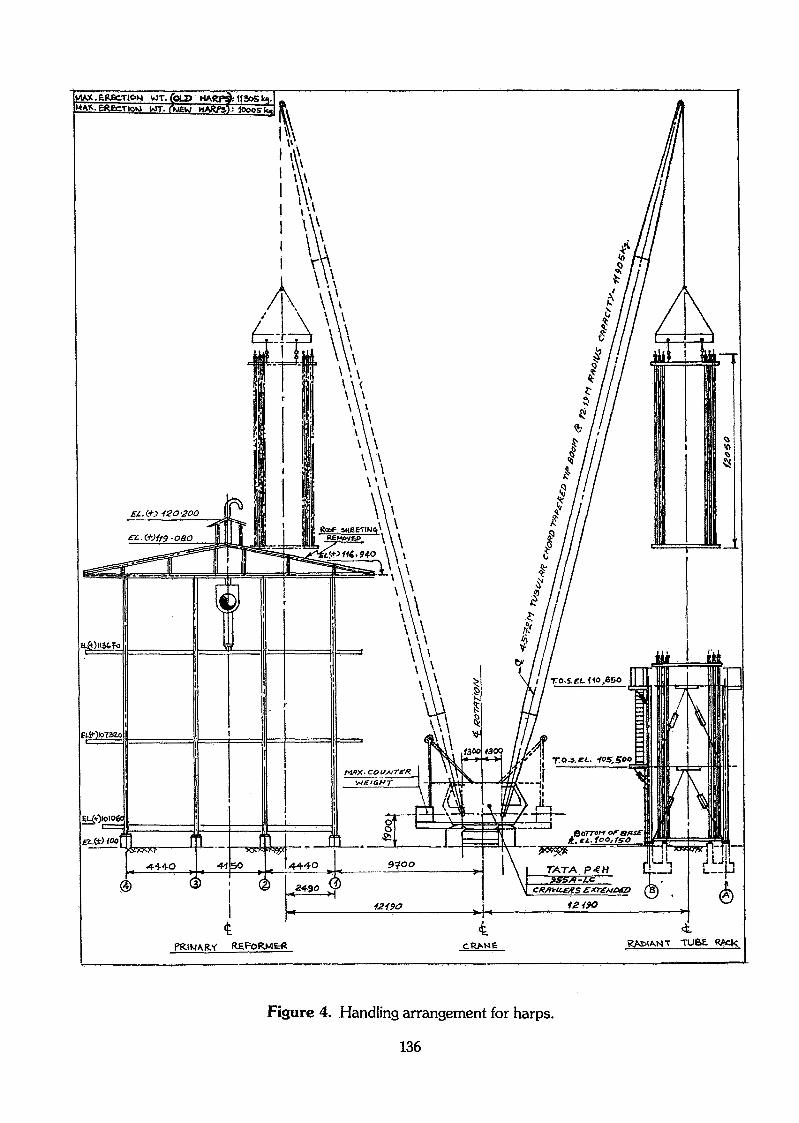
Figure 4. Handling arrangement for harps.
136

SIo.
!•
2'
3.
4.
5.
j .
r
8.
9.
10.
11.
12.
13.
14.
15.
16.
17.
18.
19.
20.
21.
22.
23.
24.
25.
26.
27.
ACTIVITY
Furnace Cooldown
Removal of insulation overpigtails/preheat air ductsRemoval of roof sheeting/gratingsRemoval of arch & tunnelburnersRemoval of pigtails
Removal of tunnel & floorrefractoryLaying of tracks onfurnace floorCutting of riser jacketand pressure shellRemoval of arch insulation
Cutting of outlet manifolds
Removal & re-calibrationof spring hangersRemoval & re-installationof harp assembliesInstallation of springhanqersAlignment. & welding ofoutlet manifoldsWelding of riser pressureshellWelding of pigtails
Balancing of harp assembly
Fixing of arch insulation
Removal of tracks
Welding of drains, stops &thermowells on manifoldsRiser transition assly.refractory & jacket weldinFixing tunnel & floorrefractoryInsulation of arch &tunnel burnersInsulation of pigtails &preheat air ductsInsulation of outletmanifoldsLeak tests
Furnace box-up
DAY
Wl
2-i«__
•t• 4
1—t-
3
-H
— 1
tulHJ-H
4 1 5 ! 6 i? 8 9 !lO! 11 '12 13lKll5 16 17 H 8 19 !20'21 122 1231 : ' \ i ! - i l :i • i • i i- ' ' 1 FfiFMn ' '
*\ : i ; ' .i ' i .. : ; ;
: : : ' ! ';i_«,_-.-4 . ,.,..,., A c '- L- 1 1 1 - » n u i- 1 a i L- t i
_., 1 ' , ; j i i•* t 1 , , . i
t - ; j • ;
— * ' i ! :! '
'• ! i '
-» ; ' l l i : !I-H , ! ' ! :
« — ii—1-4i —i »-T
-- «: ' : '• \ \ '-* : \ \ \ : - ' \— « ; - i i ; , ' . ! •
- - • ; ! : : J ' l '• iHr~•jJ
—- 1 i ; ; ; ' |i • >
1 i. " i "" :
t-
11
^l
t
i
II ' 1— J '^
.J ' _, : ' ! '
| 1
HM
| 4
; . i .4,
i . • 1 1; i .,.,_ ._j
• - , ! - ,: : ' j . j
: 1 i f— ' ' i— -e
\ j • l ' 1
i ! « j j! . ' i V
Figure 5. Primary reformer revamping.
137

s«OS
UO
LUer
ÜJerCL
01
o._iinen
AFTER REVAMR
BEFORE REVAMP
3RD. 4TH.I£AMI7NG_5jeAMING.
1 2 3 4 5 6 7 8 9
CALENDAR MONTHS ON LINE
10 11 12 13 14
Figure 6. Reformer performance after revamp.
138
Related Documents