Coal-Based Ammonia Plant Operation Useful experience in startup and initial operations on a new facility in South Africa, especially in terms of plant safety L. J. Partridge, AE & CI Ltd., Modderfontein, South Africa Experience during the commissioning and initial operation of a South African ammonia plant included a number of safety problems that provided useful knowledge for im- proved plant operations. Among the problem areas and situations were the fol- lowing: a dust bunker explosions; failure of gasifier oxy- gen isolation valves; erosion from ash particles impinging on boiler tubes; leaks due to failures at joints between piping and vessels; dangers of toxic gases. This article describes these and other experiences. At the end of 1974, the 1,100-short ton/day coal-based ammonia plant was brought on stream at the AE & CI Modderfontein plant near Johannesburg, South Africa. It is based on the Koppers-Totzek, low-pressure, high- temperature, coal gasification process. The feedstock is a semi-bituminous coal containing about 14% ash, 36% volatiles, and 1% sulfur. A simplified process scheme is shown in Figure 1. Oxygen for the gasifiers is supplied from a single-stream air separation unit. Coal dust, produced in two large ring and ball mills, is gasified in six gasifiers. Figures 2 and 3 show air separation and gasification units. The gas is compressed and desulfurized by washing with methanol at -36°F at a pressure of about 30 atm. Desulfurized gas containing about 58% CO is reacted with steam over conventional iron high-temperature shift catalyst to produce hydrogen. Carbon dioxide is removed from the gas by washing with methanol at — 72°F at a pressure of about 51 atm. Final gas purification to remove residual carbon monoxide, argon, and methane is by washing with liquid nitrogen at -310°F. Ammonia synthesis is at about 220 atm. in a conventional synthesis loop with ammonia re- frigeration. The synthesis gas compressor, refrigeration compres- sor, and the nitrogen compressor are single-stream cen- trifugal machines, while two centrifugal raw gas compres- sors and two centrifugal air compressors are provided in parallel. Except for one of the air compressors, all these major machines are driven by steam turbines. Steam for these machines is raised at 100 atm. and 950°F in two coal-fired spreader-stoker boilers. The process units cover an area of about 14 acres, and are all controlled from a central control room equipped Figure 1. Simplified process scheme. 73

Welcome message from author
This document is posted to help you gain knowledge. Please leave a comment to let me know what you think about it! Share it to your friends and learn new things together.
Transcript
Coal-Based Ammonia Plant Operation
Useful experience in startup and initial operations on a new facility inSouth Africa, especially in terms of plant safety
L. J. Partridge,AE & CI Ltd.,
Modderfontein, South Africa
Experience during the commissioning and initial operationof a South African ammonia plant included a number ofsafety problems that provided useful knowledge for im-proved plant operations.
Among the problem areas and situations were the fol-lowing: a dust bunker explosions; failure of gasifier oxy-gen isolation valves; erosion from ash particles impingingon boiler tubes; leaks due to failures at joints betweenpiping and vessels; dangers of toxic gases. This articledescribes these and other experiences.
At the end of 1974, the 1,100-short ton/day coal-basedammonia plant was brought on stream at the AE & CIModderfontein plant near Johannesburg, South Africa. Itis based on the Koppers-Totzek, low-pressure, high-temperature, coal gasification process. The feedstock is asemi-bituminous coal containing about 14% ash, 36%volatiles, and 1% sulfur.
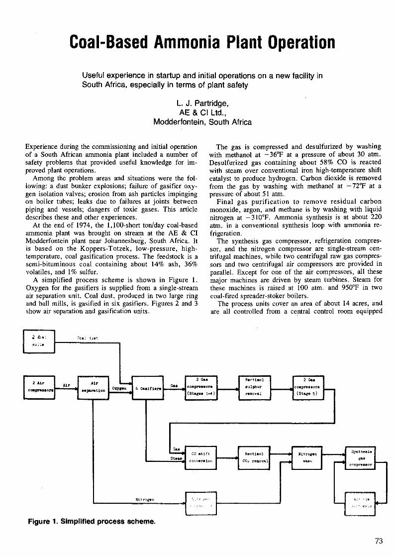
A simplified process scheme is shown in Figure 1.Oxygen for the gasifiers is supplied from a single-streamair separation unit. Coal dust, produced in two large ringand ball mills, is gasified in six gasifiers. Figures 2 and 3show air separation and gasification units.
The gas is compressed and desulfurized by washingwith methanol at -36°F at a pressure of about 30 atm.Desulfurized gas containing about 58% CO is reactedwith steam over conventional iron high-temperature shiftcatalyst to produce hydrogen. Carbon dioxide is removedfrom the gas by washing with methanol at — 72°F at apressure of about 51 atm.
Final gas purification to remove residual carbonmonoxide, argon, and methane is by washing with liquidnitrogen at -310°F. Ammonia synthesis is at about 220atm. in a conventional synthesis loop with ammonia re-frigeration.
The synthesis gas compressor, refrigeration compres-sor, and the nitrogen compressor are single-stream cen-trifugal machines, while two centrifugal raw gas compres-sors and two centrifugal air compressors are provided inparallel. Except for one of the air compressors, all thesemajor machines are driven by steam turbines. Steam forthese machines is raised at 100 atm. and 950°F in twocoal-fired spreader-stoker boilers.
The process units cover an area of about 14 acres, andare all controlled from a central control room equipped
Figure 1. Simplified process scheme.
73
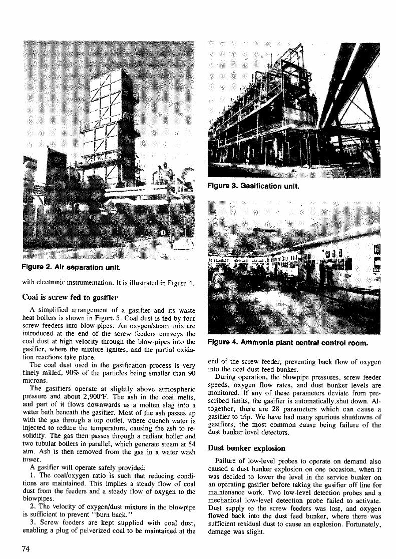
Figure 2. Air separation unit.
with electronic instrumentation. It is illustrated in Figure 4.
Coal is screw fed to gasifier
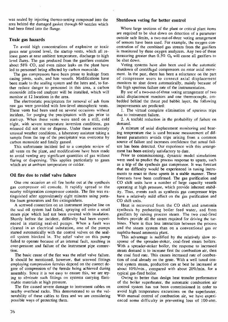
A simplified arrangement of a gasifier and its wasteheat boilers is shown in Figure 5. Coal dust is fed by fourscrew feeders into blow-pipes. An oxygen/steam mixtureintroduced at the end of the screw feeders conveys thecoal dust at high velocity through the blow-pipes into thegasifier, where the mixture ignites, and the partial oxida-tion reactions take place.
The coal dust used in the gasification process is veryfinely milled, 90% of the particles being smaller than 90microns.
The gasifiers operate at slightly above atmosphericpressure and about 2,900°F. The ash in the coal melts,and part of it flows downwards as a molten slag into awater bath beneath the gasifier. Most of the ash passes upwith the gas through a top outlet, where quench water isinjected to reduce the temperature, causing the ash to re-solidify. The gas then passes through a radiant boiler andtwo tubular boilers in parallel, which generate steam at 54atm. Ash is then removed from the gas in a water washtower.
A gasifier will operate safely provided:1. The coal/oxygen ratio is such that reducing condi-
tions are maintained. This implies a steady flow of coaldust from the feeders and a steady flow of oxygen to theblowpipes.
2. The velocity of oxygen/dust mixture in the blowpipeis sufficient to prevent "burn back."
3. Screw feeders are kept supplied with coal dust,enabling a plug of pulverized coal to be maintained at the
Figure 3. Gasification unit.
Figure 4. Ammonia plant central control room.
end of the screw feeder, preventing back flow of oxygeninto the coal dust feed bunker.
During operation, the blowpipe pressures, screw feederspeeds, oxygen flow rates, and dust bunker levels aremonitored. If any of these parameters deviate from pre-scribed limits, the gasifier is automatically shut down. Al-together, there are 28 parameters which can cause agasifier to trip. We have had many spurious shutdowns ofgasifiers, the most common cause being failure of thedust bunker level detectors.
Dust bunker explosion
Failure of low-level probes to operate on demand alsocaused a dust bunker explosion on one occasion, when itwas decided to lower the level in the service bunker onan operating gasifier before taking the gasifier off line formaintenance work. Two low-level detection probes and amechanical low-level detection probe failed to activate.Dust supply to the screw feeders was lost, and oxygenflowed back into the dust feed bunker, where there wassufficient residual dust to cause an explosion. Fortunately,damage was slight.
74
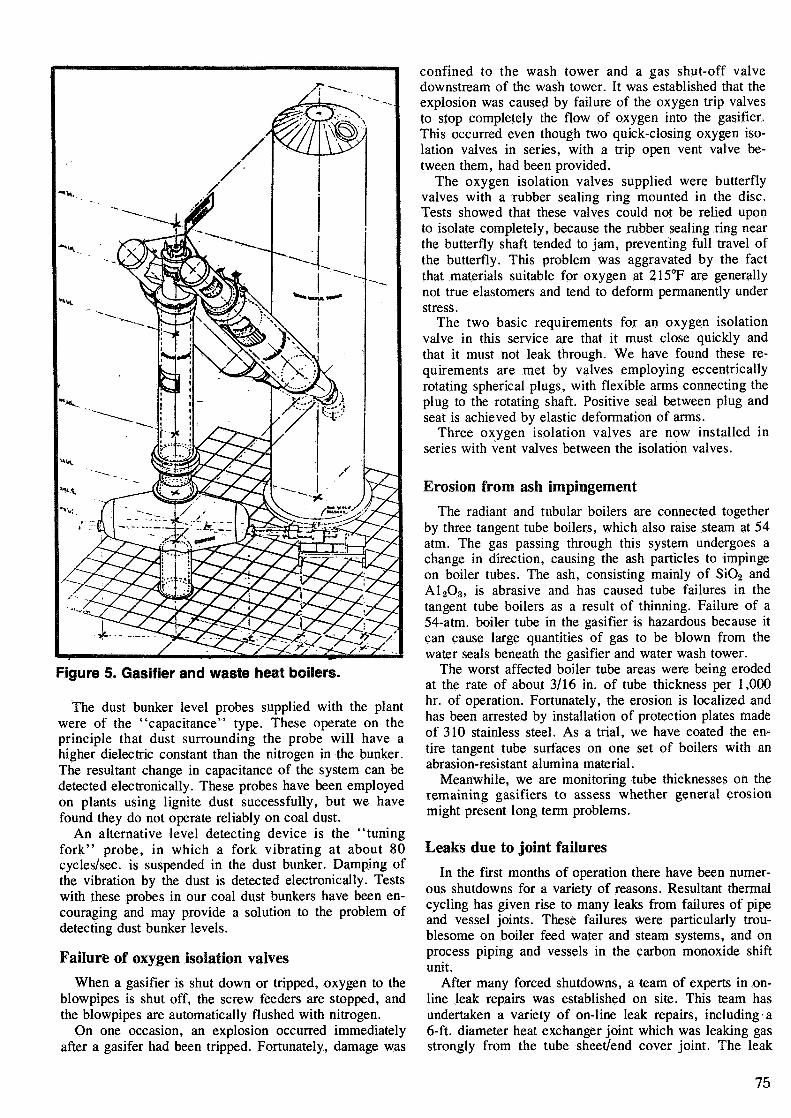
Figure 5. Gasifier and waste heat boilers.
The dust bunker level probes supplied with the plantwere of the "capacitance" type. These operate on theprinciple that dust surrounding the probe will have ahigher dielectric constant than the nitrogen in the bunker.The resultant change in capacitance of the system can bedetected electronically. These probes have been employedon plants using lignite dust successfully, but we havefound they do not operate reliably on coal dust.
An alternative level detecting device is the "tuningfork" probe, in which a fork vibrating at about 80cycles/sec, is suspended in the dust bunker. Damping ofthe vibration by the dust is detected electronically. Testswith these probes in our coal dust bunkers have been en-couraging and may provide a solution to the problem ofdetecting dust bunker levels.
Failure of oxygen isolation valves
When a gasifier is shut down or tripped, oxygen to theblowpipes is shut off, the screw feeders are stopped, andthe blowpipes are automatically flushed with nitrogen.
On one occasion, an explosion occurred immediatelyafter a gasifer had been tripped. Fortunately, damage was
confined to the wash tower and a gas shut-off valvedownstream of the wash tower. It was established that theexplosion was caused by failure of the oxygen trip valvesto stop completely the flow of oxygen into the gasifier.This occurred even though two quick-closing oxygen iso-lation valves in series, with a trip open vent valve be-tween them, had been provided.
The oxygen isolation valves supplied were butterflyvalves with a rubber sealing ring mounted in the disc.Tests showed that these valves could not be relied uponto isolate completely, because the rubber sealing ring nearthe butterfly shaft tended to jam, preventing full travel ofthe butterfly. This problem was aggravated by the factthat materials suitable for oxygen at 215°F are generallynot true elastomers and tend to deform permanently understress.
The two basic requirements for an oxygen isolationvalve in this service are that it must close quickly andthat it must not leak through. We have found these re-quirements are met by valves employing eccentricallyrotating spherical plugs, with flexible arms connecting theplug to the rotating shaft. Positive seal between plug andseat is achieved by elastic deformation of arms.
Three oxygen isolation valves are now installed inseries with vent valves between the isolation valves.
Erosion from ash impingement
The radiant and tubular boilers are connected togetherby three tangent tube boilers, which also raise steam at 54atm. The gas passing through this system undergoes achange in direction, causing the ash particles to impingeon boiler tubes. The ash, consisting mainly of SiO2 andA12O3, is abrasive and has caused tube failures in thetangent tube boilers as a result of thinning. Failure of a54-atm. boiler tube in the gasifier is hazardous because itcan cause large quantities of gas to be blown from thewater seals beneath the gasifier and water wash tower.
The worst affected boiler tube areas were being erodedat the rate of about 3/16 in. of tube thickness per 1,000hr. of operation. Fortunately, the erosion is localized andhas been arrested by installation of protection plates madeof 310 stainless steel. As a trial, we have coated the en-tire tangent tube surfaces on one set of boilers with anabrasion-resistant alumina material.
Meanwhile, we are monitoring tube thicknesses on theremaining gasifiers to assess whether general erosionmight present long term problems.
Leaks due to joint failures
In the first months of operation there have been numer-ous shutdowns for a variety of reasons. Resultant thermalcycling has given rise to many leaks from failures of pipeand vessel joints. These failures were particularly trou-blesome on boiler feed water and steam systems, and onprocess piping and vessels in the carbon monoxide shiftunit.
After many forced shutdowns, a team of experts in on-line leak repairs was established on site. This team hasundertaken a variety of on-line leak repairs, including a6-ft. diameter heat exchanger joint which was leaking gasstrongly from the tube sheet/end cover joint. The leak
75
was sealed by injecting thermo-setting compound into thearea behind the damaged gasket through 60 nozzles whichhad been fitted into the flange.
Toxic gas hazards
To avoid high concentrations of explosive or toxicgases near ground level, the startup vents, which all re-lease gases at near ambient temperature, discharge to highlevel flares. The gas produced from the gasifiers containsabout 58% CO, and even minor leaks on the plant haveled to personnel being affected by carbon monoxide.
The gas compressors have been prone to leakage fromcasing joints, seals, and lute vessels. Modifications havebeen made to the sealing system and the lutes and, to fur-ther reduce danger to personnel in this area, a carbonmonoxide infra-red analyzer will be installed, which willmonitor at 12 locations in the area.
The electrostatic precipitators for removal of ash fromraw gas were provided with low-level atmospheric vents.These vents had been used on several occasions withoutincident, for purging the precipitators with gas prior tostart-up. When these vents were used on a still, coldnight, with severe temperature inversion conditions, gasreleased did not rise or disperse. Under these extremelyunusual weather conditions, a laboratory assistant taking asample from the top of the precipitator was overcome bycarbon monoxide and fatally gassed.
This unfortunate incident led to a complete review ofall vents on the plant, and modifications have been madeto avoid venting any significant quantities of gas withoutflaring or dispersing. This applies particularly to gaseswhich are at ambient temperature or colder.
Oil fire due to relief valve failure
One one occasion an oil fire broke out at the synthesisgas compressor oil console. It rapidly spread to thenearby refrigeration compressor console. The fire was ex-tinguished after approximately eight minutes using porta-ble foam generators and fire extinguishers.
A screwed connection on an instrument impulse line onthe seal oil system had failed, spraying oil onto a smallsteam pipe which had not been covered with insulation.Shortly before the incident, difficulty had been experi-enced in starting seal-oil pumps. When a fault wascleared in an electrical substation, one of the pumpsstarted automatically with the control valves on the seal-oil system blocked in. The relief valve on this pumpfailed to operate because of an internal fault, resulting inover-pressure and failure of the instrument pipe connec-tion.
The basic cause of the fire was the relief valve failure.It should be mentioned, however, that screwed fittingsemploying compression ferrules depend on the correct de-gree of compression of the ferrule being achieved duringassembly. Since it is not easy to ensure this, we are try-ing to elminate such fittings on systems carrying flam-mable materials at high pressure.
The fire caused severe damage to instrument cables onnearby overhead racks. This demonstrated to us the vul-nerability of these cables to fires and we are consideringpossible ways of protecting them.
Shutdown voting for better control
Where large sections of the plant or critical plant itemsare required to be shut down on detection of a parameteroutside safe limits, a two-out-of-three voting arrangementof sensors have been used. For example, the oxygen con-centration of the combined gas stream from the gasifiersis monitored by three oxygen analyzers. Any two of thesemeasuring greater than 0.5% O2 will cause all gasifiers tobe shut down.
Voting systems have also been used in the automaticshutdown of centrifugal compressors on rotor axial move-ment. In the past, there has been a reluctance on the partof compressor users to connect axial displacementmonitors to shut down automatically, mainly because ofthe high spurious failure rate of the instrumentation.
By use of a two-out-of-three voting arrangement of twoaxial displacement monitors and one thermocouple, em-bedded behind the thrust pad babbit layer, the followingimprovements are predicted:
1. The virtual complete elimination of spurious tripsdue to instrument failure.
2. A tenfold reduction in the probability of failure ondemand.
A mixture of axial displacement monitoring and bear-ing temperature rise is used because measurement of dif-ferent parameters avoids trips arising from a commonsource of failure and increases confidence that actual fail-ure has been detected. Our experience with this arrange-ment has been entirely satisfactory to date.
Prior to commissioning, dynamic model simulationswere used to predict the process response to upsets, suchas a trip of the synthesis gas compressor. It was forecastthat no difficulty would be experienced in tuning instru-ments to react to these upsets in a stable manner. Theseforecasts have been confirmed. The gas purification andCO shift units have a number of large capacity vesselsoperating at high pressure, which provide inherent stabil-ity. Thus, events such as synthesis gas compressor tripshave a relatively mild effect on the gas purification andCO shift units.
Heat is recovered from the CO shift and ammoniasynthesis by preheating boiler feed water, and fromgasifiers by raising process steam. The two coal-firedboilers provide all the steam required for driving the tur-bines. There is thus less interaction between the processand the steam system than on a conventional gas ornaphtha-based ammonia plant.
This advantage is nullified by the relatively slow re-sponse of the spreader-stoker, coal-fired steam boilers.With a spreader-stoker boiler, the response to increasedsteam demand is to increase first the combustion air, thenthe coal feed rate. This causes increased rate of combus-tion of coal already on the grate. With a well tuned con-trol system steam, production can at best be increased atabout 10%/min., compared with about 20%/min. for atypical gas-fired boiler.
Owing to better than design heat transfer performanceof the boiler superheater, the automatic combustion aircontrol system has not been commissioned in order toavoid high temperature excursions on the superheater.With manual control of combustion air, we have experi-enced some difficulty in preventing loss of 100-atm.
76
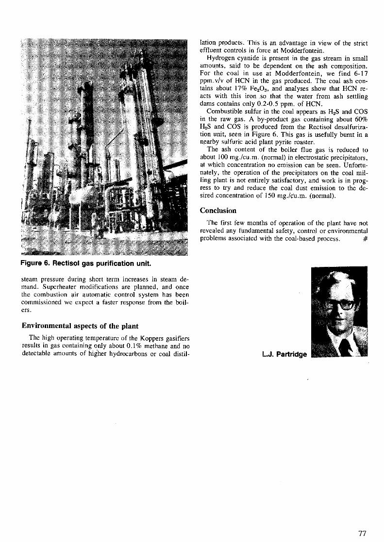
Figure 6. Rectisol gas purification unit.
steam pressure during short term increases in steam de-mand. Superheater modifications are planned, and oncethe combustion air automatic control system has beencommissioned we expect a faster response from the boil-ers.
Environmental aspects of the plant
The high operating temperature of the Koppers gasifiersresults in gas containing only about 0.1% methane and nodetectable amounts of higher hydrocarbons or coal distil-
lation products. This is an advantage in view of the stricteffluent controls in force at Modderfontein.
Hydrogen cyanide is present in the gas stream in smallamounts, said to be dependent on the ash composition.For the coal in use at Modderfontein, we find 6-17ppm.v/v of HCN in the gas produced. The coal ash con-tains about 17% Fe2O3, and analyses show that HCN re-acts with this iron so that the water from ash settlingdams contains only 0.2-0.5 ppm. of HCN.
Combustible sulfur in the coal appears as H2S and COSin the raw gas. A by-product gas containing about 60%H2S and COS is produced from the Rectisol desulfuriza-tion unit, seen in Figure 6. This gas is usefully burnt in anearby sulfuric acid plant pyrite roaster.
The ash content of the boiler flue gas is reduced toabout 100 mg./cu.m. (normal) in electrostatic precipitators,at which concentration no emission can be seen. Unfortu-nately, the operation of the precipitators on the coal mil-ling plant is not entirely satisfactory, and work is in prog-ress to try and reduce the coal dust emission to the de-sired concentration of 150 mg./c'u.m. (normal).
Conclusion
The first few months of operation of the plant have notrevealed any fundamental safety, control or environmentalproblems associated with the coal-based process. #
L.J. Partridge
77
Related Documents