-page 1 of 46- DEKRA Testing and Certification (Suzhou) Co., Ltd. No.99 Hongye Rd., Suzhou Industrial Park, Suzhou,215006, Jiangsu,China Telephone +86 0512 62515088. Telefax +86 0512 62515098 1942106E-IT-CE-P05V01 Grid-Connected PV Inverter Models: EA5KTSI,EA6KTSI,EA8KTSI,EA10KTSI,EA13KTSI,EA16KTSI Suzhou, date of issue: 2019-05-14 Author: Ranger Chen By order of EAST Group Co., Ltd. author : Ranger Chen reviewed : Star Wang DEKRA Testing and Certification (Suzhou) Co., Ltd.

Welcome message from author
This document is posted to help you gain knowledge. Please leave a comment to let me know what you think about it! Share it to your friends and learn new things together.
Transcript
-page 1 of 46-
DEKRA Testing and Certification (Suzhou) Co., Ltd. No.99 Hongye Rd., Suzhou Industrial Park, Suzhou,215006, Jiangsu,China Telephone +86 0512 62515088. Telefax +86 0512 62515098
1942106E-IT-CE-P05V01
Grid-Connected PV Inverter
Models: EA5KTSI,EA6KTSI,EA8KTSI,EA10KTSI,EA13KTSI,EA16KTSI
Suzhou, date of issue: 2019-05-14 Author: Ranger Chen
By order of EAST Group Co., Ltd.
author : Ranger Chen reviewed : Star Wang
DEKRA Testing and Certification (Suzhou) Co., Ltd.
-page 2 of 46- 1942106E-IT-CE-P05V01
DEKRA Testing and Certification (Suzhou) Co., Ltd.
CONTENTS
1 Conclusion .......................................................................................................... 3
1.1 Model description ................................................................................................ 3
2 Summary ............................................................................................................ 5
2.1 Applied standards ............................................................................................... 5
2.2 Overview of results ............................................................................................. 5
3 General Information ............................................................................................ 6
3.1 Customer Information .......................................................................................... 6
3.2 Test data ............................................................................................................. 7
3.3 Environmental conditions .................................................................................... 7
3.4 Measurement Uncertainty ................................................................................... 8
3.5 Equipment List ...................................................................................................10
4 Emission test results ..........................................................................................14
4.1 Conducted Emissions (Telecommunication Ports) .............................................19
4.2 Radiated Emission .............................................................................................20
4.3 Harmonic current emissions ...............................................................................23
4.4 Voltage fluctuations and flicker ...........................................................................27
5 Immunity test results ..........................................................................................28
5.1 Electrostatic discharge immunity ........................................................................28
5.2 Radio frequency electromagnetic field ...............................................................32
5.3 Fast transients common mode ...........................................................................34
5.4 Surge .................................................................................................................36
5.5 Radio frequency common mode ........................................................................38
5.6 Power-frequency magnetic field .........................................................................40
6 Identification of the equipment under test ...........................................................41
-page 3 of 46- 1942106E-IT-CE-P05V01
DEKRA Testing and Certification (Suzhou) Co., Ltd.
1 CONCLUSION
The conclusion and results stated in this test report are based on a non-recurrent
examination of sample(s) provided by the applicant.
The tests described in this report do not result in the right to use any approval mark as
conferred by DEKRA. As far as the tests were based on certain specifications, these are
mentioned in the report.
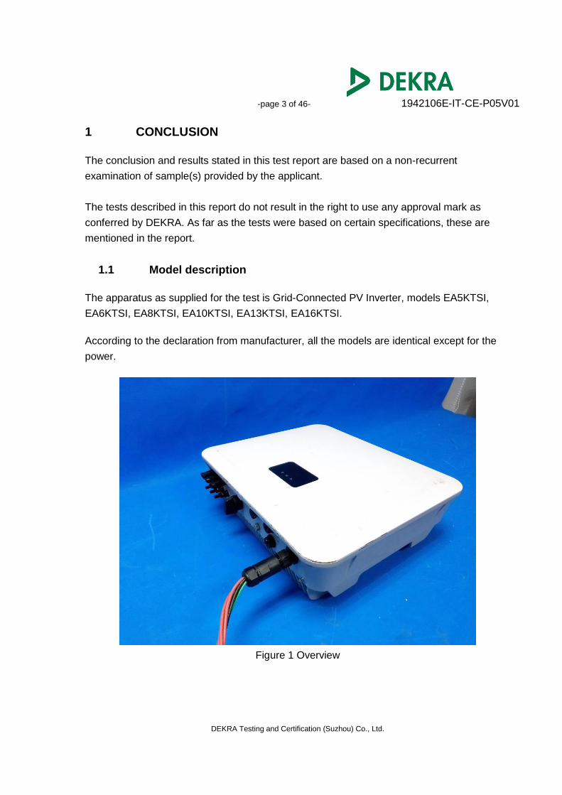
1.1 Model description
The apparatus as supplied for the test is Grid-Connected PV Inverter, models EA5KTSI,
EA6KTSI, EA8KTSI, EA10KTSI, EA13KTSI, EA16KTSI.
According to the declaration from manufacturer, all the models are identical except for the
power.
Figure 1 Overview
-page 4 of 46- 1942106E-IT-CE-P05V01
DEKRA Testing and Certification (Suzhou) Co., Ltd.
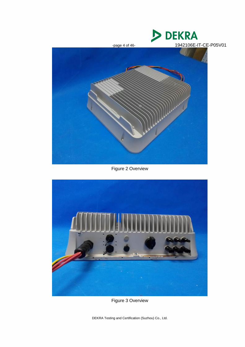
Figure 2 Overview
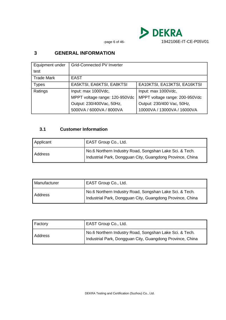
Figure 3 Overview

-page 5 of 46- 1942106E-IT-CE-P05V01
DEKRA Testing and Certification (Suzhou) Co., Ltd.
2 SUMMARY This chapter presents an overview of standards and results. Refer to the next chapters for details of measured test results and applied test levels.
2.1 Applied standards
Standard Year Title
EN 61000-6-4 2007 Generic standards — Emission
standard for industrial environments A1 2011
EN 61000-6-2 2005 Generic standards — Immunity
for industrial environments
Standard Year Title
EN 61000-6-3 2007 Generic standards — Emission standard for
residential, commercial and light-industrial
environments
A1 2011
AC 2012
EN 61000-6-1 2007 Generic standards — Immunity for residential,
commercial and light-industrial environments
Note: The test in this report uses the lower limit (EN 61000-6-3) for Emission, uses the
higher level (EN 61000-6-2) for Immunity. Use EN 61000-6-1 and EN 61000-6-2 for
Voltage dips and interruptions.
2.2 Overview of results
Emission tests Result
Conducted Emission(Mains Ports) PASS
Conducted Emission(Telecommunication Ports) N/A
Radiated Emission PASS
Harmonic current emission PASS
Voltage fluctuations and flicker PASS
Immunity tests Result
Electrostatic discharge PASS
Radio frequency electromagnetic field PASS
Electrical fast transients PASS
Surges PASS
Radio-frequency continuous conducted PASS
Power frequency magnetic field PASS
Voltage dips and interruptions PASS
-page 6 of 46- 1942106E-IT-CE-P05V01
DEKRA Testing and Certification (Suzhou) Co., Ltd.
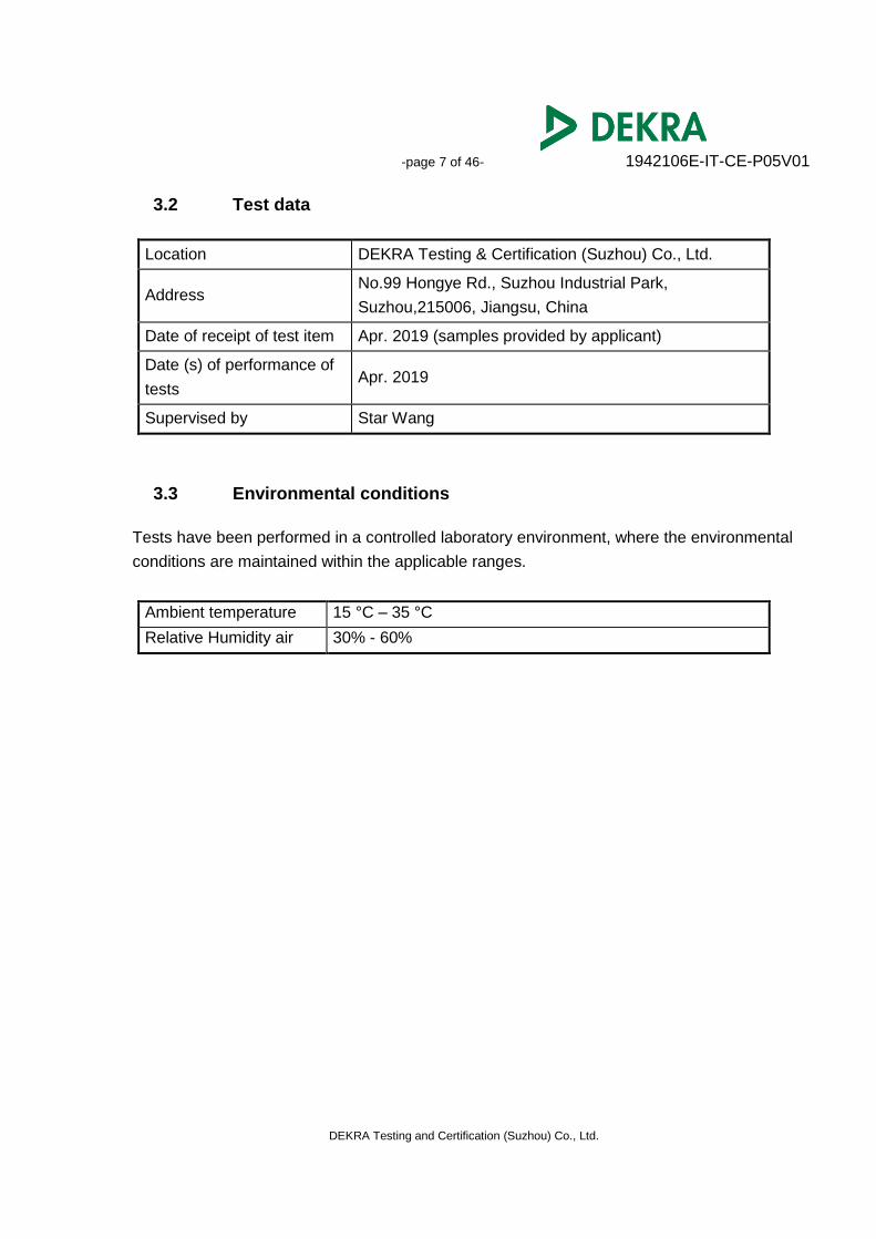
3 GENERAL INFORMATION
Equipment under
test
Grid-Connected PV Inverter
Trade Mark EAST
Types EA5KTSI, EA6KTSI, EA8KTSI EA10KTSI, EA13KTSI, EA16KTSI
Ratings
Input: max 1000Vdc,
MPPT voltage range: 120-950Vdc
Output: 230/400Vac, 50Hz,
5000VA / 6000VA / 8000VA
Input: max 1000Vdc,
MPPT voltage range: 200-950Vdc
Output: 230/400 Vac, 50Hz,
10000VA / 13000VA / 16000VA
3.1 Customer Information
Applicant EAST Group Co., Ltd.
Address No.6 Northern Industry Road, Songshan Lake Sci. & Tech.
Industrial Park, Dongguan City, Guangdong Province, China
Manufacturer EAST Group Co., Ltd.
Address No.6 Northern Industry Road, Songshan Lake Sci. & Tech.
Industrial Park, Dongguan City, Guangdong Province, China
Factory EAST Group Co., Ltd.
Address No.6 Northern Industry Road, Songshan Lake Sci. & Tech.
Industrial Park, Dongguan City, Guangdong Province, China
-page 7 of 46- 1942106E-IT-CE-P05V01
DEKRA Testing and Certification (Suzhou) Co., Ltd.
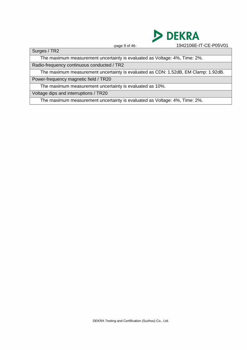
3.2 Test data
Location DEKRA Testing & Certification (Suzhou) Co., Ltd.
Address No.99 Hongye Rd., Suzhou Industrial Park,
Suzhou,215006, Jiangsu, China
Date of receipt of test item Apr. 2019 (samples provided by applicant)
Date (s) of performance of
tests Apr. 2019
Supervised by Star Wang
3.3 Environmental conditions
Tests have been performed in a controlled laboratory environment, where the environmental
conditions are maintained within the applicable ranges.
Ambient temperature 15 °C – 35 °C
Relative Humidity air 30% - 60%

-page 8 of 46- 1942106E-IT-CE-P05V01
DEKRA Testing and Certification (Suzhou) Co., Ltd.
3.4 Measurement Uncertainty
Conducted Emission (Mains Ports) / TR1
The maximum measurement uncertainty is evaluated as:
Mains: 9kHz~150kHz: 2.80dB
150kHz~30MHz: 2.40dB
Conducted Emission (Telecommunication Ports) / TR1
The maximum measurement uncertainty is evaluated as:
ISN T800: 150kHz~30MHz: 3.60 dB
ISN T8-Cat6: 150kHz~30MHz: 3.50 dB
ISN ST08: 150kHz~30MHz: 3.10 dB
Radiated emission / AC1
The maximum measurement uncertainty is evaluated as:
Horizontal: 30MHz~300MHz: 3.50 dB
300MHz~1GHz: 3.20 dB
1GHz~18GHz: 4.80 dB
Vertical: 30MHz~300MHz: 3.60 dB
300MHz~1GHz: 3.10 dB
1GHz~18GHz: 4.50 dB
Radiated emission / AC5
The maximum measurement uncertainty is evaluated as:
Horizontal: 30MHz~300MHz: 3.90 dB
300MHz~1GHz: 3.60 dB
1GHz~18GHz: 5.00 dB
Vertical: 30MHz~300MHz: 3.80 dB
300MHz~1GHz: 3.50 dB
1GHz~18GHz: 4.80 dB
Harmonic current emissions / TR20
The maximum measurement uncertainty is evaluated as: 1.8 %.
Voltage fluctuation and flicker / TR20
The maximum measurement uncertainty is evaluated as: 1.5 %.
Electrostatic discharge / AC4
The maximum measurement uncertainty is evaluated as Rise Time: 6.4 %,
Peak Current: 6 %, Current at 30 ns: 6 %, Current at 60 ns: 6 %.
Radio frequency electromagnetic field / AC4
The maximum measurement uncertainty is evaluated as 1.48dB.
Electrical fast transients / TR2
The maximum measurement uncertainty is evaluated as Voltage: 4%, Time: 2%.
-page 9 of 46- 1942106E-IT-CE-P05V01
DEKRA Testing and Certification (Suzhou) Co., Ltd.
Surges / TR2
The maximum measurement uncertainty is evaluated as Voltage: 4%, Time: 2%.
Radio-frequency continuous conducted / TR2
The maximum measurement uncertainty is evaluated as CDN: 1.52dB, EM Clamp: 1.92dB.
Power-frequency magnetic field / TR20
The maximum measurement uncertainty is evaluated as 10%.
Voltage dips and interruptions / TR20
The maximum measurement uncertainty is evaluated as Voltage: 4%, Time: 2%.

-page 10 of 46- 1942106E-IT-CE-P05V01
DEKRA Testing and Certification (Suzhou) Co., Ltd.
3.5 Equipment List
Conducted Emission(Mains Ports)/ TR1 Instrument Manufacturer Model No. Serial No. Cali. Due Date
EMI Test Receiver R&S ESCI 100906 2020.04.20
Two-Line V-Network R&S ENV216 101189 2019. 11.24
Two-Line V-Network R&S ENV216 101044 2019.06.09
Artificial Mains Network SCHWARZBECK NSLK 8128 8128-287 2019.10.20
Current Probe R&S EZ-17 100678 2020.03.07
50ohm Termination SHX TF2 07081402 2019.09.08
50ohm Termination SHX TF2 07081403 2019.09.08
50ohm Coaxial Switch Anritsu MP59B 6200464462 N/A
Coaxial Cable Suhner RG 223 TR1-C1 2019.09.27
Temperature/Humidity Meter ruitesi RTS-8S TR1-TH 2019.09.27
Conducted Emission (Telecommunication Ports) / TR1 Instrument Manufacturer Model No. Serial No. Cali. Due Date
EMI Test Receiver R&S ESCI 100906 2020.03.04
Two-Line V-Network R&S ENV216 101189 2019.06.09
Two-Line V-Network R&S ENV216 101044 2019.06.09
Impedance Stabilization Network Teseq GmbH ISN T800 30306 2020.01.22
Impedance Stabilization Network Teseq GmbH ISN T8-Cat6 29680 2020.01.22
Current Probe R&S EZ-17 100678 2019.09.08
50ohm Termination SHX TF2 07081402 2019.09.08
50ohm Termination SHX TF2 07081403 N/A
50ohm Coaxial Switch Anritsu MP59B 6200464462 2019.09.27
Coaxial Cable Suhner RG 223 TR1-C1 2019.09.27
Temperature/Humidity Meter ruitesi RTS-8S TR1-TH 2019.10.24
Radiated Emission / AC1 Instrument Manufacturer Model No. Serial No. Cali. Due Date
EMI Test Receiver R&S ESCI 100175 2019.09.08
EMI Test Receiver R&S ESCI 100726 2019.09.08
EMI Receiver Agilent N9038A MY51210196 2019.06.09
Preamplifier Quietek AP-025C CHM-0602008 2020.04.13
Preamplifier Quietek AP-025C CHM-0503006 2020.04.13
Bilog Antenna Schaffner CBL6112B 2931 2020.05.18
Bilog Antenna Schaffner CBL6112B 2933 2020.05.18
DRG Horn Antenna ETS-Lindgren 3117 00167055 2019.06.09
Coaxial Cable Huber+Suhner RG 214_U AC1-L 2019.10.10
Coaxial Cable Huber+Suhner RG 214_U AC1-R 2019.10.10
Temperature/Humidity Meter ruitesi RTS-8S AC1-TH 2019.10.24
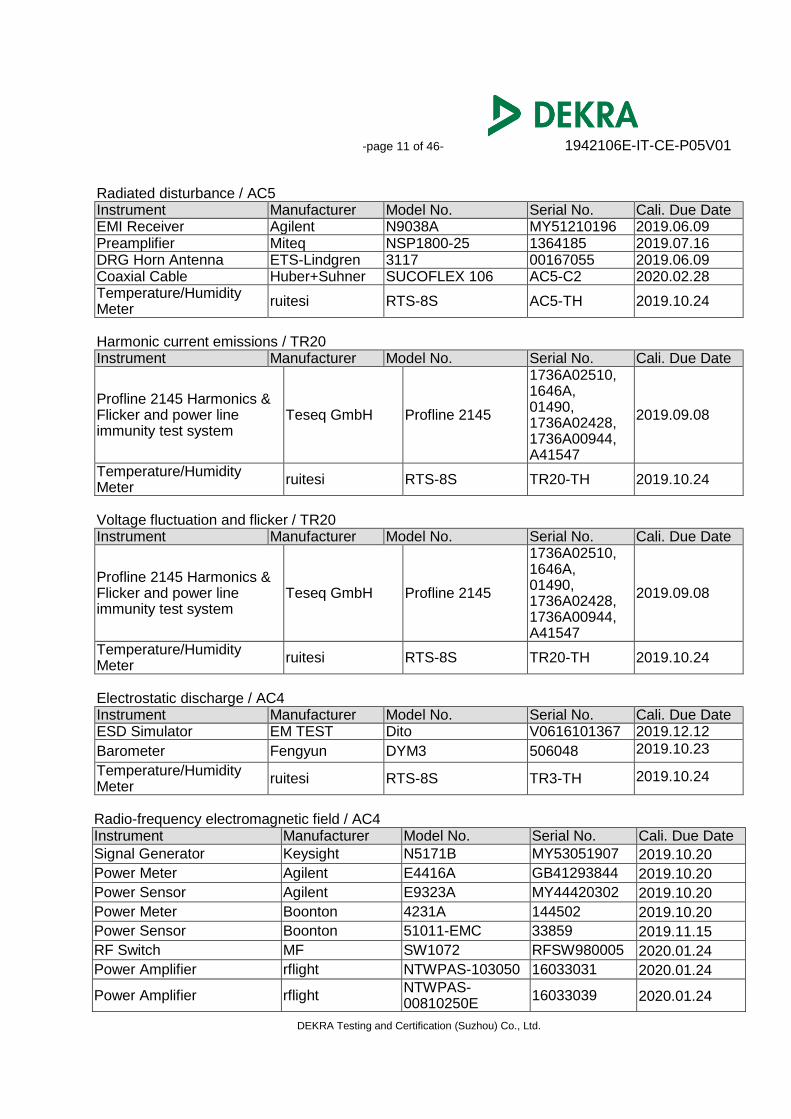
-page 11 of 46- 1942106E-IT-CE-P05V01
DEKRA Testing and Certification (Suzhou) Co., Ltd.
Radiated disturbance / AC5 Instrument Manufacturer Model No. Serial No. Cali. Due Date EMI Receiver Agilent N9038A MY51210196 2019.06.09 Preamplifier Miteq NSP1800-25 1364185 2019.07.16 DRG Horn Antenna ETS-Lindgren 3117 00167055 2019.06.09 Coaxial Cable Huber+Suhner SUCOFLEX 106 AC5-C2 2020.02.28 Temperature/Humidity Meter
ruitesi RTS-8S AC5-TH 2019.10.24
Harmonic current emissions / TR20 Instrument Manufacturer Model No. Serial No. Cali. Due Date
Profline 2145 Harmonics & Flicker and power line immunity test system
Teseq GmbH Profline 2145
1736A02510, 1646A, 01490, 1736A02428, 1736A00944, A41547
2019.09.08
Temperature/Humidity Meter
ruitesi RTS-8S TR20-TH 2019.10.24
Voltage fluctuation and flicker / TR20 Instrument Manufacturer Model No. Serial No. Cali. Due Date
Profline 2145 Harmonics & Flicker and power line immunity test system
Teseq GmbH Profline 2145
1736A02510, 1646A, 01490, 1736A02428, 1736A00944, A41547
2019.09.08
Temperature/Humidity Meter
ruitesi RTS-8S TR20-TH 2019.10.24
Electrostatic discharge / AC4 Instrument Manufacturer Model No. Serial No. Cali. Due Date ESD Simulator EM TEST Dito V0616101367 2019.12.12
Barometer Fengyun DYM3 506048 2019.10.23
Temperature/Humidity Meter
ruitesi RTS-8S TR3-TH 2019.10.24
Radio-frequency electromagnetic field / AC4 Instrument Manufacturer Model No. Serial No. Cali. Due Date
Signal Generator Keysight N5171B MY53051907 2019.10.20
Power Meter Agilent E4416A GB41293844 2019.10.20
Power Sensor Agilent E9323A MY44420302 2019.10.20
Power Meter Boonton 4231A 144502 2019.10.20
Power Sensor Boonton 51011-EMC 33859 2019.11.15
RF Switch MF SW1072 RFSW980005 2020.01.24
Power Amplifier rflight NTWPAS-103050 16033031 2020.01.24
Power Amplifier rflight NTWPAS-00810250E
16033039 2020.01.24
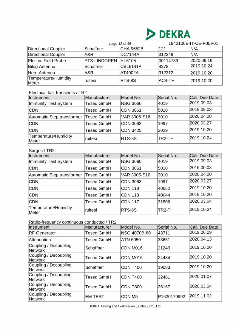
-page 12 of 46- 1942106E-IT-CE-P05V01
DEKRA Testing and Certification (Suzhou) Co., Ltd.
Directional Coupler Schaffner CHA 9652B 121 N/A
Directional Coupler A&R DC7144A 312249 N/A
Electric Field Probe ETS-LINDGREN HI-6105 00114789 2020.09.19
Bilog Antenna Schaffner CBL6141A 4278 2019.10.24
Horn Antenna A&R AT4002A 312312 2019.10.20
Temperature/Humidity Meter
ruitesi RTS-8S AC4-TH 2019.10.20
Electrical fast transients / TR2 Instrument Manufacturer Model No. Serial No. Cali. Due Date
Immunity Test System Teseq GmbH NSG 3060 4019 2019.09.03
CDN Teseq GmbH CDN 3061 5010 2019.09.03
Automatic Step transformer Teseq GmbH VAR 3005-S16 3010 2020.04.20
CDN Teseq GmbH CDN 3063 1997 2020.03.27
CDN Teseq GmbH CDN 3425 2029 2019.10.20
Temperature/Humidity Meter
ruitesi RTS-8S TR2-TH 2019.10.24
Surges / TR2 Instrument Manufacturer Model No. Serial No. Cali. Due Date
Immunity Test System Teseq GmbH NSG 3060 4019 2019.09.03
CDN Teseq GmbH CDN 3061 5010 2019.09.03
Automatic Step transformer Teseq GmbH VAR 3005-S16 3010 2020.04.20
CDN Teseq GmbH CDN 3063 1997 2020.03.27
CDN Teseq GmbH CDN 118 40652 2019.10.20
CDN Teseq GmbH CDN 118 40644 2019.10.20
CDN Teseq GmbH CDN 117 31806 2020.03.04
Temperature/Humidity Meter
ruitesi RTS-8S TR2-TH 2019.10.24
Radio-frequency continuous conducted / TR2 Instrument Manufacturer Model No. Serial No. Cali. Due Date
RF-Generator Teseq GmbH NSG 4070B-80 43711 2019.06.09
Attenuation Teseq GmbH ATN 6050 33651 2020.04.13
Coupling / Decoupling Network
Schaffner CDN M016 21249 2019.10.20
Coupling / Decoupling Network
Teseq GmbH CDN M016 24484 2019.10.20
Coupling / Decoupling Network
Schaffner CDN T400 19083 2019.10.20
Coupling / Decoupling Network
Teseq GmbH CDN T400 22461 2020.01.07
Coupling / Decoupling Network
Teseq GmbH CDN T800 26167 2020.03.04
Coupling / Decoupling Network
EM TEST CDN M5 P1620179992 2019.11.02
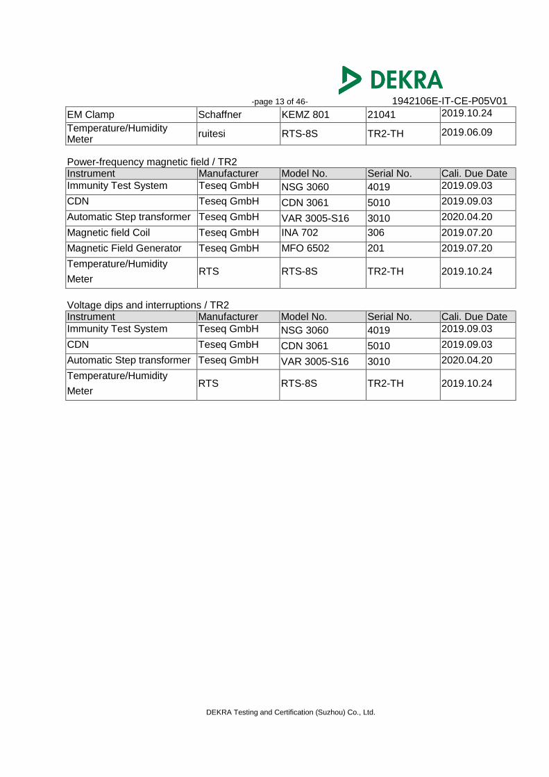
-page 13 of 46- 1942106E-IT-CE-P05V01
DEKRA Testing and Certification (Suzhou) Co., Ltd.
EM Clamp Schaffner KEMZ 801 21041 2019.10.24
Temperature/Humidity Meter
ruitesi RTS-8S TR2-TH 2019.06.09
Power-frequency magnetic field / TR2 Instrument Manufacturer Model No. Serial No. Cali. Due Date
Immunity Test System Teseq GmbH NSG 3060 4019 2019.09.03
CDN Teseq GmbH CDN 3061 5010 2019.09.03
Automatic Step transformer Teseq GmbH VAR 3005-S16 3010 2020.04.20
Magnetic field Coil Teseq GmbH INA 702 306 2019.07.20
Magnetic Field Generator Teseq GmbH MFO 6502 201 2019.07.20
Temperature/Humidity
Meter RTS RTS-8S TR2-TH 2019.10.24
Voltage dips and interruptions / TR2 Instrument Manufacturer Model No. Serial No. Cali. Due Date
Immunity Test System Teseq GmbH NSG 3060 4019 2019.09.03
CDN Teseq GmbH CDN 3061 5010 2019.09.03
Automatic Step transformer Teseq GmbH VAR 3005-S16 3010 2020.04.20
Temperature/Humidity
Meter RTS RTS-8S TR2-TH 2019.10.24
-page 14 of 46- 1942106E-IT-CE-P05V01
DEKRA Testing and Certification (Suzhou) Co., Ltd.
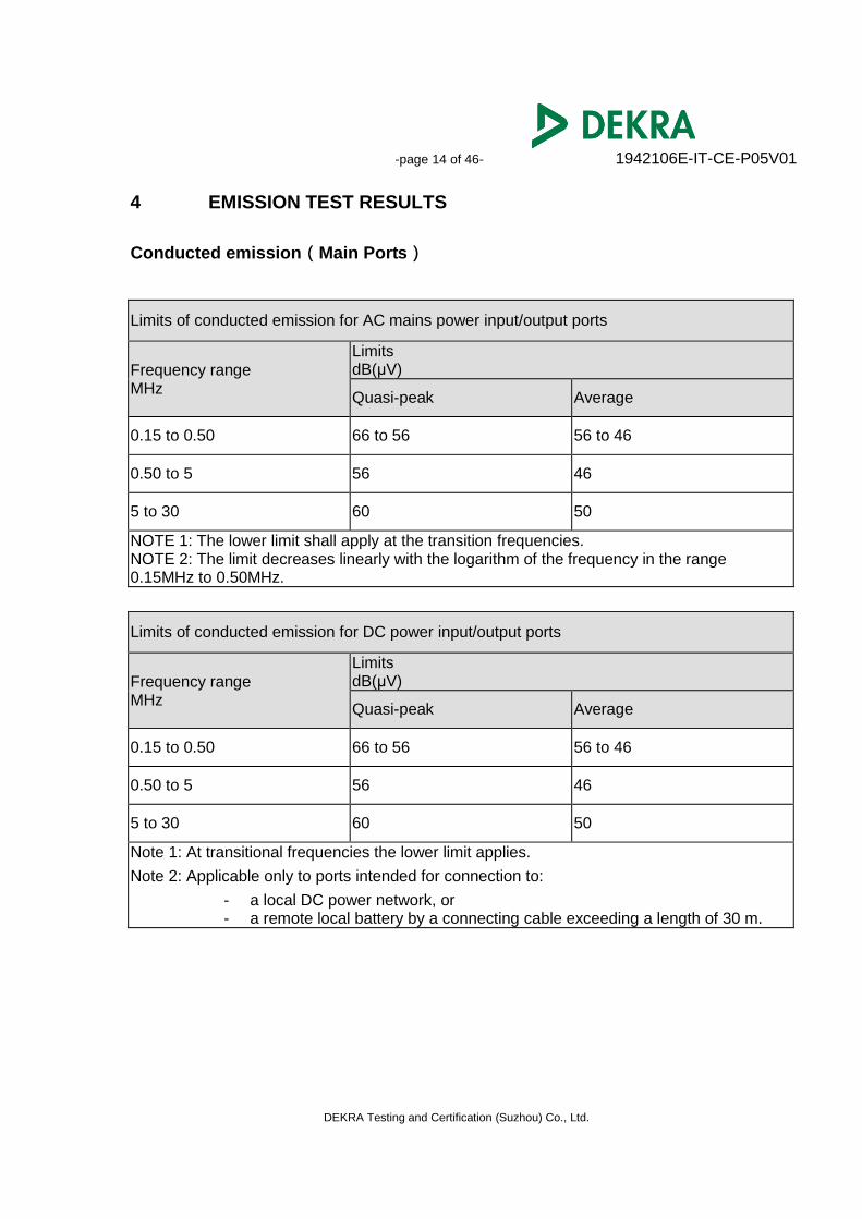
4 EMISSION TEST RESULTS
Conducted emission(Main Ports)
Limits of conducted emission for AC mains power input/output ports
Frequency range MHz
Limits dB(μV)
Quasi-peak Average
0.15 to 0.50 66 to 56 56 to 46
0.50 to 5 56 46
5 to 30 60 50
NOTE 1: The lower limit shall apply at the transition frequencies. NOTE 2: The limit decreases linearly with the logarithm of the frequency in the range 0.15MHz to 0.50MHz.
Limits of conducted emission for DC power input/output ports
Frequency range MHz
Limits dB(μV)
Quasi-peak Average
0.15 to 0.50 66 to 56 56 to 46
0.50 to 5 56 46
5 to 30 60 50
Note 1: At transitional frequencies the lower limit applies.
Note 2: Applicable only to ports intended for connection to:
- a local DC power network, or - a remote local battery by a connecting cable exceeding a length of 30 m.
-page 15 of 46- 1942106E-IT-CE-P05V01
DEKRA Testing and Certification (Suzhou) Co., Ltd.
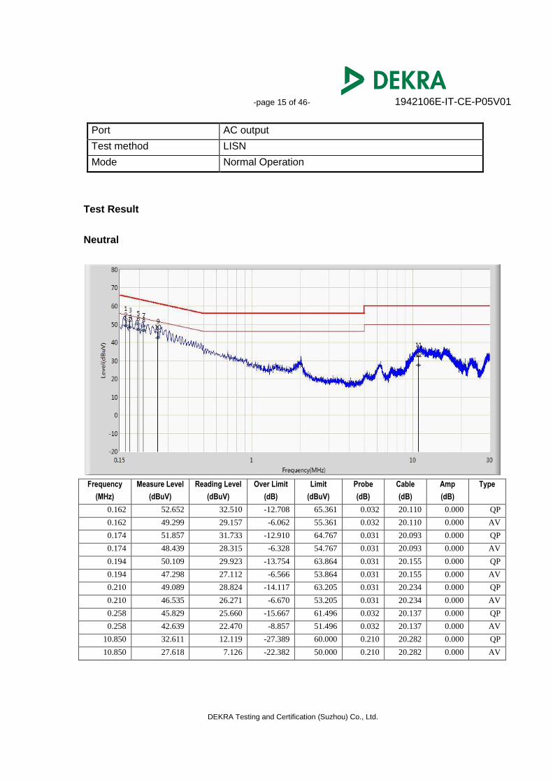
Port AC output
Test method LISN
Mode Normal Operation
Test Result
Neutral
Frequency
(MHz)
Measure Level
(dBuV)
Reading Level
(dBuV)
Over Limit
(dB)
Limit
(dBuV)
Probe
(dB)
Cable
(dB)
Amp
(dB)
Type
0.162 52.652 32.510 -12.708 65.361 0.032 20.110 0.000 QP
0.162 49.299 29.157 -6.062 55.361 0.032 20.110 0.000 AV
0.174 51.857 31.733 -12.910 64.767 0.031 20.093 0.000 QP
0.174 48.439 28.315 -6.328 54.767 0.031 20.093 0.000 AV
0.194 50.109 29.923 -13.754 63.864 0.031 20.155 0.000 QP
0.194 47.298 27.112 -6.566 53.864 0.031 20.155 0.000 AV
0.210 49.089 28.824 -14.117 63.205 0.031 20.234 0.000 QP
0.210 46.535 26.271 -6.670 53.205 0.031 20.234 0.000 AV
0.258 45.829 25.660 -15.667 61.496 0.032 20.137 0.000 QP
0.258 42.639 22.470 -8.857 51.496 0.032 20.137 0.000 AV
10.850 32.611 12.119 -27.389 60.000 0.210 20.282 0.000 QP
10.850 27.618 7.126 -22.382 50.000 0.210 20.282 0.000 AV

-page 16 of 46- 1942106E-IT-CE-P05V01
DEKRA Testing and Certification (Suzhou) Co., Ltd.
Line1
Frequency
(MHz)
Measure Level
(dBuV)
Reading Level
(dBuV)
Over Limit
(dB)
Limit
(dBuV)
Probe
(dB)
Cable
(dB)
Amp
(dB)
Type
0.162 48.042 27.900 -17.319 65.361 0.032 20.110 0.000 QP
0.162 42.852 22.710 -12.508 55.361 0.032 20.110 0.000 AV
0.174 45.964 25.840 -18.803 64.767 0.031 20.093 0.000 QP
0.174 41.099 20.974 -13.669 54.767 0.031 20.093 0.000 AV
0.310 27.333 7.260 -32.638 59.970 0.032 20.041 0.000 QP
0.310 22.605 2.532 -27.366 49.970 0.032 20.041 0.000 AV
0.478 27.827 7.644 -28.547 56.374 0.034 20.149 0.000 QP
0.478 21.761 1.578 -24.613 46.374 0.034 20.149 0.000 AV
1.990 23.452 3.165 -32.548 56.000 0.058 20.229 0.000 QP
1.990 15.865 -4.422 -30.135 46.000 0.058 20.229 0.000 AV
16.130 26.428 5.850 -33.572 60.000 0.252 20.326 0.000 QP
16.130 21.302 0.724 -28.698 50.000 0.252 20.326 0.000 AV
-page 17 of 46- 1942106E-IT-CE-P05V01
DEKRA Testing and Certification (Suzhou) Co., Ltd.
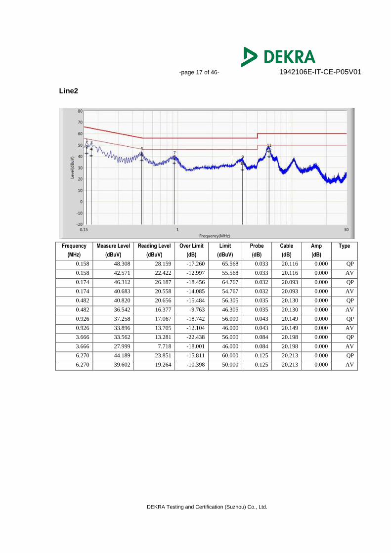
Line2
Frequency
(MHz)
Measure Level
(dBuV)
Reading Level
(dBuV)
Over Limit
(dB)
Limit
(dBuV)
Probe
(dB)
Cable
(dB)
Amp
(dB)
Type
0.158 48.308 28.159 -17.260 65.568 0.033 20.116 0.000 QP
0.158 42.571 22.422 -12.997 55.568 0.033 20.116 0.000 AV
0.174 46.312 26.187 -18.456 64.767 0.032 20.093 0.000 QP
0.174 40.683 20.558 -14.085 54.767 0.032 20.093 0.000 AV
0.482 40.820 20.656 -15.484 56.305 0.035 20.130 0.000 QP
0.482 36.542 16.377 -9.763 46.305 0.035 20.130 0.000 AV
0.926 37.258 17.067 -18.742 56.000 0.043 20.149 0.000 QP
0.926 33.896 13.705 -12.104 46.000 0.043 20.149 0.000 AV
3.666 33.562 13.281 -22.438 56.000 0.084 20.198 0.000 QP
3.666 27.999 7.718 -18.001 46.000 0.084 20.198 0.000 AV
6.270 44.189 23.851 -15.811 60.000 0.125 20.213 0.000 QP
6.270 39.602 19.264 -10.398 50.000 0.125 20.213 0.000 AV
-page 18 of 46- 1942106E-IT-CE-P05V01
DEKRA Testing and Certification (Suzhou) Co., Ltd.
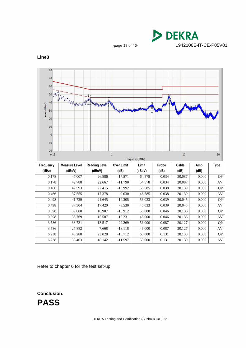
Line3
Frequency
(MHz)
Measure Level
(dBuV)
Reading Level
(dBuV)
Over Limit
(dB)
Limit
(dBuV)
Probe
(dB)
Cable
(dB)
Amp
(dB)
Type
0.178 47.007 26.886 -17.571 64.578 0.034 20.087 0.000 QP
0.178 42.788 22.667 -11.790 54.578 0.034 20.087 0.000 AV
0.466 42.593 22.415 -13.992 56.585 0.038 20.139 0.000 QP
0.466 37.555 17.378 -9.030 46.585 0.038 20.139 0.000 AV
0.498 41.729 21.645 -14.305 56.033 0.039 20.045 0.000 QP
0.498 37.504 17.420 -8.530 46.033 0.039 20.045 0.000 AV
0.898 39.088 18.907 -16.912 56.000 0.046 20.136 0.000 QP
0.898 35.769 15.587 -10.231 46.000 0.046 20.136 0.000 AV
3.586 33.731 13.517 -22.269 56.000 0.087 20.127 0.000 QP
3.586 27.882 7.668 -18.118 46.000 0.087 20.127 0.000 AV
6.238 43.288 23.028 -16.712 60.000 0.131 20.130 0.000 QP
6.238 38.403 18.142 -11.597 50.000 0.131 20.130 0.000 AV
Refer to chapter 6 for the test set-up.
Conclusion:
PASS
-page 19 of 46- 1942106E-IT-CE-P05V01
DEKRA Testing and Certification (Suzhou) Co., Ltd.
4.1 Conducted Emissions (Telecommunication Ports)
Limits of conducted common mode (asymmetric mode) disturbance at telecommunication
ports in the frequency range 0.15MHz to 30 MHz
Frequency range MHz
Voltage Limits dB(μV)
Current limits dB(μA)
Quasi-peak Average Quasi-peak Average
0.15 to 0.50 84 - 74 74 - 64 40 - 30 30 - 20
0.50 to 30 74 64 30 20
NOTE 1: The limits decrease linearly with the logarithm of the frequency in the range 0.15MHz to 0.5MHz. NOTE 2: The current and voltage disturbance limits are derived for use with an impedance stabilization network (ISN) which presents a common mode (asymmetric mode) impedance of 150Ω to the telecommunication port under test (conversion factor is 20 log10150 / I = 44dB).
Test Result
The EUT does not contain the wired network port, so it needs not to perform this test item.
-page 20 of 46- 1942106E-IT-CE-P05V01
DEKRA Testing and Certification (Suzhou) Co., Ltd.
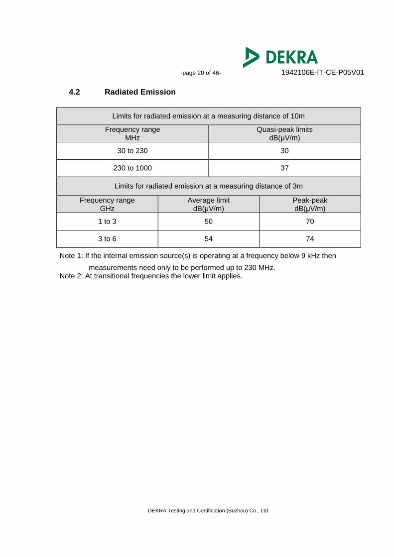
4.2 Radiated Emission
Limits for radiated emission at a measuring distance of 10m
Frequency range MHz
Quasi-peak limits dB(μV/m)
30 to 230 30
230 to 1000 37
Limits for radiated emission at a measuring distance of 3m
Frequency range GHz
Average limit dB(μV/m)
Peak-peak dB(μV/m)
1 to 3 50 70
3 to 6 54 74
Note 1: If the internal emission source(s) is operating at a frequency below 9 kHz then
measurements need only to be performed up to 230 MHz. Note 2: At transitional frequencies the lower limit applies.
-page 21 of 46- 1942106E-IT-CE-P05V01
DEKRA Testing and Certification (Suzhou) Co., Ltd.
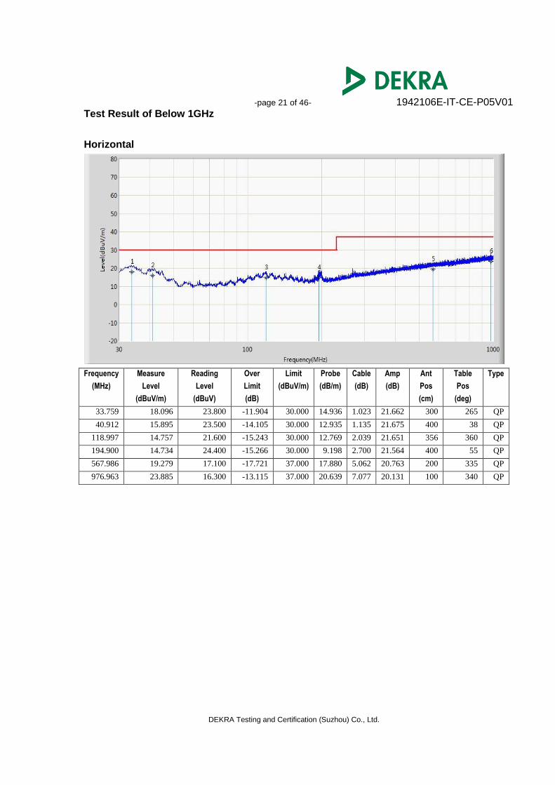
Test Result of Below 1GHz
Horizontal
Frequency
(MHz)
Measure
Level
(dBuV/m)
Reading
Level
(dBuV)
Over
Limit
(dB)
Limit
(dBuV/m)
Probe
(dB/m)
Cable
(dB)
Amp
(dB)
Ant
Pos
(cm)
Table
Pos
(deg)
Type
33.759 18.096 23.800 -11.904 30.000 14.936 1.023 21.662 300 265 QP
40.912 15.895 23.500 -14.105 30.000 12.935 1.135 21.675 400 38 QP
118.997 14.757 21.600 -15.243 30.000 12.769 2.039 21.651 356 360 QP
194.900 14.734 24.400 -15.266 30.000 9.198 2.700 21.564 400 55 QP
567.986 19.279 17.100 -17.721 37.000 17.880 5.062 20.763 200 335 QP
976.963 23.885 16.300 -13.115 37.000 20.639 7.077 20.131 100 340 QP
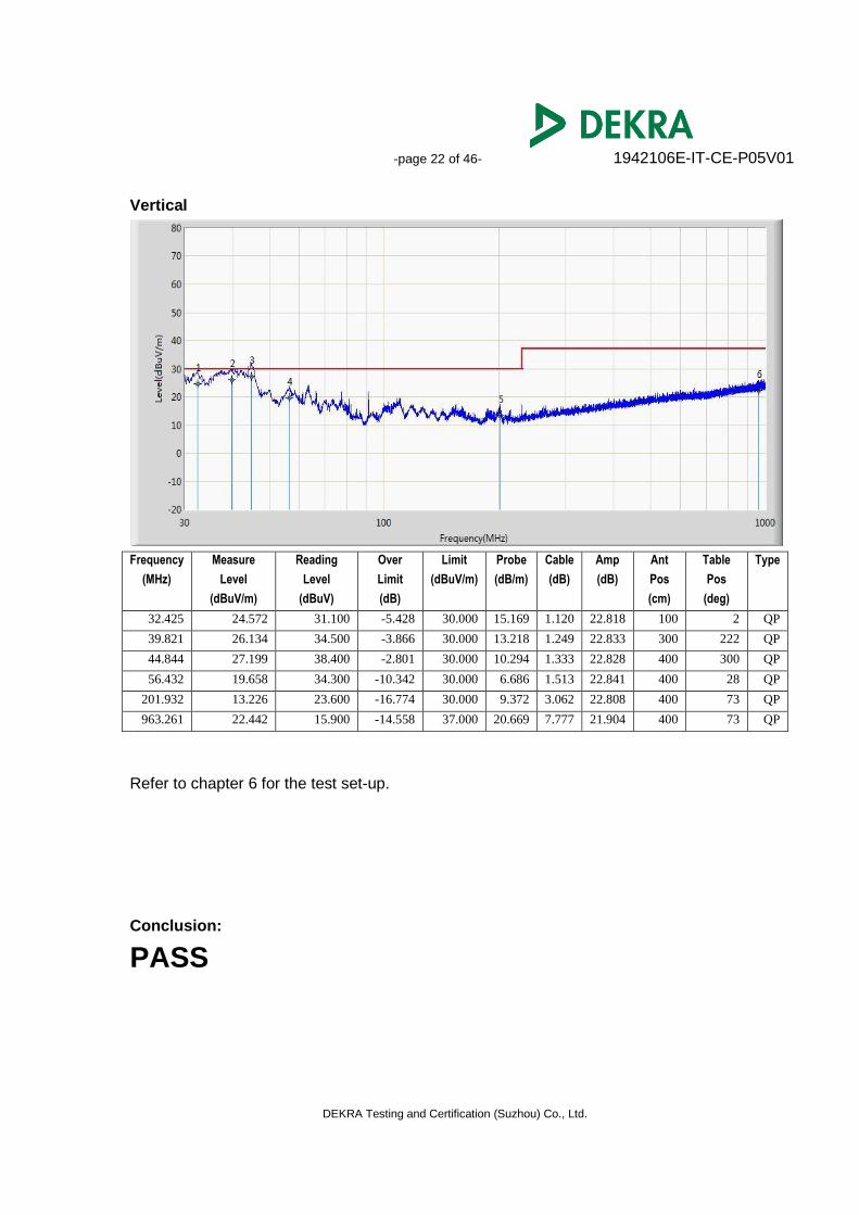
-page 22 of 46- 1942106E-IT-CE-P05V01
DEKRA Testing and Certification (Suzhou) Co., Ltd.
Vertical
Frequency
(MHz)
Measure
Level
(dBuV/m)
Reading
Level
(dBuV)
Over
Limit
(dB)
Limit
(dBuV/m)
Probe
(dB/m)
Cable
(dB)
Amp
(dB)
Ant
Pos
(cm)
Table
Pos
(deg)
Type
32.425 24.572 31.100 -5.428 30.000 15.169 1.120 22.818 100 2 QP
39.821 26.134 34.500 -3.866 30.000 13.218 1.249 22.833 300 222 QP
44.844 27.199 38.400 -2.801 30.000 10.294 1.333 22.828 400 300 QP
56.432 19.658 34.300 -10.342 30.000 6.686 1.513 22.841 400 28 QP
201.932 13.226 23.600 -16.774 30.000 9.372 3.062 22.808 400 73 QP
963.261 22.442 15.900 -14.558 37.000 20.669 7.777 21.904 400 73 QP
Refer to chapter 6 for the test set-up.
Conclusion:
PASS
-page 23 of 46- 1942106E-IT-CE-P05V01
DEKRA Testing and Certification (Suzhou) Co., Ltd.
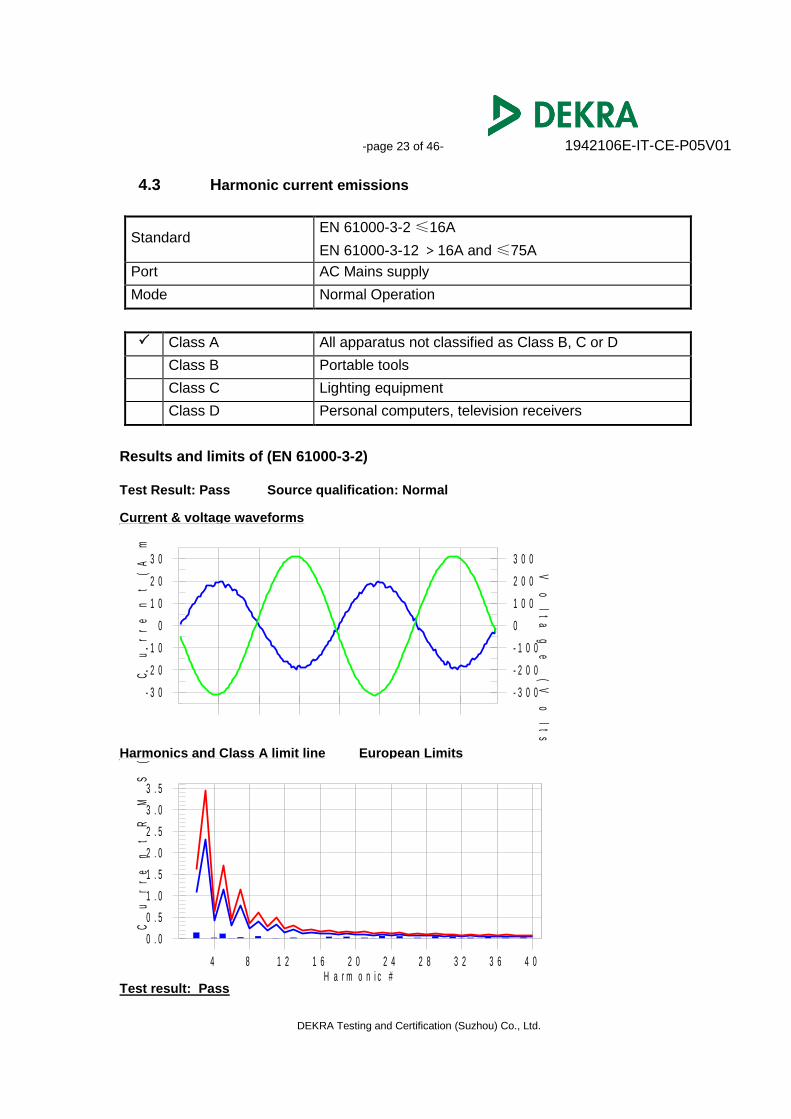
4.3 Harmonic current emissions
Standard EN 61000-3-2 ≤16A
EN 61000-3-12 >16A and ≤75A
Port AC Mains supply
Mode Normal Operation
Class A All apparatus not classified as Class B, C or D
Class B Portable tools
Class C Lighting equipment
Class D Personal computers, television receivers
Results and limits of (EN 61000-3-2)
Test Result: Pass Source qualification: Normal Current & voltage waveforms
- 3 0
- 2 0
- 1 0
0
1 0
2 0
3 0
- 3 0 0
- 2 0 0
- 1 0 0
0
1 0 0
2 0 0
3 0 0
Cu
rr
en
t
(A
mp
s)
Vo
lt
ag
e
(V
ol
ts
) Harmonics and Class A limit line European Limits
0 . 0
0 . 5
1 . 0
1 . 5
2 . 0
2 . 5
3 . 0
3 . 5
Cu
rr
en
t
RM
S(
Am
ps
)
H a r m o n i c #4 8 1 2 1 6 2 0 2 4 2 8 3 2 3 6 4 0
Test result: Pass
-page 24 of 46- 1942106E-IT-CE-P05V01
DEKRA Testing and Certification (Suzhou) Co., Ltd.
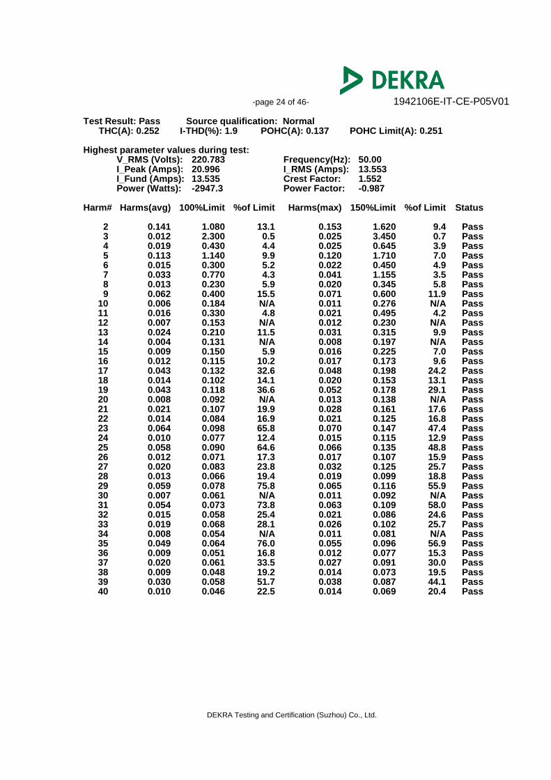
Test Result: Pass Source qualification: Normal THC(A): 0.252 I-THD(%): 1.9 POHC(A): 0.137 POHC Limit(A): 0.251 Highest parameter values during test:
V_RMS (Volts): 220.783 Frequency(Hz): 50.00 I_Peak (Amps): 20.996 I_RMS (Amps): 13.553 I_Fund (Amps): 13.535 Crest Factor: 1.552 Power (Watts): -2947.3 Power Factor: -0.987
Harm# Harms(avg) 100%Limit %of Limit Harms(max) 150%Limit %of Limit Status 2 0.141 1.080 13.1 0.153 1.620 9.4 Pass 3 0.012 2.300 0.5 0.025 3.450 0.7 Pass 4 0.019 0.430 4.4 0.025 0.645 3.9 Pass 5 0.113 1.140 9.9 0.120 1.710 7.0 Pass 6 0.015 0.300 5.2 0.022 0.450 4.9 Pass 7 0.033 0.770 4.3 0.041 1.155 3.5 Pass 8 0.013 0.230 5.9 0.020 0.345 5.8 Pass 9 0.062 0.400 15.5 0.071 0.600 11.9 Pass 10 0.006 0.184 N/A 0.011 0.276 N/A Pass 11 0.016 0.330 4.8 0.021 0.495 4.2 Pass 12 0.007 0.153 N/A 0.012 0.230 N/A Pass 13 0.024 0.210 11.5 0.031 0.315 9.9 Pass 14 0.004 0.131 N/A 0.008 0.197 N/A Pass 15 0.009 0.150 5.9 0.016 0.225 7.0 Pass 16 0.012 0.115 10.2 0.017 0.173 9.6 Pass 17 0.043 0.132 32.6 0.048 0.198 24.2 Pass 18 0.014 0.102 14.1 0.020 0.153 13.1 Pass 19 0.043 0.118 36.6 0.052 0.178 29.1 Pass 20 0.008 0.092 N/A 0.013 0.138 N/A Pass 21 0.021 0.107 19.9 0.028 0.161 17.6 Pass 22 0.014 0.084 16.9 0.021 0.125 16.8 Pass 23 0.064 0.098 65.8 0.070 0.147 47.4 Pass 24 0.010 0.077 12.4 0.015 0.115 12.9 Pass 25 0.058 0.090 64.6 0.066 0.135 48.8 Pass 26 0.012 0.071 17.3 0.017 0.107 15.9 Pass 27 0.020 0.083 23.8 0.032 0.125 25.7 Pass 28 0.013 0.066 19.4 0.019 0.099 18.8 Pass 29 0.059 0.078 75.8 0.065 0.116 55.9 Pass 30 0.007 0.061 N/A 0.011 0.092 N/A Pass 31 0.054 0.073 73.8 0.063 0.109 58.0 Pass 32 0.015 0.058 25.4 0.021 0.086 24.6 Pass 33 0.019 0.068 28.1 0.026 0.102 25.7 Pass 34 0.008 0.054 N/A 0.011 0.081 N/A Pass 35 0.049 0.064 76.0 0.055 0.096 56.9 Pass 36 0.009 0.051 16.8 0.012 0.077 15.3 Pass 37 0.020 0.061 33.5 0.027 0.091 30.0 Pass 38 0.009 0.048 19.2 0.014 0.073 19.5 Pass 39 0.030 0.058 51.7 0.038 0.087 44.1 Pass 40 0.010 0.046 22.5 0.014 0.069 20.4 Pass
-page 25 of 46- 1942106E-IT-CE-P05V01
DEKRA Testing and Certification (Suzhou) Co., Ltd.
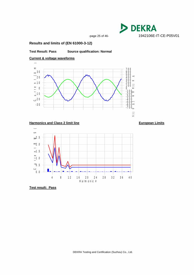
Results and limits of (EN 61000-3-12)
Test Result: Pass Source qualification: Normal Current & voltage waveforms
- 3 0
- 2 0
- 1 0
0
1 0
2 0
3 0
- 7 0 0- 6 0 0- 5 0 0- 4 0 0- 3 0 0- 2 0 0- 1 0 001 0 02 0 03 0 04 0 05 0 06 0 07 0 0
Cu
rr
en
t
(A
mp
s)
Vo
lt
ag
e
(V
ol
ts
) Harmonics and Class 2 limit line European Limits
0 . 0
0 . 5
1 . 0
1 . 5
2 . 0
2 . 5
Cu
rr
en
t
RM
S(
Am
ps
)
H a r m o n i c #4 8 1 2 1 6 2 0 2 4 2 8 3 2 3 6 4 0
Test result: Pass
-page 26 of 46- 1942106E-IT-CE-P05V01
DEKRA Testing and Certification (Suzhou) Co., Ltd.
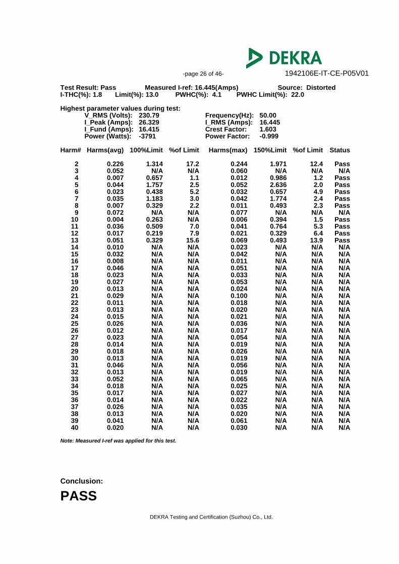
Test Result: Pass Measured I-ref: 16.445(Amps) Source: Distorted I-THC(%): 1.8 Limit(%): 13.0 PWHC(%): 4.1 PWHC Limit(%): 22.0 Highest parameter values during test:
V_RMS (Volts): 230.79 Frequency(Hz): 50.00 I_Peak (Amps): 26.329 I_RMS (Amps): 16.445 I_Fund (Amps): 16.415 Crest Factor: 1.603 Power (Watts): -3791 Power Factor: -0.999
Harm# Harms(avg) 100%Limit %of Limit Harms(max) 150%Limit %of Limit Status 2 0.226 1.314 17.2 0.244 1.971 12.4 Pass 3 0.052 N/A N/A 0.060 N/A N/A N/A 4 0.007 0.657 1.1 0.012 0.986 1.2 Pass 5 0.044 1.757 2.5 0.052 2.636 2.0 Pass 6 0.023 0.438 5.2 0.032 0.657 4.9 Pass 7 0.035 1.183 3.0 0.042 1.774 2.4 Pass 8 0.007 0.329 2.2 0.011 0.493 2.3 Pass 9 0.072 N/A N/A 0.077 N/A N/A N/A 10 0.004 0.263 N/A 0.006 0.394 1.5 Pass 11 0.036 0.509 7.0 0.041 0.764 5.3 Pass 12 0.017 0.219 7.9 0.021 0.329 6.4 Pass 13 0.051 0.329 15.6 0.069 0.493 13.9 Pass 14 0.010 N/A N/A 0.023 N/A N/A N/A 15 0.032 N/A N/A 0.042 N/A N/A N/A 16 0.008 N/A N/A 0.011 N/A N/A N/A 17 0.046 N/A N/A 0.051 N/A N/A N/A 18 0.023 N/A N/A 0.033 N/A N/A N/A 19 0.027 N/A N/A 0.053 N/A N/A N/A 20 0.013 N/A N/A 0.024 N/A N/A N/A 21 0.029 N/A N/A 0.100 N/A N/A N/A 22 0.011 N/A N/A 0.018 N/A N/A N/A 23 0.013 N/A N/A 0.020 N/A N/A N/A 24 0.015 N/A N/A 0.021 N/A N/A N/A 25 0.026 N/A N/A 0.036 N/A N/A N/A 26 0.012 N/A N/A 0.017 N/A N/A N/A 27 0.023 N/A N/A 0.054 N/A N/A N/A 28 0.014 N/A N/A 0.019 N/A N/A N/A 29 0.018 N/A N/A 0.026 N/A N/A N/A 30 0.013 N/A N/A 0.019 N/A N/A N/A 31 0.046 N/A N/A 0.056 N/A N/A N/A 32 0.013 N/A N/A 0.019 N/A N/A N/A 33 0.052 N/A N/A 0.065 N/A N/A N/A 34 0.018 N/A N/A 0.025 N/A N/A N/A 35 0.017 N/A N/A 0.027 N/A N/A N/A 36 0.014 N/A N/A 0.022 N/A N/A N/A 37 0.026 N/A N/A 0.035 N/A N/A N/A 38 0.013 N/A N/A 0.020 N/A N/A N/A 39 0.041 N/A N/A 0.061 N/A N/A N/A 40 0.020 N/A N/A 0.030 N/A N/A N/A Note: Measured I-ref was applied for this test.
Conclusion:
PASS
-page 27 of 46- 1942106E-IT-CE-P05V01
DEKRA Testing and Certification (Suzhou) Co., Ltd.
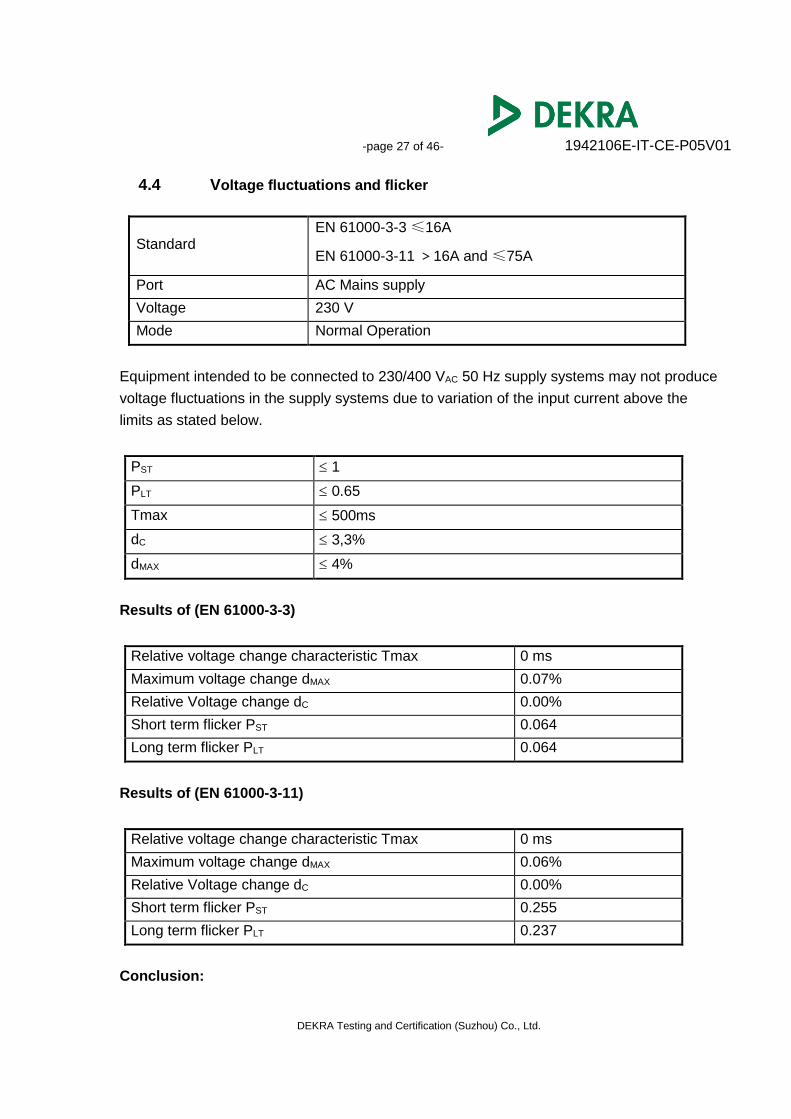
4.4 Voltage fluctuations and flicker
Standard EN 61000-3-3 ≤16A
EN 61000-3-11 >16A and ≤75A
Port AC Mains supply
Voltage 230 V
Mode Normal Operation
Equipment intended to be connected to 230/400 VAC 50 Hz supply systems may not produce
voltage fluctuations in the supply systems due to variation of the input current above the
limits as stated below.
PST 1
PLT 0.65
Tmax 500ms
dC 3,3%
dMAX 4%
Results of (EN 61000-3-3)
Relative voltage change characteristic Tmax 0 ms
Maximum voltage change dMAX 0.07%
Relative Voltage change dC 0.00%
Short term flicker PST 0.064
Long term flicker PLT 0.064
Results of (EN 61000-3-11)
Relative voltage change characteristic Tmax 0 ms
Maximum voltage change dMAX 0.06%
Relative Voltage change dC 0.00%
Short term flicker PST 0.255
Long term flicker PLT 0.237
Conclusion:
-page 28 of 46- 1942106E-IT-CE-P05V01
DEKRA Testing and Certification (Suzhou) Co., Ltd.
PASS
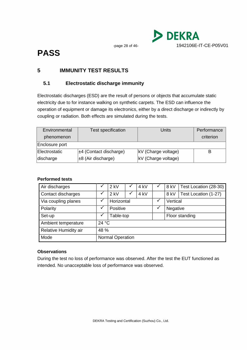
5 IMMUNITY TEST RESULTS
5.1 Electrostatic discharge immunity
Electrostatic discharges (ESD) are the result of persons or objects that accumulate static
electricity due to for instance walking on synthetic carpets. The ESD can influence the
operation of equipment or damage its electronics, either by a direct discharge or indirectly by
coupling or radiation. Both effects are simulated during the tests.
Environmental
phenomenon
Test specification Units Performance
criterion
Enclosure port
Electrostatic
discharge
±4 (Contact discharge)
±8 (Air discharge)
kV (Charge voltage)
kV (Charge voltage)
B
Performed tests
Air discharges 2 kV 4 kV 8 kV Test Location (28-30)
Contact discharges 2 kV 4 kV 8 kV Test Location (1-27)
Via coupling planes Horizontal Vertical
Polarity Positive Negative
Set-up Table-top Floor standing
Ambient temperature 24 °C
Relative Humidity air 48 %
Mode Normal Operation
Observations
During the test no loss of performance was observed. After the test the EUT functioned as
intended. No unacceptable loss of performance was observed.
-page 29 of 46- 1942106E-IT-CE-P05V01
DEKRA Testing and Certification (Suzhou) Co., Ltd.
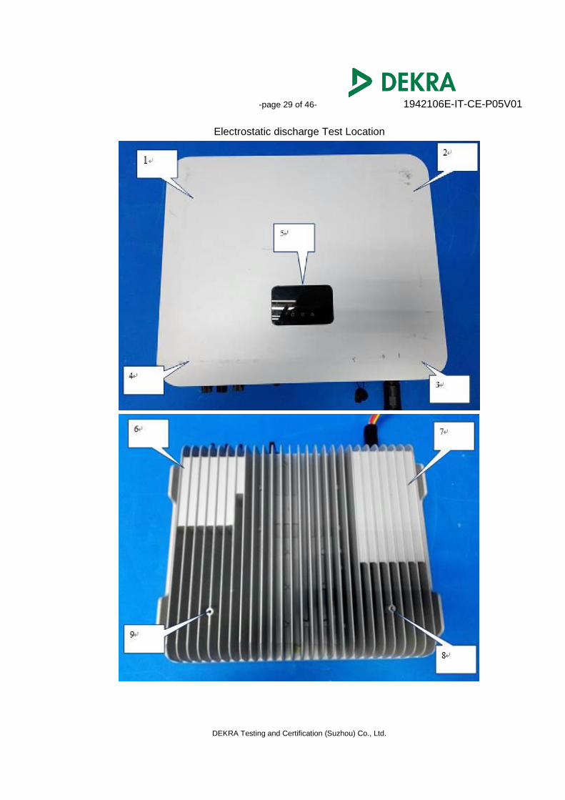
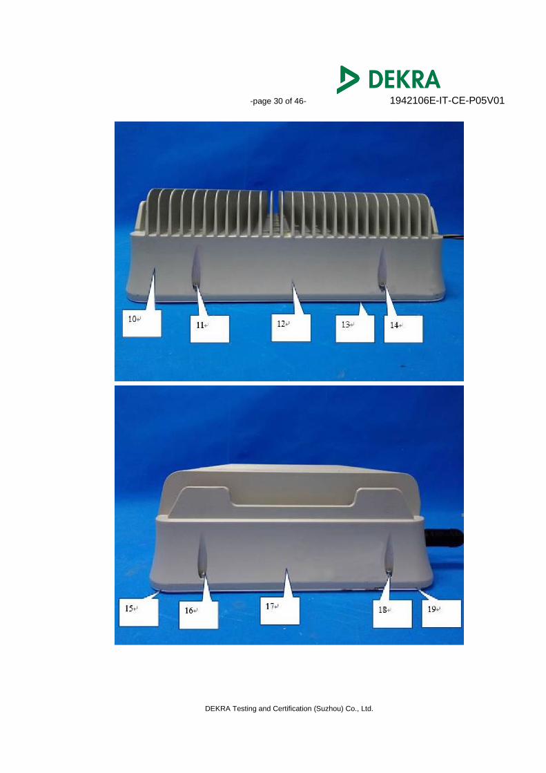
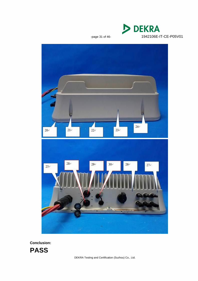
Electrostatic discharge Test Location
-page 30 of 46- 1942106E-IT-CE-P05V01
DEKRA Testing and Certification (Suzhou) Co., Ltd.
-page 31 of 46- 1942106E-IT-CE-P05V01
DEKRA Testing and Certification (Suzhou) Co., Ltd.
Conclusion:
PASS
-page 32 of 46- 1942106E-IT-CE-P05V01
DEKRA Testing and Certification (Suzhou) Co., Ltd.
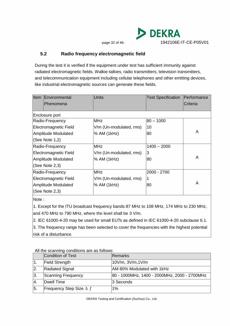
5.2 Radio frequency electromagnetic field
During the test it is verified if the equipment under test has sufficient immunity against
radiated electromagnetic fields. Walkie-talkies, radio transmitters, television transmitters,
and telecommunication equipment including cellular telephones and other emitting devices,
like industrial electromagnetic sources can generate these fields.
Item Environmental
Phenomena
Units Test Specification Performance
Criteria
Enclosure port
Radio-Frequency
Electromagnetic Field
Amplitude Modulated
(See Note 1,2)
MHz
V/m (Un-modulated, rms)
% AM (1kHz)
80 – 1000
10
80 A
Radio-Frequency
Electromagnetic Field
Amplitude Modulated
(See Note 2,3)
MHz
V/m (Un-modulated, rms)
% AM (1kHz)
1400 – 2000
3
80 A
Radio-Frequency
Electromagnetic Field
Amplitude Modulated
(See Note 2,3)
MHz
V/m (Un-modulated, rms)
% AM (1kHz)
2000 - 2700
1
80 A
Note :
1. Except for the ITU broadcast frequency bands 87 MHz to 108 MHz, 174 MHz to 230 MHz,
and 470 MHz to 790 MHz, where the level shall be 3 V/m.
2. IEC 61000-4-20 may be used for small EUTs as defined in IEC 61000-4-20 subclause 6.1.
3. The frequency range has been selected to cover the frequencies with the highest potential
risk of a disturbance.
All the scanning conditions are as follows:
Condition of Test Remarks
1. Field Strength 10V/m, 3V/m,1V/m
2. Radiated Signal AM 80% Modulated with 1kHz
3. Scanning Frequency 80 - 1000MHz, 1400 - 2000MHz, 2000 - 2700MHz
4. Dwell Time 3 Seconds
5. Frequency Step Size f 1%
-page 33 of 46- 1942106E-IT-CE-P05V01
DEKRA Testing and Certification (Suzhou) Co., Ltd.
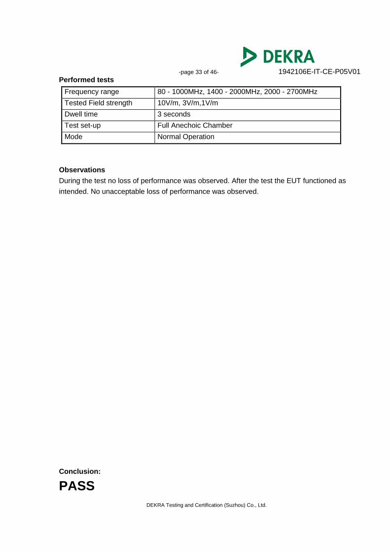
Performed tests
Frequency range 80 - 1000MHz, 1400 - 2000MHz, 2000 - 2700MHz
Tested Field strength 10V/m, 3V/m,1V/m
Dwell time 3 seconds
Test set-up Full Anechoic Chamber
Mode Normal Operation
Observations
During the test no loss of performance was observed. After the test the EUT functioned as
intended. No unacceptable loss of performance was observed.
Conclusion:
PASS
-page 34 of 46- 1942106E-IT-CE-P05V01
DEKRA Testing and Certification (Suzhou) Co., Ltd.
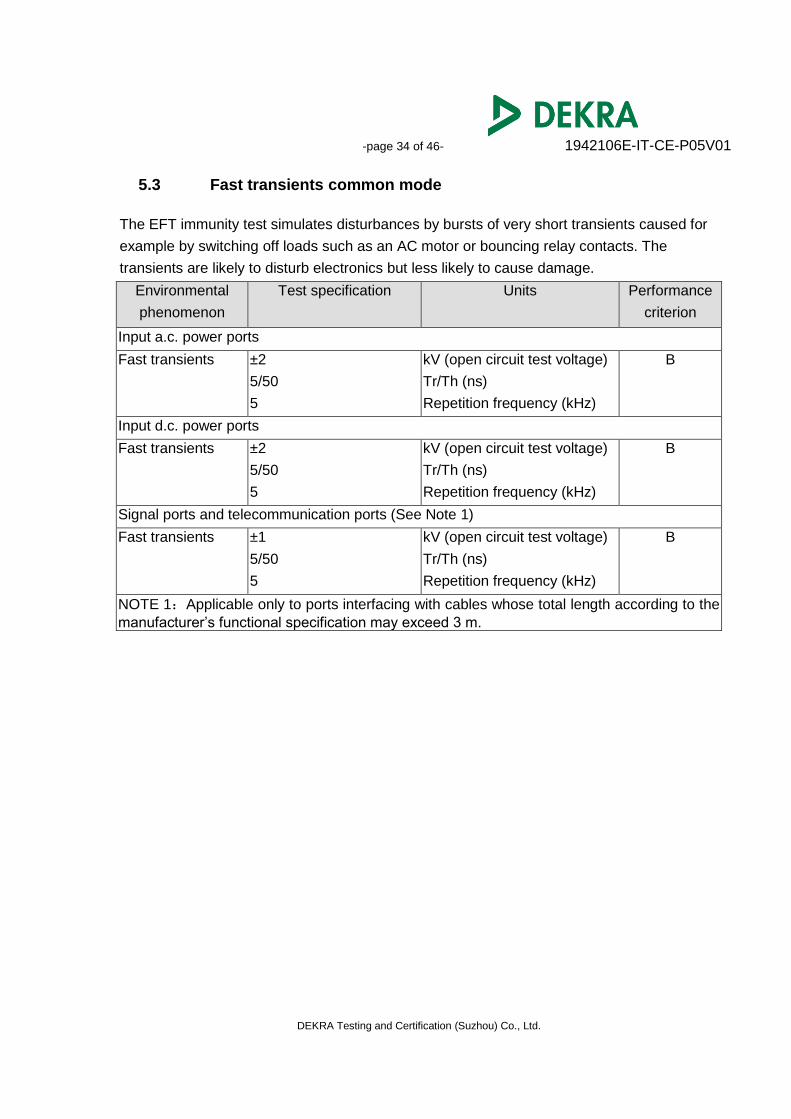
5.3 Fast transients common mode
The EFT immunity test simulates disturbances by bursts of very short transients caused for
example by switching off loads such as an AC motor or bouncing relay contacts. The
transients are likely to disturb electronics but less likely to cause damage.
Environmental
phenomenon
Test specification Units Performance
criterion
Input a.c. power ports
Fast transients ±2
5/50
5
kV (open circuit test voltage)
Tr/Th (ns)
Repetition frequency (kHz)
B
Input d.c. power ports
Fast transients ±2
5/50
5
kV (open circuit test voltage)
Tr/Th (ns)
Repetition frequency (kHz)
B
Signal ports and telecommunication ports (See Note 1)
Fast transients ±1
5/50
5
kV (open circuit test voltage)
Tr/Th (ns)
Repetition frequency (kHz)
B
NOTE 1:Applicable only to ports interfacing with cables whose total length according to the
manufacturer’s functional specification may exceed 3 m.
-page 35 of 46- 1942106E-IT-CE-P05V01
DEKRA Testing and Certification (Suzhou) Co., Ltd.
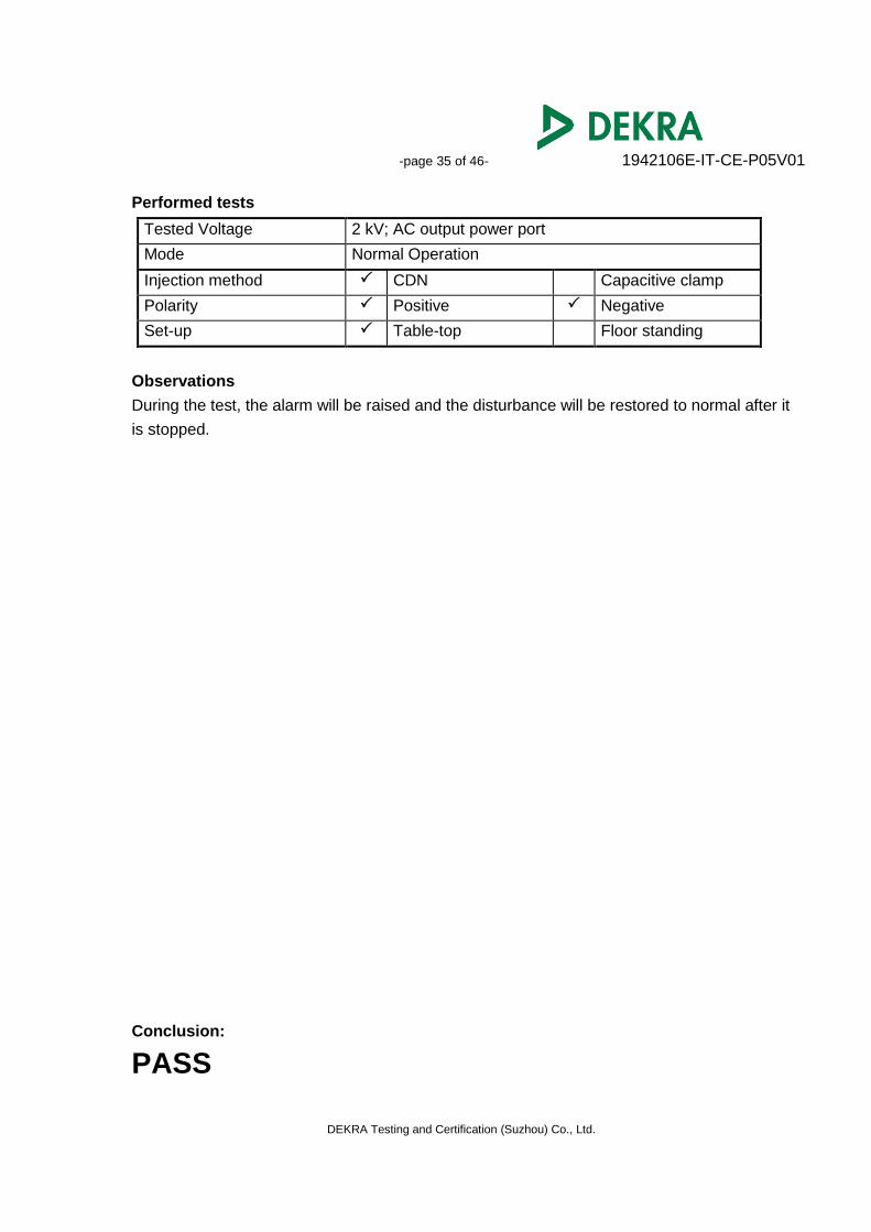
Performed tests
Tested Voltage 2 kV; AC output power port
Mode Normal Operation
Injection method CDN Capacitive clamp
Polarity Positive Negative
Set-up Table-top Floor standing
Observations
During the test, the alarm will be raised and the disturbance will be restored to normal after it
is stopped.
Conclusion:
PASS
-page 36 of 46- 1942106E-IT-CE-P05V01
DEKRA Testing and Certification (Suzhou) Co., Ltd.
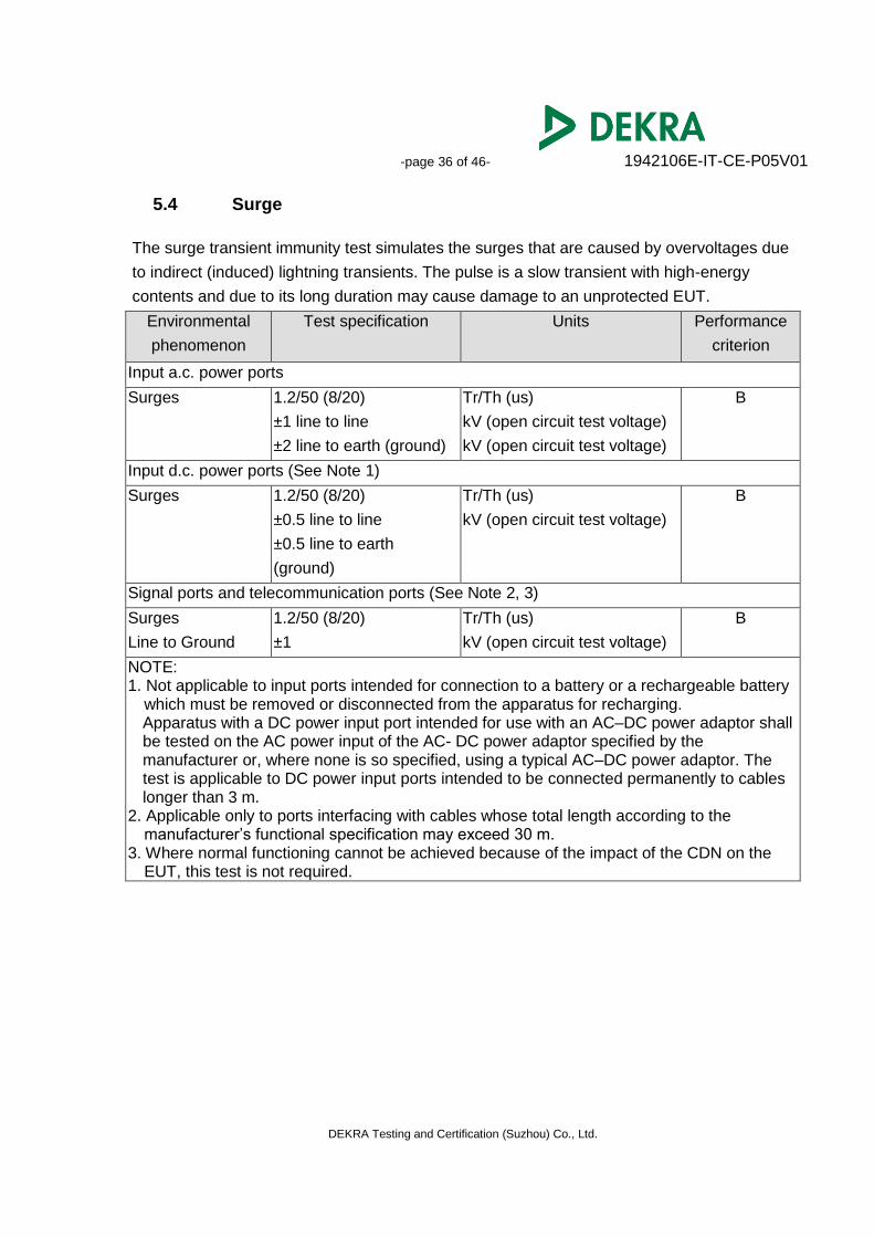
5.4 Surge
The surge transient immunity test simulates the surges that are caused by overvoltages due
to indirect (induced) lightning transients. The pulse is a slow transient with high-energy
contents and due to its long duration may cause damage to an unprotected EUT.
Environmental
phenomenon
Test specification Units Performance
criterion
Input a.c. power ports
Surges 1.2/50 (8/20)
±1 line to line
±2 line to earth (ground)
Tr/Th (us)
kV (open circuit test voltage)
kV (open circuit test voltage)
B
Input d.c. power ports (See Note 1)
Surges 1.2/50 (8/20)
±0.5 line to line
±0.5 line to earth
(ground)
Tr/Th (us)
kV (open circuit test voltage)
B
Signal ports and telecommunication ports (See Note 2, 3)
Surges
Line to Ground
1.2/50 (8/20)
±1
Tr/Th (us)
kV (open circuit test voltage)
B
NOTE: 1. Not applicable to input ports intended for connection to a battery or a rechargeable battery
which must be removed or disconnected from the apparatus for recharging. Apparatus with a DC power input port intended for use with an AC–DC power adaptor shall be tested on the AC power input of the AC- DC power adaptor specified by the manufacturer or, where none is so specified, using a typical AC–DC power adaptor. The test is applicable to DC power input ports intended to be connected permanently to cables longer than 3 m.
2. Applicable only to ports interfacing with cables whose total length according to the manufacturer’s functional specification may exceed 30 m.
3. Where normal functioning cannot be achieved because of the impact of the CDN on the EUT, this test is not required.
-page 37 of 46- 1942106E-IT-CE-P05V01
DEKRA Testing and Certification (Suzhou) Co., Ltd.
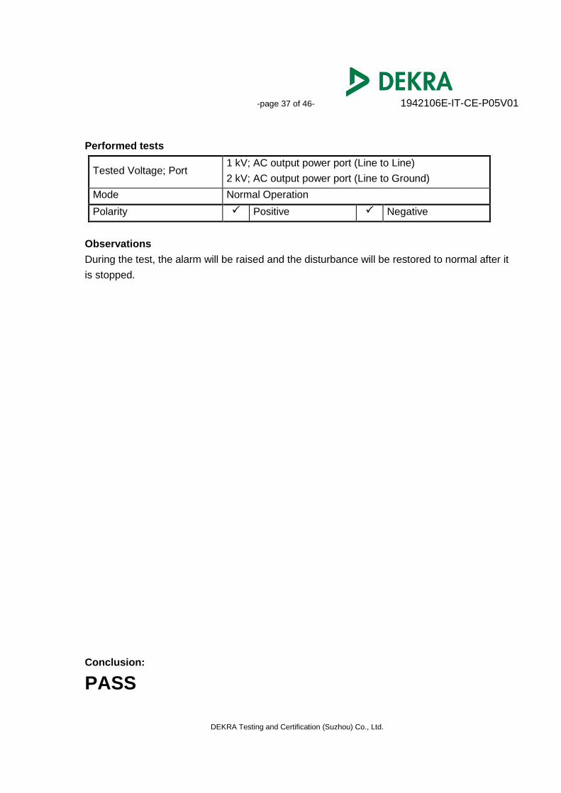
Performed tests
Tested Voltage; Port 1 kV; AC output power port (Line to Line)
2 kV; AC output power port (Line to Ground)
Mode Normal Operation
Polarity Positive Negative
Observations
During the test, the alarm will be raised and the disturbance will be restored to normal after it
is stopped.
Conclusion:
PASS
-page 38 of 46- 1942106E-IT-CE-P05V01
DEKRA Testing and Certification (Suzhou) Co., Ltd.
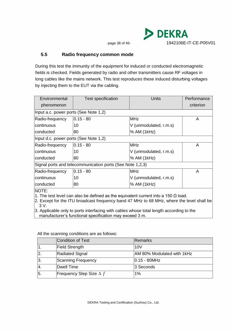
5.5 Radio frequency common mode
During this test the immunity of the equipment for induced or conducted electromagnetic
fields is checked. Fields generated by radio and other transmitters cause RF voltages in
long cables like the mains network. This test reproduces these induced disturbing voltages
by injecting them to the EUT via the cabling.
Environmental
phenomenon
Test specification Units Performance
criterion
Input a.c. power ports (See Note 1,2)
Radio-frequency
continuous
conducted
0.15 - 80
10
80
MHz
V (unmodulated, r.m.s)
% AM (1kHz)
A
Input d.c. power ports (See Note 1,2)
Radio-frequency
continuous
conducted
0.15 - 80
10
80
MHz
V (unmodulated, r.m.s)
% AM (1kHz)
A
Signal ports and telecommunication ports (See Note 1,2,3)
Radio-frequency
continuous
conducted
0.15 - 80
10
80
MHz
V (unmodulated, r.m.s)
% AM (1kHz)
A
NOTE: 1. The test level can also be defined as the equivalent current into a 150 Ω load. 2. Except for the ITU broadcast frequency band 47 MHz to 68 MHz, where the level shall be
3 V. 3. Applicable only to ports interfacing with cables whose total length according to the
manufacturer’s functional specification may exceed 3 m.
All the scanning conditions are as follows:
Condition of Test Remarks
1. Field Strength 10V
2. Radiated Signal AM 80% Modulated with 1kHz
3. Scanning Frequency 0.15 - 80MHz
4. Dwell Time 3 Seconds
5. Frequency Step Size f 1%
-page 39 of 46- 1942106E-IT-CE-P05V01
DEKRA Testing and Certification (Suzhou) Co., Ltd.
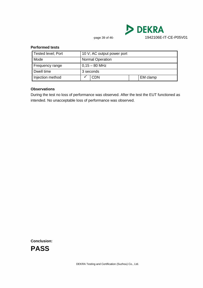
Performed tests
Tested level; Port 10 V; AC output power port
Mode Normal Operation
Frequency range 0,15 – 80 MHz
Dwell time 3 seconds
Injection method CDN EM clamp
Observations
During the test no loss of performance was observed. After the test the EUT functioned as
intended. No unacceptable loss of performance was observed.
Conclusion:
PASS
-page 40 of 46- 1942106E-IT-CE-P05V01
DEKRA Testing and Certification (Suzhou) Co., Ltd.
5.6 Power-frequency magnetic field
Environmental
phenomenon
Test specification Units Performance
criterion
Enclosure port(See Note 1,2)
Power-frequency
magnetic field
50,60
30
Hz
A/m (r.m.s)
A
NOTE: 1. Applicable only to apparatus containing devices susceptible to magnetic fields. 2. For CRTs, the acceptable jitter depends upon the character size and is calculated for a
test level of 1 A/m as follows:
where jitter J and character size C are in millimetres. As jitter is linearly proportional to the magnetic field strength, tests can be carried out at other test levels extrapolating the maximum jitter level appropriately.
Performed tests
Tested level 30 A/m
Mode Normal Operation
Frequency 50 Hz
Dwell time 60 seconds
Test Coil Position X Axis Y Axis Z Axis
Observations
During the test no loss of performance was observed. After the test the EUT functioned as
intended. No unacceptable loss of performance was observed.
Conclusion:
PASS
-page 41 of 46- 1942106E-IT-CE-P05V01
DEKRA Testing and Certification (Suzhou) Co., Ltd.
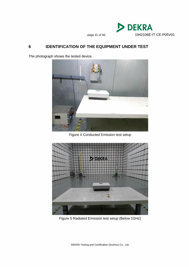
6 IDENTIFICATION OF THE EQUIPMENT UNDER TEST
The photograph shows the tested device.
Figure 4 Conducted Emission test setup
Figure 5 Radiated Emission test setup (Below 1GHz)

-page 42 of 46- 1942106E-IT-CE-P05V01
DEKRA Testing and Certification (Suzhou) Co., Ltd.
Figure 6 Harmonic current emission test setup
Figure 7 Voltage fluctuations and flicker test setup
-page 43 of 46- 1942106E-IT-CE-P05V01
DEKRA Testing and Certification (Suzhou) Co., Ltd.
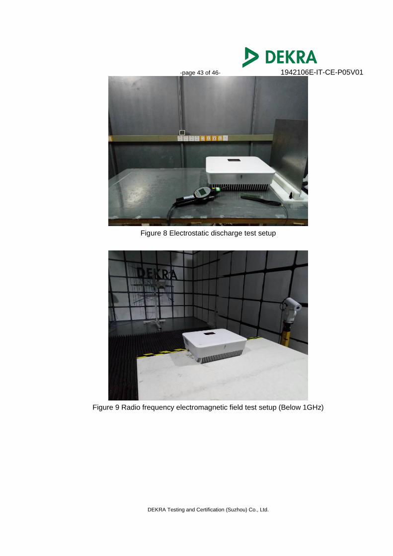
Figure 8 Electrostatic discharge test setup
Figure 9 Radio frequency electromagnetic field test setup (Below 1GHz)
-page 44 of 46- 1942106E-IT-CE-P05V01
DEKRA Testing and Certification (Suzhou) Co., Ltd.
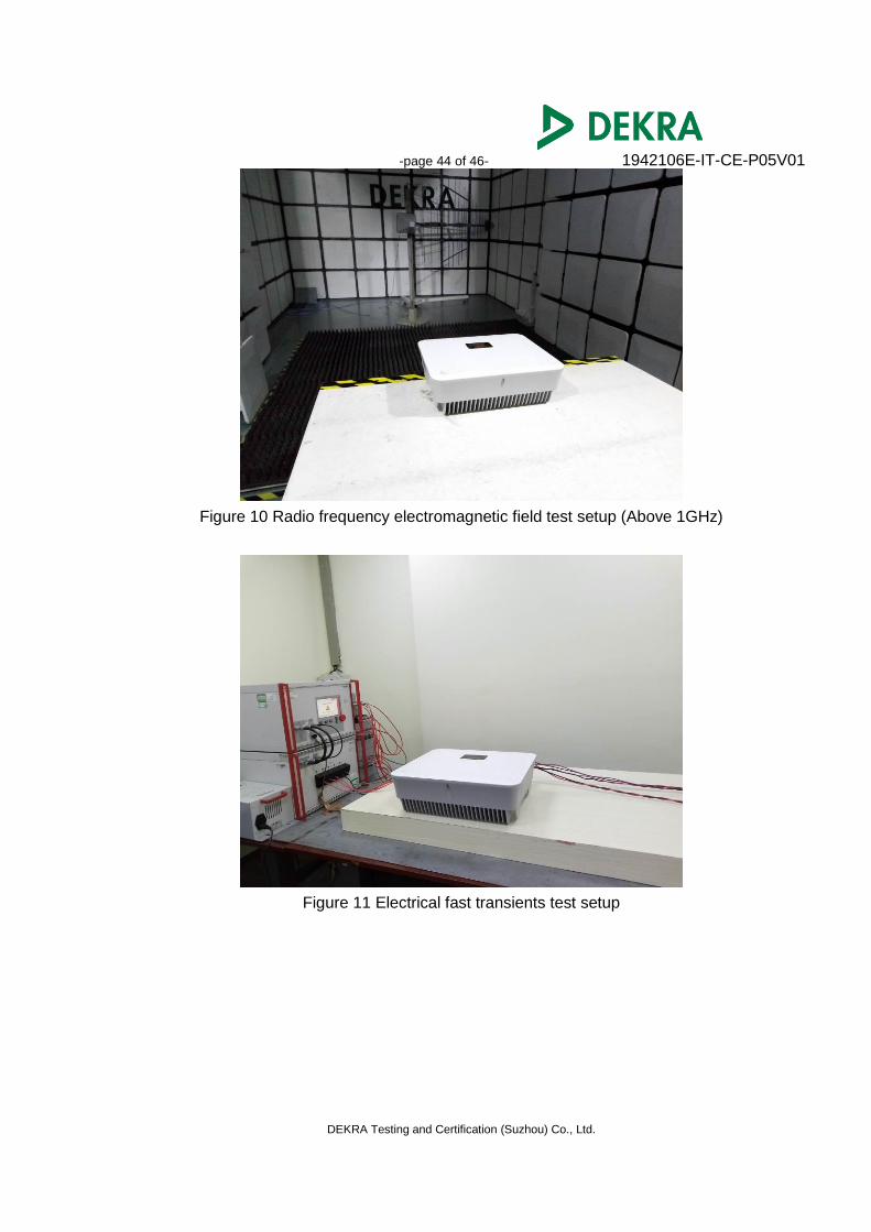
Figure 10 Radio frequency electromagnetic field test setup (Above 1GHz)
Figure 11 Electrical fast transients test setup
-page 45 of 46- 1942106E-IT-CE-P05V01
DEKRA Testing and Certification (Suzhou) Co., Ltd.
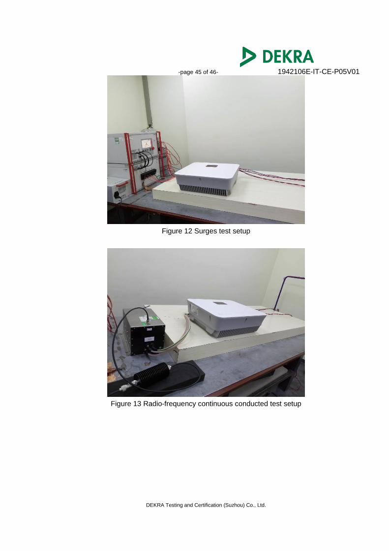
Figure 12 Surges test setup
Figure 13 Radio-frequency continuous conducted test setup
-page 46 of 46- 1942106E-IT-CE-P05V01
DEKRA Testing and Certification (Suzhou) Co., Ltd.
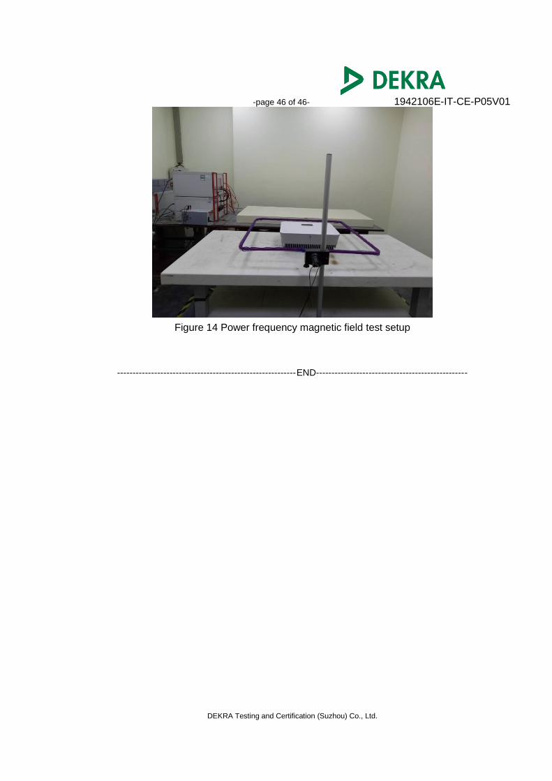
Figure 14 Power frequency magnetic field test setup
----------------------------------------------------------END-------------------------------------------------
Related Documents