SynCom SM-B1 SDH STM-1 MULTIPLEXER Technical Manual Release2.6 SynCom Network, Inc 4F, NO.31, HSINTAI ROAD, CHUPEI CITY, HSINCHU HSIEN, TAIWAN TEL:+886-3-553-0522 FAX:+886-3-553-0523 http://www.syncom.com.tw

Welcome message from author
This document is posted to help you gain knowledge. Please leave a comment to let me know what you think about it! Share it to your friends and learn new things together.
Transcript

8/20/2019 193440315-UM-SM-B1-V26
http://slidepdf.com/reader/full/193440315-um-sm-b1-v26 1/51
SynCom SM-B1 SDH STM-1 MULTIPLEXER
Technical Manual Release2.6
SynCom Network, Inc
4F, NO.31, HSINTAI ROAD, CHUPEI CITY, HSINCHU HSIEN, TAIWAN
TEL:+886-3-553-0522 FAX:+886-3-553-0523
http://www.syncom.com.tw

8/20/2019 193440315-UM-SM-B1-V26
http://slidepdf.com/reader/full/193440315-um-sm-b1-v26 2/51

8/20/2019 193440315-UM-SM-B1-V26
http://slidepdf.com/reader/full/193440315-um-sm-b1-v26 3/51
SynCom Network, Inc. Contents
Contents
Chapter 1 System Introduction & Applications...................................................................................................................1
1.1 System Introductions................................................................................................................................................1
1.2 System Specifications...............................................................................................................................................2
1.2.1 Optical Aggragate Interface.............................................................................................................................2
1.2.2 Tributary Interface...........................................................................................................................................2
1.2.3 Operations Interfaces.......................................................................................................................................3
1.2.4 Discrete Control & Alarm................................................................................................................................3
1.2.5 Timing Source Input & Output........................................................................................................................3
1.2.6 Mechanical.......................................................................................................................................................3
1.2.7 Operating Environment....................................................................................................................................4
1.2.8 Power Requirement..........................................................................................................................................4
1.3 Role Type..................................................................................................................................................................4
1.4 System Modes and Clock Source.............................................................................................................................4
1.4.1 Terminal Multiplexer (TM) Mode Application...............................................................................................5
1.4.2 Linear Add/Drop Multiplexer (LADM) Application.......................................................................................5
1.4.3 Multiplexer Section Protection (MSP) mode Application...............................................................................5
1.5 System Applications.................................................................................................................................................5
1.5.1 Point to Point Ring Application.......................................................................................................................6
1.5.2 Chain Application............................................................................................................................................6
1.5.3 Two Joint Chains Application..........................................................................................................................6
1.5.4 Self-Healing Ring (SHR) Applications............................................................................................................6
Chapter 2 Panel Descriptions...............................................................................................................................................8
2.1 Introductions.............................................................................................................................................................8
2.2 Front View of SM-B1...............................................................................................................................................8
2.2.1 System Control and System Status..................................................................................................................8
2.2.2 Transmission Status.........................................................................................................................................9
2.2.3 Optical Interfaces...........................................................................................................................................10
2.3 Back View of SM-B1.............................................................................................................................................10
2.3.1 Power Protection............................................................................................................................................112.3.2 Optical Auto Laser Shutdown........................................................................................................................11
2.4 FRONT ACCESS BOX..........................................................................................................................................11
Chapter 3 Operation, Administration & Provisioning (OAM&P)................................................................... ..................12
3.1 Overview.................................................................................................................................................................12
3.2 Operations Interfaces..............................................................................................................................................12
3.2.1 Graphical User Interface (GUI).....................................................................................................................12
3.2.2 DCC Interface................................................................................................................................................12
3.2.3 Push-Button, Transmission Status and E1 Status Indicators.........................................................................13
3.2.4 Office Alarms ................................................................................................................................................13
i

8/20/2019 193440315-UM-SM-B1-V26
http://slidepdf.com/reader/full/193440315-um-sm-b1-v26 4/51
SynCom Network, Inc. Contents
3.2.5 Discrete Environmental-Alarms ....................................................................................................................13
3.2.6 Equipment error performance .......................................................................................................................14
3.2.7 Orderwire Voice Interface (Optional)............................................................................................................14
3.3 Administration........................................................................................................................................................14
3.3.1 System Administration...................................................................................................................................14
3.3.1.1 Housekeeping........................................................................................................................................14
3.3.1.2 Administrative states ............................................................................................................................14
3.3.1.3 Operation states.....................................................................................................................................15
3.3.2 Memory Administration.................................................................................................................................15
3.3.2.1 Memory Backup and Restoration..........................................................................................................15
3.3.2.2 Data Manipulation.................................................................................................................................15
3.4 Maintenance............................................................................................................................................................15
3.4.1 Alarm Surveillance.........................................................................................................................................163.4.1.1 Failure States.........................................................................................................................................16
3.4.1.2 AIS: Alarm Indication Signaling...........................................................................................................16
3.4.1.3 FERF: Far End Receive Failure............................................................................................................17
3.4.1.4 Fault Detection, Isolation and Reporting..............................................................................................19
3.4.2 Performance Monitoring(PM)........................................................................................................................20
3.4.2.1 PM Parameters.......................................................................................................................................20
3.4.2.2 PM Data Collection and Initialization...................................................................................................22
3.4.2.3 Threshold Crossing Alerts (TCA).........................................................................................................22
3.4.3 Testing Capability..........................................................................................................................................23
3.4.3.1 Self Diagnostics Capability...................................................................................................................23
3.4.4 Loopback Test Capability..............................................................................................................................24
3.4.5 Control Features.............................................................................................................................................24
3.4.6 Optical Interface Manual Switch...................................................................................................................25
3.4.7 VC12 Path Protection Switching...................................................................................................................25
3.4.7.1 How to Enable Path Protection Switching............................................................................................25
3.4.7.2 How the Path Protection Switching is Made........................................................................................26
3.5 Provisioning............................................................................................................................................................26
3.5.1 Default Provisioning......................................................................................................................................26
3.5.2 Local and Remote Provisioning.....................................................................................................................26
Chapter 4 EM GUI System Introduction............................................................................................................................27
4.1 Overview.................................................................................................................................................................27
4.2 System Requirements..............................................................................................................................................27
4.3 Features...................................................................................................................................................................27
4.4 EM GUI Management Menu..................................................................................................................................27
4.5 The Network Topology Window and the NE Information Menu....................................................... ...................28
4.5.1 System ..........................................................................................................................................................29
4.5.2 Communication Control.................................................................................................................................33
ii

8/20/2019 193440315-UM-SM-B1-V26
http://slidepdf.com/reader/full/193440315-um-sm-b1-v26 5/51
SynCom Network, Inc. Contents
4.5.3 Cross Connection...........................................................................................................................................34
4.5.4 Protection.......................................................................................................................................................34
4.5.5 Alarm..............................................................................................................................................................34
4.5.6 PM.................................................................................................................................................................35
4.5.7 Administrate & Operation State.....................................................................................................................35
4.5.8 Download.......................................................................................................................................................36
4.5.9 Misc Tools......................................................................................................................................................36
4.6 Node Window.........................................................................................................................................................37
4.6.1 STM-1 Interface Operation............................................................................................................................37
4.6.2 E1 Interface Operation...................................................................................................................................37
4.7 Command Report Window...............................................................................................................................38
4.8 Automatic Alarm report Toolbar............................................................................................................................38
Chapter 5 Installation Guide...............................................................................................................................................415.1 Overview.................................................................................................................................................................41
5.2 General Installation.................................................................................................................................................41
5.2.1 Environment Check and Preparation.............................................................................................................41
5.2.1.1 Required Power Supply.........................................................................................................................41
5.2.1.2 Power-on Procedure..............................................................................................................................41
5.2.2 E1/T1 Port Connection...................................................................................................................................41
5.2.3 Operations Interface Installation....................................................................................................................42
5.2.3.1 Craft Interface Device (CID) Installation..............................................................................................42
5.2.4 Environmental Alarms Monitors and External Controls Installation............................................................42
5.2.5 External Timing I/O and User Byte I/O.........................................................................................................43
5.2.6 Fiber connection between COT and RT........................................................................................................43
5.2.6.1 Optical Fiber Housing...........................................................................................................................44
5.3 The Basic Parameter Setting for SM-B1 by EM GUI............................................................................................44
5.3.1 GUI serial port connection.............................................................................................................................44
5.3.1.1 Serial Communication Port Set-up .......................................................................................................44
5.3.1.2 Login EM(GUI).....................................................................................................................................44
5.3.2 More Operations of the EM GUI...................................................................................................................45
iii

8/20/2019 193440315-UM-SM-B1-V26
http://slidepdf.com/reader/full/193440315-um-sm-b1-v26 6/51

8/20/2019 193440315-UM-SM-B1-V26
http://slidepdf.com/reader/full/193440315-um-sm-b1-v26 7/51
SynCom Network, Inc SM-B1
Chapter 1 System Introduction & Applications
1.1 System IntroductionsThe SM-B1series is part of the SynCom SDH SM series products. The name of the SM stands for SDH Multiplexer, whereas “-B1” means the Box type that supports high-speed interface, STM-1.The basic type, SM-B1 is a SDH multiplexer equipped with two STM-1 optical aggregate interfacesand 8/16/21/42/63 2.048 Mbit/s tributary interfaces (It is also referred to as 2Mbit/s, 2M, or E1interchangeably throughout this or other relevant documents.). An enhanced version, SM-B1 Plus, provides more choices: (1) to increase the number of E1 tributary interfaces up to 63; or (2) to provide T1 tributary interfaces as well as E1 interfaces. Note that internally each T1 signal isembedded in an E1 signal. The hierarchical structure employed in SM-B1 series for multiplexing E1tributary into STM-1 is compliant with ITU-T G.707 as shown in the figure below.
Container (C) Tributary Unit Group (TUG)
Virtual Container (VC) Administrative (AU)
Tributary Unit (TU) Administrative Unit Group (AUG)
Figure1-1 Multiplexing Structure
As shown in the picture below, the SM-B1 enclosure is a stand-alone entity with two front accessoptical interfaces. Interfaces to low speed signals, office power, and operation interfaces can beaccessed from the back. This design is so that the SM-B1 system is constructed in a compact form.The mechanical structure is so compact that it can be used as a desktop unit. It can be easily fit into acabinet without taking much space. It can also be mounted in a standard 19-inch wide rack. The SM-B1series can be field programmed as a standard SDH Terminal Multiplexer (TM), a Linear Add/Drop Multiplexer (LADM), or an Optical Regenerator (OR) using the same unit.
The SM-B1series provides the following management functions: fault management, performance
management, configuration management, and security management. It also supports centralizednetwork management. With SynCom Element Manager; multiple SM series subnetworks can bemanaged from a central office.
The SM-B1 series supports a complete operations interface that is consistent with theTelecommunication Management Network (TMN) concept (ITU-T Recommendation M.3010) andthe requirements of the SDH Management (ITU-T Rec. G.784). Being one of the SynCom SDHseries products, the SM-B1 series works seamlessly with other SynCom SDH SM series products:SM-M1, SM-M4, SM-B16, and the SynCom Element Manager: EM, etc.
In the subsequent clauses, "SM-B1" is used for both SM-B1 and SM-B1 Plus models. Only whenfeatures for a specific model are unavailable in the other, the specific model will be mentioned.
1
STM-N AUG AU-4
AU-3
VC-4
VC-3
TUG-3 TU-3 VC-3
TUG-2 TU-2 VC-12
C-4
C-3
C-12
N139 264 kbit/s
44 736 kbit/s
34 368 kbit/s
2048 kbit/s
Pointer processing
Multiplexing
Aligning
Mapping
Multiplexing Structure

8/20/2019 193440315-UM-SM-B1-V26
http://slidepdf.com/reader/full/193440315-um-sm-b1-v26 8/51
SynCom Network, Inc SM-B1
1.2 System Specifications
This clause describes the system specifications.
1.2.1 Optical Aggragate Interface
The two optical interfaces are of the STM-1 data rate and compliant with Rec. G.957 and G.958.
Data Rate...............................................................155.520 Mbit/s + 20ppm
Source....................................................................MLM LD
Minimum Output...................................................-12 ~ -8 dBm
(Other power budget are available depending upon request.)
Wavelength...........................................................1310 + 30nm (1550nm optional)
Line Code..............................................................Scrambled NRZ
Fiber Type.............................................................single mode
Detector Type........................................................PIN-FET
Minimum Sensitivity.............................................-34 ~ -30 dBm
Min. Extinction Ratio............................................10 dB
System Gain..........................................................21/28 dB (short haul/long haul)As a convention, the two optical interfaces of each SM-B1 are named East STM-1 and West STM-1.We will refer to the optical interface as such in the subsequent clauses and other relevant documents.
1.2.2 Tributary Interface
The tributary interface complies with the ITU-T Rec. 703.
SM-B1
E1 tributaries.........................................................8/16/21 channels/ per unit
Data Rate...............................................................2.048 Mbit/s + 50ppm
Line Code..............................................................HDB3 (G.703)
Line Impedance.....................................................75/120 ohms (G.703)
Jitter performance..................................................ITU-T G.823
SM-B1 Plus mode
E1 tributaries
Data Rate...............................................................2.048 Mbit/s + 50ppm
Line Code..............................................................HDB3 (G.703)
Line Impedance.....................................................75/120 ohms (G.703)
Jitter performance..................................................ITU-T G.823
2

8/20/2019 193440315-UM-SM-B1-V26
http://slidepdf.com/reader/full/193440315-um-sm-b1-v26 9/51
SynCom Network, Inc SM-B1
E3 tributaries
Data Rate...............................................................34,368Kbit/s±20ppm (G.703)
Line Code..............................................................HDB3 (G.703)
Line Impedance.....................................................75ohms(G.703)T1 tributaries
Data Rate...............................................................1.544 Mbit/s + 50ppm
Line Code..............................................................B8ZS/AMI field selectable
Line Impedance.....................................................100 ohms
T3 tributaries
Data Rate...............................................................44,736Kbit/s±20ppm (G.703)
Line Code..............................................................B3ZS (G.703)
Line Impedance.....................................................75ohms (G.703)
Capacity
Models provided are as follows:
63/42/21/16/8 E1 channels per unit
4/8/16/21E1 and 1/2/3 E3/T3/T1 channels per unit
22 E1 and 20 T1 channels per unit
6 E1 and 2 T1 channels per unit
1.2.3 Operations Interfaces
The operation interfaces mostly follows the requirements in ITU-T Rec. G.773. However, theapplication layer message is proprietary. The management operation complies with the requirements
in ITU-T G.784.
OSS interface........................................................LAN
Local craft interface..............................................V.28, 38400 bit/s
NE/NE interface....................................................DCC, G.773, QB1
1.2.4 Discrete Control & Alarm
Office Alarms / External Control..........................major/minor (visual/audible)
Environment Alarms.............................................8
1.2.5 Timing Source Input & Output
Input......................................................................2.048MHz
Square Wave.........................................................2.048MHz data (75/120 Ohms)
Output....................................................................2.048Mb/s, framed all one
1.2.6 Mechanical
Box Size
1U (SM-B1)
Height....................................................................43mm (1.69 inches)
Width.....................................................................438mm (17.24 inches)
Depth.....................................................................244mm (9.6 inches)
3

8/20/2019 193440315-UM-SM-B1-V26
http://slidepdf.com/reader/full/193440315-um-sm-b1-v26 10/51
SynCom Network, Inc SM-B1
1.5U (SM-B1 Plus)
Height....................................................................64.5mm (2.54 inches)
Width.....................................................................438mm (17.24 inches)
Depth.....................................................................244mm (9.6 inches)Interfaces (connector)
STM-1...................................................................FC/PC
E1/T1.....................................................................DB-37
E3/T3.....................................................................BNC
CIT........................................................................DB-9
LAN.......................................................................RJ-45
Order wire Interface..............................................RJ-11
Timing I/O & User Byte I/O.................................DB-9
Environment Alarm...............................................DB-9
Office Alarm / External Control...........................DB-9
Power.....................................................................Screw lug
1.2.7 Operating Environment
Temperature Range...............................................-10oC ~ 65oC
Humidity................................................................up to 95% without condensation
1.2.8 Power Requirement
Input Voltage.........................................................AC:110V~220V ; DC:-42V~-56V
Power Consumption..............................................< 35 watt
1.3 Role Type
Each SM-B1 has a defined role in an SDH system application. Two roles are defined in currentapplications:
Central Office Terminal (COT); and
Remote Terminal (RT).
The role type is field programmable. The COT is similar to the Gateway Network Element (GNE)defined in ITU-T Rec. G.784. It acts as the gateway between the Network Elements (NEs) in thesubnetwork and the EM/GUI. The significance of the role type is that certain commands are allowedat the COT only. The details are described in CHAPTER 3 “Operation, Administration &
Provisioning (OAM&P)”.
1.4 System Modes and Clock Source
The SM-B1 can be field programmed into the following modes to support various applications. Theselectable system modes are as the following:
Terminal Multiplexer (TM) mode;
Linear Add/Drop Multiplexer (LADM) mode;
Two (independent) Terminal Multiplexers (2xTM) mode; and
Multiplexer Section Protection (MSP) mode.
The first two modes listed above are standard SDH STM-1 mode. When an SM-B1 is programmed as
4

8/20/2019 193440315-UM-SM-B1-V26
http://slidepdf.com/reader/full/193440315-um-sm-b1-v26 11/51
SynCom Network, Inc SM-B1
a TM, only one STM-1 will be active (working STM-1 is user configurable). When an SM-B1 is programmed as a 2xTM, it acts as if it houses two back-to-back TMs in one enclosure. The two TMsshare the same internal (free-run) clock source.
1.4.1 Terminal Multiplexer (TM) Mode Application
The SM-B1 may be deployed as a Terminal Multiplexer. It supports a point-to-point application if itis connected with another TM that could be an SM-M1 or an SM-B1.
The SM-B1 may be deployed as a TM when it is an end node in either a point-to-point or a chainconfiguration as Figure 1-2. When it is assigned as a TM, user can select West or East STM-1 to beactive.
SM-B1 provides many clock timing sources for network synchronization. They are: east optical linetiming, west optical line timing, external clock input timing (2.048Mbps or 2.048MHz), tributaryE1/T1/E3/T3 (optional) timing, and internal timing. The internal timing comes from an oscillator with ±4.6ppm accuracy. The user can set the priority and the sequence of timing sources for clock switching in case the current source does not work. The switching is done automatically by system. If all the clock sources fail, SM-B1 will go into holdover mode with stable clock for 24 hours at least.
Figure1-2 SM-B1 as TM
1.4.2 Linear Add/Drop Multiplexer (LADM) Application
The SM-B1 may be configured as a Linear Add/Drop Multiplexer (LADM). The SM-B1 provides aflexible, cost-effective solution for access network. The LADM SM-B1 is ideally suited for low-
density routes that primarily transport 2Mbit/s traffic.The clock source of a LADM SM-B1 is automatically assigned by the system and is generated fromTGU. TGU is optional and if TGU is absent, only through mode timing can be selected for LADMapplication. The SM-B1 is assigned as LADM as an intermediate node in a chain, a ring as Figure 1-3.
Figure1-3 SM-B1 as LADM
1.4.3 Multiplexer Section Protection (MSP) mode Application
The SM-B1 may be configured as MSP when the system application is the point-to-point ringtopology. Both two nodes should be set as MSP mode.
As SM-B1 is configured as MSP mode, the low speed interface will always switch follow the high-speed interface.
1.5 System Applications
5
SM-B1 SM-B1E1/E3/
T1/T3
E1/E3/
T1/T3
SM-B1 SM-B1
E1/E3/
T1/T3
E1/E3/
T1/T3
LADMLADM
8/20/2019 193440315-UM-SM-B1-V26
http://slidepdf.com/reader/full/193440315-um-sm-b1-v26 12/51
SynCom Network, Inc SM-B1
In each applications described below, the SynCom SDH products: SM-B1 and SM-M1; forms asubnetwork. Each subnetwork shall contain one COT and one or multiple RTs.
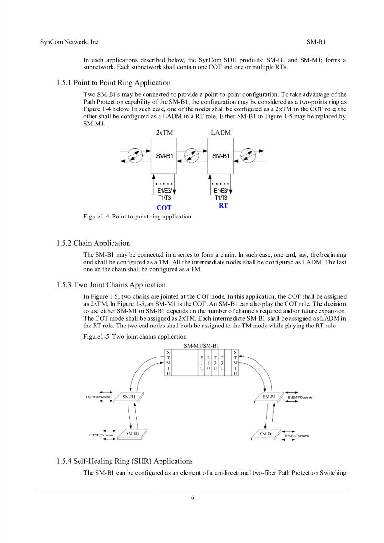
1.5.1 Point to Point Ring Application
Two SM-B1's may be connected to provide a point-to-point configuration. To take advantage of thePath Protection capability of the SM-B1, the configuration may be considered as a two-points ring asFigure 1-4 below. In such case, one of the nodes shall be configured as a 2xTM in the COT role; theother shall be configured as a LADM in a RT role. Either SM-B1 in Figure 1-5 may be replaced bySM-M1.
Figure1-4 Point-to-point ring application
1.5.2 Chain Application
The SM-B1 may be connected in a series to form a chain. In such case, one end, say, the beginningend shall be configured as a TM. All the intermediate nodes shall be configured as LADM. The lastone on the chain shall be configured as a TM.
1.5.3 Two Joint Chains ApplicationIn Figure 1-5, two chains are jointed at the COT node. In this application, the COT shall be assignedas 2xTM. In Figure 1-5, an SM-M1 is the COT. An SM-B1 can also play the COT role. The decisionto use either SM-M1 or SM-B1 depends on the number of channels required and/or future expansion.The COT mode shall be assigned as 2xTM. Each intermediate SM-B1 shall be assigned as LADM inthe RT role. The two end nodes shall both be assigned to the TM mode while playing the RT role.
Figure1-5 Two joint chains application
1.5.4 Self-Healing Ring (SHR) Applications
The SM-B1 can be configured as an element of a unidirectional two-fiber Path Protection Switching
6
COT RT
SM-B1 SM-B1
E1/E3/T1/T3
E1/E3/T1/T3
LADM2xTM
S
T
M
1
U
E
1
U
E
1
U
T
3
U
T
3
U
S
T
M
1
U
SM-B1
SM-B1
SM-B1
SM-B1
SM-M1/SM-B1
E1/E3/T1/T3 channels
E1/E3/T1/T3 channels E1/E3/T1/T3 channels
E1/E3/T1/T3 channels

8/20/2019 193440315-UM-SM-B1-V26
http://slidepdf.com/reader/full/193440315-um-sm-b1-v26 13/51
SynCom Network, Inc SM-B1
Ring (PPSR). The ring topology couples with the SM-B1 Path Protection Self-Healing capabilityenables the SDH subnetwork to overcome signal failure, node failure, or fiber cut.
In Figure 1-6, an SM-M1 is the COT. An SM-B1 can also play the COT role. All other SM-B1 onthe ring shall be assigned as LADM in the RT role. If a fiber cut occurs at one point of the ring, the
traffic will be re-routed at the path level without bit errors.Figure1-6 SM-B1 PPSR application with the SM-M1
7
S
T
M
1
U
E
1
U
E
1
U
T
3
U
T
3
U
S
T
M
1
U
SM-B1
SM-B1
SM-B1
SM-B1
SM-M1/SM-B1
E1/E3/T1/T3 channels
E1/E3/T1/T3 channels E1/E3/T1/T3 channels
E1/E3/T1/T3 channels

8/20/2019 193440315-UM-SM-B1-V26
http://slidepdf.com/reader/full/193440315-um-sm-b1-v26 14/51
SynCom Network, Inc SM-B1
Chapter 2 Panel Descriptions
2.1 IntroductionsThis chapter describes the panels of the SM-B1. A SM-B1 has a Front panel and a back panel.
2.2 Front View of SM-B1
Figure2-1 the front view of SM-B1
Figure2-2 the front view of SM-B1 Plus with E1/T1 interface
Figure2-3 the front view of SM-B1 Plus with E1/T1/E3/T3 interface
2.2.1 System Control and System Status
The system control part includes two push-buttons: RESET and ACO (Alarm Cut Off) and variousaccessible ports.
Buttons
RESET button: Pushing the RESET button will cause the system software be restarted.
ACO button: The user may use this button to silence the audible alarm.
Port
OW: RJ11 is provided to transmit OW signal. (Optional)
LAN port: RJ45 is provided for accessing GUI data on the node.
L/LAN port: RJ45 is provided for accessing GUI data on the local node. (Optional)
R/LAN port: RJ45 is provided for accessing GUI data on the remote node. (Optional)
The system status indicators include three LEDs: WORK/FAIL (of the equipment), MAJOR/MINOR (alarm status of the overall system), and ACO status. They are described as below.
WORK/FAIL LED
8
211713
2016
9
12
5
8
1
4
OW
E1 STATUS
OW LAN ACORESETWORKMAJOREW
OP
MINOR FAIL
SM-B1
EAST
RXTXRXTX
WEST
- E1 LINE
OW
SM-B1 Plus
OW LAN ACORESETWORKMAJOREW
MINOR FAIL
EAST
RXTXRXTX
WEST View in the fiber cover
- E1 WORK/FAIL
- T1 LINE
- T1 WORK/FAIL
ExtOWOW ACORESETWORKMAJOREW
MINOR FAIL
EAST
RXTXRXTX
WEST View in the fiber cover
SM-B1 Plus
R/LAN L/LAN E1 E3/DS3

8/20/2019 193440315-UM-SM-B1-V26
http://slidepdf.com/reader/full/193440315-um-sm-b1-v26 15/51
SynCom Network, Inc SM-B1
GREEN: the system is working properly
RED: A permanent RED light indicates that the system fails, or data base mismatches.
MAJOR/MINOR LED
OFF: In an alarm-free state, this LED should be OFF.RED: the system is in MAJOR alarm state.
AMBER: the system is in MINOR alarm state.
ACO LED
OFF: normal state;
AMBER: system is in the audible alarm cut-off state.
2.2.2 Transmission Status
LEDs indicate the transmission status of two high-speed lines (STM-1) and that of the E1/T1tributaries. The meanings of various displays are described below. SM-B1 provides 21 E1 LEDs, one
for each E1 line. SM-B1 Plus with E1/T1 model provides 4 LEDs: E1 Line, E1 Work/Fail, T1 Line,and T1 Work/Fail. For the SM-B1 Plus case, user is expected to use the EMS or CIT to further identify the specific tributary lines.
EAST/WEST STM1 LEDs
two LEDs indicate status of EAST STM-1, and WEST STM-1, respectively.
OFF: the optical transmitter and receiver on the east/west side have been disabled;
GREEN: the optical transmitter and receiver are working fine and in alarm-free state
RED: there are alarm(s) of the higher-order path (OPTICAL, RS, MS, VC4) on the east/west side.
E1 LEDs (SM-B1)
OFF: the corresponding E1 port is not in use (No TSA at all)
GREEN: the corresponding E1 port is in use (with TSA) and in alarm-free state
RED: Either the E1 LOS alarm or the corresponding TU12 related alarms occur.
E1/T1 Work/Fail LED (SM-B1 Plus with E1/T1 model)
OFF: all E1/T1 lines are not used.(no any TSA)
GREEN: at least one E1/T1 is used and no alarms happen on that E1/T1.
RED: at least one E1/T1 has alarms.
There are three LED on the panel of SM-B1 Plus with E1/T1/E3/T3
Ext LED (SM-B1 Plus with E1/T1/E3/T3)
OFF: all lines in the ext. board are not used.(no any TSA)
GREEN: at least one line in the ext. board is used and no alarms happen.
RED: at least one line has alarms.
E1 LED (SM-B1 Plus with E1/T1/E3/T3)
OFF: all E1 lines are not used.(no any TSA)
GREEN: at least one E1 is used and no alarms happen on that E1.
RED: at least one E1 has alarms.
E3/DS3 LED (SM-B1 Plus with E1/T1/E3/T3)
OFF: all E3/T3 lines are not used.(no any TSA)
GREEN: at least one E3/T3 is used and no alarms happen on that E3/T3.
9

8/20/2019 193440315-UM-SM-B1-V26
http://slidepdf.com/reader/full/193440315-um-sm-b1-v26 16/51
SynCom Network, Inc SM-B1
RED: at least one E3/T3 has alarms.
2.2.3 Optical Interfaces
Each SM-B1 should be equipped with two sets of optical interfaces: the East STM-1's transmitter
(TX) and receiver (RX) and the West side's transmitter (TX) and receiver (RX). The connectors areof the type FC/PC.
2.3 Back View of SM-B1
Figure2-4 the back view of SM-B1
Figure2-5 the back view of SM-B1 Plus with E1/T1 interface
Figure2-6 the back view of SM-B1 Plus with E1/T1/E3/T3 interface
As depicted in Figure2-4/2-5/2-6, the SM-B1 system's back panel consists of the followingconnectors/interfaces:
(1) E3/DS3 Rx/Tx port: They are BNC connectors to transmit E3/DS3 signal.
(2) TIMING PORT: an external reference timing can be fed into the system via this connector. Theexternal user data channel (RS232) through F1 byte is also provided in this connector.
(3) GUI PORT: The connector type is DB-9. It provides the interface with a craftperson’s local PCor display terminal.
(4) ENVIRONMENT ALARM PORT: It could accept up to 8 external environment alarms intoour system through this connector.
(5) OFFICE ALARM PORT: It’s a connector that could be set the office alarms (Major and Minor)output or the external control output.
(6) CH.1 TO CH.8 (from left to right): E1 signal input/output port. This is a DB-37 connector.
(7) CH.9 TO CH.16 (from left to right): E1 signal input/output port. This is a DB-37 connector.
(8) CH.17 TO CH.21 (from left to right): E1 signal input/output port. This is a DB-37 connector.
(9) CH.22 TO CH.29 (from left to right): E1 signal input/output port. This is a DB-37 connector.
(10) CH.30 TO CH.37 (from left to right): E1 signal input/output port. This is a DB-37 connector.
(11) CH.38 TO CH.42 (from left to right): E1 signal input/output port. This is a DB-37 connector.
(12) CH.43 TO CH.50 (Or CH43 for E1, CH1~CH7 for T1) (from left to right): E1/T1 signalinput/output port. This is a DB-37 connector.
(13) CH.51 TO CH.58 (Or CH8~CH15 for T1) (from left to right): E1/T1 signal input/output port.his is a DB-37 connector.
(14) CH.59 TO CH.63 (Or CH16~CH20 for T1) (from left to right): E1/T1 signal input/output port.
10
| O
TIMING PORT
GUI ENV. ALARM
OFFICE ALARM
CH1 ~ CH8 CH9 ~ CH16 CH17 ~ CH21
| O
TIMING PORT
GUI
ENV. ALARM
OFFICE ALARM
CH1 ~ CH8 CH9 ~ CH16 CH17 ~ CH21
CH22 ~ CH29 CH30 ~ CH37 CH38 ~ CH42

8/20/2019 193440315-UM-SM-B1-V26
http://slidepdf.com/reader/full/193440315-um-sm-b1-v26 17/51
SynCom Network, Inc SM-B1
This is a DB-37 connector.
2.3.1 Power Protection
Power protection is provided. Two power source connections: AC and DC are provided. When both
power sources are connected, the SM-B1 uses power from the AC source and switches off the DC power connection. In the event of the AC power source failure, the SM-B1 switches the DCconnection on and uses the DC power.
2.3.2 Optical Auto Laser Shutdown
SM-B1 provides the ALS function. But user can enable or disable it. If ALS function is enabled andRx detects LOS, TX will shutdown the optical automatically. This is the automatic mode for ALSfunction. In automatic mode, laser will be on for 2 seconds every 1 minute. During the shutdownstate, user can enable the laser manually. For the manual mode, user can enable the laser for 2seconds. And for the test mode, user can enable it for 90 seconds. After the timer expires, if Rx stilldetects LOS, then it goes back to automatic mode.
2.4 FRONT ACCESS BOX
Thanks to the necessary of field site, SynCom provides a Front Access Box to user. User can connectall rear connectors of SM-B1 to the rear connectors of Front Access Box. Include AC/DC power cable, Timing I/O, Environment Alarm Connector, Office Alarm Connector, GUI port and E1connector. Front Access Box provides DB37 connector to BNC converter. User can easy to accessthe E1 tributaries of SM-B1. All connector descriptions are the same as SM-B1 connector. Pleasemake reference the Chapter 2.3.The front view and rear view of Front Access Box are as following,
Figure 2-5 The Front View of Front Access Box
Figure 2-6 The Back View of Front Access Box
11
Timing I/OGUI Env. Alarm Office Alarm
16 15 14 13 12 11 10 9 8 7 6 5 4 3 2 1
IN
OUT
48VRN
GND 48V
Timing Port
GUI Env. Alarm Port
Office Alarm Port
CH1 ~ CH8 CH9 ~ CH16
|
8VRN
8VGND

8/20/2019 193440315-UM-SM-B1-V26
http://slidepdf.com/reader/full/193440315-um-sm-b1-v26 18/51
SynCom Network, Inc SM-B1
Chapter 3 Operation, Administration & Provisioning (OAM&P)
3.1 OverviewThe SM-B1 is a standard SDH system that provides optical transport. This system is designed for easy installation and operation. Centralized operation is supported by a full set of single-endedcontrol and maintenance features. Automatic diagnostics tests and default provisioning simplify theinstallation. A Graphical User Interface provides access to sophisticated maintenance and reportingfeatures. In summary, the SM-B1 provides excellent facilities for Operations, Administration,Maintenance, and Provisioning. They are described in detail in this chapter.
3.2 Operations Interfaces
The SM-B1 provides various interfaces that support user’s access to the system and allow thealarm/status information generated by the system to be reported.
Local operation interfaces include friendly Graphical User Interface (GUI), transmission status
indicators, E1/T1 status indicators, office alarms, and orderwire interface.Remote control of all the Network Element (NE) is generally via the SM-B1 located at the CentralOffice, called Central Office Terminal (COT). The COT is directly connected to the OperationsSupport System (OSS) or Element Manager (EM). To support remote operations, the COT isconnected to remote SM-B1, called Remote Terminals (RT), via the Data Communication Channel(DCC) that is embedded in the SDH signal. The COT performs the function of a Gateway Network Element (GNE).
The following sections will describe all the above operations interfaces in detail.
3.2.1 Graphical User Interface (GUI)
The SM-B1 provides a DB-9/RJ45 connector to support the Graphical User Interface (GUI). TheGUI requires a Window 95 or higher based PC connects to this interface. With the software packagethat is a Microsoft C++ based management software, the user can manage the local system and theother SynCom SDH series products that are connected in the same subnetwork.
Figure3-1 Add comport Window
Figure3-2 Add LAN port Window
All operation functions supported by EM GUI include maintenance, administration, provisioning themultiplexer, time slot assignment, and displaying the provisioning information and equipmentinformation.
3.2.2 DCC Interface
The SM-B1 has the capability to use Section DCC (D1~D3) for communications with other NEs inthe same SDH subnetwork.
12

8/20/2019 193440315-UM-SM-B1-V26
http://slidepdf.com/reader/full/193440315-um-sm-b1-v26 19/51
SynCom Network, Inc SM-B1
At this NE/NE interface, the SM-B1 currently supports the lower three layers of the OSI 7-layer interface: the DCC, LAPD, and CLNP. The application layer messages are Object-Oriented and areconsistent with the GDMO models defined in ITU-T Rec. G.774. This interface is upgradeable bysoftware changes to migrate to Common Management Information Service Element / AbstractSyntax Notation 1 (CMISE/ASN.1).
3.2.3 Push-Button, Transmission Status and E1 Status Indicators
The SM-B1 provides a RESET push-button on the front panel to request the system for soft boot, andalso an ACO (Alarm Cut-Off) push-button to cut off audible alarm immediately.
The SM-B1 also provides the transmission status indicators to show the system-level information.Three LEDs on the front panel are for this purpose. They are: (1) System work or fail(WORK/FAIL); (2) Major /Minor Alarm (MAJOR/MINOR); (3) East STM-1 status (EAST STM1);(4) West STM-1 status (WEST STM1); and (5) Alarm Cut-Off (ACO).
In addition, the SM-B1 provides 4/8/16/21 LEDs and SM-B1 Plus provides E1/T1 LEDs or E1/E3/T3 LEDs to indicate the status of channels.
The above buttons and indicators perform the tasks independent of the EM GUI or any external test
equipment.
3.2.4 Office Alarms
The SM-B1 provides four office alarms: audible major alarm (MJA), visual major alarm (MJV),audible minor alarm (MNA), and visual minor alarm (MNV). These signals also can be wired to theexternal alarms equipment. User could make a decision with the Major/Minor alarms’ classificationsassociated of equipment or signal failure.
To prevent intermittent failures from causing unnecessary maintenance activities, a provisionablealarm hold-off delay with default value of 2 seconds is provided. An office alarm will not beactivated, unless the duration of the condition is greater than the alarm hold-off delay. When a failureis cleared, an alarm clear delay with default value of 5 seconds prevents premature clearing of thealarm. As with the system indicators, when multiple alarms are active, the highest-level office alarm(audible and visual) is activated. When the highest-level alarm is cleared, the office alarm “bumpsdown” to the next highest-level active alarm.
The audible office alarms could be silenced through activation of the ACO button. However, visualalarms can’t be extinguished by the ACO function. If another alarm occurs while the ACO is active,the highest-level audible alarm is activated even if the new alarm has a lower-level condition.
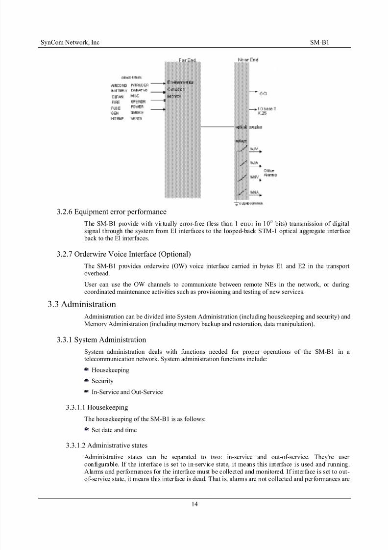
3.2.5 Discrete Environmental-Alarms
In here, 8 couplers are used to monitor 8 environmental conditions. User may choose 4 out of 14definable alarms to monitor environmental conditions. The optical couplers are set to open when thecondition is normal and closed when alarm occurred.
Figure3-3 Environmental-alarms & Office-alarms
13
8/20/2019 193440315-UM-SM-B1-V26
http://slidepdf.com/reader/full/193440315-um-sm-b1-v26 20/51
SynCom Network, Inc SM-B1
3.2.6 Equipment error performance
The SM-B1 provide with virtually error-free (less than 1 error in 1012 bits) transmission of digitalsignal through the system from El interfaces to the looped-back STM-1 optical aggregate interface back to the El interfaces.
3.2.7 Orderwire Voice Interface (Optional)
The SM-B1 provides orderwire (OW) voice interface carried in bytes E1 and E2 in the transportoverhead.
User can use the OW channels to communicate between remote NEs in the network, or duringcoordinated maintenance activities such as provisioning and testing of new services.
3.3 Administration
Administration can be divided into System Administration (including housekeeping and security) andMemory Administration (including memory backup and restoration, data manipulation).
3.3.1 System Administration
System administration deals with functions needed for proper operations of the SM-B1 in atelecommunication network. System administration functions include:
Housekeeping
Security
In-Service and Out-Service
3.3.1.1 Housekeeping
The housekeeping of the SM-B1 is as follows:
Set date and time
3.3.1.2 Administrative states
Administrative states can be separated to two: in-service and out-of-service. They're user configurable. If the interface is set to in-service state, it means this interface is used and running.Alarms and performances for the interface must be collected and monitored. If interface is set to out-
of-service state, it means this interface is dead. That is, alarms are not collected and performances are
14

8/20/2019 193440315-UM-SM-B1-V26
http://slidepdf.com/reader/full/193440315-um-sm-b1-v26 21/51
SynCom Network, Inc SM-B1
not monitored. This might happen if interface is under maintenance. For avoiding mistake, test modecan be set for interface if it’s in out-of-service state.
3.3.1.3 Operation states
Operation states show the current situation for the interface. If Administrative state is in in-servicestate, then operation states might in "UP" or "DOWN" state. UP state means the interface runscorrectly and DOWN state means no TSA is assigned for E1 interface or not used for opticalinterface in TMx1 mode. And if administrative state is in out-of-service state, then operation statesmight in "DOWN" or "TEST" state. TEST state means the interface is doing some test function, e.g.,loopback test.
Figure3-4 Administrate & Operation State window
3.3.2 Memory AdministrationMemory administration deals with the functions needed to control and administrate the SM-B1database. Memory administration includes:
Memory backup and restoration
The data manipulation
3.3.2.1 Memory Backup and Restoration
The SM-B1 provides a local primary non-volatile memory backup on the MPU circuit pack Restoration of data from the local backup memory, once initiated, will be completed within 1 minute.
3.3.2.2 Data Manipulation
To provide new services and equipment in the network, the SM-B1 has the capability of datamanipulation to deal with editing and retrieving data in the database including all settings andnetwork element configurations.
3.4 Maintenance
Maintenance is responsible for maintaining the proper functions of the NEs and the network.Maintenance includes alarm surveillance; performance monitoring, testing capability, control featuresand optical interface protection switching that are essential to the normal operations of the NEs.
The EM GUI together with the SM-B1 network management capabilities makes it easy for the user to perform the following maintenance tasks:
The trouble detection: include LOS, LOF, LOP, LOM, SD(Signal Degraded) equipment failures,
loss of synchronization, troubles on the Automatic Protection Switch (APS) channel.
15

8/20/2019 193440315-UM-SM-B1-V26
http://slidepdf.com/reader/full/193440315-um-sm-b1-v26 22/51

8/20/2019 193440315-UM-SM-B1-V26
http://slidepdf.com/reader/full/193440315-um-sm-b1-v26 23/51
SynCom Network, Inc SM-B1
3.4.1.3 FERF: Far End Receive Failure
FERF signals have been used in the digital network to alert upstream terminals of a downstreamreceive failure. The layered maintenance strategy incorporated in the SDH signal format expands theapplications of these signals in the network. In particular, FERF signals can be used for trouble
sectionalization. The SM-B1 provides FERF signals as follows:MS FERF
VC4 (Virtual Container-4) FERF
VC12 FERF
FIGURE 3-7, FIGURE 3-8, and FIGURE 3-9 shown below illustrate the relationship of these AISand FERF maintenance signals.
17

8/20/2019 193440315-UM-SM-B1-V26
http://slidepdf.com/reader/full/193440315-um-sm-b1-v26 24/51
SynCom Network, Inc SM-B1
Figure3-7 Maintenance Signals at High Order Path (AU4) Termination Point (AsynchronousMapping for 2 Mbit/s into Floating TU12)
Figure3-8 Maintenance Signals at Low Order Path (TU12) Termination Point (AsynchronousMapping for 2 Mbit/s into Floating TU12)
18

8/20/2019 193440315-UM-SM-B1-V26
http://slidepdf.com/reader/full/193440315-um-sm-b1-v26 25/51
SynCom Network, Inc SM-B1
Figure3-9 Maintenance Signals at Low Order Path (TU12) Termination Point (AsynchronousMapping for 2 Mbit/s into Floating TU12) (continued)
3.4.1.4 Fault Detection, Isolation and Reporting
The SM-B1 continuously monitors its circuit pack and all incoming signals for faults.
When a fault is detected, the SM-B1 uses automatic diagnostics to isolate the fault to a particular signal or circuit pack. Failure states that persist for the provisionable period of time (2.5+0.5seconds) will lead to indications. The system autonomously reports all alarm and status conditionsthrough appropriate system and equipment indicators, office alarm relays, the fuse and alarms panel,the local CIT, and the remote OS.
Figure3-10 Automatic Alarms Report Windows
19

8/20/2019 193440315-UM-SM-B1-V26
http://slidepdf.com/reader/full/193440315-um-sm-b1-v26 26/51
SynCom Network, Inc SM-B1
The system stores a record for all fault conditions. The user can retrieve a report of active alarm andstatus conditions via the maintenance toolbar, locally at the CIT, or remotely by the OS. The reportincludes the source address of the alarm as well as date and time of the alarm, whether or not thecondition is service affecting, and a short description of the condition.
The attributes of those alarms could be set and retrieved by software on demand locally at the EMGUI or remotely by the OS through X.25.
3.4.2 Performance Monitoring(PM)
The SM-B1 provides the capability of gathering PM data to support in-service monitoring of transmission quality. These proactive maintenance include three key steps:
Detection of transmission degradation based on regenerator section (RS), multiplex section (MS),and path;
Derivation of useful performance parameters from the detected degradation;
Communication of these parameters to a surveillance OS or local craftsperson via two distinct
mechanisms: ─ Ordinary performance parameter queries made by an OS or a local craftsperson for testing/diagnostic purpose, or to address the service quality concerns of a customer; and
─ Threshold-Cross-Alert (TCA) messages, bearing the exact performance parameter register whose threshold was crossed, are used to notify a surveillance OS of a degradation.
3.4.2.1 PM Parameters
The SM-B1 provides the following performance monitoring parameters:
Regenerator Section (RS) Layer PM
The SM-B1 monitors Severely Errored Framing Second (SEFS), and provides the following storageregisters:
Current 15-minute
95 previous 15-minute
Current day
6 Previous day
and the following threshold registers:
Threshold for current 15-minute
Threshold for current day
Multiplex Section (MS) Layer PM
The SM-B1 monitors (1) Multiplexer Section Coding Violations (MSCVs); (2) Multiplexer Section
20

8/20/2019 193440315-UM-SM-B1-V26
http://slidepdf.com/reader/full/193440315-um-sm-b1-v26 27/51
SynCom Network, Inc SM-B1
Errored Seconds (MSESs); and (3) Multiplexer Section Severely Errored Seconds (MSSESs) provides the following storage registers:
Current 15-minute
95 previous 15-minute
Current day
6 Previous day
and the following threshold registers:
Threshold for current 15-minute
Threshold for current day
VC4 Path Layer PM
SM-B1 monitors (1) VC4 Path CV (2) VC4 Path ES (3) VC4 Path SES, and provides the followingstorage registers:
Current 15-minute
95 previous 15-minute
Current day
6 Previous day
and the following threshold registers:
Threshold for current 15-minute
Threshold for current day
VC12 Path Layer PM
The SM-B1 monitors (1)VC12 Path CV (2)VC12 Path ES (3)VC12 Path SESs, and provides thefollowing storage registers:
Current 15-minute
95 previous 15-minute
Current day
6 Previous day
and the following threshold registers:
Threshold for current 15-minute
Threshold for current day
Monitoring at 2 Mbit/s line Interfaces
The SM-B1 monitors 2 Mbit/s line interface Coding Violations(CVs), and provide the following
storage registers:
Curent 15-minute
95 previous 15-minute
Current day
6 Previous day
and the following threshold registers:
Threshold for current 15-minute
Threshold for current day
21

8/20/2019 193440315-UM-SM-B1-V26
http://slidepdf.com/reader/full/193440315-um-sm-b1-v26 28/51
SynCom Network, Inc SM-B1
3.4.2.2 PM Data Collection and Initialization
Performance parameters are accumulated for each monitored transport entity and each direction of transmission. The SM-B1 provides the capability to retrieve the contents of any parameter storageregister at any time. The parameters are collected on a continuous basis, except during trouble or
failure conditions such as LOS, LOF, AIS, or LOP, the ability to accumulate such parameters is lostor severely hampered. The PM accumulation during troubles is conducted according to the followingrequirements:
Table3-1 SM-B1 PM Accumulation During Troubles
Pm Parameter Troubles
LOS LOF MS AIS VC4LOP
VC4PathAIS
VC12LOP
VC12PathAIS
RS SESs I I M M M M M
MS CVs I I I M M M M
MS Ess I I I M M M MMS SESs I I I M M M M
VC4 Path CVs I I I I I M M
VC4 Path Ess I I I I I M M
VC4 Path SESs I I I I I M M
VC12 Path CVs I I I I I I I
VC12 Path ESs I I I I I I I
VC12 Path SESs I I I I I I I
Table3-2 SM-B1 2 Mbit/s PM During Troubles
Pm Parameter Troubles
LOS
Coding Violations I
Capability is provided to initialize the registers for accumulated performance automatically on 15-minute and daily time boundaries. User can initialize the registers manually at any time via the GUIor remote EM or OS.
3.4.2.3 Threshold Crossing Alerts (TCA)
The SM-B1 provides threshold registers for monitored performance parameters as described insection 3.4.2.1, and the capability to retrieve the contents of any parameter storage register remotely
from OS or locally from COT at any time. Default values for current 15-minute and current daythreshold registers are provided in Chapter 5. These registers are provisionable remotely from OS or locally from COT.
Figure3-11 Retrieving and Setting PM Thresholds Window (for STM1):
22

8/20/2019 193440315-UM-SM-B1-V26
http://slidepdf.com/reader/full/193440315-um-sm-b1-v26 29/51
SynCom Network, Inc SM-B1
FIgure3-12 Retrieving and Setting PM Thresholds Window (for E1)
The TCA will be sent to the COT and surveillance OS by use of an autonomous message when acurrent 15-minute or current day register crosses the corresponding threshold value. A TCA message precisely identifies the performance parameter register whose value has exceeded its threshold, andthe corresponding threshold value. They constitute the notification mechanism associated with performance monitoring.
TCA is classified as a transient condition. The alert will be cleared automatically on the 15-min or daily time boundary.
3.4.3 Testing Capability
Testing deals with procedures that result in isolation of a failure to a replaceable or repairable entity.
Testing activities includes:
Analyzing alarms, PM data, and maintenance signals
Executing diagnostics
Executing controls, such as switch to protection
Activating loopbacks
In each of these activities, operations personnel gain access through either GUI or the remote EM or OS.
Craftsperson can use the SM-B1 internal testing capabilities for installation and manualtroubleshooting. Maintenance tools that achieve this isolation, besides those built into the SDH signalformat, are diagnostics, and loopbacks.
3.4.3.1 Self Diagnostics Capability
Diagnostics capabilities for equipment failures are provided in the SM-B1. These diagnostics occur automatically during the circuit pack initialization or equipment turn-up before the circuit pack goesinto service, and may be run routinely or on demand.
23

8/20/2019 193440315-UM-SM-B1-V26
http://slidepdf.com/reader/full/193440315-um-sm-b1-v26 30/51
SynCom Network, Inc SM-B1
3.4.4 Loopback Test Capability
To support pre-service operation practices and test-related activities in some applications, SM-B1 provides a combination of loopback capabilities – diagnostic and line loopbacks for STM-1, and 2M bit/s. These capabilities can be activated locally via GUI and remotely via an EM or OS. It is
explained below:
Figure3-13 Loopback test illustrations
These loopbacks connect the signals about to be transmitted to the associated incoming receiver.
When the signal is being loopbacked, it will interrupt the flow of traffic and change the normaltransmission, the associated facility and circuit pack must be set in the maintenance state (out-of-service).
3.4.5 Control Features
The SM-B1 provides the following control functions from either hardware push-button or EM GUIoperations:
Retrieve equipment configuration status: Equipment configuration status, including the indicationof the active hardware entities in redundant equipment and the active synchronization source, isretrievable via the EM GUI operations.
Manual Switch the timing source: User could manual switch the timing setting of the SM-B1system via the EM GUI operation.
Furthermore, the system may be re-initialized (reset) via hardware push-button or EM GUIoperations. The ”system reset” could be categorized in 4 levels:
Reset Software by either push the RESET button or via EM GUI operation: A push-button is provided on front panel to restart the system controller. An EM GUI operation for “Softwarereset” is also provided. System restarted by pushing the push-button has the same effects as that of a soft boot. It will not affect the provisioned data.
Reset hardware to restart system by EM GUI operation or off/on the power: In addition to “resetCPU”, all hardware chips will be restarted. This operation will not affect the provisioned data thatis stored in the non-volatile memory. But the failure states, protection switching configuration, performance parameters, and other information necessary for fault isolation will be changed toreflect the current status.
Reset FPGA to restart system by EM GUI operation: In addition to “reset hardware”, thisoperation will download FPGA codes again.
Reset OODB to restart system by EM GUI operation: In addition to “reset hardware”, thisoperation “hard boot”, reloads the default values to the database and will affect the state of memory and other resources.
24

8/20/2019 193440315-UM-SM-B1-V26
http://slidepdf.com/reader/full/193440315-um-sm-b1-v26 31/51
SynCom Network, Inc SM-B1
3.4.6 Optical Interface Manual Switch
User can locally or remotely execute/release the optical interface protection switching to the SM-B1-1 by EM GUI. The protection switching priority and the K1 byte are shown as the table below:
Table3-3 The protection switching priority
The switching type K1 byte
bit
1 2 3 4
Auto switch: SF 1 1 0 0
Auto switch: SD 1 0 1 0
Manual switch 1 0 0 0
3.4.7 VC12 Path Protection Switching
Path protection switching at VC12 level; i.e. switching on per E1 basis, is available at all SynCom
SDH series products: SM-M1 and SM-B1. This switching mechanism is applicable at ringapplication as depicted in Figure 3-13. The traffic is going at clockwise or counter-clockwisedirection at normal situation without any defect in the ring. If an optical fiber breaks or a circuit pack failure occurs, all nodes with affected traffic will reverse the working path to recover thetransmission within 50 milli-second. This is a more economic way to achieve the network robust than1+1 line protection switch.
Figure3-14 VC12 path protection switching ring(PPSR) traffic illustration
Note: Traffic in clockwise direction is the working one and the traffic in the counter-clockwisedirection is the protection one.
3.4.7.1 How to Enable Path Protection Switching
VC12 path protection switching mechanism can be enabled during the initiation of the time slotassignment (TSA) by choosing the cross connect (XC) method as Dual Feed as illustrated at Figure3-14. As the dual-feed XC method is selected for a VC12 path connection, the outgoing traffic will be dual-fed to both optical lines and the termination node can choose either of optical lines to dropthe traffic from.
25

8/20/2019 193440315-UM-SM-B1-V26
http://slidepdf.com/reader/full/193440315-um-sm-b1-v26 32/51
SynCom Network, Inc SM-B1
Figure3-15 E1 XC for PPSR Support
3.4.7.2 How the Path Protection Switching is Made
The selection of a working VC12 path can be made automatically or by the user. Once the system is powered up, system software continues monitoring all the VC12 path connections and makes protection switching automatically if a VC12 traffic defect is detected.
A user may also manually switch the working path by selecting the drop side to East STM1 or West
STM1.The input arguments include side selection and a switch priority. Switch priorities for manualswitch include Manual and Forced. After a manual switch with priority of Manual or Forced isinvoked, the current protection switch priority will be lift up from Auto to Manual or Forced. The protection switch, automatically or manually, may occur only if the switch priority is greater than thecurrent one.
3.5 Provisioning
The SM-B1 allows the user to customize many system characteristics through its provisioningfeatures. For example, performance-monitoring thresholds can be customized for each installation viathe EM GUI operations.
3.5.1 Default Provisioning
Installation provisioning is minimized with pre-determined default values set in the factory. Each parameter is given a default value. The default values for software parameters are maintained inCPU. All provisioning data are stored in non-volatile memory to prevent data loss during power failure.
3.5.2 Local and Remote Provisioning
In the SM-B1, many provisioning parameters are software settable to allow local or remote provisioning. This feature is provided especially for those parameters likely to change in service tosupport centralized operation practices.
26

8/20/2019 193440315-UM-SM-B1-V26
http://slidepdf.com/reader/full/193440315-um-sm-b1-v26 33/51
SynCom Network, Inc SM-B1
Chapter 4 EM GUI System Introduction
4.1 OverviewThis chapter will introduce the operations of EM GUI for SM-B1, including the environmentalequipment, the character, and the points for attention and how to operate the EM GUI.
SM-B1 provides the EM GUI interface with simple and easy to operate, the operator could manager all NEs (local and remote) though the PC or CIT (Craftsperson Interface Terminal), and connect toother network for each other by the Mediation Device.
To rely on the operation managerial system, User could easily arrive at the Operation AdministrationMaintenance & Provisioning (OAM&P).
4.2 System Requirements
EM GUI network manager software should be installed in a personal computer with 32 bits operatingsystem on Microsoft Win95/98/NT V4.0, or higher.
Monitor: Large size monitor with high definition is recommended.
Screen: The best working mode of the screen is 1024x768 or higher.
CPU: Pentium II 400Mhz ( the same class processor included ) is recommended or higher.
Main memory: 64MB of RAM or higher.
4.3 Features
SM-B1 EM GUI has these following features:
It can manage all the NEs (local/remote) of the sub-network individually.
It has the full function in OAM&P.
It has the friendly operation way with fully graphical oriented for user.
It could be understood fully at a glance with Layer network management.
Automatic alarm reporting for centralized management.
It has changeable network topology.
It provides the saving and accessing the document of the network topology.
4.4 EM GUI Management Menu
27

8/20/2019 193440315-UM-SM-B1-V26
http://slidepdf.com/reader/full/193440315-um-sm-b1-v26 34/51

8/20/2019 193440315-UM-SM-B1-V26
http://slidepdf.com/reader/full/193440315-um-sm-b1-v26 35/51
SynCom Network, Inc SM-B1
Figure4-2 The NE information menu
4.5.1 System
Information: Display the information of the selected node. Some parameters in the form can bechange directly by user: ”Title” ”NSAP” ”IP Address” ”Role” ”Mode”.、 、 、 、
Figure4-3 “System information” Window
OODB Version : Display the OODB version of the selected node.
Figure4-4 The “OODB Version” Window
Pack Information: Display the Pack information of the selected node.
Figure4-5 The”Pack Information” Window
29

8/20/2019 193440315-UM-SM-B1-V26
http://slidepdf.com/reader/full/193440315-um-sm-b1-v26 36/51
SynCom Network, Inc SM-B1
30

8/20/2019 193440315-UM-SM-B1-V26
http://slidepdf.com/reader/full/193440315-um-sm-b1-v26 37/51
SynCom Network, Inc SM-B1
Date/Time: Display and edit the system date/time.
Figure4-6 The “System Date/Time” Window
Laser Shutdown: Enable/disable the East/West ALS function. When administrators enable theALS function, there are three choices for different action when the optical alarm happened.
Figure4-7 The “ Select Side of ALS” Window
Clock Source: Set the system-timing source. An administrator set the ”Switch Mode” to be“Auto”, and system will be according to the priority of each source to switch timing. Anadministrator also can set the ”Switch Mode” to be “Force” to fix one clock source. Theclassification of clock source are Primary Clock Secondary、 Clock East; Line Clock West、
Line Clock Internal、 Clock and External Clock. Besides, we can retrieve the status of each timingsource set、 auto-revertive time and choose the quality of clock source in this window. About the
setting of SSM, please refer to EM-SM user manual chapter 8 " 8.3 SSM (Synchronization StatusMessage) Setting Suggestion”.
Figure4-8 The “Clock Source” Window
31

8/20/2019 193440315-UM-SM-B1-V26
http://slidepdf.com/reader/full/193440315-um-sm-b1-v26 38/51
SynCom Network, Inc SM-B1
Reset:
Figure4-9 The “Reset” submenu
- Reset: System reset.
Figure4-10 The “System Reset” Window
- Reset OODB: Reset Database. An administrator can’t do this option unless necessary, because itwill change all the parameter to the default value and effect the system operation seriously.
32

8/20/2019 193440315-UM-SM-B1-V26
http://slidepdf.com/reader/full/193440315-um-sm-b1-v26 39/51
SynCom Network, Inc SM-B1
4.5.2 Communication Control
The function provides the user to set and retrieve the node status in the network.
Figure4-11 The “Communication Control” submenu
DCC: Retrieve the status of the node data communication channel.
Figure4-12 The “DCC” Window
F1 Drop Side: Retrieve/switch the F1 drop side.
Figure4-13 The “F1 Drop Side” Window
TCP/IP: As the figure below, user can set the IP Address Subnet、 Mask and Gateway IP Addressto the node. The network manager can make communicated between machine and EM GUI viaLAN interface after setting it.
Figure4-14 The “TCP/IP” Window
33

8/20/2019 193440315-UM-SM-B1-V26
http://slidepdf.com/reader/full/193440315-um-sm-b1-v26 40/51
SynCom Network, Inc SM-B1
4.5.3 Cross Connection
Figure4-15 The NE information menu
The function allows the user to retrieve/set/delete TSA.
4.5.4 Protection
Figure4-16 The “Protection” submenu
The Item allows the user to setup ms-protection.
4.5.5 Alarm
Figure4-17 The “alarm” submenu
Retrieve Alarm: The function allows the user to view all the happening alarm of the system.
Retrieve out-of-service alarm: The function allows the user to view the happening alarm of the paths in out-of-service status.
Retrieve alarm history: The function allows the user to view alarm history.
Reset alarm history: The function allows the user to reset alarm history.
Retrieve/Set alarm severity: The function allow the user to retrieve/set STM1/E1 alarm severitylevels including Critical, Major, Minor and Warning.
Retrieve/Set Default alarm severity: The function allows the user to retrieve STM1/E1 default
34

8/20/2019 193440315-UM-SM-B1-V26
http://slidepdf.com/reader/full/193440315-um-sm-b1-v26 41/51
SynCom Network, Inc SM-B1
alarm severity level.
Alarm seconds: The function provides the user to set the Time of continuous detecting alarmhappens and clears.
Env. & Ext. alarm status: The function can retrieve/set the severity of
Environment/External/Office alarm.
4.5.6 PM
Figure4-18 The “PM” submenu
The PM function allows the user to query PM statistics, set/retrieve PM threshold, set PM Sync.Time, etc.
Set/Retrieve PM threshold: This function allows the user to set/retrieve PM threshold values aboutthe selected node.
Set/Retrieve default PM fault: This function allows the user to retrieve/regain default PMthreshold values about the selected node.
Set/Retrieve SES threshold: This function provides set code violation mode or block mode.
Retrieve PM value from DB: The function provides to query PM data.
PM Sync. Time: The funciton provides to set PM synchronization time.
Set PM: The function provides the user to clean all PM record.
4.5.7 Administrate & Operation State
Administrative states can be separated to two: in-service and out-of-service. They’re user configurable. If the interface is set to in-service state, it means this interface is used and running.Alarms and performances for the interface must be collected and monitored. If interface is set toout-of-service state, it means this interface is dead. That is, alarms are not collected and performances are not monitored. This might happen if interface is under maintenance. For avoiding mistake, test mode can be set for interface if it’s in out-of-service state.
Operation states show the current situation for the interface. If administrative state is in in-servicestate, then operation states might in “UP” or “DOWN” state. UP state means the interface runscorrectly and DOWN state means no TSA is assigned for E1 interface or not used for opticalinterface in TMx1 mode. And if administrative state is in out-of-service state, then operation statesmight in “DOWN” or “TEST” state. TEST state means the interface is doing some test function,e.g., loopback test.
35

8/20/2019 193440315-UM-SM-B1-V26
http://slidepdf.com/reader/full/193440315-um-sm-b1-v26 42/51
SynCom Network, Inc SM-B1
Figure4-19 The “Administration & Operation status” Window
4.5.8 Download
Figure4-20 The “Download” submenu
Remote Download: EM provides this function to support the NE’s database/code can be backup/update.
4.5.9 Misc Tools
Figure4-21 The “Misc Tools” submenu
36
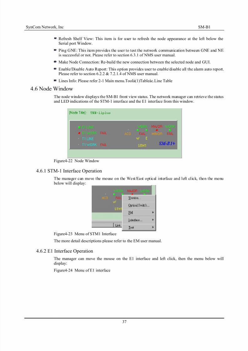
8/20/2019 193440315-UM-SM-B1-V26
http://slidepdf.com/reader/full/193440315-um-sm-b1-v26 43/51
SynCom Network, Inc SM-B1
Refresh Shelf View: This item is for user to refresh the node appearance at the left below theSerial port Window.
Ping GNE: This item provides the user to test the network communication between GNE and NEis successful or not. Please refer to section 6.3.1 of NMS user manual.
Make Node Connection: Re-build the new connection between the selected node and GUI.
Enable/Disable Auto Report: This option provides user to enable/disable all the alarm auto report.Please refer to section 6.2.2 & 7.2.1.4 of NMS user manual.
Lines Info: Please refer 2-1 Main menu.Toolà(1)Tableàc.Line Table
4.6 Node Window
The node window displays the SM-B1 front view status. The network manager can retrieve the statusand LED indications of the STM-1 interface and the E1 interface from this window.
Figure4-22 Node Window
4.6.1 STM-1 Interface Operation
The manager can move the mouse on the West/East optical interface and left click, then the menu
below will display:
Figure4-23 Menu of STM1 Interface
The more detail descriptions please refer to the EM user manual.
4.6.2 E1 Interface Operation
The manager can move the mouse on the E1 interface and left click, then the menu below willdisplay:
Figure4-24 Menu of E1 interface
37

8/20/2019 193440315-UM-SM-B1-V26
http://slidepdf.com/reader/full/193440315-um-sm-b1-v26 44/51

8/20/2019 193440315-UM-SM-B1-V26
http://slidepdf.com/reader/full/193440315-um-sm-b1-v26 45/51
SynCom Network, Inc SM-B1
Protection Switch: When the manual/auto protection switch actived, the system will auto reportalarm. All alarms list will be keep in files, in order to supply the user to look up.
39

8/20/2019 193440315-UM-SM-B1-V26
http://slidepdf.com/reader/full/193440315-um-sm-b1-v26 46/51
SynCom Network, Inc SM-B1
Figure4-29 Protection switch alarm window
Path Switch: This form displays the records of path protection switch.
Figure4-30 Path Switch Alarm Report window
Clock Switch: This form displays the records of clock switch.
Figure4-31 Clock Switch Auto Report Window
Environment Alarm: It displays all nodes’ environment alarm. All alarms list will be keep in files,in order to supply the user to look up.
Figure4-32 Environment Alarm Auto Report Window
40

8/20/2019 193440315-UM-SM-B1-V26
http://slidepdf.com/reader/full/193440315-um-sm-b1-v26 47/51
SynCom Network, Inc SM-B1
Chapter 5 Installation Guide
5.1 OverviewThis chapter provides the guideline to the installation procedure for a simple end-endnetwork configuration. Since the installation on the COT side and the RT side are quite similar, the procedureis valid for COT and RT.
5.2 General Installation
5.2.1 Environment Check and Preparation
5.2.1.1 Required Power Supply
The central office or the cabinet that houses the SM-B1 should provide the nominal –48Vdc (the rangis from -36Vdc to -63Vdc) or the 220 Vac (the rang is from 230Vac to 110Vac). If the power
protection is desired, both AC and DC should be connected. (Refer to 2.3.1 power Protection).
5.2.1.2 Power-on Procedure
The next procedures must be followed and performed in using power.
(1) Make sure our system is powered off.
(2) Connect a) -48V; b) ground for the -48V; c) frame ground to our system
(3) Measure -48V power to make sure that it is correct and no short circuit between the -48V and theframe ground.
(4) Turn on the power switch on our system
5.2.2 E1/T1 Port ConnectionLow speed E1/T1 interfaces (h1 or h2 in FIGURE 5-1 on Page 1) are provided through the DB-37connectors. Additional adapter will be necessary to adapt the DB-37 interfaces into the interfaces of the user specification. The Pin assignments of the DB-37 are detailed as following:
Figure5-1 The pin assignments of E1 port
41
1
2037
19
CH1
CH9
CH17
CH2
CH10
CH18
CH3
CH11
CH19
CH4
CH12
CH20
CH5
CH13
CH21
CH6
CH14
CH7
CH15
CH8
CH16
E1 output pin
E1 input pin
Unused pin

8/20/2019 193440315-UM-SM-B1-V26
http://slidepdf.com/reader/full/193440315-um-sm-b1-v26 48/51
SynCom Network, Inc SM-B1
Figure5-2 The pin assignments of T1 port
5.2.3 Operations Interface Installation
5.2.3.1 Craft Interface Device (CID) Installation
Connect a personal computer or notebook PC to the CID port at the backside of the SM-B1.
Figure5-3 CID interface pin assignment
5.2.4 Environmental Alarms Monitors and External Controls Installation
Four environmental alarm monitor inputs and four external control outputs are provided on the backside of the SM-B1. For detailed specifications and requirements, please refer to 3.2.4 “OfficeAlarms” and 3.2.5 “Discrete Environmental-Alarms”.
42
1
2037
19
CH22
CH30
CH38
CH23
CH31
CH24
CH32
CH40
CH25
CH33
CH26
CH34CH42
CH27
CH35
CH28
CH36
CH29
E1 output pin
E1 input pin
Unused pin
1
2037
19
E1: CH43 T1: CH1
Single output pin
Single input pin
Unused pin
T1: CH2 T1: CH3T1: CH4 T1: CH5 T1: CH6 T1: CH7
T1: CH8 T1: CH9 T1: CH10 T1: CH11 T1: CH12 T1: CH13 T1: CH14T1: CH16 T1: CH17 T1: CH18
T1: CH15T1: CH19 T1: CH20

8/20/2019 193440315-UM-SM-B1-V26
http://slidepdf.com/reader/full/193440315-um-sm-b1-v26 49/51
SynCom Network, Inc SM-B1
Figure5-4 ENV alarms and EXT CNTL interface pin assignments
5.2.5 External Timing I/O and User Byte I/O
The SM-B1 provides two kinds of clock input that are 2M Square Wave and 2M Unframed signal.And SM-B1 provides the system clock output. The F1 byte serial output and input are provided on
the same DB-9 connector.
Figure 5-5 External Timing I/O and User Byte I/O
5.2.6 Fiber connection between COT and RT
Step1: power-on COT and RT side SM-B1.
Step2: Connect the COT's optical transmitter of the east-side (EAST - TX) on the front panel to theRT's receiver of the east-side (EAST - RX) with the single-mode fiber (SMF).
Step3: Connect the RT's optical transmitter of the east-side (EAST - TX) on the front panel to theCOT's receiver of the east-side (EAST - RX) with the single-mode fiber (SMF).
43
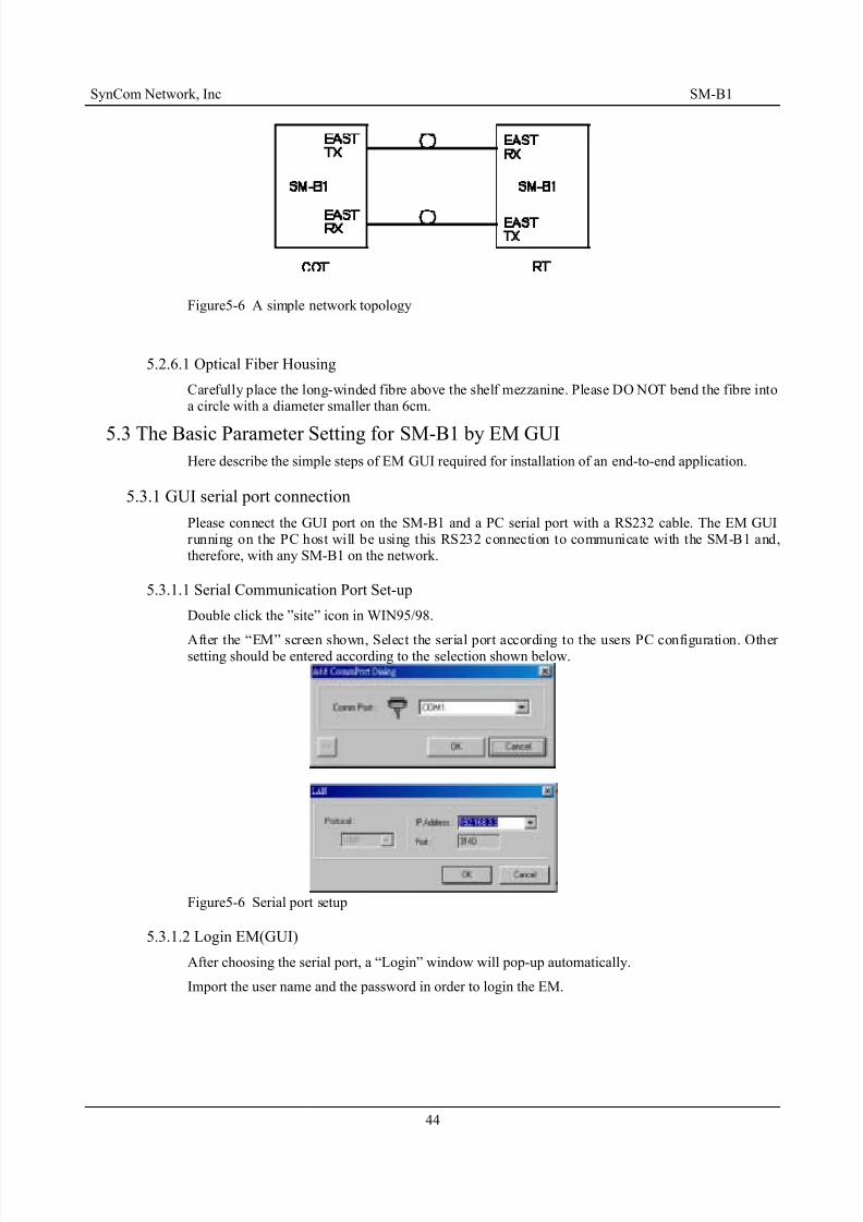
8/20/2019 193440315-UM-SM-B1-V26
http://slidepdf.com/reader/full/193440315-um-sm-b1-v26 50/51

8/20/2019 193440315-UM-SM-B1-V26
http://slidepdf.com/reader/full/193440315-um-sm-b1-v26 51/51
SynCom Network, Inc SM-B1
Figure5-7 Login window
5.3.2 More Operations of the EM GUI
The more exhaustive statements please refer to the EM user manual.
Related Documents