Grogan Subdivision 19 Lynwood Road Scarsdale, NY 10583 Town of Greenburgh Engineer’s Report Conformance with Chapter 245 of the Town of Greenburgh Code July 18, 2018 Hernane De Almeida, P.E. 26 Glenvue Drive, Carmel, NY 10512 [email protected] (914) 469-9741

Welcome message from author
This document is posted to help you gain knowledge. Please leave a comment to let me know what you think about it! Share it to your friends and learn new things together.
Transcript
Grogan Subdivision 19 Lynwood Road
Scarsdale, NY 10583
Town of Greenburgh
Engineer’s Report Conformance with Chapter 245 of the Town
of Greenburgh Code July 18, 2018
Hernane De Almeida, P.E. 26 Glenvue Drive, Carmel, NY 10512
[email protected] (914) 469-9741
zherter
Reviewed

Contained herein you will find a narrative explaining how the proposed project meets the legislative intent of Chapter 245 Protection of Steep Slopes to the best extent practicable. The disturbed areas have been illustrated on a side by side comparison on an attached plan entitled “Site Disturbance Comparison”. The disturbance area is shown on the site plans and their relationship to any property lines (no easements exist on the property), roads, walls, fences, sewer and water infrastructure and trees on the site. BACKGROUND Through casual observation the entire neighborhood, prior to development, had steep slopes and has been, over the years, developed with single family homes to the point it is today. While many predate zoning and slope regulations, the suburban environment and stability the geotechnical characteristics have withstood the test of time to be stable and is an excellent example how construction of homes through common permitting practices is safe and practical in this area. The proposed construction does not propose anything more invasive than what already exists in many of the developed properties along the Bronx River valley. This subdivision provides the creation of 2 lots from one (four tax parcels) and both new lots front a public road and is served by public utilities without the need of infrastructure expansion to meet the requirements of providing services and access to these lots. Lot 1 has an existing single family residence, attached garage, patios and walkways and shall stay largely unaffected by this proposed action of subdivision. The new lot, referred to as Lot 2, is shallow in depth compared to its width. The topographical and geometric constraints of the site will require the design professional creating the building plans for a building permit to design a house that integrates the two distinct levels of the property. Another constraint includes the building envelope for the site which dictates, through its narrowness, where principal building must be located. Therefore the remaining property is what remains to be adapted for outdoor human enjoyment. However, due to the lot and depth of the site and the intent to minimize the impact to the upper tier, the characteristics of the site dictate that development of human enjoyment will most likely require modification to topography on the lower portion of the site. The intricacies and efficacies of the design of roads and the driveways they and serve for the purpose of minimizing potential slope disturbance, as per Chapter 245 is not applicable for this project. The subdivision does not plan for the construction of any
roads in conjunction with driveways. The driveway for the proposed for the site will have the similar impact to the site slopes regardless of its final location. It is not reasonable to modify the established road topography along the frontage of the lot to minimize the impact to the slope disturbance. The elevations are established and the disturbance the site for one layout or another has no alternative that greatly minimize the impact of the disturbance area with respect to access to the site from the right of way. The proposed site plan shows retaining walls providing slope stability and a driveway within the relatively level plane area created by the wall. There is little or no natural topography remaining on the Lot 2 since it has already been modified as seen by the use of the existing retaining walls, walkways and stairs. The site plan does illustrate the modification the existing, unnatural topography to the greatest extent possible in order to minimize the potential for erosion and stormwater management. There are varying degrees of slope on the property but it is not an extremely difficult site to construct in terms of being steep as much as it is difficult to construct due to its narrowness. The constructability is a condition the contractor will need to manage at the time of construction. One obstacle of construction management is one more of staging material than any other aspect. Materials will need to be delivered as needed and storing materials for later phases of construction may prove to be difficult at first. Successful construction on more difficult lots with minimal impacts to traffic and coordination of material deliveries on an as needed basis is regularly done in the construction industry. CONSTRUCTION SAFETY PLAN’ A construction safety plan is a document with general safety protocols such as emergency phone numbers and the requirement for personal protective equipment such as safety glasses, gloves, masks, etc.); it also contains specific safety information such as onsite hazardous chemicals, and protocols for procedures of construction practices that will be utilized at the site (i.e. trench excavation, certain types of rock removal, etc.). Construction safety plans are usually part of large construction projects spanning a large site, heavy construction or large commercial structures. A construction safety plan for a project such as a single family home is unusual and is also not applicable for this application of a subdivision such that the only construction that is part of this application is the removal of a shed and removal of a portion of a patio, both very minor projects. As with any construction activity, the contractor must comply with the regulations of the Occupational Safety and Health Administration (OSHA) including personal protective equipment, trench and excavation safety and fall protection.
GEOTECHNICAL ASSESSMENT
The entire site is comprised of Urban Land-Charlton-Chatfield complex soil, a predominately sandy loam type soil; the soil map and detailed description has been attached in the appendix. The lot topography slopes higher from the roadway towards its rear property line and approximately 40 feet from the front property line, a gravity retaining wall divides the lot into two sloped terraces. Therefore, the topography of this lot is man-made and not naturally created. The slope disturbance plan shows the disturbance of the four slope categories. A comparison of disturbance with respect to three site plans (the preferred plan, the preferred plan showing tiered retaining walls and an alternative plan) is shown on Sheet 6 of the plans. The geometry of the site and the zoning regulations dictate the narrow window of possible site designs and the area required for the construction force nearly the same disturbance for all possible designs. The slopes on the site will quantitatively result in an improved stability mainly due to the implementation of proposed stability practices. The proposed project shows that slope stability is feasible for several reasons which include a theoretically reduced overburden on the soil existing soil through the construction of the proposed structure, construction of proposed retaining walls and the proper management of stormwater, as required under section 248 of the Greenburgh Town Code. The proposed site plan shows several short tiered retaining walls on the right side of the property that maintain slope stability between the two existing distinct topographical levels. An alternate site plan has been provided to show the elimination of these walls and the property to remain graded. While this approach is feasible, it does lend itself to higher probability to erosion over time.
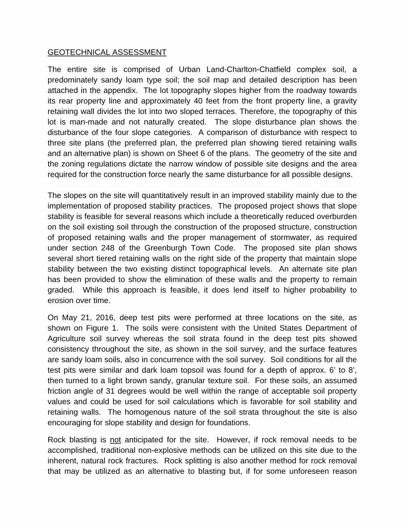
On May 21, 2016, deep test pits were performed at three locations on the site, as shown on Figure 1. The soils were consistent with the United States Department of Agriculture soil survey whereas the soil strata found in the deep test pits showed consistency throughout the site, as shown in the soil survey, and the surface features are sandy loam soils, also in concurrence with the soil survey. Soil conditions for all the test pits were similar and dark loam topsoil was found for a depth of approx. 6’ to 8’, then turned to a light brown sandy, granular texture soil. For these soils, an assumed friction angle of 31 degrees would be well within the range of acceptable soil property values and could be used for soil calculations which is favorable for soil stability and retaining walls. The homogenous nature of the soil strata throughout the site is also encouraging for slope stability and design for foundations.
Rock blasting is not anticipated for the site. However, if rock removal needs to be accomplished, traditional non-explosive methods can be utilized on this site due to the inherent, natural rock fractures. Rock splitting is also another method for rock removal that may be utilized as an alternative to blasting but, if for some unforeseen reason

blasting is required, the Town of Greenburgh and the State of New York have strict regulations dictating the process and procedure that all licensed professionals must adhere. Again, I do not foresee the use of rock blasting for this site because the process and procedures of blasting may be cost prohibitive for a small project such as this.
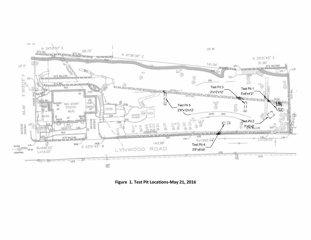
Figure 1. Test Pit Locations‐May 21, 2016

FUTURE DEVELOPMENT
The planning, design and development of the proposed building minimizes flooding and provide appropriate structural safety, slope stability, and human enjoyment while adapting the affected site to, and taking advantage of, the best use of the natural terrain and aesthetic character.
As discussed earlier, the site has already been developed to some extent and is consistent with a suburban yard that would be expected in this geographical area. No endangered species of flora or fauna are known to exist on the site. The final landscaping for the development will need to be designed specific to the final house design. The proposed subdivision does include landscape planting that will amount to a significant size consisting of indigenous vegetation and has been coordinated with the Town Arborist. We recommend, as a condition to the planning board approval, prior to issuance of a building permit for the future single family residence construction, a landscaping plan be approved by the Town of Greenburgh Department of Community Development and Conservation.
The project does not propose to disturb any natural elevations and vegetative cover of ridgelines. The current zoning regulations for the site prohibit any future structure from being tall enough to impact the nearest ridgeline. The proposed grading for the property will be consistent with the requirements of the stormwater regulations and the current stormwater design point for the property and shall be maintained by the topography sloping in the same direction as the preconstruction direction. As with any site development associated the construction of the principle building, retaining walls, open areas and regrading, there will be associated cut and fill. As would be consistent with common practice and restricted under Town code, the resulting site topography will shall not result in sharp angles of regraded slopes.
The angle of cut and fill slopes will not exceed a slope of one vertical to two horizontal except where retaining walls are proposed and there is no regrading proposed near structures that are not proposed to be protected by foundation walls or retaining walls, as required by Chapter 245 of the Town of Greenburgh Code. The project consists of mostly cuts and backfill against retaining walls and foundation walls. The backfill material to be used will be specified by the New York State licensed design professional designing such structures but will most likely comprise of crushed stone and soil native to the site. Any soil placed on washed gravel backfill will most likely to have a geotextile component in the detailed backfill specification. An important note to add is that no imported fill is required for the site and will not risk the importation of contaminated soils. Excavation should be expected to be approximately 2000 cubic yards and perhaps
removal of 750 cubic yards of material from the site, generating approximately 75 truck trips.
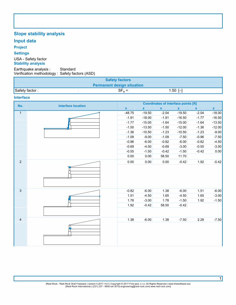
The site will require retaining walls to provide slope stability and create open space for construction and human enjoyment. By regulation, all walls over 4 feet in height are required to be designed by a qualified design professional. This site is expected to certainly require retaining walls and, as part of the planning board application site plan, a 17 foot high (above grade) retaining wall is shown to represent one possible retaining wall; a scenario that envisions the tallest wall that may be constructed. A detail for a possible retaining wall is provided in the appendix along with a slope stability analysis of the soils at the wall location. The detail is not to be used for construction, a final design must be performed by a qualified professional prior to obtaining a building permit.
A structure designed to fit into the hillside rather than altering the hillside to fit the structure by employing methods such as reduced footprint design, step-down structures, stilt houses, and minimization of grading outside the building footprint, in my professional opinion, are not viable options for this site due to the building envelope constraints, zoning height restrictions and degree of elevation change between the existing front and rear terraces of the site as previously described.
Ground stabilization, sediment and erosion control will be a part of this project and must be consistent with stabilization regulations common to all Westchester County municipalities as part of the New York State Local Stormwater Management Code requirement, which would be found in Chapter 248 of the Town of Greenburgh Code. The Town also discusses stabilization and slope disturbance in Section 245 and to encompass these regulations, a note has been added to the Stormwater Management Detail sheet of the plans stating: “Disturbance of slopes will be undertaken in workable units so that the disturbance can be completed and stabilized in one construction season and so that areas are not left bare and exposed during the period from December 15 through April 15. Disturbance of existing vegetative ground cover must not take place more than 15 days prior to grading and construction.” All stormwater related conditions (such as temporary soil stabilization) includes, if appropriate, temporary stabilization measures such as netting or mulching to secure soil during the grow-in period. This is depicted on the the plans and conforms to the Town of Greenburgh Stormwater Management Regulations. These notes and details regarding stabilization can be found on Sheet 3 and Sheet 5 of the subdivision plans submitted to the Planning Board. Also contained within the stormwater management plans are the requirements of soil stockpiling, stormwater routing and mitigation. Please note these plans show the feasibility for conformance of a suitable stormwater management plan, all final design plans will be provided by the Design Professional of Record once a suitable architectural plan is developed. The specific plans will then be submitted for
Stormwater Permit review and approval by the Town as part of the normal permitting procedure.
The current owner has no intention of developing the site at this time, our intent is to illustrate the development to show a feasible site plan conforming to the Town of Greenburgh Lot and a Bulk requirements and the buildable area as stated in section 285-39E without the need of any variances whatsoever and the reasonable representation of the extent of construction disturbance. The limits of disturbance shown on the proposed site plan should provide adequate access for construction equipment so as to not disturb anything outside the approved construction envelope.
SUMMARY
The intent of Chapter 245 is clear to help guide designers toward low impact design of large projects such as commercial projects and large subdivisions where the road layout has a substantial impact on the parcel they would eventually serve. The regulation also discusses erosion control and, to some extent, stormwater management and, in this regard, is superseded by the adoption of Chapter 248-Stormwater Management, which was enacted five years after Chapter 245 Protection of Steep Slopes was adopted.
As we have provided for in our conceptual plan, the construction, will take place as a result of this subdivision is confined to less than 12,000 square feet of land, far less than would be required to take advantage of the intent of the Chapter 245. Undue restrictions of slope disturbance on a constricted site may result with the contractor, to be conformance of such restrictions, having dangerous work conditions or may contribute to work site injuries. The developer of the site should be provided with adequate space to implement safe excavation practices. Again, needlessly restricting the disturbance area can prove to lead to unsafe conditions.
.

Appendix
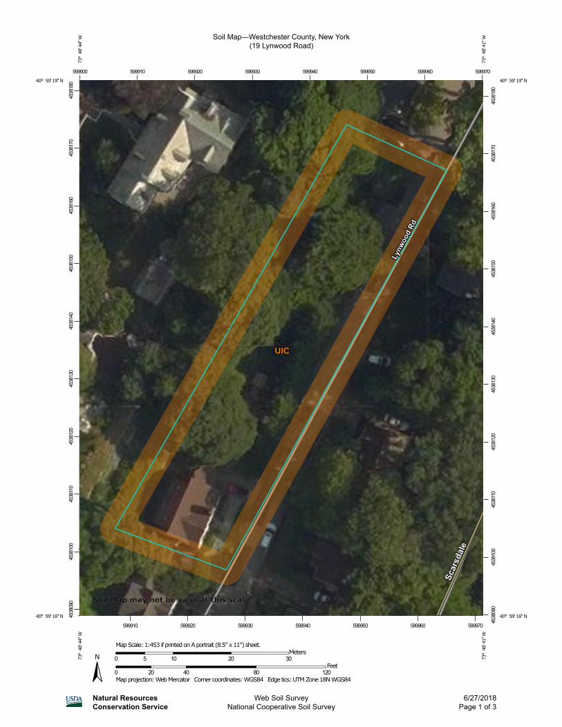
Soil Map—Westchester County, New York(19 Lynwood Road)
Natural ResourcesConservation Service
Web Soil SurveyNational Cooperative Soil Survey
6/27/2018Page 1 of 3
4538
090
4538
100
4538
110
4538
120
4538
130
4538
140
4538
150
4538
160
4538
170
4538
180
4538
090
4538
100
4538
110
4538
120
4538
130
4538
140
4538
150
4538
160
4538
170
4538
180
599900 599910 599920 599930 599940 599950 599960 599970
599910 599920 599930 599940 599950 599960 599970
40° 59' 19'' N73
° 4
8' 4
4'' W
40° 59' 19'' N
73° 4
8' 4
1'' W
40° 59' 16'' N
73° 4
8' 4
4'' W
40° 59' 16'' N
73° 4
8' 4
1'' W
N
Map projection: Web Mercator Corner coordinates: WGS84 Edge tics: UTM Zone 18N WGS840 20 40 80 120
Feet0 5 10 20 30
MetersMap Scale: 1:453 if printed on A portrait (8.5" x 11") sheet.
Soil Map may not be valid at this scale.
MAP LEGEND MAP INFORMATION
Area of Interest (AOI)Area of Interest (AOI)
SoilsSoil Map Unit Polygons
Soil Map Unit Lines
Soil Map Unit Points
Special Point FeaturesBlowout
Borrow Pit
Clay Spot
Closed Depression
Gravel Pit
Gravelly Spot
Landfill
Lava Flow
Marsh or swamp
Mine or Quarry
Miscellaneous Water
Perennial Water
Rock Outcrop
Saline Spot
Sandy Spot
Severely Eroded Spot
Sinkhole
Slide or Slip
Sodic Spot
Spoil Area
Stony Spot
Very Stony Spot
Wet Spot
Other
Special Line Features
Water FeaturesStreams and Canals
TransportationRails
Interstate Highways
US Routes
Major Roads
Local Roads
BackgroundAerial Photography
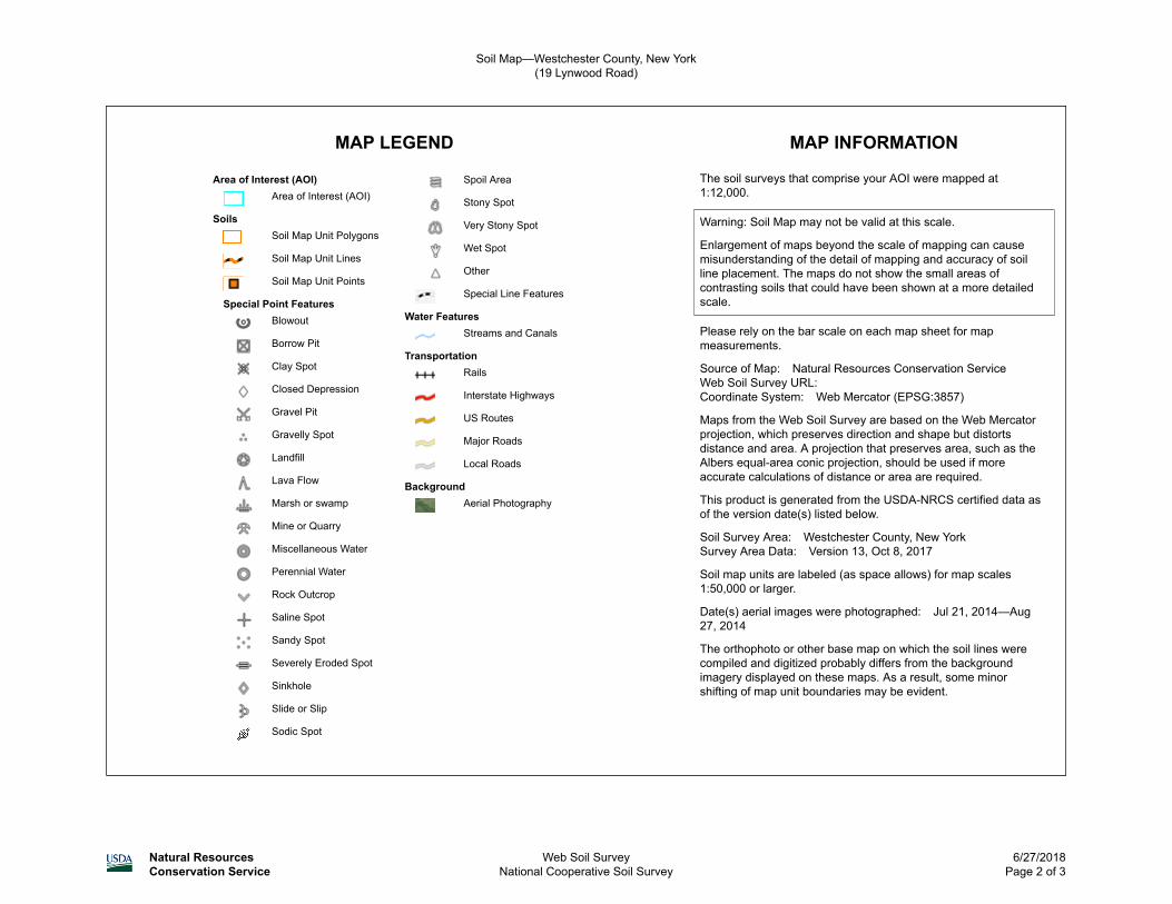
The soil surveys that comprise your AOI were mapped at 1:12,000.
Warning: Soil Map may not be valid at this scale.
Enlargement of maps beyond the scale of mapping can cause misunderstanding of the detail of mapping and accuracy of soil line placement. The maps do not show the small areas of contrasting soils that could have been shown at a more detailed scale.
Please rely on the bar scale on each map sheet for map measurements.
Source of Map: Natural Resources Conservation ServiceWeb Soil Survey URL: Coordinate System: Web Mercator (EPSG:3857)
Maps from the Web Soil Survey are based on the Web Mercator projection, which preserves direction and shape but distorts distance and area. A projection that preserves area, such as the Albers equal-area conic projection, should be used if more accurate calculations of distance or area are required.
This product is generated from the USDA-NRCS certified data as of the version date(s) listed below.
Soil Survey Area: Westchester County, New YorkSurvey Area Data: Version 13, Oct 8, 2017
Soil map units are labeled (as space allows) for map scales 1:50,000 or larger.
Date(s) aerial images were photographed: Jul 21, 2014—Aug 27, 2014
The orthophoto or other base map on which the soil lines were compiled and digitized probably differs from the background imagery displayed on these maps. As a result, some minor shifting of map unit boundaries may be evident.
Soil Map—Westchester County, New York(19 Lynwood Road)
Natural ResourcesConservation Service
Web Soil SurveyNational Cooperative Soil Survey
6/27/2018Page 2 of 3
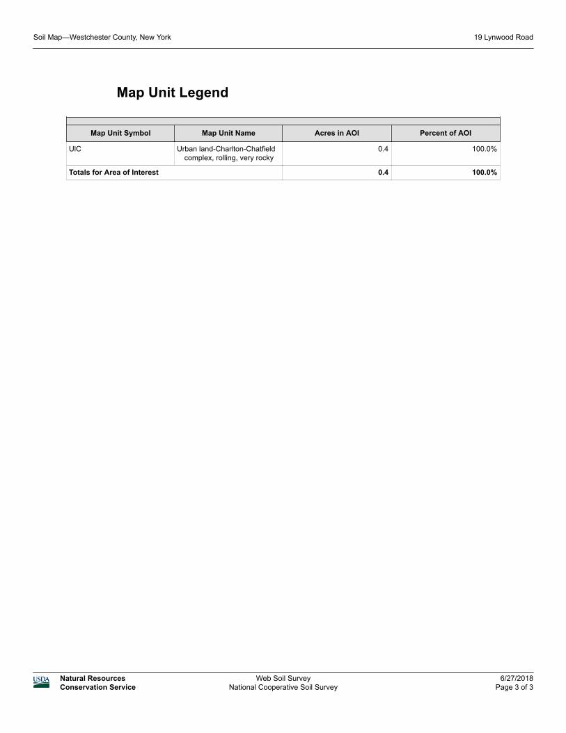
Map Unit Legend
Map Unit Symbol Map Unit Name Acres in AOI Percent of AOI
UlC Urban land-Charlton-Chatfield complex, rolling, very rocky
0.4 100.0%
Totals for Area of Interest 0.4 100.0%
Soil Map—Westchester County, New York 19 Lynwood Road
Natural ResourcesConservation Service
Web Soil SurveyNational Cooperative Soil Survey
6/27/2018Page 3 of 3

Map Unit Description
The map units delineated on the detailed soil maps in a soil survey represent the soils or miscellaneous areas in the survey area. The map unit descriptions in this report, along with the maps, can be used to determine the composition and properties of a unit.
A map unit delineation on a soil map represents an area dominated by one or more major kinds of soil or miscellaneous areas. A map unit is identified and named according to the taxonomic classification of the dominant soils. Within a taxonomic class there are precisely defined limits for the properties of the soils. On the landscape, however, the soils are natural phenomena, and they have the characteristic variability of all natural phenomena. Thus, the range of some observed properties may extend beyond the limits defined for a taxonomic class. Areas of soils of a single taxonomic class rarely, if ever, can be mapped without including areas of other taxonomic classes. Consequently, every map unit is made up of the soils or miscellaneous areas for which it is named, soils that are similar to the named components, and some minor components that differ in use and management from the major soils.
Most of the soils similar to the major components have properties similar to those of the dominant soil or soils in the map unit, and thus they do not affect use and management. These are called noncontrasting, or similar, components. They may or may not be mentioned in a particular map unit description. Some minor components, however, have properties and behavior characteristics divergent enough to affect use or to require different management. These are called contrasting, or dissimilar, components. They generally are in small areas and could not be mapped separately because of the scale used. Some small areas of strongly contrasting soils or miscellaneous areas are identified by a special symbol on the maps. If included in the database for a given area, the contrasting minor components are identified in the map unit descriptions along with some characteristics of each. A few areas of minor components may not have been observed, and consequently they are not mentioned in the descriptions, especially where the pattern was so complex that it was impractical to make enough observations to identify all the soils and miscellaneous areas on the landscape.
The presence of minor components in a map unit in no way diminishes the usefulness or accuracy of the data. The objective of mapping is not to delineate pure taxonomic classes but rather to separate the landscape into landforms or landform segments that have similar use and management requirements. The delineation of such segments on the map provides sufficient information for the development of resource plans. If intensive use of small areas is planned, however, onsite investigation is needed to define and locate the soils and miscellaneous areas.
An identifying symbol precedes the map unit name in the map unit descriptions. Each description includes general facts about the unit and gives important soil properties and qualities.
Map Unit Description: Urban land-Charlton-Chatfield complex, rolling, very rocky---Westchester County, New York
19 Lynwood Road
Natural ResourcesConservation Service
Web Soil SurveyNational Cooperative Soil Survey
6/27/2018Page 1 of 4
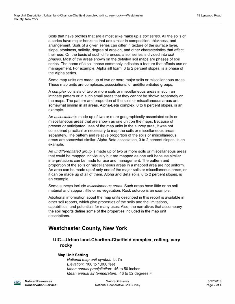
Soils that have profiles that are almost alike make up a soil series. All the soils of a series have major horizons that are similar in composition, thickness, and arrangement. Soils of a given series can differ in texture of the surface layer, slope, stoniness, salinity, degree of erosion, and other characteristics that affect their use. On the basis of such differences, a soil series is divided into soil phases. Most of the areas shown on the detailed soil maps are phases of soil series. The name of a soil phase commonly indicates a feature that affects use or management. For example, Alpha silt loam, 0 to 2 percent slopes, is a phase of the Alpha series.
Some map units are made up of two or more major soils or miscellaneous areas. These map units are complexes, associations, or undifferentiated groups.
A complex consists of two or more soils or miscellaneous areas in such an intricate pattern or in such small areas that they cannot be shown separately on the maps. The pattern and proportion of the soils or miscellaneous areas are somewhat similar in all areas. Alpha-Beta complex, 0 to 6 percent slopes, is an example.
An association is made up of two or more geographically associated soils or miscellaneous areas that are shown as one unit on the maps. Because of present or anticipated uses of the map units in the survey area, it was not considered practical or necessary to map the soils or miscellaneous areas separately. The pattern and relative proportion of the soils or miscellaneous areas are somewhat similar. Alpha-Beta association, 0 to 2 percent slopes, is an example.
An undifferentiated group is made up of two or more soils or miscellaneous areas that could be mapped individually but are mapped as one unit because similar interpretations can be made for use and management. The pattern and proportion of the soils or miscellaneous areas in a mapped area are not uniform. An area can be made up of only one of the major soils or miscellaneous areas, or it can be made up of all of them. Alpha and Beta soils, 0 to 2 percent slopes, is an example.
Some surveys include miscellaneous areas. Such areas have little or no soil material and support little or no vegetation. Rock outcrop is an example.
Additional information about the map units described in this report is available in other soil reports, which give properties of the soils and the limitations, capabilities, and potentials for many uses. Also, the narratives that accompany the soil reports define some of the properties included in the map unit descriptions.
Westchester County, New York
UlC—Urban land-Charlton-Chatfield complex, rolling, very rocky
Map Unit SettingNational map unit symbol: bd7nElevation: 100 to 1,000 feetMean annual precipitation: 46 to 50 inchesMean annual air temperature: 46 to 52 degrees F
Map Unit Description: Urban land-Charlton-Chatfield complex, rolling, very rocky---Westchester County, New York
19 Lynwood Road
Natural ResourcesConservation Service
Web Soil SurveyNational Cooperative Soil Survey
6/27/2018Page 2 of 4
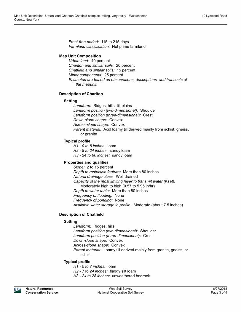
Frost-free period: 115 to 215 daysFarmland classification: Not prime farmland
Map Unit CompositionUrban land: 40 percentCharlton and similar soils: 20 percentChatfield and similar soils: 15 percentMinor components: 25 percentEstimates are based on observations, descriptions, and transects of
the mapunit.
Description of Charlton
SettingLandform: Ridges, hills, till plainsLandform position (two-dimensional): ShoulderLandform position (three-dimensional): CrestDown-slope shape: ConvexAcross-slope shape: ConvexParent material: Acid loamy till derived mainly from schist, gneiss,
or granite
Typical profileH1 - 0 to 8 inches: loamH2 - 8 to 24 inches: sandy loamH3 - 24 to 60 inches: sandy loam
Properties and qualitiesSlope: 2 to 15 percentDepth to restrictive feature: More than 80 inchesNatural drainage class: Well drainedCapacity of the most limiting layer to transmit water (Ksat):
Moderately high to high (0.57 to 5.95 in/hr)Depth to water table: More than 80 inchesFrequency of flooding: NoneFrequency of ponding: NoneAvailable water storage in profile: Moderate (about 7.5 inches)
Description of Chatfield
SettingLandform: Ridges, hillsLandform position (two-dimensional): ShoulderLandform position (three-dimensional): CrestDown-slope shape: ConvexAcross-slope shape: ConvexParent material: Loamy till derived mainly from granite, gneiss, or
schist
Typical profileH1 - 0 to 7 inches: loamH2 - 7 to 24 inches: flaggy silt loamH3 - 24 to 28 inches: unweathered bedrock
Map Unit Description: Urban land-Charlton-Chatfield complex, rolling, very rocky---Westchester County, New York
19 Lynwood Road
Natural ResourcesConservation Service
Web Soil SurveyNational Cooperative Soil Survey
6/27/2018Page 3 of 4
Properties and qualitiesSlope: 2 to 15 percentDepth to restrictive feature: 20 to 40 inches to lithic bedrockNatural drainage class: Well drainedCapacity of the most limiting layer to transmit water (Ksat): Low to
high (0.01 to 5.95 in/hr)Depth to water table: More than 80 inchesFrequency of flooding: NoneFrequency of ponding: NoneCalcium carbonate, maximum in profile: 1 percentAvailable water storage in profile: Low (about 3.2 inches)
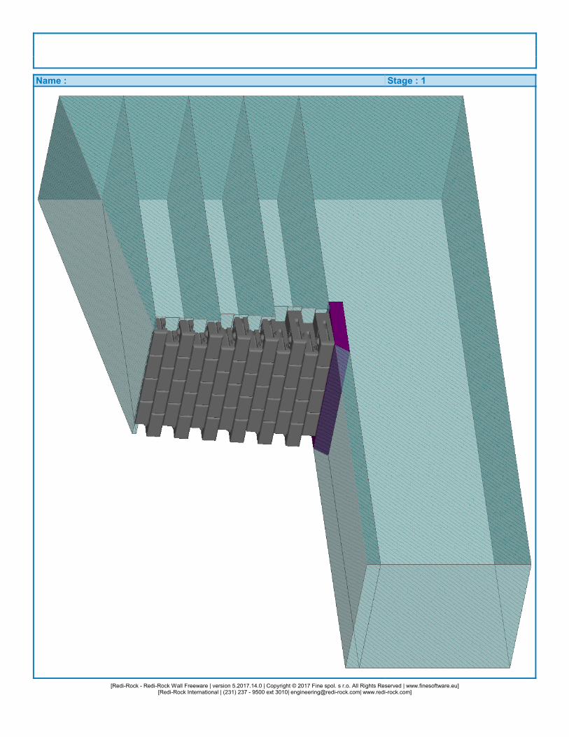
Minor Components
LeicesterPercent of map unit: 5 percentLandform: DepressionsHydric soil rating: No
SuttonPercent of map unit: 5 percentHydric soil rating: No
UdorthentsPercent of map unit: 5 percentHydric soil rating: No
Rock outcropPercent of map unit: 5 percentHydric soil rating: Unranked
HollisPercent of map unit: 2 percentHydric soil rating: No
SunPercent of map unit: 2 percentLandform: DepressionsHydric soil rating: Yes
PalmsPercent of map unit: 1 percentLandform: Marshes, swampsHydric soil rating: Yes
Data Source Information
Soil Survey Area: Westchester County, New YorkSurvey Area Data: Version 13, Oct 8, 2017
Map Unit Description: Urban land-Charlton-Chatfield complex, rolling, very rocky---Westchester County, New York
19 Lynwood Road
Natural ResourcesConservation Service
Web Soil SurveyNational Cooperative Soil Survey
6/27/2018Page 4 of 4
[Redi-Rock - Redi-Rock Wall Freeware | version 5.2017.14.0 | Copyright © 2017 Fine spol. s r.o. All Rights Reserved | www.finesoftware.eu][Redi-Rock International | (231) 237 - 9500 ext 3010| [email protected]| www.redi-rock.com]
Name : Stage : 1
1[Redi-Rock - Redi-Rock Wall Freeware | version 5.2017.14.0 | Copyright © 2017 Fine spol. s r.o. All Rights Reserved | www.finesoftware.eu]
[Redi-Rock International | (231) 237 - 9500 ext 3010| [email protected]| www.redi-rock.com]
Slope stability analysisInput dataProjectSettingsUSA - Safety factorStability analysisEarthquake analysis :Verification methodology :
StandardSafety factors (ASD)
Safety factorsPermanent design situation
Safety factor : SFs = 1.50 [–]
Interface
No. Interface locationCoordinates of interface points [ft]
x z x z x z1
2
3
4
-48.75-1.91-1.77-1.50-1.36-1.09-0.96-0.69-0.550.00
0.00
-0.821.511.781.92
1.38
-19.50-18.00-15.00-13.50-10.50-9.00-6.00-4.50-1.500.00
0.00
-6.00-4.50-3.00-0.42
-6.00
-2.04-1.91-1.64-1.50-1.23-1.09-0.82-0.69-0.4258.50
0.00
1.381.651.78
58.50
1.38
-19.50-16.50-15.00-12.00-10.50-7.50-6.00-3.00-1.5011.70
-0.42
-6.00-4.50-1.50-0.42
-7.50
-2.04-1.77-1.64-1.36-1.23-0.96-0.82-0.55-0.42
1.92
1.511.651.92
2.28
-18.00-16.50-13.50-12.00-9.00-7.50-4.50-3.000.00
-0.42
-6.00-3.00-1.50
-7.50
2[Redi-Rock - Redi-Rock Wall Freeware | version 5.2017.14.0 | Copyright © 2017 Fine spol. s r.o. All Rights Reserved | www.finesoftware.eu]
[Redi-Rock International | (231) 237 - 9500 ext 3010| [email protected]| www.redi-rock.com]
No. Interface locationCoordinates of interface points [ft]
x z x z x z5
6
7
8
9
10
-1.362.012.28
1.88
-2.043.093.23
58.50
2.96
-48.75
-3.0458.50
-12.00-10.50-9.00
-12.00
-19.50-18.00-15.00-13.50
-19.50
-21.00
-21.00-19.50
1.882.152.28
1.88
2.963.093.36
3.96
-3.04
3.96
-12.00-10.50-7.50
-13.50
-19.50-16.50-15.00
-19.50
-21.00
-21.00
2.012.15
58.50
3.36
2.963.233.36
-2.04
3.96
-12.00-9.00-7.50
-13.50
-18.00-16.50-13.50
-19.50
-19.50
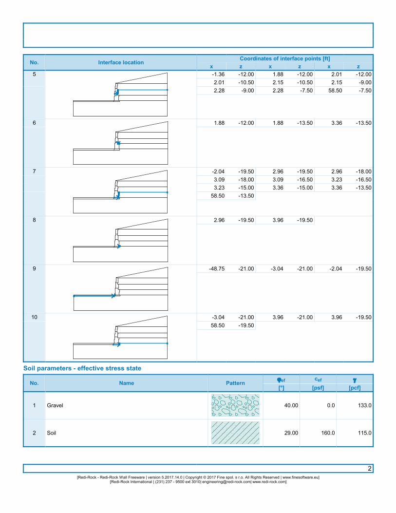
Soil parameters - effective stress state
No. Name Patternjef[°]
cef[psf]
g[pcf]
1
2
Gravel
Soil
40.00
29.00
0.0
160.0
133.0
115.0

3[Redi-Rock - Redi-Rock Wall Freeware | version 5.2017.14.0 | Copyright © 2017 Fine spol. s r.o. All Rights Reserved | www.finesoftware.eu]
[Redi-Rock International | (231) 237 - 9500 ext 3010| [email protected]| www.redi-rock.com]
Soil parameters - uplift
No. Name Patterngsat[pcf]
gs[pcf]
n[–]
1
2
Gravel
Soil
133.0
115.0
Soil parametersGravelUnit weight :Stress-state :Angle of internal friction :Cohesion of soil :Saturated unit weight :
geffectivejefcefgsat
=
===
133.0
40.000.0
133.0
pcf
°psfpcf
SoilUnit weight :Stress-state :Angle of internal friction :Cohesion of soil :Saturated unit weight :
geffectivejefcefgsat
=
===
115.0
29.00160.0115.0
pcf
°psfpcf
Rigid bodies
No. Name Sample g[pcf]
1 Wall material 120.0
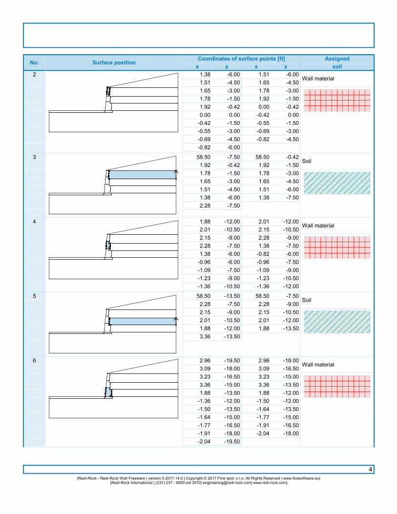
Assigning and surfaces
No. Surface positionCoordinates of surface points [ft]x z x z
Assignedsoil
1 58.500.001.92
-0.420.00
-0.42
58.500.00
11.70-0.42
Soil
4[Redi-Rock - Redi-Rock Wall Freeware | version 5.2017.14.0 | Copyright © 2017 Fine spol. s r.o. All Rights Reserved | www.finesoftware.eu]
[Redi-Rock International | (231) 237 - 9500 ext 3010| [email protected]| www.redi-rock.com]
No. Surface positionCoordinates of surface points [ft]x z x z
Assignedsoil
2
3
4
5
6
1.381.511.651.781.920.00
-0.42-0.55-0.69-0.82
58.501.921.781.651.511.382.28
1.882.012.152.281.38
-0.96-1.09-1.23-1.36
58.502.282.152.011.883.36
2.963.093.233.361.88
-1.36-1.50-1.64-1.77-1.91-2.04
-6.00-4.50-3.00-1.50-0.420.00
-1.50-3.00-4.50-6.00
-7.50-0.42-1.50-3.00-4.50-6.00-7.50
-12.00-10.50-9.00-7.50-6.00-6.00-7.50-9.00
-10.50
-13.50-7.50-9.00
-10.50-12.00-13.50
-19.50-18.00-16.50-15.00-13.50-12.00-13.50-15.00-16.50-18.00-19.50
1.511.651.781.920.00
-0.42-0.55-0.69-0.82
58.501.921.781.651.511.38
2.012.152.281.38
-0.82-0.96-1.09-1.23-1.36
58.502.282.152.011.88
2.963.093.233.361.88
-1.50-1.64-1.77-1.91-2.04
-6.00-4.50-3.00-1.50-0.420.00
-1.50-3.00-4.50
-0.42-1.50-3.00-4.50-6.00-7.50
-12.00-10.50-9.00-7.50-6.00-7.50-9.00
-10.50-12.00
-7.50-9.00
-10.50-12.00-13.50
-18.00-16.50-15.00-13.50-12.00-12.00-13.50-15.00-16.50-18.00
Wall material
Soil
Wall material
Soil
Wall material
5[Redi-Rock - Redi-Rock Wall Freeware | version 5.2017.14.0 | Copyright © 2017 Fine spol. s r.o. All Rights Reserved | www.finesoftware.eu]
[Redi-Rock International | (231) 237 - 9500 ext 3010| [email protected]| www.redi-rock.com]
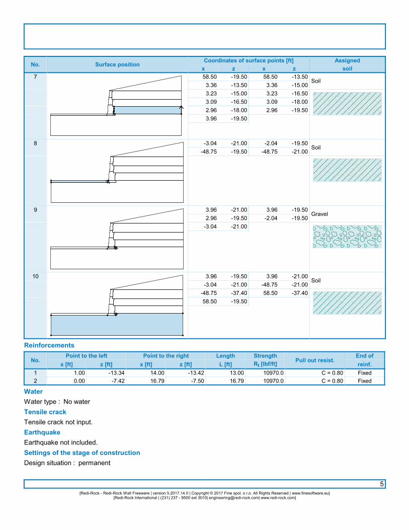
No. Surface positionCoordinates of surface points [ft]x z x z
Assignedsoil
7
8
9
10
58.503.363.233.092.963.96
-3.04-48.75
3.962.96
-3.04
3.96-3.04
-48.7558.50
-19.50-13.50-15.00-16.50-18.00-19.50
-21.00-19.50
-21.00-19.50-21.00
-19.50-21.00-37.40-19.50
58.503.363.233.092.96
-2.04-48.75
3.96-2.04
3.96-48.7558.50
-13.50-15.00-16.50-18.00-19.50
-19.50-21.00
-19.50-19.50
-21.00-21.00-37.40
Soil
Soil
Gravel
Soil
Reinforcements
No.Point to the left
x [ft] z [ft]Point to the right
x [ft] z [ft]LengthL [ft]
StrengthRt [lbf/ft]
Pull out resist.End ofreinf.
12
1.000.00
-13.34-7.42
14.0016.79
-13.42-7.50
13.0016.79
10970.010970.0
C = 0.80C = 0.80
FixedFixed
WaterWater type : No waterTensile crackTensile crack not input.EarthquakeEarthquake not included.Settings of the stage of constructionDesign situation : permanent
6[Redi-Rock - Redi-Rock Wall Freeware | version 5.2017.14.0 | Copyright © 2017 Fine spol. s r.o. All Rights Reserved | www.finesoftware.eu]
[Redi-Rock International | (231) 237 - 9500 ext 3010| [email protected]| www.redi-rock.com]
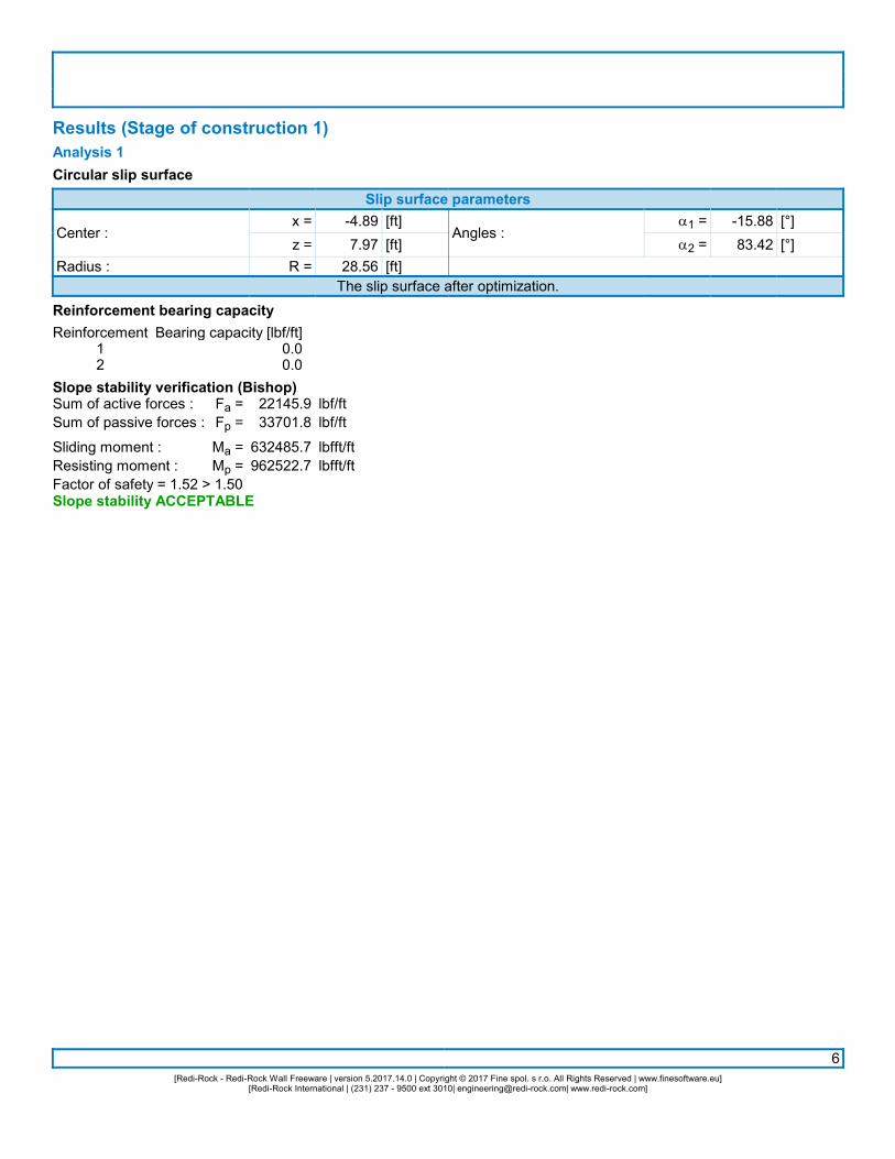
Results (Stage of construction 1)Analysis 1Circular slip surface
Slip surface parameters
Center :
Radius :
x =z =R =
-4.897.97
28.56
[ft][ft][ft]
Angles :a1 =a2 =
-15.8883.42
[°][°]
The slip surface after optimization.Reinforcement bearing capacityReinforcement
12
Bearing capacity [lbf/ft]0.00.0
Slope stability verification (Bishop)Sum of active forces :Sum of passive forces :
Sliding moment :Resisting moment :
Fa =Fp =
Ma =Mp =
22145.933701.8
632485.7962522.7
lbf/ftlbf/ft
lbfft/ftlbfft/ft
Factor of safety = 1.52 > 1.50Slope stability ACCEPTABLE
Related Documents