18SP642 – EPA07 Series 60 ® Vertical Turbocharger Actuator Service Kit P/N: 23537846 KIT DESCRIPTION Service Kit (P/N: 23537846) is for an EPA07 Series 60 ® Vertical Turbocharger Actuator Cooling Upgrade. KITS CONTENTS Two new coolant lines that supply coolant to the turbocharger/actuator and one oil supply line are necessary to complete the upgrade. Service kit (P/N: 23537846) will be available by June 1, 2007 from the Canton Parts Distribution Center. This kit contains the parts listed in Table 1. Description Current Part Number New Part Number Oil supply line to turbo 23536803 23537831 Coolant supply line to turbo 23536805 23537832 Coolant supply line to actuator 23536806 23537833 Coolant T-Fitting 23535461 same - relocated Straight fitting 5319974072 same - relocated Elbow fitting 23537216 same - repositioned Gasket – oil drain (upper) 08929285 same Tie Strap - wiring -- 05101020 Installation Instructions -- 18SP642 Table 1 Series 60 Vertical Turbocharger Actuator Service Kit Contents (P/N: 23537846) INSTALLATION PROCEDURE Remove the existing coolant and oil lines as follows: HOT COOLANT To avoid scalding from the expulsion of hot coolant, never remove the cooling system pressure cap while the engine is at operating temperature. Wear adequate protective clothing (face shield, rubber gloves, apron, and boots). Remove the cap slowly to relieve pressure. 1. Drain the coolant completely. 18SP642 Page 1 of 6

Welcome message from author
This document is posted to help you gain knowledge. Please leave a comment to let me know what you think about it! Share it to your friends and learn new things together.
Transcript

18SP642 – EPA07 Series 60® Vertical Turbocharger
Actuator Service Kit P/N: 23537846 KIT DESCRIPTION Service Kit (P/N: 23537846) is for an EPA07 Series 60® Vertical Turbocharger Actuator Cooling Upgrade. KITS CONTENTS Two new coolant lines that supply coolant to the turbocharger/actuator and one oil supply line are necessary to complete the upgrade. Service kit (P/N: 23537846) will be available by June 1, 2007 from the Canton Parts Distribution Center. This kit contains the parts listed in Table 1.
Description Current Part Number New Part Number Oil supply line to turbo 23536803 23537831
Coolant supply line to turbo 23536805 23537832 Coolant supply line to actuator 23536806 23537833
Coolant T-Fitting 23535461 same - relocated Straight fitting 5319974072 same - relocated Elbow fitting 23537216 same - repositioned
Gasket – oil drain (upper) 08929285 same Tie Strap - wiring -- 05101020
Installation Instructions -- 18SP642 Table 1 Series 60 Vertical Turbocharger Actuator Service Kit Contents
(P/N: 23537846) INSTALLATION PROCEDURE Remove the existing coolant and oil lines as follows:
HOT COOLANT To avoid scalding from the expulsion of hot coolant, never remove the cooling system pressure cap while the engine is at operating temperature. Wear adequate protective clothing (face shield, rubber gloves, apron, and boots). Remove the cap slowly to relieve pressure. 1. Drain the coolant completely.
18SP642 Page 1 of 6
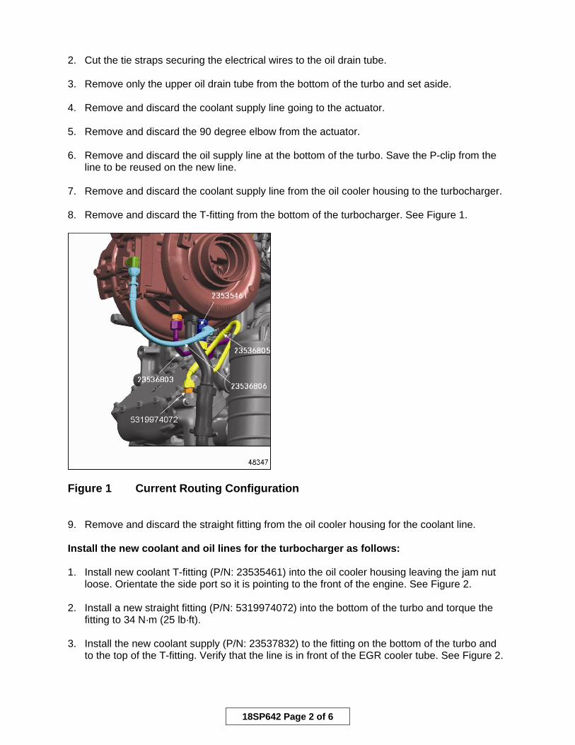
2. Cut the tie straps securing the electrical wires to the oil drain tube. 3. Remove only the upper oil drain tube from the bottom of the turbo and set aside. 4. Remove and discard the coolant supply line going to the actuator. 5. Remove and discard the 90 degree elbow from the actuator. 6. Remove and discard the oil supply line at the bottom of the turbo. Save the P-clip from the line to be reused on the new line. 7. Remove and discard the coolant supply line from the oil cooler housing to the turbocharger. 8. Remove and discard the T-fitting from the bottom of the turbocharger. See Figure 1.
Figure 1 Current Routing Configuration 9. Remove and discard the straight fitting from the oil cooler housing for the coolant line. Install the new coolant and oil lines for the turbocharger as follows: 1. Install new coolant T-fitting (P/N: 23535461) into the oil cooler housing leaving the jam nut
loose. Orientate the side port so it is pointing to the front of the engine. See Figure 2. 2. Install a new straight fitting (P/N: 5319974072) into the bottom of the turbo and torque the
fitting to 34 N·m (25 lb·ft). 3. Install the new coolant supply (P/N: 23537832) to the fitting on the bottom of the turbo and
to the top of the T-fitting. Verify that the line is in front of the EGR cooler tube. See Figure 2.
18SP642 Page 2 of 6

1. Coolant Feed Line
Figure 2 New Routing Configuration 4. Install the 90 degree fitting (P/N: 23537216) into the actuator housing, leaving the
jam nut loose. 5. Install the new coolant line (P/N:23537833) on the side of the T-fitting and to the 90 degree
fitting. See Figure 2. 6. Using a wrench on the 90 degree fitting (P/N: 23537216) to hold the fitting as not to stress
the line, torque the jam nut on the 90 degree fitting to 22 N·m (16.2 lb·ft). 7. Using a wrench on the T-fitting to hold it as not to stress the lines, torque the jam nut to
22 N·m (16.2 lb·ft). 8. Torque the coolant line (P/N: 23537833) fittings to 36-44 N·m (26.5 – 32.5 lb·ft).
See Figure 2. 9. Torque the coolant line (P/N: 23537832) to 34 N·m (25 lb·ft). See Figure 2. 10. Install the P-clip onto the new oil supply line (P/N: 23537831). Install the new line on the
correct fitting on the engine and the turbo. Torque the fittings to 36-44 N·m (26.5 – 32.5 lb·ft). Tighten the screw holding the P-clip to the mounting bracket. See Figures 3 and 4.
18SP642 Page 3 of 6
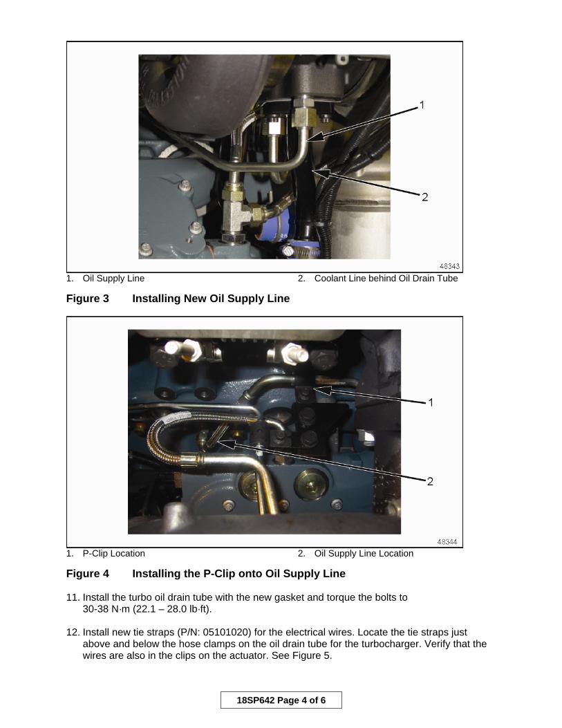
1. Oil Supply Line 2. Coolant Line behind Oil Drain Tube Figure 3 Installing New Oil Supply Line
1. P-Clip Location 2. Oil Supply Line Location Figure 4 Installing the P-Clip onto Oil Supply Line 11. Install the turbo oil drain tube with the new gasket and torque the bolts to
30-38 N·m (22.1 – 28.0 lb·ft). 12. Install new tie straps (P/N: 05101020) for the electrical wires. Locate the tie straps just
above and below the hose clamps on the oil drain tube for the turbocharger. Verify that the wires are also in the clips on the actuator. See Figure 5.
18SP642 Page 4 of 6

1. Tie Straps Location Figure 5 Installing the Tie Straps for Electrical Wires
ELECTRICAL SHOCK To avoid injury from electrical shock, do not touch battery terminals, alternator terminals, or wiring cables while the engine is operating. 13. Verify that there are no lines or electrical wires touching any components that could damage
them. See Figure 6.
18SP642 Page 5 of 6

1. Electrical Wires Location Figure 6 Verification of Electrical Wires Location
ENGINE EXHAUST To avoid injury from inhaling engine exhaust, always operate the engine in a well-ventilated area. Engine exhaust is toxic.
14. Fill coolant system to the proper level, warm the engine and recheck the coolant level.
Check for oil and coolant leaks before releasing the truck. ADDITIONAL INFORMATION/NOTES This condition only exists for engines built with the 06M07C-6469 Turbocharger Group. The turbocharger that is used in the identified group is P/N: 23536802 and is also identified by a vertical orientation of the actuator. CONTACT INFORMATION Please contact the DDC Customer Support Center at 313-592-5800 if you have any questions.
Copyright© 2007 Detroit Diesel Corporation. Detroit Diesel®, DDC®, and the spinning arrows design are registered trademarks of Detroit Diesel Corporation. All other trademarks are the property of their respective owners. 18SP642 0708 As technical advances continue, specifications will change. All rights reserved. Printed in U.S.A.
18SP642 Page 6 of 6
Related Documents