188 HEAT TRANSFER AND HEAT EXCHANGERS TABLE 8.8. Dimensionless Groups and Units of Quantities Pertaining to Heat Transfer Symbol Number Group Bi Fo Gz Gr Nu Pe Pr Re sc St Biot Fourier Graetz Grashof Nusselt Peclet Prandtl Reynolds Schmidt Stanton Notation Name and Typical Units k kd L T, AT U 0 W B e P P heat capacity [Btu/(lb)(“F), cal/(g)(’C)] diameter (ti, m) acceleration of gravity [ft/lhr)’, m/sec’] mass velocity [Ib/(hr)(ft)’, kg/sec)(m)’] heat transfer coefficient [Btu/(hr)(sqft)(”F), thermal conductivity [Btu/(hr)(sqft)(“F/ft). diffusivity (volumetric) [ft’/hr, cm2/secl length (ft, cm) temperature,temperature difference (“F or OR, “C or K) linear velocity (ft/hr, cm/sec) overall heat coefficient (same as units of h) mass rate of flow (Ib/hr, g/sec) Thermal expansion coefficient (l/”F, l/”C) time (hr, sec) viscosity [Ib/(R)(hr), g/(cm)(secll density ~ b / ( f t ) ~ , g/(~rn)~] ~/(m)’(sec)l ca1/(sec)(cm’~(~/cm)1 can exist in any particular case. Transition between modes corresponds to a maximum heat flux and the associated critical temperature difference. A table of such data by McAdams (Heat Transmission, McGraw-Hill, New York, 1954, p. 386) shows the critical temperature differences to range from 42-90°F and the maximum fluxes from 42-126 KBtu/(hr)(sqft) for organic sub- stances and up to 410 KBtu/(hr)(sqft) for water; the nature of the surface and any promoters are identified. Equations (40) and (41) of Table 8.10 are for critical heat fluxes in kettle and thermosyphon reboilers. Beyond the maximum rate, film boiling develops and the rate of heat transfer drops off very sharply. Evaluation of the boiling heat transfer coefficient in vertical tubes, as in thermosyphon reboilers, is based on a group of equations, (42)-(48), of Table 8.10. A suitable procedure is listed following these equations in that table. EXTENDED SURFACES When a film coefficient is low as in the cases of low pressure gases and viscous liquids, heat transfer can be improved economically by employing extended surfaces. Figure 8.6 illustrates a variety of extended surfaces. Since the temperature of a fin necessarily averages less than that of the bare surface, the effectiveness likewise is less than that of bare surface. For many designs, the extended surface may be taken to be 60% as effective as bare surface, but this factor depends on the heat transfer coefficient and thermal conductivity of the fin as well as its geometry. Equations and corresponding charts have been developed for the common geometries and are shown, for example, in HEDH (1983, Sec. 2.5.3) and elsewhere. One chart is given with Example 8.6. The efficiency 1 of the extended surface is defined as the ratio of a realized heat transfer to the heat transfer that would be obtained if the fin were at the bare tube temperature throughout. The total heat transfer is the sum of the heat transfers through the bare and the extended surfaces: Ab is the tube surface that is not occupied by fins. Example 8.6 performs an analysis of this kind of problem. 8.5. PRESSURE DROP IN HEAT EXCHANGERS Although the rate of heat transfer to or from fluids is improved by increase of linear velocity, such improvements are limited by the economic balance between value of equipment saving and cost of pumping. A practical rule is that pressure drop in vacuum condensers be limited to 0.5-1.0 psi (25-50 Torr) or less, depending on the required upstream process pressure. In liquid service, pressure drops of 5-1Opsi are employed as a minimum, and up to 15% or so of the upstream pressure. Calculation of tube-side pressure drop is straightforward, even of vapor-liquid mixtures when their proportions can be estimated. Example 8.7 employs the methods of Chapter 6 for pressure drop in a thermosiphon reboiler. The shell side with a number of segmental baffles presents more of a problem. It may be treated as a series of ideal tube banks connected by window zones, but also accompanied by some bypassing of the tube bundles and leakage through the baffles. A hand calculation based on this mechanism (ascribed to K.J. Bell) is illustrated by Ganapathy (1982, pp. 292-302), but the calculation usually is made with proprietary computer programs, that of HTRI for instance. A simpler method due to Kern (1950, pp. 147-152) nominally considers only the drop across the tube banks, but actually takes account of the added pressure drop through baffle windows by employing a higher than normal friction factor to evaluate pressure drop across the tube banks. Example 8.8 employs this procedure. According to Taborek (HEDH, 1983, 3.3.2), the Kern predictions usually are high, and therefore considered safe, by a factor as high as 2, except in laminar flow where the results are uncertain. In the case worked out by Ganapathy (1982, pp. 292-302), however, the Bell and Kern results are essentially the same. 8.6. TYPES OF HEAT EXCHANGERS Heat exchangers are equipment primarily for transferring heat between hot and cold streams. They have separate passages for the two streams and operate continuously. They also are called recuperators to distinguish them from regenerators, in which hot and cold streams pass alternately through the same passages and exchange heat with the mass of the equipment, which is in- tentionally made with large heat capacity. Recuperators are used mostly in cryogenic services, and at the other extreme of tem- perature, as high temperature air preheaters. They will not be discussed here; a detailed treatment of their theory is by Hausen (1983). Being the most widely used kind of process equipment is a claim that is made easily for heat exchangers. A classified directory of manufacturers of heat exchangers by Walker (1982) has several hundred items, including about 200 manufacturers of shell-and-tube equipment. The most versatile and widely used exchangers are the shell-and-tube types, but various plate and other types are valuable and economically competitive or superior in some applications. These other types will be discussed briefly, but most of the space following will be devoted to the shell-and-tube types, primarily

Welcome message from author
This document is posted to help you gain knowledge. Please leave a comment to let me know what you think about it! Share it to your friends and learn new things together.
Transcript

188 HEAT TRANSFER A N D HEAT EXCHANGERS
TABLE 8.8. Dimensionless Groups and Units of Quantities Pertaining to Heat Transfer
Symbol Number Group
Bi Fo Gz G r Nu Pe Pr Re sc St
Biot Fourier Graetz Grashof Nusselt Peclet Prandtl Reynolds Schmidt Stanton
Notation Name and Typical Units
k
kd L T, AT
U 0
W
B e P P
heat capacity [Btu/(lb)(“F), cal/(g)(’C)] diameter (ti, m) acceleration of gravity [ft/lhr)’, m/sec’] mass velocity [Ib/(hr)(ft)’, kg/sec)(m)’] heat transfer coefficient [Btu/(hr)(sqft)(”F),
thermal conductivity [Btu/(hr)(sqft)(“F/ft).
diffusivity (volumetric) [ft’/hr, cm2/secl length (ft, cm) temperature, temperature difference (“F or O R , “C or K) linear velocity (ft/hr, cm/sec) overall heat coefficient (same as units of h ) mass rate of flow (Ib/hr, g/sec) Thermal expansion coefficient (l/”F, l/”C) time (hr , sec) viscosity [Ib/(R)(hr), g/(cm)(secll density ~ b / ( f t ) ~ , g / ( ~ r n ) ~ ]
~/(m)’(sec)l
ca1/(sec)(cm’~(~/cm)1
can exist in any particular case. Transition between modes corresponds to a maximum heat flux and the associated critical temperature difference. A table of such data by McAdams (Heat Transmission, McGraw-Hill, New York, 1954, p. 386) shows the critical temperature differences to range from 42-90°F and the maximum fluxes from 42-126 KBtu/(hr)(sqft) for organic sub- stances and up to 410 KBtu/(hr)(sqft) for water; the nature of the surface and any promoters are identified. Equations (40) and (41) of Table 8.10 are for critical heat fluxes in kettle and thermosyphon reboilers. Beyond the maximum rate, film boiling develops and the rate of heat transfer drops off very sharply.
Evaluation of the boiling heat transfer coefficient in vertical tubes, as in thermosyphon reboilers, is based on a group of equations, (42)-(48), of Table 8.10. A suitable procedure is listed following these equations in that table.
EXTENDED SURFACES
When a film coefficient is low as in the cases of low pressure gases and viscous liquids, heat transfer can be improved economically by employing extended surfaces. Figure 8.6 illustrates a variety of extended surfaces. Since the temperature of a fin necessarily averages less than that of the bare surface, the effectiveness likewise is less than that of bare surface. For many designs, the extended surface may be taken to be 60% as effective as bare surface, but this factor depends on the heat transfer coefficient and thermal conductivity of the fin as well as its geometry. Equations and corresponding charts have been developed for the common geometries and are shown, for example, in HEDH (1983, Sec. 2.5.3) and elsewhere. One chart is given with Example 8.6. The efficiency 1 of the extended surface is defined as the ratio of a
realized heat transfer to the heat transfer that would be obtained if the fin were at the bare tube temperature throughout. The total heat transfer is the sum of the heat transfers through the bare and the extended surfaces:
Ab is the tube surface that is not occupied by fins. Example 8.6 performs an analysis of this kind of problem.
8.5. PRESSURE DROP IN HEAT EXCHANGERS
Although the rate of heat transfer to or from fluids is improved by increase of linear velocity, such improvements are limited by the economic balance between value of equipment saving and cost of pumping. A practical rule is that pressure drop in vacuum condensers be limited to 0.5-1.0 psi (25-50 Torr) or less, depending on the required upstream process pressure. In liquid service, pressure drops of 5-1Opsi are employed as a minimum, and up to 15% or so of the upstream pressure.
Calculation of tube-side pressure drop is straightforward, even of vapor-liquid mixtures when their proportions can be estimated. Example 8.7 employs the methods of Chapter 6 for pressure drop in a thermosiphon reboiler.
The shell side with a number of segmental baffles presents more of a problem. It may be treated as a series of ideal tube banks connected by window zones, but also accompanied by some bypassing of the tube bundles and leakage through the baffles. A hand calculation based on this mechanism (ascribed to K.J. Bell) is illustrated by Ganapathy (1982, pp. 292-302), but the calculation usually is made with proprietary computer programs, that of HTRI for instance.
A simpler method due to Kern (1950, pp. 147-152) nominally considers only the drop across the tube banks, but actually takes account of the added pressure drop through baffle windows by employing a higher than normal friction factor to evaluate pressure drop across the tube banks. Example 8.8 employs this procedure. According to Taborek (HEDH, 1983, 3.3.2), the Kern predictions usually are high, and therefore considered safe, by a factor as high as 2, except in laminar flow where the results are uncertain. In the case worked out by Ganapathy (1982, pp. 292-302), however, the Bell and Kern results are essentially the same.
8.6. TYPES OF HEAT EXCHANGERS
Heat exchangers are equipment primarily for transferring heat between hot and cold streams. They have separate passages for the two streams and operate continuously. They also are called recuperators to distinguish them from regenerators, in which hot and cold streams pass alternately through the same passages and exchange heat with the mass of the equipment, which is in- tentionally made with large heat capacity. Recuperators are used mostly in cryogenic services, and at the other extreme of tem- perature, as high temperature air preheaters. They will not be discussed here; a detailed treatment of their theory is by Hausen (1983).
Being the most widely used kind of process equipment is a claim that is made easily for heat exchangers. A classified directory of manufacturers of heat exchangers by Walker (1982) has several hundred items, including about 200 manufacturers of shell-and-tube equipment. The most versatile and widely used exchangers are the shell-and-tube types, but various plate and other types are valuable and economically competitive or superior in some applications. These other types will be discussed briefly, but most of the space following will be devoted to the shell-and-tube types, primarily

8.6. TYPES OF HEAT EXCHANGERS 189
TABLE 8.9. Equations for Heat Transfer Coefficients of Natural Convection
Vertical plates and cylinders, length L
hL/k= 0.13Xi”, turbulent, h=0.19(At)”3, for air, A t in “F, h in Btu/(hr)(sqft)(”F)
hL/k=0.59XP, laminar, 104<XL< lo9 h=0.29(At/L)1’4, for air, L in ft
lo9 < X, < 10”
Single horizontal cylinder, diameter Do
D & b L A t P S
x D = v ( ) hDo/k= 0.53XF, lo3< X, < lo9
h=O.l8(At)’”, forair, 109<X, <lo’* h=0.27(At/D,)1/4, 104<XD<109
Horizontal plates, rectangular, L the smaller dimension
Heated plates facing up or cooled facing down
hL/k=O.l4X:”, 2(107)<XL<3(1010), turbulent
hL/k=0.54X:”, 105<X,<2(107), laminar h = 0.22(~ t ) ”~ , for air
h = 0.27(At/L)”4
Heated plates facing down, or cooled facing up
hL/k=0.27XP, 3(105)<XL<3(1010), laminar h=0.12(At/L)”4, for air
Combined convection and radiation coefficients, h, + h,, for horizontal steel or insulated pipes in a room at 80°F
~~~ ~
Nominal Pipe Dia
(At),, Temperature Difference (“F) from Surface to Room
(in.) 50 100 150 200 250 300 400 500 600 700 800 900 1000 1100 1200 ~~ ~ ~
1 - 2 2.12 2.48 2.76 3.10 3.41 3.75 4.47 5.30 6.21 7.25 8.40 9.73 11.20 12.81 14.65 1 2.03 2.38 2.65 2.98 3.29 3.62 4.33 5.16 6.07 7.11 8.25 9.57 11.04 12.65 14.48 2 1.93 2.27 2.52 2.85 3.14 3.47 4.18 4.99 5.89 6.92 8.07 9.38 10.85 12.46 14.28 4 1.84 2.16 2.41 2.72 3.01 3.33 4.02 4.83 5.72 6.75 7.89 9.21 10.66 12.27 14.09 8 1.76 2.06 2.29 2.60 2.89 3.20 3.88 4.68 5.57 6.60 7.73 9.05 10.50 12.10 13.93
12 1.71 2.01 2.24 2.54 2.82 3.13 3.83 4.61 5.50 6.52 7.65 8.96 10.42 12.03 13.84 24 1.64 1.93 2.15 2.45 2.72 3.03 3.70 4.48 5.37 6.39 7.52 8.83 10.28 11.90 13.70
(McAdams, Heat Transmission, McGraw-Hill, New York, 1954).
because of their importance, but also because they are most completely documented in the literature. Thus they can be designed with a degree of confidence to fit into a process. The other types are largely proprietary and for the most part must be process designed by their manufacturers.
PLATE-AND-FRAME EXCHANGERS
Plate-and-frame exchangers are assemblies of pressed corrugated plates on a frame, as shown on Figure 8.8(a). Gaskets in grooves around the periphery contain the fluids and direct the flows into and out of the spaces between the plates. Hot and cold flows are on opposite sides of the plates. Figure 8.8(b) shows a few of the many combinations of parallel and countercurrent flows that can be maintained. Close spacing and the presence of the corrugations
result in high coefficients on both sides-several times those of shell-and-tube equipment-and fouling factors are low, of the order of 1-5 x lo-’ Btu/(hr)(sqft)(OF). The accessibility of the heat exchange surface for cleaning makes them particularly suitable for fouling services and where a high degree of sanitation is required, as in food and pharmaceutical processing. Operating pressures and temperatures are limited by the natures of the available gasketing materials, with usual maxima of 300 psig and 400°F.
Since plate-and-frame exchangers are made by comparatively few concerns, most process design information about them is proprietary but may be made available to serious enquirers. Friction factors and heat transfer coefficients vary with the plate spacing and the kinds of corrugations; a few data are cited in HEDH (1983, 3.7.4-3.7.5). Pumping costs per unit of heat transfer are said to be lower than for shell-and-tube equipment. In stainless steel

190 HEAT TRANSFER AND HEAT EXCHANGERS
TABLE 8.10. Recommended Individual Heat Transfer Coefficient Correlations.
A. Single Phase Streams
a. Laminar Flow, Re < 2300 Inside tubes
Nu, = $3.663 + 1.613 Pe(d/L), 0.1 < Pe(d/L) < lo4 (1)
Between parallel plates of length L and separation distance s
0.0156[Pe(s/L)]'.'4 1 + 0.0581Pe(~/L)I~.~ '
Nu, = 3.78 + 0.1 < Pe(s/L) < io3
In concentric annuli with 4 inside, do outside, and hydraulic diameter dh = do - 4. 1, heat transfer at inside wall: II, at outside wall; 111, at both walls at equal temperatures
0.191Pe(dh/L)10-8 Nu, = Nu, + f ( ")
do 1 + 0.117[Pe(dh/L)]o.467
Case I:
Case II:
Case Ill:
Case I:
Case II:
Case 111:
Nui, = 3.66 + 1.2
Nu, = 3.66 + [ 4 -
b. Turbulent Flow, Re > 2300
Inside tubes
Nu = 0.0214(Re0.8- 100) [ 1 + (3"], - 0.5<Pr<1.5
Nu = 0.012(Re0.87 - 280) [ 1 + (az3], - 1.5<Pr<500
Concentric annuli: Use dh for both Re and Nu. Nutube from Eqs. (10) or (11)
d, -0.16 Nu. Case I: 2- - 0.86( 2)
N U, Case II: -= 1 -0.14
N k b e
N%be
NU, Case 111: ~- - 0.86(4/d,)0.84 + I1 - 0.14(4/do)o.6]
14" be 1 + 4/d,
Across one row of long rubes: d = diameter, s = center-to-center distance, a = s/d, q~ = 1 - n/4a, L = nd/2
Re,,, = wL/Vv
Nuo,row = 0.3 + dNu?,lam + Nu?,turb
NU^,^^^ = 0 . 6 6 4 K P r " 3 NU^,^^^^ = 0.037 Re$af:Pr/[l + 2.443 Re;:i'(PP3 - 1 )I
= &L/A
a Special notation used in this table: CY = heat transfer coefficient (W/m2 K) (instead of h),
(Based on HEDH, 1983). q = viscosity (instead of p ) , and cr = thermal conductivity (instead of k).

8.6. TYPES OF HEAT EXCHANGERS 191
TABLE 8.lO-(continued)
Across a bank of n tubes deep:
1 N-L I NE
+ldP- 0 0 0 0
0 0’0 0”
y r= l -n /4a i f b z l q = l - n / 4 a b i f b < l
= aL/A = f Nu,,,,,/K, n 2 10 [ l + (n - 1)fnI Nu,,,,,/Kn, n < 10
INu,,,,, from Eq. (IS)]
fnin.,ine = 1 + (0.7/~, ’ .~) [ (b/a - 0.3)/(b/a + 0.7)’l
K = (Pr/Pr,)0.25, for liquid heating K = (Pr/Pr,)o-”, for liquid cooling K = (T/Tw)o.12, for gases
f&,,, = 1 + 2/3b
STAGGERED
+Id I+ 0 0
0 0 0 0 0-
0 0 0-i I.- 514
Subscript w designates wall condition
Banks of radial high-fin tubes: E = (bare tube surface)/(total surface of finned tube)
In line:
N,, = 0.30 ~~0.625 -0.375 ~~0.333 , 5<&<12, 5000<Re<105 (29)
Staggered: a = sl/d, b = s,/d, s = spacing of fins
Nu = 0.19(a/b)02(s/d)0~’8(h/d)-o~14 Re0.65Pro.33 , 100 < Re < 20,000 (30)
Banks o f radial low-fin tubes: D=diarneter of finned tube, s =distance between fins, h = height of fin; following correlation for D = 22.2 mrn, s = 1.25 rnm, and h = 1.4 rnm
Nu = 0.0729 , 5000 < R e i 35,000 Nu = 0.137 Reo.” 35,000 c; Re < 235,000 Nu = 0.051 1 235,000 < Re < l o 6
B. Condensation of Pure Vapors
On vertical tubes and other surfaces; r= condensation rate per unit of periphery
On a single horizontal tube: r = condensation rate per unit length of tube
(35)
(continued)
192 HEAT TRANSFER AND HEAT EXCHANGERS
TABLE 8.104continued)
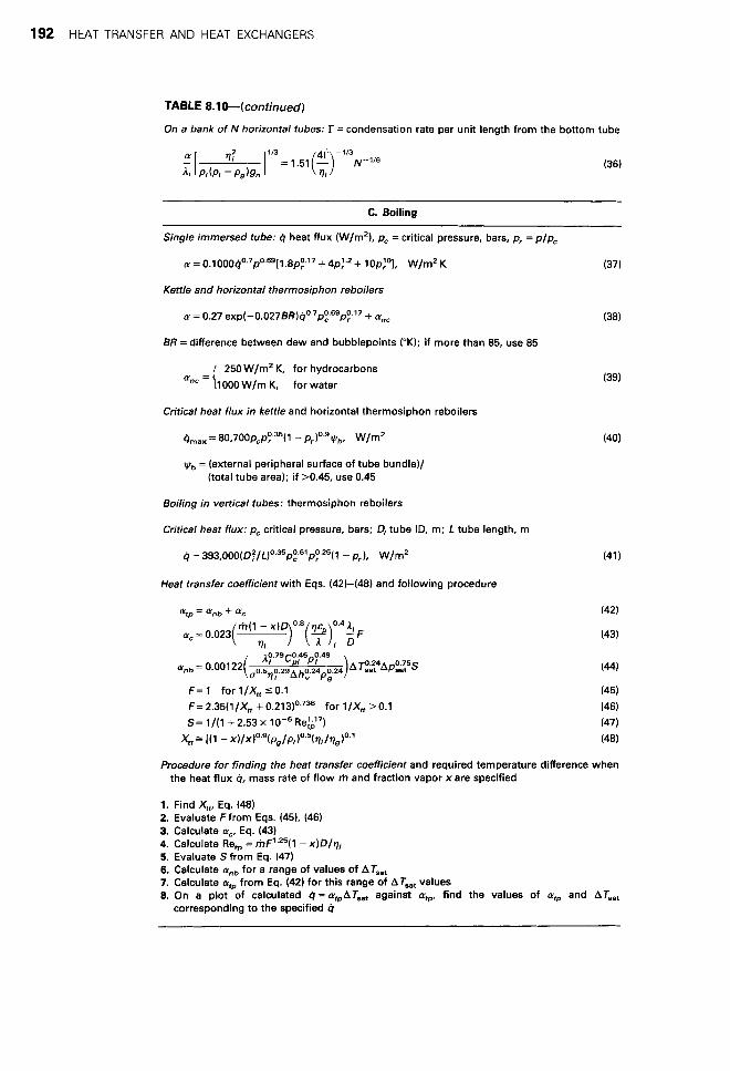
On a bank of N horizontal tubes: r = condensation rate per unit length from the bottom tube
C. Boiling
Single immersed tube: Q heat flux (W/m2), pc = critical pressure, bars, p, = p/p,
(Y = 0.1000Qo~7po~69[1 .8p;l7 + 4p:-’ + W/m2 K (37)
Kettle and horizontal thermosiphon reboilers
(Y = 0.27 e ~ p ( - 0 . 0 2 7 B R ) Q ~ . ~ p ~ ~ ~ p ~ ~ ~ + a,, (38)
BR =difference between dew and bubblepoints (“K); if more than 85, use 85
250 W/m2 K, for hydrocarbons 1000 W/m K, for water ‘ync = (
Critical heat flux in kettle and horizontal thermosiphon reboilers
qmaX = 8 0 , 7 O O p ~ ~ ~ - ~ ~ ( l - pr)O.’qb, W/m’
vb = (external peripheral surface of tube bundle)/ (total tube area); if >0.45, use 0.45
Boiling in vertical tubes: thermosiphon reboilers
Critical heat flux: pc critical pressure, bars; Di tube ID, m; L tube length, m
4 = 3 ~ 3 , 0 0 0 ( ~ ~ / f ) ~ . ~ ~ p ~ ~ ~ p ~ . ~ ~ ( 1 - pr), W/m’
Heat transfer coefficient with Eqs. (42)-(48) and following procedure
crC= 0 . 0 2 3 ( 7 7 m( l - x ) Oa (7 )0 ’42F I
A <‘4Ap:z5S
F= 1 for l/& 50.1 F=2.35(1/XW +0.213)o.736 for l/XW >O. l S= 1/(1 + 2.53 x
& = [ ( l - X)/XIO.~(Pg/P, )0.5(’I,/q,)0”
(39)
(42)
(43)
Procedure for finding the heat transfer coefficient and required temperature difference when the heat flux Q, mass rate of flow rh and fraction vapor x are specified
1. Find &, Eq. (48) 2. Evaluate Ffrom Eqs. (45). (46) 3. Calculate cu,, Eq. (43) 4. Calculate Refp = ~-hF’.’~(l - x ) D / q l 5. Evaluate S from Eq. (47) 6. Calculate cy,, for a range of values of AT,, 7. Calculate q,, from Eq. (42) for this range of ATsat values 8. On a plot of calculated Q=a;,AT,, against arp, find the values of qD and ATsat
corresponding to the specified Q

8.6. TYPES OF HEAT EXCHANGERS 193
EXAMPLE 8.6 Sizing an Exchanger with Radial Finned Tubes
A liquid is heated from 150 to 190°F with a gas that goes from 250 to 200°F. The duty is 1.25MBtu/hr. The inside film coefficient is 200, the bare tube outside coefficient is hb = 20 Btu/(hr)(sqft)("F). The tubes are 1 in. OD, the fins are in. high, 0.038 in. thick, and number 72/ft. The total tube length will be found with fins of steel, brass, or aluminum:
LMTD = (60 - 50)/1n(60/50) = 54.8, Ub = (1/20 + 1/200)-' = 18.18.
Fin surface:
A, = 72(2)(~/4)[(2.25' - 1)/144] = 3.191 sqft/ft.
Uncovered tube surface:
Ab = (~ /12 ) [1 - 72(0.038/12)] = 0.2021 Sqft/ft, A,/Ab = 3.191/0.2021= 15.79, yb = half-fin thickness = 0.038/2(12) = 0.00158 ft.
Abscissa of the chart:
x = (re - r b ) m = [(2.25 - 1)/24]d20/0.00158k
rJrb = 2.25, = 5.86/fi,
Ab = Q/ubAT(1 + VAe/Ab) = 1.25(lO6)/l8.l8(54.8)(1 + 15 .79~) sq ft.
Find ?J from the chart. Tube length, L = Ab/0.2021 ft.
k x q A , , L
Steel 26 1.149 0.59 121.6 602 Brass 60 0.756 0.76 96.5 477 AI 120 0.535 0.86 86.1 426
EXAMPLE 8.7 Pressure Drop on the Tube Side of a Vertical Thermosiphon Reboiler
Liquid with the properties of water at 5 atm and 307°F is reboiled at a feed rate of 2800Ib/(hr)(tube) with 30wt % vaporization. The tubes are 0.1 ft ID and 12 ft long. The pressure drop will be figured at an average vaporization of 15%. The Lockhart-Martinelli, method will be used, following Example 6.14, and the formulas of Tables 6.1 and 6.8:
Liquid Vapor
m (Ib/hr) 2380 420 F (Ib/ft hr) 0.45 0.036 P (Ib/cuft) 57.0 0.172 Re 67340 148544 f 0.0220 0.0203 AP/L (psi/ft) 0.00295 0.0281
X z = 0.00295/0.0281= 0.1051,
q5: = 1 + 20/X + l / X 2 = 72.21, (AP/L) two phase = 72.21(0.00295) = 0.2130, A P = 0.2130(12) = 2.56 psi,
c = 20,
5.90 ft water.
f 1
Average density in reboiler tubes is
= 1.13 lb/cuft. 2800 = 2380/57 + 420/0.172
Required height of liquid in tower above bottom of tube sheet
p,h = 2.56(144) + 1.13(12), h = 382.2/57 = 6.7 ft.

194 HEAT TRANSFER AND HEAT EXCHANGERS
EXAMPLE 8.8 Pressure Drop on the Shell Side with 25% Open Segmental Baffles, by Kern's Method (1950, p. 147)
Nomenclature and formulas:
1. 1028P:/Dt - Dl, 1.2732P:/Dt - D,, square pitch,
triangular pitch, hydraulic diameter Dh =
Q / \
D, = shell diameter, B = distance between baffles, N = number of baffles,
A, = flow area = D,BC/P,, G, = h / A s , lb/(hr)(sqft),
Re = DhGs/PL, f = 0.0121Re-0.19, 300 c Re < lo6, 25% segmental baffles,
s = specific gravity.
Numerical example:
h = 43,800 Ib/hr, s = 0.73 sp gr, p = 0.097 Ib/ft hr,
D,= 1 in., P, = 1.25 in., triangular pitch, C=1.25-1.00=0.25in.,
Ds=21.25in., 1.77ft., Dh=0.723in., O.O603ft., B=5 in . , N = 38 baffles,
A, = 21.25(0.25)(5)/1.25(144) = 0.1476 sqft, G, = 43,800/0.1476 = 296,810 lb/(hr)(sqft),
Re = 0.0603(296,810)/0.97 = 18,450, f= 0.0121(18,450)-0~'9 = 0.00187,
0.00187(296,810)2( 1.77)(39) = 4, 95 psi. A P = 5.22( 10'o)(O. 73)(0.0603)
construction, the plate-and-frame construction cost is 50-70% that of shell-and-tube, according to Marriott (Chem. Eng., April 5, 1971).
A process design of a plate-and-frame exchanger is worked out by Ganapathy (1982, p. 368).
SPIRAL HEAT EXCHANGERS
As appears on Figure 8.8(c), the hot fluid enters at the center of the spiral element and flows to the periphery; flow of the cold fluid is countercurrent, entering at the periphery and leaving at the center. Heat transfer coefficients are high on both sides, and there is no correction to the log mean temperature difference because of the true countercurrent action. These factors may lead to surface requirements 20% or so less than those of shell-and-tube ex- changers. Spiral types generally may be superior with highly viscous fluids at moderate pressures. Design procedures for spiral plate and the related spiral tube exchangers are presented by Minton (1970). Walker (1982) lists 24 manufacturers of this kind of equipment.
COMPACT (PLATE-FIN) EXCHANGERS
Units like Figure 8.6(h), with similar kinds of passages for the hot and cold fluids, are used primarily for gas service. Typically they have surfaces of the order of 1200m2/m3 (353sqft/cuft), corrugation height 3.8-11.8 mm, corrugation thickness 0.2-0.6 mm, and fin density 230-700 fins/m. The large extended surface permits about four times the heat transfer rate per unit volume that can be achieved with shell-and-tube construction. Units have been de- signed for pressures up to 80 atm or so. The close spacings militate against fouling service. Commercially, compact exchangers are used in cryogenic services, and also for heat recovery at high temperatures in connection with gas turbines. For mobile units, as
in motor vehicles, the designs of Figures 8.6(h) and (i) have the great merits of compactness. and light weight. Any kind of arrangement of cross and countercurrent flows is feasible, and three or more different streams can be accommodated in the same equipment. Pressure drop, heat transfer relations, and other aspects of design are well documented, particularly by Kays and London (1984) and in HEDH (1983, Sec. 3.9).
AIR COOLERS
In such equipment the process fluid flows through finned tubes and cooling air is blown across them with fans. Figures 8.4(g) and (h) show the two possible arrangements. The economics of application of air coolers favors services that allow 2540°F temperature difference between ambient air and process outlet. In the range above 10 MBtu/(hr), air coolers can be economically competitive with water coolers when water of adequate quality is available in sufficient amount.
Tubes are 0.75-1.00in. OD, with 7-11fins/in. and 0.5- 0.625in. high, with a total surface 15-20 times bare surface of the tube. Fans are 4-12ft/dia, develop pressures of 0.5-1.5 in. water, and require power inputs of 2-5HP/MBtu/hr or about 7.5HP/ 1OOsqft of exchanger cross section. Spacings of fans along the length of the equipment do not exceed 1.8 times the width of the cooler. Face velocities are about 10 ft/sec at a depth of three rows and 8 ft/sec at a depth of six rows.
Standard air coolers come in widths of 8, 10, 12, 16, or 20ft, lengths of 4-40ft, and stacks of 3-6 rows of tubes. Example 8.8 employs typical spacings.
Three modes of control of air flow are shown in Figure 3.3(e). Precautions may need to be taken against subcooling to the freezing point in winter.

(i) Paral le l and counter flows
( i i ) Countercurrent flows
( i i i ) Paral le l flows throughout
(b)
(C)
Figore 8.8. Plate and spiral compact exchangers. (a) Plate heat exchanger with corrugated plates, gaskets, frame, and corner portals to control flow paths. (b) Flow patterns in plate exchangers, (i) parallel-counter flows; (ii) countercurrent flows; (iii) parallel flows throughout. (c) Spiral exchanger, vertical, and horizontal cross sections.
8.7. SHELL-AND-TUBE HEAT EXCHANGERS 195
Forced draft arrangement, from below the tubes, Figure 8.4(h), develops high turbulence and consequently high heat transfer coefficients. Escape velocities, however, are low, 3 m/sec or so, and as a result poor distribution, backmixing and sensitivity to cross currents can occur. With induced draft from above the tubes, Figure 8.4(g), escape velocities may be of the order of 10 m/sec and better flow distribution results. This kind of installation is more expensive, the pressure drops are higher, and the equipment is bathed in hot air which can be deteriorating. The less solid mounting also can result in noisier operation.
Correlations for friction factors and heat transfer coefficients are cited in HEDH. Some overall coefficients based on external bare tube surfaces are in Tables 8.11 and 8.12. For single passes in cross flow, temperature correction factors are represented by Figure 8.5(c) for example; charts for multipass flow on the tube side are given in HEDH and by Kays and London (1984), for example. Preliminary estimates of air cooler surface requirements can be made with the aid of Figures 8.9 and 8.10, which are applied in Example 8.9.
DOUBLE-PIPES
This kind of exchanger consists of a central pipe supported within a larger one by packing glands [Fig. 8.4(a)]. The straight length is limited to a maximum of about 20 ft; otherwise the center pipe will sag and cause poor distribution in the annulus. It is customary to operate with the high pressure, high temperature, high density, and corrosive fluid in the inner pipe and the less demanding one in the annulus. The inner surface can be provided with scrapers [Fig. 8.4(b)] as in dewaxing of oils or crystallization from solutions. External longitudinal fins in the annular space can be used to improve heat transfer with gases or viscous fluids. When greater heat transfer surfaces are needed, several double-pipes can be stacked in any combination of series or parallel.
Double-pipe exchangers have largely lost out to shell-and-tube units in recent years, although Walker (1982) lists 70 manufacturers of them. They may be worth considering in these situations:
1. When the shell-side coefficient is less than half that of the tube side; the annular side coefficient can be made comparable to the tube side.
2. Temperature crosses that require multishell shell-and-tube units can be avoided by the inherent true countercurrent flow in double pipes.
3. High pressures can be accommodated more economically in the annulus than they can in a larger diameter shell.
4. At duties requiring only 100-200 sqft of surface the double-pipe may be more economical, even in comparison with off-the-shelf units.
The process design of double-pipe exchangers is practically the simplest heat exchanger problem. Pressure drop calculation is straightforward. Heat transfer coefficients in annular spaces have been investigated and equations are cited in Table 8.10. A chapter is devoted to this equipment by Kern (1950).
8.7. SHELL-AND-TUBE HEAT EXCHANGERS
Such exchangers are made up of a number of tubes in parallel and series through which one fluid travels and enclosed in a shell through which the other fluid is conducted.
CONSTRUCTION
The shell side is provided with a number of baffles to promote high velocities and largely more efficient cross flow on the outsides of the

196
TABLE 8.11. Overall Heat Transfer Coefficients in Air Coolers [U Btu/(hr)(OF)(sqft of outside bare tube surface)]
HEAT TRANSFER AND HEAT EXCHANGERS
Liquid Coolers Condensers
Heat-Transfer Heat-Transfer Heat-Transfer
Oils, 20" API 200°F avg. temp 300°F avg. temp 400°F avg. temp
Oils, 30" API 150°F avg. temp 200°F avg. temp 300°F avg. temp 400°F avg. temp
Oils, 40" API 150°F avg. temp 200°F avg. temp 300°F avg. temp 400°F avg. temp
10-16 10-16 13-22 30-40
12-23 25-35 45-55 50-60
25-35 50-60 55-65 60-70
Heavy oils, 8-14"API 300°F avg. temp 400°F avg. temp Diesel oil Kerosene Heavy naphtha Light naphtha Gasoline Light hydrocarbons Alcohols and most
organic solvents
Ammonia Brine, 75% water Water 50% ethylene glycol
and water
6-10 10-16 45-55 55-60 60-65 65-70 70-75 75-80
70-75
100-120 90-110
120-140
100-120
Steam Steam
10% noncondensibles 20% noncondensibles 40% noncondensibles
Pure light hydrocarbons Mixed light hydrocarbons Gasoline Gasoline-steam mixtures Medium hydrocarbons Medium hydrocarbons
Pure organic solvents Ammonia
w/steam
140-150
1 00-1 1 0 95- 1 00 70-75 80-85 65-75 60-75 70-75 45-50
55-60 75-80
100-110
Vapor Coolers
Material
Heat-Transfer Coefficient [Btu/(hr)(ft2)t2)("F)I
10 psig 50 psig 100 psig 300 psig 500 psig
Light hydrocarbons Medium hydrocarbons and organic solvents Light inorganic vapors Air Ammonia Steam Hydrogen
100% 75% VOI
50% vol 25% vol
15-20 15-20 10-15 8-10
10-15 10-15
30-35 35-40 15-20 15-20 15-20 15-20
~~
45-50 45-50 30-35 25-30 30-35 25-30
65-70 65-70 45-50 40-45 45-50 45-50
70-75 70-75 50-55 45-50 50-55 55-60
20-30 17-28 15-25 12-23
45-50 40-45 35-40 30-35
65-70 60-65 55-60 45-50
85-95 80-85 75-80 65-70
95- 1 00 85-90 85-90 80-85
[Brown, Chem. Eng. (27 Mar. 197811
TABLE 8.12. Overall Heat Transfer Coefficients in Condensers, Btu /(hr)(sqft)("F) e
Liquid Coolants
Vapor Coolant Btu/(hr)(sqft)(OF)
Alcohol Dowt h er m Dowtherm Hydrocarbons
high boiling under vacuum low boiling intermediate kerosene kerosene naphtha naphtha
Organic solvents Steam Steam-organic azeotrope Vegetable oils
water tall oil Dowtherm
water water oi I water oil water oil water water water water
100-200 60-80 80-1 20
18-50 80-200 25-40 30-65 20-30 50-75 20-40
100-200 400- 1000
40-80 20-50
Vapor
Air Coolers
Ammonia Freons Hydrocarbons, light Naphtha, heavy Naphtha, light Steam
100-120 60-80 80-1 00 60-70 70-80
130-140
'Air cooler data are based on 50mm tubes with aluminum fins 16-18 rnm high spaced 2.5-3 mm apart; coefficients based on bare tube surface. Excerpted from HEDH, 1983.

8.7. SHELL-AN
D-TU
BE HEAT EXC
HAN
GER
S 197

198 H
EAT TRAN
SFER AN
D H
EAT EXCH
ANG
ERS
w 8 n
n
9 II a h
'I
V
Eo N
..
II a h
V
$ I1
a h
V
-0
9 11 a h
v
$ II
a h
V
D I1
a h
V
m 5 e

8.7. SHELL-AND-TUBE HEAT EXCHANGERS 199
EXAMPLE 8.9 Estimation of the Surface Requirements of an Air Cooler
An oil is to be cooled from 300 to 150°F with ambient air at 90"F, with a total duty of 20 MBtu/hr. The tubes have 5/8 in. fins on 1 in. OD and 2-5/16 in. triangular spacing. The tube surface is given by
A = 1.33NWL, sqft of bare tube surface, N = number of rows of tubes, from 3 to 6, W = width of tube bank, ft, L = length of tubes, ft.
According to the data of Table 8.12, the overall coefficient may be taken as U = 60 Btu/(hr)(oF)(sqft of bare tube surface). Exchangers with 3 rows and with 6 rows will be examined.
Approach = 150 - 90 = 60"F, Cooling range = 300 - 150 = 150"F,
From Figure 8.9(f), 3 rows,
A = 160 sqft/MBtu/hr) + 160(20) = 3200 sqft = 1.33(3)WL.
When W = 16 ft, L = 50 ft. Two fans will make the ratio of section length to width,
25/16= 1.56 which is less than the max allowable of 1.8. At 7.5 HP/100 sqft,
Power = ~ 16(50) 7.5 = 60 HP. 100
From Figure 8.10(c), 6 rows,
A = 185 sqft/(MBtu/hr) + 185(20) = 3700 sqft. = 1.33(6)WL.
When W = 16 ft, L = 29 ft. Since L/W = 1.81, one fan is marginal and two should be used:
Power = [16(29)/100]7.5 = 34.8 HP.
The 6-row construction has more tube surface but takes less power and less space.
tubes. Figure 8.4(c) shows a typical construction and flow paths. The versatility and widespread use of this equipment has given rise to the development of industrywide standards of which the most widely observed are the TEMA standards. Classifications of equipment and terminology of these standards are summarized on Figure 8.11.
Baffle pitch, or distance between baffles, normally is 0.2-1.0 times the inside diameter of the shell. Both the heat transfer coefficient and the pressure drop depend on the baffle pitch, so that its selection is part of the optimization of the heat exchanger. The window of segmental baffles commonly is about 25%, but it also is a parameter in the thermal-hydraulic design of the equipment.
In order to simplify external piping, exchangers mostly are built with even numbers of tube passes. Figure 8.12(c) shows some possible arrangements, where the full lines represent partitions in one head of the exchanger and the dashed lines partitions in the opposite head. Partitioning reduces the number of tubes that can be accommodated in a shell of a given size. Table 8.12 is of such data. Square tube pitch in comparison with triangular pitch accommo- dates fewer tubes but is preferable when the shell side must be cleaned by brushing.
Two shell passes are obtained with a longitudinal baffle, type F in Figures 8.11(a) or 8.3(c). More than two shell passes normally are not provided in a single shell, but a 4-8 arrangement is thermally equivalent to two 2-4 shells in series, and higher combinations are obtained with more shells in series.
ADVANTAG E S
A wide range of design alternates and operating conditions is obtainable with shell-and-tube exchangers, in particular:
Single phases, condensation or boiling can be accommodated in either the tubes or the shell, in vertical or horizontal positions.
Pressure range and pressure drop are virtually unlimited, and can be adjusted independently for the two fluids.
Thermal stresses can be accommodated inexpensively. A great variety of materials of construction can be used and may
Extended surfaces for improved heat transfer can be used on
A great range of thermal capacities is obtainable.
The equipment is readily dismantled for cleaning or repair.
TUBE SIDE OR SHELL SIDE
Several considerations may influence which fluid goes on the tube side or the shell side.
The tube side is preferable for the fluid that has the higher pressure, or the higher temperature or is more corrosive. The tube side is less likely to leak expensive or hazardous fluids and is more easily cleaned. Both pressure drop and laminar heat transfer can be predicted more accurately for the tube side. Accordingly, when these factors are critical, the tube side should be selected for that fluid.
Turbulent flow is obtained at lower Reynolds numbers on the shell side, so that the fluid with the lower mass flow preferably goes on that side. High Reynolds numbers are obtained by multipassing the tube side, but at a price.
be different for the shell and tubes.
either side.
DESIGN OF A HEAT EXCHANGER
A substantial number of parameters is involved in the design of a shell-and-tube heat exchanger for specified thermal and hydraulic conditions and desired economics, including: tube diameter, thickness, length, number of passes, pitch, square or triangular; size of shell, number of shell baffles, baffle type, baffle windows, baffle spacing, and so on. For even a modest sized design program, Bell (in HEDH, 1983, 3.1.3) estimates that 40 separate logical designs may need to be made which lead to 240 = 1.10 x 10" different paths through the logic. Since such a number is entirely too large for normal computer processing, the problem must be simplified with

200 HEAT TRANSFER AND HEAT EXCHANGERS
I . SMELL 0. FLOATING H E A O F U N G E 16. TRANSVERSE BAFFLESOU 1. SHELLCOVER 0. CHANNEL PARTITION WWORT PLATES 3. SHELLCHINNEL 10. OT4TIONAAV TUBESHEET 18. IUPINGEMENT BAFFLE 4. I n l L L C W E R E N O F W G E 11. CHANNEL 11. VENTCONNECTION 6. SHELL NOZZLE 11. CHANNELCOVER 18. ORAIN CONNECTION 1. FLOATING TUlEWEET 13. CHANNEL NOZZLE 19. TESTCONNECTION 1. FLOATING HEAD 14. TIE ROW IN0 WAC€- 10. WCPORT SADDLES
21. LIFTING RING
Figure 8.11. Tubular Exchanger Manufacturers Association classification and terninology for heat exchangers. (a) TEMA terminology for shells and heads of heat exchangers. (b) Terminology for parts of a TEMA type AES heat exchanger. The three letters A, E, and S come from part (a).
some arbitrary decisions based on as much current practice as possible.
A logic diagram of a heat exchanger design procedure appears in Figure 8.13. The key elements are:
1. Selection of a tentative set of design parameters, Box 3 of Figure 8.13(a).
2. Rating of the tentative design, Figure 8.13(b), which means evaluating the performance with the best correlations and calculation methods that are feasible.
3. Modification of some design parameters, Figure 8.13(c), then rerating the design to meet thermal and hydraulic specifications and economic requirements.
A procedure for a tentative selection of exchanger will be described following. With the exercise of some judgement, it is feasible to perform simpler exchanger ratings by hand, but the present state of the art utilizes computer rating, with in-house programs, or those of HTRI or HTFS, or those of commercial services. More than 50 detailed numerical by hand rating examples are in the book of Kern (1950) and several comprehensive ones in the book of Ganapathy (1982).
TENTATIVE DESIGN
The stepwise procedure includes statements of some rules based on common practice.
1. Specify the flow rates, terminal temperatures and physical properties.
2. Calculate the LMTD and the temperature correction factor F from Table 8.3 or Figure 8.5.
3. Choose the simplest combination of shell and tube passes or number of shells in series that will have a value of F above 0.8 or so. The basic shell is 1-2, one shell pass and two tube passes.
4. Make an estimate of the overall heat transfer coefficient from Tables 8.4-8.7.
5. Choose a tube length, normally 8, 12, 16, or 20 ft. The 8 ft long exchanger costs about 1.4 times as much as the 20 ft one per unit of surface.
6. Standard exchanger tube diameters are 0.75 or 1 in. OD, with pitches shown in Table 8.13.
7. Find a shell diameter from Table 8.13 corresponding to the selections of tube diameter, length, pitch, and number of passes made thus far for the required surface. As a guide, many heat exchangers have length to shell diameter ratios between 6 and 8.
8. Select the kinds and number of baffles on the shell side.
The tentative exchanger design now is ready for detailed evaluation with the best feasible heat transfer and pressure drop data. The results of such a rating will suggest what changes may be needed to satisfy the thermal, hydraulic, and economic require- ments for the equipment. Example 8.10 goes through the main part of such a design.
8.8. CONDENSERS
Condensation may be performed inside or outside tubes, in horizontal or vertical positions. In addition to the statements made in the previous section about the merits of tube side or shell side: When freezing can occur, shell side is preferable because it is less likely to clog. When condensing mixtures whose lighter components are soluble in the condensate, tube side should be adopted since drainage is less complete and allows condensation (and dissolution) to occur at higher temperatures. Venting of noncondensables is more positive from tube side.

0 0 0 0 0 3 0 3 c 0 0 0 2 0 3 0 0 0 0 0 0 0
illing Segmental baffle detail
Shell
/ o o o o o o \ 0000 0000 0 0 0 0 0 0 0 0
0 000
Strip baffle
000000 f"\ 000 000
Doughnut Disc and doughnut baffle
(a) Detail (b) Baffle
Orifice baffle (a)
Q I
Pass rib
Two Pass Four Pass (C)
LSkid Bar
Rods from Baffle #2
1 I Rod from Baffle #3
Baffle #3 ' Rods from Baffle #1
(b)
(e, 1 2
4 3 ' 2 @
3 2
Y a
Six Pass Eight Pass
Fire 8.12. Arrangements of cross baffles and tube-side passes. (a) Types of cross baffles. (b) Rod baffles for minimizing tube vibrations; each tube is supported by four rods. (c) Tube-side multipass arrangements.
201

202 HEAT TRANSFER AND HEAT EXCHANGERS
THE ELEMENTS WITHIN THIS OUTLINE MAY BE DONE BY HAND OR BY COMPUTER,
SELECTION OF A BASIC HEAT
EXCHANGER TYPE
I I I I I I I I I I I I I I I I
I SELECTION OF A TENTATIVE SET OF
EXCHANGER DESIGN I PARAMETERS I
THERMAL PERFORMANCE
EVALUATION OF THE DESIGN:
_ _ _ _ _ _ _ _ _ _ J
COSTING, ETC
I I I
I
I I I I I
I I I
I I
I
LATIONS
LENGTH (DUTY PRESSURE DROPS
FLUID PROPERTIES
FOULING FACTORS
RATING PROGRAM INITIAL OUTPUT: I
LENGTH OF LARGEST DIAMETER SHELL, FEWEST
n
YES
Fwre 8.W. A procedure for the design of a heat exchanger, comprising a tentative selection of design parameters, rating of the performance, modification of this design if necessary, and re-rating to meet specifications (see ako Bell, in Heat Exchanger Design Handbook, Section 3.1.3, Hemisphere Publishing Company, 1983).

8.8. CONDENSERS 203
7
33
in19 8S0 705 551 477
004 858 540
4GO
883 d ( 2 G9S 4mi 400
90.1 803 GS8 4SG 414
852 744 GOO 4-14 3s4
,544 544 A34 442 3G8
8% 710 G32 42G 3G2
590 694 576 400 334
796 692 608 404 344
33
s i n
-_ -..
__ __-
__-
-=
--
-- --
--
-
TABLE 8.13. Tube Counts of Shell-and-Tube Heat Exchangers*
31
881 7G5 GG5 481 413
=-= 84G i 4 f i 044
402
708 074 580 391; 350
588 A92 590 422 3G0
540 G48 560 3 i 6 336
533 6-10 536 353 315
716 626 534 3563 316
G82 558 490 312 2so
GSS 600 512 340 300
31
403
---
--
€kat Escliangcr Tube Shcct Layout Count Talk
12GO
905 099 505
1242 1098
8S8 , i .L
1130 1000 884
S%i
1172 1024 ssn 038 534
1092 968 S52 5s4 500
1127
94(i
f i n
- 37 I 35
1143
805 633 545
108s 972
60s 523
1008 8S2 779
464
1024 912 558 560 47ti
9iG 852 548 50s 440
1007
I_-
8.m
532
-=
_ _ ~
-,-
1058 940 820 562 478
1106 964
SI8 z24 904 1 s3'2
944 8% 718 488 420
5SG 514 484 1 430 --
1040 902 700 542 43s
-= 902 798 GG2 4GG 358
-,-_
1032 908 792 640 456
91G 596 692 464 396
37 I 35 -
29 27
7G3 003 667 577 A87 405 427 301 3x1 303 -- _- __ 734 6% GJG 55G 560 4% 4 I O 340 348 298
048 558 5GG 484 506 430 340 284 304 250
GSO 576 506 608 510 440 368 308 310 2G0
GO-3 534 512 402 482 414 323 ZOG 3 6 238
032 532 54s 46.1 460 394 338 274 2G8 226
506 510 518 440 458 392 304 252 2G8 224
576 484 496 422 414 352 298 240 230 192
578 490 498 422 438 374 290 238 254 206
29 27
--
-- --
-- --
--
-- --
-
553 451 493 423 419 355 307 247 255 215 --- --
39 1 343 287
179 205 -
528 452 370 4GS 398 320 408 340 280 292 244 204 248 218 152 - 400 4 0G 3G2 234 214
484 424 36G 258 214
438 3% 3-13 218 19s
- -
6 - _.
- -
-- 398 304 33G 270 304 242 192 154 180 134
412 332 360 202 308 242 212 1713 185 142
378 2% 318 254 28G 226 17s 143 1GG 1,02
-- --
-- 416 358 3GG 300 322 2G8 206 168 182 152 -- --
- 252 238 210 130 110 -
398 332 258 344 286 224
23: 1 :$ I 174 120 -~
150 128 94
398 342 254 350 286 226 306 254 194 190 164 118 170 I42 98
---
19% I 17%
133 139
-======= 300 228 264 208 222 172 l(i2 126 136 10G
234 180 212 158 1RS 142 120 84 100 70
2G6 19F 232 180 192 142 138 104 110 84
218 160 198 14G 174 130 110 74 90 GG
--
-- --
-- --
88 6G
206 156 184 134 1GO 118 100 68 80 60
--
-- -- 198 140 170 124 132 94 90 G6 74 xx
-= 100 124 154 110 120 94 92 f 2 70 SG --
134 94 108 72 100 72 58 42 68 38 7-
154 108 134 9G 12G 88 78 GO 74 48
122 84 9s G4
--
l l G SO 104 1 GG 78 54 SE 3 4 441 xx --
110 74 88 5G 80 56 42 30 42 XX -~ 94 xx 82 XX xx xx xx xx xx xx
' Allowance made for Tie Rods,
'A 3/4 in. tube has 0.1963 sqft/ft, a 1 in. OD has 0.2618 sqft/ft. Allowance made for tie rods. R.O.B. = 24 x Tube Dia. Actual Number of "U" Tubes is one-half the above figures.
R.O.B. = 2: x tube dia. Actual number of "U" tubes is one-half the above figures.
-- 84 48 72 44 72 48 44 24 40 24
5G 28 52 20 44 24 20 ss 1G SS
ss ss ss ss xx xs ss xs xx sx xx ss xx xs xx xx x s xs xx xx xx xx xx xx xx sx xx xs xx xx xx xx xx xx xx xx xx xx xx xx 12 10
-__
_- - --
__-
__-
--
-
XX xx xs xx xx 8 - -
I.D. of Shell (In.)
I.D. of Shell (in.)

204 HEAT TRANSFER AND HEAT EXCHANGERS
EXAMPLE 8.10 Process Design of a Shell-and-Tube Heat Exchanger
An oil at the rate of 490,000 lb/hr is to be heated from 100 to 170°F with 145,000 lb/hr of kerosene initially at 390°F. Physical properties are
Oil 0.85 sp gr, 3.5 CP at 135°F. 0.49 sp ht Kerosene 0.82 s p gr, 0.4 CP at 200°F. 0.61 sp ht
oil, lo0 F
490000 pph
145000 pph
Kerosene outlet:
T = 390 - (490,000/145,000)(0.49/0.61)(170 - 100) = 200°F,
LMTD = (220 - 100)/ln 2.2 = 152.2, P = (170 - 100)/(390 - 100) = 0.241, R = (390 - 200)/(170 - 100) = 2.71.
From Figure 8.5(a), F = 0.88, so a 1-2 exchanger is satisfactory:
AT = 152.2(0.88) = 133.9.
From Table 8.6, with average values for medium organics,
U = 104/(57 + 16 + 50 + 34) = 63.7, Q = 490,000(0.49)(170 - 100) = 1.681(107) Btu 1 hr, A = Q/UAT = 1.681(10')/63.7(133.9) = 1970sqft, 1970/0.2618 = 7524.8 ft of 1 in. OD tubing.
Use 1: in. pitch, two tube pass. From Table 8.13, Dshs,, (number of tubes)
Required L (ft) No. Tubes Triangular Square
R 9An - - - "7"
12 627 35 (608) 37 (584) 16 470 31 (462) 33 (460) 20 376 29 (410) 31 (402)
and heavy
CONDENSER CON FIG U RAT1 0 N S
The several possible condenser configurations will be described. They are shown on Figure 8.14.
Condensation Inside Tubes: Vertical Downflow. Tube dia- meters normally are 19-25mm, and up to 50mm to minimize critical pressure drops. The tubes remain wetted with condensate which assists in retaining light soluble components of the vapor. Venting of noncondensables is positive. At low operating pressures, larger tubes may be required to minimize pressure drop; this may have the effect of substantially increasing the required heat transfer surface. A disadvantage exists with this configuration when the coolant is fouling since the shell side is more difficult to clean.
Use 16 ft tubes on If in. square pitch, two pass, 33 in. shell
LID = 16/(33/12) = 5.82,
which is near standard practice. The 20 ft length also is acceptable but will not be taken.
The pressure drops on the tube and shell sides are to be calculated.
Tube side: 0.875in. ID, 230 tubes, 32fi long: Take one velocity head per inlet or outlet, for a total of 4, in addition to friction in the tubes. The oil is the larger flow so it will be placed in the tubes.
m = 490,000/230 = 2130.4 lb/(hr)(tube).
Use formulas from Table 6.1
Re = 6.314(2130.4)/0.875(3.5) = 4392,
AP'= 5.385(10-8)(2130)'(32)(0.0385)/0. 85(0. 875)5 f= 1.6364/[ln(5(10-')/0.875 + 6.5/4392)]' = 0.0385,
= 0.691 psi.
Expansion and contraction:
AP, = 4p(u2/2q,) = 4(53.04)(3.26)'/(64.4)(144) = 0.243 psi, :. AP,,,,=0.691+0.243=0.934psi.
Shellside. Follow Example 8.8:
Dh = 1.2732(1.25/12)'/(1/12) - 1/12=0.0824ft, B = 1.25 ft between baffles, E = 0.25/12 ft between tubes, D, = 33/12 = 2.75 ft shell diameter, A, = 2.75(1.25)(0.25/12)/(1.25/12) = 0.6875 sqft, G, = 145,000/0.6875 = 210,909 lb/(hr)(sqft), Re = 0.0824(210,909)/0.4(2.42) = 17,952,
f = 0.0121(17,952)-0-19 = 0.00188, AP,,,,, = 0.001 88( 2 10 ,909)2( 2.75) (13) /5.22( 10") (0.82) (0.0824)
= 0.85 psi.
The pressure drops on each side are acceptable. Now it remains to check the heat transfer with the equations of Table 8.10 and the fouling factors of Table 8.6.
Condensation Inside Tubes: Vertical Upflow. This mode is used primarily for refluxing purposes when return of a hot condensate is required. Such units usually function as partial condensers, with the lighter components passing on through. Reflux condensers usually are no more than 6-loft long with tube diameters of 25mm or more. A possible disadvantage is the likelihood of flooding with condensate at the lower ends of the tubes.
Condensation Outside Vertical Tubes. This arrangement requires careful distribution of coolant to each tube, and requires a sump and a pump for return to a cooling tower or other source of coolant. Advantages are the high coolant side heat transfer

8.8. CONDENSERS 205
Vapor vent
1 Tubesheet vent
L Water in c Funnel
separator
n Vapor Vapor
Water
Water in
Funnel separator
J L
Alternate head Condensate
(a)
Tubesheet vent e I
out
Packed head
Slip-on flange with split ring
Baffle plate separator
-
water in
Vapor ---t
1 Condensate
(b)
I Vent I:
Packcd head
I Special water
x Slip.on flange with split rinq
Condensate
I
Water out
Water out Vapor Vapo! vent
Water in Baffle rotated 90" Condensate Split ring
(d)
, head
Vapor a b 1 mpingement
plate
Water distributor designs
I
)rain hole (plugged)
Fire 8.14. Some arrangements of shell-and-tube condensers. (a) Condensate inside tubes, vertical upflow. (b) Inside tubes, vertical downflow. (c) Outside tubes, vertical downflow. (d) Condensate outside horizontal tubes. (HEDH, 1983, 3.4.3).
coefficient and the ease of cleaning. The free draining of condensate is a disadvantage with wide range mixtures.
Condensation Inside Horizontal Tubes. This mode is employed chiefly in air coolers where it is the only feasible mode. As condensation proceeds, liquid tends to build up in the tubes, then slugging and oscillating flow can occur.
Condensation Outside Horizontal Tubes. Figure 8.14(d) shows a condenser with two tube passes and a shell side provided with vertically cut bafiles that promote side to side flow of vapor. The tubes may be controlled partially flooded to ensure desired subcooling of the condensate or for control of upstream pressure by regulating the rate of condensation. Low-fin tubes often are advantageous, except when the surface tension of the condensates
exceeds about 40dyn/cm in which event the fins fill up with stagnant liquid. The free draining characteristic of the outsides of the tubes is a disadvantage with wide condensing range mixtures, as mentioned. Other disadvantages are those generally associated with shell side fluids, namely at high pressures or high temperatures or corrosiveness. To counteract such factors, there is ease of cleaning if the coolant is corrosive or fouling. Many cooling waters are scale forming; thus they are preferably placed on the tube side. On balance, the advantages often outweigh the disadvantages and this type of condenser is the most widely used.
DESIGN CALCULATION METHOD
Data for condensation are described in Section 8.4 and given in Tables 8.4-8.7, and a few additional overall coefficients are in Table

206 HEAT TRANSFER AND HEAT EXCHANGERS
Interface - PI 9 TI
Coolant phase u
Figure 8.15. Model for partial condensation in the presence of uncondensed material: U(I;. - TL) = h,(T, - T ) + 1k,(p, -pi). [A.P. Colburn and O.A. Hougen, Ind. Eng. Chem. 26, 1178-1182 (1934)l.
8.12. The calculation of condensation of pure vapors is straight- forward. That of mixtures occurs over a range of temperatures and involves mass transfer resistance through a gas film as well as heat transfer resistance by liquid and fouling films. A model due to Colburn and Hougen (1934) is represented by Figure 8.15. The overall rate of heat transfer is regarded as the sum of the sensible heat transfer through a gas film and the heat of condensation of the material transferred by diffusion from the gas phase to the interface. The equation of this heat balance is, in terms of the notation of Figure 8.15,
U ( T - T L ) = h g ( T g - r l ) + l k g ( ~ g - ~ i ) . (8.37)
The temperature TL of the coolant is related to the heat transfer Q by
dQ = mLCL dT,
or the integrated form
T, = T,, + AQ fmLCL. (8.38)
A procedure will be described for taking the vapor from its initial dewpoint T,, to its final dewpoint corresponding to the required amount of condensation. Gas temperatures are specified at intermediate points and the heat balance is applied over one interval at a time.
1. Prepare the condensing curve, a plot of the vapor temperature T, against the amount of heat removed Q , by a series of isothermal flashes and enthalpy balances.
2. Starting at the inlet temperature T,,, specify a temperature T, a few degrees less, and note the heat transfer AQ corresponding to this temperature difference from the condensing curve.
3. Find the temperature TL of the coolant with Eq. (8.38). 4. Assume an interfacial temperature T , then find the correspond-
ing vapor pressure pi and latent heat 1. 5. From available correlations, find values of the coefficients h,, k,,
and U which are temperature- and composition-dependent, although they sometimes may be taken as constant over some ranges.
6. Check if these values satisfy the heat balance of Eq. (8.37). If not, repeat the process with other estimates of T until one is found that does satisfy the heat balance.
7. Continue with other specifications of the vapor temperature Tg, one interval at a time, until the required outlet temperature is reached.
8. The heat transfer area will be found by numerical integration of
(8.39)
Examples of numerical applications of this method are in the original paper of Colburn and Hougen (1934), in the book of Kern (1950, p. 346) and in the book of Ludwig (1983, Vol. 3, p. 116).
The Silver-Bell-Ghaly Method
This method takes advantage of the rough proportionality between heat and mass transfer coefficients according to the Chilton- Colburn analogy, and employs only heat transfer coefficients for the process of condensation from a mixture. The sensible heat Q , of the vapor is transferred through the gas film
d e , = hg(Tg - T ) dA. (8.40)
In terms of an overall heat transfer coefficient U that does not include the gas film, the total heat transfer Q , that is made up of the latent heat and the sensible heats of both vapor and liquid is represented by
dQT = U ( T - TL) dA. (8.41)
When the unknown interfacial temperature T is eliminated and the ratio Z of sensible and total heat transfers
is introduced, the result is
which is solved for the heat transfer area as
Qr 1 + Z U / h A = I, U(T, - T,", d Q p
(8.43)
Since the heat ratio Z , the temperatures and the heat transfer coefficients vary with the amount of heat transfer QT up to a position in the condenser, integration must be done numerically. The coolant temperature is evaluated from Eq. (8.38). Bell and Ghaly (1973) examine cases with multiple tube passes.
The basis of the method was stated by Silver (1947). A numerical solution of a condenser for mixed hydrocarbons was carried out by Webb and McNaught (in Chisholm, 1980, p. 98); comparison of the Silver-Bell-Ghaly result with a Colburn- Hougen calculation showed close agreement in this case. Bell and Ghaly (1973) claim only that their method predicts values from 0 to 100% over the correct values, always conservative. A solution with constant heat transfer coefficients is made in Example 8.11: A recent review of the subject has been presented by McNaught (in Taborek et al., 1983, p. 35).
8.9. REBOILERS
Reboilers are heat exchangers that are used primarily to provide boilup for distillation and similar towers. All types perform partial vaporization of a stream flowing under natural or forced circulation

8.9. REBOILERS 207
EXAMPLE 8.11 Sizing a Condenser for a Mixture by the Silver-Bell-Ghatly Method
A mixture with initial dewpoint 139.9"C and final bubblepoint 48.4"C is to be condensed with coolant at a constant temperature of 27°C. The gas film heat transfer coefficient is 40 W/m2 K and the overall coefficient is 450. Results of the calculation of the condensing curve are
T("C) 139.9 121.6 103.3 85.0 66.7 48.4 0 (W) 0 2154 3403 4325 5153 5995
shown the average gas temperature, the value of Z, and the value of the integrand of Eq. (8.44). The integrand is plotted following.
Interval 1 2 3 4 5
(T*)m 130.75 112.45 94.15 75.85 57.4 Z 0.1708 0.1613 0.1303 0.0814 0.0261 Integrand x (lo5) 6.26 7.32 8.31 8.71 9.41
The heat transfer surface is the area under the stepped curve, which is a = 0.454 m2. A solution that takes into account the substantial variation of the heat transfer coefficients along the condenser gives the result A = 0.385 m2 (Webb and McNaught, in Chisholm, 1980,
In the following tabulation, over each temperature interval are p. 98).
I I I 6000
6l 0 2000 4000
Q-
conditions. Sketches of a kettle and two types of thermosiphon reboilers are in Figure 8.4. Internal reboilers, with a tube bundle built into the tower bottom, also have some application. Flow through a vertical unit like that of Figure 8.4(f) may be forced with a pump in order to improve heat transfer of viscous or fouling materials, or when the vaporization is too low to provide enough static head difference, or when the tower skirt height is too low. A summary guide to the several types of reboilers is in Table 8.14.
KElTLE REBOILERS
Kettle reboilers consist of a bundle of tubes in an oversize shell. Submergence of the tubes is assured by an overflow weir, typically 5-15cm higher than the topmost tubes. An open tube bundle is preferred, with pitch to diameter ratios in the range of 1.5-2. Temperature in the kettle is substantially uniform. Residence time is high so that kettles are not favored for thermally sensitive materials. The large shell diameters make kettles uneconomic for high pressure operation. Deentraining mesh pads often are incorporated. Tube bundles installed directly in the tower bottom are inexpensive but the amount of surface that can be installed is limited.
HORIZONTAL SHELL SIDE THERMOSIPHONS
The fraction vaporized in thermosiphon reboilers usually can be made less than in kettles, and the holdup is much less. Less static head difference is needed as driving force for recirculation in comparison with vertical units. Circulation rate can be controlled by throttling the inlet line. Because of the forced flow, there is a temperature gradient, from the inlet bubblepoint to the exit bubblepoint, whereas in a kettle the boiling temperature is more nearly uniform, at the exit bubblepoint. Consequently, for the same percentage vaporization, the mean temperature difference between shell and tube sides will be greater for thermosiphons than for kettles. Or for the same mean temperature difference, the per- centage vaporization can be made less. Large surface require- ments favor horizontal over vertical thermosiphons. Horizontal tube bundles are easier to maintain. The usual arguments for tube side versus shell side also are applicable.
VERTICAL THERMOSIPHONS
Circulation is promoted by the difference in static heads of supply liquid and the column of partially vaporized material. The exit

208 HEAT TRANSFER AND HEAT EXCHANGERS
TABLE 8.14. A Guide to the Selection of Reboilers
Reboiler Type
Horizontal Vertical Kettle or Shell-Side Tube-Side Forced
Process Conditions Internal Thermosiphon Thermosiphon Flow
Operating pressure Moderate Near critical Deep vacuum
Design A T Moderate Large Small (mixture) Very small (pure component)
Fouling Clean Moderate Heavy Very heavy
Mixture boiling range Pure component Narrow Wide Very wide, with viscous liquid
E B-E B
G Rd P P
G G F F-P
G R R
G R F F
G G Rd P
G G G G-Rd
B Rd Rd
B G-Rd Rd P
G B B Rd
G B B P
E E G B
'Category abbreviations: B, best; G, good operation; F, fair operation, but better choice is possible; Rd, risky unless carefully designed, but could be best choice in some cases; R, risky because of insufficient data; P, poor operation; E, operable but unnecessarily expensive.
(HEDH, 1983, 3.6.1).
weight fraction vaporized should be in the range of 0.1-0.35 for hydrocarbons and 0.02-0.10 for aqueous solutions. Circulation may be controlled with a valve in the supply line. The top tube sheet often is placed at the level of the liquid in the tower. The flow area of the outlet piping commonly is made the same as that of all the tubes. Tube diameters of 19-25 mm diameter are used, lengths up to 12ft or so, but some 20ft tubes are used. Greater tube lengths make for less ground space but necessitate taller tower skirts.
Maximum heat fluxes are lower than in kettle reboilers. Because of boiling point elevations imposed by static head, vertical thermosiphons are not suitable for low temperature difference serv- ices.
Shell side vertical thermosiphons sometimes are applied when the heating medium cannot be placed on the shell side.
FORCED CIRCULATION REBOILERS
Forced circulation reboilers may be either horizontal or vertical. Since the feed liquid is at its bubblepoint, adequate NPSH must be assured for the pump if it is a centrifugal type. Linear velocities in the tubes of 15-20ft/sec usually are adequate. The main disadvantages are the costs of pump and power, and possibly severe maintenance. This mode of operation is a last resort with viscous or fouling materials, or when the fraction vaporized must be kept low.
CALCU LATlO N PROCEDURES
Equations for boiling heat transfer coefficients and maximum heat fluxes are Eqs. (37) through (48) of Table 8.10. Estimating values are in Tables 8.4-8.7. Roughly, boiling coefficients for organics are 300 Btu/(hr)(sqft)("F), or 1700 W/m2 K; and for aqueous solutions, 1000 Btu/(hr)(sqft)("F), or 5700 W/m2 K. Similarly, maximum fluxes are of the order of 20,000 Btu/(hr)(sqft), or 63,000 W/m*, for organics; and 35,000 Btu/(hr)(sqft) or 110,OOO W/m2, for aqueous systems.
The design procedure must start with a specific geometry and heat transfer surface and a specific percentage vaporization. Then the heat transfer coefficient is found, and finally the required area is calculated. When the agreement between the assumed and calculated surfaces is not close enough, the procedure is repeated with another assumed design. The calculations are long and tedious and nowadays are done by computer.
Example 8.12 summarizes the results of such calculations made on the basis of data in Heat Exchanger Design Handbook (1983). Procedures for the design of kettle, thermosiphon and forced circulation reboilers also are outlined by Polley (in Chisholm, 1980, Chap. 3).
8.10. EVAPORATORS
Evaporators employ heat to concentrate solutions or to recover dissolved solids by precipitating them from saturated solutions. They are reboilers with special provisions for separating liquid and vapor phases and for removal of solids when they are precipitated or crystallized out. Simple kettle-type reboilers [Fig. 8.4(d)] may be adequate in some applications, especially if enough freeboard is provided. Some of the many specialized types of evaporators that are in use are represented on Figure 8.16. The tubes may be horizontal or vertical, long or short; the liquid may be outside or inside the tubes, circulation may be natural or forced with pumps or propellers.
Natural circulation evaporators [Figs. 18.16(a)-(e)] are the most popular. The forced circulation type of Figure 18.16(f) is most versatile, for viscous and fouling services especially, but also the most expensive to buy and maintain. In the long tube vertical design, Figure 8.16(d), because of vaporization the liquid is in annular or film flow for a substantial portion of the tube length, and accordingly is called a rising film evaporator. In falling film
Related Documents