ADMINISTRATION OF UT OF DAMAN & DIU OFFICE OF THE PRINCIPAL, GOVERNMENT ENGINEERING COLLEGE, VARKUND, NANI-DAMAN 396210. Notice No. 25.1/EQU/GEC/ELE/2019-20/185 DATED: 27/08/2019. - Sd - (Avinash R. Chaudhari) I/c. Principal, Govt. Engineering College, Daman. Ph No. 9426888068 Email ID: [email protected] Copy to : 1. The NIC, Daman, with request to put-up on website of Administration of Daman & Diu. 2. The Field Publicity Officer, Daman with a request to publish in news papers specified in the office letter. E-TENDER The Principal, Government Engineering College, Daman on behalf of President of India, invites e-Tender for purchase of following items: 1. Supply of Equipments for Electrical Engineering through online bidding from the website of Gepnic. * On-line downloading of Tender documents 28.08.2019 to 24.09.2019 -04:30 P.M. * On-line submission of Tenders Up to 24.09.2019 – 04:30 P.M. only * On-line Opening of Technical Bids On 26.09.2019 at 10:00 A.M. * Bidders have to submit their PRICE bid in Electronic format only on https://ddtenders.gov. in/nicgep/app till the last date & time for submission. PRICE bid in Physical format shall not be accepted in any case. Only Tender fees & EMD to be submitted in physical form, all other documents related to Technical Bid shall be uploaded only through e-tender website of NIC i.e. https://ddtenders.gov.in/nicgep/app. The Tender fees & EMD shall be done by RPAD / Speed post or by hand in Tender Box in Office of the Principal, Govt. Engineering College, Daman upto 24.09.2019 by 04:30 P.M. However Tender inviting authority will not be responsible in case of Postal delay. The inviting authority reserves the rights to accept or reject any tender without assigning any reason. Tender opening can be postponed depending on the decision of the Tender committee. In-case bidder needs clarification / training for participating in online tender, they can contact: National Informatics Centre, Daman GePNIC Portal, 24x7 Help Desk Nos. 0120-4200462, 4001002, 4001005 and 6277787 Email: [email protected]

Welcome message from author
This document is posted to help you gain knowledge. Please leave a comment to let me know what you think about it! Share it to your friends and learn new things together.
Transcript

ADMINISTRATION OF UT OF DAMAN & DIU
OFFICE OF THE PRINCIPAL, GOVERNMENT ENGINEERING COLLEGE,
VARKUND, NANI-DAMAN 396210.
Notice No. 25.1/EQU/GEC/ELE/2019-20/185 DATED: 27/08/2019.
- Sd - (Avinash R. Chaudhari)
I/c. Principal, Govt. Engineering College, Daman.
Ph No. 9426888068 Email ID: [email protected]
Copy to : 1. The NIC, Daman, with request to put-up on website of Administration of
Daman & Diu. 2. The Field Publicity Officer, Daman with a request to publish in news papers
specified in the office letter.
E-TENDER
The Principal, Government Engineering College, Daman on behalf of President of India, invites e-Tender for purchase of following items:
1. Supply of Equipments for Electrical Engineering through online bidding from the website of Gepnic.
* On-line downloading of Tender documents 28.08.2019 to 24.09.2019 -04:30 P.M. * On-line submission of Tenders Up to 24.09.2019 – 04:30 P.M. only * On-line Opening of Technical Bids On 26.09.2019 at 10:00 A.M. * Bidders have to submit their PRICE bid in Electronic format only on https://ddtenders.gov. in/nicgep/app till the last date & time for submission. PRICE bid in Physical format shall not be accepted in any case. Only Tender fees & EMD to be submitted in physical form, all other documents related to Technical Bid shall be uploaded only through e-tender website of NIC i.e. https://ddtenders.gov.in/nicgep/app. The Tender fees & EMD shall be done by RPAD / Speed post or by hand in Tender Box in Office of the Principal, Govt. Engineering College, Daman upto 24.09.2019 by 04:30 P.M. However Tender inviting authority will not be responsible in case of Postal delay. The inviting authority reserves the rights to accept or reject any tender without assigning any reason. Tender opening can be postponed depending on the decision of the Tender committee.
In-case bidder needs clarification / training for participating in online tender, they can contact:
National Informatics Centre, Daman GePNIC Portal, 24x7 Help Desk Nos. 0120-4200462, 4001002, 4001005 and 6277787
Email: [email protected]

U.T. ADMINISTRATION OF DAMAN AND DIU
OFFICE OF THE PRINCIPAL, GOVERNMENT ENGINEERING COLLEGE,
VARKUND, NANI DAMAN. 396210.
Terms & Condition for supply of Equipments for Electrical Engineering Laboratory at Govt. Engineering College, Daman.
Tender Notice No. 25.1/EQU/GEC/ELE/2019-20/185 DATED: 27/08/2019.
General terms and conditions: 1. Tender bids should be submitted duly signed and stamped on every page
by the vendor’s authorized signatory on or before 24.09.2019 by 4.30 pm. (TENDER Fee Rs.1000/-) in the form of Demand Draft.
2. The EMD of Rs. 77,600/- in the form of F.D.R. in favour of “The Principal, Govt. Engineering College, Daman”.
3. The EMD FDR must have a due date of atleast 06 months. 4. The rates quoted should be valid for 180 days from the date of submission
of the Tenders.
5. The Vendor should be the authorized manufacturer / supplier / dealer of the required item.
6. The item should be complied with the specifications / configuration given in the Annexure – III.
7. Model, make and standards of the item should be specified clearly.
8. Technical literature / brochure of item indicating the quoted make and model shall be uploaded.
9. The Committee or a respective member will visit the successful bidder for Demonstration, Inspection & Physical verification of the said items to be purchased if required.
10. Manufacture / Company should be ISO Certified with valid License. Model, Make and standards of the item should be specified clearly.
11. A “Test Certificate” issued by the “National Laboratories” should be produced for the major Mechanical components used in the Machineries & Equipments.
12. Items / Machineries / Equipments to be supplied / quoted should be standard make / reputed brand. Sub-standard or made in China items are likely to be rejected from the Bid.
13. Supply, installation, testing, integration of the item shall be sole responsibility of the selected supplier within the quoted rates.
14. The supply and installation of items should be done within 30 days from the date of receipt of supply order.
15. Minimum (01) one week onsite training shall be given to users on operational modules of the item or as required.
16. Head of Office reserves the right to cancel the order in the event of delay in supply and installation beyond 30 days from the date of Purchase Order resulting in forfeit of the EMD amount.
17. Delivery: (60 Days from the receipt of Supply Order)
(a) The Equipments / Items should be ready for inspection within 40 days from the date of supply order.
(b) The Inspection committee shall inspect respective items of supply, by way of selecting any random piece from the quantity ordered within 35th to 40th day of supply order (any extension for

supply and inspection shall not exceed more than 45 days from the date of supply order) failing to which the order shall be liable for cancellation.
(c) The expense / arrangement for inspection by the inspection
committee of respective items at the factory / franchise site award of supply order, will be borne by the bidder.
18. Penalty: If the suppliers fails to deliver all or any of the Tendered items or perform the service within the specified date, penalty at the rate of 1% per week of the total order value subject to the maximum of 10% of total order value will be deducted, and also be liable to be blacklisted for future participation etc.
19. Complete warranty for minimum (01) one year period for the Tendered items from the date of installation.
20. Any required Replacement in part or complete, required services / calibration, Transportation related to such occurrence etc. during the warranty period shall be fully borne by the vendor / supplier.
21. Price of the item should be quoted in Electronic format only through GePNIC.
22. Price of the item quoted in the tender shall be inclusive all charges like applicable taxes, freight, installation, activation, integration, documentation, training etc. (if any).
23. Item-wise lowest bids will be accepted for purchase of the respective Machinery & equipments and accordingly the tender awarded to the respective suppliers.
24. The lowest quoted item should be compatible with other purchased items. (Committee reserved the right to choose best compatible supporting equipments to the Primary item).
25. The prices as quoted would be considered as the final prices for evaluation. In any case, upward revision will not be allowed.
26. After the submission of bids, no change in the content of the bid would be allowed. However, the Institute at its discretion may request the vendor to provide additional inputs if required. In case of the vendor not being able to submit the additional input in writing on or before the date specified by the Institute, the bid received from the vendor would be rejected and no explanation would be offered to the vendor for the rejection.
27. The earnest money deposited (EMD) with the bid shall be returned along with the final payment in case of successful bidder. In case of other bidders, it will be returned after finishing the codal formalities or after placing the supply order to the eligible bidder.
28. The bidder must be able to service / replace / repair the instruments within 03 to 04 days of the complaint.
29. Tenders will be opened in the presence of the committee member & the representatives of the firms who may like to be / will be present on the date and time of opening of the tenders.
30. The Selected vendor will be required to submit a Security Deposit in the form of FDR, in the favour of “The Principal, Govt. Engineering College, Daman” of 10% of total order value for a warranty period from the date of supply and installation within one week of receipt of the supply order. (the security deposit shall remain with the principal for the entire warranty period).
31. Payment will be made on submission of bill in duplicate after satisfactory completion of all the formalities of supply, installation, testing and integration of the products at Govt. Engineering College, Daman.
32. Decision of the Head of the institute will be final and binding in any matters relating to the tender.
33. In case the vendor requires any further information/clarification, they may contact the undersigned in writing on or before the due date & time of submission of tender.

34. The following documents are compulsory to be UPLOADED at the given website (in the format of PDF or JPEG) as Technical Bid, without which tender will be summarily rejected:
i. Copy of EMD of Rs. 77,600/- in the form of F.D.R. valid from a nationalised bank.
ii. Copy of Authorised Supplier / Dealer / Distributor of the said items. iii. Copy of Registration Certificate of the firm of a competent authority. iv. List of current two major clients. v. Copy of “Test Certificate” issued by the “National Laboratories” for the
major Mechanical components used in the Company / Manufacturer’s ISO Certificate.
vi. Copy of VAT / CST / PAN Card and GST. vii. Copy of Income Tax return for last three years (ONLY
ACKNOWLEGEMENT). viii. All Documents & Catalogues of related Machinery & Equipments are
compulsory. (physical submission of any Documents will be rejected)
ix. Self-certified certificate of assurance to service / repair / replace the complaint in reference of the instruments within one week of intimation.
x. Self-certified certificate of Bidder not being a “Black listed company / supplier etc.
(Avinash R. Chaudhari) I/c. Principal,
Govt. Engineering College, Daman. Ph No. 9426888068
Email ID: [email protected]

ANNEXURE - I TENDER FORM (TECHNICAL BID)
TENDER DOCUMENT FOR
PURCHASE OF ELECTRICAL MACHINERY / EQUIPMENTS AT GOVT. ENGINEERING COLLEGE, DAMAN.
Tender Notice No. 25.1/EQU/GEC/ELE/2019-20/185 DATED: 27/08/2019.. From:
Date: To, The Principal, Government Engineering College, Varkund, Nani Daman.
1. Full name of the Company / Firm / Supplier (in block letters)
:
2. Full address of the Company / Firm / Supplier with telephone number, E-mail number, fax number
:
3. Year of incorporation :
4. Name(s) of the Proprietors / Partners / Directors with their full address, Telephone Number, e-mail, fax etc.
:
5. Tender Fee Demand draft No. & Date
6. Details of EMD of Rs 77,600/- in the form of F.D.R.
7. Name of two major clients with their Address etc.
:
8. Details of Registration, Trade License, Labour Licence, other license held / obtained from the various authorities
:
9. Copy of Last three years Income-tax return i.e. 2016-17, 2017-18 & 2018-19.
:
10. Company / Firm / Supplier Bank Details
A. Bank Account No.- B. Bank Name & Branch location -
:
11. Copy of “TEST Certificate” from National Laboratories for components mentioned TEST Certificate Necessary
:
12. Service tax / VAT / CST No. :
13. PAN No. :
I / We certify that I / We read, understood and accept the contents of the broad terms and conditions incorporated in the Tender Form submit this Tender for consideration. I / We certify that the above statements are true.
( Signature of the Owner / Partner / Contractor with SEAL )
Full Name _________________________________
Address __________________________________

ANNEXURE - II Schedule of Tender
Tender Notice No. 25.1/EQU/GEC/ELE/2019-20/185 DATED: 27/08/2019.
Sr. No. Particulars Details 1. Name of the Work Supply of Equipments for Electrical Engineering
Laboratory at Govt. Engineering College, Daman.
2. Estimated Cost Rs. 25,88,400/- lakh (approx.) 3. Earnest Money Deposit
An EMD amounting to Rs. 77,600/- FD from any nationalized bank in favour of “The Principal, Govt. Engineering College, Daman.
4. Address for issue of Tender Papers
Download from the website i.e. https://ddtenders.gov.in
5. Last Date/ Time of Submission of Tender
Upto 24.09.2019 – 04:30 P.M. only
6. Address at which tender to be submitted
Office of the Principal, Govt. Engineering College, Daman.
7. Venue of Tender Opening Office of the Principal, Govt. Engineering College, Daman.
8. Date & Time of opening of Tender
On 26.09.2019 at 10:00 A.M.
NOTE Tender to remain valid till 60 days from opening the tender. Supply & Installation shall be within 30 days of award of work.
(Avinash R. Chaudhari)
I/c. Principal, Govt. Engineering College, Daman.
Ph No. 9426888068 Email ID: [email protected]
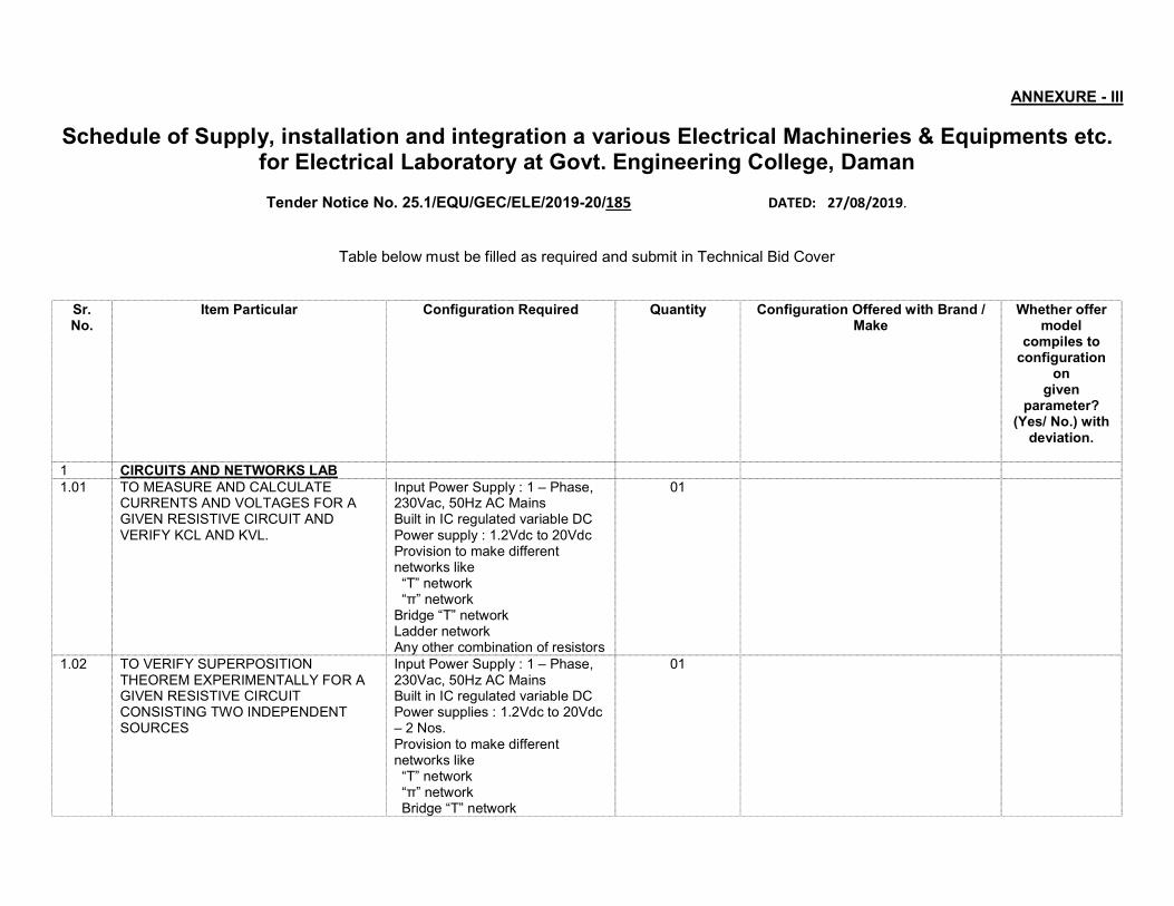
ANNEXURE - III
Schedule of Supply, installation and integration a various Electrical Machineries & Equipments etc. for Electrical Laboratory at Govt. Engineering College, Daman
Tender Notice No. 25.1/EQU/GEC/ELE/2019-20/185 DATED: 27/08/2019.
Table below must be filled as required and submit in Technical Bid Cover
Sr. No.
Item Particular Configuration Required Quantity Configuration Offered with Brand / Make
Whether offer model
compiles to configuration
on given
parameter? (Yes/ No.) with
deviation.
1 CIRCUITS AND NETWORKS LAB 1.01 TO MEASURE AND CALCULATE
CURRENTS AND VOLTAGES FOR A GIVEN RESISTIVE CIRCUIT AND VERIFY KCL AND KVL.
Input Power Supply : 1 – Phase, 230Vac, 50Hz AC Mains Built in IC regulated variable DC Power supply : 1.2Vdc to 20Vdc Provision to make different networks like “T” network “π” network Bridge “T” network Ladder network Any other combination of resistors
01
1.02 TO VERIFY SUPERPOSITION THEOREM EXPERIMENTALLY FOR A GIVEN RESISTIVE CIRCUIT CONSISTING TWO INDEPENDENT SOURCES
Input Power Supply : 1 – Phase, 230Vac, 50Hz AC Mains Built in IC regulated variable DC Power supplies : 1.2Vdc to 20Vdc – 2 Nos. Provision to make different networks like “T” network “π” network Bridge “T” network
01
Ladder network Any other combination of resistors
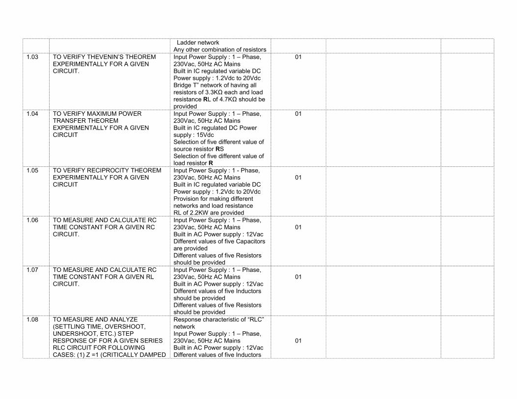
1.03 TO VERIFY THEVENIN’S THEOREM EXPERIMENTALLY FOR A GIVEN CIRCUIT.
Input Power Supply : 1 – Phase, 230Vac, 50Hz AC Mains Built in IC regulated variable DC Power supply : 1.2Vdc to 20Vdc Bridge T” network of having all resistors of 3.3KΩ each and load resistance RL of 4.7KΩ should be provided
01
1.04 TO VERIFY MAXIMUM POWER TRANSFER THEOREM EXPERIMENTALLY FOR A GIVEN CIRCUIT
Input Power Supply : 1 – Phase, 230Vac, 50Hz AC Mains Built in IC regulated DC Power supply : 15Vdc Selection of five different value of source resistor RS Selection of five different value of load resistor R
01
1.05 TO VERIFY RECIPROCITY THEOREM EXPERIMENTALLY FOR A GIVEN CIRCUIT
Input Power Supply : 1 - Phase, 230Vac, 50Hz AC Mains Built in IC regulated variable DC Power supply : 1.2Vdc to 20Vdc Provision for making different networks and load resistance RL of 2.2KW are provided
01
1.06 TO MEASURE AND CALCULATE RC TIME CONSTANT FOR A GIVEN RC CIRCUIT.
Input Power Supply : 1 – Phase, 230Vac, 50Hz AC Mains Built in AC Power supply : 12Vac Different values of five Capacitors are provided Different values of five Resistors should be provided
01
1.07 TO MEASURE AND CALCULATE RC TIME CONSTANT FOR A GIVEN RL CIRCUIT.
Input Power Supply : 1 – Phase, 230Vac, 50Hz AC Mains Built in AC Power supply : 12Vac Different values of five Inductors should be provided Different values of five Resistors should be provided
01
1.08 TO MEASURE AND ANALYZE (SETTLING TIME, OVERSHOOT, UNDERSHOOT, ETC.) STEP RESPONSE OF FOR A GIVEN SERIES RLC CIRCUIT FOR FOLLOWING CASES: (1) Ζ =1 (CRITICALLY DAMPED
Response characteristic of “RLC” network Input Power Supply : 1 – Phase, 230Vac, 50Hz AC Mains Built in AC Power supply : 12Vac Different values of five Inductors
01
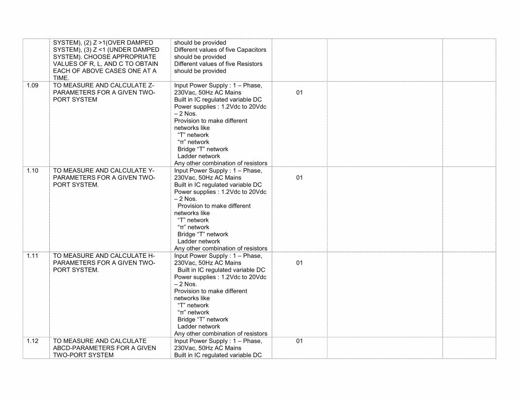
SYSTEM), (2) Ζ >1(OVER DAMPED SYSTEM), (3) Ζ <1 (UNDER DAMPED SYSTEM). CHOOSE APPROPRIATE VALUES OF R, L, AND C TO OBTAIN EACH OF ABOVE CASES ONE AT A TIME.
should be provided Different values of five Capacitors should be provided Different values of five Resistors should be provided
1.09 TO MEASURE AND CALCULATE Z-PARAMETERS FOR A GIVEN TWO-PORT SYSTEM
Input Power Supply : 1 – Phase, 230Vac, 50Hz AC Mains Built in IC regulated variable DC Power supplies : 1.2Vdc to 20Vdc – 2 Nos. Provision to make different networks like “T” network “π” network Bridge “T” network Ladder network Any other combination of resistors
01
1.10 TO MEASURE AND CALCULATE Y-PARAMETERS FOR A GIVEN TWO-PORT SYSTEM.
Input Power Supply : 1 – Phase, 230Vac, 50Hz AC Mains Built in IC regulated variable DC Power supplies : 1.2Vdc to 20Vdc – 2 Nos. Provision to make different networks like “T” network “π” network Bridge “T” network Ladder network Any other combination of resistors
01
1.11 TO MEASURE AND CALCULATE H-PARAMETERS FOR A GIVEN TWO-PORT SYSTEM.
Input Power Supply : 1 – Phase, 230Vac, 50Hz AC Mains Built in IC regulated variable DC Power supplies : 1.2Vdc to 20Vdc – 2 Nos. Provision to make different networks like “T” network “π” network Bridge “T” network Ladder network Any other combination of resistors
01
1.12 TO MEASURE AND CALCULATE ABCD-PARAMETERS FOR A GIVEN TWO-PORT SYSTEM
Input Power Supply : 1 – Phase, 230Vac, 50Hz AC Mains Built in IC regulated variable DC
01
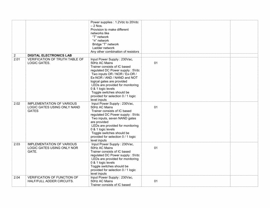
Power supplies : 1.2Vdc to 20Vdc – 2 Nos. Provision to make different networks like “T” network “π” network Bridge “T” network Ladder network Any other combination of resistors
2 DIGITAL ELECTRONICS LAB 2.01 VERIFICATION OF TRUTH TABLE OF
LOGIC GATES. Input Power Supply : 230Vac, 50Hz AC Mains Trainer consists of IC based regulated DC Power supply : 5Vdc Two inputs OR / NOR / Ex-OR / Ex-NOR / AND / NAND and NOT logical gates are provided LEDs are provided for monitoring 0 & 1 logic levels Toggle switches should be provided for selection 0 / 1 logic level inputs
01
2.02 IMPLEMENTATION OF VARIOUS LOGIC GATES USING ONLY NAND GATES
Input Power Supply : 230Vac, 50Hz AC Mains Trainer consists of IC based regulated DC Power supply : 5Vdc Two inputs, seven NAND gates are provided LEDs are provided for monitoring 0 & 1 logic levels Toggle switches should be provided for selection 0 / 1 logic level inputs
01
2.03 IMPLEMENTATION OF VARIOUS LOGIC GATES USING ONLY NOR GATE.
Input Power Supply : 230Vac, 50Hz AC Mains Trainer consists of IC based regulated DC Power supply : 5Vdc LEDs are provided for monitoring 0 & 1 logic levels Toggle switches should be provided for selection 0 / 1 logic level inputs
01
2.04 VERIFICATION OF FUNCTION OF HALF/FULL ADDER CIRCUITS.
Input Power Supply : 230Vac, 50Hz AC Mains Trainer consists of IC based
01
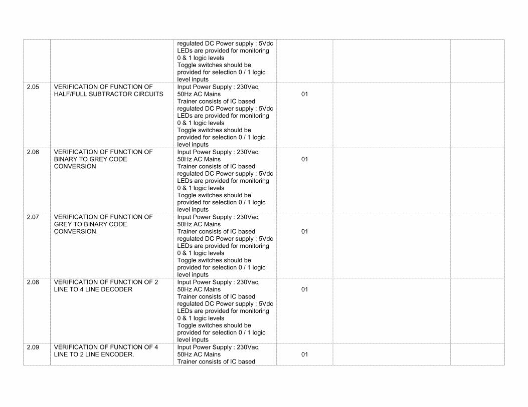
regulated DC Power supply : 5Vdc LEDs are provided for monitoring 0 & 1 logic levels Toggle switches should be provided for selection 0 / 1 logic level inputs
2.05 VERIFICATION OF FUNCTION OF HALF/FULL SUBTRACTOR CIRCUITS
Input Power Supply : 230Vac, 50Hz AC Mains Trainer consists of IC based regulated DC Power supply : 5Vdc LEDs are provided for monitoring 0 & 1 logic levels Toggle switches should be provided for selection 0 / 1 logic level inputs
01
2.06 VERIFICATION OF FUNCTION OF BINARY TO GREY CODE CONVERSION
Input Power Supply : 230Vac, 50Hz AC Mains Trainer consists of IC based regulated DC Power supply : 5Vdc LEDs are provided for monitoring 0 & 1 logic levels Toggle switches should be provided for selection 0 / 1 logic level inputs
01
2.07 VERIFICATION OF FUNCTION OF GREY TO BINARY CODE CONVERSION.
Input Power Supply : 230Vac, 50Hz AC Mains Trainer consists of IC based regulated DC Power supply : 5Vdc LEDs are provided for monitoring 0 & 1 logic levels Toggle switches should be provided for selection 0 / 1 logic level inputs
01
2.08 VERIFICATION OF FUNCTION OF 2 LINE TO 4 LINE DECODER
Input Power Supply : 230Vac, 50Hz AC Mains Trainer consists of IC based regulated DC Power supply : 5Vdc LEDs are provided for monitoring 0 & 1 logic levels Toggle switches should be provided for selection 0 / 1 logic level inputs
01
2.09 VERIFICATION OF FUNCTION OF 4 LINE TO 2 LINE ENCODER.
Input Power Supply : 230Vac, 50Hz AC Mains Trainer consists of IC based
01
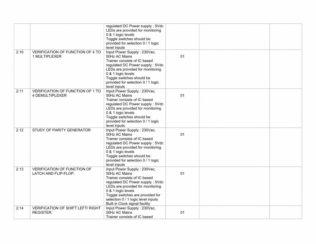
regulated DC Power supply : 5Vdc LEDs are provided for monitoring 0 & 1 logic levels Toggle switches should be provided for selection 0 / 1 logic level inputs
2.10 VERIFICATION OF FUNCTION OF 4 TO 1 MULTIPLEXER
Input Power Supply : 230Vac, 50Hz AC Mains Trainer consists of IC based regulated DC Power supply : 5Vdc LEDs are provided for monitoring 0 & 1 logic levels Toggle switches should be provided for selection 0 / 1 logic level inputs
01
2.11 VERIFICATION OF FUNCTION OF 1 TO 4 DEMULTIPLEXER
Input Power Supply : 230Vac, 50Hz AC Mains Trainer consists of IC based regulated DC Power supply : 5Vdc LEDs are provided for monitoring 0 & 1 logic levels Toggle switches should be provided for selection 0 / 1 logic level inputs
01
2.12 STUDY OF PARITY GENERATOR Input Power Supply : 230Vac, 50Hz AC Mains Trainer consists of IC based regulated DC Power supply : 5Vdc LEDs are provided for monitoring 0 & 1 logic levels Toggle switches should be provided for selection 0 / 1 logic level inputs
01
2.13 VERIFICATION OF FUNCTION OF LATCH AND FLIP-FLOP.
Input Power Supply : 230Vac, 50Hz AC Mains Trainer consists of IC based regulated DC Power supply : 5Vdc LEDs are provided for monitoring 0 & 1 logic levels Toggle switches are provided for selection 0 / 1 logic level inputs Built in Clock signal facility
01
2.14 VERIFICATION OF SHIFT LEFT/ RIGHT REGISTER.
Input Power Supply : 230Vac, 50Hz AC Mains Trainer consists of IC based
01
regulated DC Power supply : 5Vdc LEDs are provided for monitoring 0 & 1 logic levels Toggle switches are provided for selection 0 / 1 logic level inputs Built in Clock signal facility
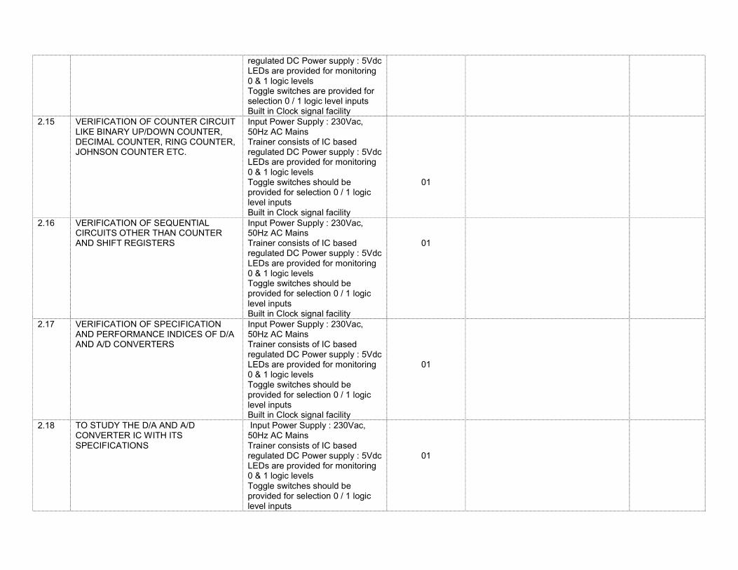
2.15 VERIFICATION OF COUNTER CIRCUIT LIKE BINARY UP/DOWN COUNTER, DECIMAL COUNTER, RING COUNTER, JOHNSON COUNTER ETC.
Input Power Supply : 230Vac, 50Hz AC Mains Trainer consists of IC based regulated DC Power supply : 5Vdc LEDs are provided for monitoring 0 & 1 logic levels Toggle switches should be provided for selection 0 / 1 logic level inputs Built in Clock signal facility
01
2.16 VERIFICATION OF SEQUENTIAL CIRCUITS OTHER THAN COUNTER AND SHIFT REGISTERS
Input Power Supply : 230Vac, 50Hz AC Mains Trainer consists of IC based regulated DC Power supply : 5Vdc LEDs are provided for monitoring 0 & 1 logic levels Toggle switches should be provided for selection 0 / 1 logic level inputs Built in Clock signal facility
01
2.17 VERIFICATION OF SPECIFICATION AND PERFORMANCE INDICES OF D/A AND A/D CONVERTERS
Input Power Supply : 230Vac, 50Hz AC Mains Trainer consists of IC based regulated DC Power supply : 5Vdc LEDs are provided for monitoring 0 & 1 logic levels Toggle switches should be provided for selection 0 / 1 logic level inputs Built in Clock signal facility
01
2.18 TO STUDY THE D/A AND A/D CONVERTER IC WITH ITS SPECIFICATIONS
Input Power Supply : 230Vac, 50Hz AC Mains Trainer consists of IC based regulated DC Power supply : 5Vdc LEDs are provided for monitoring 0 & 1 logic levels Toggle switches should be provided for selection 0 / 1 logic level inputs
01
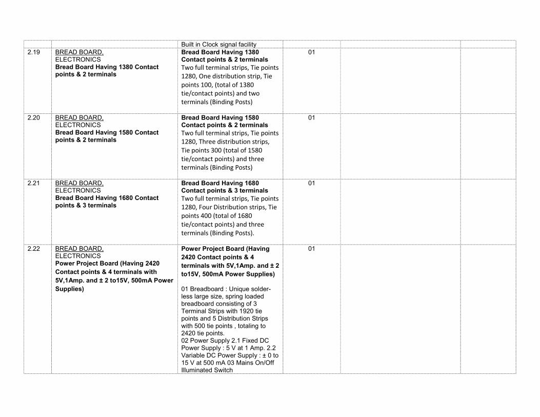
Built in Clock signal facility 2.19 BREAD BOARD,
ELECTRONICS Bread Board Having 1380 Contact points & 2 terminals
Bread Board Having 1380 Contact points & 2 terminals Two full terminal strips, Tie points 1280, One distribution strip, Tie points 100, (total of 1380 tie/contact points) and two terminals (Binding Posts)
01
2.20 BREAD BOARD, ELECTRONICS Bread Board Having 1580 Contact points & 2 terminals
Bread Board Having 1580 Contact points & 2 terminals Two full terminal strips, Tie points 1280, Three distribution strips, Tie points 300 (total of 1580 tie/contact points) and three terminals (Binding Posts)
01
2.21 BREAD BOARD, ELECTRONICS Bread Board Having 1680 Contact points & 3 terminals
Bread Board Having 1680 Contact points & 3 terminals Two full terminal strips, Tie points 1280, Four Distribution strips, Tie points 400 (total of 1680 tie/contact points) and three terminals (Binding Posts).
01
2.22 BREAD BOARD, ELECTRONICS Power Project Board (Having 2420 Contact points & 4 terminals with 5V,1Amp. and ± 2 to15V, 500mA Power Supplies)
Power Project Board (Having 2420 Contact points & 4 terminals with 5V,1Amp. and ± 2 to15V, 500mA Power Supplies)
01 Breadboard : Unique solder-less large size, spring loaded breadboard consisting of 3 Terminal Strips with 1920 tie points and 5 Distribution Strips with 500 tie points , totaling to 2420 tie points. 02 Power Supply 2.1 Fixed DC Power Supply : 5 V at 1 Amp. 2.2 Variable DC Power Supply : ± 0 to 15 V at 500 mA 03 Mains On/Off Illuminated Switch
01
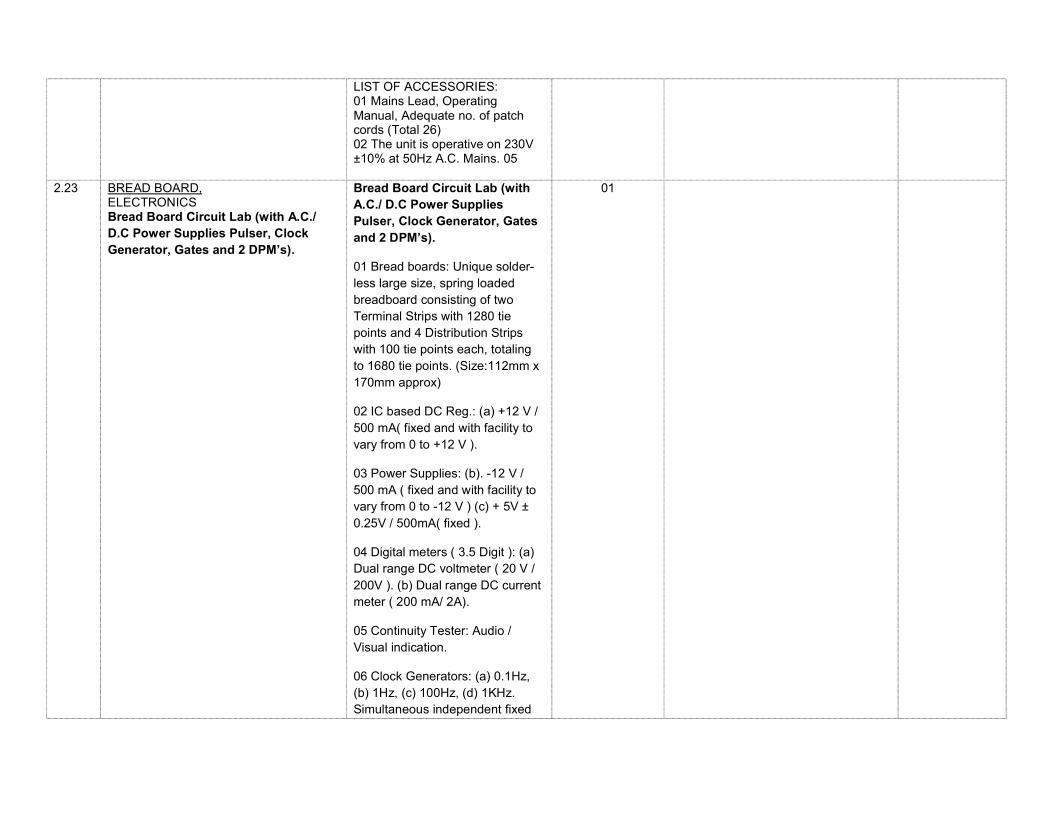
LIST OF ACCESSORIES: 01 Mains Lead, Operating Manual, Adequate no. of patch cords (Total 26) 02 The unit is operative on 230V ±10% at 50Hz A.C. Mains. 05
2.23 BREAD BOARD, ELECTRONICS Bread Board Circuit Lab (with A.C./ D.C Power Supplies Pulser, Clock Generator, Gates and 2 DPM’s).
Bread Board Circuit Lab (with A.C./ D.C Power Supplies Pulser, Clock Generator, Gates and 2 DPM’s).
01 Bread boards: Unique solder-less large size, spring loaded breadboard consisting of two Terminal Strips with 1280 tie points and 4 Distribution Strips with 100 tie points each, totaling to 1680 tie points. (Size:112mm x 170mm approx)
02 IC based DC Reg.: (a) +12 V / 500 mA( fixed and with facility to vary from 0 to +12 V ).
03 Power Supplies: (b). -12 V / 500 mA ( fixed and with facility to vary from 0 to -12 V ) (c) + 5V ± 0.25V / 500mA( fixed ).
04 Digital meters ( 3.5 Digit ): (a) Dual range DC voltmeter ( 20 V / 200V ). (b) Dual range DC current meter ( 200 mA/ 2A).
05 Continuity Tester: Audio / Visual indication.
06 Clock Generators: (a) 0.1Hz, (b) 1Hz, (c) 100Hz, (d) 1KHz. Simultaneous independent fixed
01
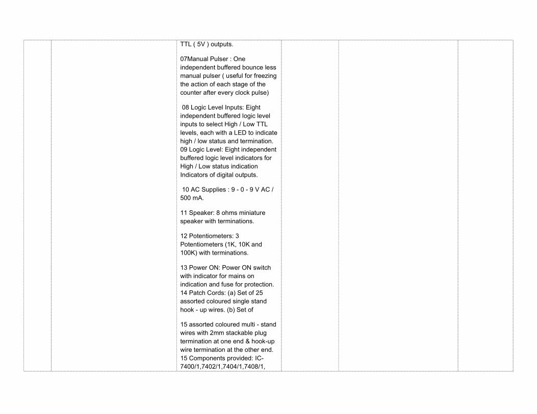
TTL ( 5V ) outputs.
07Manual Pulser : One independent buffered bounce less manual pulser ( useful for freezing the action of each stage of the counter after every clock pulse)
08 Logic Level Inputs: Eight independent buffered logic level inputs to select High / Low TTL levels, each with a LED to indicate high / low status and termination. 09 Logic Level: Eight independent buffered logic level indicators for High / Low status indication Indicators of digital outputs.
10 AC Supplies : 9 - 0 - 9 V AC / 500 mA.
11 Speaker: 8 ohms miniature speaker with terminations.
12 Potentiometers: 3 Potentiometers (1K, 10K and 100K) with terminations.
13 Power ON: Power ON switch with indicator for mains on indication and fuse for protection. 14 Patch Cords: (a) Set of 25 assorted coloured single stand hook - up wires. (b) Set of
15 assorted coloured multi - stand wires with 2mm stackable plug termination at one end & hook-up wire termination at the other end. 15 Components provided: IC-7400/1,7402/1,7404/1,7408/1,
7410/2, 7432/1, 7476/2, 7486/1, 7490/1, 7495/1, 16 Power Requirement: 230VAC ± 10% at 50Hz
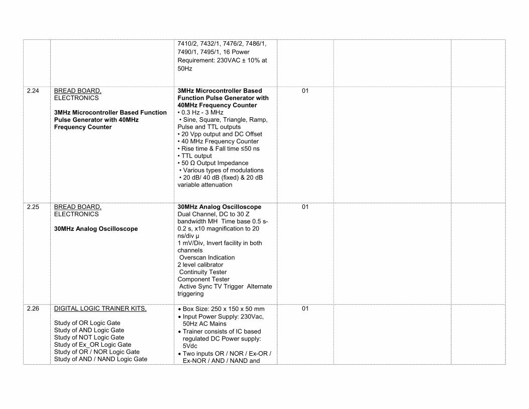
2.24 BREAD BOARD,
ELECTRONICS
3MHz Microcontroller Based Function Pulse Generator with 40MHz Frequency Counter
3MHz Microcontroller Based Function Pulse Generator with 40MHz Frequency Counter • 0.3 Hz - 3 MHz • Sine, Square, Triangle, Ramp, Pulse and TTL outputs • 20 Vpp output and DC Offset • 40 MHz Frequency Counter • Rise time & Fall time ≤50 ns • TTL output • 50 Ω Output Impedance • Various types of modulations • 20 dB/ 40 dB (fixed) & 20 dB variable attenuation
01
2.25 BREAD BOARD, ELECTRONICS
30MHz Analog Oscilloscope
30MHz Analog Oscilloscope Dual Channel, DC to 30 Z bandwidth MH Time base 0.5 s-0.2 s, x10 magnification to 20 ns/div µ 1 mV/Div, Invert facility in both channels Overscan Indication 2 level calibrator Continuity Tester Component Tester Active Sync TV Trigger Alternate triggering
01
2.26 DIGITAL LOGIC TRAINER KITS, Study of OR Logic Gate Study of AND Logic Gate Study of NOT Logic Gate Study of Ex_OR Logic Gate Study of OR / NOR Logic Gate Study of AND / NAND Logic Gate
Box Size: 250 x 150 x 50 mm Input Power Supply: 230Vac,
50Hz AC Mains Trainer consists of IC based
regulated DC Power supply: 5Vdc
Two inputs OR / NOR / Ex-OR / Ex-NOR / AND / NAND and
01
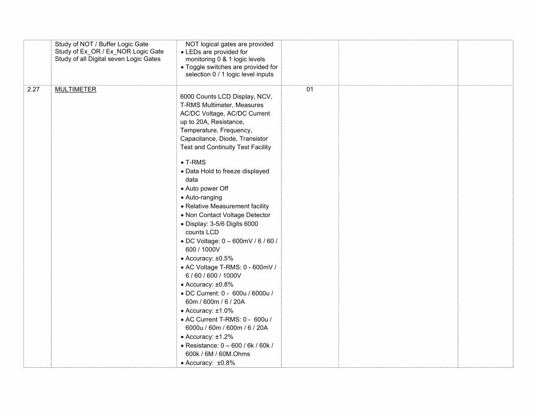
Study of NOT / Buffer Logic Gate Study of Ex_OR / Ex_NOR Logic Gate Study of all Digital seven Logic Gates
NOT logical gates are provided LEDs are provided for
monitoring 0 & 1 logic levels Toggle switches are provided for
selection 0 / 1 logic level inputs
2.27 MULTIMETER
6000 Counts LCD Display, NCV, T-RMS Multimeter, Measures AC/DC Voltage, AC/DC Current up to 20A, Resistance, Temperature, Frequency, Capacitance, Diode, Transistor Test and Continuity Test Facility
T-RMS Data Hold to freeze displayed
data Auto power Off Auto-ranging Relative Measurement facility Non Contact Voltage Detector Display: 3-5/6 Digits 6000
counts LCD DC Voltage: 0 – 600mV / 6 / 60 /
600 / 1000V Accuracy: ±0.5% AC Voltage T-RMS: 0 - 600mV /
6 / 60 / 600 / 1000V Accuracy: ±0.8% DC Current: 0 - 600u / 6000u /
60m / 600m / 6 / 20A Accuracy: ±1.0% AC Current T-RMS: 0 - 600u /
6000u / 60m / 600m / 6 / 20A
Accuracy: ±1.2% Resistance: 0 – 600 / 6k / 60k /
600k / 6M / 60M.Ohms Accuracy: ±0.8%
01
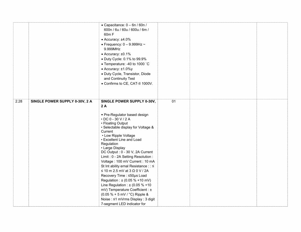
Capacitance: 0 – 6n / 60n / 600n / 6u / 60u / 600u / 6m / 60m F
Accuracy: ±4.0% Frequency: 0 – 9.999Hz ~
9.999MHz Accuracy: ±0.1% Duty Cycle: 0.1% to 99.9% Temperature: -40 to 1000 ˚C Accuracy: ±1.0%y Duty Cycle, Transistor, Diode
and Continuity Test Confirms to CE, CAT-II 1000V.
2.28 SINGLE POWER SUPPLY 0-30V, 2 A
SINGLE POWER SUPPLY 0-30V, 2 A
• Pre-Regulator based design • DC 0 - 30 V / 2 A • Floating Output • Selectable display for Voltage & Current • Low Ripple Voltage • Excellent Line and Load Regulation • Large Display DC Output : 0 - 30 V, 2A Current Limit : 0 - 2A Setting Resolution : Voltage : 100 mV Current : 10 mA St Int ability ernal Resistance : : ≤ ≤ 10 m 2.5 mV at 3 Ω 0 V / 2A Recovery Time : ≤50µs Load Regulation : ± (0.05 % +10 mV) Line Regulation : ± (0.05 % +10 mV) Temperature Coefficient : ± (0.05 % + 5 mV / °C) Ripple & Noise : ≤1 mVrms Display : 3 digit 7-segment LED indicator for
01
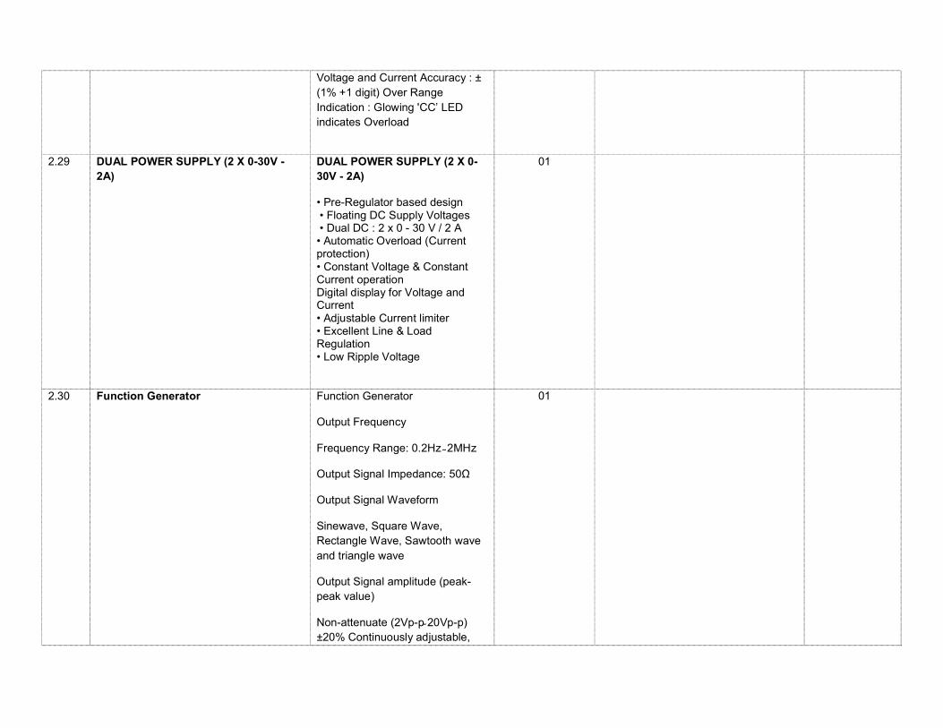
Voltage and Current Accuracy : ± (1% +1 digit) Over Range Indication : Glowing 'CC’ LED indicates Overload
2.29 DUAL POWER SUPPLY (2 X 0-30V -
2A)
DUAL POWER SUPPLY (2 X 0-30V - 2A)
• Pre-Regulator based design • Floating DC Supply Voltages • Dual DC : 2 x 0 - 30 V / 2 A • Automatic Overload (Current protection) • Constant Voltage & Constant Current operation Digital display for Voltage and Current • Adjustable Current limiter • Excellent Line & Load Regulation • Low Ripple Voltage
01
2.30 Function Generator
Function Generator
Output Frequency
Frequency Range: 0.2Hz 2MHz
Output Signal Impedance: 50Ω
Output Signal Waveform
Sinewave, Square Wave, Rectangle Wave, Sawtooth wave and triangle wave
Output Signal amplitude (peak-peak value)
Non-attenuate (2Vp-p 20Vp-p) ±20% Continuously adjustable,
01
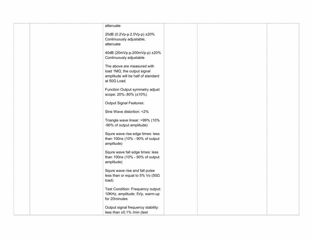
attenuate
20dB (0.2Vp-p 2.0Vp-p) ±20% Continuously adjustable, attenuate
40dB (20mVp-p 200mVp-p) ±20% Continuously adjustable
The above are measured with load 1MΩ, the output signal amplitude will be half of standard at 50Ω Load.
Function Output symmetry adjust scope: 20% 80% (±10%)
Output Signal Features:
Sine Wave distortion: <2%
Triangle wave linear: >99% (10% -90% of output amplitude)
Squre wave rise edge times: less than 100ns (10% - 90% of output amplitude)
Squre wave fall edge times: less than 100ns (10% - 90% of output amplitude)
Squre wave rise and fall pulse less than or equal to 5% Vo (50Ω load)
Test Condition: Frequency output: 10KHz, amplitude: 5Vp, warm-up for 20minutes
Output signal frequency stability: less than ±0.1% /min (test

conditions is the same as the above)
Amplitude display (only for 50Ω load, at 1MΩ load, the real output amplitude is double of the displaying value)
Display Digits : 2/3digits (Decimal point automatic select place)
Display Units: Vp-p or mVp-p
Display Errors: Vo±10% ±1d (Vo refers to the true value of
output signal)
Resolutions: Non-attenuate: 0.2Vp-p
Frequency Display:
a) Display Range: 0.2Hz -2MHz
b) Display effective digit: four or five digits
Measurement errors: ≤0.5%
Time base frequency: 12MHz frequency
Stability: ± 5x10
Working Temperature: 0C 40C
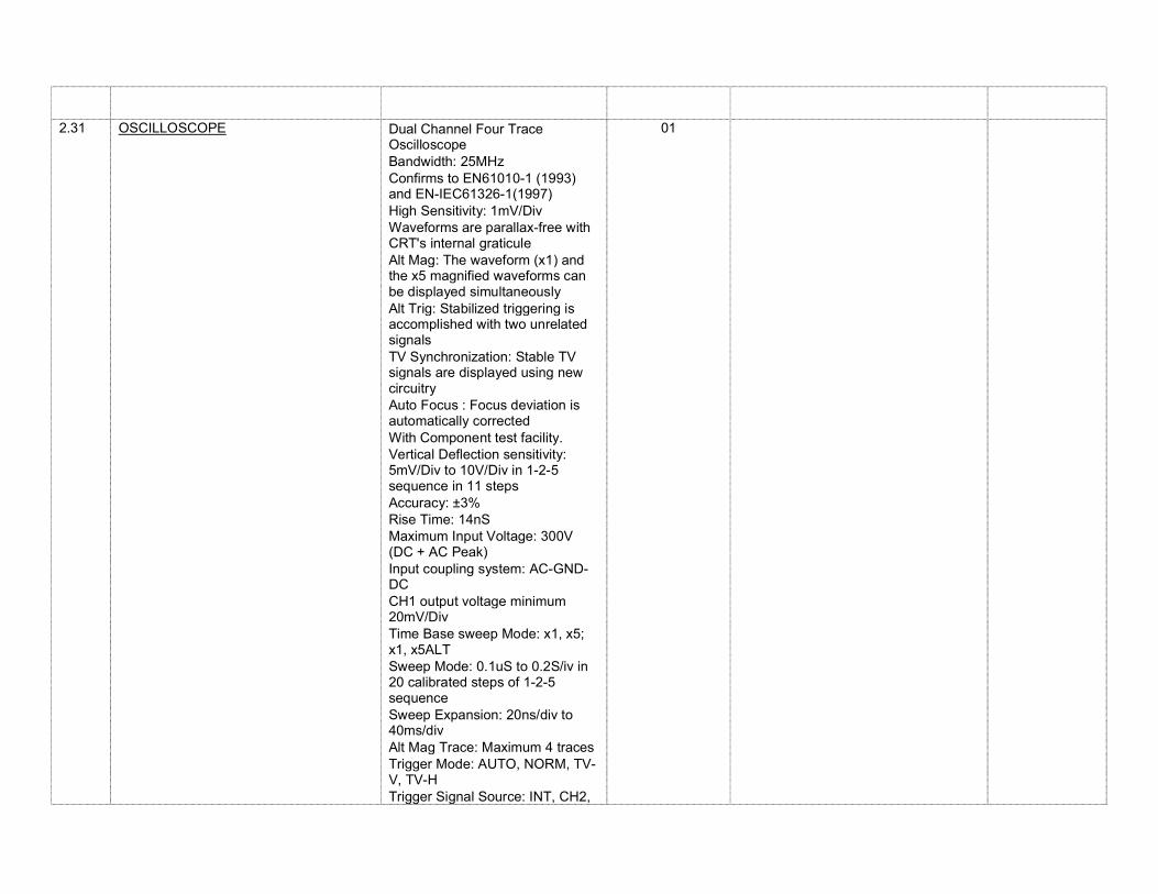
2.31 OSCILLOSCOPE Dual Channel Four Trace Oscilloscope
Bandwidth: 25MHz Confirms to EN61010-1 (1993)
and EN-IEC61326-1(1997) High Sensitivity: 1mV/Div Waveforms are parallax-free with
CRT's internal graticule Alt Mag: The waveform (x1) and
the x5 magnified waveforms can be displayed simultaneously
Alt Trig: Stabilized triggering is accomplished with two unrelated signals
TV Synchronization: Stable TV signals are displayed using new circuitry
Auto Focus : Focus deviation is automatically corrected
With Component test facility. Vertical Deflection sensitivity:
5mV/Div to 10V/Div in 1-2-5 sequence in 11 steps
Accuracy: ±3% Rise Time: 14nS Maximum Input Voltage: 300V
(DC + AC Peak) Input coupling system: AC-GND-
DC CH1 output voltage minimum
20mV/Div Time Base sweep Mode: x1, x5;
x1, x5ALT Sweep Mode: 0.1uS to 0.2S/iv in
20 calibrated steps of 1-2-5 sequence
Sweep Expansion: 20ns/div to 40ms/div
Alt Mag Trace: Maximum 4 traces Trigger Mode: AUTO, NORM, TV-
V, TV-H Trigger Signal Source: INT, CH2,
01
LINE, EXT X-Y Operation Mode: CH1, X-axis
and CH2, Y-axis Z-Axis bandwidth: DC to 2MHz Component Test Facility Calibration Signal: 0.5V Square
wave of 1kHz
Auxiliary Power Supply: 230V 50Hz AC
3 DC MACHINE LAB
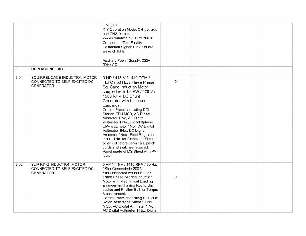
3.01 SQUIRREL CAGE INDUCTION MOTOR CONNECTED TO SELF EXCITED DC GENERATOR
3 HP / 415 V / 1440 RPM / TEFC / 50 Hz. / Three Phase Sq. Cage Induction Motor coupled with 1.8 KW / 220 V / 1500 RPM DC Shunt Generator with base and couplings. Control Panel consisting DOL Starter, TPN MCB, AC Digital Ammeter 1 No, AC Digital Voltmeter 1 No., Digital 3phase UPF wattmeter 1No., DC Digital Voltmeter 1No., DC Digital Ammeter 2Nos., Field Regulator Inbuilt 1No. for Generator Field, all other indicators, terminals, patch cords and switches required. Panel made of MS Sheet with PV facia
01
3.02 SLIP RING INDUCTION MOTOR CONNECTED TO SELF EXCITED DC GENERATOR
5 HP / 415 V / 1410 RPM / 50 Hz. / Star Connected / 200 V – Star connected wound Rotor / Three Phase Slipring Induction Motor with Mechanical Loading arrangement having Round dial scales and Friction Belt for Torque Measurement. Control Panel consisting DOL cum Rotor Resistance Starter, TPN MCB, AC Digital Ammeter 1 No, AC Digital Voltmeter 1 No., Digital
01
wattmeter 2Nos., all other indicators, terminals, patch cords and switches required. Panel made of MS Sheet with PV facia
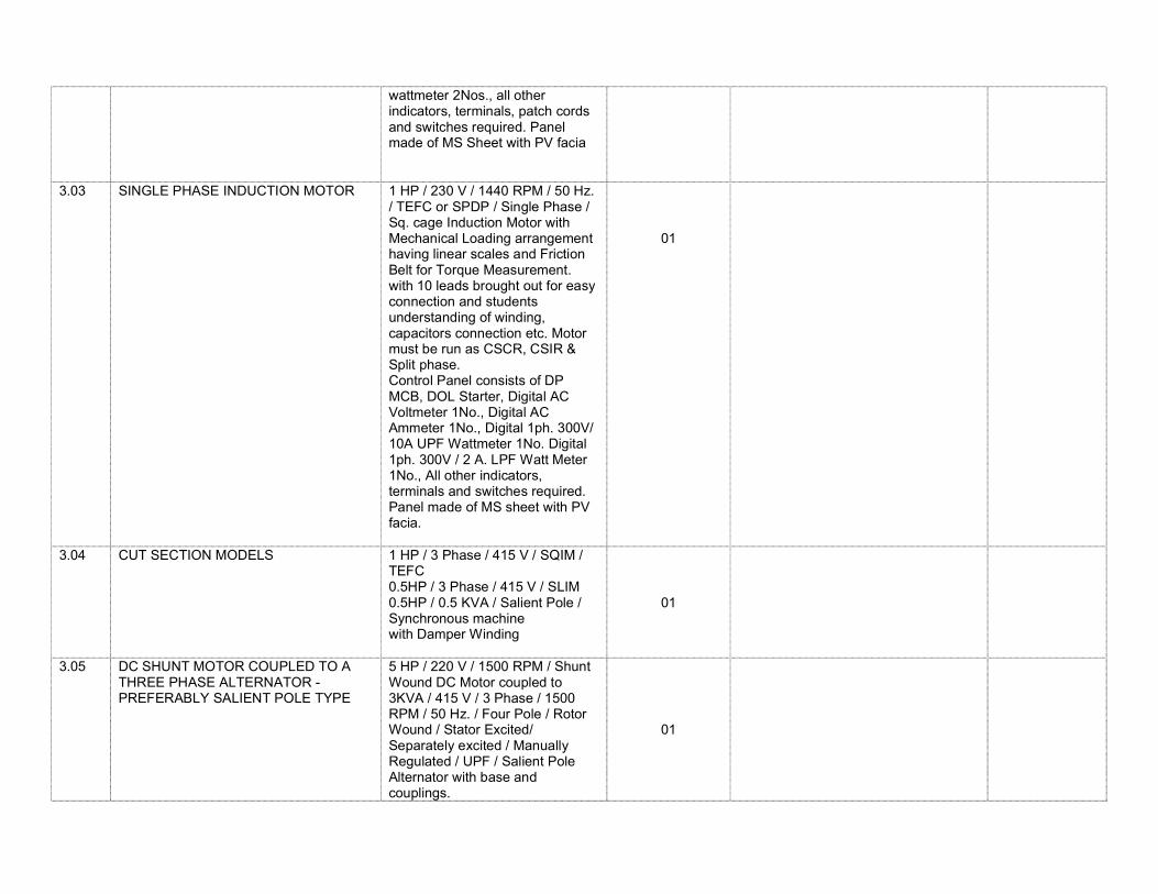
3.03 SINGLE PHASE INDUCTION MOTOR
1 HP / 230 V / 1440 RPM / 50 Hz. / TEFC or SPDP / Single Phase / Sq. cage Induction Motor with Mechanical Loading arrangement having linear scales and Friction Belt for Torque Measurement. with 10 leads brought out for easy connection and students understanding of winding, capacitors connection etc. Motor must be run as CSCR, CSIR & Split phase. Control Panel consists of DP MCB, DOL Starter, Digital AC Voltmeter 1No., Digital AC Ammeter 1No., Digital 1ph. 300V/ 10A UPF Wattmeter 1No. Digital 1ph. 300V / 2 A. LPF Watt Meter 1No., All other indicators, terminals and switches required. Panel made of MS sheet with PV facia.
01
3.04 CUT SECTION MODELS 1 HP / 3 Phase / 415 V / SQIM / TEFC 0.5HP / 3 Phase / 415 V / SLIM 0.5HP / 0.5 KVA / Salient Pole / Synchronous machine with Damper Winding
01
3.05 DC SHUNT MOTOR COUPLED TO A THREE PHASE ALTERNATOR - PREFERABLY SALIENT POLE TYPE
5 HP / 220 V / 1500 RPM / Shunt Wound DC Motor coupled to 3KVA / 415 V / 3 Phase / 1500 RPM / 50 Hz. / Four Pole / Rotor Wound / Stator Excited/ Separately excited / Manually Regulated / UPF / Salient Pole Alternator with base and couplings.
01
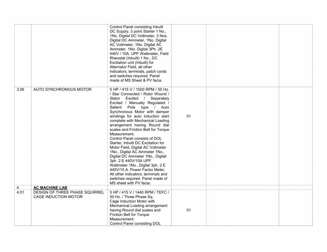
Control Panel consisting Inbuilt DC Supply, 3 point Starter 1 No., 1No. Digital DC Voltmeter, 3 Nos. Digital DC Ammeter, 1No. Digital AC Voltmeter, 1No. Digital AC Ammeter, 1No. Digital 3Ph. 2E 440V / 10A. UPF Wattmeter, Field Rheostat (Inbuilt) 1 No., DC Excitation unit (Inbuilt) for Alternator Field, all other indicators, terminals, patch cords and switches required. Panel made of MS Sheet & PV facia.
3.06 AUTO SYNCHRONOUS MOTOR
5 HP / 415 V / 1500 RPM / 50 Hz. / Star Connected / Rotor Wound / Stator Excited / Separately Excited / Manually Regulated / Salient Pole type / Auto Synchronous Motor with damper windings for auto induction start complete with Mechanical Loading arrangement having Round dial scales and Friction Belt for Torque Measurement. Control Panel consists of DOL Starter, Inbuilt DC Excitation for Motor Field, Digital AC Voltmeter 1No., Digital AC Ammeter 1No., Digital DC Ammeter 1No., Digital 3ph. 2 E 440V/10A UPF Wattmeter 1No., Digital 3ph. 2 E 440V/10 A. Power Factor Meter, All other indicators, terminals and switches required. Panel made of MS sheet with PV facia.
01
4 AC MACHINE LAB 4.01 DESIGN OF THREE PHASE SQUIRREL
CAGE INDUCTION MOTOR
5 HP / 415 V / 1440 RPM / TEFC / 50 Hz. / Three Phase Sq. Cage Induction Motor with Mechanical Loading arrangement having Round dial scales and Friction Belt for Torque Measurement. Control Panel consisting DOL
01
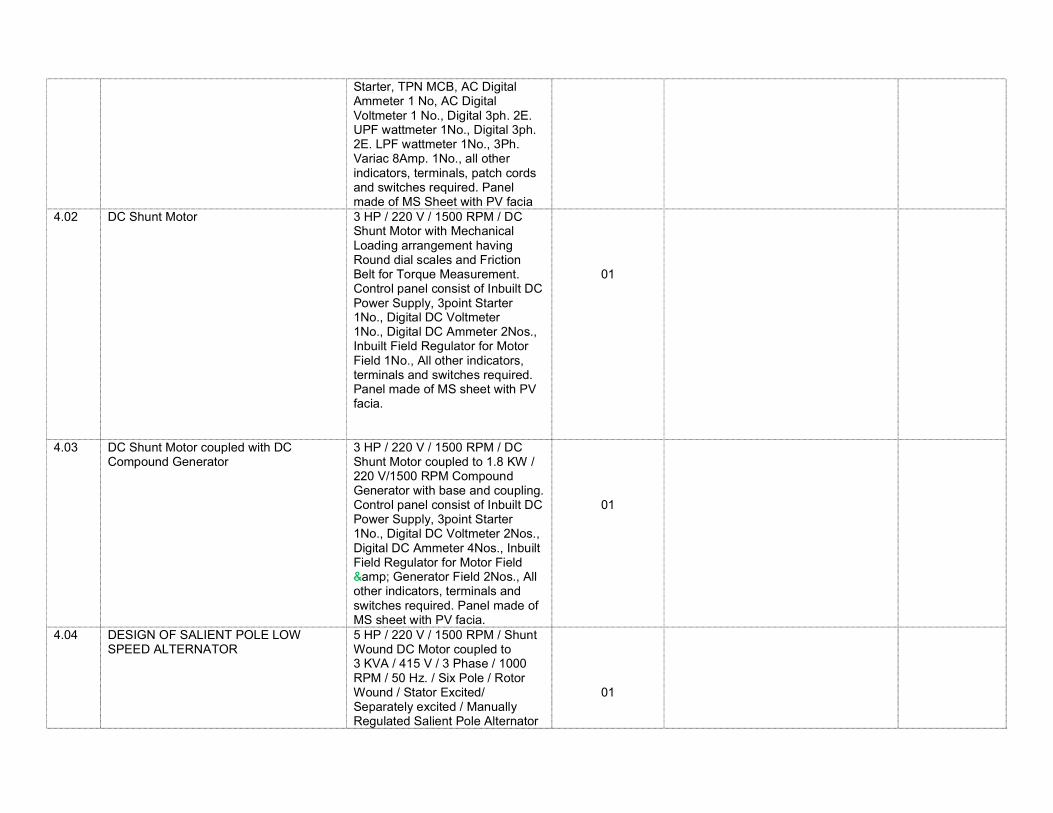
Starter, TPN MCB, AC Digital Ammeter 1 No, AC Digital Voltmeter 1 No., Digital 3ph. 2E. UPF wattmeter 1No., Digital 3ph. 2E. LPF wattmeter 1No., 3Ph. Variac 8Amp. 1No., all other indicators, terminals, patch cords and switches required. Panel made of MS Sheet with PV facia
4.02 DC Shunt Motor
3 HP / 220 V / 1500 RPM / DC Shunt Motor with Mechanical Loading arrangement having Round dial scales and Friction Belt for Torque Measurement. Control panel consist of Inbuilt DC Power Supply, 3point Starter 1No., Digital DC Voltmeter 1No., Digital DC Ammeter 2Nos., Inbuilt Field Regulator for Motor Field 1No., All other indicators, terminals and switches required. Panel made of MS sheet with PV facia.
01
4.03 DC Shunt Motor coupled with DC Compound Generator
3 HP / 220 V / 1500 RPM / DC Shunt Motor coupled to 1.8 KW / 220 V/1500 RPM Compound Generator with base and coupling. Control panel consist of Inbuilt DC Power Supply, 3point Starter 1No., Digital DC Voltmeter 2Nos., Digital DC Ammeter 4Nos., Inbuilt Field Regulator for Motor Field & Generator Field 2Nos., All other indicators, terminals and switches required. Panel made of MS sheet with PV facia.
01
4.04 DESIGN OF SALIENT POLE LOW SPEED ALTERNATOR
5 HP / 220 V / 1500 RPM / Shunt Wound DC Motor coupled to 3 KVA / 415 V / 3 Phase / 1000 RPM / 50 Hz. / Six Pole / Rotor Wound / Stator Excited/ Separately excited / Manually Regulated Salient Pole Alternator
01
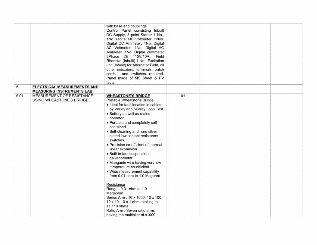
with base and couplings. Control Panel consisting Inbuilt DC Supply, 3 point Starter 1 No., 1No. Digital DC Voltmeter, 3Nos. Digital DC Ammeter, 1No. Digital AC Voltmeter, 1No. Digital AC Ammeter, 1No. Digital Wattmeter 3Phase 2E 415V/10A., Field Rheostat (Inbuilt) 1 No., Excitation unit (Inbuilt) for Alternator Field, all other indicators, terminals, patch cords and switches required. Panel made of MS Sheet & PV facia.
5 ELECTRICAL MEASUREMENTS AND MEASURING INSTRUMENTS LAB
5.01 MEASUREMENT OF RESISTANCE USING WHEASTONE’S BRIDGE
WHEASTONE’S BRIDGE Portable Wheatstone Bridge Ideal for fault location in cables
by Varley and Murray Loop Test Battery as well as mains
operated Portable and completely self-
contained Self-cleaning and hard silver
plated low contact resistance switches
Precision co-efficient of thermal linear expansion
Built-in taut suspension galvanometer
Manganin wire having very low temperature co-efficient
Wide measurement capability from 0.01 ohm to 1.0 Megohm
Resistance Range : 0.01 ohm to 1.0 Megaohm Series Arm : 10 x 1000, 10 x 100, 10 x 10, 10 x 1 ohm totalling to 11,110 ohms Ratio Arm : Seven ratio arms having the multiplier of x1000;
01
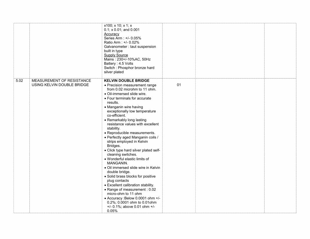
x100; x 10; x 1; x 0.1; x 0.01; and 0.001 Accuracy Series Arm : +/- 0.05% Ratio Arm : +/- 0.02% Galvanometer : taut suspension built in type Supply Source Mains : 230+/-10%AC, 50Hz Battery : 4.5 Volts Switch : Phosphor bronze hard silver plated
5.02 MEASUREMENT OF RESISTANCE USING KELVIN DOUBLE BRIDGE
KELVIN DOUBLE BRIDGE Precision measurement range
from 0.02 microhm to 11 ohm. Oil-immersed slide wire. Four terminals for accurate
results. Manganin wire having
exceptionally low temperature co-efficient.
Remarkably long lasting resistance values with excellent stability.
Reproducible measurements. Perfectly aged Manganin coils /
strips employed in Kelvin Bridges.
Click type hard silver plated self-cleaning switches.
Wonderful elastic limits of MANGANIN.
Oil immersed slide wire in Kelvin double bridge.
Solid brass blocks for positive plug contacts
Excellent calibration stability. Range of measurement : 0.02
micro-ohm to 11 ohm Accuracy :Below 0.0001 ohm +/-
0.2%; 0.0001 ohm to 0.01ohm +/- 0.1%; above 0.01 ohm +/- 0.05%
01
Slide wire: 0.001 ohm divided in 500 equal divisions. (immersed in oil)
Variable standard resistance : 10 steps of 0.001 ohm
Switches : Hard silver plated giving constant values up to 10,000 operations
Current source: 10 Amp DC.
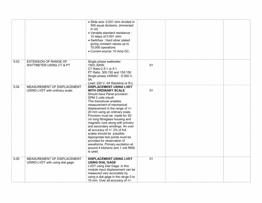
5.03 EXTENSION OF RANGE OF WATTMETER USING CT & PT
Single phase wattmeter: 150V,300W, CT Ratio:2.5:1 or 5:1 PT Ratio: 300:150 and 150:150 Single phase VARIAC : 0-300 V, 5A Load: 220 V, 4A Resistive or R-L
01
5.04 MEASUREMENT OF DISPLACEMENT USING LVDT with ordinary scale:
DISPLACEMENT USING LVDT WITH ORDINARY SCALE Should have Panel provision: DPM 2 volts inbuilt This transducer enables measurement of mechanical displacement in the range of +/- 20 mm using an ordinary scale. Provision must be made for 30-cm long fibreglass housing and magnetic core along with primary and secondary windings. An over all accuracy of +/- 2% of full scales should be possible. Appropriate test points must be provided for observation of waveforms. Primary excitation at around 4 kilohertz and 1 volt RMS is used.
01
5.05 MEASUREMENT OF DISPLACEMENT USING LVDT with using dial gage:
DISPLACEMENT USING LVDT USING DIAL GAGE LVDT using Dial Gage: in this module input displacement can be measured very accurately by using a dial gage in the range 0 to 10 mm. Over all accuracy of +/-
01

1% can be expected from this module. Other specifications remain as in part (a) above.
5.06 MEASUREMENT OF CURRENT/ VOLTAGE USING HALL EFFECT TRANSDUCER
Should have Panel provision: DPM 2 volts inbuilt Two digital panel meters, one for flux density measurement and other for current measurement. A linear Hall effect sensor IC should be use as a sensing element in this set up, which facilitates measurement of flux density B in millitesla(up to 40-m tesla). Calibration must be done with a suitable solenoid excited by a known controllable current source. A digital panel meter must be provided for current measurement. Accuracy of the order of +/- 2% can be expected. Magnetic field of permanent magnet also can be investigated.
01
5.07 THERMOCOUPLE BASED ON – OFF CONTROLLER
Should have Panel provision: DPM 2 volts inbuilt Thermocouple (Chromel-Alumel) suitable for the range 0 to 100 degree centigrade should be supplied along with the set up.In order to perform the temperature measurement (ie thermocouple, RTD and thermistor) a water container along with 1 kW heater, cable will be supplied as a common accessory for all these experiments. A standard laboratory thermometer will also be supplied. Accuracy: +/- 1.5%
01

5.08 MEASUREMENT OF PHYSICAL QUANTITIES STRAIN GAGE MODULE WITH CANTILEVER BEAM:
STRAIN GAUGE MODULE WITH CANTILEVER BEAM. Should have Panel provision: DPM 2 volts inbuilt a) Four no. of strain gages with nominal value of 350 ohms are mounted on a cantilever beam which can be loaded with the help of weights in a pan. The system is designed for a maximum of 5-kg load and can be used as a load cell also. Detailed calculations regarding stress and strain in the beam can be performed. Provision is made for two- arm and four-arm operation. Bridge balance controls in terms of coarse control and fine control are provided. An amplifier with variable gain in the range of 0 to 1000 is used for signal processing. Accuracy: +/- 1%
01
5.09 MEASUREMENT OF PHYSICAL QUANTITIES – STRAIN GAUGE MODULE WITH INDUSTRIAL LOAD CELL:
STRAIN GAUGE MODULE WITH INDUSTRIAL LOAD CELL An industrial type of load cell with 10-kg capacity will be providing at an extra cost.
01
5.10 MEASUREMENT OF PHYSICAL QUANTITIES – DIGITAL TORQUE MEASUREMENT MODEL
Digital Torque Measurement. Panel Provision:-192*192*300 mm DPM :-2 V This Digital Torque Indicator is based on the principle of standard spring balance type of torque measuring system where the difference in the spring balance reading for a loaded brake drum gives the torque in kg-cm denomination. This is an indirect method of torque measurement. In order to get direct digital indication of the torque on the meter, the spring balances along with instrumentation and reliable electronic load cell electronic (strain gauge type) are supplied
01

Scope Of Supply: 1Load Cells 50Kg capacity 2No.s 2.0.5 h.p. D.C.motor with pre-loaded pulley. 3. Loading arrangement on the motor. 4. Motor speed controller with an ammeter 0 to 2 amp. 5. Signal conditioning unit Digital indicator.(3 & ½ digit) 6. Course and fine balance for both sensor channels. Unit comes with powder coated M.S.Box. Appropriate test points are provided.
5.11 MEASUREMENT OF PHYSICAL QUANTITIES – DIGITAL STATIC TORQUE MEASUREMENT
Digital Static Torque Measurement Trainer This unit comes with rosset strain gauge based static torque measurement system With sturdy M.S. torque arm. Torque arm loading system by using Pan, weight set. Torque Arm Length:- 50cm (with facility to select torque arm as 25cm,37.5 cm, 50 cm) Weight set :- upto 2 Kg (500 gm*4) Torque measurement range (experimental):- 100 Kg-cm (i.e. 1kg-m) Torque Indicator capacity (max) :- 2000kg-cm Indicator :- 3 and ½ digit display Resolution :- 1 kg cm
01
5.12 MEASUREMENT OF PHYSICAL QUANTITIES – OPTICAL ENCODER FOR ANGLE MEASUREMENT
Optical encoder for angle measurement –(IT-31) A 360 pulses per revolution (PPR) optical encoder is mechanically coupled through a special coupling to 20 RPM d.c. motor (with gear train) excited y 12 volt d.c. supply. The push button is used to rotate the motor and in turn optical encoder shaft slowly. The optical encoder is mounted on a base with angular scale fitted
01
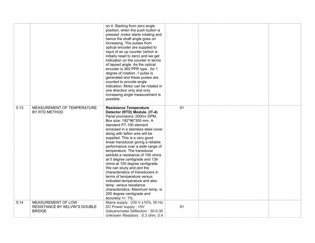
on it. Starting from zero angle position, when the push button is pressed ,motor starts rotating and hence the shaft angle goes on increasing. The pulses from optical encoder are supplied to input of an up counter (which is initially reset to zero) and we get indication on the counter in terms of lapsed angle. As the optical encoder is 360 PPR type , for 1 degree of rotation ,1 pulse is generated and these pulses are counted to provide angle indication. Motor can be rotated in one direction only and only increasing angle measurement is possible.
5.13 MEASUREMENT OF TEMPERATURE BY RTD METHOD
Resistance Temperature Detector (RTD) Module. (IT-4) Panel provisions: 200mv DPM, Box size: 192*96*300 mm. A standard PT-100 element enclosed in a stainless steel cover along with teflon wire will be supplied. This is a very good linear transducer giving a reliable performance over a wide range of temperature. The transducer exhibits a resistance of 100 ohms at 0 degree centigrade and 139 ohms at 100 degree centigrade. We can study and plot the characteristics of transducers in terms of temperature versus indicated temperature and also temp. versus resistance characteristics .Maximum temp. is 200 degree centigrade and accuracy +/- 1%.
01
5.14 MEASUREMENT OF LOW RESISTANCE BY KELVIN‟S DOUBLE BRIDGE
Mains supply : 230 V ±10%, 50 Hz DC Power supply : +5V Galvanometer Deflection : 30-0-30 Unknown Resistors : 0.3 ohm, 0.4
01
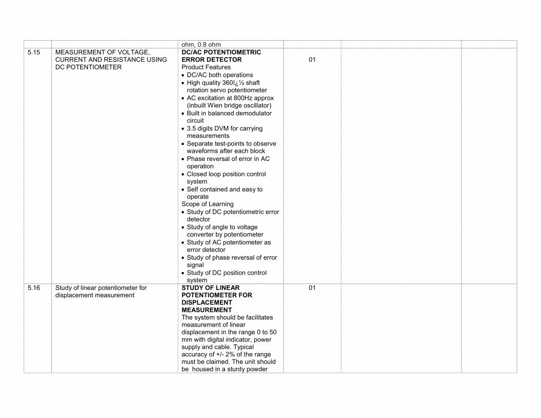
ohm, 0.8 ohm 5.15 MEASUREMENT OF VOLTAGE,
CURRENT AND RESISTANCE USING DC POTENTIOMETER
DC/AC POTENTIOMETRIC ERROR DETECTOR Product Features DC/AC both operations High quality 360� shaft
rotation servo potentiometer AC excitation at 800Hz approx
(inbuilt Wien bridge oscillator) Built in balanced demodulator
circuit 3.5 digits DVM for carrying
measurements Separate test-points to observe
waveforms after each block Phase reversal of error in AC
operation Closed loop position control
system Self contained and easy to
operate Scope of Learning Study of DC potentiometric error
detector Study of angle to voltage
converter by potentiometer Study of AC potentiometer as
error detector Study of phase reversal of error
signal Study of DC position control
system
01
5.16 Study of linear potentiometer for displacement measurement
STUDY OF LINEAR POTENTIOMETER FOR DISPLACEMENT MEASUREMENT The system should be facilitates measurement of linear displacement in the range 0 to 50 mm with digital indicator, power supply and cable. Typical accuracy of +/- 2% of the range must be claimed. The unit should be housed in a sturdy powder
01
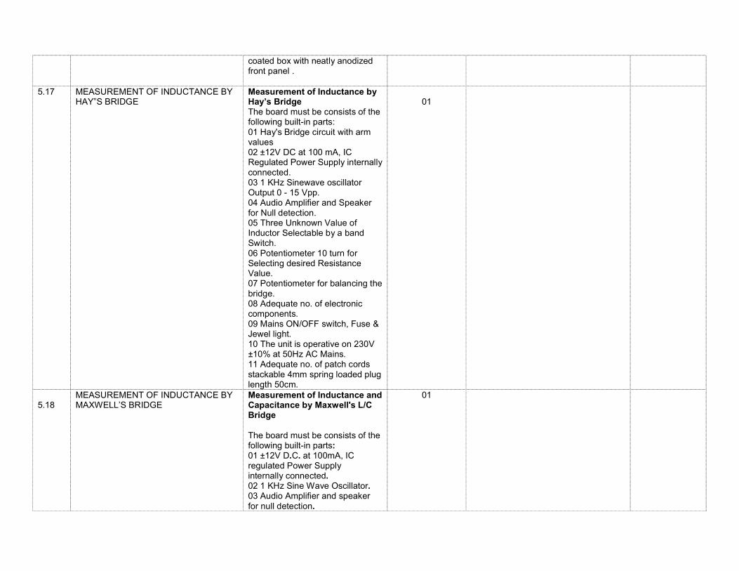
coated box with neatly anodized front panel .
5.17 MEASUREMENT OF INDUCTANCE BY HAY‟S BRIDGE
Measurement of Inductance by Hay’s Bridge The board must be consists of the following built-in parts: 01 Hay's Bridge circuit with arm values 02 ±12V DC at 100 mA, IC Regulated Power Supply internally connected. 03 1 KHz Sinewave oscillator Output 0 - 15 Vpp. 04 Audio Amplifier and Speaker for Null detection. 05 Three Unknown Value of Inductor Selectable by a band Switch. 06 Potentiometer 10 turn for Selecting desired Resistance Value. 07 Potentiometer for balancing the bridge. 08 Adequate no. of electronic components. 09 Mains ON/OFF switch, Fuse & Jewel light. 10 The unit is operative on 230V ±10% at 50Hz AC Mains. 11 Adequate no. of patch cords stackable 4mm spring loaded plug length 50cm.
01
5.18
MEASUREMENT OF INDUCTANCE BY MAXWELL’S BRIDGE
Measurement of Inductance and Capacitance by Maxwell's L/C Bridge The board must be consists of the following built-in parts: 01 ±12V D.C. at 100mA, IC regulated Power Supply internally connected. 02 1 KHz Sine Wave Oscillator. 03 Audio Amplifier and speaker for null detection.
01

04 Five unknown values of capacitors selectable by a band switch. 05 Three unknown values of inductors selectable by a band switch. 06 Two decade resistances in 100 ohm steps. 07 Potentiometer and adequate no. of other electronic components. 08 Mains ON/OFF switch, Fuse and Jewel light. 09 The unit is operative on 230VAC ±10% at 50Hz. 10 Adequate no. of patch cords stackable from rear both ends 4mm spring loaded plug length 50cm.
5.19 MEASUREMENT OF INDUCTANCE BY ANDERSON’S BRIDGE
Anderson Bridge with Power Supply and 1KHz Osc. The board must be consists of the following built-in parts : 01 Anderson Bridge circuit with arms values. 02 ±12V DC at 100 mA, IC Regulated Power Supply internally connected. 03 Potentiometer for varying one arm. 04 Three different value inductances. 05 Potentiometer with calibrated dial. 06 Five capacitors selected by a band switch. 07 Audio Amplifier with its IC regulated Power Supply. 08 1KHz Sine Wave Oscillator with its IC regulated Power Supply. 09 Speaker. 10 Mains ON/OFF switch, Fuse
01

and Jewel light. 11 The unit is operative on 230VAC ±10% at 50Hz.
5.20 MEASUREMENT OF CAPACITANCE BY OWEN’S BRIDGE
Measurement of Self Inductance by Owen’s Bridge The board must be consists of the following built in parts : 01 Owen's Bridge circuit with arm values 02 ±15V DC at 100 mA, IC Regulated Power Supply internally connected. 03 1 Khz Sinewave oscillator Output 0 - 15 Vpp. 04 Audio Amplifier and Speaker for Null detection. 05 Three Unknown Value of Inductor Selectable by a band Switch. 06 Potentiometer 1K - 10 turn for Selecting desired Resistance Value. 07 Potentiometer for balancing the bridge. 08 Adequate no. of electronic components. 09 Mains ON/OFF switch, Fuse & Jewel light. 10 The unit is operative on 230V ±10% at 50Hz AC Mains. 11 Adequate no. of patch cords stackable 4mm spring loaded plug length 50cm.
01
5.21 MEASUREMENT OF CAPACITANCE BY DE SAUTY BRIDGE
De-Sauty Bridge OBJECT The board must be consists of the following built-in parts : 01 ±12V DC at 50mA, IC regulated Power Supply internally connected. 02 OP-AMP IC 741. 03 Dual Potentiometer. 04 Adequate no. of other electronic components.
01

05 Mains ON/OFF switch, Fuse and Jewel light. 06 The unit is operative on 230V ±10% at 50Hz A.C. Mains. 07 Adequate no. of patch cords stackable from rear both ends 4mm spring loaded plug length 50cm. 08 Good quality, reliable terminal/sockets are provided at appropriate places on panel for connections/ observation of waveforms.
5.22 MEASUREMENT OF CAPACITANCE BY SCHERING BRIDGE
Measurement of unknown capacitance by Schering Bridge The board must be consists of the following built-in parts : 01 Schering Bridge circuit with arms values. 02 ±12 VDC at 100 mA, IC Regulated Power Supply internally connected. 03 1KHz Sinewave oscillator having output 0-15 Vpp. 04 Audio amplifier and speaker for null detector. 05 Three unknown value of capacitors selectable by a band switch. 06 Potentiometer for balancing the bridge. 07 Band switch to select one from six different values of resistance. 08 Adequate no. of other Electronic Components. 09 Mains ON/OFF switch, Fuse & Jewel light. 10 The unit is operative on 230V ±10% at 50Hz AC Mains. 11 Adequate no. of patch cords stackable 4mm spring loaded plug length 50cm.
01
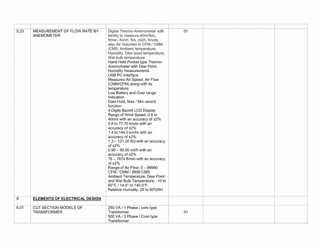
5.23 MEASUREMENT OF FLOW RATE BY
ANEMOMETER
Digital Thermo-Anemometer with facility to measure 40m/Sec, ft/min, Km/h, ft/s, mil/h, Knots, also Air Volumen in CFM / CMM /CMS, Ambient temperature, Humidity, Dew point temperature, Wet bulb temperature Hand Held Pocket type Thermo-Anemometer with Dew Point, Humidity measurements USB PC Interface Measures Air Speed, Air Flow (CMM/CFM) along with its temperature Low Battery and Over range indication Data Hold, Max / Min record function 4 Digits Backlit LCD Display Range of Wind Speed: 0.8 to 40m/s with an accuracy of ±2% 0.8 to 77.70 knots with an accuracy of ±2% 1.4 to 144.0 km/hr with an accuracy of ±2% 1.3 – 131.20 ft/s with an accuracy of ±2% 0.90 – 90.00 mil/h with an accuracy of ±2% 78 – 7874 ft/min with an accuracy of ±2% Range of Air Flow: 0 – 99990 CFM / CMM / 9999 CMS Ambient Temperature, Dew Point and Wet Bulb Temperature: -10 to 60°C / 14.0° to 140.0°F Relative Humidity: 20 to 80%RH
01
6 ELEMENTS OF ELECTRICAL DESIGN
6.01 CUT SECTION MODELS OF TRANSFORMER
250 VA / 1 Phase / core type Transformer 500 VA / 3 Phase / Core type Transformer
01
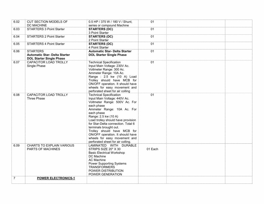
6.02 CUT SECTION MODELS OF DC MACHINE
0.5 HP / 375 W / 180 V / Shunt, series or compound Machine
01
6.03 STARTERS 3 Point Starter STARTERS (DC) 3 Point Starter
01
6.04 STARTERS 2 Point Starter
STARTERS (DC) 2 Point Starter
01
6.05 STARTERS 4 Point Starter
STARTERS (DC) 4 Point Starter
01
6.06 STARTERS Automatic Star- Delta Starter DOL Starter Single Phase
Automatic Star- Delta Starter DOL Starter Single Phase
01
6.07 CAPACITOR LOAD TROLLY Single Phase
Technical Specification Input Main Voltage: 230V Ac. Voltmeter Range: 300 Ac. Ammeter Range: 10A Ac. Range : 2.5 kw (10 A) Load Trolley should have MCB for ON/OFF operation. It should have wheels for easy movement and perforated sheet for air colling
01
6.08 CAPACITOR LOAD TROLLY Three Phase
Technical Specification Input Main Voltage: 440V Ac. Voltmeter Range: 500V Ac. For each phase Ammeter Range: 10A Ac. For each phase Range: 2.5 kw (10 A) Load trolley should have provision for Star-Delta connection. Total 6 terminals brought out. Trolley should have MCB for ON/OFF operation. It should have wheels for easy movement and perforated sheet for air colling.
01
6.09 CHARTS TO EXPLAIN VARIOUS PARTS OF MACHINES
LAMINATED WITH DURABLE STRIPS SIZE 20" X 30 Basic Electrical Workshop DC Machine AC Machine Power Supporting Systems TRANSFORMERS POWER DISTRIBUTION POWER GENERATION
01 Each
7 POWER ELECTRONICS-1
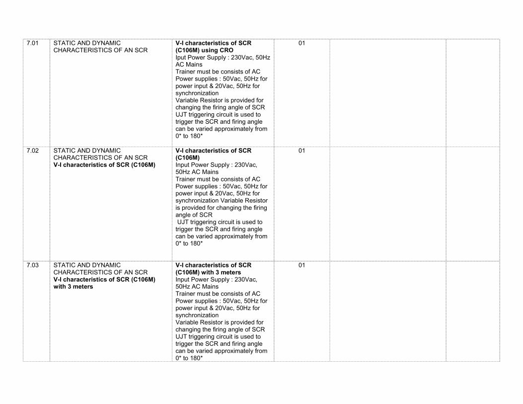
7.01 STATIC AND DYNAMIC CHARACTERISTICS OF AN SCR
V-I characteristics of SCR (C106M) using CRO Iput Power Supply : 230Vac, 50Hz AC Mains Trainer must be consists of AC Power supplies : 50Vac, 50Hz for power input & 20Vac, 50Hz for synchronization Variable Resistor is provided for changing the firing angle of SCR UJT triggering circuit is used to trigger the SCR and firing angle can be varied approximately from 0* to 180*
01
7.02 STATIC AND DYNAMIC CHARACTERISTICS OF AN SCR V-I characteristics of SCR (C106M)
V-I characteristics of SCR (C106M) Input Power Supply : 230Vac, 50Hz AC Mains Trainer must be consists of AC Power supplies : 50Vac, 50Hz for power input & 20Vac, 50Hz for synchronization Variable Resistor is provided for changing the firing angle of SCR UJT triggering circuit is used to trigger the SCR and firing angle can be varied approximately from 0* to 180*
01
7.03
STATIC AND DYNAMIC CHARACTERISTICS OF AN SCR V-I characteristics of SCR (C106M) with 3 meters
V-I characteristics of SCR (C106M) with 3 meters Input Power Supply : 230Vac, 50Hz AC Mains Trainer must be consists of AC Power supplies : 50Vac, 50Hz for power input & 20Vac, 50Hz for synchronization Variable Resistor is provided for changing the firing angle of SCR UJT triggering circuit is used to trigger the SCR and firing angle can be varied approximately from 0* to 180*
01
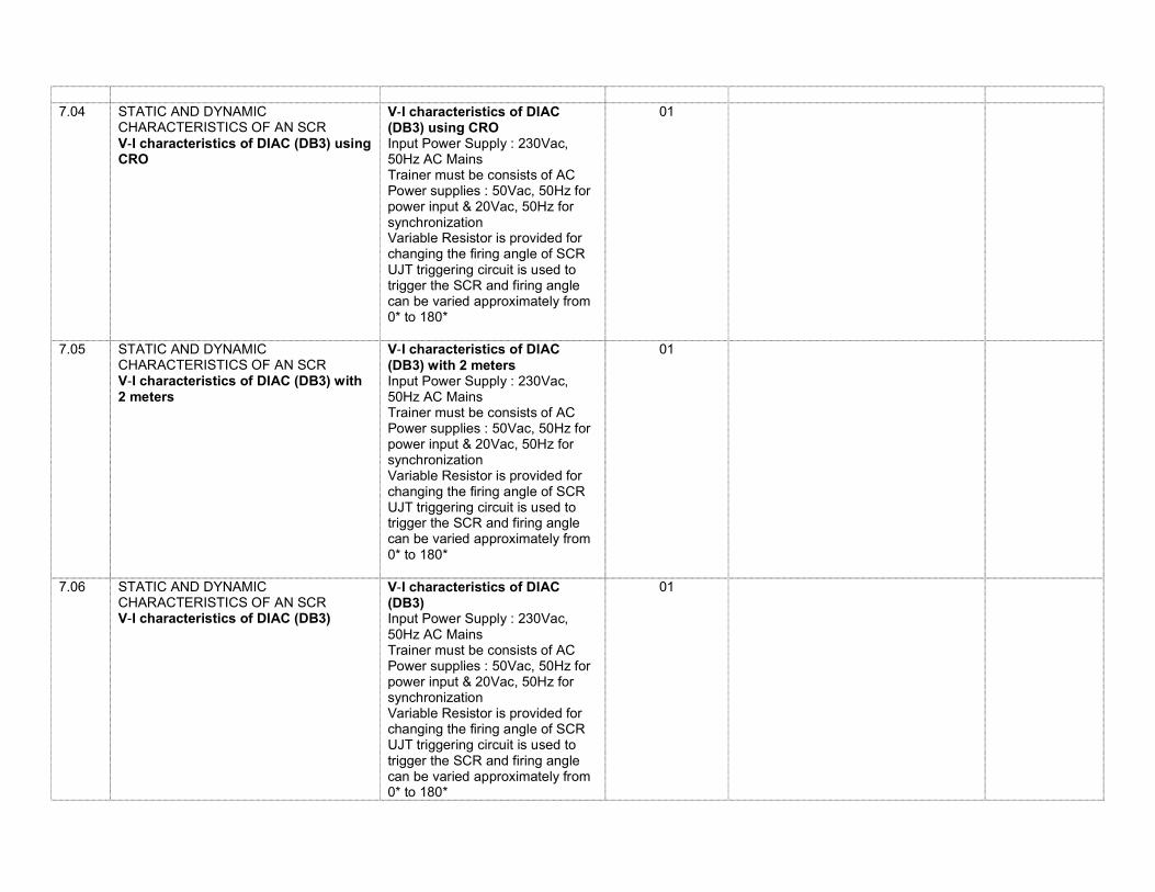
7.04 STATIC AND DYNAMIC
CHARACTERISTICS OF AN SCR V‐I characteristics of DIAC (DB3) using CRO
V‐I characteristics of DIAC (DB3) using CRO Input Power Supply : 230Vac, 50Hz AC Mains Trainer must be consists of AC Power supplies : 50Vac, 50Hz for power input & 20Vac, 50Hz for synchronization Variable Resistor is provided for changing the firing angle of SCR UJT triggering circuit is used to trigger the SCR and firing angle can be varied approximately from 0* to 180*
01
7.05 STATIC AND DYNAMIC CHARACTERISTICS OF AN SCR V‐I characteristics of DIAC (DB3) with 2 meters
V‐I characteristics of DIAC (DB3) with 2 meters Input Power Supply : 230Vac, 50Hz AC Mains Trainer must be consists of AC Power supplies : 50Vac, 50Hz for power input & 20Vac, 50Hz for synchronization Variable Resistor is provided for changing the firing angle of SCR UJT triggering circuit is used to trigger the SCR and firing angle can be varied approximately from 0* to 180*
01
7.06 STATIC AND DYNAMIC CHARACTERISTICS OF AN SCR V‐I characteristics of DIAC (DB3)
V‐I characteristics of DIAC (DB3) Input Power Supply : 230Vac, 50Hz AC Mains Trainer must be consists of AC Power supplies : 50Vac, 50Hz for power input & 20Vac, 50Hz for synchronization Variable Resistor is provided for changing the firing angle of SCR UJT triggering circuit is used to trigger the SCR and firing angle can be varied approximately from 0* to 180*
01
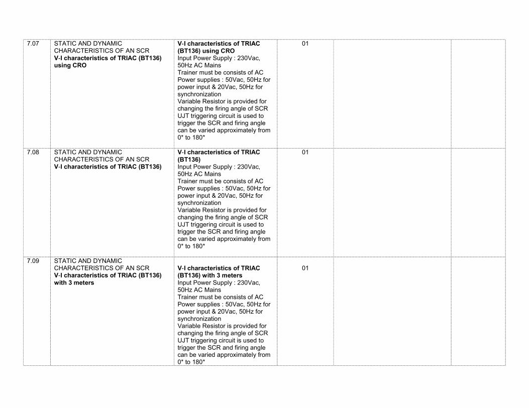
7.07 STATIC AND DYNAMIC CHARACTERISTICS OF AN SCR V‐I characteristics of TRIAC (BT136) using CRO
V‐I characteristics of TRIAC (BT136) using CRO Input Power Supply : 230Vac, 50Hz AC Mains Trainer must be consists of AC Power supplies : 50Vac, 50Hz for power input & 20Vac, 50Hz for synchronization Variable Resistor is provided for changing the firing angle of SCR UJT triggering circuit is used to trigger the SCR and firing angle can be varied approximately from 0* to 180*
01
7.08 STATIC AND DYNAMIC CHARACTERISTICS OF AN SCR V‐I characteristics of TRIAC (BT136)
V‐I characteristics of TRIAC (BT136) Input Power Supply : 230Vac, 50Hz AC Mains Trainer must be consists of AC Power supplies : 50Vac, 50Hz for power input & 20Vac, 50Hz for synchronization Variable Resistor is provided for changing the firing angle of SCR UJT triggering circuit is used to trigger the SCR and firing angle can be varied approximately from 0* to 180*
01
7.09 STATIC AND DYNAMIC CHARACTERISTICS OF AN SCR V‐I characteristics of TRIAC (BT136) with 3 meters
V‐I characteristics of TRIAC (BT136) with 3 meters Input Power Supply : 230Vac, 50Hz AC Mains Trainer must be consists of AC Power supplies : 50Vac, 50Hz for power input & 20Vac, 50Hz for synchronization Variable Resistor is provided for changing the firing angle of SCR UJT triggering circuit is used to trigger the SCR and firing angle can be varied approximately from 0* to 180*
01
7.10 OUTPUT CHARACTERISTICS AND
TRANSFER CHARACTERISTICS OF POWER MOSFET
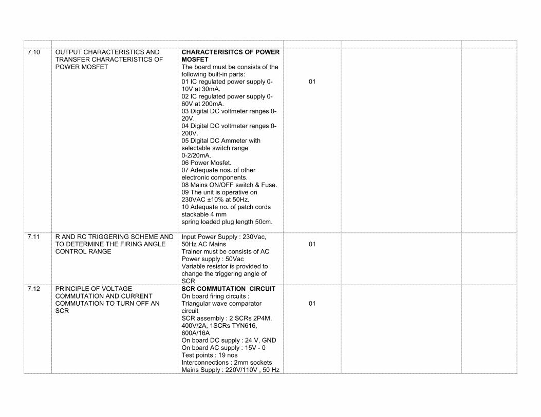
CHARACTERISITCS OF POWER MOSFET The board must be consists of the following built-in parts: 01 IC regulated power supply 0-10V at 30mA. 02 IC regulated power supply 0-60V at 200mA. 03 Digital DC voltmeter ranges 0-20V. 04 Digital DC voltmeter ranges 0-200V. 05 Digital DC Ammeter with selectable switch range 0-2/20mA. 06 Power Mosfet. 07 Adequate nos. of other electronic components. 08 Mains ON/OFF switch & Fuse. 09 The unit is operative on 230VAC ±10% at 50Hz. 10 Adequate no. of patch cords stackable 4 mm spring loaded plug length 50cm.
01
7.11 R AND RC TRIGGERING SCHEME AND TO DETERMINE THE FIRING ANGLE CONTROL RANGE
Input Power Supply : 230Vac, 50Hz AC Mains Trainer must be consists of AC Power supply : 50Vac Variable resistor is provided to change the triggering angle of SCR
01
7.12 PRINCIPLE OF VOLTAGE COMMUTATION AND CURRENT COMMUTATION TO TURN OFF AN SCR
SCR COMMUTATION CIRCUIT On board firing circuits : Triangular wave comparator circuit SCR assembly : 2 SCRs 2P4M, 400V/2A, 1SCRs TYN616, 600A/16A On board DC supply : 24 V, GND On board AC supply : 15V - 0 Test points : 19 nos Interconnections : 2mm sockets Mains Supply : 220V/110V , 50 Hz
01
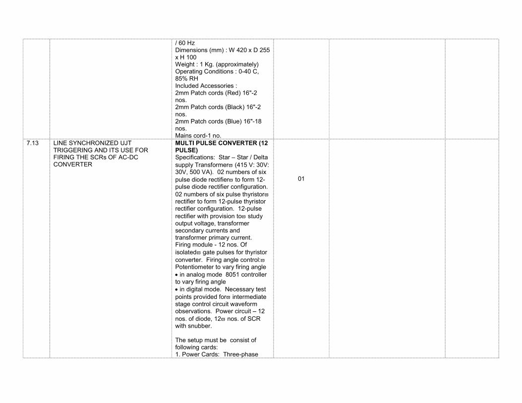
/ 60 Hz Dimensions (mm) : W 420 x D 255 x H 100 Weight : 1 Kg. (approximately) Operating Conditions : 0-40 C, 85% RH Included Accessories : 2mm Patch cords (Red) 16"-2 nos. 2mm Patch cords (Black) 16"-2 nos. 2mm Patch cords (Blue) 16"-18 nos. Mains cord-1 no.
7.13 LINE SYNCHRONIZED UJT TRIGGERING AND ITS USE FOR FIRING THE SCRs OF AC-DC CONVERTER
MULTI PULSE CONVERTER (12 PULSE) Specifications: Star – Star / Delta supply Transformer (415 V: 30V: 30V, 500 VA). 02 numbers of six pulse diode rectifier to form 12-pulse diode rectifier configuration. 02 numbers of six pulse thyristor rectifier to form 12-pulse thyristor rectifier configuration. 12-pulse rectifier with provision to study output voltage, transformer secondary currents and transformer primary current. Firing module - 12 nos. Of isolated gate pulses for thyristor converter. Firing angle control: Potentiometer to vary firing angle in analog mode 8051 controller to vary firing angle in digital mode. Necessary test points provided for intermediate stage control circuit waveform observations. Power circuit – 12 nos. of diode, 12 nos. of SCR with snubber. The setup must be consist of following cards: 1. Power Cards: Three-phase
01
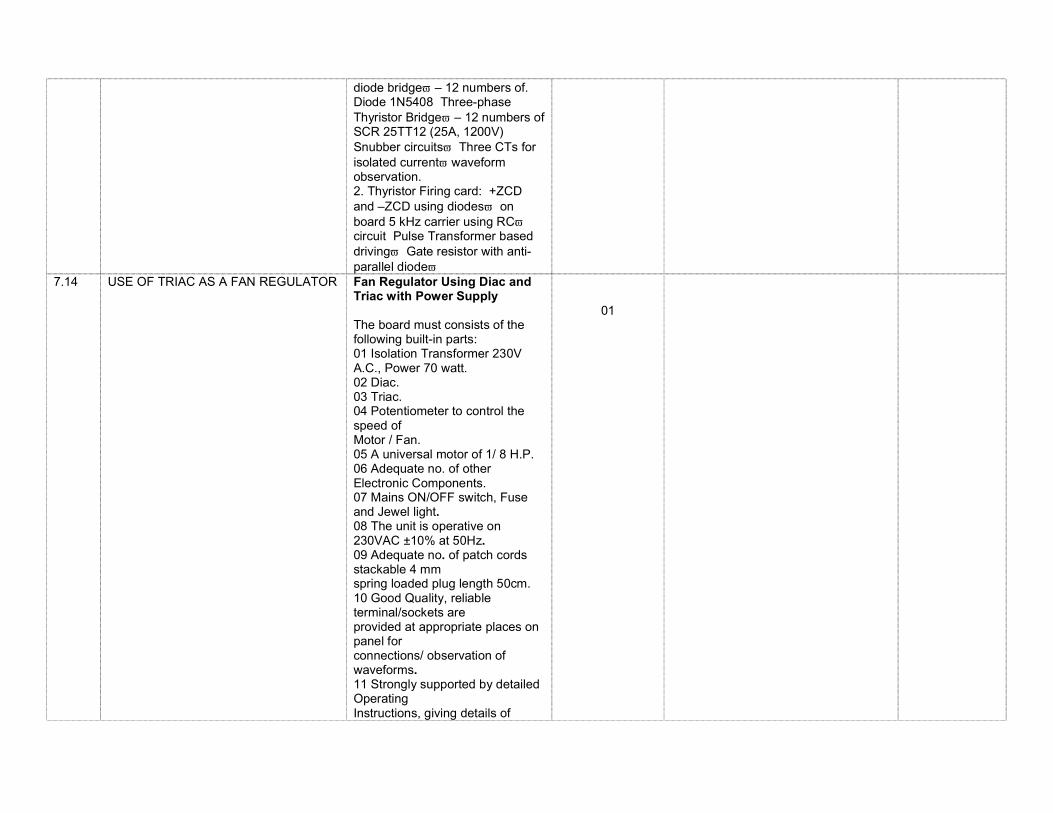
diode bridge – 12 numbers of. Diode 1N5408 Three-phase Thyristor Bridge – 12 numbers of SCR 25TT12 (25A, 1200V) Snubber circuits Three CTs for isolated current waveform observation. 2. Thyristor Firing card: +ZCD and –ZCD using diodes on board 5 kHz carrier using RC circuit Pulse Transformer based driving Gate resistor with anti-parallel diode
7.14 USE OF TRIAC AS A FAN REGULATOR
Fan Regulator Using Diac and Triac with Power Supply The board must consists of the following built-in parts: 01 Isolation Transformer 230V A.C., Power 70 watt. 02 Diac. 03 Triac. 04 Potentiometer to control the speed of Motor / Fan. 05 A universal motor of 1/ 8 H.P. 06 Adequate no. of other Electronic Components. 07 Mains ON/OFF switch, Fuse and Jewel light. 08 The unit is operative on 230VAC ±10% at 50Hz. 09 Adequate no. of patch cords stackable 4 mm spring loaded plug length 50cm. 10 Good Quality, reliable terminal/sockets are provided at appropriate places on panel for connections/ observation of waveforms. 11 Strongly supported by detailed Operating Instructions, giving details of
01
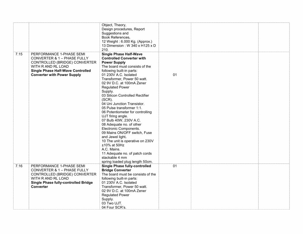
Object, Theory, Design procedures, Report Suggestions and Book References. 12 Weight : 6.000 Kg. (Approx.) 13 Dimension : W 340 x H125 x D 210.
7.15 PERFORMANCE 1-PHASE SEMI CONVERTER & 1 – PHASE FULLY CONTROLLED (BRIDGE) CONVERTER WITH R AND RL LOAD Single Phase Half-Wave Controlled Converter with Power Supply
Single Phase Half-Wave Controlled Converter with Power Supply The board must consists of the following built-in parts: 01 230V A.C. Isolated Transformer, Power 50 watt. 02 9V D.C. at 100mA Zener Regulated Power Supply. 03 Silicon Controlled Rectifier (SCR). 04 Uni Junction Transistor. 05 Pulse transformer 1:1. 06 Potentiometer for controlling UJT firing angle. 07 Bulb 40W, 230V A.C. 08 Adequate no. of other Electronic Components. 09 Mains ON/OFF switch, Fuse and Jewel light. 10 The unit is operative on 230V ±10% at 50Hz A.C. Mains. 11 Adequate no. of patch cords stackable 4 mm spring loaded plug length 50cm.
01
7.16 PERFORMANCE 1-PHASE SEMI CONVERTER & 1 – PHASE FULLY CONTROLLED (BRIDGE) CONVERTER WITH R AND RL LOAD Single Phase fully-controlled Bridge Converter
Single Phase fully-controlled Bridge Converter The board must be consists of the following built-in parts: 01 230V A.C. Isolated Transformer, Power 50 watt. 02 9V D.C. at 100mA Zener Regulated Power Supply. 03 Two UJT. 04 Four SCR’s.
01
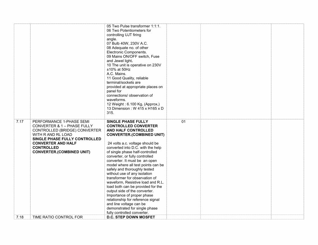
05 Two Pulse transformer 1:1:1. 06 Two Potentiometers for controlling UJT firing angle. 07 Bulb 40W, 230V A.C. 08 Adequate no. of other Electronic Components. 09 Mains ON/OFF switch, Fuse and Jewel light. 10 The unit is operative on 230V ±10% at 50Hz A.C. Mains. 11 Good Quality, reliable terminal/sockets are provided at appropriate places on panel for connections/ observation of waveforms. 12 Weight : 6.100 Kg. (Approx.) 13 Dimension : W 415 x H165 x D 315.
7.17 PERFORMANCE 1-PHASE SEMI CONVERTER & 1 – PHASE FULLY CONTROLLED (BRIDGE) CONVERTER WITH R AND RL LOAD SINGLE PHASE FULLY CONTROLLED CONVERTER AND HALF CONTROLLED CONVERTER.(COMBINED UNIT)
SINGLE PHASE FULLY CONTROLLED CONVERTER AND HALF CONTROLLED CONVERTER.(COMBINED UNIT) 24 volts a.c. voltage should be converted into D.C. with the help of single phase half-controlled converter, or fully controlled converter. It must be an open model where all test points can be safely and thoroughly tested without use of any isolation transformer for observation of waveform, Resistive load and R.L. load both can be provided for the output side of the converter. Importance of proper phase relationship for reference signal and line voltage can be demonstrated for single phase fully controlled converter.
01
7.18 TIME RATIO CONTROL FOR D.C. STEP DOWN MOSFET
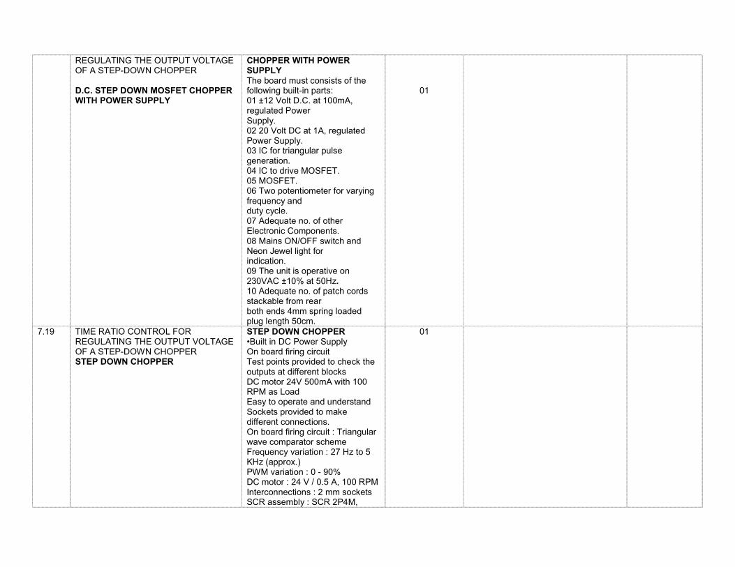
REGULATING THE OUTPUT VOLTAGE OF A STEP-DOWN CHOPPER D.C. STEP DOWN MOSFET CHOPPER WITH POWER SUPPLY
CHOPPER WITH POWER SUPPLY The board must consists of the following built-in parts: 01 ±12 Volt D.C. at 100mA, regulated Power Supply. 02 20 Volt DC at 1A, regulated Power Supply. 03 IC for triangular pulse generation. 04 IC to drive MOSFET. 05 MOSFET. 06 Two potentiometer for varying frequency and duty cycle. 07 Adequate no. of other Electronic Components. 08 Mains ON/OFF switch and Neon Jewel light for indication. 09 The unit is operative on 230VAC ±10% at 50Hz. 10 Adequate no. of patch cords stackable from rear both ends 4mm spring loaded plug length 50cm.
01
7.19 TIME RATIO CONTROL FOR REGULATING THE OUTPUT VOLTAGE OF A STEP-DOWN CHOPPER STEP DOWN CHOPPER
STEP DOWN CHOPPER •Built in DC Power Supply On board firing circuit Test points provided to check the outputs at different blocks DC motor 24V 500mA with 100 RPM as Load Easy to operate and understand Sockets provided to make different connections. On board firing circuit : Triangular wave comparator scheme Frequency variation : 27 Hz to 5 KHz (approx.) PWM variation : 0 - 90% DC motor : 24 V / 0.5 A, 100 RPM Interconnections : 2 mm sockets SCR assembly : SCR 2P4M,
01
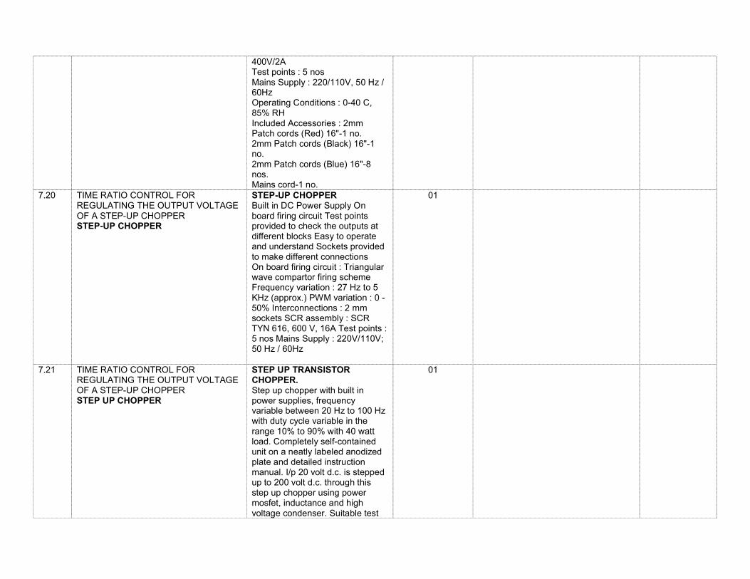
400V/2A Test points : 5 nos Mains Supply : 220/110V, 50 Hz / 60Hz Operating Conditions : 0-40 C, 85% RH Included Accessories : 2mm Patch cords (Red) 16"-1 no. 2mm Patch cords (Black) 16"-1 no. 2mm Patch cords (Blue) 16"-8 nos. Mains cord-1 no.
7.20 TIME RATIO CONTROL FOR REGULATING THE OUTPUT VOLTAGE OF A STEP-UP CHOPPER STEP-UP CHOPPER
STEP-UP CHOPPER Built in DC Power Supply On board firing circuit Test points provided to check the outputs at different blocks Easy to operate and understand Sockets provided to make different connections On board firing circuit : Triangular wave compartor firing scheme Frequency variation : 27 Hz to 5 KHz (approx.) PWM variation : 0 - 50% Interconnections : 2 mm sockets SCR assembly : SCR TYN 616, 600 V, 16A Test points : 5 nos Mains Supply : 220V/110V; 50 Hz / 60Hz
01
7.21 TIME RATIO CONTROL FOR REGULATING THE OUTPUT VOLTAGE OF A STEP-UP CHOPPER STEP UP CHOPPER
STEP UP TRANSISTOR CHOPPER. Step up chopper with built in power supplies, frequency variable between 20 Hz to 100 Hz with duty cycle variable in the range 10% to 90% with 40 watt load. Completely self-contained unit on a neatly labeled anodized plate and detailed instruction manual. I/p 20 volt d.c. is stepped up to 200 volt d.c. through this step up chopper using power mosfet, inductance and high voltage condenser. Suitable test
01
points are also provided. Panel size: 52*31*4 cm.(L*B*H)
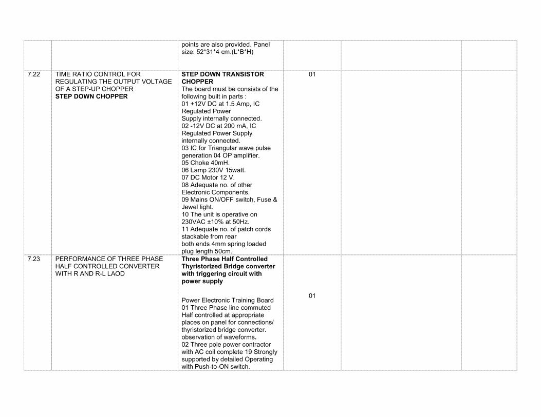
7.22 TIME RATIO CONTROL FOR REGULATING THE OUTPUT VOLTAGE OF A STEP-UP CHOPPER STEP DOWN CHOPPER
STEP DOWN TRANSISTOR CHOPPER The board must be consists of the following built in parts : 01 +12V DC at 1.5 Amp, IC Regulated Power Supply internally connected. 02 -12V DC at 200 mA, IC Regulated Power Supply internally connected. 03 IC for Triangular wave pulse generation 04 OP amplifier. 05 Choke 40mH. 06 Lamp 230V 15watt. 07 DC Motor 12 V. 08 Adequate no. of other Electronic Components. 09 Mains ON/OFF switch, Fuse & Jewel light. 10 The unit is operative on 230VAC ±10% at 50Hz. 11 Adequate no. of patch cords stackable from rear both ends 4mm spring loaded plug length 50cm.
01
7.23 PERFORMANCE OF THREE PHASE HALF CONTROLLED CONVERTER WITH R AND R-L LAOD
Three Phase Half Controlled Thyristorized Bridge converter with triggering circuit with power supply OF QUALITY PRODUCT R Power Electronic Training Board 01 Three Phase line commuted Half controlled at appropriate places on panel for connections/ thyristorized bridge converter. observation of waveforms. 02 Three pole power contractor with AC coil complete 19 Strongly supported by detailed Operating with Push-to-ON switch.
01
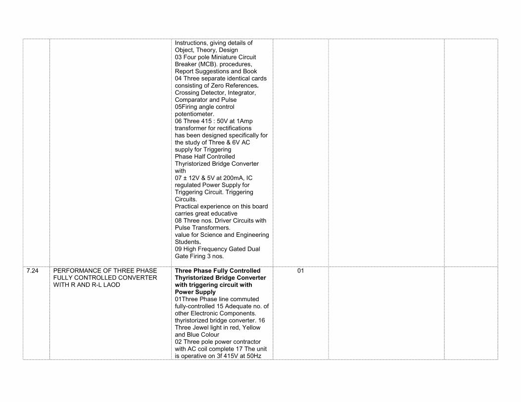
Instructions, giving details of Object, Theory, Design 03 Four pole Miniature Circuit Breaker (MCB). procedures, Report Suggestions and Book 04 Three separate identical cards consisting of Zero References. Crossing Detector, Integrator, Comparator and Pulse 05Firing angle control potentiometer. 06 Three 415 : 50V at 1Amp transformer for rectifications has been designed specifically for the study of Three & 6V AC supply for Triggering Phase Half Controlled Thyristorized Bridge Converter with 07 ± 12V & 5V at 200mA, IC regulated Power Supply for Triggering Circuit. Triggering Circuits. Practical experience on this board carries great educative 08 Three nos. Driver Circuits with Pulse Transformers. value for Science and Engineering Students. 09 High Frequency Gated Dual Gate Firing 3 nos.
7.24 PERFORMANCE OF THREE PHASE FULLY CONTROLLED CONVERTER WITH R AND R-L LAOD
Three Phase Fully Controlled Thyristorized Bridge Converter with triggering circuit with Power Supply 01Three Phase line commuted fully-controlled 15 Adequate no. of other Electronic Components. thyristorized bridge converter. 16 Three Jewel light in red, Yellow and Blue Colour 02 Three pole power contractor with AC coil complete 17 The unit is operative on 3f 415V at 50Hz
01
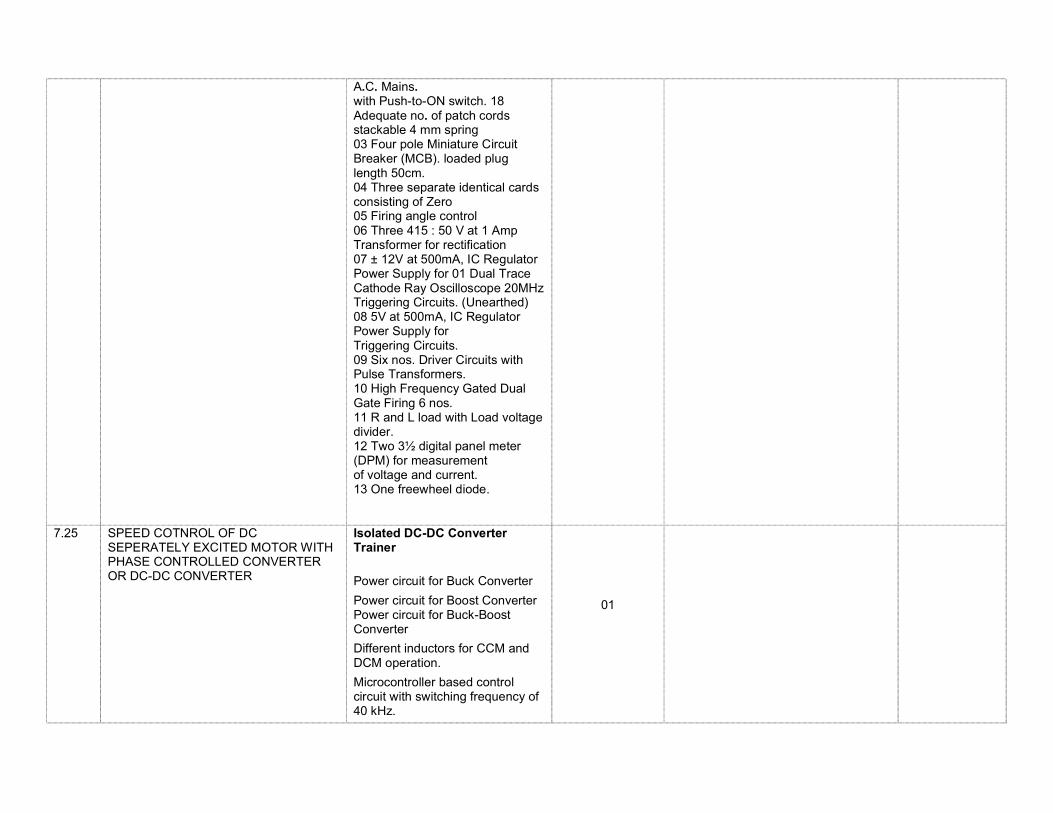
A.C. Mains. with Push-to-ON switch. 18 Adequate no. of patch cords stackable 4 mm spring 03 Four pole Miniature Circuit Breaker (MCB). loaded plug length 50cm. 04 Three separate identical cards consisting of Zero 05 Firing angle control 06 Three 415 : 50 V at 1 Amp Transformer for rectification 07 ± 12V at 500mA, IC Regulator Power Supply for 01 Dual Trace Cathode Ray Oscilloscope 20MHz Triggering Circuits. (Unearthed) 08 5V at 500mA, IC Regulator Power Supply for Triggering Circuits. 09 Six nos. Driver Circuits with Pulse Transformers. 10 High Frequency Gated Dual Gate Firing 6 nos. 11 R and L load with Load voltage divider. 12 Two 3½ digital panel meter (DPM) for measurement of voltage and current. 13 One freewheel diode.
7.25 SPEED COTNROL OF DC SEPERATELY EXCITED MOTOR WITH PHASE CONTROLLED CONVERTER OR DC-DC CONVERTER
Isolated DC-DC Converter Trainer
Power circuit for Buck Converter
Power circuit for Boost Converter Power circuit for Buck-Boost Converter
Different inductors for CCM and DCM operation.
Microcontroller based control circuit with switching frequency of 40 kHz.
01

Open loop and close loop operation
Provision for observing inductor voltage and current waveforms. The trainer should demonstrates basis three topologies of DC-DC conversion i.e. Buck, Boost, and Buck-Boost converter.
Switching frequency of 40 kHz.
Trainer includes step down power supply, control circuit, power circuit and different types of load.
The kit works directly with 230 V, 50 Hz, AC supply and other low power supplies required for the operation are derived internally.
Proper isolation between control and power circuit is provided.
Step down supply voltage of 24 V DC, fixed load resistance of 200 E, variable load rheostat of 50 E, inductance of 5 mH for CCM and 0.5 mH are provided.
Loading arrangements as a part of trainer and experimentation for continuous current mode (CCM) and discontinuous current mode (DCM) operation are provided. The setup will consist of following cards: 1. 32 bit ARM- Cortex controller card: STM32F407VGT MCU @168MHz
Buffered I/O Ports using 74HC573
2 DAC outputs
9 ADC input channels with buffering using LM324 IC
On board QEI (Quadrature Encoder Interface) section
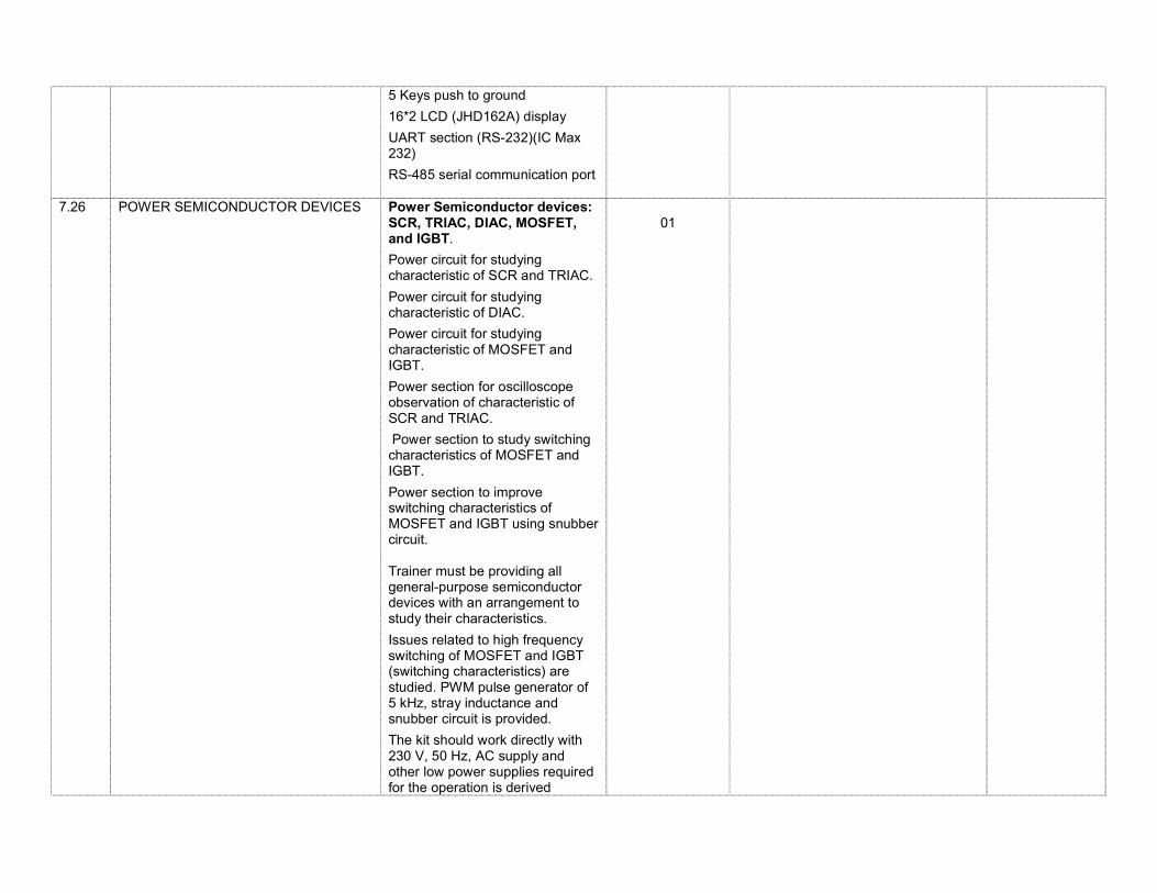
5 Keys push to ground
16*2 LCD (JHD162A) display
UART section (RS-232)(IC Max 232)
RS-485 serial communication port
7.26 POWER SEMICONDUCTOR DEVICES Power Semiconductor devices: SCR, TRIAC, DIAC, MOSFET, and IGBT.
Power circuit for studying characteristic of SCR and TRIAC.
Power circuit for studying characteristic of DIAC.
Power circuit for studying characteristic of MOSFET and IGBT.
Power section for oscilloscope observation of characteristic of SCR and TRIAC.
Power section to study switching characteristics of MOSFET and IGBT.
Power section to improve switching characteristics of MOSFET and IGBT using snubber circuit. Trainer must be providing all general-purpose semiconductor devices with an arrangement to study their characteristics.
Issues related to high frequency switching of MOSFET and IGBT (switching characteristics) are studied. PWM pulse generator of 5 kHz, stray inductance and snubber circuit is provided.
The kit should work directly with 230 V, 50 Hz, AC supply and other low power supplies required for the operation is derived
01
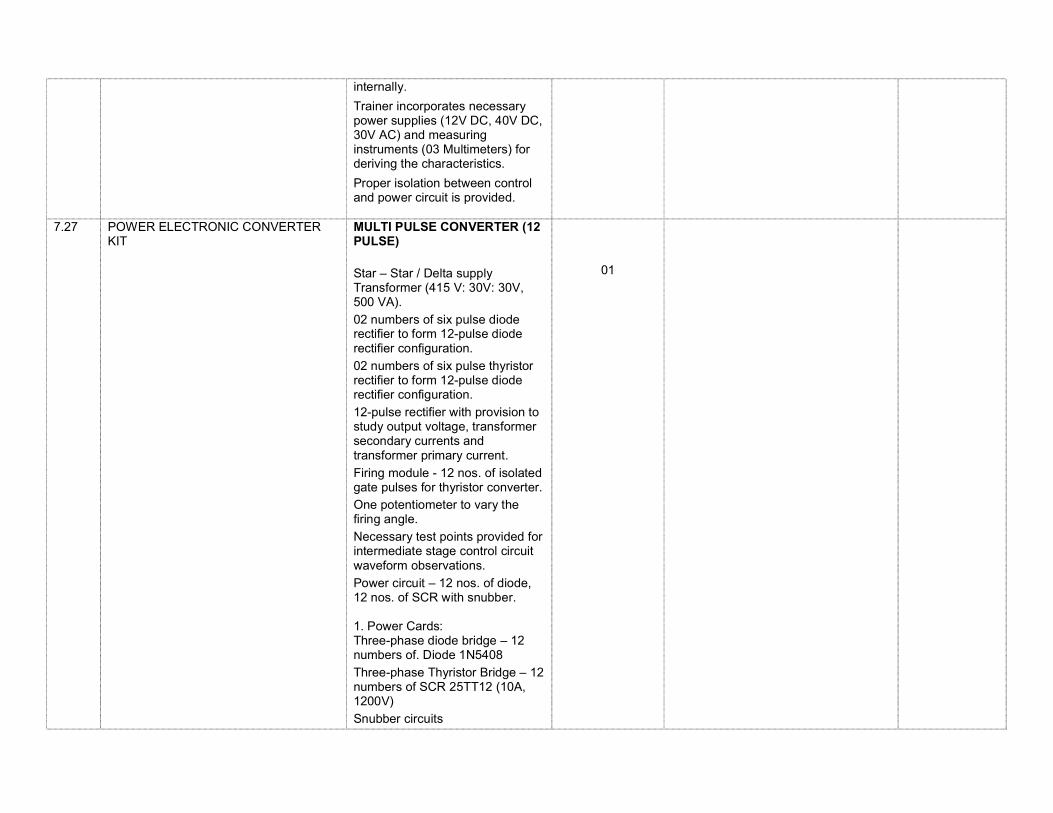
internally.
Trainer incorporates necessary power supplies (12V DC, 40V DC, 30V AC) and measuring instruments (03 Multimeters) for deriving the characteristics.
Proper isolation between control and power circuit is provided.
7.27 POWER ELECTRONIC CONVERTER KIT
MULTI PULSE CONVERTER (12 PULSE)
Star – Star / Delta supply Transformer (415 V: 30V: 30V, 500 VA).
02 numbers of six pulse diode rectifier to form 12-pulse diode rectifier configuration.
02 numbers of six pulse thyristor rectifier to form 12-pulse diode rectifier configuration.
12-pulse rectifier with provision to study output voltage, transformer secondary currents and transformer primary current.
Firing module - 12 nos. of isolated gate pulses for thyristor converter. One potentiometer to vary the firing angle.
Necessary test points provided for intermediate stage control circuit waveform observations.
Power circuit – 12 nos. of diode, 12 nos. of SCR with snubber. 1. Power Cards: Three-phase diode bridge – 12 numbers of. Diode 1N5408
Three-phase Thyristor Bridge – 12 numbers of SCR 25TT12 (10A, 1200V)
Snubber circuits
01
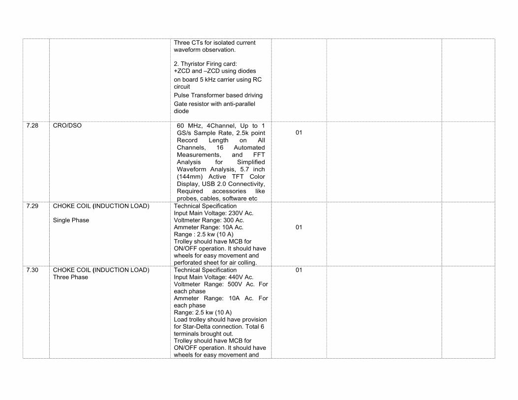
Three CTs for isolated current waveform observation. 2. Thyristor Firing card: +ZCD and –ZCD using diodes
on board 5 kHz carrier using RC circuit
Pulse Transformer based driving
Gate resistor with anti-parallel diode
7.28 CRO/DSO
60 MHz, 4Channel, Up to 1 GS/s Sample Rate, 2.5k point Record Length on All Channels, 16 Automated Measurements, and FFT Analysis for Simplified Waveform Analysis, 5.7 inch (144mm) Active TFT Color Display, USB 2.0 Connectivity, Required accessories like probes, cables, software etc
01
7.29 CHOKE COIL (INDUCTION LOAD) Single Phase
Technical Specification Input Main Voltage: 230V Ac. Voltmeter Range: 300 Ac. Ammeter Range: 10A Ac. Range : 2.5 kw (10 A) Trolley should have MCB for ON/OFF operation. It should have wheels for easy movement and perforated sheet for air colling.
01
7.30 CHOKE COIL (INDUCTION LOAD) Three Phase
Technical Specification Input Main Voltage: 440V Ac. Voltmeter Range: 500V Ac. For each phase Ammeter Range: 10A Ac. For each phase Range: 2.5 kw (10 A) Load trolley should have provision for Star-Delta connection. Total 6 terminals brought out. Trolley should have MCB for ON/OFF operation. It should have wheels for easy movement and
01
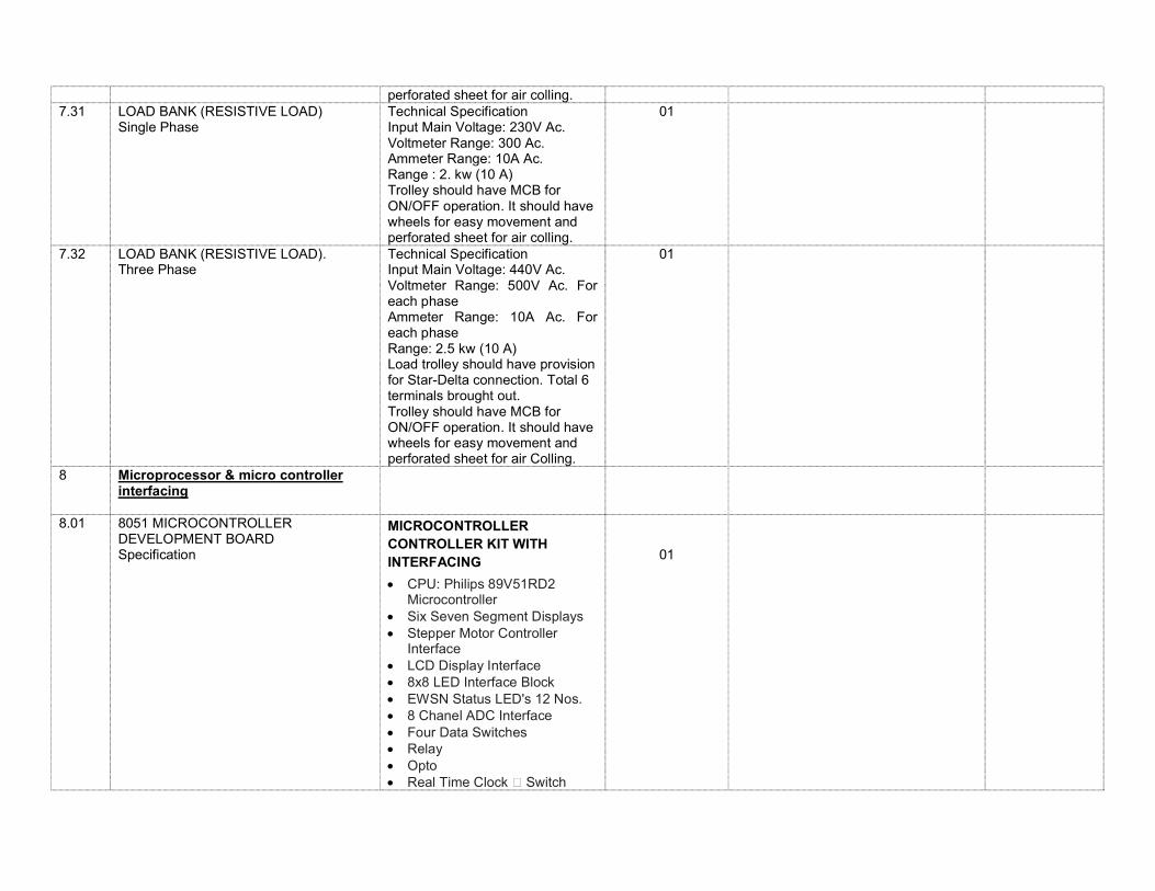
perforated sheet for air colling. 7.31 LOAD BANK (RESISTIVE LOAD)
Single Phase
Technical Specification Input Main Voltage: 230V Ac. Voltmeter Range: 300 Ac. Ammeter Range: 10A Ac. Range : 2. kw (10 A) Trolley should have MCB for ON/OFF operation. It should have wheels for easy movement and perforated sheet for air colling.
01
7.32 LOAD BANK (RESISTIVE LOAD). Three Phase
Technical Specification Input Main Voltage: 440V Ac. Voltmeter Range: 500V Ac. For each phase Ammeter Range: 10A Ac. For each phase Range: 2.5 kw (10 A) Load trolley should have provision for Star-Delta connection. Total 6 terminals brought out. Trolley should have MCB for ON/OFF operation. It should have wheels for easy movement and perforated sheet for air Colling.
01
8 Microprocessor & micro controller interfacing
8.01 8051 MICROCONTROLLER DEVELOPMENT BOARD Specification
MICROCONTROLLER CONTROLLER KIT WITH INTERFACING
CPU: Philips 89V51RD2 Microcontroller
Six Seven Segment Displays Stepper Motor Controller
Interface LCD Display Interface 8x8 LED Interface Block EWSN Status LED's 12 Nos. 8 Chanel ADC Interface Four Data Switches Relay Opto Real Time Clock Switch
01
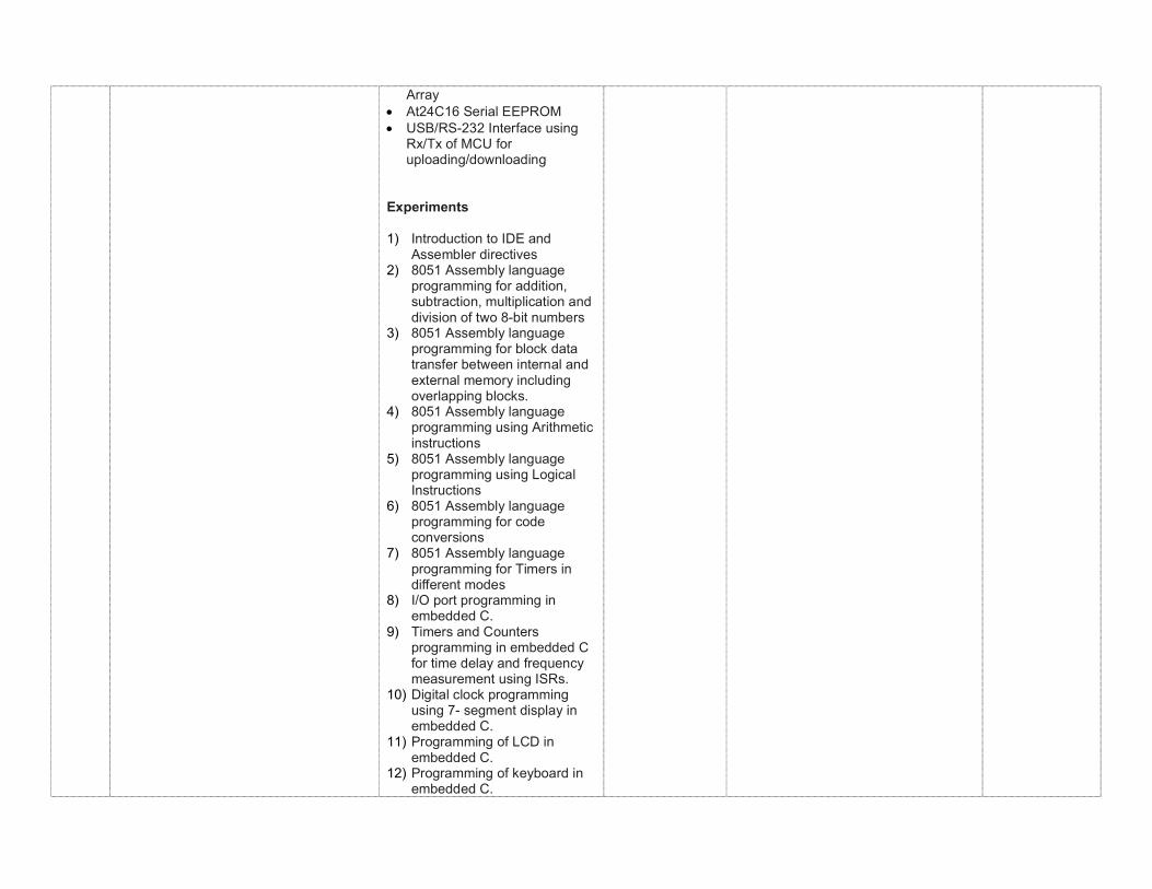
Array At24C16 Serial EEPROM USB/RS-232 Interface using
Rx/Tx of MCU for uploading/downloading
Experiments
1) Introduction to IDE and Assembler directives
2) 8051 Assembly language programming for addition, subtraction, multiplication and division of two 8-bit numbers
3) 8051 Assembly language programming for block data transfer between internal and external memory including overlapping blocks.
4) 8051 Assembly language programming using Arithmetic instructions
5) 8051 Assembly language programming using Logical Instructions
6) 8051 Assembly language programming for code conversions
7) 8051 Assembly language programming for Timers in different modes
8) I/O port programming in embedded C.
9) Timers and Counters programming in embedded C for time delay and frequency measurement using ISRs.
10) Digital clock programming using 7- segment display in embedded C.
11) Programming of LCD in embedded C.
12) Programming of keyboard in embedded C.
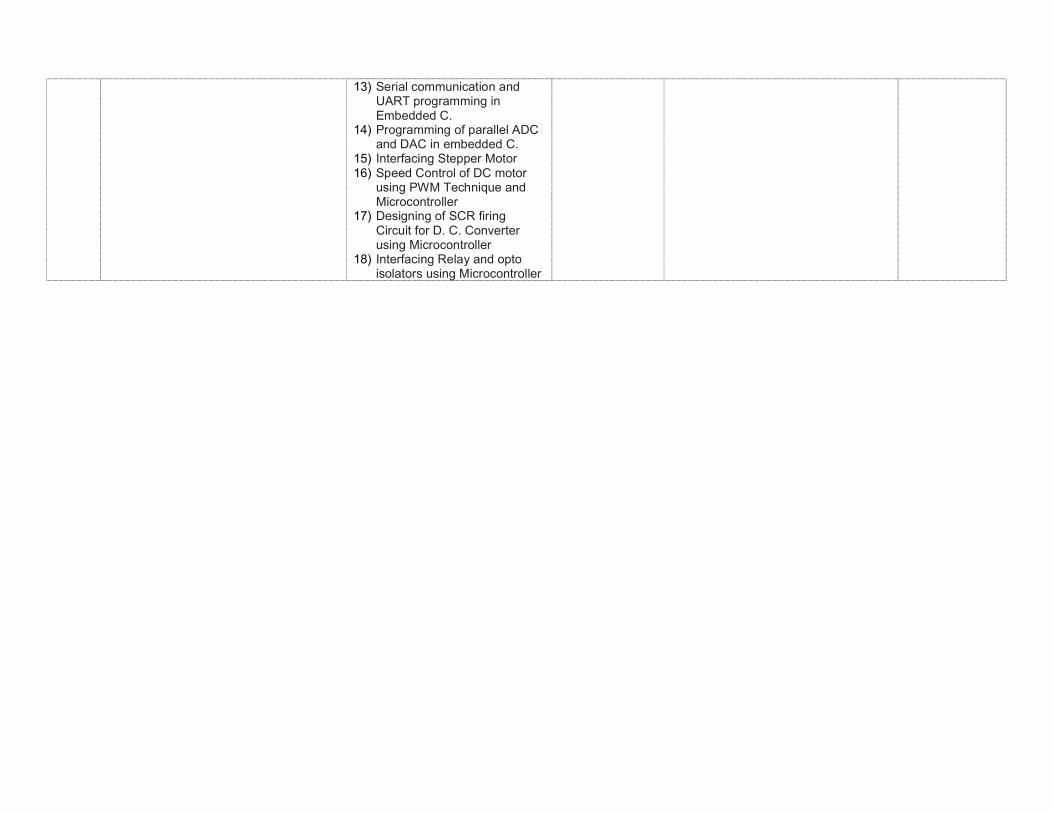
13) Serial communication and UART programming in Embedded C.
14) Programming of parallel ADC and DAC in embedded C.
15) Interfacing Stepper Motor 16) Speed Control of DC motor
using PWM Technique and Microcontroller
17) Designing of SCR firing Circuit for D. C. Converter using Microcontroller
18) Interfacing Relay and opto isolators using Microcontroller
Related Documents