http://www.robokits.co.in http://www.robokitsworld.com Page 1 ARDUINO UNO R3 BASED BLUETOOTH + USB 18 SERVO CONTROLLER [RKI-1251 and RKI-1252] User Manual ROBOKITS INDIA

Welcome message from author
This document is posted to help you gain knowledge. Please leave a comment to let me know what you think about it! Share it to your friends and learn new things together.
Transcript
http://www.robokits.co.in
http://www.robokitsworld.com Page 1
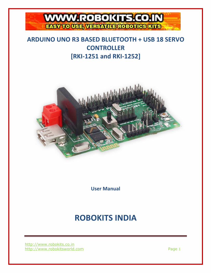
ARDUINO UNO R3 BASED BLUETOOTH + USB 18 SERVO
CONTROLLER
[RKI-1251 and RKI-1252]
User Manual
ROBOKITS INDIA
http://www.robokits.co.in
http://www.robokitsworld.com Page 2
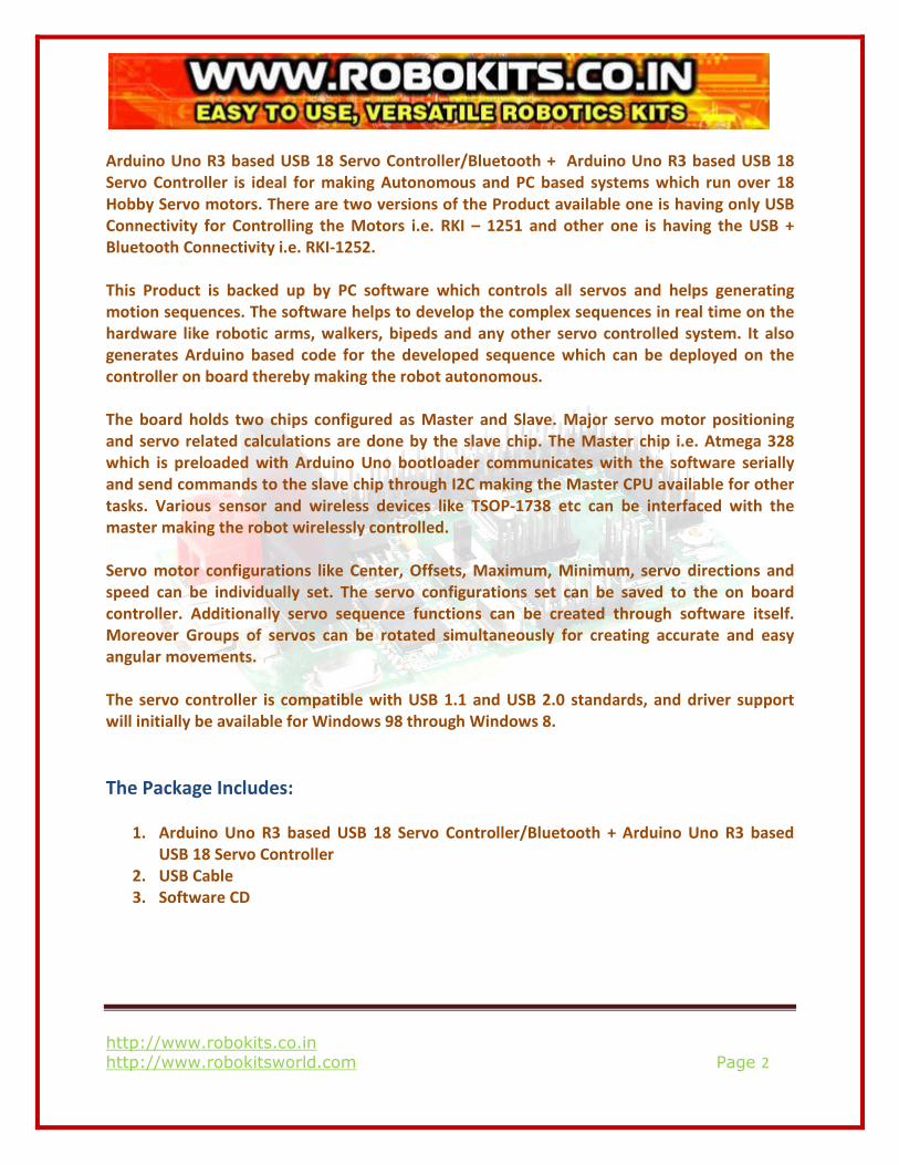
Arduino Uno R3 based USB 18 Servo Controller/Bluetooth + Arduino Uno R3 based USB 18
Servo Controller is ideal for making Autonomous and PC based systems which run over 18
Hobby Servo motors. There are two versions of the Product available one is having only USB
Connectivity for Controlling the Motors i.e. RKI – 1251 and other one is having the USB +
Bluetooth Connectivity i.e. RKI-1252.
This Product is backed up by PC software which controls all servos and helps generating
motion sequences. The software helps to develop the complex sequences in real time on the
hardware like robotic arms, walkers, bipeds and any other servo controlled system. It also
generates Arduino based code for the developed sequence which can be deployed on the
controller on board thereby making the robot autonomous.
The board holds two chips configured as Master and Slave. Major servo motor positioning
and servo related calculations are done by the slave chip. The Master chip i.e. Atmega 328
which is preloaded with Arduino Uno bootloader communicates with the software serially
and send commands to the slave chip through I2C making the Master CPU available for other
tasks. Various sensor and wireless devices like TSOP-1738 etc can be interfaced with the
master making the robot wirelessly controlled.
Servo motor configurations like Center, Offsets, Maximum, Minimum, servo directions and
speed can be individually set. The servo configurations set can be saved to the on board
controller. Additionally servo sequence functions can be created through software itself.
Moreover Groups of servos can be rotated simultaneously for creating accurate and easy
angular movements.
The servo controller is compatible with USB 1.1 and USB 2.0 standards, and driver support
will initially be available for Windows 98 through Windows 8.
The Package Includes:
1. Arduino Uno R3 based USB 18 Servo Controller/Bluetooth + Arduino Uno R3 based
USB 18 Servo Controller
2. USB Cable
3. Software CD
http://www.robokits.co.in
http://www.robokitsworld.com Page 3
Features:
• Bluetooth interface for wireless control of robots. (Optionally with RKI-1252)
• Controls 18 hobby servos from PC and Microcontroller
• USB interface
• Comes Pre-loaded Arduino Uno bootloader
• Software exports servo sequences to Arduino Uno for running servo sequences
• Independent range setting for each servo
• Independent offset, Maximum, Minimum and Direction setting for each servo
• 0.5-microsecond resolution
• 50 Hz update rate
• Small size of 80 X 47 mm
• Plug and Play, Auto detection of hardware
• Easy to use software
• Servo sequencer with speed, delay, goto and many other features
• Home and neutral position setting
• Easy to install USB driver and Application software
http://www.robokits.co.in
http://www.robokitsworld.com Page 4
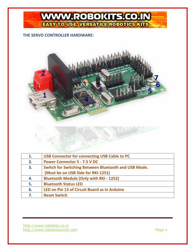
THE SERVO CONTROLLER HARDWARE:
1. USB Connector for connecting USB Cable to PC
2. Power Connector 5 - 7.5 V DC
3. Switch for Switching Between Bluetooth and USB Mode.
(Must be on USB Side for RKI-1251)
4. Bluetooth Module (Only with RKI - 1252)
5. Bluetooth Status LED
6. LED on Pin 13 of Circuit Board as in Arduino
7. Reset Switch
http://www.robokits.co.in
http://www.robokitsworld.com Page 5
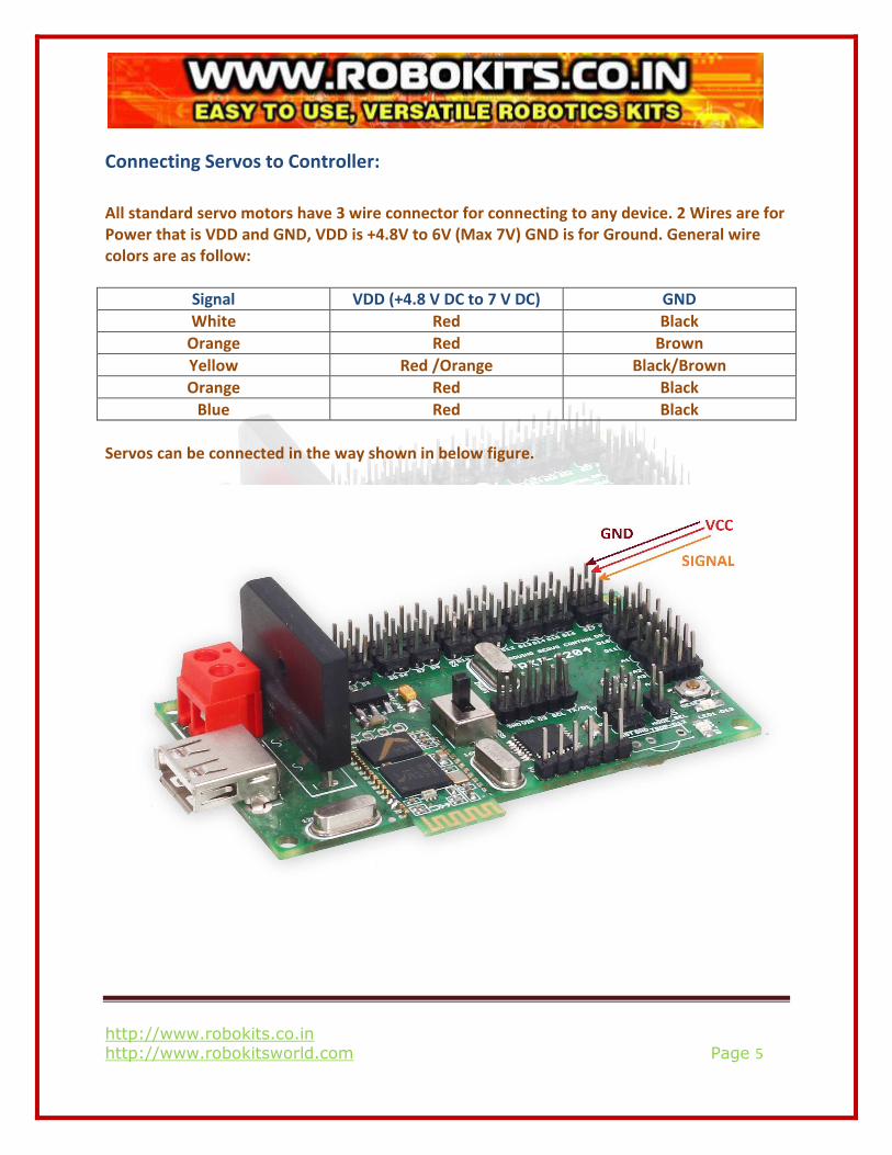
Connecting Servos to Controller:
All standard servo motors have 3 wire connector for connecting to any device. 2 Wires are for
Power that is VDD and GND, VDD is +4.8V to 6V (Max 7V) GND is for Ground. General wire
colors are as follow:
Signal VDD (+4.8 V DC to 7 V DC) GND
White Red Black
Orange Red Brown
Yellow Red /Orange Black/Brown
Orange Red Black
Blue Red Black
Servos can be connected in the way shown in below figure.
http://www.robokits.co.in
http://www.robokitsworld.com Page 6
Connecting Power Supply
Most recommended power source for servo controller is between 4.8 to 6VDC. However
sometimes a 7.5 V source is also used. You can connect the Power Source to the Power
Connector (See Page 4).
Installation and Usage
Software:
1. You can Install the Software : Robokits_USB_BT_ServoCon_Setup.exe given in the CD
with the Product or you can also download it from the Product page on Our Website. In this case you will need to install .net framework 4.0 if it is not installed already.
2. Keep clicking Next Button unless the Setup is Complete.
USB Drivers:
1. USB Drivers are Provided in the CD with the Product.
Bluetooth Setting:
1. The Setting shown here are for Windows 7. Click on Devices and Printers in the Start
Menu.
2. Make sure that your PC’s Bluetooth is On and the Servo Controller is powered up. Also
the Switch Provided on the Controller is on the Bluetooth Side.
3. Click on Add Device in the Devices and Printers Section.
http://www.robokits.co.in
http://www.robokitsworld.com Page 7
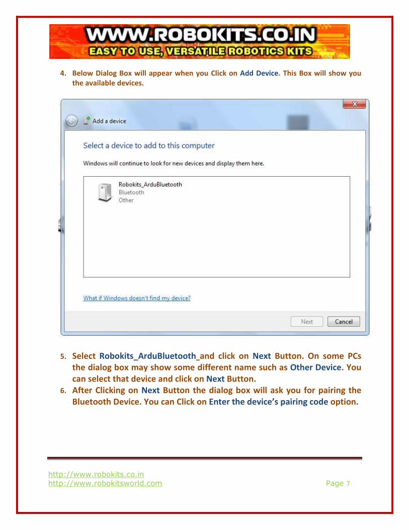
4. Below Dialog Box will appear when you Click on Add Device. This Box will show you
the available devices.
5. Select Robokits_ArduBluetooth and click on Next Button. On some PCs
the dialog box may show some different name such as Other Device. You
can select that device and click on Next Button.
6. After Clicking on Next Button the dialog box will ask you for pairing the
Bluetooth Device. You can Click on Enter the device’s pairing code option.
http://www.robokits.co.in
http://www.robokitsworld.com Page 8
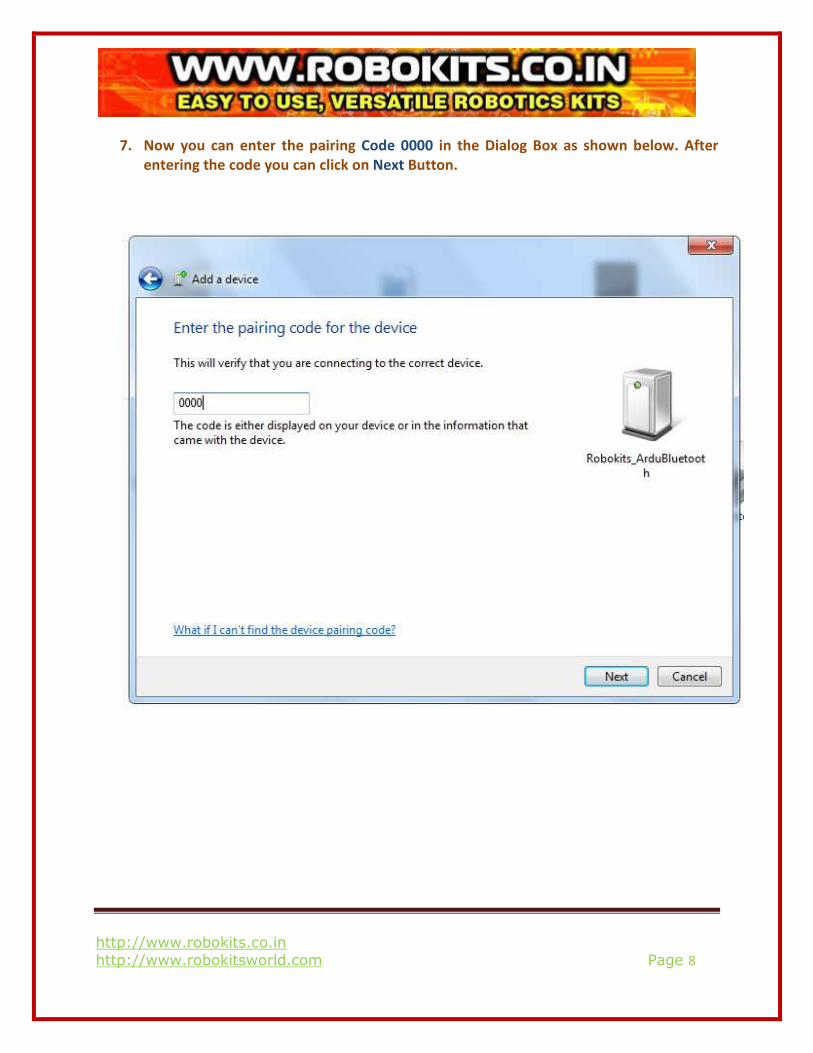
7. Now you can enter the pairing Code 0000 in the Dialog Box as shown below. After
entering the code you can click on Next Button.
http://www.robokits.co.in
http://www.robokitsworld.com Page 9
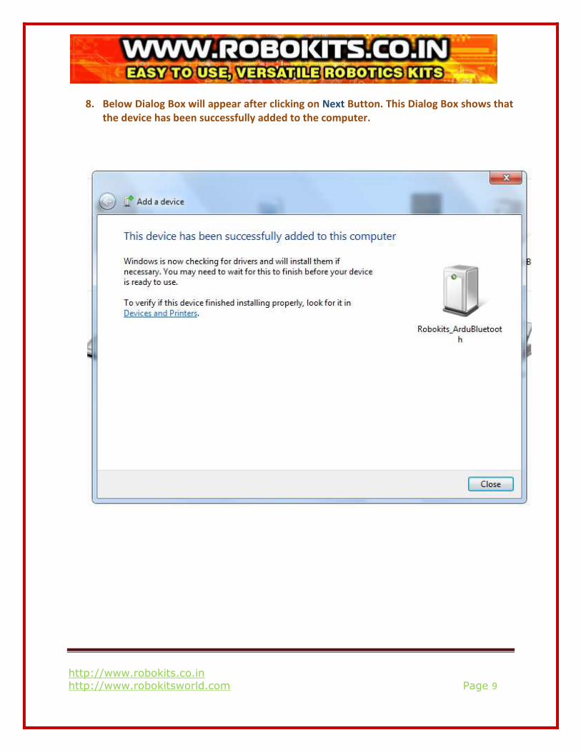
8. Below Dialog Box will appear after clicking on Next Button. This Dialog Box shows that
the device has been successfully added to the computer.
http://www.robokits.co.in
http://www.robokitsworld.com Page 10
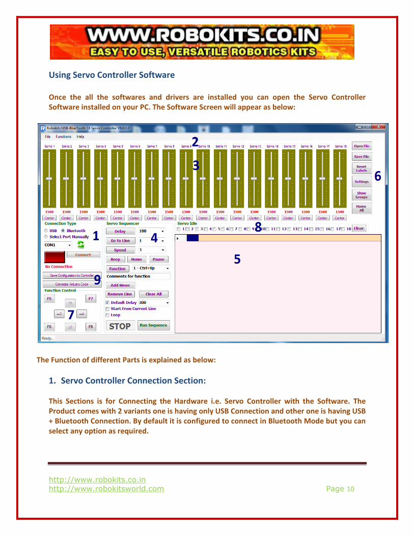
Using Servo Controller Software
Once the all the softwares and drivers are installed you can open the Servo Controller
Software installed on your PC. The Software Screen will appear as below:
The Function of different Parts is explained as below:
1. Servo Controller Connection Section:
This Sections is for Connecting the Hardware i.e. Servo Controller with the Software. The
Product comes with 2 variants one is having only USB Connection and other one is having USB
+ Bluetooth Connection. By default it is configured to connect in Bluetooth Mode but you can
select any option as required.
http://www.robokits.co.in
http://www.robokitsworld.com Page 11
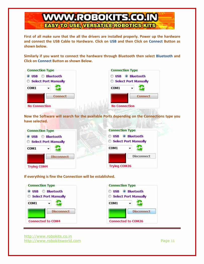
First of all make sure that the all the drivers are installed properly. Power up the hardware
and connect the USB Cable to Hardware. Click on USB and then Click on Connect Button as
shown below.
Similarly if you want to connect the hardware through Bluetooth then select Bluetooth and
Click on Connect Button as shown Below.
Now the Software will search for the available Ports depending on the Connections type you
have selected.
If everything is fine the Connection will be established.
http://www.robokits.co.in
http://www.robokitsworld.com Page 12
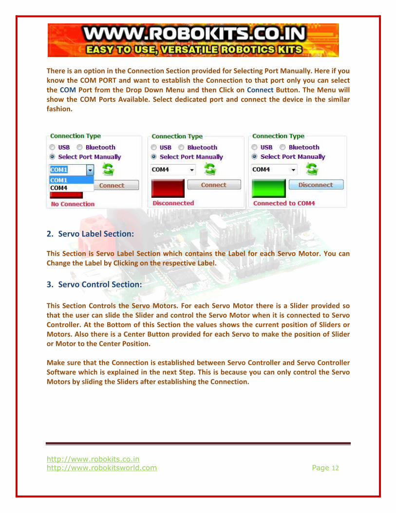
There is an option in the Connection Section provided for Selecting Port Manually. Here if you
know the COM PORT and want to establish the Connection to that port only you can select
the COM Port from the Drop Down Menu and then Click on Connect Button. The Menu will
show the COM Ports Available. Select dedicated port and connect the device in the similar
fashion.
2. Servo Label Section:
This Section is Servo Label Section which contains the Label for each Servo Motor. You can
Change the Label by Clicking on the respective Label.
3. Servo Control Section:
This Section Controls the Servo Motors. For each Servo Motor there is a Slider provided so
that the user can slide the Slider and control the Servo Motor when it is connected to Servo
Controller. At the Bottom of this Section the values shows the current position of Sliders or
Motors. Also there is a Center Button provided for each Servo to make the position of Slider
or Motor to the Center Position.
Make sure that the Connection is established between Servo Controller and Servo Controller
Software which is explained in the next Step. This is because you can only control the Servo
Motors by sliding the Sliders after establishing the Connection.
http://www.robokits.co.in
http://www.robokitsworld.com Page 13
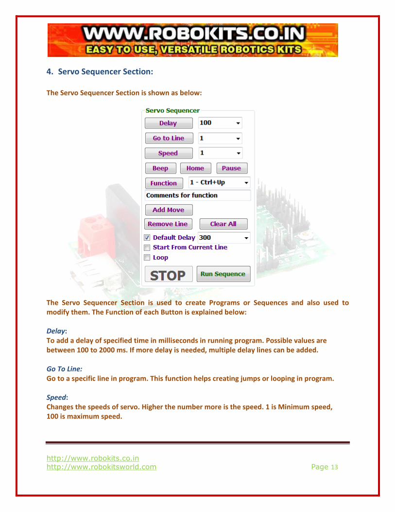
4. Servo Sequencer Section:
The Servo Sequencer Section is shown as below:
The Servo Sequencer Section is used to create Programs or Sequences and also used to
modify them. The Function of each Button is explained below:
Delay:
To add a delay of specified time in milliseconds in running program. Possible values are
between 100 to 2000 ms. If more delay is needed, multiple delay lines can be added.
Go To Line:
Go to a specific line in program. This function helps creating jumps or looping in program.
Speed:
Changes the speeds of servo. Higher the number more is the speed. 1 is Minimum speed,
100 is maximum speed.
http://www.robokits.co.in
http://www.robokitsworld.com Page 14
Beep:
Rings ‘Beep’ from computer speaker. Sounds could be different for different themes set on
PC.
Home:
Sets all servos to home position.
Pause:
Pause the program until a function is called or certain action is done.
Function:
Up to 8 different functions can be created and named for certain actions. For example you
can program different functions for walk forward, walk backward, turn left, turn right and
dance in sequencer for a biped. After creating functions you can call them with a hot key or
clicking buttons on screen and run the programmed actions.
It’s advisable to use pause at end of every function so that program doesn’t end.
ADD Move:
Add move Add the current servo positions for all 16 servos to program. By default move is
added in the last line but it can be added anywhere. When a line is selected before adding
move new line will be added before currently selected line. After a line is added numbering of
lines will change, this can affect in Go to line command.
Some servos can be excluded by selecting their numbers in servo idle box so that they will
remain unaffected while the move is performed.
Remove:
Removes the Selected Line.
Clear All:
Clears the Program Window.
Default Delay:
Add specified amount of delay between every line. This is required when program is running
on speed 1 as there will be no time for servos to complete action because before the servo
reaches specified angle next command is sent.
http://www.robokits.co.in
http://www.robokitsworld.com Page 15
Start from Current Line:
Start running program from selected line. This is useful when a specific part of program needs
to be run or for testing while developing sequence.
Loop:
Starts program again from line 1 after end.
Run Sequence:
Start running program.
Stop:
Stop running Program.
5. Sequence Window/ Program Window:
All the Sequences which are generated or modified using the Servo Sequence Sections can be
seen in this Window. Moreover for running the specific Step you can double click the Line in
this Window to Run that step.
6. Servo Settings and other Options:
The different Buttons in this Section are explained below:
Open File:
To open already saved file.
Save File:
To save Current File.
Reset Labels:
Reset the Labels of the Servos given by the User.
http://www.robokits.co.in
http://www.robokitsworld.com Page 16
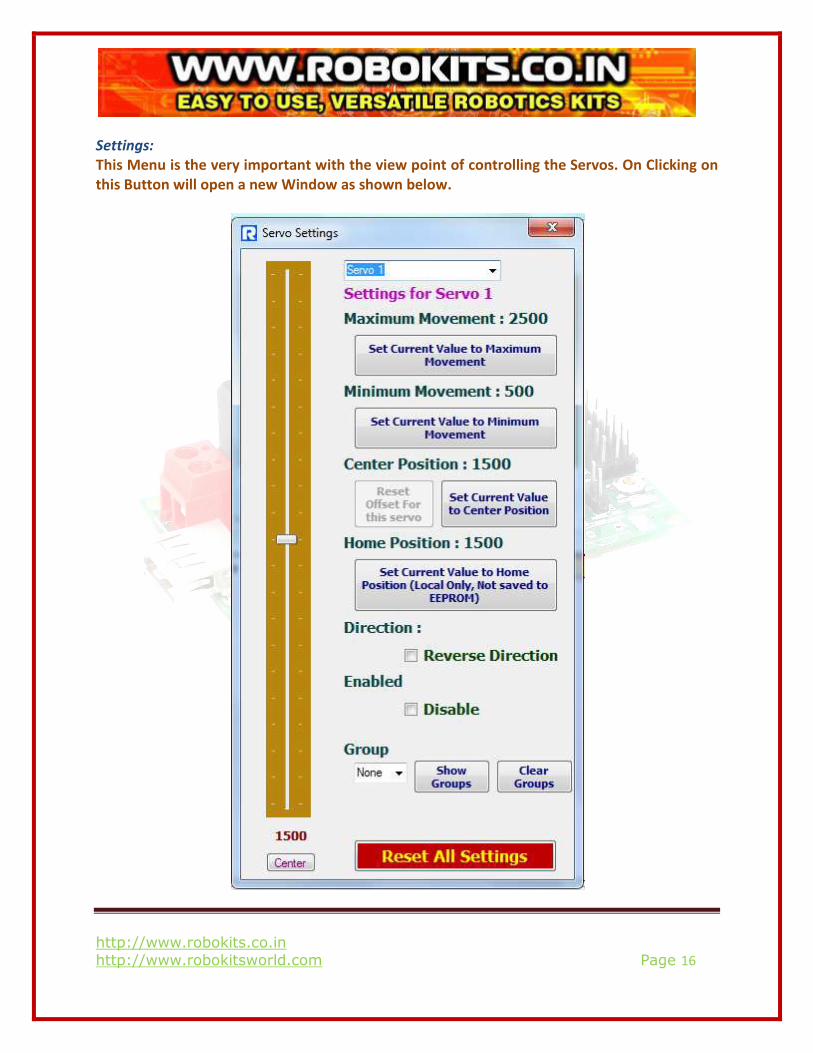
Settings:
This Menu is the very important with the view point of controlling the Servos. On Clicking on
this Button will open a new Window as shown below.
http://www.robokits.co.in
http://www.robokitsworld.com Page 17
• Slider in settings menu is same as main screen. Moving it will move selected servo.
• Servo numbers can be selected from dropdown menu on top.
• Servo controller shows movements in large range. It’s obvious that all servos have slightly
different operation range and higher and lower movement limits depending upon types
and manufacturer. Here we can set maximum and minimum movement of servo so that
motor doesn’t reach the limit. It’s also required to restrict movement when in an
assembly servo movement is obstructed by some other part.
• By default Center position is 1500. This can be changed as per requirement and servo
type. The Offset for this servo can also be reset using Reset Offset for this Servo Button.
• Home position is the position which puts servos in default state. This can be used to move
servo selected in the Drop Down Menu in certain position. This can also be called in
program.
• Checking ‘Reverse Direction’ checkbox will reverse direction of servo. This is useful
function while programming sequence for robots like bipeds or hexapods where mirror
movements are needed for left and right legs.
• Checking ‘Disable’ will disable the particular Servo.
• Before explaining the function of Show Groups Button it is important to understand the
topic of creating the Groups. Let’s see how to Create Groups:
� There is a very important feature in the Settings which is called Grouping of Servos.
Using this feature will create a group of motors which we need to run at a time. It is
very easy to create a group and one can create the maximum of 9 Groups.
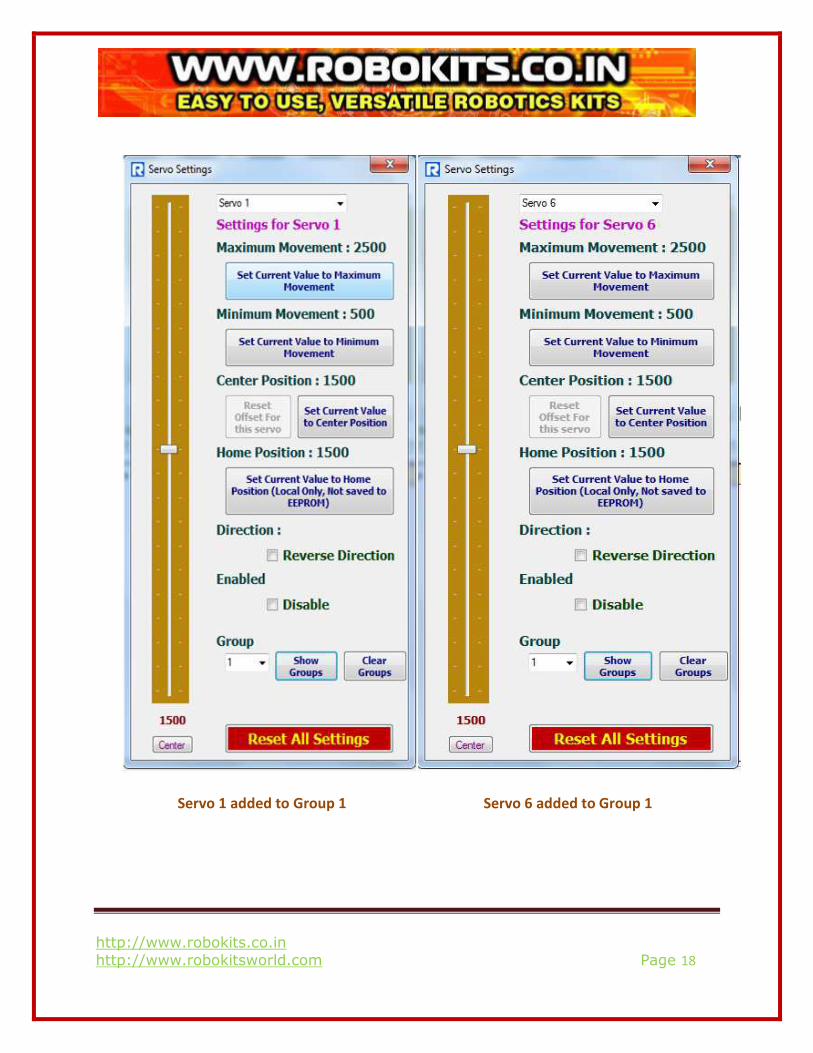
� Groups can be created from the Settings Menu itself. Let’s create the Group of two
Servo motors say 1 and 6. Select Servo 1 from the Drop Down Menu. Then go to
Group Drop Down menu in the Bottom of the Settings menu. Select 1 from Drop
Down Menu as we are creating the first group. This will create a Group 1 with Servo 1
in it. Now we need to add Servo 6 to this Group. Select Servo 6 from the Drop Down
Menu. Then again go to Group Drop Down menu. Select 1 from it. This will add Servo
6 to Group.
http://www.robokits.co.in
http://www.robokitsworld.com Page 18
Servo 1 added to Group 1 Servo 6 added to Group 1
http://www.robokits.co.in
http://www.robokitsworld.com Page 19
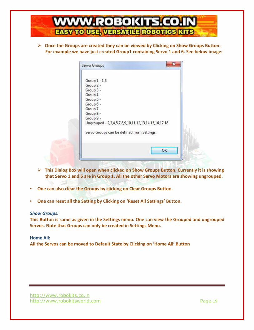
� Once the Groups are created they can be viewed by Clicking on Show Groups Button.
For example we have just created Group1 containing Servo 1 and 6. See below image:
� This Dialog Box will open when clicked on Show Groups Button. Currently it is showing
that Servo 1 and 6 are in Group 1. All the other Servo Motors are showing ungrouped.
• One can also clear the Groups by clicking on Clear Groups Button.
• One can reset all the Setting by Clicking on ‘Reset All Settings’ Button.
Show Groups:
This Button is same as given in the Settings menu. One can view the Grouped and ungrouped
Servos. Note that Groups can only be created in Settings Menu.
Home All:
All the Servos can be moved to Default State by Clicking on ‘Home All’ Button
http://www.robokits.co.in
http://www.robokitsworld.com Page 20
7. Function Control Section:
While generating the sequences one can also create the Functions as per the requirement.
For example in Biped Robot one can generate different functions for Forward, Reverse etc.
Once the functions generated you can directly call the required function from this Section.
8. Servo Idle Section:
By default when executing servo movement commands like double clicking on code line or
while running a program, servo controller will update values of all 18 servos. In some cases
this can be problem specially while using functions.
For example there a robot with 4 servo motors, 2 are for driving wheels and 2 are for wrist
and gripper. This robot is connected to servo controller with Bluetooth for wires operation
and it needs to be controlled manually by using functions. Now say there are different
functions for pick, place, and move forward-back-left-right. What happens here is if servos
are hardcoded while moving forward or backward gripper servos will also operate. Or while
opening or closing gripper wheeled servos will operate. To avoid this we can idle gripper
servos while moving and idle wheeled servos while gripping operation.
In Servo Idle box any servo can be chosen to idle while adding move. Idle servo will appear as
‘X’ in program.
9. Saving Configuration and Generating Arduino Code:
In this Section the first Button is of Save Configuration to Controller. The Configurations
Settings made for each Servo (for example: Center Position, Maximum Position , Minimum
Position etc) can be directly saved to Controller by clicking on this Button.
Once the sequence is generated for the required application and the file is saved you can
generate the Arduino Code for your sequence which can directly be deployed into the same
Servo Controller Board as it is Arduino based Controller. This will make your robot
autonomous means you don’t need PC Software for running the same sequence generated by
you. Let us see how to generate the Arduino Code.
http://www.robokits.co.in
http://www.robokitsworld.com Page 21
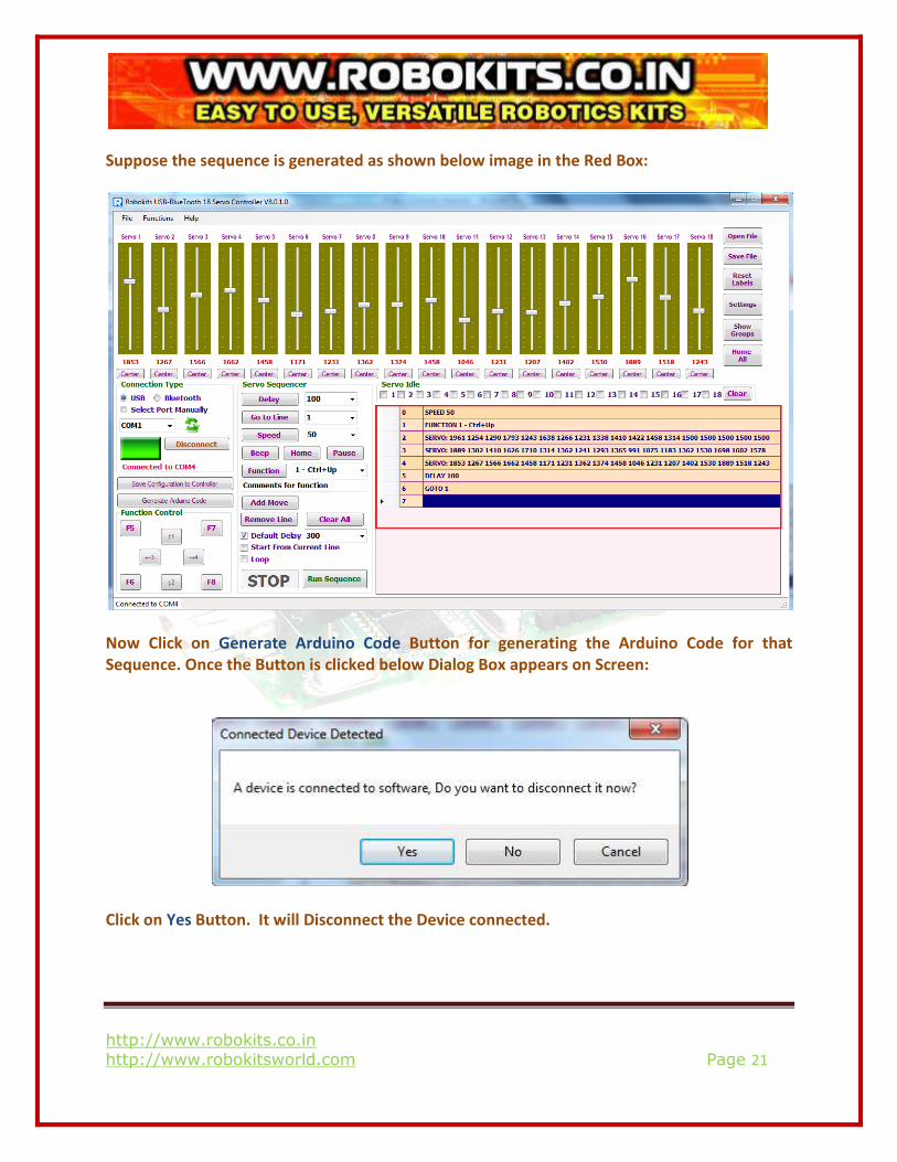
Suppose the sequence is generated as shown below image in the Red Box:
Now Click on Generate Arduino Code Button for generating the Arduino Code for that
Sequence. Once the Button is clicked below Dialog Box appears on Screen:
Click on Yes Button. It will Disconnect the Device connected.
http://www.robokits.co.in
http://www.robokitsworld.com Page 22
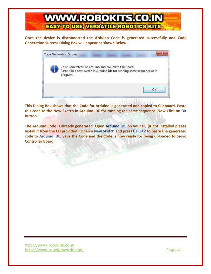
Once the device is disconnected the Arduino Code is generated successfully and Code
Generation Success Dialog Box will appear as shown Below:
This Dialog Box shows that the Code for Arduino is generated and copied to Clipboard. Paste
this code to the New Sketch in Arduino IDE for running the same sequence. Now Click on OK
Button.
The Arduino Code is already generated. Open Arduino IDE on your PC (if not installed please
install it from the CD provided). Open a New Sketch and press CTRL+V to paste the generated
code to Arduino IDE. Save the Code and the Code is now ready for being uploaded to Servo
Controller Board.
Related Documents