1 18

Welcome message from author
This document is posted to help you gain knowledge. Please leave a comment to let me know what you think about it! Share it to your friends and learn new things together.
Transcript

1
18

In this lecture ...
• Stirling and Ericsson cycles• Brayton cycle: The ideal cycle for gas-
turbine engines• The Brayton cycle with regeneration• The Brayton cycle with intercooling,
reheating and regeneration• Rankine cycle: The ideal cycle for vapour
power cycles
Prof. Bhaskar Roy, Prof. A M Pradeep, Department of Aerospace, IIT Bombay2
Lect-18

Stirling and Ericsson cycles• The ideal Otto and Diesel cycles are
internally reversible, but not totally reversible.
• Hence their efficiencies will always be less than that of Carnot efficiency.
• For a cycle to approach a Carnot cycle, heat addition and heat rejection must take place isothermally.
• Stirling and Ericsson cycles comprise of isothermal heat addition and heat rejection.
Prof. Bhaskar Roy, Prof. A M Pradeep, Department of Aerospace, IIT Bombay3
Lect-18
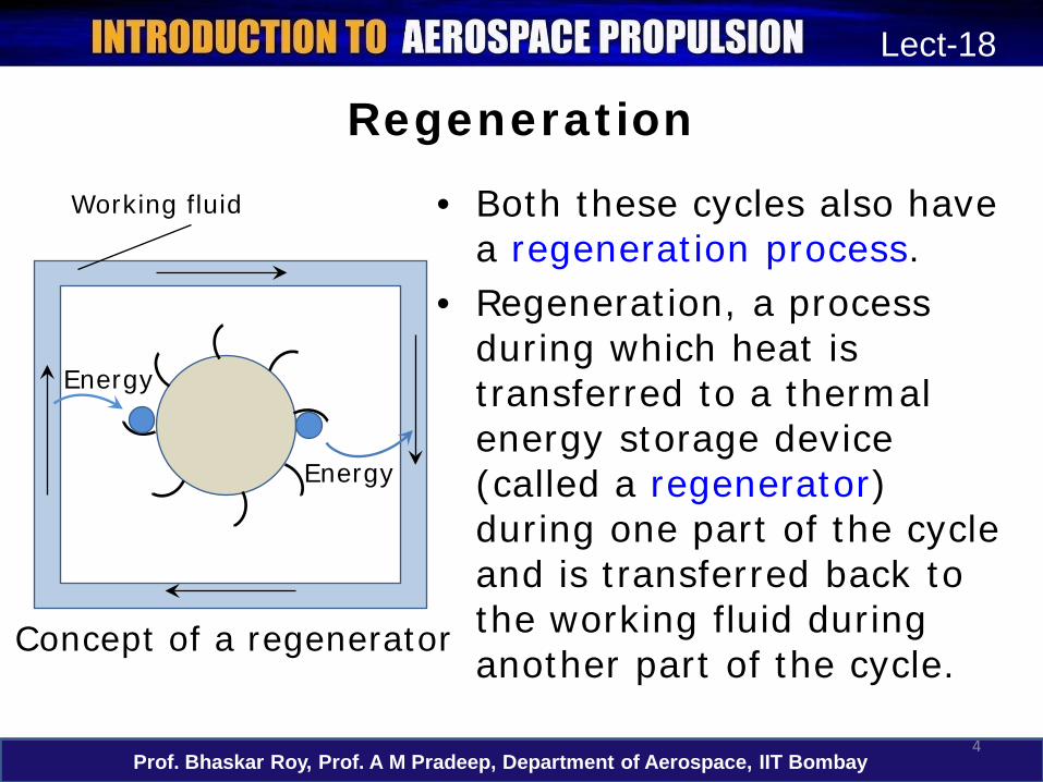
Regeneration
• Both these cycles also have a regeneration process.
• Regeneration, a process during which heat is transferred to a thermal energy storage device (called a regenerator) during one part of the cycle and is transferred back to the working fluid during another part of the cycle.
Prof. Bhaskar Roy, Prof. A M Pradeep, Department of Aerospace, IIT Bombay4
Lect-18
Energy
Energy
Working fluid
Concept of a regenerator

Stirling cycle• Consists of four totally reversible processes:
– 1-2 T = constant, expansion (heat addition from the external source)
– 2-3 v = constant, regeneration (internal heat transfer from the working fluid to the regenerator)
– 3-4 T= constant, compression (heat rejection to the external sink)
– 4-1 v = constant, regeneration (internal heat transfer from the regenerator back to the working fluid)
Prof. Bhaskar Roy, Prof. A M Pradeep, Department of Aerospace, IIT Bombay5
Lect-18

Stirling cycle
Prof. Bhaskar Roy, Prof. A M Pradeep, Department of Aerospace, IIT Bombay6
Lect-17
v
P
3
1
24
qin
qout
Isothermal
s
T qin
qout
1
34
2
Isochoric
Stirling cycle on P-v and T-s diagrams
Regeneration

Ericsson cycle• Consists of four totally reversible processes:
– 1-2 T = constant, expansion (heat addition from the external source)
– 2-3 P = constant, regeneration (internal heat transfer from the working fluid to the regenerator)
– 3-4 T= constant, compression (heat rejection to the external sink)
– 4-1 P = constant, regeneration (internal heat transfer from the regenerator back to the working fluid)
Prof. Bhaskar Roy, Prof. A M Pradeep, Department of Aerospace, IIT Bombay7
Lect-18

Ericsson cycle
Prof. Bhaskar Roy, Prof. A M Pradeep, Department of Aerospace, IIT Bombay8
Lect-17
v
P
3
1
2
4
qin
qout
Isothermal
s
T qin
qout
1
34
2
Isobaric
Ericsson cycle on P-v and T-s diagrams
Regeneration
Regeneration

Stirling and Ericsson cycles• Since both these engines are totally
reversible cycles, their efficiencies equal the Carnot efficiency between same temperature limits.
• These cycles are difficult to realise practically, but offer great potential.
• Regeneration increases efficiency.• This fact is used in many modern day cycles
to improve efficiency.
Prof. Bhaskar Roy, Prof. A M Pradeep, Department of Aerospace, IIT Bombay9
Lect-18

Brayton cycle
• The Brayton cycle was proposed by George Brayton in 1870 for use in reciprocating engines.
• Modern day gas turbines operate on Braytoncycle and work with rotating machinery.
• Gas turbines operate in open-cycle mode, but can be modelled as closed cycle using air-standard assumptions.
• Combustion and exhaust replaced by constant pressure heat addition and rejection.
Prof. Bhaskar Roy, Prof. A M Pradeep, Department of Aerospace, IIT Bombay10
Lect-18

Brayton cycle
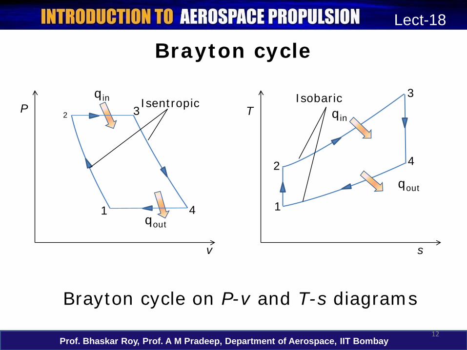
• The Brayton cycle consists of four internally reversible processes:– 1-2 Isentropic compression (in a
compressor)– 2-3 Constant-pressure heat addition– 3-4 Isentropic expansion (in a turbine)– 4-1 Constant-pressure heat rejection
Prof. Bhaskar Roy, Prof. A M Pradeep, Department of Aerospace, IIT Bombay11
Lect-18
Brayton cycle
Prof. Bhaskar Roy, Prof. A M Pradeep, Department of Aerospace, IIT Bombay12
Lect-18
v
P
1
3
4
2
qin
qout
Isentropic
Brayton cycle on P-v and T-s diagrams
s
T qin
qout
1
3
42
Isobaric

Brayton cycle
• The energy balance for a steady-flow process can be expressed as:
Prof. Bhaskar Roy, Prof. A M Pradeep, Department of Aerospace, IIT Bombay13
Lect-18
)(
)(:as written becan
fluid working thefrom and fer toheat trans The)()(
1414
2323
TTchhqTTchhq
hwwqq
pout
pin
outinoutin
−=−=
−=−=
∆=−+−
Brayton cycle
Prof. Bhaskar Roy, Prof. A M Pradeep, Department of Aerospace, IIT Bombay14
Lect-18
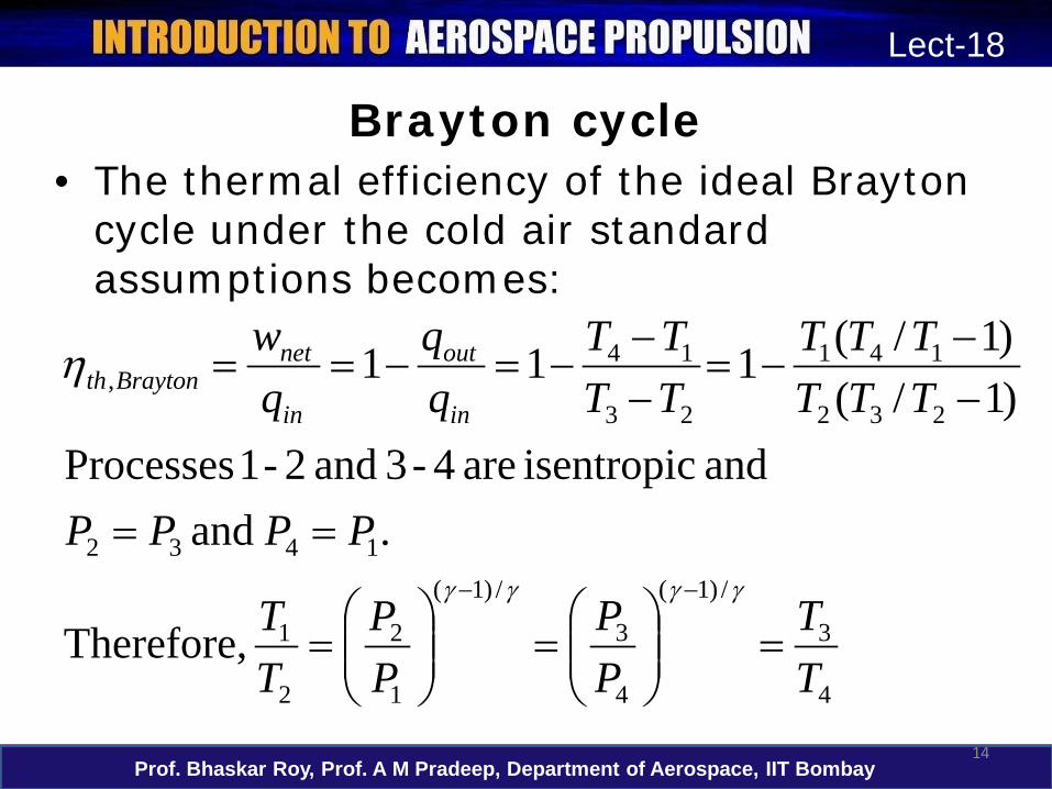
• The thermal efficiency of the ideal Braytoncycle under the cold air standard assumptions becomes:
4
3
/)1(
4
3
/)1(
1
2
2
1
1432
232
141
23
14,
Therefore,
. and and isentropic are 4-3 and 2-1 Processes
)1/()1/(111
TT
PP
PP
TT
PPPP
TTTTTT
TTTT
qw
in
out
in
netBraytonth
=
=
=
==
−−
−=−−
−=−==
−− γγγγ
η

Brayton cycle • Substituting these equations into the
thermal efficiency relation and simplifying:
• The thermal efficiency of a Brayton cycle is therefore a function of the cycle pressure ratio and the ratio of specific heats.
Prof. Bhaskar Roy, Prof. A M Pradeep, Department of Aerospace, IIT Bombay15
Lect-18
ratio. pressure theis where,
11
1
2
/)1(,
PPr
r
p
pBraytonth
=
−= − γγη

Brayton cycle with regeneration
• Regeneration can be carried out by using the hot air exhausting from the turbine to heat up the compressor exit flow.
• The thermal efficiency of the Brayton cycle increases as a part of the heat rejected is re-used.
• Regeneration decreases the heat input (thus fuel) requirements for the same net work output.
Prof. Bhaskar Roy, Prof. A M Pradeep, Department of Aerospace, IIT Bombay16
Lect-18

Brayton cycle with regeneration
Prof. Bhaskar Roy, Prof. A M Pradeep, Department of Aerospace, IIT Bombay17
Lect-18
s
Tqin
qout1
3
4
2Regeneration
5’5
6
qregen
qsaved=qregen
T-s diagram of a Brayton cycle with regeneration

Brayton cycle with regeneration
• The highest temperature occurring within the regenerator is T4.
• Air normally leaves the regenerator at a lower temperature, T5.
• In the limiting (ideal) case, the air exits the regenerator at the inlet temperature of the exhaust gases T4.
• The actual and maximum heat transfers are:qregen,act = h5 - h2 and qregen,max = h5’- h2 = h4 - h2
Prof. Bhaskar Roy, Prof. A M Pradeep, Department of Aerospace, IIT Bombay18
Lect-18

Brayton cycle with regeneration• The extent to which a regenerator approaches
an ideal regenerator is called the effectiveness, ε and is defined as ε = qregen,act / qregen,max = (h5 - h2)/(h4 - h2)
• Under the cold-air-standard assumptions, the thermal efficiency of an ideal Brayton cycle with regeneration is:
• The thermal efficiency depends upon the temperature as well as the pressure ratio.
Prof. Bhaskar Roy, Prof. A M Pradeep, Department of Aerospace, IIT Bombay19
Lect-18
γγη /)1(
3
1, )(1 −
−= pregenth r
TT

Brayton cycle with intercooling, reheating and regeneration
• The net work of a gas-turbine cycle is the difference between the turbine work output and the compressor work input.
• It can be increased by either decreasing the compressor work or increasing the turbine work, or both.
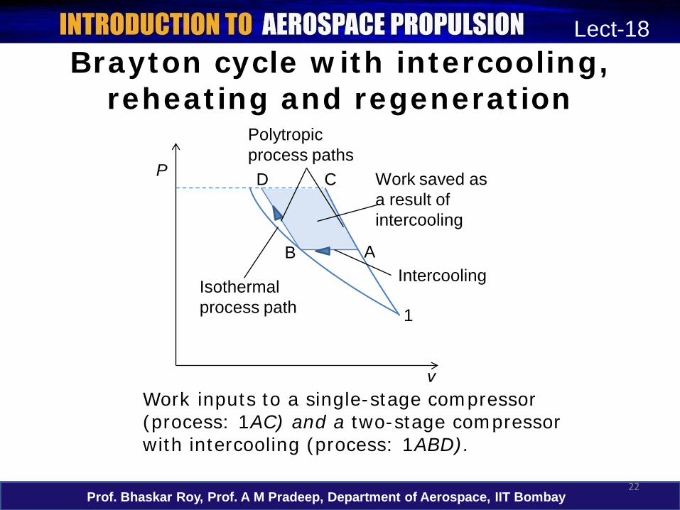
• The work required to compress a gas between two specified pressures can be decreased by carrying out the compression process in stages and cooling the gas in between: multi-stage compression with intercooling.
Prof. Bhaskar Roy, Prof. A M Pradeep, Department of Aerospace, IIT Bombay20
Lect-18

Brayton cycle with intercooling, reheating and regeneration
• Similarly the work output of a turbine can be increased by: multi-stage expansion with reheating.
• As the number of stages of compression and expansion are increased, the process approaches an isothermal process.
• A combination of intercooling and reheating can increase the net work output of a Brayton cycle significantly.
Prof. Bhaskar Roy, Prof. A M Pradeep, Department of Aerospace, IIT Bombay21
Lect-18
Brayton cycle with intercooling, reheating and regeneration
Prof. Bhaskar Roy, Prof. A M Pradeep, Department of Aerospace, IIT Bombay22
Lect-18
v
P
Polytropicprocess paths
Work saved as a result of intercooling
IntercoolingIsothermal process path
D C
B A
1
Work inputs to a single-stage compressor (process: 1AC) and a two-stage compressor with intercooling (process: 1ABD).

Prof. Bhaskar Roy, Prof. A M Pradeep, Department of Aerospace, IIT Bombay23
Lect-18
s
Tqin
qout1
6
7
4
5
10
qregen
qsaved=qregen
T-s diagram of an ideal gas-turbine cycle with intercooling, reheating, and regeneration
2
3
8
9
Brayton cycle with intercooling, reheating and regeneration

Brayton cycle with intercooling, reheating and regeneration
• The net work output of a gas-turbine cycle improves as a result of intercooling and reheating.
• However, intercooling and reheating decreases the thermal efficiency unless they are accompanied by regeneration.
• This is because intercooling decreases the average temperature at which heat is added, and reheating increases the average temperature at which heat is rejected.
Prof. Bhaskar Roy, Prof. A M Pradeep, Department of Aerospace, IIT Bombay24
Lect-18

Prof. Bhaskar Roy, Prof. A M Pradeep, Department of Aerospace, IIT Bombay25
Lect-18
s
T
As the number of compression and expansion stages increases, the Brayton cycle with intercooling, reheating, and regeneration approaches the Ericsson cycle.
P=const
TH,avg
TL,avg
Brayton cycle with intercooling, reheating and regeneration

Rankine cycle
• Rankine cycle is the ideal cycle for vapour power cycles.
• The ideal Rankine cycle does not involve any internal irreversibilities.
• The ideal cycle consists of the following:– 1-2 Isentropic compression in a pump– 2-3 Constant pressure heat addition in a boiler– 3-4 Isentropic expansion in a turbine– 4-1 Constant pressure heat rejection in a
condenser
Prof. Bhaskar Roy, Prof. A M Pradeep, Department of Aerospace, IIT Bombay26
Lect-18

Rankine cycle
Prof. Bhaskar Roy, Prof. A M Pradeep, Department of Aerospace, IIT Bombay27
Lect-18
s
T
Wpump,in qout
qinWturb,out
1
3
4
2
The ideal Rankine cycle
Rankine cycle
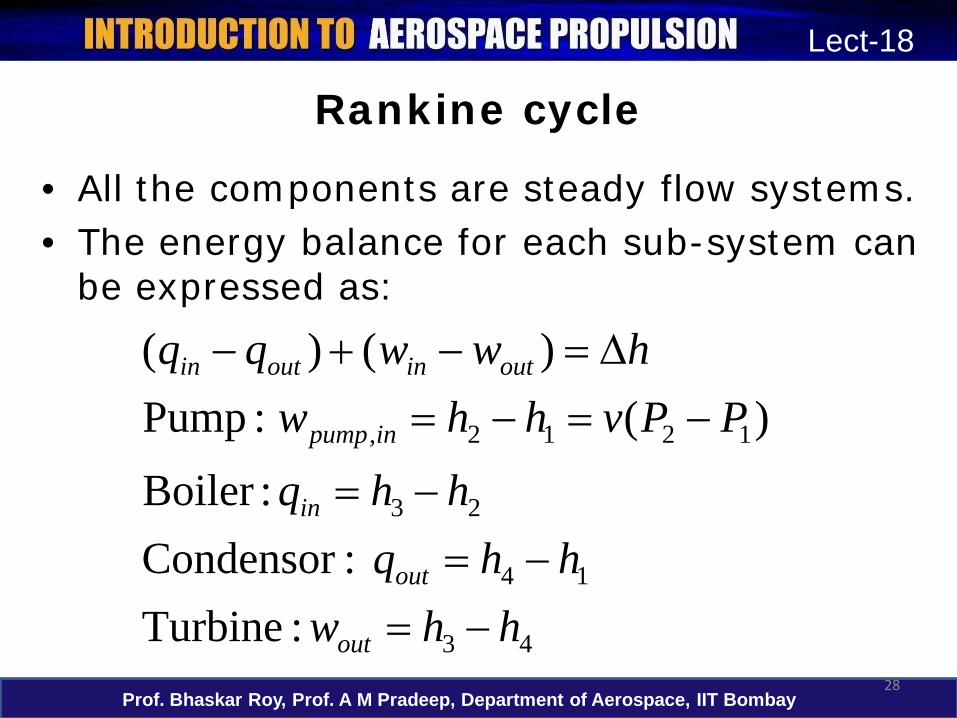
• All the components are steady flow systems.• The energy balance for each sub-system can
be expressed as:
Prof. Bhaskar Roy, Prof. A M Pradeep, Department of Aerospace, IIT Bombay28
Lect-18
43
14
23
1212,
:Turbine :Condensor
:Boiler
)(:Pump)()(
hhwhhq
hhqPPvhhw
hwwqq
out
out
in
inpump
outinoutin
−=−=
−=
−=−=∆=−+−

Rankine cycle
Prof. Bhaskar Roy, Prof. A M Pradeep, Department of Aerospace, IIT Bombay29
Lect-18
• The thermal efficiency of the ideal Rankinecycle under the cold air standard assumptions becomes:
inpumpoutturboutinnet
in
out
in
netBraytonth
wwqqwqq
qw
,,
,
where,
1
−=−=
−==η

Rankine cycle
• Rankine cycles can also be operated with reheat and regeneration.
• The average temperature during the reheat process can be increased by increasing the number of expansion and reheat stages.
• A Rankine cycle with reheat and regeneration offer substantially higher efficiencies as compared to a simple Rankinecycle.
Prof. Bhaskar Roy, Prof. A M Pradeep, Department of Aerospace, IIT Bombay30
Lect-18

In this lecture ...
• Stirling and Ericsson cycles• Brayton cycle: The ideal cycle for gas-
turbine engines• The Brayton cycle with regeneration• The Brayton cycle with intercooling,
reheating and regeneration• Rankine cycle: The ideal cycle for vapour
power cycles
Prof. Bhaskar Roy, Prof. A M Pradeep, Department of Aerospace, IIT Bombay31
Lect-18

In the next lecture ...
• Helmholtz and Gibb’s functions• Legendre transformations• Thermodynamic potentials• The Maxwell relations• The ideal gas equation of state• Compressibility factor• Other equations of state• Joule-Thomson coefficient
Prof. Bhaskar Roy, Prof. A M Pradeep, Department of Aerospace, IIT Bombay32
Lect-18
Related Documents