DNA-TR-89-109 N AN APPROACH TO THE DEVELOPMENT OF SOFTWARE U-) FOR COMPUTER-AIDED DESIGN OF SATELLITE COMMUNICATIONS RECEIVERS FOR OPERATION I < IN SCINTILLATING CHANNELS R. L. Bogusch Mission Research Corporation PO. Drawer 719 Santa Barbara, CA 93102-0719 28 April 1989 Technical Report CONTRACT No. DNA 001-88-C-0194 Approved for public release; distribution is unlimited. THIS WORK WAS SPONSORED BY THE DEFENSE NUCLEAR AGENCY UNDER RDT&E RMC CODE B4662D RW RB 00025 RAAE3200A 25904D DTIG LL. CT 'E DECO? 1989 Prepared for Defense Nuclear Agency 6801 Telegraph Road Alexandria, VA 22310-339b 1'7O6

Welcome message from author
This document is posted to help you gain knowledge. Please leave a comment to let me know what you think about it! Share it to your friends and learn new things together.
Transcript
DNA-TR-89-109
N AN APPROACH TO THE DEVELOPMENT OF SOFTWAREU-) FOR COMPUTER-AIDED DESIGN OF SATELLITE
COMMUNICATIONS RECEIVERS FOR OPERATIONI < IN SCINTILLATING CHANNELS
R. L. BoguschMission Research CorporationPO. Drawer 719Santa Barbara, CA 93102-0719
28 April 1989
Technical Report
CONTRACT No. DNA 001-88-C-0194
Approved for public release;distribution is unlimited.
THIS WORK WAS SPONSORED BY THE DEFENSE NUCLEAR AGENCYUNDER RDT&E RMC CODE B4662D RW RB 00025 RAAE3200A25904D
DTIGLL. CT 'E
DECO? 1989
Prepared forDefense Nuclear Agency6801 Telegraph RoadAlexandria, VA 22310-339b
1'7O6
DISTRIBUTION LIST UPDATE
IThi >, mailer is provided to enable DNA to maintain Current distribution lists for reports We would
appreciate your providing the requested inform-ation
Add the individual listed to your distribution list.
Delete the cited organ ization /individual
C;-ange of address
I NAME.
IORGANIZATION -
OLD ADDRESS CURRENT ADDRESS
TELEPHONE NUMVBER L_. __-.-
zi
1SUBJECT AREA(s) OF INTEREST:w I0r
UI
DNA OR OTHER GOVERNMENT CONTRACT NUMBER:-- __-___
I CERTIFICATION OF NEED T0-KNOW BY GOVERNMENT SPONSOR (if other than DNA):
I SPONSORING ORGANIZATION.
I CONTRACTING OFFICER OR REPRESENTATIVE:
SI (: SINA T UR F~--

S E ;I. A" SS PFCAlC, -
REPORT OOCJMENTATION PAGE
3 0 S-IBc' ION AvAILABIL! ')F IlIPORT
-'E~~~ -..F)A )NS:1D
4 E~ RMNC 0%~LA CF DP' '.Li 0 5 MON170JPNG )RGNj7A-I(N RFPDRT N>MBEP~s
A-
5a ,A 2 PEP'-iIPVMNG DPO-AN11A'iCN 6t, OFFT 'E SYM80L 7a NAME O--F MONI'cRING -00ANIZA>O0N
6, AD3RE55 J..state J,,, /.P 2 7 t ADDRESS 'C t State -d 'I P Cae,
Ba S AME OF F: NDING SPONSORING Sbt )FPICE SN 301 9 PROCUREMENT INSTPLMENT IDENTIFICATiON N.A4BEPO
0GANIZATON d ololicable,
Sc -ADOPESS C r, State anC ZIP Cide, TO SOURCE OF FUNDING NUMBERS
PROGRAM PROJECT r40K -vop"ELEMENT NO NO NO ACCESS10% %--
1 '-E ,cide Sec.±,ry Class,ficar,orr,.5. 12k.,1I- TUTU C D;iKVEl,61'MENT OF SOFTWARFi 101 CUMr 1 1 '1<-tiDEtD D1 E 1(; 1 I F AT["r.1i
* -SUN UAT R!S S CE VF.RS FORl UPERAYION% J CNTIFA N;;HA.C.
2 'ERSONA.. AUTHOR(S)
13a Th'PE OF REPORT 13b TIME COVERED 14 DATE OF REPORT fYea, Month, Day, T15 PAGE COUNTV.:1:, id FROT P0M -8 8 191 4 To 890428 8904a 111
6 S(UPPLEMENTARY NOTATION
~~.isi sx. ssmsridU the Dc funs.. Nucle ar Agenlc% n clltlr KDT&E P2MG Code !i001 466 L' I
W1,')25 RAAE~i3 ZUCA 25)43,
1? COSATI CODES 18 SUBJECT TERMS tConr,,,ue on reverse if' necessary and ijeyfy by block numbeyi
FIELD GROUP SUB GROUP Digital Commun icat ions Signal Sc int ill ati~on1)9 Modulation Carrier Tracking
2Coding Divers it,;19 ABSTRACT !Continue on rei-ersed nFrecessary and denedy by block numrnber)
.<:Ktr~O inv' n rf slb'' o:1 c.,,iini'li(os to provide robust communications in nuclear-disturbed
si thiI :Ori-pn4t ion . hann t -; hii been deve Ilopeo LnJt:n t," --,cr the past decade . The workdestr ibed hurL.in i-, intc2nd,-:.A Lo facilitate the process of placing these mit igation tech-niqites in Lhu liand, It th l s -igner through the development of a computer-aided design(('.AD) iif twaru -), Joe T maixito ze its iut ility, the C(AD sof tware is be ing developed Lo
rC;n ;n desktop Ipers;onlldIc iitr ( PCs) . When deve loped, this software will al low sknzmo
staI~tis-tical para--meters etc.)' obtaifned from-, Defense Nuclear A\gency signal:-,ir itt on id from ucIarCriteria (;roup signal criteria to be readily incorporated
ini CU: comioun icat ions I ink design process. the PC-based CAD software will enable the.r5 i gner to input communicctins s,,stem charac teristics that may be constrained by otherI ns irerarzions, together with DNA specifications of disturbed signal parameters that the
~,omust be designted to withstand. Th CAD software will then provide information onmodulation, demodultat ion, tracking, cod ing, and diversity requirements to obtain specific -
20 DISTRIBUTION, AVAILABILITY OF ABSTRACT 2' ABSTRAC7T SECURITrYrCcASSIFIC.ATION
- NCLASSIFIEO,UNLIMITED h SAME AS REPORT 2 OTIC USERS UNCLASS1FIED
22a NAME OF RESPONSIBLE INDIVIDUAL 2 2b TELEPHONE (Include Area Code) 22c OFFICE SYMBOL
Bklini( F. Sladd(,x (703) 325-7042 DNA/CSTI
DD FORM 1473. B4 MAR 8B% APR editionl may be used until #ahauSled SCRr LSIIAINO nS'GAll other editions are obsolete SCRT LSIIAINO -SPG
UNCLASSIFIED
CONVERSION TABLE
Conversion factors for U.S. Customary to metric (SI) units of measurementMULTIPLY BY - TO GETTO GET BY DIVIDE
an gst rom 1 .000000 E -10 meters (m)It- ; e(rp',.--J I' -i 12 I . -) ,- 2 b- I l k a)
I 2 koii pE 2al (kPa)barn I ,00,0)1000 x E -28 meter' .Brmth herrnal unit (therno.-hexicai) 1.054350 . E -3 ju.e (J
cai.: e (therriochernical) 4.184000 ,:ule J)cai (therm.:,chemical) . m2 4.184000 . E -2 mega- joulein2 (MJim2)cur 3 7(r,,0 ,F - giga becquerel ((;Bq)
re igl . 1 .74532 P -2 ra d ,n (ratl)degrep Farenhelt t =(t, +- 45 .7 /. egree kplvin (K)
eiec,-n v t 1.1,1219 . F -10 joule (J)erg 1.00N1000 . E -7 joule (J)erg second 1.000000 . E7 watt (W)foot 3.048000 x E -1 meter (m)foot-pound-force 1.355818 joule (J)g.%Il-n (U.S. liquid) 3.785412 x E-3 meter' (m3)
inch 2.540000 . E -2 meter (m)jerk 1.000000 . E -9 1 joule (j)oule.'kilog:am (J'kg) (radiation dose absorbed) 1.000000 Gray (Gy)kil(ons 4.183 terajouleskip (1000 lbf) 4.448222 . E +3 newton (N)i.ip/inch' (ksi) 6.894757 x E +3 kilo pascal (kPa)ktap ' 000000 . E +2 newton-second/m 2 (N-sim)micron 1 - 000 x E -6 meter (m)mil iO000 E -5 meter (m),nile (international) ,.o09344 1 E 43 meter (m)ounce 2.834952 x E -2 kilogram (kg)pound-force (lbs avoirdupois) 4.448222 newton (N)pound-force inch 1.129848 x E-1 newton-meter (Nm)p;:: nd-f'rce/inrh 1.751268 . E +2 newton/meter (N/m)p,, und force/foot' 4.788026 F, -2 kilo pascal (kPa)pound-force/inch' (psi) 6.894757 kilo paslcal (kPa)pou nd-iu'lss (llin avoirdup, i5) 4.535924 x E -I kilogram (kg)p,,un.J-z ass-fo_,t 2
(moment if inortia) 4.214n11 E -2 kilogr;umi-itctr (kg m')pol nd-mass/foot2
1.601846 x E +1 kilogram/meter' (kg/m)rad (radiation dose absorbed) 1.000000 x E -2 "Gray (Gy)roentgen 2.579760 x E -4 coulomb/kilogram (C/kg)shake 1.000000 x E-8 second (s)slug 1.459390 .E +1 kilogram (kg)torr (mm Hg, 0" C) 1.333220 .E-1 kilo pascal (kPa)The becquerel (Bq) is the SI unit of radioactivity, I Bq = 1 event/s.
"The Gray (Gy) is the SI unit of absorbed radiation.
iii

TABLE OF CONTENTS
Section Page
CONVERSION TABLE iii
LIST OF ILLUSTRATIONS
1 INTRODUCTION 1
1.1 Background 1
1.2 Scope of Effort 4
13 Phase I Technical Objectives 4
2 ALGORITHM DEFINITION AND DEVELOPMENT 6
2.1 Software Architecture 6
2.2 CAD Algorithms 10
3 USER INTERFACE 28
3.1 User Inputs 28
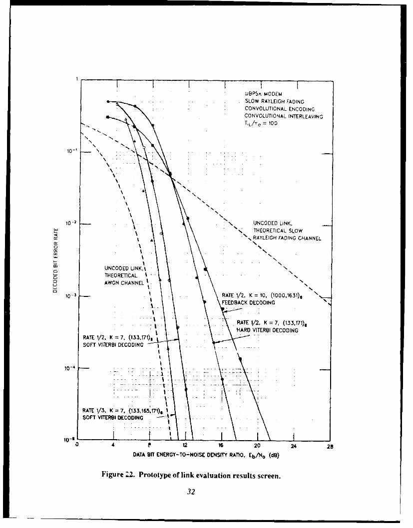
3.2 Outputs 31
4 HOST PROCESSORS 34
4.1 Intel 8086 Processor Family 34
4.2 Motorola 68000 Processor Family 35
4.3 Documentation and Distribution 35
5 CONCLUSIONS AND RECOMMENDATIONS 37
6 LIST OF REFERENCES 38
iv

LIST OF ILLUSTRATIONS
Figure Page
1 Steps involved in scintillation mitigation. 2
2 A simple PSK linklayout. 7
3 A more complex FSK link layout. 7
4 M-ary FSK link with arbitrary binary code. ?
5 M-ary FSK link with matched binary code. 9
6 Transfer function for coherent BPSK demodulator. 12
7 Transfer function for coherent offset QPSK demodulator. 13
8 Transfer fun tion for differentially coherent QPSK demodulator. 14
9 Transfer function for differentially col-erent BPSK demodulator. 15
10 Transfer function for binary FSK demodulator. 17
11 Transfer function for quaternary FSK demodulator. 18
12 Transfer function for 8-ary FSK demodulator. 19
13 Transfer function for 16-ary FSK demodulator. 20
14 Effect of toi-e spacing on 8-ary FSK transfer function. 21
15 Minimum channel bt rates for FSK and PSK demodulators. 22
16 Transfer function for rate 1/2 Viterbi decoder. 23
17 Effect of code rate on decoder transfer function. 25
18 Effect of decoder design on transfer function. 26
19 Transfer function for noncoherent combining. 27
20 Example of user input screen. 29
21 Example of data selection menu. 30
22 Prototype of link evaluation results screen. 32
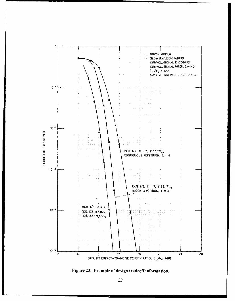
23 Example of design tradeoff information. 33
.i

SECTION IINTRODUCTION
1.1 BACKGROL NID.
Atmospheric nuclear detonations can produce a variety of disturbances to radiosignal propagation. These disturbances include absorption, phase shift, time delay,dispersion, refraction, polarization rotation, multipath, and increased noise levels. Inaddition, relatively small-scale inhomogeneities in the propagation medium can causesignal scintillations, which are random fluctuations in received signal amplitude, phase,polarization, time-of-arrival, and angle-of-arrival.
Uplinks and downlinks between ground or airborne terminals and satellites, aswell as crosslinks between satellites, are likely to suffer such signal disturbances due topropagation through regions of enhanced ionization in nuclear environments. Thedisturbed regions are particularly widespread and long-lasting following nucleardetonations at high altitudes (above about 109 kin). In such high-altitude nuclearenvironments, satellite links are susceptible to potentially severe signal scintillationsdue to widespread and long-lasting regions of field-aligned ionization structure, knownas striations.
Thus, in addition to the ever-present jamming threat, satellite systems must alsocontend with signal scintillation disturbances if the system is to operate in a nuclearenvironment. If a communications system is not specifically designed to operate in thepresence of signal scintillation, system performance will most likely be severelydegraded whcn scintillation is encountered. However, performance degradation can besubstantially reduced, or mitigated, if the characteristics of the disturbed propagationpath, or channel, are properly accounted for in the design of the communicationsequipment.
The fact that mitigation of signal scintillation, or fading, is possible can bereadily understood when one realizes that scintillation per se does not reduce theaverage signal energy below the level received in an otherwise identical ionfadingchannel. The signal energy is just redistributed in time and possibly in time of-arrivaland angle-of-arrival.
If a communications link is designed to be relatively insensitive to suchredistribution of signal energy, there is no fundamental reason why the link cannot bemade to work essentially as well in fading channels as in a nonfading additive whiteGaussian noise (AWGN) channel. Indeed, practical designs with performance infading channels closely approaching that in nonfading channels have been developed.
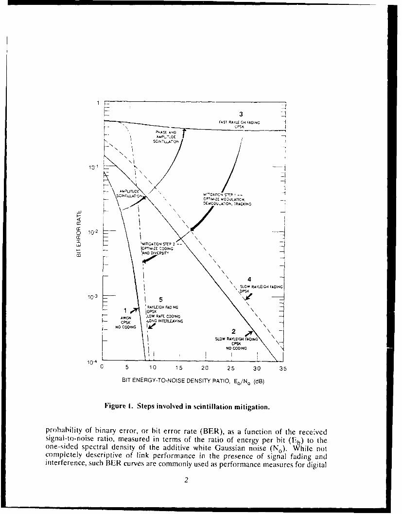
Figure 1 illustrates the nature of the problems and solutions that provide themotiation for the work described in this report. This figure is cast in terms of the
.... ... . ..---- .,. .., ai a l i l I l II
i -FAST R.AYIWf GH FADING
CPSK -4P ASE AND
AdMP"LJIE IDESC;NTrLLArGN
1 -0 _ 1 -\-
!0-1
A kPUD W(IGA flON SITP --S IiTILLATON O-!M;ZE MODIULATION,DEMODULATION, TRACXING
I-- '\ \ /-
C 10-2
Li.J kMFII ATION S~tP 2 -I IOPTIMIZE COOINGt: AND DOVERSnT
4SLOW R.AYLEIGH FADING
-\DCSK
NO COOING A O
SLOW RAYLEIGH FAOINGCPSK
NO CODINGI I Ioo,.
0 5 10 15 20 25 30 35
BIT ENERGY-TO-NOISE DENSITY RATIO, Eb/No (dB)
Figure I. Steps involved in scintillation mitigation.
probability of binary error, or bit error rate (BER), as a function of the receivedsignal-to-noise ratio, measured in terms of the ratio of energy per bit (Eb) to theone-sided spectral density of the additive white Gaussian noise (No). While notcompletely descriptive of link performance in the presence of signal fading andinterference, such BER curves are commonly used as performance measures for digital
2
links. When the value Of FbiN o is interpreted to be the mean value (i.'., the ratio of tileXCerdge signal energy to noise density), the curves are useful as long aN one keeps in
mind the fact that the error rates are also statistical averagC.
Now consider the five curves in ligure I in the order in which they arenumbered. The first curve shows the performance of an uncoded link operating in thebenign AWGN channel. Coherent phase shift keying (CPSK) is used as the example
rince it is the optimum binary signaling strategy in AWGN. Carve 1 shows the typicalexponential decrease of bit error rate with increasing signal-to-noise ratio in thenonfading channel. Curve 2 shows that signal amplitude fading causes the error rate t)decrease much less rapidly with increasing signal strength. The resulting invercdependence on EbiNo would be bad enough, but amplitude fading iS alwa,.accompanied by phase scintillation. Rapid phase scintillation can cause catastrophicfailure of coherent demodulation, as shown in Curve 3. Note that the resulting binarNerror rate, which approaches the value of 0.5 at which no information is transferred, nolonger decreases with increasing signal-to-noise ratio. This unfortunate situation stemsfrom loss of phase coherence in the demodulator, causing signal energy to interferewith itself in coherent processing.
There are two major design steps involved in mitigation of scintillation effectson digital communications links. The first step entails selection of appropriatemodulation, demodulation, tracking, and synchronization techniques in the transmitterand receiver equipment so as to remove vulnerability to rapid phase fluctuations in fastfading channels. For example, differentially coherent phase-shift keying (DPSK) doesnot require carrier phase tracking in the receiver and is therefore le,s susceptible tophase scintillation. While the simple change from coherent PSK to DPSK is not usuallyI ,ffirient hv itself to eliminate demodulation failure in fast fading, it is one techniquethat can be used in a mitigated design. Wnen comined with other techniques asdiscussed by Bogusch [1987), the result is virtual eliminatioa of the extreme scnsritiityto loss of channel coherence associated with fast fading. Performance then approachesthat which can be obtained in the presence of slow amplitude fading (Curve 4).
The second mitigatior: ,,tep :nves incorporation of error-correction codingand diversity techniques. This topic is also treated by Bogusch [19871, and in numerOu,references cited therein. In essence, the use of coding and diversity ailows the receiverdata demodulator to operate at rather high error rates inherent in fading channels andutilizes redundancy in the data stream to correct most of the demodulation errors, thusachieving acceptable overall performance. When these two mitigation steps areproperly implemented, link performance will approach that normally expected in anonfading channel (Curve 5).
Experience has shown that if a communications link is to provide satisfactoryperformance in a nuclear-disturbed fading channel, it must be designed for thatchannel. The chances of accidentally obtaining good performance with a link notdesigned for fading channel communications are slim indeed.
3

Once nuclear-induced signal propagation disturbances are incorporated into thedesign process, the probability of success improves dramatically. It is possible to de,,ignlinks that provide good performance over wide ranges of fading conditions.Consequently, if a requirement to operate in a nuclear environment is addressed at theoutset of system design, the effort associated with satisfying this requirement shOUldhave minimai impact on overall program cost and schedule.
1.2 SCOPE OF EFFORT.
An extensive inventory of practical engineering techniques to provide robhustcommunications in nuclear-disturbed propagation channels has been developed awiltested over the past decade. The work described i. *.this report is aimed Lt facilitatingthe process of placing these mitigation techniques in the hands of the designer throughthe development of a computer-aided design (CAD) softwatre package. To maximizeits utility, the CAD software is being developed to run on desktop personal computers(PCs).
This software package will allow signal statistical parameters obtained from theDefense Nuclear Agency (DNA) signal specifications [Wittwer, 1980) and from theNuclear Criteria Group Secretariat satellite link criterion to be readily incorporated in
the communications link design process.
When development is complete, the PC-based CAD program will enable thedesigner to input such parameters as data rate and system characteristics that may beconstrained by other considerations, together with DNA spccifications of disturbedsignal parameters that the system must withstand. The CAD package will then provideinformation on modulation, demodulation, carrier tracking, error-correction codingand diversity requirements fo, obtairing specified levels of link performance. Wheremore the, one design option can be used, tradeoff information will be provided. TheCAD package will utilize an interactive user interface to facilitate the designprocedure.
13 PHASE I TECHNICAL OBJECTIVES.
The Phase I work reported here has been directed toward initial development ofa software package that will provide an enhanced capability tor incorporatingscintillation mitigation techniques in the design of digital communications links. Thesoftware is intended to facilitate link design so as to ensure successful operation in thepresence of signal scintillation and jamming interference. This work will culminateduring a subsequent Phase II effort in the development of a CAD package that willprovide design options for specified levels of link performance in nuclear-disturbedchannels having specified ranges of scintillation parameters.
4

In i> Ph:I 'ffrt., th1 e ,,it) lilt% of the has;c ,ipproich ha> heenlc ~ b >he . i teecit tic NhJcctlye> that ha~ e been add re ,,ed duarli l, the c inrse (ft hi>
, r i-,c vstolo,
Nlgorithm I1 vrinitilon. Req(air n nt hav! ten d fi r or tonn i
dil-t It lu~ cil IImu ilcauil, link de lin criteria for specciid p~~r~ncW
2.Mgirithni Del~'opnient. Initial de ,ehopmeflt ()f ilporitt a' hwcn" c,:nri
rc~li~reic WI 1ml nualnuon. cil III(,]n tracking funictl)in.
3.Processor D~efinition. Requiremients, oil host III1(s.!1- inilT r'mPw('\> ir tI pc,rand Il -ace m iirs( R AM\) sntirage, disk ,t rage. and Inpt i )L t Li 10() de\c'
e2h:cil: b e Wn ,t icd to implem'2nt th CAD dlgorlthms,.
4. t ,er Inrterface De~finition. t 'ser interface requiremntsni ha\ e beendfi .:;~d~ eas,~indowks, mn-linle help, and graphical outpuLts., "() aI, to achieve at
a~cr tr ndt~interactive Interface.
[he fi dh I ng >ect ion> of this, repi ff1 present the result> (if this work. Therckja re mealts thait haveen defined for the CAD softwkare algorithmi are dlCI',Cnss InISect iii 2. 1 ia mpl e> of the naiture of the a Igorit hnmS that are being developed. toigetherwith a discus,,i o)f the architcture en\ sioned for the CAI) program. are- alsoc' mntaItxY in ISectionT 2.
Section I provides a d11i'cusSIon and examples of the user interface that has beende fi ned. A rmoni t r ,crcen aIntrface, comns siing of both text screens aind g raph icS>,crccfn, 1i> beinm dc\ eloped. 'Ihle User wilinteract wkith the screen displays by means ofa kes b(,i- d or a, RMPC & e,(lpendi ng on the hardware configa rat hin of the hos t machine.
The requirements, that have been defined for the host K('s are described in]Section 4. The CADI snft~kare is bieing developed for both the IB3% PC family of(lC>,t( p co mpliters", wIch utillie the Intel 80)8'8080,'80286i80380 proces"sor chipis, andhe Niaci nt( sh fanil\ of computerS, wkhich u.tilize the MIotorol a 08000,(V 8020,18030
p ro()ces o r c hip1s.
Fl nal lv. thle ConcIl siorIS and rec m me ndat iIns that have evolved from this PhaseI effort are presented in Section 5.
SECTION 2
ALGORITHM DEFINITION AND I)IEVELO()PMENT
2.1 SOFI ARE XRCI I I 'l'E(I' RE.
Bet()re decribinm the CA I) algorithms. i: i> appro)priatc to ir- d ICt-;w)erall architecture in which the algorithms will ftunction. [he cTh mputr r(narchitectt ral deign has an important influence on b)th the uscr mt crth.ic mtn:icfficienc kith which the CAD algorithms .ill operate. Description of the inir e,.
u,er intcrface is ivepr, in Section 3. As discussed there, the u,.er m:,, -Cti,.)mmLi n icatii)ns link in a number of different levels of detail, depend inc on the d:
tw ,,hich he know ,s or wki shes to constrain the link design, .A arictv of diffcren,.aveform, can he chosen, with many different choices aailable for the IuodLiLltl (,,c( dinL in terr caving. and 5vnchron z8,.t,. techniques. The rate, at which in f)rm;IIpa,,,es thrnuh the vari(us functional elements of a digi tal communicatio ns link cain'ar, widely, even with the same basic user data rate. Tlhi, fact alone placc, an
Impo)r:ant reqUirement for flexibility on the L's\ program architecture.
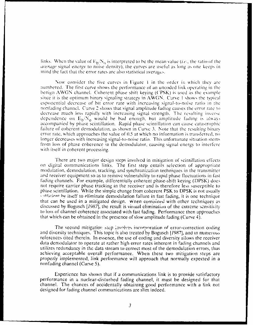
Consider, for example, the link layouts shown in Figures 2 and 3. The firstlav LIt, Figure 2, is representative of a fairly simple, albeit usefal, link architectLirecnploying binary phase-shift keying (BPSK). This is an example of a BPSK link thatincorporates a modest amount of scintillation mitigation. Specifically, this link emplo>,differentially coherent PSK with a provision for coherent l-channel DIPSKdlemoclulation (I DPSK) when channel conditions permi:, The placemen, of thedifferential encoder immediately before the hiphase modulator not only enables theuse of DPSK demodulation, it also permits the use of interleaving to break up channelerror bursts due to slow fading'. This in turn makes the use of convolutional encodingand associated error-correction decoding much more effective.
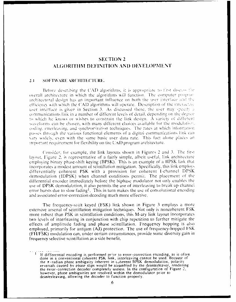
The frequency-snift keyed (FSK) link shown in Figure 3 employs a moreextensive arsenal of scintillation mitigation techniques. Not only is noncoherent FSKmore robust than PSK in scintillation conditions, this M-ary link layout incorporatestwo levels of interleaving in conjunction with chip repetition to further mitigate theeffects of amplitude fading and phase scintillation. Frequency hopping is alsoemployed, primarily for antijam (AJ) protection. The use of frequency-hopped FSK
(Ft I/FSK) modulation can, under certain circumstances, provide some diversity gain infrequency selective scintillation as a side benefit.
1 If differential encoding is performed pror to error-correction encoding, as is oftendone in a conventional coherent PSK link, interleaving cannot be used. Because ofthe 7t-radian phase ambiguity inherent in coherent BPSK demodulation, polarityreversals caused by phase slips would be scrambled by the deinterleaver, renderingthe error-correction decoder completely useless. In the configuration of Figure 2,however, phase ambiguities are resolved within the demodulator prior todeinterleaving, allowing the decoder to function properly.
6
=.L_ ' ! [C 1 NTE L A' [ OI r'r NTIAL BSS ER JA.O L MOL
SIGNALPROPAGAT ION
C PRECTION DEINTERLE,,EP DPSYi I '-SK"ECODER j qEMOOULAT O
Figure 2. A simple PSK !ink layout.
Block CBinar. Chip cony. chip FS/FBK
-Ec to -Y Repeat IL Repeat PMod~ILMo
Block Soft Bloc ahip Cony chip X- aryDecode ecde Blkt Cain* OIL c.ibn 75/FB
Bianarn
Figure 3. A more complex FSK link layout.
7
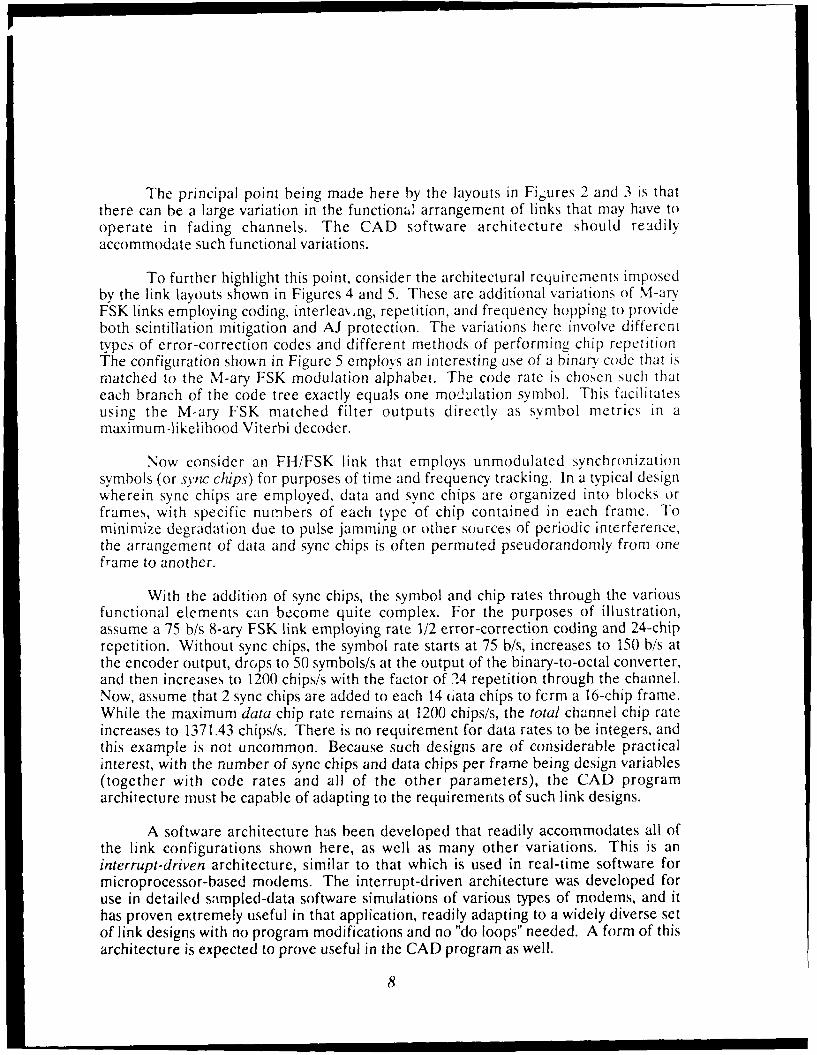
The principal point being made here by the layouts in Figures 2 and 3 is thatthere can be a large variation in the functional arrangement of links that may have tooperate in fading channels. The CAD software architecture should readilyaccommodate such functional variations.
To further highlight this point, consider the architectural requirements imposedby the link layouts shown in Figures 4 and 5. These are additional variations of M-aryFSK links employing coding, interlea,.ng, repetition, and frequency hopping to provideboth scintillation mitigation and AJ protection. The variations here involve differenttypes of error-correction codes and different methods of performing chip repetitionThe configuration shown in Figure 5 employs an interesting use of a binary code that ismatched to the M-arv FSK modulation alphabet. The code rate is chosen such thateach branch of the code tree exactly equals one modulation symbol. This facilitatesusing the M-ary FSK matched filter outputs directly as symbol metrics in amaximum-likelihood Viterbi decoder.
Now consider an FH/FSK link that employs unmodulated synchronizationsymbols (or s.ync chips) for purposes of time and frequency tracking. In a typical designwherein sync chips are employed, data and sync chips are organized into blocks orframes, with specific numbers of each type of chip contained in each frame. Tominimize degradation due to pulse jamming or other sources of periodic interference,the arrangement of data and sync chips is often permuted pseudorandomly from oneframe to another.
With the addition of sync chips, the symbol and chip rates through the variousfunctional elements can become quite complex. For the purposes of illustration,assume a 75 b/s 8-ary FSK link employing rate 1/2 error-correction coding and 24-chiprepetition. Without sync chips, the symbol rate starts at 75 b/s, increases to 150 b/s atthe encoder output, drops to 50 symbols/s at the output of the binary-to-octal converter,and then increases to 1200 chips/s with the factor of 24 repetition through the channel.Now, assume that 2 sync chips are added to each 14 oiata chips to fcrm a 16-chip frame.While the maximum data chip rate remains at 1200 chips/s, the total channel chip rateincreases to 1371.43 chips/s. There is no requirement for data rates to be integers, andthis example is not uncommon. Because such designs are of considerable practicalinterest, with the number of sync chips and data chips per frame being design variables(together with code rates and all of the other parameters), the CAD programarchitecture must be capable of adapting to the requirements of such link designs.
A software architecture has been developed that readily accommodates all ofthe link configurations shown here, as well as many other variations. This is aninterrupt-driven architecture, similar to that which is used in real-time software formicroprocessor-based modems. The interrupt-driven architecture was developed foruse in detailed sampled-data software simulations of various types of modems, and ithas proven extremely useful in that application, readily adapting to a widely diverse setof link designs with no program modifications and no "do loops" needed. A form of thisarchitecture is expected to prove useful in the CAD program as well.
8
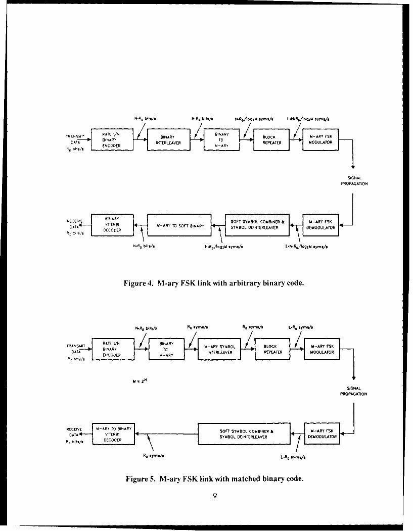
N.RD b"9u/1 N.RD bit*/* N.-R0Aog 2M uyms/I L-N.R0 OMMI syma/z
0 TE BIARY 'SIGNALC
W-ARY4OL
SAGNALPROPAGAT-IoN
REtv .- R BINARY SOFT S YMBO0 L CO MBINR &M- Y SLATA /iE8 -R OSF IAYSMBLDITRFvRDMOLTO
R DEg/ OCODER
N.R bi ms/ .. lg~dsm/ LR , ymggjWsmI
Figure . M-ary FSK link with abtched binary code.
N-o ~i R smssRDvys/ LRs9~

2.2 CAD ALGORITHMS.
Definition of the algorithms needed to automate the design of digitalcommunications links, given performance requirements, design constraints, and signalspecification data, has been greatly facilitated by use of results of previous research.Much of this research has been accomplished by the Mission Research Corporation forthe Defense Nuclear Agency, the Air Force Weapons Laboratory, the Air Force SpaceSystems Division, and other Government and industrial organizations. Examples ofrelevant research efforts are provided by the references listed at the end of this report.
The fading channel first affects a communications link in the receiverdemodulator, where the signal is detected and the imposed data modulation isestimated. The receiver includes such functions as automatic gain control (AGC),automatic frequency control (AFC) with frequency-lock loops (FLL), bit timingsynchronization with delay-lock loops (DLL), carrier phase synchronization withphase-lock loops (PLL), data detection and quantization, deinterleaving or diversitycombining, and error-correction' decoding. The detailed design configurations anddesign parameter values involved in implementing these receiver functions significantlyaffect the performance of the link in the presence of signal scintillation disturbances.
Much relevant information concerning selection of modulation and codingdesign parameters to mitigate signal scintillation is given by Bogusch [1987]. Asdiscussed there, the minimum value of the signal decorrelation time limits theminimum channel bit rate that can be employed with conventional digital modulationand demodulation techniques. The minimum value of the frequency selectivebandwidth limits the maximum channel bit rate that can be employed with conventionalsignal processing techniques. The maximum value of the decorrelation time influencesthe selection of error-correction coding and diversity parameters, including interleaverdimensions, code type and decoder design. The minimum spatial decorrelationdistance (or maximum angular scattering variance) limits the useful aperture size ofconventional antennas. The maximum decorrelation distance affects spatial diversityrequirements. Quantitative relationships between these and other signal parametersand the affected system design parameters have been established. These relationshipshave been used to define the requirements for the CAD algorithms.
Additional information on scintillation mitigation techniques, as well asinformation on the design of robust tracking loops, has been developed and presentedby Bogusch, et al. [1981, 1983], Dana, et al. [1982, 1986], Guigliano, Michelet, Newman[1983], Sawyer, et al. [1981, 1984], and Wittwer [1979, 1980, 1982], to name a few.Results from these and other relevant sources will be used to complete thedevelopment of the CAD algorithms in the subsequent phase of this effort.
10
These previous efforts have demonstrated that #,h, most accurate method ofdetermining the performance of a digital communications system is by means ofdetailed simulation of the various elements comprising the system. An extensiveinventory of simulation modules have been developed, tested, and applied in the designand evaluation of numerous existing and planned systems.
While the simulation approach, involving both software simulations andhardware channel simulators, remains the most accurate method of relating channelparameters to li.k performance, the CAD software requires algorithm- -'-,t execute inless time. The time constraints result from the fact that the design process typicallyinvolves many tradeoffs, each of which must be evaluated over a range ofsignal-to-noise ratios, decorrelation times, and frequency selective bandwidths.Although any of the specific data points could be generated easily using availablesimulation models, the accumulation of data required to optimize the selection ofdesign parameters would involve many simulation runs. This is not objectionable in abatch mode environment, but would involve lengthy sessions in front of a computerscreen in an interactive environment.
Consequently, the CAD algorithms give rise to a requirement for rapidexecution, while at the same time requiring considerable fidelity. Fortunately, asolution to these seemingly contradictory requirements has been developed during thisPhase I effort. We shall use the term transfer functions to describe the type ofalgorithms that will satisfy the requirements imposed by the CAD package.
A transfer function is simply a method of characterizing the output of a givenelement in terms of its input. If the functional elements of a digital communicationslink were all linear devices, it would be possible to derive such transfer functionsanalytically. Most of the functional elements in modern digital communicationssystems are nonlinear, however, precluding direct analytical solution. Here is wherethe extensive background in simulating such elements proves extremely valuable. Theprevious research efforts cited above have resulted in the accumulation of enoughsimulation data that we can define the required transfer functions empirically.
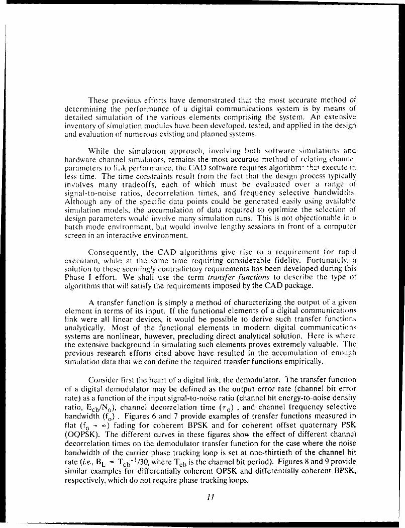
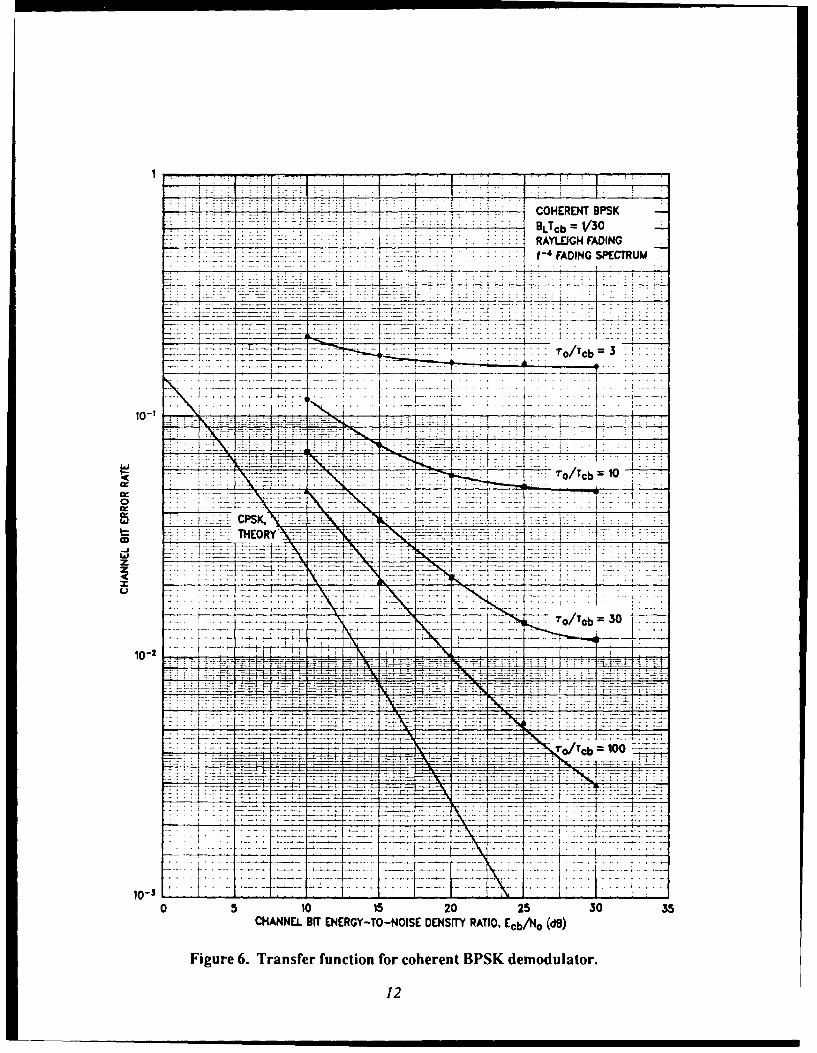
Consider first the heart of a digital link, the demodulator. The transfer functionof a digital demodulator may be defined as the output error rate (channel bit errorrate) as a function of the input signal-to-noise ratio (channel bit energy-to-noise densityratio, Ecb/No), channel decorrelation time (r,) , and channel frequency selectivebandwidth (fo) . Figures 6 and 7 provide examples of transfer functions measured inflat (fo - -) fading for coherent BPSK and for coherent offset quaternary PSK(OQPSK). The different curves in these figures show the effect of different channeldecorrelation times on the demodulator transfer function for the case where the noisebandwidth of the carrier phase tracking loop is set at one-thirtieth of the channel bitrate (i.e., BL = Tcb- 1/30, where Tcb is the channel bit period). Figures 8 and 9 providesimilar examples for differentially coherent QPSK and differentially coherent BPSK,respectively, which do not require phase tracking loops.
I1
t77 COHERENT BPSKDLT cb =V30
-~ .~f- 4 FADING SPECTRUM
77=-- --- - - 7 ~ To/Tcb
- TO/Tcb =10
05101202303
1012
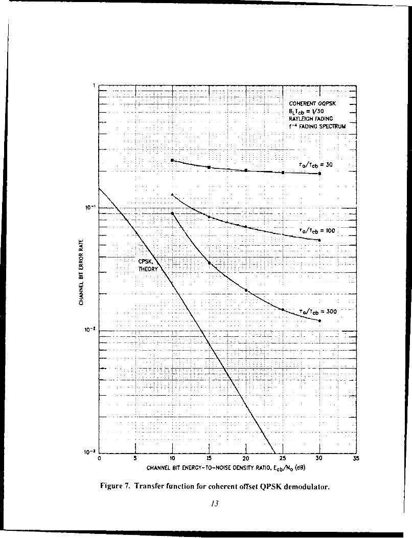
7 _ 7---7 -- 7-77 COHERENT OQPSK-BLTcb)= V30
RAYLEIGH FADINGf-4 FADING SpECTRUM
- roTcb =30
-. - o/Tcb =100
0 CPSK,
zX
10302
10-30 5 10 15 20 25 30 35
CHANNEL Orr ENERGY TO NOISE DENS"T RATIO. EcbANo (d8)
Figure 7. Transfer function for coherent offset QPSK demodulator.
13
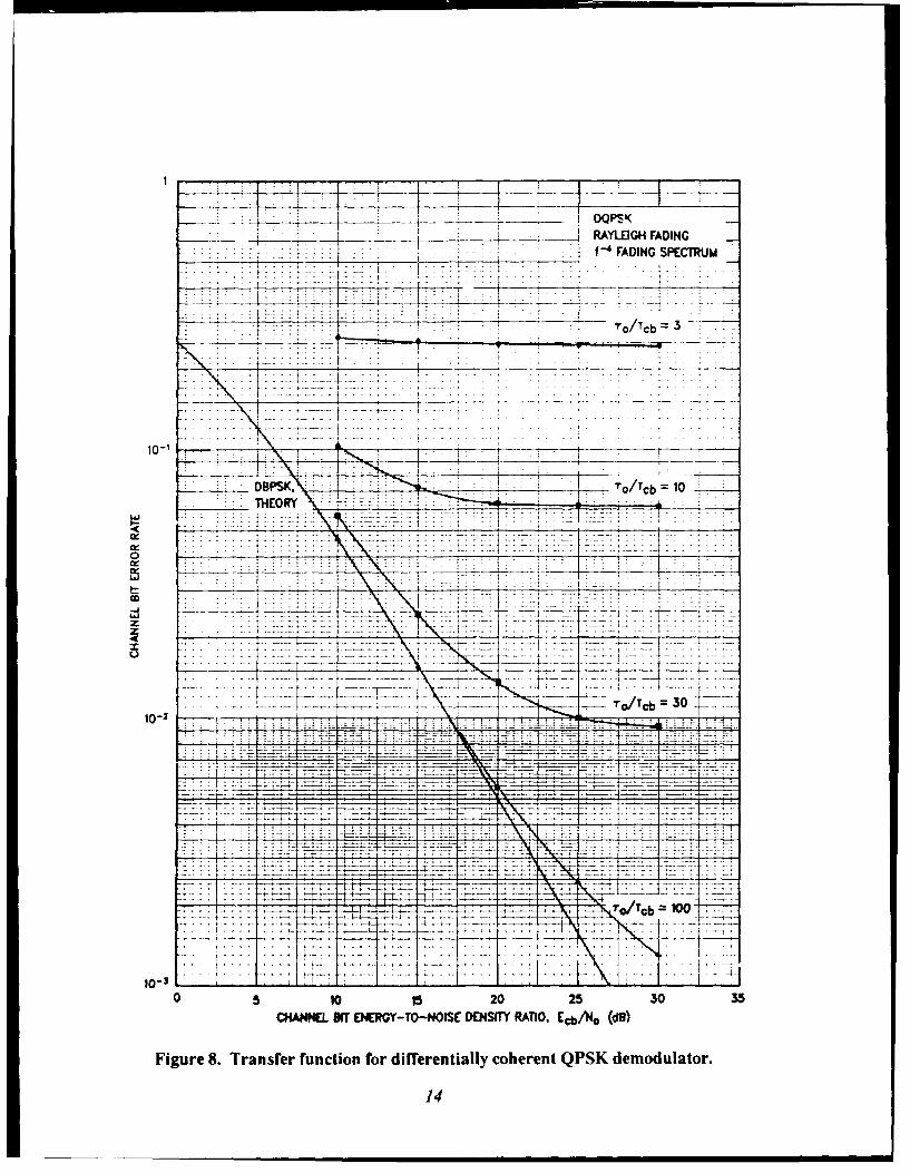
_____ _____ DQ PS K___ _____RAYLEGH FADING
f--. FAIN SECRU
_____________ ~''o/cb 3
10 -' IL .. .....------
___ITo/TcO
e t_
10-2
1.........
10-31
0 5 O 15 20 2530 5
CHANNEL SIT ENERGY-TO-NOISE DENSfTY RATIO, Ecb/N 0 (0e)
Figure 8. Transfer function for differentially coherent QPSK demodulator.
14
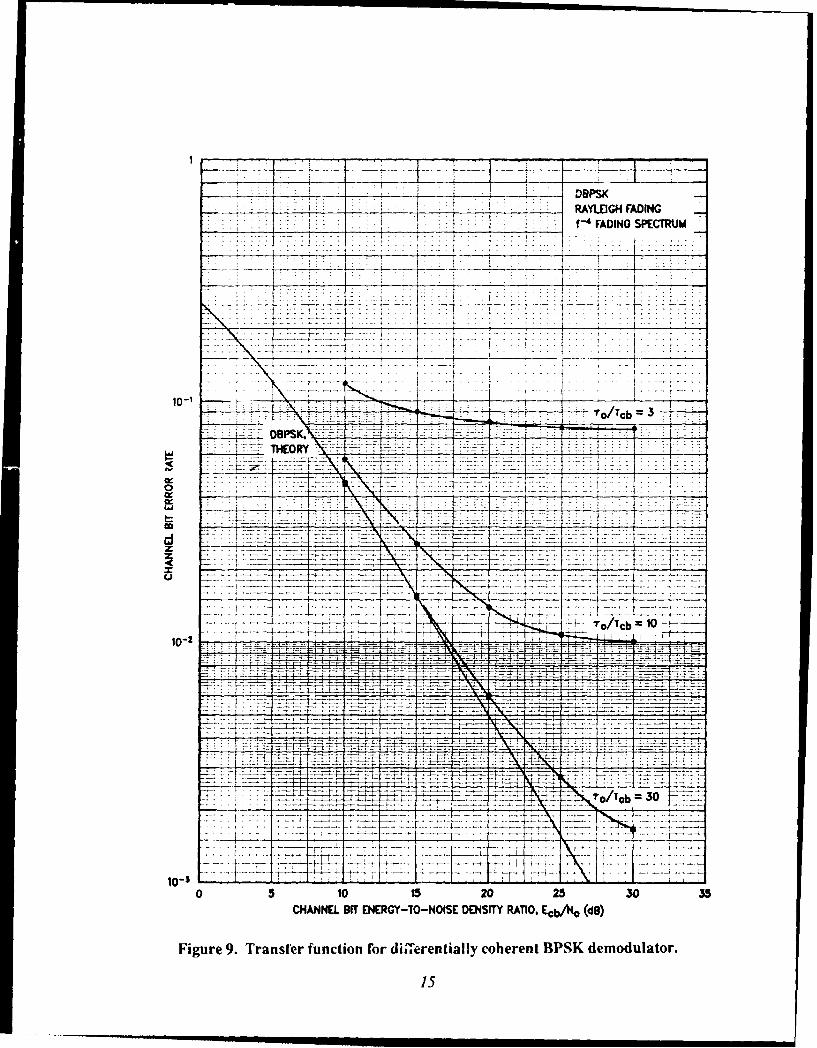
I- -- ~ DOPSK- ~ RAYLEIGHl FADING
.___ .. .. . .. . f-4 FADING SPECTRUM
+~~~~. . ...... ....-------
?ro/1cb3
DBPSK.V, ~:-~ t iTHEORY- -
102::1:- - I,! \ -- - -. - - -i7
-4----L-IEU;
0 5 10 15 20 25 50 35CHANNEL. BIT ENERGY TO NOISE DENSITY RATIO, Ecb.440 (do)
Figure 9. Transfer function for diiaaerentially coherent BPSK demodulator.
15

Corresponding results for several noncoherent FSK demodulators are given inFigures 10 through 13. These four figures provide the transfer functions for binaryFSK, quaternary FSK, 8-ary FSK, and 16-ary FSK, respectively. These figures are forthe case where the FSK modulation tone spacing (nf) is set at the minimum value fororthogonal signaling. The minimum orthogonal tone spacing is equal to themodulation symbol rate, which is the reciprocal of the modulation symbol period (i.e.,Lf = 1/T, where T = [log 2 M]. Tcb). This is a common choice to minimize thesignaling bandwidth. However, it is not necessarily the best choice, particularly in a fastfading channel where larger tone spacings can yield significantly better performance.The effect of increased tone spacing on the 8-arv FSK transfer function is shown inFigure 14. This figure shows the improvement obtained in fast fading with factor,, of 3and 10 increase in tone spacing.
Note that the dependence on decorrelation time in Figures 0 through 13 is given
npirnmetricdIllv in t.-rm of the ratio of chanpel decorrelation time to channel hit perld(T '1 cb). This parametric approach to the empirical definition of the required transferfunctions enables a large amount of data to be condensed into ! relatively smallvolume, and facilitates interpolation and extrapolation to values not explicitly containedin the transfer function data base.
These demodulator transfer functions are appropriate when the transmissionrate has been defined, and the performance of the link is to be evaluated. Perhaps thedesigne- has not yet specified the data rate, or perhaps the data rate is given but thecode rate and number of chip repetitions have yet to be defined. Then the CADalgorithms should provide the user with guidance as to appropriate choices ofmodulation rates (and hence code rates and repetition factors) for the variousmodulation options. This type of information is provided by the data plotted in Figure15. This figure shows the required signal-to-noise ratio n, eded to achieve a usablechannel bit error rate as a function of channel bit rate for several types ofdemodulators. The channel bit rate is normalized here by the channel decorrelationtime. These data show that there is a minimum usable channel bit rate for each ;ype ofdemodulator. This, together with the specified uscr data rate, defines the effectivecode rate that must be incorporated to allow the demodulator to operate with relativelylow signal-to-noise ratio near its slow fade limit (toward the right side of the figure).
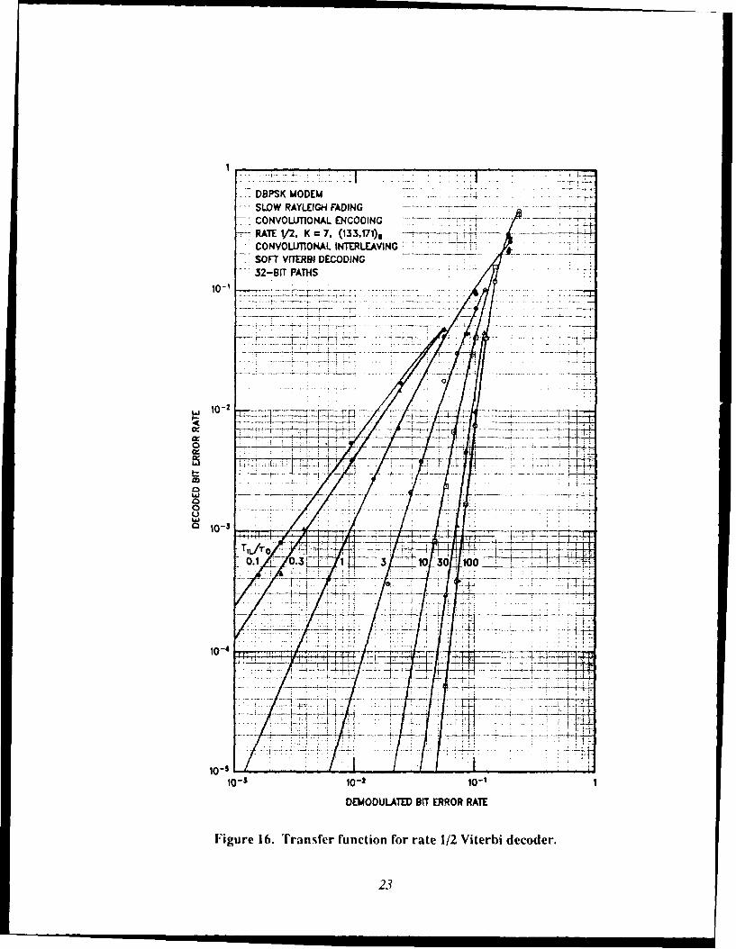
Once the code rate has been established, evaluation of the link design canproceed to the next step. This involves definition of the error-correction decoderperformance, which again can be formulated in the CAD algorithms by means of atransfer function. Figure 16 provides an example of the measured transfer function fora popular rate 1/2, constraint length 7 convolutional code with maximum-likelihoodViterbi decoding. Because the previous design step was aimed at eliminating anyvulnerability to fast fading, the measurements here are made in a slow Rayleigh-fadingch.nnel, where the amount of interleaving is crucially important to the effectiveness ofthe decoder. Thus, the measured transfer functions in Figure 16 are defined in termsof the relative interleaver span, viz., the ratio of interleaver time span to decorrelationtime (TjI./ro).
16

----- BFSI(
RAYLEIGH FADINGf~ -4ADING SPECTRUM
10-1 - ------- - --- cb
7 '7
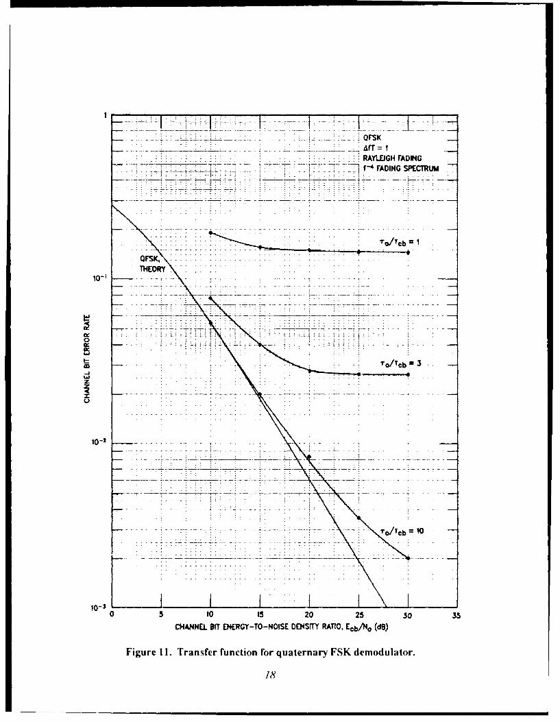
* .QFSK_______f =11 I
RAYLEIGH FADINGf -4 FADING SPECTRUM
OFSK.THEOR
1O -1
- - - -- -
'ro/Teb 3n
0-
10-3
CHANNEL BIT ENERGY-TO-NOISE DENSITY RATIO. Ecb/No (d9)
Figure 11. Transfer function for quaternary FSK demodulator.
18

B-ARY FSKAfT =IRAYEIGH4 FADINGf~ FADING SPECTRUM
ro/Tcb
8 8- ARY FS).THEORY
TO/Tb 30
10-'
to 1 15 20 25 30 35
CHANNEL BIT ENERGY-TO-NUISE DENbrry RATIO. Ecb/No (dB)
Figure 12. Transfer function for 8-an, FSI( demodulator.

16-ARY FSKAT= I
RAYLEIGH FADINGf-4 FADING SPECTRUM
10-'
16-ARY F'SK. rd b=3THEORY
T/c
'ro/Tcb 10
1o-j - iii~0 5 10 15 20 25 30 35
CHANNEL BIT ENERGY-TO-NOISE DENSITY RATIO, Ecb/No (dB)
Figure 13. Transfer function for 16-ary FSK demoduhatar.
20o

------- -ARY FSK
.. .. . .. RAYLEIGH FADINGf-' FADING SPECTrRUMTo/Tcb
10-1
8-ART F3KTHEORY
10-2 - -- - - -
AfT 10
0 5 10 Is 20 25 3CHANNEL arr ENERGY-TO-NOISE DENSITY RATIO, Ecb,4Io (dB)
[igure 14. Effect of tone Spatcing on 8-ary I'SK transfer function.
21

._ . . . . . . . - - - - - -I --- ---- -
LAL
- ~---------------~----- - -- --
C. . . . . . . . . .
r~ _j
I- L
,~-1-
. . . . . -.
04 N
(Sp) oN * *OUYV "JSN30 3SION-Ol-AD83N3 lie 13NNYH:)
22
RATE 1/,K=7 103,10%
D32ODLATT PATERORHAT
Fiue1.Trnfrfncinfrrae12Vte1 eoe
The interleaver time span is equal to the effective amount of interleavermemory (symbol span) divided by the rate at which symbols are fed into the interleaver.For example, the symbol span of a row-column (block) interleaver is equal to theproduct of the number of rows and number of columns. Similar definitions apply to,,Vnchronous and convolutional interleavers. Figure 16 shows that in a Ravleigh-fadin'channel large interleavers lead to increased decoder effectiveness, resulting in omoutput decoded bit error rates being obtained with relatively large inpt demodulatedbit error rates.
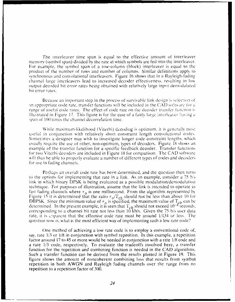
Because an important step in the process of survivable link design fs selectin n O(f1n appropriate code rate, transfer functions will be included in the CAL) soft tarC ftr arange of useful code rates. The effect of code rate on the decoder trmnsfer fuJnction ,
illutrated in Figure 17. This figure is for the case of a fairly lar,,e interleavcr havinaspan of 100 times the channel decorrelation time.
\While maximum-likelihood (Viterbi) decoding is optimum, it is gencrallv motuseful in conjunction with relatively short constraint length convolutional codes.Sometimes a designer may wish to investigate longer code constraint lengths, whichusually require the use of other, non-optimum, types of decoders. Figure 18 shows anexample of the transfer function for a specific feedback decoder. Transfer functionsfor two Viterbi decoders are included in Figure 18 for comparison. The CAD softwarewill thus be able to properly evaluate a number of different types of codes and decodersfor use in fading channels.
Perhaps an overall code rate has been determined, and the question then turnsto the options for implementing that rate in a link. As an example, consider a 75 hslink in which binary' DPSK is being evaluated as a possible modulationidemodulationtechnique. For purposes of illustration, assume that the link is intended to operate infast fading channels where T o is one millisecond. From the algorithm represented byFigure 15 it is determined that the ratio TO/Tcb should not be less than about 10 forDBPSK. Since the minimum value of r0 is specified, the maximum value of T b can bedetermined. In the present example, it is seen that Tcb should not exceed 10- seconds.corresponding to a channel bit rate not less than 10 kb/s. Given the 75 b/s user datarate, it is z.pparent that the effective code rate must be around 1/134 or less. Thequestion now is, what is the most efficient way of implementing such a low rate code?
One method of achieving a low rate code is to employ a conventional code of,say, rate 1/3 or 1/8 in conjunction with symbol repetition. In this example, a repetitionfactor around 17 to 45 or more would be needed in conjunction with a rate 1/8 code anda rate 1/3 code, respectively. To evaluate the tradeoffs involved here, a transferfunction for the repetition and combining function is needed in the CAD algorithms.Such a transfer function can be derived from the results plotted in Figure 19. Thisfigure shows the amount of noncoherent combining loss that results from symbolrepetition in both AWGN and Rayleigh fading channels over the range from norepetition to a repetition factor of 300.
24
DBPSK MODEMSLOW RAYLEIGH FADINGCONVOUTIONAL ENCODINGK= 7 RATE IIN BINARY -
CONVOLUTIONAL INTERLEAVINGTL/r, = 100VITERBI DECODING
10-1 32-BIT PATHS
-- Rate 1/2: (133.T71)8 ~ . -
Rote 1/3: (133.165,171)bRate 1/4: (135,135,147.163)8Rote V/8: (135,135.147,163.,
125,133,171,177)9 _
10-7 --.-
of ~ar~
C ____ __0 -0
co --
U'r t
10-3.. -
-7 ~ -
-4
10310-2 10-1DE3MODULATIED BIT ERROR RATE
Figure 17. Effect of code rate on decoder transfer function.
25

DBPSK MODEM "-
-SLOW RAYLEIGH FADINGRATE 1 CONVOLUTIONAL ENCODING K
-CONVOLUTIONAL INTERLEAVING. TIL/ro 100 1.
10:1
................... --....... -
10'3
* K. 10 (100160
10-4 ~
___ ___ __. .- . . ....2
oS
10- K 0 1012 0 10-f 1DEMDULTEDBI EROR77TFiue 8 EffectofdecoderG deig ontaseIucin
26-.

0 -ARYFSK ,iii .
L SYMBOL REPETITIONSQUARE-LAW COMBINING'*0.03 BINARY ERROR RATE
-- i . 2 I A Y E R R R T . . . ...... ... .. . .... ...... -- -- ........ .......... ... .. --"- --.. . ..
0
z
- 4
zz
0
10 100 300
NUMBER OF SYMBOLS COMBINED, L
Figure 19. Transfer function for noncoherent combining.
This transfer function approach can be used to represent each of the functionalelements of a digital communications link within the CAD software. The advantage ofthis approach, in addition to computational efficiency, is that the functional elementscan be arranged and rearranged in the link layout just as they could be if they wereexplicitly simulated. Of course, the transfer function approach requires that eachelement to be included in the CAD software be explicitly simulated beforehand. Asnoted previously, a significant amount of simulation data have already beenaccumulated as a by-product of previous efforts. The remaining data that will beneeded to flesh out the CAD algorithms will be generated via simulations during thecourse of the next phase of this work.
27
SECTION 3USER INTERFACE
3.1 USER INPUTS.
An important part of this initial development effort, crucial to achieving a usefulpioduct, is the definition of a truiy user-friendly interface for the CAD package. Theuser interface handles all of the interactive data input and output requirements for thepackage. This includes user specification of overall link configuration and any knownconstraints on the !ink design, such as data rate, carrier frequency, nominal maximumvalue of carrier-power-to-noise density ratio, etc. System parameters that are leftunspecified by the user are treated as "free" parameters that can be selected by theprogram to optimize the design.
Another category of user inputs consists of the specifications of ranges ofdisturbed signal parameter values that the link should be designed to withstand in anoperational nuclear environment. These parameters include signal scintillationdecorrelation time (ro), frequency selective bandwidth (fo), angular scattering variance(a a 2), total electron content (TEC), and absorption along the propagation path. Userinputs may also include velocities or %.. ,Je dynamics profiles for the terminals at bothends of the link.
The user interface is being designed with a combination of pop-up windows,menus, on-line help and graphics as appropriate to facilitate the input of data and thedisplay of results. The design objective is to make the CAD package easy to use whileproviding quantitative answers to complex design questions concerning the mitigationof signal scintillation disturbances in a nuclear environment. All interactivecommunication with the package will be accomplished using standard keyboard anddisplay equipment normally associated with the host processors defined in the followingsection. Results will be written to the monitor screen and to either a disk file or to aprinter, including comrnmoily aailablc dot ,-iatrix printers.
Interactive user input will be performed using graphical layouts on the monitoiscreen, together with keyboard or mouse input. A preliminary design of some of thescreen layouts has evolved during this effort. It is envisioned that the main input screenwill consist of a functional layout of the communications link, as defined by the user.The user will initially be presented with a menu of communications functions, orblocks, that can be incorporated into the link. As each block is selected, the menupresents a choice of valid functions that can be incorporated at the next point in thelink. At each step, the user is prompted with a set of control options with which he canrevi.se blocks already specified, add new blocks, or delete blocks. This graphical linkconfiguration screen thus enables the user to quickly define the functional layout of asmuch of the communications system as he wishes to specify.
28

An example of what the link configuration screen might look like, after a userhas rather completely defined a link layout, is shown in Figure 20.
Bit Binary Chip ChpM-ary- Encode IL to Repeat IL > FH/FSK
M-ary Mod
V
Channel
V VBit M-ary Chip Chip
4 Decode 4 De-IL < to 4 Combin < De-IL 4- DemodB inary
Select <I>nsert block <A>nalyze layout<D>elete block <Q>uit Jammer)<M>ove block<E>nter data <H>elp
Figure 20. Example of user input screen.
Upon selecting the Enter data option from this menu, the user is first queried asto which block he wishes to specify. After moving a screen highlight to identify aparticular block, a data selection menu then appears, partially overlaying the linkconfiguration screen. The data selection menu is tailored to the particularcommunications function for which data is being entered.
29

For example, if the encoder block is specified, the data selection menu mightappear something like the following example in Figure 21.
Bit lBinaryll 1 Chip 1 FChip 1 1M-ary-> Encode IL /FSK
Encoder Data Selection Mod
Code Type I' I ' I II [I I , 1, I T I ICode Rate VCode Constraint LengthCode Generator Patterns nnel
Select <N>ext parameter-P>revious parameter V
eE- ,nter valueBit <S>ave current selections
4 Decode < De-I mod
A
Jammer
<H>elp
Figure 21. Example of data selection menu.
The user then highlights the parameter he wishes to specify, and enters the valuefor that parameter. Once he is finished entering values for this parameter block, hesaves the selections and returns to the main link configuration menu. Values for theother functional blocks can then be entered in similar fashion, with each block having aparameter menu especially tailored for that function.
At each step of this process, the interface algorithms check the user inputs forappropriateness. If a value is specified that is out of the proper range, or if the functionjust will not work in the specified place, the user will be informed as to the problem.He will then be prompted as to how to take the appropriate corrective action.
30

At some point the link will either be rather completely defincs, or else the userwill have left some design choices unspecified. In either case, when he signals hisintention to terminate the initial specification phase, the program will evaluate thelikely performance of the link over the specified ranges of signal parameters. Thesesignal parameters (T O, fo0 etc.) will have been entered in the Channel Data Selectionmenu, which is one of the data entry menus. If the user has not specified the channelparameters, he will be prompted to enter his choices, or else some rather stressingdefault values will be used. A help screen will be available to the user at this point toassist him, principally by referring him to the DNA Reasonable Worst-Case SignalSpecification document.
I lelp screens will be available to assist the user at each step of the link layoutand parameter specification process. These screens will provide context-sensitive helpthat is dependent on what the user is attempting to do at the time that he requestsassistance. Thus, the help screens will offer suggestions and guidance tailored to theopcration or function currently being performed.
Once the communications link has been defined as much as the user wishes, theCAD program executes the algorithms that evaluate the peiLoa-mance of the link.Development of these algorithms constitutes a major part of this program. As has beendescribed in the preceding section, implementation of the CAD algorithms is based ontable look-up functions together with curve fits for interpolation and extrapolation ofdata. The a!gorithms are designed to rapidly provide reasonable estimates of linkperformance over the specified ranges of propagation channel conditions. Thealgorithms are also being formulated so as to identify ttiose design elements that arefound to limit link performance. The CAD program will then provide information ondesign tradeoffs that may improve performance.
3.2 OUTPUTS.
The results of the algorithmic evaluation of the link will be displayed graphicallyon the user's monitor screen. Figure 22 provides an example of the type of graphicaldisplay that the CAD program is being designed to produce. This figure compares fourdjfferent link designs, and shows the user how well he is doing relative to an uncodedlink and to a link operating in an ideal undisturbed AWGN channel.
Figure 23 shows an example of the manner in which design tradeoff informationwill be provided to the user. This example compares the bit error-rate performance ofthree different methods of incorporating an effective code rate of one-eighth into agiven link. Two of the options employ a rate 1/2 convolutional code with a factor offour repeat, with the difference between these two options centering around themanner in which the repetition function is implemented. The third option, which isshown to be preferable in terms of performance, is to employ a well-chosen rate 1/8convolutional code with no additional repetition.
31
UBPSN MODEMSLOW RAYLEIGH FADINGCONVOLUTIONAL ENCODINGCONVOLUTIONAL INTERLEAVINGTL/C =100
10 2. . UCNE IK
THOEICLSO
RALIHFDIGCANL
10 NC E U. .%IC
THEORTI AAWGN HANNE
10- RAE /2,K 1, 100 ,161NFEDAKDCDN
AN
SOFT -EB DECOODEILINK
SOF RAYLE1GH DADIGOCHNNE
DAABTEEG-ONIEDN"RTO EbN dB
FigreZ2 Pottye r inkevlutin eslt srn.
* I 32
DBPSK MODEM
SLOW RAYLEIGH FADINGCONVOLUTIONAL ENCODING
CONVOLUTIONAL INTERLEAVINGTL/'PrO = 100
SOFT VITERBI DECODING. 0 3
10-1
10-2
0
X RATE 1/2. K =7, (13 3.T7 1),0 CONTIGUOUS REPETITION, L =4
(3-
RATE 1/2. K 7. (133,171)6BLOCK REPETITION, L =4
10-4 ~ RATE 1/8,. 710-' (135,135,147,163, .
125. 133,171,78
10- -0 4 812 16 20 24 28
DATA BIT ENERGY-T0440ISE DENSrTY RAMiO Eb/4o (dB)
Figure 2.3. Example of design tradeoff information.
33
SECTION 4HOST PROCESSORS
4.1 INTEL 8086 PROCESSOR FAMILY.
To provide a baseline for the implementation of the CAD package. to ttimilic,of desktop computers are adopted as nominal standards to host the software. ln giher,they constitute a sizable installed hardware base, one that will make the (Al)application software quite useful in a variety of system design tasks.
The first of these hosts is typified by an IBM PC-AT-compatible machine ,.ithan Intel 80286 processor operating at a clock speed of 8 MHz or higher, and having anIntel 80287 numeric coprocessor. The PC-AT is assumed to have at least 512 kilobyte,(kB) of random-access memory (RAM), a hard disk with at least 20 megabytes (MIB) Ofcapacity, and a single floppy disk drive with at least 360 kB capacity. This configuratiOnis commonly encountered (or exceeded) in both government and industrial facilities.Indeed, many AT-compatible machines have at least 1 MB of RAM and a hard diskwith at least 30 MB capacity. Almost all such machines have 1.2 MB floppy drives.Many of the newer AT-class machines have clock speeds of 10 Mhz to 20 Ihz, whichprovides a significant speed advantage when using computationally-intensive softwarc.
The requirements of the CAD algorithms are compatible with the RAM, diskstorage, and processor capabilities of the IBM 'C-AT (and 100% compatiblemachines). This has been determined by constructing a prototype set of link simulationroutines that have been installed and run on three different AT-compatible machines.When the CAD software is fully developed, the executable file together with itsassociated data base is expected to fit within 512 kB of RAM. With the transferfunction approach to the CAD algorithms described above, the speed of the Intel .;0286processor in conjunction with an 80287 numeric coprocessor should he quite adequateto acnieve a reasonably fast-running package. The use of the 80287 coprocessor, wvhilehighly desirable to accelerate the floating-point computations involved in thealgorithms, is not an absolute necessity. The CAD package is being designed to rn onmachines that do not have a numeric coprocessor. However, a noticeable degradationof speed will inevitably accompany such a configuration.
An increasing number of AT-compatible machines available today employ theIntel 80386 processor with an 80387 coprocessor. The CAD package will not only runon such machines, it will run quite rapidly. Even the older PC-XT should be able torun the package, albeit with noticeably decreased speed because Of its slower 8(08processor and narrow 8-bit data bus. The use of an 8087 coprocessor will surely be anecessity if the package is to be run on an XT-class machine.
This IBM-compatible family of machines generally operates under theMicro';oft Disk Operating System (MS-DOS) or the IBM version of it (PC-D)OS).
34

( )nCquIntl,. the RAM requ i rement, of the (AD executahle code will be sized to fit\Vithin the contraint> imposed bv IM P(s operating under PC-DOS or MS-DOS. Ashas been noted. ne man AT-c mpatihle machines have at least 1 MB of RAM. lere the
O)()S environment becomes the limiting factor, supporting applications only Up to 04()kB of R-\I. The CA) package will he sized to fit within this constraint. This shouldnot present any problem because the RAM requirements of the CA) package % illprubablv he arourd 5 12 kB.
In ,u i m ;r, the running time of the CAI) package is likely to be dictated b aconihinatimn of PC processor speed and disk access time. As has been discu,,ed, the(CAl) package is be ing designcd to Fnl oin any standard IBM PC-AT and ma, be usahle"1n an IBN I('-XT as well. I Iowc'er, the 8-bit bus and slowr clock speed of the XV,t( -ether .k ith its rclativelv slow harI disk drive, will undoubtedly lead to noticeabled&gradition of speed coimpared to the AT with its I6-bit bus and 8 Mltz (or faster)
Wi ck. lieace it is anticipated that, within the IBM-compatible host category, mostasCrs ;t fLhe CA) package will employ an AT-class machine having Intel 80280,80287procc\sors or Intel 803,86 8(0387 processors.
4.2 MOTOROLA 68000 PROCESSOR FAMILY.
TIhe other host family being targeted in this CAD software development isrepresented by a Macintosh SE or Macintosh II with a Motorola 68020 or 68030processor. Either of these host machines is assumed to have a hard disk with at least 2(0NIb of capacity, and a single floppy disk drive with at least 800 kB capacity. Thesespecifications are commonly exceeded, with higher capacity disk drives being the norm.As for the PC host family, it is assumed that there will be at least 512 kB of RAMavailable for the CAD software.
Thus the requirements of the CAD algorithms are compatible with the RAM,disk storage, ano processor capabilities of the Macintosh host family. With the transferfunction approach to the CAD algorithms, the speed of the Motorola 68020,68030processors should be quite adequate. Indeed, those u.ers who run the package on aMacintosh SE or Macintosh II having a 6803(0 processor should experience the greatestspeed advantage. Benchmark tests that have been made with Fortran-coded scientificroutines Indicate that this class of Macintosh machine can be expected to execute the(Al) algorithms approximately three times faster than a 10-Milz 80286 machine withan 8-NI Iz 80287 coprocessor.
4.3 )OCUMENTATION AkNt) DISTRIBUTION.
'the ,%) package is being coded in ANSI-standard Fortran. This choiceensures that the coded algorithms will be portable to any computer for which a Fortrancompiler is available. This includes the IBM PC family and the Apple Macintoshfamily of host machines. Also, the use of Fortran will allow the algorithms to be ported
35
to larger mi icomputers and mainframes in the event that should prove desirable. Themodular architecture being developed for the CAD package will ensure that newre'u lts and new mitigation techniques can be readily incorporated as they aredeveloped.
The Ryan-McFarland Fortran compiler has been selected to compile the CADalgorithrns for use on (BM-compatible PCs using the Intel processor family runningunder DOS version 2.1 or higher. This is a GSA-certified ANSI-standard Fortran 77compiler that makes use of (but does not require) a numeric coprocessor(80)87.80287/80387) if it is installed in the PC. Another ANSI-standard Fortran 77compiler will be used to compile the Macintosh version of the CAD algorithms.
It is planned that documentation of the CAD package will be prepared in twovolumes: a user nuitual and a technical reference mnutal. The reason for documentingthe package in two volumes is partly for convenience, and partly in recognition of twocategories of users.
Most users will fall in the category of needing only the executable code, togetherwith the associated user manual. Distr; ution of executable code (.exe files) hasbecome the standard accepted method for distributing PC application software. It isrecognition of this fact that has prompted the attention to host processors and theircharacteristics and limitations. The advantages of distributing executable files aretwofold: (1) simplicity for the user, who only has to load the program and start using it,and (2) configuration control for the developer, who does not have to contend withusers making unauthorized modifications to the source code.
It is anticipated that there will be a second category of users, who will need tohave a copy of the source code as well as the executable code. The technical referencemanual will be aimed primarily at this user group.
All users will be required to become registered, or licensed, as is currently donewith other DNA codes such as SCENARIO and PRPSIM. This requirement isintended to preclude unauthorized distribution of the CAD package, and to discourageunauthorized modifications to the code.
Distribution of the CAD software package will be accomplished by means offloppy diskettes. The IBM (Intel) version of the CAD package will be prepared fordistribution on 5.25-inch diskettes. These will be standard double-sided,double-density diskettes with a capacity of 360 kB. The Macintosh (Motorola) versionwill be prepared for distribution on 3.5-inch diskettes having a capacity of 800 kB.
36
SECTION 5CONCLUSIONS AND RECOMMENDATIONS
Heretofore, quantitative evaluation of communications link performance instressing nuclear environments, and the development of mitigated designs, has reliedon use of large mainframe computers or minicomputers. While the basic nuclearphenomenology and detailed signal propagation calculations still require theapplication of mainframes or minicomputers, design data bases generated by suchcomputers can now be installed on small, desktop personal computers (PCs). Thussoftware could be written to access the data bases once they are installed on a PC. Theconcept then naturally evolves of developing PC software to facilitate the formulationof mitigated link designs to provide specified levels of performance under specifiedranges of propagation parameters. Advantages of such PC-based application softwareinclude ease of access and quick application to specific problems by analysts.
The primary objective of the work described in this report was to investigate thefeasibility of developing PC-based software that will make possible this step forward insurvivable link design capability. Based upon the results of this initial developmenteffort, it is our conclusion that it is indeed feasible to develop such a computer-aideddesign software package.
It is recommended that a Phase II effort be launched to complete thedevelopment of the CAD software package and initiate its distribution to the usercommunity. The objectives of the second phase of work would be to further define theprogram architecture, complete the development of the CAD algorithms, refine theuser interface, implement the entire software package on both host processor families,and prepare the user manual and technical reference manual. This second phase willculminate in the distribution of the CAD package to the user community.
The CAD software package that will result from this work should be ofconsiderable utility to the Defense Communications Agency and to System ProgramOffices (SPOs) who have the responsibility for developing survivable communicationssystems. This design tool will facilitate the incorporation of DNA and NCG signalspecifications into system specifications, and will assist the SPOs in evaluatingcontractor proposals during source selection and subsequent design reviews.
The DNA should find the CAD package useful in facilitating the disseminationand application of DNA signal specifications by SPOs. Furthermore, the CAD packagewill assist the DNA in determining the impact of new and revised signal specificationson existing or proposed communications systems.
The CAD package may also find commercial application as a tool for use byindustry in the design of robust digital communications systems for fading channeloperation in both nuclear and natural environments.
37

SECTION 6LIST OF REFERENCES
1. Bogusch, R. L., Digital Communications in Fading Channels: Modulation andCoding, MRC-R-1043, Mission Research Corporation, II March 1987.
2. Bogusch, R. L., M. J. Barrett, D. L. Knepp, and B. E. Sawyer, Signal PropagationEffects on Selected Satellite Systems, Unpublished.
3. Bogusch, R. L., Scintillation Hardening Options for Spread Spectrum Modems,Unpublished.
4. Bogusch, R. L., F. W. Guigliano, D. L. Knepp, and A. H. Michelet, FrequencySelective Propagation Effects on Spread-Spectrum Receiver Tracking, Proc. IEEE,Vol. 69, No. 7, pp. 787-796, July 1981.
5. Bogusch, R. L., D. L. Knepp, M. A. Messier, and F. W. Guigliano, GPS AdvancedReceiver Design Options, Unpublished.
6. Bogusch, R. L., F. W. Guigliano, and D. L. Knepp, Frequency-SelectiveScintillation Effects and Decision Feedback Equalizaticn in High Data-RateSatellite Links, Proc. IEEE, Vol. 71, No. 6, pp. 754-767, June 1983.
7. Dana, R. A., Temporal Statistics of Scintillation for Satellite Communication andRadar Systems, DNA-TR-81-129, MRC-R-692, Mission Research Corporation,April 1982.
8. Dana, R. A., Propagation of RF Signals Through Structured Ionization - Theoryand Antenna Aperture Effect Applications, DNA-TR-86-158, MRC-R-976,Mission Research Corporation, May 1986.
9. Guigliano, F. W., and R. L. Bogusch, Design and Evaluation of Survivable Linksfor IONDS, Unpublished.
10. Michelet, A. H., A Computer Simulation of Maximum Likelihood Decoding ofConvolutionally Encoded Data Propagated Through a Disturbed Medium,Unpublished.
11. Michelet, A. H., Performance of Two Spread Spectrum Communication SystemDesigns in Jamming and Scintillation, Unpublished.
12. Michelet, A. H., PSK and FSK Modem Performance With Various ConvolutionalCodes, Unpublished.
38
13. Newman, D. D., Observations of the Nature and Effects of Interleavers inCommunications Links, AFWL-TR-82-125, MRC-R-704, Mission ResearchCorporation, February 1983.
14. Newman, D. D., D. J. Krueger, F. W. Guigliano, and R. L. Bogusch, NuclearSurvivability Criteria for Satellite RF Crosslinks, Unpublished.
15. Sawyer, B. E., The Performance of Two (16,2) Octal Block Codes in a SimulatedFading Channel, AFWL-TR-80-68, MRC-R-538, Mission Research Corporation,March 1981.
16. Sawyer, B. E., and D. D. Newman, A Prelimiaury Investigation of ConcatenatedCoding Schemes Utilizing Soft Decision Processing, DNA 5853T, MRC-R-616,Mission Research Corporation, March 1981.
17. Sawyer, B. E., and J. E. Owen, A Look-Ahead Decision Feedback Equalizer,MRC-R-861, Mission Research Corporation, September 1984.
18. Wittwer, L. A., The Performance of Advanced Frequency Shift Key ModulationTechniques in Scintillated Environments I, Unpublished.
19. Wittwer, L. A., The Performance of Advanced Frequency Shift Key ModulationTechniques in Scintillated Environments II, Unpublished.
20. Wittwer, L. A., Radio Wave Propagation in Structured Ionization for SatelliteApplicati ins, DNA 5304D, Defense Nuclear Agency, December 1979.
21. Wittwer, L. A., A Trans-Ionospheric Signal Specification for Satellite C3
Applications, DNA 5662D, Defense Nuclear Agency, December 1980.
22. Wittwer, L. A., Radio Wave Propagation in Structured Ionization for SatelliteApplications II, DNA-IR-82-02, Defense Nuclear Agency, August 1982.
39
DISTRIBUTION LIST
DNA-TR-89-109
DEPARTMENT OF DEFENSE ATTN K OBRIENATTN KE
,N(CLEAR COMMAND & CENTRAL- SrST ATTN COL GUIBERSON
SUPPORT STAFF ATTN W SEIBERLINGATTN HSEQUINE ATTN SLKT
ATTN SNASSISTANT TC THE SECRETARY OP DFFFNSE ATTN CUL R ROSSATOMIC ENERGY
ATTN EXECUTiVE ASSISTANT THE JOINT STAFFATTN J6
DEFENSE ADVANCED RSCH PROJ AGENCYATTN DR MANSFIELD DEPARTMENT OF THE ARMY
DEFENSE COMMUNICATIONS AGENCY ARMY LOGISTICS MANAGEMENT (.TRATTN A320 ATTN. DLSIEATTN J DIETZ
DEP CH OF STAFF FOR OPS & PLANS
DEFENSE COMMUNICATIONS ENGINEER CENTER ATTN DAMO RQCATTN CODE R410
U S ARMY ATMOSPHERIC SCIENCES LABDEFENSE INTELLIGENCE AGENCY ATTN DRFNILES
ATTN DC 6 ATTN SLCAS-AE.EATTN DIRATTN. DT lB U S ARMY COMMUNICATIONS R&D COMMAND
ATTN RTS2B ATTN: AMSELRD ESA
ATTN VP TPOU S ARMY FOREIGN SCIENCE & TECH CTR
DEFENSE NUCLEAR AGENCY ATTN: DRXST-SDATTN DFSP G ULLRICHATTN NANF U S ARMY NUCLEAR & CHEMICAL AGENCY
ATTN NASF ATTN: MONA-NU
ATTN: OPNA U S ARMY NUCLEAR EFFECTS LABORATORYATTN PRPDRYHO ATTN: ATAA-PL
3CYS ATTN: RAAE ATTN: ATAA-TDCATTN RAAE A MARDIGUIAN ATTN: ATRC-WCCATTN RAAF K SCHWARTZATTN: RAAE L SCHROCK U S ARMY STRATEGIC DEFENSE CMDATTN. RAAE M CRAWFORD ATTN: M POPEATTN RAAE P FLEMING ATTN: R BRADSHAWATTN RAAE S BERGGREN ATTN: RSMITHATTN. RAEE ATTN: DASD-H-SAV
4 CYS ATTN: TITLU S ARMY STRATEGIC DEFENSE COMMAND
DEFENSE NUCLEAR AGENCY ATTN: W DAVIES
ATTN. TDNM
2CYS ATTN: TDTTWSUMMA U S ARMY WHITE SANDS MISSILE RANGEATTN: K CUMMINGS
DEFENSE TECHNICAL INFORMATION CENTER
2 CYS ATTN DTIC/FDAB USA SURVIVABILITY MANAGMENT OFFICEATTN; J BRAND
JOINT DATA SYSTEM SUPPORT CTR
ATTN C 312 R MASON DEPARTMENT OF THE NAVY
JOINT STRAT TGT PLANNING STAFF COMMAND & CONTROL PROGRAMSATTN. JK ATTN: OP 941ATTN JKCS
ATTN JLWT JOINT CRUISE MISSILES PROJECT OFC (PM-3)ATTN JPEM ATTN: JCMG-707ATTN: JPSS
NAVAL AIR SYSTEMS COMMANDNATIONAL SECURITY AGENCY ATTN: PMA 271
ATTN C GOEDEKENAVAL ELECTRONICS ENGRG ACTVY, PACIFIC
STRATEGIC DEFENSE INITIATIVE ORGANIZATION ATTN: D OBRYHIMATTN CGIESE
Dist-1
DNA-TR-89-109 (DL CONTINUED)
NAVAL OCEAN SYSTEMS CENTER WEAPONS LABORATORYATTN JFERGUSON ATTiq NTCA
ATTN. NTNNAVAL RESEARCH LABORATORY ATTN SUL2 CYS ATTN: H GUNSKY
ATTN H HECKATHORN DEPARTMENT OF ENERGYATTN CODE 4183ATTN: S OSSAKOW EG&G, INCATTN. J DAVIS ATTN: D WRIGHTATT N' P RODRIGUE7ATTN. B INPN . LP'IERMORL NAiONALLABATTN. DR P BERNHARDT ATTN R HAGER
ATTN. JHUBA LOS ALAMOS NATIONAL LABORATORY
NAVAL SURFACE WARFARE CENTER ATTN: D SAPPENFIELDATTN. CODE H21 ATTN: DSIMONS
ATTN. D WINSKENAVAL TECHNICAL INTELLIGENCE CTR ATTN: J WOLCOTT
ATTN- DA41 ATTN: J ZINNATTN: R W WHITAKER
NAVAL UNDERWATER SYSTEMS CENTER ATTN: T KUNKLEATTN J KATAN
SANDIA NATIONAL LABORATORIESOFC OF THE DEPUTY CHIEF OF NAVAL OPS ATTN: D HARTLEY
ATTN: NOP 941DATTN: OP 654 SANDIA NATIONAL LABORATORIESATTN: OP981N ATTN: AD THORNBROUGH
ATTN: R BACKSTROMOFFICE OF NAVAL RESEARCH ATTN: D DAHLGREN
ATTN A TUCKER ATTN: T P WRIGHTATTN: W D BROWN
SPACE & NAVAL WARFARE SYSTEMS CMD ATTN: SPACE PROJECT DIVATTN: T HUGHES ATTN: TECH LIB 3141ATTN: PD 50TDATTN: G BRUNHART OTHER GOVERNMENTATTN: S KEARNEYATTN: F W DIEDERICH CENTRAL INTELLIGENCE AGENCY
ATTN: OSWR/NEDTHEATER NUCLEAR WARFARE PROGRAM OFC ATTN: L BERG
ATTN: DSMITH
DEPARTMENT OF COMMERCEDEPARTMENT OF THE AIR FORCE ATTN: CRUSH
ATTN: E MORRISONAIR FORCE CTR FOR STUDIES & ANALYSIS ATTN: J HOFFMEYER
ATTN: RGRIFFIN ATTN: WUTLAUTATTN: AFCSA/SASC
U S DEPARTMENT OF STATEAIR FORCE ELECTRONIC WARFARE CENTER ATTN: PM/TMP
ATTN: LT M MCNEELY A
AIR FORCE SPACE SYSTEMS DIVISION DEPARTMENT OF DEFENSE CONTRACTORS
ATTN: YA AEROSPACE CORP2 CYS ATTN: YN ATTN; A LIGHTY
AIR FORCE TECHNICAL APPLICATIONS CTR ATTN: B P PURCELL
ATTN: TN ATTN: C CREWSATTN: C RICE
AIR UNIVERSITY LIBRARY ATTN: G LIGHTATTN: AUL-LSE ATTN: M ROLENZ
HQ AWS, DET 3 (CSTC/WE) ANALYTICAL SYSTEMS ENGINEERING CORPATTN: WE ATTN: SECURITY
SECRETARY OF AF/AQQS ATLANTIC RESEARCH SERVICES CORPATTN: AF/RDQI ATTN: R MCMILLAN
STRATEGIC AIR COMMAND/XRFS ATMOSPHERIC AND ENVIRONMENTAL RESEARCH INCATTN: XRFS ATTN: M KO
Dist-2
DNA-TR-89-109 (DL CONTINUED)
AJSTIN RESEARCH ASSOCIATES ATTN J D PHILLIPS
ATTN THOMPSON ATTN R STOKESATTN T EVANS
AUTOMETRIC INCORPORATEDATTN C LUCAS KAMAN SCIENCES CORP
ATTN ECONRADBDM INTERNATIONAL INC ATTN G DITTBERNER
ATTN L JACOBSKAMAN SCIENCES CORPORATION
BERKELEY RSCH ASSOCIATES. INC ATTN BGAMBILLkTTN C PRETTIE ATTN DASIAC
ATTN J WORKMAN mt IN R Ru iHERFUHUATTN S BRECHT
KAMAN SCIENCES CORPORATION
BOEiNG CO ATTN DASIACATTN GHALL
LOCKHEED MISSILES & SPACE CO, INC
CALIFORNIA RESEARCH & TECHNOLOGY, INC ATTN. J HENLEYATTN M ROSENBLATT ATTN J KUMER
ATTN: RSEARSr HARLES STARK DRAPER LAB, INC
ATTN A TETEWSKI LOCKHEED MISSILES & SPACE CO. INCATTN: 0KREJCI
COMMLNiCATIONS SATELLITE CORP
ATTN GHYDE LTV AEROSPACE & DEFENSE COMPANY2CYS ATTN. LIBRARY
*,OCRNELL UNIVERSITYATTN D FARLEY JR M I T LINCOLN LAB
ATTN M KELLY ATTN: D TOWLEATTN: I KUPIEC
ELECTROSPACE SYSTEMS, INC
ATTN P PHILLIPS MARTIN MARIETTA DENVER AEROSPACEATTN: H VON STRUVE III
EDS TECHNOLOGIES. INC
ATTN B GABBARD MAXIM TECHNOLOGIES, INC
ATTN W LELEVIER ATTN: J SO
GENERAL ELECTRIC CO MCDONNELL DOUGLAS CORP
ATTN C ZIERDT ATTN: T CRANOR
GENERAL RESEARCH CORP INC MCDONNELL DOUGLAS CORPORATIONATTN J EOLL ATTN: J GROSSMAN
ATTN: R HALPRIN
GED CENTERS. INC
ATTN E MARRAM METATECH CORPORATIONATTN: R SCHAEFER
GRUMMAN AEROSPACE CORP ATTN: RAEFER
ATTN nl(,LIOATTN: W RADASKYATTN: J DIGLIO
METEOR COMMUNICATIONS CORP
GTE GOVERNMENT SYSTEMS CORPORATION ATN: R LEADER
ATTN. W I THOMPSON, III
MISSION RESEARCH CORPHARRIS CORPORATION ATTN: J KENNEALY
ATTN: EKNICK ATTN: R ARMSTRONG
ATTN: R LARKINATTN D HAATTN: S BELANGERATTN DHANSEN AT:WHT
ATTN: W WHITEINSTITUTE FOR DEFENSE ANALYSES MISSION RESEARCH CORP
ATTN EBAUER ATTN: BRMILNERATTN. H WOLFHARD ATTN: D ARCHER
J S LEE ASSOCIATES INC 2 CYS ATTN: D J KRUEGER
ATTN: DRJLEE ATTN: D KNEPPATTN: D LANDMAN
JAYCOR ATTN: F FAJEN
ATTN J SPERLING ATTN: F GUIGLIANOATTN: G MCCARTOR
JOHNS HOPKINS UNIVERSITY ATTN: KCOSNERATTN C MENG
Dist-3
DNA-TR-89-109 (DL CONTINUED)
ATTN M FIRESTONE S CUBED2CYS ATTN MODUFF ATTN. C NEEDHAM
ATTN: R BIGONI ATTN: T CARNEY2 CYS ATTN R BOGUSCH
ATTN R DANA SCIENCE APPLICAT'ONS INTL CORPATTN: R HENDRICK ATTN: C SMITHATTN R KILB ATTN: D HAMLINATTN: S GUTSCHE ATTN: DSACHS
2 CYS ATTN: S M FRAISER ATTN: ESTRAKERATTN TECH INFO CENTER ATTN: L LINSONATTN TECH LIBRARY
SC rEiC ' D)PI ATITIO SC INIT, r-OpMITRE CORPORATION ATTN: JCOCKAYNE
ATTN DRAMPTONATTN M R DRESP SCIENCE APPLICATIONS INTL CORP
ATTN: DTELAGEMITRE CORPORATION ATTN: M CROSS
ATTN: J WHEELERATTN: M HORROCKS SRI INTERNATIONALATTN RCPESCI ATTN: D MCDANIELATIN: WFOSTER ATTN: WCHESNUT
ATTN: WJAYENORTHWEST RESEARCH ASSOC, INC
ATTN: E FREMOUW STEWART RADIANCE LABORATORYATTN: RHUPPI
PACIFIC-SIERRA RESEARCH CORPATTN: E FIELD JR TELECOMMUNICATION SCIENCE ASSOCIATESATTN. F THOMAS ATTN: R BUCKNERATTN: H BRODE TELEDYNE BROWN ENGINEERING
PHOTOMETRICS, INC ATTN: J WOLFSBERGER, JRATTN: I L KOFSKY TOYON RESEARCH CORP
PHYSICAL RESEARCH INC ATTN: J ISEATTN: W SHIH TRWINC
PHYSICAL RESEARCH INC ATTN; DR D GRYBOSATTN H FITZ ATTN: R PLEBUCHATTN: P LUNN ATTN: H CULVER
PHYSICAL RESEARCH, INC TRW SPACE & DEFENSE SYSTEMS
ATTN: R DELIBERIS ATTN: D M LAYTONATTN: T STEPHENS USER SYSTEMS, INC
PHYSICAL RESEARCH, INC ATTN: SW MCCANDLESS, JR
ATTN: J DEVOREATTN: J THOMPSON UTAH STATE UNIVERSITYATTN: W SHLUETR ATTN: K BAKERATTN: WSCHLUETER ATTN: L JENSEN
R & D ASSOCIATESATTN: C GREIFINGER VISIDYNE, INCATTN: F GILMORE ATTN: J CARPENTER
ATTN: G HOYT FOREIGNATTN: M GANTSWEG
R & D ASSOCIATES F A 2
ATTN: J WALTON ATTN: B SJOHOLM
RAND CORP FDA 3ATTN: C CRAIN ATTN: T KARLSSON
ATTN: E BEDROZIAN
RAND CORPATTN: B BENNETT
RJO ENTERPRISES/POET FACA rTN: A ALEXANDERATTN: W BURNS
Dist-4
Related Documents