Instruction Set Reference PLC-5 Programmable Controllers Allen-Bradley

Welcome message from author
This document is posted to help you gain knowledge. Please leave a comment to let me know what you think about it! Share it to your friends and learn new things together.
Transcript
InstructionSet Reference
PLC-5ProgrammableControllers
Allen-Bradley

Important User Information 6ROLG�VWDWH�HTXLSPHQW�KDV�RSHUDWLRQDO�FKDUDFWHULVWLFV�GLIIHULQJ�IURP�WKRVH�RI�HOHFWURPHFKDQLFDO�HTXLSPHQW��³6DIHW\�*XLGHOLQHV�IRU�WKH�$SSOLFDWLRQ��,QVWDOODWLRQ�DQG�0DLQWHQDQFH�RI�6ROLG�6WDWH�&RQWUROV´��3XEOLFDWLRQ�6*,������GHVFULEHV�VRPH�LPSRUWDQW�GLIIHUHQFHV�EHWZHHQ�VROLG�VWDWH�HTXLSPHQW�DQG�KDUG�ZLUHG�HOHFWURPHFKDQLFDO�GHYLFHV��%HFDXVH�RI�WKLV�GLIIHUHQFH��DQG�DOVR�EHFDXVH�RI�WKH�ZLGH�YDULHW\�RI�XVHV�IRU�VROLG�VWDWH�HTXLSPHQW��DOO�SHUVRQV�UHVSRQVLEOH�IRU�DSSO\LQJ�WKLV�HTXLSPHQW�PXVW�VDWLVI\�WKHPVHOYHV�WKDW�HDFK�LQWHQGHG�DSSOLFDWLRQ�RI�WKLV�HTXLSPHQW�LV�DFFHSWDEOH�
,Q�QR�HYHQW�ZLOO�WKH�$OOHQ�%UDGOH\�&RPSDQ\�EH�UHVSRQVLEOH�RU�OLDEOH�IRU�LQGLUHFW�RU�FRQVHTXHQWLDO�GDPDJHV�UHVXOWLQJ�IURP�WKH�XVH�RU�DSSOLFDWLRQ�RI�WKLV�HTXLSPHQW�
7KH�H[DPSOHV�DQG�GLDJUDPV�LQ�WKLV�PDQXDO�DUH�LQFOXGHG�VROHO\�IRU�LOOXVWUDWLYH�SXUSRVHV��%HFDXVH�RI�WKH�PDQ\�YDULDEOHV�DQG�UHTXLUHPHQWV�DVVRFLDWHG�ZLWK�DQ\�SDUWLFXODU�LQVWDOODWLRQ��WKH�$OOHQ�%UDGOH\�&RPSDQ\�FDQQRW�DVVXPH�UHVSRQVLELOLW\�RU�OLDELOLW\�IRU�DFWXDO�XVH�EDVHG�RQ�WKH�H[DPSOHV�DQG�GLDJUDPV�
1R�SDWHQW�OLDELOLW\�LV�DVVXPHG�E\�$OOHQ�%UDGOH\�&RPSDQ\�ZLWK�UHVSHFW�WR�XVH�RI�LQIRUPDWLRQ��FLUFXLWV��HTXLSPHQW��RU�VRIWZDUH�GHVFULEHG�LQ�WKLV�PDQXDO�
5HSURGXFWLRQ�RI�WKH�FRQWHQWV�RI�WKLV�PDQXDO��LQ�ZKROH�RU�LQ�SDUW��ZLWKRXW�ZULWWHQ�SHUPLVVLRQ�RI�WKH�$OOHQ�%UDGOH\�&RPSDQ\�LV�SURKLELWHG�
7KURXJKRXW�WKLV�PDQXDO�ZH�XVH�QRWHV�WR�PDNH�\RX�DZDUH�RI�VDIHW\ FRQVLGHUDWLRQV�
$WWHQWLRQV�KHOS�\RX�
� LGHQWLI\�D�KD]DUG
� DYRLG�WKH�KD]DUG
� UHFRJQL]H�WKH�FRQVHTXHQFHV
,PSRUWDQW���,GHQWLILHV�LQIRUPDWLRQ�WKDW�LV�HVSHFLDOO\�LPSRUWDQW�IRU�VXFFHVVIXO�DSSOLFDWLRQ�DQG�XQGHUVWDQGLQJ�RI�WKH�SURGXFW�
(WKHUQHW�LV�D�UHJLVWHUHG�WUDGHPDUN�RI�,QWHO�&RUSRUDWLRQ��;HUR[�&RUSRUDWLRQ��DQG�'LJLWDO�(TXLSPHQW�&RUSRUDWLRQ�
'DWD�+LJKZD\�3OXV��'+���3/&��3/&����3/&�����������������������������������������������/��������������/���������������������(�������(��DQG������(�DUH�WUDGHPDUNV�RI�5RFNZHOO�$XWRPDWLRQ�
$OOHQ�%UDGOH\�LV�D�WUDGHPDUN�RI�5RFNZHOO�$XWRPDWLRQ��D�FRUH�EXVLQHVV�RI�5RFNZHOO�,QWHUQDWLRQDO�&RUSRUDWLRQ�
�$77(17,21� ,GHQWLILHV�LQIRUPDWLRQ�DERXW�SUDFWLFHV�RU�FLUFXPVWDQFHV�WKDW�FDQ�OHDG�WR�SHUVRQDO�LQMXU\�RU�GHDWK��SURSHUW\�GDPDJH��RU�HFRQRPLF�ORVV�

PLC-5 Instruction Set Alphabetical Listing
PLC-5 Instruction Set Alphabetical Listing For this
Instruction:See Page:
For this Instruction:
See Page:For this
Instruction:See Page:
For this Instruction:
See Page:
ABL 17-51 CMP 3-3 JSR 13-12 RES 2-25
ACB 17-71 COP 9-20 LBL 13-5 RET 13-12
ACI 17-91 COS 4-211 LEQ 3-9 RTO 2-13
ACN 17-101 CPT 4-5 LES 3-10 SBR 13-12
ACS 4-131 CTD 2-20 LFL 11-51 SDS 18-2
ADD 4-14 CTU 2-18 LFU 11-51 SFR 13-231
AEX 17-111 DDT 10-2 LIM 3-11 SIN 4-271
AFI 13-19 DEG 6-51 LN 4-231 SQI 12-2
AHL 17-121 DFA 18-3 LOG 4-241 SQL 12-2
AIC 17-141 DIV 4-22 MCR 13-3 SQO 12-2
AND 5-2 DTR 10-8 MEQ 3-13 SQR 4-28
ARD 17-151 EOT 13-24 MOV 7-4 SRT 4-291
ARL 17-181 EQU 3-6 MSG 16-2 STD 4-311
ASC 17-211 FAL 9-2 MUL 4-25 SUB 4-34
ASN 4-151 FBC 10-2 MVM 7-5 TAN 4-351
ASR 17-221 FFL 11-5 NEG 4-26 TND 13-19
ATN 4-161 FFU 11-5 NEQ 3-15 TOD 6-3
AVE 4-171 FLL 9-21 NOT 5-4 TOF 2-9
AWA 17-231 FOR 13-8 NXT 13-8 TON 2-5
AWT 17-261 FRD 6-4 ONS 13-20 UID 13-251
BRK 13-8 FSC 9-15 OR 5-6 UIE 13-261
BSL 11-2 GEQ 3-7 OSF 13-221 XIC 1-3
BSR 11-2 GRT 3-8 OSR 13-211 XIO 1-4
BTD 7-2 IDI 1-102 OTE 1-5 XOR 5-8
BTR 15-4 IDO 1-112 OTL 1-6 XPY 4-361
BTW 15-4 IIN 1-8 OTU 1-7 1 Enhanced PLC -5 processors only.
2 6200 programming software with ControlNet PLC-5 processors only
CIO 15-252 IOT 1-9 PID NO TAG
CLR 4-20 JMP 13-5 RAD 6-61
1785-6.1 November 1998
PLC-5 Instruction Set Alphabetical Listing
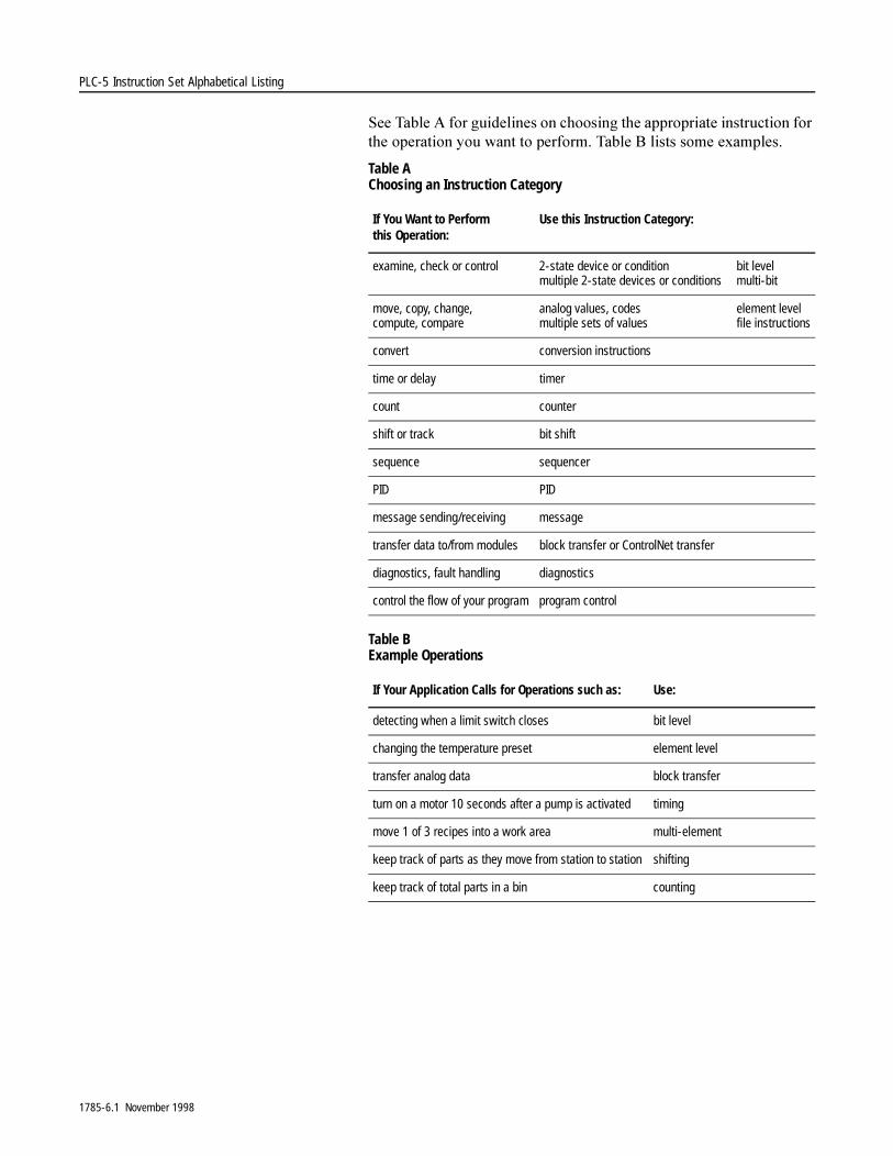
6HH�7DEOH�$�IRU�JXLGHOLQHV�RQ�FKRRVLQJ�WKH�DSSURSULDWH�LQVWUXFWLRQ�IRU�WKH�RSHUDWLRQ�\RX�ZDQW�WR�SHUIRUP��7DEOH�%�OLVWV�VRPH�H[DPSOHV�
Table AChoosing an Instruction Category
Table BExample Operations
If You Want to Perform this Operation:
Use this Instruction Category:
examine, check or control 2-state device or condition bit levelmultiple 2-state devices or conditions multi-bit
move, copy, change, compute, compare
analog values, codes element levelmultiple sets of values file instructions
convert conversion instructions
time or delay timer
count counter
shift or track bit shift
sequence sequencer
PID PID
message sending/receiving message
transfer data to/from modules block transfer or ControlNet transfer
diagnostics, fault handling diagnostics
control the flow of your program program control
If Your Application Calls for Operations such as: Use:
detecting when a limit switch closes bit level
changing the temperature preset element level
transfer analog data block transfer
turn on a motor 10 seconds after a pump is activated timing
move 1 of 3 recipes into a work area multi-element
keep track of parts as they move from station to station shifting
keep track of total parts in a bin counting
1785-6.1 November 1998

1785-6.1 November 1998
Summary of Changes
Summary of Changes
New Information Added to this Manual
7KH�OLVW�EHORZ�VXPPDUL]HV�WKH�FKDQJHV�WKDW�KDYH�EHHQ�PDGH�WR�WKLV�PDQXDO�VLQFH�WKH�ODVW�SULQWLQJ�
7R�KHOS�\RX�ILQG�QHZ�LQIRUPDWLRQ�DQG�XSGDWHG�LQIRUPDWLRQ�LQ�WKLV�UHOHDVH�RI�WKH�PDQXDO��ZH�KDYH�LQFOXGHG�FKDQJH�EDUV�DV�VKRZQ�WR�WKH�OHIW�RI�WKLV�SDUDJUDSK�
For this Update Information: See Chapter:
Converting non-decimal numbers with the FRD instruction 6
How non-existing, indirect addresses affect the COP and FLL instructions
9
How the .POS value operates in sequencer instructions 12
Using a RET instruction 13
Using the PID bias term 14
Using the no zero crossing (.NOZC) and no back calculation (.NOBC) features in the PD control block
14
Clarification to error code 89 for MSG instruction 16
Ethernet PLC-5 processors now support SLC Typed Read and SLC Typed Write MSG instructions
16
Configuring a multihop MSG instruction over Ethernet or over ControlNet
16
Monitoring the status of the .EN bit in a continuous MSG instruction
16

1785-6.1 November 1998
Summary of Changes
1RWHV�
Preface
Preface
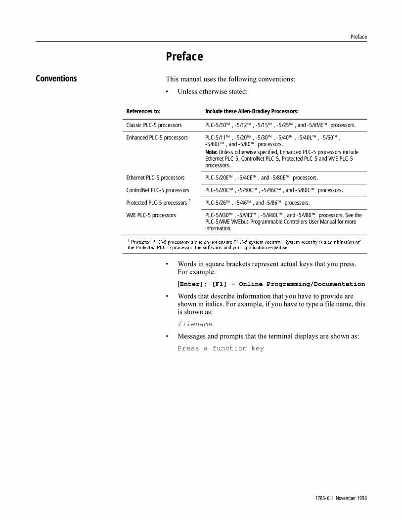
Conventions 7KLV�PDQXDO�XVHV�WKH�IROORZLQJ�FRQYHQWLRQV�
� 8QOHVV�RWKHUZLVH�VWDWHG�
� :RUGV�LQ�VTXDUH�EUDFNHWV�UHSUHVHQW�DFWXDO�NH\V�WKDW�\RX�SUHVV��)RU�H[DPSOH�
>Enter]; [F1] – Online Programming/Documentation
� :RUGV�WKDW�GHVFULEH�LQIRUPDWLRQ�WKDW�\RX�KDYH�WR�SURYLGH�DUH�VKRZQ�LQ�LWDOLFV��)RU�H[DPSOH��LI�\RX�KDYH�WR�W\SH�D�ILOH�QDPH��WKLV�LV�VKRZQ�DV��
filename
� 0HVVDJHV�DQG�SURPSWV�WKDW�WKH�WHUPLQDO�GLVSOD\V�DUH�VKRZQ�DV�
Press a function key
References to: Include these Allen-Bradley Processors:
Classic PLC-5 processors PLC-5/10™, -5/12™, -5/15™, -5/25™, and -5/VME™ processors.
Enhanced PLC-5 processors PLC-5/11™, -5/20™, -5/30™, -5/40™, -5/40L™, -5/60™, -5/60L™, and -5/80™ processors.Note: Unless otherwise specified, Enhanced PLC-5 processors include Ethernet PLC-5, ControlNet PLC-5, Protected PLC-5 and VME PLC-5 processors.
Ethernet PLC-5 processors PLC-5/20E™, -5/40E™, and -5/80E™ processors.
ControlNet PLC-5 processors PLC-5/20C™, -5/40C™, -5/46C™, and -5/80C™ processors.
Protected PLC-5 processors 1 PLC-5/26™, -5/46™, and -5/86™ processors.
VME PLC-5 processors PLC-5/V30™, -5/V40™, -5/V40L™, and -5/V80™ processors. See the PLC-5/VME VMEbus Programmable Controllers User Manual for more information.
��3URWHFWHG�3/&���SURFHVVRUV�DORQH�GR�QRW�HQVXUH�3/&���V\VWHP�VHFXULW\��6\VWHP�VHFXULW\�LV�D�FRPELQDWLRQ�RI�WKH�3URWHFWHG�3/&���SURFHVVRU��WKH�VRIWZDUH��DQG�\RXU�DSSOLFDWLRQ�H[SHUWLVH��
1785-6.1 November 1998

Preface
1RWHV�
1785-6.1 November 1998
Table of Contents
Relay-Type InstructionsXIC, XIO, OTE, OTL, OTU, IIN, IOT, IDI, IDO
Chapter 1Using Relay-Type Instructions . . . . . . . . . . . . . . . . . . . . . . . . 1-1
I/O Image Files in Data Storage . . . . . . . . . . . . . . . . . . . . . 1-2Rung Logic . . . . . . . . . . . . . . . . . . . . . . . . . . . . . . . . . . . . 1-2
Examine On (XIC). . . . . . . . . . . . . . . . . . . . . . . . . . . . . . . . . . 1-3Examine Off (XIO) . . . . . . . . . . . . . . . . . . . . . . . . . . . . . . . . . 1-3Energize (OTE) . . . . . . . . . . . . . . . . . . . . . . . . . . . . . . . . . . . . 1-4Latch (OTL) . . . . . . . . . . . . . . . . . . . . . . . . . . . . . . . . . . . . . . 1-4Unlatch (OTU) . . . . . . . . . . . . . . . . . . . . . . . . . . . . . . . . . . . . 1-5Immediate Input (IIN) . . . . . . . . . . . . . . . . . . . . . . . . . . . . . . . 1-6Immediate Output (IOT) . . . . . . . . . . . . . . . . . . . . . . . . . . . . . 1-7Immediate Data Input (IDI) . . . . . . . . . . . . . . . . . . . . . . . . . . . 1-8Immediate Data Output (IDO) . . . . . . . . . . . . . . . . . . . . . . . . . 1-8Using IDI and IDO Instructions . . . . . . . . . . . . . . . . . . . . . . . . 1-9
Timer Instructions TON, TOF, RTO Counter Instructions CTU, CTD Reset RES
Chapter 2Using Timers and Counters . . . . . . . . . . . . . . . . . . . . . . . . . . 2-1
Using Timers . . . . . . . . . . . . . . . . . . . . . . . . . . . . . . . . . . . 2-1Entering Parameters . . . . . . . . . . . . . . . . . . . . . . . . . . . . . . . 2-2Timer Accuracy . . . . . . . . . . . . . . . . . . . . . . . . . . . . . . . . . . . 2-3Timer On Delay (TON) . . . . . . . . . . . . . . . . . . . . . . . . . . . . . . 2-4
Using Status Bits . . . . . . . . . . . . . . . . . . . . . . . . . . . . . . . . 2-4Timer Off Delay (TOF) . . . . . . . . . . . . . . . . . . . . . . . . . . . . . . 2-7
Using Status Bits . . . . . . . . . . . . . . . . . . . . . . . . . . . . . . . . 2-7Retentive Timer On (RTO) . . . . . . . . . . . . . . . . . . . . . . . . . . 2-10
Using Status Bits . . . . . . . . . . . . . . . . . . . . . . . . . . . . . . . 2-10Using Counters . . . . . . . . . . . . . . . . . . . . . . . . . . . . . . . . . . 2-13
Entering Parameters . . . . . . . . . . . . . . . . . . . . . . . . . . . . 2-13Count Up (CTU) . . . . . . . . . . . . . . . . . . . . . . . . . . . . . . . . . . 2-15
Using Status Bits . . . . . . . . . . . . . . . . . . . . . . . . . . . . . . . 2-15Count Down (CTD) . . . . . . . . . . . . . . . . . . . . . . . . . . . . . . . . 2-17
Using Status Bits . . . . . . . . . . . . . . . . . . . . . . . . . . . . . . . 2-17 Timer and Counter Reset (RES). . . . . . . . . . . . . . . . . . . . . . 2-20
1785-6.1 November 1998
toc–2 Table of Contents
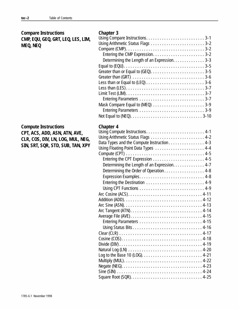
Compare InstructionsCMP, EQU, GEQ, GRT, LEQ, LES, LIM, MEQ, NEQ
Chapter 3Using Compare Instructions. . . . . . . . . . . . . . . . . . . . . . . . . . 3-1Using Arithmetic Status Flags . . . . . . . . . . . . . . . . . . . . . . . . 3-2Compare (CMP) . . . . . . . . . . . . . . . . . . . . . . . . . . . . . . . . . . . 3-2
Entering the CMP Expression. . . . . . . . . . . . . . . . . . . . . . . 3-2Determining the Length of an Expression. . . . . . . . . . . . . . 3-3
Equal to (EQU) . . . . . . . . . . . . . . . . . . . . . . . . . . . . . . . . . . . . 3-5Greater than or Equal to (GEQ). . . . . . . . . . . . . . . . . . . . . . . . 3-5Greater than (GRT) . . . . . . . . . . . . . . . . . . . . . . . . . . . . . . . . 3-6Less than or Equal to (LEQ) . . . . . . . . . . . . . . . . . . . . . . . . . . 3-6Less than (LES) . . . . . . . . . . . . . . . . . . . . . . . . . . . . . . . . . . . 3-7Limit Test (LIM) . . . . . . . . . . . . . . . . . . . . . . . . . . . . . . . . . . . 3-7
Entering Parameters . . . . . . . . . . . . . . . . . . . . . . . . . . . . . 3-7Mask Compare Equal to (MEQ) . . . . . . . . . . . . . . . . . . . . . . . 3-9
Entering Parameters . . . . . . . . . . . . . . . . . . . . . . . . . . . . . 3-9Not Equal to (NEQ). . . . . . . . . . . . . . . . . . . . . . . . . . . . . . . . 3-10
Compute InstructionsCPT, ACS, ADD, ASN, ATN, AVE, CLR, COS, DIV, LN, LOG, MUL, NEG, SIN, SRT, SQR, STD, SUB, TAN, XPY
Chapter 4Using Compute Instructions. . . . . . . . . . . . . . . . . . . . . . . . . . 4-1Using Arithmetic Status Flags . . . . . . . . . . . . . . . . . . . . . . . . 4-2Data Types and the Compute Instruction . . . . . . . . . . . . . . . . 4-3Using Floating Point Data Types . . . . . . . . . . . . . . . . . . . . . . 4-4Compute (CPT) . . . . . . . . . . . . . . . . . . . . . . . . . . . . . . . . . . . 4-5
Entering the CPT Expression . . . . . . . . . . . . . . . . . . . . . . . 4-5Determining the Length of an Expression. . . . . . . . . . . . . . 4-7Determining the Order of Operation . . . . . . . . . . . . . . . . . . 4-8Expression Examples. . . . . . . . . . . . . . . . . . . . . . . . . . . . . 4-8Entering the Destination . . . . . . . . . . . . . . . . . . . . . . . . . . 4-9Using CPT Functions . . . . . . . . . . . . . . . . . . . . . . . . . . . . . 4-9
Arc Cosine (ACS) . . . . . . . . . . . . . . . . . . . . . . . . . . . . . . . . . 4-11Addition (ADD). . . . . . . . . . . . . . . . . . . . . . . . . . . . . . . . . . . 4-12Arc Sine (ASN). . . . . . . . . . . . . . . . . . . . . . . . . . . . . . . . . . . 4-13Arc Tangent (ATN) . . . . . . . . . . . . . . . . . . . . . . . . . . . . . . . . 4-14Average File (AVE) . . . . . . . . . . . . . . . . . . . . . . . . . . . . . . . . 4-15
Entering Parameters . . . . . . . . . . . . . . . . . . . . . . . . . . . . 4-15Using Status Bits . . . . . . . . . . . . . . . . . . . . . . . . . . . . . . . 4-16
Clear (CLR) . . . . . . . . . . . . . . . . . . . . . . . . . . . . . . . . . . . . . 4-17Cosine (COS) . . . . . . . . . . . . . . . . . . . . . . . . . . . . . . . . . . . . 4-18Divide (DIV) . . . . . . . . . . . . . . . . . . . . . . . . . . . . . . . . . . . . . 4-19Natural Log (LN) . . . . . . . . . . . . . . . . . . . . . . . . . . . . . . . . . 4-20Log to the Base 10 (LOG). . . . . . . . . . . . . . . . . . . . . . . . . . . 4-21Multiply (MUL) . . . . . . . . . . . . . . . . . . . . . . . . . . . . . . . . . . . 4-22Negate (NEG). . . . . . . . . . . . . . . . . . . . . . . . . . . . . . . . . . . . 4-23Sine (SIN) . . . . . . . . . . . . . . . . . . . . . . . . . . . . . . . . . . . . . . 4-24Square Root (SQR). . . . . . . . . . . . . . . . . . . . . . . . . . . . . . . . 4-25
1785-6.1 November 1998
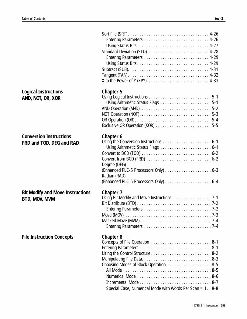
Table of Contents toc–3
Sort File (SRT) . . . . . . . . . . . . . . . . . . . . . . . . . . . . . . . . . . . 4-26Entering Parameters . . . . . . . . . . . . . . . . . . . . . . . . . . . . 4-26Using Status Bits . . . . . . . . . . . . . . . . . . . . . . . . . . . . . . . 4-27
Standard Deviation (STD) . . . . . . . . . . . . . . . . . . . . . . . . . . 4-28Entering Parameters . . . . . . . . . . . . . . . . . . . . . . . . . . . . 4-29Using Status Bits . . . . . . . . . . . . . . . . . . . . . . . . . . . . . . . 4-29
Subtract (SUB). . . . . . . . . . . . . . . . . . . . . . . . . . . . . . . . . . . 4-31Tangent (TAN) . . . . . . . . . . . . . . . . . . . . . . . . . . . . . . . . . . . 4-32X to the Power of Y (XPY). . . . . . . . . . . . . . . . . . . . . . . . . . . 4-33
Logical InstructionsAND, NOT, OR, XOR
Chapter 5Using Logical Instructions . . . . . . . . . . . . . . . . . . . . . . . . . . . 5-1
Using Arithmetic Status Flags . . . . . . . . . . . . . . . . . . . . . . 5-1AND Operation (AND). . . . . . . . . . . . . . . . . . . . . . . . . . . . . . . 5-2NOT Operation (NOT) . . . . . . . . . . . . . . . . . . . . . . . . . . . . . . . 5-3OR Operation (OR) . . . . . . . . . . . . . . . . . . . . . . . . . . . . . . . . . 5-4Exclusive OR Operation (XOR) . . . . . . . . . . . . . . . . . . . . . . . . 5-5
Conversion InstructionsFRD and TOD, DEG and RAD
Chapter 6Using the Conversion Instructions . . . . . . . . . . . . . . . . . . . . . 6-1
Using Arithmetic Status Flags . . . . . . . . . . . . . . . . . . . . . . 6-1Convert to BCD (TOD) . . . . . . . . . . . . . . . . . . . . . . . . . . . . . . 6-2Convert from BCD (FRD) . . . . . . . . . . . . . . . . . . . . . . . . . . . . 6-2Degree (DEG) (Enhanced PLC-5 Processors Only) . . . . . . . . . . . . . . . . . . . . 6-3Radian (RAD) (Enhanced PLC-5 Processors Only) . . . . . . . . . . . . . . . . . . . . 6-4
Bit Modify and Move Instructions BTD, MOV, MVM
Chapter 7Using Bit Modify and Move Instructions . . . . . . . . . . . . . . . . . 7-1Bit Distribute (BTD) . . . . . . . . . . . . . . . . . . . . . . . . . . . . . . . . 7-2
Entering Parameters . . . . . . . . . . . . . . . . . . . . . . . . . . . . . 7-2Move (MOV) . . . . . . . . . . . . . . . . . . . . . . . . . . . . . . . . . . . . . 7-3Masked Move (MVM). . . . . . . . . . . . . . . . . . . . . . . . . . . . . . . 7-4
Entering Parameters . . . . . . . . . . . . . . . . . . . . . . . . . . . . . 7-4
File Instruction Concepts Chapter 8Concepts of File Operation . . . . . . . . . . . . . . . . . . . . . . . . . . 8-1Entering Parameters . . . . . . . . . . . . . . . . . . . . . . . . . . . . . . . 8-1Using the Control Structure . . . . . . . . . . . . . . . . . . . . . . . . . . 8-2Manipulating File Data. . . . . . . . . . . . . . . . . . . . . . . . . . . . . . 8-3Choosing Modes of Block Operation . . . . . . . . . . . . . . . . . . . 8-5
All Mode . . . . . . . . . . . . . . . . . . . . . . . . . . . . . . . . . . . . . . 8-5Numerical Mode . . . . . . . . . . . . . . . . . . . . . . . . . . . . . . . . 8-6Incremental Mode . . . . . . . . . . . . . . . . . . . . . . . . . . . . . . . 8-7Special Case, Numerical Mode with Words Per Scan = 1. . 8-8
1785-6.1 November 1998
toc–4 Table of Contents
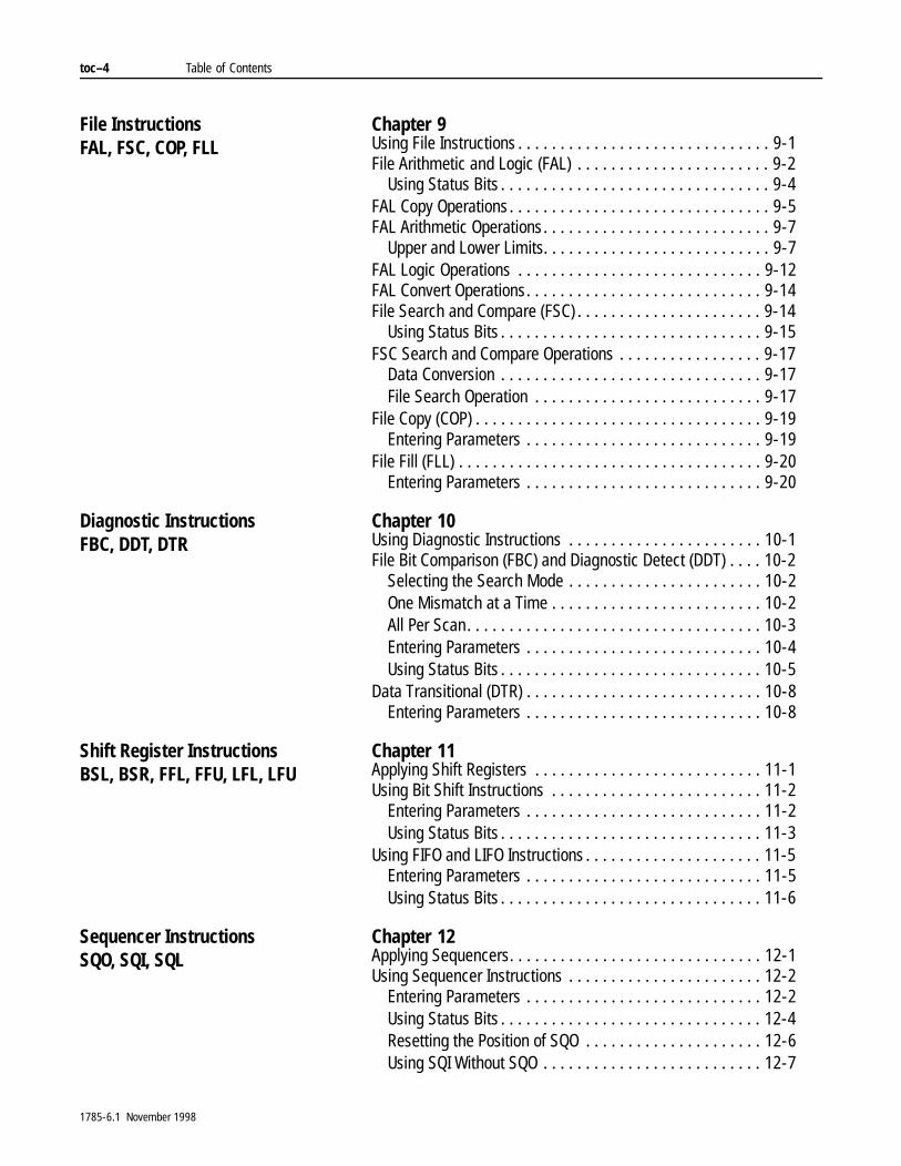
File InstructionsFAL, FSC, COP, FLL
Chapter 9Using File Instructions . . . . . . . . . . . . . . . . . . . . . . . . . . . . . . 9-1File Arithmetic and Logic (FAL) . . . . . . . . . . . . . . . . . . . . . . . 9-2
Using Status Bits . . . . . . . . . . . . . . . . . . . . . . . . . . . . . . . . 9-4FAL Copy Operations . . . . . . . . . . . . . . . . . . . . . . . . . . . . . . . 9-5FAL Arithmetic Operations. . . . . . . . . . . . . . . . . . . . . . . . . . . 9-7
Upper and Lower Limits. . . . . . . . . . . . . . . . . . . . . . . . . . . 9-7FAL Logic Operations . . . . . . . . . . . . . . . . . . . . . . . . . . . . . 9-12FAL Convert Operations. . . . . . . . . . . . . . . . . . . . . . . . . . . . 9-14File Search and Compare (FSC) . . . . . . . . . . . . . . . . . . . . . . 9-14
Using Status Bits . . . . . . . . . . . . . . . . . . . . . . . . . . . . . . . 9-15FSC Search and Compare Operations . . . . . . . . . . . . . . . . . 9-17
Data Conversion . . . . . . . . . . . . . . . . . . . . . . . . . . . . . . . 9-17File Search Operation . . . . . . . . . . . . . . . . . . . . . . . . . . . 9-17
File Copy (COP) . . . . . . . . . . . . . . . . . . . . . . . . . . . . . . . . . . 9-19Entering Parameters . . . . . . . . . . . . . . . . . . . . . . . . . . . . 9-19
File Fill (FLL) . . . . . . . . . . . . . . . . . . . . . . . . . . . . . . . . . . . . 9-20Entering Parameters . . . . . . . . . . . . . . . . . . . . . . . . . . . . 9-20
Diagnostic InstructionsFBC, DDT, DTR
Chapter 10Using Diagnostic Instructions . . . . . . . . . . . . . . . . . . . . . . . 10-1File Bit Comparison (FBC) and Diagnostic Detect (DDT) . . . . 10-2
Selecting the Search Mode . . . . . . . . . . . . . . . . . . . . . . . 10-2One Mismatch at a Time . . . . . . . . . . . . . . . . . . . . . . . . . 10-2All Per Scan. . . . . . . . . . . . . . . . . . . . . . . . . . . . . . . . . . . 10-3Entering Parameters . . . . . . . . . . . . . . . . . . . . . . . . . . . . 10-4Using Status Bits . . . . . . . . . . . . . . . . . . . . . . . . . . . . . . . 10-5
Data Transitional (DTR) . . . . . . . . . . . . . . . . . . . . . . . . . . . . 10-8Entering Parameters . . . . . . . . . . . . . . . . . . . . . . . . . . . . 10-8
Shift Register InstructionsBSL, BSR, FFL, FFU, LFL, LFU
Chapter 11Applying Shift Registers . . . . . . . . . . . . . . . . . . . . . . . . . . . 11-1Using Bit Shift Instructions . . . . . . . . . . . . . . . . . . . . . . . . . 11-2
Entering Parameters . . . . . . . . . . . . . . . . . . . . . . . . . . . . 11-2Using Status Bits . . . . . . . . . . . . . . . . . . . . . . . . . . . . . . . 11-3
Using FIFO and LIFO Instructions . . . . . . . . . . . . . . . . . . . . . 11-5Entering Parameters . . . . . . . . . . . . . . . . . . . . . . . . . . . . 11-5Using Status Bits . . . . . . . . . . . . . . . . . . . . . . . . . . . . . . . 11-6
Sequencer InstructionsSQO, SQI, SQL
Chapter 12Applying Sequencers. . . . . . . . . . . . . . . . . . . . . . . . . . . . . . 12-1Using Sequencer Instructions . . . . . . . . . . . . . . . . . . . . . . . 12-2
Entering Parameters . . . . . . . . . . . . . . . . . . . . . . . . . . . . 12-2Using Status Bits . . . . . . . . . . . . . . . . . . . . . . . . . . . . . . . 12-4Resetting the Position of SQO . . . . . . . . . . . . . . . . . . . . . 12-6Using SQI Without SQO . . . . . . . . . . . . . . . . . . . . . . . . . . 12-7
1785-6.1 November 1998
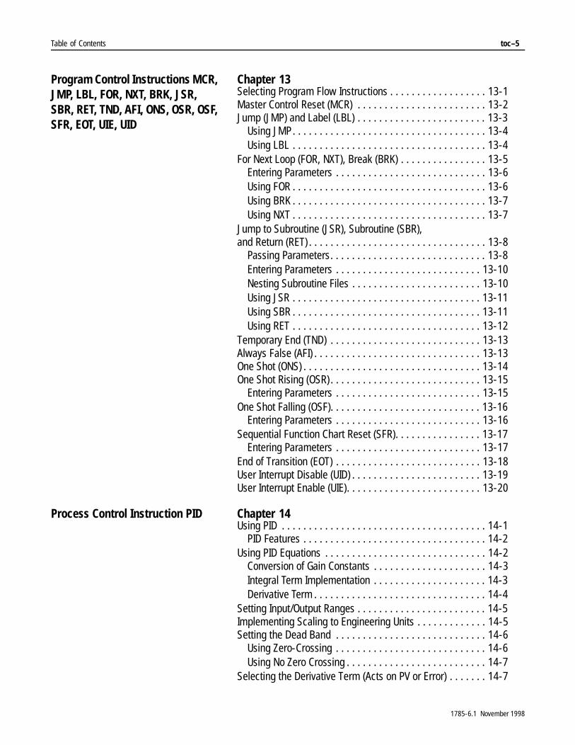
Table of Contents toc–5
Program Control Instructions MCR, JMP, LBL, FOR, NXT, BRK, JSR, SBR, RET, TND, AFI, ONS, OSR, OSF, SFR, EOT, UIE, UID
Chapter 13Selecting Program Flow Instructions . . . . . . . . . . . . . . . . . . 13-1Master Control Reset (MCR) . . . . . . . . . . . . . . . . . . . . . . . . 13-2Jump (JMP) and Label (LBL) . . . . . . . . . . . . . . . . . . . . . . . . 13-3
Using JMP. . . . . . . . . . . . . . . . . . . . . . . . . . . . . . . . . . . . 13-4Using LBL . . . . . . . . . . . . . . . . . . . . . . . . . . . . . . . . . . . . 13-4
For Next Loop (FOR, NXT), Break (BRK) . . . . . . . . . . . . . . . . 13-5Entering Parameters . . . . . . . . . . . . . . . . . . . . . . . . . . . . 13-6Using FOR . . . . . . . . . . . . . . . . . . . . . . . . . . . . . . . . . . . . 13-6Using BRK . . . . . . . . . . . . . . . . . . . . . . . . . . . . . . . . . . . . 13-7Using NXT . . . . . . . . . . . . . . . . . . . . . . . . . . . . . . . . . . . . 13-7
Jump to Subroutine (JSR), Subroutine (SBR),and Return (RET) . . . . . . . . . . . . . . . . . . . . . . . . . . . . . . . . . 13-8
Passing Parameters. . . . . . . . . . . . . . . . . . . . . . . . . . . . . 13-8Entering Parameters . . . . . . . . . . . . . . . . . . . . . . . . . . . 13-10Nesting Subroutine Files . . . . . . . . . . . . . . . . . . . . . . . . 13-10Using JSR . . . . . . . . . . . . . . . . . . . . . . . . . . . . . . . . . . . 13-11Using SBR . . . . . . . . . . . . . . . . . . . . . . . . . . . . . . . . . . . 13-11Using RET . . . . . . . . . . . . . . . . . . . . . . . . . . . . . . . . . . . 13-12
Temporary End (TND) . . . . . . . . . . . . . . . . . . . . . . . . . . . . 13-13Always False (AFI) . . . . . . . . . . . . . . . . . . . . . . . . . . . . . . . 13-13One Shot (ONS) . . . . . . . . . . . . . . . . . . . . . . . . . . . . . . . . . 13-14One Shot Rising (OSR) . . . . . . . . . . . . . . . . . . . . . . . . . . . . 13-15
Entering Parameters . . . . . . . . . . . . . . . . . . . . . . . . . . . 13-15One Shot Falling (OSF). . . . . . . . . . . . . . . . . . . . . . . . . . . . 13-16
Entering Parameters . . . . . . . . . . . . . . . . . . . . . . . . . . . 13-16Sequential Function Chart Reset (SFR). . . . . . . . . . . . . . . . 13-17
Entering Parameters . . . . . . . . . . . . . . . . . . . . . . . . . . . 13-17End of Transition (EOT) . . . . . . . . . . . . . . . . . . . . . . . . . . . 13-18User Interrupt Disable (UID) . . . . . . . . . . . . . . . . . . . . . . . . 13-19User Interrupt Enable (UIE). . . . . . . . . . . . . . . . . . . . . . . . . 13-20
Process Control Instruction PID Chapter 14Using PID . . . . . . . . . . . . . . . . . . . . . . . . . . . . . . . . . . . . . . 14-1
PID Features . . . . . . . . . . . . . . . . . . . . . . . . . . . . . . . . . . 14-2Using PID Equations . . . . . . . . . . . . . . . . . . . . . . . . . . . . . . 14-2
Conversion of Gain Constants . . . . . . . . . . . . . . . . . . . . . 14-3Integral Term Implementation . . . . . . . . . . . . . . . . . . . . . 14-3Derivative Term . . . . . . . . . . . . . . . . . . . . . . . . . . . . . . . . 14-4
Setting Input/Output Ranges . . . . . . . . . . . . . . . . . . . . . . . . 14-5Implementing Scaling to Engineering Units . . . . . . . . . . . . . 14-5Setting the Dead Band . . . . . . . . . . . . . . . . . . . . . . . . . . . . 14-6
Using Zero-Crossing . . . . . . . . . . . . . . . . . . . . . . . . . . . . 14-6Using No Zero Crossing . . . . . . . . . . . . . . . . . . . . . . . . . . 14-7
Selecting the Derivative Term (Acts on PV or Error) . . . . . . . 14-7
1785-6.1 November 1998
toc–6 Table of Contents
Setting Output Alarms . . . . . . . . . . . . . . . . . . . . . . . . . . . . . 14-7Using Output Limiting . . . . . . . . . . . . . . . . . . . . . . . . . . . . . 14-7
Anti-Reset Windup. . . . . . . . . . . . . . . . . . . . . . . . . . . . . . 14-8Using a Manual Mode Operation (Bumpless Transfer) . . . 14-8Set Output . . . . . . . . . . . . . . . . . . . . . . . . . . . . . . . . . . . . 14-8
Feedforward or Output Biasing . . . . . . . . . . . . . . . . . . . . . . 14-9Resume Last State . . . . . . . . . . . . . . . . . . . . . . . . . . . . . . . 14-9PID Instruction. . . . . . . . . . . . . . . . . . . . . . . . . . . . . . . . . . 14-10
Using No Back Calculation. . . . . . . . . . . . . . . . . . . . . . . 14-11Operational Status Bits . . . . . . . . . . . . . . . . . . . . . . . . . 14-11Integer Block . . . . . . . . . . . . . . . . . . . . . . . . . . . . . . . . . 14-11PD Block . . . . . . . . . . . . . . . . . . . . . . . . . . . . . . . . . . . . 14-12Entering Parameters . . . . . . . . . . . . . . . . . . . . . . . . . . . 14-12
Using an Integer Data File Type for the Control Block. . . . . 14-14Using Control Block Values . . . . . . . . . . . . . . . . . . . . . . 14-16
Using a PD File Type for the Control Block . . . . . . . . . . . . . 14-18Using Control Block Values . . . . . . . . . . . . . . . . . . . . . . 14-23
Programming Considerations . . . . . . . . . . . . . . . . . . . . . . 14-25Run Time Errors . . . . . . . . . . . . . . . . . . . . . . . . . . . . . . 14-25Transferring Data to the PID Instruction . . . . . . . . . . . . . 14-25
Loop Considerations . . . . . . . . . . . . . . . . . . . . . . . . . . . . . 14-26Number of PID Loops. . . . . . . . . . . . . . . . . . . . . . . . . . . 14-26Loop Update Time . . . . . . . . . . . . . . . . . . . . . . . . . . . . . 14-26
Descaling Inputs . . . . . . . . . . . . . . . . . . . . . . . . . . . . . . . . 14-27PID Examples . . . . . . . . . . . . . . . . . . . . . . . . . . . . . . . . . . 14-29Integer Block (N) Examples . . . . . . . . . . . . . . . . . . . . . . . . 14-29
Main Program File . . . . . . . . . . . . . . . . . . . . . . . . . . . . . 14-29STI Program File . . . . . . . . . . . . . . . . . . . . . . . . . . . . . . 14-30RTS Program File. . . . . . . . . . . . . . . . . . . . . . . . . . . . . . 14-32
PD Block Examples . . . . . . . . . . . . . . . . . . . . . . . . . . . . . . 14-33Main Program File . . . . . . . . . . . . . . . . . . . . . . . . . . . . . 14-33STI Program File . . . . . . . . . . . . . . . . . . . . . . . . . . . . . . 14-34RTS Program File. . . . . . . . . . . . . . . . . . . . . . . . . . . . . . 14-36Ladder Logic Simulation of a Manual Control Station . . . 14-37Cascading Loops . . . . . . . . . . . . . . . . . . . . . . . . . . . . . . 14-38Ratio Control . . . . . . . . . . . . . . . . . . . . . . . . . . . . . . . . . 14-38Process Variable Tracking . . . . . . . . . . . . . . . . . . . . . . . 14-39
PID Theory . . . . . . . . . . . . . . . . . . . . . . . . . . . . . . . . . . . . 14-40
1785-6.1 November 1998
Table of Contents toc–7
Block-Transfer Instructions BTR and BTW and ControlNet I/O Transfer Instruction CIO
Chapter 15Using Block Transfer and ControlNet I/O Transfer Instructions . . . . . . . . . . . . . . . . . . . . . . . . . . . . . . 15-1Using Block Transfer Instructions . . . . . . . . . . . . . . . . . . . . 15-1Block-Transfer Read (BTR) and Block-Transfer Write (BTW). 15-3
Block-Transfer Request Queue . . . . . . . . . . . . . . . . . . . . 15-3Entering Parameters . . . . . . . . . . . . . . . . . . . . . . . . . . . . 15-4
Using Status Bits . . . . . . . . . . . . . . . . . . . . . . . . . . . . . . . . . 15-6Using the Control Block . . . . . . . . . . . . . . . . . . . . . . . . . . . . 15-8
Requested Word Count (.RLEN) . . . . . . . . . . . . . . . . . . . . 15-8Transmitted Word Count (.DLEN) . . . . . . . . . . . . . . . . . . . 15-8File Number (.FILE) . . . . . . . . . . . . . . . . . . . . . . . . . . . . . 15-9Element Number (.ELEM). . . . . . . . . . . . . . . . . . . . . . . . . 15-9
Selecting Continuous Operation. . . . . . . . . . . . . . . . . . . . . 15-10Selecting Non-Continuous Operation . . . . . . . . . . . . . . . . . 15-12Block Transfer Timing – Classic PLC-5 Processors . . . . . . 15-13
Instruction Run Time . . . . . . . . . . . . . . . . . . . . . . . . . . . 15-13Waiting Time in the Queue. . . . . . . . . . . . . . . . . . . . . . . 15-13Transfer Time . . . . . . . . . . . . . . . . . . . . . . . . . . . . . . . . 15-13
Block Transfer Timing – Enhanced PLC-5 Processors . . . . 15-14Instruction Run Time . . . . . . . . . . . . . . . . . . . . . . . . . . . 15-14Waiting Time in the Holding Area . . . . . . . . . . . . . . . . . . 15-14Transfer Time . . . . . . . . . . . . . . . . . . . . . . . . . . . . . . . . 15-14
Programming Examples . . . . . . . . . . . . . . . . . . . . . . . . . . 15-15Example Bidirectional Alternating Block-Transfer . . . . . . 15-16Example Bidirectional Alternating Repeating
Block-Transfer . . . . . . . . . . . . . . . . . . . . . . . . . . . . . 15-17Example Bidirectional Continuous Block-Transfer . . . . . 15-18Example Directional Non-Continuous Block-Transfer . . . 15-19Example Directional Repeating Block Transfer . . . . . . . . 15-19Example Directional Continuous Block-Transfer . . . . . . . 15-20Example Buffering Block Transfer-Data . . . . . . . . . . . . . 15-21
ControlNet I/O Transfer (CIO) Instruction . . . . . . . . . . . . . . 15-22Control Block Address . . . . . . . . . . . . . . . . . . . . . . . . . . 15-22
Using the CIO Instruction . . . . . . . . . . . . . . . . . . . . . . . . . . 15-23Using Status Bits . . . . . . . . . . . . . . . . . . . . . . . . . . . . . . . . 15-24
Using the CT Control Block . . . . . . . . . . . . . . . . . . . . . . 15-25
1785-6.1 November 1998
toc–8 Table of Contents
Message Instruction MSG Chapter 16Using the Message Instruction. . . . . . . . . . . . . . . . . . . . . . . 16-1Message (MSG) . . . . . . . . . . . . . . . . . . . . . . . . . . . . . . . . . . 16-1Entering Parameters . . . . . . . . . . . . . . . . . . . . . . . . . . . . . . 16-2
Control Block Address . . . . . . . . . . . . . . . . . . . . . . . . . . . 16-2MSG Data Entry Screen . . . . . . . . . . . . . . . . . . . . . . . . . . 16-3
Using the Message Instruction for EthernetCommunications . . . . . . . . . . . . . . . . . . . . . . . . . . . . . . . . . 16-5
Entering Parameters . . . . . . . . . . . . . . . . . . . . . . . . . . . . 16-5Using the Message Instruction for PLC-5 Ethernet Interface Module Communications. . . . . . . . . . . . . . . . . . . . . . . . . . . 16-7
Entering Parameters . . . . . . . . . . . . . . . . . . . . . . . . . . . . 16-7Configuring an Ethernet Multihop MSG Instruction. . . . . . . . 16-9Using the Message Instruction for ControlNetCommunications . . . . . . . . . . . . . . . . . . . . . . . . . . . . . . . . 16-10
Control Block Address . . . . . . . . . . . . . . . . . . . . . . . . . . 16-10Configuring a ControlNet Multihop MSG Instruction . . . . . . 16-11Using Status Bits . . . . . . . . . . . . . . . . . . . . . . . . . . . . . . . . 16-12Using the Control Block . . . . . . . . . . . . . . . . . . . . . . . . . . . 16-13
Error Code (.ERR). . . . . . . . . . . . . . . . . . . . . . . . . . . . . . 16-13Requested Length (.RLEN) . . . . . . . . . . . . . . . . . . . . . . . 16-13Transmitted Length (.DLEN) . . . . . . . . . . . . . . . . . . . . . . 16-13
Entering Parameters . . . . . . . . . . . . . . . . . . . . . . . . . . . . . 16-14Communication Command . . . . . . . . . . . . . . . . . . . . . . 16-14External Data Table Addresses. . . . . . . . . . . . . . . . . . . . 16-15PLC-2 to PLC-5 Compatibility Files . . . . . . . . . . . . . . . . 16-15Sending SLC Typed Logical Read and Typed Logical
Write Commands . . . . . . . . . . . . . . . . . . . . . . . . . . . 16-16Monitoring a Message Instruction . . . . . . . . . . . . . . . . . . . 16-17Selecting Continuous Operation. . . . . . . . . . . . . . . . . . . . . 16-18Selecting Non-Continuous Operation . . . . . . . . . . . . . . . . . 16-19MSG Timing . . . . . . . . . . . . . . . . . . . . . . . . . . . . . . . . . . . 16-20Error Codes . . . . . . . . . . . . . . . . . . . . . . . . . . . . . . . . . . . . 16-22
1785-6.1 November 1998
Table of Contents toc–9
ASCII InstructionsABL, ACB, ACI, ACN, AEX, AIC, AHL, ARD, ARL, ASC, ASR, AWA, AWT
Chapter 17Using ASCII InstructionsEnhanced PLC-5 Processors Only . . . . . . . . . . . . . . . . . . . . 17-1
Using Status Bits . . . . . . . . . . . . . . . . . . . . . . . . . . . . . . . 17-2Using the Control Block . . . . . . . . . . . . . . . . . . . . . . . . . . 17-3Length (.LEN). . . . . . . . . . . . . . . . . . . . . . . . . . . . . . . . . . 17-3Position (.POS). . . . . . . . . . . . . . . . . . . . . . . . . . . . . . . . . 17-3Using Strings. . . . . . . . . . . . . . . . . . . . . . . . . . . . . . . . . . 17-3
Test Buffer for Line (ABL) . . . . . . . . . . . . . . . . . . . . . . . . . . 17-4Entering Parameters . . . . . . . . . . . . . . . . . . . . . . . . . . . . 17-4
Number of Characters in Buffer (ACB) . . . . . . . . . . . . . . . . . 17-5Entering Parameters . . . . . . . . . . . . . . . . . . . . . . . . . . . . 17-5
ASCII String to Integer (ACI) . . . . . . . . . . . . . . . . . . . . . . . . . 17-6ASCII String Concatenate (ACN) . . . . . . . . . . . . . . . . . . . . . . 17-7ASCII String Extract (AEX) . . . . . . . . . . . . . . . . . . . . . . . . . . 17-7
Entering Parameters . . . . . . . . . . . . . . . . . . . . . . . . . . . . 17-7ASCII Set or Reset Handshake Lines (AHL). . . . . . . . . . . . . . 17-8
Entering Parameters . . . . . . . . . . . . . . . . . . . . . . . . . . . . 17-8ASCII Integer to String (AIC) . . . . . . . . . . . . . . . . . . . . . . . . . 17-9ASCII Read Characters (ARD) . . . . . . . . . . . . . . . . . . . . . . . 17-10
Entering Parameters . . . . . . . . . . . . . . . . . . . . . . . . . . . 17-10ASCII Read Line (ARL) . . . . . . . . . . . . . . . . . . . . . . . . . . . . 17-12
Entering Parameters . . . . . . . . . . . . . . . . . . . . . . . . . . . 17-12ASCII String Search (ASC) . . . . . . . . . . . . . . . . . . . . . . . . . 17-14
Entering Parameters . . . . . . . . . . . . . . . . . . . . . . . . . . . 17-14ASCII String Compare (ASR). . . . . . . . . . . . . . . . . . . . . . . . 17-15ASCII Write with Append (AWA) . . . . . . . . . . . . . . . . . . . . . 17-15
Entering Parameters . . . . . . . . . . . . . . . . . . . . . . . . . . . 17-15ASCII Write (AWT) . . . . . . . . . . . . . . . . . . . . . . . . . . . . . . . 17-17
Entering Parameters . . . . . . . . . . . . . . . . . . . . . . . . . . . 17-17
Custom Application Routine Instructions SDS, DFA
Chapter 18Chapter Objectives . . . . . . . . . . . . . . . . . . . . . . . . . . . . . . . 18-1Smart Directed Sequencer (SDS) Overview . . . . . . . . . . . . . 18-2
Programming the SDS Instruction . . . . . . . . . . . . . . . . . . 18-2Diagnostic Fault Annunciator (DFA) Overview . . . . . . . . . . . 18-3
Programming the DFA Instruction . . . . . . . . . . . . . . . . . . 18-3
1785-6.1 November 1998

toc–10 Table of Contents
Instruction Timing and Memory Requirements
Appendix A-1Instruction Timing and Memory Requirements. . . . . . . . . . . . A-1Timing for Enhanced PLC-5 Processors. . . . . . . . . . . . . . . . . A-2
Bit and Word Instructions. . . . . . . . . . . . . . . . . . . . . . . . . . A-2File Instructions . . . . . . . . . . . . . . . . . . . . . . . . . . . . . . . . . A-5
Timing for Classic PLC-5 Processors . . . . . . . . . . . . . . . . . . A-10Bit and Word Instructions. . . . . . . . . . . . . . . . . . . . . . . . . A-10File Instructions . . . . . . . . . . . . . . . . . . . . . . . . . . . . . . . . A-13
Program Constants . . . . . . . . . . . . . . . . . . . . . . . . . . . . . . . A-17Direct and Indirect Elements: Enhanced PLC-5 Processors . A-17Direct and Indirect Elements: Classic PLC-5 Processors . . . A-18Indirect Bit or Elements Addresses: ClassicPLC-5 Processors . . . . . . . . . . . . . . . . . . . . . . . . . . . . . . . . A-19Additional Timing Considerations: ClassicPLC-5 Processors . . . . . . . . . . . . . . . . . . . . . . . . . . . . . . . . A-20
SFC Reference Appendix B-1Appendix Objectives . . . . . . . . . . . . . . . . . . . . . . . . . . . . . . . B-1SFC Status Information in the Processor Status File. . . . . . . . B-1Memory Allocation . . . . . . . . . . . . . . . . . . . . . . . . . . . . . . . . B-3Dynamic Constraints – Classic PLC-5 Processors Only . . . . . B-5Scanning Sequences. . . . . . . . . . . . . . . . . . . . . . . . . . . . . . . B-7
Step and Transition Scanning . . . . . . . . . . . . . . . . . . . . . . B-7Selected Branch Scanning. . . . . . . . . . . . . . . . . . . . . . . . . B-8Simultaneous Branch Scanning . . . . . . . . . . . . . . . . . . . . . B-9SFC Example and Scan Sequence . . . . . . . . . . . . . . . . . . B-11
Run Times – Classic PLC-5 Processors . . . . . . . . . . . . . . . . B-12Using Sequence Diagrams to Determine Run Time . . . . . B-13Using Equations to Determine Run Time . . . . . . . . . . . . . B-14
Valid Data Types for Instruction Operands
Appendix C-1Appendix Objectives . . . . . . . . . . . . . . . . . . . . . . . . . . . . . . . C-1Instruction Operands and Valid Data Types . . . . . . . . . . . . . . C-1
1785-6.1 November 1998
Chapter 1
Relay-Type Instructions XIC, XIO, OTE, OTL, OTU, IIN, IOT, IDI, IDO
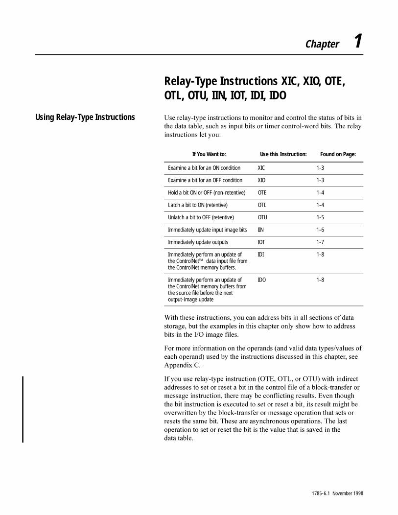
Using Relay-Type Instructions 8VH�UHOD\�W\SH�LQVWUXFWLRQV�WR�PRQLWRU�DQG�FRQWURO�WKH�VWDWXV�RI�ELWV�LQ�WKH�GDWD�WDEOH��VXFK�DV�LQSXW�ELWV�RU�WLPHU�FRQWURO�ZRUG�ELWV��7KH�UHOD\�LQVWUXFWLRQV�OHW�\RX�
:LWK�WKHVH�LQVWUXFWLRQV��\RX�FDQ�DGGUHVV�ELWV�LQ�DOO�VHFWLRQV�RI�GDWD�VWRUDJH��EXW�WKH�H[DPSOHV�LQ�WKLV�FKDSWHU�RQO\�VKRZ�KRZ�WR�DGGUHVV�ELWV�LQ�WKH�,�2�LPDJH�ILOHV�
)RU�PRUH�LQIRUPDWLRQ�RQ�WKH�RSHUDQGV��DQG�YDOLG�GDWD�W\SHV�YDOXHV�RI�HDFK�RSHUDQG��XVHG�E\�WKH�LQVWUXFWLRQV�GLVFXVVHG�LQ�WKLV�FKDSWHU��VHH�$SSHQGL[�&�
,I�\RX�XVH�UHOD\�W\SH�LQVWUXFWLRQ��27(��27/��RU�278��ZLWK�LQGLUHFW�DGGUHVVHV�WR�VHW�RU�UHVHW�D�ELW�LQ�WKH�FRQWURO�ILOH�RI�D�EORFN�WUDQVIHU�RU�PHVVDJH�LQVWUXFWLRQ��WKHUH�PD\�EH�FRQIOLFWLQJ�UHVXOWV��(YHQ�WKRXJK�WKH�ELW�LQVWUXFWLRQ�LV�H[HFXWHG�WR�VHW�RU�UHVHW�D�ELW��LWV�UHVXOW�PLJKW�EH�RYHUZULWWHQ�E\�WKH�EORFN�WUDQVIHU�RU�PHVVDJH�RSHUDWLRQ�WKDW�VHWV�RU�UHVHWV�WKH�VDPH�ELW��7KHVH�DUH�DV\QFKURQRXV�RSHUDWLRQV��7KH�ODVW�RSHUDWLRQ�WR�VHW�RU�UHVHW�WKH�ELW�LV�WKH�YDOXH�WKDW�LV�VDYHG�LQ�WKH�GDWD WDEOH�
If You Want to: Use this Instruction: Found on Page:
Examine a bit for an ON condition XIC 1-3
Examine a bit for an OFF condition XIO 1-3
Hold a bit ON or OFF (non-retentive) OTE 1-4
Latch a bit to ON (retentive) OTL 1-4
Unlatch a bit to OFF (retentive) OTU 1-5
Immediately update input image bits IIN 1-6
Immediately update outputs IOT 1-7
Immediately perform an update of the ControlNet™ data input file from the ControlNet memory buffers.
IDI 1-8
Immediately perform an update of the ControlNet memory buffers from the source file before the next output-image update
IDO 1-8
1785-6.1 November 1998

1-2 Relay-Type Instructions XIC, XIO, OTE, OTL, OTU, IIN, IOT, IDI, IDO
I/O Image Files in Data Storage
7KH�LQSXW�LPDJH�ILOH�LQ�WKH�SURFHVVRU�VWRUHV�WKH�VWDWXV�RI�LQSXW�VHQVRUV�FRQQHFWHG�WR�LQSXW�PRGXOH�WHUPLQDOV�
<RX�SURJUDP�LQVWUXFWLRQV�LQ�ODGGHU�ORJLF�WR�PRQLWRU�ELWV��8VH�D�ORJLFDO�DGGUHVV�IRU�WKH�ELW�
7KH�RXWSXW�LPDJH�ILOH�FRQWUROV�WKH�VWDWXV�RI�DFWXDWRUV�ZLUHG�WR�RXWSXW�PRGXOH�WHUPLQDOV�
<RX�SURJUDP�LQVWUXFWLRQV�LQ�ODGGHU�ORJLF�WR�FRQWURO�ELWV�
Rung Logic
$V�HDFK�FRQGLWLRQLQJ�LQVWUXFWLRQ�LV�H[HFXWHG��WKH�DGGUHVVHG�ELW�LV�H[DPLQHG�WR�VHH�LI�LW�PDWFKHV�D�FHUWDLQ�FRQGLWLRQ��RQ�RU�RII���,I�D�FRPSOHWH�SDWK�RI�WUXH�FRQGLWLRQV�H[DPLQHG�IRU�DUH�IRXQG��WKH�UXQJ�LV�VHW�WR�WUXH��7KH�UXQJ�PXVW�FRQWDLQ�D�FRQWLQXRXV�SDWK�RI�WUXH�LQVWUXFWLRQV�IURP�WKH�VWDUW�RI�WKH�UXQJ�WR�WKH�RXWSXW�IRU�WKH�RXWSXW�WR�EH�HQDEOHG�
If the Input Sensor Is: Then Its Corresponding Input Image Bit Is:
closed (on) on (1)
open (off) off (0)
If the Output Image Bit Is: Then Its Corresponding Output Is:
on (1) energized (on)
off (0) de-energized (off)
1785-6.1 November 1998
Relay-Type Instructions XIC, XIO, OTE, OTL, OTU, IIN, IOT, IDI, IDO 1-3
Examine On (XIC)
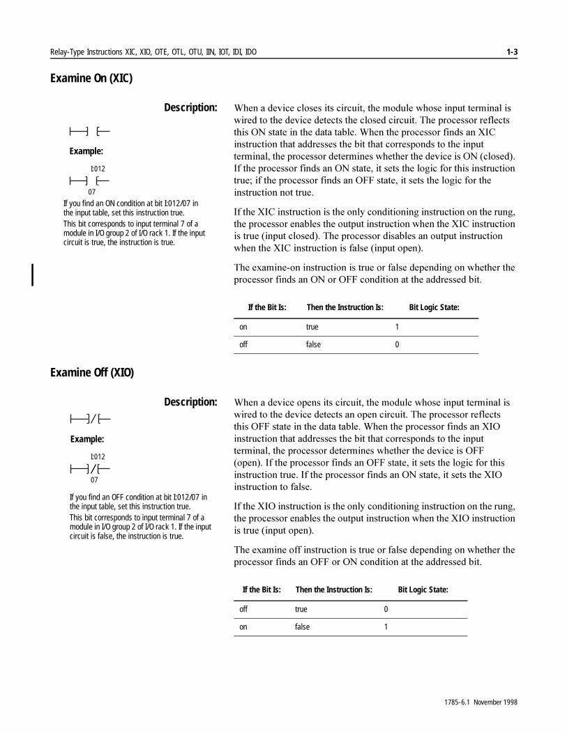
Description: :KHQ�D�GHYLFH�FORVHV�LWV�FLUFXLW��WKH�PRGXOH�ZKRVH�LQSXW�WHUPLQDO�LV�ZLUHG�WR�WKH�GHYLFH�GHWHFWV�WKH�FORVHG�FLUFXLW��7KH�SURFHVVRU�UHIOHFWV�WKLV�21�VWDWH�LQ�WKH�GDWD�WDEOH��:KHQ�WKH�SURFHVVRU�ILQGV�DQ�;,&�LQVWUXFWLRQ�WKDW�DGGUHVVHV�WKH�ELW�WKDW�FRUUHVSRQGV�WR�WKH�LQSXW�WHUPLQDO��WKH�SURFHVVRU�GHWHUPLQHV�ZKHWKHU�WKH�GHYLFH�LV�21��FORVHG���,I�WKH�SURFHVVRU�ILQGV�DQ�21�VWDWH��LW�VHWV�WKH�ORJLF�IRU�WKLV�LQVWUXFWLRQ�WUXH��LI�WKH�SURFHVVRU�ILQGV�DQ�2))�VWDWH��LW�VHWV�WKH�ORJLF�IRU�WKH�LQVWUXFWLRQ�QRW�WUXH�
,I�WKH�;,&�LQVWUXFWLRQ�LV�WKH�RQO\�FRQGLWLRQLQJ�LQVWUXFWLRQ�RQ�WKH�UXQJ��WKH�SURFHVVRU�HQDEOHV�WKH�RXWSXW�LQVWUXFWLRQ�ZKHQ�WKH�;,&�LQVWUXFWLRQ�LV�WUXH��LQSXW�FORVHG���7KH�SURFHVVRU�GLVDEOHV�DQ�RXWSXW�LQVWUXFWLRQ�ZKHQ�WKH�;,&�LQVWUXFWLRQ�LV�IDOVH��LQSXW�RSHQ��
7KH�H[DPLQH�RQ�LQVWUXFWLRQ�LV�WUXH�RU�IDOVH�GHSHQGLQJ�RQ�ZKHWKHU�WKH�SURFHVVRU�ILQGV�DQ�21�RU�2))�FRQGLWLRQ�DW�WKH�DGGUHVVHG�ELW�
Examine Off (XIO)
Description: :KHQ�D�GHYLFH�RSHQV�LWV�FLUFXLW��WKH�PRGXOH�ZKRVH�LQSXW�WHUPLQDO�LV�ZLUHG�WR�WKH�GHYLFH�GHWHFWV�DQ�RSHQ�FLUFXLW��7KH�SURFHVVRU�UHIOHFWV�WKLV�2))�VWDWH�LQ�WKH�GDWD�WDEOH��:KHQ�WKH�SURFHVVRU�ILQGV�DQ�;,2�LQVWUXFWLRQ�WKDW�DGGUHVVHV�WKH�ELW�WKDW�FRUUHVSRQGV�WR�WKH�LQSXW�WHUPLQDO��WKH�SURFHVVRU�GHWHUPLQHV�ZKHWKHU�WKH�GHYLFH�LV�2))��RSHQ���,I�WKH�SURFHVVRU�ILQGV�DQ�2))�VWDWH��LW�VHWV�WKH�ORJLF�IRU�WKLV�LQVWUXFWLRQ�WUXH��,I�WKH�SURFHVVRU�ILQGV�DQ�21�VWDWH��LW�VHWV�WKH�;,2�LQVWUXFWLRQ�WR�IDOVH�
,I�WKH�;,2�LQVWUXFWLRQ�LV�WKH�RQO\�FRQGLWLRQLQJ�LQVWUXFWLRQ�RQ�WKH�UXQJ��WKH�SURFHVVRU�HQDEOHV�WKH�RXWSXW�LQVWUXFWLRQ�ZKHQ�WKH�;,2�LQVWUXFWLRQ�LV�WUXH��LQSXW�RSHQ��
7KH�H[DPLQH�RII�LQVWUXFWLRQ�LV�WUXH�RU�IDOVH�GHSHQGLQJ�RQ�ZKHWKHU�WKH�SURFHVVRU�ILQGV�DQ�2))�RU�21�FRQGLWLRQ�DW�WKH�DGGUHVVHG�ELW�
I:012
07
Example:
If you find an ON condition at bit I:012/07 in the input table, set this instruction true.This bit corresponds to input terminal 7 of a module in I/O group 2 of I/O rack 1. If the input circuit is true, the instruction is true.
If the Bit Is: Then the Instruction Is: Bit Logic State:
on true 1
off false 0
Example:
I:012
07
If you find an OFF condition at bit I:012/07 in the input table, set this instruction true.This bit corresponds to input terminal 7 of a module in I/O group 2 of I/O rack 1. If the input circuit is false, the instruction is true.
If the Bit Is: Then the Instruction Is: Bit Logic State:
off true 0
on false 1
1785-6.1 November 1998

1-4 Relay-Type Instructions XIC, XIO, OTE, OTL, OTU, IIN, IOT, IDI, IDO
Energize (OTE)
Description: 8VH�WKH�27(�LQVWUXFWLRQ�WR�FRQWURO�D�ELW�LQ�PHPRU\��,I�WKH�ELW�FRUUHVSRQGV�WR�DQ�RXWSXW�PRGXOH�WHUPLQDO��WKH�GHYLFH�ZLUHG�WR�WKLV�WHUPLQDO�LV�HQHUJL]HG�ZKHQ�WKH�LQVWUXFWLRQ�LV�HQDEOHG�DQG�GH�HQHUJL]HG�ZKHQ�WKH�LQVWUXFWLRQ�LV�GLVDEOHG��,I�WKH�LQSXW�FRQGLWLRQV�WKDW�SUHFHGH�WKH�27(�LQVWUXFWLRQ�DUH�WUXH��WKH�SURFHVVRU�HQDEOHV�WKH�27(�LQVWUXFWLRQ��,I�WKH�LQSXW�FRQGLWLRQV�WKDW�SUHFHGH�WKH�27(�LQVWUXFWLRQ�DUH�IDOVH��WKH�SURFHVVRU�GLVDEOHV�WKH�27(�LQVWUXFWLRQ��:KHQ�UXQJ�FRQGLWLRQV�EHFRPH�IDOVH��WKH�FRUUHVSRQGLQJ�GHYLFH�GH�HQHUJL]HV�
$Q�27(�LQVWUXFWLRQ�LV�VLPLODU�WR�D�UHOD\�FRLO��7KH�27(�LQVWUXFWLRQ�LV�FRQWUROOHG�E\�SUHFHGLQJ�LQSXW�LQVWUXFWLRQV��WKH�UHOD\�FRLO�LV�FRQWUROOHG�E\�FRQWDFWV�LQ�LWV�KDUG�ZLUHG�UXQJ�
7KH�27(�LQVWUXFWLRQ�WHOOV�WKH�SURFHVVRU�WR�FRQWURO�WKH�DGGUHVVHG�ELW�EDVHG�RQ�WKH�UXQJ�FRQGLWLRQ�
Latch (OTL)
Description: 7KH�27/�LQVWUXFWLRQ�LV�D�UHWHQWLYH�RXWSXW�LQVWUXFWLRQ�WKDW�FDQ�RQO\�WXUQ�RQ�D�ELW��LW�FDQQRW�WXUQ�RII�D�ELW���7KLV�LQVWUXFWLRQ�LV�XVXDOO\�XVHG�LQ�SDLUV�ZLWK�DQ�278��XQODWFK��LQVWUXFWLRQ��ZLWK�ERWK�LQVWUXFWLRQV�DGGUHVVLQJ�WKH�VDPH�ELW�
:KHQ�\RX�DVVLJQ�DQ�DGGUHVV�WR�DQ�27/�LQVWUXFWLRQ�WKDW�FRUUHVSRQGV�WR�D�WHUPLQDO�RI�DQ�RXWSXW�PRGXOH��WKH�RXWSXW�GHYLFH�ZLUHG�WR�WKLV�WHUPLQDO�LV�HQHUJL]HG�ZKHQ�WKH�SURFHVVRU�VHWV��HQDEOHV��WKH�ELW�LQ�SURFHVVRU�PHPRU\��,I�WKH�LQSXW�FRQGLWLRQV�WKDW�SUHFHGH�WKH�27/�LQVWUXFWLRQ�DUH�WUXH��WKH�SURFHVVRU�HQDEOHV�WKH�27/�LQVWUXFWLRQ��:KHQ�UXQJ�FRQGLWLRQV�EHFRPH�IDOVH��DIWHU�EHLQJ�WUXH���WKH�ELW�UHPDLQV�VHW�DQG�WKH�FRUUHVSRQGLQJ�RXWSXW�GHYLFH�UHPDLQV�HQHUJL]HG��8VH�WKH�278�LQVWUXFWLRQ�WR�WXUQ�2))�WKH�ELW�\RX�ODWFKHG�RQ�ZLWK�WKH�27/�LQVWUXFWLRQ�
O:013
01
Example:
Turn ON bit O:013/01 of the output image table if the rung is true. Turn it OFF if the rung is false.This bit corresponds to output terminal 01 of a module in /O group 3 of I/O rack 1.
If the Rung Is: Then the Processor Turns the Bit: Bit Logic State:
true on 1
false off 0
L
O:013
01
Example:
L
Turn ON bit O:013/01 of the output image table if the rung is true.This bit corresponds to output terminal 1 of a module in I/O group 3 of I/O rack 1.
1785-6.1 November 1998
Relay-Type Instructions XIC, XIO, OTE, OTL, OTU, IIN, IOT, IDI, IDO 1-5
:KHQ�HQDEOHG��WKH�ODWFK�LQVWUXFWLRQ�WHOOV�WKH�SURFHVVRU�WR�WXUQ�RQ�WKH�DGGUHVVHG�ELW��7KHUHDIWHU��WKH�ELW�UHPDLQV�RQ��UHJDUGOHVV�RI�WKH�UXQJ�FRQGLWLRQ��XQWLO�WKH�ELW�LV�WXUQHG�RII��W\SLFDOO\�E\�DQ�XQODWFK��278��LQVWUXFWLRQ�LQ�DQRWKHU�UXQJ�
:KHQ�WKH�SURFHVVRU�FKDQJHV�IURP�5XQ�WR�3URJUDP�PRGH�RU�ZKHQ�WKH�SURFHVVRU�ORVHV�SRZHU��DQG�WKHUH�LV�EDWWHU\�EDFNXS���WKH�ODVW�WUXH�27/�LQVWUXFWLRQ�FRQWLQXHV�WR�FRQWURO�WKH�ELW�LQ�PHPRU\��7KH�ODWFKHG�RXWSXW�GHYLFH�LV�HQHUJL]HG�HYHQ�WKRXJK�WKH�UXQJ�FRQGLWLRQV�WKDW�FRQWURO�WKH�LQVWUXFWLRQ�PD\�KDYH�JRQH�IDOVH�
,PSRUWDQW���7KH�27/�LQVWUXFWLRQ�LV�UHWHQWLYH��:KHQ�WKH�SURFHVVRU�ORVHV�SRZHU��LV�VZLWFKHG�WR�3URJUDP�PRGH�RU�7HVW�PRGH��RU�GHWHFWV�D�PDMRU�IDXOW��RXWSXWV�JR�RII��EXW�WKH�VWDWHV�RI�UHWHQWLYH�RXWSXWV�DUH�UHWDLQHG�LQ�PHPRU\��:KHQ�WKH�SURFHVVRU�UHVXPHV�RSHUDWLRQ�LQ�5XQ�PRGH��UHWHQWLYH�RXWSXWV�LPPHGLDWHO\�UHWXUQ�WR�WKHLU�SUHYLRXV�VWDWHV��1RQ�UHWHQWLYH�RXWSXWV��VXFK�DV�27(�RXWSXWV��DUH�UHVHW�
Unlatch (OTU)
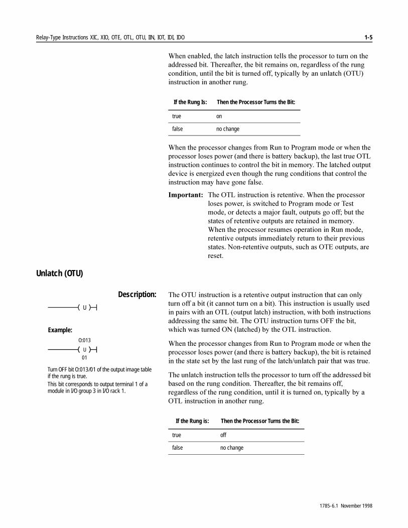
Description: 7KH�278�LQVWUXFWLRQ�LV�D�UHWHQWLYH�RXWSXW�LQVWUXFWLRQ�WKDW�FDQ�RQO\�WXUQ�RII�D�ELW��LW�FDQQRW�WXUQ�RQ�D�ELW���7KLV�LQVWUXFWLRQ�LV�XVXDOO\�XVHG�LQ�SDLUV�ZLWK�DQ�27/��RXWSXW�ODWFK��LQVWUXFWLRQ��ZLWK�ERWK�LQVWUXFWLRQV�DGGUHVVLQJ�WKH�VDPH�ELW��7KH�278�LQVWUXFWLRQ�WXUQV�2))�WKH�ELW��ZKLFK�ZDV�WXUQHG�21��ODWFKHG��E\�WKH�27/�LQVWUXFWLRQ�
:KHQ�WKH�SURFHVVRU�FKDQJHV�IURP�5XQ�WR�3URJUDP�PRGH�RU�ZKHQ�WKH�SURFHVVRU�ORVHV�SRZHU��DQG�WKHUH�LV�EDWWHU\�EDFNXS���WKH�ELW�LV�UHWDLQHG�LQ�WKH�VWDWH�VHW�E\�WKH�ODVW�UXQJ�RI�WKH�ODWFK�XQODWFK�SDLU�WKDW�ZDV�WUXH�
7KH�XQODWFK�LQVWUXFWLRQ�WHOOV�WKH�SURFHVVRU�WR�WXUQ�RII�WKH�DGGUHVVHG�ELW�EDVHG�RQ�WKH�UXQJ�FRQGLWLRQ��7KHUHDIWHU��WKH�ELW�UHPDLQV�RII��UHJDUGOHVV�RI�WKH�UXQJ�FRQGLWLRQ��XQWLO�LW�LV�WXUQHG�RQ��W\SLFDOO\�E\�D�27/�LQVWUXFWLRQ�LQ�DQRWKHU�UXQJ�
If the Rung Is: Then the Processor Turns the Bit:
true on
false no change
U
U
O:013
01
Example:
Turn OFF bit O:013/01 of the output image table if the rung is true.This bit corresponds to output terminal 1 of a module in I/O group 3 in I/O rack 1.
If the Rung is: Then the Processor Turns the Bit:
true off
false no change
1785-6.1 November 1998
1-6 Relay-Type Instructions XIC, XIO, OTE, OTL, OTU, IIN, IOT, IDI, IDO
Immediate Input (IIN)
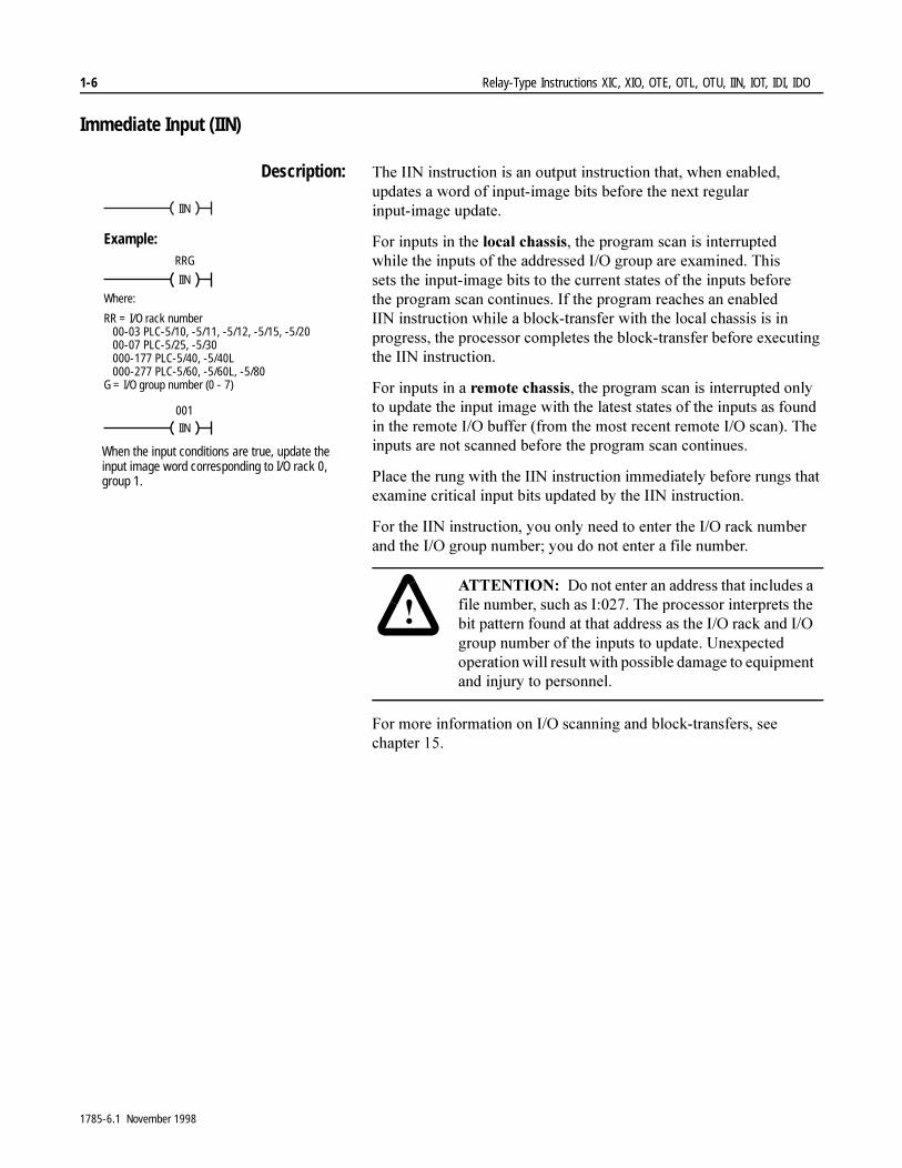
Description: 7KH�,,1�LQVWUXFWLRQ�LV�DQ�RXWSXW�LQVWUXFWLRQ�WKDW��ZKHQ�HQDEOHG��XSGDWHV�D�ZRUG�RI�LQSXW�LPDJH�ELWV�EHIRUH�WKH�QH[W�UHJXODU�LQSXW�LPDJH�XSGDWH�
)RU�LQSXWV�LQ�WKH�ORFDO�FKDVVLV��WKH�SURJUDP�VFDQ�LV�LQWHUUXSWHG�ZKLOH�WKH�LQSXWV�RI�WKH�DGGUHVVHG�,�2�JURXS�DUH�H[DPLQHG��7KLV�VHWV�WKH�LQSXW�LPDJH�ELWV�WR�WKH�FXUUHQW�VWDWHV�RI�WKH�LQSXWV�EHIRUH�WKH�SURJUDP�VFDQ�FRQWLQXHV��,I�WKH�SURJUDP�UHDFKHV�DQ�HQDEOHG�,,1�LQVWUXFWLRQ�ZKLOH�D�EORFN�WUDQVIHU�ZLWK�WKH�ORFDO�FKDVVLV�LV�LQ�SURJUHVV��WKH�SURFHVVRU�FRPSOHWHV�WKH�EORFN�WUDQVIHU�EHIRUH�H[HFXWLQJ�WKH�,,1�LQVWUXFWLRQ�
)RU�LQSXWV�LQ�D�UHPRWH�FKDVVLV��WKH�SURJUDP�VFDQ�LV�LQWHUUXSWHG�RQO\�WR�XSGDWH�WKH�LQSXW�LPDJH�ZLWK�WKH�ODWHVW�VWDWHV�RI�WKH�LQSXWV�DV�IRXQG�LQ�WKH�UHPRWH�,�2�EXIIHU��IURP�WKH�PRVW�UHFHQW�UHPRWH�,�2�VFDQ���7KH�LQSXWV�DUH�QRW�VFDQQHG�EHIRUH�WKH�SURJUDP�VFDQ�FRQWLQXHV�
3ODFH�WKH�UXQJ�ZLWK�WKH�,,1�LQVWUXFWLRQ�LPPHGLDWHO\�EHIRUH�UXQJV�WKDW�H[DPLQH�FULWLFDO�LQSXW�ELWV�XSGDWHG�E\�WKH�,,1�LQVWUXFWLRQ�
)RU�WKH�,,1�LQVWUXFWLRQ��\RX�RQO\�QHHG�WR�HQWHU�WKH�,�2�UDFN�QXPEHU�DQG�WKH�,�2�JURXS�QXPEHU��\RX�GR�QRW�HQWHU�D�ILOH�QXPEHU��
)RU�PRUH�LQIRUPDWLRQ�RQ�,�2�VFDQQLQJ�DQG�EORFN�WUDQVIHUV��VHH�FKDSWHU����
IIN
IIN
RRG
Example:
Where:
RR = I/O rack number00-03 PLC-5/10, -5/11, -5/12, -5/15, -5/2000-07 PLC-5/25, -5/30000-177 PLC-5/40, -5/40L000-277 PLC-5/60, -5/60L, -5/80
G = I/O group number (0 - 7)
IIN
001
When the input conditions are true, update the input image word corresponding to I/O rack 0, group 1.
�$77(17,21� 'R�QRW�HQWHU�DQ�DGGUHVV�WKDW�LQFOXGHV�D�ILOH�QXPEHU��VXFK�DV�,������7KH�SURFHVVRU�LQWHUSUHWV�WKH�ELW�SDWWHUQ�IRXQG�DW�WKDW�DGGUHVV�DV�WKH�,�2�UDFN�DQG�,�2�JURXS�QXPEHU�RI�WKH�LQSXWV�WR�XSGDWH��8QH[SHFWHG�RSHUDWLRQ�ZLOO�UHVXOW�ZLWK�SRVVLEOH�GDPDJH�WR�HTXLSPHQW�DQG�LQMXU\�WR�SHUVRQQHO�
1785-6.1 November 1998
Relay-Type Instructions XIC, XIO, OTE, OTL, OTU, IIN, IOT, IDI, IDO 1-7
Immediate Output (IOT)
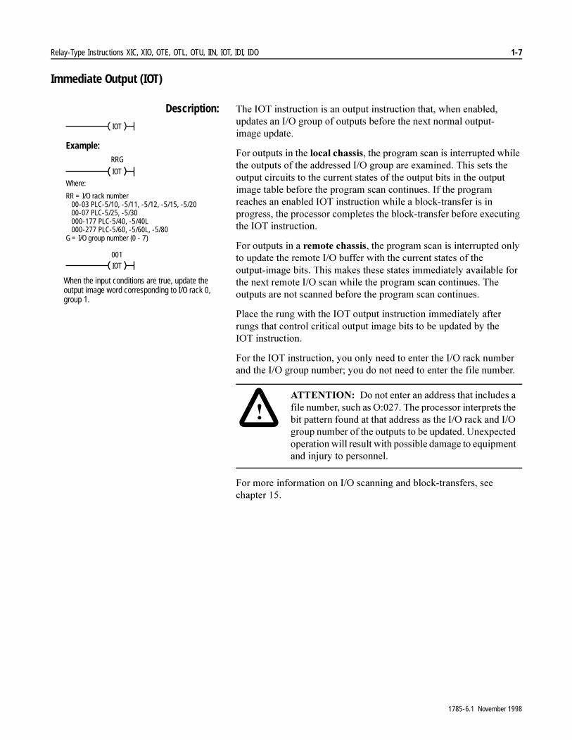
Description: 7KH�,27�LQVWUXFWLRQ�LV�DQ�RXWSXW�LQVWUXFWLRQ�WKDW��ZKHQ�HQDEOHG��XSGDWHV�DQ�,�2�JURXS�RI�RXWSXWV�EHIRUH�WKH�QH[W�QRUPDO�RXWSXW�LPDJH�XSGDWH�
)RU�RXWSXWV�LQ�WKH�ORFDO�FKDVVLV��WKH�SURJUDP�VFDQ�LV�LQWHUUXSWHG�ZKLOH�WKH�RXWSXWV�RI�WKH�DGGUHVVHG�,�2�JURXS�DUH�H[DPLQHG��7KLV�VHWV�WKH�RXWSXW�FLUFXLWV�WR�WKH�FXUUHQW�VWDWHV�RI�WKH�RXWSXW�ELWV�LQ�WKH�RXWSXW�LPDJH�WDEOH�EHIRUH�WKH�SURJUDP�VFDQ�FRQWLQXHV��,I�WKH�SURJUDP�UHDFKHV�DQ�HQDEOHG�,27�LQVWUXFWLRQ�ZKLOH�D�EORFN�WUDQVIHU�LV�LQ�SURJUHVV��WKH�SURFHVVRU�FRPSOHWHV�WKH�EORFN�WUDQVIHU�EHIRUH�H[HFXWLQJ�WKH�,27�LQVWUXFWLRQ�
)RU�RXWSXWV�LQ�D�UHPRWH�FKDVVLV��WKH�SURJUDP�VFDQ�LV�LQWHUUXSWHG�RQO\�WR�XSGDWH�WKH�UHPRWH�,�2�EXIIHU�ZLWK�WKH�FXUUHQW�VWDWHV�RI�WKH�RXWSXW�LPDJH�ELWV��7KLV�PDNHV�WKHVH�VWDWHV�LPPHGLDWHO\�DYDLODEOH�IRU�WKH�QH[W�UHPRWH�,�2�VFDQ�ZKLOH�WKH�SURJUDP�VFDQ�FRQWLQXHV��7KH�RXWSXWV�DUH�QRW�VFDQQHG�EHIRUH�WKH�SURJUDP�VFDQ�FRQWLQXHV�
3ODFH�WKH�UXQJ�ZLWK�WKH�,27�RXWSXW�LQVWUXFWLRQ�LPPHGLDWHO\�DIWHU�UXQJV�WKDW�FRQWURO�FULWLFDO�RXWSXW�LPDJH�ELWV�WR�EH�XSGDWHG�E\�WKH�,27�LQVWUXFWLRQ�
)RU�WKH�,27�LQVWUXFWLRQ��\RX�RQO\�QHHG�WR�HQWHU�WKH�,�2�UDFN�QXPEHU�DQG�WKH�,�2�JURXS�QXPEHU��\RX�GR�QRW�QHHG�WR�HQWHU�WKH�ILOH�QXPEHU��
)RU�PRUH�LQIRUPDWLRQ�RQ�,�2�VFDQQLQJ�DQG�EORFN�WUDQVIHUV��VHH�FKDSWHU����
IOT
IOT
RRG
Example:
Where:
RR = I/O rack number00-03 PLC-5/10, -5/11, -5/12, -5/15, -5/2000-07 PLC-5/25, -5/30000-177 PLC-5/40, -5/40L000-277 PLC-5/60, -5/60L, -5/80
G = I/O group number (0 - 7)
IOT
001
When the input conditions are true, update the output image word corresponding to I/O rack 0, group 1.
�$77(17,21� 'R�QRW�HQWHU�DQ�DGGUHVV�WKDW�LQFOXGHV�D�ILOH�QXPEHU��VXFK�DV�2������7KH�SURFHVVRU�LQWHUSUHWV�WKH�ELW�SDWWHUQ�IRXQG�DW�WKDW�DGGUHVV�DV�WKH�,�2�UDFN�DQG�,�2�JURXS�QXPEHU�RI�WKH�RXWSXWV�WR�EH�XSGDWHG��8QH[SHFWHG�RSHUDWLRQ�ZLOO�UHVXOW�ZLWK�SRVVLEOH�GDPDJH�WR�HTXLSPHQW�DQG�LQMXU\�WR�SHUVRQQHO�
1785-6.1 November 1998

1-8 Relay-Type Instructions XIC, XIO, OTE, OTL, OTU, IIN, IOT, IDI, IDO
Immediate Data Input (IDI)
Description: :KHQ�WKH�UXQJ�JRHV�WUXH��WKH�,',�LQVWUXFWLRQ�SHUIRUPV�DQ�LPPHGLDWH�XSGDWH�RI�WKH�&RQWURO1HW�GDWD�LQSXW�ILOH�IURP�WKH�&RQWURO1HW�PHPRU\�EXIIHUV�EHIRUH�WKH�QH[W�QRUPDO�LQSXW�LPDJH�XSGDWH��ZKLFK�RFFXUV�DW�WKH�HQG�RI�WKH�SURJUDP�VFDQ��
7R�SURJUDP�DQ�,',�LQVWUXFWLRQ��\RX�PXVW�SURYLGH�WKH�SURFHVVRU�ZLWK�WKH�IROORZLQJ�LQIRUPDWLRQ�WKDW�LW�VWRUHV�LQ�LWV�FRQWURO�EORFN�
� 'DWD�ILOH�RIIVHW�VSHFLILHV�WKH�RIIVHW�LQWR�WKH�'DWD�,QSXW�)LOH��',)��ZKHUH�ZRUGV�DUH�UHDG�±�FDQ�EH�DQ�LPPHGLDWH�YDOXH���������RU�D�ORJLFDO�DGGUHVV�WKDW�VSHFLILHV�WKH�GDWD�LPDJH�ILOH�RIIVHW�
� /HQJWK�VSHFLILHV�WKH�QXPEHU�RI�ZRUGV�WR�EH�WUDQVIHUUHG�±�DQ�LPPHGLDWH�YDOXH��������RU�D�ORJLFDO�DGGUHVV�WKDW�VSHFLILHV�WKH�QXPEHU�RI�ZRUGV�WR�EH�WUDQVIHUUHG�
� 'HVWLQDWLRQ�VSHFLILHV�D�GDWD�WDEOH�DGGUHVV�WR�EH�XVHG�DV�WKH�GHVWLQDWLRQ�RI�WKH�ZRUGV�WR�EH�WUDQVIHUUHG�
,PSRUWDQW���7KH�'HVWLQDWLRQ�VKRXOG�EH�WKH�PDWFKLQJ�GDWD�WDEOH�DGGUHVV�LQ�WKH�'DWD�,QSXW�)LOH��',)��H[FHSW�ZKHQ�\RX�XVH�WKH�LQVWUXFWLRQ�WR�HQVXUH�GDWD�EORFN�LQWHJULW\�LQ�WKH�FDVH�RI�6HOHFWDEOH�7LPHG�,QWHUUXSWV��67,V���)RU�PRUH�LQIRUPDWLRQ��VHH�SDJH�����
Immediate Data Output (IDO)
Description: :KHQ�WKH�UXQJ�JRHV�WUXH��WKH�,'2�LQVWUXFWLRQ�SHUIRUPV�DQ�LPPHGLDWH�XSGDWH�RI�WKH�&RQWURO1HW�PHPRU\�EXIIHUV�IURP�WKH�VRXUFH�ILOH�EHIRUH�WKH�QH[W�RXWSXW�LPDJH�XSGDWH��VHQGLQJ�WKH�XSGDWHG�GDWD�RXWSXW�ILOH�LQIRUPDWLRQ�DFURVV�WKH�&RQWURO1HW�QHWZRUN�WR�WKH�DSSURSULDWH�&RQWURO1HW�GHYLFH�
7R�SURJUDP�DQ�,'2�LQVWUXFWLRQ��\RX�PXVW�SURYLGH�WKH�SURFHVVRU�ZLWK�WKH�IROORZLQJ�LQIRUPDWLRQ�WKDW�LW�VWRUHV�LQ�LWV�FRQWURO�EORFN�
� 'DWD�ILOH�RIIVHW�VSHFLILHV�WKH�RIIVHW�LQWR�WKH�'DWD�2XWSXW�)LOH��'2)��ZKHUH�ZRUGV�DUH�ZULWWHQ�±�FDQ�EH�DQ�LPPHGLDWH�YDOXH���������RU�D�ORJLFDO�DGGUHVV�WKDW�VSHFLILHV�WKH�GDWD�LPDJH�ILOH�RIIVHW�
� /HQJWK�VSHFLILHV�WKH�QXPEHU�RI�ZRUGV�WR�EH�WUDQVIHUUHG�±�DQ�LPPHGLDWH�YDOXH��������RU�D�ORJLFDO�DGGUHVV�WKDW�VSHFLILHV�WKH�QXPEHU�RI�ZRUGV�WR�EH�WUDQVIHUUHG�
� 6RXUFH�VSHFLILHV�D�GDWD�WDEOH�DGGUHVV�WR�EH�XVHG�DV�WKH�VRXUFH�RI�WKH�ZRUGV�WR�EH�WUDQVIHUUHG�
,PSRUWDQW���7KH�6RXUFH�VKRXOG�EH�WKH�PDWFKLQJ�GDWD�WDEOH�DGGUHVV�LQ�WKH�'DWD�2XWSXW�)LOH��'2)��H[FHSW�ZKHQ�\RX�XVH�WKH�LQVWUXFWLRQ�WR�HQVXUH�GDWD�EORFN�LQWHJULW\�LQ�WKH�FDVH�RI�6HOHFWDEOH�7LPHG�,QWHUUXSWV��67,V���)RU�PRUH�LQIRUPDWLRQ��VHH�SDJH�����
IDIIMMEDIATE DATA INPUT
Data file offset
Length
Destination
10
N10:232
232
IDOIMMEDIATE DATA OUTPUT
Data file offset
Length
Source
10
N7:232
232
1785-6.1 November 1998

Relay-Type Instructions XIC, XIO, OTE, OTL, OTU, IIN, IOT, IDI, IDO 1-9
Using IDI and IDO Instructions <RX�FDQ�XVH�WKH�,',�DQG�,'2�LQVWUXFWLRQV�IRU�LPPHGLDWH�GDWD�LQSXW�DQG�RXWSXW�RQ�&RQWURO1HW�
)RU�PRUH�GHWDLOHG�LQIRUPDWLRQ�DERXW�ZULWLQJ�ODGGHU�SURJUDPV��VHH�\RXU�SURJUDPPLQJ�PDQXDO�
,PSRUWDQW���%H�FDUHIXO�ZKHQ�XVLQJ�6HOHFWDEOH�7LPHG�,QWHUUXSWV��67,V��ZLWK�D�SURJUDP�RQ�D�&RQWURO1HW�QHWZRUN�
$�6HOHFWDEOH�7LPHG�,QWHUUXSW��67,��SHULRGLFDOO\�LQWHUUXSWV�SULPDU\�SURJUDP�H[HFXWLRQ�LQ�RUGHU�WR�UXQ�D�VXESURJUDP�WR�FRPSOHWLRQ��,I�DQ�67,�RFFXUV�ZKLOH�D�QRUPDO�&RQWURO1HW�QRQ�GLVFUHWH�,�2�WUDQVIHU�RU�D�&RQWURO1HW�,PPHGLDWH�'DWD�,�2�LQVWUXFWLRQ��,',�RU�,'2��LV�LQ�SURJUHVV�DQG�WKH\�ERWK�RSHUDWH�RQ�WKH�VDPH�VHW�RI�GDWD��WKH�LQWHJULW\�RI�WKDW�EORFN�RI�GDWD�LV�MHRSDUGL]HG�
7R�HQVXUH�GDWD�EORFN�LQWHJULW\��ZULWH�\RXU�67,�URXWLQH�VR�WKDW�LW�RSHUDWHV�RQ�LWV�RZQ�FRS\�RI�WKH�GDWD�EORFN�WKDW�LW�QHHGV��8VH�&RQWURO1HW�,PPHGLDWH�'DWD�,�2�LQVWUXFWLRQV��,',�DQG�,'2��ZLWKLQ�\RXU�67,�WR�FRS\�WKH�QHHGHG�EORFN�RI�GDWD�RXW�WR�DQG�EDFN�IURP�D�WHPSRUDU\�ORFDWLRQ�WKDW�LV�GLIIHUHQW�IURP�WKDW�XVHG�E\�WKH�QRUPDO�GDWD�WDEOH�
)RU�GHWDLOHG�LQIRUPDWLRQ�RQ�67,V��VHH�\RXU�VRIWZDUH�XVHU�PDQXDO�
1785-6.1 November 1998

1-10 Relay-Type Instructions XIC, XIO, OTE, OTL, OTU, IIN, IOT, IDI, IDO
1RWHV�
1785-6.1 November 1998

Chapter 2
Timer Instructions TON, TOF, RTOCounter Instructions CTU, CTDReset RES
Using Timers and Counters 7LPHUV�DQG�FRXQWHUV�OHW�\RX�FRQWURO�RSHUDWLRQV�EDVHG�RQ�WLPH�RU�QXPEHU�RI�HYHQWV��7DEOH���$�OLVWV�WKH�DYDLODEOH�WLPHU�DQG�FRXQWHU�LQVWUXFWLRQV�
Table 2.A Available Timer and Counter Instructions
)RU�PRUH�LQIRUPDWLRQ�RQ�WKH�RSHUDQGV��DQG�YDOLG�GDWD�W\SHV�YDOXHV�RI�HDFK�RSHUDQG��XVHG�E\�WKH�LQVWUXFWLRQV�GLVFXVVHG�LQ�WKLV�FKDSWHU��VHH�$SSHQGL[�&�
Using Timers
%HIRUH�\RX�SURJUDP�WLPHU�LQVWUXFWLRQV��\RX�QHHG�WR�XQGHUVWDQG�WKH�SDUDPHWHUV�WKDW�\RX�HQWHU�IRU�WLPHU�LQVWUXFWLRQV�DQG�KRZ�WLPHU�DFFXUDF\�ZRUNV�
If You Want to: Use this Instruction: Found on Page:
Delay turning on an output TON 2-4
Delay turning off an output TOF 2-7
Time an event retentively RTO 2-10
Count up CTU 2-15
Count down CTD 2-17
Reset a counter, timer, or counter instruction
RE 2-20
1785-6.1 November 1998
2-2 Timer Instructions TON, TOF, RTO Counter Instructions CTU, CTD Reset RES
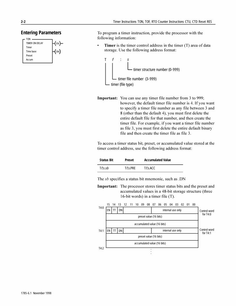
Entering Parameters 7R�SURJUDP�D�WLPHU�LQVWUXFWLRQ��SURYLGH�WKH�SURFHVVRU�ZLWK�WKH�IROORZLQJ�LQIRUPDWLRQ�
� 7LPHU�LV�WKH�WLPHU�FRQWURO�DGGUHVV�LQ�WKH�WLPHU��7��DUHD�RI�GDWD�VWRUDJH��8VH�WKH�IROORZLQJ�DGGUHVV�IRUPDW�
,PSRUWDQW���<RX�FDQ�XVH�DQ\�WLPHU�ILOH�QXPEHU�IURP���WR������KRZHYHU��WKH�GHIDXOW�WLPHU�ILOH�QXPEHU�LV����,I�\RX�ZDQW�WR�VSHFLI\�D�WLPHU�ILOH�QXPEHU�DV�DQ\�ILOH�EHWZHHQ���DQG����RWKHU�WKDQ�WKH�GHIDXOW�����\RX�PXVW�ILUVW�GHOHWH�WKH�HQWLUH�GHIDXOW�ILOH�IRU�WKDW�QXPEHU��DQG�WKHQ�FUHDWH�WKH�WLPHU�ILOH��)RU�H[DPSOH��LI�\RX�ZDQW�D�WLPHU�ILOH�QXPEHU�DV�ILOH����\RX�PXVW�ILUVW�GHOHWH�WKH�HQWLUH�GHIDXOW�ELQDU\�ILOH�DQG�WKHQ�FUHDWH�WKH�WLPHU�ILOH�DV�ILOH���
7R�DFFHVV�D�WLPHU�VWDWXV�ELW��SUHVHW��RU�DFFXPXODWHG�YDOXH�VWRUHG�DW�WKH�WLPHU�FRQWURO�DGGUHVV��XVH�WKH�IROORZLQJ�DGGUHVV�IRUPDW�
7KH�VE�VSHFLILHV�D�VWDWXV�ELW�PQHPRQLF��VXFK�DV��'1
,PSRUWDQW���7KH�SURFHVVRU�VWRUHV�WLPHU�VWDWXV�ELWV�DQG�WKH�SUHVHW�DQG�DFFXPXODWHG�YDOXHV�LQ�D����ELW�VWRUDJH�VWUXFWXUH��WKUHH����ELW�ZRUGV��LQ�D�WLPHU�ILOH��7��
EN
TON
TIMER ON DELAY
Timer
Time base
Preset
Accum
DN
Status Bit Preset Accumulated Value
Tf:s.sb Tf:s.PRE Tf:s.ACC
timer (file type)timer file number (3-999)
s
timer structure number (0-999)
T f :
preset value (16 bits)
accumulated value (16 bits)
DNTTEN
08 07 06 05 04 03 02 01 0009101112131415
internal use only Control wordfor T4:0
preset value (16 bits)
accumulated value (16 bits)
DNTTEN internal use only Control wordfor T4:1
.
.
.
T4:0
T4:1
T4:2
1785-6.1 November 1998

Timer Instructions TON, TOF, RTO Counter Instructions CTU, CTD Reset RES 2-3
� 7LPH�%DVH�GHWHUPLQHV�KRZ�WKH�WLPHU�RSHUDWHV��7DEOH���%�OLVWV�WKH�SRVVLEOH�WLPH�EDVHV�
Table 1.B Available Time Base Values
� 3UHVHW�VSHFLILHV�WKH�YDOXH�ZKLFK�WKH�WLPHU�PXVW�UHDFK�EHIRUH�WKH�SURFHVVRU�VHWV�WKH�GRQH�ELW���'1���<RX�PXVW�HQWHU�D�SUHVHW�YDOXH�IURP�����������7KH�SURFHVVRU�VWRUHV�WKH�SUHVHW�YDOXH�DV�D����ELW�LQWHJHU�YDOXH�
,PSRUWDQW���7KH�3UHVHW�YDOXH�RSHUDWHV�GLIIHUHQWO\�LI�\RX�DUH�XVLQJ�D�72)�LQVWUXFWLRQ��6HH�SDJH�����IRU�PRUH�LQIRUPDWLRQ�
� $FFXPXODWHG�9DOXH�LV�WKH�QXPEHU�RI�WLPH�LQFUHPHQWV�WKH�LQVWUXFWLRQ�KDV�FRXQWHG��:KHQ�HQDEOHG��WKH�WLPHU�XSGDWHV�WKLV�YDOXH�FRQWLQXDOO\��7\SLFDOO\��HQWHU�]HUR�ZKHQ�SURJUDPPLQJ�WKH�LQVWUXFWLRQ��,I�\RX�HQWHU�D�YDOXH��WKH�LQVWUXFWLRQ�VWDUWV�FRXQWLQJ�WLPH�EDVH�LQWHUYDOV�IURP�WKDW�YDOXH��,I�WKH�WLPHU�LV�UHVHW��WKH�DFFXPXODWHG�YDOXH�LV�]HUR��7KH�UDQJH�IRU�WKH�DFFXPXODWHG�YDOXH�LV�����������7KH�SURFHVVRU�VWRUHV�WKH�DFFXPXODWHG�YDOXH�DV�D����ELW�LQWHJHU��
,PSRUWDQW���7KH�$FFXPXODWHG�YDOXH�RSHUDWHV�GLIIHUHQWO\�LI�\RX�DUH�XVLQJ�D�72)�LQVWUXFWLRQ��6HH�SDJH�����IRU�PRUH�LQIRUPDWLRQ�
Timer Accuracy 7LPHU�DFFXUDF\�UHIHUV�WR�WKH�OHQJWK�RI�WLPH�EHWZHHQ�WKH�PRPHQW�WKH�SURFHVVRU�HQDEOHV�D�WLPHU�LQVWUXFWLRQ�DQG�WKH�PRPHQW�WKH�SURFHVVRU�FRPSOHWHV�WKH�WLPHG�LQWHUYDO��7LPHU�DFFXUDF\�GHSHQGV�RQ�WKH�SURFHVVRU�FORFN�WROHUDQFH�DQG�WKH�WLPH�EDVH��7KH�FORFN�WROHUDQFH�LV�±�������7KLV�PHDQV�WKDW�D�WLPHU�FRXOG�WLPH�RXW�HDUO\�RU�ODWH�E\������VHFRQGV����PV��IRU�D������VHFRQG�WLPH�EDVH�RU���VHFRQG�IRU�D���VHFRQG�WLPH�EDVH�
7KH������VHFRQG�WLPHU�PDLQWDLQV�DFFXUDF\�ZLWK�D�SURJUDP�VFDQ�RI�XS�WR�����VHFRQGV��WKH���VHFRQG�WLPHU�PDLQWDLQV�DFFXUDF\�ZLWK�D�SURJUDP�VFDQ�RI�XS�WR�����VHFRQGV��,I�\RXU�SURJUDPV�FDQ�H[FHHG�����RU�����VHFRQGV��UHSHDW�WKH�WLPHU�LQVWUXFWLRQ�UXQJ�VR�WKDW�WKH�UXQJ�LV�VFDQQHG�ZLWKLQ�WKHVH�OLPLWV�
7KH�GLVSOD\HG�DFFXPXODWHG�YDOXH�RI�D�WLPHU�VKRZV�DFWXDO�WLPH�EXW�LV�GHSHQGHQW�RQ�&57�XSGDWH�WLPH��7KH�DFFXPXODWHG�YDOXH�PLJKW�DSSHDU�WR�EH�OHVV�WKDQ�WKH�SUHVHW�ZKHQ�WKH�GRQH�ELW�LV�VHW�
Enter This Time Base: The Accumulated Value Range Is:
1 second to 32,767 time-base intervals (to 9.1hours)
0.01 seconds (10ms) to 32,767 time-base intervals (to 5.5 minutes)
1785-6.1 November 1998
2-4 Timer Instructions TON, TOF, RTO Counter Instructions CTU, CTD Reset RES
Timer On Delay (TON)
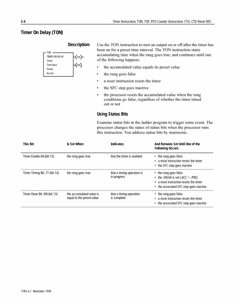
Description: 8VH�WKH�721�LQVWUXFWLRQ�WR�WXUQ�DQ�RXWSXW�RQ�RU�RII�DIWHU�WKH�WLPHU�KDV�EHHQ�RQ�IRU�D�SUHVHW�WLPH�LQWHUYDO��7KH�721�LQVWUXFWLRQ�VWDUWV�DFFXPXODWLQJ�WLPH�ZKHQ�WKH�UXQJ�JRHV�WUXH��DQG�FRQWLQXHV�XQWLO�RQH�RI�WKH�IROORZLQJ�KDSSHQV�
� WKH�DFFXPXODWHG�YDOXH�HTXDOV�LWV�SUHVHW�YDOXH
� WKH�UXQJ�JRHV�IDOVH
� D�UHVHW�LQVWUXFWLRQ�UHVHWV�WKH�WLPHU
� WKH�6)&�VWHS�JRHV�LQDFWLYH
� WKH�SURFHVVRU�UHVHWV�WKH�DFFXPXODWHG�YDOXH�ZKHQ�WKH�UXQJ�FRQGLWLRQV�JR�IDOVH��UHJDUGOHVV�RI�ZKHWKHU�WKH�WLPHU�WLPHG�RXW�RU�QRW
Using Status Bits
([DPLQH�VWDWXV�ELWV�LQ�WKH�ODGGHU�SURJUDP�WR�WULJJHU�VRPH�HYHQW��7KH�SURFHVVRU�FKDQJHV�WKH�VWDWHV�RI�VWDWXV�ELWV�ZKHQ�WKH�SURFHVVRU�UXQV�WKLV�LQVWUXFWLRQ��<RX�DGGUHVV�VWDWXV�ELWV�E\�PQHPRQLF�
EN
TON
TIMER ON DELAY
Timer
Time base
Preset
Accum
DN
This Bit: Is Set When: Indicates: And Remains Set Until One of the Following Occurs:
Timer Enable.EN (bit 15) the rung goes true that the timer is enabled • the rung goes false • a reset instruction resets the timer• the SFC step goes inactive
Timer Timing Bit .TT (bit 14) the rung goes true that a timing operation is in progress
• the rung goes false • the .DN bit is set (.ACC = .PRE)• a reset instruction resets the timer• the associated SFC step goes inactive
Timer Done Bit .DN (bit 13) the accumulated value is equal to the preset value
that a timing operation is complete
• the rung goes false• a reset instruction resets the timer• the associated SFC step goes inactive
1785-6.1 November 1998
Timer Instructions TON, TOF, RTO Counter Instructions CTU, CTD Reset RES 2-5
,I�\RX�VHW�WKH�GRQH�ELW��'1�XVLQJ�DQ�27(�LQVWUXFWLRQ��IRU�H[DPSOH��\RX�FDQ�SDXVH�WKH�WLPHU��7KH��(1�DQG��77�ELWV�UHPDLQ�VHW��EXW�WKH�DFFXPXODWHG�YDOXH�GRHV�QRW�LQFUHPHQW��7LPLQJ�UHVXPHV�ZKHQ�\RX�FOHDU�WKH��'1�ELW��,I�WKH�UXQJ�JRHV�IDOVH�ZKLOH�WKH�WLPHU�LV�SDXVHG��WKH�WLPHU�UHVHWV�DV�QRUPDO�
�� ,I�\RX�FKDQJH�WR�3URJUDP�PRGH��RU�WKH�SURFHVVRU�ORVHV�SRZHU�EHIRUH�WKH�LQVWUXFWLRQ�UHDFKHV�WKH�SUHVHW�YDOXH��WKH�IROORZLQJ�RFFXUV�
� WLPHU�HQDEOH���(1��ELW�UHPDLQV�VHW
� WLPHU�WLPLQJ���77��ELW�UHPDLQV�VHW
� DFFXPXODWHG���$&&��YDOXH�UHPDLQV�WKH�VDPH
�� 7KHQ�ZKHQ�\RX�VZLWFK�EDFN�WR�5XQ�PRGH�RU�7HVW�PRGH�RU�SRZHU�LV�UHVWRUHG��WKH�IROORZLQJ�KDSSHQV�
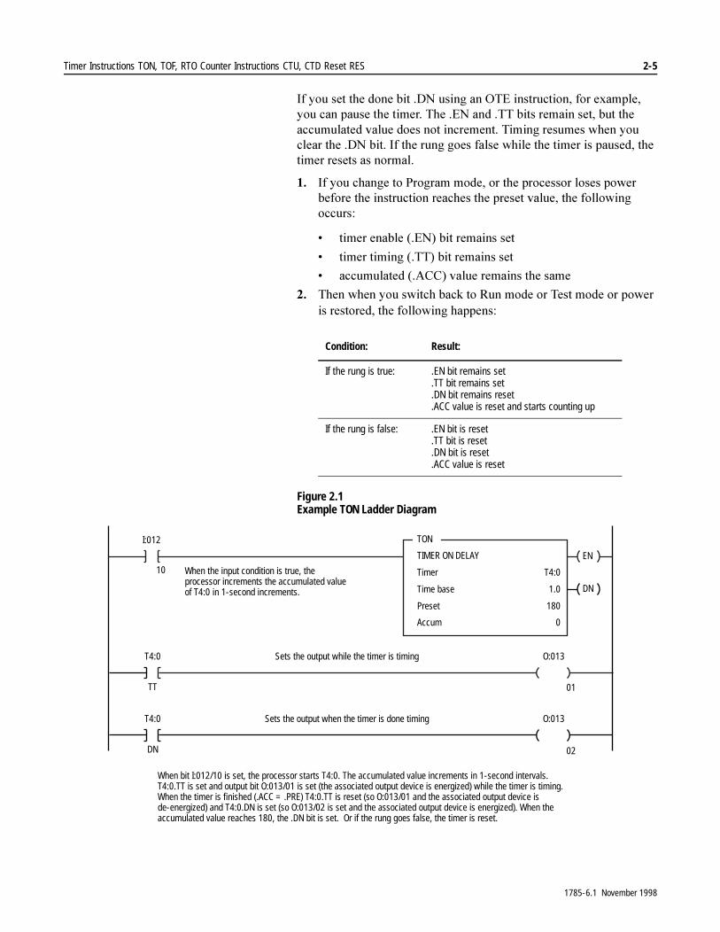
Figure 2.1 Example TON Ladder Diagram
Condition: Result:
If the rung is true: .EN bit remains set.TT bit remains set.DN bit remains reset.ACC value is reset and starts counting up
If the rung is false: .EN bit is reset.TT bit is reset.DN bit is reset.ACC value is reset
EN
TON
TIMER ON DELAY
Timer
Time base
Preset
Accum
T4:0
1.0
180
0
DN
T4:0
TT
O:013Sets the output while the timer is timing
I:012
T4:0
DN
O:013Sets the output when the timer is done timing
10
01
02
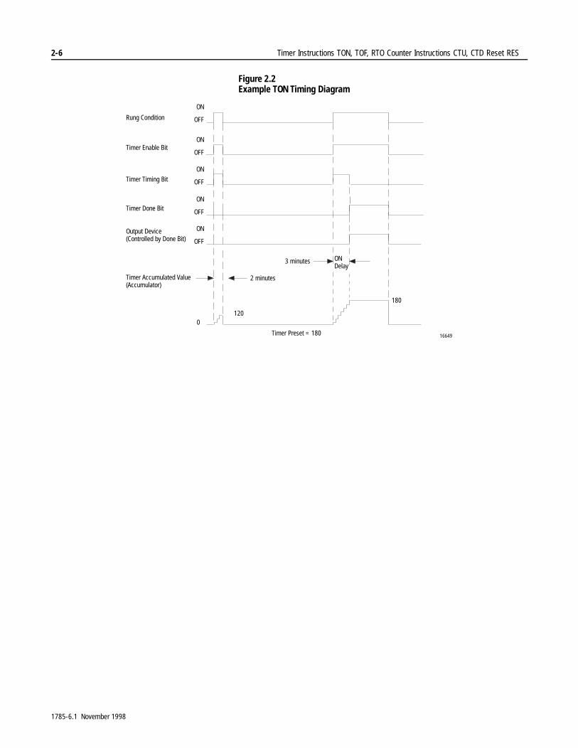
When bit I:012/10 is set, the processor starts T4:0. The accumulated value increments in 1-second intervals.T4:0.TT is set and output bit O:013/01 is set (the associated output device is energized) while the timer is timing.When the timer is finished (.ACC = .PRE) T4:0.TT is reset (so O:013/01 and the associated output device isde-energized) and T4:0.DN is set (so O:013/02 is set and the associated output device is energized). When theaccumulated value reaches 180, the .DN bit is set. Or if the rung goes false, the timer is reset.
When the input condition is true, theprocessor increments the accumulated valueof T4:0 in 1-second increments.
1785-6.1 November 1998
2-6 Timer Instructions TON, TOF, RTO Counter Instructions CTU, CTD Reset RES
Figure 2.2 Example TON Timing Diagram
ON
OFF
180
1200
16649
Rung Condition
Timer Enable Bit
Timer Timing Bit
Timer Done Bit
Output Device(Controlled by Done Bit)
Timer Accumulated Value(Accumulator)
Timer Preset = 180
2 minutes
3 minutes ONDelay
ON
OFF
ON
OFF
ON
OFF
ON
OFF
1785-6.1 November 1998
Timer Instructions TON, TOF, RTO Counter Instructions CTU, CTD Reset RES 2-7
Timer Off Delay (TOF)
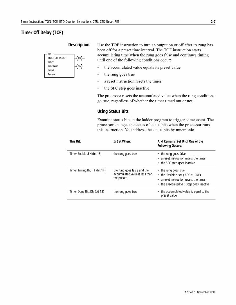
Description: 8VH�WKH�72)�LQVWUXFWLRQ�WR�WXUQ�DQ�RXWSXW�RQ�RU�RII�DIWHU�LWV�UXQJ�KDV�EHHQ�RII�IRU�D�SUHVHW�WLPH�LQWHUYDO��7KH�72)�LQVWUXFWLRQ�VWDUWV�DFFXPXODWLQJ�WLPH�ZKHQ�WKH�UXQJ�JRHV�IDOVH�DQG�FRQWLQXHV�WLPLQJ�XQWLO�RQH�RI�WKH�IROORZLQJ�FRQGLWLRQV�RFFXU�
� WKH�DFFXPXODWHG�YDOXH�HTXDOV�LWV�SUHVHW�YDOXH
� WKH�UXQJ�JRHV�WUXH
� D�UHVHW�LQVWUXFWLRQ�UHVHWV�WKH�WLPHU
� WKH�6)&�VWHS�JRHV�LQDFWLYH
7KH�SURFHVVRU�UHVHWV�WKH�DFFXPXODWHG�YDOXH�ZKHQ�WKH�UXQJ�FRQGLWLRQV�JR�WUXH��UHJDUGOHVV�RI�ZKHWKHU�WKH�WLPHU�WLPHG�RXW�RU�QRW�
Using Status Bits
([DPLQH�VWDWXV�ELWV�LQ�WKH�ODGGHU�SURJUDP�WR�WULJJHU�VRPH�HYHQW��7KH�SURFHVVRU�FKDQJHV�WKH�VWDWHV�RI�VWDWXV�ELWV�ZKHQ�WKH�SURFHVVRU�UXQV�WKLV�LQVWUXFWLRQ��<RX�DGGUHVV�WKH�VWDWXV�ELWV�E\�PQHPRQLF�
EN
TOF
TIMER OFF DELAY
Timer
Time base
Preset
Accum
DN
This Bit: Is Set When: And Remains Set Until One of the Following Occurs:
Timer Enable .EN (bit 15) the rung goes true • the rung goes false• a reset instruction resets the timer• the SFC step goes inactive
Timer Timing Bit .TT (bit 14) the rung goes false and the accumulated value is less than the preset
• the rung goes true • the .DN bit is set (.ACC = .PRE)• a reset instruction resets the timer• the associated SFC step goes inactive
Timer Done Bit .DN (bit 13) the rung goes true • the accumulated value is equal to the preset value
1785-6.1 November 1998
2-8 Timer Instructions TON, TOF, RTO Counter Instructions CTU, CTD Reset RES
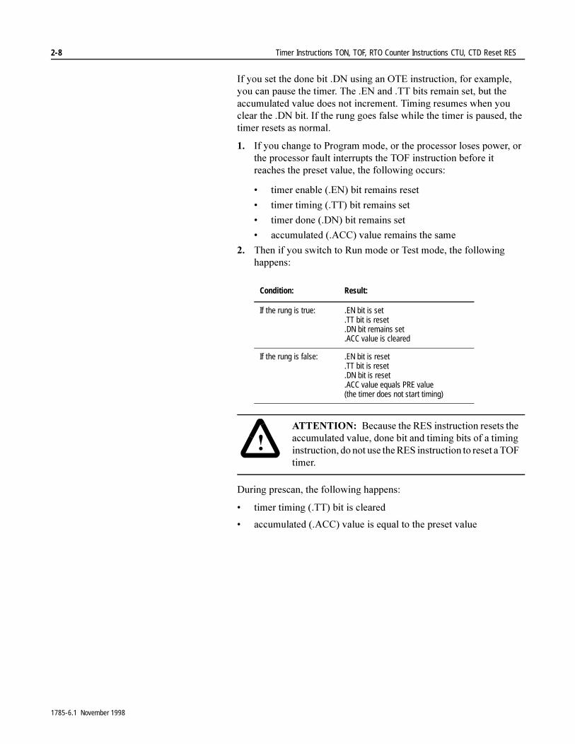
,I�\RX�VHW�WKH�GRQH�ELW��'1�XVLQJ�DQ�27(�LQVWUXFWLRQ��IRU�H[DPSOH��\RX�FDQ�SDXVH�WKH�WLPHU��7KH��(1�DQG��77�ELWV�UHPDLQ�VHW��EXW�WKH�DFFXPXODWHG�YDOXH�GRHV�QRW�LQFUHPHQW��7LPLQJ�UHVXPHV�ZKHQ�\RX�FOHDU�WKH��'1�ELW��,I�WKH�UXQJ�JRHV�IDOVH�ZKLOH�WKH�WLPHU�LV�SDXVHG��WKH�WLPHU�UHVHWV�DV�QRUPDO�
�� ,I�\RX�FKDQJH�WR�3URJUDP�PRGH��RU�WKH�SURFHVVRU�ORVHV�SRZHU��RU�WKH�SURFHVVRU�IDXOW�LQWHUUXSWV�WKH�72)�LQVWUXFWLRQ�EHIRUH�LW�UHDFKHV�WKH�SUHVHW�YDOXH��WKH�IROORZLQJ�RFFXUV�
� WLPHU�HQDEOH���(1��ELW�UHPDLQV�UHVHW
� WLPHU�WLPLQJ���77��ELW�UHPDLQV�VHW
� WLPHU�GRQH���'1��ELW�UHPDLQV�VHW
� DFFXPXODWHG���$&&��YDOXH�UHPDLQV�WKH�VDPH
�� 7KHQ�LI�\RX�VZLWFK�WR�5XQ�PRGH�RU�7HVW�PRGH��WKH�IROORZLQJ�KDSSHQV��
'XULQJ�SUHVFDQ��WKH�IROORZLQJ�KDSSHQV�
� WLPHU�WLPLQJ���77��ELW�LV�FOHDUHG
� DFFXPXODWHG���$&&��YDOXH�LV�HTXDO�WR�WKH�SUHVHW�YDOXH
Condition: Result:
If the rung is true: .EN bit is set.TT bit is reset.DN bit remains set.ACC value is cleared
If the rung is false: .EN bit is reset.TT bit is reset.DN bit is reset.ACC value equals PRE value (the timer does not start timing)
�$77(17,21� %HFDXVH�WKH�5(6�LQVWUXFWLRQ�UHVHWV�WKH�DFFXPXODWHG�YDOXH��GRQH�ELW�DQG�WLPLQJ�ELWV�RI�D�WLPLQJ�LQVWUXFWLRQ��GR�QRW�XVH�WKH�5(6�LQVWUXFWLRQ�WR�UHVHW�D�72)�WLPHU�
1785-6.1 November 1998
Timer Instructions TON, TOF, RTO Counter Instructions CTU, CTD Reset RES 2-9
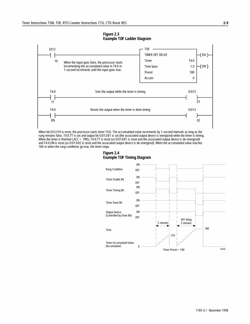
Figure 2.3 Example TOF Ladder Diagram
Figure 2.4 Example TOF Timing Diagram
EN
TOF
TIMER OFF DELAY
Timer
Time base
Preset
Accum
T4:0
1.0
180
0
DN
T4:0
TT
O:013Sets the output while the timer is timing
I:012
T4:0
DN
O:013Resets the output when the timer is done timing
10
01
02
When the input goes false, the processor starts incrementing the accumulated value in T4:0 in1-second increments until the input goes true.
When bit I:012/10 is reset, the processor starts timer T4:0. The accumulated value increments by 1-second intervals as long as therung remains false. T4:0.TT is set and output bit O:013/01 is set (the associated output device is energized) while the timer is timing.When the timer is finished (.ACC = .PRE), T4:0.TT is reset (so O:013/01 is reset and the associated output device is de-energized)and T4:0.DN is reset (so O:013/02 is reset and the associated output device is de-energized). When the accumulated value reaches180 or when the rung conditions go true, the timer stops.
ON
OFF
180
120
016650
Rung Condition
Timer Enable Bit
Timer Timing Bit
Timer Done Bit
Output Device(Controlled by Done Bit)
Timer Accumulated Value(Accumulator)
Timer Preset = 180
2 minutes 3 minutesOFF Delay
ON
OFF
ON
OFF
ON
OFF
ON
OFF
Time
1785-6.1 November 1998

2-10 Timer Instructions TON, TOF, RTO Counter Instructions CTU, CTD Reset RES
Retentive Timer On (RTO)
Description: 8VH�WKH�572�LQVWUXFWLRQ�WR�WXUQ�DQ�RXWSXW�RQ�RU�RII�DIWHU�LWV�WLPHU�KDV�EHHQ�RQ�IRU�D�SUHVHW�WLPH�LQWHUYDO��7KH�572�LQVWUXFWLRQ�OHWV�WKH�WLPHU�VWRS�DQG�VWDUW�ZLWKRXW�UHVHWWLQJ�WKH�DFFXPXODWHG�YDOXH�
7KH�572�LQVWUXFWLRQ�EHJLQV�WLPLQJ�ZKHQ�LWV�UXQJ�JRHV�WUXH��$V�ORQJ�DV�WKH�UXQJ�UHPDLQV�WUXH��WKH�WLPHU�XSGDWHV�WKH�DFFXPXODWHG�YDOXH�HDFK�SURJUDP�VFDQ��XQWLO�LW�UHDFKHV�WKH�SUHVHW�YDOXH��7KH�572�LQVWUXFWLRQ�UHWDLQV�LWV�DFFXPXODWHG�YDOXH�HYHQ�LI�RQH�RI�WKH�IROORZLQJ�RFFXUV�
� WKH�UXQJ�JRHV�IDOVH
� \RX�FKDQJH�WR�3URJUDP�PRGH
� WKH�SURFHVVRU�IDXOWV�RU�ORVHV�SRZHU
� WKH�6)&�VWHS�JRHV�LQDFWLYH�
:KHQ�WKH�SURFHVVRU�UHVXPHV�RSHUDWLRQ�RU�WKH�UXQJ�JRHV�WUXH��WLPLQJ�FRQWLQXHV�IURP�WKH�UHWDLQHG�DFFXPXODWHG�YDOXH��%\�UHWDLQLQJ�LWV�DFFXPXODWHG�YDOXH��UHWHQWLYH�WLPHUV�PHDVXUH�WKH�FXPXODWLYH�SHULRG�GXULQJ�ZKLFK�LWV�UXQJ�LV�WUXH�
,PSRUWDQW���7R�UHVHW�WKH�UHWHQWLYH�WLPHU¶V�DFFXPXODWHG�YDOXH�DQG�VWDWXV�ELWV�DIWHU�WKH�572�UXQJ�JRHV�IDOVH��\RX�PXVW�SURJUDP�D�UHVHW�LQVWUXFWLRQ�5(6�ZLWK�WKH�VDPH�DGGUHVV�LQ�DQRWKHU�UXQJ�
Using Status Bits
([DPLQH�VWDWXV�ELWV�LQ�WKH�ODGGHU�SURJUDP�WR�WULJJHU�VRPH�HYHQW��7KH�SURFHVVRU�FKDQJHV�WKH�VWDWHV�RI�VWDWXV�ELWV�ZKHQ�WKH�SURFHVVRU�UXQV�WKLV�LQVWUXFWLRQ��<RX�DGGUHVV�WKH�VWDWXV�ELWV�E\�PQHPRQLF�
EN
RTO
RETENTIVE TIMER ON
Timer
Time base
Preset
Accum
DN
This Bit: Is Set When: Indicates: And Remains Set Until One of the Following Occurs:
Timer Enable Bit .EN (bit 15) the rung goes true that a timing operation is in progress
• the rung goes false• a reset instruction resets the timer
Timer Timing Bit .TT (bit 14) the rung goes true that a timing operation is in progress
• the rung goes false• the .DN bit is set• the accumulated value is equal to
the preset value (.ACC=.PRE)• a reset instruction resets the timer
Timer Done Bit .DN (bit 13) the accumulated value is equal to the preset value
that a timing operation is complete
• the .DN bit is reset with the RES instruction.
1785-6.1 November 1998
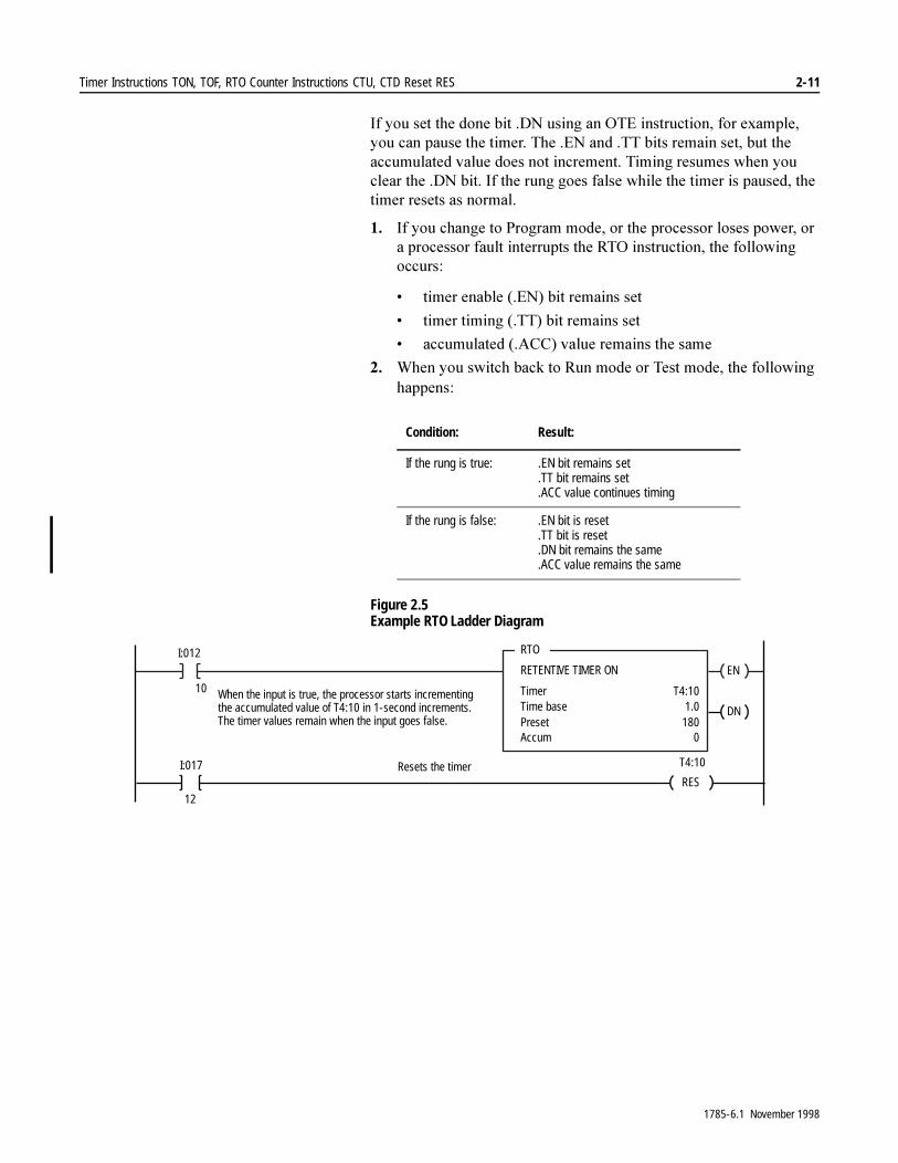
Timer Instructions TON, TOF, RTO Counter Instructions CTU, CTD Reset RES 2-11
,I�\RX�VHW�WKH�GRQH�ELW��'1�XVLQJ�DQ�27(�LQVWUXFWLRQ��IRU�H[DPSOH��\RX�FDQ�SDXVH�WKH�WLPHU��7KH��(1�DQG��77�ELWV�UHPDLQ�VHW��EXW�WKH�DFFXPXODWHG�YDOXH�GRHV�QRW�LQFUHPHQW��7LPLQJ�UHVXPHV�ZKHQ�\RX�FOHDU�WKH��'1�ELW��,I�WKH�UXQJ�JRHV�IDOVH�ZKLOH�WKH�WLPHU�LV�SDXVHG��WKH�WLPHU�UHVHWV�DV�QRUPDO�
�� ,I�\RX�FKDQJH�WR�3URJUDP�PRGH��RU�WKH�SURFHVVRU�ORVHV�SRZHU��RU�D�SURFHVVRU�IDXOW�LQWHUUXSWV�WKH�572�LQVWUXFWLRQ��WKH�IROORZLQJ�RFFXUV�
� WLPHU�HQDEOH���(1��ELW�UHPDLQV�VHW
� WLPHU�WLPLQJ���77��ELW�UHPDLQV�VHW
� DFFXPXODWHG���$&&��YDOXH�UHPDLQV�WKH�VDPH
�� :KHQ�\RX�VZLWFK�EDFN�WR�5XQ�PRGH�RU�7HVW�PRGH��WKH�IROORZLQJ�KDSSHQV�
Figure 2.5 Example RTO Ladder Diagram
Condition: Result:
If the rung is true: .EN bit remains set.TT bit remains set.ACC value continues timing
If the rung is false: .EN bit is reset.TT bit is reset.DN bit remains the same.ACC value remains the same
EN
RTO
RETENTIVE TIMER ON
TimerTime basePresetAccum
T4:101.0
1800
DN
I:012
10 When the input is true, the processor starts incrementingthe accumulated value of T4:10 in 1-second increments.The timer values remain when the input goes false.
RESI:017
12
T4:10Resets the timer
1785-6.1 November 1998
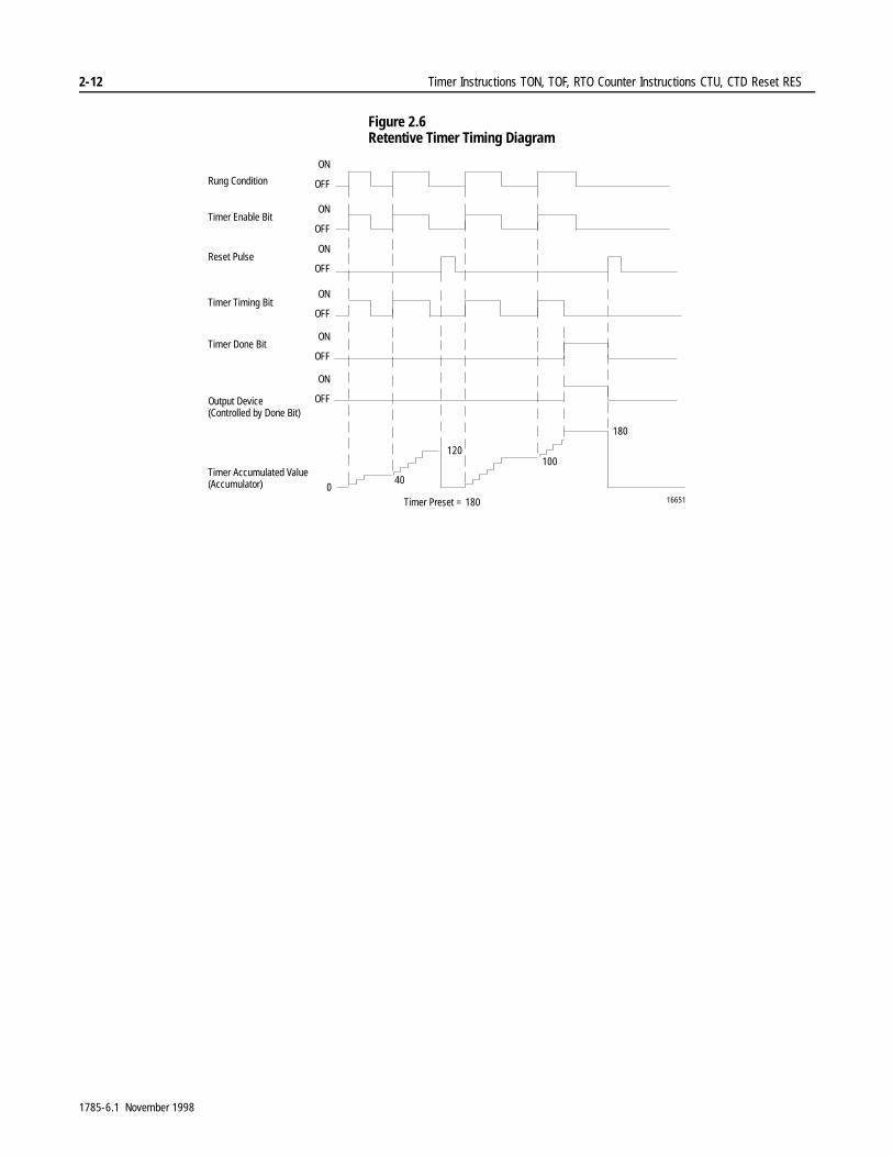
2-12 Timer Instructions TON, TOF, RTO Counter Instructions CTU, CTD Reset RES
Figure 2.6 Retentive Timer Timing Diagram
ON
OFF
180
120
016651
Rung Condition
Timer Enable Bit
Timer Timing Bit
Timer Done Bit
Output Device(Controlled by Done Bit)
Timer Accumulated Value(Accumulator)
Timer Preset = 180
ON
OFF
ON
OFF
ON
OFF
ON
OFF
Reset Pulse
40
100
ON
OFF
1785-6.1 November 1998

Timer Instructions TON, TOF, RTO Counter Instructions CTU, CTD Reset RES 2-13
Using Counters %HIRUH�XVLQJ�FRXQWHU�LQVWUXFWLRQV��\RX�QHHG�WR�XQGHUVWDQG�WKH�SDUDPHWHUV�WKDW�\RX�HQWHU�
Entering Parameters
7R�SURJUDP�D�FRXQWHU�LQVWUXFWLRQ��SURYLGH�WKH�SURFHVVRU�ZLWK�WKH�IROORZLQJ�LQIRUPDWLRQ�
� &RXQWHU�LV�WKH�FRXQWHU�FRQWURO�DGGUHVV�LQ�WKH�FRXQWHU��&��DUHD�RI�GDWD�VWRUDJH��8VH�WKH�IROORZLQJ�DGGUHVV�IRUPDW�
,PSRUWDQW���<RX�FDQ�XVH�DQ\�FRXQWHU�ILOH�QXPEHU�IURP���WR������KRZHYHU��WKH�GHIDXOW�FRXQWHU�ILOH�QXPEHU�LV����,I�\RX�ZDQW�WR�VSHFLI\�D�FRXQWHU�ILOH�QXPEHU�DV�DQ\�ILOH�EHWZHHQ���DQG����RWKHU�WKDQ�WKH�GHIDXOW�����\RX�PXVW�ILUVW�GHOHWH�WKH�HQWLUH�GHIDXOW�ILOH�IRU�WKDW�QXPEHU��DQG�WKHQ�FUHDWH�WKH�FRXQWHU�ILOH��)RU�H[DPSOH��LI�\RX�ZDQW�D�FRXQWHU�ILOH�QXPEHU�DV�ILOH����\RX�PXVW�ILUVW�GHOHWH�WKH�HQWLUH�GHIDXOW�ELQDU\�ILOH�DQG�WKHQ�FUHDWH�WKH�FRXQWHU�ILOH�DV�ILOH���
7R�DFFHVV�D�FRXQWHU�VWDWXV�ELW��SUHVHW�YDOXH��RU�DFFXPXODWHG�YDOXH��XVH�WKH�IROORZLQJ�DGGUHVV�IRUPDW�
7KH�EE�LV�D�VWDWXV�ELW�PQHPRQLF��VXFK�DV��'1
,PSRUWDQW���7KH�SURFHVVRU�VWRUHV�FRXQWHU�VWDWXV�ELWV�DQG�WKH�SUHVHW�DQG�DFFXPXODWHG�YDOXHV�LQ�D�VWRUDJH�VWUXFWXUH�����ELWV�±�WKUHH����ELW�ZRUGV��LQ�D�FRXQWHU�ILOH��&��LQ�WKH�GDWD�WDEOH�
CU
CTU
COUNT UP
Counter
Preset
Accum
DN
Status Bit Preset Accumulated Value
Cf:s.bb Cf:s.PRE Cf:s.ACC
counter (file type)counter file number (3-999)
s
counter structure number (0-999)
C f :
preset (16 bits)
accumulated value (16 bits)
DNCU
08 07 06 05 04 03 02 01 0009101112131415
internal use only Control wordfor C5:0
preset (16 bits)
accumulated value (16 bits)
DNCU internal use only Control wordfor C5:1
.
.
.
C5:0
C5:1
C5:2
OV
OV
CD
CD
UN
UN
1785-6.1 November 1998
2-14 Timer Instructions TON, TOF, RTO Counter Instructions CTU, CTD Reset RES
� 3UHVHW�VSHFLILHV�WKH�YDOXH�ZKLFK�WKH�FRXQWHU�PXVW�UHDFK�EHIRUH�LW�VHWV�WKH�GRQH�ELW��'1��(QWHU�D�SUHVHW�YDOXH�IURP�±�������XS�WR����������7KH�SUHVHW�YDOXH�LV�VWRUHG�DV�D����ELW�LQWHJHU�YDOXH��1HJDWLYH�YDOXHV�DUH�VWRUHG�LQ�WZRV�FRPSOHPHQW�IRUP�
� $FFXPXODWHG�9DOXH�LV�WKH�FXUUHQW�FRXQW�EDVHG�RQ�WKH�QXPEHU�RI�WLPHV�WKH�UXQJ�JRHV�IURP�IDOVH�WR�WUXH��7KH�DFFXPXODWHG�YDOXH�LV�VWRUHG�DV�D����ELW�LQWHJHU�YDOXH��1HJDWLYH�YDOXHV�DUH�VWRUHG�LQ�WZRV�FRPSOHPHQW�IRUP��7KH�UDQJH�RI�WKH�DFFXPXODWHG�YDOXH�LV�±�������WR����������7\SLFDOO\��\RX�HQWHU�D�]HUR�YDOXH�ZKHQ�SURJUDPPLQJ�FRXQWHU�LQVWUXFWLRQV��,I�\RX�HQWHU�D�QRQ�]HUR�YDOXH��WKH�LQVWUXFWLRQ�VWDUWV�FRXQWLQJ�IURP�WKDW�YDOXH��,I�WKH�FRXQWHU�LV�UHVHW��WKH�DFFXPXODWHG�YDOXH�LV�VHW�WR�]HUR�
1785-6.1 November 1998

Timer Instructions TON, TOF, RTO Counter Instructions CTU, CTD Reset RES 2-15
Count Up (CTU)
Description: 7KH�&78�LQVWUXFWLRQ�FRXQWV�XSZDUG�RYHU�D�UDQJH�RI�±�������WR����������(DFK�WLPH�WKH�UXQJ�JRHV�IURP�IDOVH�WR�WUXH��WKH�&78�LQVWUXFWLRQ�LQFUHPHQWV�WKH�DFFXPXODWHG�YDOXH�E\�RQH�FRXQW��:KHQ�WKH�DFFXPXODWHG�YDOXH�HTXDOV�RU�H[FHHGV�WKH�SUHVHW�YDOXH��WKH�&78�LQVWUXFWLRQ�VHWV�D�GRQH�ELW��'1��ZKLFK�\RXU�ODGGHU�SURJUDP�FDQ�XVH�WR�LQLWLDWH�VRPH�DFWLRQ��VXFK�DV�FRQWUROOLQJ�D�VWRUDJH�ELW�RU�DQ�RXWSXW�GHYLFH�
7KH�DFFXPXODWHG�YDOXH�RI�D�FRXQWHU�LV�UHWHQWLYH��7KH�FRXQW�LV�UHWDLQHG�XQWLO�UHVHW�E\�D�UHVHW�LQVWUXFWLRQ��5(6��WKDW�KDV�WKH�VDPH�DGGUHVV�DV�WKH�FRXQWHU�
Using Status Bits
([DPLQH�VWDWXV�ELWV�LQ�WKH�ODGGHU�SURJUDP�WR�WULJJHU�VRPH�HYHQW��7KH�SURFHVVRU�FKDQJHV�WKH�VWDWHV�RI�VWDWXV�ELWV�ZKHQ�WKH�SURFHVVRU�UXQV�WKH�&78�LQVWUXFWLRQ��<RX�DGGUHVV�WKH�VWDWXV�ELWV�E\�PQHPRQLF�
�
CU
CTU
COUNT UP
Counter
Preset
Accum
DN
This Bit: Is Set: And Remains Set Until One of the Following Occurs:
Count Up Enable Bit .CU (bit 15)
when the rung goes true to indicate the instruction has increased its countNote: During prescan, this bit is set to prevent a false count when the program scan begins.
• the rung goes false• a RES instruction resets the .DN bit
Count Up Done Bit .DN (bit 13)
when the accumulated value is greater than or equal to the preset value
• the accumulated value counts below the preset, either by using a CTD instruction to count down or changing the accumulated value
• a RES instruction resets the .DN bit
Count UpOverflow Bit .OV (bit 12)
when the up counter has exceeded the upper limit of +32,767 and has wrapped around to –32,768. The CTU counts up from there.
• a RES instruction resets the .DN bit• counting back down to 32,767 with a CTD instruction
with the same address
�$77(17,21� 3ODFH�FULWLFDO�FRXQWHUV�RXWVLGH�DQ�0&5�]RQH�RU�MXPSHG�VHFWLRQV�RI�ODGGHU�SURJUDP�WR�JXDUG�DJDLQVW�LQYDOLG�UHVXOWV�WKDW�FRXOG�OHDG�WR�GDPDJHG�HTXLSPHQW�RU�SHUVRQQHO�LQMXU\�
1785-6.1 November 1998

2-16 Timer Instructions TON, TOF, RTO Counter Instructions CTU, CTD Reset RES
Figure 2.7 Example CTU Ladder Diagram
Figure 2.8 Example CTU Timing Diagram
CU
CTU
COUNT UP
Counter
Preset
Accum
C5:0
4
0
DN
C5:0
DN
O:020Tells when the count is reached (ACC > or = PRE)
I:012
10
C5:0
OV
O:021Tells when the counter overflows +32,767
RES
I:017
12
C5:0
01
02
Reset the counter
Each time the input goes false to true,the processor increments the counterby 1.
12
34
0
Counter preset = 4 counts
0 16636
Rung condition thatcontrols counter
Rung condition thatcontrols reset instruction
Done Bit
Output instruction on rungcontrolled by counter
Counter Accumulated Value
ON
OFF
ON
OFF
ON
OFF
ON
OFF
Count-up enable bit
ON
OFF
1785-6.1 November 1998
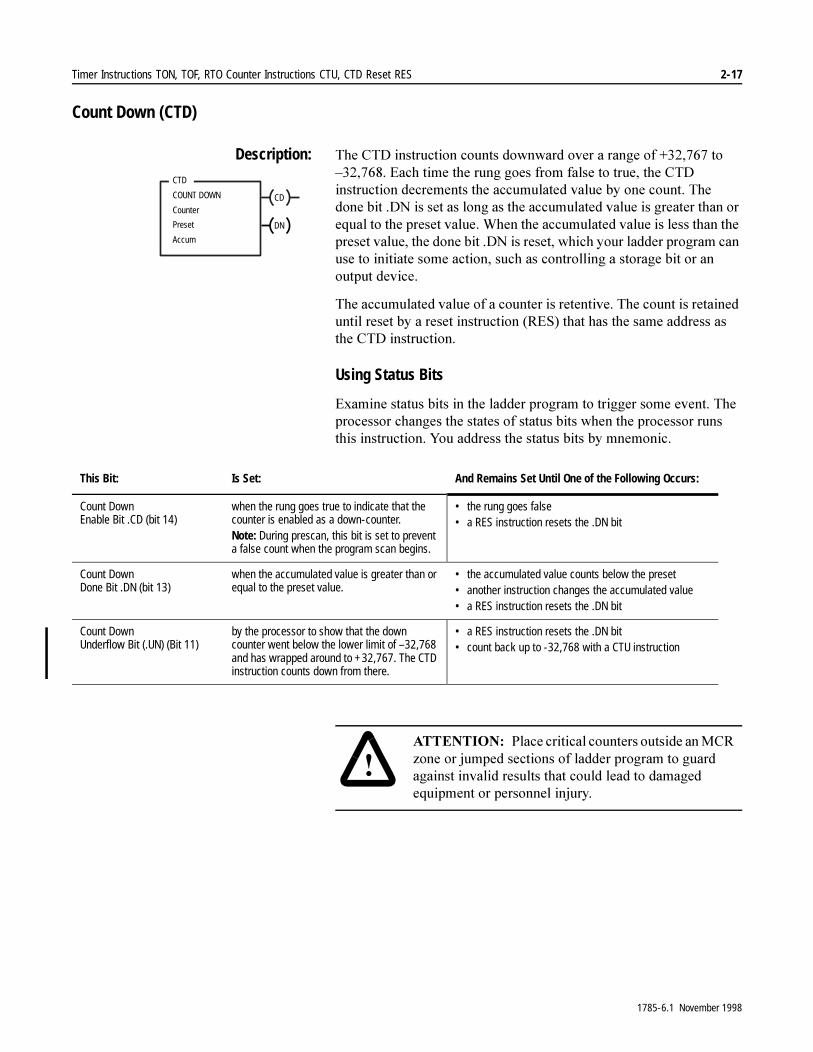
Timer Instructions TON, TOF, RTO Counter Instructions CTU, CTD Reset RES 2-17
Count Down (CTD)
Description: 7KH�&7'�LQVWUXFWLRQ�FRXQWV�GRZQZDUG�RYHU�D�UDQJH�RI���������WR�±��������(DFK�WLPH�WKH�UXQJ�JRHV�IURP�IDOVH�WR�WUXH��WKH�&7'�LQVWUXFWLRQ�GHFUHPHQWV�WKH�DFFXPXODWHG�YDOXH�E\�RQH�FRXQW��7KH�GRQH�ELW��'1�LV�VHW�DV�ORQJ�DV�WKH�DFFXPXODWHG�YDOXH�LV�JUHDWHU�WKDQ�RU�HTXDO�WR�WKH�SUHVHW�YDOXH��:KHQ�WKH�DFFXPXODWHG�YDOXH�LV�OHVV�WKDQ�WKH�SUHVHW�YDOXH��WKH�GRQH�ELW��'1�LV�UHVHW��ZKLFK�\RXU�ODGGHU�SURJUDP�FDQ�XVH�WR�LQLWLDWH�VRPH�DFWLRQ��VXFK�DV�FRQWUROOLQJ�D�VWRUDJH�ELW�RU�DQ�RXWSXW�GHYLFH�
7KH�DFFXPXODWHG�YDOXH�RI�D�FRXQWHU�LV�UHWHQWLYH��7KH�FRXQW�LV�UHWDLQHG�XQWLO�UHVHW�E\�D�UHVHW�LQVWUXFWLRQ��5(6��WKDW�KDV�WKH�VDPH�DGGUHVV�DV�WKH�&7'�LQVWUXFWLRQ�
Using Status Bits
([DPLQH�VWDWXV�ELWV�LQ�WKH�ODGGHU�SURJUDP�WR�WULJJHU�VRPH�HYHQW��7KH�SURFHVVRU�FKDQJHV�WKH�VWDWHV�RI�VWDWXV�ELWV�ZKHQ�WKH�SURFHVVRU�UXQV�WKLV�LQVWUXFWLRQ��<RX�DGGUHVV�WKH�VWDWXV�ELWV�E\�PQHPRQLF�
�
CD
CTD
COUNT DOWN
Counter
Preset
Accum
DN
This Bit: Is Set: And Remains Set Until One of the Following Occurs:
Count Down Enable Bit .CD (bit 14)
when the rung goes true to indicate that the counter is enabled as a down-counter.Note: During prescan, this bit is set to prevent a false count when the program scan begins.
• the rung goes false• a RES instruction resets the .DN bit
Count Down Done Bit .DN (bit 13)
when the accumulated value is greater than or equal to the preset value.
• the accumulated value counts below the preset• another instruction changes the accumulated value• a RES instruction resets the .DN bit
Count DownUnderflow Bit (.UN) (Bit 11)
by the processor to show that the down counter went below the lower limit of –32,768 and has wrapped around to +32,767. The CTD instruction counts down from there.
• a RES instruction resets the .DN bit• count back up to -32,768 with a CTU instruction
�$77(17,21� 3ODFH�FULWLFDO�FRXQWHUV�RXWVLGH�DQ�0&5�]RQH�RU�MXPSHG�VHFWLRQV�RI�ODGGHU�SURJUDP�WR�JXDUG�DJDLQVW�LQYDOLG�UHVXOWV�WKDW�FRXOG�OHDG�WR�GDPDJHG�HTXLSPHQW�RU�SHUVRQQHO�LQMXU\�
1785-6.1 November 1998
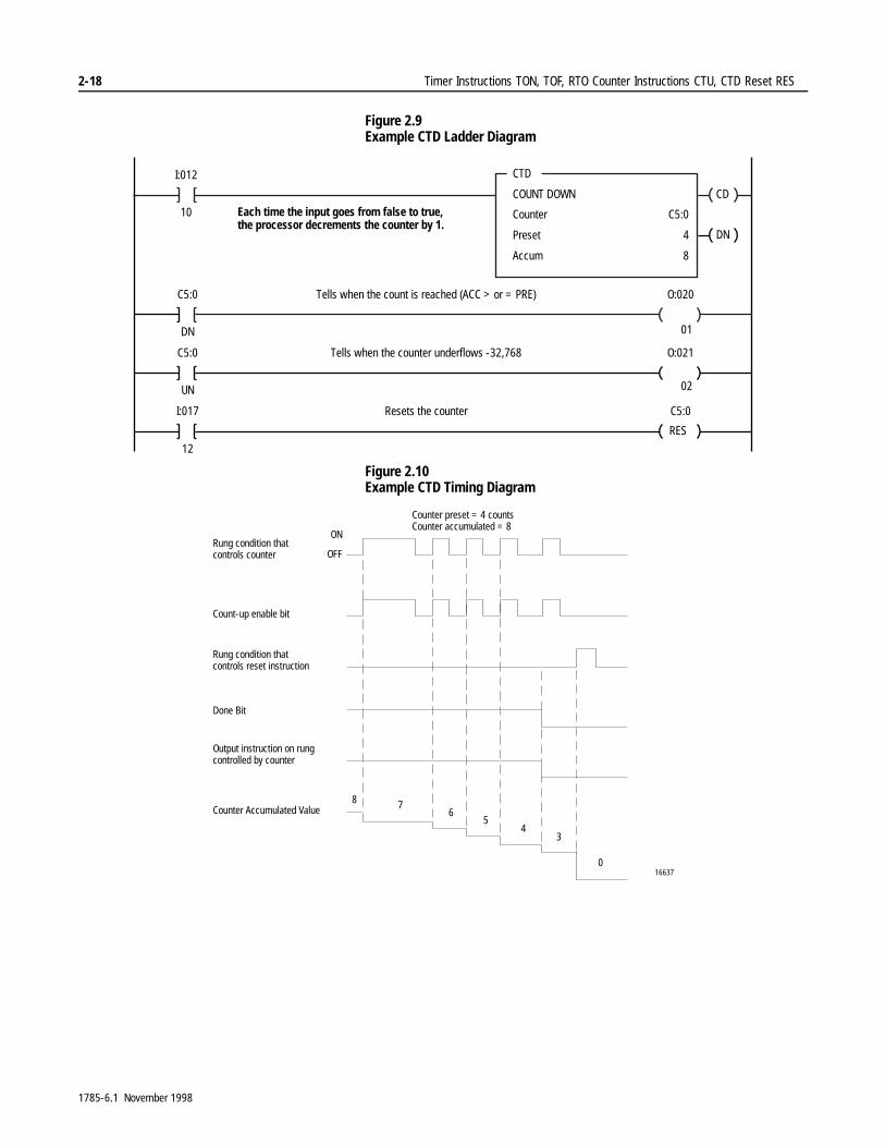
2-18 Timer Instructions TON, TOF, RTO Counter Instructions CTU, CTD Reset RES
Figure 2.9 Example CTD Ladder Diagram
Figure 2.10 Example CTD Timing Diagram
CD
CTD
COUNT DOWN
Counter
Preset
Accum
C5:0
4
8
DN
C5:0
DN
O:020Tells when the count is reached (ACC > or = PRE)
I:012
10
C5:0
UN
O:021Tells when the counter underflows -32,768
RES
I:017
12
C5:0Resets the counter
01
02
Each time the input goes from false to true,the processor decrements the counter by 1.
8 76
54
3
016637
Counter preset = 4 countsCounter accumulated = 8
Rung condition thatcontrols counter
Rung condition thatcontrols reset instruction
Done Bit
Output instruction on rungcontrolled by counter
Counter Accumulated Value
ON
OFF
Count-up enable bit
1785-6.1 November 1998
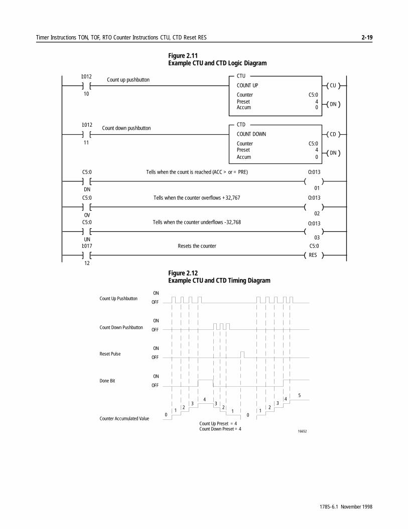
Timer Instructions TON, TOF, RTO Counter Instructions CTU, CTD Reset RES 2-19
Figure 2.11 Example CTU and CTD Logic Diagram
Figure 2.12 Example CTU and CTD Timing Diagram
CD
CTD
COUNT DOWN
CounterPresetAccum
C5:040
DN
C5:0
DN
O:013Tells when the count is reached (ACC > or = PRE)
I:012
11
C5:0
UN
Tells when the counter underflows -32,768
RES
I:017
12
C5:0Resets the counter
CU
CTU
COUNT UP
CounterPresetAccum
C5:040
DN
I:012
10
C5:0
OV
Tells when the counter overflows +32,767 O:013
O:013
01
02
03
Count up pushbutton
Count down pushbutton
01
23
43
21
01
23
45
Count Up Pushbutton
Count Down Pushbutton
Reset Pulse
Done Bit
Counter Accumulated ValueCount Up Preset = 4Count Down Preset = 4 16652
ON
OFF
ON
OFF
ON
OFF
ON
OFF
1785-6.1 November 1998
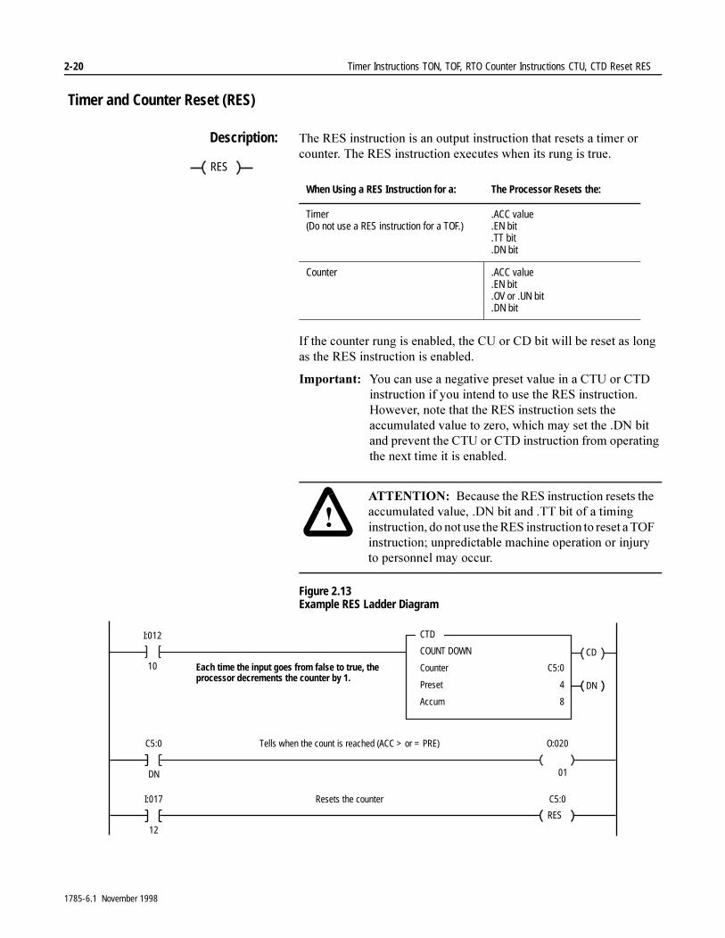
2-20 Timer Instructions TON, TOF, RTO Counter Instructions CTU, CTD Reset RES
Timer and Counter Reset (RES)
Description: 7KH�5(6�LQVWUXFWLRQ�LV�DQ�RXWSXW�LQVWUXFWLRQ�WKDW�UHVHWV�D�WLPHU�RU�FRXQWHU��7KH�5(6�LQVWUXFWLRQ�H[HFXWHV�ZKHQ�LWV�UXQJ�LV�WUXH�
,I�WKH�FRXQWHU�UXQJ�LV�HQDEOHG��WKH�&8�RU�&'�ELW�ZLOO�EH�UHVHW�DV�ORQJ�DV�WKH�5(6�LQVWUXFWLRQ�LV�HQDEOHG�
,PSRUWDQW���<RX�FDQ�XVH�D�QHJDWLYH�SUHVHW�YDOXH�LQ�D�&78�RU�&7'�LQVWUXFWLRQ�LI�\RX�LQWHQG�WR�XVH�WKH�5(6�LQVWUXFWLRQ��+RZHYHU��QRWH�WKDW�WKH�5(6�LQVWUXFWLRQ�VHWV�WKH�DFFXPXODWHG�YDOXH�WR�]HUR��ZKLFK�PD\�VHW�WKH��'1�ELW�DQG�SUHYHQW�WKH�&78�RU�&7'�LQVWUXFWLRQ�IURP�RSHUDWLQJ�WKH�QH[W�WLPH�LW�LV�HQDEOHG��
Figure 2.13 Example RES Ladder Diagram
RES
When Using a RES Instruction for a: The Processor Resets the:
Timer (Do not use a RES instruction for a TOF.)
.ACC value
.EN bit
.TT bit
.DN bit
Counter .ACC value.EN bit.OV or .UN bit.DN bit
�$77(17,21� %HFDXVH�WKH�5(6�LQVWUXFWLRQ�UHVHWV�WKH�DFFXPXODWHG�YDOXH���'1�ELW�DQG��77�ELW�RI�D�WLPLQJ�LQVWUXFWLRQ��GR�QRW�XVH�WKH�5(6�LQVWUXFWLRQ�WR�UHVHW�D�72)�LQVWUXFWLRQ��XQSUHGLFWDEOH�PDFKLQH�RSHUDWLRQ�RU�LQMXU\�WR�SHUVRQQHO�PD\�RFFXU�
CD
CTD
COUNT DOWN
Counter
Preset
Accum
C5:0
4
8
DN
C5:0
DN
O:020Tells when the count is reached (ACC > or = PRE)
I:012
10
RES
I:017
12
C5:0Resets the counter
01
Each time the input goes from false to true, theprocessor decrements the counter by 1.
1785-6.1 November 1998
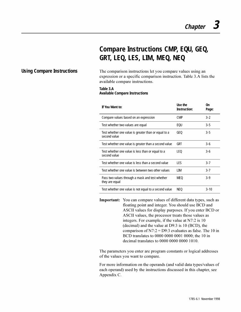
Chapter 3
Compare Instructions CMP, EQU, GEQ, GRT, LEQ, LES, LIM, MEQ, NEQ
Using Compare Instructions 7KH�FRPSDULVRQ�LQVWUXFWLRQV�OHW�\RX�FRPSDUH�YDOXHV�XVLQJ�DQ�H[SUHVVLRQ�RU�D�VSHFLILF�FRPSDULVRQ�LQVWUXFWLRQ��7DEOH���$�OLVWV�WKH�DYDLODEOH�FRPSDUH�LQVWUXFWLRQV�
Table 3.A Available Compare Instructions
,PSRUWDQW���<RX�FDQ�FRPSDUH�YDOXHV�RI�GLIIHUHQW�GDWD�W\SHV��VXFK�DV�IORDWLQJ�SRLQW�DQG�LQWHJHU��<RX�VKRXOG�XVH�%&'�DQG�$6&,,�YDOXHV�IRU�GLVSOD\�SXUSRVHV��,I�\RX�HQWHU�%&'�RU�$6&,,�YDOXHV��WKH�SURFHVVRU�WUHDWV�WKRVH�YDOXHV�DV�LQWHJHUV��)RU�H[DPSOH��LI�WKH�YDOXH�DW�1����LV�����GHFLPDO��DQG�WKH�YDOXH�DW�'����LV�����%&'���WKH�FRPSDULVRQ�RI�1���� �'����HYDOXDWHV�DV�IDOVH��7KH����LQ�%&'�WUDQVODWHV�WR����������������������WKH����LQ�GHFLPDO�WUDQVODWHV�WR���������������������
7KH�SDUDPHWHUV�\RX�HQWHU�DUH�SURJUDP�FRQVWDQWV�RU�ORJLFDO�DGGUHVVHV�RI�WKH�YDOXHV�\RX�ZDQW�WR�FRPSDUH�
)RU�PRUH�LQIRUPDWLRQ�RQ�WKH�RSHUDQGV��DQG�YDOLG�GDWD�W\SHV�YDOXHV�RI�HDFK�RSHUDQG��XVHG�E\�WKH�LQVWUXFWLRQV�GLVFXVVHG�LQ�WKLV�FKDSWHU��VHH�$SSHQGL[�&�
If You Want to:Use the Instruction:
On Page:
Compare values based on an expression CMP 3-2
Test whether two values are equal EQU 3-5
Test whether one value is greater than or equal to a second value
GEQ 3-5
Test whether one value is greater than a second value GRT 3-6
Test whether one value is less than or equal to a second value
LEQ 3-6
Test whether one value is less than a second value LES 3-7
Test whether one value is between two other values LIM 3-7
Pass two values through a mask and test whether they are equal
MEQ 3-9
Test whether one value is not equal to a second value NEQ 3-10
1785-6.1 November 1998
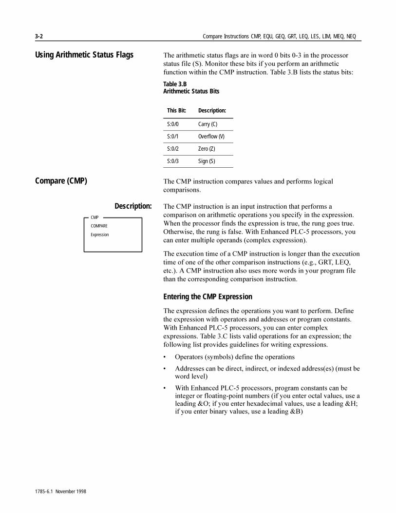
3-2 Compare Instructions CMP, EQU, GEQ, GRT, LEQ, LES, LIM, MEQ, NEQ
Using Arithmetic Status Flags 7KH�DULWKPHWLF�VWDWXV�IODJV�DUH�LQ�ZRUG���ELWV�����LQ�WKH�SURFHVVRU�VWDWXV�ILOH��6���0RQLWRU�WKHVH�ELWV�LI�\RX�SHUIRUP�DQ�DULWKPHWLF�IXQFWLRQ�ZLWKLQ�WKH�&03�LQVWUXFWLRQ��7DEOH���%�OLVWV�WKH�VWDWXV�ELWV�
Table 3.B Arithmetic Status Bits
Compare (CMP) 7KH�&03�LQVWUXFWLRQ�FRPSDUHV�YDOXHV�DQG�SHUIRUPV�ORJLFDO�FRPSDULVRQV�
Description: 7KH�&03�LQVWUXFWLRQ�LV�DQ�LQSXW�LQVWUXFWLRQ�WKDW�SHUIRUPV�D�FRPSDULVRQ�RQ�DULWKPHWLF�RSHUDWLRQV�\RX�VSHFLI\�LQ�WKH�H[SUHVVLRQ��:KHQ�WKH�SURFHVVRU�ILQGV�WKH�H[SUHVVLRQ�LV�WUXH��WKH�UXQJ�JRHV�WUXH��2WKHUZLVH��WKH�UXQJ�LV�IDOVH��:LWK�(QKDQFHG�3/&���SURFHVVRUV��\RX�FDQ�HQWHU�PXOWLSOH�RSHUDQGV��FRPSOH[�H[SUHVVLRQ��
7KH�H[HFXWLRQ�WLPH�RI�D�&03�LQVWUXFWLRQ�LV�ORQJHU�WKDQ�WKH�H[HFXWLRQ�WLPH�RI�RQH�RI�WKH�RWKHU�FRPSDULVRQ�LQVWUXFWLRQV��H�J���*57��/(4��HWF����$�&03�LQVWUXFWLRQ�DOVR�XVHV�PRUH�ZRUGV�LQ�\RXU�SURJUDP�ILOH�WKDQ�WKH�FRUUHVSRQGLQJ�FRPSDULVRQ�LQVWUXFWLRQ�
Entering the CMP Expression
7KH�H[SUHVVLRQ�GHILQHV�WKH�RSHUDWLRQV�\RX�ZDQW�WR�SHUIRUP��'HILQH�WKH�H[SUHVVLRQ�ZLWK�RSHUDWRUV�DQG�DGGUHVVHV�RU�SURJUDP�FRQVWDQWV��:LWK�(QKDQFHG�3/&���SURFHVVRUV��\RX�FDQ�HQWHU�FRPSOH[�H[SUHVVLRQV��7DEOH���&�OLVWV�YDOLG�RSHUDWLRQV�IRU�DQ�H[SUHVVLRQ��WKH�IROORZLQJ�OLVW�SURYLGHV�JXLGHOLQHV�IRU�ZULWLQJ�H[SUHVVLRQV�
� 2SHUDWRUV��V\PEROV��GHILQH�WKH�RSHUDWLRQV�
� $GGUHVVHV�FDQ�EH�GLUHFW��LQGLUHFW��RU�LQGH[HG�DGGUHVV�HV���PXVW�EH�ZRUG�OHYHO�
� :LWK�(QKDQFHG�3/&���SURFHVVRUV��SURJUDP�FRQVWDQWV�FDQ�EH�LQWHJHU�RU�IORDWLQJ�SRLQW�QXPEHUV��LI�\RX�HQWHU�RFWDO�YDOXHV��XVH�D�OHDGLQJ�2��LI�\RX�HQWHU�KH[DGHFLPDO�YDOXHV��XVH�D�OHDGLQJ�+��LI�\RX�HQWHU�ELQDU\�YDOXHV��XVH�D�OHDGLQJ�%�
This Bit: Description:
S:0/0 Carry (C)
S:0/1 Overflow (V)
S:0/2 Zero (Z)
S:0/3 Sign (S)
CMP
COMPARE
Expression
1785-6.1 November 1998
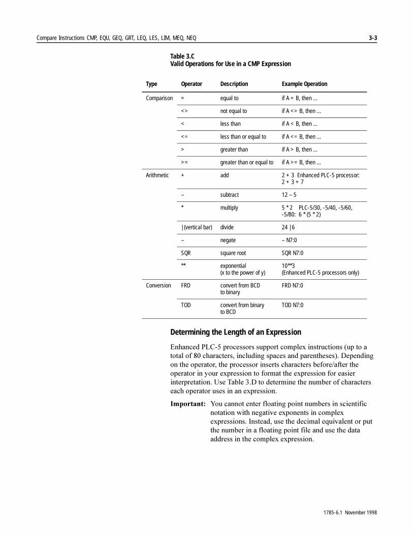
Compare Instructions CMP, EQU, GEQ, GRT, LEQ, LES, LIM, MEQ, NEQ 3-3
Table 3.C Valid Operations for Use in a CMP Expression
Determining the Length of an Expression
(QKDQFHG�3/&���SURFHVVRUV�VXSSRUW�FRPSOH[�LQVWUXFWLRQV��XS�WR�D�WRWDO�RI����FKDUDFWHUV��LQFOXGLQJ�VSDFHV�DQG�SDUHQWKHVHV���'HSHQGLQJ�RQ�WKH�RSHUDWRU��WKH�SURFHVVRU�LQVHUWV�FKDUDFWHUV�EHIRUH�DIWHU�WKH�RSHUDWRU�LQ�\RXU�H[SUHVVLRQ�WR�IRUPDW�WKH�H[SUHVVLRQ�IRU�HDVLHU�LQWHUSUHWDWLRQ��8VH�7DEOH���'�WR�GHWHUPLQH�WKH�QXPEHU�RI�FKDUDFWHUV�HDFK�RSHUDWRU�XVHV�LQ�DQ�H[SUHVVLRQ�
,PSRUWDQW���<RX�FDQQRW�HQWHU�IORDWLQJ�SRLQW�QXPEHUV�LQ�VFLHQWLILF�QRWDWLRQ�ZLWK�QHJDWLYH�H[SRQHQWV�LQ�FRPSOH[�H[SUHVVLRQV��,QVWHDG��XVH�WKH�GHFLPDO�HTXLYDOHQW�RU�SXW�WKH�QXPEHU�LQ�D�IORDWLQJ�SRLQW�ILOH�DQG�XVH�WKH�GDWD�DGGUHVV�LQ�WKH�FRPSOH[�H[SUHVVLRQ�
Type Operator Description Example Operation
Comparison = equal to if A = B, then ...
<> not equal to if A <> B, then ...
< less than if A < B, then ...
<= less than or equal to if A <= B, then ...
> greater than if A > B, then ...
>= greater than or equal to if A >= B, then ...
Arithmetic + add 2 + 3 Enhanced PLC-5 processor:2 + 3 + 7
– subtract 12 – 5
* multiply 5 * 2 PLC-5/30, -5/40, -5/60, -5/80: 6 * (5 * 2)
| (vertical bar) divide 24 | 6
– negate – N7:0
SQR square root SQR N7:0
** exponential(x to the power of y)
10**3(Enhanced PLC-5 processors only)
Conversion FRD convert from BCD to binary
FRD N7:0
TOD convert from binary to BCD
TOD N7:0
1785-6.1 November 1998
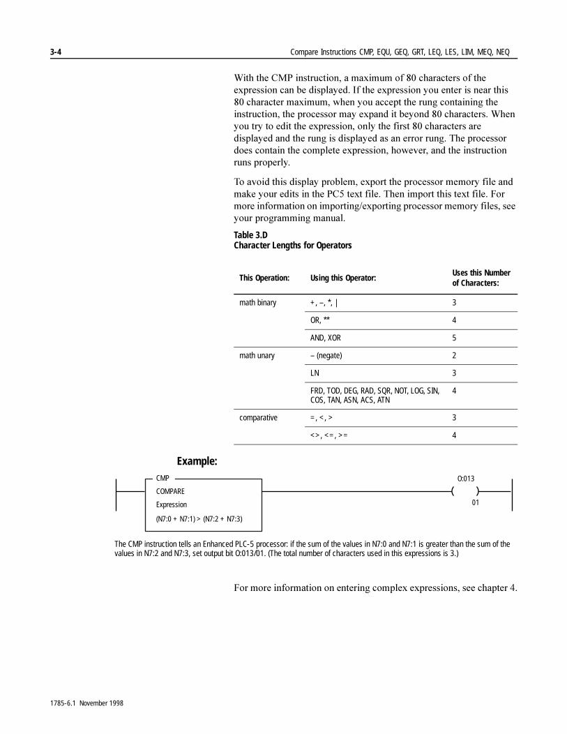
3-4 Compare Instructions CMP, EQU, GEQ, GRT, LEQ, LES, LIM, MEQ, NEQ
:LWK�WKH�&03�LQVWUXFWLRQ��D�PD[LPXP�RI����FKDUDFWHUV�RI�WKH�H[SUHVVLRQ�FDQ�EH�GLVSOD\HG��,I�WKH�H[SUHVVLRQ�\RX�HQWHU�LV�QHDU�WKLV����FKDUDFWHU�PD[LPXP��ZKHQ�\RX�DFFHSW�WKH�UXQJ�FRQWDLQLQJ�WKH�LQVWUXFWLRQ��WKH�SURFHVVRU�PD\�H[SDQG�LW�EH\RQG����FKDUDFWHUV��:KHQ�\RX�WU\�WR�HGLW�WKH�H[SUHVVLRQ��RQO\�WKH�ILUVW����FKDUDFWHUV�DUH�GLVSOD\HG�DQG�WKH�UXQJ�LV�GLVSOD\HG�DV�DQ�HUURU�UXQJ��7KH�SURFHVVRU�GRHV�FRQWDLQ�WKH�FRPSOHWH�H[SUHVVLRQ��KRZHYHU��DQG�WKH�LQVWUXFWLRQ�UXQV�SURSHUO\�
7R�DYRLG�WKLV�GLVSOD\�SUREOHP��H[SRUW�WKH�SURFHVVRU�PHPRU\�ILOH�DQG�PDNH�\RXU�HGLWV�LQ�WKH�3&��WH[W�ILOH��7KHQ�LPSRUW�WKLV�WH[W�ILOH��)RU�PRUH�LQIRUPDWLRQ�RQ�LPSRUWLQJ�H[SRUWLQJ�SURFHVVRU�PHPRU\�ILOHV��VHH�\RXU�SURJUDPPLQJ�PDQXDO�
Table 3.D Character Lengths for Operators
Example:
)RU�PRUH�LQIRUPDWLRQ�RQ�HQWHULQJ�FRPSOH[�H[SUHVVLRQV��VHH�FKDSWHU���
This Operation: Using this Operator:Uses this Number of Characters:
math binary +, –, *, | 3
OR, ** 4
AND, XOR 5
math unary – (negate) 2
LN 3
FRD, TOD, DEG, RAD, SQR, NOT, LOG, SIN, COS, TAN, ASN, ACS, ATN
4
comparative =, <, > 3
<>, <=, >= 4
CMP
COMPARE
Expression
(N7:0 + N7:1) > (N7:2 + N7:3)
O:013
01
The CMP instruction tells an Enhanced PLC-5 processor: if the sum of the values in N7:0 and N7:1 is greater than the sum of the values in N7:2 and N7:3, set output bit O:013/01. (The total number of characters used in this expressions is 3.)
1785-6.1 November 1998
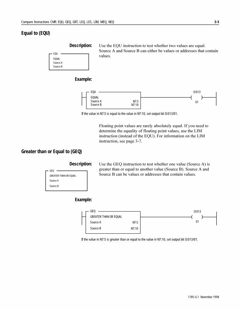
Compare Instructions CMP, EQU, GEQ, GRT, LEQ, LES, LIM, MEQ, NEQ 3-5
Equal to (EQU)
Description: 8VH�WKH�(48�LQVWUXFWLRQ�WR�WHVW�ZKHWKHU�WZR�YDOXHV�DUH�HTXDO��6RXUFH $�DQG�6RXUFH�%�FDQ�HLWKHU�EH�YDOXHV�RU�DGGUHVVHV�WKDW�FRQWDLQ�YDOXHV�
Example:
)ORDWLQJ�SRLQW�YDOXHV�DUH�UDUHO\�DEVROXWHO\�HTXDO��,I�\RX�QHHG�WR�GHWHUPLQH�WKH�HTXDOLW\�RI�IORDWLQJ�SRLQW�YDOXHV��XVH�WKH�/,0�LQVWUXFWLRQ��LQVWHDG�RI�WKH�(48���)RU�LQIRUPDWLRQ�RQ�WKH�/,0�LQVWUXFWLRQ��VHH�SDJH�����
Greater than or Equal to (GEQ)
Description: 8VH�WKH�*(4�LQVWUXFWLRQ�WR�WHVW�ZKHWKHU�RQH�YDOXH��6RXUFH�$��LV�JUHDWHU�WKDQ�RU�HTXDO�WR�DQRWKHU�YDOXH��6RXUFH�%���6RXUFH�$�DQG�6RXUFH�%�FDQ�EH�YDOXHV�RU�DGGUHVVHV�WKDW�FRQWDLQ�YDOXHV�
Example:
EQU
EQUAL
Source ASource B
EQU
EQUALSource ASource B
O:013
01N7:5N7:10
If the value in N7:5 is equal to the value in N7:10, set output bit O:013/01.
GEQ
GREATER THAN OR EQUAL
Source A
Source B
GEQ
GREATER THAN OR EQUAL
Source A
Source B
O:013
01N7:5
N7:10
If the value in N7:5 is greater than or equal to the value in N7:10, set output bit O:013/01.
1785-6.1 November 1998
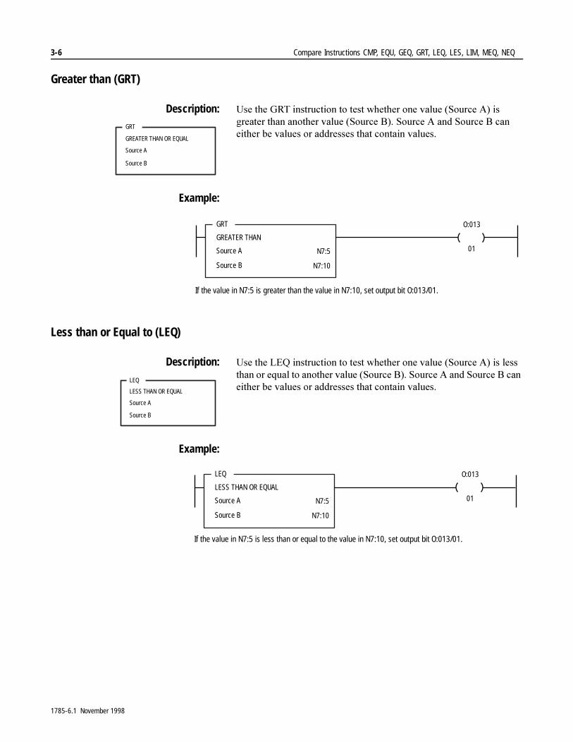
3-6 Compare Instructions CMP, EQU, GEQ, GRT, LEQ, LES, LIM, MEQ, NEQ
Greater than (GRT)
Description: 8VH�WKH�*57�LQVWUXFWLRQ�WR�WHVW�ZKHWKHU�RQH�YDOXH��6RXUFH�$��LV�JUHDWHU�WKDQ�DQRWKHU�YDOXH��6RXUFH�%���6RXUFH�$�DQG�6RXUFH�%�FDQ�HLWKHU�EH�YDOXHV�RU�DGGUHVVHV�WKDW�FRQWDLQ�YDOXHV�
Example:
Less than or Equal to (LEQ)
Description: 8VH�WKH�/(4�LQVWUXFWLRQ�WR�WHVW�ZKHWKHU�RQH�YDOXH��6RXUFH�$��LV�OHVV�WKDQ�RU�HTXDO�WR�DQRWKHU�YDOXH��6RXUFH�%���6RXUFH�$�DQG�6RXUFH�%�FDQ�HLWKHU�EH�YDOXHV�RU�DGGUHVVHV�WKDW�FRQWDLQ�YDOXHV�
Example:
GRT
GREATER THAN OR EQUAL
Source A
Source B
GRT
GREATER THAN
Source A
Source B
O:013
01N7:5
N7:10
If the value in N7:5 is greater than the value in N7:10, set output bit O:013/01.
LEQ
LESS THAN OR EQUAL
Source A
Source B
LEQ
LESS THAN OR EQUAL
Source A
Source B
O:013
01N7:5
N7:10
If the value in N7:5 is less than or equal to the value in N7:10, set output bit O:013/01.
1785-6.1 November 1998

Compare Instructions CMP, EQU, GEQ, GRT, LEQ, LES, LIM, MEQ, NEQ 3-7
Less than (LES)
Description: 8VH�WKH�/(6�LQVWUXFWLRQ�WR�WHVW�ZKHWKHU�RQH�YDOXH��6RXUFH�$��LV�OHVV�WKDQ�DQRWKHU�YDOXH��6RXUFH�%���6RXUFH�$�DQG�6RXUFH�%�FDQ�EH�YDOXHV�RU�DGGUHVVHV�WKDW�FRQWDLQ�YDOXHV�
Example:
Limit Test (LIM)
Description: 7KH�/,0�LQVWUXFWLRQ�LV�DQ�LQSXW�LQVWUXFWLRQ�WKDW�WHVWV�IRU�YDOXHV�LQVLGH�RI�RU�RXWVLGH�RI�D�VSHFLILHG�UDQJH��7KH�LQVWUXFWLRQ�LV�IDOVH�XQWLO�LW�GHWHFWV�WKDW�WKH�WHVW�YDOXH�LV�ZLWKLQ�FHUWDLQ�OLPLWV��7KHQ�WKH�LQVWUXFWLRQ�JRHV�WUXH��:KHQ�WKH�LQVWUXFWLRQ�GHWHFWV�WKDW�WKH�WHVW�YDOXH�JRHV�RXWVLGH�FHUWDLQ�OLPLWV��LW�JRHV�IDOVH�
<RX�FDQ�XVH�WKH�/,0�LQVWUXFWLRQ�WR�WHVW�LI�DQ�DQDORJ�LQSXW�YDOXH�LV�ZLWKLQ�VSHFLILHG�OLPLWV�
Entering Parameters
7R�SURJUDP�WKH�/,0�LQVWUXFWLRQ��\RX�PXVW�SURYLGH�WKH�SURFHVVRU�ZLWK�WKH�IROORZLQJ��
LES
LESS THAN
Source A
Source B
LES
LESS THAN
Source A
Source B
O:013
01N7:5
N7:10
If the value in N7:5 is less than the value in N7:10, set output bit O:013/01.
LIM
LIMIT TEST (CIRC)
Low limit
TestHigh limit
Parameter: Definition:
Low Limit a constant or an address from which the instruction reads the lower range of the specified limit range. The address contains an integer or floating-point value.
Test Value the address that contains the integer or floating-point value you examine to see whether the value is inside or outside the specified limit range.
High Limit a constant or an address from which the instruction reads the upper range of the specified limit range. The address contains an integer or floating-point value.
1785-6.1 November 1998
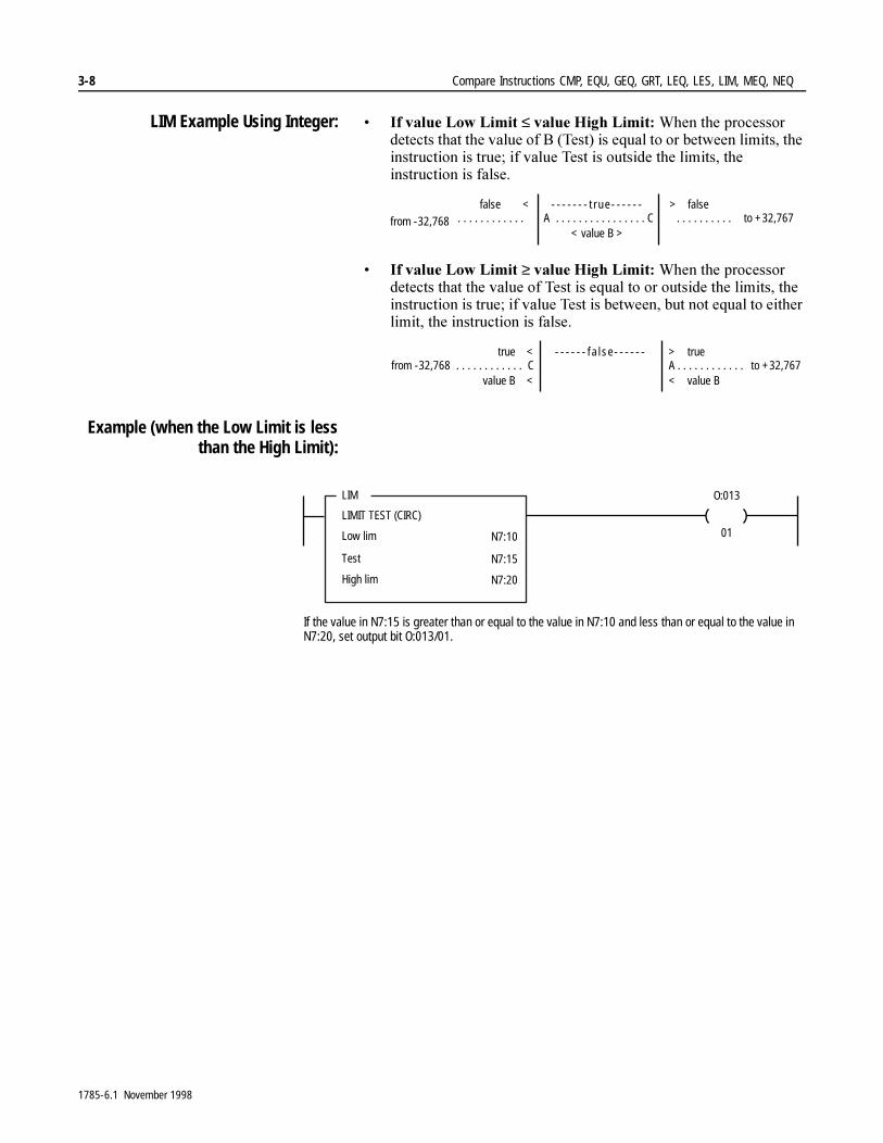
3-8 Compare Instructions CMP, EQU, GEQ, GRT, LEQ, LES, LIM, MEQ, NEQ
LIM Example Using Integer: � ,I�YDOXH�/RZ�/LPLW�≤�YDOXH�+LJK�/LPLW��:KHQ�WKH�SURFHVVRU�GHWHFWV�WKDW�WKH�YDOXH�RI�%��7HVW��LV�HTXDO�WR�RU�EHWZHHQ�OLPLWV��WKH�LQVWUXFWLRQ�LV�WUXH��LI�YDOXH�7HVW�LV�RXWVLGH�WKH�OLPLWV��WKH�LQVWUXFWLRQ�LV�IDOVH��
� ,I�YDOXH�/RZ�/LPLW�≥�YDOXH�+LJK�/LPLW��:KHQ�WKH�SURFHVVRU�GHWHFWV�WKDW�WKH�YDOXH�RI�7HVW�LV�HTXDO�WR�RU�RXWVLGH�WKH�OLPLWV��WKH�LQVWUXFWLRQ�LV�WUXH��LI�YDOXH�7HVW�LV�EHWZHHQ��EXW�QRW�HTXDO�WR�HLWKHU�OLPLW��WKH�LQVWUXFWLRQ�LV�IDOVH�
Example (when the Low Limit is lessthan the High Limit):
false < ------- t rue------ > falseA C. . . . . . . . . . . . . . . . . . . . . . . . . . . . . . . . . . . . . .
< value B >from -32,768 to +32,767
true < ------ fa lse------ > true. . . . . . . . . . . . C A . . . . . . . . . . . . from -32,768 to +32,767
value B < < value B
LIM
LIMIT TEST (CIRC)
Low lim
Test
O:013
01N7:10
N7:15
High lim N7:20
If the value in N7:15 is greater than or equal to the value in N7:10 and less than or equal to the value in N7:20, set output bit O:013/01.
1785-6.1 November 1998
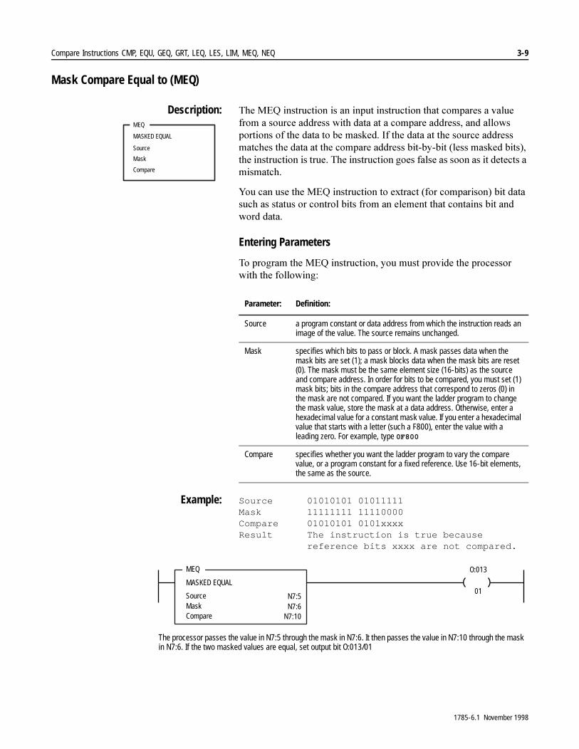
Compare Instructions CMP, EQU, GEQ, GRT, LEQ, LES, LIM, MEQ, NEQ 3-9
Mask Compare Equal to (MEQ)
Description: 7KH�0(4�LQVWUXFWLRQ�LV�DQ�LQSXW�LQVWUXFWLRQ�WKDW�FRPSDUHV�D�YDOXH�IURP�D�VRXUFH�DGGUHVV�ZLWK�GDWD�DW�D�FRPSDUH�DGGUHVV��DQG�DOORZV�SRUWLRQV�RI�WKH�GDWD�WR�EH�PDVNHG��,I�WKH�GDWD�DW�WKH�VRXUFH�DGGUHVV�PDWFKHV�WKH�GDWD�DW�WKH�FRPSDUH�DGGUHVV�ELW�E\�ELW��OHVV�PDVNHG�ELWV���WKH�LQVWUXFWLRQ�LV�WUXH��7KH�LQVWUXFWLRQ�JRHV�IDOVH�DV�VRRQ�DV�LW�GHWHFWV�D�PLVPDWFK�
<RX�FDQ�XVH�WKH�0(4�LQVWUXFWLRQ�WR�H[WUDFW��IRU�FRPSDULVRQ��ELW�GDWD�VXFK�DV�VWDWXV�RU�FRQWURO�ELWV�IURP�DQ�HOHPHQW�WKDW�FRQWDLQV�ELW�DQG�ZRUG�GDWD�
Entering Parameters
7R�SURJUDP�WKH�0(4�LQVWUXFWLRQ��\RX�PXVW�SURYLGH�WKH�SURFHVVRU�ZLWK�WKH IROORZLQJ�
Example: Source 01010101 01011111Mask 11111111 11110000Compare 01010101 0101xxxxResult The instruction is true because
reference bits xxxx are not compared.
MEQ
MASKED EQUAL
Source
Mask
Compare
Parameter: Definition:
Source a program constant or data address from which the instruction reads an image of the value. The source remains unchanged.
Mask specifies which bits to pass or block. A mask passes data when the mask bits are set (1); a mask blocks data when the mask bits are reset (0). The mask must be the same element size (16-bits) as the source and compare address. In order for bits to be compared, you must set (1) mask bits; bits in the compare address that correspond to zeros (0) in the mask are not compared. If you want the ladder program to change the mask value, store the mask at a data address. Otherwise, enter a hexadecimal value for a constant mask value. If you enter a hexadecimal value that starts with a letter (such a F800), enter the value with a leading zero. For example, type 0F800
Compare specifies whether you want the ladder program to vary the compare value, or a program constant for a fixed reference. Use 16-bit elements, the same as the source.
MEQ
MASKED EQUAL
SourceMask
O:013
01N7:5N7:6
Compare N7:10
The processor passes the value in N7:5 through the mask in N7:6. It then passes the value in N7:10 through the mask in N7:6. If the two masked values are equal, set output bit O:013/01
1785-6.1 November 1998

3-10 Compare Instructions CMP, EQU, GEQ, GRT, LEQ, LES, LIM, MEQ, NEQ
Not Equal to (NEQ)
Description: 8VH�WKH�1(4�LQVWUXFWLRQ�WR�WHVW�ZKHWKHU�WZR�YDOXHV�DUH�QRW�HTXDO��6RXUFH�$�DQG�6RXUFH�%�FDQ�EH�YDOXHV�RU�DGGUHVVHV�
Example:
NEQ
NOT EQUAL
Source A
Source B
NEQ
NOT EQUAL
Source A
Source B
O:013
01N7:5
N7:10
If the value in N7:5 is not equal to the value in N7:10, set output bit O:013/01.
1785-6.1 November 1998
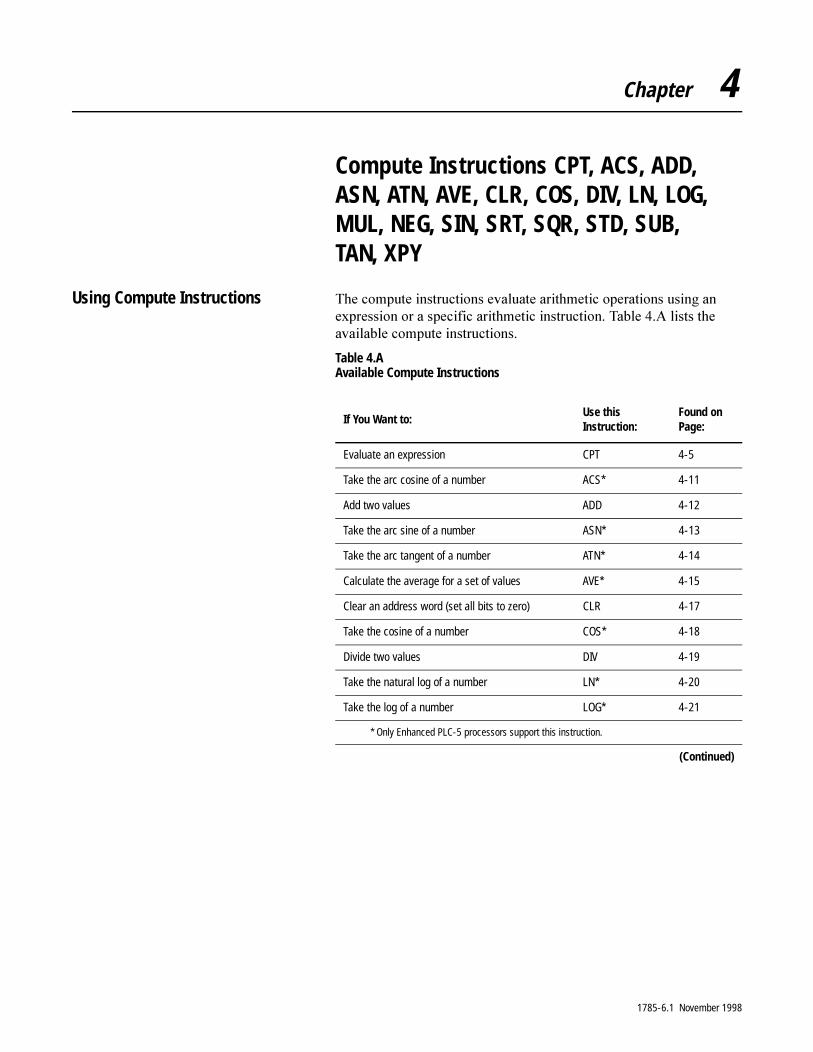
Chapter 4
Compute Instructions CPT, ACS, ADD, ASN, ATN, AVE, CLR, COS, DIV, LN, LOG, MUL, NEG, SIN, SRT, SQR, STD, SUB, TAN, XPY
Using Compute Instructions 7KH�FRPSXWH�LQVWUXFWLRQV�HYDOXDWH�DULWKPHWLF�RSHUDWLRQV�XVLQJ�DQ�H[SUHVVLRQ�RU�D�VSHFLILF�DULWKPHWLF�LQVWUXFWLRQ��7DEOH���$�OLVWV�WKH�DYDLODEOH�FRPSXWH�LQVWUXFWLRQV�
Table 4.A Available Compute Instructions
If You Want to: Use this Instruction:
Found on Page:
Evaluate an expression CPT 4-5
Take the arc cosine of a number ACS* 4-11
Add two values ADD 4-12
Take the arc sine of a number ASN* 4-13
Take the arc tangent of a number ATN* 4-14
Calculate the average for a set of values AVE* 4-15
Clear an address word (set all bits to zero) CLR 4-17
Take the cosine of a number COS* 4-18
Divide two values DIV 4-19
Take the natural log of a number LN* 4-20
Take the log of a number LOG* 4-21
* Only Enhanced PLC-5 processors support this instruction.
(Continued)
1785-6.1 November 1998
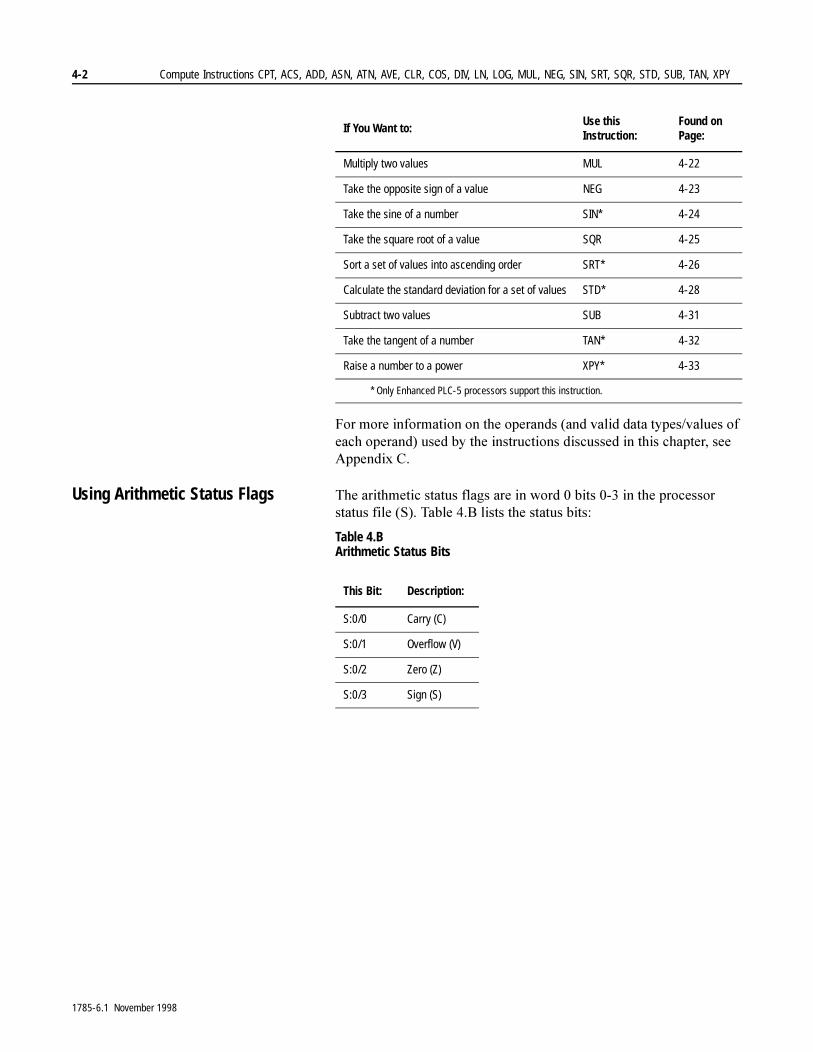
4-2 Compute Instructions CPT, ACS, ADD, ASN, ATN, AVE, CLR, COS, DIV, LN, LOG, MUL, NEG, SIN, SRT, SQR, STD, SUB, TAN, XPY
)RU�PRUH�LQIRUPDWLRQ�RQ�WKH�RSHUDQGV��DQG�YDOLG�GDWD�W\SHV�YDOXHV�RI�HDFK�RSHUDQG��XVHG�E\�WKH�LQVWUXFWLRQV�GLVFXVVHG�LQ�WKLV�FKDSWHU��VHH�$SSHQGL[�&�
Using Arithmetic Status Flags 7KH�DULWKPHWLF�VWDWXV�IODJV�DUH�LQ�ZRUG���ELWV�����LQ�WKH�SURFHVVRU�VWDWXV�ILOH��6���7DEOH���%�OLVWV�WKH�VWDWXV�ELWV�
Table 4.B Arithmetic Status Bits
Multiply two values MUL 4-22
Take the opposite sign of a value NEG 4-23
Take the sine of a number SIN* 4-24
Take the square root of a value SQR 4-25
Sort a set of values into ascending order SRT* 4-26
Calculate the standard deviation for a set of values STD* 4-28
Subtract two values SUB 4-31
Take the tangent of a number TAN* 4-32
Raise a number to a power XPY* 4-33
* Only Enhanced PLC-5 processors support this instruction.
If You Want to: Use this Instruction:
Found on Page:
This Bit: Description:
S:0/0 Carry (C)
S:0/1 Overflow (V)
S:0/2 Zero (Z)
S:0/3 Sign (S)
1785-6.1 November 1998
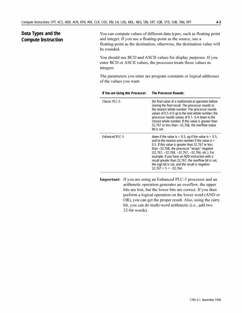
Compute Instructions CPT, ACS, ADD, ASN, ATN, AVE, CLR, COS, DIV, LN, LOG, MUL, NEG, SIN, SRT, SQR, STD, SUB, TAN, XPY 4-3
Data Types and the Compute Instruction
<RX�FDQ�FRPSXWH�YDOXHV�RI�GLIIHUHQW�GDWD�W\SHV��VXFK�DV�IORDWLQJ�SRLQW�DQG�LQWHJHU��,I�\RX�XVH�D�IORDWLQJ�SRLQW�DV�WKH�VRXUFH��XVH�D�IORDWLQJ�SRLQW�DV�WKH�GHVWLQDWLRQ��RWKHUZLVH��WKH�GHVWLQDWLRQ�YDOXH�ZLOO�EH�URXQGHG�
<RX�VKRXOG�XVH�%&'�DQG�$6&,,�YDOXHV�IRU�GLVSOD\�SXUSRVHV��,I�\RX�HQWHU�%&'�RU�$6&,,�YDOXHV��WKH�SURFHVVRU�WUHDWV�WKRVH�YDOXHV�DV�LQWHJHUV�
7KH�SDUDPHWHUV�\RX�HQWHU�DUH�SURJUDP�FRQVWDQWV�RU�ORJLFDO�DGGUHVVHV�RI�WKH�YDOXHV�\RX�ZDQW�
,PSRUWDQW��� ,I�\RX�DUH�XVLQJ�DQ�(QKDQFHG�3/&���SURFHVVRU�DQG�DQ�DULWKPHWLF�RSHUDWLRQ�JHQHUDWHV�DQ�RYHUIORZ��WKH�XSSHU�ELWV�DUH�ORVW��EXW�WKH�ORZHU�ELWV�DUH�FRUUHFW��,I�\RX�WKHQ�SHUIRUP�D�ORJLFDO�RSHUDWLRQ�RQ�WKH�ORZHU�ZRUG��$1'�RU�25���\RX�FDQ�JHW�WKH�SURSHU�UHVXOW��$OVR��XVLQJ�WKH�FDUU\�ELW��\RX�FDQ�GR�PXOWL�ZRUG�DULWKPHWLF��L�H���DGG�WZR����ELW�ZRUGV��
If You are Using this Processor: The Processor Rounds:
Classic PLC-5 the final value of a mathematical operation before storing the final result. The processor rounds to the nearest whole number: The processor rounds values of 0.5-0.9 up to the next whole number; the processor rounds values of 0.1- 0.4 down to the closest whole number. If this value is greater than 32,767 or less than –32,768, the overflow status bit is set.
Enhanced PLC-5 down if the value is < 0.5, up if the value is > 0.5, and to the nearest even number if the value is = 0.5. If this value is greater than 32,767 or less than –32,768, the processor “wraps” negative (32,767, –32,768, –32,767, –32,766, etc.). For example, if you have an ADD instruction with a result greater than 32,767, the overflow bit is set, the sign bit is set, and the result is negative: 32,767 + 5 = –32,764.
1785-6.1 November 1998
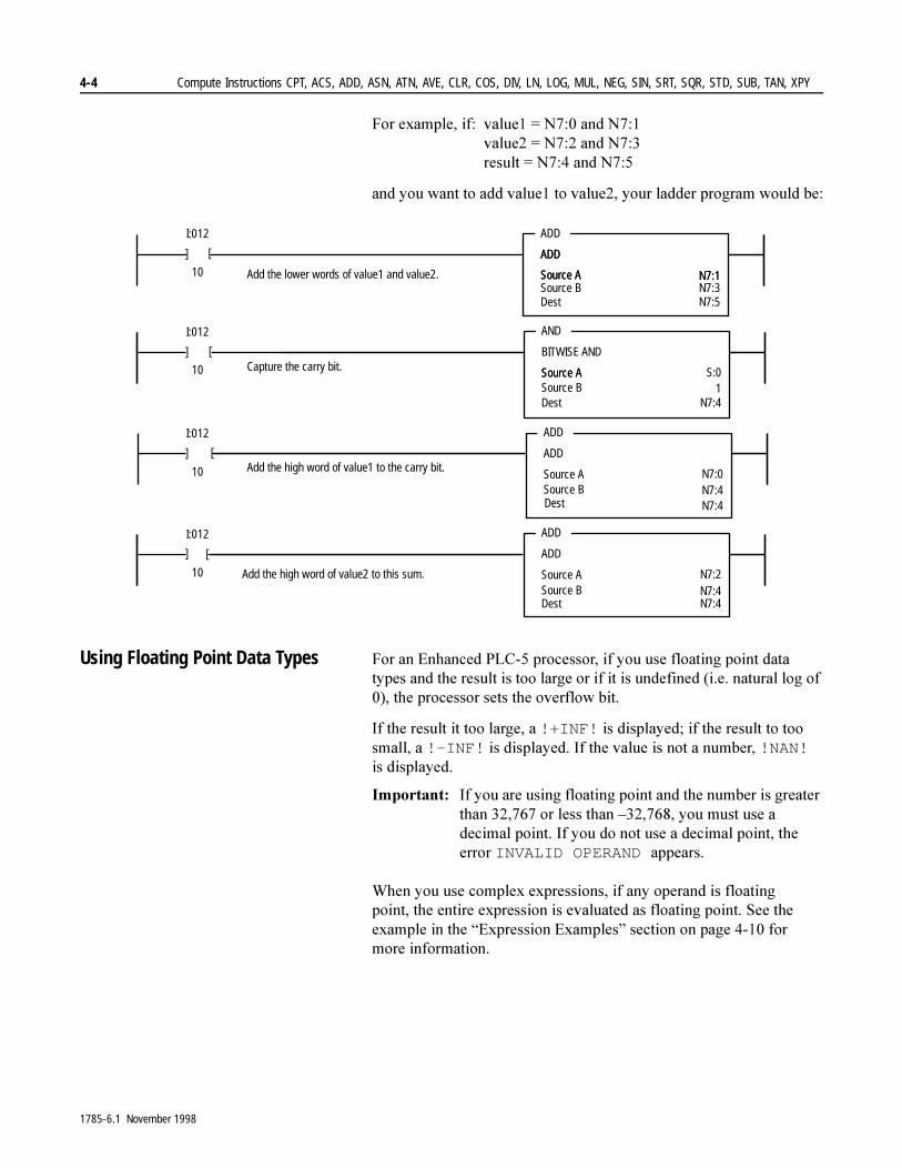
4-4 Compute Instructions CPT, ACS, ADD, ASN, ATN, AVE, CLR, COS, DIV, LN, LOG, MUL, NEG, SIN, SRT, SQR, STD, SUB, TAN, XPY
)RU�H[DPSOH��LI� YDOXH�� �1����DQG�1���YDOXH�� �1����DQG�1���UHVXOW� �1����DQG�1���
DQG�\RX�ZDQW�WR�DGG�YDOXH��WR�YDOXH���\RXU�ODGGHU�SURJUDP�ZRXOG�EH�
Using Floating Point Data Types )RU�DQ�(QKDQFHG�3/&���SURFHVVRU��LI�\RX�XVH�IORDWLQJ�SRLQW�GDWD�W\SHV�DQG�WKH�UHVXOW�LV�WRR�ODUJH�RU�LI�LW�LV�XQGHILQHG��L�H��QDWXUDO�ORJ�RI�����WKH�SURFHVVRU�VHWV�WKH�RYHUIORZ�ELW�
,I�WKH�UHVXOW�LW�WRR�ODUJH��D�!+INF!�LV�GLVSOD\HG��LI�WKH�UHVXOW�WR�WRR�VPDOO��D�!-INF!�LV�GLVSOD\HG��,I�WKH�YDOXH�LV�QRW�D�QXPEHU��!NAN!�LV GLVSOD\HG�
,PSRUWDQW��� ,I�\RX�DUH�XVLQJ�IORDWLQJ�SRLQW�DQG�WKH�QXPEHU�LV�JUHDWHU�WKDQ��������RU�OHVV�WKDQ�±��������\RX�PXVW�XVH�D�GHFLPDO�SRLQW��,I�\RX�GR�QRW�XVH�D�GHFLPDO�SRLQW��WKH�HUURU�INVALID OPERAND DSSHDUV�
:KHQ�\RX�XVH�FRPSOH[�H[SUHVVLRQV��LI�DQ\�RSHUDQG�LV�IORDWLQJ�SRLQW��WKH�HQWLUH�H[SUHVVLRQ�LV�HYDOXDWHG�DV�IORDWLQJ�SRLQW��6HH�WKH�H[DPSOH�LQ�WKH�³([SUHVVLRQ�([DPSOHV´�VHFWLRQ�RQ�SDJH������IRU�PRUH�LQIRUPDWLRQ�
]
ADD
ADD
Source ASource B
N7:1
ADD
ADD
Source A
I:012
10 N7:1N7:3
Dest N7:5
]
ADD
ADD
Source ASource B N7:4
N7:4
ADD
N7:0
ADD
ADD
Source ASource B N7:4Dest N7:4
ADD
N7:2
ADD
BITWISE AND
Source A1
Dest N7:4
AND
Source ASource B
S:0
Add the lower words of value1 and value2.
Capture the carry bit.
Add the high word of value1 to the carry bit.
Add the high word of value2 to this sum.
]
I:012
10
]
]
I:012
10
]
]
I:012
10
]
Dest
1785-6.1 November 1998

Compute Instructions CPT, ACS, ADD, ASN, ATN, AVE, CLR, COS, DIV, LN, LOG, MUL, NEG, SIN, SRT, SQR, STD, SUB, TAN, XPY 4-5
Compute (CPT) 7KH�&37�LQVWUXFWLRQ�SHUIRUPV�FRS\��DULWKPHWLF��ORJLFDO��DQG�FRQYHUVLRQ�RSHUDWLRQV�
Description: 7KH�&37�LQVWUXFWLRQ�LV�DQ�RXWSXW�LQVWUXFWLRQ�WKDW�SHUIRUPV�WKH�RSHUDWLRQV�\RX�GHILQH�LQ�WKH�H[SUHVVLRQ��DQG�ZULWHV�WKH�UHVXOW�LQWR�WKH�GHVWLQDWLRQ�DGGUHVV��7KH�&37�LQVWUXFWLRQ�FDQ�DOVR�FRS\�GDWD�IURP�RQH�DGGUHVV�WR�DQRWKHU�DQG�DXWRPDWLFDOO\�FRQYHUWV�WKH�GDWD�W\SH�DW�WKH�VRXUFH�DGGUHVV�WR�WKH�GDWD�W\SH�\RX�VSHFLI\�LQ�WKH�GHVWLQDWLRQ�DGGUHVV�
7KH�H[HFXWLRQ�WLPH�RI�D�&37�LQVWUXFWLRQ�LV�ORQJHU�WKDQ�WKH�H[HFXWLRQ�WLPH�RI�DQ�DULWKPHWLF��ORJLF�RU�PRYH�LQVWUXFWLRQ��L�H���$''��$1'��029��HWF����7KH�&37�LQVWUXFWLRQ�DOVR�XVHV�PRUH�ZRUGV�LQ�\RXU�SURJUDP�ILOH�
$IWHU�HDFK�&37�LQVWUXFWLRQ�LV�SHUIRUPHG��WKH�DULWKPHWLF�VWDWXV�ELWV�LQ�WKH�VWDWXV�ILOH�RI�WKH�GDWD�WDEOH�DUH�XSGDWHG�WKH�VDPH�DV�WKH�FRUUHVSRQGLQJ�DULWKPHWLF��ORJLF�RU�PRYH�LQVWUXFWLRQ��)RU�H[DPSOH��UHIHU�WR�WKH�GHVFULSWLRQ�RI�WKH�$''�LQVWUXFWLRQ�WR�VHH�KRZ�WKH�VWDWXV�ELWV�DUH�XSGDWHG�DIWHU�D�&37��DGG��LQVWUXFWLRQ�LV�H[HFXWHG�
Entering the CPT Expression
7KH�H[SUHVVLRQ�GHILQHV�WKH�RSHUDWLRQV�\RX�ZDQW�WR�SHUIRUP��<RX�GHILQH�WKH�H[SUHVVLRQ�ZLWK�RSHUDWRUV�DQG�DGGUHVVHV�RU�SURJUDP�FRQVWDQWV��:LWK�(QKDQFHG�3/&���SURFHVVRUV��\RX�FDQ�HQWHU�FRPSOH[�H[SUHVVLRQV��7DEOH���&�OLVWV�YDOLG�RSHUDWLRQV�IRU�DQ�H[SUHVVLRQ��WKH�IROORZLQJ�OLVW�SURYLGHV�JXLGHOLQHV�IRU�ZULWLQJ�H[SUHVVLRQV�
� 2SHUDWRUV��V\PEROV��GHILQH�WKH�RSHUDWLRQV�
� $GGUHVVHV�FDQ�EH�GLUHFW�RU�LQGLUHFW�ORJLFDO�DGGUHVV�HV���PXVW�EH�HOHPHQW�RU�ELW�OHYHO�
� :LWK�(QKDQFHG�3/&���SURFHVVRUV��SURJUDP�FRQVWDQWV�FDQ�EH�LQWHJHU�RU�IORDWLQJ�SRLQW�QXPEHUV��LI�\RX�HQWHU�RFWDO�YDOXHV��XVH�D�OHDGLQJ�2��LI�\RX�HQWHU�KH[DGHFLPDO�YDOXHV��XVH�D�OHDGLQJ�+�
� ([SUHVVLRQV�FDQ�RQO\�WRWDO����FKDUDFWHUV��LQFOXGLQJ�VSDFHV�DQG�SDUHQWKHVHV
CPT
COMPUTE
Destination
Expression
1785-6.1 November 1998

4-6 Compute Instructions CPT, ACS, ADD, ASN, ATN, AVE, CLR, COS, DIV, LN, LOG, MUL, NEG, SIN, SRT, SQR, STD, SUB, TAN, XPY
Table 4.C Valid Operations for Use in a CPT Expression
Type Operator Description Example Operation
Copy none copy from A to B enter source address in the expression enter destination address in destination
Clear none set a value to zero 0 (enter 0 for the expression)
Arithmetic + add 2 + 32 + 3 + 7 (Enhanced PLC-5 processors)
– subtract 12 – 5(12 – 5) – 7 (Enhanced PLC-5 processors)
* multiply 5 * 26 * (5 * 2) (Enhanced PLC-5 processors)
| (vertical bar) divide 24 | 6(24 | 6) *2 (Enhanced PLC-5 processors)
– negate – N7:0
SQR square root SQR N7:0
** exponential *(x to the power of y)
10**3
LN natural log * LN F8:20
LOG log to the base 10* LOG F8:3
Trigonometric ACS arc cosine* ACS F8:18
ASN arc sine* ASN F8:20
ATN arc tangent * ATN F8:22
COS cosine* COS F8:14
SIN sine* SIN F8:12
TAN tangent* TAN F8:16
Bitwise AND bitwise AND D9:3 AND D10:4
OR bitwise OR D10:4 OR D10:5
XOR bitwise exclusive OR D9:5 XOR D10:4
NOT bitwise complement NOT D9:3
Conversion FRD convert from BCD to binary
FRD N7:0
TOD convert from binary to BCD
TOD N7:0
DEG convert radians to degrees*
DEG F8:8
RAD convert degrees to radians*
RAD F8:10
* Available in Enhanced PLC-5 processors only.
1785-6.1 November 1998
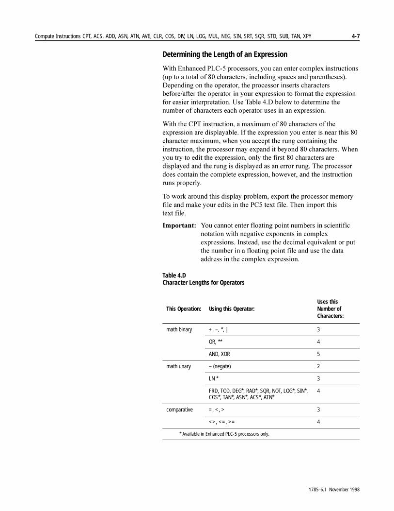
Compute Instructions CPT, ACS, ADD, ASN, ATN, AVE, CLR, COS, DIV, LN, LOG, MUL, NEG, SIN, SRT, SQR, STD, SUB, TAN, XPY 4-7
Determining the Length of an Expression
:LWK�(QKDQFHG�3/&���SURFHVVRUV��\RX�FDQ�HQWHU�FRPSOH[�LQVWUXFWLRQV��XS�WR�D�WRWDO�RI����FKDUDFWHUV��LQFOXGLQJ�VSDFHV�DQG�SDUHQWKHVHV���'HSHQGLQJ�RQ�WKH�RSHUDWRU��WKH�SURFHVVRU�LQVHUWV�FKDUDFWHUV�EHIRUH�DIWHU�WKH�RSHUDWRU�LQ�\RXU�H[SUHVVLRQ�WR�IRUPDW�WKH�H[SUHVVLRQ�IRU�HDVLHU�LQWHUSUHWDWLRQ��8VH�7DEOH���'�EHORZ�WR�GHWHUPLQH�WKH�QXPEHU�RI�FKDUDFWHUV�HDFK�RSHUDWRU�XVHV�LQ�DQ�H[SUHVVLRQ�
:LWK�WKH�&37�LQVWUXFWLRQ��D�PD[LPXP�RI����FKDUDFWHUV�RI�WKH�H[SUHVVLRQ�DUH�GLVSOD\DEOH��,I�WKH�H[SUHVVLRQ�\RX�HQWHU�LV�QHDU�WKLV����FKDUDFWHU�PD[LPXP��ZKHQ�\RX�DFFHSW�WKH�UXQJ�FRQWDLQLQJ�WKH�LQVWUXFWLRQ��WKH�SURFHVVRU�PD\�H[SDQG�LW�EH\RQG����FKDUDFWHUV��:KHQ�\RX�WU\�WR�HGLW�WKH�H[SUHVVLRQ��RQO\�WKH�ILUVW����FKDUDFWHUV�DUH�GLVSOD\HG�DQG�WKH�UXQJ�LV�GLVSOD\HG�DV�DQ�HUURU�UXQJ��7KH�SURFHVVRU�GRHV�FRQWDLQ�WKH�FRPSOHWH�H[SUHVVLRQ��KRZHYHU��DQG�WKH�LQVWUXFWLRQ�UXQV�SURSHUO\�
7R�ZRUN�DURXQG�WKLV�GLVSOD\�SUREOHP��H[SRUW�WKH�SURFHVVRU�PHPRU\�ILOH�DQG�PDNH�\RXU�HGLWV�LQ�WKH�3&��WH[W�ILOH��7KHQ�LPSRUW�WKLV�WH[W ILOH�
,PSRUWDQW���<RX�FDQQRW�HQWHU�IORDWLQJ�SRLQW�QXPEHUV�LQ�VFLHQWLILF�QRWDWLRQ�ZLWK�QHJDWLYH�H[SRQHQWV�LQ�FRPSOH[�H[SUHVVLRQV��,QVWHDG��XVH�WKH�GHFLPDO�HTXLYDOHQW�RU�SXW�WKH�QXPEHU�LQ�D�IORDWLQJ�SRLQW�ILOH�DQG�XVH�WKH�GDWD�DGGUHVV�LQ�WKH�FRPSOH[�H[SUHVVLRQ�
Table 4.D Character Lengths for Operators
This Operation: Using this Operator:Uses this Number of Characters:
math binary +, –, *, | 3
OR, ** 4
AND, XOR 5
math unary – (negate) 2
LN * 3
FRD, TOD, DEG*, RAD*, SQR, NOT, LOG*, SIN*, COS*, TAN*, ASN*, ACS*, ATN*
4
comparative =, <, > 3
<>, <=, >= 4
* Available in Enhanced PLC-5 processors only.
1785-6.1 November 1998

4-8 Compute Instructions CPT, ACS, ADD, ASN, ATN, AVE, CLR, COS, DIV, LN, LOG, MUL, NEG, SIN, SRT, SQR, STD, SUB, TAN, XPY
Determining the Order of Operation
7KH�RSHUDWLRQV�\RX�ZULWH�LQWR�WKH�H[SUHVVLRQ�DUH�SHUIRUPHG�E\�WKH�SURFHVVRU�LQ�D�SUHVFULEHG�RUGHU��QRW�QHFHVVDULO\�WKH�RUGHU�\RX�ZULWH�WKHP��<RX�FDQ�RYHUULGH�WKH�RUGHU�RI�RSHUDWLRQ�E\�JURXSLQJ�WHUPV�ZLWKLQ�SDUHQWKHVHV��IRUFLQJ�WKH�SURFHVVRU�WR�SHUIRUP�WKH�RSHUDWLRQ�ZLWKLQ�WKH�SDUHQWKHVHV�DKHDG�RI�RWKHU�RSHUDWLRQV�
2SHUDWLRQV�RI�HTXDO�RUGHU�DUH�SHUIRUPHG�OHIW�WR�ULJKW��7KH�H[SUHVVLRQ�\RX�XVH�PXVW�LQFOXGH�DQ�RSHUDWRU��7DEOH���(�VKRZV�WKH�RUGHU�RI�RSHUDWLRQ�
Table 4.E Order of Operation for CPT Expressions
Expression Examples
6LQJOH�9DOXH��7KH�H[SUHVVLRQ�645��1�����ZLWK�GHVWLQDWLRQ�1�����WHOOV�WKH�SURFHVVRU�WR�WDNH�WKH�VTXDUH�URRW�RI�WKH�YDOXH�VWRUHG�DW�1����DQG�VWRUH�WKH�UHVXOW�DW�1�����
0XOWLSOH�9DOXHV��:LWK�(QKDQFHG�3/&���SURFHVVRUV��\RX�FDQ�DOVR�XVH�IXQFWLRQV�WR�RSHUDWH�RQ�RQH�RU�PRUH�YDOXHV�LQ�WKH�H[SUHVVLRQ��FRPSOH[�H[SUHVVLRQV��IRU�FRPSXWH�DQG�FRPSDUH�RSHUDWLRQV��&RPSOH[�H[SUHVVLRQV�FDQ�EH�XS�WR����FKDUDFWHUV�ORQJ��VSDFHV�DQG�SDUHQWKHVHV�DUH�FRQVLGHUHG�FKDUDFWHUV���)RU�H[DPSOH��\RX�FRXOG�HQWHU�DQ�H[SUHVVLRQ�VXFK�DV��
Order Operation Description
1 ** exponential (XY)Enhanced PLC-5 processors only
2 – negate
NOT bitwise complement
3 * multiply
| divide
4 + add
– subtract
5 AND bitwise AND
6 XOR bitwise exclusive OR
7 OR bitwise OR
1785-6.1 November 1998

Compute Instructions CPT, ACS, ADD, ASN, ATN, AVE, CLR, COS, DIV, LN, LOG, MUL, NEG, SIN, SRT, SQR, STD, SUB, TAN, XPY 4-9
Example:
:KHQ�\RX�XVH�FRPSOH[�H[SUHVVLRQV��LI�DQ\�RSHUDQG�LV�IORDWLQJ�SRLQW��WKH�HQWLUH�H[SUHVVLRQ�LV�HYDOXDWHG�DV�IORDWLQJ�SRLQW�
Example:
Entering the Destination
(QWHU�D�GLUHFW�RU�LQGLUHFW�ORJLFDO�DGGUHVV�IRU�WKH�GHVWLQDWLRQ��7KH�LQVWUXFWLRQ�VWRUHV�WKH�UHVXOW�RI�WKH�RSHUDWLRQ�LQ�WKH�GHVWLQDWLRQ�DGGUHVV�
,PSRUWDQW���7KH�SURFHVVRU�DXWRPDWLFDOO\�FRQYHUWV�WKH�GDWD�W\SH�VSHFLILHG�E\�WKH�VRXUFH�DGGUHVV�WR�WKDW�VSHFLILHG�E\�WKH�GHVWLQDWLRQ�DGGUHVV��7KH�SURFHVVRU�XVHV�%&'�IRU�GLVSOD\�RU�FRPSDWLELOLW\�ZLWK�3/&���IDPLO\�SURFHVVRUV��<RX�PXVW�SURJUDP�DQ\�%&'�FRQYHUVLRQV�
Using CPT Functions
8VH�IXQFWLRQV�WR�RSHUDWH�RQ�RQH�RU�PRUH�YDOXHV�LQ�WKH�H[SUHVVLRQ�RI�D�&37�LQVWUXFWLRQ�WR�SHUIRUP�WKHVH�W\SHV�RI�RSHUDWLRQV�
� FRQYHUW�IURP�RQH�QXPEHU�IRUPDW�WR�DQRWKHU
� PDQLSXODWH�QXPEHUV
� SHUIRUP�WULJRQRPHWULF�IXQFWLRQV
]
CPT
COMPUTE
Destination
Expression
I:012
10N7:20
(N7:1 * 5) | (N7:2 | 7)
]
If the input word 12, bit 10 is set, multiply the value of N7:1 by 5. Divide this result by the quotient of N7:2 divided by 7.If N7:1=5 and N7:2=9, the result is 25. (The result is rounded to the nearest whole number because the constants 5 and 7 were specified as whole numbers.)
] COMPUTE
Destination
Expression
I:012
10 N7:20
(N7:1 * 5.0) | (N7:2 | 7.0)
]
CPT
If the input word 12, bit 10 is set, multiply the value of N7:1 by 5. Divide this result by the quotient of N7:2 divided by 7. If N7:1=5 and N7:2=9, the result is 19. (The result is rounded differently because the constants 5.0 and 7.0 were specified to 1 decimal place.
1785-6.1 November 1998
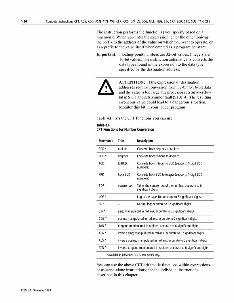
4-10 Compute Instructions CPT, ACS, ADD, ASN, ATN, AVE, CLR, COS, DIV, LN, LOG, MUL, NEG, SIN, SRT, SQR, STD, SUB, TAN, XPY
7KH�LQVWUXFWLRQ�SHUIRUPV�WKH�IXQFWLRQ�V��\RX�VSHFLI\�EDVHG�RQ�D�PQHPRQLF��:KHQ�\RX�HQWHU�WKH�H[SUHVVLRQ��HQWHU�WKH�PQHPRQLF�DV�WKH�SUHIL[�WR�WKH�DGGUHVV�RI�WKH�YDOXH�RQ�ZKLFK�\RX�ZDQW�WR�RSHUDWH��RU�DV�D�SUHIL[�WR�WKH�YDOXH�LWVHOI�ZKHQ�HQWHUHG�DV�D�SURJUDP�FRQVWDQW�
,PSRUWDQW���)ORDWLQJ�SRLQW�QXPEHUV�DUH����ELW�YDOXHV��,QWHJHUV�DUH����ELW�YDOXHV��7KH�LQVWUXFWLRQ�DXWRPDWLFDOO\�FRQYHUWV�WKH�GDWD�W\SHV�IRXQG�LQ�WKH�H[SUHVVLRQ�WR�WKH�GDWD�W\SH�VSHFLILHG�E\�WKH�GHVWLQDWLRQ�DGGUHVV��
7DEOH���)�OLVWV�WKH�&37�IXQFWLRQV�\RX�FDQ�XVH�
Table 4.F CPT Functions for Number Conversion
<RX�FDQ�XVH�WKH�DERYH�&37�DULWKPHWLF�IXQFWLRQV�ZLWKLQ�H[SUHVVLRQV�RU�DV�VWDQG�DORQH�LQVWUXFWLRQV��VHH�WKH�LQGLYLGXDO�LQVWUXFWLRQV�GHVFULEHG�LQ�WKLV�FKDSWHU�
�$77(17,21� ,I�WKH�H[SUHVVLRQ�RU�GHVWLQDWLRQ�DGGUHVVHV�UHTXLUH�FRQYHUVLRQ�IURP����ELW�WR����ELW�GDWD�DQG�WKH�YDOXH�LV�WRR�ODUJH��WKH�SURFHVVRU�VHWV�DQ�RYHUIORZ�ELW�LQ�6�����DQG�VHWV�D�PLQRU�IDXOW��6��������7KH�UHVXOWLQJ�HUURQHRXV�YDOXH�FRXOG�OHDG�WR�D�GDQJHURXV�VLWXDWLRQ��0RQLWRU�WKLV�ELW�LQ�\RXU�ODGGHU�SURJUDP�
Mnemonic Title Description
RAD * radians Converts from degrees to radians
DEG * degrees Converts from radians to degrees
TOD to BCD Converts from integer to BCD (supports 4-digit BCD numbers)
FRD from BCD Converts from BCD to integer (supports 4-digit BCD numbers)
SQR square root Takes the square root of the number; accurate to 6 significant digits
LOG * – Log to the base 10; accurate to 6 significant digits
LN * – Natural log; accurate to 6 significant digits
SIN * sine; manipulated in radians, accurate to 6 significant digits
COS * cosine; manipulated in radians, accurate to 6 significant digits
TAN * tangent; manipulated in radians, accurate to 6 significant digits
ASN * inverse sine; manipulated in radians, accurate to 6 significant digits
ACS * inverse cosine; manipulated in radians, accurate to 6 significant digits
ATN * inverse tangent; manipulated in radians, accurate to 6 significant digits
* Available in Enhanced PLC-5 processors only.
1785-6.1 November 1998
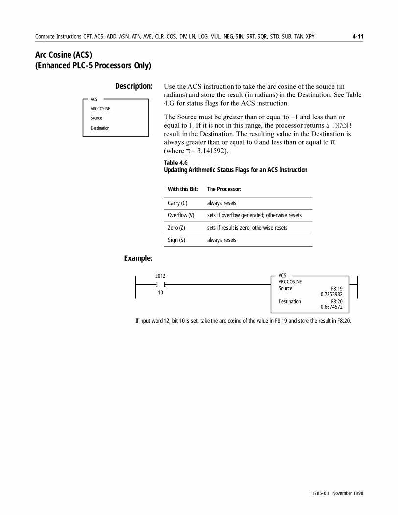
Compute Instructions CPT, ACS, ADD, ASN, ATN, AVE, CLR, COS, DIV, LN, LOG, MUL, NEG, SIN, SRT, SQR, STD, SUB, TAN, XPY 4-11
Arc Cosine (ACS) (Enhanced PLC-5 Processors Only)
Description: 8VH�WKH�$&6�LQVWUXFWLRQ�WR�WDNH�WKH�DUF�FRVLQH�RI�WKH�VRXUFH��LQ�UDGLDQV��DQG�VWRUH�WKH�UHVXOW��LQ�UDGLDQV��LQ�WKH�'HVWLQDWLRQ��6HH�7DEOH���*�IRU�VWDWXV�IODJV�IRU�WKH�$&6�LQVWUXFWLRQ�
7KH�6RXUFH�PXVW�EH�JUHDWHU�WKDQ�RU�HTXDO�WR�±��DQG�OHVV�WKDQ�RU�HTXDO�WR����,I�LW�LV�QRW�LQ�WKLV�UDQJH��WKH�SURFHVVRU�UHWXUQV�D�!NAN!�UHVXOW�LQ�WKH�'HVWLQDWLRQ��7KH�UHVXOWLQJ�YDOXH�LQ�WKH�'HVWLQDWLRQ�LV�DOZD\V�JUHDWHU�WKDQ�RU�HTXDO�WR���DQG�OHVV�WKDQ�RU�HTXDO�WR�π��ZKHUH�π� �����������
Table 4.G Updating Arithmetic Status Flags for an ACS Instruction
Example:
ACS
ARCCOSINE
Source
Destination
With this Bit: The Processor:
Carry (C) always resets
Overflow (V) sets if overflow generated; otherwise resets
Zero (Z) sets if result is zero; otherwise resets
Sign (S) always resets
]
ACSARCCOSINESource
I:012
10F8:19
Destination F8:20
]
0.7853982
0.6674572
If input word 12, bit 10 is set, take the arc cosine of the value in F8:19 and store the result in F8:20.
1785-6.1 November 1998

4-12 Compute Instructions CPT, ACS, ADD, ASN, ATN, AVE, CLR, COS, DIV, LN, LOG, MUL, NEG, SIN, SRT, SQR, STD, SUB, TAN, XPY
Addition (ADD)
Description: 8VH�WKH�$''�LQVWUXFWLRQ�WR�DGG�RQH�YDOXH��6RXUFH�$��WR�DQRWKHU�YDOXH��6RXUFH�%��DQG�SODFH�WKH�UHVXOW�LQ�WKH�GHVWLQDWLRQ��6RXUFH�$�DQG�6RXUFH�%�FDQ�HLWKHU�EH�YDOXHV�RU�DGGUHVVHV�WKDW�FRQWDLQ�YDOXHV��6HH�7DEOH���+�IRU�VWDWXV�IODJV�IRU�WKH�$''�LQVWUXFWLRQ�
,PSRUWDQW���7KH�$''�LQVWUXFWLRQ�H[HFXWHV�RQFH�HDFK�VFDQ�DV�ORQJ�DV�WKH�UXQJ�LV�WUXH��LI�\RX�RQO\�ZDQW�YDOXHV�DGGHG�RQFH��LQFOXGH�WKH�216�FRPPDQG��VHH�FKDSWHU�����
Table 4.H Updating Arithmetic Status Flags for an ADD Instruction
Example:
ADD
ADD
Source A
Source B
Destination
With this Bit: The Processor:
Carry (C) sets if carry generated; otherwise resets
Overflow (V) sets if overflow generated; otherwise resets
Zero (Z) sets if result is zero; otherwise resets
Sign (S) sets if result is negative; otherwise resets
]
ADD
ADD
Source A
Source B
I:012
10 N7:3
N7:4
Destination N7:20
]
If input word 12, bit 10 is set, add the value in N7:3 to the value in N7:4 and store the result in N7:20.
1785-6.1 November 1998

Compute Instructions CPT, ACS, ADD, ASN, ATN, AVE, CLR, COS, DIV, LN, LOG, MUL, NEG, SIN, SRT, SQR, STD, SUB, TAN, XPY 4-13
Arc Sine (ASN) (Enhanced PLC-5 Processors Only)
Description: 8VH�WKH�$61�LQVWUXFWLRQ�WR�WDNH�WKH�DUF�VLQH�WKH�VRXUFH��LQ�UDGLDQV��DQG�VWRUH�WKH�UHVXOW��LQ�UDGLDQV��LQ�WKH�'HVWLQDWLRQ��6HH�7DEOH���,�IRU�VWDWXV�IODJV�IRU�$61�LQVWUXFWLRQ�
7KH�6RXUFH�PXVW�EH�JUHDWHU�WKDQ�RU�HTXDO�WR�±��DQG�OHVV�WKDQ�RU�HTXDO�WR����,I�LW�LV�QRW�LQ�WKLV�UDQJH��WKH�SURFHVVRU�UHWXUQV�D�!NAN!�UHVXOW�LQ�WKH�'HVWLQDWLRQ��7KH�UHVXOWLQJ�YDOXH�LQ�WKH�'HVWLQDWLRQ�LV�DOZD\V�JUHDWHU�WKDQ�RU�HTXDO�WR�±π���DQG�OHVV�WKDQ�RU�HTXDO�WR�π/2��ZKHUH�π� �����������
Table 4.I Updating Arithmetic Status Flags for an ASN Instruction
Example:
ASN
ARCSINE
Source
Destination
With this Bit: The Processor:
Carry (C) always resets
Overflow (V) sets if overflow generated; otherwise resets
Zero (Z) sets if result is zero; otherwise resets
Sign (S) always resets
]
ASN
ARCSINESource
I:012
10 F8:17
Dest F8:18
]
0.7853982
0.9033391
If input word 12, bit 10 is set, take the arc sine of the value in F8:17 and store the result in F8:18.
1785-6.1 November 1998

4-14 Compute Instructions CPT, ACS, ADD, ASN, ATN, AVE, CLR, COS, DIV, LN, LOG, MUL, NEG, SIN, SRT, SQR, STD, SUB, TAN, XPY
Arc Tangent (ATN) (Enhanced PLC-5 Processors Only)
Description: 8VH�WKH�$71�LQVWUXFWLRQ�WR�WDNH�WKH�DUF�WDQJHQW�RI�WKH�VRXUFH��LQ�UDGLDQV��DQG�VWRUH�WKH�UHVXOW��LQ�UDGLDQV��LQ�WKH�'HVWLQDWLRQ��7KH�UHVXOWLQJ�YDOXH�LQ�WKH�'HVWLQDWLRQ�LV�DOZD\V�JUHDWHU�WKDQ�RU�HTXDO�WR�±π���DQG�OHVV�WKDQ�RU�HTXDO�WR�π/2��ZKHUH�π� ������������6HH�7DEOH���-�IRU�VWDWXV�IODJV�IRU�$71�LQVWUXFWLRQ�
Table 4.J Updating Arithmetic Status Flags for an ATN Instruction
Example:
ATN
ARCTANGENT
Source
Destination
With this Bit: The Processor:
Carry (C) always resets
Overflow (V) sets if overflow generated; otherwise resets
Zero (Z) sets if result is zero; otherwise resets
Sign (S) sets if result is negative; otherwise resets
]
ATN
ARCTANGENTSource
I:012
10 F8:21
Destination F8:22
]
0.7853982
0.6657737
If input word 12, bit 10 is set, take the arc tangent of the value in F8:21 and store the result in F8:22.
1785-6.1 November 1998
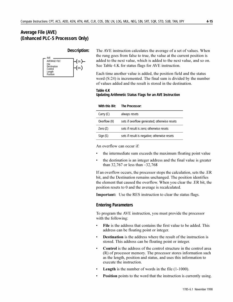
Compute Instructions CPT, ACS, ADD, ASN, ATN, AVE, CLR, COS, DIV, LN, LOG, MUL, NEG, SIN, SRT, SQR, STD, SUB, TAN, XPY 4-15
Average File (AVE) (Enhanced PLC-5 Processors Only)
Description: 7KH�$9(�LQVWUXFWLRQ�FDOFXODWHV�WKH�DYHUDJH�RI�D�VHW�RI�YDOXHV��:KHQ�WKH�UXQJ�JRHV�IURP�IDOVH�WR�WUXH��WKH�YDOXH�DW�WKH�FXUUHQW�SRVLWLRQ�LV�DGGHG�WR�WKH�QH[W�YDOXH��ZKLFK�LV�DGGHG�WR�WKH�QH[W�YDOXH��DQG�VR�RQ��6HH�7DEOH���.�IRU�VWDWXV�IODJV�IRU�$9(�LQVWUXFWLRQ�
(DFK�WLPH�DQRWKHU�YDOXH�LV�DGGHG��WKH�SRVLWLRQ�ILHOG�DQG�WKH�VWDWXV�ZRUG��6�����LV�LQFUHPHQWHG��7KH�ILQDO�VXP�LV�GLYLGHG�E\�WKH�QXPEHU�RI�YDOXHV�DGGHG�DQG�WKH�UHVXOW�LV�VWRUHG�LQ�WKH�GHVWLQDWLRQ�
Table 4.K Updating Arithmetic Status Flags for an AVE Instruction
$Q�RYHUIORZ�FDQ�RFFXU�LI�
� WKH�LQWHUPHGLDWH�VXP�H[FHHGV�WKH�PD[LPXP�IORDWLQJ�SRLQW�YDOXH
� WKH�GHVWLQDWLRQ�LV�DQ�LQWHJHU�DGGUHVV�DQG�WKH�ILQDO�YDOXH�LV�JUHDWHU�WKDQ��������RU�OHVV�WKDQ�±������
,I�DQ�RYHUIORZ�RFFXUV��WKH�SURFHVVRU�VWRSV�WKH�FDOFXODWLRQ��VHWV�WKH��(5�ELW��DQG�WKH�'HVWLQDWLRQ�UHPDLQV�XQFKDQJHG��7KH�SRVLWLRQ�LGHQWLILHV�WKH�HOHPHQW�WKDW�FDXVHG�WKH�RYHUIORZ��:KHQ�\RX�FOHDU�WKH��(5�ELW��WKH�SRVLWLRQ�UHVHWV�WR���DQG�WKH�DYHUDJH�LV�UHFDOFXODWHG�
,PSRUWDQW���8VH�WKH�5(6�LQVWUXFWLRQ�WR�FOHDU�WKH�VWDWXV�IODJV�
Entering Parameters
7R�SURJUDP�WKH�$9(�LQVWUXFWLRQ��\RX�PXVW�SURYLGH�WKH�SURFHVVRU�ZLWK�WKH�IROORZLQJ�
� )LOH�LV�WKH�DGGUHVV�WKDW�FRQWDLQV�WKH�ILUVW�YDOXH�WR�EH�DGGHG��7KLV�DGGUHVV�FDQ�EH�IORDWLQJ�SRLQW�RU�LQWHJHU�
� 'HVWLQDWLRQ�LV�WKH�DGGUHVV�ZKHUH�WKH�UHVXOW�RI�WKH�LQVWUXFWLRQ�LV�VWRUHG��7KLV�DGGUHVV�FDQ�EH�IORDWLQJ�SRLQW�RU�LQWHJHU�
� &RQWURO�LV�WKH�DGGUHVV�RI�WKH�FRQWURO�VWUXFWXUH�LQ�WKH�FRQWURO�DUHD��5��RI�SURFHVVRU�PHPRU\��7KH�SURFHVVRU�VWRUHV�LQIRUPDWLRQ�VXFK�DV�WKH�OHQJWK��SRVLWLRQ�DQG�VWDWXV��DQG�XVHV�WKLV�LQIRUPDWLRQ�WR�H[HFXWH�WKH�LQVWUXFWLRQ�
� /HQJWK�LV�WKH�QXPEHU�RI�ZRUGV�LQ�WKH�ILOH����������
� 3RVLWLRQ�SRLQWV�WR�WKH�ZRUG�WKDW�WKH�LQVWUXFWLRQ�LV�FXUUHQWO\�XVLQJ��
AVEAVERAGE FILE
ControlLength
Destination
Position
FileEN
DN
With this Bit: The Processor:
Carry (C) always resets
Overflow (V) sets if overflow generated; otherwise resets
Zero (Z) sets if result is zero; otherwise resets
Sign (S) sets if result is negative; otherwise resets
1785-6.1 November 1998
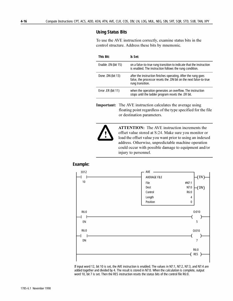
4-16 Compute Instructions CPT, ACS, ADD, ASN, ATN, AVE, CLR, COS, DIV, LN, LOG, MUL, NEG, SIN, SRT, SQR, STD, SUB, TAN, XPY
Using Status Bits
7R�XVH�WKH�$9(�LQVWUXFWLRQ�FRUUHFWO\��H[DPLQH�VWDWXV�ELWV�LQ�WKH�FRQWURO�VWUXFWXUH��$GGUHVV�WKHVH�ELWV�E\�PQHPRQLF�
,PSRUWDQW���7KH�$9(�LQVWUXFWLRQ�FDOFXODWHV�WKH�DYHUDJH�XVLQJ�IORDWLQJ�SRLQW�UHJDUGOHVV�RI�WKH�W\SH�VSHFLILHG�IRU�WKH�ILOH�RU�GHVWLQDWLRQ�SDUDPHWHUV��
Example:
This Bit: Is Set:
Enable .EN (bit 15) on a false-to-true rung transition to indicate that the instruction is enabled. The instruction follows the rung condition.
Done .DN (bit 13) after the instruction finishes operating. After the rung goes false, the processor resets the .DN bit on the next false-to-true rung transition.
Error .ER (bit 11) when the operation generates an overflow. The instruction stops until the ladder program resets the .ER bit.
�$77(17,21� 7KH�$9(�LQVWUXFWLRQ�LQFUHPHQWV�WKH�RIIVHW�YDOXH�VWRUHG�DW�6�����0DNH�VXUH�\RX�PRQLWRU�RU�ORDG�WKH�RIIVHW�YDOXH�\RX�ZDQW�SULRU�WR�XVLQJ�DQ�LQGH[HG�DGGUHVV��2WKHUZLVH��XQSUHGLFWDEOH�PDFKLQH�RSHUDWLRQ�FRXOG�RFFXU�ZLWK�SRVVLEOH�GDPDJH�WR�HTXLSPHQW�DQG�RU�LQMXU\�WR�SHUVRQQHO�
]
AVE
AVERAGE FILE
FileDest
I:012
10 #N7:1N7:0
Control R6:0
]
Length
Position
4
0
]
R6:0
EN
]
O:010
5
]
R6:0
DN
]
O:010
7
EN
DN
RESR6:0
If input word 12, bit 10 is set, the AVE instruction is enabled. The values in N7:1, N7:2, N7:3, and N7:4 are added together and divided by 4. The result is stored in N7:0. When the calculation is complete, output word 10, bit 7 is set. Then the RES instruction resets the status bits of the control file R6:0.
1785-6.1 November 1998
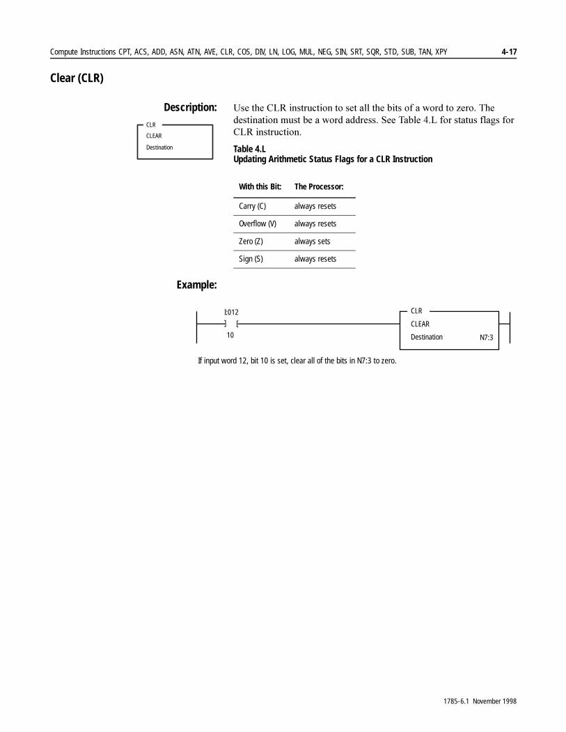
Compute Instructions CPT, ACS, ADD, ASN, ATN, AVE, CLR, COS, DIV, LN, LOG, MUL, NEG, SIN, SRT, SQR, STD, SUB, TAN, XPY 4-17
Clear (CLR)
Description: 8VH�WKH�&/5�LQVWUXFWLRQ�WR�VHW�DOO�WKH�ELWV�RI�D�ZRUG�WR�]HUR��7KH�GHVWLQDWLRQ�PXVW�EH�D�ZRUG�DGGUHVV��6HH�7DEOH���/�IRU�VWDWXV�IODJV�IRU�&/5�LQVWUXFWLRQ�
Table 4.L Updating Arithmetic Status Flags for a CLR Instruction
Example:
CLR
CLEAR
Destination
With this Bit: The Processor:
Carry (C) always resets
Overflow (V) always resets
Zero (Z) always sets
Sign (S) always resets
]
CLR
CLEAR
Destination
I:012
10 N7:3
]
If input word 12, bit 10 is set, clear all of the bits in N7:3 to zero.
1785-6.1 November 1998
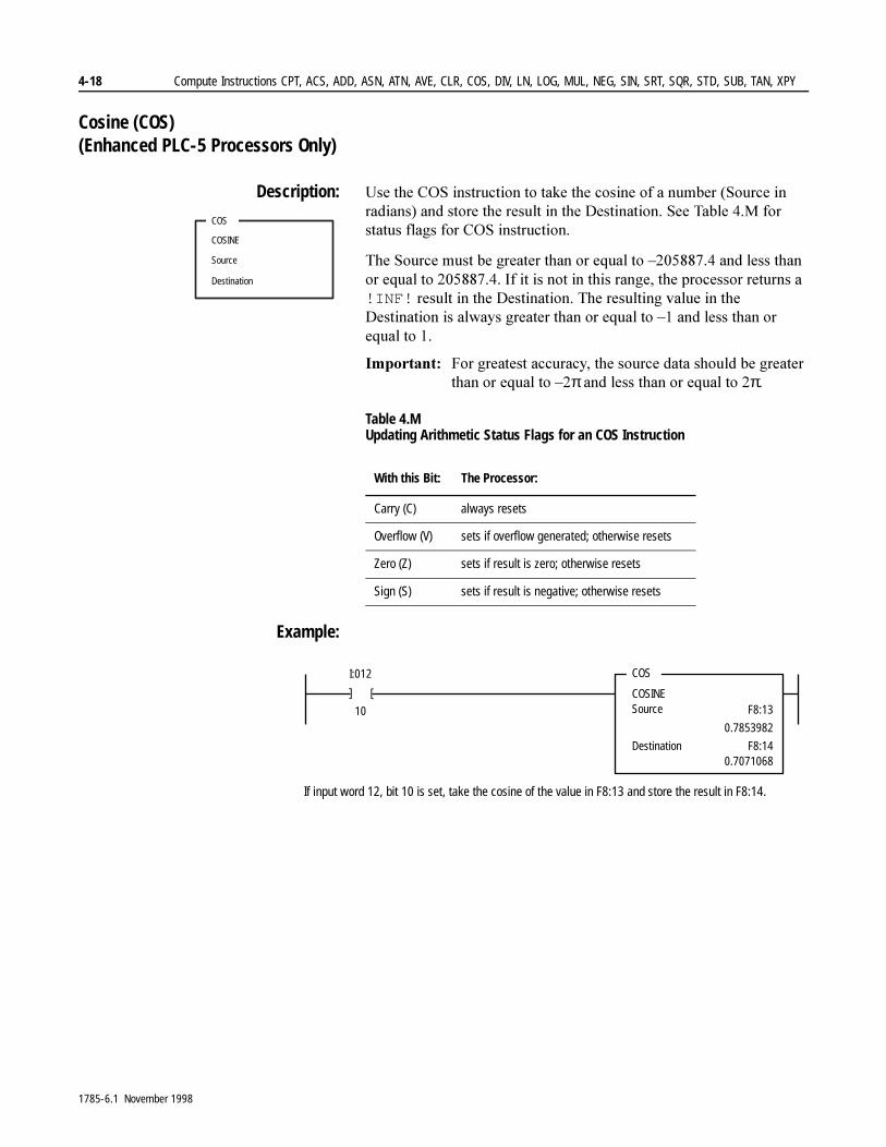
4-18 Compute Instructions CPT, ACS, ADD, ASN, ATN, AVE, CLR, COS, DIV, LN, LOG, MUL, NEG, SIN, SRT, SQR, STD, SUB, TAN, XPY
Cosine (COS) (Enhanced PLC-5 Processors Only)
Description: 8VH�WKH�&26�LQVWUXFWLRQ�WR�WDNH�WKH�FRVLQH�RI�D�QXPEHU��6RXUFH�LQ�UDGLDQV��DQG�VWRUH�WKH�UHVXOW�LQ�WKH�'HVWLQDWLRQ��6HH�7DEOH���0�IRU�VWDWXV�IODJV�IRU�&26�LQVWUXFWLRQ�
7KH�6RXUFH�PXVW�EH�JUHDWHU�WKDQ�RU�HTXDO�WR�±���������DQG�OHVV�WKDQ�RU�HTXDO�WR�����������,I�LW�LV�QRW�LQ�WKLV�UDQJH��WKH�SURFHVVRU�UHWXUQV�D�!INF!�UHVXOW�LQ�WKH�'HVWLQDWLRQ��7KH�UHVXOWLQJ�YDOXH�LQ�WKH�'HVWLQDWLRQ�LV�DOZD\V�JUHDWHU�WKDQ�RU�HTXDO�WR�±��DQG�OHVV�WKDQ�RU�HTXDO�WR���
,PSRUWDQW���)RU�JUHDWHVW�DFFXUDF\��WKH�VRXUFH�GDWD�VKRXOG�EH�JUHDWHU�WKDQ�RU�HTXDO�WR�±�π�DQG�OHVV�WKDQ�RU�HTXDO�WR��π�
Table 4.M Updating Arithmetic Status Flags for an COS Instruction
Example:
COS
COSINE
Source
Destination
With this Bit: The Processor:
Carry (C) always resets
Overflow (V) sets if overflow generated; otherwise resets
Zero (Z) sets if result is zero; otherwise resets
Sign (S) sets if result is negative; otherwise resets
]
COS
COSINESource
I:012
10 F8:13
Destination F8:14
]
0.7853982
0.7071068
If input word 12, bit 10 is set, take the cosine of the value in F8:13 and store the result in F8:14.
1785-6.1 November 1998
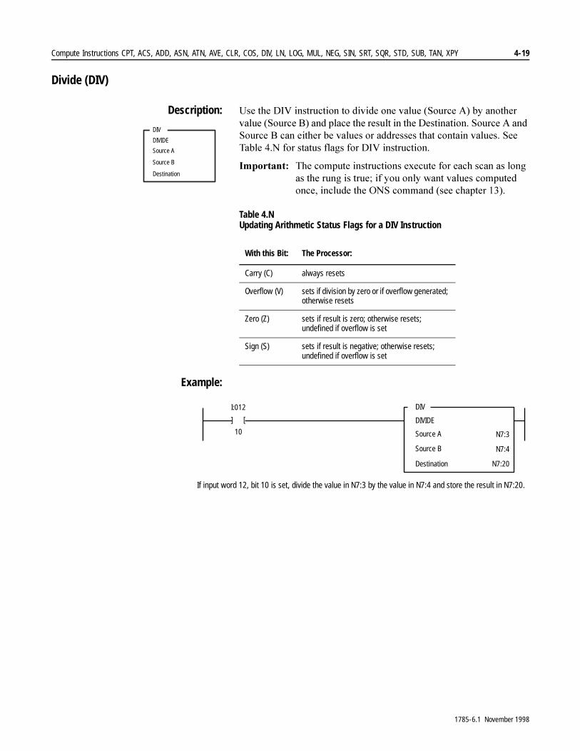
Compute Instructions CPT, ACS, ADD, ASN, ATN, AVE, CLR, COS, DIV, LN, LOG, MUL, NEG, SIN, SRT, SQR, STD, SUB, TAN, XPY 4-19
Divide (DIV)
Description: 8VH�WKH�',9�LQVWUXFWLRQ�WR�GLYLGH�RQH�YDOXH��6RXUFH�$��E\�DQRWKHU�YDOXH��6RXUFH�%��DQG�SODFH�WKH�UHVXOW�LQ�WKH�'HVWLQDWLRQ��6RXUFH�$�DQG�6RXUFH�%�FDQ�HLWKHU�EH�YDOXHV�RU�DGGUHVVHV�WKDW�FRQWDLQ�YDOXHV��6HH�7DEOH���1�IRU�VWDWXV�IODJV�IRU�',9�LQVWUXFWLRQ�
,PSRUWDQW���7KH�FRPSXWH�LQVWUXFWLRQV�H[HFXWH�IRU�HDFK�VFDQ�DV�ORQJ�DV�WKH�UXQJ�LV�WUXH��LI�\RX�RQO\�ZDQW�YDOXHV�FRPSXWHG�RQFH��LQFOXGH�WKH�216�FRPPDQG��VHH�FKDSWHU�����
Table 4.N Updating Arithmetic Status Flags for a DIV Instruction
Example:
DIV
DIVIDE
Source A
Source B
Destination
With this Bit: The Processor:
Carry (C) always resets
Overflow (V) sets if division by zero or if overflow generated; otherwise resets
Zero (Z) sets if result is zero; otherwise resets; undefined if overflow is set
Sign (S) sets if result is negative; otherwise resets;undefined if overflow is set
]
DIV
DIVIDE
Source A
Source B
I:012
10 N7:3
N7:4
Destination N7:20
]
If input word 12, bit 10 is set, divide the value in N7:3 by the value in N7:4 and store the result in N7:20.
1785-6.1 November 1998
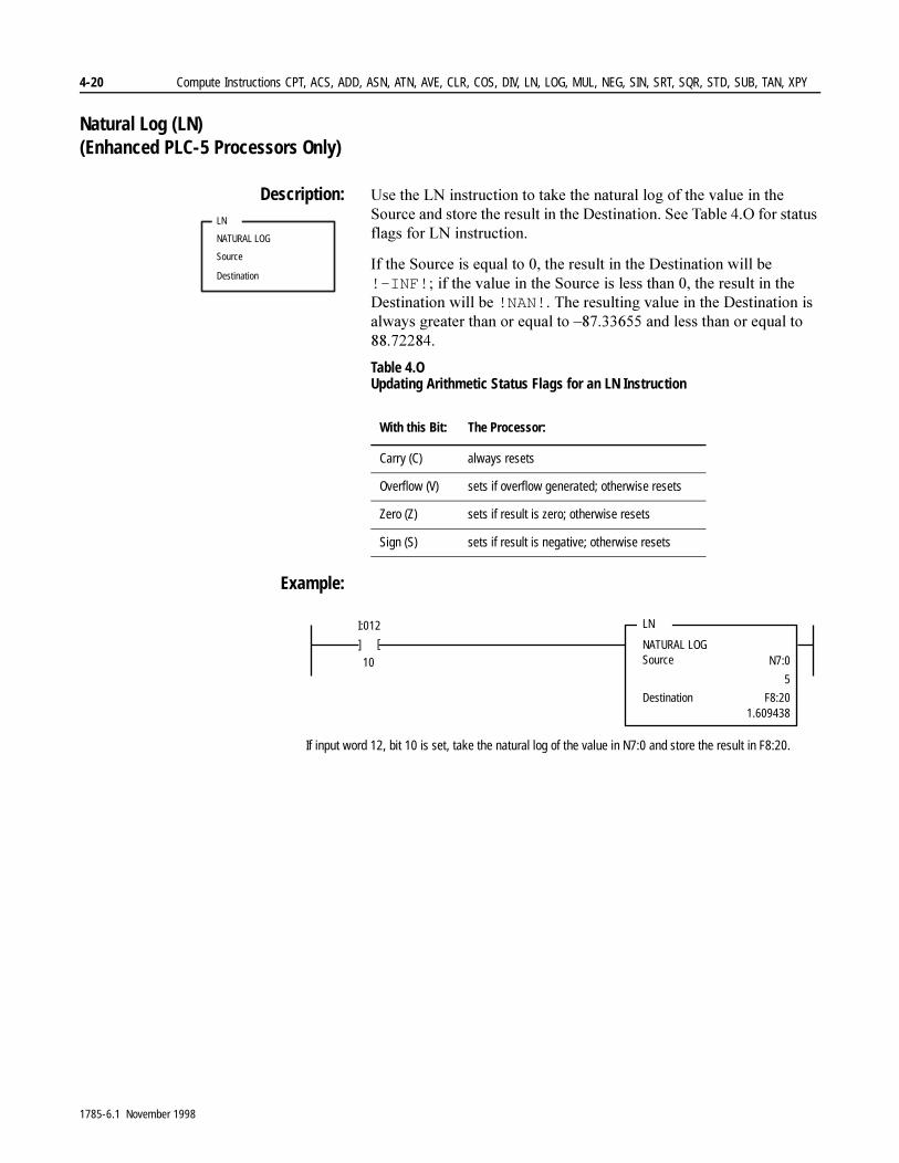
4-20 Compute Instructions CPT, ACS, ADD, ASN, ATN, AVE, CLR, COS, DIV, LN, LOG, MUL, NEG, SIN, SRT, SQR, STD, SUB, TAN, XPY
Natural Log (LN) (Enhanced PLC-5 Processors Only)
Description: 8VH�WKH�/1�LQVWUXFWLRQ�WR�WDNH�WKH�QDWXUDO�ORJ�RI�WKH�YDOXH�LQ�WKH�6RXUFH�DQG�VWRUH�WKH�UHVXOW�LQ�WKH�'HVWLQDWLRQ��6HH�7DEOH���2�IRU�VWDWXV�IODJV�IRU�/1�LQVWUXFWLRQ�
,I�WKH�6RXUFH�LV�HTXDO�WR����WKH�UHVXOW�LQ�WKH�'HVWLQDWLRQ�ZLOO�EH�!-INF!��LI�WKH�YDOXH�LQ�WKH�6RXUFH�LV�OHVV�WKDQ����WKH�UHVXOW�LQ�WKH�'HVWLQDWLRQ�ZLOO�EH�!NAN!��7KH�UHVXOWLQJ�YDOXH�LQ�WKH�'HVWLQDWLRQ�LV�DOZD\V�JUHDWHU�WKDQ�RU�HTXDO�WR�±���������DQG�OHVV�WKDQ�RU�HTXDO�WR����������
Table 4.O Updating Arithmetic Status Flags for an LN Instruction
Example:
LN
NATURAL LOG
Source
Destination
With this Bit: The Processor:
Carry (C) always resets
Overflow (V) sets if overflow generated; otherwise resets
Zero (Z) sets if result is zero; otherwise resets
Sign (S) sets if result is negative; otherwise resets
]
LN
NATURAL LOGSource
I:012
10 N7:0
Destination F8:20
]
5
1.609438
If input word 12, bit 10 is set, take the natural log of the value in N7:0 and store the result in F8:20.
1785-6.1 November 1998

Compute Instructions CPT, ACS, ADD, ASN, ATN, AVE, CLR, COS, DIV, LN, LOG, MUL, NEG, SIN, SRT, SQR, STD, SUB, TAN, XPY 4-21
Log to the Base 10 (LOG) (Enhanced PLC-5 Processors Only)
Description: 8VH�WKH�/2*�LQVWUXFWLRQ�WR�WDNH�WKH�ORJ�EDVH����RI�WKH�YDOXH�LQ�WKH�6RXUFH�DQG�VWRUH�WKH�UHVXOW�LQ�WKH�'HVWLQDWLRQ��6HH�7DEOH���3�IRU�VWDWXV�IODJV�IRU�/2*�LQVWUXFWLRQ�
,I�WKH�6RXUFH�LV�HTXDO�WR����WKH�UHVXOW�LQ�WKH�'HVWLQDWLRQ�ZLOO�EH�!-INF!��LI�WKH�YDOXH�LQ�WKH�6RXUFH�LV�OHVV�WKDQ����WKH�UHVXOW�LQ�WKH�'HVWLQDWLRQ�ZLOO�EH�!NAN!��7KH�UHVXOWLQJ�YDOXH�LQ�WKH�'HVWLQDWLRQ�LV�DOZD\V�JUHDWHU�WKDQ�RU�HTXDO�WR�±���������DQG�OHVV�WKDQ�RU�HTXDO�WR����������
Table 4.P Updating Arithmetic Status Flags for an LOG Instruction
Example:
LOG
LOG BASE 10
Source
Destination
With this Bit: The Processor:
Carry (C) always resets
Overflow (V) sets if overflow generated; otherwise resets
Zero (Z) sets if result is zero; otherwise resets
Sign (S) sets if result is negative; otherwise resets
]
LOG
LOG BASE 10Source
I:012
10 N7:2
Destination F8:3
]
5
0.6989700
If input word 12, bit 10 is set, take the log base 10 of the value in N7:2 and store the result in F8:3.
1785-6.1 November 1998
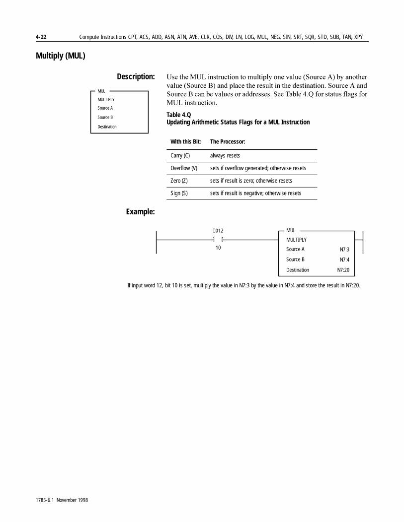
4-22 Compute Instructions CPT, ACS, ADD, ASN, ATN, AVE, CLR, COS, DIV, LN, LOG, MUL, NEG, SIN, SRT, SQR, STD, SUB, TAN, XPY
Multiply (MUL)
Description: 8VH�WKH�08/�LQVWUXFWLRQ�WR�PXOWLSO\�RQH�YDOXH��6RXUFH�$��E\�DQRWKHU�YDOXH��6RXUFH�%��DQG�SODFH�WKH�UHVXOW�LQ�WKH�GHVWLQDWLRQ��6RXUFH�$�DQG�6RXUFH�%�FDQ�EH�YDOXHV�RU�DGGUHVVHV��6HH�7DEOH���4�IRU�VWDWXV�IODJV�IRU�08/�LQVWUXFWLRQ�
Table 4.Q Updating Arithmetic Status Flags for a MUL Instruction
Example:
MUL
MULTIPLY
Source A
Source B
Destination
With this Bit: The Processor:
Carry (C) always resets
Overflow (V) sets if overflow generated; otherwise resets
Zero (Z) sets if result is zero; otherwise resets
Sign (S) sets if result is negative; otherwise resets
]
MUL
MULTIPLY
Source A
Source B
I:012
10 N7:3
N7:4
Destination N7:20
]If input word 12, bit 10 is set, multiply the value in N7:3 by the value in N7:4 and store the result in N7:20.
1785-6.1 November 1998
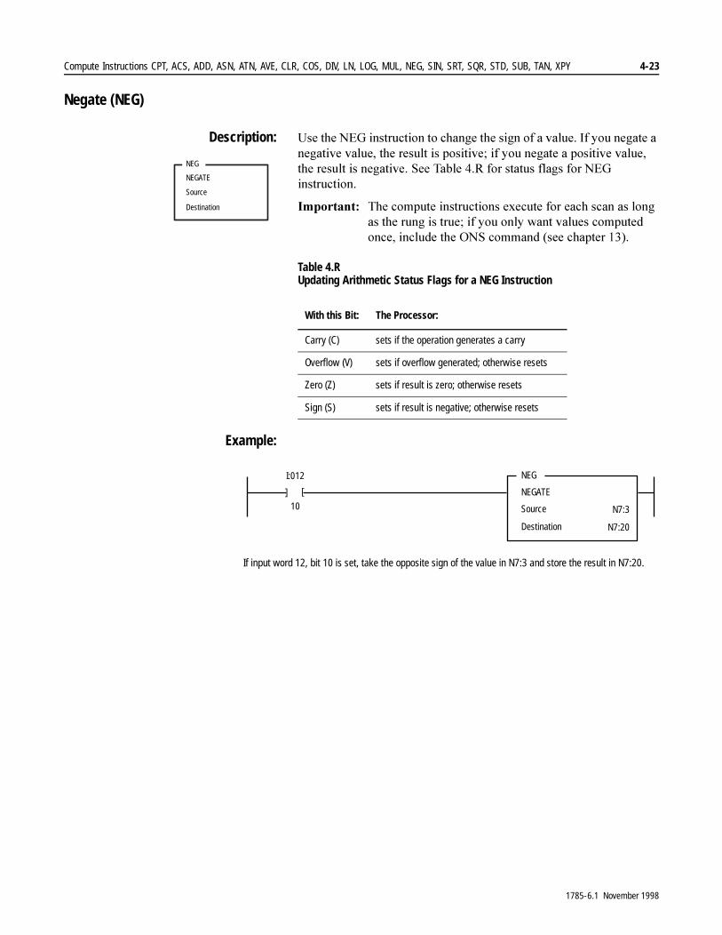
Compute Instructions CPT, ACS, ADD, ASN, ATN, AVE, CLR, COS, DIV, LN, LOG, MUL, NEG, SIN, SRT, SQR, STD, SUB, TAN, XPY 4-23
Negate (NEG)
Description: 8VH�WKH�1(*�LQVWUXFWLRQ�WR�FKDQJH�WKH�VLJQ�RI�D�YDOXH��,I�\RX�QHJDWH�D�QHJDWLYH�YDOXH��WKH�UHVXOW�LV�SRVLWLYH��LI�\RX�QHJDWH�D�SRVLWLYH�YDOXH��WKH�UHVXOW�LV�QHJDWLYH��6HH�7DEOH���5�IRU�VWDWXV�IODJV�IRU�1(*�LQVWUXFWLRQ�
,PSRUWDQW���7KH�FRPSXWH�LQVWUXFWLRQV�H[HFXWH�IRU�HDFK�VFDQ�DV�ORQJ�DV�WKH�UXQJ�LV�WUXH��LI�\RX�RQO\�ZDQW�YDOXHV�FRPSXWHG�RQFH��LQFOXGH�WKH�216�FRPPDQG��VHH�FKDSWHU�����
Table 4.R Updating Arithmetic Status Flags for a NEG Instruction
Example:
NEG
NEGATE
Source
Destination
With this Bit: The Processor:
Carry (C) sets if the operation generates a carry
Overflow (V) sets if overflow generated; otherwise resets
Zero (Z) sets if result is zero; otherwise resets
Sign (S) sets if result is negative; otherwise resets
]
NEG
NEGATE
Source
I:012
10 N7:3
]
Destination N7:20
If input word 12, bit 10 is set, take the opposite sign of the value in N7:3 and store the result in N7:20.
1785-6.1 November 1998

4-24 Compute Instructions CPT, ACS, ADD, ASN, ATN, AVE, CLR, COS, DIV, LN, LOG, MUL, NEG, SIN, SRT, SQR, STD, SUB, TAN, XPY
Sine (SIN) (Enhanced PLC-5 Processors Only)
Description: 8VH�WKH�6,1�LQVWUXFWLRQ�WR�WDNH�WKH�VLQH�RI�D�QXPEHU��6RXUFH�LQ�UDGLDQV��DQG�VWRUH�WKH�UHVXOW�LQ�WKH�'HVWLQDWLRQ��6HH�7DEOH���6�IRU�VWDWXV�IODJV�IRU�6,1�LQVWUXFWLRQ�
7KH�6RXUFH�PXVW�EH�JUHDWHU�WKDQ�RU�HTXDO�WR�±���������DQG�OHVV�WKDQ�RU�HTXDO�WR�����������,I�LW�LV�QRW�LQ�WKLV�UDQJH��WKH�SURFHVVRU�UHWXUQV�D�!INF!�UHVXOW�LQ�WKH�'HVWLQDWLRQ��7KH�UHVXOWLQJ�YDOXH�LQ�WKH�'HVWLQDWLRQ�LV�DOZD\V�JUHDWHU�WKDQ�RU�HTXDO�WR�±��DQG�OHVV�WKDQ�RU�HTXDO�WR���
,PSRUWDQW���)RU�JUHDWHVW�DFFXUDF\��WKH�VRXUFH�GDWD�VKRXOG�EH�JUHDWHU�WKDQ�RU�HTXDO�WR�±�π�DQG�OHVV�WKDQ�RU�HTXDO�WR �π�
Table 4.S Updating Arithmetic Status Flags for an SIN Instruction
Example:
SIN
SINE
Source
Destination
With this Bit: The Processor:
Carry (C) always resets
Overflow (V) sets if overflow generated; otherwise resets
Zero (Z) sets if result is zero; otherwise resets
Sign (S) sets if result is negative; otherwise resets
]
SINSINESource
I:012
10F8:11
Destination F8:12
]
0.7853982
0.7071068
If input word 12, bit 10 is set, take the sine of F8:11 and store the result in F8:12.
1785-6.1 November 1998

Compute Instructions CPT, ACS, ADD, ASN, ATN, AVE, CLR, COS, DIV, LN, LOG, MUL, NEG, SIN, SRT, SQR, STD, SUB, TAN, XPY 4-25
Square Root (SQR)
Description: 8VH�WKH�645�LQVWUXFWLRQ�WR�WDNH�WKH�VTXDUH�URRW�RI�D�YDOXH�DQG�VWRUH�WKH�UHVXOW�LQ�WKH�GHVWLQDWLRQ��7KH�VRXUFH�FDQ�EH�D�YDOXH�RU�DQ�DGGUHVV��,I�WKH�VRXUFH�YDOXH�LV�QHJDWLYH��WKH�SURFHVVRU�WDNHV�LWV�DEVROXWH�YDOXH�DQG�SHUIRUPV�WKH�VTXDUH�URRW�IXQFWLRQ��6HH�7DEOH���7�IRU�VWDWXV�IODJV�IRU�645�LQVWUXFWLRQ�
,PSRUWDQW���7KH�645�LQVWUXFWLRQ�H[HFXWHV�RQFH�IRU�HDFK�VFDQ�DV�ORQJ�DV�WKH�UXQJ�LV�WUXH��LI�\RX�RQO\�ZDQW�YDOXHV�FRPSXWHG�RQFH��LQFOXGH�WKH�216�FRPPDQG��VHH�FKDSWHU ����
Table 4.T Updating Arithmetic Status Flags for a SQR Instruction
Example:
SQR
SQUARE ROOT
Source
Destination
With this Bit: The Processor:
Carry (C) always resets
Overflow (V) sets if overflow generated during floating-point to integer conversion; otherwise resets
Zero (Z) sets if result is zero; otherwise resets
Sign (S) always resets
]
SQR
SQUARE ROOT
Source
I:012
10 N7:3
]
Destination N7:20
If input word 12, bit 10 is set, take the square root of the value in N7:3 and store the result in N7:20.
1785-6.1 November 1998
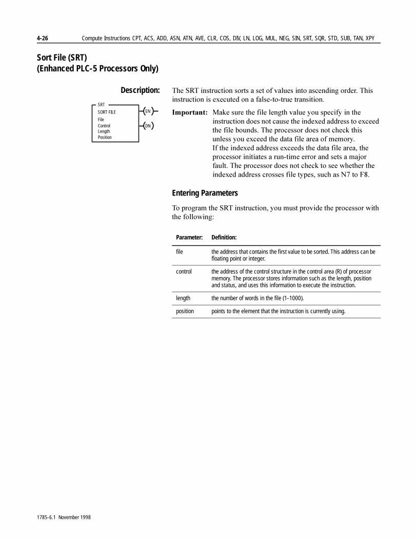
4-26 Compute Instructions CPT, ACS, ADD, ASN, ATN, AVE, CLR, COS, DIV, LN, LOG, MUL, NEG, SIN, SRT, SQR, STD, SUB, TAN, XPY
Sort File (SRT) (Enhanced PLC-5 Processors Only)
Description: 7KH�657�LQVWUXFWLRQ�VRUWV�D�VHW�RI�YDOXHV�LQWR�DVFHQGLQJ�RUGHU��7KLV�LQVWUXFWLRQ�LV�H[HFXWHG�RQ�D�IDOVH�WR�WUXH�WUDQVLWLRQ�
,PSRUWDQW���0DNH�VXUH�WKH�ILOH�OHQJWK�YDOXH�\RX�VSHFLI\�LQ�WKH�LQVWUXFWLRQ�GRHV�QRW�FDXVH�WKH�LQGH[HG�DGGUHVV�WR�H[FHHG�WKH�ILOH�ERXQGV��7KH�SURFHVVRU�GRHV�QRW�FKHFN�WKLV�XQOHVV�\RX�H[FHHG�WKH�GDWD�ILOH�DUHD�RI�PHPRU\��,I�WKH�LQGH[HG�DGGUHVV�H[FHHGV�WKH�GDWD�ILOH�DUHD��WKH�SURFHVVRU�LQLWLDWHV�D�UXQ�WLPH�HUURU�DQG�VHWV�D�PDMRU�IDXOW��7KH�SURFHVVRU�GRHV�QRW�FKHFN�WR�VHH�ZKHWKHU�WKH�LQGH[HG�DGGUHVV�FURVVHV�ILOH�W\SHV��VXFK�DV�1��WR�)��
Entering Parameters
7R�SURJUDP�WKH�657�LQVWUXFWLRQ��\RX�PXVW�SURYLGH�WKH�SURFHVVRU�ZLWK�WKH�IROORZLQJ�
SRT
SORT FILE
File
Position
ControlLength
EN
DN
Parameter: Definition:
file the address that contains the first value to be sorted. This address can be floating point or integer.
control the address of the control structure in the control area (R) of processor memory. The processor stores information such as the length, position and status, and uses this information to execute the instruction.
length the number of words in the file (1-1000).
position points to the element that the instruction is currently using.
1785-6.1 November 1998
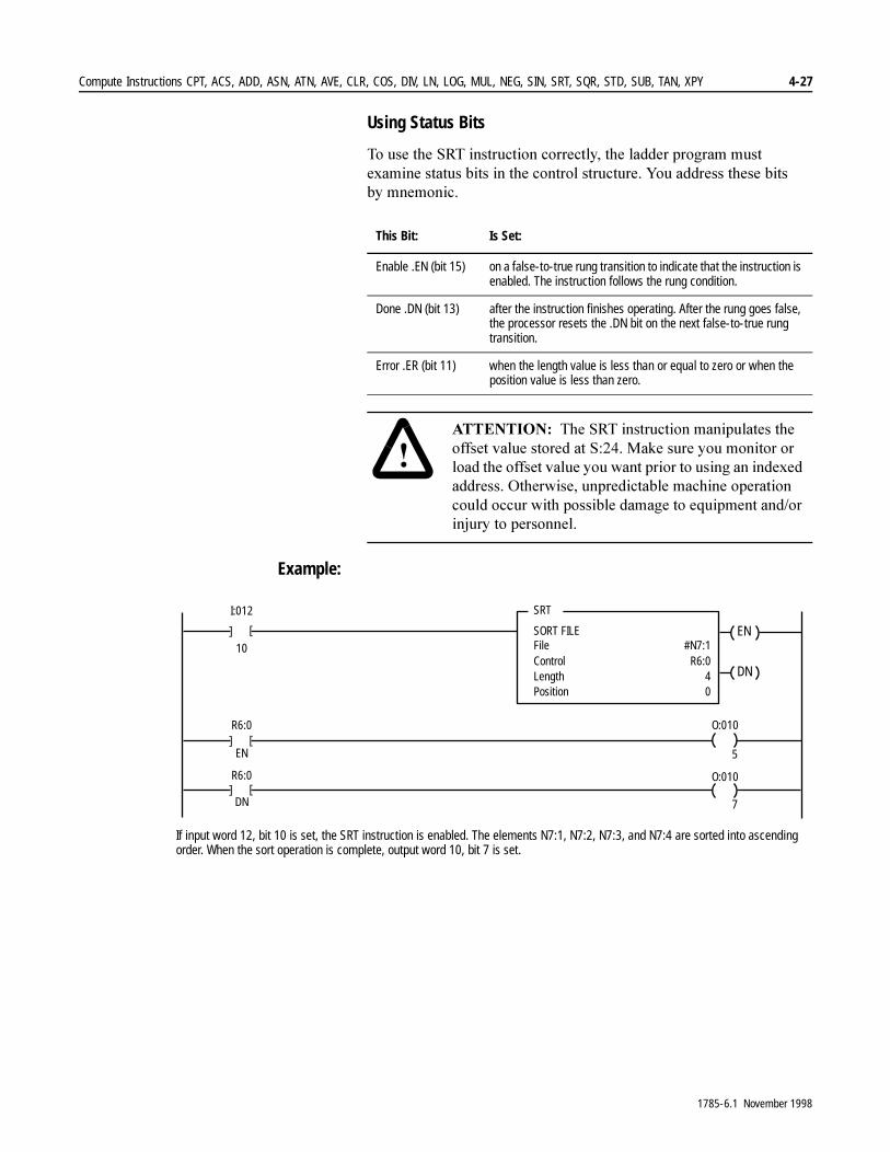
Compute Instructions CPT, ACS, ADD, ASN, ATN, AVE, CLR, COS, DIV, LN, LOG, MUL, NEG, SIN, SRT, SQR, STD, SUB, TAN, XPY 4-27
Using Status Bits
7R�XVH�WKH�657�LQVWUXFWLRQ�FRUUHFWO\��WKH�ODGGHU�SURJUDP�PXVW�H[DPLQH�VWDWXV�ELWV�LQ�WKH�FRQWURO�VWUXFWXUH��<RX�DGGUHVV�WKHVH�ELWV�E\ PQHPRQLF��
Example:
This Bit: Is Set:
Enable .EN (bit 15) on a false-to-true rung transition to indicate that the instruction is enabled. The instruction follows the rung condition.
Done .DN (bit 13) after the instruction finishes operating. After the rung goes false, the processor resets the .DN bit on the next false-to-true rung transition.
Error .ER (bit 11) when the length value is less than or equal to zero or when the position value is less than zero.
�$77(17,21� 7KH�657�LQVWUXFWLRQ�PDQLSXODWHV�WKH�RIIVHW�YDOXH�VWRUHG�DW�6�����0DNH�VXUH�\RX�PRQLWRU�RU�ORDG�WKH�RIIVHW�YDOXH�\RX�ZDQW�SULRU�WR�XVLQJ�DQ�LQGH[HG�DGGUHVV��2WKHUZLVH��XQSUHGLFWDEOH�PDFKLQH�RSHUDWLRQ�FRXOG�RFFXU�ZLWK�SRVVLEOH�GDPDJH�WR�HTXLSPHQW�DQG�RU�LQMXU\�WR�SHUVRQQHO�
]
SRT
SORT FILEFile
I:012
10 #N7:1Control R6:0
]
LengthPosition
40
]R6:0
EN
]
O:010
5
]R6:0
DN
] O:010
7
EN
DN
If input word 12, bit 10 is set, the SRT instruction is enabled. The elements N7:1, N7:2, N7:3, and N7:4 are sorted into ascending order. When the sort operation is complete, output word 10, bit 7 is set.
1785-6.1 November 1998
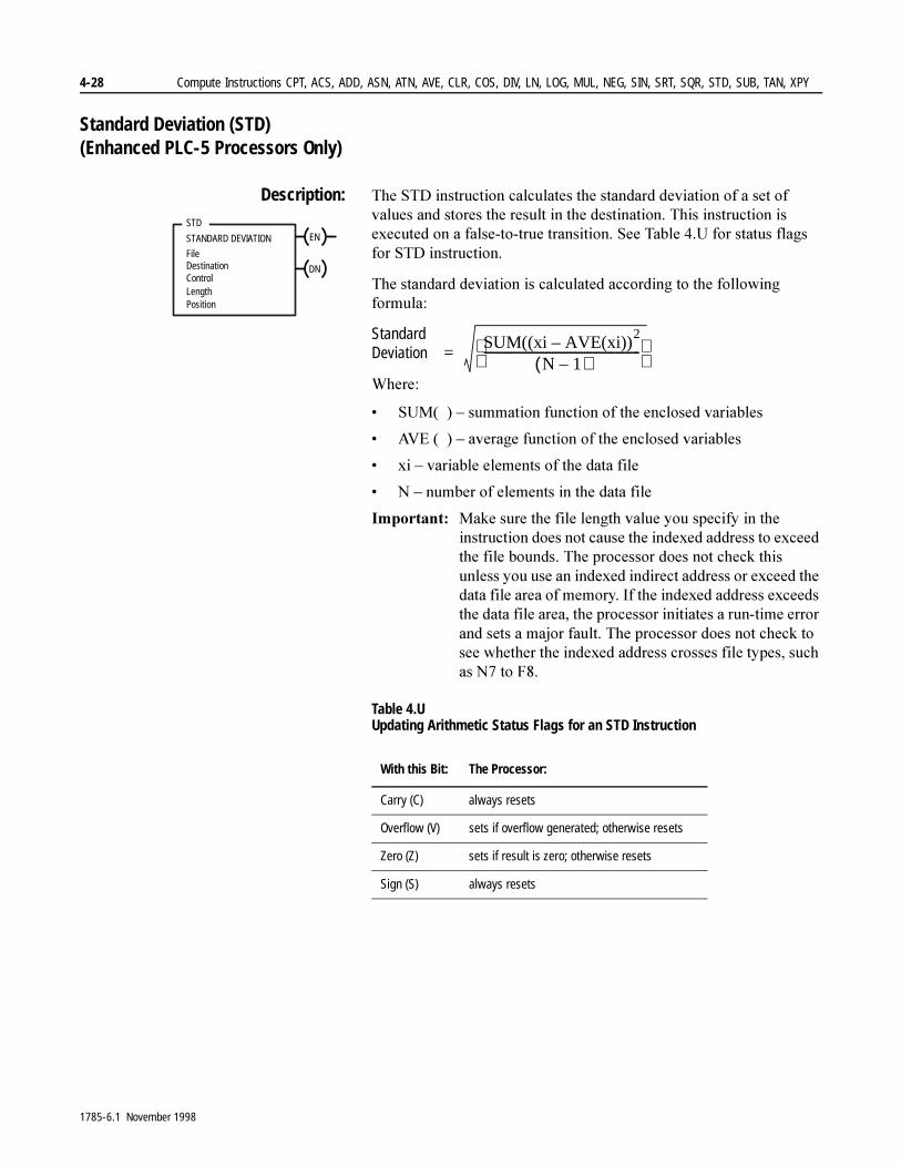
4-28 Compute Instructions CPT, ACS, ADD, ASN, ATN, AVE, CLR, COS, DIV, LN, LOG, MUL, NEG, SIN, SRT, SQR, STD, SUB, TAN, XPY
Standard Deviation (STD) (Enhanced PLC-5 Processors Only)
Description: 7KH�67'�LQVWUXFWLRQ�FDOFXODWHV�WKH�VWDQGDUG�GHYLDWLRQ�RI�D�VHW�RI�YDOXHV�DQG�VWRUHV�WKH�UHVXOW�LQ�WKH�GHVWLQDWLRQ��7KLV�LQVWUXFWLRQ�LV�H[HFXWHG�RQ�D�IDOVH�WR�WUXH�WUDQVLWLRQ��6HH�7DEOH���8�IRU�VWDWXV�IODJV�IRU�67'�LQVWUXFWLRQ�
7KH�VWDQGDUG�GHYLDWLRQ�LV�FDOFXODWHG�DFFRUGLQJ�WR�WKH�IROORZLQJ�IRUPXOD�
StandardDeviation
:KHUH�
� 680� ��±�VXPPDWLRQ�IXQFWLRQ�RI�WKH�HQFORVHG�YDULDEOHV
� $9(�� ��±�DYHUDJH�IXQFWLRQ�RI�WKH�HQFORVHG�YDULDEOHV
� [L�±�YDULDEOH�HOHPHQWV�RI�WKH�GDWD�ILOH
� 1�±�QXPEHU�RI�HOHPHQWV�LQ�WKH�GDWD�ILOH
,PSRUWDQW���0DNH�VXUH�WKH�ILOH�OHQJWK�YDOXH�\RX�VSHFLI\�LQ�WKH�LQVWUXFWLRQ�GRHV�QRW�FDXVH�WKH�LQGH[HG�DGGUHVV�WR�H[FHHG�WKH�ILOH�ERXQGV��7KH�SURFHVVRU�GRHV�QRW�FKHFN�WKLV�XQOHVV�\RX�XVH�DQ�LQGH[HG�LQGLUHFW�DGGUHVV�RU�H[FHHG�WKH�GDWD�ILOH�DUHD�RI�PHPRU\��,I�WKH�LQGH[HG�DGGUHVV�H[FHHGV�WKH�GDWD�ILOH�DUHD��WKH�SURFHVVRU�LQLWLDWHV�D�UXQ�WLPH�HUURU�DQG�VHWV�D�PDMRU�IDXOW��7KH�SURFHVVRU�GRHV�QRW�FKHFN�WR�VHH�ZKHWKHU�WKH�LQGH[HG�DGGUHVV�FURVVHV�ILOH�W\SHV��VXFK�DV�1��WR�)��
Table 4.U Updating Arithmetic Status Flags for an STD Instruction
STD
STANDARD DEVIATION
ControlLength
Destination
Position
File
EN
DN
With this Bit: The Processor:
Carry (C) always resets
Overflow (V) sets if overflow generated; otherwise resets
Zero (Z) sets if result is zero; otherwise resets
Sign (S) always resets
SUM((xi AVE(xi))2
–N 1–( )
����������������������������������������������������� =
1785-6.1 November 1998

Compute Instructions CPT, ACS, ADD, ASN, ATN, AVE, CLR, COS, DIV, LN, LOG, MUL, NEG, SIN, SRT, SQR, STD, SUB, TAN, XPY 4-29
7KHUH�DUH�WZR�ZD\V�DQ�RYHUIORZ�FDQ�RFFXU�
� WKH�LQWHUPHGLDWH�VXP�H[FHHGV�WKH�PD[LPXP�IORDWLQJ�SRLQW�YDOXH��IORDWLQJ�SRLQW�YDOXHV�DUH��±���������H±���WR�±���������H����
� WKH�GHVWLQDWLRQ�LV�DQ�LQWHJHU�DGGUHVV�DQG�WKH�ILQDO�YDOXH�LV�JUHDWHU�WKDQ�������
,I�DQ�RYHUIORZ�RFFXUV��WKH�SURFHVVRU�VWRSV�WKH�FDOFXODWLRQ��VHWV�WKH��(5�ELW��DQG�OHDYHV�WKH�GHVWLQDWLRQ�XQFKDQJHG��7KH�SRVLWLRQ�LGHQWLILHV�WKH�HOHPHQW�WKDW�FDXVHG�WKH�RYHUIORZ��:KHQ�\RX�FOHDU�WKH��(5�ELW��WKH�SRVLWLRQ�UHVHWV�WR���DQG�WKH�VWDQGDUG�GHYLDWLRQ�LV�UHFDOFXODWHG�
,PSRUWDQW���8VH�WKH�5(6�LQVWUXFWLRQ�WR�FOHDU�WKH�VWDWXV�ELWV�
Entering Parameters
7R�SURJUDP�WKH�67'�LQVWUXFWLRQ��\RX�PXVW�SURYLGH�WKH�SURFHVVRU�ZLWK�WKH�IROORZLQJ�
Using Status Bits
7R�XVH�WKH�67'�LQVWUXFWLRQ�FRUUHFWO\��H[DPLQH�VWDWXV�ELWV�LQ�WKH�FRQWURO�VWUXFWXUH��<RX�DGGUHVV�WKHVH�ELWV�E\�PQHPRQLF�
Parameter: Defines:
file the address that contains the first value to be calculated. This address can be floating point or integer.
destination the address where the result of the instruction is stored. This address can be floating point or integer.
control the address of the control structure in the control area (R) of processor memory. The processor stores information such as the length, position and status, and uses this information to execute the instruction.
length the number of words in the file (1-1000).
position points to the element that the instruction is currently using.
This Bit: Is Set:
Enable .EN (bit 15) on a false-to-true rung transition to indicate that the instruction is enabled. The instruction follows the rung condition.
Done .DN (bit 13) after the instruction finishes operating. After the rung goes false, the processor resets the .DN bit on the next false-to-true rung transition.
Error .ER (bit 11) when the operation generates an overflow. The instruction stops until the ladder program resets the .ER bit.
1785-6.1 November 1998
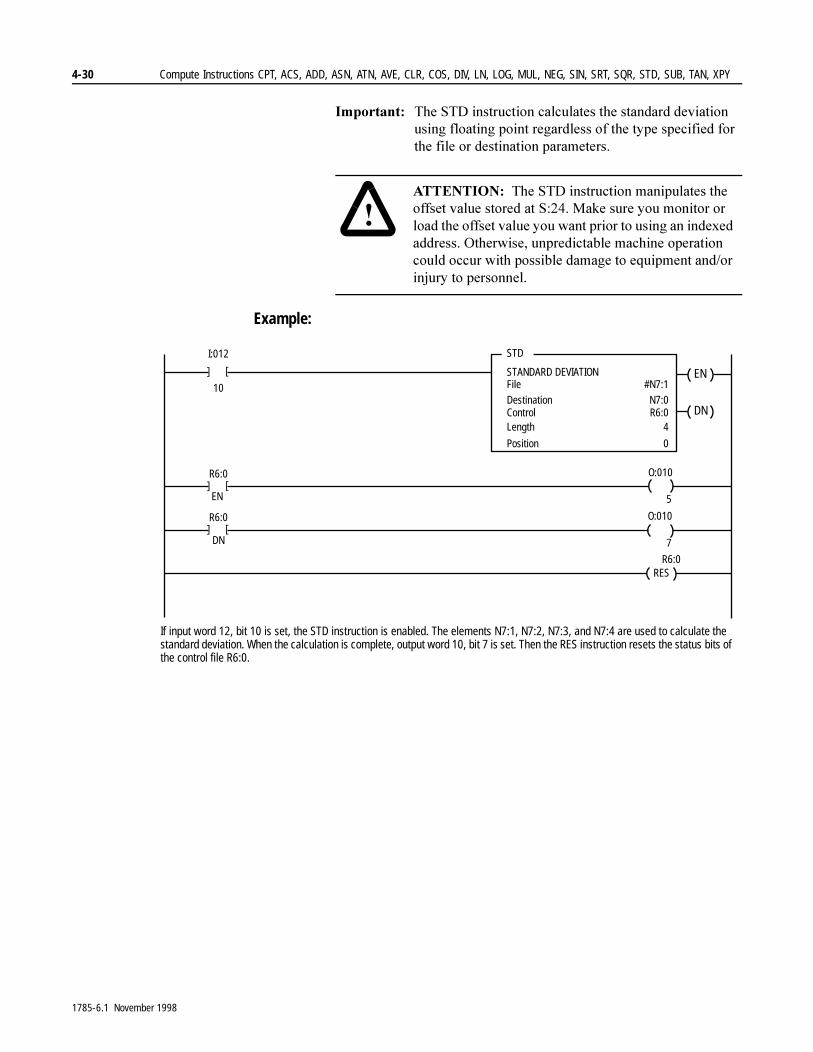
4-30 Compute Instructions CPT, ACS, ADD, ASN, ATN, AVE, CLR, COS, DIV, LN, LOG, MUL, NEG, SIN, SRT, SQR, STD, SUB, TAN, XPY
,PSRUWDQW���7KH�67'�LQVWUXFWLRQ�FDOFXODWHV�WKH�VWDQGDUG�GHYLDWLRQ�XVLQJ�IORDWLQJ�SRLQW�UHJDUGOHVV�RI�WKH�W\SH�VSHFLILHG�IRU�WKH�ILOH�RU�GHVWLQDWLRQ�SDUDPHWHUV��
Example:
�$77(17,21� 7KH�67'�LQVWUXFWLRQ�PDQLSXODWHV�WKH�RIIVHW�YDOXH�VWRUHG�DW�6�����0DNH�VXUH�\RX�PRQLWRU�RU�ORDG�WKH�RIIVHW�YDOXH�\RX�ZDQW�SULRU�WR�XVLQJ�DQ�LQGH[HG�DGGUHVV��2WKHUZLVH��XQSUHGLFWDEOH�PDFKLQH�RSHUDWLRQ�FRXOG�RFFXU�ZLWK�SRVVLEOH�GDPDJH�WR�HTXLSPHQW�DQG�RU�LQMXU\�WR�SHUVRQQHO�
]
STD
STANDARD DEVIATIONFile
I:012
10 #N7:1
Control R6:0
]
Length
Position
4
0
]R6:0
EN
]
O:010
5
]R6:0
DN
]O:010
7
Destination N7:0
EN
DN
RESR6:0
If input word 12, bit 10 is set, the STD instruction is enabled. The elements N7:1, N7:2, N7:3, and N7:4 are used to calculate the standard deviation. When the calculation is complete, output word 10, bit 7 is set. Then the RES instruction resets the status bits of the control file R6:0.
1785-6.1 November 1998
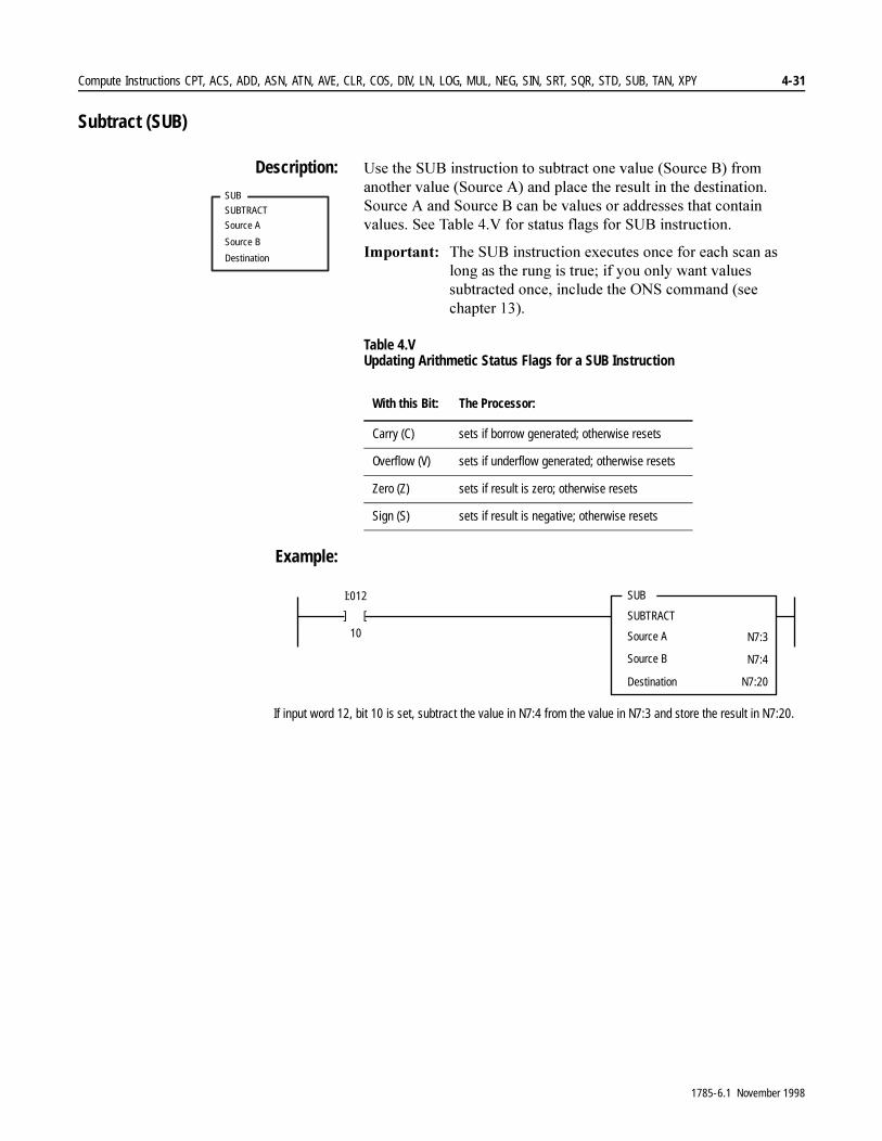
Compute Instructions CPT, ACS, ADD, ASN, ATN, AVE, CLR, COS, DIV, LN, LOG, MUL, NEG, SIN, SRT, SQR, STD, SUB, TAN, XPY 4-31
Subtract (SUB)
Description: 8VH�WKH�68%�LQVWUXFWLRQ�WR�VXEWUDFW�RQH�YDOXH��6RXUFH�%��IURP�DQRWKHU�YDOXH��6RXUFH�$��DQG�SODFH�WKH�UHVXOW�LQ�WKH�GHVWLQDWLRQ��6RXUFH�$�DQG�6RXUFH�%�FDQ�EH�YDOXHV�RU�DGGUHVVHV�WKDW�FRQWDLQ�YDOXHV��6HH�7DEOH���9�IRU�VWDWXV�IODJV�IRU�68%�LQVWUXFWLRQ�
,PSRUWDQW���7KH�68%�LQVWUXFWLRQ�H[HFXWHV�RQFH�IRU�HDFK�VFDQ�DV�ORQJ�DV�WKH�UXQJ�LV�WUXH��LI�\RX�RQO\�ZDQW�YDOXHV�VXEWUDFWHG�RQFH��LQFOXGH�WKH�216�FRPPDQG��VHH�FKDSWHU�����
Table 4.V Updating Arithmetic Status Flags for a SUB Instruction
Example:
SUB
SUBTRACT
Source A
Source B
Destination
With this Bit: The Processor:
Carry (C) sets if borrow generated; otherwise resets
Overflow (V) sets if underflow generated; otherwise resets
Zero (Z) sets if result is zero; otherwise resets
Sign (S) sets if result is negative; otherwise resets
]
SUB
SUBTRACT
Source A
Source B
I:012
10 N7:3
N7:4
Destination N7:20
]
If input word 12, bit 10 is set, subtract the value in N7:4 from the value in N7:3 and store the result in N7:20.
1785-6.1 November 1998

4-32 Compute Instructions CPT, ACS, ADD, ASN, ATN, AVE, CLR, COS, DIV, LN, LOG, MUL, NEG, SIN, SRT, SQR, STD, SUB, TAN, XPY
Tangent (TAN) (Enhanced PLC-5 Processors Only)
Description: 8VH�WKH�7$1�LQVWUXFWLRQ�WR�WDNH�WKH�WDQJHQW�RI�D�QXPEHU��6RXUFH�LQ�UDGLDQV��DQG�VWRUH�WKH�UHVXOW�LQ�WKH�'HVWLQDWLRQ��6HH�7DEOH���:�IRU�VWDWXV�IODJV�IRU�7$1�LQVWUXFWLRQ�
7KH�YDOXH�LQ�WKH�6RXUFH�PXVW�EH�JUHDWHU�WKDQ�RU�HTXDO�WR�±���������DQG�OHVV�WKDQ�RU�HTXDO�WR�����������,I�LW�LV�QRW�LQ�WKLV�UDQJH��WKH�SURFHVVRU�UHWXUQV�D�!INF!�UHVXOW�LQ�WKH�'HVWLQDWLRQ��7KH�UHVXOWLQJ�YDOXH�LQ�WKH�'HVWLQDWLRQ�LV�DOZD\V�D�UHDO�QXPEHU�
,PSRUWDQW���)RU�JUHDWHVW�DFFXUDF\��WKH�VRXUFH�GDWD�VKRXOG�EH�JUHDWHU�WKDQ�RU�HTXDO�WR�±π���DQG�OHVV�WKDQ�RU�HTXDO�WR�π���
Table 4.W Updating Arithmetic Status Flags for an TAN Instruction
Example:
TAN
TANGENT
Source
Destination
With this Bit: The Processor:
Carry (C) always resets
Overflow (V) sets if overflow generated; otherwise resets
Zero (Z) sets if result is zero; otherwise resets
Sign (S) sets if result is negative; otherwise resets
]
TAN
TANGENTSource
I:012
10 F8:15
Destination F8:16
]
0.7853982
1.000000
If input word 12, bit 10 is set, take the tangent of the value in F8:15 and store the result in F8:16.
1785-6.1 November 1998

Compute Instructions CPT, ACS, ADD, ASN, ATN, AVE, CLR, COS, DIV, LN, LOG, MUL, NEG, SIN, SRT, SQR, STD, SUB, TAN, XPY 4-33
X to the Power of Y (XPY) (Enhanced PLC-5 Processors Only)
Description: 8VH�WKH�;3<�LQVWUXFWLRQ�WR�UDLVH�D�YDOXH��6RXUFH�$��WR�D�SRZHU��6RXUFH�%��DQG�VWRUH�WKH�UHVXOW�LQ�WKH�'HVWLQDWLRQ��,I�WKH�YDOXH�LQ�6RXUFH�$�LV�QHJDWLYH��WKH�H[SRQHQW��6RXUFH�%��VKRXOG�EH�DQ�LQWHJHU�YDOXH��LI�WKH�H[SRQHQW�LV�QRW�DQ�LQWHJHU��IRU�H[DPSOH��LI�LW�LV�D�IORDWLQJ�SRLQW�YDOXH���WKH�RYHUIORZ�ELW�LV�VHW�DQG�WKH�DEVROXWH�YDOXH�RI�WKH�EDVH�LV�XVHG�LQ�WKH�FDOFXODWLRQ��6HH�7DEOH���;�IRU�VWDWXV�IODJV�IRU�;3<�LQVWUXFWLRQ�
7KH�;3<�LQVWUXFWLRQ�XVHV�WKH�IROORZLQJ�DOJRULWKP�
;3<� ���� ��<� �ORJ��;��
,I�DQ\�RI�WKH�LQWHUPHGLDWH�RSHUDWLRQV�LQ�WKLV�DOJRULWKP�SURGXFH�DQ�RYHUIORZ��WKH�DULWKPHWLF�PLQRU�IDXOW�ELW�LV�VHW��6���������7KH�DULWKPHWLF�VWDWXV�IODJ�ELW�LV�VHW�RQO\�LI�WKH�ILQDO�UHVXOW�LV�DQ�RYHUIORZ�
,PSRUWDQW���.HHS�LQ�PLQG�WKDW�[��LV�HTXDO�WR�����[�LV�HTXDO�WR����)RU�IORDWLQJ�SRLQW�QXPEHUV�����LV�HTXDO�WR�!NAN! �DQ�LQYDOLG�PDWKHPDWLFDO�YDOXH��DQG�IRU�LQWHJHUV�����LV�HTXDO�WR�±�.
Table 4.X Updating Arithmetic Status Flags for an XPY Instruction
Example:
XPY
X TO POWER OF Y
Source A
Destination
Source B
With this Bit: The Processor:
Carry (C) always resets
Overflow (V) sets if overflow generated; otherwise resets
Zero (Z) sets if result is zero; otherwise resets
Sign (S) sets if result is negative; otherwise resets
]
XPY
X TO POWER OF YSource A
I:012
10 N7:4
Destination N7:6
]
5
25
Source B N7:52
If input word 12, bit 10 is set, take the value in N7:4, raise it to the power of the value in N7:5, and stores the result in N7:6.
1785-6.1 November 1998
4-34 Compute Instructions CPT, ACS, ADD, ASN, ATN, AVE, CLR, COS, DIV, LN, LOG, MUL, NEG, SIN, SRT, SQR, STD, SUB, TAN, XPY
1RWHV�
1785-6.1 November 1998
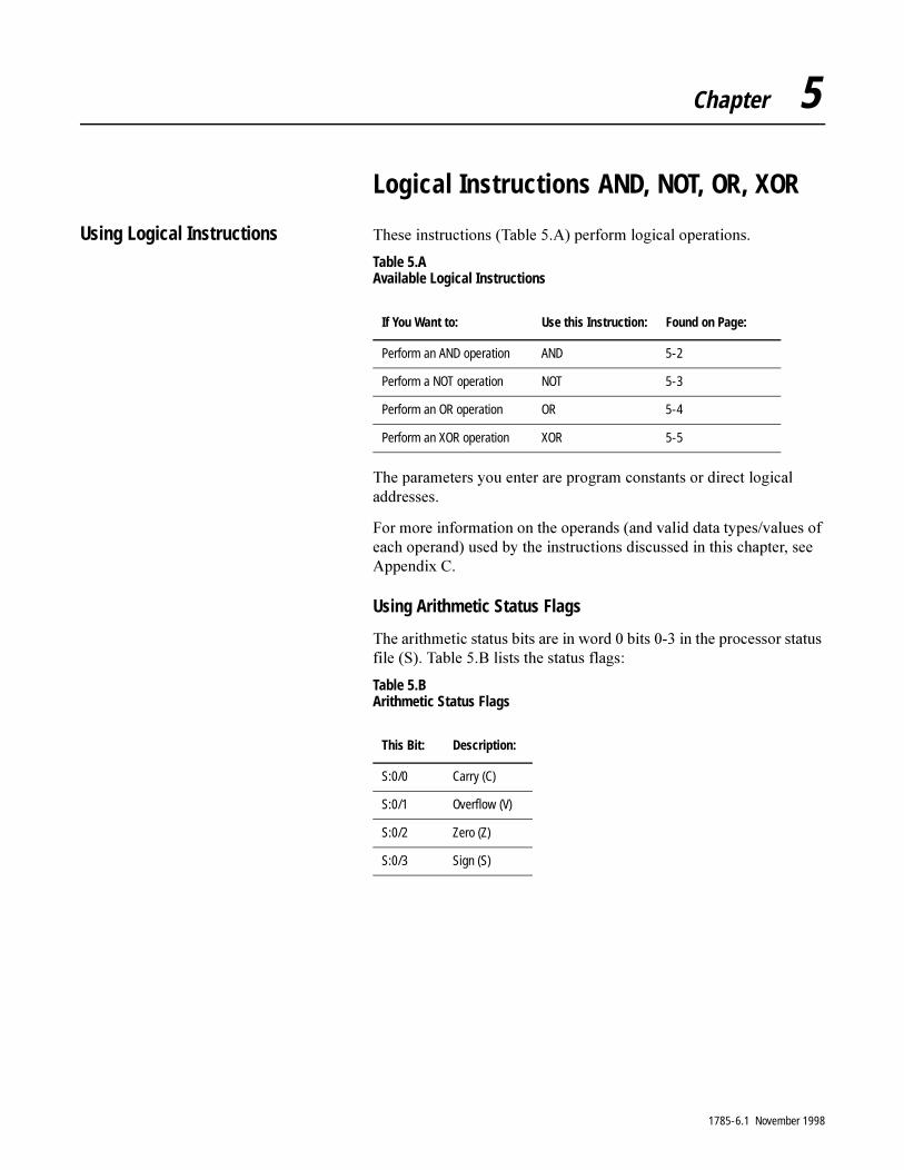
Chapter 5
Logical Instructions AND, NOT, OR, XOR
Using Logical Instructions 7KHVH�LQVWUXFWLRQV��7DEOH���$��SHUIRUP�ORJLFDO�RSHUDWLRQV�
Table 5.A Available Logical Instructions
7KH�SDUDPHWHUV�\RX�HQWHU�DUH�SURJUDP�FRQVWDQWV�RU�GLUHFW�ORJLFDO�DGGUHVVHV�
)RU�PRUH�LQIRUPDWLRQ�RQ�WKH�RSHUDQGV��DQG�YDOLG�GDWD�W\SHV�YDOXHV�RI�HDFK�RSHUDQG��XVHG�E\�WKH�LQVWUXFWLRQV�GLVFXVVHG�LQ�WKLV�FKDSWHU��VHH�$SSHQGL[�&�
Using Arithmetic Status Flags
7KH�DULWKPHWLF�VWDWXV�ELWV�DUH�LQ�ZRUG���ELWV�����LQ�WKH�SURFHVVRU�VWDWXV�ILOH��6���7DEOH���%�OLVWV�WKH�VWDWXV�IODJV�
Table 5.B Arithmetic Status Flags
If You Want to: Use this Instruction: Found on Page:
Perform an AND operation AND 5-2
Perform a NOT operation NOT 5-3
Perform an OR operation OR 5-4
Perform an XOR operation XOR 5-5
This Bit: Description:
S:0/0 Carry (C)
S:0/1 Overflow (V)
S:0/2 Zero (Z)
S:0/3 Sign (S)
1785-6.1 November 1998
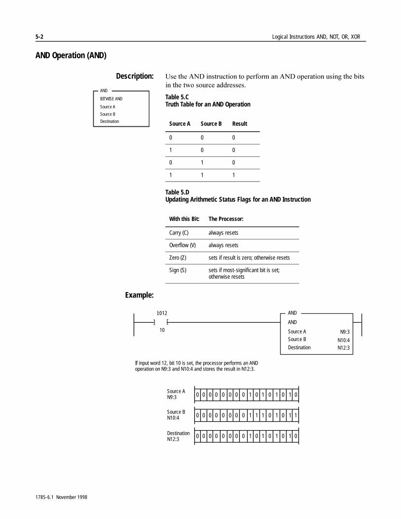
5-2 Logical Instructions AND, NOT, OR, XOR
AND Operation (AND)
Description: 8VH�WKH�$1'�LQVWUXFWLRQ�WR�SHUIRUP�DQ�$1'�RSHUDWLRQ�XVLQJ�WKH�ELWV�LQ�WKH�WZR�VRXUFH�DGGUHVVHV�
Table 5.C Truth Table for an AND Operation
Table 5.D Updating Arithmetic Status Flags for an AND Instruction
Example:
AND
BITWISE AND
Source A
Source B
Destination Source A Source B Result
0 0 0
1 0 0
0 1 0
1 1 1
With this Bit: The Processor:
Carry (C) always resets
Overflow (V) always resets
Zero (Z) sets if result is zero; otherwise resets
Sign (S) sets if most-significant bit is set; otherwise resets
AND
AND
Source ASource B
I:012
10 N9:3
[ [
Destination
If input word 12, bit 10 is set, the processor performs an ANDoperation on N9:3 and N10:4 and stores the result in N12:3.
N12:3N10:4
DestinationN12:3
Source BN10:4
11000000 0 0 0 1 0 00 1Source AN9:3
11100000 0 0 0 1 0 10 1
11000000 0 0 0 1 0 00 1
1785-6.1 November 1998
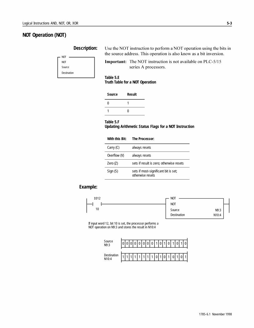
Logical Instructions AND, NOT, OR, XOR 5-3
NOT Operation (NOT)
Description: 8VH�WKH�127�LQVWUXFWLRQ�WR�SHUIRUP�D�127�RSHUDWLRQ�XVLQJ�WKH�ELWV�LQ�WKH�VRXUFH�DGGUHVV��7KLV�RSHUDWLRQ�LV�DOVR�NQRZ�DV�D�ELW�LQYHUVLRQ�
,PSRUWDQW���7KH�127�LQVWUXFWLRQ�LV�QRW�DYDLODEOH�RQ�3/&������VHULHV�$�SURFHVVRUV�
Table 5.E Truth Table for a NOT Operation
Table 5.F Updating Arithmetic Status Flags for a NOT Instruction
Example:
NOT
NOT
Source
Destination
Source Result
0 1
1 0
With this Bit: The Processor:
Carry (C) always resets
Overflow (V) always resets
Zero (Z) sets if result is zero; otherwise resets
Sign (S) sets if most-significant bit is set;otherwise resets
NOT
NOT
Source Destination
I:012
10 N9:3N10:4
[ [
If input word 12, bit 10 is set, the processor performs aNOT operation on N9:3 and stores the result in N10:4
DestinationN10:4
11000000 0 0 0 1 0 00 1SourceN9:3
00111111 1 1 1 0 1 11 0
1785-6.1 November 1998

5-4 Logical Instructions AND, NOT, OR, XOR
OR Operation (OR)
Description: 8VH�WKH�25�LQVWUXFWLRQ�WR�SHUIRUP�DQ�25�RSHUDWLRQ�XVLQJ�WKH�ELWV�LQ�WKH�WZR�VRXUFHV��FRQVWDQWV�RU�DGGUHVVHV��
Table 5.G Truth Table for an OR Operation
Table 5.H Updating Arithmetic Status Flags for an OR Instruction
Example:
OR
BITWISE INCLUSIVE OR
Source A
Source B
DestinationSource A Source B Result
0 0 0
1 0 1
0 1 1
1 1 1
With this Bit: The Processor:
Carry (C) always resets
Overflow (V) always resets
Zero (Z) sets if result is zero; otherwise resets
Sign (S) sets if most-significant bit is set;otherwise resets
OR
INCLUSIVE OR
Source ASource B
I:012
10 N9:3N10:4
[ [
Destination N12:3
If input word 12, bit 10 is set, the processor performsan OR operation on N9:3 and N10:4 and stores theresult in N12:3.
DestinationN12:3
Source BN10:4
11000000 0 0 0 1 0 00 1Source AN9:3
11100000 0 0 0 1 0 10 1
11100000 0 0 0 1 0 10 1
1785-6.1 November 1998
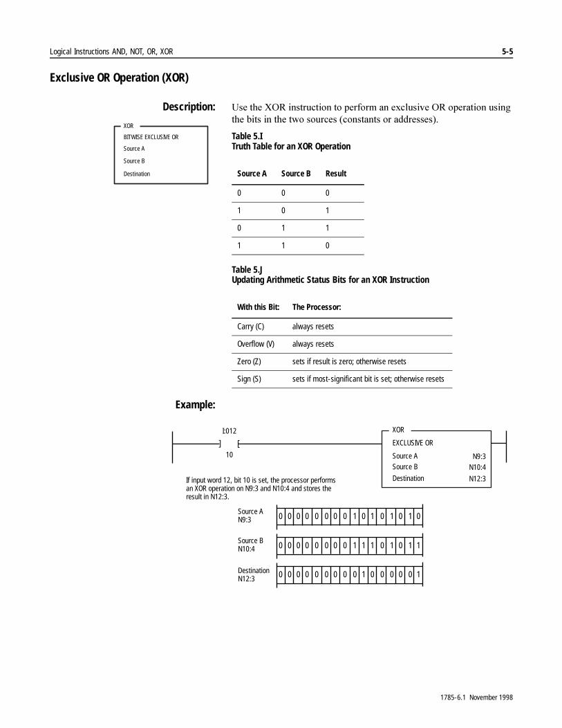
Logical Instructions AND, NOT, OR, XOR 5-5
Exclusive OR Operation (XOR)
Description: 8VH�WKH�;25�LQVWUXFWLRQ�WR�SHUIRUP�DQ�H[FOXVLYH�25�RSHUDWLRQ�XVLQJ�WKH�ELWV�LQ�WKH�WZR�VRXUFHV��FRQVWDQWV�RU�DGGUHVVHV��
Table 5.I Truth Table for an XOR Operation
Table 5.J Updating Arithmetic Status Bits for an XOR Instruction
Example:
XOR
BITWISE EXCLUSIVE OR
Source A
Source B
Destination Source A Source B Result
0 0 0
1 0 1
0 1 1
1 1 0
With this Bit: The Processor:
Carry (C) always resets
Overflow (V) always resets
Zero (Z) sets if result is zero; otherwise resets
Sign (S) sets if most-significant bit is set; otherwise resets
XOR
EXCLUSIVE OR
Source ASource B
I:012
10 N9:3N10:4
[
[
Destination N12:3If input word 12, bit 10 is set, the processor performsan XOR operation on N9:3 and N10:4 and stores theresult in N12:3.
DestinationN12:3
Source BN10:4
11000000 0 0 0 1 0 00 1Source AN9:3
11100000 0 0 0 1 0 10 1
00100000 0 0 0 0 0 10 0
1785-6.1 November 1998

5-6 Logical Instructions AND, NOT, OR, XOR
1RWHV�
1785-6.1 November 1998
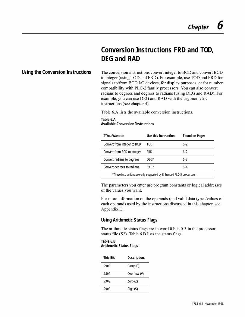
Chapter 6
Conversion Instructions FRD and TOD, DEG and RAD
Using the Conversion Instructions 7KH�FRQYHUVLRQ�LQVWUXFWLRQV�FRQYHUW�LQWHJHU�WR�%&'�DQG�FRQYHUW�%&'�WR�LQWHJHU��XVLQJ�72'�DQG�)5'���)RU�H[DPSOH��XVH�72'�DQG�)5'�IRU�VLJQDOV�WR�IURP�%&'�,�2�GHYLFHV��IRU�GLVSOD\�SXUSRVHV��RU�IRU�QXPEHU�FRPSDWLELOLW\�ZLWK�3/&���IDPLO\�SURFHVVRUV��<RX�FDQ�DOVR�FRQYHUW�UDGLDQV�WR�GHJUHHV�DQG�GHJUHHV�WR�UDGLDQV��XVLQJ�'(*�DQG�5$'���)RU�H[DPSOH��\RX�FDQ�XVH�'(*�DQG�5$'�ZLWK�WKH�WULJRQRPHWULF�LQVWUXFWLRQV��VHH�FKDSWHU�����
7DEOH���$�OLVWV�WKH�DYDLODEOH�FRQYHUVLRQ�LQVWUXFWLRQV�
Table 6.A Available Conversion Instructions
7KH�SDUDPHWHUV�\RX�HQWHU�DUH�SURJUDP�FRQVWDQWV�RU�ORJLFDO�DGGUHVVHV�RI�WKH�YDOXHV�\RX�ZDQW�
)RU�PRUH�LQIRUPDWLRQ�RQ�WKH�RSHUDQGV��DQG�YDOLG�GDWD�W\SHV�YDOXHV�RI�HDFK�RSHUDQG��XVHG�E\�WKH�LQVWUXFWLRQV�GLVFXVVHG�LQ�WKLV�FKDSWHU��VHH�$SSHQGL[�&�
Using Arithmetic Status Flags
7KH�DULWKPHWLF�VWDWXV�IODJV�DUH�LQ�ZRUG���ELWV�����LQ�WKH�SURFHVVRU�VWDWXV�ILOH��6����7DEOH���%�OLVWV�WKH�VWDWXV�IODJV�
Table 6.B Arithmetic Status Flags
If You Want to: Use this Instruction: Found on Page:
Convert from integer to BCD TOD 6-2
Convert from BCD to integer FRD 6-2
Convert radians to degrees DEG* 6-3
Convert degrees to radians RAD* 6-4
* These instructions are only supported by Enhanced PLC-5 processors.
This Bit: Description:
S:0/0 Carry (C)
S:0/1 Overflow (V)
S:0/2 Zero (Z)
S:0/3 Sign (S)
1785-6.1 November 1998

6-2 Conversion Instructions FRD and TOD, DEG and RAD
Convert to BCD (TOD)
Description: 8VH�WKH�72'�LQVWUXFWLRQ�WR�FRQYHUW�DQ�LQWHJHU�YDOXH�WR�D�%&'�YDOXH��,I�WKH�LQWHJHU�YDOXH�LV�JUHDWHU�WKDQ�������WKH�SURFHVVRU�VWRUHV������DQG�VHWV�WKH�RYHUIORZ�ELW��,I�WKH�LQWHJHU�YDOXH�LV�QHJDWLYH��WKH�SURFHVVRU�VWRUHV���LQ�WKH�GHVWLQDWLRQ�DQG�VHWV�WKH�RYHUIORZ�DQG�]HUR�VWDWXV�ELWV�
Table 6.C Updating Arithmetic Status Flags for a TOD Instruction
Example:
Convert from BCD (FRD)
Description: 8VH�WKH�)5'�LQVWUXFWLRQ�WR�FRQYHUW�D�%&'�YDOXH�WR�DQ�LQWHJHU�YDOXH��&RQYHUW�%&'�YDOXHV�WR�LQWHJHU�YDOXHV�EHIRUH�\RX�PDQLSXODWH�WKRVH�YDOXHV�ZLWK�ODGGHU�ORJLF�EHFDXVH�WKH�SURFHVVRU�WUHDWV�%&'�YDOXHV�DV�LQWHJHU�YDOXHV��7KH�DFWXDO�%&'�YDOXH�PD\�EH�ORVW�RU�GLVWRUWHG�
Table 6.D Updating Arithmetic Status Flags for a TOD Instruction
TOD
TO BCD
Source
Destination
With this Bit: The Processor:
Carry (C) always resets
Overflow (V) sets if integer value is outside the range 0-9999; otherwise resets
Zero (Z) sets if destination value is negative or zero; otherwise resets
Sign (S) always resets
]
TOD
TO BCD
Source
Destination
I:012
10 N7:3
D9:3]
If input word 12, bit 10 is set, convert the value in N7:3 to a BCD value and store the result in D9:3.
FRD
FROM BCD
Source
Destination
With this Bit: The Processor:
Carry (C) always resets
Overflow (V) always resets
Zero (Z) sets if destination value is zero; otherwise resets
Sign (S) always resets
1785-6.1 November 1998
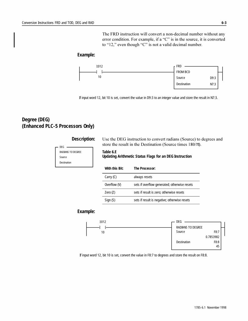
Conversion Instructions FRD and TOD, DEG and RAD 6-3
7KH�)5'�LQVWUXFWLRQ�ZLOO�FRQYHUW�D�QRQ�GHFLPDO�QXPEHU�ZLWKRXW�DQ\�HUURU�FRQGLWLRQ��)RU�H[DPSOH��LI�D�³&´�LV�LQ�WKH�VRXUFH��LW�LV�FRQYHUWHG�WR�³���´�HYHQ�WKRXJK�³&´�LV�QRW�D�YDOLG�GHFLPDO�QXPEHU�
Example:
Degree (DEG) (Enhanced PLC-5 Processors Only)
Description: 8VH�WKH�'(*�LQVWUXFWLRQ�WR�FRQYHUW�UDGLDQV��6RXUFH��WR�GHJUHHV�DQG�VWRUH�WKH�UHVXOW�LQ�WKH�'HVWLQDWLRQ��6RXUFH�WLPHV�����π��Table 6.E Updating Arithmetic Status Flags for an DEG Instruction
Example:
]
FRD
FROM BCD
Source
Destination
I:012
10 D9:3
N7:3
]
If input word 12, bit 10 is set, convert the value in D9:3 to an integer value and store the result in N7:3.
DEG
RADIANS TO DEGREE
Source
Destination
With this Bit: The Processor:
Carry (C) always resets
Overflow (V) sets if overflow generated; otherwise resets
Zero (Z) sets if result is zero; otherwise resets
Sign (S) sets if result is negative; otherwise resets
]
DEG
RADIANS TO DEGREESource
I:012
10 F8:7
Destination F8:8
]
0.7853982
45
If input word 12, bit 10 is set, convert the value in F8:7 to degrees and store the result on F8:8.
1785-6.1 November 1998
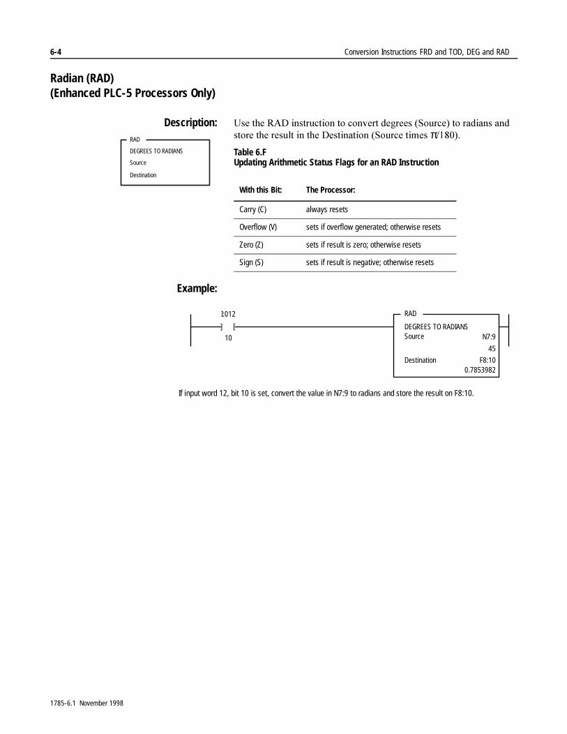
6-4 Conversion Instructions FRD and TOD, DEG and RAD
Radian (RAD) (Enhanced PLC-5 Processors Only)
Description: 8VH�WKH�5$'�LQVWUXFWLRQ�WR�FRQYHUW�GHJUHHV��6RXUFH��WR�UDGLDQV�DQG�VWRUH�WKH�UHVXOW�LQ�WKH�'HVWLQDWLRQ��6RXUFH�WLPHV�����Table 6.F Updating Arithmetic Status Flags for an RAD Instruction
Example:
RAD
DEGREES TO RADIANS
Source
Destination
With this Bit: The Processor:
Carry (C) always resets
Overflow (V) sets if overflow generated; otherwise resets
Zero (Z) sets if result is zero; otherwise resets
Sign (S) sets if result is negative; otherwise resets
]
RAD
DEGREES TO RADIANSSource
I:012
10 N7:9
Destination F8:10
]
45
0.7853982
If input word 12, bit 10 is set, convert the value in N7:9 to radians and store the result on F8:10.
1785-6.1 November 1998
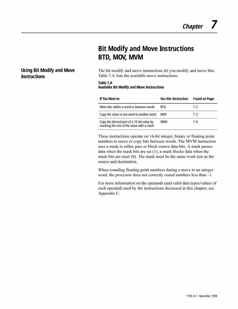
Chapter 7
Bit Modify and Move Instructions BTD, MOV, MVM
Using Bit Modify and Move Instructions
7KH�ELW�PRGLI\�DQG�PRYH�LQVWUXFWLRQV�OHW�\RX�PRGLI\�DQG�PRYH�ELWV��7DEOH���$�OLVWV�WKH�DYDLODEOH�PRYH�LQVWUXFWLRQV�
Table 7.A Available Bit Modify and Move Instructions
7KHVH�LQVWUXFWLRQV�RSHUDWH�RQ����ELW�LQWHJHU��ELQDU\�RU�IORDWLQJ�SRLQW�QXPEHUV�WR�PRYH�RU�FRS\�ELWV�EHWZHHQ�ZRUGV��7KH�090�LQVWUXFWLRQ�XVHV�D�PDVN�WR�HLWKHU�SDVV�RU�EORFN�VRXUFH�GDWD�ELWV��$�PDVN�SDVVHV�GDWD�ZKHQ�WKH�PDVN�ELWV�DUH�VHW������D�PDVN�EORFNV�GDWD�ZKHQ�WKH�PDVN�ELWV�DUH�UHVHW������7KH�PDVN�PXVW�EH�WKH�VDPH�ZRUG�VL]H�DV�WKH�VRXUFH�DQG�GHVWLQDWLRQ�
:KHQ�URXQGLQJ�IORDWLQJ�SRLQW�QXPEHUV�GXULQJ�D�PRYH�WR�DQ�LQWHJHU�ZRUG��WKH�SURFHVVRU�GRHV�QRW�FRUUHFWO\�URXQG�QXPEHUV�OHVV�WKDQ�±��
)RU�PRUH�LQIRUPDWLRQ�RQ�WKH�RSHUDQGV��DQG�YDOLG�GDWD�W\SHV�YDOXHV�RI�HDFK�RSHUDQG��XVHG�E\�WKH�LQVWUXFWLRQV�GLVFXVVHG�LQ�WKLV�FKDSWHU��VHH�$SSHQGL[�&�
If You Want to: Use this Instruction: Found on Page:
Move bits within a word or between words BTD 7-2
Copy the value in one word to another word MOV 7-3
Copy the desired part of a 16-bit value by masking the rest of the value with a mask
MVM 7-4
1785-6.1 November 1998

7-2 Bit Modify and Move Instructions BTD, MOV, MVM
Bit Distribute (BTD)
Description: 7KH�%7'�LQVWUXFWLRQ�LV�DQ�RXWSXW�LQVWUXFWLRQ�WKDW�PRYHV�XS�WR����ELWV�RI�GDWD�ZLWKLQ�D�ZRUG�RU�EHWZHHQ�ZRUGV��7KH�6RXUFH�UHPDLQV�XQFKDQJHG��7KH�LQVWUXFWLRQ�ZULWHV�RYHU�WKH�'HVWLQDWLRQ�ZLWK�WKH�VSHFLILHG�ELWV��,I�WKH�OHQJWK�RI�WKH�ELW�ILHOG�H[WHQGV�EH\RQG�WKH�'HVWLQDWLRQ�ZRUG��WKH�SURFHVVRU�GRHV�QRW�VDYH�WKH�RYHUIORZ�ELWV��7KHVH�RYHUIORZ�ELWV�DUH�ORVW��WKH\�GR�QRW�ZUDS�LQWR�WKH�QH[W�ZRUG�
2Q�HDFK�VFDQ��ZKHQ�WKH�UXQJ�WKDW�FRQWDLQV�WKH�%7'�LQVWUXFWLRQ�LV�WUXH��WKH�SURFHVVRU�PRYHV�WKH�ELW�ILHOG�IURP�WKH�VRXUFH�ZRUG�WR�WKH�GHVWLQDWLRQ�ZRUG��7R�PRYH�GDWD�ZLWKLQ�D�ZRUG��HQWHU�WKH�VDPH�DGGUHVV�IRU�WKH�VRXUFH�DQG�GHVWLQDWLRQ�
Entering Parameters
7R�SURJUDP�WKH�%7'�LQVWUXFWLRQ��\RX�PXVW�SURYLGH�WKH�SURFHVVRU�ZLWK�WKH�IROORZLQJ�
Example:Moving Bits Within a Word
BTD
BIT FIELD DISTRIB
Source
Source bitDestinationDestination bit
Length
Parameter: Definition:
Source the address of the source word in binary or integer. The source remains unchanged.
Source bit the number of the bit (lowest bit number) in the source word from which to start the move.
Destination the address of the destination word in a binary or integer file. The instruction writes over any data already stored at the destination.
Destination bit the number of the bit (lowest bit number) in the destination word where the processor starts copying the bits from the source word.
Length the number of bits to be moved.
BTD
BIT FIELD DISTRIB
SourceSource bitDestinationDestination bit
N70:223
N70:2210
Length 6
Source BitN70:22/3
Destination BitN70:22/10
00070815
101101101101 N70:22
13384
1785-6.1 November 1998
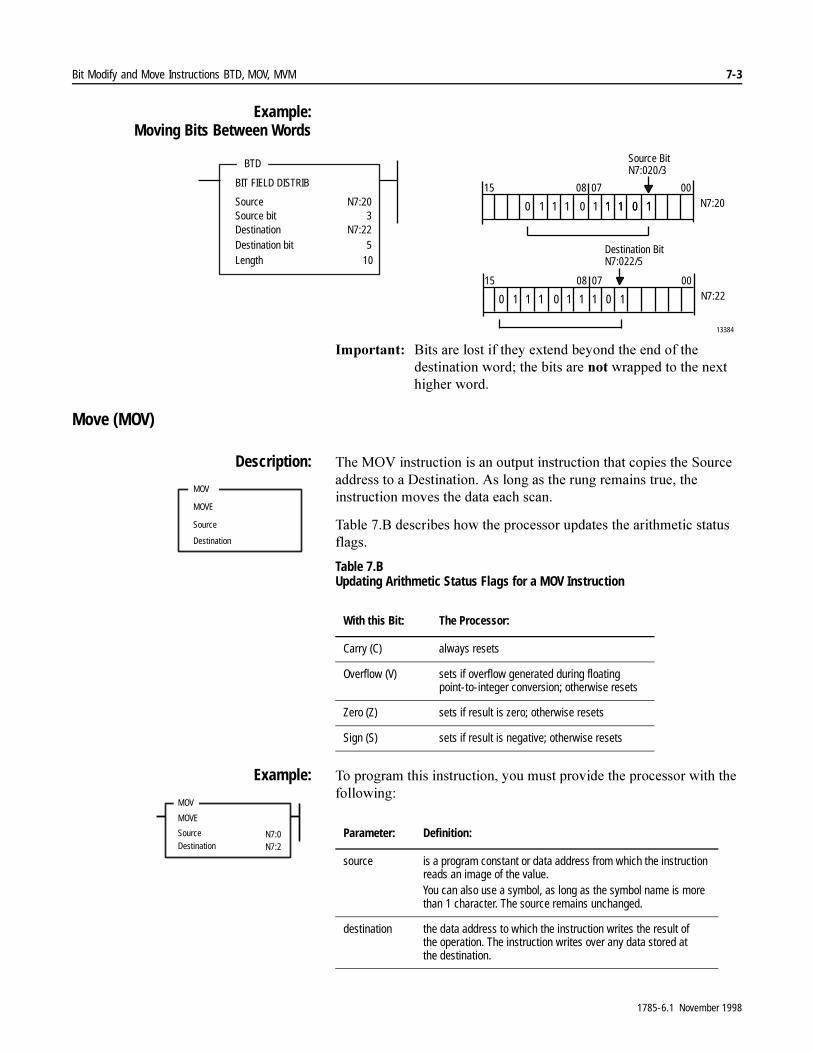
Bit Modify and Move Instructions BTD, MOV, MVM 7-3
Example:Moving Bits Between Words
,PSRUWDQW���%LWV�DUH�ORVW�LI�WKH\�H[WHQG�EH\RQG�WKH�HQG�RI�WKH�GHVWLQDWLRQ�ZRUG��WKH�ELWV�DUH�QRW�ZUDSSHG�WR�WKH�QH[W�KLJKHU�ZRUG�
Move (MOV)
Description: 7KH�029�LQVWUXFWLRQ�LV�DQ�RXWSXW�LQVWUXFWLRQ�WKDW�FRSLHV�WKH�6RXUFH�DGGUHVV�WR�D�'HVWLQDWLRQ��$V�ORQJ�DV�WKH�UXQJ�UHPDLQV�WUXH��WKH�LQVWUXFWLRQ�PRYHV�WKH�GDWD�HDFK�VFDQ�
7DEOH���%�GHVFULEHV�KRZ�WKH�SURFHVVRU�XSGDWHV�WKH�DULWKPHWLF�VWDWXV�IODJV�
Table 7.B Updating Arithmetic Status Flags for a MOV Instruction
Example: 7R�SURJUDP�WKLV�LQVWUXFWLRQ��\RX�PXVW�SURYLGH�WKH�SURFHVVRU�ZLWK�WKH�IROORZLQJ�
BTD
BIT FIELD DISTRIB
SourceSource bitDestinationDestination bit
N7:203
N7:225
Length 10Destination BitN7:022/5
101101 1011 N7:20
N7:22
1110
01 10111110
13384
Source BitN7:020/3
00070815
00070815
MOV
MOVE
Source
Destination
With this Bit: The Processor:
Carry (C) always resets
Overflow (V) sets if overflow generated during floating point-to-integer conversion; otherwise resets
Zero (Z) sets if result is zero; otherwise resets
Sign (S) sets if result is negative; otherwise resets
MOV
MOVE
SourceDestination
N7:0N7:2
Parameter: Definition:
source is a program constant or data address from which the instruction reads an image of the value.You can also use a symbol, as long as the symbol name is more than 1 character. The source remains unchanged.
destination the data address to which the instruction writes the result of the operation. The instruction writes over any data stored at the destination.
1785-6.1 November 1998
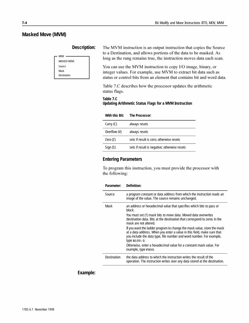
7-4 Bit Modify and Move Instructions BTD, MOV, MVM
Masked Move (MVM)
Description: 7KH�090�LQVWUXFWLRQ�LV�DQ�RXWSXW�LQVWUXFWLRQ�WKDW�FRSLHV�WKH�6RXUFH�WR�D�'HVWLQDWLRQ��DQG�DOORZV�SRUWLRQV�RI�WKH�GDWD�WR�EH�PDVNHG��$V�ORQJ�DV�WKH�UXQJ�UHPDLQV�WUXH��WKH�LQVWUXFWLRQ�PRYHV�GDWD�HDFK�VFDQ�
<RX�FDQ�XVH�WKH�090�LQVWUXFWLRQ�WR�FRS\�,�2�LPDJH��ELQDU\��RU�LQWHJHU�YDOXHV��)RU�H[DPSOH��XVH�090�WR�H[WUDFW�ELW�GDWD�VXFK�DV�VWDWXV�RU�FRQWURO�ELWV�IURP�DQ�HOHPHQW�WKDW�FRQWDLQV�ELW�DQG�ZRUG�GDWD��
7DEOH���&�GHVFULEHV�KRZ�WKH�SURFHVVRU�XSGDWHV�WKH�DULWKPHWLF�VWDWXV IODJV�
Table 7.C Updating Arithmetic Status Flags for a MVM Instruction
Entering Parameters
7R�SURJUDP�WKLV�LQVWUXFWLRQ��\RX�PXVW�SURYLGH�WKH�SURFHVVRU�ZLWK�WKH IROORZLQJ�
Example:
MVM
MASKED MOVE
Source
Mask
Destination
With this Bit: The Processor:
Carry (C) always resets
Overflow (V) always resets
Zero (Z) sets if result is zero; otherwise resets
Sign (S) sets if result is negative; otherwise resets
Parameter: Definition:
Source a program constant or data address from which the instruction reads an image of the value. The source remains unchanged.
Mask an address or hexadecimal value that specifies which bits to pass or block.You must set (1) mask bits to move data. Moved data overwrites destination data. Bits at the destination that correspond to zeros in the mask are not altered.If you want the ladder program to change the mask value, store the mask at a data address. When you enter a value in this field, make sure that you include the data type, file number and word number. For example, type B100:0.
Otherwise, enter a hexadecimal value for a constant mask value. For example, type F800.
Destination the data address to which the instruction writes the result of the operation. The instruction writes over any data stored at the destination.
1785-6.1 November 1998
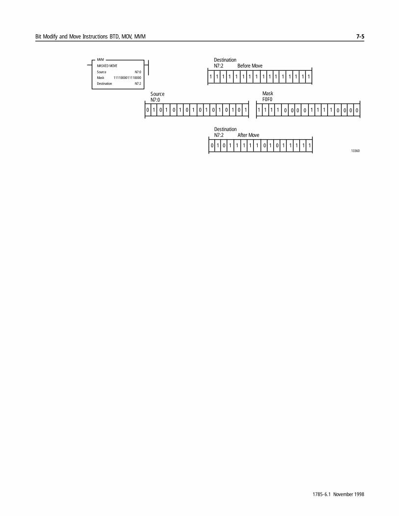
Bit Modify and Move Instructions BTD, MOV, MVM 7-5
13360
1
0
1111
0
11
0
1 1 1 1 1 1 11 1
111111 1 1 1 11 1
11111 1 1 111111 1 11
000
0 0 00 0 0 00000000
SourceN7:0
DestinationN7:2 Before Move
MaskF0F0
MVM
MASKED MOVE
Source
Mask
Destination
N7:0
1111000011110000
N7:2
DestinationN7:2 After Move
1785-6.1 November 1998

7-6 Bit Modify and Move Instructions BTD, MOV, MVM
1RWHV�
1785-6.1 November 1998

Chapter 8
File Instruction Concepts
Concepts of File Operation 7KLV�FKDSWHU�SUHVHQWV�FRQFHSWV�RI�EORFN�RSHUDWLRQ�IRU�WKH�)LOH�$ULWKPHWLF�DQG�/RJLFDO��)$/��DQG�)LOH�6HDUFK�DQG�&RPSDUH��)6&��LQVWUXFWLRQV�
7KH�)$/�LQVWUXFWLRQ�SHUIRUPV�DULWKPHWLF�DQG�ORJLFDO�RSHUDWLRQV�RQ�EORFNV�RI�ZRUGV��7KH�)6&�LQVWUXFWLRQ�SHUIRUPV�FRPSDULVRQ�RSHUDWLRQV�RQ�EORFNV�RI�ZRUGV��)RU�VSHFLILF�LQIRUPDWLRQ�DERXW�WKH�)$/�RU�)6&�LQVWUXFWLRQ��VHH�FKDSWHU���
)RU�PRUH�LQIRUPDWLRQ�RQ�WKH�RSHUDQGV��DQG�YDOLG�GDWD�W\SHV�YDOXHV�RI�HDFK�RSHUDQG��XVHG�E\�WKH�LQVWUXFWLRQV�GLVFXVVHG�LQ�WKLV�FKDSWHU��VHH�$SSHQGL[�&�
Entering Parameters <RX�QHHG�WR�SURYLGH�WKH�SURFHVVRU�ZLWK�WKH�IROORZLQJ�LQIRUPDWLRQ�ZKHQ�\RX�HQWHU�D�ILOH�LQVWUXFWLRQ��
EN
FAL
FILE ARITH/LOGICAL
ControlLengthPositionMode
DN
DestinationExpression
ER
Parameter: Definition:
Control the address of the control structure in a control type (R) file. The processor uses this information to run the instruction. See “Using the Control Structure” on page 8-2.
Length the number of words in the data block on which the file instruction operates. Enter any decimal number 1-1000.
Position the current word within the data block that the processor is accessing. You generally enter a zero to start at the beginning of a block.
Mode the number of file words operated on each time the rung is scanned in the program. The mode lets you distribute operation on the complete block of words. Specify one of the following:• for All mode, type an A• for Numerical mode, type a decimal number (1-1000)• for Incremental mode, type an IFor more information about the different modes, see “Choosing Modes of Block Operation” on page 8-5.
Destination the address where the processor stores the result of the operation. The instruction converts to the data type specified by the destination address.
Expression contains addresses, program constants, and operators that specify the source of data and the operations to be performed.If you enter the index prefix (#) for a destination or expression address, the processor accepts it as the address of the first word of a block to be operated upon. The processor assigns and uses the offset value in module status to process the block address. If you omit the # prefix, the processor accepts this as the address of a single work to be operated upon.
1785-6.1 November 1998
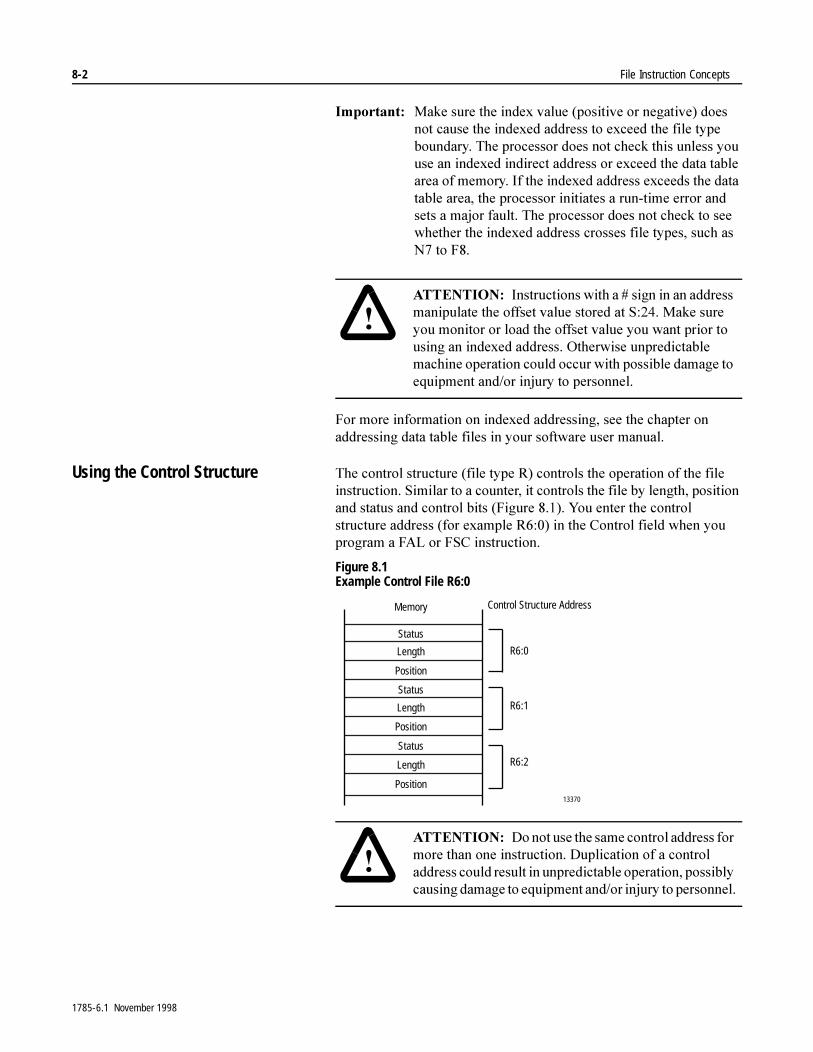
8-2 File Instruction Concepts
,PSRUWDQW���0DNH�VXUH�WKH�LQGH[�YDOXH��SRVLWLYH�RU�QHJDWLYH��GRHV�QRW�FDXVH�WKH�LQGH[HG�DGGUHVV�WR�H[FHHG�WKH�ILOH�W\SH�ERXQGDU\��7KH�SURFHVVRU�GRHV�QRW�FKHFN�WKLV�XQOHVV�\RX�XVH�DQ�LQGH[HG�LQGLUHFW�DGGUHVV�RU�H[FHHG�WKH�GDWD�WDEOH�DUHD�RI�PHPRU\��,I�WKH�LQGH[HG�DGGUHVV�H[FHHGV�WKH�GDWD�WDEOH�DUHD��WKH�SURFHVVRU�LQLWLDWHV�D�UXQ�WLPH�HUURU�DQG�VHWV�D�PDMRU�IDXOW��7KH�SURFHVVRU�GRHV�QRW�FKHFN�WR�VHH�ZKHWKHU�WKH�LQGH[HG�DGGUHVV�FURVVHV�ILOH�W\SHV��VXFK�DV�1��WR�)���
)RU�PRUH�LQIRUPDWLRQ�RQ�LQGH[HG�DGGUHVVLQJ��VHH�WKH�FKDSWHU�RQ�DGGUHVVLQJ�GDWD�WDEOH�ILOHV�LQ�\RXU�VRIWZDUH�XVHU�PDQXDO�
Using the Control Structure 7KH�FRQWURO�VWUXFWXUH��ILOH�W\SH�5��FRQWUROV�WKH�RSHUDWLRQ�RI�WKH�ILOH�LQVWUXFWLRQ��6LPLODU�WR�D�FRXQWHU��LW�FRQWUROV�WKH�ILOH�E\�OHQJWK��SRVLWLRQ�DQG�VWDWXV�DQG�FRQWURO�ELWV��)LJXUH�������<RX�HQWHU�WKH�FRQWURO�VWUXFWXUH�DGGUHVV��IRU�H[DPSOH�5�����LQ�WKH�&RQWURO�ILHOG�ZKHQ�\RX�SURJUDP�D�)$/�RU�)6&�LQVWUXFWLRQ�
Figure 8.1 Example Control File R6:0
�$77(17,21� ,QVWUXFWLRQV�ZLWK�D���VLJQ�LQ�DQ�DGGUHVV�PDQLSXODWH�WKH�RIIVHW�YDOXH�VWRUHG�DW�6�����0DNH�VXUH�\RX�PRQLWRU�RU�ORDG�WKH�RIIVHW�YDOXH�\RX�ZDQW�SULRU�WR�XVLQJ�DQ�LQGH[HG�DGGUHVV��2WKHUZLVH�XQSUHGLFWDEOH�PDFKLQH�RSHUDWLRQ�FRXOG�RFFXU�ZLWK�SRVVLEOH�GDPDJH�WR�HTXLSPHQW�DQG�RU�LQMXU\�WR�SHUVRQQHO�
Status
Length
Position
Status
Length
Position
Status
Length
Position
R6:0
R6:1
R6:2
13370
Control Structure AddressMemory
�$77(17,21� 'R�QRW�XVH�WKH�VDPH�FRQWURO�DGGUHVV�IRU�PRUH�WKDQ�RQH�LQVWUXFWLRQ��'XSOLFDWLRQ�RI�D�FRQWURO�DGGUHVV�FRXOG�UHVXOW�LQ�XQSUHGLFWDEOH�RSHUDWLRQ��SRVVLEO\�FDXVLQJ�GDPDJH�WR�HTXLSPHQW�DQG�RU�LQMXU\�WR�SHUVRQQHO�
1785-6.1 November 1998
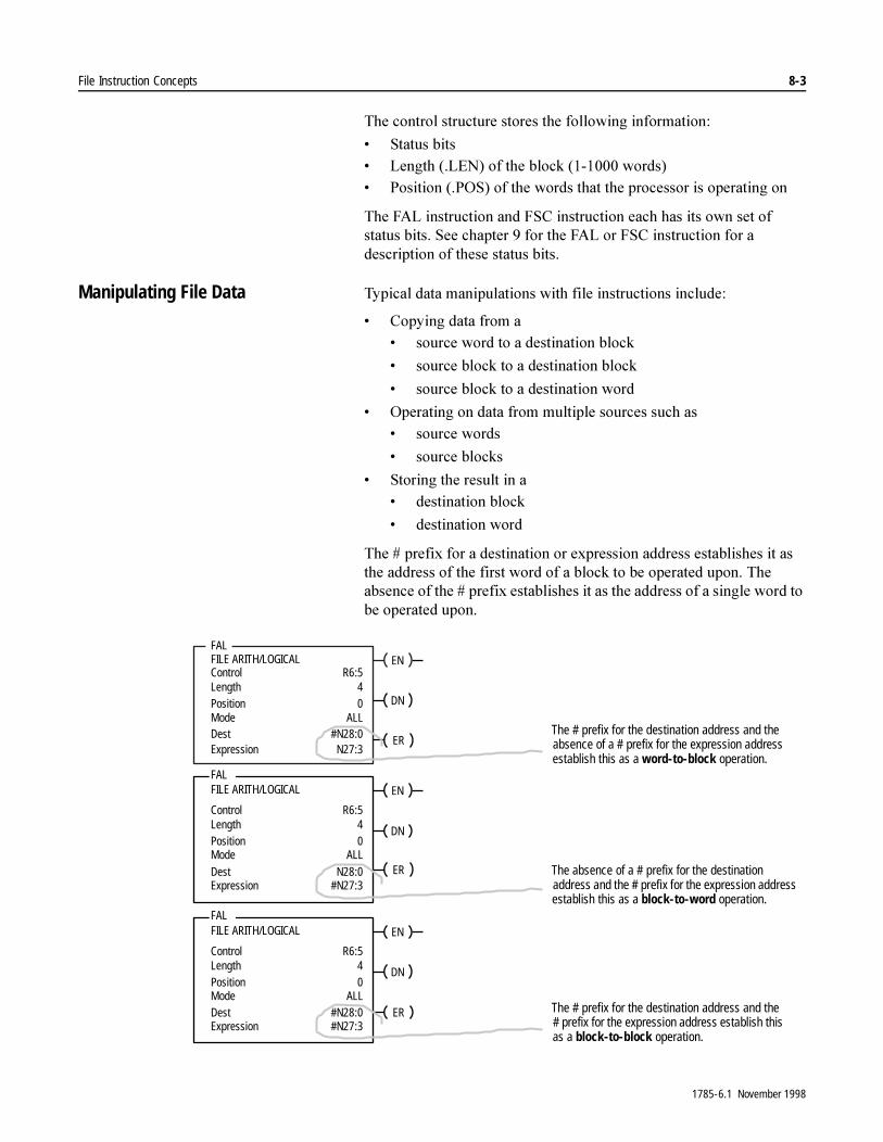
File Instruction Concepts 8-3
7KH�FRQWURO�VWUXFWXUH�VWRUHV�WKH�IROORZLQJ�LQIRUPDWLRQ�
� 6WDWXV�ELWV� /HQJWK���/(1��RI�WKH�EORFN���������ZRUGV�� 3RVLWLRQ���326��RI�WKH�ZRUGV�WKDW�WKH�SURFHVVRU�LV�RSHUDWLQJ�RQ
7KH�)$/�LQVWUXFWLRQ�DQG�)6&�LQVWUXFWLRQ�HDFK�KDV�LWV�RZQ�VHW�RI�VWDWXV�ELWV��6HH�FKDSWHU���IRU�WKH�)$/�RU�)6&�LQVWUXFWLRQ�IRU�D�GHVFULSWLRQ�RI�WKHVH�VWDWXV�ELWV�
Manipulating File Data 7\SLFDO�GDWD�PDQLSXODWLRQV�ZLWK�ILOH�LQVWUXFWLRQV�LQFOXGH��
� &RS\LQJ�GDWD�IURP�D� VRXUFH�ZRUG�WR�D�GHVWLQDWLRQ�EORFN
� VRXUFH�EORFN�WR�D�GHVWLQDWLRQ�EORFN
� VRXUFH�EORFN�WR�D�GHVWLQDWLRQ�ZRUG
� 2SHUDWLQJ�RQ�GDWD�IURP�PXOWLSOH�VRXUFHV�VXFK�DV� VRXUFH�ZRUGV�
� VRXUFH�EORFNV
� 6WRULQJ�WKH�UHVXOW�LQ�D�� GHVWLQDWLRQ�EORFN
� GHVWLQDWLRQ�ZRUG
7KH���SUHIL[�IRU�D�GHVWLQDWLRQ�RU�H[SUHVVLRQ�DGGUHVV�HVWDEOLVKHV�LW�DV�WKH�DGGUHVV�RI�WKH�ILUVW�ZRUG�RI�D�EORFN�WR�EH�RSHUDWHG�XSRQ��7KH�DEVHQFH�RI�WKH���SUHIL[�HVWDEOLVKHV�LW�DV�WKH�DGGUHVV�RI�D�VLQJOH�ZRUG�WR�EH�RSHUDWHG�XSRQ�
ENFILE ARITH/LOGICALControlLengthPositionMode
DN
Dest ERExpression
FAL
R6:540
ALL#N28:0
N27:3
ENFILE ARITH/LOGICAL
ControlLengthPositionMode
DN
Dest ERExpression
FAL
R6:540
ALL#N28:0#N27:3
ENFILE ARITH/LOGICAL
ControlLengthPositionMode
DN
Dest ERExpression
FAL
R6:540
ALLN28:0
#N27:3
The # prefix for the destination address and the absence of a # prefix for the expression address establish this as a word-to-block operation.
The absence of a # prefix for the destination address and the # prefix for the expression address establish this as a block-to-word operation.
The # prefix for the destination address and the # prefix for the expression address establish this as a block-to-block operation.
1785-6.1 November 1998
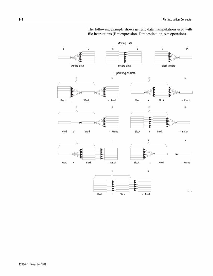
8-4 File Instruction Concepts
7KH�IROORZLQJ�H[DPSOH�VKRZV�JHQHULF�GDWD�PDQLSXODWLRQV�XVHG�ZLWK�ILOH�LQVWUXFWLRQV��(� �H[SUHVVLRQ��'� �GHVWLQDWLRQ��[� �RSHUDWLRQ���
E D E D E D
E D E D
E D E D
E D E D
Word to Block Block to Block
Operating on Data
Block to Word
Block x = Result Blockx
Moving Data
16617a
Word
E D
= ResultWord
Word x = Result BlockxWord = ResultBlock
Blockx = Result Block xWord = ResultWord
Blockx = ResultBlock
1785-6.1 November 1998
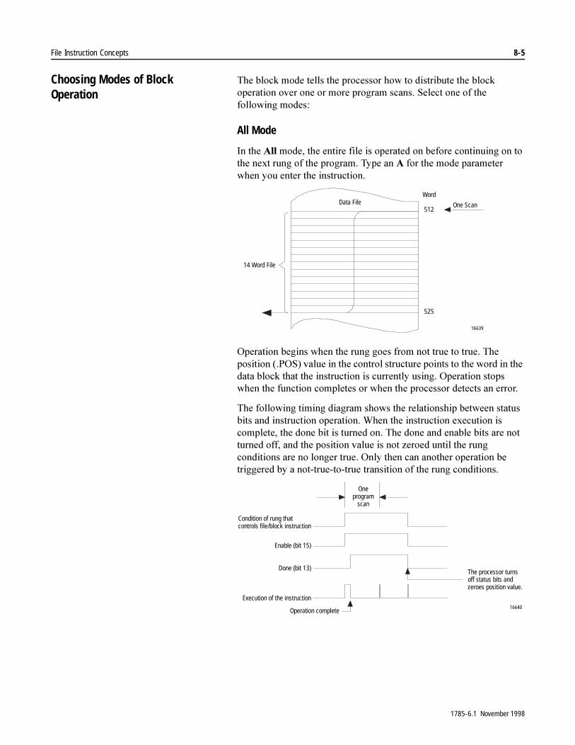
File Instruction Concepts 8-5
Choosing Modes of Block Operation
7KH�EORFN�PRGH�WHOOV�WKH�SURFHVVRU�KRZ�WR�GLVWULEXWH�WKH�EORFN�RSHUDWLRQ�RYHU�RQH�RU�PRUH�SURJUDP�VFDQV��6HOHFW�RQH�RI�WKH�IROORZLQJ�PRGHV�
All Mode
,Q�WKH�$OO�PRGH��WKH�HQWLUH�ILOH�LV�RSHUDWHG�RQ�EHIRUH�FRQWLQXLQJ�RQ�WR�WKH�QH[W�UXQJ�RI�WKH�SURJUDP��7\SH�DQ�$�IRU�WKH�PRGH�SDUDPHWHU�ZKHQ�\RX�HQWHU�WKH�LQVWUXFWLRQ�
2SHUDWLRQ�EHJLQV�ZKHQ�WKH�UXQJ�JRHV�IURP�QRW�WUXH�WR�WUXH��7KH�SRVLWLRQ���326��YDOXH�LQ�WKH�FRQWURO�VWUXFWXUH�SRLQWV�WR�WKH�ZRUG�LQ�WKH�GDWD�EORFN�WKDW�WKH�LQVWUXFWLRQ�LV�FXUUHQWO\�XVLQJ��2SHUDWLRQ�VWRSV�ZKHQ�WKH�IXQFWLRQ�FRPSOHWHV�RU�ZKHQ�WKH�SURFHVVRU�GHWHFWV�DQ�HUURU�
7KH�IROORZLQJ�WLPLQJ�GLDJUDP�VKRZV�WKH�UHODWLRQVKLS�EHWZHHQ�VWDWXV�ELWV�DQG�LQVWUXFWLRQ�RSHUDWLRQ��:KHQ�WKH�LQVWUXFWLRQ�H[HFXWLRQ�LV�FRPSOHWH��WKH�GRQH�ELW�LV�WXUQHG�RQ��7KH�GRQH�DQG�HQDEOH�ELWV�DUH�QRW�WXUQHG�RII��DQG�WKH�SRVLWLRQ�YDOXH�LV�QRW�]HURHG�XQWLO�WKH�UXQJ�FRQGLWLRQV�DUH�QR�ORQJHU�WUXH��2QO\�WKHQ�FDQ�DQRWKHU�RSHUDWLRQ�EH�WULJJHUHG�E\�D�QRW�WUXH�WR�WUXH�WUDQVLWLRQ�RI�WKH�UXQJ�FRQGLWLRQV�
Word
512
525
16639
Data File
14 Word File
One Scan
16640
Condition of rung thatcontrols file/block instruction
Enable (bit 15)
Done (bit 13)
Execution of the instruction
Oneprogram
scan
The processor turnsoff status bits andzeroes position value.
Operation complete
1785-6.1 November 1998

8-6 File Instruction Concepts
Numerical Mode
1XPHULFDO�PRGH�GLVWULEXWHV�WKH�ILOH�RSHUDWLRQ�RYHU�D�QXPEHU�RI�SURJUDP�VFDQV��7R�VHOHFW�WKH�QXPHULFDO�PRGH��HQWHU�WKH�QXPEHU�RI�ZRUGV�SHU�VFDQ����������IRU�WKH�PRGH�SDUDPHWHU�ZKHQ�\RX�HQWHU�WKH�ILOH�LQVWUXFWLRQ��7KH�QXPEHU�RI�ZRUGV�\RX�HQWHU�PXVW�EH�OHVV�WKDQ�RU�HTXDO�WR�WKH�ILOH�OHQJWK�
([HFXWLRQ�LV�WULJJHUHG�ZKHQ�WKH�UXQJ�FRQGLWLRQV�JR�IURP�QRW�WUXH�WR�WUXH��2QFH�WULJJHUHG��WKH�LQVWUXFWLRQ�LV�H[HFXWHG�FRQWLQXDOO\�HDFK�WLPH�WKH�UXQJ�LV�VFDQQHG�LQ�WKH�SURJUDP�IRU�WKH�QXPEHU�RI�VFDQV�QHFHVVDU\�WR�FRPSOHWH�RSHUDWLRQ�RQ�WKH�HQWLUH�ILOH��2QFH�WULJJHUHG��UXQJ�ORJLF�FDQ�FKDQJH�UHSHDWHGO\�ZLWKRXW�LQWHUUXSWLQJ�H[HFXWLRQ�RI�WKH�LQVWUXFWLRQ�
(DFK�WLPH�WKH�UXQJ�LV�VFDQQHG��WKH�LQVWUXFWLRQ�RSHUDWHV�RQ�WKH�QXPEHU�RI�ZRUGV�HTXDO�WR�WKH�UDWH�\RX�HQWHUHG�IRU�WKH�PRGH�YDOXH��XQWLO�LW�KDV�RSHUDWHG�RQ�WKH�QXPEHU�RI�ZRUGV�\RX�VSHFLILHG�E\�WKH�OHQJWK�YDOXH��,Q�WKH�ODVW�VFDQ�RI�WKH�UXQJ��WKH�SURFHVVRU�PD\�RSHUDWH�RQ�OHVV�WKDQ�WKH�QXPEHU�RI�ZRUGV�\RX�HQWHUHG�
,PSRUWDQW���$YRLG�XVLQJ�WKH�UHVXOWV�RI�D�ILOH�LQVWUXFWLRQ�RSHUDWLQJ�LQ�QXPHULF�PRGH�XQWLO�WKH�GRQH�ELW�LV�VHW�EHFDXVH�WKH�GDWD�ZLOO�EH�LQFRPSOHWH�
7KH�IROORZLQJ�WLPLQJ�GLDJUDP�VKRZV�WKH�UHODWLRQVKLS�EHWZHHQ�VWDWXV�ELWV�DQG�LQVWUXFWLRQ�RSHUDWLRQ�
16641
Scan #1
Scan #2
Scan #3
Scan #1
Scan #2
Scan #3
5 words
5 words
Remaining4 words
File Word
512
516517
521522
525
14-Word Block
16642
Rung is true at completion Rung is not true at completion
Condition of rung thatcontrols file instruction
Enable (bit 15)
Done (bit 13)
Execution of instruction
Multiple programscans Multiple program
scans
The processorturns off donebit and zeroesposition value.
Operation completeOperation complete The processor turns offenable and done bit andzeroes position value.
1785-6.1 November 1998

File Instruction Concepts 8-7
:KHQ�WKH�LQVWUXFWLRQ�H[HFXWLRQ�LV�FRPSOHWH��WKH�GRQH�ELW�LV�WXUQHG�RQ�
,I�WKH�UXQJ�LV�WUXH�DW�FRPSOHWLRQ��WKH�HQDEOH�ELW�DQG�GRQH�ELW�DUH�QRW�WXUQHG�RII�XQWLO�WKH�UXQJ�LV�QR�ORQJHU�WUXH��:KHQ�WKH�UXQJ�LV�QR�ORQJHU�WUXH��WKHVH�ELWV�DUH�WXUQHG�RII�DQG�WKH�SRVLWLRQ�YDOXH�LV�]HURHG�
,I�WKH�UXQJ�LV�QRW�WUXH�DW�FRPSOHWLRQ��WKH�HQDEOH�ELW�LV�WXUQHG�RII�LPPHGLDWHO\��DQG�RQH�VFDQ�DIWHU�WKH�HQDEOH�ELW�LV�WXUQHG�RII��WKH�GRQH�ELW�LV�WXUQHG�RII�DQG�WKH�SRVLWLRQ�YDOXH�LV�]HURHG�
2QO\�DIWHU�WKH�HQDEOH�DQG�GRQH�ELWV�DUH�WXUQHG�RII�FDQ�DQRWKHU�RSHUDWLRQ�EH�WULJJHUHG�E\�D�QRW�WUXH�WR�WUXH�WUDQVLWLRQ�RI�WKH�UXQJ FRQGLWLRQV�
Incremental Mode
,QFUHPHQWDO�PRGH�PDQLSXODWHV�RQH�ZRUG�RI�WKH�ILOH�HDFK�WLPH�WKH�UXQJ�JRHV�IURP�QRW�WUXH�WR�WUXH��7\SH�DQ�,�IRU�WKH�PRGH�SDUDPHWHU�ZKHQ�\RX�HQWHU�WKH�LQVWUXFWLRQ��
7KH�IROORZLQJ�WLPLQJ�GLDJUDP�VKRZV�WKH�UHODWLRQVKLS�EHWZHHQ�VWDWXV�ELWV�DQG�LQVWUXFWLRQ�RSHUDWLRQ�
16
1-Word Operation
1-Word Operation
1-Word Operation
1-Word Operation
1st Rung Enable
2nd Rung Enable
3rd Rung Enable
14th Rung Enable
File Word
Word #0
Word #1
Word #2
Word #3
Word #12
Word #13 (last word)
File Word
512
513
515
524
525
Word File
514
16644
Enable (bit 15)
Done (bit 13)
One or moreprogramscans
The processorturns off enable bit.
Condition of rung thatcontrols file instruction
Execution of instruction
The processor turnsoff status bits andzeroes position value. Operation complete
1785-6.1 November 1998
8-8 File Instruction Concepts
([HFXWLRQ�RFFXUV�RQO\�LQ�D�SURJUDP�VFDQ�LQ�ZKLFK�WKH�UXQJ�JRHV�IURP�QRW�WUXH�WR�WUXH��(DFK�WLPH�WKLV�GRHV�RFFXU��RQO\�RQH�ZRUG�RI�WKH�ILOH�LV�RSHUDWHG�RQ��7KH�HQDEOH�ELW�LV�RQ�ZKHQ�UXQJ�ORJLF�LV�WUXH��7KH�GRQH�ELW�LV�WXUQHG�RQ�ZKHQ�WKH�ODVW�ZRUG�LQ�WKH�ILOH�KDV�EHHQ�RSHUDWHG�RQ��:KHQ�WKH�ODVW�ZRUG�LQ�WKH�ILOH�KDV�EHHQ�RSHUDWHG�RQ�DQG�WKH�UXQJ�JRHV�IURP�WUXH�WR�QRW�WUXH��WKH�HQDEOH�DQG�GRQH�ELWV�DUH�WXUQHG�RII�DQG�WKH�SRVLWLRQ�YDOXH�LV�]HURHG��,I�WKH�UXQJ�UHPDLQV�WUXH�IRU�PRUH�WKDQ�RQH�SURJUDP�VFDQ��WKH�ILOH�LQVWUXFWLRQ�LV�QRW�H[HFXWHG�LQ�VXEVHTXHQW�VFDQV�DIWHU�WKH�WUDQVLWLRQ�
,PSRUWDQW��� ,I�\RX�DUH�RSHUDWLQJ�RQ�DQ�HQWLUH�ILOH��DYRLG�XVLQJ�WKH�UHVXOWV�RI�D�ILOH�EORFN�LQVWUXFWLRQ�XVLQJ�LQFUHPHQWDO�PRGH�XQWLO�WKH�GRQH�ELW�LV�RQ��WKH�GDWD�ZLOO�EH LQFRPSOHWH��
Special Case, Numerical Mode with Words Per Scan = 1
7KH�GLIIHUHQFH�EHWZHHQ�QXPHULFDO�PRGH�ZLWK�D�UDWH�RI���ZRUG�SHU�VFDQ�DQG�LQFUHPHQWDO�PRGH�LV�
� 1XPHULFDO�PRGH�ZLWK�DQ\�QXPEHU�RI�ZRUGV�SHU�VFDQ��RQO\�RQH�QRW�WUXH�WR�WUXH�UXQJ�WUDQVLWLRQ�LV�UHTXLUHG�IRU�FRQWLQXDO�H[HFXWLRQ�RI�WKH�LQVWUXFWLRQ�XQWLO�RSHUDWLRQ�LV�FRPSOHWH�RQ�WKH�HQWLUH�ILOH�
� ,QFUHPHQWDO�PRGH�UHTXLUHV�D�QRW�WUXH�WR�WUXH�UXQJ�WUDQVLWLRQ�IRU�HDFK�ZRUG�LQ�WKH�ILOH�
1785-6.1 November 1998
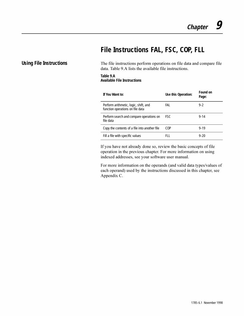
Chapter 9
File Instructions FAL, FSC, COP, FLL
Using File Instructions 7KH�ILOH�LQVWUXFWLRQV�SHUIRUP�RSHUDWLRQV�RQ�ILOH�GDWD�DQG�FRPSDUH�ILOH�GDWD��7DEOH���$�OLVWV�WKH�DYDLODEOH�ILOH�LQVWUXFWLRQV�
Table 9.A Available File Instructions
,I�\RX�KDYH�QRW�DOUHDG\�GRQH�VR��UHYLHZ�WKH�EDVLF�FRQFHSWV�RI�ILOH�RSHUDWLRQ�LQ�WKH�SUHYLRXV�FKDSWHU��)RU�PRUH�LQIRUPDWLRQ�RQ�XVLQJ�LQGH[HG�DGGUHVVHV��VHH�\RXU�VRIWZDUH�XVHU�PDQXDO�
)RU�PRUH�LQIRUPDWLRQ�RQ�WKH�RSHUDQGV��DQG�YDOLG�GDWD�W\SHV�YDOXHV�RI�HDFK�RSHUDQG��XVHG�E\�WKH�LQVWUXFWLRQV�GLVFXVVHG�LQ�WKLV�FKDSWHU��VHH�$SSHQGL[�&�
If You Want to: Use this Operation:Found on Page:
Perform arithmetic, logic, shift, and function operations on file data
FAL 9-2
Perform search and compare operations on file data
FSC 9-14
Copy the contents of a file into another file COP 9-19
Fill a file with specific values FLL 9-20
1785-6.1 November 1998

9-2 File Instructions FAL, FSC, COP, FLL
File Arithmetic and Logic (FAL) 7KH�)$/�LQVWUXFWLRQ�SHUIRUPV�FRS\��DULWKPHWLF��ORJLF��DQG�IXQFWLRQ�RSHUDWLRQV�RQ�WKH�GDWD�VWRUHG�LQ�ILOHV��7KH�)$/�LQVWUXFWLRQ�SHUIRUPV�WKH�VDPH�RSHUDWLRQV�DV�WKH�&37�LQVWUXFWLRQ��7KH�GLIIHUHQFH�LV�WKDW�WKH�)$/�LQVWUXFWLRQ�SHUIRUPV�RSHUDWLRQV�RQ�PXOWLSOH�ZRUGV��ZKLOH�WKH�&37�LQVWUXFWLRQ�KDQGOHV�VLQJOH�ZRUGV�
Description: 7KH�)$/�LQVWUXFWLRQ�LV�DQ�RXWSXW�LQVWUXFWLRQ�WKDW�SHUIRUPV�WKH�RSHUDWLRQV�GHILQHG�E\�VRXUFH�DGGUHVVHV�DQG�RSHUDWRUV�\RX�ZULWH�LQ�WKH�H[SUHVVLRQ��7KH�LQVWUXFWLRQ�ZULWHV�WKH�UHVXOWV�LQWR�D�GHVWLQDWLRQ�DGGUHVV�
6HOHFW�KRZ�WKH�SURFHVVRU�GLVWULEXWHV�WKH�RSHUDWLRQ�RYHU�RQH�RU�PRUH�SURJUDP�VFDQV�E\�\RXU�VHOHFWLRQ�RI�LQVWUXFWLRQ�PRGH��)RU�PRUH�LQIRUPDWLRQ�DERXW�PRGHV�RI�ILOH�RSHUDWLRQ��VHH�FKDSWHU���
7KH�)$/�LQVWUXFWLRQ�DXWRPDWLFDOO\�FRQYHUWV�WKH�GDWD�W\SH�DW�WKH�VRXUFH�DGGUHVVHV�WR�WKH�GDWD�W\SH�WKDW�\RX�VSHFLI\�LQ�WKH�GHVWLQDWLRQ�DGGUHVV�
<RX�FDQ�XVH�WKLV�LQVWUXFWLRQ�WR�SHUIRUP�RSHUDWLRQV�VXFK�DV��
� ]HUR�D�ILOH
� FRS\�GDWD�IURP�RQH�ILOH�WR�DQRWKHU
� PDNH�DULWKPHWLF�RU�ORJLF�FRPSXWDWLRQV�RQ�GDWD�VWRUHG�LQ�ILOHV
� XQORDG�D�ILOH�RI�HUURU�FRGHV�RQH�DW�D�WLPH�IRU�GLVSOD\�
ENFILE ARITH/LOGICAL
ControlLengthPositionMode
DN
Destination ERExpression
FAL
�$77(17,21� ,QVWUXFWLRQV�ZLWK�D���VLJQ�LQ�DQ�DGGUHVV�PDQLSXODWH�WKH�RIIVHW�YDOXH�VWRUHG�DW�6�����0DNH�VXUH�\RX�PRQLWRU�RU�ORDG�WKH�RIIVHW�YDOXH�\RX�ZDQW�SULRU�WR�XVLQJ�DQ�LQGH[HG�DGGUHVV��2WKHUZLVH�XQSUHGLFWDEOH�PDFKLQH�RSHUDWLRQ�FRXOG�RFFXU�ZLWK�SRVVLEOH�GDPDJH�WR�HTXLSPHQW�DQG�RU�LQMXU\�WR�SHUVRQQHO�
1785-6.1 November 1998
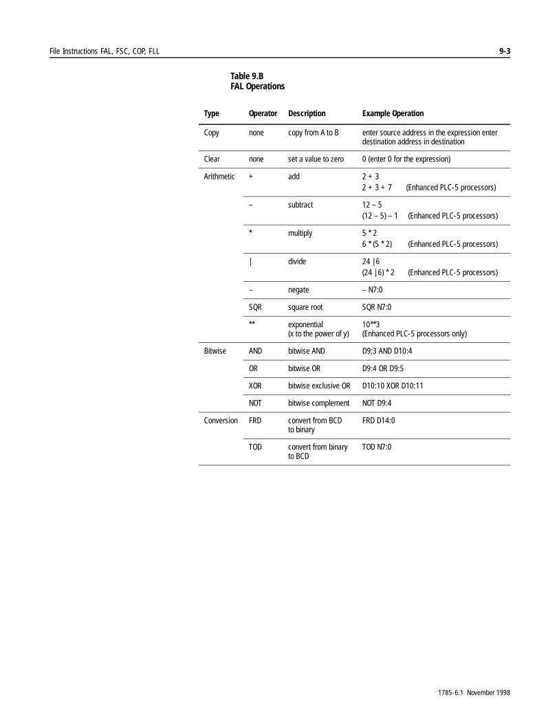
File Instructions FAL, FSC, COP, FLL 9-3
Table 9.B FAL Operations
Type Operator Description Example Operation
Copy none copy from A to B enter source address in the expression enter destination address in destination
Clear none set a value to zero 0 (enter 0 for the expression)
Arithmetic + add 2 + 32 + 3 + 7 (Enhanced PLC-5 processors)
– subtract 12 – 5 (12 – 5) – 1 (Enhanced PLC-5 processors)
* multiply 5 * 2 6 * (5 * 2) (Enhanced PLC-5 processors)
| divide 24 | 6(24 | 6) * 2 (Enhanced PLC-5 processors)
– negate – N7:0
SQR square root SQR N7:0
** exponential(x to the power of y)
10**3(Enhanced PLC-5 processors only)
Bitwise AND bitwise AND D9:3 AND D10:4
OR bitwise OR D9:4 OR D9:5
XOR bitwise exclusive OR D10:10 XOR D10:11
NOT bitwise complement NOT D9:4
Conversion FRD convert from BCD to binary
FRD D14:0
TOD convert from binaryto BCD
TOD N7:0
1785-6.1 November 1998

9-4 File Instructions FAL, FSC, COP, FLL
Using Status Bits
7R�XVH�WKH�)$/�LQVWUXFWLRQ�FRUUHFWO\��H[DPLQH�DQG�FRQWURO�VWDWXV�ELWV�LQ�WKH�FRQWURO�HOHPHQW��<RX�DGGUHVV�WKHVH�ELWV�E\�PQHPRQLF��
:LWK�WKH�)$/�LQVWUXFWLRQ��D�PD[LPXP�RI����FKDUDFWHUV�RI�WKH�H[SUHVVLRQ�FDQ�EH�GLVSOD\HG��,I�WKH�H[SUHVVLRQ�\RX�HQWHU�LV�QHDU�WKLV����FKDUDFWHU�PD[LPXP��ZKHQ�\RX�DFFHSW�WKH�UXQJ�FRQWDLQLQJ�WKH�LQVWUXFWLRQ��WKH�SURFHVVRU�PD\�H[SDQG�LW�EH\RQG����FKDUDFWHUV��:KHQ�\RX�WU\�WR�HGLW�WKH�H[SUHVVLRQ��RQO\�WKH�ILUVW����FKDUDFWHUV�DUH�GLVSOD\HG�DQG�WKH�UXQJ�LV�GLVSOD\HG�DV�DQ�HUURU�UXQJ��7KH�SURFHVVRU�GRHV�FRQWDLQ�WKH�FRPSOHWH�H[SUHVVLRQ��KRZHYHU��DQG�WKH�LQVWUXFWLRQ�UXQV�SURSHUO\�
7R�ZRUN�DURXQG�WKLV�GLVSOD\�SUREOHP��H[SRUW�WKH�SURFHVVRU�PHPRU\�ILOH�DQG�PDNH�\RXU�HGLWV�LQ�WKH�3&��WH[W�ILOH��7KHQ�LPSRUW�WKLV�WH[W�ILOH��6HH�\RXU�SURJUDPPLQJ�PDQXDO�IRU�PRUH�LQIRUPDWLRQ�RQ�LPSRUWLQJ�H[SRUWLQJ�SURFHVVRU�PHPRU\�ILOHV�
This Bit: Is Set:
Enable .EN (bit 15) by a false-to-true rung transition and indicates the instruction is enabled.In incremental mode, the .EN bit follows the rung condition.In numerical and ALL modes, the .EN bit remains set until the instruction completes its operation, regardless of the rung condition. The .EN bit is reset when the rung goes false and the instruction completes its operation.
Done .DN (bit 13) after the instruction has operated on the last set of words.In numerical mode if the instruction is false at completion, it resets the .DN bit one program scan after the operation is complete. If the instruction is true at completion, the .DN bit is reset when the instruction goes false.
Error .ER (bit 11) when the operation generates an overflow. The instruction stops until the ladder program resets the .ER bit.When the processor detects an error, the position value stores the number of the word that faulted.
1785-6.1 November 1998
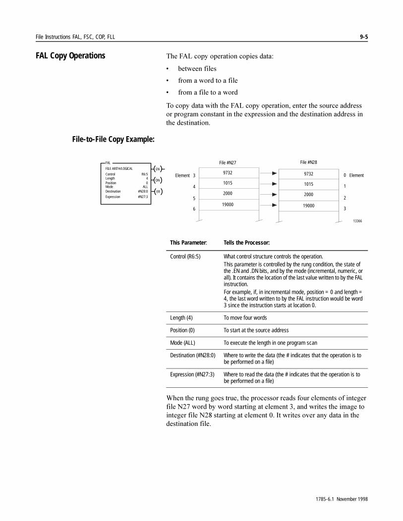
File Instructions FAL, FSC, COP, FLL 9-5
FAL Copy Operations 7KH�)$/�FRS\�RSHUDWLRQ�FRSLHV�GDWD�
� EHWZHHQ�ILOHV
� IURP�D�ZRUG�WR�D�ILOH
� IURP�D�ILOH�WR�D�ZRUG
7R�FRS\�GDWD�ZLWK�WKH�)$/�FRS\�RSHUDWLRQ��HQWHU�WKH�VRXUFH�DGGUHVV�RU�SURJUDP�FRQVWDQW�LQ�WKH�H[SUHVVLRQ�DQG�WKH�GHVWLQDWLRQ�DGGUHVV�LQ�WKH�GHVWLQDWLRQ�
File-to-File Copy Example:
:KHQ�WKH�UXQJ�JRHV�WUXH��WKH�SURFHVVRU�UHDGV�IRXU�HOHPHQWV�RI�LQWHJHU�ILOH�1���ZRUG�E\�ZRUG�VWDUWLQJ�DW�HOHPHQW����DQG�ZULWHV�WKH�LPDJH�WR�LQWHJHU�ILOH�1���VWDUWLQJ�DW�HOHPHQW����,W�ZULWHV�RYHU�DQ\�GDWD�LQ�WKH�GHVWLQDWLRQ�ILOH�
This Parameter: Tells the Processor:
Control (R6:5) What control structure controls the operation.This parameter is controlled by the rung condition, the state of the .EN and .DN bits, and by the mode (incremental, numeric, or all). It contains the location of the last value written to by the FAL instruction.For example, if, in incremental mode, position = 0 and length = 4, the last word written to by the FAL instruction would be word 3 since the instruction starts at location 0.
Length (4) To move four words
Position (0) To start at the source address
Mode (ALL) To execute the length in one program scan
Destination (#N28:0) Where to write the data (the # indicates that the operation is to be performed on a file)
Expression (#N27:3) Where to read the data (the # indicates that the operation is to be performed on a file)
File #N27
0
1
2
3
9732
1015
2000
19000
13366
3
4
6
Element
5
ENFILE ARITH/LOGICAL
ControlLengthPositionMode
DN
Destination ERExpression
FAL
R6:540
ALL#N28:0
#N27:3
Element
File #N28
9732
1015
2000
19000
1785-6.1 November 1998
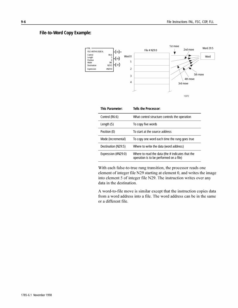
9-6 File Instructions FAL, FSC, COP, FLL
File-to-Word Copy Example:
:LWK�HDFK�IDOVH�WR�WUXH�UXQJ�WUDQVLWLRQ��WKH�SURFHVVRU�UHDGV�RQH�HOHPHQW�RI�LQWHJHU�ILOH�1���VWDUWLQJ�DW�HOHPHQW����DQG�ZULWHV�WKH�LPDJH�LQWR�HOHPHQW���RI�LQWHJHU�ILOH�1����7KH�LQVWUXFWLRQ�ZULWHV�RYHU�DQ\�GDWD�LQ�WKH�GHVWLQDWLRQ�
$�ZRUG�WR�ILOH�PRYH�LV�VLPLODU�H[FHSW�WKDW�WKH�LQVWUXFWLRQ�FRSLHV�GDWD�IURP�D�ZRUG�DGGUHVV�LQWR�D�ILOH��7KH�ZRUG�DGGUHVV�FDQ�EH�LQ�WKH�VDPH�RU�D�GLIIHUHQW�ILOH�
This Parameter: Tells the Processor:
Control (R6:6) What control structure controls the operation
Length (5) To copy five words
Position (0) To start at the source address
Mode (incremental) To copy one word each time the rung goes true
Destination (N29:5) Where to write the data (word address)
Expression (#N29:0) Where to read the data (the # indicates that the operation is to be performed on a file)
ENFILE ARITH/LOGICAL
ControlLengthPositionMode
DN
Destination ER
Expression
FAL
R6:650
INCN29:5
#N29:0
13372
Word 0
1
2
3
4
1st move2nd move
3rd move
4th move
5th move
File # N29:0Word 29:5
Word
1785-6.1 November 1998
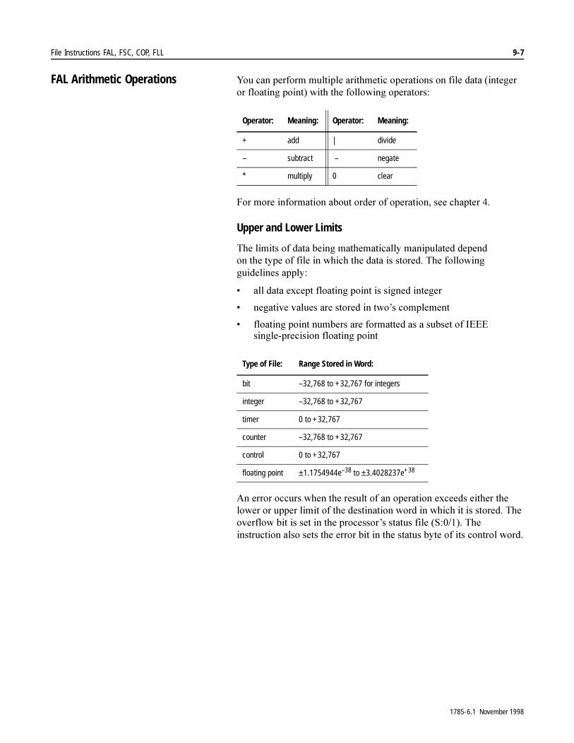
File Instructions FAL, FSC, COP, FLL 9-7
FAL Arithmetic Operations <RX�FDQ�SHUIRUP�PXOWLSOH�DULWKPHWLF�RSHUDWLRQV�RQ�ILOH�GDWD��LQWHJHU�RU�IORDWLQJ�SRLQW��ZLWK�WKH�IROORZLQJ�RSHUDWRUV�
)RU�PRUH�LQIRUPDWLRQ�DERXW�RUGHU�RI�RSHUDWLRQ��VHH�FKDSWHU���
Upper and Lower Limits
7KH�OLPLWV�RI�GDWD�EHLQJ�PDWKHPDWLFDOO\�PDQLSXODWHG�GHSHQG�RQ�WKH�W\SH�RI�ILOH�LQ�ZKLFK�WKH�GDWD�LV�VWRUHG��7KH�IROORZLQJ�JXLGHOLQHV�DSSO\�
� DOO�GDWD�H[FHSW�IORDWLQJ�SRLQW�LV�VLJQHG�LQWHJHU
� QHJDWLYH�YDOXHV�DUH�VWRUHG�LQ�WZR¶V�FRPSOHPHQW
� IORDWLQJ�SRLQW�QXPEHUV�DUH�IRUPDWWHG�DV�D�VXEVHW�RI�,(((�VLQJOH�SUHFLVLRQ�IORDWLQJ�SRLQW
$Q�HUURU�RFFXUV�ZKHQ�WKH�UHVXOW�RI�DQ�RSHUDWLRQ�H[FHHGV�HLWKHU�WKH�ORZHU�RU�XSSHU�OLPLW�RI�WKH�GHVWLQDWLRQ�ZRUG�LQ�ZKLFK�LW�LV�VWRUHG��7KH�RYHUIORZ�ELW�LV�VHW�LQ�WKH�SURFHVVRU¶V�VWDWXV�ILOH��6�������7KH�LQVWUXFWLRQ�DOVR�VHWV�WKH�HUURU�ELW�LQ�WKH�VWDWXV�E\WH�RI�LWV�FRQWURO�ZRUG�
Operator: Meaning: Operator: Meaning:
+ add | divide
– subtract – negate
* multiply 0 clear
Type of File: Range Stored in Word:
bit –32,768 to +32,767 for integers
integer –32,768 to +32,767
timer 0 to +32,767
counter –32,768 to +32,767
control 0 to +32,767
floating point ±1.1754944e–38 to ±3.4028237e+38
1785-6.1 November 1998

9-8 File Instructions FAL, FSC, COP, FLL
Addition Example: :KHQ�WKH�UXQJ�JRHV�WUXH��WKH�SURFHVVRU�DGGV�����YDOXHV�LQ�ILOH��1�����WR�WKH�FRUUHVSRQGLQJ�YDOXHV�LQ�ILOH��1������XVLQJ�WKH�QXPHULFDO�PRGH�RI����ZRUGV�SHU�VFDQ��7KH�RSHUDWLRQ�LV�SHUIRUPHG�LQ����VFDQV�DQG�WKH�LQVWUXFWLRQ�VHTXHQWLDOO\�DGGV�WKH�YDOXHV�LQ�WKH�H[SUHVVLRQ��VWRULQJ�WKH�UHVXOW�LQ�ILOH��1�����
ENFILE ARITH/LOGICALControlLengthPositionMode
DN
Dest ERExpression
FAL
R6:0100
010
#N13:0
#N11:0 + #N12:0
328
150
10
32
0
45
1579
620
0
1
2
3
4
5
6
7
800
1243
next 10 words
next 10 words
next 10 words
last 10 elements
// //
8
9
99
0
1
2
3
4
5
6
7
// //
8
9
99
10
32
1
147
99
572
300
42
19
1000
0
1
2
3
4
5
6
7
// //
8
9
99
338
182
11
179
99
617
1879
662
819
2243
+ =
13386
First Scan
Second Scan
Third Scan
Fourth Scan
Tenth Scan
File # N11:0 File # N12:0 File # N13:0
This Parameter: Tells the Processor:
Control (R6:0) What control structure controls operation
Length (100) To operate on one hundred elements
Position (0) To start at the source address
Mode (10) To execute the data in 10 words per scan
Destination (#N13:0) Where to write the result data
Expression(#N11:0 + #N12:0)
The operators, program constants, and source addresses
1785-6.1 November 1998

File Instructions FAL, FSC, COP, FLL 9-9
Subtraction Example:
:KHQ�WKH�UXQJ�JRHV�WUXH��WKH�SURFHVVRU�UHDGV�HLJKW�HOHPHQWV�RI�LQWHJHU�ILOH�1���ZRUG�E\�ZRUG�VWDUWLQJ�DW�HOHPHQW����VXEWUDFWV�D�SURJUDP�FRQVWDQW�������IURP�HDFK��DQG�ZULWHV�WKH�UHVXOW�LQWR�GHVWLQDWLRQ�ILOH�1���VWDUWLQJ�DW�HOHPHQW�����DOO�LQ�RQH�VFDQ�
This Parameter: Tells the Processor:
Control (R6:1) What control structure controls operation
Length (8) To operate on eight words
Position (0) To start at the source address
Mode (ALL) To execute the data in one program scan
Destination (#N15:10) Where to write the result data
Expression (#N14:0 – 256)
The operators, program constants, and source addresses
0
1
2
3
4
5
6
7
10
11
12
13
14
15
16
17
File #N14
72
-106
-246
-224
-256
-211
1323
364
16655a
One Scan Required
ENFILE ARITH/LOGICAL
ControlLengthPositionMode
DN
Dest ER
Expression
FAL
R6:180
ALL#N15:10
#N14:0 - 256
328
150
10
32
0
45
1579
620
File #N14-256 =
1785-6.1 November 1998
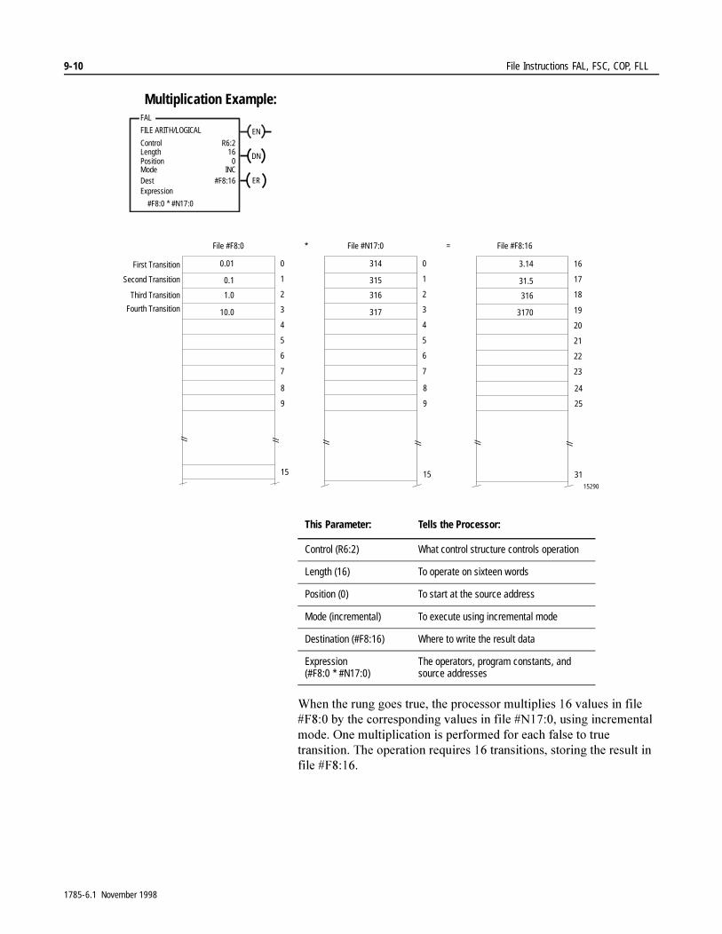
9-10 File Instructions FAL, FSC, COP, FLL
Multiplication Example:
:KHQ�WKH�UXQJ�JRHV�WUXH��WKH�SURFHVVRU�PXOWLSOLHV����YDOXHV�LQ�ILOH��)����E\�WKH�FRUUHVSRQGLQJ�YDOXHV�LQ�ILOH��1������XVLQJ�LQFUHPHQWDO�PRGH��2QH�PXOWLSOLFDWLRQ�LV�SHUIRUPHG�IRU�HDFK�IDOVH�WR�WUXH�WUDQVLWLRQ��7KH�RSHUDWLRQ�UHTXLUHV����WUDQVLWLRQV��VWRULQJ�WKH�UHVXOW�LQ�ILOH��)�����
ENFILE ARITH/LOGICAL
ControlLengthPositionMode
DN
Dest ERExpression
FAL
R6:216
0INC
#F8:16
#F8:0 * #N17:0
This Parameter: Tells the Processor:
Control (R6:2) What control structure controls operation
Length (16) To operate on sixteen words
Position (0) To start at the source address
Mode (incremental) To execute using incremental mode
Destination (#F8:16) Where to write the result data
Expression (#F8:0 * #N17:0)
The operators, program constants, and source addresses
0
1
2
3
4
5
6
7
// //
8
9
15
0
1
2
3
4
5
6
7
// //
8
9
15
314
315
316
317
16
17
18
19
20
21
22
23
// //
24
25
31
3.14
31.5
316
3170
* =
15290
0.01
0.1
1.0
10.0
First Transition
Second Transition
Third Transition
Fourth Transition
File #F8:0 File #N17:0 File #F8:16
1785-6.1 November 1998

File Instructions FAL, FSC, COP, FLL 9-11
Division Example:
:KHQ�WKH�UXQJ�JRHV�WUXH��WKH�SURFHVVRU�VWDUWV�WR�GLYLGH����YDOXHV�VWDUWLQJ�DW�1�����E\�WKH�FRUUHVSRQGLQJ�YDOXHV�LQ�ILOH��1������XVLQJ�LQFUHPHQWDO�PRGH��2QH�GLYLVLRQ�LV�SHUIRUPHG�IRU�HDFK�WUDQVLWLRQ�WR�WUXH��7KH�RSHUDWLRQ�UHTXLUHV����WUDQVLWLRQV��VWRULQJ�WKH�UHVXOW�LQ�D����ZRUG�ILOH�VWDUWLQJ�DW�1�����
ENFILE ARITH/LOGICAL
ControlLengthPositionMode
DN
Destination ER
Expression
FAL
R6:216
0INC
#N13:0
#N11:0 | #N12:0
This Parameter: Tells the Processor:
Control (R6:2) What control structure controls operation
Length (16) To operate on sixteen words
Position (0) To start at the source address
Mode (incremental) To execute using incremental mode
Destination (#N13:0) Where to write the result data
Expression (#N11:0 | #N12:0)
The operators and source addresses
0
1
2
3
4
5
6
7
// //
8
9
15
0
1
2
3
4
5
6
7
// //
8
9
15
12
5
8
9
// //
5
35
141
5
| =
17955
60
175
1128
45
First Transition
Second Transition
Third Transition
Fourth Transition
0
1
2
3
4
5
6
7
8
9
15
File N11:0 File N12:0 File N13:0Word WordWord
1785-6.1 November 1998

9-12 File Instructions FAL, FSC, COP, FLL
File Square Root Example: :KHQ�UXQJ�FRQGLWLRQV�JR�WUXH��WKH�LQVWUXFWLRQ�REWDLQV�WKH�SRVLWLYH�VTXDUH�URRW�RI�WKH�YDOXH�DW�WKH�VRXUFH��7KH�UDWH�LV�GHWHUPLQHG�E\�WKH�PRGH�\RX�VHOHFW��7KH�UHVXOW�RI�HDFK�VTXDUH�URRW�RSHUDWLRQ�LV�VWRUHG�LQ�WKH�FRUUHVSRQGLQJ�ZRUG�LQ�WKH�GHVWLQDWLRQ��RQH�ZRUG�DW�D�WLPH�
7KH�SURFHVVRU�WDNHV�WKH�VTXDUH�URRW�RI�WKH�DEVROXWH�YDOXH��LI�WKH�VLJQ�LV�QHJDWLYH��WKH�SURFHVVRU�GLVUHJDUGV�WKH�VLJQ��
$IWHU�UXQJ�JRHV�WUXH��WKH�VTXDUH�URRW�RI�WKH�ILUVW���ZRUGV�LQ�WKH�ILOH�EHJLQQLQJ�DW�1������LV�FDOFXODWHG��DQG�WKH�UHVXOW�LV�ZULWWHQ�LQ�WKH�GHVWLQDWLRQ�ILOH�EHJLQQLQJ�DW�1������(YHU\�WLPH�WKH�UXQJ�LV�VFDQQHG�WKHUHDIWHU��WKH�QH[W�IRXU�ZRUGV�DUH�FDOFXODWHG�DQG�WKH�UHVXOW�ZULWWHQ�WR�WKH�GHVWLQDWLRQ�ILOH��7KH�SURFHVVRU�UHTXLUHV�D�WRWDO�RI����VFDQV��OHQJWK� ������PRGH� ����WR�FRPSOHWH�WKH�LQVWUXFWLRQ�
FAL Logic Operations 3HUIRUP�PXOWLSOH�ORJLF�RSHUDWLRQV�RQ�ELQDU\�ILOH�GDWD�ZLWK�WKH�IROORZLQJ�ELWZLVH�ORJLF�RSHUDWRUV��
� $1'
� 25
� ;25
� 127
7R�SHUIRUP�PXOWLSOH�ORJLF�RSHUDWLRQV��\RX�HQWHU�WKH�RSHUDWRUV��VRXUFH�DGGUHVVHV��RU�SURJUDP�FRQVWDQWV�LQ�WKH�H[SUHVVLRQ��DQG�WKH�UHVXOW�DGGUHVV�LQ�WKH�GHVWLQDWLRQ�
ENFILE ARITH/LOGICALControlLengthPositionMode
DN
Destination ER
Expression
FAL
R6:464
04
#N23:4
SQR #N22:25
This Parameter: Tells the Processor:
Control (R6:4) What control structure controls the operation
Length (64) To take the square root of 64 words
Position (0) To start at the source address
Mode (4) To operate on 4 words each scan
Destination (#N23:4) Where to write the result data
Expression (SQR #N22:25) The operator and source address
1785-6.1 November 1998
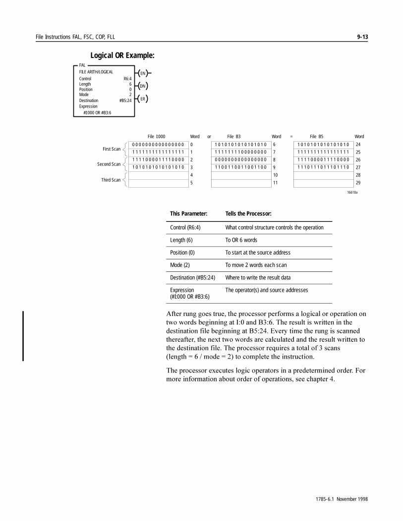
File Instructions FAL, FSC, COP, FLL 9-13
Logical OR Example:
$IWHU�UXQJ�JRHV�WUXH��WKH�SURFHVVRU�SHUIRUPV�D�ORJLFDO�RU�RSHUDWLRQ�RQ�WZR�ZRUGV�EHJLQQLQJ�DW�,���DQG�%�����7KH�UHVXOW�LV�ZULWWHQ�LQ�WKH�GHVWLQDWLRQ�ILOH�EHJLQQLQJ�DW�%������(YHU\�WLPH�WKH�UXQJ�LV�VFDQQHG�WKHUHDIWHU��WKH�QH[W�WZR�ZRUGV�DUH�FDOFXODWHG�DQG�WKH�UHVXOW�ZULWWHQ�WR�WKH�GHVWLQDWLRQ�ILOH��7KH�SURFHVVRU�UHTXLUHV�D�WRWDO�RI���VFDQV��OHQJWK ����PRGH� ����WR�FRPSOHWH�WKH�LQVWUXFWLRQ�
7KH�SURFHVVRU�H[HFXWHV�ORJLF�RSHUDWRUV�LQ�D�SUHGHWHUPLQHG�RUGHU��)RU�PRUH�LQIRUPDWLRQ�DERXW�RUGHU�RI�RSHUDWLRQV��VHH�FKDSWHU���
Expression
ENFILE ARITH/LOGICAL
ControlLengthPositionMode
R6:4602
DN
Destination #B5:24 ER
FAL
#I:000 OR #B3:6
This Parameter: Tells the Processor:
Control (R6:4) What control structure controls the operation
Length (6) To OR 6 words
Position (0) To start at the source address
Mode (2) To move 2 words each scan
Destination (#B5:24) Where to write the result data
Expression(#I:000 OR #B3:6)
The operator(s) and source addresses
0 0 0 0 0 0 0 0 0 0 0 0 0 0 0 0
1 1 1 1 1 1 1 1 1 1 1 1 1 1 1 1
1 1 1 1 0 0 0 0 1 1 1 1 0 0 0 0
1 0 1 0 1 0 1 0 1 0 1 0 1 0 1 0
0
1
2
3
4
5
File I:000
1 0 1 0 1 0 1 0 1 0 1 0 1 0 1 0
1 1 1 1 1 1 1 1 0 0 0 0 0 0 0 0
0 0 0 0 0 0 0 0 0 0 0 0 0 0 0 0
1 1 0 0 1 1 0 0 1 1 0 0 1 1 0 0
6
7
8
9
10
11
File B3
1 0 1 0 1 0 1 0 1 0 1 0 1 0 1 0
1 1 1 1 1 1 1 1 1 1 1 1 1 1 1 1
1 1 1 1 0 0 0 0 1 1 1 1 0 0 0 0
1 1 1 0 1 1 1 0 1 1 1 0 1 1 1 0
24
25
26
27
28
29
File B5
16618a
or =
First Scan
Second Scan
Third Scan
Word Word Word
1785-6.1 November 1998
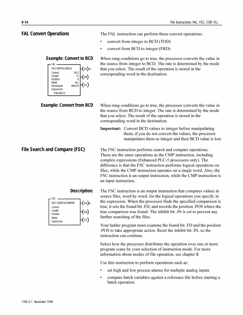
9-14 File Instructions FAL, FSC, COP, FLL
FAL Convert Operations 7KH�)$/�LQVWUXFWLRQ�FDQ�SHUIRUP�WKHVH�FRQYHUW�RSHUDWLRQV�
� FRQYHUW�IURP�LQWHJHU�WR�%&'��72'�
� FRQYHUW�IURP�%&'�WR�LQWHJHU��)5'�
Example: Convert to BCD :KHQ�UXQJ�FRQGLWLRQV�JR�WR�WUXH��WKH�SURFHVVRU�FRQYHUWV�WKH�YDOXH�LQ�WKH�VRXUFH�IURP�LQWHJHU�WR�%&'��7KH�UDWH�LV�GHWHUPLQHG�E\�WKH�PRGH�WKDW�\RX�VHOHFW��7KH�UHVXOW�RI�WKH�RSHUDWLRQ�LV�VWRUHG�LQ�WKH�FRUUHVSRQGLQJ�ZRUG�LQ�WKH�GHVWLQDWLRQ�
Example: Convert from BCD :KHQ�UXQJ�FRQGLWLRQV�JR�WR�WUXH��WKH�SURFHVVRU�FRQYHUWV�WKH�YDOXH�LQ�WKH�VRXUFH�IURP�%&'�WR�LQWHJHU��7KH�UDWH�LV�GHWHUPLQHG�E\�WKH�PRGH�WKDW�\RX�VHOHFW��7KH�UHVXOW�RI�WKH�RSHUDWLRQ�LV�VWRUHG�LQ�WKH�FRUUHVSRQGLQJ�ZRUG�LQ�WKH�GHVWLQDWLRQ�
,PSRUWDQW���&RQYHUW�%&'�YDOXHV�WR�LQWHJHU�EHIRUH�PDQLSXODWLQJ�WKHP��LI�\RX�GR�QRW�FRQYHUW�WKH�YDOXHV��WKH�SURFHVVRU�PDQLSXODWHV�WKHP�DV�LQWHJHU�DQG�WKHLU�%&'�YDOXH�LV�ORVW�
File Search and Compare (FSC) 7KH�)6&�LQVWUXFWLRQ�SHUIRUPV�VHDUFK�DQG�FRPSDUH�RSHUDWLRQV��7KHVH�DUH�WKH�VDPH�RSHUDWLRQV�DV�WKH�&03�LQVWUXFWLRQ��LQFOXGLQJ�FRPSOH[�H[SUHVVLRQV��(QKDQFHG�3/&���SURFHVVRUV�RQO\���7KH�GLIIHUHQFH�LV�WKDW�WKH�)6&�LQVWUXFWLRQ�SHUIRUPV�ORJLFDO�RSHUDWLRQV�RQ�ILOHV��ZKLOH�WKH�&03�LQVWUXFWLRQ�RSHUDWHV�RQ�D�VLQJOH�ZRUG��$OVR��WKH�)6&�LQVWUXFWLRQ�LV�DQ�RXWSXW�LQVWUXFWLRQ��ZKLOH�WKH�&03�LQVWUXFWLRQ�LV�DQ�LQSXW�LQVWUXFWLRQ�
Description: 7KH�)6&�LQVWUXFWLRQ�LV�DQ�RXWSXW�LQVWUXFWLRQ�WKDW�FRPSDUHV�YDOXHV�LQ�VRXUFH�ILOHV��ZRUG�E\�ZRUG��IRU�WKH�ORJLFDO�RSHUDWLRQV�\RX�VSHFLI\�LQ�WKH�H[SUHVVLRQ��:KHQ�WKH�SURFHVVRU�ILQGV�WKH�VSHFLILHG�FRPSDULVRQ�LV�WUXH��LW�VHWV�WKH�IRXQG�ELW��)'��DQG�UHFRUGV�WKH�SRVLWLRQ��326�ZKHUH�WKH�WUXH�FRPSDULVRQ�ZDV�IRXQG��7KH�LQKLELW�ELW��,1�LV�VHW�WR�SUHYHQW�DQ\�IXUWKHU�VHDUFKLQJ�RI�WKH�ILOHV�
<RXU�ODGGHU�SURJUDP�PXVW�H[DPLQH�WKH�IRXQG�ELW��)'�DQG�WKH�SRVLWLRQ��326�WR�WDNH�DSSURSULDWH�DFWLRQ��5HVHW�WKH�LQKLELW�ELW��,1��VR�WKH�LQVWUXFWLRQ�FDQ�FRQWLQXH�
6HOHFW�KRZ�WKH�SURFHVVRU�GLVWULEXWHV�WKH�RSHUDWLRQ�RYHU�RQH�RU�PRUH�SURJUDP�VFDQV�E\�\RXU�VHOHFWLRQ�RI�LQVWUXFWLRQ�PRGH��)RU�PRUH�LQIRUPDWLRQ�DERXW�PRGHV�RI�ILOH�RSHUDWLRQ��VHH�FKDSWHU���
8VH�WKLV�LQVWUXFWLRQ�WR�SHUIRUP�RSHUDWLRQV�VXFK�DV��
� VHW�KLJK�DQG�ORZ�SURFHVV�DODUPV�IRU�PXOWLSOH�DQDORJ�LQSXWV
� FRPSDUH�EDWFK�YDULDEOHV�DJDLQVW�D�UHIHUHQFH�ILOH�EHIRUH�VWDUWLQJ�D�EDWFK�RSHUDWLRQ
Expression
ENFILE ARITH/LOGICAL
ControlLengthPositionMode
R6:212
0ALL
DN
Destination #N14:0 ER
FAL
TOD #N7:0
EN
FSC
FILE SEARCH/COMPAR
ControlLengthPositionMode
DN
Expression ER
1785-6.1 November 1998
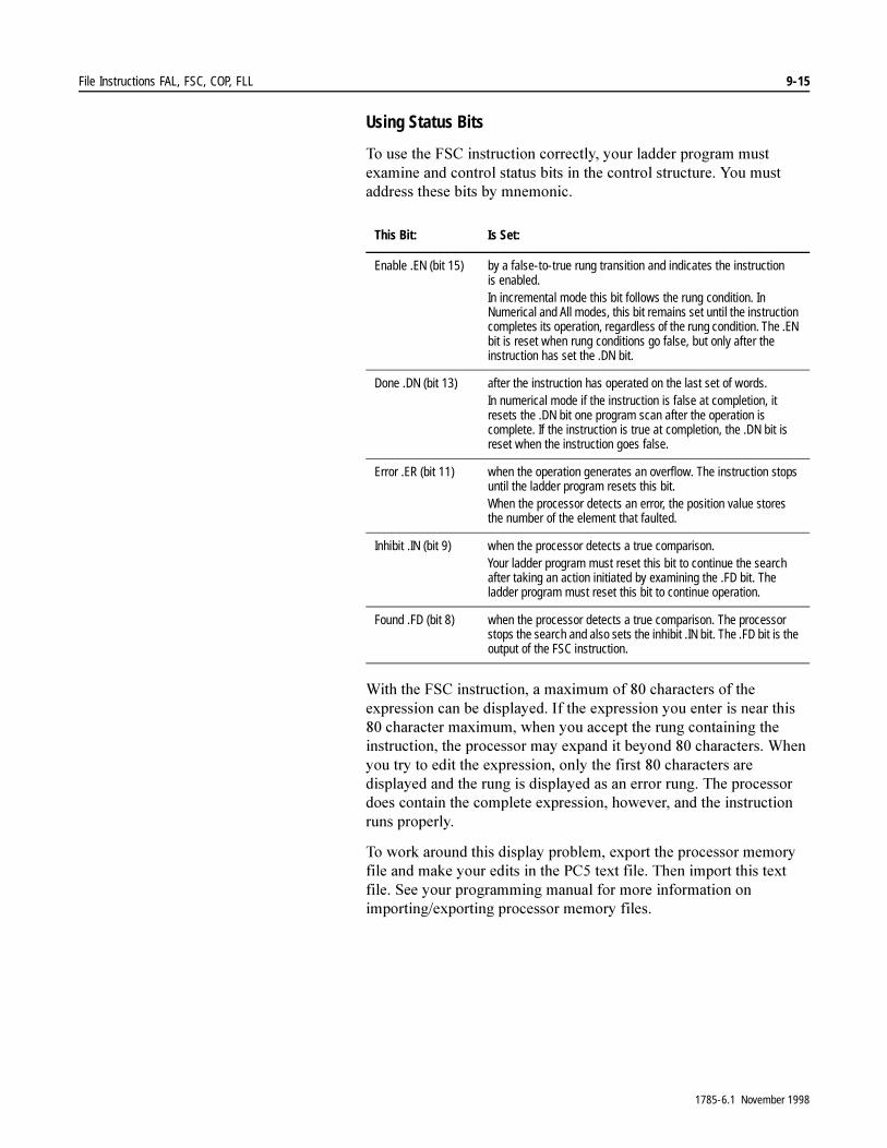
File Instructions FAL, FSC, COP, FLL 9-15
Using Status Bits
7R�XVH�WKH�)6&�LQVWUXFWLRQ�FRUUHFWO\��\RXU�ODGGHU�SURJUDP�PXVW�H[DPLQH�DQG�FRQWURO�VWDWXV�ELWV�LQ�WKH�FRQWURO�VWUXFWXUH��<RX�PXVW�DGGUHVV�WKHVH�ELWV�E\�PQHPRQLF�
:LWK�WKH�)6&�LQVWUXFWLRQ��D�PD[LPXP�RI����FKDUDFWHUV�RI�WKH�H[SUHVVLRQ�FDQ�EH�GLVSOD\HG��,I�WKH�H[SUHVVLRQ�\RX�HQWHU�LV�QHDU�WKLV����FKDUDFWHU�PD[LPXP��ZKHQ�\RX�DFFHSW�WKH�UXQJ�FRQWDLQLQJ�WKH�LQVWUXFWLRQ��WKH�SURFHVVRU�PD\�H[SDQG�LW�EH\RQG����FKDUDFWHUV��:KHQ�\RX�WU\�WR�HGLW�WKH�H[SUHVVLRQ��RQO\�WKH�ILUVW����FKDUDFWHUV�DUH�GLVSOD\HG�DQG�WKH�UXQJ�LV�GLVSOD\HG�DV�DQ�HUURU�UXQJ��7KH�SURFHVVRU�GRHV�FRQWDLQ�WKH�FRPSOHWH�H[SUHVVLRQ��KRZHYHU��DQG�WKH�LQVWUXFWLRQ�UXQV�SURSHUO\�
7R�ZRUN�DURXQG�WKLV�GLVSOD\�SUREOHP��H[SRUW�WKH�SURFHVVRU�PHPRU\�ILOH�DQG�PDNH�\RXU�HGLWV�LQ�WKH�3&��WH[W�ILOH��7KHQ�LPSRUW�WKLV�WH[W�ILOH��6HH�\RXU�SURJUDPPLQJ�PDQXDO�IRU�PRUH�LQIRUPDWLRQ�RQ�LPSRUWLQJ�H[SRUWLQJ�SURFHVVRU�PHPRU\�ILOHV�
This Bit: Is Set:
Enable .EN (bit 15) by a false-to-true rung transition and indicates the instruction is enabled.In incremental mode this bit follows the rung condition. In Numerical and All modes, this bit remains set until the instruction completes its operation, regardless of the rung condition. The .EN bit is reset when rung conditions go false, but only after the instruction has set the .DN bit.
Done .DN (bit 13) after the instruction has operated on the last set of words.In numerical mode if the instruction is false at completion, it resets the .DN bit one program scan after the operation is complete. If the instruction is true at completion, the .DN bit is reset when the instruction goes false.
Error .ER (bit 11) when the operation generates an overflow. The instruction stops until the ladder program resets this bit.When the processor detects an error, the position value stores the number of the element that faulted.
Inhibit .IN (bit 9) when the processor detects a true comparison.Your ladder program must reset this bit to continue the search after taking an action initiated by examining the .FD bit. The ladder program must reset this bit to continue operation.
Found .FD (bit 8) when the processor detects a true comparison. The processor stops the search and also sets the inhibit .IN bit. The .FD bit is the output of the FSC instruction.
1785-6.1 November 1998
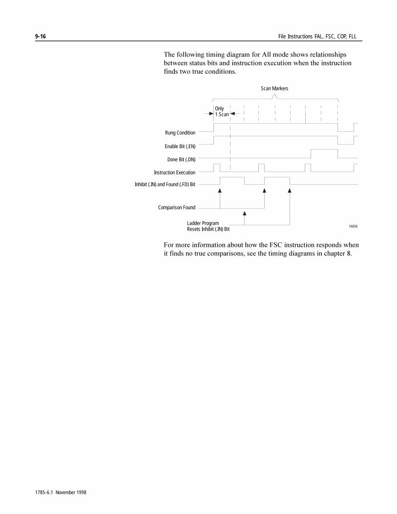
9-16 File Instructions FAL, FSC, COP, FLL
7KH�IROORZLQJ�WLPLQJ�GLDJUDP�IRU�$OO�PRGH�VKRZV�UHODWLRQVKLSV�EHWZHHQ�VWDWXV�ELWV�DQG�LQVWUXFWLRQ�H[HFXWLRQ�ZKHQ�WKH�LQVWUXFWLRQ�ILQGV�WZR�WUXH�FRQGLWLRQV�
)RU�PRUH�LQIRUPDWLRQ�DERXW�KRZ�WKH�)6&�LQVWUXFWLRQ�UHVSRQGV�ZKHQ�LW�ILQGV�QR�WUXH�FRPSDULVRQV��VHH�WKH�WLPLQJ�GLDJUDPV�LQ�FKDSWHU���
Rung Condition
Enable Bit (.EN)
Done Bit (.DN)
Instruction Execution
Inhibit (.IN) and Found (.FD) Bit
Comparison Found
Ladder Program Resets Inhibit (.IN) Bit
Only 1 Scan
Scan Markers
16656
1785-6.1 November 1998

File Instructions FAL, FSC, COP, FLL 9-17
FSC Search and Compare Operations
7KH�)6&�LQVWUXFWLRQ�SHUIRUPV�WKHVH�FRPSDULVRQV�RQ�ILOH�GDWD�DFFRUGLQJ�WR�KRZ�\RX�VSHFLI\�WKHP�LQ�WKH�([SUHVVLRQ���&RPSOH[�H[SUHVVLRQV�DUH�YDOLG�LQ�(QKDQFHG�3/&���SURFHVVRUV�RQO\��
Data Conversion
7KH�SURFHVVRU�FRPSDUHV�ILOHV�RI�GLIIHUHQW�GDWD�W\SHV�E\�LQWHUQDOO\�FRQYHUWLQJ�GDWD�LQWR�LWV�ELQDU\�HTXLYDOHQW�EHIRUH�SHUIRUPLQJ�WKH�FRPSDULVRQ��7KH�SURFHVVRU�WUHDWV�WKH�IROORZLQJ�GDWD�W\SHV�DV�LQWHJHU��WLPHU��VWDWXV��ELW��FRXQWHU��LQSXW��$6&,,��FRQWURO��RXWSXW��%&'�
,PSRUWDQW���:KHQ�\RX�FRPSDUH�IORDWLQJ�SRLQW�DQG�LQWHJHU�YDOXHV�LQ�WKH�)6&�LQVWUXFWLRQ��OLPLW�WKH�FRPSDULVRQV�WR�³OHVV�WKDQ�RU�HTXDO´�DQG�³JUHDWHU�WKDQ�RU�HTXDO�´
,PSRUWDQW���8VH�$6&,,�DQG�%&'�IRU�GLVSOD\�RQO\��DQG�QRW�DV�YDOXHV��6LQFH�WKH�SURFHVVRU�LQWHUSUHWV�WKHP�DV�LQWHJHU��WKH\�PD\�ORVH�WKHLU�PHDQLQJ�LI�\RX�HQWHU�WKHP�DV�YDOXHV�
)RU�WKH�RUGHU�LQ�ZKLFK�WKH�LQVWUXFWLRQ�SHUIRUPV�ORJLFDO�RSHUDWLRQV��VHH�WKH�VHFWLRQ�³'HWHUPLQLQJ�WKH�2UGHU�RI�2SHUDWLRQ´�LQ�FKDSWHU���
File Search Operation
:KHQ�WKH�UXQJ�FRQGLWLRQ�JRHV�WR�WUXH��WKH�GHVLUHG�FRPSDULVRQ�LV�SHUIRUPHG�RQ�GDWD�DGGUHVVHG�LQ�WKH�H[SUHVVLRQ��:RUGV�DUH�FRPSDUHG�LQ�DVFHQGLQJ�RUGHU��VWDUWLQJ�DW�WKH�EHJLQQLQJ��7KH�UDWH�LV�GHWHUPLQHG�E\�WKH�PRGH�RI�RSHUDWLRQ�WKDW�\RX�VSHFLI\��
7KH��'1�ELW��ELW�����LV�VHW�DIWHU�WKH�SURFHVVRU�KDV�FRPSDUHG�WKH�ODVW�SDLU��,I�WKH�UXQJ�LV�WUXH�DW�FRPSOHWLRQ��WKH��'1�ELW�LV�WXUQHG�RII�ZKHQ�WKH�UXQJ�LV�QR�ORQJHU�WUXH��,Q�QXPHULFDO�PRGH��KRZHYHU��LI�WKH�UXQJ�LV�QRW�WUXH�DW�FRPSOHWLRQ��WKH��'1�ELW�VWD\V�RQ�RQH�SURJUDP�VFDQ�DIWHU�WKH�RSHUDWLRQ�LV�FRPSOHWH�
Comparison: Example Expression:
Search Equal #N50:0 = #N51:0
Search Not Equal #N52:0 <> N52:11
Search Less Than #B3:100 < #N53:0
Search Less Than or Equal #F60:0 <= F60:12
Search Greater Than #N54:0 > 256
Search Greater Than or Equal F60:10 >= #N61:0
1785-6.1 November 1998

9-18 File Instructions FAL, FSC, COP, FLL
Example of Search Not Equal:
:KHQ�D�UXQJ�FRQWDLQLQJ�WKH�)6&�LQVWUXFWLRQ�JRHV�WR�WUXH��WKH�SURFHVVRU�SHUIRUPV�WKH�QRW�HTXDO�WR�FRPSDULVRQ�EHWZHHQ�ZRUGV��VWDUWLQJ�DW�%����DQG�%�����7KH�QXPEHU�RI�ZRUGV�FRPSDUHG�SHU�SURJUDP�VFDQ�����LQ�WKLV�H[DPSOH��LV�GHWHUPLQHG�E\�WKH�PRGH�\RX�VHOHFW�
:KHQ�WKH�SURFHVVRU�ILQGV�WKDW�FRUUHVSRQGLQJ�VRXUFH�ZRUGV�DUH�QRW�HTXDO��ZRUGV�%����DQG�%����LQ�WKLV�H[DPSOH���WKH�SURFHVVRU�VWRSV�WKH�VHDUFK�DQG�WXUQV�RQ�WKH�IRXQG��)'�DQG�LQKLELW��,1�ELWV�VR�\RXU�ODGGHU�SURJUDP�FDQ�WDNH�DSSURSULDWH�DFWLRQ��7R�FRQWLQXH�WKH�VHDUFK�FRPSDULVRQ��\RX�PXVW�WXUQ�RII�WKH��,1�ELW�
EN
FSC
FILE SEARCH/COMPARE
ControlLengthPositionMode
R6:090
010
DN
Expression ER
#B4:0 <> #B5:0
This Parameter: Tells the Processor:
Control (R6:0) What control structure controls the operation
Length (90) To search through 90 words
Position (0) To start at source addresses
Mode (10) To search 10 words per program scan
Expression (#B4:0 <> #B5:0)
The comparison to perform and the source addresses
0 0 0 0 0 0 0 1 0 0 0 0 0 0 0 0 ( 1 0 0 )
0 0 0 0 0 0 0 0 0 0 0 0 0 0 0 1 ( 1 )
0 0 0 0 0 0 0 0 0 0 0 0 0 0 1 0 ( 2 )
0 0 0 0 0 0 0 0 0 0 0 0 0 1 1 0 ( 6 )
0
1
2
3
4
10
89
0 0 0 0 0 0 0 1 0 0 0 0 0 0 0 0 ( 1 0 0 )
0 0 0 0 0 0 0 0 0 0 0 0 0 0 0 1 ( 1 )
0 0 0 0 0 0 0 0 0 0 0 0 0 0 1 0 ( 2 )
0 0 0 0 0 0 0 0 0 0 0 0 0 1 1 0 ( 6 )
0
1
2
3
4
10
8916620a
0 0 0 0 0 0 0 0 0 0 0 0 0 1 1 1 ( 7 ) 0 0 0 0 0 0 0 0 0 0 0 0 0 1 1 0 ( 6 )
First scan
Second scan
Ninth scan
File B4 File B5
Next 10 wordsNext 10 words
Next 10 wordsNext 10 words
Last 10 words Last 10 words
Processor stops andsets the found andinhibit bits. To continue,the program must resetthe inhibit bit.
Word Word
1785-6.1 November 1998
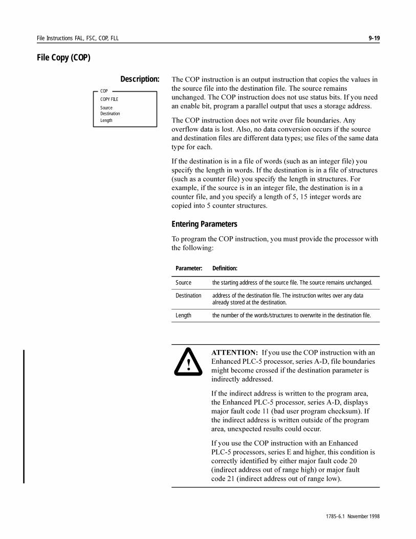
File Instructions FAL, FSC, COP, FLL 9-19
File Copy (COP)
Description: 7KH�&23�LQVWUXFWLRQ�LV�DQ�RXWSXW�LQVWUXFWLRQ�WKDW�FRSLHV�WKH�YDOXHV�LQ�WKH�VRXUFH�ILOH�LQWR�WKH�GHVWLQDWLRQ�ILOH��7KH�VRXUFH�UHPDLQV�XQFKDQJHG��7KH�&23�LQVWUXFWLRQ�GRHV�QRW�XVH�VWDWXV�ELWV��,I�\RX�QHHG�DQ�HQDEOH�ELW��SURJUDP�D�SDUDOOHO�RXWSXW�WKDW�XVHV�D�VWRUDJH�DGGUHVV�
7KH�&23�LQVWUXFWLRQ�GRHV�QRW�ZULWH�RYHU�ILOH�ERXQGDULHV��$Q\�RYHUIORZ�GDWD�LV�ORVW��$OVR��QR�GDWD�FRQYHUVLRQ�RFFXUV�LI�WKH�VRXUFH�DQG�GHVWLQDWLRQ�ILOHV�DUH�GLIIHUHQW�GDWD�W\SHV��XVH�ILOHV�RI�WKH�VDPH�GDWD�W\SH�IRU�HDFK�
,I�WKH�GHVWLQDWLRQ�LV�LQ�D�ILOH�RI�ZRUGV��VXFK�DV�DQ�LQWHJHU�ILOH��\RX�VSHFLI\�WKH�OHQJWK�LQ�ZRUGV��,I�WKH�GHVWLQDWLRQ�LV�LQ�D�ILOH�RI�VWUXFWXUHV��VXFK�DV�D�FRXQWHU�ILOH��\RX�VSHFLI\�WKH�OHQJWK�LQ�VWUXFWXUHV��)RU�H[DPSOH��LI�WKH�VRXUFH�LV�LQ�DQ�LQWHJHU�ILOH��WKH�GHVWLQDWLRQ�LV�LQ�D�FRXQWHU�ILOH��DQG�\RX�VSHFLI\�D�OHQJWK�RI�������LQWHJHU�ZRUGV�DUH�FRSLHG�LQWR���FRXQWHU�VWUXFWXUHV�
Entering Parameters
7R�SURJUDP�WKH�&23�LQVWUXFWLRQ��\RX�PXVW�SURYLGH�WKH�SURFHVVRU�ZLWK�WKH�IROORZLQJ�
COP
COPY FILE
SourceDestination
Length
Parameter: Definition:
Source the starting address of the source file. The source remains unchanged.
Destination address of the destination file. The instruction writes over any data already stored at the destination.
Length the number of the words/structures to overwrite in the destination file.
�$77(17,21� ,I�\RX�XVH�WKH�&23�LQVWUXFWLRQ�ZLWK�DQ�(QKDQFHG�3/&���SURFHVVRU��VHULHV�$�'��ILOH�ERXQGDULHV�PLJKW�EHFRPH�FURVVHG�LI�WKH�GHVWLQDWLRQ�SDUDPHWHU�LV�LQGLUHFWO\�DGGUHVVHG�
,I�WKH�LQGLUHFW�DGGUHVV�LV�ZULWWHQ�WR�WKH�SURJUDP�DUHD��WKH�(QKDQFHG�3/&���SURFHVVRU��VHULHV�$�'��GLVSOD\V�PDMRU�IDXOW�FRGH�����EDG�XVHU�SURJUDP�FKHFNVXP���,I�WKH�LQGLUHFW�DGGUHVV�LV�ZULWWHQ�RXWVLGH�RI�WKH�SURJUDP�DUHD��XQH[SHFWHG�UHVXOWV�FRXOG�RFFXU�
,I�\RX�XVH�WKH�&23�LQVWUXFWLRQ�ZLWK�DQ�(QKDQFHG�3/&���SURFHVVRUV��VHULHV�(�DQG�KLJKHU��WKLV�FRQGLWLRQ�LV�FRUUHFWO\�LGHQWLILHG�E\�HLWKHU�PDMRU�IDXOW�FRGH�����LQGLUHFW�DGGUHVV�RXW�RI�UDQJH�KLJK��RU�PDMRU�IDXOW�FRGH ����LQGLUHFW�DGGUHVV�RXW�RI�UDQJH�ORZ��
1785-6.1 November 1998

9-20 File Instructions FAL, FSC, COP, FLL
Example:
File Fill (FLL)
Description: 7KH�)//�LQVWUXFWLRQ�LV�DQ�RXWSXW�LQVWUXFWLRQ�WKDW�ILOOV�WKH�ZRUGV�RI�D�ILOH�ZLWK�D�VRXUFH�YDOXH��7KH�VRXUFH�UHPDLQV�XQFKDQJHG��7KH�)//�LQVWUXFWLRQ�GRHV�QRW�XVH�VWDWXV�ELWV��,I�\RX�QHHG�DQ�HQDEOH�ELW��SURJUDP�D�SDUDOOHO�RXWSXW�WKDW�XVHV�D�VWRUDJH�DGGUHVV�
7KH�)//�LQVWUXFWLRQ�GRHV�QRW�ZULWH�RYHU�ILOH�ERXQGDULHV��$Q\�RYHUIORZ�GDWD�LV�ORVW��$OVR��QR�GDWD�FRQYHUVLRQ�RFFXUV�LI�WKH�VRXUFH�DQG�GHVWLQDWLRQ�ILOHV�DUH�GLIIHUHQW�GDWD�W\SHV��XVH�ILOHV�RI�WKH�VDPH�GDWD�W\SH�IRU�HDFK�
,I�WKH�GHVWLQDWLRQ�LV�LQ�D�ILOH�RI�ZRUGV��VXFK�DV�DQ�LQWHJHU�ILOH��\RX�VSHFLI\�WKH�OHQJWK�LQ�ZRUGV��,I�WKH�GHVWLQDWLRQ�LV�LQ�D�ILOH�RI�VWUXFWXUHV��VXFK�DV�D�FRXQWHU�ILOH��\RX�VSHFLI\�WKH�OHQJWK�LQ�VWUXFWXUHV��)RU�H[DPSOH��LI�WKH�VRXUFH�ZRUG�LV�DQ�LQWHJHU�ILOH��WKH�GHVWLQDWLRQ�LV�LQ�D�FRXQWHU�ILOH��DQG�\RX�VSHFLI\�D�OHQJWK�RI����WKH�VRXUFH�ZRUG�LV�FRSLHG����WLPHV�WR�ILOO�WKH���FRXQWHU�VWUXFWXUHV�
7KH�)//�LQVWUXFWLRQ�LV�OHYHO�VHQVLWLYH�
Entering Parameters
7R�SURJUDP�WKH�)//�LQVWUXFWLRQ��\RX�PXVW�SURYLGH�WKH�SURFHVVRU�ZLWK�WKH�IROORZLQJ�
COP
COPY FILE
Source Destination
I:012
10#N7:0
#N12:0
[ [
Length 5
If input word 12, bit 10 is on, copy the valuesof the first five words starting at N7:0 into the firstfive words of N12:0.
FLL
FILL FILE
Source
Destination
Length
Parameter: Definition:
Source the address of the source word or a program constant. The source remains unchanged.
Destination the starting address of the destination file. The instruction writes over any data already stored at the destination.
Length the number of the words/structures to fill in the destination file
1785-6.1 November 1998

File Instructions FAL, FSC, COP, FLL 9-21
Example:
:RUGV�DUH�FRSLHG�IURP�WKH�VSHFLILHG�VRXUFH�ILOH�LQWR�WKH�VSHFLILHG�GHVWLQDWLRQ�ILOH�HYHU\�VFDQ�WKDW�WKH�UXQJ�LV�WUXH��7KH\�DUH�FRSLHG��LQ�DVFHQGLQJ�RUGHU�ZLWK�QR�WUDQVIRUPDWLRQ�RI�GDWD��XS�WR�WKH�VSHFLILHG�QXPEHU�RU�XQWLO�WKH�ODVW�ZRUG�RI�WKH�GHVWLQDWLRQ�ILOH�LV�UHDFKHG��ZKLFKHYHU�RFFXUV�ILUVW�
$FFXUDWHO\�VSHFLI\�WKH�VWDUWLQJ�DGGUHVV�DQG�OHQJWK�RI�WKH�GDWD�EORFN�\RX�DUH�ILOOLQJ��7KH�LQVWUXFWLRQ�ZLOO�QRW�ZULWH�RYHU�D�ILOH�ERXQGDU\��VXFK�DV�EHWZHHQ�ILOHV�1���DQG�1����DW�WKH�GHVWLQDWLRQ��7KH�RYHUIORZ�ZRXOG�EH�ORVW�
�$77(17,21� ,I�\RX�XVH�WKH�)//�LQVWUXFWLRQ�ZLWK�DQ�(QKDQFHG�3/&���SURFHVVRU��VHULHV�$�'��ILOH�ERXQGDULHV�PLJKW�EHFRPH�FURVVHG�LI�WKH�GHVWLQDWLRQ�SDUDPHWHU�LV�LQGLUHFWO\�DGGUHVVHG�
,I�WKH�LQGLUHFW�DGGUHVV�LV�ZULWWHQ�WR�WKH�SURJUDP�DUHD��WKH�(QKDQFHG�3/&���SURFHVVRU��VHULHV�$�'��GLVSOD\V�PDMRU�IDXOW�FRGH�����EDG�XVHU�SURJUDP�FKHFNVXP���,I�WKH�LQGLUHFW�DGGUHVV�LV�ZULWWHQ�RXWVLGH�RI�WKH�SURJUDP�DUHD��XQH[SHFWHG�UHVXOWV�FRXOG�RFFXU�
,I�\RX�XVH�WKH�)//�LQVWUXFWLRQ�ZLWK�DQ�(QKDQFHG�3/&���SURFHVVRUV��VHULHV�(�DQG�KLJKHU��WKLV�FRQGLWLRQ�LV�FRUUHFWO\�LGHQWLILHG�E\�HLWKHU�PDMRU�IDXOW�FRGH�����LQGLUHFW�DGGUHVV�RXW�RI�UDQJH�KLJK��RU�PDMRU�IDXOW�FRGH ����LQGLUHFW�DGGUHVV�RXW�RI�UDQJH�ORZ��
FLL
FILL FILE
Source Destination
I:012
10N7:0
#N12:0
[ [
Length 5If input word 12, bit 10 is on, copy the valueof word N7:0 into the first five wordsstarting at N12:0
1785-6.1 November 1998

9-22 File Instructions FAL, FSC, COP, FLL
1RWHV�
1785-6.1 November 1998
Chapter 10
Diagnostic Instructions FBC, DDT, DTR
Using Diagnostic Instructions 7KH�GLDJQRVWLF�LQVWUXFWLRQV�OHW�\RX�GHWHFW�SUREOHPV�ZLWK�GDWD�LQ�\RXU�SURJUDPV��7DEOH����$�OLVWV�WKH�DYDLODEOH�GLDJQRVWLF�LQVWUXFWLRQV�
Table 10.A Available Diagnostic Instructions
)RU�PRUH�LQIRUPDWLRQ�RQ�WKH�RSHUDQGV��DQG�YDOLG�GDWD�W\SHV�YDOXHV�RI�HDFK�RSHUDQG��XVHG�E\�WKH�LQVWUXFWLRQV�GLVFXVVHG�LQ�WKLV�FKDSWHU��VHH�$SSHQGL[�&�
If You Want to: Use this Operation: Found on Page:
Compare I/O data against a known, good reference and record any mismatches
FBC 10-2
Compare I/O data against a known, good reference, record any mismatches, and update the reference file to match the source file
DDT 10-2
Pass source data through a mask and compare the result to reference data, and then write the source word into the reference address of the next comparison.
DTR 10-8
1785-6.1 November 1998

10-2 Diagnostic Instructions FBC, DDT, DTR
File Bit Comparison (FBC) and Diagnostic Detect (DDT)
7KH�)%&�DQG�''7�GLDJQRVWLF�LQVWUXFWLRQV�DUH�RXWSXW�LQVWUXFWLRQV�WKDW�\RX�XVH�WR�PRQLWRU�PDFKLQH�RU�SURFHVV�RSHUDWLRQV�WR�GHWHFW�PDOIXQFWLRQV�
Table 10.B Available Diagnostic Instructions
Description: %RWK�WKH�)%&�DQG�''7�LQVWUXFWLRQV�FRPSDUH�ELWV�LQ�D�ILOH�RI�UHDO�WLPH�PDFKLQH�RU�SURFHVV�YDOXHV��LQSXW�ILOH��ZLWK�ELWV�LQ�D�UHIHUHQFH�ILOH��GHWHFW�GHYLDWLRQV��DQG�UHFRUG�PLVPDWFKHG�ELW�QXPEHUV��7KHVH�LQVWUXFWLRQV�UHFRUG�WKH�SRVLWLRQ�RI�HDFK�PLVPDWFK�IRXQG�DQG�SODFH�WKLV�LQIRUPDWLRQ�LQ�WKH�UHVXOW�ILOH��,I�QR�PLVPDWFKHV�DUH�IRXQG��WKH��'1�ELW�LV�VHW�EXW�WKH�UHVXOW�ILOH�UHPDLQV�XQFKDQJHG�
7KH�GLIIHUHQFH�EHWZHHQ�WKH�''7�DQG�)%&�LQVWUXFWLRQ�LV�WKDW�HDFK�WLPH�WKH�''7�LQVWUXFWLRQ�ILQGV�D�PLVPDWFK��WKH�SURFHVVRU�FKDQJHV�WKH�UHIHUHQFH�ELW�WR�PDWFK�WKH�VRXUFH�ELW��7KH�)%&�LQVWUXFWLRQ�GRHV�QRW�FKDQJH�WKH�UHIHUHQFH�ELW��8VH�WKH�''7�LQVWUXFWLRQ�WR�XSGDWH�\RXU�UHIHUHQFH�ILOH�WR�UHIOHFW�FKDQJLQJ�PDFKLQH�RU�SURFHVV�FRQGLWLRQV�
Selecting the Search Mode
6HOHFW�ZKHWKHU�WKH�GLDJQRVWLF�LQVWUXFWLRQ�VHDUFKHV�IRU�RQH�PLVPDWFK�DW�D�WLPH�RU�ZKHWKHU�LW�VHDUFKHV�IRU�DOO�PLVPDWFKHV�GXULQJ�RQH�SURJUDP�VFDQ�
One Mismatch at a Time
:LWK�HDFK�IDOVH�WR�WUXH�UXQJ�WUDQVLWLRQ��WKH�LQVWUXFWLRQ�VHDUFKHV�IRU�WKH�QH[W�PLVPDWFK�EHWZHHQ�WKH�LQSXW�DQG�UHIHUHQFH�ILOHV��8SRQ�ILQGLQJ�D�PLVPDWFK��WKH�LQVWUXFWLRQ�VWRSV�DQG�VHWV�WKH�IRXQG��)'�ELW��7KHQ�WKH�LQVWUXFWLRQ�HQWHUV�WKH�SRVLWLRQ�QXPEHU�RI�WKH�PLVPDWFK�LQWR�WKH�UHVXOW�ILOH�
7KH�''7�LQVWUXFWLRQ�DOVR�FKDQJHV�WKH�VWDWXV�RI�WKH�UHIHUHQFH�ELW�WR�PDWFK�WKH�VWDWXV�RI�WKH�FRUUHVSRQGLQJ�LQSXW�ELW��7KH�LQVWUXFWLRQ�UHVHWV�WKH�IRXQG�ELW�ZKHQ�WKH�UXQJ�JRHV�IDOVH�
If You Want to Detect Malfunctions By: Use this Instruction:
Comparing bits in a file of real-time inputs with a reference bit file that represents correct operation
FBC
Change-of-state diagnostics DDT
ENFBC
FILE BIT COMPARE
SourceReferenceResultCompare ControlLength
DN
FD
IN
ERPositionResult controlLengthPosition
1785-6.1 November 1998
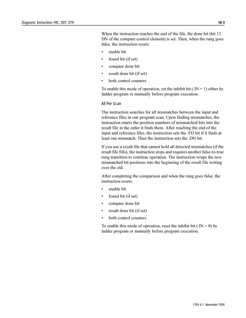
Diagnostic Instructions FBC, DDT, DTR 10-3
:KHQ�WKH�LQVWUXFWLRQ�UHDFKHV�WKH�HQG�RI�WKH�ILOH��WKH�GRQH�ELW��ELW����'1�RI�WKH�FRPSDUH�FRQWURO�HOHPHQW��LV�VHW��7KHQ��ZKHQ�WKH�UXQJ�JRHV�IDOVH��WKH�LQVWUXFWLRQ�UHVHWV�
� HQDEOH�ELW
� IRXQG�ELW��LI�VHW�
� FRPSDUH�GRQH�ELW
� UHVXOW�GRQH�ELW��LI�VHW�
� ERWK�FRQWURO�FRXQWHUV
7R�HQDEOH�WKLV�PRGH�RI�RSHUDWLRQ��VHW�WKH�LQKLELW�ELW���,1� ����HLWKHU�E\�ODGGHU�SURJUDP�RU�PDQXDOO\�EHIRUH�SURJUDP�H[HFXWLRQ�
All Per Scan
7KH�LQVWUXFWLRQ�VHDUFKHV�IRU�DOO�PLVPDWFKHV�EHWZHHQ�WKH�LQSXW�DQG�UHIHUHQFH�ILOHV�LQ�RQH�SURJUDP�VFDQ��8SRQ�ILQGLQJ�PLVPDWFKHV��WKH�LQVWUXFWLRQ�HQWHUV�WKH�SRVLWLRQ�QXPEHUV�RI�PLVPDWFKHG�ELWV�LQWR�WKH�UHVXOW�ILOH�LQ�WKH�RUGHU�LW�ILQGV�WKHP��$IWHU�UHDFKLQJ�WKH�HQG�RI�WKH�LQSXW�DQG�UHIHUHQFH�ILOHV��WKH�LQVWUXFWLRQ�VHWV�WKH��)'�ELW�LI�LW�ILQGV�DW�OHDVW�RQH�PLVPDWFK��7KHQ�WKH�LQVWUXFWLRQ�VHWV�WKH��'1�ELW�
,I�\RX�XVH�D�UHVXOW�ILOH�WKDW�FDQQRW�KROG�DOO�GHWHFWHG�PLVPDWFKHV��LI�WKH�UHVXOW�ILOH�ILOOV���WKH�LQVWUXFWLRQ�VWRSV�DQG�UHTXLUHV�DQRWKHU�IDOVH�WR�WUXH�UXQJ�WUDQVLWLRQ�WR�FRQWLQXH�RSHUDWLRQ��7KH�LQVWUXFWLRQ�ZUDSV�WKH�QHZ�PLVPDWFKHG�ELW�SRVLWLRQV�LQWR�WKH�EHJLQQLQJ�RI�WKH�UHVXOW�ILOH�ZULWLQJ�RYHU�WKH�ROG�
$IWHU�FRPSOHWLQJ�WKH�FRPSDULVRQ�DQG�ZKHQ�WKH�UXQJ�JRHV�IDOVH��WKH�LQVWUXFWLRQ�UHVHWV�
� HQDEOH�ELW
� IRXQG�ELW��LI�VHW�
� FRPSDUH�GRQH�ELW
� UHVXOW�GRQH�ELW��LI�VHW�
� ERWK�FRQWURO�FRXQWHUV
7R�HQDEOH�WKLV�PRGH�RI�RSHUDWLRQ��UHVHW�WKH�LQKLELW�ELW���,1� ����E\�ODGGHU�SURJUDP�RU�PDQXDOO\�EHIRUH�SURJUDP�H[HFXWLRQ�
1785-6.1 November 1998

10-4 Diagnostic Instructions FBC, DDT, DTR
Entering Parameters
7R�SURJUDP�WKHVH�LQVWUXFWLRQV��\RX�QHHG�WR�SURYLGH�WKH�SURFHVVRU�ZLWK�WKH�IROORZLQJ�LQIRUPDWLRQ�
8VH�WKH�UHVXOW�FRQWURO�DGGUHVV�ZLWK�PQHPRQLF�ZKHQ�\RX�DGGUHVV�WKHVH SDUDPHWHUV�
� /HQJWK���/(1��LV�WKH�GHFLPDO�QXPEHU�RI�HOHPHQWV�LQ�WKH�UHVXOW�ILOH��0DNH�WKH�OHQJWK�ORQJ�HQRXJK�WR�UHFRUG�WKH�PD[LPXP�QXPEHU�RI�H[SHFWHG�PLVPDWFKHV�
� 3RVLWLRQ���326��LV�WKH�FXUUHQW�SRVLWLRQ�LQ�WKH�UHVXOW�ILOH��(QWHU�D�YDOXH�RQO\�LI�\RX�ZDQW�WKH�LQVWUXFWLRQ�WR�VWDUW�DW�DQ�RIIVHW�FRQFXUUHQW�ZLWK�D�FRQWURO�ILOH�RIIVHW�IRU�RQH�VFDQ��
Parameter: Description:
Source the indexed address of your input file.
Reference the indexed address of the file that contains the data with which you compare your input file.
Result the indexed address of the file where the instruction stores the position (bit) number of each detected mismatch.
Cmp Control the address of the comparison control structure (R) that stores status bits, the length of the source and reference files (both should be the same), and the current position during operation. Use the compare control address with mnemonic when you address these parameters: Length (.LEN) is the decimal number of bits to be compared in the source and reference files. Remember that bits in I/O files are numbered in octal 00-17, but that bits in all other files are numbered in decimal 0-15.Position (.POS) is the current position of the bit to which the instruction points. Enter a value only if you want the instruction to start at an offset concurrent with a control file offset for one scan.
Result Control the address of the result control structure (R) that stores the bit position number each time the instruction finds a mismatch between source and reference files.
�$77(17,21� �'R�QRW�XVH�WKH�VDPH�DGGUHVV�IRU�PRUH�WKDQ�RQH�FRQWURO�VWUXFWXUH��'XSOLFDWLRQ�RI�WKHVH�DGGUHVVHV�FRXOG�UHVXOW�LQ�XQSUHGLFWDEOH�RSHUDWLRQ��SRVVLEO\�FDXVLQJ�HTXLSPHQW�GDPDJH�DQG�RU�LQMXU\�WR�SHUVRQQHO�
1785-6.1 November 1998
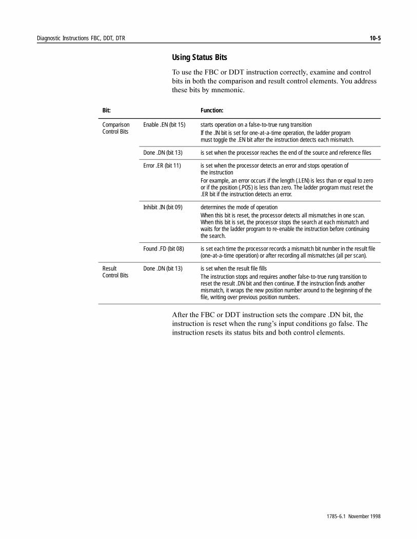
Diagnostic Instructions FBC, DDT, DTR 10-5
Using Status Bits
7R�XVH�WKH�)%&�RU�''7�LQVWUXFWLRQ�FRUUHFWO\��H[DPLQH�DQG�FRQWURO�ELWV�LQ�ERWK�WKH�FRPSDULVRQ�DQG�UHVXOW�FRQWURO�HOHPHQWV��<RX�DGGUHVV�WKHVH�ELWV�E\�PQHPRQLF�
$IWHU�WKH�)%&�RU�''7�LQVWUXFWLRQ�VHWV�WKH�FRPSDUH��'1�ELW��WKH�LQVWUXFWLRQ�LV�UHVHW�ZKHQ�WKH�UXQJ¶V�LQSXW�FRQGLWLRQV�JR�IDOVH��7KH�LQVWUXFWLRQ�UHVHWV�LWV�VWDWXV�ELWV�DQG�ERWK�FRQWURO�HOHPHQWV�
Bit: Function:
Comparison Control Bits
Enable .EN (bit 15) starts operation on a false-to-true rung transitionIf the .IN bit is set for one-at-a-time operation, the ladder program must toggle the .EN bit after the instruction detects each mismatch.
Done .DN (bit 13) is set when the processor reaches the end of the source and reference files
Error .ER (bit 11) is set when the processor detects an error and stops operation of the instructionFor example, an error occurs if the length (.LEN) is less than or equal to zero or if the position (.POS) is less than zero. The ladder program must reset the .ER bit if the instruction detects an error.
Inhibit .IN (bit 09) determines the mode of operation When this bit is reset, the processor detects all mismatches in one scan. When this bit is set, the processor stops the search at each mismatch and waits for the ladder program to re-enable the instruction before continuing the search.
Found .FD (bit 08) is set each time the processor records a mismatch bit number in the result file (one-at-a-time operation) or after recording all mismatches (all per scan).
Result Control Bits
Done .DN (bit 13) is set when the result file fills The instruction stops and requires another false-to-true rung transition to reset the result .DN bit and then continue. If the instruction finds another mismatch, it wraps the new position number around to the beginning of the file, writing over previous position numbers.
1785-6.1 November 1998
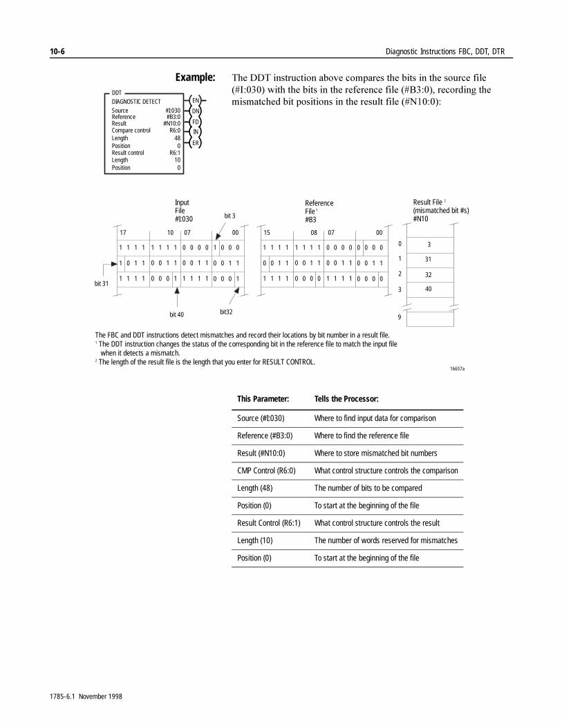
10-6 Diagnostic Instructions FBC, DDT, DTR
Example: 7KH�''7�LQVWUXFWLRQ�DERYH�FRPSDUHV�WKH�ELWV�LQ�WKH�VRXUFH�ILOH���,������ZLWK�WKH�ELWV�LQ�WKH�UHIHUHQFH�ILOH���%������UHFRUGLQJ�WKH�PLVPDWFKHG�ELW�SRVLWLRQV�LQ�WKH�UHVXOW�ILOH���1������EN
DDTDIAGNOSTIC DETECTSourceReferenceResultCompare control
#I:030#B3:0
#N10:0R6:0
Length 48
DN
FD
IN
ERPositionResult controlLength
0R6:1
10Position 0
1 1 1 1 1 1 1 1 0 0 0 0 1 0 0 0
1 0 1 1 0 0 1 1 0 0 1 1 0 0 1 1
1 1 1 1 0 0 0 1 1 1 1 1 0 0 0 1
17 07 0010
1 1 1 1 1 1 1 1
1 1 1 1 1 1 1 1
0 0 1 1
0 0 0 0 0 0 0 0
0 0 1 1 0 0 1 1 0 0 1 1
0 0 0 0 0 0 0 0
15 08 07 00
9
0
3
2
1 31
3
32
40
16657a
Result File 2
(mismatched bit #s)#N10
ReferenceFile
1
#B3bit 3
InputFile#I:030
bit 31
bit 40 bit32
The FBC and DDT instructions detect mismatches and record their locations by bit number in a result file.1 The DDT instruction changes the status of the corresponding bit in the reference file to match the input file when it detects a mismatch.2 The length of the result file is the length that you enter for RESULT CONTROL.
This Parameter: Tells the Processor:
Source (#I:030) Where to find input data for comparison
Reference (#B3:0) Where to find the reference file
Result (#N10:0) Where to store mismatched bit numbers
CMP Control (R6:0) What control structure controls the comparison
Length (48) The number of bits to be compared
Position (0) To start at the beginning of the file
Result Control (R6:1) What control structure controls the result
Length (10) The number of words reserved for mismatches
Position (0) To start at the beginning of the file
1785-6.1 November 1998
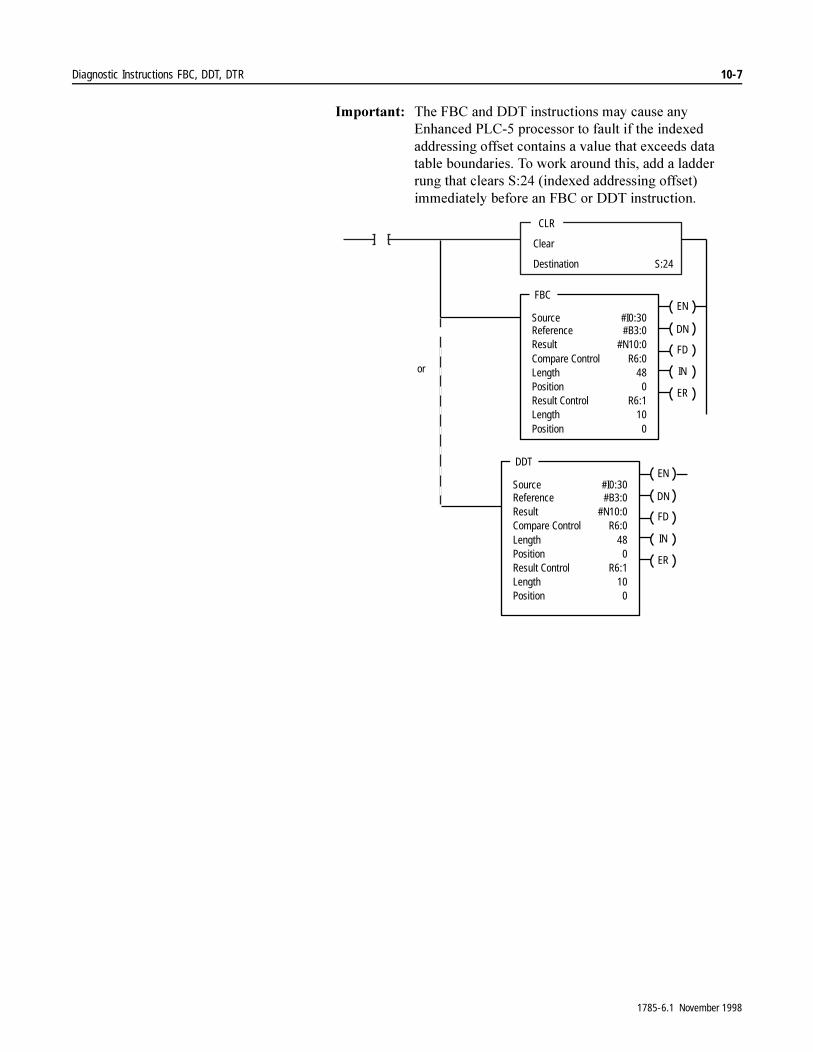
Diagnostic Instructions FBC, DDT, DTR 10-7
,PSRUWDQW���7KH�)%&�DQG�''7�LQVWUXFWLRQV�PD\�FDXVH�DQ\�(QKDQFHG�3/&���SURFHVVRU�WR�IDXOW�LI�WKH�LQGH[HG�DGGUHVVLQJ�RIIVHW�FRQWDLQV�D�YDOXH�WKDW�H[FHHGV�GDWD�WDEOH�ERXQGDULHV��7R�ZRUN�DURXQG�WKLV��DGG�D�ODGGHU�UXQJ�WKDW�FOHDUV�6�����LQGH[HG�DGGUHVVLQJ�RIIVHW��LPPHGLDWHO\�EHIRUH�DQ�)%&�RU�''7�LQVWUXFWLRQ�
CLR
Clear
Destination S:24
FBC
SourceReferenceResultCompare ControlLengthPositionResult ControlLengthPosition
#I0:30#B3:0
#N10:0R6:0
480
R6:1100
EN
DN
FD
IN
ER
or
DDT
SourceReferenceResultCompare ControlLengthPositionResult ControlLengthPosition
#I0:30#B3:0
#N10:0R6:0
480
R6:1100
EN
DN
FD
IN
ER
1785-6.1 November 1998
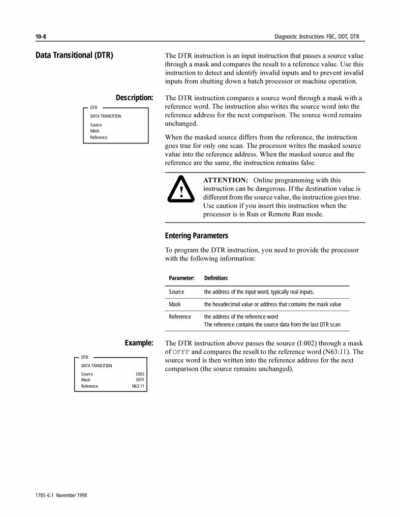
10-8 Diagnostic Instructions FBC, DDT, DTR
Data Transitional (DTR) 7KH�'75�LQVWUXFWLRQ�LV�DQ�LQSXW�LQVWUXFWLRQ�WKDW�SDVVHV�D�VRXUFH�YDOXH�WKURXJK�D�PDVN�DQG�FRPSDUHV�WKH�UHVXOW�WR�D�UHIHUHQFH�YDOXH��8VH�WKLV�LQVWUXFWLRQ�WR�GHWHFW�DQG�LGHQWLI\�LQYDOLG�LQSXWV�DQG�WR�SUHYHQW�LQYDOLG�LQSXWV�IURP�VKXWWLQJ�GRZQ�D�EDWFK�SURFHVVRU�RU�PDFKLQH�RSHUDWLRQ�
Description: 7KH�'75�LQVWUXFWLRQ�FRPSDUHV�D�VRXUFH�ZRUG�WKURXJK�D�PDVN�ZLWK�D�UHIHUHQFH�ZRUG��7KH�LQVWUXFWLRQ�DOVR�ZULWHV�WKH�VRXUFH�ZRUG�LQWR�WKH�UHIHUHQFH�DGGUHVV�IRU�WKH�QH[W�FRPSDULVRQ��7KH�VRXUFH�ZRUG�UHPDLQV�XQFKDQJHG�
:KHQ�WKH�PDVNHG�VRXUFH�GLIIHUV�IURP�WKH�UHIHUHQFH��WKH�LQVWUXFWLRQ�JRHV�WUXH�IRU�RQO\�RQH�VFDQ��7KH�SURFHVVRU�ZULWHV�WKH�PDVNHG�VRXUFH�YDOXH�LQWR�WKH�UHIHUHQFH�DGGUHVV��:KHQ�WKH�PDVNHG�VRXUFH�DQG�WKH�UHIHUHQFH�DUH�WKH�VDPH��WKH�LQVWUXFWLRQ�UHPDLQV�IDOVH��
Entering Parameters
7R�SURJUDP�WKH�'75�LQVWUXFWLRQ��\RX�QHHG�WR�SURYLGH�WKH�SURFHVVRU�ZLWK�WKH�IROORZLQJ�LQIRUPDWLRQ�
Example: 7KH�'75�LQVWUXFWLRQ�DERYH�SDVVHV�WKH�VRXUFH��,������WKURXJK�D�PDVN�RI�OFFF�DQG�FRPSDUHV�WKH�UHVXOW�WR�WKH�UHIHUHQFH�ZRUG��1��������7KH�VRXUFH�ZRUG�LV�WKHQ�ZULWWHQ�LQWR�WKH�UHIHUHQFH�DGGUHVV�IRU�WKH�QH[W�FRPSDULVRQ��WKH�VRXUFH�UHPDLQV�XQFKDQJHG��
DTR
DATA TRANSITION
SourceMask
Reference
�$77(17,21� �2QOLQH�SURJUDPPLQJ�ZLWK�WKLV�LQVWUXFWLRQ�FDQ�EH�GDQJHURXV��,I�WKH�GHVWLQDWLRQ�YDOXH�LV�GLIIHUHQW�IURP�WKH�VRXUFH�YDOXH��WKH�LQVWUXFWLRQ�JRHV�WUXH��8VH�FDXWLRQ�LI�\RX�LQVHUW�WKLV�LQVWUXFWLRQ�ZKHQ�WKH�SURFHVVRU�LV�LQ�5XQ�RU�5HPRWH�5XQ�PRGH�
Parameter: Definition:
Source the address of the input word, typically real inputs.
Mask the hexadecimal value or address that contains the mask value
Reference the address of the reference wordThe reference contains the source data from the last DTR scan
DTR
DATA TRANSITION
SourceMaskReference
I:0020FFF
N63:11
1785-6.1 November 1998
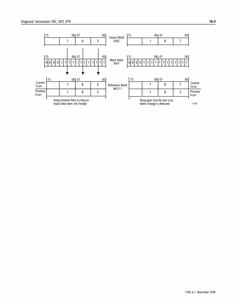
Diagnostic Instructions FBC, DDT, DTR 10-9
13385
Source WordI:002
00070815
381
CurrentScan
00070815
10 110 110 110 1 11 11
00070815
781
00070815
10 110 110 110 1 11 11
00070815
381
381PreviousScan
00070815
781
381
Mask Value0FFF
Reference WordN63:11
Rung remains false as long asinput value does not change
Rung goes true for one scanwhen change is detected
CurrentScan
PreviousScan
1785-6.1 November 1998

10-10 Diagnostic Instructions FBC, DDT, DTR
1RWHV�
1785-6.1 November 1998
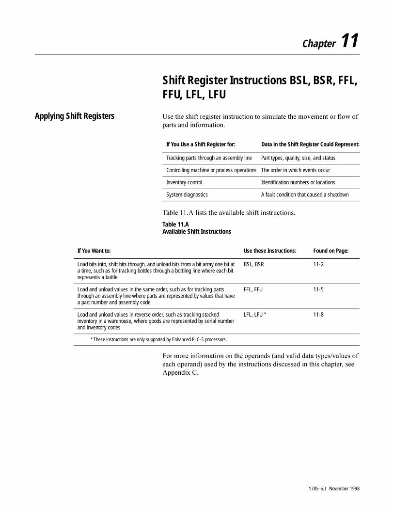
Chapter 11
Shift Register Instructions BSL, BSR, FFL, FFU, LFL, LFU
Applying Shift Registers 8VH�WKH�VKLIW�UHJLVWHU�LQVWUXFWLRQ�WR�VLPXODWH�WKH�PRYHPHQW�RU�IORZ�RI�SDUWV�DQG�LQIRUPDWLRQ�
7DEOH����$�OLVWV�WKH�DYDLODEOH�VKLIW�LQVWUXFWLRQV�
Table 11.A Available Shift Instructions
)RU�PRUH�LQIRUPDWLRQ�RQ�WKH�RSHUDQGV��DQG�YDOLG�GDWD�W\SHV�YDOXHV�RI�HDFK�RSHUDQG��XVHG�E\�WKH�LQVWUXFWLRQV�GLVFXVVHG�LQ�WKLV�FKDSWHU��VHH�$SSHQGL[�&�
If You Use a Shift Register for: Data in the Shift Register Could Represent:
Tracking parts through an assembly line Part types, quality, size, and status
Controlling machine or process operations The order in which events occur
Inventory control Identification numbers or locations
System diagnostics A fault condition that caused a shutdown
If You Want to: Use these Instructions: Found on Page:
Load bits into, shift bits through, and unload bits from a bit array one bit at a time, such as for tracking bottles through a bottling line where each bit represents a bottle
BSL, BSR 11-2
Load and unload values in the same order, such as for tracking parts through an assembly line where parts are represented by values that have a part number and assembly code
FFL, FFU 11-5
Load and unload values in reverse order, such as tracking stacked inventory in a warehouse, where goods are represented by serial number and inventory codes
LFL, LFU * 11-8
* These instructions are only supported by Enhanced PLC-5 processors.
1785-6.1 November 1998

11-2 Shift Register Instructions BSL, BSR, FFL, FFU, LFL, LFU
Using Bit Shift Instructions
Description: %LW�VKLIW�LQVWUXFWLRQV�VKLIW�DOO�ELWV�ZLWKLQ�WKH�VSHFLILHG�DGGUHVV�RQH�ELW�SRVLWLRQ�ZLWK�HDFK�IDOVH�WR�WUXH�UXQJ�WUDQVLWLRQ��7KHVH�LQVWUXFWLRQV�DUH�
� %LW�6KLIW�/HIW��%6/�
� %LW�6KLIW�5LJKW��%65�
Entering Parameters
7R�SURJUDP�D�ELW�VKLIW�LQVWUXFWLRQ��\RX�QHHG�WR�SURYLGH�WKH�SURFHVVRU�ZLWK�WKH�IROORZLQJ�LQIRUPDWLRQ��
ENBIT SHIFT LEFT
FileControlBit addressLength
DN
BSL
Parameter: Definition:
File the address of the bit array you want to manipulate. You must start the array at a 16-bit word boundary. For example, use bit 0 of word number 1, 2, 3, etc. You can end the array at any bit number up to 15,999. However, you cannot use the remaining bits in that particular element because the instruction invalidates them.
Control The address of the control structure (48 bits – three 16-bit words) in the control area (R) of memory that stores the instruction’s status bits, the size of the array (number of bits), and the bit pointer.
Position the current position of the bit to which the instruction points. Enter a value only if you want the instruction to start at an offset concurrent with a control file offset for one scan. Use the control address with mnemonic when you address this parameter.
Bit Address the address of the source bit. The instruction inserts the status of this bit in either the first (lowest) bit position (for the BSL instruction) or the last (highest) bit position (for the BSR instruction) in the array.
Length the decimal number of bits to be shifted. Remember that bits in I/O files are numbered in octal 00-17, but that bits in all other files are numbered in decimal 0-15. Use the control address with mnemonic when you address this parameter.
�$77(17,21� 'R�QRW�XVH�WKH�VDPH�FRQWURO�DGGUHVV�IRU�PRUH�WKDQ�RQH�LQVWUXFWLRQ��8QH[SHFWHG�RSHUDWLRQ�FRXOG�UHVXOW�LQ�SRVVLEOH�HTXLSPHQW�GDPDJH�DQG�RU�SHUVRQDO�LQMXU\�
1785-6.1 November 1998
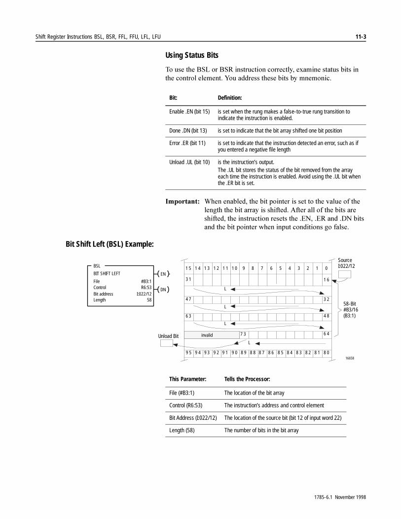
Shift Register Instructions BSL, BSR, FFL, FFU, LFL, LFU 11-3
Using Status Bits
7R�XVH�WKH�%6/�RU�%65�LQVWUXFWLRQ�FRUUHFWO\��H[DPLQH�VWDWXV�ELWV�LQ�WKH�FRQWURO�HOHPHQW��<RX�DGGUHVV�WKHVH�ELWV�E\�PQHPRQLF�
,PSRUWDQW���:KHQ�HQDEOHG��WKH�ELW�SRLQWHU�LV�VHW�WR�WKH�YDOXH�RI�WKH�OHQJWK�WKH�ELW�DUUD\�LV�VKLIWHG��$IWHU�DOO�RI�WKH�ELWV�DUH�VKLIWHG��WKH�LQVWUXFWLRQ�UHVHWV�WKH��(1���(5�DQG��'1�ELWV�DQG�WKH�ELW�SRLQWHU�ZKHQ�LQSXW�FRQGLWLRQV�JR�IDOVH�
Bit Shift Left (BSL) Example:
Bit: Definition:
Enable .EN (bit 15) is set when the rung makes a false-to-true rung transition to indicate the instruction is enabled.
Done .DN (bit 13) is set to indicate that the bit array shifted one bit position
Error .ER (bit 11) is set to indicate that the instruction detected an error, such as if you entered a negative file length
Unload .UL (bit 10) is the instruction’s output.The .UL bit stores the status of the bit removed from the array each time the instruction is enabled. Avoid using the .UL bit when the .ER bit is set.
1 5 1 4 1 2 1 1 1 0 9 8 7 6 5 4 3 2 1 0
3 1
4 7
6 3
9 5 9 4 9 3 9 2 9 1 9 0 8 9 8 8 8 7 8 6 8 5 8 4 8 3 8 2 8 1 8 0
6 47 3
4 8
3 2
1 6
1 3
16658
L
L
L
L
ENBIT SHIFT LEFT
FileControlBit addressLength
#B3:1R6:53
I:022/1258
DN
BSL
Unload Bit
SourceI:022/12
58-Bit#B3/16(B3:1)
invalid
This Parameter: Tells the Processor:
File (#B3:1) The location of the bit array
Control (R6:53) The instruction’s address and control element
Bit Address (I:022/12) The location of the source bit (bit 12 of input word 22)
Length (58) The number of bits in the bit array
1785-6.1 November 1998
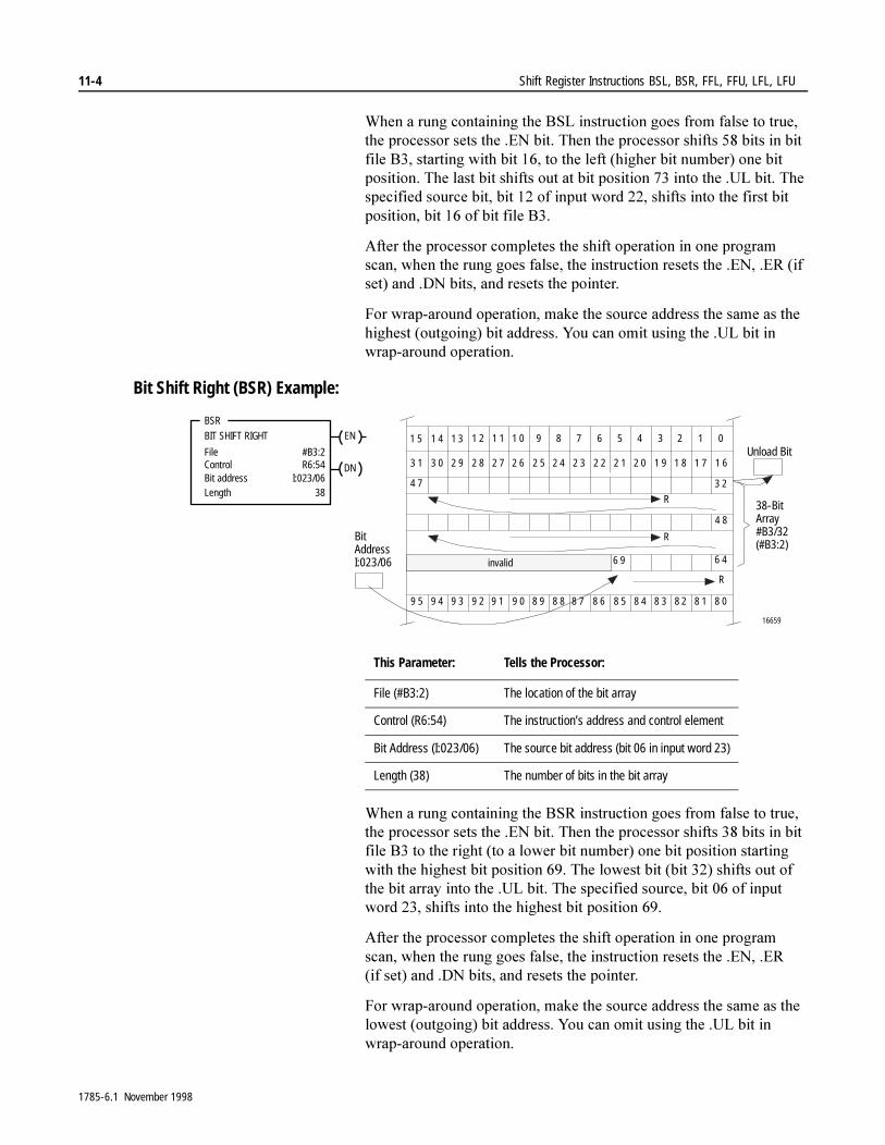
11-4 Shift Register Instructions BSL, BSR, FFL, FFU, LFL, LFU
:KHQ�D�UXQJ�FRQWDLQLQJ�WKH�%6/�LQVWUXFWLRQ�JRHV�IURP�IDOVH�WR�WUXH��WKH�SURFHVVRU�VHWV�WKH��(1�ELW��7KHQ�WKH�SURFHVVRU�VKLIWV����ELWV�LQ�ELW�ILOH�%���VWDUWLQJ�ZLWK�ELW�����WR�WKH�OHIW��KLJKHU�ELW�QXPEHU��RQH�ELW�SRVLWLRQ��7KH�ODVW�ELW�VKLIWV�RXW�DW�ELW�SRVLWLRQ����LQWR�WKH��8/�ELW��7KH�VSHFLILHG�VRXUFH�ELW��ELW����RI�LQSXW�ZRUG�����VKLIWV�LQWR�WKH�ILUVW�ELW�SRVLWLRQ��ELW����RI�ELW�ILOH�%��
$IWHU�WKH�SURFHVVRU�FRPSOHWHV�WKH�VKLIW�RSHUDWLRQ�LQ�RQH�SURJUDP�VFDQ��ZKHQ�WKH�UXQJ�JRHV�IDOVH��WKH�LQVWUXFWLRQ�UHVHWV�WKH��(1���(5��LI�VHW��DQG��'1�ELWV��DQG�UHVHWV�WKH�SRLQWHU�
)RU�ZUDS�DURXQG�RSHUDWLRQ��PDNH�WKH�VRXUFH�DGGUHVV�WKH�VDPH�DV�WKH�KLJKHVW��RXWJRLQJ��ELW�DGGUHVV��<RX�FDQ�RPLW�XVLQJ�WKH��8/�ELW�LQ�ZUDS�DURXQG�RSHUDWLRQ�
Bit Shift Right (BSR) Example:
:KHQ�D�UXQJ�FRQWDLQLQJ�WKH�%65�LQVWUXFWLRQ�JRHV�IURP�IDOVH�WR�WUXH��WKH�SURFHVVRU�VHWV�WKH��(1�ELW��7KHQ�WKH�SURFHVVRU�VKLIWV����ELWV�LQ�ELW�ILOH�%��WR�WKH�ULJKW��WR�D�ORZHU�ELW�QXPEHU��RQH�ELW�SRVLWLRQ�VWDUWLQJ�ZLWK�WKH�KLJKHVW�ELW�SRVLWLRQ�����7KH�ORZHVW�ELW��ELW�����VKLIWV�RXW�RI�WKH�ELW�DUUD\�LQWR�WKH��8/�ELW��7KH�VSHFLILHG�VRXUFH��ELW����RI�LQSXW�ZRUG�����VKLIWV�LQWR�WKH�KLJKHVW�ELW�SRVLWLRQ����
$IWHU�WKH�SURFHVVRU�FRPSOHWHV�WKH�VKLIW�RSHUDWLRQ�LQ�RQH�SURJUDP�VFDQ��ZKHQ�WKH�UXQJ�JRHV�IDOVH��WKH�LQVWUXFWLRQ�UHVHWV�WKH��(1���(5��LI VHW��DQG��'1�ELWV��DQG�UHVHWV�WKH�SRLQWHU�
)RU�ZUDS�DURXQG�RSHUDWLRQ��PDNH�WKH�VRXUFH�DGGUHVV�WKH�VDPH�DV�WKH�ORZHVW��RXWJRLQJ��ELW�DGGUHVV��<RX�FDQ�RPLW�XVLQJ�WKH��8/�ELW�LQ�ZUDS�DURXQG�RSHUDWLRQ�
1 5 1 4 1 2 1 1 1 0 9 8 7 6 5 4 3 2 1 0
4 7
9 5 9 4 9 3 9 2 9 1 9 0 8 9 8 8 8 7 8 6 8 5 8 4 8 3 8 2 8 1 8 0
6 46 9
4 8
3 2
1 3
16659
3 1 3 0 2 8 2 7 2 6 2 5 2 4 2 3 2 2 2 1 2 0 1 9 1 8 1 7 1 62 9
R
R
R
ENBIT SHIFT RIGHT
FileControlBit addressLength
#B3:2R6:54
I:023/0638
DN
BSR
BitAddressI:023/06
Unload Bit
38-BitArray#B3/32(#B3:2)
invalid
This Parameter: Tells the Processor:
File (#B3:2) The location of the bit array
Control (R6:54) The instruction’s address and control element
Bit Address (I:023/06) The source bit address (bit 06 in input word 23)
Length (38) The number of bits in the bit array
1785-6.1 November 1998
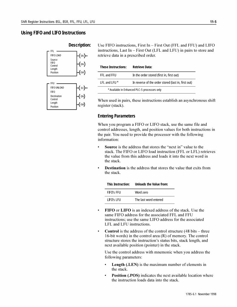
Shift Register Instructions BSL, BSR, FFL, FFU, LFL, LFU 11-5
Using FIFO and LIFO Instructions
Description: 8VH�),)2�LQVWUXFWLRQV��)LUVW�,Q�±�)LUVW�2XW��))/�DQG�))8��DQG�/,)2�LQVWUXFWLRQV��/DVW�,Q�±�)LUVW�2XW��/)/�DQG�/)8��LQ�SDLUV�WR�VWRUH�DQG�UHWULHYH�GDWD�LQ�D�SUHVFULEHG�RUGHU�
:KHQ�XVHG�LQ�SDLUV��WKHVH�LQVWUXFWLRQV�HVWDEOLVK�DQ�DV\QFKURQRXV�VKLIW�UHJLVWHU��VWDFN��
Entering Parameters
:KHQ�\RX�SURJUDP�D�),)2�RU�/,)2�VWDFN��XVH�WKH�VDPH�ILOH�DQG�FRQWURO�DGGUHVVHV��OHQJWK��DQG�SRVLWLRQ�YDOXHV�IRU�ERWK�LQVWUXFWLRQV�LQ�WKH�SDLU��<RX�QHHG�WR�SURYLGH�WKH�SURFHVVRU�ZLWK�WKH�IROORZLQJ�LQIRUPDWLRQ�
� 6RXUFH�LV�WKH�DGGUHVV�WKDW�VWRUHV�WKH�³QH[W�LQ´�YDOXH�WR�WKH�VWDFN��7KH�),)2�RU�/,)2�ORDG�LQVWUXFWLRQ��))/�RU�/)/��UHWULHYHV�WKH�YDOXH�IURP�WKLV�DGGUHVV�DQG�ORDGV�LW�LQWR�WKH�QH[W�ZRUG�LQ�WKH�VWDFN�
� 'HVWLQDWLRQ�LV�WKH�DGGUHVV�WKDW�VWRUHV�WKH�YDOXH�WKDW�H[LWV�IURP�WKH�VWDFN�
� ),)2�RU�/,)2�LV�DQ�LQGH[HG�DGGUHVV�RI�WKH�VWDFN��8VH�WKH�VDPH�),)2�DGGUHVV�IRU�WKH�DVVRFLDWHG�))/�DQG�))8�LQVWUXFWLRQV��XVH�WKH�VDPH�/,)2�DGGUHVV�IRU�WKH�DVVRFLDWHG�/)/�DQG�/)8�LQVWUXFWLRQV�
� &RQWURO�LV�WKH�DGGUHVV�RI�WKH�FRQWURO�VWUXFWXUH�����ELWV�±�WKUHH����ELW�ZRUGV��LQ�WKH�FRQWURO�DUHD��5��RI�PHPRU\��7KH�FRQWURO�VWUXFWXUH�VWRUHV�WKH�LQVWUXFWLRQ¶V�VWDWXV�ELWV��VWDFN�OHQJWK��DQG�QH[W�DYDLODEOH�SRVLWLRQ��SRLQWHU��LQ�WKH�VWDFN�
8VH�WKH�FRQWURO�DGGUHVV�ZLWK�PQHPRQLF�ZKHQ�\RX�DGGUHVV�WKH�IROORZLQJ�SDUDPHWHUV�
� /HQJWK���/(1��LV�WKH�PD[LPXP�QXPEHU�RI�HOHPHQWV�LQ�WKH VWDFN�
� 3RVLWLRQ���326��LQGLFDWHV�WKH�QH[W�DYDLODEOH�ORFDWLRQ�ZKHUH�WKH�LQVWUXFWLRQ�ORDGV�GDWD�LQWR�WKH�VWDFN�
EN
FFL
FIFO LOAD
SourceFIFOControlLength
DN
Position EM
EU
FFU
FIFO UNLOAD
FIFO
DestinationControlLength
DN
PositionEM
These Instructions: Retrieve Data:
FFL and FFU In the order stored (first in, first out)
LFL and LFU * In reverse of the order stored (last in, first out)
* Available in Enhanced PLC-5 processors only
This Instruction: Unloads the Value from:
FIFO’s FFU Word zero
LIFO’s LFU The last word entered
1785-6.1 November 1998
11-6 Shift Register Instructions BSL, BSR, FFL, FFU, LFL, LFU
� /HQJWK�VSHFLILHV�WKH�PD[LPXP�QXPEHU�RI�ZRUGV�LQ�WKH�VWDFN��$GGUHVV�WKH�OHQJWK�YDOXH�E\�PQHPRQLF��/(1�
� 3RVLWLRQ�LQGLFDWHV�WKH�QH[W�DYDLODEOH�ORFDWLRQ�ZKHUH�WKH�LQVWUXFWLRQ�ORDGV�GDWD�LQWR�WKH�VWDFN��$GGUHVV�WKH�SRVLWLRQ�YDOXH�E\�PQHPRQLF��326�
(QWHU�D�SRVLWLRQ�YDOXH�RQO\�LI�\RX�ZDQW�WKH�LQVWUXFWLRQ�WR�VWDUW�DW�DQ�RIIVHW�DW�SRZHU�XS��2WKHUZLVH��HQWHU����<RXU�ODGGHU�SURJUDP�FDQ�FKDQJH�WKH�SRVLWLRQ�LI�QHFHVVDU\��
Using Status Bits
7R�XVH�WKH�),)2�DQG�/,)2�LQVWUXFWLRQV�FRUUHFWO\��H[DPLQH�VWDWXV�ELWV�LQ�WKH�FRQWURO�VWUXFWXUH��<RX�DGGUHVV�WKHVH�ELWV�E\�PQHPRQLF�
�$77(17,21� �([FHSW�ZKHQ�SDLULQJ�VWDFN�LQVWUXFWLRQV��GR�QRW�XVH�WKH�VDPH�FRQWURO�DGGUHVV�IRU�DQ\�RWKHU�LQVWUXFWLRQ��8QH[SHFWHG�RSHUDWLRQ�FRXOG�UHVXOW�ZLWK�SRVVLEOH�HTXLSPHQW�GDPDJH�DQG�RU�SHUVRQDO�LQMXU\�
This Bit: Is Set:
Enable Load .EN (bit 15) when the rung makes a false-to-true rung transition to indicate the instruction is enabled (used in FFL and LFL instructions).Note: During prescan, this bit is set to prevent a false load when the program scan begins.
Enable Unload .EU (bit 14) when rung conditions are true to indicate the instruction is enabled (used in FFU and LFU instructions).Note: During prescan, this bit is set to prevent a false unload when the program scan begins.
Done .DN (bit 13) by the processor to indicate that the stack is full. The .DN bit inhibits loading the stack until there is room.
Empty .EM (bit 12) by the processor to indicate that the stack is empty. Do not enable the FIFO or LIFO unload commands if the .EM bit is set.
1785-6.1 November 1998
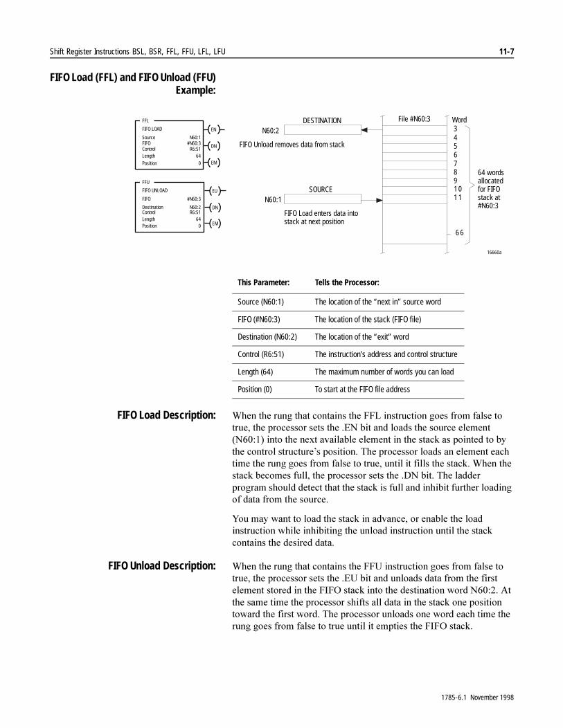
Shift Register Instructions BSL, BSR, FFL, FFU, LFL, LFU 11-7
FIFO Load (FFL) and FIFO Unload (FFU)Example:
FIFO Load Description: :KHQ�WKH�UXQJ�WKDW�FRQWDLQV�WKH�))/�LQVWUXFWLRQ�JRHV�IURP�IDOVH�WR�WUXH��WKH�SURFHVVRU�VHWV�WKH��(1�ELW�DQG�ORDGV�WKH�VRXUFH�HOHPHQW��1������LQWR�WKH�QH[W�DYDLODEOH�HOHPHQW�LQ�WKH�VWDFN�DV�SRLQWHG�WR�E\�WKH�FRQWURO�VWUXFWXUH¶V�SRVLWLRQ��7KH�SURFHVVRU�ORDGV�DQ�HOHPHQW�HDFK�WLPH�WKH�UXQJ�JRHV�IURP�IDOVH�WR�WUXH��XQWLO�LW�ILOOV�WKH�VWDFN��:KHQ�WKH�VWDFN�EHFRPHV�IXOO��WKH�SURFHVVRU�VHWV�WKH��'1�ELW��7KH�ODGGHU�SURJUDP�VKRXOG�GHWHFW�WKDW�WKH�VWDFN�LV�IXOO�DQG�LQKLELW�IXUWKHU�ORDGLQJ�RI�GDWD�IURP�WKH�VRXUFH�
<RX�PD\�ZDQW�WR�ORDG�WKH�VWDFN�LQ�DGYDQFH��RU�HQDEOH�WKH�ORDG�LQVWUXFWLRQ�ZKLOH�LQKLELWLQJ�WKH�XQORDG�LQVWUXFWLRQ�XQWLO�WKH�VWDFN�FRQWDLQV�WKH�GHVLUHG�GDWD�
FIFO Unload Description: :KHQ�WKH�UXQJ�WKDW�FRQWDLQV�WKH�))8�LQVWUXFWLRQ�JRHV�IURP�IDOVH�WR�WUXH��WKH�SURFHVVRU�VHWV�WKH��(8�ELW�DQG�XQORDGV�GDWD�IURP�WKH�ILUVW�HOHPHQW�VWRUHG�LQ�WKH�),)2�VWDFN�LQWR�WKH�GHVWLQDWLRQ�ZRUG�1������$W�WKH�VDPH�WLPH�WKH�SURFHVVRU�VKLIWV�DOO�GDWD�LQ�WKH�VWDFN�RQH�SRVLWLRQ�WRZDUG�WKH�ILUVW�ZRUG��7KH�SURFHVVRU�XQORDGV�RQH�ZRUG�HDFK�WLPH�WKH�UXQJ�JRHV�IURP�IDOVH�WR�WUXH�XQWLO�LW�HPSWLHV�WKH�),)2�VWDFN��
This Parameter: Tells the Processor:
Source (N60:1) The location of the “next in” source word
FIFO (#N60:3) The location of the stack (FIFO file)
Destination (N60:2) The location of the “exit” word
Control (R6:51) The instruction’s address and control structure
Length (64) The maximum number of words you can load
Position (0) To start at the FIFO file address
1 01 1
9876543
6 6
16660a
DESTINATION
SOURCE
FIFO Unload removes data from stack
FIFO Load enters data intostack at next position
File #N60:3 Word
64 wordsallocatedfor FIFOstack at#N60:3
N60:2
N60:1
EN
FFL
FIFO LOAD
SourceFIFOControlLength
N60:1#N60:3
R6:5164
DN
Position 0 EM
EU
FFU
FIFO UNLOAD
FIFO
DestinationControlLength
#N60:3
N60:2R6:51
64
DN
Position 0 EM
1785-6.1 November 1998
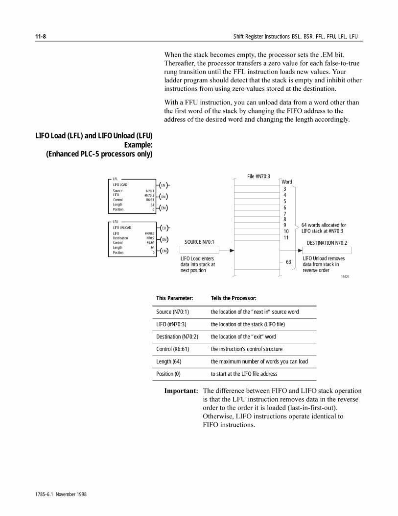
11-8 Shift Register Instructions BSL, BSR, FFL, FFU, LFL, LFU
:KHQ�WKH�VWDFN�EHFRPHV�HPSW\��WKH�SURFHVVRU�VHWV�WKH��(0�ELW��7KHUHDIWHU��WKH�SURFHVVRU�WUDQVIHUV�D�]HUR�YDOXH�IRU�HDFK�IDOVH�WR�WUXH�UXQJ�WUDQVLWLRQ�XQWLO�WKH�))/�LQVWUXFWLRQ�ORDGV�QHZ�YDOXHV��<RXU�ODGGHU�SURJUDP�VKRXOG�GHWHFW�WKDW�WKH�VWDFN�LV�HPSW\�DQG�LQKLELW�RWKHU�LQVWUXFWLRQV�IURP�XVLQJ�]HUR�YDOXHV�VWRUHG�DW�WKH�GHVWLQDWLRQ�
:LWK�D�))8�LQVWUXFWLRQ��\RX�FDQ�XQORDG�GDWD�IURP�D�ZRUG�RWKHU�WKDQ�WKH�ILUVW�ZRUG�RI�WKH�VWDFN�E\�FKDQJLQJ�WKH�),)2�DGGUHVV�WR�WKH�DGGUHVV�RI�WKH�GHVLUHG�ZRUG�DQG�FKDQJLQJ�WKH�OHQJWK�DFFRUGLQJO\��
LIFO Load (LFL) and LIFO Unload (LFU)Example:
(Enhanced PLC-5 processors only)
,PSRUWDQW���7KH�GLIIHUHQFH�EHWZHHQ�),)2�DQG�/,)2�VWDFN�RSHUDWLRQ�LV�WKDW�WKH�/)8�LQVWUXFWLRQ�UHPRYHV�GDWD�LQ�WKH�UHYHUVH�RUGHU�WR�WKH�RUGHU�LW�LV�ORDGHG��ODVW�LQ�ILUVW�RXW���2WKHUZLVH��/,)2�LQVWUXFWLRQV�RSHUDWH�LGHQWLFDO�WR�),)2 LQVWUXFWLRQV�
This Parameter: Tells the Processor:
Source (N70:1) the location of the “next in” source word
LIFO (#N70:3) the location of the stack (LIFO file)
Destination (N70:2) the location of the “exit” word
Control (R6:61) the instruction’s control structure
Length (64) the maximum number of words you can load
Position (0) to start at the LIFO file address
LIFO Load entersdata into stack atnext position
LIFO Unload removesdata from stack inreverse order
64 words allocated forLIFO stack at #N70:3
16621
DESTINATION N70:2SOURCE N70:1
File #N70:3Word34567891011
63
EN
LFL
LIFO LOAD
SourceLIFO
Length
N70:1#N70:3
R6:61
64
DN
Position 0 EM
EU
LFU
LIFO UNLOAD
LIFODestinationControlLength
#N70:3N70:2R6:61
64
DN
Position 0 EM
Control
1785-6.1 November 1998
Shift Register Instructions BSL, BSR, FFL, FFU, LFL, LFU 11-9
LIFO Load Description: :KHQ�WKH�UXQJ�WKDW�FRQWDLQV�WKH�/)/�LQVWUXFWLRQ�JRHV�IURP�IDOVH�WR�WUXH��WKH�SURFHVVRU�VHWV�WKH��(1�ELW�DQG�ORDGV�WKH�VRXUFH�ZRUG��1������LQWR�WKH�QH[W�DYDLODEOH�ZRUG�LQ�WKH�VWDFN�DV�SRLQWHG�WR�E\�WKH�FRQWURO�VWUXFWXUH¶V�SRVLWLRQ��7KH�SURFHVVRU�ORDGV�DQ�HOHPHQW�HDFK�WLPH�WKH�UXQJ�JRHV�IURP�IDOVH�WR�WUXH�XQWLO�LW�ILOOV�WKH�VWDFN��:KHQ�WKH�VWDFN�EHFRPHV�IXOO��WKH�SURFHVVRU�VHWV�WKH��'1�ELW��7KH�ODGGHU�SURJUDP�VKRXOG�GHWHFW�WKDW�WKH�VWDFN�LV�IXOO�DQG�LQKLELW�IXUWKHU�ORDGLQJ�RI�GDWD�IURP�WKH�VRXUFH�
<RX�PD\�ZDQW�WR�ORDG�WKH�VWDFN�LQ�DGYDQFH�RU�HQDEOH�WKH�ORDG�LQVWUXFWLRQ�ZKLOH�LQKLELWLQJ�WKH�XQORDG�LQVWUXFWLRQ�XQWLO�WKH�VWDFN�FRQWDLQV�WKH�GHVLUHG�GDWD�
LIFO Unload Description: :KHQ�WKH�UXQJ�WKDW�FRQWDLQV�WKH�/)8�LQVWUXFWLRQ�JRHV�IURP�IDOVH�WR�WUXH��WKH�SURFHVVRU�VHWV�WKH��(8�ELW�DQG�XQORDGV�GDWD�VWDUWLQJ�ZLWK�WKH�ODVW�ZRUG�VWRUHG�LQ�WKH�/,)2�VWDFN�LQWR�WKH�GHVWLQDWLRQ�ZRUG�1������7KH�SURFHVVRU�XQORDGV�RQH�ZRUG�HDFK�WLPH�WKH�UXQJ�JRHV�IURP�IDOVH�WR�WUXH�XQWLO�LW�HPSWLHV�WKH�/,)2�VWDFN��
:KHQ�WKH�VWDFN�EHFRPHV�HPSW\��WKH�SURFHVVRU�VHWV�WKH��(0�ELW��7KHUHDIWHU��WKH�SURFHVVRU�WUDQVIHUV�D�]HUR�YDOXH�IRU�HDFK�IDOVH�WR�WUXH�UXQJ�WUDQVLWLRQ�XQWLO�WKH�ORDG�LQVWUXFWLRQ�ORDGV�QHZ�YDOXHV��<RXU�ODGGHU�SURJUDP�VKRXOG�GHWHFW�WKDW�WKH�VWDFN�LV�HPSW\�DQG�LQKLELW�RWKHU�LQVWUXFWLRQV�IURP�XVLQJ�]HUR�YDOXHV�VWRUHG�DW�WKH�GHVWLQDWLRQ�
:LWK�D�/,)2�XQORDG�LQVWUXFWLRQ��\RX�FDQ�XQORDG�GDWD�IURP�D�ZRUG�RWKHU�WKDQ�WKH�ILUVW�ZRUG�RI�WKH�VWDFN�E\�FKDQJLQJ�WKH�/,)2�DGGUHVV�WR�WKH�DGGUHVV�RI�WKH�GHVLUHG�ZRUG�DQG�FKDQJLQJ�WKH�OHQJWK�DFFRUGLQJO\�
1785-6.1 November 1998

11-10 Shift Register Instructions BSL, BSR, FFL, FFU, LFL, LFU
1RWHV�
1785-6.1 November 1998

Chapter 12
Sequencer Instructions SQO, SQI, SQL
Applying Sequencers 6HTXHQFHU�LQVWUXFWLRQV�DUH�W\SLFDOO\�XVHG�WR�FRQWURO�DXWRPDWLF�DVVHPEO\�PDFKLQHV�WKDW�KDYH�D�FRQVLVWHQW�DQG�UHSHDWDEOH�RSHUDWLRQ��8VH�WKH�VHTXHQFHU�LQSXW�LQVWUXFWLRQ�WR�GHWHFW�ZKHQ�D�VWHS�LV�FRPSOHWH��XVH�WKH�VHTXHQFHU�RXWSXW�LQVWUXFWLRQ�WR�VHW�RXWSXW�FRQGLWLRQV�IRU�WKH�QH[W�VWHS��8VH�WKH�VHTXHQFHU�ORDG�LQVWUXFWLRQ�WR�ORDG�UHIHUHQFH�FRQGLWLRQV�LQWR�WKH�VHTXHQFHU�LQSXW�DQG�RXWSXW�ILOH�
7DEOH����$�OLVWV�WKH�DYDLODEOH�VHTXHQFHU�LQVWUXFWLRQV�
Table 12.A Available Sequencer Instructions
6HTXHQFHU�LQVWUXFWLRQV�FDQ�FRQVHUYH�SURJUDP�PHPRU\��7KHVH�LQVWUXFWLRQV�PRQLWRU�DQG�FRQWURO�PXOWLSOHV�RI����GLVFUHWH�RXWSXWV�DW�D�WLPH�LQ�D�VLQJOH�UXQJ�
)RU�PRUH�LQIRUPDWLRQ�RQ�WKH�RSHUDQGV��DQG�YDOLG�GDWD�W\SHV�YDOXHV�RI�HDFK�RSHUDQG��XVHG�E\�WKH�LQVWUXFWLRQV�GLVFXVVHG�LQ�WKLV�FKDSWHU��VHH�$SSHQGL[�&�
If You Want to: Use this Instruction: Found on Page:
Control sequential machine operations by transferring 16-bit data through a mask to output image addresses
SQO 12-5
Monitor machine operating conditions for diagnostic purposes by comparing 16-bit image data (through a mask) with data in a reference file
SQI 12-7
Capture reference conditions by manually stepping the machine through its operating sequences and loading I/O or storage data into destination files
SQL 12-8
1785-6.1 November 1998
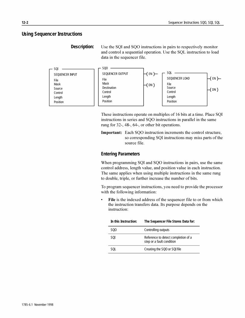
12-2 Sequencer Instructions SQO, SQI, SQL
Using Sequencer Instructions
Description: 8VH�WKH�64,�DQG�642�LQVWUXFWLRQV�LQ�SDLUV�WR�UHVSHFWLYHO\�PRQLWRU�DQG�FRQWURO�D�VHTXHQWLDO�RSHUDWLRQ��8VH�WKH�64/�LQVWUXFWLRQ�WR�ORDG�GDWD�LQ�WKH�VHTXHQFHU�ILOH�
7KHVH�LQVWUXFWLRQV�RSHUDWH�RQ�PXOWLSOHV�RI����ELWV�DW�D�WLPH��3ODFH�64,�LQVWUXFWLRQV�LQ�VHULHV�DQG�642�LQVWUXFWLRQV�LQ�SDUDOOHO�LQ�WKH�VDPH�UXQJ�IRU����������������RU�RWKHU�ELW�RSHUDWLRQV�
,PSRUWDQW���(DFK�642�LQVWUXFWLRQ�LQFUHPHQWV�WKH�FRQWURO�VWUXFWXUH��VR�FRUUHVSRQGLQJ�64,�LQVWUXFWLRQV�PD\�PLVV�SDUWV�RI�WKH�VRXUFH�ILOH�
Entering Parameters
:KHQ�SURJUDPPLQJ�64,�DQG�642�LQVWUXFWLRQV�LQ�SDLUV��XVH�WKH�VDPH�FRQWURO�DGGUHVV��OHQJWK�YDOXH��DQG�SRVLWLRQ�YDOXH�LQ�HDFK�LQVWUXFWLRQ��7KH�VDPH�DSSOLHV�ZKHQ�XVLQJ�PXOWLSOH�LQVWUXFWLRQV�LQ�WKH�VDPH�UXQJ�WR�GRXEOH��WULSOH��RU�IXUWKHU�LQFUHDVH�WKH�QXPEHU�RI�ELWV�
7R�SURJUDP�VHTXHQFHU�LQVWUXFWLRQV��\RX�QHHG�WR�SURYLGH�WKH�SURFHVVRU�ZLWK�WKH�IROORZLQJ�LQIRUPDWLRQ�
� )LOH�LV�WKH�LQGH[HG�DGGUHVV�RI�WKH�VHTXHQFHU�ILOH�WR�RU�IURP�ZKLFK�WKH�LQVWUXFWLRQ�WUDQVIHUV�GDWD��,WV�SXUSRVH�GHSHQGV�RQ�WKH�LQVWUXFWLRQ�
SQI
SEQUENCER INPUT
FileMaskSourceControlLengthPosition
EN
SQO
SEQUENCER OUTPUT
DN
FileMaskDestinationControlLengthPosition
EN
SQL
SEQUENCER LOAD
DN
FileSourceControl
LengthPosition
In this Instruction: The Sequencer File Stores Data for:
SQO Controlling outputs
SQI Reference to detect completion of a step or a fault condition
SQL Creating the SQO or SQI file
1785-6.1 November 1998
Sequencer Instructions SQO, SQI, SQL 12-3
� 0DVN��IRU�642�DQG�64,��LV�D�KH[DGHFLPDO�FRGH�RU�WKH�DGGUHVV�RI�WKH�PDVN�HOHPHQW�RU�ILOH�WKURXJK�ZKLFK�WKH�LQVWUXFWLRQ�PRYHV�GDWD��6HW�����PDVN�ELWV�WR�SDVV�GDWD��UHVHW�����PDVN�ELWV�WR�SUHYHQW�WKH�LQVWUXFWLRQ�IURP�RSHUDWLQJ�RQ�FRUUHVSRQGLQJ�GHVWLQDWLRQ�ELWV��6SHFLI\�D�KH[DGHFLPDO�YDOXH�IRU�D�FRQVWDQW�PDVN�YDOXH��6WRUH�WKH�PDVN�LQ�DQ�HOHPHQW�RU�ILOH�LI�\RX�ZDQW�WR�FKDQJH�WKH�PDVN�DFFRUGLQJ�WR�DSSOLFDWLRQ�UHTXLUHPHQWV�
� 6RXUFH��IRU�64,�DQG�64/��LV�WKH�DGGUHVV�RI�WKH�LQSXW�HOHPHQW�RU�ILOH�IURP�ZKLFK�WKH�LQVWUXFWLRQ�REWDLQV�GDWD�IRU�LWV�VHTXHQFHU�ILOH�
� 'HVWLQDWLRQ��IRU�642��RQO\��LV�WKH�GHVWLQDWLRQ�DGGUHVV�RI�WKH�RXWSXW�ZRUG�RU�ILOH�WR�ZKLFK�WKH�LQVWUXFWLRQ�PRYHV�GDWD�IURP�LWV�VHTXHQFHU�ILOH�
,PSRUWDQW��� ,I�\RX�XVH�D�ILOH�IRU�WKH�VRXUFH��PDVN��RU�GHVWLQDWLRQ�RI�D�VHTXHQFHU�LQVWUXFWLRQ��WKH�LQVWUXFWLRQ�DXWRPDWLFDOO\�GHWHUPLQHV�WKH�ILOH�OHQJWK�DQG�PRYHV�WKURXJK�WKH�ILOH�VWHS�E\�VWHS�DV�LW�PRYHV�WKURXJK�WKH�VHTXHQFHU�ILOH�
� &RQWURO�LV�WKH�DGGUHVV�RI�WKH�FRQWURO�VWUXFWXUH�LQ�WKH�FRQWURO�DUHD��5��RI�PHPRU\�����ELWV�±�WKUHH����ELW�ZRUGV��WKDW�VWRUHV�WKH�LQVWUXFWLRQ¶V�VWDWXV�ELWV��WKH�OHQJWK�RI�WKH�VHTXHQFHU�ILOH��DQG�WKH�LQVWDQWDQHRXV�SRVLWLRQ�LQ�WKH�ILOH�
8VH�WKH�FRQWURO�DGGUHVV�ZLWK�PQHPRQLF�ZKHQ�\RX�DGGUHVV�WKH�IROORZLQJ�SDUDPHWHUV�
� /HQJWK���/(1��LV�WKH�OHQJWK�RI�WKH�VHTXHQFHU�ILOH�
� 3RVLWLRQ���326��LV�WKH�FXUUHQW�SRVLWLRQ�RI�WKH�ZRUG�LQ�WKH�VHTXHQFHU�ILOH�WKDW�WKH�SURFHVVRU�LV�XVLQJ��
For this Instruction: The Control Structure Is Incremented:
SQO and SQL By the instruction itself
SQI Externally, either by the paired SQO with the same control address, or by another instruction
�$77(17,21� �([FHSW�IRU�SDLUHG�LQVWUXFWLRQV��GR�QRW�XVH�WKH�VDPH�FRQWURO�DGGUHVV�IRU�DQ\�RWKHU�SXUSRVH��'XSOLFDWLRQ�RI�D�FRQWURO�HOHPHQW�FRXOG�UHVXOW�LQ�XQSUHGLFWDEOH�RSHUDWLRQ��SRVVLEO\�FDXVLQJ�HTXLSPHQW�GDPDJH�DQG�RU�LQMXU\�WR�SHUVRQQHO�
1785-6.1 November 1998

12-4 Sequencer Instructions SQO, SQI, SQL
� /HQJWK�LV�WKH�QXPEHU�RI�VWHSV�RI�WKH�VHTXHQFHU�ILOH�VWDUWLQJ�DW�SRVLWLRQ����3RVLWLRQ���LV�WKH�VWDUW�XS�SRVLWLRQ��7KH�LQVWUXFWLRQ�UHVHWV�WR�SRVLWLRQ���DW�HDFK�FRPSOHWLRQ��
,PSRUWDQW���7KH�DGGUHVV�DVVLJQHG�IRU�D�VHTXHQFHU�ILOH�LV�VWHS�]HUR��6HTXHQFHU�LQVWUXFWLRQV�XVH��OHQJWK������ZRUGV�RI�GDWD�IRU�HDFK�ILOH�UHIHUHQFHG�LQ�WKH�LQVWUXFWLRQ��7KLV�DOVR�DSSOLHV�WR�WKH�VRXUFH��PDVN��DQG�GHVWLQDWLRQ�YDOXHV�LI�DGGUHVVHG�DV�ILOHV�
� 3RVLWLRQ�LV�WKH�ZRUG�ORFDWLRQ�LQ�WKH�VHTXHQFHU�ILOH��7KH�SRVLWLRQ�YDOXH�LV�LQFUHPHQWHG�LQWHUQDOO\�E\�642�DQG�64/�LQVWUXFWLRQV�
,PSRUWDQW���<RXU�ODGGHU�SURJUDP�FDQ�H[WHUQDOO\�LQFUHPHQW�WKH�SRVLWLRQ�YDOXH�RI�WKH�64,�LQVWUXFWLRQ��2QH�ZD\�WR�GR�WKLV�LV�WR�SDLU�LW�ZLWK�WKH�642�LQVWUXFWLRQ�DQG�DVVLJQ�WKH�VDPH�FRQWURO�VWUXFWXUH�WR�ERWK�LQVWUXFWLRQV�
,Q�HDUOLHU�VHULHV�SURFHVVRUV��LI�WKH��326�YDOXH�ZDV�RXW�RI�UDQJH��WKH��326�YDOXH�ZDV�DXWRPDWLFDOO\�VHW�WR����ZKLFK�LV�WKH�ILUVW�VWHS�LQ�WKH�VHTXHQFH��7KHUH�ZDV�QR�LQGLFDWLRQ�WKDW�WKLV�RFFXUUHG��,Q�VHULHV�(�DQG�ODWHU�SURFHVVRUV��LI�WKH��326�YDOXH�H[FHHGV�WKH�QXPEHU�RI�ZRUGV�LQ�WKH�ILOH��WKH��(5�ELW�LV�VHW��QR�GDWD�LV�ZULWWHQ��DQG�WKH��326�YDOXH�UHPDLQV�WKH�VDPH�
Using Status Bits
7R�XVH�WKH�VHTXHQFHU�LQVWUXFWLRQV�FRUUHFWO\��WKH�ODGGHU�SURJUDP�PXVW�H[DPLQH�VWDWXV�ELWV�LQ�WKH�FRQWURO�HOHPHQW��<RX�DGGUHVV�WKHVH�ELWV�E\ PQHPRQLF�
This Bit: Is Set:
Enable .EN (bit 15) (SQO or SQL) is set on a false-to-true rung transition to indicate that the instruction is enabled. The instruction follows the rung condition.Note: During prescan, this bit is set to prevent a false increment of the table pointer when the program scan begins.
Done .DN (bit 13) (SQO or SQL) is set after the instruction finishes operating on the last word in the sequencer file. After the rung goes false, the processor resets the .DN bit on the next false-to-true rung transition.
Error .ER (bit 11) when the length value is less than or equal to zero or when the position value is less than zero
1785-6.1 November 1998
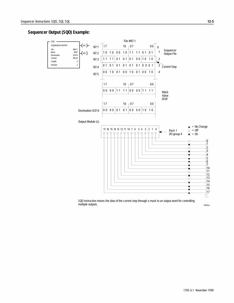
Sequencer Instructions SQO, SQI, SQL 12-5
Sequencer Output (SQO) Example:
1 0 1 0 0 0 1 0 1 1 1 1 0 1 0 1
1 1 1 1 0 1 0 1 0 1 0 0 1 0 1 0
0 1 0 1 0 1 0 1 0 1 0 1 0 0 0 1
1 7 0 7 0 010
0 0 0 0 1 1 1 1 0 0 0 0 1 1 1 1
1 7 0 7 0 010
0 0 1 0 0 1 0 0 1 0 0 1 0 0 1 0
0 0 0 0 0 1 0 1 0 0 0 0 1 0 1 0
1 7 0 7 0 010
1
2
3
4
File #N7:1
N7:2
N7:3
N7:4
N7:5
Destination O:014
Output Module (s)
Current Step
SequencerOutput File
MaskValue0F0F
Rack 1I/O group 4
SQO instruction moves the data of the current step through a mask to an output word for controllingmultiple outputs.
= No Change= Off= On
N7:1 0EN
SQO
SEQUENCER OUTPUT
DN
FileMaskDestinationControl
#N7:10F0F
O:014R6:20
Length
Position
4
2
012345671011121314151617
1
3
0
2
4567
11121314151617
10
16645a
1785-6.1 November 1998
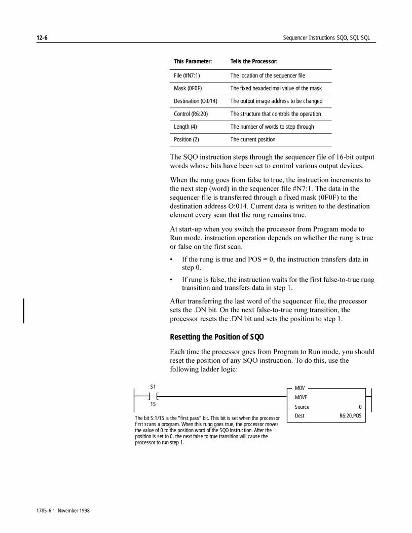
12-6 Sequencer Instructions SQO, SQI, SQL
7KH�642�LQVWUXFWLRQ�VWHSV�WKURXJK�WKH�VHTXHQFHU�ILOH�RI����ELW�RXWSXW�ZRUGV�ZKRVH�ELWV�KDYH�EHHQ�VHW�WR�FRQWURO�YDULRXV�RXWSXW�GHYLFHV�
:KHQ�WKH�UXQJ�JRHV�IURP�IDOVH�WR�WUXH��WKH�LQVWUXFWLRQ�LQFUHPHQWV�WR�WKH�QH[W�VWHS��ZRUG��LQ�WKH�VHTXHQFHU�ILOH��1�����7KH�GDWD�LQ�WKH�VHTXHQFHU�ILOH�LV�WUDQVIHUUHG�WKURXJK�D�IL[HG�PDVN���)�)��WR�WKH�GHVWLQDWLRQ�DGGUHVV�2������&XUUHQW�GDWD�LV�ZULWWHQ�WR�WKH�GHVWLQDWLRQ�HOHPHQW�HYHU\�VFDQ�WKDW�WKH�UXQJ�UHPDLQV�WUXH�
$W�VWDUW�XS�ZKHQ�\RX�VZLWFK�WKH�SURFHVVRU�IURP�3URJUDP�PRGH�WR�5XQ�PRGH��LQVWUXFWLRQ�RSHUDWLRQ�GHSHQGV�RQ�ZKHWKHU�WKH�UXQJ�LV�WUXH�RU�IDOVH�RQ�WKH�ILUVW�VFDQ�
� ,I�WKH�UXQJ�LV�WUXH�DQG�326� ����WKH�LQVWUXFWLRQ�WUDQVIHUV�GDWD�LQ�VWHS���
� ,I�UXQJ�LV�IDOVH��WKH�LQVWUXFWLRQ�ZDLWV�IRU�WKH�ILUVW�IDOVH�WR�WUXH�UXQJ�WUDQVLWLRQ�DQG�WUDQVIHUV�GDWD�LQ�VWHS���
$IWHU�WUDQVIHUULQJ�WKH�ODVW�ZRUG�RI�WKH�VHTXHQFHU�ILOH��WKH�SURFHVVRU�VHWV�WKH��'1�ELW��2Q�WKH�QH[W�IDOVH�WR�WUXH�UXQJ�WUDQVLWLRQ��WKH�SURFHVVRU�UHVHWV�WKH��'1�ELW�DQG�VHWV�WKH�SRVLWLRQ�WR�VWHS���
Resetting the Position of SQO
(DFK�WLPH�WKH�SURFHVVRU�JRHV�IURP�3URJUDP�WR�5XQ�PRGH��\RX�VKRXOG�UHVHW�WKH�SRVLWLRQ�RI�DQ\�642�LQVWUXFWLRQ��7R�GR�WKLV��XVH�WKH�IROORZLQJ�ODGGHU�ORJLF�
This Parameter: Tells the Processor:
File (#N7:1) The location of the sequencer file
Mask (0F0F) The fixed hexadecimal value of the mask
Destination (O:014) The output image address to be changed
Control (R6:20) The structure that controls the operation
Length (4) The number of words to step through
Position (2) The current position
MOV
MOVE
Source
Dest
0
R6:20.POS
S1
15
The bit S:1/15 is the "first pass" bit. This bit is set when the processorfirst scans a program. When this rung goes true, the processor movesthe value of 0 to the position word of the SQO instruction. After theposition is set to 0, the next false to true transition will cause theprocessor to run step 1.
1785-6.1 November 1998
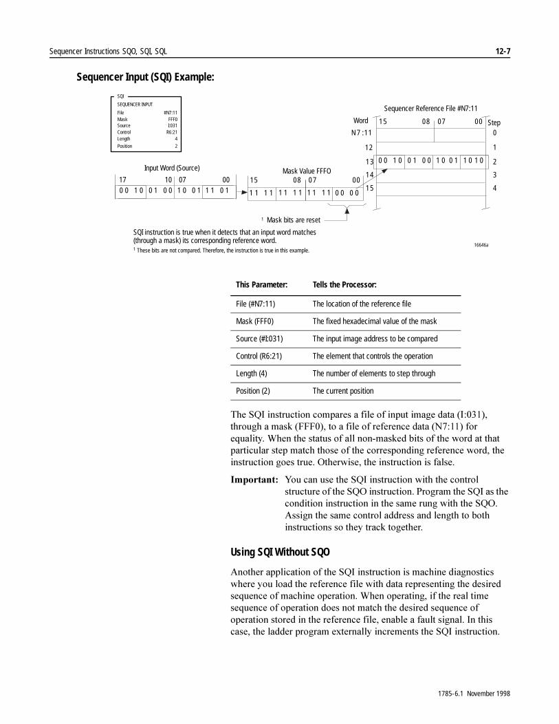
Sequencer Instructions SQO, SQI, SQL 12-7
Sequencer Input (SQI) Example:
7KH�64,�LQVWUXFWLRQ�FRPSDUHV�D�ILOH�RI�LQSXW�LPDJH�GDWD��,�������WKURXJK�D�PDVN��)))����WR�D�ILOH�RI�UHIHUHQFH�GDWD��1������IRU�HTXDOLW\��:KHQ�WKH�VWDWXV�RI�DOO�QRQ�PDVNHG�ELWV�RI�WKH�ZRUG�DW�WKDW�SDUWLFXODU�VWHS�PDWFK�WKRVH�RI�WKH�FRUUHVSRQGLQJ�UHIHUHQFH�ZRUG��WKH�LQVWUXFWLRQ�JRHV�WUXH��2WKHUZLVH��WKH�LQVWUXFWLRQ�LV�IDOVH�
,PSRUWDQW���<RX�FDQ�XVH�WKH�64,�LQVWUXFWLRQ�ZLWK�WKH�FRQWURO�VWUXFWXUH�RI�WKH�642�LQVWUXFWLRQ��3URJUDP�WKH�64,�DV�WKH�FRQGLWLRQ�LQVWUXFWLRQ�LQ�WKH�VDPH�UXQJ�ZLWK�WKH�642��$VVLJQ�WKH�VDPH�FRQWURO�DGGUHVV�DQG�OHQJWK�WR�ERWK�LQVWUXFWLRQV�VR�WKH\�WUDFN�WRJHWKHU�
Using SQI Without SQO
$QRWKHU�DSSOLFDWLRQ�RI�WKH�64,�LQVWUXFWLRQ�LV�PDFKLQH�GLDJQRVWLFV�ZKHUH�\RX�ORDG�WKH�UHIHUHQFH�ILOH�ZLWK�GDWD�UHSUHVHQWLQJ�WKH�GHVLUHG�VHTXHQFH�RI�PDFKLQH�RSHUDWLRQ��:KHQ�RSHUDWLQJ��LI�WKH�UHDO�WLPH�VHTXHQFH�RI�RSHUDWLRQ�GRHV�QRW�PDWFK�WKH�GHVLUHG�VHTXHQFH�RI�RSHUDWLRQ�VWRUHG�LQ�WKH�UHIHUHQFH�ILOH��HQDEOH�D�IDXOW�VLJQDO��,Q�WKLV�FDVH��WKH�ODGGHU�SURJUDP�H[WHUQDOO\�LQFUHPHQWV�WKH�64,�LQVWUXFWLRQ�
0 0 1 0 0 1 0 0 1 0 0 1 1 1 0 107 0010
1 1 1 1 1 1 1 1 1 1 1 1 0 0 0 0
15 07 0008
0 0 1 0 0 1 0 0 1 0 0 1 1 0 1 0
15 07 0008
12
13
14
15
N 7 :11
1
2
3
4
0
16646a
SQI
SEQUENCER INPUT
FileMaskSourceControl
#N7:11FFF0I:031
R6:21Length
Position
4
2
Word
Input Word (Source) Mask Value FFFO
Sequencer Reference File #N7:11
1 Mask bits are reset
Step
SQI instruction is true when it detects that an input word matches(through a mask) its corresponding reference word.1 These bits are not compared. Therefore, the instruction is true in this example.
17
This Parameter: Tells the Processor:
File (#N7:11) The location of the reference file
Mask (FFF0) The fixed hexadecimal value of the mask
Source (#I:031) The input image address to be compared
Control (R6:21) The element that controls the operation
Length (4) The number of elements to step through
Position (2) The current position
1785-6.1 November 1998
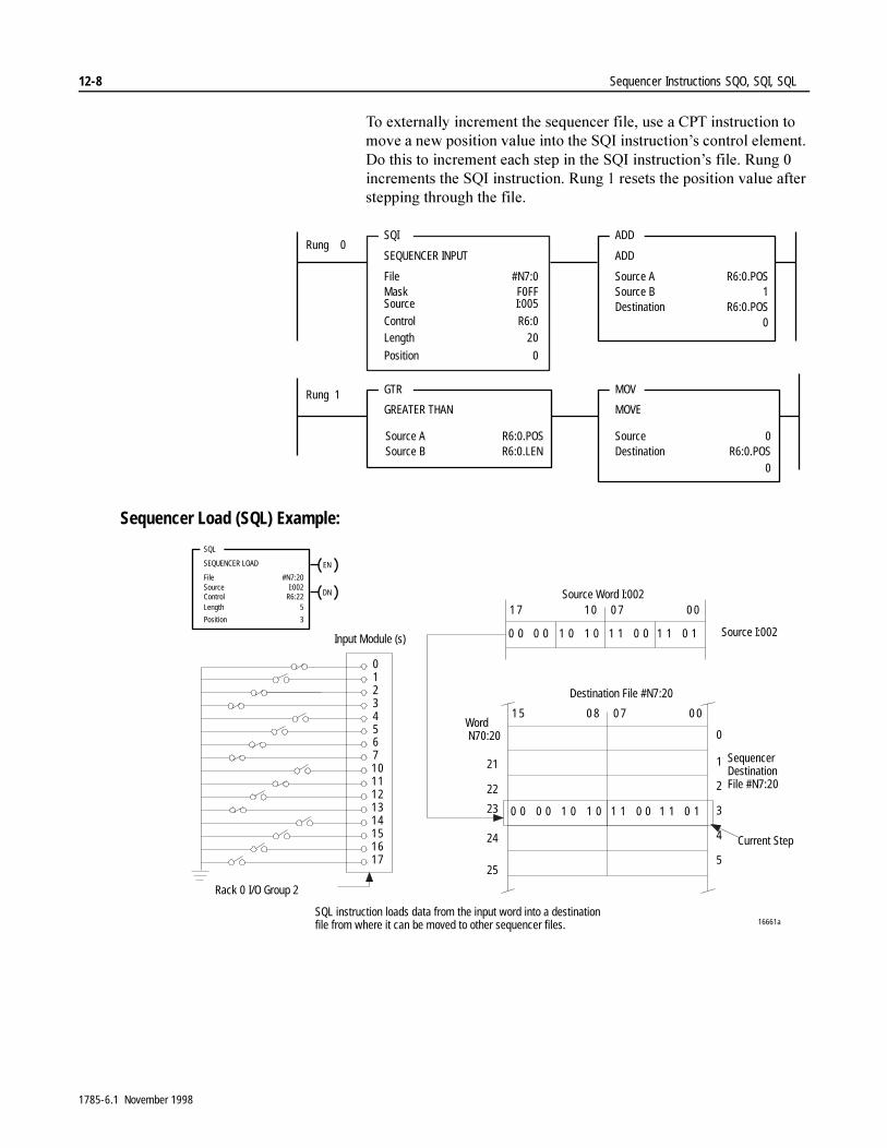
12-8 Sequencer Instructions SQO, SQI, SQL
7R�H[WHUQDOO\�LQFUHPHQW�WKH�VHTXHQFHU�ILOH��XVH�D�&37�LQVWUXFWLRQ�WR�PRYH�D�QHZ�SRVLWLRQ�YDOXH�LQWR�WKH�64,�LQVWUXFWLRQ¶V�FRQWURO�HOHPHQW��'R�WKLV�WR�LQFUHPHQW�HDFK�VWHS�LQ�WKH�64,�LQVWUXFWLRQ¶V�ILOH��5XQJ���LQFUHPHQWV�WKH�64,�LQVWUXFWLRQ��5XQJ���UHVHWV�WKH�SRVLWLRQ�YDOXH�DIWHU�VWHSSLQJ�WKURXJK�WKH�ILOH�
Sequencer Load (SQL) Example:
SQI
SEQUENCER INPUT
FileMaskSource
Control
#N7:0F0FFI:005
R6:0Length
Position
20
0
ADD
ADD
Source A
Destination R6:0.POS
R6:0.POS1
GTR
GREATER THAN
MOV
MOVE
SourceDestination
0R6:0.POS
Rung 0
Rung 1
Source B
0
Source AR6:0.LENR6:0.POS
Source B0
1 5 0 7 0 00 8
0 0 0 0 1 0 1 0 1 1 0 0 1 1 0 1
1 7 0 7 0 010
0 0 0 0 1 0 1 0 1 1 0 0 1 1 0 1
0
1
2
3
012345671011121314151617
16661a
4
5
Source Word I:002
Destination File #N7:20
Source I:002
SequencerDestinationFile #N7:20
Current Step
Rack 0 I/O Group 2
Input Module (s)
Word N70:20
21
22
23
24
25
SQL instruction loads data from the input word into a destinationfile from where it can be moved to other sequencer files.
EN
SQL
SEQUENCER LOAD
DN
FileSourceControlLength
Position
#N7:20I:002
R6:225
3
1785-6.1 November 1998
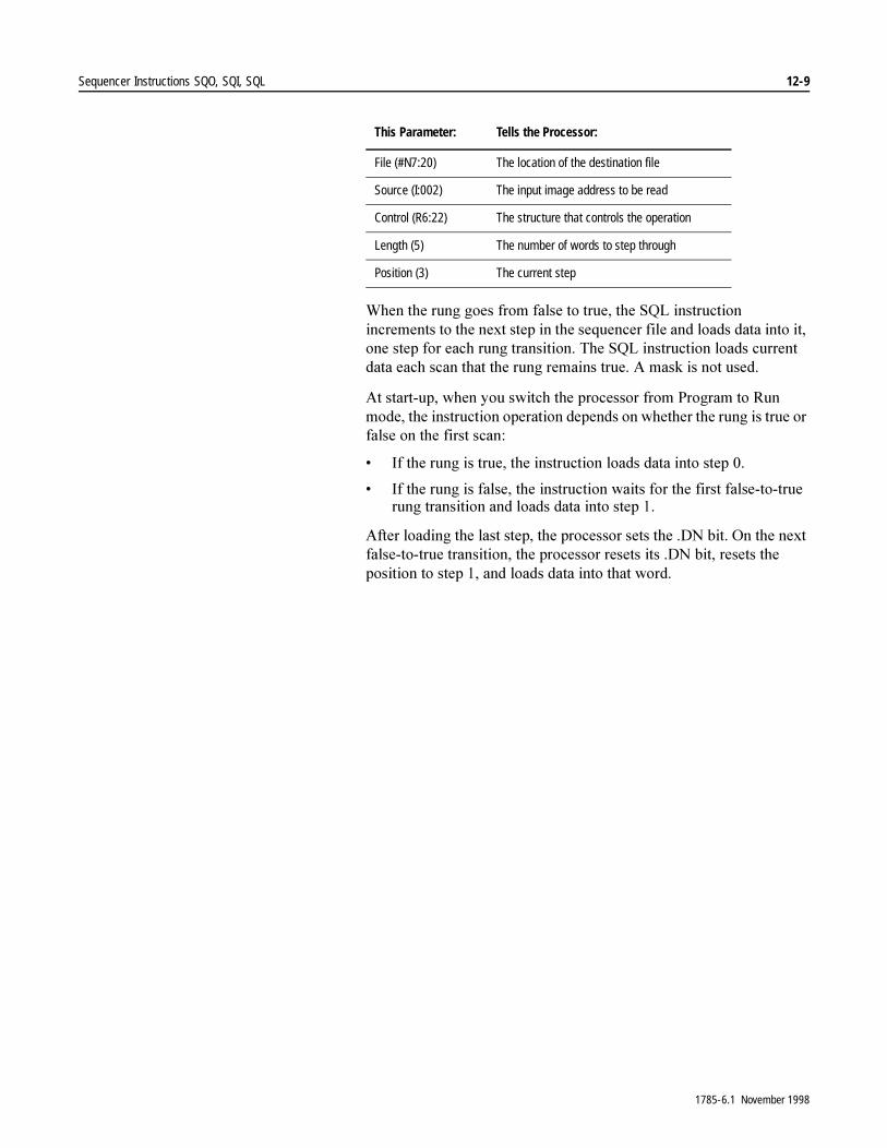
Sequencer Instructions SQO, SQI, SQL 12-9
:KHQ�WKH�UXQJ�JRHV�IURP�IDOVH�WR�WUXH��WKH�64/�LQVWUXFWLRQ�LQFUHPHQWV�WR�WKH�QH[W�VWHS�LQ�WKH�VHTXHQFHU�ILOH�DQG�ORDGV�GDWD�LQWR�LW��RQH�VWHS�IRU�HDFK�UXQJ�WUDQVLWLRQ��7KH�64/�LQVWUXFWLRQ�ORDGV�FXUUHQW�GDWD�HDFK�VFDQ�WKDW�WKH�UXQJ�UHPDLQV�WUXH��$�PDVN�LV�QRW�XVHG�
$W�VWDUW�XS��ZKHQ�\RX�VZLWFK�WKH�SURFHVVRU�IURP�3URJUDP�WR�5XQ�PRGH��WKH�LQVWUXFWLRQ�RSHUDWLRQ�GHSHQGV�RQ�ZKHWKHU�WKH�UXQJ�LV�WUXH�RU�IDOVH�RQ�WKH�ILUVW�VFDQ�
� ,I�WKH�UXQJ�LV�WUXH��WKH�LQVWUXFWLRQ�ORDGV�GDWD�LQWR�VWHS���
� ,I�WKH�UXQJ�LV�IDOVH��WKH�LQVWUXFWLRQ�ZDLWV�IRU�WKH�ILUVW�IDOVH�WR�WUXH�UXQJ�WUDQVLWLRQ�DQG�ORDGV�GDWD�LQWR�VWHS���
$IWHU�ORDGLQJ�WKH�ODVW�VWHS��WKH�SURFHVVRU�VHWV�WKH��'1�ELW��2Q�WKH�QH[W�IDOVH�WR�WUXH�WUDQVLWLRQ��WKH�SURFHVVRU�UHVHWV�LWV��'1�ELW��UHVHWV�WKH�SRVLWLRQ�WR�VWHS����DQG�ORDGV�GDWD�LQWR�WKDW�ZRUG�
This Parameter: Tells the Processor:
File (#N7:20) The location of the destination file
Source (I:002) The input image address to be read
Control (R6:22) The structure that controls the operation
Length (5) The number of words to step through
Position (3) The current step
1785-6.1 November 1998

12-10 Sequencer Instructions SQO, SQI, SQL
1RWHV�
1785-6.1 November 1998

Chapter 13
Program Control Instructions MCR, JMP, LBL, FOR, NXT, BRK, JSR, SBR, RET, TND, AFI, ONS, OSR, OSF, SFR, EOT, UIE, UID
Selecting Program Flow Instructions
3URJUDP�IORZ�LQVWUXFWLRQV�FKDQJH�WKH�IORZ�RI�ODGGHU�SURJUDP�H[HFXWLRQ��8VH�7DEOH����$�WR�VHOHFW�WKH�SURJUDP�FRQWURO�LQVWUXFWLRQ�RU�JURXS�RI�LQVWUXFWLRQV�WKDW�ILW�\RXU�SURJUDPPLQJ�UHTXLUHPHQWV�
Table 13.A Available Program Control Instructions
)RU�PRUH�LQIRUPDWLRQ�RQ�WKH�RSHUDQGV��DQG�YDOLG�GDWD�W\SHV�YDOXHV�RI�HDFK�RSHUDQG��XVHG�E\�WKH�LQVWUXFWLRQV�GLVFXVVHG�LQ�WKLV�FKDSWHU��VHH�$SSHQGL[�&�
If You Want to:Then Use these Instructions:
Found on Page:
Turn off all non-retentive outputs in a section of ladder program
MCR 13-2
Jump over a section of a program that does not always need to be executed
JMP, LBL 13-3
Loop through a set of rungs for a preset number of times
FOR, NXT, BRK 13-5
Jump to a separate subroutine file, pass data to the subroutine, perform an operation, and return the results
JSR, SBR, RET 13-8
Mark a temporary end that halts program execution beyond it
TND 13-13
Disable a rung AFI 13-13
Trigger a one-shot event based on a change in rung condition
ONS, OSR,* OSF* 13-14 (ONS), 13-15 (OSR),13-16 (OSF)
Reset a sequential function chart SFR* 13-17
End a transition file EOT 13-18
Enable or disable user interrupts UIE,* UID* 13-19 (UID), 13-20 (UIE)
*These instructions are only supported by Enhanced PLC-5 processors.
1785-6.1 November 1998
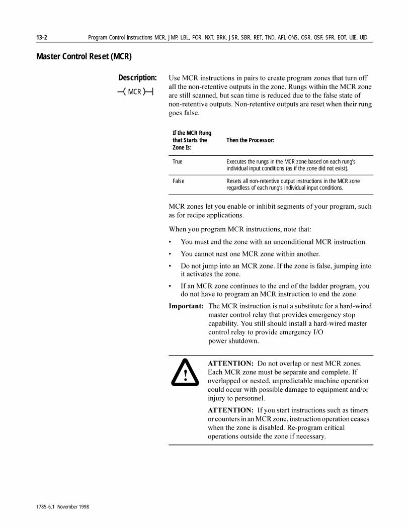
13-2 Program Control Instructions MCR, JMP, LBL, FOR, NXT, BRK, JSR, SBR, RET, TND, AFI, ONS, OSR, OSF, SFR, EOT, UIE, UID
Master Control Reset (MCR)
Description: 8VH�0&5�LQVWUXFWLRQV�LQ�SDLUV�WR�FUHDWH�SURJUDP�]RQHV�WKDW�WXUQ�RII�DOO�WKH�QRQ�UHWHQWLYH�RXWSXWV�LQ�WKH�]RQH��5XQJV�ZLWKLQ�WKH�0&5�]RQH�DUH�VWLOO�VFDQQHG��EXW�VFDQ�WLPH�LV�UHGXFHG�GXH�WR�WKH�IDOVH�VWDWH�RI�QRQ�UHWHQWLYH�RXWSXWV��1RQ�UHWHQWLYH�RXWSXWV�DUH�UHVHW�ZKHQ�WKHLU�UXQJ�JRHV�IDOVH�
0&5�]RQHV�OHW�\RX�HQDEOH�RU�LQKLELW�VHJPHQWV�RI�\RXU�SURJUDP��VXFK�DV�IRU�UHFLSH�DSSOLFDWLRQV�
:KHQ�\RX�SURJUDP�0&5�LQVWUXFWLRQV��QRWH�WKDW�
� <RX�PXVW�HQG�WKH�]RQH�ZLWK�DQ�XQFRQGLWLRQDO�0&5�LQVWUXFWLRQ�
� <RX�FDQQRW�QHVW�RQH�0&5�]RQH�ZLWKLQ�DQRWKHU�
� 'R�QRW�MXPS�LQWR�DQ�0&5�]RQH��,I�WKH�]RQH�LV�IDOVH��MXPSLQJ�LQWR�LW�DFWLYDWHV�WKH�]RQH�
� ,I�DQ�0&5�]RQH�FRQWLQXHV�WR�WKH�HQG�RI�WKH�ODGGHU�SURJUDP��\RX�GR�QRW�KDYH�WR�SURJUDP�DQ�0&5�LQVWUXFWLRQ�WR�HQG�WKH�]RQH�
,PSRUWDQW���7KH�0&5�LQVWUXFWLRQ�LV�QRW�D�VXEVWLWXWH�IRU�D�KDUG�ZLUHG�PDVWHU�FRQWURO�UHOD\�WKDW�SURYLGHV�HPHUJHQF\�VWRS�FDSDELOLW\��<RX�VWLOO�VKRXOG�LQVWDOO�D�KDUG�ZLUHG�PDVWHU�FRQWURO�UHOD\�WR�SURYLGH�HPHUJHQF\�,�2�SRZHU VKXWGRZQ��
MCR
If the MCR Rung that Starts the Zone Is:
Then the Processor:
True Executes the rungs in the MCR zone based on each rung’s individual input conditions (as if the zone did not exist).
False Resets all non-retentive output instructions in the MCR zone regardless of each rung’s individual input conditions.
�$77(17,21� 'R�QRW�RYHUODS�RU�QHVW�0&5�]RQHV��(DFK�0&5�]RQH�PXVW�EH�VHSDUDWH�DQG�FRPSOHWH��,I�RYHUODSSHG�RU�QHVWHG��XQSUHGLFWDEOH�PDFKLQH�RSHUDWLRQ�FRXOG�RFFXU�ZLWK�SRVVLEOH�GDPDJH�WR�HTXLSPHQW�DQG�RU�LQMXU\�WR�SHUVRQQHO�
$77(17,21� ,I�\RX�VWDUW�LQVWUXFWLRQV�VXFK�DV�WLPHUV�RU�FRXQWHUV�LQ�DQ�0&5�]RQH��LQVWUXFWLRQ�RSHUDWLRQ�FHDVHV�ZKHQ�WKH�]RQH�LV�GLVDEOHG��5H�SURJUDP�FULWLFDO�RSHUDWLRQV�RXWVLGH�WKH�]RQH�LI�QHFHVVDU\�
1785-6.1 November 1998
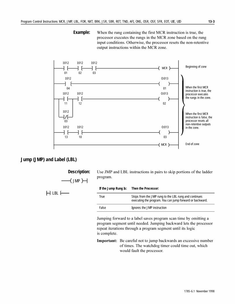
Program Control Instructions MCR, JMP, LBL, FOR, NXT, BRK, JSR, SBR, RET, TND, AFI, ONS, OSR, OSF, SFR, EOT, UIE, UID 13-3
Example: :KHQ�WKH�UXQJ�FRQWDLQLQJ�WKH�ILUVW�0&5�LQVWUXFWLRQ�LV�WUXH��WKH�SURFHVVRU�H[HFXWHV�WKH�UXQJV�LQ�WKH�0&5�]RQH�EDVHG�RQ�WKH�UXQJ�LQSXW�FRQGLWLRQV��2WKHUZLVH��WKH�SURFHVVRU�UHVHWV�WKH�QRQ�UHWHQWLYH�RXWSXW�LQVWUXFWLRQV�ZLWKLQ�WKH�0&5�]RQH�
Jump (JMP) and Label (LBL)
Description: 8VH�-03�DQG�/%/�LQVWUXFWLRQV�LQ�SDLUV�WR�VNLS�SRUWLRQV�RI�WKH�ODGGHU�SURJUDP�
-XPSLQJ�IRUZDUG�WR�D�ODEHO�VDYHV�SURJUDP�VFDQ�WLPH�E\�RPLWWLQJ�D�SURJUDP�VHJPHQW�XQWLO�QHHGHG��-XPSLQJ�EDFNZDUG�OHWV�WKH�SURFHVVRU�UHSHDW�LWHUDWLRQV�WKURXJK�D�SURJUDP�VHJPHQW�XQWLO�LWV�ORJLF�LV FRPSOHWH�
,PSRUWDQW���%H�FDUHIXO�QRW�WR�MXPS�EDFNZDUGV�DQ�H[FHVVLYH�QXPEHU�RI�WLPHV��7KH�ZDWFKGRJ�WLPHU�FRXOG�WLPH�RXW��ZKLFK�ZRXOG�IDXOW�WKH�SURFHVVRU�
I:012
04
I:012
11
O:013
01
O:013
02
MCR
I:012
01
I:012
02
I:012
03
MCR
03
I:012
I:012
12
I:012
13
O:013
03
I:012
10
Beginning of zone
When the first MCRinstruction is false, theprocessor resets allnon-retentive outputsin the zone.
End of zone
When the first MCRinstruction is true, theprocessor executesthe rungs in the zone.
JMP
LBL []If the Jump Rung Is: Then the Processor:
True Skips from the JMP rung to the LBL rung and continues executing the program. You can jump forward or backward.
False Ignores the JMP instruction
1785-6.1 November 1998

13-4 Program Control Instructions MCR, JMP, LBL, FOR, NXT, BRK, JSR, SBR, RET, TND, AFI, ONS, OSR, OSF, SFR, EOT, UIE, UID
Using JMP
7KH�-03�LQVWUXFWLRQ�OHWV�WKH�SURFHVVRU�VNLS�UXQJV��<RX�FDQ�MXPS�WR�WKH�VDPH�ODEHO�IURP�RQH�RU�PRUH�-03�LQVWUXFWLRQV��
Using LBL
7KH�/%/�LQVWUXFWLRQ�LV�WKH�WDUJHW�RI�WKH�-03�LQVWUXFWLRQ�WKDW�KDV�WKH�VDPH�ODEHO�QXPEHU��3ODFH�WKH�/%/�LQVWUXFWLRQ�ILUVW�RQ�WKH�UXQJ�WR�ZKHUH�\RX�ZDQW�WKH�SURFHVVRU�WR�MXPS�
,PSRUWDQW���0DNH�VXUH�WKDW�WKH�/%/�LQVWUXFWLRQ�LV�WKH�ILUVW�LQVWUXFWLRQ�RQ�WKH�UXQJ���7KH�VRIWZDUH�FXUUHQWO\�OHWV�\RX�WR�FUHDWH�D�EUDQFK�DURXQG�DQ�/%/�LQVWUXFWLRQ��WKLV�ZLOO�FDXVH�WKH�SURFHVVRU�WR�RSHUDWH�LQFRUUHFWO\��
,I�\RX�PRGLI\�DQG�DFFHSW�D�UXQJ�FRQWDLQLQJ�D�ODEHO�ZKLOH�RQ�OLQH�ZLWK�WKH�SURFHVVRU�LQ�5XQ�PRGH��WKH�VRIWZDUH�FUHDWHV�DQ�,�5�SDLU��,I�\RX�PRGLI\�WKH�,�UXQJ�EHIRUH�DVVHPEOLQJ�WKH�HGLWV��WKH�SURFHVVRU�ZLOO�IDXOW�ZLWK�D�GXSOLFDWH�ODEHO�HUURU�
7KHUH�DUH�IRXU�ZD\V�WR�DYRLG�WKLV�SUREOHP�
� (GLW�WKH�UXQJ�ZLWK�WKH�SURFHVVRU�LQ�3URJUDP�PRGH�
� &DQFHO�WKH�HGLWV�DQG�UH�HGLW�WKH�UXQJ�
� /HW�WKH�IDXOW�RFFXU��WKHQ�FOHDU�WKH�IDXOW�DIWHU�DVVHPEOLQJ�WKH�HGLWV�
� $VVHPEOH�WKH�ILUVW�HGLW��WKHQ�PRGLI\�WKH�UXQJ�DJDLQ�WR�PDNH�WKH�VHFRQG�FKDQJH��,I�\RX�DUH�HGLWLQJ�RQ�OLQH��WKH�SURFHVVRU�PD\�H[HFXWH�WKH�UXQJ�ZLWK�WKH�ILUVW�HGLW�DQG�PD\�FDXVH�WKH�SURFHVVRU�WR�IDXOW�RU�UXQ�LPSURSHUO\�
�$77(17,21� -XPSHG�WLPHUV�DQG�FRXQWHUV�DUH�QRW�VFDQQHG��5H�SURJUDP�FULWLFDO�RSHUDWLRQV�RXWVLGH�WKH�MXPSHG�]RQH�
If You Have this Processor: Valid LBL Numbers:Valid Amount Per Program File:
Enhanced PLC-5 000-255 256
Classic PLC-5 0-31 32
1785-6.1 November 1998

Program Control Instructions MCR, JMP, LBL, FOR, NXT, BRK, JSR, SBR, RET, TND, AFI, ONS, OSR, OSF, SFR, EOT, UIE, UID 13-5
JMP and LBL Example: :KHQ�WKH�UXQJ�FRQWDLQLQJ�WKH�-03�LQVWUXFWLRQ�JRHV�WUXH��WKH�SURFHVVRU�MXPSV�RYHU�VXFFHVVLYH�UXQJV�XQWLO�LW�UHDFKHV�WKH�UXQJ�WKDW�FRQWDLQV�WKH�/%/�LQVWUXFWLRQ�ZLWK�WKH�VDPH�QXPEHU��7KH�SURFHVVRU�UHVXPHV�H[HFXWLQJ�DW�WKH�/%/�UXQJ��
7KH�WLPHU��721��ZLOO�QRW�XSGDWH�DV�ORQJ�DV�,��������LV�WUXH�
For Next Loop (FOR, NXT), Break (BRK)
Description: 8VH�)25��%5.�DQG�1;7�LQVWUXFWLRQV�WR�FUHDWH�\RXU�RZQ�SURJUDPPLQJ�URXWLQHV�ZKHUH�\RX�FRQWURO�WKH�QXPEHU�RI�WLPHV�WKH�ORRS�LV�H[HFXWHG�
,PSRUWDQW���'XULQJ�SUHVFDQ��ODGGHU�LQVWUXFWLRQV�ZLWKLQ�WKH�)25�1;7�ORRS�DUH�SUHVFDQQHG��QRW�VNLSSHG��
LBL
EN
TON
TIMER ON DELAY
Time basePresetAccum
1.0100
0
DN
I:012
10
20
O:013
13
O:013
02
I:012
10
O:013
01
JMP
I:012
13
20
I:012
11
I:012
17
T4:0
DN Timer T4:0
When input I:012/13 is set, the processor jumps to label 20 and continues program execution. It does notexecute the rungs between these two points.
NXT
FOR
FOR
Label numberIndexInitial valueTerminal valueStep size
NEXT
Label Number �$77(17,21� 8VLQJ�)25�DQG�1;7�LQVWUXFWLRQV�ZLWKLQ�DQ�RXWSXW�EUDQFK�FDQ�FDXVH�XQSUHGLFWDEOH�PDFKLQH�RSHUDWLRQ�
:KHQ�XVLQJ�WKH�)25�DQG�1;7�LQVWUXFWLRQV�ZLWKLQ�D�EUDQFK�LQ�D�ODGGHU�SURJUDP��WKH�H[HFXWLRQ�RI�WKH�)25�1;7�ORRS�PD\�QRW�RFFXU�DV�H[SHFWHG��'R�QRW�XVH�WKH�)25�RU�1;7�LQVWUXFWLRQV�ZKHQ�SURJUDPPLQJ�ZLWKLQ�D�EUDQFK�LQ�D�ODGGHU�SURJUDP�
1785-6.1 November 1998
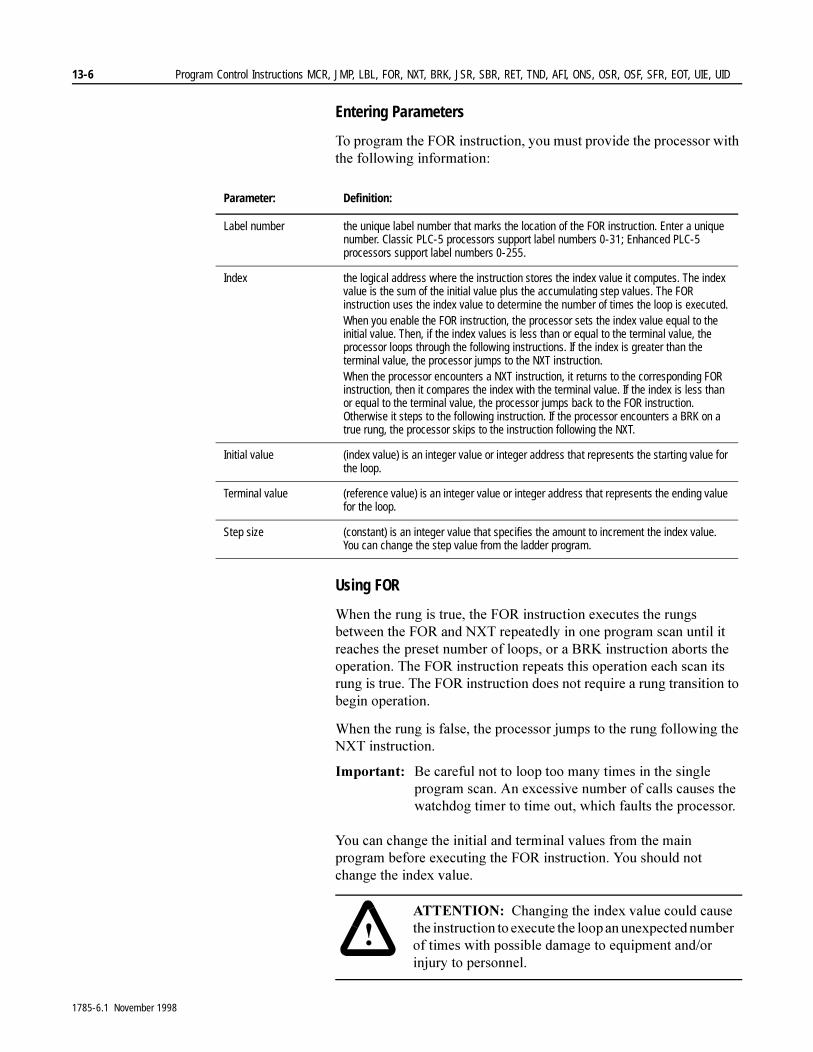
13-6 Program Control Instructions MCR, JMP, LBL, FOR, NXT, BRK, JSR, SBR, RET, TND, AFI, ONS, OSR, OSF, SFR, EOT, UIE, UID
Entering Parameters
7R�SURJUDP�WKH�)25�LQVWUXFWLRQ��\RX�PXVW�SURYLGH�WKH�SURFHVVRU�ZLWK�WKH�IROORZLQJ�LQIRUPDWLRQ�
Using FOR
:KHQ�WKH�UXQJ�LV�WUXH��WKH�)25�LQVWUXFWLRQ�H[HFXWHV�WKH�UXQJV�EHWZHHQ�WKH�)25�DQG�1;7�UHSHDWHGO\�LQ�RQH�SURJUDP�VFDQ�XQWLO�LW�UHDFKHV�WKH�SUHVHW�QXPEHU�RI�ORRSV��RU�D�%5.�LQVWUXFWLRQ�DERUWV�WKH�RSHUDWLRQ��7KH�)25�LQVWUXFWLRQ�UHSHDWV�WKLV�RSHUDWLRQ�HDFK�VFDQ�LWV�UXQJ�LV�WUXH��7KH�)25�LQVWUXFWLRQ�GRHV�QRW�UHTXLUH�D�UXQJ�WUDQVLWLRQ�WR�EHJLQ�RSHUDWLRQ��
:KHQ�WKH�UXQJ�LV�IDOVH��WKH�SURFHVVRU�MXPSV�WR�WKH�UXQJ�IROORZLQJ�WKH�1;7�LQVWUXFWLRQ�
,PSRUWDQW���%H�FDUHIXO�QRW�WR�ORRS�WRR�PDQ\�WLPHV�LQ�WKH�VLQJOH�SURJUDP�VFDQ��$Q�H[FHVVLYH�QXPEHU�RI�FDOOV�FDXVHV�WKH�ZDWFKGRJ�WLPHU�WR�WLPH�RXW��ZKLFK�IDXOWV�WKH�SURFHVVRU�
<RX�FDQ�FKDQJH�WKH�LQLWLDO�DQG�WHUPLQDO�YDOXHV�IURP�WKH�PDLQ�SURJUDP�EHIRUH�H[HFXWLQJ�WKH�)25�LQVWUXFWLRQ��<RX�VKRXOG�QRW�FKDQJH�WKH�LQGH[�YDOXH��
Parameter: Definition:
Label number the unique label number that marks the location of the FOR instruction. Enter a unique number. Classic PLC-5 processors support label numbers 0-31; Enhanced PLC-5 processors support label numbers 0-255.
Index the logical address where the instruction stores the index value it computes. The index value is the sum of the initial value plus the accumulating step values. The FOR instruction uses the index value to determine the number of times the loop is executed.When you enable the FOR instruction, the processor sets the index value equal to the initial value. Then, if the index values is less than or equal to the terminal value, the processor loops through the following instructions. If the index is greater than the terminal value, the processor jumps to the NXT instruction.When the processor encounters a NXT instruction, it returns to the corresponding FOR instruction, then it compares the index with the terminal value. If the index is less than or equal to the terminal value, the processor jumps back to the FOR instruction. Otherwise it steps to the following instruction. If the processor encounters a BRK on a true rung, the processor skips to the instruction following the NXT.
Initial value (index value) is an integer value or integer address that represents the starting value for the loop.
Terminal value (reference value) is an integer value or integer address that represents the ending value for the loop.
Step size (constant) is an integer value that specifies the amount to increment the index value. You can change the step value from the ladder program.
�$77(17,21� &KDQJLQJ�WKH�LQGH[�YDOXH�FRXOG�FDXVH�WKH�LQVWUXFWLRQ�WR�H[HFXWH�WKH�ORRS�DQ�XQH[SHFWHG�QXPEHU�RI�WLPHV�ZLWK�SRVVLEOH�GDPDJH�WR�HTXLSPHQW�DQG�RU�LQMXU\�WR�SHUVRQQHO��
1785-6.1 November 1998

Program Control Instructions MCR, JMP, LBL, FOR, NXT, BRK, JSR, SBR, RET, TND, AFI, ONS, OSR, OSF, SFR, EOT, UIE, UID 13-7
$OVR��LI�\RX�HGLW�D�)25�1;7�LQVWUXFWLRQ�LQ�5HPRWH�581�PRGH��PDNH�VXUH�WKDW�\RX�PDNH�WKH�FRUUHVSRQGLQJ�FKDQJHV�WR�ERWK�UXQJV�EHIRUH�DVVHPEOLQJ�HGLWV��)RU�H[DPSOH��LI�\RX�ZDQW�WR�FKDQJH�WKH�ODEHO�QXPEHU�IRU�WKH�)25�1;7�SDLU��FKDQJH�WKH�ODEHO�LQ�WKH�)25�LQVWUXFWLRQ�DQG�LQ�WKH�1;7�LQVWUXFWLRQ��WKHQ�DVVHPEOH�WKH�HGLWV��,I�\RX�DVVHPEOH�HGLWV�DIWHU�FKDQJLQJ�RQO\�RQH�RI�WKH�LQVWUXFWLRQV�LQ�WKH�)25�1;7�SDLU��WKH�SURFHVVRU�FDXVHV�D�UXQ�WLPH�HUURU�RU�ZDWFKGRJ�WLPHRXW�
Using BRK
7KH�%5.�LQVWUXFWLRQ�VWRSV�WKH�)25�LQVWUXFWLRQ¶V�RSHUDWLRQ��3ODFH�WKH�%5.�UXQJ�DQ\ZKHUH�EHWZHHQ�WKH�)25�DQG�1;7�UXQJV��:KHQ�WKH�UXQJ�JRHV�WUXH��LW�UHWXUQV�WKH�SURFHVVRU�WR�WKH�QH[W�KLJKHVW�ORRS��LI�\RX�DUH�XVLQJ�QHVWHG�ORRSV��RU�WR�WKH�IROORZLQJ�LQVWUXFWLRQ�DIWHU�WKH�FRUUHVSRQGLQJ�1;7�LQVWUXFWLRQ�LQ�WKH�PDLQ�SURJUDP�
8VH�%5.�WR�H[LW�WKH�ORRS�ZKHQHYHU�WKH�SURFHVVRU�GHWHFWV�DQ�HUURU�RU�WR�DYRLG�SURORQJHG�ORRSV�WKDW�FRXOG�FDXVH�WKH�ZDWFKGRJ�WLPHU�WR�WLPH�RXW��ZKLFK�ZRXOG�IDXOW�WKH�SURFHVVRU�
Using NXT
7KH�1;7�LQVWUXFWLRQ�PXVW�EH�SURJUDPPHG�RQ�DQ�XQFRQGLWLRQDO�UXQJ�WKDW�LV�WKH�ODVW�UXQJ�WR�EH�UHSHDWHG�E\�WKH�)RU�1H[W�ORRS��7KH�1;7�LQVWUXFWLRQ�UHWXUQV�WKH�SURFHVVRU�WR�WKH�FRUUHVSRQGLQJ�)25�LQVWUXFWLRQ��LGHQWLILHG�E\�WKH�ODEHO�QXPEHU�VSHFLILHG�LQ�WKH�1;7 LQVWUXFWLRQ��
FOR, BRK, and NXT Example:
FOR
Label number 0
N7:10
rung
IndexInitial valueTerminal valueStep size
N7:00
101
rungrung
FOR
/ BRK
NEXT
Label Number
NXT
0
N7:10
5
5
rungrungrung
rungrungrung
If integer file 7, word 10, bit 5 is true, initialize N7:0 tozero and execute the rungs until the NXT. When theprocessor encounters the NXT, increment N7:0 andjump back to the FOR instruction. As long as N7:0is less than or equal to 10, keep executing the loop.When N7:0 is greater than 10, jump to the rungfollowing the NXT.
If integer file 7, word 10, bit 5 ever goes true,break out of the loop and jump to the rungfollowing the NXT instruction.
If integer file 7, word 10, bit 5 is false,skip to the rung following the NXT instruction.
1785-6.1 November 1998

13-8 Program Control Instructions MCR, JMP, LBL, FOR, NXT, BRK, JSR, SBR, RET, TND, AFI, ONS, OSR, OSF, SFR, EOT, UIE, UID
Jump to Subroutine (JSR), Subroutine (SBR), and Return (RET)
Description: 7KH�-65��6%5��DQG�5(7�LQVWUXFWLRQV�GLUHFW�WKH�SURFHVVRU�WR�JR�WR�D�VHSDUDWH�VXEURXWLQH�ILOH�ZLWKLQ�WKH�ODGGHU�SURJUDP��VFDQ�WKDW�VXEURXWLQH�ILOH�RQFH��DQG�UHWXUQ�WR�WKH�SRLQW�RI�GHSDUWXUH�
7KH�-65�LQVWUXFWLRQ�GLUHFWV�WKH�SURFHVVRU�WR�WKH�VSHFLILHG�VXEURXWLQH�ILOH��DQG�LI�UHTXLUHG��GHILQHV�WKH�SDUDPHWHUV�SDVVHG�WR�DQG�UHFHLYHG�IURP�WKH�VXEURXWLQH��7KH�RSWLRQDO�6%5�LQVWUXFWLRQ�LV�WKH�KHDGHU�LQVWUXFWLRQ�WKDW�VWRUHV�LQFRPLQJ�SDUDPHWHUV��8VH�6%5�RQO\�LI�\RX�ZDQW�WR�SDVV�SDUDPHWHUV��7KH�5(7�LQVWUXFWLRQ�HQGV�WKH�VXEURXWLQH��DQG�LI�UHTXLUHG��VWRUHV�SDUDPHWHUV�WR�EH�UHWXUQHG�WR�WKH�-65�LQVWUXFWLRQ�LQ�WKH�PDLQ�SURJUDP�
,PSRUWDQW��� ,I�\RX�XVH�WKH�6%5�LQVWUXFWLRQ��WKH�6%5�LQVWUXFWLRQ�PXVW�EH�WKH�ILUVW�LQVWUXFWLRQ�RQ�WKH�ILUVW�UXQJ�LQ�WKH�SURJUDP�ILOH�WKDW�FRQWDLQV�WKH�VXEURXWLQH�
8VH�D�VXEURXWLQH�WR�VWRUH�UHFXUULQJ�VHFWLRQV�RI�SURJUDP�ORJLF�WKDW�FDQ�EH�DFFHVVHG�IURP�PXOWLSOH�SURJUDP�ILOHV��$�VXEURXWLQH�VDYHV�PHPRU\�EHFDXVH�\RX�SURJUDP�LW�RQO\�RQFH�
8SGDWH�FULWLFDO�,�2�ZLWKLQ�VXEURXWLQHV�XVLQJ�LPPHGLDWH�LQSXW�DQG�RU�RXWSXW�LQVWUXFWLRQV��,,1��,27���HVSHFLDOO\�LI�\RXU�DSSOLFDWLRQ�FDOOV�IRU�QHVWHG�RU�UHODWLYHO\�ORQJ�VXEURXWLQHV��2WKHUZLVH��WKH�SURFHVVRU�GRHV�QRW�XSGDWH�,�2�XQWLO�LW�UHDFKHV�WKH�HQG�RI�WKH�PDLQ�SURJUDP��DIWHU�H[HFXWLQJ�DOO�VXEURXWLQHV���2XWSXWV�LQ�VXEURXWLQHV�DUH�OHIW�LQ�WKHLU�ODVW�VWDWH�
Passing Parameters
3DVV�VHOHFWHG�YDOXHV�WR�D�VXEURXWLQH�EHIRUH�H[HFXWLRQ�VR�WKH�VXEURXWLQH�FDQ�SHUIRUP�PDWKHPDWLFDO�RU�ORJLFDO�RSHUDWLRQV�RQ�WKH�GDWD�DQG�UHWXUQ�WKH�UHVXOWV�WR�WKH�PDLQ�SURJUDP�
)RU�H[DPSOH��\RX�FDQ�ZULWH�D�JHQHULF�VXEURXWLQH�IRU�PXOWLSOH�UHFLSH�RSHUDWLRQV��7KHQ�SDVV�SUHVHW�YDOXHV�IRU�HDFK�UHFLSH�WR�WKH�VXEURXWLQH�LQ�DGYDQFH��RU�KDYH�WKH�PDLQ�SURJUDP�VSHFLI\�DQG�SDVV�SUHVHWV�DFFRUGLQJ�WR�DSSOLFDWLRQ�UHTXLUHPHQWV�
JUMP TO SUBROUTINEJSR
Prog file numberInput parameterReturn parameter
RETURN ( )Return parameter
SUBROUTINEInput parameter
SBR
RET
1785-6.1 November 1998
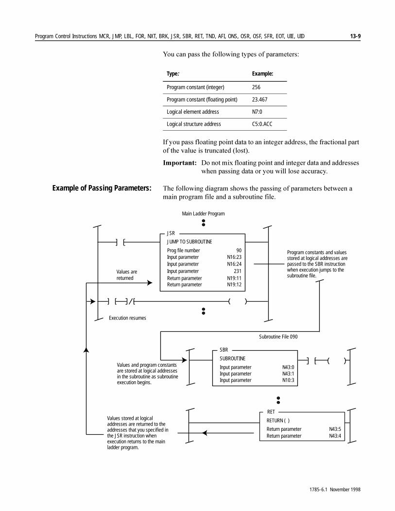
Program Control Instructions MCR, JMP, LBL, FOR, NXT, BRK, JSR, SBR, RET, TND, AFI, ONS, OSR, OSF, SFR, EOT, UIE, UID 13-9
<RX�FDQ�SDVV�WKH�IROORZLQJ�W\SHV�RI�SDUDPHWHUV�
,I�\RX�SDVV�IORDWLQJ�SRLQW�GDWD�WR�DQ�LQWHJHU�DGGUHVV��WKH�IUDFWLRQDO�SDUW�RI�WKH�YDOXH�LV�WUXQFDWHG��ORVW��
,PSRUWDQW���'R�QRW�PL[�IORDWLQJ�SRLQW�DQG�LQWHJHU�GDWD�DQG�DGGUHVVHV�ZKHQ�SDVVLQJ�GDWD�RU�\RX�ZLOO�ORVH�DFFXUDF\�
Example of Passing Parameters: 7KH�IROORZLQJ�GLDJUDP�VKRZV�WKH�SDVVLQJ�RI�SDUDPHWHUV�EHWZHHQ�D�PDLQ�SURJUDP�ILOH�DQG�D�VXEURXWLQH�ILOH�
Type: Example:
Program constant (integer) 256
Program constant (floating point) 23.467
Logical element address N7:0
Logical structure address C5:0.ACC
RET
JSR
JUMP TO SUBROUTINE
Prog file numberInput parameterInput parameterInput parameter
90N16:23N16:24
231Return parameterReturn parameter
N19:11N19:12
Main Ladder Program
SBR
SUBROUTINE
Input parameterInput parameterInput parameter
N43:0N43:1N10:3
RETURN ( )
Return parameterReturn parameter
N43:5N43:4
Subroutine File 090
Execution resumes
Values stored at logicaladdresses are returned to theaddresses that you specified inthe JSR instruction whenexecution returns to the mainladder program.
Values arereturned
Program constants and valuesstored at logical addresses arepassed to the SBR instructionwhen execution jumps to thesubroutine file.
Values and program constantsare stored at logical addressesin the subroutine as subroutineexecution begins.
1785-6.1 November 1998
13-10 Program Control Instructions MCR, JMP, LBL, FOR, NXT, BRK, JSR, SBR, RET, TND, AFI, ONS, OSR, OSF, SFR, EOT, UIE, UID
Entering Parameters
7R�SURJUDP�WKHVH�LQVWUXFWLRQV��SURYLGH�WKH�SURFHVVRU�ZLWK�WKH�IROORZLQJ�LQIRUPDWLRQ�
:KHQ�HQWHULQJ�LQSXW�DQG�UHWXUQ�SDUDPHWHUV�
� :KHQ�\RX�HQWHU�WKH�-65�LQVWUXFWLRQ��WKH�SURJUDPPLQJ�VRIWZDUH�SURPSWV�\RX�IRU�LQSXW�SDUDPHWHUV��$IWHU�\RX�HQWHU�DQ�LQSXW�SDUDPHWHU��SUHVV�[Enter]��7KH�VRIWZDUH�SURPSWV�\RX�IRU�DQRWKHU�LQSXW�SDUDPHWHU��:KHQ�\RX�GR�QRW�KDYH�DQ\�PRUH�LQSXW�SDUDPHWHUV�WR�HQWHU��SUHVV�[Enter] DJDLQ��7KHQ�WKH�SURJUDPPLQJ�VRIWZDUH�SURPSWV�\RX�IRU�UHWXUQ�SDUDPHWHUV�LQ�WKH�VDPH�PDQQHU�DV�LW�GLG�IRU�WKH�LQSXW�SDUDPHWHUV��<RX�FDQQRW�HQWHU�PRUH�WKDQ�HLJKW�LQSXW�DQG�UHWXUQ�SDUDPHWHUV�FRPELQHG�
� 0DNH�WKH�QXPEHU�RI�-65�LQSXWV�WR�\RXU�VXEURXWLQH�JUHDWHU�WKDQ�RU�HTXDO�WR�WKH�QXPEHU�RI�LQSXW�SDUDPHWHU�DGGUHVVHV�LQ�WKH�6%5�LQVWUXFWLRQ��)HZHU�LQSXWV�WKDQ�DGGUHVVHV�WR�UHFHLYH�WKHP�FDXVHV�D�UXQ�WLPH�HUURU�
� 0DNH�WKH�QXPEHU�RI�5(7�UHWXUQ�SDUDPHWHUV�JUHDWHU�WKDQ�RU�HTXDO�WR�WKH�QXPEHU�RI�-65�UHWXUQ�DGGUHVVHV�WR�UHFHLYH�WKHP��)HZHU�RXWSXWV�WKDQ�DGGUHVVHV�WR�UHFHLYH�WKHP�FDXVHV�D�UXQ�WLPH�HUURU�
Nesting Subroutine Files
<RX�FDQ�QHVW�XS�WR�HLJKW�VXEURXWLQHV�ZLWKLQ�D�SURJUDP�ILOH��7KLV�PHDQV�\RX�FDQ�GLUHFW�SURJUDP�IORZ�IURP�WKH�PDLQ�SURJUDP�WR�D�VXEURXWLQH�DQG�RQ�WR�DQRWKHU�VXEURXWLQH��DV�ORQJ�WKHUH�DUH�QR�PRUH�WKDQ���OHYHOV�RI�VXEURXWLQHV�
Parameter: Definition:
Program file number the program file number of the file that contains the subroutine
Input parameter (JSR) a program constant or an address of a parameter to be sent to the subroutine (optional)
Input parameter (SBR) an address where the subroutine stores the incoming data (optional)
Return parameter (JSR) an address that stores the data received from the subroutine (optional)
Return parameter (RET) a program constant or an address of a parameter to be returned to the JSR instruction in the main program (optional)
1785-6.1 November 1998
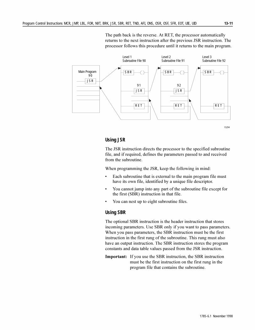
Program Control Instructions MCR, JMP, LBL, FOR, NXT, BRK, JSR, SBR, RET, TND, AFI, ONS, OSR, OSF, SFR, EOT, UIE, UID 13-11
7KH�SDWK�EDFN�LV�WKH�UHYHUVH��$W�5(7��WKH�SURFHVVRU�DXWRPDWLFDOO\�UHWXUQV�WR�WKH�QH[W�LQVWUXFWLRQ�DIWHU�WKH�SUHYLRXV�-65�LQVWUXFWLRQ��7KH�SURFHVVRU�IROORZV�WKLV�SURFHGXUH�XQWLO�LW�UHWXUQV�WR�WKH�PDLQ�SURJUDP�
Using JSR
7KH�-65�LQVWUXFWLRQ�GLUHFWV�WKH�SURFHVVRU�WR�WKH�VSHFLILHG�VXEURXWLQH�ILOH��DQG�LI�UHTXLUHG��GHILQHV�WKH�SDUDPHWHUV�SDVVHG�WR�DQG�UHFHLYHG�IURP�WKH�VXEURXWLQH�
:KHQ�SURJUDPPLQJ�WKH�-65��NHHS�WKH�IROORZLQJ�LQ�PLQG�
� (DFK�VXEURXWLQH�WKDW�LV�H[WHUQDO�WR�WKH�PDLQ�SURJUDP�ILOH�PXVW�KDYH�LWV�RZQ�ILOH��LGHQWLILHG�E\�D�XQLTXH�ILOH�GHVFULSWRU�
� <RX�FDQQRW�MXPS�LQWR�DQ\�SDUW�RI�WKH�VXEURXWLQH�ILOH�H[FHSW�IRU�WKH�ILUVW��6%5��LQVWUXFWLRQ�LQ�WKDW�ILOH�
� <RX�FDQ�QHVW�XS�WR�HLJKW�VXEURXWLQH�ILOHV�
Using SBR
7KH�RSWLRQDO�6%5�LQVWUXFWLRQ�LV�WKH�KHDGHU�LQVWUXFWLRQ�WKDW�VWRUHV�LQFRPLQJ�SDUDPHWHUV��8VH�6%5�RQO\�LI�\RX�ZDQW�WR�SDVV�SDUDPHWHUV��:KHQ�\RX�SDVV�SDUDPHWHUV��WKH�6%5�LQVWUXFWLRQ�PXVW�EH�WKH�ILUVW�LQVWUXFWLRQ�LQ�WKH�ILUVW�UXQJ�RI�WKH�VXEURXWLQH��7KLV�UXQJ�PXVW�DOVR�KDYH�DQ�RXWSXW�LQVWUXFWLRQ��7KH�6%5�LQVWUXFWLRQ�VWRUHV�WKH�SURJUDP�FRQVWDQWV�DQG�GDWD�WDEOH�YDOXHV�SDVVHG�IURP�WKH�-65�LQVWUXFWLRQ�
,PSRUWDQW��� ,I�\RX�XVH�WKH�6%5�LQVWUXFWLRQ��WKH�6%5�LQVWUXFWLRQ�PXVW�EH�WKH�ILUVW�LQVWUXFWLRQ�RQ�WKH�ILUVW�UXQJ�LQ�WKH�SURJUDP�ILOH�WKDW�FRQWDLQV�WKH�VXEURXWLQH�
S B R
JS R
R E T
9 1
S B R
JS R
R E T
9 2
S B R
R E T
JS R
9 0
15294
Level 1Subroutine File 90
Level 2Subroutine File 91
Level 3Subroutine File 92
Main Program
1785-6.1 November 1998
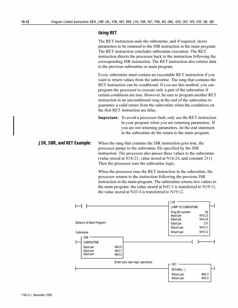
13-12 Program Control Instructions MCR, JMP, LBL, FOR, NXT, BRK, JSR, SBR, RET, TND, AFI, ONS, OSR, OSF, SFR, EOT, UIE, UID
Using RET
7KH�5(7�LQVWUXFWLRQ�HQGV�WKH�VXEURXWLQH��DQG�LI�UHTXLUHG��VWRUHV�SDUDPHWHUV�WR�EH�UHWXUQHG�WR�WKH�-65�LQVWUXFWLRQ�LQ�WKH�PDLQ�SURJUDP��7KH�5(7�LQVWUXFWLRQ�FRQFOXGHV�VXEURXWLQH�H[HFXWLRQ��7KH�5(7�LQVWUXFWLRQ�GLUHFWV�WKH�SURFHVVRU�EDFN�WR�WKH�LQVWUXFWLRQ�IROORZLQJ�WKH�FRUUHVSRQGLQJ�-65�LQVWUXFWLRQ��7KH�5(7�LQVWUXFWLRQ�DOVR�UHWXUQV�GDWD�WR�WKH�SUHYLRXV�VXEURXWLQH�RU�PDLQ�SURJUDP�
(YHU\�VXEURXWLQH�PXVW�FRQWDLQ�DQ�H[HFXWDEOH�5(7�LQVWUXFWLRQ�LI�\RX�ZDQW�WR�UHWXUQ�YDOXHV�IURP�WKH�VXEURXWLQH��7KH�UXQJ�WKDW�FRQWDLQV�WKH�5(7�LQVWUXFWLRQ�FDQ�EH�FRQGLWLRQDO��,I�\RX�XVH�WKLV�PHWKRG��\RX�FDQ�SURJUDP�WKH�SURFHVVRU�WR�H[HFXWH�RQO\�D�SDUW�RI�WKH�VXEURXWLQH�LI�FHUWDLQ�FRQGLWLRQV�DUH�WUXH��+RZHYHU��EH�VXUH�WR�SURJUDP�DQRWKHU�5(7�LQVWUXFWLRQ�LQ�DQ�XQFRQGLWLRQDO�UXQJ�DW�WKH�HQG�RI�WKH�VXEURXWLQH�WR�JXDUDQWHH�D�YDOLG�UHWXUQ�IURP�WKH�VXEURXWLQH�ZKHQ�WKH�FRQGLWLRQV�RQ�WKH�ILUVW�5(7�LQVWUXFWLRQ�DUH�IDOVH�
,PSRUWDQW���7R�DYRLG�D�SURFHVVRU�IDXOW��RQO\�XVH�WKH�5(7�LQVWUXFWLRQ�LQ�\RXU�SURJUDP�ZKHQ�\RX�DUH�UHWXUQLQJ�SDUDPHWHUV��,I�\RX�DUH�QRW�UHWXUQLQJ�SDUDPHWHUV��OHW�WKH�HQG�VWDWHPHQW�LQ�WKH�VXEURXWLQH�GR�WKH�UHWXUQ�WR�WKH�PDLQ�SURJUDP�
JSR, SBR, and RET Example: :KHQ�WKH�UXQJ�WKDW�FRQWDLQV�WKH�-65�LQVWUXFWLRQ�JRHV�WUXH��WKH�SURFHVVRU�MXPSV�WR�WKH�VXEURXWLQH�ILOH�VSHFLILHG�E\�WKH�-65�LQVWUXFWLRQ��7KH�SURFHVVRU�DOVR�SDVVHV�WKUHH�YDOXHV�WR�WKH�VXEURXWLQH��YDOXH�VWRUHG�DW�1�������YDOXH�VWRUHG�DW�1�������DQG�FRQVWDQW�������7KHQ�WKH�SURFHVVRU�UXQV�WKH�VXEURXWLQH�ORJLF�
:KHQ�WKH�SURFHVVRU�UXQV�WKH�5(7�LQVWUXFWLRQ�LQ�WKH�VXEURXWLQH��WKH�SURFHVVRU�UHWXUQV�WR�WKH�LQVWUXFWLRQ�IROORZLQJ�WKH�SUHYLRXV�-65�LQVWUXFWLRQ�LQ�WKH�PDLQ�SURJUDP��7KH�VXEURXWLQH�UHWXUQV�WZR�YDOXHV�WR�WKH�PDLQ�SURJUDP��WKH�YDOXH�VWRUHG�DW�1�����LV�WUDQVIHUUHG�WR�1�������WKH�YDOXH�VWRUHG�DW�1�����LV�WUDQVIHUUHG�WR�1������
RETURN ( )
Return par
JUMP TO SUBROUTINE
Balance of Main Program
Subroutine
(Enter your own logic operation)
Prog file numberInput parInput parInput par
90N16:23N16:24
231
JSR
RET
Return parReturn par
N19:11N19:12
SUBROUTINE
Input parInput parInput par
SBR
N43:0N43:1N43:2
Return parN43:3N43:4
1785-6.1 November 1998

Program Control Instructions MCR, JMP, LBL, FOR, NXT, BRK, JSR, SBR, RET, TND, AFI, ONS, OSR, OSF, SFR, EOT, UIE, UID 13-13
Temporary End (TND)
Description: :KHQ�WKH�SURFHVVRU�HQFRXQWHUV�WKH�71'�LQVWUXFWLRQ��WKH�SURFHVVRU�UHVHWV�WKH�ZDWFKGRJ�WLPHU��WR�]HUR���SHUIRUPV�DQ�,�2�XSGDWH��DQG�EHJLQV�UXQQLQJ�WKH�ODGGHU�SURJUDP�DW�WKH�ILUVW�LQVWUXFWLRQ�LQ�WKH�PDLQ�SURJUDP�
,QVHUW�WKH�71'�LQVWUXFWLRQ�ZKHQ�GHEXJJLQJ�RU�WURXEOHVKRRWLQJ�\RXU�ODGGHU�SURJUDP��7KH�71'�LQVWUXFWLRQ�OHWV�\RXU�SURJUDP�UXQ�RQO\�XS�WR�WKLV�LQVWUXFWLRQ��0RYH�LW�SURJUHVVLYHO\�WKURXJK�\RXU�SURJUDP�DV�\RX�GHEXJ�HDFK�QHZ�VHFWLRQ��$OVR�XVH�WKH�71'�LQVWUXFWLRQ�DV�D�ERXQGDU\�EHWZHHQ�WKH�PDLQ�SURJUDP�DQG�ORFDO�VXEURXWLQHV��<RX�FDQ�SURJUDP�WKH�71'�LQVWUXFWLRQ�XQFRQGLWLRQDOO\��RU�FRQGLWLRQ�LWV�UXQJ�DFFRUGLQJ�WR�\RXU�GHEXJJLQJ�QHHGV��
,PSRUWDQW���'R�QRW�FRQIXVH�WKH�71'�LQVWUXFWLRQ�ZLWK�WKH�HQG�RI�SURJUDP�V\PERO��(23���<RX�FDQQRW�SODFH�LQVWUXFWLRQV�RQ�WKH�UXQJ�WKDW�KDV�WKH�(23�V\PERO�
Always False (AFI)
Description: 7KH�$),�LQVWUXFWLRQ�LV�DQ�LQSXW�LQVWUXFWLRQ�WKDW�PDNHV�WKH�UXQJ�IDOVH�ZKHQ�LQVHUWHG�LQ�WKH�FRQGLWLRQ�VLGH�RI�WKH�UXQJ��<RX�FDQ�XVH�WKH�$),�LQVWUXFWLRQ�WR�WHPSRUDULO\�GLVDEOH�D�UXQJ�ZKHQ�\RX�GHEXJ�D�SURJUDP�
TND
TND
I:012
04
I:012
05
Example:
AFI
Example:
1785-6.1 November 1998
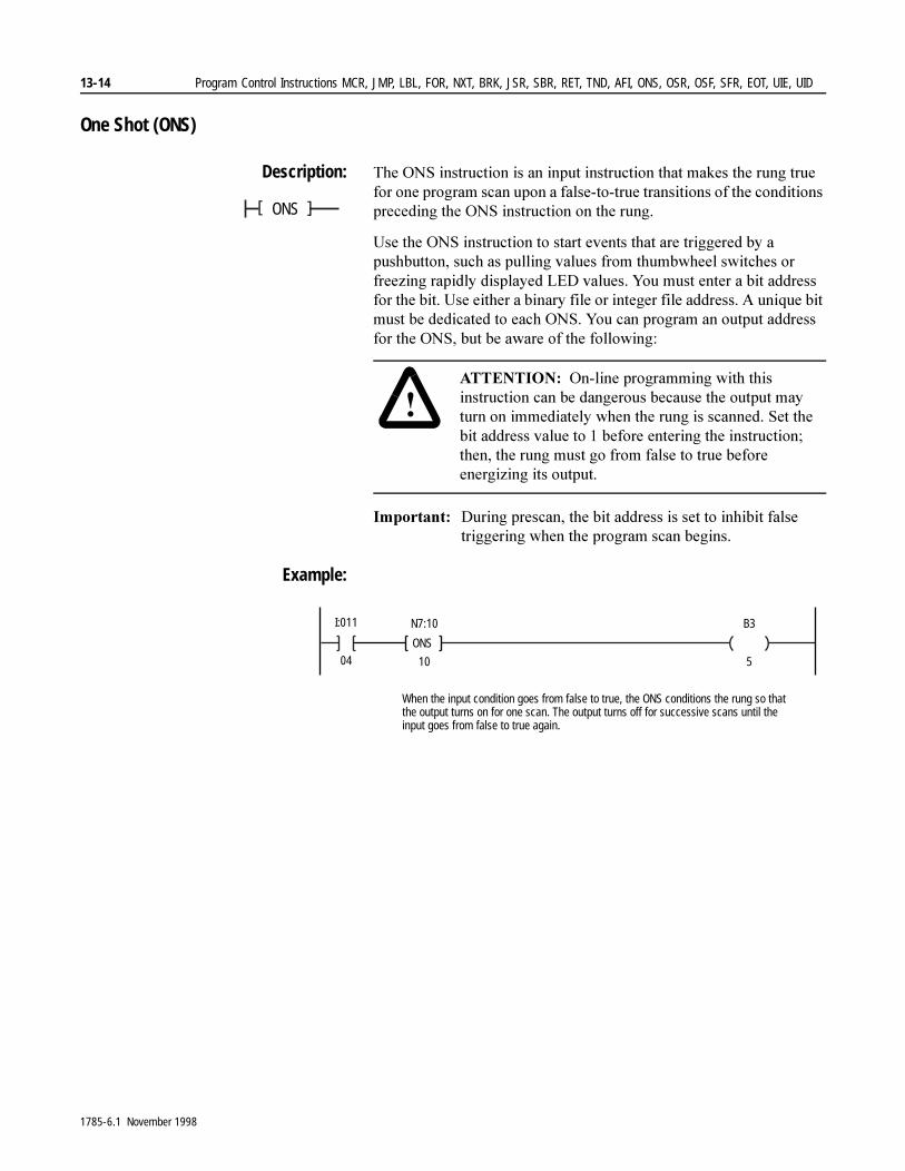
13-14 Program Control Instructions MCR, JMP, LBL, FOR, NXT, BRK, JSR, SBR, RET, TND, AFI, ONS, OSR, OSF, SFR, EOT, UIE, UID
One Shot (ONS)
Description: 7KH�216�LQVWUXFWLRQ�LV�DQ�LQSXW�LQVWUXFWLRQ�WKDW�PDNHV�WKH�UXQJ�WUXH�IRU�RQH�SURJUDP�VFDQ�XSRQ�D�IDOVH�WR�WUXH�WUDQVLWLRQV�RI�WKH�FRQGLWLRQV�SUHFHGLQJ�WKH�216�LQVWUXFWLRQ�RQ�WKH�UXQJ�
8VH�WKH�216�LQVWUXFWLRQ�WR�VWDUW�HYHQWV�WKDW�DUH�WULJJHUHG�E\�D�SXVKEXWWRQ��VXFK�DV�SXOOLQJ�YDOXHV�IURP�WKXPEZKHHO�VZLWFKHV�RU�IUHH]LQJ�UDSLGO\�GLVSOD\HG�/('�YDOXHV��<RX�PXVW�HQWHU�D�ELW�DGGUHVV�IRU�WKH�ELW��8VH�HLWKHU�D�ELQDU\�ILOH�RU�LQWHJHU�ILOH�DGGUHVV��$�XQLTXH�ELW�PXVW�EH�GHGLFDWHG�WR�HDFK�216��<RX�FDQ�SURJUDP�DQ�RXWSXW�DGGUHVV�IRU�WKH�216��EXW�EH�DZDUH�RI�WKH�IROORZLQJ��
,PSRUWDQW���'XULQJ�SUHVFDQ��WKH�ELW�DGGUHVV�LV�VHW�WR�LQKLELW�IDOVH�WULJJHULQJ�ZKHQ�WKH�SURJUDP�VFDQ�EHJLQV�
Example:
ONS[ ]
�$77(17,21� 2Q�OLQH�SURJUDPPLQJ�ZLWK�WKLV�LQVWUXFWLRQ�FDQ�EH�GDQJHURXV�EHFDXVH�WKH�RXWSXW�PD\�WXUQ�RQ�LPPHGLDWHO\�ZKHQ�WKH�UXQJ�LV�VFDQQHG��6HW�WKH�ELW�DGGUHVV�YDOXH�WR���EHIRUH�HQWHULQJ�WKH�LQVWUXFWLRQ��WKHQ��WKH�UXQJ�PXVW�JR�IURP�IDOVH�WR�WUXH�EHIRUH�HQHUJL]LQJ�LWV�RXWSXW�
I:011
04
When the input condition goes from false to true, the ONS conditions the rung so thatthe output turns on for one scan. The output turns off for successive scans until theinput goes from false to true again.
ONS
N7:10
10
B3
5
1785-6.1 November 1998
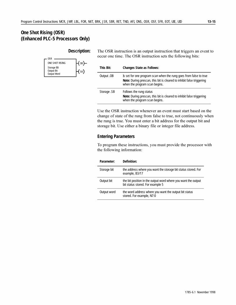
Program Control Instructions MCR, JMP, LBL, FOR, NXT, BRK, JSR, SBR, RET, TND, AFI, ONS, OSR, OSF, SFR, EOT, UIE, UID 13-15
One Shot Rising (OSR) (Enhanced PLC-5 Processors Only)
Description: 7KH�265�LQVWUXFWLRQ�LV�DQ�RXWSXW�LQVWUXFWLRQ�WKDW�WULJJHUV�DQ�HYHQW�WR�RFFXU�RQH�WLPH��7KH�265�LQVWUXFWLRQ�VHWV�WKH�IROORZLQJ�ELWV��
8VH�WKH�265�LQVWUXFWLRQ�ZKHQHYHU�DQ�HYHQW�PXVW�VWDUW�EDVHG�RQ�WKH�FKDQJH�RI�VWDWH�RI�WKH�UXQJ�IURP�IDOVH�WR�WUXH��QRW�FRQWLQXRXVO\�ZKHQ�WKH�UXQJ�LV�WUXH��<RX�PXVW�HQWHU�D�ELW�DGGUHVV�IRU�WKH�RXWSXW�ELW�DQG�VWRUDJH�ELW��8VH�HLWKHU�D�ELQDU\�ILOH�RU�LQWHJHU�ILOH�DGGUHVV�
Entering Parameters
7R�SURJUDP�WKHVH�LQVWUXFWLRQV��\RX�PXVW�SURYLGH�WKH�SURFHVVRU�ZLWK�WKH�IROORZLQJ�LQIRUPDWLRQ�
OBONE SHOT RISING
Output BitStorage BIt
SB
OSR
Output Word
This Bit: Changes State as Follows:
Output .OB Is set for one program scan when the rung goes from false to trueNote: During prescan, this bit is cleared to inhibit false triggering when the program scan begins.
Storage .SB Follows the rung statusNote: During prescan, this bit is cleared to inhibit false triggering when the program scan begins.
Parameter: Definition:
Storage bit the address where you want the storage bit status stored. For example, B3/17
Output bit the bit position in the output word where you want the output bit status stored. For example 5
Output word the word address where you want the output bit status stored. For example, N7:0
1785-6.1 November 1998
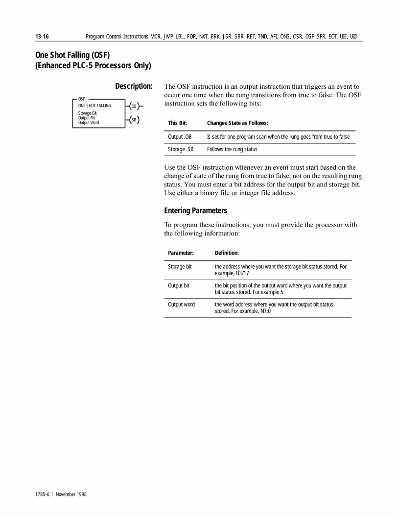
13-16 Program Control Instructions MCR, JMP, LBL, FOR, NXT, BRK, JSR, SBR, RET, TND, AFI, ONS, OSR, OSF, SFR, EOT, UIE, UID
One Shot Falling (OSF) (Enhanced PLC-5 Processors Only)
Description: 7KH�26)�LQVWUXFWLRQ�LV�DQ�RXWSXW�LQVWUXFWLRQ�WKDW�WULJJHUV�DQ�HYHQW�WR�RFFXU�RQH�WLPH�ZKHQ�WKH�UXQJ�WUDQVLWLRQV�IURP�WUXH�WR�IDOVH��7KH�26)�LQVWUXFWLRQ�VHWV�WKH�IROORZLQJ�ELWV�
8VH�WKH�26)�LQVWUXFWLRQ�ZKHQHYHU�DQ�HYHQW�PXVW�VWDUW�EDVHG�RQ�WKH�FKDQJH�RI�VWDWH�RI�WKH�UXQJ�IURP�WUXH�WR�IDOVH��QRW�RQ�WKH�UHVXOWLQJ�UXQJ�VWDWXV��<RX�PXVW�HQWHU�D�ELW�DGGUHVV�IRU�WKH�RXWSXW�ELW�DQG�VWRUDJH�ELW��8VH�HLWKHU�D�ELQDU\�ILOH�RU�LQWHJHU�ILOH�DGGUHVV�
Entering Parameters
7R�SURJUDP�WKHVH�LQVWUXFWLRQV��\RX�PXVW�SURYLGH�WKH�SURFHVVRU�ZLWK�WKH�IROORZLQJ�LQIRUPDWLRQ�
OBONE SHOT FALLING
Output BitStorage BIt
SB
OSF
Output Word This Bit: Changes State as Follows:
Output .OB Is set for one program scan when the rung goes from true to false
Storage .SB Follows the rung status
Parameter: Definition:
Storage bit the address where you want the storage bit status stored. For example, B3/17
Output bit the bit position of the output word where you want the output bit status stored. For example 5
Output word the word address where you want the output bit status stored. For example, N7:0
1785-6.1 November 1998

Program Control Instructions MCR, JMP, LBL, FOR, NXT, BRK, JSR, SBR, RET, TND, AFI, ONS, OSR, OSF, SFR, EOT, UIE, UID 13-17
Sequential Function Chart Reset (SFR) (Enhanced PLC-5 Processors Only)
Description: 7KH�6)5�LQVWUXFWLRQ�UHVHWV�WKH�ORJLF�LQ�D�VHTXHQWLDO�IXQFWLRQ�FKDUW��:KHQ�DQ�6)5�LQVWUXFWLRQ�JRHV�WUXH��WKH�SURFHVVRU�SHUIRUPV�D�SRVWVFDQ�ODVWVFDQ�RQ�DOO�DFWLYH�VWHSV�DQG�DFWLRQV�LQ�WKH�VHOHFWHG�ILOH��DQG�WKHQ�UHVHWV�WKH�ORJLF�LQ�WKH�6)&�RQ�WKH�QH[W�SURJUDP�VFDQ��7KH�FKDUW�UHPDLQV�LQ�WKLV�UHVHW�VWDWH�XQWLO�WKH�6)5�LQVWUXFWLRQ�JRHV�IDOVH��7KH�6)5�LQVWUXFWLRQ�DOVR�UHVHWV�DOO�UHWHQWLYH�DFWLRQV�WKDW�DUH�FXUUHQWO\�DFWLYH�
Entering Parameters
7R�SURJUDP�WKLV�LQVWUXFWLRQ��\RX�PXVW�SURYLGH�WKH�SURFHVVRU�ZLWK�WKH�IROORZLQJ�LQIRUPDWLRQ�
,PSRUWDQW���7KH�5HVWDUW�6WHS�DW�SDUDPHWHU�LV�RQO\�DYDLODEOH�ZLWK�3/&��������������������VHULHV�$��DQG�3/&������������/��������������/�VHULHV�%�DQG�DOO�(QKDQFHG�3/&���VHULHV�&�SURFHVVRUV��,I�\RX�DUH�XVLQJ�D�3/&������RU�������VHULHV $�SURFHVVRU��WKH�6)&�UHVHWV�WR�WKH�LQLWLDO�VWHS�
$�VWHS�QXPEHU�LV�D�VRIWZDUH�DVVLJQHG�UHIHUHQFH�QXPEHU�DVVRFLDWHG�ZLWK�HDFK�VWHS��<RX�PXVW�FRQILJXUH�\RXU�6)&�WR�GLVSOD\�WKHVH�QXPEHUV��)RU�LQIRUPDWLRQ�RQ�FRQILJXULQJ�\RXU�GLVSOD\��VHH�\RXU�SURJUDPPLQJ�PDQXDO�
$�VWHS�QDPH�LV�DQ\�QDPH�WKDW�\RX�DVVLJQ�WR�WKH�VWHS��)RU�PRUH�LQIRUPDWLRQ��VHH�WKH�VHFWLRQ�RQ�DVVLJQLQJ�VWHS�DQG�WUDQVLWLRQ�QDPHV�LQ�\RXU�SURJUDPPLQJ�PDQXDO�
,PSRUWDQW���0DNH�VXUH�WKDW�WKH�VWHS�LV�DFWXDOO\�D�VWHS�DQG�QRW�D�WUDQVLWLRQ�RU�PDFUR��7KLV�FDXVHV�WKH�SURFHVVRU�WR�IDXOW��WKH�VRIWZDUH�GRHV�QRW�SHUIRUP�D�FKHFN��$OVR�PDNH�VXUH�WKDW�WKH�VWHS�LV�QRW�ZLWKLQ�D�VLPXOWDQHRXV�EUDQFK�RU�WKH�SURFHVVRU�ZLOO�IDXOW�
SFC Reset
Prog file number
SFR
Restart step at
Parameter: Definition:
Program File Number a valid SFC program file number
Restart Step at enter one of the following: • a valid step reference number, 0 to 32767 (entering a 0
defaults to restarting at the initial step)• a valid step name• an integer address (that stores a step reference number)• an address symbol (of an integer address that stores a step
reference number)
SFC Reset
Prog file number
SFR
Example:
2
N7:5Restart step at
1785-6.1 November 1998
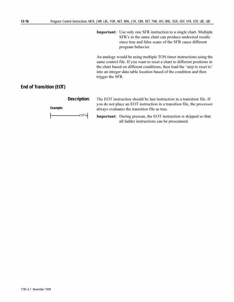
13-18 Program Control Instructions MCR, JMP, LBL, FOR, NXT, BRK, JSR, SBR, RET, TND, AFI, ONS, OSR, OSF, SFR, EOT, UIE, UID
,PSRUWDQW���8VH�RQO\�RQH�6)5�LQVWUXFWLRQ�WR�D�VLQJOH�FKDUW��0XOWLSOH�6)5¶V�LQ�WKH�VDPH�FKDUW�FDQ�SURGXFH�XQGHVLUHG�UHVXOWV�VLQFH�WUXH�DQG�IDOVH�VFDQV�RI�WKH�6)5�FDXVH�GLIIHUHQW�SURJUDP�EHKDYLRU�
$Q�DQDORJ\�ZRXOG�EH�XVLQJ�PXOWLSOH�721�WLPHU�LQVWUXFWLRQV�XVLQJ�WKH�VDPH�FRQWURO�ILOH��,I�\RX�ZDQW�WR�UHVHW�D�FKDUW�WR�GLIIHUHQW�SRVLWLRQV�LQ�WKH�FKDUW�EDVHG�RQ�GLIIHUHQW�FRQGLWLRQV��WKHQ�ORDG�WKH�µVWHS�WR�UHVHW�WR¶�LQWR�DQ�LQWHJHU�GDWD�WDEOH�ORFDWLRQ�EDVHG�RI�WKH�FRQGLWLRQ�DQG�WKHQ�WULJJHU�WKH�6)5�
End of Transition (EOT)
Description: 7KH�(27�LQVWUXFWLRQ�VKRXOG�EH�ODVW�LQVWUXFWLRQ�LQ�D�WUDQVLWLRQ�ILOH��,I�\RX�GR�QRW�SODFH�DQ�(27�LQVWUXFWLRQ�LQ�D�WUDQVLWLRQ�ILOH��WKH�SURFHVVRU�DOZD\V�HYDOXDWHV�WKH�WUDQVLWLRQ�ILOH�DV�WUXH��
,PSRUWDQW���'XULQJ�SUHVFDQ��WKH�(27�LQVWUXFWLRQ�LV�VNLSSHG�VR�WKDW�DOO�ODGGHU�LQVWUXFWLRQV�FDQ�EH�SUHVFDQQHG�
[ EOT ]
Example:
1785-6.1 November 1998

Program Control Instructions MCR, JMP, LBL, FOR, NXT, BRK, JSR, SBR, RET, TND, AFI, ONS, OSR, OSF, SFR, EOT, UIE, UID 13-19
User Interrupt Disable (UID)(Enhanced PLC-5 Processors Only)
Description: 7KH�8,'�LQVWUXFWLRQ�LV�XVHG�WR�WHPSRUDULO\�GLVDEOH�LQWHUUXSW�SURJUDPV��VXFK�DV�6HOHFWDEOH�7LPHG�,QWHUUXSWV��67,��RU�3URFHVVRU�,QSXW�,QWHUUXSWV��3,,��
:KHQ�WKH�UXQJ�LV�WUXH��WKH�8,'�LQVWUXFWLRQ�LQFUHPHQWV�DQ�LQWHUQDO�LQWHUUXSW�GLVDEOH�FRXQWHU��$V�ORQJ�DV�WKLV�FRXQWHU�YDOXH�GRHV�QRW�HTXDO�]HUR��WKH�FXUUHQWO\�H[HFXWLQJ�SURJUDP�FDQQRW�EH�LQWHUUXSWHG�E\�DQ�67,�RU�D�3,,��$OVR��LI�\RX�KDYH�D�VXEURXWLQH�FDOO�ZLWKLQ�D�8,(�8,'�SDLU��WKDW�VXEURXWLQH�UXQV�ZLWKRXW�LQWHUUXSWLRQ�
7KH�8,'�LQVWUXFWLRQ�GRHV�QRW�GLVDEOH�WKH�XVHU�IDXOW�URXWLQH�
,PSRUWDQW���6LQFH�WKH�8,'�LQVWUXFWLRQ�PDNHV�D�SURJUDP�XQ�LQWHUUXSWLEOH��WKH�SURFHVVRU¶V�UHVSRQVH�WLPH�WR�DQ�67,�RU�3,,�HYHQW�PD\�EH�DIIHFWHG��7KH�8,'�8,(�VHFWLRQ�RI�\RXU�SURJUDP�VKRXOG�EH�DV�VKRUW�DV�SRVVLEOH��/HDYLQJ�67,V�DQG�3,,V�GLVDEOHG�IRU�H[WHQGHG�SHULRGV�RI�WLPH�HYHQWXDOO\�OHDGV�WR�67,�DQG�3,,�RYHUODS�HUURUV�
,PSRUWDQW��� ,I�\RX�KDYH�DQ\�EORFN�WUDQVIHU�LQ�DQ�67,�RU�3,,�DQG�WKDW�EORFN�WUDQVIHU�LQVWUXFWLRQ�LV�ZLWKLQ�D�8,'�8,(�VHFWLRQ�RI�\RXU�SURJUDP��WKH�PDLQ�SURJUDP�VFDQ�VWRSV�XQWLO�WKH�EORFN�WUDQVIHU�FRPSOHWHV�
UID
1785-6.1 November 1998

13-20 Program Control Instructions MCR, JMP, LBL, FOR, NXT, BRK, JSR, SBR, RET, TND, AFI, ONS, OSR, OSF, SFR, EOT, UIE, UID
User Interrupt Enable (UIE) (Enhanced PLC-5 Processors Only)
Description: 7KH�8,(�LQVWUXFWLRQ�UH�HQDEOHV�67,�RU�3,,�LQWHUUXSW�SURJUDPV�
:KHQ�WKH�UXQJ�LV�WUXH�DQG�WKH�LQWHUQDO�LQWHUUXSW�GLVDEOH�FRXQWHU�LV�JUHDWHU�WKDQ�]HUR��WKH�LQWHUUXSW�GLVDEOH�FRXQWHU�LV�GHFUHPHQWHG�
:KHQ�WKH�FRXQWHU�HTXDOV�]HUR��WKH�SURJUDP�FXUUHQWO\�H[HFXWLQJ�LV�WKHQ�DEOH�WR�EH�LQWHUUXSWHG�DJDLQ��,I�WKHUH�DUH�DQ\�LQWHUUXSW�SURJUDPV�SHQGLQJ��WKH\�DUH�H[HFXWHG�DW�WKLV�WLPH�
Example:
UIE
I:012
01
O:013
02
O:013
02
UID
I:012
01
I:012
02
I:012
03
UIE
03
I:012
I:012
04
I:012
04
O:013
03
I:012
02
Program can be interrupted
Program can be interrupted
Program cannotbe interrupted
1785-6.1 November 1998
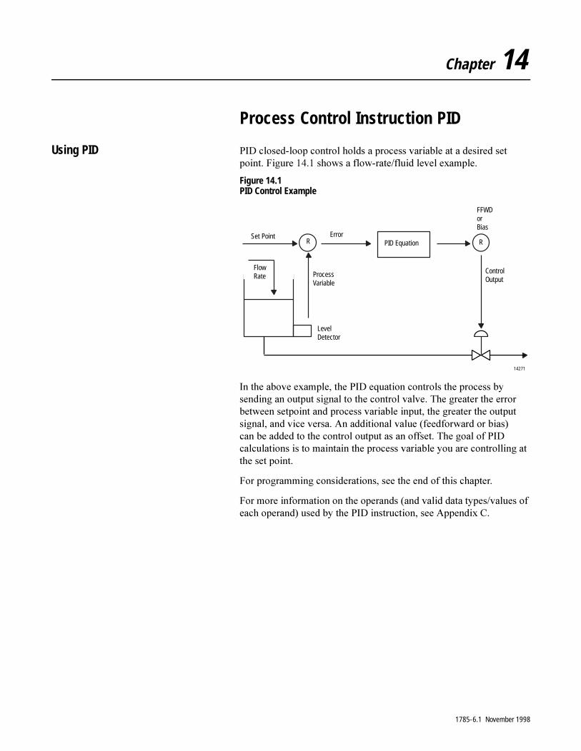
Chapter 14
Process Control Instruction PID
Using PID 3,'�FORVHG�ORRS�FRQWURO�KROGV�D�SURFHVV�YDULDEOH�DW�D�GHVLUHG�VHW�SRLQW��)LJXUH������VKRZV�D�IORZ�UDWH�IOXLG�OHYHO�H[DPSOH�
Figure 14.1 PID Control Example
,Q�WKH�DERYH�H[DPSOH��WKH�3,'�HTXDWLRQ�FRQWUROV�WKH�SURFHVV�E\�VHQGLQJ�DQ�RXWSXW�VLJQDO�WR�WKH�FRQWURO�YDOYH��7KH�JUHDWHU�WKH�HUURU�EHWZHHQ�VHWSRLQW�DQG�SURFHVV�YDULDEOH�LQSXW��WKH�JUHDWHU�WKH�RXWSXW�VLJQDO��DQG�YLFH�YHUVD��$Q�DGGLWLRQDO�YDOXH��IHHGIRUZDUG�RU�ELDV��FDQ�EH�DGGHG�WR�WKH�FRQWURO�RXWSXW�DV�DQ�RIIVHW��7KH�JRDO�RI�3,'�FDOFXODWLRQV�LV�WR�PDLQWDLQ�WKH�SURFHVV�YDULDEOH�\RX�DUH�FRQWUROOLQJ�DW�WKH�VHW�SRLQW�
)RU�SURJUDPPLQJ�FRQVLGHUDWLRQV��VHH�WKH�HQG�RI�WKLV�FKDSWHU�
)RU�PRUH�LQIRUPDWLRQ�RQ�WKH�RSHUDQGV��DQG�YDOLG�GDWD�W\SHV�YDOXHV�RI�HDFK�RSHUDQG��XVHG�E\�WKH�3,'�LQVWUXFWLRQ��VHH�$SSHQGL[�&�
FlowRate
Set Point Error
ProcessVariable
LevelDetector
PID Equation
ControlOutput
FFWDorBias
R R
14271
1785-6.1 November 1998
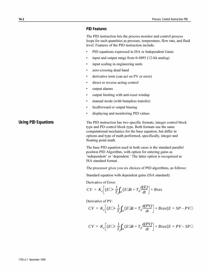
14-2 Process Control Instruction PID
PID Features
7KH�3,'�LQVWUXFWLRQ�OHWV�WKH�SURFHVV�PRQLWRU�DQG�FRQWURO�SURFHVV�ORRSV�IRU�VXFK�TXDQWLWLHV�DV�SUHVVXUH��WHPSHUDWXUH��IORZ�UDWH��DQG�IOXLG�OHYHO��)HDWXUHV�RI�WKH�3,'�LQVWUXFWLRQ�LQFOXGH�
� 3,'�HTXDWLRQV�H[SUHVVHG�LQ�,6$�RU�,QGHSHQGHQW�*DLQV
� LQSXW�DQG�RXWSXW�UDQJH�IURP������������ELW�DQDORJ�
� LQSXW�VFDOLQJ�LQ�HQJLQHHULQJ�XQLWV
� ]HUR�FURVVLQJ�GHDG�EDQG
� GHULYDWLYH�WHUP��FDQ�DFW�RQ�39�RU�HUURU�
� GLUHFW�RU�UHYHUVH�DFWLQJ�FRQWURO
� RXWSXW�DODUPV
� RXWSXW�OLPLWLQJ�ZLWK�DQWL�UHVHW�ZLQGXS
� PDQXDO�PRGH��ZLWK�EXPSOHVV�WUDQVIHU�
� IHHGIRUZDUG�RU�RXWSXW�ELDVLQJ
� GLVSOD\LQJ�DQG�PRQLWRULQJ�3,'�YDOXHV
Using PID Equations 7KH�3,'�LQVWUXFWLRQ�KDV�WZR�VSHFLILF�IRUPDWV��LQWHJHU�FRQWURO�EORFN�W\SH�DQG�3'�FRQWURO�EORFN�W\SH��%RWK�IRUPDWV�XVH�WKH�VDPH�FRPSXWDWLRQDO�PHFKDQLFV�IRU�WKH�EDVH�HTXDWLRQ��EXW�GLIIHU�LQ�RSWLRQV�DQG�W\SH�RI�PDWK�SHUIRUPHG��VSHFLILFDOO\��LQWHJHU�DQG�IORDWLQJ�SRLQW�PDWK�
7KH�EDVH�3,'�HTXDWLRQ�XVHG�LQ�ERWK�FDVHV�LV�WKH�VWDQGDUG�SDUDOOHO�SRVLWLRQ�3,'�$OJRULWKP��ZLWK�RSWLRQ�IRU�HQWHULQJ�JDLQV�DV�µLQGHSHQGHQW¶�RU�µGHSHQGHQW�¶�7KH�ODWWHU�RSWLRQ�LV�UHFRJQL]HG�DV�,6$�VWDQGDUG�IRUPDW�
7KH�SURFHVVRU�JLYHV�\RX�VL[�FKRLFHV�RI�3,'�DOJRULWKPV��DV�IROORZV�
6WDQGDUG�HTXDWLRQ�ZLWK�GHSHQGHQW�JDLQV��,6$�VWDQGDUG���
'HULYDWLYH�RI�(UURU�
'HULYDWLYH�RI�39�
CV Kc E( ) 1Ti���� E( ) t Td+d
d(E)dt����������
0
t∫+ Bias+=
CV Kc E( ) 1Ti���� E( ) t Td+d
d(PV)dt
��������������0
t∫+ Bias E SP PV–=( )+=
CV Kc E( ) 1Ti���� E( ) t Td+d
d(PV)dt
��������������0
t∫+ Bias E PV SP–=( )+=
1785-6.1 November 1998

Process Control Instruction PID 14-3
,QGHSHQGHQW�JDLQV�HTXDWLRQ�
'HULYDWLYH�RI�(UURU�
'HULYDWLYH�RI�39�
:KHUH�
Conversion of Gain Constants
&RQYHUW�IURP�VWDQGDUG�WR�LQGHSHQGHQW�JDLQV�FRQVWDQWV�E\�VXEVWLWXWLQJ�FRQWUROOHU�JDLQ��.F���UHVHW����7L���DQG�UDWH��7G��YDOXHV�LQ�WKH�IROORZLQJ IRUPXODV�
Integral Term Implementation
3HUIRUP�LQWHJUDWLRQ�E\�PDLQWDLQLQJ�DQ�DFFXPXODWHG�VXP��6N�
,Q�WKH�FDVH�RI�,QGHSHQGHQW�*DLQV���6N� �.L�(N�∆W���6N±�
:LWK�'HSHQGHQW�*DLQV�VHOHFWHG��
Kp = Proportional Gain (Unitless) SP = Set Point
Ki = Integral Gain (Seconds–1) PV = Process Variable
Kd = Derivative Gain (Seconds) Error = (SP – PV) or (PV – SP)
= Reset Gain (Repeats/Minute)Bias = Feed-Forward or External Bias
CV = Output Control Variable
Td = Rate Gain (Repeats/Minute) ∆t = Loop Update Time
CV KP E( ) Ki E( ) t Kd+dd(E)dt���������� Bias+
0
t∫+=
CV KP E( ) Ki E( ) t Kd–dd(PV)
dt��������������
0
t∫ Bias E SP PV–=( )+ +=
CV KP E( ) Ki E( ) t Kd+dd(PV)
dt��������������
0
t∫ Bias E PV SP–=( )+ +=
1T1�����
Kp Kc unitless=
KiKc
60Ti�����������inverse seconds=
Kd Kc(Td)60 seconds=
Sk1Ti���� Ek( )∆t Sk 1–+=
1785-6.1 November 1998
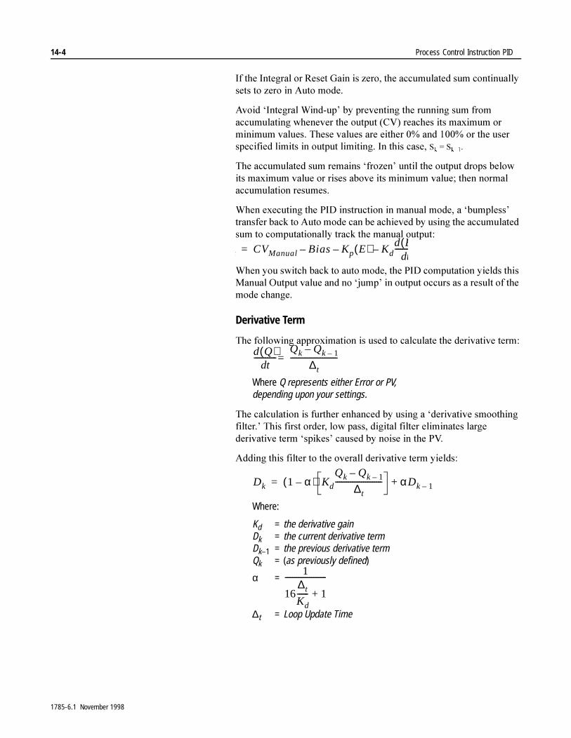
14-4 Process Control Instruction PID
,I�WKH�,QWHJUDO�RU�5HVHW�*DLQ�LV�]HUR��WKH�DFFXPXODWHG�VXP�FRQWLQXDOO\�VHWV�WR�]HUR�LQ�$XWR�PRGH�
$YRLG�µ,QWHJUDO�:LQG�XS¶�E\�SUHYHQWLQJ�WKH�UXQQLQJ�VXP�IURP�DFFXPXODWLQJ�ZKHQHYHU�WKH�RXWSXW��&9��UHDFKHV�LWV�PD[LPXP�RU�PLQLPXP�YDOXHV��7KHVH�YDOXHV�DUH�HLWKHU����DQG������RU�WKH�XVHU�VSHFLILHG�OLPLWV�LQ�RXWSXW�OLPLWLQJ��,Q�WKLV�FDVH��6N� �6N±��
7KH�DFFXPXODWHG�VXP�UHPDLQV�µIUR]HQ¶�XQWLO�WKH�RXWSXW�GURSV�EHORZ�LWV�PD[LPXP�YDOXH�RU�ULVHV�DERYH�LWV�PLQLPXP�YDOXH��WKHQ�QRUPDO�DFFXPXODWLRQ�UHVXPHV�
:KHQ�H[HFXWLQJ�WKH�3,'�LQVWUXFWLRQ�LQ�PDQXDO�PRGH��D�µEXPSOHVV¶�WUDQVIHU�EDFN�WR�$XWR�PRGH�FDQ�EH�DFKLHYHG�E\�XVLQJ�WKH�DFFXPXODWHG�VXP�WR�FRPSXWDWLRQDOO\�WUDFN�WKH�PDQXDO�RXWSXW�
:KHQ�\RX�VZLWFK�EDFN�WR�DXWR�PRGH��WKH�3,'�FRPSXWDWLRQ�\LHOGV�WKLV�0DQXDO�2XWSXW�YDOXH�DQG�QR�µMXPS¶�LQ�RXWSXW�RFFXUV�DV�D�UHVXOW�RI�WKH�PRGH�FKDQJH�
Derivative Term
7KH�IROORZLQJ�DSSUR[LPDWLRQ�LV�XVHG�WR�FDOFXODWH�WKH�GHULYDWLYH�WHUP�
Where Q represents either Error or PV,depending upon your settings.
7KH�FDOFXODWLRQ�LV�IXUWKHU�HQKDQFHG�E\�XVLQJ�D�µGHULYDWLYH�VPRRWKLQJ�ILOWHU�¶�7KLV�ILUVW�RUGHU��ORZ�SDVV��GLJLWDO�ILOWHU�HOLPLQDWHV�ODUJH�GHULYDWLYH�WHUP�µVSLNHV¶�FDXVHG�E\�QRLVH�LQ�WKH�39�
$GGLQJ�WKLV�ILOWHU�WR�WKH�RYHUDOO�GHULYDWLYH�WHUP�\LHOGV�
Where:
Kd = the derivative gainDk = the current derivative termDk–1 = the previous derivative termQk = (as previously defined)
α =
∆t = Loop Update Time
k CVManual Bias– Kp E( )– Kdd E(
dt��������–=
d Q( )dt
������������Qk Qk 1––
∆t�������������������������=
Dk 1 α–( ) Kd
Qk Qk 1––
∆t������������������������� αDk 1–+=
1
16∆t
Kd������ 1+
����������������������
1785-6.1 November 1998
Process Control Instruction PID 14-5
Setting Input/Output Ranges 7KH�LQSXW�PRGXOH�WKDW�PHDVXUHV�WKH�SURFHVVRU�YDULDEOH��39��PXVW�KDYH�D�IXOO�VFDOH�ELQDU\�UDQJH�RI���������7KH�SURFHVVRU�LJQRUHV�WKH�XSSHU�IRXU�PRVW�VLJQLILFDQW�ELWV�RI�WKH����ELW�SURFHVV�YDULDEOH��LQWHJHU�3,'�RQO\��
7KH�FRQWURO�RXWSXW�KDV�WKH�VDPH�UDQJH�RI���������<RX�FDQ�VHW�OLPLWV�RQ�WKH�RXWSXW�WR�OLPLW�WKH�RXWSXW�FDOFXODWHG�E\�WKH�3,'�LQVWUXFWLRQ�WR�DQ\�YDOXH�LQ�WKH�UDQJH�RI��������
7KH�WLHEDFN�LQSXW��RXWSXW�WUDFNLQJ��IURP�D�PDQXDO�FRQWURO�VWDWLRQ�PXVW�DOVR�KDYH�D�UDQJH�RI���������7KH�3,'�LQVWUXFWLRQ�XVHV�WKH�UHVXOW�WR�FDOFXODWH�WKH�LQWHJUDO�DFFXPXODWHG�YDOXH��ZKLFK�DOORZV�IRU�EXPSOHVV�WUDQVIHU�IURP�PDQXDO�WR�DXWRPDWLF�FRQWURO�
7KH�3,'�LQVWUXFWLRQ�DOVR�FRSLHV�WKH�WLHEDFN�YDOXH�LQWR�WKH�FRQWURO�RXWSXW�VWRUDJH�ORFDWLRQ�ZKHQ�LQ�PDQXDO�PRGH��7LHEDFN�LQSXW�LV�RQO\�XVHG�ZKHQ�\RX�XVH�D�KDUGZDUH�DXWR�PDQXDO�VWDWLRQ��2WKHUZLVH��VHW�WKH�WLHEDFN�YDOXH�WR�]HUR�
Implementing Scaling to Engineering Units – Integer File Type
<RX�FDQ�VFDOH�WKH�VHWSRLQW�DQG�]HUR�FURVVLQJ�GHDG�EDQG�YDOXHV�WR�HQJLQHHULQJ�XQLWV�IRU�LQWHJHU�ILOH�W\SHV��<RX�FDQ�DOVR�GLVSOD\�WKH�SURFHVV�YDULDEOH�DQG�HUURU�YDOXHV�LQ�WKHVH�VDPH�HQJLQHHULQJ�XQLWV�
:KHQ�\RX�VHOHFW�VFDOLQJ��WKH�3,'�LQVWUXFWLRQ�VFDOHV�WKH�VHWSRLQW��GHDG�EDQG��SURFHVV�YDULDEOH��DQG�HUURU�YDOXHV��<RX�DOVR�KDYH�
�� (QWHU�WKH�PD[LPXP�DQG�PLQLPXP�YDOXHV�6PD[�DQG�6PLQ�LQ�WKH�3,'�FRQWURO�EORFN��ZRUGV���DQG�����7KH�6PLQ�YDOXH�FRUUHVSRQGV�WR�DQ�DQDORJ�YDOXH�RI�]HUR�IRU�WKH�ORZHVW�UHDGLQJ�RI�WKH�SURFHVV�YDULDEOH��WKH�6PD[�YDOXH�FRUUHVSRQGV�WR�DQ�DQDORJ�YDOXH�RI������IRU�WKH�KLJKHVW�UHDGLQJ�RI�WKH�SURFHVV�YDULDEOH��7KHVH�YDOXHV�UHSUHVHQW�SURFHVV�OLPLWV��6HW�6PLQ�DQG�6PD[�WR���LI�\RX�GR�QRW�ZDQW�VFDOLQJ�
)RU�H[DPSOH��LI�\RX�PHDVXUH�D�VFDOH�RI�WHPSHUDWXUH�IURP�±����39 ���WR��������39 �������HQWHU�±���IRU�6PLQ�DQG������IRU�6PD[�
,I�WKH�DQDORJ�LQSXW�PRGXOH�LV�QRW�FRQILJXUHG�WR�UHWXUQ�D�YDOXH�LQ�WKH�UDQJH���������VHH�³'HVFDOLQJ�,QSXWV´�RQ�SDJH�������LQ�WKLV�FKDSWHU�
�� 5HVHW�ELW���RI�ZRUG���LQ�WKH�3,'�FRQWURO�EORFN��LQWHJHU�ILOH�W\SH�RQO\���6HW�WKLV�ELW�RQO\�LI�\RX�ZDQW�WR�LQKLELW�VFDOLQJ�WKH�VHWSRLQW��<RX�PXVW�LQKLELW�VHWSRLQW�VFDOLQJ�RI�D�FDVFDGHG�LQQHU�ORRS�ZKLOH�VFDQQLQJ�RWKHU�ORRS�YDULDEOHV�
1785-6.1 November 1998
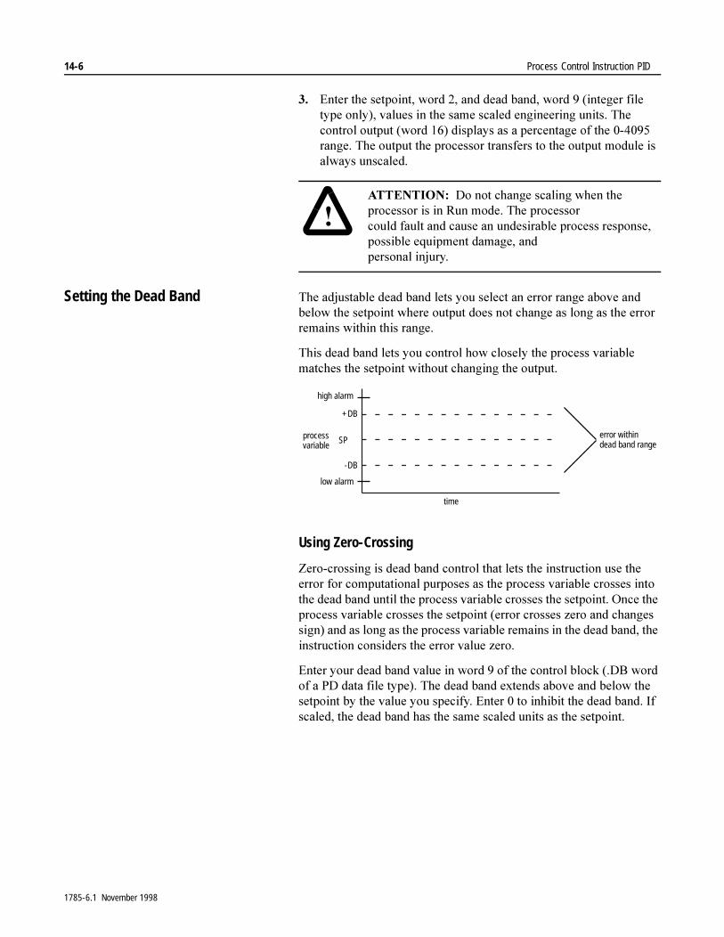
14-6 Process Control Instruction PID
�� (QWHU�WKH�VHWSRLQW��ZRUG����DQG�GHDG�EDQG��ZRUG����LQWHJHU�ILOH�W\SH�RQO\���YDOXHV�LQ�WKH�VDPH�VFDOHG�HQJLQHHULQJ�XQLWV��7KH�FRQWURO�RXWSXW��ZRUG�����GLVSOD\V�DV�D�SHUFHQWDJH�RI�WKH��������UDQJH��7KH�RXWSXW�WKH�SURFHVVRU�WUDQVIHUV�WR�WKH�RXWSXW�PRGXOH�LV�DOZD\V�XQVFDOHG��
Setting the Dead Band 7KH�DGMXVWDEOH�GHDG�EDQG�OHWV�\RX�VHOHFW�DQ�HUURU�UDQJH�DERYH�DQG�EHORZ�WKH�VHWSRLQW�ZKHUH�RXWSXW�GRHV�QRW�FKDQJH�DV�ORQJ�DV�WKH�HUURU�UHPDLQV�ZLWKLQ�WKLV�UDQJH�
7KLV�GHDG�EDQG�OHWV�\RX�FRQWURO�KRZ�FORVHO\�WKH�SURFHVV�YDULDEOH�PDWFKHV�WKH�VHWSRLQW�ZLWKRXW�FKDQJLQJ�WKH�RXWSXW�
Using Zero-Crossing
=HUR�FURVVLQJ�LV�GHDG�EDQG�FRQWURO�WKDW�OHWV�WKH�LQVWUXFWLRQ�XVH�WKH�HUURU�IRU�FRPSXWDWLRQDO�SXUSRVHV�DV�WKH�SURFHVV�YDULDEOH�FURVVHV�LQWR�WKH�GHDG�EDQG�XQWLO�WKH�SURFHVV�YDULDEOH�FURVVHV�WKH�VHWSRLQW��2QFH�WKH�SURFHVV�YDULDEOH�FURVVHV�WKH�VHWSRLQW��HUURU�FURVVHV�]HUR�DQG�FKDQJHV�VLJQ��DQG�DV�ORQJ�DV�WKH�SURFHVV�YDULDEOH�UHPDLQV�LQ�WKH�GHDG�EDQG��WKH�LQVWUXFWLRQ�FRQVLGHUV�WKH�HUURU�YDOXH�]HUR�
(QWHU�\RXU�GHDG�EDQG�YDOXH�LQ�ZRUG���RI�WKH�FRQWURO�EORFN���'%�ZRUG�RI�D�3'�GDWD�ILOH�W\SH���7KH�GHDG�EDQG�H[WHQGV�DERYH�DQG�EHORZ�WKH�VHWSRLQW�E\�WKH�YDOXH�\RX�VSHFLI\��(QWHU���WR�LQKLELW�WKH�GHDG�EDQG��,I�VFDOHG��WKH�GHDG�EDQG�KDV�WKH�VDPH�VFDOHG�XQLWV�DV�WKH�VHWSRLQW�
�$77(17,21� 'R�QRW�FKDQJH�VFDOLQJ�ZKHQ�WKH�SURFHVVRU�LV�LQ�5XQ�PRGH��7KH�SURFHVVRU�FRXOG�IDXOW�DQG�FDXVH�DQ�XQGHVLUDEOH�SURFHVV�UHVSRQVH��SRVVLEOH�HTXLSPHQW�GDPDJH��DQG�SHUVRQDO�LQMXU\�
+DB
-DB
SPprocessvariable
time
error withindead band range
low alarm
high alarm
1785-6.1 November 1998
Process Control Instruction PID 14-7
Using No Zero Crossing
7KH�VHULHV�(�SURFHVVRU�DGGHG�D�QR�]HUR�FURVVLQJ�IHDWXUH��ZKLFK�LV�XVHIXO�IRU�DSSOLFDWLRQV�WKDW�UXQ�KLJK�LQHUWLD�SURFHVVHV�WKDW�VORZO\�PRYH�D�KLJK�PDVV�ZKLFK�LV�KDUG�WR�VWRS��7KH�QR�]HUR�FURVVLQJ�IHDWXUH�FDXVHV�WKH�&9�RXWSXW�QRW�WR�FKDQJH�YDOXH�DV�ORQJ�DV�WKH�39�LV�LQVLGH�WKH�GHDGEDQG�UDQJH��LQVWHDG�RI�RQO\�DIWHU�UHDFKLQJ�WKH�VHWSRLQW�YDOXH��:LWK�WKH�SURSHU�WXQLQJ��LW�LV�WKHQ�SRVVLEOH�WR�KDYH�WKH�39�GULIW�WR�WKH�VHWSRLQW�YDOXH�
Selecting the Derivative Term (Acts on PV or Error)
'HULYDWLYH�LV�D�FKDQJH�RI�VWDWH�YDULDEOH��<RX�FDQ�VHOHFW�ZKHWKHU�WKH�GHULYDWLYH�WHUP�LQ�HLWKHU�3,'�HTXDWLRQ�DFWV�RQ�FKDQJHV�LQ�WKH�SURFHVVRU�YDULDEOH�RU�HUURU�YDOXH��8VH�ELW���RI�ZRUG���LQ�WKH�FRQWURO�EORFN���'2�ZRUG�RI�D�3'�GDWD�ILOH�W\SH��WR�VHOHFW�WKH�W\SH�RI�GHULYDWLYH�DFWLRQ�\RX�ZDQW�
Setting Output Alarms <RX�FDQ�VHW�DQ�RXWSXW�DODUP�RQ�WKH�FRQWURO�YDULDEOH�RXWSXW�DW�D�VHOHFWHG�YDOXH�DERYH�RU�EHORZ�WKH�VHWSRLQW��:KHQ�WKH�LQVWUXFWLRQ�GHWHFWV�WKDW�WKH�RXWSXW�KDV�UHDFKHG�HLWKHU�YDOXH��WKH�SURFHVVRU�VHWV�DQ�DODUP�ELW��ELW����IRU�ORZHU�OLPLW��ELW���IRU�XSSHU�OLPLW��LQ�ZRUG���RI�WKH�FRQWURO�EORFN���2/+�DQG��2//�ELWV�RI�D�3'�GDWD�ILOH�W\SH���$ODUP�ELWV�DUH�UHVHW�E\�WKH�LQVWUXFWLRQ�ZKHQ�WKH�RXWSXW�FRPHV�EDFN�LQVLGH�WKH�OLPLWV��7KH�LQVWUXFWLRQ�GRHV�QRW�SUHYHQW�WKH�RXWSXW�IURP�H[FHHGLQJ�WKH�DODUP�YDOXHV�XQOHVV�\RX�VHOHFW�RXWSXW�OLPLWLQJ�
(QWHU�WKH�XSSHU�RXWSXW�DODUP�LQ�ZRUG������0$;2��DQG�WKH�ORZHU�RXWSXW�DODUP�LQ�ZRUG������0,12��RI�WKH�FRQWURO�EORFN��7KH�SURFHVVRU�KDQGOHV�RXWSXW�DODUP�YDOXHV�DV�D�SHUFHQWDJH�RI�WKH�RXWSXW��,I�\RX�GR�QRW�ZDQW�DODUPV��HQWHU����IRU�WKH�ORZHU�DODUP�DQG������IRU�WKH�XSSHU�DODUP�
Using Output Limiting <RX�FDQ�VHW�DQ�RXWSXW�OLPLW��SHUFHQW�RI�RXWSXW��RQ�WKH�FRQWURO�RXWSXW��:KHQ�WKH�LQVWUXFWLRQ�GHWHFWV�WKDW�WKH�RXWSXW�KDV�UHDFKHG�D�OLPLW��LW�VHWV�DQ�DODUP�ELW��ELW�����2//�IRU�WKH�ORZHU�OLPLW��ELW����2/+�IRU�WKH�XSSHU�OLPLW��LQ�ZRUG���RI�WKH�FRQWURO�EORFN�DQG�SUHYHQWV�WKH�RXWSXW�IURP�H[FHHGLQJ�HLWKHU�YDOXH��7KH�LQVWUXFWLRQ�OLPLWV�WKH�RXWSXW�WR���DQG������LI�\RX�GR�QRW�VSHFLI\�D�OLPLW�
7R�XVH�RXWSXW�OLPLWV��VHW�WKH�OLPLW�HQDEOH�ELW��ELW����RI�ZRUG����DQG�HQWHU�WKH�XSSHU�OLPLW�LQ�ZRUG����DQG�WKH�ORZHU�OLPLW�LQ�ZRUG�����/LPLW�YDOXHV�DUH�D�SHUFHQWDJH����������RI�WKH�RXWSXW�
,PSRUWDQW��� ,I�\RX�DUH�XVLQJ�WKH�3'�GDWD�ILOH�W\SH�IRU�WKH�FRQWURO�EORFN��WKH�SURFHVVRU�SHUIRUPV�WKLV�IXQFWLRQ�ZLWKRXW�\RX�KDYLQJ�WR�VHW�ELWV�
1785-6.1 November 1998
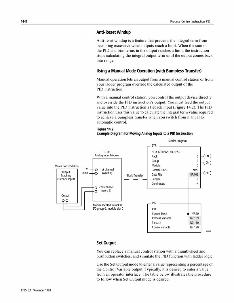
14-8 Process Control Instruction PID
Anti-Reset Windup
$QWL�UHVHW�ZLQGXS�LV�D�IHDWXUH�WKDW�SUHYHQWV�WKH�LQWHJUDO�WHUP�IURP�EHFRPLQJ�H[FHVVLYH�ZKHQ�RXWSXWV�UHDFK�D�OLPLW��:KHQ�WKH�VXP�RI�WKH�3,'�DQG�ELDV�WHUPV�LQ�WKH�RXWSXW�UHDFKHV�D�OLPLW��WKH�LQVWUXFWLRQ�VWRSV�FDOFXODWLQJ�WKH�LQWHJUDO�RXWSXW�WHUP�XQWLO�WKH�RXWSXW�FRPHV�EDFN�LQWR�UDQJH�
Using a Manual Mode Operation (with Bumpless Transfer)
0DQXDO�RSHUDWLRQ�OHWV�DQ�RXWSXW�IURP�D�PDQXDO�FRQWURO�VWDWLRQ�RU�IURP�\RXU�ODGGHU�SURJUDP�RYHUULGH�WKH�FDOFXODWHG�RXWSXW�RI�WKH�3,' LQVWUXFWLRQ�
:LWK�D�PDQXDO�FRQWURO�VWDWLRQ��\RX�FRQWURO�WKH�RXWSXW�GHYLFH�GLUHFWO\�DQG�RYHUULGH�WKH�3,'�LQVWUXFWLRQ¶V�RXWSXW��<RX�PXVW�IHHG�WKH�RXWSXW�YDOXH�LQWR�WKH�3,'�LQVWUXFWLRQ¶V�WLHEDFN�LQSXW��)LJXUH��������7KH�3,'�LQVWUXFWLRQ�XVHV�WKLV�YDOXH�WR�FDOFXODWH�WKH�LQWHJUDO�WHUP�YDOXH�UHTXLUHG�WR�DFKLHYH�D�EXPSOHVV�WUDQVIHU�ZKHQ�\RX�VZLWFK�IURP�PDQXDO�WR�DXWRPDWLF�FRQWURO�
Figure 14.2 Example Diagram for Moving Analog Inputs to a PID Instruction
Set Output
<RX�FDQ�UHSODFH�D�PDQXDO�FRQWURO�VWDWLRQ�ZLWK�D�WKXPEZKHHO�DQG�SXVKEXWWRQ�VZLWFKHV��DQG�VLPXODWH�WKH�3,'�IXQFWLRQ�ZLWK�ODGGHU�ORJLF�
8VH�WKH�6HW�2XWSXW�PRGH�WR�HQWHU�D�YDOXH�UHSUHVHQWLQJ�D�SHUFHQWDJH�RI�WKH�&RQWURO�9DULDEOH�RXWSXW��7\SLFDOO\��LW�LV�GHVLUHG�WR�HQWHU�D�YDOXH�IURP�DQ�RSHUDWRU�LQWHUIDFH��7KH�WDEOH�EHORZ�LOOXVWUDWHV�WKH�SURFHGXUH�WR�IROORZ�ZKHQ�6HW�2XWSXW�PRGH�LV�GHVLUHG�
15297
ENBLOCK TRANSFER READRackGroup
ModuleControl Block
00
0N7:0
DN
Data FileLength
N7:1096
ER
BTR
Continuous N
PIDControl blockProcess Variable
TiebackControl variable
N7:20N7:109
N7:110N7:120
PID
OutputTracking
(Tieback Input)
Output
12-bitAnalog Input Module
PVInput
1st channel(word 1)
2nd channel(word 2)
Module located in rack 0,I/O group 0, module slot 0
Block Transfer
Ladder Program
Main Control Station
1785-6.1 November 1998

Process Control Instruction PID 14-9
Table 14.A Set Output Mode Procedure
,I�WKH�VHW�RXWSXW�YDOXH�LV�JUHDWHU�WKDQ�WKH�XSSHU�&9�OLPLW�RU�ORZHU�WKDQ�WKH�ORZHU�&9�OLPLW�DQG�RXWSXW�OLPLWLQJ�LV�HQDEOHG�DQG�WKH�3,'�LQVWUXFWLRQ�LV�LQ�6HW�2XWSXW�PRGH��WKH�SURFHVVRU�XVHV�WKH�DFWXDO�RXWSXW��QRW�WKH�VHW�RXWSXW�YDOXH��WR�FDOFXODWH�WKH�LQWHJUDO�DFFXPXODWRU�WHUP�IRU�FDOFXODWLQJ�EXPSOHVV�WUDQVIHU�
Feedforward or Output Biasing <RX�FDQ�IHHGIRUZDUG�D�GLVWXUEDQFH�IURP�WKH�V\VWHP�RU�ELDV�RXWSXW�E\�IHHGLQJ�HLWKHU�RI�WKHVH�YDOXHV�LQWR�WKH�3,'�LQVWUXFWLRQ¶V�IHHGIRUZDUG�ELDV�ZRUG��ZRUG���3'�%,$6��RI�WKH�FRQWURO�EORFN��(LWKHU�YDOXH�PXVW�KDYH�D�UDQJH�RI�±�����WR��������LQWHJHU��RU�±�������WR����������IORDWLQJ�SRLQW��
7KH�IHHGIRUZDUG�YDOXH�UHSUHVHQWV�D�GLVWXUEDQFH�IHG�LQWR�WKH�3,'�LQVWUXFWLRQ�EHIRUH�WKH�GLVWXUEDQFH�KDV�D�FKDQFH�WR�FKDQJH�WKH�SURFHVV�YDULDEOH��)HHGIRUZDUG�LV�RIWHQ�XVHG�WR�FRQWURO�SURFHVVHV�ZLWK�D�WUDQVSRUWDWLRQ�ODJ��)RU�H[DPSOH��D�IHHGIRUZDUG�YDOXH�UHSUHVHQWLQJ�³FROG�ZDWHU�SRXUHG�LQWR�D�ZDUP�PL[´�FRXOG�ERRVW�WKH�RXWSXW�IDVWHU�WKDQ�ZDLWLQJ�IRU�WKH�SURFHVV�YDULDEOH�WR�FKDQJH�DV�D�UHVXOW�RI�PL[LQJ�
$�ELDV�YDOXH�FDQ�EH�XVHG�WR�FRPSHQVDWH�IRU�D�VWHDG\�VWDWH�ORVV�RI�HQHUJ\�IURP�WKH�FRQWUROOHG�SURFHVV�
Resume Last State :LWK�WKH�UHVXPH�ODVW�VWDWH�IXQFWLRQ��\RX�FDQ�PDNH�IXOO�XVH�RI�WKH�DQDORJ�RXWSXW�PRGXOH¶V�KROG�ODVW�VWDWH�IXQFWLRQ��7KH�UHVXPH�ODVW�VWDWH�IXQFWLRQ�OHWV�WKH�3,'�LQVWUXFWLRQ�UHVXPH�FDOFXODWLQJ�WKH�LQWHJUDO�WHUP�RI�WKH�3,'�DOJRULWKP�IURP�LWV�ODVW�RXWSXW�YDOXH��LQVWHDG�RI�]HUR��ZKHQ�UHWXUQLQJ�WR�5XQ�PRGH�
,I�\RX�DUH�XVLQJ�DQ�LQWHJHU�GDWD�ILOH�IRU�WKH�FRQWURO�EORFN��VHW�WKH�ELWV�DFFRUGLQJ�WR�WKH�JXLGHOLQHV�EHORZ��,I�\RX�DUH�XVLQJ�D�3'�GDWD�ILOH�W\SH�IRU�WKH�FRQWURO�EORFN��WKH�SURFHVVRU�VDYHV�WKH�LQWHJUDO�DFFXPXODWRU�DQG�XVHV�LW�ZKHQ�JRLQJ�IURP�3URJUDP�WR�5XQ�PRGH�
Integer Control Block (N7:0) PD Control Block (PD10:0)
Select Automatic Mode Mode:0 (0:auto/1:manual)(bit N7:0/1 = 0)
A/M Station Mode = Auto(bit PD10:0.MO = 0)
Select Set Output Mode SET OUTPUT MODE: 1 (0:no/1:yes)(bit N7:0/4 = 1)
Software A/M Mode = Manual(bit PD10:0.SWM = 1)
Note: In data monitor, MODE=AUTO changes to MODE=SW MANUAL.
Enter % in Set OutputValue (0-100%)
SET OUTPUT VALUE %(word N7:10 = %value)
SET OUTPUT %(word PD10:0.SO = % value)
1785-6.1 November 1998

14-10 Process Control Instruction PID
8VH�WKLV�IXQFWLRQ�DV�IROORZV�
� 6HW�ZRUG����ELW���LI�\RX�FRQILJXUHG�WKH�DQDORJ�RXWSXW�PRGXOH�WR�KROG�ODVW�VWDWH�LI�D�IDXOW�RFFXUV�DQG�ZKHQ�FKDQJLQJ�IURP�5XQ�WR�3URJUDP�PRGH
� 5HVHW�ZRUG����ELW���LI�\RX�FRQILJXUHG�WKH�DQDORJ�RXWSXW�PRGXOH�WR�WXUQ�RII�LI�D�IDXOW�RFFXUV�DQG�ZKHQ�FKDQJLQJ�IURP�5XQ�WR�3URJUDP�PRGH�
5HVXPH�/DVW�6WDWH�LV�DYDLODEOH�ZLWK�WKH�IROORZLQJ�SURFHVVRUV�
� (QKDQFHG�3/&���SURFHVVRUV�DOO�VHULHV�DOO�UHYV
� 3/&������VHULHV�$�UHY�&�DQG�ODWHU
� 3/&������VHULHV�%�UHY�+�DQG�ODWHU
� 3/&������VHULHV�$�UHY�'�DQG�ODWHU
PID Instruction
Description: 7KH�3,'�LQVWUXFWLRQ�LV�DQ�RXWSXW�LQVWUXFWLRQ�WKDW�FRQWUROV�SK\VLFDO�SURSHUWLHV��VXFK�DV�WHPSHUDWXUH��SUHVVXUH��OLTXLG�OHYHO��RU�IORZ�UDWH�RI�SURFHVV�ORRSV�
7KH�3,'�LQVWUXFWLRQ�FRQWUROV�D�3,'�ORRS�ZLWK�LQSXWV�IURP�DQ�DQDORJ�LQSXW�PRGXOH�DQG�DQ�RXWSXW�WR�DQ�DQDORJ�RXWSXW�PRGXOH��)RU�WHPSHUDWXUH�FRQWURO��\RX�FDQ�FRQYHUW�WKH�DQDORJ�RXWSXW�WR�D�WLPH�SURSRUWLRQLQJ�RQ�RII�RXWSXW�IRU�GULYLQJ�D�KHDWHU�RU�FRROLQJ�XQLW�
([HFXWH�WKH�3,'�LQVWUXFWLRQ�SHULRGLFDOO\�DW�FRQVWDQW�LQWHUYDOV�XVLQJ�D�WLPHU��D�VHOHFWDEOH�WLPHG�LQWHUUXSW��67,���RU�UHDO�WLPH�VDPSOLQJ��7KH�ODGGHU�SURJUDP�FDQ�LQWHUDFW�ZLWK�WKH�3,'�DOJRULWKP�E\�FKDQJLQJ�YDULDEOHV�GXULQJ�RSHUDWLRQ��RU�\RX�FDQ�FKDQJH�YDULDEOHV�IURP�D�SURJUDPPLQJ�WHUPLQDO�RU�IURP�VWDWLRQV�RQ�D�'DWD�+LJKZD\��RU�'DWD�+LJKZD\�3OXV��FRPPXQLFDWLRQV�OLQN�
7KH�3,'�LQVWUXFWLRQ�SURYLGHV�EXPSOHVV�WUDQVIHU�HYHQ�ZKHQ�QRW�XVLQJ�WKH�LQWHJUDO�JDLQ��,W�GRHV�WKLV�E\�JHQHUDWLQJ�D�ELDV�WHUP�HTXDO�WR�WKH�GLIIHUHQFH�EHWZHHQ�WKH�SURSRUWLRQDO�WHUP�DQG�WKH�PDQXDOO\�DGMXVWHG�RXWSXW�DV�IROORZV�
,I�\RX�VHOHFW�PDQXDO�PRGH�ZLWK�WLHEDFN�%,$6� ��7,(%$&.�±�3WHUP�±�'WHUP
,I�\RX�VHOHFW�PDQXDO�PRGH�ZLWK�VHWRXWSXW�%,$6� ��6(7287387�PRGH�±�3WHUP�±�'WHUP
�$77(17,21� ,I�\RX�ZDQW�WR�XVH�WKLV�IXQFWLRQ��VHW�ELW���RQO\�DIWHU�WKH�3,'�LQVWUXFWLRQ�KDV�H[HFXWHG�DW�OHDVW�RQFH��DW�VWDUW�XS��RU�ZKHQ�UHWXUQLQJ�WR�5XQ�PRGH��,I�\RX�GR�QRW�OHW�WKH�3,'�LQVWUXFWLRQ�H[HFXWH�DW�OHDVW�RQFH��XQSUHGLFWDEOH�PDFKLQH�RSHUDWLRQ�PD\�RFFXU�FDXVLQJ�SRVVLEOH�GDPDJH�WR�HTXLSPHQW�DQG�RU�LQMXU\�WR�SHUVRQQHO�
PID
PID
Control BlockProcess variable
Tieback
Control variable
1785-6.1 November 1998
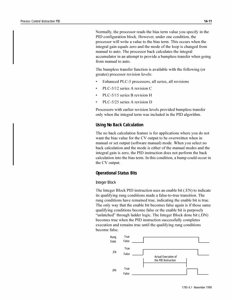
Process Control Instruction PID 14-11
1RUPDOO\��WKH�SURFHVVRU�UHDGV�WKH�ELDV�WHUP�YDOXH�\RX�VSHFLI\�LQ�WKH�3,'�FRQILJXUDWLRQ�EORFN��+RZHYHU��XQGHU�RQH�FRQGLWLRQ��WKH�SURFHVVRU�ZLOO�ZULWH�D�YDOXH�WR�WKH�ELDV�WHUP��7KLV�RFFXUV�ZKHQ�WKH�LQWHJUDO�JDLQ�HTXDOV�]HUR�DQG�WKH�PRGH�RI�WKH�ORRS�LV�FKDQJHG�IURP�PDQXDO�WR�DXWR��7KH�SURFHVVRU�EDFN�FDOFXODWHV�WKH�LQWHJUDO�DFFXPXODWRU�LQ�DQ�DWWHPSW�WR�SURYLGH�D�EXPSOHVV�WUDQVIHU�ZKHQ�JRLQJ�IURP�PDQXDO�WR�DXWR�
7KH�EXPSOHVV�WUDQVIHU�IXQFWLRQ�LV�DYDLODEOH�ZLWK�WKH�IROORZLQJ��RU�JUHDWHU��SURFHVVRU�UHYLVLRQ�OHYHOV�
� (QKDQFHG�3/&���SURFHVVRUV��DOO�VHULHV��DOO�UHYLVLRQV
� 3/&������VHULHV�$�UHYLVLRQ�&
� 3/&������VHULHV�%�UHYLVLRQ�+
� 3/&������VHULHV�$�UHYLVLRQ�'
3URFHVVRUV�ZLWK�HDUOLHU�UHYLVLRQ�OHYHOV�SURYLGHG�EXPSOHVV�WUDQVIHU�RQO\�ZKHQ�WKH�LQWHJUDO�WHUP�ZDV�LQFOXGHG�LQ�WKH�3,'�DOJRULWKP�
Using No Back Calculation
7KH�QR�EDFN�FDOFXODWLRQ�IHDWXUH�LV�IRU�DSSOLFDWLRQV�ZKHUH�\RX�GR�QRW�ZDQW�WKH�ELDV�YDOXH�IRU�WKH�&9�RXWSXW�WR�EH�RYHUZULWWHQ�ZKHQ�LQ�PDQXDO�RU�VHW�RXWSXW��VRIWZDUH�PDQXDO��PRGH��:KHQ�\RX�VHOHFW�QR�EDFN�FDOFXODWLRQ�DQG�WKH�PRGH�LV�HLWKHU�RI�WKH�PDQXDO�PRGHV�DQG�WKH�LQWHJUDO�JDLQ�LV�]HUR��WKH�3,'�LQVWUXFWLRQ�GRHV�QRW�SHUIRUP�WKH�EDFN�FDOFXODWLRQ�LQWR�WKH�ELDV�WHUP��,Q�WKLV�FRQGLWLRQ��D�EXPS�FRXOG�RFFXU�LQ�WKH�&9�RXWSXW�
Operational Status Bits
Integer Block
7KH�,QWHJHU�%ORFN�3,'�LQVWUXFWLRQ�XVHV�DQ�HQDEOH�ELW���(1��WR�LQGLFDWH�LWV�TXDOLI\LQJ�UXQJ�FRQGLWLRQV�PDGH�D�IDOVH�WR�WUXH�WUDQVLWLRQ��7KH�UXQJ�FRQGLWLRQV�KDYH�UHPDLQHG�WUXH��LQGLFDWLQJ�WKH�HQDEOH�ELW�LV�WUXH��7KH�RQO\�ZD\�WKDW�WKH�HQDEOH�ELW�EHFRPHV�IDOVH�DJDLQ�LV�LI�WKRVH�VDPH�TXDOLI\LQJ�FRQGLWLRQV�EHFRPH�IDOVH�RU�WKH�HQDEOH�ELW�LV�SXUSRVHO\�³XQODWFKHG´�WKURXJK�ODGGHU�ORJLF��7KH�,QWHJHU�%ORFN�GRQH�ELW���'1��EHFRPHV�WUXH�ZKHQ�WKH�3,'�LQVWUXFWLRQ�VXFFHVVIXOO\�FRPSOHWHV�H[HFXWLRQ�DQG�UHPDLQV�WUXH�XQWLO�WKH�TXDOLI\LQJ�UXQJ�FRQGLWLRQV�EHFRPH�IDOVH�
Actual Execution of the PID Instruction
TrueFalse
True
False
True
False
RungState
.EN
.DN
1785-6.1 November 1998

14-12 Process Control Instruction PID
PD Block
7KH�3'�%ORFN�3,'�LQVWUXFWLRQ�KDV�RQO\�DQ�HQDEOH�ELW���(1��WR�LQGLFDWH�RSHUDWLRQDO�VWDWXV��7KLV�ELW�LQGLFDWHV�WKDW�LWV�TXDOLI\LQJ�UXQJ�FRQGLWLRQV�DUH�WUXH��LQ�ZKLFK�FDVH�WKH�HQDEOH�ELW�LV�WUXH��D�IDOVH�WR�WUXH�WUDQVLWLRQ�LV�QRW�QHHGHG���7KH�RQO\�ZD\�WKH�HQDEOH�ELW�EHFRPHV�IDOVH�DJDLQ�LV�LI�WKHVH�VDPH�TXDOLI\LQJ�FRQGLWLRQV�EHFRPH�IDOVH��7KH�3'�EORFN�GRHV�QRW�XVH�D�GRQH�ELW�
,PSRUWDQW���8QOLNH�WKH�,QWHJHU�%ORFN�YHUVLRQ��WKH�3'�%ORFN�3,'�H[HFXWHV�DJDLQ�LI�WKH�SURJUDP�VFDQ�HQFRXQWHUV�WKLV�UXQJ�DJDLQ�ZKLOH�WKH�UXQJ�VWDWH�LV�VWLOO�WUXH�
Entering Parameters
:KHQ�\RX�HQWHU�WKH�LQVWUXFWLRQ��\RX�PXVW�VSHFLI\�IRXU�DGGUHVVHV�WKDW�DUH�IXQGDPHQWDO�WR�WKH�RSHUDWLRQ�RI�WKH�LQVWUXFWLRQ��$IWHU�\RX�HQWHU�WKHVH�DGGUHVVHV��WKH�SURJUDPPLQJ�VRIWZDUH�GLVSOD\V�D�VFUHHQ�IURP�ZKLFK�\RX�HQWHU�WKH�RSHUDWLQJ�SDUDPHWHUV�RI�WKH�LQVWUXFWLRQ�
7KH�XVH�RI�LQWHJHU�FRQWURO�EORFNV�YHUVXV�3'�FRQWURO�EORFNV�GHSHQGV�RQ�\RXU�SURFHVVRU��,I�\RX�DUH�XVLQJ�D�&ODVVLF�3/&���SURFHVVRU��WKH�3'�FRQWURO�EORFN�LV�QRW�DYDLODEOH��,Q�WKH�(QKDQFHG�3/&���SURFHVVRUV��ERWK�WKH�1�DQG�3'�FRQWURO�EORFNV�DUH�DYDLODEOH��7KH�3'�FRQWURO�EORFN�JLYHV�\RX�PRUH�IOH[LELOLW\��L�H���IORDWLQJ�SRLQW�YDULDEOHV��KLJKHU�UHVROXWLRQ�±����ELW�YHUVXV����ELW��
Actual Execution of the PID Instruction
True
False
True
False
RungState
.EN
1785-6.1 November 1998
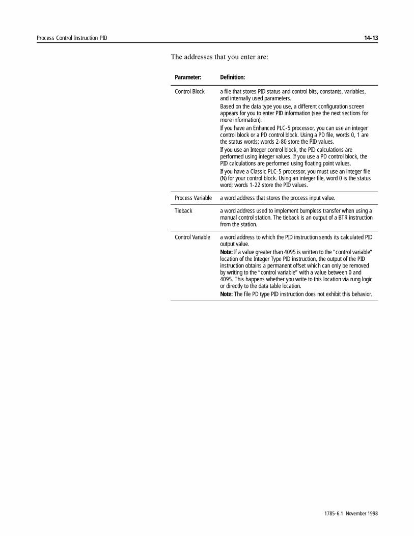
Process Control Instruction PID 14-13
7KH�DGGUHVVHV�WKDW�\RX�HQWHU�DUH�
Parameter: Definition:
Control Block a file that stores PID status and control bits, constants, variables, and internally used parameters.Based on the data type you use, a different configuration screen appears for you to enter PID information (see the next sections for more information).If you have an Enhanced PLC-5 processor, you can use an integer control block or a PD control block. Using a PD file, words 0, 1 are the status words; words 2-80 store the PID values.If you use an Integer control block, the PID calculations are performed using integer values. If you use a PD control block, the PID calculations are performed using floating point values.If you have a Classic PLC-5 processor, you must use an integer file (N) for your control block. Using an integer file, word 0 is the status word; words 1-22 store the PID values.
Process Variable a word address that stores the process input value.
Tieback a word address used to implement bumpless transfer when using a manual control station. The tieback is an output of a BTR instruction from the station.
Control Variable a word address to which the PID instruction sends its calculated PID output value.Note: If a value greater than 4095 is written to the “control variable” location of the Integer Type PID instruction, the output of the PID instruction obtains a permanent offset which can only be removed by writing to the “control variable” with a value between 0 and 4095. This happens whether you write to this location via rung logic or directly to the data table location.Note: The file PD type PID instruction does not exhibit this behavior.
1785-6.1 November 1998

14-14 Process Control Instruction PID
Using an Integer Data File Type for the Control Block
:KHQ�XVLQJ�DQ�LQWHJHU�GDWD�ILOH�W\SH�IRU�WKH�FRQWURO�EORFN��WKH�GDWD�PRQLWRU�VFUHHQ�IRU�WKH�3,'�LQVWUXFWLRQ�VKRZV�WKH�IROORZLQJ�LQIRUPDWLRQ��VRPH�RI�ZKLFK�LV�GLVSOD\�RQO\��VRPH�RI�ZKLFK�\RX�VSHFLI\�WKH�YDOXHV��7DEOH����%��
Table 14.B PID Parameter Descriptions (Integer Control Block)
Parameter: Description:
Equation Enter whether you want to use independent (0) or dependent (1) gains. Displays one of the following:
INDEPENDENT (0) – for independent gainsDEPENDENT (1) – for dependent gains (ISA)
Use dependent gains when you want to use standard loop tuning methods. Use independent gains when you want the three gain constants (P, I, and D) to operate independently.
Mode Displays operating mode:
AUTO (0) – automatic PID controlMANUAL (1) – control from a manual control station
Sets the use of the tieback parameter for manual operation
Error Displays one of the following error value:Reverse acting: 0 = SP-PVDirect acting: 1 = PV-SP
Output Limiting Displays whether or not the instruction clamps the output at the high and low limiting values. Displays one of the following:
NO (0) – output not clampedYES (1) – output clamped
The PID algorithm has an anti-reset windup feature that prevents the integral term from becoming too large when the output reaches the high or low alarm limits. If the limits are reached, the algorithm stops calculating the integral term until the output comes back into range.
Set output mode Selects the use of set output value % for manual operation
Setpoint scaling Selects if the setpoint is to be interpreted as a value in the engineering units or an unscaled (0 to 4095) value
Derivative input Selects if derivative term is based on changes in PV or on changes in error
Last state resume Selects if you want to resume last state or hold last state
(Continued)
1785-6.1 November 1998

Process Control Instruction PID 14-15
Deadband status Set if the PV is inside the selected deadband range; reset if it is not
Upper CV limit alarm Set if calculated CV is greater than the CV upper limit word %
Lower CV limit alarm Set if calculated CV is less than the CV lower limit word %
Setpoint out of range Displays whether or not the setpoint is out of the range of engineering units you selected on the PID Configuration screen. Displays one of the following:
NO (0) – SP within rangeYES (1) – SP out of range
Note: A major processor fault occurs if the SP is out of range when the instruction is first enabled.
PID done Displays whether the PID instruction has completed (1 = done; 0 = not done).
PID enabled Displays whether the PID instruction is enabled (1 = enabled; 0 = not enabled).
Feed forward Enter a value between –4095 and 4095 for the amount of feed forward. The ladder program can enter a feedforward value to bump the output in anticipation of a disturbance. This value is often used to control a process with transportation lag.
Max scaled input Enter the integer number (–32,768 - 32,767) that is the maximum value available from the analog module. For example, use 4095 for a module whose range is 0-4095.
Min scaled input Enter the number that is the minimum value available from the analog module. For example, use 0 for a module whose range is 0 to 4095.
Dead band For an unscaled deadband, enter a value in the engineering units you selected on the PID Configuration screen. Valid range is 0 to 4095 unscaled, –32,768 to +32,767 scaled.Note: The deadband is zero crossing.
Set output value % Enter a percent (0-100%) to use as the CV Output when ‘set output mode’ is selected.
Upper CV limit % Enter a percent (0-100) above which the algorithm clamps the output.
Lower CV limit % Enter a percent (0-100) below which the algorithm clamps the output.
Scaled PV value Displays data from the analog input module that the instruction scales to the same engineering units that you selected for the setpoint.
Scaled error Displays the current error in scaled engineering units
Current CV % Displays current controlled variable output value as a percent
Setpoint Enter an integer. Valid range is 0 to 4095 (unscaled) or Smin- Smax (scaled engineering units).
Proportional gain (Kc)
Enter an integer. Valid entry range is 0-32,767 (unitless) or Kp 0-32,767. The processor divides the entry value by 100 for calculations.
Reset time (Ti) minutes/repeat
Enter an integer. Valid entry range for Ti is 0-32,767 (minutes times 100). The processor automatically divides the entry value by 100 for calculations.Valid entry range for Ki is 0-32,767 (inverse seconds times 1000). The processor automatically divides the entry by 1000 for calculations.
(Continued)
Parameter: Description:
1785-6.1 November 1998

14-16 Process Control Instruction PID
Using Control Block Values
:RUG���RI�WKH�FRQWURO�EORFN�FRQWDLQV�VWDWXV�DQG�FRQWURO�ELWV��7DEOH����&�VKRZV�WKH�YDOXHV�VWRUHG�LQ�HDFK�ZRUG�RI�WKH�FRQWURO�EORFN�
Table 14.C PID Control Block (Integer Control Block)
Derivative rate (Td) Enter an integer. Valid entry range is 0-32,767 or KD 0-32,767. The processor divides the entry value by 100 for calculations.
Loop update time Enter an update time (greater than or equal to 0.01 seconds) at 1/5 to 1/10 times the natural period of the load (load time constant). Valid entry range is 1-32,767 seconds. The processor divides the entry value by 100 for calculations. The load time constant should be greater than:
1ms(algorithm) + block transfer time (ms)Periodically enable the PID instruction at a constant interval equal to the update time. For update times of less than 100 msec, use an STI. When update times are greater than 100 msec, use a timer or a real-time sampling.Note: If you omit an update time or enter a negative update time, a major fault occurs the first time the processor runs the PID instruction.
Parameter: Description:
Word: Contains: Term: Entry Range:
0 Bit 15 Enabled (EN)Bit 13 Done (DN)Bit 11 Set point out of rangeBit 10 Output alarm, lower limitBit 9 Output alarm, upper limitBit 8 DB, set when error is in deadbandBit 7 Resume last state (0=yes; 1=hold last state)Bit 6 Derivative action (0=PV, 1=error)Bit 5 Setpoint descaling (0=no, 1=yes)Bit 4 Set output (0=no, 1=yes)Bit 3 Output limiting (0=no, 1=yes)Bit 2 Control (0=reverse, 1=direct)Bit 1 Mode (0=automatic, 1=manual)Bit 0 Equation (0=independent, 1=ISA)Note: During prescan, bits 8, 9, 10, in addition to the Integral Accumulator and Derivative Error values, are cleared and the error register value of previous scans is set to 32,767.
1 reserved
2 Setpoint SP 0-4095 (unscaled) Smin–Smax (scaled)
Note: Terms marked with an asterisk (*) are entered as Yy × 100. The term itself is Yy. The term marked with a double asterisk (**) is entered as Yy × 1000. The term itself is Yy.
(Continued)
1785-6.1 November 1998

Process Control Instruction PID 14-17
3 Independent: Proportional gain x 100 (unitless) Kp* 0-32,767
ISA: Controller gain x 100 (unitless) Kc* 0-32,767
4 Independent: Integral gain x 1000 (1/sec) Ki** 0-32,767
ISA: Reset term x 100 (minutes per repeat) Ti* 0-32,767
5 Independent: Derivative gain x 100 (seconds) Kd* 0-32,767
ISA: Rate term x100 (minutes) Td* 0-32,767
6 Feedforward or bias FF/Bias –4095-+4095
7 Maximum scaling Smax –32,768-+32,767
8 Minimum scaling Smin –32,768-+32,767
9 Dead band DB 0-4095 (unscaled) Smin–Smax (scaled)
10 Set output SETOUT 0-100%
11 Maximum output limit (% of output) Lmax 0-100%
12 Minimum output limit (% of output) Lmin 0-100%
13 Loop update time x 100 (seconds) dt 0-32,767
14 Scaled PV value (displayed) Smin–Smax
15 Scaled error value (displayed) Smin–Smax
16 Output (% of 4095) CV 0-100%
17-22 internal storage; do not use
Note: Terms marked with an asterisk (*) are entered as Yy × 100. The term itself is Yy. The term marked with a double asterisk (**) is entered as Yy × 1000. The term itself is Yy.
Word: Contains: Term: Entry Range:
1785-6.1 November 1998
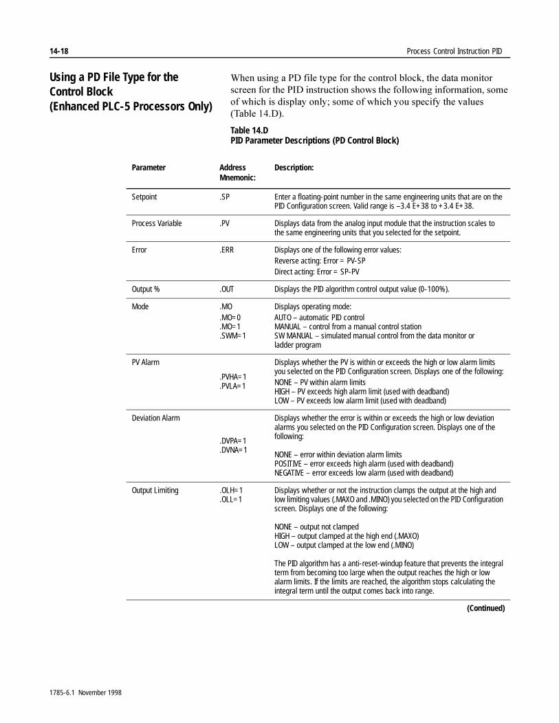
14-18 Process Control Instruction PID
Using a PD File Type for the Control Block (Enhanced PLC-5 Processors Only)
:KHQ�XVLQJ�D�3'�ILOH�W\SH�IRU�WKH�FRQWURO�EORFN��WKH�GDWD�PRQLWRU�VFUHHQ�IRU�WKH�3,'�LQVWUXFWLRQ�VKRZV�WKH�IROORZLQJ�LQIRUPDWLRQ��VRPH�RI�ZKLFK�LV�GLVSOD\�RQO\��VRPH�RI�ZKLFK�\RX�VSHFLI\�WKH�YDOXHV�7DEOH����'��
Table 14.D PID Parameter Descriptions (PD Control Block)
Parameter AddressMnemonic:
Description:
Setpoint .SP Enter a floating-point number in the same engineering units that are on the PID Configuration screen. Valid range is –3.4 E+38 to +3.4 E+38.
Process Variable .PV Displays data from the analog input module that the instruction scales to the same engineering units that you selected for the setpoint.
Error .ERR Displays one of the following error values: Reverse acting: Error = PV-SPDirect acting: Error = SP-PV
Output % .OUT Displays the PID algorithm control output value (0-100%).
Mode .MO.MO=0.MO=1.SWM=1
Displays operating mode:AUTO – automatic PID controlMANUAL – control from a manual control stationSW MANUAL – simulated manual control from the data monitor or ladder program
PV Alarm
.PVHA=1
.PVLA=1
Displays whether the PV is within or exceeds the high or low alarm limits you selected on the PID Configuration screen. Displays one of the following:NONE – PV within alarm limitsHIGH – PV exceeds high alarm limit (used with deadband)LOW – PV exceeds low alarm limit (used with deadband)
Deviation Alarm
.DVPA=1
.DVNA=1
Displays whether the error is within or exceeds the high or low deviation alarms you selected on the PID Configuration screen. Displays one of the following:
NONE – error within deviation alarm limitsPOSITIVE – error exceeds high alarm (used with deadband)NEGATIVE – error exceeds low alarm (used with deadband)
Output Limiting .OLH=1.OLL=1
Displays whether or not the instruction clamps the output at the high and low limiting values (.MAXO and .MINO) you selected on the PID Configuration screen. Displays one of the following:
NONE – output not clampedHIGH – output clamped at the high end (.MAXO)LOW – output clamped at the low end (.MINO)
The PID algorithm has a anti-reset-windup feature that prevents the integral term from becoming too large when the output reaches the high or low alarm limits. If the limits are reached, the algorithm stops calculating the integral term until the output comes back into range.
(Continued)
1785-6.1 November 1998

Process Control Instruction PID 14-19
SP Out of Range .SPOR=0.SPOR=1
Displays whether or not the setpoint is out of the range of engineering units you selected on the PID Configuration screen. Displays one of the following:
NO – SP within rangeYES – SP out of range
Note: A major processor fault occurs if the SP is out of range when the instruction is first enabled.
Error Within DB .EWD=0.EWD=1
Displays whether the error is within or exceeds the deadband value you enter on this screen. The deadband is zero crossing. Displays one of the following:
RESET – Error exits the deadband zoneSET – Error crosses the deadband centerline
PID Initialized .INI=0.INI=1
Each time you change a value in the control block, the PID instruction takes over twice as long to execute (until initialized) on the first scan. Displays one of the following:
NO – PID instruction not initialized after you changed control block valuesYES – PID instruction remains initialized because you did not change any control block values
Attention: Do not change the range of input or engineering units when running. If you must do this, then you must reset this bit to re-initialize. Otherwise, the instruction will malfunction with possible damage to equipment and injury to personnel.
A/M Station Mode .MO=0.MO=1
Enter whether you want automatic (0) or manual (1) PID control. Displays one of the following:
AUTO (0) – automatic PID controlMANUAL (1) – manual PID control
Manual control specified that an output from a manual control station overrides the calculated output of the PID algorithm.
Note: Manual overrides Set Output Mode.
Software A/M Mode .SWM=0.SWM=1
Enter whether you want automatic PID (0) control or Set Output Mode (1), for software-simulated control. Displays one of the following:
AUTO (0) – automatic PID controlSW MANUAL (1) – software-simulated PID control
You can simulate a manual control station with the data monitor when you program a single loop. To do this, set .SWM to SW MANUAL and enter a Set Output Percent value.
You can simulate a manual control station with ladder logic, pushwheels, and pushbutton switches when you program several loops. To do this, set .SWM to SW MANUAL and move a value into the set output element .SO.
(Continued)
Parameter AddressMnemonic:
Description:
1785-6.1 November 1998

14-20 Process Control Instruction PID
Status Enable .EN=0.EN=1
Enter whether to use (1) or inhibit (0) this bit which displays the rung condition so you can see whether the PID instruction is operating. Displays one of the following:
0 – instruction not executing1 – instruction executing
Proportional Gain .KP Enter a floating-point value. Valid range for independent or standard gains is 0 to 3.4 E+38 (unitless).
Integral Gain .KI Enter a floating-point value. Valid range for independent gains is 0 to 3.4 E+38 inverse seconds; valid range for standard gains is 0 to 3.4 E+38 minutes per repeat.
Derivative Gain .KD Enter a floating-point value. Valid range for independent gains is 0 to 3.4 E+38 seconds; valid range for standard gains is 0 to 3.4E+38 minutes.
Output Bias % .BIAS Enter a value (–100 to +100) to represent the percentage of output you want to feed forward or use as a bias to the output. The bias value can compensate for steady-loss of energy from the system.
The ladder program can enter a feedforward value to bump the output in anticipation of a disturbance. This value is often used to control a process with transportation lag.
Tieback % .TIE Displays a number (0 to 100) representing the percent of raw tieback (0 – 4095) from the manual control station. The PID algorithm uses this number to achieve bumpless transfer when switching from manual to auto mode.
Set Output % .SO Enter a percent (0 to 100), from this screen or a ladder program, to represent the software-manually controlled output.When you select software-simulated control (.SWM=1), the PID instruction overrides the algorithm with the set output value (0 - 4095) for transfer to the output module, and copies it to .OUT for display as a percent. The transfer to software-simulated control is bumpless because .SO (under your control) starts with the last automatic algorithm output. Do not vary .SO until after the transfer.To achieve bumpless transfer when changing from software-simulated control to automatic control, the PID algorithm changes the integral term so that the output is equal to the set output value.
Parameter AddressMnemonic:
Description:
1785-6.1 November 1998

Process Control Instruction PID 14-21
:KHQ�XVLQJ�D�3'�ILOH�W\SH�IRU�WKH�FRQWURO�EORFN��WKH�GDWD�PRQLWRU�VFUHHQ�IRU�WKH�3,'�LQVWUXFWLRQ�SURYLGHV�DFFHVV�WR�D�3,'�FRQILJXUDWLRQ�VFUHHQ��)URP�WKH�3,'�FRQILJXUDWLRQ�VFUHHQ��\RX�FDQ�GHILQH�WKH�IROORZLQJ�FKDUDFWHULVWLFV�RI�WKH�3,'�LQVWUXFWLRQ��7DEOH����(��
Table 14.E PID Configuration Descriptions (PD Control Block)
Parameter: Address Mnemonic:
Description:
PID Equation .PE=0.PE=1
Enter whether you want to use independent (0) or dependent (1) gains. Displays one of the following:
INDEPENDENT (0) – for independent gainsDEPENDENT (1) – for dependent gains
Use dependent gains when you want to use standard loop tuning methods. Use independent gains when you want the three gain constants (P, I, and D) to operate independently.
Derivative of .DO=0.DO=1
Enter whether you want the derivative of the PV (0) or the error (1). Displays one of the following:
PV (0) – for PV derivativeERROR (1) – for error derivative
Select the PV derivative for more stable control when you do not change the setpoint often. Select the error derivative for fast responses to setpoint changes when the algorithm can tolerate overshoots.
Control Action .CA=0.CA=1
Enter whether you want reverse (0) or direct acting (1). Displays one of the following:
REVERSE (0) – for reverse acting (E = SP-PV)DIRECT (1) – for direct acting (E = PV-SP)
PV Tracking .PVT=0.PVT=1
Enter whether you do not (0) or do (1) want PV tracking. Displays one of the following:
NO (0) – for no trackingYES (1) – for PV tracking
Select no tracking if the algorithm can tolerate a bump when switching from manual to automatic control. Select PV tracking if you want the setpoint to track the PV in manual control for bumpless transfer to automatic control.
Update Time .UPD Enter an update time (greater than or equal to .01 seconds) at 1/5 to 1/10 the natural period of the load (load time constant). The load time constant should be greater than:
3ms(algorithm) + block transfer time (ms)
Periodically enable the PID instruction at a constant interval equal to the update time. When the program scan time is close to the required update time, use an STI to ensure a constant update interval. When the program scan is several times faster than the required update time, use a timer.
Attention: If you omit an update time or enter a negative update time, a major fault occurs the first time the processor runs the PID instruction.
(Continued)
1785-6.1 November 1998
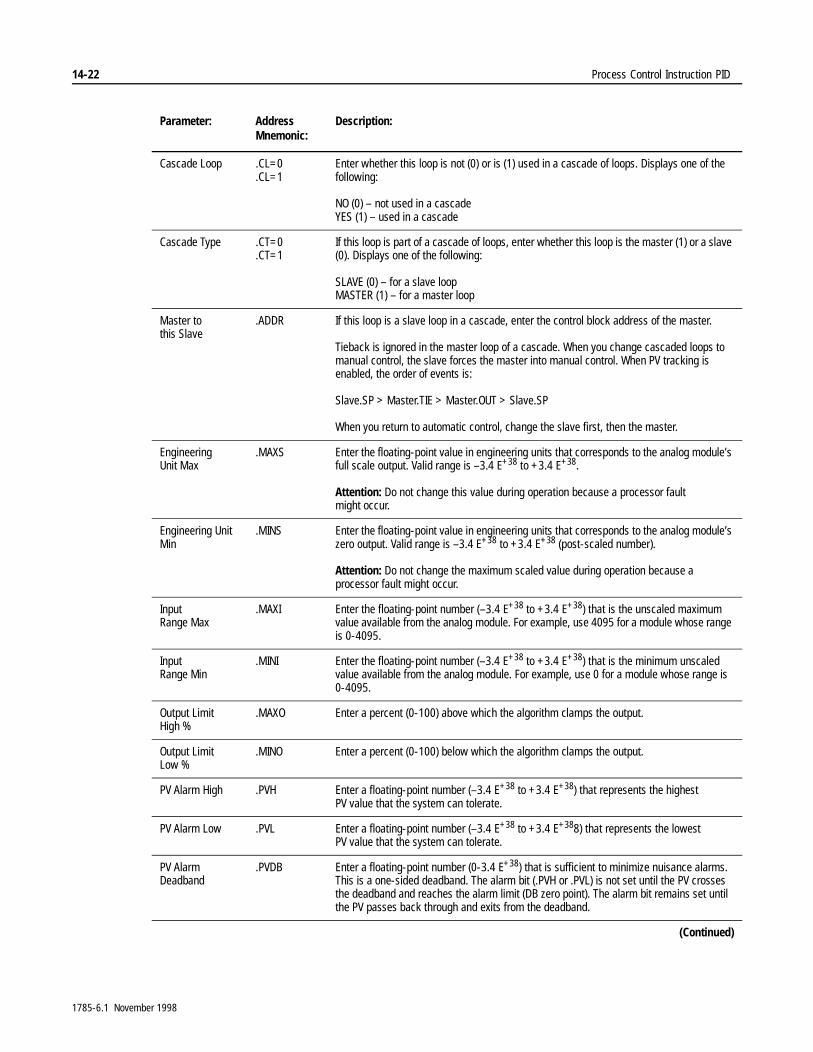
14-22 Process Control Instruction PID
Cascade Loop .CL=0.CL=1
Enter whether this loop is not (0) or is (1) used in a cascade of loops. Displays one of the following:
NO (0) – not used in a cascadeYES (1) – used in a cascade
Cascade Type .CT=0.CT=1
If this loop is part of a cascade of loops, enter whether this loop is the master (1) or a slave (0). Displays one of the following:
SLAVE (0) – for a slave loopMASTER (1) – for a master loop
Master to this Slave
.ADDR If this loop is a slave loop in a cascade, enter the control block address of the master.
Tieback is ignored in the master loop of a cascade. When you change cascaded loops to manual control, the slave forces the master into manual control. When PV tracking is enabled, the order of events is:
Slave.SP > Master.TIE > Master.OUT > Slave.SP
When you return to automatic control, change the slave first, then the master.
Engineering Unit Max
.MAXS Enter the floating-point value in engineering units that corresponds to the analog module’s full scale output. Valid range is –3.4 E+38 to +3.4 E+38.
Attention: Do not change this value during operation because a processor fault might occur.
Engineering Unit Min
.MINS Enter the floating-point value in engineering units that corresponds to the analog module’s zero output. Valid range is –3.4 E+38 to +3.4 E+38 (post-scaled number).
Attention: Do not change the maximum scaled value during operation because a processor fault might occur.
Input Range Max
.MAXI Enter the floating-point number (–3.4 E+38 to +3.4 E+38) that is the unscaled maximum value available from the analog module. For example, use 4095 for a module whose range is 0-4095.
Input Range Min
.MINI Enter the floating-point number (–3.4 E+38 to +3.4 E+38) that is the minimum unscaled value available from the analog module. For example, use 0 for a module whose range is 0-4095.
Output Limit High %
.MAXO Enter a percent (0-100) above which the algorithm clamps the output.
Output Limit Low %
.MINO Enter a percent (0-100) below which the algorithm clamps the output.
PV Alarm High .PVH Enter a floating-point number (–3.4 E+38 to +3.4 E+38) that represents the highest PV value that the system can tolerate.
PV Alarm Low .PVL Enter a floating-point number (–3.4 E+38 to +3.4 E+388) that represents the lowest PV value that the system can tolerate.
PV Alarm Deadband
.PVDB Enter a floating-point number (0-3.4 E+38) that is sufficient to minimize nuisance alarms. This is a one-sided deadband. The alarm bit (.PVH or .PVL) is not set until the PV crosses the deadband and reaches the alarm limit (DB zero point). The alarm bit remains set until the PV passes back through and exits from the deadband.
(Continued)
Parameter: Address Mnemonic:
Description:
1785-6.1 November 1998
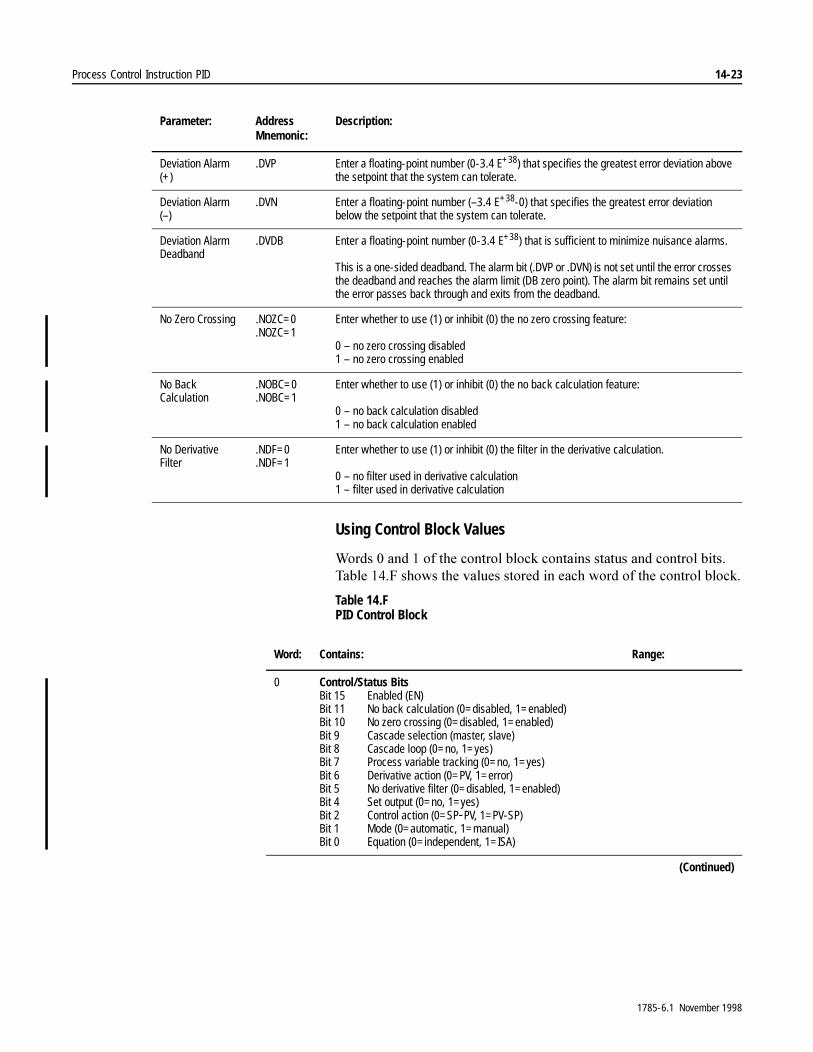
Process Control Instruction PID 14-23
Using Control Block Values
:RUGV���DQG���RI�WKH�FRQWURO�EORFN�FRQWDLQV�VWDWXV�DQG�FRQWURO�ELWV��7DEOH����)�VKRZV�WKH�YDOXHV�VWRUHG�LQ�HDFK�ZRUG�RI�WKH�FRQWURO�EORFN�
Table 14.F PID Control Block
Deviation Alarm (+)
.DVP Enter a floating-point number (0-3.4 E+38) that specifies the greatest error deviation above the setpoint that the system can tolerate.
Deviation Alarm (–)
.DVN Enter a floating-point number (–3.4 E+38-0) that specifies the greatest error deviation below the setpoint that the system can tolerate.
Deviation Alarm Deadband
.DVDB Enter a floating-point number (0-3.4 E+38) that is sufficient to minimize nuisance alarms.
This is a one-sided deadband. The alarm bit (.DVP or .DVN) is not set until the error crosses the deadband and reaches the alarm limit (DB zero point). The alarm bit remains set until the error passes back through and exits from the deadband.
No Zero Crossing .NOZC=0.NOZC=1
Enter whether to use (1) or inhibit (0) the no zero crossing feature:
0 – no zero crossing disabled1 – no zero crossing enabled
No Back Calculation
.NOBC=0
.NOBC=1Enter whether to use (1) or inhibit (0) the no back calculation feature:
0 – no back calculation disabled1 – no back calculation enabled
No Derivative Filter
.NDF=0
.NDF=1Enter whether to use (1) or inhibit (0) the filter in the derivative calculation.
0 – no filter used in derivative calculation1 – filter used in derivative calculation
Parameter: Address Mnemonic:
Description:
Word: Contains: Range:
0 Control/Status BitsBit 15 Enabled (EN)Bit 11 No back calculation (0=disabled, 1=enabled)Bit 10 No zero crossing (0=disabled, 1=enabled)Bit 9 Cascade selection (master, slave)Bit 8 Cascade loop (0=no, 1=yes)Bit 7 Process variable tracking (0=no, 1=yes)Bit 6 Derivative action (0=PV, 1=error)Bit 5 No derivative filter (0=disabled, 1=enabled)Bit 4 Set output (0=no, 1=yes)Bit 2 Control action (0=SP-PV, 1=PV-SP)Bit 1 Mode (0=automatic, 1=manual)Bit 0 Equation (0=independent, 1=ISA)
(Continued)
1785-6.1 November 1998

14-24 Process Control Instruction PID
1 Status BitsBit 12 PID initialized (0=no, 1=yes)Bit 11 Set point out of rangeBit 10 Output alarm, lower limitBit 9 Output alarm, upper limitBit 8 DB, set when error is in DBBit 3 Error is alarmed lowBit 2 Error is alarmed highBit 1 Process variable (PV) is alarmed lowBit 0 Process variable (PV) is alarmed highNote: During prescan, bit 12 is cleared.
2, 3 Setpoint –3.4 E+38 to +3.4 E+38
4, 5 Independent: Proportional gain (unitless) 0 to +3.4 E+38
ISA: Controller gain (unitless) 0 to +3.4 E+38
6, 7 Independent: Integral gain (1/sec) 0 to +3.4 E+38
ISA: Reset term (minutes per repeat)
0 to +3.4 E+38
8, 9 Independent: Derivative gain (seconds) 0 to +3.4 E+38
ISA: Rate term (minutes) 0 to +3.4 E+38
10, 11 Feedforward or bias –100 to +100%
12, 13 Maximum scaling –3.4E+38 to +3.4 E+38
14, 15 Minimum scaling –3.4 E+38 to +3.4 E+38
16, 17 Dead band 0 to +3.4 E+38
18, 19 Set output 0-100%
20, 21 Maximum output limit (% of output) 0-100%
22, 23 Minimum output limit (% of output) 0-100%
24, 25 Loop update time (seconds)
26, 27 Scaled PV value (displayed)
28, 29 Scaled error value (displayed)
30, 31 Output (% of 4095) 0-100%
32, 33 Process variable high alarm value –3.4 E+38 to +3.4 E+38
34, 35 Process variable low alarm value –3.4 E+38 to +3.4 E+38
36, 37 Error high alarm value 0 to +3.4 E+38
38, 39 Error low alarm value –3.4 E+38 to 0
40, 41 Process variable alarm deadband 0 to +3.4 E+38
42, 43 Error alarm deadband 0 to +3.4 E+38
(Continued)
Word: Contains: Range:
1785-6.1 November 1998
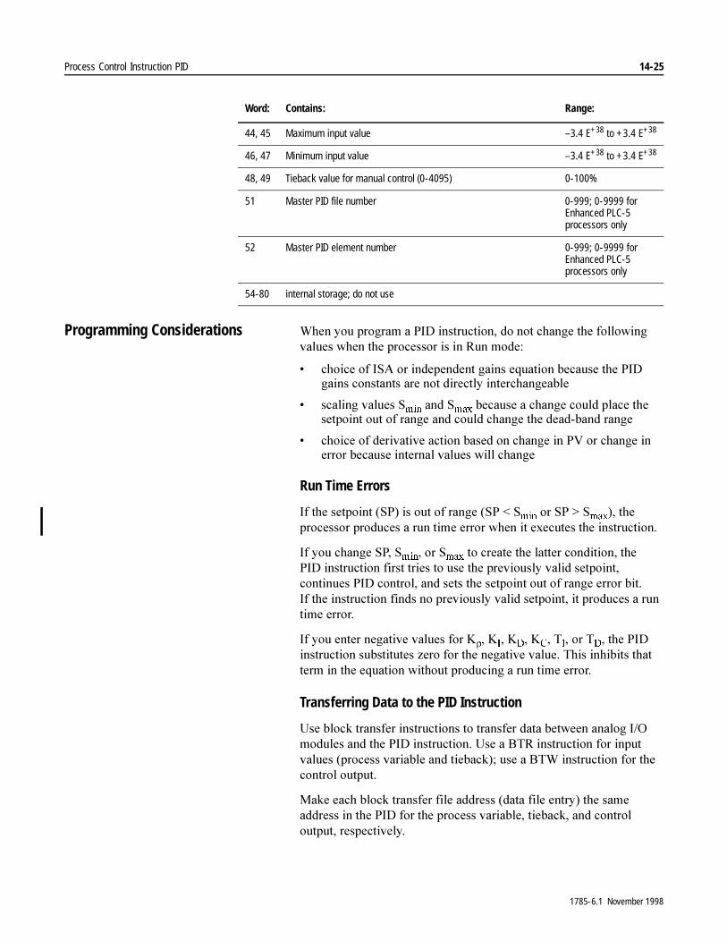
Process Control Instruction PID 14-25
Programming Considerations :KHQ�\RX�SURJUDP�D�3,'�LQVWUXFWLRQ��GR�QRW�FKDQJH�WKH�IROORZLQJ�YDOXHV�ZKHQ�WKH�SURFHVVRU�LV�LQ�5XQ�PRGH�
� FKRLFH�RI�,6$�RU�LQGHSHQGHQW�JDLQV�HTXDWLRQ�EHFDXVH�WKH�3,'�JDLQV�FRQVWDQWV�DUH�QRW�GLUHFWO\�LQWHUFKDQJHDEOH
� VFDOLQJ�YDOXHV�6PLQ�DQG�6PD[�EHFDXVH�D�FKDQJH�FRXOG�SODFH�WKH�VHWSRLQW�RXW�RI�UDQJH�DQG�FRXOG�FKDQJH�WKH�GHDG�EDQG�UDQJH
� FKRLFH�RI�GHULYDWLYH�DFWLRQ�EDVHG�RQ�FKDQJH�LQ�39�RU�FKDQJH�LQ�HUURU�EHFDXVH�LQWHUQDO�YDOXHV�ZLOO�FKDQJH
Run Time Errors
,I�WKH�VHWSRLQW��63��LV�RXW�RI�UDQJH��63���6PLQ�RU�63�!�6PD[���WKH�SURFHVVRU�SURGXFHV�D�UXQ�WLPH�HUURU�ZKHQ�LW�H[HFXWHV�WKH�LQVWUXFWLRQ�
,I�\RX�FKDQJH�63��6PLQ��RU�6PD[�WR�FUHDWH�WKH�ODWWHU�FRQGLWLRQ��WKH�3,'�LQVWUXFWLRQ�ILUVW�WULHV�WR�XVH�WKH�SUHYLRXVO\�YDOLG�VHWSRLQW��FRQWLQXHV�3,'�FRQWURO��DQG�VHWV�WKH�VHWSRLQW�RXW�RI�UDQJH�HUURU�ELW��,I�WKH�LQVWUXFWLRQ�ILQGV�QR�SUHYLRXVO\�YDOLG�VHWSRLQW��LW�SURGXFHV�D�UXQ�WLPH�HUURU�
,I�\RX�HQWHU�QHJDWLYH�YDOXHV�IRU�.S��.,��.'��.&��7,��RU�7'��WKH�3,'�LQVWUXFWLRQ�VXEVWLWXWHV�]HUR�IRU�WKH�QHJDWLYH�YDOXH��7KLV�LQKLELWV�WKDW�WHUP�LQ�WKH�HTXDWLRQ�ZLWKRXW�SURGXFLQJ�D�UXQ�WLPH�HUURU�
Transferring Data to the PID Instruction
8VH�EORFN�WUDQVIHU�LQVWUXFWLRQV�WR�WUDQVIHU�GDWD�EHWZHHQ�DQDORJ�,�2�PRGXOHV�DQG�WKH�3,'�LQVWUXFWLRQ��8VH�D�%75�LQVWUXFWLRQ�IRU�LQSXW�YDOXHV��SURFHVV�YDULDEOH�DQG�WLHEDFN���XVH�D�%7:�LQVWUXFWLRQ�IRU�WKH�FRQWURO�RXWSXW�
0DNH�HDFK�EORFN�WUDQVIHU�ILOH�DGGUHVV��GDWD�ILOH�HQWU\��WKH�VDPH�DGGUHVV�LQ�WKH�3,'�IRU�WKH�SURFHVV�YDULDEOH��WLHEDFN��DQG�FRQWURO�RXWSXW��UHVSHFWLYHO\�
44, 45 Maximum input value –3.4 E+38 to +3.4 E+38
46, 47 Minimum input value –3.4 E+38 to +3.4 E+38
48, 49 Tieback value for manual control (0-4095) 0-100%
51 Master PID file number 0-999; 0-9999 for Enhanced PLC-5 processors only
52 Master PID element number 0-999; 0-9999 for Enhanced PLC-5 processors only
54-80 internal storage; do not use
Word: Contains: Range:
1785-6.1 November 1998
14-26 Process Control Instruction PID
1RW�DOO�$OOHQ�%UDGOH\�DQDORJ�LQSXW�PRGXOHV�HQWHU�GDWD�LQ�WKH�VDPH�IRUPDW��<RX�PXVW�GHWHUPLQH�ZKHUH�WR�VWRUH�FKDQQHO�GDWD��)RU�H[DPSOH��WHPSHUDWXUH�VHQVLQJ�PRGXOHV��VXFK�DV�WKH������,5�DQG������,;(��SODFH�VWDWXV�ZRUGV�LQ�IURQW�RI�WKH�ZRUGV�WKDW�FRQWDLQ�FKDQQHO�GDWD��)RU�LQIRUPDWLRQ�DERXW�ZKHUH�DQ�DQDORJ�PRGXOH�VWRUHV�FKDQQHO�GDWD��VHH�WKH�GRFXPHQWDWLRQ�IRU�WKH�PRGXOH�
Loop Considerations 7KH�QXPEHU�RI�3,'�ORRSV��ORRS�XSGDWH�WLPH��DQG�ORFDWLRQ�RI����ELW�DQDORJ�LQSXW�PRGXOHV�DUH�LPSRUWDQW�FRQVLGHUDWLRQV�IRU�XVLQJ�WKH�3,'�LQVWUXFWLRQ�
Number of PID Loops
7KH�QXPEHU�RI�3,'�ORRSV�WKDW�WKH�SURFHVVRU�FDQ�KDQGOH�GHSHQGV�RQ�WKH�XSGDWH�WLPH�UHTXLUHG�E\�WKH�ORRSV��7KH�ORQJHU�WKH�XSGDWH�WLPH�DQG�WKH�OHVV�VRSKLVWLFDWHG�WKH�ORRS�FRQWURO��WKH�PRUH�ORRSV�WKH�SURFHVVRU�FDQ�FRQWURO�
7KH�VXP�RI�WKH�ZRUVW�FDVH�EORFN�WUDQVIHU�WLPH�DVVRFLDWHG�ZLWK�WKH�DQDORJ�LQSXWV�SOXV�WKH�WLPH�UHTXLUHG�IRU�RQH�SURJUDP�VFDQ�VKRXOG�EH�OHVV�WKDQ�WKH�XSGDWH�WLPH�UHTXLUHG�E\�WKH�ORRSV�
Loop Update Time
7KH�3,'�LQVWUXFWLRQ�FDOFXODWHV�D�QHZ�FRQWURO�RXWSXW�ZKHQHYHU�LWV�UXQJ�FKDQJHV�IURP�IDOVH�WR�WUXH�ZKHQ�XVLQJ�DQ�LQWHJHU�GDWD�ILOH�IRU�WKH�FRQWURO�EORFN��$�3,'�LQVWUXFWLRQ�ZLWK�D�3'�FRQWURO�EORFN�ZLOO�H[HFXWH�HYHU\�VFDQ�LQ�ZKLFK�WKH�UXQJ�LV�WUXH��<RX�FDQ�XVH�D�RQH�VKRW�LQVWUXFWLRQ�WR�IRUFH�WKH�3,'�LQVWUXFWLRQ�ZLWK�D�3'�FRQWURO�EORFN�WR�RQO\�H[HFXWH�RQ�D�IDOVH�WR�WUXH�WUDQVLWLRQ��6HH�WKH�H[DPSOHV�DW�WKH�HQG�RI�WKLV�FKDSWHU��)RU�WKH�LQVWUXFWLRQ�WR�RSHUDWH�SUHGLFWDEO\��WKH�XSGDWH�WLPH�PXVW�EH�HTXDO�WR�WKH�UDWH�DW�ZKLFK�WKH�3,'�UXQJ�FKDQJHV�EHWZHHQ�IDOVH�DQG�WUXH��'HYLDWLRQ�LQ�WRJJOH�UDWH�IURP�WKH�XSGDWH�WLPH�VXEVWDQWLDOO\�GHJUDGHV�WKH�DFFXUDF\�RI�3,'�FDOFXODWLRQV�
<RX�VKRXOG�SURJUDP�IDVW�UHVSRQVH�ORRSV��XSGDWH�WLPHV�OHVV�WKDQ�����PV��LQ�WKH�VHOHFWDEOH�WLPHG�LQWHUUXSW��67,��DORQJ�ZLWK�WKH�FRUUHVSRQGLQJ�EORFN�WUDQVIHU�LQVWUXFWLRQV��8QODWFK�WKH�3,'�HQDEOH�ELW�WR�IRUFH�H[HFXWLRQ�HYHU\�67,�VFDQ��LI�\RX�DUH�XVLQJ�D�3'�GDWD�ILOH�IRU�WKH�FRQWURO�EORFN�\RX�GR�QRW�KDYH�WR�XQODWFK�WKH�HQDEOH�ELW���<RX�PXVW�SODFH�FRUUHVSRQGLQJ�DQDORJ�,�2�PRGXOHV�LQ�WKH�ORFDO�FKDVVLV�ZKHQ�\RX�VHH�WKLV�FRQILJXUDWLRQ�
3URJUDP�VORZHU�UHVSRQVH�ORRSV��XSGDWH�WLPHV�RI�JUHDWHU�WKDQ�����PV��LQ�WKH�PDLQ�ODGGHU�SURJUDP�DQG�XVH�WLPHUV�RU�UHDO�WLPH�VDPSOLQJ�WR�FRQWURO�WKH�XSGDWH�WLPH�
1785-6.1 November 1998
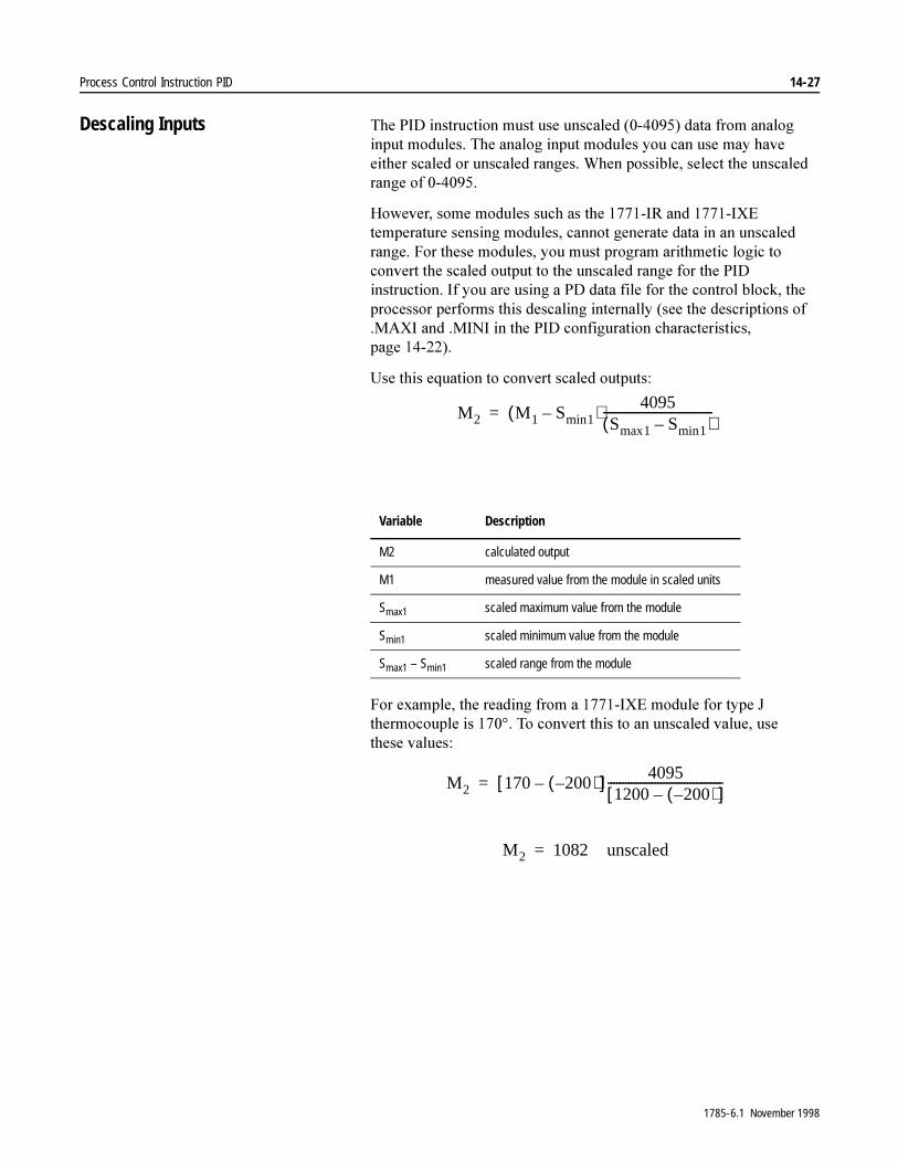
Process Control Instruction PID 14-27
Descaling Inputs 7KH�3,'�LQVWUXFWLRQ�PXVW�XVH�XQVFDOHG����������GDWD�IURP�DQDORJ�LQSXW�PRGXOHV��7KH�DQDORJ�LQSXW�PRGXOHV�\RX�FDQ�XVH�PD\�KDYH�HLWKHU�VFDOHG�RU�XQVFDOHG�UDQJHV��:KHQ�SRVVLEOH��VHOHFW�WKH�XQVFDOHG�UDQJH�RI��������
+RZHYHU��VRPH�PRGXOHV�VXFK�DV�WKH������,5�DQG������,;(�WHPSHUDWXUH�VHQVLQJ�PRGXOHV��FDQQRW�JHQHUDWH�GDWD�LQ�DQ�XQVFDOHG�UDQJH��)RU�WKHVH�PRGXOHV��\RX�PXVW�SURJUDP�DULWKPHWLF�ORJLF�WR�FRQYHUW�WKH�VFDOHG�RXWSXW�WR�WKH�XQVFDOHG�UDQJH�IRU�WKH�3,'�LQVWUXFWLRQ��,I�\RX�DUH�XVLQJ�D�3'�GDWD�ILOH�IRU�WKH�FRQWURO�EORFN��WKH�SURFHVVRU�SHUIRUPV�WKLV�GHVFDOLQJ�LQWHUQDOO\��VHH�WKH�GHVFULSWLRQV�RI��0$;,�DQG��0,1,�LQ�WKH�3,'�FRQILJXUDWLRQ�FKDUDFWHULVWLFV��SDJH �������
8VH�WKLV�HTXDWLRQ�WR�FRQYHUW�VFDOHG�RXWSXWV�
)RU�H[DPSOH��WKH�UHDGLQJ�IURP�D������,;(�PRGXOH�IRU�W\SH�-�WKHUPRFRXSOH�LV�������7R�FRQYHUW�WKLV�WR�DQ�XQVFDOHG�YDOXH��XVH�WKHVH�YDOXHV�
Variable Description
M2 calculated output
M1 measured value from the module in scaled units
Smax1 scaled maximum value from the module
Smin1 scaled minimum value from the module
Smax1 – Smin1 scaled range from the module
M2 M1 Smin1–( ) 4095Smax1 Smin1–( )�������������������������������������=
M2 170 200–( )–[ ] 40951200 200–( )–[ ]���������������������������������������=
M2 1082 unscaled=
1785-6.1 November 1998

14-28 Process Control Instruction PID
,I�\RX�DUH�VXUH�WKDW�WKH�WHPSHUDWXUH�RI�\RXU�SURFHVV�ZLOO�DOZD\V�UHPDLQ�ZLWKLQ�D�VSHFLILF�UDQJH��\RX�FDQ�VHW�WKH�OLPLWV�IRU�6PLQ��DQG�6PD[��LQVWHDG�RI�WKH�PLQLPXP�DQG�PD[LPXP�YDOXHV�IRU�WKH�WKHUPRFRXSOH�PRGXOH��7KLV�WHFKQLTXH�LPSURYHV�WKH�UHVROXWLRQ�RI�WKH�SURFHVV�YDULDEOH��
)LJXUH������VKRZV�WKH�ODGGHU�ORJLF�\RX�QHHG�WR�DGG�WR�\RXU�3,'�SURJUDP��7DEOH����*�OLVWV�WKH�YDULDEOHV�LQ�WKLV�H[DPSOH�
Figure 14.3 Descaling PID Values Example
�$77(17,21� ,I�\RX�VHW�WKH�OLPLWV�LQVWHDG�RI�XVLQJ�WKH�ORZHU�DQG�XSSHU�WHPSHUDWXUH�OLPLWV�RI�WKH�WKHUPRFRXSOH�RU�57'�PRGXOH��\RX�PXVW�NHHS�WKH�SURFHVV�ZLWKLQ�WKH�OLPLWV�\RX�VSHFLI\��)DLOXUH�WR�NHHS�WKH�SURFHVV�ZLWKLQ�WKH�OLPLWV�FRXOG�FDXVH�XQSUHGLFWDEOH�RSHUDWLRQ��GDPDJH�WR�HTXLSPHQW��RU�LQMXU\�WR�SHUVRQQHO�
ENFILE ARITHMETIC/LOGIC
ControlLengthPositionMode
R6:260
ALL
FAL
Destination
Expression#N17:0 - #N18:0
#N19:0
FILE ARITHMETIC/LOGICControlLengthPositionMode
R6:560
ALL
FAL
Destination
Expression#N19:0 * #N20:0
#N21:0
DN
ER
EN
DN
ER
1785-6.1 November 1998

Process Control Instruction PID 14-29
Table 14.G Variables for the Descaling PID Values Example
PID Examples 7KH�IROORZLQJ�H[DPSOHV�DVVXPH�WKDW�WKH�FKDQQHO�GDWD�LV�VWRUHG�VWDUWLQJ�DW�WKH�EHJLQQLQJ��ILUVW�ZRUG��RI�WKH�EORFN�WUDQVIHU�ILOH�
Integer Block (N) Examples Main Program File
:KHQ�\RX�SODFH�WKH�3,'�LQVWUXFWLRQ�LQ�WKH�PDLQ�SURJUDP�ILOH��FRQWURO�WKH�VDPSOH�WLPH�ZLWK�D�WLPHU��ZKHUH�WKH�3,'�/RRS�8SGDWH�7LPH� �WLPHU�SUHVHW�
7LPHU�EDVHG�H[HFXWLRQ�XVHV�D�IUHH�UXQQLQJ�WLPHU�IRU�HYHQW�FRRUGLQDWLRQ��:KHQ�WKH�WLPHU¶V�DFFXPXODWHG�YDOXH�UHDFKHV�LWV�SUHVHW�YDOXH��LW�WULJJHUV�WKH�ORRS�XSGDWH�VHTXHQFH��7KH�WLPHU�LPPHGLDWHO\�UHVHWV�DQG�UHVWDUWV�WR�PDLQWDLQ�D�FRQVLVWHQW�XSGDWH�LQWHUYDO��8VH�WLPHU�EDVHG�H[HFXWLRQ�LQ�³VORZHU´�ORRS�DSSOLFDWLRQV�RU�LQ�DSSOLFDWLRQV�ZLWK�UHODWLYHO\�IHZ�ORRSV��6HH�)LJXUH������IRU�SURJUDPPLQJ�H[DPSOH�
7KH�DFFXUDF\�RI�WKH�WLPHU�GHSHQGV�RQ�WKH�WLPH�EDVH�DQG�WKH�WRWDO�VFDQ�WLPH�RI�WKH�SURFHVVRU��$OZD\V�FKRRVH�WKH������VHFRQG�WLPH�EDVH�IRU�WKLV�3,'�DSSOLFDWLRQ��'XSOLFDWH�WKH�WLPHU�LQVWUXFWLRQ�HOVHZKHUH�LQ�WKH�SURJUDP�LI�WKH�SURFHVVRU�VFDQ�WLPH��ORFDO�,�2�VFDQ�SOXV�SURJUDP�VFDQ��LV�JUHDWHU�WKDQ�����VHFRQGV�
%HFDXVH�EORFN�WUDQVIHUV�LQ�WKH�ORFDO�FKDVVLV�RFFXU�DV\QFKURQRXVO\�GXULQJ�PDLQ�SURJUDP�VFDQ��\RX�QHHG�D�VWRUDJH�ELW�WR�HQVXUH�WKDW�WKH�VWDWH�RI�WKH�3,'�LQSXW�FRQGLWLRQ�UHPDLQV�FRQVWDQW�GXULQJ�WKH�HQWLUH�SURJUDP�VFDQ��&RQGLWLRQ�DOO�3,'�LQVWUXFWLRQV�XVLQJ�WKLV�VWRUDJH�ELW�
Variable Description
Smax maximum scaling value
Smin minimum scaling value
constant for each channel
#N17:0 contains M1 values for each channel
#N18:0 contains Smin constants for each channel
#N19:0 contains the result of M1-Smin for each channel
#N20:0 location where you store K for each channel
#N21:0 contains the resulting unscaled value for each channel
K4095
Smax Smin–���������������������������=
1785-6.1 November 1998
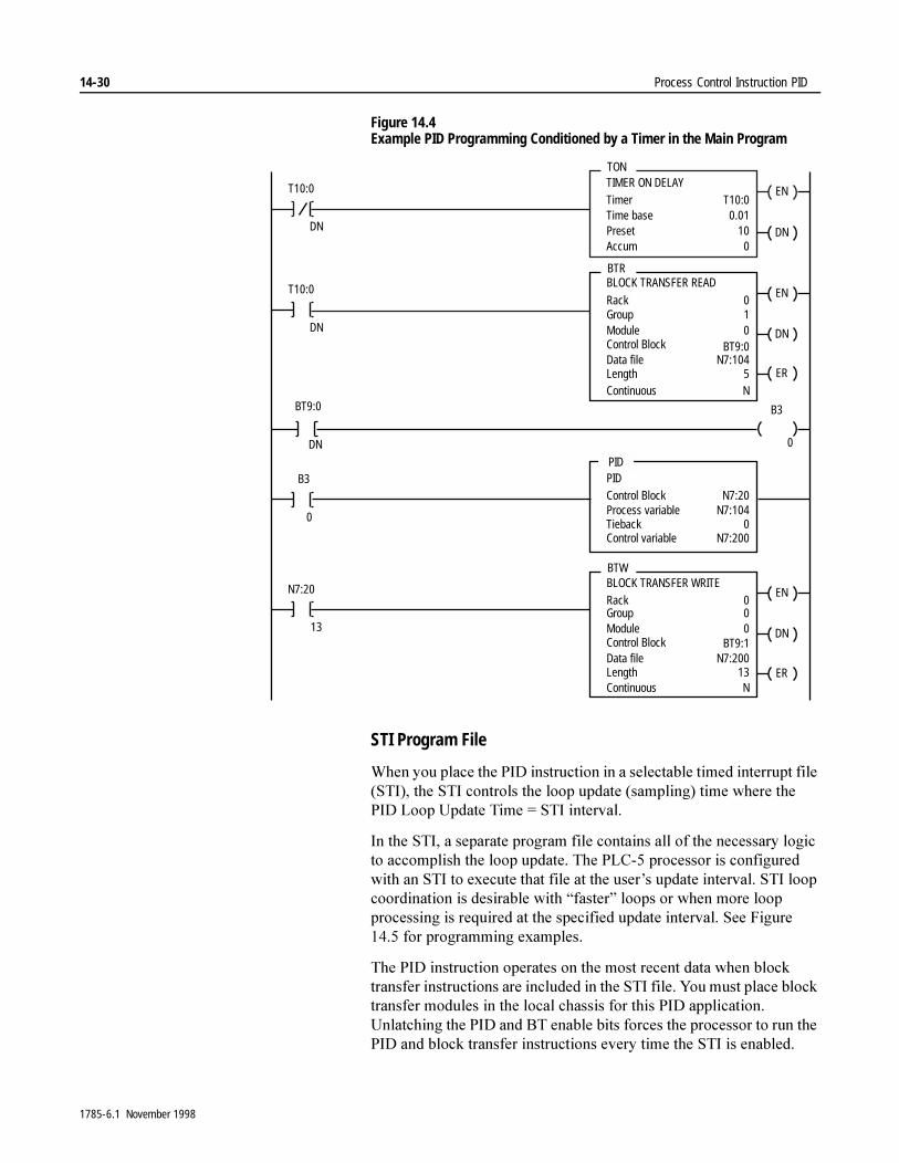
14-30 Process Control Instruction PID
Figure 14.4 Example PID Programming Conditioned by a Timer in the Main Program
STI Program File
:KHQ�\RX�SODFH�WKH�3,'�LQVWUXFWLRQ�LQ�D�VHOHFWDEOH�WLPHG�LQWHUUXSW�ILOH��67,���WKH�67,�FRQWUROV�WKH�ORRS�XSGDWH��VDPSOLQJ��WLPH�ZKHUH�WKH�3,'�/RRS�8SGDWH�7LPH� �67,�LQWHUYDO�
,Q�WKH�67,��D�VHSDUDWH�SURJUDP�ILOH�FRQWDLQV�DOO�RI�WKH�QHFHVVDU\�ORJLF�WR�DFFRPSOLVK�WKH�ORRS�XSGDWH��7KH�3/&���SURFHVVRU�LV�FRQILJXUHG�ZLWK�DQ�67,�WR�H[HFXWH�WKDW�ILOH�DW�WKH�XVHU¶V�XSGDWH�LQWHUYDO��67,�ORRS�FRRUGLQDWLRQ�LV�GHVLUDEOH�ZLWK�³IDVWHU´�ORRSV�RU�ZKHQ�PRUH�ORRS�SURFHVVLQJ�LV�UHTXLUHG�DW�WKH�VSHFLILHG�XSGDWH�LQWHUYDO��6HH�)LJXUH������IRU�SURJUDPPLQJ�H[DPSOHV�
7KH�3,'�LQVWUXFWLRQ�RSHUDWHV�RQ�WKH�PRVW�UHFHQW�GDWD�ZKHQ�EORFN�WUDQVIHU�LQVWUXFWLRQV�DUH�LQFOXGHG�LQ�WKH�67,�ILOH��<RX�PXVW�SODFH�EORFN�WUDQVIHU�PRGXOHV�LQ�WKH�ORFDO�FKDVVLV�IRU�WKLV�3,'�DSSOLFDWLRQ��8QODWFKLQJ�WKH�3,'�DQG�%7�HQDEOH�ELWV�IRUFHV�WKH�SURFHVVRU�WR�UXQ�WKH�3,'�DQG�EORFN�WUDQVIHU�LQVWUXFWLRQV�HYHU\�WLPH�WKH�67,�LV�HQDEOHG�
ENTIMER ON DELAYTimerTime basePresetAccum
T10:00.01
100
DN
T10:0
DN
TON
ENBLOCK TRANSFER READ
RackGroupModuleControl Block
010 DN
Data fileLength
N7:1045 ER
BTR
Continuous N
T10:0
DN
B3
0
ENBLOCK TRANSFER WRITERackGroupModuleControl Block
000 DN
Data fileLength
N7:20013 ER
BTW
Continuous N
N7:20
13
PIDControl BlockProcess variableTiebackControl variable
N7:20N7:104
0N7:200
B3
0
BT9:0
BT9:0
DN
BT9:1
PID
1785-6.1 November 1998
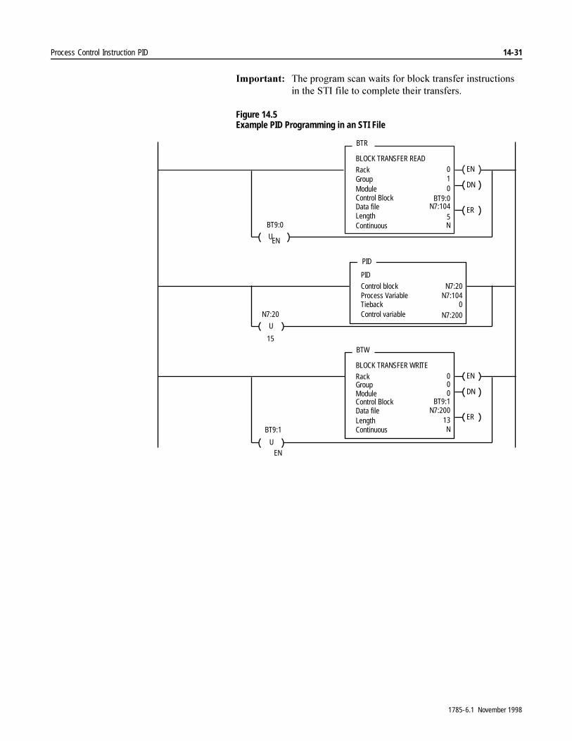
Process Control Instruction PID 14-31
,PSRUWDQW���7KH�SURJUDP�VFDQ�ZDLWV�IRU�EORFN�WUDQVIHU�LQVWUXFWLRQV�LQ�WKH�67,�ILOH�WR�FRPSOHWH�WKHLU�WUDQVIHUV�
Figure 14.5 Example PID Programming in an STI File
ENBLOCK TRANSFER READ
RackGroupModuleControl Block
0
0 DN
Data fileLength
N7:104 ER
BTR
Continuous N
PID
Control blockProcess VariableTiebackControl variable
N7:20N7:104
PID
U
U
N7:20
15
ENBLOCK TRANSFER WRITE
RackGroupModuleControl Block
0
0 DN
Data fileLength 13 ER
BTW
Continuous N
U
1
BT9:0
5BT9:0
EN
0N7:200
0
BT9:1N7:200
BT9:1
EN
1785-6.1 November 1998
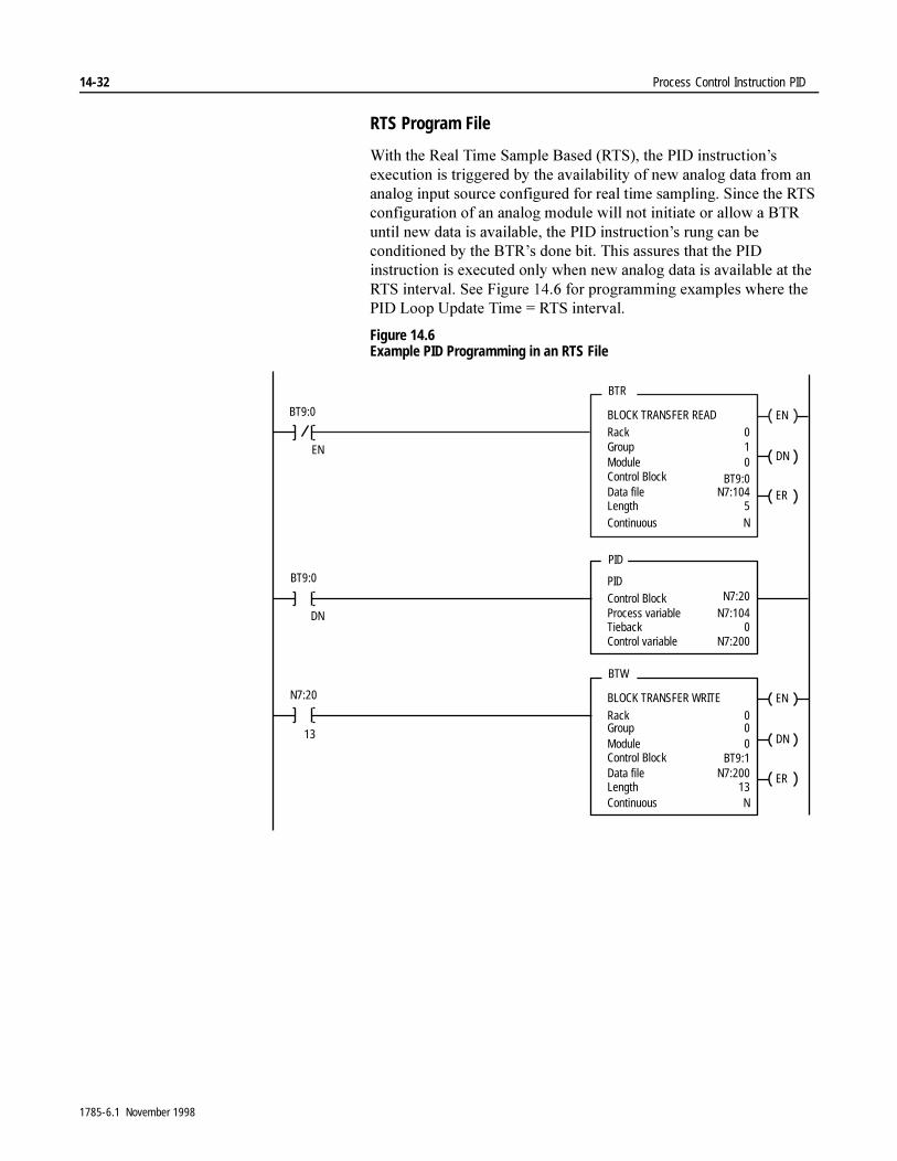
14-32 Process Control Instruction PID
RTS Program File
:LWK�WKH�5HDO�7LPH�6DPSOH�%DVHG��576���WKH�3,'�LQVWUXFWLRQ¶V�H[HFXWLRQ�LV�WULJJHUHG�E\�WKH�DYDLODELOLW\�RI�QHZ�DQDORJ�GDWD�IURP�DQ�DQDORJ�LQSXW�VRXUFH�FRQILJXUHG�IRU�UHDO�WLPH�VDPSOLQJ��6LQFH�WKH�576�FRQILJXUDWLRQ�RI�DQ�DQDORJ�PRGXOH�ZLOO�QRW�LQLWLDWH�RU�DOORZ�D�%75�XQWLO�QHZ�GDWD�LV�DYDLODEOH��WKH�3,'�LQVWUXFWLRQ¶V�UXQJ�FDQ�EH�FRQGLWLRQHG�E\�WKH�%75¶V�GRQH�ELW��7KLV�DVVXUHV�WKDW�WKH�3,'�LQVWUXFWLRQ�LV�H[HFXWHG�RQO\�ZKHQ�QHZ�DQDORJ�GDWD�LV�DYDLODEOH�DW�WKH�576�LQWHUYDO��6HH�)LJXUH������IRU�SURJUDPPLQJ�H[DPSOHV�ZKHUH�WKH�3,'�/RRS�8SGDWH�7LPH� �576�LQWHUYDO�
Figure 14.6 Example PID Programming in an RTS File
ENBLOCK TRANSFER READRackGroupModuleControl Block
010 DN
Data fileLength
N7:1045
ER
BTR
Continuous N
EN
BT9:0
BT9:0
ENBLOCK TRANSFER WRITE
RackGroupModuleControl Block
000 DN
Data fileLength
N7:20013
ER
BTW
Continuous N
BT9:1
N7:20
13
PIDControl BlockProcess variableTiebackControl variable
N7:1040
N7:200
PID
BT9:0
DN
N7:20
1785-6.1 November 1998
Process Control Instruction PID 14-33
PD Block Examples Main Program File
:KHQ�\RX�SODFH�WKH�3,'�LQVWUXFWLRQ�LQ�WKH�PDLQ�SURJUDP�ILOH��FRQWURO�WKH�VDPSOH�WLPH�ZLWK�D�WLPHU��ZKHUH�WKH�3,'�/RRS�8SGDWH�7LPH� �WLPHU�SUHVHW�
7LPHU�EDVHG�H[HFXWLRQ�XVHV�D�IUHH�UXQQLQJ�WLPHU�IRU�HYHQW�FRRUGLQDWLRQ��:KHQ�WKH�WLPHU¶V�DFFXPXODWHG�YDOXH�UHDFKHV�LWV�SUHVHW�YDOXH��LW�WULJJHUV�WKH�ORRS�XSGDWH�VHTXHQFH��7KH�WLPHU�LPPHGLDWHO\�UHVHWV�DQG�UHVWDUWV�WR�PDLQWDLQ�D�FRQVLVWHQW�XSGDWH�LQWHUYDO��8VH�WLPHU�EDVHG�H[HFXWLRQ�LQ�³VORZHU´�ORRS�DSSOLFDWLRQV�RU�LQ�DSSOLFDWLRQV�ZLWK�UHODWLYHO\�IHZ�ORRSV��6HH�)LJXUH������IRU�SURJUDPPLQJ�H[DPSOH�
7KH�DFFXUDF\�RI�WKH�WLPHU�GHSHQGV�RQ�WKH�WLPH�EDVH�DQG�WKH�WRWDO�VFDQ�WLPH�RI�WKH�SURFHVVRU��$OZD\V�FKRRVH�WKH������VHFRQG�WLPH�EDVH�IRU�WKLV�3,'�DSSOLFDWLRQ��'XSOLFDWH�WKH�WLPHU�LQVWUXFWLRQ�HOVHZKHUH�LQ�WKH�SURJUDP�LI�WKH�SURFHVVRU�VFDQ�WLPH��ORFDO�,�2�VFDQ�SOXV�SURJUDP�VFDQ��LV�JUHDWHU�WKDQ�����VHFRQGV�
%HFDXVH�EORFN�WUDQVIHUV�LQ�WKH�ORFDO�FKDVVLV�RFFXU�DV\QFKURQRXVO\�GXULQJ�PDLQ�SURJUDP�VFDQ��\RX�QHHG�D�VWRUDJH�ELW�WR�HQVXUH�WKDW�WKH�VWDWH�RI�WKH�3,'�LQSXW�FRQGLWLRQ�UHPDLQV�FRQVWDQW�GXULQJ�WKH�HQWLUH�SURJUDP�VFDQ��&RQGLWLRQ�DOO�3,'�LQVWUXFWLRQV�XVLQJ�WKLV�VWRUDJH�ELW�
1785-6.1 November 1998
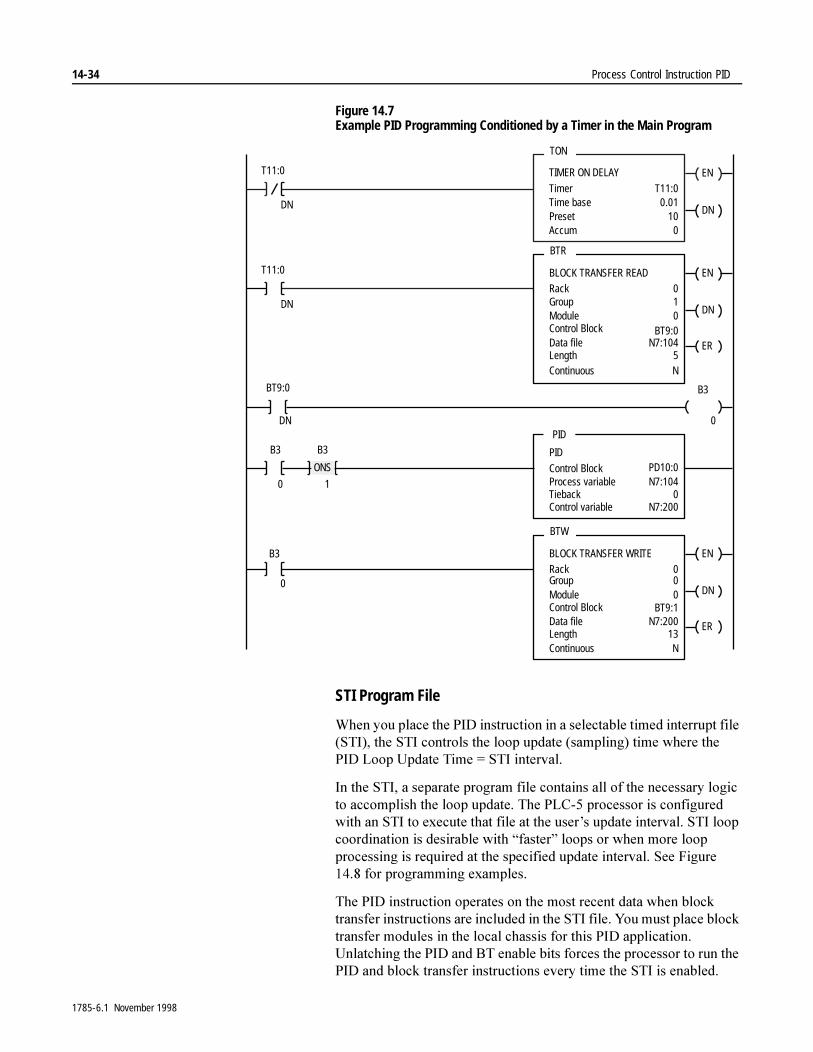
14-34 Process Control Instruction PID
Figure 14.7 Example PID Programming Conditioned by a Timer in the Main Program
STI Program File
:KHQ�\RX�SODFH�WKH�3,'�LQVWUXFWLRQ�LQ�D�VHOHFWDEOH�WLPHG�LQWHUUXSW�ILOH��67,���WKH�67,�FRQWUROV�WKH�ORRS�XSGDWH��VDPSOLQJ��WLPH�ZKHUH�WKH�3,'�/RRS�8SGDWH�7LPH� �67,�LQWHUYDO�
,Q�WKH�67,��D�VHSDUDWH�SURJUDP�ILOH�FRQWDLQV�DOO�RI�WKH�QHFHVVDU\�ORJLF�WR�DFFRPSOLVK�WKH�ORRS�XSGDWH��7KH�3/&���SURFHVVRU�LV�FRQILJXUHG�ZLWK�DQ�67,�WR�H[HFXWH�WKDW�ILOH�DW�WKH�XVHU¶V�XSGDWH�LQWHUYDO��67,�ORRS�FRRUGLQDWLRQ�LV�GHVLUDEOH�ZLWK�³IDVWHU´�ORRSV�RU�ZKHQ�PRUH�ORRS�SURFHVVLQJ�LV�UHTXLUHG�DW�WKH�VSHFLILHG�XSGDWH�LQWHUYDO��6HH�)LJXUH������IRU�SURJUDPPLQJ�H[DPSOHV�
7KH�3,'�LQVWUXFWLRQ�RSHUDWHV�RQ�WKH�PRVW�UHFHQW�GDWD�ZKHQ�EORFN�WUDQVIHU�LQVWUXFWLRQV�DUH�LQFOXGHG�LQ�WKH�67,�ILOH��<RX�PXVW�SODFH�EORFN�WUDQVIHU�PRGXOHV�LQ�WKH�ORFDO�FKDVVLV�IRU�WKLV�3,'�DSSOLFDWLRQ��8QODWFKLQJ�WKH�3,'�DQG�%7�HQDEOH�ELWV�IRUFHV�WKH�SURFHVVRU�WR�UXQ�WKH�3,'�DQG�EORFN�WUDQVIHU�LQVWUXFWLRQV�HYHU\�WLPH�WKH�67,�LV�HQDEOHG�
ENTIMER ON DELAY
TimerTime basePresetAccum
T11:00.01
100
DN
T11:0
DN
TON
ENBLOCK TRANSFER READRackGroupModuleControl Block
010 DN
Data fileLength
N7:1045
ER
BTR
Continuous N
T11:0
DN
B3
0
ENBLOCK TRANSFER WRITERackGroupModuleControl Block
000 DN
Data fileLength
N7:20013
ER
BTW
Continuous N
PID
Control BlockProcess variableTiebackControl variable
N7:1040
N7:200
PIDB3
0
BT9:0
BT9:0
DN
BT9:1
B3
1
ONS PD10:0
B3
0
1785-6.1 November 1998

Process Control Instruction PID 14-35
,PSRUWDQW���7KH�SURJUDP�VFDQ�ZDLWV�IRU�EORFN�WUDQVIHU�LQVWUXFWLRQV�LQ�WKH�67,�ILOH�WR�FRPSOHWH�WKHLU�WUDQVIHUV�
Figure 14.8 Example PID Programming in an STI File
ENBLOCK TRANSFER READ
RackGroupModuleControl Block
0
0 DN
Data fileLength
N7:104 ER
BTR
Continuous N
PIDControl blockProcess VariableTiebackControl variable
N7:104
PID
U
ENBLOCK TRANSFER WRITE
RackGroupModuleControl Block
0
0 DN
Data fileLength 13 ER
BTW
Continuous N
U
1
BT9:0
5BT9:0
EN
0N7:200
0
BT9:1N7:200
BT9:1
EN
PD10:0
1785-6.1 November 1998
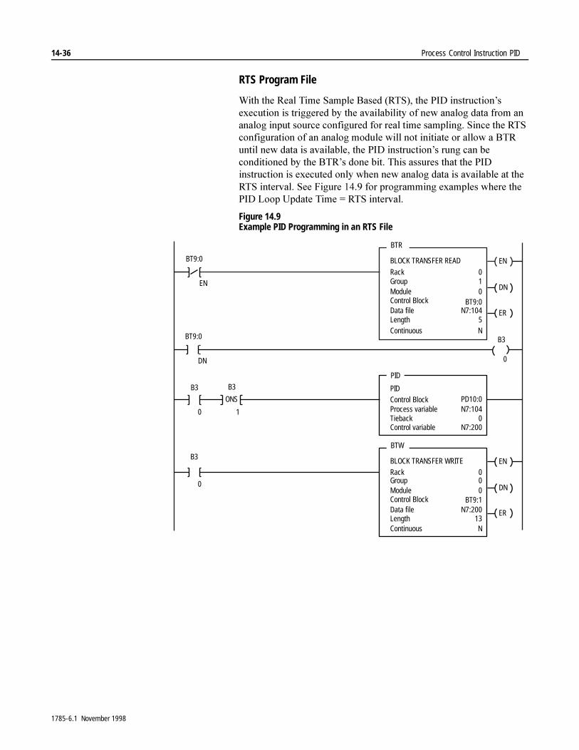
14-36 Process Control Instruction PID
RTS Program File
:LWK�WKH�5HDO�7LPH�6DPSOH�%DVHG��576���WKH�3,'�LQVWUXFWLRQ¶V�H[HFXWLRQ�LV�WULJJHUHG�E\�WKH�DYDLODELOLW\�RI�QHZ�DQDORJ�GDWD�IURP�DQ�DQDORJ�LQSXW�VRXUFH�FRQILJXUHG�IRU�UHDO�WLPH�VDPSOLQJ��6LQFH�WKH�576�FRQILJXUDWLRQ�RI�DQ�DQDORJ�PRGXOH�ZLOO�QRW�LQLWLDWH�RU�DOORZ�D�%75�XQWLO�QHZ�GDWD�LV�DYDLODEOH��WKH�3,'�LQVWUXFWLRQ¶V�UXQJ�FDQ�EH�FRQGLWLRQHG�E\�WKH�%75¶V�GRQH�ELW��7KLV�DVVXUHV�WKDW�WKH�3,'�LQVWUXFWLRQ�LV�H[HFXWHG�RQO\�ZKHQ�QHZ�DQDORJ�GDWD�LV�DYDLODEOH�DW�WKH�576�LQWHUYDO��6HH�)LJXUH������IRU�SURJUDPPLQJ�H[DPSOHV�ZKHUH�WKH�3,'�/RRS�8SGDWH�7LPH� �576�LQWHUYDO�
Figure 14.9 Example PID Programming in an RTS File
ENBLOCK TRANSFER READ
RackGroupModuleControl Block
010 DN
Data fileLength
N7:1045
ER
BTR
Continuous N
EN
ENBLOCK TRANSFER WRITERackGroupModuleControl Block
000 DN
Data fileLength
N7:20013
ER
BTW
Continuous N
PIDControl BlockProcess variableTiebackControl variable
N7:1040
N7:200
PID
BT9:0
BT9:1
BT9:0
B3
0DN
BT9:0
PD10:0
B3
0
B3
ONS
1
B3
0
1785-6.1 November 1998
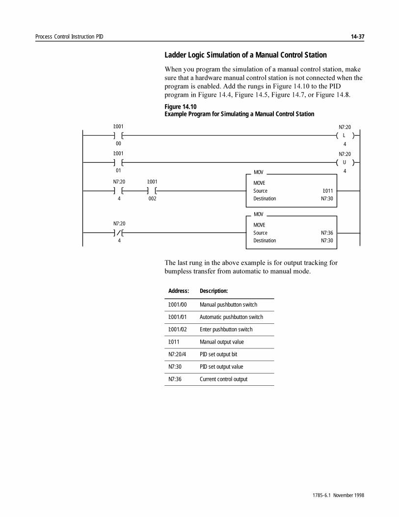
Process Control Instruction PID 14-37
Ladder Logic Simulation of a Manual Control Station
:KHQ�\RX�SURJUDP�WKH�VLPXODWLRQ�RI�D�PDQXDO�FRQWURO�VWDWLRQ��PDNH�VXUH�WKDW�D�KDUGZDUH�PDQXDO�FRQWURO�VWDWLRQ�LV�QRW�FRQQHFWHG�ZKHQ�WKH�SURJUDP�LV�HQDEOHG��$GG�WKH�UXQJV�LQ�)LJXUH�������WR�WKH�3,'�SURJUDP�LQ�)LJXUH�������)LJXUH�������)LJXUH�������RU�)LJXUH������
Figure 14.10 Example Program for Simulating a Manual Control Station
7KH�ODVW�UXQJ�LQ�WKH�DERYH�H[DPSOH�LV�IRU�RXWSXW�WUDFNLQJ�IRU�EXPSOHVV�WUDQVIHU�IURP�DXWRPDWLF�WR�PDQXDO�PRGH�
L
I:001
00
N7:20
4
N7:20
4
MOVE
SourceDestination
I:011N7:30
MOV
N7:20
4
U
I:001
01
N7:20
4
I:001
002
MOVE
SourceDestination
N7:36N7:30
MOV
Address: Description:
I:001/00 Manual pushbutton switch
I:001/01 Automatic pushbutton switch
I:001/02 Enter pushbutton switch
I:011 Manual output value
N7:20/4 PID set output bit
N7:30 PID set output value
N7:36 Current control output
1785-6.1 November 1998
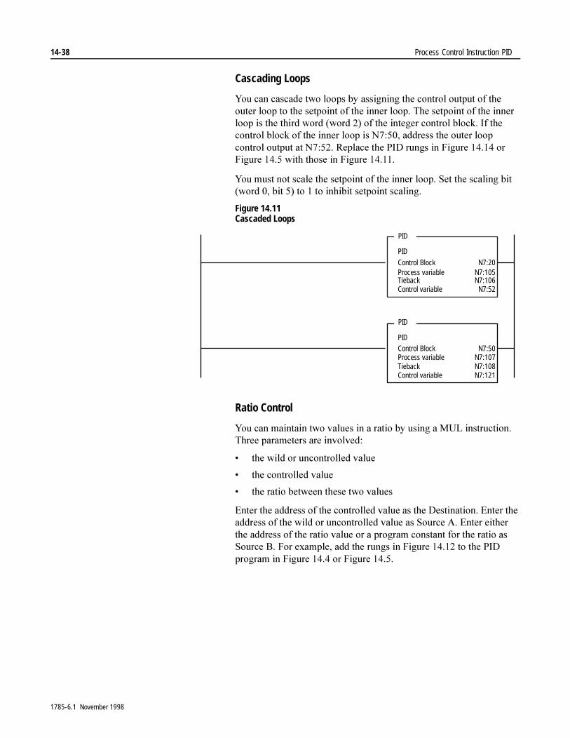
14-38 Process Control Instruction PID
Cascading Loops
<RX�FDQ�FDVFDGH�WZR�ORRSV�E\�DVVLJQLQJ�WKH�FRQWURO�RXWSXW�RI�WKH�RXWHU�ORRS�WR�WKH�VHWSRLQW�RI�WKH�LQQHU�ORRS��7KH�VHWSRLQW�RI�WKH�LQQHU�ORRS�LV�WKH�WKLUG�ZRUG��ZRUG����RI�WKH�LQWHJHU�FRQWURO�EORFN��,I�WKH�FRQWURO�EORFN�RI�WKH�LQQHU�ORRS�LV�1������DGGUHVV�WKH�RXWHU�ORRS�FRQWURO�RXWSXW�DW�1������5HSODFH�WKH�3,'�UXQJV�LQ�)LJXUH�������RU�)LJXUH������ZLWK�WKRVH�LQ�)LJXUH�������
<RX�PXVW�QRW�VFDOH�WKH�VHWSRLQW�RI�WKH�LQQHU�ORRS��6HW�WKH�VFDOLQJ�ELW��ZRUG����ELW����WR���WR�LQKLELW�VHWSRLQW�VFDOLQJ�
Figure 14.11 Cascaded Loops
Ratio Control
<RX�FDQ�PDLQWDLQ�WZR�YDOXHV�LQ�D�UDWLR�E\�XVLQJ�D�08/�LQVWUXFWLRQ��7KUHH�SDUDPHWHUV�DUH�LQYROYHG�
� WKH�ZLOG�RU�XQFRQWUROOHG�YDOXH
� WKH�FRQWUROOHG�YDOXH
� WKH�UDWLR�EHWZHHQ�WKHVH�WZR�YDOXHV
(QWHU�WKH�DGGUHVV�RI�WKH�FRQWUROOHG�YDOXH�DV�WKH�'HVWLQDWLRQ��(QWHU�WKH�DGGUHVV�RI�WKH�ZLOG�RU�XQFRQWUROOHG�YDOXH�DV�6RXUFH�$��(QWHU�HLWKHU�WKH�DGGUHVV�RI�WKH�UDWLR�YDOXH�RU�D�SURJUDP�FRQVWDQW�IRU�WKH�UDWLR�DV�6RXUFH�%��)RU�H[DPSOH��DGG�WKH�UXQJV�LQ�)LJXUH�������WR�WKH�3,'�SURJUDP�LQ�)LJXUH������RU�)LJXUH������
PID
Control BlockProcess variableTiebackControl variable
N7:20N7:105N7:106N7:52
PID
PIDControl BlockProcess variableTiebackControl variable
N7:50N7:107N7:108N7:121
PID
1785-6.1 November 1998
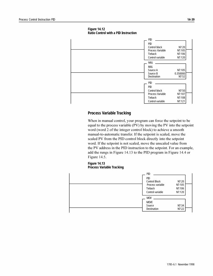
Process Control Instruction PID 14-39
Figure 14.12 Ratio Control with a PID Instruction
Process Variable Tracking
:KHQ�LQ�PDQXDO�FRQWURO��\RXU�SURJUDP�FDQ�IRUFH�WKH�VHWSRLQW�WR�EH�HTXDO�WR�WKH�SURFHVV�YDULDEOH��39��E\�PRYLQJ�WKH�39�LQWR�WKH�VHWSRLQW�ZRUG��ZRUG���RI�WKH�LQWHJHU�FRQWURO�EORFN��WR�DFKLHYH�D�VPRRWK�PDQXDO�WR�DXWRPDWLF�WUDQVIHU��,I�WKH�VHWSRLQW�LV�VFDOHG��PRYH�WKH�VFDOHG�39�IURP�WKH�3,'�FRQWURO�EORFN�GLUHFWO\�LQWR�WKH�VHWSRLQW�ZRUG��,I�WKH�VHWSRLQW�LV�QRW�VFDOHG��PRYH�WKH�XQVFDOHG�YDOXH�IURP�WKH�39�DGGUHVV�LQ�WKH�3,'�LQVWUXFWLRQ�WR�WKH�VHWSRLQW��)RU�DQ�H[DPSOH��DGG�WKH�UXQJV�LQ�)LJXUH�������WR�WKH�3,'�SURJUDP�LQ�)LJXUH������RU�)LJXUH������
Figure 14.13 Process Variable Tracking
PIDControl blockProcess VariableTiebackControl variable
N7:20N7:105N7:106N7:120
PID
MULSource ASource BDestination
N7:1050.350000
N7:52
MUL
PIDControl blockProcess VariableTiebackControl variable
N7:50N7:107N7:108N7:121
PID
PIDControl BlockProcess variableTiebackControl variable
N7:20N7:105N7:106N7:120
PID
MOVESource Destination
N7:34N7:22
MOV
1785-6.1 November 1998
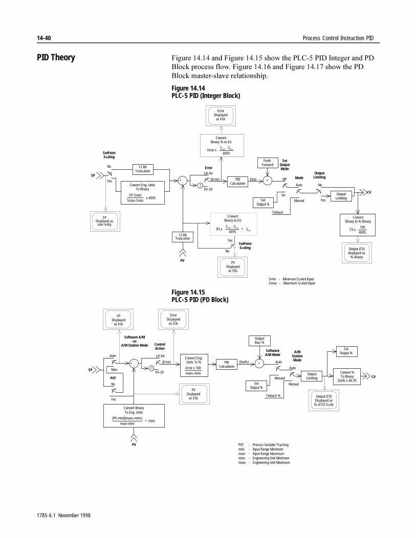
14-40 Process Control Instruction PID
PID Theory )LJXUH�������DQG�)LJXUH�������VKRZ�WKH�3/&���3,'�,QWHJHU�DQG�3'�%ORFN�SURFHVV�IORZ��)LJXUH�������DQG�)LJXUH�������VKRZ�WKH�3'�%ORFN�PDVWHU�VODYH�UHODWLRQVKLS�
Figure 14.14 PLC-5 PID (Integer Block)
Figure 14.15 PLC-5 PID (PD Block)
SP
PV
CV
Smin - Minimum Scaled InputSmax - Maximum Scaled Input
Yes
SetPointScaling
Error
SetOutputMode
Mode
Convert Eng. UnitsTo Binary
SP-SminSmax-Smin
x 4095
No
+-
-1PV-SP
SP-PV
(Error) PIDCalculation
(Out) +
Feed-Forward
On
Off
SetOutput %
OutputLimiting
Manual
Auto
Tieback
12 BitTruncation
12 BitTruncation
Yes
No
OutputLimiting
ErrorDisplayed
as EUs
ConvertBinary % to EU
Error xSmax - Smin
4095
SPDisplayed as
user entry
ConvertBinary to EU
PV xSmax - Smin
4095+ Smin
PVDisplayed
as EUs
No
YesSetPointScaling
ConvertBinary to % Binary
CV x100
4095
Output (CV)displayed as
% Binary
SP
PV
CV
PVT - Process Variable Trackingmini - Input Range Minimummaxi - Input Range Maximummins - Engineering Unit Minimummaxs - Engineering Unit Maximum
Yes
Software A/M-or-
A/M Station Mode ControlAction Software
A/M ModeA/M
StationMode
Convert BinaryTo Eng. Units
(PV-mini)(maxs-mins)
maxi-mini+ mins
No
Man
Auto
+-
-1PV-SP
SP-PV
(Error)Convert Eng.Units To %
Error x 100maxs-mins
(Out%) +
OutputBias %
Manual
Auto
OutputLimiting
Convert %To Binary
Out% x 40.95
SetOutput %
PVT
Manual
Auto
Tieback % Output (CV)Displayed as
% of EU Scale
SetOutput %
PVDisplayed
as EUs
PIDCalculation
ErrorDisplayed
as EUs
SPDisplayed
as EUs
1785-6.1 November 1998

Process Control Instruction PID 14-41
Figure 14.16 PLC-5 PID (PD Block) as Master/Slave Loops
Convert %To Binary
Out% x 40.95
PV
ControlAction
Convert %To Eng. Units
x (maxs-mins)100
+ mins+
--1
PV-SP
SP-PV(Master.Out) (SP)
CV
+
OutputBias %
Manual
Auto
Manual
Auto
Tieback %
SP
PV
Yes
Software A/M-or-
A/M Station Mode
Convert BinaryTo Eng. Units
(PV-mini)(maxs-mins)maxi-mini
+ mins
No
Man
Auto
+-
-1PV-SP
SP-PV
(Error) PIDCalculation
(Out%) +
Manual
Auto
SetOutput %
OutputLimitingPVT
Manual
Auto(Master.Out)
Manual
Auto
Manual
Auto
SoftwareA/M Mode
A/MStation Mode
Convert Eng.Units To %
x 100maxs-minsYes
NoSP
PV
Items referenced in this boxare parameters, units, andmodes as they pertain to thedesignated Slave loop.
SlaveLoop
MasterLoop
PVT
SoftwareA/M Mode A/M
StationMode
Convert Eng.Units To %Error x 100maxs-mins
SetOutput %
SetOutput %
PIDCalculation
OutputLimiting
SetOutput %
OutputBias %
SoftwareA/M Mode A/M
StationMode
Convert Eng.Units To %Error x 100maxs-mins
ControlAction
Convert BinaryTo Eng. Units
(PV-mini)(maxs-mins)maxi-mini
+ mins
1785-6.1 November 1998
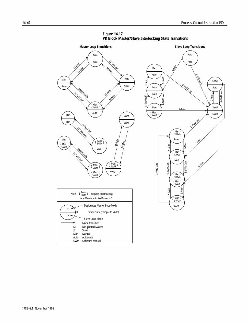
14-42 Process Control Instruction PID
Figure 14.17 PD Block Master/Slave Interlocking State Transitions
ManSWM
Auto
( )
Auto
Auto
Man
Man
SWM
Auto
Man
Auto
Man
Man
SWM
SWM
Auto
Man
Man
Man
Man
Auto
Man
Auto
Auto
SWM
Auto
SWM
SWM
Note: indicates that this loop
is in Manual with SWM also on".
*
*
Designates Master Loop Mode
Stable State (Composite Mode)
Slave Loop Mode
Mode transitionDesignated MasterSlave
MSMan ManualAuto AutomaticSWM Software Manual
Master Loop Transitions Slave Loop Transitions
SWM
SWM
ManSWM( )
ManSWM( )
ManSWM( )
ManSWM( )
ManSWM( )
ManSWM( )
ManSWM( )
ManSWM( )
ManSWM( )
ManSWM( )
ManSWM( )
ManSWM( )
S-SWM (on)
M-A
uto
M-M
an
M-Auto
M-Man
M-Auto
M-Man
M-SWM (on)
M-SWM (off)
M-SWM (on)M-Auto
M-SWM (on)
M-SWM (off)
M-SWM (on)
M-SWM (off)
S-Auto
S-Au
to
S-M
anS-
SWM
(on)
S-SW
M (o
ff)
S-Au
to
S-SW
M (o
n)
S-SW
M (o
ff)
S-SW
M (o
ff)
S-SW
M (o
n)
S-Au
to
S-M
anS-
Auto
S-M
an
S-Man
S-SW
M (on)
S-Man
S-M
an
S-SWM
(on)
1785-6.1 November 1998

Chapter 15
Block-Transfer Instructions BTR and BTW ControlNet I/O Transfer Instruction CIO
Using Block Transfer and ControlNet I/O Transfer Instructions
%ORFN�WUDQVIHU�LQVWUXFWLRQV�OHW�\RX�WUDQVIHU�ZRUGV�WR�RU�IURP�D�EORFN�WUDQVIHU�PRGXOH��&RQWURO1HW�,�2�WUDQVIHU�LQVWUXFWLRQV�OHW�\RX�SHUIRUP�XQVFKHGXOHG�WUDQVIHUV�WR�,�2�PRGXOHV�RQ�D�&RQWURO1HW��QHWZRUN��7DEOH����$�OLVWV�WKH�DYDLODEOH�EORFN�WUDQVIHU�DQG�&RQWURO1HW�,�2�WUDQVIHU�LQVWUXFWLRQV�
Table 15.A Available Block Transfer and ControlNet I/O Transfer Instructions
)RU�PRUH�LQIRUPDWLRQ�RQ�WKH�RSHUDQGV��DQG�YDOLG�GDWD�W\SHV�YDOXHV�RI�HDFK�RSHUDQG��XVHG�E\�WKH�LQVWUXFWLRQV�GLVFXVVHG�LQ�WKLV�FKDSWHU��VHH�$SSHQGL[�&�
Using Block Transfer Instructions :LWK�EORFN�WUDQVIHU�LQVWUXFWLRQV��\RX�FDQ�WUDQVIHU�XS�WR����ZRUGV�DW�D�WLPH�WR�RU�IURP�D�EORFN�WUDQVIHU�PRGXOH�LQ�D�ORFDO�RU�UHPRWH�,�2�FKDVVLV��<RX�FDQ�DOVR�WUDQVIHU�XS�WR����ZRUGV�DW�D�WLPH�EHWZHHQ�D�VXSHUYLVRU\�SURFHVVRU��VFDQQHU�PRGH��DQG�D�SURFHVVRU�FRQILJXUHG�IRU�DGDSWHU�PRGH�
7KH�(QKDQFHG�3/&���SURFHVVRUV�KDYH�FRQILJXUDEOH�FRPPXQLFDWLRQ�FKDQQHOV��FKRRVH�EHWZHHQ�UHPRWH�,�2�VFDQQHU��UHPRWH�,�2�DGDSWHU��RU�'+���/DGGHU�EORFN�WUDQVIHU�LQVWUXFWLRQV�DUH�QRW�QHFHVVDU\�ZKHQ�XVLQJ�(QKDQFHG�3/&���SURFHVVRUV�LQ�DGDSWHU�PRGH�
7DEOH����%�GHVFULEHV�KRZ�WR�EORFN�WUDQVIHU�GDWD�WR�D�ORFDO�RU�UHPRWH�UDFN�ZKHQ�WKH�SURFHVVRU�LV�FRQILJXUHG�IRU�VFDQQHU�PRGH��)LJXUH������LOOXVWUDWHV�KRZ�WKH�WUDQVIHU�RFFXUV�
If You Want to:Use this Instruction:
Found on Page:
Transfer words to a block transfer module BTW 15-3
Transfer words from a block transfer module
BTR 15-3
Perform unscheduled transfers to I/O modules on a ControlNet network
CIO 15-22
1785-6.1 November 1998
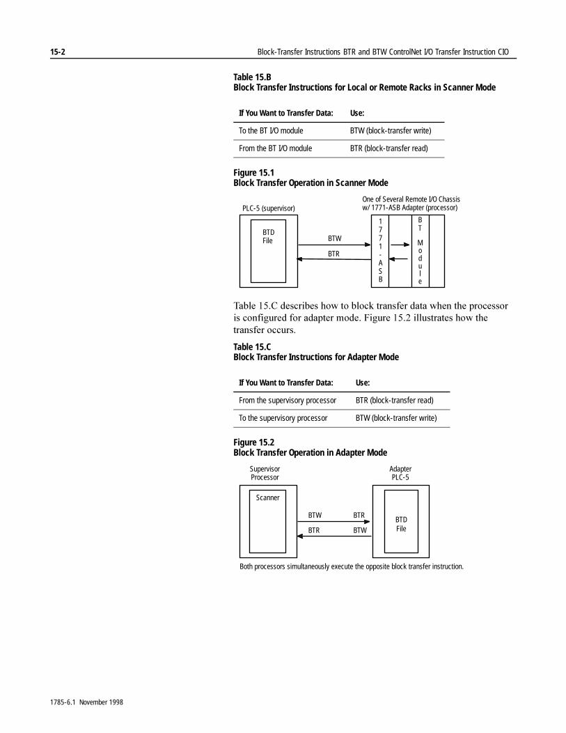
15-2 Block-Transfer Instructions BTR and BTW ControlNet I/O Transfer Instruction CIO
Table 15.B Block Transfer Instructions for Local or Remote Racks in Scanner Mode
Figure 15.1 Block Transfer Operation in Scanner Mode
7DEOH����&�GHVFULEHV�KRZ�WR�EORFN�WUDQVIHU�GDWD�ZKHQ�WKH�SURFHVVRU�LV�FRQILJXUHG�IRU�DGDSWHU�PRGH��)LJXUH������LOOXVWUDWHV�KRZ�WKH�WUDQVIHU�RFFXUV�
Table 15.C Block Transfer Instructions for Adapter Mode
Figure 15.2 Block Transfer Operation in Adapter Mode
If You Want to Transfer Data: Use:
To the BT I/O module BTW (block-transfer write)
From the BT I/O module BTR (block-transfer read)
If You Want to Transfer Data: Use:
From the supervisory processor BTR (block-transfer read)
To the supervisory processor BTW (block-transfer write)
One of Several Remote I/O Chassisw/ 1771-ASB Adapter (processor)
BTDFile
1771-ASB
BT
Module
BTW
BTR
PLC-5 (supervisor)
AdapterPLC-5
Scanner
BTR
BTWBTDFile
BTW
BTR
Both processors simultaneously execute the opposite block transfer instruction.
SupervisorProcessor
1785-6.1 November 1998
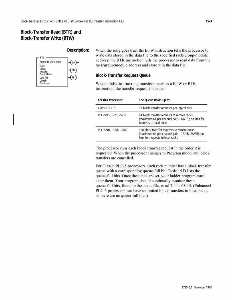
Block-Transfer Instructions BTR and BTW ControlNet I/O Transfer Instruction CIO 15-3
Block-Transfer Read (BTR) and Block-Transfer Write (BTW)
Description: :KHQ�WKH�UXQJ�JRHV�WUXH��WKH�%7:�LQVWUXFWLRQ�WHOOV�WKH�SURFHVVRU�WR�ZULWH�GDWD�VWRUHG�LQ�WKH�GDWD�ILOH�WR�WKH�VSHFLILHG�UDFN�JURXS�PRGXOH�DGGUHVV��WKH�%75�LQVWUXFWLRQ�WHOOV�WKH�SURFHVVRU�WR�UHDG�GDWD�IURP�WKH�UDFN�JURXS�PRGXOH�DGGUHVV�DQG�VWRUH�LW�LQ�WKH�GDWD�ILOH�
Block-Transfer Request Queue
:KHQ�D�IDOVH�WR�WUXH�UXQJ�WUDQVLWLRQ�HQDEOHV�D�%7:�RU�%75�LQVWUXFWLRQ��WKH�WUDQVIHU�UHTXHVW�LV�TXHXHG�
7KH�SURFHVVRU�UXQV�HDFK�EORFN�WUDQVIHU�UHTXHVW�LQ�WKH�RUGHU�LW�LV�UHTXHVWHG��:KHQ�WKH�SURFHVVRU�FKDQJHV�WR�3URJUDP�PRGH��DQ\�EORFN�WUDQVIHUV�DUH�FDQFHOOHG�
)RU�&ODVVLF�3/&���SURFHVVRUV��HDFK�UDFN�QXPEHU�KDV�D�EORFN�WUDQVIHU�TXHXH�ZLWK�D�FRUUHVSRQGLQJ�TXHXH�IXOO�ELW��7DEOH����'�OLVWV�WKH�TXHXH�IXOO�ELWV��2QFH�WKHVH�ELWV�DUH�VHW��\RXU�ODGGHU�SURJUDP�PXVW�FOHDU�WKHP��<RXU�SURJUDP�VKRXOG�FRQWLQXDOO\�PRQLWRU�WKHVH�TXHXH�IXOO�ELWV��IRXQG�LQ�WKH�VWDWXV�ILOH��ZRUG����ELWV���������(QKDQFHG�3/&���SURFHVVRUV�FDQ�KDYH�XQOLPLWHG�EORFN�WUDQVIHUV�LQ�ORFDO�UDFNV��VR�WKHUH�DUH�QR�TXHXH�IXOO�ELWV��
ENBLOCK TRNSFR READ
RackGroupModuleControl Block
DN
Data fileLength
ER
BTR
Continuous
For this Processor: The Queue Holds Up to:
Classic PLC-5 17 block transfer requests per logical rack
PLC-5/11, 5/20, -5/30 64 block transfer requests to remote racks (maximum 64 per channel pair – 1A/1B); no limit for requests to local racks
PLC-5/40, -5/60, -5/80 128 block transfer requests to remote racks (maximum 64 per channel pair – 1A/1B, 2A/2B); no limit for requests to local racks
1785-6.1 November 1998

15-4 Block-Transfer Instructions BTR and BTW ControlNet I/O Transfer Instruction CIO
Table 15.D Queue-Full Bits for Block Transfer Requests (Word 7) – Classic PLC-5 Processors
7KH�QXPEHU�RI�UDFNV�LQ�\RXU�V\VWHP�GHSHQGV�RQ�WKH�SURFHVVRU�\RX�XVH�
$�%75�RU�%7:�LQVWUXFWLRQ�ZULWHV�YDOXHV�LQWR�LWV�FRQWURO�EORFN�DGGUHVV��D�ILYH�ZRUG�LQWHJHU�ILOH��ZKHQ�WKH�LQVWUXFWLRQ�LV�HQWHUHG��7KH�SURFHVVRU�XVHV�WKHVH�YDOXHV�WR�H[HFXWH�WKH�WUDQVIHU�
7KH�(QKDQFHG�3/&���SURFHVVRUV�DOVR�KDYH�D�EORFN�WUDQVIHU�ILOH�W\SH��%7���<RX�FDQ�VWLOO�XVH�H[LVWLQJ�SURJUDPV�ZLWK�LQWHJHU�ILOH�W\SHV��EXW�WKH�QHZ�%7�ILOH�W\SH�PDNHV�DGGUHVVLQJ�HDVLHU��)RU�H[DPSOH��LI�\RX�QHHG�WZR�FRQWURO�ILOHV��\RX�FDQ�XVH�%7�����DQG�%7������XVLQJ�LQWHJHU�ILOHV��\RX�ZRXOG�KDYH�WR�XVH��IRU�H[DPSOH��1����DQG�1����
Entering Parameters
7R�SURJUDP�D�%7:�RU�%75�LQVWUXFWLRQ��\RX�PXVW�SURYLGH�WKH�SURFHVVRU�ZLWK�WKH�IROORZLQJ�LQIRUPDWLRQ�WKDW�LW�VWRUHV�LQ�LWV�FRQWURO�EORFN�
� 5DFN�LV�WKH�,�2�UDFN�QXPEHU��������RFWDO��RI�WKH�,�2�FKDVVLV�LQ�ZKLFK�\RX�SODFHG�WKH�WDUJHW�,�2�PRGXOH��7DEOH����(�OLVWV�WKH�YDOLG�UDQJHV�IRU�UDFN�QXPEHUV�
Table 15.E Valid Ranges for Rack Number in Block Transfer Instructions
Bit Description
S:7/8 Block-transfer queue for rack 0 is full
S:7/9 Block-transfer queue for rack 1 is full
S:7/10 Block-transfer queue for rack 2 is full
S:7/11 Block-transfer queue for rack 3 is full
S:7/12 Block-transfer queue for rack 4 is full
S:7/13 Block-transfer queue for rack 5 is full
S:7/14 Block-transfer queue for rack 6 is full
S:7/15 Block-transfer queue for rack 7 is full
Processor Maximum Racks Valid Range for Rack Numbers (octal)
PLC-5/10, -5/11, -5/12, -5/15, -5/20, -5/VME
4 00-03
PLC-5/25, -5/30 8 00-07
PLC-5/40, -5/40L 16 00-17
PLC-5/60, -5/60L, -5/80 24 00-27
1785-6.1 November 1998
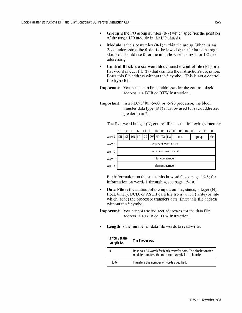
Block-Transfer Instructions BTR and BTW ControlNet I/O Transfer Instruction CIO 15-5
� *URXS�LV�WKH�,�2�JURXS�QXPEHU�������ZKLFK�VSHFLILHV�WKH�SRVLWLRQ�RI�WKH�WDUJHW�,�2�PRGXOH�LQ�WKH�,�2�FKDVVLV�
� 0RGXOH�LV�WKH�VORW�QXPEHU�������ZLWKLQ�WKH�JURXS��:KHQ�XVLQJ���VORW�DGGUHVVLQJ��WKH���VORW�LV�WKH�ORZ�VORW��WKH���VORW�LV�WKH�KLJK�VORW��<RX�VKRXOG�XVH���IRU�WKH�PRGXOH�ZKHQ�XVLQJ����RU�����VORW�DGGUHVVLQJ�
� &RQWURO�%ORFN�LV�D�VL[�ZRUG�EORFN�WUDQVIHU�FRQWURO�ILOH��%7��RU�D�ILYH�ZRUG�LQWHJHU�ILOH��1��WKDW�FRQWUROV�WKH�LQVWUXFWLRQ¶V�RSHUDWLRQ��(QWHU�WKLV�ILOH�DGGUHVV�ZLWKRXW�WKH���V\PERO��7KLV�LV�QRW�D�FRQWURO�ILOH��W\SH�5��
,PSRUWDQW���<RX�FDQ�XVH�LQGLUHFW�DGGUHVVHV�IRU�WKH�FRQWURO�EORFN�DGGUHVV�LQ�D�%75�RU�%7:�LQVWUXFWLRQ�
,PSRUWDQW��� ,Q�D�3/&��������������RU�������SURFHVVRU��WKH�EORFN�WUDQVIHU�GDWD�W\SH��%7��PXVW�EH�XVHG�IRU�UDFN�DGGUHVVHV�JUHDWHU�WKDQ���
7KH�ILYH�ZRUG�LQWHJHU��1��FRQWURO�ILOH�KDV�WKH�IROORZLQJ�VWUXFWXUH�
)RU�LQIRUPDWLRQ�RQ�WKH�VWDWXV�ELWV�LQ�ZRUG����VHH�SDJH�������IRU�LQIRUPDWLRQ�RQ�ZRUGV���WKURXJK����VHH�SDJH�������
� 'DWD�)LOH�LV�WKH�DGGUHVV�RI�WKH�LQSXW��RXWSXW��VWDWXV��LQWHJHU��1���IORDW��ELQDU\��%&'��RU�$6&,,�GDWD�ILOH�IURP�ZKLFK��ZULWH��RU�LQWR�ZKLFK��UHDG��WKH�SURFHVVRU�WUDQVIHUV�GDWD��(QWHU�WKLV�ILOH�DGGUHVV�ZLWKRXW�WKH���V\PERO�
,PSRUWDQW���<RX�FDQQRW�XVH�LQGLUHFW�DGGUHVVHV�IRU�WKH�GDWD�ILOH�DGGUHVV�LQ�D�%75�RU�%7:�LQVWUXFWLRQ�
� /HQJWK�LV�WKH�QXPEHU�RI�GDWD�ILOH�ZRUGV�WR�UHDG�ZULWH�
If You Set the Length to:
The Processor:
0 Reserves 64 words for block transfer data. The block transfer module transfers the maximum words it can handle.
1 to 64 Transfers the number of words specified.
requested word count
transmitted word count
DNSTEN
08 07 06 05 04 03 02 01 0009101112131415
element number
file-type number
word 0 EWCOER TONR RW rack group slot
word 1
word 2
word 3
word 4
1785-6.1 November 1998
15-6 Block-Transfer Instructions BTR and BTW ControlNet I/O Transfer Instruction CIO
,PSRUWDQW���$�IORDWLQJ�SRLQW�HOHPHQW�FRQVLVWV�RI�WZR�ZRUGV��ZKHQ�\RX�VSHFLI\�D�YDOXH�LQ�WKH�/HQJWK�ILHOG�IRU�D�IORDWLQJ�SRLQW�GDWD�ILOH��RQO\�KDOI�RI�WKRVH�IORDWLQJ�SRLQW�HOHPHQWV�DUH�UHDG�ZULWWHQ��)RU�H[DPSOH��LI�\RX�VSHFLI\����IRU�WKH�OHQJWK�����IORDWLQJ�SRLQW�HOHPHQWV�ZLOO�DFWXDOO\�EH�UHDG�ZULWWHQ�
,PSRUWDQW���)ORDWLQJ�SRLQW�GDWD�ILOH�OHQJWKV�PXVW�EH�DQ�HYHQ�QXPEHU�
� &RQWLQXRXV�GHWHUPLQHV�WKH�PRGH�RI�RSHUDWLRQ���
Using Status Bits 7R�XVH�WKH�%75�DQG�%7:�LQVWUXFWLRQV�FRUUHFWO\��H[DPLQH�WKH�LQVWUXFWLRQ¶V�VWDWXV�ELWV�VWRUHG�LQ�WKH�FRQWURO�EORFN��7KHVH�ELWV�DUH�LQ�ZRUG���RI�WKH�FRQWURO�EORFN��
,PSRUWDQW���7KH�ELW�ODEHOV���(1���67���&2��HWF���FDQ�RQO\�EH�XVHG�ZLWK�WKH�EORFN�WUDQVIHU�ILOH�W\SH��%7���
If You Specify: The Instruction Uses This Mode:
Yes Continuous – once the rung goes true, the instruction continues to transfer data until the continuous (.CO) bit is reset and the rung is false or you edit the instruction and specify NO for continuous mode.
No Non-continuous – the instruction is enabled each time the rung goes true and performs only one data transfer per rung transition.
�$77(17,21� ([FHSW�IRU�WKH�FRQWLQXRXV�ELW��&2��ELW�����DQG�WKH�WLPHRXW�ELW��72��ELW������GR�QRW�PRGLI\�DQ\�VWDWXV�ELW�ZKLOH�WKH�EORFN�WUDQVIHU�LQVWUXFWLRQ�LV�HQDEOHG��8QSUHGLFWDEOH�RSHUDWLRQ�FRXOG�RFFXU�ZLWK�SRVVLEOH�GDPDJH�WR�HTXLSPHQW�DQG�RU�LQMXU\�WR�SHUVRQQHO�
This Bit: Is Set:
Enable .EN (bit 15) when the rung goes true. This bit shows that the instruction is enabled (that the block transfer is in progress).In non-continuous mode, the .EN bit remains set until the block transfer finishes or fails and the rung goes false.In continuous mode, once the .EN bit is set, it remains set regardless of the rung condition.
Start .ST (bit 14) when the processor begins transferring data. The .ST bit is reset at the false-to-true transition after the .DN bit or .ER bit is set.
Done .DN (bit 13) at completion of the block transfer, if the data is valid. The .DN bit is set asynchronous to the program scan so the .DN bit may go true any time after the block transfer is initiated. The .DN bit is reset the next time the associated rung goes from false to true.
1785-6.1 November 1998
Block-Transfer Instructions BTR and BTW ControlNet I/O Transfer Instruction CIO 15-7
,PSRUWDQW���:KHQ�XVLQJ�LQWHJHU��1��DQG�EORFN�WUDQVIHU��%7��ILOH�W\SHV��WKH��(1���67���'1���(5���(:��DQG��15�ELWV�DUH�FOHDUHG�GXULQJ�SUHVFDQ�
<RXU�ODGGHU�SURJUDP�VKRXOG�FRQGLWLRQ�WKH�XVH�RI�EORFN�WUDQVIHU�GDWD�RQ�WKH�VWDWH�RI�WKH��'1�ELW�
Error .ER (bit 12) when the processor detects that the block transfer failed. The .ER bit is reset the next time the associated rung goes from false to true.
Continue .CO (bit 11) when you edit the instruction for repeated operation of the block transfer after the first scan, independent of whether the processor continues to scan the rung.Reset the .CO bit if you want the rung condition to initiate block transfers (return to non-continuous mode). If you are using continuous block transfers in a sequential function chart, see Appendix B, “SFC Reference,” in this manual.
Enable-waiting .EW (bit 10)
when the block transfer request enters the queue. If the queue is full, this bit remains reset until there is room in the queue.The .EW bit is reset when the associated rung goes from false to true.In continuous mode, once the .EW bit it set, it remains set.Use the .EW bit to verify that a BTW or BTR instruction is queued before leaving an SFC step.
No Response .NR (bit 09) if the block transfer module does not respond to the first local block transfer request. The .NR bit is reset when the associated rung goes from false to true (not used with remote block transfer).
Time Out .TO (bit 08) if you reset the time out bit through ladder logic or data monitor, the processor repeatedly tries to send a block transfer request to an unresponsive module for four seconds before setting the .ER bit.If you set the .TO bit through ladder logic or data monitor, the processor disables the four-second timer and requests a block transfer one more time before setting the .ER bit.
Read-Write .RW (bit 07) controlled by the instruction. A 0 indicates a write operation; a 1 indicates a read operation.
This Bit: Is Set:
�$77(17,21� 7KH�SURFHVVRU�UXQV�EORFN�WUDQVIHU�LQVWUXFWLRQV�DV\QFKURQRXVO\�WR�SURJUDP�VFDQ��7KH�VWDWXV�RI�WKHVH�ELWV�FRXOG�FKDQJH�DW�DQ\�SRLQW�LQ�WKH�SURJUDP�VFDQ��,I�\RX�H[DPLQH�WKHVH�ELWV�LQ�ODGGHU�ORJLF��FRS\�WKH�VWDWXV�RQFH�WR�D�VWRUDJH�ELW�ZKRVH�VWDWXV�LV�V\QFKURQL]HG�ZLWK�WKH�SURJUDP�VFDQ��2WKHUZLVH��WLPLQJ�SUREOHPV�PD\�LQYDOLGDWH�\RXU�SURJUDP�ZLWK�SRVVLEOH�GDPDJH�WR�HTXLSPHQW�RU�LQMXU\�WR�SHUVRQQHO�
1785-6.1 November 1998
15-8 Block-Transfer Instructions BTR and BTW ControlNet I/O Transfer Instruction CIO
Using the Control Block ,Q�DGGLWLRQ�WR�WKH�VWDWXV�ELWV��WKH�FRQWURO�EORFN�FRQWDLQV�RWKHU�SDUDPHWHUV�WKH�SURFHVVRU�XVHV�WR�FRQWURO�EORFN�WUDQVIHU�LQVWUXFWLRQV��7DEOH����)�OLVWV�WKHVH�YDOXHV�
Table 15.F Values in the Block Transfer Control Block
Requested Word Count (.RLEN)
7KLV�LV�WKH�QXPEHU�RI�ZRUGV�WR�EH�WUDQVIHUUHG�EHWZHHQ�WKH�SURFHVVRU�DQG�WKH�PRGXOH�������ZRUGV���WKH�SURFHVVRU�FUHDWHV�D�ILOH�RI�WKH�OHQJWK�\RX�VSHFLILHG�WKDW�VWDUWV�DW�WKH�GDWD�DGGUHVV�\RX�HQWHU��7KH�OHQJWK�GHSHQGV�RQ�WKH�WDUJHW�PRGXOH�RU�\RXU�DSSOLFDWLRQ��)RU�H[DPSOH��LI�\RX�VSHFLI\����LQ�WKLV�ILHOG��\RX�DUH�VSHFLI\LQJ�D�EORFN�OHQJWK�RI����DQG�WKH�SURFHVVRU�FUHDWHV�D����ZRUG�ILOH��LI�\RX�VSHFLI\�����\RX�DUH�VSHFLI\LQJ�D�EORFN�OHQJWK�RI����DQG�WKH�SURFHVVRU�FUHDWHV�D����ZRUG�ILOH��,I�\RX�VSHFLI\�D���ZKHQ�\RX�HQWHU�WKH�EORFN�WUDQVIHU�LQVWUXFWLRQ��WKH�SURFHVVRU�OHWV�WKH�EORFN�WUDQVIHU�PRGXOH�GHWHUPLQH�WKH�QXPEHU�RI�ZRUGV�WKDW�QHHG�WR�EH�WUDQVIHUUHG�DQG�FUHDWHV�D�GHIDXOW����ZRUG�ILOH�
Transmitted Word Count (.DLEN)
7KLV�LV�WKH�QXPEHU�RI�ZRUGV�WKH�PRGXOH�DFWXDOO\�WUDQVIHUUHG�DIWHU�WKH�LQVWUXFWLRQ�FRPSOHWHV�H[HFXWLRQ��7KH�SURFHVVRU�XVHV�WKLV�QXPEHU�WR�YHULI\�WKH�WUDQVIHU��7KLV�QXPEHU�VKRXOG�PDWFK�WKH�UHTXHVWHG�ZRUG�FRXQW��XQOHVV�WKH�WUDQVPLWWHG�ZRUG�FRXQW�LV�]HUR���,I�WKHVH�QXPEHUV�GR�QRW�PDWFK��WKH�SURFHVVRU�VHWV�WKH��(5�ELW��ELW�����
7KH�(QKDQFHG�3/&���SURFHVVRUV�DOVR�KDYH�HUURU�FRGHV��ZRUG���RI�WKH�LQWHJHU�ILOH�FRQWURO�EORFN�RU�VWRUHG�LQ�WKH��'/(1�ZRUG�RI�WKH�%7�FRQWURO�EORFN��WKDW�WKH�SURFHVVRU�FDQ�VHW�GXULQJ�WKH�WUDQVIHU��,I�D�EORFN�WUDQVIHU�HUURU�RFFXUV�LQ�DQ�(QKDQFHG�3/&���SURFHVVRU��WKH�HUURU�FRGH�LV�VWRUHG�LQ�WKH�WUDQVPLWWHG�ZRUG�FRXQW��7KLV�HUURU�FDQ�EH�LGHQWLILHG�E\�LWV�QHJDWLYH�QXPEHU��2QO\�RQH�HUURU�FRGH�LV�VWRUHG�DW�D�WLPH��D�QHZ�HUURU�FRGH�RYHUZULWHV�DQ\�SUHYLRXV�HUURU�FRGH���7DEOH����*�OLVWV�WKHVH�HUURU�FRGHV�
Word – Integer Control Bock
BT Control Block Description
0 .EN through .RW Status bits
1 .RLEN Requested word count
2 .DLEN Transmitted word count / error code(Enhanced PLC-5 processors)
3 .FILE File type / number
4 .ELEM Element number
1785-6.1 November 1998

Block-Transfer Instructions BTR and BTW ControlNet I/O Transfer Instruction CIO 15-9
Table 15.G Enhanced PLC-5 Processor Block Transfer Error Codes
File Number (.FILE)
7KLV�QXPEHU�LGHQWLILHV�WKH�ILOH�QXPEHU�RI�WKH�LQWHJHU�ILOH�IURP�ZKLFK�WKH�GDWD�LV�ZULWWHQ�RU�WR�ZKLFK�WKH�GDWD�LV�UHDG��)RU�H[DPSOH��WKH�ILOH�QXPEHU�RI�1�����LV���
Element Number (.ELEM)
7KLV�QXPEHU�LGHQWLILHV�WKH�VWDUWLQJ�ZRUG�LQ�WKH�GDWD�ILOH�DGGUHVV��)RU�H[DPSOH��LQ�1������WKH�ZRUG�QXPEHU�LV����
ErrorNumber:
Description:
–1 not used
–2 not used
–3 The size of the block transfer plus the size of the index in the block transfer data table was greater than the size of the block transfer data table file.
–4 There was an invalid transfer of block transfer write data between the adapter and the block transfer module.
–5 The checksum of the block transfer read data was wrong.
–6 The block transfer module requested a different length than the associated block transfer instruction. This could happen if a 64-word block transfer instruction was executed and the block transfer module’s default length was not 64 words.
–7 Block transfer data was lost due to a bad communication channel. Possible reasons are noise, bad connections, and loose wires. Check resistors.
–8 Error in block transfer protocol – unsolicited block transfer.
–9 The block transfer timeout, set in the instruction, timed out before completion.
–10 No communication channels are configured for remote I/O or rack number does not appear in rack list.
–11 No communication channels are configured for the requested rack or slot.
–12 The adapter is faulted or not present for the BT command.
–13 Queues for remote block transfers are full.
1785-6.1 November 1998

15-10 Block-Transfer Instructions BTR and BTW ControlNet I/O Transfer Instruction CIO
Selecting Continuous Operation &RQWLQXRXV�EORFN�WUDQVIHU�LV�VLPLODU�WR�GLVFUHWH�,�2�WUDQVIHU�LQ�WKDW�WKH�,�2�LV�XSGDWHG�FRQWLQXRXVO\��EXW�FRQWLQXRXV�EORFN�WUDQVIHU�XSGDWHV�EORFN�WUDQVIHU�,�2��VXFK�DV�DQDORJ�LQSXW�DQG�DQDORJ�RXWSXW�GDWD�
&RQWLQXRXV�PRGH�OHWV�\RX�SHUIRUP�PXOWLSOH�EORFN�WUDQVIHUV�E\�SURJUDPPLQJ�RQO\�RQH�EORFN�WUDQVIHU�LQVWUXFWLRQ��ZLWK�QR�LQSXW�FRQGLWLRQV�RQ�WKH�UXQJ���2QFH�WKH�FRQWLQXRXV�EORFN�WUDQVIHU�VWDUWV��WKH�WUDQVIHU�LV�FRQWLQXRXVO\�H[HFXWHG�RQFH�SHU�VFDQ��LQGHSHQGHQW�RI�ZKHWKHU�WKH�SURFHVVRU�FRQWLQXHV�WR�VFDQ�WKH�DVVRFLDWHG�UXQJ�DQG�LQGHSHQGHQW�RI�WKH�UXQJ�FRQGLWLRQ��7R�HQDEOH�FRQWLQXRXV�RSHUDWLRQ��VHOHFW�&RQWLQXRXV�ZKHQ�\RX�HQWHU�WKH�EORFN�WUDQVIHU�LQVWUXFWLRQ�
&RQWLQXRXV�PRGH�ZRUNV�DV�IROORZV��)LJXUH�������
�� :KHQ�WKH�UXQJ�WKDW�FRQWDLQV�WKH�EORFN�WUDQVIHU�LQVWUXFWLRQ�JRHV�WUXH��WKH�SURFHVVRU�VHWV�WKH��(1�ELW��7KH�SURFHVVRU�DOVR�UHVHWV�WKH��'1���(5���67���(:�DQG��15�ELWV�
�� 7KH�SURFHVVRU�WKHQ�TXHXHV�WKH�EORFN�WUDQVIHU�UHTXHVW��:KHQ�WKH�EORFN�WUDQVIHU�UHTXHVW�HQWHUV�WKH�TXHXH��WKH�SURFHVVRU�VHWV�WKH��(:�ELW�
�� :KHQ�WKH�SURFHVVRU�VWDUWV�WR�SURFHVV�WKH�EORFN�WUDQVIHU�UHTXHVW��WKH�SURFHVVRU�VHWV�WKH��67�ELW�
�� ,I�QR�HUURU�RFFXUV�GXULQJ�WUDQVPLVVLRQ��WKH�SURFHVVRU�VHWV�WKH��'1�ELW��7KH�SURFHVVRU�FRSLHV�WKH�DFWXDO�QXPEHU�RI�HOHPHQWV�VHQW�RU�UHFHLYHG�E\�WKH�EORFN�WUDQVIHU�LQVWUXFWLRQ�LQWR�WKH�WUDQVPLWWHG�ZRUG�FRXQW��ZRUG���RI�WKH�FRQWURO�EORFN��
,I�DQ�HUURU�RFFXUV��WKH�SURFHVVRU�VHWV�WKH��(5�ELW��,I�DQ�HUURU�RFFXUV�LQ�DQ�(QKDQFHG�3/&���SURFHVVRU��WKH�SURFHVVRU�DOVR�SXWV�WKH�HUURU�FRGH�LQ�WKH�WUDQVPLWWHG�ZRUG�FRXQW�ORFDWLRQ�DV�D�QHJDWLYH�QXPEHU�
�� ,I�WKHUH�LV�QR�UHVSRQVH��DQG�DIWHU�WKH�SURFHVVRU�VHWV�WKH��15�ELW���WKH�SURFHVVRU�WULHV�WR�VHQG�WKH�EORFN�WUDQVIHU�DJDLQ��,I�WKH��72�ELW�LV�UHVHW��WKH�SURFHVVRU�UHSHDWHGO\�VHQGV�WKH�UHTXHVW�IRU�IRXU�VHF�RQGV��,I�WKH��72�ELW�LV�VHW��WKH�SURFHVVRU�RQO\�UHWULHV�WKH�UHTXHVW�RQH�WLPH�
�� ,I�D�FRQWLQXRXV�EORFN�WUDQVIHU�KDV�DQ�HUURU��\RX�PXVW�UHVWDUW�LW�WR�FRQWLQXH���6HH�)LJXUH������RQ�SDJH�������IRU�DQ�H[DPSOH�SURJUDP��
1785-6.1 November 1998

Block-Transfer Instructions BTR and BTW ControlNet I/O Transfer Instruction CIO 15-11
Figure 15.3 Timing Diagram for Status Bits in Continuous BTR and BTW Instructions
$�FRQWLQXRXV�EORFN�WUDQVIHU�FRQWLQXHV�DV�ORQJ�DV�WKH�SURFHVVRU�VWD\V�LQ�5XQ�RU�7HVW�PRGH�DQG�WKH�WUDQVIHU�GRHV�QRW�HUURU��,I�\RX�VZLWFK�WR�3URJUDP�PRGH�RU�WKH�SURFHVVRU�IDXOWV��WKH�EORFN�WUDQVIHU�VWRSV�DQG�ZLOO�QRW�VWDUW�DJDLQ�XQWLO�WKH�SURFHVVRU�VFDQV�WKH�UXQJ�WKDW�FRQWDLQV�WKH�EORFN�WUDQVIHU�LQVWUXFWLRQ��,I�UXQQLQJ�FRQWLQXRXV�EORFN�WUDQVIHUV�IURP�ZLWKLQ�VHTXHQWLDO�IXQFWLRQ�FKDUWV��VHH�DSSHQGL[�%�
7R�VWRS�FRQWLQXRXV�RSHUDWLRQ�HLWKHU��PRGLI\�WKH�EORFN�WUDQVIHU�LQVWUXFWLRQ�DQG�VHOHFW�QRQ�FRQWLQXRXV��RU�UHVHW�WKH��&2�ELW�
EN
EW
ST
DN
CO stage 1
stage 2
ER
Rung true Requestenters thequeue
Instructionbeginsexecution
Instructionfinishes
Rung trueRung false
Stage 1 - If .CO set, return to stage 2; if .CO reset, go to stage 3
Stage 2 - Return here for continuous operation
Stage 3 - Go here if .CO is reset
stage 3
1785-6.1 November 1998
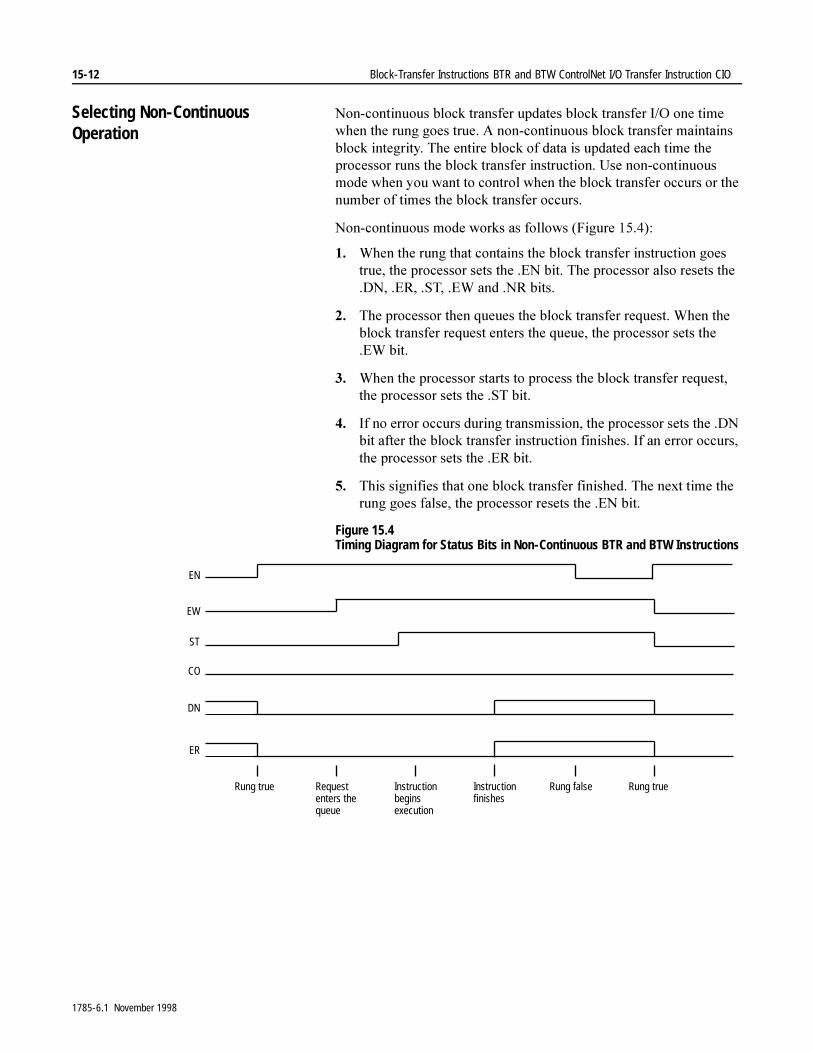
15-12 Block-Transfer Instructions BTR and BTW ControlNet I/O Transfer Instruction CIO
Selecting Non-Continuous Operation
1RQ�FRQWLQXRXV�EORFN�WUDQVIHU�XSGDWHV�EORFN�WUDQVIHU�,�2�RQH�WLPH�ZKHQ�WKH�UXQJ�JRHV�WUXH��$�QRQ�FRQWLQXRXV�EORFN�WUDQVIHU�PDLQWDLQV�EORFN�LQWHJULW\��7KH�HQWLUH�EORFN�RI�GDWD�LV�XSGDWHG�HDFK�WLPH�WKH�SURFHVVRU�UXQV�WKH�EORFN�WUDQVIHU�LQVWUXFWLRQ��8VH�QRQ�FRQWLQXRXV�PRGH�ZKHQ�\RX�ZDQW�WR�FRQWURO�ZKHQ�WKH�EORFN�WUDQVIHU�RFFXUV�RU�WKH�QXPEHU�RI�WLPHV�WKH�EORFN�WUDQVIHU�RFFXUV�
1RQ�FRQWLQXRXV�PRGH�ZRUNV�DV�IROORZV��)LJXUH�������
�� :KHQ�WKH�UXQJ�WKDW�FRQWDLQV�WKH�EORFN�WUDQVIHU�LQVWUXFWLRQ�JRHV�WUXH��WKH�SURFHVVRU�VHWV�WKH��(1�ELW��7KH�SURFHVVRU�DOVR�UHVHWV�WKH��'1���(5���67���(:�DQG��15�ELWV�
�� 7KH�SURFHVVRU�WKHQ�TXHXHV�WKH�EORFN�WUDQVIHU�UHTXHVW��:KHQ�WKH�EORFN�WUDQVIHU�UHTXHVW�HQWHUV�WKH�TXHXH��WKH�SURFHVVRU�VHWV�WKH��(:�ELW�
�� :KHQ�WKH�SURFHVVRU�VWDUWV�WR�SURFHVV�WKH�EORFN�WUDQVIHU�UHTXHVW��WKH�SURFHVVRU�VHWV�WKH��67�ELW�
�� ,I�QR�HUURU�RFFXUV�GXULQJ�WUDQVPLVVLRQ��WKH�SURFHVVRU�VHWV�WKH��'1�ELW�DIWHU�WKH�EORFN�WUDQVIHU�LQVWUXFWLRQ�ILQLVKHV��,I�DQ�HUURU�RFFXUV��WKH�SURFHVVRU�VHWV�WKH��(5�ELW�
�� 7KLV�VLJQLILHV�WKDW�RQH�EORFN�WUDQVIHU�ILQLVKHG��7KH�QH[W�WLPH�WKH�UXQJ�JRHV�IDOVH��WKH�SURFHVVRU�UHVHWV�WKH��(1�ELW�
Figure 15.4 Timing Diagram for Status Bits in Non-Continuous BTR and BTW Instructions
EN
EW
ST
DN
CO
ER
Rung true Rung trueRung falseRequestenters thequeue
Instructionbeginsexecution
Instructionfinishes
1785-6.1 November 1998
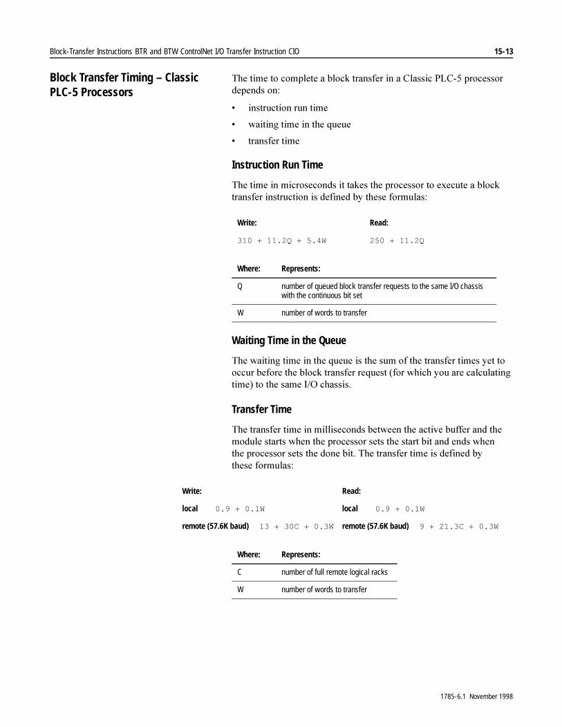
Block-Transfer Instructions BTR and BTW ControlNet I/O Transfer Instruction CIO 15-13
Block Transfer Timing – Classic PLC-5 Processors
7KH�WLPH�WR�FRPSOHWH�D�EORFN�WUDQVIHU�LQ�D�&ODVVLF�3/&���SURFHVVRU�GHSHQGV�RQ�
� LQVWUXFWLRQ�UXQ�WLPH
� ZDLWLQJ�WLPH�LQ�WKH�TXHXH
� WUDQVIHU�WLPH
Instruction Run Time
7KH�WLPH�LQ�PLFURVHFRQGV�LW�WDNHV�WKH�SURFHVVRU�WR�H[HFXWH�D�EORFN�WUDQVIHU�LQVWUXFWLRQ�LV�GHILQHG�E\�WKHVH�IRUPXODV�
Waiting Time in the Queue
7KH�ZDLWLQJ�WLPH�LQ�WKH�TXHXH�LV�WKH�VXP�RI�WKH�WUDQVIHU�WLPHV�\HW�WR�RFFXU�EHIRUH�WKH�EORFN�WUDQVIHU�UHTXHVW��IRU�ZKLFK�\RX�DUH�FDOFXODWLQJ�WLPH��WR�WKH�VDPH�,�2�FKDVVLV�
Transfer Time
7KH�WUDQVIHU�WLPH�LQ�PLOOLVHFRQGV�EHWZHHQ�WKH�DFWLYH�EXIIHU�DQG�WKH�PRGXOH�VWDUWV�ZKHQ�WKH�SURFHVVRU�VHWV�WKH�VWDUW�ELW�DQG�HQGV�ZKHQ�WKH�SURFHVVRU�VHWV�WKH�GRQH�ELW��7KH�WUDQVIHU�WLPH�LV�GHILQHG�E\�WKHVH�IRUPXODV�
Write: Read:
310 + 11.2Q + 5.4W 250 + 11.2Q
Where: Represents:
Q number of queued block transfer requests to the same I/O chassis with the continuous bit set
W number of words to transfer
Write: Read:
local 0.9 + 0.1W local 0.9 + 0.1W
remote (57.6K baud) 13 + 30C + 0.3W remote (57.6K baud) 9 + 21.3C + 0.3W
Where: Represents:
C number of full remote logical racks
W number of words to transfer
1785-6.1 November 1998

15-14 Block-Transfer Instructions BTR and BTW ControlNet I/O Transfer Instruction CIO
Block Transfer Timing – Enhanced PLC-5 Processors
7KH�WLPH�WR�FRPSOHWH�D�EORFN�WUDQVIHU�LQ�(QKDQFHG�3/&���SURFHVVRUV�GHSHQGV�RQ�
� LQVWUXFWLRQ�UXQ�WLPH
� ZDLWLQJ�WLPH�LQ�WKH�KROGLQJ�DUHD��TXHXH�
� WUDQVIHU�WLPH
Instruction Run Time
7KH�WLPH�LW�WDNHV�WKH�SURFHVVRU�WR�H[HFXWH�D�EORFN�WUDQVIHU�LQVWUXFWLRQ�LV�WKH�VDPH�IRU�D�UHDG�RU�D�ZULWH������PLFURVHFRQGV�
Waiting Time in the Holding Area
7KH�ZDLWLQJ�WLPH�LQ�WKH�KROGLQJ�DUHD�LV�WKH�VXP�RI�WKH�WUDQVIHU�WLPHV�\HW�WR�RFFXU�EHIRUH�WKH�EORFN�WUDQVIHU�UHTXHVW��IRU�ZKLFK�\RX�DUH�FDOFXODWLQJ�WLPH��WR�WKH�VDPH�,�2�FKDVVLV�
Transfer Time
7KH�WUDQVIHU�WLPH�LQ�PLOOLVHFRQGV�EHWZHHQ�WKH�DFWLYH�EXIIHU�DQG�WKH�PRGXOH�VWDUWV�ZKHQ�WKH�SURFHVVRU�VHWV�WKH�VWDUW�ELW�DQG�HQGV�ZKHQ�WKH�SURFHVVRU�VHWV�WKH�GRQH�ELW��7KH�WUDQVIHU�WLPH�LV�GHILQHG�E\�WKLV�IRUPXOD��VDPH�IRU�D�UHDG�RU�ZULWH��
local 600 µsec + x(w)
remote (57.6K baud) 4 + 8C + 0.3W
remote (115K baud) 4 + 4.6C + 0.15W
remote (230K baud) 4 + 3.2C + 0.075W
Where this: Represents:
x • 8 or less block transfers queued in local rack = 86 µsec
• more than 8 block transfers queued in local rack = 300 µsecNote: This timing assumes that no other block transfers are queued to the same slot and that successive block transfers to the same slot are executed every 1000 µsec.
C number of full remote logical racks
W number of words to transfer
1785-6.1 November 1998
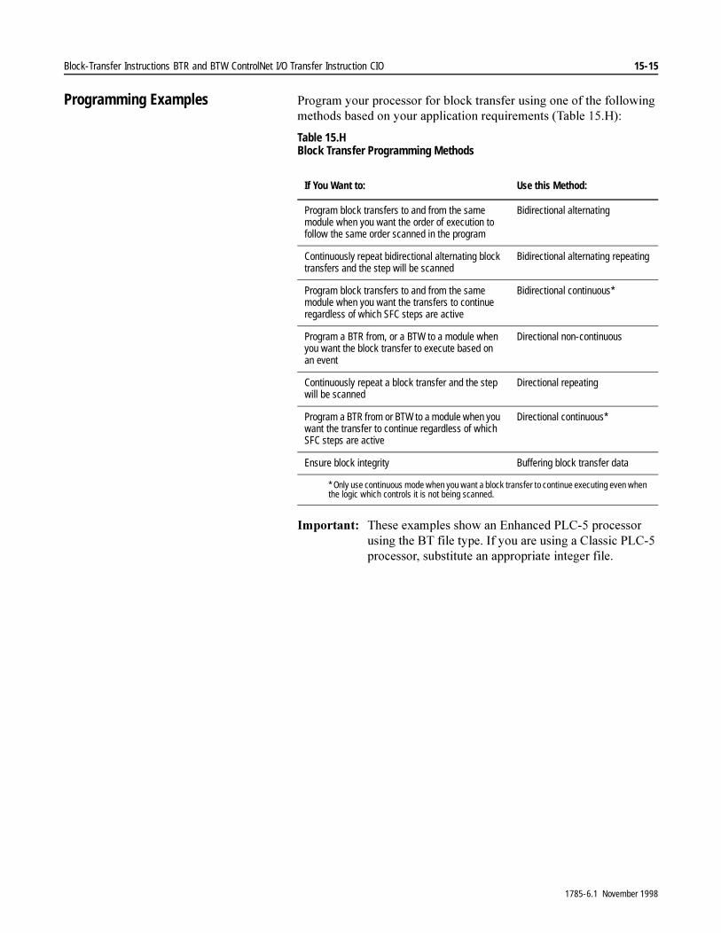
Block-Transfer Instructions BTR and BTW ControlNet I/O Transfer Instruction CIO 15-15
Programming Examples 3URJUDP�\RXU�SURFHVVRU�IRU�EORFN�WUDQVIHU�XVLQJ�RQH�RI�WKH�IROORZLQJ�PHWKRGV�EDVHG�RQ�\RXU�DSSOLFDWLRQ�UHTXLUHPHQWV��7DEOH����+��
Table 15.H Block Transfer Programming Methods
,PSRUWDQW���7KHVH�H[DPSOHV�VKRZ�DQ�(QKDQFHG�3/&���SURFHVVRU�XVLQJ�WKH�%7�ILOH�W\SH��,I�\RX�DUH�XVLQJ�D�&ODVVLF�3/&���SURFHVVRU��VXEVWLWXWH�DQ�DSSURSULDWH�LQWHJHU�ILOH�
If You Want to: Use this Method:
Program block transfers to and from the same module when you want the order of execution to follow the same order scanned in the program
Bidirectional alternating
Continuously repeat bidirectional alternating block transfers and the step will be scanned
Bidirectional alternating repeating
Program block transfers to and from the same module when you want the transfers to continue regardless of which SFC steps are active
Bidirectional continuous*
Program a BTR from, or a BTW to a module when you want the block transfer to execute based on an event
Directional non-continuous
Continuously repeat a block transfer and the step will be scanned
Directional repeating
Program a BTR from or BTW to a module when you want the transfer to continue regardless of which SFC steps are active
Directional continuous*
Ensure block integrity Buffering block transfer data
* Only use continuous mode when you want a block transfer to continue executing even when the logic which controls it is not being scanned.
1785-6.1 November 1998

15-16 Block-Transfer Instructions BTR and BTW ControlNet I/O Transfer Instruction CIO
Example Bidirectional Alternating Block-Transfer
)LJXUH������VKRZV�D�ELGLUHFWLRQDO�DOWHUQDWLQJ�EORFN�WUDQVIHU�H[DPSOH��8VLQJ�UXQJV�OLNH�WKLV�H[DPSOH�PDNHV�VXUH�WKH�EORFN�WUDQVIHU�UHTXHVWV�DUH�H[HFXWHG�LQ�WKH�RUGHU�LQ�ZKLFK�WKH\�ZHUH�VHQW�WR�WKH�TXHXH��7KH�SURFHVVRU�DOWHUQDWHV�EHWZHHQ�WKH�%75V�DQG�%7:V�LQ�WKH�RUGHU�LQ�ZKLFK�WKH\�DUH�VFDQQHG�E\�YLUWXH�RI�WKH�;,2�FRQGLWLRQ��7KH�;,2�FRQGLWLRQ�SUHYHQWV�WKH�EORFN�WUDQVIHU�UHDG�DQG�EORFN�WUDQVIHU�ZULWH�IURP�TXHXHLQJ�VLPXOWDQHRXVO\��7KH�EORFN�WUDQVIHU�FRQWLQXHV�DV�ORQJ�DV�WKH�RSWLRQDO�FRQGLWLRQ�LV�WUXH�
2Q�WKH�UXQJV�RI�ORJLF��\RX�PD\�LQFOXGH�DV�PDQ\�RSWLRQDO�FRQGLWLRQV�DV�\RX�ZLVK�WR�WKH�OHIW�RI�WKH�UHTXLUHG�HQDEOH�ELW�FRQGLWLRQ��;,2��WUDQVLWLRQ�
Figure 15.5 Example Bidirectional Alternating Block Transfer
Precondition
ENBLOCK TRANSFER READ
RackGroupModuleControl Block
320 DN
Data fileLength
N11:010
ER
BTR
Continuous N0
ENBLOCK TRANSFER WRITE
RackGroupModuleControl Block
320
DN
Data fileLength
N11:1011
ER
BTW
Continuous NOBlock-transfer rungs must be scanned for the transfers to occur.The preconditions allow time-driven or event-driven transfers.
Precondition
BTRenable bit
BTWenable bit
BT10:0
EN
BT10:1
EN
BT10:1
EN EN
BT10:0
BT10:0
BT10:1
BTRenable bit
BTWenable bit
1785-6.1 November 1998
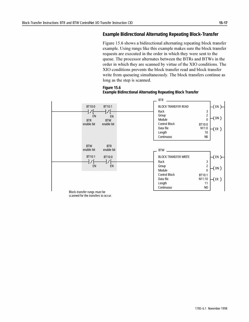
Block-Transfer Instructions BTR and BTW ControlNet I/O Transfer Instruction CIO 15-17
Example Bidirectional Alternating Repeating Block-Transfer
)LJXUH������VKRZV�D�ELGLUHFWLRQDO�DOWHUQDWLQJ�UHSHDWLQJ�EORFN�WUDQVIHU�H[DPSOH��8VLQJ�UXQJV�OLNH�WKLV�H[DPSOH�PDNHV�VXUH�WKH�EORFN�WUDQVIHU�UHTXHVWV�DUH�H[HFXWHG�LQ�WKH�RUGHU�LQ�ZKLFK�WKH\�ZHUH�VHQW�WR�WKH�TXHXH��7KH�SURFHVVRU�DOWHUQDWHV�EHWZHHQ�WKH�%75V�DQG�%7:V�LQ�WKH�RUGHU�LQ�ZKLFK�WKH\�DUH�VFDQQHG�E\�YLUWXH�RI�WKH�;,2�FRQGLWLRQV��7KH�;,2�FRQGLWLRQV�SUHYHQWV�WKH�EORFN�WUDQVIHU�UHDG�DQG�EORFN�WUDQVIHU�ZULWH�IURP�TXHXHLQJ�VLPXOWDQHRXVO\��7KH�EORFN�WUDQVIHUV�FRQWLQXH�DV�ORQJ�DV�WKH�VWHS�LV�VFDQQHG�
Figure 15.6 Example Bidirectional Alternating Repeating Block Transfer
ENBLOCK TRANSFER READ
RackGroupModuleControl Block
320 DN
Data fileLength
N11:010
ER
BTR
Continuous N0
ENBLOCK TRANSFER WRITE
RackGroupModuleControl Block
320
DN
Data fileLength
N11:1011
ER
BTW
Continuous NOBlock-transfer rungs must bescanned for the transfers to occur.
BTRenable bit
BTWenable bit
BT10:0
EN
BT10:1
EN
BT10:1
EN EN
BT10:0
BT10:0
BT10:1
BTWenable bit
BTRenable bit
1785-6.1 November 1998

15-18 Block-Transfer Instructions BTR and BTW ControlNet I/O Transfer Instruction CIO
Example Bidirectional Continuous Block-Transfer
)LJXUH������VKRZV�D�ELGLUHFWLRQDO�FRQWLQXRXV�EORFN�WUDQVIHU�H[DPSOH�
Figure 15.7 Example Bidirectional Continuous Block Transfer
ENBLOCK TRANSFER READRackGroupModuleControl Block
361 DN
Preconditions
Data fileLength
N7:1000
ER
BTR
Continuous YES
ENBLOCK TRANSFER WRITERackGroupModuleControl Block
361 DN
Data fileLength
N7:2000
ER
BTW
Continuous YES
Preconditions
U
U
BT10:0
BT10:1
BT10:0 BT10:0
ENER
EN
Scan the rung once to start continuous block transfers. The continuousoperation starts on a false-to-true rung transition and continues,whether or not the rungs are scanned again. To stop continuous operation, use the Data Monitor to reset the continuous bit (.CO orbit 11), or change the Continuous field in the instruction to NO.
These rungs will reset block transfers and should be placed in logic where rungs arebeing scanned for error recovery. Your logic must rescan the block transfers withpreconditions true in order to restart continuous block transfers.
BT10:1
ER
BT10:1
1785-6.1 November 1998
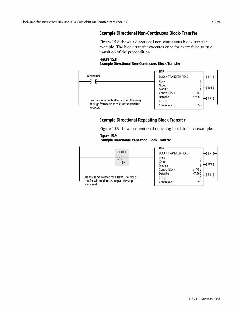
Block-Transfer Instructions BTR and BTW ControlNet I/O Transfer Instruction CIO 15-19
Example Directional Non-Continuous Block-Transfer
)LJXUH������VKRZV�D�GLUHFWLRQDO�QRQ�FRQWLQXRXV�EORFN�WUDQVIHU�H[DPSOH��7KH�EORFN�WUDQVIHU�H[HFXWHV�RQFH�IRU�HYHU\�IDOVH�WR�WUXH�WUDQVLWLRQ�RI�WKH�SUHFRQGLWLRQ�
Figure 15.8 Example Directional Non-Continuous Block Transfer
Example Directional Repeating Block Transfer
)LJXUH������VKRZV�D�GLUHFWLRQDO�UHSHDWLQJ�EORFN�WUDQVIHU�H[DPSOH�
Figure 15.9 Example Directional Repeating Block Transfer
ENBLOCK TRANSFER READ
RackGroupModuleControl Block
251 DN
Data fileLength
N7:5000
ER
BTR
Continuous NO
Use the same method for a BTW. The rungmust go from false to true for the transferto occur.
Precondition
BT10:0
ENBLOCK TRANSFER READ
RackGroupModuleControl Block
251 DN
Data fileLength
N7:5000
ER
BTR
Continuous NOUse the same method for a BTW. The blocktransfer will continue as long as the stepis scanned.
EN
BT10:0
BT10:0
1785-6.1 November 1998

15-20 Block-Transfer Instructions BTR and BTW ControlNet I/O Transfer Instruction CIO
Example Directional Continuous Block-Transfer
)LJXUH�������VKRZV�D�GLUHFWLRQDO�FRQWLQXRXV�EORFN�WUDQVIHU�H[DPSOH�
Figure 15.10 Example Directional Continuous Block Transfer
ENBLOCK TRANSFER READRackGroupModuleControl Block
251 DN
Precondition
Data fileLength
N7:5000
ER
BTR
Continuous YES
U
Use the same method for a BTW. Scan the rung onceto start continuous block transfers. The continuousoperation starts on a false-to-true rung transition andcontinues, whether or not the rungs are scannedagain. To stop continuous operation, use the DataMonitor to reset the continuous bit (.CO or bit 11), orchange the Continuous field in the instruction to NO.
BTRerror bit
BTRenable bitBT10:0
ENER
This rung will reset block transfers and should be placed in logic where rungs are beingscanned for error recovery. Your logic must rescan the block transfers with preconditionstrue in order to restart continuous block transfers.
BT10:0
BT10:0
1785-6.1 November 1998

Block-Transfer Instructions BTR and BTW ControlNet I/O Transfer Instruction CIO 15-21
Example Buffering Block Transfer-Data
,I�\RX�EORFN�WUDQVIHU�GDWD�UHSHDWHGO\��EXIIHU�WKH�ILOH�E\�H[DPLQLQJ�WKH�%75�GRQH�ELW�DQG�H[HFXWLQJ�D�ILOH�WR�ILOH�PRYH��RU�FRS\��ZKHQ�WKH�GRQH�ELW�LV�WUXH��7KLV�HQVXUHV�ILOH�LQWHJULW\�RI�WKH�EORFN�WUDQVIHU�UHDG�GDWD�ILOH�
ENBTRBLOCK TRANSFER READ
RackGroupModuleControl Block
221 DNEN
Data FileLength
N7:4004
ER
Continuous NO
ENFALFILE ARITH/LOGICALControlLengthPositionMode
R6:440
ALL
DN
Destination #N7:500 ERExpression #N7:400
BTRenable bit
BTRdone bit
BT10:0
BT10:0
BT10:0
DN
1785-6.1 November 1998
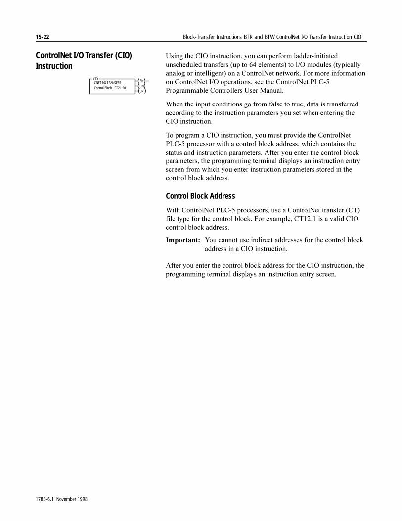
15-22 Block-Transfer Instructions BTR and BTW ControlNet I/O Transfer Instruction CIO
ControlNet I/O Transfer (CIO) Instruction
8VLQJ�WKH�&,2�LQVWUXFWLRQ��\RX�FDQ�SHUIRUP�ODGGHU�LQLWLDWHG�XQVFKHGXOHG�WUDQVIHUV��XS�WR����HOHPHQWV��WR�,�2�PRGXOHV��W\SLFDOO\�DQDORJ�RU�LQWHOOLJHQW��RQ�D�&RQWURO1HW�QHWZRUN��)RU�PRUH�LQIRUPDWLRQ�RQ�&RQWURO1HW�,�2�RSHUDWLRQV��VHH�WKH�&RQWURO1HW�3/&���3URJUDPPDEOH�&RQWUROOHUV�8VHU�0DQXDO�
:KHQ�WKH�LQSXW�FRQGLWLRQV�JR�IURP�IDOVH�WR�WUXH��GDWD�LV�WUDQVIHUUHG�DFFRUGLQJ�WR�WKH�LQVWUXFWLRQ�SDUDPHWHUV�\RX�VHW�ZKHQ�HQWHULQJ�WKH�&,2�LQVWUXFWLRQ�
7R�SURJUDP�D�&,2�LQVWUXFWLRQ��\RX�PXVW�SURYLGH�WKH�&RQWURO1HW�3/&���SURFHVVRU�ZLWK�D�FRQWURO�EORFN�DGGUHVV��ZKLFK�FRQWDLQV�WKH�VWDWXV�DQG�LQVWUXFWLRQ�SDUDPHWHUV��$IWHU�\RX�HQWHU�WKH�FRQWURO�EORFN�SDUDPHWHUV��WKH�SURJUDPPLQJ�WHUPLQDO�GLVSOD\V�DQ�LQVWUXFWLRQ�HQWU\�VFUHHQ�IURP�ZKLFK�\RX�HQWHU�LQVWUXFWLRQ�SDUDPHWHUV�VWRUHG�LQ�WKH�FRQWURO�EORFN�DGGUHVV�
Control Block Address
:LWK�&RQWURO1HW�3/&���SURFHVVRUV��XVH�D�&RQWURO1HW�WUDQVIHU��&7��ILOH�W\SH�IRU�WKH�FRQWURO�EORFN��)RU�H[DPSOH��&7�����LV�D�YDOLG�&,2�FRQWURO�EORFN�DGGUHVV�
,PSRUWDQW���<RX�FDQQRW�XVH�LQGLUHFW�DGGUHVVHV�IRU�WKH�FRQWURO�EORFN�DGGUHVV�LQ�D�&,2�LQVWUXFWLRQ�
$IWHU�\RX�HQWHU�WKH�FRQWURO�EORFN�DGGUHVV�IRU�WKH�&,2�LQVWUXFWLRQ��WKH�SURJUDPPLQJ�WHUPLQDO�GLVSOD\V�DQ�LQVWUXFWLRQ�HQWU\�VFUHHQ�
CIOCNET I/O TRANSFERControl Block CT21:50
EN
DNER
1785-6.1 November 1998
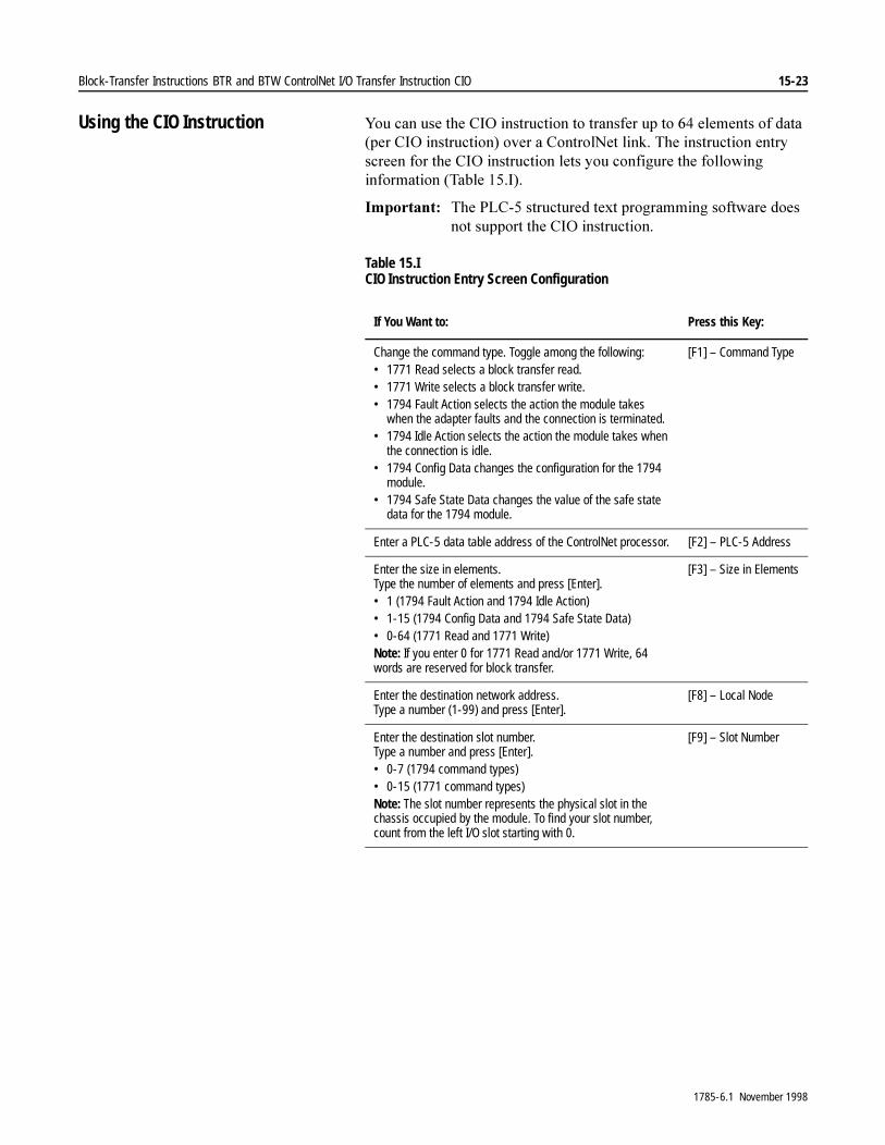
Block-Transfer Instructions BTR and BTW ControlNet I/O Transfer Instruction CIO 15-23
Using the CIO Instruction <RX�FDQ�XVH�WKH�&,2�LQVWUXFWLRQ�WR�WUDQVIHU�XS�WR����HOHPHQWV�RI�GDWD��SHU�&,2�LQVWUXFWLRQ��RYHU�D�&RQWURO1HW�OLQN��7KH�LQVWUXFWLRQ�HQWU\�VFUHHQ�IRU�WKH�&,2�LQVWUXFWLRQ�OHWV�\RX�FRQILJXUH�WKH�IROORZLQJ�LQIRUPDWLRQ��7DEOH����,��
,PSRUWDQW���7KH�3/&���VWUXFWXUHG�WH[W�SURJUDPPLQJ�VRIWZDUH�GRHV�QRW�VXSSRUW�WKH�&,2�LQVWUXFWLRQ�
Table 15.I CIO Instruction Entry Screen Configuration
If You Want to: Press this Key:
Change the command type. Toggle among the following:• 1771 Read selects a block transfer read.• 1771 Write selects a block transfer write.• 1794 Fault Action selects the action the module takes
when the adapter faults and the connection is terminated.• 1794 Idle Action selects the action the module takes when
the connection is idle.• 1794 Config Data changes the configuration for the 1794
module.• 1794 Safe State Data changes the value of the safe state
data for the 1794 module.
[F1] – Command Type
Enter a PLC-5 data table address of the ControlNet processor. [F2] – PLC-5 Address
Enter the size in elements.Type the number of elements and press [Enter].• 1 (1794 Fault Action and 1794 Idle Action)• 1-15 (1794 Config Data and 1794 Safe State Data)• 0-64 (1771 Read and 1771 Write)Note: If you enter 0 for 1771 Read and/or 1771 Write, 64 words are reserved for block transfer.
[F3] – Size in Elements
Enter the destination network address.Type a number (1-99) and press [Enter].
[F8] – Local Node
Enter the destination slot number.Type a number and press [Enter].• 0-7 (1794 command types)• 0-15 (1771 command types)Note: The slot number represents the physical slot in the chassis occupied by the module. To find your slot number, count from the left I/O slot starting with 0.
[F9] – Slot Number
1785-6.1 November 1998
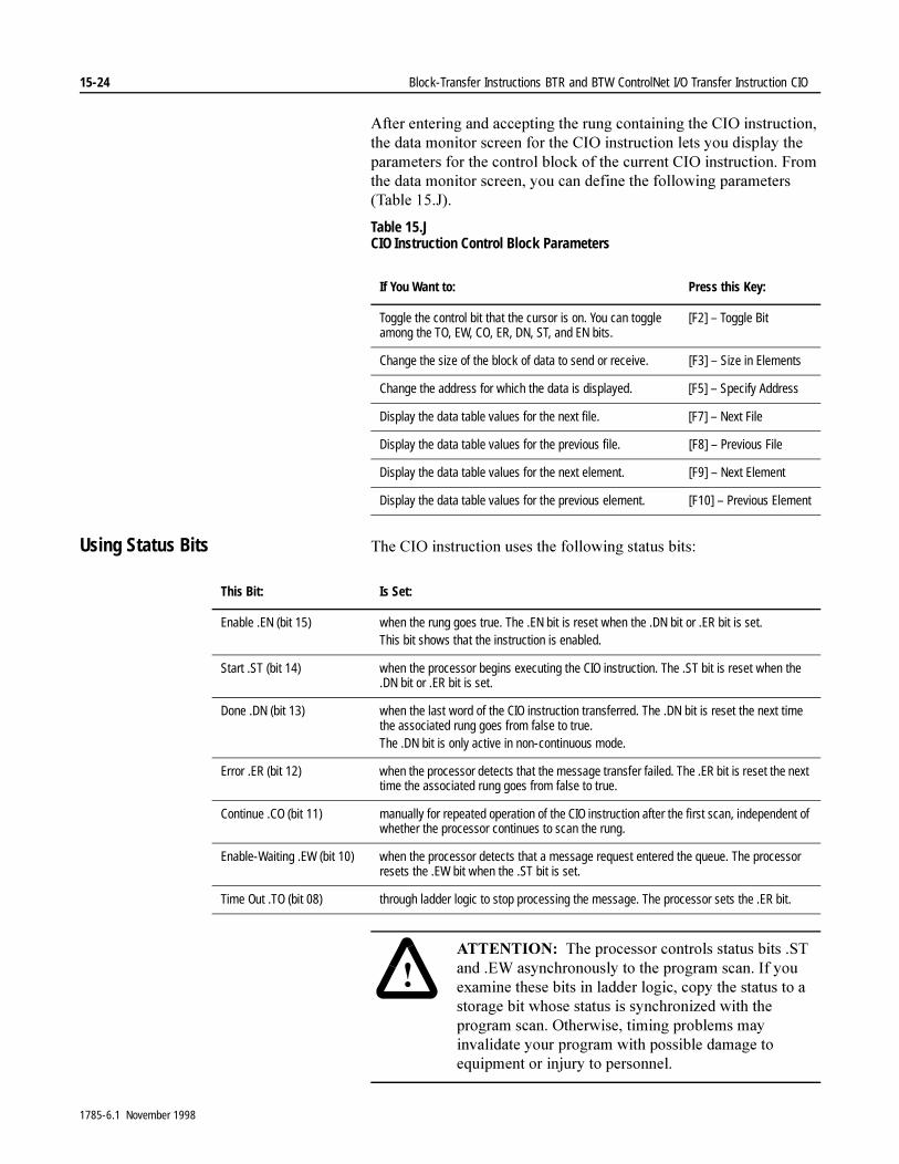
15-24 Block-Transfer Instructions BTR and BTW ControlNet I/O Transfer Instruction CIO
$IWHU�HQWHULQJ�DQG�DFFHSWLQJ�WKH�UXQJ�FRQWDLQLQJ�WKH�&,2�LQVWUXFWLRQ��WKH�GDWD�PRQLWRU�VFUHHQ�IRU�WKH�&,2�LQVWUXFWLRQ�OHWV�\RX�GLVSOD\�WKH�SDUDPHWHUV�IRU�WKH�FRQWURO�EORFN�RI�WKH�FXUUHQW�&,2�LQVWUXFWLRQ��)URP�WKH�GDWD�PRQLWRU�VFUHHQ��\RX�FDQ�GHILQH�WKH�IROORZLQJ�SDUDPHWHUV��7DEOH����-��
Table 15.J CIO Instruction Control Block Parameters
Using Status Bits 7KH�&,2�LQVWUXFWLRQ�XVHV�WKH�IROORZLQJ�VWDWXV�ELWV�
If You Want to: Press this Key:
Toggle the control bit that the cursor is on. You can toggle among the TO, EW, CO, ER, DN, ST, and EN bits.
[F2] – Toggle Bit
Change the size of the block of data to send or receive. [F3] – Size in Elements
Change the address for which the data is displayed. [F5] – Specify Address
Display the data table values for the next file. [F7] – Next File
Display the data table values for the previous file. [F8] – Previous File
Display the data table values for the next element. [F9] – Next Element
Display the data table values for the previous element. [F10] – Previous Element
This Bit: Is Set:
Enable .EN (bit 15) when the rung goes true. The .EN bit is reset when the .DN bit or .ER bit is set.This bit shows that the instruction is enabled.
Start .ST (bit 14) when the processor begins executing the CIO instruction. The .ST bit is reset when the .DN bit or .ER bit is set.
Done .DN (bit 13) when the last word of the CIO instruction transferred. The .DN bit is reset the next time the associated rung goes from false to true.The .DN bit is only active in non-continuous mode.
Error .ER (bit 12) when the processor detects that the message transfer failed. The .ER bit is reset the next time the associated rung goes from false to true.
Continue .CO (bit 11) manually for repeated operation of the CIO instruction after the first scan, independent of whether the processor continues to scan the rung.
Enable-Waiting .EW (bit 10) when the processor detects that a message request entered the queue. The processor resets the .EW bit when the .ST bit is set.
Time Out .TO (bit 08) through ladder logic to stop processing the message. The processor sets the .ER bit.
�$77(17,21� 7KH�SURFHVVRU�FRQWUROV�VWDWXV�ELWV��67�DQG��(:�DV\QFKURQRXVO\�WR�WKH�SURJUDP�VFDQ��,I�\RX�H[DPLQH�WKHVH�ELWV�LQ�ODGGHU�ORJLF��FRS\�WKH�VWDWXV�WR�D�VWRUDJH�ELW�ZKRVH�VWDWXV�LV�V\QFKURQL]HG�ZLWK�WKH�SURJUDP�VFDQ��2WKHUZLVH��WLPLQJ�SUREOHPV�PD\�LQYDOLGDWH�\RXU�SURJUDP�ZLWK�SRVVLEOH�GDPDJH�WR�HTXLSPHQW�RU�LQMXU\�WR�SHUVRQQHO�
1785-6.1 November 1998

Block-Transfer Instructions BTR and BTW ControlNet I/O Transfer Instruction CIO 15-25
Using the CT Control Block
,Q�DGGLWLRQ�WR�WKH�VWDWXV�ELWV��WKH�&7�FRQWURO�EORFN�FRQWDLQV�WKHVH�SDUDPHWHUV�WKDW�WKH�&RQWURO1HW�3/&���SURFHVVRU�XVHV�WR�FRQWURO�&,2 LQVWUXFWLRQV�
�$77(17,21� )RU�FRQWLQXRXV�PRGH�WR�RSHUDWH�FRUUHFWO\��\RX�PXVW�VHW�WKH��&2�ELW��HLWKHU�RQ�WKH�FRQILJXUDWLRQ�VFUHHQ�RU�WKURXJK�ODGGHU�ORJLF��EHIRUH�\RX�HQDEOH�WKH�&,2�LQVWUXFWLRQ�
Word: CT Control Block: Description:
0 .EN through .TO Status bitsSee “Using Status Bits” above.
1 .ERR Error codeThis is where the processor stores the error code if a problem occurs during message transmission.
2 .RLEN Requested lengthThis is the requested number of elements you wish to transfer with the message instruction.
3 .DLEN Done lengthThis is the number of elements the module actually transferred after the instruction completes execution. This number should match the requested length (unless the requested length is 0).
4 .FILE File numberThis number identifies the file number of the file from which the data is written or to which the data is read. For example, the file number of N12:1 is 12.
5 .ELEM Element numberThis number identifies the starting word in the data file address. For example, in N12:1, the word number is 1.
1785-6.1 November 1998

15-26 Block-Transfer Instructions BTR and BTW ControlNet I/O Transfer Instruction CIO
1RWHV�
1785-6.1 November 1998
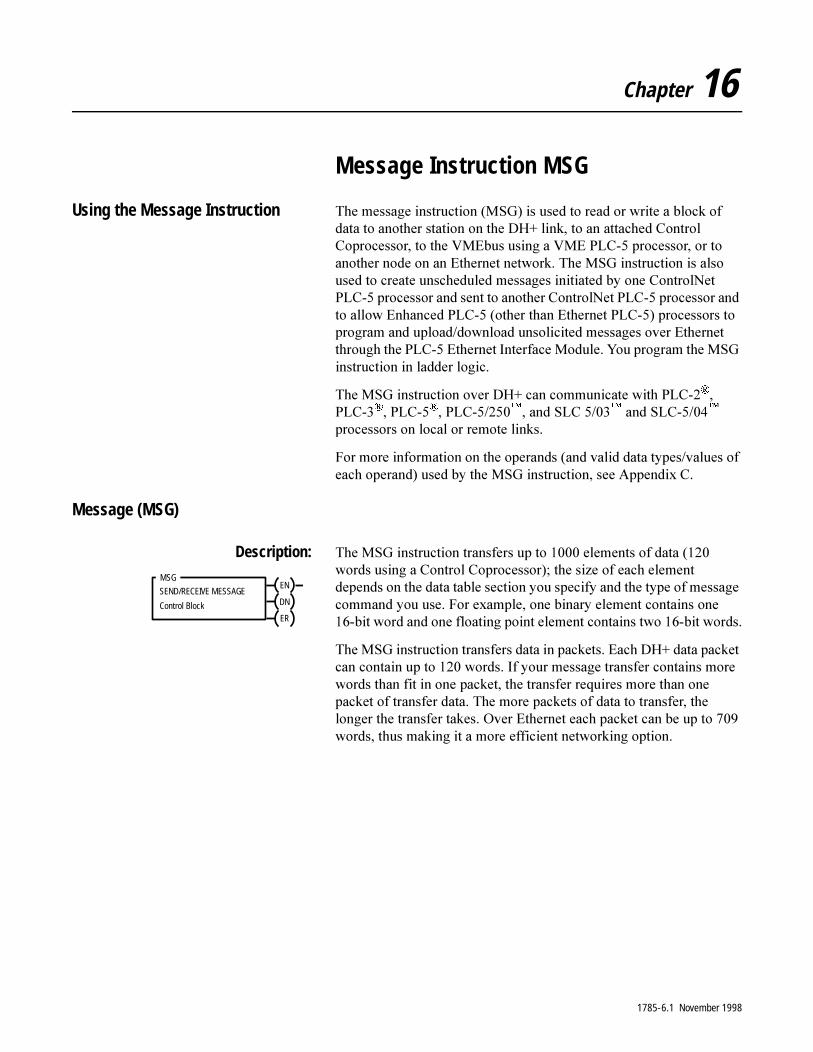
Chapter 16
Message Instruction MSG
Using the Message Instruction 7KH�PHVVDJH�LQVWUXFWLRQ��06*��LV�XVHG�WR�UHDG�RU�ZULWH�D�EORFN�RI�GDWD�WR�DQRWKHU�VWDWLRQ�RQ�WKH�'+��OLQN��WR�DQ�DWWDFKHG�&RQWURO�&RSURFHVVRU��WR�WKH�90(EXV�XVLQJ�D�90(�3/&���SURFHVVRU��RU�WR�DQRWKHU�QRGH�RQ�DQ�(WKHUQHW�QHWZRUN��7KH�06*�LQVWUXFWLRQ�LV�DOVR�XVHG�WR�FUHDWH�XQVFKHGXOHG�PHVVDJHV�LQLWLDWHG�E\�RQH�&RQWURO1HW�3/&���SURFHVVRU�DQG�VHQW�WR�DQRWKHU�&RQWURO1HW�3/&���SURFHVVRU�DQG�WR�DOORZ�(QKDQFHG�3/&����RWKHU�WKDQ�(WKHUQHW�3/&����SURFHVVRUV�WR�SURJUDP�DQG�XSORDG�GRZQORDG�XQVROLFLWHG�PHVVDJHV�RYHU�(WKHUQHW�WKURXJK�WKH�3/&���(WKHUQHW�,QWHUIDFH�0RGXOH��<RX�SURJUDP�WKH�06*�LQVWUXFWLRQ�LQ�ODGGHU�ORJLF�
7KH�06*�LQVWUXFWLRQ�RYHU�'+��FDQ�FRPPXQLFDWH�ZLWK�3/&�����3/&�����3/&�����3/&���������DQG�6/&�������DQG�6/&�������SURFHVVRUV�RQ�ORFDO�RU�UHPRWH�OLQNV�
)RU�PRUH�LQIRUPDWLRQ�RQ�WKH�RSHUDQGV��DQG�YDOLG�GDWD�W\SHV�YDOXHV�RI�HDFK�RSHUDQG��XVHG�E\�WKH�06*�LQVWUXFWLRQ��VHH�$SSHQGL[�&�
Message (MSG)
Description: 7KH�06*�LQVWUXFWLRQ�WUDQVIHUV�XS�WR������HOHPHQWV�RI�GDWD������ZRUGV�XVLQJ�D�&RQWURO�&RSURFHVVRU���WKH�VL]H�RI�HDFK�HOHPHQW�GHSHQGV�RQ�WKH�GDWD�WDEOH�VHFWLRQ�\RX�VSHFLI\�DQG�WKH�W\SH�RI�PHVVDJH�FRPPDQG�\RX�XVH��)RU�H[DPSOH��RQH�ELQDU\�HOHPHQW�FRQWDLQV�RQH����ELW�ZRUG�DQG�RQH�IORDWLQJ�SRLQW�HOHPHQW�FRQWDLQV�WZR����ELW�ZRUGV�
7KH�06*�LQVWUXFWLRQ�WUDQVIHUV�GDWD�LQ�SDFNHWV��(DFK�'+��GDWD�SDFNHW�FDQ�FRQWDLQ�XS�WR�����ZRUGV��,I�\RXU�PHVVDJH�WUDQVIHU�FRQWDLQV�PRUH�ZRUGV�WKDQ�ILW�LQ�RQH�SDFNHW��WKH�WUDQVIHU�UHTXLUHV�PRUH�WKDQ�RQH�SDFNHW�RI�WUDQVIHU�GDWD��7KH�PRUH�SDFNHWV�RI�GDWD�WR�WUDQVIHU��WKH�ORQJHU�WKH�WUDQVIHU�WDNHV��2YHU�(WKHUQHW�HDFK�SDFNHW�FDQ�EH�XS�WR�����ZRUGV��WKXV�PDNLQJ�LW�D�PRUH�HIILFLHQW�QHWZRUNLQJ�RSWLRQ�
SEND/RECEIVE MESSAGEEN
Control Block DN
ER
MSG
1785-6.1 November 1998

16-2 Message Instruction MSG
7KH�IROORZLQJ�WDEOH�OLVWV�ZKLFK�(QKDQFHG�3/&���SURFHVVRUV��VHULHV�DQG�UHYLVLRQ��\RX�FDQ�XVH�ZLWK�WKH�06*�LQVWUXFWLRQ�WR�WUDQVIHU�GDWD�IURP�WR�D�3/&���SURFHVVRU�RU�WR�IURP�DQ�6/&������RU������SURFHVVRU�LQ�6/&�QDWLYH�PRGH�
Entering Parameters 6SHFLI\�D�FRQWURO�EORFN�DGGUHVV�ZKHQ�\RX�ILUVW�HQWHU�WKH�06*�LQVWUXFWLRQ��7KH�FRQWURO�EORFN�LV�ZKHUH�DOO�RI�WKH�LQIRUPDWLRQ�UHODWLQJ�WR�WKH�PHVVDJH�ZLOO�EH�VWRUHG��$IWHU�HQWHULQJ�WKH�FRQWURO�EORFN��WKH�SURJUDPPLQJ�WHUPLQDO�DXWRPDWLFDOO\�GLVSOD\V�D�GDWD�HQWU\�VFUHHQ��IURP�ZKLFK�\RX�HQWHU�LQVWUXFWLRQ�SDUDPHWHUV�WKDW�DUH�VWRUHG�DW�WKH�FRQWURO�EORFN�DGGUHVV��<RX�FDQ�DOVR�XVH�WKH�GDWD�PRQLWRU�VFUHHQ�IRU�WKH�06*�LQVWUXFWLRQ�WR�HGLW�VHOHFWHG�SDUDPHWHUV�
Control Block Address
:LWK�&ODVVLF�3/&���SURFHVVRUV��XVH�DQ�LQWHJHU�ILOH��1��ZLWKRXW�WKH���V\PERO�IRU�WKH�PHVVDJH�FRQWURO�EORFN��)RU�H[DPSOH�1����LV�D�YDOLG�06*�FRQWURO�EORFN�DGGUHVV�
Processor Series/Revision:
Processors:
Series A / revision M PLC-5/40, -5/40L, -5/60, -5/60L
Series A / revision J PLC-5/30
Series A / revision H PLC-5/11, -5/20
Series B / revision J PLC-5/40, -5/40L, -5/60, -5/60L
Series C / revision G Enhanced, Ethernet, and VME PLC-5 processors
Series C / revision H ControlNet PLC-5
Series D / revision A Enhanced, Ethernet, ControlNet, and VME PLC-5 processors
If You Have this Processor: Use this Control Block Address:
Classic PLC-5 an integer file (N) without the # symbol for the message control block. Example: N7:0
Enhanced PLC-5, EthernetPLC-5, or VME PLC-5
an integer file (N) or the message (MG) file type to access the message control block for DH+ transfers. Example: MG10:0
Using the MG control block, the control block size is fixed at 56 words. This size is displayed on the screen in the BLOCK SIZE field. You must use the MG control block if you are sending messages to an SLC 500 processor using the SLC read and write commands, or if you are sending message out any port other than channel 1A.
Ethernet PLC-5, ControlNetPLC-5, VME PLC-5
a message (MG) file type to access the VMEbus, Ethernet, or ControlNet network
1785-6.1 November 1998
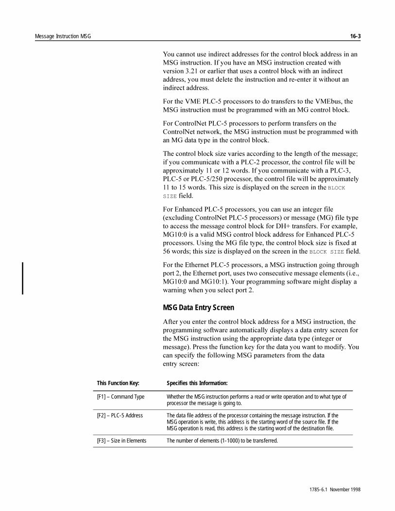
Message Instruction MSG 16-3
<RX�FDQQRW�XVH�LQGLUHFW�DGGUHVVHV�IRU�WKH�FRQWURO�EORFN�DGGUHVV�LQ�DQ�06*�LQVWUXFWLRQ��,I�\RX�KDYH�DQ�06*�LQVWUXFWLRQ�FUHDWHG�ZLWK�YHUVLRQ������RU�HDUOLHU�WKDW�XVHV�D�FRQWURO�EORFN�ZLWK�DQ�LQGLUHFW�DGGUHVV��\RX�PXVW�GHOHWH�WKH�LQVWUXFWLRQ�DQG�UH�HQWHU�LW�ZLWKRXW�DQ�LQGLUHFW DGGUHVV�
)RU�WKH�90(�3/&���SURFHVVRUV�WR�GR�WUDQVIHUV�WR�WKH�90(EXV��WKH�06*�LQVWUXFWLRQ�PXVW�EH�SURJUDPPHG�ZLWK�DQ�0*�FRQWURO�EORFN�
)RU�&RQWURO1HW�3/&���SURFHVVRUV�WR�SHUIRUP�WUDQVIHUV�RQ�WKH�&RQWURO1HW�QHWZRUN��WKH�06*�LQVWUXFWLRQ�PXVW�EH�SURJUDPPHG�ZLWK�DQ�0*�GDWD�W\SH�LQ�WKH�FRQWURO�EORFN�
7KH�FRQWURO�EORFN�VL]H�YDULHV�DFFRUGLQJ�WR�WKH�OHQJWK�RI�WKH�PHVVDJH��LI�\RX�FRPPXQLFDWH�ZLWK�D�3/&���SURFHVVRU��WKH�FRQWURO�ILOH�ZLOO�EH�DSSUR[LPDWHO\����RU����ZRUGV��,I�\RX�FRPPXQLFDWH�ZLWK�D�3/&����3/&���RU�3/&�������SURFHVVRU��WKH�FRQWURO�ILOH�ZLOO�EH�DSSUR[LPDWHO\����WR����ZRUGV��7KLV�VL]H�LV�GLVSOD\HG�RQ�WKH�VFUHHQ�LQ�WKH�BLOCK
SIZE�ILHOG�
)RU�(QKDQFHG�3/&���SURFHVVRUV��\RX�FDQ�XVH�DQ�LQWHJHU�ILOH��H[FOXGLQJ�&RQWURO1HW�3/&���SURFHVVRUV��RU�PHVVDJH��0*��ILOH�W\SH�WR�DFFHVV�WKH�PHVVDJH�FRQWURO�EORFN�IRU�'+��WUDQVIHUV��)RU�H[DPSOH��0*�����LV�D�YDOLG�06*�FRQWURO�EORFN�DGGUHVV�IRU�(QKDQFHG�3/&���SURFHVVRUV��8VLQJ�WKH�0*�ILOH�W\SH��WKH�FRQWURO�EORFN�VL]H�LV�IL[HG�DW����ZRUGV��WKLV�VL]H�LV�GLVSOD\HG�RQ�WKH�VFUHHQ�LQ�WKH�BLOCK SIZE�ILHOG�
)RU�WKH�(WKHUQHW�3/&���SURFHVVRUV��D�06*�LQVWUXFWLRQ�JRLQJ�WKURXJK�SRUW����WKH�(WKHUQHW�SRUW��XVHV�WZR�FRQVHFXWLYH�PHVVDJH�HOHPHQWV��L�H���0*�����DQG�0*�������<RXU�SURJUDPPLQJ�VRIWZDUH�PLJKW�GLVSOD\�D�ZDUQLQJ�ZKHQ�\RX�VHOHFW�SRUW���
MSG Data Entry Screen
$IWHU�\RX�HQWHU�WKH�FRQWURO�EORFN�DGGUHVV�IRU�D�06*�LQVWUXFWLRQ��WKH�SURJUDPPLQJ�VRIWZDUH�DXWRPDWLFDOO\�GLVSOD\V�D�GDWD�HQWU\�VFUHHQ�IRU�WKH�06*�LQVWUXFWLRQ�XVLQJ�WKH�DSSURSULDWH�GDWD�W\SH��LQWHJHU�RU�PHVVDJH���3UHVV�WKH�IXQFWLRQ�NH\�IRU�WKH�GDWD�\RX�ZDQW�WR�PRGLI\��<RX�FDQ�VSHFLI\�WKH�IROORZLQJ�06*�SDUDPHWHUV�IURP�WKH�GDWD�HQWU\ VFUHHQ�
This Function Key: Specifies this Information:
[F1] – Command Type Whether the MSG instruction performs a read or write operation and to what type of processor the message is going to.
[F2] – PLC-5 Address The data file address of the processor containing the message instruction. If the MSG operation is write, this address is the starting word of the source file. If the MSG operation is read, this address is the starting word of the destination file.
[F3] – Size in Elements The number of elements (1-1000) to be transferred.
1785-6.1 November 1998

16-4 Message Instruction MSG
,I�\RX�VHOHFW�WKH�$6&,,�RSWLRQ�XVLQJ�WKH�[F1] – Command Type �NH\���IRU�XVH�ZLWK�3/&���9���GRLQJ�UHDG�ZULWHV�WR�WKH�90(EXV���WKH�VRIWZDUH�GLVSOD\V�D�QHZ�VFUHHQ�IRU�\RX�WR�HQWHU�WKH�WH[W�IRU�\RXU�$6&,,�FRPPXQLFDWLRQV��5HIHU�WR�WKH�3/&���90(�90(EXV�3URJUDPPDEOH�&RQWUROOHUV�8VHU�0DQXDO�IRU�WKH�V\QWD[�RI�FRPPDQG�WH[W�WR�GR�90(EXV�WUDQVIHUV�
)RU�&RQWURO�&RSURFHVVRU�GDWD�WUDQVIHUV�XVLQJ�WKH�06*�LQVWUXFWLRQ��XVH�WKH�IROORZLQJ�FKRLFHV�
� FRPPXQLFDWLRQ�FRPPDQG�±�VHOHFW�3/&���ZRUG�UDQJH�UHDG�RU�3/&���ZRUG�UDQJH�ZULWH
� GHVWLQDWLRQ�GDWD�WDEOH�DGGUHVV�±����WKURXJK�����PDWFKHV�FRUUHVSRQGLQJ�UHDG�ZULWH�KDQGOHU�LQ�FRSURFHVVRUV�DSSOLFDWLRQ�SURJUDP
� 3RUW�QXPEHU�±��$
[F4] – Local/Remote LOCAL: the message is sent to a device on the local DH+ link.REMOTE: the message is sent through a bridge (DH, DH II, etc.) to anotherDH+ link.
If you select REMOTE, the function keys [F5] – Remote Station, [F6] – Link ID, and[F7] – Remote Link are active.
[F5] – Remote Station The DH or DH II address (1-376 octal) of the target station.
PLC-2 and PLC-3 processors require communication adapter modules (1771-KA2 and 1775-KA, respectively) when they operate as stations on data highway. In these configurations, the remote station address is the address of the communication adapter module.
[F6] – Link ID The remote link where the processor you want to communicate with resides. The default is 0.
[F7] – Remote Link Toggles through DH, DH II, and other choices for what connects the remote link to the local DH+.
[F8] – Local Node The local station address on the DH+ (0-77 octal).
If you communicate with another processor on the local link, this address is the address of the target station on the local link.
If you communicate with a target station on a remote link, this address is the station number of the communication adapter module that bridges the data highway.
[F9] – Destination Address The starting address of the source or destination file in the target processor.
[F10] – Port Number The channel for message communications. Valid options are: 0, 1A (default), 1B, 2A, 2B, and 3A for the ASCII command.
This Function Key: Specifies this Information:
1785-6.1 November 1998
Message Instruction MSG 16-5
Using the Message Instruction for Ethernet Communications
7KH�PHVVDJH��06*��LQVWUXFWLRQ�WUDQVIHUV�XS�WR������HOHPHQWV�RI�GDWD��WKH�VL]H�RI�HDFK�HOHPHQW�GHSHQGV�RQ�WKH�GDWD�WDEOH�VHFWLRQ�WKDW�\RX�VSHFLI\�DQG�WKH�W\SH�RI�PHVVDJH�FRPPDQG�WKDW�\RX�XVH��2QH�ELQDU\�HOHPHQW�FRQWDLQV�RQH����ELW�ZRUG��IRU�H[DPSOH��DQG�RQH�IORDWLQJ�SRLQW�HOHPHQW�FRQWDLQV�WZR����ELW�ZRUGV�
7KH�06*�LQVWUXFWLRQ�WUDQVIHUV�GDWD�LQ�SDFNHWV��(DFK�SDFNHW�FDQ�FRQWDLQ�XS�WR�����ZRUGV�IRU�(WKHUQHW�SURFHVVRUV��,I�\RXU�PHVVDJH�WUDQVIHU�FRQWDLQV�PRUH�ZRUGV�WKDQ�ILW�LQ�RQH�SDFNHW��WKH�WUDQVIHU�UHTXLUHV�PRUH�WKDQ�RQH�SDFNHW�RI�WUDQVIHU�GDWD��7KH�PRUH�SDFNHWV�RI�GDWD�WR�WUDQVIHU��WKH�ORQJHU�WKH�WUDQVIHU�WDNHV�
Entering Parameters
7KH�FRQWURO�EORFN�LV�ZKHUH�DOO�RI�WKH�LQIRUPDWLRQ�UHODWLQJ�WR�WKH�PHVVDJH�LV�VWRUHG��(WKHUQHW�PHVVDJH�LQVWUXFWLRQV�XVH�WZR�FRQVHFXWLYH�06*�HOHPHQWV�WKH�ILUVW�RQH�FRQWDLQV�WKH�PHVVDJH�LQIRUPDWLRQ��WKH�VHFRQG�RQH�FRQWDLQV�WKH�GHVWLQDWLRQ�DGGUHVV�
,PSRUWDQW���6LQFH�WKH�(WKHUQHW�PHVVDJHV�QHHG�WZR�FRQVHFXWLYH�FRQWURO�EORFNV��WKH�PHVVDJH�FRQWURO�EORFN�WKDW�\RX�VSHFLI\�PXVW�VWDUW�RQ�DQ�HYHQ�QXPEHU��
$IWHU�HQWHULQJ�WKH�FRQWURO�EORFN��WKH�SURJUDPPLQJ�WHUPLQDO�DXWRPDWLFDOO\�GLVSOD\V�D�GDWD�HQWU\�VFUHHQ��IURP�ZKLFK�\RX�HQWHU�LQVWUXFWLRQ�SDUDPHWHUV�WKDW�DUH�VWRUHG�DW�WKH�FRQWURO�EORFN�DGGUHVV�
<RX�PXVW�HQWHU�D�SRUW�QXPEHU�RI���WR�HQDEOH�D�VSHFLDO�VFUHHQ�IRU�(WKHUQHW�WUDQVIHUV�
�$77(17,21� :KLOH�FRQILJXULQJ�06*�LQVWUXFWLRQV�IRU�WKH�'+��DQG�VHULDO�OLQNV��NHHS�LQ�PLQG�WKH�ILOHV�XVHG�IRU�(WKHUQHW�06*�FRQWURO�EORFNV�
,I�\RX�FKRRVH�D�ILOH�EHLQJ�XVHG�DV�DQ�(WKHUQHW�FRQWURO�EORFN��WKH�SURJUDPPLQJ�VRIWZDUH�SURPSWV�\RX�WR�FKRRVH�ZKHWKHU�\RX�ZDQW�WR�RYHUZULWH�WKH�ILOH��,I�\RX�FKRRVH�WR�RYHUZULWH�WKH�ILOH��XQSUHGLFWDEOH�PDFKLQH�RSHUDWLRQ�FRXOG�RFFXU�
1785-6.1 November 1998

16-6 Message Instruction MSG
7KH�(WKHUQHW�3/&���SURFHVVRUV�GR�QRW�VXSSRUW�KRVWQDPHV�DV�D�PHDQV�RI�DGGUHVVLQJ�PHVVDJHV��+RZHYHU��\RX�FDQ�XVH�KRVW�QDPHV�ZLWK�3/&���SURJUDPPLQJ�VRIWZDUH�IRU�FRQQHFWLQJ�WR�(WKHUQHW�3/&���SURFHVVRUV�LI�D�QDPH�VHUYHU�LV�RQ�WKH�QHWZRUN�RU�D�KRVW�ILOH�LV�PDLQWDLQHG�RQ�\RXU�ZRUNVWDWLRQ�
This Field: Specifies this Information:
Command Type Whether the MSG instruction performs a read or write operation. The software toggles between:• PLC-5 Typed Read• PLC-5 Typed Write• PLC-5 Typed Write to SLC• PLC-5 Typed Read from SLC• SLC Typed Logical Read• SLC Typed Logical Write• PLC-2 Unprotected Read• PLC-2 Unprotected Write• PLC-3 Word Range Read• PLC-3 Word Range Write• ASCII
PLC-5 Address The data file address of the processor containing the message instruction. If the MSG operation is write, this address is the starting word of the source file. If theMSG operation is read, this address is the starting word of the destination file.
Size in Elements The number of elements (1-1000) to be transferred.
IP Address The MSG instruction’s destination node.• If the destination is another PLC-5/20E, -5/40E, or -5/80E, the destination must be
a full Internet address• If the destination is an INTERCHANGE™ client program, enter the word “CLIENT”
as the destination node. Do not enter an IP address.Note: You must set [F10] – Port Number to 2 in order to access this function.
Destination Address The starting address of the source or destination file in the target processor.
Port Number The channel for message communications. Ethernet communications use channel 2.
Multihop Select yes if you want to send the MSG instruction to a ControlLogix device. Then use the Multihop tab to specify the path of the MSG instruction. For more information, see “Configuring an Ethernet Multihop MSG Instruction” on page 16-9.
1785-6.1 November 1998

Message Instruction MSG 16-7
Using the Message Instruction for PLC-5 Ethernet Interface Module Communications
8VH�WKH�06*�LQVWUXFWLRQ�WR�DOORZ�(QKDQFHG�3/&���SURFHVVRUV�WR�SURJUDP�DQG�XSORDG�GRZQORDG�XQVROLFLWHG�PHVVDJHV��XS�WR������HOHPHQWV�HDFK��RYHU�(WKHUQHW�WKURXJK�WKH�3/&���(WKHUQHW�,QWHUIDFH�0RGXOH��7KH�VL]H�RI�HDFK�HOHPHQW�GHSHQGV�RQ�WKH�GDWD�WDEOH�VHFWLRQ�WKDW�\RX�VSHFLI\�DQG�WKH�W\SH�RI�PHVVDJH�FRPPDQG�WKDW�\RX�XVH��2QH�ELQDU\�HOHPHQW�FRQWDLQV�RQH����ELW�ZRUG��IRU�H[DPSOH��DQG�RQH�IORDWLQJ�SRLQW�HOHPHQW�FRQWDLQV�WZR����ELW�ZRUGV�
7R�SURJUDP�D�06*�LQVWUXFWLRQ��\RX�PXVW�SURYLGH�WKH�3/&���(WKHUQHW�,QWHUIDFH�0RGXOH�DQG�WKH�FRQQHFWHG�(QKDQFHG�3/&���SURFHVVRU�ZLWK�D�FRQWURO�EORFN�DGGUHVV��ZKLFK�FRQWDLQV�WKH�VWDWXV�DQG�LQVWUXFWLRQ�SDUDPHWHUV��$IWHU�HQWHULQJ�WKH�FRQWURO�EORFN�SDUDPHWHUV��WKH�SURJUDPPLQJ�WHUPLQDO�GLVSOD\V�DQ�LQVWUXFWLRQ�HQWU\�VFUHHQ�IURP�ZKHUH�\RX�FDQ�HQWHU�LQVWUXFWLRQ�SDUDPHWHUV�WKDW�DUH�VWRUHG�LQ�WKH�FRQWURO�EORFN�DGGUHVV�
Entering Parameters
7KH�FRQWURO�EORFN�LV�ZKHUH�DOO�RI�WKH�LQIRUPDWLRQ�UHODWLQJ�WR�WKH�PHVVDJH�LV�VWRUHG��(WKHUQHW�PHVVDJH�LQVWUXFWLRQV�XVH�WZR�FRQVHFXWLYH�06*�HOHPHQWV�WKH�ILUVW�RQH�FRQWDLQV�WKH�PHVVDJH�LQIRUPDWLRQ��WKH�VHFRQG�RQH�FRQWDLQV�WKH�GHVWLQDWLRQ�DGGUHVV�
,PSRUWDQW���6LQFH�WKH�(WKHUQHW�PHVVDJHV�QHHG�WZR�FRQVHFXWLYH�FRQWURO�EORFNV��WKH�PHVVDJH�FRQWURO�EORFN�WKDW�\RX�VSHFLI\�PXVW�VWDUW�RQ�DQ�HYHQ�QXPEHU�
$IWHU�HQWHULQJ�WKH�FRQWURO�EORFN��WKH�3/&���SURJUDPPLQJ�VRIWZDUH�DXWRPDWLFDOO\�GLVSOD\V�D�GDWD�HQWU\�VFUHHQ��IURP�ZKLFK�\RX�HQWHU�LQVWUXFWLRQ�SDUDPHWHUV�WKDW�DUH�VWRUHG�DW�WKH�FRQWURO�EORFN�DGGUHVV�
1785-6.1 November 1998
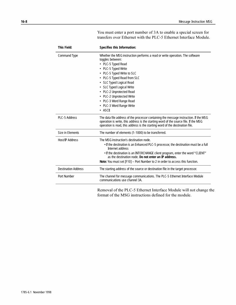
16-8 Message Instruction MSG
<RX�PXVW�HQWHU�D�SRUW�QXPEHU�RI��$�WR�HQDEOH�D�VSHFLDO�VFUHHQ�IRU�WUDQVIHUV�RYHU�(WKHUQHW�ZLWK�WKH�3/&���(WKHUQHW�,QWHUIDFH�0RGXOH�
5HPRYDO�RI�WKH�3/&���(WKHUQHW�,QWHUIDFH�0RGXOH�ZLOO�QRW�FKDQJH�WKH�IRUPDW�RI�WKH�06*�LQVWUXFWLRQV�GHILQHG�IRU�WKH�PRGXOH�
This Field: Specifies this Information:
Command Type Whether the MSG instruction performs a read or write operation. The software toggles between:• PLC-5 Typed Read• PLC-5 Typed Write• PLC-5 Typed Write to SLC• PLC-5 Typed Read from SLC• SLC Typed Logical Read• SLC Typed Logical Write• PLC-2 Unprotected Read• PLC-2 Unprotected Write• PLC-3 Word Range Read• PLC-3 Word Range Write• ASCII
PLC-5 Address The data file address of the processor containing the message instruction. If the MSG operation is write, this address is the starting word of the source file. If the MSG operation is read, this address is the starting word of the destination file.
Size in Elements The number of elements (1-1000) to be transferred.
Host/IP Address The MSG instruction’s destination node.•If the destination is an Enhanced PLC-5 processor, the destination must be a full
Internet address•If the destination is an INTERCHANGE client program, enter the word “CLIENT”
as the destination node. Do not enter an IP address.Note: You must set [F10] – Port Number to 2 in order to access this function.
Destination Address The starting address of the source or destination file in the target processor.
Port Number The channel for message communications. The PLC-5 Ethernet Interface Module communications use channel 3A.
1785-6.1 November 1998
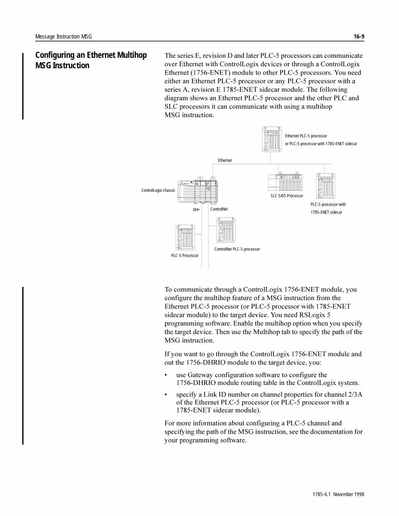
Message Instruction MSG 16-9
Configuring an Ethernet Multihop MSG Instruction
7KH�VHULHV�(��UHYLVLRQ�'�DQG�ODWHU�3/&���SURFHVVRUV�FDQ�FRPPXQLFDWH�RYHU�(WKHUQHW�ZLWK�&RQWURO/RJL[�GHYLFHV�RU�WKURXJK�D�&RQWURO/RJL[�(WKHUQHW�������(1(7��PRGXOH�WR�RWKHU�3/&���SURFHVVRUV��<RX�QHHG�HLWKHU�DQ�(WKHUQHW�3/&���SURFHVVRU�RU�DQ\�3/&���SURFHVVRU�ZLWK�D�VHULHV�$��UHYLVLRQ�(������(1(7�VLGHFDU�PRGXOH��7KH�IROORZLQJ�GLDJUDP�VKRZV�DQ�(WKHUQHW�3/&���SURFHVVRU�DQG�WKH�RWKHU�3/&�DQG�6/&�SURFHVVRUV�LW�FDQ�FRPPXQLFDWH�ZLWK�XVLQJ�D�PXOWLKRS�06* LQVWUXFWLRQ�
7R�FRPPXQLFDWH�WKURXJK�D�&RQWURO/RJL[������(1(7�PRGXOH��\RX�FRQILJXUH�WKH�PXOWLKRS�IHDWXUH�RI�D�06*�LQVWUXFWLRQ�IURP�WKH�(WKHUQHW�3/&���SURFHVVRU��RU�3/&���SURFHVVRU�ZLWK������(1(7�VLGHFDU�PRGXOH��WR�WKH�WDUJHW�GHYLFH��<RX�QHHG�56/RJL[���SURJUDPPLQJ�VRIWZDUH��(QDEOH�WKH�PXOWLKRS�RSWLRQ�ZKHQ�\RX�VSHFLI\�WKH�WDUJHW�GHYLFH��7KHQ�XVH�WKH�0XOWLKRS�WDE�WR�VSHFLI\�WKH�SDWK�RI�WKH�06*�LQVWUXFWLRQ�
,I�\RX�ZDQW�WR�JR�WKURXJK�WKH�&RQWURO/RJL[������(1(7�PRGXOH�DQG�RXW�WKH������'+5,2�PRGXOH�WR�WKH�WDUJHW�GHYLFH��\RX�
� XVH�*DWHZD\�FRQILJXUDWLRQ�VRIWZDUH�WR�FRQILJXUH�WKH������'+5,2�PRGXOH�URXWLQJ�WDEOH�LQ�WKH�&RQWURO/RJL[�V\VWHP�
� VSHFLI\�D�/LQN�,'�QXPEHU�RQ�FKDQQHO�SURSHUWLHV�IRU�FKDQQHO����$�RI�WKH�(WKHUQHW�3/&���SURFHVVRU��RU�3/&���SURFHVVRU�ZLWK�D������(1(7�VLGHFDU�PRGXOH��
)RU�PRUH�LQIRUPDWLRQ�DERXW�FRQILJXULQJ�D�3/&���FKDQQHO�DQG�VSHFLI\LQJ�WKH�SDWK�RI�WKH�06*�LQVWUXFWLRQ��VHH�WKH�GRFXPHQWDWLRQ�IRU�\RXU�SURJUDPPLQJ�VRIWZDUH�
DH+ ControlNet
ControlLogix chassisSLC 5/05 Processor
ControlNet PLC-5 processor
PLC-5 Processor
Ethernet
PLC-5 processor with
1785-ENET sidecar
Ethernet PLC-5 processor
or PLC-5 processor with 1785-ENET sidecar
1785-6.1 November 1998

16-10 Message Instruction MSG
Using the Message Instruction for ControlNet Communications
8VH�WKH�06*�LQVWUXFWLRQ�WR�FUHDWH�XQVFKHGXOHG�PHVVDJHV��XS�WR������HOHPHQWV�HDFK��WKDW�DUH�LQLWLDWHG�E\�RQH�&RQWURO1HW�3/&���SURFHVVRU�DQG�VHQW�WR�DQRWKHU�&RQWURO1HW�3/&���SURFHVVRU��)RU�PRUH�LQIRUPDWLRQ�RQ�&RQWURO1HW�,�2�RSHUDWLRQV��VHH�WKH�&RQWURO1HW�3/&���3URJUDPPDEOH�&RQWUROOHUV�8VHU�0DQXDO�
:KHQ�WKH�LQSXW�FRQGLWLRQV�JR�IURP�IDOVH�WR�WUXH��GDWD�LV�WUDQVIHUUHG�DFFRUGLQJ�WR�WKH�LQVWUXFWLRQ�SDUDPHWHUV�\RX�VHW�ZKHQ�HQWHULQJ�WKH�06*�LQVWUXFWLRQ�
7R�SURJUDP�D�06*�LQVWUXFWLRQ��\RX�PXVW�SURYLGH�WKH�&RQWURO1HW�3/&���SURFHVVRU�ZLWK�D�FRQWURO�EORFN�DGGUHVV��ZKLFK�FRQWDLQV�WKH�VWDWXV�DQG�LQVWUXFWLRQ�SDUDPHWHUV��$IWHU�HQWHULQJ�WKH�FRQWURO�EORFN�SDUDPHWHUV��WKH�SURJUDPPLQJ�WHUPLQDO�GLVSOD\V�DQ�LQVWUXFWLRQ�HQWU\�VFUHHQ�IURP�ZKHUH�\RX�FDQ�HQWHU�LQVWUXFWLRQ�SDUDPHWHUV�WKDW�DUH�VWRUHG�LQ�WKH�FRQWURO�EORFN�DGGUHVV��
Control Block Address
:LWK�&RQWURO1HW�3/&���SURFHVVRUV��XVH�D�PHVVDJH�GDWD�ILOH��0*��IRU�WKH�PHVVDJH�FRQWURO�EORFN��)RU�H[DPSOH��0*������LV�D�YDOLG�06*�FRQWURO�EORFN�DGGUHVV�
<RX�FDQ�XVH�WKH�0HVVDJH��0*��ILOH�W\SH�DQG�WKH�06*�LQVWUXFWLRQ�WR�VHQG�WZR�FRPPDQGV�RYHU�&RQWURO1HW�ZLWKLQ�WKH�ORFDO�&RQWURO1HW�OLQN�
� 3/&���7\SHG�:ULWH� 3/&���7\SHG�5HDG
$IWHU�\RX�HQWHU�WKH�FRQWURO�EORFN�DGGUHVV�IRU�WKH�06*�LQVWUXFWLRQ��WKH�SURJUDPPLQJ�WHUPLQDO�GLVSOD\V�DQ�LQVWUXFWLRQ�HQWU\�VFUHHQ��3UHVV�WKH�IXQFWLRQ�NH\�IRU�WKH�GDWD�\RX�ZDQW�WR�PRGLI\��<RX�FDQ�VSHFLI\�WKH�IROORZLQJ�IURP�WKH�LQVWUXFWLRQ�HQWU\�VFUHHQ�
This Field: Specifies this Information:
Command Type Change the command type. Toggle between the following:• PLC-5 Typed Write selects a write operation to a ControlNet PLC-5 processor• PLC-5 Typed Read selects a read operation from another ControlNet PLC-5
processor
PLC-5 Address The PLC-5 data table address of the ControlNet processor. If the MSG operation is write, this address is the starting word of the source file. If the MSG operation is read, this address is the starting word of the destination file.
Size in Elements The number of elements (1-1000) to be transferred.
Local Node The destination node address (1-99).
Destination Address The starting address of the source or destination file in the target processor.
Port Number The channel for message communications. The port number must be 2 for ControlNet.
Multihop Select yes if you want to send the MSG instruction to a ControlLogix device. Then use the Multihop tab to specify the path of the MSG instruction. For more information, see “Configuring an ControlNet Multihop MSG Instruction” on page 16-11.
1785-6.1 November 1998
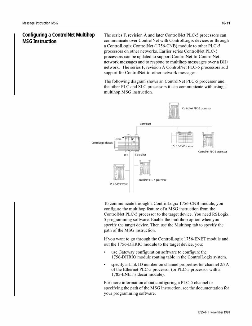
Message Instruction MSG 16-11
Configuring a ControlNet Multihop MSG Instruction
7KH�VHULHV�)��UHYLVLRQ�$�DQG�ODWHU�&RQWURO1HW�3/&���SURFHVVRUV�FDQ�FRPPXQLFDWH�RYHU�&RQWURO1HW�ZLWK�&RQWURO/RJL[�GHYLFHV�RU�WKURXJK�D�&RQWURO/RJL[�&RQWURO1HW�������&1%��PRGXOH�WR�RWKHU�3/&���SURFHVVRUV�RQ�RWKHU�QHWZRUNV��(DUOLHU�VHULHV�&RQWURO1HW�3/&���SURFHVVRUV�FDQ�EH�XSGDWHG�WR�VXSSRUW�&RQWURO1HW�WR�&RQWURO1HW�QHWZRUN�PHVVDJHV�DQG�WR�UHVSRQG�WR�PXOWLKRS�PHVVVDJHV�RYHU�D�'+��QHWZRUN���7KH�VHULHV )��UHYLVLRQ�$�&RQWURO1HW�3/&���SURFHVVRUV�DGG�VXSSRUW�IRU�&RQWURO1HW�WR�RWKHU�QHWZRUN PHVVDJHV�
7KH�IROORZLQJ�GLDJUDP�VKRZV�DQ�&RQWURO1HW�3/&���SURFHVVRU�DQG�WKH�RWKHU�3/&�DQG�6/&�SURFHVVRUV�LW�FDQ�FRPPXQLFDWH�ZLWK�XVLQJ�D�PXOWLKRS�06*�LQVWUXFWLRQ�
7R�FRPPXQLFDWH�WKURXJK�D�&RQWURO/RJL[������&1%�PRGXOH��\RX�FRQILJXUH�WKH�PXOWLKRS�IHDWXUH�RI�D�06*�LQVWUXFWLRQ�IURP�WKH�&RQWURO1HW�3/&���SURFHVVRU�WR�WKH�WDUJHW�GHYLFH��<RX�QHHG�56/RJL[���SURJUDPPLQJ�VRIWZDUH��(QDEOH�WKH�PXOWLKRS�RSWLRQ�ZKHQ�\RX�VSHFLI\�WKH�WDUJHW�GHYLFH��7KHQ�XVH�WKH�0XOWLKRS�WDE�WR�VSHFLI\�WKH�SDWK�RI�WKH�06*�LQVWUXFWLRQ�
,I�\RX�ZDQW�WR�JR�WKURXJK�WKH�&RQWURO/RJL[������(1(7�PRGXOH�DQG�RXW�WKH������'+5,2�PRGXOH�WR�WKH�WDUJHW�GHYLFH��\RX�
� XVH�*DWHZD\�FRQILJXUDWLRQ�VRIWZDUH�WR�FRQILJXUH�WKH������'+5,2�PRGXOH�URXWLQJ�WDEOH�LQ�WKH�&RQWURO/RJL[�V\VWHP�
� VSHFLI\�D�/LQN�,'�QXPEHU�RQ�FKDQQHO�SURSHUWLHV�IRU�FKDQQHO����$�RI�WKH�(WKHUQHW�3/&���SURFHVVRU��RU�3/&���SURFHVVRU�ZLWK�D������(1(7�VLGHFDU�PRGXOH��
)RU�PRUH�LQIRUPDWLRQ�DERXW�FRQILJXULQJ�D�3/&���FKDQQHO�RU�VSHFLI\LQJ�WKH�SDWK�RI�WKH�06*�LQVWUXFWLRQ��VHH�WKH�GRFXPHQWDWLRQ�IRU�\RXU�SURJUDPPLQJ�VRIWZDUH�
DH+ ControlNet
ControlLogix chassisSLC 5/05 Processor
ControlNet PLC-5 processor
PLC-5 Processor
ControlNet
ControlNet PLC-5 processor
ControlNet PLC-5 processor
1785-6.1 November 1998
16-12 Message Instruction MSG
Using Status Bits 7KH�06*�LQVWUXFWLRQ�XVHV�WKH�IROORZLQJ�VWDWXV�ELWV��
,PSRUWDQW���7KH�ELW�ODEHOV���(1���67���&2��HWF���FDQ�RQO\�EH�XVHG�ZLWK�WKH�PHVVDJH�ILOH�W\SH��0*���
,PSRUWDQW��� ,I�WKH�6)&�VWDUWRYHU�DQG��&2�ELWV�DUH�FOHDUHG��WKH��(1���67���'1���(5���(:��DQG��15�ELWV�DUH�FOHDUHG�GXULQJ SUHVFDQ�
�$77(17,21� 'R�QRW�PRGLI\�DQ\�VWDWXV�ELW�ZKLOH�WKH�,QVWUXFWLRQ�LV�HQDEOHG��8QSUHGLFWDEOH�PDFKLQH�RSHUDWLRQ�FRXOG�RFFXU�ZLWK�SRVVLEOH�GDPDJH�WR�HTXLSPHQW�DQG�RU�LQMXU\�WR�SHUVRQQHO�
This Bit: Is Set:
Enable .EN (bit 15) when the rung goes true. This bit shows that the instruction is enabled (that the instruction is being executed). In non-continuous mode, .EN bit remains set until the message is completed and the rung goes false. In continuous mode, once .EN bit is set, it remains set regardless of the rung condition.
Start .ST (bit 14) when the processor begins executing the MSG instruction. The .ST bit is reset when the .DN bit or .ER bit is set.
Done .DN (bit 13) when the last packet of the MSG instruction transferred. The .DN bit is reset the next time the associated rung goes from false to true. The .DN bit is only active in non-continuous mode.
Error .ER (bit 12) when the processor detects that the message transfer failed. The .ER bit is reset the next time the associated rung goes from false to true.
Continue .CO (bit 11) manually for repeated operation of the MSG instruction after the first scan, independent of whether the processor continues to scan the rung. Reset the .CO bit if you want the rung condition to initiate messages (return to non-continuous mode).
Enable-Waiting .EW (bit 10) when the processor detects that a message request entered the queue. The processor resets the .EW bit when the .ST bit is set.
No Response .NR (bit 09) if the target processor does not respond to the first MSG request. The .NR bit is reset when the associated rung goes from false to true.
Time Out .TO (bit 08) if you set the .TO bit through ladder logic, the processor stops processing the message and sets the .ER bit (timeout error 55). A DH+ message time out in 30-60 seconds. A ControlNet message will time out in 4 seconds
No Cache .NC (ControlNet processors only)
if you set the .NC bit, the open connection is closed when the MSG is done. If this bit remains reset, the connection remains open even when the MSG is complete.
�$77(17,21� 7KH�SURFHVVRU�FRQWUROV�VWDWXV�ELWV��67�DQG��(:�DV\QFKURQRXVO\�WR�WKH�SURJUDP�VFDQ��,I�\RX�H[DPLQH�WKHVH�ELWV�LQ�ODGGHU�ORJLF��FRS\�WKH�VWDWXV�WR�D�VWRUDJH�ELW�ZKRVH�VWDWXV�LV�V\QFKURQL]HG�ZLWK�WKH�SURJUDP�VFDQ��2WKHUZLVH��WLPLQJ�SUREOHPV�PD\�LQYDOLGDWH�\RXU�SURJUDP�ZLWK�SRVVLEOH�GDPDJH�WR�HTXLSPHQW�RU�LQMXU\�WR�SHUVRQQHO�
1785-6.1 November 1998

Message Instruction MSG 16-13
Using the Control Block ,Q�DGGLWLRQ�WR�WKH�VWDWXV�ELWV��WKH�FRQWURO�EORFN�FRQWDLQV�RWKHU�SDUDPHWHUV�WKH�SURFHVVRU�XVHV�WR�FRQWURO�PHVVDJH�LQVWUXFWLRQV��7DEOH����$�OLVWV�WKHVH�YDOXHV�
Table 16.A Values in the Control Block
Error Code (.ERR)
7KLV�LV�ZKHUH�WKH�SURFHVVRU�VWRUHV�WKH�HUURU�FRGH�LI�D�SUREOHP�RFFXUV�GXULQJ�PHVVDJH�WUDQVPLVVLRQ��(UURU�FRGHV�DUH�OLVWHG�LQ�7DEOH����(�
Requested Length (.RLEN)
7KLV�LV�WKH�UHTXHVWHG�DPRXQW�RI�HOHPHQWV�WKH�XVHU�ZLVKHV�WR�WUDQVIHU�ZLWK�WKH�PHVVDJH�LQVWUXFWLRQ�
Transmitted Length (.DLEN)
7KLV�LV�WKH�QXPEHU�RI�HOHPHQWV�WKH�PRGXOH�DFWXDOO\�WUDQVIHUUHG�DIWHU�WKH�LQVWUXFWLRQ�FRPSOHWHV�H[HFXWLRQ��7KLV�QXPEHU�VKRXOG�PDWFK�WKH�UHTXHVWHG�OHQJWK�
Word – IntegerControl Block
Message Control Block Description
0 .EN thru .RW Control bits
0 - low byte .ERR Error code
2 - high byte .RLEN Requested length
2 - low byte .DLEN Done length
3 Internal data
1785-6.1 November 1998
16-14 Message Instruction MSG
Entering Parameters Communication Command
7KH�IROORZLQJ�WDEOH�GHVFULEHV�WKH�FRPPXQLFDWLRQ�FRPPDQGV�
<RX�FDQ�XVH�WKH�7\SHG�5HDG�DQG�7\SHG�:ULWH�FRPPDQGV�WR�WUDQVIHU�GDWD�WDEOH�VHFWLRQV�ZLWKRXW�FRXQWLQJ�WKH�DFWXDO�ZRUGV�SHU�GDWD�WDEOH�HOHPHQW��<RX�RQO\�KDYH�WR�VSHFLI\�WKH�QXPEHU�RI�HOHPHQWV�\RX�ZDQW�WR�WUDQVIHU��)RU�H[DPSOH��LQ�WKH�GDWD�WDEOH�WLPHU�VHFWLRQ��RQH�HOHPHQW�FRQWDLQV���ZRUGV��EXW�LQ�WKH�ELQDU\�GDWD�WDEOH�VHFWLRQ��RQH�HOHPHQW�FRQWDLQV�RQH�ZRUG�
If You Want the Instruction to: Select the Command:
Read data identified by a type code. This command reads data structures without you specifying the actual word length. For example, if you choose a typed read of the PLC-5 timer data section with a requested data size of 5 elements, the MSG instruction reads 15 words (5 timer structures of 3 words each).
PLC-5 Typed Read
Write data identified by a type code. This command writes data structures without you specifying the actual word length.
PLC-5 Typed Write
Read 16-bit words from any area of the PLC-2 data table or PLC-2 compatibility file. PLC-2 Unprotected Read
Write 16-bit words to any area of the PLC-2 data table or PLC-2 compatibility file. PLC-2 Unprotected Write
Read data identified by a type code. This command reads data structures without specifying the actual word length. This command provides additional data verification for communications between a PLC-5 and SLC 500 processor.1
PLC-5 Typed Read from SLC2, 3
Write data identified by a type code. This command writes data structures without specifying the actual word length. This command provides additional data verification for communications between a PLC-5 and SLC 500 processor.1
PLC-5 Typed Write to SLC2, 3
Read a range of words, starting at the address specified for the external address in the MSG control file and reading sequentially the number of words specified for the requested size field in the MSG control file. The data that is read is stored, starting at the address specified fro the internal address in the MSG control file. This is used for communicating between a PLC-5 and SLC 500 processor.1
SLC Typed Logical Read3
Write a range of words, starting at the address specified for the internal address in the MSG control file and writing sequentially the number of words specified for the requested size field in the MSG control file. The data from the internal address is written, starting at the address specified for the external address in the MSG control file. This is used for communicating between a PLC-5 and SLC 500 processor.1
SLC Typed Logical Write3
Read a range of words, starting at the address specified for the external address in the MSG control file and reading sequentially the number of words specified for the requested size field in the MSG control file. The data that is read is stored, starting at the address specified for the internal address in the MSG control file.
PLC-3 Word Range Read
Write a range of words, starting at the address specified for the internal address in the MSG control file and writing sequentially the number of words specified for the requested size field in the MSG control file. The data from the internal address is written, starting at the address specified for the external address in the MSG control file.
PLC-3 Word Range Write
1The PLC-5 is limited to a maximum message of 103 words (206 bytes). The maximum message size for SLC 5/03™ and SLC 5/04™ processors is 103 words (206 bytes). The maximum message size capability of all other SLC 500 processors is 41 words (82 bytes).2These commands are valid only with any SLC 5/04 and SLC 5/03 series C and later processors.3These commands are only valid with processors listed in the table on page 16-2.
1785-6.1 November 1998
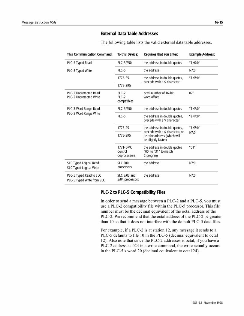
Message Instruction MSG 16-15
External Data Table Addresses
7KH�IROORZLQJ�WDEOH�OLVWV�WKH�YDOLG�H[WHUQDO�GDWD�WDEOH�DGGUHVVHV�
PLC-2 to PLC-5 Compatibility Files
,Q�RUGHU�WR�VHQG�D�PHVVDJH�EHWZHHQ�D�3/&���DQG�D�3/&����\RX�PXVW�XVH�D�3/&���FRPSDWLELOLW\�ILOH�ZLWKLQ�WKH�3/&���SURFHVVRU��7KLV�ILOH�QXPEHU�PXVW�EH�WKH�GHFLPDO�HTXLYDOHQW�RI�WKH�RFWDO�DGGUHVV�RI�WKH�3/&����:H�UHFRPPHQG�WKDW�WKH�RFWDO�DGGUHVV�RI�WKH�3/&���EH�JUHDWHU�WKDQ����VR�WKDW�LW�GRHV�QRW�LQWHUIHUH�ZLWK�WKH�GHIDXOW�3/&���GDWD�ILOHV�
)RU�H[DPSOH��LI�D�3/&���LV�DW�VWDWLRQ�����DQ\�PHVVDJH�LW�VHQGV�WR�D�3/&���GHIDXOWV�WR�ILOH����LQ�WKH�3/&����GHFLPDO�HTXLYDOHQW�WR�RFWDO������$OVR�QRWH�WKDW�VLQFH�WKH�3/&���DGGUHVVHV�LV�RFWDO��LI�\RX�KDYH�D�3/&���DGGUHVV�DV�����LQ�D�ZULWH�FRPPDQG��WKH�ZULWH�DFWXDOO\�RFFXUV�LQ�WKH�3/&��¶V�ZRUG�����GHFLPDO�HTXLYDOHQW�WR�RFWDO�����
This Communication Command: To this Device: Requires that You Enter: Example Address:
PLC-5 Typed Read
PLC-5 Typed Write
PLC-5/250 the address in double quotes “1N0:0”
PLC-5 the address N7:0
1775-S5 the address in double quotes, precede with a $ character
“$N7:0”
1775-SR5
PLC-2 Unprotected ReadPLC-2 Unprotected Write
PLC-2PLC-2compatibles
octal number of 16-bitword offset
025
PLC-3 Word Range ReadPLC-3 Word Range Write
PLC-5/250 the address in double quotes “1N7:0”
PLC-5 the address in double quotes, precede with a $ character
“$N7:0”
1775-S5 the address in double quotes, precede with a $ character, or just the address (which will be slightly faster)
“$N7:0”N7:0
1775-SR5
1771-DMCControlCoprocessors
the address in double quotes “00’ to “31” to matchC program
“01”
SLC Typed Logical ReadSLC Typed Logical Write
SLC 500processors
the address N7:0
PLC-5 Typed Read to SLCPLC-5 Typed Write from SLC
SLC 5/03 and5/04 processors
the address N7:0
1785-6.1 November 1998
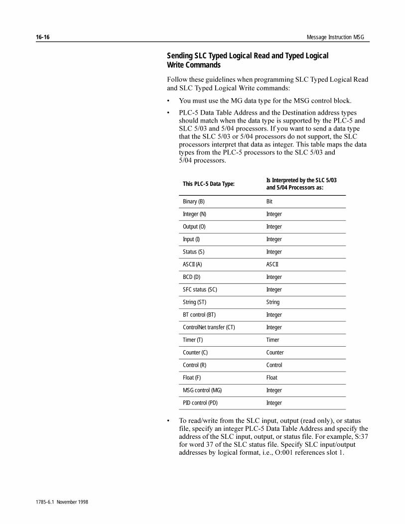
16-16 Message Instruction MSG
Sending SLC Typed Logical Read and Typed Logical Write Commands
)ROORZ�WKHVH�JXLGHOLQHV�ZKHQ�SURJUDPPLQJ�6/&�7\SHG�/RJLFDO�5HDG�DQG�6/&�7\SHG�/RJLFDO�:ULWH�FRPPDQGV�
� <RX�PXVW�XVH�WKH�0*�GDWD�W\SH�IRU�WKH�06*�FRQWURO�EORFN�
� 3/&���'DWD�7DEOH�$GGUHVV�DQG�WKH�'HVWLQDWLRQ�DGGUHVV�W\SHV�VKRXOG�PDWFK�ZKHQ�WKH�GDWD�W\SH�LV�VXSSRUWHG�E\�WKH�3/&���DQG�6/&������DQG������SURFHVVRUV��,I�\RX�ZDQW�WR�VHQG�D�GDWD�W\SH�WKDW�WKH�6/&������RU������SURFHVVRUV�GR�QRW�VXSSRUW��WKH�6/&�SURFHVVRUV�LQWHUSUHW�WKDW�GDWD�DV�LQWHJHU��7KLV�WDEOH�PDSV�WKH�GDWD�W\SHV�IURP�WKH�3/&���SURFHVVRUV�WR�WKH�6/&������DQG����� SURFHVVRUV�
� 7R�UHDG�ZULWH�IURP�WKH�6/&�LQSXW��RXWSXW��UHDG�RQO\���RU�VWDWXV�ILOH��VSHFLI\�DQ�LQWHJHU�3/&���'DWD�7DEOH�$GGUHVV�DQG�VSHFLI\�WKH�DGGUHVV�RI�WKH�6/&�LQSXW��RXWSXW��RU�VWDWXV�ILOH��)RU�H[DPSOH��6����IRU�ZRUG����RI�WKH�6/&�VWDWXV�ILOH��6SHFLI\�6/&�LQSXW�RXWSXW�DGGUHVVHV�E\�ORJLFDO�IRUPDW��L�H���2�����UHIHUHQFHV�VORW���
This PLC-5 Data Type:Is Interpreted by the SLC 5/03and 5/04 Processors as:
Binary (B) Bit
Integer (N) Integer
Output (O) Integer
Input (I) Integer
Status (S) Integer
ASCII (A) ASCII
BCD (D) Integer
SFC status (SC) Integer
String (ST) String
BT control (BT) Integer
ControlNet transfer (CT) Integer
Timer (T) Timer
Counter (C) Counter
Control (R) Control
Float (F) Float
MSG control (MG) Integer
PID control (PD) Integer
1785-6.1 November 1998

Message Instruction MSG 16-17
� 3/&���$6&,,�GDWD�LV�E\WH�GDWD������ZRUG���ZKHUHDV��DQ�6/&�$6&,,�GDWD�HOHPHQW�LV�RQH�ZRUG��7KHUHIRUH��LI�\RX�UHTXHVW�DQ�3/&���7\SHG�5HDG�RI����HOHPHQWV��WKH�6/&�����SURFHVVRU�VHQGV�D�SDFNHW�FRQWDLQLQJ����E\WHV�����ZRUGV��
� 3/&���SURFHVVRUV�DOORZV������HOHPHQWV�IRU�PRVW�GDWD�W\SHV�ZKHUHDV�6/&�����SURFHVVRUV�RQO\�DOORZ�����HOHPHQWV�
Monitoring a Message Instruction 7R�PRQLWRU�RU�HGLW�06*�LQVWUXFWLRQ�SDUDPHWHUV�DQG�VWDWXV�ELWV�DIWHU�\RX�HQWHU�WKH�06*�LQVWUXFWLRQ��GLVSOD\�WKH�GDWD�PRQLWRU�VFUHHQ�IRU�WKH�06*�LQVWUXFWLRQ�DQG�ILOH�W\SH�\RX�DUH�XVLQJ�
,I�\RX�DUH�XVLQJ�DQ�LQWHJHU��1��ILOH�W\SH��\RX�FDQ�GR�WKH�IROORZLQJ�IURP�WKH�GDWD�PRQLWRU�VFUHHQ��7DEOH����%��
Table 16.B Data Monitor Screen for the MSG Instruction – N File Type
,I�\RX�DUH�XVLQJ�DQ�PHVVDJH��0*��ILOH�W\SH��\RX�FDQ�GR�WKH�IROORZLQJ�IURP�WKH�GDWD�PRQLWRU�VFUHHQ��7DEOH����&��
Table 16.C Data Monitor Screen for the MSG Instruction – MG File Type
If You Are Using this File Type: See:
integer (N) Table 16.B
message (MG) Table 16.C
If You Want to: Press this Key:
specify the number of elements (1-1000) you want to read from or write to the network station
[F3} – Size in Elements
set and reset status bits [F9] – Toggle Bit
If You Want to: Press this Key:
Toggle the control bit that the cursor is on.You can toggle among the TO, NR, EW, CO, ER, DN, ST, and EN bits
[F2] – Toggle Bit
Change the size of the block of data to send or receive. [F3] – Size in Elements
Change the address for which the data is displayed. [F5] – Specify Address
Display the data table values for the next file. [F7] – Next File
Display the data table values for the previous file. [F8] – Previous File
Display the data table values for the next element. [F9] – Next Element
Display the data table values for the previous element. [F10] – Previous Element
1785-6.1 November 1998
16-18 Message Instruction MSG
Selecting Continuous Operation &RQWLQXRXV�PRGH�OHWV�\RX�XVH�PXOWLSOH�PHVVDJH�WUDQVIHUV�E\�SURJUDPPLQJ�RQO\�RQH�06*�LQVWUXFWLRQ��ZLWK�QR�LQSXW�FRQGLWLRQV�RQ�WKH�UXQJ���2QFH�WKH�FRQWLQXRXV�PHVVDJH�WUDQVIHU�VWDUWV��WKH�WUDQVIHU�LV�FRQWLQXRXVO\�H[HFXWHG��LQGHSHQGHQW�RI�ZKHWKHU�WKH�SURFHVVRU�FRQWLQXHV�WR�VFDQ�WKH�DVVRFLDWHG�UXQJ�DQG�LQGHSHQGHQW�RI�WKH�UXQJ�FRQGLWLRQ��7R�HQDEOH�FRQWLQXRXV�RSHUDWLRQ��VHW�WKH��&2�ELW�
&RQWLQXRXV�PRGH�ZRUNV�DV�IROORZV��)LJXUH�������
�� :KHQ�WKH�UXQJ�WKDW�FRQWDLQV�WKH�06*�LQVWUXFWLRQ�JRHV�WUXH��WKH�SURFHVVRU�LQLWLDWLQJ�WKH�06*�LQVWUXFWLRQ�VHWV�WKH��(1�ELW��7KH�SURFHVVRU�DOVR�UHVHWV�WKH��(5�DQG��'1�ELWV�
�� 7KH�SURFHVVRU�WKHQ�TXHXHV�WKH�PHVVDJH�UHTXHVW��:KHQ�WKH�PHVVDJH�UHTXHVW�HQWHUV�WKH�TXHXH��WKH�SURFHVVRU�VHWV�WKH��(:�ELW�
�� :KHQ�WKH�SURFHVVRU�VWDUWV�WR�SURFHVV�WKH�PHVVDJH�UHTXHVW��WKH�SURFHVVRU�VHWV�WKH��67�ELW��7KH�QH[W�WLPH�WKH�SURFHVVRU�UHFHLYHV�QHWZRUN�FRQWURO��WKH�SURFHVVRU�WUDQVPLWV�WKH�PHVVDJH�
�� ,I�DQ�HUURU�RFFXUV��WKH�SURFHVVRU�VHWV�WKH��(5�ELW�DQG�VWRUHV�DQ�HUURU�FRGH�LQ�WKH�ORZHU�E\WH�RI�ZRUG���RI�WKH�FRQWURO�EORFN�IRU�&ODVVLF�3/&���SURFHVVRUV�DQG�ZRUG���RI�WKH�FRQWURO�EORFN�IRU�(QKDQFHG�3/&���SURFHVVRUV�
,PSRUWDQW���)LJXUH������LV�DSSURSULDWH�IRU�(QKDQFHG�3/&���SURFHVVRUV�RQO\��<RX�FDQ�UHVHW�&ODVVLF�3/&���SURFHVVRUV�E\�WRJJOLQJ�WKH�HUURU�RU�HQDEOH�ELWV�
�$77(17,21� )RU�FRQWLQXRXV�PRGH�WR�RSHUDWH�FRUUHFWO\��\RX�PXVW�VHW�WKH��&2�ELW��HLWKHU�RQ�WKH�FRQILJXUDWLRQ�VFUHHQ�RU�WKURXJK�ODGGHU�ORJLF��EHIRUH�\RX�HQDEOH�WKH�06*�LQVWUXFWLRQ�
1785-6.1 November 1998
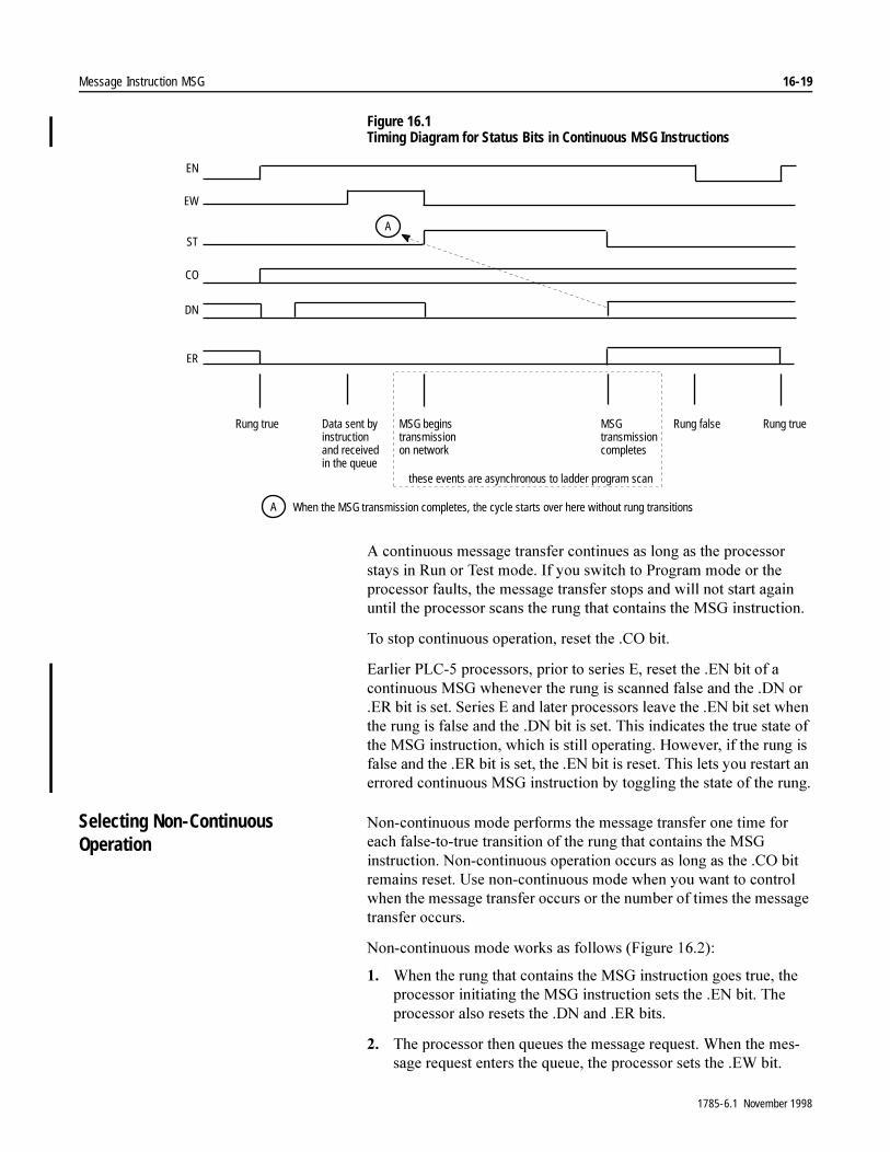
Message Instruction MSG 16-19
Figure 16.1 Timing Diagram for Status Bits in Continuous MSG Instructions
$�FRQWLQXRXV�PHVVDJH�WUDQVIHU�FRQWLQXHV�DV�ORQJ�DV�WKH�SURFHVVRU�VWD\V�LQ�5XQ�RU�7HVW�PRGH��,I�\RX�VZLWFK�WR�3URJUDP�PRGH�RU�WKH�SURFHVVRU�IDXOWV��WKH�PHVVDJH�WUDQVIHU�VWRSV�DQG�ZLOO�QRW�VWDUW�DJDLQ�XQWLO�WKH�SURFHVVRU�VFDQV�WKH�UXQJ�WKDW�FRQWDLQV�WKH�06*�LQVWUXFWLRQ�
7R�VWRS�FRQWLQXRXV�RSHUDWLRQ��UHVHW�WKH��&2�ELW�
(DUOLHU�3/&���SURFHVVRUV��SULRU�WR�VHULHV�(��UHVHW�WKH��(1�ELW�RI�D�FRQWLQXRXV�06*�ZKHQHYHU�WKH�UXQJ�LV�VFDQQHG�IDOVH�DQG�WKH��'1�RU��(5�ELW�LV�VHW��6HULHV�(�DQG�ODWHU�SURFHVVRUV�OHDYH�WKH��(1�ELW�VHW�ZKHQ�WKH�UXQJ�LV�IDOVH�DQG�WKH��'1�ELW�LV�VHW��7KLV�LQGLFDWHV�WKH�WUXH�VWDWH�RI�WKH�06*�LQVWUXFWLRQ��ZKLFK�LV�VWLOO�RSHUDWLQJ��+RZHYHU��LI�WKH�UXQJ�LV�IDOVH�DQG�WKH��(5�ELW�LV�VHW��WKH��(1�ELW�LV�UHVHW��7KLV�OHWV�\RX�UHVWDUW�DQ�HUURUHG�FRQWLQXRXV�06*�LQVWUXFWLRQ�E\�WRJJOLQJ�WKH�VWDWH�RI�WKH�UXQJ�
Selecting Non-Continuous Operation
1RQ�FRQWLQXRXV�PRGH�SHUIRUPV�WKH�PHVVDJH�WUDQVIHU�RQH�WLPH�IRU�HDFK�IDOVH�WR�WUXH�WUDQVLWLRQ�RI�WKH�UXQJ�WKDW�FRQWDLQV�WKH�06*�LQVWUXFWLRQ��1RQ�FRQWLQXRXV�RSHUDWLRQ�RFFXUV�DV�ORQJ�DV�WKH��&2�ELW�UHPDLQV�UHVHW��8VH�QRQ�FRQWLQXRXV�PRGH�ZKHQ�\RX�ZDQW�WR�FRQWURO�ZKHQ�WKH�PHVVDJH�WUDQVIHU�RFFXUV�RU�WKH�QXPEHU�RI�WLPHV�WKH�PHVVDJH�WUDQVIHU�RFFXUV�
1RQ�FRQWLQXRXV�PRGH�ZRUNV�DV�IROORZV��)LJXUH�������
�� :KHQ�WKH�UXQJ�WKDW�FRQWDLQV�WKH�06*�LQVWUXFWLRQ�JRHV�WUXH��WKH�SURFHVVRU�LQLWLDWLQJ�WKH�06*�LQVWUXFWLRQ�VHWV�WKH��(1�ELW��7KH�SURFHVVRU�DOVR�UHVHWV�WKH��'1�DQG��(5�ELWV�
�� 7KH�SURFHVVRU�WKHQ�TXHXHV�WKH�PHVVDJH�UHTXHVW��:KHQ�WKH�PHV�VDJH�UHTXHVW�HQWHUV�WKH�TXHXH��WKH�SURFHVVRU�VHWV�WKH��(:�ELW�
EN
EW
ST
CO
ER
Rung true Rung trueRung falseData sent byinstructionand receivedin the queue
MSG beginstransmissionon network
MSGtransmissioncompletes
DN
A
When the MSG transmission completes, the cycle starts over here without rung transitionsA
these events are asynchronous to ladder program scan
1785-6.1 November 1998
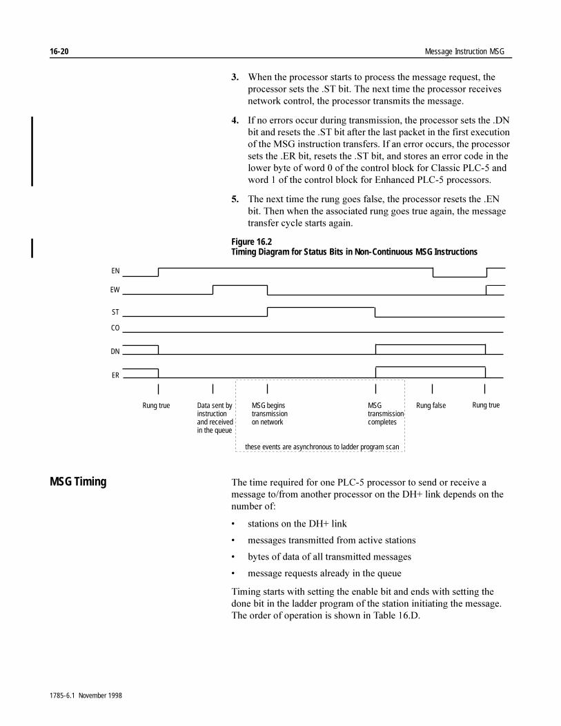
16-20 Message Instruction MSG
�� :KHQ�WKH�SURFHVVRU�VWDUWV�WR�SURFHVV�WKH�PHVVDJH�UHTXHVW��WKH�SURFHVVRU�VHWV�WKH��67�ELW��7KH�QH[W�WLPH�WKH�SURFHVVRU�UHFHLYHV�QHWZRUN�FRQWURO��WKH�SURFHVVRU�WUDQVPLWV�WKH�PHVVDJH�
�� ,I�QR�HUURUV�RFFXU�GXULQJ�WUDQVPLVVLRQ��WKH�SURFHVVRU�VHWV�WKH��'1�ELW�DQG�UHVHWV�WKH��67�ELW�DIWHU�WKH�ODVW�SDFNHW�LQ�WKH�ILUVW�H[HFXWLRQ�RI�WKH�06*�LQVWUXFWLRQ�WUDQVIHUV��,I�DQ�HUURU�RFFXUV��WKH�SURFHVVRU�VHWV�WKH��(5�ELW��UHVHWV�WKH��67�ELW��DQG�VWRUHV�DQ�HUURU�FRGH�LQ�WKH�ORZHU�E\WH�RI�ZRUG���RI�WKH�FRQWURO�EORFN�IRU�&ODVVLF�3/&���DQG�ZRUG���RI�WKH�FRQWURO�EORFN�IRU�(QKDQFHG�3/&���SURFHVVRUV�
�� 7KH�QH[W�WLPH�WKH�UXQJ�JRHV�IDOVH��WKH�SURFHVVRU�UHVHWV�WKH��(1�ELW��7KHQ�ZKHQ�WKH�DVVRFLDWHG�UXQJ�JRHV�WUXH�DJDLQ��WKH�PHVVDJH�WUDQVIHU�F\FOH�VWDUWV�DJDLQ�
Figure 16.2 Timing Diagram for Status Bits in Non-Continuous MSG Instructions
MSG Timing 7KH�WLPH�UHTXLUHG�IRU�RQH�3/&���SURFHVVRU�WR�VHQG�RU�UHFHLYH�D�PHVVDJH�WR�IURP�DQRWKHU�SURFHVVRU�RQ�WKH�'+��OLQN�GHSHQGV�RQ�WKH�QXPEHU�RI�
� VWDWLRQV�RQ�WKH�'+��OLQN
� PHVVDJHV�WUDQVPLWWHG�IURP�DFWLYH�VWDWLRQV
� E\WHV�RI�GDWD�RI�DOO�WUDQVPLWWHG�PHVVDJHV
� PHVVDJH�UHTXHVWV�DOUHDG\�LQ�WKH�TXHXH
7LPLQJ�VWDUWV�ZLWK�VHWWLQJ�WKH�HQDEOH�ELW�DQG�HQGV�ZLWK�VHWWLQJ�WKH�GRQH�ELW�LQ�WKH�ODGGHU�SURJUDP�RI�WKH�VWDWLRQ�LQLWLDWLQJ�WKH�PHVVDJH��7KH�RUGHU�RI�RSHUDWLRQ�LV�VKRZQ�LQ�7DEOH����'�
EN
EW
ST
DN
CO
ER
Rung true Data sent byinstructionand receivedin the queue
MSG beginstransmissionon network
MSGtransmissioncompletes
Rung trueRung false
these events are asynchronous to ladder program scan
1785-6.1 November 1998
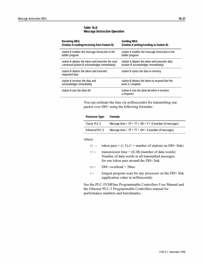
Message Instruction MSG 16-21
Table 16.D Message Instruction Operation
<RX�FDQ�HVWLPDWH�WKH�WLPH��LQ�PLOOLVHFRQGV��IRU�WUDQVPLWWLQJ�RQH�SDFNHW�RYHU�'+��XVLQJ�WKH�IROORZLQJ�IRUPXODV�
ZKHUH�
TP = WRNHQ�SDVV� ������������QXPEHU�RI�VWDWLRQV�RQ�'+��OLQN�
TT� � WUDQVPLVVLRQ�WLPH� ���������QXPEHU�RI�GDWD�ZRUGV�1XPEHU�RI�GDWD�ZRUGV�LQ�DOO�WUDQVPLWWHG�PHVVDJHVIRU�RQH�WRNHQ�SDVV�DURXQG�WKH�'+��OLQN�
OH� '+��RYHUKHDG� ���PV
P� ORQJHVW�SURJUDP�VFDQ�IRU�DQ\�SURFHVVRU�RQ�WKH�'+��OLQN�DSSOLFDWLRQ�YDOXH�LQ�PLOOLVHFRQGV�
6HH�WKH�3/&��90(EXV�3URJUDPPDEOH�&RQWUROOHUV�8VHU�0DQXDO�DQG�WKH�(WKHUQHW�3/&���3URJUDPPDEOH�&RQWUROOHUV�PDQXDO�IRU�SHUIRUPDQFH�QXPEHUV�DQG�EHQFKPDUNV�
Receiving MSG(Station A reading/receiving from Station B)
Sending MSG(Station A writing/sending to Station B)
station A enables the message instruction in the ladder program
station A enables the message instruction in the ladder program
station A obtains the token and transmits the read command (station B acknowledges immediately)
station A obtains the token and transmits data (station B acknowledges immediately)
station B obtains the token and transmits requested data
station B stores the data in memory
station A receives the data and acknowledges immediately
station B obtains the token to respond that the write is complete
station A sets the done bit station A sets the done bit when it receives a response
Processor Type: Formula:
Classic PLC-5 Message time = TP + TT + OH + P + 8 (number of messages)
Enhanced PLC-5 Message time = TP + TT + OH + 8 (number of messages)
1785-6.1 November 1998

16-22 Message Instruction MSG
Error Codes :KHQ�WKH�SURFHVVRU�GHWHFWV�DQ�HUURU�GXULQJ�WKH�WUDQVIHU�RI�PHVVDJH�GDWD��WKH�SURFHVVRU�VHWV�WKH��(5�ELW�DQG�HQWHUV�DQ�HUURU�FRGH�WKDW�\RX�FDQ�PRQLWRU�IURP�\RXU�SURJUDPPLQJ�WHUPLQDO��,I�WKH�PHVVDJH�LV�QRQ�FRQWLQXRXV��WKH�SURFHVVRU�VHWV�WKH��(5�ELW�WKH�ILUVW�WLPH�WKH�SURFHVVRU�VFDQV�WKH�06*�LQVWUXFWLRQ�
Table 16.E Errors Detected By the Processor
Code:
Enhanced PLC-51
MG data typeClassic PLC-52
N data type Ethernet Only Description (Displayed on the Data Monitor screen):
0037 55 0037 message timed out in local processor
0083 131 0083 processor is disconnected
0089 137 0089 message buffer is full
If the MSG is going out channel 0, there are not enough internal buffers available. Decrease the number of MSG instructions to this port.
Otherwise, the destination node sent back a MSG indicating that its buffers are full. Decrease the number of MSG instructions going to the destination node.
0092 146 0092 no response (regardless of station type)
00D3 211 00D3 you formatted the control block incorrectly
00D5 213 00D5 incorrect address for the local data table
0200 2 link layer timed out or received a NAK
0300 3 duplicate token holder detected by link layer
0400 4 local port is disconnected
0500 5 application layer timed out waiting for a response
0600 6 duplicate node detected
0700 7 station is off line
0800 8 hardware fault
1000 129 1000 illegal command from local processor
2000 130 2000 communication module not working
3000 131 remote node is missing, disconnected, or shut down
4000 132 4000 processor connected but faulted (hardware)
5000 133 5000 you used the wrong station number
6000 134 6000 requested function is not available
7000 135 7000 processor is in program node
1Hexadecimal – word 1 of the control block2Decimal – low byte of word 0 of the control block
1785-6.1 November 1998
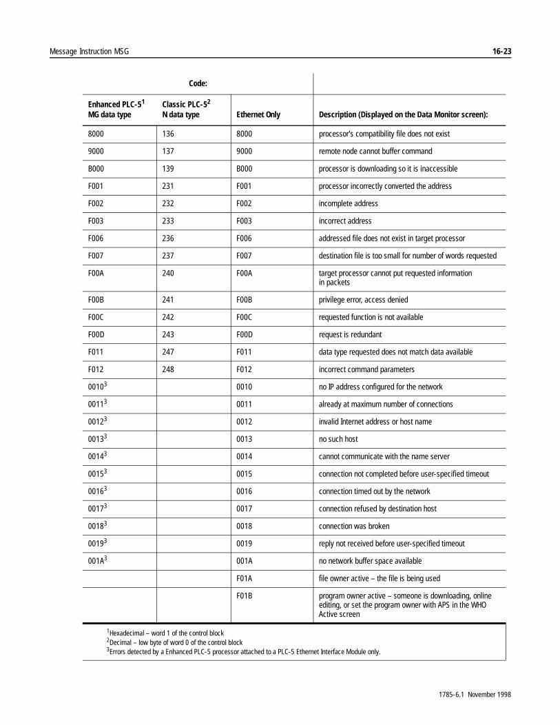
Message Instruction MSG 16-23
8000 136 8000 processor’s compatibility file does not exist
9000 137 9000 remote node cannot buffer command
B000 139 B000 processor is downloading so it is inaccessible
F001 231 F001 processor incorrectly converted the address
F002 232 F002 incomplete address
F003 233 F003 incorrect address
F006 236 F006 addressed file does not exist in target processor
F007 237 F007 destination file is too small for number of words requested
F00A 240 F00A target processor cannot put requested information in packets
F00B 241 F00B privilege error, access denied
F00C 242 F00C requested function is not available
F00D 243 F00D request is redundant
F011 247 F011 data type requested does not match data available
F012 248 F012 incorrect command parameters
00103 0010 no IP address configured for the network
00113 0011 already at maximum number of connections
00123 0012 invalid Internet address or host name
00133 0013 no such host
00143 0014 cannot communicate with the name server
00153 0015 connection not completed before user-specified timeout
00163 0016 connection timed out by the network
00173 0017 connection refused by destination host
00183 0018 connection was broken
00193 0019 reply not received before user-specified timeout
001A3 001A no network buffer space available
F01A file owner active – the file is being used
F01B program owner active – someone is downloading, online editing, or set the program owner with APS in the WHO Active screen
1Hexadecimal – word 1 of the control block2Decimal – low byte of word 0 of the control block3Errors detected by a Enhanced PLC-5 processor attached to a PLC-5 Ethernet Interface Module only.
Code:
Enhanced PLC-51
MG data typeClassic PLC-52
N data type Ethernet Only Description (Displayed on the Data Monitor screen):
1785-6.1 November 1998
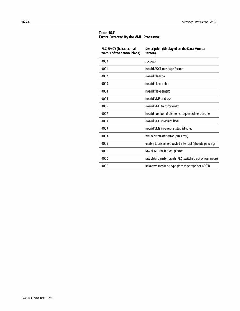
16-24 Message Instruction MSG
Table 16.F Errors Detected By the VME Processor
PLC-5/40V (hexadecimal – word 1 of the control block)
Description (Displayed on the Data Monitor screen):
0000 success
0001 invalid ASCII message format
0002 invalid file type
0003 invalid file number
0004 invalid file element
0005 invalid VME address
0006 invalid VME transfer width
0007 invalid number of elements requested for transfer
0008 invalid VME interrupt level
0009 invalid VME interrupt status-id value
000A VMEbus transfer error (bus error)
000B unable to assert requested interrupt (already pending)
000C raw data transfer setup error
000D raw data transfer crash (PLC switched out of run mode)
000E unknown message type (message type not ASCII)
1785-6.1 November 1998
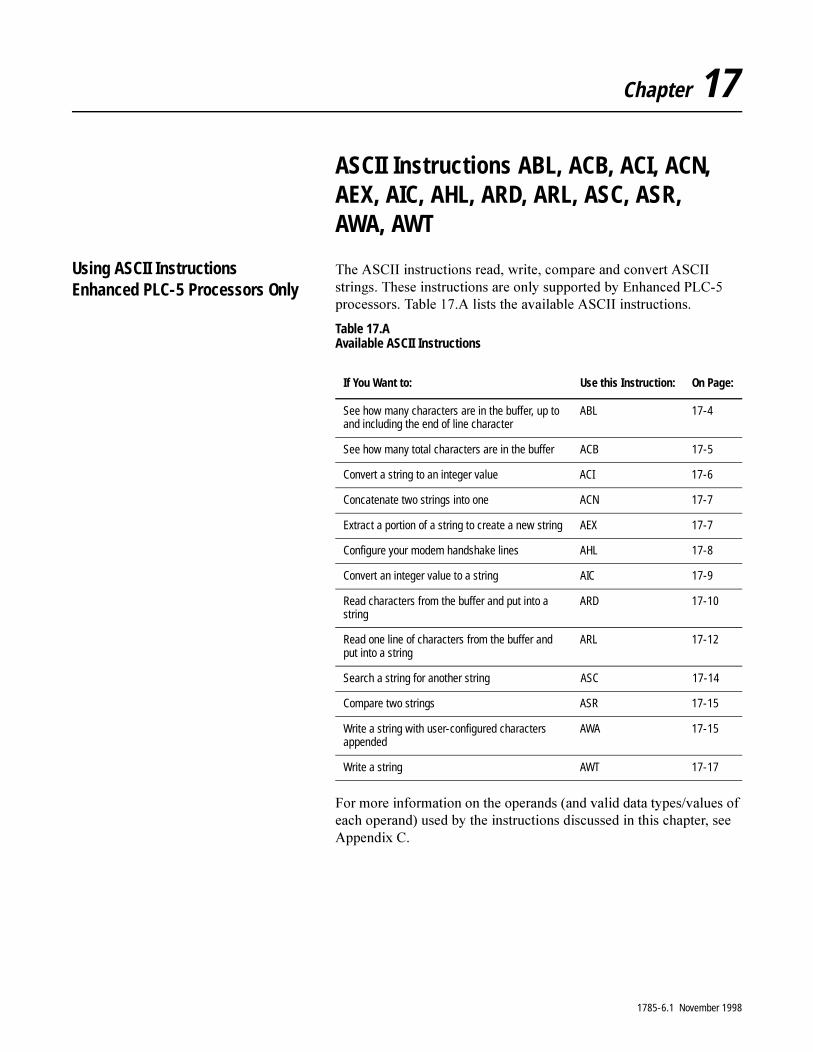
Chapter 17
ASCII Instructions ABL, ACB, ACI, ACN, AEX, AIC, AHL, ARD, ARL, ASC, ASR, AWA, AWT
Using ASCII InstructionsEnhanced PLC-5 Processors Only
7KH�$6&,,�LQVWUXFWLRQV�UHDG��ZULWH��FRPSDUH�DQG�FRQYHUW�$6&,,�VWULQJV��7KHVH�LQVWUXFWLRQV�DUH�RQO\�VXSSRUWHG�E\�(QKDQFHG�3/&���SURFHVVRUV��7DEOH����$�OLVWV�WKH�DYDLODEOH�$6&,,�LQVWUXFWLRQV�
Table 17.A Available ASCII Instructions
)RU�PRUH�LQIRUPDWLRQ�RQ�WKH�RSHUDQGV��DQG�YDOLG�GDWD�W\SHV�YDOXHV�RI�HDFK�RSHUDQG��XVHG�E\�WKH�LQVWUXFWLRQV�GLVFXVVHG�LQ�WKLV�FKDSWHU��VHH�$SSHQGL[�&�
If You Want to: Use this Instruction: On Page:
See how many characters are in the buffer, up to and including the end of line character
ABL 17-4
See how many total characters are in the buffer ACB 17-5
Convert a string to an integer value ACI 17-6
Concatenate two strings into one ACN 17-7
Extract a portion of a string to create a new string AEX 17-7
Configure your modem handshake lines AHL 17-8
Convert an integer value to a string AIC 17-9
Read characters from the buffer and put into a string
ARD 17-10
Read one line of characters from the buffer and put into a string
ARL 17-12
Search a string for another string ASC 17-14
Compare two strings ASR 17-15
Write a string with user-configured characters appended
AWA 17-15
Write a string AWT 17-17
1785-6.1 November 1998
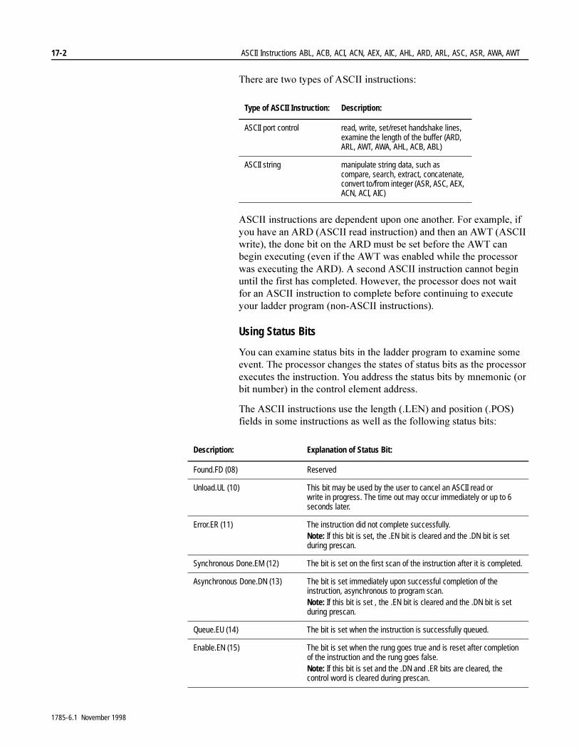
17-2 ASCII Instructions ABL, ACB, ACI, ACN, AEX, AIC, AHL, ARD, ARL, ASC, ASR, AWA, AWT
7KHUH�DUH�WZR�W\SHV�RI�$6&,,�LQVWUXFWLRQV��
$6&,,�LQVWUXFWLRQV�DUH�GHSHQGHQW�XSRQ�RQH�DQRWKHU��)RU�H[DPSOH��LI�\RX�KDYH�DQ�$5'��$6&,,�UHDG�LQVWUXFWLRQ��DQG�WKHQ�DQ�$:7��$6&,,�ZULWH���WKH�GRQH�ELW�RQ�WKH�$5'�PXVW�EH�VHW�EHIRUH�WKH�$:7�FDQ�EHJLQ�H[HFXWLQJ��HYHQ�LI�WKH�$:7�ZDV�HQDEOHG�ZKLOH�WKH�SURFHVVRU�ZDV�H[HFXWLQJ�WKH�$5'���$�VHFRQG�$6&,,�LQVWUXFWLRQ�FDQQRW�EHJLQ�XQWLO�WKH�ILUVW�KDV�FRPSOHWHG��+RZHYHU��WKH�SURFHVVRU�GRHV�QRW�ZDLW�IRU�DQ�$6&,,�LQVWUXFWLRQ�WR�FRPSOHWH�EHIRUH�FRQWLQXLQJ�WR�H[HFXWH�\RXU�ODGGHU�SURJUDP��QRQ�$6&,,�LQVWUXFWLRQV��
Using Status Bits
<RX�FDQ�H[DPLQH�VWDWXV�ELWV�LQ�WKH�ODGGHU�SURJUDP�WR�H[DPLQH�VRPH�HYHQW��7KH�SURFHVVRU�FKDQJHV�WKH�VWDWHV�RI�VWDWXV�ELWV�DV�WKH�SURFHVVRU�H[HFXWHV�WKH�LQVWUXFWLRQ��<RX�DGGUHVV�WKH�VWDWXV�ELWV�E\�PQHPRQLF��RU�ELW�QXPEHU��LQ�WKH�FRQWURO�HOHPHQW�DGGUHVV�
7KH�$6&,,�LQVWUXFWLRQV�XVH�WKH�OHQJWK���/(1��DQG�SRVLWLRQ���326��ILHOGV�LQ�VRPH�LQVWUXFWLRQV�DV�ZHOO�DV�WKH�IROORZLQJ�VWDWXV�ELWV�
Type of ASCII Instruction: Description:
ASCII port control read, write, set/reset handshake lines, examine the length of the buffer (ARD, ARL, AWT, AWA, AHL, ACB, ABL)
ASCII string manipulate string data, such as compare, search, extract, concatenate, convert to/from integer (ASR, ASC, AEX, ACN, ACI, AIC)
Description: Explanation of Status Bit:
Found.FD (08) Reserved
Unload.UL (10) This bit may be used by the user to cancel an ASCII read or write in progress. The time out may occur immediately or up to 6 seconds later.
Error.ER (11) The instruction did not complete successfully.Note: If this bit is set, the .EN bit is cleared and the .DN bit is set during prescan.
Synchronous Done.EM (12) The bit is set on the first scan of the instruction after it is completed.
Asynchronous Done.DN (13) The bit is set immediately upon successful completion of the instruction, asynchronous to program scan.Note: If this bit is set , the .EN bit is cleared and the .DN bit is set during prescan.
Queue.EU (14) The bit is set when the instruction is successfully queued.
Enable.EN (15) The bit is set when the rung goes true and is reset after completion of the instruction and the rung goes false.Note: If this bit is set and the .DN and .ER bits are cleared, the control word is cleared during prescan.
1785-6.1 November 1998
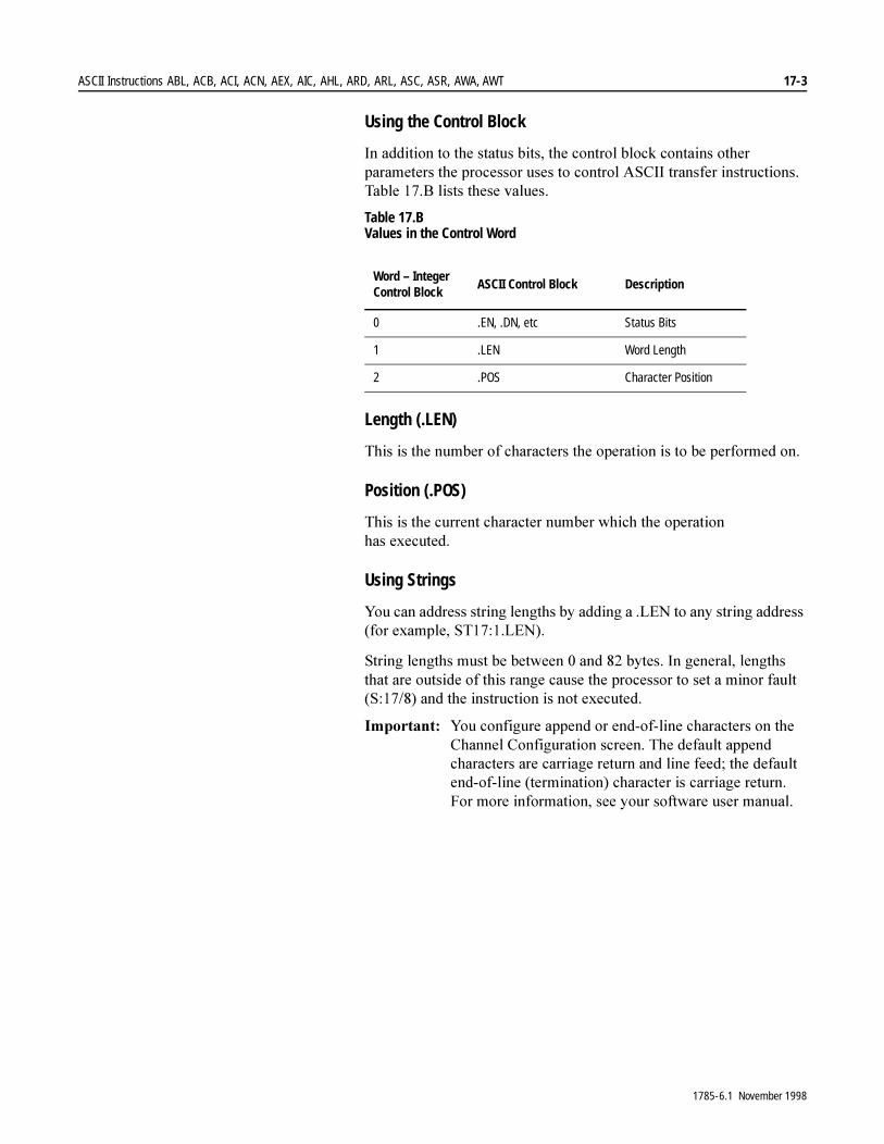
ASCII Instructions ABL, ACB, ACI, ACN, AEX, AIC, AHL, ARD, ARL, ASC, ASR, AWA, AWT 17-3
Using the Control Block
,Q�DGGLWLRQ�WR�WKH�VWDWXV�ELWV��WKH�FRQWURO�EORFN�FRQWDLQV�RWKHU�SDUDPHWHUV�WKH�SURFHVVRU�XVHV�WR�FRQWURO�$6&,,�WUDQVIHU�LQVWUXFWLRQV��7DEOH����%�OLVWV�WKHVH�YDOXHV�
Table 17.B Values in the Control Word
Length (.LEN)
7KLV�LV�WKH�QXPEHU�RI�FKDUDFWHUV�WKH�RSHUDWLRQ�LV�WR�EH�SHUIRUPHG�RQ�
Position (.POS)
7KLV�LV�WKH�FXUUHQW�FKDUDFWHU�QXPEHU�ZKLFK�WKH�RSHUDWLRQ�KDV�H[HFXWHG�
Using Strings
<RX�FDQ�DGGUHVV�VWULQJ�OHQJWKV�E\�DGGLQJ�D��/(1�WR�DQ\�VWULQJ�DGGUHVV��IRU�H[DPSOH��67�����/(1��
6WULQJ�OHQJWKV�PXVW�EH�EHWZHHQ���DQG����E\WHV��,Q�JHQHUDO��OHQJWKV�WKDW�DUH�RXWVLGH�RI�WKLV�UDQJH�FDXVH�WKH�SURFHVVRU�WR�VHW�D�PLQRU�IDXOW��6�������DQG�WKH�LQVWUXFWLRQ�LV�QRW�H[HFXWHG�
,PSRUWDQW���<RX�FRQILJXUH�DSSHQG�RU�HQG�RI�OLQH�FKDUDFWHUV�RQ�WKH�&KDQQHO�&RQILJXUDWLRQ�VFUHHQ��7KH�GHIDXOW�DSSHQG�FKDUDFWHUV�DUH�FDUULDJH�UHWXUQ�DQG�OLQH�IHHG��WKH�GHIDXOW�HQG�RI�OLQH��WHUPLQDWLRQ��FKDUDFWHU�LV�FDUULDJH�UHWXUQ��)RU�PRUH�LQIRUPDWLRQ��VHH�\RXU�VRIWZDUH�XVHU�PDQXDO�
Word – Integer Control Block
ASCII Control Block Description
0 .EN, .DN, etc Status Bits
1 .LEN Word Length
2 .POS Character Position
1785-6.1 November 1998
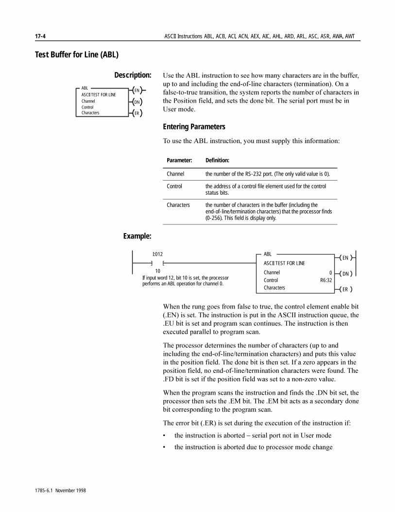
17-4 ASCII Instructions ABL, ACB, ACI, ACN, AEX, AIC, AHL, ARD, ARL, ASC, ASR, AWA, AWT
Test Buffer for Line (ABL)
Description: 8VH�WKH�$%/�LQVWUXFWLRQ�WR�VHH�KRZ�PDQ\�FKDUDFWHUV�DUH�LQ�WKH�EXIIHU��XS�WR�DQG�LQFOXGLQJ�WKH�HQG�RI�OLQH�FKDUDFWHUV��WHUPLQDWLRQ���2Q�D�IDOVH�WR�WUXH�WUDQVLWLRQ��WKH�V\VWHP�UHSRUWV�WKH�QXPEHU�RI�FKDUDFWHUV�LQ�WKH�3RVLWLRQ�ILHOG��DQG�VHWV�WKH�GRQH�ELW��7KH�VHULDO�SRUW�PXVW�EH�LQ�8VHU�PRGH�
Entering Parameters
7R�XVH�WKH�$%/�LQVWUXFWLRQ��\RX�PXVW�VXSSO\�WKLV�LQIRUPDWLRQ�
Example:
:KHQ�WKH�UXQJ�JRHV�IURP�IDOVH�WR�WUXH��WKH�FRQWURO�HOHPHQW�HQDEOH�ELW���(1��LV�VHW��7KH�LQVWUXFWLRQ�LV�SXW�LQ�WKH�$6&,,�LQVWUXFWLRQ�TXHXH��WKH��(8�ELW�LV�VHW�DQG�SURJUDP�VFDQ�FRQWLQXHV��7KH�LQVWUXFWLRQ�LV�WKHQ�H[HFXWHG�SDUDOOHO�WR�SURJUDP�VFDQ�
7KH�SURFHVVRU�GHWHUPLQHV�WKH�QXPEHU�RI�FKDUDFWHUV��XS�WR�DQG�LQFOXGLQJ�WKH�HQG�RI�OLQH�WHUPLQDWLRQ�FKDUDFWHUV��DQG�SXWV�WKLV�YDOXH�LQ�WKH�SRVLWLRQ�ILHOG��7KH�GRQH�ELW�LV�WKHQ�VHW��,I�D�]HUR�DSSHDUV�LQ�WKH�SRVLWLRQ�ILHOG��QR�HQG�RI�OLQH�WHUPLQDWLRQ�FKDUDFWHUV�ZHUH�IRXQG��7KH��)'�ELW�LV�VHW�LI�WKH�SRVLWLRQ�ILHOG�ZDV�VHW�WR�D�QRQ�]HUR�YDOXH�
:KHQ�WKH�SURJUDP�VFDQV�WKH�LQVWUXFWLRQ�DQG�ILQGV�WKH��'1�ELW�VHW��WKH�SURFHVVRU�WKHQ�VHWV�WKH��(0�ELW��7KH��(0�ELW�DFWV�DV�D�VHFRQGDU\�GRQH�ELW�FRUUHVSRQGLQJ�WR�WKH�SURJUDP�VFDQ�
7KH�HUURU�ELW���(5��LV�VHW�GXULQJ�WKH�H[HFXWLRQ�RI�WKH�LQVWUXFWLRQ�LI�
� WKH�LQVWUXFWLRQ�LV�DERUWHG�±�VHULDO�SRUW�QRW�LQ�8VHU�PRGH
� WKH�LQVWUXFWLRQ�LV�DERUWHG�GXH�WR�SURFHVVRU�PRGH�FKDQJH
ABL
ASCII TEST FOR LINE
ChannelControlCharacters
EN
DN
ER
Parameter: Definition:
Channel the number of the RS-232 port. (The only valid value is 0).
Control the address of a control file element used for the control status bits.
Characters the number of characters in the buffer (including the end-of-line/termination characters) that the processor finds (0-256). This field is display only.
ABL
ASCII TEST FOR LINE
Channel
Control
I:012
10
[ [
Characters
0R6:32If input word 12, bit 10 is set, the processor
performs an ABL operation for channel 0.
EN
DN
ER
1785-6.1 November 1998
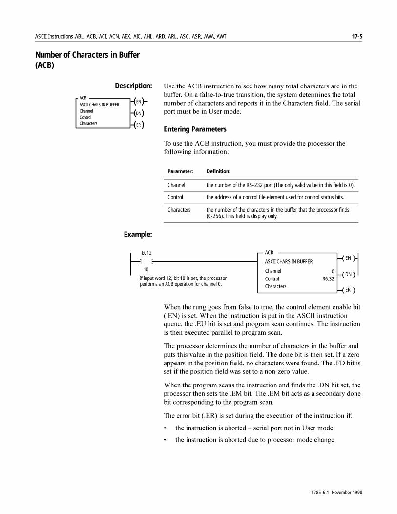
ASCII Instructions ABL, ACB, ACI, ACN, AEX, AIC, AHL, ARD, ARL, ASC, ASR, AWA, AWT 17-5
Number of Characters in Buffer (ACB)
Description: 8VH�WKH�$&%�LQVWUXFWLRQ�WR�VHH�KRZ�PDQ\�WRWDO�FKDUDFWHUV�DUH�LQ�WKH�EXIIHU��2Q�D�IDOVH�WR�WUXH�WUDQVLWLRQ��WKH�V\VWHP�GHWHUPLQHV�WKH�WRWDO�QXPEHU�RI�FKDUDFWHUV�DQG�UHSRUWV�LW�LQ�WKH�&KDUDFWHUV�ILHOG��7KH�VHULDO�SRUW�PXVW�EH�LQ�8VHU�PRGH�
Entering Parameters
7R�XVH�WKH�$&%�LQVWUXFWLRQ��\RX�PXVW�SURYLGH�WKH�SURFHVVRU�WKH�IROORZLQJ�LQIRUPDWLRQ�
Example:
:KHQ�WKH�UXQJ�JRHV�IURP�IDOVH�WR�WUXH��WKH�FRQWURO�HOHPHQW�HQDEOH�ELW���(1��LV�VHW��:KHQ�WKH�LQVWUXFWLRQ�LV�SXW�LQ�WKH�$6&,,�LQVWUXFWLRQ�TXHXH��WKH��(8�ELW�LV�VHW�DQG�SURJUDP�VFDQ�FRQWLQXHV��7KH�LQVWUXFWLRQ�LV�WKHQ�H[HFXWHG�SDUDOOHO�WR�SURJUDP�VFDQ�
7KH�SURFHVVRU�GHWHUPLQHV�WKH�QXPEHU�RI�FKDUDFWHUV�LQ�WKH�EXIIHU�DQG�SXWV�WKLV�YDOXH�LQ�WKH�SRVLWLRQ�ILHOG��7KH�GRQH�ELW�LV�WKHQ�VHW��,I�D�]HUR�DSSHDUV�LQ�WKH�SRVLWLRQ�ILHOG��QR�FKDUDFWHUV�ZHUH�IRXQG��7KH��)'�ELW�LV�VHW�LI�WKH�SRVLWLRQ�ILHOG�ZDV�VHW�WR�D�QRQ�]HUR�YDOXH�
:KHQ�WKH�SURJUDP�VFDQV�WKH�LQVWUXFWLRQ�DQG�ILQGV�WKH��'1�ELW�VHW��WKH�SURFHVVRU�WKHQ�VHWV�WKH��(0�ELW��7KH��(0�ELW�DFWV�DV�D�VHFRQGDU\�GRQH�ELW�FRUUHVSRQGLQJ�WR�WKH�SURJUDP�VFDQ�
7KH�HUURU�ELW���(5��LV�VHW�GXULQJ�WKH�H[HFXWLRQ�RI�WKH�LQVWUXFWLRQ�LI�
� WKH�LQVWUXFWLRQ�LV�DERUWHG�±�VHULDO�SRUW�QRW�LQ�8VHU�PRGH�
� WKH�LQVWUXFWLRQ�LV�DERUWHG�GXH�WR�SURFHVVRU�PRGH�FKDQJH
ACB
ASCII CHARS IN BUFFER
ChannelControlCharacters
EN
DN
ER
Parameter: Definition:
Channel the number of the RS-232 port (The only valid value in this field is 0).
Control the address of a control file element used for control status bits.
Characters the number of the characters in the buffer that the processor finds (0-256). This field is display only.
ACB
ASCII CHARS IN BUFFER
Channel
Control
I:012
10
[ [
Characters
0R6:32If input word 12, bit 10 is set, the processor
performs an ACB operation for channel 0.
EN
DN
ER
1785-6.1 November 1998
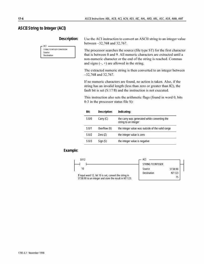
17-6 ASCII Instructions ABL, ACB, ACI, ACN, AEX, AIC, AHL, ARD, ARL, ASC, ASR, AWA, AWT
ASCII String to Integer (ACI)
Description: 8VH�WKH�$&,�LQVWUXFWLRQ�WR�FRQYHUW�DQ�$6&,,�VWULQJ�WR�DQ�LQWHJHU�YDOXH�EHWZHHQ�±�������DQG��������
7KH�SURFHVVRU�VHDUFKHV�WKH�VRXUFH��ILOH�W\SH�67��IRU�WKH�ILUVW�FKDUDFWHU�WKDW�LV�EHWZHHQ���DQG����$OO�QXPHULF�FKDUDFWHUV�DUH�H[WUDFWHG�XQWLO�D�QRQ�QXPHULF�FKDUDFWHU�RU�WKH�HQG�RI�WKH�VWULQJ�LV�UHDFKHG��&RPPDV�DQG�VLJQV��±�����DUH�DOORZHG�LQ�WKH�VWULQJ�
7KH�H[WUDFWHG�QXPHULF�VWULQJ�LV�WKHQ�FRQYHUWHG�WR�DQ�LQWHJHU�EHWZHHQ�±�������DQG��������
,I�QR�QXPHULF�FKDUDFWHUV�DUH�IRXQG��QR�DFWLRQ�LV�WDNHQ��$OVR��LI�WKH�VWULQJ�KDV�DQ�LQYDOLG�OHQJWK��OHVV�WKDQ�]HUR�RU�JUHDWHU�WKDQ������WKH�IDXOW�ELW�LV�VHW��6�������DQG�WKH�LQVWUXFWLRQ�LV�QRW�H[HFXWHG�
7KLV�LQVWUXFWLRQ�DOVR�VHWV�WKH�DULWKPHWLF�IODJV��IRXQG�LQ�ZRUG����ELWV�����LQ�WKH�SURFHVVRU�VWDWXV�ILOH�6��
Example:
ACI
STRING TO INTEGER CONVERSION
Source Destination
Bit: Description: Indicating:
S:0/0 Carry (C) the carry was generated while converting the string to an integer
S:0/1 Overflow (V) the integer value was outside of the valid range
S:0/2 Zero (Z) the integer value is zero
S:0/3 Sign (S) the integer value is negative
ACI
STRING TO INTEGER
Source
Destination
I:012
10
[
[
ST38:90N7:123
75If input word 12, bit 10 is set, convert the string inST38:90 to an integer and store the result in N7:123.
1785-6.1 November 1998
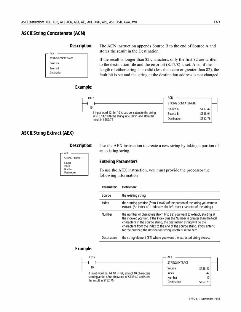
ASCII Instructions ABL, ACB, ACI, ACN, AEX, AIC, AHL, ARD, ARL, ASC, ASR, AWA, AWT 17-7
ASCII String Concatenate (ACN)
Description: 7KH�$&1�LQVWUXFWLRQ�DSSHQGV�6RXUFH�%�WR�WKH�HQG�RI�6RXUFH�$�DQG�VWRUHV�WKH�UHVXOW�LQ�WKH�'HVWLQDWLRQ�
,I�WKH�UHVXOW�LV�ORQJHU�WKDQ����FKDUDFWHUV��RQO\�WKH�ILUVW����DUH�ZULWWHQ�WR�WKH�GHVWLQDWLRQ�ILOH�DQG�WKH�HUURU�ELW��6�������LV�VHW��$OVR��LI�WKH�OHQJWK�RI�HLWKHU�VWULQJ�LV�LQYDOLG��OHVV�WKDQ�]HUR�RU�JUHDWHU�WKDQ������WKH�IDXOW�ELW�LV�VHW�DQG�WKH�VWULQJ�DW�WKH�GHVWLQDWLRQ�DGGUHVV�LV�QRW�FKDQJHG�
Example:
ASCII String Extract (AEX)
Description: 8VH�WKH�$(;�LQVWUXFWLRQ�WR�FUHDWH�D�QHZ�VWULQJ�E\�WDNLQJ�D�SRUWLRQ�RI�DQ�H[LVWLQJ�VWULQJ��
Entering Parameters
7R�XVH�WKH�$(;�LQVWUXFWLRQ��\RX�PXVW�SURYLGH�WKH�SURFHVVRU�WKH�IROORZLQJ�LQIRUPDWLRQ
Example:
ACN
STRING CONCATENATE
Source A
Destination
Source B
ACN
STRING CONCATENATE
Source A
Source B
I:012
10
[
[
ST37:42ST38:91
ST52:76Destination
If input word 12, bit 10 is set, concatenate the stringin ST37:42 with the string in ST38:91 and store theresult in ST52:76
AEX
STRING EXTRACT
SourceIndexNumberDestination
Parameter: Definition:
Source the existing string.
Index the starting position (from 1 to 82) of the portion of the string you want to extract. (An index of 1 indicates the left-most character of the string.)
Number the number of characters (from 0 to 82) you want to extract, starting at the indexed position. If the Index plus the Number is greater than the total characters in the source string, the destination string will be the characters from the index to the end of the source string. If you enter 0 for the number, the destination string length is set to zero.
Destination the string element (ST) where you want the extracted string stored.
AEX
STRING EXTRACT
Source
Index
I:012
10
[ [
NumberDestination
ST38:404210
ST52:75
If input word 12, bit 10 is set, extract 10 charactersstarting at the 42nd character of ST38:40 and storethe result in ST52:75.
1785-6.1 November 1998
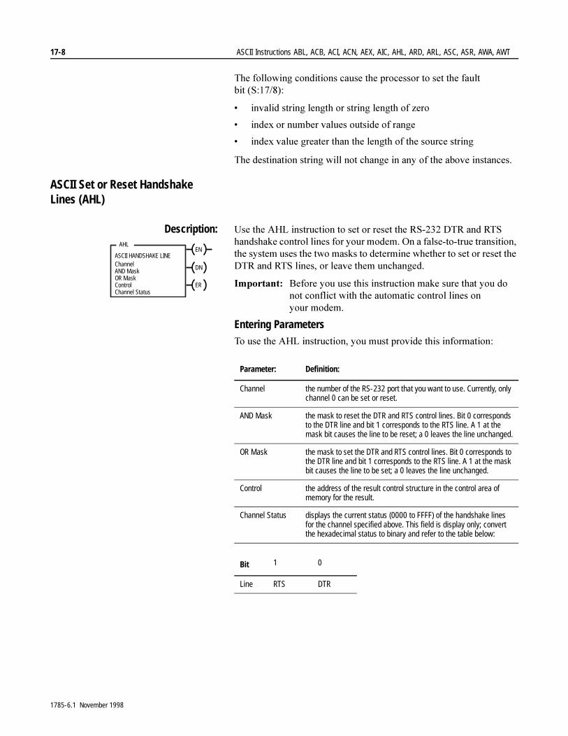
17-8 ASCII Instructions ABL, ACB, ACI, ACN, AEX, AIC, AHL, ARD, ARL, ASC, ASR, AWA, AWT
7KH�IROORZLQJ�FRQGLWLRQV�FDXVH�WKH�SURFHVVRU�WR�VHW�WKH�IDXOW�ELW �6�������
� LQYDOLG�VWULQJ�OHQJWK�RU�VWULQJ�OHQJWK�RI�]HUR
� LQGH[�RU�QXPEHU�YDOXHV�RXWVLGH�RI�UDQJH
� LQGH[�YDOXH�JUHDWHU�WKDQ�WKH�OHQJWK�RI�WKH�VRXUFH�VWULQJ
7KH�GHVWLQDWLRQ�VWULQJ�ZLOO�QRW�FKDQJH�LQ�DQ\�RI�WKH�DERYH�LQVWDQFHV�
ASCII Set or Reset Handshake Lines (AHL)
Description: 8VH�WKH�$+/�LQVWUXFWLRQ�WR�VHW�RU�UHVHW�WKH�56�����'75�DQG�576�KDQGVKDNH�FRQWURO�OLQHV�IRU�\RXU�PRGHP��2Q�D�IDOVH�WR�WUXH�WUDQVLWLRQ��WKH�V\VWHP�XVHV�WKH�WZR�PDVNV�WR�GHWHUPLQH�ZKHWKHU�WR�VHW�RU�UHVHW�WKH�'75�DQG�576�OLQHV��RU�OHDYH�WKHP�XQFKDQJHG�
,PSRUWDQW���%HIRUH�\RX�XVH�WKLV�LQVWUXFWLRQ�PDNH�VXUH�WKDW�\RX�GR�QRW�FRQIOLFW�ZLWK�WKH�DXWRPDWLF�FRQWURO�OLQHV�RQ�\RXU PRGHP�
Entering Parameters7R�XVH�WKH�$+/�LQVWUXFWLRQ��\RX�PXVW�SURYLGH�WKLV�LQIRUPDWLRQ�
AHL
ChannelAND MaskOR MaskControlChannel Status
EN
DN
ER
ASCII HANDSHAKE LINE
Parameter: Definition:
Channel the number of the RS-232 port that you want to use. Currently, only channel 0 can be set or reset.
AND Mask the mask to reset the DTR and RTS control lines. Bit 0 corresponds to the DTR line and bit 1 corresponds to the RTS line. A 1 at the mask bit causes the line to be reset; a 0 leaves the line unchanged.
OR Mask the mask to set the DTR and RTS control lines. Bit 0 corresponds to the DTR line and bit 1 corresponds to the RTS line. A 1 at the mask bit causes the line to be set; a 0 leaves the line unchanged.
Control the address of the result control structure in the control area of memory for the result.
Channel Status displays the current status (0000 to FFFF) of the handshake lines for the channel specified above. This field is display only; convert the hexadecimal status to binary and refer to the table below:
Bit 1 0
Line RTS DTR
1785-6.1 November 1998

ASCII Instructions ABL, ACB, ACI, ACN, AEX, AIC, AHL, ARD, ARL, ASC, ASR, AWA, AWT 17-9
Example: (Reset DTR and RTS Lines)
Example: (Set DTR and RTS Lines)
7KH�HUURU�ELW���(5��LV�VHW�GXULQJ�WKH�H[HFXWLRQ�RI�WKH�LQVWUXFWLRQ�LI�WKH�LQVWUXFWLRQ�LV�DERUWHG�GXH�WR�SURFHVVRU�PRGH�FKDQJH�
ASCII Integer to String (AIC)
Description: 8VH�WKH�$,&�LQVWUXFWLRQ�WR�FRQYHUW�DQ�LQWHJHU�YDOXH��EHWZHHQ�±�������DQG���������WR�DQ�$6&,,�VWULQJ��7KH�VRXUFH�FDQ�EH�D�FRQVWDQW�RU�DQ�LQWHJHU�DGGUHVV�
Example:
AHL
ASCII HANDSHAKE LINES
Channel
AND Mask
I:012
10
[
[
OR MaskControl
000030000
Channel StatusR6:23
EN
DN
ERIf input word 12, bit 10 is set, bit 0 and bit 1 of the ANDmask is set to RESET (OFF) the DTR and RTS lines.Channel status will display a 000D.
AHL
ASCII HANDSHAKE LINES
Channel
AND Mask
I:012
11
[
[
OR MaskControl
000000003
Channel StatusR6:22
EN
DN
ERIf input word 12, bit 11 is set, bit 0 and bit 1 of the ORmask is set to SET (ON) the DTR and RTS lines.Channel status will display a 001F.
AIC
INTEGER TO STRING
Source
Destination
AIC
INTEGER TO STRING
Source
Destination
I:012
10
[
[
867ST38:42
If input word 12, bit 10 is set, convert the value867 to a string and store the result in ST38:42.
1785-6.1 November 1998
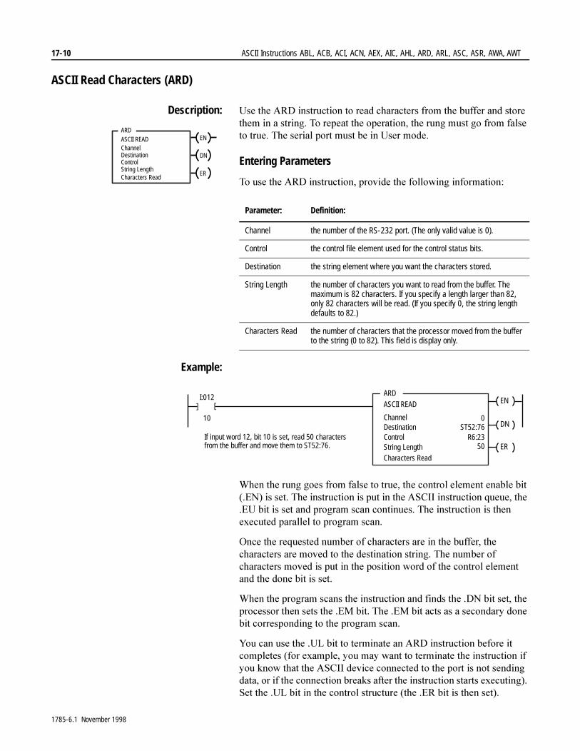
17-10 ASCII Instructions ABL, ACB, ACI, ACN, AEX, AIC, AHL, ARD, ARL, ASC, ASR, AWA, AWT
ASCII Read Characters (ARD)
Description: 8VH�WKH�$5'�LQVWUXFWLRQ�WR�UHDG�FKDUDFWHUV�IURP�WKH�EXIIHU�DQG�VWRUH�WKHP�LQ�D�VWULQJ��7R�UHSHDW�WKH�RSHUDWLRQ��WKH�UXQJ�PXVW�JR�IURP�IDOVH�WR�WUXH��7KH�VHULDO�SRUW�PXVW�EH�LQ�8VHU�PRGH�
Entering Parameters
7R�XVH�WKH�$5'�LQVWUXFWLRQ��SURYLGH�WKH�IROORZLQJ�LQIRUPDWLRQ�
Example:
:KHQ�WKH�UXQJ�JRHV�IURP�IDOVH�WR�WUXH��WKH�FRQWURO�HOHPHQW�HQDEOH�ELW���(1��LV�VHW��7KH�LQVWUXFWLRQ�LV�SXW�LQ�WKH�$6&,,�LQVWUXFWLRQ�TXHXH��WKH��(8�ELW�LV�VHW�DQG�SURJUDP�VFDQ�FRQWLQXHV��7KH�LQVWUXFWLRQ�LV�WKHQ�H[HFXWHG�SDUDOOHO�WR�SURJUDP�VFDQ�
2QFH�WKH�UHTXHVWHG�QXPEHU�RI�FKDUDFWHUV�DUH�LQ�WKH�EXIIHU��WKH�FKDUDFWHUV�DUH�PRYHG�WR�WKH�GHVWLQDWLRQ�VWULQJ��7KH�QXPEHU�RI�FKDUDFWHUV�PRYHG�LV�SXW�LQ�WKH�SRVLWLRQ�ZRUG�RI�WKH�FRQWURO�HOHPHQW�DQG�WKH�GRQH�ELW�LV�VHW�
:KHQ�WKH�SURJUDP�VFDQV�WKH�LQVWUXFWLRQ�DQG�ILQGV�WKH��'1�ELW�VHW��WKH�SURFHVVRU�WKHQ�VHWV�WKH��(0�ELW��7KH��(0�ELW�DFWV�DV�D�VHFRQGDU\�GRQH�ELW�FRUUHVSRQGLQJ�WR�WKH�SURJUDP�VFDQ�
<RX�FDQ�XVH�WKH��8/�ELW�WR�WHUPLQDWH�DQ�$5'�LQVWUXFWLRQ�EHIRUH�LW�FRPSOHWHV��IRU�H[DPSOH��\RX�PD\�ZDQW�WR�WHUPLQDWH�WKH�LQVWUXFWLRQ�LI�\RX�NQRZ�WKDW�WKH�$6&,,�GHYLFH�FRQQHFWHG�WR�WKH�SRUW�LV�QRW�VHQGLQJ�GDWD��RU�LI�WKH�FRQQHFWLRQ�EUHDNV�DIWHU�WKH�LQVWUXFWLRQ�VWDUWV�H[HFXWLQJ���6HW�WKH��8/�ELW�LQ�WKH�FRQWURO�VWUXFWXUH��WKH��(5�ELW�LV�WKHQ�VHW��
ARDASCII READChannel
ControlString Length
Destination
Characters Read
EN
DN
ER
Parameter: Definition:
Channel the number of the RS-232 port. (The only valid value is 0).
Control the control file element used for the control status bits.
Destination the string element where you want the characters stored.
String Length the number of characters you want to read from the buffer. The maximum is 82 characters. If you specify a length larger than 82, only 82 characters will be read. (If you specify 0, the string length defaults to 82.)
Characters Read the number of characters that the processor moved from the buffer to the string (0 to 82). This field is display only.
ARDASCII READ
ChannelDestination
I:012
10
[ [
Control
0ST52:76
R6:23String Length 50
Characters Read
EN
DN
ERIf input word 12, bit 10 is set, read 50 charactersfrom the buffer and move them to ST52:76.
1785-6.1 November 1998
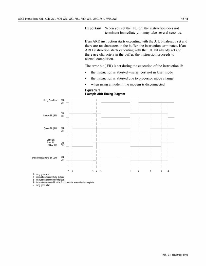
ASCII Instructions ABL, ACB, ACI, ACN, AEX, AIC, AHL, ARD, ARL, ASC, ASR, AWA, AWT 17-11
,PSRUWDQW���:KHQ�\RX�VHW�WKH��8/�ELW��WKH�LQVWUXFWLRQ�GRHV�QRW�WHUPLQDWH�LPPHGLDWHO\��LW�PD\�WDNH�VHYHUDO�VHFRQGV�
,I�DQ�$5'�LQVWUXFWLRQ�VWDUWV�H[HFXWLQJ�ZLWK�WKH��8/�ELW�DOUHDG\�VHW�DQG�WKHUH�DUH�QR�FKDUDFWHUV�LQ�WKH�EXIIHU��WKH�LQVWUXFWLRQ�WHUPLQDWHV��,I�DQ�$5'�LQVWUXFWLRQ�VWDUWV�H[HFXWLQJ�ZLWK�WKH��8/�ELW�DOUHDG\�VHW�DQG�WKHUH�DUH�FKDUDFWHUV�LQ�WKH�EXIIHU��WKH�LQVWUXFWLRQ�SURFHHGV�WR�QRUPDO FRPSOHWLRQ�
7KH�HUURU�ELW���(5��LV�VHW�GXULQJ�WKH�H[HFXWLRQ�RI�WKH�LQVWUXFWLRQ�LI�
� WKH�LQVWUXFWLRQ�LV�DERUWHG�±�VHULDO�SRUW�QRW�LQ�8VHU�PRGH
� WKH�LQVWUXFWLRQ�LV�DERUWHG�GXH�WR�SURFHVVRU�PRGH�FKDQJH
� ZKHQ�XVLQJ�D�PRGHP��WKH�PRGHP�LV�GLVFRQQHFWHG
Figure 17.1 Example ARD Timing Diagram
1 2 3 4 5 1 5 2 3 4
Rung Condition
Enable Bit (.EN)
Queue Bit (.EU)
Done BitError Bit(.DN or. ER)
Synchronous Done Bit (.EM)
ONOFF
ONOFF
ONOFF
ONOFF
ONOFF
1 - rung goes true2 - instruction successfully queued3 - instruction execution complete4 - instruction scanned for the first time after execution is complete5 - rung goes false
1785-6.1 November 1998
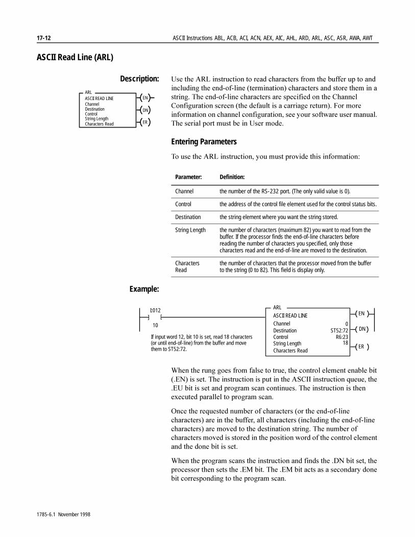
17-12 ASCII Instructions ABL, ACB, ACI, ACN, AEX, AIC, AHL, ARD, ARL, ASC, ASR, AWA, AWT
ASCII Read Line (ARL)
Description: 8VH�WKH�$5/�LQVWUXFWLRQ�WR�UHDG�FKDUDFWHUV�IURP�WKH�EXIIHU�XS�WR�DQG�LQFOXGLQJ�WKH�HQG�RI�OLQH��WHUPLQDWLRQ��FKDUDFWHUV�DQG�VWRUH�WKHP�LQ�D�VWULQJ��7KH�HQG�RI�OLQH�FKDUDFWHUV�DUH�VSHFLILHG�RQ�WKH�&KDQQHO�&RQILJXUDWLRQ�VFUHHQ��WKH�GHIDXOW�LV�D�FDUULDJH�UHWXUQ���)RU�PRUH�LQIRUPDWLRQ�RQ�FKDQQHO�FRQILJXUDWLRQ��VHH�\RXU�VRIWZDUH�XVHU�PDQXDO��7KH�VHULDO�SRUW�PXVW�EH�LQ�8VHU�PRGH�
Entering Parameters
7R�XVH�WKH�$5/�LQVWUXFWLRQ��\RX�PXVW�SURYLGH�WKLV�LQIRUPDWLRQ�
Example:
:KHQ�WKH�UXQJ�JRHV�IURP�IDOVH�WR�WUXH��WKH�FRQWURO�HOHPHQW�HQDEOH�ELW���(1��LV�VHW��7KH�LQVWUXFWLRQ�LV�SXW�LQ�WKH�$6&,,�LQVWUXFWLRQ�TXHXH��WKH��(8�ELW�LV�VHW�DQG�SURJUDP�VFDQ�FRQWLQXHV��7KH�LQVWUXFWLRQ�LV�WKHQ�H[HFXWHG�SDUDOOHO�WR�SURJUDP�VFDQ�
2QFH�WKH�UHTXHVWHG�QXPEHU�RI�FKDUDFWHUV��RU�WKH�HQG�RI�OLQH�FKDUDFWHUV��DUH�LQ�WKH�EXIIHU��DOO�FKDUDFWHUV��LQFOXGLQJ�WKH�HQG�RI�OLQH�FKDUDFWHUV��DUH�PRYHG�WR�WKH�GHVWLQDWLRQ�VWULQJ��7KH�QXPEHU�RI�FKDUDFWHUV�PRYHG�LV�VWRUHG�LQ�WKH�SRVLWLRQ�ZRUG�RI�WKH�FRQWURO�HOHPHQW�DQG�WKH�GRQH�ELW�LV�VHW�
:KHQ�WKH�SURJUDP�VFDQV�WKH�LQVWUXFWLRQ�DQG�ILQGV�WKH��'1�ELW�VHW��WKH�SURFHVVRU�WKHQ�VHWV�WKH��(0�ELW��7KH��(0�ELW�DFWV�DV�D�VHFRQGDU\�GRQH�ELW�FRUUHVSRQGLQJ�WR�WKH�SURJUDP�VFDQ�
ARLASCII READ LINEChannel
ControlString LengthCharacters Read
Destination
EN
DN
ER
Parameter: Definition:
Channel the number of the RS-232 port. (The only valid value is 0).
Control the address of the control file element used for the control status bits.
Destination the string element where you want the string stored.
String Length the number of characters (maximum 82) you want to read from the buffer. If the processor finds the end-of-line characters before reading the number of characters you specified, only those characters read and the end-of-line are moved to the destination.
Characters Read
the number of characters that the processor moved from the buffer to the string (0 to 82). This field is display only.
ARL
ASCII READ LINEChannelDestination
I:012
10
[ [
Control
0ST52:72
R6:23String LengthCharacters Read
18
EN
DN
ER
If input word 12, bit 10 is set, read 18 characters(or until end-of-line) from the buffer and movethem to ST52:72.
1785-6.1 November 1998
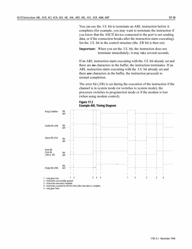
ASCII Instructions ABL, ACB, ACI, ACN, AEX, AIC, AHL, ARD, ARL, ASC, ASR, AWA, AWT 17-13
<RX�FDQ�XVH�WKH��8/�ELW�WR�WHUPLQDWH�DQ�$5/�LQVWUXFWLRQ�EHIRUH�LW�FRPSOHWHV��IRU�H[DPSOH��\RX�PD\�ZDQW�WR�WHUPLQDWH�WKH�LQVWUXFWLRQ�LI�\RX�NQRZ�WKDW�WKH�$6&,,�GHYLFH�FRQQHFWHG�WR�WKH�SRUW�LV�QRW�VHQGLQJ�GDWD��RU�LI�WKH�FRQQHFWLRQ�EUHDNV�DIWHU�WKH�LQVWUXFWLRQ�VWDUWV�H[HFXWLQJ���6HW�WKH��8/�ELW�LQ�WKH�FRQWURO�VWUXFWXUH��WKH��(5�ELW�LV�WKHQ�VHW��
,PSRUWDQW���:KHQ�\RX�VHW�WKH��8/�ELW��WKH�LQVWUXFWLRQ�GRHV�QRW�WHUPLQDWH�LPPHGLDWHO\��LW�PD\�WDNH�VHYHUDO�VHFRQGV�
,I�DQ�$5/�LQVWUXFWLRQ�VWDUWV�H[HFXWLQJ�ZLWK�WKH��8/�ELW�DOUHDG\�VHW�DQG�WKHUH�DUH�QR�FKDUDFWHUV�LQ�WKH�EXIIHU��WKH�LQVWUXFWLRQ�WHUPLQDWHV��,I�DQ�$5/�LQVWUXFWLRQ�VWDUWV�H[HFXWLQJ�ZLWK�WKH��8/�ELW�DOUHDG\�VHW�DQG�WKHUH�DUH�FKDUDFWHUV�LQ�WKH�EXIIHU��WKH�LQVWUXFWLRQ�SURFHHGV�WR�QRUPDO FRPSOHWLRQ�
7KH�HUURU�ELW���(5��LV�VHW�GXULQJ�WKH�H[HFXWLRQ�RI�WKH�LQVWUXFWLRQ�LI�WKH�FKDQQHO�LV�LQ�V\VWHP�PRGH��RU�VZLWFKHV�WR�V\VWHP�PRGH���WKH�SURFHVVRU�VZLWFKHV�WR�SURJUDP�WHVW�PRGH�RU�LI�WKH�PRGHP�LV�ORVW��ZKHQ�XVLQJ�PRGHP�FRQWURO��
Figure 17.2 Example ARL Timing Diagram
1 2 3 4 5 1 5 2 3 4
Rung Condition
Enable Bit (.EN)
Queue Bit (.EU)
ONOFF
ONOFF
ONOFF
ONOFF
ONOFFEmpty Bit (.EM)
Done BitError Bit(.DN or. ER)
1 - rung goes true2 - instruction successfully queued3 - instruction execution complete4 - instruction scanned for the first time after execution is complete5 - rung goes false
1785-6.1 November 1998
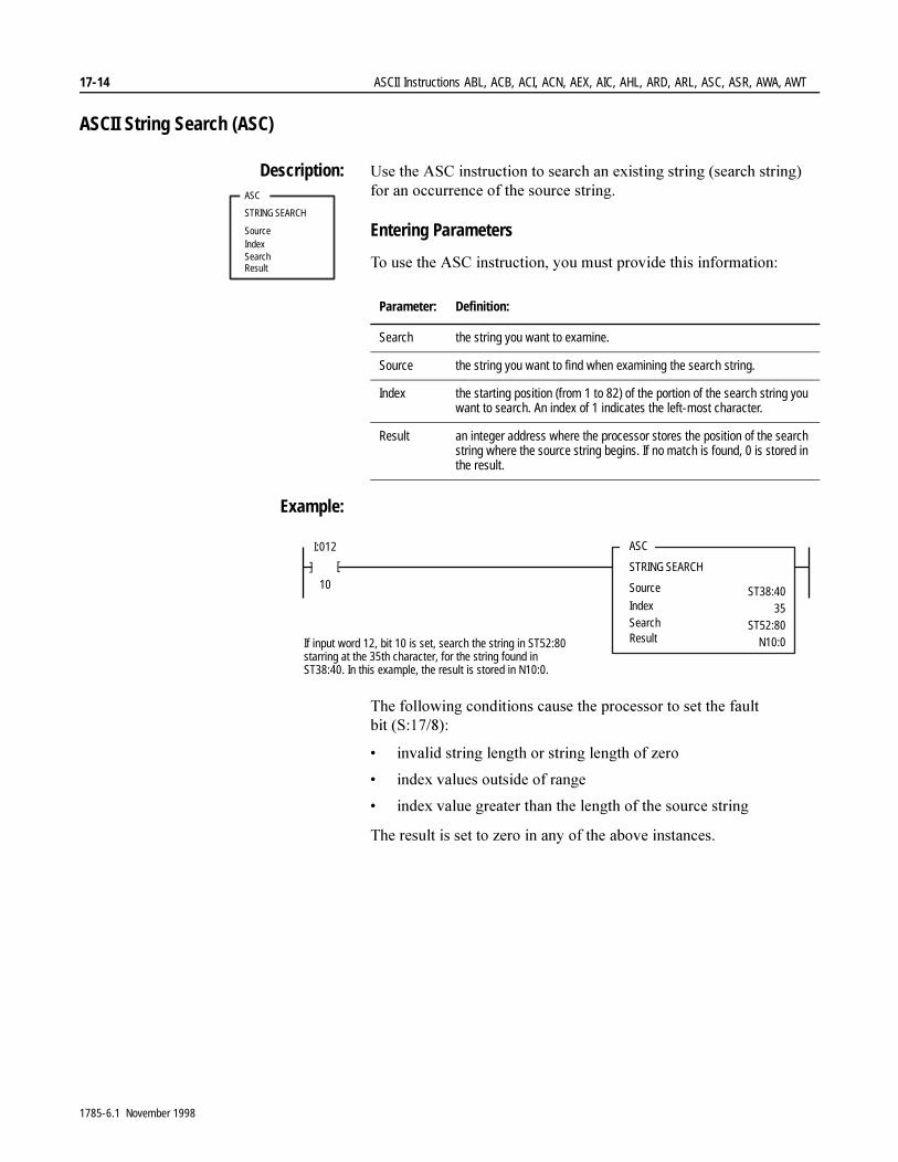
17-14 ASCII Instructions ABL, ACB, ACI, ACN, AEX, AIC, AHL, ARD, ARL, ASC, ASR, AWA, AWT
ASCII String Search (ASC)
Description: 8VH�WKH�$6&�LQVWUXFWLRQ�WR�VHDUFK�DQ�H[LVWLQJ�VWULQJ��VHDUFK�VWULQJ��IRU�DQ�RFFXUUHQFH�RI�WKH�VRXUFH�VWULQJ�
Entering Parameters
7R�XVH�WKH�$6&�LQVWUXFWLRQ��\RX�PXVW�SURYLGH�WKLV�LQIRUPDWLRQ�
Example:
7KH�IROORZLQJ�FRQGLWLRQV�FDXVH�WKH�SURFHVVRU�WR�VHW�WKH�IDXOW�ELW��6�������
� LQYDOLG�VWULQJ�OHQJWK�RU�VWULQJ�OHQJWK�RI�]HUR
� LQGH[�YDOXHV�RXWVLGH�RI�UDQJH
� LQGH[�YDOXH�JUHDWHU�WKDQ�WKH�OHQJWK�RI�WKH�VRXUFH�VWULQJ
7KH�UHVXOW�LV�VHW�WR�]HUR�LQ�DQ\�RI�WKH�DERYH�LQVWDQFHV�
ASC
STRING SEARCH
SourceIndexSearchResult
Parameter: Definition:
Search the string you want to examine.
Source the string you want to find when examining the search string.
Index the starting position (from 1 to 82) of the portion of the search string you want to search. An index of 1 indicates the left-most character.
Result an integer address where the processor stores the position of the search string where the source string begins. If no match is found, 0 is stored in the result.
ASC
STRING SEARCH
Source
Index
I:012
10
SearchResult
ST38:4035
ST52:80N10:0
[ [
If input word 12, bit 10 is set, search the string in ST52:80starring at the 35th character, for the string found inST38:40. In this example, the result is stored in N10:0.
1785-6.1 November 1998
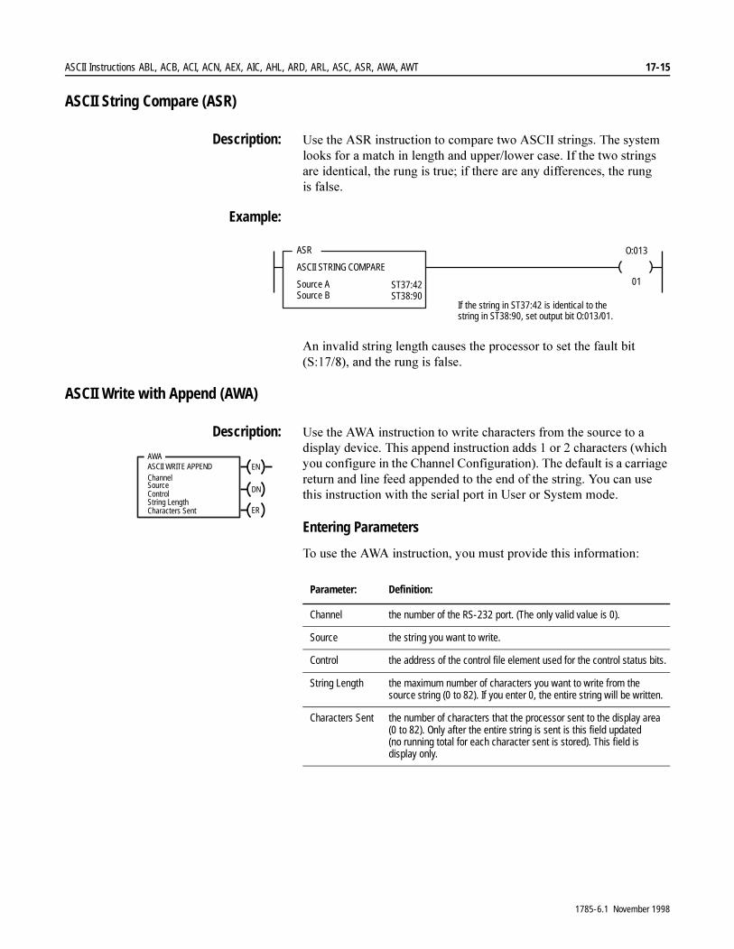
ASCII Instructions ABL, ACB, ACI, ACN, AEX, AIC, AHL, ARD, ARL, ASC, ASR, AWA, AWT 17-15
ASCII String Compare (ASR)
Description: 8VH�WKH�$65�LQVWUXFWLRQ�WR�FRPSDUH�WZR�$6&,,�VWULQJV��7KH�V\VWHP�ORRNV�IRU�D�PDWFK�LQ�OHQJWK�DQG�XSSHU�ORZHU�FDVH��,I�WKH�WZR�VWULQJV�DUH�LGHQWLFDO��WKH�UXQJ�LV�WUXH��LI�WKHUH�DUH�DQ\�GLIIHUHQFHV��WKH�UXQJ�LV�IDOVH�
Example:
$Q�LQYDOLG�VWULQJ�OHQJWK�FDXVHV�WKH�SURFHVVRU�WR�VHW�WKH�IDXOW�ELW��6��������DQG�WKH�UXQJ�LV�IDOVH�
ASCII Write with Append (AWA)
Description: 8VH�WKH�$:$�LQVWUXFWLRQ�WR�ZULWH�FKDUDFWHUV�IURP�WKH�VRXUFH�WR�D�GLVSOD\�GHYLFH��7KLV�DSSHQG�LQVWUXFWLRQ�DGGV���RU���FKDUDFWHUV��ZKLFK�\RX�FRQILJXUH�LQ�WKH�&KDQQHO�&RQILJXUDWLRQ���7KH�GHIDXOW�LV�D�FDUULDJH�UHWXUQ�DQG�OLQH�IHHG�DSSHQGHG�WR�WKH�HQG�RI�WKH�VWULQJ��<RX�FDQ�XVH�WKLV�LQVWUXFWLRQ�ZLWK�WKH�VHULDO�SRUW�LQ�8VHU�RU�6\VWHP�PRGH�
Entering Parameters
7R�XVH�WKH�$:$�LQVWUXFWLRQ��\RX�PXVW�SURYLGH�WKLV�LQIRUPDWLRQ�
ASR
ASCII STRING COMPARE
Source ASource B
O:013
01ST37:42ST38:90
If the string in ST37:42 is identical to thestring in ST38:90, set output bit O:013/01.
AWAASCII WRITE APPENDChannel
ControlString LengthCharacters Sent
Source
EN
DN
ER
Parameter: Definition:
Channel the number of the RS-232 port. (The only valid value is 0).
Source the string you want to write.
Control the address of the control file element used for the control status bits.
String Length the maximum number of characters you want to write from the source string (0 to 82). If you enter 0, the entire string will be written.
Characters Sent the number of characters that the processor sent to the display area (0 to 82). Only after the entire string is sent is this field updated (no running total for each character sent is stored). This field is display only.
1785-6.1 November 1998

17-16 ASCII Instructions ABL, ACB, ACI, ACN, AEX, AIC, AHL, ARD, ARL, ASC, ASR, AWA, AWT
Example:
:KHQ�WKH�UXQJ�JRHV�IURP�IDOVH�WR�WUXH��WKH�FRQWURO�HOHPHQW�HQDEOH�ELW���(1��LV�VHW��7KH�LQVWUXFWLRQ�LV�SXW�LQ�WKH�$6&,,�LQVWUXFWLRQ�TXHXH��WKH��(8�ELW�LV�VHW�DQG�SURJUDP�VFDQ�FRQWLQXHV��7KH�LQVWUXFWLRQ�LV�WKHQ�H[HFXWHG�SDUDOOHO�WR�SURJUDP�VFDQ�
7ZHQW\�ILYH�FKDUDFWHUV�IURP�WKH�VWDUW�RI�VWULQJ�67������DUH�VHQW�WR�WKH�GLVSOD\�GHYLFH�DQG�WKHQ�XVHU�FRQILJXUHG�DSSHQG�FKDUDFWHUV�DUH�VHQW��7KH�GRQH�ELW�LV�VHW�DQG�D�YDOXH�RI����LV�VHQW�WR�WKH�SRVLWLRQ�ZRUG��
:KHQ�WKH�SURJUDP�VFDQV�WKH�LQVWUXFWLRQ�DQG�ILQGV�WKH��'1�ELW�VHW��WKH�SURFHVVRU�WKHQ�VHWV�WKH��(0�ELW�WR�DFW�DV�D�VHFRQGDU\�GRQH�ELW�FRUUHVSRQGLQJ�WR�WKH�SURJUDP�VFDQ�
<RX�FDQ�XVH�WKH��8/�ELW�WR�WHUPLQDWH�DQ�$:$�LQVWUXFWLRQ�EHIRUH�LW�FRPSOHWHV��IRU�H[DPSOH��\RX�PD\�ZDQW�WR�WHUPLQDWH�WKH�LQVWUXFWLRQ�LI�\RX�NQRZ�WKDW�WKH�$6&,,�GHYLFH�FRQQHFWHG�WR�WKH�SRUW�FDQQRW�DFFHSW�GDWD��RU�LI�WKH�FRQQHFWLRQ�EUHDNV�DIWHU�WKH�LQVWUXFWLRQ�VWDUWV�H[HFXWLQJ���6HW�WKH��8/�ELW�LQ�WKH�FRQWURO�VWUXFWXUH��WKH��(5�ELW�LV�WKHQ�VHW��
,PSRUWDQW���:KHQ�\RX�VHW�WKH��8/�ELW��WKH�LQVWUXFWLRQ�GRHV�QRW�WHUPLQDWH�LPPHGLDWHO\��LW�PD\�WDNH�VHYHUDO�VHFRQGV�
,I�DQ�$:$�LQVWUXFWLRQ�VWDUWV�H[HFXWLQJ�ZLWK�WKH��8/�ELW�DOUHDG\�VHW��WKH�LQVWUXFWLRQ�DERUWV�LPPHGLDWHO\�
7KH�HUURU�ELW���(5��LV�VHW�GXULQJ�WKH�H[HFXWLRQ�RI�WKH�LQVWUXFWLRQ�LI�WKH�LQVWUXFWLRQ�LV�DERUWHG�GXH�WR�SURFHVVRU�PRGH�FKDQJH�RU�LI�WKH�PRGHP�EHFRPHV�ORVW��ZKHQ�XVLQJ�PRGHP�FRQWURO���,I�WKH�PRGHP�ZDV�DOUHDG\�ORVW��WKH�LQVWUXFWLRQ�VWLOO�H[HFXWHV��
AWA
ASCII WRITE APPEND
ChannelSource
I:012
10
[ [
Control
0ST37:42
R6:23String LengthCharacters Sent
25
EN
DN
ERIf input word 12, bit 10 is set, read 25 characters fromST37:42 and write it to the display device. Then writea carriage return and line feed (default).
1785-6.1 November 1998
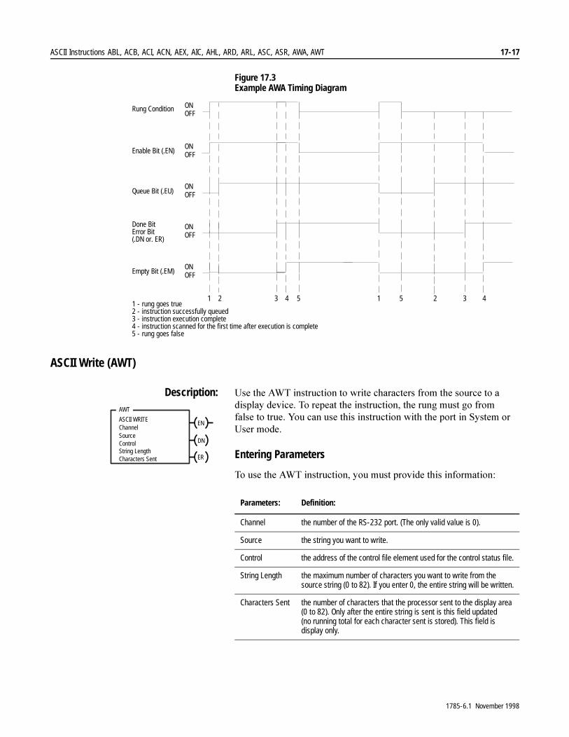
ASCII Instructions ABL, ACB, ACI, ACN, AEX, AIC, AHL, ARD, ARL, ASC, ASR, AWA, AWT 17-17
Figure 17.3 Example AWA Timing Diagram
ASCII Write (AWT)
Description: 8VH�WKH�$:7�LQVWUXFWLRQ�WR�ZULWH�FKDUDFWHUV�IURP�WKH�VRXUFH�WR�D�GLVSOD\�GHYLFH��7R�UHSHDW�WKH�LQVWUXFWLRQ��WKH�UXQJ�PXVW�JR�IURP�IDOVH�WR�WUXH��<RX�FDQ�XVH�WKLV�LQVWUXFWLRQ�ZLWK�WKH�SRUW�LQ�6\VWHP�RU�8VHU�PRGH�
Entering Parameters
7R�XVH�WKH�$:7�LQVWUXFWLRQ��\RX�PXVW�SURYLGH�WKLV�LQIRUPDWLRQ�
1 2 3 4 5 1 5 2 3 4
Rung Condition
Enable Bit (.EN)
Queue Bit (.EU)
ONOFF
ONOFF
ONOFF
ONOFF
ONOFFEmpty Bit (.EM)
Done BitError Bit(.DN or. ER)
1 - rung goes true2 - instruction successfully queued3 - instruction execution complete4 - instruction scanned for the first time after execution is complete5 - rung goes false
AWT
ASCII WRITEChannel
ControlString LengthCharacters Sent
Source
EN
DN
ER
Parameters: Definition:
Channel the number of the RS-232 port. (The only valid value is 0).
Source the string you want to write.
Control the address of the control file element used for the control status file.
String Length the maximum number of characters you want to write from the source string (0 to 82). If you enter 0, the entire string will be written.
Characters Sent the number of characters that the processor sent to the display area (0 to 82). Only after the entire string is sent is this field updated (no running total for each character sent is stored). This field is display only.
1785-6.1 November 1998
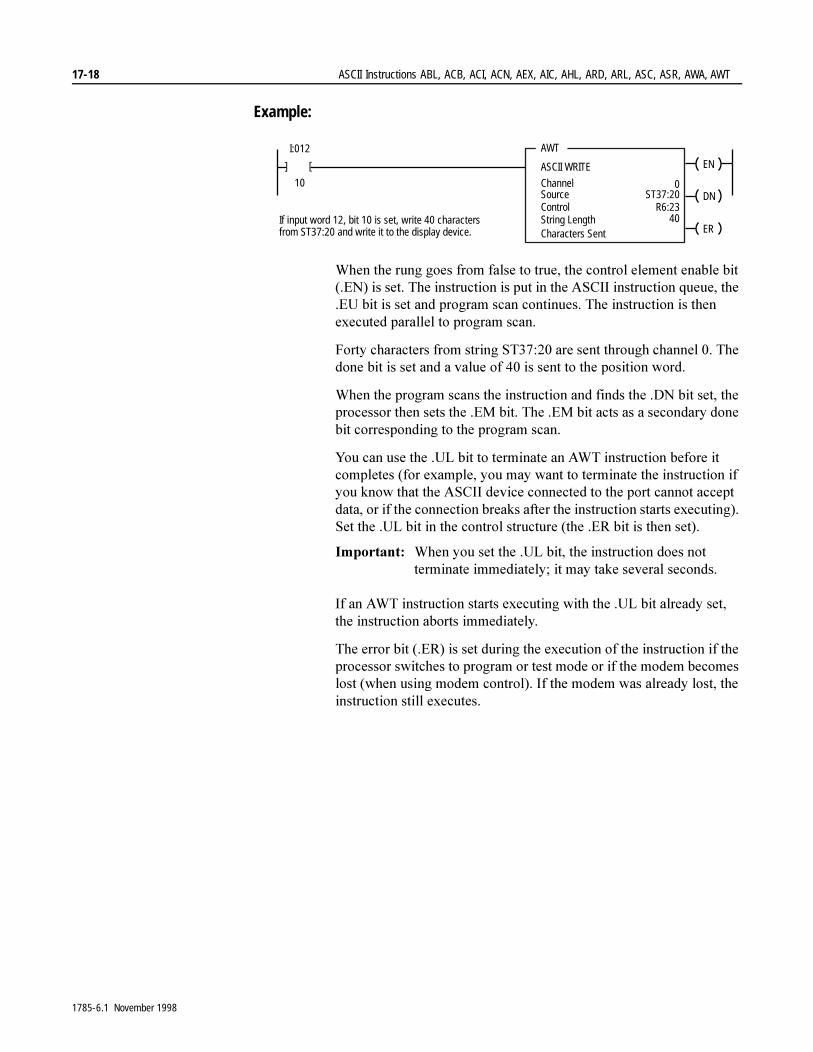
17-18 ASCII Instructions ABL, ACB, ACI, ACN, AEX, AIC, AHL, ARD, ARL, ASC, ASR, AWA, AWT
Example:
:KHQ�WKH�UXQJ�JRHV�IURP�IDOVH�WR�WUXH��WKH�FRQWURO�HOHPHQW�HQDEOH�ELW���(1��LV�VHW��7KH�LQVWUXFWLRQ�LV�SXW�LQ�WKH�$6&,,�LQVWUXFWLRQ�TXHXH��WKH��(8�ELW�LV�VHW�DQG�SURJUDP�VFDQ�FRQWLQXHV��7KH�LQVWUXFWLRQ�LV�WKHQ�H[HFXWHG�SDUDOOHO�WR�SURJUDP�VFDQ�
)RUW\�FKDUDFWHUV�IURP�VWULQJ�67������DUH�VHQW�WKURXJK�FKDQQHO����7KH�GRQH�ELW�LV�VHW�DQG�D�YDOXH�RI����LV�VHQW�WR�WKH�SRVLWLRQ�ZRUG�
:KHQ�WKH�SURJUDP�VFDQV�WKH�LQVWUXFWLRQ�DQG�ILQGV�WKH��'1�ELW�VHW��WKH�SURFHVVRU�WKHQ�VHWV�WKH��(0�ELW��7KH��(0�ELW�DFWV�DV�D�VHFRQGDU\�GRQH�ELW�FRUUHVSRQGLQJ�WR�WKH�SURJUDP�VFDQ��
<RX�FDQ�XVH�WKH��8/�ELW�WR�WHUPLQDWH�DQ�$:7�LQVWUXFWLRQ�EHIRUH�LW�FRPSOHWHV��IRU�H[DPSOH��\RX�PD\�ZDQW�WR�WHUPLQDWH�WKH�LQVWUXFWLRQ�LI�\RX�NQRZ�WKDW�WKH�$6&,,�GHYLFH�FRQQHFWHG�WR�WKH�SRUW�FDQQRW�DFFHSW�GDWD��RU�LI�WKH�FRQQHFWLRQ�EUHDNV�DIWHU�WKH�LQVWUXFWLRQ�VWDUWV�H[HFXWLQJ���6HW�WKH��8/�ELW�LQ�WKH�FRQWURO�VWUXFWXUH��WKH��(5�ELW�LV�WKHQ�VHW��
,PSRUWDQW���:KHQ�\RX�VHW�WKH��8/�ELW��WKH�LQVWUXFWLRQ�GRHV�QRW�WHUPLQDWH�LPPHGLDWHO\��LW�PD\�WDNH�VHYHUDO�VHFRQGV�
,I�DQ�$:7�LQVWUXFWLRQ�VWDUWV�H[HFXWLQJ�ZLWK�WKH��8/�ELW�DOUHDG\�VHW��WKH�LQVWUXFWLRQ�DERUWV�LPPHGLDWHO\�
7KH�HUURU�ELW���(5��LV�VHW�GXULQJ�WKH�H[HFXWLRQ�RI�WKH�LQVWUXFWLRQ�LI�WKH�SURFHVVRU�VZLWFKHV�WR�SURJUDP�RU�WHVW�PRGH�RU�LI�WKH�PRGHP�EHFRPHV�ORVW��ZKHQ�XVLQJ�PRGHP�FRQWURO���,I�WKH�PRGHP�ZDV�DOUHDG\�ORVW��WKH�LQVWUXFWLRQ�VWLOO�H[HFXWHV�
AWT
ASCII WRITE
ChannelSource
I:012
10
[ [
Control
0ST37:20
R6:23String LengthCharacters Sent
40
EN
DN
ERIf input word 12, bit 10 is set, write 40 charactersfrom ST37:20 and write it to the display device.
1785-6.1 November 1998
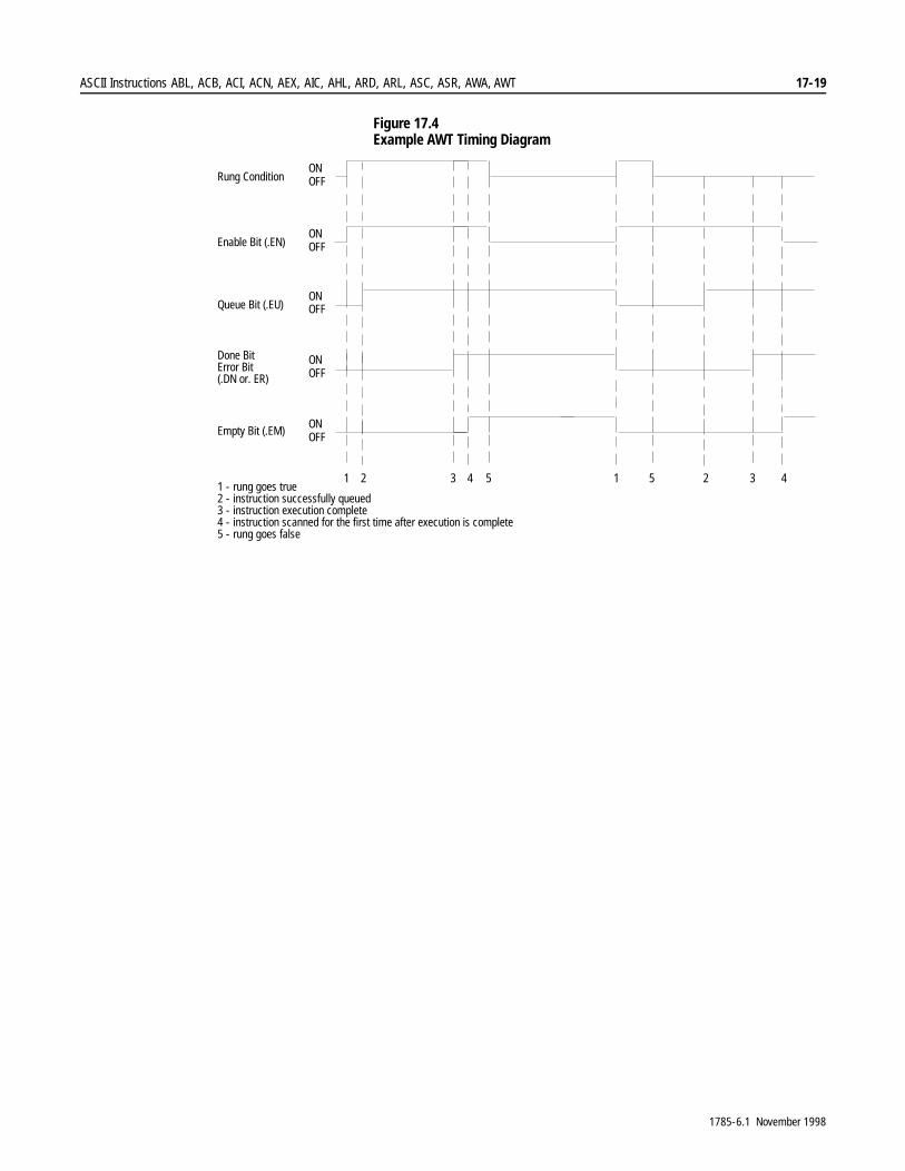
ASCII Instructions ABL, ACB, ACI, ACN, AEX, AIC, AHL, ARD, ARL, ASC, ASR, AWA, AWT 17-19
Figure 17.4 Example AWT Timing Diagram
1 2 3 4 5 1 5 2 3 4
Rung Condition
Enable Bit (.EN)
Queue Bit (.EU)
ONOFF
ONOFF
ONOFF
ONOFF
ONOFFEmpty Bit (.EM)
Done BitError Bit(.DN or. ER)
1 - rung goes true2 - instruction successfully queued3 - instruction execution complete4 - instruction scanned for the first time after execution is complete5 - rung goes false
1785-6.1 November 1998

17-20 ASCII Instructions ABL, ACB, ACI, ACN, AEX, AIC, AHL, ARD, ARL, ASC, ASR, AWA, AWT
1RWHV�
1785-6.1 November 1998
Chapter 18
Custom Application Routine Instructions SDS, DFA
Chapter Objectives 7KLV�FKDSWHU�LQWURGXFHV�WKH�&XVWRP�$SSOLFDWLRQ�5RXWLQH��&$5��LQVWUXFWLRQV��6'6�DQG�')$��IRU�3/&���SURJUDPPLQJ�VRIWZDUH��<RX�QHHG�WKH�&XVWRP�$SSOLFDWLRQ�5RXWLQH��&$5��VRIWZDUH�LQ�RUGHU�WR�XVH�WKHVH�LQVWUXFWLRQV�
)RU�PRUH�LQIRUPDWLRQ�RQ�WKH�RSHUDQGV��DQG�YDOLG�GDWD�W\SHV�YDOXHV�RI�HDFK�RSHUDQG��XVHG�E\�WKH�LQVWUXFWLRQV�GLVFXVVHG�LQ�WKLV�FKDSWHU��VHH�$SSHQGL[�&�
For Information About: See:
SDS or DFA CAR utilities Distributed Diagnostic and Machine Control User Manual
AGA3 PLC-5 AGA Mass Flow Custom Application Routine Programming Manual
AGA7 PLC-5 Volumetric Flow CARs for Turbine and Displacement Metering User Manual
NX19 PLC-5 Volumetric Flow CARs for Orifice Metering User Manual
API PLC-5 Volumetric Flow CARs for Turbine and Displacement Metering User Manual
1785-6.1 November 1998
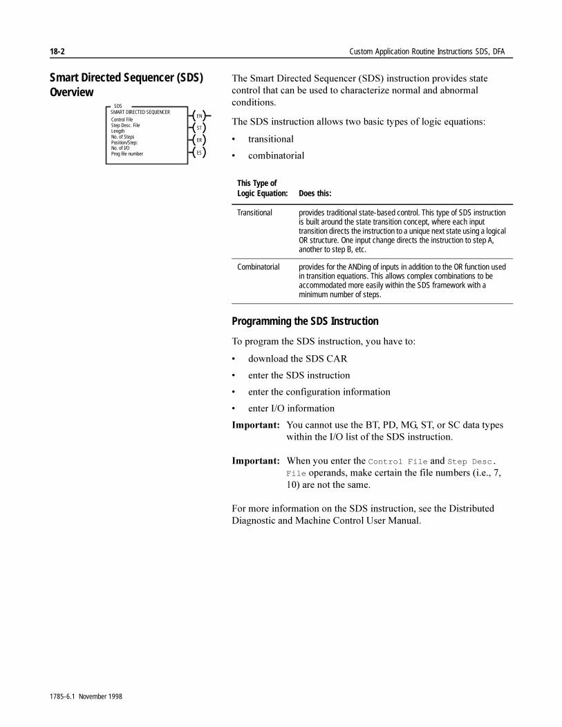
18-2 Custom Application Routine Instructions SDS, DFA
Smart Directed Sequencer (SDS) Overview
7KH�6PDUW�'LUHFWHG�6HTXHQFHU��6'6��LQVWUXFWLRQ�SURYLGHV�VWDWH�FRQWURO�WKDW�FDQ�EH�XVHG�WR�FKDUDFWHUL]H�QRUPDO�DQG�DEQRUPDO�FRQGLWLRQV�
7KH�6'6�LQVWUXFWLRQ�DOORZV�WZR�EDVLF�W\SHV�RI�ORJLF�HTXDWLRQV�
� WUDQVLWLRQDO
� FRPELQDWRULDO
Programming the SDS Instruction
7R�SURJUDP�WKH�6'6�LQVWUXFWLRQ��\RX�KDYH�WR�
� GRZQORDG�WKH�6'6�&$5
� HQWHU�WKH�6'6�LQVWUXFWLRQ
� HQWHU�WKH�FRQILJXUDWLRQ�LQIRUPDWLRQ
� HQWHU�,�2�LQIRUPDWLRQ
,PSRUWDQW���<RX�FDQQRW�XVH�WKH�%7��3'��0*��67��RU�6&�GDWD�W\SHV�ZLWKLQ�WKH�,�2�OLVW�RI�WKH�6'6�LQVWUXFWLRQ�
,PSRUWDQW���:KHQ�\RX�HQWHU�WKH�Control File�DQG�Step Desc. File�RSHUDQGV��PDNH�FHUWDLQ�WKH�ILOH�QXPEHUV��L�H����������DUH�QRW�WKH�VDPH�
)RU�PRUH�LQIRUPDWLRQ�RQ�WKH�6'6�LQVWUXFWLRQ��VHH�WKH�'LVWULEXWHG�'LDJQRVWLF�DQG�0DFKLQH�&RQWURO�8VHU�0DQXDO�
SDSSMART DIRECTED SEQUENCER
Control File Step Desc. FileLengthNo. of StepsPosition/Step:No. of I/OProg file number
EN
ST
ER
ES
This Type of Logic Equation: Does this:
Transitional provides traditional state-based control. This type of SDS instruction is built around the state transition concept, where each input transition directs the instruction to a unique next state using a logical OR structure. One input change directs the instruction to step A, another to step B, etc.
Combinatorial provides for the ANDing of inputs in addition to the OR function used in transition equations. This allows complex combinations to be accommodated more easily within the SDS framework with a minimum number of steps.
1785-6.1 November 1998
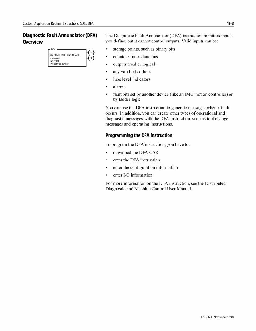
Custom Application Routine Instructions SDS, DFA 18-3
Diagnostic Fault Annunciator (DFA) Overview
7KH�'LDJQRVWLF�)DXOW�$QQXQFLDWRU��')$��LQVWUXFWLRQ�PRQLWRUV�LQSXWV�\RX�GHILQH��EXW�LW�FDQQRW�FRQWURO�RXWSXWV��9DOLG�LQSXWV�FDQ�EH�
� VWRUDJH�SRLQWV��VXFK�DV�ELQDU\�ELWV
� FRXQWHU���WLPHU�GRQH�ELWV
� RXWSXWV��UHDO�RU�ORJLFDO�
� DQ\�YDOLG�ELW�DGGUHVV
� OXEH�OHYHO�LQGLFDWRUV
� DODUPV
� IDXOW�ELWV�VHW�E\�DQRWKHU�GHYLFH��OLNH�DQ�,0&�PRWLRQ�FRQWUROOHU��RU�E\�ODGGHU�ORJLF
<RX�FDQ�XVH�WKH�')$�LQVWUXFWLRQ�WR�JHQHUDWH�PHVVDJHV�ZKHQ�D�IDXOW�RFFXUV��,Q�DGGLWLRQ��\RX�FDQ�FUHDWH�RWKHU�W\SHV�RI�RSHUDWLRQDO�DQG�GLDJQRVWLF�PHVVDJHV�ZLWK�WKH�')$�LQVWUXFWLRQ��VXFK�DV�WRRO�FKDQJH�PHVVDJHV�DQG�RSHUDWLQJ�LQVWUXFWLRQV�
Programming the DFA Instruction
7R�SURJUDP�WKH�')$�LQVWUXFWLRQ��\RX�KDYH�WR�
� GRZQORDG�WKH�')$�&$5
� HQWHU�WKH�')$�LQVWUXFWLRQ
� HQWHU�WKH�FRQILJXUDWLRQ�LQIRUPDWLRQ
� HQWHU�,�2�LQIRUPDWLRQ
)RU�PRUH�LQIRUPDWLRQ�RQ�WKH�')$�LQVWUXFWLRQ��VHH�WKH�'LVWULEXWHG�'LDJQRVWLF�DQG�0DFKLQH�&RQWURO�8VHU�0DQXDO�
DFA
DIAGNOSTIC FAULT ANNUNCIATOR
Control File No. of I/O Program file number
EN
ER
1785-6.1 November 1998

18-4 Custom Application Routine Instructions SDS, DFA
1RWHV�
1785-6.1 November 1998
Appendix A
Instruction Timing and Memory Requirements
Instruction Timing and Memory Requirements
7KH�WLPH�LW�WDNHV�IRU�D�SURFHVVRU�WR�VFDQ�DQ�LQVWUXFWLRQ�GHSHQGV�RQ�WKH�W\SH�RI�LQVWUXFWLRQ��WKH�W\SH�RI�DGGUHVVLQJ��WKH�W\SH�RI�GDWD��ZKHWKHU�WKH�LQVWUXFWLRQ�KDV�WR�FRQYHUW�GDWD��DQG�ZKHWKHU�WKH�LQVWUXFWLRQ�LV�WUXH�RU�IDOVH�
7KH�WLPLQJ�DQG�PHPRU\�UHTXLUHPHQWV�HVWLPDWHV�LQ�WKLV�FKDSWHU�KDYH�WKH�IROORZLQJ�DVVXPSWLRQV�
� GLUHFW�DGGUHVVLQJ
� LQWHJHU�GDWD��H[FHSW�ZKHUH�QRWHG
� QR�GDWD�W\SH�FRQYHUVLRQV
� DGGUHVVHV�ZLWKLQ�ILUVW������ZRUGV�RI�WKH�GDWD�WDEOH�IRU�&ODVVLF�3/&���SURFHVVRUV��DGGUHVVHV�ZLWKLQ�ILUVW������ZRUGV�IRU�(QKDQFHG�3/&���SURFHVVRUV
� H[HFXWLRQ�WLPHV�VKRZQ�LQ�µV
0HPRU\�UHTXLUHPHQWV�UHIHU�WR�WKH�QXPEHU�RI�ZRUGV�WKH�LQVWUXFWLRQ�XVHV��,Q�VRPH�FDVHV��DQ�LQVWUXFWLRQ�PD\�KDYH�D�UDQJH�RI�PHPRU\�UHTXLUHPHQWV��7KH�UDQJH�RI�ZRUGV�H[LVWV�EHFDXVH�WKH�LQVWUXFWLRQ�FDQ�XVH�GLIIHUHQW�W\SHV�RI�GDWD�DQG�DGGUHVVLQJ�PRGHV�
7KH�WDEOHV�DUH�GLYLGHG�LQWR�LQVWUXFWLRQ�WLPHV�DQG�PHPRU\�UHTXLUHPHQWV�WKDW�DUH�VSHFLILF�WR�HDFK�SURFHVVRU�
If You Are Using this Processor: See Page:
Enhanced PLC-5, series CBit and Word InstructionsFile Instructions
A-2A-5
Classic PLC-5 (all series):Bit and Word InstructionsFile Instructions
A-10A-13
1785-6.1 November 1998
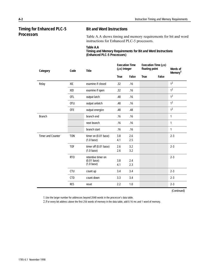
A-2 Instruction Timing and Memory Requirements
Timing for Enhanced PLC-5 Processors
Bit and Word Instructions
7DEOH�$�$�VKRZV�WLPLQJ�DQG�PHPRU\�UHTXLUHPHQWV�IRU�ELW�DQG�ZRUG�LQVWUXFWLRQV�IRU�(QKDQFHG�3/&���SURFHVVRUV�
Table A.A Timing and Memory Requirements for Bit and Word Instructions(Enhanced PLC-5 Processors)
Category Code Title
Execution Time (µs) integer
Execution Time (µs)floating point Words of
Memory1
True False True False
Relay XIC examine if closed .32 .16 12
XIO examine if open .32 .16 12
OTL output latch .48 .16 12
OTU output unlatch .48 .16 12
OTE output energize .48 .48 12
Branch branch end .16 .16 1
next branch .16 .16 1
branch start .16 .16 1
Timer and Counter TON timer on (0.01 base)(1.0 base)
3.84.1
2.62.5
2-3
TOF timer off (0.01 base)(1.0 base)
2.62.6
3.23.2
2-3
RTO retentive timer on(0.01 base)(1.0 base)
3.84.1
2.42.3
2-3
CTU count up 3.4 3.4 2-3
CTD count down 3.3 3.4 2-3
RES reset 2.2 1.0 2-3
(Continued)
��Use the larger number for addresses beyond 2048 words in the processor’s data table.
��)or every bit address above the first 256 words of memory in the data table, add 0.16 ms and 1 word of memory.
1785-6.1 November 1998
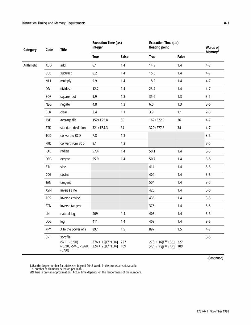
Instruction Timing and Memory Requirements A-3
Category Code Title
Execution Time (µs) integer
Execution Time (µs)floating point Words of
Memory1
True False True False
Arithmetic ADD add 6.1 1.4 14.9 1.4 4-7
SUB subtract 6.2 1.4 15.6 1.4 4-7
MUL multiply 9.9 1.4 18.2 1.4 4-7
DIV divides 12.2 1.4 23.4 1.4 4-7
SQR square root 9.9 1.3 35.6 1.3 3-5
NEG negate 4.8 1.3 6.0 1.3 3-5
CLR clear 3.4 1.1 3.9 1.1 2-3
AVE average file 152+E25.8 30 162+E22.9 36 4-7
STD standard deviation 321+E84.3 34 329+E77.5 34 4-7
TOD convert to BCD 7.8 1.3 3-5
FRD convert from BCD 8.1 1.3 3-5
RAD radian 57.4 1.4 50.1 1.4 3-5
DEG degree 55.9 1.4 50.7 1.4 3-5
SIN sine 414 1.4 3-5
COS cosine 404 1.4 3-5
TAN tangent 504 1.4 3-5
ASN inverse sine 426 1.4 3-5
ACS inverse cosine 436 1.4 3-5
ATN inverse tangent 375 1.4 3-5
LN natural log 409 1.4 403 1.4 3-5
LOG log 411 1.4 403 1.4 3-5
XPY X to the power of Y 897 1.5 897 1.5 4-7
SRT sort file(5/11, -5/20)(-5/30, -5/40, -5/60,-5/80)
276 + 12[E**1.34]224 + 25[E**1.34]
227189
278 + 16[E**1.35]230 + 33[E**1.35]
227189
3-5
(Continued)
1.Use the larger number for addresses beyond 2048 words in the processor’s data table.E = number of elements acted on per scanSRT true is only an approximation. Actual time depends on the randomness of the numbers.
1785-6.1 November 1998

A-4 Instruction Timing and Memory Requirements
Category Code Title
Execution Time (µs) integer
Execution Time (µs)floating point Words of
Memory1
True False True False
Logic AND and 5.9 1.4 4-7
OR or 5.9 1.4 4-7
XOR exclusive or 5.9 1.4 4-7
NOT not 4.6 1.3 3-5
Move MOV move 4.5 1.3 5.6 1.3 3-5
MVM masked move 6.2 1.4 4-7
BTD bit distributor 10.0 1.7 6-9
Comparison EQU equal 3.8 1.0 4.6 1.0 3-5
NEQ not equal 3.8 1.0 4.5 1.0 3-5
LES less than 4.0 1.0 5.1 1.0 3-5
LEQ less than or equal 4.0 1.0 5.1 1.0 3-5
GRT greater than 4.0 1.0 5.1 1.0 3-5
GEQ greater than orequal
4.0 1.0 5.1 1.0 3-5
LIM limit test 6.1 1.1 8.4 1.1 4-7
MEQ mask compare if equal
5.1 1.1 4-7
Compare CMP all 2.48 + (Σ[0.8 + i]) 2.16 + Wi[0.56] 2.48 + (Σ[0.8 + i]) 2.16 + Wi[0.56] 2+Wi
Compute CPT all 2.48.+ (Σ[0.8 + i]) 2.16 + Wi[0.56] 2.48.+ (Σ[0.8 + i]) 2.16 + Wi[0.56] 2+Wi
1.Use the larger number for addresses beyond 2048 words in the processor’s data table.i = execution time of each instruction (operation, e.g. ADD, SUB, etc.) used within the CMP or the CPT expressionWi = number of words of memory used by the instruction (operation, e.g. ADD, SUB, etc) within the CMP or CPT expressionCMP or CPT instructions are calculated with short direct addressing
1785-6.1 November 1998
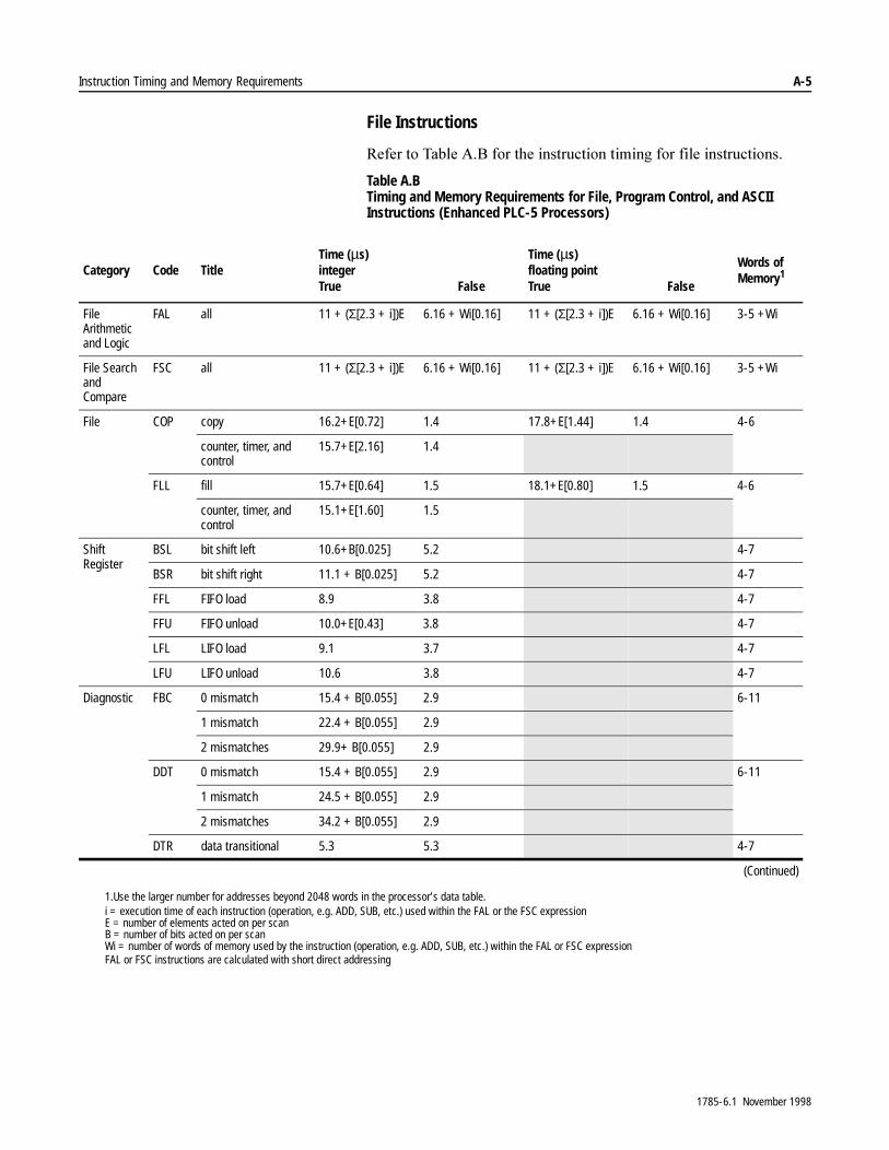
Instruction Timing and Memory Requirements A-5
File Instructions
5HIHU�WR�7DEOH�$�%�IRU�WKH�LQVWUXFWLRQ�WLPLQJ�IRU�ILOH�LQVWUXFWLRQV�
Table A.B Timing and Memory Requirements for File, Program Control, and ASCII Instructions (Enhanced PLC-5 Processors)
Category Code TitleTime (µs)integerTrue False
Time (µs)floating pointTrue False
Words of Memory1
File Arithmetic and Logic
FAL all 11 + (Σ[2.3 + i])E 6.16 + Wi[0.16] 11 + (Σ[2.3 + i])E 6.16 + Wi[0.16] 3-5 +Wi
File Search and Compare
FSC all 11 + (Σ[2.3 + i])E 6.16 + Wi[0.16] 11 + (Σ[2.3 + i])E 6.16 + Wi[0.16] 3-5 +Wi
File COP copy 16.2+E[0.72] 1.4 17.8+E[1.44] 1.4 4-6
counter, timer, and control
15.7+E[2.16] 1.4
FLL fill 15.7+E[0.64] 1.5 18.1+E[0.80] 1.5 4-6
counter, timer, and control
15.1+E[1.60] 1.5
Shift Register
BSL bit shift left 10.6+B[0.025] 5.2 4-7
BSR bit shift right 11.1 + B[0.025] 5.2 4-7
FFL FIFO load 8.9 3.8 4-7
FFU FIFO unload 10.0+E[0.43] 3.8 4-7
LFL LIFO load 9.1 3.7 4-7
LFU LIFO unload 10.6 3.8 4-7
Diagnostic FBC 0 mismatch 15.4 + B[0.055] 2.9 6-11
1 mismatch 22.4 + B[0.055] 2.9
2 mismatches 29.9+ B[0.055] 2.9
DDT 0 mismatch 15.4 + B[0.055] 2.9 6-11
1 mismatch 24.5 + B[0.055] 2.9
2 mismatches 34.2 + B[0.055] 2.9
DTR data transitional 5.3 5.3 4-7
(Continued)
1.Use the larger number for addresses beyond 2048 words in the processor’s data table.i = execution time of each instruction (operation, e.g. ADD, SUB, etc.) used within the FAL or the FSC expressionE = number of elements acted on per scanB = number of bits acted on per scanWi = number of words of memory used by the instruction (operation, e.g. ADD, SUB, etc.) within the FAL or FSC expressionFAL or FSC instructions are calculated with short direct addressing
1785-6.1 November 1998
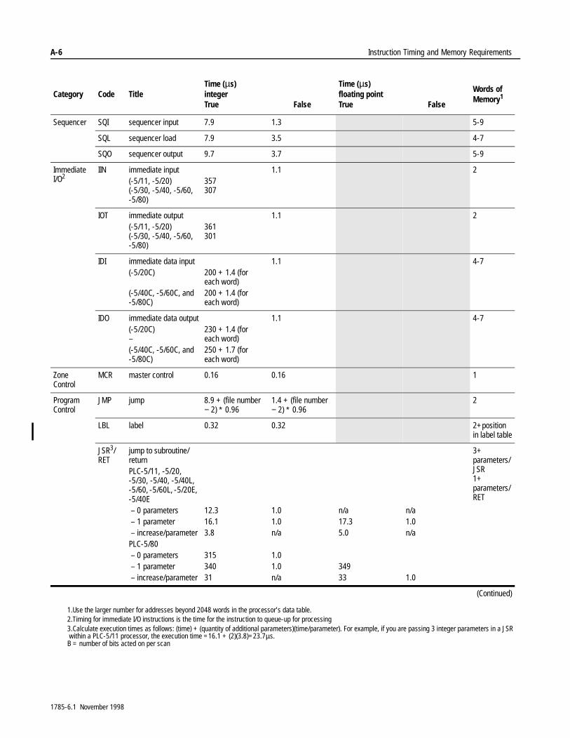
A-6 Instruction Timing and Memory Requirements
Category Code TitleTime (µs)integerTrue False
Time (µs)floating pointTrue False
Words of Memory1
Sequencer SQI sequencer input 7.9 1.3 5-9
SQL sequencer load 7.9 3.5 4-7
SQO sequencer output 9.7 3.7 5-9
Immediate I/O2
IIN immediate input(-5/11, -5/20)(-5/30, -5/40, -5/60, -5/80)
357307
1.1 2
IOT immediate output(-5/11, -5/20)(-5/30, -5/40, -5/60, -5/80)
361301
1.1 2
IDI immediate data input(-5/20C)
(-5/40C, -5/60C, and -5/80C)
200 + 1.4 (for each word)200 + 1.4 (for each word)
1.1 4-7
IDO immediate data output(-5/20C)–(-5/40C, -5/60C, and -5/80C)
230 + 1.4 (for each word)250 + 1.7 (for each word)
1.1 4-7
Zone Control
MCR master control 0.16 0.16 1
Program Control
JMP jump 8.9 + (file number − 2) ∗ 0.96
1.4 + (file number − 2) ∗ 0.96
2
LBL label 0.32 0.32 2+position in label table
JSR3/RET
jump to subroutine/returnPLC-5/11, -5/20, -5/30, -5/40, -5/40L, -5/60, -5/60L, -5/20E, -5/40E – 0 parameters – 1 parameter – increase/parameterPLC-5/80 – 0 parameters – 1 parameter – increase/parameter
12.316.13.8
31534031
1.01.0n/a
1.01.0n/a
n/a17.35.0
34933
n/a1.0n/a
1.0
3+parameters/JSR1+parameters/RET
(Continued)
1.Use the larger number for addresses beyond 2048 words in the processor’s data table.2.Timing for immediate I/O instructions is the time for the instruction to queue-up for processing3.Calculate execution times as follows: (time) + (quantity of additional parameters)(time/parameter). For example, if you are passing 3 integer parameters in a JSR within a PLC-5/11 processor, the execution time =16.1 + (2)(3.8)=23.7µs.B = number of bits acted on per scan
1785-6.1 November 1998
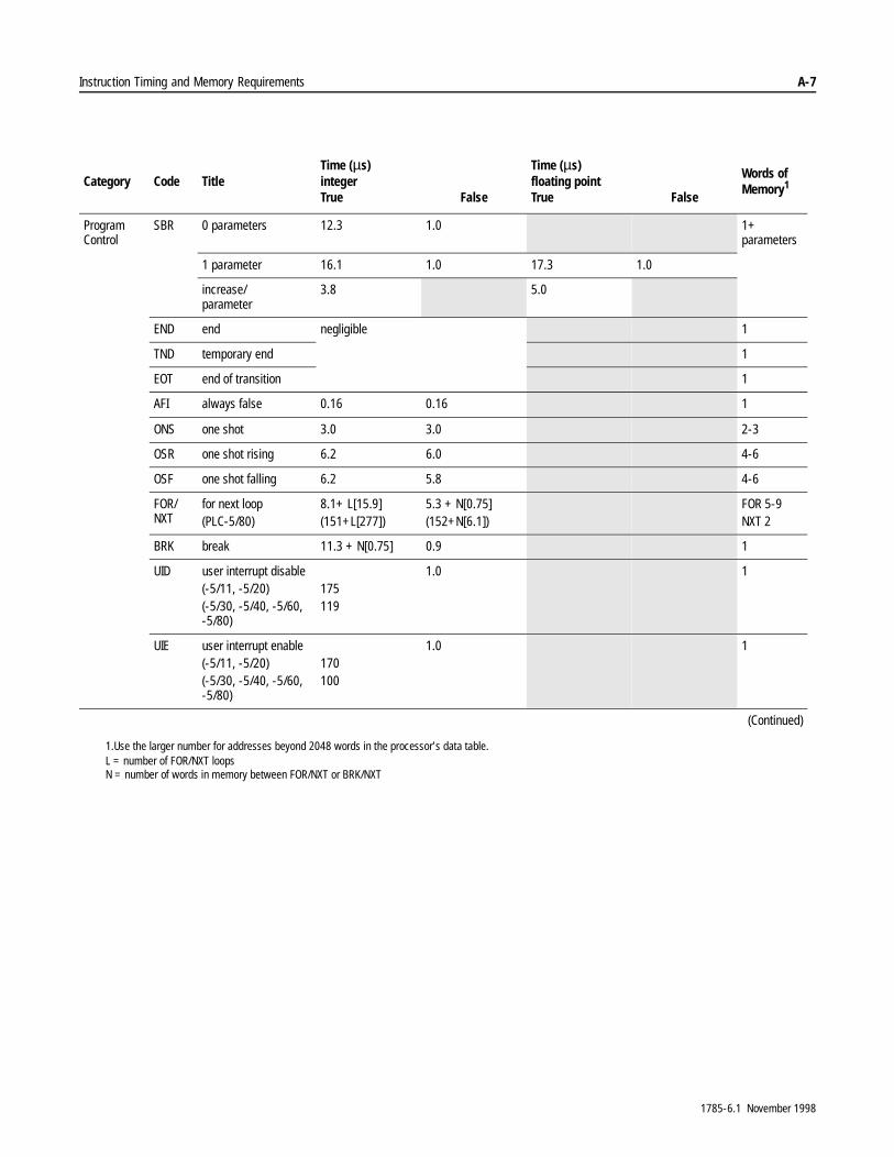
Instruction Timing and Memory Requirements A-7
Category Code TitleTime (µs)integerTrue False
Time (µs)floating pointTrue False
Words of Memory1
Program Control
SBR 0 parameters 12.3 1.0 1+parameters
1 parameter 16.1 1.0 17.3 1.0
increase/parameter
3.8 5.0
END end negligible 1
TND temporary end 1
EOT end of transition 1
AFI always false 0.16 0.16 1
ONS one shot 3.0 3.0 2-3
OSR one shot rising 6.2 6.0 4-6
OSF one shot falling 6.2 5.8 4-6
FOR/NXT
for next loop(PLC-5/80)
8.1+ L[15.9](151+L[277])
5.3 + N[0.75](152+N[6.1])
FOR 5-9NXT 2
BRK break 11.3 + N[0.75] 0.9 1
UID user interrupt disable(-5/11, -5/20)(-5/30, -5/40, -5/60, -5/80)
175119
1.0 1
UIE user interrupt enable(-5/11, -5/20)(-5/30, -5/40, -5/60, -5/80)
170100
1.0 1
(Continued)
1.Use the larger number for addresses beyond 2048 words in the processor’s data table.L = number of FOR/NXT loopsN = number of words in memory between FOR/NXT or BRK/NXT
1785-6.1 November 1998

A-8 Instruction Timing and Memory Requirements
Category Code TitleTime (µs)integerTrue False
Time (µs)floating pointTrue False
Words of Memory1
Process Control
PID PID loop control 5-9
Gains Independent(-5/11, -5/20, -5/20E, -5/20C)(-5/30, -5/40, -5/40E, -5/40C, -5/40L, -5/60, -5/60C, -5/60L, -5/80, -5/80E, -5/80C)
462
655
3.0 882 58
ISA(-5/11, -5/20, -5/20E, -5/20C)(-5/30, -5/40, -5/40E, -5/40C, -5/40L, -5/60, -5/60C, -5/60L, -5/80, -5/80E, -5/80C)
560
895
1142
Modes Manual(-5/11, -5/20, -5/20E, -5/20C)(-5/30, -5/40, -5/40E, -5/40C, -5/40L, -5/60, -5/60C, -5/60L, -5/80, -5/80E, -5/80C)
372
420
900
Set Output(-5/11, -5/20, -5/20E, -5/20C)(-5/30, -5/40, -5/40E, -5/40C, -5/40L, -5/60, -5/60C, -5/60L, -5/80, -5/80E, -5/80C)
380
440
882
Cascade Slave 1286
Master 840
ASCII2 ABL2 test buffer for line(-5/11, -5/20)(-5/30, -5/40, -5/60, -5/80)
316388
214150
3-5
ACB 2 no. of characters in buffer(-5/11, -5/20)(-5/30, -5/40, -5/60, -5/80)
316389
214150
3-5
ACI string to integer(-5/11, -5/20)(-5/30, -5/40, -5/60, -5/80)
220 + C[11]140 + C[21.4]
1.4 3-5
(Continued)
1.Use the larger number for addresses beyond 2048 words in the processor’s data table.2.Timing for ASCII instructions is the time for the instruction to queue-up for processing in channel 0.
1785-6.1 November 1998
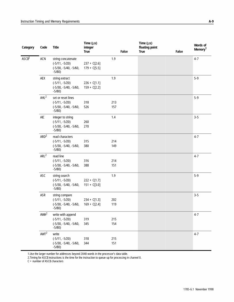
Instruction Timing and Memory Requirements A-9
Category Code TitleTime (µs)integerTrue False
Time (µs)floating pointTrue False
Words of Memory1
ASCII2 ACN string concatenate(-5/11, -5/20)(-5/30, -5/40, -5/60, -5/80)
237 + C[2.6]179 + C[5.5]
1.9 4-7
AEX string extract(-5/11, -5/20)(-5/30, -5/40, -5/60, -5/80)
226 + C[1.1]159 + C[2.2]
1.9 5-9
AHL2 set or reset lines(-5/11, -5/20)(-5/30, -5/40, -5/60, -5/80)
318526
213157
5-9
AIC integer to string(-5/11, -5/20)(-5/30, -5/40, -5/60, -5/80)
260270
1.4 3-5
ARD2 read characters(-5/11, -5/20)(-5/30, -5/40, -5/60, -5/80)
315380
214149
4-7
ARL2 read line(-5/11, -5/20)(-5/30, -5/40, -5/60, -5/80)
316388
214151
4-7
ASC string search(-5/11, -5/20)(-5/30, -5/40, -5/60, -5/80)
222 + C[1.7]151 + C[3.0]
1.9 5-9
ASR string compare(-5/11, -5/20)(-5/30, -5/40, -5/60, -5/80)
234 + C[1.3]169 + C[2.4]
202119
3-5
AWA2 write with append(-5/11, -5/20)(-5/30, -5/40, -5/60, -5/80)
319345
215154
4-7
AWT2 write(-5/11, -5/20)(-5/30, -5/40, -5/60, -5/80)
318344
215151
4-7
1.Use the larger number for addresses beyond 2048 words in the processor’s data table.2.Timing for ASCII instructions is the time for the instruction to queue-up for processing in channel 0.C = number of ASCII characters
1785-6.1 November 1998

A-10 Instruction Timing and Memory Requirements
Timing for Classic PLC-5 Processors
Bit and Word Instructions
7DEOH�$�&�VKRZV�WLPLQJ�DQG�PHPRU\�UHTXLUHPHQWV�IRU�ELW�DQG�ZRUG�LQVWUXFWLRQV�IRU�&ODVVLF�3/&���SURFHVVRUV��
Table A.C Timing and Memory Requirements for Bit and Word Instructions(Classic PLC-5 Processors)
Category Code Title
Execution Time (µs)integer
Execution Time (µs)floating point
Words of Memory1
True False True False
Relay XIC examine if closed 1.3 0.8 12
XIO examine if open 1.3 0.8 12
OTL output latch 1.6 0.8 12
OTU output unlatch 1.6 0.8 11
OTE output energize 1.6 1.6 12
Branch branch end 0.8 0.8 1
next branch 0.8 0.8 1
branch start 0.8 0.8 1
Timer and Counter TON timer on (0.01 base)(1.0 base)
3944
2728
2-3
TOF timer off (0.01 base)(1.0 base)
3030
4351
2-3
RTO retentive timer on(0.01 base)(1.0 base)
3944
2424
2-3
CTU count up 32 34 2-3
CTD count down 34 34 2-3
RES reset 30 14 2-3
1 Use the smaller number if all addresses are below word 4096; use the larger number if all addresses are above 4096.2 For every bit address above the first 256 words of memory in the data table, add 0.8 µs to the execution time and 1 word of memory to the requirements.
(Continued)
1785-6.1 November 1998
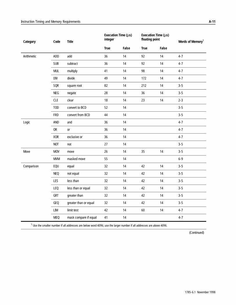
Instruction Timing and Memory Requirements A-11
Category Code Title
Execution Time (µs)integer
Execution Time (µs)floating point
Words of Memory1
True False True False
Arithmetic ADD add 36 14 92 14 4-7
SUB subtract 36 14 92 14 4-7
MUL multiply 41 14 98 14 4-7
DIV divide 49 14 172 14 4-7
SQR square root 82 14 212 14 3-5
NEG negate 28 14 36 14 3-5
CLE clear 18 14 23 14 2-3
TOD convert to BCD 52 14 3-5
FRD convert from BCD 44 14 3-5
Logic AND and 36 14 4-7
OR or 36 14 4-7
XOR exclusive or 36 14 4-7
NOT not 27 14 3-5
Move MOV move 26 14 35 14 3-5
MVM masked move 55 14 6-9
Comparison EQU equal 32 14 42 14 3-5
NEQ not equal 32 14 42 14 3-5
LES less than 32 14 42 14 3-5
LEQ less than or equal 32 14 42 14 3-5
GRT greater than 32 14 42 14 3-5
GEQ greater than or equal 32 14 42 14 3-5
LIM limit test 42 14 60 14 4-7
MEQ mask compare if equal 41 14 4-7
1 Use the smaller number if all addresses are below word 4096; use the larger number if all addresses are above 4096.
(Continued)
1785-6.1 November 1998
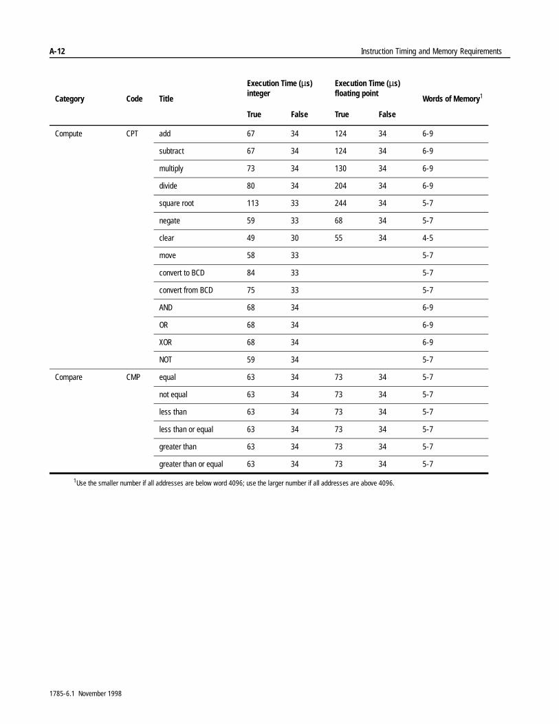
A-12 Instruction Timing and Memory Requirements
Compute CPT add 67 34 124 34 6-9
subtract 67 34 124 34 6-9
multiply 73 34 130 34 6-9
divide 80 34 204 34 6-9
square root 113 33 244 34 5-7
negate 59 33 68 34 5-7
clear 49 30 55 34 4-5
move 58 33 5-7
convert to BCD 84 33 5-7
convert from BCD 75 33 5-7
AND 68 34 6-9
OR 68 34 6-9
XOR 68 34 6-9
NOT 59 34 5-7
Compare CMP equal 63 34 73 34 5-7
not equal 63 34 73 34 5-7
less than 63 34 73 34 5-7
less than or equal 63 34 73 34 5-7
greater than 63 34 73 34 5-7
greater than or equal 63 34 73 34 5-7
1Use the smaller number if all addresses are below word 4096; use the larger number if all addresses are above 4096.
Category Code Title
Execution Time (µs)integer
Execution Time (µs)floating point
Words of Memory1
True False True False
1785-6.1 November 1998

Instruction Timing and Memory Requirements A-13
File Instructions
7KH�LQVWUXFWLRQ�WLPLQJ�IRU�ILOH�LQVWUXFWLRQV�GHSHQGV�RQ�WKH�GDWD�W\SH��QXPEHU�RI�ILOHV�DFWHG�RQ�SHU�VFDQ��QXPEHU�RI�HOHPHQWV�DFWHG�RQ�SHU�VFDQ��DQG�ZKHWKHU�WKH�LQVWUXFWLRQ�FRQYHUWV�GDWD�EHWZHHQ�LQWHJHU�DQG�IORDWLQJ�SRLQW�IRUPDWV�
� IRU�LQWHJHU�WR�IORDWLQJ�SRLQW�FRQYHUVLRQ��DGG�
��µV�IRU�HDFK�HOHPHQW�DGGUHVV���µV�IRU�HDFK�ILOH�DGGUHVV����SUHIL[�
� IRU�IORDWLQJ�SRLQW�WR�LQWHJHU�FRQYHUVLRQ�DGG�
���µV�IRU�HDFK�HOHPHQW�DGGUHVV���µV�IRU�HDFK�ILOH�DGGUHVV����SUHIL[�
Table A.D Timing and Memory Requirements for File Instructions (Classic PLC-5 Processors)
Category Code Title
Time (µs)integer
Time (µs)floating point
Time (µs)integer or floating point Words of
Memory1
True True False
File Arithmetic and Logic FAL add 98 + W[36.7 + N] 98 + W[95.1 + N] 54 7-12
subtract 98 + W[36.7 + N] 98 + W[95.1 + N] 54 7-12
multiply 98 + W[42.5 + N] 98 + W[101.2 + N] 54 7-12
divide 98 + W[51.1 + N] 98 + W[180.3 + N] 54 7-12
square root 98 + W[84.7 + N] 98 + W[220.5 + N] 54 6-10
negate 98 + W[29.2 + N] 98 + W[37.2 + N] 54 6-10
clear 98 + W[18.4 + N] 98 + W[24.0 + N] 54 5-8
move 98 + W[27.3 + N] 98 + W[36.2 + N] 54 6-10
convert to BCD 98 + W[54.3 + N] 54 6-10
convert from BCD 98 + W[45.4 + N] 54 6-10
1 Use the smaller number if all addresses are below word 4096; use the larger number if all addresses are above 4096.W = number of elements acted on per scanN = 2 × (number of integer file addresses) + 8 × (number of floating-point file addresses) + 6 × (number of timer, counter, or control file addresses) + ( number ofconversions between integer and floating point formats)
(Continued)
1785-6.1 November 1998
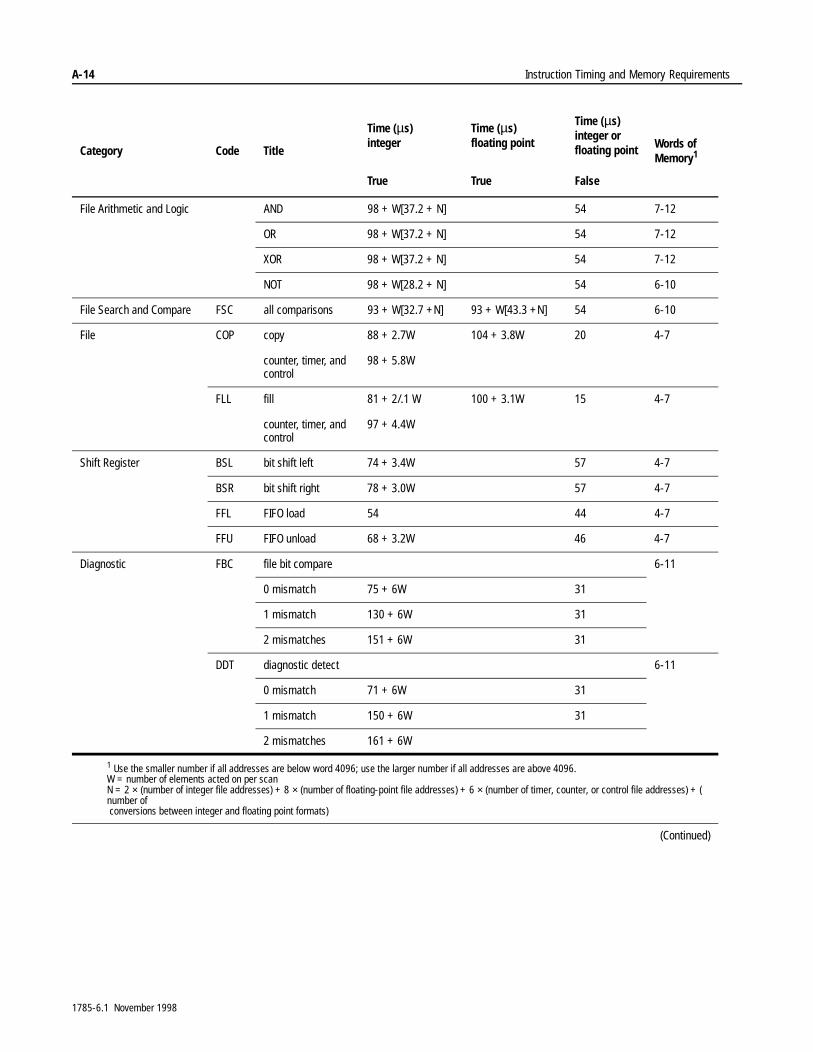
A-14 Instruction Timing and Memory Requirements
File Arithmetic and Logic AND 98 + W[37.2 + N] 54 7-12
OR 98 + W[37.2 + N] 54 7-12
XOR 98 + W[37.2 + N] 54 7-12
NOT 98 + W[28.2 + N] 54 6-10
File Search and Compare FSC all comparisons 93 + W[32.7 +N] 93 + W[43.3 +N] 54 6-10
File COP copy 88 + 2.7W 104 + 3.8W 20 4-7
counter, timer, and control
98 + 5.8W
FLL fill 81 + 2/.1 W 100 + 3.1W 15 4-7
counter, timer, and control
97 + 4.4W
Shift Register BSL bit shift left 74 + 3.4W 57 4-7
BSR bit shift right 78 + 3.0W 57 4-7
FFL FIFO load 54 44 4-7
FFU FIFO unload 68 + 3.2W 46 4-7
Diagnostic FBC file bit compare 6-11
0 mismatch 75 + 6W 31
1 mismatch 130 + 6W 31
2 mismatches 151 + 6W 31
DDT diagnostic detect 6-11
0 mismatch 71 + 6W 31
1 mismatch 150 + 6W 31
2 mismatches 161 + 6W
1 Use the smaller number if all addresses are below word 4096; use the larger number if all addresses are above 4096.W = number of elements acted on per scanN = 2 × (number of integer file addresses) + 8 × (number of floating-point file addresses) + 6 × (number of timer, counter, or control file addresses) + ( number of conversions between integer and floating point formats)
(Continued)
Category Code Title
Time (µs)integer
Time (µs)floating point
Time (µs)integer or floating point Words of
Memory1
True True False
1785-6.1 November 1998
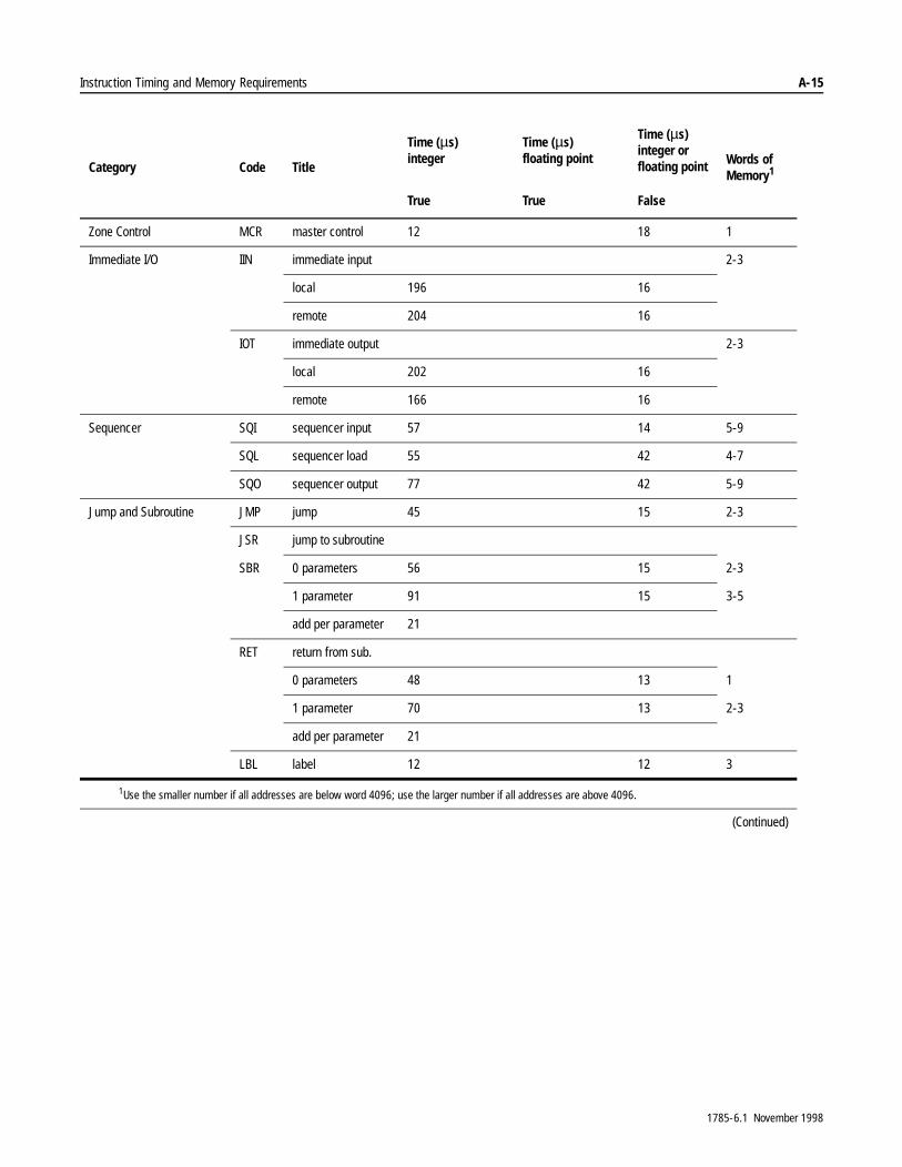
Instruction Timing and Memory Requirements A-15
Zone Control MCR master control 12 18 1
Immediate I/O IIN immediate input 2-3
local 196 16
remote 204 16
IOT immediate output 2-3
local 202 16
remote 166 16
Sequencer SQI sequencer input 57 14 5-9
SQL sequencer load 55 42 4-7
SQO sequencer output 77 42 5-9
Jump and Subroutine JMP jump 45 15 2-3
JSR jump to subroutine
SBR 0 parameters 56 15 2-3
1 parameter 91 15 3-5
add per parameter 21
RET return from sub.
0 parameters 48 13 1
1 parameter 70 13 2-3
add per parameter 21
LBL label 12 12 3
1Use the smaller number if all addresses are below word 4096; use the larger number if all addresses are above 4096.
(Continued)
Category Code Title
Time (µs)integer
Time (µs)floating point
Time (µs)integer or floating point Words of
Memory1
True True False
1785-6.1 November 1998
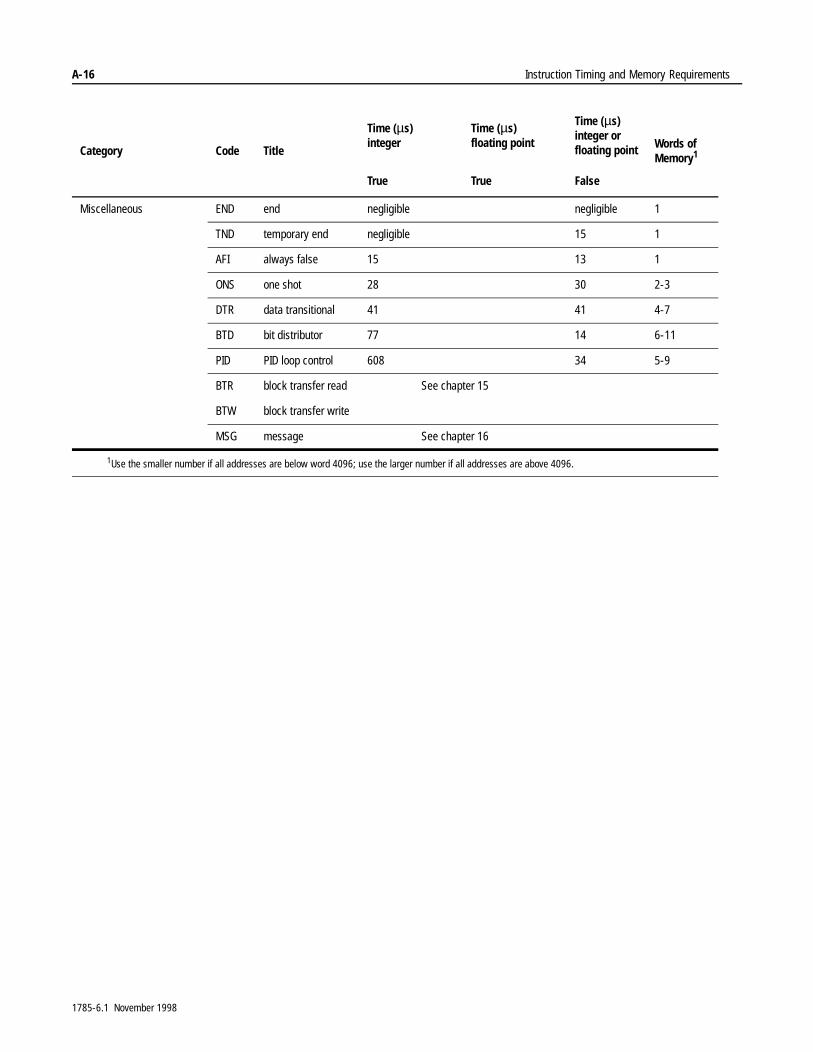
A-16 Instruction Timing and Memory Requirements
Miscellaneous END end negligible negligible 1
TND temporary end negligible 15 1
AFI always false 15 13 1
ONS one shot 28 30 2-3
DTR data transitional 41 41 4-7
BTD bit distributor 77 14 6-11
PID PID loop control 608 34 5-9
BTR block transfer read See chapter 15
BTW block transfer write
MSG message See chapter 16
1Use the smaller number if all addresses are below word 4096; use the larger number if all addresses are above 4096.
Category Code Title
Time (µs)integer
Time (µs)floating point
Time (µs)integer or floating point Words of
Memory1
True True False
1785-6.1 November 1998
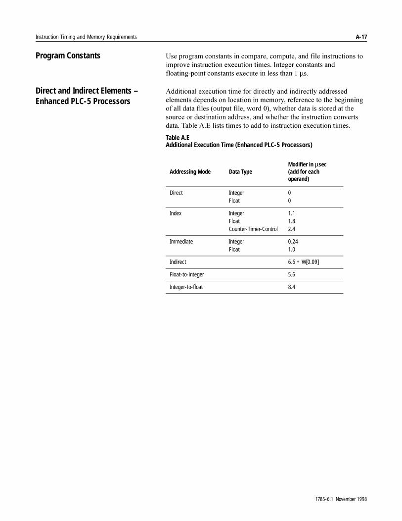
Instruction Timing and Memory Requirements A-17
Program Constants 8VH�SURJUDP�FRQVWDQWV�LQ�FRPSDUH��FRPSXWH��DQG�ILOH�LQVWUXFWLRQV�WR�LPSURYH�LQVWUXFWLRQ�H[HFXWLRQ�WLPHV��,QWHJHU�FRQVWDQWV�DQG�IORDWLQJ�SRLQW�FRQVWDQWV�H[HFXWH�LQ�OHVV�WKDQ���µV�
Direct and Indirect Elements – Enhanced PLC-5 Processors
$GGLWLRQDO�H[HFXWLRQ�WLPH�IRU�GLUHFWO\�DQG�LQGLUHFWO\�DGGUHVVHG�HOHPHQWV�GHSHQGV�RQ�ORFDWLRQ�LQ�PHPRU\��UHIHUHQFH�WR�WKH�EHJLQQLQJ�RI�DOO�GDWD�ILOHV��RXWSXW�ILOH��ZRUG�����ZKHWKHU�GDWD�LV�VWRUHG�DW�WKH�VRXUFH�RU�GHVWLQDWLRQ�DGGUHVV��DQG�ZKHWKHU�WKH�LQVWUXFWLRQ�FRQYHUWV�GDWD��7DEOH�$�(�OLVWV�WLPHV�WR�DGG�WR�LQVWUXFWLRQ�H[HFXWLRQ�WLPHV�
Table A.E Additional Execution Time (Enhanced PLC-5 Processors)
Addressing Mode Data TypeModifier in µsec (add for each operand)
Direct IntegerFloat
00
Index IntegerFloatCounter-Timer-Control
1.11.82.4
Immediate IntegerFloat
0.241.0
Indirect 6.6 + W[0.09]
Float-to-integer 5.6
Integer-to-float 8.4
1785-6.1 November 1998
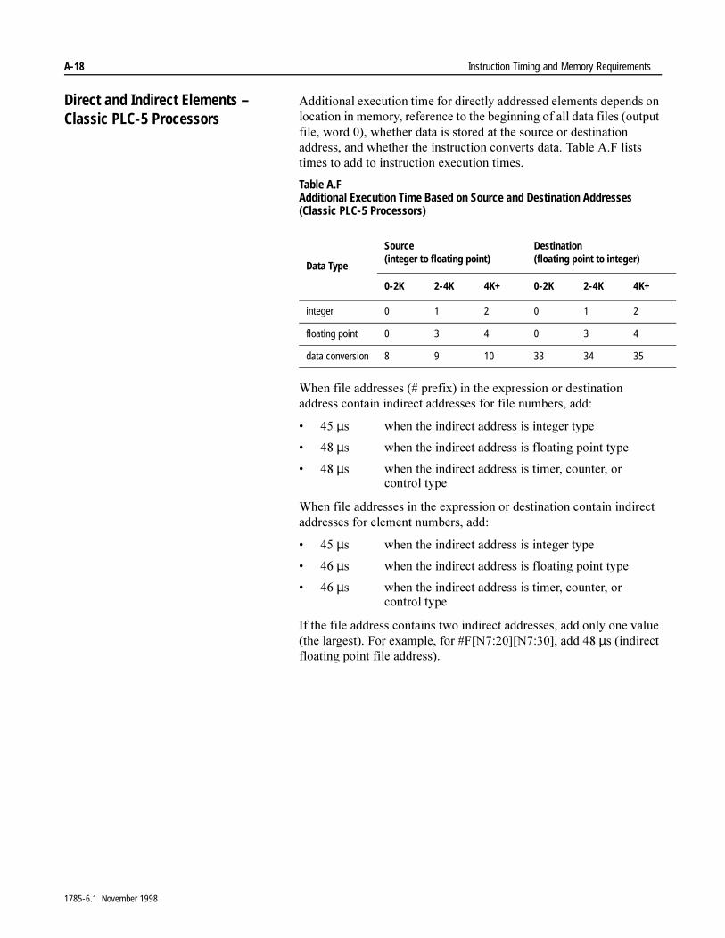
A-18 Instruction Timing and Memory Requirements
Direct and Indirect Elements – Classic PLC-5 Processors
$GGLWLRQDO�H[HFXWLRQ�WLPH�IRU�GLUHFWO\�DGGUHVVHG�HOHPHQWV�GHSHQGV�RQ�ORFDWLRQ�LQ�PHPRU\��UHIHUHQFH�WR�WKH�EHJLQQLQJ�RI�DOO�GDWD�ILOHV��RXWSXW�ILOH��ZRUG�����ZKHWKHU�GDWD�LV�VWRUHG�DW�WKH�VRXUFH�RU�GHVWLQDWLRQ�DGGUHVV��DQG�ZKHWKHU�WKH�LQVWUXFWLRQ�FRQYHUWV�GDWD��7DEOH�$�)�OLVWV�WLPHV�WR�DGG�WR�LQVWUXFWLRQ�H[HFXWLRQ�WLPHV�
Table A.F Additional Execution Time Based on Source and Destination Addresses(Classic PLC-5 Processors)
:KHQ�ILOH�DGGUHVVHV����SUHIL[��LQ�WKH�H[SUHVVLRQ�RU�GHVWLQDWLRQ�DGGUHVV�FRQWDLQ�LQGLUHFW�DGGUHVVHV�IRU�ILOH�QXPEHUV��DGG�
� ���µV ZKHQ�WKH�LQGLUHFW�DGGUHVV�LV�LQWHJHU�W\SH
� ���µV ZKHQ�WKH�LQGLUHFW�DGGUHVV�LV�IORDWLQJ�SRLQW�W\SH
� ���µV ZKHQ�WKH�LQGLUHFW�DGGUHVV�LV�WLPHU��FRXQWHU��RU�FRQWURO�W\SH
:KHQ�ILOH�DGGUHVVHV�LQ�WKH�H[SUHVVLRQ�RU�GHVWLQDWLRQ�FRQWDLQ�LQGLUHFW�DGGUHVVHV�IRU�HOHPHQW�QXPEHUV��DGG�
� ���µV ZKHQ�WKH�LQGLUHFW�DGGUHVV�LV�LQWHJHU�W\SH
� ���µV ZKHQ�WKH�LQGLUHFW�DGGUHVV�LV�IORDWLQJ�SRLQW�W\SH
� ���µV ZKHQ�WKH�LQGLUHFW�DGGUHVV�LV�WLPHU��FRXQWHU��RU�FRQWURO�W\SH
,I�WKH�ILOH�DGGUHVV�FRQWDLQV�WZR�LQGLUHFW�DGGUHVVHV��DGG�RQO\�RQH�YDOXH��WKH�ODUJHVW���)RU�H[DPSOH��IRU��)>1����@>1����@��DGG����µV��LQGLUHFW�IORDWLQJ�SRLQW�ILOH�DGGUHVV��
Data Type
Source(integer to floating point)
Destination(floating point to integer)
0-2K 2-4K 4K+ 0-2K 2-4K 4K+
integer 0 1 2 0 1 2
floating point 0 3 4 0 3 4
data conversion 8 9 10 33 34 35
1785-6.1 November 1998
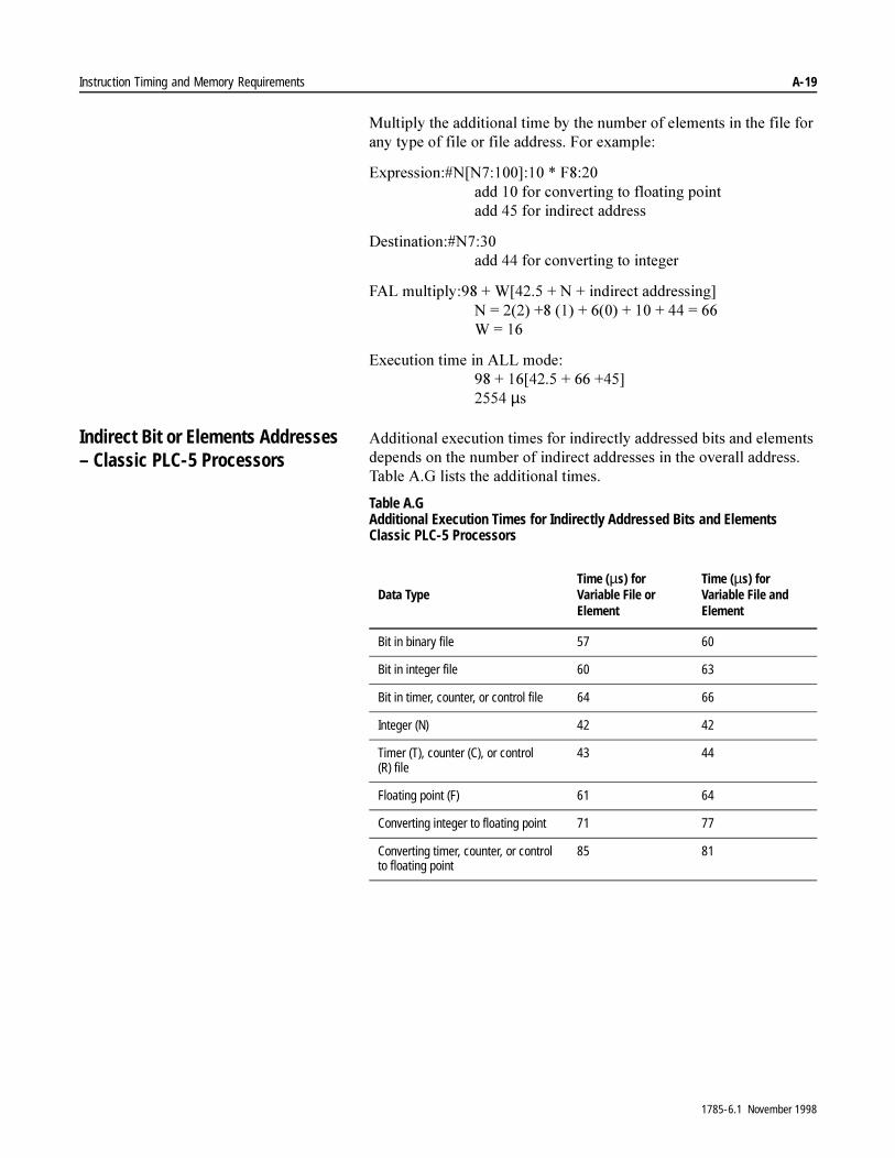
Instruction Timing and Memory Requirements A-19
0XOWLSO\�WKH�DGGLWLRQDO�WLPH�E\�WKH�QXPEHU�RI�HOHPHQWV�LQ�WKH�ILOH�IRU�DQ\�W\SH�RI�ILOH�RU�ILOH�DGGUHVV��)RU�H[DPSOH�
([SUHVVLRQ��1>1�����@���� �)����DGG����IRU�FRQYHUWLQJ�WR�IORDWLQJ�SRLQWDGG����IRU�LQGLUHFW�DGGUHVV
'HVWLQDWLRQ��1����DGG����IRU�FRQYHUWLQJ�WR�LQWHJHU
)$/�PXOWLSO\������:>�������1���LQGLUHFW�DGGUHVVLQJ@1� ������������������������������ ����:� ���
([HFXWLRQ�WLPH�LQ�$//�PRGH��������>�������������@�����µV
Indirect Bit or Elements Addresses – Classic PLC-5 Processors
$GGLWLRQDO�H[HFXWLRQ�WLPHV�IRU�LQGLUHFWO\�DGGUHVVHG�ELWV�DQG�HOHPHQWV�GHSHQGV�RQ�WKH�QXPEHU�RI�LQGLUHFW�DGGUHVVHV�LQ�WKH�RYHUDOO�DGGUHVV��7DEOH�$�*�OLVWV�WKH�DGGLWLRQDO�WLPHV�
Table A.G Additional Execution Times for Indirectly Addressed Bits and Elements Classic PLC-5 Processors
Data TypeTime (µs) for Variable File or Element
Time (µs) for Variable File and Element
Bit in binary file 57 60
Bit in integer file 60 63
Bit in timer, counter, or control file 64 66
Integer (N) 42 42
Timer (T), counter (C), or control (R) file
43 44
Floating point (F) 61 64
Converting integer to floating point 71 77
Converting timer, counter, or control to floating point
85 81
1785-6.1 November 1998

A-20 Instruction Timing and Memory Requirements
Additional Timing Considerations – Classic PLC-5 Processors
7DEOH�$�+�OLVWV�DGGLWLRQDO�WLPLQJ�FRQVLGHUDWLRQV�
Table A.H Additional Timing Considerations (Classic PLC-5 Processors)
Tasks Time (milliseconds)
Housekeeping 4.5 max
Resident Local I/O scan 1 per assigned rack number
Remote I/O scan 10 per assigned rack number at 57.6 Kb
1785-6.1 November 1998
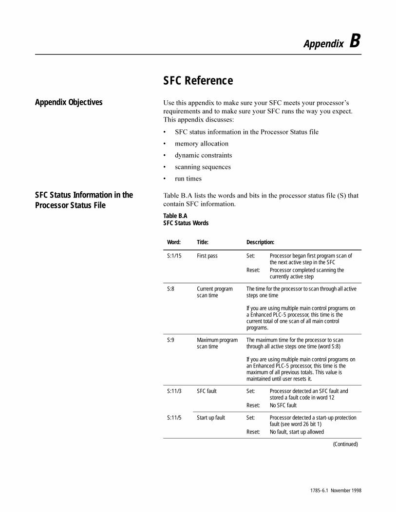
Appendix B
SFC Reference
Appendix Objectives 8VH�WKLV�DSSHQGL[�WR�PDNH�VXUH�\RXU�6)&�PHHWV�\RXU�SURFHVVRU¶V�UHTXLUHPHQWV�DQG�WR�PDNH�VXUH�\RXU�6)&�UXQV�WKH�ZD\�\RX�H[SHFW��7KLV�DSSHQGL[�GLVFXVVHV�
� 6)&�VWDWXV�LQIRUPDWLRQ�LQ�WKH�3URFHVVRU�6WDWXV�ILOH
� PHPRU\�DOORFDWLRQ
� G\QDPLF�FRQVWUDLQWV
� VFDQQLQJ�VHTXHQFHV
� UXQ�WLPHV
SFC Status Information in the Processor Status File
7DEOH�%�$�OLVWV�WKH�ZRUGV�DQG�ELWV�LQ�WKH�SURFHVVRU�VWDWXV�ILOH��6��WKDW�FRQWDLQ�6)&�LQIRUPDWLRQ�
Table B.A SFC Status Words
Word: Title: Description:
S:1/15 First pass Set: Processor began first program scan of the next active step in the SFC
Reset: Processor completed scanning thecurrently active step
S:8 Current program scan time
The time for the processor to scan through all active steps one time
If you are using multiple main control programs on a Enhanced PLC-5 processor, this time is the current total of one scan of all main control programs.
S:9 Maximum program scan time
The maximum time for the processor to scan through all active steps one time (word S:8)
If you are using multiple main control programs on an Enhanced PLC-5 processor, this time is the maximum of all previous totals. This value is maintained until user resets it.
S:11/3 SFC fault Set: Processor detected an SFC fault and stored a fault code in word 12
Reset: No SFC fault
S:11/5 Start up fault Set: Processor detected a start-up protection fault (see word 26 bit 1)
Reset: No fault, start up allowed
(Continued)
1785-6.1 November 1998
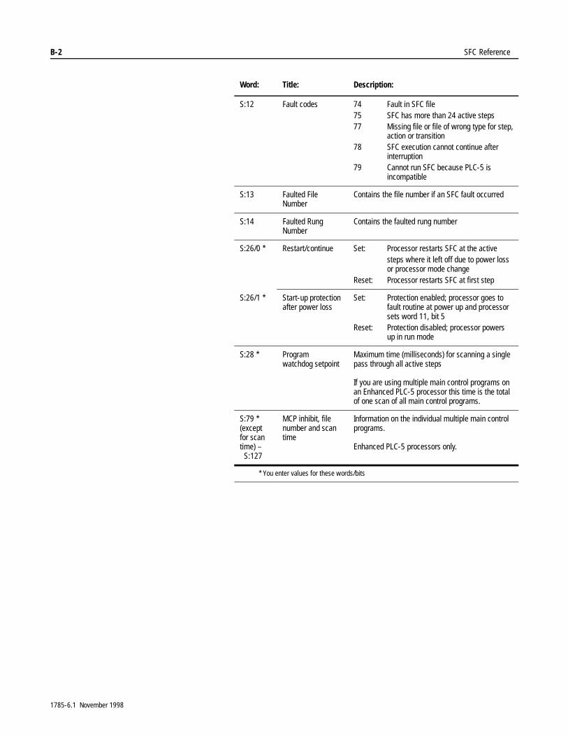
B-2 SFC Reference
S:12 Fault codes 74 Fault in SFC file 75 SFC has more than 24 active steps77 Missing file or file of wrong type for step,
action or transition78 SFC execution cannot continue after
interruption79 Cannot run SFC because PLC-5 is
incompatible
S:13 Faulted File Number
Contains the file number if an SFC fault occurred
S:14 Faulted Rung Number
Contains the faulted rung number
S:26/0 * Restart/continue Set: Processor restarts SFC at the activesteps where it left off due to power loss or processor mode change
Reset: Processor restarts SFC at first step
S:26/1 * Start-up protection after power loss
Set: Protection enabled; processor goes tofault routine at power up and processorsets word 11, bit 5
Reset: Protection disabled; processor powersup in run mode
S:28 * Program watchdog setpoint
Maximum time (milliseconds) for scanning a single pass through all active steps
If you are using multiple main control programs on an Enhanced PLC-5 processor this time is the total of one scan of all main control programs.
S:79 * (except for scan time) –
S:127
MCP inhibit, file number and scan time
Information on the individual multiple main control programs.
Enhanced PLC-5 processors only.
* You enter values for these words/bits
Word: Title: Description:
1785-6.1 November 1998
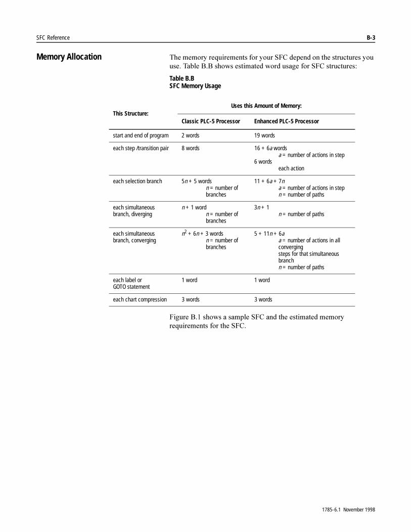
SFC Reference B-3
Memory Allocation 7KH�PHPRU\�UHTXLUHPHQWV�IRU�\RXU�6)&�GHSHQG�RQ�WKH�VWUXFWXUHV�\RX�XVH��7DEOH�%�%�VKRZV�HVWLPDWHG�ZRUG�XVDJH�IRU�6)&�VWUXFWXUHV�
Table B.B SFC Memory Usage
)LJXUH�%���VKRZV�D�VDPSOH�6)&�DQG�WKH�HVWLPDWHG�PHPRU\�UHTXLUHPHQWV�IRU�WKH�6)&�
This Structure:Uses this Amount of Memory:
Classic PLC-5 Processor Enhanced PLC-5 Processor
start and end of program 2 words 19 words
each step /transition pair 8 words 16 + 6a wordsa = number of actions in step
6 wordseach action
each selection branch 5n + 5 wordsn = number of branches
11 + 6a + 7na = number of actions in stepn = number of paths
each simultaneous branch, diverging
n + 1 wordn = number of branches
3n + 1n = number of paths
each simultaneous branch, converging
n2 + 6n + 3 wordsn = number of branches
5 + 11n + 6aa = number of actions in all convergingsteps for that simultaneous branchn = number of paths
each label or GOTO statement
1 word 1 word
each chart compression 3 words 3 words
1785-6.1 November 1998
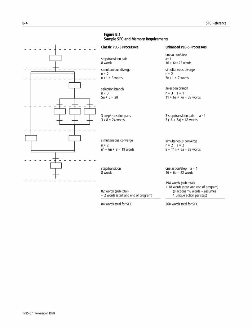
B-4 SFC Reference
Figure B.1 Sample SFC and Memory Requirements
Classic PLC-5 Processors Enhanced PLC-5 Processors
step/transition pair8 words
one action/stepa=116 + 6a=22 words
simultaneous divergen = 2n +1 = 3 words
simultaneous divergen = 23n +1 = 7 words
selection branchn = 35n + 5 = 20
selection branchn = 3 a = 111 + 6a + 7n = 38 words
3 step/transition pairs3 x 8 = 24 words
3 step/transition pairs a =13 (16 + 6a) = 66 words
simultaneous convergen = 2n2 + 6n + 3 = 19 words
simultaneous convergen = 2 a = 25 + 11n + 6a = 39 words
step/transition8 words
one action/step a = 116 + 6a = 22 words
82 words (sub total)+ 2 words (start and end of program)
194 words (sub total)+ 18 words (start and end of program)
(8 actions * 6 words – assumes1 unique action per step)
84 words total for SFC 260 words total for SFC
1785-6.1 November 1998
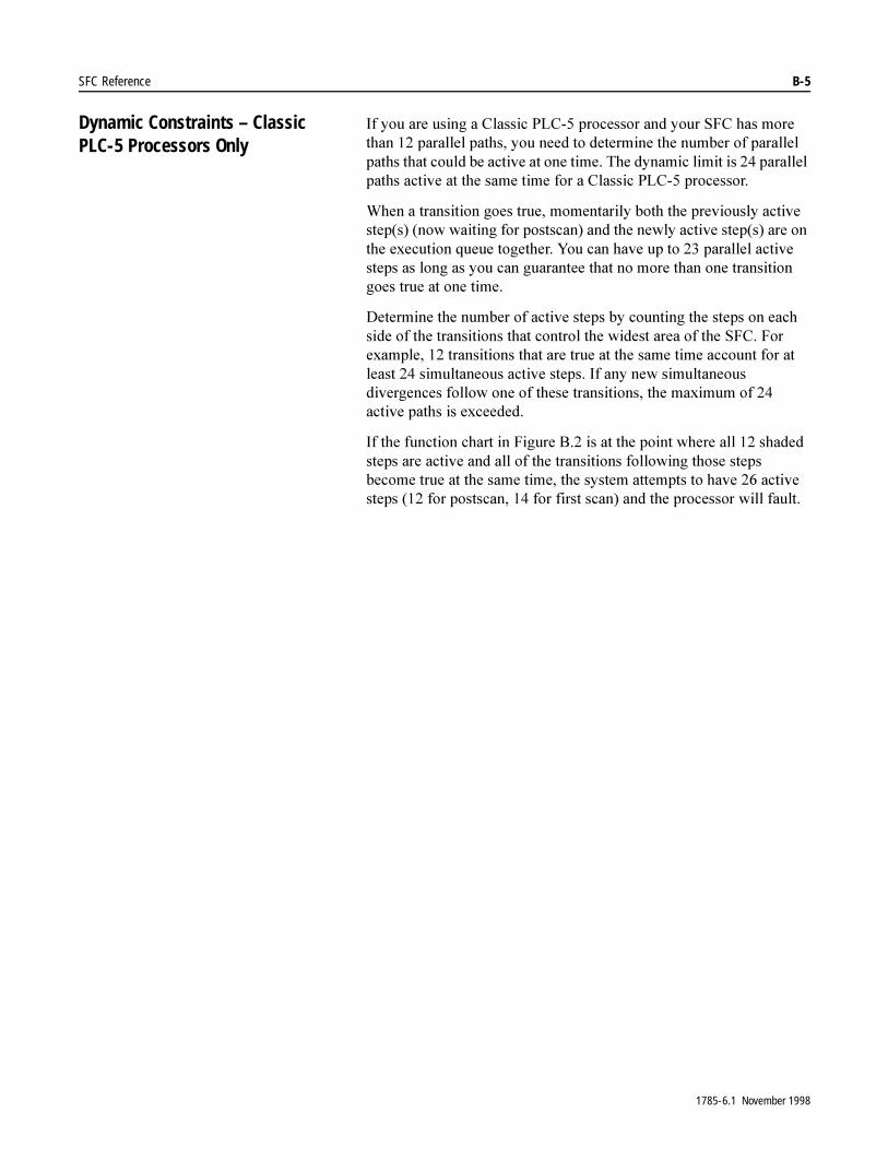
SFC Reference B-5
Dynamic Constraints – Classic PLC-5 Processors Only
,I�\RX�DUH�XVLQJ�D�&ODVVLF�3/&���SURFHVVRU�DQG�\RXU�6)&�KDV�PRUH�WKDQ����SDUDOOHO�SDWKV��\RX�QHHG�WR�GHWHUPLQH�WKH�QXPEHU�RI�SDUDOOHO�SDWKV�WKDW�FRXOG�EH�DFWLYH�DW�RQH�WLPH��7KH�G\QDPLF�OLPLW�LV����SDUDOOHO�SDWKV�DFWLYH�DW�WKH�VDPH�WLPH�IRU�D�&ODVVLF�3/&���SURFHVVRU�
:KHQ�D�WUDQVLWLRQ�JRHV�WUXH��PRPHQWDULO\�ERWK�WKH�SUHYLRXVO\�DFWLYH�VWHS�V���QRZ�ZDLWLQJ�IRU�SRVWVFDQ��DQG�WKH�QHZO\�DFWLYH�VWHS�V��DUH�RQ�WKH�H[HFXWLRQ�TXHXH�WRJHWKHU��<RX�FDQ�KDYH�XS�WR����SDUDOOHO�DFWLYH�VWHSV�DV�ORQJ�DV�\RX�FDQ�JXDUDQWHH�WKDW�QR�PRUH�WKDQ�RQH�WUDQVLWLRQ�JRHV�WUXH�DW�RQH�WLPH�
'HWHUPLQH�WKH�QXPEHU�RI�DFWLYH�VWHSV�E\�FRXQWLQJ�WKH�VWHSV�RQ�HDFK�VLGH�RI�WKH�WUDQVLWLRQV�WKDW�FRQWURO�WKH�ZLGHVW�DUHD�RI�WKH�6)&��)RU�H[DPSOH�����WUDQVLWLRQV�WKDW�DUH�WUXH�DW�WKH�VDPH�WLPH�DFFRXQW�IRU�DW�OHDVW����VLPXOWDQHRXV�DFWLYH�VWHSV��,I�DQ\�QHZ�VLPXOWDQHRXV�GLYHUJHQFHV�IROORZ�RQH�RI�WKHVH�WUDQVLWLRQV��WKH�PD[LPXP�RI����DFWLYH�SDWKV�LV�H[FHHGHG�
,I�WKH�IXQFWLRQ�FKDUW�LQ�)LJXUH�%���LV�DW�WKH�SRLQW�ZKHUH�DOO����VKDGHG�VWHSV�DUH�DFWLYH�DQG�DOO�RI�WKH�WUDQVLWLRQV�IROORZLQJ�WKRVH�VWHSV�EHFRPH�WUXH�DW�WKH�VDPH�WLPH��WKH�V\VWHP�DWWHPSWV�WR�KDYH����DFWLYH�VWHSV�����IRU�SRVWVFDQ�����IRU�ILUVW�VFDQ��DQG�WKH�SURFHVVRU�ZLOO�IDXOW�
1785-6.1 November 1998
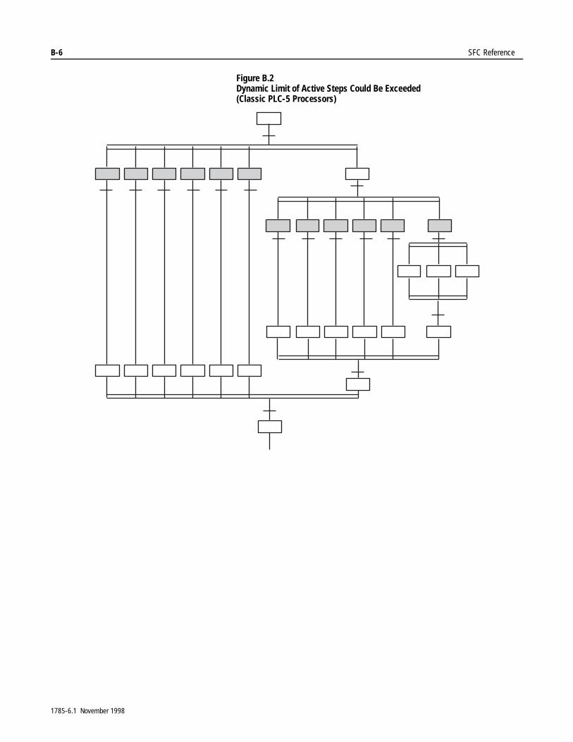
B-6 SFC Reference
Figure B.2 Dynamic Limit of Active Steps Could Be Exceeded(Classic PLC-5 Processors)
1785-6.1 November 1998
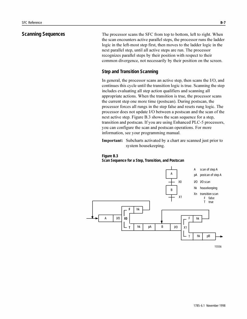
SFC Reference B-7
Scanning Sequences 7KH�SURFHVVRU�VFDQV�WKH�6)&�IURP�WRS�WR�ERWWRP��OHIW�WR�ULJKW��:KHQ�WKH�VFDQ�HQFRXQWHUV�DFWLYH�SDUDOOHO�VWHSV��WKH�SURFHVVRU�UXQV�WKH�ODGGHU�ORJLF�LQ�WKH�OHIW�PRVW�VWHS�ILUVW��WKHQ�PRYHV�WR�WKH�ODGGHU�ORJLF�LQ�WKH�QH[W�SDUDOOHO�VWHS��XQWLO�DOO�DFWLYH�VWHSV�DUH�UXQ��7KH�SURFHVVRU�UHFRJQL]HV�SDUDOOHO�VWHSV�E\�WKHLU�SRVLWLRQ�ZLWK�UHVSHFW�WR�WKHLU�FRPPRQ�GLYHUJHQFH��QRW�QHFHVVDULO\�E\�WKHLU�SRVLWLRQ�RQ�WKH�VFUHHQ�
Step and Transition Scanning
,Q�JHQHUDO��WKH�SURFHVVRU�VFDQV�DQ�DFWLYH�VWHS��WKHQ�VFDQV�WKH�,�2��DQG�FRQWLQXHV�WKLV�F\FOH�XQWLO�WKH�WUDQVLWLRQ�ORJLF�LV�WUXH��6FDQQLQJ�WKH�VWHS�LQFOXGHV�HYDOXDWLQJ�DOO�VWHS�DFWLRQ�TXDOLILHUV�DQG�VFDQQLQJ�DOO�DSSURSULDWH�DFWLRQV��:KHQ�WKH�WUDQVLWLRQ�LV�WUXH��WKH�SURFHVVRU�VFDQV�WKH�FXUUHQW�VWHS�RQH�PRUH�WLPH��SRVWVFDQ���'XULQJ�SRVWVFDQ��WKH�SURFHVVRU�IRUFHV�DOO�UXQJV�LQ�WKH�VWHS�IDOVH�DQG�UHVHWV�UXQJ�ORJLF��7KH�SURFHVVRU�GRHV�QRW�XSGDWH�,�2�EHWZHHQ�D�SRVWVFDQ�DQG�WKH�VFDQ�RI�WKH�QH[W�DFWLYH�VWHS��)LJXUH�%���VKRZV�WKH�VFDQ�VHTXHQFH�IRU�D�VWHS��WUDQVLWLRQ�DQG�SRVWVFDQ��,I�\RX�DUH�XVLQJ�(QKDQFHG�3/&���SURFHVVRUV��\RX�FDQ�FRQILJXUH�WKH�VFDQ�DQG�SRVWVFDQ�RSHUDWLRQV��)RU�PRUH�LQIRUPDWLRQ��VHH�\RXU�SURJUDPPLQJ�PDQXDO�
,PSRUWDQW���6XEFKDUWV�DFWLYDWHG�E\�D�FKDUW�DUH�VFDQQHG�MXVW�SULRU�WR�V\VWHP�KRXVHNHHSLQJ�
Figure B.3 Scan Sequence for a Step, Transition, and Postscan
15556
A I/O
hk
hk pA B I/O
hk
hk pB
F
T
X0
F
T
X0 F
T
X1
X0
X1
A
B
A scan of step A
pA postcan of step A
I/O I/O scan
hk housekeeping
Xn transition scanF falseT true
1785-6.1 November 1998

B-8 SFC Reference
Selected Branch Scanning
7KH�SURFHVVRU�VHOHFWV�RQH�SDWK�RI�PXOWLSOH�SDUDOOHO�SDWKV�LQ�D�VHOHFWHG�EUDQFK��)LJXUH�%�����7KH�SURFHVVRU�WHVWV�WUDQVLWLRQV�;��WKURXJK�;Q��IURP�OHIW�WR�ULJKW��XQWLO�RQH�RI�WKH�WUDQVLWLRQV�EHFRPH�WUXH��7KH�SDWK�ZLWK�WKH�ILUVW�WUXH�WUDQVLWLRQ�LV�WKH�DFWLYH�SDWK�
Figure B.4 Selected Branch – Divergence
%HFDXVH�RQO\�RQH�SDWK�LV�DFWLYH��WKH�VFDQ�VHTXHQFH�IRU�WKH�FRQYHUJHQFH�LV�WKH�VDPH�DV�IRU�D�VWHS�DQG�WUDQVLWLRQ��)LJXUH�%���VKRZV�WKH�VFDQ�VHTXHQFH�IRU�WKH�GLYHUJHQFH�DQG�FRQYHUJHQFH�RI�D�VHOHFWHG�EUDQFK�
X0 X1 X2 X7/ /
1785-6.1 November 1998

SFC Reference B-9
Figure B.5 Scan Sequence for a Selected Branch - Divergence and Convergence
Simultaneous Branch Scanning
7KH�SURFHVVRU�VFDQV�DOO�SDUDOOHO�SDWKV�LQ�D�VLPXOWDQHRXV�EUDQFK��)LJXUH�%�����2Q�WKH�ILUVW�VFDQ��WKH�SURFHVVRU�VFDQV�VWHS�%��WKHQ�VWHS�&��XQWLO�WKH�SURFHVVRU�VFDQV�DOO�WKH�VWHSV�RQ�WKH�GLYHUJHQFH�
Figure B.6 Simultaneous Branch – Divergence
2Q�VXEVHTXHQW�VFDQV��WKH�SURFHVVRU�VFDQV�LQ�WKH�RUGHU�RI�VWHS��,�2��DQG�WUDQVLWLRQ�IRU�HDFK�SDWK��VWDUWLQJ�IURP�WKH�OHIW�
15557
A I/O
hk
hk pA C I/O
hk
hk pC
F
T
X1 F
T
X3
X0
X2
B
A scan of step A
pA postcan of step A
I/O I/O scan
hk housekeeping
Xn transition scanF falseT truen transition number
oh overhead
X1
X3
C n
A
hk pA B I/O
hk
hk pB
F
T
X2T
F
T
X0
oh
Classic PLC-5 Processors: maximum of 7 selections
Enhanced PLC-5 Processors: maximum of 16 selections
/ /
B C D N
1785-6.1 November 1998
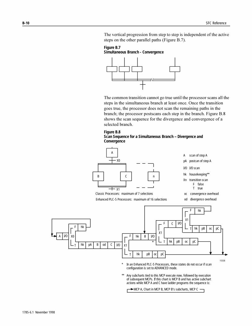
B-10 SFC Reference
7KH�YHUWLFDO�SURJUHVVLRQ�IURP�VWHS�WR�VWHS�LV�LQGHSHQGHQW�RI�WKH�DFWLYH�VWHSV�RQ�WKH�RWKHU�SDUDOOHO�SDWKV��)LJXUH�%����
Figure B.7 Simultaneous Branch - Convergence
7KH�FRPPRQ�WUDQVLWLRQ�FDQQRW�JR�WUXH�XQWLO�WKH�SURFHVVRU�VFDQV�DOO�WKH�VWHSV�LQ�WKH�VLPXOWDQHRXV�EUDQFK�DW�OHDVW�RQFH��2QFH�WKH�WUDQVLWLRQ�JRHV�WUXH��WKH�SURFHVVRU�GRHV�QRW�VFDQ�WKH�UHPDLQLQJ�SDWKV�LQ�WKH�EUDQFK��WKH�SURFHVVRU�SRVWVFDQV�HDFK�VWHS�LQ�WKH�EUDQFK��)LJXUH�%���VKRZV�WKH�VFDQ�VHTXHQFH�IRU�WKH�GLYHUJHQFH�DQG�FRQYHUJHQFH�RI�D�VHOHFWHG�EUDQFK�
Figure B.8 Scan Sequence for a Simultaneous Branch – Divergence and Convergence
/ /
15558
X0
X1
B
A scan of step A
pA postcan of step A
I/O I/O scan
hk housekeeping**
Xn transition scanF falseT true
oc convergence overhead
C n
A
od divergence overhead
A I/O
hk
hk pA C I/O
hk
hk pB
F
T
X0 F
T
X1B od
C
hk pB
F
T
X1
pCoc
I/O
hk
hk
F
T
X1
pB pCoc
pCoc
B I/O
*
Classic Processors: maximum of 7 selections
Enhanced PLC-5 Processors: maximum of 16 selections
* In an Enhanced PLC-5 Processors, these states do not occur if scanconfiguration is set to ADVANCED mode.
** Any subcharts tied to this MCP execute now, followed by executionof subsequent MCPs. If this chart is MCP B and has active subchartactions while MCP A and C have ladder programs the sequence is:
MCP A, Chart in MCP B, MCP B's subcharts, MCP C
1785-6.1 November 1998
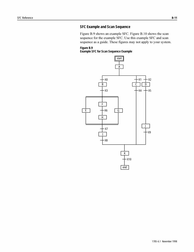
SFC Reference B-11
SFC Example and Scan Sequence
)LJXUH�%���VKRZV�DQ�H[DPSOH�6)&��)LJXUH�%����VKRZV�WKH�VFDQ�VHTXHQFH�IRU�WKH�H[DPSOH�6)&��8VH�WKLV�H[DPSOH�6)&�DQG�VFDQ�VHTXHQFH�DV�D�JXLGH��7KHVH�ILJXUHV�PD\�QRW�DSSO\�WR�\RXU�V\VWHP�
Figure B.9 Example SFC for Scan Sequence Example
A
CB D
J
F
H
E G
I
K
X0 X1 X2
X4 X5
X9
X3
X6
X7
X8
X10
start
end
1785-6.1 November 1998
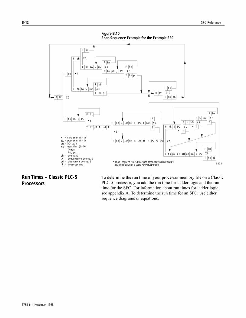
B-12 SFC Reference
Figure B.10 Scan Sequence Example for the Example SFC
Run Times – Classic PLC-5 Processors
7R�GHWHUPLQH�WKH�UXQ�WLPH�RI�\RXU�SURFHVVRU�PHPRU\�ILOH�RQ�D�&ODVVLF�3/&���SURFHVVRU��\RX�DGG�WKH�UXQ�WLPH�IRU�ODGGHU�ORJLF�DQG�WKH�UXQ�WLPH�IRU�WKH�6)&��)RU�LQIRUPDWLRQ�DERXW�UXQ�WLPHV�IRU�ODGGHU�ORJLF��VHH�DSSHQGL[�$��7R�GHWHUPLQH�WKH�UXQ�WLPH�IRU�DQ�6)&��XVH�HLWKHU�VHTXHQFH�GLDJUDPV�RU�HTXDWLRQV�
I /OT o d G I /O hk E I /O pF H I /O G
F o d G I /O hk E I /O F I /O
F
TT hk
hkF
pB E o d F
T hk pE o c
F hk E I/O
pH o c pG I I /O
F H I /O
T
F G I /O
T
F hk
T
F hk
T hk p I
X 8
X 7
X 7
X 7
K I/O
F hk
T hk pK
X 10
X 7
X 6
X 6
X 3T hk
o hF
pA B I/O
X 0I /O
T hk
F
X 1
pA C I/O
o h
T h k
F
pA I /O
h k
X 2
D
T hk
F
p D I /OJ
X 5
hk
T hk
F
pJ
X 9
hk
T hk
F
X 4
hk
p C
15303
A
ApAI/OX N
ohocodhk
= step scan (A - K)= post scan (A - K)= I/O scan= transition (1 - 10)
T=trueF=fa lse
= overhead= convergence overhead= divergence overhead= housekeeping
* In an Enhanced PLC-5 Processor, these states do not occur ifscan configuration is set to ADVANCED mode.
*
*
1785-6.1 November 1998
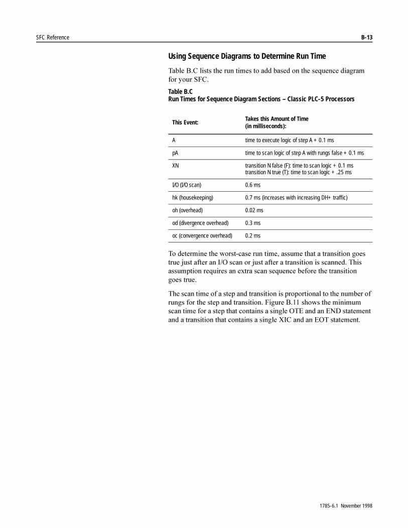
SFC Reference B-13
Using Sequence Diagrams to Determine Run Time
7DEOH�%�&�OLVWV�WKH�UXQ�WLPHV�WR�DGG�EDVHG�RQ�WKH�VHTXHQFH�GLDJUDP�IRU�\RXU�6)&�
Table B.C Run Times for Sequence Diagram Sections – Classic PLC-5 Processors
7R�GHWHUPLQH�WKH�ZRUVW�FDVH�UXQ�WLPH��DVVXPH�WKDW�D�WUDQVLWLRQ�JRHV�WUXH�MXVW�DIWHU�DQ�,�2�VFDQ�RU�MXVW�DIWHU�D�WUDQVLWLRQ�LV�VFDQQHG��7KLV�DVVXPSWLRQ�UHTXLUHV�DQ�H[WUD�VFDQ�VHTXHQFH�EHIRUH�WKH�WUDQVLWLRQ�JRHV�WUXH�
7KH�VFDQ�WLPH�RI�D�VWHS�DQG�WUDQVLWLRQ�LV�SURSRUWLRQDO�WR�WKH�QXPEHU�RI�UXQJV�IRU�WKH�VWHS�DQG�WUDQVLWLRQ��)LJXUH�%����VKRZV�WKH�PLQLPXP�VFDQ�WLPH�IRU�D�VWHS�WKDW�FRQWDLQV�D�VLQJOH�27(�DQG�DQ�(1'�VWDWHPHQW�DQG�D�WUDQVLWLRQ�WKDW�FRQWDLQV�D�VLQJOH�;,&�DQG�DQ�(27�VWDWHPHQW�
This Event:Takes this Amount of Time(in milliseconds):
A time to execute logic of step A + 0.1 ms
pA time to scan logic of step A with rungs false + 0.1 ms
XN transition N false (F): time to scan logic + 0.1 mstransition N true (T): time to scan logic + .25 ms
I/O (I/O scan) 0.6 ms
hk (housekeeping) 0.7 ms (increases with increasing DH+ traffic)
oh (overhead) 0.02 ms
od (divergence overhead) 0.3 ms
oc (convergence overhead) 0.2 ms
1785-6.1 November 1998

B-14 SFC Reference
Figure B.11 Minimum Scan Time for a Step and Transition Pair
Using Equations to Determine Run Time
7KH�HTXDWLRQV�\RX�XVH�GHSHQG�RQ�ZKHWKHU�WKH�VFDQ�LV�VWHDG\�VWDWH��VLPSOH�VWHS�DQG�WUDQVLWLRQ��RU�GLYHUJHQW�DQG�FRQYHUJHQW�
6WHDG\�VWDWH�6FDQ�7LPH�LV�ZKHQ�DOO�WUDQVLWLRQV�IROORZLQJ�DFWLYH�VWHSV�DUH�IDOVH��8VH�WKLV�HTXDWLRQ��7DEOH�%�'��
Tmilliseconds = 0.8a + 0.7 + Tscan
Table B.D Variables for Steady-State Scan Time
'LYHUJHQW�6FDQ�7LPH�VWDUWV�ZKHQ�WKH�SURFHVVRU�WHVWV�D�WUDQVLWLRQ�DQG�HQGV�ZKHQ�WKH�SURFHVVRU�VFDQV�WKH�QH[W�VWHS¶V�,�2��'LYHUJHQW�VFDQ�WLPH�LQFOXGHV�WUDQVLWLRQ�VFDQ�WLPH��SRVWVFDQ�WLPH�RI�WKH�SUHYLRXV�VWHS��VFDQ�WLPH�RI�WKH�QHZ�VWHS��RYHUKHDG��DQG�VFDQ�WLPH�RI�HDFK�SDUDOOHO�DFWLYH�VWHS�RXWVLGH�RI�WKH�GLYHUJHQFH�
14271
A I/O
hk
hk pA B I/O
hk
hk pB
T
X0
F
F
T
X1
X0
X1
A
B
1.9 ms 1.9 ms
1.6 ms
1.6 ms
Where: Is:
Tmilliseconds steady-state scan time in milliseconds
a number of active steps
Tscan total time to scan logic in all active steps and associated false transitions
1785-6.1 November 1998
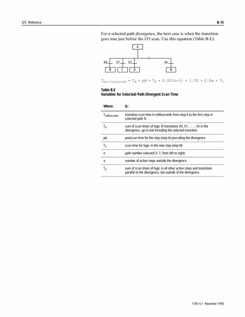
SFC Reference B-15
)RU�D�VHOHFWHG�SDWK�GLYHUJHQFH��WKH�EHVW�FDVH�LV�ZKHQ�WKH�WUDQVLWLRQ�JRHV�WUXH�MXVW�EHIRUH�WKH�,�2�VFDQ��8VH�WKLV�HTXDWLRQ��7DEOH�%�(��
Tmilliseconds = TX + pA + TS + 0.02(n±1) + 1.55 + 0.8a + T0
Table B.E Variables for Selected-Path Divergent Scan Time
Where: Is:
Tmilliseconds transition scan time in milliseconds from step A to the first step in selected path N
TX sum of scan times of logic of transitions X0, X1, . . . , Xn in the divergence, up to and including the selected transition
pA postscan time for the step (step A) preceding the divergence
TS scan time for logic in the new step (step N)
n path number selected (1-7, from left to right)
a number of active steps outside the divergence
T0 sum of scan times of logic in all other active steps and transitions parallel to the divergence, but outside of the divergence
X0 X1 X2 Xn/ /
A
B C D N
1785-6.1 November 1998
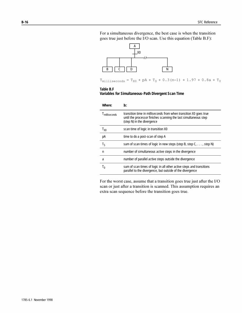
B-16 SFC Reference
)RU�D�VLPXOWDQHRXV�GLYHUJHQFH��WKH�EHVW�FDVH�LV�ZKHQ�WKH�WUDQVLWLRQ�JRHV�WUXH�MXVW�EHIRUH�WKH�,�2�VFDQ��8VH�WKLV�HTXDWLRQ��7DEOH�%�)��
Tmilliseconds = TX0 + pA + TS + 0.3(n±1) + 1.97 + 0.8a + T0
Table B.F Variables for Simultaneous-Path Divergent Scan Time
)RU�WKH�ZRUVW�FDVH��DVVXPH�WKDW�D�WUDQVLWLRQ�JRHV�WUXH�MXVW�DIWHU�WKH�,�2�VFDQ�RU�MXVW�DIWHU�D�WUDQVLWLRQ�LV�VFDQQHG��7KLV�DVVXPSWLRQ�UHTXLUHV�DQ�H[WUD�VFDQ�VHTXHQFH�EHIRUH�WKH�WUDQVLWLRQ�JRHV�WUXH�
Where: Is:
Tmilliseconds transition time in milliseconds from when transition X0 goes true until the processor finishes scanning the last simultaneous step (step N) in the divergence
TX0 scan time of logic in transition X0
pA time to do a post-scan of step A
TS sum of scan times of logic in new steps (step B, step C, . . . , step N)
n number of simultaneous active steps in the divergence
a number of parallel active steps outside the divergence
T0 sum of scan times of logic in all other active steps and transitions parallel to the divergence, but outside of the divergence
X0
/ /
A
B C D N
1785-6.1 November 1998

SFC Reference B-17
&RQYHUJHQW�6FDQ�7LPH�LV�ZKHQ�D�VLPXOWDQHRXV�EUDQFK�HQGV��7KH�EHVW�FDVH�LV�ZKHQ�WKH�WUDQVLWLRQ�JRHV�WUXH�MXVW�EHIRUH�WKH�,�2�VFDQ��8VH�WKLV�HTXDWLRQ��7DEOH�%�*��
Tmilliseconds = TX1 + Tp + TZ + 0.2(n±1) + 1.5 + 0.8a + T0
Table B.G Variables for Simultaneous-Path Convergent Scan Time
)RU�WKH�ZRUVW�FDVH��DVVXPH�WKDW�D�WUDQVLWLRQ�JRHV�WUXH�MXVW�DIWHU�WKH�,�2�VFDQ�RU�MXVW�DIWHU�D�WUDQVLWLRQ�LV�VFDQQHG��7KLV�DVVXPSWLRQ�UHTXLUHV�DQ�H[WUD�VFDQ�VHTXHQFH�EHIRUH�WKH�WUDQVLWLRQ�JRHV�WUXH�
Where: Is:
Tmilliseconds transition time in milliseconds from when transition X1 goes true until the processor finishes scanning step Z
TX1 scan time of logic in transition X1
Tp sum of postscan times of steps F, G, . . . , N
TZ scan time of logic in step Z
n number of simultaneous active steps in the convergence
a number of parallel active steps outside of the convergence
T0 sum of scan times of logic in all other active steps and transitions parallel to the convergence, but outside of the convergence
X1/ /
Z
F G H N
1785-6.1 November 1998

B-18 SFC Reference
1RWHV�
1785-6.1 November 1998

Appendix C
Valid Data Types for Instruction Operands
Appendix Objectives 7KLV�DSSHQGL[�OLVWV�DOO�RI�WKH�DYDLODEOH�LQVWUXFWLRQV�DQG�WKHLU�RSHUDQGV�DQG�WKH�GDWD�W\SHV�YDOXHV�WKDW�DUH�YDOLG�IRU�HDFK�RSHUDQG�
7KH�IROORZLQJ�WDEOH�H[SODLQV�HDFK�YDOLG�GDWD�W\SH�YDOXH�
Instruction Operands and Valid Data Types
7DEOH�&�$�VKRZV�WKH�SURJUDPPLQJ�LQVWUXFWLRQV�\RX�FDQ�XVH�DQG�WKH�RSHUDQGV�IRU�WKRVH�LQVWUXFWLRQV��<RX�FDQ�DOVR�XVH�WKLV�WDEOH�WR�IRUPDW�LQVWUXFWLRQV�LQ�$6&,,�IRU�LPSRUWLQJ��)RU�PRUH�LQIRUPDWLRQ�RQ�LPSRUWLQJ��VHH�\RXU�SURJUDPPLQJ�PDQXDO�
,QVWUXFWLRQV�PDUNHG�ZLWK�DQ�DVWHULVN�� ��DUH�RQO\�VXSSRUWHG�E\�(QKDQFHG�3/&���SURFHVVRUV�
7R�HQWHU�WKH�LPSRUW�V\QWD[�IRU�DQ\�RI�WKH�LQVWUXFWLRQV�OLVWHG�LQ�7DEOH�&�$�
� HQFORVH�DOO�RI�WKH�RSHUDQGV�LQ�SDUHQWKHVHV
� VHSDUDWH�HDFK�RI�WKH�RSHUDQGV�E\�FRPPDV
)RU�H[DPSOH��WKH�IROORZLQJ�LV�WKH�LPSRUW�V\QWD[�IRU�WKH�)$/ LQVWUXFWLRQ�
)$/��5������������$//���1������1����1�����
This Data Type/Value:
Accepts:
immediate(program constant)
any value between –32,768 and 32,767
integer any integer data type: integer, timer, counter, status, bit, input, output, ASCII, BCD, control (e.g., N7:0, C4:0, etc.)
float any floating point data type with 7-digit precision (valid range is ±1.1754944e–38 to ±3.4028237e+38).
block transfer any block transfer data type (e.g., BT14:0)
ControlNet transfer any CT data type (e.g., CT14:0)
message any message data type (e.g., MG15:0)
PID any PID data type (e.g., PD16:0) or integer data type (e.g., N7:0)
string any string data type (e.g., ST12:0)
SFC status any SFC status data type (e.g., SC17:0)
1785-6.1 November 1998
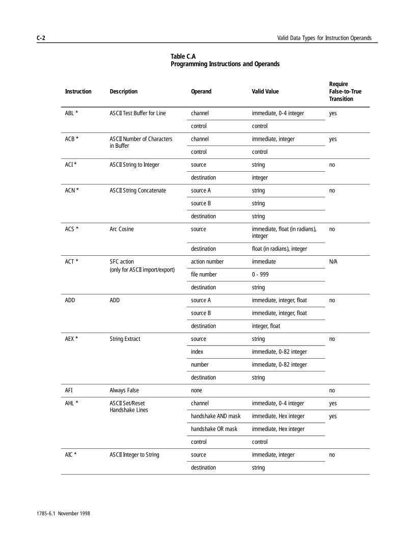
C-2 Valid Data Types for Instruction Operands
Table C.A Programming Instructions and Operands
Instruction Description Operand Valid ValueRequire False-to-True Transition
ABL * ASCII Test Buffer for Line channel immediate, 0-4 integer yes
control control
ACB * ASCII Number of Characters in Buffer
channel immediate, integer yes
control control
ACI * ASCII String to Integer source string no
destination integer
ACN * ASCII String Concatenate source A string no
source B string
destination string
ACS * Arc Cosine source immediate, float (in radians), integer
no
destination float (in radians), integer
ACT * SFC action(only for ASCII import/export)
action number immediate N/A
file number 0 - 999
destination string
ADD ADD source A immediate, integer, float no
source B immediate, integer, float
destination integer, float
AEX * String Extract source string no
index immediate, 0-82 integer
number immediate, 0-82 integer
destination string
AFI Always False none no
AHL * ASCII Set/Reset Handshake Lines
channel immediate, 0-4 integer yes
handshake AND mask immediate, Hex integer yes
handshake OR mask immediate, Hex integer
control control
AIC * ASCII Integer to String source immediate, integer no
destination string
1785-6.1 November 1998
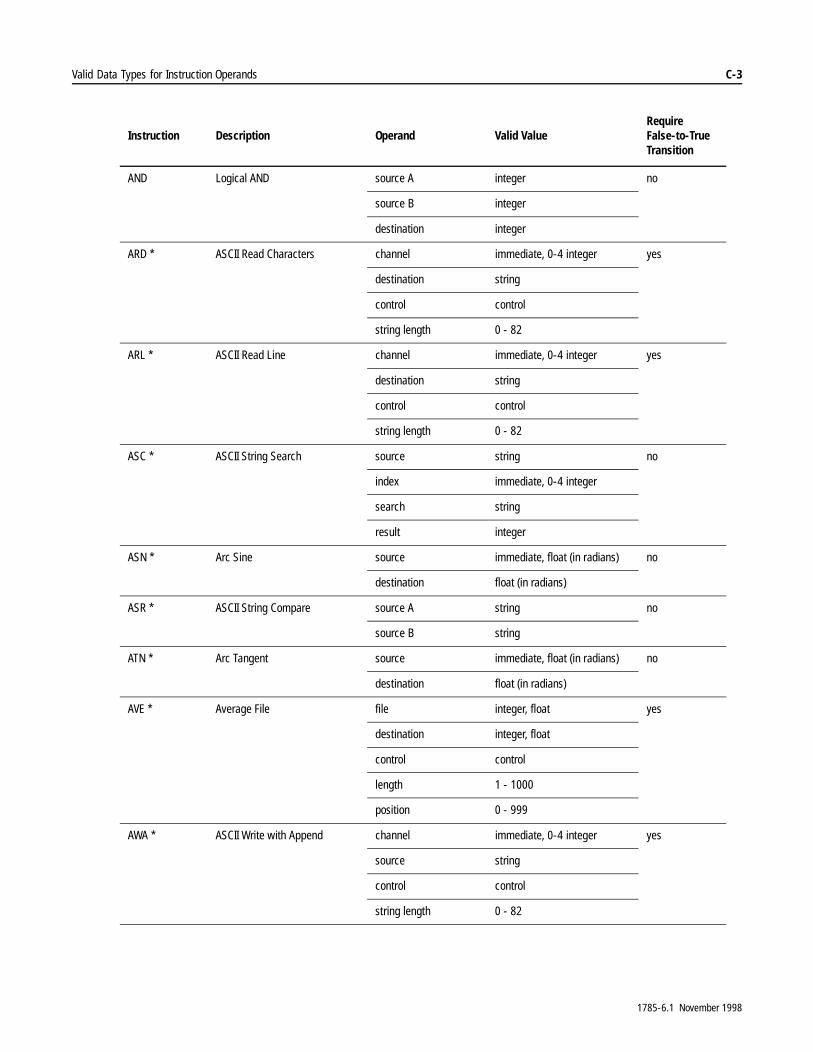
Valid Data Types for Instruction Operands C-3
AND Logical AND source A integer no
source B integer
destination integer
ARD * ASCII Read Characters channel immediate, 0-4 integer yes
destination string
control control
string length 0 - 82
ARL * ASCII Read Line channel immediate, 0-4 integer yes
destination string
control control
string length 0 - 82
ASC * ASCII String Search source string no
index immediate, 0-4 integer
search string
result integer
ASN * Arc Sine source immediate, float (in radians) no
destination float (in radians)
ASR * ASCII String Compare source A string no
source B string
ATN * Arc Tangent source immediate, float (in radians) no
destination float (in radians)
AVE * Average File file integer, float yes
destination integer, float
control control
length 1 - 1000
position 0 - 999
AWA * ASCII Write with Append channel immediate, 0-4 integer yes
source string
control control
string length 0 - 82
Instruction Description Operand Valid ValueRequire False-to-True Transition
1785-6.1 November 1998

C-4 Valid Data Types for Instruction Operands
AWT * ASCII Write channel immediate, integer yes
source string
control control
length 0 - 82 yes
BRK Break none no
BSL Bit Shift Left file binary yes
control control
bit address bit
length 1 - 16000 (length in bits)
BSR Bit Shift Right file binary yes
control control
bit address bit
length 1 - 16000 (length in bits)
BTD Bit Distribute source immediate, integer no
source bit immediate, (0 - 15) integer
destination integer
destination bit immediate (0 - 15)
length immediate (1 - 16)
Instruction Description Operand Valid ValueRequire False-to-True Transition
1785-6.1 November 1998
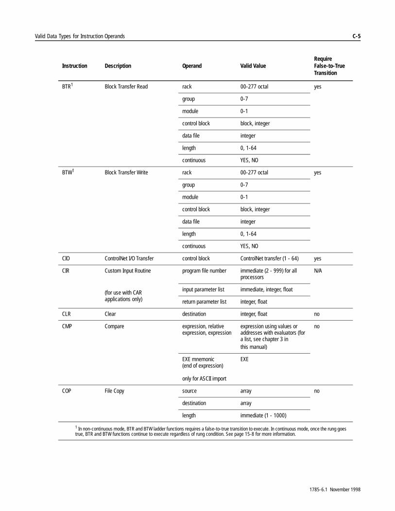
Valid Data Types for Instruction Operands C-5
BTR1 Block Transfer Read rack 00-277 octal yes
group 0-7
module 0-1
control block block, integer
data file integer
length 0, 1-64
continuous YES, NO
BTW1 Block Transfer Write rack 00-277 octal yes
group 0-7
module 0-1
control block block, integer
data file integer
length 0, 1-64
continuous YES, NO
CIO ControlNet I/O Transfer control block ControlNet transfer (1 - 64) yes
CIR Custom Input Routine
(for use with CAR applications only)
program file number immediate (2 - 999) for all processors
N/A
input parameter list immediate, integer, float
return parameter list integer, float
CLR Clear destination integer, float no
CMP Compare expression, relative expression, expression
expression using values or addresses with evaluators (for a list, see chapter 3 in this manual)
no
EXE mnemonic (end of expression)
only for ASCII import
EXE
COP File Copy source array no
destination array
length immediate (1 - 1000)
1 In non-continuous mode, BTR and BTW ladder functions requires a false-to-true transition to execute. In continuous mode, once the rung goes true, BTR and BTW functions continue to execute regardless of rung condition. See page 15-8 for more information.
Instruction Description Operand Valid ValueRequire False-to-True Transition
1785-6.1 November 1998
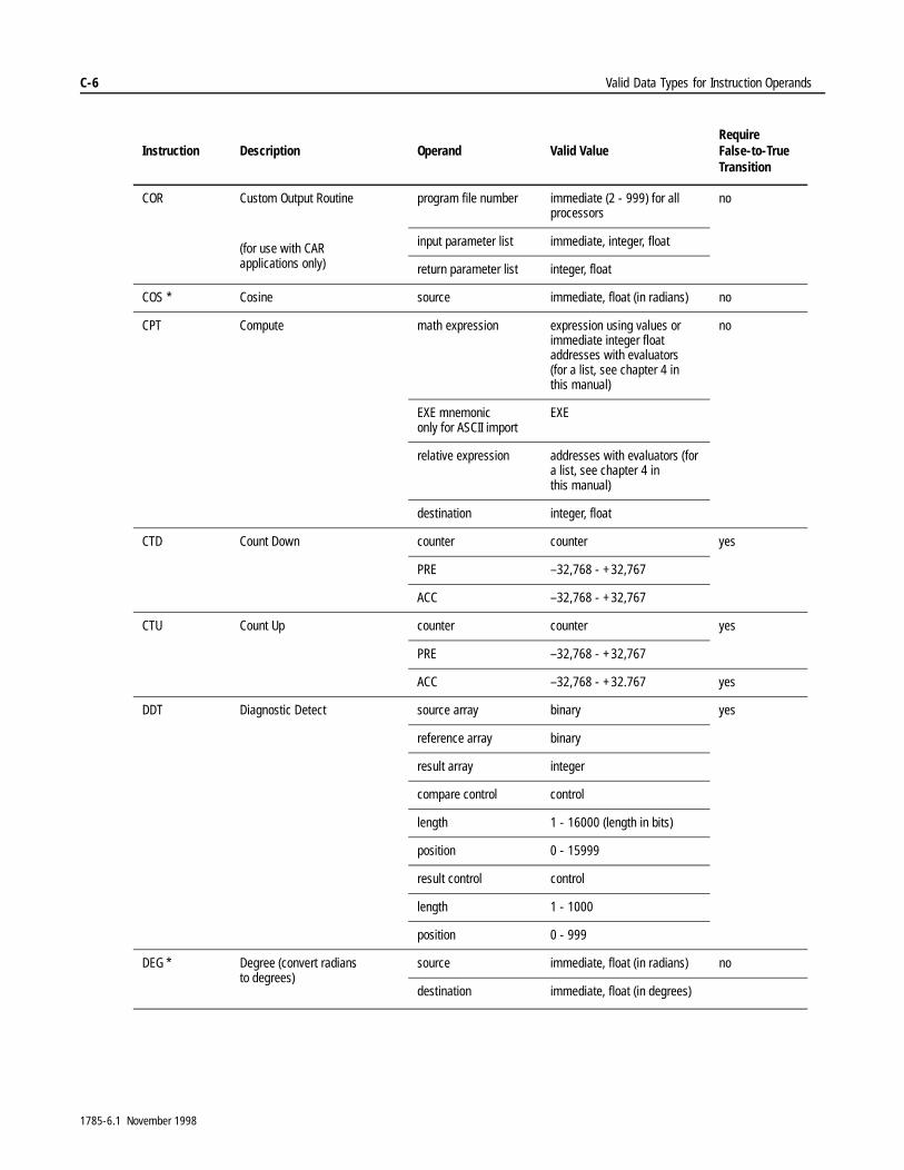
C-6 Valid Data Types for Instruction Operands
COR Custom Output Routine
(for use with CAR applications only)
program file number immediate (2 - 999) for all processors
no
input parameter list immediate, integer, float
return parameter list integer, float
COS * Cosine source immediate, float (in radians) no
CPT Compute math expression expression using values or immediate integer float addresses with evaluators (for a list, see chapter 4 in this manual)
no
EXE mnemoniconly for ASCII import
EXE
relative expression addresses with evaluators (for a list, see chapter 4 in this manual)
destination integer, float
CTD Count Down counter counter yes
PRE –32,768 - +32,767
ACC –32,768 - +32,767
CTU Count Up counter counter yes
PRE –32,768 - +32,767
ACC –32,768 - +32.767 yes
DDT Diagnostic Detect source array binary yes
reference array binary
result array integer
compare control control
length 1 - 16000 (length in bits)
position 0 - 15999
result control control
length 1 - 1000
position 0 - 999
DEG * Degree (convert radians to degrees)
source immediate, float (in radians) no
destination immediate, float (in degrees)
Instruction Description Operand Valid ValueRequire False-to-True Transition
1785-6.1 November 1998
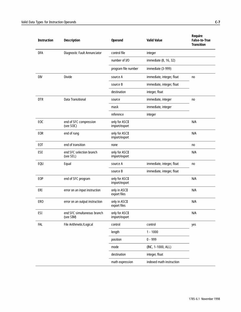
Valid Data Types for Instruction Operands C-7
DFA Diagnostic Fault Annunciator control file integer
number of I/O immediate (8, 16, 32)
program file number immediate (3-999)
DIV Divide source A immediate, integer, float no
source B immediate, integer, float
destination integer, float
DTR Data Transitional source immediate, integer no
mask immediate, integer
reference integer
EOC end of SFC compression (see SOC)
only for ASCII import/export
N/A
EOR end of rung only for ASCII import/export
N/A
EOT end of transition none no
ESE end SFC selection branch(see SEL)
only for ASCII import/export
N/A
EQU Equal source A immediate, integer, float no
source B immediate, integer, float
EOP end of SFC program only for ASCII import/export
N/A
ERI error on an input instruction only in ASCII export files
N/A
ERO error on an output instruction only in ASCII export files
N/A
ESI end SFC simultaneous branch (see SIM)
only for ASCII import/export
N/A
FAL File Arithmetic/Logical control control yes
length 1 - 1000
position 0 - 999
mode (INC, 1-1000, ALL)
destination integer, float
math expression indexed math instruction
Instruction Description Operand Valid ValueRequire False-to-True Transition
1785-6.1 November 1998
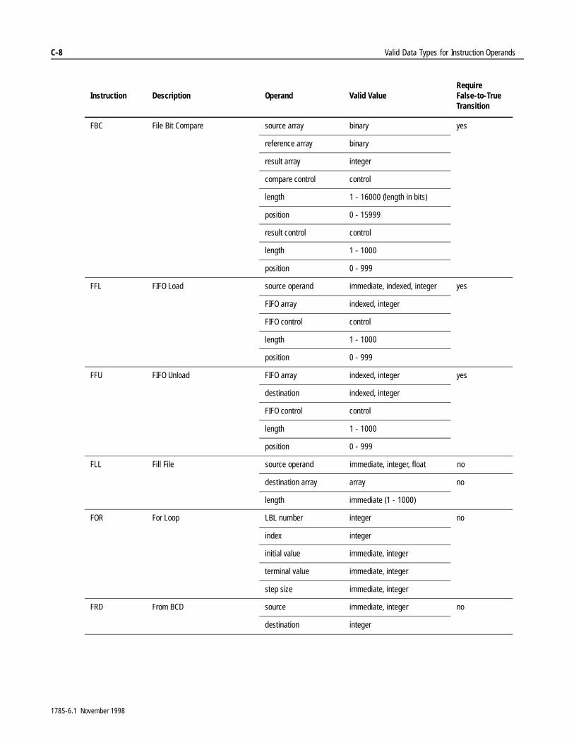
C-8 Valid Data Types for Instruction Operands
FBC File Bit Compare source array binary yes
reference array binary
result array integer
compare control control
length 1 - 16000 (length in bits)
position 0 - 15999
result control control
length 1 - 1000
position 0 - 999
FFL FIFO Load source operand immediate, indexed, integer yes
FIFO array indexed, integer
FIFO control control
length 1 - 1000
position 0 - 999
FFU FIFO Unload FIFO array indexed, integer yes
destination indexed, integer
FIFO control control
length 1 - 1000
position 0 - 999
FLL Fill File source operand immediate, integer, float no
destination array array no
length immediate (1 - 1000)
FOR For Loop LBL number integer no
index integer
initial value immediate, integer
terminal value immediate, integer
step size immediate, integer
FRD From BCD source immediate, integer no
destination integer
Instruction Description Operand Valid ValueRequire False-to-True Transition
1785-6.1 November 1998

Valid Data Types for Instruction Operands C-9
FSC File Search and Compare control control yes
length 1 - 1000
position 0 - 999
mode immediate, integer (0, INC, 1-1000, ALL)
math expression indexed math instruction
GEQ Greater Than or Equal To source A immediate, integer, float no
source B immediate, integer, float
GRT Greater Than source A immediate, integer, float no
source B immediate, integer, float
IDI Immediate Data Input data file offset immediate (0-999), integer yes
length immediate (1-64), integer
destination integer
IDO Immediate Data Output data file offset immediate (0-999), integer yes
length immediate (1-64), integer
source integer
IIN Immediate Input I (input) word immediate, integerPLC-5/10, 11, 12 15, 20, 25, 30: 000-077PLC-5/40, 40L: 000-157PLC-5/60, 60L, 80, :000-237
no
IOT Immediate Output O (output) word immediate, integerPLC-5/10, 11, 12, 15, 20, 25, 30: 000-077PLC-5/40, 40L: 000-157PLC-5/60, 60L, 80: 000-237
no
JMP Jump label number immediateClassic PLC-5 processors: 0-31Enhanced PLC-5 processors: 0-255
no
JSR Jump to Subroutine ladder program number
immediate (2 - 999) no
input parameter list immediate, integer, float
return parameter list integer float no
LAB SFC label (import/export only) file number immediate Classic PLC-5 processors: 0-31Enhanced PLC-5 processors: 0-255
N/A
Instruction Description Operand Valid ValueRequire False-to-True Transition
1785-6.1 November 1998
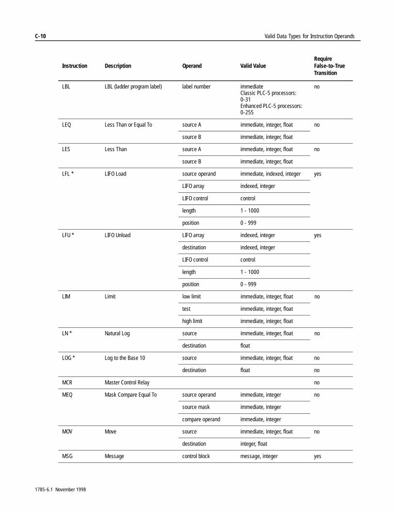
C-10 Valid Data Types for Instruction Operands
LBL LBL (ladder program label) label number immediate Classic PLC-5 processors: 0-31Enhanced PLC-5 processors: 0-255
no
LEQ Less Than or Equal To source A immediate, integer, float no
source B immediate, integer, float
LES Less Than source A immediate, integer, float no
source B immediate, integer, float
LFL * LIFO Load source operand immediate, indexed, integer yes
LIFO array indexed, integer
LIFO control control
length 1 - 1000
position 0 - 999
LFU * LIFO Unload LIFO array indexed, integer yes
destination indexed, integer
LIFO control control
length 1 - 1000
position 0 - 999
LIM Limit low limit immediate, integer, float no
test immediate, integer, float
high limit immediate, integer, float
LN * Natural Log source immediate, integer, float no
destination float
LOG * Log to the Base 10 source immediate, integer, float no
destination float no
MCR Master Control Relay no
MEQ Mask Compare Equal To source operand immediate, integer no
source mask immediate, integer
compare operand immediate, integer
MOV Move source immediate, integer, float no
destination integer, float
MSG Message control block message, integer yes
Instruction Description Operand Valid ValueRequire False-to-True Transition
1785-6.1 November 1998
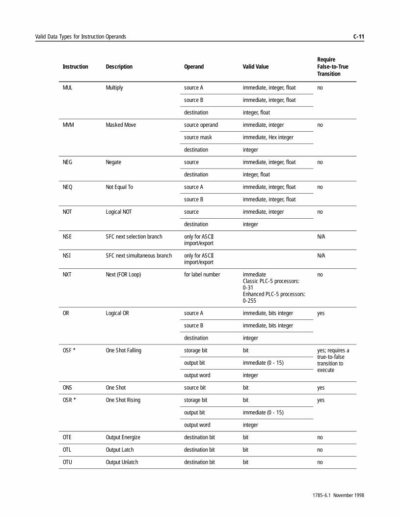
Valid Data Types for Instruction Operands C-11
MUL Multiply source A immediate, integer, float no
source B immediate, integer, float
destination integer, float
MVM Masked Move source operand immediate, integer no
source mask immediate, Hex integer
destination integer
NEG Negate source immediate, integer, float no
destination integer, float
NEQ Not Equal To source A immediate, integer, float no
source B immediate, integer, float
NOT Logical NOT source immediate, integer no
destination integer
NSE SFC next selection branch only for ASCII import/export
N/A
NSI SFC next simultaneous branch only for ASCII import/export
N/A
NXT Next (FOR Loop) for label number immediateClassic PLC-5 processors: 0-31Enhanced PLC-5 processors: 0-255
no
OR Logical OR source A immediate, bits integer yes
source B immediate, bits integer
destination integer
OSF * One Shot Falling storage bit bit yes; requires a true-to-false transition to execute
output bit immediate (0 - 15)
output word integer
ONS One Shot source bit bit yes
OSR * One Shot Rising storage bit bit yes
output bit immediate (0 - 15)
output word integer
OTE Output Energize destination bit bit no
OTL Output Latch destination bit bit no
OTU Output Unlatch destination bit bit no
Instruction Description Operand Valid ValueRequire False-to-True Transition
1785-6.1 November 1998
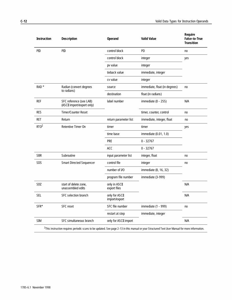
C-12 Valid Data Types for Instruction Operands
PID PID control block PD no
control block integer yes
pv value integer
tieback value immediate, integer
cv value integer
RAD * Radian (convert degrees to radians)
source immediate, float (in degrees) no
destination float (in radians)
REF SFC reference (see LAB)(ASCII import/export only)
label number immediate (0 - 255) N/A
RES Timer/Counter Reset timer, counter, control no
RET Return return parameter list immediate, integer, float no
RTO2 Retentive Timer On timer timer yes
time base immediate (0.01, 1.0)
PRE 0 - 32767
ACC 0 - 32767
SBR Subroutine input parameter list integer, float no
SDS Smart Directed Sequencer control file integer no
number of I/O immediate (8, 16, 32)
program file number immediate (3-999)
SDZ start of delete zone, unassembled edits
only in ASCII export files
N/A
SEL SFC selection branch only for ASCII import/export
N/A
SFR* SFC reset SFC file number immediate (1 - 999) no
restart at step immediate, integer
SIM SFC simultaneous branch only for ASCII import N/A
2This instruction requires periodic scans to be updated. See page 2-13 in this manual or your Structured Text User Manual for more information.
Instruction Description Operand Valid ValueRequire False-to-True Transition
1785-6.1 November 1998
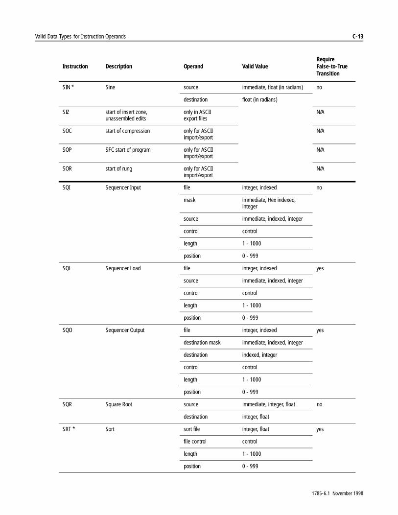
Valid Data Types for Instruction Operands C-13
SIN * Sine source immediate, float (in radians) no
destination float (in radians)
SIZ start of insert zone, unassembled edits
only in ASCII export files
N/A
SOC start of compression only for ASCII import/export
N/A
SOP SFC start of program only for ASCII import/export
N/A
SOR start of rung only for ASCII import/export
N/A
SQI Sequencer Input file integer, indexed no
mask immediate, Hex indexed, integer
source immediate, indexed, integer
control control
length 1 - 1000
position 0 - 999
SQL Sequencer Load file integer, indexed yes
source immediate, indexed, integer
control control
length 1 - 1000
position 0 - 999
SQO Sequencer Output file integer, indexed yes
destination mask immediate, indexed, integer
destination indexed, integer
control control
length 1 - 1000
position 0 - 999
SQR Square Root source immediate, integer, float no
destination integer, float
SRT * Sort sort file integer, float yes
file control control
length 1 - 1000
position 0 - 999
Instruction Description Operand Valid ValueRequire False-to-True Transition
1785-6.1 November 1998
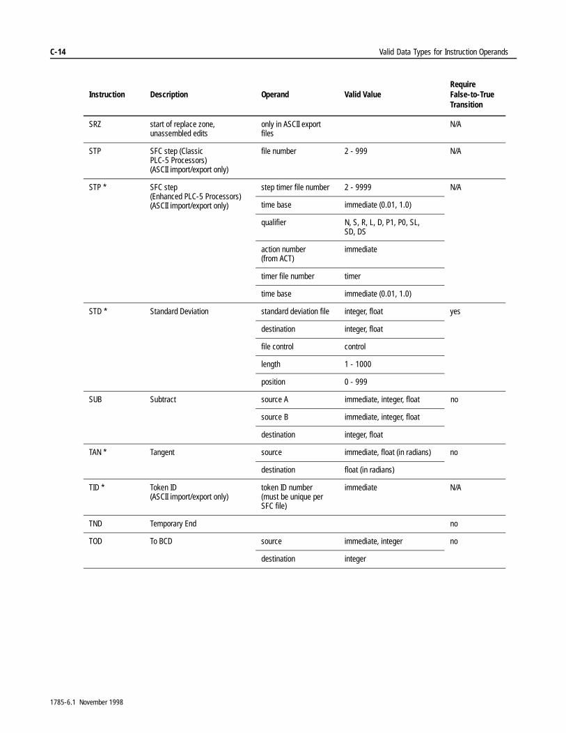
C-14 Valid Data Types for Instruction Operands
SRZ start of replace zone, unassembled edits
only in ASCII export files
N/A
STP SFC step (Classic PLC-5 Processors)(ASCII import/export only)
file number 2 - 999 N/A
STP * SFC step (Enhanced PLC-5 Processors)(ASCII import/export only)
step timer file number 2 - 9999 N/A
time base immediate (0.01, 1.0)
qualifier N, S, R, L, D, P1, P0, SL, SD, DS
action number (from ACT)
immediate
timer file number timer
time base immediate (0.01, 1.0)
STD * Standard Deviation standard deviation file integer, float yes
destination integer, float
file control control
length 1 - 1000
position 0 - 999
SUB Subtract source A immediate, integer, float no
source B immediate, integer, float
destination integer, float
TAN * Tangent source immediate, float (in radians) no
destination float (in radians)
TID * Token ID (ASCII import/export only)
token ID number(must be unique per SFC file)
immediate N/A
TND Temporary End no
TOD To BCD source immediate, integer no
destination integer
Instruction Description Operand Valid ValueRequire False-to-True Transition
1785-6.1 November 1998
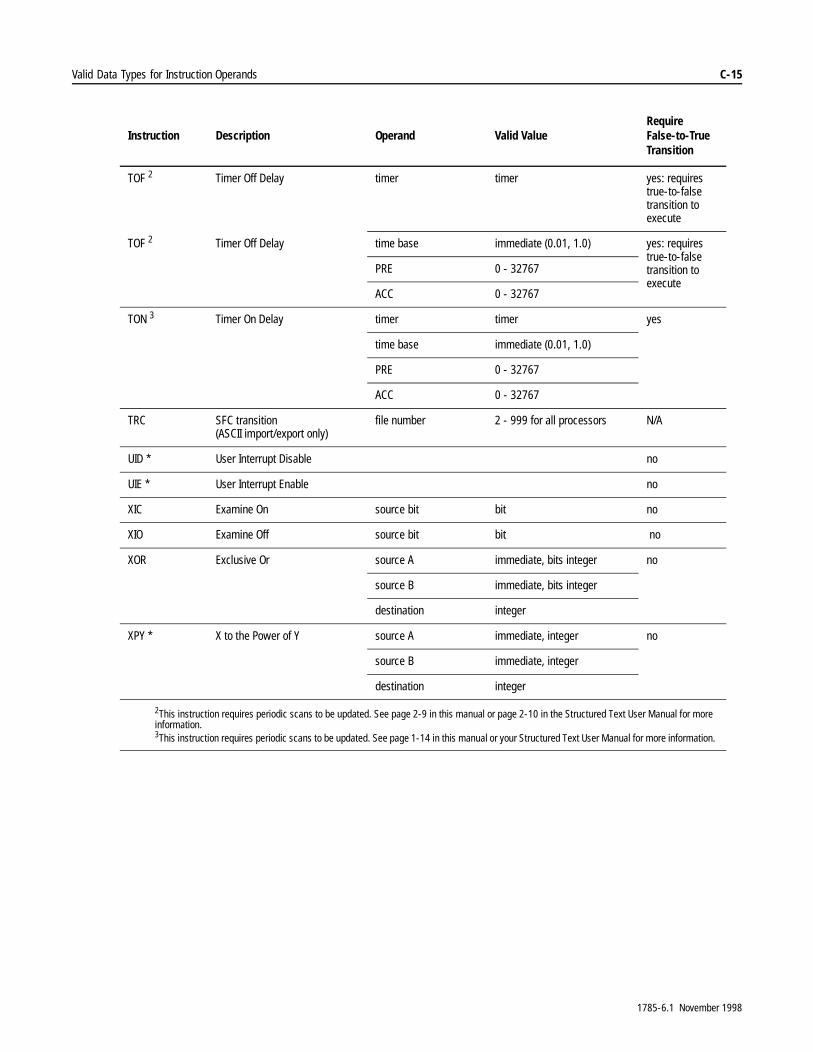
Valid Data Types for Instruction Operands C-15
TOF 2 Timer Off Delay timer timer yes: requires true-to-false transition to execute
TOF 2 Timer Off Delay time base immediate (0.01, 1.0) yes: requires true-to-false transition to execute
PRE 0 - 32767
ACC 0 - 32767
TON 3 Timer On Delay timer timer yes
time base immediate (0.01, 1.0)
PRE 0 - 32767
ACC 0 - 32767
TRC SFC transition(ASCII import/export only)
file number 2 - 999 for all processors N/A
UID * User Interrupt Disable no
UIE * User Interrupt Enable no
XIC Examine On source bit bit no
XIO Examine Off source bit bit no
XOR Exclusive Or source A immediate, bits integer no
source B immediate, bits integer
destination integer
XPY * X to the Power of Y source A immediate, integer no
source B immediate, integer
destination integer
2This instruction requires periodic scans to be updated. See page 2-9 in this manual or page 2-10 in the Structured Text User Manual for more information.3This instruction requires periodic scans to be updated. See page 1-14 in this manual or your Structured Text User Manual for more information.
Instruction Description Operand Valid ValueRequire False-to-True Transition
1785-6.1 November 1998

C-16 Valid Data Types for Instruction Operands
1RWHV�
1785-6.1 November 1998

Index
A
ABL instruction 17-4
ACB instruction 17-5
ACI instruction 17-6
ACN instruction 17-7
ACS instruction 4-11
ADD instruction 4-12
Addition instructionADD 4-12
AEX instruction 17-7
AFI instruction 13-13
AHL instruction 17-8
AIC instruction 17-9
Always False instruction 13-13
AND instruction 5-2
AND Operation instructionAND 5-2
Arc Cosine instructionACS 4-11
Arc Sine instructionASN 4-13
Arc Tangent instructionATN 4-14
ARD instruction 17-10
ARL instruction 17-12
ASC instruction 17-14
ASCIIABL 17-4ACB 17-5ACI 17-6ACN 17-7AEX 17-7AHL 17-8AIC 17-9ARD 17-10ARL 17-12ASC 17-14ASR 17-15AWA 17-15AWT 17-17
ASCII instructions, strings 17-3
ASCII Integer to String instruction 17-9
ASCII Read Characters instruction 17-10
ASCII Read Line instruction 17-12
ASCII Set Handshake Lines instruction 17-8
ASCII String Compare instruction 17-15
ASCII String Concatenate instruction 17-7
ASCII String Extract instruction 17-7
ASCII String Search instruction 17-14
ASCII String to Integer instruction 17-6
ASCII Write Append instruction 17-15
ASCII Write instruction 17-17
ASN instruction 4-13
ASR instruction 17-15
ATN instruction 4-14
1785-6.1 November 1998

I–2 Index
Attention32- to 16-bit conversion 4-10AVE indexed address 4-16change index value 13-6control structure addressing 10-4DTR online programming 10-8entering input addresses 1-6entering output addresses 1-7FAL indexed address 9-2FOR and NXT with output branches 13-5FOR and NXT within branches 13-5indexed addressing 8-2jumped timers and counters 13-4MCR zones
overlapping or nesting 13-2timers and counters 13-2
modify status bits of BTR/BTW 15-6MSG
status bits .ST and .EW 15-24online programming with ONS 13-14pairing stack instructions 11-6PID
change engineering unit max 14-22change engineering unit min 14-22change inputs or units 14-19changing scaling 14-6resume last state 14-10setting temperature limits 14-28update time 14-21
placement of critical counters 2-15, 2-17resetting TON and TOF 2-8, 2-20SRT indexed address 4-27status of BTR/BTW bits 15-7STD indexed address 4-30use of control address 12-3using control addresses 8-2using control addresses for instructions 11-2
AVE instruction 4-15
Average File instructionAVE 4-15
AWA instruction 17-15
AWT instruction 17-17
B
Bit Distribute instructionBTD 7-2
Bit Shift Left (BSL) instruction 11-2
Bit Shift Right (BSR) instruction 11-2
block transferBTR instruction 15-3BTW instruction 15-3direct communication mode 15-2I/O scan mode 15-1instructions 15-1programming examples 15-15timing 15-13, 15-14
Block Transfer Read instructionBTR 15-3
Block Transfer Write instructionBTW 15-3
Break (BRK) instruction 13-5
BRK instruction 13-5
BSL instruction 11-2
BSR instruction 11-2
BTD instruction 7-2
BTR instruction 15-3
BTW instruction 15-3
C
CAR utility 18-1
CIO instruction 15-22monitoring 15-24status bits 15-24using 15-23
Classic PLC5 processors 1
Clear instructionCLR 4-17
CLR instruction 4-17
CMPinstruction 3-2
1785-6.1 November 1998
Index I–3
compareEQU 3-5expression 3-2GEQ 3-5, 3-6instructions 3-2length of expressions 3-3LEQ 3-6LES 3-7NEQ 3-10
computeACS 4-11ADD 4-12ASN 4-13ATN 4-14AVE 4-15CLR 4-17COS 4-18CPT 4-5DEG 6-3DIV 4-19EOT 13-18expression 4-5FSC 9-14functions 4-9IOT 1-7length of expressions 4-7LN 4-20LOG 4-21MUL 4-22NEG 4-23ONS 13-14order of operation 4-8RAD 6-4SIN 4-24SQR 4-25SRT 4-26STD 4-28SUB 4-31TAN 4-32XPY 4-33
Compute instructionCPT 4-5
connecting to Ethernet PLC5 processors using hostnames 16-6
control fileexample 8-2
ControlNet I/O transferinstruction 15-22
ControlNet PLC5 processors 1
convergentscan time B-14
conversionBCD 6-2FRD 6-2
Convert from BCD instructionFRD 6-2
Convert to BCD instructionTOD 6-2
COP instruction 9-19
COS instruction 4-18
Cosine instructionCOS 4-18
Count Down instruction 2-17
Count Up instruction 2-15
counterCTD 2-17CTU 2-15RES 2-20
countersinstructions 2-13
CPT instruction 4-5
CTD instruction 2-17
CTU instruction 2-15
custom application routine 18-1
D
data filesmanipulating 8-3range of values C-1
data storageI/O image files 1-2
Data Transitional instructionDTR 10-8
1785-6.1 November 1998
I–4 Index
DDT instruction 10-2
DEG instruction 6-3
Degree instructionDEG 6-3
derivative smoothing 14-4
DFA instruction 18-1
diagnosticDDT 10-2DTR 10-8FBC 10-2parameters 10-4, 10-8search mode 10-2status 10-5
Diagnostic Detect instructionDDT 10-2
Diagnostic Fault Annunciator Instruction 18-1
diagnostic instructions 10-1
direct communicationblock transfer 15-2
DIV instruction 4-19
divergentscan time B-14
Divide instructionDIV 4-19
DTR instruction 10-8
E
element manipulationLIM 3-7MEQ 3-9MOV 7-3MVM 7-4
End of Transmission instructionEOT 13-18
engineering unitsscaling 14-5
Enhanced PLC5 processors 1
EOT instruction 13-18
EQU instruction 3-5
Equal To instruction 3-5
Ethernet PLC5 processors 1
Examine Off instruction 1-3
Examine On instruction 1-3
expressiondetermining the length of 3-3, 4-7
F
FAL logical instruction 9-12
FBC instruction 10-2
FFL instruction 11-5
FFU instruction 11-5
FIFO Load (FFL) instruction 11-5
FIFO Unload (FFU) instruction 11-5
filesearch and compare operations 9-17
File Arithmetic and Logic instructionFAL 9-2
File Bit Comparison instructionFBC 10-2
file conceptscontrol structure 8-2manipulating data 8-3modes of operation 8-5
File Copy instructionCOP 9-19
File Fill instructionFLL 9-20
file instructionslogical 9-12
File Search and Compare instructionFSC 9-14
1785-6.1 November 1998
Index I–5
filesarithmetic operations 9-7copy operations 9-5functions 9-14instruction
COP 9-19FLL 9-20
logical operations 9-12operation modes 8-5
FLL instruction 9-20
floating pointvalid value range C-1
For (FOR) instruction 13-5
FOR instruction 13-5
FRD instruction 6-2
FSC instruction 9-14
G
gain constants 14-3
GEQ instruction 3-5, 3-6
Greater Than or Equal To instruction 3-5, 3-6
I
I/O image files 1-2
I/O scan modeblock transfer 15-1
IDI instruction 1-8using 1-9
IDO instruction 1-8using 1-9
IIN instruction 1-6
Immediate Data Inputinstruction 1-8
Immediate Data Outputinstruction 1-8
Immediate Input instruction 1-6
Immediate Output instructionIOT 1-7
incremental mode 8-7
instructionControlNet I/O transfer 15-22immediate data input 1-8immediate data output 1-8
instructionsASCII 17-1block transfer 15-1CIO
monitoring 15-24compare 3-2diagnostic 10-1memory requirements A-1message 16-1operands C-1program flow 13-1relay-type 1-1, 2-1sequencer 12-1shift register 11-1timer 2-1timing A-1
INVALID OPERANDerror message 4-4
IOT instruction 1-7
J
JMP instruction 13-3
JSR instruction 13-8
Jump instruction 13-3
Jump to Subroutine instruction 13-8
L
Label (LBL) instruction 13-5
Label instruction 13-3
LBL instruction 13-3, 13-5
LEQ instruction 3-6
LES instruction 3-7
Less Than instruction 3-7
Less Than or Equal To instruction 3-6
LFL instruction 11-5
LFU instruction 11-5
1785-6.1 November 1998
I–6 Index
LIFO Load (LFL) instruction 11-5
LIFO Unload (LFU) instruction 11-5
LIM instruction 3-7
Limit Test instruction 3-7
LN instruction 4-20
LOGinstruction 4-21
Log to the base 10 instructionLOG 4-21
logicalAND 5-2NOT 5-3OR 5-4XOR 5-5
M
manipulatingfile data 8-3
Masked Comparison for Equal instruction 3-9
Masked Move instruction 7-4
Master Control Reset instruction 13-2
MCR instruction 13-2
memoryinstruction requirements A-1SFC requirements B-3
MEQ instruction 3-9
messageinstruction 16-1
modesfile operation 8-5
monitoringCIO instructions 15-24
MOV instruction 7-3
Move instructionMOV 7-3
MSGinstruction entry 16-10
MSG instruction 16-1using 16-10
MUL instruction 4-22
Multiply instructionMUL 4-22
MVM instruction 7-4
N
Natural Log instructionLN 4-20
NEG instruction 4-23
Negate instructionNEG 4-23
NEQ instruction 3-10
Next (NXT) instruction 13-5
Not Equal To instruction 3-10
NOT instruction 5-3
NOT Operation instructionNOT 5-3
Number of Char in Buffer instruction 17-5
NXT instruction 13-5
O
One Shot Falling (OSF) instruction 13-16
One Shot instructionONS 13-14
One Shot Rising (OSR) instruction 13-15
ONS instruction 13-14
operandsinstructions C-1
OR instruction 5-4
OR Operation instructionOR 5-4
order of operation 4-8
OSF instruction 13-16
OSR instruction 13-15
OTE instruction 1-4
OTL instruction 1-4
OTU instruction 1-5
1785-6.1 November 1998
Index I–7
Output Energize instruction 1-4
Output Latch instruction 1-4
Output Unlatch instruction 1-5
P
PIDbiasing 14-9equations 14-2examples 14-29instruction 14-10integer examples 14-29PD examples 14-33selecting derivative term 14-7setting output alarms 14-7using manual mode 14-8using output limiting 14-7
PID instruction 14-1
PLC2 compatibility file 16-15
process controlbiasing 14-9derivative smoothing 14-4equations 14-2gain constants 14-3integer PID examples 14-29PD PID examples 14-33PID 14-10PID examples 14-29PID instruction 14-1selecting derivative term 14-7setting output alarms 14-7using manual mode 14-8using output limiting 14-7
program constantvalid value range C-1
program constants 3-2, 4-5
program flowAFI 13-13JMP and LBL 13-3JSR, SBR, and RET 13-8MCR 13-2UID 13-19UIE 13-20
program flow instructionFOR, BRK, LBL, and RET 13-5OSF 13-16OSR 13-15SFR 13-17
program flow instructions 13-1
ProgrammingSDS instruction 18-2
programminginstructions
operands C-1
Proportional, Integral, and Derivative instruction 14-10
R
RAD instruction 6-4
Radian instructionRAD 6-4
relay-typeIIN 1-6OTE 1-4OTL 1-4OTU 1-5XIC 1-3XIO 1-3
RES instruction 2-20
Reset instruction 2-20
RET instruction 13-8
Retentive Timer On instruction 2-10
Return instruction 13-8
RTO instruction 2-10
run timesdetermining B-12
1785-6.1 November 1998
I–8 Index
S
SBR instruction 13-8
scalingto engineering units 14-5
scan sequenceSFC B-7
scan timeconvergent B-14divergent B-14steady–state B-14
scanner modeconfiguring 15-13, 15-14
SDS instruction 18-1
selection branchscanning sequence B-8
sequencerapplying 12-1instructions 12-1SQI 12-2SQL 12-2SQO 12-2
Sequencer Input instruction 12-2
Sequencer Load instruction 12-2
Sequencer Output instruction 12-2
Sequential Function Chart Resetinstruction 13-17
SFCconstraints B-5example
scanning sequence B-11memory requirements B-3scanning sequence
example B-11selection branch B-8simultaneous branch B-9
scanning sequencesstep/transition B-7
status information B-1
SFR instruction 13-17
shift register instructionapplying 11-1BSL and BSR 11-2FFL and FFU 11-5LFL and LFU 11-5
simultaneous branchscanning sequence B-9
SIN instruction 4-24
Sine instructionSIN 4-24
Smart Directed Sequencer (SDS) Instructionoverview 18-2programming 18-2
Smart Directed Sequencer Instruction 18-1
Sort File instructionSRT 4-26
SQI instruction 12-2
SQL instruction 12-2
SQO instruction 12-2
SQR instruction 4-25
Square Root instructionSQR 4-25
SRT instruction 4-26
Standard Deviation instructionSTD 4-28
status bitsCIO instruction 15-24
status informationSFC B-1
STD instruction 4-28
steady-statescan time B-14
stepscanning sequence B-7
SUB instruction 4-31
Subroutine Header instruction 13-8
Subtract instructionSUB 4-31
1785-6.1 November 1998
Index I–9
T
TAN instruction 4-32
Tangent instructionTAN 4-32
Temporary Endinstruction 13-13
Temporary End instruction 13-20
Test Buffer For Line instruction 17-4
timeraccuracy 2-3instruction parameters 2-2, 2-13RES 2-20RTO 2-10TOF 2-7TON instruction 2-4
Timer Off Delay instruction 2-7
Timer On Delay instruction 2-4
timers 2-1
timingblock transfer 15-13, 15-14instructions A-1
tipconnecting to Ethernet PLC5 processors
using hostnames 16-6
TNDinstruction 13-13
TND instruction 13-19, 13-20
TOD instruction 6-2
TOF instruction 2-7
TON instruction 2-4
transitionscanning sequence B-7
U
units, engineeringscaling 14-5
User Interrupt DisableUID 13-19
User Interrupt EnableUIE 13-20
usingCIO instruction 15-23IDI instruction 1-9IDO instruction 1-9MSG instruction 16-10
X
X to the Power of Y instructionXPY 4-33
XIC instruction 1-3
XIO instruction 1-3
XOR instruction 5-5
XOR Operation instructionXOR 5-5
XPY instruction 4-33
1785-6.1 November 1998

I–10 Index
1RWHV�
1785-6.1 November 1998

Allen-BradleyPublication Problem ReportIf you find a problem with our documentation, please complete and return this form
Publication ICCG-5.21 - August 1995 PN 955107-82
Pub. Name
Cat. No. Pub. No. Pub. Date Part No.
Check Problem(s) Type: Describe Problem(s): Internal Use Only
procedure/step
example
explanation
illustration
guideline
other
definition
feature
info in manual
(accessibility)
info not inmanual
text illustrationTechnical Accuracy
Completeness
What information is missing?
Clarity
Sequence
What is not in the right order?
What is unclear?
Other Comments
Use back for more comments.
Your Name Location/Phone
Return to: Marketing Communications, Allen-Bradley Co., 1 Allen-Bradley Drive, Mayfield Hts., OH 44124-6118Phone: (440)646-3166FAX: (440)646-4320
PLC-5 Programmable Controllers Instruction Set Reference
1785 series 1785-6.1 955133-83November 1998

Other Comments
PLEASE FOLD HERE
12�3267$*(�1(&(66$5<�,)�0$,/('�,1�7+(�
81,7('�67$7(6
BUSINESS REPLY MAILFIRST-CLASS MAIL PERMIT NO. 18235 CLEVELAND OH
POSTAGE WILL BE PAID BY THE ADDRESSEE
��$//(1�%5$'/(<�'50$<),(/'�+(,*+76�2+�����������
3/($6(�5(029(
PLEASE FASTEN HERE (DO NOT STAPLE)

1785-6.1 November 1998
Customer Support,I�\RX�QHHG�DGGLWLRQDO�DVVLVWDQFH�LQ�XVLQJ�\RXU�VRIWZDUH��$OOHQ�%UDGOH\�RIIHUV�WHOHSKRQH�DQG�RQ�VLWH�SURGXFW�VXSSRUW�DW�&XVWRPHU�6XSSRUW�&HQWHUV�ZRUOGZLGH�
)RU�WHFKQLFDO�DVVLVWDQFH�RQ�WKH�WHOHSKRQH��ILUVW�FRQWDFW�\RXU�ORFDO�VDOHV�RIILFH��GLVWULEXWRU��RU�V\VWHP�LQWHJUDWRU��,I�DGGLWLRQDO�DVVLVWDQFH�LV�QHHGHG��WKHQ�FRQWDFW�\RXU�ORFDO�&XVWRPHU�6XSSRUW�&HQWHU�RU�FRQWDFW�6\VWHP�6XSSRUW�6HUYLFHV�
In the United States and Canada ,I�\RX�KDYH�D�6XSSRUW3OXV�DJUHHPHQW�RU�\RXU�VRIWZDUH�LV�XQGHU�ZDUUDQW\��\RX�FDQ�FRQWDFW�6\VWHP�6XSSRUW�6HUYLFHV�DW������������������+DYH�\RXU�VXSSRUW�FRQWUDFW�RU�VRIWZDUH�UHJLVWUDWLRQ�QXPEHU�DYDLODEOH�
)RU�DVVLVWDQFH�WKDW�UHTXLUHV�RQ�VLWH�VXSSRUW��FRQWDFW�\RXU�ORFDO�VDOHV�RIILFH��GLVWULEXWRU��RU�V\VWHP�LQWHJUDWRU��'XULQJ�QRQ�RIILFH�KRXUV��FRQWDFW�$OOHQ�%UDGOH\����KRXU�+RW�/LQH�DW����������������
Outside of the United States &RQWDFW�\RXU�ORFDO�&XVWRPHU�6XSSRUW�&HQWHU�DW�
)RU�DVVLVWDQFH�WKDW�UHTXLUHV�RQ�VLWH�VXSSRUW��FRQWDFW�\RXU�ORFDO�RIILFH��GLVWULEXWRU��RU�V\VWHP�LQWHJUDWRU��'XULQJ�QRQ�RIILFH�KRXUV��FRQWDFW�\RXU�ORFDO�&XVWRPHU�6XSSRUW�&HQWHU�
Region or Area Customer Support CenterTelephone Number
Canada (Cambridge, Ontario) 519-623-1810
Latin America (Mexico) 52-5-259-0040
United Kingdom (Milton Keynes) 44-908 838800
France (Paris) (33-1) 3067-7200
Germany (Gruiten) (49) 2104 6900
Italy (Milan) (39-2) 939-721
Asia Pacific (Hong Kong) (852) 887-4788
Spain (Barcelona) (34-3) 331-7004
1785-6.1 November 1998 PN 955133-83Supersedes 1785-6.1 Feburary 1996 © 1998 Rockwell International Corporation. Printed in USA
Related Documents


