HARTZELL Hartzell Fan, Inc., Piqua, Ohio 45356 www.hartzellfan.com Bulletin A-138-A January 2005 ® H A R T Z E L L F A N , IN C P IQ U A , O H IO U S A B U IL T W IT H H O N O R Fiberglass Air Control Products Series FFL Series FEP Series FLC Series FCO Series FCP

Welcome message from author
This document is posted to help you gain knowledge. Please leave a comment to let me know what you think about it! Share it to your friends and learn new things together.
Transcript

HARTZELLHartzell Fan, Inc., Piqua, Ohio 45356
www.hartzellfan.comBulletin A-138-A January 2005
®
HARTZELL FAN, INCPIQUA, OHIO USA
BUILT WITH HONOR
Fiberglass Air Control ProductsSeries FFL Series FEP Series FLC Series FCO Series FCP

Construction Options and AccessoriesAbrasive/Erosive Resistant Coating HartKoate is an abra-sive/erosive and impact resistant coating for application in envi-ronments where abrasive/erosive conditions may exist. HartKoateis particularly appropriate for use when water mist and/or abrasiveparticles exist in the airstream. HartKoate helps prevent prematuredeterioration of equipment in environments where uncoated com-ponents may fail. Max. temp. 200°F.Hi-Cor Construction - All airstream surfaces exposed to corro-sive environment will be protected with a layer of Synthetic(Nexus) surfacing veil. An additional final coat of resin will beapplied for extra corrosion resistance.Electrostatically Grounded Fiberglass - For applications inwhich fiberglass control products are handling gas fumes that arenot only corrosive but also potentially explosive, the equipmentshould be specially constructed to control and remove static elec-tricity. Interior airstream surfaces can be coated with a “carbonrich” resin coat and grounding straps secured from the side of theframe. All that remains to effectively ground the part is to groundthe frame at the time of installation.
Inlet Control Damper – Round Dampers areavailable for blower's drilled inlet flange to bothincrease the efficiency of the system and per-mit control of air volume. Dampers epoxy coat-ed, or of stainless steel.Guards - Inlet and outlet guards are availablefor fiberglass dampers and louvers. OSHA style. Stainless steelconstruction, epoxy coated steel, or fiberglass.Manual Operators and Locking Quadrants – Available mountedto control dampers.Motor Operators and Actuators – Available in electric or pneu-matic with options per customer specifications.
Caution: The drive assembly or the periphery of the blades ofa fan less than seven (7) feet above the floor or working levelmust be guarded to be in accordance with OSHA regulations.
Hartzell Model Code Explanation ........................Page 2Construction Options and Accessories ..............Page 2Corrosion Resistance Guide ................................Page 3Fiberglass Fixed Blade Louver........................Pages 4-5
Fiberglass End-Pivoted Shutter ......................Pages 6-7Fiberglass Center-Pivoted Damper ................Pages 8-9Fiberglass Control Dampers ........................Pages 10-11
A FEP D -24 - WX -36 FG -- - -TypeA – Production ItemS – Stock Item Q – Special Quote
Product SeriesMounting (D-Duct, F-Flange, A-Angle)Width in inches (Parallel to blades)Not AssignedWX (width by)Height in inches (Perpendicular to blades)Material of ConstructionNot AssignedNot Assigned Not Assigned
Hartzell Model Code Explanation
2Bulletin A-138-A www.hartzellfan.com
1 (800) 336-3267
®
Ratings for Air Performance and LeakageHartzell Fan, Inc. certifies that the Series FFL - Fiberglass Fixed Blade Drainable Louver, Series FEP - Fiberglass End-PivotedAutomatic Shutter, Series FLC - Fiberglass Low Velocity, Center-Pivoted Damper, Series FCO and FCP - Fiberglass VolumeControl Dampers air performance and leakage ratings shown herein are reliable and accurate and in accordance with industrystandards. The ratings shown are based on tests and procedures performed in accordance with AMCA Standard 500.
Index
HARTZELL FAN, INCPIQUA, OHIO USA
BUILT WITH HONOR
Example:Assume a needed Fiberglass Automatic Shutter for 6,000 CFM.for a duct size of 24" wide x 36" high. The shutter area will be 6Sq. Ft. and the face velocity will be 1,000 FPM. Reading the per-formance curve on page 6 we find the pressure loss through theshutter at 0.27" static pressure.The model code can be constructed as follows: Type will be a pro-duction item (code A), product series for the Fiberglass End Pivoted
Automatic Shutter is FEP, duct mounting will be used (code D),Width is 24, Height is 36, material of construction is fiberglass(Code FG).Note: All other informational fields must be filled withhyphens/dashes (-) if they are not applicable.
This bulletin lists Hartzell's line of Fiberglass Air Control Products and accessories. More than 70 Hartzell offices can provide specific perfor-mance and installation data to meet your requirements. Call your Hartzell representative for assistance.Visit our website (www.hartzellfan.com)or call toll-free 1 (800) 336-3267 for the name of your Hartzell representative.

Corrosion Resistance Guide
3Bulletin A-138-A www.hartzellfan.com
1 (800) 336-3267
®
Hetron 693 6694 510AAshland Reichold Dow
Environment F. F. F.
ALKALIES (Synthetic Veil)Ammonium Bicarbonate to 50% 140 S170 160Ammonium Carbonate 120 S140 150Ammonium Hydroxide to 5% S90 S180 S180Ammonium Hydroxide to 10% S90 S170 S150Ammonium Hydroxide to 29% NR S100 S100Barium Carbonate 180 S240 210Barium Hydroxide to 10% – S170 150Calcium Hydroxide to 15% 160 S210 S180Magnesium Carbonate 160 S210 180Potassium Bicarbonate to 10% 90 S170 S150Potassium Carbonate to 10% 90 S180 S150Potassium Hydroxide to 25% NR S120 S150Sodium Bicarbonate to 10% 140 S210 S180Sodium Carbonate to 35% 90 S180 S180Sodium Hydroxide to 10% NR S160 S180Sodium Hydroxide to 25% NR S160 S180Sodium Sulfide 90 S220 S210Trisodium Phosphate to 50% – S175 210
SALTSAluminum Chloride *120 *240 *210Aluminum Potassium Sulfate 160 240 210Aluminum Sulfate 250 240 210Ammonium Chloride *200 *220 *210Ammonium Nitrate 200 220 220Ammonium Persulfate 150 200 180Ammonium Persulfate, saturate 150 NR NRAmmonium Sulfate 200 220 220Aniline Sulfate to 25% 150 220 210Aniline Sulfate, saturated 150 220 NRBarium Chloride 200 240 210Barium Sulfide NR S210 180Calcium Chlorate 180 220 220Calcium Chloride 250 240 220Calcium Sulfate *200 *240 *210Copper Chloride *250 *220 *220Copper Cyanide 90 S220 210Copper Fluoride NR S170 NRCopper Sulfate 250 240 210Ferric Chloride *250 *220 *210Ferric Nitrate 170 220 210Ferric Sulfate 200 220 210Ferrous Chloride *220 *220 *210Ferrous Nitrate 160 220 210Ferrous Sulfate 220 220 210Lead Acetate 160 220 210Magnesium Chloride 220 240 210Magnesium Hydroxide – S210 210Magnesium Sulfate 200 210 210Mercuric Chloride *210 *220 *210Mercurous Chloride 210 220 210Nickel Chloride 220 220 210Nickel Nitrate 220 220 210Nickel Sulfate 220 220 210Potassium Chloride 200 240 210Potassium Dichromate 200 220 210Potassium Ferricyanide 200 220 210Potassium Nitrate 200 220 210Potassium Permangnate 150 210 210Potassium Persulfate 90 220 210Potassium Sulfate 200 240 210Silver Nitrate 200 220 210Sodium Acetate 150 220 210Sodium Bisulfate 200 220 210Sodium Chloride 200 240 180Sodium Chlorite to 10% 175 170 150Sodium Cyanide 100 220 210Sodium Dichromate 160 220 210
Hetron 693 6694 510AAshland Reichold Dow
Environment F. F. F.
ACIDSAcetic to 10% 180 200 210Acetic to 50% 90 160 180Acetic to 100% NR NRAcrylic to 25% – 100 100Benzene Sulfonic to 25% 180 210 150Benzene Sulfonic 25% up 90 210 NRBenzoic 250 220 210Boric 180 220 210Butyric to 50% 150 150 210Butyric 50% up – 100 80Carbonic 160 220 NRChloroacetic to 25% NR *180 *150Chloroacetic 25% to 50% NR *150 *120Chromic to 5% 100 110 150Chromic to 10% to 20% – NR 150Citic *200 *220 *210Fluoboric *S90 *S220 *S210Gluosilicic up to 10% S100 S150 S180Formic up to 10% 200 150 180Gluconic to 50% 120 180 180Hydrobromic to 25% *160 *170 *180Hydrochloric to 15% *230 *210 *180Hydrocyanic to 10% 200 170 210Hydrofluoric to 10% ***S100 ***S150 ***S150Hydrofluorsilicic up to 10% *S100 *S150 *S180Hypochlorous to 20% 90 110 NRLactic *200 *220 *210Maleic 170 210 210Nitric to 5% 200 170 150Nitric 5% to 20% – 140 120Oleic 200 220 210Oxalic *220 *220 *210Perchloric to 10% H&D **150 **150Phosphoric *220 *S210 *S210Phosphoric, super – *S210 *S210Phthalic Anhydride *150 *210 *210Picric to 10% 100 170 NRSilicic – 220 NRStearic 200 220 210Sulfamic to 25% 160 150 NRSulfuric to 25% *200 *220 *210Sulfuric to 50% *200 *200 *180Sulfuric to 70% *150 *180 *100Sulfuric to 80% NR 80 NRSulfurous to 10% 90 110 120Tannic 200 220 210Tartaric 220 220 210Trichoroacetic to 50% *90 *220 *200
ALCOHOLSAmyl 200 210 120Benzyl NR 100 NRButyl 190 150 120Ethyl 90 120 80Methyl 90 80 NR
GASES AND VAPORSAmmonia, Dry 90 170 100Ammonia, Wet 90 NR NRBromine, Wet 90 *100 NRCarbon Dioxide 250 250 250Carbon Monoxide 200 250 250Chlorine, Dry *200 *210 NRFlorine – NR 80Hydrogen Fluoride, Vapor *90 *S180 *S180Hydrogen Sulfide to 5% 250 240 180Sulfur Dioxide, Dry 200 250 210Sulfur Dioxide, Wet 200 250 210Sulfur Trioxide, Wet – 220 210
Temperature values shown are for immersion or condensate contact applications. Where temperature values are shown, resin is suitable for hood and duct type applications for the full operating temperature range of the product. See product specifications for materials of construction and maximum operating temperature limits.
Hetron 693 6694 510AAshland Reichold Dow
Environment F. F. F.
SALTS (cont’d.)Sodium Ferricyanide 220 220 210Sodium Floride – S180 S180Sodium Nitrate 220 220 210Sodium Nitrite 220 NRSodium Silicate PH less than 1 160 210 NRSodium Sulfate 180 240 210Sodium Sulfite – 220 210Stannic Chloride *180 *220 *210Stannous Chloride *200 *220 *210Zinc Chloride 200 *220 *210Zinc Nitrate 180 220 210Zinc Sulfite 150 220 NR
SOLVENTSAcetone to 10% NR 180 180Benzene 90 80 NRCarbon Disulfide NR NR NRCarbon Tetrachloride 90 VAPOR 110 150Chlorobenzene NR NR NREthyl Acetate NR NR NREthyl Chloride 90 VAPOR NR NREthylene Dibromide NR NR NREthylene Glycol 250 220 210n-Heptane 120 210 210Hexane – 150 160Methyl Ethyl Ketone to 10% NR 80 NRNaphtha 200 210 180Naphthalene 130 220 210Tetrachloroethylene NR 100 80Toluene 90 NR 80Xylene 90 80 80
BLEACHESCalcium Chlorate 180 220 220Calcium Hypochlorite 100 NR S160Chlorine Dioxide up to 15% – 160 *200Chlorine Water *125 *210 *200Hydrogen Peroxide to 30% 120 100 150Sodium Chlorate 90 210 210Sodium Hypochlorite to 15% NR 125 S180
OTHERSAlum. Chlorohydroxide to 50% – 220 210Ammonium Phosphate 150 210 210Aqua Rega NR *80 NRDetergents 120 170 150Glycerine 200 220 210Kerosene 120 210 180Photographic Solutions – 80 NRPerchlorethylene NR 100 80Sodium Tetraborate 180 S210 180Sodium Tripolyphosphate 125 210 210Sodium Xylene Sulfonate – 170 160Sorbitol Solutions 180 220 160Urea 90 170 150Urea-Ammonium-Nitrate – 120 120Fertilizer Fumes 100 120 150Shell-D-D NR 100 NRSteam Vapor 180 210 180
SAFETY ACCESSORIES, APPLICATION AND USE WARNINGThe safe application and use of equipment supplied by Hartzell Fan, Inc. is the responsibility of the installer, the user, the owner, and the employer. Since the application and use of its equipment canvary greatly, Hartzell Fan, Inc. offers various product types, optional safety accessories, and sound performance data per laboratory tests. Hartzell Fan, Inc. sells its equipment with and without safetyaccessories, and accordingly, it can supply such safety accessories only upon receipt of an order. The need for safety accessories will frequently depend upon the type of system, fan location and operating procedures being employed. The proper protective safety accessories to meet company standards, local codes, and the requirements of the Occupational Safety and Health Act must bedetermined by the user since safety requirements vary depending on the location and use of the equipment. If applicable local conditions, standards, codes or OSHA rules require the addition of thesafety accessories, the user should specify and obtain the required safety accessories from Hartzell Fan, Inc. and should not allow the operation of the equipment without them.
Owners, employers, users and installers should read “RECOMMENDED SAFETY PRACTICES FOR USERS AND INSTALLERS OF INDUSTRIAL AND COMMERCIAL FANS”published by the Air Movement and Control Association International, Inc., 30 West University Drive, Arlington Heights, Illinois 60004. A copy of this publication is enclosed with each fan shipped fromHartzell Fan, Inc., and is also available upon request at Hartzell's office in Piqua, Ohio 45356.Please contact Hartzell Fan, Inc. or your local Hartzell representative for more information on product types, safety accessories, and sound performance estimates.Remember, the selection of safety accessories and the safe application and use of equipment supplied by Hartzell Fan, Inc. is your responsibility.
NOTES: NR = Not Recommended S = Synthetic surfacing veil or mat required. Contact factory. "–" = No test data available* Special shaft and hardware required, contact factory.** Special design considerations required (explosive environment), contact factory.*** Do not use HartKoate. Special shaft and hardware required, contact factory.
For environments not shown, or when temperatures exceed the maximum listed, contact factory.Hydrocarbon fuel environments may require static grounding, contact factory.
Do not use HartKoate (Alum. Oxide) with Hydrofluoric acid.
ReferenceC.R.G.1.1

300 400 500 600 800 10000.010
0.0125
0.015
0.020
0.025
0.030
0.040
0.050
0.060
0.080
0.100
Velocity - Feet per Minute
Sta
tic P
ress
ure
-in
W.G
.
Series FFL - FiberglassFixed Blade Drainable Louver
Figure 5.5 Pressure DropBased Upon Net Free Area
4www.hartzellfan.com
1 (800) 336-3267Bulletin A-138-A
®
Series FFL, Fiberglass Fixed BladeDrainable Louver
Applications - The Hartzell Series FFL are fixed blade drainablelouvers constructed entirely of fiberglass. It is recommended forair intake, exhaust, or pressure relief. This fiberglass shutter isbest suited for applications where corrosive elements exist infume or vapor form. Maximum temperature is 200°F.• Maximum Recommended Free Area Inlet Velocity – 825 FPM.• Maximum Louver Size – 72" wide x 72" high. Larger size units
are available in multiple panel construction with special rein-forced manufacturing techniques.
• Minimum panel size is 12" wide x 12" high.
Construction Features:All parts of this product are fiberglass and Isophthalic polyesterresin. Joints are bonded with an industrial grade epoxy adhesive,having similar corrosion resistant properties as a polyester resin.The resin has a Class I flame spread rate of 25 or less. All sur-faces are protected to be ultra-violet resistant.Solid fiberglass reinforced plastic shapes and pultrusions utilizewoven fiberglass mat material for superior strength. The dimen-sional stability of fiberglass is excellent. Fiberglass will notbecome brittle at low temperatures, and at 0°F the laminatedfiberglass will be stronger than at room temperature. Fiberglassreinforced plastic has a strength to weight ratio 43% greater thanthat of aluminum.
Frame – 4" x 11⁄16" x 1⁄8" fiberglass reinforced polyester.Blades – Minimum .070" thick fiberglass reinforced polyester.Draining – Blades drain to either side with runoff discharged atbottom of louver.Standard Color – Medium gray. Other colors available uponrequest.
Mounting Configurations – Flanged frame for narrow walls ref-erence drawing no. D742. Full perimeter angle for deep walls ref-erence drawing no. D743, (check local building codes).Corrosive Resistant Guide – Please refer to CorrosionResistance Guide on Page 3 for topcoat resin application foradditional corrosion resistance.Options and Accessories
• Insect screen• Fiberglass bird screen• Fiberglass mounting angle• HartKoate, Hi-Cor, or electrostatically grounded construction.• For construction options and other accessories please refer
to page 2.
Hartzell Fan, Inc. certifies that the Series FFL -Fiberglass Fixed Blade Drainable Louver, airperformance ratings shown herein are reli-able and accurate and in accordance withindustry standards. The ratings shown arebased on tests and procedures performed inaccordance with AMCA Standard 500.
HARTZELL FAN, INCPIQUA, OHIO USA
BUILT WITH HONOR
Series FFLFiberglass Fixed Blade Drainable Louver
Performance Data

5Bulletin A-138-A www.hartzellfan.com
1 (800) 336-3267
®
A
C
B
WALLOPENING
D1/8 1/8
FLANGE MOUNT
WALLOPENING
AIRFLOW
OPTIONAL BIRDSCREEN
OPTIONAL
FLANGE
4"
3 1/4TYP.
1/2 TYP.
1 1/16 TYP.
AIRFLOW
OPENINGWALLC
ANGLE MOUNT
OPTIONAL1" MOUNTING
ANGLE
1 1/2" MOUNTING
45
1/4TYP.
Dimensions – Series FFL Fiberglass Fixed Blade Drainable Louver
Free Area In Square Feet
Note: Maximum blade length is 72". Larger size units are available in multiple panel construction with special reinforced manufacturing tech-niques. Dimensions and specifications are subject to change. Certified prints are available.
Width12 14 16 18 20 22 24 26 28 30 32 36 40 42 44 48 54 60 72
12 .40 .48 .56 .65 .73 .81 .89 .97 1.05 1.13 1.21 1.38 1.54 1.62 1.70 1.87 1.96 2.21 2.70
14 .41 .50 .58 .66 .75 .83 .91 1.0 1.08 1.16 1.25 1.41 1.58 1.66 1.75 1.92 1.99 2.24 2.74
16 .47 .56 .66 .76 .85 .95 1.04 1.14 1.23 1.33 1.42 1.61 1.80 1.90 1.99 2.18 2.26 2.55 3.12
18 .54 .65 .76 .86 .97 1.08 1.19 1.30 1.41 1.52 1.63 1.85 2.06 2.17 2.28 2.50 2.59 2.92 3.57
20 .66 .80 .93 1.07 1.20 1.34 1.47 1.61 1.74 1.87 2.01 2.28 2.55 2.68 2.82 3.09 3.21 3.61 4.42
22 .72 .87 1.01 1.16 1.31 1.45 1.60 1.74 1.89 2.04 2.18 2.48 2.77 2.91 3.06 3.35 3.51 3.95 4.83
24 .79 .95 1.11 1.27 1.43 1.59 1.75 1.91 2.07 2.23 2.39 2.71 3.03 3.19 3.35 3.67 3.83 4.31 5.27
26 .87 1.05 1.23 1.40 1.58 1.76 1.93 2.11 2.29 2.47 2.64 3.0 3.35 3.53 3.7 4.06 4.24 4.78 5.83
28 .95 1.14 1.34 1.53 1.72 1.91 2.10 2.30 2.49 2.69 2.88 3.26 3.65 3.84 4.03 4.42 4.62 5.19 6.35
30 1.04 1.25 1.46 1.66 1.89 2.10 2.31 2.52 2.73 2.94 3.15 3.57 4.0 4.21 4.42 4.84 5.06 5.70 6.96
32 1.15 1.39 1.62 1.86 2.09 2.32 2.56 2.79 3.03 3.26 3.49 3.96 4.43 4.66 4.90 5.36 5.63 6.33 7.73
36 1.29 1.56 1.82 2.08 2.34 2.60 2.87 3.13 3.39 3.65 3.91 4.44 4.96 5.22 5.49 6.01 6.30 7.08 8.66
40 1.42 1.71 2.0 2.28 2.57 2.88 3.14 3.43 3.72 4.01 4.30 4.87 5.45 5.73 6.02 6.60 6.90 7.76 9.49
42 1.48 1.78 2.08 2.37 2.67 2.97 3.27 3.57 3.87 4.17 4.47 5.07 5.67 5.96 6.26 6.86 7.49 8.39 10.18
44 1.55 1.86 2.17 2.48 2.80 3.11 3.42 3.74 4.05 4.36 4.68 5.30 5.93 6.24 6.55 7.18 7.50 8.44 10.32
48 1.67 2.01 2.35 2.69 3.03 3.36 3.70 4.04 4.38 4.72 5.06 5.73 6.41 6.75 7.09 7.76 8.10 9.12 11.15
54 1.92 2.31 2.70 3.09 3.48 3.87 4.26 4.65 5.04 5.43 5.82 6.60 7.38 7.77 8.16 8.94 9.31 10.50 12.84
60 2.18 2.62 3.06 3.50 3.94 4.39 4.82 5.26 5.70 6.14 6.58 7.46 8.34 8.78 9.22 10.11 10.57 11.86 14.54
72 2.67 3.21 3.75 4.29 4.83 5.37 5.91 6.46 7.0 7.54 8.08 9.16 10.24 10.78 11.32 12.40 13.0 14.62 17.86
Hei
gh
t
FAN SIZE A B C D12 12 12 121⁄4 121⁄414 14 14 141⁄4 141⁄416 16 16 161⁄4 161⁄418 18 18 181⁄4 181⁄420 20 20 201⁄4 201⁄422 22 22 221⁄4 221⁄424 24 24 241⁄4 241⁄426 26 26 261⁄4 261⁄428 28 28 281⁄4 281⁄430 30 30 301⁄4 301⁄432 32 32 321⁄4 321⁄436 36 36 361⁄4 361⁄440 40 40 401⁄4 401⁄442 42 42 421⁄4 421⁄444 44 44 441⁄4 441⁄448 48 48 481⁄4 481⁄454 54 54 541⁄4 541⁄460 60 60 601⁄4 601⁄472 72 72 721⁄4 721⁄4

400 500 600 800 1000 1250 1500 2000 2500 3000
1.00
0.800.80
0.60
0.50
0.40
0.30
0.25
0.15
0.20
Velocity - Feet per Minute
Sta
tic P
ress
ure
-in
W.G
.
Series FEP - FiberglassEnd-Pivoted Automatic Shutter
Figure 5.5 Pressure Drop
6Bulletin A-138-A www.hartzellfan.com
1 (800) 336-3267
®
Series FEP, Fiberglass End-PivotedAutomatic Shutter
Applications - The Hartzell Series FEP are end-pivoted, gravity,backdraft shutters constructed entirely of fiberglass. It is recom-mended for gravity backdraft prevention applications, used inconjunction with low pressure, low velocity fans such as propellerfans and utility sets.This fiberglass shutter is best suited for appli-cations where corrosive elements exist in fume or vapor form.• Maximum temperature is 200°F.• Maximum Face Velocity – 2,500 FPM.• Maximum Differential Pressure – 1" W.G.• Maximum Panel Size – 48" wide x 48" high. Larger size units
are available in multiple panel construction with special rein-forced manufacturing techniques.
• Minimum panel size is 12" wide x 12" high.
Construction Features:All parts of this product are fiberglass and Isophthalic polyesterresin. Joints are bonded with an industrial grade epoxy adhesive,having similar corrosion resistant properties as a polyester resin.The resin has a Class I flame spread rate of 25 or less. All sur-faces are protected to be ultra-violet resistant.Solid fiberglass reinforced plastic shapes and pultrusions utilizewoven fiberglass mat material for superior strength. The dimen-sional stability of fiberglass is excellent. Fiberglass will notbecome brittle at low temperatures, and at 0°F the laminatedfiberglass will be stronger than at room temperature. Fiberglassreinforced plastic has a strength to weight ratio 43% greater thanthat of aluminum.
Frame – 4" x 11⁄16" x 1⁄8" fiberglass reinforced polyester.Blades – Minimum .070" thick fiberglass reinforced polyester.Stops – 1⁄8" fiberglass reinforced polyester angle.Axles – 3⁄4" diameter fiberglass reinforced polyester rod.Bearings – Fiber reinforced thermoplastic.Standard Color – Medium gray. Other colors available uponrequest.
Mounting Configurations – Flange Mount reference drawingno. D722. Duct Mount reference drawing no. D723.Corrosive Resistant Guide – Please refer to CorrosionResistance Guide on Page 3 for topcoat resin application foradditional corrosion resistance.Options and Accessories
• Insect screen• Blade seals• Fiberglass mounting angle• For construction options and other accessories please refer to
page 2. Not available with HartKoate, Hi-Cor, or electrostaticallygrounded construction.
Hartzell Fan, Inc. certifies that the SeriesFEP - Fiberglass End-Pivoted AutomaticShutter, air performance ratings shown hereinare reliable and accurate and in accordancewith industry standards.The ratings shown arebased on tests and procedures performed inaccordance with AMCA Standard 500.
HARTZELL FAN, INCPIQUA, OHIO USA
BUILT WITH HONOR
Series FEPFiberglass End Pivoted
Automatic Shutter
Performance Data

NOMINALSHUTTER SIZE A B C D G
12 12 12 121⁄4 121⁄4 61⁄414 14 14 141⁄4 141⁄4 61⁄416 16 16 161⁄4 161⁄4 61⁄418 18 18 181⁄4 181⁄4 61⁄420 20 20 201⁄4 201⁄4 61⁄422 22 22 221⁄4 221⁄4 813⁄16
24 24 24 241⁄4 241⁄4 61⁄426 26 26 261⁄4 261⁄4 813⁄16
28 28 28 281⁄4 281⁄4 813⁄16
30 30 30 301⁄4 301⁄4 813⁄16
32 32 32 321⁄4 321⁄4 813⁄16
36 36 36 361⁄4 361⁄4 813⁄16
40 40 40 401⁄4 401⁄4 813⁄16
42 42 42 421⁄4 421⁄4 813⁄16
44 44 44 441⁄4 441⁄4 813⁄16
48 48 48 481⁄4 481⁄4 813⁄16
54 54 54 541⁄4 541⁄4 813⁄16
60 60 60 601⁄4 601⁄4 813⁄16
NOMINALSHUTTER SIZE A B C D E F G
12 12 12 121⁄4 121⁄4 141⁄8 141⁄8 61⁄414 14 14 141⁄4 141⁄4 161⁄8 161⁄8 61⁄416 16 16 161⁄4 161⁄4 181⁄8 181⁄8 61⁄418 18 18 181⁄4 181⁄4 201⁄8 201⁄8 61⁄420 20 20 201⁄4 201⁄4 221⁄8 221⁄8 813⁄16
22 22 22 221⁄4 221⁄4 241⁄8 241⁄8 61⁄424 24 24 241⁄4 241⁄4 261⁄8 261⁄8 61⁄426 26 26 261⁄4 261⁄4 281⁄8 281⁄8 61⁄428 28 28 281⁄4 281⁄4 301⁄8 301⁄8 813⁄16
30 30 30 301⁄4 301⁄4 321⁄8 321⁄8 813⁄16
32 32 32 321⁄4 321⁄4 341⁄8 341⁄8 813⁄16
36 36 36 361⁄4 361⁄4 381⁄8 381⁄8 813⁄16
40 40 40 401⁄4 401⁄4 421⁄8 421⁄8 813⁄16
42 42 42 421⁄4 421⁄4 441⁄8 441⁄8 813⁄16
44 44 44 441⁄4 441⁄4 461⁄8 461⁄8 813⁄16
48 48 48 481⁄4 481⁄4 501⁄8 501⁄8 813⁄16
54 54 54 541⁄4 541⁄4 561⁄8 561⁄8 813⁄16
60 60 60 601⁄4 601⁄4 621⁄8 621⁄8 813⁄16
7Bulletin A-138-A www.hartzellfan.com
1 (800) 336-3267
®
Dimensions – Series FEP Fiberglass End-Pivoted Automatic ShutterDuct Mount
Flange Mount
Note: Multiple panels fastened together with FRP strips adhered to channel frame. Axles 3/4" Dia. FRP. Axles are 4" long each end through36”, above 36” axles are full blade length.
Dimensions and specifications are subject to change.Certified prints are available.
A
B
1/8
CWALL
OPENING
1/8
AIRFLOW
4"
GMAX.
D1/8 1/8
WALLOPENING
OPENINGWALLD
A
CB WALLOPENING
E
F
FLANGE MOUNT
AIRFLOW
4"
GMAX.
BLADE WIDTH
ONE PANEL TWO
12
48
60
PANELS
BLADE
HEIGHT
48 60
1 1.25 1.5 2 2.5 3 4 5 6 8 10 12.5 15 20 25 30 40 50
1.00
0.800.80
0.60
0.50
0.40
0.30
0.25
0.10
0.125
0.15
0.20
Leakage - (CFM / Sq. Ft.)
Sta
tic P
ress
ure
-in
W.G
.
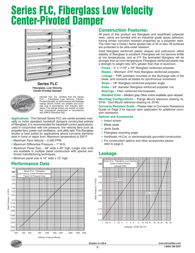
Series FLC - Fiberglass, Low Velocity,Center Pivoted Damper
Leakage Data
With Seals
Without Seals
400 500 600 800 1000 1250 1500 2000 2500 3000
1.00
0.800.80
0.60
0.50
0.40
0.30
0.25
0.025
0.030
0.040
0.050
0.060
0.080
0.100
0.125
0.15
0.20
Velocity - Feet per Minute
Sta
tic P
ress
ure
-in
W.G
.
Series FLC - FiberglassLow Velocity, Center-Pivoted Damper
Figure 5.5 Pressure Drop
Applications - The Hartzell Series FLC are center-pivoted, man-ually or motor operated, backdraft dampers constructed entirelyof fiberglass. It is recommended for backdraft control applications,used in conjunction with low pressure, low velocity fans such aspropeller fans, power roof ventilators, and utility sets.This fiberglassshutter is best suited for applications where corrosive elementsexist in fume or vapor form. Maximum temperature is 200°F.• Maximum Face Velocity – 2,500 FPM.• Maximum Differential Pressure – 1" W.G.• Maximum Panel Size – 48" wide x 48" high. Larger size units
are available in multiple panel construction with special rein-forced manufacturing techniques.
• Minimum panel size is 12" wide x 12" high.
Bulletin A-138-A
8www.hartzellfan.com
1 (800) 336-3267
®
Series FLC, Fiberglass Low VelocityCenter-Pivoted Damper
Hartzell Fan, Inc. certifies that the SeriesFLC - Fiberglass Low Velocity, Center-Pivoted Damper, air performance and leakageratings shown herein are reliable and accu-rate and in accordance with industry stan-dards. The ratings shown are based on testsand procedures performed in accordancewith AMCA Standard 500.
HARTZELL FAN, INCPIQUA, OHIO USA
BUILT WITH HONOR
Series FLCFiberglass, Low Velocity,Center-Pivoted Damper
Construction Features:All parts of this product are fiberglass and Isophthalic polyesterresin. Joints are bonded with an industrial grade epoxy adhesive,having similar corrosion resistant properties as a polyester resin.The resin has a Class I flame spread rate of 25 or less. All surfacesare protected to be ultra-violet resistant.Solid fiberglass reinforced plastic shapes and pultrusions utilizestability of fiberglass is excellent. Fiberglass will not become brittleat low temperatures, and at 0°F the laminated fiberglass will bestronger than at room temperature. Fiberglass reinforced plastic hasa strength to weight ratio 43% greater than that of aluminum.
Frame – 4" x 11⁄16" x 1⁄8" fiberglass reinforced polyester.Blades – Minimum .070" thick fiberglass reinforced polyester.Linkage – FRP, airstream mounted on the discharge side of theblade, and connects all blades for synchronous movement.Stops – 1⁄8" fiberglass reinforced polyester angle.Axles – 3⁄4" diameter fiberglass reinforced polyester rod.Bearings – Fiber reinforced thermoplastic.Standard Color – Medium gray. Other colors available upon request.
Mounting Configurations – Flange Mount reference drawing no.D744. Duct Mount reference drawing no. D745.Corrosive Resistant Guide – Please refer to Corrosion ResistanceGuide on Page 3 for topcoat resin application for additional corro-sion resistance.Options and Accessories
• Insect screen• Blade seals• Jamb Seals• Fiberglass mounting angle• HartKoate, Hi-Cor, or electrostatically grounded construction.• For construction options and other accessories please
refer to page 2.
Performance Data
Leakage

NOMINALDAMPER SIZE A B C D E F G
12 12 12 121⁄4 121⁄4 141⁄8 141⁄8 61⁄414 14 14 141⁄4 141⁄4 161⁄8 161⁄8 61⁄416 16 16 161⁄4 161⁄4 181⁄8 181⁄8 61⁄418 18 18 181⁄4 181⁄4 201⁄8 201⁄8 61⁄420 20 20 201⁄4 201⁄4 221⁄8 221⁄8 61⁄422 22 22 221⁄4 221⁄4 241⁄8 241⁄8 61⁄424 24 24 241⁄4 241⁄4 261⁄8 261⁄8 61⁄426 26 26 261⁄4 261⁄4 281⁄8 281⁄8 61⁄428 28 28 281⁄4 281⁄4 301⁄8 301⁄8 61⁄430 30 30 301⁄4 301⁄4 321⁄8 321⁄8 61⁄432 32 32 321⁄4 321⁄4 341⁄8 341⁄8 61⁄436 36 36 361⁄4 361⁄4 381⁄8 381⁄8 95⁄840 40 40 401⁄4 401⁄4 421⁄8 421⁄8 95⁄842 42 42 421⁄4 421⁄4 441⁄8 441⁄8 95⁄844 44 44 441⁄4 441⁄4 461⁄8 461⁄8 95⁄848 48 48 481⁄4 481⁄4 501⁄8 501⁄8 95⁄854 54 54 541⁄4 541⁄4 561⁄8 561⁄8 95⁄860 60 60 601⁄4 601⁄4 621⁄8 621⁄8 95⁄8
Dimensions – Series FLC Fiberglass Low Velocity, Center-Pivoted Damper
9Bulletin A-138-A www.hartzellfan.com
1 (800) 336-3267
®
Duct Mount
Flange Mount
Note: Multiple panels fastened together with FRP strips adhered to channel frame. Axles 3/4" Dia. FRP. Axles are 4" long each end through 36",above 36" axles are full blade length.
Dimensions and specifications are subject to change.Certified prints are available.
Warning: Allowances must be considered to eliminateside axle interference.
1/8
CWALL
OPENING
1/8
AIRFLOW
GMAX.
4"
A
1/8
B5"
3/4 DIA.
A
CB WALLOPENING
D
E
F
WALLOPENING
AIRFLOW
4"
GMAX.
3/4 DIA.
5"
BLADE WIDTH
ONE PANEL TWO
12
48
60
PANELS
BLADE
HEIGHT
48 60
NOMINALDAMPER SIZE A B C G
12 12 12 121⁄4 61⁄414 14 14 141⁄4 61⁄416 16 16 161⁄4 61⁄418 18 18 181⁄4 61⁄420 20 20 201⁄4 61⁄422 22 22 221⁄4 61⁄424 24 24 241⁄4 61⁄426 26 26 261⁄4 61⁄428 28 28 281⁄4 61⁄430 30 30 301⁄4 61⁄432 32 32 321⁄4 61⁄436 36 36 361⁄4 95⁄840 40 40 401⁄4 95⁄842 42 42 421⁄4 95⁄844 44 44 441⁄4 95⁄848 48 48 481⁄4 95⁄854 54 54 541⁄4 95⁄860 60 60 601⁄4 95⁄8

250200150125100806050403025201512.510
10.00
8.00
6.005.00
4.00
3.002.50
2.00
1.501.25
0.20
0.150.125
0.10
0.250.30
0.40
0.500.60
0.800.80
1.00
Leakage - (CFM / Sq. Ft.)
Sta
tic P
ress
ure
-in
W.G
.
Series FCO & FCP - FiberglassVolume Control Damper
Leakage Data
With Seals
Without Seals
500600
8001000
12501500
20002500
30004000
50006000
800010000
1.000.80
0.600.500.40
0.300.25
0.100.125
0.15
0.20
1.251.50
2.002.503.00
4.005.006.00
8.0010.00
Velocity - Feet per Minute
Sta
tic P
ress
ure
-in
W.G
.
Series FCO & FCP - FiberglassVolume Control Damper
Figure 5.5 Pressure Drop
Series FCO & FCP, Fiberglass VolumeControl Dampers
10Bulletin A-138-A www.hartzellfan.com
1 (800) 336-3267
®
Applications - The Hartzell Series FCO and FCP are center pivoted,manually or motor operated, volume control and/or back flowshut-off dampers constructed entirely of fiberglass. Series FCO isopposed blade; Series FCP is parallel blade. These products arerecommended for system balance, back flow prevention and/orfan isolation applications used in conjunction with medium- tohigh-pressure process ventilation or fume exhaust systems. Thefiberglass volume control damper is best suited for applicationswhere corrosive elements exist in fume or vapor form. Maximumtemperature is 200°F.• Maximum Face Velocity – 6,000 FPM.• Maximum Differential Pressure – 20" W.G.• Maximum Panel Size – Maximum single panel size is deter-
mined by the system static pressure. At high pressures, multi-panel may be required. Refer to page 11 for additional details.
Construction Features:All parts of this product are fiberglass and Isophthalic polyesterresin. Joints are bonded with an industrial grade epoxy adhesive,having similar corrosion resistant properties as a polyester resin.The resin has a Class I flame spread rate of 25 or less. All surfacesare protected to be ultra-violet resistant.Solid fiberglass reinforced plastic shapes and pultrusions utilizewoven fiberglass mat material for superior strength. The dimen-sional stability of fiberglass is excellent. Fiberglass will not becomebrittle at low temperatures, and at 0°F the laminated fiberglass willbe stronger than at room temperature. Fiberglass reinforced plastichas a strength to weight ratio 43% greater than that of aluminum.
Frame – 8" x 2-11⁄16" x 3/16" fiberglass reinforced polyester.Blades – Minimum 3/16" thick fiberglass reinforced polyester.Linkage – Stainless steel enclosed in damper frame, outside ofairstream.Operation – Control shaft may be located on either side, withoptions.Stops – 1⁄8" fiberglass reinforced polyester angle.Axles – 3⁄4" diameter fiberglass reinforced polyester rod.Bearings – Fiber reinforced thermoplastic.Standard Color – Medium gray. Other colors available uponrequest
Mounting Configurations – Opposed blade reference drawing no.D840. Parallel blade reference drawing no. D841.Corrosive Resistant Guide – Please refer to CorrosionResistance Guide on Page 3 for topcoat resin application for addi-tional corrosion resistance.Options and Accessories
• Blade seals• Jamb seals• Operators and Quadrants• HartKoate, Hi-Cor, or electrostatically grounded construction.• For construction options and other accessories please
refer to page 2.
Hartzell Fan, Inc. certifies that the SeriesFCO and FCP - Fiberglass Volume ControlDamper, air performance and leakage rat-ings shown herein are reliable and accurateand in accordance with industry standards.The ratings shown are based on tests andprocedures performed in accordance withAMCA Standard 500.
HARTZELL FAN, INCPIQUA, OHIO USA
BUILT WITH HONOR
Series FCOOpposed Blade
Series FCPParallel Blade
LeakagePerformance Data

Dimensions – Series FCO & FCPFiberglass Volume Control Dampers
11Bulletin A-138-A www.hartzellfan.com
1 (800) 336-3267
®
Damper Maximum Blade Length Vs. Static Pressure
Note:1. Table equals pressure torque in Inch-Pounds, at 1" differen-tial static pressure.2. For torque at different pressures, multiply differential pres-sure by tabulated values.3. For torque values with jamb seals, multiply tabulated valuesby 1.36.
Dimensions and specifications are subject to change. Certified prints are available.
Damper Operational Torque
Note: Maximum panel size is determined by system static pressure. The abovechart indicates maximum blade length as a function of system static pressure.When, at a given pressure condition, longer blades are required, jack-shafted,multi-panel construction shall be used. In those cases additional detail will besupplied on special factory drawings.
Dimensions A and B to match Customer Requirements
A
B
2 11/16"
2 11/16"FRAME
FRAME
AIRFLOW
8 1/2"
AIRFLOW3/4" DIA.
5"
WIDE
HIGH
VERTICAL SECTION PARALLEL BLADE
VERTICAL SECTIONOPPOSED BLADE
12 18 24 30 36 42 54 6048
20
15
10
5
BLADE LENGTH (A DIM.) - INCHES
DAMPER MAXIMUM BLADE LENGTH VS. STATIC PRESSURE
MULTIPLEPANELS REQ'D.
SIZE 12 18 24 30 36 42 48 54 6012 1.6 2.4 3.2 4.0 4.8 5.6 6.4 7.2 8.018 2.4 3.6 4.8 6.0 7.2 8.4 9.6 10.8 12.024 3.2 4.8 6.4 8.0 9.6 11.2 12.8 14.4 15.930 4.0 6.0 8.0 10.0 12.0 14.0 15.9 17.9 19.936 4.8 7.2 9.6 12.0 14.4 16.8 19.1 21.5 23.942 5.6 8.4 11.2 14.0 16.8 19.5 22.3 25.1 27.948 6.4 9.6 12.8 15.9 19.1 22.3 25.5 28.7 31.954 7.2 10.8 14.4 17.9 21.5 25.1 28.7 32.3 35.960 8.0 12.0 15.9 19.9 23.9 27.9 31.9 35.9 39.9

Hartzell Fan, Inc., Piqua, Ohio 45356 • Plants in Piqua, Ohio and Portland, Indiana.
Litho in U.S.A. A-138-A 01/05www.hartzellfan.com
Hartzell WarrantyLIMITED WARRANTIESHartzell represents to Buyer that any goods to be delivered hereunder will be produced in compliance with the requirements of the Fair Labor Standards Act of 1938 as amended.Hartzell also warrants to Buyer its goods to be free from defects in workmanship and material under normal use and service for one (1) year after tender of delivery by Hartzell, plus six months allowance for shipment to approved stocking dealers and distributors. No warranty extends to future performance of goods and any claims for breach of warranty or otherwise accrues upon tender of delivery.The foregoing constitute Hartzell’s sole and exclusive warranties and are in lieu of all other warranties, whether written, oral, express, implied or statutory.
LIMITATION OF LIABILITY FOR BREACH OF WARRANTYHartzell’s obligation for any breach of warranty is limited to repairing or replacing, at its option, without cost to Buyer at its factory any goods which shall, within such a warranty period, be returned to it with transportation charges prepaid, and which its examination shall disclose to its satisfaction to have been defective. Any request for repair or replacement should be directed to Hartzell Fan, Inc., P.O. Box 919, Piqua, Ohio 45356. Hartzell will not pay for any repairs made outside its factory without its prior written consent. This does not apply to any such Hartzell goods which have failed as a result of faulty installation or abuse, or incorrect electrical connections or alterations, made by others, or use under abnormal operating conditions or misapplication of the goods.
LIMITATION OF LIABILITYTo the extent the above limitation of liability for breach of warranty is not applicable, the liability of Hartzell on any claim of any kind, including negligence, for any loss or damage arising out of or connected with, or resulting from the sale and purchase of the goods or services covered by these Terms and Conditions of Sale or from the performance or breach of any contract pertaining to such sale or purchase or from the design manufacture, sale, delivery, resale, installation, technical direction installation, inspection repair, operation or use of any goods or services covered by these Terms and Conditions shall, in no case exceed the price allocable to the goods or services which gave rise to the claim and shall terminate one year after tender of delivery of said goods or services, plus six months allowance for shipment to approved stocking dealers and distributors. In no event will Hartzell be responsible or liable for any labor or other incidental costs associated with the removal or replacement of defective products or materials.In no event whether as a result of breach of contract, or warranty or alleged negligence, defects, incorrect advice or other causes, shall Hartzell be liable for special or consequential damages, including, but not limited to, loss of profits or revenue, loss of use of the equipment or any associated equipment, cost of substitute equipment, facilities or services, down time costs, or claims of customers of the Buyer for such damages. Hartzell neither assumes nor authorizes any person to assume for it any other liability in connection with the sale of its goods or services.NO IMPLIED WARRANTIES OF MERCHANTABILITY OR FITNESSHARTZELL DOES NOT WARRANT THAT SAID GOODS ARE OF MERCHANTABLE QUALITY OR THAT THEY ARE FIT FOR ANY PARTICULAR PURPOSE. THERE IS NO IMPLIED WARRANTY OF MERCHANTABILITY AND THERE IS NO IMPLIED WARRANTY OF FITNESS.
Marine – Mine Duty Blowers
Propeller Fans Cooling Tower & Heat Exchanger Fans
Duct Fans Duct Axial Fans
Vaneaxial Blowers Cool Blast & Utility Fans Steel Centrifugal Blowers Roof Ventilators –Steel & Fiberglass
Heating Equipment –Gas & Steam
Fiberglass Axial Flow Fans
Fiberglass Centrifugal Blowers
peilerman
Typewritten Text
Rev. Warranty 5/1/11
Related Documents