User’s Manual Pub. 0300215-04 Rev. B

Welcome message from author
This document is posted to help you gain knowledge. Please leave a comment to let me know what you think about it! Share it to your friends and learn new things together.
Transcript

User’s Manual Pub. 0300215-04 Rev. B
ii CompactLogix™ 4 Channel Isolated Analog HART Input Module
User’s Manual Pub. 0300215-04 Rev. B
Important Notes
1. Please read all the information in this owner’s guide before installing the
product.
2. The information in this owner's guide applies to hardware Series A and
firmware version 1.00 or later.
3. This guide assumes that the reader has a full working knowledge of the
relevant processor.
Notice
The products and services described in this owner's guide are useful in a wide
variety of applications. Therefore, the user and others responsible for applying
the products and services described herein are responsible for determining their
acceptability for each application. While efforts have been made to provide
accurate information within this owner's guide, Spectrum Controls, Inc. assumes
no responsibility for the accuracy, completeness, or usefulness of the information
herein.
Under no circumstances will Spectrum Controls, Inc. be responsible or liable for
any damages or losses, including indirect or consequential damages or losses,
arising out of either the use of any information within this owner's guide or the
use of any product or service referenced herein.
No patent liability is assumed by Spectrum Controls, Inc. with respect to the use
of any of the information, products, circuits, programming, or services referenced
herein.
The information in this owner's guide is subject to change without notice.
Limited Warranty
Spectrum Controls, Inc. warrants that its products are free from defects in
material and workmanship under normal use and service, as described in
Spectrum Controls, Inc. literature covering this product, for a period of 1 year.
The obligations of Spectrum Controls, Inc. under this warranty are limited to
replacing or repairing, at its option, at its factory or facility, any product which
shall, in the applicable period after shipment, be returned to the Spectrum
Controls, Inc. facility, transportation charges prepaid, and which after
examination is determined, to the satisfaction of Spectrum Controls, Inc., to be
thus defective.
This warranty shall not apply to any such equipment which shall have been
repaired or altered except by Spectrum Controls, Inc. or which shall have been
subject to misuse, neglect, or accident. In no case, shall the liability of Spectrum
Controls, Inc. exceed the purchase price. The aforementioned provisions do not
extend the original warranty period of any product which has either been repaired
or replaced by Spectrum Controls, Inc.
CompactLogix™ 4 Channel Isolated Analog Input Module iii
User’s Manual Pub. 0300215-04 Rev. B
Table of Contents IMPORTANT NOTES ............................................................................................................................................... II
LIMITED WARRANTY .............................................................................................................................................. II
CHAPTER 1 MODULE OVERVIEW ......................................................................................................................... 1-1
GENERAL DESCRIPTION .............................................................................................................................. 1-1 INPUT TYPES AND RANGES.......................................................................................................................... 1-1 DATA FORMATS ....................................................................................................................................... 1-2 FILTER FREQUENCIES ................................................................................................................................ 1-2 HARDWARE FEATURES .............................................................................................................................. 1-2
1.5.1 General Diagnostic Features ..................................................................................................................... 1-2 SYSTEM OVERVIEW ................................................................................................................................... 1-3
1.6.1 Module Power-up ..................................................................................................................................... 1-3 1.6.2 Module Operation ..................................................................................................................................... 1-3
CHAPTER 2 INSTALLATION AND WIRING ............................................................................................................. 2-1
BEFORE YOU BEGIN .................................................................................................................................. 2-1 TOOLS AND EQUIPMENT ............................................................................................................................ 2-1 COMPLIANCE TO EUROPEAN UNION DIRECTIVES ............................................................................................. 2-1
2.3.1 ATEX Directive ........................................................................................................................................... 2-2 POWER REQUIREMENTS ............................................................................................................................ 2-2 GENERAL CONSIDERATIONS ....................................................................................................................... 2-2
2.5.1 Hazardous Location Considerations .......................................................................................................... 2-3 2.5.2 Prevent Electrostatic Discharge ................................................................................................................ 2-3 2.5.3 Remove Power .......................................................................................................................................... 2-4 2.5.4 Selecting a Location .................................................................................................................................. 2-4
MOUNTING ............................................................................................................................................. 2-5 2.6.1 Minimum Spacing ..................................................................................................................................... 2-5 2.6.2 Parts List ................................................................................................................................................... 2-6 2.6.3 Panel Mounting ........................................................................................................................................ 2-8 2.6.4 Replacing a Single Module within a System ............................................................................................. 2-9
WIRING THE MODULE ............................................................................................................................ 2-10 2.7.1 Perform the Startup Procedure ............................................................................................................... 2-14 2.7.2 Monitor Module Status to Check if the Module is Operating Correctly .................................................. 2-14
CHAPTER 3 CONFIGURING THE IF4IH FOR COMPACTLOGIX USING STUDIO 5000 ................................................ 3-1
SETTING UP THE GENERIC PROFILE .............................................................................................................. 3-1 USING THE ADD-ON PROFILE ...................................................................................................................... 3-4
3.2.1 Installing the Add-On Profile ..................................................................................................................... 3-5 3.2.2 Adding the IF4IH Module to Your Logix Project ........................................................................................ 3-5
USER-DEFINED DATA TYPES ....................................................................................................................... 3-6 PROJECT TAGS ......................................................................................................................................... 3-8
SAMPLE PROJECT LADDER ............................................................................................................................................ 3-9
CHAPTER 4 CONFIGURING THE IF4IH FOR A MICROLOGIX 1500 USING STUDIO 500 ........................................... 4-1
MODULE MEMORY MAP ........................................................................................................................... 4-1 CONFIGURING THE 1769SC-IF4IH IN A MICROLOGIX 1500 SYSTEM................................................................ 4-2 USING THE LADDER SAMPLE ....................................................................................................................... 4-6
4.3.1 Copying Subroutines from the Sample Project.......................................................................................... 4-7 4.3.2 Copying Ladder from the Sample Project ................................................................................................. 4-7 4.3.3 Importing Tag Database and Rung Comments ......................................................................................... 4-8
iv CompactLogix™ 4 Channel Isolated Analog Input Module
User’s Manual Pub. 0300215-04 Rev. B
CHAPTER 5 MODULE DATA, STATUS, AND CHANNEL CONFIGURATION .............................................................. 5-1
MODULE MEMORY MAP ........................................................................................................................... 5-1 ACCESSING INPUT IMAGE FILE DATA ACCESSING ........................................................................................... 5-2 INPUT DATA FILE ...................................................................................................................................... 5-3
5.3.1 Input Data Values (Words 0 to 3) ............................................................................................................. 5-3 5.3.2 Time Stamp Value (Word 4) ...................................................................................................................... 5-3 5.3.3 General Status Bits S0 to S3 (Word 5) ....................................................................................................... 5-3 5.3.4 Out of Service Status Bits OS0 to OS3 (Word 5) ........................................................................................ 5-4 5.3.5 Over-Range Flag Bits O0 to O3 (Word 6) .................................................................................................. 5-4 5.3.6 Under-Range Flag Bits U0 to U3 (Word 6) ................................................................................................ 5-4 5.3.7 High Process Alarm Flag Bits H0 to H3 (Word 6) ...................................................................................... 5-5 5.3.8 Low Process Alarm Flag Bits L0 to L3 (Word 6) ......................................................................................... 5-5 5.3.9 Pad (Word 7) ............................................................................................................................................. 5-5 5.3.10 HART Data (Words 8 to 27)..................................................................................................................... 5-5 5.3.11 Message Slave Control (Word 28)........................................................................................................... 5-5 5.3.12 Message Reply Size (Word 29) ................................................................................................................ 5-5 5.3.13 Message Reply Buffer (Words 30…49) .................................................................................................... 5-5 5.3.14 Reserved (Words 50…71) ........................................................................................................................ 5-5
MODULE CONFIGURATION ......................................................................................................................... 5-6 5.4.1 Real Time Sample Value (Word 0) ............................................................................................................ 5-7 5.4.2 General Configuration Bits (Word 1) ........................................................................................................ 5-8 5.4.3 Filter Frequency and General Settings (Words 2, 8, 14, 20) ...................................................................... 5-9 5.4.4 Input Type and Data Format (Words 3, 9, 15, 21) .................................................................................. 5-13 5.4.5 Process Alarm High Setpoint (Words 4, 10, 16, 22) ................................................................................ 5-16 5.4.6 Process Alarm Low Setpoint (Words 5, 11, 17, 23) ................................................................................. 5-16 5.4.7 Process Alarm Deadband (Words 6, 12, 18, 24) ..................................................................................... 5-16 5.4.8 Pad (Words 7, 13, 19, 25) ....................................................................................................................... 5-17 5.4.9 Channel X1 HART Slot Variables 0 & 1 (Words 26, 28, 30, 32) ................................................................ 5-17 5.4.10 Channel X1 HART Slot Variables 2 & 3 (Words 25, 27, 31, 33) .............................................................. 5-17
OUTPUT DATA FILE ................................................................................................................................. 5-18 5.5.1 Unlatch Process High Alarms UH0 to UH3 (Word 0) ............................................................................... 5-18 5.5.2 Unlatch Process Low Alarms UL0 to UL3 (Word 0) ................................................................................. 5-18 5.5.3 Hart Suspend HS0 to HS3 (Word 0) ......................................................................................................... 5-19 5.5.4 Packet Just Scanned (Word 1) ................................................................................................................. 5-19 5.5.5 Message Master Control (Word 2) ......................................................................................................... 5-19 5.5.6 Message Request Size (Word 3) .............................................................................................................. 5-19 5.5.7 Message Request Buffer (Words 4…23) .................................................................................................. 5-20 5.5.8 Reserved (Words 24…45) ........................................................................................................................ 5-20
DETERMINING EFFECTIVE RESOLUTION AND RANGE .................................................................................... 5-20 DETERMINING MODULE UPDATE TIME ...................................................................................................... 5-21
5.7.1 Calculating Module Update Time ........................................................................................................... 5-21
CHAPTER 6 ENABLING AND USING HART ON THE 1769SC-IF4IH .......................................................................... 6-1
CONFIGURING THE MODULE FOR HART ....................................................................................................... 6-1 6.1.1 Configuring the IF4IH Module for (Hart Acquisition/Communication) ..................................................... 6-1
HART PACKET DATA ................................................................................................................................. 6-2 6.2.1 How the Module Connects to a Field Device ............................................................................................. 6-2 6.2.2 Auto Acquisition ........................................................................................................................................ 6-3 6.2.3 Packet Interval ........................................................................................................................................ 6-11
SENDING AND RECEIVING MESSAGES .......................................................................................................... 6-12 6.3.1 Module Output Tags Used for Messaging .............................................................................................. 6-12 6.3.2 Module Input Tags Used for Messaging ................................................................................................. 6-13 6.3.3 Processing a Message ............................................................................................................................. 6-14
MODULE-SPECIFIC COMMANDS ................................................................................................................ 6-31
CompactLogix™ 4 Channel Isolated Analog Input Module v
User’s Manual Pub. 0300215-04 Rev. B
6.4.1 Get HART Device Information ................................................................................................................. 6-31 6.4.2 HART Channel Suspension and Resume .................................................................................................. 6-34 6.4.3 HART Pass-Through Command ............................................................................................................... 6-36
HART PROTOCOL OVERVIEW ................................................................................................................... 6-46 6.5.1 Message Format ..................................................................................................................................... 6-47 6.5.2 Sending a HART Command to a Field Device via Pass-through .............................................................. 6-49
CHAPTER 7 PROGRAMMING EXAMPLES ............................................................................................................. 7-1
COMPACTLOGIX ....................................................................................................................................... 7-1 7.1.1 Initializing the IF4IH Module ..................................................................................................................... 7-1 7.1.2 Reset/Reconfig .......................................................................................................................................... 7-2 7.1.3 Swap Byte Order ....................................................................................................................................... 7-4 7.1.4 Converting Unpacked ASCII to Packed ASCII ............................................................................................. 7-4
MICROLOGIX 1500 .................................................................................................................................. 7-8 7.2.1 MAIN Routine............................................................................................................................................ 7-9 7.2.2 PACKETS Routine ..................................................................................................................................... 7-10 7.2.3 MSG_TO_MOD Routine .......................................................................................................................... 7-13 7.2.4 SRC_CHECK Routine ................................................................................................................................ 7-30 7.2.5 DEST_CHECKSUM Routine ...................................................................................................................... 7-32 7.2.6 HART_MSG Routine ................................................................................................................................ 7-34 7.2.7 WORD_BYTE Routine .............................................................................................................................. 7-45 7.2.8 HART_CHECK Routine ............................................................................................................................. 7-48 7.2.9 7 BYTE_WORD Routine ........................................................................................................................... 7-50
CHAPTER 8 DIAGNOSTICS AND TROUBLESHOOTING ........................................................................................... 8-1
SAFETY CONSIDERATIONS ........................................................................................................................... 8-1 8.1.1 Indicator Lights ......................................................................................................................................... 8-1 8.1.2 Stand Clear of Equipment ......................................................................................................................... 8-1 8.1.3 Program Alteration ................................................................................................................................... 8-1 8.1.4 Safety Circuits ........................................................................................................................................... 8-2
MODULE OPERATION VS. CHANNEL OPERATION ............................................................................................ 8-2 POWER-UP DIAGNOSTICS .......................................................................................................................... 8-2 CHANNEL DIAGNOSTICS ............................................................................................................................. 8-3
8.4.1 Invalid Channel Configuration Detection .................................................................................................. 8-3 8.4.2 Over- or Under-Range Detection .............................................................................................................. 8-3
NON-CRITICAL VS. CRITICAL MODULE ERRORS ............................................................................................... 8-3 MODULE ERROR DEFINITION TABLE ............................................................................................................. 8-3
8.6.1 Module Error Field .................................................................................................................................... 8-4 8.6.2 Extended Error Information Field .............................................................................................................. 8-4
ERROR CODES .......................................................................................................................................... 8-5 MODULE INHIBIT FUNCTION ....................................................................................................................... 8-6 GETTING TECHNICAL ASSISTANCE ............................................................................................................... 8-6
APPENDIX A MODULE SPECIFICATIONS ...............................................................................................................A-1
APPENDIX B HART UNIVERSAL AND COMMON PRACTICE COMMANDS .............................................................. B-1
INDEX .................................................................................................................................................................. I-1
vi CompactLogix™ 4 Channel Isolated Analog Input Module
User’s Manual Pub. 0300215-04 Rev. B
Preface
NOTE
This is a re-issue of an existing manual, with some corrections, and
updated ATEX information.
Read this preface to familiarize yourself with the rest of the manual. This preface
covers the following topics:
• Who should use this manual
• How to use this manual
• Related documentation
• Technical support
• Documentation
• Conventions used in this manual
Who Should Use This Manual
Use this manual if you are responsible for designing, installing, programming, or
troubleshooting control systems that use Allen-Bradley I/O and/or compatible
controllers, such as MicroLogix 1500 or CompactLogix.
How to Use This Manual
As much as possible, we organized this manual to explain, in a task-by-task
manner, how to install, configure, program, operate, and troubleshoot a control
system using the 1769sc-IF4IHV2.
Related Documentation
The table below provides a listing of publications that contain important
information about Allen-Bradley PLC systems.
For Refer to this Document Allen-Bradley
Pub. No.
User instructions MicroLogix™ 1500 User
Manual 1764-UM001A
Product information
1769 Compact Discrete
Input/Output Modules
Product Data
1769-2.1
Overview of MicroLogix
1500 system
MicroLogix™ 1500
System Overview 1764-SO001B
Overview of Compact IO
system
Compact™ I/O System
Overview 1769-SO001A
User Instructions CompactLogix User
Manual 1769-UM007B
CompactLogix™ 4 Channel Isolated Analog Input Module vii
User’s Manual Pub. 0300215-04 Rev. B
For Refer to this Document Allen-Bradley
Pub. No.
Wiring and grounding
information
Allen-Bradley
Programmable Controller
Grounding and Wiring
Guidelines
1770-4.1
Technical Support
For technical support, please contact your local Rockwell Automation
TechConnect Office for all Spectrum products. Contact numbers are as follows:
• USA 440-646-6900
• United Kingdom 01908 635230
• Australia 1800-809-929
• Mexico 001-888-365-8677
• Brazil (55) 11 3618 8800
• Europe +49 211 41553 63
or send an email to [email protected]
Documentation
If you would like a manual, you can download a free electronic version from the
Internet at www.spectrumcontrols.com
Conventions Used in This Manual
The following conventions are used throughout this manual:
• Bulleted lists (like this one) provide information not procedural steps.
• lists provide sequential steps or hierarchical information.
• Italic type is used for emphasis.
• Bold type identifies headings and sub-headings:
WARNING
Identifies information about practices or circumstances that can lead to
personal injury or death, property damage, or economic loss. These
messages help you to identify a hazard, avoid a hazard, and recognize the
consequences.
ATTENTION
Actions ou situations risquant d’entraîner des blessures pouvant être
mortelles, des dégâts matériels ou des pertes financières. Les messages «
Attention » vous aident à identifier un danger, à éviter ce danger et en
discerner les conséquences.
NOTE
Identifies information that is critical for successful application and
understanding of the product.

viii CompactLogix™ 4 Channel Isolated Analog Input Module
User’s Manual Pub. 0300215-04 Rev. B
User’s Manual Pub. 0300215-04 Rev. B
Chapter 1 Module Overview
This chapter describes the 1769sc-IF4IH and the conformally coated 1769sc-
IF4IHK isolated HART analog input modules, and explains how the modules
read current, voltage, and current with HART input data. Other than the
conformal coating, both modules are identical so all information applicable to the
1769sc-IF4IH also applies to the K version. The following section covers:
• Module hardware and diagnostic features.
• An overview of the system and module operation.
General Description
The IF4IH is a four-channel, isolated module that allows each channel to be
configured independently for either current, voltage, or current with HART
communication. The module digitally converts and stores analog data from any
combination mentioned above as well as HART data for channels configured for
HART. Each input channel is individually configured via software for a specific
input device, data format and filter frequency, and provides over-range and
under-range detection and indication.
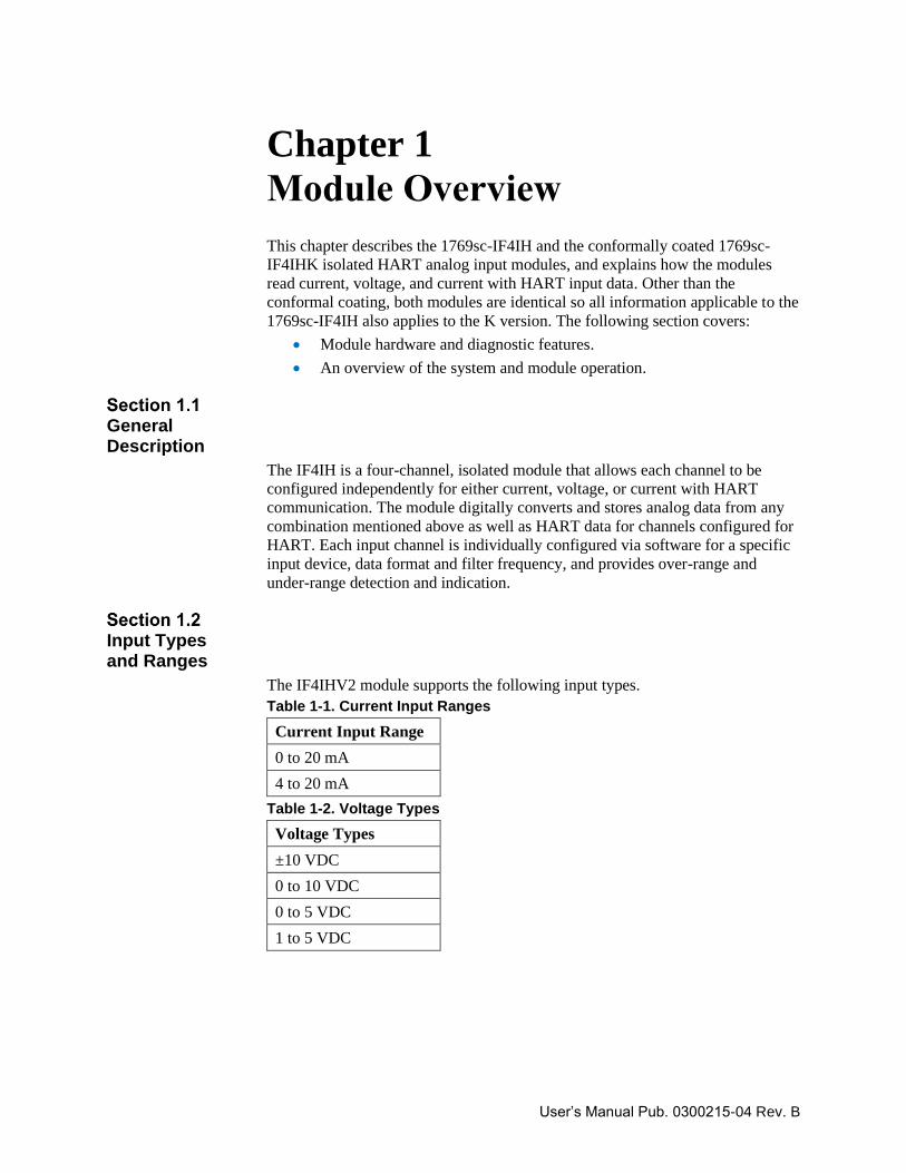
Input Types and Ranges
The IF4IHV2 module supports the following input types.
Table 1-1. Current Input Ranges
Current Input Range
0 to 20 mA
4 to 20 mA
Table 1-2. Voltage Types
Voltage Types
±10 VDC
0 to 10 VDC
0 to 5 VDC
1 to 5 VDC
1-2 Chapter 1: Module Overview
User’s Manual Pub. 0300215-04 Rev. B
Data Formats
For each channel, the data can be configured for:
• Engineering Units ×1.
• Scaled-for-PID.
• Percent of full scale.
• Raw/proportional counts.
Filter Frequencies
The module uses a digital filter that provides high-frequency noise rejection for
the input signals. The filter is programmable, allowing you to select from five
different filter frequencies for each channel:
• 28.5 Hz
• 50 Hz
• 60 Hz
• 300 Hz
• 360 Hz
Hardware Features
The module contains a removable terminal block. Channels are wired as
differential inputs (that is, each channel will have a dedicated ground).
NOTE
A jumper must be installed on the terminal block between CH- and
CH-iRtn for all current input ranges.
Module configuration is done via the controller’s programming software. In
addition, some controllers support configuration via the user program. In either
case, the module configuration is stored in the memory of the controller. Refer to
your controller’s user manual for more information.
The module contains a diagnostic LED that helps you identify the source of
problems that may occur during power-up or during normal channel operation.
The LED indicates both status and power. Power-up and channel diagnostics are
explained Chapter 8.
Chapter 1: Module Overview 1-3
User’s Manual Pub. 0300215-04 Rev. B
System Overview
The modules communicate to the controller through the bus interface. The
modules also receive 5 VDC and 24 VDC power through the bus interface.
At power-up, the module performs a check of its internal circuits, memory, and
basic functions. During this time, the module status LED remains off. If no faults
are found during power-up diagnostics, the module status LED is turned on.
After power-up checks are complete, the module waits for valid channel
configuration data. If an invalid configuration is detected, the module generates a
configuration error. Once a channel is properly configured and enabled, it
continuously converts the input data to a value within the range selected for that
channel.
Each time a channel is read by the input module, that data value is tested by the
module for an over-range, under-range, open-circuit, or “input data not valid”
condition. If such a condition is detected, a unique bit is set in the channel status
word. The channel status word is described in Section 5.3 Input Data File.
Using the module image table, the controller reads the two’s complement binary
converted input data from the module. This typically occurs at the end of the
program scan or when commanded by the control program. If the controller and
the module determine that the data transfer has been made without error, the data
is used in the control program.
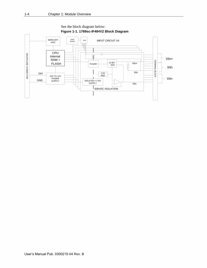
When the module receives the input from an analog device, the module’s
circuitry multiplexes the input into an A/D converter. The converter reads the
signal and converts it as required for the type of input. If HART is enabled on a
channel, the HART data is acquired by means of an onboard HART modem.
NOTE
The HART data is acquired asynchronously from the analog acquisition
process, and therefore does not directly affect the analog update time.
The module is designed to support up to 4 isolated channels which can be
independently configured for voltage, current, or current with HART. The
module converts the analog values directly into digital counts which are viewed
and accessed from within the PLC via controller input tags.
The HART data, if enabled, is converted directly to a block of twenty controller
input tags. The data within this block of twenty tags is multiplexed. For
information on HART and how to demultiplex the HART data, refer to Chapter
6.
1-4 Chapter 1: Module Overview
User’s Manual Pub. 0300215-04 Rev. B
See the block diagram below:
Figure 1-1. 1769sc-IF4IHV2 Block Diagram
24V TO 12V
POWER
SUPPLY
CPU
RAM +
FLASH
INPUT CIRCUIT X4
Vin+
Vin-
Irtn
MERCURY
ASIC
BA
CK
PL
AN
E C
ON
NE
CT
OR
TE
RM
INA
L B
LO
CK
24V
GND
Internal
500VDC ISOLATION
24 BITADC
iCoupler Vin+
Vin-
Irtn
ISOLATED +/-15V
SUPPLY
2.5V
REF
MuxHART
Modem
User’s Manual Pub. 0300215-04 Rev. B
Chapter 2 Installation and Wiring
Before You Begin
This chapter covers:
• Tools and Equipment
• Compliance to European Union directives
• Power requirements
• General considerations
• Mounting
• Wiring the module
Tools and Equipment
You need the following tools and equipment:
• Medium blade or cross-head screwdriver.
• Analog input device.
• Shielded, twisted-pair cable for wiring (Belden™ 8761 or equivalent for
voltage and current inputs).
• Controller (for example, a MicroLogix™ 1500 or CompactLogix™
controller).
• Programming device and software (for example, Studio 500™ or Studio
5000™).
Compliance to European Union Directives
This product is approved for installation within the European Union and EEA
regions. It has been designed and tested to meet the following directives.
The 1769sc-IF4IH module is tested to meet Council Directive 2014/30/EU
Electromagnetic Compatibility (EMC) and the following standards, in whole or
in part, documented in a technical construction file:
• EN 61131-2 Programable controllers, Part 2 - Equipment requirements
and tests.
• EN 61000-6-2 Electromagnetic compatibility (EMC) – Part 6-2: Generic
standards – Immunity standard for industrial environments.
• EN 61000-6-4 Electromagnetic compatibility (EMC) – Part 6-4: Generic
standards – Emission standard for industrial environments.
2-2 Chapter 2: Installation and Wiring
User’s Manual Pub. 0300215-04 Rev. B
UKCA Electromagnetic Compatibility Regulations 2016
• BS EN 61131-2, BS EN 61000-6-4, BS EN 61000-6-2.
This product is intended for use in an industrial environment.
This product is tested to meet Council Directive 2014/30/U/ATEX, and the
following standards, in whole or in part, documented in a technical construction
file:
• EN 60079-0 Explosive atmospheres – Part 0: Equipment – General
requirements.
• EN 60079-7 Explosive atmospheres – Part 7: Equipment protection by
increased safety "e".
This module also meets the standards for the United Kingdom Equipment and
Protective Systems Intended for use in Potentially Explosive Atmospheres
Regulations 2016:
• BS EN 60079-0
• BS EN 60079-7
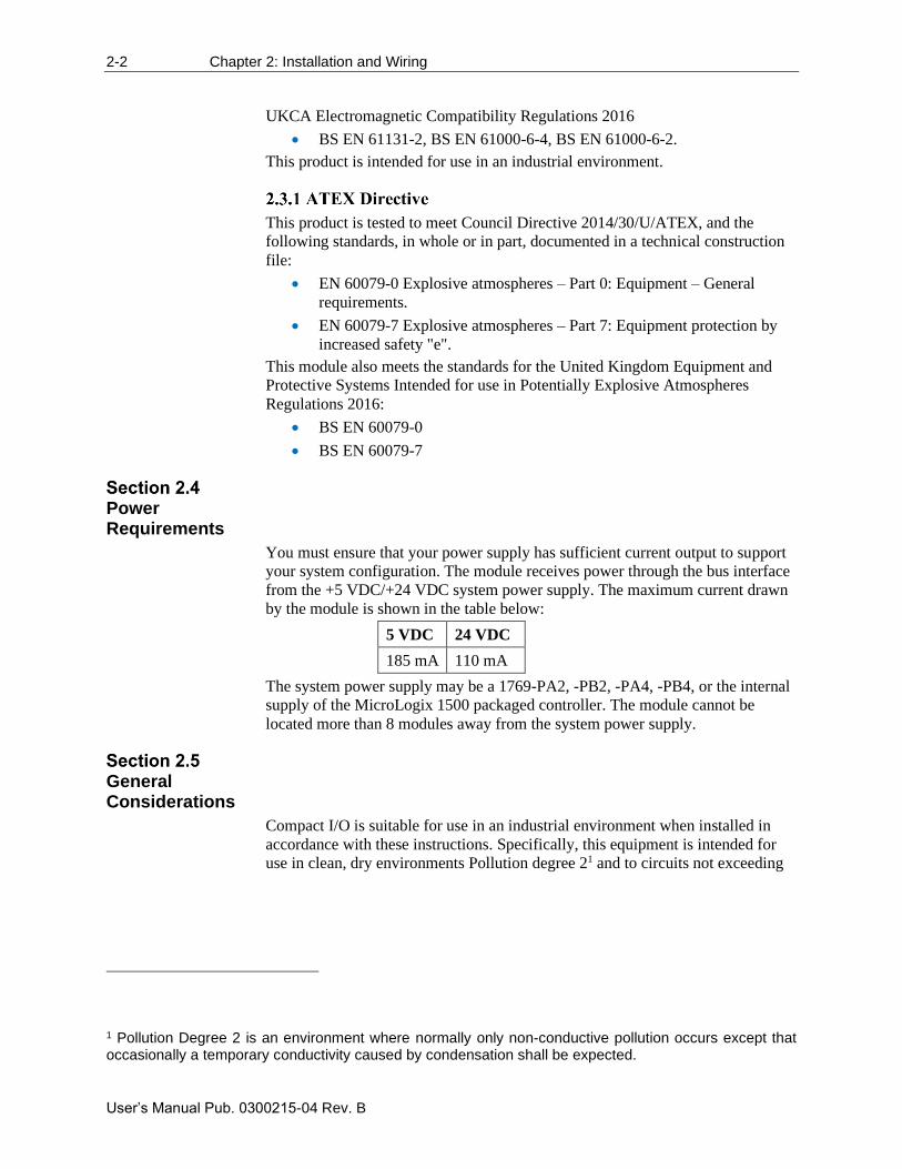
Power Requirements
You must ensure that your power supply has sufficient current output to support
your system configuration. The module receives power through the bus interface
from the +5 VDC/+24 VDC system power supply. The maximum current drawn
by the module is shown in the table below:
5 VDC 24 VDC
185 mA 110 mA
The system power supply may be a 1769-PA2, -PB2, -PA4, -PB4, or the internal
supply of the MicroLogix 1500 packaged controller. The module cannot be
located more than 8 modules away from the system power supply.
General Considerations
Compact I/O is suitable for use in an industrial environment when installed in
accordance with these instructions. Specifically, this equipment is intended for
use in clean, dry environments Pollution degree 21 and to circuits not exceeding
1 Pollution Degree 2 is an environment where normally only non-conductive pollution occurs except that occasionally a temporary conductivity caused by condensation shall be expected.
Chapter 2: Installation and Wiring 2-3
User’s Manual Pub. 0300215-04 Rev. B
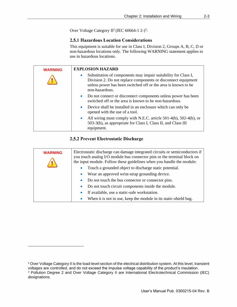
Over Voltage Category II2 (IEC 60664-1 2-)3:
This equipment is suitable for use in Class I, Division 2, Groups A, B, C, D or
non-hazardous locations only. The following WARNING statement applies to
use in hazardous locations.
WARNING
EXPLOSION HAZARD
• Substitution of components may impair suitability for Class I,
Division 2. Do not replace components or disconnect equipment
unless power has been switched off or the area is known to be
non-hazardous.
• Do not connect or disconnect components unless power has been
switched off or the area is known to be non-hazardous.
• Device shall be installed in an enclosure which can only be
opened with the use of a tool.
• All wiring must comply with N.E.C. article 501-4(b), 502-4(b), or
503-3(b), as appropriate for Class I, Class II, and Class III
equipment.
WARNING
Electrostatic discharge can damage integrated circuits or semiconductors if
you touch analog I/O module bus connector pins or the terminal block on
the input module. Follow these guidelines when you handle the module:
• Touch a grounded object to discharge static potential.
• Wear an approved wrist-strap grounding device.
• Do not touch the bus connector or connector pins.
• Do not touch circuit components inside the module.
• If available, use a static-safe workstation.
• When it is not in use, keep the module in its static-shield bag.
2 Over Voltage Category II is the load-level section of the electrical distribution system. At this level, transient voltages are controlled, and do not exceed the impulse voltage capability of the product’s insulation. 3 Pollution Degree 2 and Over Voltage Category II are International Electrotechnical Commission (IEC) designations.
2-4 Chapter 2: Installation and Wiring
User’s Manual Pub. 0300215-04 Rev. B
WARNING
Remove power before removing or inserting this module. When you
remove, or insert, a module with power applied, an electrical arc may
occur. An electrical arc can cause personal injury or property damage by:
• Sending an erroneous signal to your system’s field devices,
causing unintended machine motion.
• Causing an explosion in a hazardous environment.
• Causing an electrical arc. Such arcing causes excessive wear to
contacts on both the module and its mating connector, and may
lead to premature failure.
Reducing Noise
Most applications require installation in an industrial enclosure to reduce the
effects of electrical interference. Analog inputs are highly susceptible to
electrical noise. Electrical noise coupled to the analog inputs will reduce the
performance (accuracy) of the module.
Group your modules to minimize adverse effects from radiated electrical noise
and heat. Consider the following conditions when selecting a location for the
analog module. Position the module:
• Away from sources of electrical noise such as hard-contact switches,
relays, and AC motor drives.
• Away from modules which generate significant radiated heat, such as the
1769-IA16. Refer to the module’s heat dissipation specification.
In addition, route shielded, twisted-pair analog input wiring away from any high
voltage I/O wiring.
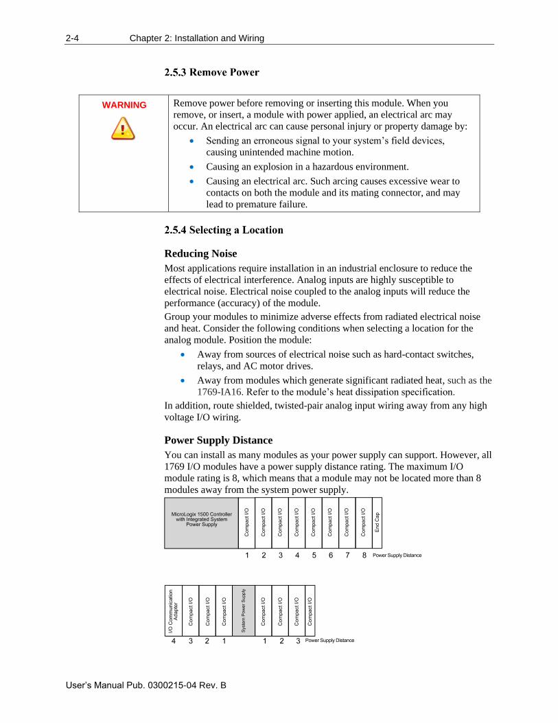
Power Supply Distance
You can install as many modules as your power supply can support. However, all
1769 I/O modules have a power supply distance rating. The maximum I/O
module rating is 8, which means that a module may not be located more than 8
modules away from the system power supply.
Chapter 2: Installation and Wiring 2-5
User’s Manual Pub. 0300215-04 Rev. B
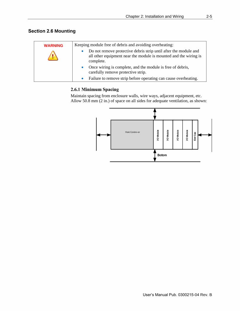
Mounting
WARNING
Keeping module free of debris and avoiding overheating:
• Do not remove protective debris strip until after the module and
all other equipment near the module is mounted and the wiring is
complete.
• Once wiring is complete, and the module is free of debris,
carefully remove protective strip.
• Failure to remove strip before operating can cause overheating.
Maintain spacing from enclosure walls, wire ways, adjacent equipment, etc.
Allow 50.8 mm (2 in.) of space on all sides for adequate ventilation, as shown:
2-6 Chapter 2: Installation and Wiring
User’s Manual Pub. 0300215-04 Rev. B
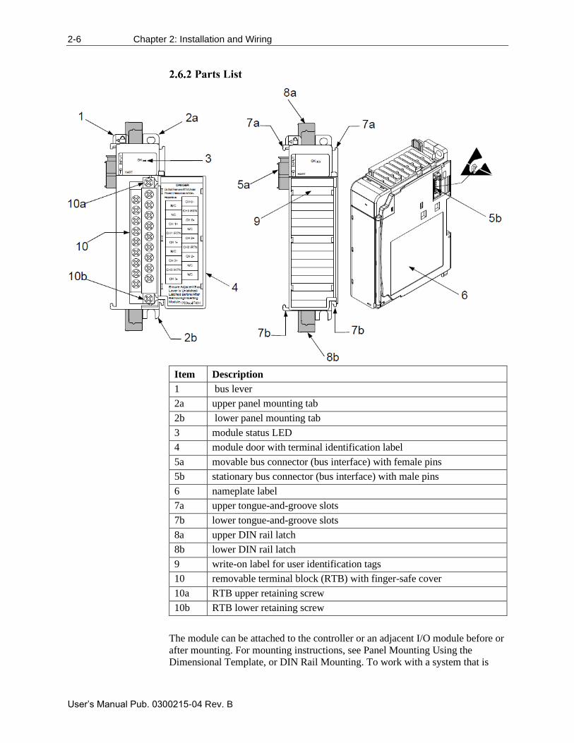
Item Description
1 bus lever
2a upper panel mounting tab
2b lower panel mounting tab
3 module status LED
4 module door with terminal identification label
5a movable bus connector (bus interface) with female pins
5b stationary bus connector (bus interface) with male pins
6 nameplate label
7a upper tongue-and-groove slots
7b lower tongue-and-groove slots
8a upper DIN rail latch
8b lower DIN rail latch
9 write-on label for user identification tags
10 removable terminal block (RTB) with finger-safe cover
10a RTB upper retaining screw
10b RTB lower retaining screw
The module can be attached to the controller or an adjacent I/O module before or
after mounting. For mounting instructions, see Panel Mounting Using the
Dimensional Template, or DIN Rail Mounting. To work with a system that is
Chapter 2: Installation and Wiring 2-7
User’s Manual Pub. 0300215-04 Rev. B
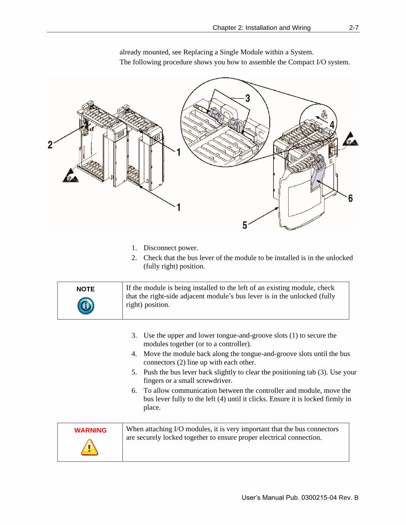
already mounted, see Replacing a Single Module within a System.
The following procedure shows you how to assemble the Compact I/O system.
1. Disconnect power.
2. Check that the bus lever of the module to be installed is in the unlocked
(fully right) position.
NOTE
If the module is being installed to the left of an existing module, check
that the right-side adjacent module’s bus lever is in the unlocked (fully
right) position.
3. Use the upper and lower tongue-and-groove slots (1) to secure the
modules together (or to a controller).
4. Move the module back along the tongue-and-groove slots until the bus
connectors (2) line up with each other.
5. Push the bus lever back slightly to clear the positioning tab (3). Use your
fingers or a small screwdriver.
6. To allow communication between the controller and module, move the
bus lever fully to the left (4) until it clicks. Ensure it is locked firmly in
place.
WARNING
When attaching I/O modules, it is very important that the bus connectors
are securely locked together to ensure proper electrical connection.
2-8 Chapter 2: Installation and Wiring
User’s Manual Pub. 0300215-04 Rev. B
7. Attach an end cap terminator (5) to the last module in the system by
using the tongue-and-groove slots as before.
8. Lock the end cap bus terminator (6).
WARNING
A 1769-ECR or 1769-ECL right or left end cap respectively must be used
to terminate the end of the 1769 communication bus.
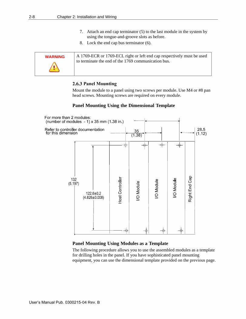
Mount the module to a panel using two screws per module. Use M4 or #8 pan
head screws. Mounting screws are required on every module.
Panel Mounting Using the Dimensional Template
Panel Mounting Using Modules as a Template
The following procedure allows you to use the assembled modules as a template
for drilling holes in the panel. If you have sophisticated panel mounting
equipment, you can use the dimensional template provided on the previous page.
Chapter 2: Installation and Wiring 2-9
User’s Manual Pub. 0300215-04 Rev. B
Due to module mounting hole tolerance, it is important to follow these
procedures:
1. On a clean work surface, assemble no more than three modules.
2. Using the assembled modules as a template, carefully mark the center of
all module-mounting holes on the panel.
3. Return the assembled modules to the clean work surface, including any
previously mounted modules.
4. Drill and tap the mounting holes for the recommended M4 or #8 screw.
5. Place the modules back on the panel, and check for proper hole
alignment.
6. Attach the modules to the panel using the mounting screws.
NOTE
If mounting more modules, mount only the last one of this group and put
the others aside. This reduces remounting time during drilling and tapping
of the next group.
7. Repeat steps 1 to 6 for any remaining modules.
DIN Rail Mounting
The module can be mounted using the following DIN rails:
• 35 × 7.5 mm (EN 50 022 – 35 × 7.5)
• 35 × 15 mm (EN 50 022 - 35 × 15)
Before mounting the module on a DIN rail, close the DIN rail latches. Press the
DIN rail mounting area of the module against the DIN rail. The latches will
momentarily open and lock into place.
1. Remove power. See important note at the beginning of this chapter.
2. On the module to be removed, remove the upper and lower mounting
screws from the module (or open the DIN latches using a flat-blade or
Phillips head screwdriver).
3. Move the bus lever to the right to disconnect (unlock) the bus.
4. On the right-side adjacent module, move its bus lever to the right
(unlock) to disconnect it from the module to be removed.
5. Gently slide the disconnected module forward. If you feel excessive
resistance, check that the module has been disconnected from the bus,
and that both mounting screws have been removed (or DIN latches
opened).
NOTE
It may be necessary to rock the module slightly from front to back to
remove it, or, in a panel-mounted system, to loosen the screws of adjacent
modules.
2-10 Chapter 2: Installation and Wiring
User’s Manual Pub. 0300215-04 Rev. B
6. Before installing the replacement module, be sure that the bus lever on
the module to be installed and on the right-side adjacent module or end
cap are in the unlocked (fully right) position.
7. Slide the replacement module into the open slot.
8. Connect the modules together by locking (fully left) the bus levers on
the replacement module and the right-side adjacent module.
9. Replace the mounting screws (or snap the module onto the DIN rail).
Wiring the Module
When wiring your system, use the following guidelines:
• Channels are isolated from one another by ±500 VDC maximum.
• As a general rule, allow at least 15.2 cm (6 in.) of separation for every
120 V of power.
• Routing field wiring in a grounded conduit can reduce electrical noise.
• If field wiring must cross AC or power cables, ensure that they cross at
right angles.
• Provision shall be made to prevent the rated voltage being exceeded by
the transient disturbances of more than 140% of the peak rated voltage.
The equipment shall be installed in an enclosure that provides a degree of
protection not less than IP 54 in accordance with EN 60079-0 and used
in an environment of not more than pollution degree 2. The enclosure
shall be accessible only with the use of a tool.
• The power supply commons must stay within 500 VDC or 120 VAC of
each other.
• Grounding to earth is accomplished through mounting of modules on rail.
• Subject devices are for operation in Ambient Temperature Range: 0 °C to
+60 °C.
Terminal Block
• For voltage and current sensors, use Belden 8761 shielded, twisted-pair
wire (or equivalent) to ensure proper operation and high immunity to
electrical noise.
• To ensure optimum accuracy, limit overall cable impedance by keeping a
cable as short as possible. Locate the module as close to input devices as
the application permits.
Grounding
• This product is intended to be mounted to a well-grounded mounting
surface such as a metal panel. Additional grounding connections from the
module’s mounting tabs or DIN rail (if used) are not required unless the
mounting surface cannot be grounded.
• Keep cable shield connections to ground as short as possible.
• Ground the shield drain wire at one end only. The preferred location is as
follows.
Chapter 2: Installation and Wiring 2-11
User’s Manual Pub. 0300215-04 Rev. B
- If it is necessary to connect the shield drain wire at the module
end, connect it to earth ground using a panel or DIN rail
mounting screw.
- Refer to Industrial Automation Wiring and Grounding
Guidelines, Allen-Bradley publication 1770-4.1, for additional
information.
Terminal Door Label
A removable, write-on label is provided with the module. Remove the label from
the door, mark your unique identification of each terminal with permanent ink,
and slide the label back into the door. Your markings (ID tag) will be visible
when the module door is closed.
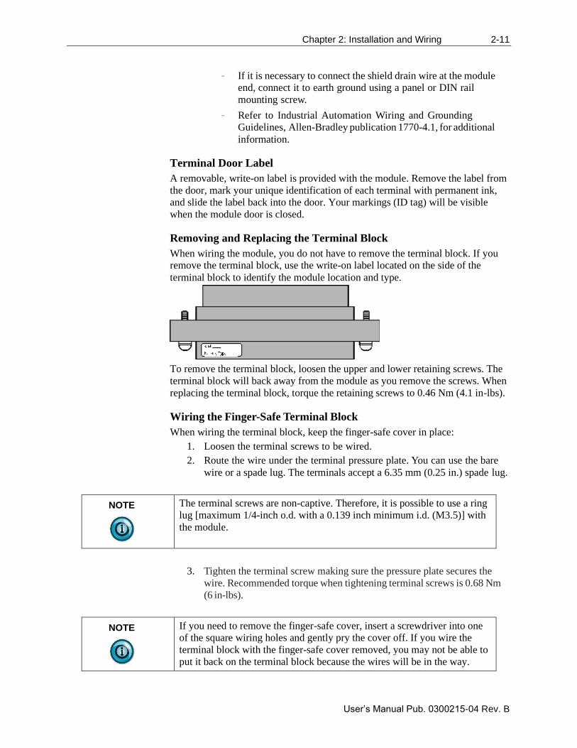
Removing and Replacing the Terminal Block
When wiring the module, you do not have to remove the terminal block. If you
remove the terminal block, use the write-on label located on the side of the
terminal block to identify the module location and type.
To remove the terminal block, loosen the upper and lower retaining screws. The
terminal block will back away from the module as you remove the screws. When
replacing the terminal block, torque the retaining screws to 0.46 Nm (4.1 in-lbs).
Wiring the Finger-Safe Terminal Block
When wiring the terminal block, keep the finger-safe cover in place:
1. Loosen the terminal screws to be wired.
2. Route the wire under the terminal pressure plate. You can use the bare
wire or a spade lug. The terminals accept a 6.35 mm (0.25 in.) spade lug.
NOTE
The terminal screws are non-captive. Therefore, it is possible to use a ring
lug [maximum 1/4-inch o.d. with a 0.139 inch minimum i.d. (M3.5)] with
the module.
3. Tighten the terminal screw making sure the pressure plate secures the
wire. Recommended torque when tightening terminal screws is 0.68 Nm
(6 in-lbs).
NOTE
If you need to remove the finger-safe cover, insert a screwdriver into one
of the square wiring holes and gently pry the cover off. If you wire the
terminal block with the finger-safe cover removed, you may not be able to
put it back on the terminal block because the wires will be in the way.
2-12 Chapter 2: Installation and Wiring
User’s Manual Pub. 0300215-04 Rev. B
Wire Size and Terminal Screw Torque
Each terminal accepts up to two wires with the following restrictions:
Wire Type Wire Size Terminal Screw
Torque
Retaining Screw Torque
Solid Cu-90 °C (194 °F) #14 to #22 AWG
(1.63 to 0.65 mm)
0.68 Nm (6 in-lbs) 0.46 Nm (4.1 in-lbs)
Stranded Cu-90 °C (194 °F) #16 to #22 AW
(1.29 to 0.65 mm)
0.68 Nm (6 in-lbs) 0.46 Nm (4.1 in-lbs)
WARNING
USE SUPPLY WIRES SUITABLE FOR 20 °C ABOVE
SURROUNDING AMBIENT TEMPERATURE.
WARNING
UTILISER DES FILS D’ALIMENTATION QUI CONVIENNENT A
UNE TEMPERATURE DE 20 °C AU-DESSUS DE LA
TEMPERATURE AMBIANTE.
WARNING
SHOCK HAZARD
To prevent shock hazard, care should be taken when wiring the module to
analog signal sources. Before wiring any module, disconnect power from
the system power supply, and another other power source to the module.
Chapter 2: Installation and Wiring 2-13
User’s Manual Pub. 0300215-04 Rev. B
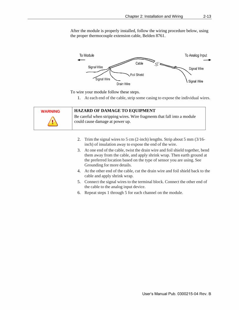
After the module is properly installed, follow the wiring procedure below, using
the proper thermocouple extension cable, Belden 8761.
To wire your module follow these steps.
1. At each end of the cable, strip some casing to expose the individual wires.
WARNING
HAZARD OF DAMAGE TO EQUIPMENT
Be careful when stripping wires. Wire fragments that fall into a module
could cause damage at power up.
2. Trim the signal wires to 5 cm (2-inch) lengths. Strip about 5 mm (3/16-
inch) of insulation away to expose the end of the wire.
3. At one end of the cable, twist the drain wire and foil shield together, bend
them away from the cable, and apply shrink wrap. Then earth ground at
the preferred location based on the type of sensor you are using. See
Grounding for more details.
4. At the other end of the cable, cut the drain wire and foil shield back to the
cable and apply shrink wrap.
5. Connect the signal wires to the terminal block. Connect the other end of
the cable to the analog input device.
6. Repeat steps 1 through 5 for each channel on the module.
2-14 Chapter 2: Installation and Wiring
User’s Manual Pub. 0300215-04 Rev. B
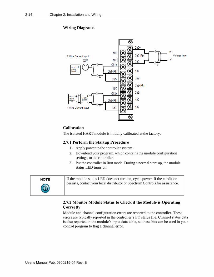
Wiring Diagrams
Calibration
The isolated HART module is initially calibrated at the factory.
1. Apply power to the controller system.
2. Download your program, which contains the module configuration
settings, to the controller.
3. Put the controller in Run mode. During a normal start-up, the module
status LED turns on.
NOTE
If the module status LED does not turn on, cycle power. If the condition
persists, contact your local distributor or Spectrum Controls for assistance.
Module and channel configuration errors are reported to the controller. These
errors are typically reported in the controller’s I/O status file. Channel status data
is also reported in the module’s input data table, so these bits can be used in your
control program to flag a channel error.
User’s Manual Pub. 0300215-04 Rev. B
Chapter 3 Configuring the IF4IH for
CompactLogix Using Studio
5000
This chapter explains how to incorporate the IF4IH module into a CompactLogix
system using Studio 5000 programming software. The process of incorporating
your HART module into the CompactLogix system is similar to the process
needed to add an Allen-Bradley module. You use your Studio 5000 programming
software to install and configure your HART module.
The module is not currently in the Studio 5000 I/O pick list, so you will need to
copy and paste information from a sample project that can be obtained from our
website at www.spectrumcontrols.com. You may also choose to build onto the
sample project itself. The sample project contains the module profile, user
defined data types, configuration tags, input tags, output tags, and ladder samples
needed to configure each HART module. This chapter will discuss the process of
copying the bits and pieces from the sample project. The topics discussed in this
chapter include:
• Setting up the generic profile.
• Understanding user defined data types.
• Adding the controller and program tags.
• Using the provided ladder sample.
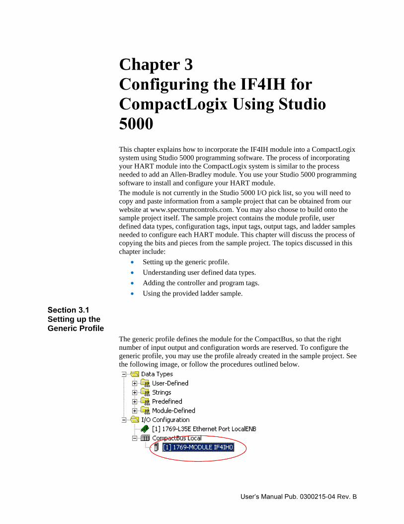
Setting up the Generic Profile
The generic profile defines the module for the CompactBus, so that the right
number of input output and configuration words are reserved. To configure the
generic profile, you may use the profile already created in the sample project. See
the following image, or follow the procedures outlined below.
3-2 Chapter 3: Configuring the IF4IH for CompactLogix Using Studio 5000
User’s Manual Pub. 0300215-04 Rev. B
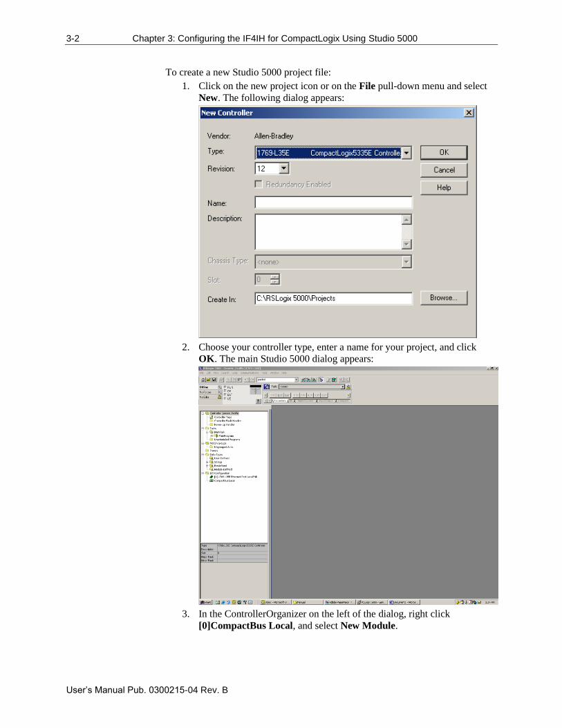
To create a new Studio 5000 project file:
1. Click on the new project icon or on the File pull-down menu and select
New. The following dialog appears:
2. Choose your controller type, enter a name for your project, and click
OK. The main Studio 5000 dialog appears:
3. In the ControllerOrganizer on the left of the dialog, right click
[0]CompactBus Local, and select New Module.
Chapter 3: Configuring the IF4IH for CompactLogix Using Studio 5000 3-3
User’s Manual Pub. 0300215-04 Rev. B
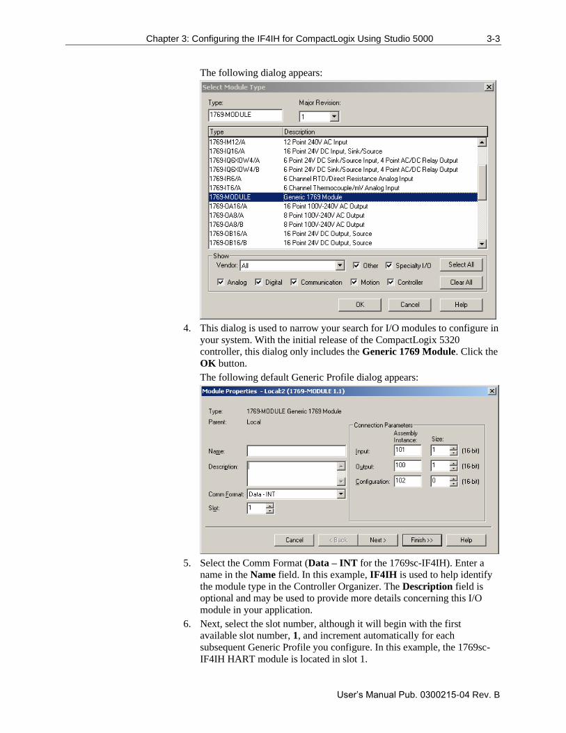
The following dialog appears:
4. This dialog is used to narrow your search for I/O modules to configure in
your system. With the initial release of the CompactLogix 5320
controller, this dialog only includes the Generic 1769 Module. Click the
OK button.
The following default Generic Profile dialog appears:
5. Select the Comm Format (Data – INT for the 1769sc-IF4IH). Enter a
name in the Name field. In this example, IF4IH is used to help identify
the module type in the Controller Organizer. The Description field is
optional and may be used to provide more details concerning this I/O
module in your application.
6. Next, select the slot number, although it will begin with the first
available slot number, 1, and increment automatically for each
subsequent Generic Profile you configure. In this example, the 1769sc-
IF4IH HART module is located in slot 1.
3-4 Chapter 3: Configuring the IF4IH for CompactLogix Using Studio 5000
User’s Manual Pub. 0300215-04 Rev. B
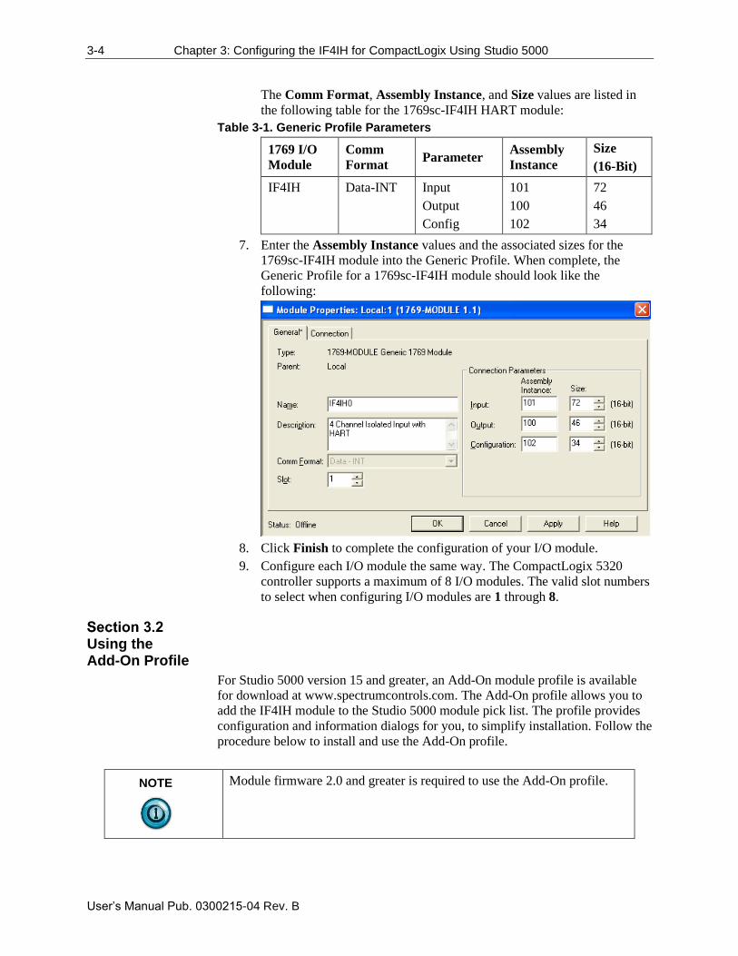
The Comm Format, Assembly Instance, and Size values are listed in
the following table for the 1769sc-IF4IH HART module:
Table 3-1. Generic Profile Parameters
1769 I/O
Module
Comm
Format Parameter
Assembly
Instance
Size
(16-Bit)
IF4IH Data-INT Input
Output
Config
101
100
102
72
46
34
7. Enter the Assembly Instance values and the associated sizes for the
1769sc-IF4IH module into the Generic Profile. When complete, the
Generic Profile for a 1769sc-IF4IH module should look like the
following:
8. Click Finish to complete the configuration of your I/O module.
9. Configure each I/O module the same way. The CompactLogix 5320
controller supports a maximum of 8 I/O modules. The valid slot numbers
to select when configuring I/O modules are 1 through 8.
Using the Add-On Profile
For Studio 5000 version 15 and greater, an Add-On module profile is available
for download at www.spectrumcontrols.com. The Add-On profile allows you to
add the IF4IH module to the Studio 5000 module pick list. The profile provides
configuration and information dialogs for you, to simplify installation. Follow the
procedure below to install and use the Add-On profile.
NOTE
Module firmware 2.0 and greater is required to use the Add-On profile.
Chapter 3: Configuring the IF4IH for CompactLogix Using Studio 5000 3-5
User’s Manual Pub. 0300215-04 Rev. B
To install:
1. Download the zipped file (SC 1769sc-IF4IH DTM 1.0.0.3 Setup.zip)
from the Spectrum Controls website and unzip the file.
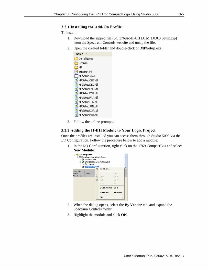
2. Open the created folder and double-click on MPSetup.exe:
3. Follow the online prompts.
Once the profiles are installed you can access them through Studio 5000 via the
I/O Configuration. Follow the procedure below to add a module:
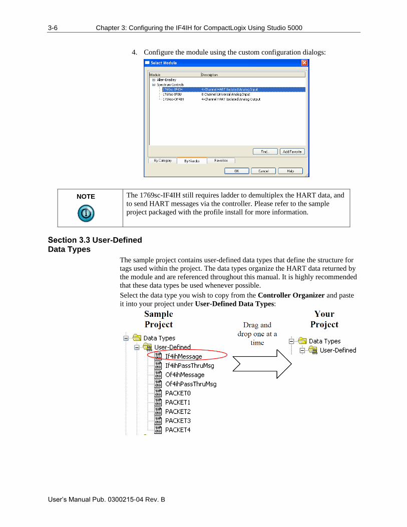
1. In the I/O Configuration, right click on the 1769 CompactBus and select
New Module:
2. When the dialog opens, select the By Vender tab, and expand the
Spectrum Controls folder.
3. Highlight the module and click OK.
3-6 Chapter 3: Configuring the IF4IH for CompactLogix Using Studio 5000
User’s Manual Pub. 0300215-04 Rev. B
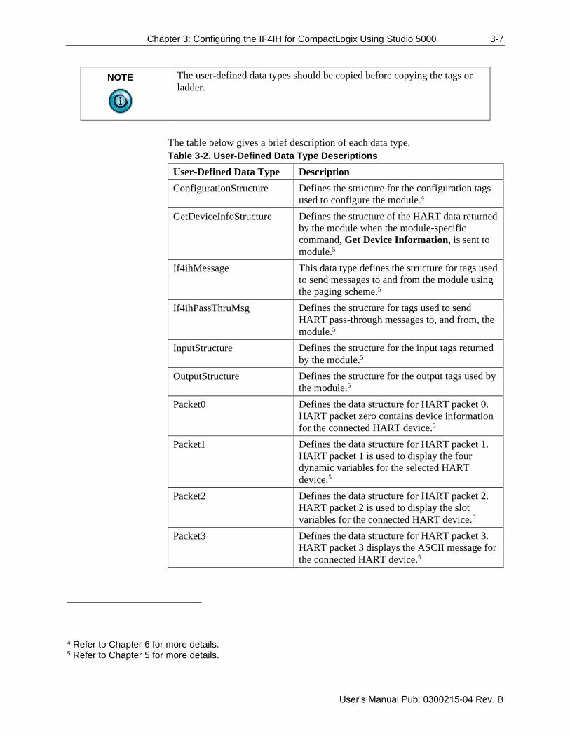
4. Configure the module using the custom configuration dialogs:
NOTE
The 1769sc-IF4IH still requires ladder to demultiplex the HART data, and
to send HART messages via the controller. Please refer to the sample
project packaged with the profile install for more information.
User-Defined Data Types
The sample project contains user-defined data types that define the structure for
tags used within the project. The data types organize the HART data returned by
the module and are referenced throughout this manual. It is highly recommended
that these data types be used whenever possible.
Select the data type you wish to copy from the Controller Organizer and paste
it into your project under User-Defined Data Types:
Chapter 3: Configuring the IF4IH for CompactLogix Using Studio 5000 3-7
User’s Manual Pub. 0300215-04 Rev. B
NOTE
The user-defined data types should be copied before copying the tags or
ladder.
The table below gives a brief description of each data type.
Table 3-2. User-Defined Data Type Descriptions
User-Defined Data Type Description
ConfigurationStructure Defines the structure for the configuration tags
used to configure the module.4
GetDeviceInfoStructure Defines the structure of the HART data returned
by the module when the module-specific
command, Get Device Information, is sent to
module.5
If4ihMessage This data type defines the structure for tags used
to send messages to and from the module using
the paging scheme.5
If4ihPassThruMsg Defines the structure for tags used to send
HART pass-through messages to, and from, the
module.5
InputStructure Defines the structure for the input tags returned
by the module.5
OutputStructure Defines the structure for the output tags used by
the module.5
Packet0 Defines the data structure for HART packet 0.
HART packet zero contains device information
for the connected HART device.5
Packet1 Defines the data structure for HART packet 1.
HART packet 1 is used to display the four
dynamic variables for the selected HART
device.5
Packet2 Defines the data structure for HART packet 2.
HART packet 2 is used to display the slot
variables for the connected HART device.5
Packet3 Defines the data structure for HART packet 3.
HART packet 3 displays the ASCII message for
the connected HART device.5
4 Refer to Chapter 6 for more details. 5 Refer to Chapter 5 for more details.
3-8 Chapter 3: Configuring the IF4IH for CompactLogix Using Studio 5000
User’s Manual Pub. 0300215-04 Rev. B
User-Defined Data Type Description
Packet4 Defines the data structure for HART packet 4.
HART packet 4 contains the extended status for
the connected HART device.5
Project Tags
The project tags were created to simplify the configuration of the module as well
as reduce confusion related to using only the module local tags. The tags defined
in the sample project use the user defined data types described in the previous
section.
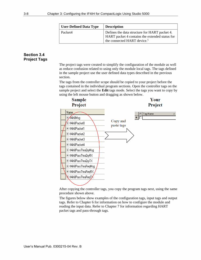
The tags from the controller scope should be copied to your project before the
tags contained in the individual program sections. Open the controller tags on the
sample project and select the Edit tags mode. Select the tags you want to copy by
using the left mouse button and dragging as shown below.
After copying the controller tags, you copy the program tags next, using the same
procedure shown above.
The figures below show examples of the configuration tags, input tags and output
tags. Refer to Chapter 6 for information on how to configure the module and
reading the input data. Refer to Chapter 7 for information regarding HART
packet tags and pass-through tags.
Chapter 3: Configuring the IF4IH for CompactLogix Using Studio 5000 3-9
User’s Manual Pub. 0300215-04 Rev. B
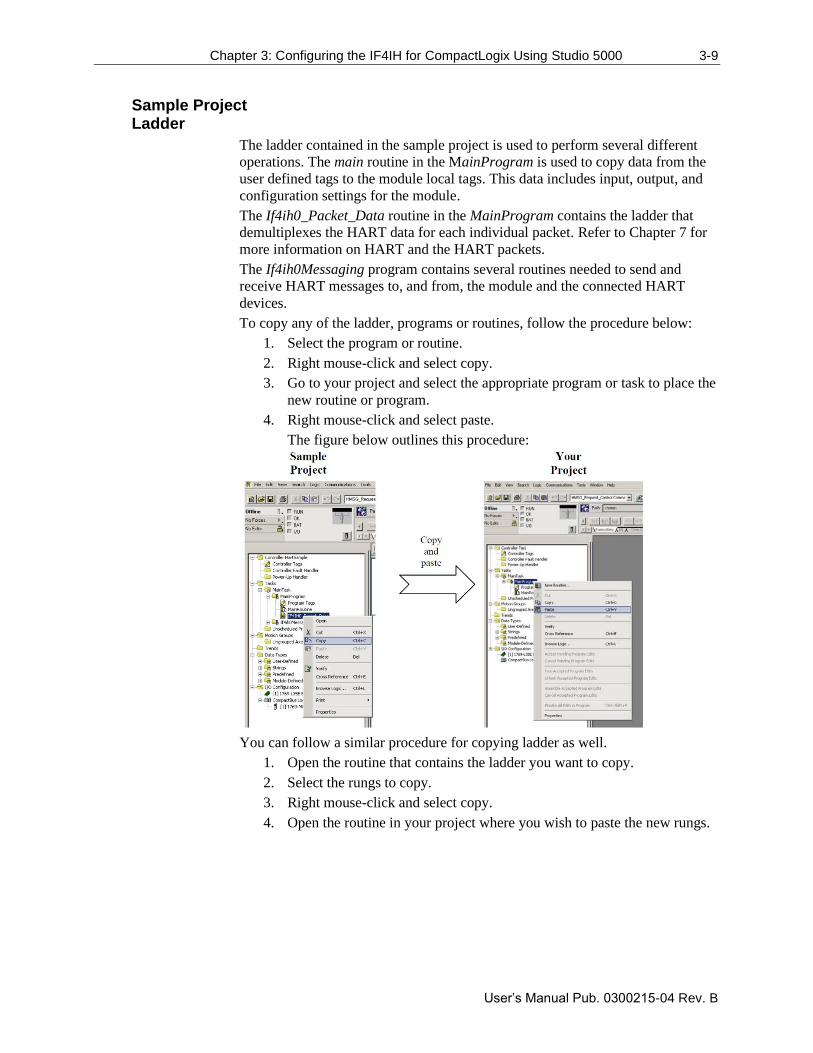
Sample Project Ladder
The ladder contained in the sample project is used to perform several different
operations. The main routine in the MainProgram is used to copy data from the
user defined tags to the module local tags. This data includes input, output, and
configuration settings for the module.
The If4ih0_Packet_Data routine in the MainProgram contains the ladder that
demultiplexes the HART data for each individual packet. Refer to Chapter 7 for
more information on HART and the HART packets.
The If4ih0Messaging program contains several routines needed to send and
receive HART messages to, and from, the module and the connected HART
devices.
To copy any of the ladder, programs or routines, follow the procedure below:
1. Select the program or routine.
2. Right mouse-click and select copy.
3. Go to your project and select the appropriate program or task to place the
new routine or program.
4. Right mouse-click and select paste.
The figure below outlines this procedure:
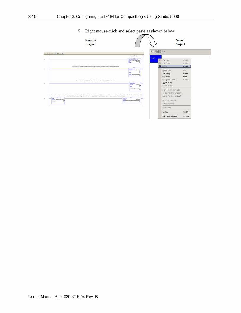
You can follow a similar procedure for copying ladder as well.
1. Open the routine that contains the ladder you want to copy.
2. Select the rungs to copy.
3. Right mouse-click and select copy.
4. Open the routine in your project where you wish to paste the new rungs.
3-10 Chapter 3: Configuring the IF4IH for CompactLogix Using Studio 5000
User’s Manual Pub. 0300215-04 Rev. B
5. Right mouse-click and select paste as shown below:
User’s Manual Pub. 0300215-04 Rev. B
Chapter 4 Configuring the
IF4IH for a MicroLogix 1500
Using Studio 500
This chapter explains the 1769sc-IF4IH module’s addressing scheme and
describes module configuration using Studio 500 and a MicroLogix 1500
controller. This chapter will cover the following:
• Module Addressing
• Configuring the IF4IH in a MicroLogix 1500 System
• Using the Ladder Sample
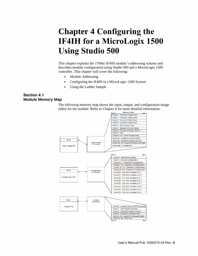
Module Memory Map
The following memory map shows the input, output, and configuration image
tables for the module. Refer to Chapter 6 for more detailed information.
4-2 Chapter 4: Configuring the IF4IH for a MicroLogix 1500 Using Studio 500
User’s Manual Pub. 0300215-04 Rev. B
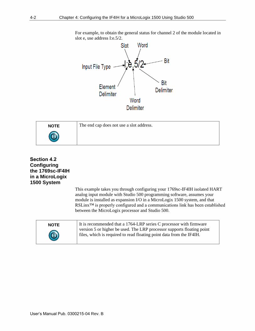
For example, to obtain the general status for channel 2 of the module located in
slot e, use address I:e.5/2.
NOTE
The end cap does not use a slot address.
Configuring the 1769sc-IF4IH in a MicroLogix 1500 System
This example takes you through configuring your 1769sc-IF4IH isolated HART
analog input module with Studio 500 programming software, assumes your
module is installed as expansion I/O in a MicroLogix 1500 system, and that
RSLinx™ is properly configured and a communications link has been established
between the MicroLogix processor and Studio 500.
NOTE
It is recommended that a 1764-LRP series C processor with firmware
version 5 or higher be used. The LRP processor supports floating point
files, which is required to read floating point data from the IF4IH.

Chapter 4: Configuring the IF4IH for a MicroLogix 1500 Using Studio 500 4-3
User’s Manual Pub. 0300215-04 Rev. B
To configure:
1. Start Studio and create a MicroLogix 1500 application. The following
dialog appears:
2. While offline, double-click on the IO Configuration icon under the
controller folder.
The following IO Configuration dialog appears:
3. This dialog allows you to manually enter expansion modules into
expansion slots, or to automatically read the configuration of the
controller. To read the existing controller configuration, click on the
Read IO Config button.
4-4 Chapter 4: Configuring the IF4IH for a MicroLogix 1500 Using Studio 500
User’s Manual Pub. 0300215-04 Rev. B
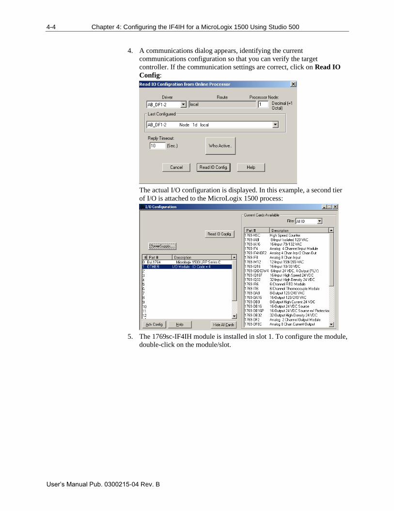
4. A communications dialog appears, identifying the current
communications configuration so that you can verify the target
controller. If the communication settings are correct, click on Read IO
Config:
The actual I/O configuration is displayed. In this example, a second tier
of I/O is attached to the MicroLogix 1500 process:
5. The 1769sc-IF4IH module is installed in slot 1. To configure the module,
double-click on the module/slot.
Chapter 4: Configuring the IF4IH for a MicroLogix 1500 Using Studio 500 4-5
User’s Manual Pub. 0300215-04 Rev. B
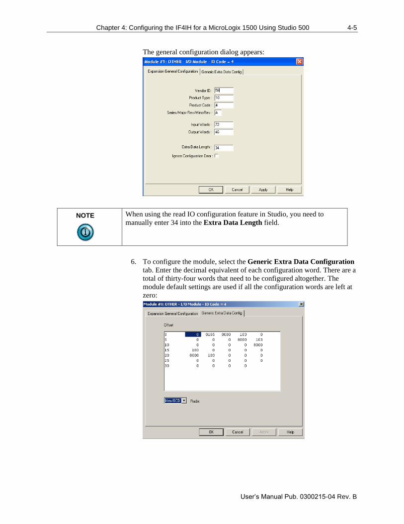
The general configuration dialog appears:
NOTE
When using the read IO configuration feature in Studio, you need to
manually enter 34 into the Extra Data Length field.
6. To configure the module, select the Generic Extra Data Configuration
tab. Enter the decimal equivalent of each configuration word. There are a
total of thirty-four words that need to be configured altogether. The
module default settings are used if all the configuration words are left at
zero:
4-6 Chapter 4: Configuring the IF4IH for a MicroLogix 1500 Using Studio 500
User’s Manual Pub. 0300215-04 Rev. B
NOTE
For a complete description of each of these parameters and the choices
available for each of them, refer to Chapter 5.
Using the Ladder Sample
To get started we recommend that you use the provided MicroLogix 1500 sample
project. Refer to Chapter 7 for the sample project or visit our website at
www.spectrumcontrols.com.
The sample project contains nine different subroutines which are used to perform
various HART related tasks. The following list describes the function of each
subroutine within the project file.
Table 4-1. Ladder Routines
Routine Description
MAIN The main routine is the starting point for the ladder
program.
PACKETS
The “packets” routine is used to demultiplex the
HART data from the input file to individual integer
files, so that the data can be viewed or used within
the ladder program. This routine is called from the
MAIN routine.
MSG_TO_MOD
This routine is used to send and receive messages
to and from the module. Refer to Chapter 6 for
more details regarding sending and receiving
messages. This routine is called from the
HART_MSG routine.
SRC_CHECK
Calculates the checksum for a message sent to the
module one page at a time. This routine is called
from the MSG_TO_MOD routine.
DEST_CHECKSUM
This routine calculates the checksum for a message
received from the module one page at a time. This
routine is called from the MSG_TO_MOD routine.
HART_MSG
This routine composes HART messages that will be
sent to the module/field transmitter. This routine is
called from the MAIN routine.
WORD_BYTE Converts word data to its byte equivalent. This
routine is called from the HART_MSG routine.
HART_CHECK
Calculates the checksum for the HART message
being sent to the module/field device. This routine
is called from the HART_MSG routine.
BYTE_WORD Converts byte data to its word equivalent. This
routine is called by the HART_MSG routine.
Chapter 4: Configuring the IF4IH for a MicroLogix 1500 Using Studio 500 4-7
User’s Manual Pub. 0300215-04 Rev. B
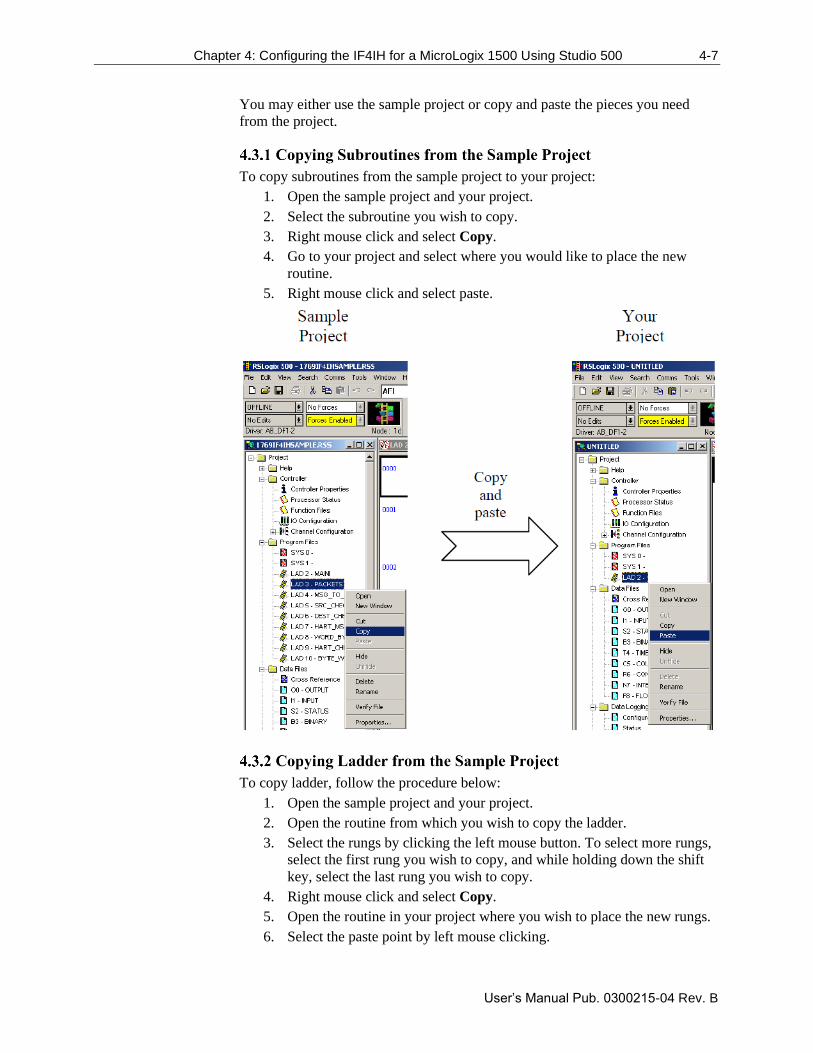
You may either use the sample project or copy and paste the pieces you need
from the project.
To copy subroutines from the sample project to your project:
1. Open the sample project and your project.
2. Select the subroutine you wish to copy.
3. Right mouse click and select Copy.
4. Go to your project and select where you would like to place the new
routine.
5. Right mouse click and select paste.
To copy ladder, follow the procedure below:
1. Open the sample project and your project.
2. Open the routine from which you wish to copy the ladder.
3. Select the rungs by clicking the left mouse button. To select more rungs,
select the first rung you wish to copy, and while holding down the shift
key, select the last rung you wish to copy.
4. Right mouse click and select Copy.
5. Open the routine in your project where you wish to place the new rungs.
6. Select the paste point by left mouse clicking.
4-8 Chapter 4: Configuring the IF4IH for a MicroLogix 1500 Using Studio 500
User’s Manual Pub. 0300215-04 Rev. B
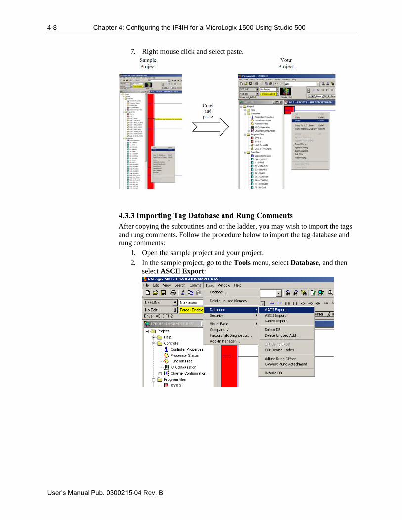
7. Right mouse click and select paste.
After copying the subroutines and or the ladder, you may wish to import the tags
and rung comments. Follow the procedure below to import the tag database and
rung comments:
1. Open the sample project and your project.
2. In the sample project, go to the Tools menu, select Database, and then
select ASCII Export:
Chapter 4: Configuring the IF4IH for a MicroLogix 1500 Using Studio 500 4-9
User’s Manual Pub. 0300215-04 Rev. B
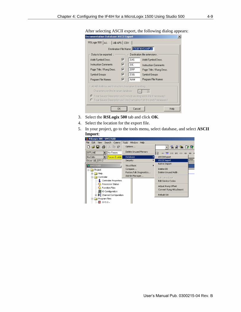
After selecting ASCII export, the following dialog appears:
3. Select the RSLogix 500 tab and click OK.
4. Select the location for the export file.
5. In your project, go to the tools menu, select database, and select ASCII
Import:
4-10 Chapter 4: Configuring the IF4IH for a MicroLogix 1500 Using Studio 500
User’s Manual Pub. 0300215-04 Rev. B
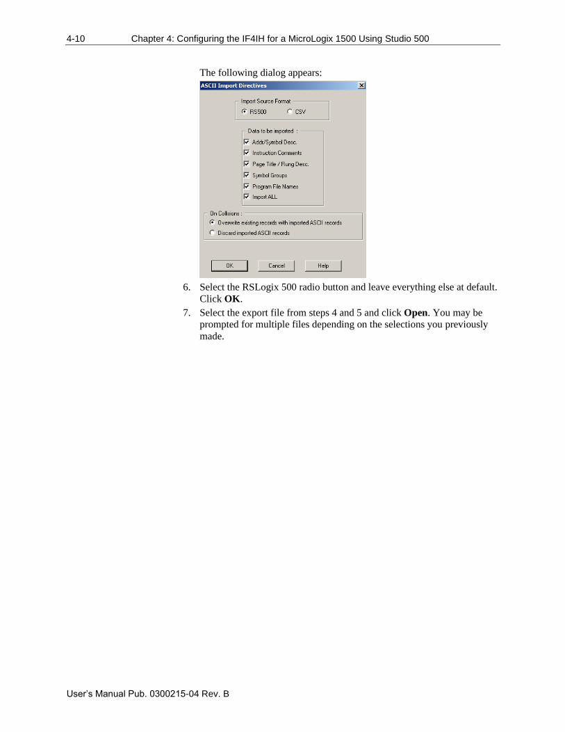
The following dialog appears:
6. Select the RSLogix 500 radio button and leave everything else at default.
Click OK.
7. Select the export file from steps 4 and 5 and click Open. You may be
prompted for multiple files depending on the selections you previously
made.
User’s Manual Pub. 0300215-04 Rev. B
Chapter 5 Module Data, Status, and
Channel Configuration
After installing the 1769sc-IF4IH isolated HART input module, you must
configure it for operation, usually using the programming software compatible
with the controller (for example, Studio 500 or Studio 5000). Once configuration
is complete and reflected in the ladder logic, you need to operate the module and
to verify its configuration.
This chapter contains information on the following:
• Module memory map
• Accessing input image file data ·
• Configuring channels
• Determining effective resolution and range
• Determining module update time
Module Memory Map
The module uses fifty input words for data and status bits (input image), twenty-
four output words, and thirty-four configuration words.
5-2 Chapter 5: Module Data, Status, and Configuration
User’s Manual Pub. 0300215-04 Rev. B
NOTE
Not all controllers support program access to the configuration file. Refer
to your controller’s user manual.
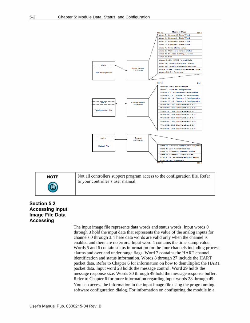
Accessing Input Image File Data Accessing
The input image file represents data words and status words. Input words 0
through 3 hold the input data that represents the value of the analog inputs for
channels 0 through 3. These data words are valid only when the channel is
enabled and there are no errors. Input word 4 contains the time stamp value.
Words 5 and 6 contain status information for the four channels including process
alarms and over and under range flags. Word 7 contains the HART channel
identification and status information. Words 8 through 27 include the HART
packet data. Refer to Chapter 6 for information on how to demultiplex the HART
packet data. Input word 28 holds the message control. Word 29 holds the
message response size. Words 30 through 49 hold the message response buffer.
Refer to Chapter 6 for more information regarding input words 28 through 49.
You can access the information in the input image file using the programming
software configuration dialog. For information on configuring the module in a
Chapter 5: Module Data, Status, and Configuration 5-3
User’s Manual Pub. 0300215-04 Rev. B
MicroLogix 1500 system using Studio 500, see Chapter 5; and for the
CompactLogix using Studio 5000, see Chapter 4.
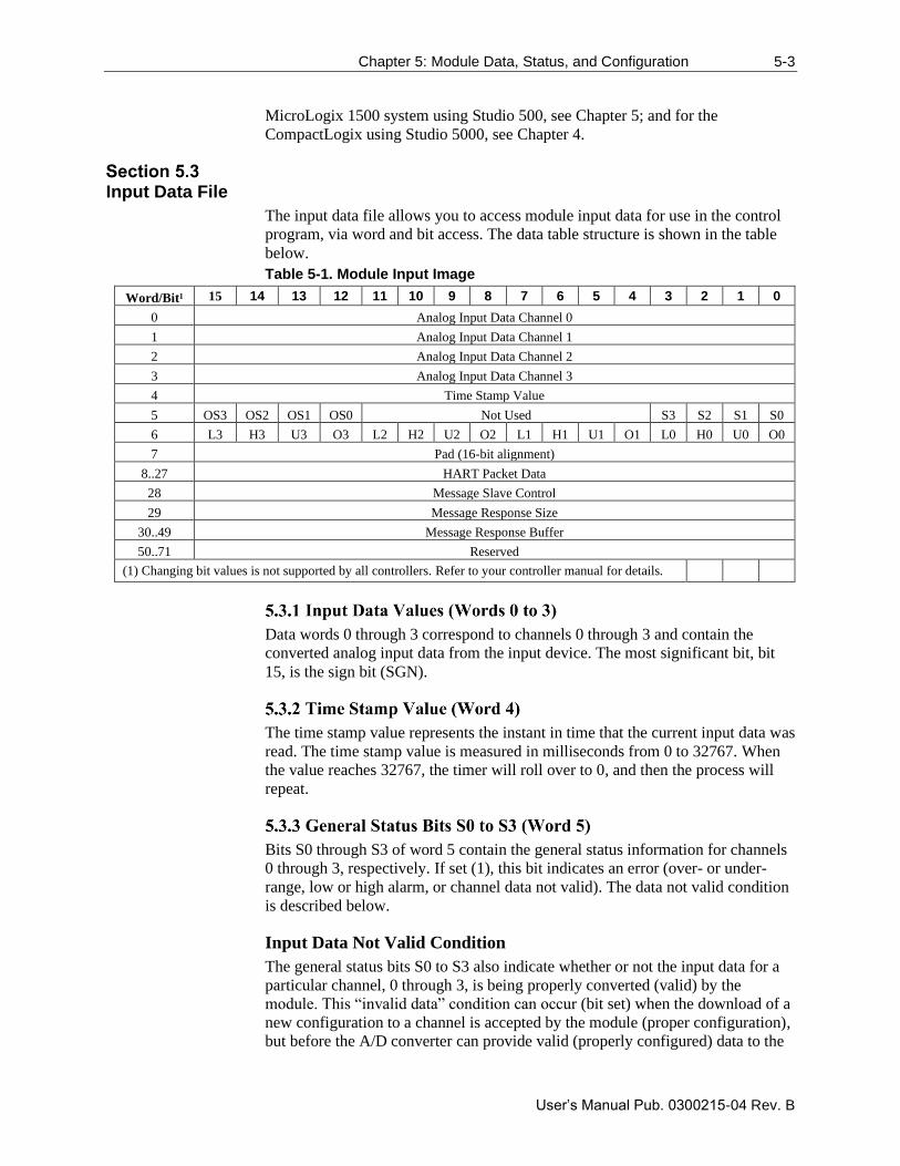
Input Data File
The input data file allows you to access module input data for use in the control
program, via word and bit access. The data table structure is shown in the table
below.
Table 5-1. Module Input Image
Word/Bit¹ 15 14 13 12 11 10 9 8 7 6 5 4 3 2 1 0
0 Analog Input Data Channel 0
1 Analog Input Data Channel 1
2 Analog Input Data Channel 2
3 Analog Input Data Channel 3
4 Time Stamp Value
5 OS3 OS2 OS1 OS0 Not Used S3 S2 S1 S0
6 L3 H3 U3 O3 L2 H2 U2 O2 L1 H1 U1 O1 L0 H0 U0 O0
7 Pad (16-bit alignment)
8..27 HART Packet Data
28 Message Slave Control
29 Message Response Size
30..49 Message Response Buffer
50..71 Reserved
(1) Changing bit values is not supported by all controllers. Refer to your controller manual for details.
Data words 0 through 3 correspond to channels 0 through 3 and contain the
converted analog input data from the input device. The most significant bit, bit
15, is the sign bit (SGN).
The time stamp value represents the instant in time that the current input data was
read. The time stamp value is measured in milliseconds from 0 to 32767. When
the value reaches 32767, the timer will roll over to 0, and then the process will
repeat.
Bits S0 through S3 of word 5 contain the general status information for channels
0 through 3, respectively. If set (1), this bit indicates an error (over- or under-
range, low or high alarm, or channel data not valid). The data not valid condition
is described below.
Input Data Not Valid Condition
The general status bits S0 to S3 also indicate whether or not the input data for a
particular channel, 0 through 3, is being properly converted (valid) by the
module. This “invalid data” condition can occur (bit set) when the download of a
new configuration to a channel is accepted by the module (proper configuration),
but before the A/D converter can provide valid (properly configured) data to the
5-4 Chapter 5: Module Data, Status, and Configuration
User’s Manual Pub. 0300215-04 Rev. B
1769 bus master/controller. The following information highlights the bit
operation of the Data Not Valid condition:
• The default and module power-up bit condition is reset (0).
• The bit condition is set (1) when a new configuration is received and
determined valid by the module. The set (1) bit condition remains until
the module begins converting analog data for the previously accepted
new configuration. When conversion begins, the bit condition is reset
(0). The amount of time it takes for the module to begin the conversion
process depends on the number of channels being configured and the
amount of configuration data downloaded by the controller.
NOTE
If the new configuration is invalid, the bit function remains reset (0) and
the module posts a configuration error. See Configuration Errors.
• If A/D hardware errors prevent the conversion process from taking place,
the bit condition is set to (1).
Bits SO0 through SO3 of word 0 indicate whether the associated channel is out
of service (i.e., automatic HART acquisition is suspended).
NOTE
A channel that is placed out-of-service (that is, Suspended) will
automatically resume service after three minutes, as long as no pass-
through commands are issued before the three minutes expires.
Over-range bits for channels 0 through 3 are contained in word 6, even-numbered
bits. They apply to all input types. When set (1), the over-range flag bit indicates
an input signal that is at the maximum of its normal operating range for the
represented channel or sensor. The module automatically resets (0) the bit when
the data value falls below the maximum for that range.
NOTE
If a channel is configured for a voltage type input and an open-circuit
condition is present, the over-range flag bit will be set to indicate the open
circuit condition and the associated channel data word will display the
full-scale value.
Under-range bits for channels 0 through 3 are contained in word 6, odd-
numbered bits. They apply to all input types. When set (1), the under-range flag
bit indicates an input signal that is at the minimum of its normal operating range
for the represented channel or sensor. The module automatically resets (0) the bit
Chapter 5: Module Data, Status, and Configuration 5-5
User’s Manual Pub. 0300215-04 Rev. B
when the under-range condition is cleared, and the data value is within the
normal operating range.
NOTE
If a channel is configured for a current type input, and an open-circuit
condition is present, the under-range flag bit will be set to indicate the
open circuit condition, and the associated channel data word will display
the minimum scale value.
The high process alarm flag is set when the measured analog signal exceeds the
high process alarm setpoint. The high process alarm setpoint is defined in Section
5.4 Module Configuration.
The low process alarm flag is set when the measured analog signal falls below
the low process alarm setpoint. The low process alarm setpoint is defined in
Section 5.4 Module Configuration.
Word 7 is not used and will always be zero. This word is used to maintain 16-bit
alignment.
This block of twenty words contains the multiplexed HART data for all four
channels.6
The message slave control word controls how data is returned from the module
after sending a message using output words 2 through 236.
The message reply size indicates the number of bytes returned by the module
after sending a message using output words 2 through 236.
After sending a message to the module, the response data for the message is
stored in the message reply buffer6.
Reserved for future expansion.
6 For more details refer to Chapter 7
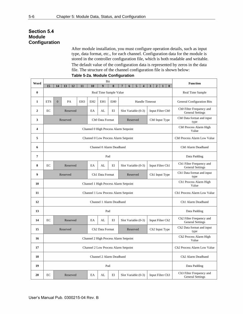
5-6 Chapter 5: Module Data, Status, and Configuration
User’s Manual Pub. 0300215-04 Rev. B
Module Configuration
After module installation, you must configure operation details, such as input
type, data format, etc., for each channel. Configuration data for the module is
stored in the controller configuration file, which is both readable and writable.
The default value of the configuration data is represented by zeros in the data
file. The structure of the channel configuration file is shown below:
Table 5-2a. Module Configuration
Word Bit
Function 15 14 13 12 11 10 9 8 7 6 5 4 3 2 1 0
0 Real Time Sample Value Real Time Sample
1 ETS 0 PA EH3 EH2 EH1 EH0 Handle Timeout General Configuration Bits
2 EC Reserved EA AL EI Slot Variable (0-3) Input Filter Ch0 Ch0 Filter Frequency and
General Settings
3 Reserved Ch0 Data Format Reserved Ch0 Input Type Ch0 Data format and input
type
4 Channel 0 High Process Alarm Setpoint Ch0 Process Alarm High
Value
5 Channel 0 Low Process Alarm Setpoint Ch0 Process Alarm Low Value
6 Channel 0 Alarm Deadband Ch0 Alarm Deadband
7 Pad Data Padding
8 EC Reserved EA AL EI Slot Variable (0-3) Input Filter Ch1 Ch1 Filter Frequency and
General Settings
9 Reserved Ch1 Data Format Reserved Ch1 Input Type Ch1 Data format and input
type
10 Channel 1 High Process Alarm Setpoint Ch1 Process Alarm High
Value
11 Channel 1 Low Process Alarm Setpoint Ch1 Process Alarm Low Value
12 Channel 1 Alarm Deadband Ch1 Alarm Deadband
13 Pad Data Padding
14 EC Reserved EA AL EI Slot Variable (0-3) Input Filter Ch2 Ch2 Filter Frequency and
General Settings
15 Reserved Ch2 Data Format Reserved Ch2 Input Type Ch2 Data format and input
type
16 Channel 2 High Process Alarm Setpoint Ch2 Process Alarm High
Value
17 Channel 2 Low Process Alarm Setpoint Ch2 Process Alarm Low Value
18 Channel 2 Alarm Deadband Ch2 Alarm Deadband
19 Pad Data Padding
20 EC Reserved EA AL EI Slot Variable (0-3) Input Filter Ch3 Ch3 Filter Frequency and
General Settings
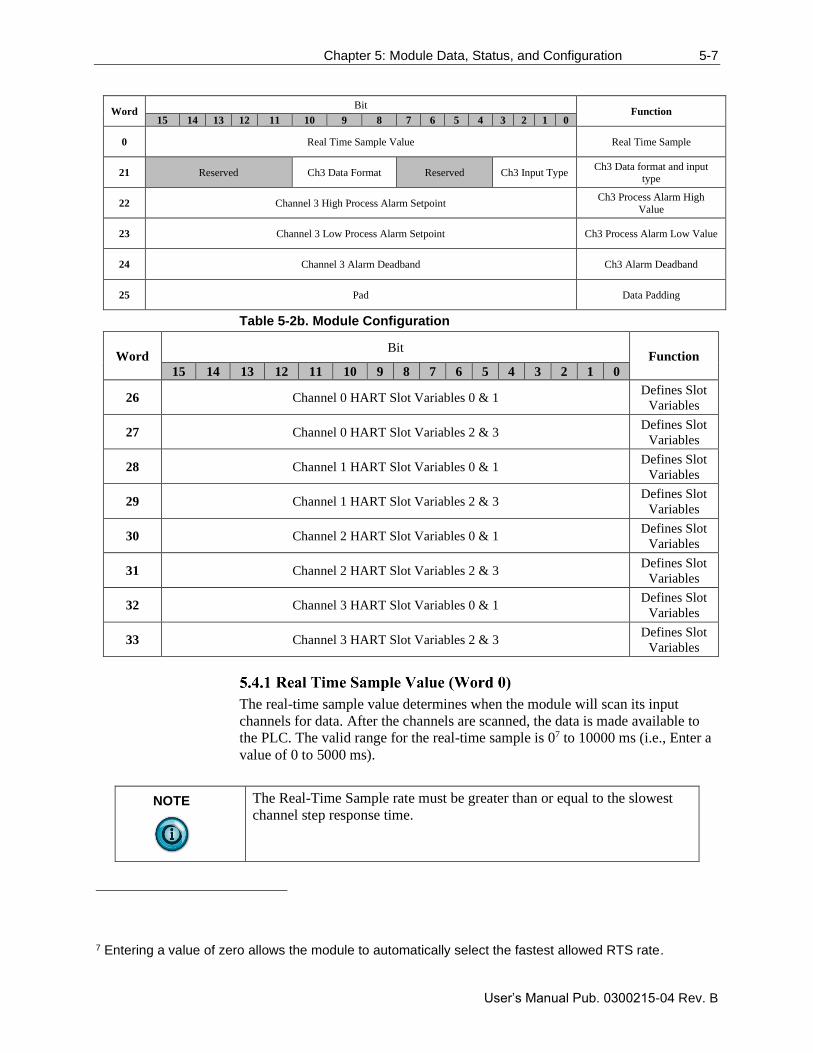
Chapter 5: Module Data, Status, and Configuration 5-7
User’s Manual Pub. 0300215-04 Rev. B
Word Bit
Function 15 14 13 12 11 10 9 8 7 6 5 4 3 2 1 0
0 Real Time Sample Value Real Time Sample
21 Reserved Ch3 Data Format Reserved Ch3 Input Type Ch3 Data format and input
type
22 Channel 3 High Process Alarm Setpoint Ch3 Process Alarm High
Value
23 Channel 3 Low Process Alarm Setpoint Ch3 Process Alarm Low Value
24 Channel 3 Alarm Deadband Ch3 Alarm Deadband
25 Pad Data Padding
Table 5-2b. Module Configuration
Word Bit
Function
15 14 13 12 11 10 9 8 7 6 5 4 3 2 1 0
26 Channel 0 HART Slot Variables 0 & 1 Defines Slot
Variables
27 Channel 0 HART Slot Variables 2 & 3 Defines Slot
Variables
28 Channel 1 HART Slot Variables 0 & 1 Defines Slot
Variables
29 Channel 1 HART Slot Variables 2 & 3 Defines Slot
Variables
30 Channel 2 HART Slot Variables 0 & 1 Defines Slot
Variables
31 Channel 2 HART Slot Variables 2 & 3 Defines Slot
Variables
32 Channel 3 HART Slot Variables 0 & 1 Defines Slot
Variables
33 Channel 3 HART Slot Variables 2 & 3 Defines Slot
Variables
The real-time sample value determines when the module will scan its input
channels for data. After the channels are scanned, the data is made available to
the PLC. The valid range for the real-time sample is 07 to 10000 ms (i.e., Enter a
value of 0 to 5000 ms).
NOTE
The Real-Time Sample rate must be greater than or equal to the slowest
channel step response time.
7 Entering a value of zero allows the module to automatically select the fastest allowed RTS rate.
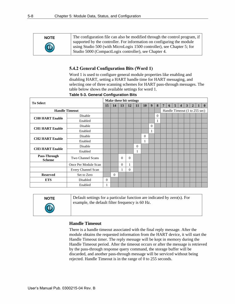
5-8 Chapter 5: Module Data, Status, and Configuration
User’s Manual Pub. 0300215-04 Rev. B
NOTE
The configuration file can also be modified through the control program, if
supported by the controller. For information on configuring the module
using Studio 500 (with MicroLogix 1500 controller), see Chapter 5; for
Studio 5000 (CompactLogix controller), see Chapter 4.
Word 1 is used to configure general module properties like enabling and
disabling HART, setting a HART handle time for HART messaging, and
selecting one of three scanning schemes for HART pass-through messages. The
table below shows the available settings for word 1.
Table 5-3. General Configuration Bits
To Select Make these bit settings
15 14 13 12 11 10 9 8 7 6 5 4 3 2 1 0
Handle Timeout Handle Timeout (1 to 255 sec)
CH0 HART Enable Disable 0
Enabled 1
CH1 HART Enable Disable 0
Enabled 1
CH2 HART Enable Disable 0
Enabled 1
CH3 HART Enable Disable 0
Enabled 1
Pass-Through
Scheme Two Channel Scans 0 0
Once Per Module Scan 0 1
Every Channel Scan 1 0
Reserved Set to Zero 0
ETS Disabled 0
Enabled 1
NOTE
Default settings for a particular function are indicated by zero(s). For
example, the default filter frequency is 60 Hz.
Handle Timeout
There is a handle timeout associated with the final reply message. After the
module obtains the requested information from the HART device, it will start the
Handle Timeout timer. The reply message will be kept in memory during the
Handle Timeout period. After the timeout occurs or after the message is retrieved
by the pass-through response query command, the storage buffer will be
discarded, and another pass-through message will be serviced without being
rejected. Handle Timeout is in the range of 0 to 255 seconds.
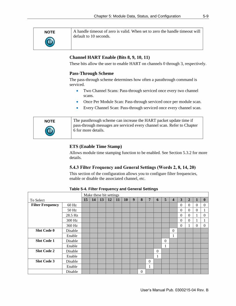
Chapter 5: Module Data, Status, and Configuration 5-9
User’s Manual Pub. 0300215-04 Rev. B
NOTE
A handle timeout of zero is valid. When set to zero the handle timeout will
default to 10 seconds.
Channel HART Enable (Bits 8, 9, 10, 11)
These bits allow the user to enable HART on channels 0 through 3, respectively.
Pass-Through Scheme
The pass-through scheme determines how often a passthrough command is
serviced.
• Two Channel Scans: Pass-through serviced once every two channel
scans.
• Once Per Module Scan: Pass-through serviced once per module scan.
• Every Channel Scan: Pass-through serviced once every channel scan.
NOTE
The passthrough scheme can increase the HART packet update time if
pass-through messages are serviced every channel scan. Refer to Chapter
6 for more details.
ETS (Enable Time Stamp)
Allows module time stamping function to be enabled. See Section 5.3.2 for more
details.
This section of the configuration allows you to configure filter frequencies,
enable or disable the associated channel, etc.
Table 5-4. Filter Frequency and General Settings
To Select
Make these bit settings
15 14 13 12 11 10 9 8 7 6 5 4 3 2 1 0
Filter Frequency 60 Hz 0 0 0 0
50 Hz 0 0 0 1
28.5 Hz 0 0 1 0
300 Hz 0 0 1 1
360 Hz 0 1 0 0
Slot Code 0 Disable 0
Enable 1
Slot Code 1 Disable 0
Enable 1
Slot Code 2 Disable 0
Enable 1
Slot Code 3 Disable 0
Enable 1
Disable 0
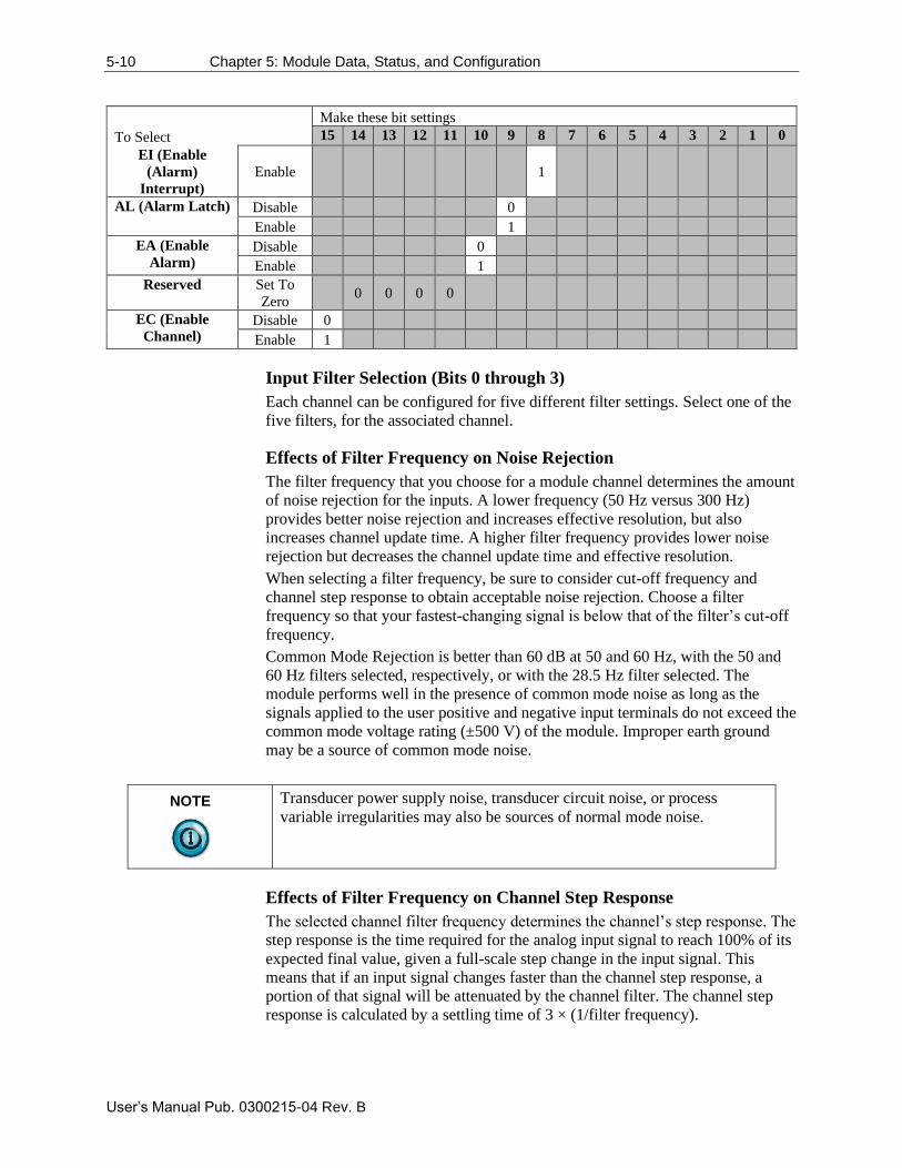
5-10 Chapter 5: Module Data, Status, and Configuration
User’s Manual Pub. 0300215-04 Rev. B
To Select
Make these bit settings
15 14 13 12 11 10 9 8 7 6 5 4 3 2 1 0
EI (Enable
(Alarm)
Interrupt)
Enable 1
AL (Alarm Latch) Disable 0
Enable 1
EA (Enable
Alarm) Disable 0
Enable 1
Reserved Set To
Zero 0 0 0 0
EC (Enable
Channel) Disable 0
Enable 1
Input Filter Selection (Bits 0 through 3)
Each channel can be configured for five different filter settings. Select one of the
five filters, for the associated channel.
Effects of Filter Frequency on Noise Rejection
The filter frequency that you choose for a module channel determines the amount
of noise rejection for the inputs. A lower frequency (50 Hz versus 300 Hz)
provides better noise rejection and increases effective resolution, but also
increases channel update time. A higher filter frequency provides lower noise
rejection but decreases the channel update time and effective resolution.
When selecting a filter frequency, be sure to consider cut-off frequency and
channel step response to obtain acceptable noise rejection. Choose a filter
frequency so that your fastest-changing signal is below that of the filter’s cut-off
frequency.
Common Mode Rejection is better than 60 dB at 50 and 60 Hz, with the 50 and
60 Hz filters selected, respectively, or with the 28.5 Hz filter selected. The
module performs well in the presence of common mode noise as long as the
signals applied to the user positive and negative input terminals do not exceed the
common mode voltage rating (±500 V) of the module. Improper earth ground
may be a source of common mode noise.
NOTE
Transducer power supply noise, transducer circuit noise, or process
variable irregularities may also be sources of normal mode noise.
Effects of Filter Frequency on Channel Step Response
The selected channel filter frequency determines the channel’s step response. The
step response is the time required for the analog input signal to reach 100% of its
expected final value, given a full-scale step change in the input signal. This
means that if an input signal changes faster than the channel step response, a
portion of that signal will be attenuated by the channel filter. The channel step
response is calculated by a settling time of 3 × (1/filter frequency).
Chapter 5: Module Data, Status, and Configuration 5-11
User’s Manual Pub. 0300215-04 Rev. B
NOTE
The Real-Time Sample rate must be greater than or equal to the slowest
channel step response time or a configuration error will occur.
Table 5-5. Filter Frequency and Step Response
Filter Frequency Step Response1
28.5 Hz 108 ms
50 Hz 62 ms
60 Hz 52 ms
300 Hz 12 ms
360 Hz 10 ms
1The channel update time is equal to the channel step response
Channel Cut-Off Frequency
The filter cut-off frequency, -3 dB, is the point on the frequency response curve
where frequency components of the input signal are passed with 3 dB of
attenuation. The following table shows cut-off frequencies for the supported
filters.
Table 5-6. Filter Frequency versus Channel Cut-off Frequency
Filter
Frequency
Cut-off
Frequency Rejection
28.5 Hz 2.3 Hz 67 dB at 50/60 Hz
50 Hz 4.0 Hz 96 dB at 50 Hz
60 Hz 4.7 Hz 96 dB at 60 Hz
300 Hz 24 Hz 25 dB at 50 Hz
360 Hz 28 Hz 25 dB at 60 Hz
All input frequency components at or below the cut-off frequency are passed by
the digital filter with less than 3 dB of attenuation.
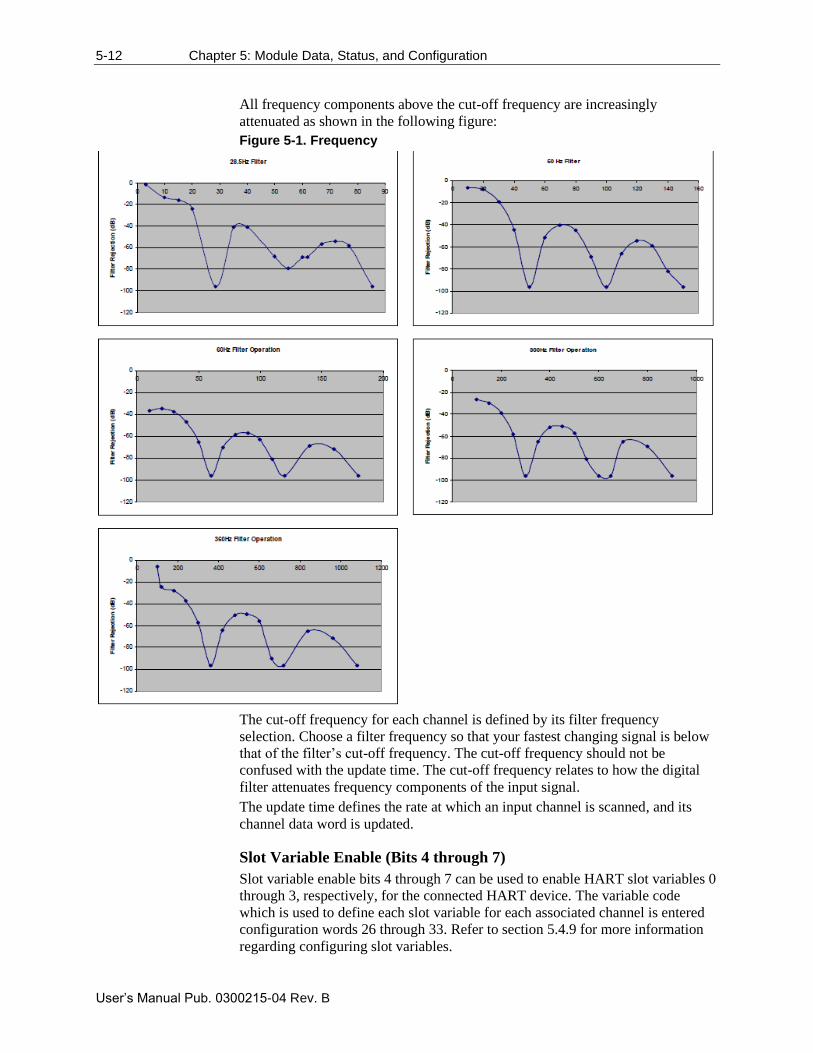
5-12 Chapter 5: Module Data, Status, and Configuration
User’s Manual Pub. 0300215-04 Rev. B
All frequency components above the cut-off frequency are increasingly
attenuated as shown in the following figure:
Figure 5-1. Frequency
The cut-off frequency for each channel is defined by its filter frequency
selection. Choose a filter frequency so that your fastest changing signal is below
that of the filter’s cut-off frequency. The cut-off frequency should not be
confused with the update time. The cut-off frequency relates to how the digital
filter attenuates frequency components of the input signal.
The update time defines the rate at which an input channel is scanned, and its
channel data word is updated.
Slot Variable Enable (Bits 4 through 7)
Slot variable enable bits 4 through 7 can be used to enable HART slot variables 0
through 3, respectively, for the connected HART device. The variable code
which is used to define each slot variable for each associated channel is entered
configuration words 26 through 33. Refer to section 5.4.9 for more information
regarding configuring slot variables.
Chapter 5: Module Data, Status, and Configuration 5-13
User’s Manual Pub. 0300215-04 Rev. B
NOTE
Slot variables are not supported by all HART devices.
NOTE
Slot codes must be enabled in sequential order. For example, SV0
(Enabled), SV1 (Disabled), and SV2 (Enabled), is not a valid
configuration. In this case, all three slot variables would be enabled.
EI (Enable [Alarm] Interrupt)
Allows each channel’s process alarm interrupts to be enabled.
AL (Alarm Latch)
Allows latching of each channel’s process alarms to be enabled.
EA (Enable Alarm)
Enable process alarming on the associated channel.
Reserved
Reserved for future expansion and should be set to zero.
EC (Enable Channel)
Enable associated channel.
This section of the configuration allows the user to define the input type (i.e., 0 to
20 mA, 4 to 20 mA, 0 to 10 VDC, etc.) and the data format for the associated
channel.
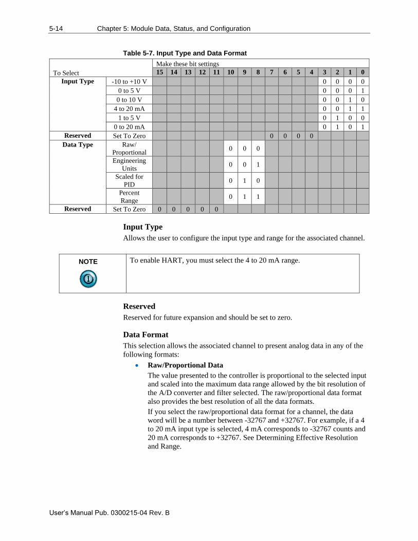
5-14 Chapter 5: Module Data, Status, and Configuration
User’s Manual Pub. 0300215-04 Rev. B
Table 5-7. Input Type and Data Format
To Select
Make these bit settings
15 14 13 12 11 10 9 8 7 6 5 4 3 2 1 0
Input Type -10 to +10 V 0 0 0 0
0 to 5 V 0 0 0 1
0 to 10 V 0 0 1 0
4 to 20 mA 0 0 1 1
1 to 5 V 0 1 0 0
0 to 20 mA 0 1 0 1
Reserved Set To Zero 0 0 0 0
Data Type Raw/
Proportional 0 0 0
Engineering
Units 0 0 1
Scaled for
PID 0 1 0
Percent
Range 0 1 1
Reserved Set To Zero 0 0 0 0 0
Input Type
Allows the user to configure the input type and range for the associated channel.
NOTE
To enable HART, you must select the 4 to 20 mA range.
Reserved
Reserved for future expansion and should be set to zero.
Data Format
This selection allows the associated channel to present analog data in any of the
following formats:
• Raw/Proportional Data
The value presented to the controller is proportional to the selected input
and scaled into the maximum data range allowed by the bit resolution of
the A/D converter and filter selected. The raw/proportional data format
also provides the best resolution of all the data formats.
If you select the raw/proportional data format for a channel, the data
word will be a number between -32767 and +32767. For example, if a 4
to 20 mA input type is selected, 4 mA corresponds to -32767 counts and
20 mA corresponds to +32767. See Determining Effective Resolution
and Range.
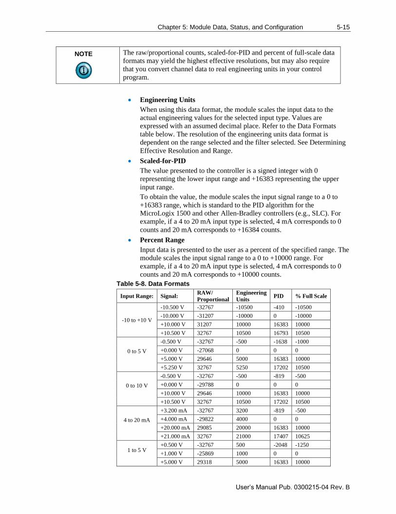
Chapter 5: Module Data, Status, and Configuration 5-15
User’s Manual Pub. 0300215-04 Rev. B
NOTE
The raw/proportional counts, scaled-for-PID and percent of full-scale data
formats may yield the highest effective resolutions, but may also require
that you convert channel data to real engineering units in your control
program.
• Engineering Units
When using this data format, the module scales the input data to the
actual engineering values for the selected input type. Values are
expressed with an assumed decimal place. Refer to the Data Formats
table below. The resolution of the engineering units data format is
dependent on the range selected and the filter selected. See Determining
Effective Resolution and Range.
• Scaled-for-PID
The value presented to the controller is a signed integer with 0
representing the lower input range and +16383 representing the upper
input range.
To obtain the value, the module scales the input signal range to a 0 to
+16383 range, which is standard to the PID algorithm for the
MicroLogix 1500 and other Allen-Bradley controllers (e.g., SLC). For
example, if a 4 to 20 mA input type is selected, 4 mA corresponds to 0
counts and 20 mA corresponds to +16384 counts.
• Percent Range
Input data is presented to the user as a percent of the specified range. The
module scales the input signal range to a 0 to +10000 range. For
example, if a 4 to 20 mA input type is selected, 4 mA corresponds to 0
counts and 20 mA corresponds to +10000 counts.
Table 5-8. Data Formats
Input Range: Signal: RAW/
Proportional
Engineering
Units PID % Full Scale
-10 to +10 V
-10.500 V -32767 -10500 -410 -10500
-10.000 V -31207 -10000 0 -10000
+10.000 V 31207 10000 16383 10000
+10.500 V 32767 10500 16793 10500
0 to 5 V
-0.500 V -32767 -500 -1638 -1000
+0.000 V -27068 0 0 0
+5.000 V 29646 5000 16383 10000
+5.250 V 32767 5250 17202 10500
0 to 10 V
-0.500 V -32767 -500 -819 -500
+0.000 V -29788 0 0 0
+10.000 V 29646 10000 16383 10000
+10.500 V 32767 10500 17202 10500
4 to 20 mA
+3.200 mA -32767 3200 -819 -500
+4.000 mA -29822 4000 0 0
+20.000 mA 29085 20000 16383 10000
+21.000 mA 32767 21000 17407 10625
1 to 5 V
+0.500 V -32767 500 -2048 -1250
+1.000 V -25869 1000 0 0
+5.000 V 29318 5000 16383 10000
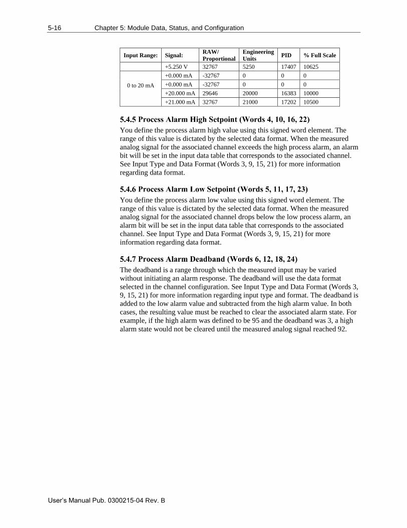
5-16 Chapter 5: Module Data, Status, and Configuration
User’s Manual Pub. 0300215-04 Rev. B
Input Range: Signal: RAW/
Proportional
Engineering
Units PID % Full Scale
+5.250 V 32767 5250 17407 10625
0 to 20 mA
+0.000 mA -32767 0 0 0
+0.000 mA -32767 0 0 0
+20.000 mA 29646 20000 16383 10000
+21.000 mA 32767 21000 17202 10500
You define the process alarm high value using this signed word element. The
range of this value is dictated by the selected data format. When the measured
analog signal for the associated channel exceeds the high process alarm, an alarm
bit will be set in the input data table that corresponds to the associated channel.
See Input Type and Data Format (Words 3, 9, 15, 21) for more information
regarding data format.
You define the process alarm low value using this signed word element. The
range of this value is dictated by the selected data format. When the measured
analog signal for the associated channel drops below the low process alarm, an
alarm bit will be set in the input data table that corresponds to the associated
channel. See Input Type and Data Format (Words 3, 9, 15, 21) for more
information regarding data format.
The deadband is a range through which the measured input may be varied
without initiating an alarm response. The deadband will use the data format
selected in the channel configuration. See Input Type and Data Format (Words 3,
9, 15, 21) for more information regarding input type and format. The deadband is
added to the low alarm value and subtracted from the high alarm value. In both
cases, the resulting value must be reached to clear the associated alarm state. For
example, if the high alarm was defined to be 95 and the deadband was 3, a high
alarm state would not be cleared until the measured analog signal reached 92.
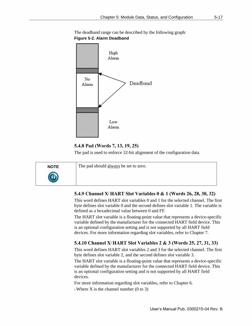
Chapter 5: Module Data, Status, and Configuration 5-17
User’s Manual Pub. 0300215-04 Rev. B
The deadband range can be described by the following graph:
Figure 5-2. Alarm Deadband
The pad is used to enforce 32-bit alignment of the configuration data.
NOTE
The pad should always be set to zero.
This word defines HART slot variables 0 and 1 for the selected channel. The first
byte defines slot variable 0 and the second defines slot variable 1. The variable is
defined as a hexadecimal value between 0 and FF.
The HART slot variable is a floating-point value that represents a device-specific
variable defined by the manufacturer for the connected HART field device. This
is an optional configuration setting and is not supported by all HART field
devices. For more information regarding slot variables, refer to Chapter 7.
This word defines HART slot variables 2 and 3 for the selected channel. The first
byte defines slot variable 2, and the second defines slot variable 3.
The HART slot variable is a floating-point value that represents a device-specific
variable defined by the manufacturer for the connected HART field device. This
is an optional configuration setting and is not supported by all HART field
devices.
For more information regarding slot variables, refer to Chapter 6.
1 Where X is the channel number (0 to 3)
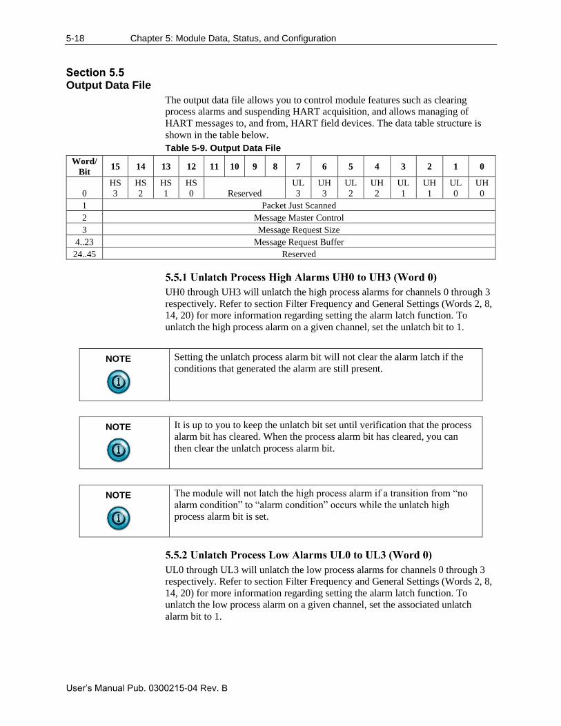
5-18 Chapter 5: Module Data, Status, and Configuration
User’s Manual Pub. 0300215-04 Rev. B
Output Data File
The output data file allows you to control module features such as clearing
process alarms and suspending HART acquisition, and allows managing of
HART messages to, and from, HART field devices. The data table structure is
shown in the table below.
Table 5-9. Output Data File
Word/
Bit 15 14 13 12 11 10 9 8 7 6 5 4 3 2 1 0
0
HS
3
HS
2
HS
1
HS
0 Reserved
UL
3
UH
3
UL
2
UH
2
UL
1
UH
1
UL
0
UH
0
1 Packet Just Scanned
2 Message Master Control
3 Message Request Size
4..23 Message Request Buffer
24..45 Reserved
UH0 through UH3 will unlatch the high process alarms for channels 0 through 3
respectively. Refer to section Filter Frequency and General Settings (Words 2, 8,
14, 20) for more information regarding setting the alarm latch function. To
unlatch the high process alarm on a given channel, set the unlatch bit to 1.
NOTE
Setting the unlatch process alarm bit will not clear the alarm latch if the
conditions that generated the alarm are still present.
NOTE
It is up to you to keep the unlatch bit set until verification that the process
alarm bit has cleared. When the process alarm bit has cleared, you can
then clear the unlatch process alarm bit.
NOTE
The module will not latch the high process alarm if a transition from “no
alarm condition” to “alarm condition” occurs while the unlatch high
process alarm bit is set.
UL0 through UL3 will unlatch the low process alarms for channels 0 through 3
respectively. Refer to section Filter Frequency and General Settings (Words 2, 8,
14, 20) for more information regarding setting the alarm latch function. To
unlatch the low process alarm on a given channel, set the associated unlatch
alarm bit to 1.
Chapter 5: Module Data, Status, and Configuration 5-19
User’s Manual Pub. 0300215-04 Rev. B
NOTE
Setting the unlatch process alarm bit will not clear the alarm latch if the
conditions that generated the alarm are still present.
NOTE
It is up to you to keep the unlatch bit set until verification that the process
alarm bit has cleared. When the process alarm bit has cleared, you can
then clear the unlatch process alarm bit.
NOTE
The module will not latch the low process alarm if a transition from “no
alarm condition” to “alarm condition” occurs while the unlatch low
process alarm bit is set.
HS0 to HS3 are used to suspend all HART acquisition, except pass-through
messages, on channels 0 through 3 respectively. To suspend HART acquisition,
set the associated channel suspend bit to 1. Normal HART acquisition will
resume when the bit is cleared.
When demultiplexing HART data from the module, this output word can be used
to speed up the acquisition process by overriding the automatic 500 ms
acquisition delay between packets.8 To override the delay, the packet just
scanned word needs to be populated with word seven from the input data file on
each scan of the ladder program. Input word seven contains the channel and
packet number just scanned.
NOTE
Input word seven is the first word of twenty which contains the
multiplexed HART data for each channel.
This word is used to control the data flow of a message sent to the module. These
messages include module commands such as HART pass-through, HART
suspend and resume, and get device information.6
The message request size determines the size of the message, in bytes, that will
be sent to the module.6
8 Refer to Chapter 6 for more details.
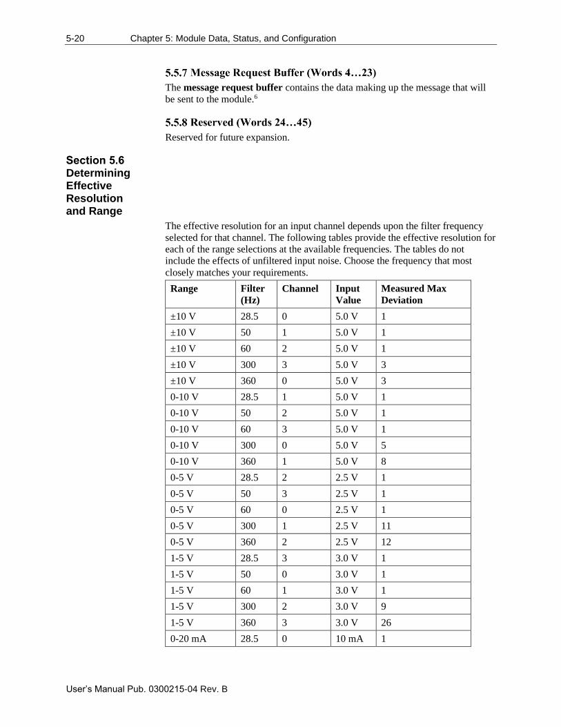
5-20 Chapter 5: Module Data, Status, and Configuration
User’s Manual Pub. 0300215-04 Rev. B
The message request buffer contains the data making up the message that will
be sent to the module.6
Reserved for future expansion.
Determining Effective Resolution and Range
The effective resolution for an input channel depends upon the filter frequency
selected for that channel. The following tables provide the effective resolution for
each of the range selections at the available frequencies. The tables do not
include the effects of unfiltered input noise. Choose the frequency that most
closely matches your requirements.
Range Filter
(Hz)
Channel Input
Value
Measured Max
Deviation
±10 V 28.5 0 5.0 V 1
±10 V 50 1 5.0 V 1
±10 V 60 2 5.0 V 1
±10 V 300 3 5.0 V 3
±10 V 360 0 5.0 V 3
0-10 V 28.5 1 5.0 V 1
0-10 V 50 2 5.0 V 1
0-10 V 60 3 5.0 V 1
0-10 V 300 0 5.0 V 5
0-10 V 360 1 5.0 V 8
0-5 V 28.5 2 2.5 V 1
0-5 V 50 3 2.5 V 1
0-5 V 60 0 2.5 V 1
0-5 V 300 1 2.5 V 11
0-5 V 360 2 2.5 V 12
1-5 V 28.5 3 3.0 V 1
1-5 V 50 0 3.0 V 1
1-5 V 60 1 3.0 V 1
1-5 V 300 2 3.0 V 9
1-5 V 360 3 3.0 V 26
0-20 mA 28.5 0 10 mA 1
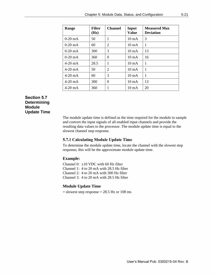
Chapter 5: Module Data, Status, and Configuration 5-21
User’s Manual Pub. 0300215-04 Rev. B
Range Filter
(Hz)
Channel Input
Value
Measured Max
Deviation
0-20 mA 50 1 10 mA 3
0-20 mA 60 2 10 mA 1
0-20 mA 300 3 10 mA 13
0-20 mA 360 0 10 mA 16
4-20 mA 28.5 1 10 mA 1
4-20 mA 50 2 10 mA 1
4-20 mA 60 3 10 mA 1
4-20 mA 300 0 10 mA 13
4-20 mA 360 1 10 mA 20
Determining Module Update Time
The module update time is defined as the time required for the module to sample
and convert the input signals of all enabled input channels and provide the
resulting data values to the processor. The module update time is equal to the
slowest channel step response.
To determine the module update time, locate the channel with the slowest step
response; this will be the approximate module update time.
Example:
Channel 0: ±10 VDC with 60 Hz filter
Channel 1: 4 to 20 mA with 28.5 Hz filter
Channel 2: 4 to 20 mA with 300 Hz filter
Channel 3: 4 to 20 mA with 28.5 Hz filter
Module Update Time
= slowest step response = 28.5 Hz or 108 ms

5-22 Chapter 5: Module Data, Status, and Configuration
User’s Manual Pub. 0300215-04 Rev. B
User’s Manual Pub. 0300215-04 Rev. B
Chapter 6 Enabling and Using HART on
the 1769sc-IF4IH
This chapter outlines the detailed settings and configuration related to HART
communication for the 1769sc-IF4IH module. These settings determine how the
module acquires HART data.
The chapter covers:
• Configuring the module for HART
• HART Packet Data
• Sending and Receiving Messages
• Module-specific Commands
• HART protocol overview
NOTE
The ladder samples and tags referenced in this chapter were created for the
Compact Logix controller using Studio 5000 software, see Chapter 3. If
you plan on using a MicroLogix 1500 controller, see Chapter 4.
Configuring the Module for HART
For HART to be active on any given channel, the channel configuration must
contain the following basic settings.
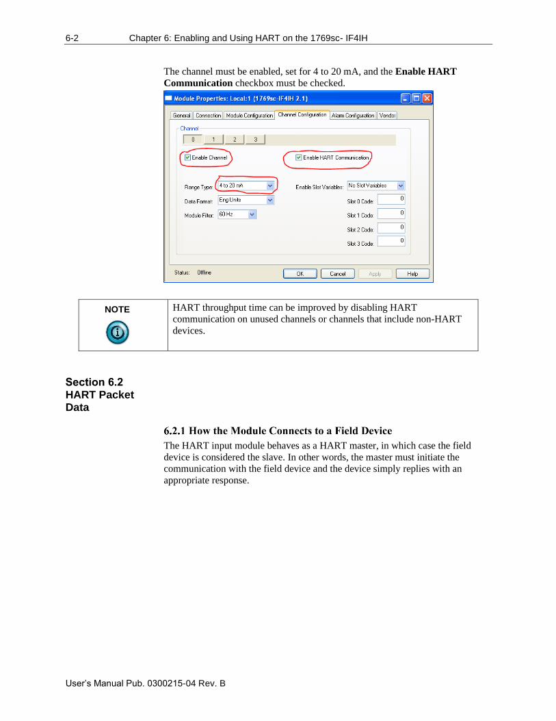
6-2 Chapter 6: Enabling and Using HART on the 1769sc- IF4IH
User’s Manual Pub. 0300215-04 Rev. B
The channel must be enabled, set for 4 to 20 mA, and the Enable HART
Communication checkbox must be checked.
NOTE
HART throughput time can be improved by disabling HART
communication on unused channels or channels that include non-HART
devices.
HART Packet Data
The HART input module behaves as a HART master, in which case the field
device is considered the slave. In other words, the master must initiate the
communication with the field device and the device simply replies with an
appropriate response.
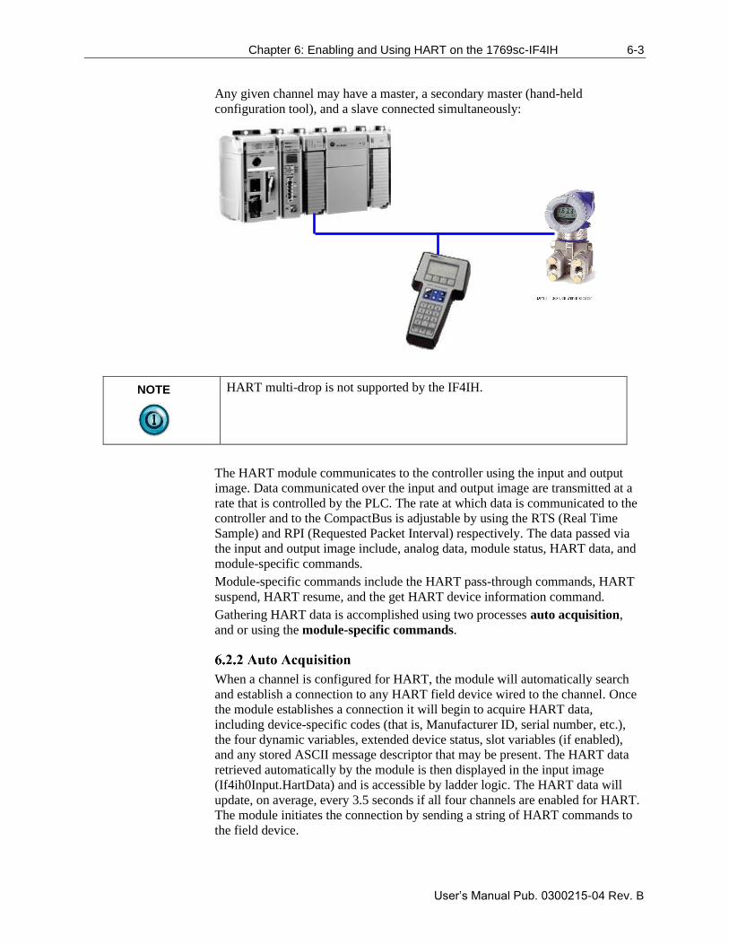
Chapter 6: Enabling and Using HART on the 1769sc-IF4IH 6-3
User’s Manual Pub. 0300215-04 Rev. B
Any given channel may have a master, a secondary master (hand-held
configuration tool), and a slave connected simultaneously:
NOTE
HART multi-drop is not supported by the IF4IH.
The HART module communicates to the controller using the input and output
image. Data communicated over the input and output image are transmitted at a
rate that is controlled by the PLC. The rate at which data is communicated to the
controller and to the CompactBus is adjustable by using the RTS (Real Time
Sample) and RPI (Requested Packet Interval) respectively. The data passed via
the input and output image include, analog data, module status, HART data, and
module-specific commands.
Module-specific commands include the HART pass-through commands, HART
suspend, HART resume, and the get HART device information command.
Gathering HART data is accomplished using two processes auto acquisition,
and or using the module-specific commands.
When a channel is configured for HART, the module will automatically search
and establish a connection to any HART field device wired to the channel. Once
the module establishes a connection it will begin to acquire HART data,
including device-specific codes (that is, Manufacturer ID, serial number, etc.),
the four dynamic variables, extended device status, slot variables (if enabled),
and any stored ASCII message descriptor that may be present. The HART data
retrieved automatically by the module is then displayed in the input image
(If4ih0Input.HartData) and is accessible by ladder logic. The HART data will
update, on average, every 3.5 seconds if all four channels are enabled for HART.
The module initiates the connection by sending a string of HART commands to
the field device.
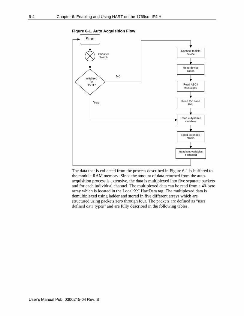
6-4 Chapter 6: Enabling and Using HART on the 1769sc- IF4IH
User’s Manual Pub. 0300215-04 Rev. B
Figure 6-1. Auto Acquisition Flow
The data that is collected from the process described in Figure 6-1 is buffered to
the module RAM memory. Since the amount of data returned from the auto-
acquisition process is extensive, the data is multiplexed into five separate packets
and for each individual channel. The multiplexed data can be read from a 40-byte
array which is located in the Local:X:I.HartData tag. The multiplexed data is
demultiplexed using ladder and stored in five different arrays which are
structured using packets zero through four. The packets are defined as “user
defined data types” and are fully described in the following tables.
Start Channel Switch
Initialized
for HART?
Connect to field device
Read device codes
Read extended status
Read ASCII messages
Read PVU and PVL
Read 4 dynamic variables
Read slot variables if enabled
No
Yes
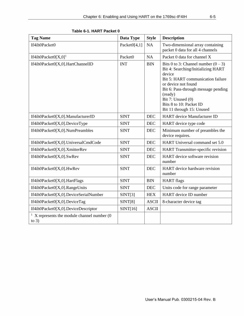
Chapter 6: Enabling and Using HART on the 1769sc-IF4IH 6-5
User’s Manual Pub. 0300215-04 Rev. B
Table 6-1. HART Packet 0
Tag Name Data Type Style Description
If4ih0Packet0 Packet0[4,1] NA Two-dimensional array containing
packet 0 data for all 4 channels
If4ih0Packet0[X,0]1 Packet0 NA Packet 0 data for channel X
If4ih0Packet0[X,0].HartChannelID INT BIN Bits 0 to 3: Channel number (0 – 3)
Bit 4: Searching/Initializing HART
device
Bit 5: HART communication failure
or device not found
Bit 6: Pass-through message pending
(ready)
Bit 7: Unused (0)
Bits 8 to 10: Packet ID
Bit 11 through 15: Unused
If4ih0Packet0[X,0].ManufacturerID SINT DEC HART device Manufacturer ID
If4ih0Packet0[X,0].DeviceType SINT DEC HART device type code
If4ih0Packet0[X,0].NumPreambles SINT DEC Minimum number of preambles the
device requires.
If4ih0Packet0[X,0].UniversalCmdCode SINT DEC HART Universal command set 5.0
If4ih0Packet0[X,0].XmitterRev SINT DEC HART Transmitter-specific revision
If4ih0Packet0[X,0].SwRev SINT DEC HART device software revision
number
If4ih0Packet0[X,0].HwRev SINT DEC HART device hardware revision
number
If4ih0Packet0[X,0].HartFlags SINT BIN HART flags
If4ih0Packet0[X,0].RangeUnits SINT DEC Units code for range parameter
If4ih0Packet0[X,0].DeviceSerialNumber SINT[3] HEX HART device ID number
If4ih0Packet0[X,0].DeviceTag SINT[8] ASCII 8-character device tag
If4ih0Packet0[X,0].DeviceDescriptor SINT[16] ASCII
1 X represents the module channel number (0
to 3)
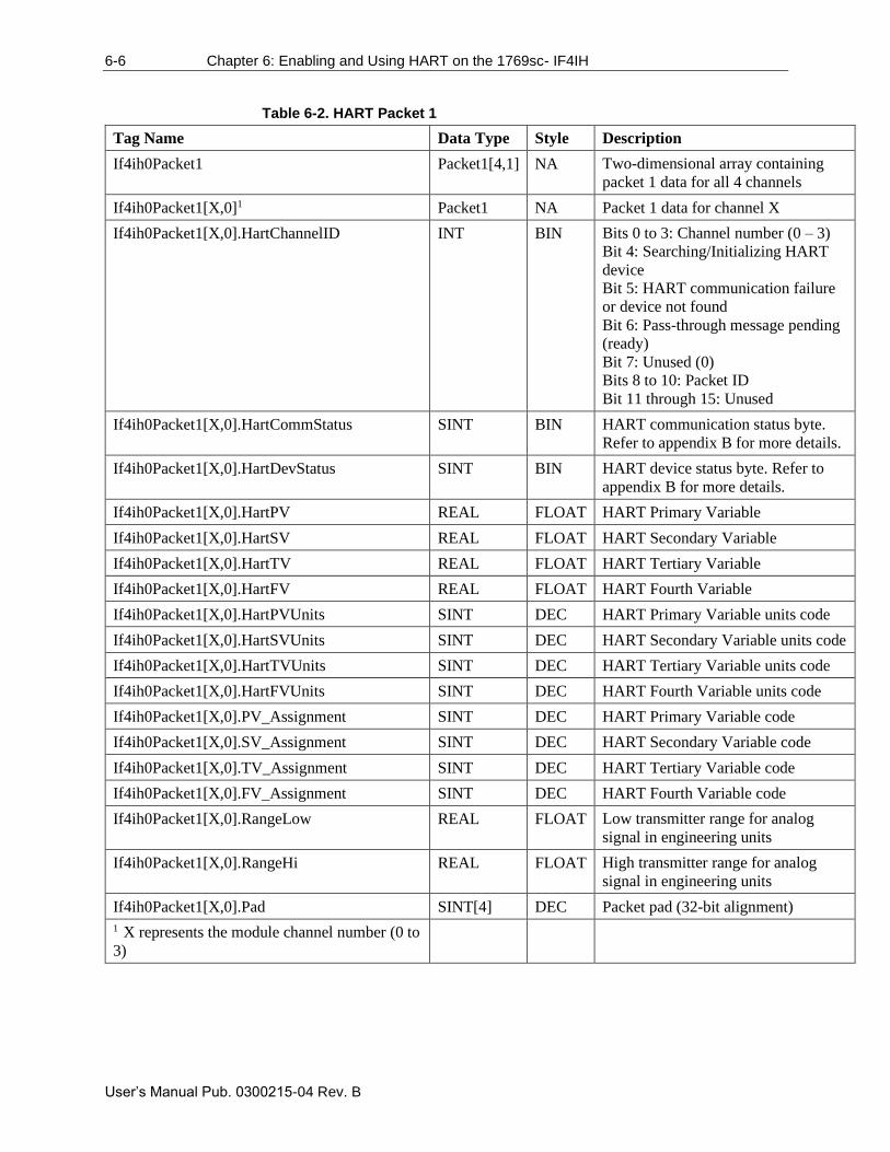
6-6 Chapter 6: Enabling and Using HART on the 1769sc- IF4IH
User’s Manual Pub. 0300215-04 Rev. B
Table 6-2. HART Packet 1
Tag Name Data Type Style Description
If4ih0Packet1 Packet1[4,1] NA Two-dimensional array containing
packet 1 data for all 4 channels
If4ih0Packet1[X,0]1 Packet1 NA Packet 1 data for channel X
If4ih0Packet1[X,0].HartChannelID INT BIN Bits 0 to 3: Channel number (0 – 3)
Bit 4: Searching/Initializing HART
device
Bit 5: HART communication failure
or device not found
Bit 6: Pass-through message pending
(ready)
Bit 7: Unused (0)
Bits 8 to 10: Packet ID
Bit 11 through 15: Unused
If4ih0Packet1[X,0].HartCommStatus SINT BIN HART communication status byte.
Refer to appendix B for more details.
If4ih0Packet1[X,0].HartDevStatus SINT BIN HART device status byte. Refer to
appendix B for more details.
If4ih0Packet1[X,0].HartPV REAL FLOAT HART Primary Variable
If4ih0Packet1[X,0].HartSV REAL FLOAT HART Secondary Variable
If4ih0Packet1[X,0].HartTV REAL FLOAT HART Tertiary Variable
If4ih0Packet1[X,0].HartFV REAL FLOAT HART Fourth Variable
If4ih0Packet1[X,0].HartPVUnits SINT DEC HART Primary Variable units code
If4ih0Packet1[X,0].HartSVUnits SINT DEC HART Secondary Variable units code
If4ih0Packet1[X,0].HartTVUnits SINT DEC HART Tertiary Variable units code
If4ih0Packet1[X,0].HartFVUnits SINT DEC HART Fourth Variable units code
If4ih0Packet1[X,0].PV_Assignment SINT DEC HART Primary Variable code
If4ih0Packet1[X,0].SV_Assignment SINT DEC HART Secondary Variable code
If4ih0Packet1[X,0].TV_Assignment SINT DEC HART Tertiary Variable code
If4ih0Packet1[X,0].FV_Assignment SINT DEC HART Fourth Variable code
If4ih0Packet1[X,0].RangeLow REAL FLOAT Low transmitter range for analog
signal in engineering units
If4ih0Packet1[X,0].RangeHi REAL FLOAT High transmitter range for analog
signal in engineering units
If4ih0Packet1[X,0].Pad SINT[4] DEC Packet pad (32-bit alignment)
1 X represents the module channel number (0 to
3)
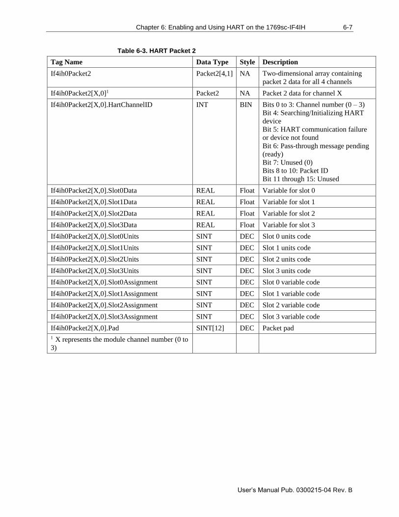
Chapter 6: Enabling and Using HART on the 1769sc-IF4IH 6-7
User’s Manual Pub. 0300215-04 Rev. B
Table 6-3. HART Packet 2
Tag Name Data Type Style Description
If4ih0Packet2 Packet2[4,1] NA Two-dimensional array containing
packet 2 data for all 4 channels
If4ih0Packet2[X,0]1 Packet2 NA Packet 2 data for channel X
If4ih0Packet2[X,0].HartChannelID INT BIN Bits 0 to 3: Channel number (0 – 3)
Bit 4: Searching/Initializing HART
device
Bit 5: HART communication failure
or device not found
Bit 6: Pass-through message pending
(ready)
Bit 7: Unused (0)
Bits 8 to 10: Packet ID
Bit 11 through 15: Unused
If4ih0Packet2[X,0].Slot0Data REAL Float Variable for slot 0
If4ih0Packet2[X,0].Slot1Data REAL Float Variable for slot 1
If4ih0Packet2[X,0].Slot2Data REAL Float Variable for slot 2
If4ih0Packet2[X,0].Slot3Data REAL Float Variable for slot 3
If4ih0Packet2[X,0].Slot0Units SINT DEC Slot 0 units code
If4ih0Packet2[X,0].Slot1Units SINT DEC Slot 1 units code
If4ih0Packet2[X,0].Slot2Units SINT DEC Slot 2 units code
If4ih0Packet2[X,0].Slot3Units SINT DEC Slot 3 units code
If4ih0Packet2[X,0].Slot0Assignment SINT DEC Slot 0 variable code
If4ih0Packet2[X,0].Slot1Assignment SINT DEC Slot 1 variable code
If4ih0Packet2[X,0].Slot2Assignment SINT DEC Slot 2 variable code
If4ih0Packet2[X,0].Slot3Assignment SINT DEC Slot 3 variable code
If4ih0Packet2[X,0].Pad SINT[12] DEC Packet pad
1 X represents the module channel number (0 to
3)
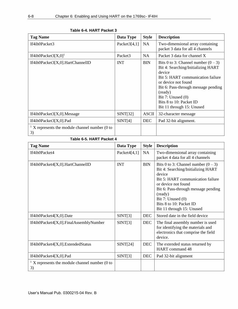
6-8 Chapter 6: Enabling and Using HART on the 1769sc- IF4IH
User’s Manual Pub. 0300215-04 Rev. B
Table 6-4. HART Packet 3
Tag Name Data Type Style Description
If4ih0Packet3 Packet3[4,1] NA Two-dimensional array containing
packet 3 data for all 4 channels
If4ih0Packet3[X,0]1 Packet3 NA Packet 3 data for channel X
If4ih0Packet3[X,0].HartChannelID INT BIN Bits 0 to 3: Channel number (0 – 3)
Bit 4: Searching/Initializing HART
device
Bit 5: HART communication failure
or device not found
Bit 6: Pass-through message pending
(ready)
Bit 7: Unused (0)
Bits 8 to 10: Packet ID
Bit 11 through 15: Unused
If4ih0Packet3[X,0].Message SINT[32] ASCII 32-character message
If4ih0Packet3[X,0].Pad SINT[4] DEC Pad 32-bit alignment.
1 X represents the module channel number (0 to
3)
Table 6-5. HART Packet 4
Tag Name Data Type Style Description
If4ih0Packet4 Packet4[4,1] NA Two-dimensional array containing
packet 4 data for all 4 channels
If4ih0Packet4[X,0].HartChannelID INT BIN Bits 0 to 3: Channel number (0 – 3)
Bit 4: Searching/Initializing HART
device
Bit 5: HART communication failure
or device not found
Bit 6: Pass-through message pending
(ready)
Bit 7: Unused (0)
Bits 8 to 10: Packet ID
Bit 11 through 15: Unused
If4ih0Packet4[X,0].Date SINT[3] DEC Stored date in the field device
If4ih0Packet4[X,0].FinalAssemblyNumber SINT[3] DEC The final assembly number is used
for identifying the materials and
electronics that comprise the field
device.
If4ih0Packet4[X,0].ExtendedStatus SINT[24] DEC The extended status returned by
HART command 48
If4ih0Packet4[X,0].Pad SINT[3] DEC Pad 32-bit alignment
1 X represents the module channel number (0 to
3)
Chapter 6: Enabling and Using HART on the 1769sc-IF4IH 6-9
User’s Manual Pub. 0300215-04 Rev. B
NOTE
Not all of the HART data that is returned by the process outlined in Figure
6-1 gets passed to the packets. To access the data that is not passed to the
packets, you must execute the appropriate HART message using the pass-
through command, which is discussed later in this chapter.
The ladder determines which packet to copy the data to by monitoring the state of
bits 0, 1, 2, and 8, 9, 10, found in the first two bytes of the Local:X:I.HartData
tag. Bits 0, 1, 2, determine the current channel being scanned and bits 8, 9, and
10 determine the packet number. The ladder example, shown in Figure 6-2
performs this operation.
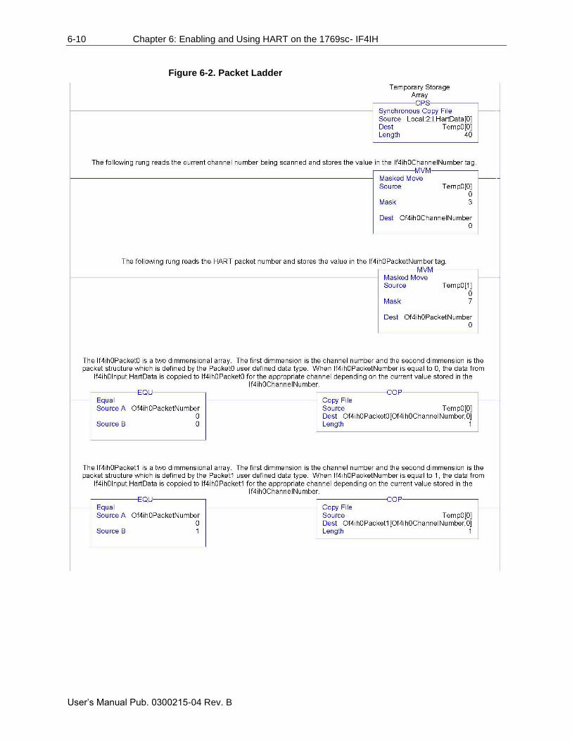
6-10 Chapter 6: Enabling and Using HART on the 1769sc- IF4IH
User’s Manual Pub. 0300215-04 Rev. B
Figure 6-2. Packet Ladder
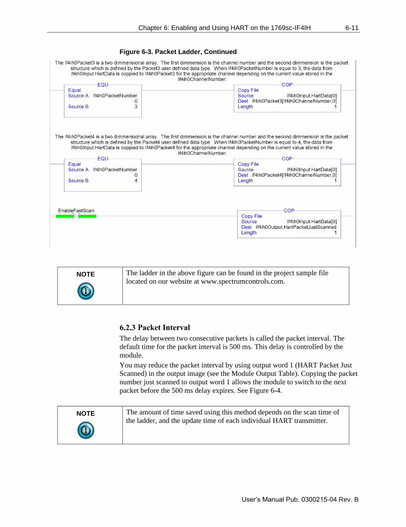
Chapter 6: Enabling and Using HART on the 1769sc-IF4IH 6-11
User’s Manual Pub. 0300215-04 Rev. B
Figure 6-3. Packet Ladder, Continued
NOTE
The ladder in the above figure can be found in the project sample file
located on our website at www.spectrumcontrols.com.
The delay between two consecutive packets is called the packet interval. The
default time for the packet interval is 500 ms. This delay is controlled by the
module.
You may reduce the packet interval by using output word 1 (HART Packet Just
Scanned) in the output image (see the Module Output Table). Copying the packet
number just scanned to output word 1 allows the module to switch to the next
packet before the 500 ms delay expires. See Figure 6-4.
NOTE
The amount of time saved using this method depends on the scan time of
the ladder, and the update time of each individual HART transmitter.
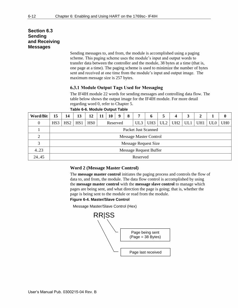
6-12 Chapter 6: Enabling and Using HART on the 1769sc- IF4IH
User’s Manual Pub. 0300215-04 Rev. B
Sending and Receiving Messages
Sending messages to, and from, the module is accomplished using a paging
scheme. This paging scheme uses the module’s input and output words to
transfer data between the controller and the module, 38 bytes at a time (that is,
one page at a time). The paging scheme is used to minimize the number of bytes
sent and received at one time from the module’s input and output image. The
maximum message size is 257 bytes.
The IF4IH module 22 words for sending messages and controlling data flow. The
table below shows the output image for the IF4IH module. For more detail
regarding word 0, refer to Chapter 5.
Table 6-6. Module Output Table
Word/Bit 15 14 13 12 11 10 9 8 7 6 5 4 3 2 1 0
0 HS3 HS2 HS1 HS0 Reserved UL3 UH3 UL2 UH2 UL1 UH1 UL0 UH0
1 Packet Just Scanned
2 Message Master Control
3 Message Request Size
4..23 Message Request Buffer
24..45 Reserved
Word 2 (Message Master Control)
The message master control initiates the paging process and controls the flow of
data to, and from, the module. The data flow control is accomplished by using
the message master control with the message slave control to manage which
pages are being sent, and what direction the page is going; that is, whether the
page is being sent to the module or read from the module.
Figure 6-4. Master/Slave Control
RR|SS
Message Master/Slave Control (Hex)
Page being sent (Page = 38 Bytes)
Page last received
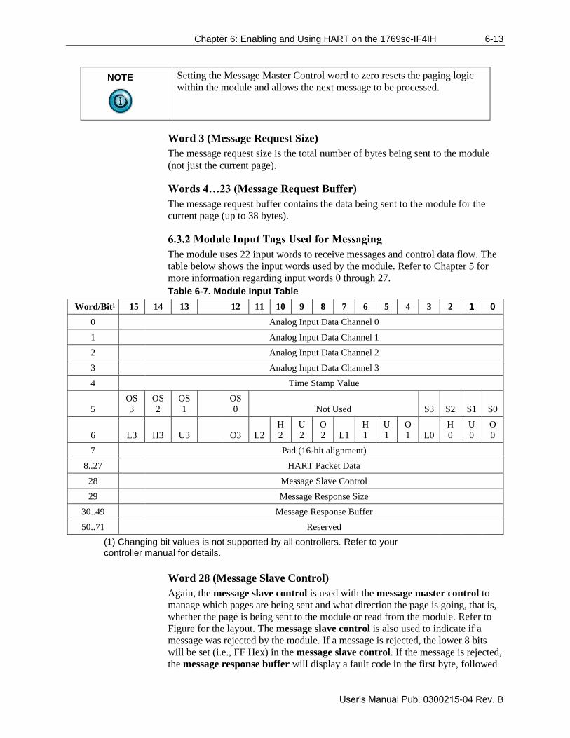
Chapter 6: Enabling and Using HART on the 1769sc-IF4IH 6-13
User’s Manual Pub. 0300215-04 Rev. B
NOTE
Setting the Message Master Control word to zero resets the paging logic
within the module and allows the next message to be processed.
Word 3 (Message Request Size)
The message request size is the total number of bytes being sent to the module
(not just the current page).
Words 4…23 (Message Request Buffer)
The message request buffer contains the data being sent to the module for the
current page (up to 38 bytes).
The module uses 22 input words to receive messages and control data flow. The
table below shows the input words used by the module. Refer to Chapter 5 for
more information regarding input words 0 through 27.
Table 6-7. Module Input Table
Word/Bit¹ 15 14 13 12 11 10 9 8 7 6 5 4 3 2 1 0
0 Analog Input Data Channel 0
1 Analog Input Data Channel 1
2 Analog Input Data Channel 2
3 Analog Input Data Channel 3
4 Time Stamp Value
5
OS
3
OS
2
OS
1
OS
0 Not Used S3 S2 S1 S0
6 L3 H3 U3
O3 L2
H
2
U
2
O
2 L1
H
1
U
1
O
1 L0
H
0
U
0
O
0
7 Pad (16-bit alignment)
8..27 HART Packet Data
28 Message Slave Control
29 Message Response Size
30..49 Message Response Buffer
50..71 Reserved
(1) Changing bit values is not supported by all controllers. Refer to your controller manual for details.
Word 28 (Message Slave Control)
Again, the message slave control is used with the message master control to
manage which pages are being sent and what direction the page is going, that is,
whether the page is being sent to the module or read from the module. Refer to
Figure for the layout. The message slave control is also used to indicate if a
message was rejected by the module. If a message is rejected, the lower 8 bits
will be set (i.e., FF Hex) in the message slave control. If the message is rejected,
the message response buffer will display a fault code in the first byte, followed
6-14 Chapter 6: Enabling and Using HART on the 1769sc- IF4IH
User’s Manual Pub. 0300215-04 Rev. B
by a checksum in the second.
The table below lists the possible responses.
Table 6-8. Paging Error Codes
Error Code Description
1 A page was sent out of sequence.
2 While processing page 2, 3, etc. The message size was different
than it was for page 1.
3 The message size given exceeds the max allowed.
4 The message page data checksum is not correct.
Word 29 (Message Response Size)
The message response size indicates the total number of bytes being returned by
the module.
Words 30…49 (Message Response Buffer)
The message response buffer contains the response data for the current page up
to thirty-eight bytes at a time.
To complete a message from beginning to end, follow the steps listed below:
1. Store the message you wish to send to the module in an array.
Remember the message can be up to 257 bytes long, so make the array
large enough.
2. Copy the first page of data, up to 38 bytes, to the message request
buffer. If the number of bytes is odd, the last byte in the last word will
be padded with a zero.
3. Calculate the checksum of the message by taking the exclusive OR of all
the words within the page (19 max). Place the result into the last word of
the message (that is, word # 20 if a full page).
4. Enter the size of the message to be sent to the module into the message
request size output word.
5. Add a 1 to the lower nibble of the message master control word (that is,
0001 Hex). The message master control should be zero when the
message is started.
6. Wait for the module to reply that it has received the page without error,
by monitoring the second nibble of the message slave control (i.e.,
0100).
If the lower nibble contains FF, stop the process because the data is
corrupted. The first byte in the message response buffer will contain the
paging error code. Refer to the Paging Error Codes table for a description
of the errors.
7. Check to see if there are more pages to send by comparing the bytes sent
to the message request size. If so, repeat steps 2 through 6. If not, go to
step 8.
8. Monitor the lower nibble of the message slave control to see if the first
page of the response data is ready (0101).
Chapter 6: Enabling and Using HART on the 1769sc-IF4IH 6-15
User’s Manual Pub. 0300215-04 Rev. B
9. Copy the first page of the response data from the message response
buffer to a temporary array.
10. Take the exclusive OR of all the words within the page (19 max), with
the exception, of the last word, which is the checksum. Compare the
calculated checksum with the checksum stored in the last byte. If they
are equal, go to step 11. If they are not, stop the process because the data
is corrupted.
11. Check to see if there is more response data remaining by comparing the
bytes received to the message response size. If so, repeat steps 8 through
10. If not, the message is finished. To send another message clear the
message master control and repeat the process.
A graphical representation of the process can be seen in the following figures.
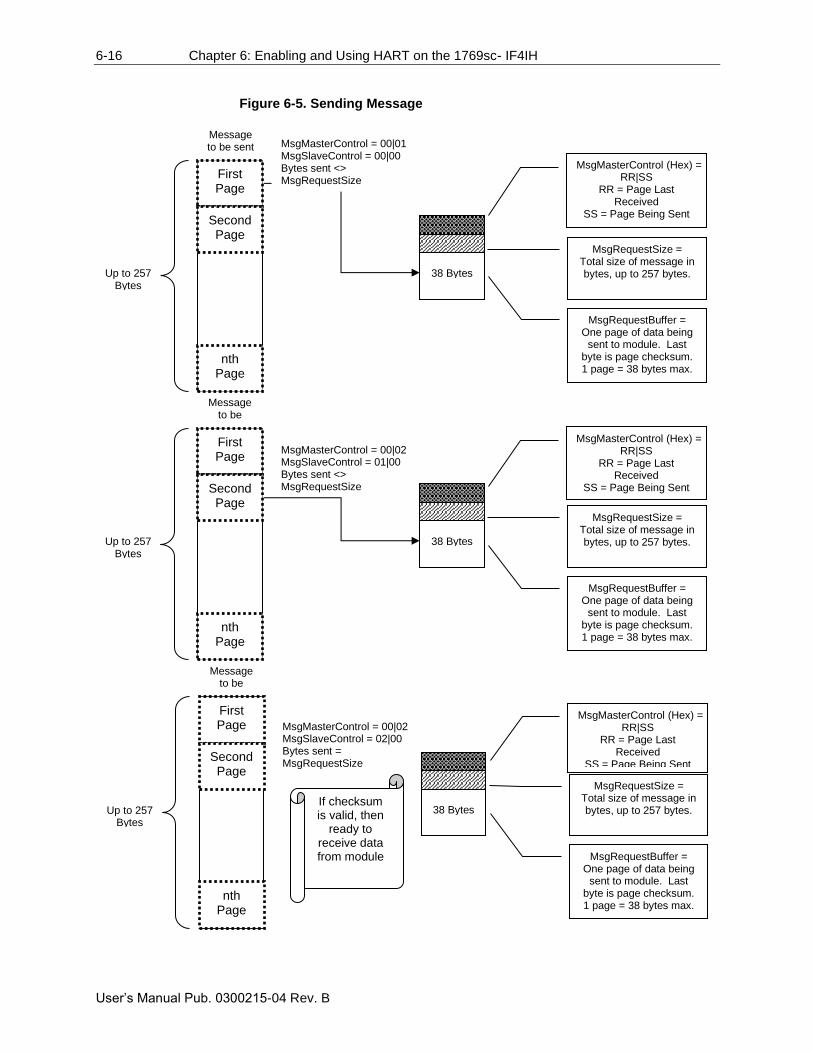
6-16 Chapter 6: Enabling and Using HART on the 1769sc- IF4IH
User’s Manual Pub. 0300215-04 Rev. B
Figure 6-5. Sending Message
Up to 257 Bytes
MsgMasterControl (Hex) = RR|SS
RR = Page Last Received
SS = Page Being Sent
MsgRequestSize = Total size of message in bytes, up to 257 bytes.
MsgRequestBuffer = One page of data being
sent to module. Last byte is page checksum. 1 page = 38 bytes max.
First Page
38 Bytes
Second Page
nth Page
MsgMasterControl = 00|02 MsgSlaveControl = 01|00 Bytes sent <> MsgRequestSize
Message to be sent
Up to 257 Bytes
MsgMasterControl (Hex) = RR|SS
RR = Page Last Received
SS = Page Being Sent
MsgRequestSize = Total size of message in bytes, up to 257 bytes.
MsgRequestBuffer = One page of data being
sent to module. Last byte is page checksum. 1 page = 38 bytes max.
First Page
38 Bytes
Second Page
nth Page
MsgMasterControl = 00|02 MsgSlaveControl = 02|00 Bytes sent = MsgRequestSize
Message to be sent
If checksum is valid, then
ready to receive data from module
MsgMasterControl (Hex) = RR|SS
RR = Page Last Received
SS = Page Being Sent
MsgRequestSize = Total size of message in bytes, up to 257 bytes.
MsgRequestBuffer = One page of data being
sent to module. Last byte is page checksum. 1 page = 38 bytes max.
First Page
Up to 257 Bytes
38 Bytes
Second Page
nth Page
MsgMasterControl = 00|01 MsgSlaveControl = 00|00 Bytes sent <> MsgRequestSize
Message to be sent
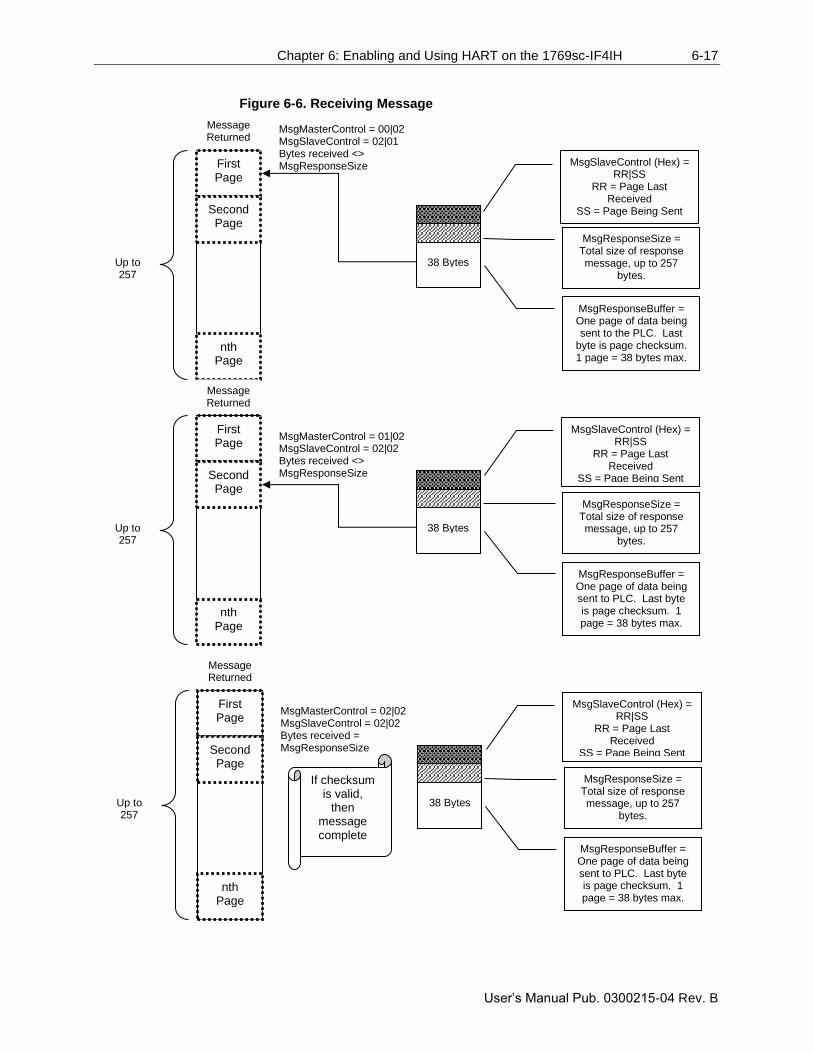
Chapter 6: Enabling and Using HART on the 1769sc-IF4IH 6-17
User’s Manual Pub. 0300215-04 Rev. B
Figure 6-6. Receiving Message
MsgSlaveControl (Hex) = RR|SS
RR = Page Last Received
SS = Page Being Sent
MsgResponseSize = Total size of response message, up to 257
bytes.
MsgResponseBuffer = One page of data being sent to the PLC. Last
byte is page checksum. 1 page = 38 bytes max.
First Page
Up to 257
Bytes
38 Bytes
Second Page
nth Page
MsgMasterControl = 00|02 MsgSlaveControl = 02|01 Bytes received <> MsgResponseSize
Message Returned
MsgSlaveControl (Hex) = RR|SS
RR = Page Last Received
SS = Page Being Sent
MsgResponseSize = Total size of response message, up to 257
bytes.
MsgResponseBuffer = One page of data being sent to PLC. Last byte is page checksum. 1 page = 38 bytes max.
First Page
Up to 257
Bytes
38 Bytes
Second Page
nth Page
MsgMasterControl = 01|02 MsgSlaveControl = 02|02 Bytes received <> MsgResponseSize
Message Returned
MsgSlaveControl (Hex) = RR|SS
RR = Page Last Received
SS = Page Being Sent
MsgResponseSize = Total size of response message, up to 257
bytes.
MsgResponseBuffer = One page of data being sent to PLC. Last byte is page checksum. 1 page = 38 bytes max.
First Page
Up to 257
Bytes
38 Bytes
Second Page
nth Page
MsgMasterControl = 02|02 MsgSlaveControl = 02|02 Bytes received = MsgResponseSize
Message Returned
If checksum is valid,
then message complete
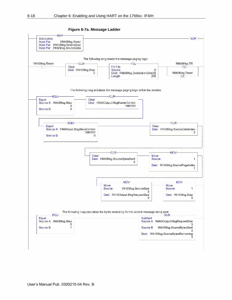
6-18 Chapter 6: Enabling and Using HART on the 1769sc- IF4IH
User’s Manual Pub. 0300215-04 Rev. B
Figure 6-7a. Message Ladder
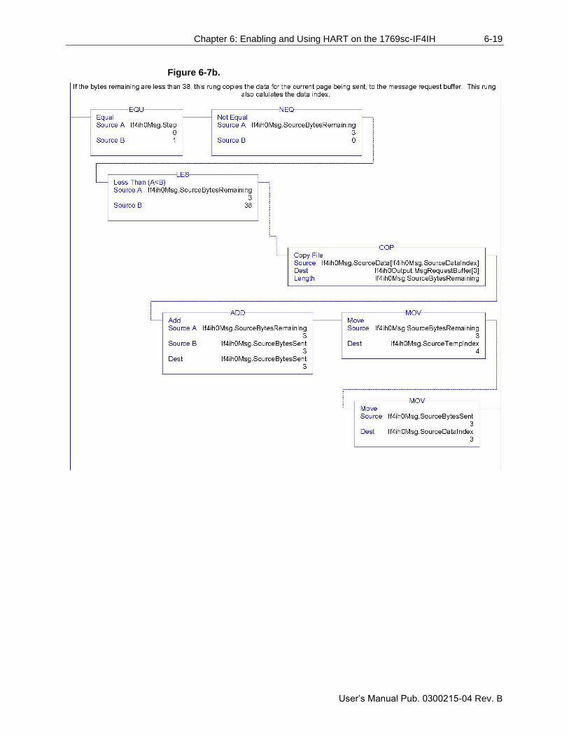
Chapter 6: Enabling and Using HART on the 1769sc-IF4IH 6-19
User’s Manual Pub. 0300215-04 Rev. B
Figure 6-7b.
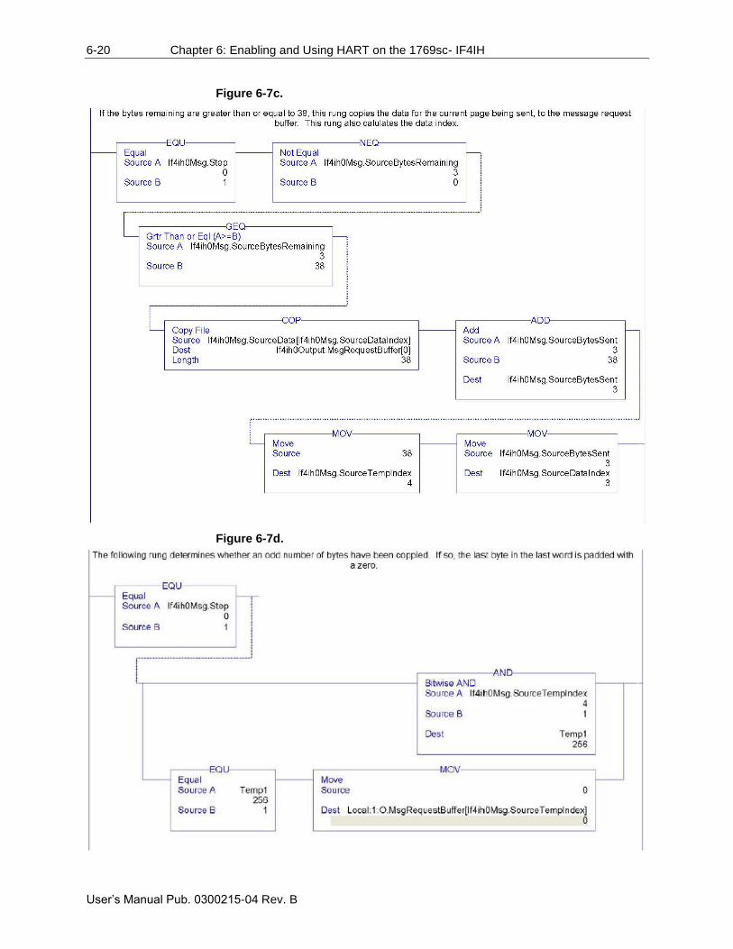
6-20 Chapter 6: Enabling and Using HART on the 1769sc- IF4IH
User’s Manual Pub. 0300215-04 Rev. B
Figure 6-7c.
Figure 6-7d.
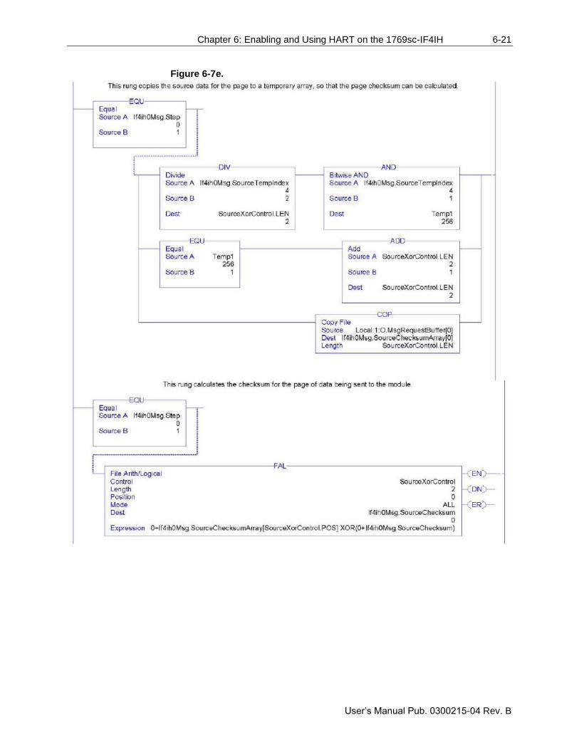
Chapter 6: Enabling and Using HART on the 1769sc-IF4IH 6-21
User’s Manual Pub. 0300215-04 Rev. B
Figure 6-7e.
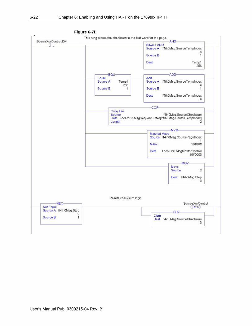
6-22 Chapter 6: Enabling and Using HART on the 1769sc- IF4IH
User’s Manual Pub. 0300215-04 Rev. B
Figure 6-7f.
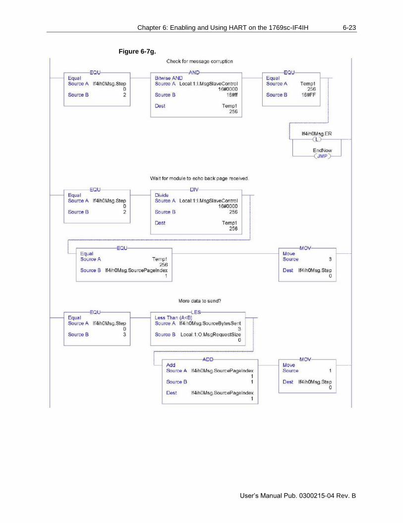
Chapter 6: Enabling and Using HART on the 1769sc-IF4IH 6-23
User’s Manual Pub. 0300215-04 Rev. B
Figure 6-7g.
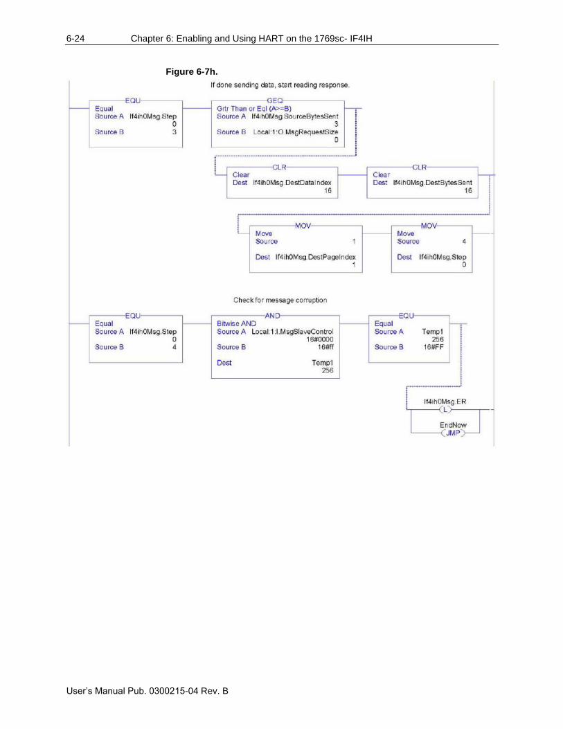
6-24 Chapter 6: Enabling and Using HART on the 1769sc- IF4IH
User’s Manual Pub. 0300215-04 Rev. B
Figure 6-7h.
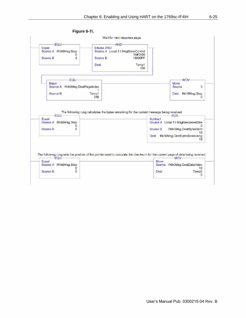
Chapter 6: Enabling and Using HART on the 1769sc-IF4IH 6-25
User’s Manual Pub. 0300215-04 Rev. B
Figure 6-7i.
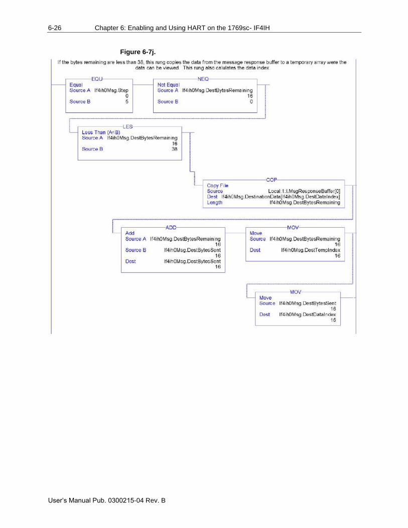
6-26 Chapter 6: Enabling and Using HART on the 1769sc- IF4IH
User’s Manual Pub. 0300215-04 Rev. B
Figure 6-7j.
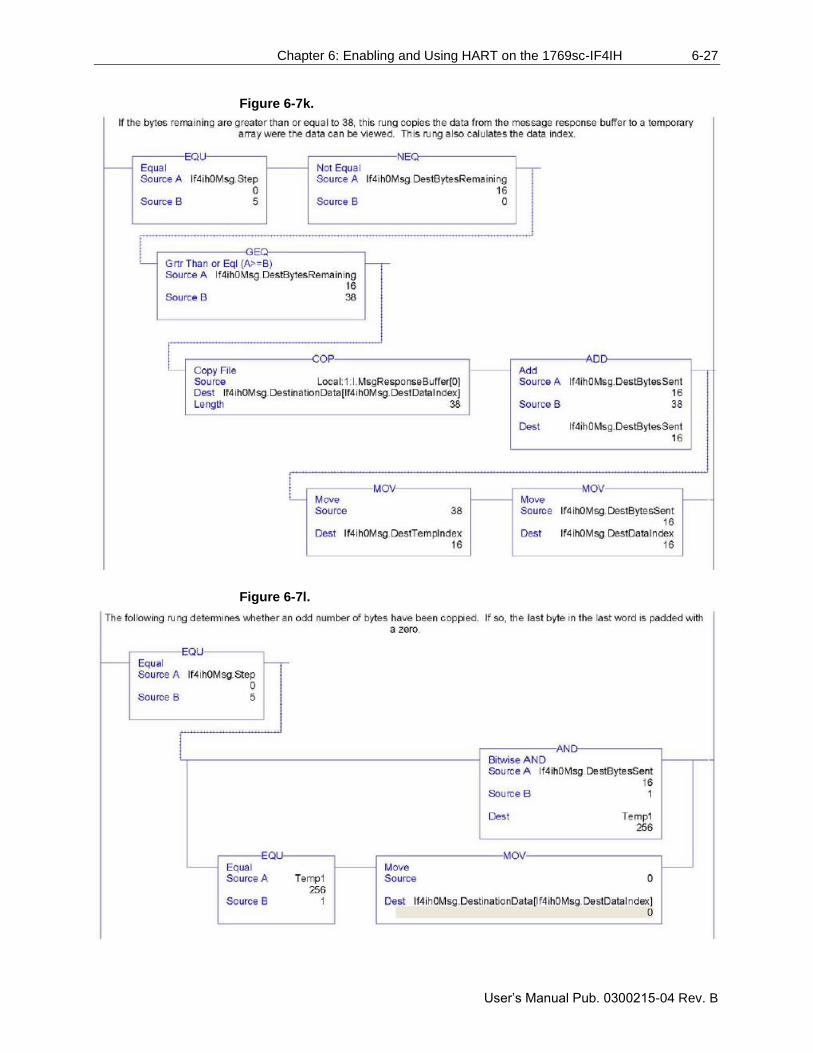
Chapter 6: Enabling and Using HART on the 1769sc-IF4IH 6-27
User’s Manual Pub. 0300215-04 Rev. B
Figure 6-7k.
Figure 6-7l.
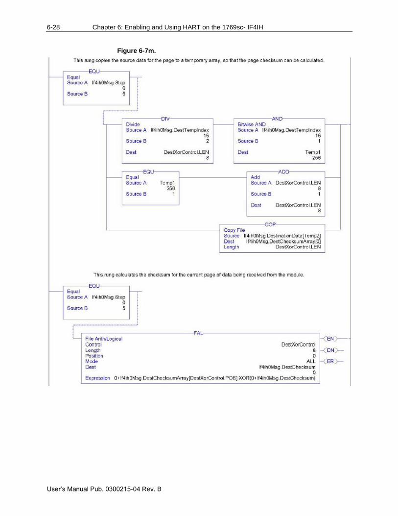
6-28 Chapter 6: Enabling and Using HART on the 1769sc- IF4IH
User’s Manual Pub. 0300215-04 Rev. B
Figure 6-7m.
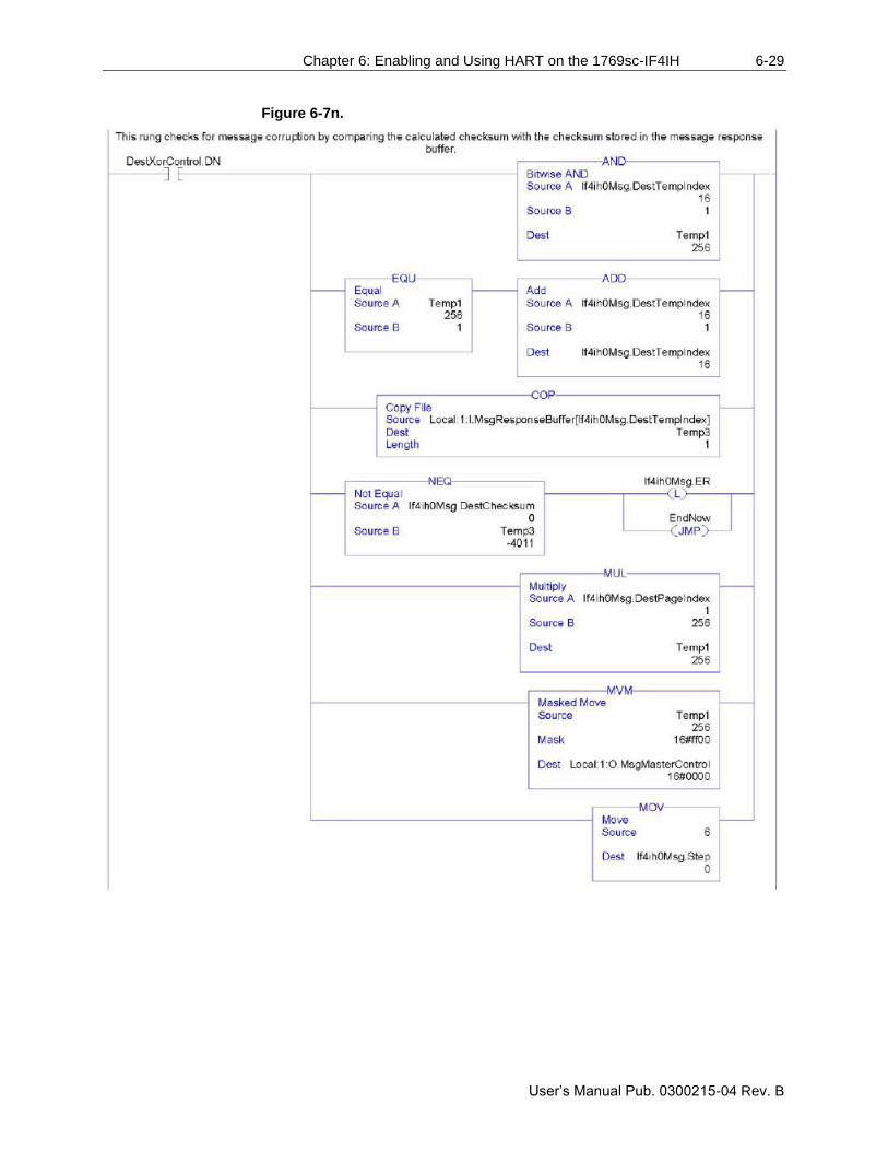
Chapter 6: Enabling and Using HART on the 1769sc-IF4IH 6-29
User’s Manual Pub. 0300215-04 Rev. B
Figure 6-7n.
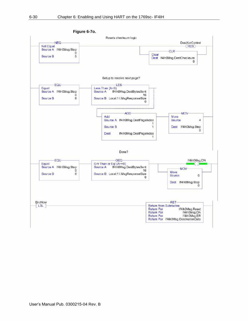
6-30 Chapter 6: Enabling and Using HART on the 1769sc- IF4IH
User’s Manual Pub. 0300215-04 Rev. B
Figure 6-7o.
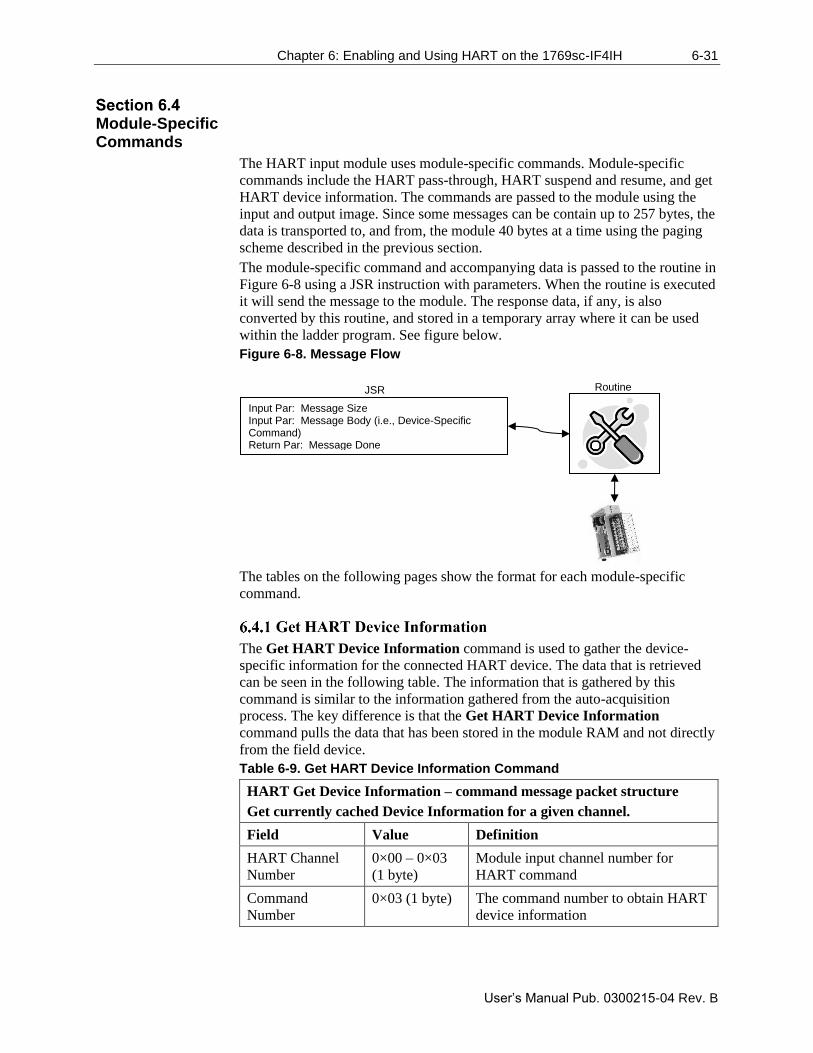
Chapter 6: Enabling and Using HART on the 1769sc-IF4IH 6-31
User’s Manual Pub. 0300215-04 Rev. B
Module-Specific Commands
The HART input module uses module-specific commands. Module-specific
commands include the HART pass-through, HART suspend and resume, and get
HART device information. The commands are passed to the module using the
input and output image. Since some messages can be contain up to 257 bytes, the
data is transported to, and from, the module 40 bytes at a time using the paging
scheme described in the previous section.
The module-specific command and accompanying data is passed to the routine in
Figure 6-8 using a JSR instruction with parameters. When the routine is executed
it will send the message to the module. The response data, if any, is also
converted by this routine, and stored in a temporary array where it can be used
within the ladder program. See figure below.
Figure 6-8. Message Flow
The tables on the following pages show the format for each module-specific
command.
The Get HART Device Information command is used to gather the device-
specific information for the connected HART device. The data that is retrieved
can be seen in the following table. The information that is gathered by this
command is similar to the information gathered from the auto-acquisition
process. The key difference is that the Get HART Device Information
command pulls the data that has been stored in the module RAM and not directly
from the field device.
Table 6-9. Get HART Device Information Command
HART Get Device Information – command message packet structure
Get currently cached Device Information for a given channel.
Field Value Definition
HART Channel
Number
0×00 – 0×03
(1 byte)
Module input channel number for
HART command
Command
Number
0×03 (1 byte) The command number to obtain HART
device information
Input Par: Message Size Input Par: Message Body (i.e., Device-Specific Command) Return Par: Message Done Return Par: Message Response (i.e., Temp Array)
JSR
Routine
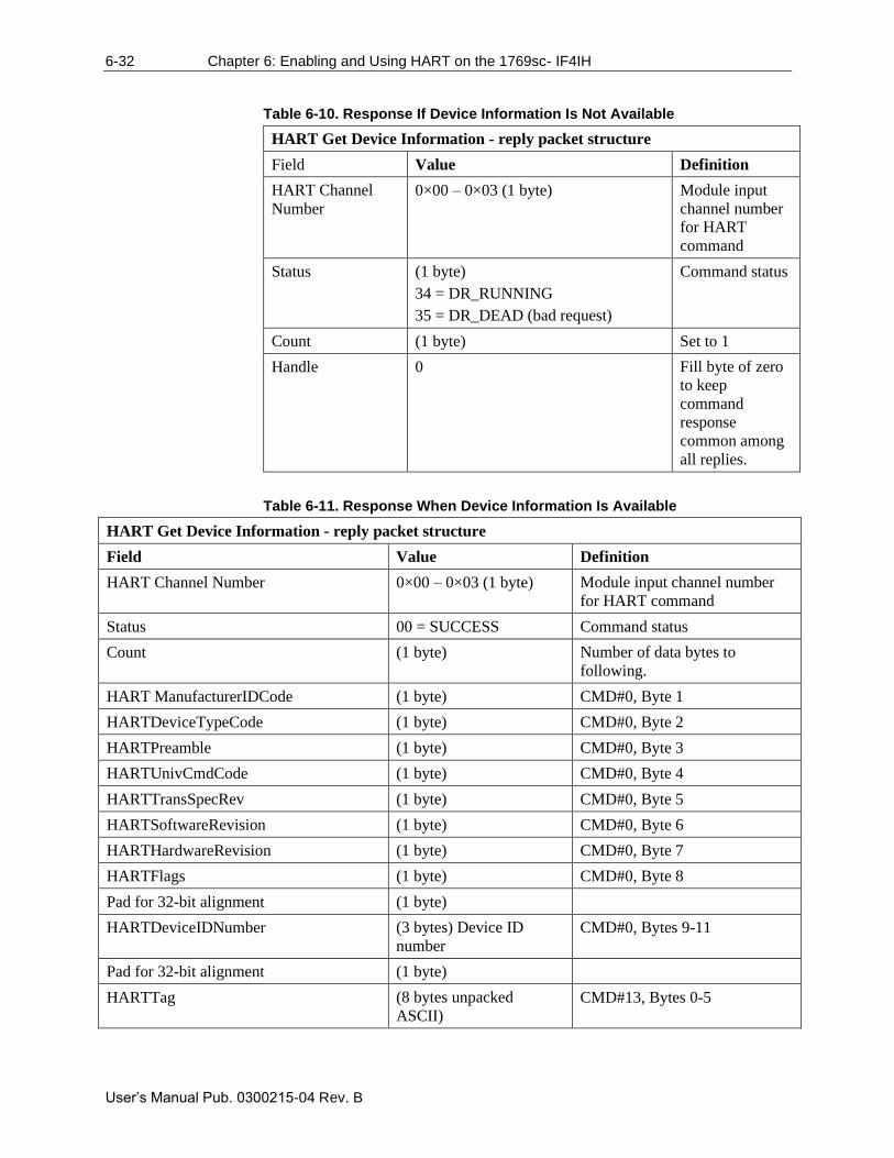
6-32 Chapter 6: Enabling and Using HART on the 1769sc- IF4IH
User’s Manual Pub. 0300215-04 Rev. B
Table 6-10. Response If Device Information Is Not Available
HART Get Device Information - reply packet structure
Field Value Definition
HART Channel
Number
0×00 – 0×03 (1 byte) Module input
channel number
for HART
command
Status (1 byte)
34 = DR_RUNNING
35 = DR_DEAD (bad request)
Command status
Count (1 byte) Set to 1
Handle 0 Fill byte of zero
to keep
command
response
common among
all replies.
Table 6-11. Response When Device Information Is Available
HART Get Device Information - reply packet structure
Field Value Definition
HART Channel Number 0×00 – 0×03 (1 byte) Module input channel number
for HART command
Status 00 = SUCCESS Command status
Count (1 byte) Number of data bytes to
following.
HART ManufacturerIDCode (1 byte) CMD#0, Byte 1
HARTDeviceTypeCode (1 byte) CMD#0, Byte 2
HARTPreamble (1 byte) CMD#0, Byte 3
HARTUnivCmdCode (1 byte) CMD#0, Byte 4
HARTTransSpecRev (1 byte) CMD#0, Byte 5
HARTSoftwareRevision (1 byte) CMD#0, Byte 6
HARTHardwareRevision (1 byte) CMD#0, Byte 7
HARTFlags (1 byte) CMD#0, Byte 8
Pad for 32-bit alignment (1 byte)
HARTDeviceIDNumber (3 bytes) Device ID
number
CMD#0, Bytes 9-11
Pad for 32-bit alignment (1 byte)
HARTTag (8 bytes unpacked
ASCII)
CMD#13, Bytes 0-5
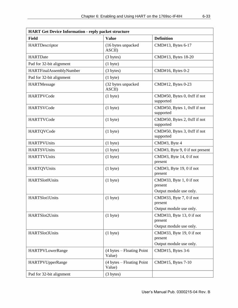
Chapter 6: Enabling and Using HART on the 1769sc-IF4IH 6-33
User’s Manual Pub. 0300215-04 Rev. B
HART Get Device Information - reply packet structure
Field Value Definition
HARTDescriptor (16 bytes unpacked
ASCII)
CMD#13, Bytes 6-17
HARTDate (3 bytes) CMD#13, Bytes 18-20
Pad for 32-bit alignment (1 byte)
HARTFinalAssemblyNumber (3 bytes) CMD#16, Bytes 0-2
Pad for 32-bit alignment (1 byte)
HARTMessage (32 bytes unpacked
ASCII)
CMD#12, Bytes 0-23
HARTPVCode (1 byte) CMD#50, Bytes 0, 0xff if not
supported
HARTSVCode (1 byte) CMD#50, Bytes 1, 0xff if not
supported
HARTTVCode (1 byte) CMD#50, Bytes 2, 0xff if not
supported
HARTQVCode (1 byte) CMD#50, Bytes 3, 0xff if not
supported
HARTPVUnits (1 byte) CMD#3, Byte 4
HARTSVUnits (1 byte) CMD#3, Byte 9, 0 if not present
HARTTVUnits (1 byte) CMD#3, Byte 14, 0 if not
present
HARTQVUnits (1 byte) CMD#3, Byte 19, 0 if not
present
HARTSlot0Units (1 byte) CMD#33, Byte 1, 0 if not
present
Output module use only.
HARTSlot1Units (1 byte) CMD#33, Byte 7, 0 if not
present
Output module use only.
HARTSlot2Units (1 byte) CMD#33, Byte 13, 0 if not
present
Output module use only.
HARTSlot3Units (1 byte) CMD#33, Byte 19, 0 if not
present
Output module use only.
HARTPVLowerRange (4 bytes – Floating Point
Value)
CMD#15, Bytes 3-6
HARTPVUpperRange (4 bytes – Floating Point
Value)
CMD#15, Bytes 7-10
Pad for 32-bit alignment (3 bytes)
6-34 Chapter 6: Enabling and Using HART on the 1769sc- IF4IH
User’s Manual Pub. 0300215-04 Rev. B
The command status, the second byte in the reply packet for the module-specific
command, can return three different responses, SUCCESS, RUNNING and
DEAD. These responses echo the state of the module at the time the command is
sent. The conditions for each response are as follows:
SUCCESS will be sent back when all of the following conditions are met:
• Command and HART Channel number are both valid.
• HART channel device information is available.
RUNNING will be sent back when all of the following conditions are met:
• Command and HART Channel number are both valid.
• HART channel is enabled, and communication has been established,
meaning at least the device addressing information is available.
• HART channel is already in the state of gathering device information.
Reply will be sent back without additional events triggered.
DEAD will be sent back if any of the following conditions is true:
• Command or HART Channel number is invalid.
• HART channel is not enabled.
• HART communication has not been established, meaning that the 5-byte
unique address has not been determined yet.
• All other conditioned not generating RUNNING or SUCCESS.
Sometimes referred to as "Out of Service" and "In Service" respectively, these
commands can be used to suspend or resume operation of an enabled HART
channel. When a suspend HART command is sent, the HART module will keep
the current HART configuration information and stop all communication
processes on the selected channel. However, there are overriding conditions, such
as a configuration change, which can cause the HART function to reset. Normal
HART operation will resume if the resume HART command is sent to the
module during a HART suspension.
NOTE
The HART suspend and resume can be initiated by setting a bit in the
output image.
NOTE
If the resume command is received, without previously receiving a
suspension command, it will be ignored.
NOTE
The selected channel will resume normal HART operations three minutes
after the suspension command has been received by the module. Pass-
through for that channel resets the timer to 3 minutes.
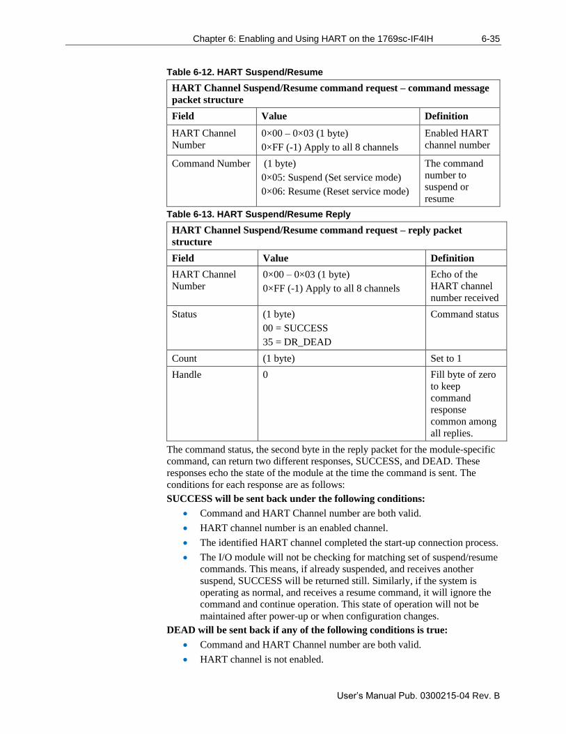
Chapter 6: Enabling and Using HART on the 1769sc-IF4IH 6-35
User’s Manual Pub. 0300215-04 Rev. B
Table 6-12. HART Suspend/Resume
HART Channel Suspend/Resume command request – command message
packet structure
Field Value Definition
HART Channel
Number
0×00 – 0×03 (1 byte)
0×FF (-1) Apply to all 8 channels
Enabled HART
channel number
Command Number (1 byte)
0×05: Suspend (Set service mode)
0×06: Resume (Reset service mode)
The command
number to
suspend or
resume
Table 6-13. HART Suspend/Resume Reply
HART Channel Suspend/Resume command request – reply packet
structure
Field Value Definition
HART Channel
Number
0×00 – 0×03 (1 byte)
0×FF (-1) Apply to all 8 channels
Echo of the
HART channel
number received
Status (1 byte)
00 = SUCCESS
35 = DR_DEAD
Command status
Count (1 byte) Set to 1
Handle 0 Fill byte of zero
to keep
command
response
common among
all replies.
The command status, the second byte in the reply packet for the module-specific
command, can return two different responses, SUCCESS, and DEAD. These
responses echo the state of the module at the time the command is sent. The
conditions for each response are as follows:
SUCCESS will be sent back under the following conditions:
• Command and HART Channel number are both valid.
• HART channel number is an enabled channel.
• The identified HART channel completed the start-up connection process.
• The I/O module will not be checking for matching set of suspend/resume
commands. This means, if already suspended, and receives another
suspend, SUCCESS will be returned still. Similarly, if the system is
operating as normal, and receives a resume command, it will ignore the
command and continue operation. This state of operation will not be
maintained after power-up or when configuration changes.
DEAD will be sent back if any of the following conditions is true:
• Command and HART Channel number are both valid.
• HART channel is not enabled.
6-36 Chapter 6: Enabling and Using HART on the 1769sc- IF4IH
User’s Manual Pub. 0300215-04 Rev. B
• HART communication has not been established, meaning that the 5-byte
unique address has not been determined yet, or the module is still
obtaining device information.
• All other conditioned not generating SUCCESS.
The HART Pass-Through Command can be used to send any HART command
including universal, common practice or device-specific, directly to a field
device. The module in this case could be considered a HART bridge. There can
be two (2) instances of a HART pass-through message being serviced, meaning
the pass-through message queue is 2 deep. The HART pass-through response will
be queued the moment the command is received, if the queue spaces are not
already in use, and be dispatched after at least a full scan is done. In other words,
after servicing a pass-through, the HART module will make sure all enabled
HART channels have updated variable values before another pass-through is
placed into service.
All HART pass-through commands require a series of messages to be exchanged.
First, a pass-through command request must be sent to the HART module to
initiate the pass-through command. The HART module will respond to the
command request with a command request reply that includes a handle that can
be used to obtain the pass-through message response. Once the handle is
received, the user may issue a Get Command Query to obtain the status of the
pass-through command and the pass-through command response data, if it is
available.
There is a handle timeout associated with the final reply message. After the
HART module obtains the requested information from the HART device, it will
start a handle timeout timer. Refer to Chapter 5 for information regarding how to
set the handle timeout. The reply message will be kept persistent during the
handle timeout period. When the handle timeout timer expires the reply message
will be discarded, and another passthrough message will be serviced without
being rejected. The user-defined handle timeout is in the range of 1 to 255
seconds.
NOTE
If the HART message being sent or received using the pass-through
command contains floating point values, the order of the bytes must be
reversed.
Depending on the HART command, the data contained within the HART
message may include floating point numbers or double integers. If a floating
point or double integer is contained within the HART message, you must be
aware that the order of the bytes that make up the float or double will need to be
reversed. The reason for this is related to how the bytes are stored in the
ControlLogix processor.
The ControlLogix processor stores the bytes in memory in a format referred to as
"little-endian". Little-endian is an order in which the "little end" (least significant
value in the sequence) is stored first (at the lowest storage address). However,
HART devices transmit the byte data in the reverse order or "big-endian". Refer
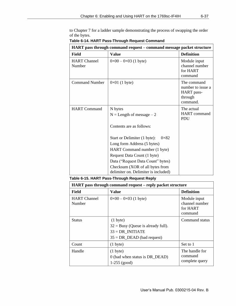
Chapter 6: Enabling and Using HART on the 1769sc-IF4IH 6-37
User’s Manual Pub. 0300215-04 Rev. B
to Chapter 7 for a ladder sample demonstrating the process of swapping the order
of the bytes.
Table 6-14. HART Pass-Through Request Command
HART pass through command request – command message packet structure
Field Value Definition
HART Channel
Number
0×00 – 0×03 (1 byte) Module input
channel number
for HART
command
Command Number 0×01 (1 byte)
The command
number to issue a
HART pass-
through
command.
HART Command N bytes
N = Length of message – 2
Contents are as follows:
Start or Delimiter (1 byte): 0×82
Long form Address (5 bytes)
HART Command number (1 byte)
Request Data Count (1 byte)
Data (“Request Data Count” bytes)
Checksum (XOR of all bytes from
delimiter on. Delimiter is included)
The actual
HART command
PDU
Table 6-15. HART Pass-Through Request Reply
HART pass through command request – reply packet structure
Field Value Definition
HART Channel
Number
0×00 – 0×03 (1 byte) Module input
channel number
for HART
command
Status (1 byte)
32 = Busy (Queue is already full).
33 = DR_INITIATE
35 = DR_DEAD (bad request)
Command status
Count (1 byte) Set to 1
Handle (1 byte)
0 (bad when status is DR_DEAD)
1-255 (good)
The handle for
command
complete query
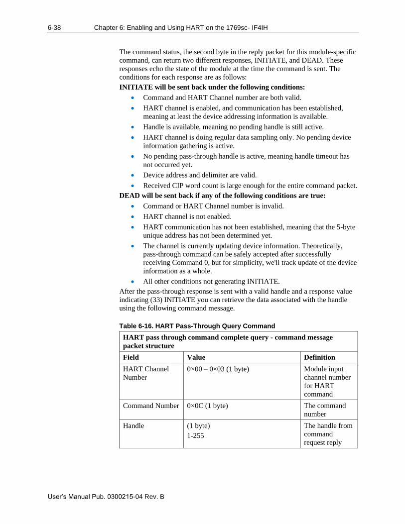
6-38 Chapter 6: Enabling and Using HART on the 1769sc- IF4IH
User’s Manual Pub. 0300215-04 Rev. B
The command status, the second byte in the reply packet for this module-specific
command, can return two different responses, INITIATE, and DEAD. These
responses echo the state of the module at the time the command is sent. The
conditions for each response are as follows:
INITIATE will be sent back under the following conditions:
• Command and HART Channel number are both valid.
• HART channel is enabled, and communication has been established,
meaning at least the device addressing information is available.
• Handle is available, meaning no pending handle is still active.
• HART channel is doing regular data sampling only. No pending device
information gathering is active.
• No pending pass-through handle is active, meaning handle timeout has
not occurred yet.
• Device address and delimiter are valid.
• Received CIP word count is large enough for the entire command packet.
DEAD will be sent back if any of the following conditions are true:
• Command or HART Channel number is invalid.
• HART channel is not enabled.
• HART communication has not been established, meaning that the 5-byte
unique address has not been determined yet.
• The channel is currently updating device information. Theoretically,
pass-through command can be safely accepted after successfully
receiving Command 0, but for simplicity, we'll track update of the device
information as a whole.
• All other conditions not generating INITIATE.
After the pass-through response is sent with a valid handle and a response value
indicating (33) INITIATE you can retrieve the data associated with the handle
using the following command message.
Table 6-16. HART Pass-Through Query Command
HART pass through command complete query - command message
packet structure
Field Value Definition
HART Channel
Number
0×00 – 0×03 (1 byte) Module input
channel number
for HART
command
Command Number 0×0C (1 byte) The command
number
Handle (1 byte)
1-255
The handle from
command
request reply
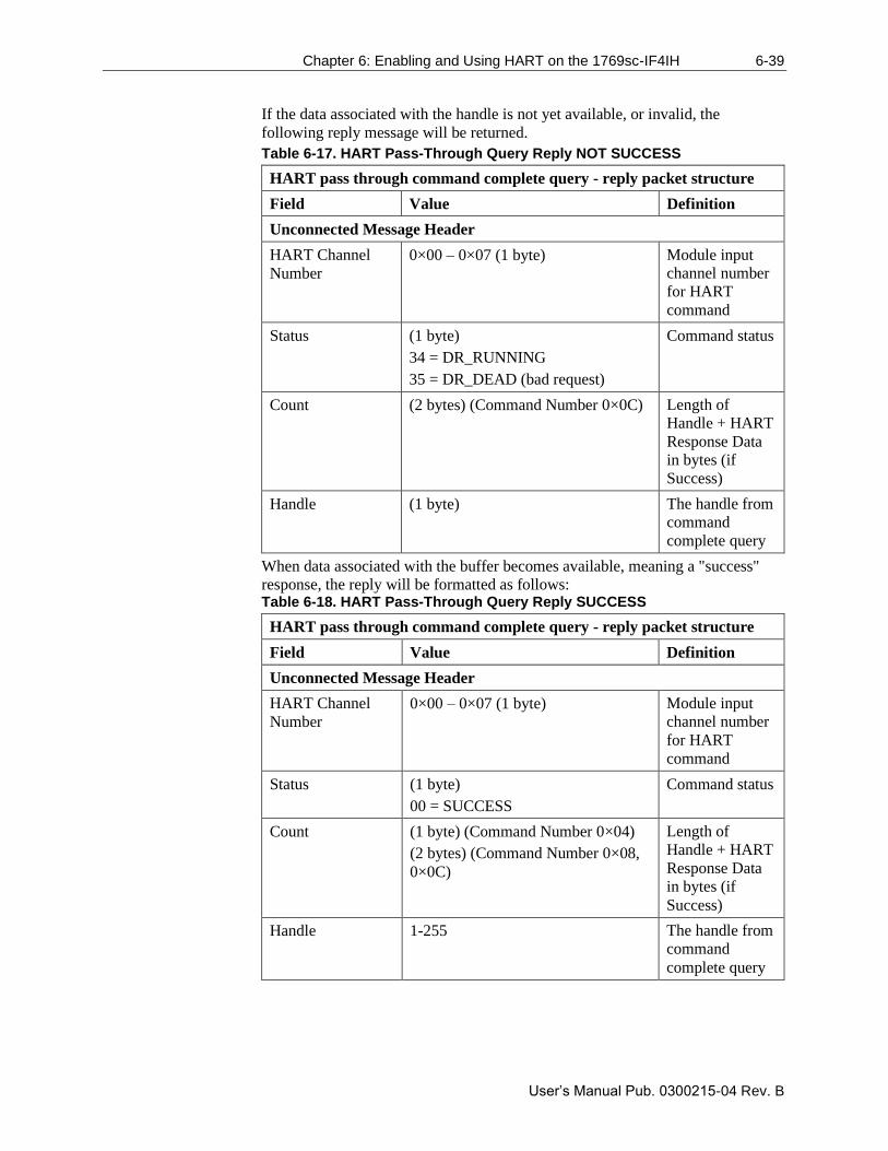
Chapter 6: Enabling and Using HART on the 1769sc-IF4IH 6-39
User’s Manual Pub. 0300215-04 Rev. B
If the data associated with the handle is not yet available, or invalid, the
following reply message will be returned.
Table 6-17. HART Pass-Through Query Reply NOT SUCCESS
HART pass through command complete query - reply packet structure
Field Value Definition
Unconnected Message Header
HART Channel
Number
0×00 – 0×07 (1 byte) Module input
channel number
for HART
command
Status (1 byte)
34 = DR_RUNNING
35 = DR_DEAD (bad request)
Command status
Count (2 bytes) (Command Number 0×0C) Length of
Handle + HART
Response Data
in bytes (if
Success)
Handle (1 byte) The handle from
command
complete query
When data associated with the buffer becomes available, meaning a "success"
response, the reply will be formatted as follows: Table 6-18. HART Pass-Through Query Reply SUCCESS
HART pass through command complete query - reply packet structure
Field Value Definition
Unconnected Message Header
HART Channel
Number
0×00 – 0×07 (1 byte) Module input
channel number
for HART
command
Status (1 byte)
00 = SUCCESS
Command status
Count (1 byte) (Command Number 0×04)
(2 bytes) (Command Number 0×08,
0×0C)
Length of
Handle + HART
Response Data
in bytes (if
Success)
Handle 1-255 The handle from
command
complete query
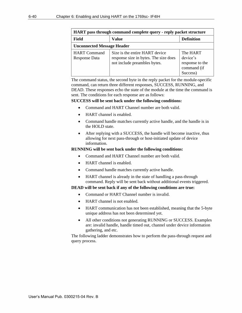
6-40 Chapter 6: Enabling and Using HART on the 1769sc- IF4IH
User’s Manual Pub. 0300215-04 Rev. B
HART pass through command complete query - reply packet structure
Field Value Definition
Unconnected Message Header
HART Command
Response Data
Size is the entire HART device
response size in bytes. The size does
not include preambles bytes.
The HART
device’s
response to the
command (if
Success)
The command status, the second byte in the reply packet for the module-specific
command, can return three different responses, SUCCESS, RUNNING, and
DEAD. These responses echo the state of the module at the time the command is
sent. The conditions for each response are as follows:
SUCCESS will be sent back under the following conditions:
• Command and HART Channel number are both valid.
• HART channel is enabled.
• Command handle matches currently active handle, and the handle is in
the HOLD state.
• After replying with a SUCCESS, the handle will become inactive, thus
allowing for next pass-through or host-initiated update of device
information.
RUNNING will be sent back under the following conditions:
• Command and HART Channel number are both valid.
• HART channel is enabled.
• Command handle matches currently active handle.
• HART channel is already in the state of handling a pass-through
command. Reply will be sent back without additional events triggered.
DEAD will be sent back if any of the following conditions are true:
• Command or HART Channel number is invalid.
• HART channel is not enabled.
• HART communication has not been established, meaning that the 5-byte
unique address has not been determined yet.
• All other conditions not generating RUNNING or SUCCESS. Examples
are: invalid handle, handle timed out, channel under device information
gathering, and etc.
The following ladder demonstrates how to perform the pass-through request and
query process.
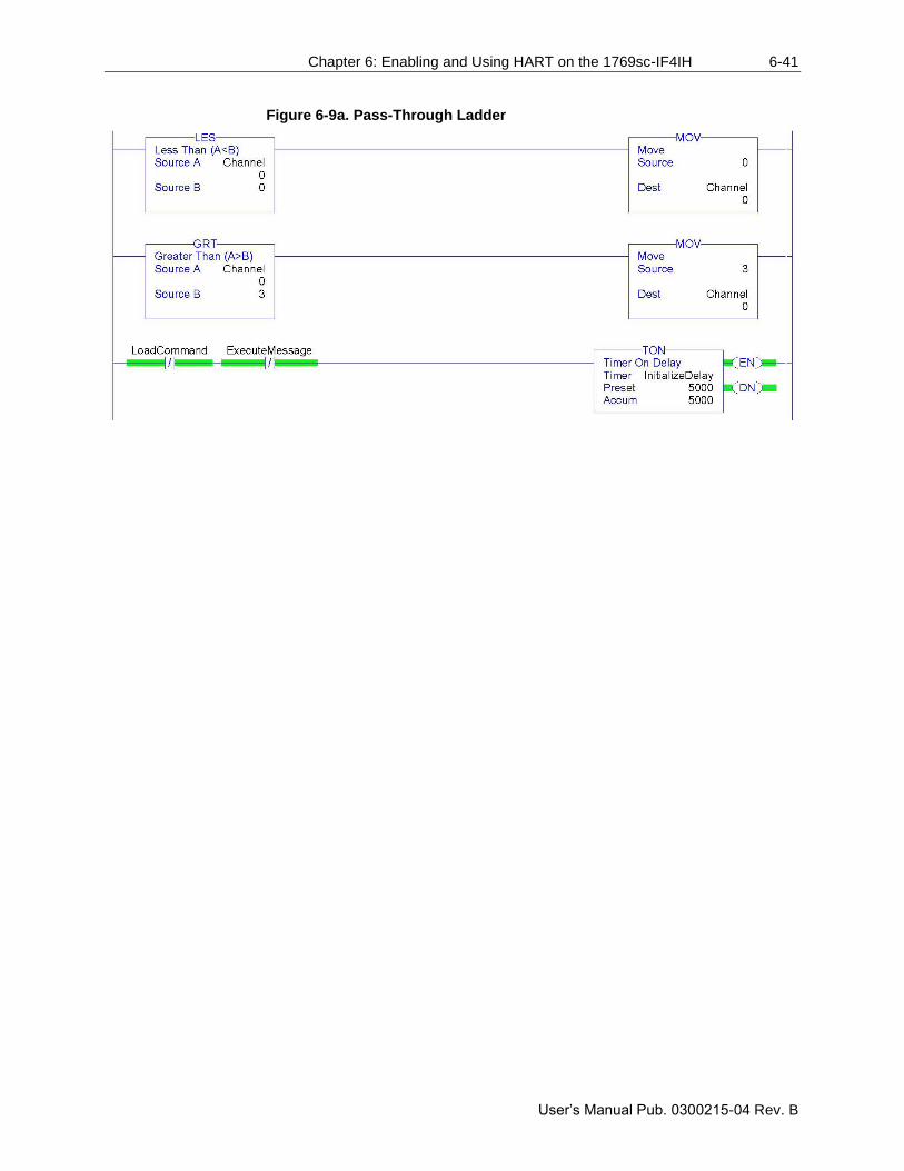
Chapter 6: Enabling and Using HART on the 1769sc-IF4IH 6-41
User’s Manual Pub. 0300215-04 Rev. B
Figure 6-9a. Pass-Through Ladder
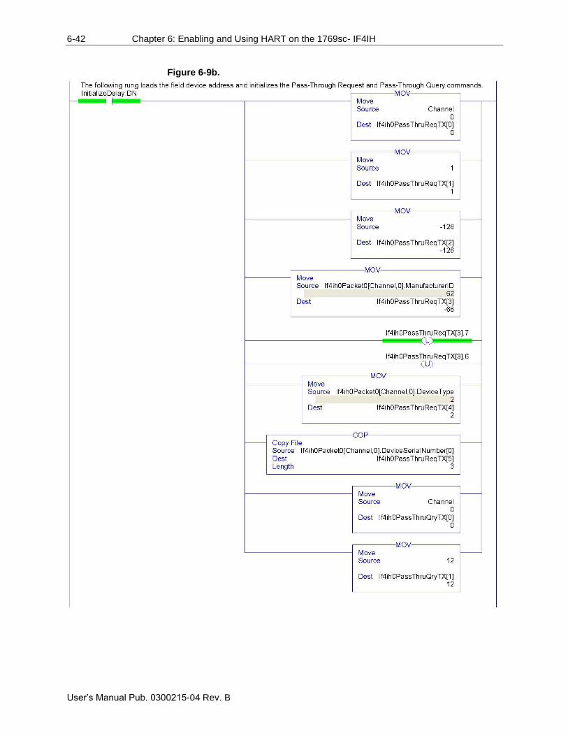
6-42 Chapter 6: Enabling and Using HART on the 1769sc- IF4IH
User’s Manual Pub. 0300215-04 Rev. B
Figure 6-9b.
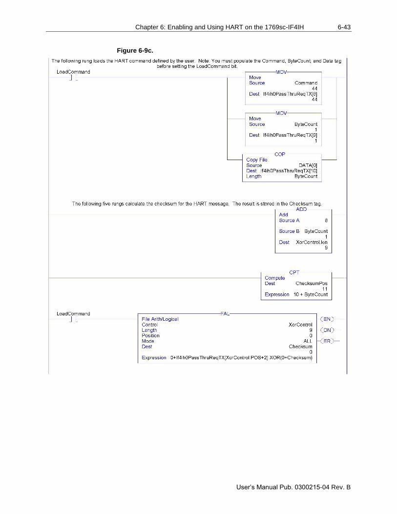
Chapter 6: Enabling and Using HART on the 1769sc-IF4IH 6-43
User’s Manual Pub. 0300215-04 Rev. B
Figure 6-9c.
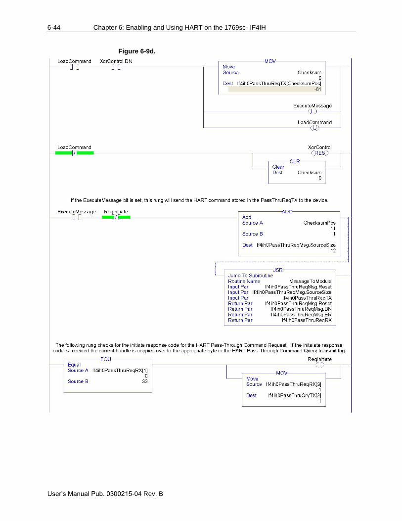
6-44 Chapter 6: Enabling and Using HART on the 1769sc- IF4IH
User’s Manual Pub. 0300215-04 Rev. B
Figure 6-9d.
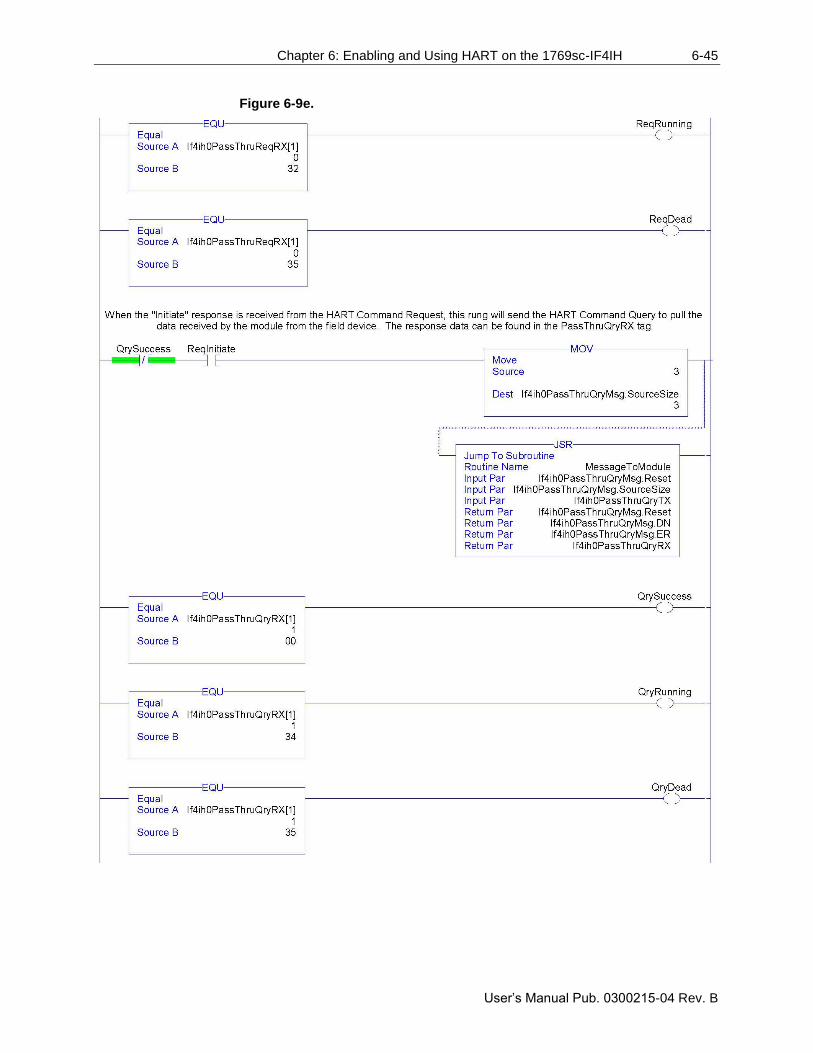
Chapter 6: Enabling and Using HART on the 1769sc-IF4IH 6-45
User’s Manual Pub. 0300215-04 Rev. B
Figure 6-9e.
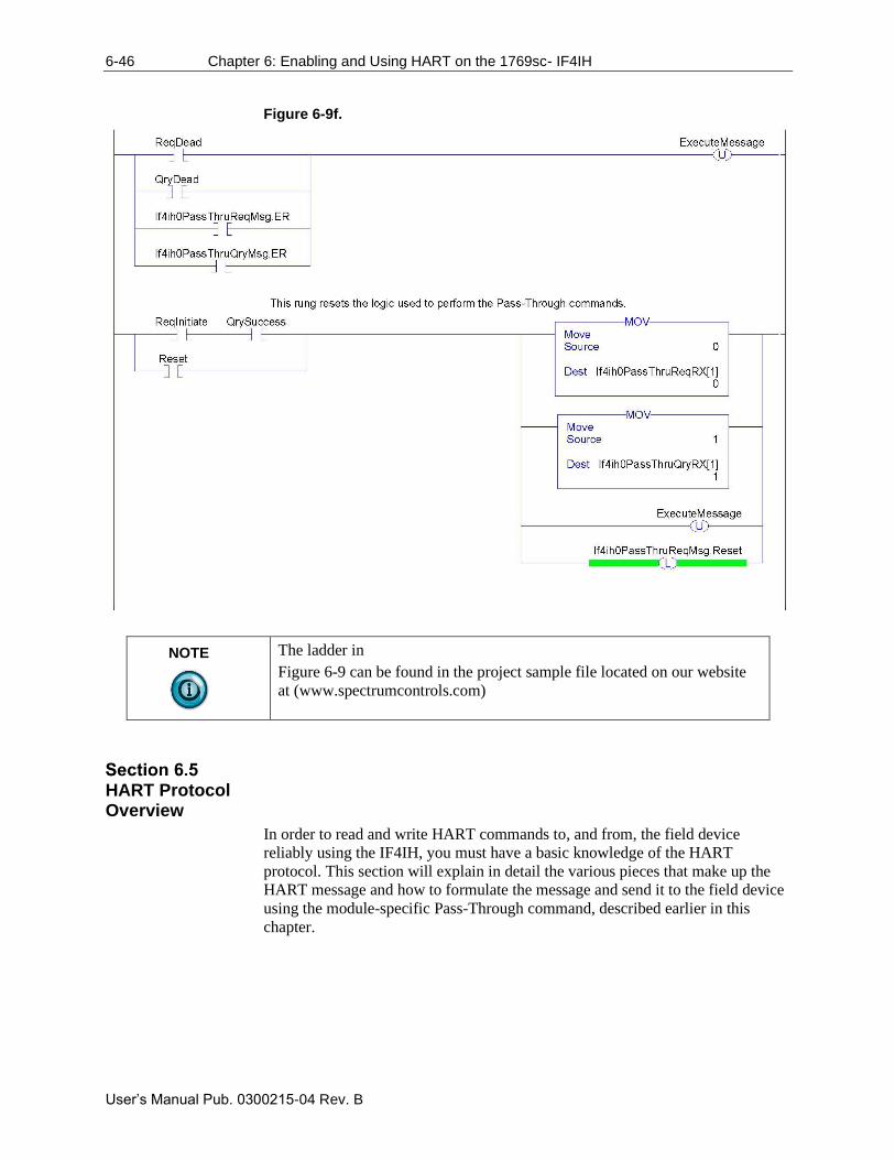
6-46 Chapter 6: Enabling and Using HART on the 1769sc- IF4IH
User’s Manual Pub. 0300215-04 Rev. B
Figure 6-9f.
NOTE
The ladder in
Figure 6-9 can be found in the project sample file located on our website
at (www.spectrumcontrols.com)
HART Protocol Overview
In order to read and write HART commands to, and from, the field device
reliably using the IF4IH, you must have a basic knowledge of the HART
protocol. This section will explain in detail the various pieces that make up the
HART message and how to formulate the message and send it to the field device
using the module-specific Pass-Through command, described earlier in this
chapter.
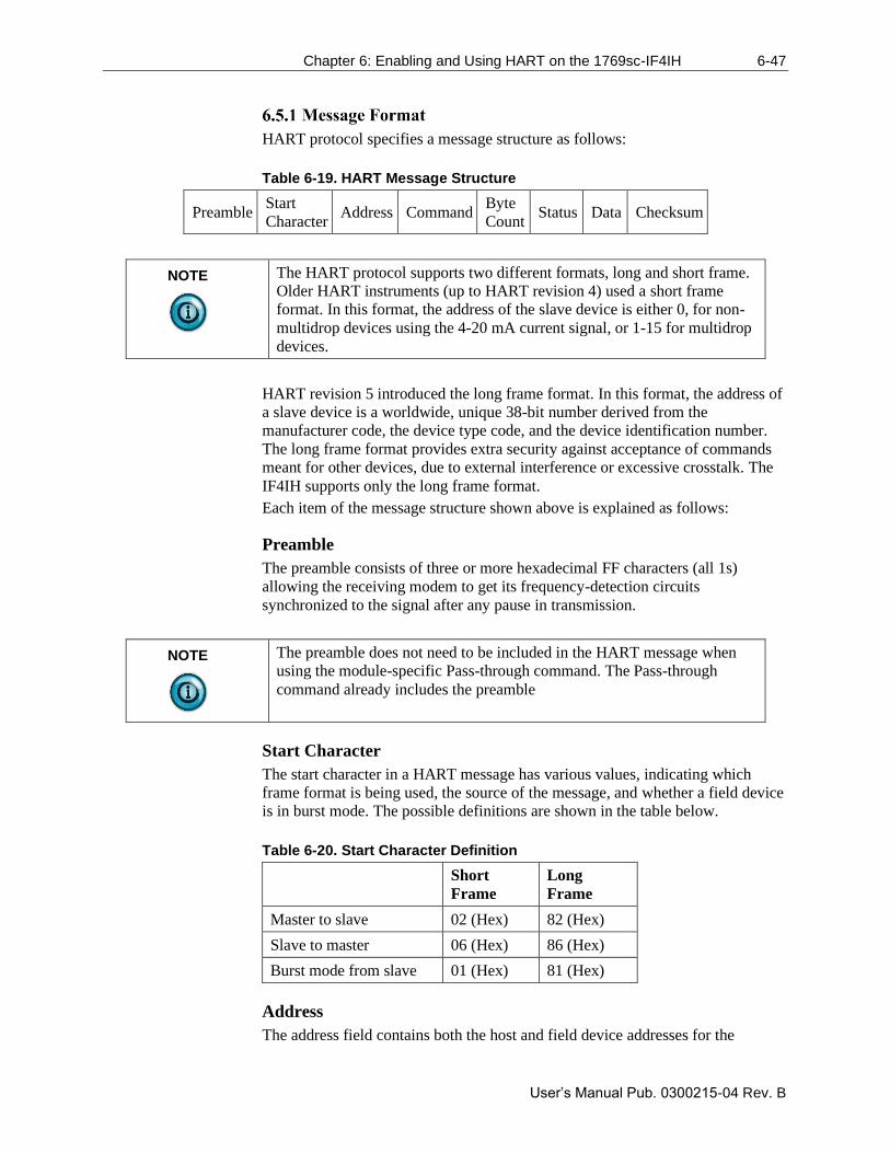
Chapter 6: Enabling and Using HART on the 1769sc-IF4IH 6-47
User’s Manual Pub. 0300215-04 Rev. B
HART protocol specifies a message structure as follows:
Table 6-19. HART Message Structure
Preamble Start
Character Address Command
Byte
Count Status Data Checksum
NOTE
The HART protocol supports two different formats, long and short frame.
Older HART instruments (up to HART revision 4) used a short frame
format. In this format, the address of the slave device is either 0, for non-
multidrop devices using the 4-20 mA current signal, or 1-15 for multidrop
devices.
HART revision 5 introduced the long frame format. In this format, the address of
a slave device is a worldwide, unique 38-bit number derived from the
manufacturer code, the device type code, and the device identification number.
The long frame format provides extra security against acceptance of commands
meant for other devices, due to external interference or excessive crosstalk. The
IF4IH supports only the long frame format.
Each item of the message structure shown above is explained as follows:
Preamble
The preamble consists of three or more hexadecimal FF characters (all 1s)
allowing the receiving modem to get its frequency-detection circuits
synchronized to the signal after any pause in transmission.
NOTE
The preamble does not need to be included in the HART message when
using the module-specific Pass-through command. The Pass-through
command already includes the preamble
Start Character
The start character in a HART message has various values, indicating which
frame format is being used, the source of the message, and whether a field device
is in burst mode. The possible definitions are shown in the table below.
Table 6-20. Start Character Definition
Short
Frame
Long
Frame
Master to slave 02 (Hex) 82 (Hex)
Slave to master 06 (Hex) 86 (Hex)
Burst mode from slave 01 (Hex) 81 (Hex)
Address
The address field contains both the host and field device addresses for the
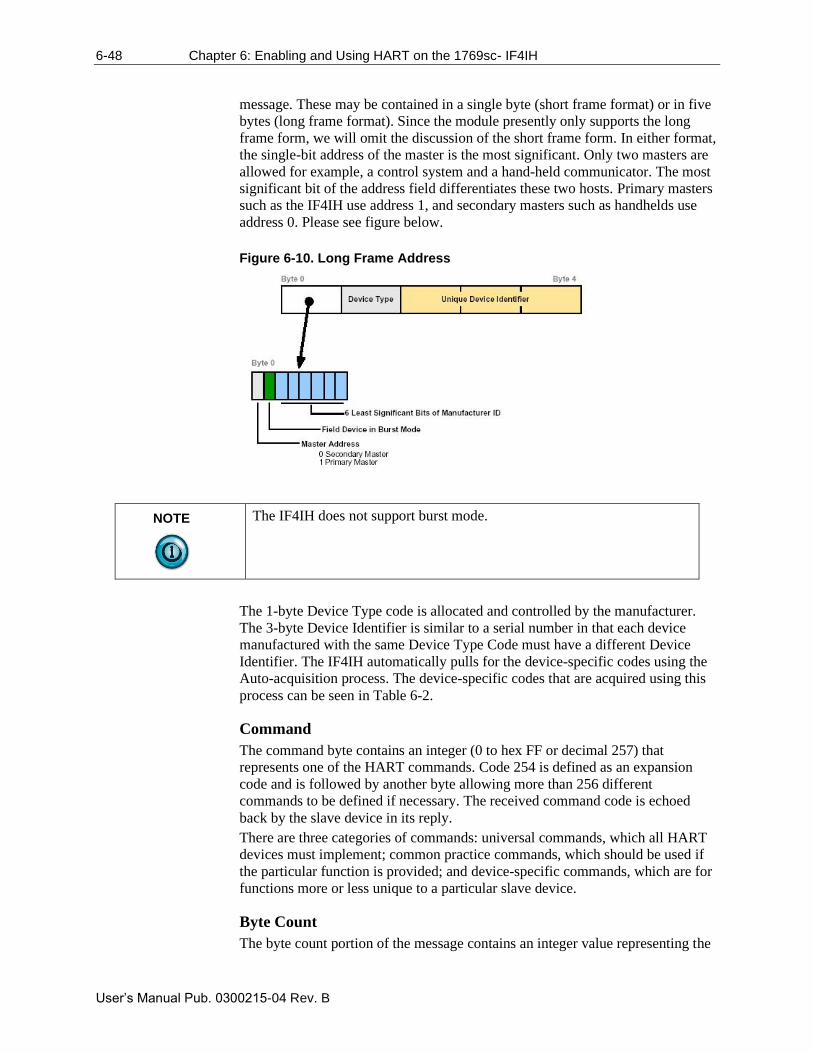
6-48 Chapter 6: Enabling and Using HART on the 1769sc- IF4IH
User’s Manual Pub. 0300215-04 Rev. B
message. These may be contained in a single byte (short frame format) or in five
bytes (long frame format). Since the module presently only supports the long
frame form, we will omit the discussion of the short frame form. In either format,
the single-bit address of the master is the most significant. Only two masters are
allowed for example, a control system and a hand-held communicator. The most
significant bit of the address field differentiates these two hosts. Primary masters
such as the IF4IH use address 1, and secondary masters such as handhelds use
address 0. Please see figure below.
Figure 6-10. Long Frame Address
NOTE
The IF4IH does not support burst mode.
The 1-byte Device Type code is allocated and controlled by the manufacturer.
The 3-byte Device Identifier is similar to a serial number in that each device
manufactured with the same Device Type Code must have a different Device
Identifier. The IF4IH automatically pulls for the device-specific codes using the
Auto-acquisition process. The device-specific codes that are acquired using this
process can be seen in Table 6-2.
Command
The command byte contains an integer (0 to hex FF or decimal 257) that
represents one of the HART commands. Code 254 is defined as an expansion
code and is followed by another byte allowing more than 256 different
commands to be defined if necessary. The received command code is echoed
back by the slave device in its reply.
There are three categories of commands: universal commands, which all HART
devices must implement; common practice commands, which should be used if
the particular function is provided; and device-specific commands, which are for
functions more or less unique to a particular slave device.
Byte Count
The byte count portion of the message contains an integer value representing the
Chapter 6: Enabling and Using HART on the 1769sc-IF4IH 6-49
User’s Manual Pub. 0300215-04 Rev. B
number of bytes that form the remainder of this message excluding the
checksum. In other words, the byte count determines the length of the data and
status.
Status
Status is included only in reply messages from a slave. It consists of two bytes of
bit-coded information. The first byte indicates communication errors, if any.
Otherwise, if communication was good, this byte may indicate the status of the
received command such as a busy device, or a command not recognized. The
second status byte indicates the operational state of the slave device. A properly
operating slave device will have both status bytes set to logical zero. The
meaning of the individual status bits can be found in Appendix B.
Data
This portion of the HART message contains the data, if any, for the command.
Not all commands or responses contain data. For those that do, up to 25 bytes can
be included. Data may be in the form of unsigned integers, floating point
numbers, or ASCII character strings. The number of bytes of data, and the data
format used for each item are specified for each HART command.
Checksum
The checksum byte contains the exclusive-or (longitudinal parity) of all the bytes
that precede it in the message, starting with the Start Character. This provides a
further check on transmission integrity, beyond the parity check on the 8 bits of
each individual byte.
Now that you're familiar with the bits and pieces that make up a HART message,
the next step will be to formulate a message, and to successfully send the
message to the field device using the pass-through command. The first step is to
formulate the message and populate the source tag If4ih0PassThruReqTX. This
tag is used in the ladder sample shown in Figure 6-9.
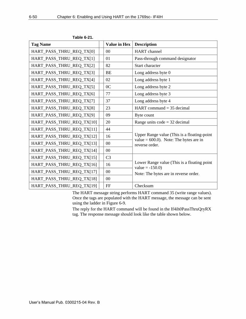
6-50 Chapter 6: Enabling and Using HART on the 1769sc- IF4IH
User’s Manual Pub. 0300215-04 Rev. B
Table 6-21.
Tag Name Value in Hex Description
HART_PASS_THRU_REQ_TX[0] 00 HART channel
HART_PASS_THRU_REQ_TX[1] 01 Pass-through command designator
HART_PASS_THRU_REQ_TX[2] 82 Start character
HART_PASS_THRU_REQ_TX[3] BE Long address byte 0
HART_PASS_THRU_REQ_TX[4] 02 Long address byte 1
HART_PASS_THRU_REQ_TX[5] 0C Long address byte 2
HART_PASS_THRU_REQ_TX[6] 77 Long address byte 3
HART_PASS_THRU_REQ_TX[7] 37 Long address byte 4
HART_PASS_THRU_REQ_TX[8] 23 HART command = 35 decimal
HART_PASS_THRU_REQ_TX[9] 09 Byte count
HART_PASS_THRU_REQ_TX[10] 20 Range units code = 32 decimal
HART_PASS_THRU_REQ_TX[11] 44
Upper Range value (This is a floating-point
value = 600.0). Note: The bytes are in
reverse order.
HART_PASS_THRU_REQ_TX[12] 16
HART_PASS_THRU_REQ_TX[13] 00
HART_PASS_THRU_REQ_TX[14] 00
HART_PASS_THRU_REQ_TX[15] C3 Lower Range value (This is a floating point
value = -150.0)
Note: The bytes are in reverse order.
HART_PASS_THRU_REQ_TX[16] 16
HART_PASS_THRU_REQ_TX[17] 00
HART_PASS_THRU_REQ_TX[18] 00
HART_PASS_THRU_REQ_TX[19] FF Checksum
The HART message string performs HART command 35 (write range values).
Once the tags are populated with the HART message, the message can be sent
using the ladder in Figure 6-9.
The reply for the HART command will be found in the If4ih0PassThruQryRX
tag. The response message should look like the table shown below.
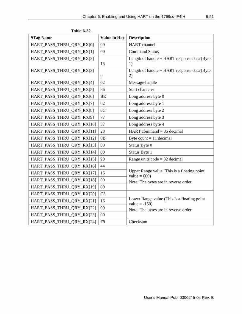
Chapter 6: Enabling and Using HART on the 1769sc-IF4IH 6-51
User’s Manual Pub. 0300215-04 Rev. B
Table 6-22.
9Tag Name Value in Hex Description
HART_PASS_THRU_QRY_RX[0] 00 HART channel
HART_PASS_THRU_QRY_RX[1] 00 Command Status
HART_PASS_THRU_QRY_RX[2]
15
Length of handle + HART response data (Byte
1)
HART_PASS_THRU_QRY_RX[3]
0
Length of handle + HART response data (Byte
2)
HART_PASS_THRU_QRY_RX[4] 02 Message handle
HART_PASS_THRU_QRY_RX[5] 86 Start character
HART_PASS_THRU_QRY_RX[6] BE Long address byte 0
HART_PASS_THRU_QRY_RX[7] 02 Long address byte 1
HART_PASS_THRU_QRY_RX[8] 0C Long address byte 2
HART_PASS_THRU_QRY_RX[9] 77 Long address byte 3
HART_PASS_THRU_QRY_RX[10] 37 Long address byte 4
HART_PASS_THRU_QRY_RX[11] 23 HART command = 35 decimal
HART_PASS_THRU_QRY_RX[12] 0B Byte count = 11 decimal
HART_PASS_THRU_QRY_RX[13] 00 Status Byte 0
HART_PASS_THRU_QRY_RX[14] 00 Status Byte 1
HART_PASS_THRU_QRY_RX[15] 20 Range units code = 32 decimal
HART_PASS_THRU_QRY_RX[16] 44 Upper Range value (This is a floating point
value = 600)
Note: The bytes are in reverse order.
HART_PASS_THRU_QRY_RX[17] 16
HART_PASS_THRU_QRY_RX[18] 00
HART_PASS_THRU_QRY_RX[19] 00
HART_PASS_THRU_QRY_RX[20] C3 Lower Range value (This is a floating point
value = -150)
Note: The bytes are in reverse order.
HART_PASS_THRU_QRY_RX[21] 16
HART_PASS_THRU_QRY_RX[22] 00
HART_PASS_THRU_QRY_RX[23] 00
HART_PASS_THRU_QRY_RX[24] F9 Checksum

6-52 Chapter 6: Enabling and Using HART on the 1769sc- IF4IH
User’s Manual Pub. 0300215-04 Rev. B
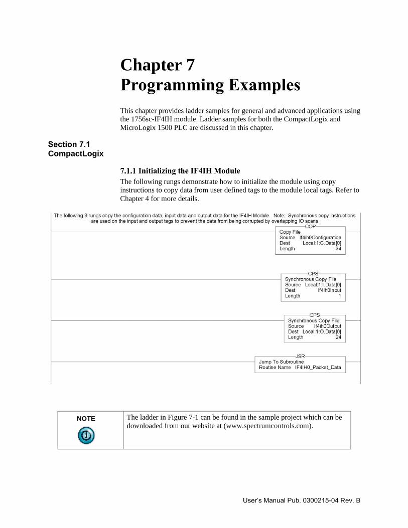
User’s Manual Pub. 0300215-04 Rev. B
Chapter 7 Programming Examples
This chapter provides ladder samples for general and advanced applications using
the 1756sc-IF4IH module. Ladder samples for both the CompactLogix and
MicroLogix 1500 PLC are discussed in this chapter.
CompactLogix
The following rungs demonstrate how to initialize the module using copy
instructions to copy data from user defined tags to the module local tags. Refer to
Chapter 4 for more details.
NOTE
The ladder in Figure 7-1 can be found in the sample project which can be
downloaded from our website at (www.spectrumcontrols.com).
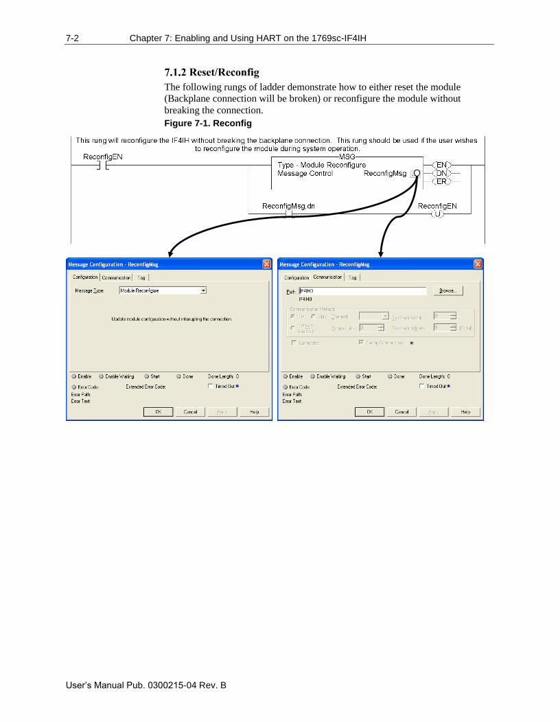
7-2 Chapter 7: Enabling and Using HART on the 1769sc-IF4IH
User’s Manual Pub. 0300215-04 Rev. B
The following rungs of ladder demonstrate how to either reset the module
(Backplane connection will be broken) or reconfigure the module without
breaking the connection.
Figure 7-1. Reconfig
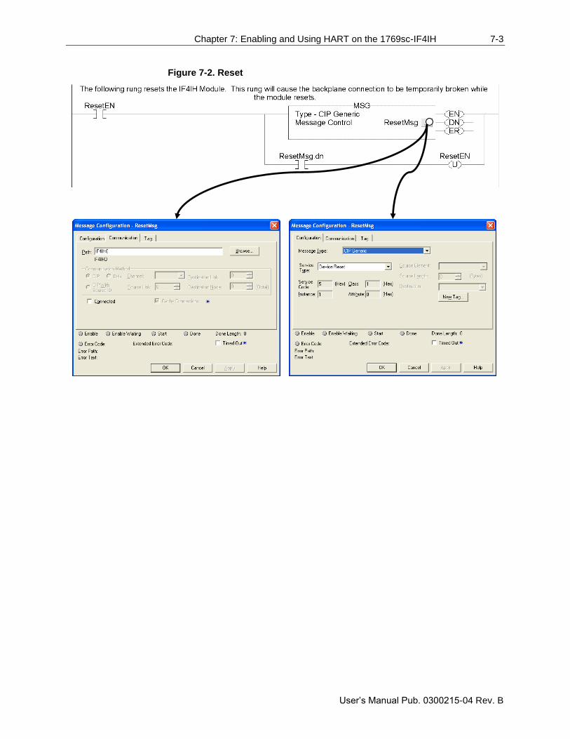
Chapter 7: Enabling and Using HART on the 1769sc-IF4IH 7-3
User’s Manual Pub. 0300215-04 Rev. B
Figure 7-2. Reset
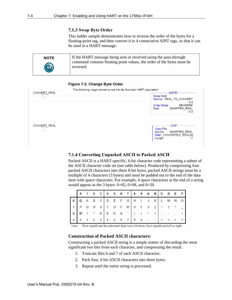
7-4 Chapter 7: Enabling and Using HART on the 1769sc-IF4IH
User’s Manual Pub. 0300215-04 Rev. B
This ladder sample demonstrates how to reverse the order of the bytes for a
floating-point tag, and then convert it to 4 consecutive SINT tags, so that it can
be used in a HART message.
NOTE
If the HART message being sent or received using the pass-through
command contains floating point values, the order of the bytes must be
reversed.
Figure 7-3. Change Byte Order
Packed ASCII is a HART-specific, 6-bit character code representing a subset of
the ASCII character code set (see table below). Produced by compressing four
packed ASCII characters into three 8-bit bytes, packed ASCII strings must be a
multiple of 4 characters (3 bytes) and must be padded out to the end of the data
item with space characters. For example, 4 space characters at the end of a string
would appear as the 3 bytes: 0×82, 0×08, and 0×20.
Construction of Packed ASCII characters:
Constructing a packed ASCII string is a simple matter of discarding the most
significant two bits from each character, and compressing the result:
1. Truncate Bits 6 and 7 of each ASCII character.
2. Pack four, 6 bit-ASCII characters into three bytes.
3. Repeat until the entire string is processed.
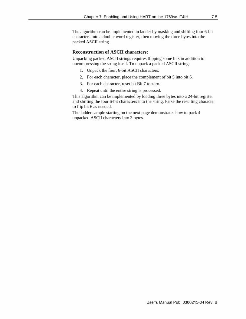
Chapter 7: Enabling and Using HART on the 1769sc-IF4IH 7-5
User’s Manual Pub. 0300215-04 Rev. B
The algorithm can be implemented in ladder by masking and shifting four 6-bit
characters into a double word register, then moving the three bytes into the
packed ASCII string.
Reconstruction of ASCII characters:
Unpacking packed ASCII strings requires flipping some bits in addition to
uncompressing the string itself. To unpack a packed ASCII string:
1. Unpack the four, 6-bit ASCII characters.
2. For each character, place the complement of bit 5 into bit 6.
3. For each character, reset bit Bit 7 to zero.
4. Repeat until the entire string is processed.
This algorithm can be implemented by loading three bytes into a 24-bit register
and shifting the four 6-bit characters into the string. Parse the resulting character
to flip bit 6 as needed.
The ladder sample starting on the next page demonstrates how to pack 4
unpacked ASCII characters into 3 bytes.
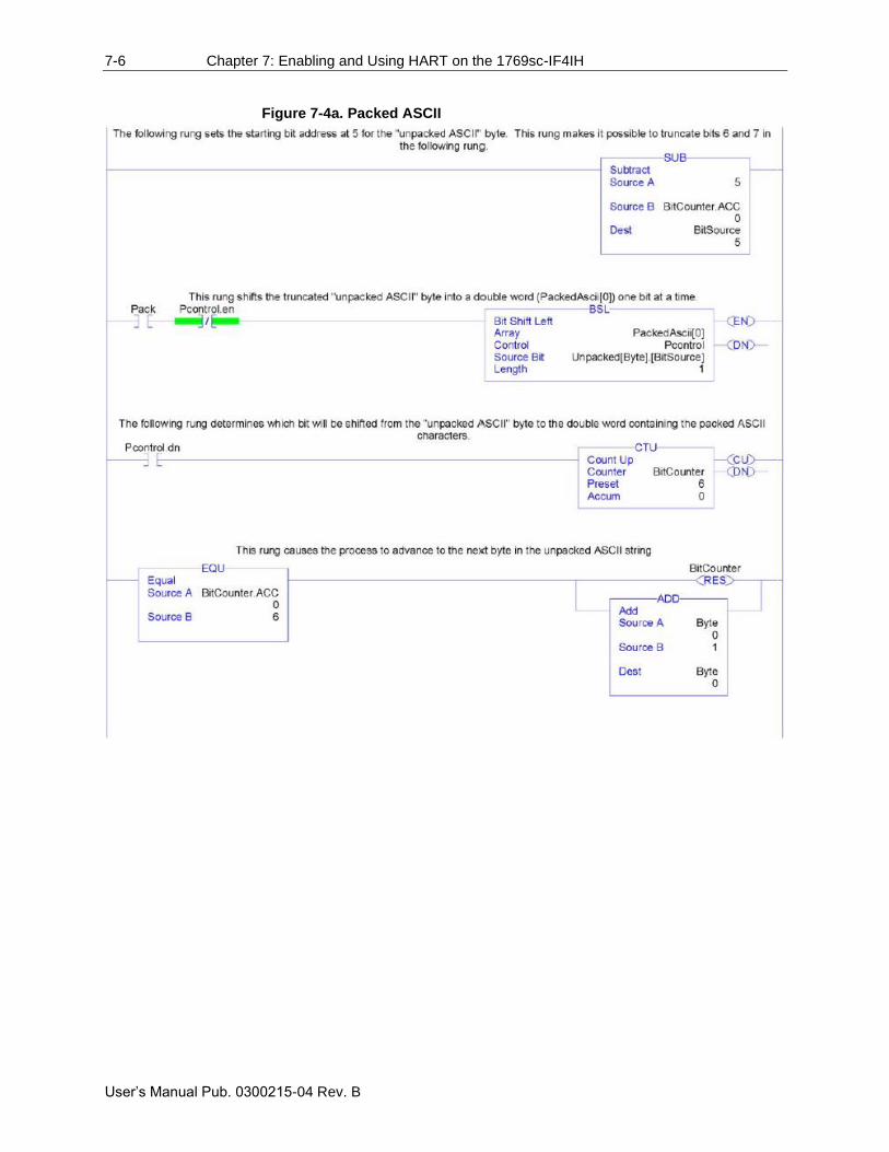
7-6 Chapter 7: Enabling and Using HART on the 1769sc-IF4IH
User’s Manual Pub. 0300215-04 Rev. B
Figure 7-4a. Packed ASCII
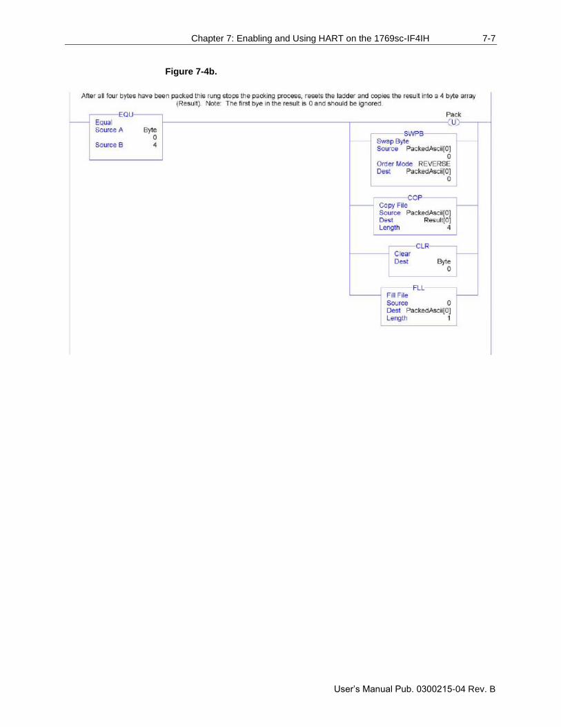
Chapter 7: Enabling and Using HART on the 1769sc-IF4IH 7-7
User’s Manual Pub. 0300215-04 Rev. B
Figure 7-4b.
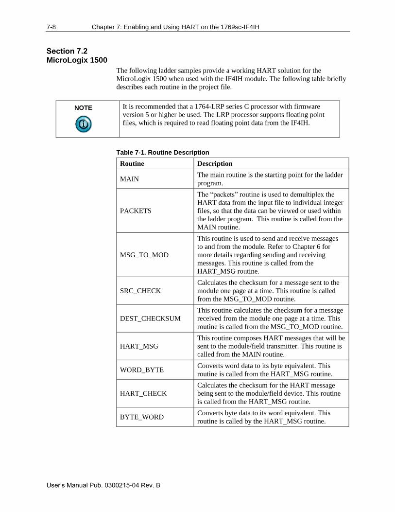
7-8 Chapter 7: Enabling and Using HART on the 1769sc-IF4IH
User’s Manual Pub. 0300215-04 Rev. B
MicroLogix 1500
The following ladder samples provide a working HART solution for the
MicroLogix 1500 when used with the IF4IH module. The following table briefly
describes each routine in the project file.
NOTE
It is recommended that a 1764-LRP series C processor with firmware
version 5 or higher be used. The LRP processor supports floating point
files, which is required to read floating point data from the IF4IH.
Table 7-1. Routine Description
Routine Description
MAIN The main routine is the starting point for the ladder
program.
PACKETS
The “packets” routine is used to demultiplex the
HART data from the input file to individual integer
files, so that the data can be viewed or used within
the ladder program. This routine is called from the
MAIN routine.
MSG_TO_MOD
This routine is used to send and receive messages
to and from the module. Refer to Chapter 6 for
more details regarding sending and receiving
messages. This routine is called from the
HART_MSG routine.
SRC_CHECK
Calculates the checksum for a message sent to the
module one page at a time. This routine is called
from the MSG_TO_MOD routine.
DEST_CHECKSUM
This routine calculates the checksum for a message
received from the module one page at a time. This
routine is called from the MSG_TO_MOD routine.
HART_MSG
This routine composes HART messages that will be
sent to the module/field transmitter. This routine is
called from the MAIN routine.
WORD_BYTE Converts word data to its byte equivalent. This
routine is called from the HART_MSG routine.
HART_CHECK
Calculates the checksum for the HART message
being sent to the module/field device. This routine
is called from the HART_MSG routine.
BYTE_WORD Converts byte data to its word equivalent. This
routine is called by the HART_MSG routine.
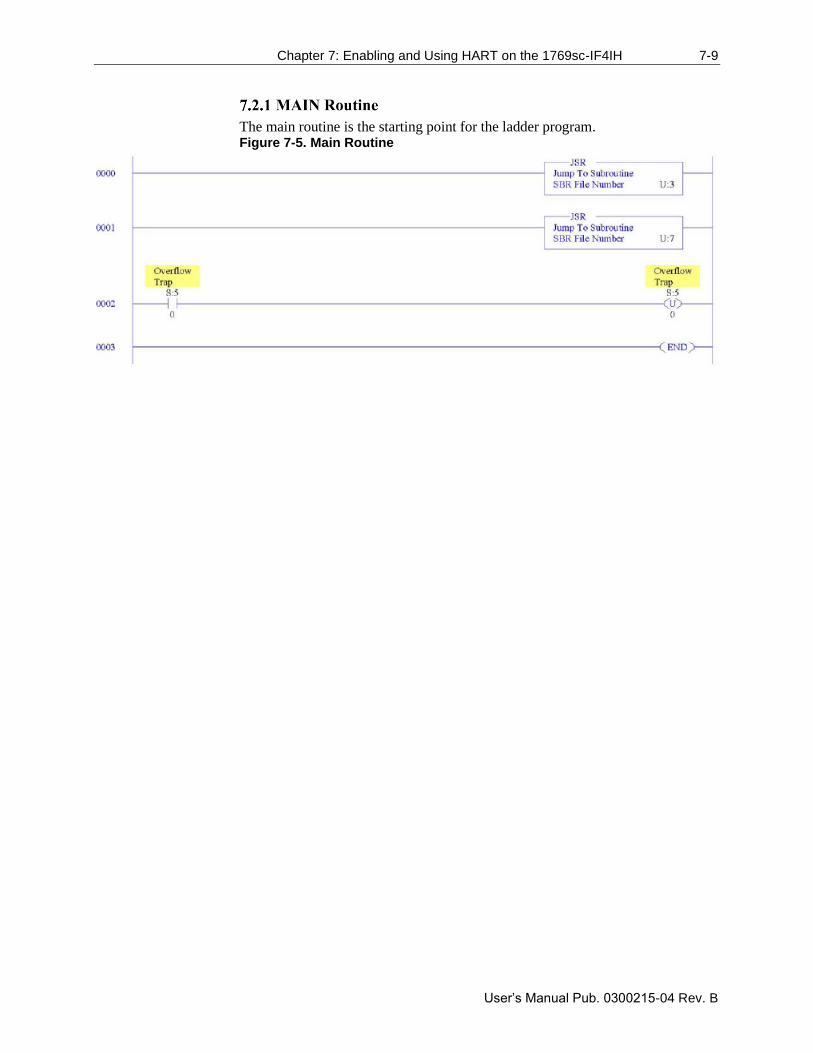
Chapter 7: Enabling and Using HART on the 1769sc-IF4IH 7-9
User’s Manual Pub. 0300215-04 Rev. B
The main routine is the starting point for the ladder program. Figure 7-5. Main Routine
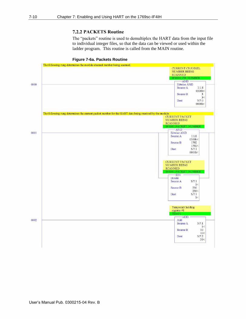
7-10 Chapter 7: Enabling and Using HART on the 1769sc-IF4IH
User’s Manual Pub. 0300215-04 Rev. B
The “packets” routine is used to demultiplex the HART data from the input file
to individual integer files, so that the data can be viewed or used within the
ladder program. This routine is called from the MAIN routine.
Figure 7-6a. Packets Routine
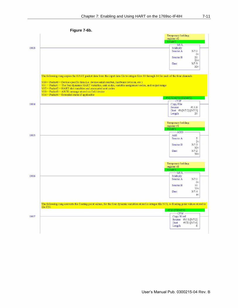
Chapter 7: Enabling and Using HART on the 1769sc-IF4IH 7-11
User’s Manual Pub. 0300215-04 Rev. B
Figure 7-6b.
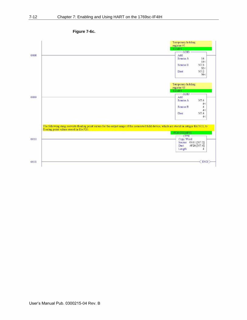
7-12 Chapter 7: Enabling and Using HART on the 1769sc-IF4IH
User’s Manual Pub. 0300215-04 Rev. B
Figure 7-6c.
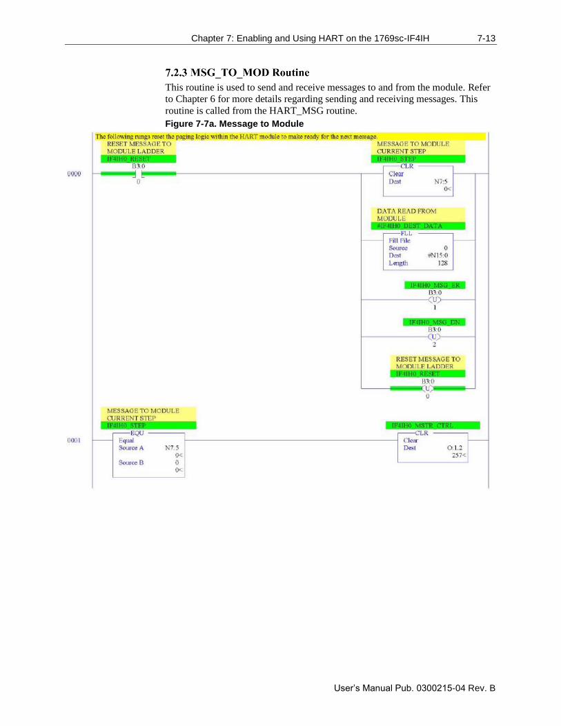
Chapter 7: Enabling and Using HART on the 1769sc-IF4IH 7-13
User’s Manual Pub. 0300215-04 Rev. B
This routine is used to send and receive messages to and from the module. Refer
to Chapter 6 for more details regarding sending and receiving messages. This
routine is called from the HART_MSG routine.
Figure 7-7a. Message to Module
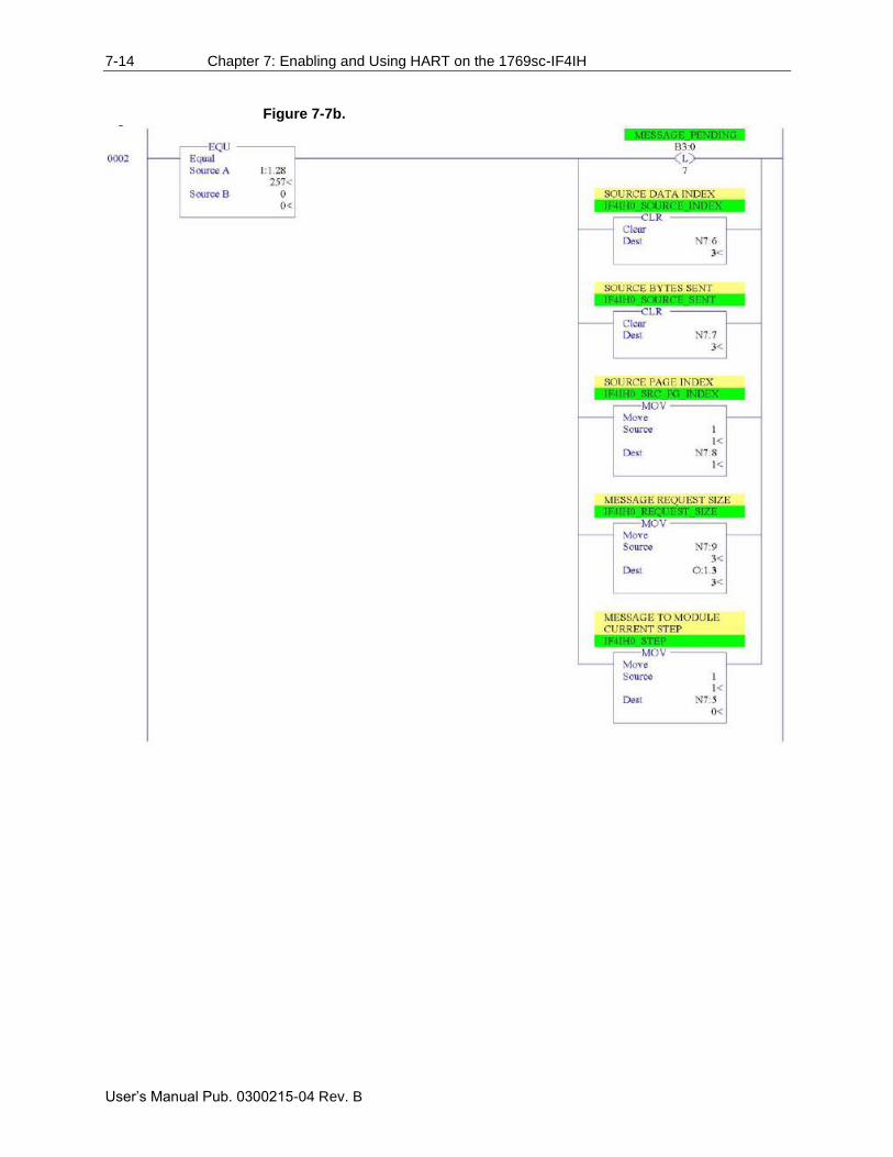
7-14 Chapter 7: Enabling and Using HART on the 1769sc-IF4IH
User’s Manual Pub. 0300215-04 Rev. B
Figure 7-7b.
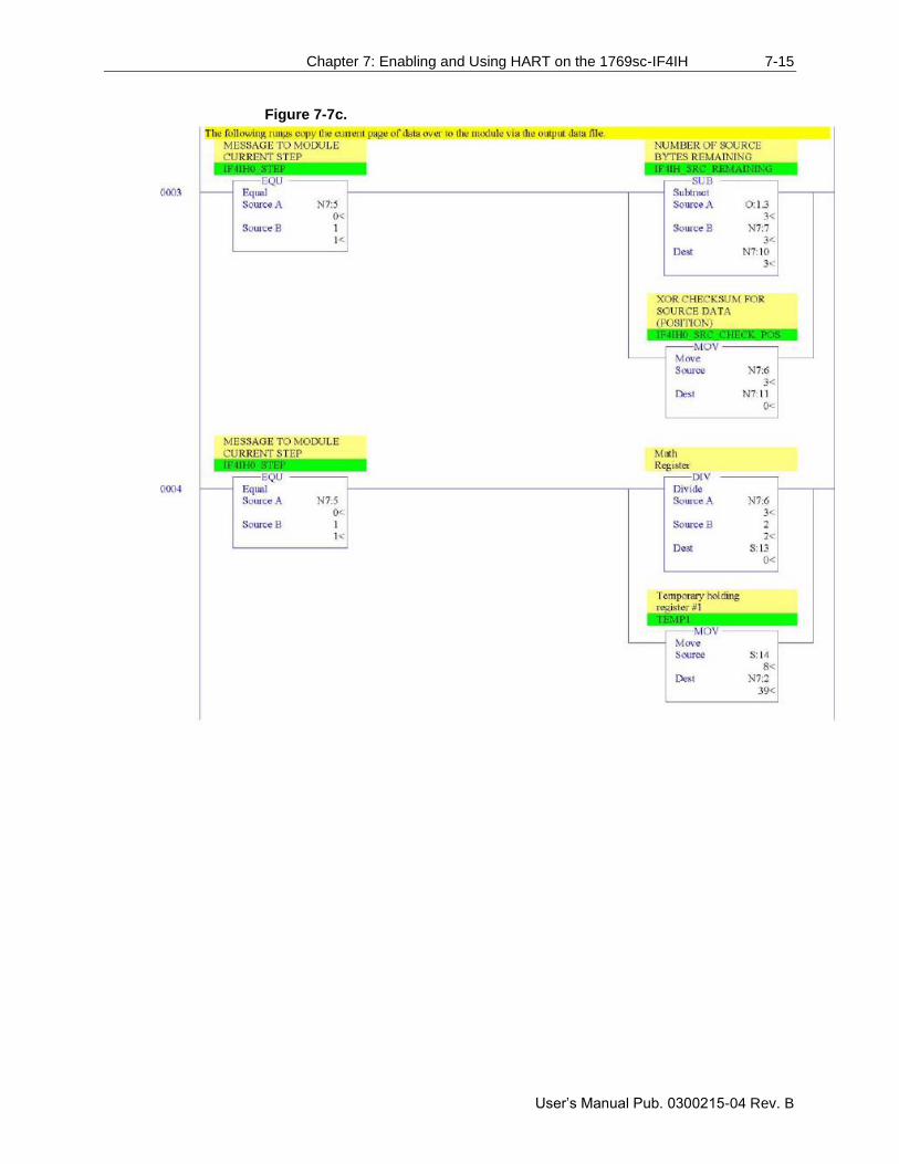
Chapter 7: Enabling and Using HART on the 1769sc-IF4IH 7-15
User’s Manual Pub. 0300215-04 Rev. B
Figure 7-7c.
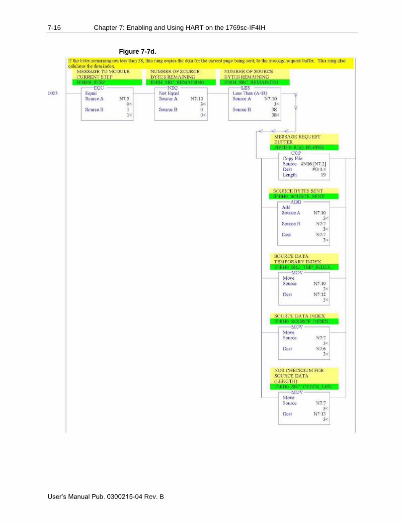
7-16 Chapter 7: Enabling and Using HART on the 1769sc-IF4IH
User’s Manual Pub. 0300215-04 Rev. B
Figure 7-7d.
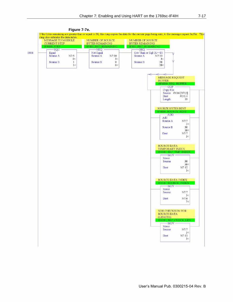
Chapter 7: Enabling and Using HART on the 1769sc-IF4IH 7-17
User’s Manual Pub. 0300215-04 Rev. B
Figure 7-7e.
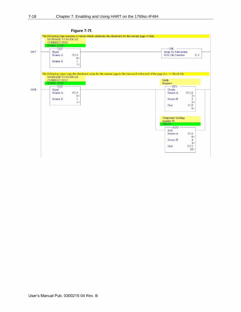
7-18 Chapter 7: Enabling and Using HART on the 1769sc-IF4IH
User’s Manual Pub. 0300215-04 Rev. B
Figure 7-7f.
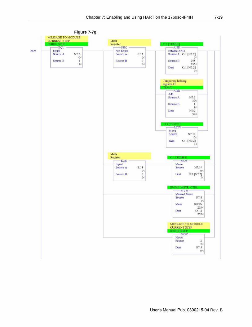
Chapter 7: Enabling and Using HART on the 1769sc-IF4IH 7-19
User’s Manual Pub. 0300215-04 Rev. B
Figure 7-7g.
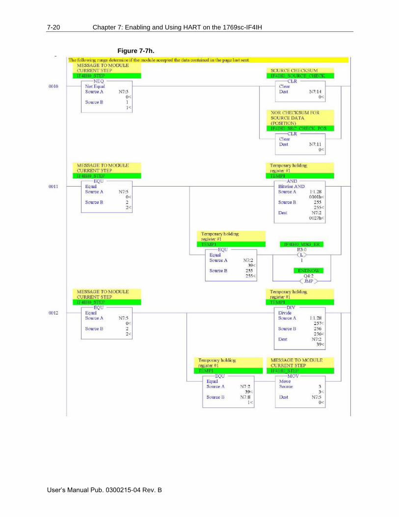
7-20 Chapter 7: Enabling and Using HART on the 1769sc-IF4IH
User’s Manual Pub. 0300215-04 Rev. B
Figure 7-7h.
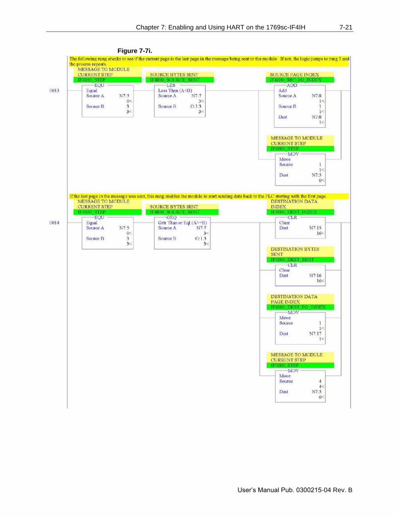
Chapter 7: Enabling and Using HART on the 1769sc-IF4IH 7-21
User’s Manual Pub. 0300215-04 Rev. B
Figure 7-7i.
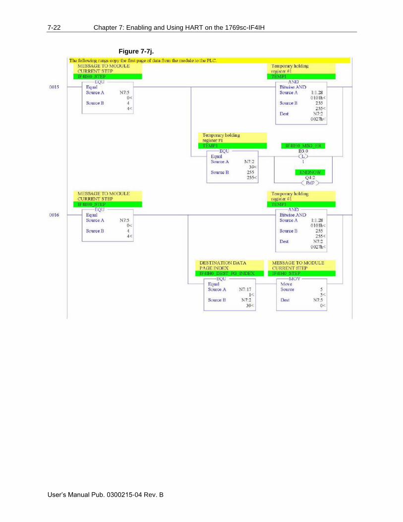
7-22 Chapter 7: Enabling and Using HART on the 1769sc-IF4IH
User’s Manual Pub. 0300215-04 Rev. B
Figure 7-7j.
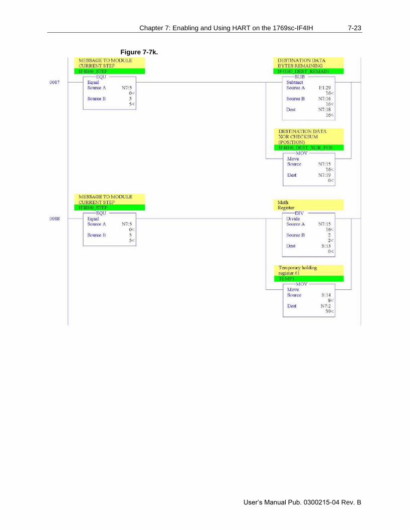
Chapter 7: Enabling and Using HART on the 1769sc-IF4IH 7-23
User’s Manual Pub. 0300215-04 Rev. B
Figure 7-7k.
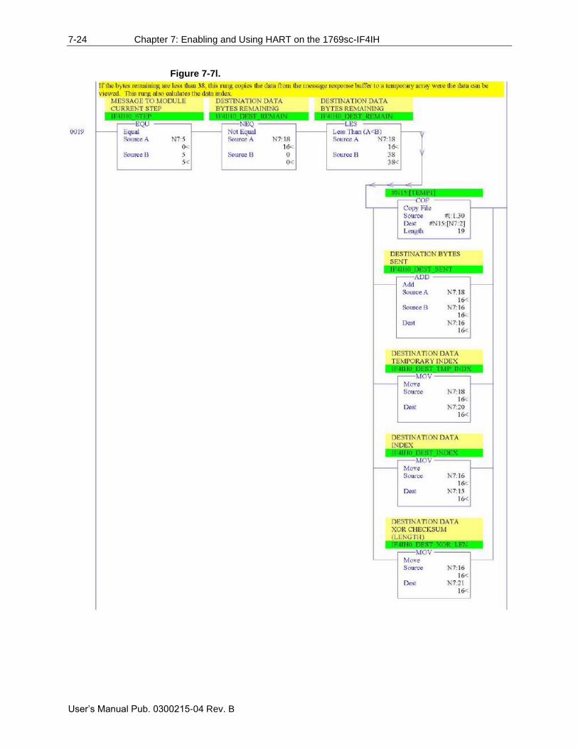
7-24 Chapter 7: Enabling and Using HART on the 1769sc-IF4IH
User’s Manual Pub. 0300215-04 Rev. B
Figure 7-7l.
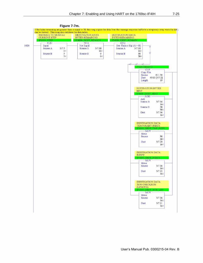
Chapter 7: Enabling and Using HART on the 1769sc-IF4IH 7-25
User’s Manual Pub. 0300215-04 Rev. B
Figure 7-7m.

7-26 Chapter 7: Enabling and Using HART on the 1769sc-IF4IH
User’s Manual Pub. 0300215-04 Rev. B
Figure 7-7n.
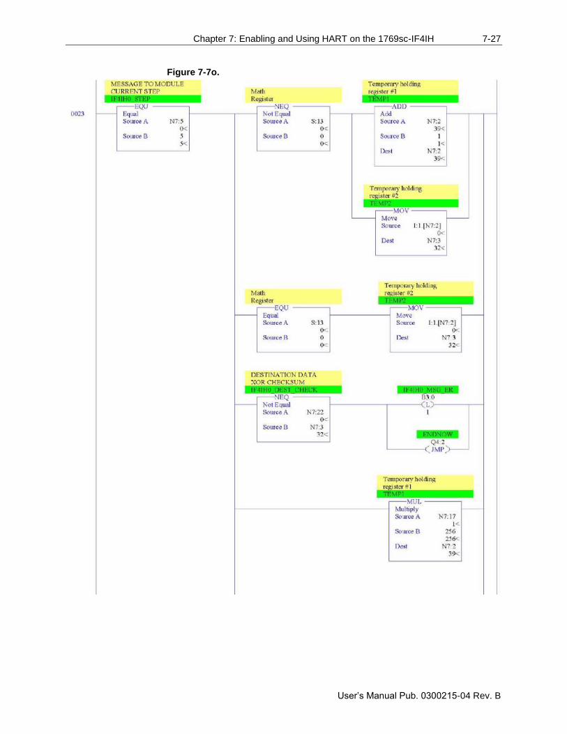
Chapter 7: Enabling and Using HART on the 1769sc-IF4IH 7-27
User’s Manual Pub. 0300215-04 Rev. B
Figure 7-7o.
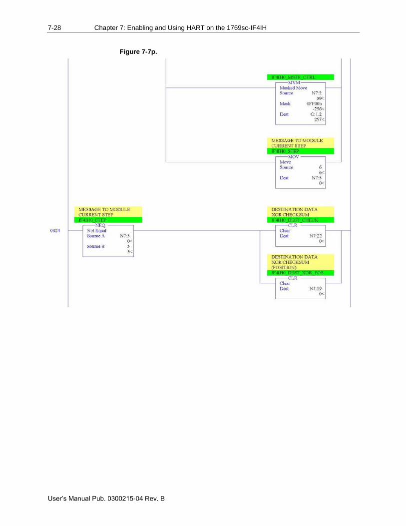
7-28 Chapter 7: Enabling and Using HART on the 1769sc-IF4IH
User’s Manual Pub. 0300215-04 Rev. B
Figure 7-7p.
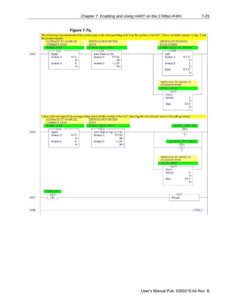
Chapter 7: Enabling and Using HART on the 1769sc-IF4IH 7-29
User’s Manual Pub. 0300215-04 Rev. B
Figure 7-7q.
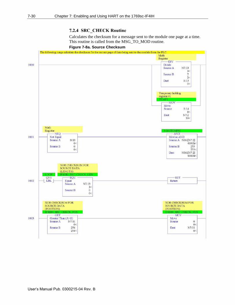
7-30 Chapter 7: Enabling and Using HART on the 1769sc-IF4IH
User’s Manual Pub. 0300215-04 Rev. B
Calculates the checksum for a message sent to the module one page at a time.
This routine is called from the MSG_TO_MOD routine.
Figure 7-8a. Source Checksum
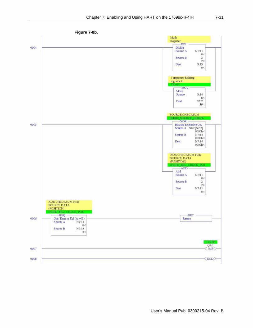
Chapter 7: Enabling and Using HART on the 1769sc-IF4IH 7-31
User’s Manual Pub. 0300215-04 Rev. B
Figure 7-8b.
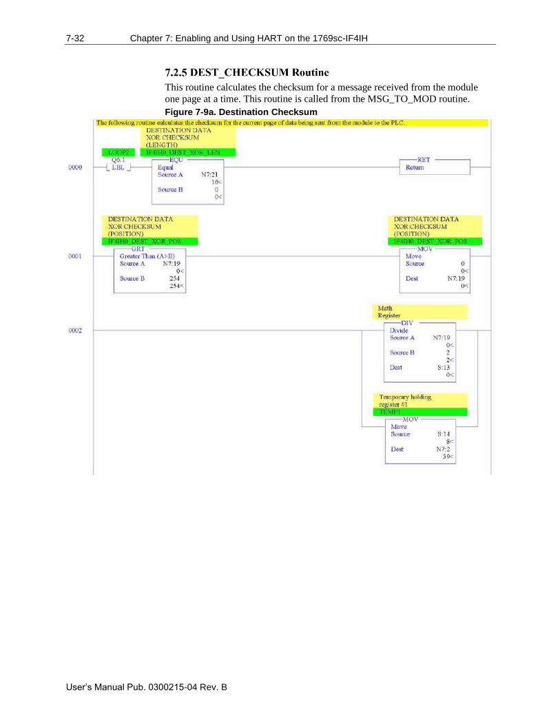
7-32 Chapter 7: Enabling and Using HART on the 1769sc-IF4IH
User’s Manual Pub. 0300215-04 Rev. B
This routine calculates the checksum for a message received from the module
one page at a time. This routine is called from the MSG_TO_MOD routine.
Figure 7-9a. Destination Checksum
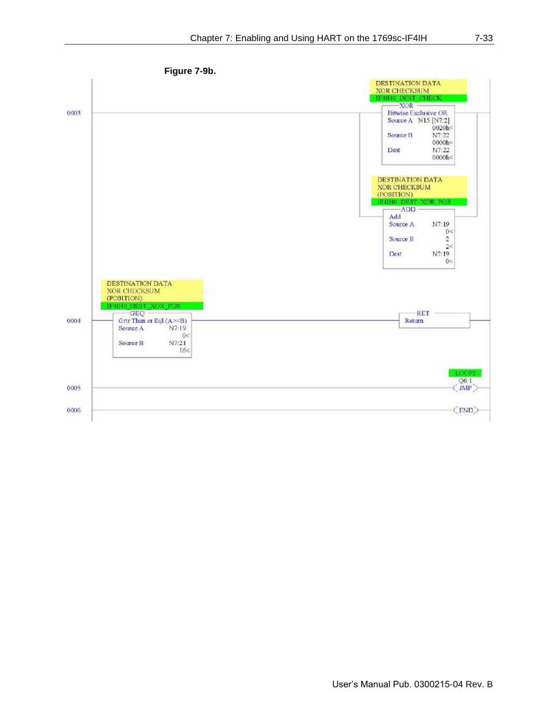
Chapter 7: Enabling and Using HART on the 1769sc-IF4IH 7-33
User’s Manual Pub. 0300215-04 Rev. B
Figure 7-9b.
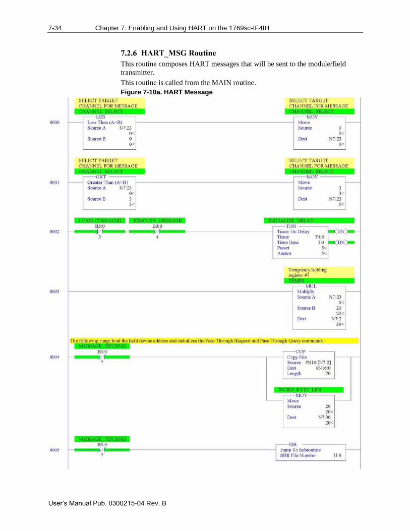
7-34 Chapter 7: Enabling and Using HART on the 1769sc-IF4IH
User’s Manual Pub. 0300215-04 Rev. B
This routine composes HART messages that will be sent to the module/field
transmitter.
This routine is called from the MAIN routine.
Figure 7-10a. HART Message

Chapter 7: Enabling and Using HART on the 1769sc-IF4IH 7-35
User’s Manual Pub. 0300215-04 Rev. B
Figure 7-10b.
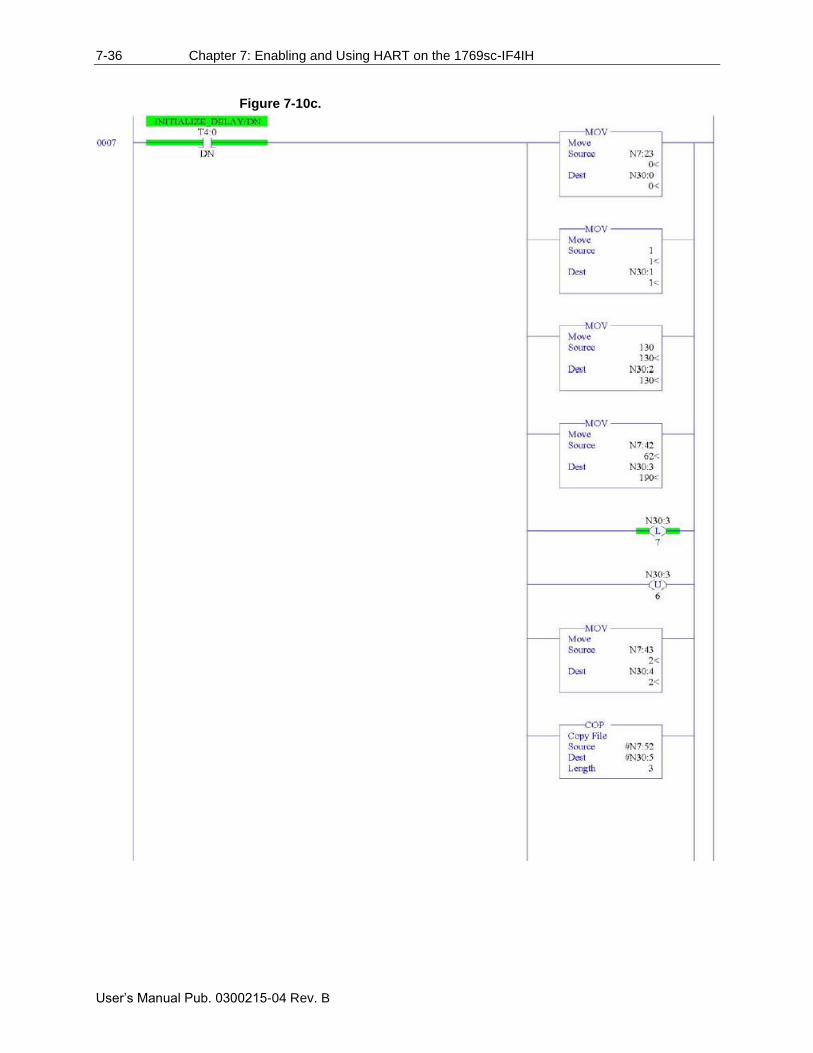
7-36 Chapter 7: Enabling and Using HART on the 1769sc-IF4IH
User’s Manual Pub. 0300215-04 Rev. B
Figure 7-10c.
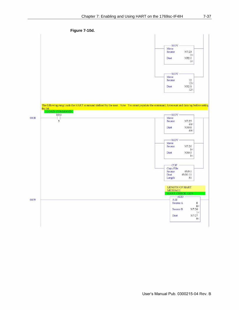
Chapter 7: Enabling and Using HART on the 1769sc-IF4IH 7-37
User’s Manual Pub. 0300215-04 Rev. B
Figure 7-10d.
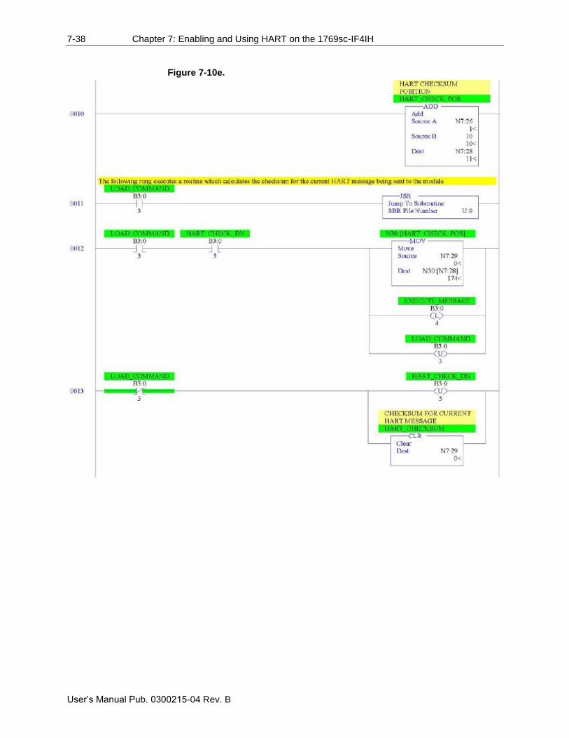
7-38 Chapter 7: Enabling and Using HART on the 1769sc-IF4IH
User’s Manual Pub. 0300215-04 Rev. B
Figure 7-10e.
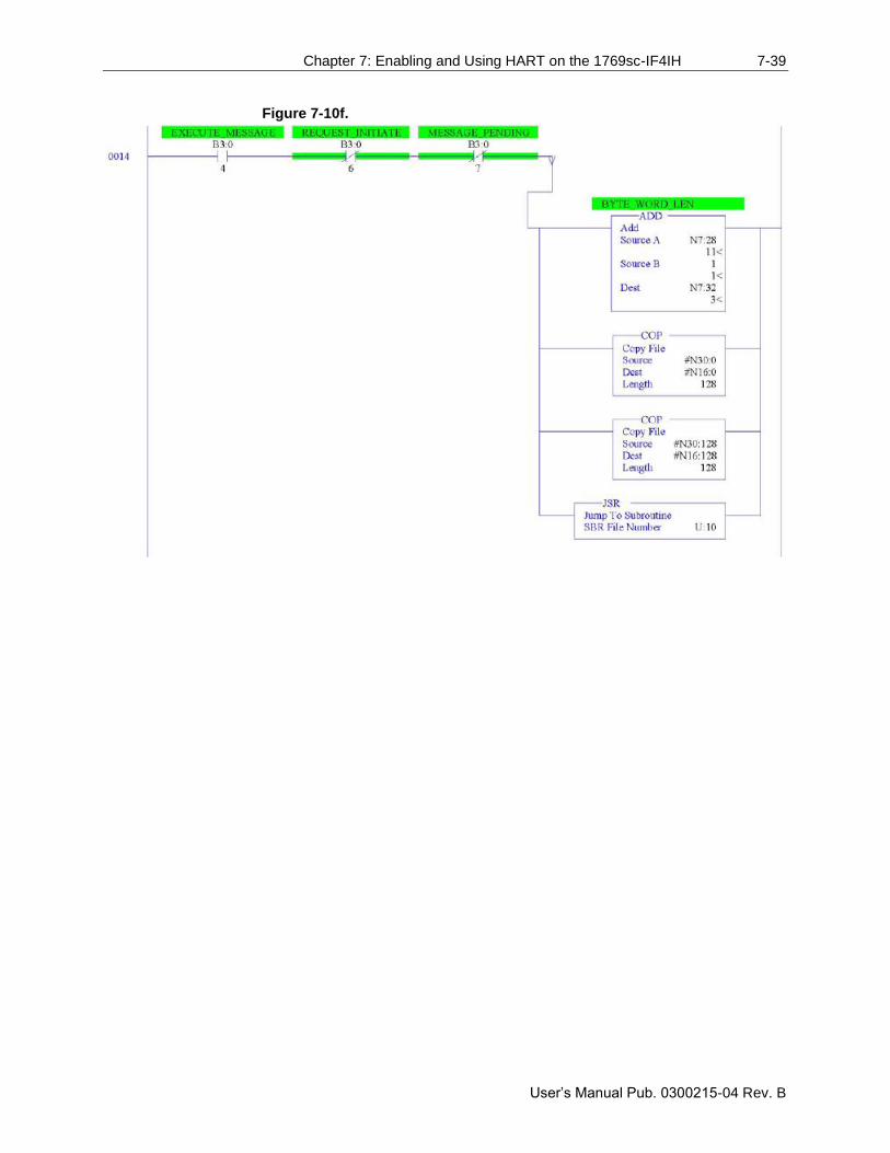
Chapter 7: Enabling and Using HART on the 1769sc-IF4IH 7-39
User’s Manual Pub. 0300215-04 Rev. B
Figure 7-10f.

7-40 Chapter 7: Enabling and Using HART on the 1769sc-IF4IH
User’s Manual Pub. 0300215-04 Rev. B
Figure 7-10g.
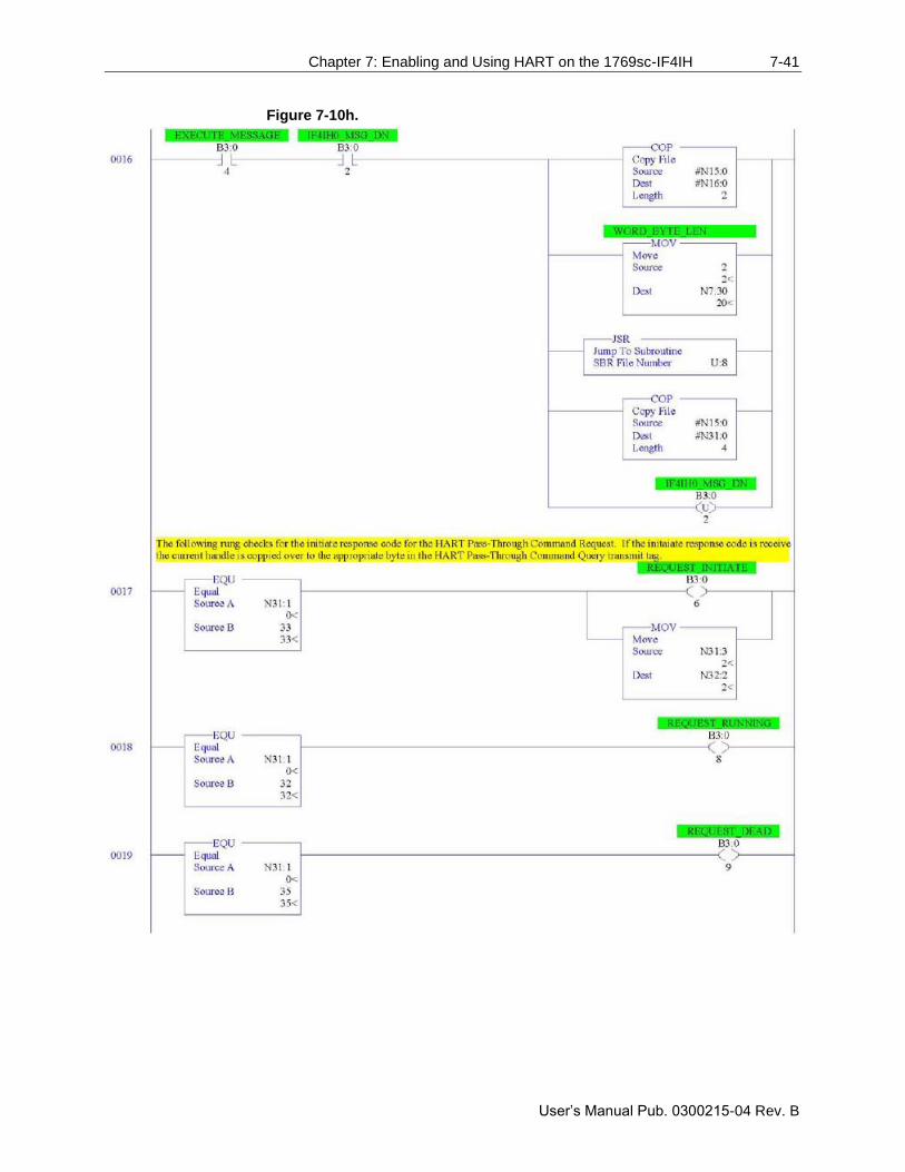
Chapter 7: Enabling and Using HART on the 1769sc-IF4IH 7-41
User’s Manual Pub. 0300215-04 Rev. B
Figure 7-10h.
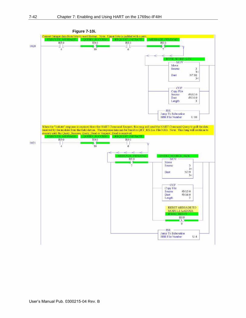
7-42 Chapter 7: Enabling and Using HART on the 1769sc-IF4IH
User’s Manual Pub. 0300215-04 Rev. B
Figure 7-10i.
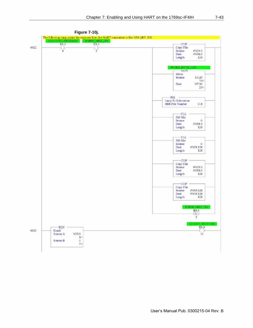
Chapter 7: Enabling and Using HART on the 1769sc-IF4IH 7-43
User’s Manual Pub. 0300215-04 Rev. B
Figure 7-10j.
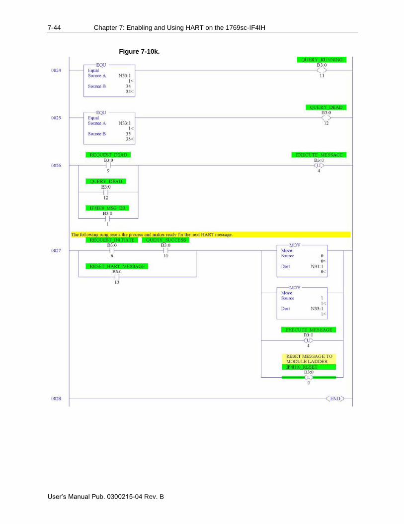
7-44 Chapter 7: Enabling and Using HART on the 1769sc-IF4IH
User’s Manual Pub. 0300215-04 Rev. B
Figure 7-10k.
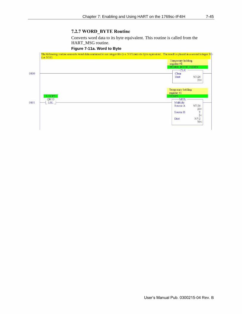
Chapter 7: Enabling and Using HART on the 1769sc-IF4IH 7-45
User’s Manual Pub. 0300215-04 Rev. B
Converts word data to its byte equivalent. This routine is called from the
HART_MSG routine.
Figure 7-11a. Word to Byte
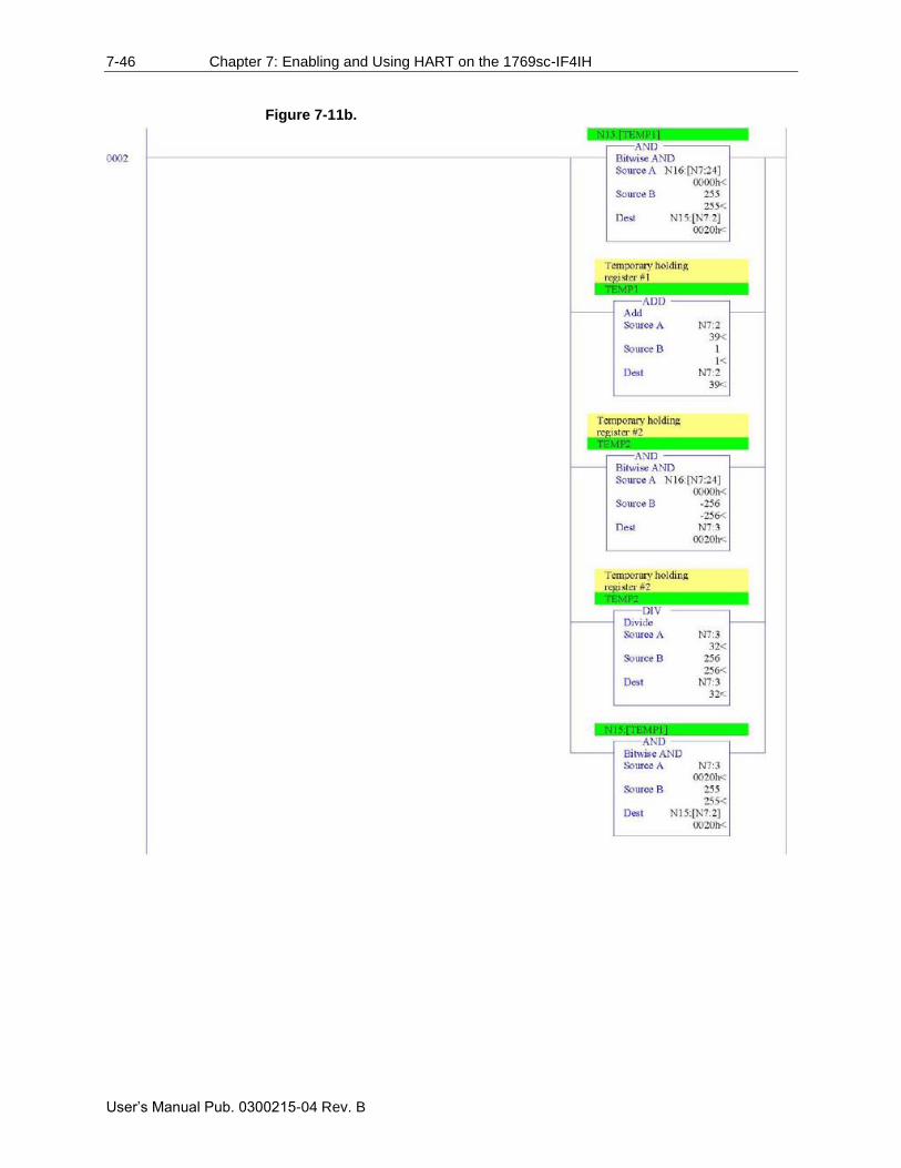
7-46 Chapter 7: Enabling and Using HART on the 1769sc-IF4IH
User’s Manual Pub. 0300215-04 Rev. B
Figure 7-11b.
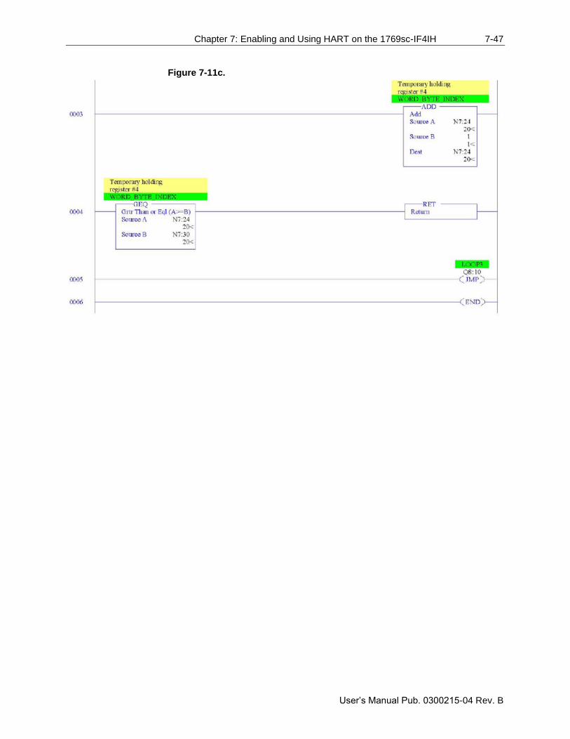
Chapter 7: Enabling and Using HART on the 1769sc-IF4IH 7-47
User’s Manual Pub. 0300215-04 Rev. B
Figure 7-11c.
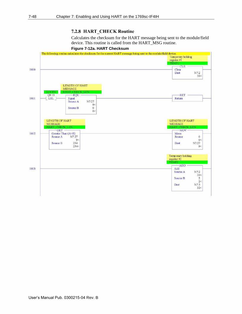
7-48 Chapter 7: Enabling and Using HART on the 1769sc-IF4IH
User’s Manual Pub. 0300215-04 Rev. B
Calculates the checksum for the HART message being sent to the module/field
device. This routine is called from the HART_MSG routine.
Figure 7-12a. HART Checksum
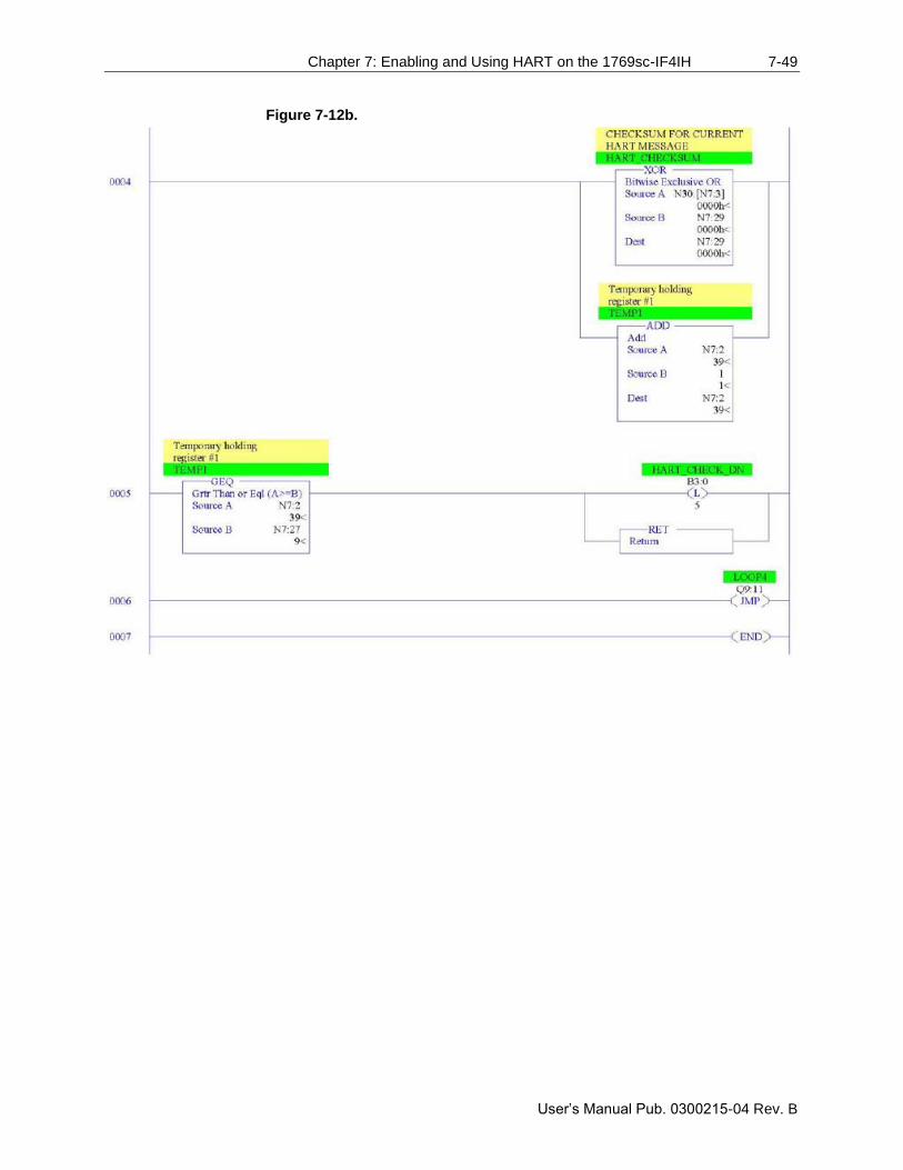
Chapter 7: Enabling and Using HART on the 1769sc-IF4IH 7-49
User’s Manual Pub. 0300215-04 Rev. B
Figure 7-12b.
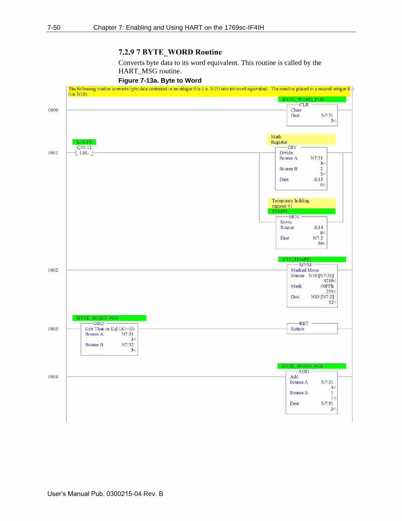
7-50 Chapter 7: Enabling and Using HART on the 1769sc-IF4IH
User’s Manual Pub. 0300215-04 Rev. B
Converts byte data to its word equivalent. This routine is called by the
HART_MSG routine.
Figure 7-13a. Byte to Word
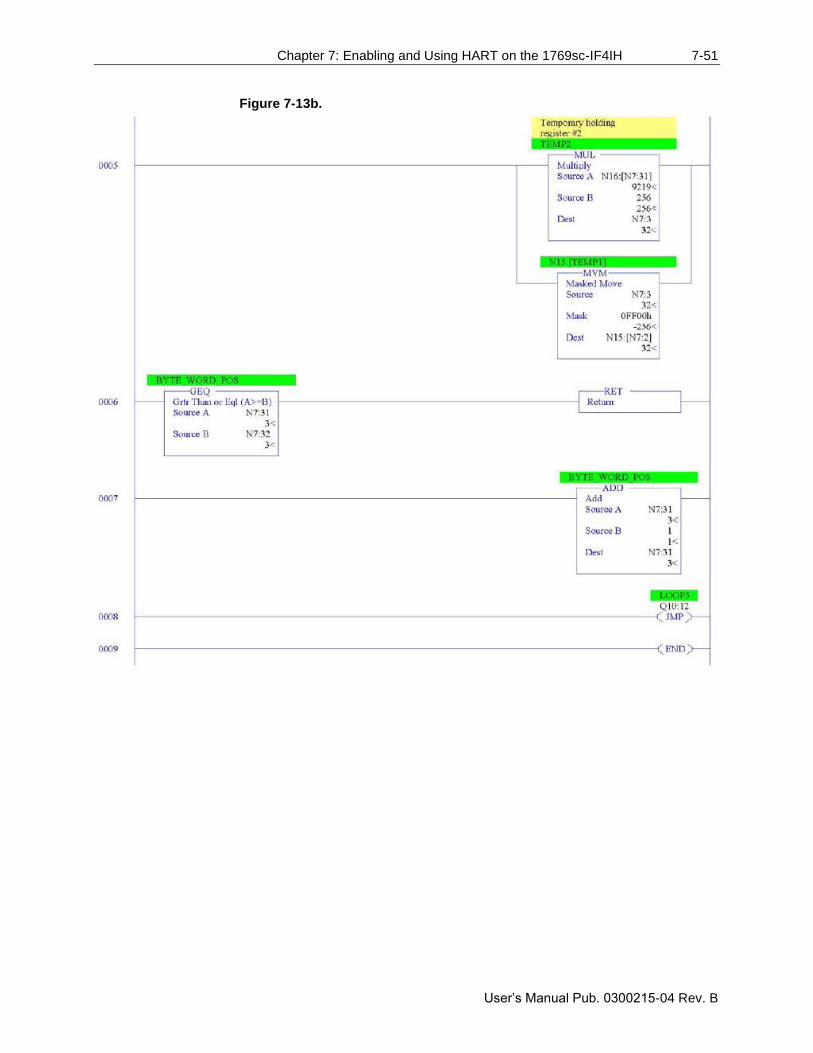
Chapter 7: Enabling and Using HART on the 1769sc-IF4IH 7-51
User’s Manual Pub. 0300215-04 Rev. B
Figure 7-13b.

7-52 Chapter 7: Enabling and Using HART on the 1769sc-IF4IH
User’s Manual Pub. 0300215-04 Rev. B
User’s Manual Pub. 0300215-04 Rev. B
Chapter 8 Diagnostics and
Troubleshooting
This chapter describes troubleshooting the isolated HART input module. This
chapter contains information on:
• Safety considerations while troubleshooting
• Internal diagnostics during module operation
• Module errors
• Contacting Spectrum Controls, Inc. for technical assistance
Safety Considerations
Safety considerations are an important element of proper troubleshooting
procedures. Actively thinking about the safety of yourself and others, as well as
the condition of your equipment, is of primary importance.
The following sections describe several safety concerns you should be aware of
when troubleshooting your control system.
WARNING
HAZARD OF INJURY TO PERSONNEL
Never reach into a machine to actuate a switch because unexpected motion
can occur and cause injury. Remove all electrical power at the main power
disconnect switches before checking electrical connections or inputs/
outputs causing machine motion.
When the green LED on the module is lit, it indicates that power is applied to the
module, and that it has passed its internal tests.
When troubleshooting any system problem, have all personnel remain clear of
the equipment. The problem could be intermittent, and sudden unexpected
machine motion could occur. Have someone ready to operate an emergency stop
switch in case it becomes necessary to shut off power.
There are several possible causes of alteration to the user program, including
extreme environmental conditions, Electromagnetic Interference (EMI), improper
grounding, improper wiring connections, and unauthorized tampering. If you
suspect a program has been altered, check it against a previously saved master
program.
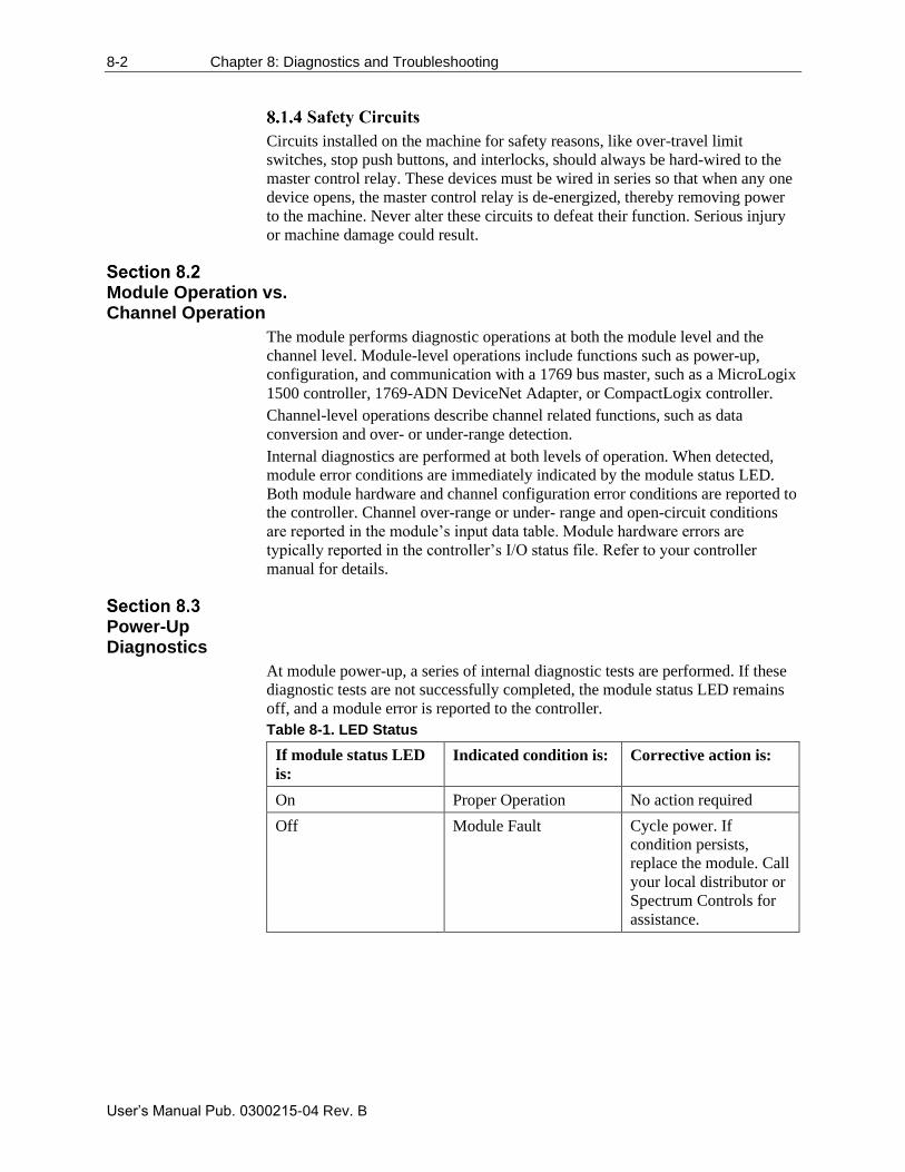
8-2 Chapter 8: Diagnostics and Troubleshooting
User’s Manual Pub. 0300215-04 Rev. B
Circuits installed on the machine for safety reasons, like over-travel limit
switches, stop push buttons, and interlocks, should always be hard-wired to the
master control relay. These devices must be wired in series so that when any one
device opens, the master control relay is de-energized, thereby removing power
to the machine. Never alter these circuits to defeat their function. Serious injury
or machine damage could result.
Module Operation vs. Channel Operation
The module performs diagnostic operations at both the module level and the
channel level. Module-level operations include functions such as power-up,
configuration, and communication with a 1769 bus master, such as a MicroLogix
1500 controller, 1769-ADN DeviceNet Adapter, or CompactLogix controller.
Channel-level operations describe channel related functions, such as data
conversion and over- or under-range detection.
Internal diagnostics are performed at both levels of operation. When detected,
module error conditions are immediately indicated by the module status LED.
Both module hardware and channel configuration error conditions are reported to
the controller. Channel over-range or under- range and open-circuit conditions
are reported in the module’s input data table. Module hardware errors are
typically reported in the controller’s I/O status file. Refer to your controller
manual for details.
Power-Up Diagnostics
At module power-up, a series of internal diagnostic tests are performed. If these
diagnostic tests are not successfully completed, the module status LED remains
off, and a module error is reported to the controller.
Table 8-1. LED Status
If module status LED
is:
Indicated condition is: Corrective action is:
On Proper Operation No action required
Off Module Fault Cycle power. If
condition persists,
replace the module. Call
your local distributor or
Spectrum Controls for
assistance.
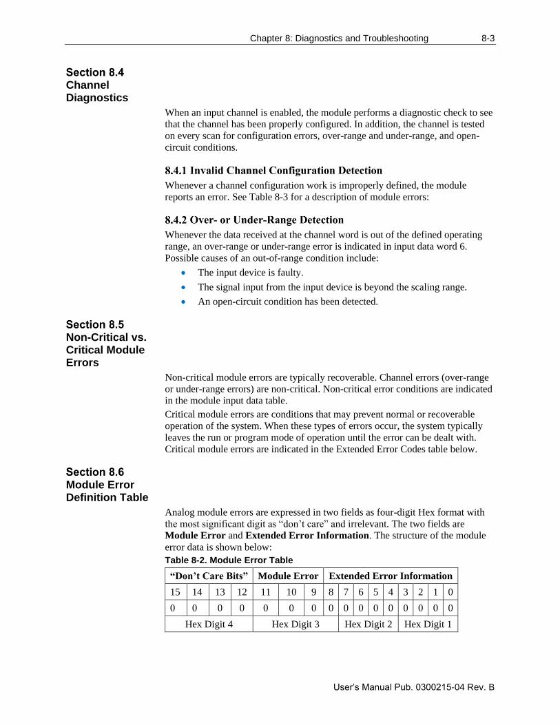
Chapter 8: Diagnostics and Troubleshooting 8-3
User’s Manual Pub. 0300215-04 Rev. B
Channel Diagnostics
When an input channel is enabled, the module performs a diagnostic check to see
that the channel has been properly configured. In addition, the channel is tested
on every scan for configuration errors, over-range and under-range, and open-
circuit conditions.
Whenever a channel configuration work is improperly defined, the module
reports an error. See Table 8-3 for a description of module errors:
Whenever the data received at the channel word is out of the defined operating
range, an over-range or under-range error is indicated in input data word 6.
Possible causes of an out-of-range condition include:
• The input device is faulty.
• The signal input from the input device is beyond the scaling range.
• An open-circuit condition has been detected.
Non-Critical vs. Critical Module Errors
Non-critical module errors are typically recoverable. Channel errors (over-range
or under-range errors) are non-critical. Non-critical error conditions are indicated
in the module input data table.
Critical module errors are conditions that may prevent normal or recoverable
operation of the system. When these types of errors occur, the system typically
leaves the run or program mode of operation until the error can be dealt with.
Critical module errors are indicated in the Extended Error Codes table below.
Module Error Definition Table
Analog module errors are expressed in two fields as four-digit Hex format with
the most significant digit as “don’t care” and irrelevant. The two fields are
Module Error and Extended Error Information. The structure of the module
error data is shown below:
Table 8-2. Module Error Table
“Don’t Care Bits” Module Error Extended Error Information
15 14 13 12 11 10 9 8 7 6 5 4 3 2 1 0
0 0 0 0 0 0 0 0 0 0 0 0 0 0 0 0
Hex Digit 4 Hex Digit 3 Hex Digit 2 Hex Digit 1
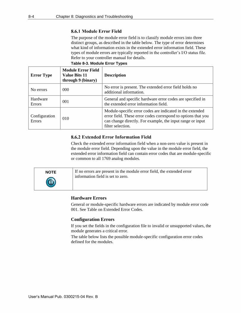
8-4 Chapter 8: Diagnostics and Troubleshooting
User’s Manual Pub. 0300215-04 Rev. B
The purpose of the module error field is to classify module errors into three
distinct groups, as described in the table below. The type of error determines
what kind of information exists in the extended error information field. These
types of module errors are typically reported in the controller’s I/O status file.
Refer to your controller manual for details.
Table 8-3. Module Error Types
Error Type
Module Error Field
Value Bits 11
through 9 (binary)
Description
No errors 000 No error is present. The extended error field holds no
additional information.
Hardware
Errors 001
General and specific hardware error codes are specified in
the extended error information field.
Configuration
Errors 010
Module-specific error codes are indicated in the extended
error field. These error codes correspond to options that you
can change directly. For example, the input range or input
filter selection.
Check the extended error information field when a non-zero value is present in
the module error field. Depending upon the value in the module error field, the
extended error information field can contain error codes that are module-specific
or common to all 1769 analog modules.
NOTE
If no errors are present in the module error field, the extended error
information field is set to zero.
Hardware Errors
General or module-specific hardware errors are indicated by module error code
001. See Table on Extended Error Codes.
Configuration Errors
If you set the fields in the configuration file to invalid or unsupported values, the
module generates a critical error.
The table below lists the possible module-specific configuration error codes
defined for the modules.
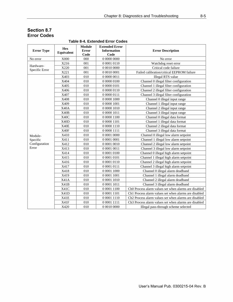
Chapter 8: Diagnostics and Troubleshooting 8-5
User’s Manual Pub. 0300215-04 Rev. B
Error Codes
Table 8-4. Extended Error Codes
Error Type Hex
Equivalent
Module
Error
Code
Extended Error
Information
Code
Error Description
No error X000 000 0 0000 0000 No error
Hardware-
Specific Error
X216 001 0 0001 0110 Watchdog reset error
X220 001 0 0010 0000 Critical code failure
X221 001 0 0010 0001 Failed calibration/critical EEPROM failure
Module-
Specific
Configuration
Error
X403 010 0 0000 0011 Illegal RTS value
X404 010 0 0000 0100 Channel 0 illegal filter configuration
X405 010 0 0000 0101 Channel 1 illegal filter configuration
X406 010 0 0000 0110 Channel 2 illegal filter configuration
X407 010 0 0000 0111 Channel 3 illegal filter configuration
X408 010 0 0000 1000 Channel 0 illegal input range
X409 010 0 0000 1001 Channel 1 illegal input range
X40A 010 0 0000 1010 Channel 2 illegal input range
X40B 010 0 0000 1011 Channel 3 illegal input range
X40C 010 0 0000 1100 Channel 0 illegal data format
X40D 010 0 0000 1101 Channel 1 illegal data format
X40E 010 0 0000 1110 Channel 2 illegal data format
X40F 010 0 0000 1111 Channel 3 illegal data format
X410 010 0 0001 0000 Channel 0 illegal low alarm setpoint
X411 010 0 0001 0001 Channel 1 illegal low alarm setpoint
X412 010 0 0001 0010 Channel 2 illegal low alarm setpoint
X413 010 0 0001 0011 Channel 3 illegal low alarm setpoint
X414 010 0 0001 0100 Channel 0 illegal high alarm setpoint
X415 010 0 0001 0101 Channel 1 illegal high alarm setpoint
X416 010 0 0001 0110 Channel 2 illegal high alarm setpoint
X417 010 0 0001 0111 Channel 3 illegal high alarm setpoint
X418 010 0 0001 1000 Channel 0 illegal alarm deadband
X419 010 0 0001 1001 Channel 1 illegal alarm deadband
X41A 010 0 0001 1010 Channel 2 illegal alarm deadband
X41B 010 0 0001 1011 Channel 3 illegal alarm deadband
X41C 010 0 0001 1100 Ch0 Process alarm values set when alarms are disabled
X41D 010 0 0001 1101 Ch1 Process alarm values set when alarms are disabled
X41E 010 0 0001 1110 Ch2 Process alarm values set when alarms are disabled
X41F 010 0 0001 1111 Ch3 Process alarm values set when alarms are disabled
X420 010 0 0010 0000 Illegal pass-through scheme selected
8-6 Chapter 8: Diagnostics and Troubleshooting
User’s Manual Pub. 0300215-04 Rev. B
Module Inhibit Function
Some controllers support the module inhibit function. See your controller manual
for details.
Whenever the 1769sc-IF4IH module is inhibited, the module continues to
provide information about changes at its inputs to the 1769 CompactBus master
(for example, a CompactLogix controller).
Getting Technical Assistance
Note that your module contains electrostatic components that are susceptible to
damage from electrostatic discharge (ESD). An electrostatic charge can
accumulate on the surface of ordinary wrapping or cushioning material. In the
unlikely event that the module should need to be returned to Spectrum
Controls Inc., please ensure that the unit is enclosed in approved ESD
packaging (such as static-shielding/metallized bag or black conductive
container). Spectrum Controls, Inc. reserves the right to void the warranty on
any unit that is improperly packaged for shipment.
RMA (Return Merchandise Authorization) form required for all product returns.
For further information or assistance, please contact your local distributor, or call
the technical support number provided under the Technical Support section in the
Preface.
Declaration of Conformity
Available upon request
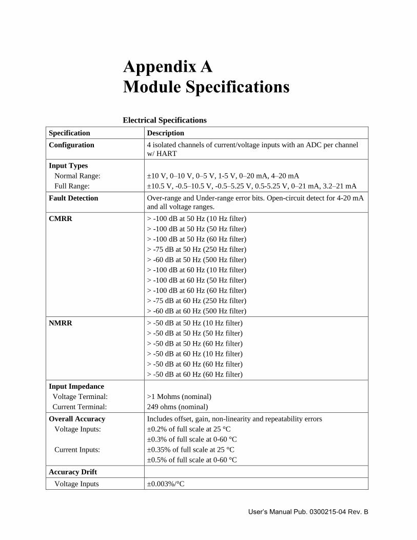
User’s Manual Pub. 0300215-04 Rev. B
Appendix A
Module Specifications
Electrical Specifications
Specification Description
Configuration 4 isolated channels of current/voltage inputs with an ADC per channel
w/ HART
Input Types
Normal Range:
Full Range:
±10 V, 0–10 V, 0–5 V, 1-5 V, 0–20 mA, 4–20 mA
±10.5 V, -0.5–10.5 V, -0.5–5.25 V, 0.5-5.25 V, 0–21 mA, 3.2–21 mA
Fault Detection Over-range and Under-range error bits. Open-circuit detect for 4-20 mA
and all voltage ranges.
CMRR > -100 dB at 50 Hz (10 Hz filter)
> -100 dB at 50 Hz (50 Hz filter)
> -100 dB at 50 Hz (60 Hz filter)
> -75 dB at 50 Hz (250 Hz filter)
> -60 dB at 50 Hz (500 Hz filter)
> -100 dB at 60 Hz (10 Hz filter)
> -100 dB at 60 Hz (50 Hz filter)
> -100 dB at 60 Hz (60 Hz filter)
> -75 dB at 60 Hz (250 Hz filter)
> -60 dB at 60 Hz (500 Hz filter)
NMRR > -50 dB at 50 Hz (10 Hz filter)
> -50 dB at 50 Hz (50 Hz filter)
> -50 dB at 50 Hz (60 Hz filter)
> -50 dB at 60 Hz (10 Hz filter)
> -50 dB at 60 Hz (60 Hz filter)
> -50 dB at 60 Hz (60 Hz filter)
Input Impedance
Voltage Terminal:
Current Terminal:
>1 Mohms (nominal)
249 ohms (nominal)
Overall Accuracy
Voltage Inputs:
Current Inputs:
Includes offset, gain, non-linearity and repeatability errors
±0.2% of full scale at 25 °C
±0.3% of full scale at 0-60 °C
±0.35% of full scale at 25 °C
±0.5% of full scale at 0-60 °C
Accuracy Drift
Voltage Inputs ±0.003%/°C
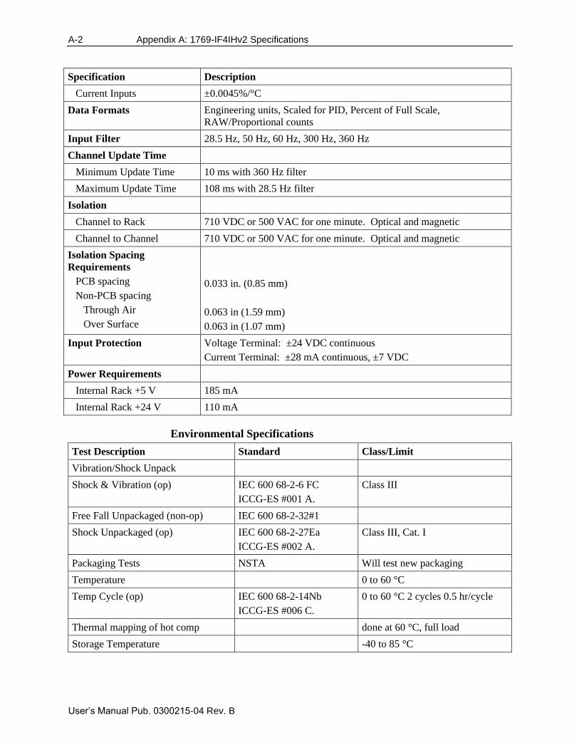
A-2 Appendix A: 1769-IF4IHv2 Specifications
User’s Manual Pub. 0300215-04 Rev. B
Specification Description
Current Inputs ±0.0045%/°C
Data Formats Engineering units, Scaled for PID, Percent of Full Scale,
RAW/Proportional counts
Input Filter 28.5 Hz, 50 Hz, 60 Hz, 300 Hz, 360 Hz
Channel Update Time
Minimum Update Time 10 ms with 360 Hz filter
Maximum Update Time 108 ms with 28.5 Hz filter
Isolation
Channel to Rack 710 VDC or 500 VAC for one minute. Optical and magnetic
Channel to Channel 710 VDC or 500 VAC for one minute. Optical and magnetic
Isolation Spacing
Requirements
PCB spacing
Non-PCB spacing
Through Air
Over Surface
0.033 in. (0.85 mm)
0.063 in (1.59 mm)
0.063 in (1.07 mm)
Input Protection Voltage Terminal: ±24 VDC continuous
Current Terminal: ±28 mA continuous, ±7 VDC
Power Requirements
Internal Rack +5 V 185 mA
Internal Rack +24 V 110 mA
Environmental Specifications
Test Description Standard Class/Limit
Vibration/Shock Unpack
Shock & Vibration (op) IEC 600 68-2-6 FC
ICCG-ES #001 A.
Class III
Free Fall Unpackaged (non-op) IEC 600 68-2-32#1
Shock Unpackaged (op) IEC 600 68-2-27Ea
ICCG-ES #002 A.
Class III, Cat. I
Packaging Tests NSTA Will test new packaging
Temperature 0 to 60 °C
Temp Cycle (op) IEC 600 68-2-14Nb
ICCG-ES #006 C.
0 to 60 °C 2 cycles 0.5 hr/cycle
Thermal mapping of hot comp done at 60 °C, full load
Storage Temperature -40 to 85 °C
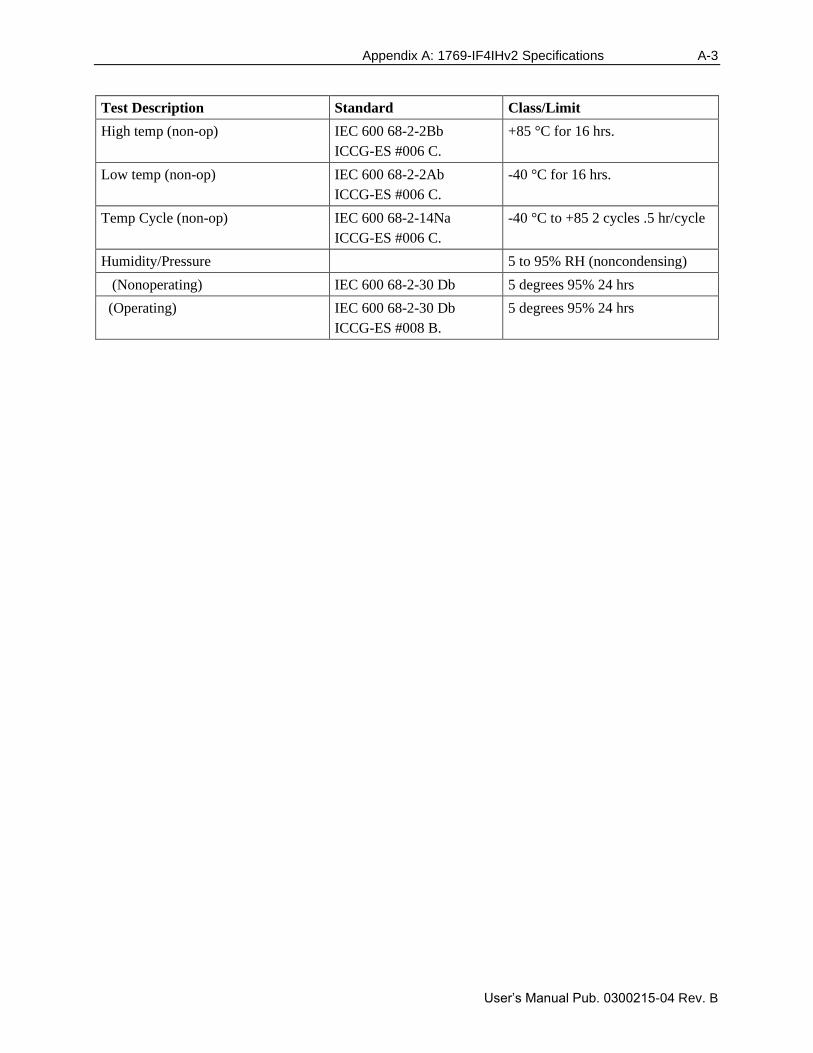
Appendix A: 1769-IF4IHv2 Specifications A-3
User’s Manual Pub. 0300215-04 Rev. B
Test Description Standard Class/Limit
High temp (non-op) IEC 600 68-2-2Bb
ICCG-ES #006 C.
+85 °C for 16 hrs.
Low temp (non-op) IEC 600 68-2-2Ab
ICCG-ES #006 C.
-40 °C for 16 hrs.
Temp Cycle (non-op) IEC 600 68-2-14Na
ICCG-ES #006 C.
-40 °C to +85 2 cycles .5 hr/cycle
Humidity/Pressure 5 to 95% RH (noncondensing)
(Nonoperating) IEC 600 68-2-30 Db 5 degrees 95% 24 hrs
(Operating) IEC 600 68-2-30 Db
ICCG-ES #008 B.
5 degrees 95% 24 hrs
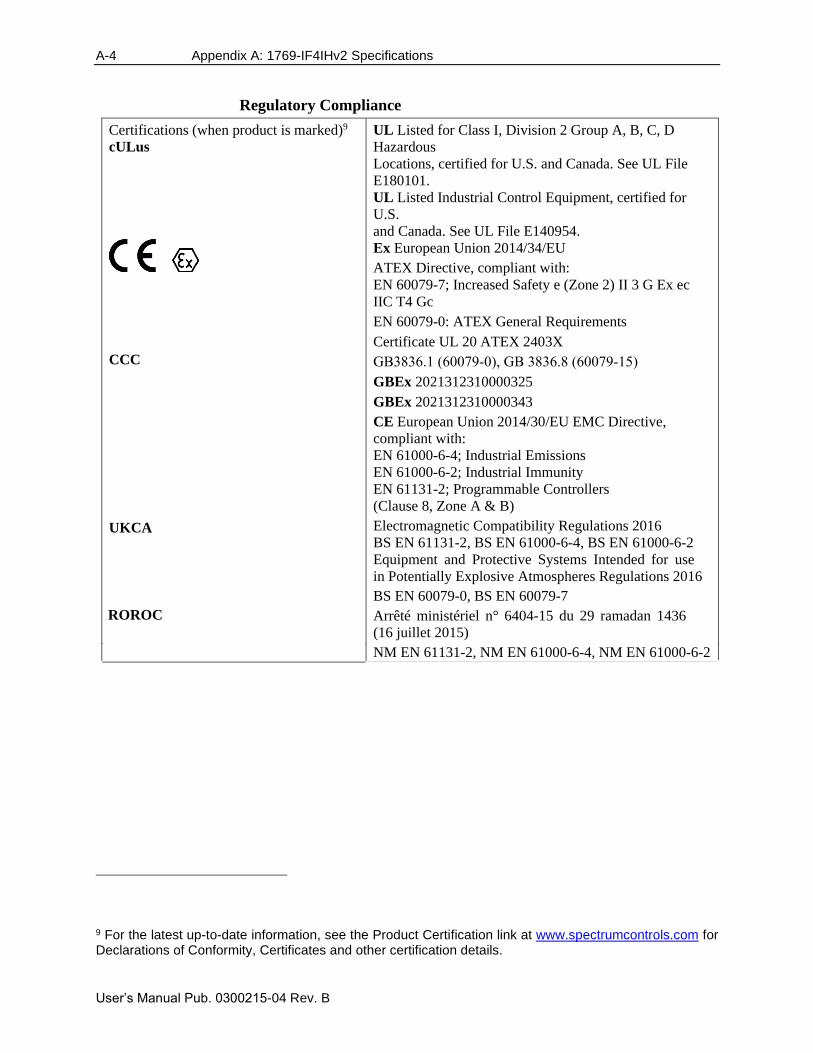
A-4 Appendix A: 1769-IF4IHv2 Specifications
User’s Manual Pub. 0300215-04 Rev. B
Regulatory Compliance
Certifications (when product is marked)9
cULus
CCC
UKCA
ROROC
UL Listed for Class I, Division 2 Group A, B, C, D
Hazardous
Locations, certified for U.S. and Canada. See UL File
E180101.
UL Listed Industrial Control Equipment, certified for
U.S.
and Canada. See UL File E140954.
Ex European Union 2014/34/EU
ATEX Directive, compliant with:
EN 60079-7; Increased Safety e (Zone 2) II 3 G Ex ec
IIC T4 Gc
EN 60079-0: ATEX General Requirements
Certificate UL 20 ATEX 2403X
GB3836.1 (60079-0), GB 3836.8 (60079-15)GBEx 2021312310000325
GBEx 2021312310000343
CE European Union 2014/30/EU EMC Directive,
compliant with:
EN 61000-6-4; Industrial Emissions
EN 61000-6-2; Industrial Immunity
EN 61131-2; Programmable Controllers
(Clause 8, Zone A & B)
Electromagnetic Compatibility Regulations 2016
BS EN 61131-2, BS EN 61000-6-4, BS EN 61000-6-2
Equipment and Protective Systems Intended for use
in Potentially Explosive Atmospheres Regulations 2016
BS EN 60079-0, BS EN 60079-7
Arrêté ministériel n° 6404-15 du 29 ramadan 1436
(16 juillet 2015)
NM EN 61131-2, NM EN 61000-6-4, NM EN 61000-6-2
9 For the latest up-to-date information, see the Product Certification link at www.spectrumcontrols.com for Declarations of Conformity, Certificates and other certification details.
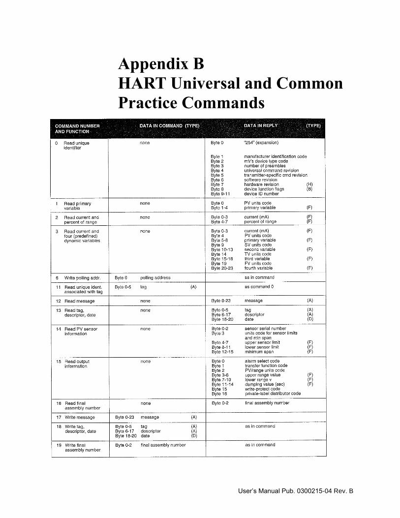
User’s Manual Pub. 0300215-04 Rev. B
Appendix B
HART Universal and Common
Practice Commands
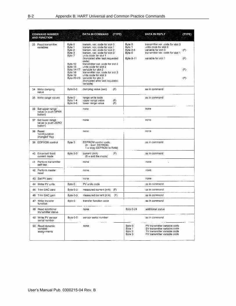
B-2 Appendix B: HART Universal and Common Practice Commands
User’s Manual Pub. 0300215-04 Rev. B
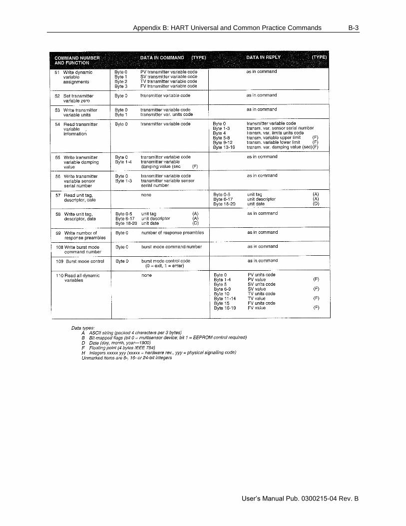
Appendix B: HART Universal and Common Practice Commands B-3
User’s Manual Pub. 0300215-04 Rev. B
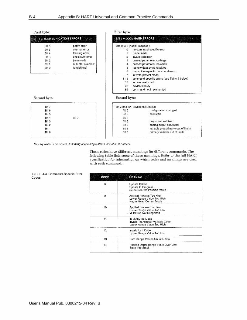
B-4 Appendix B: HART Universal and Common Practice Commands
User’s Manual Pub. 0300215-04 Rev. B

User’s Manual Pub. 0300215-04 Rev. B
Index Address 6-47 Alarm Latch 5-13 Auto Acquisition 6-3 Big-endian 6-36 block diagram 1-4 Byte Count 6-48 Channel HART Enable 5-9 Checksum 6-49 Command 6-48 Configuring the IF4IH for the Micro 1500 4-2 Configuring the module for HART 6-1 Conventions
used in the manual, vii Copying Ladder 4-7 Copying Routines or Programs 4-7 Cut-Off Frequency 5-11 Data 6-49 Data Format 5-14 Disable Channel 5-13 Effective Resolution 5-20 EMC Directive 2-1 Enable Alarm 5-13 Enable Fast Scan 6-11 Enable Interrupt 5-13 Engineering Units 5-15 ETS (Enable Time Stamp) 5-9 Exporting Tags 4-8 Filter
Frequencies 1-2 Filter Frequency and General Settings 5-9 General Configuration Bits 5-8 General Status Bits 5-3 Generic Profile 3-1 Get HART Device Information 6-31 Handle Timeout 5-8 HART Message Format 6-47 Hart multi-drop 6-3 HART Packet Data 6-2 HART Pass-Through Command 6-36 HART Protocol 6-46 Hart Suspend 5-19 HART Suspend/Resume 6-34 Hazardous Location 2-3 High Process Alarm 5-5 Importing Tags 4-8 Input Data Values 5-3 Input Filter Selection 5-10 Input Image 5-2 Input Tags 6-13 Input Type 1-1 Input Type 5-14 LED 1-2 Little-endian 6-36 Low Process Alarm 5-5
Memory Map 5-1 Message Master Control 5-19 Message Master Control 6-12 Message Reply Buffer 5-5 Message Reply Size 5-5 Message Request Buffer 5-20 Message Request Buffer 6-13 Message Request Size 5-19 Message Request Size 6-13 Message Response Buffer 6-14 Message Response Size 6-14 Message Slave Control 5-5 Message Slave Control 6-13 Messages 6-12 Micro 1500 Ladder Samples 4-6 Minimum spacing 2-5 Module
mounting 2-5 Module Configuration 5-6 Module Memory Map 4-1 module specific commands 6-3 Module Specific Commands 6-31 Module Update Time 5-21 Mounting
module 2-5 Noise Rejection 5-10 Noise, reducing 2-4 Open-Circuit 5-4 Out of Service Status Bits 5-4 Output Data File 5-18 Output Tags 6-12 Over-Range Flag Bits 5-4 Packed ASCII 7-4 Packet Interval 6-11 Packet Just Scanned/Fast Scan 5-19
Paging Error Codes 6-14 Pass-Through Scheme 5-9 Percent Range 5-15 Preamble 6-47 Process Alarm Deadband 5-16 Process Alarm High Setpoint 5-16 Process Alarm Low Setpoint 5-16 Process Alarms
High Low
Deadband 5-5 Processing a Message 6-14
Raw/Proportional Data 5-14
Real Time Sample Value 5-7 Reset/Reconfig 7-2 Sample Ladder 3-9
Scaled-for-PID 5-15
Sending a HART Command 6-49

User’s Manual Pub. 0300215-04 Rev. B
Slot Variable Enable 5-12 Specifications A-1 Start Character 6-47 Status 5-3 Status 6-49 Step Response 5-10 Swap Byte Order 7-4 Tags 3-8
Technical support contact information, vii
Time Stamp Value 5-3 Under-Range Flag Bits 5-4 Unlatch Process High Alarm 5-18 Unlatch Process Low Alarm 5-18 User-Defined Data Types 3-6

User’s Manual Pub. 0300215-04 Rev. B

User’s Manual Pub. 0300215-04 Rev. B
©2003-2021, Spectrum Controls, Inc. All rights reserved. Specifications subject to change without
notice. The Encompass logo and Point IO are trademarks of Rockwell Automation.
Corporate Headquarters
Spectrum Controls Inc.
1705 132nd Avenue NE, Bellevue, WA 98005 USA
Fax: 425-641-9473
Tel: 425-746-9481
Web Site: www.spectrumcontrols.com
E-mail: [email protected]
Related Documents