ENGINE AND EMISSION CONTROL

Welcome message from author
This document is posted to help you gain knowledge. Please leave a comment to let me know what you think about it! Share it to your friends and learn new things together.
Transcript
ENGINE ANDEMISSIONCONTROL
17-1
ENGINE ANDEMISSIONCONTROL
CONTENTS
ENGINE CONTROL SYSTEM 3. . . . . . . .
SERVICE SPECIFICATION 3. . . . . . . . . . . . . . .
ON-VEHICLE SERVICE 3. . . . . . . . . . . . . . . . . . Accelerator Cable Check and Adjustment 3. . .
ACCELERATOR CABLE AND PEDAL 4. . . .
EMISSION CONTROL SYSTEM 5. . . . . . . . . . . . . . . . . . . . . . . . . . . .
GENERAL INFORMATION 5. . . . . . . . . . . . . . . . Emission Control Device Reference Table 5. . . . . . . . . . . . . . . . . . . . . . . . . . . . . . . . . . . . . .
SERVICE SPECIFICATIONS 6. . . . . . . . . . . . . .
SPECIAL TOOL 6. . . . . . . . . . . . . . . . . . . . . . . . .
VACUUM HOSE 6. . . . . . . . . . . . . . . . . . . . . . . . . Vacuum Hose Piping Diagram 6. . . . . . . . . . . . . .
Vacuum Circuit Diagram 7. . . . . . . . . . . . . . . . . . . .
Vacuum Hose Check 7. . . . . . . . . . . . . . . . . . . . . . .
Vacuum Hose Installation 7. . . . . . . . . . . . . . . . . . .
CRANKCASE EMISSION CONTROL SYSTEM 8. . . . . . . . . . . . . . . . . . . . . . . . . . . . . . . .
General Information 8. . . . . . . . . . . . . . . . . . . . . . . .
System Diagram 8. . . . . . . . . . . . . . . . . . . . . . . . . . .
Component Location 8. . . . . . . . . . . . . . . . . . . . . . .
Positive Crankcase Ventilation System Check 9. . . . . . . . . . . . . . . . . . . . . . . . . . . . . . . . . . . . .
PCV Valve Check 9. . . . . . . . . . . . . . . . . . . . . . . . . .
EVAPORATIVE EMISSION CONTROLSYSTEM 10. . . . . . . . . . . . . . . . . . . . . . . . . . . . . . .
General Information 10. . . . . . . . . . . . . . . . . . . . . .
System Diagram 10. . . . . . . . . . . . . . . . . . . . . . . . .
Component Location 10. . . . . . . . . . . . . . . . . . . . .
Purge Control System Check 11. . . . . . . . . . . . . .
Purge Port Vacuum Check 11. . . . . . . . . . . . . . . . .
Purge Control Solenoid Valve Check 12. . . . . .
CONTINUED ON NEXT PAGE

17-2
EXHAUST GAS RECIRCUL ATION (EGR)SYSTEM 13. . . . . . . . . . . . . . . . . . . . . . . . . . . . . . .
General Information 13. . . . . . . . . . . . . . . . . . . . . .
Operation 13. . . . . . . . . . . . . . . . . . . . . . . . . . . . . . . .
System Diagram 13. . . . . . . . . . . . . . . . . . . . . . . . .
Component Location 13. . . . . . . . . . . . . . . . . . . . .
Exhaust Gas Recirculation (EGR) ControLSystem Check 14. . . . . . . . . . . . . . . . . . . . . . . . . . .
EGR Valve (Stepper Motor) Check 14. . . . . . . .
EGR VALVE 16. . . . . . . . . . . . . . . . . . . . . . . . . . . .
CATALYTIC CONVERTER 17. . . . . . . . . . . . . . .
ENGINE AND EMISSION CONTROL – Engine Control System 17-3
ENGINE CONTROL SYSTEMSERVICE SPECIFICATION
Items Standard value
Accelerator cable play mm 1 – 2
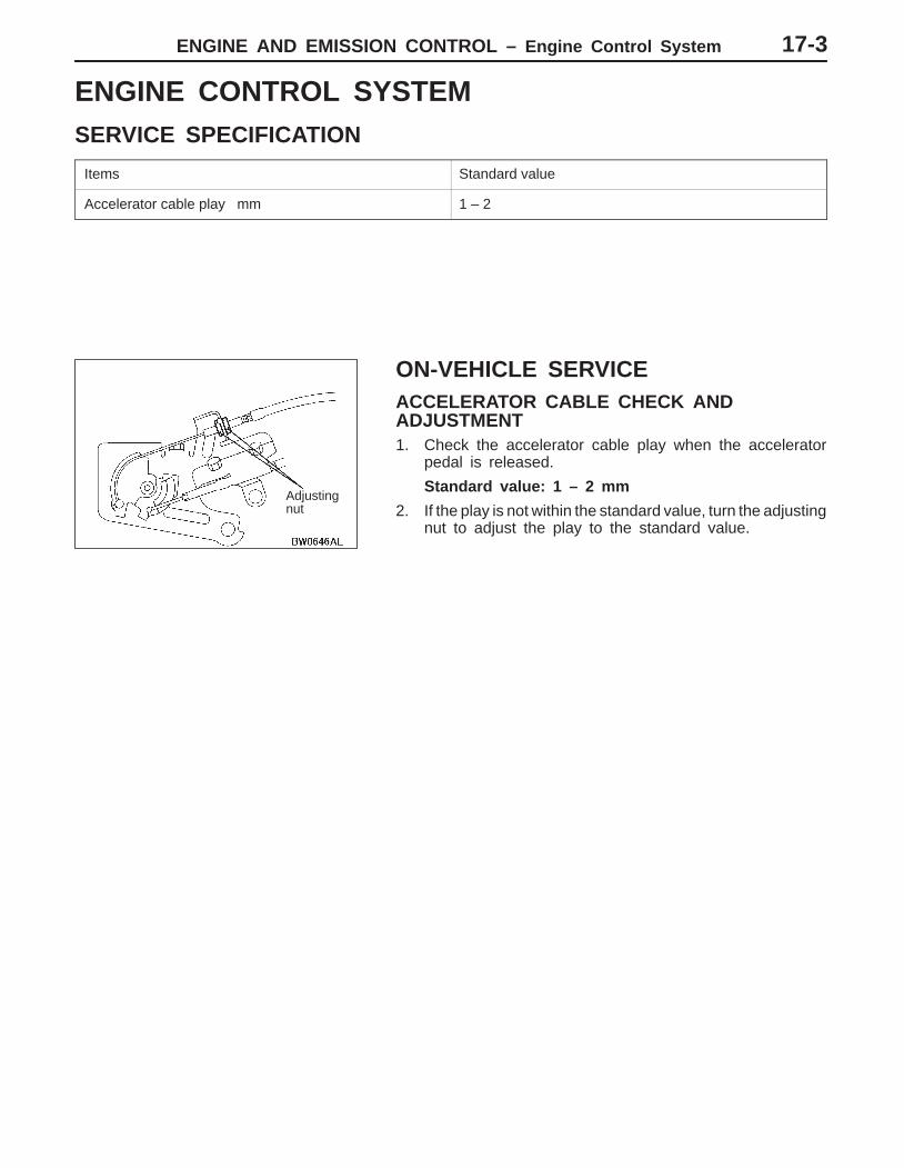
ON-VEHICLE SERVICEACCELERATOR CABLE CHECK ANDADJUSTMENT1. Check the accelerator cable play when the accelerator
pedal is released.
Standard value: 1 – 2 mm
2. If the play is not within the standard value, turn the adjustingnut to adjust the play to the standard value.
Adjustingnut
ENGINE AND EMISSION CONTROL – Engine Control System17-4
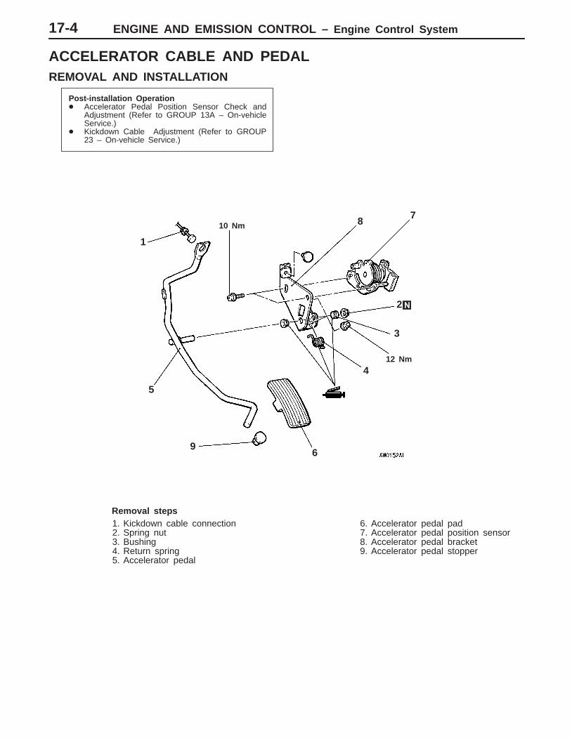
ACCELERATOR CABLE AND PEDALREMOVAL AND INSTALLATION
Post-installation Operation Accelerator Pedal Position Sensor Check and
Adjustment (Refer to GROUP 13A – On-vehicleService.)
Kickdown Cable Adjustment (Refer to GROUP23 – On-vehicle Service.)
12 Nm
2
9
5
1
6
8
3
710 Nm
4
Removal steps1. Kickdown cable connection2. Spring nut3. Bushing4. Return spring5. Accelerator pedal
6. Accelerator pedal pad7. Accelerator pedal position sensor8. Accelerator pedal bracket9. Accelerator pedal stopper
ENGINE AND EMISSION CONTROL – Emission Control System 17-5
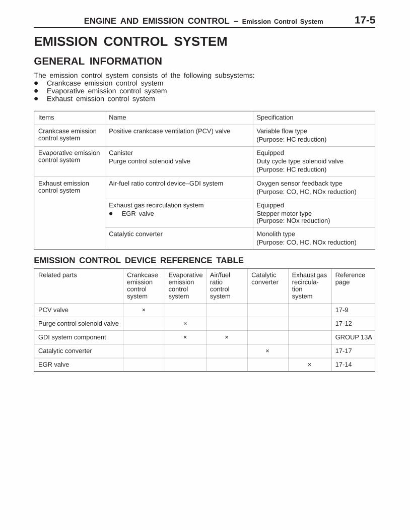
EMISSION CONTROL SYSTEMGENERAL INFORMATIONThe emission control system consists of the following subsystems: Crankcase emission control system Evaporative emission control system Exhaust emission control system
Items Name Specification
Crankcase emissioncontrol system
Positive crankcase ventilation (PCV) valve Variable flow type(Purpose: HC reduction)
Evaporative emissioncontrol system
CanisterPurge control solenoid valve
EquippedDuty cycle type solenoid valve(Purpose: HC reduction)
Exhaust emissioncontrol system
Air-fuel ratio control device–GDI system Oxygen sensor feedback type(Purpose: CO, HC, NOx reduction)
Exhaust gas recirculation system EGR valve
EquippedStepper motor type(Purpose: NOx reduction)
Catalytic converter Monolith type(Purpose: CO, HC, NOx reduction)
EMISSION CONTROL DEVICE REFERENCE TABLE
Related parts Crankcaseemissioncontrol system
Evaporativeemissioncontrol system
Air/fuel ratio control system
Catalyticconverter
Exhaust gasrecircula-tionsystem
Referencepage
PCV valve × 17-9
Purge control solenoid valve × 17-12
GDI system component × × GROUP 13A
Catalytic converter × 17-17
EGR valve × 17-14
ENGINE AND EMISSION CONTROL – Emission Control System17-6
SERVICE SPECIFICATIONS
Items Standard value
Purge control solenoid valve coil resistance (at 20C) Ω 36 – 44
EGR valve (stepper motor) coil resistance (at 20C) Ω 10 – 20
SPECIAL TOOL
Tool Number Name Use
MB991658 Test harness set Inspection of EGR valve
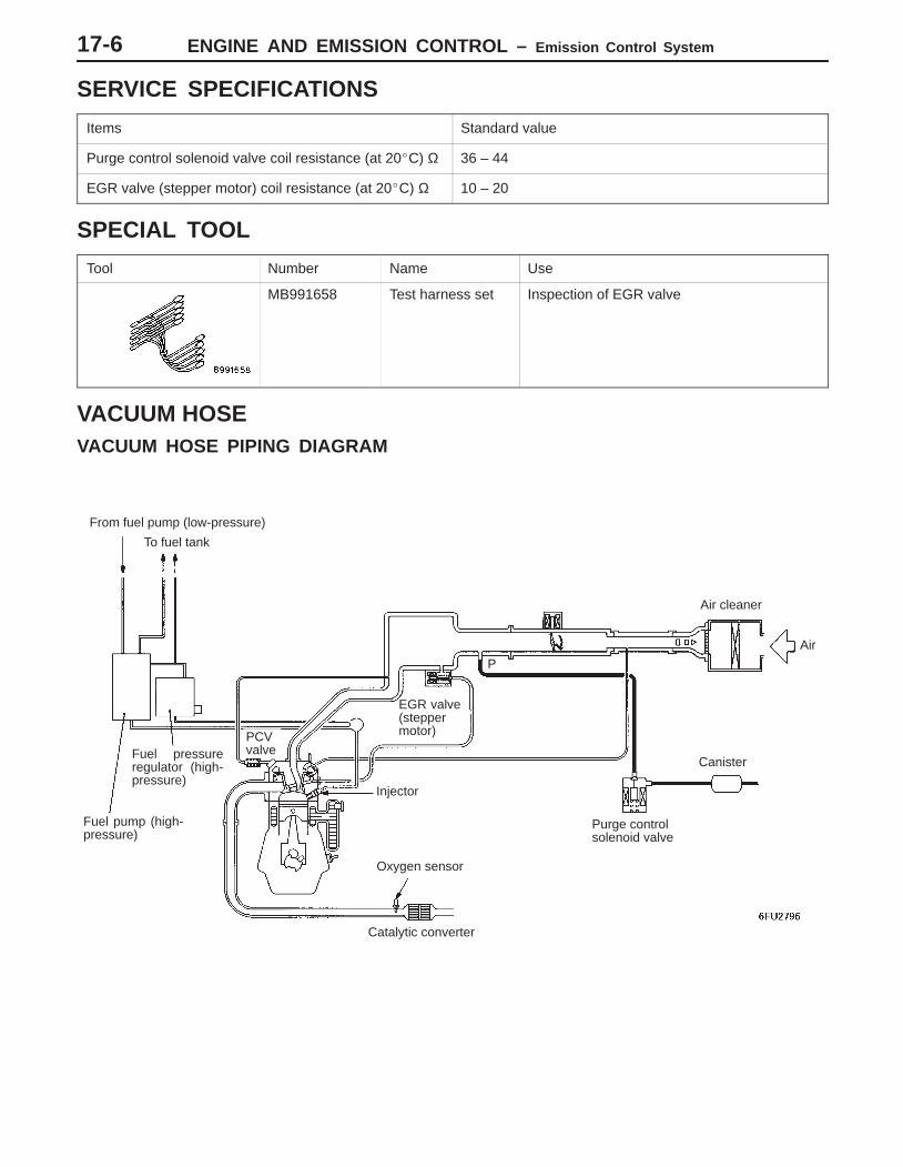
VACUUM HOSEVACUUM HOSE PIPING DIAGRAM
PCVvalve
From fuel pump (low-pressure)
Canister
Purge controlsolenoid valve
Oxygen sensor
Fuel pressureregulator (high-pressure)
To fuel tank
EGR valve(steppermotor)
P
Catalytic converter
Fuel pump (high-pressure)
Injector
Air cleaner
Air
ENGINE AND EMISSION CONTROL – Emission Control System 17-7
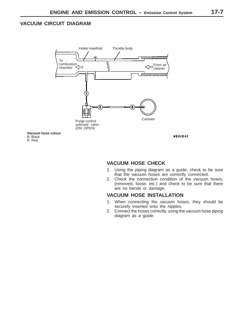
VACUUM CIRCUIT DIAGRAM
To combustionchamber
Intake manifold Throttle body
From aircleaner
Vacuum hose colourB: BlackR: Red
Purge control solenoid valve(ON: OPEN)
Canister
VACUUM HOSE CHECK1. Using the piping diagram as a guide, check to be sure
that the vacuum hoses are correctly connected.2. Check the connection condition of the vacuum hoses,
(removed, loose, etc.) and check to be sure that thereare no bends or damage.
VACUUM HOSE INSTALLATION1. When connecting the vacuum hoses, they should be
securely inserted onto the nipples.2. Connect the hoses correctly, using the vacuum hose piping
diagram as a guide.
ENGINE AND EMISSION CONTROL – Emission Control System
PCV valve
PCV valve
17-8
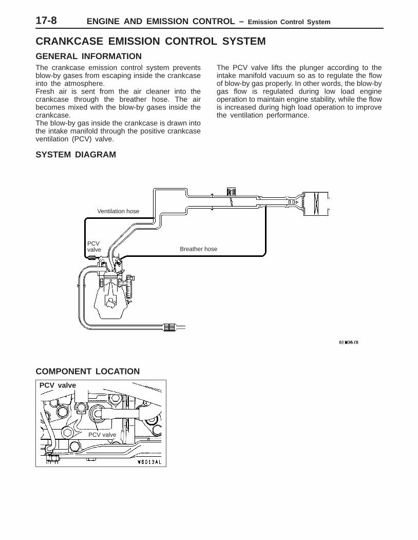
CRANKCASE EMISSION CONTROL SYSTEMGENERAL INFORMATIONThe crankcase emission control system preventsblow-by gases from escaping inside the crankcaseinto the atmosphere.Fresh air is sent from the air cleaner into thecrankcase through the breather hose. The airbecomes mixed with the blow-by gases inside thecrankcase.The blow-by gas inside the crankcase is drawn intothe intake manifold through the positive crankcaseventilation (PCV) valve.
The PCV valve lifts the plunger according to theintake manifold vacuum so as to regulate the flowof blow-by gas properly. In other words, the blow-bygas flow is regulated during low load engineoperation to maintain engine stability, while the flowis increased during high load operation to improvethe ventilation performance.
SYSTEM DIAGRAM
PCV valve
Ventilation hose
Breather hose
COMPONENT LOCATION

ENGINE AND EMISSION CONTROL – Emission Control System 17-9
POSITIVE CRANKCASE VENTILATION SYSTEMCHECK1. Remove the ventilation hose from the PCV valve.2. Remove the PCV valve from the rocker cover.3. Reinstall the PCV valve at the ventilation hose.4. Start the engine and run at idle.
5. Place a finger at the opening of the PCV valve and checkthat vacuum of the intake manifold is felt.
NOTEAt this moment, the plunger in the PCV valve moves backand forth.
6. If vacuum is not felt, clean the PCV valve or replace it.
PCV VALVE CHECK1. Insert a thin rod into the PCV valve from the side shown
in the illustration (rocker cover installation side), and movethe rod back and forth to check that the plunger moves.
2. If the plunger does not move, there is clogging in thePCV valve. In this case, clean or replace the PCV valve.
PCV valve
ENGINE AND EMISSION CONTROL – Emission Control System
Purge control solenoid valve
Purge control solenoid valve
17-10
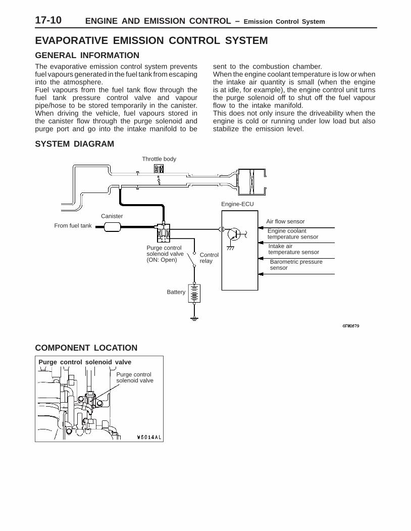
EVAPORATIVE EMISSION CONTROL SYSTEMGENERAL INFORMATIONThe evaporative emission control system preventsfuel vapours generated in the fuel tank from escapinginto the atmosphere.Fuel vapours from the fuel tank flow through thefuel tank pressure control valve and vapourpipe/hose to be stored temporarily in the canister.When driving the vehicle, fuel vapours stored inthe canister flow through the purge solenoid andpurge port and go into the intake manifold to be
sent to the combustion chamber.When the engine coolant temperature is low or whenthe intake air quantity is small (when the engineis at idle, for example), the engine control unit turnsthe purge solenoid off to shut off the fuel vapourflow to the intake manifold.This does not only insure the driveability when theengine is cold or running under low load but alsostabilize the emission level.
SYSTEM DIAGRAM
From fuel tank
Canister
Purge control solenoid valve(ON: Open)
Air flow sensor
Barometric pressuresensor
Controlrelay
Throttle body
Engine-ECU
Engine coolant temperature sensor
Intake air temperature sensor
Battery
COMPONENT LOCATION
ENGINE AND EMISSION CONTROL – Emission Control System 17-11
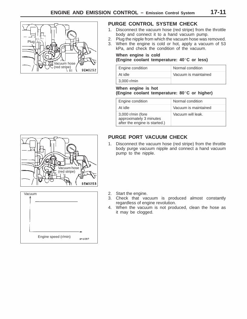
PURGE CONTROL SYSTEM CHECK1. Disconnect the vacuum hose (red stripe) from the throttle
body and connect it to a hand vacuum pump.2. Plug the nipple from which the vacuum hose was removed.3. When the engine is cold or hot, apply a vacuum of 53
kPa, and check the condition of the vacuum.
When engine is cold(Engine coolant temperature: 40 C or less)
Engine condition Normal condition
At idle Vacuum is maintained
3,000 r/min
When engine is hot(Engine coolant temperature: 80 C or higher)
Engine condition Normal condition
At idle Vacuum is maintained
3,000 r/min (foreapproximately 3 minutesafter the engine is started.)
Vacuum will leak.
PURGE PORT VACUUM CHECK1. Disconnect the vacuum hose (red stripe) from the throttle
body purge vacuum nipple and connect a hand vacuumpump to the nipple.
2. Start the engine.3. Check that vacuum is produced almost constantly
regardless of engine revolution.4. When the vacuum is not produced, clean the hose as
it may be clogged.
Plug
Vacuum hose(red stripe)
Vacuum hose(red stripe)
Vacuum
Engine speed (r/min)
ENGINE AND EMISSION CONTROL – Emission Control System17-12
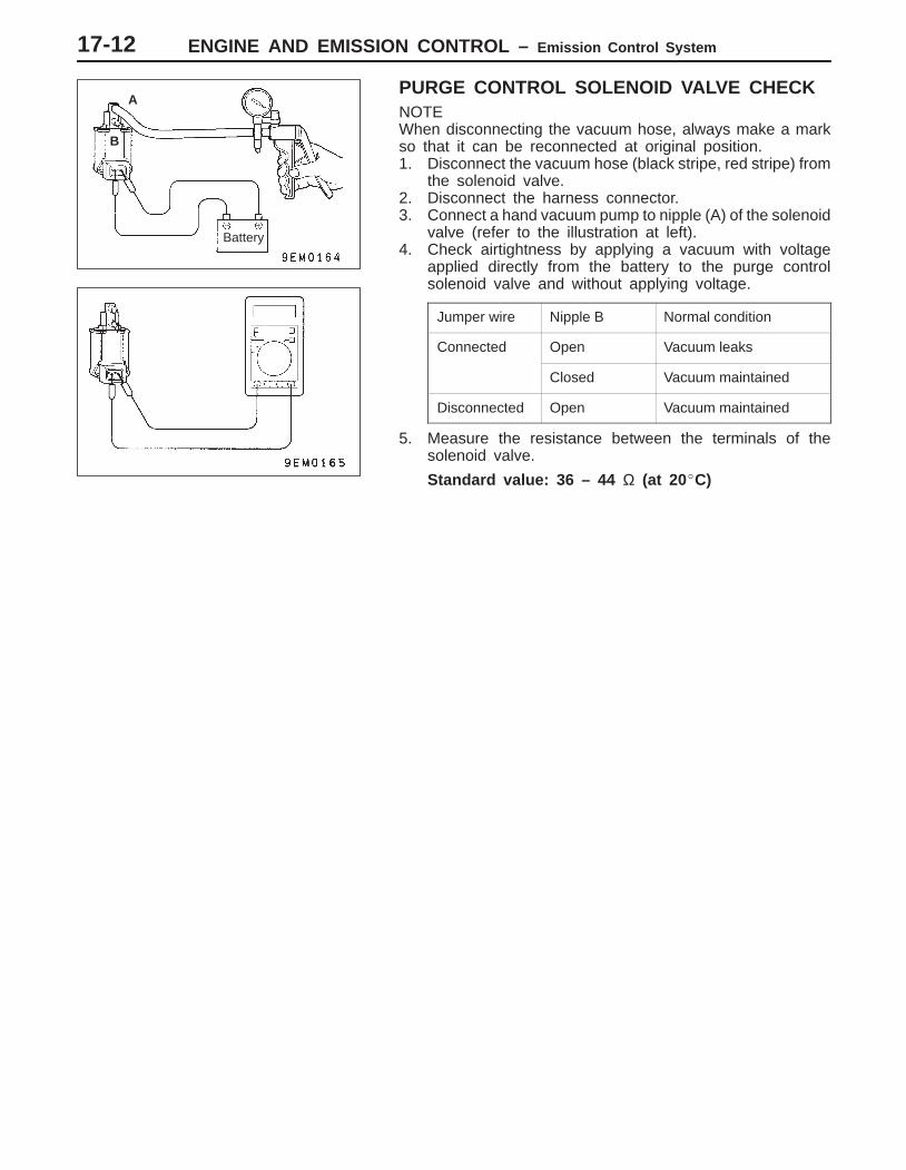
PURGE CONTROL SOLENOID VALVE CHECKNOTEWhen disconnecting the vacuum hose, always make a markso that it can be reconnected at original position.1. Disconnect the vacuum hose (black stripe, red stripe) from
the solenoid valve.2. Disconnect the harness connector.3. Connect a hand vacuum pump to nipple (A) of the solenoid
valve (refer to the illustration at left).4. Check airtightness by applying a vacuum with voltage
applied directly from the battery to the purge controlsolenoid valve and without applying voltage.
Jumper wire Nipple B Normal condition
Connected Open Vacuum leaks
Closed Vacuum maintained
Disconnected Open Vacuum maintained
5. Measure the resistance between the terminals of thesolenoid valve.
Standard value: 36 – 44 Ω (at 20C)
Battery
B
A
ENGINE AND EMISSION CONTROL – Emission Control System
EGR valveThrottlebody
EGR valve
17-13
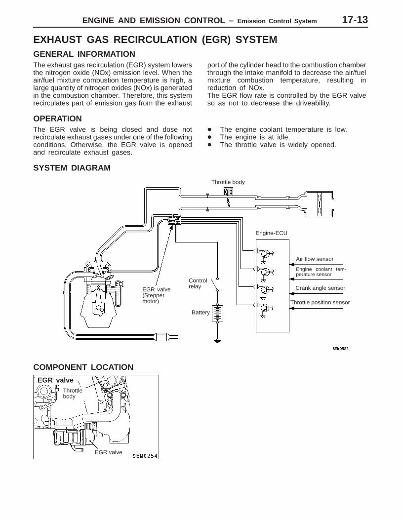
EXHAUST GAS RECIRCULATION (EGR) SYSTEMGENERAL INFORMATIONThe exhaust gas recirculation (EGR) system lowersthe nitrogen oxide (NOx) emission level. When theair/fuel mixture combustion temperature is high, alarge quantity of nitrogen oxides (NOx) is generatedin the combustion chamber. Therefore, this systemrecirculates part of emission gas from the exhaust
port of the cylinder head to the combustion chamberthrough the intake manifold to decrease the air/fuelmixture combustion temperature, resulting inreduction of NOx.The EGR flow rate is controlled by the EGR valveso as not to decrease the driveability.
OPERATIONThe EGR valve is being closed and dose notrecirculate exhaust gases under one of the followingconditions. Otherwise, the EGR valve is openedand recirculate exhaust gases.
The engine coolant temperature is low. The engine is at idle. The throttle valve is widely opened.
SYSTEM DIAGRAM
Air flow sensor
Engine coolant tem-perature sensor
Crank angle sensorControlrelay
Engine-ECU
Battery
Throttle body
EGR valve(Steppermotor) Throttle position sensor
COMPONENT LOCATION
ENGINE AND EMISSION CONTROL – Emission Control System17-14
EXHAUST GAS RECIRCULATION (EGR)CONTROL SYSTEM CHECKRefer to GROUP 13A – Troubleshooting.
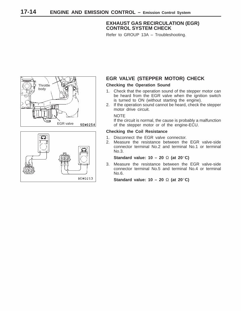
EGR VALVE (STEPPER MOTOR) CHECKChecking the Operation Sound1. Check that the operation sound of the stepper motor can
be heard from the EGR valve when the ignition switchis turned to ON (without starting the engine).
2. If the operation sound cannot be heard, check the steppermotor drive circuit.
NOTEIf the circuit is normal, the cause is probably a malfunctionof the stepper motor or of the engine-ECU.
Checking the Coil Resistance1. Disconnect the EGR valve connector.2. Measure the resistance between the EGR valve-side
connector terminal No.2 and terminal No.1 or terminalNo.3.
Standard value: 10 – 20 Ω (at 20C)
3. Measure the resistance between the EGR valve-sideconnector terminal No.5 and terminal No.4 or terminalNo.6.
Standard value: 10 – 20 Ω (at 20C)
Throttlebody
EGR valve
ENGINE AND EMISSION CONTROL – Emission Control System 17-15
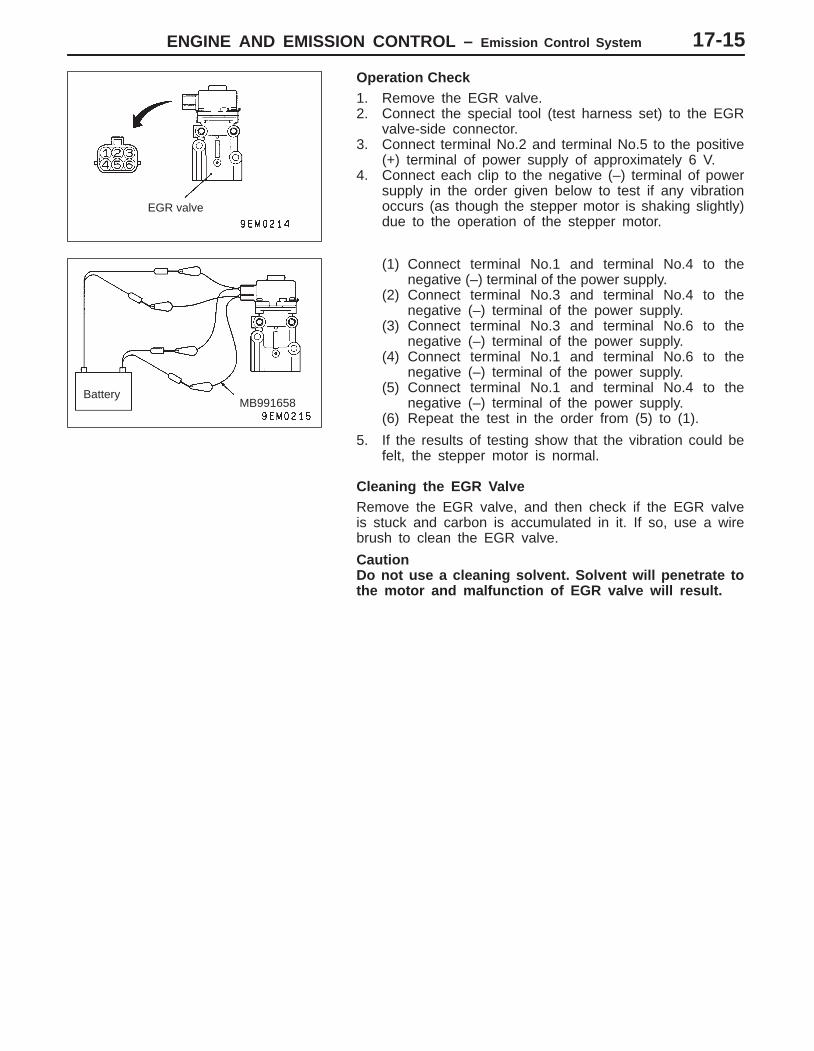
Operation Check1. Remove the EGR valve.2. Connect the special tool (test harness set) to the EGR
valve-side connector.3. Connect terminal No.2 and terminal No.5 to the positive
(+) terminal of power supply of approximately 6 V.4. Connect each clip to the negative (–) terminal of power
supply in the order given below to test if any vibrationoccurs (as though the stepper motor is shaking slightly)due to the operation of the stepper motor.
(1) Connect terminal No.1 and terminal No.4 to thenegative (–) terminal of the power supply.
(2) Connect terminal No.3 and terminal No.4 to thenegative (–) terminal of the power supply.
(3) Connect terminal No.3 and terminal No.6 to thenegative (–) terminal of the power supply.
(4) Connect terminal No.1 and terminal No.6 to thenegative (–) terminal of the power supply.
(5) Connect terminal No.1 and terminal No.4 to thenegative (–) terminal of the power supply.
(6) Repeat the test in the order from (5) to (1).
5. If the results of testing show that the vibration could befelt, the stepper motor is normal.
Cleaning the EGR ValveRemove the EGR valve, and then check if the EGR valveis stuck and carbon is accumulated in it. If so, use a wirebrush to clean the EGR valve.
CautionDo not use a cleaning solvent. Solvent will penetrate tothe motor and malfunction of EGR valve will result.
EGR valve
BatteryMB991658
ENGINE AND EMISSION CONTROL – Emission Control System17-16
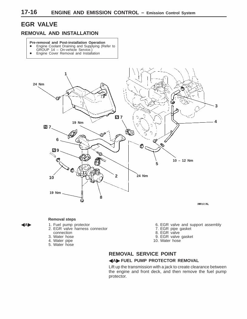
EGR VALVEREMOVAL AND INSTALLATION
Pre-removal and Post-installation Operation Engine Coolant Draining and Supplying (Refer to
GROUP 14 – On-vehicle Service.) Engine Cover Removal and Installation
1
9
24 Nm
24 Nm
19 Nm
10
19 Nm8
7
5
2
3
10 – 12 Nm
47
6
Removal stepsA 1. Fuel pump protector
2. EGR valve harness connector connection
3. Water hose4. Water pipe5. Water hose
6. EGR valve and support assembly7. EGR pipe gasket8. EGR valve9. EGR valve gasket
10. Water hose
REMOVAL SERVICE POINTA FUEL PUMP PROTECTOR REMOVALLift up the transmission with a jack to create clearance betweenthe engine and front deck, and then remove the fuel pumpprotector.
ENGINE AND EMISSION CONTROL – Emission Control System 17-17
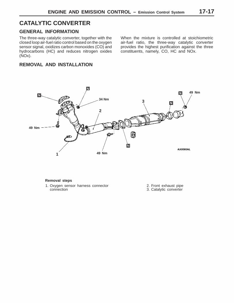
CATALYTIC CONVERTERGENERAL INFORMATIONThe three-way catalytic converter, together with theclosed loop air-fuel ratio control based on the oxygensensor signal, oxidizes carbon monoxides (CO) andhydrocarbons (HC) and reduces nitrogen oxides(NOx).
When the mixture is controlled at stoichiometricair-fuel ratio, the three-way catalytic converterprovides the highest purification against the threeconstituents, namely, CO, HC and NOx.
REMOVAL AND INSTALLATION
49 Nm
49 Nm
34 Nm
49 Nm
1
2
3
Removal steps1. Oxygen sensor harness connector
connection2. Front exhaust pipe3. Catalytic converter

NOTES
17-1
ENGINE ANDEMISSIONCONTROL
CONTENTS
EMISSION CONTROL SYSTEM
GENERAL 2. . . . . . . . . . . . . . . . . . . . . . . . . . . . . . . Outline of Change 2. . . . . . . . . . . . . . . . . . . . . . . . .
SERVICE SPECIFICATIONS 2. . . . . . . . . . . . . .
VACUUM HOSE 2. . . . . . . . . . . . . . . . . . . . . . . . .
Vacuum Hose Piping Diagram 2. . . . . . . . . . . . . .
Vacuum Circuit Diagram 3. . . . . . . . . . . . . . . . . . . .
EVAPORATIVE EMISSION CONTROLSYSTEM 3. . . . . . . . . . . . . . . . . . . . . . . . . . . . . . . .
Purge Control System Check 3. . . . . . . . . . . . . . .
Purge Port Vacuum Check 4. . . . . . . . . . . . . . . . . .
Purge Control Solenoid Valve Check 4. . . . . . . .
ENGINE AND EMISSION CONTROL – Emission Control System17-2
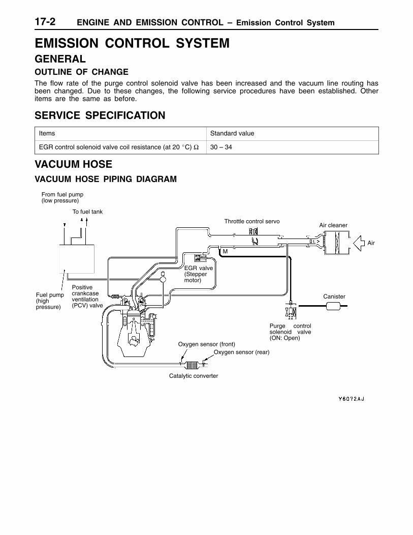
EMISSION CONTROL SYSTEMGENERALOUTLINE OF CHANGEThe flow rate of the purge control solenoid valve has been increased and the vacuum line routing hasbeen changed. Due to these changes, the following service procedures have been established. Otheritems are the same as before.
SERVICE SPECIFICATION
Items Standard value
EGR control solenoid valve coil resistance (at 20 C) Ω 30 – 34
VACUUM HOSEVACUUM HOSE PIPING DIAGRAM
Air cleaner
Fuel pump(highpressure)
Throttle control servo
Canister
Purge controlsolenoid valve(ON: Open)
EGR valve(Steppermotor)
Oxygen sensor (front)Oxygen sensor (rear)
Catalytic converter
Air
From fuel pump(low pressure)
To fuel tank
Positivecrankcaseventilation(PCV) valve
M
ENGINE AND EMISSION CONTROL – Emission Control System 17-3
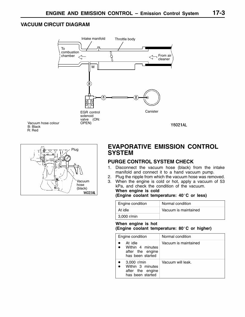
VACUUM CIRCUIT DIAGRAM
To combustionchamber
Intake manifold Throttle body
From aircleaner
EGR controlsolenoidvalve (ON:OPEN)Vacuum hose colour
B: BlackR: Red
Canister
M
EVAPORATIVE EMISSION CONTROLSYSTEMPURGE CONTROL SYSTEM CHECK1. Disconnect the vacuum hose (black) from the intake
manifold and connect it to a hand vacuum pump.2. Plug the nipple from which the vacuum hose was removed.3. When the engine is cold or hot, apply a vacuum of 53
kPa, and check the condition of the vacuum.When engine is cold(Engine coolant temperature: 40C or less)
Engine condition Normal condition
At idle Vacuum is maintained
3,000 r/min
When engine is hot(Engine coolant temperature: 80C or higher)
Engine condition Normal condition
At idle Within 4 minutes
after the enginehas been started
Vacuum is maintained
3,000 r/min Within 3 minutes
after the enginehas been started
Vacuum will leak.
Plug
Vacuumhose(black)
ENGINE AND EMISSION CONTROL – Emission Control System17-4
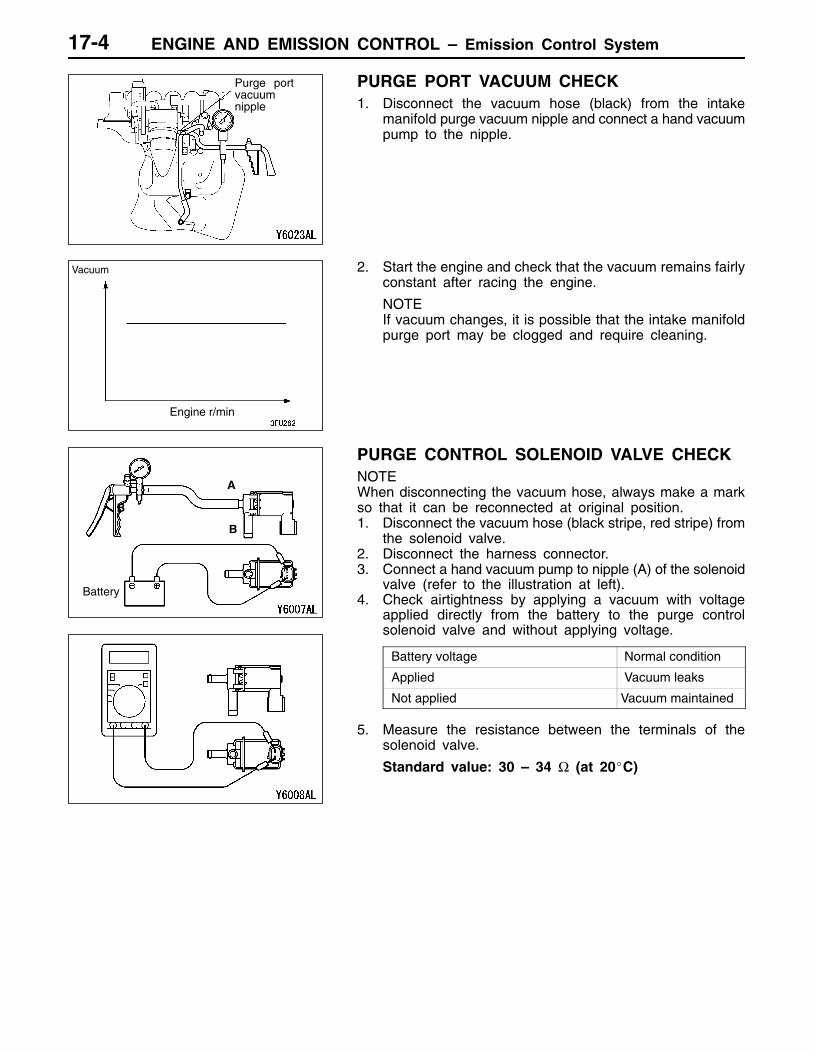
PURGE PORT VACUUM CHECK1. Disconnect the vacuum hose (black) from the intake
manifold purge vacuum nipple and connect a hand vacuumpump to the nipple.
2. Start the engine and check that the vacuum remains fairlyconstant after racing the engine.
NOTEIf vacuum changes, it is possible that the intake manifoldpurge port may be clogged and require cleaning.
PURGE CONTROL SOLENOID VALVE CHECKNOTEWhen disconnecting the vacuum hose, always make a markso that it can be reconnected at original position.1. Disconnect the vacuum hose (black stripe, red stripe) from
the solenoid valve.2. Disconnect the harness connector.3. Connect a hand vacuum pump to nipple (A) of the solenoid
valve (refer to the illustration at left).4. Check airtightness by applying a vacuum with voltage
applied directly from the battery to the purge controlsolenoid valve and without applying voltage.
Battery voltage Normal condition
Applied Vacuum leaks
Not applied Vacuum maintained
5. Measure the resistance between the terminals of thesolenoid valve.
Standard value: 30 – 34 Ω (at 20C)
Purge portvacuumnipple
Engine r/min
Vacuum
A
B
B
Battery
17-1
ENGINE ANDEMISSIONCONTROL
CONTENTS
ENGINE CONTROL SYSTEM 2. . . . . . . . . . . .
GENERAL 2. . . . . . . . . . . . . . . . . . . . . . . . . . . . . . . Outline of Changes 2. . . . . . . . . . . . . . . . . . . . . . . . .
SERVICE SPECIFICATION 2. . . . . . . . . . . . . . . .
ON-VEHICLE SERVICE 2. . . . . . . . . . . . . . . . . . . Accelerator Cable Check and Adjustment<4G9-MPI> 2. . . . . . . . . . . . . . . . . . . . . . . . . . . . . . . .
ACCELERATOR CABLE AND PEDAL 3. . . . . .
EMISSION CONTROL SYSTEM <MPI> 4. . . . . . . . . . . . . . . . . . . . . . . . . . . . . . . . .
GENERAL 4. . . . . . . . . . . . . . . . . . . . . . . . . . . . . . . Outline of Changes 4. . . . . . . . . . . . . . . . . . . . . . . . .
GENERAL INFORMATION 4. . . . . . . . . . . . . . . .
SERVICE SPECIFICATIONS 5. . . . . . . . . . . . . .
VACUUM HOSE 5. . . . . . . . . . . . . . . . . . . . . . . . . . Vacuum Hose Piping Diagram 5. . . . . . . . . . . . . . . .
Vacuum Circuit Diagram 6. . . . . . . . . . . . . . . . . . . . .
Vacuum Hose Check 6. . . . . . . . . . . . . . . . . . . . . . . .
Vacuum Hose Installation 6. . . . . . . . . . . . . . . . . . . .
CRANKCASE EMISSION CONTROL SYSTEM 7. . . . . . . . . . . . . . . . . . . . . . . . . . . . . . . .
System Diagram 7. . . . . . . . . . . . . . . . . . . . . . . . . . . .
Component Location 7. . . . . . . . . . . . . . . . . . . . . . . .
EVAPORATIVE EMISSION CONTROL SYSTEM 8. . . . . . . . . . . . . . . . . . . . . . . . . . . . . . . .
General Information 8. . . . . . . . . . . . . . . . . . . . . . . . .
System Diagram 8. . . . . . . . . . . . . . . . . . . . . . . . . . . .
Component Location 8. . . . . . . . . . . . . . . . . . . . . . . .
Purge Control System Check 9. . . . . . . . . . . . . . . .
Purge Port Vacuum Check 9. . . . . . . . . . . . . . . . . . .
Purge Control Solenoid Valve Check 10. . . . . . . .
EXHAUST GAS RECIRCULATION (EGR)SYSTEM 11. . . . . . . . . . . . . . . . . . . . . . . . . . . . . . .
General Information 11. . . . . . . . . . . . . . . . . . . . . . . .
Operation 11. . . . . . . . . . . . . . . . . . . . . . . . . . . . . . . . .
System Diagram 11. . . . . . . . . . . . . . . . . . . . . . . . . . .
Component Location 11. . . . . . . . . . . . . . . . . . . . . . .
Exhaust Gas Recirculation (EGR) Control System Check 12. . . . . . . . . . . . . . . . . . . . . . . . . . .
EGR Valve Check 12. . . . . . . . . . . . . . . . . . . . . . . .
EGR Port Vacuum Check 13. . . . . . . . . . . . . . . . . .
EGR Control Solenoid Valve Check 13. . . . . . . . .
CATALYTIC CONVERTER 14. . . . . . . . . . . . . . .
ENGINE AND EMISSION CONTROL – Engine Control System17-2
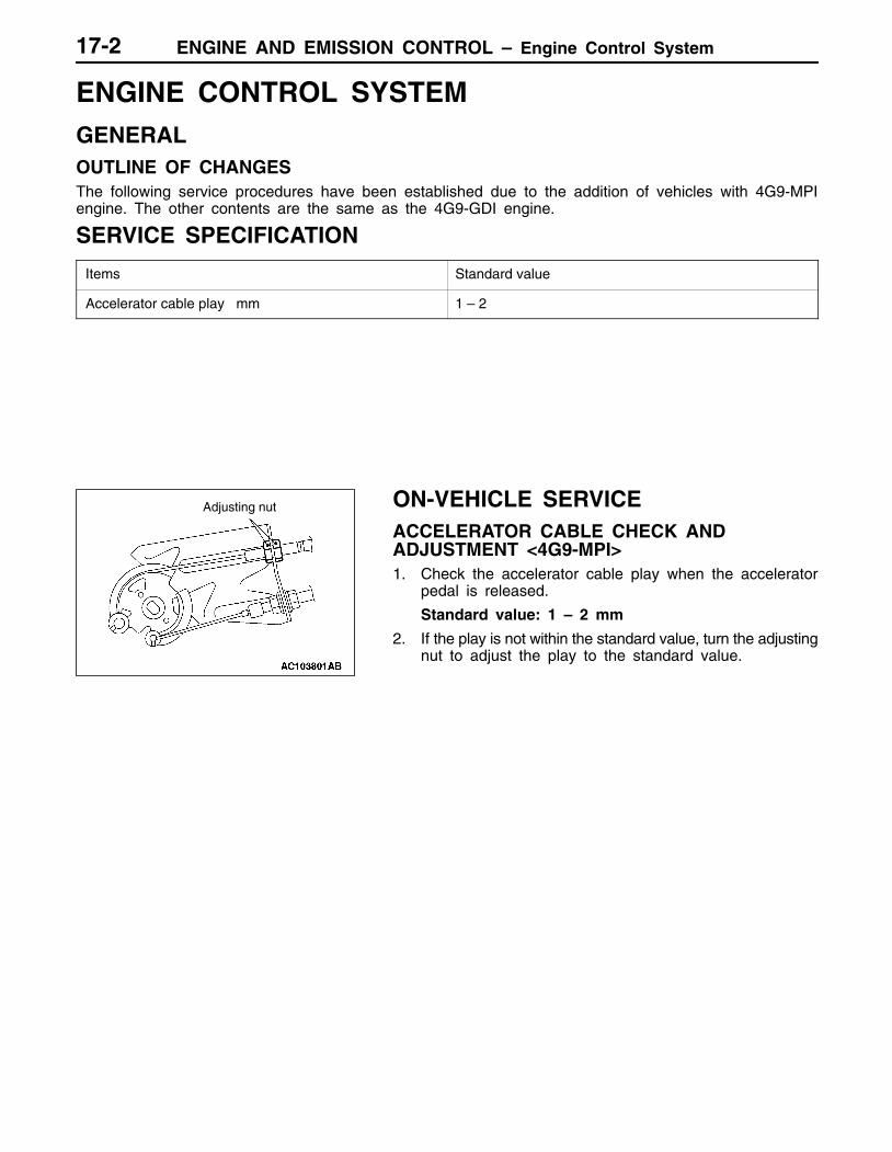
ENGINE CONTROL SYSTEMGENERALOUTLINE OF CHANGESThe following service procedures have been established due to the addition of vehicles with 4G9-MPIengine. The other contents are the same as the 4G9-GDI engine.
SERVICE SPECIFICATION
Items Standard value
Accelerator cable play mm 1 – 2
ON-VEHICLE SERVICEACCELERATOR CABLE CHECK ANDADJUSTMENT <4G9-MPI>1. Check the accelerator cable play when the accelerator
pedal is released.
Standard value: 1 – 2 mm
2. If the play is not within the standard value, turn the adjustingnut to adjust the play to the standard value.
Adjusting nut
ENGINE AND EMISSION CONTROL – Engine Control SystemENGINE AND EMISSION CONTROL – Engine Control System 17-3
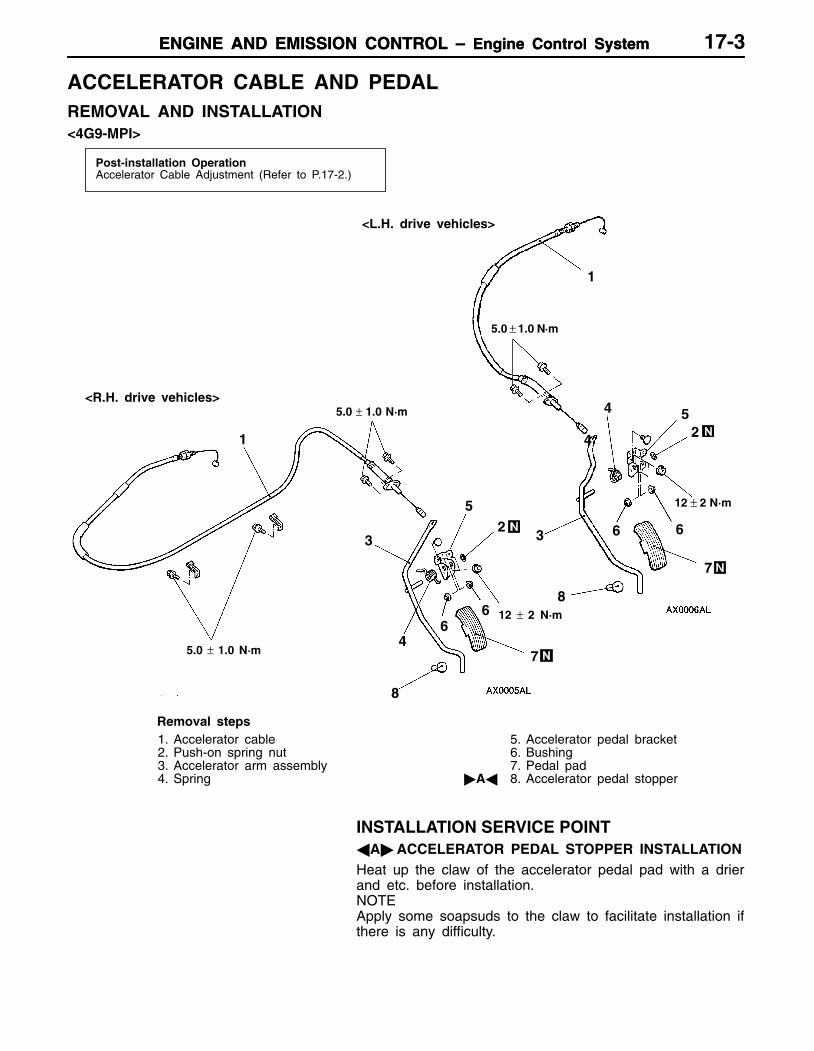
ACCELERATOR CABLE AND PEDALREMOVAL AND INSTALLATION<4G9-MPI>
Post-installation OperationAccelerator Cable Adjustment (Refer to P.17-2.)
1
23
24
<L.H. drive vehicles>
<R.H. drive vehicles>
8
6
5
7
5
3
4
6
7
8
1
5.0 ± 1.0·
6
6
45.0 ± 1.0·
5.0 ± 1.0·
12 ± 2·
12 ± 2 ·
Removal steps1. Accelerator cable2. Push-on spring nut3. Accelerator arm assembly4. Spring
5. Accelerator pedal bracket6. Bushing7. Pedal pad
A 8. Accelerator pedal stopper
INSTALLATION SERVICE POINTAACCELERATOR PEDAL STOPPER INSTALLATIONHeat up the claw of the accelerator pedal pad with a drierand etc. before installation.NOTEApply some soapsuds to the claw to facilitate installation ifthere is any difficulty.
ENGINE AND EMISSION CONTROL – Emission Control System <MPI>17-4
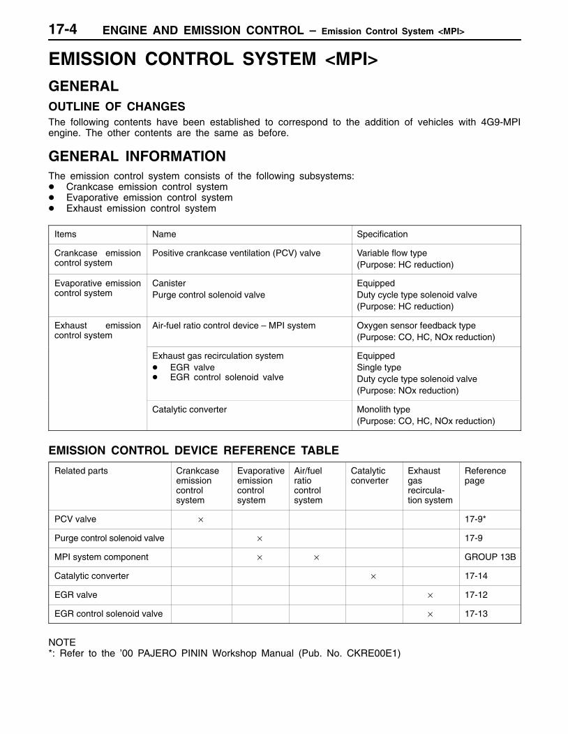
EMISSION CONTROL SYSTEM <MPI>GENERALOUTLINE OF CHANGESThe following contents have been established to correspond to the addition of vehicles with 4G9-MPIengine. The other contents are the same as before.
GENERAL INFORMATIONThe emission control system consists of the following subsystems: Crankcase emission control system Evaporative emission control system Exhaust emission control system
Items Name Specification
Crankcase emissioncontrol system
Positive crankcase ventilation (PCV) valve Variable flow type(Purpose: HC reduction)
Evaporative emissioncontrol system
CanisterPurge control solenoid valve
EquippedDuty cycle type solenoid valve(Purpose: HC reduction)
Exhaust emissioncontrol system
Air-fuel ratio control device – MPI system Oxygen sensor feedback type(Purpose: CO, HC, NOx reduction)
Exhaust gas recirculation system EGR valve EGR control solenoid valve
EquippedSingle typeDuty cycle type solenoid valve(Purpose: NOx reduction)
Catalytic converter Monolith type(Purpose: CO, HC, NOx reduction)
EMISSION CONTROL DEVICE REFERENCE TABLE
Related parts Crankcaseemissioncontrol system
Evaporativeemissioncontrol system
Air/fuel ratio control system
Catalyticconverter
Exhaustgas recircula-tion system
Referencepage
PCV valve × 17-9*
Purge control solenoid valve × 17-9
MPI system component × × GROUP 13B
Catalytic converter × 17-14
EGR valve × 17-12
EGR control solenoid valve × 17-13
NOTE*: Refer to the ’00 PAJERO PININ Workshop Manual (Pub. No. CKRE00E1)
ENGINE AND EMISSION CONTROL – Emission Control System <MPI> 17-5
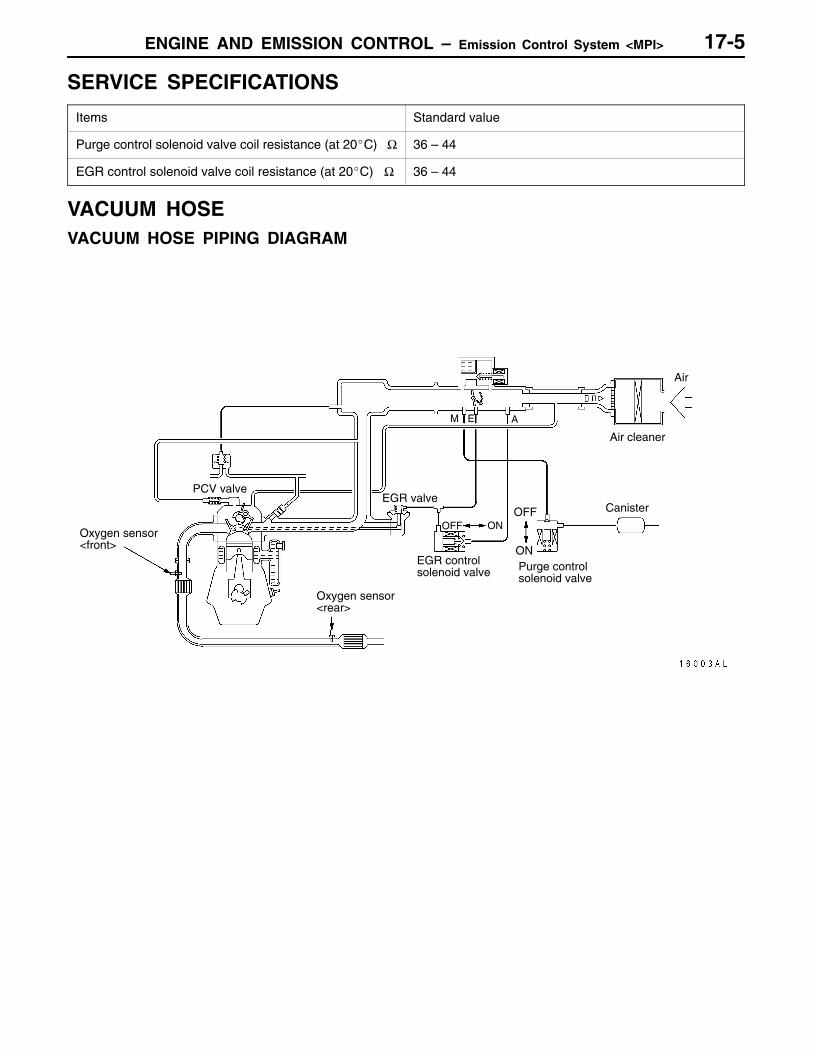
SERVICE SPECIFICATIONS
Items Standard value
Purge control solenoid valve coil resistance (at 20C) Ω 36 – 44
EGR control solenoid valve coil resistance (at 20C) Ω 36 – 44
VACUUM HOSEVACUUM HOSE PIPING DIAGRAM
PCV valve
OFFEGR valve
Air cleaner
ON
Canister
Purge controlsolenoid valve
EGR controlsolenoid valve
Oxygen sensor<rear>
Air
OFF ONOxygen sensor<front>
M E A
ENGINE AND EMISSION CONTROL – Emission Control System <MPI>17-6
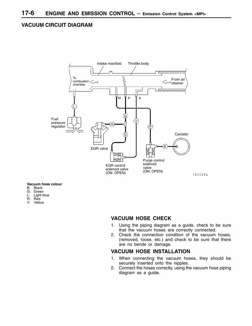
VACUUM CIRCUIT DIAGRAM
From aircleaner
Intake manifold Throttle body
To combustionchamber
Fuelpressureregulator
EGR control solenoid valve(ON: OPEN)
Canister
Purge control solenoidvalve(ON: OPEN)
EGR valve
Vacuum hose colourB: BlackG: GreenL: Light blueR: RedY: Yellow
M P A
L
GY
G
G
R
B
VACUUM HOSE CHECK1. Using the piping diagram as a guide, check to be sure
that the vacuum hoses are correctly connected.2. Check the connection condition of the vacuum hoses,
(removed, loose, etc.) and check to be sure that thereare no bends or damage.
VACUUM HOSE INSTALLATION1. When connecting the vacuum hoses, they should be
securely inserted onto the nipples.2. Connect the hoses correctly, using the vacuum hose piping
diagram as a guide.
ENGINE AND EMISSION CONTROL – Emission Control System <MPI>
PCV valve
17-7
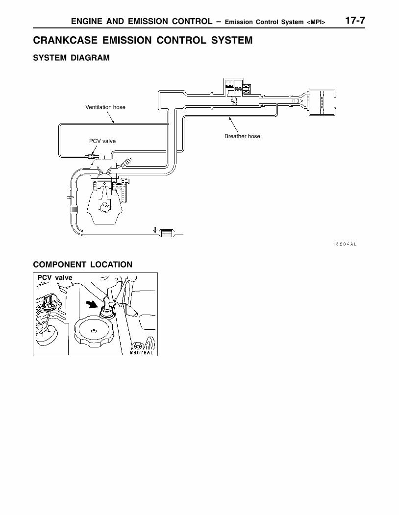
CRANKCASE EMISSION CONTROL SYSTEM
SYSTEM DIAGRAM
Ventilation hose
Breather hosePCV valve
COMPONENT LOCATION
ENGINE AND EMISSION CONTROL – Emission Control System <MPI>
Purge control solenoid valve
17-8
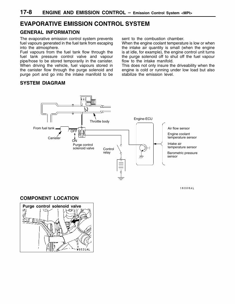
EVAPORATIVE EMISSION CONTROL SYSTEMGENERAL INFORMATIONThe evaporative emission control system preventsfuel vapours generated in the fuel tank from escapinginto the atmosphere.Fuel vapours from the fuel tank flow through thefuel tank pressure control valve and vapourpipe/hose to be stored temporarily in the canister.When driving the vehicle, fuel vapours stored inthe canister flow through the purge solenoid andpurge port and go into the intake manifold to be
sent to the combustion chamber.When the engine coolant temperature is low or whenthe intake air quantity is small (when the engineis at idle, for example), the engine control unit turnsthe purge solenoid off to shut off the fuel vapourflow to the intake manifold.This does not only insure the driveability when theengine is cold or running under low load but alsostabilize the emission level.
SYSTEM DIAGRAM
From fuel tank
Canister
Purge control solenoid valve
OFF
ON
Air flow sensor
Barometric pressuresensor
Controlrelay
Throttle bodyEngine-ECU
Engine coolanttemperature sensor
Intake air temperature sensor
COMPONENT LOCATION
ENGINE AND EMISSION CONTROL – Emission Control System <MPI> 17-9
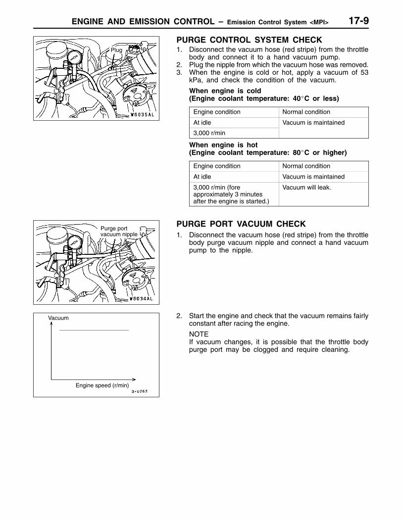
PURGE CONTROL SYSTEM CHECK1. Disconnect the vacuum hose (red stripe) from the throttle
body and connect it to a hand vacuum pump.2. Plug the nipple from which the vacuum hose was removed.3. When the engine is cold or hot, apply a vacuum of 53
kPa, and check the condition of the vacuum.
When engine is cold(Engine coolant temperature: 40C or less)
Engine condition Normal condition
At idle Vacuum is maintained
3,000 r/min
When engine is hot(Engine coolant temperature: 80C or higher)
Engine condition Normal condition
At idle Vacuum is maintained
3,000 r/min (foreapproximately 3 minutesafter the engine is started.)
Vacuum will leak.
PURGE PORT VACUUM CHECK1. Disconnect the vacuum hose (red stripe) from the throttle
body purge vacuum nipple and connect a hand vacuumpump to the nipple.
2. Start the engine and check that the vacuum remains fairlyconstant after racing the engine.
NOTEIf vacuum changes, it is possible that the throttle bodypurge port may be clogged and require cleaning.
Plug
Purge port vacuum nipple
Vacuum
Engine speed (r/min)
ENGINE AND EMISSION CONTROL – Emission Control System <MPI>17-10
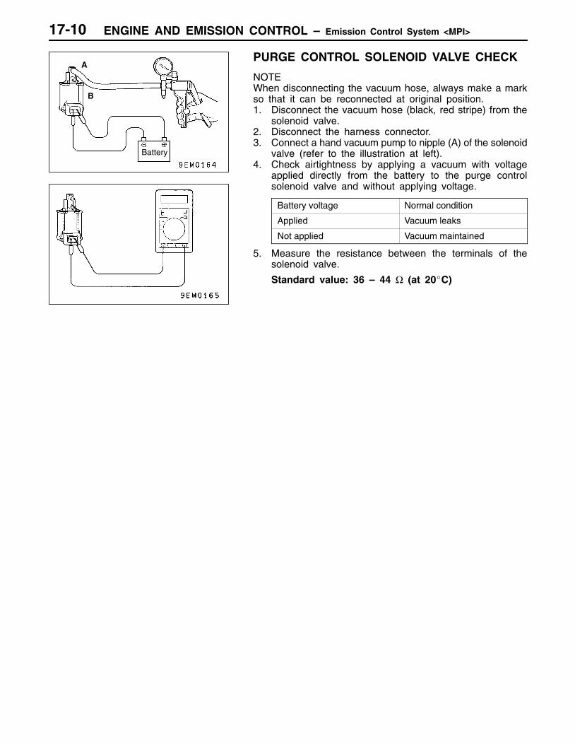
PURGE CONTROL SOLENOID VALVE CHECK
NOTEWhen disconnecting the vacuum hose, always make a markso that it can be reconnected at original position.1. Disconnect the vacuum hose (black, red stripe) from the
solenoid valve.2. Disconnect the harness connector.3. Connect a hand vacuum pump to nipple (A) of the solenoid
valve (refer to the illustration at left).4. Check airtightness by applying a vacuum with voltage
applied directly from the battery to the purge controlsolenoid valve and without applying voltage.
Battery voltage Normal condition
Applied Vacuum leaks
Not applied Vacuum maintained
5. Measure the resistance between the terminals of thesolenoid valve.
Standard value: 36 – 44 Ω (at 20C)
Battery
B
A
ENGINE AND EMISSION CONTROL – Emission Control System <MPI>
EGR control solenoid valve EGR valve
17-11
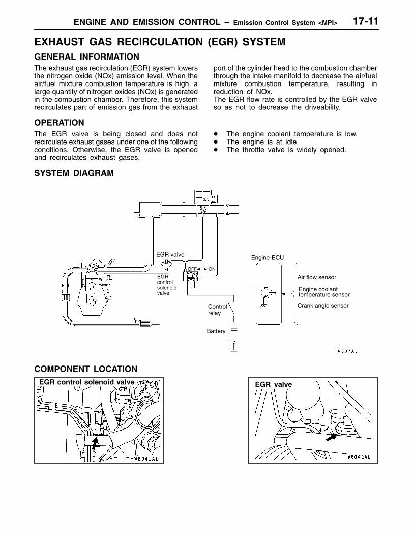
EXHAUST GAS RECIRCULATION (EGR) SYSTEMGENERAL INFORMATIONThe exhaust gas recirculation (EGR) system lowersthe nitrogen oxide (NOx) emission level. When theair/fuel mixture combustion temperature is high, alarge quantity of nitrogen oxides (NOx) is generatedin the combustion chamber. Therefore, this systemrecirculates part of emission gas from the exhaust
port of the cylinder head to the combustion chamberthrough the intake manifold to decrease the air/fuelmixture combustion temperature, resulting inreduction of NOx.The EGR flow rate is controlled by the EGR valveso as not to decrease the driveability.
OPERATIONThe EGR valve is being closed and does notrecirculate exhaust gases under one of the followingconditions. Otherwise, the EGR valve is openedand recirculates exhaust gases.
The engine coolant temperature is low. The engine is at idle. The throttle valve is widely opened.
SYSTEM DIAGRAM
ONOFF
EGRcontrolsolenoidvalve
Air flow sensor
Engine coolanttemperature sensor
Crank angle sensorControlrelay
Engine-ECU
Battery
EGR valve
COMPONENT LOCATION
ENGINE AND EMISSION CONTROL – Emission Control System <MPI>17-12
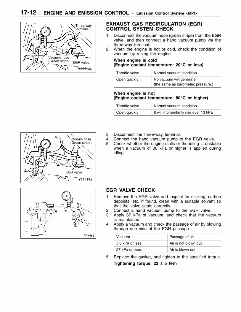
EXHAUST GAS RECIRCULATION (EGR)CONTROL SYSTEM CHECK1. Disconnect the vacuum hose (green stripe) from the EGR
valve, and then connect a hand vacuum pump via thethree-way terminal.
2. When the engine is hot or cold, check the condition ofvacuum by racing the engine.
When engine is cold(Engine coolant temperature: 20C or less)
Throttle valve Normal vacuum condition
Open quickly No vacuum will generate(the same as barometric pressure.)
When engine is hot(Engine coolant temperature: 80C or higher)
Throttle valve Normal vacuum condition
Open quickly It will momentarily rise over 13 kPa
3. Disconnect the three-way terminal.4. Connect the hand vacuum pump to the EGR valve.5. Check whether the engine stalls or the idling is unstable
when a vacuum of 30 kPa or higher is applied duringidling.
EGR VALVE CHECK1. Remove the EGR valve and inspect for sticking, carbon
deposits, etc. If found, clean with a suitable solvent sothat the valve seats correctly.
2. Connect a hand vacuum pump to the EGR valve.3. Apply 67 kPa of vacuum, and check that the vacuum
is maintained.4. Apply a vacuum and check the passage of air by blowing
through one side of the EGR passage.
Vacuum Passage of air
5.0 kPa or less Air is not blown out
27 kPa or more Air is blown out
5. Replace the gasket, and tighten to the specified torque.
Tightening torque: 22 ± 5 N·m
Three-wayterminal
Vacuum hose(Green stripe) EGR valve
EGR valve
Plug Vacuum hose(Green stripe)
ENGINE AND EMISSION CONTROL – Emission Control System <MPI> 17-13
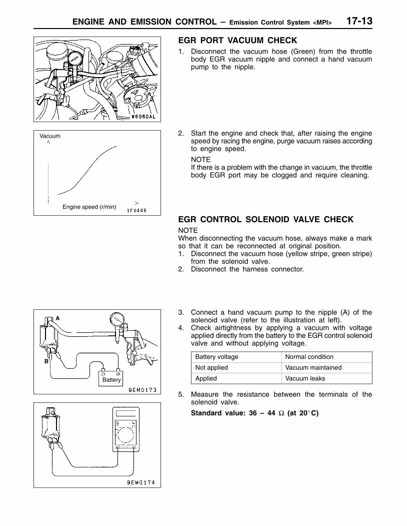
EGR PORT VACUUM CHECK1. Disconnect the vacuum hose (Green) from the throttle
body EGR vacuum nipple and connect a hand vacuumpump to the nipple.
2. Start the engine and check that, after raising the enginespeed by racing the engine, purge vacuum raises accordingto engine speed.
NOTEIf there is a problem with the change in vacuum, the throttlebody EGR port may be clogged and require cleaning.
EGR CONTROL SOLENOID VALVE CHECKNOTEWhen disconnecting the vacuum hose, always make a markso that it can be reconnected at original position.1. Disconnect the vacuum hose (yellow stripe, green stripe)
from the solenoid valve.2. Disconnect the harness connector.
3. Connect a hand vacuum pump to the nipple (A) of thesolenoid valve (refer to the illustration at left).
4. Check airtightness by applying a vacuum with voltageapplied directly from the battery to the EGR control solenoidvalve and without applying voltage.
Battery voltage Normal condition
Not applied Vacuum maintained
Applied Vacuum leaks
5. Measure the resistance between the terminals of thesolenoid valve.
Standard value: 36 – 44 Ω (at 20C)
Vacuum
Engine speed (r/min)
A
B
Battery

ENGINE AND EMISSION CONTROL – Emission Control System <MPI>17-14
CATALYTIC CONVERTERREMOVAL AND INSTALLATION
1
2
4
3
5
50 ± 10 ·
50 ± 10 ·
50 ± 10 ·
50 ± 10 ·
50 ± 10 ·
50 ± 10 ·
13 ± 2 ·
Front catalytic converter removalsteps1. Front pipe2. Oxygen sensor (front)3. Front catalytic converter
Catalytic converter removal steps1. Front pipe4. Oxygen sensor (rear)5. Catalytic converter
Related Documents