Features • 400 t capacity • 2 599 mton-m maximum load moment • 5 066 mton-m maximum load moment with MAX-ER® • 96 m No. 58 HL boom • 105,6 m No. 133A fixed jib on No. 58 HL boom combination • 138 m No. 59 luffing jib on No. 58 HL boom combination • 372 kW engine Manitowoc 16000 Product Guide ASME B30.5 Metric

Welcome message from author
This document is posted to help you gain knowledge. Please leave a comment to let me know what you think about it! Share it to your friends and learn new things together.
Transcript

Features• 400tcapacity
• 2599mton-mmaximumloadmoment
• 5066mton-mmaximumloadmomentwithMAX-ER®
• 96mNo.58HLboom
• 105,6mNo.133AfixedjibonNo.58HLboomcombination
• 138mNo.59luffingjibonNo.58HLboomcombination
• 372kWengine
Manitowoc 16000 Product GuideASMEB30.5Metric

Features
HydraulicsOur closed-loop system provides a separate hydraulic circuit to power each crane function. The result is truly independent, variable-speed operation of the swing, load hoist, boom hoist and travel functions.
EPIC®Manitowoc’s field-proven Electronically Processed Independent Controls (EPIC) system with CAN-BUS technology delivers high productivity and precise load control by instantly matching a crane’s commands to the crane function. EPIC maximizes a Manitowoc crane’s function capability and simplifies servicing by pinpointing any problem in the crane’s engine, power transmission and other operating systems. In addition, EPIC increases versatility by easily tailoring a Manitowoc crane’s operation for specialized applications, with or without attachments.
FACT™ ConnectorsManitowoc’s Fast Aligning Connection Technology (FACT) precisely and accurately aligns crane components for safe, fast, easy assembly.
CraneSTAR is an exclusive and innovative crane asset management system that helps improve your profitability and reduce costs by remotely monitoring critical crane data. Visit www.cranestar.com for more information.

Manitowoc16000 3
Contents
Specifications 4Outlinedimensions 7Transportdata 15Craneassembly 16Performancedata 19Boomcombinations 24Heavyliftboomrange/loadcharts 27Upperboompointrange/loadcharts 29WindAttachmentrange/loadcharts 31Fixedjibrange/loadcharts 35Luffingjibrange/loadcharts 38MAX-ER®completeinformation 42ManitowocCraneCare 56

4
Specificationshydraulic power for the hoisting drums, boom hoist, swing, left crawler and right crawler.
719 L hydraulic reservoir is equipped with breather, clean out access, and internal diffuser.
Each function is equipped with relief valves to protect the hydraulic circuit from overload or shock.
System includes oil cooler and replaceable, full flow filter. All oil is filtered before entering the hydraulic pumps.
Drums
Basic machine is equipped with 108,6 cm wide and 64,1 cm diameter main hoist drum, mounted in the boom butt, and 82,2 cm wide and 64,1 cm diameter whip drum, mounted in the rotating bed. Each drum is driven by a variable-displacement hydraulic motor through a planetary reduction system. Drums are grooved for 28 mm rope.
Powered hoisting/lowering operation is standard with automatic (spring applied, hydraulically released) multi-disc brakes, and drum rotation indicators.
Optional: Auxiliary (third) hydraulic powered drum rated 147 kN line pull mounted in boom butt.
Swing system
High strength steel adapter module is mounted on 3 m diameter triple row roller turntable bearing. Bearing adapter-mounted independent swing is powered by a fixed-displacement hydraulic motor coupled to an internal brake and planetary reduction.
Swing system maximum speed: 2.2 rpm.
Moving mast hoist system
Independent moving mast hoist with two grooved drums, each 32,5 cm wide and 64,1 cm diameter drum grooved for 1-1/8" diameter wire rope.
Drum is powered by variable-displacement hydraulic motors coupled to integral brake and planetary reduction gearboxes. Ratcheting pawl and rotation indicator are standard.
Raise 96 m full main boom from 0° - 82° in 3 minutes, 48 seconds.
Upperworks
Engine
Cummins Model QSX15 – C500 Tier 4i/3b diesel, 372 kW (500 BHP) at 1800 RPM.
Or
Cummins QSX15-C500 Tier 3 diesel, rated 500 HP at 1800 RPM
Includes pump drive disconnect for easier starting, engine block heater (120V), ether starting aid, high silencing muffler, hydraulic oil cooler, radiator and fan.
Multiple hydraulic pump drive transmission provides power for all machine functions.
Two 12 volt, 1400 CCA at -18°C, 24 volt system and 100 amp alternator.
946 L, with level indicator in operator’s cab.
Optional: Cold-weather package with heater for fluids, and computer display.
Controls
Modulating electronic-over-hydraulic controls provide infinite speed response directly proportional to control lever movement. Controls include Manitowoc’s exclusive EPIC® Electronically Processed Independent Control system with CAN-BUS technology providing microprocessor driven control logic, pump control, on-board diagnostics, and service information.
Block-up limit control is standard for hoist and whip lines.
Integrated Rated Capacity Limiter system (RCL) is standard for main boom and upper boom point. “Function cut-out” or “warning only” operation is selected via a keyed switch on the RCL console.
Travel and swing alarms are standard.
Optional: Anemometer (wind speed indicator). Booms and jibs are pre wired for anemometer.
Hydraulic system
High-pressure piston pumps, driven by a multi-pump transmission, provide independent closed-loop

Manitowoc16000 5
Specifications
Boom support system
Moving Mast is 9,75 m long and connects the boom hoist reeving to the steel boom suspension strap rigging. When used with the optional self-erect package, the mast is used for crane assembly and disassembly. It is capable of lifting and positioning the crawler assemblies, stacking the counterweights, and assembling the boom and luffing jib.
Spring cushioned boom stop and automatic boom stop are standard.
Counterweight
Counterweight tray and counterweights for the upperworks attaches to the rotating bed with power actuated pins. Carbody counterweight connect to the carbody via high strength steel hooks integral with the carbody structure.
QTY. ITEM UNIT WEIGHT TOTAL WEIGHT
kg kg
10UpperworksUpperSideBox 8164 81640
1 Counterweight Tray 19958 19958
Series 1 Total 101 598
4UpperworksUpperSideBox 8164 32656
2 CarbodyCenterBox 13608 27216
Series 2 Total 161 470
2UpperworksUpperSideBox 8164 16328
4 CarbodySideBox 6804 27216
Series 3 Total 205 014
Vision operator’s cab
The Vision Cab™ is a fully enclosed and insulated galvannealed steel module mounted to the left front corner of rotating bed. Module is equipped with power tilt, sliding door, large safety glass windows, front and roof windshield wipers, dome light, sun visor and shade, fire extinguisher, air conditioning, swing and travel alarms, and radio/CD player. Operator’s station swings over front of rotating bed for transportation.
Optional: Nylon protective window covers.
Lowerworks
Carbody
Connects rotating bed to crawler assemblies. High strength fabricated steel assembly with FACT™ connection system for safe, fast installation and removal of crawler assemblies.
Crawlers
Crawler assemblies are 10,4 m long with 1,5 m wide cast steel crawler pads and automatically lubricated intermediate rollers. Each crawler is identical and can be mounted on either side of the carbody. Each crawler is powered independently by a variable displacement hydraulic motor and includes hydraulically powered pin actuators for fast installation and removal from carbody. Carbody mounted drive motors are connected to crawler final reduction via drive shaft with guard. Crawlers provide ample tractive effort for counter rotation with full rated load.
Maximum ground speed of 1,24 kph.
Attachments
No. 58 heavy-lift boom
The liftcrane is equipped with 30 m No. 58 basic boom consisting of 8 m butt, 12 m insert with luffing hoist sheaves, 5 m transition insert, and 5 m top with thirteen 76,2 cm diameter tapered roller bearing sheaves. Includes rope guides, boom hoist wire rope, boom angle indicator and hook and weight ball. The boom utilize Manitowoc’s exclusive FACT™ connection system boom connector. Spring cushioned boom stop. Automatic boom stop. Powered boom hinge system including cylinder, piping, operating controls, and locking device standard.
Optional: 6 m and 12 m No. 58 boom inserts with steel boom suspension straps.
Optional: No. 58 detachable upper boom point with one 76,2 cm diameter tapered roller bearing steel sheave grooved for 28 mm rope with rope guard.
Optional: 97,6 t detachable extended upper boom point with three 76,2 cm diameter tapered roller bearing steel sheave grooved for 28 mm rope with rope guard.

6
Specifications
No. 133A fixed jib
21,3 m basic No. 133A fixed jib including pin connected 9,1 m butt, 12,2 m top, 6,4 m strut and mounting hardware.
Optional: 3 m, 6,1 m and 12,2 m No. 133A inserts with pin connectors.
Utilize fixed jib inserts in combination with the No. 133A fixed jib length of 42,7 m.
No. 59 luffing jib
24 m basic No. 59 luffing jib including PIN connected 7 m butt, (1) 6 m inserts and 11 m top, basic pendants, fixed strut, jib strut, backstay pendants, boom point guide wheel, luffing jib hoist with ratchet and pawl; quick disconnect for jib hoist piping, and 1" luffing jib hoist line (luffing jib preparation is standard).
Optional: 6 m and 12 m No. 59 luffing jib inserts with steel boom suspension straps.
Utilize luffing jib inserts in combination with the No. 59 basic luffing jib for total luffing jib lengths up to 84 m.
The Wheeled MAX-ER®
The Wheeled MAX-ER® attachment components include:
30 m of No. 59A mast consisting of a 6 m butt, 6 m insert, 12 m insert and 6 m top.
One additional swing drive (for a total of two) mounted on the rotating module. Each swing drive is powered by a fixed-displacement hydraulic motor coupled to a planetary reduction gearbox and internal brake.
Two 12 m heavy No. 58 boom inserts.
Counterweight includes (8) 19 958 kg and (2) 13 608 kg boxes.
The wheeled MAX-ER® counterweight can be positioned 11 m, 13 m, or 15 m behind the crane’s centerline of rotation, utilizing structural stinger equipped with hydraulic cylinder.
The Hanging MAX-ER®
The Hanging MAX-ER® attachment components include:
30 m of No. 59A mast consisting of a 6 m butt, 6 m insert, 12 m insert and 6 m top.
One additional swing drive (for a total of two) mounted on the rotating module. Each swing drive is powered by a fixed-displacement hydraulic motor coupled to a planetary reduction gearbox and internal brake.
Two 12 m heavy No. 58 boom inserts.
The hanging MAX-ER® counterweight assembly attaches to the top of the mast by steel straps and to the rear of the upperworks by a beam assembly.
Counterweight includes (10) 19 958 kg and (2) 6 804 kg boxes.
The hanging MAX-ER® counterweight can be positioned 11 m, 13 m, or 15 m behind the crane’s centerline of rotation.
Optional equipment
18,1 t swivel hook and weight ball. Single line pull is 13 610 kg.
Self-erect system includes, jacking cylinders with pads, 41 t assembly block and crawler handling chains.
Hydraulic Test Kit: required to properly analyze the performance of the EPIC® control system.
Service Interval Kits for the regularly scheduled maintenance of general crane operations.
Special Paint color(s) other than Manitowoc standard red and black.
Custom vinyl decal(s) of customer name and/or logo from artwork supplied by customer.
Export Packaging: basic crane, boom and jib sections.
Additional load blocks available upon request.


Manitowoc16000 9
Outline dimensions
H
L
W
Rotating bed assemblyLength 13,25mWidth 3,20mHeight 2,87mWeight 39612kg
H
L
Carbody assemblyLength 6,78mWidth 3,00mHeight 2,52mWeight 28161kgNote: Weight includes rotating bed adapter frame with bearing turntable, four swing drives, and carbody.
H
L
Rotating bed and carbody assembly (decked version)Length 6,78mWidth 3,00mHeight 3,20mWeight 64982kg
W
H
L
CrawlersLength 10,43mWidth 2,03mHeight 1,61mWeight 32665kg

10
Outline dimensions
H
L
No. 58 Boom butt, drum 1, luffing drum, wire ropeLength 10,13mWidth 2,96mHeight 3,10mWeight 21609kg
HL W
Upper counterweight trayLength 2,14mWidth 8,33mHeight 0,53mWeight 19958kg
H
L
W
Carbody side counterweight Series 3 x 4Length 2,18mmWidth 0,86mHeight 0,89mWeight 6803kg
H
L
WCarbody center counterweight Series 2 x 2 Series 3 x 2Length 3,45mWidth 1,80mHeight 0,89mWeight 13607kg
H
L
Upper counterweight Series 1 x 10 Series 2 x 14 Series 3 x 16Length 2,54mWidth 2,61mHeight 0,41mWeight 8164kg

Manitowoc16000 11
Outline dimensions
H
L
12,0 m No. 58 boom insert and strapsLength 12,19mWidth 2,96mHeight 2,65mWeight 4236kg
H
L
6,0 m No. 58 boom insert and strapsLength 6,19mWidth 2,96mHeight 2,67mWeight 2562kg
H
L
12,0 m No. 58 heavy boom insert with sheaveLength 12,19mWidth 2,96mHeight 2,67mWeight 5595kg
H
L
6,0 m No. 58 WA boom insert and strapsLength 6,19mWidth 2,96mHeight 2,67mWeight 2690kg
H
L
3,0 m No. 58 WA boom insert and strapsLength 3,19mWidth 2,96mHeight 2,67mWeight 1599kg

12
Outline dimensions
H
L
11,0 m No. 59 luffing jib topLength 11,95mWidth 2,69mHeight 2,54mWeight 6015kg
H
L
No. 58 WA boom cap and No. 58 WA extended upper boom pointLength 11,50mWidth 2,70mHeight 2,97mWeight 8519kg
H
L
7,0 m No. 58 extended upper boom pointLength 9,52mWidth 2,60mHeight 1,99mWeight 3674kg
H
L
5,0 m No. 58 boom top with 5,0 m transitional insert and strapsLength 11,41mWidth 2,96mHeight 2,67mWeight 11373kg
H
L
3,0 m No. 58 boom insert with BRS cylinder and strapsLength 3,40mWidth 2,96mHeight 2,78mWeight 5488kg

Manitowoc16000 13
Outline dimensions
H
L
12,0 m No. 59 luffing jib insertLength 12,19mWidth 2,69mHeight 2,17mWeight 2928kg
H
L
6,0 m No. 59 luffing jib insertLength 6,19mWidth 2,69mHeight 2,17mWeight 1685kg
H
L
7,0 m No. 59 luffing jib buttLength 7,15mWidth 2,69mHeight 2,17mWeight 2722kg
12,2 m No. 133A fixed jib topLength 13,06mWidth 2,08mHeight 1,65mWeight 3649kg
L
H
H
L
11,5 m No. 59 luffing jib strut with point sheaves and strapsLength 12,46mWidth 2,69mHeight 2,27mWeight 9287kg
H
L
11,5 m No. 59 luffing jib upper point roller assemblyLength 2,64mWidth 0,41mHeight 0,81mWeight 460kg

14
Outline dimensions
W
L
D
L
Hook block for 28 mm wire ropeCapacity 410mt Length 3,37mWeight 9661kg Width 1,19m
Capacity 317mt Length 2,63mWeight 7892kg Width 1,15m
Capacity 227mt Length 2,72mWeight 5257kg Width 0,93m
Capacity 182mt Length 2,65mWeight 4308kg Width 0,87m
Capacity 100mt Length 2,28mWeight 3404kg Width 0,86m
Capacity 41mt* Length 1,90mWeight 1179kg Width 0,91m*Assemblyblock
Weight ballCapacity/Swivel 18mt Diameter 0,47m
Weight 771kg Length 1,23m
12,2 m No. 133A fixed jib insertLength 12,32mWidth 2,07mHeight 1,65mWeight 1712kg
H
L
6,1 m No. 133A fixed jib insertLength 6,22mWidth 2,07mHeight 1,65mWeight 960kg
H
L
3,0 m No. 133A fixed jib insertLength 3,18mWidth 2,07mHeight 1,65mWeight 559kg
H
L
9,1 m No. 133A fixed jib butt with strutsLength 9,38mWidth 2,07mHeight 2,42mWeight 4607kg
L
H

Manitowoc16000 15
Transport dataLoad summary
107 m No. 58WA boom with BRS + 7 m No. 58 extended upper boom pointQuantityontrailerload#
(Doesnotincludeblocking,strapping,etc.)
ItemWeighteachitem
kg1 2 3 4 5 6 7 8 9 10 11 12 13 14 15 16 17 18 19 20 21
Upperworksmodule 39612 1
Carbodyandadapter 28161 1
Crawlerassembly 32665 1 1
Counterweighttray 19958 1 1
Uppercounterweight(box) 8164 1 1 1 2 1 2 1 1 2 1 2
Carbodycentercounterweight 13607 1 1
Carbodysidecounterweight 6803 1 1 1 1
Auxiliarycounterweighttray 2903 1
Auxiliarycounterweight(box) 7938 1
8,0mNo.58boombutt,drum1w/wirerope 21609 1
5,0mNo.58boomtopandstraps 9169 1
5,0mNo.58boomtrans.insertandstraps 2204 1
6,0mNo.58boominsertandstraps 2562 1
12,0mNo,58boomwithWRGBoominsertandstraps 5595 1
12,0mNo.58boominsertandstraps 4236 1 1 1 1 1 1
3,0mNo.58boominsertwithBRScylinderandstraps
5448 1
BRSA-frameandintermediatesuspension 680 1
No.58WAboomcapandNo.58WAextendedupperboompoint
3674 1
180t5sheaveloadblock 4309 1
100t3sheaveloadblock 3402 1
Reelcable-701m 3629 1
Miscellaneous 907 1
Payloadforeachtrailerm
39612
28161
32665
32665
19538
21609
20562
19203
20564
16705
20564
16029
15802
18890
11683
18414
19958
20410
20410
13380
19684


Manitowoc16000 19
Performance data
Main hoist 28 mm wire rope Single line speed in m per minute
Layer
Singlelinepullkg
1335mm
2363mm
3391mm
4419mm
5447mm
6475mm
7503mm
8531mm
9559mm
10587mm
11615mm
0 105 114 123 132 140 149 158 167 176 184 193
2268 105 114 123 132 140 149 158 167 176 184 193
4536 105 114 123 131 139 147 154 162 169 176 183
6804 103 110 117 124 131 135 136 137 138 139 141
9072 98 101 102 104 105 106 107 108 109 111 112
11340 83 84 85 87 87 89 90 91 92 94 95
13608 71 73 74 75 76 77 78 80 81 82 83
16239 62 63 65 66 67 68 69 70 72 73 74
Whip drum 28 mm wire ropeSingle line speed in m per minute
Layer
Singlelinepullkg
1335mm
2363mm
3391mm
4419mm
5447mm
6475mm
7503mm
0 85 92 99 106 113 120 127
2268 80 86 92 98 105 111 116
4536 75 81 86 91 96 101 101
6804 68 69 69 70 71 72 73
9072 53 54 55 56 57 58 59
11340 45 45 46 47 48 49 50
13608 39 40 41 41 42 43 44

20
Performance data
No. 58 HL boomMain load block reeving 28 mm wire rope
No.partsofline Maximumloadkg
2 32520
4 65090
6 97610
8 130180
10 162750
12 195270
14 227840
16 260360
18 292930
20 322690
22 351530
24 379840
26 400000
No. 58 HL boom 28 mm hoist line
Whipline-drum2or3 Hoistline-drum1
Boomlength 1Part 2Part
Maximumpartsoflineforfullhoistingrangem m m m
30,0 79 116 838 26
36,0 91 134 853 22
42,0 104 152 853 18
48,0 116 171 930 18
54,0 128 186 930 14
60,0 140 204 930 14
66,0 152 223 930 12
72,0 165 241 930 10
78,0 177 259 930 10
84,0 189 277 930 8
90,0 201 296 930 6
96,0 213 314 930 6
NOTE: Hoist and whip line lengths given in table will allow hook to touch ground. When block travel below ground is required, add additional rope equal to parts of line times added travel distance. Hoisting distance or line pull may be limited when block travel below ground is required.
Optional high speed whip 28 mm wire rope single line speed in m per minute
Layer
Singlelinepullkg
1335mm
2363mm
3391mm
4419mm
5447mm
6475mm
7503mm
0 105 114 123 132 140 149 158
2268 105 114 123 132 140 149 158
4536 105 114 123 131 139 147 154
6804 103 110 117 124 131 135 136
9072 98 101 102 104 105 106 107
11340 83 84 85 87 87 89 90
13608 71 73 74 75 76 77 78

Manitowoc16000 21
Performance data
No. 58 WA boom with 7.6 m extended upper boom point28 mm wire rope
Whipline-drum2or3 Hoistline-drum1
Boomlength 1Part 2Part Totalparts
oflinem m m m
65 183 244 686 8
68 183 259 701 8
71 183 274 732 8
74 198 274 762 8
77 198 290 792 8
80 198 290 808 8
83 213 305 838 8
86 213 320 869 8
89 229 320 899 8
92 - - 914 8
No. 58 HL boom with 7 m extended upper boom point and 30 m No. 59A mast 28 mm wire rope
Boomlength
Whiplinedrum2or3
Hoistlinedrum1
1Part Totalpartsoflinem(ft) m m
96,0(315.0) 229 747 6
NOTE: Hoist and whip line lengths given in table will allow hook to touch ground. When block travel below ground is required, add additional rope equal to parts of line times added travel distance. Hoisting distance or line pull may be limited when block travel below ground is required.
No. 58 HL boom with 7 m extended upper boom point and No. 59A 30 m mast 28 mm wire rope
No.partsofline Maximumloadkg
2 32520
4 65090
6 81500
No. 58 HL boom with 7 m extended upper boom point28 mm wire rope
Boomlength
Whiplinedrum2or3
Hoistlinedrum1
1Part Totalpartsoflinem m m
66,0 168 533 6
72,0 180 579 6
78,0 192 610 6
84,0 204 655 6
90,0 216 701 6
NOTE: Hoist and whip line lengths given in table will allow hook to touch ground. When block travel below ground is required, add additional rope equal to parts of line times added travel distance. Hoisting distance or line pull may be limited when block travel below ground is required.
No. 58 HL boom with 7 m extended upper boom pointMain load block reeving28 mm wire rope
No.partsofline Maximumloadkg
2 32520
4 65090
6 97600
No. 58 WA boom with 7.6 m extended upper boom pointMain load block reeving28 mm wire rope
No.partsofline Maximumloadkg
2 32520
4 65090
6 97610
8 130000

22
Performance data
No. 59 luffing jib on No. 58 HL boom28 mm hoist line
Hoistlinedrum1
Whiplinedrum2
Boomlength
1Part 2Part
m m m m
30,0 747 244 366
36,0 808 259 381
42,0 808 274 396
48,0 823 290 427
54,0 823 305 442
60,0 823 305 442
66,0 823 305 422
NOTE: Hoist line lengths given in table include all luffing jib lengths. Hoist and whip line lengths given in table will allow hook to touch ground. When block travel below ground is required, add additional rope equal to parts of line times added travel distance. Hoisting distance or line pull may be limited when block travel below ground is required.
No. 133A fixed jib on No. 58 HL boom28 mm hoist line
Hoistlinedrum1
Hoistlinedrum2
m m m
42,0 535 475
48,0 565 475
54,0 610 475
60,0 660 475
66,0 670 475
72,0 705 475
NOTE: Hoist line lengths given in table include all luffing jib lengths. Hoist and whip line lengths given in table will allow hook to touch ground. When block travel below ground is required, add additional rope equal to parts of line times added travel distance. Hoisting distance or line pull may be limited when block travel below ground is required.
No. 59 luffing jib on No. 58 HL boomMain load block reeving28 mm hoist line
No.partsofline Maximumloadkg
2 32520
4 65090
6 97610
8 130180
10 162750
12 185200
No. 133A luffing jib on No. 58 HL boom Main load block reeving28 mm hoist line
No.partsofline Maximumloadkg
2 32520
4 65090
6 93300

Manitowoc16000 23
Performance data
MAX-ERNo. 58 HL boom28 mm wire rope
Whipline-drum2or3 Hoistline-drum1Boomlength
1Part 2PartTotalpartsoflinem m m m
42,0 107 152 1082 24
48,0 119 171 1128 22
54,0 131 189 1158 20
60,0 143 207 1158 18
66,0 155 226 1158 16
72,0 168 244 1158 14
78,0 177 262 1189 14
84,0 189 277 1189 12
90,0 201 296 1189 10
96,0 213 314 1189 8
102,0 226 332 1189 8
108,0 238 351 1189 6
114,0 250 369 1189 6
120,0 262 387 1189 6
NOTE: Hoist and whip line lengths given in table will allow hook to touch ground. When block travel below ground is required, add additional rope equal to parts of line times added travel distance. Hoisting distance or line pull may be limited when block travel below ground is required.
MAX-ERNo. 58 HL boomMain load block reeving28 mm wire rope
No.partsofline Maximumloadkg
2 32520
4 65090
6 97610
8 130180
10 162750
12 195270
14 227840
16 260360
18 292930
20 322690
22 351530
24 379800


28
Boom load charts
No. 58 HL boom
Radiusm
150 590 kg Counterweight 54 430 kg Carbody counterweight
Boomlengthm
30,0 36,0 42,0 48,0 54,0 60,0 66,0 72,0 78,0 84,0 90,0 96,0
6,4 400,0
8,0 323,8 323,3 283,4
10,0 256,4 256,1 256,6 257,2 216,1
12,0 194,8 195,1 195,5 195,4 193,2 181,9 159,6 147,0
14,0 153,7 153,9 154,2 154,1 154,0 154,5 145,6 134,0 129,7 113,7 95,5
18,0 106,3 106,4 106,6 106,3 106,2 105,8 105,5 105,7 105,4 103,4 89,4 77,2
22,0 79,6 79,7 79,9 79,5 79,4 78,9 78,5 78,0 77,6 77,0 76,8 72,5
26,0 62,4 62,5 62,7 62,4 62,1 61,6 61,3 60,7 60,2 59,6 59,0 58,4
30,0 50,3 50,5 50,7 50,3 50,1 49,6 49,2 48,6 48,1 47,5 46,9 46,2
34,0 41,6 41,9 41,5 41,3 40,8 40,3 39,8 39,2 38,5 38,0 37,3
38,0 35,0 34,7 34,5 33,9 33,6 32,9 32,4 31,7 31,1 30,4
40,0 32,1 31,9 31,7 31,1 30,7 30,1 29,5 28,8 28,3 27,6
44,0 27,0 26,8 26,2 25,9 25,2 24,7 24,0 23,4 22,7
48,0 22,8 22,3 21,9 21,2 20,7 20,0 19,4 18,7
52,0 19,4 18,9 18,5 17,9 17,4 16,6 16,1 15,3
56,0 16,1 15,7 15,1 14,5 13,8 13,3 12,5
60,0 13,3 12,6 12,1 11,4 10,8 10,1
64,0 11,1 10,5 10,0 9,3 8,7 7,9
68,0 8,6 8,1 7,4 6,8 6,1
70,0 7,7 7,2 6,5 6,0 5,3
76,0 4,9 4,2 3,7
For complete chart, refer to www.cranelibrary.com.
360°Rating,kgx1000

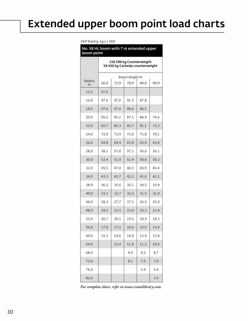
Extended upper boom point load charts
30
No. 58 HL boom with 7 m extended upper boom point
Radiusm
150 590 kg Counterweight 54 430 kg Carbody counterweight
Boomlengthm
66,0 72,0 78,0 84,0 90,0
15,2 97,6
16,8 97,6 97,6 91,3 87,8
18,0 97,6 97,6 89,6 86,5
20,0 95,5 95,1 87,1 84,4 74,6
22,0 82,7 82,3 82,7 81,1 72,5
24,0 72,9 72,4 72,0 71,8 70,1
26,0 64,8 64,4 63,9 63,4 63,0
28,0 58,1 57,6 57,1 56,6 56,1
30,0 52,4 51,9 51,4 50,8 50,3
32,0 45,5 47,0 46,5 45,9 45,4
34,0 43,3 42,7 42,2 41,6 41,1
38,0 36,2 35,6 35,1 34,5 33,9
40,0 33,3 32,7 32,2 31,5 31,0
44,0 28,3 27,7 27,1 26,5 25,9
48,0 24,2 23,5 23,0 22,3 21,8
52,0 20,7 20,1 19,5 18,9 18,3
56,0 17,8 17,1 16,6 15,9 15,4
60,0 15,2 14,6 14,0 13,4 12,8
64,0 12,4 11,8 11,2 10,6
68,0 9,9 9,2 8,7
72,0 8,1 7,5 7,0
76,0 5,9 5,4
82,0 3,4
For complete chart, refer to www.cranelibrary.com.
360°Rating,kgx1000

Wind Attachment range diagram
Manitowoc16000 31
No. 58 WA with 7,6 m extended upper boom point
83 0 80 0
70 0
60 0
50 0
40 0
30 0
20 0
2.67 m
8.24m 1.52 m
COUNTERWEIGHTTAILSWING
ROTATION
HEI
GH
T A
BO
VE
GR
OU
ND
m
16
12
28
20
24
36
44
48
40
32
56
52
64
72
68
60
76
84
80
88
96
104
100
92
DISTANCE FROM CENTERLINE OF ROTATION m
282012 36 44 52 6860 76 84

32
Wind Attachment load charts
No. 58 WA with 7,6 m extended upper boom point
166 920 kg Counterweight54 430 kg Carbody counterweight
28° offset 35° offsetBoomlengthm Boomlengthm
Radiusm
65,0 71,0 77,0 83,0 89,0 92,0 Radiusm
65,0 71,0 77,0 83,0 89,0 92,0
15,2 130.0 130.0 15,2 130.0
18,0 118.5 118.1 117.8 117.5 86.5 108.5 18,0 119.9 118.7 118.4 87.8 87.3 87.1
22,0 88.7 88.0 87.5 87.0 75.8 86.3 22,0 89.3 88.7 88.3 77.0 76.5 76.3
24,0 78.2 77.5 76.9 76.3 59.7 75.6 24,0 78.7 78.1 77.6 60.9 60.3 60.0
28,0 62.3 61.5 61.0 60.3 53.5 59.5 28,0 62.8 62.0 61.5 54.6 54.0 53.7
30,0 56.2 55.4 54.8 54.1 43.5 53.3 30,0 56.6 55.9 55.3 44.6 44.0 43.7
34,0 46.4 45.5 44.9 44.2 39.4 43.3 34,0 46.7 45.9 45.3 40.5 39.9 39.6
36,0 42.3 41.5 40.9 40.1 32.7 39.2 36,0 42.6 41.9 41.3 33.7 33.1 32.7
40,0 35.7 34.8 34.1 33.4 29.8 32.4 40,0 35.9 35.1 34.4 30.8 30.1 29.8
42,0 32.8 31.9 31.3 30.5 24.9 29.6 42,0 33.1 32.2 31.6 25.9 25.2 24.9
46,0 28.0 27.1 26.4 25.6 22.8 24.7 46,0 28.2 27.3 26.7 23.8 23.1 22.7
48,0 25.9 24.9 24.3 23.5 19.1 22.5 48,0 26.1 25.2 24.5 20.0 19.3 18.9
52,0 22.2 21.2 20.6 19.8 14.5 18.8 52,0 22.3 21.4 20.8 15.4 14.7 14.3
58,0 17.6 16.7 16.0 15.2 10.8 14.2 58,0 17.7 16.8 16.2 11.7 10.9 10.6
64,0 13.9 13.0 12.3 11.5 7.8 10.5 64,0 13.1 12.4 8.6 7.9 7.5
70,0 9.3 8.5 5.0 7.5 70,0 9.4 6.0 5.1 4.6
76,0 6.7 5.9 4.6 76,0
For complete chart, refer to www.cranelibrary.com.
360°Rating,kgx1000

Manitowoc16000 33
Wind Attachment range diagramwith Boom Raising System
No. 58 WA with BRS with 7,6 m extended upper boom point
121.9
118.9
115.8
112.8
109.7
15.2
18.3
21.3
24.4
27.4
30.5
33.5
36.6
39.6
42.7
45.7
48.8
51.8
54.9
57.9
61.0
64.0
67.1
70.1
73.2
76.2
79.2
82.3
85.3
88.4
91.4
94.5
97.5
100.6
103.6
106.7
79.2
12.2
18.3
24.4
30.5
36.6
42.7
48.8
54.9
61.0
67.1
73.2
HEI
GH
T A
BO
VE
GR
OU
ND
(MET
ERS)
2.67m
8.70m
COUNTERWEIGHTTAILSWING
1.52m
ROTATION
9.05m
MASTTAILSWING
EXTENDED UPPERBOOMPOINT28° OFFSET
EXTENDED UPPERBOOM POINT35° OFFSET
80°70°
60°
50°
107m 104m 101m 98m 95m 92m 89m
NO.58BRSBOOM
83°
40°
DISTANCE FROM CENTERLINE OF ROTATION (METERS)

34
Wind Attachment load chartswith Boom Raising System
No. 58 WA with BRS with 7,6 m extended upper boom point
166 920 kg Counterweight54 430 kg Carbody counterweight18 730 kg Auxiliary counterweight
28° offset 35° offsetBoomlengthm Boomlengthm
Radiusm
89,0 92,0 95,0 98,0 101,0 104,0 107,0 Radiusm
89,0 92,0 95,0 98,0 101,0 104,0 107,0
18,3 116,0 108,8 107,0 105,7 18,3 111,9 105,7 101,6
20,0 106,1 105,4 104,6 103,6 99,3 90,9 87,8 20,0 107,1 105,0 98,3 95,8 92,8 85,8
22,0 93,9 92,3 91,6 90,6 92,7 88,5 86,6 22,0 94,0 93,2 93,4 92,7 90,4 84,1 82,0
24,0 82,8 81,8 81,2 80,3 81,6 81,8 81,1 24,0 83,4 82,5 82,0 81,0 82,9 81,2 80,1
28,0 66,4 65,5 64,8 64,0 65,0 64,9 64,3 28,0 66,9 66,1 65,5 64,7 65,8 65,6 65,0
30,0 59,7 58,9 58,3 57,5 58,3 58,1 57,6 30,0 60,3 59,5 59,0 58,2 59,0 58,9 58,3
34,0 48,7 48,0 47,4 46,6 47,3 47,2 46,6 34,0 49,3 48,6 48,0 47,2 47,9 47,8 47,2
36,0 44,2 43,5 42,9 42,1 42,8 42,6 42,1 36,0 44,8 44,0 43,4 42,7 43,3 43,2 42,7
40,0 36,6 35,9 35,2 34,5 35,1 35,0 34,4 40,0 37,1 36,3 35,7 35,0 35,6 35,5 34,9
42,0 33,3 32,6 32,0 31,2 31,9 31,7 31,2 42,0 33,8 33,0 32,4 31,7 32,3 32,2 31,7
46,0 27,7 26,9 26,3 25,6 26,2 26,1 25,5 46,0 28,1 27,3 26,8 26,0 26,6 26,5 25,9
48,0 25,2 24,5 23,9 23,1 23,7 23,6 23,0 48,0 25,6 24,8 24,3 23,5 24,1 24,0 23,4
52,0 20,9 20,1 19,5 18,8 19,4 19,3 18,7 52,0 21,2 20,4 19,9 19,1 19,7 19,6 19,0
58,0 15,4 14,7 14,1 13,4 14,0 13,9 13,3 58,0 15,7 15,0 14,4 13,7 14,3 14,2 13,6
64,0 11,0 10,3 9,8 9,0 9,6 9,5 8,9 64,0 11,2 10,5 10,0 9,3 9,8 9,7 9,2
70,0 7,4 6,6 6,1 5,4 5,9 5,8 5,3 70,0 7,5 6,8 6,3 5,5 6,1 6,0 5,5
74,0 5,2 5,6 74,0 5,3
360°Rating,kgx1000
For complete chart, refer to www.cranelibrary.com.

Fixed jib range diagram
35Manitowoc16000
No. 58 HL boom with No. 133A fixed jibH
EIG
HT
AB
OV
E G
RO
UN
D (M
ETER
S)
DISTANCE FROM CENTERLINE OF ROTATION (METERS)
12.2
18.3
24.4
30.5
36.6
42.7
48.8
54.9
61.0
67.1
73.2
27.4
30.5
33.5
36.6
39.6
42.7
45.7
48.8
51.8
54.9
57.9
61.0
64.0
67.1
70.1
73.2
76.2
79.2
82.3
85.3
88.4
91.4
94.5
97.5
100.6
103.6
106.7
109.7
9.1
3.0
NO.58HL BOOM82˚
BOOM ANGLE
66m
72m
42m
48m
54m
60m
40˚
30˚
20˚
70˚ 60˚
50˚
21.3m
24.4m
27.4m
30.5m
33.5m
36.6m
39.6m
42.7m
NO.133 OR133A JIB
8˚JIB OFFSET
ANGLE
ROTATION
8.24m 1.52m
2.67m
COUNTERWEIGHTTAILSWING
12.2
15.2
18.3
21.3
24.4
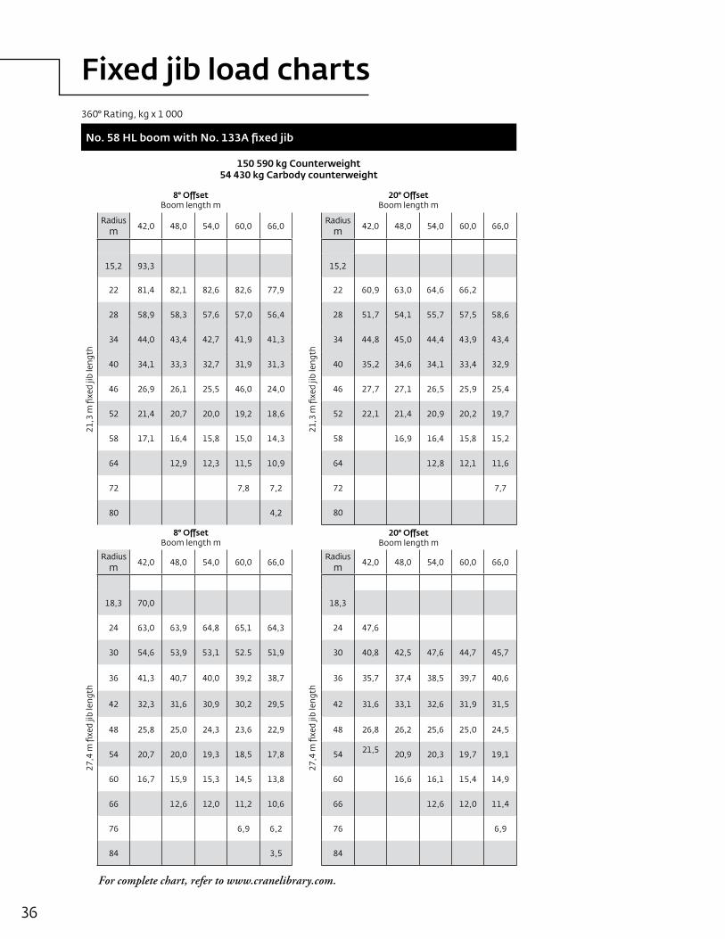
Fixed jib load charts
36
For complete chart, refer to www.cranelibrary.com.
360°Rating,kgx1000
No. 58 HL boom with No. 133A fixed jib
150 590 kg Counterweight 54 430 kg Carbody counterweight
8° OffsetBoomlengthm
20° OffsetBoomlengthm
Radiusm 42,0 48,0 54,0 60,0 66,0
Radiusm 42,0 48,0 54,0 60,0 66,0
21,3mfixedjiblength
15,2 93,3
21,3mfixedjiblength
15,2
22 81,4 82,1 82,6 82,6 77,9 22 60,9 63,0 64,6 66,2
28 58,9 58,3 57,6 57,0 56,4 28 51,7 54,1 55,7 57,5 58,6
34 44,0 43,4 42,7 41,9 41,3 34 44,8 45,0 44,4 43,9 43,4
40 34,1 33,3 32,7 31,9 31,3 40 35,2 34,6 34,1 33,4 32,9
46 26,9 26,1 25,5 46,0 24,0 46 27,7 27,1 26,5 25,9 25,4
52 21,4 20,7 20,0 19,2 18,6 52 22,1 21,4 20,9 20,2 19,7
58 17,1 16,4 15,8 15,0 14,3 58 16,9 16,4 15,8 15,2
64 12,9 12,3 11,5 10,9 64 12,8 12,1 11,6
72 7,8 7,2 72 7,7
80 4,2 80
8° OffsetBoomlengthm
20° OffsetBoomlengthm
Radiusm 42,0 48,0 54,0 60,0 66,0
Radiusm 42,0 48,0 54,0 60,0 66,0
27,4mfixedjiblength
18,3 70,0
27,4mfixedjiblength
18,3
24 63,0 63,9 64,8 65,1 64,3 24 47,6
30 54,6 53,9 53,1 52.5 51,9 30 40,8 42,5 47,6 44,7 45,7
36 41,3 40,7 40,0 39,2 38,7 36 35,7 37,4 38,5 39,7 40,6
42 32,3 31,6 30,9 30,2 29,5 42 31,6 33,1 32,6 31,9 31,5
48 25,8 25,0 24,3 23,6 22,9 48 26,8 26,2 25,6 25,0 24,5
54 20,7 20,0 19,3 18,5 17,8 54 21,5 20,9 20,3 19,7 19,1
60 16,7 15,9 15,3 14,5 13,8 60 16,6 16,1 15,4 14,9
66 12,6 12,0 11,2 10,6 66 12,6 12,0 11,4
76 6,9 6,2 76 6,9
84 3,5 84

Fixed jib load charts
37Manitowoc16000
No. 58 HL boom with No. 133A fixed jib
150 590 kg Counterweight 54 430 kg Carbody counterweight
8° OffsetBoomlengthm
20° OffsetBoomlengthm
Radiusm 42,0 48,0 54,0 60,0 66,0
Radiusm 42,0 48,0 54,0 60,0 66,0
36,6mfixedjiblength
20,0 53,4
36,6mfixedjiblength
20,0
28 45,9 46,6 47,4 47,7 47,7 28 38,2
34 41,3 42,3 43,3 43,7 43,7 34 33,3 34,1 35,0 35,6 36,3
40 35,8 35,1 34,4 33,7 33,1 40 29,4 30,3 31,2 32,1 32,8
46 28,5 27,8 27,1 26,3 25,7 46 26,3 27,3 28,2 28,4 27,8
52 23,0 22,3 21,5 20,8 20,1 52 23,7 23,7 23,1 22,5 21,9
58 18,7 17,9 17,2 16,4 15,8 58 19,7 19,1 18,5 17,9 17,3
64 15,2 14,4 13,7 12,9 12,2 64 16,0 15,4 14,8 14,1 13,6
70 12,3 11.6 10,8 10,1 9,3 70 12,3 11,7 11,0 10,5
80 7,0 6,2 5,5 80 6,9 6,3
88 3,7 88
8° OffsetBoomlengthm
20° OffsetBoomlengthm
Radiusm 42,0 48,0 54,0 60,0
Radiusm 42,0 48,0 54,0 60,0
42,7mfixedjiblength
22,9 43,5
42,7mfixedjiblength
22,9
30 38,0 38,6 39,2 39,5 30
36 34,1 34,9 35,7 36,3 36 27,8 28,4 29,0 29,5
42 30,7 31,7 32,3 31,6 42 24,6 25,3 25,9 26,6
48 26,8 26,3 25,6 24,8 48 21,9 22,7 23,4 24,1
54 21,9 21,2 20,4 19,7 54 19,7 20,6 21,3 21,6
60 17,8 17,1 16,4 15,6 60 17,9 18,5 17,8 17,2
66 14,6 13,8 13,1 12,3 66 15,5 14,9 14,3 13,7
76 10,3 9,5 8,8 8,0 76 10,2 9,7 9,0
84 6,1 5,3 84 6,1
92 92
For complete chart, refer to www.cranelibrary.com.
360°Rating,kgx1000


Manitowoc16000 39
Luffing jib load charts
No. 58 HL boom with No. 59 luffing jib
150 590 kg Counterweight 54 430 kg Carbody counterweight
87° Boom angle
Radiusm
30,0 42,0 54,0 66,0 Radiusm
30,0 42,0 54,0 60,0 Radiusm
30,0 42,0 54,0 60,0
24,0mLuffi
ngjiblength
11,6 185,2
36,0mLuffi
ngjiblength
15,2 136,1 116,8
48,0mLuffi
ngjiblength
18,3 107,4 92,1
14,0 157,7 151,0 117,4 99,6 16,0 131,2 113,3 22,0 91,9 81,6 70,3 66,6
18,0 121.1 112,6 97,8 84,8 18,0 118,9 104,3 89,0 84,5 24,0 81,6 75,6 66,2 62,6
22,0 92,7 92,7 82,2 72,3 22,0 92,3 89,1 77,1 73,3 30,0 61,2 61,0 55,5 52,6
26,0 74,6 73,9 69,5 62,1 26,0 74,4 74,3 67,1 64,0 34,0 52,0 51,8 49,5 47,0
32,0 32,0 57,0 56,9 55,2 52,5 38,0 44,9 44,8 44,4 42,0
38,0 38,0 45,6 45,5 44,8 43,0 42,0 39,3 39,2 39,1 37,6
44,0 44,0 46,0 34,8 34,7 34,5 33,7
52,0 52,0 52,0 27,0
56,0 56,0 56,0
60,0 60,0 60,0
Radiusm
30,0 42,0 54,0 60,0 Radiusm
30,0 42,0 54,0 Radiusm
30,0 42,0 54,0
60,0mLuffi
ngjiblength
21,3 86,0 73,5
72,0mLuffi
ngjiblength
21,3
84,0mLuffi
ngjiblength
21,3
24,0 79,1 69,3 58,2 51,8 24,0 24,0
28,0 65,9 62,1 53,2 49,6 28,0 58.3 51,2 43,1 28,0 42,6 37,9
34,0 51,1 50,9 45,8 43,2 34,0 49.9 48,2 40,6 34,0 40,7 36,7 31,4
40,0 41,1 40,9 39,4 37,2 40,0 40.0 39,8 36,3 40,0 38,7 35,4 30,0
48,0 31,9 31,8 31,7 30,4 48,0 30.9 30.7 30.3 48,0 29,8 29,6 26,4
56,0 25,6 25,5 35,3 24,9 56,0 24.5 24.4 24.2 56,0 23,4 23,3 22,7
64,0 18,4 18,3 18,2 18,1 64,0 19.8 19.7 19.5 64,0 18,8 18,6 18,5
72,0 72,0 16.1 15,7 15,2 72,0 15,2 15,1 14,9
84,0 84,0 84,0 10,6 9,6 9,1
88,0 88,0 88,0 6,8 6,6
For complete chart, refer to www.cranelibrary.com.
Boomlengthm Boomlengthm Boomlengthm
Boomlengthm Boomlengthm Boomlengthm
360°Rating,kgx1000

40
Luffing jib load charts
No. 58 HL boom with No. 59 luffing jib
150 590 kg Counterweight 54 430 kg Carbody counterweight
75° Boom angle
Radiusm
30,0 42,0 54,0 66,0 Radiusm
30,0 42,0 54,0 60,0 Radiusm
30,0 42,0 54,0 60,0
24,0mLuffi
ngjiblength
24,0 75,636,0mLuffi
ngjiblength
24,0
48,0mLuffi
ngjiblength
34,0 46,4
26,0 68,1 65,0 26,0 36,0 43,0
28,0 61,9 59,1 28,0 61,1 38,0 40,0 37,6
32,0 52,1 49,7 46,9 43,5 32,0 51,4 48,7 40,0 37,3 35,1 32,6
36,0 42,5 40,2 37,2 36,0 44,0 41,7 39,1 42,0 34,9 32,9 30,5 29,1
38,0 37,3 32,3 38,0 41,0 38,9 36,3 34,9 44,0 32,8 30,8 28,5 27,2
42,0 30,2 42,0 35,9 34,0 31,8 30,4 46,0 30,8 29,0 26,8 25,6
46,0 46,0 30,0 28,0 26,8 50,0 27,4 25,7 23,7 22,6
52,0 52,0 22,4 56,0 23,2 21,7 20,0 19,0
54,0 54,0 60,0 19,5 17,9 17,0
56,0 56,0 64,0 16,0 15,2
Radiusm
30,0 42,0 54,0 60,0 Radiusm
30,0 42,0 48,0 Radiusm
30,0
60,0mLuffi
ngjiblength
40,0 36,1
72,0mLuffi
ngjiblength
40,0
84,0mLuffi
ngjiblength
40,0
44,0 31,6 29,6 44,0 44,0
48,0 27,9 26,0 23,9 22,7 48,0 26,6 24,7 48,0
54,0 23,5 21,8 19,9 18,8 54,0 22,2 20,5 19,5 54,0 21,0
60,0 19,9 18,4 16,8 15,8 60,0 18,7 17,1 16,3 60,0 17,5
66,0 17,0 15,7 14,2 13,3 66,0 15,9 14,5 13,6 66,0 14,7
72,0 13,4 12,0 11,3 72,0 13,5 12,2 11,5 72,0 12,3
76,0 10,7 10,0 76,0 12,1 10,9 10,3 76,0 11,0
80,0 80,0 9,8 9,1 80,0 9,8
84,0 84,0 8,7 8,1 84,0 8,7
88,0 88,0 88,0 7,7
For complete chart, refer to www.cranelibrary.com.
Boomlengthm
Boomlengthm
Boomlengthm(ft)
Boomlengthm
Boomlengthm
Boomlengthm
360°Rating,kgx1000

Manitowoc16000 41
Luffing jib load charts
No. 58 HL boom with No. 59 luffing jib
150 590 kg Counterweight 54 430 kg Carbody counterweight
65° Boom angle
Radiusm
30,0 42,0 54,0 66,0 Radiusm
30,0 42,0 54,0 60,0 Radiusm
30,0 42,0 54,0
24,0mLuffi
ngjiblength
32,0 47,9
36,0mLuffi
ngjiblength
32,0
48,0mLuffi
ngjiblength
32,0
36,0 41,0 36,0 36,0
40,0 61,9 32,4 40,0 34,8 40,0
44,0 28,2 25,0 44,0 30,6 27,4 44,0
48,0 21,9 18,5 48,0 27,0 24,2 48,0 26,0
52,0 16,2 52,0 21,5 18,4 16,6 52,0 23,1 20,3
56,0 54,0 20,3 17,4 15,7 54,0 21,9 19,1
60,0 60,0 14,6 13,1 60,0 18,5 16,2 13,3
62,0 62,0 12,3 62,0 17,5 15,3 12,6
68,0 68,0 68,0 10,6
72,0 72,0 72,0 9,3
Radiusm
30,0 42,0 Radiusm
30,0
60,0mLuffi
ngjiblength
54,0 20,6
72,0mLuffi
ngjiblength
54,0
56,0 19,5 56,0
58,0 18,4 15,7 58,0
60,0 17,4 14,8 60,0 16,1
64,0 15,6 13,2 64,0 14,3
68,0 14,0 11,8 68,0 12,7
72,0 12,6 10,5 72,0 11,3
74,0 11,8 9,9 74,0 10,7
76,0 9,3 76,0 10,1
80,0 80,0 9,0
84,0 84,0 7,9
For complete chart, refer to www.cranelibrary.com.
BoomlengthmBoomlengthm Boomlengthm
Boomlengthm
Boomlengthm
360°Rating,kgx1000

42
Outline dimensionsMAX-ER®

43Manitowoc16000
Outline dimensionsMAX-ER®
Wheeled carrier (US)Length 8,15mWidth 3,05mHeight 3,00mWeight 28304kg
Wheeled carrier (European)Length 8,15mWidth 2,98mHeight 3,00mWeight 28622kg
Lifting frame and telescopic beamLength 6,04mWidth 2,73mHeight 2,99mWeight 16828kg
H
L
W
W
H
L
H
L
W

44
Outline dimensionsMAX-ER®
Side counterweightLength 3,59mWidth 2,72mHeight 0,69mWeight 13608kg
Side counterweightLength 3,59mWidth 2,72mHeight 0,78mWeight 19958kg
No. 59A mast butt and top package, drum, wire rope, equilizerLength 14,84mWidth 2,99mHeight 2,66mWeight 20593kg
H
L
W
H
L
W
L
H

45Manitowoc16000
Outline dimensionsMAX-ER®
12 m No. 59A mast insertLength 12,19mWidth 2,72mHeight 2,23mWeight 4375kg
6 m No. 59A mast insertLength 6,19mWidth 2,72mHeight 2,29mWeight 3366kg
12 m No. 58 heavy boom insert with equiliizer railsLength 12,19mWidth 2,98mHeight 2,67mWeight 4602kg
12 m No. 58 heavy boom insertLength 12,19mWidth 2,98mHeight 2,67mWeight 5087kg
L
H
L
H
L
H
L
H


48
Boom range diagram with Mast
No. 58 HL boom with 30,0 m No.59A mast
HE
IGH
T A
BO
VE
GR
OU
ND
(ME
TER
S)
DISTANCE FROM CENTERLINE OF ROTATION (METERS)
12.2
18.3
24.4
30.5
36.6
42.7
48.8
54.9
61.0
67.1
73.2
18.3
21.3
24.4
27.4
30.5
33.5
36.6
39.6
42.7
45.7
48.8
51.8
54.9
57.9
61.0
64.0
67.1
70.1
73.2
76.2
79.2
82.3
85.3
88.4
91.4
94.5
97.5
100.6
103.6
106.7
MASTTAILSWING
11.19m
COUNTERWEIGHTTAILSWING
2.67m
8.24m 1.52m
ROTATION
NO.58HLBOOM
83˚
80˚
70˚
60˚
50˚
40˚
30˚
96m
90m
84m
78m
72m
66m
60m
54m
48m
42m

49Manitowoc16000
Boom load charts with Mast
No. 58 HL boom with 30,0 m No.59A mast
150 590 kg Counterweight 54 430 kg Carbody counterweight
Radiusm
42,0 48,0 54,0 60,0 66,0 72,0 78,0 84,0 90,0 96,0
8,0 332,1
12,0 215,4 215,7 215,5 215,3 215,4 215,1
16,0 140,0 140,1 140,0 139,7 139,8 139,4 139,2 138,8 138,9 126,9
20,0 101,7 101,6 101,3 101,0 101,0 100,5 100,2 99,7 99,4 98,9
24,0 78,4 78,2 77,9 77,5 77,4 76,9 76,5 75,9 75,7 75,0
28,0 62,7 62,5 62,2 61,7 61,7 61,1 60,7 60,1 59,7 59,0
32,0 51,5 51,2 50,9 50,4 50,3 49,7 49,3 48,6 48,3 47,5
36,0 43,0 42,7 42,3 41,8 41,7 41,1 40,7 40,0 39,7 38.9
40,0 36,3 36,0 35,7 35,1 35,1 34,4 34,0 33,3 32,9 32,2
44,0 30,7 30,3 29,8 29,7 29,1 28,6 27,9 27,6 26,8
48,0 25,8 25,3 25,3 24,7 24,2 23,5 23,1 22,4
52,0 22,1 21,7 21,6 20,9 20,5 19,8 19,4 18,6
56,0 18,5 18,4 17,8 17,3 16,7 16,3 15,5
60,0 15,7 15,1 14,6 13,9 13,6 12,7
64,0 13,2 12,7 12,2 11,6 11,2 10,4
70,0 9,6 9,2 8,5 8,2 7,2
80,0 3,7
Boomlengthm
360°Rating,kgx1000


Extended upper boom point load charts
51Manitowoc16000
No. 58 HL boom with 30,0 No. 59A mast and 7,0 m extended upper boom point
Radiusm
150 590 kg Counterweight 54 430 kg Carbody counterweight
Boomlengthm
96,0
18,3 81,5
20,0 81,5
22,0 81,5
24,0 78,4
26,0 70,2
30,0 56,3
32,0 50,9
34,0 46,1
36,0 41,9
38,0 38,3
42,0 32,0
46,0 27,0
50,0 22,8
54,0 19,3
58,0 16,3
62,0 13,6
64,0 12,5
66,0 11,4
70,0 9,3
72,0 8,4
74,0 7,5
78,0 5,6
80,0 4,6
82,0 3,8
For complete chart, refer to www.cranelibrary.com.
360°Rating,kgx1000


53Manitowoc16000
MAX-ER® load charts
MAX-ER at 15 m position No. 58 HL boom with 30,0 m No.59A mast
150 590 kg Counterweight 54 430 kg Carbody counterweight 231 970 kg Wheeled counterweight
Boomlengthm
Radiusm
42,0 48,0 54,0 60,0 66,0 72,0 78,0 84,0 90,0 96,0 102,0 108,0 114,0 120,0
7,9 379,8
10,0 379,8 340,0 312,2
12,0 379,8 340,0 311,4 282,4 251,1 227,8
14,0 361,9 338,1 310,6 277,8 250,4 225,2 203,5 177,0 148,4
18,0 278,9 278,4 279,5 267,1 241,4 217,8 198,9 177,0 148,4 126,9 107,8 92,9 79,7
20,0 250,4 249,8 249,2 248,8 236,9 214,2 196,6 176,8 148,4 126,9 107,8 92,9 79,5 68,8
24,0 207,1 206,6 206,0 205,2 205,0 203,4 192,2 170,4 145,3 126,9 107,6 92,7 79,3 68,6
30,0 163,3 162,8 162,2 161,5 161,3 160,5 159,9 158,7 137,0 126,6 106,5 91,0 77,6 67,1
36,0 133,8 133,3 132,7 132,1 131,8 131,0 130,5 129,6 128,5 124,1 104,2 89,0 75,7 65,0
42,0 112,1 115,5 110,8 110,6 109,8 109,3 108,5 108,0 107.1 102,0 87,0 73,9 61,1
48,0 95,4 94,8 94,6 93,9 93,3 92,5 92,1 91,1 90,6 84,9 72,1 57,6
54,0 82,2 82,1 81,4 80,8 80,0 79,6 78,7 78,1 77,3 70,2 54,0
60,0 71,8 71,1 70,6 69,9 69,5 68,6 68,1 67,3 66,8 50,4
66,0 62,7 62,2 61,4 61,1 60,2 59,7 58,9 58,3 46,8
74,0 53,1 52,3 52,0 51,1 50,6 49,8 49,3 42,1
80,0 46,6 46,3 45,5 45,0 44,2 43,7 38,5
84,0 43,0 42,2 41,7 40,9 40,4 36,6
96,0 33,4 32,6 32,1 31,1
100,0 30,3 29,8 28,8
108,0 16,8 23,9
112,0 21,6
116,0 17,8
For complete chart, refer to www.cranelibrary.com.
360°Rating,kgx1000


55Manitowoc16000
Luffing jib load charts MAX-ER®
MAX-ER at 15 m position No. 58 HL boom with No. 59 luffing jib
150 590 kg Counterweight 54 430 kg Carbody counterweight 231 970 kg Wheeled counterweight
86° Boom angle
Radiusm 42,0 60,0 78,0 96,0
Radiusm 42,0 60,0 78,0 96,0
Radiusm 42,0 60,0 78,0 96,0
24,0mLuffi
ngjiblength
13,7 185,4 146,836,0mLuffi
ngjiblength
18,0 139,7
48,0mLuffi
ngjiblength
20,0 115,5
14,0 181,7 129,8 20,0 124,2 111,3 76,4 22,0 111,7 85,3
16,0 156,7 117,1 24,0 101,2 94,7 68,7 47,4 26,0 94,5 77,2 54,9 38,1
18,0 137,6 107,2 98,6 62,2 26,0 93,0 87,6 64,7 46,0 30,0 80,1 68,3 49,8 35,5
20,0 123,4 99,3 92,6 60,5 28,0 86,2 81,6 60,8 43,7 34,0 70,1 59,8 44,7 32,4
22,0 112,3 96,4 86,5 59,0 32,0 75,9 70,2 53,5 39,4 38,0 62,7 52,1 39,9 29,4
24,0 103,8 89,4 80,7 57,2 34,0 72,2 64,9 50,2 37,4 42,0 55,9 45,5 35,6 26,7
26,0 97,4 79,1 75,3 54,3 36,0 69,1 60,3 47,3 35,6 46,0 48,5 40,1 32,1 24,4
28,0 89,8 70,8 51,5 38,0 65,8 56,4 44,8 33,9 50,0 42,9 36,0 29,2 22,5
30,0 67,4 49,2 42,0 41,3 31,4 54,0 27,6 21,2
32,0 47,0 44,0 30,9 56,0 21,1
Radiusm 42,0 60,0 78,0 96,0
Radiusm 42,0 60,0 78,0 96,0
Radiusm 42,0 60,0 78,0 96,0
60,0mLuffi
ngjiblength
24,0 79,7
72,0mLuffi
ngjiblength
28,0 55,4 46,9
84,0mLuffi
ngjiblength
32,0 39,4
28,0 78,3 61,0 43,8 30,1 32,0 54,5 46,0 33,6 23,5 38,0 38,0 33,6 25,1 17,4
32,0 71,4 55,8 40,6 28,7 38,0 51,6 41,3 30,4 21,4 44,0 36,7 30,9 22,9 15,9
38,0 60,5 47,7 35,4 25,4 44,0 45,4 36,2 27,0 19,2 50,0 34,3 27,7 20,6 14,3
42,0 53,5 42,6 32,1 23,4 50,0 39,3 31,4 23,7 17,0 56,0 30,5 24,6 18,4 12,8
46,0 47,2 37,9 29,0 21,4 54,0 35,6 28,5 21,7 15,6 62,0 27,1 21,7 16,3 11,3
50,0 41,7 33,8 26,3 19,6 58,0 32,1 25,8 19,9 14,4 68,0 23,9 19,2 14,6 10,1
56,0 35,0 28,7 22,9 17,3 64,0 27,8 22,5 17,5 12,8 74,0 21,3 17,0 13,0 9,1
60,0 31,5 26,2 21,1 16,1 70,0 24,3 19,9 15,7 11,6 80,0 18,2 15,3 11,8 8,3
64,0 27,0 24,4 19,9 15,2 76,0 21,6 18,2 14,6 10,8 86,0 14,5 14,1 11,1 7,7
68,0 14,9 80,0 10,7 92,0 7,5
For complete chart, refer to www.cranelibrary.com.
Boomlengthm
Boomlengthm
Boomlengthm
Boomlengthm
Boomlengthm
Boomlengthm
360°Rating,kgx1000

56
Manitowoc Crane CareManitowoc Crane Care is the industry’s most advanced service and support program, designed to keep your cranes up and running. Manitowoc’s distributor network and customer support personnel are available to support you 24 hours a day, 7 days a week, 365 days a year. There are five key disciplines of Manitowoc Crane Care:
PartsGenuine Manitowoc replacement parts are accessible through your distributor.
Service and technical supportAssistance with crane selection, lift planning and ground bearing calculations or field service and maintenance.
Technical publicationsOperator, parts, service and capacity chart manuals are available in multiple formats in major languages.
TrainingA variety of training courses are available online or through Manitowoc training centers.
EnCORERebuild, repair, remanufacture or exchange your current crane through our local network, for a fraction of the cost of a new crane.
www.manitowoccranecare.com
CraneSTAR is an exclusive and innovative crane asset management system that helps improve your profitability and reduce costs by remotely monitoring critical crane data. Visit www.cranestar.com for more information.

Manitowoc16000 57
Notes


©2013Manitowoc0413-16000PG-US-E
This document is non-contractual. Constant improvement and engineering progress make it necessary that we reserve the right to make specification, equipment, and price changes without notice. Illustrations shown may include optional equipment and accessories and may not include all standard equipment.
Regional offices
ChinaShanghai, China Tel:+862164570066Fax:+862164574955
Greater Asia-Pacific Singapore Tel:+6562641188Fax:+6568624040
Europe, Middle East, Africa Ecully, France Tel:+33(0)472182020Fax:+33(0)472182000
Americas Manitowoc, Wisconsin, USA Tel:+19206846621Fax:+19206836277
Shady Grove, Pennsylvania, USA Tel:+17175978121Fax:+17175974062
Regional headquarters
Manitowoc Cranes
ChinaBeijingChengduGuangzhouXian
Greater Asia-PacificAustraliaBrisbaneMelbourneSydneyIndiaChennaiDelhiHyderabadPuneKoreaSeoulPhilippinesMakatiCitySingapore
FactoriesBrazilPassoFundoChinaTaiAnZhangjiagangFranceCharlieuMoulinsGermanyWilhelmshavenIndiaPuneItalyNiellaTanaroPortugalBaltarFânzeresSlovakiaSarisUSAManitowocPortWashingtonShadyGrove
AmericasBrazilAlphavilleMexicoMonterreyChileSantiago
Europe, Middle East, AfricaFranceBaudemontCergyDecinesGermanyLangenfeldItalyLainateNetherlandsBredaPolandWarsawPortugalBaltarRussiaMoscowSouth AfricaJohannesburgU.A.E.DubaiU.K.Buckingham
www.manitowoccranes.com
Related Documents