16 Liquid Level Control 16.1 INTRODUCTION f or distillation columns level control refers, in most cases, to overhead condenser receivers (reflux accumulators), column bases, surge or feed tanks, and sometimes steam condensate receivers. For most of these applications, the chief function is not that of holding level constant, but rather of achieving the smoothest possible transitions in manipulated flows in response to disturbances. This is “averaging” level control.’ As stated in Chapter 1, the b c t i o n s of averaging level control are: 1. Balancing inflows against outflows at a point in a process. 2. Providing for smooth and gradual changes in manipulated flows to avoid upsetting process equipment. 3. Maintaining inventory or accumulation between an upper and a lower limit (not at a fixed value). On new projects the engineer is confronted with two alternatives: (1) the tank or holdup size is already specified and the problem is to get maximum flow smoothing, or (2) the tank is to be sized and the level control system designed to achieve flow smoothing adequate for downstream composition controls. For the latter we make rH 3 10/wR, where wR is downstream closed- loop resonant fi-equency, radians/minute. Before getting into specific applications of level control on distillation columns, let us review briefly the theory of averaging level control on simple vessels. 16.2 LEVEL CONTROL OF SIMPLE VESSELS For a simple vessel such as &own in Figure 16.1 where the level is controlled by outflow and there is no sipficant level self-regulation effect, we need only a few equations: 375

Welcome message from author
This document is posted to help you gain knowledge. Please leave a comment to let me know what you think about it! Share it to your friends and learn new things together.
Transcript

16 Liquid Level Control
16.1 INTRODUCTION
f or distillation columns level control refers, in most cases, to overhead condenser receivers (reflux accumulators), column bases, surge or feed tanks, and sometimes steam condensate receivers. For most of these applications, the chief function is not that of holding level constant, but rather of achieving the smoothest possible transitions in manipulated flows in response to disturbances. This is “averaging” level control.’
As stated in Chapter 1, the bc t ions of averaging level control are:
1. Balancing inflows against outflows at a point in a process. 2. Providing for smooth and gradual changes in manipulated flows to avoid
upsetting process equipment. 3. Maintaining inventory or accumulation between an upper and a lower
limit (not at a fixed value).
On new projects the engineer is confronted with two alternatives: (1) the tank or holdup size is already specified and the problem is to get maximum flow smoothing, or (2) the tank is to be sized and the level control system designed to achieve flow smoothing adequate for downstream composition controls. For the latter we make rH 3 10/wR, where wR is downstream closed- loop resonant fi-equency, radians/minute.
Before getting into specific applications of level control on distillation columns, let us review briefly the theory of averaging level control on simple vessels.
16.2 LEVEL CONTROL OF SIMPLE VESSELS For a simple vessel such as &own in Figure 16.1 where the level is controlled
by outflow and there is no sipficant level self-regulation effect, we need only a few equations:
375

376 Ltquid Lmel Control
(16.1)
&PI&) = L b H ( s ) (16.2) (16.3)
Q ~ J ) = 4 2 0 de, 64s) (16.4)
Q4s) - Q4-t) = H($) As
e,(s) = K& G&(s) x ed(4
where = inflow, fi3/min = outflow, fi3/min = vessel cross-sectional area, fi? (vertical, cylindrical vessel
Ql a A
H = liquid level, feet k b = level transmitter output signal L b = 12 psi/AHT for pneumatics MH, = level transmitter input span, feet of process fluid Kd G&) = controller transfer hc t ion 0, = controller output signal
a / d 8 , = valve gain, or flow control loop gain, - (see &scussions in Sections 3.9 and 4.7)
assumed)
fi3/min psi
For a cascade level-flow system:
e o = 1 d c L f
where K* = flow measurement gain of linear flow meter
= ($3
FIGURE 16.1 Level control of simple vessel

16.2 Level Control of Simple Vesseh 377
where
m],,, = maximum flow of flow-meter span, ft3/min The analysis employed here is further simplified in that the effects of variable
Equations (16.1) through (16.4) may be combined into the signal flow valve-pressure drop are omitted, as are transmitter dynamics.
diagram of Figure 16.2, from which we may write by inspection:
and
(16.5)
(16.6)
Proportional-Only Control
For this case Kch Gch(s) becomes simply Kch. Then equation (16.5) becomes:
(16.7)
and equation (16.6) becomes:
If the input span of the valve positioner is the same as the transmitter output span (as, for example, 3-15 psig), and if the valve has an installed linear flow characteristic with a wide-open capacity approximately equal to four times flowsheet flow, GS, then:
A M T - - TH (16.9) - - A - - A
4 0 4Q3 Kch QFS
K J c h d B , [&h [TI This last equation is very useful for finding the desired holdup, A AHT,
provided a value of rH is specified. Usually we choose Kch = 2 and bias the

Liquid Level Gm
ml
378
E % z? E 9 f &
c, C
I
8
Q)
I
4
- E VI
L
g E E
NU
W=
Gii
- P $B 5
5
urn

16.2 Level Conh.01 @Sample Vesseh 379
proportional controller so that the tank level is midscale on the level transmitter. This leaves the top 25 percent of the transmitter span for overrides. Then:
A AHT = v~ = THK* (4%~) (16.9a) = STWQFS (16.9b)
For level control cascaded to flow control:
A AHT = VT = THKch (Qo)rnax (16.9~)
Proportional-Reset Control
Although the proportional-only control system is simple, inexpensive, and almost foolproof (at least when implemented with fixed-gain relays), it has limitations:
1. If tank size is specified, the flow smoothing is limited by rH because one cannot safely use Kch < 1.
2. Because mechanics ofien do not calibrate valves precisely, use of Kch = 1 is risky; the valve may not be closed when the level is at zero. Consequently we usually specify KA = 2.
3. If tank size is not specified but is to be calculated from equation (16.9a) or (16.9c), a large tank will be required since for a given rH, VT is proportional
Although in theory there exists a number of controllers that permit one to use Kd < 1, the PI controller has been most popular. Since the unenhanced PI controller with Kch < 1 does not ensure that the tank will not run dry or oveiflow, past practice has been to have high and low alarms or high and low interlocks. In recent years, however, the PI controller enhanced or augmented with auto overrides has provided an almost foolproof way of keeping liquid within the vessel. It provides, under most circumstances, much more flow smoothing for a given size vessel than will a proportional-only controller.”
Before exploring the theory, let us make some additional design assumptions:
1. Nozzle-to-nozzle spacing is so chosen that process operation will be satisfactory with the level at any location between the nozzles. “Nozzles” here refers to &ose used for connecting the level-measuring device to the vessel.
2. Normal set point for the PI level controller is midscale of level transmitter span, that is, m T / 2 . This is required for proper functioning of the auto overrides. Note that the level transmitter span is usually less than the nozzle- to-node spacing. This allows for some variation in liquid specific gravity.
3. Level control is cascaded to flow control. With floating pressure columns and with the trend toward small control-valve pressure drops for energy con- servation, this is virtually mandatory to counteract the effect of control valve up- and downstream pressure variations. The flow measurement must be linear; if an orifice flow meter is used, it must be followed by a square-root extractor.
to Kd.
380 Liquid Level Control
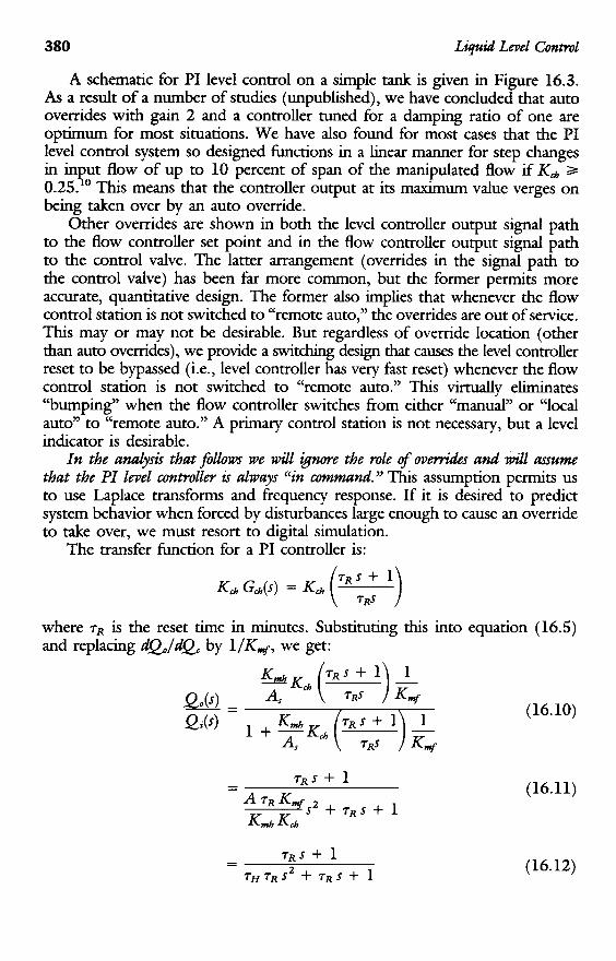
A schematic for PI level control on a simple tank is given in Figure 16.3. As a result of a number of studies (unpublished), we have concluded that auto overrides with gain 2 and a controller tuned for a damping ratio of one are optimum for most situations. We have also found for most cases that the PI level control system so designed functions in a h e a r manner for step changes in in ut flow of up to 10 percent of span of the manipulated flow if Kub 3 0.25. This means that the controller output at its maximum value verges on being taken over by an auto override.
Other overrides are shown in both the level controller output signal path to the flow controller set point and in the flow controller output signal path to the control valve. The latter arrangement (overrides in the signal path to the control valve) has been far more common, but the former permits more accurate, quantitative design. The former also implies that whenever the flow control station is not switched to “remote auto,” the overrides are out of service. This may or may not be desirable. But regardless of override location (other than auto Overrides), we provide a switching design that causes the level controller reset to be bypassed (i.e., level controller has very fast reset) whenever the flow control station is not switched to “remote auto.” This virtually eliminates “bumping” when the flow controller switches fi-om either “manual” or “local auto” to “remote auto.” A primary control station is not necessary, but a level indicator is desirable.
In the a d y s S that f i l h we will & w e the role of ovevrides and will assume that the PI level controller is always “in mmund.” This assumption permits us to use Laplace transforms and frequency response. If it is desired to predict system behavior when forced by disturbances large enough to cause an override to take over, we must resort to digital simulation.
The transfer function for a PI controller is:
Po
where rR is the reset time in minutes. Substituting this into equation (16.5) and replacing aQ,/QC by 1/K4, we get:
K-,
?-as+ 1
(16.10)
(16.11)
(16.12)

16.2 Level Control ofsimple Vessels 381
Similarly, from equation (16.6) :
(16.13)
Now the denominator of equations (16.12) and (16.13) has some interesting characteristics not widely appreciated. It is a quadratic whose damping ratio is :
or TR = 4 t2 TH
Let us also define:
(16.14a)
(16.15)
(16.15a)
From equations (16.14) and (16.15) we can see that if TR is fixed, then as
1. The damping ratio, 5, approaches zero and the control loop becomes
2. TQ becomes very large.
The loop therefore becomes slower and less stable at the same time. This resonance is sometimes called a “reset cycle” since it would not exist if the controller did not have automatic reset.
E, on the other hand, one increases Kd, while holding TR constant, TQ becomes small, transmitter and valve dynamics become sigdicant, and the loop eventually becomes unstable. This is commonly called a “gain cycle” since it is caused by excess gain. Since the loop approaches instability for both very large and very small values of Kch, we say that it is umdzthnahy stable.
In desigmng a level control system with a proportional-reset controller several practical considerations must be kept in mind:
1. The damping ratio preferably should be at least unity. A low damping ratio, as shown by equations (16.12) and (16.13), causes severe peaking in the frequency response in the vicinity of the closed-loop natural frequency, l / ~ ~ Flow and level regulation in that frequency range will be very poor.
2. Adjacent or related process controls must be designed with closed-loop natural frequencies much different from that of the level control; usually they are designed to be much faster.
one decreases Kch two things happen:
very resonant, approaching instability.

382 Liquid Level control
3. For a given dampmg ratio, reset time must be increased as Koh is decreased. It frequently happens that for a desired and specified ICd, one cannot readily obtain the necessary rR with a particular commercial controller. The major instrument manufacturers can usually furnish modification kits or modified controllers with a larger rR.
For 5 = 1 it can be seen from equation (16.14a) that:
TR = 4 TH (16.16)
and TQ = 2 TH = 7 R / 2 (16.17)
(16.18) and
TQ = 4 TH = TR/4 (16.19)
One of the major disadvantages of PI controllers for liquid level is that they always cause the manipulated flow change temporarily to be greater than the disturbance flow change. For example, if the system we have been considering is subjected to a step change in inflow, we obtain the following:
(AQo)m = 1.38 for 5 = 0.4 AQi
= 1.14 for5 = 1.0 = 1.048 for5 = 2.0
The fact that the outflow swings more than the inflow can create serious problems if the process is running close to capacity. For such applications we should choose 6 = 2.0 or use a proportional-only controller. For most other applications, 5 = 1 should suffice and places less of a burden on available controller settings.
At this point it may be appropriate to note that a viable alternative to PI level control is PL level ~ o n t r o l . ~ ’ ~ It has transfer functions very similar to those of the PI level control; for a damping ratio of unity, the transfer functions are identical if one reduces the PL level controller gain, Kd, by a factor of 2. For Kd < 1, it requires auto overrides just as the PI controller does. It has the feature, useful in some circumstances, of not needing antireset windup. It is not a standard commercial item but usually can be assembled with various standard devices.
Augmented PI Controllers
A plain PI controller, even if tuned for 5 = 1, cannot guarantee that level will be held within the vessel. To protect upper and lower permissible level limits, we have found two approaches useful:

16.2 Level Control ofsimple Vmek 383
1. Auto overrides for pneumatics. When the level becomes too hgh or too low, a propomonal-only controller (usually a fixed-gain relay) takes over through a high- or low-selector.2 As shown by Figure 16.3, the high-level gain 2 auto override is so biased that its output is 3.0 psig when the input (level transmitter signal) is 9.0 psig. Then its output is 15.0 psig when its input is 15 psig. Correspondingly the low-level gain 2 auto override is so biased that when the input is 9.0 psig, its output is 15 psig; if its input goes down to 3.0 psig (zero level), its output is also 3.0 psig.
2. Nonlinear PI controllers for electronic^.^ A preferred version has long reset time and a s d ICd in the vicinity of the set point. As the level deviates signhcantly from set p i n & Kd increases and TR decreases. Although in theory this is not quite as foolproof as auto overrides, our studies show that it rarely permits excessive deviations of level, and then only by a small amount. This design does not provide flow smoothing quite as good as that of the PI plus override scheme. This is so because manipulated flow changes more rapidly so that level moves away from the top or bottom of the tank more quickly.
Effect of Installed Valve Flow Characteristic
If the PI level control system (or proportional-only) is not a cascade level- flow system, then it is desirable to have a control valve with a linear installed flow characteristic, that is, t Q / d 8 , = constant. Then control-loop dynamics would be independent of flow rate and
where (ep), is the flow through the valve in its wide-open position.
15.1, reference 1: If the valve has an equal-percentage installed characteristic, then from Table
@o = eo kEP 12
Since kEp = 3.9 for a 50:l equal-percentage value (kEp = In a where a = 50):
Referring to equation (16.14), we see that if a controller is set up correctly
a. 4 = 0.7 whenQ, = (eFs/2), and b. 5 = 1.4 whenQ, = 2Gs Thus we see that, with an equal-percentage installed flow characteristic, the
relative stability is decreased at low flow and increased at high flow. For this case it is best to find controller settings for 5 = 1 at the minimum expected flow.
with 5 = 1 a t e = Gs, then:

3%
Liquid Level Control - 0
C
s 8 g 8 G
0
c1
5 s e v
g
S8
v)
I
W’
5g E:

16.2 Level Control of Simple Vessels 385
If pump and valve curves are available, and if the hydraulic resistance and static heads of the process equipment are known, we can usually calculate the installed flow characteristic. Alternatively, with permission from production supervision, we can experimentally make a plot of valve loading signal versus flow. The slope of this curve at average rate a is aQJaYlC.
For a cascade level-flow system, the control-valve installed-flow characteristic should also be linear.’
Auto-Override Time Constant
For large swings in the disturbance flow that will drive the level far enough that one of the auto overrides takes effect, the system temporarily will be under control of the proportional-only auto override. In this regime it is not absolutely necessary that control be stable; the auto override will drive the system back into the linear, stable r e p e . The proportional-only auto-override control system has the characteristic time constant:
A AHT [THIOR = KOR (Qo)rnax
To date we have been unable to come up with a truly rational way of specifying the desired numerical value of [T&R. On the basis of experience, we suggest that it not be less than one minute. For some applications a much larger value will be desirable.
Tuning Procedure for PI Controller
From the preceding it may be apparent that to get maximum flow smoothing with a gven commercial controller and specified damping ratio, the e n p e e r will be constrained by either [&,Imin or [TR],, of that controller. To find out which, and to determine [K&]d=,gn or [TR]d=ign, the following procedure is suggested:
1. Let [&I,, = 0.25 (see reference 10). This is larger than the minimum available gain of any commercial controller with whch we are familiar.
2. If
choose
[TRIdesign = [TRImax
and find

386
3. If
Liquid Level Control
choose
and find
4. If
and
16.3 LEVEL CONTROL OF OVERHEAD CONDENSER RECEIVER VIA TOP-PRODUCT WITHDRAWAL
Ordinarily this is a simple system to design since it almost always fits the preceding analysis. Chapter 3, Section 9, discusses some of the practical details. For proportional-only control, one should make TH 1 2 minutes; for a PI controller, one should make TQ I 2 minutes.
16.4 LEVEL CONTROL OF OVERHEAD CONDENSER RECEIVER VIA REFLUX MANIPULATION
For this application it is necessary to take reflux subcooling into account. It is also more convenient to use weight units. The amount of vapor condensed in the column by cold reflux is:
where wR = external reflux flow, Ibm/min cp = reflux specific heat, pcu/lbm "C To = vapor condensing temperature, "C T R = external reflux temperature, "C A = vapor latent heat of condensation, pcu/lbm, of process vapor

16.4 Level control of Overhead Gmhmer Receiver Pia Repm Manipulatum 387
Then r 1
(16.20)
(16.21)
(16.22)
where
wt- wc
WD = top-product flow, Ibm/min pL = external reflux density, lbm/ft3 AT = cross-sectional area of tank, f? (vertical cylindrical design assumed)
Strictly speaking we should include condenser dynamics but these usually amount to only a half-minute to a minute lag. The larger TH or TQ is, the less signhcant will be condenser lag. By malung TH 2 5 minutes, we can usually ignore condenser lag.
We may now prepare the signal flow diagram of Figure 16.4 for propomonal- only level control. By inspection we can see that:
= vapor to top tray, Ibm/min = vaporfim top tray to condenser, Ibm/min; also rate of
condensation
1 - fP&) -
1 wt- 1(s) - %(S) [ 1 + (To - TR) 1 I
X (16.23) P L A T + l
Let us now define:
Then
where
(16.24)
(16.25)

388 L
ipid Level Control
c
0
c, m S
c
- - sa - E 3 0 E
E
m >
3 2 E - - c, C
0
0
8
- 5 - CI 0
p.
m 8 cn 8
c,
- 2 s 8 P m
2
U
C
h
C
- - C
0
0
p.
E - B 28 sz L
42 E E
*=
W=
529
LW

16.6 Column-Bme Level Control via Feed F h Manipulatirm 389
Note that rH contains Ksc and is inversely proportional to it. Some idea - of the magnitude of Ksc may be obtained by assuming as an example To - T' = 100°C, A = 100 pcu/lb, and cp = 0.5 pcu/lb"C. Then Ksc = 1.5. Subcooling therefore can have a signhcant effect on TH.
For PI level control we can readily show that:
(16.26)
16.5 COLUMN-BASE LEVEL CONTROL VIA BOITOM-PRODUCT MANIPULATION
This is usually a fairly straightforward system to design since it fits the analysis of Section 16.2. Some of the practical details are discussed in Chapter 4. For most applications one should make rH 2 10 minutes.
16.6 COLUMN-BASE LEVEL CONTROL VIA FEED FLOW MANIPULATION
For this case the simple analysis of Section 16.2 must be extended to take into account the lags between the column feed point and the column base. Let us suppose that there are n trays between these two points and that hydraulic lag of each tray is first order with a time constant rm (see Chapter 13). Typical values are in the range of 3-8 seconds. It has been shown elsewhere (Chapter 12 of reference 1) that a number of equal lags may be approximated by dead time:
= ,-n +m> 1 (rm5 + 1)" (16.27)
Such an approximation simplifies considerably either hand or computer
wl(5) = e-nTms wF(5) (16.28)
calculations. If the feed enters at its boiling point, then
and
(16.29)
where wl = flow, Ibm/min, from lowest downcomer into column base; flow due
to reflux or feed change wV = boilup, Ibm/min wB = bottom product, lbm/min

390 Liquid Level control
The equations for the remainder of the system now follow the analysis of Section 16.2. The complete system, level control cascaded to feed flow control, may be represented by the signal flow diagram of Figure 16.5. By inspection we can see that:
wds) - [w&) + tPg(31
Let us next define:
PL AB 5
a = tarm (16.31)
Without going through the mathematics, we will simply state that, by means of Bode and Nichols plots, we found that for well-damped response (Mp = 2 db):
a PLABKWF - - 1 KnIbKJ, KL
- =-H=
and U, = 0.25 = a o R
where
u, = closed-loop resonant frequency, dimensionless (wR) = closed-loop resonant frequency, rad/&
(16.32)
(16.32a)
Equation (16.32) defines a minimum value of rH; for greater stability and
For PI control choose: filtering one may use larger values of rH.
= 20a 1 (0.25/a) T R Z 5 x (16.33)
The level and inflow responses to a step change in outflow of an averaging level control system with dead time and a PI controller tuned as recommended above are given in Figure 16.6.
Recently we have done some work (unpublished) that suggests that incor- poration of a Smith predictors.9 would help greatly.
16.7 COLUMN-BASE LEVEL CONTROL CASCADED TO STEAM FLOW CONTROL
Ordinarily it is satisfactory to use liquid level as a measure of inventory. In the case of distillation columns, however, this measurement is ambiguous to some extent. The levels in the overhead condensate receiver and in the column

16.7 Colum
n-Bme Level G
mm
l Cm
dd
to Steam F
h Conm
l 391
c
0
c, m
=I a
c
- - - E g b:
3! e 2 s! 3 2 8 3
9
2 x m L
- - c, c 0
0
- 8
- z 3 - C
m c 0
- g - F Ljg 53 L
42 E e n"
a=
2s b
m

392 Liquid Lm
ei Gm
mi 3 s & 5 0
3
0
C
- e m
t - i!! 0
+r
*r
2 :
g
'c
z 3 E 6
e 8 8 - +r
C
- - f - F E 2%
SJ
cn E ii: rn
-a3 WE
ao
3a

16.7 Column-Base Level Contvol Cascaded to Steam Flow Control 393
base do not accurately reflect either total column inventory or inventory changes. Put another way, level changes can occur that do not result from inventory changes. So far we have ignored these, but they can be very important when base level is controlled by throttling heating-medium flow.
Thermosyphon Reboiler Swell
In Chapter 4 it was mentioned that two factors can affect the volumetric percent vapor in the tubes and thereby cause a liquid displacement or “swell” in the column base.
A. Heat Load For a constant liquid level in the column base, as heat load increases, percent
vapor in the tubes increases. The effect is most marked at low heat loads. At a given operating point:
V,(s) = kd ~ S T ( 4 (16.34)
where
V , = change in tube vapor volume in tubes, fi3, due to heat load change
wsT = steam flow, lbm/min = change in liquid volume in column base, fi3, due to heat load change
B. Column-Base Liquid level For a constant heat load, an increase in base level normally decreases tube
v H ( s ) = ~ V Z H B ( ~ ) (16.35) vapor volume:
where V, = change in tube vapor volume, fi3,
due to base liquid level change
due to change in tube vapor volume
a HB
= change in liquid volume in column base, fi3,
k2 = * The total volume change, VB(s), in the column base is now seen as attributable
to three factors: liquid flows entering and leaving the column base, and the two “swell factors”:

394 Liquid Level Control
where
w1 = liquid fi-om last downcomer due to reflux or feed, Ibm/min wm = liquid downflow due to inverse or direct response, Ibm/min wB = bottom product flow, Ibm/min wv = vapor boilup, Ibm/min
Inverse Response
may cause the following:
“inverse” response.
“direct)’ response.
As pointed out in Chapter 13, an i w e a s e in vapor flow up the column
1. A temporary zwease in liquid flow down the column, which is called
2. A temporary decrease in liquid flow down the column, which we term
3. No change in liquid downflow. This we call “neutral” response.
For either inverse or &rect response, the mathematical relationship was shown to be:
(16.37)
Ibm/min Ibm/min where Km has the units x min and T~ is the individual tray hydraulic
time constant in minutes. Note that when K * / T ~ is both positive and greater than unity, there is inverse response for base level as well as for base composition. This is so because the reflux flow momentarily exceeds the boilup.
Overall Control System
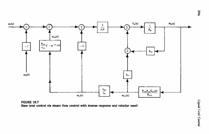
If we are not limited in column-base holdup and can design for reasonably well-damped control, then we can treat reboiler dynamics as negligible. This says that steam flow responds to the flow controller set point immediately, and that boilup follows steam flow without lag. We may then prepare the signal flow diagram of Figure 16.7. Note that Ke = steam flow-meter gain = 12/(wfl)-. This may be partially reduced to the form of Figure 16.8. From this last illustration we can see some of the loop’s characteristics as they are affected by reboiler swell and inverse response.
A. Reboiler Swell From the denominator of the upper-right-hand term of Figure 16.8 we can
see that for stability with proportional-only level control we must have:
(16.38)

16.7 Column-Base Level Control Cascaded to Steam Fknv Control 395
The term b92 is normally both negative and small. But as pointed out in Chapter 4, kVl is often large at low heat loads; the control system designer must be carell about the term:
At startup some control systems of this type will simply drive to a high base level and wide-open steam valve because of a large k91 or improperly chosen values of the other parameters.
If a PI controller is used instead of a proportional-only controller, the denominator of the upper-right-hand box of Figure 16.8 becomes:
An examination of the mathematics suggests that for stability we should make A B - KV1 > kVl Kmh and 7 R A,/& > p L
B. Inverse Response If Km is positive, we have inverse response and the effect is unstablizing,
as is swell. A common approach to design, when holdup is adequately large, is to make
loop calculations without the inverse response term and to design for a closed- loop natural period equal to or greater than 1 0 n ~ ~ .
If the control loop has to be tightly tuned because holdup is small, we can design a compensator for inverse response called an "inverse response predictor."8 It is analogous to the Smith predictor for dead-time compensation.'
The control loop containing the predictor is shown in Figure 16.9. The predictor contains a model of the inverse response and cancels its effect from the measured variable, allowing us to tune the controller as though inverse response were not present. The time-domain equation for the predictor is:
~ ( t ) = K~ p,(t - H TTR) - e,(t)l At + ~ ( t - 1) (16.39) where
It can be shown by equation (16.39) that P(t ) will have a slight offset from set point. The impulse function shown in Figure 16.9 after the predictor eliminates this.
The inverse response predictor must be implemented in a microproces- sor controller or control computer that has storage capability for the term 8, (t - n T ~ ) .
396 Liquid Level C
ontrol
- - cn E z n 2 s 3
e - - 0
W i3 - E 0
0
L
a3
c
.% 3 2 s - CI c z G
E m x m 3
7-zi w%
a-
ern 0
- > 0
c
- 2
s
ss

16.7 C
olumn-B
ase Level Control Cascaded to Steam
Flow Control
397
2 r 2 3 m
c
IC
0
C
0
m1
1
as3
gg -
2
e; Ln
.

398 Liquid Level Control
8 E E
m
E m
>
- - e 8 - s 8 c, e - 8 n
8
3 E 2
e&
zs 5: g
g L
e P)
UP
)

16.8 Column-Base Level Control via Cmhmate Tbrottltng 399
If K m / ~ m is unity or close to it, the inverse response term in Figure 16.8 becomes simplified:
(16.40) Km - (1 - - 1 - e-nTrnJ
T m
The system now behaves as though it has dead time.
16.8 COLUMN-BASE LEVEL CONTROL VIA CONDENSATE THROTTLING FROM A FLOODED REBOILER
(CASCADE LEVEL-FLOW CONTROL)
As a final example, let us look at the control of column-base level by throttling condensate flow fiom the reboiler. We will ignore possible column inverse response but will take swell into account. Column acoustic impedance, seen fiom the base, will be assumed to be resistive only. The basic, open-loop signal flow diagram for the flooded reboiler is given in Figure 15.13. We need in addition the following relationships:
(16.41)
(16.42)
where
K,+ = steam condensate flow-meter gain
wo = steam condensate flow, Ibm/min w, = boilup,Ibm/min wu = rate of steam condensation, lbm/min VB = liquid volume between level taps, ft3 pL = liquid density, lbm/fi3 wl = liquid downflow fiom column, Ibm/min
= 12/(tt7,)max
fi3 liquid lbm/min boilup kVl = swell coefficient,
~~1 = column acoustic resistance, 1bf&/fi5. It is assumed that column impedance is fast enough to reduce to a constant.
(16.44)

400 Liqutd Level Control
P B = column-base pressure, lbf/fi? pBu = process vapor density, Ibm/fi3
For a small number of flooded reboilers examined to date, the kvl term is essentially constant from low to high heat loads; that is, the relationship between heat load and tube vapor volume is a straight line. The compression effect due to process-side liquid-elevation changes has not been checked but is believed to be small; it is neglected in this analysis.
The preliminary signal flow diagram of Figure 16.10 may now be prepared. It may be reduced readily to the form of Figure 16.11.
Some consolidation of terms of Figure 16.11 may now be accomplished:
(16.45) 1 kvl P L J - 1 k - - = v1 PLS PL5
Next, let:
so
From equation (15.27a):
(16.46)
(16.47)
(16.48)
(16.49)
(16.50)
(16.51)
(16.52)

16.8 Column-Base Level Control via Cma!ensate Tbrottling 401
From Figure 16.11 and equations (16.48) and (16.52) we can see that the characteristic equation for this system is:
For proportional-only control this reduces to:
(16.54)
or
or
(16.56)
It can be seen fiom equation (16.56) that for stability we must make KL 71 6 1. But this is not enough for a practical design; the damping ratio should be at least one, where:
or
(16.57)
(16.58)
For 5 = 1: 4 K ~ 7 2 = 1 - 2KL71 +KZ< (16.59)
Now let
(2 kR + 1) k 2 d m 71
KL =
(16.60)
(16.61)
(16.62)

402 Liquid Level C
ontrol
5 2
- - 0 n
: 0 0
e m 0
m
e E &
- E 5 3 E 2 8 !! 8 - 5 3 2 E al
c,
m w - I
+.'
E
- al 2
0
V L
- 42 E E - z $l U
e m E
m
- Z
-FI
rdi? W=
rm
5s
&&

16.8 Colum
n-Base Level Control via Cm
hnsate Throttling 403
2
5 5 m
rE
b
0
c 0
;-z z!z 5
s
u-8
U
ma
Ba
sunil k sharma

404 Liquid Level Control
= 7JKL to be as large as possible, we should choose from equation (16.62) the solution that gives the smallest value of KL. For a proportional-reset controller, choose:
Since for slow, well-damped response we want
,-
(16.63)
With such a controller it will be necessary, as indicated earlier, to use auto overrides or a controller with nonlinear gain and reset.
1. Buckley, P. S., Techniqzles of Process Control, Wiley, New York, 1964.
2. Buckley, P. S., “Designing Override and Feedfonvard Controls,” Cont. Eng., 48-51 (Aug. 1971), 82-85 (Oct. 1971).
3. Cox, R. K., “Some Practical Consid- erations in the Applications of Ov- errides,” presented at ISA Joint Spring Conference, St. Louis, Apr. 1973.
4. Shunta, J. P., and W. Fehenwi, “Nonlinear Control of Liquid Level,” INTECH, 43-48 (Jan. 1976).
5. Buckley, P. S., “Selection of Optimum Final Element Characteristics,” pre- sented at ISA Svmmsium. Wil-
REFERENCES mington, Del., May 4-5, 1964.
6. Buckley, P. S., and W. L. Luyben, “A Propomonal-Lag Level Controller,” DTIECH, 65-68 (Dec. 1977).
7. Cheung, T. F., and W. L. Luyben, “A Further Study of the PL Level Controller,”ISA Trans., 18 (2): 73- 77 (1979).
8. Shunta, J. P., “A Compensator for In- verse Response,” presented at ISM 84 meeting, Houston, TX, Oct. 22, 1984.
9. Smith, 0. J. M., ISA J. 6(2) (1959). 10. Buckley, P. S., “Recent Advances in
Averaging Level Control,” Proceed- ings, 1983 Joint Symposium, ISA, Houston, Tex., Apr. 18-21, 1983.
Related Documents