15EE305J -MICROCONTROLLER LAB COURSE MANUAL DEPARTMENT OF ELECTRICAL & ELECTRONICS ENGINEERING FACULTY OF ENGINEERING & TECHNOLOGY SRMUNIVERSITY, Kattankulathur – 603 203

Welcome message from author
This document is posted to help you gain knowledge. Please leave a comment to let me know what you think about it! Share it to your friends and learn new things together.
Transcript
15EE305J -MICROCONTROLLER LAB
COURSE MANUAL
DEPARTMENT OF ELECTRICAL & ELECTRONICS ENGINEERING FACULTY OF ENGINEERING & TECHNOLOGY
SRMUNIVERSITY, Kattankulathur – 603 203

LIST OF EXEPRIMENTS
SL.No. Name of the Experiments Page No.
CYCLE 1
1 Introduction of Microprocessor and Microcontroller Kit
2
Arithmetic operation
a) Addition of 2 - 8 bit numbers
b) Subtraction of 2 - 8 bit numbers
c) Multiplication of 2 - 8 numbers
d) Division of 2 - 8 bit numbers
3 Finding maximum value in an array
4
Sorting of data
a) Ascending order
b) Descending order
5 Code Conversion
a) Hex-to-ASCII
b) ASCII-to-Binary conversion
6 Square root of a given data
CYCLE 2
7 Transfer data serially between two kits (Study of
8253/8251)
8 Seven segment display
9 8 bit ADC
10 8 bit DAC
11 Internal Interrupt Program
12 Stepper motor control using 8051 microcontroller
13 Traffic light controller
1. STUDY OF 8051 MICROCONTROLLER
Aim
To study the microcontroller 8051
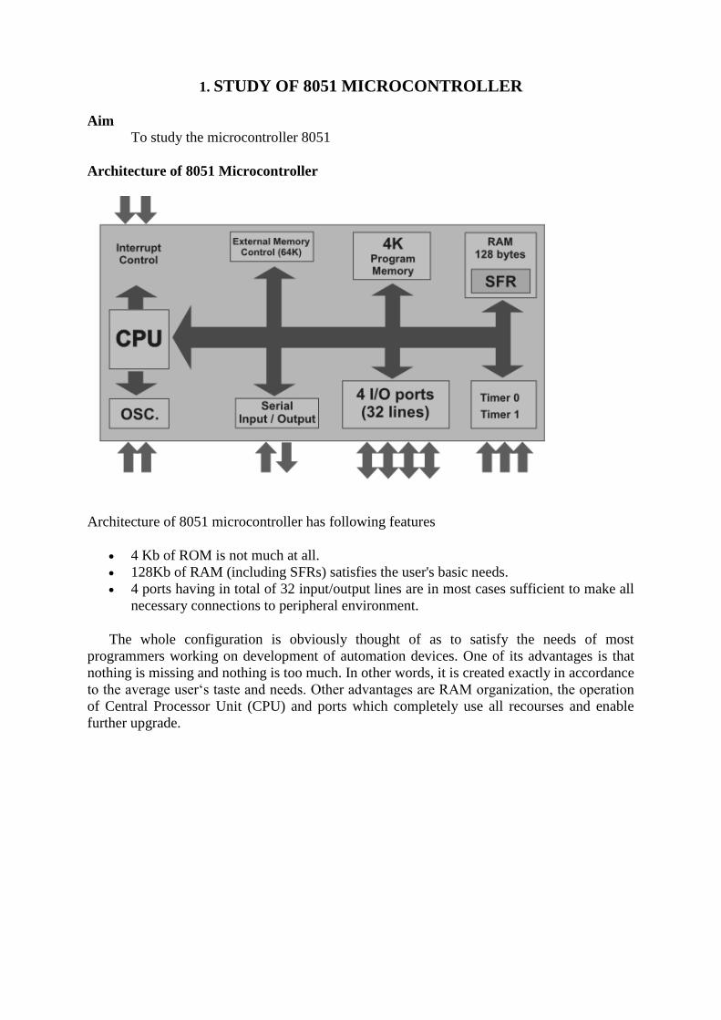
Architecture of 8051 Microcontroller
Architecture of 8051 microcontroller has following features
4 Kb of ROM is not much at all.
128Kb of RAM (including SFRs) satisfies the user's basic needs.
4 ports having in total of 32 input/output lines are in most cases sufficient to make all
necessary connections to peripheral environment.
The whole configuration is obviously thought of as to satisfy the needs of most
programmers working on development of automation devices. One of its advantages is that
nothing is missing and nothing is too much. In other words, it is created exactly in accordance
to the average user‘s taste and needs. Other advantages are RAM organization, the operation
of Central Processor Unit (CPU) and ports which completely use all recourses and enable
further upgrade.
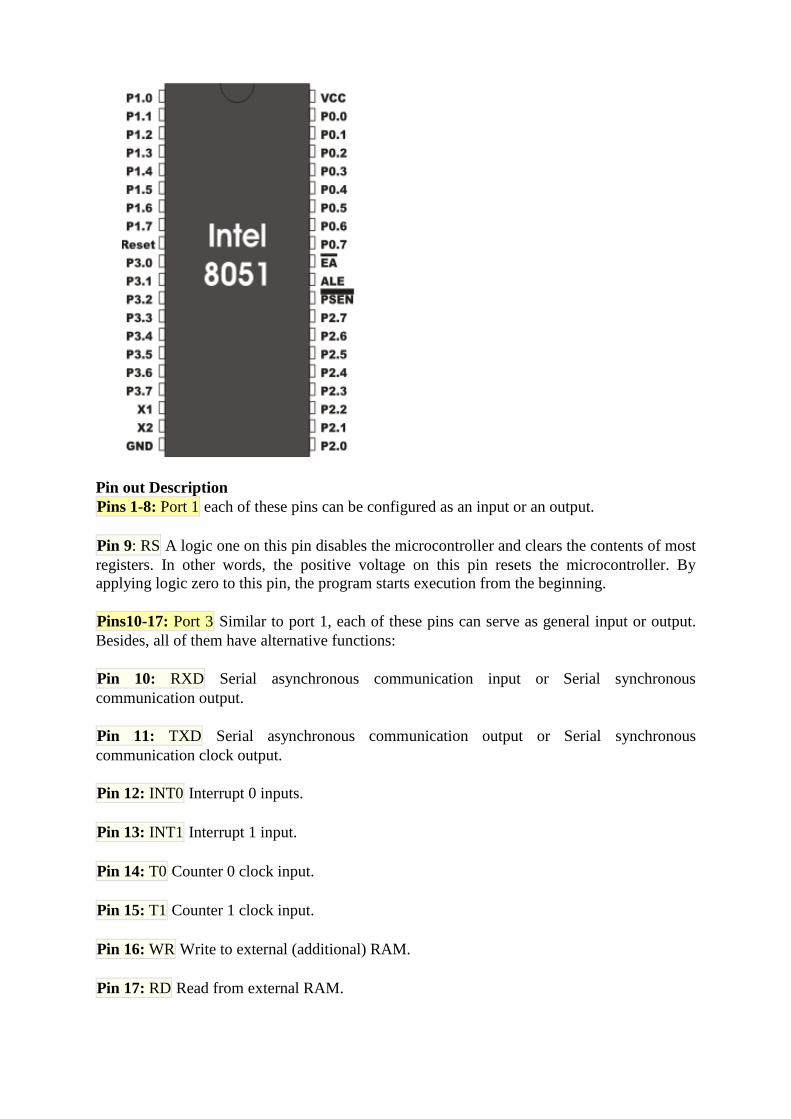
Pin out Description
Pins 1-8: Port 1 each of these pins can be configured as an input or an output.
Pin 9: RS A logic one on this pin disables the microcontroller and clears the contents of most
registers. In other words, the positive voltage on this pin resets the microcontroller. By
applying logic zero to this pin, the program starts execution from the beginning.
Pins10-17: Port 3 Similar to port 1, each of these pins can serve as general input or output.
Besides, all of them have alternative functions:
Pin 10: RXD Serial asynchronous communication input or Serial synchronous
communication output.
Pin 11: TXD Serial asynchronous communication output or Serial synchronous
communication clock output.
Pin 12: INT0 Interrupt 0 inputs.
Pin 13: INT1 Interrupt 1 input.
Pin 14: T0 Counter 0 clock input.
Pin 15: T1 Counter 1 clock input.
Pin 16: WR Write to external (additional) RAM.
Pin 17: RD Read from external RAM.

Pin 18, 19: X2, X1 Internal oscillator input and output. A quartz crystal which specifies
operating frequency is usually connected to these pins. Instead of it, miniature ceramics
resonators can also be used for frequency stability. Later versions of microcontrollers operate
at a frequency of 0 Hz up to over 50 Hz.
Pin 20: GND Ground.
Pin 21-28: Port 2 If there is no intention to use external memory then these port pins are
configured as general inputs/outputs. In case external memory is used, the higher address
byte, i.e. addresses A8-A15 will appear on this port. Even though memory with capacity of
64Kb is not used, which means that not all eight port bits are used for its addressing, the rest
of them are not available as inputs/outputs.
Pin 29: PSEN If external ROM is used for storing program then a logic zero (0) appears on it
every time the microcontroller reads a byte from memory.
Pin 30: ALE Prior to reading from external memory, the microcontroller puts the lower
address byte (A0-A7) on P0 and activates the ALE output. After receiving signal from the
ALE pin, the external register (usually 74HCT373 or 74HCT375 add-on chip) memorizes the
state of P0 and uses it as a memory chip address. Immediately after that, the ALU pin is
returned its previous logic state and P0 is now used as a Data Bus. As seen, port data
multiplexing is performed by means of only one additional (and cheap) integrated circuit. In
other words, this port is used for both data and address transmission.
Pin 31: EA By applying logic zero to this pin, P2 and P3 are used for data and address
transmission with no regard to whether there is internal memory or not. It means that even
there is a program written to the microcontroller, it will not be executed. Instead, the program
written to external ROM will be executed. By applying logic one to the EA pin, the
microcontroller will use both memories, first internal then external (if exists).
Pin 32-39: Port 0 Similar to P2, if external memory is not used, these pins can be used as
general inputs/outputs. Otherwise, P0 is configured as address output (A0-A7) when the ALE
pin is driven high (1) or as data output (Data Bus) when the ALE pin is driven low (0).
Pin 40: VCC +5V power supply.
Input/Output Ports (I/O Ports)
All 8051 microcontrollers have 4 I/O ports each comprising 8 bits which can be configured as
inputs or outputs. Accordingly, in total of 32 input/output pins enabling the microcontroller to
be connected to peripheral devices are available for use.
Pin configuration, i.e. whether it is to be configured as an input (1) or an output (0), depends
on its logic state. In order to configure a microcontroller pin as an input, it is necessary to
apply a logic zero (0) to appropriate I/O port bit. In this case, voltage level on appropriate pin
will be 0.
Similarly, in order to configure a microcontroller pin as an input, it is necessary to apply a
logic one (1) to appropriate port. In this case, voltage level on appropriate pin will be 5V (as
is the case with any TTL input). This may seem confusing but don't loose your patience. It all
becomes clear after studying simple electronic circuits connected to an I/O pin.
Memory Organization
The 8051 has two types of memory and these are Program Memory and Data Memory.
Program Memory (ROM) is used to permanently save the program being executed, while
Data Memory (RAM) is used for temporarily storing data and intermediate results created
and used during the operation of the microcontroller. Depending on the model in use (we are
still talking about the 8051 microcontroller family in general) at most a few Kb of ROM and
128 or 256 bytes of RAM is used. However…
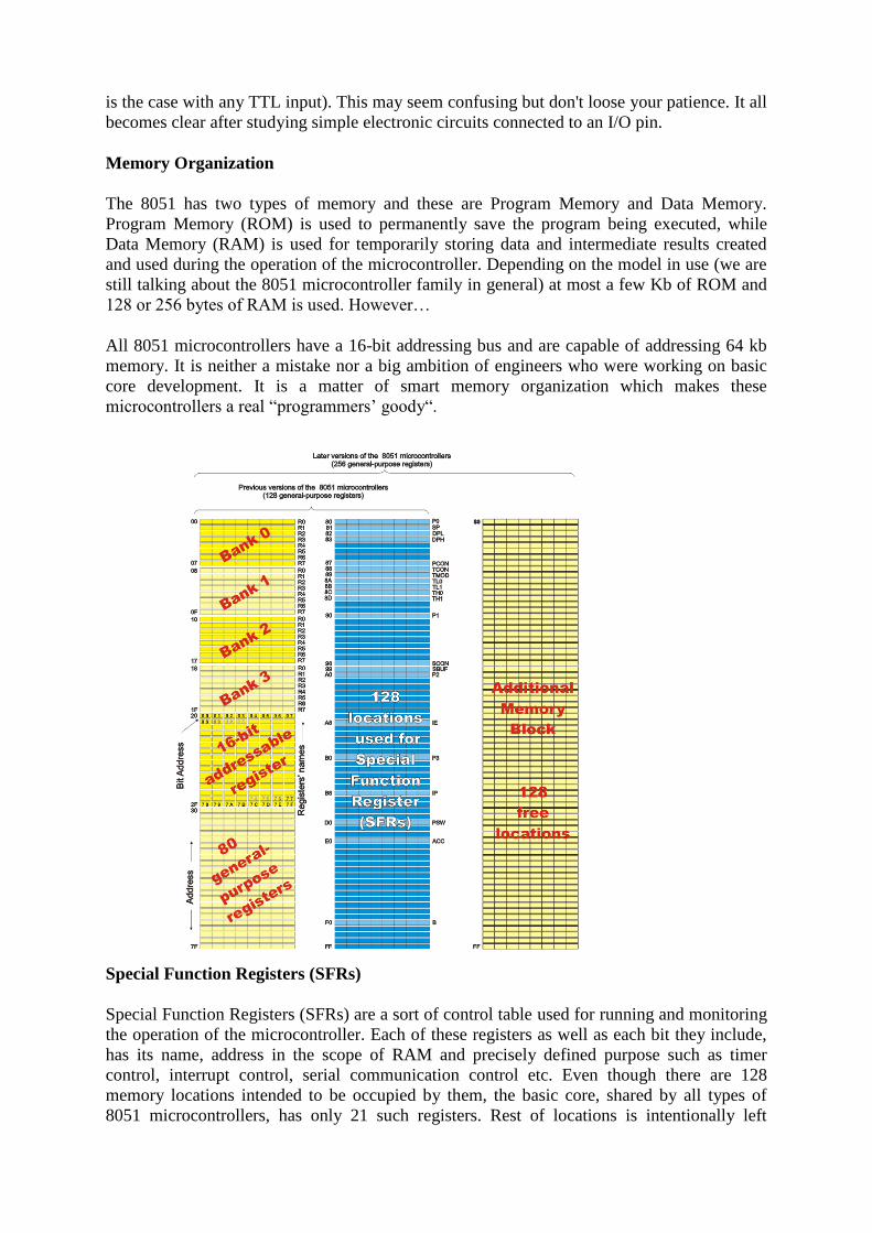
All 8051 microcontrollers have a 16-bit addressing bus and are capable of addressing 64 kb
memory. It is neither a mistake nor a big ambition of engineers who were working on basic
core development. It is a matter of smart memory organization which makes these
microcontrollers a real “programmers’ goody“.
Special Function Registers (SFRs)
Special Function Registers (SFRs) are a sort of control table used for running and monitoring
the operation of the microcontroller. Each of these registers as well as each bit they include,
has its name, address in the scope of RAM and precisely defined purpose such as timer
control, interrupt control, serial communication control etc. Even though there are 128
memory locations intended to be occupied by them, the basic core, shared by all types of
8051 microcontrollers, has only 21 such registers. Rest of locations is intentionally left

unoccupied in order to enable the manufacturers to further develop microcontrollers keeping
them compatible with the previous versions. It also enables programs written a long time ago
for microcontrollers which are out of production now to be used today.
Program Status Word (PSW) Register
PSW register is one of the most important SFRs. It contains several status bits that reflect the
current state of the CPU. Besides, this register contains Carry bit, Auxiliary Carry, two
register bank select bits, Overflow flag, parity bit and user-definable status flag.
P - Parity bit. If a number stored in the accumulator is even then this bit will be
automatically set (1), otherwise it will be cleared (0). It is mainly used during data transmit
and receive via serial communication.
- Bit 1. This bit is intended to be used in the future versions of microcontrollers.
OV Overflow occurs when the result of an arithmetical operation is larger than 255 and
cannot be stored in one register. Overflow condition causes the OV bit to be set (1).
Otherwise, it will be cleared (0).
RS0, RS1 - Register bank select bits. These two bits are used to select one of four register
banks of RAM. By setting and clearing these bits, registers R0-R7 are stored in one of four
banks of RAM.
RS1 RS2 Space in RAM
0 0 Bank0 00h-07h
0 1 Bank1 08h-0Fh
1 0 Bank2 10h-17h
1 1 Bank3 18h-1Fh
F0 - Flag 0. This is a general-purpose bit available for use.
AC - Auxiliary Carry Flag is used for BCD operations only.
CY - Carry Flag is the (ninth) auxiliary bit used for all arithmetical operations and shift
instructions.
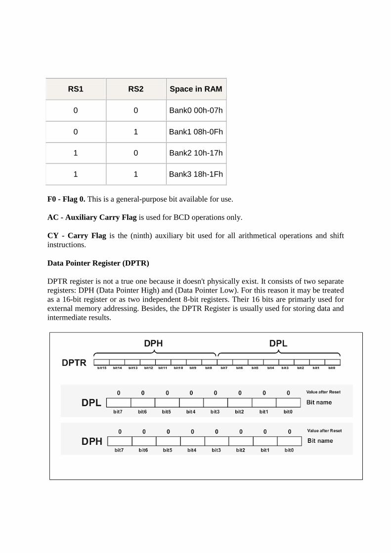
Data Pointer Register (DPTR)
DPTR register is not a true one because it doesn't physically exist. It consists of two separate
registers: DPH (Data Pointer High) and (Data Pointer Low). For this reason it may be treated
as a 16-bit register or as two independent 8-bit registers. Their 16 bits are primarly used for
external memory addressing. Besides, the DPTR Register is usually used for storing data and
intermediate results.

Stack Pointer (SP) Register
A value stored in the Stack Pointer points to the first free stack address and permits stack
availability. Stack pushes increment the value in the Stack Pointer by 1. Likewise, stack pops
decrement its value by 1. Upon any reset and power-on, the value 7 is stored in the Stack
Pointer, which means that the space of RAM reserved for the stack starts at this location. If
another value is written to this register, the entire Stack is moved to the new memory
location.
P0, P1, P2, P3 - Input/Output Registers
If neither external memory nor serial communication system are used then 4 ports with in
total of 32 input/output pins are available for connection to peripheral environment. Each bit
within these ports affects the state and performance of appropriate pin of the microcontroller.
Thus, bit logic state is reflected on appropriate pin as a voltage (0 or 5 V) and vice versa,
voltage on a pin reflects the state of appropriate port bit.
As mentioned, port bit state affects performance of port pins, i.e. whether they will be
configured as inputs or outputs. If a bit is cleared (0), the appropriate pin will be configured
as an output, while if it is set (1), the appropriate pin will be configured as an input. Upon
reset and power-on, all port bits are set (1), which means that all appropriate pins will be
configured as inputs.
Counters and Timers
As you already know, the microcontroller oscillator uses quartz crystal for its operation. As
the frequency of this oscillator is precisely defined and very stable, pulses it generates are
always of the same width, which makes them ideal for time measurement. Such crystals are
also used in quartz watches. In order to measure time between two events it is sufficient to
count up pulses coming from this oscillator. That is exactly what the timer does. If the timer
is properly programmed, the value stored in its register will be incremented (or decremented)
with each coming pulse, i.e. once per each machine cycle. A single machine-cycle instruction
lasts for 12 quartz oscillator periods, which means that by embedding quartz with oscillator
frequency of 12MHz, a number stored in the timer register will be changed million times per
second, i.e. each microsecond.
The 8051 microcontroller has 2 timers/counters called T0 and T1. As their names suggest,
their main purpose is to measure time and count external events. Besides, they can be used
for generating clock pulses to be used in serial communication, so called Baud Rate.
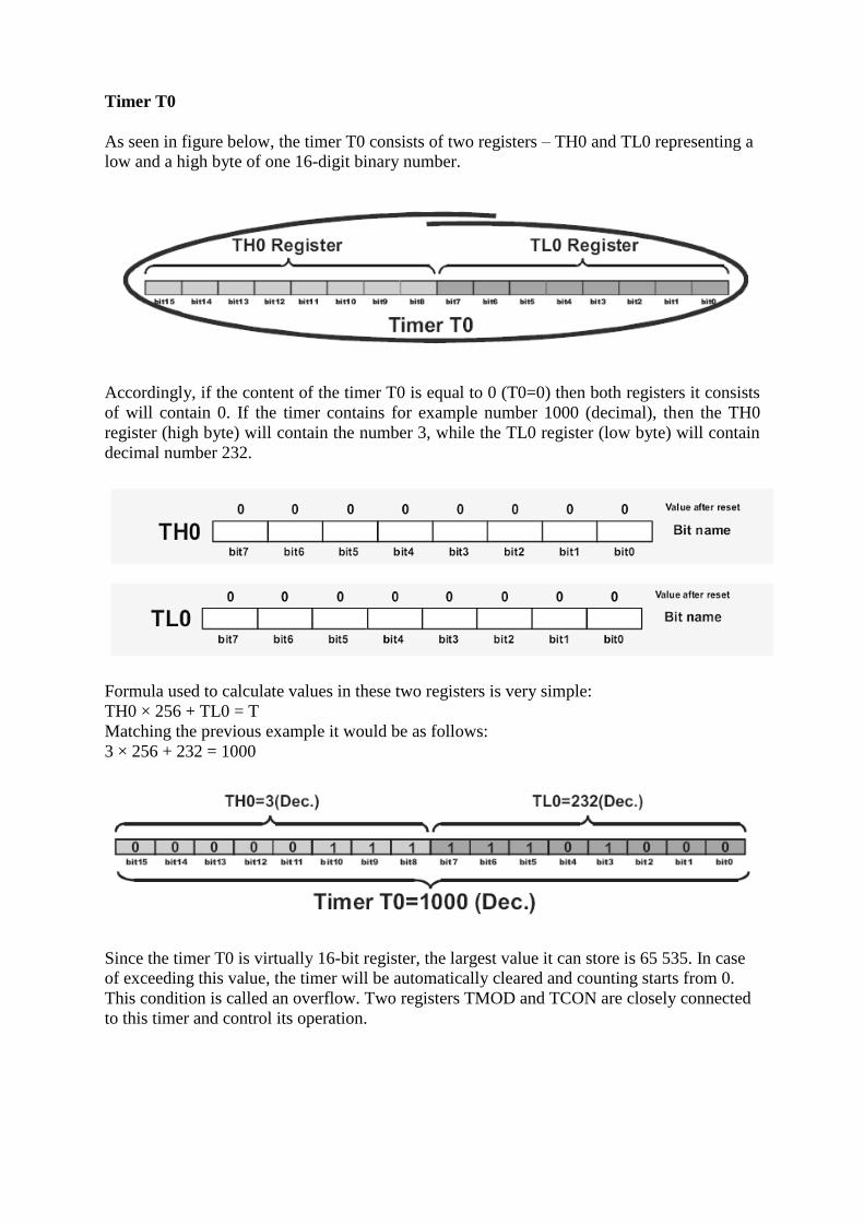
Timer T0
As seen in figure below, the timer T0 consists of two registers – TH0 and TL0 representing a
low and a high byte of one 16-digit binary number.
Accordingly, if the content of the timer T0 is equal to 0 (T0=0) then both registers it consists
of will contain 0. If the timer contains for example number 1000 (decimal), then the TH0
register (high byte) will contain the number 3, while the TL0 register (low byte) will contain
decimal number 232.
Formula used to calculate values in these two registers is very simple:
TH0 × 256 + TL0 = T
Matching the previous example it would be as follows:
3 × 256 + 232 = 1000
Since the timer T0 is virtually 16-bit register, the largest value it can store is 65 535. In case
of exceeding this value, the timer will be automatically cleared and counting starts from 0.
This condition is called an overflow. Two registers TMOD and TCON are closely connected
to this timer and control its operation.
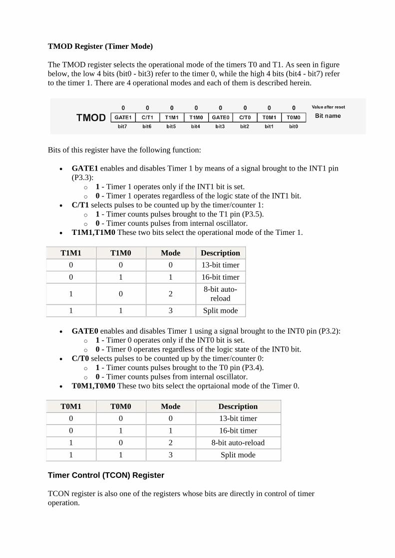
TMOD Register (Timer Mode)
The TMOD register selects the operational mode of the timers T0 and T1. As seen in figure
below, the low 4 bits (bit0 - bit3) refer to the timer 0, while the high 4 bits (bit4 - bit7) refer
to the timer 1. There are 4 operational modes and each of them is described herein.
Bits of this register have the following function:
GATE1 enables and disables Timer 1 by means of a signal brought to the INT1 pin
(P3.3):
o 1 - Timer 1 operates only if the INT1 bit is set.
o 0 - Timer 1 operates regardless of the logic state of the INT1 bit.
C/T1 selects pulses to be counted up by the timer/counter 1:
o 1 - Timer counts pulses brought to the T1 pin (P3.5).
o 0 - Timer counts pulses from internal oscillator.
T1M1,T1M0 These two bits select the operational mode of the Timer 1.
T1M1 T1M0 Mode Description
0 0 0 13-bit timer
0 1 1 16-bit timer
1 0 2 8-bit auto-
reload
1 1 3 Split mode
GATE0 enables and disables Timer 1 using a signal brought to the INT0 pin (P3.2):
o 1 - Timer 0 operates only if the INT0 bit is set.
o 0 - Timer 0 operates regardless of the logic state of the INT0 bit.
C/T0 selects pulses to be counted up by the timer/counter 0:
o 1 - Timer counts pulses brought to the T0 pin (P3.4).
o 0 - Timer counts pulses from internal oscillator.
T0M1,T0M0 These two bits select the oprtaional mode of the Timer 0.
T0M1 T0M0 Mode Description
0 0 0 13-bit timer
0 1 1 16-bit timer
1 0 2 8-bit auto-reload
1 1 3 Split mode
Timer Control (TCON) Register
TCON register is also one of the registers whose bits are directly in control of timer
operation.

Only 4 bits of this register are used for this purpose, while rest of them is used for interrupt
control to be discussed later.
TF1 bit is automatically set on the Timer 1 overflow.
TR1 bit enables the Timer 1.
o 1 - Timer 1 is enabled.
o 0 - Timer 1 is disabled.
TF0 bit is automatically set on the Timer 0 overflow.
TR0 bit enables the timer 0.
o 1 - Timer 0 is enabled.
o 0 - Timer 0 is disabled.
Timer 1
Timer 1 is identical to timer 0, except for mode 3 which is a hold-count mode. It means that
they have the same function, their operation is controlled by the same registers TMOD and
TCON and both of them can operate in one out of 4 different modes.
Result:
Thus the 8051 Architecture has been studied.
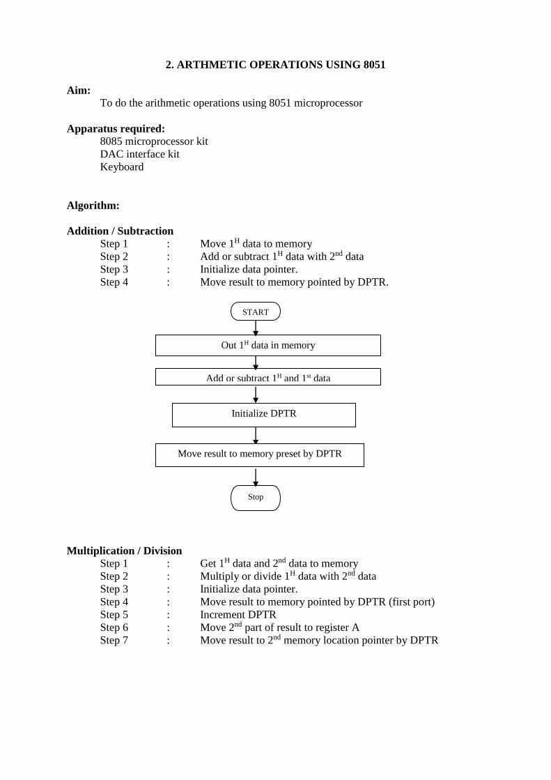
2. ARTHMETIC OPERATIONS USING 8051
Aim:
To do the arithmetic operations using 8051 microprocessor
Apparatus required:
8085 microprocessor kit
DAC interface kit
Keyboard
Algorithm:
Addition / Subtraction
Step 1 : Move 1H data to memory
Step 2 : Add or subtract 1H data with 2nd data
Step 3 : Initialize data pointer.
Step 4 : Move result to memory pointed by DPTR.
Multiplication / Division
Step 1 : Get 1H data and 2nd data to memory
Step 2 : Multiply or divide 1H data with 2nd data
Step 3 : Initialize data pointer.
Step 4 : Move result to memory pointed by DPTR (first port)
Step 5 : Increment DPTR
Step 6 : Move 2nd part of result to register A
Step 7 : Move result to 2nd memory location pointer by DPTR
START
Out 1H data in memory
Add or subtract 1H and 1st data
Initialize DPTR
Stop
Move result to memory preset by DPTR
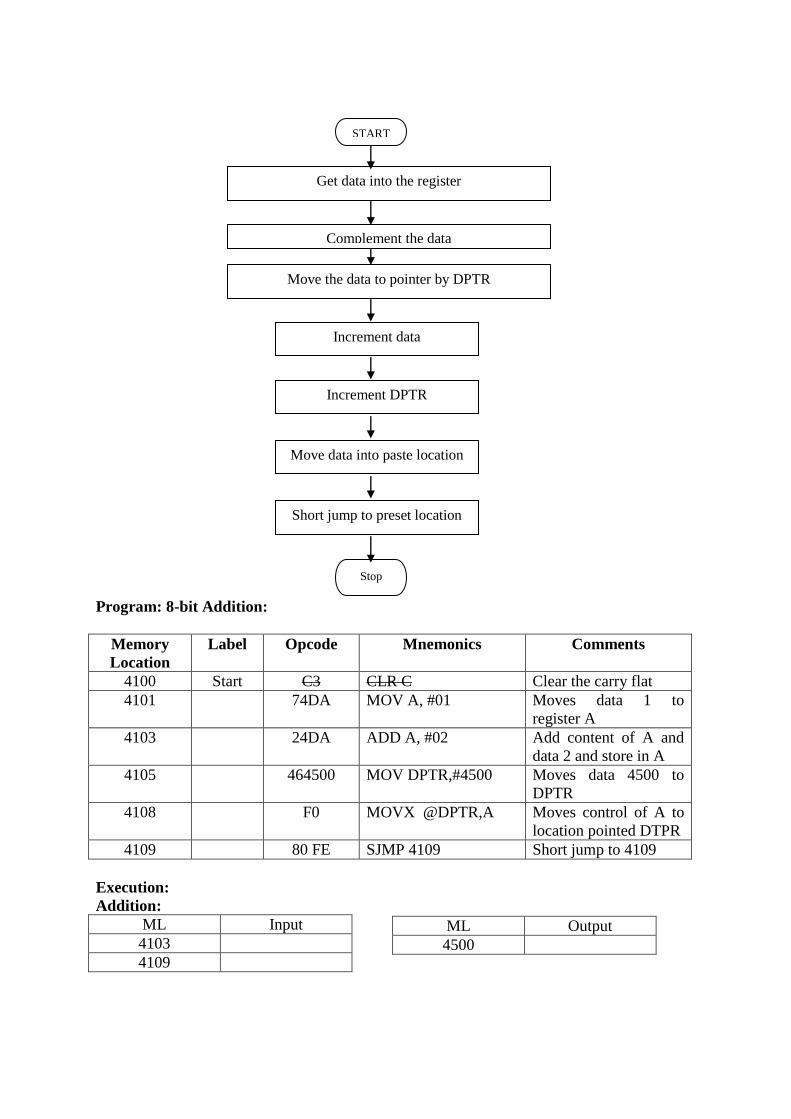
Program: 8-bit Addition:
Memory
Location
Label Opcode Mnemonics Comments
4100 Start C3 CLR C Clear the carry flat
4101 74DA MOV A, #01 Moves data 1 to
register A
4103 24DA ADD A, #02 Add content of A and
data 2 and store in A
4105 464500 MOV DPTR,#4500 Moves data 4500 to
DPTR
4108 F0 MOVX @DPTR,A Moves control of A to
location pointed DTPR
4109 80 FE SJMP 4109 Short jump to 4109
Execution:
Addition:
ML Input
4103
4109
ML Output
4500
START
Get data into the register
Complement the data
Move the data to pointer by DPTR
Stop
Increment data
Increment DPTR
Move data into paste location
Short jump to preset location
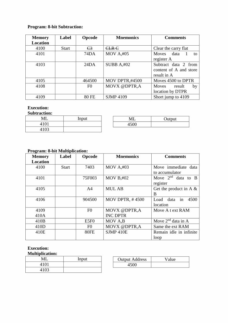
Program: 8-bit Subtraction:
Memory
Location
Label Opcode Mnemonics Comments
4100 Start C3 CLR C Clear the carry flat
4101 74DA MOV A,#05 Moves data 1 to
register A
4103 24DA SUBB A,#02 Subtract data 2 from
content of A and store
result in A
4105 464500 MOV DPTR,#4500 Moves 4500 to DPTR
4108 F0 MOVX @DPTR,A Moves result by
location by DTPR
4109 80 FE SJMP 4109 Short jump to 4109
Execution:
Subtraction:
ML Input
4101
4103
Program: 8-bit Multiplication:
Memory
Location
Label Opcode Mnemonics Comments
4100 Start 7403 MOV A,#03 Move immediate data
to accumulator
4101 75F003 MOV B,#02 Move 2nd data to B
register
4105 A4 MUL AB Get the product in A &
B
4106 904500 MOV DPTR, # 4500 Load data in 4500
location
4109
410A
F0 MOVX @DPTR,A
INC DPTR
Move A t ext RAM
410B E5F0 MOV A,B Move 2nd data in A
410D F0 MOVX @DPTR,A Same the ext RAM
410E 80FE SJMP 410E Remain idle in infinite
loop
Execution:
Multiplication:
ML Input
4101
4103
ML Output
4500
Output Address Value
4500
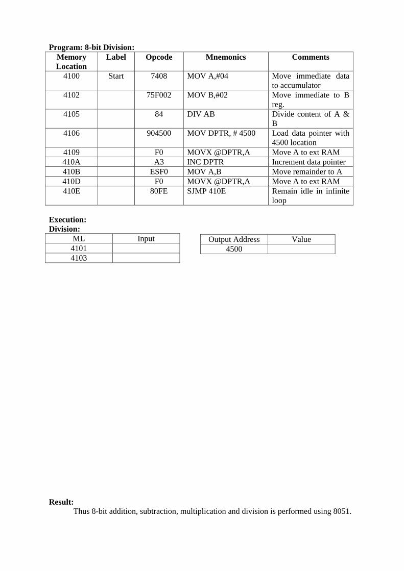
Program: 8-bit Division:
Memory
Location
Label Opcode Mnemonics Comments
4100 Start 7408 MOV A,#04 Move immediate data
to accumulator
4102 75F002 MOV B,#02 Move immediate to B
reg.
4105 84 DIV AB Divide content of A &
B
4106 904500 MOV DPTR, # 4500 Load data pointer with
4500 location
4109 F0 MOVX @DPTR,A Move A to ext RAM
410A A3 INC DPTR Increment data pointer
410B ESF0 MOV A,B Move remainder to A
410D F0 MOVX @DPTR,A Move A to ext RAM
410E 80FE SJMP 410E Remain idle in infinite
loop
Execution:
Division:
ML Input
4101
4103
Result:
Thus 8-bit addition, subtraction, multiplication and division is performed using 8051.
Output Address Value
4500
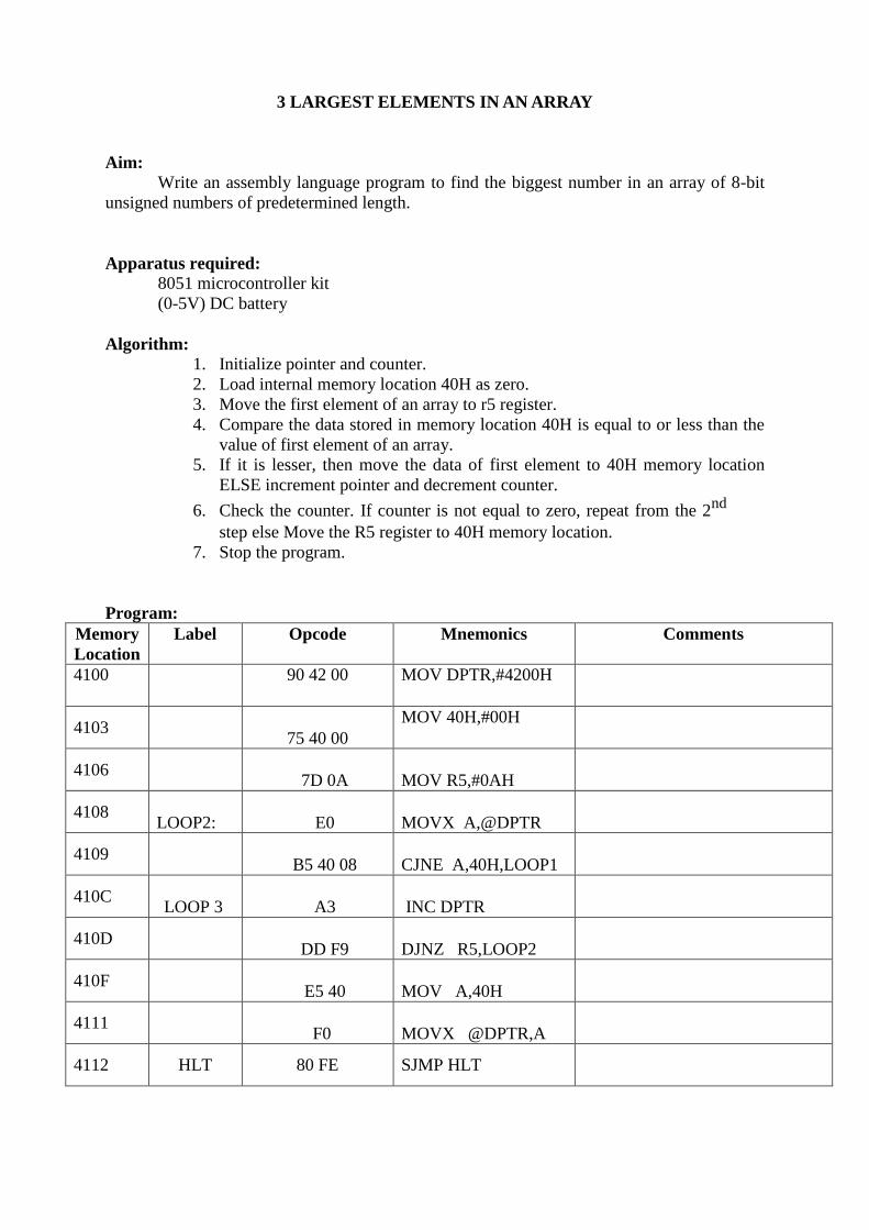
3 LARGEST ELEMENTS IN AN ARRAY
Aim:
Write an assembly language program to find the biggest number in an array of 8-bit
unsigned numbers of predetermined length.
Apparatus required:
8051 microcontroller kit
(0-5V) DC battery
Algorithm:
1. Initialize pointer and counter.
2. Load internal memory location 40H as zero.
3. Move the first element of an array to r5 register.
4. Compare the data stored in memory location 40H is equal to or less than the
value of first element of an array.
5. If it is lesser, then move the data of first element to 40H memory location
ELSE increment pointer and decrement counter.
6. Check the counter. If counter is not equal to zero, repeat from the 2nd
step else Move the R5 register to 40H memory location.
7. Stop the program.
Program:
Memory
Location
Label Opcode Mnemonics Comments
4100 90 42 00 MOV DPTR,#4200H
4103 75 40 00
MOV 40H,#00H
4106 7D 0A MOV R5,#0AH
4108 LOOP2: E0 MOVX A,@DPTR
4109 B5 40 08 CJNE A,40H,LOOP1
410C LOOP 3 A3 INC DPTR
410D DD F9 DJNZ R5,LOOP2
410F E5 40 MOV A,40H
4111 F0 MOVX @DPTR,A
4112 HLT 80 FE SJMP HLT
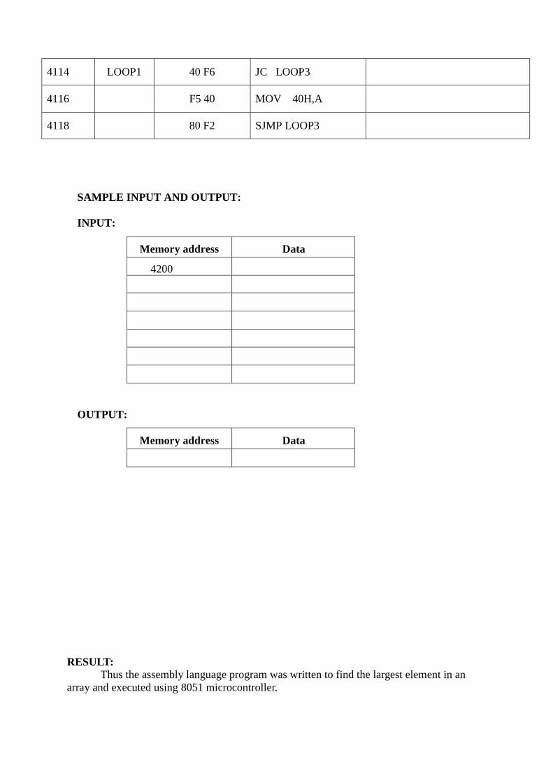
4114 LOOP1 40 F6 JC LOOP3
4116 F5 40 MOV 40H,A
4118 80 F2 SJMP LOOP3
SAMPLE INPUT AND OUTPUT:
INPUT:
Memory address Data
4200
OUTPUT:
Memory address Data
RESULT:
Thus the assembly language program was written to find the largest element in an
array and executed using 8051 microcontroller.
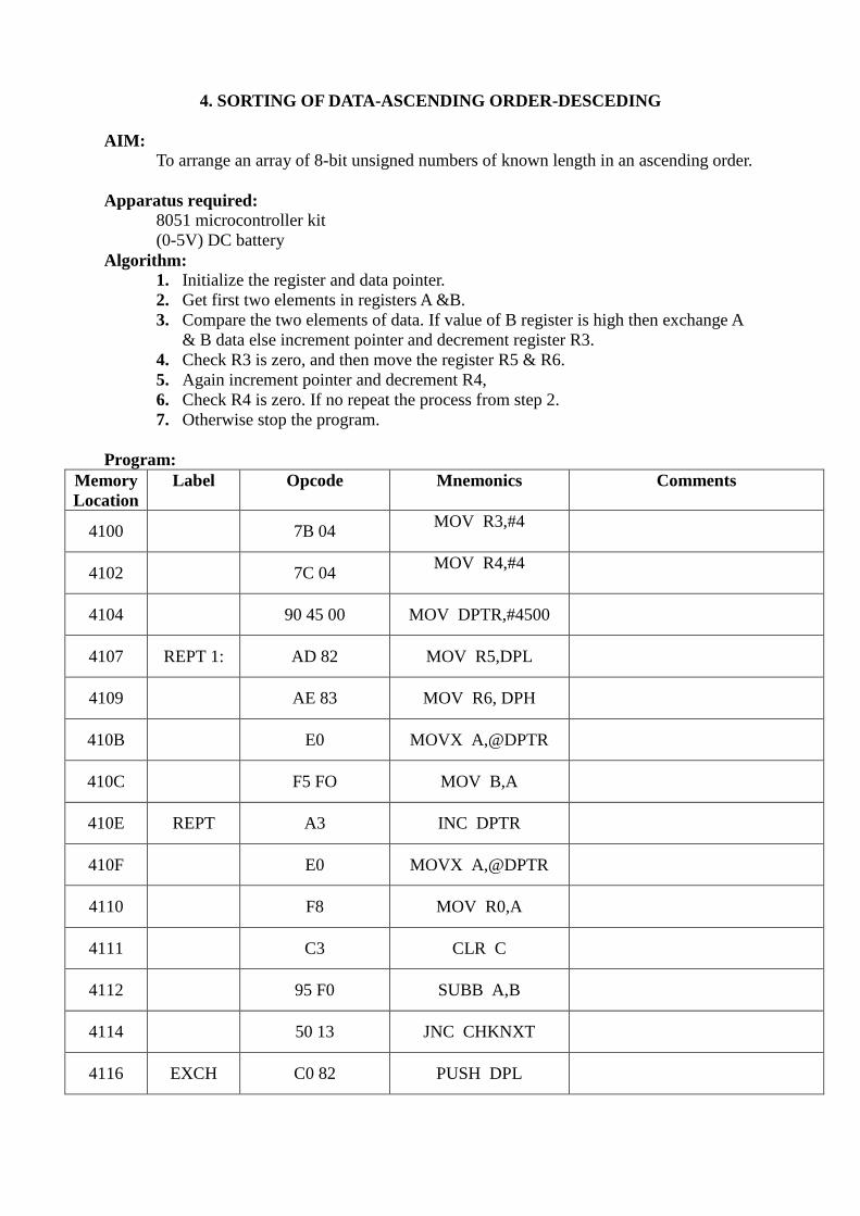
4. SORTING OF DATA-ASCENDING ORDER-DESCEDING
AIM:
To arrange an array of 8-bit unsigned numbers of known length in an ascending order.
Apparatus required:
8051 microcontroller kit
(0-5V) DC battery
Algorithm:
1. Initialize the register and data pointer.
2. Get first two elements in registers A &B.
3. Compare the two elements of data. If value of B register is high then exchange A
& B data else increment pointer and decrement register R3.
4. Check R3 is zero, and then move the register R5 & R6.
5. Again increment pointer and decrement R4,
6. Check R4 is zero. If no repeat the process from step 2.
7. Otherwise stop the program.
Program:
Memory
Location
Label Opcode Mnemonics Comments
4100 7B 04 MOV R3,#4
4102 7C 04 MOV R4,#4
4104 90 45 00 MOV DPTR,#4500
4107 REPT 1: AD 82 MOV R5,DPL
4109 AE 83 MOV R6, DPH
410B E0 MOVX A,@DPTR
410C F5 FO MOV B,A
410E REPT A3 INC DPTR
410F E0 MOVX A,@DPTR
4110 F8 MOV R0,A
4111 C3 CLR C
4112 95 F0 SUBB A,B
4114 50 13 JNC CHKNXT
4116 EXCH C0 82 PUSH DPL

4118 C0 83 PUSH DPH
411A 8D 83 MOV DPL,R5
411C 8E 83 MOV DPH,R6
411E E8 MOV A,R0
411F F0 MOVX @DPTR,A
4120 D0 83 POP DPH
4122 D0 82 POP DPL
4124 E5 F0 MOV A,B
4126 F0 MOVX @DPTR,A
4127 88 F0 MOV B,R0
4129 CHKNXT: DBE3 DJNZ R3,REPT
412B 1C DEC R4
412C EC MOV A,R4
412D FB MOV R3,A
412E OC INC R 4
412F 8D 82 MOV DPL,R5
4131 8E 83 MOV DPH,R6
4133 A3 INC DPTR
4134 DC D1 DJNZ R4,REPT1
4136 80 FE SJMP HLT
Algorithm:
1. Initialize the register and data pointer.
2. Get first two elements in registers A &B.
3. Compare the two elements of data. If value of B register is low then exchange A &
B data else increment pointer and decrement register R3.
4. Check R3 is zero, and then move the register R5 & R6.
5. Again increment pointer and decrement R4,
6. Check R4 is zero. If no repeat the process from step 2.
7. Otherwise stop the program.
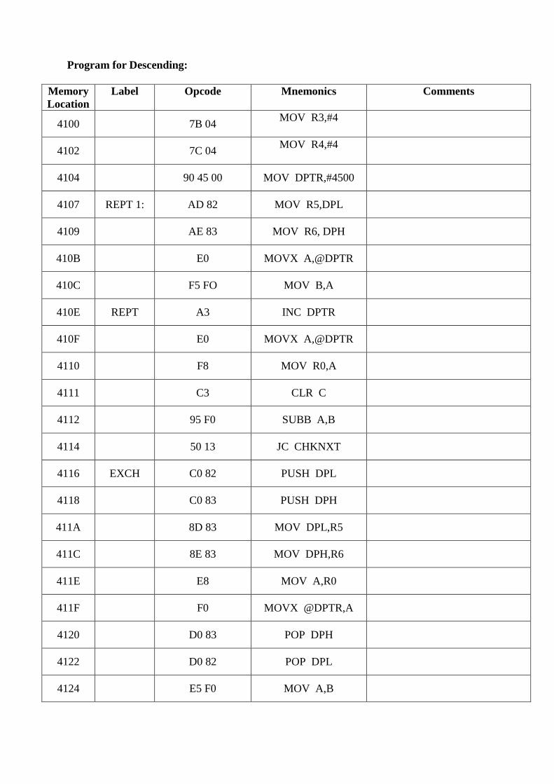
Program for Descending:
Memory
Location
Label Opcode Mnemonics Comments
4100 7B 04 MOV R3,#4
4102 7C 04 MOV R4,#4
4104 90 45 00 MOV DPTR,#4500
4107 REPT 1: AD 82 MOV R5,DPL
4109 AE 83 MOV R6, DPH
410B E0 MOVX A,@DPTR
410C F5 FO MOV B,A
410E REPT A3 INC DPTR
410F E0 MOVX A,@DPTR
4110 F8 MOV R0,A
4111 C3 CLR C
4112 95 F0 SUBB A,B
4114 50 13 JC CHKNXT
4116 EXCH C0 82 PUSH DPL
4118 C0 83 PUSH DPH
411A 8D 83 MOV DPL,R5
411C 8E 83 MOV DPH,R6
411E E8 MOV A,R0
411F F0 MOVX @DPTR,A
4120 D0 83 POP DPH
4122 D0 82 POP DPL
4124 E5 F0 MOV A,B
4126 F0 MOVX @DPTR,A
4127 88 F0 MOV B,R0
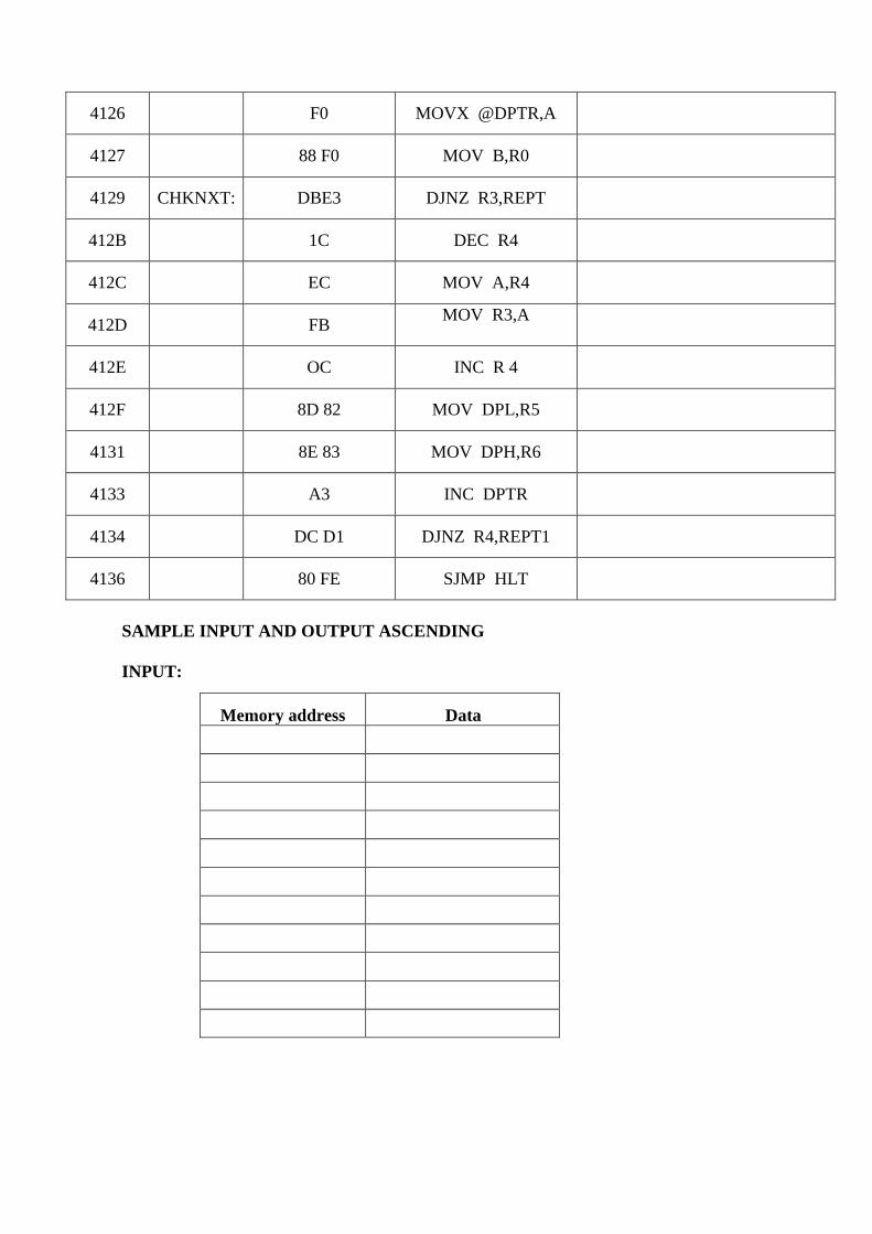
4129 CHKNXT: DBE3 DJNZ R3,REPT
412B 1C DEC R4
412C EC MOV A,R4
412D FB MOV R3,A
412E OC INC R 4
412F 8D 82 MOV DPL,R5
4131 8E 83 MOV DPH,R6
4133 A3 INC DPTR
4134 DC D1 DJNZ R4,REPT1
4136 80 FE SJMP HLT
SAMPLE INPUT AND OUTPUT ASCENDING
INPUT:
Memory address Data
OUTPUT:
Memory address Data
SAMPLE INPUT AND OUTPUT DESCENDING
INPUT:
Memory address Data
OUTPUT:
Memory address Data
RESULT:
Thus the assembly language program was written to sort the data in an ascending order and
executed using 8051 microcontroller.
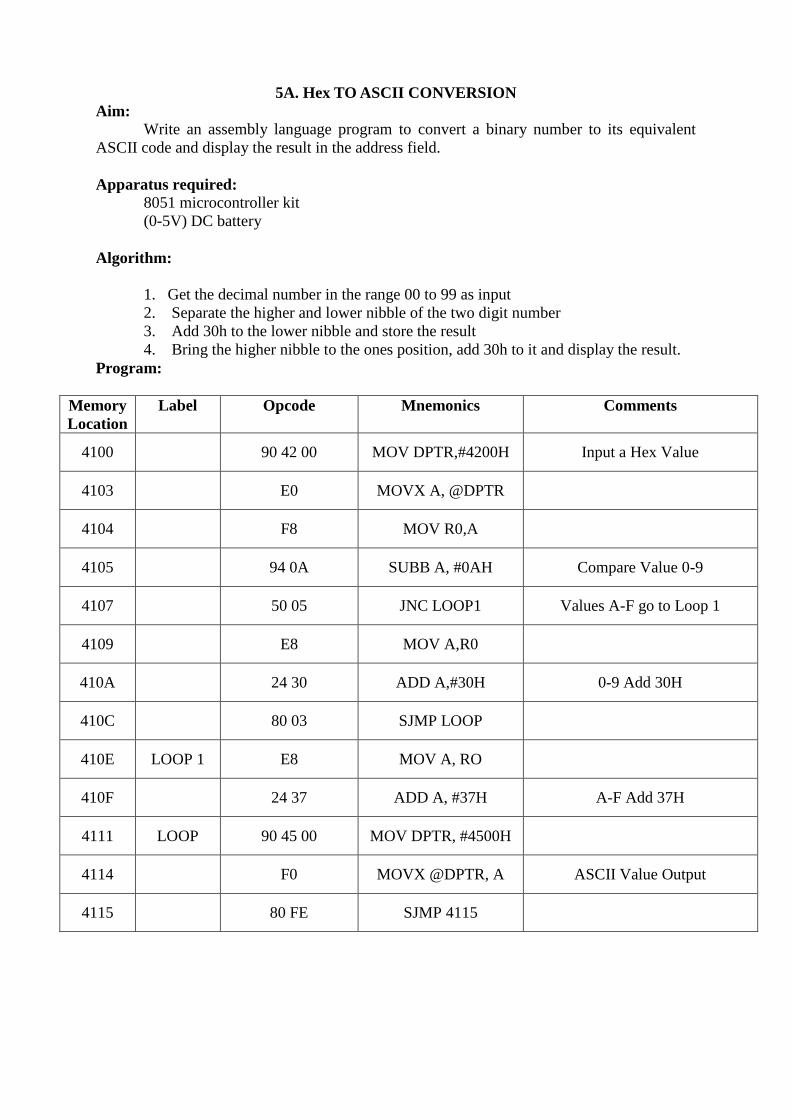
5A. Hex TO ASCII CONVERSION
Aim:
Write an assembly language program to convert a binary number to its equivalent
ASCII code and display the result in the address field.
Apparatus required:
8051 microcontroller kit
(0-5V) DC battery
Algorithm:
1. Get the decimal number in the range 00 to 99 as input
2. Separate the higher and lower nibble of the two digit number
3. Add 30h to the lower nibble and store the result
4. Bring the higher nibble to the ones position, add 30h to it and display the result.
Program:
Memory
Location
Label Opcode Mnemonics Comments
4100 90 42 00 MOV DPTR,#4200H Input a Hex Value
4103 E0 MOVX A, @DPTR
4104 F8 MOV R0,A
4105 94 0A SUBB A, #0AH Compare Value 0-9
4107 50 05 JNC LOOP1 Values A-F go to Loop 1
4109 E8 MOV A,R0
410A 24 30 ADD A,#30H 0-9 Add 30H
410C 80 03 SJMP LOOP
410E LOOP 1 E8 MOV A, RO
410F 24 37 ADD A, #37H A-F Add 37H
4111 LOOP 90 45 00 MOV DPTR, #4500H
4114 F0 MOVX @DPTR, A ASCII Value Output
4115 80 FE SJMP 4115

SAMPLE INPUT AND OUTPUT:
INPUT:
Memory address Data
4200 Hex Data=
OUTPUT:
Memory address Data
4500 ASCII Data=
Result:
Thus the assembly language program was written to converter Hexadecimal number to
equivalent ASCII Code and executed using 8051 microcontroller.
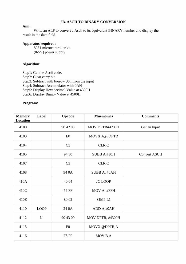
5B. ASCII TO BINARY CONVERSION
Aim:
Write an ALP to convert a Ascii to its equivalent BINARY number and display the
result in the data field.
Apparatus required:
8051 microcontroller kit
(0-5V) power supply
Algorithm:
Step1: Get the Ascii code.
Step2: Clear carry bit
Step3: Subtract with borrow 30h from the input
Step4: Subtract Accumulator with 0AH
Step5: Display Hexadecimal Value at 4300H
Step6: Display Binary Value at 4500H
Program:
Memory
Location
Label Opcode Mnemonics Comments
4100 90 42 00 MOV DPTR#4200H Get an Input
4103 E0 MOVX A,@DPTR
4104 C3 CLR C
4105 94 30 SUBB A,#30H Convert ASCII
4107 C3 CLR C
4108 94 0A SUBB A, #0AH
410A 40 04 JC LOOP
410C 74 FF MOV A, #FFH
410E 80 02 SJMP L1
4110 LOOP 24 0A ADD A,#0AH
4112 L1 90 43 00 MOV DPTR, #4300H
4115 F0 MOVX @DPTR,A
4116 F5 F0 MOV B,A

4118 79 08 MOV R1,#08H
411A 90 45 00 MOV DPTR,#4500H BINARY OUTPUT
411D LOP 13 RRC A
411E F5 F0 MOV B,A
4120 40 05 JC LOOP1
4122 74 00 MOV A,#00H
4124 F0 MOVX @DPTR,A
4125 80 03 SJMP RESULT
4127 LOOP1 74 01 MOV A, #01H
4129 F0 MOVX @DPTR, A
412A RESULT 05 82 INC DPL
412C E5 F0 MOV A,B
412E D9 ED DJNZ R1, LOP
4130 80 FE SJMP 4130
Address Sample1 Sample2
Input (ASCII) 4200
Hexa Decimal Value 4300
Output (BINARY)in
the data field
4500
4501
Result:
Thus the assembly language program was written to converter ASCII number to equivalent
Binary Value and executed using 8051 microcontroller.
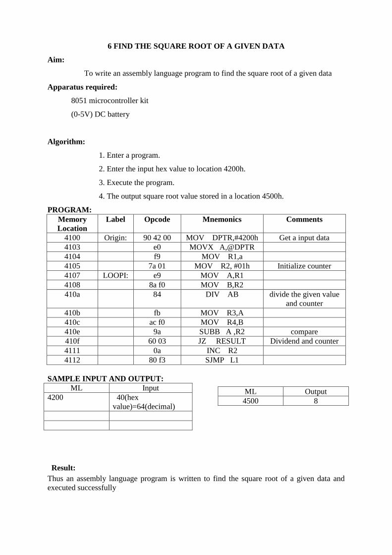
6 FIND THE SQUARE ROOT OF A GIVEN DATA
Aim:
To write an assembly language program to find the square root of a given data
Apparatus required:
8051 microcontroller kit
(0-5V) DC battery
Algorithm:
1. Enter a program.
2. Enter the input hex value to location 4200h.
3. Execute the program.
4. The output square root value stored in a location 4500h.
PROGRAM:
Memory
Location
Label Opcode Mnemonics Comments
4100 Origin: 90 42 00 MOV DPTR,#4200h Get a input data
4103 e0 MOVX A,@DPTR
4104 f9 MOV R1,a
4105 7a 01 MOV R2, #01h Initialize counter
4107 LOOPI: e9 MOV A,R1
4108 8a f0 MOV B,R2
410a 84 DIV AB divide the given value
and counter
410b fb MOV R3,A
410c ac f0 MOV R4,B
410e 9a SUBB A ,R2 compare
410f 60 03 JZ RESULT Dividend and counter
4111 0a INC R2
4112 80 f3 SJMP L1
SAMPLE INPUT AND OUTPUT:
Result: Thus an assembly language program is written to find the square root of a given data and
executed successfully
ML Input
4200 40(hex
value)=64(decimal)
ML Output
4500 8

7. Transfer data serially between two kits
Aim:
To write an assembly language program Transmitting and Receiving the data between two
kits.
Apparatus required:
8051 microcontroller kit
(0-5V) DC battery
Algorithm:
1. Initialize TMOD with 20H
2. Set the values for TCON and SCON
3. Set the input address to DPTR
4. Based on the bit value on SCON store the data in SBUF
5. Increment DPTR and check for the loop end value
PROGRAM FOR RECEIVER.
Memory
Location
Label Opcode Mnemonics Comments
4100 75 89 20 MOV TMOD, #20H
4103 75 8D A0 MOV TH1, #0A0H
4106 75 8B 00 MOV TL1, #00H
4109 75 88 40 MOV TCON, #40H
410C 75 98 58 MOV SCON, #58H
410F 90 45 00 MOV DPTR, #4500H
4112 RELOAD 7D 05 MOV R5, #05H
4114 CHECK 30 98 FD JNB SCON.0, CHECK
4117 C2 98 CLR SCON.0
4119 E5 99 MOV A, SBUF
411B F0 MOVX @DPTR, A
411C A3 INC DPTR
411D B4 3F F2 CJNE A, #3FH,
RELOAD
4120 DD F2 DJNZ R5, CHECK
4122 E4 CLAR A
4123 12 00 20 LCALL 0020H

Algorithm for Transmitter:
1. Initialize TMOD with 20H
2. Set the values for TCON and SCON
3. Set the input address to DPTR
4. Based on the bit value on SCON store the data in SBUF and move the data
to register ‘A’.
5. Increment DPTR and check for the loop end value
PROGRAM FOR TRANSMITTER.
Memory
Location
Label Opcode Mnemonics Comments
4100 75 89 20 MOV TMOD, #20H
4103 75 8D A0 MOV TH1, #0A0H
4106 75 8B 00 MOV TL1, #00H
4109 75 88 40 MOV TCON, #40H
410C 75 98 58 MOV SCON, #58H
410F 90 45 00 MOV DPTR, #4500H
4112 RELOAD 7D 05 MOV R5, #05H
4114 REPEAT E0 MOVX A, @DPTR
4115 F5 99 MOV SBUF, A
4117 CHECK 30 99 FD JNB SCON.1, CHECK
411A C2 99 CLR SCON.1
411C A3 INC DPTR
411D B4 3F F2 CJNE A, #3FH,
RELOAD
4120 DD F2 DJNZ R5, REPEAT
4122 E4 CLAR A
4123 12 00 20 LCALL 0020H
SAMPLE INPUT AND OUTPUT:
Sl.No Transmitter Input (Hex Values) Receiver Output (Hex Values)
1 00 00
2 11 11
3 22 22
4 33 33

Result: Thus an assembly language program displaying characters on seven segment display has been
executed.
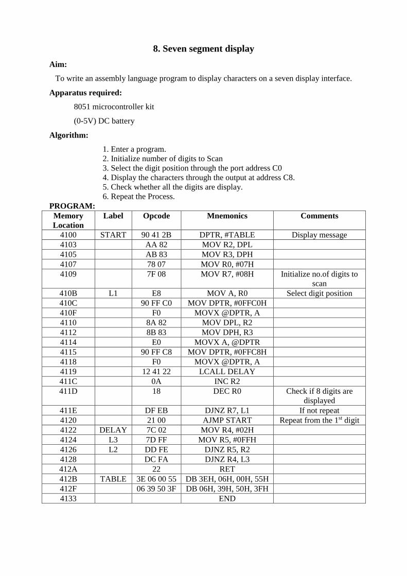
8. Seven segment display
Aim:
To write an assembly language program to display characters on a seven display interface.
Apparatus required:
8051 microcontroller kit
(0-5V) DC battery
Algorithm:
1. Enter a program.
2. Initialize number of digits to Scan
3. Select the digit position through the port address C0
4. Display the characters through the output at address C8.
5. Check whether all the digits are display.
6. Repeat the Process.
PROGRAM:
Memory
Location
Label Opcode Mnemonics Comments
4100 START 90 41 2B DPTR, #TABLE Display message
4103 AA 82 MOV R2, DPL
4105 AB 83 MOV R3, DPH
4107 78 07 MOV R0, #07H
4109 7F 08 MOV R7, #08H Initialize no.of digits to
scan
410B L1 E8 MOV A, R0 Select digit position
410C 90 FF C0 MOV DPTR, #0FFC0H
410F F0 MOVX @DPTR, A
4110 8A 82 MOV DPL, R2
4112 8B 83 MOV DPH, R3
4114 E0 MOVX A, @DPTR
4115 90 FF C8 MOV DPTR, #0FFC8H
4118 F0 MOVX @DPTR, A
4119 12 41 22 LCALL DELAY
411C 0A INC R2
411D 18 DEC R0 Check if 8 digits are
displayed
411E DF EB DJNZ R7, L1 If not repeat
4120 21 00 AJMP START Repeat from the 1st digit
4122 DELAY 7C 02 MOV R4, #02H
4124 L3 7D FF MOV R5, #0FFH
4126 L2 DD FE DJNZ R5, R2
4128 DC FA DJNZ R4, L3
412A 22 RET
412B TABLE 3E 06 00 55 DB 3EH, 06H, 00H, 55H
412F 06 39 50 3F DB 06H, 39H, 50H, 3FH
4133 END
SAMPLE INPUT AND OUTPUT:
Sl.No Input (hex Values) Output (Characters)
Result:
Thus an assembly language program displaying characters on seven segment display has been
executed.
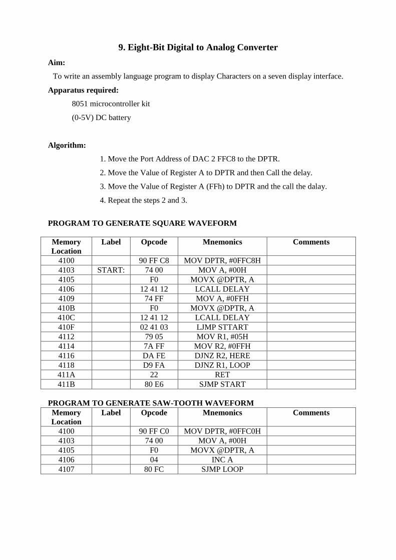
9. Eight-Bit Digital to Analog Converter
Aim:
To write an assembly language program to display Characters on a seven display interface.
Apparatus required:
8051 microcontroller kit
(0-5V) DC battery
Algorithm:
1. Move the Port Address of DAC 2 FFC8 to the DPTR.
2. Move the Value of Register A to DPTR and then Call the delay.
3. Move the Value of Register A (FFh) to DPTR and the call the dalay.
4. Repeat the steps 2 and 3.
PROGRAM TO GENERATE SQUARE WAVEFORM
Memory
Location
Label Opcode Mnemonics Comments
4100 90 FF C8 MOV DPTR, #0FFC8H
4103 START: 74 00 MOV A, #00H
4105 F0 MOVX @DPTR, A
4106 12 41 12 LCALL DELAY
4109 74 FF MOV A, #0FFH
410B F0 MOVX @DPTR, A
410C 12 41 12 LCALL DELAY
410F 02 41 03 LJMP STTART
4112 79 05 MOV R1, #05H
4114 7A FF MOV R2, #0FFH
4116 DA FE DJNZ R2, HERE
4118 D9 FA DJNZ R1, LOOP
411A 22 RET
411B 80 E6 SJMP START
PROGRAM TO GENERATE SAW-TOOTH WAVEFORM
Memory
Location
Label Opcode Mnemonics Comments
4100 90 FF C0 MOV DPTR, #0FFC0H
4103 74 00 MOV A, #00H
4105 F0 MOVX @DPTR, A
4106 04 INC A
4107 80 FC SJMP LOOP

PROGRAM TO GENERATE TRIANGULAR WAVEFORM
Memory
Location
Label Opcode Mnemonics Comments
4100 90 FF C8 MOV DPTR, #0FFC8H
4103 74 00 MOV A, #00H
4105 F0 MOVX @DPTR, A
4106 04 INC A
4107 70 FC JNZ LOOP1
4109 74 FF MOV A, #0FFH
411B F0 MOVX @DPTR, A
410C 14 DEC A
410D 70 FC JNZ LOOP2
410F 02 41 03 LJMP START
Result: Thus an assembly language program for Digital to Analog has been executed.

10. Eight-Bit Analog to Digital Converter
Aim:
To write an assembly language program to display Characters on a seven display interface.
Apparatus required:
8051 microcontroller kit
(0-5V) DC battery
Algorithm:
1. Make ALE low/high by moving the respective data from A register to
DPTR.
2. Move the SOC( Start Of Conversion) data to DPTR from FFD0
3. Check for the End Of Conversion and read data from Buffer at address
FFC0
4. End the Program.
PROGRAM:
Port Address for 74LS174 Latch: FFC8
Port Address for SOC: FFD0
Port Address for EOC 1: FFD8
Port Address for 74LS 244 Buffer: FFC0
Memory
Location
Label Opcode Mnemonics Comments
4100 90 FF C8 MOV DPTR, #FFC8
4103 74 10 MOV A, #10 Select Channel 0
4105 F0 MOVX @DPTR, A Make ALE Low
4106 74 18 MOV A, #18 Make ALE High
4108 F0 MOVX @DPTR, A
4109 90 FF D0 MOV DPTR, #FFD0
410C 74 01 MOV A, #01 SOC Signal High
410E F0 MOVX @DPTR, A
410F 74 00 MOV A, #00 SOC Signal Low
4111 F0 MOVX @DPTR, A
4112 90 FF D8 MOV DPTR, #FFD8
4115 E0 MOVX A, @DPTR
4116 30 E0 FC JNB E0, WAIT Check For EOC
4119 90 FF C0 MOV DPTR, #FFC0 Read ADC Data
411C E0 MOVX A, @DPTR
4110 90 41 50 MOV DPTR, #4150 Store the Data
4120 F0 MOVX @DPTR, A
4121 90 FE SJMP HERE

Result: Thus an assembly language program is executed for analog to digital conversion.

11. Internal Interrupt
Aim:
To write an assembly language program for Internal Interrupt.
Apparatus required:
8051 microcontroller kit
(0-5V) DC battery
Algorithm:
1. Move the value 081H to the Interrupt Enable pin to enable it.
2. Press INT0 interrupt is enabled. LED’s are on.
3. End the Program.
PROGRAM:
Memory
Location
Label Opcode Mnemonics Comments
4100 75 A8 81 MOV IE, #081H EXT0 Interrupt is
enabled
4103 20 89 03 JB TCON.1, LOOP1
4106 75 90 00 MOV P1, #00H
4109 LOOP1 30 89 03 JNB TCON.1, LOOP2
410C 75 90 FF MOV P1, #0FFH
410F LOOP2 32 RET1
4110 80 FE SJMP 4110
Result: Thus an assembly language program for the internal interrupt has been done.
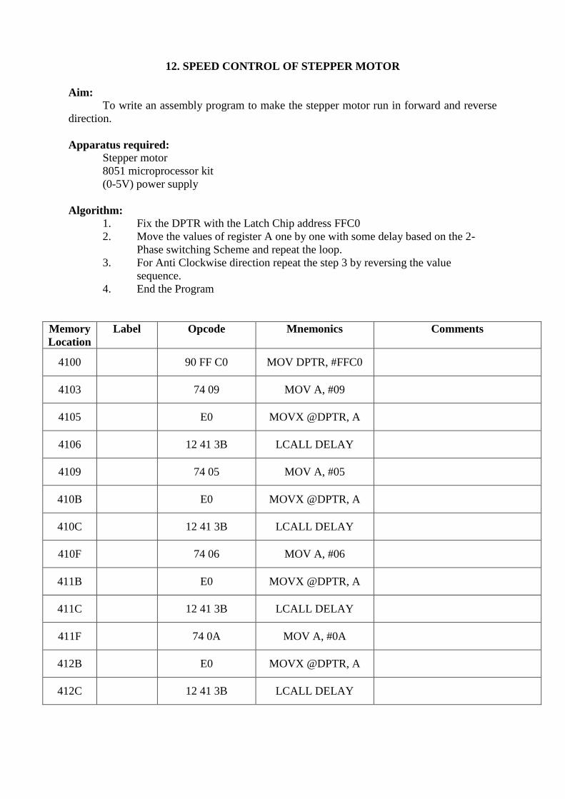
12. SPEED CONTROL OF STEPPER MOTOR
Aim:
To write an assembly program to make the stepper motor run in forward and reverse
direction.
Apparatus required:
Stepper motor
8051 microprocessor kit
(0-5V) power supply
Algorithm:
1. Fix the DPTR with the Latch Chip address FFC0
2. Move the values of register A one by one with some delay based on the 2-
Phase switching Scheme and repeat the loop.
3. For Anti Clockwise direction repeat the step 3 by reversing the value
sequence.
4. End the Program
Memory
Location
Label Opcode Mnemonics Comments
4100 90 FF C0 MOV DPTR, #FFC0
4103 74 09 MOV A, #09
4105 E0 MOVX @DPTR, A
4106 12 41 3B LCALL DELAY
4109 74 05 MOV A, #05
410B E0 MOVX @DPTR, A
410C 12 41 3B LCALL DELAY
410F 74 06 MOV A, #06
411B E0 MOVX @DPTR, A
411C 12 41 3B LCALL DELAY
411F 74 0A MOV A, #0A
412B E0 MOVX @DPTR, A
412C 12 41 3B LCALL DELAY

412F SJMP 412F
413B DELAY
413B L2 MOV R0, #55
413D L1 MOV R1, #FF
413F DJNZ R1, L1
413B DJNZ R0, L2
413D RET
Result:
Thus an assembly language program to control of stepper motor was executed
successfully using 8051 Microcontroller kit.

13. TRAFFIC LIGHT CONTROLLER
Aim:
To write an assembly language program to display Characters on a seven display interface.
Apparatus required:
8051 microcontroller kit
(0-5V) DC battery
Algorithm:
1. Fix the control the control and move the control word to control register.
2. Move the Traffic Light LED Position values to Port A, Port B and Port C
respectively based on the logic.
3. Fix the delay based on the requirement.
3. Execute the program.
PROGRAM: 4100 ORG 4100
CONTRL EQU 0FF0FH
PORT A EQU 0FF0CH
PORT B EQU 0FF0DH
PORT C EQU 0FF0EH
Memory
Location
Label Opcode Mnemonics Comments
4100 74 80 MOV A, #80H
4102 90 FF 0F MOV DPTR, #CONTRL
4105 F0 MOVX @DPTR, A
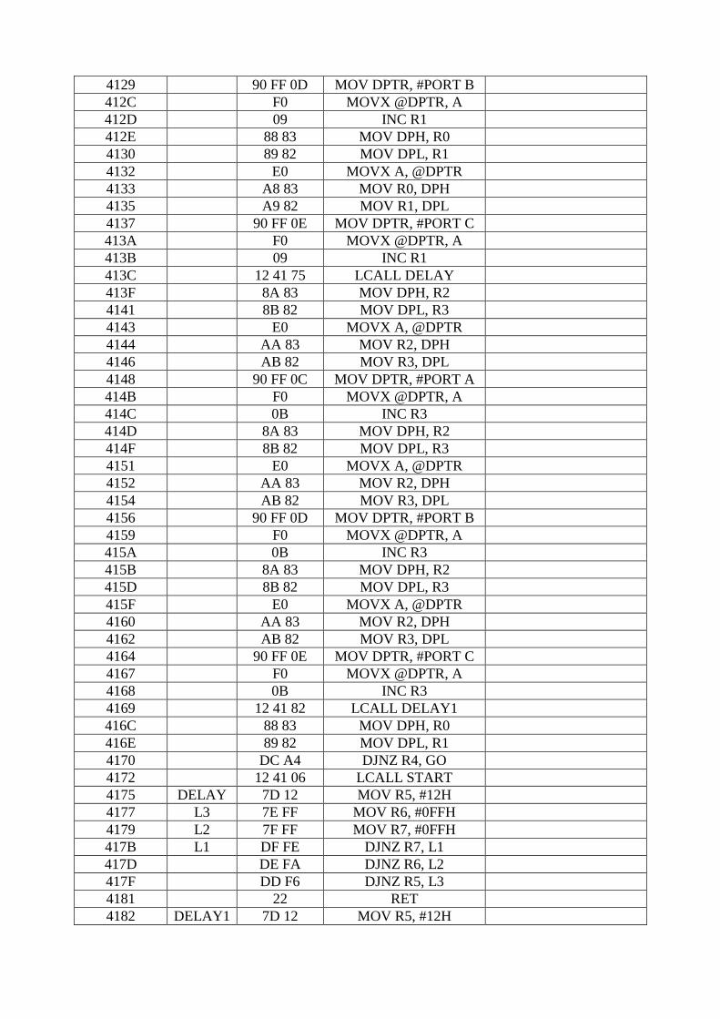
4106 START 7C 04 MOV R4, #04H
4108 90 41 9B MOV DPTR, #LOOK1
410B AA 83 MOV R2, DPH
410D AB 82 MOV R3, DPL
410F 90 41 8F MOV DPTR, #LOOK
4112 A8 83 MOV R0, DPH
4114 A9 82 MOV R1, DPL
4116 GO E0 MOVX A, @DPTR
4117 A8 83 MOV R0, DPH
4119 A9 82 MOV R1, DPL
411B 90 FF 0C MOV DPTR, #PORT A
411E F0 MOVX @DPTR, A
411F 09 INC R1
4120 88 83 MOV DPH, R0
4122 89 82 MOV DPL, R1
4124 E0 MOVX A, @DPTR
4125 A8 83 MOV R0, DPH
4127 A9 82 MOV R1, DPL
4129 90 FF 0D MOV DPTR, #PORT B
412C F0 MOVX @DPTR, A
412D 09 INC R1
412E 88 83 MOV DPH, R0
4130 89 82 MOV DPL, R1
4132 E0 MOVX A, @DPTR
4133 A8 83 MOV R0, DPH
4135 A9 82 MOV R1, DPL
4137 90 FF 0E MOV DPTR, #PORT C
413A F0 MOVX @DPTR, A
413B 09 INC R1
413C 12 41 75 LCALL DELAY
413F 8A 83 MOV DPH, R2
4141 8B 82 MOV DPL, R3
4143 E0 MOVX A, @DPTR
4144 AA 83 MOV R2, DPH
4146 AB 82 MOV R3, DPL
4148 90 FF 0C MOV DPTR, #PORT A
414B F0 MOVX @DPTR, A
414C 0B INC R3
414D 8A 83 MOV DPH, R2
414F 8B 82 MOV DPL, R3
4151 E0 MOVX A, @DPTR
4152 AA 83 MOV R2, DPH
4154 AB 82 MOV R3, DPL
4156 90 FF 0D MOV DPTR, #PORT B
4159 F0 MOVX @DPTR, A
415A 0B INC R3
415B 8A 83 MOV DPH, R2
415D 8B 82 MOV DPL, R3
415F E0 MOVX A, @DPTR
4160 AA 83 MOV R2, DPH
4162 AB 82 MOV R3, DPL
4164 90 FF 0E MOV DPTR, #PORT C
4167 F0 MOVX @DPTR, A
4168 0B INC R3
4169 12 41 82 LCALL DELAY1
416C 88 83 MOV DPH, R0
416E 89 82 MOV DPL, R1
4170 DC A4 DJNZ R4, GO
4172 12 41 06 LCALL START
4175 DELAY 7D 12 MOV R5, #12H
4177 L3 7E FF MOV R6, #0FFH
4179 L2 7F FF MOV R7, #0FFH
417B L1 DF FE DJNZ R7, L1
417D DE FA DJNZ R6, L2
417F DD F6 DJNZ R5, L3
4181 22 RET
4182 DELAY1 7D 12 MOV R5, #12H
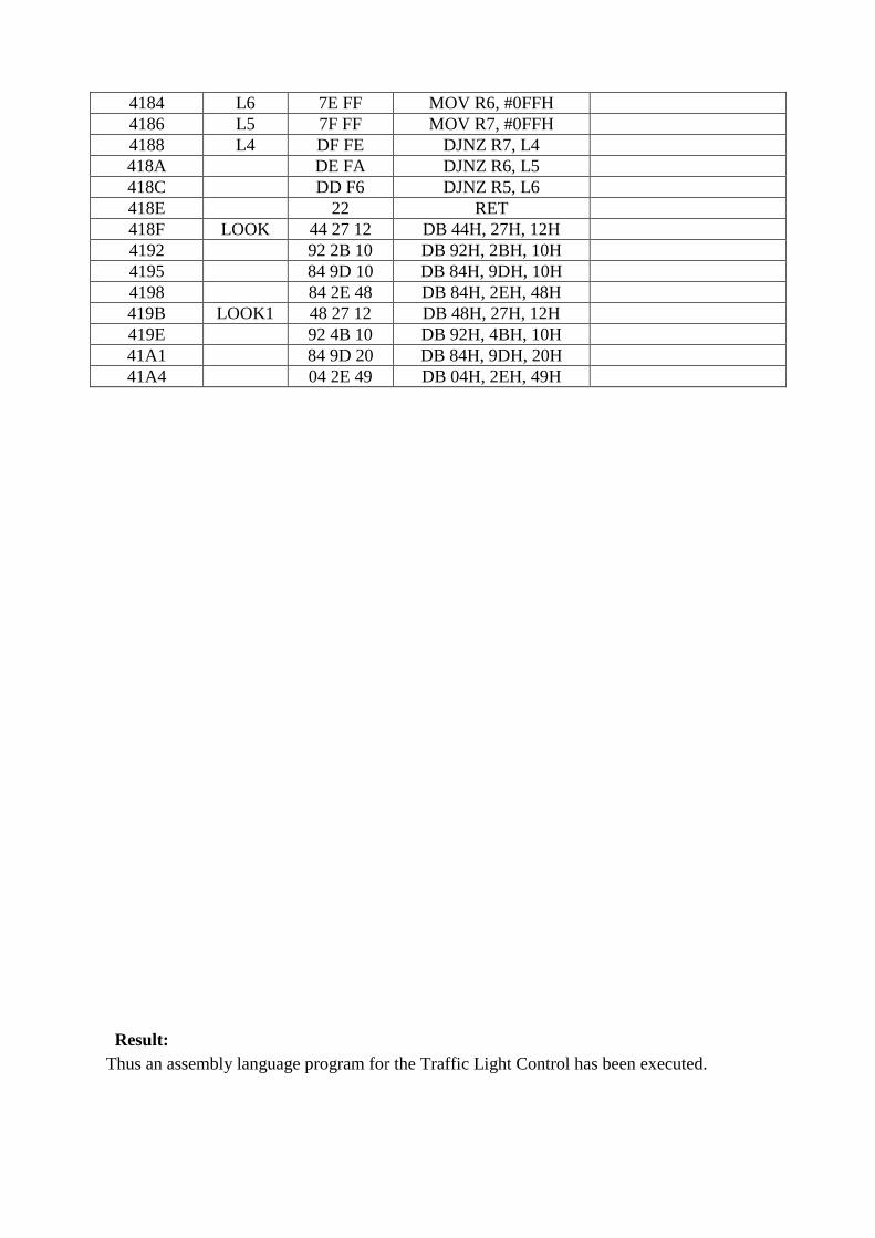
4184 L6 7E FF MOV R6, #0FFH
4186 L5 7F FF MOV R7, #0FFH
4188 L4 DF FE DJNZ R7, L4
418A DE FA DJNZ R6, L5
418C DD F6 DJNZ R5, L6
418E 22 RET
418F LOOK 44 27 12 DB 44H, 27H, 12H
4192 92 2B 10 DB 92H, 2BH, 10H
4195 84 9D 10 DB 84H, 9DH, 10H
4198 84 2E 48 DB 84H, 2EH, 48H
419B LOOK1 48 27 12 DB 48H, 27H, 12H
419E 92 4B 10 DB 92H, 4BH, 10H
41A1 84 9D 20 DB 84H, 9DH, 20H
41A4 04 2E 49 DB 04H, 2EH, 49H
Result: Thus an assembly language program for the Traffic Light Control has been executed.
Related Documents