Design and Analysis of Solar Devices in Public Places to Help Meet Energy Demand Justin Roberts, Justin Halversen, Christopher Running, Nathan Johnson Undergraduate Research Assistants Brigham Young University Provo, UT John Salmon Assistant Professor Brigham Young University Provo, UT Email: [email protected] Abstract—As finite energy resources are rapidly depleting, the world desperately needs to rely on more renewable energy resources, such as solar energy. The research described hereafter designs and analyzes the use of solar cells in public places, in the form of a solar table, to assess whether their use and energy output justifies their cost for use in public environments. The ultimate goal of this research is to develop a suite of devices and applications whereby solar power can be a publicly accessible commodity and to increase the usage of solar power by testing particular instances where solar technology can make an impact. Finally, this research explores the possible future that small-scale solar devices and technologies have when distributed throughout our community as part of the solution to the increasing energy demand. Keywords—Solar Energy, Design for Sustainability, Public Places, Cost-Benefit Analysis, Solar Tables I. I NTRODUCTION A. Background The sun’s energy emissions are significantly higher than other alternative energy sources. The world’s energy consumption totaled 107,748 TWh in 2013, averaging to 12.3 TW being drawn at any given moment throughout the year [3]. The sun’s power output is approximately 3.6 X 10 26 W with the incident power on the Earth being 166 X 10 15 W [1]. 30% of this incident power is reflected back into space and 19% is absorbed by the clouds and atmosphere [1]. This leaves 85 X 10 15 W (or 85,000 TW) of potential power to be collected through solar technologies at any given moment. The amount of power available from the sun is well over 6000 times the current world consumption. Indeed, there is a very large and renewable reservoir of untapped potential solar energy which could be made directly available to more people. B. Decreasing Costs for Solar Technology Solar costs have decreased over time [4]. Findings from Berkeley Lab’s ‘Utility-Scale Solar’ report shows the declining price of solar energy per KWh over time. This report drew from large volumes of empirical data among ground-mounted solar projects larger than 5 MW. Their findings showed that median up-front costs have dropped from around $6.3/W in 2009 to $3.1/W in 2014 [4]. It mentioned that some projects built in 2014 were even priced as low as $2/W. ,QVWDOOHG 3ULFH : $& ,QVWDOODWLRQ <HDU Fig. 1. Average installed price of photovoltaic projects (data from [4]) The Energy Department’s ‘Sunshot Initiative’ has a goal to decrease costs for solar technologies by 75% from 2010 to 2020 by funding universities, national laboratories, and other various projects [4]. If these trends continue, solar energy will be a promising energy resource for the general public. C. Solar Devices in Public Places The combination of more affordable solar technology, an ever-increasing global energy consumption, and a high potential of incident solar energy on the earth, encourages one to more fully explore the role of solar devices in becoming much more ubiquitous in today’s society. A number of research projects have begun this exploration including investigations in solar roads [10], solar bus stops [8], and even using solar cells as clothing [11]. This paper explores the design of a “solar table” that can be applied in any location where people use horizontal surfaces in some way that could capture some degree of incident light from the sun. This project supports the theme of the 2016 IEEE Technologies for Sustainability (SusTech) Conference which is “Sustainability in an Intelligent World” by implementing engineering, technology, and the use of renewable solar energy to create a more sustainable environment on a college campus. These “tables” could be found in a variety of outdoor locations with publicly available horizontal surfaces such as picnic tables at parks and campgrounds, on benches at train stations, and throughout outdoor patios at restaurants. However, horizontal surfaces placed indoors but close to windows still have some,

Welcome message from author
This document is posted to help you gain knowledge. Please leave a comment to let me know what you think about it! Share it to your friends and learn new things together.
Transcript

Design and Analysis of Solar Devices in PublicPlaces to Help Meet Energy Demand
Justin Roberts, Justin Halversen,Christopher Running, Nathan Johnson
Undergraduate Research AssistantsBrigham Young University
Provo, UT
John SalmonAssistant Professor
Brigham Young UniversityProvo, UT
Email: [email protected]
Abstract—As finite energy resources are rapidly depleting,the world desperately needs to rely on more renewable energyresources, such as solar energy. The research described hereafterdesigns and analyzes the use of solar cells in public places, inthe form of a solar table, to assess whether their use and energyoutput justifies their cost for use in public environments. Theultimate goal of this research is to develop a suite of devices andapplications whereby solar power can be a publicly accessiblecommodity and to increase the usage of solar power by testingparticular instances where solar technology can make an impact.Finally, this research explores the possible future that small-scalesolar devices and technologies have when distributed throughoutour community as part of the solution to the increasing energydemand.
Keywords—Solar Energy, Design for Sustainability, PublicPlaces, Cost-Benefit Analysis, Solar Tables
I. INTRODUCTION
A. Background
The sun’s energy emissions are significantly higherthan other alternative energy sources. The world’s energyconsumption totaled 107,748 TWh in 2013, averaging to 12.3TW being drawn at any given moment throughout the year[3]. The sun’s power output is approximately 3.6 X 1026 Wwith the incident power on the Earth being 166 X 1015 W[1]. 30% of this incident power is reflected back into spaceand 19% is absorbed by the clouds and atmosphere [1]. Thisleaves 85 X 1015 W (or 85,000 TW) of potential power tobe collected through solar technologies at any given moment.The amount of power available from the sun is well over6000 times the current world consumption. Indeed, there is avery large and renewable reservoir of untapped potential solarenergy which could be made directly available to more people.
B. Decreasing Costs for Solar Technology
Solar costs have decreased over time [4]. Findings fromBerkeley Lab’s ‘Utility-Scale Solar’ report shows the decliningprice of solar energy per KWh over time. This report drewfrom large volumes of empirical data among ground-mountedsolar projects larger than 5 MW. Their findings showed thatmedian up-front costs have dropped from around $6.3/W in2009 to $3.1/W in 2014 [4]. It mentioned that some projectsbuilt in 2014 were even priced as low as $2/W.
8QWLWOHG*UDSK%XLOGHU 3DJHRI
,QVWDOOHG3ULFH
:$
&
,QVWDOODWLRQ<HDU
Fig. 1. Average installed price of photovoltaic projects (data from [4])
The Energy Department’s ‘Sunshot Initiative’ has a goalto decrease costs for solar technologies by 75% from 2010 to2020 by funding universities, national laboratories, and othervarious projects [4]. If these trends continue, solar energy willbe a promising energy resource for the general public.
C. Solar Devices in Public Places
The combination of more affordable solar technology,an ever-increasing global energy consumption, and a highpotential of incident solar energy on the earth, encourages oneto more fully explore the role of solar devices in becomingmuch more ubiquitous in today’s society. A number of researchprojects have begun this exploration including investigations insolar roads [10], solar bus stops [8], and even using solar cellsas clothing [11].
This paper explores the design of a “solar table” that can beapplied in any location where people use horizontal surfacesin some way that could capture some degree of incident lightfrom the sun. This project supports the theme of the 2016 IEEETechnologies for Sustainability (SusTech) Conference whichis “Sustainability in an Intelligent World” by implementingengineering, technology, and the use of renewable solar energyto create a more sustainable environment on a college campus.These “tables” could be found in a variety of outdoor locationswith publicly available horizontal surfaces such as picnic tablesat parks and campgrounds, on benches at train stations, andthroughout outdoor patios at restaurants. However, horizontalsurfaces placed indoors but close to windows still have some,
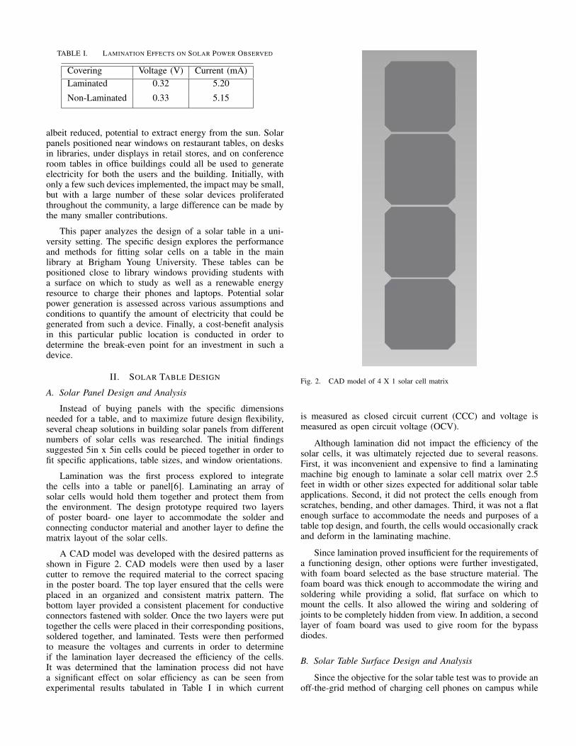
TABLE I. LAMINATION EFFECTS ON SOLAR POWER OBSERVED
Covering Voltage (V) Current (mA)Laminated 0.32 5.20
Non-Laminated 0.33 5.15
albeit reduced, potential to extract energy from the sun. Solarpanels positioned near windows on restaurant tables, on desksin libraries, under displays in retail stores, and on conferenceroom tables in office buildings could all be used to generateelectricity for both the users and the building. Initially, withonly a few such devices implemented, the impact may be small,but with a large number of these solar devices proliferatedthroughout the community, a large difference can be made bythe many smaller contributions.
This paper analyzes the design of a solar table in a uni-versity setting. The specific design explores the performanceand methods for fitting solar cells on a table in the mainlibrary at Brigham Young University. These tables can bepositioned close to library windows providing students witha surface on which to study as well as a renewable energyresource to charge their phones and laptops. Potential solarpower generation is assessed across various assumptions andconditions to quantify the amount of electricity that could begenerated from such a device. Finally, a cost-benefit analysisin this particular public location is conducted in order todetermine the break-even point for an investment in such adevice.
II. SOLAR TABLE DESIGN
A. Solar Panel Design and Analysis
Instead of buying panels with the specific dimensionsneeded for a table, and to maximize future design flexibility,several cheap solutions in building solar panels from differentnumbers of solar cells was researched. The initial findingssuggested 5in x 5in cells could be pieced together in order tofit specific applications, table sizes, and window orientations.
Lamination was the first process explored to integratethe cells into a table or panel[6]. Laminating an array ofsolar cells would hold them together and protect them fromthe environment. The design prototype required two layersof poster board- one layer to accommodate the solder andconnecting conductor material and another layer to define thematrix layout of the solar cells.
A CAD model was developed with the desired patterns asshown in Figure 2. CAD models were then used by a lasercutter to remove the required material to the correct spacingin the poster board. The top layer ensured that the cells wereplaced in an organized and consistent matrix pattern. Thebottom layer provided a consistent placement for conductiveconnectors fastened with solder. Once the two layers were puttogether the cells were placed in their corresponding positions,soldered together, and laminated. Tests were then performedto measure the voltages and currents in order to determineif the lamination layer decreased the efficiency of the cells.It was determined that the lamination process did not havea significant effect on solar efficiency as can be seen fromexperimental results tabulated in Table I in which current
Fig. 2. CAD model of 4 X 1 solar cell matrix
is measured as closed circuit current (CCC) and voltage ismeasured as open circuit voltage (OCV).
Although lamination did not impact the efficiency of thesolar cells, it was ultimately rejected due to several reasons.First, it was inconvenient and expensive to find a laminatingmachine big enough to laminate a solar cell matrix over 2.5feet in width or other sizes expected for additional solar tableapplications. Second, it did not protect the cells enough fromscratches, bending, and other damages. Third, it was not a flatenough surface to accommodate the needs and purposes of atable top design, and fourth, the cells would occasionally crackand deform in the laminating machine.
Since lamination proved insufficient for the requirements ofa functioning design, other options were further investigated,with foam board selected as the base structure material. Thefoam board was thick enough to accommodate the wiring andsoldering while providing a solid, flat surface on which tomount the cells. It also allowed the wiring and soldering ofjoints to be completely hidden from view. In addition, a secondlayer of foam board was used to give room for the bypassdiodes.
B. Solar Table Surface Design and Analysis
Since the objective for the solar table test was to provide anoff-the-grid method of charging cell phones on campus while
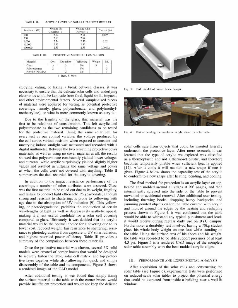
TABLE II. ACRYLIC COVERING SOLAR CELL TEST RESULTS
Resistance (Ω) Voltage NoCovering (V)
Voltage withAcrylic (V) Current (A)
100 2.52 2.51 0.025330 2.53 2.541,000 2.54 2.53 0.0210,000 2.53 2.52100,000 2.53 2.53 0.00002
TABLE III. PROTECTIVE MATERIAL COMPARISON
Material Cost Durability Yellowing Weight Eff.Glass 3 3 No 3 -Polycarbonate 2 1 Yes 1 3Acrylic (PMMA) 1 2 No 1 1
1- Best, 3- Worst
studying, eating, or taking a break between classes, it wasnecessary to ensure that the delicate solar cells and underlyingelectronics would be kept safe from food, liquid spills, impacts,and other environmental factors. Several sample-sized piecesof material were acquired for testing as potential protectivecoverings, namely, glass, polycarbonate, and poly(methyl-methacrylate), or what is more commonly known as acrylic.
Due to the fragility of the glass, this material was thefirst to be ruled out of consideration. This left acrylic andpolycarbonate as the two remaining candidates to be testedfor the protective material. Using the same solar cell forevery test as our control variable, the voltage produced bythe cell across various resistors when exposed to constant andunvarying indoor sunlight was measured and recorded with adigital multimeter. Between the two remaining protective covermaterials, as well as using no cover material at all, the resultsshowed that polycarbonate consistently yielded lower voltagesand currents, while acrylic surprisingly yielded slightly highervalues and resulted in virtually the same voltage and poweras when the cells were not covered with anything. Table IIsummarizes the data recorded for the acrylic covering.
In addition to the impact resistance performance of thecoverings, a number of other attributes were assessed. Glasswas the first material to be ruled out due to its weight, fragility,and failure to conduct light efficiently. Polycarbonate, althoughstrong and resistant to shattering, is prone to yellowing withage due to the absorption of UV radiation [9]. This yellow-ing, or photodegradation, prohibits the conduction of certainwavelengths of light as well as decreases its aesthetic appeal,making it a less useful candidate for a solar cell coveringcompared to glass. Ultimately, it was decided that the acrylicmaterial would be the optimal choice for a covering due to itslower cost, reduced weight, fair resistance to shattering, resis-tance to photodegradation from exposure to UV solar radiation,and highest recorded power efficiency. Table III provides asummary of the comparison between these materials.
Once the protective material was chosen, several 3D solidmodels were created of corner braces that would be designedto securely fasten the table, solar cell matrix, and top protec-tive layer together while also allowing for quick and simpledisassembly of the table and its components. Figure 3 showsa rendered image of the CAD model.
After additional testing, it was found that simply fixingthe surface material to the table with the corner braces wouldprovide insufficient protection and would not keep the delicate
Fig. 3. CAD model of corner brace design
Fig. 4. Test of bending thermoplastic acrylic sheet for solar table
solar cells safe from objects that could be inserted laterallyunderneath the protective layer. After more research, it waslearned that the type of acrylic we explored was classifiedas a thermoplastic and not a thermoset plastic, and thereforebecomes temporarily pliable when sufficient heat is applied[12]. After it cools it will maintain a new shape if one isgiven. Figure 4 below shows the capability test of the acrylicto conform to a new shape after heating, bending, and cooling.
The final method for protection is an acrylic layer on top,heated and molded around all edges at 90 angles, and thenintermittently screwed into the side of the table to preventunwanted or accidental removal. After additional user testing,including throwing books, dropping heavy backpacks, andjamming pointed objects on top the table covered with acrylicand molded around the edges by the heating and reshapingprocess shown in Figure 4, it was confirmed that the tablewould be able to withstand any typical punishment and loadsit would receive during regular daily use on BYU campus.Furthermore, a durability test involved having a 70kg studentplace his whole body weight on one foot while standing onthe table. Using the surface area of his shoes and his weight,the table was recorded to be able support pressures of at least4.3 psi. Figure 5 is a rendered CAD image of the completesolar table assembly with the heat molded acrylic edges.
III. PERFORMANCE AND EXPERIMENTAL ANALYSIS
After acquisition of the solar cells and constructing thesolar table (see Figure 6), experimental tests were performedon reduced-scale solar tables to project the potential energythat could be extracted from inside a building near a well-litwindow.

Fig. 5. CAD model of solar table with molded acrylic edges
Fig. 6. Concept image of the solar table
The total potential power given from solar cell tests weremeasured using the following equation:
P =Pc
Ac·Am (1)
where P is defined as the total potential power in Watts (W)of the solar table, Pc is the potential power of the individualsolar cells in Watts, and Ac and Am are the surface areas of asingle cell and the total area the solar cell matrix, respectively,in square inches (in2), such that the number of solar cells nc
on the table is:nc =
Am
Ac(2)
andP = Pcnc (3)
A. Theoretical Solar Table Power Potential
The solar cells, as mentioned above, that best fit ourapplication were 5in x 5in and this area of 25 in2 was rated tooutput 2.8 W of power. The prototype solar table was measuredto fit 70 cells on the top, meaning theoretically the tablewould be able to produce 196 W in ideal conditions. However,it was fully expected that this maximum value would berarely, if ever, observed based on the application environmentsand constraints imposed upon the device to serve additionalpurposes (e.g. inside study table).
After all, a completely horizontal orientation of a solarpanel is not the optimum angle of inclination to maximize
Fig. 7. The scattering of a source ray into randomly-angled diffuse rays anda main specular ray (from [7])
the cell efficiency of absorbing incident light directly from thesun (with the exception of certain latitudes at certain timesof the day). After an original incident light ray from the sunstrikes or passes through a material of a differing density likewalls, ceilings, or glass windows, the incident ray is split upinto many smaller and less intense beams that reflect off ofthe material at random angles due to the reflections off ofthe microscopic surface imperfections that are present, calleddiffused light. However, since this current application of usingsolar cells on the tops of tables will initially be used indoors,the majority of light energy that these cells will be absorbingis diffused light [5]. The incident beam will also producea primary reflected ray called the specular beam that willreflect off at approximately the same angle as the incidentbeam with varying intensity depending on the roughness ofthe material it is incident upon, or equivalently the amount ofdiffused light that is produced. These types of beams are mostcommonly visualized when reflecting off of surfaces such assnow, mirrors, or finely polished metals as depicted in Figure7 [7]. Since the initial locations of the solar table will beindoors, most, if not all of the light absorbed by the cellswill be diffused light that is the result of the scattering of anincident beam after making contact with the surrounding wallsand other rough-surfaced objects.8QWLWOHG*UDSK%XLOGHU 3DJHRI
9ROWD
JHP
9
&XUUHQWP$
Fig. 8. Current vs voltage measurements to determine maximum power inshade

B. Experimental Testing for Solar Table Power Potential
In order to experimentally evaluate the impact of thediffused incident light on the solar table inside a building,a simple device was designed to quantify the energy createdwith different resistances. Results were produced in a practicalexperiment consisting of a small 3
4 X 1 inch square solar cellplaced in series with 15 different resistors. After measuringthe voltage output from the cell, using one resistor at a timeto generate various currents, sets of data were gathered fromboth shaded and sun-lit areas. This data enabled comparisonsof power generation at different resistive loads to calculate themaximum instantaneous power of the cells in both light anddark conditions. This point of instantaneous power derivedfrom voltage and current is henceforth referred to as the“Maximum Power Point” (MPP). Data for the shaded portionis provided in Figure 8. The solar cell produced 0.335 X 10⁻³
W/in2 in the shaded area and 4.652 X 10⁻³ W/in2 in directsunlight. These values, when applied to the dimensions ofthe solar table prototype (see Figure 9), gave an extrapolatedmaximum power of 8.14 W.
Fig. 9. Assembly of Prototype Solar Table next to the Window in the BYUCrabtree Engineering Building
C. Experimental Testing using Data Logger for MPP
As the measured results differed so drastically, it becamenecessary to retry testing using a device that could make manymeasurements over an extended period of time. Such a devicewas constructed to track the maximum power point of 25-5X5in. cells (total area of 625 in2) incrementally over the space ofa few days. This data logger used an Arduino micro-controllerand a few custom-designed PCB’s, as shown in Figure 10, totake scaled analog voltage values and store them in an SDcard. The microcontroller, as shown in Figure 11, allowed thecurrent from the cells to pass through unique combinationsof resistors (ranging from 61 to 10000 ohms) in order togenerate a data set from which the MPP could be extracted.The time, date, and luminescence were recorded with eachreading. Readings were taken every minute and stored in theSD card until the device was powered off. It’s important tonote that after all the tests were completed using this device,they were determined to have an error of +/-10%. This errorwas calculated by making hand calculations using the samecells in the same location at the same time.
The highest MPP ever observed with this device whileattached to the test 25-cell system was 4.88 W (see data
Fig. 10. Custom-designed PCB’s and power logging device for accuratemeasurements
from logger presented in Figure 12), or 7.808 X 10⁻³ W/in2.This result was surprising, as the preliminary practical testestimated a maximum power of only 4.65 X 10⁻³ W/in2
with inside conditions near a south facing window. The newpotential power output of the table was reassessed to be 13.66W. This value was trusted to be more likely than the otherconsidering the variables that existed between the cells usedin the preliminary testing and the cells used in this small-scale system test. Possible causes of the discrepancy mighthave been misinterpretation of instrument readings or failure toanticipate variables such as cell composition or inconsistencyin sunlight between tests. Also, the datalogger allowed for alonger test period whereas the manual test was taken in onesitting. It is also important to point out that the datalogger wastesting 5X5 in. cells where the manual test was testing 3
4 X 1in. bought from a different vendor.
IV. COST-BENEFIT ANALYSIS
The next step was to determine the cost vs. energy savingsover time in order to determine how long it would take topay off the cells and the solar table collectively. The variousestimated costs for this prototype design are summarized inTable IV and include significantly conservative estimates.
The total estimated cost of the prototype solar table wasapproximately $450. BYU was assumed to pay $0.05 per kWhof electricity [14]. Utah, over the course of a year, has anaverage rate of 5.3 hrs per day of unobstructed sunlight [13].If the cells provided 13.66W for 5.3 hours per day, it would
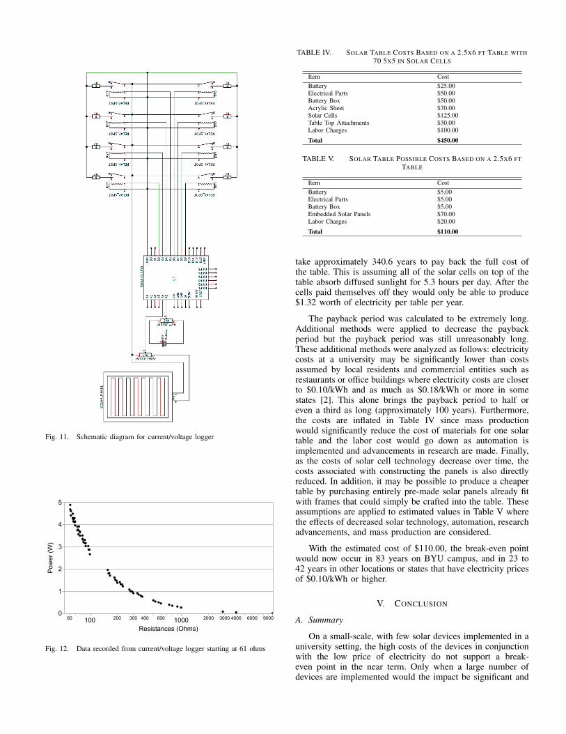
Fig. 11. Schematic diagram for current/voltage logger
7UDQVSRVHRI8QWLWOHG*UDSK%XLOGHU 3DJHRI
3RZHU:
5HVLVWDQFHV2KPV
Fig. 12. Data recorded from current/voltage logger starting at 61 ohms
TABLE IV. SOLAR TABLE COSTS BASED ON A 2.5X6 FT TABLE WITH70 5X5 IN SOLAR CELLS
Item CostBattery $25.00Electrical Parts $50.00Battery Box $50.00Acrylic Sheet $70.00Solar Cells $125.00Table Top Attachments $30.00Labor Charges $100.00
Total $450.00
TABLE V. SOLAR TABLE POSSIBLE COSTS BASED ON A 2.5X6 FTTABLE
Item CostBattery $5.00Electrical Parts $5.00Battery Box $5.00Embedded Solar Panels $70.00Labor Charges $20.00
Total $110.00
take approximately 340.6 years to pay back the full cost ofthe table. This is assuming all of the solar cells on top of thetable absorb diffused sunlight for 5.3 hours per day. After thecells paid themselves off they would only be able to produce$1.32 worth of electricity per table per year.
The payback period was calculated to be extremely long.Additional methods were applied to decrease the paybackperiod but the payback period was still unreasonably long.These additional methods were analyzed as follows: electricitycosts at a university may be significantly lower than costsassumed by local residents and commercial entities such asrestaurants or office buildings where electricity costs are closerto $0.10/kWh and as much as $0.18/kWh or more in somestates [2]. This alone brings the payback period to half oreven a third as long (approximately 100 years). Furthermore,the costs are inflated in Table IV since mass productionwould significantly reduce the cost of materials for one solartable and the labor cost would go down as automation isimplemented and advancements in research are made. Finally,as the costs of solar cell technology decrease over time, thecosts associated with constructing the panels is also directlyreduced. In addition, it may be possible to produce a cheapertable by purchasing entirely pre-made solar panels already fitwith frames that could simply be crafted into the table. Theseassumptions are applied to estimated values in Table V wherethe effects of decreased solar technology, automation, researchadvancements, and mass production are considered.
With the estimated cost of $110.00, the break-even pointwould now occur in 83 years on BYU campus, and in 23 to42 years in other locations or states that have electricity pricesof $0.10/kWh or higher.
V. CONCLUSION
A. Summary
On a small-scale, with few solar devices implemented in auniversity setting, the high costs of the devices in conjunctionwith the low price of electricity do not support a break-even point in the near term. Only when a large number ofdevices are implemented would the impact be significant and

the costs be reduced. Even still, inside conditions are less thanideal relying on diffused light. It would be a more acceptableoption if direct sunlight was being used in outside publicspaces. If the manufacturer rating of 2.8 W were used, thenthe table would produce 196 W and would pay itself off in5.8 years while saving $18.95/year using the university powercost of $0.05/kWh. It is important to note that 2.8 W is atheoretical value and would need further testing to support thepayoff claim of 5.8 years, but leads to the notion that outdoorapplications are much more reasonable.
However, certain intangible or indirect benefits may makethe concept of solar devices more economically viable. As theworld continues to gain familiarity and confidence in solarenergy technology, research and development will continue toaccelerate in this field, which in turn will decrease the costof this technology even further. Users of the solar table canbecome more conscious of their energy consumption and seekout more sustainable ways of meeting their needs. Finally,education of solar energy technology, especially in a universitysetting, will create a greater general awareness of the manypractical uses of this technology as well as of the importanceof developing a self-sufficient community.
B. Future Work
If more power is able to be generated by the implementa-tion of these tables in outdoor environments, then the tableswill also be able to generate enough voltage to charge largerdevices commonly used on a college campus setting, suchas laptops and tablets, which increases the usefulness andappeal of the tables overall. To improve the amount of powergenerated by the table, and thus decrease the payback time,future research and design options for outdoor derivationsof the solar table concept will be considered, specificallypicnic tables around campus. The challenge presented withoutdoor applications is that of weatherproofing the systemagainst the harsh seasonal conditions of Utah and other similarenvironments.
Other applications of solar devices may become morefeasible in different public places, especially in conditions thatare outside and are exposed to greater levels of sunlight. Futureefforts will explore solar picnic tables, solar blinds, solar cars,and solar posters in order to determine if there are other small-scale implementations of solar energy devices that prove usefulin developing a self-sustaining community.
ACKNOWLEDGMENT
The authors would like to express gratitude to the BrighamYoung University ORCA program and Pacific Horizon CreditUnion for funding some of the cost of materials.
REFERENCES
[1] Derek Abbott. Keeping the energy debate clean: how do we supply theworld’s energy needs? Proceedings of the IEEE, 98(1):42–66, 2010.
[2] U.S. Energy Information Administration. Electric power monthly withdata for May 2016, 2016.
[3] International Energy Agency. Key World Energy Statistics 2015, 2015.
[4] Mark Bolinger and Joachim Seel. Utility-Scale Solar 2014: AnEmpirical Analysis of Project Cost, Performance, and Pricing Trendsin the United States. September 2015. Lawrence Berkeley NationalLaboratory.
[5] Pat Hanrahan and Wolfgang Krueger. Reflection from layered surfacesdue to subsurface scattering. In Proceedings of the 20th Annual Confer-ence on Computer Graphics and Interactive Techniques, SIGGRAPH’93, pages 165–174, New York, NY, USA, 1993. ACM.
[6] J. Huang, G. Li, and Y. Yang. A Semi-transparent Plastic Solar CellFabricated by a Lamination Process. Advanced Materials, 20(3):415–419, 2008.
[7] Scott Juds. Photoelectric sensors and controls: selection and applica-tion, volume 63. CRC Press, 1988.
[8] Damon Langlois, Christopher Paynter, James Ward, and MichaelMarek. Solar-powered bus stop, September 24 2003. US Patent App.10/528,983.
[9] M. Yazdan Mehr, W.D. van Driel, K.M.B. Jansen, P. Deeben,M. Boutelje, and G.Q. Zhang. Photodegradation of bisphenol a poly-carbonate under blue light radiation and its effect on optical properties.Optical Materials, 35(3):504 – 508, 2013.
[10] A Northmore and S Tighe. Innovative Pavement Design: Are SolarRoads Feasible? In 2012 Conference and Exhibition of the Transporta-tion Association of Canada-Transportation: Innovations and Opportu-nities, 2012.
[11] Markus B Schubert and Jurgen H Werner. Flexible solar cells forclothing. Materials Today, 9(6):42–50, 2006.
[12] D Singh, A Kumar, and KN Rai. Nanosil strengthening of PMMAcomposite panels. Journal of Thermoplastic Composite Materials,25(5):591–606, 2012.
[13] Solardirect.com. http://www.solardirect.com/pv/systems/gts/gts-sizing-sun-hours.html, 2015. Accessed: 2016-07-30.
[14] The Daily Universe. It’s not a power plant, it’s a heatingplant. http://universe.byu.edu/2007/01/08/its-not-a-power-plant-its-a-heating-plant/, 2007. Accessed: 2016-08-02.
Related Documents