IEEE TRANSACTIONS ON VERY LARGE SCALE INTEGRATION (VLSI) SYSTEMS, VOL. 20, NO. 4, APRIL 2012 697 VLSI Architecture of Arithmetic Coder Used in SPIHT Kai Liu, Evgeniy Belyaev, and Jie Guo Abstract—A high-throughput memory-efficient arithmetic coder architecture for the set partitioning in hierarchical trees (SPIHT) image compression is proposed based on a simple context model in this paper. The architecture benefits from various opti- mizations performed at different levels of arithmetic coding from higher algorithm abstraction to lower circuits’ implementations. First, the complex context model used by software is mitigated by designing a simple context model, which just uses the brother nodes’ states in the coding zerotree of SPIHT to form context sym- bols for the arithmetic coding. The simple context model results in a regular access pattern during reading the wavelet transform coefficients, which is convenient to the hardware implementation, but at a cost of slight performance loss. Second, in order to avoid rescanning the wavelet transform coefficients, a breadth first search SPIHT without lists algorithm is used instead of SPIHT with lists algorithm. Especially, the coding bit-planes of each zero tree are processed in parallel. Third, an out-of-order execution mechanism for different types of context is proposed that can allocate the context symbol to the idle arithmetic coding core with a different order that of the input. For the balance of the input rate of the wavelet coefficients, eight arithmetic coders are replicated in the compression system. And in one arithmetic coder, there exists four cores to process different contexts. Fourth, several dedicated circuits are designed to further improve the throughput of the architecture. The common bit detection (CBD) circuit is used for unrolling the renormalization stage of the arithmetic coding. The carry look-ahead adder (CLA) and fast multiplier-divider are also employed to shorten the critical path in the architecture. Moreover, an adaptive clock switch mechanism can stop some invalid bit-planes’ clock for the power saving purpose according to the input images. Experimental results demonstrate that the proposed architecture attains a throughput of 902.464 Mb/s at its maximum and achieves savings of 20.08% in power consumption over full bit-planes coding scheme based on field-programmable gate arrays (FPGAs). Index Terms—Arithmetic coding, common bit detection (CBD) circuit, context model, out-of-order execution, set partitioning in hierarchical trees (SPIHT), VLSI arithmetic coder architecture. Manuscript received May 14, 2010; revised September 14, 2010; accepted January 19, 2011. Date of publication February 24, 2011; date of current ver- sion March 12, 2012. This work was supported in part by the National Natural Science Foundation of China under Grant 60802076, by the Fundamental Re- search Funds for the Central Universities under Grant JY10000903003, and by the Open Research Funds of State Key Laboratory for novel software technology under Grant KFKT2010B28. This work was done in part at the State Key Lab- oratory for Novel Software Technology, Nanjing University, China. K. Liu is with the Computer School, Xidian University, Shaanxi 710071, China (e-mail: [email protected]). E. Belyaev is with Saint-Petersburg Institute for Informatics and Automation of the Russian Academy of Sciences, Saint-Petersburg 199178, Russian Feder- ation (e-mail: [email protected]). J. Guo is with the Communication School, Xidian University, Xi’an, Shaanxi 710071, China (e-mail: [email protected]). Color versions of one or more of the figures in this paper are available online at http://ieeexplore.ieee.org. Digital Object Identifier 10.1109/TVLSI.2011.2109068 I. INTRODUCTION A S arithmetic coding (AC) [1], [2] method can obtain op- timal performance for its ability to generate codes with fractional bits, it is widely used by various image compression algorithms, such as the QM in JPEG [3], the MQ in JPEG2000 [4]–[6], and the context-based adaptive binary arithmetic coder (CABAC) [7], [8] in H.264. Especially, the set partitioning in hierarchical trees (SPIHT) [9] uses an AC method to improve its peak signal-to-noise ratio (PSNR) about 0.5 dB. Although the theory and program code of AC are mature, the complicated internal operations of AC limit its application for some real time fields, such as satellite image and high speed camera image com- pressions. In order to achieve performance gains, high speed ar- chitecture of AC in compression scenarios must be designed to meet the throughput requirement. Thus both industrial and academic research groups have put their efforts to AC hardware architectures for various image compression systems. However, there are two main challenges in hardware architecture design for high speed applications. One is data dependencies in AC which require the result of iteration before next run can commence during the adaptive model up- date and internal loops. The other one is that AC requires in- creasingly greater precision as more data arrive. In order to deal with such difficulties, several architectures are proposed in the past years. Wiseman [10] proposed a systolic hardware architecture for a quasi AC which is a simple version of AC. In [10], the archi- tecture uses a pipeline processing to compute each stage of AC, which eliminates an internal high frequency clock and utilizes a fast lookup table for state transitions. Although the architec- ture can improve the speed of the internal operations, such as the probability interval update and cumulative calculations, it cannot offer supports for multi-contexts AC processing in image compression fields. For the QM coder in JPEG, Andra’s [11] gave a new architecture which decreases operations for the more probable symbol (MPS) and used a non-overlap window style for the speedup purpose. In [11], the probability interval par- tition is accelerated by exchange of the less probable symbol (LPS) interval with the MPS interval. Thus the amount of op- erations is reduced by 60%–70% compared with other coders. Another highlight of [11] is the non-overlap window that is ap- plied to the continuous MPS in order to simplify renormaliza- tion operation. Due to simple operations in Andra’s coder, the performance is slightly lowered by 1%–3%. In SPIHT algorithm aspect, many researchers proposed var- ious modifications to improve performance of SPIHT. Some algorithms aim for better PSNR values, which do not concern 1063-8210/$26.00 © 2011 IEEE

Welcome message from author
This document is posted to help you gain knowledge. Please leave a comment to let me know what you think about it! Share it to your friends and learn new things together.
Transcript
IEEE TRANSACTIONS ON VERY LARGE SCALE INTEGRATION (VLSI) SYSTEMS, VOL. 20, NO. 4, APRIL 2012 697
VLSI Architecture of Arithmetic CoderUsed in SPIHT
Kai Liu, Evgeniy Belyaev, and Jie Guo
Abstract—A high-throughput memory-efficient arithmeticcoder architecture for the set partitioning in hierarchical trees(SPIHT) image compression is proposed based on a simple contextmodel in this paper. The architecture benefits from various opti-mizations performed at different levels of arithmetic coding fromhigher algorithm abstraction to lower circuits’ implementations.First, the complex context model used by software is mitigatedby designing a simple context model, which just uses the brothernodes’ states in the coding zerotree of SPIHT to form context sym-bols for the arithmetic coding. The simple context model resultsin a regular access pattern during reading the wavelet transformcoefficients, which is convenient to the hardware implementation,but at a cost of slight performance loss. Second, in order to avoidrescanning the wavelet transform coefficients, a breadth firstsearch SPIHT without lists algorithm is used instead of SPIHTwith lists algorithm. Especially, the coding bit-planes of each zerotree are processed in parallel. Third, an out-of-order executionmechanism for different types of context is proposed that canallocate the context symbol to the idle arithmetic coding core witha different order that of the input. For the balance of the input rateof the wavelet coefficients, eight arithmetic coders are replicated inthe compression system. And in one arithmetic coder, there existsfour cores to process different contexts. Fourth, several dedicatedcircuits are designed to further improve the throughput of thearchitecture. The common bit detection (CBD) circuit is usedfor unrolling the renormalization stage of the arithmetic coding.The carry look-ahead adder (CLA) and fast multiplier-dividerare also employed to shorten the critical path in the architecture.Moreover, an adaptive clock switch mechanism can stop someinvalid bit-planes’ clock for the power saving purpose accordingto the input images. Experimental results demonstrate that theproposed architecture attains a throughput of 902.464 Mb/s at itsmaximum and achieves savings of 20.08% in power consumptionover full bit-planes coding scheme based on field-programmablegate arrays (FPGAs).
Index Terms—Arithmetic coding, common bit detection (CBD)circuit, context model, out-of-order execution, set partitioning inhierarchical trees (SPIHT), VLSI arithmetic coder architecture.
Manuscript received May 14, 2010; revised September 14, 2010; acceptedJanuary 19, 2011. Date of publication February 24, 2011; date of current ver-sion March 12, 2012. This work was supported in part by the National NaturalScience Foundation of China under Grant 60802076, by the Fundamental Re-search Funds for the Central Universities under Grant JY10000903003, and bythe Open Research Funds of State Key Laboratory for novel software technologyunder Grant KFKT2010B28. This work was done in part at the State Key Lab-oratory for Novel Software Technology, Nanjing University, China.
K. Liu is with the Computer School, Xidian University, Shaanxi 710071,China (e-mail: [email protected]).
E. Belyaev is with Saint-Petersburg Institute for Informatics and Automationof the Russian Academy of Sciences, Saint-Petersburg 199178, Russian Feder-ation (e-mail: [email protected]).
J. Guo is with the Communication School, Xidian University, Xi’an, Shaanxi710071, China (e-mail: [email protected]).
Color versions of one or more of the figures in this paper are available onlineat http://ieeexplore.ieee.org.
Digital Object Identifier 10.1109/TVLSI.2011.2109068
I. INTRODUCTION
A S arithmetic coding (AC) [1], [2] method can obtain op-timal performance for its ability to generate codes with
fractional bits, it is widely used by various image compressionalgorithms, such as the QM in JPEG [3], the MQ in JPEG2000[4]–[6], and the context-based adaptive binary arithmetic coder(CABAC) [7], [8] in H.264. Especially, the set partitioning inhierarchical trees (SPIHT) [9] uses an AC method to improveits peak signal-to-noise ratio (PSNR) about 0.5 dB. Althoughthe theory and program code of AC are mature, the complicatedinternal operations of AC limit its application for some real timefields, such as satellite image and high speed camera image com-pressions. In order to achieve performance gains, high speed ar-chitecture of AC in compression scenarios must be designed tomeet the throughput requirement.
Thus both industrial and academic research groups have puttheir efforts to AC hardware architectures for various imagecompression systems. However, there are two main challengesin hardware architecture design for high speed applications. Oneis data dependencies in AC which require the result of iteration
before next run can commence during the adaptive model up-date and internal loops. The other one is that AC requires in-creasingly greater precision as more data arrive. In order to dealwith such difficulties, several architectures are proposed in thepast years.
Wiseman [10] proposed a systolic hardware architecture fora quasi AC which is a simple version of AC. In [10], the archi-tecture uses a pipeline processing to compute each stage of AC,which eliminates an internal high frequency clock and utilizesa fast lookup table for state transitions. Although the architec-ture can improve the speed of the internal operations, such asthe probability interval update and cumulative calculations, itcannot offer supports for multi-contexts AC processing in imagecompression fields. For the QM coder in JPEG, Andra’s [11]gave a new architecture which decreases operations for the moreprobable symbol (MPS) and used a non-overlap window stylefor the speedup purpose. In [11], the probability interval par-tition is accelerated by exchange of the less probable symbol(LPS) interval with the MPS interval. Thus the amount of op-erations is reduced by 60%–70% compared with other coders.Another highlight of [11] is the non-overlap window that is ap-plied to the continuous MPS in order to simplify renormaliza-tion operation. Due to simple operations in Andra’s coder, theperformance is slightly lowered by 1%–3%.
In SPIHT algorithm aspect, many researchers proposed var-ious modifications to improve performance of SPIHT. Somealgorithms aim for better PSNR values, which do not concern
1063-8210/$26.00 © 2011 IEEE
698 IEEE TRANSACTIONS ON VERY LARGE SCALE INTEGRATION (VLSI) SYSTEMS, VOL. 20, NO. 4, APRIL 2012
about hardware issues. Kassim [12] introduced a method for se-lecting an optimal wavelet packet transform (WPT) basis forSPIHT, which efficiently compacts the high-frequency subbandenergy into as few trees as possible and avoids parental con-flicts. Their proposed SPIHT-WPT coder achieved improvedcoding gains for highly textured images. Ansari [13] proposeda context based SPIHT (CSPIHT) method, which used a seg-mentation and interactive method for selecting the contextualregion of interest mask to achieve a better performance resultsin medical images. In order to reduce memory and speed upSPIHT software, Akter [14] used one list to store the coordi-nates of wavelet coefficients instead of three lists of SPIHT andmerged the sorting pass with the refinement pass together as onescan pass. On the other side, Wheeler [15] proposed a modifiedSPIHT algorithm which does not use lists. Because of no insertand search operations for list, the speed of algorithm can be im-proved greatly.
In SPIHT implementation area, corresponding architecturesare mainly designed for SPIHT algorithm without AC. Memorybands for storing the wavelet coefficients are used in SPIHTcoder [16], [17]. But for some large width images, for example,satellite images, it is difficult to integrate many memories onboard in the memory bands architectures. Fry and Hauck [18]realized a configurable SPIHT coder with field programmablegate array (FPGA) devices, which can reach a throughput of244 Mpixels/s. Huang [19] gave his SPIHT implementation ar-chitecture which modified the coefficient scanning process ofSPIHT and used a 1-D addressing method for the wavelet co-efficients. The throughput of [19] can be 30 frames per secondwith CIF images. Ritter [20] proposed an SPIHT coder withreduced access to random memory. Pan [21] proposed a listlessmodified SPIHT which reduced memory in hardware architec-ture. Unfortunately, all of these architectures mentioned abovedid not give a detailed AC part description in their coders.However for some critical applications, an AC part in SPIHT isnontrivial in order to further improve the performance. There-fore it is necessary to design a high speed AC architecture forSPIHT.
As far as architecture is concerned, there are three stagesduring implementation. The first step for designing an ACin SPIHT is to set a context model suitable for hardwareprocessing. One of context model is designed in the QccPack-SPIHT by Fowler [22]. In the architecture, a simple contextmodel based on the QccPackSPIHT software is designed,which just exploits the relationship of nodes in one zerotree andestablishes four types of context for current position value, cur-rent position sign, descendant set (D set) and grant descendantset (L set). The second step is to remove the internal loops ofAC and arrange different modules for hardware. The last stepis to connect all modules by different paths to build one AC.The main contributions of this architecture can be summarizedas follows.
1) A simple context state model which is based on theneighbor pixels’ significant states is designed for hard-ware implementation.In order to achieve high speed architecture, we adopt afixed breadth first search scan order for SPIHT codinginstead of variable scan order to avoid rescanning the
wavelet coefficients. Based on this scanning order,we design a simple context model which just uses thebrother nodes’ states in the coding tree for the fastprocessing purpose. The degradation of performancein PSNR values compared with the QccPackSPIHTcontext model is slight through the experimental results.
2) According to the context model, different context sym-bols formed by SPIHT algorithm are processed in par-allel by the arithmetic coder for the speedup purpose.In order to improve the throughput of our arithmeticcoder, we utilize two methods to remove the bottlenecksin the whole image coding process. One method is abit-plane parallel scheme for all wavelet coefficient bit-planes, which changes the process order of bit-planefrom sequential to parallel manner. The other importantway is an out of order mechanism for the execution inthe arithmetic coder. By the out of order execution formultiple contexts, the coding speed can be acceleratedgreatly. Thus the architecture is able to consume mul-tiple input symbols in one clock cycle.
3) In order to reduce memory size, an internal memoryarray is used for the cumulative probability values. Carrylook-ahead adder (CLA) circuits are employed for theupdate of probability variables.Since the architecture uses an FPGA platform as pro-totype, plenty of flip-flops in the device can be usedfor the memory array instead of external RAM struc-ture. Therefore the access time can be improved sig-nificantly for the internal memory array. At the sametime, the critical path is shortened by the advancedcalculation circuit structure, such as the CLA and fastmultiplier-divider.
4) For power efficient design, a dedicated adaptive powermanagement module is used to stop clocks for the in-valid bit-plane, which contains no information about thewavelet coefficients. And the memory access pattern isalso compacted for power saving purpose.
According to SPIHT, the number of bit-planes used for rep-resenting the wavelet coefficients varies with different images.The rich content images may use more bits to represent thewavelet coefficients. On the other hand, the poor content im-ages may require fewer bits to represent these coefficients. Then,we can stop some bit-plane coders by cutting its input clockaccording to the maximal coefficient in wavelet domain adap-tively. We also analyze the pattern of memory access and opti-mize the memory behavior in the architecture to reduce powerconsumption.
The rest of this paper is organized as follows. Section IIprovides an overview of AC and SPIHT algorithms. The chal-lenges for SPIHT arithmetic coding architecture are also shownin that section. In Section III, after the bit-plane parallel SPIHTwith breadth first search is described, the proposed contextsymbol model based on the wavelet coefficient’s magnitude andsign characteristic is described in detail for architecture design.The architecture of arithmetic coder and the whole SPIHTcoding structure are given in Section IV. The experimentalresults would be given in Section V. Section VI provides a briefsummary.
LIU et al.: VLSI ARCHITECTURE OF ARITHMETIC CODER USED IN SPIHT 699
II. BACKGROUND AND MOTIVATION
A. Principle of Arithmetic Coding
Let be a set of symbols. Every symbol , getsa probability when . Codewordfor symbols sequence is repre-sented as bits of number,
, where and are theprobability and the cumulative probability of sequenceaccordingly. In practice, integer implementation of arith-metic coder is based on three -size registers: low, high, andrange [23].
Let be the cumulative counts for the symbol ,i.e., . Then the interval for the symbol
is . If the current probability in-terval is , then the update can be done by the fol-lowing formula:
range high lowhigh low range
low low range(1)
The precision of registers low, high, and range grows withincrement. For decreasing coding latency and avoiding registersunderflowing, the normalization procedure is used as follows.
1) If high HALF, where HALF , then a “0” bitis written into output bitstream.
2) If low HALF, then a “1” bit is written into output bit-stream.
3) Otherwise, output bit is not defined. In this case, abit_to_follows counter is increased. Then if condition 1 issatisfied then a “0” bit and bit_to_follows ones are writteninto output bitstream. If condition 2 is satisfied then a“1” bit and bit_to_follows zeros are written into outputbitstream.
After the above conditions, the registers low, high are scaledto avoid underflowing. The corresponding codes are shown inFig. 7.
Basically, AC will shorten the length of the coding intervalcontinuously as new symbols arrive. If the input symbol’sprobability is high, the shrink of the coding interval will beslow. Otherwise, if there are some rare symbols in the coder,the speed of shrink will be fast. Thus, the coding interval will belarge at the end of coding for high probability symbols whichconsume fewer bits for final codes than those of low frequencysymbols.
In practical applications, conditional probabilities of symbolshave better performance than non-conditional probabilities do.Then the context-based AC is widely used in the various fields.The context means conditions for current symbol. As far as theimage coding is concerned, the context refers to neighbor pixels’states. After the transform stage in compression, the coefficientshave the property of energy compaction. Then different coeffi-cients form different context windows using a preset model. Thedifferent contexts will be sent to independent coding parts forupdating the interval and emitting the code bits.
B. SPIHT Image Compression
SPIHT with lists algorithm uses three different lists to storesignificant information of wavelet coefficients for image codingpurpose. Three lists are list of insignificant sets (LIS), list ofinsignificant pixels (LIP), and list of significant pixels (LSP).At first, SPIHT combines nodes of a coefficient tree in waveletdomain and its successor nodes into one set which is denotedas insignificant. With traveling each tree node, sets in the LISare partitioned into four different subsets which are tested forsignificant state. The function used for testing set significantstate is defined by the following formula:
otherwise.(2)
Note: is the coefficient value for position in thewavelet domain. The stands for the set of coefficients and
is used for significant state of set at bit-plane .If the magnitudes of nodes in the set are less than some prede-
fined threshold, i.e., the set is insignificant, a bit will be emittedfor the entire set. Because of similarity of coefficients in a ze-rotree, the strategy used in the partition procedure can be veryefficient for coding transform information. That is why SPIHTcan use fewer bits to code coefficients of one image after wavelettransform.
During the partition processing, AC consumes coding sym-bols with its contexts and switches to the different probabilityinterval. After updating the probability interval, AC outputs thefinal coding bits. The key factor of AC performance is its contextscheme. If the context model is simple, the corresponding hard-ware complexity is low at a cost of performance degradation.On the contrary, with the complicated context forms, the per-formance of AC can be improved, but the capacity of memoryand throughput will be a significant bottleneck in architecture.
C. Challenges With SPIHT Arithmetic Coding Architecture
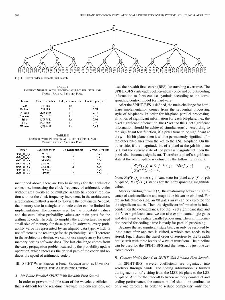
As far as hardware architecture of arithmetic coder in SPIHTis concerned, there are three main challenges for designers tosolve during real-time implementation. First, a large amount ofcoding symbols is supplied to arithmetic coder which can bea bottleneck for high speed real-time applications. Because thescheme of SPIHT is a bit-plane based method, which codes eachbit-plane from the most significant bit-plane (MSB) to the leastsignificant bit-plane (LSB) sequentially, the quantity of contextsymbols for arithmetic coder will be proportional to the codedplanes that are determined by the maximal wavelet coefficient.For the 9/7 wavelet filter, the precision of wavelet coefficientwill be increased compared to the pixel precision after trans-formation stage. Therefore in order to keep speed balance be-tween the wavelet transformation and the arithmetic coder, thethroughput of arithmetic coder must match the input rate of thewavelet stage. For the design of arithmetic coder, we test sometypical images with different pixel precision and compressionratio using the QccPackSPIHT software. The number of contextsymbols used for the arithmetic coding is shown in Tables I–III.In Tables I–III, the average context symbols per pixel and thebit-planes used for arithmetic coding are proportional to the bitrate and the bit depth of pixel. In order to achieve the balance
700 IEEE TRANSACTIONS ON VERY LARGE SCALE INTEGRATION (VLSI) SYSTEMS, VOL. 20, NO. 4, APRIL 2012
Fig. 1. Travel order of breadth first search.
TABLE ICONTEXT NUMBER WITH PRECISION AT 8 BIT PER PIXEL AND
TARGET RATE AT 4 BIT PER PIXEL
TABLE IINUMBER WITH PRECISION AT 10 BIT PER PIXEL AND
TARGET RATE AT 5 BIT PER PIXEL
mentioned above, there are two basic ways for the arithmeticcoder, i.e., increasing the clock frequency of arithmetic coderwithout area overhead or multiple arithmetic coders’ replica-tion without the clock frequency increment. In the architecture,a replication method is used to alleviate the bottleneck. Second,the memory size in a single arithmetic coder can be limited forimplementation. The memory used for the probability valuesand the cumulative probability values are main parts for thearithmetic coder. In order to simplify the architecture, we needsmall size of memory for these parts. In software, every prob-ability value is represented by an aligned data type, which isnot efficient as the real range for the probability used. Thereforein the architecture design, we cannot use simple array for thesememory part as software does. The last challenge comes fromthe carry propagation problem caused by the probability updateoperation, which increases the critical path of the coder and re-duces the speed of arithmetic coder.
III. SPIHT WITH BREADTH FIRST SEARCH AND ITS CONTEXT
MODEL FOR ARITHMETIC CODING
A. Bit-Plane Parallel SPIHT With Breadth First Search
In order to prevent multiple scan of the wavelet coefficientsthat is difficult for the real-time hardware implementations, we
uses the breadth first search (BFS) for traveling a zerotree. TheSPIHT-BFS visits each coefficient only once and outputs codinginformation to form context symbols according to the corre-sponding context model for hardware.
After the SPIHT-BFS is defined, the main challenge for hard-ware implementation comes from the sequential processingstyle of bit-planes. In order for bit-plane parallel processing,all kinds of significant information for each bit-plane, i.e., thepixel significant information, the set and the set significantinformation should be achieved simultaneously. According tothe significant test function, if a pixel turns to be significant atthe th bit-plane, then it will be permanently significant forthe other bit-planes from the th to the LSB bit-plane. On theother side, if the magnitude bit of a pixel at the th bit-planeis 1, but the current state of the pixel is insignificant, then thepixel also becomes significant. Therefore a pixel’s significantstate at the th bit-plane is defined by the following formula:
(3)
Note: is the significant state for pixel at of thbit-plane, stands for the corresponding magnitudevalue.
After expanding formula (3), the relationship between signifi-cance of each coefficient and magnitude bit can be obtained. Forthe architecture design, an OR gates array can be exploited forthe significant states. Then the significant information is inde-pendent on the coding planes. For the set significant state andthe set significant state, we can also exploit some logic gatesand delay unit to realize parallel processing. Then all informa-tion needed for coding a tree is ready for parallel processing.
Because the set significant state bits can only be resolved bylogic gates after one tree is visited, a whole tree needs to bestored. Fig. 1 draws the travel order of zerotree by the breadthfirst search with three levels of wavelet transform. The pipelinecan be used for the SPIHT-BFS and the latency is just one ze-rotree clocks.
B. Context Model for AC in SPIHT With Breadth First Search
In SPIHT-BFS, wavelet coefficients are organized intozerotrees through bands. The coding information is formedduring each run of visiting from the MSB bit-plane to the LSBbit-plane. And for the tradeoff between memory constraint andcoding performance, the context model should be confined toonly one zerotree. In order to reduce complexity, only four
LIU et al.: VLSI ARCHITECTURE OF ARITHMETIC CODER USED IN SPIHT 701
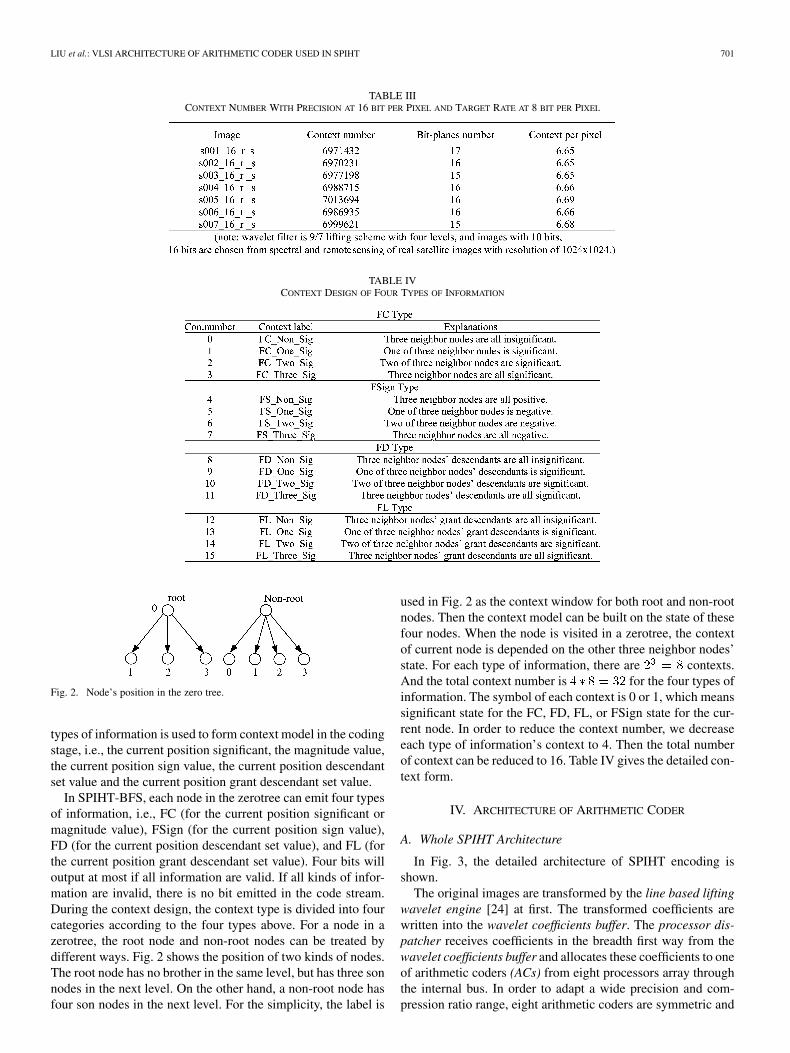
TABLE IIICONTEXT NUMBER WITH PRECISION AT 16 BIT PER PIXEL AND TARGET RATE AT 8 BIT PER PIXEL
TABLE IVCONTEXT DESIGN OF FOUR TYPES OF INFORMATION
Fig. 2. Node’s position in the zero tree.
types of information is used to form context model in the codingstage, i.e., the current position significant, the magnitude value,the current position sign value, the current position descendantset value and the current position grant descendant set value.
In SPIHT-BFS, each node in the zerotree can emit four typesof information, i.e., FC (for the current position significant ormagnitude value), FSign (for the current position sign value),FD (for the current position descendant set value), and FL (forthe current position grant descendant set value). Four bits willoutput at most if all information are valid. If all kinds of infor-mation are invalid, there is no bit emitted in the code stream.During the context design, the context type is divided into fourcategories according to the four types above. For a node in azerotree, the root node and non-root nodes can be treated bydifferent ways. Fig. 2 shows the position of two kinds of nodes.The root node has no brother in the same level, but has three sonnodes in the next level. On the other hand, a non-root node hasfour son nodes in the next level. For the simplicity, the label is
used in Fig. 2 as the context window for both root and non-rootnodes. Then the context model can be built on the state of thesefour nodes. When the node is visited in a zerotree, the contextof current node is depended on the other three neighbor nodes’state. For each type of information, there are contexts.And the total context number is for the four types ofinformation. The symbol of each context is 0 or 1, which meanssignificant state for the FC, FD, FL, or FSign state for the cur-rent node. In order to reduce the context number, we decreaseeach type of information’s context to 4. Then the total numberof context can be reduced to 16. Table IV gives the detailed con-text form.
IV. ARCHITECTURE OF ARITHMETIC CODER
A. Whole SPIHT Architecture
In Fig. 3, the detailed architecture of SPIHT encoding isshown.
The original images are transformed by the line based liftingwavelet engine [24] at first. The transformed coefficients arewritten into the wavelet coefficients buffer. The processor dis-patcher receives coefficients in the breadth first way from thewavelet coefficients buffer and allocates these coefficients to oneof arithmetic coders (ACs) from eight processors array throughthe internal bus. In order to adapt a wide precision and com-pression ratio range, eight arithmetic coders are symmetric and

702 IEEE TRANSACTIONS ON VERY LARGE SCALE INTEGRATION (VLSI) SYSTEMS, VOL. 20, NO. 4, APRIL 2012
Fig. 3. Architecture of SPIHT encoding.
Fig. 4. Arithmetic coder’s core structure.
work in parallel. The output of each arithmetic coder is sentto the internal bus and is distributed to the corresponding codeFIFO by the code FIFO dispatcher. The Read FIFO and Trun-cate module are responsible for the final code stream formation,which reads each code FIFO from top to bottom and truncatesthe code stream according to the bit rate requirement. Besidesthe main parts in the architecture, there are some auxiliary mod-ules in Fig. 3. The power management part will stop the clockinput for the unused bit-planes of each arithmetic coder basedon the maximal bit-plane register file for power reduction. Theconfiguration and control part is responsible for the parameterssetting such as image resolution, wavelet type, decomposition
level and target bit rate. The control signals for the whole archi-tecture are also asserted by this part.
From Fig. 3, the arithmetic coder in the overall architectureplays an important role during the coding process. The arith-metic coder consists of three main parts, i.e., the tree construc-tion noted as Tree Con, the bit plane context FIFOs array andthe coding core. The tree construction part visits the wavelet co-efficients by the breadth first search order. During the readingprocess, the context values of each bit-plane are formed basedon the context model mentioned. For speedup, all valid bit-planes are scanned in parallel. The invalid bit-planes are idle bystopping the corresponding clock. The bit plane context FIFOs
LIU et al.: VLSI ARCHITECTURE OF ARITHMETIC CODER USED IN SPIHT 703
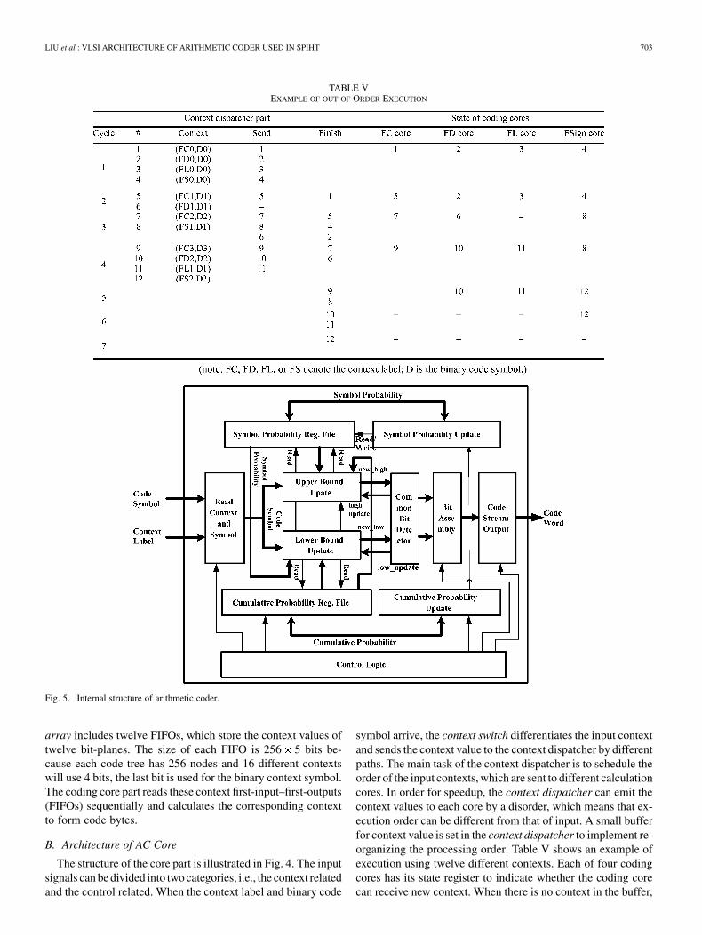
TABLE VEXAMPLE OF OUT OF ORDER EXECUTION
Fig. 5. Internal structure of arithmetic coder.
array includes twelve FIFOs, which store the context values oftwelve bit-planes. The size of each FIFO is 256 5 bits be-cause each code tree has 256 nodes and 16 different contextswill use 4 bits, the last bit is used for the binary context symbol.The coding core part reads these context first-input–first-outputs(FIFOs) sequentially and calculates the corresponding contextto form code bytes.
B. Architecture of AC Core
The structure of the core part is illustrated in Fig. 4. The inputsignals can be divided into two categories, i.e., the context relatedand the control related. When the context label and binary code
symbol arrive, the context switch differentiates the input contextand sends the context value to the context dispatcher by differentpaths. The main task of the context dispatcher is to schedule theorder of the input contexts, which are sent to different calculationcores. In order for speedup, the context dispatcher can emit thecontext values to each core by a disorder, which means that ex-ecution order can be different from that of input. A small bufferfor context value is set in the context dispatcher to implement re-organizing the processing order. Table V shows an example ofexecution using twelve different contexts. Each of four codingcores has its state register to indicate whether the coding corecan receive new context. When there is no context in the buffer,
704 IEEE TRANSACTIONS ON VERY LARGE SCALE INTEGRATION (VLSI) SYSTEMS, VOL. 20, NO. 4, APRIL 2012
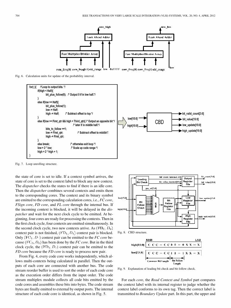
Fig. 6. Calculation units for update of the probability interval.
Fig. 7. Loop unrolling structure.
the state of core is set to idle. If a context symbol arrives, thestate of core is set to the context label to block any new context.The dispatcher checks the states to find if there is an idle core.Then the dispatcher combines several contexts and emits themto the corresponding cores. The context and its binary symbolare emitted to the corresponding calculation cores, i.e., FC core,FSign core, FD core, and FL core through the internal bus. Ifthe incoming context is blocked, it will be delayed in the dis-patcher and wait for the next clock cycle to be emitted. At be-ginning, four cores are ready for processing the contexts. Then inthe first clock cycle, four contexts are emitted simultaneously. Inthe second clock cycle, two new contexts arrive. Ascontext pair is not finished, context pair is blocked.Only context pair can be emitted to the FC core be-cause has been done by the FC core. But in the thirdclock cycle, the context pair can be emitted to theFD core because the FD core is ready to process new pair.
From Fig. 4, every code core works independently, which al-lows multi-contexts being calculated in parallel. Then the out-puts of each core are connected with another bus. The codestream reorder buffer is used to sort the order of each code coreas the execution order differs from the input order. The codestream multiplex module collects all code bits emitted by thecode cores and assembles these bits into bytes. The code streambytes are finally emitted to external by output ports. The internalstructure of each code core is identical, as shown in Fig. 5.
Fig. 8. CBD structure.
Fig. 9. Explanation of leading bit check and bit follow check.
For each core, the Read Context and Symbol part comparesthe context label with its internal register to judge whether thecontext label conforms to its own tag. Then the correct label istransmitted to Boundary Update part. In this part, the upper and
LIU et al.: VLSI ARCHITECTURE OF ARITHMETIC CODER USED IN SPIHT 705
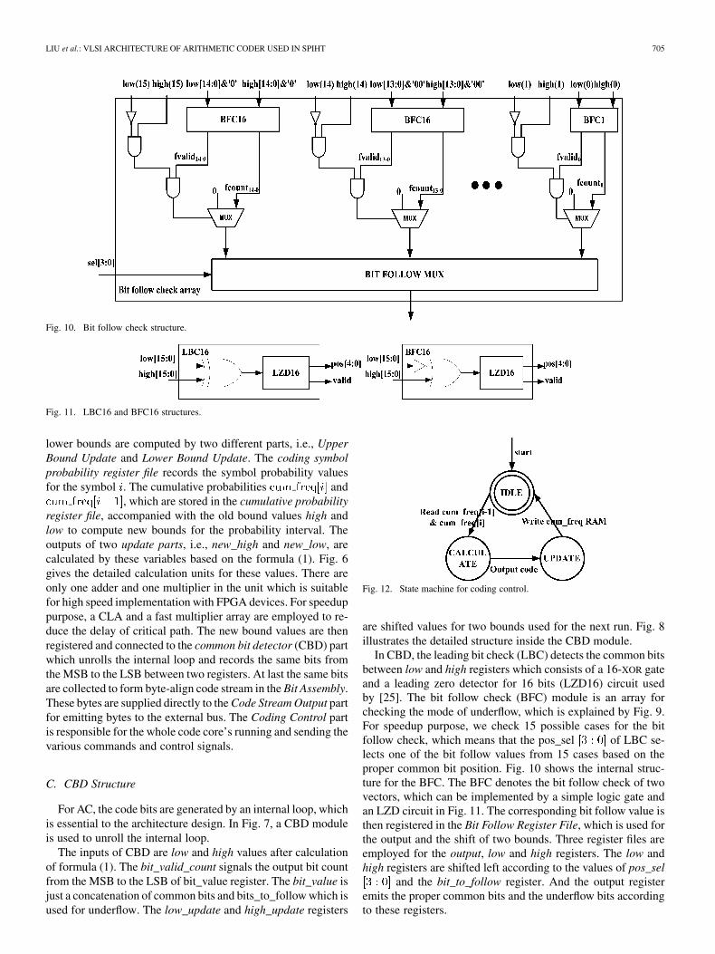
Fig. 10. Bit follow check structure.
Fig. 11. LBC16 and BFC16 structures.
lower bounds are computed by two different parts, i.e., UpperBound Update and Lower Bound Update. The coding symbolprobability register file records the symbol probability valuesfor the symbol . The cumulative probabilities and
, which are stored in the cumulative probabilityregister file, accompanied with the old bound values high andlow to compute new bounds for the probability interval. Theoutputs of two update parts, i.e., new_high and new_low, arecalculated by these variables based on the formula (1). Fig. 6gives the detailed calculation units for these values. There areonly one adder and one multiplier in the unit which is suitablefor high speed implementation with FPGA devices. For speeduppurpose, a CLA and a fast multiplier array are employed to re-duce the delay of critical path. The new bound values are thenregistered and connected to the common bit detector (CBD) partwhich unrolls the internal loop and records the same bits fromthe MSB to the LSB between two registers. At last the same bitsare collected to form byte-align code stream in the Bit Assembly.These bytes are supplied directly to the Code Stream Output partfor emitting bytes to the external bus. The Coding Control partis responsible for the whole code core’s running and sending thevarious commands and control signals.
C. CBD Structure
For AC, the code bits are generated by an internal loop, whichis essential to the architecture design. In Fig. 7, a CBD moduleis used to unroll the internal loop.
The inputs of CBD are low and high values after calculationof formula (1). The bit_valid_count signals the output bit countfrom the MSB to the LSB of bit_value register. The bit_value isjust a concatenation of common bits and bits_to_follow which isused for underflow. The low_update and high_update registers
Fig. 12. State machine for coding control.
are shifted values for two bounds used for the next run. Fig. 8illustrates the detailed structure inside the CBD module.
In CBD, the leading bit check (LBC) detects the common bitsbetween low and high registers which consists of a 16-XOR gateand a leading zero detector for 16 bits (LZD16) circuit usedby [25]. The bit follow check (BFC) module is an array forchecking the mode of underflow, which is explained by Fig. 9.For speedup purpose, we check 15 possible cases for the bitfollow check, which means that the pos_sel of LBC se-lects one of the bit follow values from 15 cases based on theproper common bit position. Fig. 10 shows the internal struc-ture for the BFC. The BFC denotes the bit follow check of twovectors, which can be implemented by a simple logic gate andan LZD circuit in Fig. 11. The corresponding bit follow value isthen registered in the Bit Follow Register File, which is used forthe output and the shift of two bounds. Three register files areemployed for the output, low and high registers. The low andhigh registers are shifted left according to the values of pos_sel
and the bit_to_follow register. And the output registeremits the proper common bits and the underflow bits accordingto these registers.
706 IEEE TRANSACTIONS ON VERY LARGE SCALE INTEGRATION (VLSI) SYSTEMS, VOL. 20, NO. 4, APRIL 2012
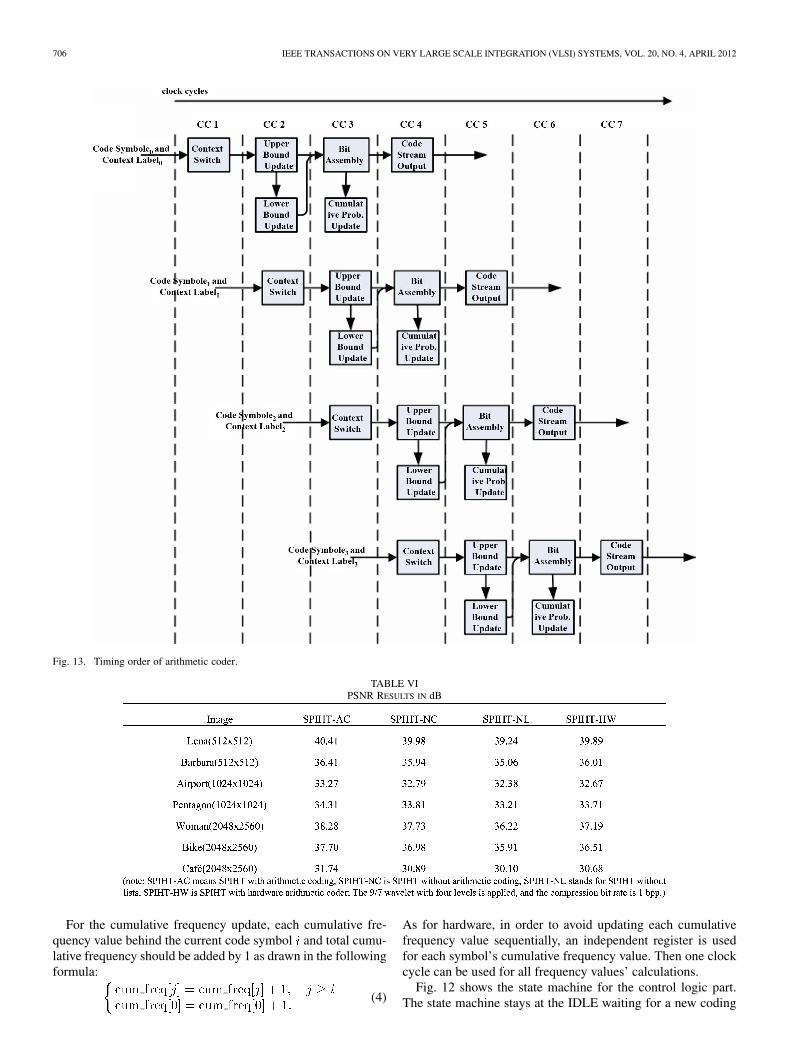
Fig. 13. Timing order of arithmetic coder.
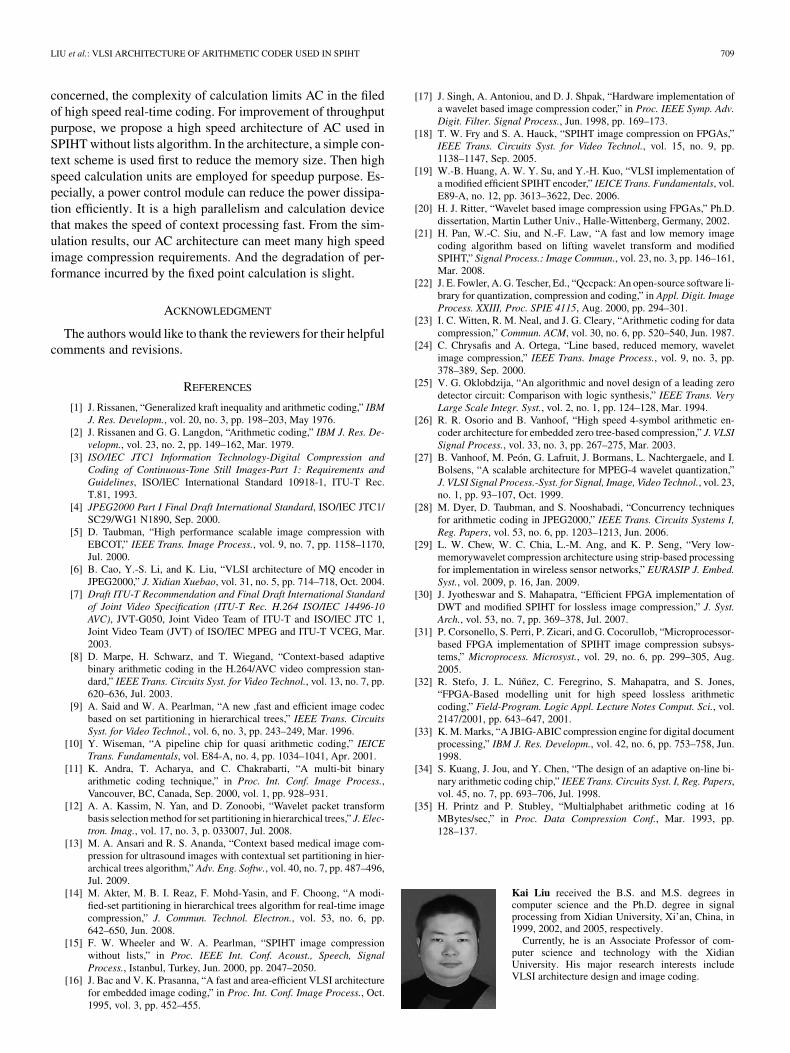
TABLE VIPSNR RESULTS IN dB
For the cumulative frequency update, each cumulative fre-quency value behind the current code symbol and total cumu-lative frequency should be added by 1 as drawn in the followingformula:
(4)
As for hardware, in order to avoid updating each cumulativefrequency value sequentially, an independent register is usedfor each symbol’s cumulative frequency value. Then one clockcycle can be used for all frequency values’ calculations.
Fig. 12 shows the state machine for the control logic part.The state machine stays at the IDLE waiting for a new coding

LIU et al.: VLSI ARCHITECTURE OF ARITHMETIC CODER USED IN SPIHT 707
TABLE VIISYNTHESIS RESULTS OF THE WHOLE COMPRESSION SYSTEM
TABLE VIIISYNTHESIS RESULTS OF THE ARITHMETIC PART
TABLE IXMEMORY CAPACITY FOR CUMULATIVE PROBABILITIES
symbol. When a new symbol arrives, the state machine assertsa read signal for the lookup table of the cumulative probabilityand jumps to the CALCULATE state. In the CALCULATE, theprobability interval bounds are updated. The control signals ofthe Bit Assembly and Stream Output parts are sent by the statemachine in this state. The next state is the UPDATE state whichprovides a write signal for the cumulative ram and starts the cu-mulative probability update process. After all cumulative proba-bility values are renewed, the state machine returns to the initialIDLE state for next symbol.
Fig. 13 illustrates the timing order for the whole pipelinestages of the architecture. Due to pipelining style, the codercan consume one symbol per clock cycle. The pipeline has fourstages: context switch, probability bounds update, bit emit/cu-mulative update, and code stream output. In the pipeline, thecode symbol and context label are processed every clock at eachstage based on the analysis of the architecture. After the pipelinesets up, the code stream bytes can outflow every clock.
V. EXPERIMENTAL RESULTS
A. Software Results
The experimental results come in two folds, i.e., software andhardware. First, PSNR results for typical images using differentSPIHT methods are recorded, including SPIHT with arithmetic,SPIHT without arithmetic, SPIHT without lists and arithmeticand our SPIHT prototype. Table VI lists the detailed data. Fromthe results, SPIHT-HW is slightly lower than SPIHT-AC as theprecision is limited during the wavelet transform and a simplecontext model is involved.
B. Hardware Results Based on FPGA Device
The overall architecture including the wavelet part andthe arithmetic part is synthesized and simulated by VHDLusing XC2V3000 as target device. The results are reported byXILINX ISE9.1-XST and shown in the Table VII. The maximal
Fig. 14. Power saving curves with different pixel precisions in arithmeticcoding part.

708 IEEE TRANSACTIONS ON VERY LARGE SCALE INTEGRATION (VLSI) SYSTEMS, VOL. 20, NO. 4, APRIL 2012
TABLE XPERFORMANCE COMPARISONS OF DIFFERENT SPIHT CODERS ON FPGA DEVICES
TABLE XIPERFORMANCE COMPARISONS OF AC CODERS
clock frequency is 56.404 MHz. For hardware implementa-tion, the input is confined to gray images with resolution of1024 1024 and the precision of pixel from 8 bits to 16 bits.Thus the throughput of whole compression system is 56.404frames per second (fps). Then for pixel precision of 16 bitswith resolution 1024 1024, the throughput of coder can be
902.464 Mb/s at its maximum. Inorder to test arithmetic part independently, we also synthesizethis part and record the results in the Table VIII. There arefour contexts processed simultaneously in the architecture.Each context uses one bit for symbols. Then four symbolscan be consumed simultaneously. The throughput is 71.054 MSPS/s, i.e., 284.2 MSPS/s.
C. Memory, Throughput and Power Analysis
As the memory size is important, the memory capacity ofarithmetic coder in SPIHT-HW is analyzed briefly. In the arith-metic coder, a short type integer is used for the symbol proba-bility. The main part of memory is composed by the cumulativeprobability storage. Table IX gives the cumulative probabilitymemory content in the architecture. Only 512 bits are allocatedfor storage requirement and one block ram unit in the device isenough for this. Another two parts of memory come from the
context FIFOs and the code FIFOs, which are responsible forthe context buffer and the code stream buffer. The number of thecontext FIFOs is 12 8 and the total bits are122 880 bits. Each code FIFO can be set to 128 8 bits. Thenthe size of the code FIFOs is 8192 bits. Therefore,the total size of memory used in the architecture is 128.5 kb.
For comparisons, Table X lists the results of different SPIHTimage compression systems based on FPGA devices. AndTable XI shows the throughput comparison with other ACcoders. From the experimental results, the proposed SPIHTimage compression systems and the AC coder can obtain goodscore in many advanced architectures.
The power saving effect is also tested by several typicalimages. Fig. 14 illustrates the detailed results reported fromXPower Analyzer tool with compression ratio at 8:1. Fromthe experimental results, the power saving rate can be about20.08% on average due to the method of stopping the clock ofinvalid bit-planes.
VI. CONCLUSION
Arithmetic coding makes itself a standard technique for itshigh efficiency. However, as far as hardware implementation is
LIU et al.: VLSI ARCHITECTURE OF ARITHMETIC CODER USED IN SPIHT 709
concerned, the complexity of calculation limits AC in the filedof high speed real-time coding. For improvement of throughputpurpose, we propose a high speed architecture of AC used inSPIHT without lists algorithm. In the architecture, a simple con-text scheme is used first to reduce the memory size. Then highspeed calculation units are employed for speedup purpose. Es-pecially, a power control module can reduce the power dissipa-tion efficiently. It is a high parallelism and calculation devicethat makes the speed of context processing fast. From the sim-ulation results, our AC architecture can meet many high speedimage compression requirements. And the degradation of per-formance incurred by the fixed point calculation is slight.
ACKNOWLEDGMENT
The authors would like to thank the reviewers for their helpfulcomments and revisions.
REFERENCES
[1] J. Rissanen, “Generalized kraft inequality and arithmetic coding,” IBMJ. Res. Developm., vol. 20, no. 3, pp. 198–203, May 1976.
[2] J. Rissanen and G. G. Langdon, “Arithmetic coding,” IBM J. Res. De-velopm., vol. 23, no. 2, pp. 149–162, Mar. 1979.
[3] ISO/IEC JTC1 Information Technology-Digital Compression andCoding of Continuous-Tone Still Images-Part 1: Requirements andGuidelines, ISO/IEC International Standard 10918-1, ITU-T Rec.T.81, 1993.
[4] JPEG2000 Part I Final Draft International Standard, ISO/IEC JTC1/SC29/WG1 N1890, Sep. 2000.
[5] D. Taubman, “High performance scalable image compression withEBCOT,” IEEE Trans. Image Process., vol. 9, no. 7, pp. 1158–1170,Jul. 2000.
[6] B. Cao, Y.-S. Li, and K. Liu, “VLSI architecture of MQ encoder inJPEG2000,” J. Xidian Xuebao, vol. 31, no. 5, pp. 714–718, Oct. 2004.
[7] Draft ITU-T Recommendation and Final Draft International Standardof Joint Video Specification (ITU-T Rec. H.264 ISO/IEC 14496-10AVC), JVT-G050, Joint Video Team of ITU-T and ISO/IEC JTC 1,Joint Video Team (JVT) of ISO/IEC MPEG and ITU-T VCEG, Mar.2003.
[8] D. Marpe, H. Schwarz, and T. Wiegand, “Context-based adaptivebinary arithmetic coding in the H.264/AVC video compression stan-dard,” IEEE Trans. Circuits Syst. for Video Technol., vol. 13, no. 7, pp.620–636, Jul. 2003.
[9] A. Said and W. A. Pearlman, “A new ,fast and efficient image codecbased on set partitioning in hierarchical trees,” IEEE Trans. CircuitsSyst. for Video Technol., vol. 6, no. 3, pp. 243–249, Mar. 1996.
[10] Y. Wiseman, “A pipeline chip for quasi arithmetic coding,” IEICETrans. Fundamentals, vol. E84-A, no. 4, pp. 1034–1041, Apr. 2001.
[11] K. Andra, T. Acharya, and C. Chakrabarti, “A multi-bit binaryarithmetic coding technique,” in Proc. Int. Conf. Image Process.,Vancouver, BC, Canada, Sep. 2000, vol. 1, pp. 928–931.
[12] A. A. Kassim, N. Yan, and D. Zonoobi, “Wavelet packet transformbasis selection method for set partitioning in hierarchical trees,” J. Elec-tron. Imag., vol. 17, no. 3, p. 033007, Jul. 2008.
[13] M. A. Ansari and R. S. Ananda, “Context based medical image com-pression for ultrasound images with contextual set partitioning in hier-archical trees algorithm,” Adv. Eng. Softw., vol. 40, no. 7, pp. 487–496,Jul. 2009.
[14] M. Akter, M. B. I. Reaz, F. Mohd-Yasin, and F. Choong, “A modi-fied-set partitioning in hierarchical trees algorithm for real-time imagecompression,” J. Commun. Technol. Electron., vol. 53, no. 6, pp.642–650, Jun. 2008.
[15] F. W. Wheeler and W. A. Pearlman, “SPIHT image compressionwithout lists,” in Proc. IEEE Int. Conf. Acoust., Speech, SignalProcess., Istanbul, Turkey, Jun. 2000, pp. 2047–2050.
[16] J. Bac and V. K. Prasanna, “A fast and area-efficient VLSI architecturefor embedded image coding,” in Proc. Int. Conf. Image Process., Oct.1995, vol. 3, pp. 452–455.
[17] J. Singh, A. Antoniou, and D. J. Shpak, “Hardware implementation ofa wavelet based image compression coder,” in Proc. IEEE Symp. Adv.Digit. Filter. Signal Process., Jun. 1998, pp. 169–173.
[18] T. W. Fry and S. A. Hauck, “SPIHT image compression on FPGAs,”IEEE Trans. Circuits Syst. for Video Technol., vol. 15, no. 9, pp.1138–1147, Sep. 2005.
[19] W.-B. Huang, A. W. Y. Su, and Y.-H. Kuo, “VLSI implementation ofa modified efficient SPIHT encoder,” IEICE Trans. Fundamentals, vol.E89-A, no. 12, pp. 3613–3622, Dec. 2006.
[20] H. J. Ritter, “Wavelet based image compression using FPGAs,” Ph.D.dissertation, Martin Luther Univ., Halle-Wittenberg, Germany, 2002.
[21] H. Pan, W.-C. Siu, and N.-F. Law, “A fast and low memory imagecoding algorithm based on lifting wavelet transform and modifiedSPIHT,” Signal Process.: Image Commun., vol. 23, no. 3, pp. 146–161,Mar. 2008.
[22] J. E. Fowler, A. G. Tescher, Ed., “Qccpack: An open-source software li-brary for quantization, compression and coding,” in Appl. Digit. ImageProcess. XXIII, Proc. SPIE 4115, Aug. 2000, pp. 294–301.
[23] I. C. Witten, R. M. Neal, and J. G. Cleary, “Arithmetic coding for datacompression,” Commun. ACM, vol. 30, no. 6, pp. 520–540, Jun. 1987.
[24] C. Chrysafis and A. Ortega, “Line based, reduced memory, waveletimage compression,” IEEE Trans. Image Process., vol. 9, no. 3, pp.378–389, Sep. 2000.
[25] V. G. Oklobdzija, “An algorithmic and novel design of a leading zerodetector circuit: Comparison with logic synthesis,” IEEE Trans. VeryLarge Scale Integr. Syst., vol. 2, no. 1, pp. 124–128, Mar. 1994.
[26] R. R. Osorio and B. Vanhoof, “High speed 4-symbol arithmetic en-coder architecture for embedded zero tree-based compression,” J. VLSISignal Process., vol. 33, no. 3, pp. 267–275, Mar. 2003.
[27] B. Vanhoof, M. Peón, G. Lafruit, J. Bormans, L. Nachtergaele, and I.Bolsens, “A scalable architecture for MPEG-4 wavelet quantization,”J. VLSI Signal Process.-Syst. for Signal, Image, Video Technol., vol. 23,no. 1, pp. 93–107, Oct. 1999.
[28] M. Dyer, D. Taubman, and S. Nooshabadi, “Concurrency techniquesfor arithmetic coding in JPEG2000,” IEEE Trans. Circuits Systems I,Reg. Papers, vol. 53, no. 6, pp. 1203–1213, Jun. 2006.
[29] L. W. Chew, W. C. Chia, L.-M. Ang, and K. P. Seng, “Very low-memorywavelet compression architecture using strip-based processingfor implementation in wireless sensor networks,” EURASIP J. Embed.Syst., vol. 2009, p. 16, Jan. 2009.
[30] J. Jyotheswar and S. Mahapatra, “Efficient FPGA implementation ofDWT and modified SPIHT for lossless image compression,” J. Syst.Arch., vol. 53, no. 7, pp. 369–378, Jul. 2007.
[31] P. Corsonello, S. Perri, P. Zicari, and G. Cocorullob, “Microprocessor-based FPGA implementation of SPIHT image compression subsys-tems,” Microprocess. Microsyst., vol. 29, no. 6, pp. 299–305, Aug.2005.
[32] R. Stefo, J. L. Núñez, C. Feregrino, S. Mahapatra, and S. Jones,“FPGA-Based modelling unit for high speed lossless arithmeticcoding,” Field-Program. Logic Appl. Lecture Notes Comput. Sci., vol.2147/2001, pp. 643–647, 2001.
[33] K. M. Marks, “A JBIG-ABIC compression engine for digital documentprocessing,” IBM J. Res. Developm., vol. 42, no. 6, pp. 753–758, Jun.1998.
[34] S. Kuang, J. Jou, and Y. Chen, “The design of an adaptive on-line bi-nary arithmetic coding chip,” IEEE Trans. Circuits Syst. I, Reg. Papers,vol. 45, no. 7, pp. 693–706, Jul. 1998.
[35] H. Printz and P. Stubley, “Multialphabet arithmetic coding at 16MBytes/sec,” in Proc. Data Compression Conf., Mar. 1993, pp.128–137.
Kai Liu received the B.S. and M.S. degrees incomputer science and the Ph.D. degree in signalprocessing from Xidian University, Xi’an, China, in1999, 2002, and 2005, respectively.
Currently, he is an Associate Professor of com-puter science and technology with the XidianUniversity. His major research interests includeVLSI architecture design and image coding.
710 IEEE TRANSACTIONS ON VERY LARGE SCALE INTEGRATION (VLSI) SYSTEMS, VOL. 20, NO. 4, APRIL 2012
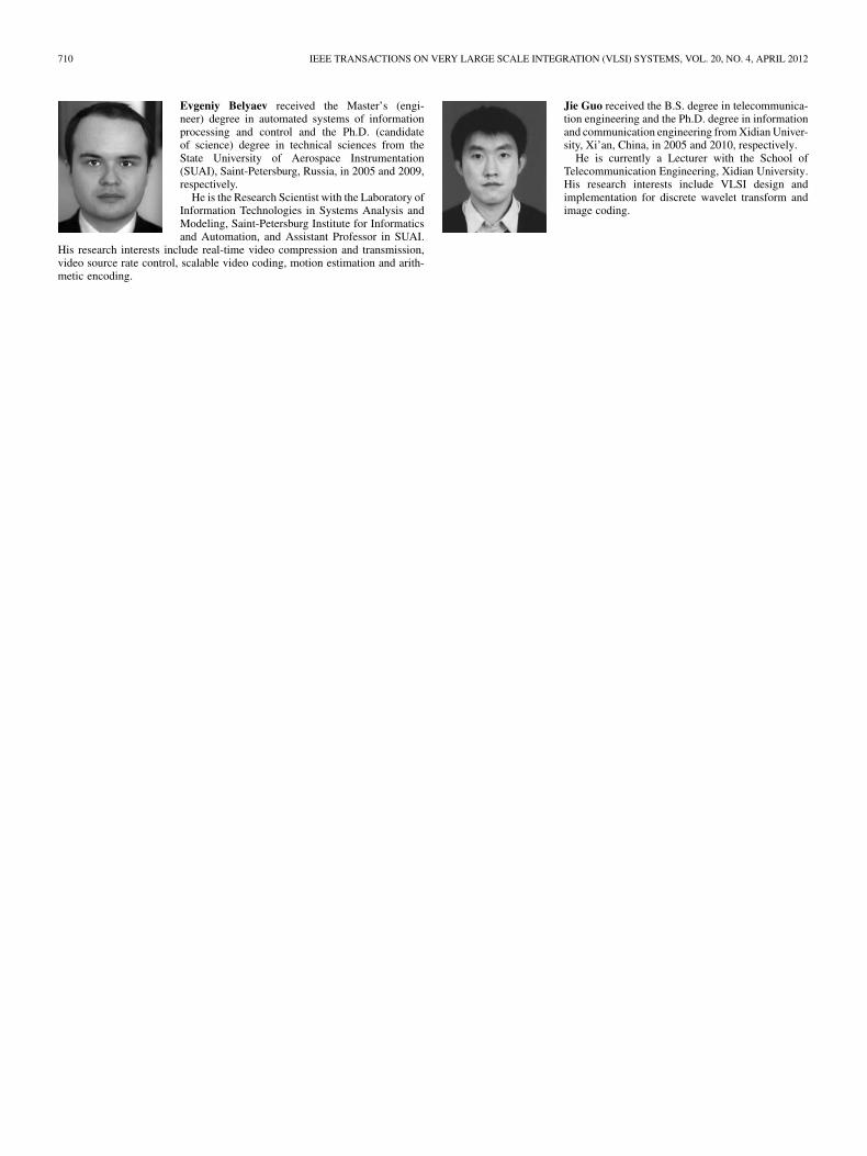
Evgeniy Belyaev received the Master’s (engi-neer) degree in automated systems of informationprocessing and control and the Ph.D. (candidateof science) degree in technical sciences from theState University of Aerospace Instrumentation(SUAI), Saint-Petersburg, Russia, in 2005 and 2009,respectively.
He is the Research Scientist with the Laboratory ofInformation Technologies in Systems Analysis andModeling, Saint-Petersburg Institute for Informaticsand Automation, and Assistant Professor in SUAI.
His research interests include real-time video compression and transmission,video source rate control, scalable video coding, motion estimation and arith-metic encoding.
Jie Guo received the B.S. degree in telecommunica-tion engineering and the Ph.D. degree in informationand communication engineering from Xidian Univer-sity, Xi’an, China, in 2005 and 2010, respectively.
He is currently a Lecturer with the School ofTelecommunication Engineering, Xidian University.His research interests include VLSI design andimplementation for discrete wavelet transform andimage coding.
Related Documents
![1 1 1 1 1 1 1 ¢ 1 1 1 - pdfs.semanticscholar.org€¦ · 1 1 1 [ v . ] v 1 1 ¢ 1 1 1 1 ý y þ ï 1 1 1 ð 1 1 1 1 1 x ...](https://static.cupdf.com/doc/110x72/5f7bc722cb31ab243d422a20/1-1-1-1-1-1-1-1-1-1-pdfs-1-1-1-v-v-1-1-1-1-1-1-y-1-1-1-.jpg)
![$1RYHO2SWLRQ &KDSWHU $ORN6KDUPD +HPDQJL6DQH … · 1 1 1 1 1 1 1 ¢1 1 1 1 1 ¢ 1 1 1 1 1 1 1w1¼1wv]1 1 1 1 1 1 1 1 1 1 1 1 1 ï1 ð1 1 1 1 1 3](https://static.cupdf.com/doc/110x72/5f3ff1245bf7aa711f5af641/1ryho2swlrq-kdswhu-orn6kdupd-hpdqjl6dqh-1-1-1-1-1-1-1-1-1-1-1-1-1-1.jpg)

![1 1 1 1 1 1 1 ¢ 1 , ¢ 1 1 1 , 1 1 1 1 ¡ 1 1 1 1 · 1 1 1 1 1 ] ð 1 1 w ï 1 x v w ^ 1 1 x w [ ^ \ w _ [ 1. 1 1 1 1 1 1 1 1 1 1 1 1 1 1 1 1 1 1 1 1 1 1 1 1 1 1 1 ð 1 ] û w ü](https://static.cupdf.com/doc/110x72/5f40ff1754b8c6159c151d05/1-1-1-1-1-1-1-1-1-1-1-1-1-1-1-1-1-1-1-1-1-1-1-1-1-1-w-1-x-v.jpg)


![[XLS]fmism.univ-guelma.dzfmism.univ-guelma.dz/sites/default/files/le fond... · Web view1 1 1 1 1 1 1 1 1 1 1 1 1 1 1 1 1 1 1 1 1 1 1 1 1 1 1 1 1 1 1 1 1 1 1 1 1 1 1 1 1 1 1 1 1 1](https://static.cupdf.com/doc/110x72/5b9d17e509d3f2194e8d827e/xlsfmismuniv-fond-web-view1-1-1-1-1-1-1-1-1-1-1-1-1-1-1-1-1-1-1-1-1-1.jpg)