Chapter 15 15-1 15.1 Error Code Table 15.1.1 Error Code 0009-6175 iR5570 / iR6570 T-15-1 Code Description E000 the heater fails to heat E001 there is an abnormal rise in temperature E002 there is an error in the rise in temperature E003 there is an error in the rise in temperature E004 there is an error in the IH power supply/IH control mechanism E005 there is no fixing web/there is an error in the detection of web solenoid connection E010 there is a feed motor error E012 there is a drum motor error E013 the waste toner pipe is clogged E014 there is a fixing motor error E020 there is no toner in the developing assembly; there is an error in the detection of developing assembly toner sensor connection; there is an error in the detection of developing hopper toner sensor connection E025 there is an error in the detection of toner feed motor over-current, there is an error in the detection of toner bottle motor over-current, there is an error in the detection of toner bottle motor connection E032 the counter of the NE controller has malfunctioned E061 there is a potential control error/there is an APC error E100 there is a BD error E110 there is a polygon motor error E121 there is a controller cooling error E196 the EEPROM is faulty E202 there is an HP error E225 there is an error in the intensity of light E227 there is an error in the power supply (24 V) E240 there is an error in the communication between the main controller PCB and the DC controller PCB

Welcome message from author
This document is posted to help you gain knowledge. Please leave a comment to let me know what you think about it! Share it to your friends and learn new things together.
Transcript
Chapter 15
15-1
15.1 Error Code Table
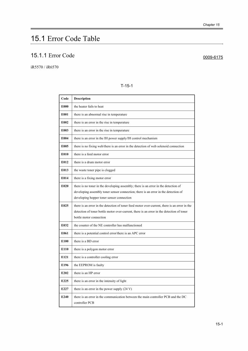
15.1.1 Error Code 0009-6175
iR5570 / iR6570
T-15-1
Code Description
E000 the heater fails to heat
E001 there is an abnormal rise in temperature
E002 there is an error in the rise in temperature
E003 there is an error in the rise in temperature
E004 there is an error in the IH power supply/IH control mechanism
E005 there is no fixing web/there is an error in the detection of web solenoid connection
E010 there is a feed motor error
E012 there is a drum motor error
E013 the waste toner pipe is clogged
E014 there is a fixing motor error
E020 there is no toner in the developing assembly; there is an error in the detection of
developing assembly toner sensor connection; there is an error in the detection of
developing hopper toner sensor connection
E025 there is an error in the detection of toner feed motor over-current, there is an error in the
detection of toner bottle motor over-current, there is an error in the detection of toner
bottle motor connection
E032 the counter of the NE controller has malfunctioned
E061 there is a potential control error/there is an APC error
E100 there is a BD error
E110 there is a polygon motor error
E121 there is a controller cooling error
E196 the EEPROM is faulty
E202 there is an HP error
E225 there is an error in the intensity of light
E227 there is an error in the power supply (24 V)
E240 there is an error in the communication between the main controller PCB and the DC
controller PCB
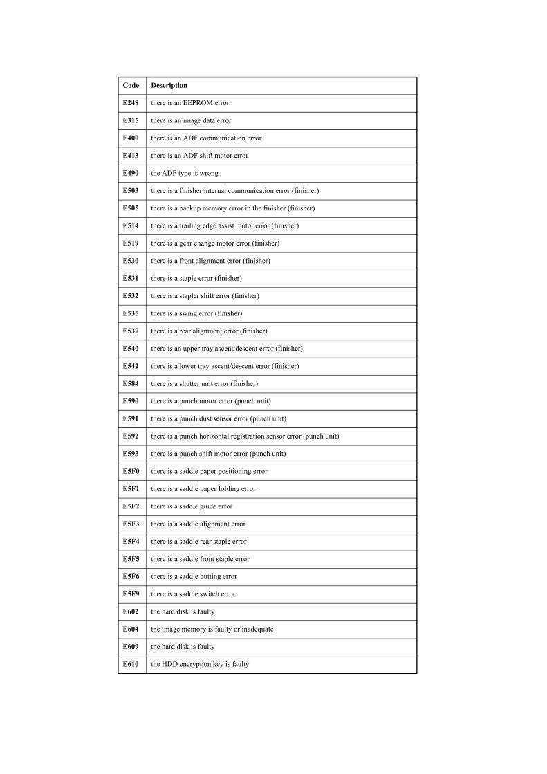
E248 there is an EEPROM error
E315 there is an image data error
E400 there is an ADF communication error
E413 there is an ADF shift motor error
E490 the ADF type is wrong
E503 there is a finisher internal communication error (finisher)
E505 there is a backup memory error in the finisher (finisher)
E514 there is a trailing edge assist motor error (finisher)
E519 there is a gear change motor error (finisher)
E530 there is a front alignment error (finisher)
E531 there is a staple error (finisher)
E532 there is a stapler shift error (finisher)
E535 there is a swing error (finisher)
E537 there is a rear alignment error (finisher)
E540 there is an upper tray ascent/descent error (finisher)
E542 there is a lower tray ascent/descent error (finisher)
E584 there is a shutter unit error (finisher)
E590 there is a punch motor error (punch unit)
E591 there is a punch dust sensor error (punch unit)
E592 there is a punch horizontal registration sensor error (punch unit)
E593 there is a punch shift motor error (punch unit)
E5F0 there is a saddle paper positioning error
E5F1 there is a saddle paper folding error
E5F2 there is a saddle guide error
E5F3 there is a saddle alignment error
E5F4 there is a saddle rear staple error
E5F5 there is a saddle front staple error
E5F6 there is a saddle butting error
E5F9 there is a saddle switch error
E602 the hard disk is faulty
E604 the image memory is faulty or inadequate
E609 the hard disk is faulty
E610 the HDD encryption key is faulty
Code Description
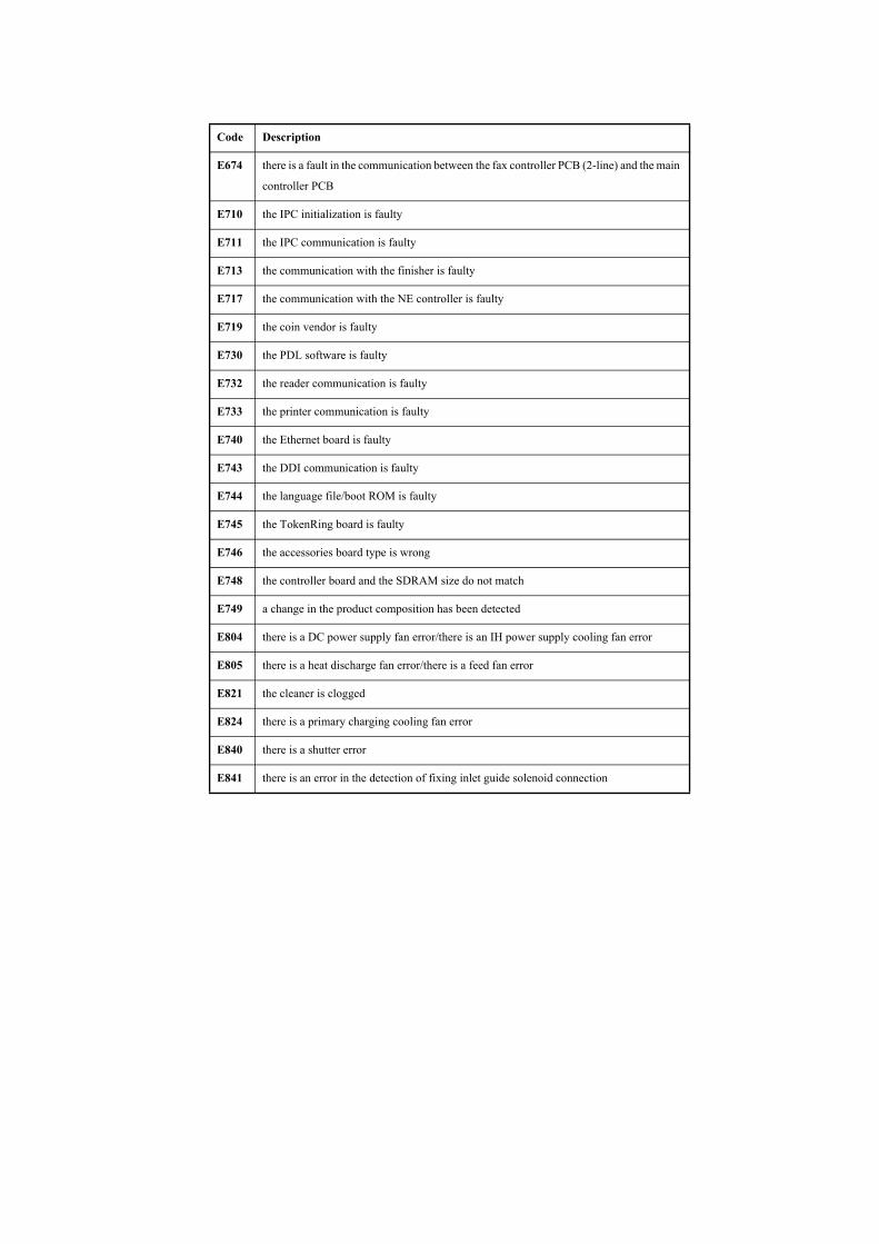
E674 there is a fault in the communication between the fax controller PCB (2-line) and the main
controller PCB
E710 the IPC initialization is faulty
E711 the IPC communication is faulty
E713 the communication with the finisher is faulty
E717 the communication with the NE controller is faulty
E719 the coin vendor is faulty
E730 the PDL software is faulty
E732 the reader communication is faulty
E733 the printer communication is faulty
E740 the Ethernet board is faulty
E743 the DDI communication is faulty
E744 the language file/boot ROM is faulty
E745 the TokenRing board is faulty
E746 the accessories board type is wrong
E748 the controller board and the SDRAM size do not match
E749 a change in the product composition has been detected
E804 there is a DC power supply fan error/there is an IH power supply cooling fan error
E805 there is a heat discharge fan error/there is a feed fan error
E821 the cleaner is clogged
E824 there is a primary charging cooling fan error
E840 there is a shutter error
E841 there is an error in the detection of fixing inlet guide solenoid connection
Code Description
Chapter 15
15-4
15.2 Error Code Details
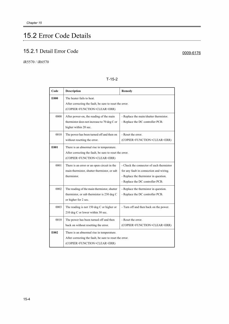
15.2.1 Detail Error Code 0009-6176
iR5570 / iR6570
T-15-2
Code Description Remedy
E000 The heater fails to heat.
After correcting the fault, be sure to reset the error.
(COPIER>FUNCTION>CLEAR>ERR)
0000 After power-on, the reading of the main
thermistor does not increase to 70 deg C or
higher within 20 sec.
- Replace the main/shutter thermistor.
- Replace the DC controller PCB.
0010 The power has been turned off and then on
without resetting the error.
- Reset the error.
(COPIER>FUNCTION>CLEAR>ERR)
E001 There is an abnormal rise in temperature.
After correcting the fault, be sure to reset the error.
(COPIER>FUNCTION>CLEAR>ERR)
0001 There is an error or an open circuit in the
main thermistor, shutter thermistor, or sub
thermistor.
- Check the connector of each thermistor
for any fault in connection and wiring.
- Replace the thermistor in question.
- Replace the DC controller PCB.
0002 The reading of the main thermistor, shutter
thermistor, or sub thermistor is 230 deg C
or higher for 2 sec.
- Replace the thermistor in question.
- Replace the DC controller PCB.
0003 The reading is not 150 deg C or higher or
210 deg C or lower within 30 sec.
- Turn off and then back on the power.
0010 The power has been turned off and then
back on without resetting the error.
- Reset the error.
(COPIER>FUNCTION>CLEAR>ERR)
E002 There is an abnormal rise in temperature.
After correcting the fault, be sure to reset the error.
(COPIER>FUNCTION>CLEAR>ERR)

0000 The reading of the main thermistor is not
100 deg C 12 sec after it has exceeded 70
deg C.
- Check the connector of the main/shutter
thermistor for any fault in connection and
wiring.
- Check the main/shutter thermistor for
mounting condition.
- Replace the main/shutter thermistor.
- Replace the fixing heater unit.
- Replace the DC controller PCB.
0001 The reading of the main thermistor is not
150 deg C 15 after it has exceeded 100 deg
C.
0010 The power has been turned off and then
back on without resetting the error.
- Reset the error.
(COPIER>FUNCTION>CLEAR>ERR)
E003 There is an abnormal rise in temperature.
After correcting the fault, be sure to reset the error.
(COPIER>FUNCTION>CLEAR>ERR)
0000 The reading of the main thermistor is
lower than 70 deg C for 2 sec or more after
it has exceeded 100 deg C.
- Check the connector of the main/shutter
thermistor for any fault in connection and
wiring.
- Check the main/shutter thermistor for
mounting condition.
- Replace the main/shutter thermistor.
- Replace the fixing heater unit.
- Replace the DC controller PCB.
0010 The power has been turned off and then
back on without resetting the error.
- Reset the error.
(COPIER>FUNCTION>CLEAR>ERR)
E004 The IH power supply is faulty/the IH control mechanism is faulty.
After correcting the fault, be sure to reset the error.
(COPIER>FUNCTION>CLEAR>ERR)
0101 There is a mismatch between the input
voltage and the IH power supply ID.
Replace the fixing heater power supply
with one designed for the country of
installation (voltage).
Code Description Remedy
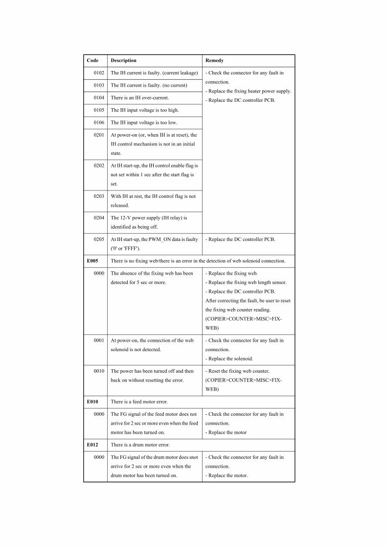
0102 The IH current is faulty. (current leakage) - Check the connector for any fault in
connection.
- Replace the fixing heater power supply.
- Replace the DC controller PCB.
0103 The IH current is faulty. (no current)
0104 There is an IH over-current.
0105 The IH input voltage is too high.
0106 The IH input voltage is too low.
0201 At power-on (or, when IH is at reset), the
IH control mechanism is not in an initial
state.
0202 At IH start-up, the IH control enable flag is
not set within 1 sec after the start flag is
set.
0203 With IH at rest, the IH control flag is not
released.
0204 The 12-V power supply (IH relay) is
identified as being off.
0205 At IH start-up, the PWM_ON data is faulty
('0' or 'FFFF').
- Replace the DC controller PCB.
E005 There is no fixing web/there is an error in the detection of web solenoid connection.
0000 The absence of the fixing web has been
detected for 5 sec or more.
- Replace the fixing web.
- Replace the fixing web length sensor.
- Replace the DC controller PCB.
After correcting the fault, be user to reset
the fixing web counter reading.
(COPIER>COUNTER>MISC>FIX-
WEB)
0001 At power-on, the connection of the web
solenoid is not detected.
- Check the connector for any fault in
connection.
- Replace the solenoid.
0010 The power has been turned off and then
back on without resetting the error.
- Reset the fixing web counter.
(COPIER>COUNTER>MISC>FIX-
WEB)
E010 There is a feed motor error.
0000 The FG signal of the feed motor does not
arrive for 2 sec or more even when the feed
motor has been turned on.
- Check the connector for any fault in
connection.
- Replace the motor
E012 There is a drum motor error.
0000 The FG signal of the drum motor does snot
arrive for 2 sec or more even when the
drum motor has been turned on.
- Check the connector for any fault in
connection.
- Replace the motor.
Code Description Remedy
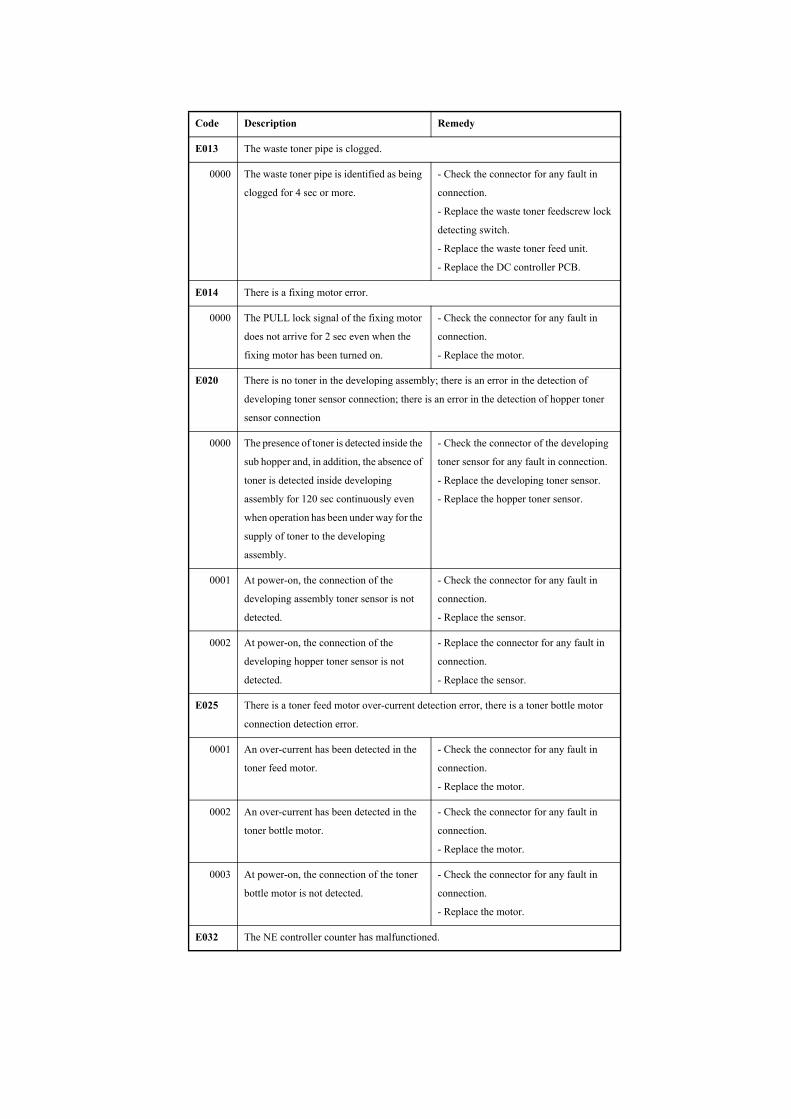
E013 The waste toner pipe is clogged.
0000 The waste toner pipe is identified as being
clogged for 4 sec or more.
- Check the connector for any fault in
connection.
- Replace the waste toner feedscrew lock
detecting switch.
- Replace the waste toner feed unit.
- Replace the DC controller PCB.
E014 There is a fixing motor error.
0000 The PULL lock signal of the fixing motor
does not arrive for 2 sec even when the
fixing motor has been turned on.
- Check the connector for any fault in
connection.
- Replace the motor.
E020 There is no toner in the developing assembly; there is an error in the detection of
developing toner sensor connection; there is an error in the detection of hopper toner
sensor connection
0000 The presence of toner is detected inside the
sub hopper and, in addition, the absence of
toner is detected inside developing
assembly for 120 sec continuously even
when operation has been under way for the
supply of toner to the developing
assembly.
- Check the connector of the developing
toner sensor for any fault in connection.
- Replace the developing toner sensor.
- Replace the hopper toner sensor.
0001 At power-on, the connection of the
developing assembly toner sensor is not
detected.
- Check the connector for any fault in
connection.
- Replace the sensor.
0002 At power-on, the connection of the
developing hopper toner sensor is not
detected.
- Replace the connector for any fault in
connection.
- Replace the sensor.
E025 There is a toner feed motor over-current detection error, there is a toner bottle motor
connection detection error.
0001 An over-current has been detected in the
toner feed motor.
- Check the connector for any fault in
connection.
- Replace the motor.
0002 An over-current has been detected in the
toner bottle motor.
- Check the connector for any fault in
connection.
- Replace the motor.
0003 At power-on, the connection of the toner
bottle motor is not detected.
- Check the connector for any fault in
connection.
- Replace the motor.
E032 The NE controller counter has malfunctioned.
Code Description Remedy
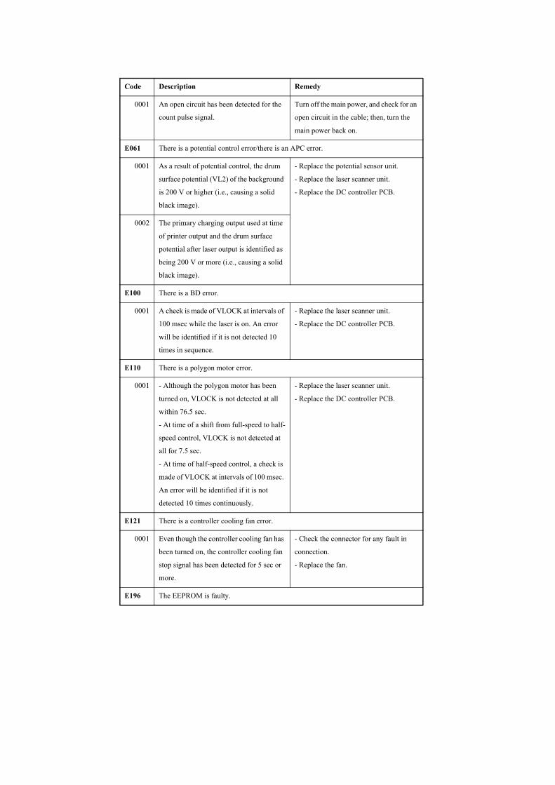
0001 An open circuit has been detected for the
count pulse signal.
Turn off the main power, and check for an
open circuit in the cable; then, turn the
main power back on.
E061 There is a potential control error/there is an APC error.
0001 As a result of potential control, the drum
surface potential (VL2) of the background
is 200 V or higher (i.e., causing a solid
black image).
- Replace the potential sensor unit.
- Replace the laser scanner unit.
- Replace the DC controller PCB.
0002 The primary charging output used at time
of printer output and the drum surface
potential after laser output is identified as
being 200 V or more (i.e., causing a solid
black image).
E100 There is a BD error.
0001 A check is made of VLOCK at intervals of
100 msec while the laser is on. An error
will be identified if it is not detected 10
times in sequence.
- Replace the laser scanner unit.
- Replace the DC controller PCB.
E110 There is a polygon motor error.
0001 - Although the polygon motor has been
turned on, VLOCK is not detected at all
within 76.5 sec.
- At time of a shift from full-speed to half-
speed control, VLOCK is not detected at
all for 7.5 sec.
- At time of half-speed control, a check is
made of VLOCK at intervals of 100 msec.
An error will be identified if it is not
detected 10 times continuously.
- Replace the laser scanner unit.
- Replace the DC controller PCB.
E121 There is a controller cooling fan error.
0001 Even though the controller cooling fan has
been turned on, the controller cooling fan
stop signal has been detected for 5 sec or
more.
- Check the connector for any fault in
connection.
- Replace the fan.
E196 The EEPROM is faulty.
Code Description Remedy

1abb There is a mismatch between the data that
has been written in EEPROM and the data
that has been read. (a: chip No. 0 through
5; bb: chip faulty address)
- Initialize the RAM.
- Replace the EEPROM.
- Replace the DC controller PCB.
2abb The ID in EEPROM that has been read and
the ID in ROM are compared. An error
will be identified if they do not match. (a:
chip No. 0 through 5; bb: chip faulty
address)
3abb When the main power is turned on, the ID
in EEPROM and the ID in ROM are
compared. An error will be identified if
they do not match. (a: chip No. 0 through
5; bb: chip faulty address)
- Check the position and condition of the
EEPROM.
- Initialize the RAM.
- Replace the EEPROM.
- Replace the DC controller PCB.
E202 There is a scanner HP error.
0001 An error has occurred when the sensor was
moved to home position.
The scanner HP sensor is faulty; the
scanner motor is faulty; the reader
controller PCB is faulty.
- Check the connector for any fault in
connection.
- Replace the scanner HP sensor.
- Replace the scanner motor.
- Replace the reader controller PCB.
0002 An error has occurred when the sensor was
moved from home position.
The scanner HP sensor is faulty; the
scanner motor is faulty; the reader
controller PCB is faulty.
E225 The intensity of light is inadequate.
0001 At time of shading, the intensity if below a
specific level.
- Check the connector for any fault in
connection.
- Replace the scanning lamp.
- Replace the inverter PCB.
- Replace the reader controller PCB.
0002 ADFThe intensity is below a specific level
between sheets (ADF).
E227 there is an error in the power supply (24 V).
0001 At power-on, the 24-V port is OFF. - Check the connector for any fault in
connection.
- Replace the power supply.0002 At the start of a job, the 24-V port is OFF.
0003 At the end of a job, the 24-V port is off.
0004 When a load is driven, the 24-V port is
OFF.
E240 The communication between the main controller PCB and the DC controller PCB is
faulty.
Code Description Remedy
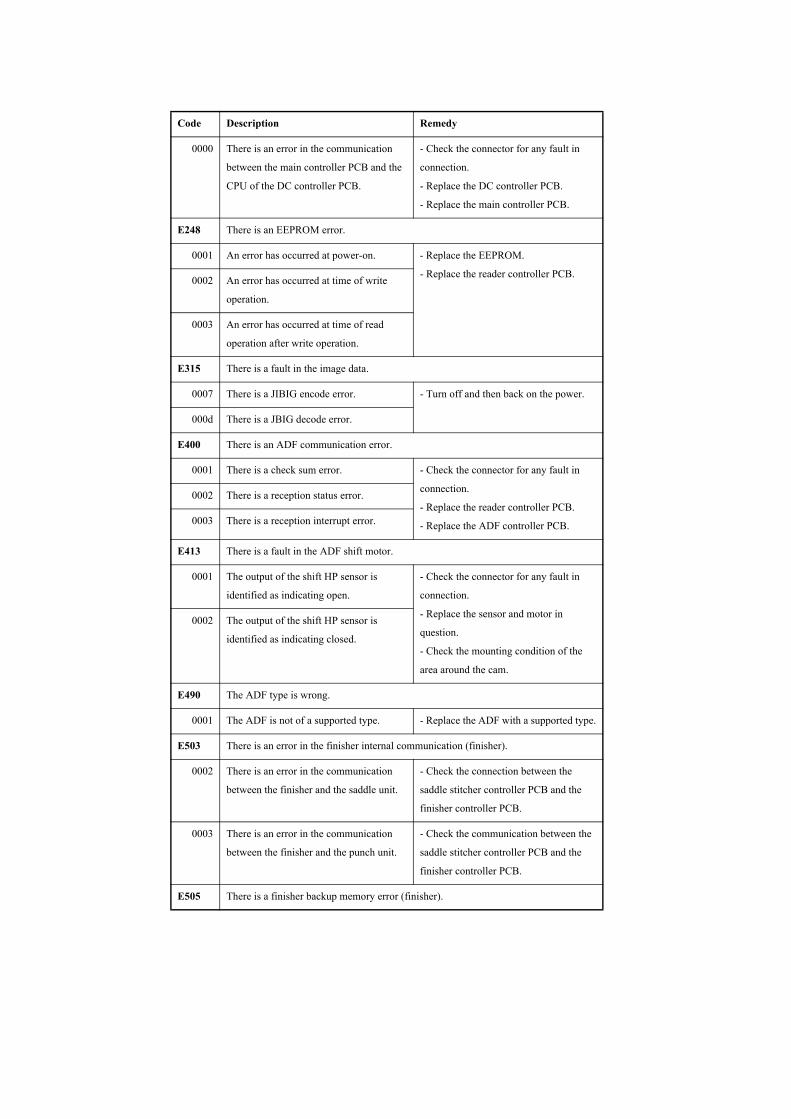
0000 There is an error in the communication
between the main controller PCB and the
CPU of the DC controller PCB.
- Check the connector for any fault in
connection.
- Replace the DC controller PCB.
- Replace the main controller PCB.
E248 There is an EEPROM error.
0001 An error has occurred at power-on. - Replace the EEPROM.
- Replace the reader controller PCB.0002 An error has occurred at time of write
operation.
0003 An error has occurred at time of read
operation after write operation.
E315 There is a fault in the image data.
0007 There is a JIBIG encode error. - Turn off and then back on the power.
000d There is a JBIG decode error.
E400 There is an ADF communication error.
0001 There is a check sum error. - Check the connector for any fault in
connection.
- Replace the reader controller PCB.
- Replace the ADF controller PCB.
0002 There is a reception status error.
0003 There is a reception interrupt error.
E413 There is a fault in the ADF shift motor.
0001 The output of the shift HP sensor is
identified as indicating open.
- Check the connector for any fault in
connection.
- Replace the sensor and motor in
question.
- Check the mounting condition of the
area around the cam.
0002 The output of the shift HP sensor is
identified as indicating closed.
E490 The ADF type is wrong.
0001 The ADF is not of a supported type. - Replace the ADF with a supported type.
E503 There is an error in the finisher internal communication (finisher).
0002 There is an error in the communication
between the finisher and the saddle unit.
- Check the connection between the
saddle stitcher controller PCB and the
finisher controller PCB.
0003 There is an error in the communication
between the finisher and the punch unit.
- Check the communication between the
saddle stitcher controller PCB and the
finisher controller PCB.
E505 There is a finisher backup memory error (finisher).
Code Description Remedy
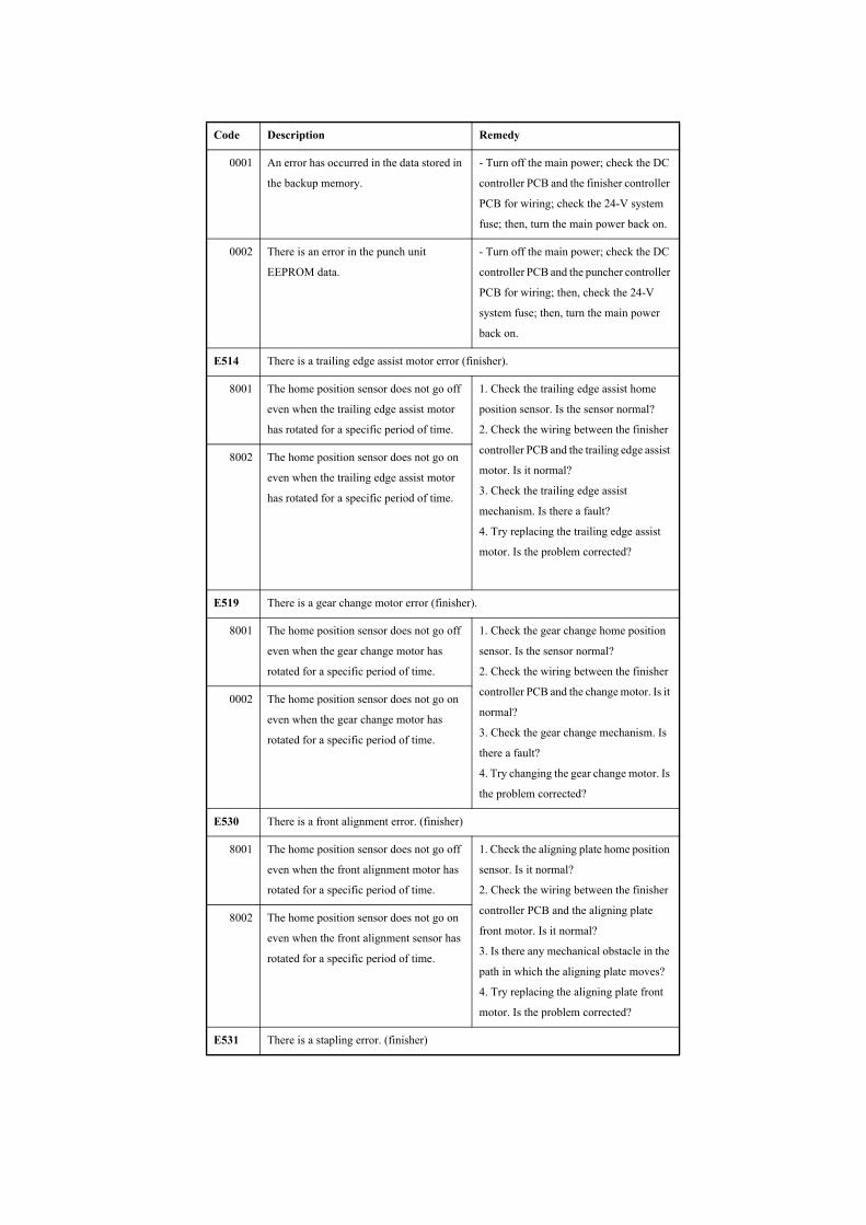
0001 An error has occurred in the data stored in
the backup memory.
- Turn off the main power; check the DC
controller PCB and the finisher controller
PCB for wiring; check the 24-V system
fuse; then, turn the main power back on.
0002 There is an error in the punch unit
EEPROM data.
- Turn off the main power; check the DC
controller PCB and the puncher controller
PCB for wiring; then, check the 24-V
system fuse; then, turn the main power
back on.
E514 There is a trailing edge assist motor error (finisher).
8001 The home position sensor does not go off
even when the trailing edge assist motor
has rotated for a specific period of time.
1. Check the trailing edge assist home
position sensor. Is the sensor normal?
2. Check the wiring between the finisher
controller PCB and the trailing edge assist
motor. Is it normal?
3. Check the trailing edge assist
mechanism. Is there a fault?
4. Try replacing the trailing edge assist
motor. Is the problem corrected?
8002 The home position sensor does not go on
even when the trailing edge assist motor
has rotated for a specific period of time.
E519 There is a gear change motor error (finisher).
8001 The home position sensor does not go off
even when the gear change motor has
rotated for a specific period of time.
1. Check the gear change home position
sensor. Is the sensor normal?
2. Check the wiring between the finisher
controller PCB and the change motor. Is it
normal?
3. Check the gear change mechanism. Is
there a fault?
4. Try changing the gear change motor. Is
the problem corrected?
0002 The home position sensor does not go on
even when the gear change motor has
rotated for a specific period of time.
E530 There is a front alignment error. (finisher)
8001 The home position sensor does not go off
even when the front alignment motor has
rotated for a specific period of time.
1. Check the aligning plate home position
sensor. Is it normal?
2. Check the wiring between the finisher
controller PCB and the aligning plate
front motor. Is it normal?
3. Is there any mechanical obstacle in the
path in which the aligning plate moves?
4. Try replacing the aligning plate front
motor. Is the problem corrected?
8002 The home position sensor does not go on
even when the front alignment sensor has
rotated for a specific period of time.
E531 There is a stapling error. (finisher)
Code Description Remedy
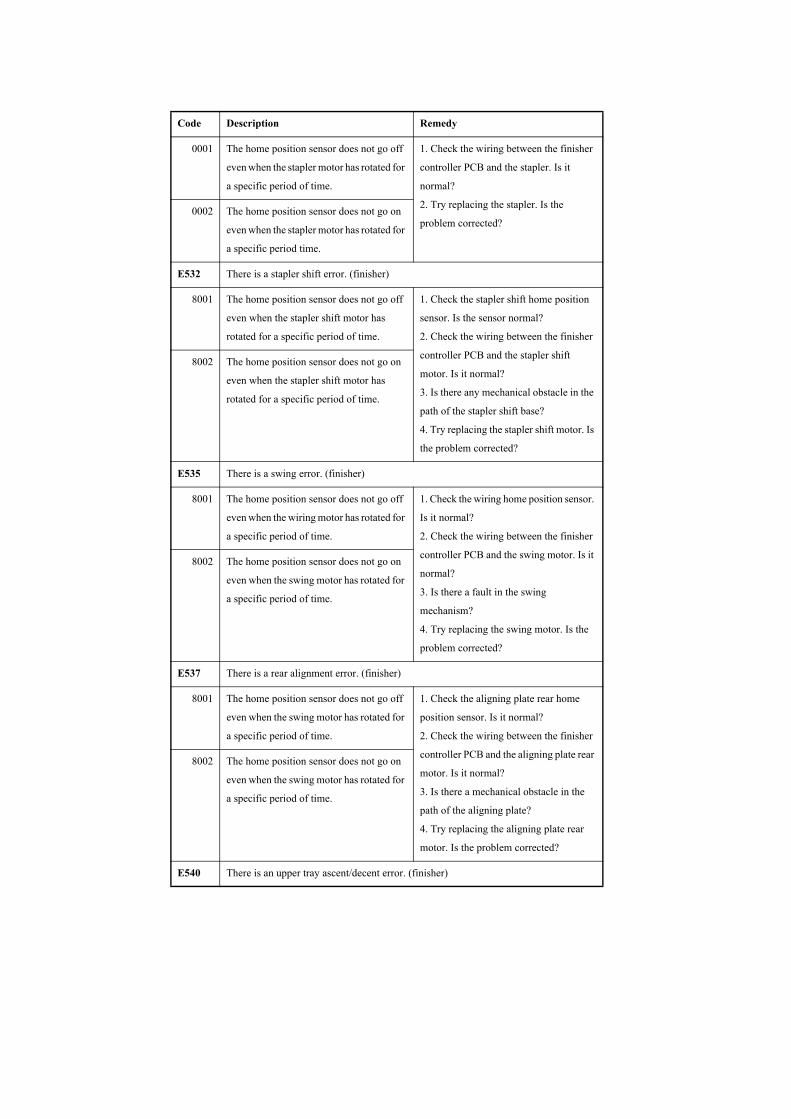
0001 The home position sensor does not go off
even when the stapler motor has rotated for
a specific period of time.
1. Check the wiring between the finisher
controller PCB and the stapler. Is it
normal?
2. Try replacing the stapler. Is the
problem corrected?0002 The home position sensor does not go on
even when the stapler motor has rotated for
a specific period time.
E532 There is a stapler shift error. (finisher)
8001 The home position sensor does not go off
even when the stapler shift motor has
rotated for a specific period of time.
1. Check the stapler shift home position
sensor. Is the sensor normal?
2. Check the wiring between the finisher
controller PCB and the stapler shift
motor. Is it normal?
3. Is there any mechanical obstacle in the
path of the stapler shift base?
4. Try replacing the stapler shift motor. Is
the problem corrected?
8002 The home position sensor does not go on
even when the stapler shift motor has
rotated for a specific period of time.
E535 There is a swing error. (finisher)
8001 The home position sensor does not go off
even when the wiring motor has rotated for
a specific period of time.
1. Check the wiring home position sensor.
Is it normal?
2. Check the wiring between the finisher
controller PCB and the swing motor. Is it
normal?
3. Is there a fault in the swing
mechanism?
4. Try replacing the swing motor. Is the
problem corrected?
8002 The home position sensor does not go on
even when the swing motor has rotated for
a specific period of time.
E537 There is a rear alignment error. (finisher)
8001 The home position sensor does not go off
even when the swing motor has rotated for
a specific period of time.
1. Check the aligning plate rear home
position sensor. Is it normal?
2. Check the wiring between the finisher
controller PCB and the aligning plate rear
motor. Is it normal?
3. Is there a mechanical obstacle in the
path of the aligning plate?
4. Try replacing the aligning plate rear
motor. Is the problem corrected?
8002 The home position sensor does not go on
even when the swing motor has rotated for
a specific period of time.
E540 There is an upper tray ascent/decent error. (finisher)
Code Description Remedy
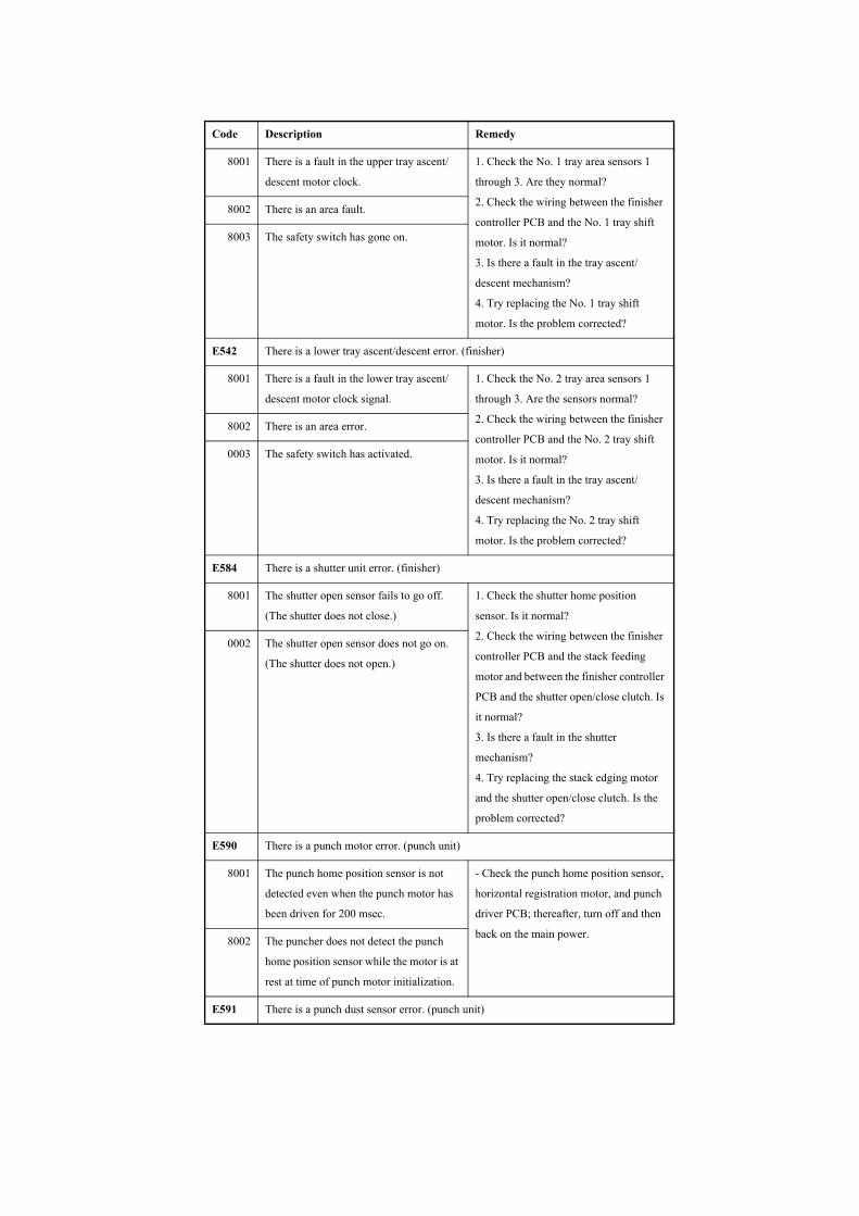
8001 There is a fault in the upper tray ascent/
descent motor clock.
1. Check the No. 1 tray area sensors 1
through 3. Are they normal?
2. Check the wiring between the finisher
controller PCB and the No. 1 tray shift
motor. Is it normal?
3. Is there a fault in the tray ascent/
descent mechanism?
4. Try replacing the No. 1 tray shift
motor. Is the problem corrected?
8002 There is an area fault.
8003 The safety switch has gone on.
E542 There is a lower tray ascent/descent error. (finisher)
8001 There is a fault in the lower tray ascent/
descent motor clock signal.
1. Check the No. 2 tray area sensors 1
through 3. Are the sensors normal?
2. Check the wiring between the finisher
controller PCB and the No. 2 tray shift
motor. Is it normal?
3. Is there a fault in the tray ascent/
descent mechanism?
4. Try replacing the No. 2 tray shift
motor. Is the problem corrected?
8002 There is an area error.
0003 The safety switch has activated.
E584 There is a shutter unit error. (finisher)
8001 The shutter open sensor fails to go off.
(The shutter does not close.)
1. Check the shutter home position
sensor. Is it normal?
2. Check the wiring between the finisher
controller PCB and the stack feeding
motor and between the finisher controller
PCB and the shutter open/close clutch. Is
it normal?
3. Is there a fault in the shutter
mechanism?
4. Try replacing the stack edging motor
and the shutter open/close clutch. Is the
problem corrected?
0002 The shutter open sensor does not go on.
(The shutter does not open.)
E590 There is a punch motor error. (punch unit)
8001 The punch home position sensor is not
detected even when the punch motor has
been driven for 200 msec.
- Check the punch home position sensor,
horizontal registration motor, and punch
driver PCB; thereafter, turn off and then
back on the main power.8002 The puncher does not detect the punch
home position sensor while the motor is at
rest at time of punch motor initialization.
E591 There is a punch dust sensor error. (punch unit)
Code Description Remedy

8001 The incoming light voltage is faulty in the
presence of light.
- Turn off and then back on the main
power.
8002 The incoming light voltage is faulty in the
absence of light.
E592 There is a punch horizontal registration sensor error. (punch unit)
8001 The incoming light voltage is faulty in the
presence of light. (trailing edge sensor)
- turn off and then back on the main
power.
8002 The incoming light is faulty in the absence
of light and voltage. (trailing edge sensor)
8003 The incoming light voltage is faulty in the
presence of light. (horizontal registration
sensor 1)
8004 The incoming light voltage is faulty in the
absence of light. (horizontal registration
sensor 1)
8005 The incoming light voltage is faulty in the
presence of light. (horizontal registration
sensor 2)
8006 The incoming light voltage is faulty in the
absence of light. (horizontal registration
sensor 2)
8007 The incoming light voltage is faulty in the
presence of light. (horizontal registration
sensor 3)
8008 The incoming light voltage is faulty in the
absence of light. (horizontal registration
sensor 3)
8009 The incoming light voltage is faulty in the
presence of light. (horizontal registration
sensor 4)
800A The incoming light voltage is faulty in the
absence of light. (horizontal registration
sensor 4)
E593 There is a punch shift motor error. (punch unit)
8001 In the presence of light, the incoming light
voltage HP sensor does not go off.
- Turn off and the back on the main
power.
8002 In the absence of light, the incoming light
voltage HP sensor does not go on.
E5F0 There is a saddle paper positioning error.
Code Description Remedy

0001 The paper positioning plate home position
sensor does not go on even when the paper
positioning plate motor has been driven for
1.33 sec.
paper positioning plate motor (M4S),
paper positioning plate home position
sensor (PI7S)
- Check the paper positioning plate motor
(M4S) and the paper positioning plate
home position sensor (PI7S).
0002 The paper positioning plate home position
sensor does not go off even when the paper
positioning plate motor has been driven for
1 sec.
paper positioning plate motor (M4S),
paper positioning plate home position
sensor (PI7S)
E5F1 There is a saddle paper folding error.
0001 The number of detection pulses of the
paper folding motor clock sensor is lower
than a specific value.
paper folding motor (M2S), paper folding
motor clock sensor (PI4S)
- Check the paper folding motor (M2S)
and the paper folding motor clock sensor
(PI4S).
0002 The start of the paper folding home
position sensor does not change even when
the paper folding motor has been driven
for 3 sec.
paper folding motor (M2S), paper folding
motor clock sensor (PI4S)
E5F2 There is a saddle guide error.
0001 The guide home position sensor does not
go on even when the guide motor has been
driven for 0.455 sec.
guide motor (M3S), guide home position
sensor (PI13S)
- Check the guide motor (M3S) and the
guide home position sensor (PI13S).
0002 The guide home position sensor does not
go off even when the guide motor has been
driven for 1 sec.
guide motor (M3S), guide home position
sensor (PI13S)
E5F3 There is a saddle alignment error.
Code Description Remedy
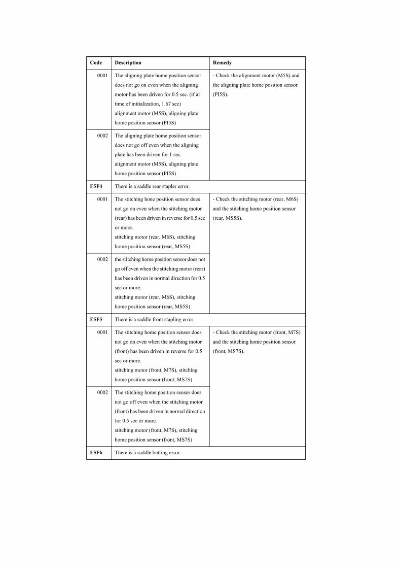
0001 The aligning plate home position sensor
does not go on even when the aligning
motor has been driven for 0.5 sec. (if at
time of initialization, 1.67 sec)
alignment motor (M5S), aligning plate
home position sensor (PI5S)
- Check the alignment motor (M5S) and
the aligning plate home position sensor
(PI5S).
0002 The aligning plate home position sensor
does not go off even when the aligning
plate has been driven for 1 sec.
alignment motor (M5S), aligning plate
home position sensor (PI5S)
E5F4 There is a saddle rear stapler error.
0001 The stitching hone position sensor does
not go on even when the stitching motor
(rear) has been driven in reverse for 0.5 sec
or more.
stitching motor (rear, M6S), stitching
home position sensor (rear, MS5S)
- Check the stitching motor (rear, M6S)
and the stitching home position sensor
(rear, MS5S).
0002 the stitching home position sensor does not
go off even when the stitching motor (rear)
has been driven in normal direction for 0.5
sec or more.
stitching motor (rear, M6S), stitching
home position sensor (rear, MS5S)
E5F5 There is a saddle front stapling error.
0001 The stitching home position sensor does
not go on even when the stitching motor
(front) has been driven in reverse for 0.5
sec or more.
stitching motor (front, M7S), stitching
home position sensor (front, MS7S)
- Check the stitching motor (front, M7S)
and the stitching home position sensor
(front, MS7S).
0002 The stitching home position sensor does
not go off even when the stitching motor
(front) has been driven in normal direction
for 0.5 sec or more.
stitching motor (front, M7S), stitching
home position sensor (front, MS7S)
E5F6 There is a saddle butting error.
Code Description Remedy

8001 The paper pushing plate home position
sensor does not go on even when the paper
pushing plate motor has been driven for
0.3 sec or more.
paper pushing plate motor (M8S), paper
pushing plate home position sensor
(PI14S)
- Check the paper pushing plate motor
(M8S) and the paper pushing plate home
position sensor (PI14S).
8002 The paper pushing plate home position
sensor does not go off even when the paper
pushing plate motor has been driven for 80
msec.
paper pushing plate motor (M8S), paper
pushing plate home position sensor
(PI14S)
8003 The number of detection pulses of the
paper pushing plate motor clock sensor is
lower than a specific value.
paper pushing plate motor (M8S), paper
pushing plate motor clock sensor (PI1S)
- Check the paper pushing plate motor
(M8S) and the paper pushing plate motor
clock sensor (PI1S).
8004 The paper pushing plate leading edge
sensor does not go off even when the paper
pushing plate motor has been driven for 80
msec.
paper pushing plate motor (M8S), paper
pushing plate leading edge position sensor
(PI15S)
- Check the power pushing plate motor
(M8S) and the paper pushing plate
leading edge position sensor (PI15S).
8005 The paper pushing plate leading edge
position sensor does not go on even when
the paper pushing plate has been driven for
0.3 sec or more.
paper pushing plate motor (M8S), paper
pushing plate leading edge position sensor
(PI15S)
E5F9 There is a saddle switch error.
Code Description Remedy
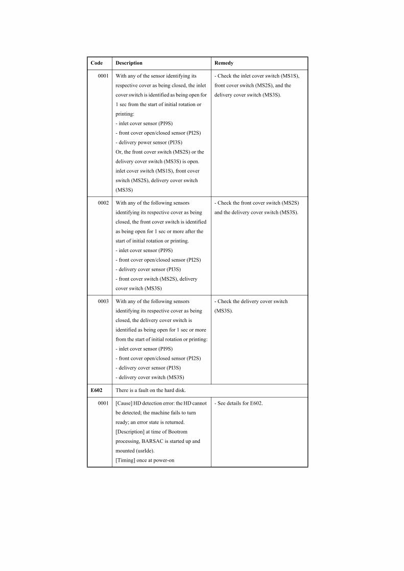
0001 With any of the sensor identifying its
respective cover as being closed, the inlet
cover switch is identified as being open for
1 sec from the start of initial rotation or
printing:
- inlet cover sensor (PI9S)
- front cover open/closed sensor (PI2S)
- delivery power sensor (PI3S)
Or, the front cover switch (MS2S) or the
delivery cover switch (MS3S) is open.
inlet cover switch (MS1S), front cover
switch (MS2S), delivery cover switch
(MS3S)
- Check the inlet cover switch (MS1S),
front cover switch (MS2S), and the
delivery cover switch (MS3S).
0002 With any of the following sensors
identifying its respective cover as being
closed, the front cover switch is identified
as being open for 1 sec or more after the
start of initial rotation or printing.
- inlet cover sensor (PI9S)
- front cover open/closed sensor (PI2S)
- delivery cover sensor (PI3S)
- front cover switch (MS2S), delivery
cover switch (MS3S)
- Check the front cover switch (MS2S)
and the delivery cover switch (MS3S).
0003 With any of the following sensors
identifying its respective cover as being
closed, the delivery cover switch is
identified as being open for 1 sec or more
from the start of initial rotation or printing:
- inlet cover sensor (PI9S)
- front cover open/closed sensor (PI2S)
- delivery cover sensor (PI3S)
- delivery cover switch (MS3S)
- Check the delivery cover switch
(MS3S).
E602 There is a fault on the hard disk.
0001 [Cause] HD detection error: the HD cannot
be detected; the machine fails to turn
ready; an error state is returned.
[Description] at time of Bootrom
processing, BARSAC is started up and
mounted (usrIde).
[Timing] once at power-on
- See details for E602.
Code Description Remedy
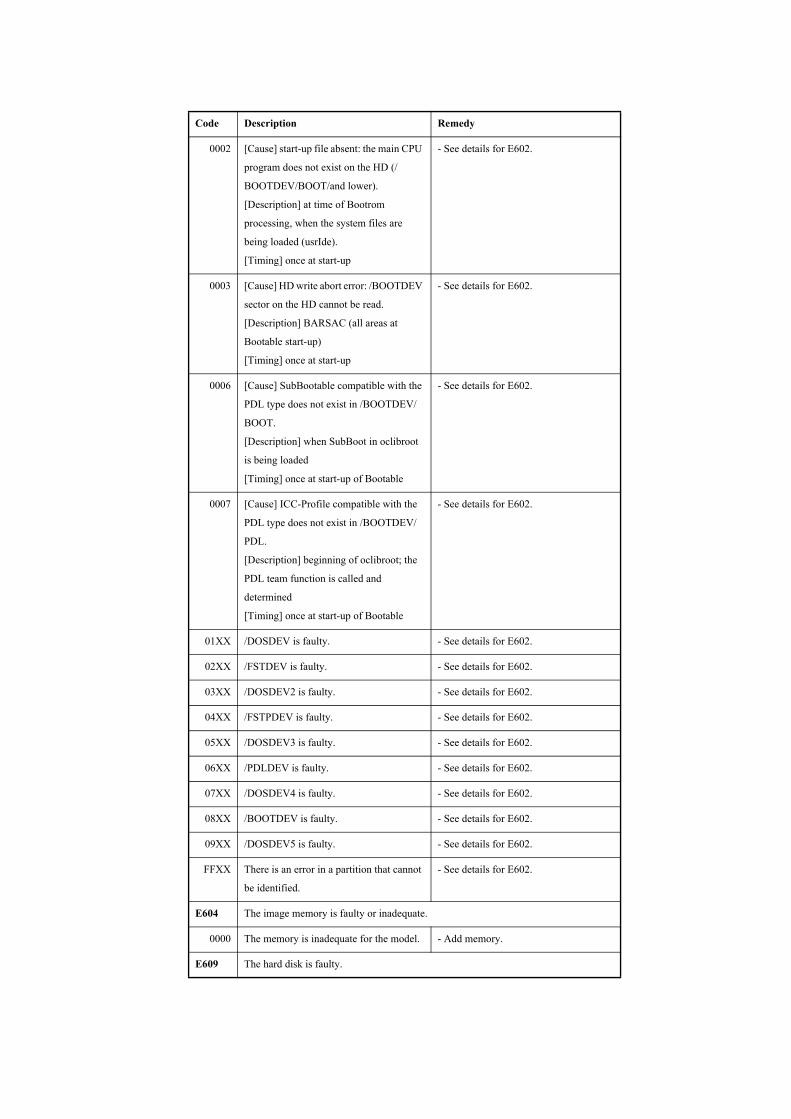
0002 [Cause] start-up file absent: the main CPU
program does not exist on the HD (/
BOOTDEV/BOOT/and lower).
[Description] at time of Bootrom
processing, when the system files are
being loaded (usrIde).
[Timing] once at start-up
- See details for E602.
0003 [Cause] HD write abort error: /BOOTDEV
sector on the HD cannot be read.
[Description] BARSAC (all areas at
Bootable start-up)
[Timing] once at start-up
- See details for E602.
0006 [Cause] SubBootable compatible with the
PDL type does not exist in /BOOTDEV/
BOOT.
[Description] when SubBoot in oclibroot
is being loaded
[Timing] once at start-up of Bootable
- See details for E602.
0007 [Cause] ICC-Profile compatible with the
PDL type does not exist in /BOOTDEV/
PDL.
[Description] beginning of oclibroot; the
PDL team function is called and
determined
[Timing] once at start-up of Bootable
- See details for E602.
01XX /DOSDEV is faulty. - See details for E602.
02XX /FSTDEV is faulty. - See details for E602.
03XX /DOSDEV2 is faulty. - See details for E602.
04XX /FSTPDEV is faulty. - See details for E602.
05XX /DOSDEV3 is faulty. - See details for E602.
06XX /PDLDEV is faulty. - See details for E602.
07XX /DOSDEV4 is faulty. - See details for E602.
08XX /BOOTDEV is faulty. - See details for E602.
09XX /DOSDEV5 is faulty. - See details for E602.
FFXX There is an error in a partition that cannot
be identified.
- See details for E602.
E604 The image memory is faulty or inadequate.
0000 The memory is inadequate for the model. - Add memory.
E609 The hard disk is faulty.
Code Description Remedy
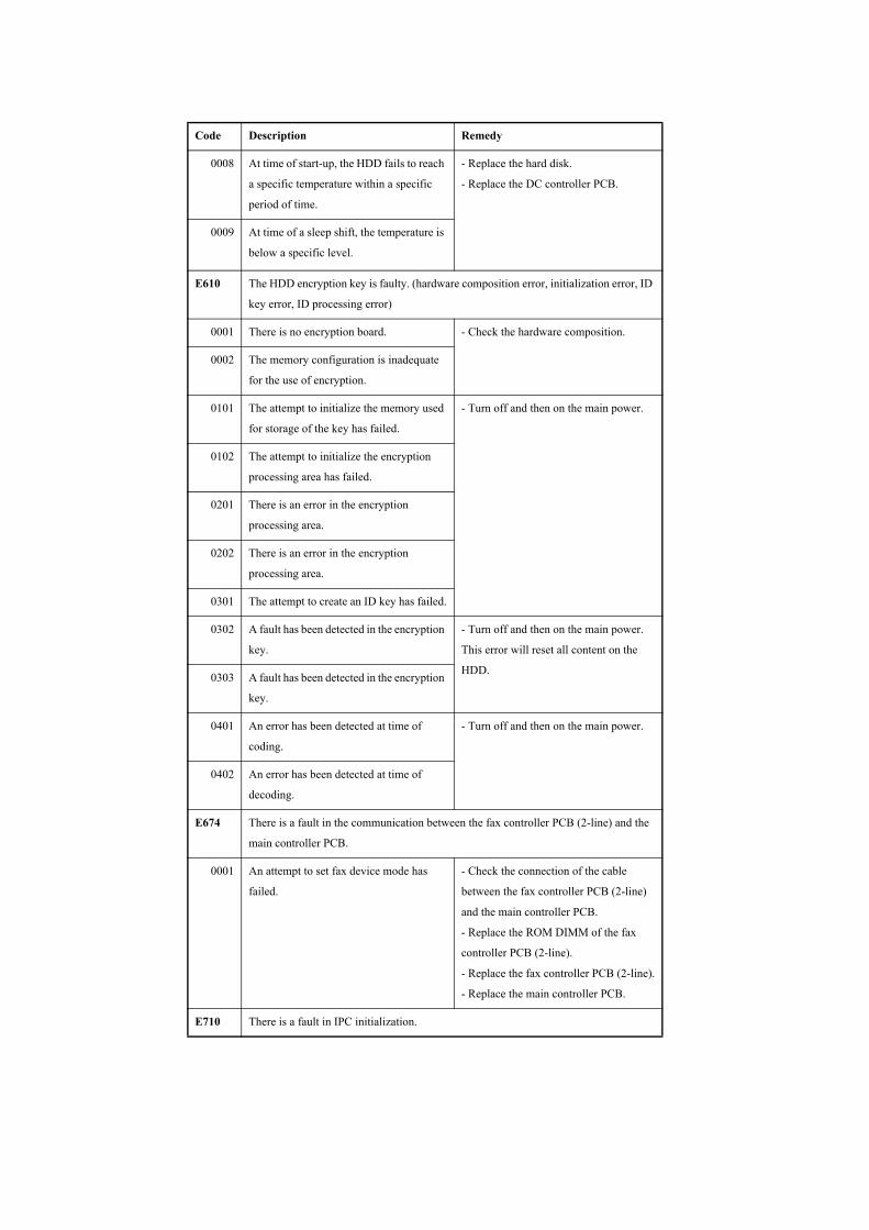
0008 At time of start-up, the HDD fails to reach
a specific temperature within a specific
period of time.
- Replace the hard disk.
- Replace the DC controller PCB.
0009 At time of a sleep shift, the temperature is
below a specific level.
E610 The HDD encryption key is faulty. (hardware composition error, initialization error, ID
key error, ID processing error)
0001 There is no encryption board. - Check the hardware composition.
0002 The memory configuration is inadequate
for the use of encryption.
0101 The attempt to initialize the memory used
for storage of the key has failed.
- Turn off and then on the main power.
0102 The attempt to initialize the encryption
processing area has failed.
0201 There is an error in the encryption
processing area.
0202 There is an error in the encryption
processing area.
0301 The attempt to create an ID key has failed.
0302 A fault has been detected in the encryption
key.
- Turn off and then on the main power.
This error will reset all content on the
HDD.0303 A fault has been detected in the encryption
key.
0401 An error has been detected at time of
coding.
- Turn off and then on the main power.
0402 An error has been detected at time of
decoding.
E674 There is a fault in the communication between the fax controller PCB (2-line) and the
main controller PCB.
0001 An attempt to set fax device mode has
failed.
- Check the connection of the cable
between the fax controller PCB (2-line)
and the main controller PCB.
- Replace the ROM DIMM of the fax
controller PCB (2-line).
- Replace the fax controller PCB (2-line).
- Replace the main controller PCB.
E710 There is a fault in IPC initialization.
Code Description Remedy
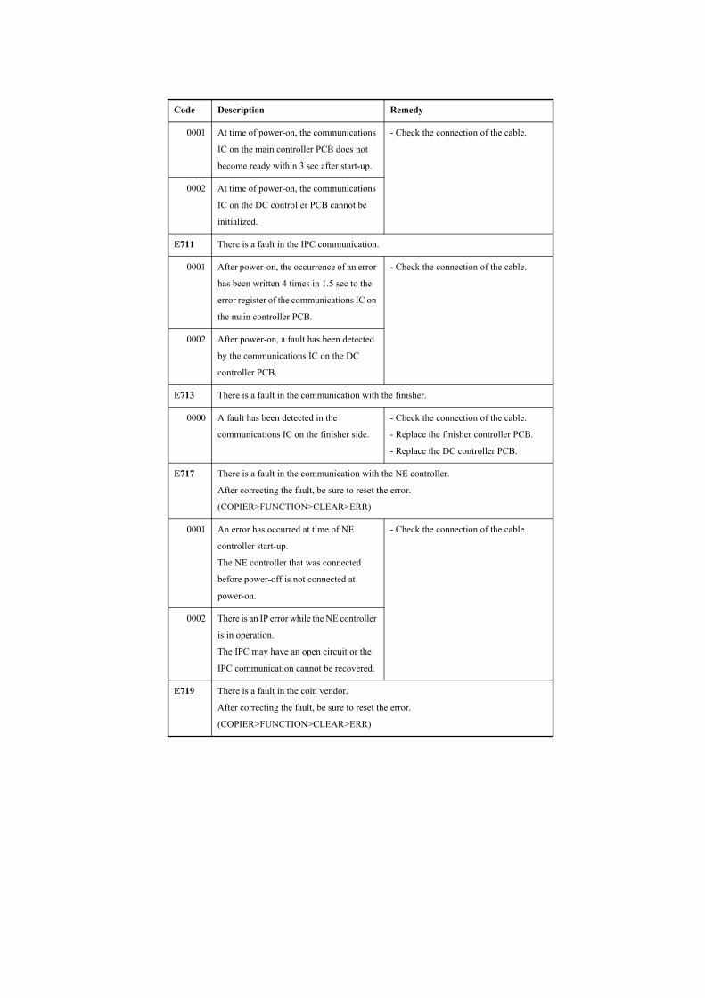
0001 At time of power-on, the communications
IC on the main controller PCB does not
become ready within 3 sec after start-up.
- Check the connection of the cable.
0002 At time of power-on, the communications
IC on the DC controller PCB cannot be
initialized.
E711 There is a fault in the IPC communication.
0001 After power-on, the occurrence of an error
has been written 4 times in 1.5 sec to the
error register of the communications IC on
the main controller PCB.
- Check the connection of the cable.
0002 After power-on, a fault has been detected
by the communications IC on the DC
controller PCB.
E713 There is a fault in the communication with the finisher.
0000 A fault has been detected in the
communications IC on the finisher side.
- Check the connection of the cable.
- Replace the finisher controller PCB.
- Replace the DC controller PCB.
E717 There is a fault in the communication with the NE controller.
After correcting the fault, be sure to reset the error.
(COPIER>FUNCTION>CLEAR>ERR)
0001 An error has occurred at time of NE
controller start-up.
The NE controller that was connected
before power-off is not connected at
power-on.
- Check the connection of the cable.
0002 There is an IP error while the NE controller
is in operation.
The IPC may have an open circuit or the
IPC communication cannot be recovered.
E719 There is a fault in the coin vendor.
After correcting the fault, be sure to reset the error.
(COPIER>FUNCTION>CLEAR>ERR)
Code Description Remedy
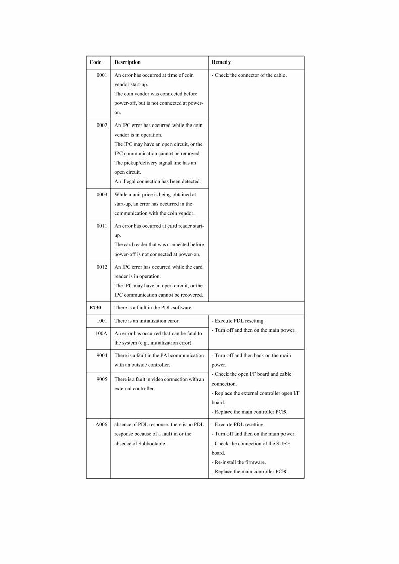
0001 An error has occurred at time of coin
vendor start-up.
The coin vendor was connected before
power-off, but is not connected at power-
on.
- Check the connector of the cable.
0002 An IPC error has occurred while the coin
vendor is in operation.
The IPC may have an open circuit, or the
IPC communication cannot be removed.
The pickup/delivery signal line has an
open circuit.
An illegal connection has been detected.
0003 While a unit price is being obtained at
start-up, an error has occurred in the
communication with the coin vendor.
0011 An error has occurred at card reader start-
up.
The card reader that was connected before
power-off is not connected at power-on.
0012 An IPC error has occurred while the card
reader is in operation.
The IPC may have an open circuit, or the
IPC communication cannot be recovered.
E730 There is a fault in the PDL software.
1001 There is an initialization error. - Execute PDL resetting.
- Turn off and then on the main power.100A An error has occurred that can be fatal to
the system (e.g., initialization error).
9004 There is a fault in the PAI communication
with an outside controller.
- Turn off and then back on the main
power.
- Check the open I/F board and cable
connection.
- Replace the external controller open I/F
board.
- Replace the main controller PCB.
9005 There is a fault in video connection with an
external controller.
A006 absence of PDL response: there is no PDL
response because of a fault in or the
absence of Subbootable.
- Execute PDL resetting.
- Turn off and then on the main power.
- Check the connection of the SURF
board.
- Re-install the firmware.
- Replace the main controller PCB.
Code Description Remedy

A007 There is a mismatch in version between the
machine control software and the PDL
control software.
- Execute PDL resetting.
- Turn off and then on the main power.
- Execute full formatting and install the
system software.
B013 The font data is corrupted. - Turn off and then on the main power.
- Re-install the system software.
- Execute full formatting and install the
system software.
E732 There is a fault in the reader communication.
0001 There is a DDI-S communication error. - Check the communication between the
reader unit and the main controller.
- Check the power supply of the reader
unit. (Check to see if initialization takes
place at start-up.)
- Replace the reader controller PCB,
reader relay PCB, or main controller
PCB.
E733 There is a fault in the printer communication.
0000 The attempt at communication with the
printer fails at start-up.
- Check the connection of the cable
between the DC controller and the main
controller.
- Check the power supply of the printer.
(Check to see if initialization takes place
at start-up.)
- Replace the DC controller PCB or the
main controller PCB.
0001 There is a DDI-P communication error.
E740 There is a fault in the Ethernet board.
0002 The MAC address is illegal. - Replace the main controller PCB.
E743 There is a fault in the DDI communication.
0000 An SCI error has occurred; the reception
data is faulty; a reception time-out error
has occurred; a SEQ time-out error has
occurred
- Disconnect and then connect the
connector between the reader unit and the
printer unit.
- Replace the cable, reader controller
PCB, and main controller PCB.
E744 There is a fault in the language file/boot ROM.
Code Description Remedy
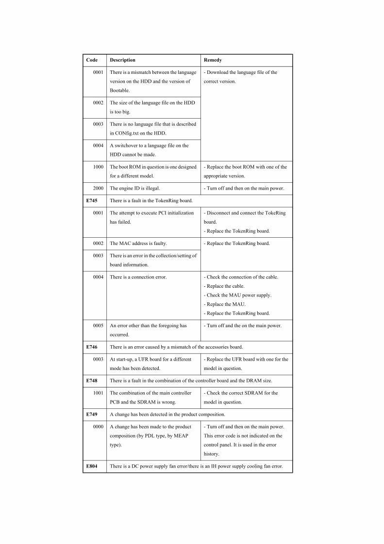
0001 There is a mismatch between the language
version on the HDD and the version of
Bootable.
- Download the language file of the
correct version.
0002 The size of the language file on the HDD
is too big.
0003 There is no language file that is described
in CONfig.txt on the HDD.
0004 A switchover to a language file on the
HDD cannot be made.
1000 The boot ROM in question is one designed
for a different model.
- Replace the boot ROM with one of the
appropriate version.
2000 The engine ID is illegal. - Turn off and then on the main power.
E745 There is a fault in the TokenRing board.
0001 The attempt to execute PCI initialization
has failed.
- Disconnect and connect the TokeRing
board.
- Replace the TokenRing board.
0002 The MAC address is faulty. - Replace the TokenRing board.
0003 There is an error in the collection/setting of
board information.
0004 There is a connection error. - Check the connection of the cable.
- Replace the cable.
- Check the MAU power supply.
- Replace the MAU.
- Replace the TokenRing board.
0005 An error other than the foregoing has
occurred.
- Turn off and the on the main power.
E746 There is an error caused by a mismatch of the accessories board.
0003 At start-up, a UFR board for a different
mode has been detected.
- Replace the UFR board with one for the
model in question.
E748 There is a fault in the combination of the controller board and the DRAM size.
1001 The combination of the main controller
PCB and the SDRAM is wrong.
- Check the correct SDRAM for the
model in question.
E749 A change has been detected in the product composition.
0000 A change has been made to the product
composition (by PDL type, by MEAP
type).
- Turn off and then on the main power.
This error code is not indicated on the
control panel. It is used in the error
history.
E804 There is a DC power supply fan error/there is an IH power supply cooling fan error.
Code Description Remedy
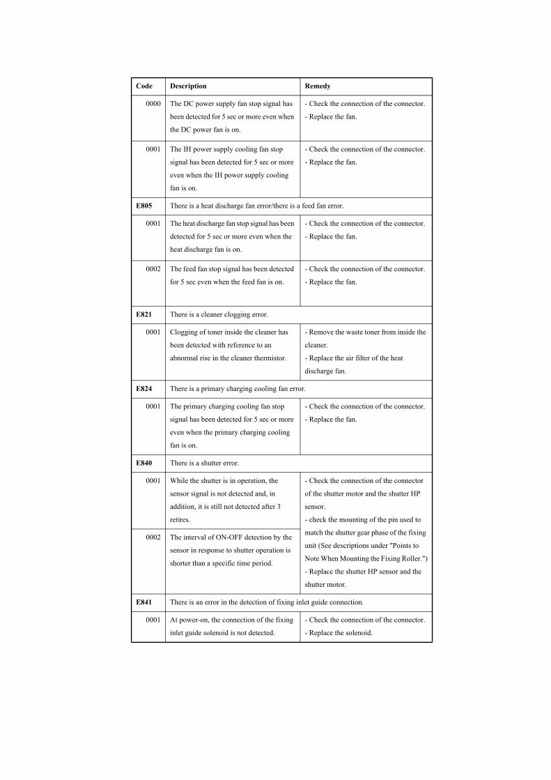
0000 The DC power supply fan stop signal has
been detected for 5 sec or more even when
the DC power fan is on.
- Check the connection of the connector.
- Replace the fan.
0001 The IH power supply cooling fan stop
signal has been detected for 5 sec or more
even when the IH power supply cooling
fan is on.
- Check the connection of the connector.
- Replace the fan.
E805 There is a heat discharge fan error/there is a feed fan error.
0001 The heat discharge fan stop signal has been
detected for 5 sec or more even when the
heat discharge fan is on.
- Check the connection of the connector.
- Replace the fan.
0002 The feed fan stop signal has been detected
for 5 sec even when the feed fan is on.
- Check the connection of the connector.
- Replace the fan.
E821 There is a cleaner clogging error.
0001 Clogging of toner inside the cleaner has
been detected with reference to an
abnormal rise in the cleaner thermistor.
- Remove the waste toner from inside the
cleaner.
- Replace the air filter of the heat
discharge fan.
E824 There is a primary charging cooling fan error.
0001 The primary charging cooling fan stop
signal has been detected for 5 sec or more
even when the primary charging cooling
fan is on.
- Check the connection of the connector.
- Replace the fan.
E840 There is a shutter error.
0001 While the shutter is in operation, the
sensor signal is not detected and, in
addition, it is still not detected after 3
retires.
- Check the connection of the connector
of the shutter motor and the shutter HP
sensor.
- check the mounting of the pin used to
match the shutter gear phase of the fixing
unit (See descriptions under "Points to
Note When Mounting the Fixing Roller.")
- Replace the shutter HP sensor and the
shutter motor.
0002 The interval of ON-OFF detection by the
sensor in response to shutter operation is
shorter than a specific time period.
E841 There is an error in the detection of fixing inlet guide connection.
0001 At power-on, the connection of the fixing
inlet guide solenoid is not detected.
- Check the connection of the connector.
- Replace the solenoid.
Code Description Remedy
Chapter 15
15-26
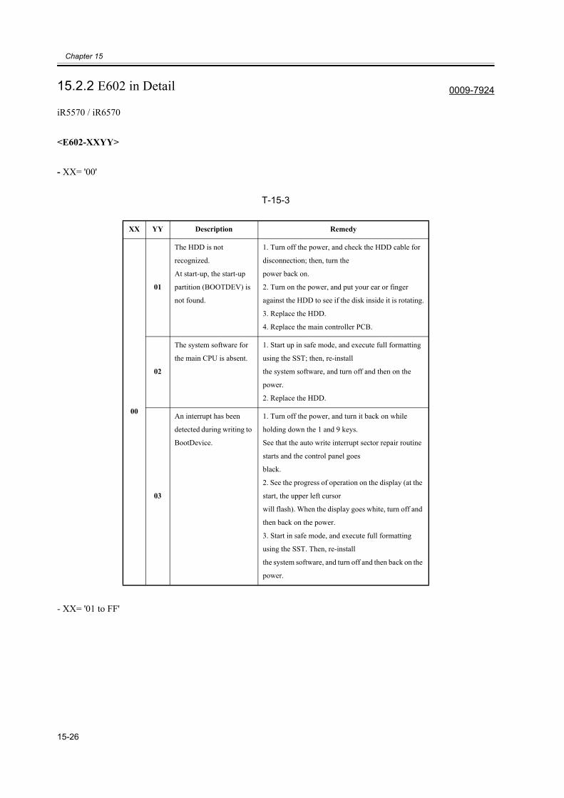
15.2.2 E602 in Detail 0009-7924
iR5570 / iR6570
<E602-XXYY>
- XX= '00'
T-15-3
- XX= '01 to FF'
XX YY Description Remedy
00
01
The HDD is not
recognized.
At start-up, the start-up
partition (BOOTDEV) is
not found.
1. Turn off the power, and check the HDD cable for
disconnection; then, turn the
power back on.
2. Turn on the power, and put your ear or finger
against the HDD to see if the disk inside it is rotating.
3. Replace the HDD.
4. Replace the main controller PCB.
02
The system software for
the main CPU is absent.
1. Start up in safe mode, and execute full formatting
using the SST; then, re-install
the system software, and turn off and then on the
power.
2. Replace the HDD.
03
An interrupt has been
detected during writing to
BootDevice.
1. Turn off the power, and turn it back on while
holding down the 1 and 9 keys.
See that the auto write interrupt sector repair routine
starts and the control panel goes
black.
2. See the progress of operation on the display (at the
start, the upper left cursor
will flash). When the display goes white, turn off and
then back on the power.
3. Start in safe mode, and execute full formatting
using the SST. Then, re-install
the system software, and turn off and then back on the
power.
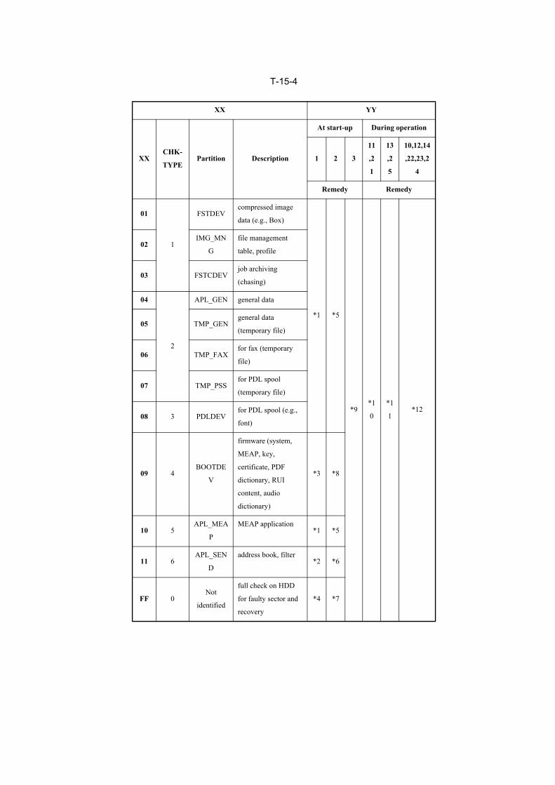
T-15-4
XX YY
XXCHK-
TYPEPartition Description
At start-up During operation
1 2 3
11
,2
1
13
,2
5
10,12,14
,22,23,2
4
Remedy Remedy
01
1
FSTDEVcompressed image
data (e.g., Box)
*1 *5
*9*1
0
*1
1*12
02IMG_MN
G
file management
table, profile
03 FSTCDEVjob archiving
(chasing)
04
2
APL_GEN general data
05 TMP_GENgeneral data
(temporary file)
06 TMP_FAXfor fax (temporary
file)
07 TMP_PSSfor PDL spool
(temporary file)
08 3 PDLDEVfor PDL spool (e.g.,
font)
09 4BOOTDE
V
firmware (system,
MEAP, key,
certificate, PDF
dictionary, RUI
content, audio
dictionary)
*3 *8
10 5APL_MEA
P
MEAP application*1 *5
11 6APL_SEN
D
address book, filter*2 *6
FF 0Not
identified
full check on HDD
for faulty sector and
recovery
*4 *7
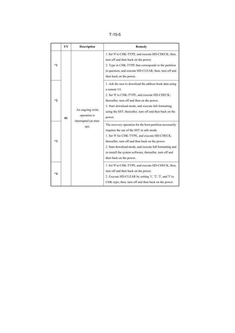
T-15-5
YY Description Remedy
*1
01
An ongoing write
operation is
interrupted (at start-
up).
1. Set '0' to CHK-TYPE, and execute HD-CHECK; then,
turn off and then back on the power.
2. Type in CHK-TYPE that corresponds to the partition
in question, and execute HD-CLEAR; then, turn off and
then back on the power.
*2
1. Ask the user to download the address book data using
a remote UI.
2. Set '0' to CHK-TYPE, and execute HD-CHECK;
thereafter, turn off and then on the power.
3. Start download mode, and execute full formatting
using the SST; thereafter, turn off and then back on the
power.
*3
The recovery operation for the boot partition necessarily
requires the use of the SST in safe mode.
1. Set '0' for CHK-TYPE, and execute HD-CHECK;
thereafter, turn off and then back on the power.
2. Start download mode, and execute full formatting and
re-install the system software; thereafter, turn off and
then back on the power.
*4
1. Set '0' to CHK-TYPE, and execute HD-CHECK; then,
turn off and then back on the power.
2. Execute HD-CLEAR by setting '1', '2', '3', and '5' to
CHK-type; then, turn off and then back on the power.
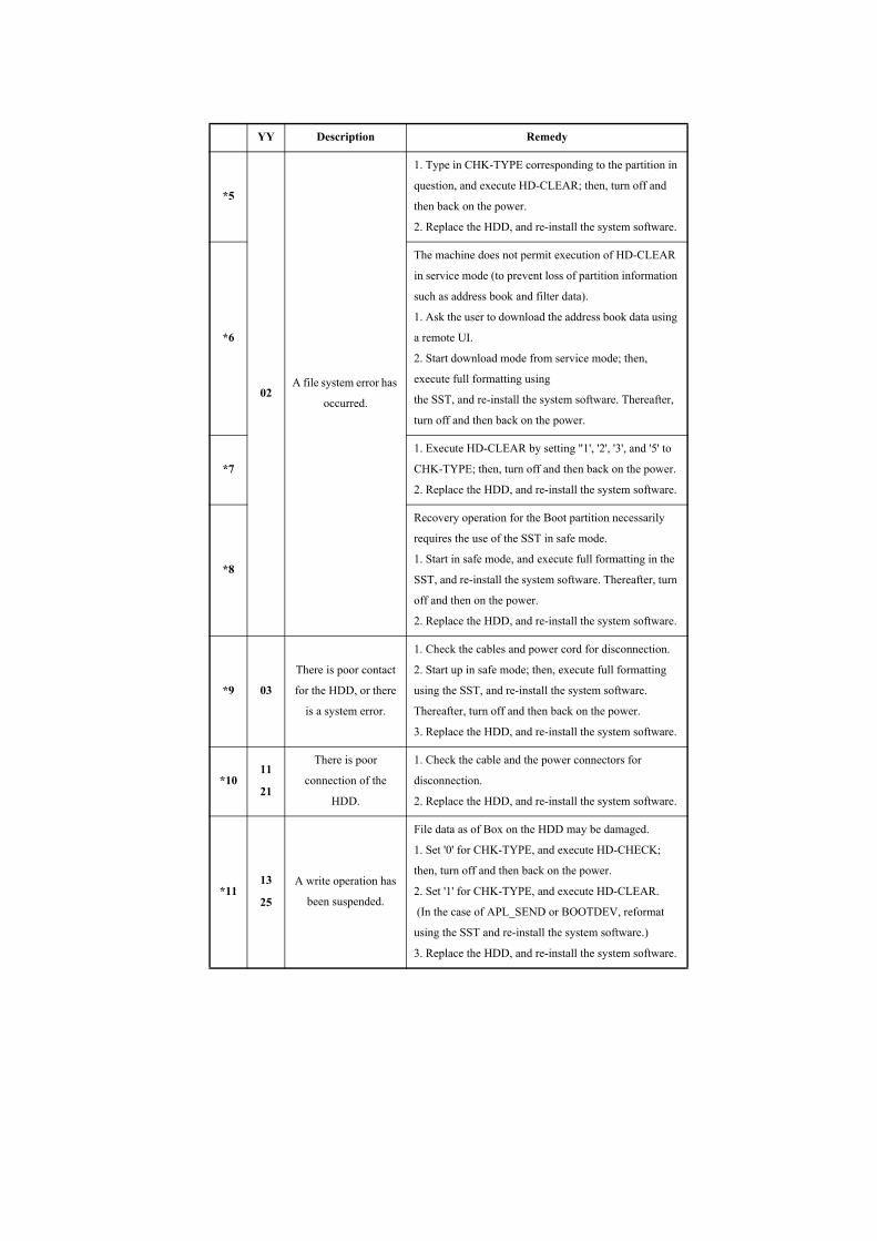
*5
02A file system error has
occurred.
1. Type in CHK-TYPE corresponding to the partition in
question, and execute HD-CLEAR; then, turn off and
then back on the power.
2. Replace the HDD, and re-install the system software.
*6
The machine does not permit execution of HD-CLEAR
in service mode (to prevent loss of partition information
such as address book and filter data).
1. Ask the user to download the address book data using
a remote UI.
2. Start download mode from service mode; then,
execute full formatting using
the SST, and re-install the system software. Thereafter,
turn off and then back on the power.
*7
1. Execute HD-CLEAR by setting "1', '2', '3', and '5' to
CHK-TYPE; then, turn off and then back on the power.
2. Replace the HDD, and re-install the system software.
*8
Recovery operation for the Boot partition necessarily
requires the use of the SST in safe mode.
1. Start in safe mode, and execute full formatting in the
SST, and re-install the system software. Thereafter, turn
off and then on the power.
2. Replace the HDD, and re-install the system software.
*9 03
There is poor contact
for the HDD, or there
is a system error.
1. Check the cables and power cord for disconnection.
2. Start up in safe mode; then, execute full formatting
using the SST, and re-install the system software.
Thereafter, turn off and then back on the power.
3. Replace the HDD, and re-install the system software.
*1011
21
There is poor
connection of the
HDD.
1. Check the cable and the power connectors for
disconnection.
2. Replace the HDD, and re-install the system software.
*1113
25
A write operation has
been suspended.
File data as of Box on the HDD may be damaged.
1. Set '0' for CHK-TYPE, and execute HD-CHECK;
then, turn off and then back on the power.
2. Set '1' for CHK-TYPE, and execute HD-CLEAR.
(In the case of APL_SEND or BOOTDEV, reformat
using the SST and re-install the system software.)
3. Replace the HDD, and re-install the system software.
YY Description Remedy

*12
10
12
14
22
23
24
There is a system error
or a packet data error.
1. Start up in safe mode; then, execute full formatting
using the SST, and re-install the system software.
Thereafter, turn off and then back on the power.
2. Replace the HDD, and re-install the system software.
YY Description Remedy
Chapter 15
15-31
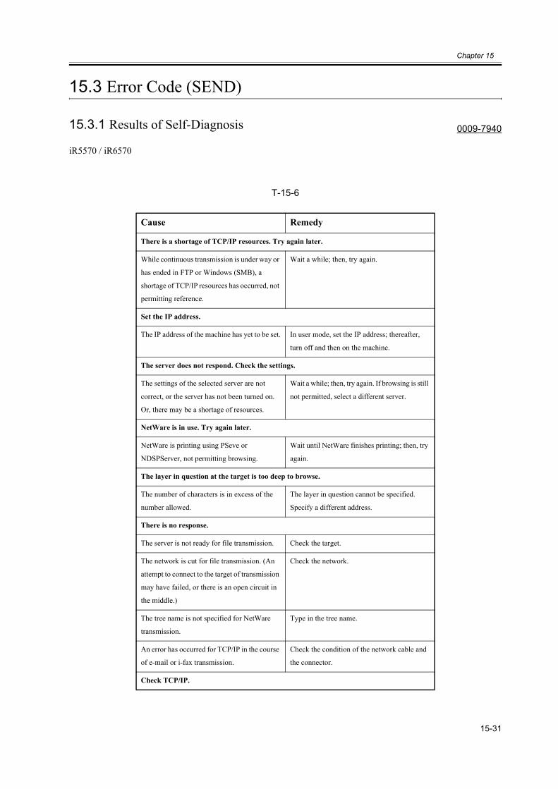
15.3 Error Code (SEND)
15.3.1 Results of Self-Diagnosis 0009-7940
iR5570 / iR6570
T-15-6
Cause Remedy
There is a shortage of TCP/IP resources. Try again later.
While continuous transmission is under way or
has ended in FTP or Windows (SMB), a
shortage of TCP/IP resources has occurred, not
permitting reference.
Wait a while; then, try again.
Set the IP address.
The IP address of the machine has yet to be set. In user mode, set the IP address; thereafter,
turn off and then on the machine.
The server does not respond. Check the settings.
The settings of the selected server are not
correct, or the server has not been turned on.
Or, there may be a shortage of resources.
Wait a while; then, try again. If browsing is still
not permitted, select a different server.
NetWare is in use. Try again later.
NetWare is printing using PSeve or
NDSPServer, not permitting browsing.
Wait until NetWare finishes printing; then, try
again.
The layer in question at the target is too deep to browse.
The number of characters is in excess of the
number allowed.
The layer in question cannot be specified.
Specify a different address.
There is no response.
The server is not ready for file transmission. Check the target.
The network is cut for file transmission. (An
attempt to connect to the target of transmission
may have failed, or there is an open circuit in
the middle.)
Check the network.
The tree name is not specified for NetWare
transmission.
Type in the tree name.
An error has occurred for TCP/IP in the course
of e-mail or i-fax transmission.
Check the condition of the network cable and
the connector.
Check TCP/IP.
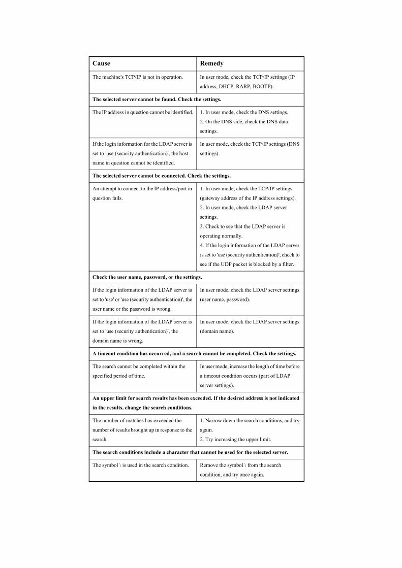
The machine's TCP/IP is not in operation. In user mode, check the TCP/IP settings (IP
address, DHCP, RARP, BOOTP).
The selected server cannot be found. Check the settings.
The IP address in question cannot be identified. 1. In user mode, check the DNS settings.
2. On the DNS side, check the DNS data
settings.
If the login information for the LDAP server is
set to 'use (security authentication)', the host
name in question cannot be identified.
In user mode, check the TCP/IP settings (DNS
settings).
The selected server cannot be connected. Check the settings.
An attempt to connect to the IP address/port in
question fails.
1. In user mode, check the TCP/IP settings
(gateway address of the IP address settings).
2. In user mode, check the LDAP server
settings.
3. Check to see that the LDAP server is
operating normally.
4. If the login information of the LDAP server
is set to 'use (security authentication)', check to
see if the UDP packet is blocked by a filter.
Check the user name, password, or the settings.
If the login information of the LDAP server is
set to 'use' or 'use (security authentication)', the
user name or the password is wrong.
In user mode, check the LDAP server settings
(user name, password).
If the login information of the LDAP server is
set to 'use (security authentication)', the
domain name is wrong.
In user mode, check the LDAP server settings
(domain name).
A timeout condition has occurred, and a search cannot be completed. Check the settings.
The search cannot be completed within the
specified period of time.
In user mode, increase the length of time before
a timeout condition occurs (part of LDAP
server settings).
An upper limit for search results has been exceeded. If the desired address is not indicated
in the results, change the search conditions.
The number of matches has exceeded the
number of results brought up in response to the
search.
1. Narrow down the search conditions, and try
again.
2. Try increasing the upper limit.
The search conditions include a character that cannot be used for the selected server.
The symbol \ is used in the search condition. Remove the symbol \ from the search
condition, and try once again.
Cause Remedy
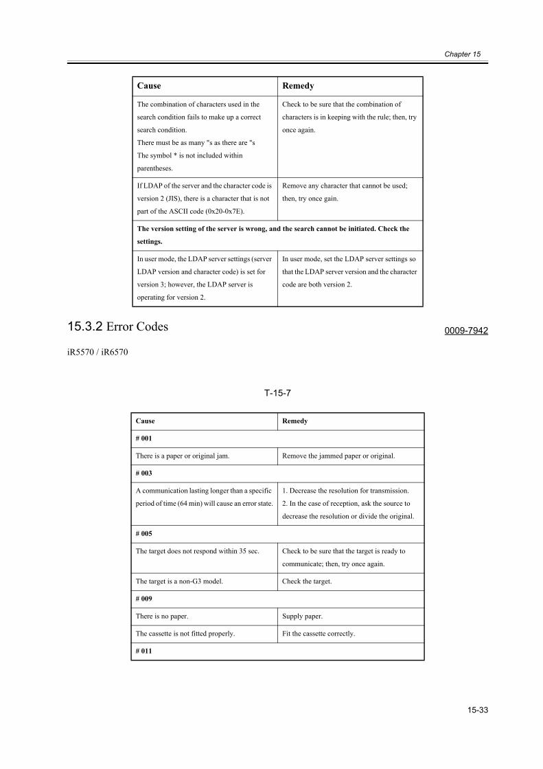
Chapter 15
15-33
15.3.2 Error Codes 0009-7942
iR5570 / iR6570
T-15-7
The combination of characters used in the
search condition fails to make up a correct
search condition.
There must be as many "s as there are "s
The symbol * is not included within
parentheses.
Check to be sure that the combination of
characters is in keeping with the rule; then, try
once again.
If LDAP of the server and the character code is
version 2 (JIS), there is a character that is not
part of the ASCII code (0x20-0x7E).
Remove any character that cannot be used;
then, try once gain.
The version setting of the server is wrong, and the search cannot be initiated. Check the
settings.
In user mode, the LDAP server settings (server
LDAP version and character code) is set for
version 3; however, the LDAP server is
operating for version 2.
In user mode, set the LDAP server settings so
that the LDAP server version and the character
code are both version 2.
Cause Remedy
# 001
There is a paper or original jam. Remove the jammed paper or original.
# 003
A communication lasting longer than a specific
period of time (64 min) will cause an error state.
1. Decrease the resolution for transmission.
2. In the case of reception, ask the source to
decrease the resolution or divide the original.
# 005
The target does not respond within 35 sec. Check to be sure that the target is ready to
communicate; then, try once again.
The target is a non-G3 model. Check the target.
# 009
There is no paper. Supply paper.
The cassette is not fitted properly. Fit the cassette correctly.
# 011
Cause Remedy
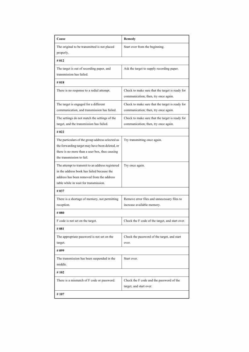
The original to be transmitted is not placed
properly.
Start over from the beginning.
# 012
The target is out of recording paper, and
transmission has failed.
Ask the target to supply recording paper.
# 018
There is no response to a redial attempt. Check to make sure that the target is ready for
communication; then, try once again.
The target is engaged for a different
communication, and transmission has failed.
Check to make sure that the target is ready for
communication; then, try once again.
The settings do not match the settings of the
target, and the transmission has failed.
Check to make sure that the target is ready for
communication; then, try once again.
# 022
The particulars of the group address selected as
the forwarding target may have been deleted, or
there is no more than a user box, thus causing
the transmission to fail.
Try transmitting once again.
The attempt to transmit to an address registered
in the address book has failed because the
address has been removed from the address
table while in wait for transmission.
Try once again.
# 037
There is a shortage of memory, not permitting
reception.
Remove error files and unnecessary files to
increase available memory.
# 080
F code is not set on the target. Check the F code of the target, and start over.
# 081
The appropriate password is not set on the
target.
Check the password of the target, and start
over.
# 099
The transmission has been suspended in the
middle.
Start over.
# 102
There is a mismatch of F code or password. Check the F code and the password of the
target, and start over.
# 107
Cause Remedy
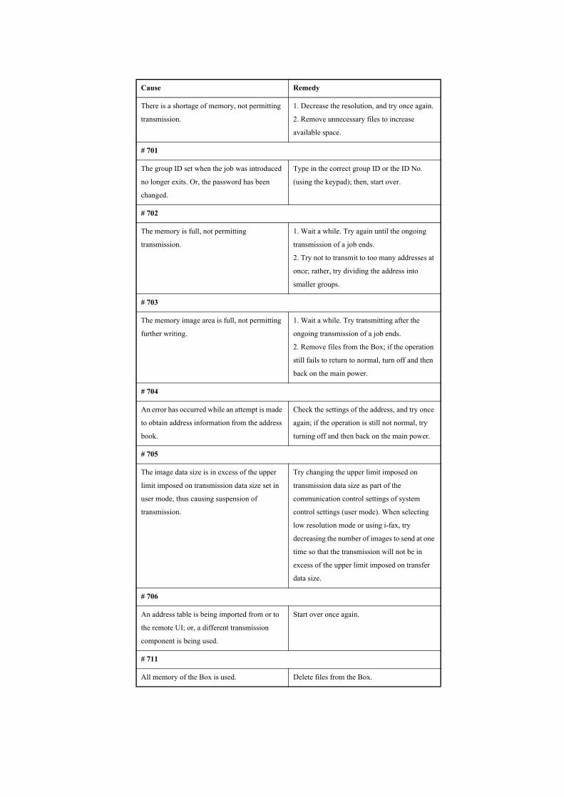
There is a shortage of memory, not permitting
transmission.
1. Decrease the resolution, and try once again.
2. Remove unnecessary files to increase
available space.
# 701
The group ID set when the job was introduced
no longer exits. Or, the password has been
changed.
Type in the correct group ID or the ID No.
(using the keypad); then, start over.
# 702
The memory is full, not permitting
transmission.
1. Wait a while. Try again until the ongoing
transmission of a job ends.
2. Try not to transmit to too many addresses at
once; rather, try dividing the address into
smaller groups.
# 703
The memory image area is full, not permitting
further writing.
1. Wait a while. Try transmitting after the
ongoing transmission of a job ends.
2. Remove files from the Box; if the operation
still fails to return to normal, turn off and then
back on the main power.
# 704
An error has occurred while an attempt is made
to obtain address information from the address
book.
Check the settings of the address, and try once
again; if the operation is still not normal, try
turning off and then back on the main power.
# 705
The image data size is in excess of the upper
limit imposed on transmission data size set in
user mode, thus causing suspension of
transmission.
Try changing the upper limit imposed on
transmission data size as part of the
communication control settings of system
control settings (user mode). When selecting
low resolution mode or using i-fax, try
decreasing the number of images to send at one
time so that the transmission will not be in
excess of the upper limit imposed on transfer
data size.
# 706
An address table is being imported from or to
the remote UI; or, a different transmission
component is being used.
Start over once again.
# 711
All memory of the Box is used. Delete files from the Box.
Cause Remedy

# 712
The Box is full of files. Remove file from the Box.
# 713
The file has been removed from the Box before
transmitting the URL.
Put the file in question back into the Box, and
start over.
# 751
The server is yet to start up. The network is
disconnected. (The connection to the target
may have failed, or the connection may have
been cut in the middle.)
Check the target. Check the network.
# 752
The SMTP server name of the e-main/i-fax in
question may be wrong, or the server in
question is yet to start up. Or, the appropriate
domain name or e-mail address has not been
set. Or, the network has been disconnected.
Using the network settings of the system
control setup (user mode), check the SMTP
server name, domain name, and e-mail address.
Check to see that the SMTP server is operating
normally. Check the connection of the network.
# 753
A TCP/IP error has occurred in the course of e-
mail transmission. (e.g., socket, select error)
Check the condition of the network cable and
the connector. If the operation does not return
to normal, try turning off and then back on the
main power of the machine.
# 754
The server has not been started up for
transmission, or the network is disconnected.
Or, the target settings are wrong.
Check the server and the network. Check the
settings of the target.
# 755
The TCP/IP settings are not operating
normally, thus not permitting transmission.
In user mode, check the TCP/IP settings.
The appropriate IP address has not been set up. In user mode, check the TCP/IP settings.
When the machine is started up, its IP address
is not assigned by means of DHCP, RARP, or
BOOTP.
In user mode, check the TCP/IP settings.
# 756
In system control setup (user mode), 'use
NetWare' is set to 'off' in NetWare settings.
In network settings of system control setup
(user mode), set 'use NetWare' to 'on'.
# 801
Cause Remedy
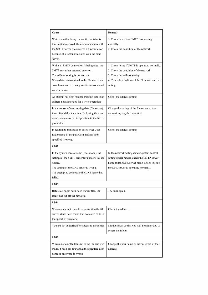
While e-mail is being transmitted or i-fax is
transmitted/received, the communication with
the SMTP server encountered a timeout error
because of a factor associated with the main
server.
1. Check to see that SMTP is operating
normally.
2. Check the condition of the network.
While an SMTP connection is being used, the
SMTP server has returned an error.
The address setting is not correct.
When data is transmitted to the file server, an
error has occurred owing to a factor associated
with the server.
1. Check to see if SMTP is operating normally.
2. Check the condition of the network.
3. Check the address setting.
4. Check the condition of the file server and the
setting.
An attempt has been made to transmit data to an
address not authorized for a write operation.
Check the address setting.
In the course of transmitting data (file server),
it was found that there is a file having the same
name, and an overwrite operation to the file is
prohibited.
Change the setting of the file server so that
overwriting may be permitted.
In relation to transmission (file server), the
folder name or the password that has been
specified is wrong.
Check the address setting.
# 802
In the system control setup (user mode), the
settings of the SMTP server for e-mail/i-fax are
wrong.
The setting of the DNS server is wrong.
The attempt to connect to the DNS server has
failed.
In the network settings under system control
settings (user mode), check the SMTP server
name and the DNS server name. Check to see if
the DNS server is operating normally.
# 803
Before all pages have been transmitted, the
target has cut off the network.
Try once again.
# 804
When an attempt is made to transmit to the file
server, it has been found that no match exits in
the specified directory.
Check the address.
You are not authorized for access to the folder. Set the server so that you will be authorized to
access the folder.
# 806
When an attempt to transmit to the file server is
made, it has been found that the specified user
name or password is wrong.
Change the user name or the password of the
address.
Cause Remedy
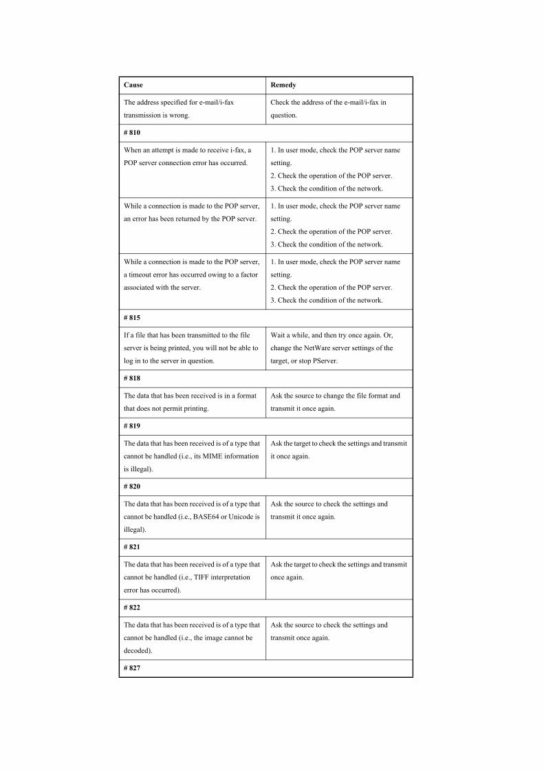
The address specified for e-mail/i-fax
transmission is wrong.
Check the address of the e-mail/i-fax in
question.
# 810
When an attempt is made to receive i-fax, a
POP server connection error has occurred.
1. In user mode, check the POP server name
setting.
2. Check the operation of the POP server.
3. Check the condition of the network.
While a connection is made to the POP server,
an error has been returned by the POP server.
1. In user mode, check the POP server name
setting.
2. Check the operation of the POP server.
3. Check the condition of the network.
While a connection is made to the POP server,
a timeout error has occurred owing to a factor
associated with the server.
1. In user mode, check the POP server name
setting.
2. Check the operation of the POP server.
3. Check the condition of the network.
# 815
If a file that has been transmitted to the file
server is being printed, you will not be able to
log in to the server in question.
Wait a while, and then try once again. Or,
change the NetWare server settings of the
target, or stop PServer.
# 818
The data that has been received is in a format
that does not permit printing.
Ask the source to change the file format and
transmit it once again.
# 819
The data that has been received is of a type that
cannot be handled (i.e., its MIME information
is illegal).
Ask the target to check the settings and transmit
it once again.
# 820
The data that has been received is of a type that
cannot be handled (i.e., BASE64 or Unicode is
illegal).
Ask the source to check the settings and
transmit it once again.
# 821
The data that has been received is of a type that
cannot be handled (i.e., TIFF interpretation
error has occurred).
Ask the target to check the settings and transmit
once again.
# 822
The data that has been received is of a type that
cannot be handled (i.e., the image cannot be
decoded).
Ask the source to check the settings and
transmit once again.
# 827
Cause Remedy
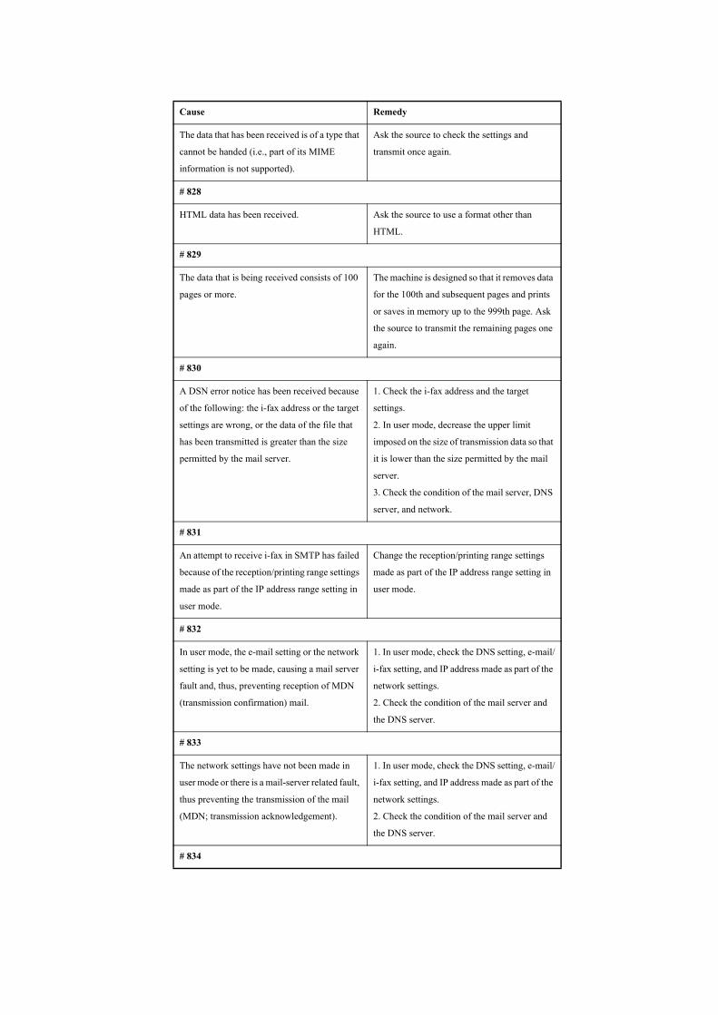
The data that has been received is of a type that
cannot be handed (i.e., part of its MIME
information is not supported).
Ask the source to check the settings and
transmit once again.
# 828
HTML data has been received. Ask the source to use a format other than
HTML.
# 829
The data that is being received consists of 100
pages or more.
The machine is designed so that it removes data
for the 100th and subsequent pages and prints
or saves in memory up to the 999th page. Ask
the source to transmit the remaining pages one
again.
# 830
A DSN error notice has been received because
of the following: the i-fax address or the target
settings are wrong, or the data of the file that
has been transmitted is greater than the size
permitted by the mail server.
1. Check the i-fax address and the target
settings.
2. In user mode, decrease the upper limit
imposed on the size of transmission data so that
it is lower than the size permitted by the mail
server.
3. Check the condition of the mail server, DNS
server, and network.
# 831
An attempt to receive i-fax in SMTP has failed
because of the reception/printing range settings
made as part of the IP address range setting in
user mode.
Change the reception/printing range settings
made as part of the IP address range setting in
user mode.
# 832
In user mode, the e-mail setting or the network
setting is yet to be made, causing a mail server
fault and, thus, preventing reception of MDN
(transmission confirmation) mail.
1. In user mode, check the DNS setting, e-mail/
i-fax setting, and IP address made as part of the
network settings.
2. Check the condition of the mail server and
the DNS server.
# 833
The network settings have not been made in
user mode or there is a mail-server related fault,
thus preventing the transmission of the mail
(MDN; transmission acknowledgement).
1. In user mode, check the DNS setting, e-mail/
i-fax setting, and IP address made as part of the
network settings.
2. Check the condition of the mail server and
the DNS server.
# 834
Cause Remedy

The i-fax address or the condition settings of
the target may be wrong, there may be a fault in
the network or the mail server, or the target may
have encountered a memory full condition, thus
causing an MDS error notice.
Check the specified i-fax address and the target
conditions.
# 835
The number of text lines is more than the
maximum number of lines permitted for i-fax.
Ask the target to decrease the number of text
lines and try once again.
# 837
A request has been made by a host that comes
under the restrictions imposed by 'IP address
range setting' in user mode.
Check the setting of the IP address range in user
mode. The attempt to access in question may be
illegal.
# 839
The SMTP authentication (SMTPAUTH) user
name or password for e-mail/i-fax (network
settings) may be wrong.
Check the user name and password used for
SMTP authentication (SMTPAUTH) as part of
the network settings under system control
settings (user mode).
# 841
In relation to an attempt for transmission for e-
mail/i-fax, there is no coding algorithm that
may be used in common with the mail server.
1. Set 'SSL' to 'OFF' as part of the network
settings under system control settings (user
mode).
2. Add a coding algorithm that may be used in
common (mail server settings).
# 842
In relation to an attempt for transmission of e-
mail/i-fax, a request has been made for the use
of a client certificate by the mail server.
1. Set 'SSL' to 'OFF' as part of the network
settings under the system control settings (user
mode).
2. Change the mail server settings so that it will
not request a client certificate.
# 843
The time used by the KDC (key distribution
center) server and the time used by the machine
are different significantly.
1. Correct the time as part of the date/time
settings under the system control settings (user
mode).
2. Correct the time used by the KDC (key
distribution center) server.
# 847
The memory of the Box has been used up, not
permitting the storage of the received file in the
fax box.
Remove unnecessary files from the fax box or
the system box.
Cause Remedy
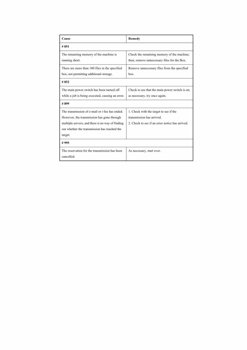
# 851
The remaining memory of the machine is
running short.
Check the remaining memory of the machine;
then, remove unnecessary files for the Box.
There are more than 100 files in the specified
box, not permitting additional storage.
Remove unnecessary files from the specified
box.
# 852
The main power switch has been turned off
while a job is being executed, causing an error.
Check to see that the main power switch is on;
as necessary, try once again.
# 899
The transmission of e-mail or i-fax has ended.
However, the transmission has gone through
multiple servers, and there is no way of finding
out whether the transmission has reached the
target.
1. Check with the target to see if the
transmission has arrived.
2. Check to see if an error notice has arrived.
# 995
The reservation for the transmission has been
cancelled.
As necessary, start over.
Cause Remedy
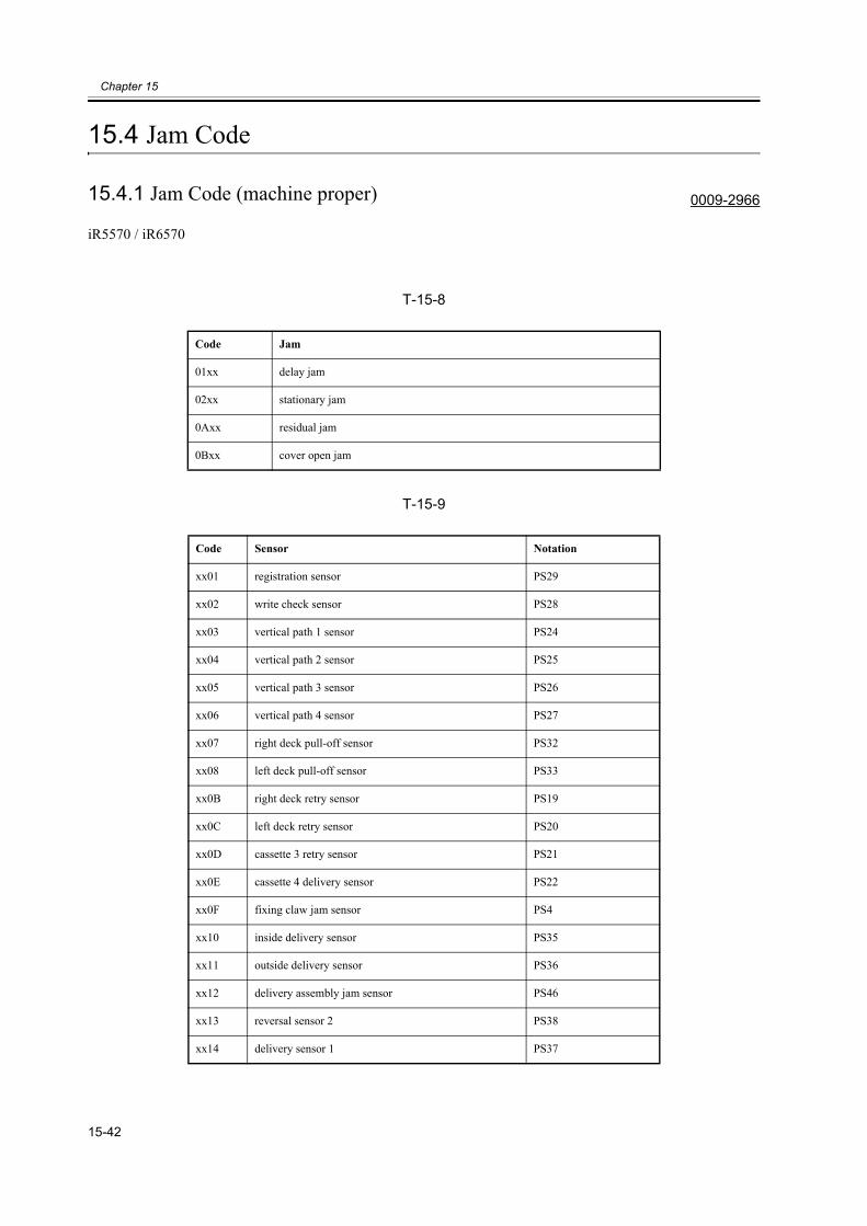
Chapter 15
15-42
15.4 Jam Code
15.4.1 Jam Code (machine proper) 0009-2966
iR5570 / iR6570
T-15-8
T-15-9
Code Jam
01xx delay jam
02xx stationary jam
0Axx residual jam
0Bxx cover open jam
Code Sensor Notation
xx01 registration sensor PS29
xx02 write check sensor PS28
xx03 vertical path 1 sensor PS24
xx04 vertical path 2 sensor PS25
xx05 vertical path 3 sensor PS26
xx06 vertical path 4 sensor PS27
xx07 right deck pull-off sensor PS32
xx08 left deck pull-off sensor PS33
xx0B right deck retry sensor PS19
xx0C left deck retry sensor PS20
xx0D cassette 3 retry sensor PS21
xx0E cassette 4 delivery sensor PS22
xx0F fixing claw jam sensor PS4
xx10 inside delivery sensor PS35
xx11 outside delivery sensor PS36
xx12 delivery assembly jam sensor PS46
xx13 reversal sensor 2 PS38
xx14 delivery sensor 1 PS37
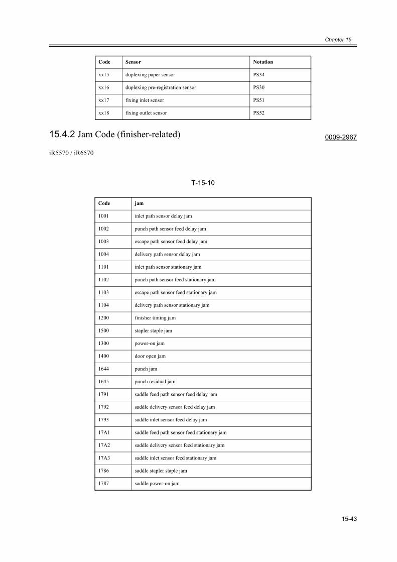
Chapter 15
15-43
15.4.2 Jam Code (finisher-related) 0009-2967
iR5570 / iR6570
T-15-10
xx15 duplexing paper sensor PS34
xx16 duplexing pre-registration sensor PS30
xx17 fixing inlet sensor PS51
xx18 fixing outlet sensor PS52
Code jam
1001 inlet path sensor delay jam
1002 punch path sensor feed delay jam
1003 escape path sensor feed delay jam
1004 delivery path sensor delay jam
1101 inlet path sensor stationary jam
1102 punch path sensor feed stationary jam
1103 escape path sensor feed stationary jam
1104 delivery path sensor stationary jam
1200 finisher timing jam
1500 stapler staple jam
1300 power-on jam
1400 door open jam
1644 punch jam
1645 punch residual jam
1791 saddle feed path sensor feed delay jam
1792 saddle delivery sensor feed delay jam
1793 saddle inlet sensor feed delay jam
17A1 saddle feed path sensor feed stationary jam
17A2 saddle delivery sensor feed stationary jam
17A3 saddle inlet sensor feed stationary jam
1786 saddle stapler staple jam
1787 saddle power-on jam
Code Sensor Notation
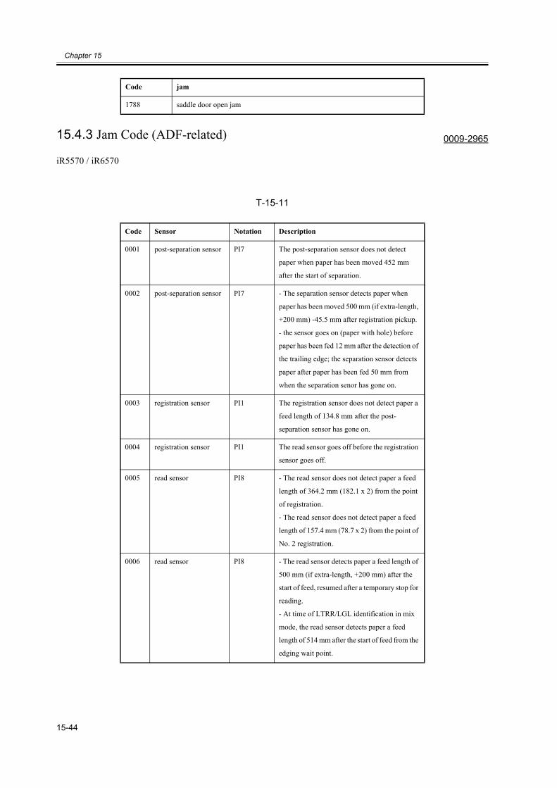
Chapter 15
15-44
15.4.3 Jam Code (ADF-related) 0009-2965
iR5570 / iR6570
T-15-11
1788 saddle door open jam
Code Sensor Notation Description
0001 post-separation sensor PI7 The post-separation sensor does not detect
paper when paper has been moved 452 mm
after the start of separation.
0002 post-separation sensor PI7 - The separation sensor detects paper when
paper has been moved 500 mm (if extra-length,
+200 mm) -45.5 mm after registration pickup.
- the sensor goes on (paper with hole) before
paper has been fed 12 mm after the detection of
the trailing edge; the separation sensor detects
paper after paper has been fed 50 mm from
when the separation senor has gone on.
0003 registration sensor PI1 The registration sensor does not detect paper a
feed length of 134.8 mm after the post-
separation sensor has gone on.
0004 registration sensor PI1 The read sensor goes off before the registration
sensor goes off.
0005 read sensor PI8 - The read sensor does not detect paper a feed
length of 364.2 mm (182.1 x 2) from the point
of registration.
- The read sensor does not detect paper a feed
length of 157.4 mm (78.7 x 2) from the point of
No. 2 registration.
0006 read sensor PI8 - The read sensor detects paper a feed length of
500 mm (if extra-length, +200 mm) after the
start of feed, resumed after a temporary stop for
reading.
- At time of LTRR/LGL identification in mix
mode, the read sensor detects paper a feed
length of 514 mm after the start of feed from the
edging wait point.
Code jam
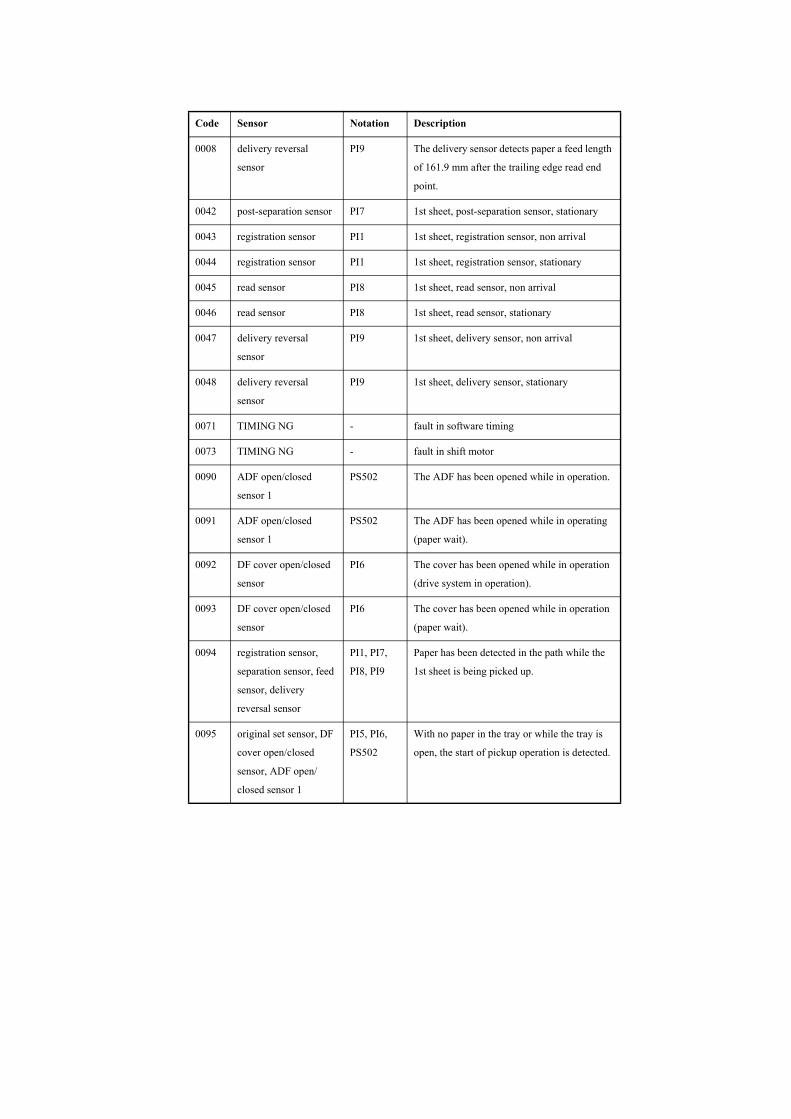
0008 delivery reversal
sensor
PI9 The delivery sensor detects paper a feed length
of 161.9 mm after the trailing edge read end
point.
0042 post-separation sensor PI7 1st sheet, post-separation sensor, stationary
0043 registration sensor PI1 1st sheet, registration sensor, non arrival
0044 registration sensor PI1 1st sheet, registration sensor, stationary
0045 read sensor PI8 1st sheet, read sensor, non arrival
0046 read sensor PI8 1st sheet, read sensor, stationary
0047 delivery reversal
sensor
PI9 1st sheet, delivery sensor, non arrival
0048 delivery reversal
sensor
PI9 1st sheet, delivery sensor, stationary
0071 TIMING NG - fault in software timing
0073 TIMING NG - fault in shift motor
0090 ADF open/closed
sensor 1
PS502 The ADF has been opened while in operation.
0091 ADF open/closed
sensor 1
PS502 The ADF has been opened while in operating
(paper wait).
0092 DF cover open/closed
sensor
PI6 The cover has been opened while in operation
(drive system in operation).
0093 DF cover open/closed
sensor
PI6 The cover has been opened while in operation
(paper wait).
0094 registration sensor,
separation sensor, feed
sensor, delivery
reversal sensor
PI1, PI7,
PI8, PI9
Paper has been detected in the path while the
1st sheet is being picked up.
0095 original set sensor, DF
cover open/closed
sensor, ADF open/
closed sensor 1
PI5, PI6,
PS502
With no paper in the tray or while the tray is
open, the start of pickup operation is detected.
Code Sensor Notation Description
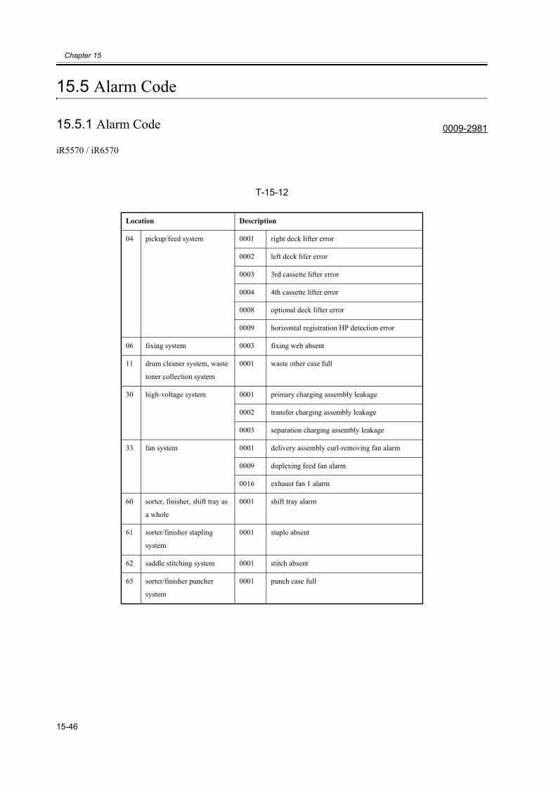
Chapter 15
15-46
15.5 Alarm Code
15.5.1 Alarm Code 0009-2981
iR5570 / iR6570
T-15-12
Location Description
04 pickup/feed system 0001 right deck lifter error
0002 left deck lifer error
0003 3rd cassette lifter error
0004 4th cassette lifter error
0008 optional deck lifter error
0009 horizontal registration HP detection error
06 fixing system 0003 fixing web absent
11 drum cleaner system, waste
toner collection system
0001 waste other case full
30 high-voltage system 0001 primary charging assembly leakage
0002 transfer charging assembly leakage
0003 separation charging assembly leakage
33 fan system 0001 delivery assembly curl-removing fan alarm
0009 duplexing feed fan alarm
0016 exhaust fan 1 alarm
60 sorter, finisher, shift tray as
a whole
0001 shift tray alarm
61 sorter/finisher stapling
system
0001 staple absent
62 saddle stitching system 0001 stitch absent
65 sorter/finisher puncher
system
0001 punch case full
Related Documents