As an Energy Star® Partner, International Comfort Products has determined that this product meets the ENERGY STAR® guidelines for energy efficiency. Use of the AHRI Certified TM Mark in- dicates a manufacturer’s participation in the program. For verification of certi- fication for individual products, go to www.ahridirectory.org . 462 51 2102 05 10/18/10 15 SEER, PACKAGE GAS / ELECTRIC UNIT, 2 to 5 TONS 208/230-1-60, Single Phase REFRIGERATION CIRCUIT • Environmentally sound R-410A refrigerant • Copper tube/aluminum fin condenser and evaporator coils • Two stage scroll compressors standard on all models EASY TO INSTALL AND SERVICE • Installs easily on a rooftop or at ground level • Easy three-panel accessibility for maintenance and installation • Easily converts to down discharge applications • Combination gas heating and electric cooling • Low NOx units available BUILT TO LAST • Hail guard (3/8” spacing) wire grilles standard on PGS models (2” spacing wire grilles on PGD models) • Induced-draft combustion and venting • High efficiency ECM blower motor on all models • Pre-painted steel cabinet • Direct spark ignition • Aluminized steel tubular heat exchanger on PGD5 models; Stainless Steel tubular heat exchanger on PGS5 models • Vertical condenser fan discharge • Full perimeter steel base rails • High and low pressure switches provide added reliability for the compressor • PGS5 with tin-coated copper evaporator coil standard WARRANTY* • 5 year No Hassle Replacementt limited warranty on PGS5 models. • 20 year heat exchanger limited warranty on PGD5; Lifetime heat exchanger limited warranty on PGS5 models. • 5 year parts limited warranty (including compressor and coils) - With timely registration, an additional 5 year parts limited warranty (including compressor and coils) * Applies to original purchaser/homeowner, some limitations may apply. See warranty certificate for complete details. UNIT PERFORMANCE DATA Model Number COOLING HEATING Unit Dimensions Height x Width x Depth Inches (mm) Operating Weight lbs / kg Standard Stainless Steel Heat Exch. with Tin-coated Evap. Coil Net Capacity BTU/h High / Low S.E.E.R E.E.R. Input BTU/h Efficiency AFUE % PGD524040K00*C PGS524040KGP*C 22,600 / 17,600 15.5 11.4 40,000 80.0 44 3 / 4 x48 3 / 16 x32 5 / 8 (1137x1224x829) 396 (180) PGD524060K00*C PGS524060KGP*C 22,600 / 17,600 15.5 11.4 60,000 80.0 44 3 / 4 x48 3 / 16 x32 5 / 8 (1137x1224x829) 401 (182) PGD536060K00*C PGS536060KGP*C 34,600 / 24, 400 15.0 12.0 60,000 80.0 48 3 / 4 x48 3 / 16 x44 1 / 8 (1238x1224x1121) 485 (220) PGD536090K00*C PGS536090KGP*C 34,600 / 24, 400 15.0 12.0 90,000 80.4 48 3 / 4 x48 3 / 16 x44 1 / 8 (1238x1224x1121) 493 (224) PGD548090K00*C PGS548090KGP*C 46,000 / 33,400 15.0 11.0 90,000 80.4 50 3 / 4 x48 3 / 16 x44 1 / 8 (1289x1224x1121) 521 (236) PGD548115K00*C PGS548115KGP*C 46,000 / 33,400 15.0 11.0 115,000 80.3 50 3 / 4 x48 3 / 16 x44 1 / 8 (1289x1224x1121) 521 (236) PGD548130K00*C PGS548130KGP*C 46,000 / 33,400 15.0 11.0 130,000 78.9 50 3 / 4 x48 3 / 16 x44 1 / 8 (1289x1224x1121) 521 (236) PGD560090K00*C PGS560090KGP*C 57,000 / 40,500 14.5 11.0 90,000 80.4 54 3 / 4 x48 3 / 16 x44 1 / 8 (1391x1224x1121) 512 (260) PGD560115K00*C PGS560115KGP*C 57,000 / 40,500 14.5 11.0 115,000 80.3 54 3 / 4 x48 3 / 16 x44 1 / 8 (1391x1224x1121) 512 (260) PGD560130K00*C PGS560130KGP*C 57,000 / 40,500 14.5 11.0 130,000 78.9 54 3 / 4 x48 3 / 16 x44 1 / 8 (1391x1224x1121) 512 (260) * 0 = Standard Model, 1 = Low NOx California Model ® PGD5, PGS5 Product Specifications E N V I R O N M E N T A L L Y S O U N D R E F R I G E R A N T

Welcome message from author
This document is posted to help you gain knowledge. Please leave a comment to let me know what you think about it! Share it to your friends and learn new things together.
Transcript

As an Energy Star® Partner,International Comfort Products hasdetermined that this product meetsthe ENERGY STAR® guidelines forenergy efficiency.
Use of the AHRI Certified TM Mark in-dicates a manufacturer’s participationin the program. For verification of certi-fication for individual products, go towww.ahridirectory.org .
462 51 2102 05 10/18/10
15 SEER, PACKAGE GAS / ELECTRIC UNIT, 2 to 5 TONS208/230−1−60, Single PhaseREFRIGERATION CIRCUIT
• Environmentally sound R-410A refrigerant• Copper tube/aluminum fin condenser and evaporator coils• Two stage scroll compressors standard on all models
EASY TO INSTALL AND SERVICE• Installs easily on a rooftop or at ground level• Easy three-panel accessibility for maintenance and installation• Easily converts to down discharge applications• Combination gas heating and electric cooling• Low NOx units available
BUILT TO LAST• Hail guard (3/8” spacing) wire grilles standard on PGS models (2” spacing wire grilles on PGD models)• Induced-draft combustion and venting• High efficiency ECM blower motor on all models• Pre-painted steel cabinet• Direct spark ignition• Aluminized steel tubular heat exchanger on PGD5 models;
Stainless Steel tubular heat exchanger on PGS5 models• Vertical condenser fan discharge• Full perimeter steel base rails• High and low pressure switches provide added reliability for the compressor• PGS5 with tin-coated copper evaporator coil standard
WARRANTY*• 5 year No Hassle Replacementt limited warranty on PGS5 models.• 20 year heat exchanger limited warranty on PGD5; Lifetime heat exchanger limited warranty on PGS5 models.• 5 year parts limited warranty (including compressor and coils)
- With timely registration, an additional 5 year parts limited warranty (including compressor and coils)*Applies to original purchaser/homeowner, some limitations may apply. See warranty certificate for complete details.
UNIT PERFORMANCE DATAModel Number COOLING HEATING Unit Dimensions
Height x Width xDepth
Inches (mm)
OperatingWeightlbs / kgStandard
Stainless SteelHeat Exch. with
Tin-coated Evap. Coil
Net CapacityBTU/h
High / Low S.E.E.R E.E.R.Input BTU/h
EfficiencyAFUE %
PGD524040K00*C PGS524040KGP*C 22,600 / 17,600 15.5 11.4 40,000 80.0443/4x483/16x325/8(1137x1224x829) 396 (180)
PGD524060K00*C PGS524060KGP*C 22,600 / 17,600 15.5 11.4 60,000 80.0443/4x483/16x325/8(1137x1224x829) 401 (182)
PGD536060K00*C PGS536060KGP*C 34,600 / 24, 400 15.0 12.0 60,000 80.0483/4x483/16x441/8(1238x1224x1121) 485 (220)
PGD536090K00*C PGS536090KGP*C 34,600 / 24, 400 15.0 12.0 90,000 80.4483/4x483/16x441/8(1238x1224x1121) 493 (224)
PGD548090K00*C PGS548090KGP*C 46,000 / 33,400 15.0 11.0 90,000 80.4503/4x483/16x441/8(1289x1224x1121) 521 (236)
PGD548115K00*C PGS548115KGP*C 46,000 / 33,400 15.0 11.0 115,000 80.3503/4x483/16x441/8(1289x1224x1121) 521 (236)
PGD548130K00*C PGS548130KGP*C 46,000 / 33,400 15.0 11.0 130,000 78.9503/4x483/16x441/8(1289x1224x1121) 521 (236)
PGD560090K00*C PGS560090KGP*C 57,000 / 40,500 14.5 11.0 90,000 80.4543/4x483/16x441/8(1391x1224x1121) 512 (260)
PGD560115K00*C PGS560115KGP*C 57,000 / 40,500 14.5 11.0 115,000 80.3543/4x483/16x441/8(1391x1224x1121) 512 (260)
PGD560130K00*C PGS560130KGP*C 57,000 / 40,500 14.5 11.0 130,000 78.9543/4x483/16x441/8(1391x1224x1121) 512 (260)
* 0 = Standard Model, 1 = Low NOx California Model
®
PGD5, PGS5Product SpecificationsENVIRONM
ENTA
LLY
SO
UN
DR
EFRIGERANT

SPECIFICATIONS SUBJECT TO CHANGE WITHOUT NOTICE2 462 51 2102 05
MODEL NOMENCLATURE
MODEL SERIES1 2 3 4 5,6 7,8,9 10 11,12 13 14 15
P G D 5 36 090 K 00 0 C 1P = Package
A = Air Conditioner
H = Heat Pump
G = Gas/Electric
D = Dual Fuel TYPED = Standard
S = Mainline w/ SS HX TIER3 = 13
4 = 14
5 = 15 SEER24 = 24,000 BTUH = 2 Tons
36 = 36,000 BTUH = 3 Tons
48 = 48,000 BTUH = 4 Tons
60 = 60,000 BTUH = 5 Tons NOMINAL COOLING CAPACITY000 = no factory heat
040 = 40,000 BTU/hr
060 = 60,000 BTU/hr
090 = 90,000 BTU/hr
115 = 115,000 BTU/hr
130 = 130,000 BTU/hr NOMINAL HEATING BTUH (input)
K = 208/230−1−60 VOLTAGE00 = No options
GP = Tin Coated Copper Evap Main Tubes plus Stainless Steel Heat Exchanger
FACTORY INSTALLED OPTIONS0 = Standard
1 = Low NOx FEATURE CODESales Model Digit
Engineering Digit

SPECIFICATIONS SUBJECT TO CHANGE WITHOUT NOTICE 3462 51 2102 05
UNIT SPECIFICATIONS − PGD5, PGS5UNIT SIZE 24040 24060 36060 36090 48090NOMINAL COOLING CAPACITY (ton) 2 2 3 3 4NOMINAL HEATING INPUT (Btu/hr) 40,000 60,000 60,000 90,000 90,000OPERATING WEIGHT (lb/kg) 396/179.6 401/181.9 485/220.0 493/223.6 521/236.3COMPRESSOR Two−Stage ScrollREFRIGERANT (R−410A) QUANTITY (lb/kg) 10.1/4.6 10.1/4.6 9.5/4.3 9.5/4.3 15.3/6.9REFRIGERANT METERING DEVICE TXVSize 2 Ton 2 Ton 3 Ton 3 Ton 4 TonOUTDOOR FANNominal CFM 2700 2700 2800 2800 3300Diameter (in./mm) 22/559 22/559 22/559 22/559 22/559Motor HP (RPM) 1/8 (825) 1/8 (825) 1/8 (825) 1/8 (825) 1/4 (1100)OUTDOOR COILRows...Fins/in 2...21 2...21 2...21 2...21 2...21Face Area (sq. ft.) 13.6 13.6 17.5 17.5 19.4INDOOR COILRows...Fins/in 3...17 3...17 3...17 3...17 3...17Face Area (sq. ft.) 3.7 3.7 4.7 4.7 5.7INDOOR BLOWERNominal Low Stage Airflow (CFM) 600 600 850 850 1100Nominal High Stage Airflow (CFM) 800 800 1200 1200 1600Blower Wheel Size (in. x in.) 10x10 10x10 11x10 11x10 11x10Blower Wheel Size (mm x mm) 254x254 254x254 279x254 279x254 279x254Motor HP (RPM) 1/2 1/2 3/4 3/4 1FURNACE SECTIONNatural Gas Burner Orifice No. (Qty...Drill Size)* 2...44 2...38 2...38 3...38 3...38HIGH−PRESSURE SWITCH (psig)Cutout 670+/−10Reset (Auto) 470+/−25HIGH−PRESSURE SWITCH 2 (psig)(Compressor Solenoid)Cutout 565+/−15Reset (Auto) 455+/−15LOSS−OF−CHARGE/LOW−PRESSURE SWITCH(Liquid Line) (psig)Cutout 23+/−5Reset (Auto) 55+/−5RETURN−AIR FILTERS (in.) Throwaway** 20x24x1 24x30x1 24x36x1RETURN−AIR FILTERS (mm) Throwaway** 508x610x25 610x762x25 610x914x25
* Based on altitude of 0 to 2000 ft (0 to 610 m).** Recommended filter sizes for field−installed air filter grilles mounted on the wall or ceiling of theconditioned structure. Required filter sizes shown are based on the AHRI (Air Conditioning, Heating, and RefrigerationInstitute) rated high stage cooling airflow and a maximum face velocity of 300 ft/minute for throwawayfilters or 450 ft/minute for permanent filters. Air filter pressure drop for non−standard filters must notexceed .08 inches water column.

SPECIFICATIONS SUBJECT TO CHANGE WITHOUT NOTICE4 462 51 2102 05
UNIT SPECIFICATIONS − PGD5, PGS5UNIT SIZE 48115 48130 60090 60115 60130NOMINAL COOLING CAPACITY (ton) 4 4 5 5 5NOMINAL HEATING INPUT (Btu/hr) 115,000 130,000 90,000 115,000 130,000OPERATING WEIGHT (lb/kg) 521/236.3 521/236.3 572/259.5 572/259.5 572/259.5COMPRESSOR Two−Stage ScrollREFRIGERANT (R−410A) QUANTITY (lb/kg) 15.3/6.9 15.3/6.9 15.8/7.2 15.8/7.2 15.8/7.2REFRIGERANT METERING DEVICE TXVSize 4 Ton 4 Ton 5 Ton 5 Ton 5 TonOUTDOOR FANNominal CFM 3300 3300 3300 3300 3300Diameter (in./mm) 22/559 22/559 22/559 22/559 22/559Motor HP (RPM) 1/4 (1100) 1/4 (1100) 1/3 (1110) 1/3 (1110) 1/3 (1110)OUTDOOR COILRows...Fins/in 2...21 2...21 2...21 2...21 2...21Face Area (sq. ft.) 19.4 19.4 23.3 23.3 23.3INDOOR COILRows...Fins/in 3...17 3...17 4...17 4...17 4...17Face Area (sq. ft.) 5.7 5.7 5.7 5.7 5.7INDOOR BLOWERNominal Low Stage Airflow (CFM) 1100 1100 1200 1200 1200Nominal High Stage Airflow (CFM) 1600 1600 1750 1750 1750Blower Wheel Size (in. x in.) 11x10 11x10 11x10 11x10 11x10Blower Wheel Size (mm x mm) 279x254 279x254 279x254 279x254 279x254Motor HP (RPM) 1 1 1 1 1FURNACE SECTIONNatural Gas Burner Orifice No. (Qty...Drill Size)* 3...33 3...31 3...38 3...33 3...31HIGH−PRESSURE SWITCH (psig)Cutout 670+/−10Reset (Auto) 470+/−25HIGH−PRESSURE SWITCH 2 (psig)(Compressor Solenoid)Cutout 565+/−15Reset (Auto) 455+/−15LOSS−OF−CHARGE/LOW−PRESSURE SWITCH(Liquid Line) (psig)Cutout 23+/−5Reset (Auto) 55+/−5RETURN−AIR FILTERS (in.) Throwaway** 24x36x1RETURN−AIR FILTERS (mm) Throwaway** 610x914x25
* Based on altitude of 0 to 2000 ft (0 to 610 m).** Recommended filter sizes for field−installed air filter grilles mounted on the wall or ceiling of theconditioned structure. Required filter sizes shown are based on the AHRI (Air Conditioning, Heating, and RefrigerationInstitute) rated high stage cooling airflow and a maximum face velocity of 300 ft/minute for throwawayfilters or 450 ft/minute for permanent filters. Air filter pressure drop for non−standard filters must notexceed .08 inches water column.

SPECIFICATIONS SUBJECT TO CHANGE WITHOUT NOTICE 5462 51 2102 05
UNIT AIRFLOW, Horizontal and Downflow Discharge, 230 Volts, Dry CoilUnit
PGD5, PGS5Heating Rise
RangeMotorSpeed
WireColor
External Static Pressure ("WC)0.1 0.2 0.3 0.4 0.5 0.6 0.7 0.8 0.9
2404030 - 60°F
(17 - 33°C)
Low1 BlueCFM 659 551 440 355 - - - - -Heating Rise (°F) 46 55 NA NA NA NA NA NA NAHeating Rise (°C) 25 30 NA NA NA NA NA NA NA
Med-Low PinkCFM 726 625 537 407 - - - - -Heating Rise (°F) 42 48 56 NA NA NA NA NA NAHeating Rise (°C) 23 27 31 NA NA NA NA NA NA
Medium2 RedCFM 907 837 759 679 588 474 343 - -Heating Rise (°F) 33 36 40 45 51 NA NA NA NAHeating Rise (°C) 19 20 22 25 29 NA NA NA NA
Med-High3 OrangeCFM 953 870 807 718 652 528 443 - -Heating Rise (°F) 32 35 37 42 46 57 NA NA NAHeating Rise (°C) 18 19 21 23 26 32 NA NA NA
High BlackCFM 1179 1118 1061 996 942 864 794 718 619Heating Rise (°F) NA NA NA 30 32 35 38 42 49Heating Rise (°C) NA NA NA 17 18 19 21 23 27
2406025 - 55°F
(14 - 31°C)
Low1 BlueCFM 659 551 440 355 - - - - -Heating Rise (°F) NA NA NA NA NA NA NA NA NAHeating Rise (°C) NA NA NA NA NA NA NA NA NA
Med-Low PinkCFM 726 625 537 407 - - - - -Heating Rise (°F) NA NA NA NA NA NA NA NA NAHeating Rise (°C) NA NA NA NA NA NA NA NA NA
Medium2 RedCFM 907 837 759 679 588 474 343 - -Heating Rise (°F) 49 53 NA NA NA NA NA NA NAHeating Rise (°C) 27 29 NA NA NA NA NA NA NA
Med-High OrangeCFM 953 870 807 718 652 528 443 - 480Heating Rise (°F) 47 51 55 NA NA NA NA NA NAHeating Rise (°C) 26 28 31 NA NA NA NA NA NA
High3 BlackCFM 1179 1118 1061 996 942 864 794 718 619Heating Rise (°F) 38 40 42 45 47 51 NA NA NAHeating Rise (°C) 21 22 23 25 26 29 NA NA NA
3606025 - 55°F
(14 - 31°C)
Low1 BlueCFM 921 740 448 - - - - - -Heating Rise (°F) 48 NA NA NA NA NA NA NA NAHeating Rise (°C) 27 NA NA NA NA NA NA NA NA
Med-Low PinkCFM 1019 849 603 479 - - - - -Heating Rise (°F) 44 52 NA NA NA NA NA NA NAHeating Rise (°C) 24 29 NA NA NA NA NA NA NA
Medium3 RedCFM 1272 1203 1150 1097 1054 996 937 881 841Heating Rise (°F) 35 37 39 41 42 45 47 50 53Heating Rise (°C) 19 21 21 23 23 25 26 28 29
Med-High2 OrangeCFM 1321 1258 1212 1168 1114 1075 1009 956 904Heating Rise (°F) 34 35 37 38 40 41 44 46 49Heating Rise (°C) 19 20 20 21 22 23 24 26 27
High BlackCFM 1478 1426 1387 1334 1292 1247 1212 1148 1108Heating Rise (°F) 30 31 32 33 34 36 37 39 40Heating Rise (°C) 17 17 18 19 19 20 20 22 22
3609035 - 65°F
(19 - 36°C)
Low1 BlueCFM 921 740 448 - - - - - -Heating Rise (°F) NA NA NA NA NA NA NA NA NAHeating Rise (°C) NA NA NA NA NA NA NA NA NA
Med-Low PinkCFM 1019 849 603 479 - - - - -Heating Rise (°F) NA NA NA NA NA NA NA NA NAHeating Rise (°C) NA NA NA NA NA NA NA NA NA
Medium RedCFM 1272 1203 1150 1097 1054 996 937 881 841Heating Rise (°F) 53 57 59 62 65 NA NA NA NAHeating Rise (°C) 30 31 33 34 36 NA NA NA NA
Med-High2 OrangeCFM 1321 1258 1212 1168 1114 1075 1009 956 904Heating Rise (°F) 51 54 56 58 61 63 NA NA NAHeating Rise (°C) 29 30 31 32 34 35 NA NA NA
High3 BlackCFM 1478 1426 1387 1334 1292 1247 1212 1148 1108Heating Rise (°F) 46 48 49 51 53 55 56 59 61Heating Rise (°C) 26 26 27 28 29 30 31 33 34

SPECIFICATIONS SUBJECT TO CHANGE WITHOUT NOTICE6 462 51 2102 05
UNIT AIRFLOW, Horizontal and Downflow Discharge, 230 Volts, Dry CoilUnit
PGD5, PGS5Heating Rise
RangeMotorSpeed
WireColor
External Static Pressure ("WC)0.1 0.2 0.3 0.4 0.5 0.6 0.7 0.8 0.9
4809035 - 65°F
(19 - 36°C)
Low1 BlueCFM 1201 1159 1101 1062 1004 957 897 852 793Heating Rise (°F) 57 59 62 64 NA NA NA NA NAHeating Rise (°C) 31 33 34 36 NA NA NA NA NA
Med-Low3 PinkCFM 1419 1364 1318 1258 1214 1160 1118 1053 1009Heating Rise (°F) 48 50 52 54 56 59 61 65 NAHeating Rise (°C) 27 28 29 30 31 33 34 36 NA
Medium2 RedCFM 1678 1635 1602 1558 1513 1474 1438 1404 1349Heating Rise (°F) 41 42 42 44 45 46 47 48 50Heating Rise (°C) 23 23 24 24 25 26 26 27 28
Med-High OrangeCFM 1916 1881 1846 1810 1761 1722 1681 1647 1600Heating Rise (°F) 35 36 37 38 39 39 40 41 43Heating Rise (°C) 20 20 20 21 21 22 22 23 24
High BlackCFM 2093 2051 2024 1967 1947 1907 1854 1826 1749Heating Rise (°F) NA NA NA 35 35 36 37 37 39Heating Rise (°C) NA NA NA 19 19 20 20 21 22
4811530 - 60°F
(17 - 33°C)
Low1 BlueCFM 1201 1159 1101 1062 1004 957 897 852 793Heating Rise (°F) NA NA NA NA NA NA NA NA NAHeating Rise (°C) NA NA NA NA NA NA NA NA NA
Med-Low PinkCFM 1419 1364 1318 1258 1214 1160 1118 1053 1009Heating Rise (°F) NA NA NA NA NA NA NA NA NAHeating Rise (°C) NA NA NA NA NA NA NA NA NA
Medium2 RedCFM 1678 1635 1602 1558 1513 1474 1438 1404 1349Heating Rise (°F) 52 53 54 56 57 59 60 NA NAHeating Rise (°C) 29 30 30 31 32 33 34 NA NA
Med-High OrangeCFM 1916 1881 1846 1810 1761 1722 1681 1647 1600Heating Rise (°F) 45 46 47 48 49 50 52 53 54Heating Rise (°C) 25 26 26 27 27 28 29 29 30
High3 BlackCFM 2093 2051 2024 1967 1947 1907 1854 1826 1749Heating Rise (°F) 42 42 43 44 45 46 47 48 50Heating Rise (°C) 23 24 24 25 25 25 26 26 28
4813035 - 65°oF
(19 - 36°oC)
Low1 BlueCFM 1201 1159 1101 1062 1004 957 897 852 793Heating Rise (°F) NA NA NA NA NA NA NA NA NAHeating Rise (°C) NA NA NA NA NA NA NA NA NA
Med-Low PinkCFM 1419 1364 1318 1258 1214 1160 1118 1053 1009Heating Rise (°F) NA NA NA NA NA NA NA NA NAHeating Rise (°C) NA NA NA NA NA NA NA NA NA
Medium2 RedCFM 1678 1635 1602 1558 1513 1474 1438 1404 1349Heating Rise (°F) 57 59 60 62 64 65 NA NA NAHeating Rise (°C) 32 33 33 34 35 36 NA NA NA
Med-High OrangeCFM 1916 1881 1846 1810 1761 1722 1681 1647 1600Heating Rise (°F) 50 51 52 53 55 56 57 58 60Heating Rise (°C) 28 28 29 30 30 31 32 32 33
High3 BlackCFM 2093 2051 2024 1967 1947 1907 1854 1826 1749Heating Rise (°F) 46 47 48 49 49 50 52 53 55Heating Rise (°C) 26 26 26 27 27 28 29 29 31
6009035 - 65°F
(19 - 36°C)
Low1 BlueCFM 1320 1256 1211 1142 1096 1028 973 903 835Heating Rise (°F) 52 54 56 60 62 NA NA NA NAHeating Rise (°C) 29 30 31 33 34 NA NA NA NA
Med-Low3 PinkCFM 1351 1295 1258 1212 1170 1124 1080 1036 992Heating Rise (°F) 50 53 54 56 58 60 63 NA NAHeating Rise (°C) 28 29 30 31 32 34 35 NA NA
Medium2 RedCFM 1824 1782 1742 1711 1673 1641 1607 1563 1490Heating Rise (°F) 37 38 39 40 41 41 42 44 46Heating Rise (°C) 21 21 22 22 23 23 24 24 25
Med-High OrangeCFM 2001 1958 1923 1883 1831 1776 1705 1624 1538Heating Rise (°F) NA 35 35 36 37 38 40 42 44Heating Rise (°C) NA 19 20 20 21 21 22 23 25
High BlackCFM 2292 2238 2158 2049 1935 1840 1732 1635 1513Heating Rise (°F) NA NA NA NA 35 37 39 42 45Heating Rise (°C) NA NA NA NA 20 21 22 23 25

SPECIFICATIONS SUBJECT TO CHANGE WITHOUT NOTICE 7462 51 2102 05
UNIT AIRFLOW, Horizontal and Downflow Discharge, 230 Volts, Dry Coil
UnitPGD5, PGS5
Heating RiseRange
MotorSpeed
WireColor
External Static Pressure ("WC)
0.1 0.2 0.3 0.4 0.5 0.6 0.7 0.8 0.9
6011530 - 60°F
(17 - 33°C)
Low1 Blue
CFM 1320 1256 1211 1142 1096 1028 973 903 835
Heating Rise (°F) NA NA NA NA NA NA NA NA NA
Heating Rise (°C) NA NA NA NA NA NA NA NA NA
Med-Low Pink
CFM 1351 1295 1258 1212 1170 1124 1080 1036 992
Heating Rise (°F) NA NA NA NA NA NA NA NA NA
Heating Rise (°C) NA NA NA NA NA NA NA NA NA
Medium2 Red
CFM 1824 1782 1742 1711 1673 1641 1607 1563 1490
Heating Rise (°F) 48 49 50 51 52 53 54 56 58
Heating Rise (°C) 26 27 28 28 29 29 30 31 32
Med-High3 Orange
CFM 2001 1958 1923 1883 1831 1776 1705 1624 1538
Heating Rise (°F) 43 44 45 46 47 49 51 54 56
Heating Rise (°C) 24 25 25 26 26 27 28 30 31
High Black
CFM 2292 2238 2158 2049 1935 1840 1732 1635 1513
Heating Rise (°F) 38 39 40 42 45 47 50 53 57
Heating Rise (°C) 21 22 22 24 25 26 28 30 32
6013035 - 65°F
(19 - 36°C)
Low1 Blue
CFM 1320 1256 1211 1142 1096 1028 973 903 835
Heating Rise (°F) NA NA NA NA NA NA NA NA NA
Heating Rise (°C) NA NA NA NA NA NA NA NA NA
Med-Low Pink
CFM 1351 1295 1258 1212 1170 1124 1080 1036 992
Heating Rise (°F) NA NA NA NA NA NA NA NA NA
Heating Rise (°C) NA NA NA NA NA NA NA NA NA
Medium2 Red
CFM 1887 1847 1783 1726 1677 1625 1578 1527 1432
Heating Rise (°F) 51 52 54 56 57 59 61 63 NA
Heating Rise (°C) 28 29 30 31 32 33 34 35 NA
Med-High3 Orange
CFM 2001 1958 1923 1883 1831 1776 1705 1624 1538
Heating Rise (°F) 48 49 50 51 53 54 56 59 63
Heating Rise (°C) 27 27 28 28 29 30 31 33 35
High Black
CFM 2292 2238 2158 2049 1935 1840 1732 1635 1513
Heating Rise (°F) 42 43 45 47 50 52 56 59 64
Heating Rise (°C) 23 24 25 26 28 29 31 33 35
* Air delivery values are without air filter and are for dry coil (See Table 15 - PGD5, PGS5 Wet Coil Pressure Drop table).
1 Factory-shipped low stage cooling speed
2 Factory-shipped high stage cooling speed
3Factory-shipped heating speed
"NA" = Not allowed for heating speed
Note: Deduct field-supplied air filter pressure drop and wet coil pressure drop to obtain external static pressure available for ducting.
FILTER PRESSURE DROP
FILTER SIZE
CFM500 600 700 800 900 1000 1100 1200 1300 1400 1500 1600 1700 1800 1900 2000 2100 2200 2300
Pressure Drop (inches water column)20 x 24 x 1 — — — — 0.09 0.1 0.11 0.13 0.14 0.15 0.16 — — — — — — — —24 x 30 x 1 — — — — — — — 0.07 0.08 0.09 0.1 0.11 0.12 0.13 0.14 0.15 0.16 0.17 0.1824 x 36 x 1 — — — — — — — 0.06 0.07 0.07 0.08 0.09 0.09 0.10 0.11 0.12 0.13 0.14 0.14
Minimum Filter Requirements:20 x 24 x 1 = PGD524, PGS52424 x 30 x 1 = PGD536, PGS53624 x 36 x 1 = PGD548, PGS548, PGD560, PGS560
WET COIL PRESSURE DROP (in wc)UnitSize
STANDARD CFM (SCFM)
600 700 800 900 1000 1100 1200 1300 1400 1500 1600 1700 1800 1900 2000 2100
24 0.005 0.007 0.010 0.012 0.015 − − − − − − − − − − −
36 − − − 0.019 0.023 0.027 0.032 0.037 0.042 0.047 − − − − − −
48 − − − − − − 0.027 0.032 0.036 0.041 0.046 0.052 0.057 0.063 0.068 −
60 − − − − − − − − − 0.029 0.032 0.036 0.040 0.045 0.049 0.053
SPECIFICATIONS SUBJECT TO CHANGE WITHOUT NOTICE8 462 51 2102 05
UNIT ELECTRICAL SPECIFICATIONSMODEL
NUMBERPGD5, PGS5
NominalV-PH-HZ
Voltage Range Compressor OFM IFM IDM Power Supply
Min. Max. RLA LRA FLA FLA FLA MCA MOCP
24040
208/230−1−60 187 253
10.3 52 0.9 4.1 0.65 17.9 2524060 10.3 52 0.9 4.1 1.65 17.9 2536060 16.7 82 0.9 6.0 1.65 27.8 4036090 16.7 82 0.9 6.0 0.65 27.8 4048090 21.2 96 1.5 7.6 0.65 35.6 5048115 21.2 96 1.5 7.6 1.65 35.6 5048130 21.2 96 1.5 7.6 0.52 35.6 5060090 25.6 118 1.9 7.6 0.65 41.5 6060115 25.6 118 1.9 7.6 1.65 41.5 6060130 25.6 118 1.9 7.6 0.52 41.5 60
LEGEND
FLA = Full Load Amps
LRA = Locked Rotor Amps
MCA = Minimum Circuit Ampacity
MOCP = Maximum Overcurrent Protection
RLA = Rated Load Amps
1. In compliance with NEC (National Electrical Code) requirements
for multimotor and combination load equipment (refer to NEC
Articles 430 and 440), the overcurrent protective device for the
unit shall be Power Supply fuse. The CGA (Canadian Gas
Association) units may be fuse or circuit breaker.
2. Minimum wire size is based on 60 C copper wire. If other than
60 C wire is used, or if length exceeds wire length in table,
determine size from NEC.

SPECIFICATIONS SUBJECT TO CHANGE WITHOUT NOTICE 9462 51 2102 05
PG
D5,
PG
S52
4 E
XT
EN
DE
D C
OO
LIN
G P
ER
FO
RM
AN
CE
− H
IGH
CO
OL
EVA
PO
RA
TOR
AIR
COND
ENSE
R EN
TERI
NG A
IR T
EMPE
RATU
RES
deg
F75
(23.
8�C)
85 (2
9.4�
C)95
(35�
C)10
5 (4
0.5�
C)11
5 (4
6.1�
C)12
5 (5
1.6�
C)
CFM
EWB
Capa
city
MBt
uhTo
tal
Syst
emKW
Capa
city
MBt
uhTo
tal
Syst
emKW
Capa
city
MBt
uhTo
tal
Syst
emKW
Capa
city
MBt
uhTo
tal
Syst
emKW
Capa
city
MBt
uhTo
tal
Syst
emKW
Capa
city
MBt
uhTo
tal
Syst
emKW
Tota
lSe
nsTo
tal
Sens
Tota
lSe
nsTo
tal
Sens
Tota
lSe
nsTo
tal
Sens
700
5721
.77
21.7
71.
6120
.88
20.8
81.
7919
.95
19.9
52.
0018
.94
18.9
42.
2317
.86
17.8
62.
4816
.66
16.6
62.
7762
22.4
018
.69
1.61
21.2
918
.21
1.80
20.1
317
.70
2.00
18.9
518
.95
2.23
17.8
617
.86
2.48
16.6
616
.66
2.77
6322
.85
15.1
81.
6221
.71
14.7
01.
8020
.52
14.2
12.
0119
.25
13.7
02.
2317
.90
13.1
62.
4816
.42
12.5
82.
7767
24.6
615
.72
1.64
23.4
415
.24
1.83
22.1
514
.75
2.03
20.7
914
.24
2.26
19.3
413
.70
2.51
17.7
413
.12
2.79
7227
.16
12.7
51.
6725
.83
12.2
81.
8624
.42
11.8
02.
0622
.94
11.2
92.
2921
.33
10.7
62.
5419
.57
10.1
82.
83
800
5722
.76
22.7
61.
6421
.81
21.8
11.
8220
.81
20.8
12.
0319
.74
19.7
42.
2618
.58
18.5
82.
5117
.29
17.2
92.
8062
22.9
720
.16
1.64
21.8
421
.76
1.82
20.8
120
.81
2.03
19.7
419
.74
2.26
18.5
818
.58
2.51
17.2
917
.29
2.80
6323
.39
16.2
01.
6422
.19
15.7
11.
8320
.94
15.2
12.
0319
.62
14.6
92.
2618
.22
14.1
42.
5116
.69
13.5
42.
7967
25.2
216
.81
1.67
23.9
416
.32
1.85
22.6
015
.82
2.05
21.1
815
.30
2.28
19.6
714
.74
2.53
18.0
114
.14
2.82
7227
.77
13.4
31.
7026
.37
12.9
61.
8824
.90
12.4
82.
0923
.35
11.9
52.
3121
.66
11.4
12.
5720
.60
11.0
52.
57
PG
D5,
PG
S52
4 E
XT
EN
DE
D C
OO
LIN
G P
ER
FO
RM
AN
CE
− L
OW
CO
OL
EVA
PO
RA
TOR
AIR
COND
ENSE
R EN
TERI
NG A
IR T
EMPE
RATU
RES
deg
F75
(23.
8�C)
85 (2
9.4�
C)95
(35�
C)10
5 (4
0.5�
C)11
5 (4
6.1�
C)12
5 (5
1.6�
C)
CFM
EWB
Capa
city
MBt
uhTo
tal
Syst
emKW
Capa
city
MBt
uhTo
tal
Syst
emKW
Capa
city
MBt
uhTo
tal
Syst
emKW
Capa
city
MBt
uhTo
tal
Syst
emKW
Capa
city
MBt
uhTo
tal
Syst
emKW
Capa
city
MBt
uhTo
tal
Syst
emKW
Tota
lSe
nsTo
tal
Sens
Tota
lSe
nsTo
tal
Sens
Tota
lSe
nsTo
tal
Sens
525
5716
.65
16.6
51.
0515
.95
15.9
51.
2015
.21
15.2
11.
3714
.40
14.4
01.
5713
.52
13.5
21.
8012
.55
12.5
52.
0762
17.2
014
.47
1.06
16.2
914
.07
1.21
15.3
413
.65
1.37
14.4
014
.40
1.57
13.5
213
.52
1.80
12.5
512
.55
2.07
6317
.61
11.7
51.
0616
.69
11.3
61.
2115
.70
10.9
61.
3814
.64
10.5
31.
5713
.50
10.0
71.
8012
.27
9.58
2.06
6719
.23
12.2
61.
0818
.23
11.8
71.
2217
.18
11.4
71.
3916
.05
11.0
31.
5814
.83
10.5
81.
8113
.50
10.0
92.
0772
21.4
810
.05
1.09
20.4
19.
661.
2419
.26
9.26
1.41
18.0
28.
841.
6016
.69
8.39
1.83
15.2
47.
902.
09
600
5717
.52
17.5
21.
0816
.77
16.7
71.
2315
.96
15.9
61.
3915
.10
15.1
01.
5914
.15
14.1
51.
8213
.11
13.1
12.
0962
17.7
115
.66
1.08
16.7
816
.75
1.23
15.9
615
.96
1.39
15.1
015
.10
1.59
14.1
514
.15
1.82
13.1
213
.12
2.09
6318
.10
12.5
81.
0817
.12
12.1
81.
2316
.09
11.7
61.
3914
.98
11.3
21.
5913
.80
10.8
51.
8112
.51
10.3
52.
0867
19.7
513
.14
1.09
18.7
112
.74
1.24
17.6
012
.32
1.41
16.4
111
.88
1.60
15.1
411
.41
1.83
13.7
610
.91
2.09
7222
.06
10.6
11.
1120
.93
10.2
11.
2619
.72
9.80
1.43
18.4
19.
361.
6217
.03
8.91
1.85
15.5
18.
412.
11

SPECIFICATIONS SUBJECT TO CHANGE WITHOUT NOTICE10 462 51 2102 05
PG
D5,
PG
S53
6 E
XT
EN
DE
D C
OO
LIN
G P
ER
FO
RM
AN
CE
− H
IGH
CO
OL
EVA
PO
RA
TOR
AIR
COND
ENSE
R EN
TERI
NG A
IR T
EMPE
RATU
RES
deg
F75
(23.
8�C)
85 (2
9.4�
C)95
(35�
C)10
5 (4
0.5�
C)11
5 (4
6.1�
C)12
5 (5
1.6�
C)
CFM
EWB
Capa
city
MBt
uhTo
tal
Syst
emKW
Capa
city
MBt
uhTo
tal
Syst
emKW
Capa
city
MBt
uhTo
tal
Syst
emKW
Capa
city
MBt
uhTo
tal
Syst
emKW
Capa
city
MBt
uhTo
tal
Syst
emKW
Capa
city
MBt
uhTo
tal
Syst
emKW
Tota
lSe
nsTo
tal
Sens
Tota
lSe
nsTo
tal
Sens
Tota
lSe
nsTo
tal
Sens
1050
5733
.64
33.6
42.
2832
.32
32.3
22.
5330
.90
30.9
02.
8129
.36
29.3
63.
1127
.65
27.6
53.
4625
.71
25.7
13.
8462
34.4
728
.72
2.29
32.8
328
.00
2.54
31.1
127
.24
2.81
29.3
629
.36
3.11
27.6
527
.65
3.46
25.7
125
.71
3.84
6335
.12
23.2
52.
2933
.44
22.5
62.
5431
.65
21.8
32.
8129
.73
21.0
73.
1227
.64
20.2
53.
4525
.33
19.3
53.
8367
37.7
624
.04
2.32
35.9
423
.34
2.57
34.0
022
.61
2.84
31.9
121
.83
3.15
29.6
521
.00
3.49
27.1
420
.10
3.87
7342
.16
18.4
12.
3740
.12
17.7
32.
6237
.93
17.0
12.
9035
.58
16.2
43.
2033
.02
15.4
33.
5430
.21
14.5
33.
92
1200
5735
.06
35.0
62.
3233
.64
33.6
42.
5832
.12
32.1
22.
8530
.46
30.4
63.
1628
.63
28.6
33.
5026
.56
26.5
63.
8962
35.2
930
.91
2.33
33.6
433
.64
2.58
32.1
232
.12
2.85
30.4
630
.46
3.16
28.6
328
.63
3.50
26.5
626
.56
3.89
6335
.86
24.7
92.
3334
.09
24.0
82.
5832
.22
23.3
42.
8530
.23
22.5
63.
1528
.05
21.7
13.
4925
.66
20.7
83.
8767
38.5
225
.68
2.36
36.6
224
.97
2.61
34.6
024
.22
2.88
32.4
323
.43
3.19
30.0
622
.57
3.53
27.4
721
.64
3.90
7342
.99
19.3
12.
4140
.85
18.6
12.
6638
.57
17.8
72.
9336
.13
17.0
93.
2433
.48
16.2
53.
5830
.56
15.3
53.
96
PG
D5,
PG
S53
6 E
XT
EN
DE
D C
OO
LIN
G P
ER
FO
RM
AN
CE
− L
OW
CO
OL
EVA
PO
RA
TOR
AIR
COND
ENSE
R EN
TERI
NG A
IR T
EMPE
RATU
RES
deg
F75
(23.
8�C)
85 (2
9.4�
C)95
(35�
C)10
5 (4
0.5�
C)11
5 (4
6.1�
C)12
5 (5
1.6�
C)
CFM
EWB
Capa
city
MBt
uhTo
tal
Syst
emKW
Capa
city
MBt
uhTo
tal
Syst
emKW
Capa
city
MBt
uhTo
tal
Syst
emKW
Capa
city
MBt
uhTo
tal
Syst
emKW
Capa
city
MBt
uhTo
tal
Syst
emKW
Capa
city
MBt
uhTo
tal
Syst
emKW
Tota
lSe
nsTo
tal
Sens
Tota
lSe
nsTo
tal
Sens
Tota
lSe
nsTo
tal
Sens
745
5723
.27
23.2
71.
4622
.34
22.3
41.
6521
.31
21.3
11.
8720
.19
20.1
92.
1218
.95
18.9
52.
4117
.58
17.5
82.
7662
23.9
120
.06
1.46
22.7
019
.54
1.65
21.4
118
.97
1.87
20.1
920
.19
2.12
18.9
518
.95
2.41
17.5
817
.58
2.76
6324
.46
16.2
81.
4723
.21
15.7
71.
6621
.87
15.2
31.
8720
.42
14.6
52.
1218
.85
14.0
32.
4117
.14
13.3
62.
7567
26.6
316
.96
1.48
25.2
916
.45
1.67
23.8
515
.90
1.89
22.2
815
.32
2.14
20.5
814
.69
2.43
18.7
214
.02
2.77
7229
.67
13.8
61.
5128
.20
13.3
51.
7026
.61
12.8
11.
9124
.89
12.2
32.
1623
.01
11.6
02.
4520
.96
10.9
32.
79
850
5724
.45
24.4
51.
4823
.43
23.4
31.
6722
.33
22.3
31.
8921
.11
21.1
12.
1419
.80
19.8
02.
4418
.32
18.3
22.
7862
24.6
121
.68
1.48
23.4
323
.43
1.67
22.3
322
.33
1.89
21.1
221
.12
2.14
19.8
019
.80
2.44
18.3
218
.32
2.78
6325
.11
17.4
21.
4923
.80
16.8
91.
6822
.39
16.3
41.
8920
.88
15.7
42.
1419
.24
15.1
02.
4317
.46
14.4
22.
7767
27.3
318
.17
1.50
25.9
217
.64
1.69
24.4
017
.08
1.91
22.7
616
.48
2.15
20.9
915
.84
2.44
19.0
615
.15
2.78
7230
.44
14.6
41.
5328
.89
14.1
21.
7127
.21
13.5
51.
9325
.40
12.9
62.
1723
.45
12.3
32.
4621
.30
11.6
52.
80

SPECIFICATIONS SUBJECT TO CHANGE WITHOUT NOTICE 11462 51 2102 05
PG
D5,
PG
S54
8 E
XT
EN
DE
D C
OO
LIN
G P
ER
FO
RM
AN
CE
− H
IGH
CO
OL
EVA
PO
RA
TOR
AIR
COND
ENSE
R EN
TERI
NG A
IR T
EMPE
RATU
RES
deg
F75
(23.
8�C)
85 (2
9.4�
C)95
(35�
C)10
5 (4
0.5�
C)11
5 (4
6.1�
C)12
5 (5
1.6�
C)
CFM
EWB
Capa
city
MBt
uhTo
tal
Syst
emKW
Capa
city
MBt
uhTo
tal
Syst
emKW
Capa
city
MBt
uhTo
tal
Syst
emKW
Capa
city
MBt
uhTo
tal
Syst
emKW
Capa
city
MBt
uhTo
tal
Syst
emKW
Capa
city
MBt
uhTo
tal
Syst
emKW
Tota
lSe
nsTo
tal
Sens
Tota
lSe
nsTo
tal
Sens
Tota
lSe
nsTo
tal
Sens
1400
5744
.39
44.3
93.
4042
.70
42.7
03.
7140
.87
40.8
74.
0538
.88
38.8
84.
4336
.67
36.6
74.
8434
.16
34.1
65.
3062
45.4
338
.20
3.41
43.3
337
.29
3.72
41.1
136
.31
4.05
38.8
738
.87
4.43
36.6
736
.67
4.84
35.3
035
.30
4.84
6346
.29
30.8
53.
4244
.11
29.9
53.
7341
.79
29.0
04.
0639
.28
28.0
04.
4336
.54
26.9
14.
8433
.51
25.7
35.
2967
50.0
432
.01
3.46
47.7
131
.11
3.77
45.2
130
.16
4.11
42.5
029
.14
4.48
41.0
028
.60
4.43
36.2
426
.85
5.34
7255
.24
25.8
83.
5352
.68
24.9
83.
8449
.93
24.0
44.
1846
.96
23.0
44.
5545
.43
22.5
34.
5240
.04
20.7
55.
41
1600
5746
.32
46.3
23.
4844
.10
44.1
03.
7942
.54
42.5
44.
1340
.41
40.4
14.
5138
.04
38.0
44.
9236
.62
36.6
24.
9362
46.5
741
.09
3.48
44.4
344
.43
3.79
42.5
442
.54
4.13
41.4
041
.40
4.51
38.0
438
.04
4.92
36.6
136
.61
4.93
6347
.25
32.8
13.
4944
.97
31.8
93.
8042
.55
30.9
24.
1339
.95
29.9
04.
5037
.11
28.8
04.
9133
.97
27.5
95.
3667
51.0
734
.10
3.53
48.6
233
.18
3.84
46.0
032
.20
4.18
43.1
931
.17
4.55
40.1
230
.06
4.96
38.3
629
.43
4.97
7256
.36
27.1
73.
6053
.67
26.2
53.
9150
.80
25.2
94.
2547
.69
24.2
64.
6244
.30
23.1
55.
0342
.55
22.5
95.
06
PG
D5,
PG
S54
8 E
XT
EN
DE
D C
OO
LIN
G P
ER
FO
RM
AN
CE
− L
OW
CO
OL
EVA
PO
RA
TOR
AIR
COND
ENSE
R EN
TERI
NG A
IR T
EMPE
RATU
RES
deg
F75
(23.
8�C)
85 (2
9.4�
C)95
(35�
C)10
5 (4
0.5�
C)11
5 (4
6.1�
C)12
5 (5
1.6�
C)
CFM
EWB
Capa
city
MBt
uhTo
tal
Syst
emKW
Capa
city
MBt
uhTo
tal
Syst
emKW
Capa
city
MBt
uhTo
tal
Syst
emKW
Capa
city
MBt
uhTo
tal
Syst
emKW
Capa
city
MBt
uhTo
tal
Syst
emKW
Capa
city
MBt
uhTo
tal
Syst
emKW
Tota
lSe
nsTo
tal
Sens
Tota
lSe
nsTo
tal
Sens
Tota
lSe
nsTo
tal
Sens
965
5731
.49
31.4
92.
2230
.30
30.3
02.
4929
.02
29.0
22.
7827
.63
27.6
33.
1226
.10
26.1
03.
5124
.40
24.4
03.
9662
32.4
927
.41
2.21
30.9
626
.74
2.48
29.3
426
.03
2.78
27.6
427
.57
3.12
26.1
026
.10
3.51
24.4
024
.40
3.97
6333
.19
22.2
82.
2131
.62
21.6
22.
4829
.95
20.9
22.
7828
.14
20.1
83.
1226
.19
19.3
93.
5224
.04
18.5
33.
9767
36.1
423
.21
2.21
34.4
522
.54
2.47
32.6
521
.84
2.77
30.7
221
.10
3.10
28.6
220
.30
3.49
26.3
119
.44
3.94
7240
.19
19.0
22.
2138
.34
18.3
62.
4636
.37
17.6
72.
7534
.25
16.9
33.
0831
.95
16.1
43.
4629
.40
15.2
93.
90
1100
5733
.04
33.0
42.
2431
.76
31.7
62.
5030
.39
30.3
92.
8028
.90
28.9
03.
1327
.27
27.2
73.
5225
.45
25.4
53.
9762
33.4
229
.57
2.23
31.8
528
.86
2.50
30.3
930
.39
2.80
28.9
028
.90
3.13
27.2
727
.27
3.52
25.4
525
.45
3.97
6334
.05
23.7
62.
2332
.40
23.0
82.
5030
.64
22.3
72.
8028
.77
21.6
13.
1426
.73
20.8
13.
5324
.50
19.9
23.
9967
37.0
624
.78
2.23
35.2
924
.10
2.49
33.4
023
.38
2.78
31.3
922
.62
3.12
29.2
021
.81
3.51
26.7
920
.93
3.95
7241
.21
20.0
32.
2339
.26
19.3
52.
4837
.19
18.6
42.
7734
.96
17.8
83.
1032
.54
17.0
73.
4829
.89
16.1
93.
92

SPECIFICATIONS SUBJECT TO CHANGE WITHOUT NOTICE12 462 51 2102 05
PG
D5,
PG
S56
0 E
XT
EN
DE
D C
OO
LIN
G P
ER
FO
RM
AN
CE
− H
IGH
CO
OL
EVA
PO
RA
TOR
AIR
COND
ENSE
R EN
TERI
NG A
IR T
EMPE
RATU
RES
deg
F75
(23.
8�C)
85 (2
9.4�
C)95
(35�
C)10
5 (4
0.5�
C)11
5 (4
6.1�
C)12
5 (5
1.6�
C)
CFM
EWB
Capa
city
MBt
uhTo
tal
Syst
emKW
Capa
city
MBt
uhTo
tal
Syst
emKW
Capa
city
MBt
uhTo
tal
Syst
emKW
Capa
city
MBt
uhTo
tal
Syst
emKW
Capa
city
MBt
uhTo
tal
Syst
emKW
Capa
city
MBt
uhTo
tal
Syst
emKW
Tota
lSe
nsTo
tal
Sens
Tota
lSe
nsTo
tal
Sens
Tota
lSe
nsTo
tal
Sens
2000
5758
.24
58.2
44.
4155
.10
55.1
04.
8454
.80
54.8
04.
6952
.40
52.4
05.
2346
.70
46.7
06.
4042
.90
42.9
07.
0262
58.4
654
.46
4.42
55.7
955
.79
4.84
55.3
655
.36
4.69
52.7
352
.73
5.23
46.9
446
.94
6.40
43.2
043
.20
7.02
6359
.23
43.3
34.
4256
.27
42.0
74.
8555
.68
41.8
34.
6952
.48
40.4
95.
2245
.80
37.7
46.
3741
.56
36.0
26.
9767
63.5
644
.86
4.50
60.3
543
.59
4.92
56.8
842
.24
5.38
56.6
242
.14
5.33
48.9
739
.21
6.44
44.3
737
.49
7.05
7269
.55
35.3
34.
5966
.01
34.0
75.
0262
.20
32.7
35.
4858
.07
31.3
05.
9953
.51
29.7
46.
5448
.46
28.0
37.
15
1750
5756
.01
56.0
14.
2953
.76
53.7
64.
7251
.30
51.3
05.
1950
.80
50.8
05.
0845
.20
45.2
06.
2741
.70
41.7
06.
8962
57.1
950
.62
4.31
54.4
549
.37
4.73
51.5
148
.01
5.19
50.9
347
.74
5.08
45.5
045
.50
6.27
41.9
941
.99
6.89
6358
.18
40.7
54.
3255
.35
39.5
14.
7452
.28
38.2
05.
2051
.66
37.9
55.
1045
.27
35.2
76.
2641
.16
33.5
96.
8767
62.4
842
.11
4.39
59.4
140
.86
4.81
57.0
039
.90
5.18
55.7
139
.39
5.21
48.4
736
.58
6.34
44.0
034
.88
6.94
7268
.41
33.6
94.
4865
.01
32.4
64.
9161
.35
31.1
45.
3757
.37
29.7
25.
8852
.97
28.1
96.
4448
.09
26.5
37.
04
PG
D5,
PG
S56
0 E
XT
EN
DE
D C
OO
LIN
G P
ER
FO
RM
AN
CE
− L
OW
CO
OL
EVA
PO
RA
TOR
AIR
COND
ENSE
R EN
TERI
NG A
IR T
EMPE
RATU
RES
deg
F75
(23.
8�C)
85 (2
9.4�
C)95
(35�
C)10
5 (4
0.5�
C)11
5 (4
6.1�
C)12
5 (5
1.6�
C)
CFM
EWB
Capa
city
MBt
uhTo
tal
Syst
emKW
Capa
city
MBt
uhTo
tal
Syst
emKW
Capa
city
MBt
uhTo
tal
Syst
emKW
Capa
city
MBt
uhTo
tal
Syst
emKW
Capa
city
MBt
uhTo
tal
Syst
emKW
Capa
city
MBt
uhTo
tal
Syst
emKW
Tota
lSe
nsTo
tal
Sens
Tota
lSe
nsTo
tal
Sens
Tota
lSe
nsTo
tal
Sens
1200
5739
.88
39.8
82.
7038
.34
38.3
43.
0436
.64
36.6
43.
4334
.74
34.7
43.
8731
.90
31.9
04.
3729
.70
29.7
04.
9462
40.9
435
.96
2.69
39.0
135
.09
3.04
36.9
034
.14
3.43
34.9
034
.90
3.87
32.6
032
.60
4.37
30.1
630
.16
4.94
6341
.76
29.1
42.
6939
.78
28.2
73.
0437
.61
27.3
43.
4235
.23
26.3
33.
8732
.61
25.2
24.
3729
.69
24.0
44.
9667
45.0
430
.17
2.68
42.8
729
.29
3.02
40.5
028
.35
3.40
37.9
127
.31
3.84
35.0
426
.21
4.33
31.8
425
.00
4.90
7249
.59
24.4
02.
6847
.18
23.5
23.
0144
.52
22.5
63.
3841
.68
21.5
53.
8038
.47
20.4
34.
2834
.93
19.2
14.
84
1370
5741
.69
41.6
92.
7240
.00
40.0
03.
0737
.90
37.9
03.
4535
.45
35.4
53.
8933
.62
33.6
24.
3830
.90
30.9
04.
9562
41.9
838
.83
2.72
40.0
240
.02
3.07
38.1
838
.18
3.45
36.1
336
.13
3.89
33.8
233
.82
4.38
31.1
931
.19
4.95
6342
.72
31.0
92.
7240
.63
30.2
03.
0738
.35
29.2
43.
4535
.86
28.2
13.
8933
.13
27.0
94.
4030
.10
25.8
74.
9867
46.0
332
.23
2.72
43.7
531
.34
3.05
41.2
730
.36
3.43
38.5
529
.32
3.86
35.5
628
.18
4.36
32.2
526
.93
4.92
7250
.62
25.6
82.
7148
.09
24.7
83.
0445
.37
23.8
33.
4142
.32
22.7
73.
8339
.01
21.6
44.
3135
.34
20.4
04.
86
* 6
3°F
Ew
b is a
t 7
5°F
en
teri
ng
dry
bu
lb -
Ten
nessee V
alle
y A
uth
ori
ty [
TV
A]
ratin
g c
on
ditio
ns;
all
oth
ers
at
80
°F e
nte
rin
g d
ry b
ulb
.
LE
GE
ND
:B
F —
Byp
ass F
acto
rE
wb
— E
nte
rin
g W
et
Bu
lbkW
— T
ota
l U
nit P
ow
er
Inp
ut
SH
C —
Sen
sib
le H
eat
Cap
acity (
x1000 B
tuh
)T
C —
To
tal C
ap
acity (
x10
00
Btu
h)
(net)
NO
TE
S:
1. R
atin
gs a
re n
et;
th
ey a
cco
un
t fo
r th
e e
ffects
of th
e e
vap
ora
tor
fan
mo
tor
po
wer
an
d h
eat.
2. D
irect
inte
rpo
latio
n is p
erm
issib
le. D
o n
ot
ext
rap
ola
te.
3. T
he fo
llow
ing
fo
rmu
las m
ay b
e u
sed
:
Sen
sib
le C
ap
acity (
BT
U/h
)
1.1
0 x
cfm
t Ld
b =
tE
db -
Tota
l C
ap
acity (
BT
U/h
)
4.5
x c
fmh
Lw
b =
hE
wb -
Wh
ere
: h
Ew
b =
En
thalp
y o
f air
en
teri
ng
evap
ora
tor
co
il
tLw
b =
Wet
bu
lb t
em
pera
ture
co
rresp
on
din
g t
o e
nth
alp
y o
f air
leavin
g e
vap
ora
tor
co
il (h
Lw
b)
4. T
he S
HC
is b
ased
on
80
°F E
db
tem
pera
ture
of air
en
teri
ng
evap
ora
tor
co
il.B
elo
w 8
0°F
Ed
b, su
btr
act
(co
rr facto
r x
cfm
) fr
om
SH
C.
Ab
ove 8
0°F
Ed
b, ad
d (
co
rr facto
r x
cfm
) to
SH
C. C
orr
ectio
n F
acto
r =
1.1
0 x
(1
+ B
F)
x (E
db
+ 8
0).

SPECIFICATIONS SUBJECT TO CHANGE WITHOUT NOTICE 13462 51 2102 05
UNIT DIMENSIONS − PGD5, PGS524

SPECIFICATIONS SUBJECT TO CHANGE WITHOUT NOTICE14 462 51 2102 05
UNIT DIMENSIONS − PGD5, PGS536 − 60

SPECIFICATIONS SUBJECT TO CHANGE WITHOUT NOTICE 15462 51 2102 05
WIRING SCHEMATIC − ALL MODELS
FIELD
SUPPLY
BK
C F
SCHEMATIC208/230−1−60
SEE NOTE 5
0G
ENERGIZED
TG
DE−ENERGIZED
0W
45BR
TW
T+45BR
ENERGIZED DE−ENERGIZED
T+60
HEATING FAN LOGICCOOLING FAN LOGIC
LEGEND
FIELD SPLICETERMINAL (MARKED)TERMINAL (UNMARKED)SPLICESPLICE (MARKED)
FACTORY WIRINGFIELD CONTROL WIRING
FIELD POWER WIRINGACCESSORY OR OPTIONALWIRING
TO INDICATE COMMONPOTENTIAL ONLY:NOT TO REPRESENT WIRING
BLR BLOWER RELAYC CONTACTOR
COMP COMPRESSOR MOTORCR COMBUSTION RELAYEQUIP EQUIPMENT
FS FLAME SENSORFU FUSEGND GROUNDGVR GAS VALVE RELAY
HV TRAN HIGH VOLTAGE TRANSFORMERI IGNITOR
IGC INTERGRATED GAS UNITCONTROLLER
IDM INDUCED DRAFT MOTORIFM INDOOR FAN MOTOR
LS1 PRIMARY LIMIT SWITCH
MGV MAIN GAS VALVEOFM OUTDOOR FAN MOTOR
QT QUADRUPLE TERMINALRS ROLLOUT SWITCHTRAN TRANSFORMER
EQUIP_GND
CC1 C2
IDMV
Y
BR
G/Y
CAP 2
QT
COMPC
R
S
L2
L2
L2
L1
C
J2
W
IFO
G
RS
LS
LS
CS
CS
GV
GV
C
IGC
GROUNDEDTHRU STANDOFF
CM
BM
FS
RT
YBR
FS
LS1
RS
LS2R
TRAN
24VC
230COM
MGVM C
OFM
CAP1Y
BR
C11 21
23 23
BK
Y
BL
COMPRESSOR PLUG
Y
Y
BK
V
BK
Y
BL
BL
V
V
Y
GY
BR
G/Y
BR
Y/P BR
BK
BK
CCH
GRN
IF USEDNOTES:1. IFANY OFTHEORI-GINALWIRESFUR-NISHEDARE RE-PLACED, THEYMUSTBE RE-PLACEDWITHTYPE 90DEG. CWIREOR ITSEQUI-VAL-ENT.2. SEEPRICEPAGESFORTHER-MOSTATANDSUB-BASES.3. USE75DEG.COPPERCON-DUCT-ORSFORFIELD IN-STALL-ATION.4. SEEIN-STALL-ATIONIN-STRUC-TIONS FORPROPERHEAT-INGANDCOOL-INGCON-NEC-TIONS FORYOURUNIT.INDOORFANMOTORPLUGS −”DONOTDIS-CON-NECTUNDERLOAD”5. ONSOMEMODELSLS1ANDLS2AREWIREDINSERIES. ONOTHERMODELSONLYLS1USED.6. IN-DUCER
H
L2
L1
SEENOTE 4
BL
P
ROBK
BK
BKBK
Y
O
DANGER: ELECTRICAL SHOCK HAZARD DISCONNECT POWER BEFORE SERVICIN
CONNECTION WIRING DIAGRAM
Y
R
G
P
Y1
R
G
Y2
COLOR CODE
BK BLACKBL BLUEBR BROWNGY GRAY
G GREENO ORANGEP PINKR REDV VIOLETW WHITEY YELLOW
I
BR C
Y
CAP 1 CAPACITOR, COMPCAP 2 CAPACITOR, INDUCERPRS PRESSURE SWITCH
3C
X5
W4
R 24V
P212
HEATLOWCOOL
G46
W Y1 RC3 2 1P1
COM
C
CFUSE
COM
R
3A
24VAC
IFB
R
W
RBR
IFM
GNDL2
L1
COM
1 2 43 5
BR
Y
BK
GY
LPSHPS1
Y/PBL/P
PRS
SEENOTE 6
GND
1
1
1
1
1
SEE NOTE 4
O O
IFB INDOOR FAN BOARD
LGPS LOW GAS PRESSURE SWITCH (WHEN USED)
LGPS (WHEN USED)
LS2 SECONDARY LIMIT SWITCH
T’STAT THERMOSTAT
BR
R
5A FUSE
SEENOTE 7
SEE NOTE 8
BL/P
Y25
W WT’STAT
1
Y
COMP SOLENOID
HPS2
BKR
R
BK
BKR
R
21SOL
P3
208
HIGHCOOL
48EZ500078 F

SPECIFICATIONS SUBJECT TO CHANGE WITHOUT NOTICE16 462 51 2102 05
WIRING SCHEMATIC − ALL MODELS
SEE NOTE 4
Y
BL
BK
DANGER: ELECTRICAL SHOCK HAZARD DISCONNECT POWER BEFORE SERVICI
LADDER WIRING DIAGRAM
48EZ500078
IFM
Y
VRV
Y
C21
L1
208/230 VAC, 60 HZ, 1PH
CCHIF USED
C
11
23
COMP
C RS
OFM
CAP
H
FC
23
RCS
FIELD SUPPLY
BK
Y
YY
BK
BK BK
L2BK
G/Y
BR
USE COPPER CONDUCTORS ONLY
GRN
11
G/Y
TRAN208230
24V
COM
C
BRIDM
CAP2
CR CMY
G/Y
5A FUSER
FS
RS
RS
LS
LS
GV
R
G
W
BL BL
RS
LS1 LS2
M C
MGV
GY
BR
G/Y
L2
IGCIGC
C
GV
C
CONTC1 C2
BR1
1
1
1
R
G
W
Y1
C
T’STAT
BK Y
V
BK
Y
BR
CS
CS
IFO
24VAC R
FUSE3A
P2−1”R”P1−1”R”
P1−4”G”
P2−5”X”
P1−6”W”
P2−3”W”
P2−4”R”
P1−3”Y1”
HPS1
BL/P
LPS
BL/P Y/P
Y 12
43
5
IFM
PRS
BL
O
BR
COM C
P2−2”C”
C
COM
P1−2”C”
L1
SEE NOTE 6IFB
IFB
F
11
1123
23Y
IGCIGC
Y
BR
GY
W
R
BK
R
O O
Y/P
BR
PR
BK
LGPS (WHEN USED)
FS
(SEE NOTE 5)
IFB
OFM
CONTROL BOX AREA
COMP
CS
R
CAP 1
H C F
IFM
1 UNIT COMPONENT ARRANGEMENT
OUTDOOR FANSECTION
COMPRESSORSECTION
INDOOR FANSECTION
TRANC
21 23
2311
LS1
LS1
IGC
CAP 2
IDM
PRS
I
MGVMC
FS
RS
GASSECTION
(SMALLCABINET)
(LARGE)LS2(SMALL)
LPS
HPS
SEE NOTE 7
SEE NOTE 8
R
1
Y2
P1−5”Y2”
SOL
HPS2
BK R R BK
R R
BK
COMPSOLENOID
12
P3
HEAT LOWCOOL
HIGHCOOL
R
G
W
Y
P
SPECIFICATIONS SUBJECT TO CHANGE WITHOUT NOTICE 17462 51 2102 05
CONTROLS
Operating sequenceHeating − On a call for heating, terminal “W” of the thermostat isenergized, starting the induced−draft motor. When the pressureswitch senses that the induced−draft motor is moving sufficientcombustion air, the burner sequence begins. This function isperformed by the integrated gas unit controller (IGC). The indoor(evaporator)−fan motor is energized 45 sec after flame isestablished. When the thermostat is satisfied and W isde−energized, the burners stop firing and the indoor (evaporator)fan motor shuts off after a 45−sec time−off delay.
Cooling Operation − With a call for first stage cooling, theoutdoor fan and low−stage compressor are energized. Iflow−stage cannot satisfy cooling demand, high−stage is energizedby the thermostat. After second stage is satisfied, the unit returnsto low−stage operation until first stage is satisfied or until secondstage is required again. When both first stage and second stagecooling are satisfied, the compressor will shut off.NOTE: When two−stage unit is operating at low stage, systemvapor (suction) pressure will be higher than a standardsingle−stage system or high−stage operation.

SPECIFICATIONS SUBJECT TO CHANGE WITHOUT NOTICE18 462 51 2102 05
ACCESSORIES
ROOF CURBS
RETURN AIR
SMALLBASE UNIT
SUPPLYAIR
LARGEBASE UNIT
UNIT PLACEMENT ON COMMON CURB
C
B
A
F
D
E
LARGE CURB
C
B
A
F
DE
Dashed lines show cross supportlocation for large basepan units.
SMALL OR LARGE BASE UNIT
COMMON CURB
ROOF CURB DETAIL
Wood nailer*
Roofcurb*
Insulation(field supplied)
*Provided with roofcurb
Cant stripfield supplied
Roofing materialfield supplied
Flashing fieldsupplied
HVAC unitbase rails
Roofcurb
SealingGasket
HVAC unitbasepan
Anchor screw
A09090
A09095
A09096
A09094
UNIT SIZE CATALOGNUMBER
AIN. (mm)
B (small base)IN. (mm)*
B (large base)IN. (mm)*
CIN. (mm)
DIN. (mm)
EIN. (mm)
FIN. (mm)
Small or LargeCPRFCURB010A00 11 (279)
10 (254)14 (356) 16 (406) 47.8 (1214)
32.4 (822)2.7 (69)
CPRFCURB011A00 14 (356)
LargeCPRFCURB012A00 11 (279)
14 (356) 43.9 (1116)CPRFCURB013A00 14 (356)
* Part Numbers CPRCURB010A00 and CPRCURB011A00 can be used on both small and large basepan units. The cross supports must be located based on whether the unitis a small basepan or a large basepan.NOTES:
1. Roof curb must be set up for unit being installed.
2. Seal strip must be applied, as required, to unit being installed.
3. Roof curb is made of 16−gauge steel.
4. Attach ductwork to curb (flanges of duct rest on curb).
5. Insulated panels: 1−in. (25.4 mm) thick fiberglass 1 lb. density.
International Comfort Products, LLCLewisburg, Tennessee 37091 USA
www.GoAirquest.comSPECIFICATIONS SUBJECT TO CHANGE WITHOUT NOTICE 19462 51 2102 05
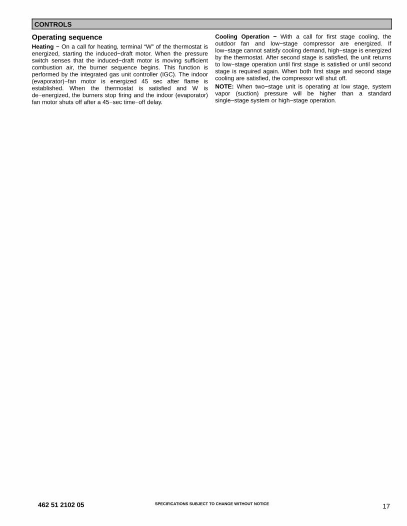
PGD5, PGS5 ACCESSORIES (Continued)Accessory Model Number Description Use With
CURBS
CPRFCURB010A00 Roof Curb, 11” High 24 − 60
CPRFCURB011A00 Roof Curb, 14” High 24 − 60
CPRFCURB012A00 Roof Curb, 11” High 36 − 60
CPRFCURB013A00 Roof Curb, 14” High 36 − 60
Note: CPRFCURB010A00 AND CPRFCURB011A00 can be used with 36−60 size units with some overhang.
ADAPTER CURBS*CPADCURB001A00 Adapter curb for use with NPRFCURB006A00 & NPRFCURB007A00 24
CPADCURB002A00 Adapter curb for use with NPRFCURB008A00 & NPRFCURB009A00 36 − 60
* Can also be used when replacing other manufacturer’s older generation units that contain a composite base without a metal base rail.
CONCENTRIC ADAPTERS − (Use with curb only)NPCONADP001A00 For 18” round duct (use with curbs CPRFCURB010A00, CPRFCURB011A00) Small Curb
NPCONADP002A00 For 18” round duct (use with curbs CPRFCURB012A00, CPRFCURB013A00) Large Curb
CONCENTRIC DIFFUSERS − (Ceiling or under roof)AXB020CSA* Step Down Diffuser − Fits 2’ x 4’ Ceiling Grid (16” round collars for flex conn.) 24 − 42
AXB020CFA* Flush Mount Diffuser − Fits 2’ x 4’ Ceiling Grid (16” round collars for flex conn.) 24 − 42
AXB030CSA Step Down Diffuser − Fits 2’ x 4’ Ceiling Grid (18” round collars for flex conn.) 24 − 60
AXB030CFA Flush Mount Diffuser − Fits 2’ x 4’ Ceiling Grid (18” round collars for flex conn.) 24 − 60
* A field supplied 18” to 16” round reducer required when used with NP concentric adaptor
DAMPERS
CPMANDPR007A00Manual Outside Air Damper − (Includes filter rack and 1” filter, same asCPFILTRK kit)
24CPMANDPR008A00 36
CPMANDPR009A00 48, 60
INTERNAL FILTER RACKS
CPFILTRK007A00
Internal Filter Rack (includes 1−inch filters)
24
CPFILTRK008A00 36CPFILTRK009A00 48, 60
LOW AMBIENT, ANTI−CYCLE, COMPRESSOR START ASSIST
CPLOWAMB001A00Low Ambient Control − enables cooling system to operate down to 0 Deg. F bycycling condenser fan on and off. ALL
NRTIMEGD001A00 Five Minute Compressor Delay ALL
CPHSTART002A00 PTC Compressor Start Assist Kit ALL
GAS CONVERSION KITS
NPLPCONV013A00 Natural to LP Conversion Kit ( 0 − 2000’ ) ALL
NPLPCONV014A00 Natural to LP Conversion Kit ( 2001’ − 6000’ ) ALL
NPNGCONV004A00 LP to Natural Gas Conversion Kit ( 0 − 2000’ ) ALL
FLUE DISCHARGE DEFLECTOR
NRFLUEDS001A00Directs flue gas exhaust 90 degrees upward from current discharge. Designedto allow tighter distances between unit and combustible surfaces. 24 inchHeight. AGA certified.
ALL
DUCT TRANSITIONS
NPDUCFLG002A00 Square to Round (1 set of 2, use with horizontal duct flanges only) 24−48
HAIL GUARDS / COIL PROTECTION (Factory installed on PGS models)NAPA00701GR 3/8” spacing dense wire grilles 24
NAPA01001GR 3/8” spacing dense wire grilles 36
NAPA01101GR 3/8” spacing dense wire grilles 48
NAPA01301GR 3/8” spacing dense wire grilles 60
Related Documents