15" PLANER MODEL G1021Z INSTRUCTION MANUAL COPYRIGHT ©2000 BY GRIZZLY INDUSTRIAL, INC. WARNING: NO PORTION OF THIS MANUAL MAY BE REPRODUCED IN ANY SHAPE OR FORM WITHOUT THE WRITTEN APPROVAL OF GRIZZLY INDUSTRIAL, INC. JANUARY, 2000 PRINTED IN U.S.A.

Welcome message from author
This document is posted to help you gain knowledge. Please leave a comment to let me know what you think about it! Share it to your friends and learn new things together.
Transcript

15" PLANERMODEL G1021Z
INSTRUCTION MANUAL
COPYRIGHT ©2000 BY GRIZZLY INDUSTRIAL, INC.WARNING: NO PORTION OF THIS MANUAL MAY BE REPRODUCED IN ANY SHAPE
OR FORM WITHOUT THE WRITTEN APPROVAL OF GRIZZLY INDUSTRIAL, INC.JANUARY, 2000 PRINTED IN U.S.A.

-2- G1021Z 15" Planer
Table Of ContentsPAGE
1. SAFETYSAFETY INSTRUCTIONS FOR POWER TOOLS..................................................4-5ADDITIONAL SAFETY INSTRUCTIONS FOR PLANERS........................................6
2. CIRCUIT REQUIREMENTS220V OPERATION ....................................................................................................7FUSING ....................................................................................................................7GROUNDING ............................................................................................................7EXTENSION CORDS ................................................................................................7
3. INTRODUCTIONCOMMENTARY..........................................................................................................8UNPACKING ..............................................................................................................9PARTS INVENTORY ................................................................................................9CLEAN UP ..............................................................................................................10SITE CONSIDERATIONS........................................................................................10
4. ASSEMBLYOVERVIEW..............................................................................................................11HANDWHEEL ..........................................................................................................11SPEED CHANGE KNOB ........................................................................................12EXTENSION ROLLERS ..........................................................................................12DUST PORT ............................................................................................................13KNIFE SETTING JIG ..............................................................................................13
5. ADJUSTMENTSOVERVIEW..............................................................................................................14GAUGE BLOCK ......................................................................................................15TABLE ADJUSTMENT........................................................................................15-16KNIFE INSPECTION ..............................................................................................17KNIFE SHARPENING ............................................................................................18KNIFE SETTING ................................................................................................19-20CHIP BREAKER ......................................................................................................21FEED ROLLER HEIGHT ........................................................................................22FEED ROLLER PRESSURE ..................................................................................23BED ROLLERS........................................................................................................24CHIP DEFLECTOR..................................................................................................25ANTI-KICKBACK ....................................................................................................26BELTS ................................................................................................................26-27GEARBOX ..............................................................................................................27THICKNESS SCALE ..............................................................................................28
G1021Z 15" Planer -3-
Table Of ContentsPAGE
6. OPERATIONSOVERVIEW..............................................................................................................29TABLE LOCKS ........................................................................................................29POWER FEED ........................................................................................................30HANDWHEEL ..........................................................................................................30DEPTH LIMITER ....................................................................................................30TEST RUN ..............................................................................................................31WOOD SPECIES ....................................................................................................31WOOD CHARACTERISTICS ..................................................................................32
7. MAINTENANCEGENERAL................................................................................................................33TABLE ......................................................................................................................33KNIVES....................................................................................................................33LUBRICATION ....................................................................................................34-35
8. CLOSURE ....................................................................................................................36
TROUBLESHOOTING ..............................................................................................................37ADJUSTMENT BLOCK PATTERN ..........................................................................................38

-4- G1021Z 15" Planer
Safety Instructions For Power Tools
SECTION 1: SAFETY
5. KEEP CHILDREN AND VISITORS AWAY .All children and visitors should be kept asafe distance from work area.
6. MAKE WORK SHOP CHILD PROOF withpadlocks, master switches, or by removingstarter keys.
7. DON’T FORCE TOOL . It will do the jobbetter and safer at the rate for which it wasdesigned.
8. USE RIGHT TOOL. Don’t force tool orattachment to do a job for which it was notdesigned.
1. KEEP GUARDS IN PLACE and in workingorder.
2. REMOVE ADJUSTING KEYS ANDWRENCHES. Form habit of checking tosee that keys and adjusting wrenches areremoved from tool before turning on.
3. KEEP WORK AREA CLEAN . Clutteredareas and benches invite accidents.
4. DON’T USE IN DANGEROUS ENVIRON-MENT. Don’t use power tools in damp orwet locations, or where any flammable ornoxious fumes may exist. Keep work areawell lighted.
For Your Own Safety Read InstructionManual Before Operating This Equipment
Indicates an imminently hazardous situation which, if notavoided, WILL result in death or serious injury.
Indicates a potentially hazardous situation which, if not avoid-ed, COULD result in death or serious injury.
Indicates a potentially hazardous situation which, if not avoid-ed, MAY result in minor or moderate injury. It may also beused to alert against unsafe practices.
This symbol is used to alert the user to useful informationabout proper operation of the equipment.
The purpose of safety symbols is to attract your attention to possible hazardous conditions.Thismanual uses a series of symbols and signal words which are intended to convey the level ofimportance of the safety messages. The progression of symbols is described below. Rememberthat safety messages by themselves do not eliminate danger and are not a substitute for prop-er accident prevention measures.
NOTICE

G1021Z 15" Planer -5-
9. USE PROPER EXTENSION CORD. Makesure your extension cord is in good condi-tion. Conductor size should be in accor-dance with the chart below. The amperagerating should be listed on the motor or toolnameplate. An undersized cord will cause adrop in line voltage resulting in loss ofpower and overheating.Your extension cordmust also contain a ground wire and plugpin. Always repair or replace extensioncords if they become damaged.
Minimum Gauge for Extension Cords
10. WEAR PROPER APPAREL. Do not wearloose clothing, gloves, neckties, rings,bracelets, or other jewelry which may getcaught in moving parts. Non-slip footwearis recommended. Wear protective hair cov-ering to contain long hair.
11. ALWAYS USE SAFETY GLASSES. Alsouse face or dust mask if cutting operation isdusty. Everyday eyeglasses only haveimpact resistant lenses, they are NOT safe-ty glasses.
12. SECURE WORK. Use clamps or a vise tohold work when practical. It’s safer thanusing your hand and frees both hands tooperate tool.
LENGTHAMP RATING 25ft 50ft 100ft0-6 18 16 167-10 18 16 1411-12 16 16 1413-16 14 12 1217-20 12 12 1021-30 10 10 No
Safety Instructions For Power Tools
13. DON’T OVERREACH. Keep proper footingand balance at all times.
14. MAINTAIN TOOLS WITH CARE. Keeptools sharp and clean for best and safestperformance. Follow instructions for lubri-cating and changing accessories.
15. DISCONNECT TOOLS before servicingand changing accessories, such as blades,bits, cutters, and the like.
16. REDUCE THE RISK OF UNINTENTION-AL STARTING. Make sure switch is in offposition before plugging in.
17. USE RECOMMENDED ACCESSORIES.Consult the owner’s manual for recom-mended accessories. The use of improperaccessories may cause risk of injury.
18. CHECK DAMAGED PARTS. Before fur-ther use of the tool, a guard or other partthat is damaged should be carefullychecked to determine that it will operateproperly and perform its intended function.Check for alignment of moving parts, bind-ing of moving parts, breakage of parts,mounting, and any other conditions thatmay affect its operation. A guard or otherpart that is damaged should be properlyrepaired or replaced.
19. NEVER LEAVE TOOL RUNNING UNAT-TENDED.TURN POWER OFF. Don’t leavetool until it comes to a complete stop.

-6- G1021Z 15" Planer
Additional Safety Instructions For Planers
No list of safety guidelines can be com-plete. Every shop environment is different.Always consider safety first, as it applies toyour individual working conditions. Usethis and other machinery with caution andrespect. Failure to do so could result in seri-ous personal injury, damage to equipmentor poor work results.
Like all power tools, there is danger associ-ated with the Model G1021Z 15" Planer. Usethe tool with respect and caution to lessenthe possibility of mechanical damage oroperator injury. If normal safety precau-tions are overlooked or ignored. Seriouspersonal injury may occur.
1. Ensure that the machine sits firmly on thefloor before use. Any “wobbles” must becorrected by shimming or blocking beforeoperation.
2. This machine is not designed to processany other material except wood.
3. Never position fingers or thumbs near theinfeed roller.
4. Long stock should always be fully support-ed by some type of support fixture.
5. Do not operate planer with dull or damagedknives.
6. Ensure that the planer is properly adjustedbefore using.
7. Do not remove excessive amounts ofwood in a single pass.
8. Inspect your stock before planing. Rejectstock with defects and foreign material.
9. Do not attempt to remove jams until poweris disconnected and all moving parts havecome to a complete stop.
10. Provide adequate infeed and outfeedspace for operating the planer.
11. Do not plane wood less than 12" long and1⁄4" thick.
12. Do not plane lumber with loose knots orknots that may become loose during planing.
Operation of this equipment has the poten-tial to propel debris into the air which cancause eye injury. Always wear safety glass-es or goggles when operating equipment.Everyday glasses or reading glasses onlyhave impact resistant lenses, they are notsafety glasses. Be certain the safety glass-es you wear meet the appropriate stan-dards of the American National StandardsInstitute (ANSI).

G1021Z 15" Planer -7-
220V Operation
SECTION 2: CIRCUIT REQUIREMENTS
The G1021Z Planer motor is wired to operate at220V only. A cordset without a 220V plug isincluded with the Model G1021Z. Plugs andreceptacles can be purchased at your local hard-ware store or home center. Contact your localelectrical contractor if uncertain about connectingto a 220V circuit.
When operating at 220V, we recommend using aNEMA-style 6-15 plug and outlet as depicted inFigure 1 . You may also “hard-wire” the planerdirectly to your panel, provided you place a dis-connect switch near the machine. Check the elec-trical codes in your area for specifics on wiringrequirements.
Under normal load, the Model G1021Z drawsabout 12 amps. We recommend a 15-amp circuitor a 20-amp slow-blow fuse. A circuit rated anyhigher will not adequately protect the motor.
Equipment returned to us for service that showsevidence of being over-fused will be repaired orreplaced totally at the customer’s expense,regardless of the present warranty status.
Fusing
We do not recommend the use of extension cordson 220V equipment. It is much better to arrangethe placement of your equipment and theinstalled wiring to eliminate the need for exten-sion cords. Should it be necessary to use anextension make sure the cord is rated HardService (grade S) or better. Refer to the chart inSection 1: Safety Instructions to determine theminimum gauge for the extension cord. Theextension cord must also contain a ground wireand plug pin. Always repair or replace extensioncords when they become worn or damaged.
Extension Cords
Grounding
This equipment must be grounded. Pleaseensure that this machine is continuouslygrounded from the motor to the machine frameand then to a known ground. Verify that anyexisting electrical outlet and circuit you intendto plug into is actually grounded. If it is not, itwill be necessary to run a separate 12 A.W.G.copper grounding wire from the outlet to aknown ground. Under no circumstances shouldthe grounding pin from any three-pronged plugbe removed. Serious personal injury mayoccur.
Figure 1. NEMA 6-15 220V/15A connector.
220V/240V15A
NEMA L6-15
In the event of an electrical short, groundingreduces the risk of electric shock by providing apath of least resistance to disperse electric cur-rent. This tool is equipped with a power cord hav-ing an equipment-grounding conductor. The out-let must be properly installed and grounded inaccordance with all local codes and ordinances.

-8- G1021Z 15" Planer
SECTION 3: GENERAL INFORMATION
To operate this, or any power tool, safely andefficiently, it is essential to become as familiarwith its characteristics as possible. The timeyou invest before you begin to use your ModelG1021Z will be time well spent. DO NOT oper-ate this machine until you are completely famil-iar with the contents of this manual. Make sureyou read and understand all of the safety pro-cedures. If you do not understand something,DO NOT operate the machine.
Commentary
We are proud to offer the Grizzly Model G1021Z15" Planer. The Model G1021Z is part of a grow-ing Grizzly family of fine woodworking machinery.When used according to the guidelines set forthin this manual, you can expect years of trouble-free, enjoyable operation and proof of Grizzly’scommitment to customer satisfaction.
The Model G1021Z is intended for home and pro-fessional use. The G1021Z features a 3 HP, 220Vsingle-phase motor with an easy Off magneticpower switch, jack screw and/or spring loadedknife setting, triple belt drive, large side-mountedhandwheel and a solid one-piece cabinet stand.
A number of optional accessories for the ModelG1021Z are available through the Grizzly catalog.They include a heavy-duty mobile base, rollerstands, replacement knives and Planer Pal® plan-er jigs, which are invaluable when setting up oradjusting your planer’s cutting knives.
We are also pleased to provide this manual withthe Model G1021Z. It was written to guide youthrough assembly, review safety considerations,and cover general operating procedures. It repre-sents our effort to produce the best documenta-tion possible. If you have any comments regard-ing this manual, please write to us at the addressbelow:
Grizzly Industrial, Inc.C/O Technical Documentation
P.O. Box 2069Bellingham, WA 98227-2069
Most importantly, we stand behind our machines.If you have any service questions or partsrequests, please call or write us at the locationlisted below.
The specifications, drawings, and photographsillustrated in this manual represent the ModelG1021Z as supplied when the manual was pre-pared. However, owing to Grizzly’s policy of con-tinuous improvement, changes may be made atany time with no obligation on the part of Grizzly.Whenever possible, though, we send manualupdates to all owners of a particular tool ormachine. Should you receive one, we urge you toinsert the new information with the old and keepit for reference.
Grizzly Industrial, Inc.2406 Reach Road
Williamsport, PA 17701Phone: (570) 326-3806
Fax: (800) 438-5901E-Mail: [email protected]
Web Site: http://www.grizzly.com

G1021Z 15" Planer -9-
Unpacking
The planer is shipped from the factory in a care-fully packed crate. If you find the machine to bedamaged after you’ve signed for delivery and thetruck and driver are already gone, you will need tofile a freight claim with the carrier. Save the con-tainers and all packing materials for inspection bythe carrier or their agent. Without the packingmaterials, filing a freight claim can be difficult. Ifyou need advice regarding this situation, pleasecall us immediately.
The G1021Z is a heavy machine with a 540lb. shipping weight. DO NOT over-exertyourself while unpacking or moving yourmachine – get assistance. In the event thatyour planer must be moved up or down aflight of stairs, be sure that the stairs arecapable of supporting the combined weightof people and the machine. Failure to usecare while assembling or moving couldresult in serious personal injury.
Parts Inventory
After all the parts have been removed from thecontainer, you should have:
Planer Unit on StandDust PortRoller Extensions (2)Dust Port Mounting Hardware
Cap Screw M6 - 1.0 x 12 3Lock Washer M6 3Hex Bolts M6 - 1.0 x 12 3Hex Nuts M6 - 1.0 3Washers M6 6
Roller Extension Mounting Hardware BagHex Bolts M8 -1.25 x 20 6Flat Washers 8mm 6Setscrews M8 - 1.25 x 12 6
Depth Handwheel HardwareHandle 1Hex Nut M10 - 1.25 1Flat Washer 10mm 1Scale (Hi - Lo) 1Key 1
Knife Setting JigKnife Setting Jig Rod 1Knife Setting Jig Brackets 2E-clips 4
Tool KitAllen® Wrench 3mm 1Allen® Wrench 4mm 1Allen® Wrench 5mm 1Allen® Wrench 6mm 1Open End Wrench 8-10mm 1Open End Wrench 12-14mm 1
In the event that any parts are missing, we will behappy to replace them. Contact our CustomerService number for assistance. If any non-propri-etary parts such as nuts, bolts or washers aremissing, we will be happy to replace these too,but for the sake of expediency, these items canbe obtained at your local hardware store.
NOTICEA full parts list and breakdown can befound toward the end of this manual. Foreasier assembly, or to identify missingparts, please refer to the detailed illustra-tions at the end of the manual.

-10- G1021Z 15" Planer
Clean Up
The unpainted surfaces are coated with a waxyoil to protect them from corrosion during ship-ment. Remove this protective coating with a sol-vent cleaner or citrus-based degreaser. Avoidchlorine-based solvents as they may damagepainted surfaces should they come in contact.Always follow the usage instructions on the prod-uct you choose for clean up.
Follow the safety rules listed below whenworking with solvents.1. Read and follow all directions and
warnings on the solvent label.
2. Work only in a well ventilated area.
3. Do not work near any type of openflame (e.g., pilot lights, keroseneheaters, and so on).
4. DO NOT smoke while working withflammable material.
5. Paper towels from the cleaning processare extremely combustible. Dispose ofwaste towels so they do not create afire hazard.
Site Considerations
FLOOR LOADYour G1021Z Planer represents a large weightload in a small footprint. Most commercial floorsare suitable for the Model G1021Z. Some resi-dential floors may require additional support toaccommodate both machine and operator.
WORKING CLEARANCESWorking clearances can be thought of as the dis-tances between machines and obstacles thatallow safe operation of every machine withoutlimitation. Consider existing and anticipatedmachine needs, size of material to be processedthrough each machine, and space for auxiliarystands and/or work tables. Also consider the rel-ative position of each machine to one another forefficient material handling. Be sure to allow your-self sufficient room to safely run your machines inany foreseeable operation.
LIGHTING AND OUTLETSLighting should be bright enough to eliminateshadow and prevent eye strain. Electrical circuitsshould be dedicated or large enough to handlecombined motor amp loads. Outlets should belocated near each machine so power or exten-sion cords are not obstructing high-traffic areas.Be sure to observe local electrical codes for prop-er installation of new lighting, outlets, or circuits.
Many of the solvents commonly used toclean machinery can be highly flammable,and toxic when inhaled or ingested. Alwayswork in well-ventilated areas far from poten-tial ignition sources when dealing with sol-vents. Use care when disposing of wasterags and towels to be sure they do not cre-ate fire or environmental hazards. Keepchildren and animals safely away whencleaning and assembling this machine.
Make your shop “child safe”. Ensure thatyour workplace is inaccessible to young-sters by closing and locking all entranceswhen you are away. Never allow visitors inyour shop when assembling, adjusting oroperating equipment.

G1021Z 15" Planer -11-
Lifting Handles
This planer is heavy and awkward to move.We recommend that you use the properequipment to put the planer into position inyour shop or on a mobile base. Lifting with-out proper equipment or ample assistancecould result in serious injury.
Figure 2. Location of lifting handles.
SECTION 4: ASSEMBLY
Overview
The G1021Z Planer requires very little assemblywhen you receive it. There a just a few easyassembly steps to get the machine ready for yourshop. The machine should be properly adjustedfrom the factory, however should you desire tocheck the various settings, the following sectionwill detail the proper adjustment procedures.
This planer unit is very heavy, approximately 480lbs.There are lifting handles which slide out of thebase of the planer head (Figure 2) which can beused to move the unit. These can be used as lift-ing points using an overhead lift, block and tack-le or a forklift, or if you have three other friendswho are each willing to grab a handle!
Handwheel
The handwheel is used to raise and lower theplaner table.
TO MOUNT THE HANDWHEEL:
1. The handwheel shaft is at the front rightcorner of the planer. Insert the key into thekeyway on the shaft, then line up the notchon the handwheel bore with the key. Slidethe handwheel onto the shaft.
2. Slide the direction scale over the keyedshaft so it sits on the center face of thehandwheel. See Figure 3.
3. Secure the handwheel with the 10mm -1.25 hex nut and washer provided.
4. Attach the handle to the outer edge of thehandwheel. The handle threads into thehole on the handwheel.
Figure 3. Handwheel attachment.

-12- G1021Z 15" Planer
Extension Rollers
Speed Change Knob
The infeed and outfeed extension rollers supportthe work as it goes through the machine.
TO MOUNT THE EXTENSION ROLLERS:
1. Thread three (3) 8mm setscrews into themounting bracket of the extension rollers.The setscrew holes are located just belowthe mounting holes. Just start them into theholes for now.
2. Use three (3) hex bolts and washers tomount the extension rollers. See Figure 5.Make sure the roller assembly is orientedas shown in Figure 6.
3. Position a straightedge on the table bed, soit lays on the table and suspends over theextension rollers. See Figure 6.
Figure 5. Extension roller attachment points.
Height AdjustSetscrew
Mounting Bolt
Figure 4. Installing speed change knob.
4. Move the edge of the mounting bracketwhich is closest to the table bed up or downuntil the first roller is even with the straight-edge. Tighten the mounting bolts justenough to hold that position. Now adjustthe three setscrews until the roller which isfurthest out is even with the straightedge. Itmay require various combinations of loos-ening and/or tightening the setscrews andbolts to level the extension rollers with thetable.
5. Repeat steps 3-4 for the other extensionroller assembly.
Figure 6. Checking extension roller height.
Thread the black plastic knob onto the speedchange shaft located on the right hand side ofthe machine. See Figure 4. Note that speedchanges should only be done with the motorrunning. See the Operations section.
G1021Z 15" Planer -13-
Planer knives are dangerously sharp. Useextreme caution when working near cuttingsurfaces. Failure to exercise care whileworking near knives could result in severepersonal injury.
Knife Setting Jig
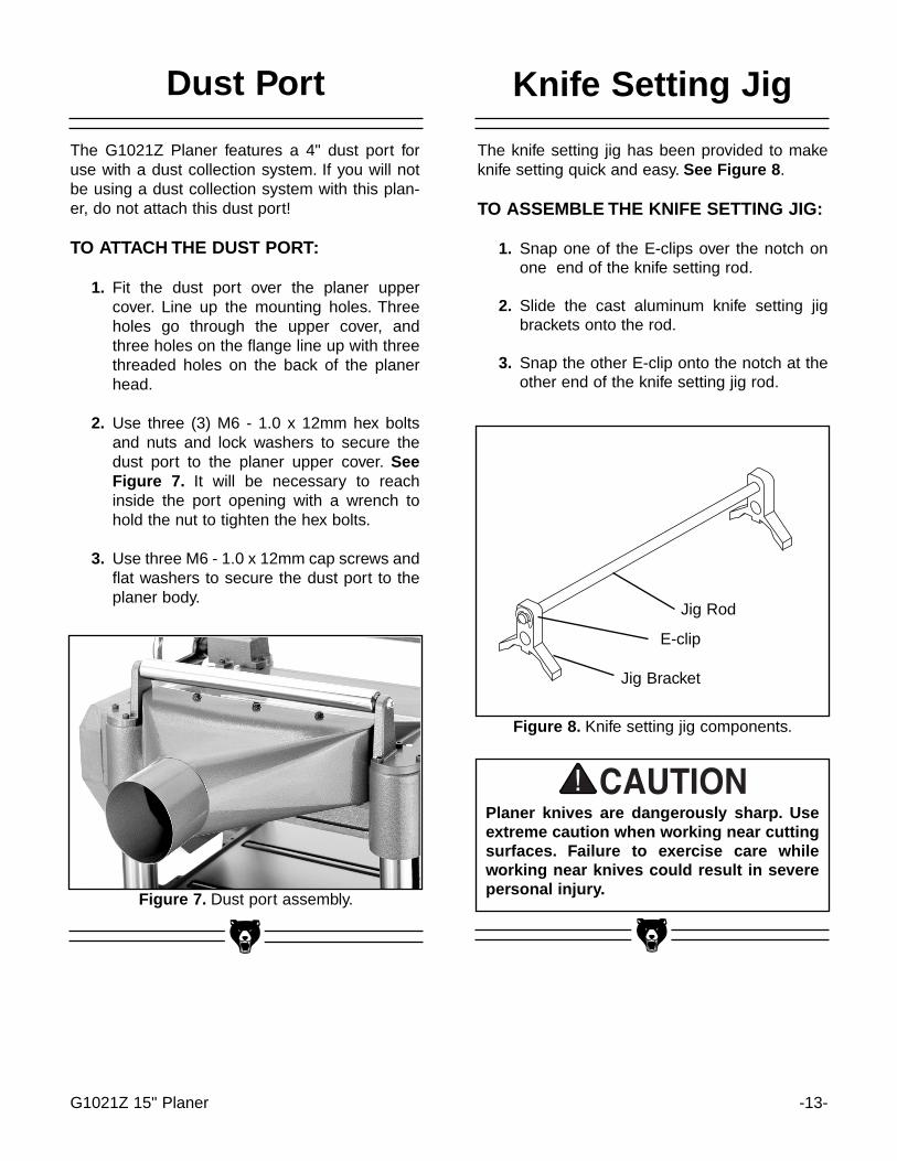
The knife setting jig has been provided to makeknife setting quick and easy. See Figure 8 .
TO ASSEMBLE THE KNIFE SETTING JIG:
1. Snap one of the E-clips over the notch onone end of the knife setting rod.
2. Slide the cast aluminum knife setting jigbrackets onto the rod.
3. Snap the other E-clip onto the notch at theother end of the knife setting jig rod.
Figure 8. Knife setting jig components.
E-clip
Jig Rod
Jig Bracket
Dust Port
The G1021Z Planer features a 4" dust port foruse with a dust collection system. If you will notbe using a dust collection system with this plan-er, do not attach this dust port!
TO ATTACH THE DUST PORT:
1. Fit the dust port over the planer uppercover. Line up the mounting holes. Threeholes go through the upper cover, andthree holes on the flange line up with threethreaded holes on the back of the planerhead.
2. Use three (3) M6 - 1.0 x 12mm hex boltsand nuts and lock washers to secure thedust port to the planer upper cover. SeeFigure 7. It will be necessary to reachinside the port opening with a wrench tohold the nut to tighten the hex bolts.
3. Use three M6 - 1.0 x 12mm cap screws andflat washers to secure the dust port to theplaner body.
Figure 7. Dust port assembly.

-14- G1021Z 15" Planer
SECTION 5: ADJUSTMENTS
Overview
Once assembly has been completed, yourG1021Z 15" Planer requires just a few adjust-ments to ready it for use in your shop.
Many adjustments have already been made atthe factory, yet we recommend you familiarizeyourself with all of the following procedures togain a better understanding of the Planer’s con-struction and operation.
General control and adjustment locations areshown in Figure 9:
A. The switch is thermally protected and mag-netically controlled and features push but-tons to turn the planer on and off.
B. The handwheel raises and lowers the tableand controls the depth of cut. Turning thehandwheel clockwise raises the table andcounter-clockwise lowers the table.
C. The bed rollers ease stock movementthrough the planer and are adjustable.
D. The three position feed rate change knobshifts planer feed speed from neutral to 16and 20 feet per minute.
E. The table lock knob secures the table in afixed position.
F. Extra large ball bearing return rollers
G. Removable belt guard.
A
B
C
DE
G
F
Figure 9. Overview of planer adjustment controls.

G1021Z 15" Planer -15-
Gauge Block
Before attempting any table adjustments, you willneed to construct a gauge block. See Figure 10 .A larger gauge block diagram is also included atthe end of the manual for your convenience.Precision adjustments later on require accuracywhen milling the gauge block. Do not use com-mon 2x4 material. Use maple or similar type ofhardwood.
Using a magnetic dial indicator is a good alterna-tive to constructing a gauge block. Use the dialindicator whenever the instructions call for use ofthe gauge block and/or feeler gauge. Refer to thecurrent Grizzly catalog for dial indicators.
Table Adjustment
To plane stock perfectly square, it is importantthat the table is parallel to the cutterhead.
TO CHECK TABLE PARALLELISM:
1. Place the gauge block on the table underone end of the cutterhead.
2. Turn the handwheel to raise the table untilthe block barely touches the cutterheadbody. The block should not be touchingthe knives. See Figure 11 .
3. Slide the block toward the opposite side ofthe cutterhead. Use a feeler gauge to mea-sure the width of the gap, if any, betweenthe top of the block and the bottom of thecutterhead. If there is a gap, make a note,reading the distance from the feeler gauge.
4. If the block wedges tightly between thetable and cutterhead when shifting fromone side to the other, repeat steps 1through 3 above, but start from the oppo-site end of the cutterhead.
Figure 10. Guide block specifications.
DO NOT make adjustments while the planeris running. Ensure that the switch is off,power is disconnected and moving partshave stopped before making adjustments.Failure to comply could result in seriousinjury or electrical shock hazard.
Figure 11. Guide block indicates parallelism.
If the gap difference from one side to the other isequal to or less than 0.004", no further adjust-ment is necessary.

-16- G1021Z 15" Planer
Figure 12. Cap screws for column adjustment.
If the gap difference from one side to the other isgreater than 0.004", but less than 0.016", go tostep 5.
If the gap difference from one side to the other isgreater than 0.016", the table raising chain underthe planer base will need to be adjusted. Pleasecall our Customer Service number for chainadjustment instructions.
To adjust for gap differences of less than 0.016":
5. Determine which side of the table must beraised to correct the gap.
6. Locate the two cap screws in the table cast-ing for each of the columns. See Figure 12 .Loosen both sets of cap screws for eachcolumn on the side you wish to adjust.
7. Push down or pull up the table in thedesired direction. Hold the table in positionand retighten the cap screws.
8. Recheck the table to cutterhead parallelismagain. Repeat steps 1 through 7 until thedeviation is less than 0.004".
Lock Knob
Loosen these capscrews to micro adjustthe table height
Notes
Planer knives are dangerously sharp. Useextreme caution when inspecting, removing,sharpening, or replacing knives into the cut-terhead. Substantial risk of injury!

G1021Z 15" Planer -17-
Figure 14. Placing springs into knife slots.
Figure 15. Cover Removed, Jig on cutterhead
The knives of your planer must be periodicallyadjusted and will ultimately need to be removedfor sharpening. Adjustments should be as preciseas possible with tolerances within .002"-.003" toprolong the sharpness of the knife edges.Improperly adjusted knives can cause an imbal-ance condition in the cutterhead and shortenbearing life, as well as produce substandardplaning results.
TO INSPECT THE KNIVES:
1. UNPLUG THE PLANER!
2. Remove the dust port and upper cover andcutterhead guard to expose the top of thecutterhead. See Figure 15.
Knife Inspection
The knives are set at the factory using jackscrews before shipping. Springs are also includedwith your machine, installed beneath the knives.These may be used instead of the jack screwsdepending on your preference. Refer to Figure13 for placement of the jack screws or springs.
Jack Screw
Spring
Figure 13. Typical placement of jack screws orsprings.
If you decide you prefer to use the spring adjust-ment method, you need to remove each knife,remove the jack screws, leave the two springsunder each knife, and replace the knife.
Loosen the gib bolts until the knife is loose in theslot. The gib bolts turn clockwise to loosen andcounterclockwise to tighten (when facing thehead of the bolt). Carefully remove the knife. Backthe jack screws out completely from the threadedhole and remove. If the springs have become dis-lodged in the removal process, be sure to place 1spring in each of the two holes in bottom of theknife slot. The springs do not go into the threadedhole where the jack screws were installed. SeeFigure 14.
When using jack screws, it is not necessary toinstall the springs. However it will not affect theadjustment if both the springs and jack screwsare in place together.

-18- G1021Z 15" Planer
Figure 16. Proper knife setting jig placement.
3. Remove the belt guard. Carefully turn thecutterhead (using the pulley) until the firstknife is top dead center.
4. Using the knife setting gauge, check theknife height. The jig should sit solidly withboth feet on the cutterhead. See Figure 16.If the knife is adjusted properly, the contactpoint at the center of each adjuster shouldjust touch the tip of the knife. If the knifedoes not make contact, or if the knife caus-es the adjuster’s legs to not seat on the cut-terhead, the knives need to be adjusted. Itmay be helpful to mark the side of the knifewith an ink marker to indicate whether it ishigh or low. This will make the actual adjust-ment process easier.
Once you have completed inspection on all threeknives, you will able to determine whether or notthere is a need to adjust the knives in the cutter-head. Proceed to the appropriate section follow-ing depending upon whether you are using thejack screws or the springs.
Knife Sharpening
Knife sharpness is one of the most important fac-tors in getting good results with the planer. Knivescan be made to last a long time if care is taken inchecking the condition of the wood which is putinto the machine. The biggest problem will comefrom wood with nails or other metal embedded.This will nick or chip the knives and can require acomplete regrinding. Another wear factor is sand,grit, or other dirt on the surface of the wood whichthe knives have to cut through. At the speed thecutterhead is rotating, these types of surface con-tamination can have a very abrasive effect.
This planer has knives with a grind angle of 35˚which is a configuration which should suit mostgeneral planing needs. The optimal grind or bevelangle is a compromise between effective cutting(the smaller the angle the better the cuttingaction) and edge life where the larger the anglethe more the edge is supported, thus the longer itwill last.
For the best results it is best to have planer knivessharpened by a professional sharpening servicewhich has the grinding and measurement equip-ment to assure that the knife cutting geometry ismaintained at optimum levels. It is a procedurewhich requires some care and precision, other-wise, a set of blades can be easily ruined. Knivesshould always be ground as a set so they can beproperly matched. Unequal material removal canresult in an unbalanced cutterhead which canaffect not only planing surface quality but ulti-mately the life of the cutterhead bearings.
Please refer to Section 6 Adjustments - KnifeSetting for complete detail on the removal andreinstallation of planer knives.

G1021Z 15" Planer -19-
Figure 17. Side view with jack screws.
Knife Setting
When making adjustments, all three knivesmust be adjusted the same. Do not adjustone knife without adjusting the others aswell. Improper knife height adjustment canresult in damage to knives, poor planer per-formance and possible operator injury.
The knives are locked into the cutterhead withwedge-type gibs and gib bolts. Jack screws underthe knives allow fine tuning to help in the settingprocess.
To set the knives:
1. UNPLUG THE PLANER!
2. Remove the upper cover to expose the cut-terhead.
3. Loosen the gib bolts until the knife is loosein the slot. The gib bolts turn clockwise toloosen and counterclockwise to tighten(when facing the head of the bolt). SeeFigure 17 .
ADJUSTMENTS USING JACKSCREWS
Figure 18. Tightening knives in cutterhead.
5. Adjust the screws below each end of theknife until both feet of the gauge rest even-ly on the cutterhead and the knife is justtouching the bottom of the middle foot ofthe gauge. The gauge will set the knives ata uniform protrusion of approximately .070"above the cutterhead. The knife heightshould vary no more than .002"-.003"across the length of the cutterhead.
6. Maintain a constant pressure on the gaugewhile re-tightening the gib bolts.
7. Repeat the same procedure on the remain-ing knives. As mentioned before, the stan-dard knife setting gauge is satisfactory forreasonably accurate knife setting tasks.
4. Place the knife setting jig over the knife onthe cutterhead as shown in Figure 18 . Thefeet should be securely planted on the cut-terhead. Make sure the gauge extensionrod is parallel to the cutterhead to maintainaccuracy.
Planer knives are dangerously sharp. Useextreme caution when inspecting, remov-ing, sharpening, or replacing knives into thecutterhead. Substantial risk of injury!

-20- G1021Z 15" -20-
The knives are locked into the cutterhead withwedge-type gibs and gib bolts. Jack screws underthe knives may be substituted with springs to helpin the setting process. It is advised that the jackscrews be removed when using the springs. Toset the knives:
1. UNPLUG THE PLANER!
2. Remove the upper cover to expose the cut-terhead.
3. Loosen the gib bolts until the knife is loosein the slot. The gib bolts turn clockwise toloosen and counterclockwise to tighten(when facing the head of the bolt). SeeFigure 19.
ADJUSTMENTS USING SPRINGS
Figure 19. Side view with springs.
When making adjustments, all three knivesmust be adjusted the same. Do not adjustone knife without adjusting the others aswell. Improper knife height adjustment canresult in damage to knives, poor planer per-formance and possible operator injury.
Planer knives are dangerously sharp. Useextreme caution when inspecting, remov-ing, sharpening, or replacing knives into thecutterhead. Substantial risk of injury!
Figure 20. Tightening knives in cutterhead.
4. Place the knife setting gauge on the cutter-head as described previously, so the feetare securely planted on the cutterhead.Make sure the gauge extension rod is par-allel to the cutterhead to maintain accuracy.
5. The downward pressure provided by thegauge will set the knives at a uniform pro-trusion of approximately .070" above thecutter. The knife height should vary no morethan .002"-.003" across the length of thecutterhead.
6. Maintain a constant pressure on the gaugewhile re-tightening the gib bolts. See Figure20.
7. Repeat the same procedure on the remain-ing knives. As mentioned before, the stan-dard knife setting gauge is satisfactory forreasonably accurate knife setting tasks.

G1021Z 15" Planer -21-
Figure 22. Chip breaker height adjustment.
6. If an adjustment is necessary, loosen thelocknuts and turn the setscrews. SeeFigure 22 . Stop turning when the bottom ofthe chip breaker just touches the gaugeblock.
7. Re-tighten both locknuts
8. Replace the exhaust hood.
Chip Breaker
The chip breaker is located on the top side of theplaner and extends down around the front of thecutterhead. Its function is to prevent tear-out ordeep, unregulated gouging as the knives removematerial. The chip breaker works by breaking thewoodchips as they are being cut by the cutter-head. The chip breaker also deflects and expelsthe woodchips away from the surface of theboard and out of the planer.
TO ADJUST THE CHIPBREAKER:
1. Disconnect the machine from the powersource, remove the dust hood and lowerthe table.
2. Ensure that the knives are properly adjust-ed.
3. Place the gauge block on the table directlyunder the cutterhead. Using a one millime-ter (0.040") feeler gauge between thegauge block and the cutterhead, raise thetable until one of the knives just touches thefeeler gauge. Rotate the cutterhead manu-ally to be sure the knife is at bottom deadcenter.
4. Lock the table by tightening the table lockknobs.
5. Remove the feeler gauge and slide thegauge block under the chip breaker. SeeFigure 21 . The chip breaker should justtouch the top of the gauge block. Slide thegauge block to the opposite end of the chipbreaker and check it in the same manner.
Figure 21. Location of chip breaker assembly.
Gauge Block
Chipbreaker Infeed RollerCutterhead
DO NOT make adjustments while the planeris running. Ensure that the switch is off,power is disconnected and moving partshave stopped before making adjustments.Failure to ensure that power is disconnect-ed could result in serious injury or electri-cal shock hazard.

-22- G1021Z 15" Planer
Feed Roller Height
The infeed and outfeed rollers propel the lumberthrough the planer.The rollers also press the lum-ber flat against the planer table.
Set the infeed and outfeed rollers 0.040" belowthe knife edge at bottom dead center.
TO CHECK ROLLER HEIGHT:
1. Disconnect the machine from the powersource.
2. Lower the table so the gauge block will fitunder one side of the infeed roller.
3. Raise the table until the gauge block barelytouches the infeed roller. See Figure 23 .Do not change position of the table.
4. Slide the gauge block over so it is under theedge of one of the knives. Turn the cutter-head until one of the knives is at bottomdead center over the gauge block.
5. Measure the clearance between the top ofthe gauge block and the edge of the knifewith a feeler gauge. Note the measurementindicated on the feeler gauge.
Figure 23. Feed roller height inspection.
Chipbreaker Infeed Roller Anti-KickbackFingers
6. Repeat steps 1-5 for the opposite side ofthe roller. Repeat all steps for the outfeedroller.
Feeler gauge measurement should equal 0.040".
TO ADJUST ROLLER HEIGHT:
1. Remove the drive chain cover to access theroller adjustments on the drive chain side ofthe planer. A single socket head cap screwholds the drive chain cover on. Belt sideadjustments are already accessible.
2. Loosen the roller adjustment check nutsand turn the roller height setscrews tochange the height of the roller as needed.See Figure 24 .
3. Check roller height according to the aboveinstructions. Continue turning the setscrewuntil the roller is properly adjusted.
4. When the roller is set in the correct posi-tion, re-tighten the check nuts you loosenedin Step 2 above.
5. Check your settings one last time andrepeat steps 1-4 if necessary.
Figure 24. Feed roller height adjustment.

G1021Z 15" Planer -23-
Figure 26. Roller pressure assembly.
Pressure Setscrew
Pressure Spring
Roller
Check Nut Height Setscrew
4. Remove the springs that are in the holesleft by the setscrews. See Figure 26 .
5. Check for any dirt or grit. Clean the springsand setscrews if dirty.
6. Screw the three regular-pressuresetscrews back in until they are flush withthe top of the head casting.
7. Screw the light pressure setscrew until it isapproximately 1⁄4" above the head casting.The feed chain applies additional tension tothe right side of the outfeed roller, so thepressure added by the setscrew need notbe as high.
To be effective, the infeed and outfeed rollersmust put pressure on the workpiece as it feedsthrough the planer. Too little pressure results inslipping boards, too much pressure results injamming.
Experiment with the best pressure settings foryour work situations. Some rough cut lumber willfeed through fine with relatively few problems,while other lumber will have more difficulty.
Adjusting roller pressure does not affect height.
TO ADJUST ROLLER PRESSURE:
1. Disconnect the machine from the powersource.
2. Ensure that knives and feed rollers are setcorrectly.
3. Unscrew the four large pressure setscrewson top of the planer body. See Figure 25 .
Feed Roller Pressure
Figure 25. Roller pressure adjustment.
Light PressureSetscrew
RegularPressure
Setscrews

-24- G1021Z 15" Planer
Bed Rollers
Figure 27. Inspecting bed roller height.
4. Use a wrench to turn the eccentric shaftswhich adjust roller height. Stop turningwhen the table rollers are at the properheight.
5. Once your roller heights are correct, re-tighten all the setscrews.
6. Check the height of the table rollers. Repeatsteps 1-5 until the bed rollers are properlyset. Spin the bed rollers to ensure freemovement.
The bed rollers ease stock movement through theplaner. The height of the bed rollers will varydepending on the types of wood you will be plan-ing. When planing rough stock, set the rollersslightly high to keep the lumber from draggingalong the bed. However, snipe may be unavoid-able. Smooth lumber should be planed with therollers set just above the plane of the table. Thiswill minimize snipe.
TO ADJUST THE BED ROLLERS:
1. Ensure that power is disconnected and laya high quality straightedge across bothtable rollers. Use a try square to keep thestraightedge perpendicular to the table.
2. Use a feeler gauge to measure the clear-ance between the bottom of the straightedge and the table. Ideal clearance isbetween 0.002" and 0.005". Measure inseveral places. This measurement must beconsistent across the entire table. SeeFigure 27.
Figure 28. Adjusting bed roller height.
3. Loosen the setscrews on both sides ofeach bed roller. See Figure 28.
SetscrewsSetscrews

G1021Z 15" Planer -25-
Chip Deflector
The chip deflector keeps chips from falling ontothe outfeed roller. It is the orange plastic platelocated under the top cover.
The beveled edge of the chip deflector should beabout 1⁄8" - 1⁄4" from the knife edge. Carefully rotatethe cutterhead to gauge the distance between thechip deflector and the knives. Adjust if necessary.However, if the chip deflector is set too close tothe knives, the rotating cutterhead may pull it inand destroy it.
TO ADJUST THE CHIP DEFLECTOR:
1. Disconnect the machine from the powersource and remove the planer’s uppercover.
2. Loosen the three deflector mounting bolts.See Figure 29 . Make sure the bevelededge of the deflector faces the cutterhead.
3. Move the deflector until its edge is approxi-mately 1⁄8" - 1⁄4" from the tip of the cuttingknives. Push down on the deflector with awooden stick to check if it will touch theknives. Cautiously rotate the cutterhead toensure clearance. Do Not touch the knives- severe cuts may result.
4. Re-tighten the chip deflector mounting boltsand re-mount the upper cover to the planer.
Figure 29. Chip deflector access.
Chip Deflector
Chipbreaker
Cutterhead
Mounting Bolts
Planer knives are dangerously sharp. Useextreme caution when inspecting, remov-ing, sharpening, or replacing knives into thecutterhead. Substantial risk of injury!

-26- G1021Z 15" Planer
The Model G1021Z Planer provides an anti-kick-back safety feature. The anti-kickback fingershang from a rod suspended across the front ofthe cutterhead casting. The anti-kickback fingersshould be inspected regularly. Check the fingersto ensure that they swing freely and easily. SeeFigure 30 .
Figure 30. Anti-kickback assembly.
The belt and pulley assembly are on the left sideof the planer. The belts transfer power from themotor to the cutterhead and then through thegearbox to the feed rollers. Remove the belt coverby unscrewing the two lock knobs holding thecover in place.
TO INSPECT/ADJUST THE PULLEYS:
Place a metal ruler or other straightedge acrossthe pulleys to check alignment. The pulleys arealigned if the ruler crosses them evenly. SeeFigure 31.
If the pulleys are out of alignment:
1. Loosen the bolts that hold the motor to themotor mount bracket.
2. Adjust the position of the motor until thepulleys are in line.
3. Re-tighten all bolts.
Figure 31. Checking pulley alignment.
DO NOT apply oil or other lubricants to theanti-kickback fingers. Oil or grease willattract dust and restrict free movement ofthe fingers, which could result in damage toyour workpiece, the planer, or possibly seri-ous injury to the operator or others in theworkplace. Call our Customer Service num-ber if the anti-kickback fingers do not movefreely when setting up your planer. DO NOTattempt to use the planer if the anti-kick-back fingers are not operating properly.
BeltsAnti-Kickback

G1021Z 15" Planer -27-
TO CHECK BELT TENSION:
Squeeze the V-Belts at their midpoints with mod-erate finger pressure. You should be able todeflect each V-Belt about 3/4". Belts will rarely betoo tight, but will sometimes be too loose.
To adjust belt tension:
1. Remove the belt guard using the twothreaded knobs. Remove the panel at theback of the machine stand to gain accessto the motor assembly.
2. The motor pivots on a platform which issuspended at one end by a threadedadjustment bolt. Adjust the two locknuts upor down the shaft until the desired beltdeflection is achieved. See Figure 32.
3. Tighten the bolts against the pivot plate tolock the motor adjustment into place.
4. Check belt tension again. Repeat steps 2-3as necessary.
Figure 32. Adjusting belt tension.
The gearbox is located just behind the handwheelon the right side of the planer. The gearbox trans-fers power from the belt-driven cutterhead to thepower feed rollers. The two-speed transmission iscontrolled by a push/pull lever on the right side ofthe planer. When engaged, the power feed rollerswill move lumber through the planer at either 16or 20 feet-per-minute. The center lever position isneutral.
TO INSPECT THE GEARBOX:
1. Loosen the socket head cap screw on thegearbox cover. Gently pull the cover off theroll pins that hold it in place.
2. Check the bolts holding the sprockets inplace. Inspect the drive chains to ensurethat the retaining clips are in place. Replacethe clips if necessary. See Figure 33.
Figure 33. Location of sprocket bolts.
Move these nuts toadjust belt tension.
DO NOT make adjustments while the planeris running. Ensure that the switch is off,power is disconnected and moving partshave stopped before making adjustments.Failure to comply could result in seriousinjury.
Gearbox

-28- G1021Z 15" Planer
The thickness scale, located below the handwheel,can be adjusted for accuracy. However, materialmust be run through the machine to adjust thethickness scale. Make certain you have followed thedirections in the Operations Section for TestRunning before attempting to make these adjust-ments.
TO ADJUST THE SCALE:
1. Adjust the table height to the approximatethickness of your test lumber. Measure thelumber with calipers to determine its exactthickness.
2. Move the table to 1/16" under the thickness ofyour lumber and feed your test board throughthe planer.
3. Turn the handwheel one half rotation and runthe board through once more. Turn the boardover and repeat.
Figure 34. Thickness scale.
AdjustmentScrew
4. Re-measure the board and compare yourresults with the scale. If there is a discrep-ancy, loosen the scale adjustment screwand correct the position. See Figure 34.
Thickness Scale
NOTES

G1021Z 15" Planer -29-
planer on long stock, use the stock returnrollers on the top of the machine to move thematerial back to the infeed side of themachine.
9. Avoid planing wood with a high water content.Wood with more than 20% moisture content orwood exposed to rain or snow, will plane poor-ly and cause excessive wear to the knives andmotor. Excess moisture can also hasten rustand corrosion.
10.Read as much as possible about planing pro-cedures. Alternative publications present morewood specific planing requirements. They willoften share tips on safety and more efficientways to operate your planer.
1. Inspect lumber for defects, warping, cupping,twisting, and for foreign objects (nails, staples,imbedded gravel, etc,). If you have any ques-tion about the quality of your lumber, do notuse it. Remember, wood stacked on a con-crete floor can have small pieces of stone orconcrete pressed into the wood.
2. Use the full width of the planer. Alternatebetween the left, the right and the middlewhen feeding lumber into the planer. Yourknives will remain sharp much longer.
3. Scrape all glue off of joined boards beforeplaning.
4. Plane ONLY natural wood fiber. No wood com-posites, laminates, particle board, plywoods orplastics should be run through the planer.
5. Surface wood with the grain. NEVER feedend-cut or end-grained lumber into your planer.
6. Do not use boards with knots, splits, cross-grain or other obvious blemishes or defects.They can damage the machine and pose thepossibility of operator injury.
7. Keep your work area clear.8. When making multiple passes through the
Before attempting to adjust table height, loosenthe two black knobs on the left side of the table.After table height is adjusted and the table heightis set, tighten the two black knobs back downagain. See Figure 35 .
Figure 35. Table lock knob.
The Model G1021Z 15" Planer is a powerfulwoodworking machine, designed and con-structed for professional-quality applica-tions. Because of its powerful motor andrazor-sharp knives, the Model G1021Z isinherently dangerous and should be oper-ated with considerable caution and respect.Failure to do so could result in damage tothe machine, or severe injury to the opera-tor or others in the work area.
SECTION 6: Operations
Overview
Table Locks

-30- G1021Z 15" Planer
Crank the handwheel to raise or lower the tableaccording to the desired workpiece thickness.Make sure the height scale is properly adjusted.
The power feed features two feed rates; 16 FPMand 20 FPM. When running the machine, theoperator can control the feed speed by movingthe feed control knob. Moving the knob toward themachine produces the 20 FPM feed speed, awayfrom the machine produces 16 FPM and a centerposition places the gear box in neutral. SeeFigure 36.
Figure 36. Feed speed adjustment knob.
The Model G1021Z is equipped with a depth lim-iter located on the bottom of the cutterhead cast-ing just under the nameplate. See Figure 37. Thedepth limiter controls maximum depth of cut to1/8".
With the limiting clip installed, you cannot cutmore than 1/8" in a single pass. While cutting thismuch material is possible, it is not recommended.Take it slow and easy.The quality of your work willbe better and your planer will last longer.
Figure 37. Location of depth limiter.
Depth Limiter
NOTICETo avoid mechanical damage to the planer,do not remove the depth limiter.
Power Feed Handwheel
Depth Limiter
NOTICEIf you take a cut that is too large, the planerwill bog down noticeably. The motor mayeven stall. If this happens, turn off thepower immediately, lower the table, andremove your workpiece. Re-adjust yourtable to allow a lesser cut and repeat youroperation.
NOTICEThe feed rate should be set while the plan-er is running but before feeding lumber intoit. DO NOT attempt to change speeds afterthe cutting operation has begun.
G1021Z 15" Planer -31-
Once the assembly is complete and the adjust-ments are done to your satisfaction, you areready to test the machine.
Turn on the power supply at the main panel.Press the START button. Make sure that your fin-ger is poised on the STOP button, just in casethere is a problem. The planer should runsmoothly, with little or no vibration or rubbingnoises. Strange or unnatural noises should beinvestigated and corrected before operating themachine further.
Test Run
DO NOT attempt to investigate or adjust themachine while it is running. Wait until themachine is turned off, unplugged and allworking parts have come to a rest beforeyou do anything!
If noises occur that cannot be found by visualinspection, feel free to contact our service depart-ment for help.
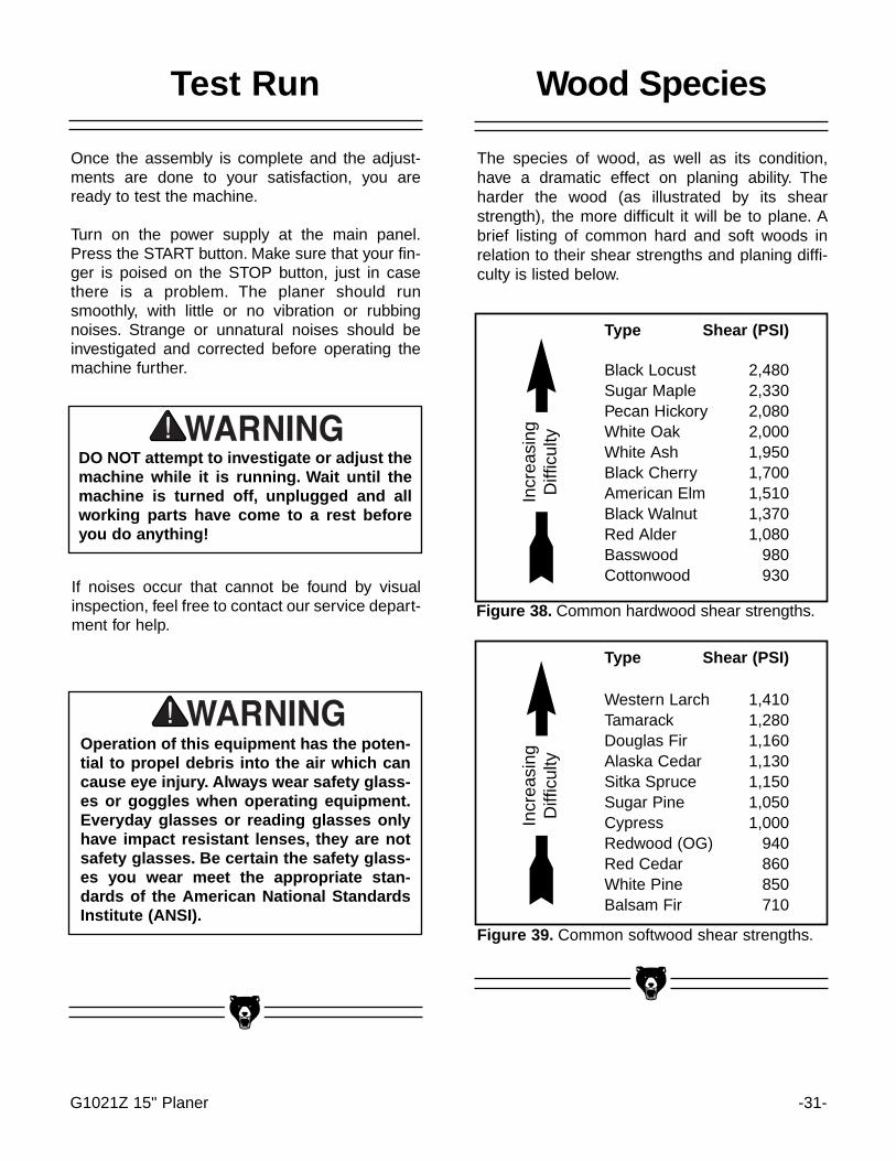
The species of wood, as well as its condition,have a dramatic effect on planing ability. Theharder the wood (as illustrated by its shearstrength), the more difficult it will be to plane. Abrief listing of common hard and soft woods inrelation to their shear strengths and planing diffi-culty is listed below.
Type Shear (PSI)
Black Locust 2,480Sugar Maple 2,330Pecan Hickory 2,080White Oak 2,000White Ash 1,950Black Cherry 1,700American Elm 1,510Black Walnut 1,370Red Alder 1,080Basswood 980Cottonwood 930
Incr
easi
ngD
iffic
ulty
Figure 38. Common hardwood shear strengths.
Type Shear (PSI)
Western Larch 1,410Tamarack 1,280Douglas Fir 1,160Alaska Cedar 1,130Sitka Spruce 1,150Sugar Pine 1,050Cypress 1,000Redwood (OG) 940Red Cedar 860White Pine 850Balsam Fir 710
Incr
easi
ngD
iffic
ulty
Figure 39. Common softwood shear strengths.
Wood Species
Operation of this equipment has the poten-tial to propel debris into the air which cancause eye injury. Always wear safety glass-es or goggles when operating equipment.Everyday glasses or reading glasses onlyhave impact resistant lenses, they are notsafety glasses. Be certain the safety glass-es you wear meet the appropriate stan-dards of the American National StandardsInstitute (ANSI).

-32- G1021Z 15" Planer
Wood Characteristics
The species of wood, as well as condition, willaffect planing ability. The harder the wood, themore difficult it will be to plane. We’ve includedbelow, a list of wood characteristics you mayencounter when planing. The following descrip-tions of defects will give you some possibleanswers to problems you may encounter whileplaning different materials. Possible solutions fol-low the descriptions.
Chipped Grain - usually a result of cuttingagainst the grain, or planing wood with knots orexcessive amount of cross grain. Chipped graincan also be caused by dull knives or misalignedchipbreaker. Often, chipped grain can be avoidedby slowing down the feed rate and by taking shal-low cuts. If those options do not work, inspectyour lumber and determine if its grain pattern iscausing the problem. If the wood does not showsubstantial crossgrain, inspect your knives forsharpness and inspect the chipbreaker for properalignment. See the Adjustment Section.
Fuzzy Grain - Usually caused by surfacing lum-ber with too high a moisture content. Sometimesfuzzy grain is a characteristic of some woods,such as basswood. Fuzzy grain can also becaused by dull knives or an incorrect grindingbevel. Check with a moisture meter. If moisture isgreater than 20%, sticker the wood and allow todry. Otherwise, inspect knife condition.
Glossy Surface - Usually caused by dull knivestaking shallow cuts at a slow feed speed. Surfacegloss will usually be accompanied by overheat-ing. Often, lumber will be scorched and eventual-ly, damage to knives will occur. If knives are sharpon inspection, increase feed speed and/or cuttingdepth.
Snipe - Occurs when board ends have morematerial removed than the rest of the board.Usually caused when one or both of the bedrollers are set too high. Can also be caused bythe chipbreaker or pressure bar being set toohigh. However, small amount of snipe isinevitable.
Snipe can be minimized by proper adjustment ofthe planer’s components, but complete removalof snipe is extremely unlikely. More likely, you willbe able to reduce it to a tolerance of .002". Ifsnipe under that level is a problem, consider plan-ing lumber longer than your intended work lengthand cut off the excess after planing is completed.
Uneven Knife Marks - Uneven knife marks canoccur when the chipbreaker is set too high.Inspect cutterhead bearings if re-adjustment ofthe chipbreaker fails to remedy the situation.
Chatter Marks - Usually caused by incorrectchipbreaker and pressure bar setting heights.Chatter marks can also be caused by running anarrow wood piece through the planer at eitherthe right or left end of the cutterhead. Chatter, likeuneven knife marks, will show in the form of a''washboard'' look. Chatter marks are more likelyto be inconsistent in appearance than unevenknife marks.
Wavy Surface - Caused by poor knife heightadjustment, wavy surface appears when oneknife is taking deeper cuts than the rest of theknives. Remedy by re-setting the knives to a tol-erance of ± .003".
Pitch & Glue Build-up - Glue and resin build-upon the rollers and cutterhead will cause over-heating by decreasing cutting sharpness whileincreasing drag in the feed mechanism. Theresult can include scorched lumber as well asuneven knife marks and chatter.
Chip Marks - Occur when chips aren’t properlyexpelled from the cutterhead. The knives catchthe chips and drag them across the lumber beingplaned. Chips tend to be random and non-uni-form (as compared to chipped grain). Can becaused by exhaust blockage or too much roombetween the cutterhead and chip deflector. Usinga dust collection system in combination with theplaner can help reduce chip marks. Inspect thechip deflector and readjust (as described earlierin the text).

G1021Z 15" Planer -33-
SECTION 7: MAINTENANCE
Make a habit of inspecting your planer each timeyou use it. Check for the following conditions andrepair or replace when necessary:
1. Loose mounting bolts.
2. Worn switch.
3. Worn or damaged cords and plugs.
4. Damaged V-belts.
5. Any other condition that could hamper thesafe operation of this machine.
General Knives
The inspection and setting of the planer knives iscovered extensively in Section 5: Adjustments.
Table
The table and other non-painted surfaces on theModel G1021Z should be protected against rustand pitting. Wiping the table clean after every useensures that moisture from wood dust isn’tallowed to trap moisture against bare metal sur-faces.
Some woodworkers recommend using automo-tive paste wax on exposed steel and cast iron sur-faces. The wax provides a layer of protection, aswell as reducing friction between lumber and thetable, making cuts faster and smoother. Avoidwaxes that contain silicone or other syntheticingredients. These materials can find their wayinto lumber that’s being worked, and can makestaining and finishing difficult. If you use pastewax, make sure that it’s 100% Carnauba wax.

-34- G1021Z 15" Planer
Lubrication
The Model G1021Z features factory-sealed bear-ings. A sealed bearing requires no lubricationduring its lifetime. Should a bearing fail, yourplaner will probably develop a noticeable rumble,which will increase when the machine is putunder load. If allowed to get worse, overheating ofthe journal containing the bad bearing couldoccur. If the bad bearing is not replaced, it willeventually seize - possibly doing damage to otherparts of the machine. Bearings are standard sizesand can be replaced through Grizzly.
Proper lubrication of other components of theModel G1021Z are essential for long life and trou-ble-free operation. Below is a list of componentsthat require periodic lubrication. Schedules arebased on daily use. Adjust accordingly for yourlevel of use.
Columns/Lead Screws - The four columnsshould be lubricated weekly with light oil.Unfasten dust covers to gain access. The fourlead screws should be lubricated with generalpurpose grease once a month.
Worm Gear - The worn gear should be inspectedmonthly and lubricated when needed. Removethe worm gear box to inspect. See parts diagramfor location.
Chain - The table height adjustment chain shouldbe inspected monthly and lubricated when need-ed. A good quality bicycle chain lubricant workswell for periodic lubrication.
Gear Box - Gear box oil should be drained afterthe first 20 hours of operation. See Figure 40.Replace with 80W-90 gear oil. Inspect levels peri-odically and change yearly. Replace gear oil morefrequently under heavy use. Fill until oil reachesthe top of the filler plug port for correct oil level.
Drive Chain - The drive chain should be inspect-ed and lubricated monthly. Check sprocket, chainand cotter pin during inspection. Use a generalpurpose grease. Some chains will have masterlinks instead of cotter pins.
Feed Rollers - The infeed/outfeed pressuresetscrews double as lubrication ports for therollers. See Figure 41. Add 1-2 drops of lightmachine oil to all ports before each use. Dailylubrication of feed rollers is crucial to the opera-tion of your planer. Lubricate before start-up.Apply a light oil, making sure that the lubricantpenetrates the bearing.
Figure 40. Gearbox fill and drain points.
Figure 41. Feed roller lubrication points.
Fill
Drain

G1021Z 15" Planer -35-
Clean and lubricate the chain sprockets as need-ed. The gearbox oil should be checked before thefirst use. It is full when oil begins dribbling out ofthe fill hole. Oil should be replaced yearly. Use80W-90 gear oil in normal situations. Use 50Wmotor oil for unheated, winter shops. SeeAdjustment Section.
The lead screws and columns should be wiped ofany grease and dust build up once a week. Theyshould be relubricated with light machine oil. SeeFigure 42.
Figure 42. Lead Screw inside of column.
Lead Screw
Column
Notes
-36- G1021Z 15" Planer
The following pages contain parts diagrams, partslists, general machine data and warranty/returninformation for your Model G1021Z Planer.
If you need parts or help in assembling yourmachine, or if you need operational information,we encourage you to call the Grizzly IndustrialService Department. Our trained service techni-cians will be glad to help you.
If you have comments dealing specifically withthis manual, please write to our Bellingham,Washington location using the address in theIntroduction. The specifications, drawings, andphotographs illustrated in this manual representthe Model G1021Z as supplied when the manualwas prepared. However, due to Grizzly’s policy ofcontinuous improvement, changes may be madeat any time with no obligation on the part ofGrizzly. Whenever possible, though, we sendmanual updates to all owners of a particular toolor machine. Should you receive one, add the newinformation to this manual and keep it for refer-ence.
We have included some important safety mea-sures that are essential to this machine’s opera-tion. While most safety measures are generallyuniversal, Grizzly reminds you that each work-shop is different and safety rules should be con-sidered as they apply to your specific situation.
We recommend you keep a copy of our currentcatalog for complete information regardingGrizzly's warranty and return policy. If you needadditional technical information relating to thismachine, or if you need general assistance orreplacement parts, please contact the ServiceDepartment listed in Section 3: GENERALINFORMATION.
Additional information sources are necessary torealize the full potential of this machine. Tradejournals, woodworking magazines, and your locallibrary are good places to start.
SECTION 8: CLOSURE
The Model G1021Z was specificallydesigned for wood cutting operations. DONOT MODIFY AND/OR USE THIS PLANERFOR ANY OTHER PURPOSE. Modificationsor improper use of this tool will void thewarranty. If you are confused about anyaspect of this machine, DO NOT use it untilyou have answered all your questions.Serious injury may occur.
Like all power tools, there is danger associ-ated with the Model G1021Z 15" Planer. Usethe tool with respect and caution to lessenthe possibility of mechanical damage oroperator injury. If normal safety precautionsare overlooked or ignored. Serious injurymay occur.
Always wear ANSI-approved safety glassesor goggles and hearing protection whenoperating equipment — particularly whentesting new tools or machinery. Do not allowvisitors into your workshop when testing oroperating equipment. Serious injury mayoccur.

G1021Z 15" Planer -37-
This section covers the most common processing problems encountered in planing and what to do aboutthem. Do not make any adjustments until planer is unplugged and moving parts have come to a completestop. See the section on Wood Characteristics for additional troubleshooting information.
TROUBLESHOOTING
SYMPTOM
Motor will not start.
Motor will not start; fuses orcircuit breakers blow.
Motor overheats.
Motor stalls (resulting inblown fuses or tripped cir-cuit).
Machine slows when oper-ating.
Loud, repetitious noise com-ing from machine
Machine is loud when cut-ting. Overheats or bogsdown in the cut.
Infeed roller marks are lefton the workpiece.
Outfeed roller marks are lefton right side of workpiece.
Cannot control snipe.
Chip buildup on outfeedroller.
Machine howls on startup.
Table moves down whilecutting.
POSSIBLE CAUSE
1. Low voltage.2. Open circuit in motor or loose
connections.
1. Short circuit in line cord or plug.2. Short circuit in motor or loose
connections.3. Incorrect fuses or circuit break-
ers in power line.
1. Motor overloaded.2. Air circulation through the motor
restricted.
1. Short circuit in motor or looseconnections.
2. Low voltage.3. Incorrect fuses or circuit break-
ers in power line.4. Motor overloaded.
1. Feed rate too high.2. Depth of cut too great.
1. Pulley setscrews or keys aremissing or loose.
2. Motor fan is hitting the cover.3. V-belt is defective
1. Excessive depth of cut.2. Knives are dull
Depth of cut too shallow.
Too much spring tension on feedroller.
Long or heavy board sags as itenters and exits.
Chips working their way backunder the chip deflector.
Chip deflector too close to thecutterhead.
Knives dull
CORRECTIVE ACTION
1. Check power line for proper voltage.2. Inspect all lead connections on motor for loose or open connec-
tions.
1. Inspect cord or plug for damaged insulation and shorted wires.2. Inspect all connections on motor for loose or shorted terminals or
worn insulation.3. Install correct fuses or circuit breakers.
1. Reduce load on motor.2. Clean out motor to provide normal air circulation.
1. Inspect connections on motor for loose or shorted terminals orworn insulation.
2 Correct the low voltage conditions.3. Install correct fuses or circuit breakers.
4. Reduce load on motor.
1. Feed workpiece slower.2. Reduce depth of cut.
1. Inspect keys and setscrews. Replace or tighten if necessary.2. Tighten fan or shim cover.3. Replace V-belt. See Maintenance.
1. Decrease depth of cut.2. Sharpen knives.
Increase depth of cut.
Refer to Feed Roller Pressure section for adjustment.
Lift up on unsupported end of board as it enters and exits cutter-head.
Lay duct tape over the mounting bolts along the outside edge toseal any possible gaps.
Move chip deflector back 1/8" to 1/4" from the cutterhead.
Replace knives.

-38- G1021Z 15" Planer

G1021Z 15" Planer -39-
Grizzly Industrial, Inc. warrants every product it sells for a period of 1 year to the original purchaser fromthe date of purchase. This warranty does not apply to defects due directly or indirectly to misuse, abuse,negligence, accidents, repairs or alterations or lack of maintenance. This is Grizzly’s sole written warrantyand any and all warranties that may be implied by law, including any merchantability or fitness, for any par-ticular purpose, are hereby limited to the duration of this written warranty. We do not warrant or representthat the merchandise complies with the provisions of any law or acts unless the manufacturer so warrants.In no event shall Grizzly’s liability under this warranty exceed the purchase price paid for the product andany legal actions brought against Grizzly shall be tried in the State of Washington, County of Whatcom.
We shall in no event be liable for death, injuries to persons or property or for incidental, contingent, special,or consequential damages arising from the use of our products.
To take advantage of this warranty, contact us by mail or phone and give us all the details. We will then issueyou a “Return Number’’, which must be clearly posted on the outside as well as the inside of the carton. Wewill not accept any item back without this number. Proof of purchase must accompany the merchandise.
The manufacturers reserve the right to change specifications at any time because they constantly strive toachieve better quality equipment. We make every effort to ensure that our products meet high quality anddurability standards and we hope you never need to use this warranty.
Please feel free to write or call us if you have any questions about the machine or the manual.
Thank you again for your business and continued support. We hope to serve you again soon.
WARRANTY AND RETURNS
Related Documents