15 MW CAES Plant with Above Ground Storage – Distributed Generation 15 MW CAES Plant with Above Ground Storage – Distributed Generation based on based on Novel Concepts Developed by ESPC Novel Concepts Developed by ESPC Project Sponsored by Project Sponsored by EPRI EPRI Presented by Presented by Dr. Michael Nakhamkin, Dr. Michael Nakhamkin, Energy Storage and Power Corporation Energy Storage and Power Corporation

Welcome message from author
This document is posted to help you gain knowledge. Please leave a comment to let me know what you think about it! Share it to your friends and learn new things together.
Transcript

15 MW CAES Plant with Above Ground Storage – Distributed Generation15 MW CAES Plant with Above Ground Storage – Distributed Generationbased on based on
Novel Concepts Developed by ESPCNovel Concepts Developed by ESPC
Project Sponsored by Project Sponsored by EPRIEPRI
Presented by Presented by
Dr. Michael Nakhamkin, Dr. Michael Nakhamkin, Energy Storage and Power CorporationEnergy Storage and Power Corporation
Presentation
• The 110 MW CAES Project for Alabama Electric Cooperative:
– Concept, Design, Engineering, Operations– Lessons learned
• 15 MW CAES Plant with Above ground Storage:– Heat and Mass Balances– P&IDs– Lay Out drawings– Capital Cost Estimate– Summary

The CAES TechnologyThe 110 MW CAES Project
Alabama Electric Cooperative

Gross Power = 191 MWHeat Rate = 9,350 Btu/kWh
General Electric 7FA CT Performance at Different Ambient Temperatures at Sea Level
GCFuelAmbient
Air
T 0
T 2562
T 1079M 1083
P 250
195 MW
T 713
M 1060
0 F
390 MW Ambient Temperature
Gross Power = 150 MWHeat Rate = 9,760 Btu/kWh
GCFuelAmbient
Air
T 95
T 2562
T 1141M 935
P 214
171.1 MW
T 812
M 898
95 F
324.6 MW Ambient Temperature
Gross Power = 172 MWHeat Rate = 9,360 Btu/kWh
GCFuelAmbient
Air
T 59
T 2562
T 1116M 984
P 228
173.4 MW
T 749
M 963
59 F - ISO
348.7 MW Ambient Temperature

Simplified Schematic of CAES Plant
Stores Wind Energy in the Form of Compressed Air
Compressors Power Generating Expanders
Recuperator
Combustors
Off-Peak Wind/Renewable Energy
Motor Generator
Peak Power Energy
Underground Storage
CAES Technology Features
CAES technology was developed as a load management plant with the prime purposes:• To store the off-peak energy that is not needed and inexpensive
and to increase load factor of base-load plants (Coal, Nuclear)• To release this energy during peak hours when energy is needed and the price is high
• The AEC’s 110MW CAES Project had been driven by two factors:– Due to very low off peak loads, two 300 MW coal-fired plants during off-peak hours
operated at very low loads with extremely high heat rates and sometimes had been shot down
– AEC had shortage of peak power
• Project met all performance guarantees, costs and schedule and in successful operation for over 17 years.
• Q: Why there were no other up w. CAES Plants built?• A: New Technology and No big motivations then cost of NG was then $2/M BTU and Coal
$1.5/M Btu
• The current development of Wind Power- the primarily uncontrollable energy source- requires the CAES plants to store wind energy produced during off-peak hours and distribute it with additional benefits during peak hours when energy is needed and cost of energy is high
• Now NG Cost is $10/M Btu and possibly will go up.

Alabama Compressed Air Energy Storage PlantPeak Power 110 MW; 26 hrs of continuous Power Generation;
Heat rate is 4000 Btu/kWh; Off-Peak Power 51MW, Capital Cost $600/kW
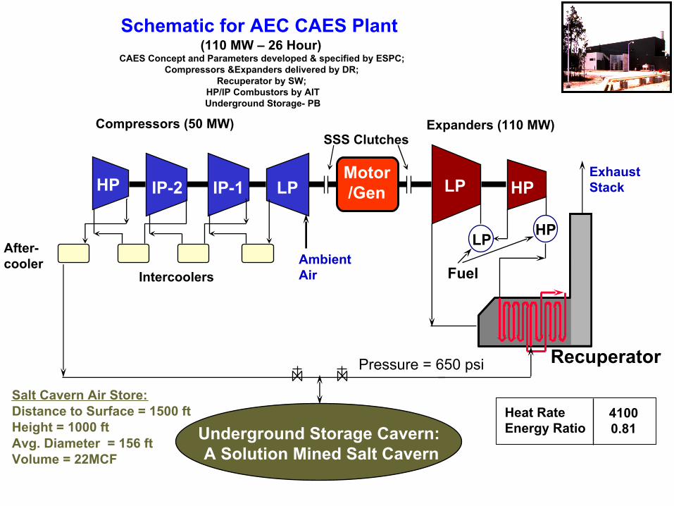
Schematic for AEC CAES Plant (110 MW – 26 Hour)
CAES Concept and Parameters developed & specified by ESPC; Compressors &Expanders delivered by DR;
Recuperator by SW; HP/lP Combustors by AITUnderground Storage- PB
FuelAfter-cooler
Compressors (50 MW)
LP HP
Expanders (110 MW)
HP IP-2 IP-1 LP LP HP
Intercoolers
SSS Clutches
Ambient Air
Underground Storage Cavern: A Solution Mined Salt Cavern
Motor/Gen
Recuperator
Heat RateEnergy Ratio
41000.81
Exhaust Stack
Salt Cavern Air Store:Distance to Surface = 1500 ftHeight = 1000 ftAvg. Diameter = 156 ftVolume = 22MCF
Pressure = 650 psi
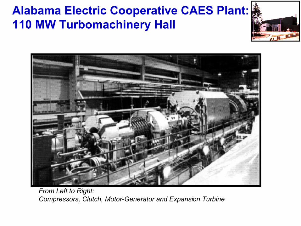
Alabama Electric Cooperative CAES Plant: 110 MW Turbomachinery Hall
From Left to Right: Compressors, Clutch, Motor-Generator and Expansion Turbine

The 110 MW CAES Plant Engineering, Optimization and Delivery
ESPC developed, optimized and specified the 110 MW CAES plant concept based on available and/or newly developed components provided by various suppliers:
The reheat, intercooled and recuperated turbomachinery is based on:• Compressors and expanders provided by Dresser Rand• HP and LP combustors provided by AIT • Advanced Recuperator provided by Struthers Well (patented by ESPC)• Underground Storage by Parsons Brinkerhoff• Control philosophy for operation and Safety
ESPC was conducting technical supervision of the project execution including:• Supervision of the turbomachinery development by Dresser Rand• Supervision of the HP combustors development by AIT• Development of the test procedures• Supervised performance guarantee tests and issued the Test Report• Under contract with EPRI, ESPC recorded key plant parameters during 1991-1994 -three
years after the project commercialization, and issued “ Value Engineering” Report

EPRI was Co-sponsor of the CAES Project Concentrating on R&D Issues:Turbomachinery, Advanced Recuperator, Project Technical Supervision, the LP Expander TIT Increase
Ground Breaking Ceremony ESPC Received EPRI’s Dr. R. Schainker, EPRI Achievement Award Ray Claussen, AEC, VP Operations, PlanningDr. M. Nakhamkin, ESPC

Unique Features and Components of the AEC’s Turbomachinery/Plant
The multi-component single-shaft turbomachinery train has the first of the kind unique features and unique components- all optimized and developed during the project execution:• Reheat expander train with HP/LP combustors• Intercooled Compressor train• Advanced Recuperator• Turbo expander and compressor trains are integrated with the underground storage• Control Philosophy- Power Control by both HP/LP fuel and air flows
First of the kind Components with only single applications:
Dresser Rand:– HP steam turbine converted into the expander and integrated with the HP combustors– The industrial expander with increased TIT from 1350F to 1500 F that required the first
time applied by DR nozzles cooling• AIT:
– Developed unique HP combustor (800 p.s.i.a and 1000F) uniquely operating at variable airflow– Newly developed LP combustor (200 p.s.i.a 1600F) uniquely operating at variable airflow
• Struthers Wells:– Advanced Recuperator

Lessons LearnedSummarized in the published by EPRI’s “Value Engineering” report (produced by ESPC)
The 110 ME CAES project (with first of the kind unique features and unique components)- is unquestionably successful- It met all performance guarantees, schedule and budget.
There are lessons learned:
The single-shaft turbomachinery train with multiple (9) components has some operationaland maintenance complicationsConclusions: the separate components approach would provide operational and maintenanceadvantages
First of the kind components specifically developed for the CAES turbomachinery had a very limited power generation experience and had no operational and maintenance manuals for
Conclusions: use of off-shelf /standard components will resolve this issues.
The novel HP/LP combustors:• Had no operational and maintenance manuals based on experience • The HP combustor has inherently very high NOx emissions (app. 70 p.p.m.v.)• The LP combustor is customized for this train and has higher than CTs NOx emissions Conclusions: • Novel HP/LP combustors should be avoided• It is better to burn fuel in DLN combustors developed by OEMs
Single compressor train has limitation on use of available off-peak powerConclusions: Multiple compressors provide operational and maintenance advantages

15 MW CAES Plant with Above Ground Storagebased on Novel CAES Plant Concepts
Developed & Patented by ESPC
CAES Plant Power:– 30% of power generated by a Combustion Turbine–70% Green Power is generated by Air Expanders utilizing the stored (operating w/o combustors and utilizing the CT exhaust gas heat - the air bottoming cycle (similar to steam bottoming cycle for CC plants)
–The Overall heat rate is approximately 4000 Btu/kWh (vs. 10,000-11,000 by CTs)
The fuel is burned only in CT’s combustors (there is no additional fuel burners/combustors)
The storage is pressurized by multiple stand-alone off-shelf motor driven compressors
Significantly lower capital costs due to:– Use of standard components–No new components–Simple construction & tuning up
Schedule time is within two years
The storage size is significantly reduced with associated storage costs

15 MW CAES Plant with Air Injection and Bottoming Cycle Based on Taurus 60
Major components: CT, multiple Compressors; Recuperator; HP&LP Expanders
44.05 F14.7 PSIA
42 Lb/s
609.3 F101.8 F 290.5 PSIA 6.148 MW412.6 PSIA 60.04 MBTU/Hr 5 Lb/s24.59 Lb/s 0.775 Lb/s Air Injection
3.716 MW6.937 MW 900 F
90 F 173.814.7 PSIA
25 Lb/s 954 F14.7 PSIA
5.929 MW Gross GT 49 Lb/s10127 BTU/kWhr Gross LHV Heat Rate
444 F1530 PSIA 90 F24.59 Lb/s 800 PSIA
47 Lb/s 15.19 MW Net Total Power3953 BTU/kWhr Net LHV Heat Rate
Exhaust
Air
Power Production Mode
Compressed Air
Compressor
Gas Turbine
Motor
Storage
Air
IntercoolersRecuperator
Fuel HP Expander
~~
~
LP Expander

CTs Performance vs. Ambient TemperaturesGER 3567H

PG7241FA with DLN (150.4 MW @ 95°F)
Humid Air Injection:Measured:• 18.3 MW increase @ 3.5% humidity, 95°F ambientPredicted:• 26.6 MW increase @ 5.5% humidity,
NOX:
• 9 ppm with DLN combustor
• 12 ppm with steam injection and DLN
• < 9 ppm with HAI and DLN
: During testing there were no known operational limits that were exceeded. Specifically, during the testing all vibration, compressor (7241 Limits), emissions, combustion dynamics and generator temperature
limits were not exceeded…The test criteria were met ”.
Calpine Broad River ProjectWhere AI Validation Tests Conducted

CAES Plant Power consist of 5.2 MW of CT Power and 10.6 MW Green Power
0
1000
2000
3000
4000
5000
6000
7000
8000
9000
10000
11000
Pla
nt
En
erg
y B
TU
Performance of CT & CAES Plants
Energy(1.7 kW)
CT CAES CT CAES CT CAES
Total CAES Energy 3,0 kWh (10,200 Btu)
CT Energy 1kWh (3412 Btu)
CT HR 10,000 Bru/kWh
CAES HR 3700 Btu/kWh
Green CAES Energy2 kWh (6800 Btu)

1 kWh of Stored Off-peak Energy Returns 0.78 kWh of Peak Energy
-1.25
-1
-0.75
-0.5
-0.25
0
0.25
0.5
0.75
1En
ergy
Rel
ease
kW
Ener
gy P
rodu
ced
kWWin
d E
ner
gy
Effectiveness of Wind Energy
Off-peak 1 kWh
Green peak 0.78 kWh
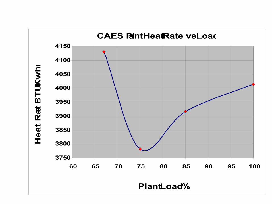
CAES Plant Heat Rate vs. Load
3750
3800
3850
3900
3950
4000
4050
4100
4150
60 65 70 75 80 85 90 95 100
Plant Load %
Hea
t R
ate B
TU
/Kw
hr

CAES Plant with Air Injection and Bottoming Cycle Based on GE 7B CT
Major components: CT, Multiple Compressors; Recuperator; HP&LP Expanders60.68 F14.7 PSIA440 Lb/s
665.5 MBTU/Hr 528 F86 F 8.591 Lb/s 206.4 PSIA 52.96 MW
14.7 PSIA 60 Lb/s497.1 Lb/s Air Injection
50.3 MW94.13 MW 900 F
86 F 222.6 F14.7 PSIA333 Lb/s
66.91 MW Gross 9945 BTU/kWhr Gross LHV HR
102 F1450 PSIA
327.9 Lb/s95 F
800 PSIA500 Lb/s
166.46 MW Net Total Power3997.8 BTU/kWhr Net LHV Heat Rate
Exhaust
Air
Power Production Mode
Compressed Air
Compressor
Gas Turbine
Motor
Storage
Air
IntercoolersRecuperator
FuelHP Expander
~~
~
LP Expander

15 MW CAES Plant with Bottoming Cycle and Inlet Chilling
Based on Taurus 60
Major Components: CT; Multiple Compressors; Expander; Recuperator; Compressed Air Storage
44.7 F14.7 PSIA
47 Lb/s
9.008 MW44.7 F14.7 PSIA 63.47 MMBTU/hr LHV
47 Lb/s 0.819 lb/s Fuel6.937 MW 800 F
90 F 268.9 F14.7 PSIA
25 Lb/s 960.7 F14.7 PSIA
5.814 GT Generator MW 48.49 Lb/s10916.9 Gross LHV BTU/kWhr
102 F1500 PSIA 90 F
24.56 Lb/s 800 PSIA47 Lb/s 14.52 MW Net Total Power
4373 BTU/kWhr Net LHV Heat Rate
Solar Torus 60 CAES, Expander & GT Inlet Air Cooling
Exhaust
GT Air
Power Production Mode
Compressed Air
Compressor
Gas Turbine
Motor
Storage
Air
IntercoolersRecuperator
Fuel
Expander
~~
~

CAES Plant with Bottoming Cycle and Inlet Chilling Based on GE 7B CT
Major components: CT, Multiple Compressors; Recuperator; Expanders;
Compressed Air Storage44.87F14.7PSIA535Lb/s
44.87F14.7PSIA 683.2MMBTU/hr LHV 111.5MW535Lb/s 8.82lb/s Fuel
96.54MW 850.6F
86 F 200F14.7PSIA356Lb/s
62.86Gross MW 10870Gross LHV BTU/kWhr
102F1450PSIA350.5Lb/s
95 F950PSIA535Lb/s
172.9MW Net Total Power3951BTU/kWhr Net LHV Heat Rate
Exhaust
GT Air
Power Production Mode
Compressed Air
Compressor
Gas Turbine
Motor
Storage
Air
IntercoolersRecuperator
FuelExpander
~~
~44.87F14.7PSIA535Lb/s
44.87F14.7PSIA 683.2MMBTU/hr LHV 111.5MW535Lb/s 8.82lb/s Fuel
96.54MW 850.6F
86 F 200F14.7PSIA356Lb/s
62.86Gross MW 10870Gross LHV BTU/kWhr
102F1450PSIA350.5Lb/s
95 F950PSIA535Lb/s
172.9MW Net Total Power3951BTU/kWhr Net LHV Heat Rate
Exhaust
GT Air
Power Production Mode
Compressed Air
Compressor
Gas Turbine
Motor
Storage
Air
IntercoolersRecuperator
FuelExpander
~~
~
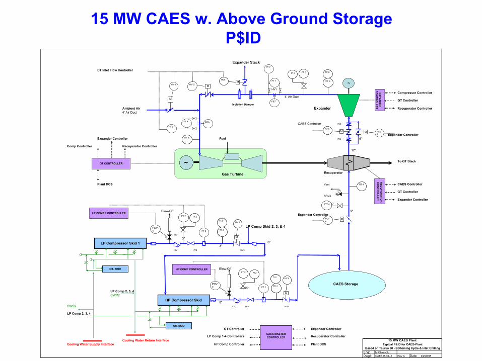
15 MW CAES w. Above Ground Storage P$ID
Expander Stack
CT Inlet Flow Controller
HV1Compressor Controller
4' Air DuctGT Controller
Isolation DamperAmbient Air Expander Recuperator Controller4' Air Duct
CAES Controller HV6
Expander ControllerExpander Controller Fuel HV6 6"
Comp Controller Recuperator Controller12"
To GT Stack
Recuperator
Plant DCS Vent CAES Controller
GT ControllerSRV4
Expander ControllerSRV7
Blow-Off 9"Expander Controller
LP Comp Skid 2, 3, & 4
HV1
3"6"
3"CV1 HV2 HV3
Blow-Off
HV1
LP Comp 2, 3, 4CWR2
8"CWS2 CV2 HV4 HV5
LP Comp 2, 3, 4
GT Controller Expander Controller
LP Comp 1-4 Controllers Recuperator ControllerCooling Water Return Interface
Cooling Water Supply Interface HP Comp Controller Plant DCS
Eng:Dwg#: Rev A Date: 04/20/08
M Chiruvolu
15 MW CAES PlantTypical P&ID for CAES-Plant
Based on Taurus 60 - Bottoming Cycle & Inlet Chilling
CAES15-CL-1
LP Compressor Skid 1
OIL SKID
PIT 4
CAES MASTERCONTROLLER
FE7
PT 7
FT 7 ~MHV12
TIT 4
TIT 9
MPCV 4
TIT 6
TC 6 PT 6 PI 6
EXPAN
DER
C
ON
TRO
LLER R
ECU
PERA
TOR
C
ON
TRO
LLER
LP COMP 1 CONTROLLER
M
HV 3
TE 2
TI 2
TE 2
TI 2
PCV1 FT 2
PT 2 PI 2
Gas Turbine
~
M
HV 9
GT CONTROLLER
MFV 5
FE9
PT 9
FT 9
MHV8
M HCV 5
CAES Storage
HP Compressor Skid
OIL SKID
HP COMP CONTROLLER
M
HV 5
TE 2
TI 2
TE 2
TI 2
PCV2 FT 2
PT 2 PI 2
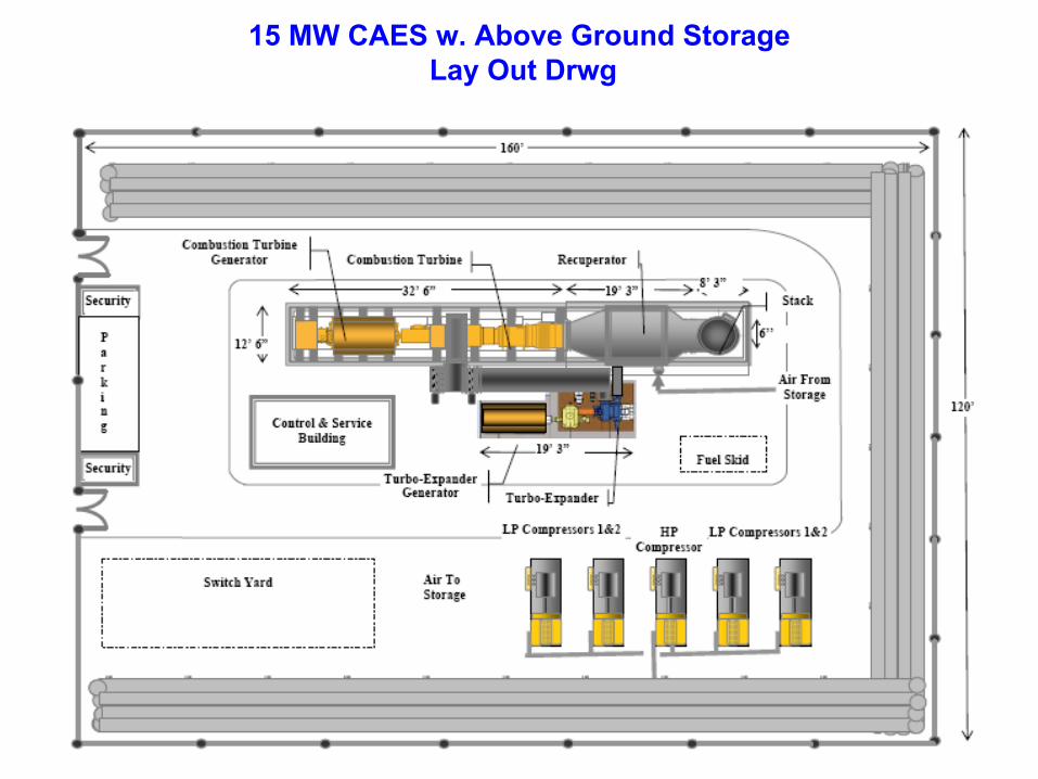
15 MW CAES w. Above Ground Storage Lay Out Drwg

Summary Table of Performance Estimates(w/o specific optimization)
Description of Item Air Injection Inlet Cooling
Civil/Architecture Site, Clearing & Grubbing 60,000 60,000
Fence 440 LF w/2gates 6,600 6,600 Slab on Grade w/ 2' Haunches 80,750 80,750
Compressor Slabs (X4) 9,500 9,500 Control & Service Building 360,000 360,000
Sub-total 516,850 516,850 Equipment Costs
Combustion Turbine 2,600,000 2,600,000 LP Air Compressor 1,400,000 1,400,000
HP Compressor 450,000 450,000 Heat Exchangers 950,000 950,000
HP Expander 484,000 1,000,000 LP Expander 727,000 -
Compressed air Storage 5,200,000 5,200,000 Sub-total 11,811,000 11,600,000
Mechanical (installation)
Combustion Turbine 750,000 750,000 LP Air Compressor 150,000 150,000
HP Compressor 50,000 50,000 Heat Exchangers 225,000 225,000
HP Expander 125,000 300,000 LP Expander 250,000 - 8" Steel Pipe 30,000 30,000
Sub-total 1,580,000 1,505,000 Electrical and Controls
Misc. Electrical 100,000 100,000 Field Mounted Instruments 150,000 150,000
Sub-total 250,000 250,000 Indirect Costs
Engineering and Management 1,200,000 1,200,000 Start Up & Commissioning 100,000 100,000
Contingency 750,000 750,000 Construction Overhead etc. 750,000 750,000
EPC Contractor Profit 1,500,000 1,500,000 Licensing Fee 125,000 125,000
Sub-total 4,425,000 4,425,000
Total Capital Cost 18,583,000 $18,297,000

Major performance characteristics of the 15 MW CAES/AI/ Expander concept can be summarized as follows:
• The total CAES plant power is 15.2 MW and includes the power of the Taurus 60 combustion turbine (augmented by the injected stored air) plus the additional power produced by HP and LP expanders utilizing the preheated stored air. The heat rate is 3960 Btu/kWh.
• The CAES plant has two major power generation components:– The Taurus CT generating of approximately 5.2 MW (at 90F ambient temperature) with heat
rate of approximately 12,000 Btu/kWh and – The green (w/o fuel consumption) CAES power is the 10.6 MW that is the sum of
approximately 9.9 MW, generated by HP and LP expanders plus the CT power augmentation by approximately 0.72 MW due to air injection.
• The off-peak energy storage:– The stored off-peak energy of 13.8MWh results in total generation of 15.2 MWh of peak energy,
i.e. energy ratio is approximately 0.91 – The stored off-peak energy of 13.8MWh results in generation of 10.6 MWh of green peak
energy, i.e. energy ratio is approximately1.3 or 1 kWh of the stored off peak energy generates 0.77 kWh of peak energy w/o using fuel.
• Above ground energy storage is sized for two hours of the continuous peak power generation:– Total energy generated is 30.4 MWh– Total energy stored 27.6 MWh
• Specific costs for this concept are $1200-1300/kW

Comparative Analysis of Generation Costsfor
Coal. CT, CC and CAES plants
Peaking Power Generation Options Comparison Fuel Price @ $10 per MM BTU Gas (Coal $2)
25
50
75
100
125
150
175
200
225
250
275
300
325
350
375
400
425
0 10 20 30 40 50 60
Capacity Factor (%)
Coal CT CTCC CAES 15MW

ESPC with its subcontractors is delivering CAES projects on EPC basis.Estimated specific costs of the overall project including underground storage is approximately $550-600/kW. Delivery time is approximately 24 months, primarily controlled by a combustion
turbine deliveryThese concepts are based on various combinations of the major standard /off – shelf components-existing or new combustion turbines, air compressors, air expanders and heat recovery recuperator –all integrated with a compressed air storage and engineered for specific operational,economic and geological conditions.
As it relates to the selection of a combustion turbine, customers have a choice of selection a combustion turbine based on their preferences and ESPC will design/engineer the CAES plantbased on the selected combustion turbine. These h&m balances are based on GE7FA, GE 7EAand GE 7B CTs for 400 MW, 300 MW and 150 CAES plants respectively
Suppliers of Off-Combustion Turbine standard components include but not limited to:Air Compressors: MAN Turbo, Dresser-Rand, and Ingersoll-RandTurbo-Expanders: Major OEM’s with IP back pressure steam turbine technology; MAN Turbo,
Skoda, Atlas Copco, and HitachiRecuperator: RGP Engineering, Nooter/Eriksen, Deltech, and BHEL
ESPC has a number of qualified EPC contractors for delivery of CAES projects with typicalwarranties and guaranties and with typical commercial terms.

Technology Offerings• ESPC offers the Power Augmentation - AI and CAES
technology for licensing.
• ESPC delivers the AI and CAES projects on turn-key basis with typical performance guarantees
• ESPC is flexible to cooperate with Customers in delivery the AI and CAES projects.
• Discussion of program
Business contacts- Dr. Michael Nakhamkin [[email protected]]
Related Documents