MAHARASHTRA STATE BOARD OF TECHNICAL EDUCATION (Autonomous) (ISO/IEC - 27001 - 2005 Certified) WINTER – 15 EXAMINATION Subject Code : 17528 Model Answer ___________________________________________________________________________________________ Page 1 of 28 Important Instructions to examiners: 1) The answers should be examined by key words and not as word-to-word as given in the model answer scheme. 2) The model answer and the answer written by candidate may vary but the examiner may try to assess the understanding level of the candidate. 3) The language errors such as grammatical, spelling errors should not be given more Importance (Not applicable for subject English and Communication Skills. 4) While assessing figures, examiner may give credit for principal components indicated in the figure. The figures drawn by candidate and model answer may vary. The examiner may give credit for any equivalent figure drawn. 5) Credits may be given step wise for numerical problems. In some cases, the assumed constant values may vary and there may be some difference in the candidate’s answers and model answer. 6) In case of some questions credit may be given by judgement on part of examiner of relevant answer based on candidate’s understanding. 7) For programming language papers, credit may be given to any other program based on equivalent concept. Q.No/Beat Model answer/marking Scheme/Key words Mark s 01 (a) Threshold: It is particular case of resolution. It is defined as the minimum value of input below which no output can be detected. Resolution: It is defined as the smallest increment in the measured value that can be detected with certainty by the instrument. 01 01 (b) OVERSHOOT: The overshoot is defined as the maximum amount by which the pointer moves beyond the steady state. Because of mass and inertia, a moving parts, i.e. the pointer of the instrument does not immediately comes to rest in the final deflection position. The pointer goes beyond the steady state i.e. it overshoots. 02 (c) RANGE: It can be defined as the measure of the instrument between the lowest and highest readings it can measure. Ex: A thermometer has a scale from −40°C to 100°C. Thus the range varies from −40°C to 100°C. SPAN: 01

Welcome message from author
This document is posted to help you gain knowledge. Please leave a comment to let me know what you think about it! Share it to your friends and learn new things together.
Transcript
MAHARASHTRA STATE BOARD OF TECHNICAL EDUCATION (Autonomous)
(ISO/IEC - 27001 - 2005 Certified) WINTER – 15 EXAMINATION
Subject Code : 17528 Model Answer ___________________________________________________________________________________________
Page 1 of 28
Important Instructions to examiners: 1) The answers should be examined by key words and not as word-to-word as given in the model answer scheme. 2) The model answer and the answer written by candidate may vary but the examiner may try to assess the understanding level of the candidate. 3) The language errors such as grammatical, spelling errors should not be given more Importance (Not applicable for subject English and Communication Skills. 4) While assessing figures, examiner may give credit for principal components indicated in the figure. The figures drawn by candidate and model answer may vary. The examiner may give credit for any equivalent figure drawn. 5) Credits may be given step wise for numerical problems. In some cases, the assumed constant values may vary and there may be some difference in the candidate’s answers and model answer. 6) In case of some questions credit may be given by judgement on part of examiner of relevant answer based on candidate’s understanding. 7) For programming language papers, credit may be given to any other program based on equivalent concept.
Q.No/Beat Model answer/marking Scheme/Key words Marks
01 (a) Threshold: It is particular case of resolution.
It is defined as the minimum value of input below which no output can be detected.
Resolution: It is defined as the smallest increment in the measured value that can be detected with certainty by the instrument.
01
01
(b) OVERSHOOT:
The overshoot is defined as the maximum amount by which the pointer moves beyond the steady state.
Because of mass and inertia, a moving parts, i.e. the pointer of the instrument does not immediately comes to rest in the final deflection position. The pointer goes beyond the steady state i.e. it overshoots.
02
(c) RANGE:
It can be defined as the measure of the instrument between the lowest and highest readings it can measure.
Ex: A thermometer has a scale from −40°C to 100°C. Thus the range
varies from −40°C to 100°C.
SPAN:
01
MAHARASHTRA STATE BOARD OF TECHNICAL EDUCATION (Autonomous)
(ISO/IEC - 27001 - 2005 Certified) WINTER – 15 EXAMINATION
Subject Code : 17528 Model Answer ___________________________________________________________________________________________
Page 2 of 28
It can be defined as the difference of reading from the minimum to maximum scale value.
Ex: In the case of a thermometer, its scale goes from −40°C to 100°C. Thus its span is 140°C. It is actually a deviation from true value expressed as a percentage of the span.
01
(d) Transducer: A transducer senses the desired input in one physical form and converts it to an output in another physical form.
Active transducer:are those which does not required power supply for its operation examples-Piezoelectric crystal,tachogenerator,photovoltaic cells
Passive transducer:-are those which required external supply for its operation.Examples-Strain gauge,Potentiometer,resistance thermometer etc
01
01
(e) The working principle of thermocouple depends upon the thermoelectric effect. If two dissimilar metals are joined together so as to form a closed circuit there will be two junctions where they meet each other. If one of these junctions is heated then a current flows in the circuit which can be detected by a galvanometer. The amount of current produced depends on the difference temperature between two junction and on the characteristics of two metals. This is also known as Seebeck effect.
02
(f) For measuring the temperature above 1400 degrees thermocouples, thermisters, are used. Rradiation pyrometer may be used for measurement of furnace temperature. Whereas thermisters can be used for exhaust valves temperature.
02
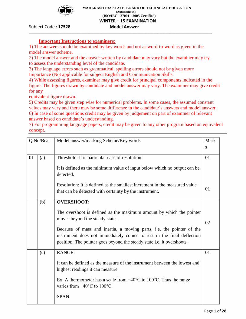
(g) Potentiometer is passive transducer since it requires external power source for its operation. It is used for linear or rotary displacement measurement. Basically a resistance potentiometer consists of resistance element providing with a sliding contact. The sliding contact is known as wiper. The motion of the sliding contact may be translatory or rotational. Some have a combination of both motions with resistive element in the form of helix so called heliport.
Note:- Application -1 mark, Principle -1 mark
02
MAHARASHTRA STATE BOARD OF TECHNICAL EDUCATION (Autonomous)
(ISO/IEC - 27001 - 2005 Certified) WINTER – 15 EXAMINATION
Subject Code : 17528 Model Answer ___________________________________________________________________________________________
Page 3 of 28
(h) Low Pressure Measurement is done using the instruments(Any four 1/2M
each)
Mcleod Gauge:-10-1 to 10-5 torr,Pirani gauge:- 10-5 to 101 torr
Ionization Gauge:-10-3to10-11torr, Bourdon Gauge:-upto 10 torr
Bellows:-upto 10-2torr(Torr OR mm of Hg)
02
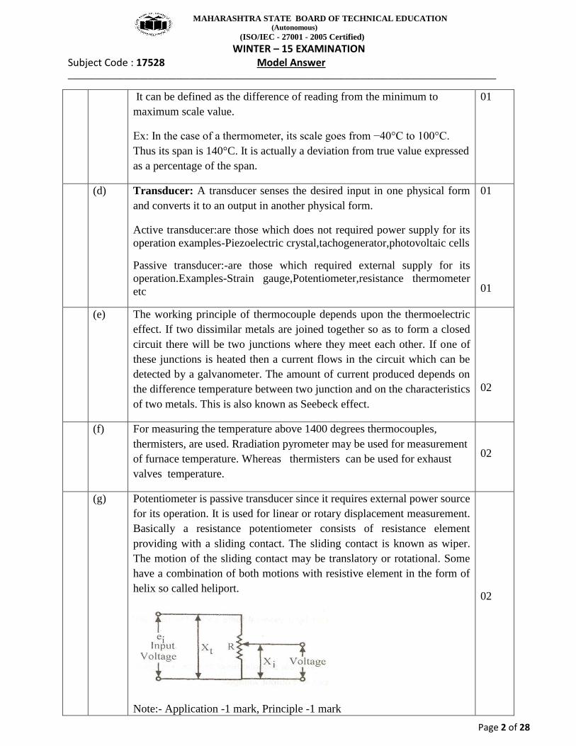
(i) Hair hygrometer is cheap pocket size instrument used for humidity measurement. Certain material such as human hair , animal membrane, wood & paper undergo changes in liner dimension when they absorb moisture from the atmosphere. Human hair become longer as the humidity of the surrounding air increases, & shortens when the air becomes dry.
Note:-Diagram preferred not essential
02
(j) The resistance of strain gauge wire is directly proportional to the mechanical stress applied on it Strain gauge is a passive ,resistive transducer which transforms mechanical elongation and compression into a resistance change .the change in resistance is due to variation in the length and cross sectional area of the gauge wire.
The characteristics of strain gauge is describe in terms of its sensitivity , which is usually called the Gauge Factor(G.F.)of the strain gauge .
Strain gauge materials
For fabrication of strain gauge we require grid material, Supporting or backing material and bonding material.
01
01
MAHARASHTRA STATE BOARD OF TECHNICAL EDUCATION (Autonomous)
(ISO/IEC - 27001 - 2005 Certified) WINTER – 15 EXAMINATION
Subject Code : 17528 Model Answer ___________________________________________________________________________________________
Page 4 of 28
1) Advance :
It is 55 % copper, 45 % nickel having gauge factor 2.
2) Isoelastic:
It is 36 % nickel, 8 % copper, 4 % Mn, Si
3) Nichrome:
It is nickel, chromium alloy having gauge factor 2.
4) Maganin :
It has 0.47 gauge factor and low temperature coefficient.
(k) Electromagnetic flow meter is a kind of induction instrument designed by Faraday’s law of electromagnetic induction to measure flow of conductive media in the tube. Electromagnetic flow meter can realize local indication and output electrical current signal of 4-20mA which can be used to record, adjust and control.
02
(l) Any four points each ½ Marks
Pneumatic control system Electronic control system
More cost than electronic controller
These controllers are cheap
Can be used from long dist
It has no fire hazards Chances of fire hazards
Large size system Handy and compact
Condensate in the instrument air causes choking action of nozzle
No such problem occurs
No shielding required Stray magnetic field affects transmitted signal therefore shielding is required
Not possible to keep actuator at long distance
Possible to keep actuator at long distance
02
MAHARASHTRA STATE BOARD OF TECHNICAL EDUCATION (Autonomous)
(ISO/IEC - 27001 - 2005 Certified) WINTER – 15 EXAMINATION
Subject Code : 17528 Model Answer ___________________________________________________________________________________________
Page 5 of 28
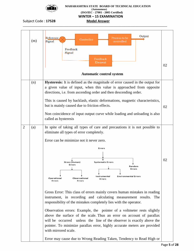
(m)
Automatic control system
02
(n) Hysteresis: It is defined as the magnitude of error caused in the output for a given value of input, when this value is approached from opposite directions, i.e. from ascending order and then descending order.
This is caused by backlash, elastic deformations, magnetic characteristics, but is mainly caused due to friction effects.
Non coincidence of input output curve while loading and unloading is also called as hysteresis
02
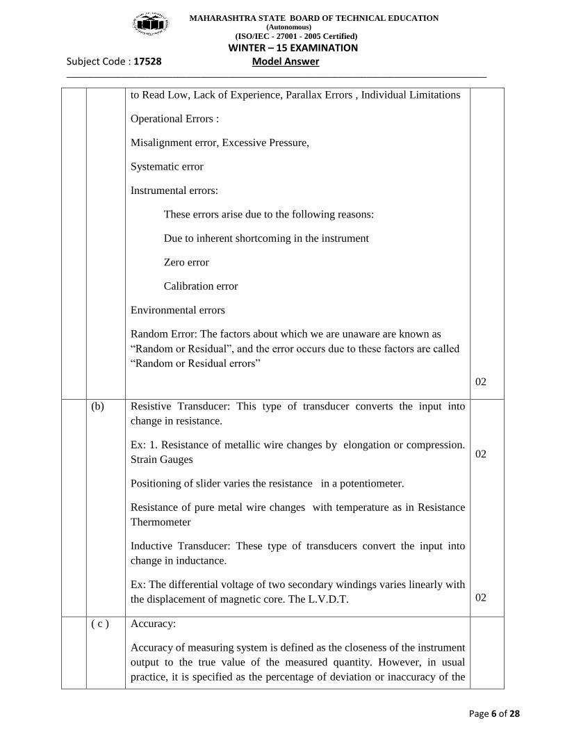
2 (a) In spite of taking all types of care and precautions it is not possible to eliminate all types of error completely.
Error can be minimize not it never zero.
Gross Error: This class of errors mainly covers human mistakes in reading instrument, in recording and calculating measurement results. The responsibility of the mistakes completely lies with the operator.
Observation errors: Example, the pointer of a voltmeter rests slightly above the surface of the scale. Thus an error on account of parallax will be occurred unless the line of the observer is exactly above the pointer. To minimize parallax error, highly accurate meters are provided with mirrored scale.
Error may cause due to Wrong Reading Taken, Tendency to Read High or
02
MAHARASHTRA STATE BOARD OF TECHNICAL EDUCATION (Autonomous)
(ISO/IEC - 27001 - 2005 Certified) WINTER – 15 EXAMINATION
Subject Code : 17528 Model Answer ___________________________________________________________________________________________
Page 6 of 28
to Read Low, Lack of Experience, Parallax Errors , Individual Limitations
Operational Errors :
Misalignment error, Excessive Pressure,
Systematic error
Instrumental errors:
These errors arise due to the following reasons:
Due to inherent shortcoming in the instrument
Zero error
Calibration error
Environmental errors
Random Error: The factors about which we are unaware are known as “Random or Residual”, and the error occurs due to these factors are called
“Random or Residual errors”
02
(b) Resistive Transducer: This type of transducer converts the input into change in resistance.
Ex: 1. Resistance of metallic wire changes by elongation or compression. Strain Gauges
Positioning of slider varies the resistance in a potentiometer.
Resistance of pure metal wire changes with temperature as in Resistance Thermometer
Inductive Transducer: These type of transducers convert the input into change in inductance.
Ex: The differential voltage of two secondary windings varies linearly with the displacement of magnetic core. The L.V.D.T.
02
02
( c ) Accuracy:
Accuracy of measuring system is defined as the closeness of the instrument output to the true value of the measured quantity. However, in usual practice, it is specified as the percentage of deviation or inaccuracy of the
MAHARASHTRA STATE BOARD OF TECHNICAL EDUCATION (Autonomous)
(ISO/IEC - 27001 - 2005 Certified) WINTER – 15 EXAMINATION
Subject Code : 17528 Model Answer ___________________________________________________________________________________________
Page 7 of 28
measurement from the true value.
Precision is defined as the ability of the instrument to reproduce a certain set of readings within a given accuracy.
For example, if a particular transducer is subjected to an accurately known input and if the repeated read outs of the instrument lie within say ±1%, then the precision or alternatively the precision error of the instrument would be sated as ±1%. Thus the highly precise instrument is one that gives the same output information when the reading is repeated a large number of times.
Precision of the instrument is in fact, dependent on the repeatability.
1)In accuracy measurements are dependent on the systematic errors,In presion it depends on random errors
2)Accuracy is determined by proper calibration,presion is determined by statistical analysis
04
( d )
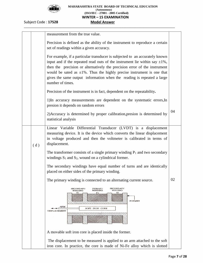
Linear Variable Differential Transducer (LVDT) is a displacement measuring device. It is the device which converts the linear displacement in voltage produced and then the voltmeter is calibrated in terms of displacement.
The transformer consists of a single primary winding P1 and two secondary windings S1 and S2, wound on a cylindrical former.
The secondary windings have equal number of turns and are identically placed on either sides of the primary winding.
The primary winding is connected to an alternating current source.
A movable soft iron core is placed inside the former.
The displacement to be measured is applied to an arm attached to the soft iron core. In practice, the core is made of Ni-Fe alloy which is slotted
02
MAHARASHTRA STATE BOARD OF TECHNICAL EDUCATION (Autonomous)
(ISO/IEC - 27001 - 2005 Certified) WINTER – 15 EXAMINATION
Subject Code : 17528 Model Answer ___________________________________________________________________________________________
Page 8 of 28
longitudinally to reduce eddy current losses.
When the core is in its normal (null) position, equal voltages are induced in the two secondary windings.
Accordingly, output voltage ES1 of the secondary winding S1 is more than ES2, the output voltage of secondary winding S2.
The magnitude of voltage is thus ES1- ES2 and the output voltage is in phase with ES1, the output voltage of secondary winding S1.
Similarly, if a core is moved to the of null position, then the flux linking with winding S2 becomes larger than that with winding S1. These results in ES2 becoming larger than Es1. The output voltage in this case is E0 = ES2- ES1 and is in phase with ES2; i.e., the output voltage of secondary winding S2.
02
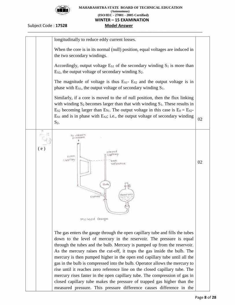
( e )
The gas enters the gauge through the open capillary tube and fills the tubes down to the level of mercury in the reservoir. The pressure is equal through the tubes and the bulb. Mercury is pumped up from the reservoir. As the mercury raises the cut-off, it traps the gas inside the bulb. The mercury is then pumped higher in the open end capillary tube until all the gas in the bulb is compressed into the bulb. Operator allows the mercury to rise until it reaches zero reference line on the closed capillary tube. The mercury rises faster in the open capillary tube. The compression of gas in closed capillary tube makes the pressure of trapped gas higher than the measured pressure. This pressure difference causes difference in the
02
MAHARASHTRA STATE BOARD OF TECHNICAL EDUCATION (Autonomous)
(ISO/IEC - 27001 - 2005 Certified) WINTER – 15 EXAMINATION
Subject Code : 17528 Model Answer ___________________________________________________________________________________________
Page 9 of 28
mercury level in the two tubes.
Mathematically pressure is calculated as P = KHHo(1 - KH)
02
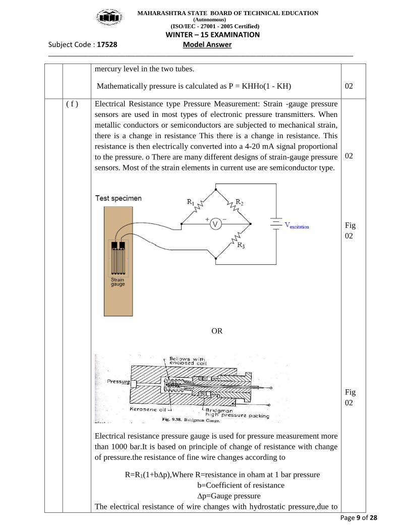
( f ) Electrical Resistance type Pressure Measurement: Strain -gauge pressure sensors are used in most types of electronic pressure transmitters. When metallic conductors or semiconductors are subjected to mechanical strain, there is a change in resistance This there is a change in resistance. This resistance is then electrically converted into a 4-20 mA signal proportional to the pressure. o There are many different designs of strain-gauge pressure sensors. Most of the strain elements in current use are semiconductor type.
OR
Electrical resistance pressure gauge is used for pressure measurement more than 1000 bar.It is based on principle of change of resistance with change of pressure.the resistance of fine wire changes according to
R=R1(1+b∆p),Where R=resistance in oham at 1 bar pressure b=Coefficient of resistance ∆p=Gauge pressure The electrical resistance of wire changes with hydrostatic pressure,due to
02
Fig 02
Fig 02
MAHARASHTRA STATE BOARD OF TECHNICAL EDUCATION (Autonomous)
(ISO/IEC - 27001 - 2005 Certified) WINTER – 15 EXAMINATION
Subject Code : 17528 Model Answer ___________________________________________________________________________________________
Page 10 of 28
bulk compression effect.the wires used for this gauge are manganin,gold chrome.The coil is enclosed in flexible kerosene filled bellows,which transmits the pressure under measurement to the coil.The change in resistance with change in pressure is measured with wheatstone bridge.
02
Qu.3. Attempt Any FOUR of the following 4 x 4 Marks.
a) Specification for displacement Transducer: (Any 4 Specifications: 1 mark each.)
The technical specification of LVDT is as follows Range: 0 to 50 mm Accuracy: 0.1% range Power: +/ V dc Ambient Temperature: -40 to +50˚c Input: 0 to 1.0 V ac Output: 0 to 50 Mv dc Enclose: General purpose type 4/Nema 4. Cable: Belden 8408/4 conducting shielded 20 AWG or Equivalent.
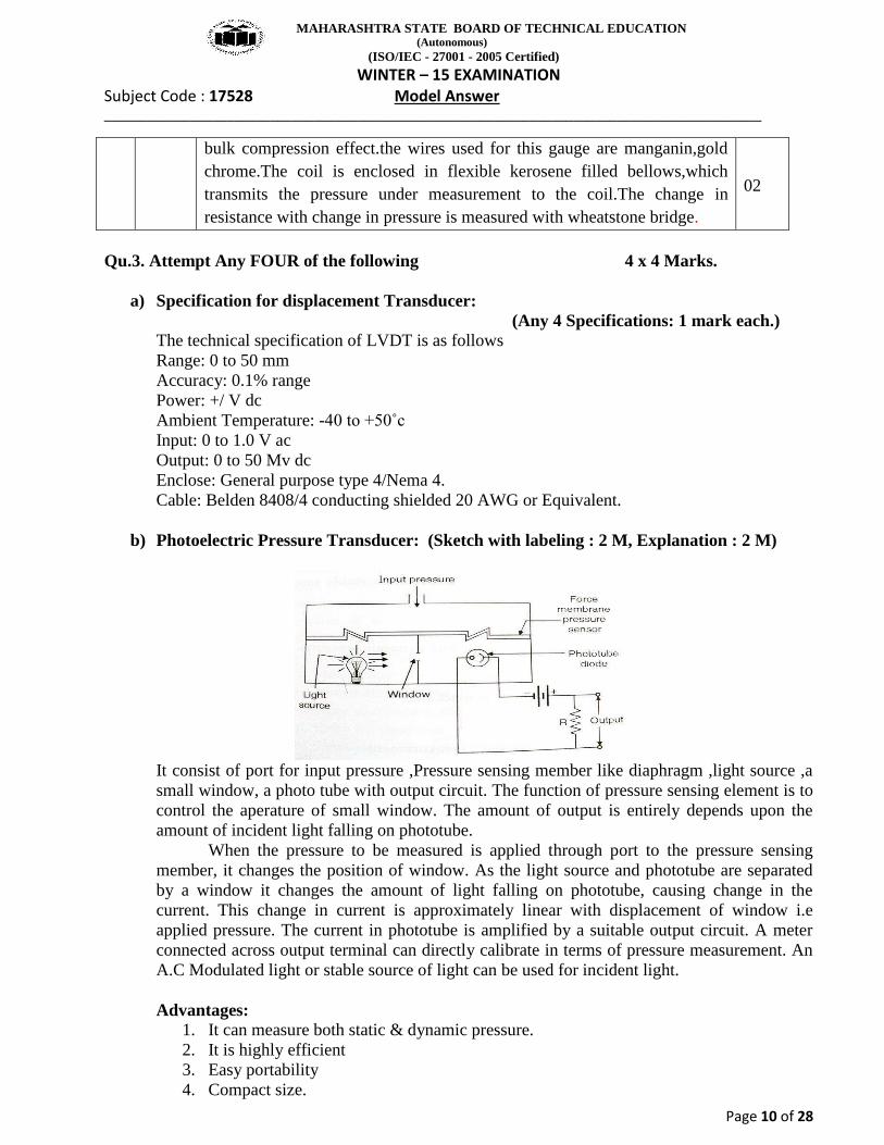
b) Photoelectric Pressure Transducer: (Sketch with labeling : 2 M, Explanation : 2 M)
It consist of port for input pressure ,Pressure sensing member like diaphragm ,light source ,a small window, a photo tube with output circuit. The function of pressure sensing element is to control the aperature of small window. The amount of output is entirely depends upon the amount of incident light falling on phototube.
When the pressure to be measured is applied through port to the pressure sensing member, it changes the position of window. As the light source and phototube are separated by a window it changes the amount of light falling on phototube, causing change in the current. This change in current is approximately linear with displacement of window i.e applied pressure. The current in phototube is amplified by a suitable output circuit. A meter connected across output terminal can directly calibrate in terms of pressure measurement. An A.C Modulated light or stable source of light can be used for incident light. Advantages:
1. It can measure both static & dynamic pressure. 2. It is highly efficient 3. Easy portability 4. Compact size.
MAHARASHTRA STATE BOARD OF TECHNICAL EDUCATION (Autonomous)
(ISO/IEC - 27001 - 2005 Certified) WINTER – 15 EXAMINATION
Subject Code : 17528 Model Answer ___________________________________________________________________________________________
Page 11 of 28
Limitation: 1. Less stable for long term measurement 2. Considerably displacement in force membrane is necessary.
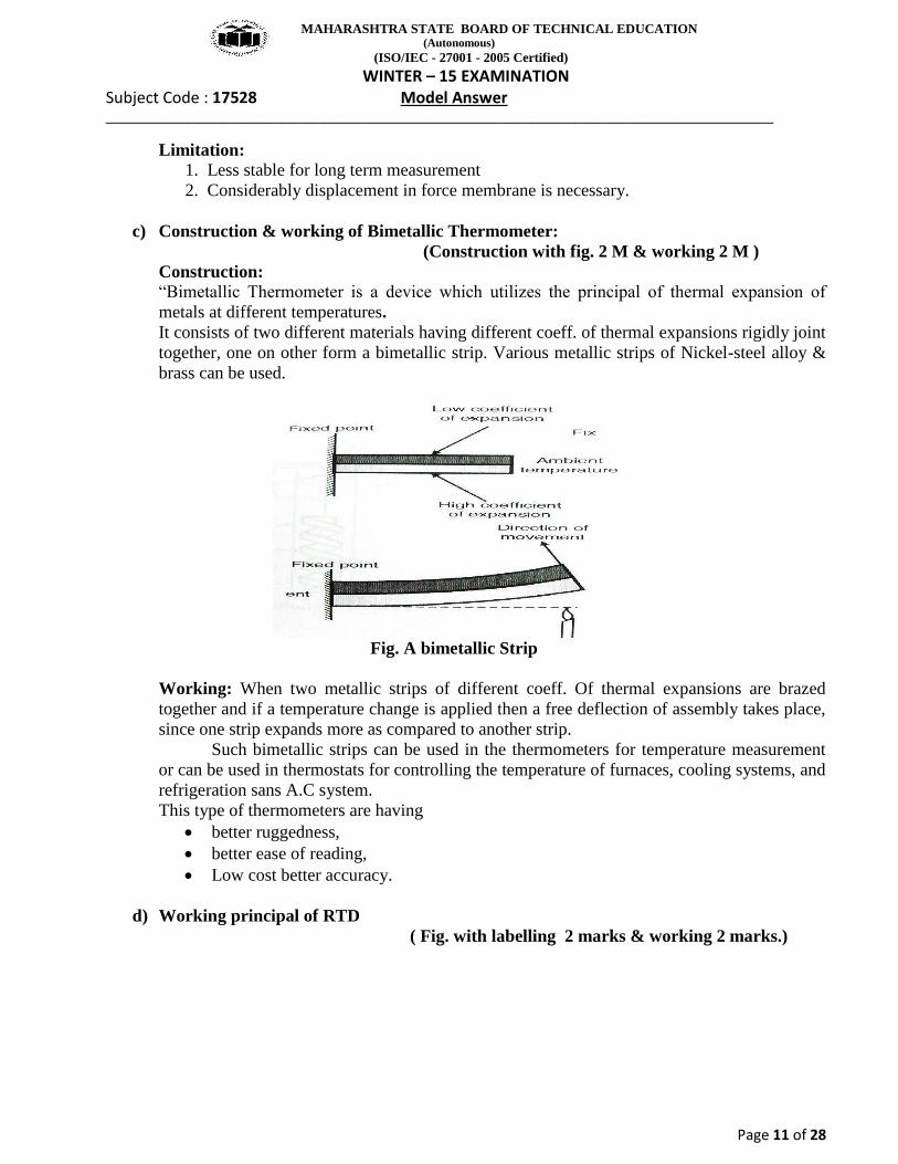
c) Construction & working of Bimetallic Thermometer: (Construction with fig. 2 M & working 2 M )
Construction: “Bimetallic Thermometer is a device which utilizes the principal of thermal expansion of
metals at different temperatures. It consists of two different materials having different coeff. of thermal expansions rigidly joint together, one on other form a bimetallic strip. Various metallic strips of Nickel-steel alloy & brass can be used.
Fig. A bimetallic Strip
Working: When two metallic strips of different coeff. Of thermal expansions are brazed together and if a temperature change is applied then a free deflection of assembly takes place, since one strip expands more as compared to another strip.
Such bimetallic strips can be used in the thermometers for temperature measurement or can be used in thermostats for controlling the temperature of furnaces, cooling systems, and refrigeration sans A.C system. This type of thermometers are having
better ruggedness, better ease of reading, Low cost better accuracy.
d) Working principal of RTD
( Fig. with labelling 2 marks & working 2 marks.)
MAHARASHTRA STATE BOARD OF TECHNICAL EDUCATION (Autonomous)
(ISO/IEC - 27001 - 2005 Certified) WINTER – 15 EXAMINATION
Subject Code : 17528 Model Answer ___________________________________________________________________________________________
Page 12 of 28
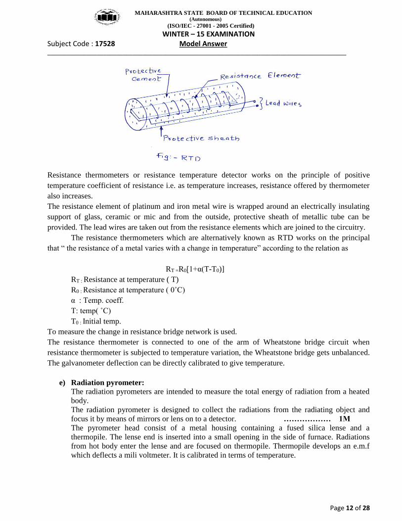
Resistance thermometers or resistance temperature detector works on the principle of positive temperature coefficient of resistance i.e. as temperature increases, resistance offered by thermometer also increases. The resistance element of platinum and iron metal wire is wrapped around an electrically insulating support of glass, ceramic or mic and from the outside, protective sheath of metallic tube can be provided. The lead wires are taken out from the resistance elements which are joined to the circuitry.
The resistance thermometers which are alternatively known as RTD works on the principal that “ the resistance of a metal varies with a change in temperature” according to the relation as
RT =R0[1+α(T-T0)] RT : Resistance at temperature ( T) R0 : Resistance at temperature ( 0˚C)
α : Temp. coeff. T: temp( ˚C) T0 : Initial temp.
To measure the change in resistance bridge network is used. The resistance thermometer is connected to one of the arm of Wheatstone bridge circuit when resistance thermometer is subjected to temperature variation, the Wheatstone bridge gets unbalanced. The galvanometer deflection can be directly calibrated to give temperature.
e) Radiation pyrometer:
The radiation pyrometers are intended to measure the total energy of radiation from a heated body. The radiation pyrometer is designed to collect the radiations from the radiating object and focus it by means of mirrors or lens on to a detector. ……………… 1M The pyrometer head consist of a metal housing containing a fused silica lense and a thermopile. The lense end is inserted into a small opening in the side of furnace. Radiations from hot body enter the lense and are focused on thermopile. Thermopile develops an e.m.f which deflects a mili voltmeter. It is calibrated in terms of temperature.
MAHARASHTRA STATE BOARD OF TECHNICAL EDUCATION (Autonomous)
(ISO/IEC - 27001 - 2005 Certified) WINTER – 15 EXAMINATION
Subject Code : 17528 Model Answer ___________________________________________________________________________________________
Page 13 of 28
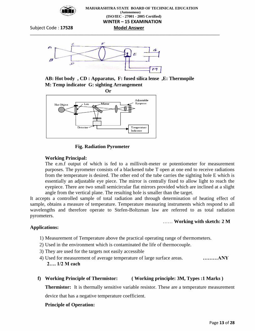
AB: Hot body , CD : Apparatus, F: fused silica lense ,E: Thermopile M: Temp indicator G: sighting Arrangement Or
Fig. Radiation Pyrometer
Working Principal: The e.m.f output of which is fed to a millivolt-meter or potentiometer for measurement purposes. The pyrometer consists of a blackened tube T open at one end to receive radiations from the temperature is desired. The other end of the tube carries the sighting hole E which is essentially an adjustable eye piece. The mirror is centrally fixed to allow light to reach the eyepiece. There are two small semicircular flat mirrors provided which are inclined at a slight angle from the vertical plane. The resulting hole is smaller than the target.
It accepts a controlled sample of total radiation and through determination of heating effect of sample, obtains a measure of temperature. Temperature measuring instruments which respond to all wavelengths and therefore operate to Stefen-Boltzman law are referred to as total radiation pyrometers. …… Working with sketch: 2 M Applications:
1) Measurement of Temperature above the practical operating range of thermometers. 2) Used in the environment which is contaminated the life of thermocouple. 3) They are used for the targets not easily accessible 4) Used for measurement of average temperature of large surface areas. ………ANY
2…. 1/2 M each
f) Working Principle of Thermistor: ( Working principle: 3M, Types :1 Marks )
Thermistor: It is thermally sensitive variable resistor. These are a temperature measurement
device that has a negative temperature coefficient.
Principle of Operation:
MAHARASHTRA STATE BOARD OF TECHNICAL EDUCATION (Autonomous)
(ISO/IEC - 27001 - 2005 Certified) WINTER – 15 EXAMINATION
Subject Code : 17528 Model Answer ___________________________________________________________________________________________
Page 14 of 28
These are made up of ceramic like semi conducting materials like copper oxide , manganese oxide
,nickel oxide, cobalt oxide, Lithium oxide and titanium oxide.
These oxides are blended in a suitable proportional and compressed into the desired shapes from the
mixed power and heat treated to recrystallize them, resulting in the dense ceramic body with the
required resistance temperature characteristics.
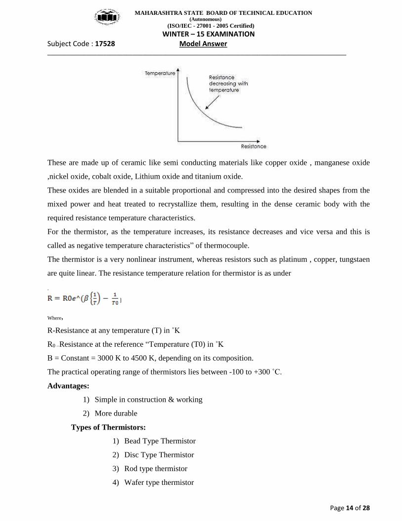
For the thermistor, as the temperature increases, its resistance decreases and vice versa and this is
called as negative temperature characteristics” of thermocouple.
The thermistor is a very nonlinear instrument, whereas resistors such as platinum , copper, tungstaen
are quite linear. The resistance temperature relation for thermistor is as under
.
]
Where,
R-Resistance at any temperature (T) in ˚K
R0 –Resistance at the reference “Temperature (T0) in ˚K
Β = Constant = 3000 K to 4500 K, depending on its composition.
The practical operating range of thermistors lies between -100 to +300 ˚C.
Advantages:
1) Simple in construction & working
2) More durable
Types of Thermistors:
1) Bead Type Thermistor
2) Disc Type Thermistor
3) Rod type thermistor
4) Wafer type thermistor
MAHARASHTRA STATE BOARD OF TECHNICAL EDUCATION (Autonomous)
(ISO/IEC - 27001 - 2005 Certified) WINTER – 15 EXAMINATION
Subject Code : 17528 Model Answer ___________________________________________________________________________________________
Page 15 of 28
QU.4 Attempt any FOUR 4X4 Marks a) Working of Rotameter
(Explanation: 2 marks and Figures: 2 marks)
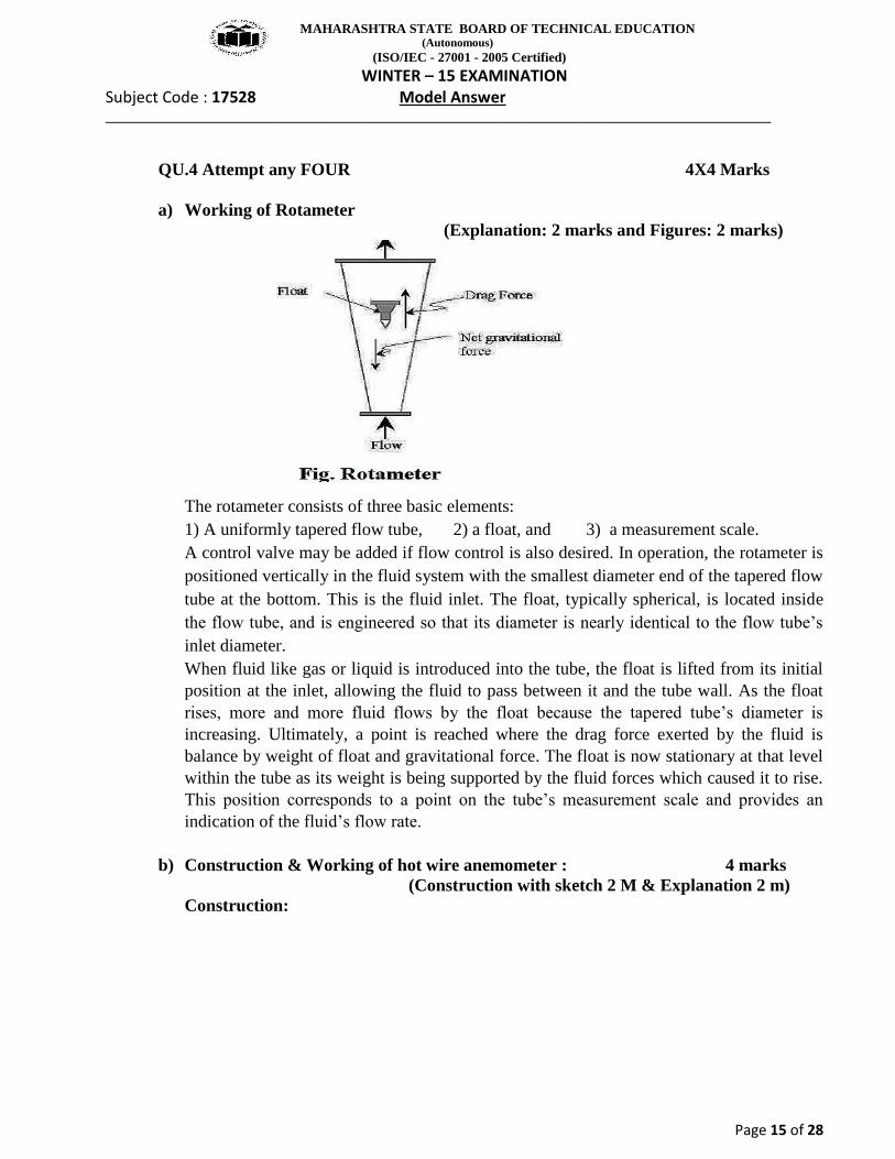
The rotameter consists of three basic elements: 1) A uniformly tapered flow tube, 2) a float, and 3) a measurement scale. A control valve may be added if flow control is also desired. In operation, the rotameter is positioned vertically in the fluid system with the smallest diameter end of the tapered flow tube at the bottom. This is the fluid inlet. The float, typically spherical, is located inside the flow tube, and is engineered so that its diameter is nearly identical to the flow tube’s
inlet diameter. When fluid like gas or liquid is introduced into the tube, the float is lifted from its initial position at the inlet, allowing the fluid to pass between it and the tube wall. As the float rises, more and more fluid flows by the float because the tapered tube’s diameter is
increasing. Ultimately, a point is reached where the drag force exerted by the fluid is balance by weight of float and gravitational force. The float is now stationary at that level within the tube as its weight is being supported by the fluid forces which caused it to rise. This position corresponds to a point on the tube’s measurement scale and provides an
indication of the fluid’s flow rate.
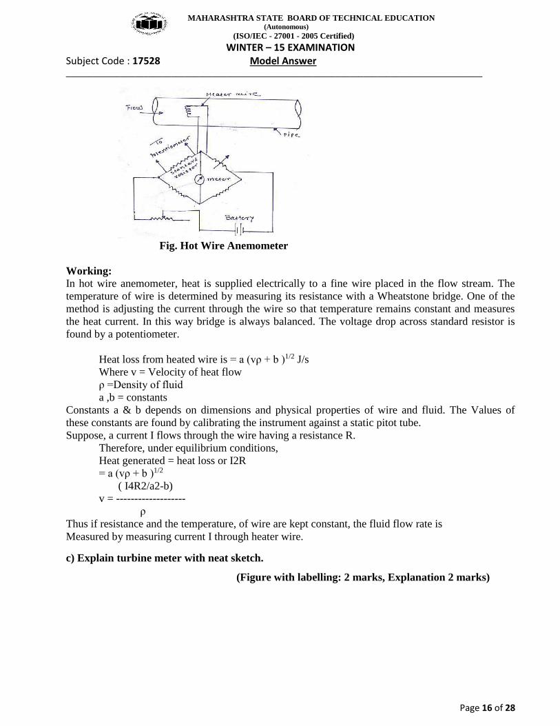
b) Construction & Working of hot wire anemometer : 4 marks (Construction with sketch 2 M & Explanation 2 m) Construction:
MAHARASHTRA STATE BOARD OF TECHNICAL EDUCATION (Autonomous)
(ISO/IEC - 27001 - 2005 Certified) WINTER – 15 EXAMINATION
Subject Code : 17528 Model Answer ___________________________________________________________________________________________
Page 16 of 28
Fig. Hot Wire Anemometer
Working: In hot wire anemometer, heat is supplied electrically to a fine wire placed in the flow stream. The temperature of wire is determined by measuring its resistance with a Wheatstone bridge. One of the method is adjusting the current through the wire so that temperature remains constant and measures the heat current. In this way bridge is always balanced. The voltage drop across standard resistor is found by a potentiometer.
Heat loss from heated wire is = a (vρ + b )1/2 J/s Where v = Velocity of heat flow ρ =Density of fluid a ,b = constants
Constants a & b depends on dimensions and physical properties of wire and fluid. The Values of these constants are found by calibrating the instrument against a static pitot tube. Suppose, a current I flows through the wire having a resistance R.
Therefore, under equilibrium conditions, Heat generated = heat loss or I2R
= a (vρ + b )1/2 ( I4R2/a2-b)
v = ------------------- ρ Thus if resistance and the temperature, of wire are kept constant, the fluid flow rate is Measured by measuring current I through heater wire.
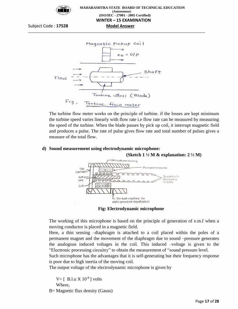
c) Explain turbine meter with neat sketch.
(Figure with labelling: 2 marks, Explanation 2 marks)
MAHARASHTRA STATE BOARD OF TECHNICAL EDUCATION (Autonomous)
(ISO/IEC - 27001 - 2005 Certified) WINTER – 15 EXAMINATION
Subject Code : 17528 Model Answer ___________________________________________________________________________________________
Page 17 of 28
The turbine flow meter works on the principle of turbine. if the losses are kept minimum the turbine speed varies linearly with flow rate i.e flow rate can be measured by measuring the speed of the turbine. When the blade passes by pick up coil, it interrupt magnetic field and produces a pulse. The rate of pulse gives flow rate and total number of pulses gives a measure of the total flow.
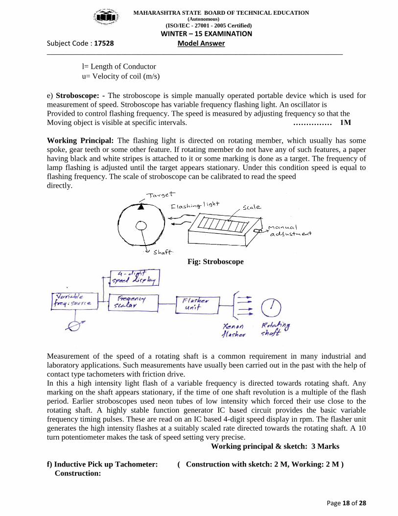
d) Sound measurement using electrodynamic microphone: (Sketch 1 ½ M & explanation: 2 ½ M)
Fig: Electrodynamic microphone
The working of this microphone is based on the principle of generation of e.m.f when a moving conductor is placed in a magnetic field. Here, a thin sensing –diaphragm is attached to a coil placed within the poles of a permanent magnet and the movement of the diaphragm due to sound –pressure generates the analogous induced voltages in the coil. This induced –voltage is given to the “Electronic processing circuitry” to obtain the measurement of “sound pressure level. Such microphone has the advantages that it is self-generating but their frequency response is poor due to high inertia of the moving coil. The output voltage of the electrodynamic microphone is given by
V= [ B.l.u X 10-8 ] volts Where,
B= Magnetic flux density (Gauss)
MAHARASHTRA STATE BOARD OF TECHNICAL EDUCATION (Autonomous)
(ISO/IEC - 27001 - 2005 Certified) WINTER – 15 EXAMINATION
Subject Code : 17528 Model Answer ___________________________________________________________________________________________
Page 18 of 28
l= Length of Conductor u= Velocity of coil (m/s)
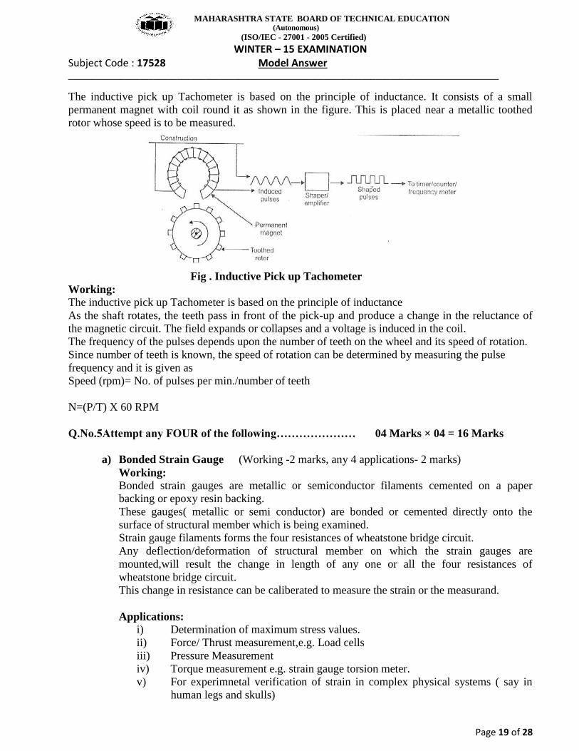
e) Stroboscope: - The stroboscope is simple manually operated portable device which is used for measurement of speed. Stroboscope has variable frequency flashing light. An oscillator is Provided to control flashing frequency. The speed is measured by adjusting frequency so that the Moving object is visible at specific intervals. …………… 1M Working Principal: The flashing light is directed on rotating member, which usually has some spoke, gear teeth or some other feature. If rotating member do not have any of such features, a paper having black and white stripes is attached to it or some marking is done as a target. The frequency of lamp flashing is adjusted until the target appears stationary. Under this condition speed is equal to flashing frequency. The scale of stroboscope can be calibrated to read the speed directly.
Fig: Stroboscope
Measurement of the speed of a rotating shaft is a common requirement in many industrial and laboratory applications. Such measurements have usually been carried out in the past with the help of contact type tachometers with friction drive. In this a high intensity light flash of a variable frequency is directed towards rotating shaft. Any marking on the shaft appears stationary, if the time of one shaft revolution is a multiple of the flash period. Earlier stroboscopes used neon tubes of low intensity which forced their use close to the rotating shaft. A highly stable function generator IC based circuit provides the basic variable frequency timing pulses. These are read on an IC based 4-digit speed display in rpm. The flasher unit generates the high intensity flashes at a suitably scaled rate directed towards the rotating shaft. A 10 turn potentiometer makes the task of speed setting very precise. Working principal & sketch: 3 Marks f) Inductive Pick up Tachometer: ( Construction with sketch: 2 M, Working: 2 M ) Construction:
MAHARASHTRA STATE BOARD OF TECHNICAL EDUCATION (Autonomous)
(ISO/IEC - 27001 - 2005 Certified) WINTER – 15 EXAMINATION
Subject Code : 17528 Model Answer ___________________________________________________________________________________________
Page 19 of 28
The inductive pick up Tachometer is based on the principle of inductance. It consists of a small permanent magnet with coil round it as shown in the figure. This is placed near a metallic toothed rotor whose speed is to be measured.
Fig . Inductive Pick up Tachometer Working: The inductive pick up Tachometer is based on the principle of inductance As the shaft rotates, the teeth pass in front of the pick-up and produce a change in the reluctance of the magnetic circuit. The field expands or collapses and a voltage is induced in the coil. The frequency of the pulses depends upon the number of teeth on the wheel and its speed of rotation. Since number of teeth is known, the speed of rotation can be determined by measuring the pulse frequency and it is given as Speed (rpm)= No. of pulses per min./number of teeth N=(P/T) X 60 RPM Q.No.5Attempt any FOUR of the following………………… 04 Marks × 04 = 16 Marks
a) Bonded Strain Gauge (Working -2 marks, any 4 applications- 2 marks) Working: Bonded strain gauges are metallic or semiconductor filaments cemented on a paper backing or epoxy resin backing. These gauges( metallic or semi conductor) are bonded or cemented directly onto the surface of structural member which is being examined. Strain gauge filaments forms the four resistances of wheatstone bridge circuit. Any deflection/deformation of structural member on which the strain gauges are mounted,will result the change in length of any one or all the four resistances of wheatstone bridge circuit. This change in resistance can be caliberated to measure the strain or the measurand. Applications:
i) Determination of maximum stress values. ii) Force/ Thrust measurement,e.g. Load cells iii) Pressure Measurement iv) Torque measurement e.g. strain gauge torsion meter. v) For experimnetal verification of strain in complex physical systems ( say in
human legs and skulls)
MAHARASHTRA STATE BOARD OF TECHNICAL EDUCATION (Autonomous)
(ISO/IEC - 27001 - 2005 Certified) WINTER – 15 EXAMINATION
Subject Code : 17528 Model Answer ___________________________________________________________________________________________
Page 20 of 28
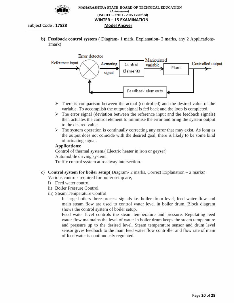
b) Feedback control system ( Diagram- 1 mark, Explanation- 2 marks, any 2 Applications- 1mark)
There is comparison between the actual (controlled) and the desired value of the
variable. To accomplish the output signal is fed back and the loop is completed. The error signal (deviation between the reference input and the feedback signals)
then actuates the control element to minimise the error and bring the system output to the desired value.
The system operation is continually correcting any error that may exist, As long as the output does not coincide with the desired goal, there is likely to be some kind of actuating signal.
Applications: Control of thermal system.( Electric heater in iron or geyser) Automobile driving system. Traffic control system at roadway intersection.
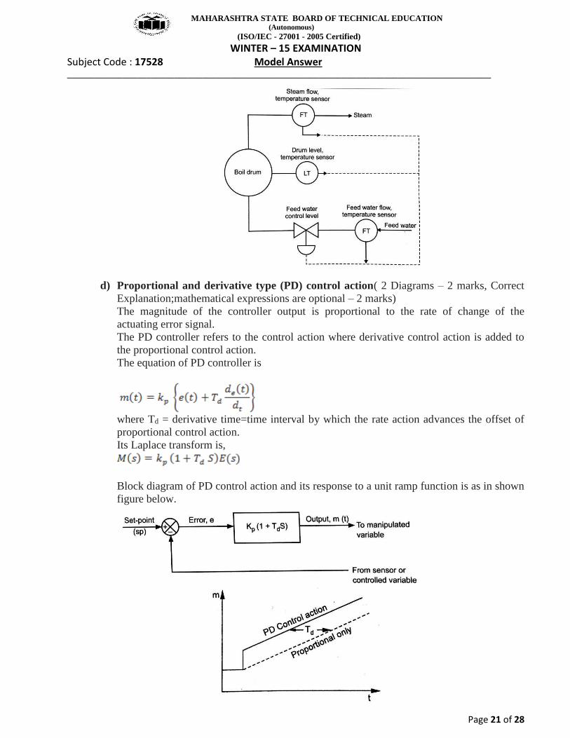
c) Control system for boiler setup( Diagram- 2 marks, Correct Explanation – 2 marks) Various controls required for boiler setup are, i) Feed water control ii) Boiler Pressure Control iii) Steam Temperature Control
In large boilers three process signals i.e. boiler drum level, feed water flow and main steam flow are used to control water level in boiler drum. Block diagram shows the control system of boiler setup. Feed water level controls the steam temperature and pressure. Regulating feed water flow maintains the level of water in boiler drum keeps the steam temperature and pressure up to the desired level. Steam temperature sensor and drum level sensor gives feedback to the main feed water flow controller and flow rate of main of feed water is continuously regulated.
MAHARASHTRA STATE BOARD OF TECHNICAL EDUCATION (Autonomous)
(ISO/IEC - 27001 - 2005 Certified) WINTER – 15 EXAMINATION
Subject Code : 17528 Model Answer ___________________________________________________________________________________________
Page 21 of 28
d) Proportional and derivative type (PD) control action( 2 Diagrams – 2 marks, Correct Explanation;mathematical expressions are optional – 2 marks) The magnitude of the controller output is proportional to the rate of change of the actuating error signal. The PD controller refers to the control action where derivative control action is added to the proportional control action. The equation of PD controller is
where Td = derivative time=time interval by which the rate action advances the offset of proportional control action. Its Laplace transform is,
Block diagram of PD control action and its response to a unit ramp function is as in shown figure below.
MAHARASHTRA STATE BOARD OF TECHNICAL EDUCATION (Autonomous)
(ISO/IEC - 27001 - 2005 Certified) WINTER – 15 EXAMINATION
Subject Code : 17528 Model Answer ___________________________________________________________________________________________
Page 22 of 28
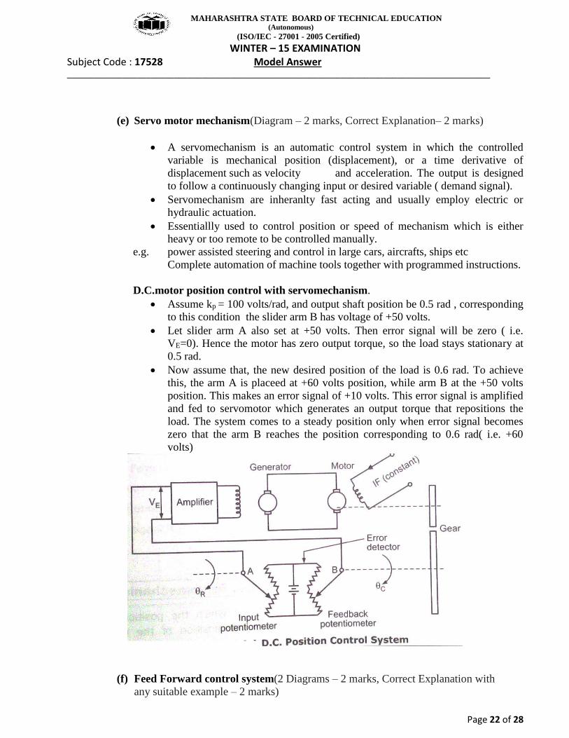
(e) Servo motor mechanism(Diagram – 2 marks, Correct Explanation– 2 marks)
A servomechanism is an automatic control system in which the controlled variable is mechanical position (displacement), or a time derivative of displacement such as velocity and acceleration. The output is designed to follow a continuously changing input or desired variable ( demand signal).
Servomechanism are inheranlty fast acting and usually employ electric or hydraulic actuation.
Essentiallly used to control position or speed of mechanism which is either heavy or too remote to be controlled manually.
e.g. power assisted steering and control in large cars, aircrafts, ships etc Complete automation of machine tools together with programmed instructions. D.C.motor position control with servomechanism.
Assume kp = 100 volts/rad, and output shaft position be 0.5 rad , corresponding to this condition the slider arm B has voltage of +50 volts.
Let slider arm A also set at +50 volts. Then error signal will be zero ( i.e. VE=0). Hence the motor has zero output torque, so the load stays stationary at 0.5 rad.
Now assume that, the new desired position of the load is 0.6 rad. To achieve this, the arm A is placeed at +60 volts position, while arm B at the +50 volts position. This makes an error signal of +10 volts. This error signal is amplified and fed to servomotor which generates an output torque that repositions the load. The system comes to a steady position only when error signal becomes zero that the arm B reaches the position corresponding to 0.6 rad( i.e. +60 volts)
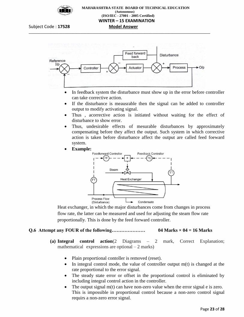
(f) Feed Forward control system(2 Diagrams – 2 marks, Correct Explanation with any suitable example – 2 marks)
MAHARASHTRA STATE BOARD OF TECHNICAL EDUCATION (Autonomous)
(ISO/IEC - 27001 - 2005 Certified) WINTER – 15 EXAMINATION
Subject Code : 17528 Model Answer ___________________________________________________________________________________________
Page 23 of 28
In feedback system the disturbance must show up in the error before controller
can take corrective action. If the disturbance is meausrable then the signal can be added to controller
output to modify activating signal. Thus , acorrective action is initiated without waiting for the effect of
disturbance to show error. Thus, undesirable effects of mesurable disturbances by approximately
compensating before they affect the output. Such system in which corrective action is taken before disturbance affect the output are called feed foeward system.
Example:
Heat exchanger, in which the major disturbances come from changes in process flow rate, the latter can be measured and used for adjusting the steam flow rate proportionally. This is done by the feed forward controller.
Q.6 Attempt any FOUR of the following………………… 04 Marks × 04 = 16 Marks
(a) Integral control action(2 Diagrams – 2 mark, Correct Explanation; mathematical expressions are optional – 2 marks)
Plain proportional contoller is removed (reset). In integral control mode, the value of controller output m(t) is changed at the
rate proportional to the error signal. The steady state error or offset in the proportional control is eliminated by
including integral control action in the controller. The output signal m(t) can have non-zero value when the error signal e is zero.
This is impossible in proportional control because a non-zero control signal requirs a non-zero error signal.
MAHARASHTRA STATE BOARD OF TECHNICAL EDUCATION (Autonomous)
(ISO/IEC - 27001 - 2005 Certified) WINTER – 15 EXAMINATION
Subject Code : 17528 Model Answer ___________________________________________________________________________________________
Page 24 of 28
The output equation of integral controller is,
The laplace transform is,
Where Ti = Integral time setting of the controller For zero error, the value of output remains stationary. If value of error ‘e’ is doubled, then the value of output m(t) varies twice as
fast. The ontrgral control mode, continuously integrating the area under the error
curve, it eliminates offset by forcing the addition( or removal) of mass or energy which should have been added ( or removed) in past.
Block diagram
Response curve.
Controller stays fixed when eror is zero. This controller output value remains
what it was when the error reached zero. Controller output changes at the rate of kppercentage per second for every 1%
of error (ep). There are delays in controller output change and time error reduction.
(b) Pressure Thermometer(Diagram – 2 marks, Correct Explanation of any pressure one thermometer – 2 marks)
Principle of woking: Fluid expansion due to an increase in the pressure in a given
volumeof the temperature measuring system. The bulb of thermometer is filled with either a liquid or gas or liquid-vapour mixture. Different pressure thermometers depending upon type of fluid are,
MAHARASHTRA STATE BOARD OF TECHNICAL EDUCATION (Autonomous)
(ISO/IEC - 27001 - 2005 Certified) WINTER – 15 EXAMINATION
Subject Code : 17528 Model Answer ___________________________________________________________________________________________
Page 25 of 28
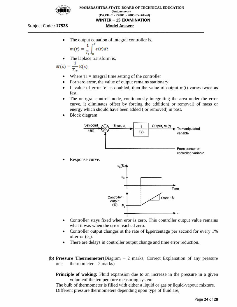
(i) Mercury –in-steel thermometer (ii) Constant volume gas thermometer, or (iii) Vapour pressure thermometer
Figure below shows the vapour pressure thermometer
Working: The liquid in a bulb of vapour –pressure system boils and vapourises until the
pressure in the system equals the vapour pressure of boiling liquid. These vapours creats pressure on nonvolatile fluid which causes its motion in
bourdon tube. Deflection of bourdon tube is caliberated to measure the temperature. Volatile liquid works as a spring (Its vapourisation depends on the measurand
temperature) Non-volatile liquid works as a transmitting link.
(c) Ultrasonic flow meter (Diagram – 2 marks, Correct Explanation; mathematical
expression is optional – 2 marks) In ultrasonic flow meters, the measurement of flow rate is determined by the variation in parameters of ultrasonic oscillation which varies with flow rate.
MAHARASHTRA STATE BOARD OF TECHNICAL EDUCATION (Autonomous)
(ISO/IEC - 27001 - 2005 Certified) WINTER – 15 EXAMINATION
Subject Code : 17528 Model Answer ___________________________________________________________________________________________
Page 26 of 28
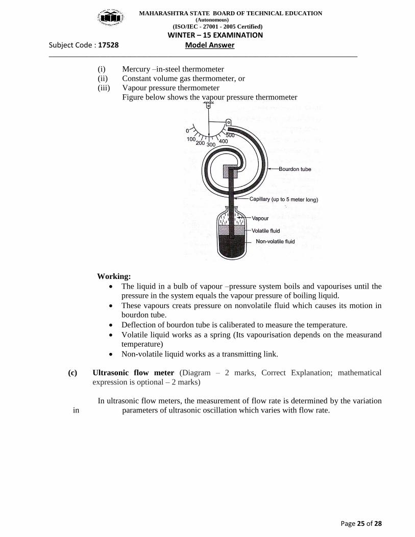
Working principle:
Apperent change in the velocity of propogation of sound waves in a fluid varies with a change in the velocity of the fluid flow.
Electronic oscillator generates ultrasound waves which are transmitted across the flow in pipe by transducers A and B as shown in figure.
Electronic oscillator gives out waves alternatively to transducers while detector receives those alternatively. This is done by a change over switch.
The difference in transit times of ultrasonic pulses is linearly proportional to flow velocity.
Velocity of flow can be given by,
where, V= velocit of fluid in pipe L = the acoustic path length between A and B C = Velocity of sound in fluid θ = angle of path w.r.t.to the pipe axis ∆T = TAB - TBA = Difference in transit time. (d) Eddy Current dynamometer.(Diagram – 1 marks, Correct Explanation; – 3marks)
MAHARASHTRA STATE BOARD OF TECHNICAL EDUCATION (Autonomous)
(ISO/IEC - 27001 - 2005 Certified) WINTER – 15 EXAMINATION
Subject Code : 17528 Model Answer ___________________________________________________________________________________________
Page 27 of 28
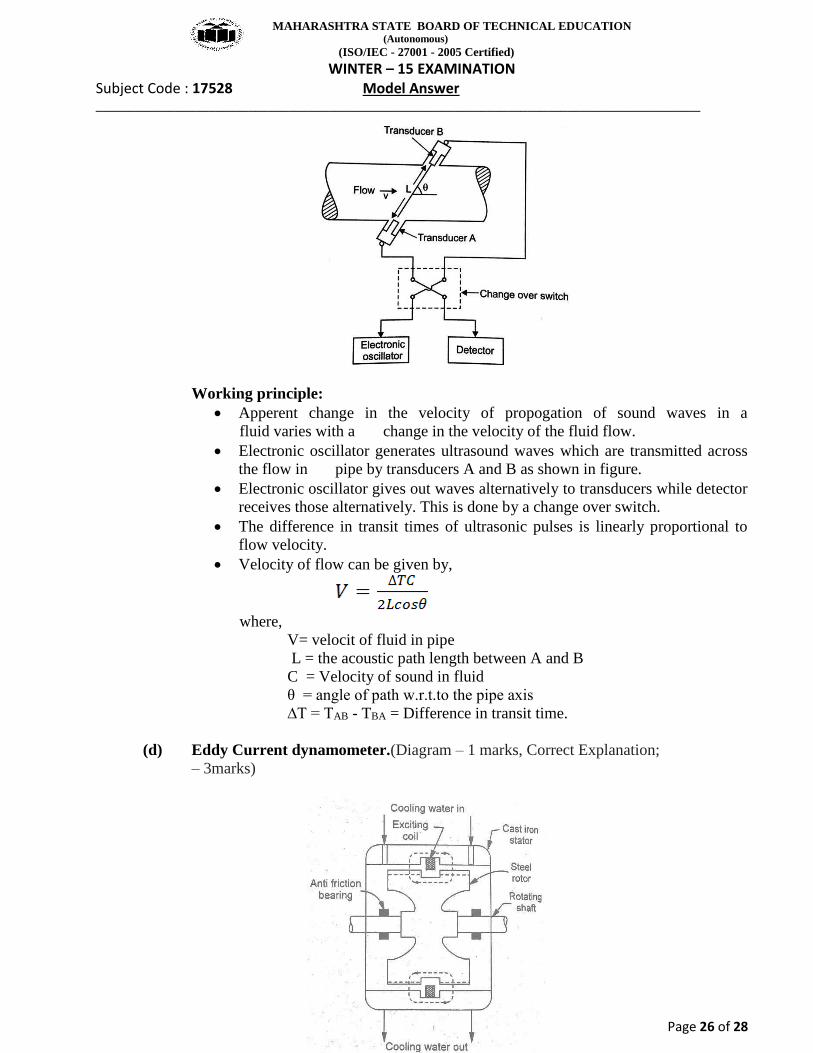
Principle: When an isolated conductor moves through the magnetic flux, voltage is induced and local currents flow in a short circular path (eddy currents) within conductor. These induced eddy currents get dissipated in the form of heat. Working:
It consists of toothed nonmagnetic solid metallic rotor connected to the shaft whose power is to be measured.
Nonmagnetic rotor rotates inside cast iron stator. Stator consists of D.C. supply excited coil. The stator is mounted such
that it permits free swing about its axis and is provided with torque arm, which measures torque.
To dissipate the generated heat, water is supplied in stator casing. During operation, rotor turns and causes constant change in flux density at all
points of stator, resulting formation of eddy current, which opposes the motion of rotor. This opposing resistance is measured by brake drum in the form of torque.
Apprx. Speed limit = 6000 rpm. Usual power limit = 250 kW
(e) Control system for speed control of motor.( Diagram – 1 mark, Correct Explanation– 3
marks)
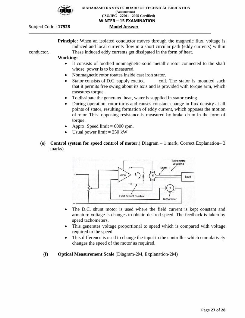
The D.C. shunt motor is used where the field current is kept constant and
armature voltage is changes to obtain desired speed. The feedback is taken by speed tachometers.
This generates voltage proportional to speed which is compared with voltage required to the speed.
This difference is used to change the input to the controller which cumulatively changes the speed of the motor as required.
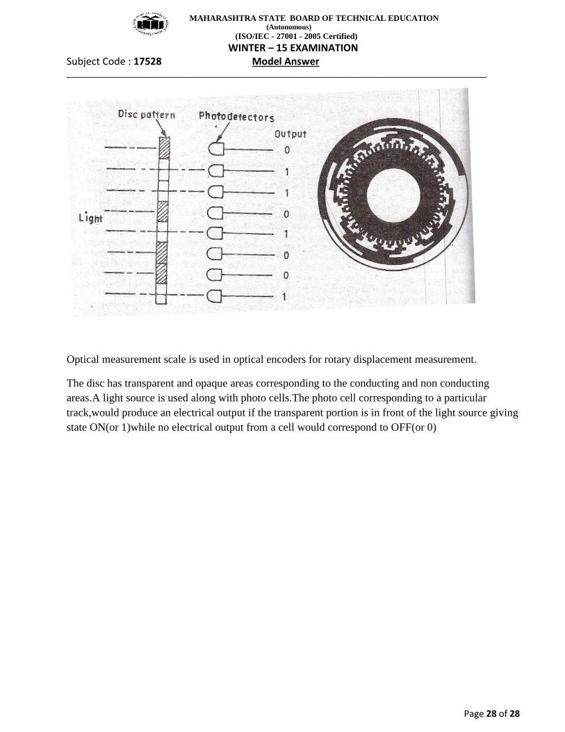
(f) Optical Measurement Scale (Diagram-2M, Explanation-2M)
MAHARASHTRA STATE BOARD OF TECHNICAL EDUCATION (Autonomous)
(ISO/IEC - 27001 - 2005 Certified) WINTER – 15 EXAMINATION
Subject Code : 17528 Model Answer ___________________________________________________________________________________________
Page 28 of 28
Optical measurement scale is used in optical encoders for rotary displacement measurement.
The disc has transparent and opaque areas corresponding to the conducting and non conducting areas.A light source is used along with photo cells.The photo cell corresponding to a particular track,would produce an electrical output if the transparent portion is in front of the light source giving state ON(or 1)while no electrical output from a cell would correspond to OFF(or 0)
Related Documents