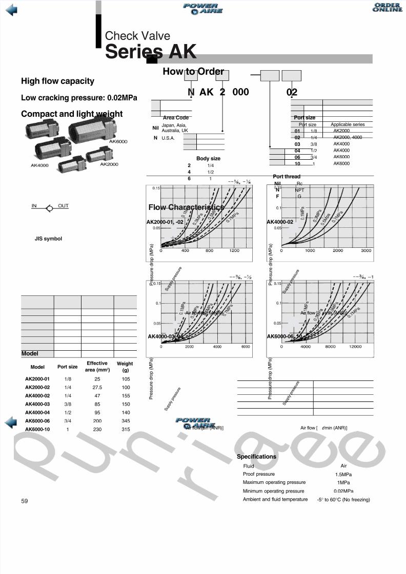
AK How to Order Check Valve Series AK 000 02 N 2 Area Code Nil N Japan, Asia, Australia, UK U.S.A. Body size Port thread Port size 2 4 6 N F Rc NPT G Nil 01 02 03 04 06 10 AK2000 AK2000, 4000 AK4000 AK4000 AK6000 AK6000 Port size Applicable series Specifications Fluid Proof pressure Maximum operating pressure Minimum operating pressure Ambient and fluid temperature Air 1.5MPa 1MPa 0.02MPa -5 to 60°C (No freezing) Air flow ( l /min (ANR)) Air flow [ l /min (ANR)] Air flow [ l /mi n (ANR)] Air flow [ l /min (ANR)] P r e s s u r e d r o p ( M P a ) P r e s s u r e d r o p ( M P a ) P r e s s u r e d r o p ( M P a ) P r e s s u r e d r o p ( M P a ) AK2000-01, -02 AK4000-02 AK4000-03, 04 AK6000-06, 10 Model Model Effective area (mm²) Port size Weight (g) AK2000-01 AK2000-02 AK4000-02 AK4000-03 AK4000-04 AK6000-06 AK6000-10 25 27.5 47 85 95 200 230 105 100 155 150 140 345 315 S u p p l y p r e s s u r e High flow capacity Low cracking pressure: 0.02MPa Compact and light weight JIS symbol S u p p l y p r e s s u r e Flow Characteristics S u p p l y p r e s s u r e S u p p l y p r e s s u r e 1/4 1/2 1 59 1/8 1/4 1/4 3/8 1/2 3/4 1 1/8 1/4 3/8 1/2 3/4 1

Welcome message from author
This document is posted to help you gain knowledge. Please leave a comment to let me know what you think about it! Share it to your friends and learn new things together.
Transcript
8/3/2019 15 AK Series Valves
http://slidepdf.com/reader/full/15-ak-series-valves 1/6
AK
How to Order
Check Valve
Series AK
000 02N 2
Area Code
Nil
N
Japan, Asia,Australia, UK
U.S.A.
Body size
Port thread
Port size
246
NF
RcNPT
G
Nil
010203040610
AK2000AK2000, 4000AK4000AK4000AK6000AK6000
Port size Applicable series
Specifications
Fluid
Proof pressure
Maximum operating pressure
Minimum operating pressure
Ambient and fluid temperature
Air
1.5MPa
1MPa
0.02 MPa
-5 ° to 60 ° C (No freezing)
Air flow ( l /min (ANR)) Air flow [ l /min (ANR)]
Air flow [ l /min (ANR)] Air flow [ l /min (ANR)]
P r e s s u r e
d r o p
( M P a
)
P r e s s u r e
d r o p
( M P a
)
P r e s s u r e
d r o p
( M P a
)
P r e s s u r e
d r o p
( M P a
)
AK2000-01, -02 AK4000-02
AK4000-03, 04 AK6000-06, 10
Model
ModelEffective
area (mm ² )Port sizeWeight
(g)
AK2000-01
AK2000-02
AK4000-02
AK4000-03
AK4000-04
AK6000-06
AK6000-10
25
27.5
47
85
95
200
230
105
100
155
150
140
345
315
S u p p l y p r e s s u r e
High flow capacity
Low cracking pressure: 0.02MPaCompact and light weight
JIS symbol
S u p p l y p r e s s u r e
Flow Characteristics
S u p p l y p
r e s s u r e
S u p p l y p r e s s u r e
1/41/21
59
1/8
1/4
1/4
3/8
1/2
3/4
1
1/81/43/81/23/41

8/3/2019 15 AK Series Valves
http://slidepdf.com/reader/full/15-ak-series-valves 2/6
Series A
Construction
Dimensions
Component parts
Replacement parts
No.
No.
Description
Description
Material
MaterialPart No.
AK2000 AK4000 AK6000
qw
e
rtyu
Valve
Spring
O-ring
Ring
Seat ring
Cover
Body
POM
Stainless steel
NBR
NBR
Brass, NBR
Aluminum die casted Note 1)
Aluminum die casted Note 1)
19033
19037
19014
19015
19016
19013
19024
19025
19026
19023
20 x 17 x 1.5
Note 1) AK2000: Zinc alloy
AK2000 AK4000/6000
Model Port size L1 HBAK2000-01, 02AK4000-02, 03, 04AK6000-06, 10
506795
253650
223650
Caution
1/8, 1/41/4, 3/8, 1/2
3/4, 1
Read carefully before handling.Refer to page 64 and 65 for Safety Instructions and common precautionson the products mentioned in this catalog, refer to page 66 through 68 forprecautions for every series.
IN OUT IN OUT
IN OUT
H
BL1

8/3/2019 15 AK Series Valves
http://slidepdf.com/reader/full/15-ak-series-valves 3/6
ASS
How to Order
Slow Start Co ntrol Valv e
Series ASSMeter-out Type
00 02N 3
Area Code
Nil
N
Japan, Asia,Australia, UK ∗
U.S.A.
Body sizePort thread
Port size
Meter-out control type:A control valve with cylinder speedcontrol function, fixed throttle, and rapid
air supply function
Meter-in-control type:A control valve with cylinder speedcontrol function and rapid air supplyfunction
61
∗Special order only
13
56
1/83/8
3/41
B
S.S.C. valve
Meter-out type
Nil
NF
Rc
NPTG
Applicable seriesPort size010203040610
ASS100, 110ASS300, 310ASS300, 310
ASS500ASS500, 600
ASS600
1/81/43/81/23/41
B
AccessoryNil Without bracket
With bracket
Fluid
Maximum operating pressure
Ambient and fluid temperature
Setting pressure
SpecificationsAir
0.7MPa
–5 ° to 60 ° C (No freezing)
0.1 to 0.5MPa
Model
Model
Type
Meter-outcontrol
Meter-incontrol
ASS100
ASS300
ASS500
ASS600
ASS110
ASS310
Port sizeEffective area (mm ² ) Weight
(g)Free flowControlled flow
2.4
14.5
52.0
80.0
2.4
16.5
97
220
580
950
97
220
9.5
22.0
55.0
90.0
5.4
23.0
1/8
1/4, 3/8
1/2, 3/4
3/4, 1
1/8
1/4, 3/8
Caution
Be sure to read before handling.Refer to page 64 and 65 for Safety Instructions and common precautions onthe products mentioned in this catalog, and page 66 through 68 forprecautions on every series.
PAT.PEND

8/3/2019 15 AK Series Valves
http://slidepdf.com/reader/full/15-ak-series-valves 4/6
Series ASS
Prevents accidents caused by thecylinder rod sudden extensions
Syste m circuit
Meter-out Graph/Pressure to time Meter-in Graph/Pressure to time
If pressure is applied only to one side ofthe cylinder, the rod could get out ofcontrol, leading to accidents that couldinvolve injury to humans or damage tothe product or jigs. The meter-out typeSSC valve prevents the suddenextensions by effecting meter-in controlwhen there is no pressure, and resumesthe ordinary meter-out control after thecylinder has been pressurized. With themeter-in type, there is no risk of suddenextensions because the cylinder speedis constantly under meter-in control.
During the operating stroke at initial actuation, thecylinder moves at a slow speed from A to B due to thefixed throttle of the SSC valve. When it reaches B, thehead pressure (PH) rises quickly as indicated by the linefrom C to D. Therefore, there is no time loss associatedwith the pressure transmission lag indicated by the linefrom C to E, as in the case of meter-in control that iseffected through the use of a speed controller. Duringnormal operation after the cylinder has beenpressurized, the cylinder's speed control is effected bythe ordinary meter-out control.
Due to meter-in control, the cylinder moves from A to Bregardless of whether it is an initial operation or anormal operation. When it reaches B, the head pressure(PH) rises quickly as indicated by the line from C to D.Therefore, there is no time loss associated with thepressure transmission lag indicated by the line from C toE, as in the case of meter-in control that is effectedthrough the use of a speed controller. During normaloperation after the cylinder has been pressurized, thecylinder's speed control is effected also by the ordinarymeter-in control.
M o v e m e n
t
o f
t h
e c y l i n
d e r
b y s p e e d control valve
M o v e m e n t o f t h e c y l i n d e r b y f i x e d t h r o t t l e v a l v e
M o v e m e n t o
f t h e c y l i n d e
r
b y m
e t e r c o n t r o l
P H
PR (Atmospheric pressure)Delay in pressure transmisPR(Atmospheric pressure)Delay in pressure transmission
M o v e m e n t o f t h e c y l i n d e r
M o v e m e n t o f t h e c y l i n d e r
M o v e m
e n t o
f t h e c y l i n d
e r
M o v e m
e n t o
f t h e c y l i n d
e r
P r e s s u r e
S t r o k e
P r e s s u r e
S t r o k e
P r e s s
u r e
S t r o k e
P r e s s
u r e
S t r o k e
P r e s s u r e
S t r o k e
P r e s s u r e
S t r o k e

8/3/2019 15 AK Series Valves
http://slidepdf.com/reader/full/15-ak-series-valves 5/6
Series ASS
63
Flow Characteristics Cylider Extension Prevention Primary Sp
Conditions: Supply pressure at 0.5MPa, No load∗ Primary speed of meter-in type can be controlled
as likely as during normal operation.
ASS100/ASS110
Supply pressure: 0.5MPaSupply pressure: 0.5MPa
Supply pressure: 0.5MPaSupply pressure: 0.5MPa
Supply pressure: 0.5MPa
E f f e c t i v e a r e a
( m m
² )
E f f e c t i v e a r e a
( m m
² )
E f f e c t i v e a r e a
( m m
² )
E f f e c t i v e a r e a
( m m
² )
E f f e c t i v e a r e a
( m m
² )
F l o w
[ l
/ m i n ( A N R ) ]
F l o w
[ l / m
i n ( A N R ) ]
F l o w
[ l / m
i n ( A N R ) ]
F l o w
[ l / m i n ( A N R ) ]
F l o w
[ l / m i n ( A N R ) ]
Needle rotation (turns)
Needle rotation (turns) Needle rotation (turns)
Needle rotation (turns)
Needle rotation (turns)
2.5
2.5
2.0
2.0
1.5
1.5
1.0
1.0
0.5
0.5
0
0
0
0
2
2
2
2
2
24
4
4
4
6
6
6
6
8
8
8
10 0 0
0
0
0
50
100
150
4
4
6
6
8
8
8
10
10
10
10
10
10
12
12
12
12
14
14
14
200
400
600
800
1,000
P r i m a r y s p e e
d ( m m
/ s )
0
50
50
50
100
150
200
250
20
20
20
20
2530
30
30
40
40
40
40
50 63 80
80
80
100
100
200 300
Cylinder bore size (mm)
ASS300
ASS310 ASS500
ASS600
60
60
60
120
140
160
500
1,000
1,000
1,500
2,000
2,000
3,000
3,000
3,500
4,000
4,000
2,500
705,000
Meter-out control
M a x .
1 6
. 5
1 0 0 0 l / m i n ( A N R )
8/3/2019 15 AK Series Valves
http://slidepdf.com/reader/full/15-ak-series-valves 6/6
Series ASS
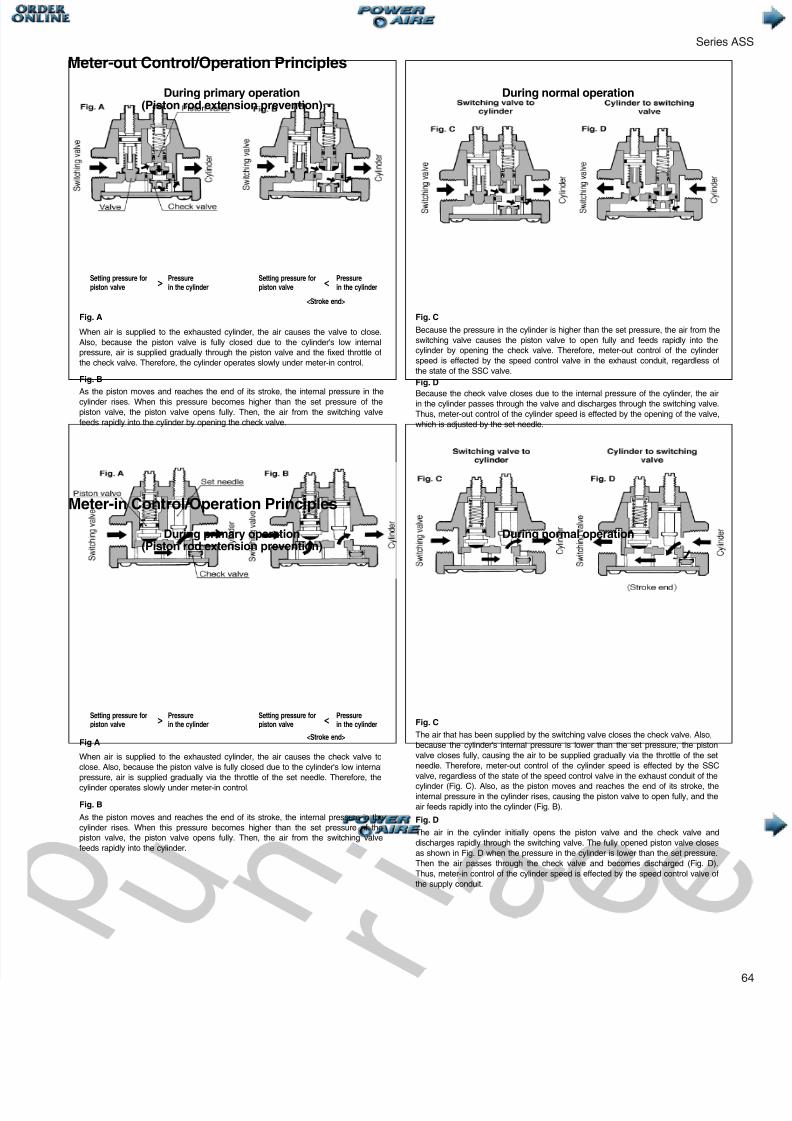
Fig. D
Fig. D
Fig. C
Fig. C
Fig. B
Fig. B
Fig A
Fig. A
During primary operation(Piston rod extension prevention)
Setting pressure forpiston valve
Pressurein the cylinder
Setting pressure forpiston valve
During primary operation(Piston rod extension prevention)
During normal operation
During normal operation
Meter-out Control/Operation Principles
Meter-in Control/Operation Principles
When air is supplied to the exhausted cylinder, the air causes the valve to close.Also, because the piston valve is fully closed due to the cylinder's low internalpressure, air is supplied gradually through the piston valve and the fixed throttle ofthe check valve. Therefore, the cylinder operates slowly under meter-in control.
As the piston moves and reaches the end of its stroke, the internal pressure in thecylinder rises. When this pressure becomes higher than the set pressure of thepiston valve, the piston valve opens fully. Then, the air from the switching valvefeeds rapidly into the cylinder by opening the check valve.
When air is supplied to the exhausted cylinder, the air causes the check valve toclose. Also, because the piston valve is fully closed due to the cylinder's low internalpressure, air is supplied gradually via the throttle of the set needle. Therefore, thecylinder operates slowly under meter-in control.
As the piston moves and reaches the end of its stroke, the internal pressure in thecylinder rises. When this pressure becomes higher than the set pressure of thepiston valve, the piston valve opens fully. Then, the air from the switching valvefeeds rapidly into the cylinder.
Because the pressure in the cylinder is higher than the set pressure, the air from theswitching valve causes the piston valve to open fully and feeds rapidly into thecylinder by opening the check valve. Therefore, meter-out control of the cylinderspeed is effected by the speed control valve in the exhaust conduit, regardless ofthe state of the SSC valve.
Because the check valve closes due to the internal pressure of the cylinder, the airin the cylinder passes through the valve and discharges through the switching valve.Thus, meter-out control of the cylinder speed is effected by the opening of the valve,which is adjusted by the set needle.
The air that has been supplied by the switching valve closes the check valve. Also,because the cylinder's internal pressure is lower than the set pressure, the pistonvalve closes fully, causing the air to be supplied gradually via the throttle of the setneedle. Therefore, meter-out control of the cylinder speed is effected by the SSCvalve, regardless of the state of the speed control valve in the exhaust conduit of the
cylinder (Fig. C). Also, as the piston moves and reaches the end of its stroke, theinternal pressure in the cylinder rises, causing the piston valve to open fully, and theair feeds rapidly into the cylinder (Fig. B).
The air in the cylinder initially opens the piston valve and the check valve anddischarges rapidly through the switching valve. The fully opened piston valve closesas shown in Fig. D when the pressure in the cylinder is lower than the set pressure.Then the air passes through the check valve and becomes discharged (Fig. D).Thus, meter-in control of the cylinder speed is effected by the speed control valve ofthe supply conduit.
> < Pressurein the cylinder
Setting pressure forpiston valve
Pressurein the cylinder
Setting pressure forpiston valve> < Pressure
in the cylinder
<Stroke end>
<Stroke end>
Related Documents