HYDRAULICS 1. Hydraulics : It is the branch of Engineering which deals with the behaviour of fluid under the conditions of rest (or) motion. 2. Fluid mechanics : It is the branch of engineering which deals with the behaviour of fluid under the conditions of rest and motion. 3. Fluid Kinematics : It is the fluid mechanics which deals study of velocity & acceleration of fluid particles without taking into consideration any force (or) energy 4. Density = ρ = Mass / Volume (Units = Kg/m 3 ) 5. Specific Weight (or) Weight density = ω = Þ x g = density x Sp. Gravity = Weight/ unit volume (Units = KN/m 3 ) 6. Specific gravity = Sp. Wt of liquid (Units = No units) Sp.wt of pure water at standard temp (4 0 c) Where Sp.gravity(g) = 9.81 KN/m 3 (Sp.gravity of pure water is taken as unity) 7. Specific Volume(V) = Volume/Mass = 1/ ρ (Reciprocal Density) 8. Surface tension(σ) = It is the property of liquid which enables it to resist tensile Stress (Units = N/m) → Surface tension is due to cohesion between particles at free surface Eg: Falling drops of water become spheres due to surface tension 9. Capillarity(h) = 4 σ cosα (It is a phenomenon of rise or fall of a liquid surface in a ω d small vertical tube held in a liquid relative to general level of the liquid) α for water = 0 and α for glass = 140 0 → Capillarity is due to both cohesion and adhesion between particles at free surface 10. Pressure of liquid (or) Intensity of Pressure = Þ = P/A = Force Area Þ = ω h (where h-static head, p-intensity of pressure, ω-weight density) 11. Units for Intensity of Pressure = N/m 2 (or) N/ mm 2 (or) in metres of liquid (or) mm of liquid 12. 1 Pascal = 1Pa = N/m 2 , 1 KPa = 1 KN/m 2 & 1 MPa = 1 MN/m 2 = 1 N/mm 2

Welcome message from author
This document is posted to help you gain knowledge. Please leave a comment to let me know what you think about it! Share it to your friends and learn new things together.
Transcript

HYDRAULICS
1. Hydraulics : It is the branch of Engineering which deals with the behaviour of fluid under the conditions of rest (or) motion.
2. Fluid mechanics : It is the branch of engineering which deals with the behaviour of
fluid under the conditions of rest and motion. 3. Fluid Kinematics : It is the fluid mechanics which deals study of velocity &
acceleration of fluid particles without taking into consideration any force (or) energy 4. Density = ρ = Mass / Volume (Units = Kg/m3) 5. Specific Weight (or) Weight density = ω = Þ x g = density x Sp. Gravity
= Weight/ unit volume (Units = KN/m3)
6. Specific gravity = Sp. Wt of liquid (Units = No units) Sp.wt of pure water at standard temp (40c)
Where Sp.gravity(g) = 9.81 KN/m3 (Sp.gravity of pure water is taken as unity)
7. Specific Volume(V) = Volume/Mass = 1/ ρ (Reciprocal Density) 8. Surface tension(σ) = It is the property of liquid which enables it to resist tensile
Stress (Units = N/m) → Surface tension is due to cohesion between particles at free surface Eg: Falling drops of water become spheres due to surface tension
9. Capillarity(h) = 4 σ cosα (It is a phenomenon of rise or fall of a liquid surface in a ω d small vertical tube held in a liquid relative to general level
of the liquid) α for water = 0 and α for glass = 1400
→ Capillarity is due to both cohesion and adhesion between particles at free surface
10. Pressure of liquid (or) Intensity of Pressure = Þ = P/A = Force
Area Þ = ω h (where h-static head, p-intensity of pressure,
ω-weight density)
11. Units for Intensity of Pressure = N/m2 (or) N/ mm2 (or) in metres of liquid (or) mm of liquid
12. 1 Pascal = 1Pa = N/m2 , 1 KPa = 1 KN/m2 & 1 MPa = 1 MN/m2 = 1 N/mm2

13. The force per unit area is called Intensity of Pressure.
14. Newton’s law of viscosity: The shear stress on a layer of a fluid is directly proportional to the rate of shear strain.
Eg: Newtonian fluid, water
15. Viscosity: It is also known as absolute viscosity or Dynamic viscosity. It is defined as the property of liquid which offers resistance to the movement of one layer of liquid over another adjacent layer of liquid.
→ The the property of the liquid which control its rate of flow is called Viscosity.
→ The viscosity of liquid is due to cohesion and interaction between particles.
Viscosity (or) absolute (or) dynamic viscosity:
S.I Units = N-S/m2 = 1 Pa-S
C.G.S Units = 0.1 N-S/m2 = 1 poise = 0.1 Pa-S = 1 dyne-S/cm2
16. Kinematic Viscosity: It is defined as the ratio of dynamic Viscosity (or) absolute viscosity to the density of liquid Kinematic Viscosity = Dynamic Viscosity
Density
S.I Units = m2/S
C.G.S Units = 0.1 cm2 /S = 1 stoke = 10-4 m2/S
→ The Surface tension of mercury at normal temperature is higher than that of water
→ The Viscosity of water higher than that of mercury
17. Compressibility: It is the property of liquid by virtue of which liquid undergo a change in volume with the change in pressure.
→ The compressibility is the reciprocal of bulk modulus.
Compressibility = Volumetric strain = ∆V Compressive stress ∆ P Bulk modulus = Compressive stress = ∆ P Volumetric strain ∆V
= Increase in pressure Volumetric Strain
18. Static Head: The vertical height from the free surface of the liquid is called
Static head
19. The atmospheric air exerts a normal pressure upon all surfaces with which it is in contact and it is known as atmospheric pressure. It is also known as barometric pressure.

20. The pressure measured with the help of a pressure gauge is known as guage pressure.
21. Atmospheric (or) Barometric pressure at sea level(above absolute zero) is call Standard atmospheric pressure
= 101.3 KN/m2
= 10.3m of water = 760mm of Hg
→ The pressure below atmospheric, gauge pressure will be negative. This negative pressure is known as vaccum pressure.
22. Absolute pressure = Atmospheric pressure + Gauge pressure(positive)
(for pressure above atmospheric)
23. Manometers is used to measure i) High pressure of liquids ii) Vaccum pressure (or) negative pressure iii) Pressure in pipes and channels
24. Differential manometer is used to measure Difference of pressure between Two points in a pipe
25. U-Tube Differential manometer is used to measure Pressure difference between Two points.
26. Inverted Differential manometer is used to measure Low Difference of pressure accurately
27. Piezometer is simplest form of manometer is used to measure Moderate pressures of
liquid
28. Orifice meter (cheaper than venturimeter) is used to measure Discharge of the liquid
29. Venturi meter is used to measure Discharge of the liquid
30. Pitot tube is used to measure Velocity of flow at required point in a pipe.
31. Total Pressure : The force exerted by a static fluid on a surface (either plance or curved) when the fluid comes in contact with the surface. This force always normal to the surface.
32. Centre of Pressure : The point of application of the resultant pressure on the surface (or)
The resultant hydrostatic force acts through a point is known as centre of pressure
33. Horizontally immersed surface = P = W.A. X 34. Vertically immersed surface = P = W.A. X
and depth of centre of pressure (h) = IG + X AX
Where P = Total pressure
The maximum efficiency of transmission through a pipe is 66.67%
The depth of centre of pressure is always below the depth of centre of gravity
35. Inclined immersed surface = P = W.A. X and depth of centre of pressure (h) = IG Sin2θ + X AX
36. Velocity of liquid is maximum at centre of pipe & Minimum at near the walls 37. Lock gates = R = P . (Lock gates are provided in navigation chambers
2sinα to change the water level in a canal (or) river for navigation)
38. The time of Oscillation (T) = 2Л K2 Where K – radius of gyration
h.g h – metacentric height 39. Buoyancy : The tendency of liquid to uplift an immersed body, because of the
upward thrust of the liquid is known as buoyancy. 40. Buoyant force : The force tending to lift up the body is called force of buoyancy (or)
buoyant force
41. Centre of Buoyancy : The point through which the buoyant force is supposed to act, is known as centre of buoyancy.
42. Metacentre : The point about which a floating body starts oscillating, when given
small angular displacement. It is denoted by ‘M’
43. Metacentric height : The distance between the centre of gravity (G) of the floating body and the metacentre(M)
→ If the force of buoyancy is more than the weight of the liquid displaced, then
the body will float. → If the force of buoyancy is less than the weight of the liquid displaced, then the
body sink down. → When the body is placed over a liquid, if the gravitational force is less than the
upthrust of the liquid, then the body will float. → When the body is placed over a liquid, if the gravitational force is more than
the upthrust of the liquid, then the body will sing down
44. Metacentre (or) Meta centric height
GM = I . – BG = BM - BG V 45. Momentum Equation: It is based on law of momentum or momentum principle
which states that “ The net force acting on a mass of fluid is equal to the change in momentum of flow per unit time in that direction”
F = d(mv) (mv- momentum) dt
Impulse – momentum equation = F x dt = d(mv)

46. Euler’s equation = dp/p + g. dx + v.dv = 0 is based on the following assumptions
i) The fluid is non-viscous ii) The fluid is homogeneous and incompressible iii) The flow is continuous, steady and along the streamline iv) The velocity of flow is uniform over the section
47. Potential energy (or) potential head: It is due to the position above some suitable
datum line. It is denoted by ‘z’ 48. Kinetic energy (or) Kinetic (or Velocity) head: It is due to the velocity of flowing
liquid. Its value is given by V2/2g, (v-Velocity, g-acceleration due to gravity)
49. Pressure energy (or) pressure head: It is due to the pressure of liquid. Its value is given by p/w
50. Total energy, E = Potential energy + Kinetic Energy + Pressure energy
51. Total head = Potential head + Kinetic head + Pressure head 52. Benoulli’s theorm = Law of conservation of energy
53. Continuity equation = Law of conservation of mass
54. Bernoulli’s equation ( applied to Venturimeter,Orifice and pitot tube)
(It states that for a incompressible liquid, flowing in a continuous stream, the total energy of particle remains same while particles moves from one point to another)
i) Mathematically is incompressible liquids = P1 + V12+Z1 = P2 + V2
2+Z2 = Constant w 2g w 2g
ii) Real liquids = P1 + V12+Z1 = P2 + V2
2+Z2 +hL w 2g w 2g
55. Rate of Discharge : The quantity of liquid flowing per second through a section of pipe (or) channel is called discharge
Units = cumecs (or) m3/s
Rate of discharge =(Q) = a. v 56. Equation of continuity: The quantity of liquid passing per second is same at all
sections is known as equation of continuity
Q1=Q2=Q3 or a1v1 = a2v2 = a3v3 57. The point at which the streamlines first become parallel is called vena contracta.
58. Theoretical velocity of jet at vena contracta = √2.g H ( This expression is called Torcelli’s theorem)
59. In a convergent – divergent mouthpiece, the ratio of areas at outlet and at vena
contracta(i.e convergences of mouthpiece) = a/ac = 1+ Ha-Hc H
60. The error in discharge (dQ/Q) to the error in measurement of head(dH/H) over a rectangular notch = dQ = 3 dH
Q 2 H
61. The error in discharge (dQ/Q) to the error in measurement of head(dH/H) over a Traiangular notch = dQ = 5 dH
Q 2 H 62. Bazin’s Formula of discharge over Rectangular weir = mL√2.g H 3/2
Where ‘m’ is equal to = 0.405 + 0.003 H
63. The discharge through Siphon spillway = cd.a .√2.g H 64. i) The power transmitted through a pipe = W x Q (H – Hf )
ii) The efficiency of power transmission through a pipe = H - Hf H
65. The Discharge(Q) through a Channel of Circular section will be maximum , when the depth of water = 0.95 x diameter(d) of the Circular channel
66. The Velocity(V) through a Channel of Circular section will be maximum , when the
depth of water = 0.81 x diameter(d) of the Circular channel
67. A Venturiflume is used to measure Discharge of liquid
68. The Critical depth meter is used to measure Hydraulic jump
69. Force exerted by jet of water impinging normally on a fixed plate (FX) = WaV2 g
70. Force exerted by jet of water impinging normally on a fixed plate inclined at an angle θ = (FN) = WaV2 x Sinθ
g
71. Force exerted by jet in the direction of flow = (FX) = FN Sinθ = WaV2 x Sin2θ g
72. Force exerted by jet in the direction normal to flow = FN Cosθ = WaV2 x Sin2θ g
73. When a jet of water enters and leaves the curved fixed plate (or) Vane tangentially, then the force of the jet along normal to the place
= WaV2 (Cosα+Cosβ) g
74. Force exerted by a jet of water impinging normally on a plate which due to the impact of jet, moves in the direct of jet with a Velocity(V) is = Wa(V-v)2
g

75. When a jet of water enters and leaves the moving curved vane , then the force of jet in the direct of motion of the vane = WaV (Vw-Vwl)
G
76. Hydraulic turbine: It converts Hydraulic energy to Mechanical energy 77. Centrifugal pump : It converts Kinetic Energy of water to Pressure Energy
78. Pump : It converts Mechanical Energy into hydraulic Energy
79. Hydraulic ram is used for lifting water without an electric motor
80. At vena contracta
i) C.S area is minimum ii) Pressure is minimum iii) Velocity is maximum iv) Streamlines are straight & parallel to each other.
81. Mouthpiece: The length of mouth piece = 2 to 3 time diameter of orifice
82. Co-efficient of Contraction (CC) = Area of jet at Venacontracta(aC) = 0.64
Area of Orifice(a)
83. Co-efficient of Velocity(Cv)= Actual velocity of jet at Venacontracta(V) = 0.97 Theoretical Velocity (Vth)
84. Co-efficient of Discharge(Cd) = Actual through orifice(Q) = 0.62 Theoretical discharge (Qth)
85. Co-efficient of Resistance(Cr)= Loss of head in orifice(Q) = x2 Head of water available at exit (Qth) 4yH
Where x – horizontal distance y – Vertical distance H – Water head
Orifice: ( A small opening in the wall or base of a vessel through which the fluid flows)
86. The discharge large rectangular orifice(Q) = 2/3 cd.b .√2.g [H23/2 – H1
3/2] 87. The discharge Wholly submerged orifice(Q) = cd.b . 2.gH [H2 – H1]
88. Time required to empty a tank completely through an orifice = 2A√H1
cd.a .√2.g 89. Time required to empty a hemispherical tank completely through an orifice =
= 14 Л R5/2 . 15 cd.a .√2.g
90. An Orifice is called a large orifice, if water head(h)= 5 x diameter of the orifice(d)
h = 5d

Mouthpiece: (It is an attachment in the form of a small tube or pipe fixed to the orifice)
91. External mouth piece: Pressure at venacontracta = Ha – 0.89H
92. The discharge through external mouthpiece = 0.855 a 2gH 93. Internal mouth piece: Pressure at venacontracta = Ha –H 94. The discharge through internal mouthpiece when running free = 0.50 a 2gH 95. The discharge through internal mouthpiece when running full = 0.707 a 2gH
96. The re-entrant or Borda’s mouth piece is an internal mouth piece.
97. If the jet of liquid after contraction does not touch the sides of the mouth pieces,
then the mouth piece, is said to be running free. In this case, the length of mouth piece is equal to the diameter of the orifice (Runner free : L = d)
98. If the jet of liquid after contraction expands and fills up the whole mouth piece, then
the mouth piece, is said to be running full. In this case, the length of mouth piece is more than 3 times the diameter of the orifice (Running full : L= 3d )
Venturimeter: It is used to measure discharge of liquid flowing in a pipe.
The length of divergent cone = 3 to 4 times loger that that of the divergent cone The discharge through a venturimeter = Cd.a1.a2 √2gh √a1
2 – a22
Where Cd = Coefficient of discharge a1 = Area of inlet a2 = area at throat and h – venture head
→ Velocity of liquid at the throat is higher than that of inlet
→ The Pressure of liquid at throat is lower than that of inlet
→ The Velocity and Pressure of liquid flowing through divergent portion decreases.
→ When venturimeter is inclined it shows same reading.
Notch: ( An opening provided in the side of a tank or vessel, made with metallic plate)
99. Notch is used to measure the rate of flow through a small channel (or) tank 100. The discharge large rectangular notch = 2/3 cd.b .√2.g .H3/2
101. The discharge large triangular notch = 8/15 cd.b .√2.g .tan(θ/2).H 5/2
102. Right angle V-notch = 8/15 cd.b .√2.g.H 5/2 (Where θ = 900)
Weir:( Any regular obstruction in an open channel over which the flow takes place)
103. Weir is used to measure the rate of flow of water in rivers (or) streams
104. Francis formula for Cipoletti weir = 1.84.L .H3/2
105. Francis formula,the discharge over large rectangular weir =
2/3 cd.(L-0.1nH) .√2.g .H3/2
106. The discharge over a trapezoidal notch (or) weir is called a Cipolleti notch (or) Cipolleti weir
→Discharges of trapezoidal notch (or) weir = Discharge over rectangular notch (or) weir + Discharge over triangle notch (or) weir
Broad Crested weir: A weir said to be a broad crested weir, if the width of the crest of
the weir is more than half the height of water above the weir crest. (w > h/2)
Maximum Discharge over a broad crested weir = 171. cd. L.H3/2
Narrow Crested weir: A weir said to be a broad crested weir, if the width of the crest Of the weir is less than half the height of water above the weir crest
(w < h/2)
107. Free nappe: The pressure below the nappe is atmospheric
108. Depressed nappe: The pressure below the nappe is negative
Submerged (or) drowned weir: When the water level on the downstream side of a weir is above the top surface of a weir, then the weir is known as submerged or drowned weir.
(D/s>top)
i) A weir, generally, used as a spill way of a dam is Ogee Weir. ii) It has been observed that whenever water is flowing over a rectangular weir,
having no end contractions, the nappe (i.e, sheet of water flowing over the weir) touches the side walls of the channel. After flowing over the weir, the nappe falls away from the weir, thus creating a space beneath the water. In such a case, some air is trapped beneath the weir.
iii) If the atmospheric pressure exists beneath the nappe, it is then known as free
nappe.
iv) If the pressure below the nappe is negative, it is then called a depressed nappe.
v) Sometimes, no air is left below the water and the nappe adheres or clings to the downstream side of the weir. Such a nappe is called clinging nappe or an adhering nappe.

109. According t Darcy’s Formula
i) Loss of head due to friction in a pipe (hL) = 4.f.l.v2 (Major loss of head) 2.g.d
ii) Minor loss of head due to friction a) Loss of head due to sudden enlargement(he) = (V1-V2)2 2.g
b) Loss of head due to sudden contraction(hc) = V2 1 - 1 2
2.g CC
c) Loss of head at inlet (or) entrance of a pipe(hi) = 0.50 V2
2.g d) Loss of head at outlet (or) exit of a pipe(hi) = V2
2.g
110. Nozzle : The nozzle is a tapering mouthpiece which is fitted to the end of a water pipe line to discharge water at high velocity
→ the nozzle is generally made of convergent shape.
111. The diameter(d) of nozzle of Maximum transmission of power(d) = D5 ¼ 8.f.l
Where f – Darcy’s co-efficient of friction of pipe.
112. Power transmitted through a pipe is maximum when friction head loss(hL) = one third of total head supplied (h/3) 113. Power transmitted through a pipe line (in watts) = Weight of water flowing in ‘N/S’ x Head of water in ‘m’ 114. For Max. horse power of a nozzle,
the head supplied (h) = 3x head loss in pipe due to friction (hL)
115. Hydraulic gradient (i) = Head loss due to friction = hf = Loss of head Total length of the channel L Unit length
Flow throough Open channels
116. Chezy’s formula = V = C m.i => Discharge = Q = a. v = A.C. mi
Where V – Mean velocity of liquid, C – Chezy’s constant.
117. Hydraulic mean depth(m) = Area of flow (A) = d for circular pipe Wetted perimeter 4
118. Manning’s formula = Q = A.M.m2/3. i1/2

119. The channel is said to be most economical if
a) It give maximum discharge for a given c/s area and bed slope b) It has minimum wetter perimeter c) It involves lesser excavation for the designed amount of discharge.
Most Economical section of channel
120. The most economical section of rectangular channel
Hydraulic radius (r) = half the depth of flow => r = d/2
121. The most economical section of triangular channel
Hydraulic mean depth = half the depth of flow => dm = d/2
122. The most economical section of triangular channel
Sloping sides at an angle of 450 with the vertical
123. The discharge through a channel of rectangular section is maximum when
Breadth (b) = 2 x depth => d = b/2
124. The discharge through a channel of trapezoidal section is maximum when
Sloping side (d) = 1/2 x width at the top (b) => d = b/2
125. Critical depth : The depth of water in a channel corresponding to the minimum Sp.energy is known as critical depth.
126. The Depth of channel is less than Critical depth of channel is known as
torrential flow i.e., dchannel < dcr is known as torrential flow
127. The Depth of channel is more than Critical depth of channel is known as tranquil flow
i.e., dchannel > dcr is known as tranquil flow
a) Froude’s Number (FN) < 1.00 - Sub critical in Open channel flow
b) Froude’s Number (FN) = 1.00 - Critical Flow in Open channel flow
c) Froude’s Number (FN) > 1.00 - Shooting Flow in Open channel flow
a) Ideal fluid => No viscosity b) Real fluid => Viscosity
c) Newtonian fluids => Viscosity does not change with rate of deformation (or) shear strain
d) Non Newtonian fluids =>Viscosity change with rate of deformation (or)
shear strain
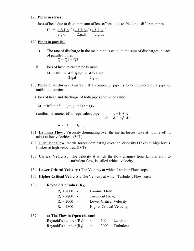
128. Pipes in series :
loss of head due to friction = sum of loss of head due to friction is different pipes
H = 4.f1.l1.v12 +4.f2.l2.v2
2 +4.f3.l3.v32
2.g.d1 2.g.d2 2.g.d3
129. Pipes in parallel : i) The rate of discharge in the main pipe is equal to the sum of discharges in each
of parallel pipes Q = Q1 + Q2
ii) loss of head in each pipe is same
hf1 = hf2 = 4.f1.l1.v12 = 4.f2.l2.v2
2 2.g.d1 2.g.d2
130. Pipes in uniform diameter : If a compound pipe is to be replaced by a pipe of
uniform diameter
i) loss of head and discharge of both pipes should be same hf1 = hf2 = hf3, Q= Q1 = Q2 = Q3 ii) uniform diameter (d) of equivalent pipe = l = l1 + l2 + l3 d5 d1
5 d25 d3
5 Where l = l1 + l2 + l3
131. Laminar Flow : Viscosity dominating over the inertia forces (take at low level). It takes at low velocities (VIL)
132. Turbulent Flow: Inertia forces dominating over the Viscosity (Takes at high level). It takes at high velocities. (IVT)
133. Critical Velocity: The velocity at which the flow changes from laminar flow to turbulent flow, is called critical velocity
134. Lower Critical Velocity : The Velocity at which Laminar Flow stops
135. Higher Critical Velocity : The Velocity at which Turbulent Flow starts
136. Reynold’s number (Rn)
Rn < 2000 - Laminar Flow Rn > 2800 - Turbulent Flow, Rn = 2000 - Lower Critical Velocity Rn = 2800 - Higher Critical Velocity
137. a) The Flow in Open channel
Reynold’s number (Rn) < 500 - Laminar Reynold’s number (Rn) > 2000 - Turbulent

138. The Kinetic Energy correction factor(α) for a laminar flow through a Circular pipe = 2.00
139. The Momentum correction factor(β) for a laminar flow through a Circular pipe = 4/3 = 1.33
140. The Kinetic Energy correction factor for a turbulent flow through a Circular pipe between 1.03 to 1.06
141. The Practical Value of Kinetic Energy correction factor
for a Turbulent flow is unity
142. The Loss of head due to Viscosity for laminar flow in a pipe hL = 32 µ v l Where µ - viscosity of the liquid w d2 w – Sp.wt. of flowing liquid
143. Loss of head due to friction in a pipe of uniform diameter in which viscous flow is
taking place = 16 . Rn
144. The Co-efficient of Viscosity (in poises), according to the method of orifice type Viscometer = µ = 0.0022t – 1.80 x Sp.gr. of liquid (ω)
t
145. Torque required to overcome viscous resistance of Footstep bearing (T) = Л2µNR4 60t
146. Torque req. to overcome viscous resistance of Collar bearing (T)=Л2µN R14-R1
4 60t
147. The Velocity of Wave Sound = K/ρ Where K- Bulk modulus Ρ – Density of the liquid
148. i) Mach number < Unity = Sub-Sonic Flow
ii) Mach number = Unity = Sonic Flow
iii) Mach between 1 to 6 = Super Sonic Flow
iv) Mach between > 6 = Hypersonic Flow
149. Inertia Force = Mass x Acceleration of flowing liquid 150. Viscous Force = Shear stress due to viscosity x C/S. Area of flow
151. Gravity Force = Mass x Acceleration due to gravity of flowing liquid
152. Surface tension force = Surface tension per unit length x length of the surface
flowing liquid
153. Pressure Force = Intensity of pressure x area of flowing liquid
154. Elastic Force = Elastic stress x area of flowing liquid

155. a) Reynold’s Number = (Rn) = Inertia Force / Viscous Force
b) Froude’s Number = (Fn) = Inertia Force / Gravity Force
c) Weber’s Number = (Wn) = Inertia Force / Surface tension Force
d) Euler’s Number = (En) = Inertia Force / Pressure Force
e) Mach’s Number = (Mn) = Inertia Force / Elastic Force
(or) Cauchy’s number
→ In centrifugal pump, flow leaving the impeller is free vortex 156. a) Specific speed of turbine = N P .
H5/4
b) Specific speed of Centrifugal pump = N Q . H3/4
c) Unit speed of turbine = N. H
d) Unit discharge of turbine = Q. H
e) Unit power of turbine = P. H3/2
157. Discharge through a reciprocating pump For single acting → Q = LAN (in m3/s)
60 For double acting → Q =2 LAN (in m3/s)
60
158. Power required to drive a reciprocating pump For single acting → W Q (Hs+Hd) For double acting → 2 W Q (Hs+Hd)
159. Specific Speed (NS) 12 – 70 80 – 420 420 – 1000 (Slow Speed) (Medium Speed) (High Speed)
Peltan Wheel Francis Turbine Kaplan Turbine
Head
Low Head - < 15 - Propeller (or) Kaplan
Medium - 15 – 70m - Kaplan (or) Francis
High Head - 70 – 250m - Francis (or) Pelton
Very High Head - > 250m - Peltan Wheel

160. Specific Speed of turbine = produces unit horse power at unit head
161. For low discharge, high head = reciprocating pump 162. a) Peltan Wheel - Tangential flow Impulse turbine (Impulse)
b) Francis Turbine - Reaction radial flow turbine (or) Outward flow
reaction turbine
c) Kaplan Turbine - Axial Flow reaction turbine
163. A Turbine is called Impulse, if an inlet of the turbine, the total energy is only
Kinetic energy
164. A Turbine is called reaction turbine, if an inlet of the turbine, the total energy is
only Kinetic energy and pressure energy
165. For a low head, high discharge – Kaplan turbine
166. For high head, low discharge – Peltan turbine (Receprocating pumps)
167. For high head, impellers are mounted in series
168. To discharge large quantity of liquid – impellers are mounted in parallel.
169. Flow reaction of francis turbine = Velocity of flow at inlet = 0.15 to .30 Theoretical Jet of velocity 170. Speed ratio of francis turbine = 0.60 to 0.90
171. Speed ratio for peltan wheel turbine = 0.40 to 0.50
172. Jet pump : Lifting water to the turbines (or) boilers.
173. Air lift pump : Lifting water from deep wells
174. Jet ratio = Dia. Of peltan wheel Dia of Jet of water
175. Speed ratio = µ .
2.g.H 176. a) Mechanical efficiency of turbine (hm) = Power at shaft .
Power given to the runner

b) Overall efficiency of turbine (ho) = Power at shaft .
Power at inlet of turbine
177. The discharge of the petal turbine = Q = Л d2 x 2.g.H 4
Francis turbine=Q= Л D B Vf
Kaplan Turbine = Q = Л (Do2 – Db
2) 4 178. Governing of turbine = The Speed is kept constant under all conditions 179. Cavitation will take place in case of Francis Turbine & Centrifugal pump
180. Cavitation occurs at low pressure.
181. In order to avoid cavitation in centrifugal pumps, suction pressure should be high.
182. Newton’s law of viscosity ---> Shear stress is directly(α) proportional to Velocity Gradient 183. a) Temperature is directly proportional(α) to Viscosity of Liquid b) Temperature is inversely proportional to Viscosity of gas 184. Centre of pressure of a plane surface immersed in a liquid is below the centre of
gravity of the plane surface 185. The resultant hydrostatic force acts through a point known as Centre of pressure
186. Metacentric height = Metacenter + Centre of gravity
187. Convergent-divergent mouthpiece having maximum co-efficient of discharge than
orifice
188. The Co-efficient discharge for a mouthpiece is more than for an orifice Cd (Mouth piece) > Cd (Orifice)
189. Laminar flow through a circular pipe,
the maximum velocity = 2 x average velocity.
190. In Laminar Flow, Loss of pressure head is directly(α) proportional to velocity. 191. The viscous flow between two parallel plates, the pressure drop per unit length = 12µU D2 192. Hydraulic Gradient Line(HGL) = Pressure head + datum head (potential head) = p/w + z 193. Total Gradient Line (TGL) = Pressurehead+Kinetic head+Datum head = p/w+z+V2/2g
Syphon: It is a long bent pipe used to connect two reservoirs at different levels intervened by a high ridge.
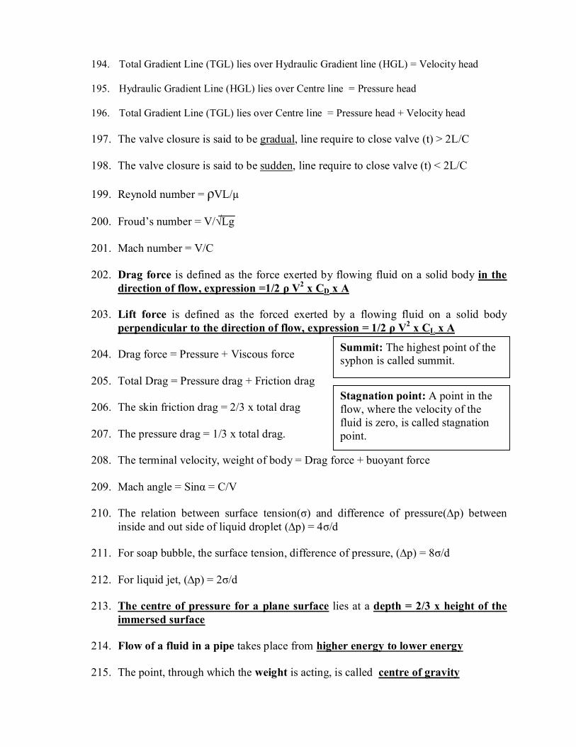
194. Total Gradient Line (TGL) lies over Hydraulic Gradient line (HGL) = Velocity head 195. Hydraulic Gradient Line (HGL) lies over Centre line = Pressure head
196. Total Gradient Line (TGL) lies over Centre line = Pressure head + Velocity head
197. The valve closure is said to be gradual, line require to close valve (t) > 2L/C
198. The valve closure is said to be sudden, line require to close valve (t) < 2L/C
199. Reynold number = ρVL/µ
200. Froud’s number = V/√Lg
201. Mach number = V/C
202. Drag force is defined as the force exerted by flowing fluid on a solid body in the
direction of flow, expression =1/2 ρ V2 x CD x A
203. Lift force is defined as the forced exerted by a flowing fluid on a solid body perpendicular to the direction of flow, expression = 1/2 ρ V2 x CL x A
204. Drag force = Pressure + Viscous force
205. Total Drag = Pressure drag + Friction drag
206. The skin friction drag = 2/3 x total drag
207. The pressure drag = 1/3 x total drag.
208. The terminal velocity, weight of body = Drag force + buoyant force
209. Mach angle = Sinα = C/V
210. The relation between surface tension(σ) and difference of pressure(∆p) between
inside and out side of liquid droplet (∆p) = 4σ/d
211. For soap bubble, the surface tension, difference of pressure, (∆p) = 8σ/d
212. For liquid jet, (∆p) = 2σ/d
213. The centre of pressure for a plane surface lies at a depth = 2/3 x height of the immersed surface
214. Flow of a fluid in a pipe takes place from higher energy to lower energy
215. The point, through which the weight is acting, is called centre of gravity
Summit: The highest point of the syphon is called summit.
Stagnation point: A point in the flow, where the velocity of the fluid is zero, is called stagnation point.

216. The point, about which a floating body, starts oscillating when the body is titled is called meta centre
217. Orifice, mouthpieces are used to measure rate of flow
218. Velocity of approach(V) = Discharge over notch
Area of channel
219. The Co-efficient of friction in terms of shear stress = f = 2τ0 / ρV2
220. Reynold shear stress for turbulent flow = ρUV1
221. Shear velocity (u) = τ0/ρ
222. When the pipes are connected in series, the total rate of flow is same as flowing through each pipe, H = hf1 + hf2
223. When the pipes are connected in parallel, the total loss of head is same as in
each pipe hf1 = hf2, Q = Q1 + Q2
224. Water hammer in pipes takes place when Flowing fluid suddenly brought to rest by closing valve = V Kρ
225. The valve is closed gradually = ρLV t
226. Model analysis of pipes flow are based on Reynold number 227. Model analysis of free surface flows are based on Froude number
228. Model analysis of aeroplanes and projectile moving at Super sonic speed are
based on Mach number
229. The boundary-layer takes place for real fluids
230. The thickness of laminar boundary layer α x1/2
231. The thickness of turbulent boundary layer α x4/5
232. Specific energy of flowing fluid per unit weight = γ2 + h
2g 233. The depth of flow at which Specific energy is minimum = Critical depth
Critical depth = (q2/g)1/3 234. For Circular channel, Wetter perimeter(P) = 2 R θ
235. For Circular channel, Area of flow = R2 θ – Sin2θ
2 236. Mechanical efficiency of Centrifugal pump = Power at the impeller
SHP

237. The Manometer head(Hm) of a centrifugal pump =
Total head at outlet – Total head at inlet 238. To produce high head by multistage centrifugal pump, the impellers are
connected in series
239. To discharge a large quantity of liquid by multi stage centrifugal pump, the impellers are connected in parallel.
240. Specific speed of a pump = Head developed is unity and discharge is one cubic meter
241. Cavitation take place if the pressure of the flowing fluid at any point is less than vapour pressure of fluid.
242. Indicator diagram = Variation of pressure head in the cylinder
243. Air vessel – to obtain continuous supply of water at uniform rate.
244. Limiting value of separation head = 2.50m (abs)
245. Hydraulic accumulator = Storing the energy of a fluid in the form of pressure energy
246. Hydraulic intensifier = Increasing pressure intensity of a fluid.
247. Hydraulic ram is a pump which works on the principle of water-hammer.
248. Hydraulic coupling = transmitting same torque to the driven shaft
249. Torque converter = Transmitting increased (or) decreased torque to the driven shaft.
250. Rotameter is used to measure discharge of fluids
251. Current meter is used to measure velocity
252. Hotwireanemometer is used to measure Velocity of gases
253. An air vessel provided at the summit in a siphon to avoid the interruption in the flow.
254. A nozzle placed at the end of water pipe line discharges at high pressure
255. The value of Specific weight for water in SI units = 9810 M/m3
256. The angle of contact(θ)between water and glass tube in case of capillary rise = 00
257. The angle of contact(θ)between mercury and glass tube in case of capillary depression = 1280
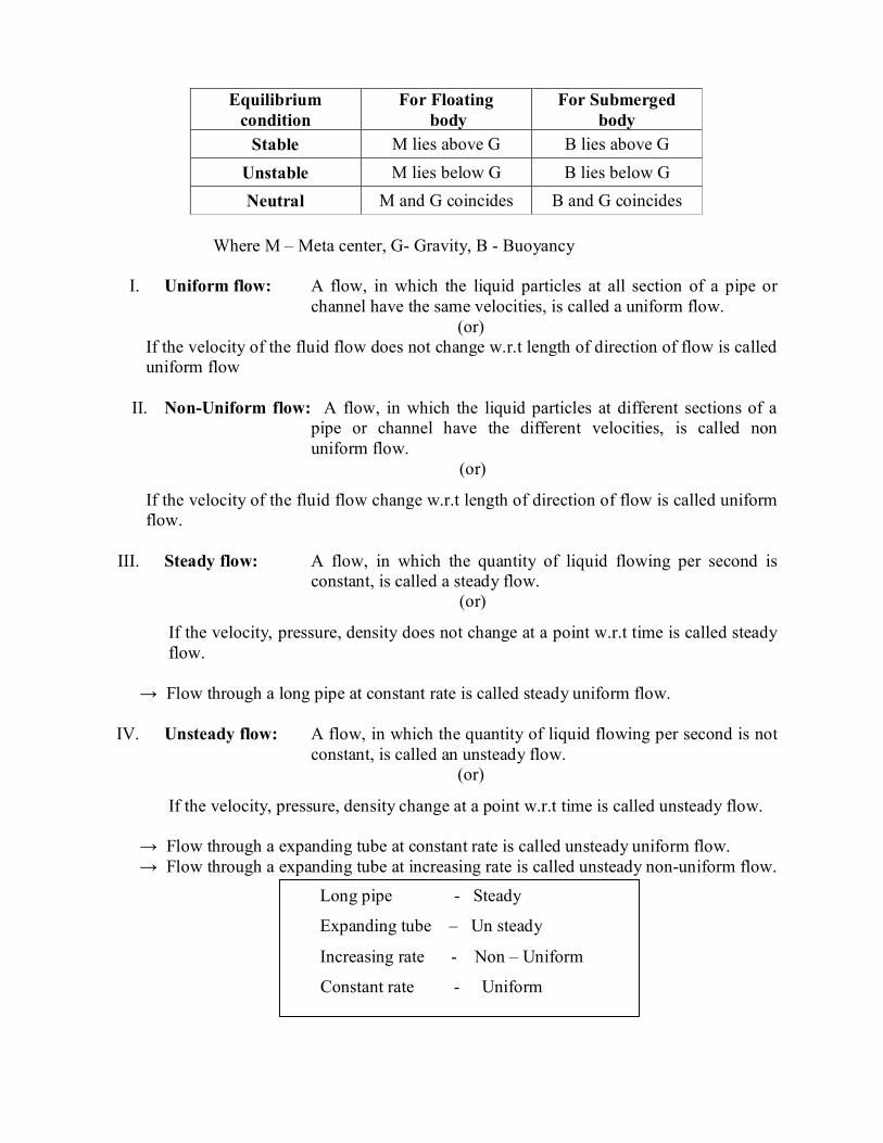
Equilibrium condition
For Floating body
For Submerged body
Stable M lies above G B lies above G Unstable M lies below G B lies below G Neutral M and G coincides B and G coincides
Where M – Meta center, G- Gravity, B - Buoyancy
I. Uniform flow: A flow, in which the liquid particles at all section of a pipe or channel have the same velocities, is called a uniform flow.
(or) If the velocity of the fluid flow does not change w.r.t length of direction of flow is called uniform flow
II. Non-Uniform flow: A flow, in which the liquid particles at different sections of a
pipe or channel have the different velocities, is called non uniform flow.
(or)
If the velocity of the fluid flow change w.r.t length of direction of flow is called uniform flow.
III. Steady flow: A flow, in which the quantity of liquid flowing per second is constant, is called a steady flow.
(or)
If the velocity, pressure, density does not change at a point w.r.t time is called steady flow.
→ Flow through a long pipe at constant rate is called steady uniform flow.
IV. Unsteady flow: A flow, in which the quantity of liquid flowing per second is not constant, is called an unsteady flow.
(or)
If the velocity, pressure, density change at a point w.r.t time is called unsteady flow.
→ Flow through a expanding tube at constant rate is called unsteady uniform flow. → Flow through a expanding tube at increasing rate is called unsteady non-uniform flow.
Long pipe - Steady
Expanding tube – Un steady
Increasing rate - Non – Uniform
Constant rate - Uniform

V. Streamline flow: A flow, in which each liquid particle has a definite path and the paths of individual particles do not cross each other, is called a streamline flow.
VI. Laminar flow: If the fluid particles move in straight lines and all the lines are parallel to the surface, the flow is called laminar flow.
VII. Turbulent flow: A flow, in which each liquid particle does not have a definite
path and the paths of individual particles also cross each other, is called a Turbulent flow.
VIII. Compressibility flow: A flow, in which the volume of a fluid and its density changes
during the flow, is called a compressible flow. All the gases are considered to have compressible flow.
(or)
If the density of fluid changes from point to point in a flow is called compressible flow. →In a compressible flow, the volume of the flowing liquid changes during the flow.
IX. Incompressible flow: A flow, in which the volume of a fluid and its density changes
does not change during the flow, is called a incompressible flow. All the liquids are considered to have incompressible flow.
(or) If the density of fluid is constant from point to point in a flow is called incompressible flow.
→ In a incompressible flow, the volume of the flowing liquid does not changes during the flow.
X. Rotational flow: A flow, in which the fluid particles also rotate (i.e., have some
angular velocity) about their own axes while flowing, is called rotational flow.
→In a rotational flow, the particles rotate about their own axes while flowing.
XI. Irrotational flow: A flow, in which the fluid particles do not rotate (i.e., have some angular velocity) about their own axes and not retain their original orientations, is called rotational flow.
XII. One-dimensional flow: A flow, in which the streamlines of its moving particles are
represented by straight line, is called an one-dimensional flow.
XIII. Two-dimensional flow: A flow, whose streamlines of its moving particles are represented by curve, is called Two-dimensional flow.
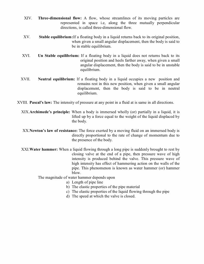
XIV. Three-dimensional flow: A flow, whose streamlines of its moving particles are represented in space i.e, along the three mutually perpendicular directions, is called three-dimensional flow.
XV. Stable equilibrium :If a floating body in a liquid returns back to its original position,
when given a small angular displacement, then the body is said to be in stable equilibrium.
XVI. Un Stable equilibrium: If a floating body in a liquid does not returns back to its
original position and heels farther away, when given a small angular displacement, then the body is said to be in unstable equilibrium.
XVII. Neutral equilibrium: If a floating body in a liquid occupies a new position and remains rest in this new position, when given a small angular displacement, then the body is said to be in neutral equilibrium.
XVIII. Pascal’s law: The intensity of pressure at any point in a fluid at is same in all directions.
XIX.Archimede’s principle: When a body is immersed wholly (or) partially in a liquid, it is
lifted up by a force equal to the weight of the liquid displaced by the body.
XX.Newton’s law of resistance: The force exerted by a moving fluid on an immersed body is
directly proportional to the rate of change of momentum due to the presence of the body.
XXI.Water hammer: When a liquid flowing through a long pipe is suddenly brought to rest by
closing valve at the end of a pipe, then pressure wave of high intensity is produced behind the valve. This pressure wave of high intensity has effect of hammering action on the walls of the pipe. This phenomenon is known as water hammer (or) hammer blow.
The magnitude of water hammer depends upon a) Length of pipe line b) The elastic properties of the pipe material c) The elastic properties of the liquid flowing through the pipe d) The speed at which the valve is closed.
Related Documents