10 Selection, Design and Construction of Offshore Wind Turbine Foundations Sanjeev Malhotra, PE, GE Parsons Brinckerhoff, Inc. United States of America 1. Introduction In the past twenty five years, European nations have led the way in the development of offshore wind farms. However, development in offshore wind energy is picking speed in other continents as well. More recently, there has been explosive growth in investment in the clean energy sector, with onshore and offshore wind power taking by far the largest share of that investment. About 50 billion US dollars were invested each year since 2007. Although economic crises may have impeded investment in 2010. In the last few years nearly 30 to 40 percent of all new installed power generation capacity in Europe and the United States is attributed to wind energy. The European Wind Energy Association estimates that between 20 GW and 40 GW of offshore wind energy capacity will be operating in the European Union by 2020. The US Department of Energy predicts that 50 GW of installed offshore wind energy will be developed in the next 20 years (NWTC, 2006). This means at least US$100 billion of capital investment with about US$50 billion going to offshore design and construction contracts. In the United States, offshore wind power development has not been a focus area because there is great potential for wind power on land. However, high quality onshore wind resources are mostly located in the Midwest and Central United States while the demand centers are located along the coasts, thereby making the cost of transmission high. On the northeast coast of the United States, offshore development is an attractive alternative because electricity costs are high and transmission line construction from the mid-west faces many obstacles. Higher quality wind resources, proximity to coastal population centers, potential for reducing land use, aesthetic concerns, and ease of transportation and installation are a few of the compelling reasons why power companies are turning their attention to offshore development. Offshore turbines are being made larger to economize in the foundation and power collection costs. As the technology for wind turbines improves, the industry has developed wind turbines with rotor diameters as large as 150 m and power ratings of over 7.5 MW to 10 MW. As increasing number of wind farms are being planned 15 to 50 km from shore in water depths of over 50 m, the combination of water depth, the increasing wind tower heights and rotor blade diameters create loads that complicate the foundation design and consequently place a greater burden on the engineer to develop more innovative and cost-effective foundations and support structures. Moreover, offshore foundations are exposed to additional loads such as ocean currents, storm wave loading, ice loads and potential ship impact loads. All of these factors pose significant challenges in the www.intechopen.com

Welcome message from author
This document is posted to help you gain knowledge. Please leave a comment to let me know what you think about it! Share it to your friends and learn new things together.
Transcript

10
Selection, Design and Construction of Offshore Wind Turbine Foundations
Sanjeev Malhotra, PE, GE Parsons Brinckerhoff, Inc. United States of America
1. Introduction
In the past twenty five years, European nations have led the way in the development of offshore wind farms. However, development in offshore wind energy is picking speed in other continents as well. More recently, there has been explosive growth in investment in the clean energy sector, with onshore and offshore wind power taking by far the largest share of that investment. About 50 billion US dollars were invested each year since 2007. Although economic crises may have impeded investment in 2010. In the last few years nearly 30 to 40 percent of all new installed power generation capacity in Europe and the United States is attributed to wind energy. The European Wind Energy Association estimates that between 20 GW and 40 GW of offshore wind energy capacity will be operating in the European Union by 2020. The US Department of Energy predicts that 50 GW of installed offshore wind energy will be developed in the next 20 years (NWTC, 2006). This means at least US$100 billion of capital investment with about US$50 billion going to offshore design and construction contracts. In the United States, offshore wind power development has not been a focus area because there is great potential for wind power on land. However, high quality onshore wind resources are mostly located in the Midwest and Central United States while the demand centers are located along the coasts, thereby making the cost of transmission high. On the northeast coast of the United States, offshore development is an attractive alternative because electricity costs are high and transmission line construction from the mid-west faces many obstacles. Higher quality wind resources, proximity to coastal population centers, potential for reducing land use, aesthetic concerns, and ease of transportation and installation are a few of the compelling reasons why power companies are turning their attention to offshore development. Offshore turbines are being made larger to economize in the foundation and power collection costs. As the technology for wind turbines improves, the industry has developed wind turbines with rotor diameters as large as 150 m and power ratings of over 7.5 MW to 10 MW. As increasing number of wind farms are being planned 15 to 50 km from shore in water depths of over 50 m, the combination of water depth, the increasing wind tower heights and rotor blade diameters create loads that complicate the foundation design and consequently place a greater burden on the engineer to develop more innovative and cost-effective foundations and support structures. Moreover, offshore foundations are exposed to additional loads such as ocean currents, storm wave loading, ice loads and potential ship impact loads. All of these factors pose significant challenges in the
www.intechopen.com
Wind Turbines
232
design and construction of wind turbine support structures and foundations. This chapter summarizes current practices in selecting and designing such foundations.
2. Background
2.1 Wind turbine farm layout Primary components of a typical offshore wind farm include several wind turbines located in the water, connected by a series of cables to an offshore transformer station which in turn is connected by an undersea cable to an onshore transformer station linked to the existing power grid (Figure 1). The wind turbines are usually spaced laterally at several (4 to 8) times the rotor diameter and staggered so as to minimize wake effects. Placing turbines closer reduces the quantity of electric cable required but it increases turbulence and wake effects thereby reducing power generation. Therefore, laying out wind turbine farms includes minimizing the length of cabling required yet maximizing power generation so as to optimize costs per unit of power produced.
Fig. 1. Wind Farm Components and their Layout, (Malhotra, 2007c)
2.2 Wind turbine components The components of a wind turbine system (Figure 2) include the foundation, the support structure, the transition piece, the tower, the rotor blades and the nacelle. The foundation system and support structure, used to keep the turbine in its proper position while being exposed to the forces of nature such as wind and sea waves, can be made using a variety of materials such as reinforced concrete or steel. Support structures connect the transition piece or tower to the foundation at seabed level. In some cases, the foundations serve as support structures as well by extending from the seabed level to above the water level and connecting directly to the transition piece or tower. The transition piece connects the tower to the support structure or foundation. The transition piece also provides a means to correct any misalignment of the foundation that may have occurred during installation. The towers are made of steel plate rolled into conical subsections that are cut and rolled into the right shape, and then welded together. The nacelles contain the key electro-mechanical components of the wind turbine, including the gearbox and generator. The rotor blades are made of fiberglass mats impregnated with polyester or carbon fiber composites. The power cable from each turbine is inserted in a “J” shaped plastic tube which carries the cable to the cable trench in the seabed.
www.intechopen.com

Selection, Design and Construction of Offshore Wind Turbine Foundations
233
Fig. 2. Wind Turbine System Components (Malhotra, 2007c)
2.3 Wind turbine operation As wind flows through a turbine it forces the rotor blades to rotate, transforming kinetic energy of the wind to mechanical energy of the rotating turbine. The rotation of the turbine drives a shaft which through a gear box drives a power generator which generates current through the principal of electromagnetic induction. The shaft, gearbox and generator are located in the nacelle. The nacelle is able to revolve about a vertical axis so as to optimally direct the turbine to face the prevailing wind. The electric current thus generated is converted to a higher voltage via a transformer at the base of the tower. The power that can be harnessed from the wind is proportional to the cube of wind speed up to a theoretical maximum of about 59 percent. However, today’s wind turbines convert only a fraction of the available wind power to electricity and are shut down beyond a certain wind speed because of structural limitations and concern for wear and tear. So far, it is considered cost optimal to start power regulation at 10-min wind speed of 9-10 m/s, have full regulation at mean wind speeds above 14-15 m/s and shut-down or idle mode at 25 m/s. Power regulation is the ability of a system to provide near constant voltage over a wide range of load conditions. To minimize fluctuation and to control the power flow, the pitch of the blades of offshore wind turbines is regulated. At lower wind speeds, variable rotor speed regulation is used to smooth out power output. The yaw of the turbine is also varied every 30-sec to 60-sec, to maximize operating efficiency which creates gyroscopic loads. The
www.intechopen.com
Wind Turbines
234
pitching and yawing creates non-linear aerodynamics and hysteresis which have to be modeled in turbine response calculations.
2.4 Wind turbine foundation performance requirements Deformation tolerances are usually specified by the wind turbine manufacturer and are based on the requirements for the operation of the wind turbine. Typically, these tolerances include a maximum allowable rotation at pile head after installation, and also a maximum accumulated permanent rotation resulting from cyclic loading over the design life. For an onshore wind turbine, the maximum allowable tilt at pile head after installation is typically between 0.003 to 0.008 radian (0.2 degrees to 0.45 degrees). A somewhat larger tilt 0.009 (0.5 degrees) may be allowed for offshore wind turbines. Any permanent tilt related to construction tolerances must be subtracted from these specified tolerances. Typical values of construction tolerances range from 0.003 to 0.0044 radians (0.20 degrees to 0.25 degrees). Allowable rotation of the support structure/foundation during operation is generally defined in terms of rotational stiffness which typically ranges between 25 GNm/radian to 30 GNm/radian (Vestas, 2007).
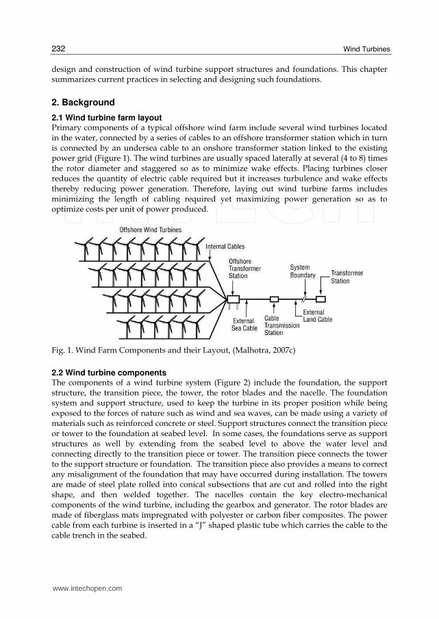
2.5 Foundation dynamics Foundation dynamics is an important consideration in the design of an offshore wind turbine. As the offshore wind turbine rotates, the blades travel past the tower creating vibrations to which the offshore wind turbine is sensitive. It has been shown that when a three bladed rotor encounters a turbulent eddy it resists peak forces at frequencies of 1P and 3P, where P is the blade passing frequency. For a typical variable speed turbine, the blade passing frequency is between an approximate range of 0.18 Hz and 0.26 Hz, and rotation frequency, which is between about 0.54 Hz and 0.78 Hz. Meanwhile, cyclic loading from sea waves typically occurs at a frequency between 0.04 Hz and 0.34 Hz (Gaythwaite, 1990). Therefore, to avoid resonance, the offshore wind turbine (turbine, tower, support structure and foundation) have to be designed with a natural frequency that is different from the rotor frequencies as well as wave frequencies as shown in Figure 3.
Fig. 3. Typical ranges for frequencies for waves, rotors, blade passing and structure (Malhotra, 2009).
Larger turbine diameters will require taller towers and heavier nacelles. The range of natural rotational frequencies 1P and 3P will also increase linearly with the blade diameter.
www.intechopen.com

Selection, Design and Construction of Offshore Wind Turbine Foundations
235
Since the natural frequency of the tower system is inversely proportional to the height of tower squared, the frequency of the higher towers will decrease rapidly and will fall in the region of wave frequencies, thereby imposing even greater demands on the design of the foundation and support structure. Accordingly, the support structure and foundation system would need to be made relatively stiff. A stiffer foundation would require more materials and therefore cost more than a flexible foundation.
3. Design process
The design process involves an initial site selection followed by an assessment of external conditions, selection of wind turbine size, subsurface investigation, assessment of geo-hazards, foundation and support structure selection, developing design load cases, and performing geotechnical and structural analyses. A flow diagram for the design process of a typical offshore wind turbine is shown in Figure 4. For achieving economies of scale, wind
Fig. 4. Design Process for a typical offshore wind turbine (Malhotra, 2007c)
SITE SELECTION
ASSESSMENT OF EXTERNAL CONDITIONS
DESIGN LOADS FOR TURBINE
SELECTION OF SITE CLASS AND “OFF THE SHELF” WIND TURBINE
SUPPORT STRUCTURE SELECTION AND EVALUATION
DETERMINE DESIGN LOAD CASES
SUPPORT STRUCTURE AND FOUNDATION ANALYSES
STRUCTURAL INTEGRITY,
FATIGUE CHECK AND CHECK FOR PERFORMANCE
SITE SUSBURFACE INVESTIGATION
DESIGN COMPLETED
www.intechopen.com

Wind Turbines
236
turbines are generally mass produced and available in four predefined classes based on wind speed. Consequently, the designer simply selects one of the predefined turbine classes that may apply to the wind farm site. Because the water depth, seabed conditions, sea state statistics (wave heights and current velocities), ice climate etc., may vary widely between sites, the use of a generic support structure concept is not feasible. Therefore, the tower, substructure and foundation, are designed for site specific conditions. The foundation system is selected based on several factors such as the level of design loads, depth of water at the site, the site geology and potential impact to the marine environment. As larger, customized wind turbines are developed, they will require an integrated analytical model of the turbine, support structure and foundation system and rigorous analyses with site specific wind and wave regimes.
3.1 Site selection Besides favourable wind conditions, factors that govern selection of a wind farm site include site availability, visibility and distance from shore, proximity to power demand sites, proximity to local electricity distribution companies, potential impact to existing shipping routes and dredged channels, interference with telecom installations, buried under-sea cables and gas lines, distance from local airports to avoid potential interference with aircraft flight paths and interference with bird flight paths. An offshore wind farm faces numerous challenges in all phases. During early development an environmental impact study phase requires extensive public involvement, while the permitting process is time consuming and requires ample input from various stakeholders, such as fishermen, local communities, aviation authorities, the Coast Guard authorities, the Corps of Engineers and others. A proactive approach with early community involvement generally helps the process. During this time perhaps by focusing on works that are more visible to the community such as onshore substations and cable routes the developer may be able to achieve progress. Locating the wind array farther from shore obviously will reduce visual impact. Obtaining suitable connections to the power grid and early collaborations with various suppliers of the wind turbine and cable systems are crucial for the successful project design and implementation. An early identification and evaluation of potential grid connection points to develop various substation locations and cable routes is essential for gaining public approval. From an electrical engineering standpoint, the compatibility between the wind farm export power cables and the grid require careful evaluation with respect to grid code compliance and system interface.
3.2 Assessment of external conditions Following initial site selection, the developer makes an assessment of external conditions such as the level of existing wind conditions, water depth, currents, tides, wave conditions, and ice loading, the site geology and associated geo-hazards, such as sea-floor mudslides, scour and seismic hazards.
3.2.1 Design loads Since wind loading is the dominant loading on an offshore wind turbine structure, it results in dynamics characteristics that are different from the wave and current loading that dominates the design of foundations for typical oil and gas installations. The loading on
www.intechopen.com
Selection, Design and Construction of Offshore Wind Turbine Foundations
237
wind turbine foundations is characterized by relatively small vertical loading and larger horizontal and moment loads which are also dynamic. The design loads are classified into permanent, variable and environmental loads.
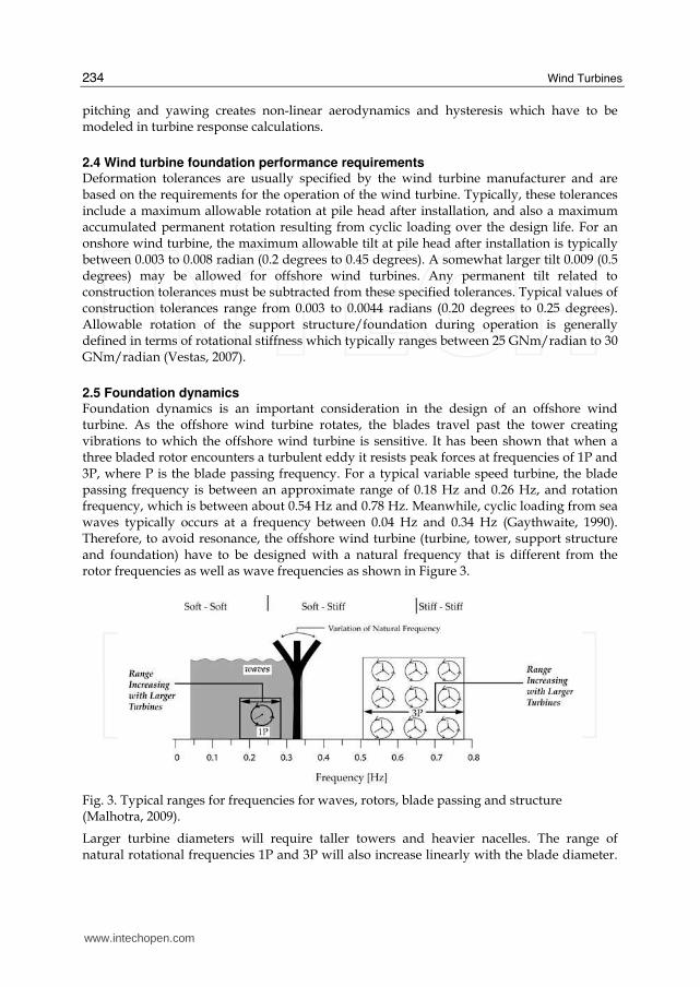
3.2.2 Permanent loads Permanent loads include the mass of the structure in air, including the mass of grout and ballast, equipment, or attachments which are permanently mounted onto the access platform and hydrostatic forces on the various members below the waterline. These forces include buoyancy also. Permanent loads from typical offshore wind turbines are presented in Table 1.
Typical 3.0 MW Turbine
80 m Hub Height
Typical 3.6 MW Turbine
80 m Hub Height
Typical 5 MW Turbine
90 m Hub Height
Future 7.5 MW Turbine
100 m Hub Height
Tower 156 ton 178 ton 347 ton ~550 ton
Nacelle 68 ton 70 ton 240 ton ~300 ton
Rotor 40 ton 40 ton 110 ton ~180 ton
Table 1. Permanent Loads from a Typical Offshore Wind Turbine (Various Sources)
3.2.3 Variable loads Variable loads are loads that may vary in magnitude, position and direction during the period under consideration. These include personnel, crane operational loads, ship impacts from service vessels, loads from fendering, access ladders, platforms and variable ballast and also actuation loads. Actuation loads result from the operation of the wind turbine. These include torque control from the generator, yaw and pitch actuator loads and mechanical braking loads. In addition to the above, gravity loads on the rotor blades, centrifugal and Coriolis forces, and gyroscopic forces due to yawing must be included in design. Loads that arise during fabrication and installation of the wind turbine or its components also classify as variable loads. During fabrication, erection lifts of various structural components generate lifting forces, while in the installation phase forces are generated during load out, transportation to the site, launching and upending, as well as during lifts related to installation. The necessary data for computation of all operating loads are provided by the operator and the equipment manufacturers. The data need to be critically evaluated by the designer. Forces generated during operations are often dynamic or impulsive in nature and must be treated as such. For vessel mooring, design forces are computed for the largest ship likely to approach at operational speeds. Generally, permanent and variable loads can be quantified with some certainty.
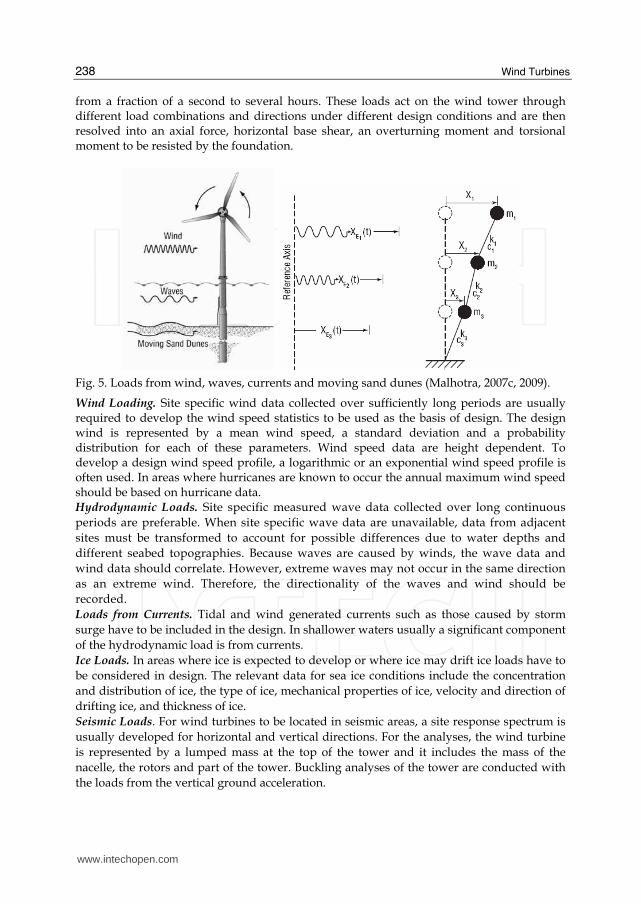
3.2.4 Environmental loading Environmental loads depend on the site climate and include loads from wind, wave, ice, currents and earthquakes and have a greater degree of uncertainty associated with them (Figure 5). These loads are time dependent, covering a wide range of time periods ranging
www.intechopen.com
Wind Turbines
238
from a fraction of a second to several hours. These loads act on the wind tower through different load combinations and directions under different design conditions and are then resolved into an axial force, horizontal base shear, an overturning moment and torsional moment to be resisted by the foundation.
Fig. 5. Loads from wind, waves, currents and moving sand dunes (Malhotra, 2007c, 2009).
Wind Loading. Site specific wind data collected over sufficiently long periods are usually required to develop the wind speed statistics to be used as the basis of design. The design wind is represented by a mean wind speed, a standard deviation and a probability distribution for each of these parameters. Wind speed data are height dependent. To develop a design wind speed profile, a logarithmic or an exponential wind speed profile is often used. In areas where hurricanes are known to occur the annual maximum wind speed should be based on hurricane data. Hydrodynamic Loads. Site specific measured wave data collected over long continuous periods are preferable. When site specific wave data are unavailable, data from adjacent sites must be transformed to account for possible differences due to water depths and different seabed topographies. Because waves are caused by winds, the wave data and wind data should correlate. However, extreme waves may not occur in the same direction as an extreme wind. Therefore, the directionality of the waves and wind should be recorded. Loads from Currents. Tidal and wind generated currents such as those caused by storm surge have to be included in the design. In shallower waters usually a significant component of the hydrodynamic load is from currents. Ice Loads. In areas where ice is expected to develop or where ice may drift ice loads have to be considered in design. The relevant data for sea ice conditions include the concentration and distribution of ice, the type of ice, mechanical properties of ice, velocity and direction of drifting ice, and thickness of ice. Seismic Loads. For wind turbines to be located in seismic areas, a site response spectrum is usually developed for horizontal and vertical directions. For the analyses, the wind turbine is represented by a lumped mass at the top of the tower and it includes the mass of the nacelle, the rotors and part of the tower. Buckling analyses of the tower are conducted with the loads from the vertical ground acceleration.
www.intechopen.com

Selection, Design and Construction of Offshore Wind Turbine Foundations
239
3.2.5 Environmental loading conditions in the United States Across the globe, foundation designers for offshore wind farms will face varied environmental conditions. For example, in the United States alone, environmental loading conditions include hurricanes in the southeastern United States and the Gulf of Mexico, and Northeast storms along the east coast from Maine to Virginia, and floating freshwater ice in the Great Lakes region. Hurricanes are large, revolving tropical cyclones which form well defined spirals with a distinct low pressure center and can be as large as 1000 km in diameter, traveling at a velocity of up to 11 m/s. Wind data for a number of hurricanes that made landfall in the US over a 50 year period are available. However, measured wave data from hurricanes are however quite limited and simplified methods are often employed to estimate design load parameters for wave loads. Northeast winter storms are generated in the winter at higher latitudes with colder air at their core and do not have a well defined spiral and are often much larger in diameter that hurricanes. Even though these storms produce winds with lower velocities than hurricanes, their larger diameter can develop bigger high energy waves. Approximately 30 northeast storms occur in the northern portion of the Atlantic coast every year. Therefore, these storms must be considered in the determination of the wind turbine design loads. In most European waters, sea ice is not a common phenomenon. It mostly occurs in the Barents Sea, northern and western parts of the Norwegian Sea, and inland waters such as the Baltic and Skagerak. Moreover, most offshore wind turbines have been installed in saline water either in the North Sea or the Baltic Sea. Meanwhile, the Great Lakes region of the US consists of large bodies of fresh water and is more susceptible to the formation of floating ice than are salt seas. Floating fresh water ice is harder than salt water ice and should be considered in the design of support structures for turbines in certain locations. Data on environmental conditions obtained from various projects at various locations are summarized in Table 2.
North Sea
Baltic Sea
Coastline United Kingdom
US East Coast
Gulf of Mexico
US West Coast
Wind 50 yr Extreme 10 min Mean Wind (m/s)
50 54.5 38-46 46 45 33
50 yr Extreme 5 sec Gust (m/s)
60 65 46 - 55 55 54 40
Waves and Currents 50-yr Max. Wave Height (m)
22.3 5 8-12 24.2 19.9 17
Related Wave Period (sec)
14.5 13.0 14.0 13.7- 14.5 13 15 -17
50-yr Tidal Current Surface Velocity (m/s)
1.71 1.7 3.0 2.06 1.03 1.0
50-yr Storm Surge Current Surface Velocity (m/s)
0.43 0.30 0.7 0.5 0.25 0.25
Table 2. Comparison of Environmental Loading Conditions (Various Sources)
www.intechopen.com
Wind Turbines
240
3.2.6 Application of available design standards The lack of available guidelines for offshore wind turbine structures in the United States drives the designers of support structures for offshore wind turbines to look at the established design practice for conventional fixed offshore platforms as outlined in guidelines prepared by the American Petroleum Institute (API), of Washington, D.C. However, designers must first recognize the differences in the two types of structures and how they respond to applied dynamic loads. The assessment of the dynamic response of offshore wind turbines differs from that of offshore oil and gas platforms and also onshore wind turbines. Offshore platforms are designed using static or quasi-static response calculations for external design loads, whereas, offshore wind turbines are driven by a combination of wind, wave and current loading in a non-linear dynamic analyses. The natural frequency of the offshore wind turbine is somewhere between the wave and rotor frequencies. On the other hand fixed platforms for the offshore oil industry are usually designed to have natural frequencies well above the wave frequencies. Unlike common practice in the offshore platforms, frequency domain analysis of dynamic response is seldom used for offshore wind turbines. The non-linear behavior of aerodynamic loading of the rotor, time domain simulations are generally required for an accurate assessment of both fatigue and ultimate limits states. Since the operating state of the wind turbine varies along with variable wind conditions, a number of load cases need to be analyzed. Compared with onshore wind turbines, wave and current climate cause a large extension of the number of load cases. Moreover, the influence of the foundation and support structure on the overall dynamic behavior is much larger compared to that of an onshore wind turbine. Extreme wave loads generally govern the design of conventional fixed offshore platforms
with wind loads contributing a mere 10 percent to the total load. Therefore, existing offshore
standards emphasize wave loading but pay little attention to the combination with wind
loads. In contrast, the design of offshore wind turbines is generally governed by extreme
wind, wave and current loads, with almost equal weight being given to wind and wave
loads depending on the site location. In addition, given the highly flexible response of the
wind turbine structure, fatigue loads are critical.
So far, a key assumption in the design of wind turbines in Europe is that the turbines must
be able to withstand extreme events with a return period of 50 years, whereas, the oil and
gas industry structures are designed to withstand 100 year events. Therefore, the resulting
reliability for offshore wind turbines and conventional fixed offshore platforms is
understandably different. Extending the use of design loads obtained from API in the design
of support structure and foundation will result in a higher degree of conservatism for the
foundation design than for the wind turbine and consequently lead to higher construction
costs. For the design of wind turbines a 10-minute average wind speed is considered long
enough to cover all high frequency fluctuations of the wind speed and short enough to have
statistical stable values. This is significantly different from offshore platform design where
1-hour average values are used.
For the design of offshore structures in the United States three exposure category levels corresponding to the consequence of failure are considered (API, 1993). Consequences would include environmental impact, danger to human life or economic loss. The failure of manned facilities or those with oil and gas storage facilities are considered of high consequence. Failure of platforms that may be manned but are evacuated during storms or
www.intechopen.com

Selection, Design and Construction of Offshore Wind Turbine Foundations
241
do not have oil and gas storage is considered to be of medium consequence. Structures that are never manned and have low consequence of failure fall in the low consequence category. For the Gulf of Mexico, associated with each of these categories are a minimum wave height and period, wind speed and current speed to be used for design. Offshore wind turbines are generally unmanned in storm situations so that the risk of human injury is low compared to typical manned offshore structures. Moreover, economic consequences of collapse and the related environmental pollution are low. For now, offshore wind turbines are likely to fall in the low consequence category. But as they become more integrated into the power grid and supply more power to the grid, the consequences of their failure are likely to increase. API-RP2A (1993) guidelines suggest that the recurrence interval for the oceanic design criteria should be several times the design life of the offshore platform. Typical offshore platforms have a design life of about 20 years and are designed using 100 year return period oceanic criteria. However, for offshore wind turbine foundation design, a 50 year recurrence period is being used in Europe and appears appropriate for the United States as well. Ultimate load cases may result from different environmental conditions (wind, wave, current, ice) and system operating conditions or installation procedures. Per the DNV (2004), for offshore wind turbine foundation design, a recurrence interval of 50 years is considered for extreme environmental conditions. For installation, operation and normal environmental conditions a recurrence interval of 1 year is considered. In the past few years, the International Electrotechnical Commission, of Geneva, Switzerland, and the Det Norske Veritas, a classification organization that has its headquarters in Oslo, Norway, have developed guidelines for offshore wind turbines, guidelines that for the interim are being used for projects in the United States.
4. Typical support structures
Support structures for offshore wind towers can be categorized by their configuration and method of installation into six basic types, described below. Gravity Structures As the name implies, gravity structures resist the overturning loads solely by means of its own gravity. These are typically used at sites where installation of piles in the underlying seabed is difficult, such as on a hard rock ledge or on competent soil sites in relatively shallow waters. Gravity caissons are typically concrete shell structures. These structures are cost-effective when the environmental loads are relatively low, and the dead load is significant, or when additional ballast can be provided at a reasonable cost. Monopiles This is a simple design in which the wind tower, made up of steel pipe, is supported by the monopile, either directly or through a transition piece. The monopile consists of a large diameter steel pipe pile of up to 6 m in diameter with wall thicknesses as much as 150 mm. Depending on the subsurface conditions, the pile is typically driven into the seabed by either large impact or vibratory hammers, or the piles are grouted into sockets drilled into rock. Compared to the gravity base foundation, the monopile has minimal and localized environmental impact. By far, the monopile is the most commonly used foundation for offshore wind turbines. Guyed Monopile Towers The limitation of excessive deflection of a monopile in deeper waters is overcome by stabilizing the monopile with tensioned guy wires. Tripods Where guyed towers are not feasible, tripods can be used to limit the deflections of the wind towers. The pre-fabricated frame is triangular in plan view and consists of steel
www.intechopen.com

Wind Turbines
242
pipe members connecting each corner. A jacket leg is installed at each corner which is diagonally and horizontally braced to a transition piece in the center. The tripod braced frame and the piles are constructed onshore and transported by barge to the site. Another construction advantage of these types of foundations is that they do not require any seabed preparation. In 2009, tripods were installed in 30 m of water for the Alpha Ventus wind farm located 45 km from the island of Borkum, Germany. Braced Lattice Frames A modification of the tripod frame, the lattice frame has more structural members. The jacket consists of a 3-leg or 4-leg structure made of steel pipes interconnected with bracing to provide the required stiffness. Braced lattice frames have been used in deep water installations offshore of Scotland and are being planned for wind farms offshore of New Jersey. Floating Tension Leg Platforms Floating structures are partially submerged by means of tensioned vertical anchor legs. The submerged part of the structure helps dampen the motion of the system. Installation is simple because the structure can be floated to the site and connected to anchor piles or suction caissons. The structure can be subsequently lowered by use of ballast tanks, tension systems, or both. The entire structure can be disconnected from the anchor piles and floated back to shore for major maintenance or repair of the wind turbine. Another version of the floating foundation requires merely a counterweight lowered to the seabed, in effect anchoring the floating platform. Several concepts for floating foundations are in the testing stage, with at least one in the demonstration phase in the Adriatic Sea off the south coast of Italy. The following factors should be considered when selecting support structures for offshore wind turbines: • Required dynamic response in the given water depth;
• Constructability and logistics of installation, including contractor experience and availability of equipment;
• Costs of fabrication and availability of steel and other materials; and • Environmental effects. The required dynamic response of the overall system in the given water depth is the main consideration. Because the dynamic response of a typical wind turbine depends on the stiffness of the support structure, which in turn is inversely proportional to its free standing height (or water depth) to the third power, one can use the water depth as a main factor for selecting the support structure in initial design. In 2004 and 2005, the author surveyed nearly 40 wind farms in Europe to obtain data on such details as water depths, distance from shore, soil conditions, and types of foundations and support structures employed. Water depth was correlated with support structure type to create Figure 6. The author believes that each of these support structures can be installed in even greater water depths with innovation and improved designs.
5. Typical foundations
Foundations anchor the support structures to the seabed, and typically fall into the six types described herein. Gravity Caissons This type of foundation has been used for several offshore wind farms in Europe. For economical fabrication of gravity caissons one requires a shipyard or a drydock near the site (Figure 7) which allows the massive foundation structures to be floated out to
www.intechopen.com

Selection, Design and Construction of Offshore Wind Turbine Foundations
243
Fig. 6. Various types of support structures and their applicable water depth (Malhotra, 2007b, c).
Fig. 7. Gravity Base Foundation being constructed for Nysted Offshore Wind Farm at Rødsand, Denmark. (Courtesy of Bob Bittner, Ben C. Gerwick, Inc.)
the site and sunk. Site preparation and placement required for gravity caissons typically involves dredging several meters of generally loose, soft seabed sediment and replacement with compacted, crushed stone to prepare a level bed for the gravity caisson to rest on.
www.intechopen.com

Wind Turbines
244
Special screeds and accurate surveying is required to accomplish this task. Installation of these structures is relatively time consuming. For example, approximately 29 days were needed to complete four gravity foundations at the Nysted wind farm constructed in Denmark in 2003. Driven Pipe Pile The driven steel pipe pile option is an efficient foundation solution in deep waters. The typical method of offshore and near-shore installation of piled structures is to float the structure (monopile, tripod or braced frame) into position and then to drive the piles into the seabed using hydraulic hammers (Figure 8). The handling of the piles requires the use of a crane of sufficient capacity, preferably a floating crane vessel. Use of open-ended driven pipe piles allows the sea bottom sediment to be encased inside the pipe thus minimizing disturbance. The noise generated during pile driving in the marine environment might cause a short term adverse impact to aquatic life. Since the number of piles is typically few and spread apart, these adverse impacts are only short term and relatively minor. Installation times for driven monopiles are relatively short. For example, individual monopiles constructed in 2004 as part of the Scroby Sands wind farm in Norfolk, United Kingdom, required less than 24 hours to install. Although available offshore pile-driving hammers with a rated energy of 3,000 kJ or more are capable of installing piles with diameters as large as 4.5 m, newer, higher-capacity models with adaptors for even larger piles are being developed. Pile driveability evaluations and hammer selection are crucial parts of the process.
Fig. 8. Menck Pile driving hammer atop a steel pipe pile at Kentish Flats Offshore Wind Farm, UK (Courtesy: Elsam)
Post-Grouted Closed-end Pile in Predrilled Hole In this design, a closed-ended steel pipe pile is placed into a predrilled hole and then grouted in place. This option (Figure 9) is often used for offshore pile foundations less than 5 m in diameter and offers significant advantages over the cast-in-place drilled shaft option, including advance fabrication of the pile, better quality control, and much shorter construction time on the water. This option requires a specially fabricated large diameter reverse circulation drill. It also requires handling and placement of a
www.intechopen.com

Selection, Design and Construction of Offshore Wind Turbine Foundations
245
long, large diameter pile, with considerable weight. Closed-end piles can be floated to the site and lowered into the drill hole by slowly filling them with water. Installation times for drilled and post-grouted monopiles are relatively long, averaging about 50 hours per monopile.
Fig. 9. Typical Installation Sequence for a post grouted closed end pipe pile in predrilled hole (Malhotra, 2007c)
Drilled Shafts The installation of bored, cast-in-place concrete pile requires driving a relatively thin (25 mm) walled casing through the soft sediment to the underlying denser material (if necessary to establish a seal), then drilling through and below the casing to the required base elevation. Bending resistance is provided by a heavy reinforcing cage utilizing high strength, large diameter bars, with double ring, where necessary. The casing provides excavation support, guides the drilling tool, contains the fluid concrete, and serves as sacrificial corrosion protection. This approach requires a large, specially fabricated reverse circulation drill. The use of drilled shafts for offshore wind turbine foundations suffers from several disadvantages, including the need for placement of reinforcement, as well as the need to transport and place large quantities of concrete offshore. The logistics associated with offshore concreting and reinforcement placement make drilled shafts uneconomical for offshore wind turbines. Composite “Drive-Drill-Drive” Pile This procedure requires an adaptation of existing drilling and piling techniques and involves a combination of drive-drill-drive sequence to achieve the design depth. Installation times for monopiles using this composite sequence are relatively long. For example, the construction of monopiles as part of the North Hoyle wind farm in the United Kingdom in 2003 required approximately 70 to 90 hours on average. Suction Anchor Suction anchors consist of a steel canister with an open bottom and closed top. Like piles, suction anchors (Figure 10) are cylindrical in shape but have larger diameters (10 m to 15 m) and subsequently shallower penetration depths. They are installed by sinking into the seabed and then pumping the water out of the pile using a submersible pump (Figure 11). Pumping the water creates a pressure difference across the sealed top, resulting in a downward hydrostatic force on the pile top. The hydrostatic pressure thus developed pushes the anchor to the design depth. Once the design depth is achieved, the pumps are disconnected and retrieved. Installing suction caissons is relatively time consuming, as evidenced during the construction of the Hornes Rev II wind farm in Denmark in 2008. Approximately 32 hours were needed to complete installation of a single suction caisson for a meteorological mast, of which 10 hours involved penetration. Sunction anchors resist tension loads by relying on the weight of the soil encased by the steel bucket along with side friction on the walls and hydrostatic pressure. The stability of the system is ensured because
www.intechopen.com

Wind Turbines
246
Fig. 10. Suction Anchors for an offshore platform being transported to site in the Gulf of Mexico (Courtesy Prof Aubeny, TAMU).
Fig. 11. Installation stages of a Suction Anchor
there is not enough time for the bucket to be pulled out of the soil during a wave passage. As the bucket is pulled up, a cavity is formed between the soil surface and the bottom of the bucket which creates a suction pressure that resists the uplift loads. These foundations carry compression loads by side friction and end bearing. Suction anchors are expected to be particularly suitable for foundations in soft cohesive sediments. These foundations cannot be used in rock, in gravel or in dense sand. Suction anchors are cheaper to install since they do not require underwater pile drivers. At the end of a wind turbine's life, a suction anchor may be removed completely from the seabed, unlike piled foundations. This provides room for recycling and reuse.
www.intechopen.com
Selection, Design and Construction of Offshore Wind Turbine Foundations
247
Foundation selection considerations for offshore wind turbines include: • Soil Conditions that facilitate installation and performance, • Driveability for driven piles and penetrability for suction anchors, • Constructability and logistics of installation, including Contractor experience and
availability of equipment, and
• Costs of fabrication, availability of steel and other materials. • Environmental impact considerations. Soil conditions at a project site will generally drive the method of installation and constructability aspects. Driven monopiles are most adaptable to a variety of soil conditions. They are currently the most commonly used foundation for offshore wind turbine projects. Their construction procedure can be modified to suit the site conditions encountered. For example, in the presence of cobbles and boulders, or very dense sands the Contractor may use a sequence of drilling and driving to achieve the required design depth for the monopile. In cohesive till and in soft rock, drilled shafts or post-grouted closed end pipe in drilled hole may be most suitable. Gravity base foundations will be feasible in shallow waters, where competent bearing stratum, such as a rock ledge or glacial till is available at shallow depth. Suction caissons will be geotechnically feasible in soft clay strata and medium dense sands. The final selection of the foundation may be driven by other factors such as environmental impact, costs of construction, availability of equipment and contractor preference.
6. Environmental impact of foundation installation
The type of foundation selected will also have an impact on the environment. If drilled
shafts are selected as the foundation then the issue of disposing the excavated material will
need to be addressed. The larger areas required for gravity caissons also pose significant
disturbance to the seabed environment. To limit the area of dredging required for the
gravity base foundation, some form of ground improvement can be performed. The use of
various available ground improvement techniques for such purposes should be further
examined. Use of open-ended driven pipe piles allows the sea bottom sediment to be
encased inside the pipe thus minimizing disturbance.
Airborne Noise: During construction of offshore farms, airborne noise from construction
work (vessels, ramming, pile driving, etc.) will likely affect birds and marine mammals, but
as the construction operations are of limited duration, the effects are expected only to be
temporary. However, sensitive time periods like breeding or nursery periods should be
avoided if the construction site is placed near important biological areas - which may be in
conflict with the intentions of the developers to establish offshore wind farms when stormy
weather is least probable.
Underwater Construction Noise: During construction, underwater noise from construction vessels and drilling or piling equipment may have a detrimental effect on marine mammals, fish and benthos. These effects are especially evident when driving monopiles. Noise from pile driving can either cause behavioral changes, injury or mortality in fish when they are very close to the source and exposed to either sufficiently prolonged durations of noise or elevated pressure levels. Accurately analyzing and addressing these effects is somewhat complicated. The sound pressure levels and acoustic particle motion produced from pile installation can vary depending on pile type, pile size, soil conditions, and type of hammer. Furthermore, the diversity in fish anatomy, hearing sensitivity, and behavior, as well as the
www.intechopen.com

Wind Turbines
248
acoustic nature of the environment itself for example, water depth, bathymetry, tides, further complicates the issue of how fish are affected by pile driving noise and how severe those effects may be. Experiences from a variety of marine projects in the US and offshore wind farm projects in Sweden indicate that barotrauma from pile driving noise results either in mortality or trauma in fish, resulting in loss of consciousness and drifting on the water surface as if they were dead. However, the effect is considered temporary. In the case of fish larvae, noise from construction work at sensitive periods may result in a very high fish mortality rate. Accordingly, construction work during larvae season should be avoided. Generally, peak sound pressure levels of more than about 160 dB at a reference pressure of 1 μPa are considered harmful to aquatic life and marine mammals (Elmer et al, 2007). Available approaches for mitigating noise related to pile driving include prolonging hammer impact, using an air-bubble curtain or bubble tree, using an isolation casing with foam coating, or using a vibratory hammer. Prolonging hammer impact results in lower velocity amplitudes and frequencies, lowering overall noise levels. A bubble curtain involves pumping air into a network of perforated pipes surrounding the pile. As the air escapes the perforations, it forms an almost continuous curtain of bubbles around the pile, preventing the sound waves from being transmitted into the surrounding water. A foam-coated isolation casing works in a similar manner. Vibratory hammers operating between 20 and 40 Hz generate sounds that are 15 to 20 decibels lower than those generated by impact driving. Although vibratory hammers are effective within a limited range of soil conditions, they are easily adaptable to pile diameters of as much as 6 m. Underwater Operational Noise: During operation, noise from offshore turbines can be transmitted into the water in two ways: the noise either enters the water via the air as airborne sound, or the noise is transmitted into the water from tower and foundation as structural noise. The frequency and level of underwater noise is thereby to a certain degree determined by the way the tower is constructed and by the choice of foundation type and material (monopile/steel - or caisson type/concrete - foundation). Underwater noise from offshore wind turbines must of course exceed the level of underwater background noise (ambient noise, especially from ships) in order to have any impacts on marine fauna. Measurements from offshore farms Vindeby in Denmark (caisson foundation type) and Bockstigen in Sweden (monopile) indicate that underwater noise is primarily a result of the structural noise from tower and foundation (Bach et al., 2000). When the results were scaled up, based on measurements from a 2MW onshore wind turbine, it was concluded that the underwater noise might be audible to marine mammals within a radius of 20 m from the foundation. Generally, it is believed that for frequencies above 1 kHz, the underwater noise from offshore turbines will not exceed the ambient noise, whereas it is expected that for frequencies below 1 kHz, noise from turbines will have a higher level than the background noise. Only measurements and impact studies after the construction can reveal if underwater noise will really affect marine mammals. The impact on fish from low frequency sounds (infrasound, below 20 Hz) is uncertain. The effects from noise and electromagnetic fields on fish communities living at the seabed are still a subject of further study.
7. Foundation design considerations
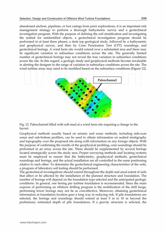
7.1 Geotechnical Investigation Since foundation construction costs can balloon from unanticipated subsurface conditions, such as paleochannels, the presence of boulders or foreign objects such as shipwrecks,
www.intechopen.com
Selection, Design and Construction of Offshore Wind Turbine Foundations
249
abandoned anchors, pipelines, or lost casings from prior explorations, it is an important risk management strategy to perform a thorough bathymetric survey and a geotechnical investigation program. With the purpose of defining the soil stratification and investigating the seabed for unidentified objects, a geotechnical investigation program should be performed in at least three phases: a desk top geological study, followed by a bathymetric and geophysical survey, and then by Cone Penetration Test (CPT) soundings, and geotechnical borings. A wind farm site would extend over a substantial area and there may be significant variation in subsurface conditions across the site. The generally limited number of geotechnical borings may not reveal the true variation in subsurface conditions across the site. In this regard, a geologic study and geophysical methods become invaluable in alerting the designer to the range of variation in subsurface conditions across the site. The wind turbine array may need to be modified based on the subsurface conditions (Figure 12).
Fig. 12. Paleochannel filled with soft mud at a wind farm site requiring a change in the layout.
Geophysical methods usually based on seismic and sonar methods, including side-scan sonar and sub-bottom profilers, can be used to obtain information on seabed stratigraphy and topography over the proposed site along with information on any foreign objects. With the purpose of confirming the results of the geophysical profiling, cone soundings should be performed in an array across the site. These should be supplemented by several borings located strategically across the study area. Proper surveying methods and locating systems must be employed to ensure that the bathymetry, geophysical methods, geotechnical soundings and borings, and the actual installation are all controlled to the same positioning relative to each other. To determine the geotechnical engineering characteristics of the soils, a program of laboratory soil testing should be performed. The geotechnical investigations should extend throughout the depth and areal extent of soils that affect or be affected by the installation of the planned structure and foundation. The number of borings will depend on the foundation type selected and the anticipated geologic conditions. In general, one boring per turbine foundation is recommended. Since the main expense of performing an offshore drilling program is the mobilization of the drill barge, performing fewer borings may not be as cost-effective. Moreover, obtaining geotechnical information at foundation location goes a long way in reducing risk. If pile foundations are selected, the borings and soundings should extend at least 5 m to 10 m beyond the preliminary estimated depth of pile foundations. If a gravity structure is selected, the
Paleochannel
www.intechopen.com

Wind Turbines
250
borings should extend to a depth such that stress increase in the soil and the resulting strain caused by the gravity structure is negligible. Moreover, multiple borings may be required for each gravity structure to account for variation in subsurface conditions. All in all, a geotechnical engineer experienced in offshore investigations should be retained for planning and executing such investigations. He (or she) should be able to modify the initially proposed plan based on site conditions encountered. The program should be equipped to switch between soil sampling, rotary coring, and insitu testing, where needed. For cable routing studies, relatively shallow cone soundings or vibro-core borings may be performed to obtain information for the cable trench.
7.2 Local geology and geologic hazards Geologic hazards that have the potential for causing failures of offshore engineered manmade structures include slope failures, fault ruptures, and adverse soil conditions. Such hazards can be triggered by external events, including earthquakes and surface storms. For instance, Hurricane Ivan, Katrina and Rita destroyed 118 oil drilling platforms and caused substantial damage to underwater pipelines by triggering slope failures. Pipelines and undersea cables face several geohazards including:
• Submarine slope failures including rotational or translational failures and sheet flows, • Sea floor rupture associated with seismic activity, and • Rough sea floor where the cable or pipeline may have to bridge over rock outcrops and
channels. Seafloor Mudslides. If the seafloor at the proposed site of the wind farm is even mildly sloping, it could be susceptible to localized or areal sea-wave or earthquake induced mudslides or submarine slides that could adversely impact the foundations. Numerous submarine slides have been documented on the coasts of continental United States. Identifying slope stability hazards in the marine environment is a challenging and important task. Marine slope failures can occur on slopes with gradients as low as 2 to 6 degrees. But their most notable feature is their large aerial extent. For example, the Sigsbee Escarpment in the Gulf of Mexico and the Storegga Slide in the Norwegian Sea are among the largest documented submarine slides in the world. A submarine slide can either result in
Fig. 13. Documented Submarine slope failures in the United States (Hance, 2003).
www.intechopen.com
Selection, Design and Construction of Offshore Wind Turbine Foundations
251
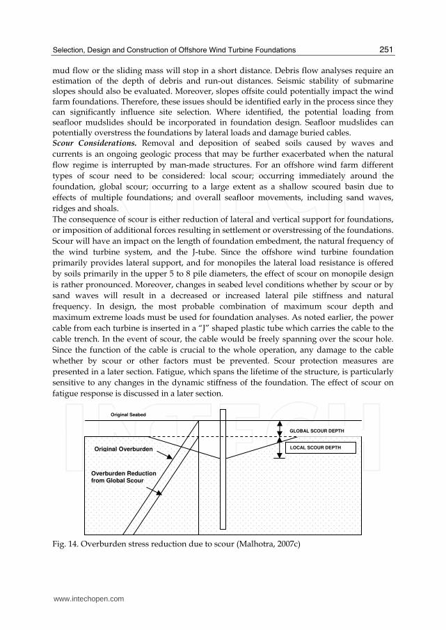
mud flow or the sliding mass will stop in a short distance. Debris flow analyses require an estimation of the depth of debris and run-out distances. Seismic stability of submarine slopes should also be evaluated. Moreover, slopes offsite could potentially impact the wind farm foundations. Therefore, these issues should be identified early in the process since they can significantly influence site selection. Where identified, the potential loading from seafloor mudslides should be incorporated in foundation design. Seafloor mudslides can potentially overstress the foundations by lateral loads and damage buried cables. Scour Considerations. Removal and deposition of seabed soils caused by waves and
currents is an ongoing geologic process that may be further exacerbated when the natural
flow regime is interrupted by man-made structures. For an offshore wind farm different
types of scour need to be considered: local scour; occurring immediately around the
foundation, global scour; occurring to a large extent as a shallow scoured basin due to
effects of multiple foundations; and overall seafloor movements, including sand waves,
ridges and shoals.
The consequence of scour is either reduction of lateral and vertical support for foundations,
or imposition of additional forces resulting in settlement or overstressing of the foundations.
Scour will have an impact on the length of foundation embedment, the natural frequency of
the wind turbine system, and the J-tube. Since the offshore wind turbine foundation
primarily provides lateral support, and for monopiles the lateral load resistance is offered
by soils primarily in the upper 5 to 8 pile diameters, the effect of scour on monopile design
is rather pronounced. Moreover, changes in seabed level conditions whether by scour or by
sand waves will result in a decreased or increased lateral pile stiffness and natural
frequency. In design, the most probable combination of maximum scour depth and
maximum extreme loads must be used for foundation analyses. As noted earlier, the power
cable from each turbine is inserted in a “J” shaped plastic tube which carries the cable to the
cable trench. In the event of scour, the cable would be freely spanning over the scour hole.
Since the function of the cable is crucial to the whole operation, any damage to the cable
whether by scour or other factors must be prevented. Scour protection measures are
presented in a later section. Fatigue, which spans the lifetime of the structure, is particularly
sensitive to any changes in the dynamic stiffness of the foundation. The effect of scour on
fatigue response is discussed in a later section.
Fig. 14. Overburden stress reduction due to scour (Malhotra, 2007c)
GLOBAL SCOUR DEPTH
LOCAL SCOUR DEPTH
Original Seabed
Overburden Reduction from Global Scour
Original Overburden
www.intechopen.com

Wind Turbines
252
Seismic Considerations. The level of seismicity of the site where the wind turbine structure is to be installed should be assessed either through available data or through detailed investigations. If the area is determined to be seismically active and the wind turbine will be affected by such activity, then site specific response spectra and design criteria should be developed. Depending on the location of the site, seismic hazards of liquefaction, seismic settlement, lateral spreading and earthquake loads could adversely impact the wind tower foundations and should be addressed in the design. The potential for seismic induced sea waves also known as tsunamis should also be assessed. Generally, earthquake loads seldom drive the design for wind turbines. For conceptual level studies seismic ground accelerations may be obtained from prior studies or relevant seismic hazard map. Liquefaction Potential. Soil liquefaction, defined as a significant reduction in soil strength and stiffness as a result of increase in pore pressure during dynamic loading, is a major cause of damage to built structures during earthquakes. Typically, the hazard from liquefaction occurs in four ways, including: a) bearing failure, b) settlement, c) localized differential lateral movements, and d) ground loss or highly localized subsidence associated with expulsion of material such as “sand boils”. Usually, for soil liquefaction to occur offshore, two conditions must exist: including a) presence of loose, sandy soils or silty soils of low plasticity, and, b) a source of sudden or rapid loading, typically associated with earthquakes. Generally, soil conditions found at offshore wind farm sites would be susceptible to liquefaction should an earthquake occur. Therefore, liquefaction potential at all wind farm sites should be performed in the early phase of design development. Lateral Spread Potential. Lateral spreading occurs primarily by horizontal displacement of soils at the seabed due to liquefaction of underlying granular deposits. The degradation in the undrained shear resistance arising from liquefaction may lead to limited lateral spreads induced by earthquake inertial loading. Such spreads can occur on gently sloping ground or where nearby drainage or stream channels can lead to static shear biases on essentially horizontal ground. The determination of lateral spread potential and an assessment of its likely magnitude ought to be addressed as a part of the hazard assessment process for an offshore wind farm site. In the event that there is a potential for lateral spreading at a wind farm site, it should be incorporated in the design of the foundation. For instance, if pile foundations are employed, passive forces from the moving soil mass should be applied to the pile foundation and checked for moment and shear capacity and related deflection (Figure 15). Alternately, the expected soil displacement may be applied to the pile model to evaluate the related shear and moment developed in the pile.
Fig. 15. Forces on Monopile Foundation from lateral spreading of liquefied seabed soils (Malhotra, 2007c).
www.intechopen.com

Selection, Design and Construction of Offshore Wind Turbine Foundations
253
8. Foundation analyses
Gravity Base Foundations: In gravity base foundations, the passage of waves produces
dynamic horizontal forces concentrated on the top of the structure. At the same time,
pressure fluctuations of the passing crest and trough reduces the apparent weight of the
gravity structure and creates a mode for vertical vibration. With or without earthquake
forces, the eccentricity of the wave forces results in coupled rocking and sliding modes of
vibrations. During a major storm, the simultaneous occurrence of vertical, sliding and
rocking loads would create high stress concentrations at the edges of the foundation
resulting in excess pore pressures and possible localized yielding of foundation soils below
the foundation edge opposing the storm. Following the passage of the storm, the excess pore
pressures would dissipate causing settlement and related differential settlement possibly
resulting in tilting of the foundation. Therefore, for gravity foundations, uplift, overturning,
sliding, bearing capacity, lateral displacement and settlement are potential failure modes
-25000
-20000
-15000
-10000
-5000
0
5000
10000
15000
20000
25000
0 50 100 150 200 250 300 350 400Wave Phase
Ve
rt. &
Ho
r. L
oa
ds
an
d M
om
en
t
-4000
-2000
0
2000
4000
6000
8000
10000
12000
14000
Moment (kN.m)Horizontal Load (kN)Vertical Load (kN)Uplift Force (kN)
(a)
Ultimate Bearing Capacity for Circular Foundation
0
50
100
150
200
250
0 50 100 150 200 250 300 350 400Wave Phase
Bea
rin
g C
ap
acit
y (k
Pa)
Qult
(b)
Fig. 16. (a and b): Bearing capacity of Gravity Base with varying load levels.
www.intechopen.com

Wind Turbines
254
and require evaluation. Immediate, primary and secondary consolidation settlement, permanent horizontal displacements and resulting differential settlements have to be evaluated. Differential settlements should incorporate the lateral variation of the soil conditions, unsymmetrical weight distributions, predominant directional loading and seismically induced settlement. The required sliding resistance determines the minimum weight of the system, based on Coulomb’s relation for frictional material. It has been found that heave force on the gravity base is a more dominant factor leading to instability by sliding than the overturning moment from the aerodynamic loads (Henderson et. al., 2003). Heave force can be calculated using Bernoulli’s theorem for the undisturbed wave kinematics (instead of the more complicated diffraction theory). Vertical bearing capacity is computed using bearing capacity theory developed by Prandtl, Brinch Hansen and Terzaghi. In bearing capacity calculations, the inclined and eccentric loads on the gravity
Check for: Sliding Overturning
Preliminary Loads, Vertical, Horizontal Load and Overturning Moment
Preliminary Size and Shape based on Experience
Estimate Hydrodynamic Loading for assumed size and shape: Heave, Drag and Inertial Forces for various time/phase intervals
Evaluate General and Local Bearing Capacity for discrete time steps of oncoming design wave and heave forces
Estimate Ice Loading, if any for assumed Shape
Are all criteria met?
Revise Size
No Sizing Complete
Yes Perform Dynamic Analyses
Are Dynamic Response Criteria met?
Yes
No
Compute Settlement. Differential Settlement
Yes
Fig. 17. Design process for an offshore Gravity Base Structure (Malhotra, 2007c)
www.intechopen.com

Selection, Design and Construction of Offshore Wind Turbine Foundations
255
base can create a severe reduction in the effective area and allowable bearing capacity, therefore reduction factors for inclined and eccentric loads have to be applied. Because of its sensitivity to the ratio of the vertical and lateral loading, an evaluation of bearing capacity and hydrodynamic heave and lateral forces is required for many phases of the oncoming design wave (Figure 16, a and b). The design of the gravity base foundation is iterative in the sense that the large contribution from hydrodynamic loading on the gravity base depends on the shape and size of the gravity structure, which is in turn is governed by its load bearing function (Figure 17). Dynamic analyses of gravity base foundations require consideration of soil-structure interaction effects. For homogeneous soil conditions, the soils can be modeled as an elastic half space with an equivalent shear modulus G. Foundation stiffness coefficients can be determined based on elastic theory. These stiffnesses can be used in structural analyses for wind and wave loading on the turbine and its support structure. To account for the strain dependency of shear modulus and internal soil damping, a range of shear modulii and damping should be considered in developing foundation springs. In the case where heave from wave passage and excessive overturning moments lead to formation of a gap at the base of the gravity foundation, these procedures overestimate the foundation stiffness. Gravity base structures are generally massive and constitute a majority of the weight of the wind tower system. Therefore, the fundamental period of vibration of the gravity base should be small compared to the rest of the wind tower system. Since the modes of vibration of the wind tower and the gravity base are different, an uncoupled analysis would be expected to provide reasonable estimates of foundation behavior (Figure 18).
Fig. 18. Analytical Model of Gravity base showing Uncoupled Translational and Rotational Springs (Malhotra, 2007c).
Deep Foundations Geotechnical design methods for driven pile foundations focus on three
aspects. 1) Axial load carrying capacity in compression and tension, 2) Response under
www.intechopen.com
Wind Turbines
256
cyclic lateral loads, and 3) installation. The main objective of the design is to select a
foundation size that can develop the required axial capacity, perform adequately under
lateral loads without excessive deflection and rotation at mudline, and withstand the
installation stresses needed to penetrate the pile without buckling the walls. A typical
driven pile design will require the prediction of: 1) Penetration resistance with depth, 2)
Depth to Fixity under lateral loads, 3) Minimum required penetration depth for fixity and
axial capacity considerations, 4) Driveability evaluation.
Bearing capacity and lateral load deformation performance of the pile is evaluated using
finite element procedures or other available procedures using the p-y approach. For a
detailed treatment of axial pile capacity for pipe piles, the reader is referred to Malhotra
(2002).
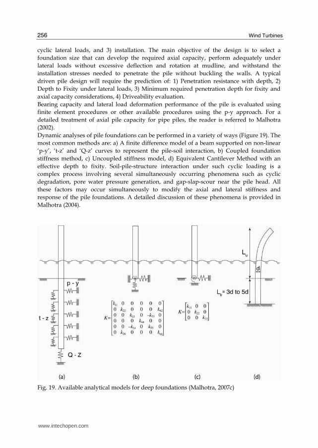
Dynamic analyses of pile foundations can be performed in a variety of ways (Figure 19). The
most common methods are: a) A finite difference model of a beam supported on non-linear
‘p-y’, ‘t-z’ and ‘Q-z’ curves to represent the pile-soil interaction, b) Coupled foundation
stiffness method, c) Uncoupled stiffness model, d) Equivalent Cantilever Method with an
effective depth to fixity. Soil-pile-structure interaction under such cyclic loading is a
complex process involving several simultaneously occurring phenomena such as cyclic
degradation, pore water pressure generation, and gap-slap-scour near the pile head. All
these factors may occur simultaneously to modify the axial and lateral stiffness and
response of the pile foundations. A detailed discussion of these phenomena is provided in
Malhotra (2004).
Fig. 19. Available analytical models for deep foundations (Malhotra, 2007c)
www.intechopen.com

Selection, Design and Construction of Offshore Wind Turbine Foundations
257
Pile Driveability: Driveability evaluations are a crucial part of the design process. One-
dimensional wave equation analyses have been widely used to evaluate pile driveability
and hammer performance. The purpose of wave equation analyses is to predict the behavior
of the pile during installation for specific site conditions and driving equipment. In the
United States, wave equation analyses are typically performed using computer program
GRLWEAP developed by Goble, Rausche and Likens (GRL) (1997) to assess the range of pile
hammer energies required to drive the piles. The major purpose of this study is to 1)
estimate the feasibility of driving the piles to design depth with the selected hammer, 2) to
evaluate pile tensile and compressive stresses and pile driving resistances for the selected
range in hammer energies, and 3) to develop preliminary driving criteria. A case study on
driveability of very large diameter piles can be found in Malhotra 2007c.
Fig. 20. Typical flow diagram in the design of suction caissons, (Malhotra, 2007c).
www.intechopen.com

Wind Turbines
258
Suction Caissons Geotechnical design methods for suction caissons focus on two aspects.
1) installation and retrieval, and 2) uplift capacity. The main objective of the design is to
select a caisson size that can develop the required uplift capacity and withstand the
installation suction needed to penetrate the caisson without buckling the walls or failing
the soil plug. A typical suction caisson design will require the prediction of: 1) Penetration
resistance with depth, 2) Required suction with depth, 3) Optimum location of pad eye for
lateral loads (if any), 4) Self-weight penetration depth, and, 5) Maximum penetration
depth. Once the caisson is sized, a caisson penetrability study is performed. This study is
performed to ensure that the soil resistance offered is less than the driving force on the
caisson. The driving force on the caisson consists of the buoyant weight of the caisson and
the applied suction. It is necessary to ensure that critical suction is not exceeded. A
detailed discussion of the design process with design examples (Figure 20) are provided
in Malhotra (2007c).
9. Fatigue
Fatigue is the process of gradual damage done to materials when subjected to continually
changing stresses. Due to these repeated stress changes, the material slowly deteriorates,
initiating cracks which will eventually propagate and lead to eventual failure. Offshore
wind turbines are by default subjected to loads varying in time from wind as well as waves.
This means that the stresses on the support structure will also vary continuously making
them prone to fatigue. Tubular steel structures such as monopiles, braced lattice frames and
tripods in deep water and exposed to wave loading are particularly susceptible to fatigue.
To be able to take fatigue into account in the design process, an empirical design method for
the design of steel structures is commonly used. Fatigue evaluation during design involves
comparing the intended design life of the structure with its predicted fatigue life as limited
by “hot-spot” stresses, i.e. areas of high local stress reversals. Fatigue, which spans the
lifetime of the structure, is particularly sensitive to any changes in the dynamic stiffness of
the foundation. Small increases in stress levels will increase fatigue damage by the power of
4. Minor amounts of scour can result in relatively minor changes in foundation stiffness and
consequent cyclic stresses, yet result in major changes in fatigue response. It can be shown
that for a typical monopile, lowering the natural frequency of the foundation by a small
amount (5 to 8 percent), will have a dramatic effect on fatigue (almost 100 percent)
(Malhotra, 2007c). At lower natural frequency of the pile more wave energy will create a
resonant response of the wind turbine and increase fatigue. Therefore, great emphasis is
placed on foundation selection and foundation dynamics.
10. Other considerations
Corrosion Protection: Since the most intensive corrosion typically occurs in the splash zone,
the transition piece is usually provided with a heavy duty protective coating. To protect the
underwater part of the transition piece and piles against corrosion, sacrificial cathodic
protection (in addition to the shop-applied coating) is used.
Scour Potential: A site specific study should be performed to assess potential scouring of
the seafloor. Typical scour protection measures include scour mats made up of buoyant
www.intechopen.com

Selection, Design and Construction of Offshore Wind Turbine Foundations
259
polypropylene fronds and polyester webbing which is anchored securely to the seabed or
crushed rock mattresses.
Marine Growth: The plant and animal life on the site causes marine growth on structural
components in the water and in the splash zone. The potential for marine growth should
be addressed, since it adds weight to the structural components of the system and may
increase hydrodynamic loads. Special paints and coatings are available that prevent marine
growth.
Impact from Ship Collision: Accidents between ships and wind farms can result in damage
to the wind farm, the ship and the local environment in a variety of ways. Although the
probability of occurrence of ship collisions should be relatively low, the consequences could
be serious. Accordingly, mitigating measures are warranted. Mitigation techniques involve
a two pronged approach. Reduce frequency of collision and reduce consequences of
collision. An optimum approach would be one which balances between the two approaches.
Collision risks can be reduced by passive measures, such as proper marking of the wind
farm and the individual wind turbines using classical techniques as marking lights,
painting, buoys or by active measures such radar based ship detection in combination with
emergency towing capabilities. Collision damage can be reduced by classical fendering
techniques designed based on the existing experience with pier, ship, tug and buoy
fendering and specifically developed for offshore wind farm applications. Damage
reduction solutions for offshore wind farms will be different from classic applications: for
individual monopile wind turbines since one has to balance on the one hand the need to
absorb without damage the impact of small vessels and on the other hand the requirement
of quick total collapse of the monopile with a structural fuse such as a plastic hinge
mechanism forming at or below the sea-bottom when the colliding ship is an larger oil or
chemical tanker in order to avoid damage to the tanker.
11. Construction considerations
Transportation: Monopiles, tripods, braced frames and suction caissons are usually
transported to the site on barges. In some cases, for the larger diameter monopiles, the ends
are capped and sealed and they are floated to the site. Gravity caissons either are floated to
the site, and then filled with ballast or transported by barge (Figure 21). The turbine is
usually transported in one piece.
Erection: A jack-up rig serves as a fairly stable platform for carrying out the operation of
installing the piles, the tower, nacelle and rotors. However, its inherent stability brings with
it a lack of maneuverability during installation of the tower. Ship-shaped vessels and flat
bottom barges are most commonly available but provide the least stability for construction
work. Ship-shaped vessels with rotating cranes offer the optimum mix of stability and
maneuverability in carrying out the construction work (Figure 22).
Offshore electric cabling: Undersea power transmission cables are deployed using an
environmentally sensitive process called “hydro-plowing” in which the cables are buried 2-3
m under the ocean floor. This process uses high-powered jets to fluidize a pathway in the
sea floor. The cables are then laid in the pathway and are buried as the sediment settles
around them. This technique is minimally invasive and quickly returns the sea bed to its
original form.
www.intechopen.com

Wind Turbines
260
(a) Monopile being floated out to site.
(b) Gravity Bases being lowered from barge
Fig. 21. Transportation of Wind Turbine Components (Courtesy of Bob Bittner, Ben C. Gerwick, Inc.)
www.intechopen.com

Selection, Design and Construction of Offshore Wind Turbine Foundations
261
Fig. 22. Wind Turbine being erected with a crane from a special ship at Kentish Flats Offshore Wind Farm, UK (Courtesy: Elsam)
12. Construction operations planning
Significant cost and schedule savings can be achieved by evaluating each step of the construction process and assuring that it is indeed necessary and being performed in the most efficient manner. Minor changes in design can often lead to significant changes in the construction process, such as reducing the number of construction steps or removing a construction step altogether. Therefore, designers should be familiar with the construction processes involved and be able to assess that would consider a constructability review as well as schedule and cost analysis.
The wind farm at Scroby Sands in Norfolk, United Kingdom is an example of how minor
design changes can lead significant savings in construction schedule and costs. The
designers decided to make minor modifications to the monopile by welding a flange to
which the wind tower could be bolted thereby getting rid of the transition piece and the
expensive grouting used to connect it to the monopile altogether.
www.intechopen.com

Wind Turbines
262
The Nysted wind farm at Rodsand in Denmark involved fabricating the gravity bases on the barge itself at a casting yard off of Poland’s Baltic Coast. The significantly lower labor cost along with the more efficient construction process led to considerable cost savings. The gravity bases used at Middlegrunden Wind Farm were designed using composite construction, i.e., internal steel can was encased in reinforced concrete and filled with ballast to create the gravity base. Composite construction saved substantial construction time and led to cost savings. Similarly, means and methods of transportation and erection can also be streamlined by minimizing the number of operations required to perform the work. For example, the monopiles and the wind tower can all be placed on the same jack-up barge before towing to the site, thereby reducing the need for another ship.
13. Maintenance considerations
Maintenance cost is also consideration in the overall wind farm economics and should be considered in the early phases of the development project. The operation of wind turbines at sea is much more challenging than onshore operations. Offshore maintenance and operations involve more costs, since the sea conditions are more irregular and extreme, a higher level of specialist expertise is required, stricter security requirements must be met and longer travel times are involved. Maintenance is categorized into preventive and corrective maintenance. Preventive maintenance comprises planned turbine maintenance according to a fixed maintenance schedule at intervals of 4 to 6 months. Corrective maintenance is required when a malfunction has occurred. In some cases, it is possible to remedy the problem remotely. In other cases, a visit to the turbine is required. The costs of maintaining the turbines can add up over their design life and should be considered in the initial financial rate of return analyses. Key factors to be considered when estimating costs for operational maintenance include: Distance from port, availability of boats, weather and insurance premiums.
14. Conclusions
Increasing wind turbine and tower sizes and installations in deeper waters have clearly
demonstrated a need for more innovative and cost-effective foundations. There is room for
improvement in all areas of wind farm development; in design, through the innovative use
of composite materials, support structures and foundations; and in construction processes,
through improvements in installation techniques, fabrication, and transportation. Six basic
types of offshore wind turbine support structures and foundations have been described,
along with their advantages and drawbacks. General considerations in the selection, design,
analyses and construction of these structures have been presented. This paper will assist
wind farm developers and engineers in identifying various issues that are likely to arise in
the development phase of an offshore wind farm.
15. Acknowledgements
The author wishes to thank Dr. George Munfakh of Parsons Brinckerhoff for promoting
innovation in the geo-industry; and encouraging this work, and for his review and valuable
www.intechopen.com

Selection, Design and Construction of Offshore Wind Turbine Foundations
263
suggestions. The author is grateful to his employer Parsons Brinckerhoff for the opportunity
to work on design studies for various offshore wind farms first in the United Kingdom and
now in the United States. The author is grateful to Dr. Aubeny at TAMU, Mr. Bob Bittner,
then of Ben C. Gerwick, Inc., and Elsam, for various construction photographs, and to Mr.
Pedro Silva for creating various illustrations. Opinions expressed in this paper are solely of
the writer and are not necessarily consistent with the policy or opinions of Parsons
Brinckerhoff, Inc.
16. References
[1] American Petroleum Institute, “Recommended Practice for Planning, Design and
Constructing Fixed Offshore Platforms – Working Stress Design, API RP2A-WSD,”
Twentieth Edition, July 1993.
[2] American Petroleum Institute, “Recommended Practice for Planning, Design and
Constructing Fixed Offshore Platforms – Load and Resistance Factor Design, API
RP2A-LRFD,” First Edition, July 1993.
[3] Bach, S., Teilmann, J. & Henriksen, O.D. 2000. VVM-redegørelse for havmølleparker ved
Rødsand. Teknisk rapport vedrørende marsvin. Rapport til SEAS. 41 pp.
[4] Elmer, W. J. Gerasch, T. Neumann, J. Gabriel, K. Betke, M. Schultz-von Glahn, (2007),
“Measurement and Reduction of Offshore Wind Turbine Construction Noise,” DEWI Magazine Nr. 30, February 2007.
[5] Gaythwaite, J.H., (1990) “Design of Marine Facilities for the Berthing, Mooring, and
Repair of Vessels,” Van Nostrand Reinhold Company ISBN-13: 978-0442229009, June
1990.
[6] Hance, J. J., (2003) “Submarine Slope Stability,” Project Report for the Minerals Management
Service Under the MMS/OTRC Coop. Research Agreement 1435-01-99-CA-31003, Task
Order 18217, MMS Project 421, August 2003.
[7] Henderson, Andrew, M.B. Zaaijer, T.R. Camp, “Hydrodynamic Loading on Offshore
Wind Turbines,” (2003) Proceedings Offshore Wind Energy in Mediterranean and Other
European Seas (OWEMES) Conference 2003, Naples, Sept 2003.
[8] Malhotra Sanjeev, (2009), “Design Considerations for Offshore Wind Turbine
Foundations in the United States,” International Society of Offshore Polar Engineers,
Osaka, Japan, June 24-26, 2009.
[9] Malhotra Sanjeev, (2007c), “Selection, Design and Construction Guidelines for Offshore
Wind Turbine Foundations,” PB Research & Innovation Report, Oct., 2007.
[10] Malhotra Sanjeev, (2007b), “Design and Construction Considerations for Offshore Wind
Turbine Foundations,” 26th International Conference on Offshore Mechanics and Arctic
Engineering, San Diego, California, June 10-15, 2007.
[11] Malhotra Sanjeev, (2007a), “Performance of Open-Ended Pipe Piles in Cretaceous Soils,”
ASCE Geo-Institute’s Geo-Denver 2007 Conference, Denver, Feb. 2007.
[12] Malhotra, Sanjeev, (2004), “Soil Pile Structure Interaction during Earthquakes,”
Proceedings of the GeoInstitute’s Conference on Geotechnical Engineering for
Transportation Infrastructure, GeoTrans04, Los Angeles, 2004.
www.intechopen.com

Wind Turbines
264
[13] Malhotra, Sanjeev, (2002), “Axial Capacity of Open Ended Steel Pipe Piles in Sand,”
Proceedings of the International Congress on Deep Foundations, ASCE, Orlando,
Florida, 2002.
[14] National Wind Technology Center, (2006), Golden, Colorado,
http://www.nrel.gov/wind/windpact/ Jan., 2006.
[15] U.S. Department of Energy, (2004) “Wind Power Today and Tomorrow,” March 2004.
[16] Vestas Wind Systems, “Personal Communication with Vestas, March 2007.
www.intechopen.com

Wind TurbinesEdited by Dr. Ibrahim Al-Bahadly
ISBN 978-953-307-221-0Hard cover, 652 pagesPublisher InTechPublished online 04, April, 2011Published in print edition April, 2011
InTech EuropeUniversity Campus STeP Ri Slavka Krautzeka 83/A 51000 Rijeka, Croatia Phone: +385 (51) 770 447 Fax: +385 (51) 686 166www.intechopen.com
InTech ChinaUnit 405, Office Block, Hotel Equatorial Shanghai No.65, Yan An Road (West), Shanghai, 200040, China
Phone: +86-21-62489820 Fax: +86-21-62489821
The area of wind energy is a rapidly evolving field and an intensive research and development has taken placein the last few years. Therefore, this book aims to provide an up-to-date comprehensive overview of thecurrent status in the field to the research community. The research works presented in this book are dividedinto three main groups. The first group deals with the different types and design of the wind mills aiming forefficient, reliable and cost effective solutions. The second group deals with works tackling the use of differenttypes of generators for wind energy. The third group is focusing on improvement in the area of control. Eachchapter of the book offers detailed information on the related area of its research with the main objectives ofthe works carried out as well as providing a comprehensive list of references which should provide a richplatform of research to the field.
How to referenceIn order to correctly reference this scholarly work, feel free to copy and paste the following:
Sanjeev Malhotra (2011). Selection, Design and Construction of Offshore Wind Turbine Foundations, WindTurbines, Dr. Ibrahim Al-Bahadly (Ed.), ISBN: 978-953-307-221-0, InTech, Available from:http://www.intechopen.com/books/wind-turbines/selection-design-and-construction-of-offshore-wind-turbine-foundations
Related Documents