SIMRAD Optronics ICARE Z.I. Les Paluds / 792 Av. de la Fleuride / 13400 AUBAGNE – France Phone : +33 (0)4 42 18 06 00 / Fax : +33 (0)4 42 03 01 19 / mail : [email protected] www.icarenet.com / www.simrad-optronics.com SIMRAD OPTRONICS ICARE ECHO 2 and ECHO 4 detection units INSTALLATION, OPERATING AND MAINTENANCE MANUAL +NOSP0014449 Issue 4 dated "30.05.06"

Welcome message from author
This document is posted to help you gain knowledge. Please leave a comment to let me know what you think about it! Share it to your friends and learn new things together.
Transcript

SIMRAD Optronics ICARE Z.I. Les Paluds / 792 Av. de la Fleuride / 13400 AUBAGNE – France
Phone : +33 (0)4 42 18 06 00 / Fax : +33 (0)4 42 03 01 19 / mail : [email protected]
www.icarenet.com / www.simrad-optronics.com
SIMRAD OPTRONICS ICARE
ECHO 2 and ECHO 4 detection units
INSTALLATION, OPERATING AND MAINTENANCE MANUAL
+NOSP0014449 Issue 4 dated "30.05.06"

2 / 72
ECHO 2 and ECHO 4 detection units
We thank you for having just bought a SIMRAD Optron ics ICARE wall-mounted detection unit.
Thorough studies were given to this product to guar antee you a maximum operating safety, a large flexibility of use and maintenance while proposing excellent performances.
This manual is meant for the installer, the operato r and the maintenance department. After the general and technical specification chapt ers, every building trade will find the chapters corresponding to its necessary information.
The reading of the present manual is essential for any person intervening at installation level and before the fi rst use, at operating level and at maintenance of equipment lev el.

CONTENTS
1 GENERAL NOTES...................................... ..................................................................6
1.1 USE FIELD................................................................................................................6
1.2 PRESENTATION ......................................................................................................6
2 TECHNICAL CHARACTERISTICS.......................... .....................................................7
2.1 MAIN CHARACTERISTICS AND CAPACITY ........................................... ................7
2.2 ASSOCIATED DETECTORS ....................................................................................9
2.3 FUNCTIONS ...........................................................................................................10
2.4 EXTENSIONS .........................................................................................................11
3 INSTALLATION ....................................... ...................................................................12
3.1 RECOMMENDATIONS...........................................................................................12
3.2 ASSEMBLING ......................................... ...............................................................12
3.3 ELEMENTS FLAGGING ........................................... ..............................................13
3.4 DETECTORS CONNECTION .................................................................................16
3.5 ELECTRICAL POWER SUPPLY CONNECTION................. ..................................19
3.6 SERVO-CONTROLS CONNECTION .....................................................................21
3.7 CONNECTION OF THE RS232 SERIAL LINK................ .......................................22
3.8 CONNECTION OF THE REMOTE ACKNOWLEDGEMENT........... .......................23
4 COMMINSSIONING / CHANNEL CONFIGURATION............. ....................................24
4.1 INTRODUCTION.....................................................................................................24
4.2 MATERIAL CONFIGURATION............................. ..................................................24
4.3 SWITCHING ON .....................................................................................................27
4.4 SOFTWARE CONFIGURATION............................. ................................................28
5 OPERATING ...............................................................................................................29
5.1 INTRODUCTION.....................................................................................................29
5.2 SYMBOLS AND MESSAGES ON THE DISPLAY................ ..................................29
5.3 MAIN SCREEN .......................................................................................................30
5.4 ACCESS CODE TO MENUS ..................................................................................31
5.5 MENUS DIAGRAM ...................................... ...........................................................32
5.6 TEST FUNCTIONS .................................................................................................34
5.7 CHANNEL CREATION ................................... ........................................................35

4 / 72
5.8 CHANNEL PARAMETERS AND ALARM THRESHOLDS MODIFICATIO N ..........36
5.9 CHANNEL SUPPRESSION................................ ....................................................39
5.10 ALARMS INHIBITION .................................. ......................................................39
5.11 DOUBT ACKNOWLEDEMENT FUNCTION...................... .................................40
5.12 CLOCK ADJUSTMENT................................... ...................................................41
5.13 BUZZER USE.....................................................................................................41
5.14 BATTERIES AND EMERGENCY POWER SUPPLY USE........... ......................42
5.15 SETTING OF THE RS232 COMMUNICATION ..................................................43
5.16 MODBUS PROTOCOLE ................................... .................................................44
5.17 ACCESS CODE CHANGE ................................. ................................................49
5.18 LANGUAGE CHOICE.................................... .....................................................49
5.19 SOFTWARE VERSION ......................................................................................50
5.20 ADDITION / SUPPRESSION OF A RELAY MODULE........... ............................50
5.21 RELAY PROGRAMMATION ................................ ..............................................51
5.22 USE OF FANS (CAR PARKS ) ........................... ...............................................56
6 MAINTENANCE ........................................ ..................................................................59
6.1 SENSOR RATING ..................................................................................................59
6.2 INTERVENTION ON A SENSOR............................................................................60
6.3 EXTENSION OF THE NUMBER OF RELAYS .................. .....................................61
6.4 ADDITION / REPLACEMENT OF THE BATTERIES............ ..................................66
6.5 FUSES REPLACEMENT .................................. ......................................................67
6.6 INCIDENTS GUIDE BOOK............................... ......................................................69
7 TRANSPORT AND STORAGE .............................. .....................................................71
8 WARNINGS.................................................................................................................71
8.1 FOREWORD...........................................................................................................71
8.2 OWNERSHIP AND CONFIDENTIALITY.................................... .............................71
8.3 LIABILITY .......................................... .....................................................................71
8.4 WARRANTY COVERAGE ......................................................................................72

FIGURES CONTENTS
Figure 1: ECHO 4 detection unit .............................................................................................6
Figure 2: Position of the different elements of the ECHO 4 detection unit..........................13
Figure 3: Connection terminal blocks position ......................................................................14
Figure 4: « RELAY » terminal block wiring ...........................................................................15
Figure 5: Cable preparation...................................................................................................17
Figure 6: Cable fixation ..........................................................................................................18
Figure 7: Connection of the serial link to a PC .....................................................................22
Figure 8: Remote acknowledgement connection .................................................................23
Figure 9: Position of the control board configuration straps ................................................25
Figure 10: Measurement channel LEDs ...............................................................................29
Figure 11: Menus diagram.....................................................................................................33
Figure 12: Example of configuration of a typical installation ................................................55
Figure 13: Fans triggering......................................................................................................58
Figure 14: The 8 relay extension module .............................................................................62
Figure 15: Relay modules connection...................................................................................64
Figure 16: Relay module: address straps configuration.......................................................65
Figure 17: Batteries position..................................................................................................66
Figure 18: Position of the fuses.............................................................................................67
Figure 19: Position of the main power supply fuse...............................................................68
TABLE CONTENTS
Table 1: “GENERAL” terminal block wiring........................................................................15 Table 2: Correspondence between the sensors flagging and the detection unit ...............18 Table 3 : Channel configuration for each strap..................................................................26 Table 4: Relay module wiring ............................................................................................63 Table 5: Incidents guide book............................................................................................69

6 / 72
1 GENERAL NOTES
1.1 USE FIELD
These detection units enable an easy monitoring of numerous detectors or different types or scales. Initially oriented to the gas or flammable vapors detection, they can be used with all the types of detectors manufactured by SIMRAD Optronics ICARE: toximeters (H2S, NH3, CO, NO2, etc.), explosimeters, gas analysers (O2, CO2, etc.), flame detectors...
They can also receive information from detectors of other brands which are equipped of a current output with a 4–20 mA format (for more details, see chapter 2.2 page 9).
The design means of these detection units enables to obtain excellent functional characteristics as well as a flexible and easy operating, particularly thanks to the use of microprocessors.
Finally, these detection units are designed on a modular way so as to facilitate the extension of the relays number.
Therefore, these detection units are particularly well adapted to the semi-industrial or tertiary sector in which the reliability and the operating easiness are essential points.
1.2 PRESENTATION
The ECHO 2 and ECHO 4 are composed of a wall-mounted box to which the detectors and the servo-controls are connected.
Figure 1: ECHO 4 detection unit
The ECHO 4 version enables the control of 4 measurement channels, and the ECHO 2 version enables the control of 2 measurement channels.

2 TECHNICAL CHARACTERISTICS
2.1 MAIN CHARACTERISTICS AND CAPACITY
Except the number of available measurement channels, the ECHO 2 and ECHO 4 detection unit’s characteristics are strictly similar.
Power supply: On mains power or by continuous power supply AC input: 230 V AC 50-60 Hz / 1A
(115 V AC 50-60 Hz / 2 A on request) DC input: 24 V (24 to 28 VDC); 3 A Minimum Emergency power supply: 2 batteries 24 V / 4Ah. (optional) Autonomy: approx. 4 hours for 4 standard sensors
(Power<1W). Fuses: Main fuse: 5 A definite time Relay module fuses: A definite time.
Environment: Operating temperature: 0 to +45°C Relative humidity: 10 to 90% RH Protection rate: IP31
Physical: Dimensions (L x W x depth): 250 × 300 × 87 mm Weight: 2.5 kg without battery 3.7 kg with battery Assembling: Wall-mounted Alarms: 4 programmable thresholds Sound: Buzzer Visual: LED AL.1, AL.2, AL.3, AL.4 on each channel and
a fault LED Configuration: increasing or decreasing alarm level
Automatic acknowledgement as soon as the alarm disappears or manual acknowledgement

8 / 72
Relay outputs: 4 configurable relays + 1 fault relay, which can be
extended to 45 relays (out of the detection unit). INTERRUPTING CAPACITY: 2 A / 230 VAC; 2 A / 125VDC FAULT RELAY: normally energized, not configurable. CONFIGURABLE RELAYS: The relays can be used at one or several alarm
levels of the detection unit channels. It is possible to activate the same relay on several alarms of several channels. The relays can be normally energized supplied or normally not battery-powered.
FANS CONTROL: Thanks to a specific functionality, the control of the fans located in a car park is made easier. (low speed / high speed, temporization adjustment…).
EXTENSION: The extension is made by the addition of modules
of 8 remote relays which are linked to the detection unit by a unique safety bus.
Maximum: 5 boxes, i.e. 40 relays.
Front panel:
LCD DISPLAY: Backlighted of 4 lines of 20 characters
LED: Alarms: Red Fault: Yellow Power supply: Green KEYBOARD: 4 keys that enable to move in the menus
Measurement channels: CHANNELS NUMBER: ECHO 4: 4 channels
ECHO 2: 2 channels
TYPE OF SENSOR: Every SIMRAD Optronics ICARE’s sensor
4-20 mA standard output sensor, feed under 28V (Pmax = 10 Watts),
SIMRAD Optronics ICARE’s explosimeter EX05

SETTINGS: Name of the sensor,
Measurement scale, Name of the gas to be detected, Alarm thresholds…
Other functions: RS232C output, MODBUS Protocol Remote acknowledgement input
2.2 ASSOCIATED DETECTORS
4-20 mA output sensors:
The ECHO 2 / ECHO 4 detection units can control all the types of the SIMRAD Optronics ICARE’s line of detectors with a 4-20 mA output.
- explosimeters,
- toximeters,
- oxygenometers,
- catharometers,
- flame detectors…
Other 4-20 mA sensors can also be controlled by the detection unit (please, contact us).
High consumption sensors with a 4-20mA output:
They are all the sensors that can consume more than 5 Watts. These sensors correspond to specific applications. In order to extend your installation with this type of sensors, please contact SIMRAD Optronics ICARE.
EX05 explosimeter sensors:
Thanks to the ECHO EX05 sensors, it is possible to get an explosimeter detection economically attractive.
10 / 72
2.3 FUNCTIONS
2.3.1 DETECTION UNIT COMPUTERIZED CONTROL
The control of the ECHO 2 / ECHO 4 detection unit is made by a card with a microprocessor. Thanks to the use of a microprocessor, it is possible to obtain characteristics equivalent to those that are found on more top-of-the-scale detection units:
- Friendly user interface in the form of menus displayed on a 4-line
alphanumeric screen. - Configuration of the name of the sensor. - Configuration of the detection scale extent and of the name of the detected
gas. - Configuration of the alarm threshold (level, direction, storage). - Configurable alarm relays: possibility of starting the alarm relays on one or
several alarm relays with one or several measurement channels (opportunity of creating detection zones).
- For use in a car park, the fans control is automated. - Time recorder so as to date the events (alarms, faults...). - RS232C output series enabling the printing on event of the alarm or fault
messages. - Upgraded insensitivity to disturbances: in order to avoid false gas alarms, the
measurement is filtered during several seconds.
2.3.2 SENSOR PROTECTION
The exposure of an explosimeter detector to high gas concentrations can damage it in some cases.
The ECHO detection units are equipped of a protective device for this type of sensor.
Therefore, if the value measured by an explosimeter detector exceeds 120% of the scale (120 %LIE), the detection unit:
- Jams the measure displayed on « >100 % LIE » and indicates that the sensor is in alarm verification function.
- Keeps the alarm and associated relays statuses.
- Turns off the power supply of the sensor.
The working of the device is made by an acknowledgement voluntary action from the operator who must have checked that the cause of the alarm (gas presence) has disappeared.

2.4 EXTENSIONS
Extension of the detection unit relay number
In its standard version, the detection unit is equipped with 4 configurable relays, and of a general fault relay.
It is possible to add until five 8 relay modules. These modules are removed out of the detection unit and are connected to it by a single wire.
The detail of this operation is described on paragraph 6.3 page 61.

12 / 72
3 INSTALLATION
3.1 RECOMMENDATIONS
The ECHO 2 / ECHO 4 detection unit is designed to work in every heated premises out of any dangerous atmosphere . It will be preferably installed in a monitored and ventilated place.
3.2 ASSEMBLING
Safe practice:
- Keep a sufficient space under the detection unit for the inlet of the electrical cables.
- The installer has to make sure that the support (wall) and the planned fixation easily support the detection unit weight.
« Rackable » detection unit:
The detection unit is a wall-mounted cabinet.
The wall-mounting can be done with 4 4mm diameter screws.
The attachment points are accessible after the door opening. They are situated at the 4 angles of the control unit.

3.3 ELEMENTS FLAGGING
The Figure 2 enables the flagging of the different elements of the detection unit.
Figure 2: Position of the different elements of the ECHO 4 detection unit
Power 24V
Cable fixation + shielding links to the ground
Lamp
Card
Position of the emergency batteries (optional)
Control card Wiring plan
Mains connection

14 / 72
All the connection terminal blocks are positioned on the front of the control board.
They are separated into 2 parts:
- The « RELAY » terminal block, located on the left of the board is dedicated to the servo-controls and can receive a maximum tension of 250 VAC.
- The « GENERAL » terminal block, located on the right of the board is reserved to continuous power supplies, to the connections of the four measurement channels and to the various functions.
-
Figure 3: Connection terminal blocks position
RELAY terminal blocks: servo-controls wiring
GENERAL terminal blocks: power supply wiring and various functions

Figure 4: « RELAY » terminal block wiring N° Function N° Function 1 + uninterruptible power supply or +
battery 13 + main power supply
2 - uninterruptible power supply or - battery
14 - main power supply
3 Acknowledgement 15 Relay card: + power supply 4 Link RS232: GND 16 Control relay card: signal E+ 5 Link RS232: signal Rx 17 Control relay card: signal E- 6 Link RS232: signal Tx 18 Relay card: - power supply 7 Channel 2: signal A (M if sensor
EX05) 19 Channel 1: signal A (M if sensor
EX05) 8 Channel 2: signal I (C if sensor EX05) 20 Channel 1: signal I (C if sensor EX05) 9 Channel 2: signal M (R if sensor
EX05) 21 Channel 1: signal M (R if sensor
EX05) 10 Channel 4: signal A (M if sensor
EX05) 22 Channel 3: signal A (M if sensor
EX05) 11 Channel 4: signal I (C if sensor EX05) 23 Channel 3: signal I (C if sensor EX05) 12 Channel 4: signal M (R if sensor
EX05) 24 Channel 3: signal M (R if sensor
EX05)
Table 1: “GENERAL” terminal block wiring Notes:
- For the EX05 type explosimeters sensors, the terminals are called M, C, R instead of A, I, M.
- See chart 2 on page 18, for the measurement channels wiring.
relay 2
C T R
C T R
relay 1
C T R
relay 3
relay 4
C T R
C T R
Defect
relay
Fault
relay
C T R
Caution:
There is only one inverser. The contacts of the defect relay are doubled so as to have an easier wiring servo-control.

16 / 72
3.4 DETECTORS CONNECTION
3.4.1 CABLES SPECIFICATION 4-20mA sensors:
NFM87202 instrumentation cable, shielded three conductor cable 0.9 mm² or 1.5 mm² advised cable: 01 IT 09 EG type. If the sensor is in a dangerous zone, the cable will have to be armored advised cable: 01 IT 09 EG FA type, GORSE brand Maximum cable length: 2 Km For high consumption cables (> 5 Watts ) or for longer distances : Please contact SIMRAD Optronics ICARE
EX05 type explosimeter sensor:
NFM87202 Instrumentation cable, 1 armored shielded three conductor cable 1.5 mm² advised cable: 01 IT 15 EG FA type. Maximum cable length: 450 m
3.4.2 CONNECTION
Each detector is linked to the detection unit by a shielded three conductor cable. This shielding ensures a protection against the industrial electrical interference.
1. Cable preparation: see Figure 5. If the cable is armored:
The armor ensures a mechanical protection for the crossing of dangerous zones for example. The armature must not penetrate the detection unit cable grommet.
Take out the sheath being very careful so as not to cut the shielding
continuity thread.
Strip the wires on a 8mm length.
Twist the wires.

Figure 5: Cable preparation
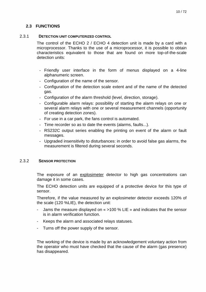
2. Cable fixation: see Figure 6. Insert the cable through the cable gland
Wind up the shielding continuity thread around the cable.
Make the cable go through one of the supplied collar Then, screw the
collar on the metallic plate in the back of the box, so as to ensure a solid fixation and a good continuity between the shielding and the box. If the collar is too large, you can swat it on the cable with pliers.
Take out the
sheath on a 7cm
length and twist
the wires
Cut the cable
armor
Shielding
continuity
thread
Strip each wire on
a 8mm length
18 / 72
Figure 6: Cable fixation
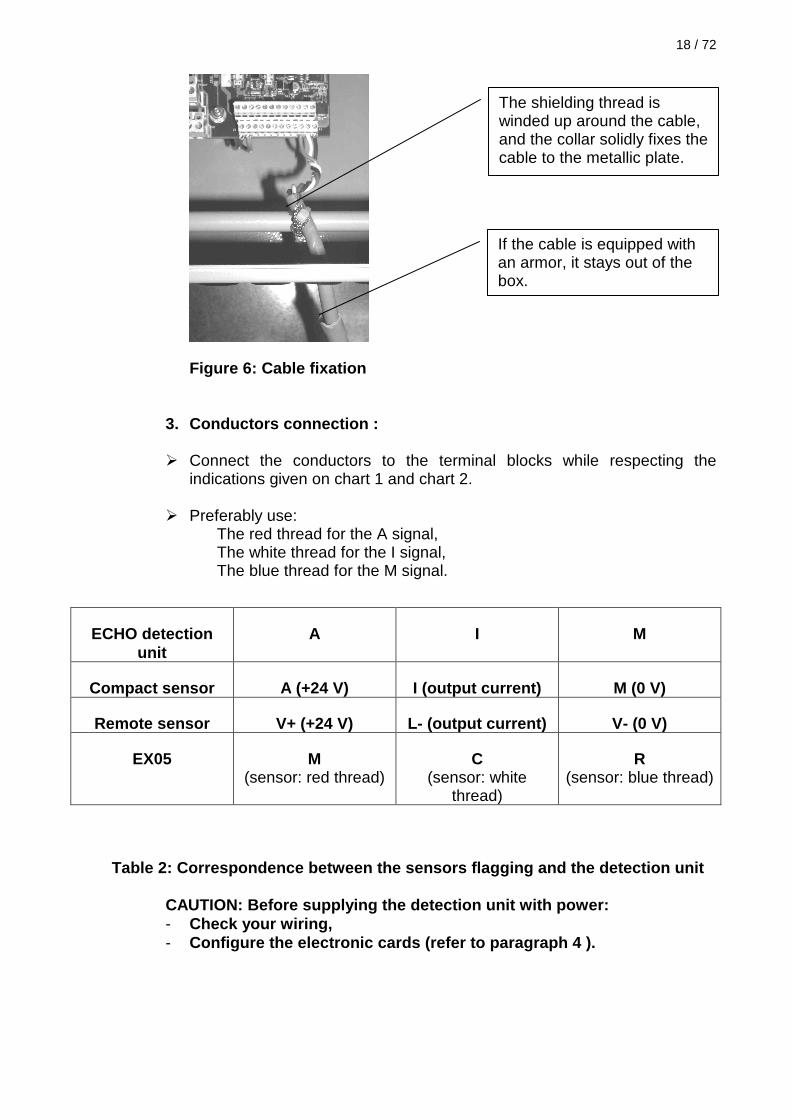
3. Conductors connection :
Connect the conductors to the terminal blocks while respecting the indications given on chart 1 and chart 2.
Preferably use:
The red thread for the A signal, The white thread for the I signal, The blue thread for the M signal.
Table 2: Correspondence between the sensors flaggin g and the detection unit
CAUTION: Before supplying the detection unit with p ower: - Check your wiring, - Configure the electronic cards (refer to paragraph 4 ).
ECHO detection unit
A I M
Compact sensor A (+24 V) I (output current) M (0 V)
Remote sensor V+ (+24 V) L- (output current) V- (0 V)
EX05 M (sensor: red thread)
C (sensor: white
thread)
R (sensor: blue thread)
The shielding thread is winded up around the cable, and the collar solidly fixes the cable to the metallic plate.
If the cable is equipped with an armor, it stays out of the box.

3.5 ELECTRICAL POWER SUPPLY CONNECTION
3.5.1 PRECAUTIONS
So as to avoid any electrical shock, the general power supply of the
detection unit has to be connected only after the detectors and servo-controls complete wiring and after its checking.
The power supply of the detection unit and of its servo-controls will have to
be protected by a differential circuit breaker in accordance with the standard in effect. The circuit breaker is not located in the detection unit box.
Use a 3 x 1.5 mm² cable in accordance with the standard in effect and with
the industrial regulation. Before supplying power to the detection unit, configure the straps of the
control board measurement channels. In order to carry out this operation, refer to paragraph 4 page 24.
3.5.2 CONNECTION TO THE MAIN ELECTRICAL POWER SUPPLY
Take out the cable protection sheath on a 5 cm length. Strip the threads on a 8mm length. Pass the cable through the cable gland designed for this purpose and
located below the power supply. Connect the conductors directly on the power supply terminal block.
Flagging: L: Phase 220 V electric mains
N: Neutral 220 V electric mains T: Earth
Do not forget to tighten the cable gland.

20 / 72
3.5.3 24 V EXTERNAL POWER SUPPLY CONNECTION
The detection unit can work on a 24V DC power supply. This power supply must be sized so as to provide at least 3 amperes. The connection is made with two 1.5 mm² conductors. Refer to Chart 1 page 15 for the wiring diagram. After being connected, the external power supply has to be declared at the detection unit level. Refer to paragraph 5.14 page 42. Note: The batteries and the external power supply share the same connector. It is not possible to have both the external power supply and the emergency batteries as emergency power supply at the same time.
3.5.4 BATTERIES CONNECTION (OPTIONAL)
This emergency power supply is made of two lead rechargeable batteries 12V / 1.2 Ah that enable a 24V uninterruptible power supply. The electric connection of the battery to the detection unit is made by the terminals 1 (battery +) and 2 (battery -) of the general terminal block. The emergency batteries are continuously recharged when the electric mains is present. When the batteries are connected, they have to be declared at the detection unit level. Refer to paragraph 5.14 page 42. Notes:
- The batteries and the external power supply share the same connector. It is not possible to have both the external power supply and the emergency batteries as emergency power supply at the same time.
- The battery life depends on the consumption of the used sensors. For an installation with 4 standard sensors (P < 1 Watts), the battery life lasts 4 hours.

3.6 SERVO-CONTROLS CONNECTION
3.6.1 RELAY SPECIFICATION
Type: 1 inversor Breaking capacity: 2 A under 220 VAC; 2 A under 125 VDC The detection unit is equipped of a fault relay and of 4 configurable alarm relays. - The fault relay is normally activated and its configuration cannot be modified.
It is set off on every fault appearance and it comes back to its normal status only when there is no fault. The 4 alarm relays are configurable. See paragraph 5.21 page 51.
3.6.2 PRECAUTIONS
So as to avoid any electric shock, the general power supply of the detection unit and of its servo-controls must be connected only after the complete wiring of the relays.
3.6.3 CONNECTION The cable preparation and fixation are similar to those of the detector cables. Refer to paragraph 3.4.2 page 16. The connection of the conductors to the terminal blocks will be made in accordance with the indications given on Figure 4 page 15.
Caution: It is necessary to configure the working of the relays. Refer to paragraph 5.21 page 51.

22 / 72
3.7 CONNECTION OF THE RS232 SERIAL LINK The standard ECHO detection units are equipped with a RS232 type serial link. It can be configured as follow:
- In MODBUS mode - In serial link printer mode
Messages format (in serial link printer mode):
In “printer” mode, each appearance or disappearance of an alarm or fault keys on a message which contain the date, the time, the channel and the event occurred. Example of message: 23/03/2003 14:09 CHANNEL: 01 APPEARANCE ALARM 1 This information is in ASCII format and can be directly displayed on a terminal, a PC, or they can be printed on a serial printer.
Connection: Use a shielded three conductor instrumentation cable. The cable preparation and fixation is similar to the one of the detectors cables. Refer to paragraph 3.4 page 16.
Diagram of a connection on a PC :
Figure 7: Connection of the serial link to a PC Transmission configuration: Refer to paragraph 5.15 & 5.16 page 43.
General terminal
block
ECHO detection
unit
Terminal 5: Rx
Terminal 6: Tx
Terminal 4:
Gnd
Connector 9
points of the PC
Terminal 2: Tx
Terminal 3: Rx
Terminal 5:
Gnd

3.8 CONNECTION OF THE REMOTE ACKNOWLEDGEMENT
In some applications, it can be interesting to be able to acknowledge an alarm or a remote fault, without having to move until the detection unit. The ECHO detection units have a remote acknowledgement input, which is controlled with a press-button. Note: The remote acknowledgement acknowledges all the detection unit channels at the same time. Connection:
Use an instrumentation cable, 1 shielded pair. The cable preparation and fixation is similar to the one of the detectors cables. Refer to paragraph 3.4.2. page 16.
Diagram of the remote acknowledgement connection.
Figure 8: Remote acknowledgement connection
Note: If the terminal 4 (GND) is already fitted by the GND thread of the RS232 link, it is possible to use another GND terminal of the detection unit.
General terminal
block
ECHO detection
unit
Terminal
3 Acquit
Terminal 4:
Gnd

24 / 72
4 COMMINSSIONING / CHANNEL CONFIGURATION
4.1 INTRODUCTION
The commissioning of the detection unit or of a sensor has to follow the 4 following stages:
1. CHANNELS MATERIAL CONFIGURATION The configuration is made thanks to straps located on the main card. The configuration of these straps must be done when the detection unit is off, following the recommendations of the paragraph 4.2.
2. SWITCHING ON Supply the detection unit with power. The detail of this operation is described on paragraph 0
3. SOFTWARE CONFIGURATION The matter is to declare the channels, to configure the wanted scale, the alarm levels and the associated relay(s). The detail of this operation is described on paragraph 4.4.
4. CALIBRATION Follow, for each measurement channel, the calibration procedures described in paragraph 6.1.page 59.
4.2 MATERIAL CONFIGURATION
This stage enables the adaptation of the electronics to the type of sensor connected on the channel.
Caution: Two sensors family can be connected to the detection unit.
- The EX05 explosimeter sensors, - The sensors with a 4/20mA output.
The detection unit configuration is not the same for the two sensors. It is important to know which type of sensor is connected to the channel which needs to be configure.

4.2.1 POSITION OF THE CONFIGURATION STRAPS
The figure below shows the position of the configuration straps for each detection unit channel:
BUZZER
CV1 CHANNEL 1
Relay
Relay
Relay
Relay Relay
CV3 CHANNEL 3
CV4 CHANNEL 4
CV5 CHANNEL 1
CV2 CHANN
EL 2
CV6 CHANNEL 2
CV7 CHANNEL 3
CV8 CHANNEL 4
F1
GENERAL TTERMINAL BLOCK RELAY TERMINAL BLOCK
1-2 3-4 5-6
FUSES
F2
Relay 2 C T R
Relay 1 C T R
Relay 4 C T R
Relay 3 C T R
Relay Def. C T R Relay Def. C T R
1-2 3-4 5-6
1-2 3-4 5-6 1-2 3-4 5-6
FRONT PANEL
DISPLAY
Display card
Figure 9: Position of the control board configurati on straps

26 / 72
4.2.2 STRAPS CONFIGURATION Procedure to follow:
1. Check that the detection unit is non current-carrying, 2. Identify the type of connected sensor (sensor with a 4/20mA output or
explosimeter sensor), 3. Locate the position of the straps associated to the considered channel with the
help of the Figure 9 page 25, 4. Position the straps of the considered channel depending on the sensor that is
used and on the chart below:
Table 3: Channel configuration for each strap
Channel 1 STRAP CV5 STRAP CV1
Channel 2 STRAP CV6 STRAP CV2
Channel 3 STRAP CV7 STRAP CV3
Channel 4 STRAP CV8 STRAP CV4
SENSOR 4 / 20 mA Standard
( Power ≤ 5 Watts )
1 – 2
3 – 4
5 - 6
1 2 3 4 5 6
EXPLOSIMETER SENSOR EX05 TYPE
1 – 2
3 – 4
5 - 6
1 2 3 4 5 6
Use of high consumption sensors:
They are all the sensors which can consume more than 5 Watts. These sensors correspond to specific applications. To extend your installation with this type of sensor, contact SIMRAD Optronics ICARE. The consumption of your sensor is indicated on its identification label.

4.3 SWITCHING ON
4.3.1 CHECKING BEFORE SWITCHING ON
All the wiring must be checked as some mistakes can damage the equipment.
It is advised, before the system switching on, to read the chapter 3 page 12.
4.3.2 SWITCHING ON
For safety reasons, the device does not have on its front face any means of switching on or off, as these functions have to be done by a disconnecting switch on the outside of the system.
During the switching on, there is an inhibition of the alarms (which lasts approximately 10 seconds) which enables the equilibrium of the various groups.
Stabilization time
The stabilization time depends on the type of the used detector and can vary in large proportions.
This time lasts a few seconds for a UVIR type flame detector or for an explosimeter detector; however, it can reach several minutes for a semi-conductor or electrochemical sensor.
As the stabilization time can, for some detectors, exceed the inhibition time during the switching on, faults or alarms can occur during the first bringing into service or during a new switching on.
Clock adjustment
The clock is only used to record the time of the messages which are emitted on the RS232 serial link.
If you use this function, it is necessary to set the clock after each switching on. Refer to paragraph 5.12. page 41 to perform this operation.
28 / 72
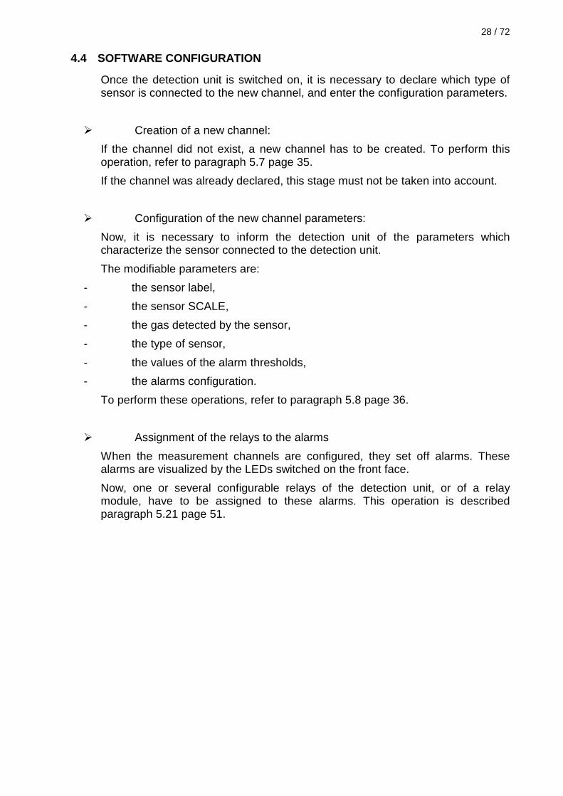
4.4 SOFTWARE CONFIGURATION
Once the detection unit is switched on, it is necessary to declare which type of sensor is connected to the new channel, and enter the configuration parameters.
Creation of a new channel:
If the channel did not exist, a new channel has to be created. To perform this operation, refer to paragraph 5.7 page 35.
If the channel was already declared, this stage must not be taken into account.
Configuration of the new channel parameters:
Now, it is necessary to inform the detection unit of the parameters which characterize the sensor connected to the detection unit.
The modifiable parameters are:
- the sensor label,
- the sensor SCALE,
- the gas detected by the sensor,
- the type of sensor,
- the values of the alarm thresholds,
- the alarms configuration.
To perform these operations, refer to paragraph 5.8 page 36.
Assignment of the relays to the alarms
When the measurement channels are configured, they set off alarms. These alarms are visualized by the LEDs switched on the front face.
Now, one or several configurable relays of the detection unit, or of a relay module, have to be assigned to these alarms. This operation is described paragraph 5.21 page 51.

5 OPERATING
5.1 INTRODUCTION
The detection unit enables a simultaneous control of the good working and the detection of the detectors.
The status of each detector is indicated in the form of an electric lamp signal under the number of the corresponding channel.
Figure 10: Measurement channel LEDs
5.2 SYMBOLS AND MESSAGES ON THE DISPLAY
The display is split into 3 logical areas.
Area 1: in this area are displayed the messages linked to the context.
Area 2: the bottom line contains the wording of the available functions separated by a vertical line. There is a function key for each slot on the display. Thanks to the function keys, it is possible to move in the menus diagram.
Area 3: the column on the right side is reserved to the pictograms. These pictograms indicate:
Line 1: The battery: charged: , charge fault: , nothing if it is not used.
Line 2: Status of the electric mains: fixed: present electric mains, flashing: no electric mains.
N° of the channels
LEDs of alarm 1
LEDs of alarm 2
Two-coloured LEDs: on = green, defect = yellow
LEDs of alarm 3
LEDs of alarm 4

30 / 72
Line 3: Status of the inter-card communication:
fixed: OK, flashing: fault of communication with one card at least.
Line 4: valid access code:
either it is displayed or there is nothing.
A R E A 1 A 3 | A R E A | 2 |
5.3 MAIN SCREEN
It is the screen which is used for the normal operating of the detection unit.
It displays the information useful for the user.
0 1 C h a n n e l 0 1 D E F E C T 0 % G A S 0 % | | | | | | | | | 1 0 0 %
V x - 1 V x + 1 M E N U A C Q .
N° of the channel
Label of the channel
Information on the channel status
Concentration given by the sensor, displayed on a digital form and on barograph
Visualization of scroll up or scroll down
Access to the menus
Alarm and defect acknowledgement

5.4 ACCESS CODE TO MENUS
The pressing of the « MENU » key on the main menu enables the access to the configuration menus. This access is protected by a password.
A C C E S S C O D E X X X X - - + + > > V A L .
Password capture:
Use the keys « ++ » and « -- » to modify the value of the flashing character.
When the keyed character is correct, use the key « >> » to go to the following character.
The « VAL. » key is to validate the keyed code.
The symbol
on the display right bottom confirms that the keyed code is correct.
In a factory configuration, the password is 0000.
Password modification:
Refer to paragraph 5.16 page 44.
Password loss:
Contact SIMRAD Optronics ICARE.

32 / 72
5.5 MENUS DIAGRAM
From the main screen, the menus are accessible by the key « MENU ».
The password has to be previously keyed (symbol
present).
The following screen gives the version number, as well as the access to the different menus.
0 V O I E 0 1 D O U B T 0 % G A S 0 % | | | | | | | | | 1 0 0 %
V x - 1 V x + 1 F U N C A C K .
E C H O M U L T I P O I N T
S O F T W A R E : I L 1 4 4 5 8 . 0 0
C H A N T E S T P R O G E S C .
The functions proposed by these menus are detailed on the following page.
Access to the measurement channels monitoring functions
Access to the test functions of the lamps, buzzer, relays…
Access to programmation and configuration functions of the detection unit, channels, relays…
Back to the upper screen

SIMRAD Optronics ICARE Z.I. Les Paluds / 792 Av. de la Fleuride / 13400 AUBAGNE – France
Phone : +33 (0)4 42 18 06 00 / Fax : +33 (0)4 42 03 01 19 / mail : [email protected]
www.icarenet.com / www.simrad-optronics.com
Figure 11: Menus diagram
Relay configuration
Channel adjustment
System parameters
Output tests Channel adjustment
Inhibition / End of inhibition
Zero
Calibration
Sensor power supply On/Off
Ambiguity function
Short circuit reclosing
Channel programmation
Buzzer test
Relay test
Main screen
MENU
Access screen to menus
PROG CHANNEL TEST
Lamp test
Modules automatic detection
Clock adjustment
Serial / MODBUS interface configuration
Validation / inhibition of the buzzer
Battery selection / 24V emergency
Change of the access code
Language
Channel editing
Channel suppression
Channel creation
Channel copy and paste
Activated sequency
Stand by status
Fans prog. Activated sequency
Temporisation
Software version

SIMRAD Optronics ICARE Z.I. Les Paluds / 792 Av. de la Fleuride / 13400 AUBAGNE – France
Phone : +33 (0)4 42 18 06 00 / Fax : +33 (0)4 42 03 01 19 / mail : [email protected]
www.icarenet.com / www.simrad-optronics.com
5.6 TEST FUNCTIONS
Access to the menu:
From the main screen, perform the following operations:
MENU TEST
O U T P U T T E S T
L E D B U Z Z R E L E S C
LAMP: test LAMP
Thanks to this function, all the lamps of the detection unit can be switched on, so as to visualize a possible breakdown.
Note:
In fact, the lamps are LED indicators, and are not frequently out of order. It is not possible to replace just a LED.
BUZZ: buzzer test
This function is to test the buzzer of the detection unit.
REL: Relay test
This function enables the launching of a relay of the detection unit or of an extension module.
Then, a display appears and it indicates which relay of which card must be activated or disabled.
R E L A Y T E S T
B o a r d : C o n t r o l R e l a y # 1 : O F F B O A R + 1 C H G E S C
Concerned
card
N° and
status of the
concerned
relay Modification
of the
concerned
card
Modification
of the
concerned
relay
Change of
the relay
status
(ON or OFF)
Back to
the
previous
display

Notes:
- the relay 5 corresponds to the fault relay,
- if there is no extension relay, the control board only is available,
- to modify the status of a relay card relay, this card must have been previously declared to the detection unit ( see paragraph 5.19 page 50 ).
5.7 CHANNEL CREATION
To add a new sensor to the detection unit, it has to be declared to the system.
This operation requires several stages:
- declaration of the new channel
- printing of the parameters of the new channel
- assignments of the alarm relays to the new channel
- possible adjustment of the used relay parameters.
Access to the menu:
From the main display, perform the following operations:
MENU PROG function « Channel configuration »
Operating process:
1. Choose the number of the channel which has to be created by pressing the key « Vx+1 ».
2. Scroll through the functions with the « Ft>> » and choose the function “création voie” 1 (channel creation).
3. Press « VAL .».
The new channel is created.
The detection unit automatically displays the printing screen of the new channel parameters. Refer to paragraph 5.8.
1 If the channel already exists, the function channel creation does not exist.
CAUTION: Check that the servo-controls connected to the relay are inhibited.

36 / 72
5.8 CHANNEL PARAMETERS AND ALARM THRESHOLDS MODIFIC ATION
This function enables the modification of the parameters, which characterizes the sensor connected to the detection unit.
The modifiable parameters are:
- the sensor label,
- the sensor scale,
- the gas detected by the sensor,
- the type of sensor,
- the values of the alarm thresholds.
Access to the menu:
- either from the main menu: MENU PROG function « Channel Configuration » function « Edit channel »,
- or directly after the creation of a new channel.
Label modification:
1. Choose the function « Label » with the key « Ft>> » and press the key « VAL. ».
2. Use the keys « ++ » and « --» to modify the value of the flashing character, and the key « >> » to move to the next character.
3. Confirm the new label by pressing the key « VAL. ».
Scale modification:
This function enables to adapt the measurement channel to the sensor detection scale. In most cases, the detection scales generally vary of 0 from the sensor full scale value. Therefore, only the full scale detection value needs to be adjusted, because the scale low value fault is adjusted on zero.
However, some very particular applications may need a low scale different from zero. In this case, use the function « Mini Ech » to adjust the low value of the detection scale to the wanted value.
Operating process:
1. Choose the function « Scale » with the key « Ft>> » and press the key « VAL. ».
2. Choose the function « Scale max » with the key « Ft>> » and press the key « VAL. ».
3. Log in the value of the sensor full scale. For example, for an explosimeter sensor detecting from 0 to 100% LIE, log in 00100 and then, confirm.
4. Do not modify the function « Scale min » except if your sensor has a specific scale which does not start at zero.

Modification of the detected gas:
This function enables the modification of the unit and the name of the gas detected by the sensor. The unit can be chosen amongst a list of current units (%, PPM…). The name of the gas can be freely printed. Therefore, it is possible to display the exact name of the detected gas.
Operating process:
1. Choose the function « Gas » with the key « Ft>> » and press the key « VAL. ».
2. Unit modification:
- Scroll through the different possible units with the key « CHG » (%, %LIE, PPM, % VOL …).
- Confirm your choice with the key « VAL. ».
3. Modification of the name of the gas:
- Use the keys « ++ » and « --» to modify the value of the flashing character, and the key « >> » to go to the next character.
- Confirm the name of the gas by pressing the key « VAL. ».
Modification of the type of sensor:
This function enables to indicate to the detection unit the type of sensor which is connected on the channel which is being configured. There exist 3 types of sensors which are differently controlled by the detection unit:
- The standard 4-20mA sensor: they are all the sensors with a 4-20mA output current loop.
Choose this configuration for the SIMRAD Optronics ICARE sensors, the reference of which starts with TX, TT, TO, CT, CO IREX, ET, EI, EO.
- The 4-20mA explosimeter sensors: they are explosimeter sensors with a 4-20mA output; but their function of the filaments protection is not integrated in the sensor. If this configuration is chosen, and that the measurement of the sensor exceeds 120 % of the scale, the detection unit switches off the sensor power supply and keeps the alarms (function of sensor protection or ambiguity function).
Choose this configuration for the SIMRAD Optronics ICARE’s explosimeter compact sensors the reference of which starts with CX.
Note: for the SIMRAD Optronics ICARE digital remote sensors (reference starting with TX), the configuration « standard 4-20mA sensor » must be chosen.
- The EX05 explosimeter sensors: they are low cost explosimeter sensors; the sensor power supply is directly controlled by the detection unit.
Choose this configuration for the SIMRAD Optronics ICARE EX05 explosimeter sensors.

38 / 72
Operating process:
5. Choose the function « Capteur » (« sensor ») with the key « Ft>> » and press the key « VAL. ».
6. Scroll through the different types of possible sensors with the key « CHG ».
7. Confirm your choice with the key « VAL. ».
Alarm threshold values modification:
This function enables the modification of the different parameters concerning the 4 alarm thresholds. The modifiable parameters are:
- The use of the alarm threshold: is the threshold used?
- Value of the alarm threshold. It is the measurement value at which the alarm sets off.
- Threshold activation direction. It is possible to activate the alarm :
- UP direction, that is to say when the measurement becomes superior to the alarm threshold. This is the case for most of the sensors in which we try to make sure that there is no gas (explosimeter sensors, toximeters…).
- DOWN direction, that is to say when the measurement becomes inferior to the alarm threshold. This is the case, for example, of the oxygenometer sensors in which we want to make sure that the oxygen is present in a sufficient quantity in the atmosphere.
- the alarm memorization:
- If the alarm is memorized, it disappears only if the activation condition has disappeared AND that the alarm has been acknowledged.
- If the alarm is not memorized, it disappears as soon as the activation condition is no longer real: it will acknowledge itself when the measurement has passed below the alarm level (for an up direction).
Operating process:
1. Choose the function « Edit levels » («threshold printing») with the key « Ft>> » and press the key « VAL. ».
2. Choose the wanted threshold with the key « Edge ».
3. Choose the wanted function with the key « Ft>> » and confirm with the key « VAL. ».
4. Choose the wanted value and confirm with the key « VAL. ».

Note:
Once the alarm thresholds configuration is done, do not forget to configure the relay(s) that will be associated to this threshold.
5.9 CHANNEL SUPPRESSION
This function enables the suppression of a detection unit channel.
Note: if a channel is suppressed, the power supply of the sensor on this channel is switched off.
Access to the menu:
From the main screen, perform the following operations:
MENU PROG function « Channel configuration »
Operating process:
1. Choose the number of the channel to suppress with the key « Vx+1 ».
2. Scroll through the functions with the key « Ft>> » and choose the function « Erase channel » 2 (« channel suppression »)
3. Press « VAL .».
4. the detection unit asks you to confirm the channel suppression.
5. Confirm the suppression by pressing « VAL. » again.
The channel is suppressed.
5.10 ALARMS INHIBITION
It is possible to inhibit the alarms of one or several measurement channels. The value that is displayed stays valid, but the alarms and servo-control relays are no longer set off.
Access to the menu:
From the main screen, perform the following operations:
MENU CHAN
2 If the chosen channel does not exist, the channel suppression function does not exist neither.
40 / 72
Operating process:
1. Choose the number of the channel to inhibit with the key « Vx+1 ».
2. Scroll through the functions with the key « Ft>> » and choose the function « Inhibition / End inh. ».
3. Press « VAL .».
On the top right of the display, « INHIBIT » appears to indicate that the channel is inhibited. Another press on « VAL » puts an end to the inhibition.
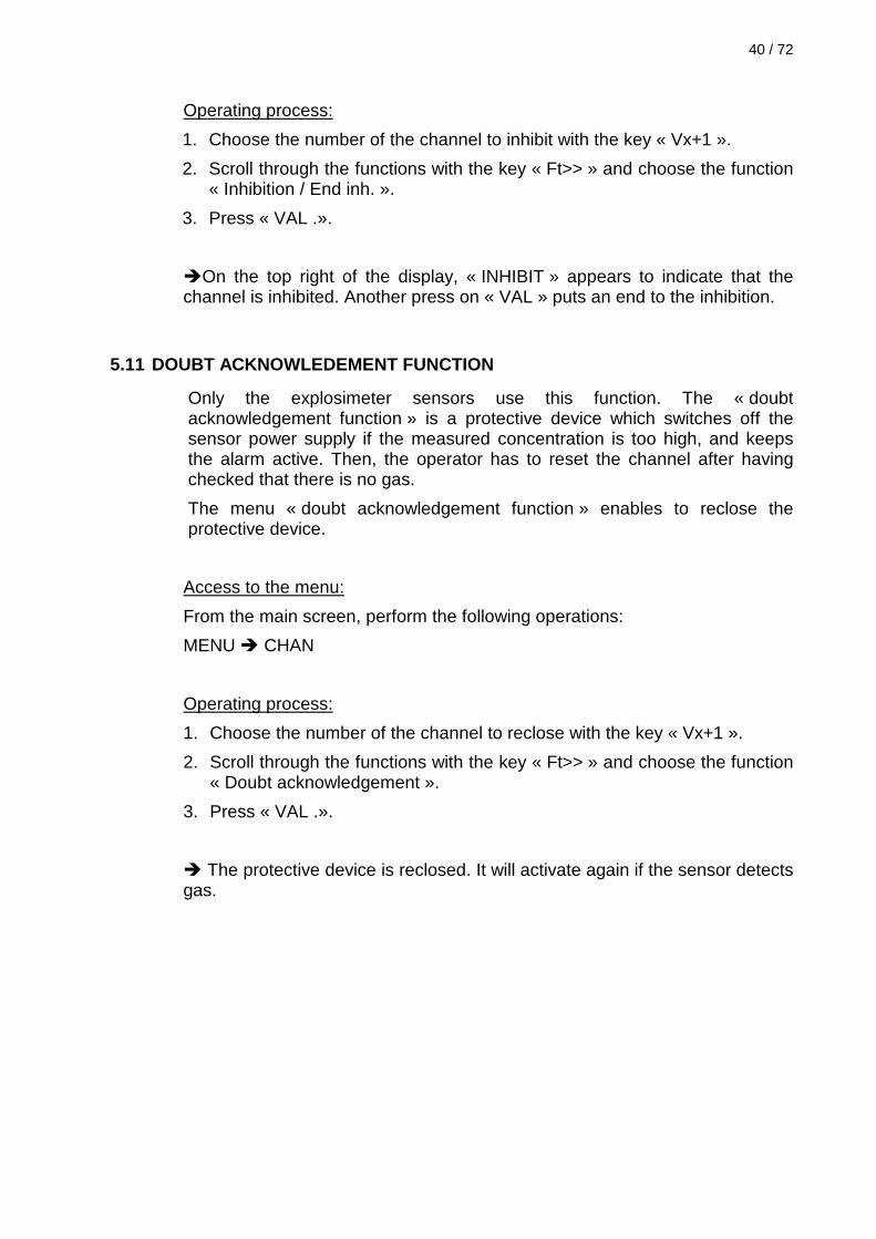
5.11 DOUBT ACKNOWLEDEMENT FUNCTION
Only the explosimeter sensors use this function. The « doubt acknowledgement function » is a protective device which switches off the sensor power supply if the measured concentration is too high, and keeps the alarm active. Then, the operator has to reset the channel after having checked that there is no gas.
The menu « doubt acknowledgement function » enables to reclose the protective device.
Access to the menu:
From the main screen, perform the following operations:
MENU CHAN
Operating process:
1. Choose the number of the channel to reclose with the key « Vx+1 ».
2. Scroll through the functions with the key « Ft>> » and choose the function « Doubt acknowledgement ».
3. Press « VAL .».
The protective device is reclosed. It will activate again if the sensor detects gas.

5.12 CLOCK ADJUSTMENT
A clock is integrated to the detection unit. It enables the recording of the messages emitted on the RS232 output.
The clock is not saved if there a power supply switching off.
Access to the menu:
From the main screen, perform the following operations:
MENU PROG function « System prog »
Operating process:
1. Choose the function « Time setting » with the key « Ft>> » and press « VAL. ».
2. Use the keys « ++ » and « -- » to modify the day, month, year, time, or minute value, and the key « >> » to go to the next character.
3. Confirm with the key « VAL. ».
5.13 BUZZER USE
The detection unit is equipped with a buzzer.
The buzzer rings at each event, and it can be acknowledged by the key « ACK » of the main screen.
It is possible to inhibit this buzzer.
Access to the menu:
From the main screen, perform the following operations:
MENU PROG function « System prog »
Operating process:
1. Choose the function « Sound config. » with the key « Ft>> » and press « VAL. ».
2. Use the key «CHG » to use or inhibit the buzzer.
3. Confirm with the key « VAL. ».
42 / 72
5.14 BATTERIES AND EMERGENCY POWER SUPPLY USE
The detection unit can be supplied with power:
- by its main power supply source: the electric mains,
- by an emergency 24 Volts,
- by batteries.
It is necessary to indicate to the detection unit if the emergency power supply is realized:
- with batteries: in this case, the detection unit performs the batteries charge, controls their estatus and sets off a fault if they are empty.
- with a 24V emergency power supply. Then, the detection unit checks the presence of this tension, and sets off a fault if the emergency tension is inferior to 20V.
- or if it is not used. The detection unit does not set off a fault if there is no emergency power supply.
Access to the menu:
From the main screen, perform the following operations:
MENU PROG function « System prog »
Operating process:
1. Choose the function « Powered 24V» (« emergency 24V») with the key « Ft>> » and press « VAL. ».
2. Use the key «CHG » to choose the wanted emergency mode.
3. Confirm with the key « VAL. ».

5.15 SETTING OF THE RS232 COMMUNICATION
The standard detection unit is equipped with a RS232 type serial link, which can be configured:
- Either in “printer” mode: the detection unit then emits a message at every event which happens:
- fault appearance / disappearance,
- alarm appearance / disappearance,
- operator's intervention…
- Either in “MODBUS” mode: refer to paragraph 5.16.
It is possible to modify the communication protocol of this link and specially:
- Transmission speed: 2400, 4800, 9600, 19200, 38400 bauds.
- Parity: pair, odd or without.
- Mode: Printer or MODBUS
- The slave’s number
The transmission is always made on 8 bits with a stop bit.
Access to the menu:
From the main screen, perform the following operations:
MENU PROG function « Prog. système »
Operating process:
1. Choose the function « Serial interface » with the key « Ft>> » and press « VAL. ».
2. Choose the wanted function with the key « Ft>> » and confirm with the key « VAL. ».
3. Choose the wanted value and confirm with the key « VAL. ».
44 / 72
5.16 MODBUS PROTOCOLE
The MODBUS communication & the slave’s number must be declared in the “Serial Interface” menu (refer to paragraph 5.15.)
Features: Protocole: MODBUS RTU type (binary) Format: the same than RS232 communication Response time: < 100mS Slave’s number: 1 to 127 Allowed commands: Word reading (03 or 04)
1 word writing (06) Diagnostic (08)
Error codes processed: 01 (Function code unknown)
02 (Wrong address).
Generalities:
GOUL MODICON’s MODBUS RTU (binary) protocol is a data producer/consumer model (only 1 producer by network).
Notes:
- MODBUS specification (available on www.modbus.org) defines some addresses (register or coil) which are incremented from 1 in relation to the addresses which are really retransmitted on the line.
- The addresses mentioned in this document, and especially in the MODBUS exchange table, are the addresses retransmitted on the line.
Exchange description:
The exchanges are made on the MODBUS data producer’s initiative, which emits its request. When the data consumer understands it, it sends the response.
Each message contains 4 types of information:
The slave’s number (1 byte), designates the request’s recipient (request’s frame) or the response’s sender (response’s frame).
The function code (1 byte), selects a control (reading, writing) and enables to check if the response is correct.
The information field (« n » bytes), contains the parameters linked to the function.
The control word CRC16 (2 bytes), contributes to detect the transmission errors.
All information are coded in hexadecimal format.

Function WORD READING:
MODBUS data producer’s question frame
01 to 7F 03 or 04 [2 bytes]
PF ………pf
[2 bytes]
PF ………pf
[2 bytes]
PF ………pf
Slave’s number
Function code
1rst word address
Number of words to
read
CRC 16
Detection unit response frame
01 to 7F 03 or 04 [1 bit] [2 bytes]
PF ………pf
[2 bytes]
PF ………pf
[2 bytes]
PF ………pf
[2 bytes]
PF ………pf
Slave’s number
Function code
Number of read bytes
Value of the 1rst word
---------- Value of the last read
word
CRC 16
Function 1 MOT WRITING:
MODBUS data producer question frame
01 to 7F 06 [2 bytes]
PF ………pf
[2 bytes]
PF ………pf
[2 bytes]
PF ………pf
Slave’s number
Function code
Word address
Word to write
CRC 16
Detection unit response frame
01 to 7F 06 [2 bytes]
PF ………pf
[2 bytes]
PF ………pf
[2 bytes]
PF ………pf
Slave’s number
Function code
Word address
Value od the written word
CRC 16
Response in case of INCORRECT PARAMETERS
Detection unit response frame in case of incorrect question parameters
01 to 7F 83, 84 or 86
[1 bit] [2 bytes]
PF ………pf
Slave’s number
Function code
Error code
CRC 16
Error code = 01 Incorrect function code
Error code = 02 Incorrect address

46 / 72
Diagnostic functions
The ECHO detection unit accepts certain diagnostic function to test the communication:
MODBUS data producer question frame
01 to 7F 08 [2 bytes]
PF ………pf
[2 bytes]
PF ………pf
[2 bytes]
PF ………pf
Slave’s number
Function code
Diagnostic code
Data CRC 16
Detection unit response frame
01 to 7F 08 [2 bytes]
PF ………pf
[2 bytes]
PF ………pf
[2 bytes]
PF ………pf
Slave’s number
Function code
Diagnostic code
Data CRC 16
The accepted diagnostic codes are:
00 Request’s echo
01 or 0A Reset of diagnostic counter
0B Number of correct frames received
0C Number of frames received with CRC error
0D Number or sent back errors.
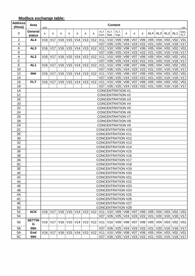
Modbus exchange table:
Add ress (Hexa)
Area MSB
Content LSB
0 General status
x x x x x x x FLT Com.
FLT. Batt.
FLT. Sup. x x x AL4 AL3 AL2 AL1 Gen.
FLT.
2 AL4 V16 V17 V16 V15 V14 V13 V12 V11 V10 V09 V08 V07 V06 V05 V04 V03 V02 V01 4 V27 V26 V25 V24 V23 V22 V21 V20 V19 V18 V17 6 AL3 V16 V17 V16 V15 V14 V13 V12 V11 V10 V09 V08 V07 V06 V05 V04 V03 V02 V01 8 V27 V26 V25 V24 V23 V22 V21 V20 V19 V18 V17 A AL2 V16 V17 V16 V15 V14 V13 V12 V11 V10 V09 V08 V07 V06 V05 V04 V03 V02 V01 C V27 V26 V25 V24 V23 V22 V21 V20 V19 V18 V17 E AL1 V16 V17 V16 V15 V14 V13 V12 V11 V10 V09 V08 V07 V06 V05 V04 V03 V02 V01 10 V27 V26 V25 V24 V23 V22 V21 V20 V19 V18 V17 12 INH V16 V17 V16 V15 V14 V13 V12 V11 V10 V09 V08 V07 V06 V05 V04 V03 V02 V01 14 V27 V26 V25 V24 V23 V22 V21 V20 V19 V18 V17 16 FLT V16 V17 V16 V15 V14 V13 V12 V11 V10 V09 V08 V07 V06 V05 V04 V03 V02 V01 18 V27 V26 V25 V24 V23 V22 V21 V20 V19 V18 V17 1A CONCENTRATION V1 1C CONCENTRATION V2 1E CONCENTRATION V3 20 CONCENTRATION V4 22 CONCENTRATION V5 24 CONCENTRATION V6 26 CONCENTRATION V7 28 CONCENTRATION V8 2A CONCENTRATION V9 2C CONCENTRATION V10 2E CONCENTRATION V11 30 CONCENTRATION V12 32 CONCENTRATION V13 34 CONCENTRATION V14 36 CONCENTRATION V15 38 CONCENTRATION V16 3A CONCENTRATION V17 3C CONCENTRATION V18 3E CONCENTRATION V19 40 CONCENTRATION V20 42 CONCENTRATION V21 44 CONCENTRATION V22 46 CONCENTRATION V23 48 CONCENTRATION V24 4A CONCENTRATION V25 4C CONCENTRATION V26 4E CONCENTRATION V27 50 CONCENTRATION V28 52 ACK V16 V17 V16 V15 V14 V13 V12 V11 V10 V09 V08 V07 V06 V05 V04 V03 V02 V01 54 V27 V26 V25 V24 V23 V22 V21 V20 V19 V18 V17
56 SETTIN
G V16 V17 V16 V15 V14 V13 V12 V11 V10 V09 V08 V07 V06 V05 V04 V03 V02 V01
58 INH V27 V26 V25 V24 V23 V22 V21 V20 V19 V18 V17 5A End V16 V17 V16 V15 V14 V13 V12 V11 V10 V09 V08 V07 V06 V05 V04 V03 V02 V01 5C INH V27 V26 V25 V24 V23 V22 V21 V20 V19 V18 V17

48 / 72
Area « General status »: (Reading access)
Gen. Fault If = 1, indicates a fault status in the detection unit.
AL1 to AL4 If = 1, at least an alarm 1,2,3 or 4 I signalled.
Fault Main If = 1, the main power supply is absent.
Fault Batt. If = 1, the battery is discharged, or uninterruptible power supply voltage is too low.
Fault Com. If = 1, problem of communication between the different control cards.
Area “AL1 to AL4”: (Reading access)
If the bit correspondent to the channel is set to 1, the channel is in alarm mode.
Area « Inh »: (Reading access)
If the bit correspondent to the channel is set to 1, the channel is inhibited.
Area « FLT »: (Reading access)
If the bit correspondent to the channel is set to 1, the channel is in fault mode.
Area « Concentration »: (Reading access)
Measure processed by the detection unit for the wanted channel. The value is an integer & unsigned value. For the scales with a comma, its position has to be noted down on the detection unit.
Example: If the detection unit displays 20,8, the value will be 208.
Area « ACK »: (Reading access)
When the "ACK" bit is at "1", this acknowledges the channel module.
Area « Inh »: (Reading access)
When the "Inh" bit is at "1", this inhibits a channel module.
Area « End Inh »: (Reading access)
When the "End Inh" bit is at "1", this sets the channel back to normal operation.

5.17 ACCESS CODE CHANGE
The access code enables the access to the menus.
In a factory configuration, the password is 0000. Thanks to this function the user can change the password.
It is possible to choose a password composed of 4 alphanumerical characters.
Access to the menu:
From the main screen, perform the following operations:
MENU PROG function « System prog. »
Operating process:
1. Choose the function « Password change » with the key « Ft>> » and press « VAL. ».
2. Use the keys « ++ » and « --» to modify the value of the flashing character and the key « >> » to go to the next character.
3. Press « VAL » to confirm the new code.
Note:
In case of the code loss, contact SIMRAD Optronics ICARE.
5.18 LANGUAGE CHOICE
It is possible to display the menus in English or in French.
Access to the menu:
From the main screen, perform the following operations:
MENU PROG function « System prog. »
Operating process:
1. Choose the function «Langue» with the key « Ft>> » and press « VAL. ».
2. Use the key «CHG » to choose the wanted language.
3. Press « ESC » so as not to modify the configuration.

50 / 72
5.19 SOFTWARE VERSION
This menu enables to visualise the software version of the different control cards in the detection unit. It is dedicated to maintenance.
Access to the menu:
From the main screen, perform the following operations:
MENU PROG function “System prog. ”
4. Choose the function “ Software version ” with the key “« Ft>> “ and press « VAL. ».
5.20 ADDITION / SUPPRESSION OF A RELAY MODULE
In its basic version, the detection unit has 4 configurable relays and a general fault relay. It is possible to extend the number of the relays activated by the detection unit, by adding modules of 8 relays.
Note:
The new relay module has to be connected to the detection unit before being configured.
Access to the menu:
From the main screen, perform the following operations:
MENU PROG function « System prog. »
Operating process:
4. Choose the function « Board detection » with the key « Ft>> » and press « VAL. ».
5. Then, the detection unit displays the relay modules already detected.
Press « SCAN » to start the scanning. The moving symbol « + » enables to follow the scanning advance.
6. When the scanning is over, check that the new module is effectively detected and confirm the new configuration with the key « VAL. ».
7. Go to paragraph 5.21 page 51 to configure the relays of the new module.
Note:
If the new module is not detected, check the wiring. Refer to paragraph 6.3 page 61.

5.21 RELAY PROGRAMMATION
After being configured, the measurement channels set off the alarms. They are visualized by the LEDs switched on the front face.
All the relays of the detection unit, except the fault relays can be configured individually. It is possible to fix:
- relay unenergized condition: the relay can be configured on normal working condition (normally power supplied = positive safety) or on normal unenergized condition (normally not power supplied),
- its activation conditions: what are the alarms that will set off the relay.
- Its operating mode. Two modes are possible:
- SYNTHESIS MODE: the relay comes back on unenergized condition when all the activation conditions have disappeared. This mode can me use for example to command a flashing light which will be on as long as there is an alarm. It is important to note that if one of the activation conditions is a memorized alarm, the relay will be beck on its unenergized condition only when the cause of the alarm has disappeared AND that the alarm has been acknowledged.
- BUZZER MODE: the relay remains active as long as the alarm has not been acknowledged. (press « ACQ »). After the acknowledgement, the relay disappears even if the alarm is still present. If the alarm is not memorized and disappears the relay also disappears (it is not advised to use an alarm which is not memorized with a sound alarm mode).
Notes:
- It is possible to create detection areas by selecting a single channel alarm level or several multi-channel alarm levels as a relay activation condition. The relay will be active if at least one of the activation conditions is real, and it will be back to its unenergized condition when all the activation conditions have disappeared. This functionality avoids the increase of the channel individual relays and an expensive wiring.
- If the relay is already assigned to a fan, the unenergized condition only can be modified.
Access to the menu:
From the main screen, perform the following operations:
MENU PROG function « Relays program. ».

52 / 72
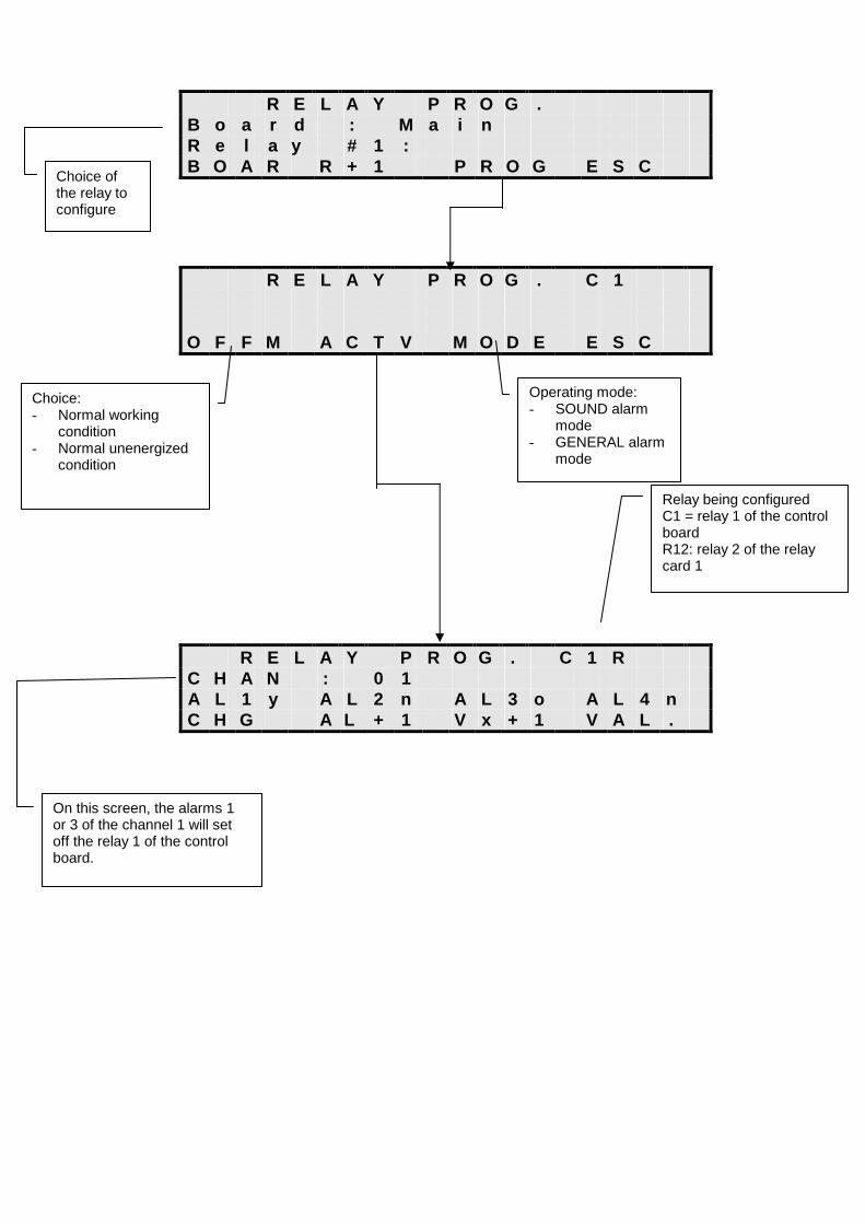
Operating process:
1. Choice of the relay to configure:
- Use the key « BOAR » to choose the card of the relay to configure (Cx = control board x relay, R1x = relay card 1 x relay…).
- Use the key « R+1 » to choose the number of the relay to configure
- Press « PROG » after having chosen the good relay.
2. Relay configuration:
- OFFM: enables to choose the relay unenergized condition. It is possible to choose between:
- A relay which is on normal unenergized condition (normally not power supplied)
- or on normal working condition (normally power supplied = positive safety).
- ACTV: enables to choose which alarms will set off the relay.
- Start by configuring the alarms of the channel 1.
- Use the key « AL+1 » to choose the alarm threshold to configure.
- Use the key « CHG » to make the relay active (o), or not (n) on the alarm which is being configured.
- Once the relay is configured for all the alarms of the channel 1, perform the same operations for the channels 2, 3 and 4. The screens for the other channels are accessible by pressing the key « Vx+1 ».
- MODE: enables to choose the relay operating mode. The possible choices are:
- BUZZER mode: the relay remains active as long as the alarm is not acknowledged,
- SYNTHESIS mode: the relay remains active as long as the alarm is kept.
R E L A Y P R O G .
B o a r d : M a i n R e l a y # 1 : B O A R R + 1 P R O G E S C
R E L A Y P R O G . C 1
O F F M A C T V M O D E E S C
R E L A Y P R O G . C 1 R
C H A N : 0 1 A L 1 y A L 2 n A L 3 o A L 4 n C H G A L + 1 V x + 1 V A L .
Choice: - Normal working
condition - Normal unenergized
condition
Operating mode: - SOUND alarm
mode - GENERAL alarm
mode
Choice of the relay to configure
On this screen, the alarms 1 or 3 of the channel 1 will set off the relay 1 of the control board.
Relay being configured C1 = relay 1 of the control board R12: relay 2 of the relay card 1
54 / 72
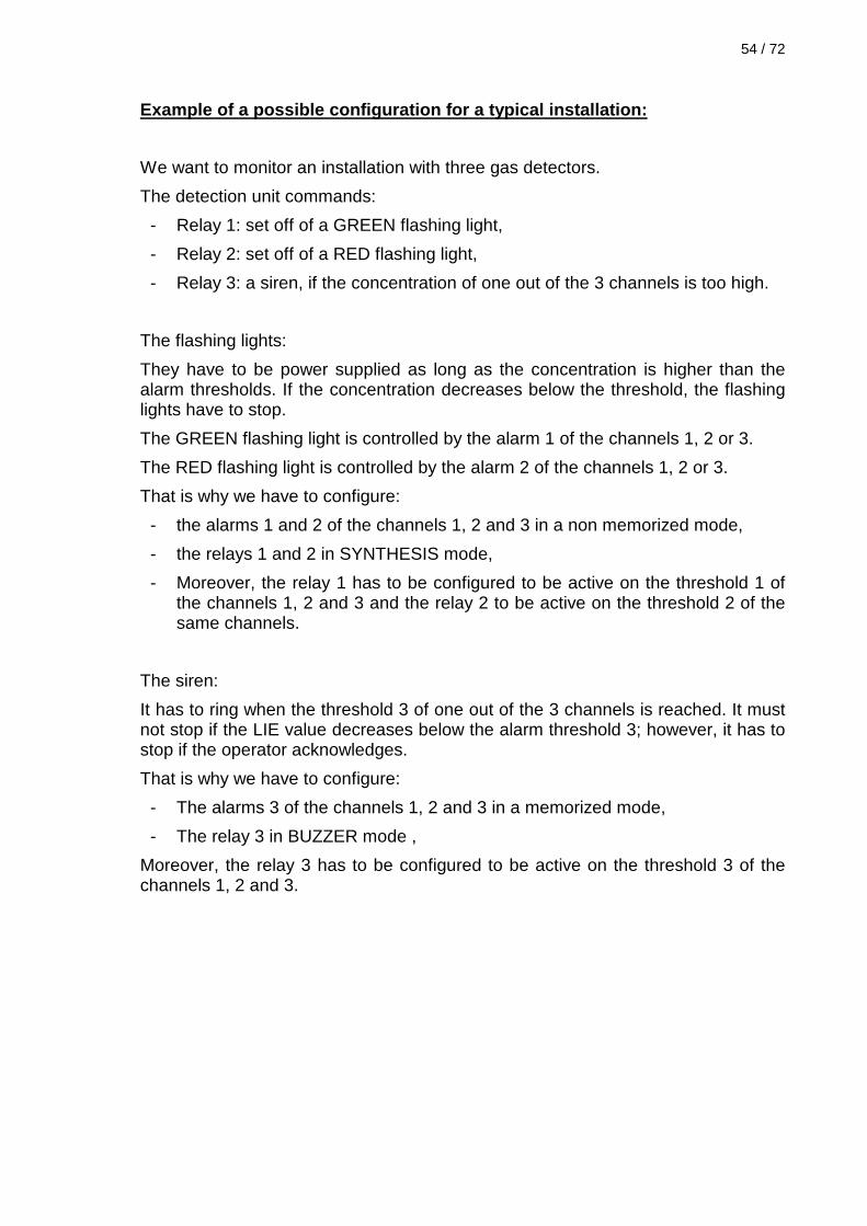
Example of a possible configuration for a typical i nstallation:
We want to monitor an installation with three gas detectors.
The detection unit commands:
- Relay 1: set off of a GREEN flashing light,
- Relay 2: set off of a RED flashing light,
- Relay 3: a siren, if the concentration of one out of the 3 channels is too high.
The flashing lights:
They have to be power supplied as long as the concentration is higher than the alarm thresholds. If the concentration decreases below the threshold, the flashing lights have to stop.
The GREEN flashing light is controlled by the alarm 1 of the channels 1, 2 or 3.
The RED flashing light is controlled by the alarm 2 of the channels 1, 2 or 3.
That is why we have to configure:
- the alarms 1 and 2 of the channels 1, 2 and 3 in a non memorized mode,
- the relays 1 and 2 in SYNTHESIS mode,
- Moreover, the relay 1 has to be configured to be active on the threshold 1 of the channels 1, 2 and 3 and the relay 2 to be active on the threshold 2 of the same channels.
The siren:
It has to ring when the threshold 3 of one out of the 3 channels is reached. It must not stop if the LIE value decreases below the alarm threshold 3; however, it has to stop if the operator acknowledges.
That is why we have to configure:
- The alarms 3 of the channels 1, 2 and 3 in a memorized mode,
- The relay 3 in BUZZER mode ,
Moreover, the relay 3 has to be configured to be active on the threshold 3 of the channels 1, 2 and 3.

Figure 12: Example of configuration of a typical in stallation
Light RED Fan PV/LS
RELAY 1 GENERAL alarm
mode Active on AL1 of channels 1,2,3
RELAY 2 GENERAL alarm
mode Active on AL2 of channels 1,2,3
RELAY 3 SOUND alarm
mode Active on AL3 of channels 1,2,3
CHANNEL
1
ALARM 1
Not memorized
ALARM 2
Not memorized
ALARM 3
memorized
ALARM 4
Not used
CHANNEL
2
ALARM 1
Not memorized
ALARM 2
Not memorized
ALARM 3
memorized
ALARM 4
Not used
CHANNEL
3
ALARM 1
Not memorized
ALARM 2
Not memorized
ALARM 3
memorized
ALARM 4
Not used
Light GREEN Fan PV/LS
Siren, Fan, V/LS

56 / 72
5.22 USE OF FANS (CAR PARKS )
The ECHO 2 / ECHO 4 detection units can be used to ensure the monitoring of an indoor car park.
The function « fans » enables an efficient control of the switching on, the stop and the function low speed/ high speed of the fans. The detection unit can control until 4 different fans.
Notes:
- The user can freely choose the relays used for the low speed (relay PV=relay LS) and high speed (relay GV=relay HS), as well as the channel(s) which is/are used to command the fan.
- The alarms 1 and 2 of these channels are then respectively assigned to the command of the fan low speed or high speed.
- For the channels which set off the fans, the alarms must be configured with no memorization, and the alarm thresholds 2 must be higher than the alarm threshold 1.
- The temporization enables the definition of the minimum time during which the fan will work in low speed and in high speed.
- If the alarms disappear, the fan will keep working during this temporization.
- If the alarm 2 appears before the end of the low speed temporization, the fan finishes its cycle in low speed before passing in high speed.
- When passing from low speed to high speed, the LS relay is disabled 2 seconds before the activation of the HS relay.
The Figure 13 represents a typical case of fans triggering depending on the measured concentration.

Threshold 2 Threshold 1
LS LS
HS
Time
Time
Holding time Holding time
Lowspeed relay desactivated during 2 sec. Before Highspeed relay activation
Measurement (ppm)
Relay status

58 / 72
Figure 13: Fans triggering
Access to the menu:
From the main display, perform the following operations:
MENU PROG function « Electric fan config. »
Operating mode:
1. Choice of the fan:
- Use the key « V+1 » to choose the fan to configure.
2. Use of the fan:
- Choose the function « Use » with the key « Ft>> » and press « VAL. ».
- Choose « yes » with the key « CHG » and confirm.
3. Choice of the relays associated to low speed and high speed:
- Choose the function « Low speed » or « Highspeed » with the key « Ft>> » and press « VAL. ».
- Use the key « BOAR » to choose the card of the relay to configure ( Cx = control board x relay, R1x = card relay x relay 1…).
- Use the key « R+1 » to choose the number of the relay to configure.
- Press « VAL. » after having chosen the good relay.
4. Temporization adjustment:
- Choose the function « Holdtime » with the key « Ft>> » and press « VAL. ».
- Adjust the wanted temporization with the keys « --», « ++ » and « >> » and confirm.
5. Choice of the associated channels:
- Choose the function « Connected channels » (« associated channels ») with the key « Ft>> » and press « VAL. ».
- Use the keys « Vx-1 » and « Vx+1 » to scroll through the channels, and, with the key « CHG », choose whether the channel will set the fan on (yes) or off (no).
- Scroll through all the detection unit channels so as to make sure that only the wanted channels will set off the fan, and confirm the configuration with the key « VAL. ».

6 MAINTENANCE
Preliminary :
All the operations described in this chapter must be performed by a competent technician .
6.1 SENSOR RATING
These rating operations are necessary for all the detectors that do not have an internal calibration system. (Ex: SCALE COMPACT SENSOR or serial sensor « ECHO » type EX, EO, ET). These operations can also enable a more precise display when there are some differences between the value displayed by the detection unit and the measurement of a transmitter. Notes: - Entirely perform the procedure of the adjustment of the zero before
starting the one of the gain adjustment. - The alarms are automatically inhibited during the rating or zero operations.
ADJUSTMENT OF THE ZERO
Access to the menu:
From the main display, perform the following operations:
MENU CHAN
Operating mode:
1. Go on the channel to calibrate with the key « Vx+1 ».
2. Choose the function « Zero adjustment » with the key « Ft>> » and press « VAL. ». The detection unit displays the measured concentration.
3. To inject the calibration gas mixture correspondent to the zero on the detector. The ambient air can be used in case of certainty that there is not any presence of another gas.
4. When the measurement is stabilized, press the key « ZERO ».
5. If the detection unit displays « fault », check that the calibration gas mixture is correct. If it is so, change the sensor.
60 / 72
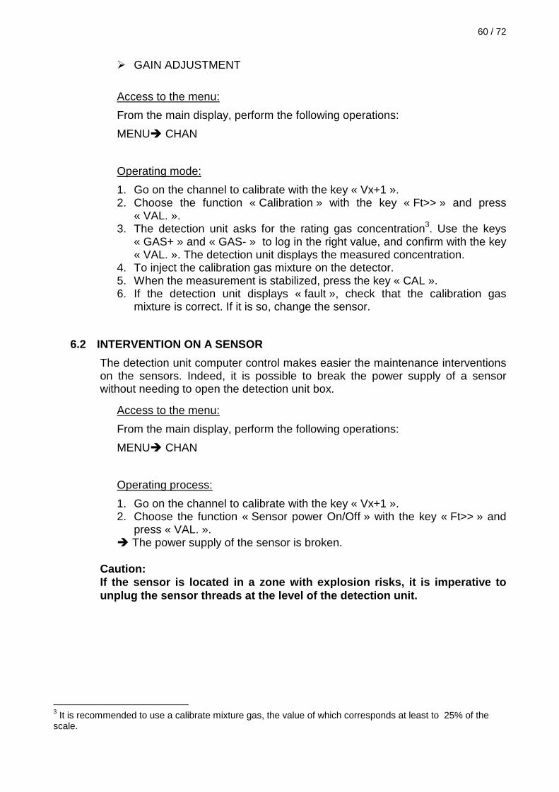
GAIN ADJUSTMENT
Access to the menu:
From the main display, perform the following operations:
MENU CHAN
Operating mode:
1. Go on the channel to calibrate with the key « Vx+1 ». 2. Choose the function « Calibration » with the key « Ft>> » and press
« VAL. ». 3. The detection unit asks for the rating gas concentration3. Use the keys
« GAS+ » and « GAS- » to log in the right value, and confirm with the key « VAL. ». The detection unit displays the measured concentration.
4. To inject the calibration gas mixture on the detector. 5. When the measurement is stabilized, press the key « CAL ». 6. If the detection unit displays « fault », check that the calibration gas
mixture is correct. If it is so, change the sensor.
6.2 INTERVENTION ON A SENSOR
The detection unit computer control makes easier the maintenance interventions on the sensors. Indeed, it is possible to break the power supply of a sensor without needing to open the detection unit box.
Access to the menu:
From the main display, perform the following operations:
MENU CHAN
Operating process:
1. Go on the channel to calibrate with the key « Vx+1 ». 2. Choose the function « Sensor power On/Off » with the key « Ft>> » and
press « VAL. ». The power supply of the sensor is broken.
Caution: If the sensor is located in a zone with explosion r isks, it is imperative to unplug the sensor threads at the level of the detec tion unit.
3 It is recommended to use a calibrate mixture gas, the value of which corresponds at least to 25% of the scale.

6.3 EXTENSION OF THE NUMBER OF RELAYS
In its basic version, the detection unit has 4 configurable relays, and a general fault relay. It is possible to extend the number of relays activated by the detection unit by adding 8 relay modules.
6.3.1 CHARACTERISTICS
Breaking capacity of the relays:
2 A / 230 VAC
2 A / 125VDC
Maximum number of modules for each detection unit:
Five 8 relay modules, that is to say 40 relays in all.
Modules location:
Remote out of the detection unit, protected in a box (cabinet for example).
Connection to the detection unit:
Connection with a single shielded 2 conductor cable pair by pair + general display.
This cable can be armored if a mechanical protection is necessary.
Maximum distance between the detection unit and the modules:
2 Km maximum.
Modules power supply:
The power supply is provided by the detection unit.
Modules fixation:
On DIN rail (not supplied)
Dimensions:
125 x 75 x 53 mm
Weight:
300 grams

62 / 72
6.3.2 FIXATION / CONNECTION
The 8 relay module is designed to be assembled with a DIN rail (omega).
Figure 14: The 8 relay extension module

N° Function N° Function 1 + Power supply 48 Communication signal E+ 2 - Power supply ( GND ) 47 Communication signal E- 3 + Power supply 46 Communication signal E+ 4 - Power supply ( GND ) 45 Communication signal E- 5 GND 44 GND 6 GND 43 GND 7 GND 42 GND 8 GND 41 GND 9 GND 40 GND
10 Relay 8 : Normally open 39 Relay 4 : Normally closed 11 Relay 8 : Common 38 Relay 4 : Common 12 Relay 8 : Normally closed 37 Relay 4 : Normally open 13 Relay 7 : Normally open 36 Relay 3 : Normally closed 14 Relay 7 : Common 35 Relay 3 : Common 15 Relay 7 : Normally closed 34 Relay 3 : Normally open 16 Relay 6 : Normally open 33 Relay 2 : Normally closed 17 Relay 6 : Common 32 Relay 2 : Common 18 Relay 6 : Normally closed 31 Relay 2 : Normally open 19 Relay 5 : Normally open 30 Relay 1 : Normally closed 20 Relay 5 : Common 29 Relay 1 : Common 21 Relay 5 : Normally closed 28 Relay 1 : Normally open 22 Not connected 27 Not connected 23 Not connected 26 Not connected 24 Not connected 25 Not connected
Table 4: Relay module wiring

64 / 72
6.3.3 COMMISSIONING
The bringing into service of a 8 relay module is performed according to the following operations:
Electric connections.
Make electric connections of the modules to the detection unit according to the connection diagram below and to the information given in the Table 4.
Figure 15: Relay modules connection
CAUTION: This operation must be performed when the detection unit is out of tension.
1
2
3
4
48
47
46
45
Terminal 15 of the detection unit (Alim+)
Terminal 18 of the detection unit (GND)
1
2
3
4
48
47
46
45
1
2
3
4
48
47
46
45
Terminal 16 of the detection unit (Bus E+)
Terminal 17 of the detection unit(Bus E-)
Resistance of line end 100Ω

Note:
It is possible to locally power supplied the relay module and not to use the power supply provided by the detection unit. It enables the use of a cable with a single pair for the connection with the detection unit.
The power supply required by the module is 18 – 30 VDC / 0.1 A.
Material configuration.
The address of the modules has to be configure.
Even if it is not an obligation, it is logical to leave from the address 1 for the first module, and to add 1 to this address at each extension.
The valid address goes from 1 to 5.
The chart below indicates the straps configuration depending on the wanted address.
Relay module 1
Relay module 2
Relay module 3
Relay module 4
Relay module 5
Figure 16: Relay module: address straps configurati on
Software configuration.
The software configuration requires two stages: the declaration of the extension module and then, the relay configuration.
To declare the added module, refer to paragraph 5.19 page 50 .
When the module is correctly declared, the 8 relays of the module can be individually programmed. The software configuration is the same as the one of the detection unit configurable relays. Refer to paragraph 5.21 page 51.
Note:
The status of each relay is displayed on LEDs that can be seen through the transparent face of the module.

66 / 72
6.4 ADDITION / REPLACEMENT OF THE BATTERIES
It is possible to equip the ECHO detection unit with an emergency power supply on batteries. This kit « batteries » includes:
- 2 12 V / 4 Ah batteries
- the necessary connector technology.
Putting into place of the kit batteries:
1. Turn off the electric mains power supply of the detection unit.
2. Connect the 2 batteries and link the red thread and the blue thread to the batteries and to the GENERAL terminal block, according to, the diagram on the figure. The detection unit has then to switch on.
3. Put the batteries in their housing and correctly drive the blue and the red threads.
4. Put into place the lock on bar and its two screws.
5. Switch on again the electric main power supply of the detection unit.
6. Configure the software to declare the use of the batteries. Refer to paragraph 5.14 page 42.
Figure 17: Batteries position
- +
Battery 1
- +
Battery 2
Blue thread: towards terminal 2 of the GENERAL terminal block control board
Red thread: towards terminal 1 of the GENERAL terminal block control board

6.5 FUSES REPLACEMENT
The detection unit is equipped with 2 fuses that are located on the control board.
- The fuse F1 (1A temporized) enables the protection of the relay modules power supply.
- The fuse F2 (5A temporized) protects the detection unit general and continuous power supply. F2 isn't affected by a wiring problem, or a short-circuit, on a sensor.
Spare fuses are available in SIMRAD Optronics ICARE.
They have to be replaced with thin jaw pincers (CMS component) and the detection unit out of tension .
Figure 18: Position of the fuses
F1: protection of the relay modules
F2: protection of the detection unit

68 / 72
Main power supply Fuses: The main power supply is equipped with a 4A / 250 VAC rapid fuse (5x20).
Figure 19: Position of the main power supply fuse
F3 : fuse main power supply

6.6 INCIDENTS GUIDE BOOK
The chart below lists the most frequent incidents.
Table 5: Incidents guide book
INDICATIONS
POSSIBLES CAUSES
SOLUTIONS
The electric mains or continuous power supply is plug in but the display remains switched off.
The detection unit is not power supplied. The fuse F2 or F3 is faultive. The continuous detection unit emits a too weak power for the detection unit.
Check the electric mains presence. Replace the fuse. Make sure the power supply delivers at least 3A .
The display indicates « absent sensor » and a channel fault LED remains switched on.
The 4-20mA detector is not connected. The connection of the detector to the terminal block is not correct.
Make sure the connections between the sensor and the detection unit are good.
The display indicates « drift fault» and a channel fault LED remains switched on.
The signal emitted by the detector is inferior to 2 mA. The detector is not correctly calibrated.
Check that the detector is not in fault or inhibition mode. Re-calibrate the detector.
The display indicates «doubt acknowledgement function »
The detector emits a signal superior to 20 mA.
Wait for the stabilization of the detector. Check that the explosimetric detector is not on DOUBT ACKNOWLEDGEMENT FUNCTION. Apply the procedure described par. 5.1.

70 / 72
The display indicates « ABS sensor »
The sensor is absent or badly connected The sensor is faultive
Check the wiring Change the sensor
A channel fault LED which is not used remains switched on.
The channel is still declared. Suppress the channel which is not used.
On the display, the symbol
flashes and the main fault LED is switched on or is flashing.
The fuse F1 is faultive The communication between the detection unit and a relay module is faultive. The communication between the main card and the LED card is faultive
Replace the fuse. Check the cable between the detection unit and the relay module Check the patch cord between the 2 cards.
The Symbol of the display flashes and the main fault LED is switched on
The batteries are not sufficiently recharged. The batteries are declared but not present The batteries are faultive
Wait for the batteries to be completely recharged Check the batteries configuration Replace the batteries
On the display, the Symbol flashes and the main fault LED is switched on or is flashing.
The main power supply has disappeared
Check the electric mains presence
An alarm LED is switched on and the correspondent relay as wall as the common are active though the value is below the alarm threshold.
Alarm in memorized mode Decreasing alarm threshold
Press ACQUIT to acknowledge the alarm Adjust the alarm in increasing alarm threshold
A relay is activated when the associated alarm is absent.
The relay in the « normally power supplied mode » The relay is associated to another alarm
Check the relay configuration. Check the relay configuration
No active sound alarm even in alarm conditions.
The buzzer is inactive Check the buzzer configuration

7 TRANSPORT AND STORAGE
In every case of transport (servicing, return for modification, etc. ...), it is recommended to place the device and its accessories in their original package. These packages are rationally designed so as to avoid any deterioration of the material.
It is in the user's interest to store the waiting material in premises without dust or humidity and at a temperature between 0 and 50 °.
8 WARNINGS
8.1 FOREWORD
The products characteristics can be modified without previous notice for improvement purposes or for upgrading to meet applicable standards.
8.2 OWNERSHIP AND CONFIDENTIALITY
The information, design data, drawings and diagrams contained in this document remain the property of SIMRAD Optronics ICARE and are confidential.
The information contained in this document cannot be used, either partially or wholly, nor divulged or reproduced without the previous agreement of SIMRAD Optronics ICARE.
8.3 LIABILITY
The liability of SIMRAD Optronics ICARE shall be limited to any direct prejudice resulting from failure on SIMRAD Optronics ICARE's part to fulfil the contract. SIMRAD Optronics ICARE shall decline all liability for any indirect prejudice caused.
By explicit agreement between the parties, the term "indirect prejudice" shall refer in particular to any financial loss, moral damage, loss or profit, earnings, clients or order, or any action taken against the client by a third party.
Moreover, any damages due from SIMRAD Optronics ICARE for any reason, whatsoever shall not exceed the tax-exclusive value of the contract, except in the event of an intentional or fraudulent offense on the part of SIMRAD Optronics ICARE.

72 / 72
8.4 WARRANTY COVERAGE
The application of the equipment warranty is subject to compliance with the status-of-the-art and the operating instructions contained in this manual.
Furthermore, SIMRAD Optronics ICARE declines all liability, for damage to equipment or harmful accidents caused by negligence, failure to supervise the equipment or failure to use the equipment in compliance with the applicable recommendations, standards and regulations stipulated in the present manual.
The SIMRAD Optronics ICARE warranty shall not apply to faults resulting either from materials supplied by the purchaser, from designed imposed by the purchaser, from servicing or maintenance carried out on SIMRAD Optronics ICARE equipment by a third party not explicitly authorized, of from the use of unsuitable conditions.
In order to guarantee correct operation of the system, any addition of equipment to the system or any modification of the installation must be validated by SIMRAD Optronics ICARE.
Related Documents