140 New Montgomery Power Distribution Design A Senior Project presented to the Faculty of the Electrical Engineering Department California Polytechnic State University, San Luis Obispo In Partial Fulfillment of the Requirements for the Degree Bachelor of Science by Stephen Shaffer August, 2011 © 2011

Welcome message from author
This document is posted to help you gain knowledge. Please leave a comment to let me know what you think about it! Share it to your friends and learn new things together.
Transcript

140 New Montgomery Power Distribution Design
A Senior Project
presented to
the Faculty of the Electrical Engineering Department
California Polytechnic State University, San Luis Obispo
In Partial Fulfillment
of the Requirements for the Degree
Bachelor of Science
by
Stephen Shaffer
August, 2011
© 2011

TABLE OF CONTENTS
Section Page
Acknowledgements.................................................................................................................. i
Abstract …………………………………………………………………………………….. ii
I. Introduction ................................................................................................................ 1
II. Background ................................................................................................................ 2
III. Requirements ............................................................................................................. 4
IV. Design......................................................................................................................... 9
V. Future Additions........................................................................................................ 29
VI. Conclusion…………………………………………………………………………. 30
VII. Bibliography ……………………………………………………………………….. 31
Appendices
A. Schematic .................................................................................................................. 32
B. Time Schedule Allocation ......................................................................................... 33
LIST OF TABLES AND FIGURES
Table Page
1. Table-1: Square Footage of Building ............................................................................ 11
2. Table-2: Lighting Load of Building............................................................................... 12
3. Table-3: Outlet Load of Building...................................................................................... 13
4. Table-4: Mechanical Load of Building............................................................................. 14
5. Table-5: Elevator Load of Building.................................................................................. 15
6. Table-6: Total Electrical Load of Building....................................................................... 15
7. Table-7: Emergency Generator Calculations................................................................ 20
Figures
1. Figure 1: Existing Transformer Vault............................................................................ 9
2. Figure-2: Existing and New PG&E Transformer Vaults............................................. 16
3. Figure-3: Symbol List……………………………...................................................... 17
4. Figure-4: Basement level of Power Riser Diagram..................................................... 18
5. Figure-5: Busway Risers.............................................................................................. 21
6. Figure-6: Mechanical Panel and Busway Riser 2BR................................................... 22
7. Figure-7: Panelboard 2SH23 on the 23rd
Floor.....…………………………............... 22
8. Figure-8: Elevators and Sewage Pump Located on the 27th and 28th Floors………. 23
9. Figure-9: Distribution Board 2DB27………………………………………………... 24
10. Figure-10: Emergency Riser Diagram………………………………………………. 25
11. Figure-11: Metering System……………………………………………………….... 26
12. Figure-12: Generator and Small Electrical Room…………………………………… 26
13. Figure-13: Typical Electrical Room Plan…………………….……………………… 27

140 New Montgomery Power Distribution Design Page i
Acknowledgements
First off, I would like to thank my parents. They have been amazing role models, truly living
their lives as an example to me. They have always been there for me whenever I needed them,
always willing to lend a helping hand or give some good advice. My dad was always
encouraging me to get outside and build something. Whether it be a tree fort, a hydrogen
generator or a go-cart, he was always able to help me. And my mom was an awesome mom. She
was very trustworthy and allowed me to build things even if it was dangerous.
Lastly, I want to thank The Engineering Enterprise. They are an awesome company. I am proud
to be one of their designers now. They allowed me to use my first project as my Senior Project
which was very kind of them.

140 New Montgomery Power Distribution Design Page ii
Abstract
The Power Distribution Design for a high-rise building requires a great deal of coordination and
design from the structural, electrical, mechanical, telecommunication, and PG&E engineers. This
report will cover how I was able to coordinate and design the power distribution system for 140
New Montgomery, a 28 story building located in San Francisco. Furthermore, this report will
cover the steps taken in the future to ensure a smooth transition from the schematic design phase
to the construction document phase.

140 New Montgomery Power Distribution Design Page 1
Introduction
The Senior Project is a great way to apply Cal Poly's Learn-By-Doing technique for any student.
For my senior project, I decided to design the electrical power distribution system for 140 New
Montgomery. 140 New Montgomery is a 28 story building located in San Francisco, CA. My
design will be for the 100% Schematic Design phase. The schematic design of this project will
be used for the “bid” package and therefore needs to include all the necessary electrical
equipment (but does not necessarily have to show how it is all hooked up). Throughout this
project, I was able to apply what I have learned from Cal Poly. From sizing transformers, to
figuring out load-calcs and even calculating line-voltages, my electrical engineering background
helped in many ways. There are many steps and challenges involved with designing an electrical
power distribution system for a high-rise in San Francisco. Some of the larger steps include:
bidding the project, coordinating temporary/permanent power services with PG&E, and of
course, the actual design of the distribution system. This report will cover how I was able to
complete these steps and overcome the challenges involved with them.

140 New Montgomery Power Distribution Design Page 2
Background
The Engineering Enterprise (TEE) is an Electrical Engineering and Lighting Design firm located
in Alameda, CA. Their mission statement is as follows:
“Founded in 1974, The Engineering Enterprise (TEE) immediately established itself as an industry leader in
progressive, forward thinking design. Our team of electrical engineers and lighting designers offer extensive
expertise in a wide range of sectors including high rise office buildings, educational facilities, transportation,
hospitality & healthcare, theater & performing arts, data centers, detention facilities and convention centers. Our
projects can be found in locations throughout the world from The Bay Area to the Middle East.
The collective diversity of our designers within our two offices maintain TEE‟s position at the forefront of
sustainable “green” design, and in the research and application of new technologies. We strive to accommodate the
individual needs of our clients on a project by project basis, designs that are technically sound, innovative, cost-
effective and always completed on schedule.
The value of a firm's service lies in its technical qualifications, its professional conduct and its standing within the
engineering and lighting design professions. We believe that The Engineering Enterprise is best measured by these
standards. Our solid background of accomplishment and reputation for dependability and are well known and
respected by our clients.”
The Engineering Enterprise focuses most of its design work to local buildings in the Bay Area,
specifically San Francisco. I was hired as an electrical designer by TEE on June 22, 2011. I
currently have 3 projects being designed/build which include: San Francisco Modern Art
Museum, 150 Market Street (Twitters New Headquarters), and 140 New Montgomery Street. I
chose to use 140 New Montgomery Street as my Senior Project because it is a good example of
engineering and how I applied what I learned at Cal Poly to really learn-by-doing.

140 New Montgomery Power Distribution Design Page 3
140 New Montgomery was built in 1925 and was San Francisco‟s first skyscraper when its
construction began. It was the tallest building in the city and was called the “Pacific Telephone
Building” because it housed Pacific Telephone and Telegraph Company for many years. The
building was sold in 2007 to Wilson Meany Sullivan for $118 million. It was intended to house
condominiums, however when the market crashed, this idea of condominiums faltered as well.
The owner finally decided to completely redo the interior of the building and make it open to
floor-by-floor tenants. Perkins+Will was hired as the Architect, and we (TEE) were hired as the
Electrical Engineers to design (but not install) the new electrical distribution system for the
building.

140 New Montgomery Power Distribution Design Page 4
Requirements
The Engineering Enterprise was hired to do the “core and shell” of 140 New Montgomery. “Core
and shell” refers to the core and shell of a building. This would include things such main lobby,
basement storage, support & parking areas, fire pump room, boiler room, electrical & mechanical
rooms on each floor, partial elevator lobbies, restrooms, janitor closets, elevator machine/control
rooms, penthouse/roof mechanical equipment spaces, etc. It is very typical that an engineering
firm is hired to do just the “core and shell” of a building because often owners do not have
tenants yet. In this case, the owner is hoping to rent out floors to companies for office-space. The
company/tenant would then move in and renovate the floor themselves. Because I am just
designing the “core and shell” electrical power distribution system, much of my designs will
allow the tenants the ability to wire their floor however they deem fit. The official project
description is as follows:
1.0 Project Description
1.1 Overview
A. The project consists of the complete MEP renovation of an existing 27-story highrise
building totaling approximately 340,000 square feet with two levels below grade of
basement storage, support spaces and parking garage totaling approximately 39,800
square feet, located in the City of San Francisco, California.
B. Only core/shell construction will be included in project scope. This includes main
lobby, basement storage, support & parking areas, fire pump room, boiler room,
electrical & mechanical rooms on each floor, partial elevator lobbies, restrooms,
janitor closets, elevator machine/control rooms, penthouse/roof mechanical
equipment spaces, etc.
1.2 Electrical Systems and/or Features
A. Incoming power, telephone, and cable television services.
B. Power distribution system.
C. Emergency power distribution system.
D. Power connections to all motors.
E. Grounding and transient voltage surge protection system.
F. Branch circuiting of all devices, equipment, and appliances.
G. Interior lighting and lighting control system.
H. Emergency/egress lighting system.
I. Exterior lighting and controls.

140 New Montgomery Power Distribution Design Page 5
J. Assistance with fire alarm/life safety system.
K. Provisions for telecommunication and cable television system to include raceways,
power and grounding infrastructures.
L. Provide interface of electrical systems with EMCS system.
2.0 Scope of Services
2.1 Design Development Phase
A. Review the program and criteria requirements developed by the Owner and
Architect.
B. Attend meetings with the design team and Owner to obtain and coordinate
information related to the electrical systems and site utilities in order to develop the
drawing package.
C. Contact utility companies to begin coordination of incoming services.
D. Consult with inspection authorities as needed to determine special code requirements.
E. Interface with other consultants to coordinate design of electrical systems with other
building system requirements and/or features.
F. Obtain information from other consultants concerning electrical load requirements
for equipment covered under their Divisions.
G. Coordinate space requirements with Architect for electrical and telecommunication
rooms.
H. Layout electrical equipment to insure that space allocated is sufficient.
I. Review lighting design requirements with the Architect and incorporate layout into
our drawings.
J. Prepare drawings to include the following:
1. Power riser diagrams.
2. Grounding system riser diagram.
3. Telecommunications riser diagram.
4. Site or ground floor electrical plan.
5. Electrical room layout plans
6. Floor plans with lighting and device layouts.
2.2 Construction Document Phase
A. Attend meeting with the design team to obtain final information concerning system
requirements for the electrical design.
B. Final interface with other consultants to coordinate connection requirements.
C. Final coordination and verification of incoming service requirements with utility
companies.
D. Prepare complete set of construction drawings for electrical systems.
E. Prepare detailed construction specifications for electrical systems outlining materials
and installation requirements.
F. Prepare Title 24 energy compliance documentation for lighting system to include the
following:
1. Interior calculations and completion of associated forms.
2. Exterior calculations and completion of associated forms.
3. Confirmation of exterior lighting zone per Title 24 standards based on site
location.
G. Review documents with inspection authorities as required.

140 New Montgomery Power Distribution Design Page 6
2.3 Construction Administration Phase
A. Review shop drawings, submittal data, and record “as-built” drawings.
B. Respond to field questions and prepare clarification instructions as needed.
C. Attend construction coordination meetings on an as-needed/as-requested basis. We
have included 3 trips to the site under this proposal.
D. Visit site periodically to verify compliance with construction documents. We have
included 3 trips to the site, in addition to final walk-through, under this proposal.
3.0 Extra Services not Included
3.1 Special Studies
A. Special environmental impact investigations and related research. Such studies are
not anticipated under this proposed agreement.
B. Leadership in Energy and Environmental Design (LEED) related services.
C. Life cycle cost analyses and energy effectiveness studies.
3.2 Design Services
A. Redesign for reasons not the fault of The Engineering Enterprise, including the
following:
1. Changes in project scope or Owner requirements following the approval of
scope and compensation outlined in this document.
2. Changes to project drawings following the Owner‟s approval of documents
submitted by The Engineering Enterprise at the completion of the Design
Development Phase.
B. Services to provide designs for deductive or additive alternate bid items.
C. Employment of special sub-consultants at the request of the Contractor.
D. Structural analysis or structural and seismic design of equipment anchorage and
support systems.
E. Design of fire alarm / life safety system.
F. Design of building management system or temperature control system.
G. Design of voice / data equipment (LAN, WAN, PBX, phones, etc).
H. Design of telecommunication cabling system.
I. Design of security system.
J. Design of television distribution cabling system.
3.3 Construction Administration Services
A. Preparation of maintenance or operating manuals.
B. Preparation of record “as-built” documents.
C. System commissioning.
D. Trips to the construction site in excess of those listed in Scope of Services above.
E. Prolonged construction support services should construction time on any portion of
the project be exceeded by more than 20 percent of the time for completion stipulated
in the construction contract.
F. Reviews of change orders that are the result of Owner generated changes, or are
generated by other disciplines and/or consultants.
4.0 Additional Understandings
4.1 Materials and Services Provided by the Architect
A. Informational and coordination prints of project architectural, structural, civil,
landscape, mechanical, etc. drawings as required, and at times requested, by The
Engineering Enterprise for the performance of services outlined herein.

140 New Montgomery Power Distribution Design Page 7
B. Base floor plans and site plan(s) compatible with Windows operating system and in a
format readable by the AutoCAD 2008 computer aided drafting program. Include
architectural title blocks adapted for this project.
C. Detailed information on Owner furnished equipment to be installed or for which
provisions are to be made under the electrical subcontract.
D. Reproduction of drawings, specifications and reports for in-house distribution to the
Architect's staff and record copies of construction documents for the consultant's use.
5.0 Terms and Conditions of Service
5.1 Warranty
The Engineering Enterprise makes no warranty, either expressly or implied, as to our
findings, recommendations, specifications or professional advice, except that these were
promulgated after being prepared in accordance with generally accepted professional
engineering practices.
5.2 Third Party Liability
The Engineering Enterprise does not guarantee the completion of performance contracts
by the construction contractor(s) or other third parties, nor is it responsible for their acts
or omissions, or for the safety of the contractor(„s) work.
5.3 Insurance Limits
Fees proffered anticipate Professional Liability Insurance burden in the maximum amount
of $2,000,000.00. Should a greater amount of insurance be required, an upward
adjustment of quoted fee will be necessary.
5.4 Segregation of Contract
The quoted fee and fee apportionments are predicated upon a single contract covering all
of the work described herein. In the event that only a partial contract is assigned, the fees
stipulated are void and a new proposal will be submitted reflecting an abbreviated scope
of services.
5.5 Documents
The drawings and specifications prepared by the Consultant, whether in hard copy or
machine-readable format, are instruments of service to be used only for the specific
project(s) covered by this agreement. All drawings, including tracings and/or special
masters as well as calculations shall remain the property of The Engineering Enterprise.
Because information and data delivered in an electronic format may be altered, either
inadvertently or otherwise, The Engineering Enterprise reserves the right to remove from
copies provided to architect all identification reflecting the involvement of The
Engineering Enterprise in the preparation of the data.

140 New Montgomery Power Distribution Design Page 8
6.0 Compensation
I have omitted this section due to the competitive nature of “bidding” and its
irrelevance to this Senior Project
140 New Montgomery Power Distribution Design Page 9
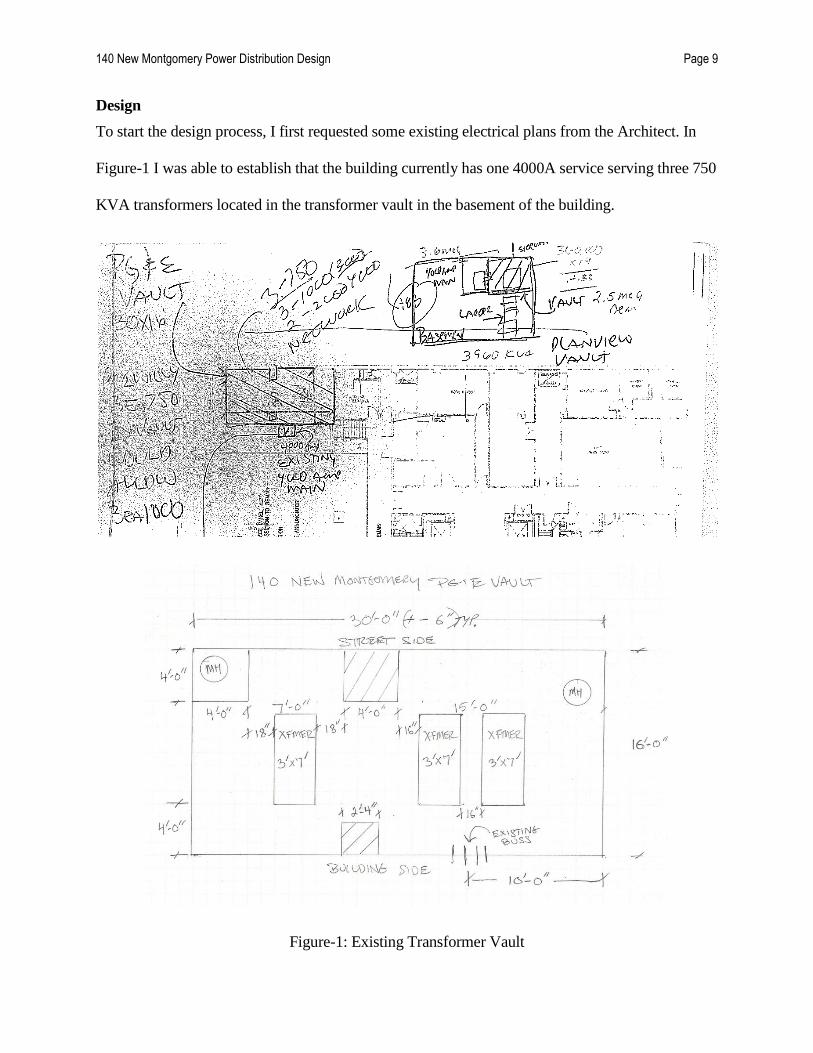
Design
To start the design process, I first requested some existing electrical plans from the Architect. In
Figure-1 I was able to establish that the building currently has one 4000A service serving three 750
KVA transformers located in the transformer vault in the basement of the building.
Figure-1: Existing Transformer Vault

140 New Montgomery Power Distribution Design Page 10
As you probably noticed, these electrical plans are a complete mess. This is often the case when
dealing with much older buildings. Sometimes we are actually hired to "walk-through" the existing
building to create new existing electrical plans. However, we did not deem it necessary nor put it in
our fee for this project.
Next, I did some load calculations to figure out if the current PG&E service of 4000A could handle
the new load of the building. Excel is an extremely useful tool for doing load-calcs, and is
commonly used/accepted in industry. I used specific "watts-per-square-foot" from previous similar
projects done by TEE for these calculations.

140 New Montgomery Power Distribution Design Page 11
Table-1 shows the square footage breakdown of the building. As can be seen, most of the building
will be office space.
ELECTRICAL LOAD SUMMARY
PROJECT:
EQUIP. LOAD
BUILDING AREAS
OFFICE STORAGE/EQUIP
RM GARAGE TOTAL
SQUARE FOOTAGE
BSMT LEVEL P2 13,891 13,891
BSMT LEVEL P1 16,743 9,180 25,923
1ST FLOOR 14,123 14,123
2ND FLOOR 13,732 13,732
3RD FLOOR 13,819 13,819
4TH FLOOR 13,726 13,726
5TH FLOOR 13,680 13,680
6TH FLOOR 13,680 13,680
7TH FLOOR 13,680 13,680
8TH FLOOR 13,680 13,680
9TH FLOOR 13,680 13,680
10TH FLOOR 13,680 13,680
11TH FLOOR 13,680 13,680
12TH FLOOR 13,680 13,680
13TH FLOOR 13,680 13,680
14TH FLOOR 13,680 13,680
15TH FLOOR 13,680 13,680
16TH FLOOR 13,680 13,680
17TH FLOOR 13,680 13,680
18TH FLOOR 13,573 13,573
19TH FLOOR 12,458 12,458
20TH FLOOR 12,458 12,458
21ST FLOOR 12,458 12,458
22ND FLOOR 12,548 12,548
23RD FLOOR 9,900 9,900
24TH FLOOR 9,900 9,900
25TH FLOOR 9,900 9,900
26TH FLOOR 9,900 9,900
27TH FLOOR 4,126 4,126
PENTHOUSE 771 771
TOTALS 340,461 31,405 9,180 381,046
Table-1: Square Footage of Building

140 New Montgomery Power Distribution Design Page 12
Table-2 shows the lighting load breakdown of the building. I used 1.5 watts per square foot for
office space, 0.8 watts per square foot for storage/equipment space, and 0.5 watts per square foot
for the parking garage.
LIGHT LOAD IN WATTS Office Storage Garage Watts
WATTS PER SQFT 1.5 0.8 0.5
BSMT LEVEL P2 - 11,113 - 11,113
BSMT LEVEL P1 - 13,394 4,590 17,984
1ST FLOOR 21,185 - - 21,185
2ND FLOOR 20,598 - - 20,598
3RD FLOOR 20,729 - - 20,729
4TH FLOOR 20,589 - - 20,589
5TH FLOOR 20,520 - - 20,520
6TH FLOOR 20,520 - - 20,520
7TH FLOOR 20,520 - - 20,520
8TH FLOOR 20,520 - - 20,520
9TH FLOOR 20,520 - - 20,520
10TH FLOOR 20,520 - - 20,520
11TH FLOOR 20,520 - - 20,520
12TH FLOOR 20,520 - - 20,520
13TH FLOOR 20,520 - - 20,520
14TH FLOOR 20,520 - - 20,520
15TH FLOOR 20,520 - - 20,520
16TH FLOOR 20,520 - - 20,520
17TH FLOOR 20,520 - - 20,520
18TH FLOOR 20,360 - - 20,360
19TH FLOOR 18,687 - - 18,687
20TH FLOOR 18,687 - - 18,687
21ST FLOOR 18,687 - - 18,687
22ND FLOOR 18,822 - - 18,822
23RD FLOOR 14,850 - - 14,850
24TH FLOOR 14,850 - - 14,850
25TH FLOOR 14,850 - - 14,850
26TH FLOOR 14,850 - - 14,850
27TH FLOOR 6,189 - - 6,189
PENTHOUSE - 617 - 617
TOTALS 510,692 25,124 4,590 540,406
Table-2: Lighting Load of Building
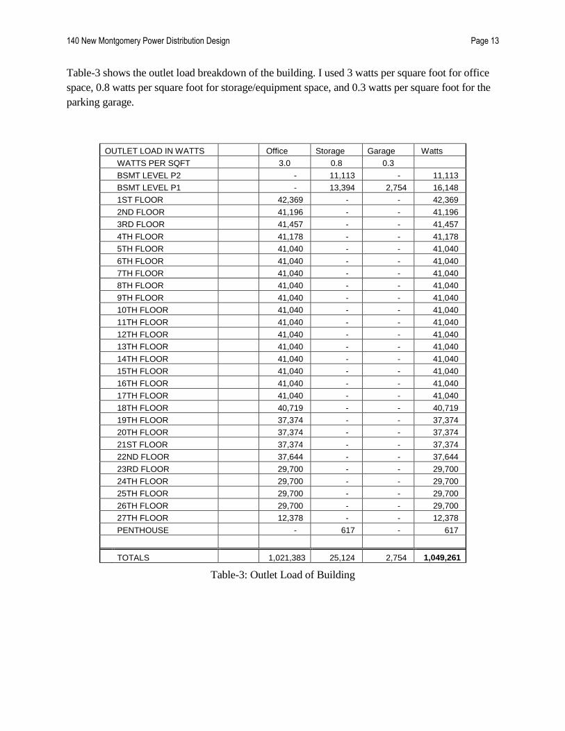
140 New Montgomery Power Distribution Design Page 13
Table-3 shows the outlet load breakdown of the building. I used 3 watts per square foot for office
space, 0.8 watts per square foot for storage/equipment space, and 0.3 watts per square foot for the
parking garage.
OUTLET LOAD IN WATTS Office Storage Garage Watts
WATTS PER SQFT 3.0 0.8 0.3
BSMT LEVEL P2 - 11,113 - 11,113
BSMT LEVEL P1 - 13,394 2,754 16,148
1ST FLOOR 42,369 - - 42,369
2ND FLOOR 41,196 - - 41,196
3RD FLOOR 41,457 - - 41,457
4TH FLOOR 41,178 - - 41,178
5TH FLOOR 41,040 - - 41,040
6TH FLOOR 41,040 - - 41,040
7TH FLOOR 41,040 - - 41,040
8TH FLOOR 41,040 - - 41,040
9TH FLOOR 41,040 - - 41,040
10TH FLOOR 41,040 - - 41,040
11TH FLOOR 41,040 - - 41,040
12TH FLOOR 41,040 - - 41,040
13TH FLOOR 41,040 - - 41,040
14TH FLOOR 41,040 - - 41,040
15TH FLOOR 41,040 - - 41,040
16TH FLOOR 41,040 - - 41,040
17TH FLOOR 41,040 - - 41,040
18TH FLOOR 40,719 - - 40,719
19TH FLOOR 37,374 - - 37,374
20TH FLOOR 37,374 - - 37,374
21ST FLOOR 37,374 - - 37,374
22ND FLOOR 37,644 - - 37,644
23RD FLOOR 29,700 - - 29,700
24TH FLOOR 29,700 - - 29,700
25TH FLOOR 29,700 - - 29,700
26TH FLOOR 29,700 - - 29,700
27TH FLOOR 12,378 - - 12,378
PENTHOUSE - 617 - 617
TOTALS 1,021,383 25,124 2,754 1,049,261
Table-3: Outlet Load of Building

140 New Montgomery Power Distribution Design Page 14
Table-4 shows the outlet load breakdown of the mechanical load of the building. I used 5.5 watts
per square foot for office space, 1.5 watts per square foot for storage/equipment space, and 1.5
watts per square foot for the parking garage.
MECH. LOAD IN WATTS Office Storage Garage Watts
WATTS PER SQFT 5.5 1.5 1.5
BSMT LEVEL P2 - 20,837 - 20,837
BSMT LEVEL P1 - 25,115 13,770 38,885
1ST FLOOR 77,677 - - 77,677
2ND FLOOR 75,526 - - 75,526
3RD FLOOR 76,005 - - 76,005
4TH FLOOR 75,493 - - 75,493
5TH FLOOR 75,240 - - 75,240
6TH FLOOR 75,240 - - 75,240
7TH FLOOR 75,240 - - 75,240
8TH FLOOR 75,240 - - 75,240
9TH FLOOR 75,240 - - 75,240
10TH FLOOR 75,240 - - 75,240
11TH FLOOR 75,240 - - 75,240
12TH FLOOR 75,240 - - 75,240
13TH FLOOR 75,240 - - 75,240
14TH FLOOR 75,240 - - 75,240
15TH FLOOR 75,240 - - 75,240
16TH FLOOR 75,240 - - 75,240
17TH FLOOR 75,240 - - 75,240
18TH FLOOR 74,652 - - 74,652
19TH FLOOR 68,519 - - 68,519
20TH FLOOR 68,519 - - 68,519
21ST FLOOR 68,519 - - 68,519
22ND FLOOR 69,014 - - 69,014
23RD FLOOR 54,450 - - 54,450
24TH FLOOR 54,450 - - 54,450
25TH FLOOR 54,450 - - 54,450
26TH FLOOR 54,450 - - 54,450
27TH FLOOR 22,693 - - 22,693
PENTHOUSE 333,000 333,000
TOTALS 1,872,536 378,951 13,770 2,265,257
Table-4: Mechanical Load of Building

140 New Montgomery Power Distribution Design Page 15
Table-5 shows the elevator loads of the building. With 7 - 50HP elevators, the load of the building
is 350,000Watts.
ELEV. LOAD IN WATTS HP Watts Watts
ELEV. #1 50HP 50,000 50,000
ELEV. #2 50HP 50,000 50,000
ELEV. #3 50HP 50,000 50,000
ELEV. #4 50HP 50,000 50,000
ELEV. #5 50HP 50,000 50,000
ELEV. #6 50HP 50,000 50,000
FRIEGHT ELEV. 50HP 50,000 50,000
TOTALS 350,000 - - 350,000
Table-5: Elevator Load of Building
Table-6 shows the total load summary of the building. The load in amps was calculated using
480V (the incoming service from PG&E is 480V). To calculate the current, you divide 4,204,923
Watts by 831 Volts (480V x Square-Root(3) since its 3-phase) = 5,060Amps. I then multiplied this
number by 1.25 to accommodate any extra load (we always size for an extra 25% load. It is always
better to have too much power than too little power).
LOAD SUMMARY Office Storage Garage Watts
LIGHTING LOADS 510,692 25,124 4,590 540,406
OUTLET LOADS 1,021,383 25,124 2,754 1,049,261
MECH. LOADS 1,872,536 378,951 13,770 2,265,257
ELEV. LOADS 350,000 - - 350,000
TOTAL 3,754,610 429,199 21,114 4,204,923
LOAD IN AMPS (480V) 5,060
x 1.25 FOR 80% C.B. 6,325
SERVICE SIZE IN AMPS 1 @ 3,000
1 @ 4,000
Table-6: Total Electrical Load of Building
The first thing to note when looking at these load calcs is the service size in amps in Table-6.
These calculations call for a 7,000A service, as opposed to the 4,000A service currently serving the
building. To best accommodate this extra load (and to save a ton of money), I chose to keep the

140 New Montgomery Power Distribution Design Page 16
4,000A service and just add another separate 3,000A service rather than a single 7,000A service.
By doing this, we were able to keep the incoming 4,000A service and were also able to keep the
three 750KVA transformers located in the basement vault. To accommodate this extra 3,000A
service, however, we added a second transformer vault. After much discussion with PG&E via
phone/email, we decided it best to leave the 3 old 750KVA transformers in the original vault, and
just a single 750KVA transformer in the new vault. I oversized the new transformer vault, with the
idea that the owner may want to add a second new transformer to it in the future. Figure-2 shows
the layout of the existing and new PG&E transformer vaults.
Figure-2: Existing and New PG&E Transformer Vaults
The next step in the design process was to create a power riser diagram. This step is definitely
the bulk of the design process. The power riser diagram basically lays out the electrical
distribution system spanning the height of the building from the basement to the 28th floor. The
bulk of the equipment will be located in the basement, with the busway risers rising up through
the electric rooms on each floor. Figure 3 shows the symbol list and abbreviations used in our
specs.

140 New Montgomery Power Distribution Design Page 17
Figure-3: Symbols List
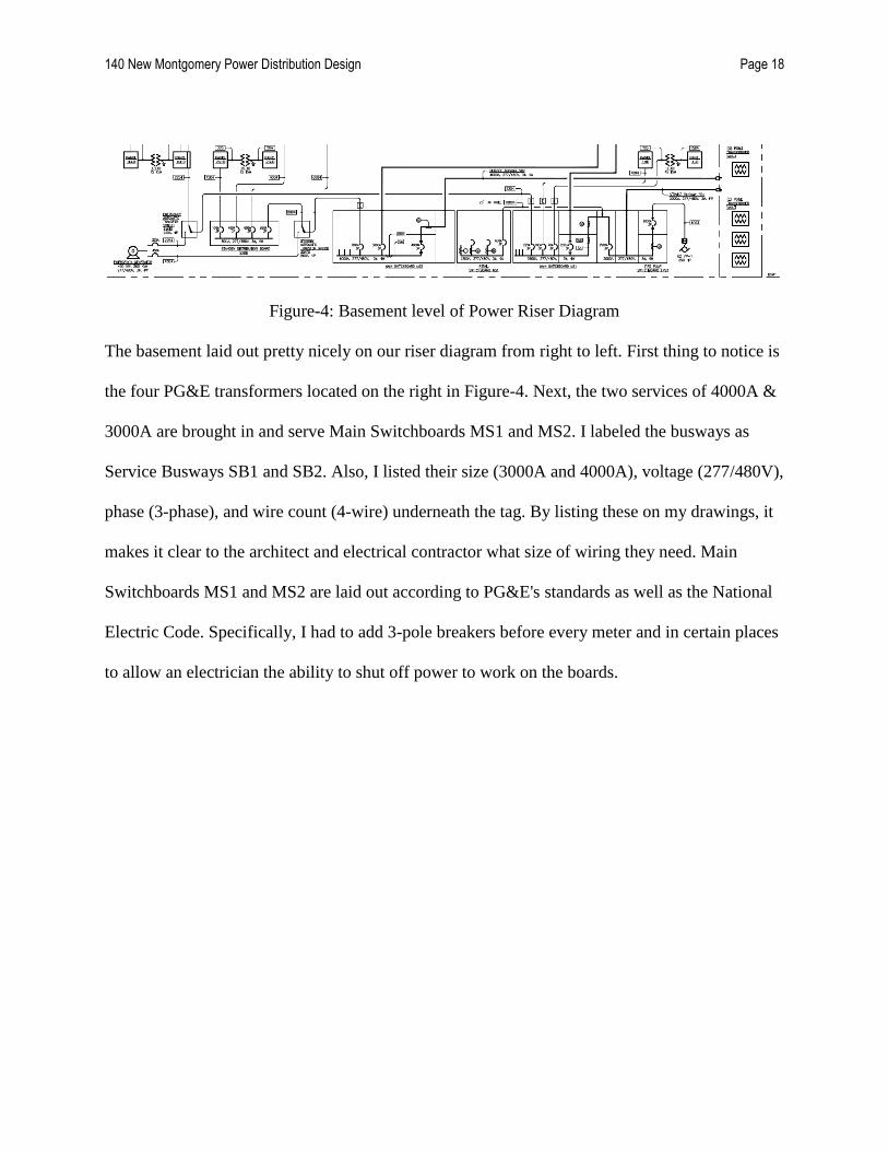
140 New Montgomery Power Distribution Design Page 18
Figure-4: Basement level of Power Riser Diagram
The basement laid out pretty nicely on our riser diagram from right to left. First thing to notice is
the four PG&E transformers located on the right in Figure-4. Next, the two services of 4000A &
3000A are brought in and serve Main Switchboards MS1 and MS2. I labeled the busways as
Service Busways SB1 and SB2. Also, I listed their size (3000A and 4000A), voltage (277/480V),
phase (3-phase), and wire count (4-wire) underneath the tag. By listing these on my drawings, it
makes it clear to the architect and electrical contractor what size of wiring they need. Main
Switchboards MS1 and MS2 are laid out according to PG&E's standards as well as the National
Electric Code. Specifically, I had to add 3-pole breakers before every meter and in certain places
to allow an electrician the ability to shut off power to work on the boards.

140 New Montgomery Power Distribution Design Page 19
The next thing to notice in our power riser diagram is the generator located to the left in Figure-
4. TEE has a general spreadsheet for sizing building generators. I just plugged in the load, and
determined that we need a 400 KW generator to serve the building. The spreadsheet can be seen
in Table-7 below.
GENERATOR SIZING CALCS
DESCRIPTION LOADS % GENSET LOAD
Emergency Load
Lighting
Retail/Office 510.7 kW 0.2 102.1 kW
Garage/Storage 30 kW 0.2 5.9 kW
Total 108.1 kW
Fire Alarm/Life Safety
Retail/Office 54.0 kW
Garage 2.0 kW
Total 56.0 kW
Total Emergency Load 164.1 kW
Load in Amps 197.4 Amps
Standby Load
Elevators
Low-Rise Bank 50.0 hp 34.9 kW
High-Rise Bank 50.0 hp 43.2 kW
Freight Bank 50.0 hp 54.0 kW
Total 132.1 kW
HVAC
TEF-1 3.0 hp 4.0 kW
TEF-2 3.0 hp 4.0 kW
SPF-1 10.0 hp 11.6 kW
Total 19.6 kW
Plumbing
JP-1 2.0 hp 2.8 kW
FOP-1 2 @ 1.0 hp 3.4 kW
SP-1 2 @ 3.0 hp 8.0 kW
Total 14.2 kW
Total Standby Load 165.9 kW
Load in Amps 199.6 Amps

140 New Montgomery Power Distribution Design Page 20
Generator Size
Emergency 164.1 kW
Standby 165.90 kW
Total Load 330 kW
Generator Size 400 kW
Table-7: Emergency Generator Calculations
The final things to note in the power riser diagram of the basement are the automatic transfer
switches 1EATS and 2SATS. 1EATS is the emergency automatic transfer switch and will
transfer the load of the emergency power from the main switchboard MS1 to the generator in the
case of a power outage. 2SATS is the standby automatic transfer switch and will transfer the load
of standby power from the main switchboard MS2 to the emergency generator in the case of a
power outage. Emergency power refers to the power required to run emergency equipment such
as fire smoke dampers, strobes/horns, and egress lighting whereas the standby power in this case
is powering the elevators.
Moving upward in the power riser diagram, we find the busway riser's 1BR and 2BR in Figure-5.
These two busway risers will rise up the building and be in the electric room on every floor.
These risers have "taps" in them on every floor, which gives us the ability to plug our panel
boards into them. You will see 150A, 3-pole breakers at every tap, which once again is according
to the National Electric Code (Figure-4). These breakers give the ability to an electrician to cut
off the power on a floor (rather than the whole building) when working on the panelboards.
Please note that I left the first floor empty (without panelboards) because the owner has decided
to rent out the first floor as retail/restaurants. Often, a restaurant chain or retail chain will bring in
their own electrician with their own special panelboards. I left a space for them in the electric
room to plug in and meter their own equipment. On the second floor (and all the other floors),

140 New Montgomery Power Distribution Design Page 21
you will notice a panelboard titled Panel 1H2. The "1" refers to it receiving power from Busway
Riser 1BR, the "H" refers to the fact that it is high-voltage (277/480V), and the "2" refers to the
floor it is located on. Because this board is high-voltage, we use it almost exclusively to serve the
lighting loads (the mechanical loads are on a different riser). After this high-voltage panel, you
will find a transformer titled 1TX2. It is a 45KVA transformer, and it steps the voltage down
from 277/480V to 120/208V which serves Panel 1L2. From this low-voltage panel, I serve the
typical outlet loads of the building.
Figure-5: Busway Risers
Next, I added the mechanical to Busway Riser 2BR as seen in Figure-6. I contacted the
mechanical engineers (Homes Culley) and found out that all of their pumps/motors/equipment
would be operating at high-voltage (277/480V). This was good news to me, because now I do
not have to transform the voltage down and can save the owner some money by not including
any transformers for the mechanical riser. Also, the load-per-floor was very minimal for the
mechanical equipment, so I was able to just use one single panelboard to serve 3 floors. You will
find these panelboards located on floors 3, 6, 9, 12, 15, 18, 21, and 24. Each panelboard serves
its floor, and the floors immediately above and below it. Because the mechanical equipment
draws a little more current than lighting/outlet loads, I had to add a 400A, 3-pole breaker to meet
National's Electric Code standard.

140 New Montgomery Power Distribution Design Page 22
Figure-6: Mechanical Panel and Busway Riser 2BR
Next, I decided to hook up the seven elevators. The first three elevators only have the ability to
go up to the 22nd floor. Their elevator room is located on the 23rd floor, which is where the
Panelboard 2SH23 is located as well in Figure-7. This 400A panelboard is fed from a 400A
feeder that comes from distribution board 2SDB located in the basement. These three 50HP
elevators (ELEV-1,2,3) are then fed from the 400A panelboard 2SH23. (Note: The tag "1003"
refers to the feeder size. the "100" stands for 100Amps, and the "3" refers to it having 3 wires.)
Figure-7: Panelboard 2SH23 on the 23rd Floor
The next bank of elevators is able to go up to the 26th floor. The panelboard 2SH27 located in
the 27th floor elevator room serves these three elevators (ELEV-4,5,6) Figure-8. This panelboard

140 New Montgomery Power Distribution Design Page 23
is fed from a distribution board 2SDB27 which is also located in the same elevator machine
room. This distribution board also serves the last elevator, ELEV-7, which is the penthouse
elevator located on the 28th floor. The sewage pump SPF-1 is the final motor served from this
distribution board and is located on the roof. I left an empty breaker on this distribution board to
give the owner the option to add another pump or motor to it in the future (always a good idea as
an engineer to allow for expansion).
Figure-8: Elevators and Sewage Pump Located on the 27th and 28th Floors
Also located on the 27th floor/roof is distribution board 2DB27 as seen in Figure-9. This is a
600A board and is being served from the mechanical riser 2BR. Connected to this board are the
three cold water pumps and four cooling towers. The size of these have yet to be determined by
the mechanical engineer, however by using a 600A board, I have left the ME with quite a few
options to choose from. Once again, these are all fused/breaker boards in compliance with the
National Electric Code.

140 New Montgomery Power Distribution Design Page 24
Figure-9: Distribution Board 2DB27
The last piece of equipment shown on the power riser diagram is the emergency riser shown in
Figure-10. This emergency riser is fed by the emergency automatic transfer switch 1EATS
(which is fed from the emergency generator). Connected to this riser (but not protected by
breakers because it is not required) is the high voltage panel 1EH25. These panels serve the
emergency lighting (also known as egress lighting) in the building. As a requirement of the NEC,
when the power is cut to a building, a generator must power egress lighting. Egress lighting
refers to only using certain lights to light-up a pathway out of the building. Connected to panel
1EH25 is the transformer 1ETX25 which steps-down the 277/480V panel to 120/208V to serve
panel 1EL25. 1EL25 is the emergency panel that serves certain outlet loads (specified by owner).
Because the emergency load is much lower than the typical floor load, I was able to only use a
single high voltage and low voltage panel every 5 floors. Each panel serves the two floors
immediately above and below it.

140 New Montgomery Power Distribution Design Page 25
Figure-10: Emergency Riser Diagram
A final addition to the power riser diagram was the metering system. In order to meet certain
LEED (Leadership in Energy and Environmental Design) requirements, the owner decided to
add an Emon-Demon metering system to the building. Getting a building LEED certified greatly
increases the tax breaks the owner and tenants receive from the government. For 140 New
Montgomery, we are going for Gold certified (this is second best only to Platinum certified).
These meters are symbolized by an "M"-looking symbol as depicted in Figure-11 and can be
found on every floor of the building. These meters give the owner the option to bill his tenants
by the amount of energy/gas they use.

140 New Montgomery Power Distribution Design Page 26
Figure-11: Metering System
The next thing to lay out was the generator room. This was located on the basement level as well
as shown in Figure-12. As stated before, the generator was sized to be 400KW. Contacting
Caterpillar (a generator company), we established that a 660 gallon diesel tank would be needed
for this generator. This large diesel tank would allow the generator to run continuously for 10+
hours (the owner had requested that be the minimum amount of emergency power time). Please
note the two exits to the generator room are there to meet the requirements of the N.E.C. Also
located next to the generator room is a small electrical room as depicted in Figure-12. This
electrical room is used mainly for emergency and standby loads.
Figure-12: Generator and Small Electrical Room

140 New Montgomery Power Distribution Design Page 27
The next and final task of designing for the 100% Schematic Design phase was to lay out a
typical electric room. This will give the company‟s bidding on the job a good idea of what
electrical equipment will need to be mounted, and where it will be located in the building.
Figure-13 shows a typical electric room. I modeled this room after the 15th
floor, which is our
worst case scenario floor. The reason why it‟s the worst case floor is because it is the only floor
where the Emergency, Standby, and Mechanical risers all have multiple panelboards in the
electric room.
Figure-13: Typical Electrical Room Plan
The dashed lines just below the “E” line and just above the “F” line are column lines. It is very
tough to put a riser through a column, which is why I placed risers 1BR and 2BR in the location
above. Also they needed 4‟ clearance in front of them according to the NEC. The toughest pieces

140 New Montgomery Power Distribution Design Page 28
of equipment to place are the transformers 1TX and 1ETX mainly because of their size. These
transformers also need 4‟ clearance in front of them which is why I staggered them. You will
also see the Adura lighting control gateway. This lighting system allows all the fixtures in the
building to be controlled wirelessly via the internet. It also gives power consumption breakdowns
in nice graphical form. The owner opted to get this lighting system to gain a couple credits with
LEED. Once again, we are going for gold, so every point helps. And lastly you will see the Fire
Alarm panel located near the door in Figure-13. The fire alarm company has yet to be picked, so
it is not 100% clear where their equipment is going to be located. I left room in the electrical
room for their main board in case they want to put it there. Once again, my boss always tells me
to plan for the worst case scenario.

140 New Montgomery Power Distribution Design Page 29
Future Additions
With the schematic design completed, the project is now currently in the bidding phase. The
owner put together what is called a “bid package” which is the 100% SD drawings of
mechanical, electrical, structural, telecom and fire-alarm plans. He gave these plans to many
different contractor firms, and the firms are currently pricing the labor/equipment costs. In 2
months, there will be a meeting with the owner, and one-by-one each contractor will enter the
meeting, present his costs and how he will be able to handle the project, and leave. We will then
decide which contractor has the best price and will get the project done on time. Since this is not
a government job, the lowest bidder does not necessarily win. Often the owner picks a better-
known company even if they aren‟t the lowest bidder because he trusts that they will be able to
get the construction done on time. Once all of this has been completed, TEE will get back
involved with the project. The bulk of our work is done, however I will make myself available
for the construction document phase. My main job at that time will be to answer RFIs (request
for information) from the electrical contractor. These usually are just asking questions to clarify
certain aspects of my design. Often these contractors try to cut corners to save money, so at the
end of the project I will do a “punch-list”. This will include walking the entire length of the
building to make sure that the electrical equipment has been installed according to my specs. The
project is expected to be completed by 2014.

140 New Montgomery Power Distribution Design Page 30
Conclusion
The design of the power distribution system for 140 New Montgomery proved to be both a
challenging and enjoyable task. It put all of my engineering skills to the true test: learn by doing.
I was definitely surprised that within a week of walking in the Cal Poly graduation, I would be
designing a major electrical system that would serve a real-life building. And not only any
building, I designed the power distribution system for a 28 story building in San Francisco! I
truly believe that Cal Poly greatly prepared me for the working world.

140 New Montgomery Power Distribution Design Page 31
Bibliography
Emphoris. “140 New Montgomery Street”. Emphoris Corporation 2011. http://www.emporis.com/application/?nav=building&lng=3&id=118764
Mcpartland, Brian J. “National Electric Code 2011 Handbook”. McGraw-Hill Professional
Publishing 2011.

140 New Montgomery Power Distribution Design Page 32
Appendix A: Schematic
See attached schematics E-1: LEVEL B1 ELECTRICAL PLAN, E-2: TYPICAL LEVEL
ELECTRICAL PLAN, and E-3: POWER RISER DIAGRAM.

140 New Montgomery Power Distribution Design Page 33
Appendix B: Time Schedule Allocation
ID Task Name Start Finish Duration
Jun 2011 Jul 2011 Aug 2011
19 20 21 22 23 24 25 26 27 28 29 30 1 2 3 4 5 6 7 8 9 10 11 12 13 14 15 16 17 18 19 20 21 22 23 24 25 26 27 28 29 30 31 1 2 3 4 5 6 7 8 9 10 11
1 5d6/24/20116/20/2011Gathering Project Information
2 1d6/27/20116/24/2011Bidding Project
3 2.5d6/29/20116/27/2011Load Calculations
4 4d7/5/20116/29/2011Coordinating Service with PG&E
5 3d7/7/20117/5/2011Designing Transformer Vault
6 11d7/22/20117/8/2011Designing Riser Diagram
7 3d7/27/20117/22/2011Designing Basement Layout
8 4d8/1/20117/27/2011Designing Typical Electric Room
9 9d8/11/20118/1/2011Writing Report


Related Documents


![Conversion of the amplitude-probability distribution ... · Conversion of the Amplitude-Probability Distribution Func ... [Montgomery, 1954; Watt, et a1., ] 958 ; Crichlow and Disney,](https://static.cupdf.com/doc/110x72/5b604d4f7f8b9aa2388bb047/conversion-of-the-amplitude-probability-distribution-conversion-of-the-amplitude-probability.jpg)
![[XLS] · Web view1 140 2 140 3 140 4 140 5 140 6 140 7 140 8 140 9 140 10 140 11 140 12 140 13 140 14 140 15 140 16 140 17 140 18 140 19 140 20 140 21 140 22 140 23 140 24 140 25](https://static.cupdf.com/doc/110x72/5b0e34b97f8b9a96478b4bbf/xls-view1-140-2-140-3-140-4-140-5-140-6-140-7-140-8-140-9-140-10-140-11-140-12.jpg)