14 IEEE TRANSACTIONS ON INDUSTRIAL ELECTRONICS, VOL. 54, NO. 1, FEBRUARY 2007 Neural Network Applications in Power Electronics and Motor Drives—An Introduction and Perspective Bimal K. Bose, Life Fellow, IEEE Invited Paper Abstract—Artificial intelligence (AI) techniques, particularly the neural networks, are recently having significant impact on power electronics and motor drives. Neural networks have created a new and advancing frontier in power electronics, which is already a complex and multidisciplinary technology that is going through dynamic evolution in the recent years. This paper gives a com- prehensive introduction and perspective of neural network appli- cations in the intelligent control and estimation for power elec- tronics and motor drives area. The principal topologies of neural networks that are currently most relevant for applications in power electronics have been reviewed including the detailed description of their properties. Both feedforward and feedback or recurrent architectures have been covered in the description. The applica- tion examples that are discussed in this paper include nonlinear function generation, delayless filtering and waveform processing, feedback signal processing of vector drive, space vector PWM of two-level and multilevel inverters, adaptive flux vector estimation, and some of their combination for vector-controlled ac drive. Ad- ditional selected applications in the literature are included in the references. From the current trend of the technology, it appears that neural networks will find widespread applications in power electronics and motor drives in future. Index Terms—Backpropagation network, induction motor drive, intelligent control and estimation, neural network, percep- tron, recurrent network, space vector PWM. I. INTRODUCTION T HE ARTIFICIAL INTELLIGENCE (AI) techniques, such as expert system (ES), fuzzy logic (FL), artificial neural network (ANN or NNW), and genetic algorithm (GA) have recently been applied widely in power electronics and motor drives. The goal of AI is to plant human or natural intelligence in a computer so that a computer can think intelligently like a human being. A system with embedded computational in- telligence is often defined as an “intelligent system” that has “learning,” “self-organizing,” or “self-adapting” capability. Computational intelligence has been debated for a long time, and will possibly be debated for ever. However, there is no denying the fact that computers can have adequate intelligence to help solving our problems that are difficult to solve by traditional methods. Therefore, it is true that AI techniques Manuscript received May 15, 2006; revised September 9, 2006. Abstract pub- lished on the Internet November 30, 2006. The author is with the Department of Electrical and Computer Engineering, University of Tennessee, Knoxville, TN 37996-2100 USA (e-mail: bbose@utk. edu). Digital Object Identifier 10.1109/TIE.2006.888683 are now being extensively used in industrial process control, image processing, diagnostics, medicine, space technology, and information management system, just to name a few. While ES and FL are rule-based, and tend to emulate the behavioral nature of human brain, the NNW is more generic in nature that tends to emulate the biological neural network directly. The history of NNW goes back to 1940s, but its advancement was camouflaged by the glamorous evolution of modern-day digital computers. From the beginning of 1990s, the NNW technology captivated the attention of a large segment of scientific com- munity. Since then, the technology has been advancing rapidly and its applications are expanding in different areas. The GA theory (also known as evolutionary computation) was proposed in 1970s and it is based on principles of genetics (or Darwin’s survival of the fittest theory of evolution). Basically, it solves optimization problem by an evolutionary process resulting in a best (fittest) solution (survivor). Lotfy Zadeh, the inventor of FL, defined ES as hard or precise computing and FL, NNW, and GA as soft or approximate computing. Among all the branches of AI, the NNW seems to have max- imum impact on power electronics and motor drives area that is evident by the publications in the literature. However, the litera- ture in this area is hardly more than 10–15 years old. In fact, the NNW technology itself is advancing fast in the recent years and its applications in different areas are expanding rapidly. Modern advanced intelligent systems often tend to hybrid neuro, fuzzy, and GA techniques for improvement of performance. The main body of this paper will describe principles of different NNWs and their applications in power electronics and motor drives. II. STRUCTURE OF NEURON A. Biological and Artificial Neurons A NNW consists of a number of artificial neurons that are interconnected together. The structure of artificial neuron is in- spired by the concept of biological neuron shown in Fig. 1(a). Basically, it is the processing element in the nervous system of the brain that receives and combines signals from other sim- ilar neurons through thousands of input paths called dendrites. Each input signal (electrical in nature), flowing through den- drite, passes through a synapse or synaptic junction as shown. The junction is an infinitesimal gap in the dendrite which is filled with neurotransmitter fluid that either accelerates or retards the flow of the signal. These signals are accumulated in the nucleus (or soma), nonlinearly modified at the output before flowing to 0278-0046/$25.00 © 2007 IEEE

Welcome message from author
This document is posted to help you gain knowledge. Please leave a comment to let me know what you think about it! Share it to your friends and learn new things together.
Transcript

14 IEEE TRANSACTIONS ON INDUSTRIAL ELECTRONICS, VOL. 54, NO. 1, FEBRUARY 2007
Neural Network Applications in Power Electronicsand Motor Drives—An Introduction and Perspective
Bimal K. Bose, Life Fellow, IEEE
Invited Paper
Abstract—Artificial intelligence (AI) techniques, particularly theneural networks, are recently having significant impact on powerelectronics and motor drives. Neural networks have created a newand advancing frontier in power electronics, which is already acomplex and multidisciplinary technology that is going throughdynamic evolution in the recent years. This paper gives a com-prehensive introduction and perspective of neural network appli-cations in the intelligent control and estimation for power elec-tronics and motor drives area. The principal topologies of neuralnetworks that are currently most relevant for applications in powerelectronics have been reviewed including the detailed descriptionof their properties. Both feedforward and feedback or recurrentarchitectures have been covered in the description. The applica-tion examples that are discussed in this paper include nonlinearfunction generation, delayless filtering and waveform processing,feedback signal processing of vector drive, space vector PWM oftwo-level and multilevel inverters, adaptive flux vector estimation,and some of their combination for vector-controlled ac drive. Ad-ditional selected applications in the literature are included in thereferences. From the current trend of the technology, it appearsthat neural networks will find widespread applications in powerelectronics and motor drives in future.
Index Terms—Backpropagation network, induction motordrive, intelligent control and estimation, neural network, percep-tron, recurrent network, space vector PWM.
I. INTRODUCTION
THE ARTIFICIAL INTELLIGENCE (AI) techniques, suchas expert system (ES), fuzzy logic (FL), artificial neural
network (ANN or NNW), and genetic algorithm (GA) haverecently been applied widely in power electronics and motordrives. The goal of AI is to plant human or natural intelligencein a computer so that a computer can think intelligently likea human being. A system with embedded computational in-telligence is often defined as an “intelligent system” that has“learning,” “self-organizing,” or “self-adapting” capability.Computational intelligence has been debated for a long time,and will possibly be debated for ever. However, there is nodenying the fact that computers can have adequate intelligenceto help solving our problems that are difficult to solve bytraditional methods. Therefore, it is true that AI techniques
Manuscript received May 15, 2006; revised September 9, 2006. Abstract pub-lished on the Internet November 30, 2006.
The author is with the Department of Electrical and Computer Engineering,University of Tennessee, Knoxville, TN 37996-2100 USA (e-mail: [email protected]).
Digital Object Identifier 10.1109/TIE.2006.888683
are now being extensively used in industrial process control,image processing, diagnostics, medicine, space technology, andinformation management system, just to name a few. WhileES and FL are rule-based, and tend to emulate the behavioralnature of human brain, the NNW is more generic in nature thattends to emulate the biological neural network directly. Thehistory of NNW goes back to 1940s, but its advancement wascamouflaged by the glamorous evolution of modern-day digitalcomputers. From the beginning of 1990s, the NNW technologycaptivated the attention of a large segment of scientific com-munity. Since then, the technology has been advancing rapidlyand its applications are expanding in different areas. The GAtheory (also known as evolutionary computation) was proposedin 1970s and it is based on principles of genetics (or Darwin’ssurvival of the fittest theory of evolution). Basically, it solvesoptimization problem by an evolutionary process resulting ina best (fittest) solution (survivor). Lotfy Zadeh, the inventor ofFL, defined ES as hard or precise computing and FL, NNW,and GA as soft or approximate computing.
Among all the branches of AI, the NNW seems to have max-imum impact on power electronics and motor drives area that isevident by the publications in the literature. However, the litera-ture in this area is hardly more than 10–15 years old. In fact, theNNW technology itself is advancing fast in the recent years andits applications in different areas are expanding rapidly. Modernadvanced intelligent systems often tend to hybrid neuro, fuzzy,and GA techniques for improvement of performance. The mainbody of this paper will describe principles of different NNWsand their applications in power electronics and motor drives.
II. STRUCTURE OF NEURON
A. Biological and Artificial Neurons
A NNW consists of a number of artificial neurons that areinterconnected together. The structure of artificial neuron is in-spired by the concept of biological neuron shown in Fig. 1(a).Basically, it is the processing element in the nervous system ofthe brain that receives and combines signals from other sim-ilar neurons through thousands of input paths called dendrites.Each input signal (electrical in nature), flowing through den-drite, passes through a synapse or synaptic junction as shown.The junction is an infinitesimal gap in the dendrite which is filledwith neurotransmitter fluid that either accelerates or retards theflow of the signal. These signals are accumulated in the nucleus(or soma), nonlinearly modified at the output before flowing to
0278-0046/$25.00 © 2007 IEEE

BOSE: NEURAL NETWORK APPLICATIONS IN POWER ELECTRONICS AND MOTOR DRIVES—AN INTRODUCTION AND PERSPECTIVE 15
Fig. 1. (a) Structure of biological neuron. (b) Model of artificial neuron.
other neurons through the branches of axon as shown. The ad-justment of the impedance or conductance of the synaptic gap bythe neurotransmitter fluid contributes to the “memory” or “in-telligence” of the brain. According to the theory of the neuron,we are led to believe that our brain has distributed associativememory or intelligence characteristics which are contributed bythe synaptic junctions of the cells. It may be interesting to notehere that when a human baby is born, it has around 100 billionneurons in the brain. Typically, from the age 40, around one mil-lion neurons die every day.
The model of an artificial neuron that closely matches the bi-ological neuron is shown in Fig. 1(b). Basically, it has op-ampsummer-like structure. The artificial neuron (or simply neuron)is also called processing element (PE), neurode, node, or cell.Each input signal (continuous variable or discrete pulses) flowsthrough a gain or weight (called synaptic weight or connec-tion strength) which can be positive (excitory) or negative (in-hibitory), integer or noninteger. The summing node accumulatesall the input-weighted signals, adds to the weighted bias signal, and then passes to the output through the nonlinear (or linear)
activation or transfer function (TF) as shown.
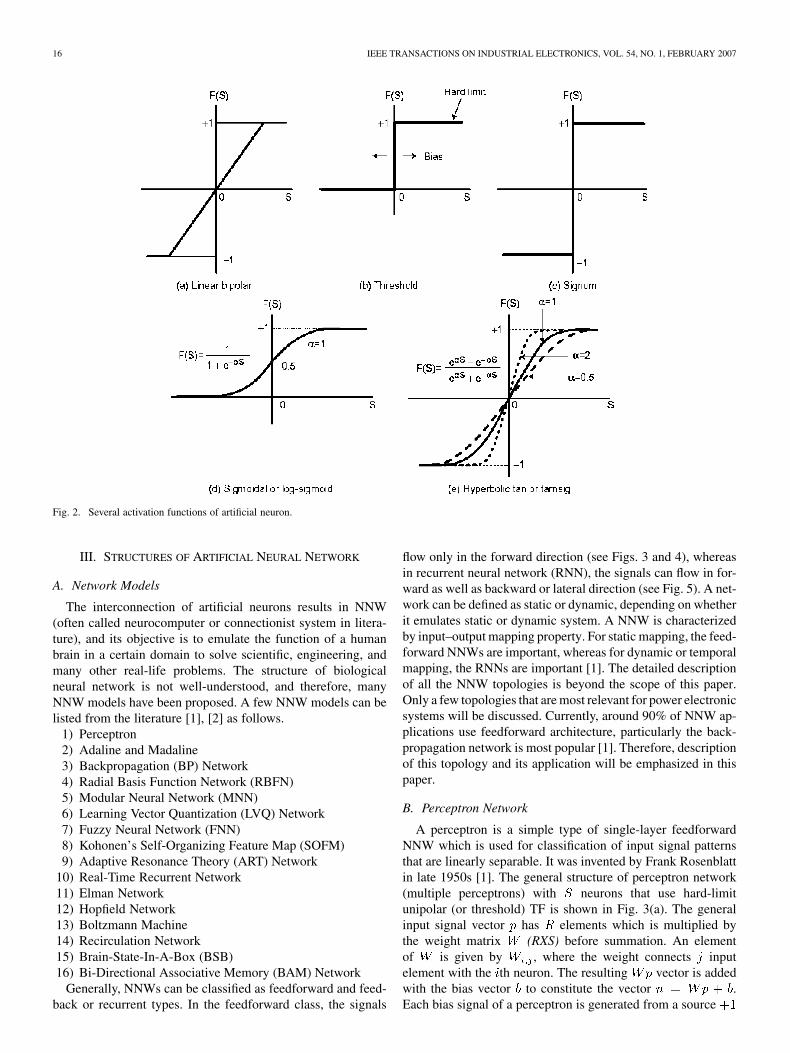
1) Activation Functions: Several common type activationfunctions used in artificial neuron are shown in Fig. 2. Theseare defined, respectively, as linear (bipolar), threshold, signum,sigmoidal (or log-sigmoid), and hyperbolic tan (or tan-sigmoid).Another type of function that is often used is the Gaussian func-tion, but is not included here. The magnitude of these functionsvaries between 0 and 1, or to as indicated. The linearfunction can be unipolar or bipolar. With slope of infinity, ittransforms to threshold or signum function, respectively. Thesigmoidal and hyperbolic tan functions are commonly used inpower electronic system. Their mathematical expressions areincluded in the respective figure, where is the gain or co-efficient that adjusts the slope or sensitivity. Both these func-tions are differentiable, and the derivative is maximumat . All these functions are squashing in nature, i.e.,they limit the neuron response between the asymptotic values.Note that nonlinear activation function contributes to the non-linear transfer characteristics of neuron that permit nonlinearinput–output mapping of NNW which will be discussed later.However, with linear activation function, this nonlinearity islost.
16 IEEE TRANSACTIONS ON INDUSTRIAL ELECTRONICS, VOL. 54, NO. 1, FEBRUARY 2007
Fig. 2. Several activation functions of artificial neuron.
III. STRUCTURES OF ARTIFICIAL NEURAL NETWORK
A. Network Models
The interconnection of artificial neurons results in NNW(often called neurocomputer or connectionist system in litera-ture), and its objective is to emulate the function of a humanbrain in a certain domain to solve scientific, engineering, andmany other real-life problems. The structure of biologicalneural network is not well-understood, and therefore, manyNNW models have been proposed. A few NNW models can belisted from the literature [1], [2] as follows.
1) Perceptron2) Adaline and Madaline3) Backpropagation (BP) Network4) Radial Basis Function Network (RBFN)5) Modular Neural Network (MNN)6) Learning Vector Quantization (LVQ) Network7) Fuzzy Neural Network (FNN)8) Kohonen’s Self-Organizing Feature Map (SOFM)9) Adaptive Resonance Theory (ART) Network
10) Real-Time Recurrent Network11) Elman Network12) Hopfield Network13) Boltzmann Machine14) Recirculation Network15) Brain-State-In-A-Box (BSB)16) Bi-Directional Associative Memory (BAM) Network
Generally, NNWs can be classified as feedforward and feed-back or recurrent types. In the feedforward class, the signals
flow only in the forward direction (see Figs. 3 and 4), whereasin recurrent neural network (RNN), the signals can flow in for-ward as well as backward or lateral direction (see Fig. 5). A net-work can be defined as static or dynamic, depending on whetherit emulates static or dynamic system. A NNW is characterizedby input–output mapping property. For static mapping, the feed-forward NNWs are important, whereas for dynamic or temporalmapping, the RNNs are important [1]. The detailed descriptionof all the NNW topologies is beyond the scope of this paper.Only a few topologies that are most relevant for power electronicsystems will be discussed. Currently, around 90% of NNW ap-plications use feedforward architecture, particularly the back-propagation network is most popular [1]. Therefore, descriptionof this topology and its application will be emphasized in thispaper.
B. Perceptron Network
A perceptron is a simple type of single-layer feedforwardNNW which is used for classification of input signal patternsthat are linearly separable. It was invented by Frank Rosenblattin late 1950s [1]. The general structure of perceptron network(multiple perceptrons) with neurons that use hard-limitunipolar (or threshold) TF is shown in Fig. 3(a). The generalinput signal vector has elements which is multiplied bythe weight matrix (RXS) before summation. An elementof is given by , where the weight connects inputelement with the th neuron. The resulting vector is addedwith the bias vector to constitute the vector .Each bias signal of a perceptron is generated from a source

BOSE: NEURAL NETWORK APPLICATIONS IN POWER ELECTRONICS AND MOTOR DRIVES—AN INTRODUCTION AND PERSPECTIVE 17
Fig. 3. (a) Perceptron network. (b) Illustration of pattern classificationboundary for the upper perceptron.
through a weight as shown. The output vector is then given by. The weight is normally indicated by a
dot in each link, but is not shown here. The pattern classificationproperty for the upper perceptron only is explained in Fig. 3(b)for and inputs, where and . Theshaded area in the figure classifies the and inputs thatgive output, whereas the unshaded area gives 0 output. The“decision” boundary line is denoted by . The bias shifts theboundary line horizontally with the slope remaining the same,whereas the input weights alter its slope. For more than twoinputs, the classification boundary is given by a hyperplane.The boundary hyperplane for each perceptron can be designedto be different by assigning different weights and biases. Asupervised training algorithm (perceptron learning rule) withthe help of computer program [2] can design all the weights forthe desired classification boundaries. The NNW training willbe discussed later. A simple application of perceptron networkmay be to isolate healthy signals in a power electronic systemfrom the noisy signals and use for control and monitoring. Itcan also be trained to solve complex Boolean functions [2] withlogical input signals and identification of drive system responsecharacteristics.
It may be mentioned here that Adaline and Madaline (mul-tiple Adalines) NNW has the same structure as that of percep-tron except the activation function is bipolar linear. The linearNNW can give linear input-output mapping only. Besides usingfor pattern classification as discussed above, it can be used forlinearizing nonlinear functions (linear function approximation)or pattern association.
C. Backpropagation Network
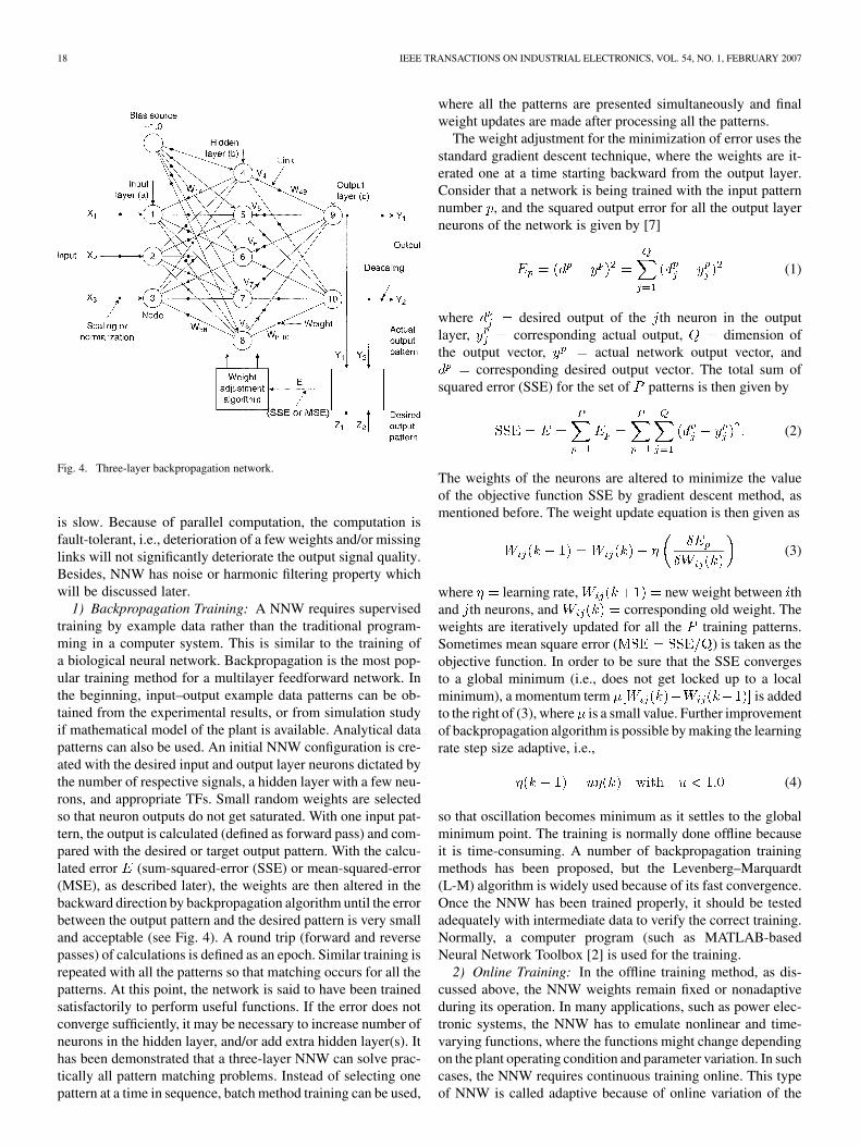
The feedforward multilayer backpropagation topology,shown in Fig. 4, is most commonly used in power electronicsand motor drives. The name “backpropagation” comes fromthe method of supervised training used for the NNW shownby the lower two blocks in the figure. This will be explainedlater. The network is normally called multilayer perceptron(MLP) type, because of its evolution from the single-layerperceptron discussed before, but its TF can be different fromthreshold function. The MLP type NNW is very powerfulcomputationally compared with perceptron NNW. It uses errorbackpropagation supervised training algorithm which was firstdescribed by Paul Werbos in 1974. Subsequently, Rumelhart,Hinton, Williams, McClelland, Parker, LeCun, etc., furthermade contributions to this method [1]. The example NNWshown in the figure, has three input signals ( , , ),and two output signals ( and ). The circles represent theneurons which have associated TF (not shown), and the weightsare indicated by dots (often omitted). The network shown hasthree layers: (a) input layer, (b) hidden layer, and (c) outputlayer. With five neurons in the hidden layer as indicated, it isnormally defined as 3–5–2 network. The input layer is nothingbut the nodes that distribute the signals to the middle layer.Therefore, the topology is often defined as two-layer network.The bias source is normally coupled to both hidden and outputlayer neurons, although it is shown here for the hidden layeronly for simplicity. Although the network handles continuousvariables, the input and output signals can be continuous,logical, or discrete bidirectional. If the I/O signals are bipolar,the hidden layer neurons usually has hyperbolic tan TF andthe output layer has bipolar linear TF. On the other hand, forunipolar signals, these TFs can be sigmoidal and unipolar linear,respectively. The signals within the NNW are processed in perunit (pu) magnitude, and therefore, input signals normalizationand output signals descaling or denormalization are used asshown. Although, theoretically, three-layer NNW can solve allthe mapping problems, occasionally more than three layers areused.
The NNW has analogy with biological neural network, asmentioned before. Like a biological network, where the memoryor intelligence is contributed in a distributed manner by thesynaptic junctions of neurons, the NNW synaptic weights con-tribute similar distributed intelligence. This intelligence permitsthe basic input–output mapping or pattern recognition propertyof NNW. This is also defined as associative memory by whichwhen one signal pattern is impressed at the input, the corre-sponding pattern is generated at the output. This pattern gen-eration or pattern recognition is possible by adequate trainingof the NNW. The discussion on training and application exam-ples given later will make the concepts adequately clear.
One distinct feature of neurocomputation is that it isvery fast when massive parallel computation is done withthe help of ASIC chip. An ASIC chip can have embeddedread-only memory/random-access memory (ROM/RAM),where the weights can be stored and TFs can be implementedby a look-up table. This is unlike digital signal processing(DSPP/microcomputer-based sequential computation which
18 IEEE TRANSACTIONS ON INDUSTRIAL ELECTRONICS, VOL. 54, NO. 1, FEBRUARY 2007
Fig. 4. Three-layer backpropagation network.
is slow. Because of parallel computation, the computation isfault-tolerant, i.e., deterioration of a few weights and/or missinglinks will not significantly deteriorate the output signal quality.Besides, NNW has noise or harmonic filtering property whichwill be discussed later.
1) Backpropagation Training: A NNW requires supervisedtraining by example data rather than the traditional program-ming in a computer system. This is similar to the training ofa biological neural network. Backpropagation is the most pop-ular training method for a multilayer feedforward network. Inthe beginning, input–output example data patterns can be ob-tained from the experimental results, or from simulation studyif mathematical model of the plant is available. Analytical datapatterns can also be used. An initial NNW configuration is cre-ated with the desired input and output layer neurons dictated bythe number of respective signals, a hidden layer with a few neu-rons, and appropriate TFs. Small random weights are selectedso that neuron outputs do not get saturated. With one input pat-tern, the output is calculated (defined as forward pass) and com-pared with the desired or target output pattern. With the calcu-lated error (sum-squared-error (SSE) or mean-squared-error(MSE), as described later), the weights are then altered in thebackward direction by backpropagation algorithm until the errorbetween the output pattern and the desired pattern is very smalland acceptable (see Fig. 4). A round trip (forward and reversepasses) of calculations is defined as an epoch. Similar training isrepeated with all the patterns so that matching occurs for all thepatterns. At this point, the network is said to have been trainedsatisfactorily to perform useful functions. If the error does notconverge sufficiently, it may be necessary to increase number ofneurons in the hidden layer, and/or add extra hidden layer(s). Ithas been demonstrated that a three-layer NNW can solve prac-tically all pattern matching problems. Instead of selecting onepattern at a time in sequence, batch method training can be used,
where all the patterns are presented simultaneously and finalweight updates are made after processing all the patterns.
The weight adjustment for the minimization of error uses thestandard gradient descent technique, where the weights are it-erated one at a time starting backward from the output layer.Consider that a network is being trained with the input patternnumber , and the squared output error for all the output layerneurons of the network is given by [7]
(1)
where desired output of the th neuron in the outputlayer, corresponding actual output, dimension ofthe output vector, actual network output vector, and
corresponding desired output vector. The total sum ofsquared error (SSE) for the set of patterns is then given by
(2)
The weights of the neurons are altered to minimize the valueof the objective function SSE by gradient descent method, asmentioned before. The weight update equation is then given as
(3)
where learning rate, new weight between thand th neurons, and corresponding old weight. Theweights are iteratively updated for all the training patterns.Sometimes mean square error ( ) is taken as theobjective function. In order to be sure that the SSE convergesto a global minimum (i.e., does not get locked up to a localminimum), a momentum term is addedto the right of (3), where is a small value. Further improvementof backpropagation algorithm is possible by making the learningrate step size adaptive, i.e.,
(4)
so that oscillation becomes minimum as it settles to the globalminimum point. The training is normally done offline becauseit is time-consuming. A number of backpropagation trainingmethods has been proposed, but the Levenberg–Marquardt(L-M) algorithm is widely used because of its fast convergence.Once the NNW has been trained properly, it should be testedadequately with intermediate data to verify the correct training.Normally, a computer program (such as MATLAB-basedNeural Network Toolbox [2] is used for the training.
2) Online Training: In the offline training method, as dis-cussed above, the NNW weights remain fixed or nonadaptiveduring its operation. In many applications, such as power elec-tronic systems, the NNW has to emulate nonlinear and time-varying functions, where the functions might change dependingon the plant operating condition and parameter variation. In suchcases, the NNW requires continuous training online. This typeof NNW is called adaptive because of online variation of the

BOSE: NEURAL NETWORK APPLICATIONS IN POWER ELECTRONICS AND MOTOR DRIVES—AN INTRODUCTION AND PERSPECTIVE 19
Fig. 5. (a) Structure of real-time recurrent network (RNN). (b) Block diagramfor training.
weights or the structure. Fast and improved version of back-propagation algorithm (such as L-M algorithm) can be used foronline training by high-speed PC or DSP to tune the weights, ifthe process speed is not very fast. Fortunately, DSP speed hasimproved dramatically and cost of memory has fallen sharplyin the recent years. If the range of the plant parameter variationis known ahead of time, the NNW can be trained offline withthe nominal parameters, and then the tuning of the weights canbe done online by a high-speed DSP. Random weight change(RWC) algorithm [8] was proposed to enhance the speed of on-line learning. Extended Kalman filter (EKF) training methodcan also be applied for online training [69].
IV. NEURAL NETWORKS FOR DYNAMICAL SYSTEM
The feedforward NNWs, discussed in the previous section,can give only static input–output nonlinear (or linear) mapping,i.e., the output remains fixed at any instant with the fixed inputat that instant. In many applications, a NNW is required to bedynamic; that is, it should be able to emulate a dynamic systemwith temporal behavior, such as identification of a machinemodel, control and estimation of flux, speed, etc. Such a net-work has storage property like that of a capacitor or inductor.
A. Recurrent Network
A recurrent neural network (RNN) normally uses feedbackfrom the output layer to an earlier layer, and is often defined asa feedback network. Fig. 5(a) shows the general structure of atwo-layer real-time RNN which was proposed and trained byWilliams and Zipser in 1989 [1]. The feedback network with
Fig. 6. Time-delayed neural network with tapped delay line.
time delays ( ) shown can emulate a dynamical system. Theoutput in this case not only depends on the present input, butalso prior inputs, thus giving temporal behavior of the network.If, for example, the input is a step function, the response will re-verberate in time domain until steady-state condition is reachedat the output. The network can emulate nonlinear differentialequations that are characteristics of a nonlinear dynamicalsystem. Of course, if TFs of the neurons are linear, it will repre-sent linear system. Such a network can be trained by dynamicalbackpropagation algorithm [1], where the desired time-domainoutput from the reference dynamical system (plant) can be usedstep-by-step to force the ANN (or RNN) output to track bytuning the weights dynamically sample-by-sample, as indicatedin Fig. 5(b). As an example, consider a one-input one-outputRNN which is desired to emulate a series nonlinear R-L-Ccircuit [plant in Fig. 5(b)]. A step voltage signal is appliedto the plant and the RNN simultaneously. The current response
of the plant is the target signal, and it is used totune the RNN weights. Then, the RNN will emulate the R-L-Ccircuit model. On the same principle, the RNN can emulate acomplex dynamical system. An example application in powerelectronic system for adaptive flux estimation will be discussedlater using the EKF algorithm.
B. Time-Delayed Networks
1) Static NNW With Tapped Delay Line Input: Another NNWtopology which is popular in dynamical system is the time-de-layed neural network (TDNN) shown in Fig. 6. In this case, thesingle input is fed to a multi-input static NNW through atapped delay line which generates the sequence of signals withunit delay ( ) as shown. These signals are then multiplied bythe respective weights (not shown) and generate the outputthrough the NNW. The corresponding equation is
(4a)
where represents nonlinear function due to the NNW. Theequation represents an th order nonlinear dynamical systemwhich is expressed in finite difference form. Note that there isno feedback from the output to the input. The TDNN can betrained by static backpropagation method for the desired dy-namical function. Equation (4a) can represent linear dynamicalsystem if the TFs are linear. The network has been used as non-linear predictor, adaptive transverse filter, and FFT analyzer ofa wave [1]. In the last case, for example, sequentially sampleddistorted current waves can be presented to a multilayer NNW
20 IEEE TRANSACTIONS ON INDUSTRIAL ELECTRONICS, VOL. 54, NO. 1, FEBRUARY 2007
Fig. 7. Neural network with time-delayed input and output.
which can be trained to generate the fundamental amplitude foreach wave.
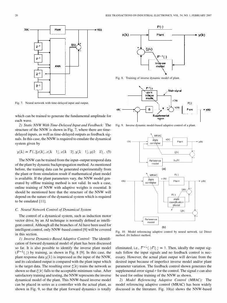
2) Static NNW With Time-Delayed Input and Feedback: Thestructure of the NNW is shown in Fig. 7, where there are time-delayed inputs, as well as time-delayed outputs as feedback sig-nals. In this case, the NNW is required to emulate the dynamicalsystem given by
(5)
The NNW can be trained from the input–output temporal dataof the plant by dynamic backpropagation method. As mentionedbefore, the training data can be generated experimentally fromthe plant or from simulation result if mathematical plant modelis available. If the plant parameters vary, the NNW model gen-erated by offline training method is not valid. In such a case,online training of NNW with adaptive weights is essential. Itshould be mentioned here that the structure of the NNW willdepend on the nature of the dynamical system which is requiredto be emulated [11].
C. Neural Network Control of Dynamical System
The control of a dynamical system, such as induction motorvector drive, by an AI technique is normally defined as intelli-gent control. Although all the branches of AI have been used forintelligent control, only NNW-based control [9] will be coveredin this section.
1) Inverse Dynamics-Based Adaptive Control: The identifi-cation of forward dynamical model of plant has been discussedso far. It is also possible to identify the inverse plant model( ) by training, as shown in Fig. 8 [9]. In this case, theplant response data is impressed as the input of the NNW,and its calculated output is compared with the plant input whichis the target data. The resulting error trains the network asshown so that falls to the acceptable minimum value. Aftersatisfactory training and testing, the NNW represents the inversedynamical model of the plant. This NNW-based inverse modelcan be placed in series as a controller with the actual plant, asshown in Fig. 9, so that the plant forward dynamics is totally
Fig. 8. Training of inverse dynamic model of plant.
Fig. 9. Inverse dynamic model-based adaptive control of a plant.
Fig. 10. Model referencing adaptive control by neural network. (a) Directmethod. (b) Indirect method.
eliminated, i.e., . Then, ideally the output sig-nals follow the input signals and no feedback control is nec-essary. However, the actual plant output will deviate from thedesired input because of imperfect inverse model and/or plantparameter variation. The feedback control shown generates thesupplemental error signal for the control. The signal can alsobe used for online training of the NNW as shown.
2) Model Referencing Adaptive Control (MRAC): Themodel referencing adaptive control (MRAC) has been widelydiscussed in the literature. Fig. 10(a) shows the NNW-based

BOSE: NEURAL NETWORK APPLICATIONS IN POWER ELECTRONICS AND MOTOR DRIVES—AN INTRODUCTION AND PERSPECTIVE 21
Fig. 11. Training of neural network for emulation of actual controller.
MRAC, where the plant output is desired to track the dynamicresponse of the reference model. The reference model can berepresented by dynamical equation(s) and solved in real-timeby a DSP. The error signal between the actual plant outputand the reference model output trains the NNW controller on-line so as to make the tracking error zero. Therefore, the plantwith the NNW has the response which is identical to that of thereference model. One problem of this direct method is that theplant lies between the controller and the error, and there is noway to propagate the error backward in the controller by errorbackpropagation training. This problem is solved in Fig. 10(b)by indirect method. In this case, the NNW identification model
is first generated to emulate the forward model of the plant.This model is then placed in series with the NNW controller(instead of the actual plant) to track the reference model asshown. The tuning of the NNW controller is now convenientthrough the NNW model.
3) Emulation of Actual Controller: Fig. 11 shows a feedbacksystem with the controller in the front-end. The controller canbe simple or complex. It can be static, as well as dynamic.Whatever it is, a neural controller, as shown in the figure, canbe trained to emulate the actual controller, and then the NNWcan substitute the actual controller. Once the neural controllerhas been trained and replaced the controller, it can be retrainedonline for plant parameter variation to make it adaptive. Afuzzy controller, for example, in Fig. 11, that is static andnonlinear, can be P-I, P-D, or P-I-D type. The fuzzy controllercan be easily replaced by NNW controller since both controlsare based on input–output nonlinear mapping principle. A morecomplex ANFIS (adaptive neuro-fuzzy inference system) cantrain the neural controller offline [12] or online by backpropa-gation method.
V. NEURAL NETWORK APPLICATIONS
The history of neural network applications in power elec-tronics and motor drives is very recent, and hardly extends be-yond the last 10–15 years, as mentioned before. In this sec-tion, several example applications which are mainly based onthe author’s own research will be discussed briefly because ofthe length constraint of this paper. The details of the NNW de-sign and their performances for these applications can be foundin the respective cited references. There are, of course, many
other applications which can be found in the large number ofextra references included in this paper.
A. Three-Phase Sine Wave Generation
A simple application of NNW in power electronics is dis-cussed in the beginning to clarify the ideas, particularly thetraining method. The network, shown in Fig. 12, is designedto generate three-phase sine functions from the input signalin radians (0 to ) [14]. The amplitude is set to 1 for nor-malized data handling. The NNW uses a three-layer backprop-agation network with the topology of 1–5–3, using tan-sigmoidTF in the hidden layer and linear bipolar TF in the output layer.A bias of couples to the hidden and output layer neurons.The bias may not be needed, but it is considered for generality.The training data for was generated in the step size of 0.1radian, and the corresponding output target data were gener-ated by MATLAB sine functions. The input-output data file inMATLAB was imported to GUI (graphical user interface) fortraining. The network was trained by MATLAB Neural Net-work Toolbox [2] using the L-M algorithm. The reference de-scribes the details of NNW training. After training the network,it was converted to Simulink program for testing. A sawtoothwave with was impressed at the input and the correspondingthree-phase sine waves were generated at the output. The ac-tual output waves were compared with the target waves to val-idate the success of training. The training was started initiallywith the topology 1-2-3, and the corresponding test results after500 epochs of training are shown in Fig. 13. The specified goalof SSE was 0.04, but it failed to converge and the error waslocked near 15. The corresponding output waves were highlymismatched. Another round of training was continued with thetopology 1-3-3, and the SSE was found to reduce to 0.1 and waslocked at this value. Finally, the training was successful withthe topology 1-5-3 network where the actual output waves co-incided with the target waves and the error converged to the de-sired goal of 0.001 after 178 epochs, as shown in Fig. 14. Thefinal matrices of weights and biases are summarized below
The weights indicate large variation in magnitudes and the im-portance of good resolution in storage, while implementing thenetwork.
Note that precision three-phase sine functions can be gener-ated by a large look-up table in a DSP. However, NNW has the

22 IEEE TRANSACTIONS ON INDUSTRIAL ELECTRONICS, VOL. 54, NO. 1, FEBRUARY 2007
Fig. 12. Backpropagation network for generation of three-phase sine functions.
Fig. 13. Training of 1–2–3 network. (a) Training error. (b) Test results.
advantage that it can interpolate with precision the course ex-ample data used for the training. Besides, a dedicated ASIC chipcan be used for implementation of a task relieving the DSP forother computations.
B. Delayless Filtering and Waveform Processing
1) Single-Phase Square Wave at Constant Frequency: ANNW can be used for delayless filtering of harmonic-richwaveforms in power electronics, as well as waveform pro-cessing [17], as shown in Fig. 15. A traditional low-pass filter
Fig. 14. Training of 1–5–3 network. (a) Training error. (b) Test results.
(LPF) causes frequency-sensitive phase delay and amplitudeattenuation at the output. A square-wave line current which isusually encountered for a thyristor or diode rectifier with highlyinductive load is considered in this case, although other typesof waveforms are also possible. The wave ( ) and its auxiliaryform ( ) through an arbitrary LPF are given as input to theNNW as shown. The output ( ) comes out as sine waveat the same frequency and proportional to the square-waveamplitude, but is locked at 0 phase angle. The auxiliary waveis needed because with the constant amplitude square-waveinput, variable amplitude sine wave output is not possible. Mul-tiphase balanced output waves (in this case three-phase) can begenerated easily by programming the NNW. Such waveform

BOSE: NEURAL NETWORK APPLICATIONS IN POWER ELECTRONICS AND MOTOR DRIVES—AN INTRODUCTION AND PERSPECTIVE 23
Fig. 15. Single-phase square-wave delayless filtering and multiphasing atoutput by neural network (MSE = 2:33881e� 005, 600 epochs).
processing may be important for sinusoidal PWM inverter orcycloconverter, where the command can be generated froma simple square-wave signal. The NNW was trained offlinewith actual and data at the input and the desired output(generated by prior FFT analysis of the input square-wave).The backpropagation NNW (2–16–3) uses bipolar linear TF atthe input and output layers, but hyperbolic tan TF in the hiddenlayer. The MSE and the number of epochs required for thetraining are included in the figure title. A small deviation in fre-quency and distortion of input square-wave will give tolerableerror at the output. Generalizing the waveform processing, itcan be said that any arbitrary waveform can be transformed toarbitrary output wave at single or multiphase with the help ofNNW, and the input–output amplitude tracking relation can beprogrammed to be linear or nonlinear with arbitrary functionalrelation. The study also suggests that NNW can be used aszero-crossing detector (ZCD) for a distorted wave.
2) Three-Phase PWM Waves at Variable Frequency: It ispossible to have delayless filtering of three-phase PWM wavesof a voltage-fed inverter at variable frequency with the help ofNNW [17], as shown in Fig. 16. The fundamental voltages atzero phase-shift angle permit correct estimation of feedback sig-nals for vector control of ac drive. The PWM line voltage waves
, , and are generated by sinusoidal PWM technique,where only wave is shown. The PWM waves are initially fil-tered by identical LPFs as shown to convert the discrete wavesinto continuous waves before processing through the NNW. InFig. 16(b), the NNW input waves, and the corresponding desiredand estimated waves are shown for 10 kHz carrier frequency( ), whereas Fig. 16(c) shows results at kHz. TheMSE and the number of epochs required in the training are in-cluded in the figure title. In the later case, the MSE failed to
Fig. 16. (a) Three-phase PWM waves delayless filtering by neural network.(b) Network output at f = 10 kHz (MSE = 1:99796e � 005, 90 epochs).(c) Network output at f = 1:0 kHz (MSE = 29:0519e� 005, 500 epochs).
converge below the large value shown. In the later case, theestimated waves indicate more distortion. The test results for60 Hz fundamental frequency are shown only, although the per-formance was tested to be satisfactory at variable frequency inthe range of 5–60 Hz. Note that in this case the NNW com-pensates the phase delay and attenuation of LPF (that vary withfundamental frequency) besides filtering the PWM waves. Witha more complex structure of NNW and extensive training, theharmonic quality at the output can be improved.

24 IEEE TRANSACTIONS ON INDUSTRIAL ELECTRONICS, VOL. 54, NO. 1, FEBRUARY 2007
Fig. 17. Neural network for feedback signal estimation.
C. Feedback Signal Estimation of Induction Motor Drive
The vector or field-oriented control of ac drive requires com-plex calculation of feedback signals. The rotor flux-orientedinduction motor vector drive requires computation of the fol-lowing equations [6] to estimate rotor flux ( ), torque ( ), andunit vector ( , ) signals from the machine terminalvoltages and currents:
(6)
(7)
(8)
(9)
(10)
(11)
(12)
(13)
(14)
(15)
(16)
(17)
(18)
(19)
where all the standard symbols have been used. Normally, a mi-croprocessor/DSP is used to solve these equations in real-time.
A feedforward NNW can also solve the equations except theintegrations which are dynamical in nature. The integrationsand conversions in the front-end can be easily done byop-amp low-pass filters, and the remaining equations can besolved by a backpropagation NNW, as shown in Fig. 17 [18].Solving (12)–(19) basically involve addition, subtraction, mul-tiplication, division, and square-rooting of signals which arenothing but the process of input–output mapping. Note that allthe input signals are in variable frequency and magnitude. Thetraining data of the NNW can be generated by DSP calculation,or simulation result could be used. The three-layer topology(4–20–4) has bipolar linear TF for the input layer, and tan-sig-moid TF for the hidden and output layers (indicated by “ ”symbol). The bias is coupled to the hidden layer only (throughweights) as indicated. The NNW after training was found tohave some harmonic ripple filtering effect. With 15 kHz SPWMof the inverter, the NNW output had very little distortion. How-ever, with 1.0 kHz switching frequency, the distortion was some-what magnified (less filtering effect).
D. Space Vector PWM of Voltage-Fed Inverter
Space vector modulation (SVM) has recently grown as a verypopular PWM method for three-phase voltage-fed inverter withisolated neutral load (such as ac motor) because of its superiorharmonic quality and extended undermodulation (UM) range[6] compared with the traditional SPWM method. However, onedifficulty of SVM is that it requires complex online DSP-basedcomputation that usually limits its operation up to several kHzof switching frequency. This problem has been solved by ap-plying NNW in SVM implementation. As mentioned before, afeedforward NNW has basically static nonlinear input–outputmapping property. The computational delay of this mapping be-comes negligible if NNW is implemented by ASIC-based par-allel architecture. A feedforward carrier-based PWM technique,such as SVM, can also be looked upon as a nonlinear mappingphenomena, where the command phase voltages can be sam-pled at the input and the corresponding pulse width patternscan be generated at the output. Therefore, it appears logical

BOSE: NEURAL NETWORK APPLICATIONS IN POWER ELECTRONICS AND MOTOR DRIVES—AN INTRODUCTION AND PERSPECTIVE 25
Fig. 18. Turn-on time of phase-A (T ) as function of command vectorangle (� ) in the six sectors.
that backpropagation type NNW with high computational capa-bility can implement the SVM algorithm. In addition, the non-linear voltage transfer characteristics in overmodulation (OM)region can be easily linearized by compensation. The NNW canbe conveniently trained offline with the data generated by cal-culation of the SVM algorithm. Considering the importance ofNNW-based SVM, it will be reviewed for two-level, three-level,and five-level inverters.
1) Two-Level Inverter: The NNW-based SVM implementa-tion of a two-level inverter has been discussed in the literature[22]. By prior analysis, it can be established that the turn-ontime of phase-A upper switch ( ) (see Fig. 18) can be ex-pressed in the general form
(20)
where sampling time (or period of switching frequency),command voltage magnitude, voltage ampli-
tude function scale factor, angle in a sector (one of thesix sectors), and turn-on pulsewidth function at unitvoltage amplitude. Fig. 18 shows the plot of (20) in all the sixsectors with variable covering UM and OM regions. In UMregion, , and therefore, increases linearlywith . The UM region ends at the upper value of whenthe maximum and minimum values of are and 0,respectively. At OM mode-1 and mode-2, saturates atthe upper and lower levels as shown when it (shown by dottedcurves) tends to exceed the limit values. Then, becomesnonlinear function of . The curves for andfor the corresponding phases B and C are identical but mutuallyphase-shifted by 120 . The relation between and cov-ering both UM and OM regions for dc link voltageis illustrated in Fig. 19. The linear characteristics in UM region
ends at as shown. In OM region, theproblem is to generate an appropriate relation betweenand so that linear transfer relation is maintained between
and actual inverter output. It can be shown that UM curve inFig. 19 can be extended to OM mode-1 and mode-2 by usinga nonlinear scale factor that increases
nonlinearly in Fig. 19 until square-wave is reached atat square wave (i.e., ). The idea is the same
as SPWM OM principle where modulation voltage is magnified.The data generated from Figs. 18 and 19 are used to train a back-propagation NNW shown in Fig. 20. Basically, it consists of two
Fig. 19. f(V ) versus V relation in UM and OM regions.
subnets. The angle subnet (lower part) receives the commandvoltage vector angle at the input and solves the turn-on pulsewidth functions , , and as shown. Theupper voltage subnet receives the command voltage magnitude
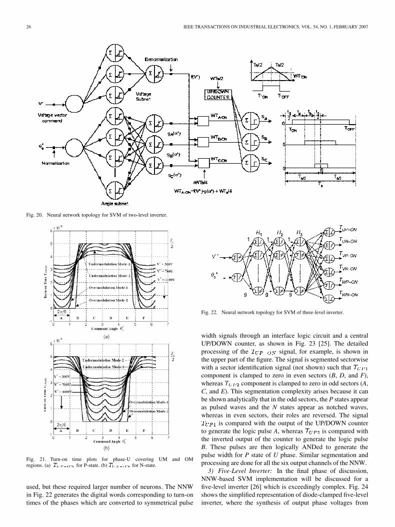
and converts it to . Both the voltage subnet (1–3–1)and angle subnet (1–17–3) have three layers with sigmoidal TFin the hidden and output layers. The angle subnet outputs aremultiplied by and added with the bias signalto generate the digital words corresponding turn-on time of thethree phases. Then, a single UP/DOWN counter converts thesewords into the respective symmetrical pulse widths, as shownin the figure.
2) Three-Level Inverter: The NNW-based SVM principlefor two-level inverter can be extended to a three-level inverter[23]–[25]. These references also discuss SVM technique ofthree-level inverter in UM and OM regions and their DSP-basedimplementation. The SVM of a three-level inverter is morecomplex than a two-level inverter because it is characterizedby switching states. Each phase voltage output can bepositive (P-state), negative (N-state), or zero (0) (neutral-pointclamped) depending on the state of the phase-leg switches. Thecalculated turn-on times for P-state and N-state of a phase leg(U phase) for symmetrical pulse widths within a sample time( ) [25] are plotted in Fig. 21 for all the six sectors (A-F) withvariable command voltage ( ) and its angular position ( ),where turn-on time of -state for phase orand turn-on time of -state for phase- . Thecurves for phases V and W are identical but are mutuallyphase-shifted by 120 The particular case considers dc linkvoltage and ms (i.e., 1.0 kHz switchingfrequency). Both UM and OM regions of the inverter areincluded in the figure. In UM mode-1, the curves remainunsaturated, but reaches saturation at 0.5 ms ( ) at the endof this mode, and then mode-2 starts. In OM modes 1 and 2,part of the curves reach clamping level 0 as indicated. Withincrease in modulation factor, the curves become trapezoidalin shape and ultimately approach square-wave. The mappingof turn-on times in Fig. 21 as function of and generatedata for training the NNW. Fig. 22 shows the trained NNWtopology for SVM implementation. The five-layer NNW uses35 neurons. Both the input and output layers use bipolar linearTF, whereas the hidden layers use hyperbolic tan TF. The studyindicated that a three-layer or four-layer NNW could also be
26 IEEE TRANSACTIONS ON INDUSTRIAL ELECTRONICS, VOL. 54, NO. 1, FEBRUARY 2007
Fig. 20. Neural network topology for SVM of two-level inverter.
Fig. 21. Turn-on time plots for phase-U covering UM and OMregions. (a) T for P-state. (b) T for N-state.
used, but these required larger number of neurons. The NNWin Fig. 22 generates the digital words corresponding to turn-ontimes of the phases which are converted to symmetrical pulse
Fig. 22. Neural network topology for SVM of three-level inverter.
width signals through an interface logic circuit and a centralUP/DOWN counter, as shown in Fig. 23 [25]. The detailedprocessing of the signal, for example, is shown inthe upper part of the figure. The signal is segmented sectorwisewith a sector identification signal (not shown) such thatcomponent is clamped to zero in even sectors (B, D, and F),whereas component is clamped to zero in odd sectors (A,C, and E). This segmentation complexity arises because it canbe shown analytically that in the odd sectors, the P states appearas pulsed waves and the N states appear as notched waves,whereas in even sectors, their roles are reversed. The signal
is compared with the output of the UP/DOWN counterto generate the logic pulse A, whereas is compared withthe inverted output of the counter to generate the logic pulseB. These pulses are then logically ANDed to generate thepulse width for P state of U phase. Similar segmentation andprocessing are done for all the six output channels of the NNW.
3) Five-Level Inverter: In the final phase of discussion,NNW-based SVM implementation will be discussed for afive-level inverter [26] which is exceedingly complex. Fig. 24shows the simplified representation of diode-clamped five-levelinverter, where the synthesis of output phase voltages from

BOSE: NEURAL NETWORK APPLICATIONS IN POWER ELECTRONICS AND MOTOR DRIVES—AN INTRODUCTION AND PERSPECTIVE 27
Fig. 23. Neural network with simplified interface logic and counter to generate pulse width signals.
Fig. 24. Simplified representation of five-level inverter.
the five levels of capacitor voltages is indicated throughfive-position multiplexer switches. The hexagon switchingstates of the inverter are indicated in Fig. 25. The inverter has
switching states, 96 triangles, 61 effective spacevectors, and multiplicity of switching states for inner trianglecorners as shown. The six sectors of the hexagon are num-bered A to F, respectively. The sector A is drawn separately inFig. 25(b) showing its 16 triangles and the switching intervals( , , and ) for the corner vectors, where(sampling time). The command voltage trajectory for modula-tion factor is shown on the hexagon. The locationof the command vector in a triangle ( ) of the hexagon canbe determined by the equation
(21)
Fig. 25. (a) Switching states of five-level inverter. (b) Sector-A triangleshowing switching states.
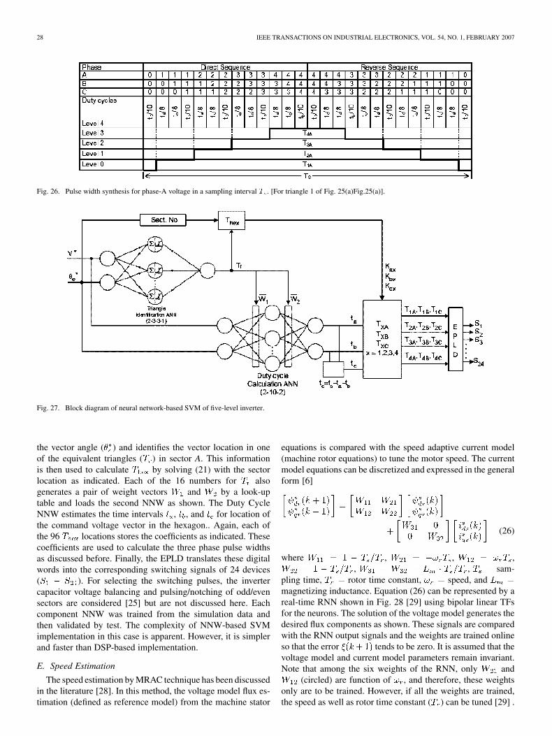
where located insector A. In fact, pulse width information of SVM can be ob-tained by identifying the command vector location in any ofthe 96 triangles from the principles of input-output nonlinearmapping. Fig. 26 shows the typical levels of the output voltage(Levels 0 to 4) for phase-A and the corresponding synthesis ofpulse widths in the four levels are given by
(22)
(23)
(24)
(25)
where , , and of the cornerswitching states for the location of the vector, and
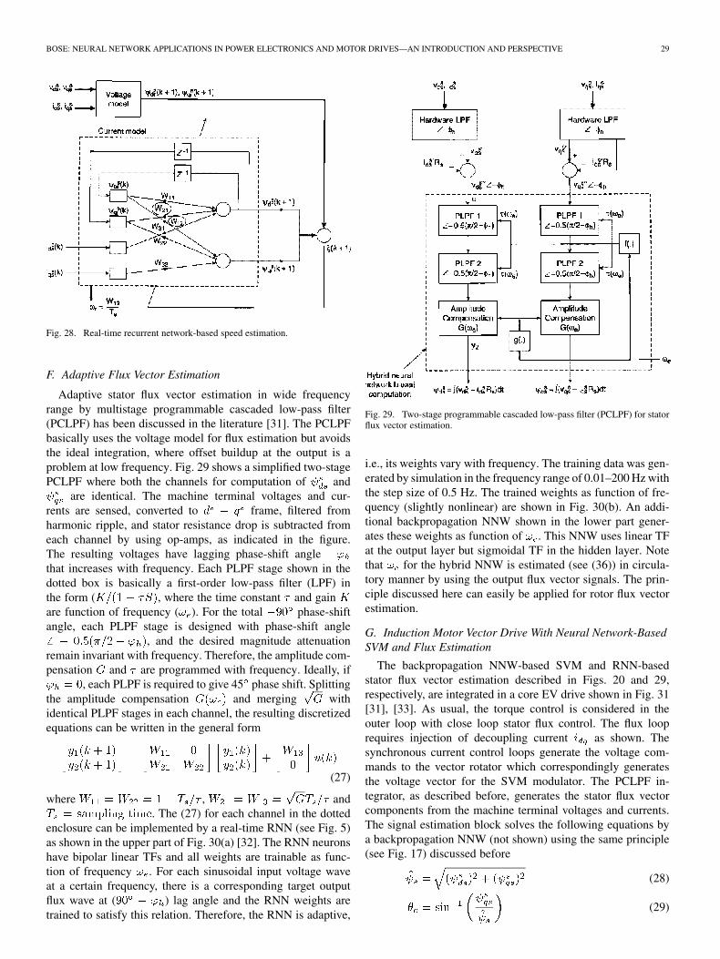
, etc. coefficients (function of ) of timeintervals that determine the pulse widths. These coefficients (12for each phase) for the three phases can be generated by priorcomputation and storing. Fig. 27 shows the NNW-based SVMimplementation for the complete inverter in the UM rangeonly. The NNW is segmented into two parts: the first one isthe Triangle Identification NNW (2–3–3–1) and the second oneis the Duty Cycle Calculation NNW (2–10–2) as shown. Thefirst NNW receives the command voltage magnitude ( ) and
28 IEEE TRANSACTIONS ON INDUSTRIAL ELECTRONICS, VOL. 54, NO. 1, FEBRUARY 2007
Fig. 26. Pulse width synthesis for phase-A voltage in a sampling interval T . [For triangle 1 of Fig. 25(a)Fig.25(a)].
Fig. 27. Block diagram of neural network-based SVM of five-level inverter.
the vector angle ( ) and identifies the vector location in oneof the equivalent triangles ( ) in sector A. This informationis then used to calculate by solving (21) with the sectorlocation as indicated. Each of the 16 numbers for alsogenerates a pair of weight vectors and by a look-uptable and loads the second NNW as shown. The Duty CycleNNW estimates the time intervals , , and for location ofthe command voltage vector in the hexagon.. Again, each ofthe 96 locations stores the coefficients as indicated. Thesecoefficients are used to calculate the three phase pulse widthsas discussed before. Finally, the EPLD translates these digitalwords into the corresponding switching signals of 24 devices( ). For selecting the switching pulses, the invertercapacitor voltage balancing and pulsing/notching of odd/evensectors are considered [25] but are not discussed here. Eachcomponent NNW was trained from the simulation data andthen validated by test. The complexity of NNW-based SVMimplementation in this case is apparent. However, it is simplerand faster than DSP-based implementation.
E. Speed Estimation
The speed estimation by MRAC technique has been discussedin the literature [28]. In this method, the voltage model flux es-timation (defined as reference model) from the machine stator
equations is compared with the speed adaptive current model(machine rotor equations) to tune the motor speed. The currentmodel equations can be discretized and expressed in the generalform [6]
(26)
where , , ,, , sam-
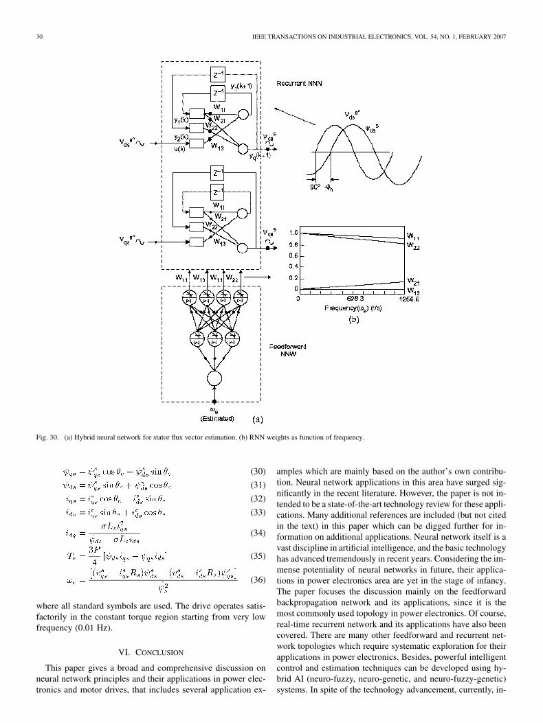
pling time, rotor time constant, speed, andmagnetizing inductance. Equation (26) can be represented by areal-time RNN shown in Fig. 28 [29] using bipolar linear TFsfor the neurons. The solution of the voltage model generates thedesired flux components as shown. These signals are comparedwith the RNN output signals and the weights are trained onlineso that the error tends to be zero. It is assumed that thevoltage model and current model parameters remain invariant.Note that among the six weights of the RNN, only and
(circled) are function of , and therefore, these weightsonly are to be trained. However, if all the weights are trained,the speed as well as rotor time constant ( ) can be tuned [29] .
BOSE: NEURAL NETWORK APPLICATIONS IN POWER ELECTRONICS AND MOTOR DRIVES—AN INTRODUCTION AND PERSPECTIVE 29
Fig. 28. Real-time recurrent network-based speed estimation.
F. Adaptive Flux Vector Estimation
Adaptive stator flux vector estimation in wide frequencyrange by multistage programmable cascaded low-pass filter(PCLPF) has been discussed in the literature [31]. The PCLPFbasically uses the voltage model for flux estimation but avoidsthe ideal integration, where offset buildup at the output is aproblem at low frequency. Fig. 29 shows a simplified two-stagePCLPF where both the channels for computation of and
are identical. The machine terminal voltages and cur-rents are sensed, converted to frame, filtered fromharmonic ripple, and stator resistance drop is subtracted fromeach channel by using op-amps, as indicated in the figure.The resulting voltages have lagging phase-shift anglethat increases with frequency. Each PLPF stage shown in thedotted box is basically a first-order low-pass filter (LPF) inthe form ( , where the time constant and gainare function of frequency ( ). For the total phase-shiftangle, each PLPF stage is designed with phase-shift angle
, and the desired magnitude attenuationremain invariant with frequency. Therefore, the amplitude com-pensation and are programmed with frequency. Ideally, if
, each PLPF is required to give 45 phase shift. Splittingthe amplitude compensation and merging withidentical PLPF stages in each channel, the resulting discretizedequations can be written in the general form
(27)
where , and. The (27) for each channel in the dotted
enclosure can be implemented by a real-time RNN (see Fig. 5)as shown in the upper part of Fig. 30(a) [32]. The RNN neuronshave bipolar linear TFs and all weights are trainable as func-tion of frequency . For each sinusoidal input voltage waveat a certain frequency, there is a corresponding target outputflux wave at ( ) lag angle and the RNN weights aretrained to satisfy this relation. Therefore, the RNN is adaptive,
Fig. 29. Two-stage programmable cascaded low-pass filter (PCLPF) for statorflux vector estimation.
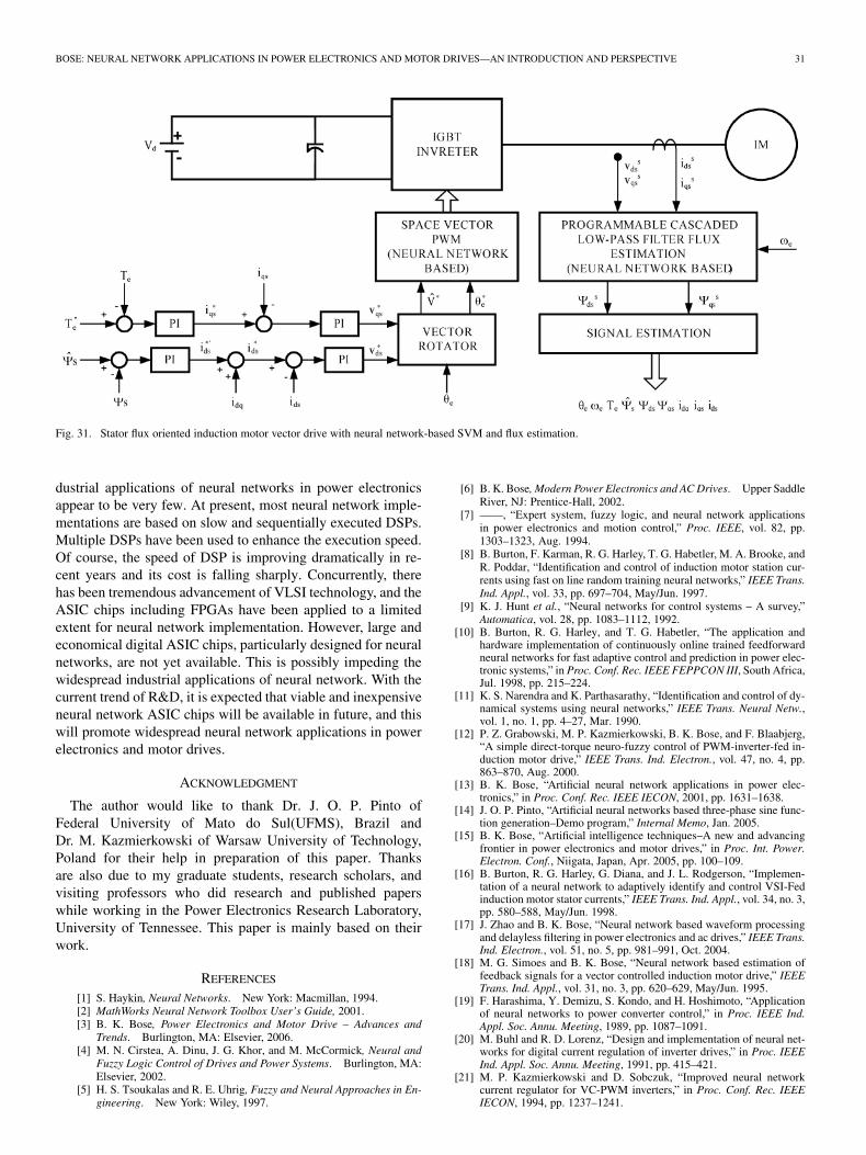
i.e., its weights vary with frequency. The training data was gen-erated by simulation in the frequency range of 0.01–200 Hz withthe step size of 0.5 Hz. The trained weights as function of fre-quency (slightly nonlinear) are shown in Fig. 30(b). An addi-tional backpropagation NNW shown in the lower part gener-ates these weights as function of . This NNW uses linear TFat the output layer but sigmoidal TF in the hidden layer. Notethat for the hybrid NNW is estimated (see (36)) in circula-tory manner by using the output flux vector signals. The prin-ciple discussed here can easily be applied for rotor flux vectorestimation.
G. Induction Motor Vector Drive With Neural Network-BasedSVM and Flux Estimation
The backpropagation NNW-based SVM and RNN-basedstator flux vector estimation described in Figs. 20 and 29,respectively, are integrated in a core EV drive shown in Fig. 31[31], [33]. As usual, the torque control is considered in theouter loop with close loop stator flux control. The flux looprequires injection of decoupling current as shown. Thesynchronous current control loops generate the voltage com-mands to the vector rotator which correspondingly generatesthe voltage vector for the SVM modulator. The PCLPF in-tegrator, as described before, generates the stator flux vectorcomponents from the machine terminal voltages and currents.The signal estimation block solves the following equations bya backpropagation NNW (not shown) using the same principle(see Fig. 17) discussed before
(28)
(29)
30 IEEE TRANSACTIONS ON INDUSTRIAL ELECTRONICS, VOL. 54, NO. 1, FEBRUARY 2007
Fig. 30. (a) Hybrid neural network for stator flux vector estimation. (b) RNN weights as function of frequency.
(30)
(31)
(32)
(33)
(34)
(35)
(36)
where all standard symbols are used. The drive operates satis-factorily in the constant torque region starting from very lowfrequency (0.01 Hz).
VI. CONCLUSION
This paper gives a broad and comprehensive discussion onneural network principles and their applications in power elec-tronics and motor drives, that includes several application ex-
amples which are mainly based on the author’s own contribu-tion. Neural network applications in this area have surged sig-nificantly in the recent literature. However, the paper is not in-tended to be a state-of-the-art technology review for these appli-cations. Many additional references are included (but not citedin the text) in this paper which can be digged further for in-formation on additional applications. Neural network itself is avast discipline in artificial intelligence, and the basic technologyhas advanced tremendously in recent years. Considering the im-mense potentiality of neural networks in future, their applica-tions in power electronics area are yet in the stage of infancy.The paper focuses the discussion mainly on the feedforwardbackpropagation network and its applications, since it is themost commonly used topology in power electronics. Of course,real-time recurrent network and its applications have also beencovered. There are many other feedforward and recurrent net-work topologies which require systematic exploration for theirapplications in power electronics. Besides, powerful intelligentcontrol and estimation techniques can be developed using hy-brid AI (neuro-fuzzy, neuro-genetic, and neuro-fuzzy-genetic)systems. In spite of the technology advancement, currently, in-
BOSE: NEURAL NETWORK APPLICATIONS IN POWER ELECTRONICS AND MOTOR DRIVES—AN INTRODUCTION AND PERSPECTIVE 31
Fig. 31. Stator flux oriented induction motor vector drive with neural network-based SVM and flux estimation.
dustrial applications of neural networks in power electronicsappear to be very few. At present, most neural network imple-mentations are based on slow and sequentially executed DSPs.Multiple DSPs have been used to enhance the execution speed.Of course, the speed of DSP is improving dramatically in re-cent years and its cost is falling sharply. Concurrently, therehas been tremendous advancement of VLSI technology, and theASIC chips including FPGAs have been applied to a limitedextent for neural network implementation. However, large andeconomical digital ASIC chips, particularly designed for neuralnetworks, are not yet available. This is possibly impeding thewidespread industrial applications of neural network. With thecurrent trend of R&D, it is expected that viable and inexpensiveneural network ASIC chips will be available in future, and thiswill promote widespread neural network applications in powerelectronics and motor drives.
ACKNOWLEDGMENT
The author would like to thank Dr. J. O. P. Pinto ofFederal University of Mato do Sul(UFMS), Brazil andDr. M. Kazmierkowski of Warsaw University of Technology,Poland for their help in preparation of this paper. Thanksare also due to my graduate students, research scholars, andvisiting professors who did research and published paperswhile working in the Power Electronics Research Laboratory,University of Tennessee. This paper is mainly based on theirwork.
REFERENCES
[1] S. Haykin, Neural Networks. New York: Macmillan, 1994.[2] MathWorks Neural Network Toolbox User’s Guide, 2001.[3] B. K. Bose, Power Electronics and Motor Drive – Advances and
Trends. Burlington, MA: Elsevier, 2006.[4] M. N. Cirstea, A. Dinu, J. G. Khor, and M. McCormick, Neural and
Fuzzy Logic Control of Drives and Power Systems. Burlington, MA:Elsevier, 2002.
[5] H. S. Tsoukalas and R. E. Uhrig, Fuzzy and Neural Approaches in En-gineering. New York: Wiley, 1997.
[6] B. K. Bose, Modern Power Electronics and AC Drives. Upper SaddleRiver, NJ: Prentice-Hall, 2002.
[7] ——, “Expert system, fuzzy logic, and neural network applicationsin power electronics and motion control,” Proc. IEEE, vol. 82, pp.1303–1323, Aug. 1994.
[8] B. Burton, F. Karman, R. G. Harley, T. G. Habetler, M. A. Brooke, andR. Poddar, “Identification and control of induction motor station cur-rents using fast on line random training neural networks,” IEEE Trans.Ind. Appl., vol. 33, pp. 697–704, May/Jun. 1997.
[9] K. J. Hunt et al., “Neural networks for control systems – A survey,”Automatica, vol. 28, pp. 1083–1112, 1992.
[10] B. Burton, R. G. Harley, and T. G. Habetler, “The application andhardware implementation of continuously online trained feedforwardneural networks for fast adaptive control and prediction in power elec-tronic systems,” in Proc. Conf. Rec. IEEE FEPPCON III, South Africa,Jul. 1998, pp. 215–224.
[11] K. S. Narendra and K. Parthasarathy, “Identification and control of dy-namical systems using neural networks,” IEEE Trans. Neural Netw.,vol. 1, no. 1, pp. 4–27, Mar. 1990.
[12] P. Z. Grabowski, M. P. Kazmierkowski, B. K. Bose, and F. Blaabjerg,“A simple direct-torque neuro-fuzzy control of PWM-inverter-fed in-duction motor drive,” IEEE Trans. Ind. Electron., vol. 47, no. 4, pp.863–870, Aug. 2000.
[13] B. K. Bose, “Artificial neural network applications in power elec-tronics,” in Proc. Conf. Rec. IEEE IECON, 2001, pp. 1631–1638.
[14] J. O. P. Pinto, “Artificial neural networks based three-phase sine func-tion generation–Demo program,” Internal Memo, Jan. 2005.
[15] B. K. Bose, “Artificial intelligence techniques–A new and advancingfrontier in power electronics and motor drives,” in Proc. Int. Power.Electron. Conf., Niigata, Japan, Apr. 2005, pp. 100–109.
[16] B. Burton, R. G. Harley, G. Diana, and J. L. Rodgerson, “Implemen-tation of a neural network to adaptively identify and control VSI-Fedinduction motor stator currents,” IEEE Trans. Ind. Appl., vol. 34, no. 3,pp. 580–588, May/Jun. 1998.
[17] J. Zhao and B. K. Bose, “Neural network based waveform processingand delayless filtering in power electronics and ac drives,” IEEE Trans.Ind. Electron., vol. 51, no. 5, pp. 981–991, Oct. 2004.
[18] M. G. Simoes and B. K. Bose, “Neural network based estimation offeedback signals for a vector controlled induction motor drive,” IEEETrans. Ind. Appl., vol. 31, no. 3, pp. 620–629, May/Jun. 1995.
[19] F. Harashima, Y. Demizu, S. Kondo, and H. Hoshimoto, “Applicationof neural networks to power converter control,” in Proc. IEEE Ind.Appl. Soc. Annu. Meeting, 1989, pp. 1087–1091.
[20] M. Buhl and R. D. Lorenz, “Design and implementation of neural net-works for digital current regulation of inverter drives,” in Proc. IEEEInd. Appl. Soc. Annu. Meeting, 1991, pp. 415–421.
[21] M. P. Kazmierkowski and D. Sobczuk, “Improved neural networkcurrent regulator for VC-PWM inverters,” in Proc. Conf. Rec. IEEEIECON, 1994, pp. 1237–1241.

32 IEEE TRANSACTIONS ON INDUSTRIAL ELECTRONICS, VOL. 54, NO. 1, FEBRUARY 2007
[22] J. O. P. Pinto, B. K. Bose, L. E. B. daSilva, and M. P. Kazmierkowski,“A neural network based space vector PWM controller for voltage-fedinverter induction motor drive,” IEEE Trans. Ind. Appl., vol. 36, no. 6,pp. 1628–1636, Nov./Dec. 2000.
[23] S. Mondal, J. O. P. Pinto, and B. K. Bose, “A neural network basedspace vector PWM controller for a three-level voltage-fed inverterinduction motor drive,” IEEE Trans. Ind. Appl., vol. 38, no. 3, pp.660–669, May/Jun. 2002.
[24] S. K. Mondal, B. K. Bose, V. Oleschuk, and J. O. P. Pinto, “Spacevector pulse width modulation of three-level inverter extending oper-ation into overmodulation region,” IEEE Trans. Power Electron., vol.18, no. 2, pp. 604–611, Mar. 2003.
[25] C. Wang, B. K. Bose, V. Oleschuk, S. Mondal, and J. O. P. Pinto,“Neural network based SVM of a three-level inverter covering over-modulation region and performance evaluation on induction motordrives,” in Proc. Conf. Rec. IEEE IECON, 2003, pp. 1–6.
[26] N. P. Filho, J. O. P. Pinto, B. K. Bose, and L. E. B. daSilva, “A neuralnetwork based space vector PWM of a five-level voltage-fed inverter,”in Proc. Conf. Rec. IEEE Ind. Appl. Soc. Annu. Meeting, 2004, pp.2181–2187.
[27] D. Daniolos, M. K. Darwish, and P. Mehta, “Optimized PWM invertercontrol using artificial neural networks,” Electron. Lett., vol. 31, no. 20,pp. 1739–1740, Sep. 1995.
[28] C. Schauder, “Adaptive speed identification for vector control of in-duction motors without rotational transducers,” IEEE Trans. Ind. Appl.,vol. 28, no. 5, pp. 1054–1061, Sep./Oct. 1992.
[29] B. Jayanand, “Simulation studies on speed sensorless operation ofvector controlled induction motor drives using neural network,” Ph.D.dissertation, IIT, Madras, India, 1997.
[30] L. Ben-Brahim and R. Kurosawa, “Identification of induction motorspeed using neural networks,” in Proc. IEEE PCC, Yokohama, 1993,pp. 689–694.
[31] B. K. Bose and N. R. Patel, “A sensorless stator flux oriented vectorcontrolled induction motor drive with neuro-fuzzy based performanceenhancement,” in Proc. IEEE Ind. Appl. Soc. Annu. Meeting, 1997, pp.393–400.
[32] L. E. B. daSilva, B. K. Bose, and J. O. P. Pinto, “Recurrent neuralnetwork based implementation of a programmable cascaded low passfilter used in stator flux synthesis of vector controlled induction motordrive,” IEEE Trans. Ind. Electron., vol. 46, no. 3, pp. 662–665, Jun.1999.
[33] J. O. P. Pinto, B. K. Bose, and L. E. Borges, “A stator flux orientedvector controlled induction motor drive with space vector PWM andflux vector synthesis by neural networks,” IEEE Trans. Ind. Appl., vol.37, no. 5, pp. 1308–1318, Sep./Oct. 2001.
[34] M. H. Kim, M. G. Simoes, and B. K. Bose, “Neural network based esti-mation of power electronic waveforms,” IEEE Trans. Power Electron.,vol. 11, no. 2, pp. 383–369, Mar. 1996.
[35] B. Karanayil, M. F. Rahman, and C. Grantham, “Rotor resistance iden-tification using artificial neural networks for an indirect vector con-trolled induction motor drive,” in Proc. Conf. Rec. IEEE IECON, vol.1001, pp. 1315–1320.
[36] ——, “Stator and rotor resistance observers for induction motor drivenusing fuzzy logic and neural networks,” IEEE Trans. Energy Conv., vol.20, no. 4, pp. 771–780, Dec. 2005.
[37] B. Singh, V. Verma, and J. Solanki, “Active power filter based selectivecompensation of current using neural network,” in Proc. Conf. Rec.IEEE ISIE, 2004, pp. 104–110.
[38] S. M. R. Rafiei, R. Ghazi, and H. A. Taliyat, “IEEE-519-based real-timeand optimal control of active filters under nonsinusoidal line voltagesusing neural networks,” IEEE Trans. Power Del., vol. 17, no. 3, pp.815–821, Jul. 2002.
[39] F. Temurtas, R. Gunturkun, N. Yumusaka, and H. Temurtas, “Harmonicdetection using feedforward and recurrent neural networks for activefilters,” Electric Power Syst. Res., vol. 72, pp. 33–40, 2004.
[40] Y. Wang, J. Gu, and C. Chen, “An improved adaline algorithm for on-line tracking of harmonic components,” Int. J. Power Energy Syst., vol.23, pp. 117–127, 2003.
[41] D. O. Abdeslam, P. Wira, J. Merckle, and Y. A. Chapuis, “A neuralapproach for the control of an active power filter,” in Proc. Conf. Rec.IPEC, Niigata, Japan, 2005, pp. 923–929.
[42] T. Hiyama et al., “Evaluation of neural network based real time max-imum power tracking controller in PV system,” IEEE Trans. EnergyConv., vol. 10, no. 3, Sep. 1995.
[43] M. A. El-Sharkawi, “High performance brushless motors using neuralnetwork,” in Proc. IEEE PES Summer Conf., Jul. 1993, pp. 200–207.
[44] S. Wersooriya and M. A. El-Sharkawi, “Identification and control of adc motor using backpropagation neural network,” IEEE Trans. EnergyConvers., vol. 6, pp. 663–669, Dec. 1991.
[45] Y. S. Kung, C. M. Liaw, and M. S. Ouyang, “Adaptive speed controlfor induction motor drives using neural networks,” IEEE Trans. Ind.Electron., vol. 42, no. 1, pp. 25–32, Feb. 1995.
[46] K. L. Shi, T. F. Chan, Y. K. Wong, and S. L. Ho, “Direct self controlof induction motor based on neural network,” IEEE Trans. Ind. Appl.,vol. 37, no. 5, pp. 1290–1298, Sep.-Oct. 2001.
[47] A. Rabaai, R. Kotaru, and M. D. Kankam, “Online training of par-allel neural network estimators for control of induction motors,” IEEETrans. Ind. Appl., vol. 37, no. 5, pp. 1512–1521, Sep.-Oct. 2001.
[48] T. C. Chen and T. T. Sheu, “Model referencing neural network con-troller for induction motor speed control,” IEEE Trans. Energy Conv.,vol. 17, no. 2, pp. 157–163, Jun. 2002.
[49] M. Wlas, Z. Krzeminski, J. Guzinski, H. Abu-Rub, and H. A. Tolyat,“Artificial-neural-network-based sensorless nonlinear control of induc-tion motors,” IEEE Trans. Energy Conv., vol. 20, no. 3, pp. 520–528,Sep. 2005.
[50] S. H. Kim, T. S. Park, J. Y. Yoo, and G. T. Park, “Speed sensorlessvector control of an induction motor using neural network speed esti-mation,” IEEE Trans. Ind. Electron., vol. 48, no. 3, pp. 609–614, Jun.2001.
[51] M. Mohamadian, E. Nowicki, F. Ashrafzadeh, A. Chu, R. Sachdeva,and E. Evanik, “A novel neural network controller and its efficient DSPimplementation for vector controlled induction motor drives,” IEEETrans. Ind. Appl., vol. 39, no. 6, pp. 1622–1629, Nov./Dec. 2003.
[52] C. M. Kwan and F. L. Lewis, “Robust backstepping control of induc-tion motors using neural networks,” IEEE Trans. Neural Networks, vol.11, no. 5, pp. 1178–1187, Sep. 2000.
[53] F. J. Lin, R. J. Wai, W. D. Chou, and S. P. Hsu, “Adaptive backstep-ping control using recurrent neural network for linear induction motordrive,” IEEE Trans. Ind. Electron., vol. 49, no. 1, pp. 134–146, Feb.2002.
[54] A. Rubaai and R. Kotaru, “Online identification and control of a DCmotor using learning adaptation of neural networks,” IEEE Trans. Ind.Appl., vol. 33, no. 3, pp. 935–942, May-Jun. 2000.
[55] E. N. Sanchez, A. G. Loukianov, and R. A. Felix, “Dynamic triangularneural controller for stepper motor trajectory tracking,” IEEE Trans.Syst. Man, Cybern., vol. 32, no. 1, pt. C, pp. 24–30, Feb. 2002.
[56] A. Rabaai and R. Kotaru, “Adaptation learning control scheme fora high performance permanent-magnet stepper motor using onlinerandom training of neural networks,” IEEE Trans. Ind. Appl., vol. 37,no. 2, pp. 495–502, Mar.-Apr. 2001.
[57] G. J. Wang, C. T. Fong, and K. J. Chang, “Neural network based self-tuning PI controller for precise motion control of PMAC motors,” IEEETrans. Ind. Electron., vol. 48, no. 2, pp. 408–415, Apr. 2001.
[58] H. J. Guo, S. Sagawa, T. Watanabe, and O. Ichinokura, “Sensorlessdriving method of permanent-magnet synchronous motors basedon neural networks,” IEEE Trans. Magn., vol. 39, no. 5, pt. 2, pp.3247–3249, Sep. 2003.
[59] F. J. Lin, R. J. Wai, and H. P. Chen, “A PM synchronous motor drivewith an on-line trained fuzzy neural network controller,” IEEE Trans.Energy Conv., vol. 13, pp. 319–325, 1998.
[60] T. D. Batzel and K. Y. Lee, “An approach to sensorless operation ofthe permanent–Magnet synchronous motor using diagonally recurrentneural networks,” IEEE Trans. Energy Conv., vol. 18, pp. 100–106,Mar. 2003.
[61] Y. Yang, D. M. Vilathgamuwa, and M. A. Rahman, “Implementation ofan artificial-neural-network-based real-time adaptive controller for aninterior permanent-magnet motor drive,” IEEE Trans. Ind. Appl., vol.39, no. 1, pp. 96–104, Jan./Feb. 2003.
[62] T. Pajchrowski, K. Urbanski, and K. Zawirski, “Robust speed controlof PMSM servodrive based on ANN application,” in Proc. 10th Eur.Conf. Power Electron. Appl., Toulouse, Sep. 2–4, 2003, 833.
[63] T. Pajchrowski and K. Zawirski, “Robust speed control of servodrivebased on ANN,” in Proc. Conf. Rec. IEEE ISIE, 2005, pp. 81–86.
[64] R. J. Wai, “Total sliding mode controller for PM synchronous servomotor drive using recurrent fuzzy neural network,” IEEE Trans. Ind.Electron., vol. 48, no. 5, pp. 926–944, Oct. 2001.
[65] A. Rubaai, D. Ricketts, and M. D. Kankam, “Development and imple-mentation of an adaptive fuzzy- neural-network controller for brushlessdrives,” IEEE Trans. Ind. Appl., vol. 38, no. 2, pp. 441–447, Mar./Apr.2002.

BOSE: NEURAL NETWORK APPLICATIONS IN POWER ELECTRONICS AND MOTOR DRIVES—AN INTRODUCTION AND PERSPECTIVE 33
[66] L. Wenzhe, A. Keyhani, and A. Fardoun, “Neural network basedmodeling and parameter identification of switched reluctance motors,”IEEE Trans. Energy Conv., vol. 18, no. 2, pp. 284–290, Jun. 2003.
[67] E. Mese and D. A. Torry, “An approach for sensorless position estima-tion for switched reluctance motors using artificial neural networks,”IEEE Trans. Power Electron., vol. 17, pp. 66–75, Jan. 2002.
[68] X. Q. Liu, H. Y. Zhang, J. Liu, and J. Yang, “Fault detection and diag-nosis of permanent magnet DC motor based on parameter estimationand neural network,” IEEE Trans. Ind. Electron., vol. 47, no. 5, pp.1021–1030, Oct. 2000.
[69] R. M. Tallam, T. G. Habetler, and R. G. Harley, “Continual on-linetraining of neural networks with applications to electric machinefault diagnostics,” in Proc. Conf. Rec. IEEE PESC, 2001, vol. 4, pp.2224–2228.
[70] X. Z. Gao and S. J. Ovaska, “Motor fault detection using Elman neuralnetwork with genetic algorithm-aided training,” in Proc. IEEE Int.Conf. Syst., Man, Cybern., 2000, vol. 4, pp. 2386–2392.
[71] G. V. Puskorius and L. A. Feldkamp, “Neurocontrol of nonlinear dy-namical systems with Kalman filter trained recurrent networks,” IEEETrans. Neural Networks, vol. 5, no. 2, pp. 279–297, Mar. 1994.
[72] S. Wu and T. W. S. Chao, “Induction machine fault detection usingSOM-based RBF neural networks,” IEEE Trans. Ind. Electron., vol.51, no. 1, pp. 183–194, Feb. 2004.
Bimal K. Bose (S’59–M’60–SM’78–F’89–LF’96)received the B.E. degree from Bengal EngineeringCollege (currently Bengal Engineering and ScienceUniversity), Calcutta, India, in 1956, the M.S. degreefrom the University of Wisconsin, Madison, in 1960,and Ph.D. degree from Calcutta University, Calcutta,in 1966.
He held the Condra Chair of Excellence (EndowedChair) in Power Electronics at the University ofTennessee, Knoxville, since 1987, where he wasresponsible for teaching and the research program in
power electronics and motor drives. Concurrently, he served as DistinguishedScientist (1989–2000) and Chief Scientist (1987–1989) of EPRI-PowerElectronics Applications Center, Knoxville. Prior to this, he was a ResearchEngineer in the General Electric Corporate Research and Development Center(now GE Global Research Center), Schenectady, NY, for 11 years (1976–1987),an Associate Professor of Electrical Engineering, Rensselaer Polytechnic In-stitute, Troy, NY, for five years (1971–1976), and a faculty member at Bengal
Engineering and Science University for 11 years (1960–1971). He is specializedin power electronics and motor drives, specially including power converters,PWM techniques, microcomputer/DSP control, electric/hybrid vehicle drives,renewable energy systems, and artificial intelligence (expert system, fuzzylogic, and neural network) applications in power electronic systems. He hasbeen power electronics consultant in a large number of industries. He holdsHonorary Professorship with Shanghai University (1991), China University ofMining and Technology (1995), Xi’an Mining University (1998), HuazhongUniversity of Science and Technology (2002), and Honorary Adviser of BeijingPower Electronics R&D Center (1990). He has authored/edited seven books inpower electronics: Power Electronics and Motor Drives – Advances and Trends(New York: Academic Press, 2006), Modern Power Electronics and AC Drives(Englewood Cliffs, NJ: Prentice-Hall, 2002), Power Electronics and AC Drives(Englewood Cliffs, NJ: Prentice-Hall, 1986), Power Electronics and VariableFrequency Drives (New York: Wiley, 1997), Modern Power Electronics (Pis-cataway, NJ: IEEE Press, 1992), Microcomputer Control of Power Electronicsand Drives (Piscataway, NJ: IEEE Press, 1987), and Adjustable Speed AC DriveSystems (Piscataway, NJ: IEEE Press, 1981). He has given tutorials, keynoteaddresses, and invited seminars extensively throughout the world, particularlyin IEEE sponsored programs and conferences. He has authored more than 190papers and holds 21 U.S. patents.
Dr. Bose is a recipient of a number of awards, including the IEEE PowerElectronics Society Newell Award (2005), IEEE Meritorious AchievementAward in Continuing Education (1997), IEEE Lamme Gold Medal (1996),IEEE-IES Eugene Mittelmann Award (for lifetime achievement) (1994),IEEE Region 3 Outstanding Engineer Award (1994), IEEE-IAS OutstandingAchievement Award (1993), Calcutta University Mouat Gold Medal (1970),GE Silver Patent Medal (1986), GE Publication Award (1985), and a numberof IEEE prize paper awards. He also received the Distinguished AlumnusAward (2006) from Bengal Engineering and Science University. He has servedthe IEEE in various capacities, including Chairman of the IEEE IndustrialElectronics Society (IES) Power Electronics Council, Associate Editor of theIEEE TRANSACTIONS ON INDUSTRIAL ELECTRONICS, IEEE-IECON PowerElectronics Chairman, Chairman of the IEEE Industry Applications Society(IAS) Industrial Power Converter Committee, IAS member of the NeuralNetwork Council, Vice-Chair of IEEE Medals Council, Member of IEEEEnergy Policy Committee, Member of the IEEE Fellow Committee, Memberof Lamme Medals Committee, etc. He has been a Member of the EditorialBoard of the PROCEEDINGS OF THE IEEE since 1995. He was the Guest Editorof the PROCEEDINGS OF THE IEEE (Special Issue on Power Electronics andMotion Control), August 1994. He has served as a Distinguished Lecturer ofboth the IAS and IES, and is now Vice-Chairman of the IAS DistinguishedLecturer Program.
Related Documents