1 April 2014

Welcome message from author
This document is posted to help you gain knowledge. Please leave a comment to let me know what you think about it! Share it to your friends and learn new things together.
Transcript

1
April 2
014

2
CLUB INFORMATION Chairman Pam ZS6APT 083 770 9514 [email protected]
Vice Chairman Gawie ZS6GJJ 012 664 0467 [email protected]
Secretary Billy ZS6WPS 081 485 2120 [email protected]
Treasurer Pam ZS6APT 083 770 9514 [email protected]
Technical Johan ZS6CAQ 072 371 9854 [email protected]
Bulletin Relays Jimmy ZS6APS 083 969 3967 [email protected]
Editor Pam ZS6APT 083 770 9514 [email protected]
Co-Editor Jimmy ZS6APS 083 969 3967 [email protected]
Sunday Night Talks Pine ZS6GST 082 602 8880 [email protected]
Club Fixed Activities and Venue
Club meetings : 14h00 Every second Saturday of the month
Club news bulletins: 07h30 Sundays on 145.775 MHz FM & 7.078 MHz LSB
Sunday Night Talks: 19h30 on 145.775 MHz
Clubhouse address: Scout Hall, Springbok Street, Wierda Park
Correspondence: The Secretary, PO Box 14960, Lyttelton, 0140
Banking particulars: Centurion Radio Amateur Club, Standard Bank, Lyttelton
Branch Code - 010945 - Account No - 017366380
Web Site: www.cqcenturion.org
Allen Joss Auto - We
make a difference
Directions (Gps) Lat 25 49 59 00
S- Long 28 11 40 00 E
Sales Executive
PLATINUM MEMBER 13
YEARS
1985- 26 YEARS
Tel 083 375 6800 or 012-
5675171/2/3
Fax 0866-58 -1963 /012-543-
1241/012567-5999
(Personal)[email protected]
Mail ( Work)
Mail (Personal My training Academy)

3
From the Chairman
Greetings and salutations!
Well, we meet once again! It is almost the end of the financial year
for the club, and, as usual, subs are due. Your early payment would
be appreciated. Please remember that your continuted membership
is of great importance to us and we appreciate your contribution to
the club. Many thanks to those of you who have already paid.
The AGM is almost upon us. The meeting will commence at 12 noon, and will be followed
by a Bring and Braai. You need bring only your own meat and liquid refreshments, all the
other accompaniments will be supplied, including the cutlery and crockery. Elma, xyl of
Gawie ZS6GJJ has agreed to handle the catering. Many thanks to Elma, Gawie and the
ladies who will be assisting. There is no cost to attend the meeting, but to attend the
function will cost R25.00 per person, and R10.00 for children under 12. Please contact
me if you would like to attend the function.
As mentioned in the last issue of the magazine, there is a great need for bulletin
compilers and readers, as well as assistance with the bulletin relays. Please, guys, think
about this, and see what you can do to help.
Dave ZS6AAW can always be relied upon to bring something of interest along to the
meeting, and in this issue of the magazine, I have decided to publish some of the items he
has shown the members. Check on page 4 for the
photographs. Many thanks Dave.
This month I have published two articles from Dave ZS6AZP,
one on a Regenerative MW receiver, and the other on QRP
Field Operations. Keep them coming Dave. Much
appreciated. Cover picture courtesy of Johan ZS6CAQ.
Until we meet again, Happy Hamming and Gud DX!
73 de Pam ZS6APT
Pam ZS6APT
An elderly lady was invited to an old firend’s home for dinner one evening.
She was impressed by the way her lady friend preceded every request to her husband with the endearing terms such as: Honey, My Love, Darling, Sweetheart, etc.
The couple has been married almost 70 years and, clearly, they were still very much in love.
While the husband was in the living room, her lady friend leaned over to her hostess to say, “I think it’s wonderful that, after all these years, you can still call your husband all
those loving names.”
The elderly lady hung her head, “I have to tell you the truth” she said, “His name slipped my mind about 10 years ago, and I’m scared to death to ask the cranky old goat what his
name is.”

4
4
TAKE A BREAK
Some Homebrew QRP Goodies from Dave ZS6AAW
An engineer was crossing a road one day, when a frog called out to him and said, "If you kiss me, I'll turn into a beautiful princess." He bent over, picked up the frog, and put it in his pocket. The frog spoke up again and said, "If you kiss me, I'll turn back into a beautiful princess and stay with you for one week."
The engineer took the frog out of his pocket, smiled at it and returned it to the pocket. The frog then cried out, "If you kiss me and turn me back into a princess, I'll stay with you for one week and do
anything you want." Again, the engineer took the frog out, smiled at it and put it back into his pocket. Finally, the frog asked, "What is the matter? I've told you I'm a beautiful princess and that I'll stay with you for one week and do anything you want. Why won't you kiss me?" The engineer said, "Look, I'm an
engineer. I don't have time for a girlfriend, but a talking frog - now that's cool."

5
5
Call back the past – a Regenerative MW receiver using a single germanium
transistor
Dave, ZS6AZP
Johan, ZS6CAQ recently sent me an electronic copy of a Ladybird Book entitled “Making
a Transistor Radio” by G.C.Dobbs (better known as G3RJV of G-QRP Club fame) which
was first published in 1972. The final circuit described was a regenerative medium wave
receiver making use of OC45 and OC71 germanium transistors of late 50’s vintage.
Reading this book brought back memories of the first really successful MW regenerative
receiver I built as a callow schoolboy in the very early 60’s using a borrowed surplus
“white spot” germanium r.f. transistor.
I thought it would be fun to try and replicate the original receiver using an old OC44
transistor I found recently in one of my “jewel boxes” when busy with a major sort-out
of my shack. The OC44 was a “modern” replacement for the older “white spot” device.
The OC71 mentioned above incidentally replaced the surplus “red spot” a.f. transistor (I
still remember paying 15s 6d for the first one I bought – almost a month’s pocket money!)
The actual circuit I built is depicted in Figure 1.
Figure 1.
I have no recollection as to where I found the original circuit, but the basic design did,
some time later, make its appearance in slightly enhanced form, in the article “Personal
Transistor Two” by A. Sydenham in the October 1963 edition of Practical Wireless.
As with any regenerative receiver design, the most critical aspect in achieving good
performance is in obtaining smooth regeneration control (in this case provided by correct
+
- 4.5V
500pF
2000pF
8k2
33k
22pF
470
2k5
820pF
100µ
1 Transistor MW Regenerative Receiver
OC44
5k : 8
Output Trsfmr.
Hi or Low Z phones
10µ
to Ant
to Ground rod
(if required)
L1 See text
100pF
C1
C2
See text
See text
VR1
6
6
adjustment of VR1) by the adjustment of VR1) by the correct selection of the amount of
feedback - too much and the circuit turns into an uncontrollable oscillator, too little and
both selectivity and output level suffer. Ideally for optimum performance when receiving
an AM station, the regeneration control should be set so that the set is just on the point of
oscillation. In this circuit the feedback is provided by C2, which has to be selected to suit
the gain of the transistor used. With the OC44, a 22pF capacitor turned out to be the
optimum value. (When an AF125, a later generation of germanium transistor with much
higher gain was tried, C2 had to be reduced to 10pF). Smooth regeneration is also
affected by the antenna used – the loading provided by a short antenna, and most antennas
are ”short” in relation to the Medium Wave band, has a negative effect on circuit
operation, and thus C1 has to be chosen with care – in my application with a 38m long
wire antenna, a 100pF capacitor was needed.
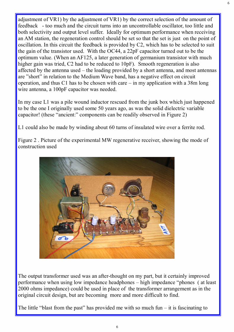
In my case L1 was a pile wound inductor rescued from the junk box which just happened
to be the one I originally used some 50 years ago, as was the solid dielectric variable
capacitor! (these “ancient:” components can be readily observed in Figure 2)
L1 could also be made by winding about 60 turns of insulated wire over a ferrite rod.
Figure 2 . Picture of the experimental MW regenerative receiver, showing the mode of
construction used
The output transformer used was an after-thought on my part, but it certainly improved
performance when using low impedance headphones – high impedance “phones ( at least
2000 ohms impedance) could be used in place of the transformer arrangement as in the
original circuit design, but are becoming more and more difficult to find.
The little “blast from the past” has provided me with so much fun – it is fascinating to

7
7
tune through the MW band, particularly at night when the D layer has disappeared, to see
just how many stations can be received. Things are of course quieter during the day when
I can only pick up three stations at decent volume. I have not found the use of a ground
connection necessary, but in some cases it could prove useful.
It is difficult to grasp how well a properly constructed simple regenerative receiver works
in practice until you’ve tried it out yourself. By the way they can also be made to work on
the HF bands and can form an integral part of your portable (QRP?) station. The only
difference when receiving SSB or CW signals is that the regeneration control is adjusted
so that the receiver is gently oscillating to provide the missing carrier needed for
demodulation. Definitely worth a try!
QRP Field Operations
Lessons learnt from the Kruger trip and many other field trips
Submitted by Dave, ZS6AZP
The following article has been extracted, with full permission of the author, from the blog
of Richard Hayter, ZS6RSH. I hope the reader will be as inspired by it as much as I was,
and also encouraged to get out of the shack and get operating from the open air!
Quoting from Richard’s blog: (the text in italics are not in Richard’s blog, but have been
added for clarification)
Herewith are some of the practical lessons learnt on the Kruger trip and other field
operations during my time in South Africa. (Richard, home call N4HAY, was in the RSA
on an extended work assignment for his USA based company, and has a home in North
Carolina). The observations pertain to the deployment of an end-fed wire halfwave(# 18
awg) and a counterpoise of 8ft 6 inches in length and the use of a tunable tank circuit as
the coupler.
These comments relate to a simple operation where the aim is to get on the air easily in
order to make local (South Africa wide) contacts and then to take down the system easily
and quickly after a day or two of operations. It is assumed that a minimum system has
been packed with very limited spares. In my case my whole station plus antenna and
accessories easily fitted into a plastic container the size of a shoe box. Pictures 1 and 2
show the extent of the radio related items taken into the field, while List 1 provides a
detailed description of each.

8
8
Picture 1: Items laid out for clarity
Picture 2 : Items packed in plastic container
List 1 : List of Equipment
Plastic food container
Norcal 40 A, 1.53 Watts output, QRP, 40m Rig (CW only!)
Granadilla Tin homebrew end fed half wave coupler
LED SWR Meter
Palm Paddles
66ft 4inches #16 AWG. 40m Halfwave antenna, with launch cord attached
8ft 6inch Counterpoise (1m = 39.37 inches, 12 inches to the foot for those who
have forgotten!)
Launch cord with 3 fishing weights attached

9
9
Spare cord (20ft)
2 x BNC barrel connectors
SLA Battery, 12V, 1.3Ah
SLA power cable and 2A fuse
Car Battery extension power cable
2 x 2A fuses
Keyline
Earphones
Leatherman
Mini Multimeter (Radio Shack)
Plastic tuning screw driver (for Granadilla Tin Tuner)
Pen
Paper
Operator ..........(fill in the blank)
For this type of deployment it is absolutely NOT necessary to try and get the wire up more
than 15 – 20ft in the air. Attempting to get it higher will almost guarantee difficulties in
the form of multiple launch attempts, tangled cord and wire, frustration, and if it goes
badly, the loss of the whole antenna system.
20 Practical Hints
Be very patient when unwinding the cord and antenna wire. The total length of my
40m system is 66ft of wire with a 60ft cord. If you get in a tangle then it can take
another 20 minutes to untangle it. I wind this up over one hand and turning the
wrap around every 10 winds or so to prevent it twisting. This can be easily
unwound by releasing each turn carefully. Once the cord and wire is lying on a nice
bare piece of ground (or a plastic ground sheet laid smoothly on the ground), make
certain that the coils are laid so that the end of the cord is at the “top of the pile”. It
will then uncoil during the launch without incident. Use slippery plastic (nylon?)
cord as found in the hardware store.
Make sure that the end of the wire that will connect to your radio is fixed before
launching. Preferably tied to a convenient tree branch about 8ft above the operating
position. Here I am assuming that the most likely deployment will be a sloper with
one end up about 8ft. Trust me it is no fun to watch the whole system end up in the
tree. Been there done that!
If an error is made in the launch and you need to retrieve the cord then disconnect the
weights before pulling the cord back through the tree. Do this every time and don’t
take a chance. The weights will hang (get stuck!).
Consider a spare set of detachable weights. The chances of hanging in a tree are
extremely high. The most likely is a situation where the weight and cord does not
drop to the ground after the launch. Now you are forced to retrieve the cord by
pulling it back through the tree. Often the weights will snag in the “Vee” of a

10
10
branch joint making it impossible to retrieve. A good strong cord is an asset in this
case because heavy pressure can be applied in an effort to dislodge the weight. (be
very careful – it could come back at you like a missile!)
Spend time and be patient in carefully selecting the tree to launch over. Preferably
launch over a tree as opposed to trying to select a specific branch. An ideal tree
would be about 25ft high. Select a tree that has smooth branches and few leaves as
possible. Do not select an Acacia thorn tree! Optimise the tree selection taking
into consideration the fact that you want to be QRV quickly, you want the weight to
drop to the ground and you want to be able to easily recover the wire and cord after
operation.
1.3Ah battery easily lasts a week provided it is in good working order. I had many
lengthy QSOs during this 5 day trip. This assumes the use of minimum power on
40m. In my experience it is easily possible to make regular QSOs throughout the
day on +500km path lengths using 1.5Watts output power maximum. See table
below
Try to get as much of the antenna up in the air and horizontal to the ground. Ideally
both ends at 20ft above ground between two trees. An inverted L with 46ft
horizontal and 20ft vertical. It is amazing how much this configuration improves
the signal strength. This is why I carry two cords. The same set of weights can be
used to deploy each cord.
Put some plastic putty over the joint between the cord and the antenna wire. This will
allow it to glide through the tree easier.
When laying the 8ft counterpoise along the ground be sure that it is not a safety hazard.
It is easy for people to trip over the wire.
Park away (pack away)the radio and accessories each time after use. Leaving it set up
is an invitation to the monkeys to pull the counterpoise and to try eating the battery.
Take a small portable plastic table. One of those small green ones. They pack easily in
the boot and allow the operating position to be set up comfortably under a tree. It
can also be moved as the sun position changes. See picture 3 below to get the
general idea
Battery and Rig Test Measurements
(Before and after 5 days operation)
Measurement Start of trip End of trip Battery Voltage Radio OFF 13.01V 12.3VBattery Voltage Radio ON 12.99V 12.22VBattery Voltage KEYDOWN 12.75V 11.92VCurrent RX 19.9mA 19.9mACurrent KEYDOWN 190mAPower Output 1.58W 1.4W
Notes: Measurements taken at 7020kHz with Keithly multimeter andAD8307 Power Meter using 36dB attenuator

11
11
Picture 3 : Typical operating position
Consider using a length of coax between the radio and the tuner to avoid RFI issues. I
certainly experienced RFI/common mode on this trip on one occasion when I had
the tuner directly connected to the radio. I believe the end of the wire and tuner
were too close to the radio.
Build the coupler with a link switch so that you can connect the coax/ground to the
counterpoise end of the secondary coil. Sometimes this will improve the match.
Sometimes it will cause RFI.
Make the coupler tunable with a small variable capacitor. The resonant point can
change by up to 30pF depending on deployment conditions.
If possible try to get the wire in the clear. However if it has to snake through the tree it
will still work fb (fine business – very good) and no problem.
If possible have a variable power output rig so that when conditions are good you can
reduce power and save battery. In South Africa the rig only needs to operate on a
single frequency of 7020kHz CW. A simple DC Rx can be used with RIT and an
attenuator. BCI is not an issue during daytime operations, however it is an issue
during early evening unfortunately.
Always carry a Leatherman or Swiss Army type knife. Preferably with one of those
spikes that used to be used for taking stones out of horse’s hooves. This spike can
be used to loosen tight knots. The knife blade is useful for cutting off snake’s heads
and for general defence.
Wear a hat and stay hydrated. Look after the XYL and the kids
Enjoy!

12
Birthdays
April 4th Pine ZS6GST
April 4th Duane ZS6PCM
April 6th Ray ZS6RSW
April 25th Johan ZS6BB
May 2nd Chris ZS6LOG
May 11th Linda ZR6AWV
May 20th Billy ZS6WPS
May 31st Gawie ZS6GJJ
Anniversaries
April 15th Rian ZS6RXY and Ilse
April 17th Andrew ZR6TUR and Marita
The Chairman, Committee and members of the Centurion Radio Amateur Club join
together in wishing you all a very HAPPY BIRTHDAY and congratulations on your
WEDDING ANNIVERSARY
Conclusion
One may wonder how successful Richard’s (“Dick” to all his CW friends!) QRP
operation, running some 1.5W output on 40m, from the Kruger Park was in practical
terms- well, he managed to have fb QSOs with the following stations, some more than
once:
ZS1JX, ZS1TTZ, ZS4SF, ZS6A, ZS6ADY, ZS6AJY, ZS6AQW, ZS6AZP, ZS6BK,
ZS6BNE, ZS6PTA (op. ZS6ALG)
In my opinion, a great success given the limited operation time Dick had in between game
drives etc and also considering how few CW operators there are left in ZS land! Time to
do something about it?
Appendix
Circuit diagram of the “Granadilla Tin Tuner”
Granadilla Tin Tuner
to EFHW antenna
to Counterpoise
30pf air spaced trimmer
100pf500V
T1
T1 : T50-2 toroidPri - 3 turnsSec – 28 turns
Coax to Rig
Related Documents


![ATA SEET STEALTH Concealment Solutions anel and ......AU = Omni antenna, unconcealed Varies with antenna FS = Radio module, InvisiWave concealment, short, active cooling 24 [27] FT](https://static.cupdf.com/doc/110x72/6095328721060171306f1703/ata-seet-stealth-concealment-solutions-anel-and-au-omni-antenna-unconcealed.jpg)


