Attachme ent H.1.1

Welcome message from author
This document is posted to help you gain knowledge. Please leave a comment to let me know what you think about it! Share it to your friends and learn new things together.
Transcript

Attachmeent H.1.1

T-15
T-13T-14
T-5T-3
T-1
T-10T-7
T-2
T-8 T-6
T-12 T-4
T-12
T-16
T-9 T-11
T-17 T-18T-19
T-20 T-21 T-23
T-22T-24

Attachmeent H.1.2
S-4S-8
S-17
S-15
S-12

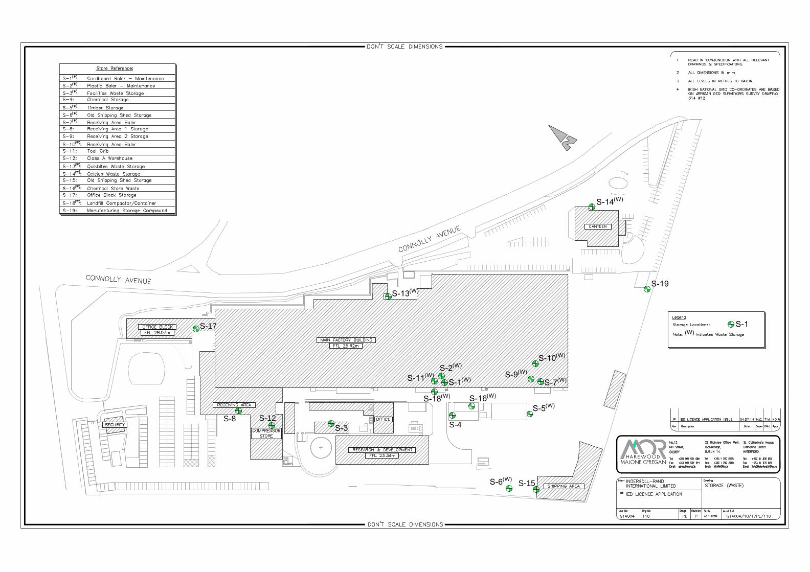
Attachmeent H.1.3
FB-10
FB-6
FB-5
FB-1
FB-12
FB-9 FB-8
FB-2
FB-7
FB-3
FB-2
FB-4FB-11
Legend
Bund Location Points:

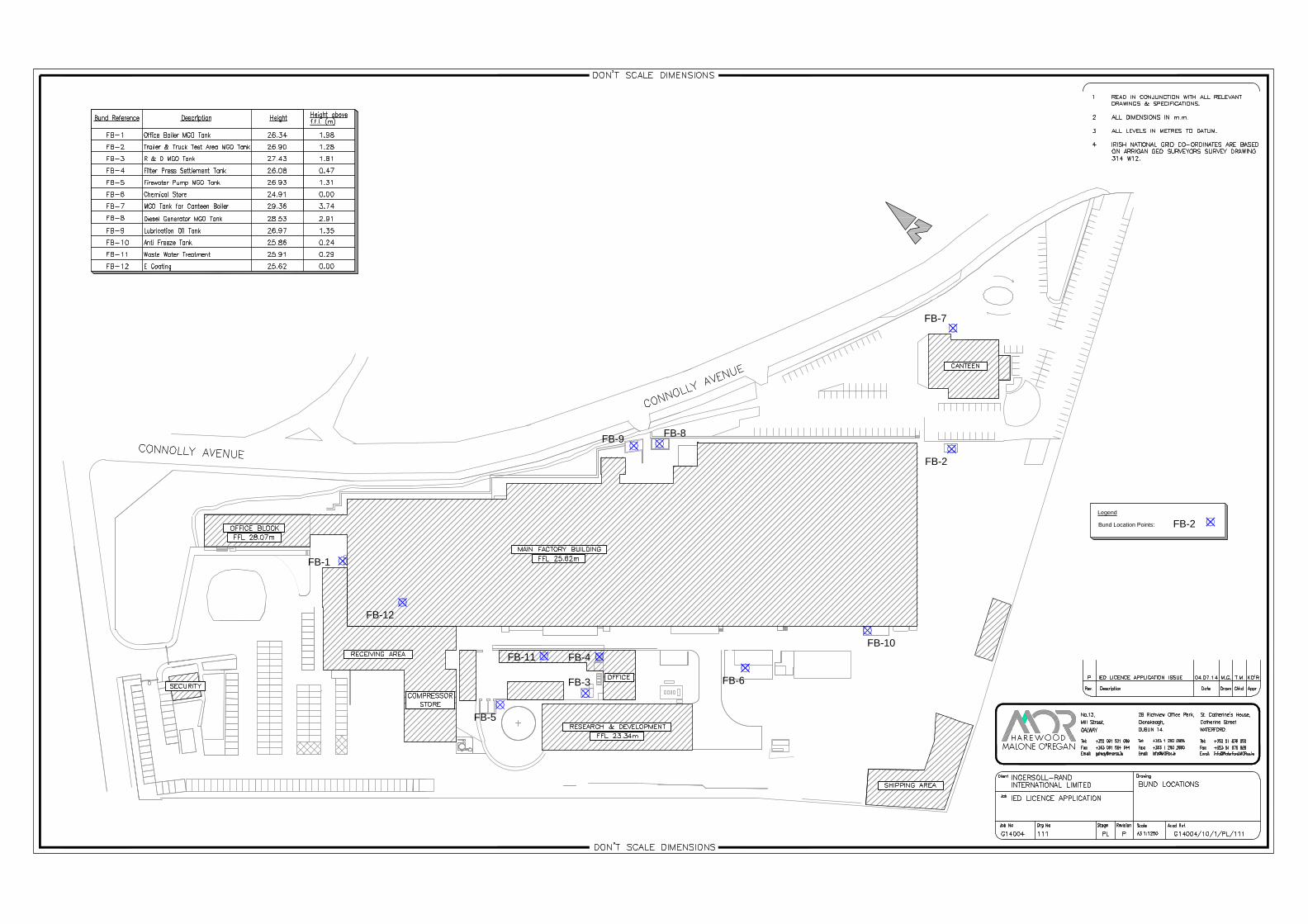
Attachmeent H.1.4
Ingersoll‐Rand International Limited IE Licence Application Attachment H.1.4
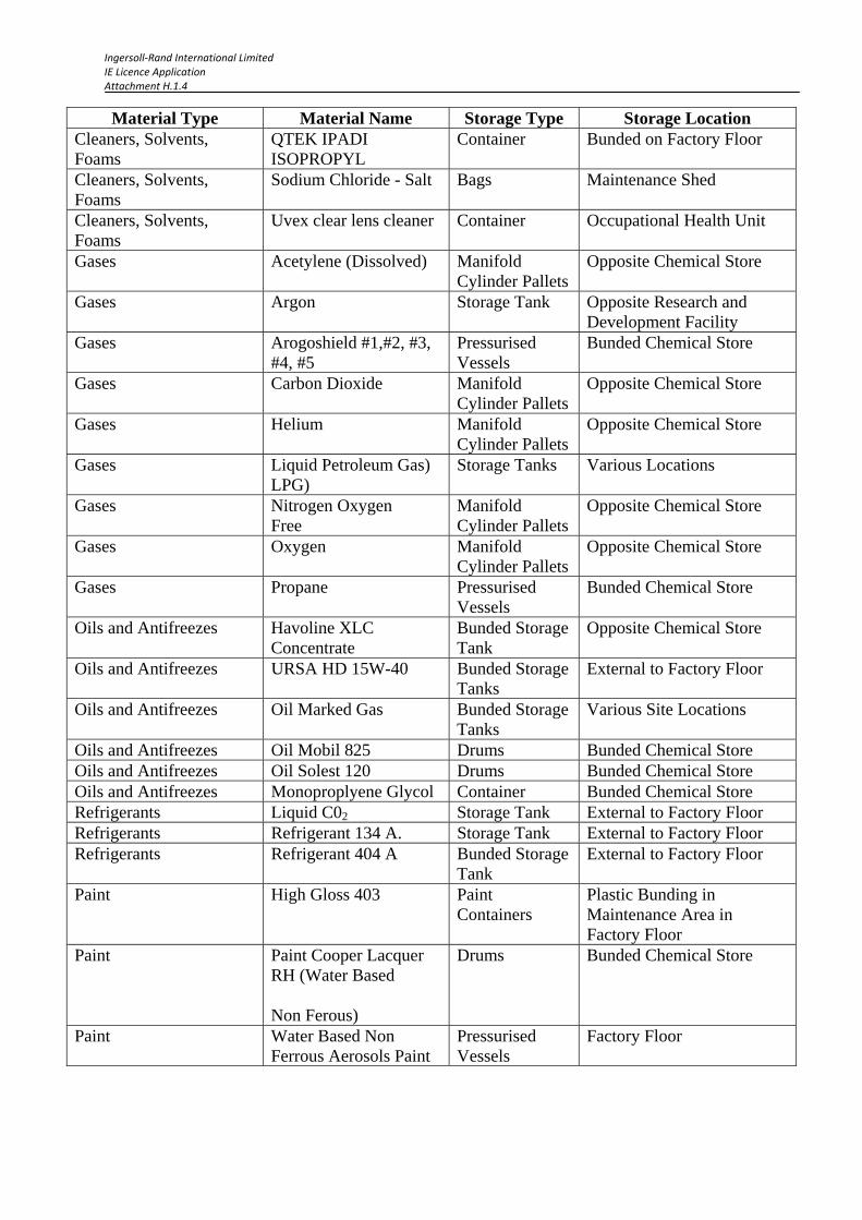
Details Of Storage Conditions in Each Location
Material Type Material Name Storage Type Storage Location Metals and Others Aluminium Racking Factory Floor Metals and Others Carbon Steel Racking Factory Floor Metals and Others Copper Racking Factory Floor Metals and Others Polymer fittings (hoses,
harnesses, fitted insulation)
Racking Factory Floor
Metals and Others Engines Racking Factory Floor Metals and Others Compressors Racking Factory Floor Metals and Others Hardware (various) Racking Factory Floor Chemicals Additive C IBCs Bunded Chemical Store Chemicals Auxilab 121 IBCs Bunded Chemical Store Chemicals Ferric Chloride IBCs Bunded Chemical Store Chemicals Gardobond r 2600a
IBCs Bunded Chemical Store
Chemicals Gardobond r 2604e IBCs Bunded Chemical Store Chemicals Gardobond_additive h
7004 IBCs/drums Bunded Chemical Store
Chemicals Gardoclean s 5174 IBCs/drums Bunded Chemical Store Chemicals Gardolene D6800 IBCs/drums Bunded Chemical Store Chemicals Gardobond additive
H7107 IBCs/drums Bunded Chemical Store
Chemicals Gardobond additive H7204
IBCs/drums Bunded Chemical Store
Chemicals Gardacid P4309 IBCs/drums Bunded Chemical Store Chemicals Hydrochloric Acid IBCs/drums Bunded Chemical Store Chemicals Coagulant C26 IBCs/drums Bunded Chemical Store Chemicals Gardolene V6513 IBCs/drums Bunded Chemical Store Chemicals Gardobond additive
H7141 IBCs/drums Bunded Chemical Store
Chemicals Biocide A-Z710021 IBCs/drums Bunded Chemical Store Cleaners, Solvents, Foams
Acetone (Cleaner) Drum Bunded Chemical Store
Cleaners, Solvents, Foams
Antifoam C Drum Bunded Chemical Store
Cleaners, Solvents, Foams
AVAL WSR Drum Bunded Chemical Store
Cleaners, Solvents, Foams
Foam (Isocyanates) Pressurised Tank
Factory Floor
Cleaners, Solvents, Foams
Foam (Polyol) Pressurised Tank
Factory Floor
Cleaners, Solvents, Foams
Isopropyl alcohol (Propan-2-01)
Drum Bunded Chemical Store
Material Type Material Name Storage Type Storage Location Cleaners, Solvents, Foams
Metaspray 5 (Tube Cleaner)
Container Factory Floor
Ingersoll‐Rand International Limited IE Licence Application Attachment H.1.4
Material Type Material Name Storage Type Storage Location Cleaners, Solvents, Foams
QTEK IPADI ISOPROPYL
Container Bunded on Factory Floor
Cleaners, Solvents, Foams
Sodium Chloride - Salt Bags Maintenance Shed
Cleaners, Solvents, Foams
Uvex clear lens cleaner Container Occupational Health Unit
Gases Acetylene (Dissolved) Manifold Cylinder Pallets
Opposite Chemical Store
Gases Argon Storage Tank Opposite Research and Development Facility
Gases Arogoshield #1,#2, #3, #4, #5
Pressurised Vessels
Bunded Chemical Store
Gases Carbon Dioxide Manifold Cylinder Pallets
Opposite Chemical Store
Gases Helium Manifold Cylinder Pallets
Opposite Chemical Store
Gases Liquid Petroleum Gas) LPG)
Storage Tanks Various Locations
Gases Nitrogen Oxygen Free
Manifold Cylinder Pallets
Opposite Chemical Store
Gases Oxygen Manifold Cylinder Pallets
Opposite Chemical Store
Gases Propane Pressurised Vessels
Bunded Chemical Store
Oils and Antifreezes Havoline XLC Concentrate
Bunded Storage Tank
Opposite Chemical Store
Oils and Antifreezes URSA HD 15W-40 Bunded Storage Tanks
External to Factory Floor
Oils and Antifreezes Oil Marked Gas Bunded Storage Tanks
Various Site Locations
Oils and Antifreezes Oil Mobil 825 Drums Bunded Chemical Store Oils and Antifreezes Oil Solest 120 Drums Bunded Chemical Store Oils and Antifreezes Monoproplyene Glycol Container Bunded Chemical Store Refrigerants Liquid C02 Storage Tank External to Factory Floor Refrigerants Refrigerant 134 A. Storage Tank External to Factory Floor Refrigerants Refrigerant 404 A Bunded Storage
Tank External to Factory Floor
Paint High Gloss 403 Paint Containers
Plastic Bunding in Maintenance Area in Factory Floor
Paint Paint Cooper Lacquer RH (Water Based Non Ferous)
Drums Bunded Chemical Store
Paint Water Based Non Ferrous Aerosols Paint
Pressurised Vessels
Factory Floor
Ingersoll‐Rand International Limited IE Licence Application Attachment H.1.4
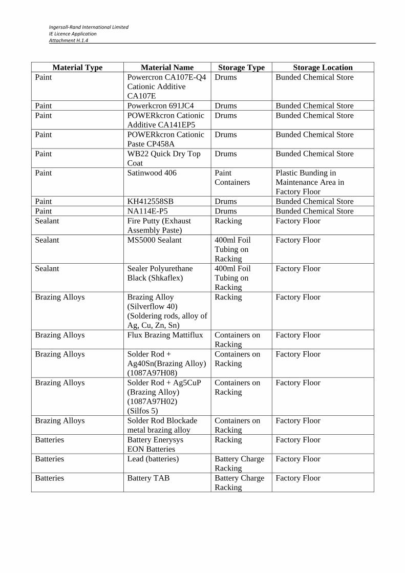
Material Type Material Name Storage Type Storage Location Paint Powercron CA107E-Q4
Cationic Additive CA107E
Drums Bunded Chemical Store
Paint Powerkcron 691JC4 Drums Bunded Chemical Store Paint POWERkcron Cationic
Additive CA141EP5 Drums Bunded Chemical Store
Paint POWERkcron Cationic Paste CP458A
Drums Bunded Chemical Store
Paint WB22 Quick Dry Top Coat
Drums Bunded Chemical Store
Paint Satinwood 406 Paint Containers
Plastic Bunding in Maintenance Area in Factory Floor
Paint KH412558SB Drums Bunded Chemical Store Paint NA114E-P5 Drums Bunded Chemical Store Sealant Fire Putty (Exhaust
Assembly Paste) Racking Factory Floor
Sealant MS5000 Sealant 400ml Foil Tubing on Racking
Factory Floor
Sealant Sealer Polyurethane Black (Shkaflex)
400ml Foil Tubing on Racking
Factory Floor
Brazing Alloys Brazing Alloy (Silverflow 40) (Soldering rods, alloy of Ag, Cu, Zn, Sn)
Racking Factory Floor
Brazing Alloys Flux Brazing Mattiflux Containers on Racking
Factory Floor
Brazing Alloys Solder Rod + Ag40Sn(Brazing Alloy) (1087A97H08)
Containers on Racking
Factory Floor
Brazing Alloys Solder Rod + Ag5CuP (Brazing Alloy) (1087A97H02) (Silfos 5)
Containers on Racking
Factory Floor
Brazing Alloys Solder Rod Blockade metal brazing alloy
Containers on Racking
Factory Floor
Batteries Battery Enerysys EON Batteries
Racking Factory Floor
Batteries Lead (batteries) Battery Charge Racking
Factory Floor
Batteries Battery TAB Battery Charge Racking
Factory Floor

Ingersoll‐Rand International Limited IE Licence Application Attachment H.1.4
Material Type Material Name Storage Type Storage Location Adhesives Butyl Strip Racking Factory Floor Adhesives Glue (Super) 3M Scotch grip Racking Factory Floor Miscellaneous Flux Liquid Containers Plastic Bunding on
Factory Floor Miscellaneous Flux Stay Clean Soldering
Fluxes Containers Plastic Bunding on
Factory Floor Miscellaneous Foam - Small Container UK
FP 600 A side NDT 1340 Foam
Pressurised Vessels
Bunded Chemical Store
Miscellaneous Foam - Small Container UK FP 600 B Comp CF 20 Foam
Pressurised Vessels
Bunded Chemical Store
Miscellaneous Loctite 277 Containers Plastic Bunding on Factory Floor
Miscellaneous Loctite 767 Aluminium Antiseize paste
Containers Plastic Bunding on Factory Floor
Miscellaneous Oil Mobil 1330 IBCs/Drums Bunded Chemical Store Miscellaneous PRO SHIELD 661 additive
e-coat IBCs/Drums Bunded Chemical Store
Miscellaneous Robotic Welding 300 kg Rolls (Carbofil)
Racking Factory Floor
Miscellaneous Sodium Bicarbonate (Bread-soda)
Containers Plastic Bunding on Factory Floor
Miscellaneous Welding wire : OK Autrod 12.51
Racking Factory Floor
Miscellaneous Welding Anti Spatter (Silicon Free )
Containers Plastic Bunding on Factory Floor
Laboratory LCK 350 Phosphat/Phosphate,
Curvettes/ Lab Containers
Laboratory
Laboratory LCK 311 Chlorid/Chloride/Chlorure
Curvettes/ Lab Containers
Laboratory
Laboratory LCK153 Sulfat/Sulphate/Sulfate
Curvettes/ Lab Containers
Laboratory
Laboratory LCK 337 Nickel Curvettes/ Lab Containers
Laboratory
Laboratory LCK360 Zinc Curvettes/ Lab Containers
Laboratory
Laboratory 21058-69 CuVer 1 Copper Reagent
Curvettes/ Lab Containers
Laboratory
Laboratory Conductivity Standard 84μS/cm
Curvettes/ Lab Containers
Laboratory
Laboratory Conductivity Standard 100μS/cm
Curvettes/ Lab Containers
Laboratory
Laboratory Conductivity Standard 500μS/cm
Curvettes/ Lab Containers
Laboratory
Ingersoll‐Rand International Limited IE Licence Application Attachment H.1.4
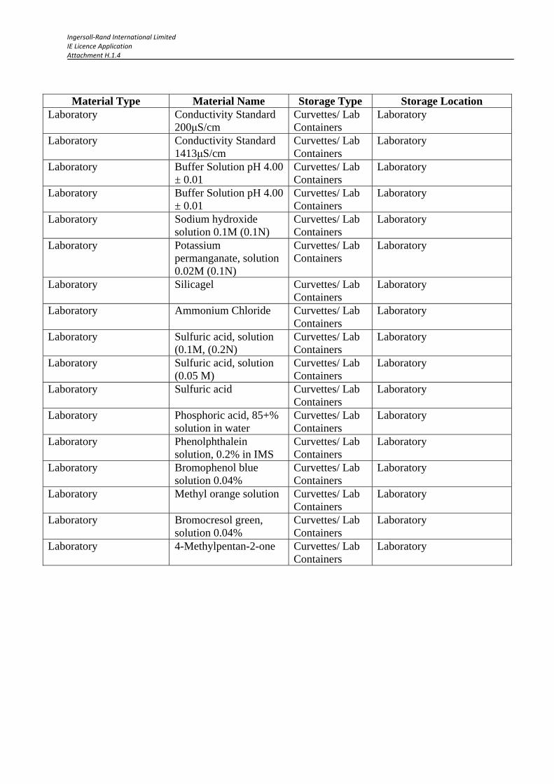
Material Type Material Name Storage Type Storage Location Laboratory Conductivity Standard
200μS/cm Curvettes/ Lab Containers
Laboratory
Laboratory Conductivity Standard 1413μS/cm
Curvettes/ Lab Containers
Laboratory
Laboratory Buffer Solution pH 4.00 ± 0.01
Curvettes/ Lab Containers
Laboratory
Laboratory Buffer Solution pH 4.00 ± 0.01
Curvettes/ Lab Containers
Laboratory
Laboratory Sodium hydroxide solution 0.1M (0.1N)
Curvettes/ Lab Containers
Laboratory
Laboratory Potassium permanganate, solution 0.02M (0.1N)
Curvettes/ Lab Containers
Laboratory
Laboratory Silicagel Curvettes/ Lab Containers
Laboratory
Laboratory Ammonium Chloride Curvettes/ Lab Containers
Laboratory
Laboratory Sulfuric acid, solution (0.1M, (0.2N)
Curvettes/ Lab Containers
Laboratory
Laboratory Sulfuric acid, solution (0.05 M)
Curvettes/ Lab Containers
Laboratory
Laboratory Sulfuric acid Curvettes/ Lab Containers
Laboratory
Laboratory Phosphoric acid, 85+% solution in water
Curvettes/ Lab Containers
Laboratory
Laboratory Phenolphthalein solution, 0.2% in IMS
Curvettes/ Lab Containers
Laboratory
Laboratory Bromophenol blue solution 0.04%
Curvettes/ Lab Containers
Laboratory
Laboratory Methyl orange solution Curvettes/ Lab Containers
Laboratory
Laboratory Bromocresol green, solution 0.04%
Curvettes/ Lab Containers
Laboratory
Laboratory 4-Methylpentan-2-one Curvettes/ Lab Containers
Laboratory

Attachmment H.2

Monitoring and Control of Disposal of Waste
Hazardous Waste
list
Doc No. EV01
Rev. J
Objective: To ensure that all waste is
removed off site in a manner which is
compliant with environmental
regulations
Measure: Environmental Business
Scorecard
Scorecard: yes
Dispose of waste in
specified container or
bunded drum, clearly
labelled to confirm
contents of waste.
Organise collection
using licensed waste
contractor
Non Hazardous
Waste: cardboard,
plastic,
paper,timber,landfill,
metal and other
recyclable material
Recyclable
(For Bailing)
Dispose of in designated
recycling bins
Move to Baler
Move to collection point
for recycled waste.
Organise collection
using licensed waste
contractor as per
contract
Recyclable
(unbaled)
EPA European
hazardous waste list
reviewed yearly
(EWC Codes)
Ensure that SDS is in
place (See process
EV08)
Review disposal process
in line with requirements
of SDS
Train relevant personnel
(how to use,risks,
controls, requirements
for PPE and disposal)
Batteries: Send batteries
to Haz. Waste Room in
Chemical Store and put
in spill proof container.
Batteries are prepared
for removal by approved
outside contractor
Obtain relevant Waste
Transfer documentation
Containers collected by
approved contractor.
Move to designated
bin in storage area
Arrange
collection by
licensed
contractor as
required
Transfer waste to the
inside of the chemical
store
Confirm with
Environmental
personnel what
hazardous waste can be
shipped monthly
Hazardous and Non Hazardous waste:
Record waste quantities and other relevant details in the "waste Management record"
file, F/private/Environment/IR MEHS requirements/ Waste Management
Operator
Chemical store operator
Recycling Operator
EH&S Personnel
Non
Recyclable(Landfill)
Non recyclable materials to
be disposed of in landfill
bins. Colour Black
Material to be transferred to
compactor area and
disposed in compactor
Only Non-Recyclable
materials are to be disposed
in compactor.
No paper, plastic,
cardboard, timber.
Compactor to be locked
when not in use.
Key with security if
required.
Office Areas
Wastepaper & plastic to be
disposed in recycling bins
(green stations)
Cardboard to be disposed in
recycling bin in production
area
Non-recyclable materials &
waste food to be disposed in
landfill bins in kitchen areas.
1. Hazardous Waste Locations
1. Beside Spray Booth
2.In rework area
3. Truck charging area
4. Truck Varnish
5. Truck Assembly
Truck Assembly:
1. Trailer Test & start of
trailer line
Trailer Assembly:
Endurance AreaR&D:
Batteries to be stored in a
spill proof bund
Batteries:
2. Types of Drums
Dispose in designated green
bins labelled “Hazardous Waste”
only
When printed this map is an uncontrolled copy. For controlled soft copy see TK Galway Business Process Sharepoint.
Hazardous Waste:
Lights,absorbant
material,filter cake,filters,
batteries, medical waste,
oil & containers
Reference:
EHS 201 POLLUTION PREVENTION
EHS 208 WASTE MANAGEMENT
EHS 209 HAZARDOUS SUBSTANCES MANAGEMENT
ENV-F-29 WASTE STREAMS
GALWAY EH 207 LAND POLLUTION CONTROL
Office personnel
Obtain relevant Waste
Transfer documentation

Attachmeent H.3.1

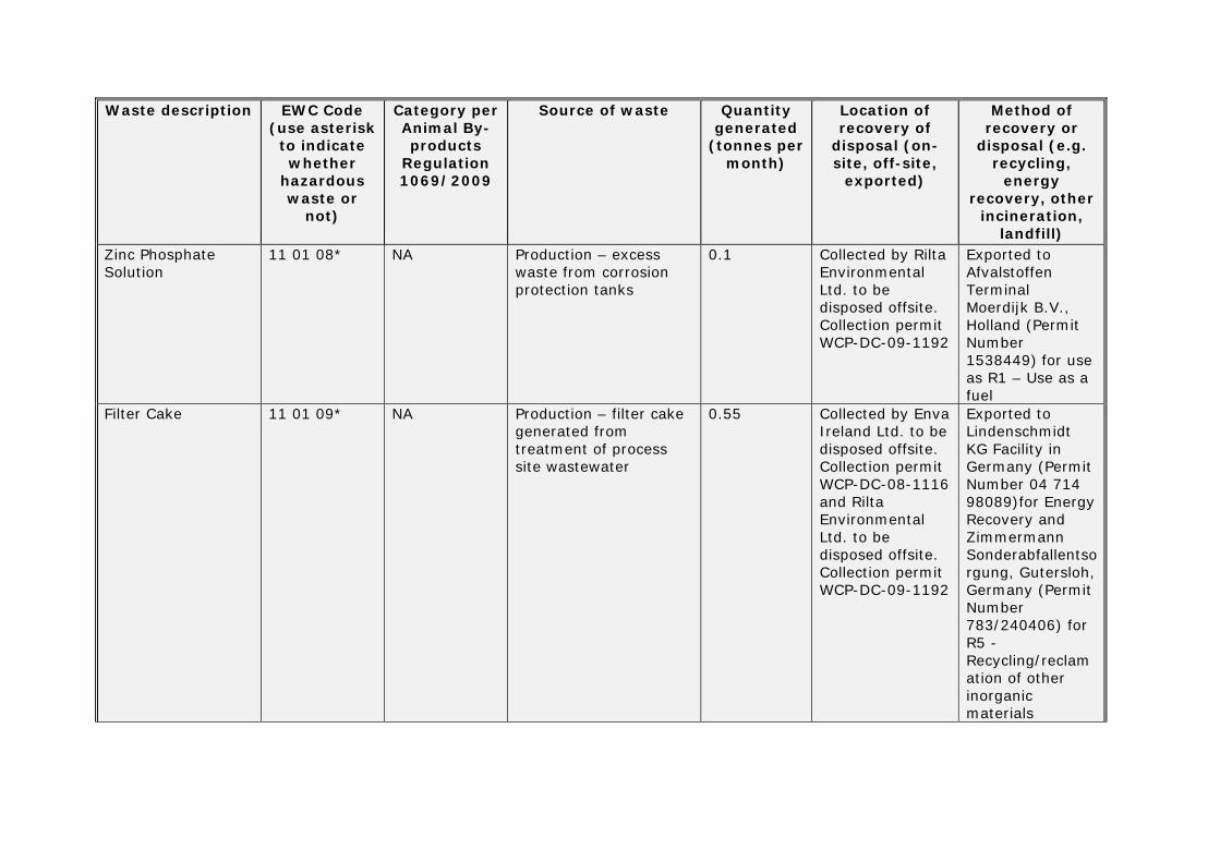
TABLE H.3(i): Generation of waste at the installation and its management Waste description EWC Code
(use asterisk to indicate whether
hazardous waste or
not)
Category per Animal By-products
Regulation 1069/2009
Source of waste Quantitygenerated
(tonnes per month)
Location of recovery of
disposal (on-site, off-site,
exported)
Method of recovery or
disposal (e.g. recycling,
energy recovery, other
incineration, landfill)
Less than 10% Solution of Sulphuric Acid and Phosphoric Acid
06 01 06* NA Production – excess acid from descaling of corrosion protection tanks
0.2 Collected by Rilta Environmental Ltd. to be disposed offsite. Collection permit WCP-DC-09-1192
Exported to Revatech SA, Engis, Belgium for use as R6 – Regeneration of acids/bases (Permit Number D31 B311/7412/ DG/MV)
Mixture of Paints 08 01 11* NA Production – excess paint from ECoating process
0.5 Collected by Enva Ireland Ltd. to be disposed offsite. Collection permit WCP-DC-08-1116 and Rilta Environmental Ltd. to be disposed offsite. Collection permit WCP-DC-09-1192
Exported to Lindenschmidt KG Facility in Germany (Permit Number 04 714 98089) and Afvalstoffen Terminal Moerdijk B.V., Holland (Permit Number 1538449) for use as R1 – Use as a fuel
Waste description EWC Code (use asterisk
to indicate whether
hazardous waste or
not)
Category per Animal By-products
Regulation 1069/2009
Source of waste Quantitygenerated
(tonnes per month)
Location of recovery of
disposal (on-site, off-site,
exported)
Method of recovery or
disposal (e.g. recycling,
energy recovery, other
incineration, landfill)
Zinc Phosphate Solution
11 01 08* NA Production – excess waste from corrosion protection tanks
0.1 Collected by Rilta Environmental Ltd. to be disposed offsite. Collection permit WCP-DC-09-1192
Exported to Afvalstoffen Terminal Moerdijk B.V., Holland (Permit Number 1538449) for use as R1 – Use as a fuel
Filter Cake 11 01 09* NA Production – filter cake generated from treatment of process site wastewater
0.55 Collected by Enva Ireland Ltd. to be disposed offsite. Collection permit WCP-DC-08-1116 and Rilta Environmental Ltd. to be disposed offsite. Collection permit WCP-DC-09-1192
Exported to Lindenschmidt KG Facility in Germany (Permit Number 04 714 98089)for Energy Recovery and Zimmermann Sonderabfallentsorgung, Gutersloh, Germany (Permit Number 783/240406) for R5 - Recycling/reclamation of other inorganic materials
Waste description EWC Code (use asterisk
to indicate whether
hazardous waste or
not)
Category per Animal By-products
Regulation 1069/2009
Source of waste Quantitygenerated
(tonnes per month)
Location of recovery of
disposal (on-site, off-site,
exported)
Method of recovery or
disposal (e.g. recycling,
energy recovery, other
incineration, landfill)
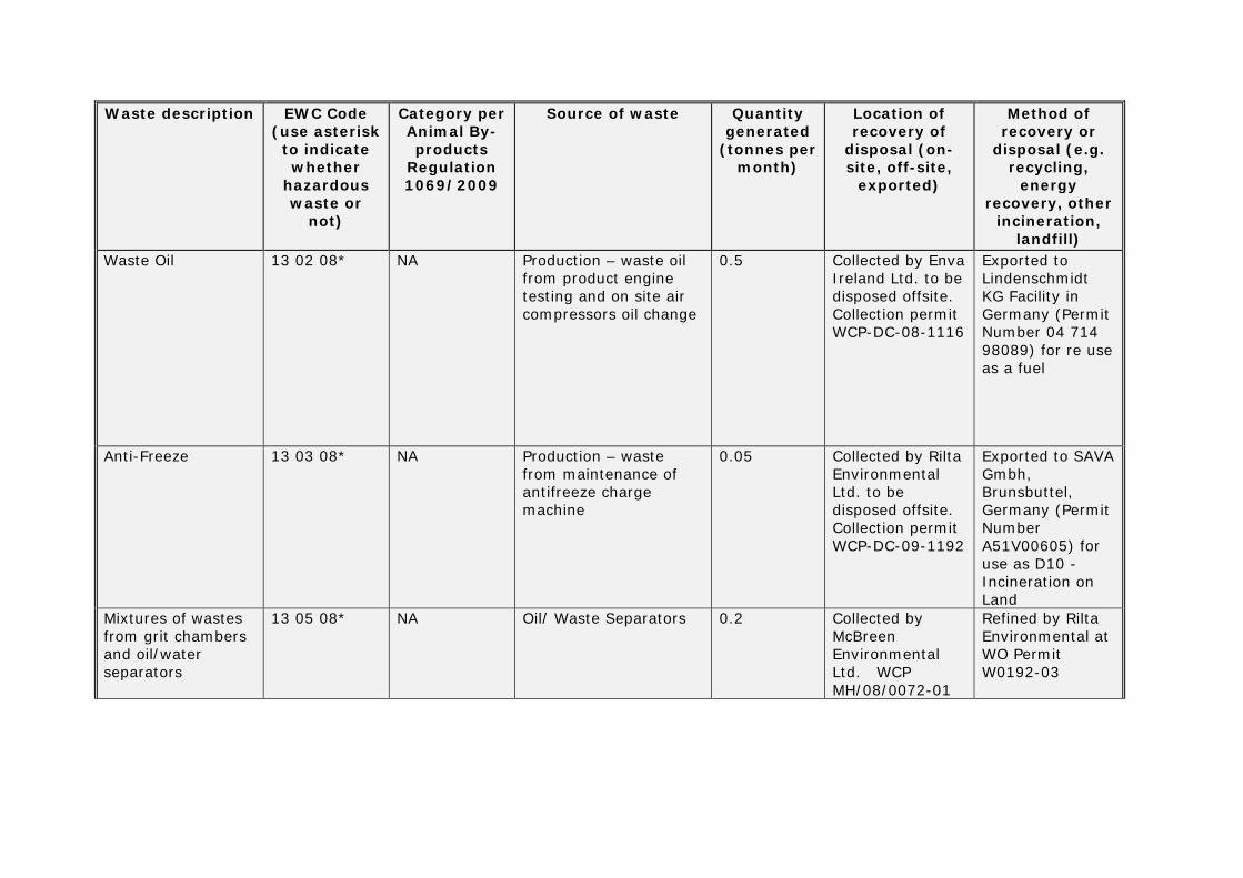
Waste Oil 13 02 08* NA Production – waste oil from product engine testing and on site air compressors oil change
0.5 Collected by Enva Ireland Ltd. to be disposed offsite. Collection permit WCP-DC-08-1116
Exported to Lindenschmidt KG Facility in Germany (Permit Number 04 714 98089) for re use as a fuel
Anti-Freeze 13 03 08* NA Production – waste from maintenance of antifreeze charge machine
0.05 Collected by Rilta Environmental Ltd. to be disposed offsite. Collection permit WCP-DC-09-1192
Exported to SAVA Gmbh, Brunsbuttel, Germany (Permit Number A51V00605) for use as D10 - Incineration on Land
Mixtures of wastes from grit chambers and oil/water separators
13 05 08* NA Oil/ Waste Separators 0.2 Collected by McBreen Environmental Ltd. WCP MH/08/0072-01
Refined by Rilta Environmental at WO Permit W0192-03

Waste description EWC Code (use asterisk
to indicate whether
hazardous waste or
not)
Category per Animal By-products
Regulation 1069/2009
Source of waste Quantitygenerated (tonnes
per month)
Location of recovery of
disposal (on-site, off-site, exported)
Method of recovery or
disposal (e.g. recycling,
energy recovery, other
incineration, landfill)
Antifreeze 13 03 08* NA Production – waste from maintenance of antifreeze charge machine
0.05 Collected by Enva Ireland Ltd. to be disposed offsite. Collection permit WCP-DC-08-1116 and Rilta Environmental Ltd. to be disposed offsite. Collection permit WCP-DC-09-1192
Processed by Enva Ireland Ltd at W0184-03 and Rilta Environmental at W0192-03
Empty adhesive containers in 205ltr drum, non-regulated
15 01 10* NA Production - soldering departments.
0.05 Collected by Enva Ireland Ltd. to be disposed offsite. Collection permit WCP-DC-08-1116 and Rilta Environmental Ltd. to be disposed offsite.
Processed by Enva Ireland Ltd at W0184-03 and Rilta Environmental at W0192-03
Collected (WASTE,UN 3175 SOLIDS CONTAINING FLAMMABLE LIQUID (SOLID OILY WASTE) ,4.1,ADR,II, UN DRUM)
15 02 02* NA Production - varnish booths, clean up of oil drips.
0.07 Collected by Enva Ireland Ltd. to be disposed offsite. Collection permit WCP-DC-08-1116
Exported to Lindenschmidt KG Facility in Germany (Permit Number 04 714 98089) for re use as a fuel

Waste description EWC Code (use asterisk
to indicate whether
hazardous waste or
not)
Category per Animal By-products
Regulation 1069/2009
Source of waste Quantitygenerated
(tonnes per month)
Location of recovery of
disposal (on-site, off-site,
exported)
Method of recovery or
disposal (e.g. recycling,
energy recovery, other
incineration, landfill)
Empty adhesive containers in 205ltr drum, non-regulated
15 01 10* NA Production - soldering departments.
0.05 Collected by Enva Ireland Ltd. to be disposed offsite. Collection permit WCP-DC-08-1116 and Rilta Environmental Ltd. to be disposed offsite. Collection permit WCP-DC-09-1192
Exported to Lindenschmidt KG Facility in Germany (Permit Number 04 714 98089) for re use as a fuel
Collected (WASTE,UN 3175 SOLIDS CONTAINING FLAMMABLE LIQUID (SOLID OILY WASTE) ,4.1,ADR,II, UN DRUM)
15 02 02* NA Production - varnish booths, clean up of oil drips.
0.07 Collected by Enva Ireland Ltd. to be disposed offsite. Collection permit WCP-DC-08-1116
Exported to Lindenschmidt KG Facility in Germany (Permit Number 04 714 98089) for re use as a fuel
Waste description EWC Code (use asterisk
to indicate whether
hazardous waste or
not)
Category per Animal By-products
Regulation 1069/2009
Source of waste Quantitygenerated
(tonnes per month)
Location of recovery of
disposal (on-site, off-site,
exported)
Method of recovery or
disposal (e.g. recycling,
energy recovery, other
incineration, landfill)
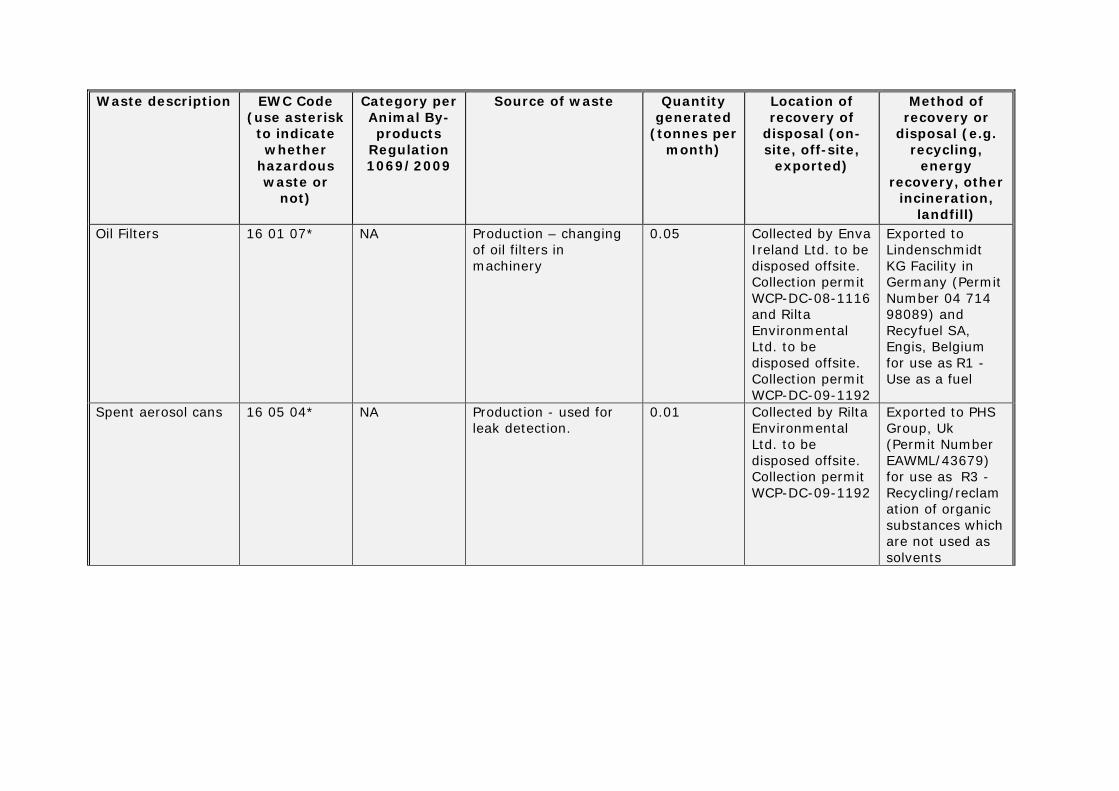
Oil Filters 16 01 07* NA Production – changing of oil filters in machinery
0.05 Collected by Enva Ireland Ltd. to be disposed offsite. Collection permit WCP-DC-08-1116 and Rilta Environmental Ltd. to be disposed offsite. Collection permit WCP-DC-09-1192
Exported to Lindenschmidt KG Facility in Germany (Permit Number 04 714 98089) and Recyfuel SA, Engis, Belgium for use as R1 - Use as a fuel
Spent aerosol cans 16 05 04* NA Production - used for leak detection.
0.01 Collected by Rilta Environmental Ltd. to be disposed offsite. Collection permit WCP-DC-09-1192
Exported to PHS Group, Uk (Permit Number EAWML/43679) for use as R3 - Recycling/reclamation of organic substances which are not used as solvents
Waste description EWC Code (use asterisk
to indicate whether
hazardous waste or not)
Category per Animal By-products
Regulation 1069/2009
Source of waste Quantitygenerated
(tonnes per month)
Location of recovery of
disposal (on-site, off-site,
exported)
Method of recovery or
disposal (e.g. recycling, energy recovery, other
incineration, landfill)
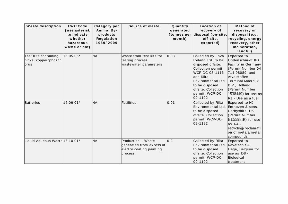
Test Kits containing nickel/copper/phosphorus
16 05 06* NA Waste from test kits for testing process wastewater parameters
0.03 Collected by Enva Ireland Ltd. to be disposed offsite. Collection permit WCP-DC-08-1116 and Rilta Environmental Ltd. to be disposed offsite. Collection permit WCP-DC-09-1192
Exported to Lindenschmidt KG Facility in Germany (Permit Number 04 714 98089 and Afvalstoffen Terminal Moerdijk B.V., Holland (Permit Number 1538449) for use as R1 - Use as a fuel
Batteries 16 06 01* NA Facilities 0.01 Collected by Rilta Environmental Ltd. to be disposed offsite. Collection permit WCP-DC-09-1192
Exported to HJ Enthoven & sons, Derbyshire, UK (Permit Number BL5598IR) for use as R4 - recycling/reclamation of metals/metal compounds
Liquid Aqueous Waste 16 10 01* NA Production – Waste generated from excess of electro coating painting process
0.2 Collected by Rilta Environmental Ltd. to be disposed offsite. Collection permit WCP-DC-09-1192
Exported to Revatech SA, Liege, Belgium for use as D8 - Biological treatment
Waste description EWC Code (use asterisk
to indicate whether
hazardous waste or
not)
Category per Animal By-products
Regulation 1069/2009
Source of waste Quantitygenerated (tonnes
per month)
Location of recovery of
disposal (on-site, off-site,
exported)
Method of recovery or
disposal (e.g. recycling,
energy recovery, other
incineration, landfill)
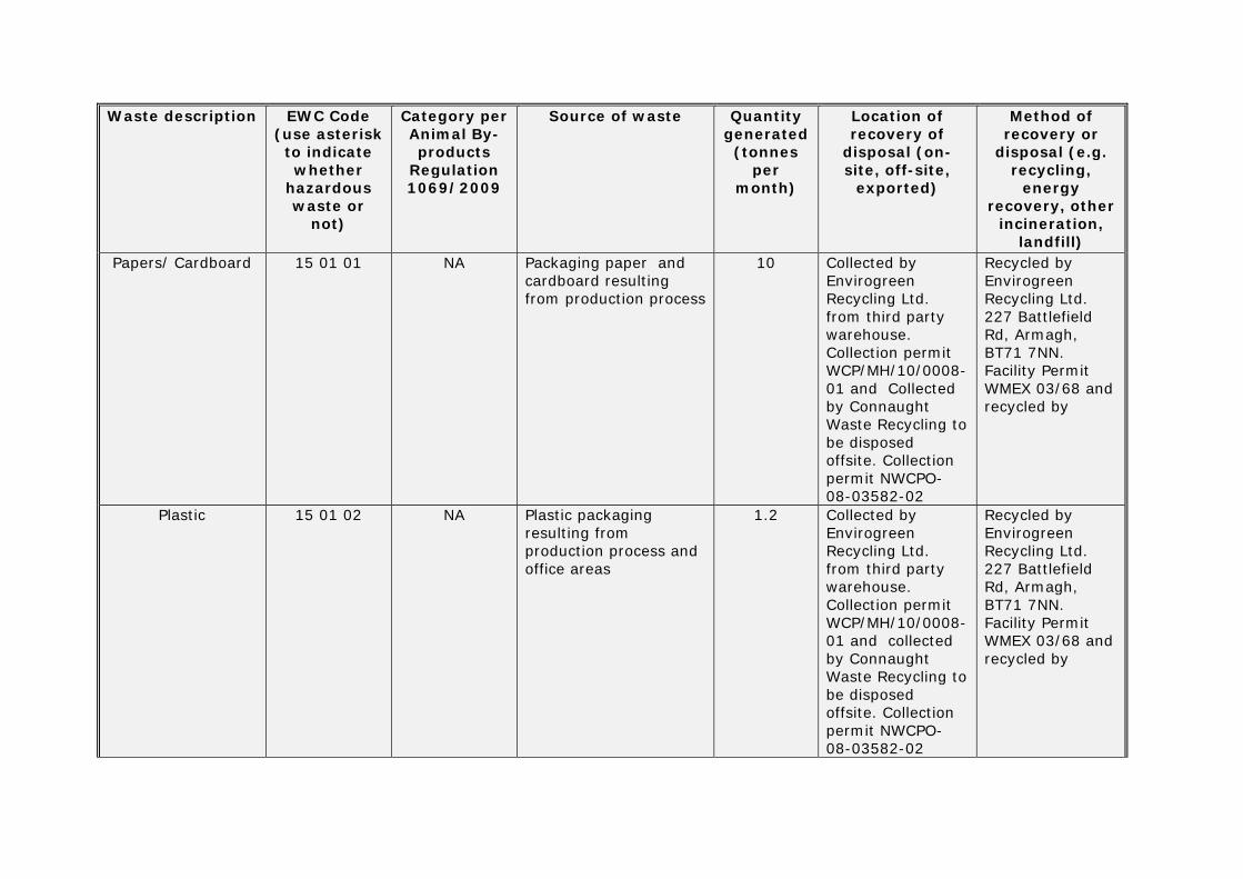
Papers/ Cardboard 15 01 01 NA Packaging paper and cardboard resulting from production process
10 Collected by Envirogreen Recycling Ltd. from third party warehouse. Collection permit WCP/MH/10/0008-01 and Collected by Connaught Waste Recycling to be disposed offsite. Collection permit NWCPO-08-03582-02
Recycled by Envirogreen Recycling Ltd. 227 Battlefield Rd, Armagh, BT71 7NN. Facility Permit WMEX 03/68 and recycled by
Plastic 15 01 02 NA Plastic packaging resulting from production process and office areas
1.2 Collected by Envirogreen Recycling Ltd. from third party warehouse. Collection permit WCP/MH/10/0008-01 and collected by Connaught Waste Recycling to be disposed offsite. Collection permit NWCPO-08-03582-02
Recycled by Envirogreen Recycling Ltd. 227 Battlefield Rd, Armagh, BT71 7NN. Facility Permit WMEX 03/68 and recycled by
Waste description EWC Code (use asterisk
to indicate whether
hazardous waste or
not)
Category per Animal By-products
Regulation 1069/2009
Source of waste Quantitygenerated
(tonnes per month)
Location of recovery of
disposal (on-site, off-site,
exported)
Method of recovery or
disposal (e.g. recycling,
energy recovery, other
incineration, landfill)
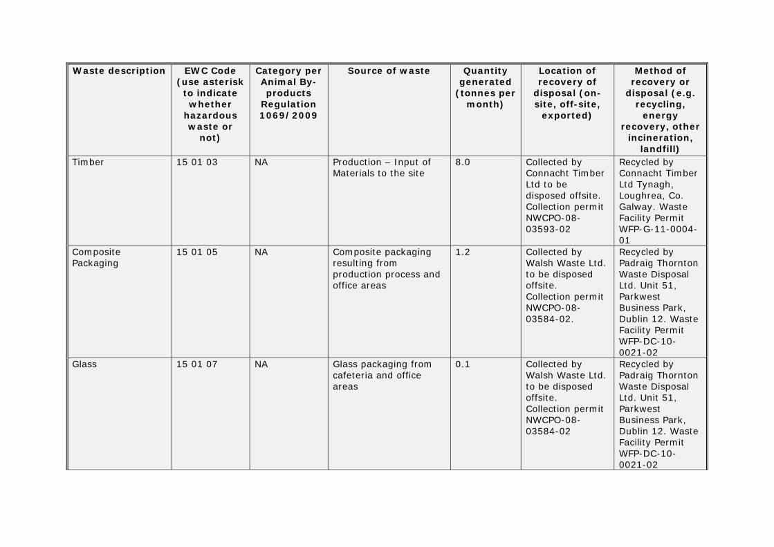
Timber 15 01 03 NA Production – Input of Materials to the site
8.0 Collected by Connacht Timber Ltd to be disposed offsite. Collection permit NWCPO-08-03593-02
Recycled by Connacht Timber Ltd Tynagh, Loughrea, Co. Galway. Waste Facility Permit WFP-G-11-0004-01
Composite Packaging
15 01 05 NA Composite packaging resulting from production process and office areas
1.2 Collected by Walsh Waste Ltd. to be disposed offsite. Collection permit NWCPO-08-03584-02.
Recycled by Padraig Thornton Waste Disposal Ltd. Unit 51, Parkwest Business Park, Dublin 12. Waste Facility Permit WFP-DC-10-0021-02
Glass 15 01 07 NA Glass packaging from cafeteria and office areas
0.1 Collected by Walsh Waste Ltd. to be disposed offsite. Collection permit NWCPO-08-03584-02
Recycled by Padraig Thornton Waste Disposal Ltd. Unit 51, Parkwest Business Park, Dublin 12. Waste Facility Permit WFP-DC-10-0021-02
Waste description EWC Code
(use asterisk to indicate whether
hazardous waste or
not)
Category per Animal
By-products
Regulation 1069/2009
Source of waste Quantitygenerated (tonnes
per month)
Location of recovery of
disposal (on-site, off-site,
exported)
Method of recovery or disposal (e.g. recycling, energy recovery, other
incineration, landfill)
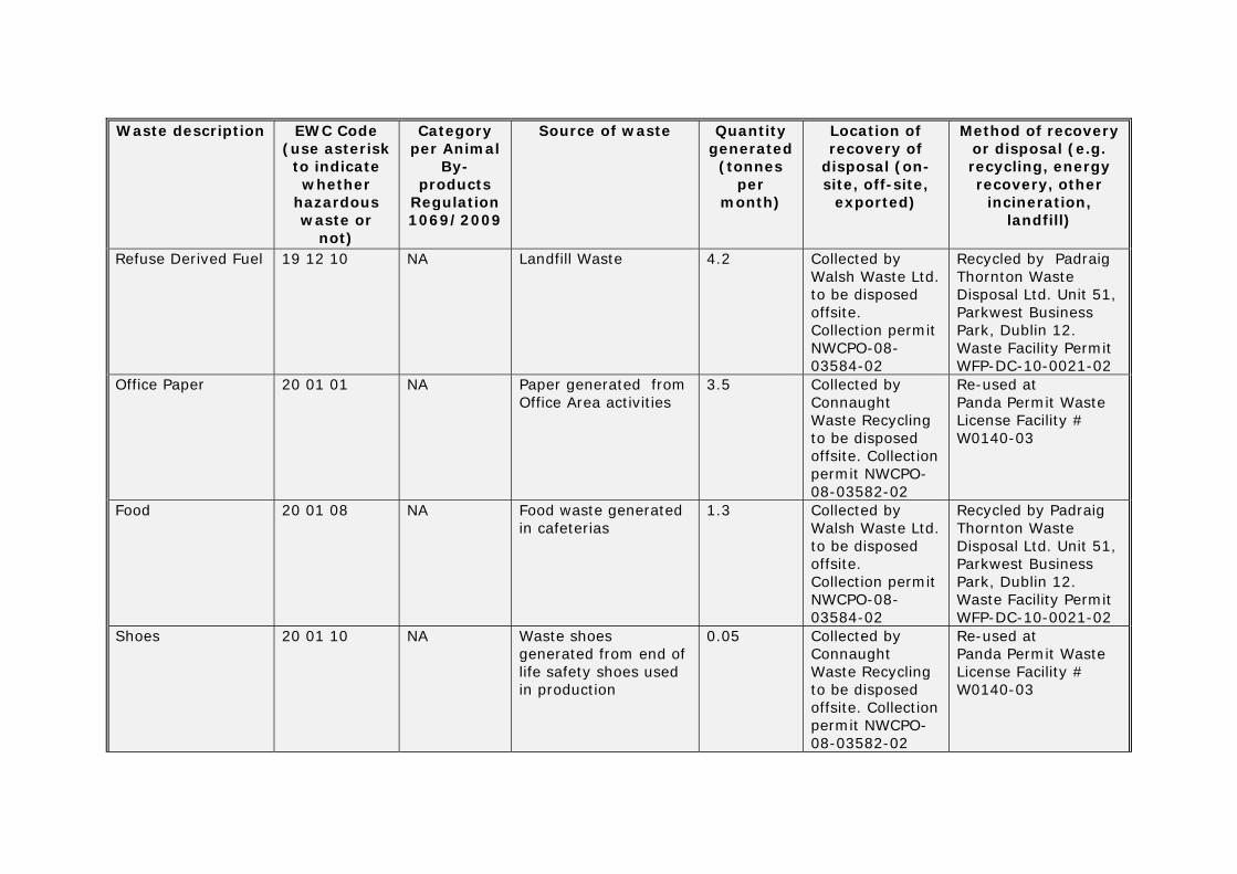
Refuse Derived Fuel 19 12 10 NA Landfill Waste 4.2 Collected by Walsh Waste Ltd. to be disposed offsite. Collection permit NWCPO-08-03584-02
Recycled by Padraig Thornton Waste Disposal Ltd. Unit 51, Parkwest Business Park, Dublin 12. Waste Facility Permit WFP-DC-10-0021-02
Office Paper 20 01 01 NA Paper generated from Office Area activities
3.5 Collected by Connaught Waste Recycling to be disposed offsite. Collection permit NWCPO-08-03582-02
Re-used at Panda Permit Waste License Facility # W0140-03
Food 20 01 08 NA Food waste generated in cafeterias
1.3 Collected by Walsh Waste Ltd. to be disposed offsite. Collection permit NWCPO-08-03584-02
Recycled by Padraig Thornton Waste Disposal Ltd. Unit 51, Parkwest Business Park, Dublin 12. Waste Facility Permit WFP-DC-10-0021-02
Shoes 20 01 10 NA Waste shoes generated from end of life safety shoes used in production
0.05 Collected by Connaught Waste Recycling to be disposed offsite. Collection permit NWCPO-08-03582-02
Re-used at Panda Permit Waste License Facility # W0140-03

Waste description
EWC Code (use asterisk
to indicate whether
hazardous waste or
not)
Category per Animal By-products
Regulation 1069/2009
Source of waste Quantitygenerated
(tonnes per month)
Location of recovery of
disposal (on-site, off-site,
exported)
Method of recovery or
disposal (e.g. recycling,
energy recovery, other
incineration, landfill)
Waste Oil (Non Hazardous)
20 01 25 NA Used for preparing food in cafeterias
0.1 Collected by Frylite Ltd. to be disposed offsite. Collected permit WCP-DC-10-1297 and McBreen Environmental Services to be disposed offsite.
Processed by Enva Ireland Ltd at W0184-03 and Rilta Environmental at W0192-03
Electrical and Computer Monitors
20 01 36 NA Computer monitors and electrical cables from office areas
0.1 Collected by Connaught Waste Recycling to be disposed offsite. Collection permit NWCPO-08-03582-02
Recycled by KMK Permit at Waste License# W0113-03
Metals 20 01 40 NA Metal packaging from production process
0.06 Collected by Connaught Waste Recycling to be disposed offsite. Collection permit NWCPO-08-03582-02
Recycled by KMK Permit at Waste License# W0113-03
Waste description
EWC Code (use asterisk
to indicate whether
hazardous waste or
not)
Category per Animal By-products
Regulation 1069/2009
Source of waste Quantitygenerated
(tonnes per month)
Location of recovery of
disposal (on-site, off-site,
exported)
Method of recovery or
disposal (e.g. recycling,
energy recovery, other
incineration, landfill)
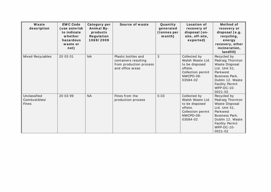
Mixed Recycables 20 03 01 NA Plastic bottles and containers resulting from production process and office areas
3 Collected by Walsh Waste Ltd. to be disposed offsite. Collection permit NWCPO-08-03584-02
Recycled by Padraig Thornton Waste Disposal Ltd. Unit 51, Parkwest Business Park, Dublin 12. Waste Facility Permit WFP-DC-10-0021-02
Unclassified Combustibles/ Fines
20 03 99 NA Fines from the production process
0.03 Collected by Walsh Waste Ltd. to be disposed offsite. Collection permit NWCPO-08-03584-02
Recycled by Padraig Thornton Waste Disposal Ltd. Unit 51, Parkwest Business Park, Dublin 12. Waste Facility Permit WFP-DC-10-0021-02

Attachmeent H.3.2

Environmental, Health & Safety Requirement Page 1 of 4
Approved: 23/06/2014
TITLE: Waste Management DOC. # Rev.
EHS- 208 (Galway) Orig
This document revision is software controlled.
Printed copies are for reference only. Printed 7/7/2014
1.0 PURPOSE This requirement provides the definitions and procedures that must be used by the Galway facility in identifying, managing, reducing, segregating and disposing of all generated wastes.
2.0 SCOPE This requirement applies to the Galway facility.
3.0 DEFINITIONS 3.1 Hazardous waste – Any waste or combination of wastes that exhibits characteristics that
are considered hazardous by the responsible regulatory authority because it poses a substantial present or potential hazard to human health or living organisms and/or because of the nature of the waste (toxicity, potential for cumulative effects, non-degradable nature, etc.).
3.2 Recyclable waste – Waste which can be recycled into another product, i.e. plastic, cardboard..
3.3 Re-usable waste – waste which can be re-introduced by the supplier, i.e. timber pallets,
steel returnable crates from vendors, etc.
3.4 Landfill waste – waste which is not recyclable or re-usable.
3.1 RELEVANT PROCESSES :
• EV01 Monitoring and Control of the Disposal of Waste
• EV02 Working with Asbestos
• EV06 Setting and Monitoring of Objectives and targets
• EV07 Control of Register of Environmental legislation
• Contractors EH&S red book training

Environmental, Health & Safety Requirement Page 2 of 4
Approved: 23/06/2014
TITLE: Waste Management DOC. # Rev.
EHS- 208 (Galway) Orig
This document revision is software controlled.
Printed copies are for reference only. Printed 7/7/2014
4.0 REQUIREMENTS A written waste management plan provides information on the proper handling, usage, and disposal of all waste types at the facility, meeting the following requirements;
Characterization of wastes
Regulatory requirements and permits
Selection of waste contractors
Waste contractor and facility audits
Management of waste
Recordkeeping and reporting procedures
Maintenance and routine inspections of equipment at the facility
Training
Review and update the waste management plan
The Waste Management Plan contains the following;
Characterization of wastes All waste is characterized as per the European Waste Catalogue European Waste Codes (EWC’s).
Regulatory requirements and permits Waste permits and registration are maintained on file available for inspections including the following details;
Review of permits required for waste contractors and facilities to operate including expiry dates of such permits
Waste generation, storage, transport, treatment or disposal, and authorization for trans-frontier shipment of waste in addition to relevant reports generated e.g. for regulatory submission to EPA
Ingersoll Rand International Galway notifies the Ingersoll Rand Corporate Environmental, Health and Safety (EHS) Department of its waste disposal contractors and facilities including the types of waste that is sent to each disposal site
Environmental, Health & Safety Requirement Page 3 of 4
Approved: 23/06/2014
TITLE: Waste Management DOC. # Rev.
EHS- 208 (Galway) Orig
This document revision is software controlled.
Printed copies are for reference only. Printed 7/7/2014
The facility obtains and reviews the certificate of insurance from each waste transportation contractor that is used by the facility on an annual basis to ensure the insurance meets the minimum Ingersoll Rand requirements.
Selection of waste contractors Only waste contractors (including facility contractors) who have the relevant permits and licenses are considered for use.
Waste contractor and facility audits The facility conducts a review and audit of each waste contractor and facility regularly.
Management of waste A Waste committee comprising members of the EHS team, Area Managers, Commodity Managers, Waste Reduction and Recycling Operators and third party warehouse personnel, coordinate the management and disposal of waste from the site, as well as reducing incoming waste from vendors to the site.
The site sets annual waste reduction targets in line with Corporate Objectives and progress against these targets is tracked monthly.
The site implements the Ingersoll Rands EHS policy of minimizing waste generation and having a hierarchy of waste management. This hierarchy of waste management details that, whenever possible, we seek to, in order, reduce, reuse, recycle, recover and finally avoid sending waste to landfill.
To achieve this hierarchy of waste, all waste is segregated and disposed of in the relevant bin or location, e.g. plastic, cardboard, paper, timber, etc. Waste containers are clearly labeled with the name of the waste.
Waste containers are closed except when adding wastes and stored secured.
Record keeping and reporting The facility maintains records of the types and quantities of waste generated, where it was transferred to and ultimately disposed of by the licensed waste contractors and facilities. (Reference Waste spreadsheet in MEHS documents folder in F: Private/Waste Management).
Ingersoll Rand International Galway notifies the Ingersoll Rand Corporate Environmental, Health and Safety (EHS) Department of its waste disposal contractors and facilities including the types of waste that is sent to each disposal site.
Maintenance and Routine Inspections of Storage Areas at the Facility Storage areas and containers are regularly inspected to identify and prevent leaks of part of the sites 5S and Preventative Maintenance Programs.

Environmental, Health & Safety Requirement Page 4 of 4
Approved: 23/06/2014
TITLE: Waste Management DOC. # Rev.
EHS- 208 (Galway) Orig
This document revision is software controlled.
Printed copies are for reference only. Printed 7/7/2014
Training Annual training for all employees for waste segregation is carried out annually. In addition, specific training for all personnel who handle waste on a regular basis i.e. Waste Reduction and Recycling Operators is carried out annually.
Records of training are filed in F:Private/Training/EHS and also hard copies are stored on site.
REVISION HISTORY
Rev Date Description Approved By
Orig 01/01/2011 Initial Release A. Kleinbaum
Rev. 1/9/013 Revision Tim Folan
C 23/6/2014 Revision Review Tim Folan/ Ciaran Ryan

Attachment I.4 / I.5/

MA
LON
E O
’RE
GA
N
June 2014
13, Mill Street, Galway.
Tel: +353 (0)91 531069 Fax :+353 (0)91 564644 e-mail: [email protected]
St. Catherine’s House, Catherine Street,
Waterford.
Tel: +353 (0)51 876855 Fax :+353 (0)51 876828
e-mail: [email protected]
2B Richview Office Park, Clonskeagh, Dublin 14.
Tel: +353 (0)1 2602655 Fax: +353 (0)1 2602660
e-mail: [email protected]
Ingersoll-Rand International Limited
Mervue Galway
Baseline Characterisation

Baseline Report June 2014 Ingersoll-Rand International Limited Mervue, Galway
Malone O’Regan i
Ingersoll-Rand International Limited
Mervue Galway
Baseline Report
TABLE OF CONTENTS 1.0 Introduction ...................................... ................................................................... 1
1.1 Project Objective ...................................................................................... 1 1.2 Relevant Background information............................................................. 1 1.3 Scope of Work.......................................................................................... 2 1.4 Disclaimer ................................................................................................ 3
2.0 Site Location & Description ....................... ......................................................... 4 2.1 Site Location & Surrounding Land Use ..................................................... 4 2.2 Site Layout and Use ................................................................................. 4 2.3 Existing Drainage Layout.......................................................................... 4 2.4 Water Supply............................................................................................ 4 2.5 Development Zoning Status ..................................................................... 4 2.6 Site History ............................................................................................... 5 2.7 Initial baseline and monitoring reports ...................................................... 5 2.7.1 Hydrogeological Infrastructure on site and Previous Reports ................... 5 2.7.2 Groundwater Monitoring Report (2000) – Bord na Mona .......................... 5 2.7.3 Groundwater Monitoring Report (2001) – Enviroco................................... 5 2.8 Site Investigations – Hydrocarbon Leak ................................................... 5 2.8.1 Background to the Incident ....................................................................... 5 2.8.2 Initial Site Investigation – S.M. Bennet & Co. Ltd. (2002-2003)................. 6 2.8.3 ERM Site Investigation (2003) .................................................................. 6 2.8.4 Corrective Action Plan (2003-2004) ........................................................ 10 2.8.5 Additional Remediation and Monitoring Works (2004-2005) ................... 11 2.8.6 Monitoring Reports 2005 to date ............................................................ 12 2.9 Remedial Works ..................................................................................... 12 2.9.1 Product Recovered during the Remedial Works ..................................... 12
3.0 Environmental Site Setting ........................ ....................................................... 14 3.1 Topography ............................................................................................ 14 3.2 Geology.................................................................................................. 14 3.3 Hydrogeology ......................................................................................... 14 3.4 Aquifer Classification and Vulnerability Rating........................................ 15 3.5 Groundwater Use ................................................................................... 15 4.6 Hydrological Features ............................................................................ 15 3.7 Designated Sites .................................................................................... 16
4.0 Baseline Methodology .............................. ........................................................ 17 4.1 Groundwater Level Monitoring ............................................................... 17 4.2 Free Phase Hydrocarbon Monitoring ...................................................... 17 4.3 Groundwater Sampling Methodology ..................................................... 17 4.3.1 Well Condition Survey ............................................................................ 17 4.3.2 Groundwater Sampling ........................................................................... 17 4.3.3 Groundwater Assessment ...................................................................... 17 4.3.4 Field Measured Parameters ................................................................... 18 4.3.5 Analytical Parameters ............................................................................ 18
5.0 Baseline Environmental Conditions ................. ............................................... 19

Baseline Report June 2014 Ingersoll-Rand International Limited Mervue, Galway
Malone O’Regan ii
5.1 Soils ....................................................................................................... 19 5.2 Groundwater .......................................................................................... 20 5.2.1 Free Phase Hydrocarbon Contamination 2014 ....................................... 20 5.2.2 Dissolved Phase Hydrocarbon Contamination........................................ 20 5.2.3 Analytical Results ................................................................................... 20 5.3 Summary ................................................................................................ 26
6.0 Conclusions........................................ ............................................................... 27 7.0 References ........................................ ................................................................. 29 FIGURES (within text) Figure 1 ERM interpretation of fractured zones and plume of free product. Figure 2 Changes in groundwater levels (MW1) Figure 3 ERM interpretation of cross section beneath the R&D building DRAWINGS (at back of text) Drawing 1 Site Location Drawing 2 Site Layout Drawing 3 Historic Site Investigation Locations Drawing 4 Monitoring Wells Locations Drawing 5 Subsoil Map Drawing 6 Bedrock Geology Drawing 7 Inferred Groundwater Flow Direction Drawing 8 Aquifer Bedrock Classification Drawing 9 Aquifer Vulnerability Drawing 10 Wells within a 2Km Radius Drawing 11 Natura 2000 Sites within 2km of Site TABLES Table 1 Trench Rationale (within text) Table 2 Groundwater Analytical Results – 2014 Table 3 Groundwater Level Measurements Table 4 Historic Soil Results Table 5 Oil Recovered (litres) (within text) APPENDICES Appendix A Chain of Custody Record Appendix B Groundwater Analytical Reports
Baseline Report June 2014 Ingersoll-Rand International Limited Mervue, Galway
Malone O’Regan 1
1.0 Introduction Ingersoll-Rand International Limited (IR) is applying for an Industrial Emissions (IE) Licence from the Environmental Protection Agency (EPA) for its facility located in Mervue, Galway City (refer to Drawing No. 1). IR have been testing a new, more environmentally friendly coating process called e-coat. Following extensive testing this process has proved successful and IR wish to bring it into full production. This process will fall under class of activity 12.3:
The surface treatment of metals and plastic materials using an electrolytic or chemical process where the volume of the treatment vat exceeds 30m3
Malone O'Regan (MOR) was commissioned by IR to complete a baseline report as part of the IE Licence application process. 1.1 Project Objective The project objectives include: • Determine the level of contamination of soil and groundwater in order that a quantified
comparison may be made to the state of the site upon the permanent cessation of the industrial emissions directive activity.
• Provision of summary details of known ground and/or groundwater contamination, historical or current, on or under the site.
• Provide an update on remediation work completed at the site. 1.2 Relevant Background information The site is an operational facility and as a result of a historic lube oil leak that was identified in 2002, some hydrocarbon contamination has been identified on site. This historic incident is being addressed in accordance with the requirements of the EPA’s Office of Environmental Enforcement (OEE) and in that regard a significant number of site investigations, characterisation and remediation has been completed since the incident occurred in order to develop a representative conceptual site model and undertake remedial efforts at the site to address the identified contamination. It is understood that a release of lubricating oil first became apparent in February 2002 when lube oil was observed at the base of the LPG storage tank in the Research and Development area of the site. It is reported that the source of the oil leak was stopped on the 7th February 2002. Investigations to determine the cause of the leak were undertaken by S.M. Bennet and Co. Ltd in February 2002 and the conclusion was made that the source of the leak was a lubricating oil junction pipe which had leaked at the corner of the R&D building near the footpath. As part of the emergency measures, approximately 1,500L mobile free product was collected where accessible. A comprehensive suite of site investigations and emergency remedial measures were implemented at the time. Significant investment has been made by IR in relation to investigative and remedial works associated with this lube oil leak. The key findings of these works were that the hydrocarbon plume is broadly confined to the south eastern corner of the site. A Quantitative Risk Assessment determined that there was no risk to human health or environmental receptors. Furthermore based on groundwater monitoring data collected in April 2014 there is no evidence of any current offsite hydrocarbon impacts.
Baseline Report June 2014 Ingersoll-Rand International Limited Mervue, Galway
Malone O’Regan 2
Since the outset, all remediation works have been undertaken in close collaboration with the Environmental Protection Agency (EPA). In this regard IR have recently initiated a complete review of the current EPA approved remediation design to determine whether there are supplementary measures that could be implemented to improve the efficiency of the free phase recovery operations and thereby expedite the completion of the remediation works. This review is being undertaken under the direction of the Office of Environmental Enforcement (OEE) and any proposed improvements to the remediation design will be agreed in advance with the OEE. 1.3 Scope of Work The scope of work undertaken in preparing this baseline report comprised the following elements and activities: • A desk-based study that comprised of a review of published geological and
hydrogeological information, historical maps, utility location drawings all from recognised data sources including the databases of the Geological Survey of Ireland (GSI), Office of Public Works (OPW), and Environmental Protection Agency (EPA);
• Interviews with site personnel and a site walkover; • A review of documents provided by the Client to establish baseline details of the site
setting;
• A review of documents provided by the Client to establish details on an historic leak event that occurred in 2002 and the emergency response and ongoing works associated with it. The documents reviewed included:
o Excerpt from Bord na Mona Report (Date estimated 1998). o Bi-annual Groundwater Monitoring Report (April 2000) Bord na Mona. o Bi-annual Groundwater Monitoring Report (August 2001) Enviroco
Management Ltd. o Demarcation of Main locations of lubricating oil contamination at Thermo
King, Galway (May 2002) S.M. Bennet & Co. Ltd. o December 2002 IPC Groundwater Monitoring Programme at Thermo King
Europe, Galway (February 2003) S.M. Bennet & Co. Ltd. o Preliminary Remedial Action Plan (June 2003) ERM. o Remedial Investigations and Quantitative Risk Assessment (June 2003)
ERM. o Project Lube: Corrective Action Plan (September 2003) ERM. o 2-D Electrical Tomography Survey (October 2003) LGS. o Corrective Action Plan Implementation Report (March 2004) ERM. o Quarterly Monitoring (4th June 2004). o Quarterly Monitoring ( 30th June 2004) :- Re-issue of 4th June 2004 report. o Additional Remediation and Monitoring Works (April 2005) ERM. o Additional Remediation and Monitoring Works (August 2005) ERM. o Corrective Action Plan Monitoring Report (October 2005) ERM. o Environmental Monitoring Data (January 2006) ERM. o Site Monitoring Report (April 2006) ERM. o Site Monitoring Report (July 2006) ERM. o Site Monitoring Report (October 2006) ERM. o Site Monitoring Report (January 2007) ERM. o Final Report (May 2007) ERM.
Baseline Report June 2014 Ingersoll-Rand International Limited Mervue, Galway
Malone O’Regan 3
o Summary Report on Lubricant Oil Remediation Works (June 2007) ERM. o Site Monitoring Report (July 2007) ERM. o Summary Monitoring Report 2007 (January 2008) ERM. o Annual Summary Monitoring Report 2009 (Biospheric Engineering Ltd.). o Product recovery data 2010, 2011, 2012 and 2013.
• A detailed site inspection by a Senior Malone O’Regan Environmental Consultant.
• Topographical survey of all monitoring well locations to Ordnance Survey datum.
• Collection of a round of water level dips in order to establish groundwater flow
direction.
• Collection of groundwater samples, where possible, from all of the accessible monitoring wells. Identify the locations where free product is present.
• Presentation of the findings of the review in a baseline report. 1.4 Disclaimer The conclusions presented in this report are professional opinions based solely on the tasks outlined herein and the information made available to MOR. They are intended for the purpose outlined herein and for the indicated site and project. The report is for the sole use of the Client. This report may not be relied upon by any other party without explicit agreement from MOR. Opinions and recommendations presented herein apply to the site conditions existing at the time of the assessment. They cannot apply to changes at the site of which MOR is not aware and has not had the opportunity to evaluate. This report is intended for use in its entirety; no excerpt may be taken to be representative of this assessment. All work carried out in preparing this report has utilised and is based on MOR professional knowledge and understanding of the current relevant Irish and European Community standards, codes and legislation.

Baseline Report June 2014 Ingersoll-Rand International Limited Mervue, Galway
Malone O’Regan 4
2.0 Site Location & Description 2.1 Site Location & Surrounding Land Use The site is located at the junction of Monivea Road and Connolly Avenue approximately 1.3km north east of Galway city centre. The site covers an area of approximately 5.8 hectares. The regional site location is illustrated on Drawing No. 1. The facility is located in a mixed use area with residential, educational, commercial and industrial uses in the immediate vicinity. The site is bounded to the south by playing pitches, to the west by residential properties, to the east by Connolly Avenue beyond which lies a residential estate and by commercial premises beyond the Monivea Road to the north. 2.2 Site Layout and Use IR operates a manufacturing facility for trailer mounted refrigeration units at the plant. The plant has produced trailer mounted refrigerator units on site since 1976. Currently two types of units are produced at the plant for large trailers and for smaller trucks at rates of 60 and 35 units per day respectively. The facility employs approximately 500 staff members. The site is accessed from two entrances; from Monivea Road and Connolly Avenue respectively. The site generally consists of a large manufacturing plant with a reception area and office block, with separate Research and Development, Quality and Cafeteria buildings. Refer to Drawing No. 2 for a site layout. Surface covering consists of hardstanding predominately of concrete with a small amount of tarmac cover and planted areas located particularly in the northern portion and along the site boundaries. 2.3 Existing Drainage Layout There is an onsite waste water treatment plant operated by IR personnel. The treated waste water is discharged into a combined Local Authority foul and storm water drain. Surface water runoff from the site also discharges to the combined Local Authority drain for ultimate treatment at the Mutton Island treatment facility that is operated by the Local Authority. 2.4 Water Supply The site is served with a public water supply from the Local Authority. 2.5 Development Zoning Status The Galway City Development Plan 2011 (GCDP 2011-2017), outlines that the site is zoned ‘I’ which is defined as: ‘Industry’: To provide enterprise, industry and related uses. Zoning seeks to promote the development of uses that achieve objectives for the area concerned and to prevent the development of incompatible uses. Land use zonings are utilised in the plan to indicate various objectives for these areas.
Baseline Report June 2014 Ingersoll-Rand International Limited Mervue, Galway
Malone O’Regan 5
2.6 Site History Prior to 1976 the site was in use by a French Multinational company called Potez who made industrial and home heating units. The site was originally developed in the 1960s. 2.7 Initial baseline and monitoring reports A number of baseline and monitoring reports were completed prior to the discovery of the lube oil leak and include the following. 2.7.1 Hydrogeological Infrastructure on site and Pr evious Reports A hydrogeological assessment was completed by Bord na Mona at this site (estimated 1998). These works included the installation of 5No. groundwater monitoring wells (MW-01 to MW-05) which were installed to depths of between 9.48 to 22.62 meters below ground level (mbGL). Static water levels in these wells varied between 2.92mbGL (MW-01) to 9.24 mbGL (MW-02). 2.7.2 Groundwater Monitoring Report (2000) – Bord n a Mona Bord na Mona undertook bi-annual monitoring in 2000 (January to June). Five wells were sampled (MW1-MW5). No evidence of hydrocarbon contamination was observed during either the fieldwork or in the chemical analysis (TPH). 2.7.3 Groundwater Monitoring Report (2001) – Enviro co Enviroco undertook bi-annual groundwater monitoring in 2001 (1st half). Samples were collected over two monitoring events (June and July 2001) due to ‘insufficient water volume for sampling’ initially reported for MW2, MW4 and MW5. An oil type product was identified and sampled in MW5. The results of the analysis indicated that hydrocarbon contamination was present in all wells at that time with the exception of MW1. The highest concentrations were identified in MW5 (1.646mg/l) and MW3 (1.097mg/l). According to the Enviroco report, the laboratory interpretation of the contamination was lube oil. 2.8 Site Investigations – Hydrocarbon Leak Following the identification of the lube oil leak in February 2002 a large number of site investigations were completed at the facility during the years. The site investigation reports associated with the incident are summarised in this section. The majority of the locations can be identified on Drawing No. 3. 2.8.1 Background to the Incident When the release of lubricating oil first became apparent in February 2002 at the base of the LPG storage tank in the Research and Development area of the site oil was also detected in the lubrication (lube) oil sump and observed discharging into the foul sewer at an estimated rate of 0.5 litres/min (l/min)1. Further non-intrusive investigation at that time, identified free product with 1m thickness in an existing monitoring well (MW5) located to the west of the R&D Building that had been drilled 27m into bedrock. This well is located approximately 35m to west-northwest from the LPG storage tank. In addition water sampled in another existing well (MW4) located adjacent to the chemical stores building and 20m north of the LPG tank had an oil sheen visible. It is reported that the source of the oil leak was stopped on the 7th February 2002. It is assumed for the purpose of this review, that the supply of oil was disconnected until the
1 Between 2002 and 2003, S.M. Bennet & Co. Ltd. supervised the installation of a ‘collar’ on the sewer pipe at the site boundary to stop further contamination migrating offsite via this conduit.

Baseline Report June 2014 Ingersoll-Rand International Limited Mervue, Galway
Malone O’Regan 6
exact location of the leak could be determined, given at that point in time that the exact leakage location was unknown. Investigations to determine the cause of the leak were undertaken by S.M. Bennet and Co. Ltd in February 2002 and the conclusion was made that the source of the leak was a lubricating oil junction pipe which had leaked at the corner of the R&D building near the footpath. The single skinned ½ inch qualpex pipeline that had been installed sometime after 1999 was installed as per the recognised standards at the time; however this installation would not be in accordance with current best practice standards for pressurised oil systems. As a result, a kink occurred in the pipe line allowing oil to leak from the pipe at some location between the lube oil bulk storage tanks and the R&D building. It is not known exactly when the oil leak commenced although it has been confirmed to be sometime after 1999. 2.8.2 Initial Site Investigation – S.M. Bennet & Co . Ltd. (2002-2003) S.M. Bennet & Co. Ltd. were appointed by IR immediately upon the identification of the leak. As part of their works they completed the following site investigations in 2002: • 10No. shallow boreholes into the overburden to a maximum depth of 4m (BH1-
BH10). • 12/13No. trial pits excavated to a maximum depth of 4.5m (TP1-TP13). • 8No. deep boreholes installed into the limestone bedrock (depth ranging from 9-36m)
(MW1-MW4, MW5a, MW5b, B-H1 and B-H2). MW5a was converted into a 5m deep sump.
Initial Remedial Measures Implemented, Product Migr ation and Thickness As part of the emergency measures, approximately 1,500L mobile free product was collected where accessible. The initial site investigation undertaken by S.M. Bennet & Co. Ltd. in February 2002 estimated that leakage from the oil pipe to the surrounding area occurred at a rate of 175ml per minute during operational hours although it was later clarified that this could be halved to 87.5ml/min when taking into account the surrounding material. Pressure testing of other sections of the lubricating oil line confirmed they were intact. Oil and groundwater migration also appeared to be limited to the gravel and weathered bedrock zones. In BH1 and BH2, oil and groundwater were encountered within the weathered zone at depths of 6.5-6.8m and 4.0-4.5m respectively. Up to 1m apparent thickness of oil, with the physical appearance of lube oil, was found in monitoring wells on the western site boundary (B-H2 and MW5b). Please note, that the 1m thickness should not be considered reflective of the thickness of product in the underlying aquifer/perched water as an overestimation occurs due to the fact that the installed well provides a preferential conduit for oil to collect to a thickness greater than that which would be naturally observed; this continues until equilibrium is reached. Groundwater Monitoring – December 2002 S.M. Bennet & Co. Ltd. undertook groundwater monitoring in December 2002. In addition to the 5No. wells sampled, two additional wells installed as part of the lube oil remediation project were also examined (BH1 and BH2). During this monitoring event, free phase oil was observed in MW4 and in an additional well, BH1. Thickness of product in BH1 was reported as approximately 2mm and the product was described as having a purple colour. 2.8.3 ERM Site Investigation (2003) Subsequent to the initial emergency response, investigation and remedial works undertaken by S.M. Bennet & Co. Ltd., ERM were appointed by IR to carry out a review of the project and additional investigation works. This phase of the investigation included installation of:
Baseline Report June 2014 Ingersoll-Rand International Limited Mervue, Galway
Malone O’Regan 7
• 5No. shallow monitoring wells to a depth of 11.5m. • 1No. deep monitoring well to 30m. • 9No. soil bores to a maximum depth of 5m.
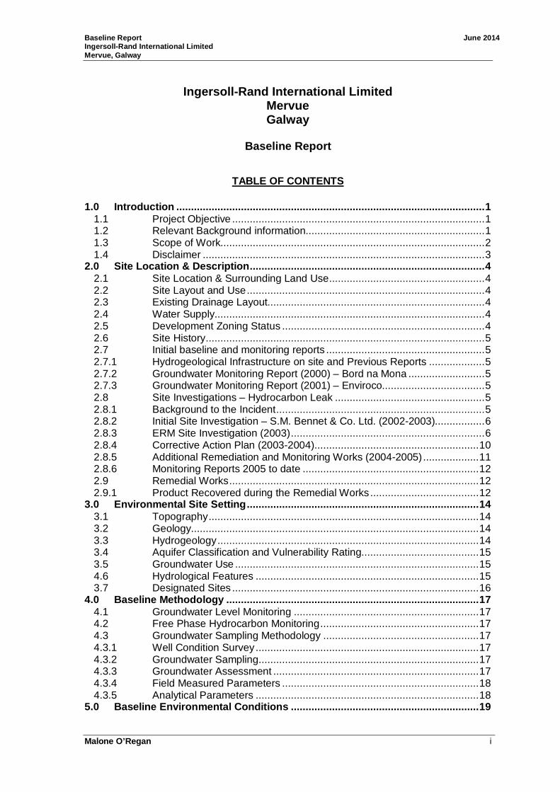
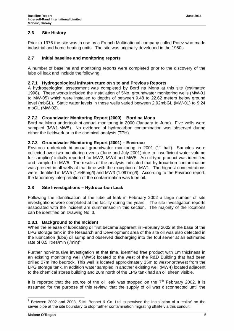
Geology Based on the site investigations completed by ERM in April/May 2003, the R&D area is underlain by 1.7-3m of Made Ground which is comprised of a silty clay fill with some limestone gravel, brick fragments, slag and plastic. The made ground is underlain by natural glacial boulder clay to depths of 5-6m comprising of gravelly clays with occasional pebbles and cobbles. At certain locations the clay contained a gravel rich or sandy horizon at a depth of approximate 3-3.5m (SB1, SB2, SB5 and SB9). The Burren Limestone was encountered in each of the boreholes installed during the ERM site investigation phase of works. Fractures zones were generally encountered within the limestone bedrock in two zones: • Upper Fracture Zone: Between 5-11mbGL (concentrated between 6-8mbGL). • Lower Fracture Zone: Between 14-26mbGL.
Fractures encountered were both vertical and sub-horizontal in nature. Figure 1: ERM interpretation of fractured zones and plume of free product
A vertical fracture was identified in ERM3 between 8 and 11mbGL which was in excess of 8cm at its base and contained silts and clays as well as sand and fine gravel lenses. This borehole was the only borehole during this investigation that displayed visible evidence of lube oil during coring. Lube oil was identified at 8.2mbGL. ERM concluded: • “The shallow zone appears to be laterally extensive across the western site
boundary, and is associated with the presence of both free product and groundwater”.
Baseline Report June 2014 Ingersoll-Rand International Limited Mervue, Galway
Malone O’Regan 8
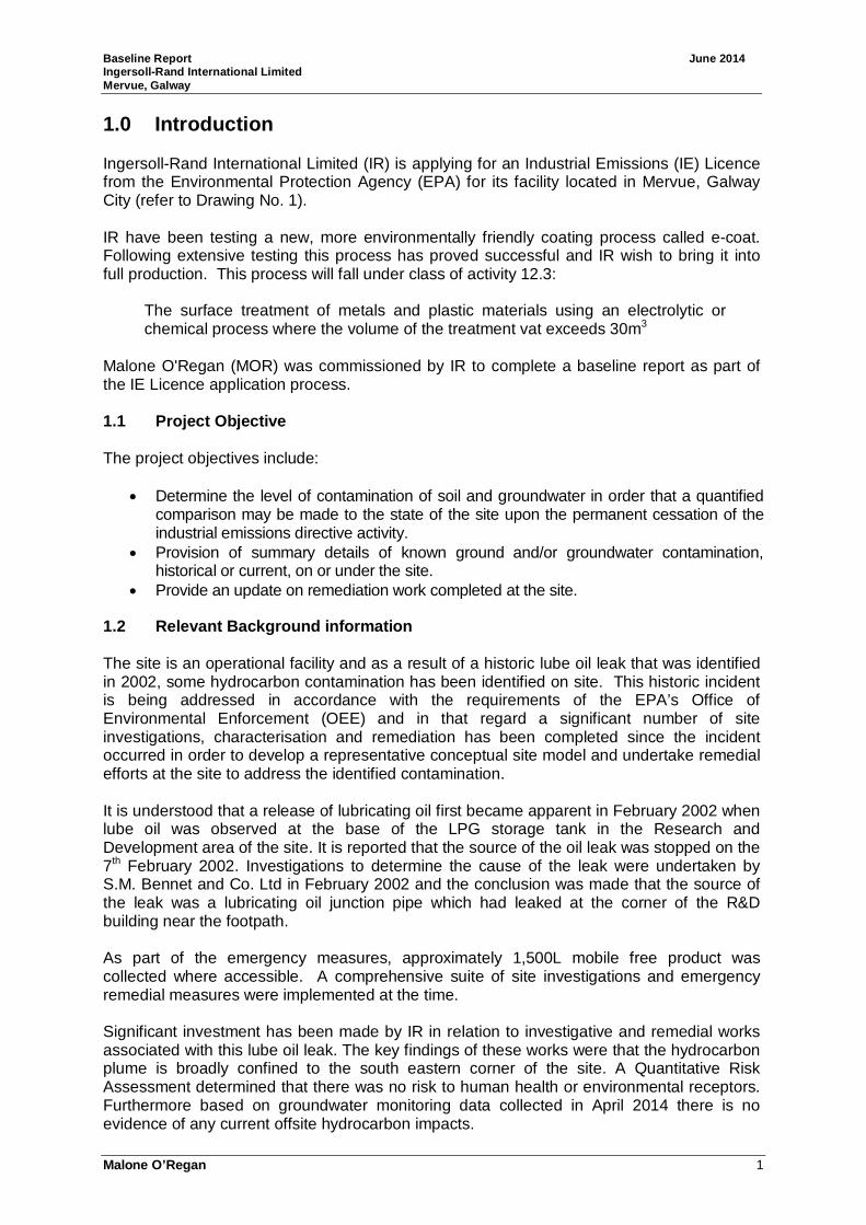
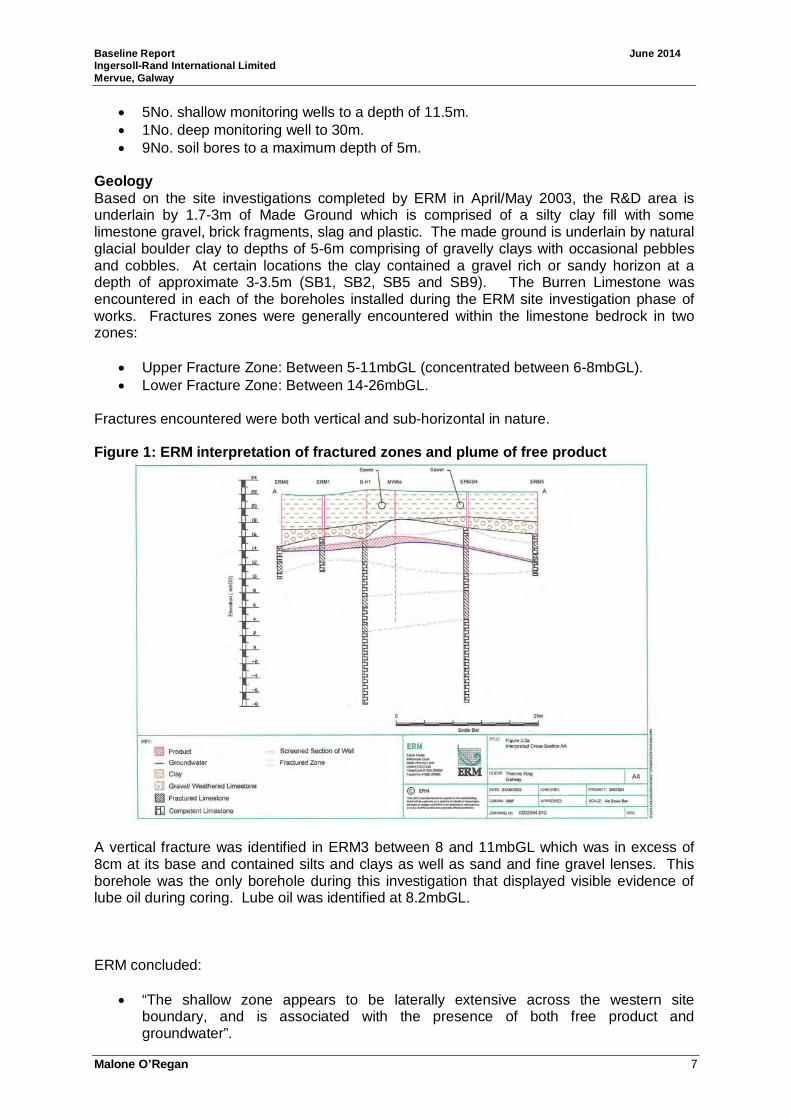
• “Free phase is not present within the weathered zone at the base of the overburden”. Groundwater Levels According to the initial review completed by ERM, groundwater flow direction is generally in a westerly direction. Groundwater was encountered in each of the ‘deeper’ groundwater wells installed into the limestone bedrock. In the areas adjacent to the leak, a variation of 2m was observed in the groundwater levels measured in boreholes ERM5 and ERM3 which are located less than 15m apart. It was suggested that this was likely due to the less developed fractures observed during the drilling of ERM5 when compared to other wells. The ERM 15 month post leak report also identified that groundwater is locally raised in the vicinity of B-H2 and a number of factors were considered including karstic flow conditions, rainfall and the possibility of a leak from the sewer line in the area. ERM also identified a change in groundwater water levels over a three week period (23/04/2003-15/05/2003) in MW1 which was attributed to heavy rainfall that occurred during that time period. Figure 2: Changes in groundwater levels (MW1)
Hydrogeological Tests Raising head tests were undertaken by ERM on 5No. wells in May 2003, the results of which indicated hydraulic conductivity ranging from 3x10⁻⁵m/d (B-H2) to 0.3m/d (MW2). The average hydraulic conductivity was calculated as 0.06m/d. Services/Foundations – possible conduits A number of subsurface structures were considered by ERM when examining the potential conduits. Sewers and Service Lines S.M. Bennet & Co. Ltd. identified during the initial investigations that the sewer line acted as a conduit for the free product to migrate. ERM excavated the site sewer located approximately 3m to the south of the R&D building. This line was located at a depth of 1.1mbGL, in a bed of wet, lose grey hardcore. Free product was identified by ERM during these works. Foundations The foundations associated with the R&D building were also investigated. The R&D building is reportedly constructed on strip foundations with 1.5m concrete slabs supporting the external and major internal walls. The building floor is underlain by 150mm concrete
Baseline Report June 2014 Ingersoll-Rand International Limited Mervue, Galway
Malone O’Regan 9
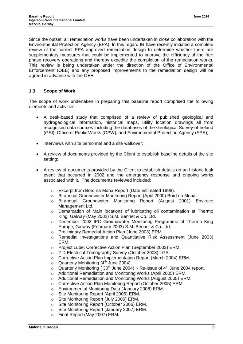
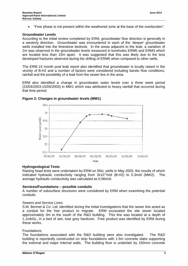
slab overlying insulation and 200mm of hardcore which appears to extend to the base of the strip foundations. There is some suggestion that the hardcore material is underlain by reworked clays and madeground is therefore present to a depth of approximately 2.5m. ERM hypothesised that the hardcore material is acting as a preferential conduit for free product to migrate beneath the R&D building. Soil bores SB4, SB5 and SB9 were installed beneath the foundation. Pink product was identified in both SB4 and SB5, while SB9 located further north in the R&D building reported strong hydrocarbon odours although no product identified. These boreholes were reinstated upon completion of the works. Geology ERM conclude that in places the hardcore material ‘intersects or is connected to the sandy or gravelly materials within the Till, providing a contaminant migration pathway into the natural materials’. Figure 3: ERM interpretation of cross section benea th the R&D building
Product Thickness Although initially it had been concluded that the plume had been delineated following the site works, within a 5 day period, oil was identified in ERM5 and ERM6 and therefore it became clear that the plume had not been delineated to the south of MW5. MW6 was considered to represent the northern edge of the plume. ERM estimated that the true product thickness onsite could be represented by a value of 0.16m. Product Analysis Product samples were collected from the monitoring wells and also from the storage tanks in order to allow a comparison of the products. The interpretation of the analysis concluded that all samples represented Total Petroleum Hydrocarbon (TPH) characteristics consistent with biodegraded lubricating oil.

Baseline Report June 2014 Ingersoll-Rand International Limited Mervue, Galway
Malone O’Regan 10
Viscosity data was also undertaken on the free product samples. The viscosity results indicated that the samples from the storage tank and Manhole BH5 were fresher than the samples collected from MW5b, B-H1 and MW5a – suggesting that the latter samples reflected the effects of weathering. Analysis ERM submitted soil and groundwater samples from a number of locations for TPH, Polycyclic Aromatic Hydrocarbons (PAHs) and benzene, toluene, ethylbenzene and xylene (BTEX) analysis. Risk Assessment ERM refined the conceptual site model and conducted a risk assessment to determine if there was any potential risk to any identified human or environmental receptors. The conclusions of the risk assessment were that none of the Tier II Site Specific Target Levels were exceeded for any of the contaminants of concern present for any of the exposure pathways identified. In addition the risk assessment conclusions confirmed that the free product identified does not present a risk to human health or the environment. Remedial Strategy As the outcome of the risk assessment identified that there were no offsite risks associated with the lube oil leak the extent of the remedial strategy agreed with the EPA focused on the collection of any residual contamination present on site and the prevention of offsite migration. A number of remedial measures were considered at the time before a chosen strategy was selected that included a combination of source removal and monitoring. 2.8.4 Corrective Action Plan (2003-2004) ERM documented a Corrective Action Plan (CAP) in March 2004 the objectives of which were as follows: • Primary Objective: recover as much free product as possible. • Secondary Objective: ian iterative site investigation process and revision of QRA. • EPA also requested the evaluation of bioremediation as a possible remedial measure
that could be implemented on site. • Forensic analysis of oil.
Between September 2003 and March 2004 ERM completed the following works which were documented in the 2004 CAP report: Onsite Works Undertaken • Geophysics – 2D electrical tomography. • Installation of additional wells to delineate the extent of the plume – 4No. onsite:
o ERM7 (15.5mbGL) – located to the west of ERM6. o ERM8 (10.3mbGL) – located to the east of ERM5 and ERM2. o ERM9 (13.6mbGL) – located adjacent to source area. o ERM10 (12.5mbGL) – located to the east of ERM7 due to the identification of
product in ERM7. o The geology encountered was consistent with that previously seen on site.
• Groundwater Monitoring (August and December). • Forensic Analysis. • Remedial Well Installations - Four 100mm remediation wells were installed in
October 2003 (RW1, RW2, RW3 and RW4). Wells were drilled to 12mbGL and were screened from the top of the weathered rock zone head to the base of the upper fractured surface.
Baseline Report June 2014 Ingersoll-Rand International Limited Mervue, Galway
Malone O’Regan 11
• Well Decommissioning – MW5a, B-H1 and MW5b although the latter two were only partially grouted.
• Well Repairs – ERM4 and ERM5. • Product Recovery Trials. • Service trench investigation - beyond ERM3 the sewer joins another sewer line that
comes from the entrance of the R&D building (northwest), and heads off in a southwest direction off-site. A section 10m long was exposed. The sewer itself is located at a relatively shallow depth of less than 1m and no evidence of free phase product was observed. During the investigation works, the concrete ‘collar’ installed by S.M. Bennet & Co. Ltd. during the initial response was uncovered. There was no evidence of free product observed.
Offsite Works Undertaken • Geophysics – 2D electrical tomography. • Additional monitoring Wells - within the adjacent Tara Grove residential areas
(ERM11, ERM12 and ERM13). o ERM11 and ERM13 – upper fractured zone (screened from 3.0-12.0mbGL
and 8.5-14.5mbGL, respectively). o ERM12 – Lower fractured zone – screened from 20-23.5mbGL.
• Hydrogeological testing. Following the completion of these works, ERM concluded the following points: • Distribution of plume is similar to that previous identified. • Free phase thickness appears to be generally decreasing but is influenced by
groundwater levels. • QRA findings remain – no risk to human health or environmental receptors. • Various trials undertaken illustrated that volume recovery is similar to that achieved
by hand bailing. Remedial Works Undertaken During the period July to November 2003, IR undertook hand-bailing of product from all onsite monitoring wells. The remedial works were suspended between November 2003 and February 2004 to allow some remedial trials to be completed. Between July 2003 and March 2004 it was estimated by ERM that 301L of product was hand-bailed from the onsite wells; the majority (285L) of which was recovered between July and November 2003. 2.8.5 Additional Remediation and Monitoring Works ( 2004-2005) Additional works were undertaken by ERM in between 2004 and 2005 and documented in the August 2005 Report. A trial trench was excavated in November 2004 adjacent to location SB3. Free product was identified during these works so the trench was left open and IR personnel periodically removed the accumulated water and oil. Following discussions with IR and the EPA a ‘Remedial Strategy Review Document’ was submitted which was discussed at a meeting with the EPA in December 2004. This document reportedly outlined additional remedial works to be implemented at the site. The items completed and documented in the August 2005 report included: • Ongoing removal of free product in the trench adjacent to SB3. • Installation of additional trenches – 6No. trenches were excavated during two periods
between 4th January and 4th February 2005 to a depth of 1.5mbGL. • Installation of additional 8No. gas monitoring wells (SB101-SB108) to a maximum
depth of 3mbGL. • Sampling (soil and groundwater).
Baseline Report June 2014 Ingersoll-Rand International Limited Mervue, Galway
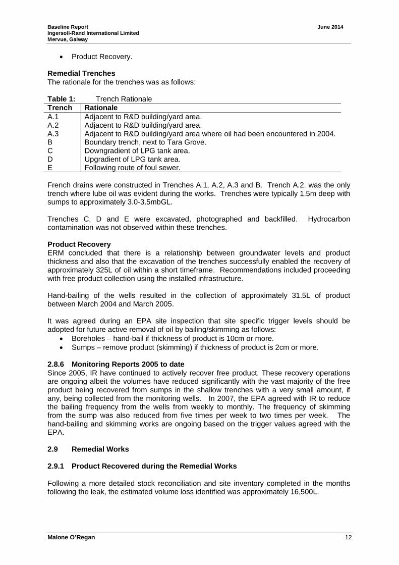
Malone O’Regan 12
• Product Recovery. Remedial Trenches The rationale for the trenches was as follows: Table 1: Trench Rationale Trench Rationale A.1 Adjacent to R&D building/yard area. A.2 Adjacent to R&D building/yard area. A.3 Adjacent to R&D building/yard area where oil had been encountered in 2004. B Boundary trench, next to Tara Grove. C Downgradient of LPG tank area. D Upgradient of LPG tank area. E Following route of foul sewer. French drains were constructed in Trenches A.1, A.2, A.3 and B. Trench A.2. was the only trench where lube oil was evident during the works. Trenches were typically 1.5m deep with sumps to approximately 3.0-3.5mbGL. Trenches C, D and E were excavated, photographed and backfilled. Hydrocarbon contamination was not observed within these trenches. Product Recovery ERM concluded that there is a relationship between groundwater levels and product thickness and also that the excavation of the trenches successfully enabled the recovery of approximately 325L of oil within a short timeframe. Recommendations included proceeding with free product collection using the installed infrastructure. Hand-bailing of the wells resulted in the collection of approximately 31.5L of product between March 2004 and March 2005. It was agreed during an EPA site inspection that site specific trigger levels should be adopted for future active removal of oil by bailing/skimming as follows: • Boreholes – hand-bail if thickness of product is 10cm or more. • Sumps – remove product (skimming) if thickness of product is 2cm or more.
2.8.6 Monitoring Reports 2005 to date Since 2005, IR have continued to actively recover free product. These recovery operations are ongoing albeit the volumes have reduced significantly with the vast majority of the free product being recovered from sumps in the shallow trenches with a very small amount, if any, being collected from the monitoring wells. In 2007, the EPA agreed with IR to reduce the bailing frequency from the wells from weekly to monthly. The frequency of skimming from the sump was also reduced from five times per week to two times per week. The hand-bailing and skimming works are ongoing based on the trigger values agreed with the EPA. 2.9 Remedial Works 2.9.1 Product Recovered during the Remedial Works Following a more detailed stock reconciliation and site inventory completed in the months following the leak, the estimated volume loss identified was approximately 16,500L.
Baseline Report June 2014 Ingersoll-Rand International Limited Mervue, Galway
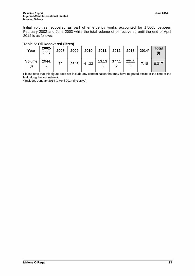
Malone O’Regan 13
Initial volumes recovered as part of emergency works accounted for 1,500L between February 2002 and June 2003 while the total volume of oil recovered until the end of April 2014 is as follows: Table 5: Oil Recovered (litres)
Year 2002-2007
2008 2009 2010 2011 2012 2013 2014* Total
(l)
Volume (l)
2944.2
70 2643 41.33 13.13
5 377.1
7 221.1
8 7.18 6,317
Please note that this figure does not include any contamination that may have migrated offsite at the time of the leak along the foul network. * Includes January 2014 to April 2014 (inclusive)
Baseline Report June 2014 Ingersoll-Rand International Limited Mervue, Galway
Malone O’Regan 14
3.0 Environmental Site Setting 3.1 Topography The site slopes gently to the south west with elevations of approximately 27 to 28 meters above Ordnance Datum (maOD) present in the northern and eastern portions of the site. Topographic levels of approximately 24maOD and 22maOD are present in the western and south western portions of the site respectively. The topography of the surrounding area ranges from approximately 10maOD to 60maOD and generally falls towards Lough Atalia. 3.2 Geology Quaternary Geology The site is underlain by made ground to varying thicknesses depending on infrastructure present which in turn is underlain predominately by Limestone Till as identified in the Quaternary Geology maps (Refer Drawing No. 5). Bedrock Geology According to the GSI (2013) the site is underlain by Dinantian Pure Bedded Limestone. This bedrock comprises undifferentiated Visean Limestone (Drawing No. 6). There are no reported faults in the vicinity of the site (GSI, 2014). Approximately 2 kilometers (km) west of the site the geology changes to granites (and other igneous intrusives); this contact is located along the southern portion of Lough Atalia (GSI, 2014). 3.3 Hydrogeology Aquifer Characteristics According to the GSI (2013) the aquifer beneath the site is a Karstic aquifer assigned to the Galway East Groundwater Body (GWB). There is currently no information available in relation to the aquifer characteristics of this GWB. However a GWB report has been produced for the Clare-Corrib GWB which is also a karstic system and is located adjacent to the Galway East GWB. Recharge to the bedrock aquifer in the Clare-Corrib GWB occurs through both point and diffuse mechanisms (GSI, 2004). Diffusive recharge occurs over the Clare-Corrib GWB through rainfall percolating through the permeable subsoil. Point recharge to the underlying aquifer occurs through swallow holes and collapse features/dolines. Point recharge occurs via many small sinks that are present in the low permeability tills. Recharge also occurs along ‘losing’ sections of streams in the area such as River Clare, Sinking River and Abbert River. According to the GSI (2004) the main discharges associated with this GWB are to streams, rivers and large springs found within the body. Some of these large springs (eg. Kilcoona, Bunatober and Aucloggeen) issue from the bottom of a limestone scarp that is thought to represent an ancient shoreline of Lough Corrib. During winter groundwater fills the turloughs present in the area and partly discharges via artificial channels created to alleviate flooding (GSI, 2004). Well yields reported for this GWB are highly variable due to the Karstic nature of the bedrock. Of 60 wells located within this GWB, the well yields of 59% are reported to be excellent / good, 23% are reported to be poor / failed with the remainder described as moderate (GSI, 2004). The median yield of wells in this GWB is reported by the GSI (2004) to be 131 m3/d. According to the GSI (2004) groundwater flow within this GWB is to the southwest with all groundwater discharging to Lough Corrib. In general, the nature of groundwater flow
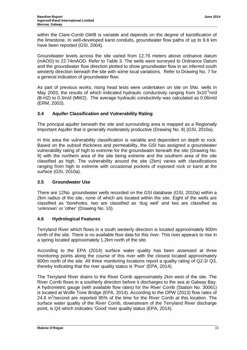
Baseline Report June 2014 Ingersoll-Rand International Limited Mervue, Galway
Malone O’Regan 15
within the Clare-Corrib GWB is variable and depends on the degree of karstification of the limestone. In well-developed karst conduits, groundwater flow paths of up to 9.6 km have been reported (GSI, 2004). Groundwater levels across the site varied from 12.76 meters above ordnance datum (mAOD) to 22.74mAOD. Refer to Table 3. The wells were surveyed to Ordnance Datum and the groundwater flow direction plotted to show groundwater flow in an inferred south westerly direction beneath the site with some local variations. Refer to Drawing No. 7 for a general indication of groundwater flow. As part of previous works, rising head tests were undertaken on site on 5No. wells in May 2003, the results of which indicated hydraulic conductivity ranging from 3x10⁻⁵m/d (B-H2) to 0.3m/d (MW2). The average hydraulic conductivity was calculated as 0.06m/d (ERM, 2003). 3.4 Aquifer Classification and Vulnerability Ratin g The principal aquifer beneath the site and surrounding area is mapped as a Regionally Important Aquifer that is generally moderately productive (Drawing No. 8) (GSI, 2010a). In this area the vulnerability classification is variable and dependent on depth to rock. Based on the subsoil thickness and permeability, the GSI has assigned a groundwater vulnerability rating of high to extreme for the groundwater beneath the site (Drawing No. 9) with the northern area of the site being extreme and the southern area of the site classified as high. The vulnerability around the site (2km) varies with classifications ranging from high to extreme with occasional pockets of exposed rock or karst at the surface (GSI, 2010a). 3.5 Groundwater Use There are 12No. groundwater wells recorded on the GSI database (GSI, 2010a) within a 2km radius of the site, none of which are located within the site. Eight of the wells are classified as ‘boreholes, two are classified as ‘dug well’ and two are classified as ‘unknown’ or ‘other’ (Drawing No. 10). 4.6 Hydrological Features Terryland River which flows in a south westerly direction is located approximately 900m north of the site. There is no available flow data for this river. This river appears to rise in a spring located approximately 1.2km north of the site. According to the EPA (2014) surface water quality has been assessed at three monitoring points along the course of this river with the closest located approximately 800m north of the site. All three monitoring locations report a quality rating of Q2-3/ Q3, thereby indicating that the river quality status is ‘Poor’ (EPA, 2014). The Terryland River drains to the River Corrib approximately 2km west of the site. The River Corrib flows in a southerly direction before it discharges to the sea at Galway Bay. A hydrometric gauge (with available flow rates) for the River Corrib (Station No. 30061) is located at Wolfe Tone Bridge (EPA, 2014). According to the OPW (2013) flow rates of 24.6 m3/second are reported 95% of the time for the River Corrib at this location. The surface water quality of the River Corrib, downstream of the Terryland River discharge point, is Q4 which indicates ‘Good’ river quality status (EPA, 2014).

Baseline Report June 2014 Ingersoll-Rand International Limited Mervue, Galway
Malone O’Regan 16
3.7 Designated Sites According to the National Parks and Wildlife Services (NPWS, 2014) there are a number of protected areas within a 2km radius of the site. To the northwest of the site is Lough Corrib which has been designated as a Special Area of Conservation (SAC) (Site code 000297), a Proposed Natural Heritage Area (pNHA) (Site code 000297) and a designed Special Protected Area (SPA) (Site code 004042). Located southwest of site is Lough Atalia, part of the Galway Bay and inner bay, designated SPA (Site code 004031), SAC (Site code 000268) and pNHA (Site code 000268). Refer to Drawing No. 11.

Baseline Report June 2014 Ingersoll-Rand International Limited Mervue, Galway
Malone O’Regan 17
4.0 Baseline Methodology The following works were undertaken in order to compile representative current baseline data. 4.1 Groundwater Level Monitoring Gauging of groundwater levels in the groundwater monitoring wells was completed in April 2014 using a Solinst water level meter. Groundwater level measurements were collected on the 25th April 2014 by a Malone O’Regan Environmental Consultant. All measurements were taken relative to the surveyed reference points (i.e. top of the well casing (mbtoc)). These reference points were surveyed during the location survey. 4.2 Free Phase Hydrocarbon Monitoring Monitoring for free-phase hydrocarbon product was carried in April 2014 at all monitoring wells using an oil-water interface meter to determine if any measureable thickness of hydrocarbon product (LNAPL - Light non-aqueous phase liquid) had accumulated on the water surface. 4.3 Groundwater Sampling Methodology 4.3.1 Well Condition Survey As part of the ongoing works to review the remedial strategy on site, a well condition survey was undertaken in April 2014 of all monitoring wells installed as part of the previous works. Accessible wells are identified on Drawing No. 4. 4.3.2 Groundwater Sampling Groundwater samples were collected in accordance with the following methodology. Static groundwater levels were measured at each monitoring well/ sump using a water level meter (prior to purging). Groundwater levels were recorded relative to the top of the well inner casing. Prior to sampling, three well volumes were purged from each groundwater monitoring wells using an inertial pump with dedicated tubing and a footvalve to prevent cross-contamination between the wells. Field measured water quality parameters using calibrated equipment, together with observations on the physical appearance of purged water were recorded at the time of sampling. Field measurements were recorded for pH, temperature, electrical conductivity dissolved oxygen and oxidation reduction potential. Following purging, samples were decanted into labelled containers supplied by Jones Environmental Laboratory, a UKAS and ISO 17025 accredited laboratory. The samples were kept cool, in darkness and sent to the Laboratory for analysis. In order to maintain sample integrity, a Chain of Custody document was completed to track sample possession from time of sample collection to time of analysis. A copy of this document is included in Appendix A. 4.3.3 Groundwater Assessment Field measured parameters were compared, where applicable, to the relevant standards in the Statutory Instrument ‘S.I. No. 9 of 2010: European Communities Environmental Objectives (Groundwater) Regulations 2010’, as amended 2012 (‘S.I. No. 149 of 2012’).

Baseline Report June 2014 Ingersoll-Rand International Limited Mervue, Galway
Malone O’Regan 18
The Interim Guideline Values (IGVs) for Groundwater from the Environmental Protection Agency (EPA) report ‘Towards Setting Guideline Values for the Protection of Groundwater; Interim Report’ (2003) were used in the absence of groundwater standards for specific parameters following by the Drinking Water Standards 2007 (S.I No. 278 of 2007). Groundwater results are presented in Table 2. 4.3.4 Field Measured Parameters Field measured groundwater quality parameters, together with physical observations were recorded for water purged from each sample location are presented in Table 2 together with the relevant Groundwater Standards. 4.3.5 Analytical Parameters Samples were collected from all of the accessible wells and analysed for a wide range of parameters. In total 23No. samples were analysed for some or all of the following parameters: • Metals: (arsenic (As), cadmium (Cd), chromium (Cr), copper (Cu), lead (Pb),
mercury (Hg), nickel (Ni), zinc (Zn), boron (B), aluminum (Al), iron (Fe),manganese (Mn), barium (Ba), Selenium (Se), sodium (Na), potassium (K), magnesium (Mg), silver (Ag), calcium (Ca)).
• Total Petroleum Hydrocarbons (TPH). • BTEX (Benzene, toluene, ethyl benzene and xylene). • MTBE (Methyl tert-butyl ether). • Volatile Organic Carbons (VOCs) . • Semi Volatile Organic Compounds (sVOCs) including PAHs, phenol and
chlorinated phenols. • Biological Oxygen Demand (BOD). • Chemical Oxygen Demand (COD). • Surfactants. • Sulphate. • Total cyanide. • Nitrate as NO3. • Nitrite as NO2. • Total oxidized Nitrogen as N. • Ammoniacal Nitrogen as N. • Ortho-phosphate as PO4.
Groundwater results from the 2014 groundwater monitoring programme are contained in Table 2.

Baseline Report June 2014 Ingersoll-Rand International Limited Mervue, Galway
Malone O’Regan 19
5.0 Baseline Environmental Conditions This chapter discuss the baseline environmental conditions of the site in the following sections. 5.1 Soils As discussed in Section 4.2, a significant amount of site investigation works were completed during the years following the lube oil leak as part of the remedial works undertaken to collect free product. A large number of soil samples were collected at that time and were analysed for some or all of the following parameters: • Total Petroleum Hydrocarbons (TPH); • Fraction of Organic Carbon (FOC); • BTEX (Benzene, toluene, ethyl benzene and xylene); and • Polycyclic aromatic hydrocarbons (PAHs) (acenaphthylene, acenaphthene,
anthracene, benzo(a)anthracene, benzo(b)fluoranthene, benzo(a)pyrene, benzo(ghi)perylene, chrysene, dibenzo(ah)anthracene, fluoranthene, fluorene, pyrene, phenanthrene, naphthalene and indeno(123-cd)pyrene).
Table No. 4 contains the available results from these historic investigations. As expected, based on historical soil samples collected following the lube oil leak hydrocarbon contamination was identified in soils in the area adjacent to the original 2002 leak. Between May 2003 and May 2005 a total of 39No. soil samples were collected. TPH concentrations were below the laboratory method of detection limit (MDL) of 10mg/kg in 7No. samples. Reported TPH concentrations in the other 32No. samples analysed ranged from 11mg/kg (SB007, 1.95 to 2.1m) to 11,877mg/kg (SB4, 1.6 to 1.7m). The highest TPH concentrations were generally detected in the soils beneath the R&D Building which is consistent with the field reports of free product observations at this location which is adjacent to the location of the original leak. Ethylbenzene and toluene were detected above the MDL (5 µg/kg) in one of the 16No. samples analysed while xylene was detected above the MDL (5 µg/kg) in two of the 16No. samples analysed. An ethylbenzene concentration of 362µg/kg was detected at SB2 (1.4 to 1.7m). Xylene concentrations of 1375 µg/kg and 15 µg/kg were detected at SB2 (1.4 to 1.7m) and SB4 (1.6 to 1.7m) respectively. A toluene concentration of 29mg/kg was detected at SB4 (1.6 to 1.7m). PAHs were detected in one of the 14No. samples analysed. A sample taken at SB4 (1.6 to 1.7m) showed detections of Benzo(a)anthracene (16mg/kg), Chrysene (6mg/kg), Benzo(b)fluoranthene (6mg/kg), Benzo(a)pyrene (6mg/kg), Dibenzo(ah)anthracene (4mg/kg) and Benzo(ghi)perylene (2mg/kg). FOC results for 3No. samples analysed were 0.869%, 1.29% and 0.608% at SB001 (5m), SB007 (0.95 to 1.0m) and ERM2 (1.0 to 2.0) respectively.
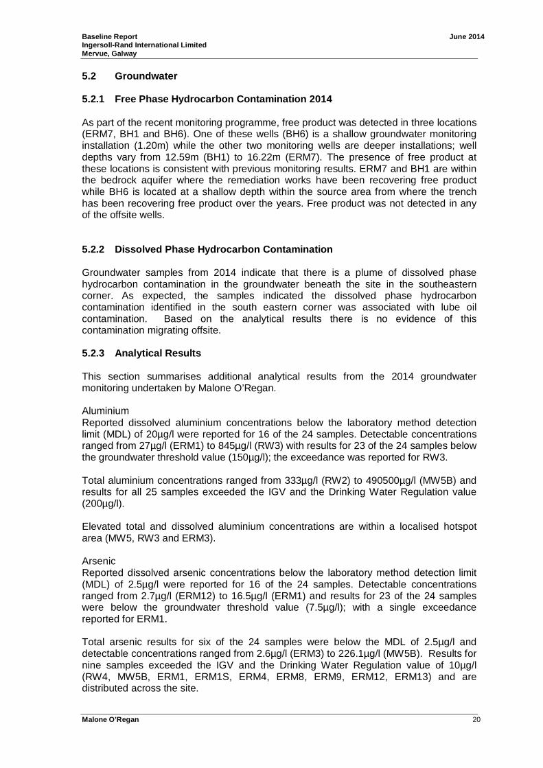
Baseline Report June 2014 Ingersoll-Rand International Limited Mervue, Galway
Malone O’Regan 20
5.2 Groundwater 5.2.1 Free Phase Hydrocarbon Contamination 2014 As part of the recent monitoring programme, free product was detected in three locations (ERM7, BH1 and BH6). One of these wells (BH6) is a shallow groundwater monitoring installation (1.20m) while the other two monitoring wells are deeper installations; well depths vary from 12.59m (BH1) to 16.22m (ERM7). The presence of free product at these locations is consistent with previous monitoring results. ERM7 and BH1 are within the bedrock aquifer where the remediation works have been recovering free product while BH6 is located at a shallow depth within the source area from where the trench has been recovering free product over the years. Free product was not detected in any of the offsite wells. 5.2.2 Dissolved Phase Hydrocarbon Contamination Groundwater samples from 2014 indicate that there is a plume of dissolved phase hydrocarbon contamination in the groundwater beneath the site in the southeastern corner. As expected, the samples indicated the dissolved phase hydrocarbon contamination identified in the south eastern corner was associated with lube oil contamination. Based on the analytical results there is no evidence of this contamination migrating offsite. 5.2.3 Analytical Results This section summarises additional analytical results from the 2014 groundwater monitoring undertaken by Malone O’Regan. Aluminium Reported dissolved aluminium concentrations below the laboratory method detection limit (MDL) of 20µg/l were reported for 16 of the 24 samples. Detectable concentrations ranged from 27µg/l (ERM1) to 845µg/l (RW3) with results for 23 of the 24 samples below the groundwater threshold value (150µg/l); the exceedance was reported for RW3. Total aluminium concentrations ranged from 333µg/l (RW2) to 490500µg/l (MW5B) and results for all 25 samples exceeded the IGV and the Drinking Water Regulation value (200µg/l). Elevated total and dissolved aluminium concentrations are within a localised hotspot area (MW5, RW3 and ERM3). Arsenic Reported dissolved arsenic concentrations below the laboratory method detection limit (MDL) of 2.5µg/l were reported for 16 of the 24 samples. Detectable concentrations ranged from 2.7µg/l (ERM12) to 16.5µg/l (ERM1) and results for 23 of the 24 samples were below the groundwater threshold value (7.5µg/l); with a single exceedance reported for ERM1. Total arsenic results for six of the 24 samples were below the MDL of 2.5µg/l and detectable concentrations ranged from 2.6µg/l (ERM3) to 226.1µg/l (MW5B). Results for nine samples exceeded the IGV and the Drinking Water Regulation value of 10µg/l (RW4, MW5B, ERM1, ERM1S, ERM4, ERM8, ERM9, ERM12, ERM13) and are distributed across the site.
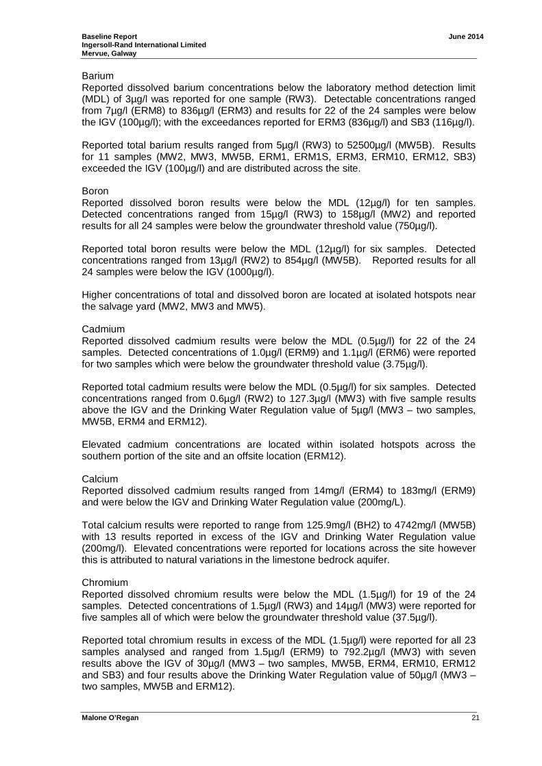
Baseline Report June 2014 Ingersoll-Rand International Limited Mervue, Galway
Malone O’Regan 21
Barium Reported dissolved barium concentrations below the laboratory method detection limit (MDL) of 3µg/l was reported for one sample (RW3). Detectable concentrations ranged from 7µg/l (ERM8) to 836µg/l (ERM3) and results for 22 of the 24 samples were below the IGV (100µg/l); with the exceedances reported for ERM3 (836µg/l) and SB3 (116µg/l). Reported total barium results ranged from 5µg/l (RW3) to 52500µg/l (MW5B). Results for 11 samples (MW2, MW3, MW5B, ERM1, ERM1S, ERM3, ERM10, ERM12, SB3) exceeded the IGV (100µg/l) and are distributed across the site. Boron Reported dissolved boron results were below the MDL (12µg/l) for ten samples. Detected concentrations ranged from 15µg/l (RW3) to 158µg/l (MW2) and reported results for all 24 samples were below the groundwater threshold value (750µg/l). Reported total boron results were below the MDL (12µg/l) for six samples. Detected concentrations ranged from 13µg/l (RW2) to 854µg/l (MW5B). Reported results for all 24 samples were below the IGV (1000µg/l). Higher concentrations of total and dissolved boron are located at isolated hotspots near the salvage yard (MW2, MW3 and MW5). Cadmium Reported dissolved cadmium results were below the MDL (0.5µg/l) for 22 of the 24 samples. Detected concentrations of 1.0µg/l (ERM9) and 1.1µg/l (ERM6) were reported for two samples which were below the groundwater threshold value (3.75µg/l). Reported total cadmium results were below the MDL (0.5µg/l) for six samples. Detected concentrations ranged from 0.6µg/l (RW2) to 127.3µg/l (MW3) with five sample results above the IGV and the Drinking Water Regulation value of 5µg/l (MW3 – two samples, MW5B, ERM4 and ERM12). Elevated cadmium concentrations are located within isolated hotspots across the southern portion of the site and an offsite location (ERM12). Calcium Reported dissolved cadmium results ranged from 14mg/l (ERM4) to 183mg/l (ERM9) and were below the IGV and Drinking Water Regulation value (200mg/L). Total calcium results were reported to range from 125.9mg/l (BH2) to 4742mg/l (MW5B) with 13 results reported in excess of the IGV and Drinking Water Regulation value (200mg/l). Elevated concentrations were reported for locations across the site however this is attributed to natural variations in the limestone bedrock aquifer. Chromium Reported dissolved chromium results were below the MDL (1.5µg/l) for 19 of the 24 samples. Detected concentrations of 1.5µg/l (RW3) and 14µg/l (MW3) were reported for five samples all of which were below the groundwater threshold value (37.5µg/l). Reported total chromium results in excess of the MDL (1.5µg/l) were reported for all 23 samples analysed and ranged from 1.5µg/l (ERM9) to 792.2µg/l (MW3) with seven results above the IGV of 30µg/l (MW3 – two samples, MW5B, ERM4, ERM10, ERM12 and SB3) and four results above the Drinking Water Regulation value of 50µg/l (MW3 – two samples, MW5B and ERM12).
Baseline Report June 2014 Ingersoll-Rand International Limited Mervue, Galway
Malone O’Regan 22
Elevated concentrations were reported for hotspots located within the salvage yard and to the south of the R&D building an offsite location (ERM12). Copper Reported dissolved copper results were below the MDL (7µg/l) for 21 of the 24 samples. Detected concentrations of 11µg/l (MW3), 14µg/l (MW3) and 22µg/l (MW2) were reported which were all below the groundwater threshold value (1500µg/l). Reported total copper results were below the MDL (7µg/l) for seven samples. Detected concentrations ranged from 7µg/l (ERM3) to 4140µg/l (MW3) with eight sample results above the IGV of 30µg/l (MW2 – 30µg/l, MW3 – two samples, MW5B, ERM4, ERM10, ERM12, SB3) and a single result was above the Drinking Water Regulation value of 2000µg/l (MW3). Elevated concentrations were reported for samples collected from the salvage yard and the area to the south of the R&D building. Iron Reported dissolved iron results were below the MDL (20µg/l) for six of the 24 samples. Detected concentrations ranging from 20µg/l (ERM10) to 11350µg/l (ERM9) were reported for 18 samples, ten of which exceeded the IGV (200µg/l) (RW1, RW2, RW4, MW3, ERM1, ERM1S, ERM6, ERM8, ERM9, SB2). Reported total iron results were reported above the MDL (20µg/l) for all 23 samples analysed and concentrations ranged from 83µg/l (BH2) to 1,024,000µg/l (1,024mg/l - MW3). The reported result for one of the 23 samples (83µg/l – BH2) was below the IGV and Drinking Water Regulation value of 200µg/l, all other sample results exceeded these values. The highest iron concentrations were reported for samples collected from the salvage yard (MW3) and hotspots to the south of the R&D building (e.g. MW5B and ERM1) and offsite locations (ERM12 and ERM13). Lead Reported dissolved lead results were below the MDL (5µg/l) for all 24 samples. Reported total lead results were below the MDL (5µg/l) for eight of the 23 samples analysed and concentrations ranged from 6µg/l (RW1) to 1,633µg/l (MW3). The reported results for 13 of the 23 samples were above the IGV and the Drinking Water Regulation value (10µg/l)). The highest lead concentrations were reported for samples collected from the salvage yard (MW3) and a hotspot in the area to the south of the R&D building (MW5B and ERM4) and an offsite location (ERM12). Magnesium Reported dissolved magnesium results for all 24 samples were above the MDL (0.1µg/l) and ranged from 0.1µg/l (ERM3) to 9.7µg/l (MW1). Reported total magnesium results for all 23 samples were reported above the MDL (0.1mg/l) and ranged from 0.1mg/l (RW3) to 322.7mg/l (MW5B). The reported result for two of the 23 samples (MW3 – 61mg/l and MW5B – 322.7mg/l) were above the IGV (50mg/l).
Baseline Report June 2014 Ingersoll-Rand International Limited Mervue, Galway
Malone O’Regan 23
Manganese Reported dissolved manganese results were below the MDL (2µg/l) for eight of the 24 samples. Detected concentrations ranging from 4µg/l (BH2) to 652µg/l (ERM9) were reported for 16 samples. There is no applicable groundwater assessment criteria value for dissolved manganese. Reported total manganese results were reported above the MDL (2µg/l) for all 23 samples analysed and concentrations ranging from 6µg/l (RW3) to 11240µg/l (MW5B). The reported results for three samples (BH2, RW3, MW1) were below the IGV and Drinking Water Regulation value of 50µg/l, all other 20 sample results exceeded these values. Elevated manganese concentrations were reported for locations across the site. Mercury Reported dissolved and total mercury results were below the MDL (1µg/l) for all 24 samples (23 samples for total mercury). The groundwater threshold value of 0.75µg/l is lower than the MDL value however the MDL equals the Drinking Water Regulation value of 1µg/l. Nickel Reported dissolved nickel results were below the MDL (2µg/l) for 20 of the 24 samples. Detected concentrations of 4µg/l (ERM3), 11µg/l(MW2), 13µg/l(MW3), 23µg/l(MW3) were reported of which one result one result (23µg/l - MW3) exceeded the groundwater threshold value (15µg/l). Reported total nickel results were below the MDL (2µg/l) for three samples. Detected concentrations ranged from 2µg/l (MW1 and ERM9) to 1727µg/l (MW3) with eight sample results above the IGV and Drinking Water Regulation value of 20µg/l (MW3 – two samples, MW5B, ERM4, ERM10, ERM12, ERM13, SB3). The highest nickel concentrations were reported for samples collected from the salvage yard (MW3) and hotspot areas to the south of the R&D building and an offsite location (ERM12). Potassium Reported dissolved potassium results ranged from 0.9µg/l (MW1), 46.1µg/l(ERM4), there is no applicable assessment criteria value for dissolved potassium. Reported total potassium results ranged from 1µg/l(MW1), 46.1µg/l(ERM4) with 13 of the 23 reported results above the IGV (5µg/l). Elevated potassium concentrations were reported for samples collected from across the site. Selenium Reported dissolved selenium results for all 24 samples were below the MDL (3µg/l). Reported total selenium results for 21 of 23 analysed samples were below the MDL (3µg/l). The reported detectable concentrations of 3µg/l (ERM10) and 5µg/l (ERM6) were below the Drinking Water Regulation value of 10µg/l. Silver Reported dissolved silver results were below the MDL (5µg/l) for all 24 samples.

Baseline Report June 2014 Ingersoll-Rand International Limited Mervue, Galway
Malone O’Regan 24
Reported total silver results were below the MDL (5µg/l) for 18 of the 23 samples analysed and detected concentrations for five samples ranged from 5µg/l (ERM13) to 10µg/l (MW3). There are no applicable groundwater assessment criteria for silver. Sodium Reported dissolved sodium results for all 24 samples ranged from 15.1µg/l (ERM12) to 436.8µg/l(RW3) with a single exceedance of the groundwater threshold value (150µg/l) reported for RW3. Reported total sodium results for all 23 analysed samples ranged from 16.2µg/l (ERM12), 437µg/l (RW3) with a single exceedance of the groundwater threshold value (150µg/l) the Drinking Water Regulation value (200µg/l) reported for RW3. Zinc Reported dissolved zinc results for 13 of the 24 samples were below the MDL (3µg/l). Detected results ranged from 3µg/l (ERM4, ERM6 ERM8) to 60µg/l (MW3). There are no applicable groundwater assessment criteria for dissolved zinc. Reported total zinc results for all 23 analysed samples ranged from 5µg/l(RW3) to 37470µg/l(MW3). Results for six of the 23 samples (MW3 – two samples, MW5B, ERM4, ERM10, ERM12) were above the IGV (100µg/l). Inorganics Field Measurements All field measurements taken for the 26 samples collected were all within the accepted range for groundwater in Ireland. Nitrate Reported nitrate results for ten of the 24 samples were below the MDL (0.2mg/l). Detectable concentrations for 13 of the 24 samples were below the groundwater regulation value (50mg/l) and ranged from 0.4mg/l (MW5B and ERM10) to 14.2mg/l (MW2). One sample reported for SB3 (58.4mg/l) exceeded the groundwater regulation value the Drinking Water Regulation value (250mg/l). Nitrite Reported nitrite results for 20 of the 24 samples were below the MDL (0.02mg/l). Detectable concentrations for four of the 24 samples ranged from 0.08mg/l (RW3) to 0.3mg/l (MW3) and were below the groundwater threshold value of 0.375mg/l and the Drinking Water Regulation value (0.5mg/l). Ammoniacal nitrogen Reported ammoniacal nitrogen results for 20 of the 24 samples were above the MDL (0.03mg/l as N) and ranged from 0.03mg/l as N (ERM10 and ERM13) to 2.17mg/l as N (MW5B) and nine results (RW4, MW3, MW5B, ERM3, ERM4 ERM8, ERM9, ERM10 and SB2) exceeded the upper groundwater threshold value (0.175mg/l as N). Seven results (RW4, MW3, MW5B, ERM3, ERM4 ERM8 and SB2) exceeded the Drinking Water Regulation value (0.23mg/l). Orthophosphate Reported results for 20 of the 22 samples analysed for orthophosphate were below the MDL (0.06mg/l as PO4) with detectable concentrations of 0.31mg/l (MW3) and 0.47mg/l (MW2) which exceeded the groundwater threshold value of 0.11mg/l as PO4 or 0.035mg/l as P.

Baseline Report June 2014 Ingersoll-Rand International Limited Mervue, Galway
Malone O’Regan 25
Reported MRP orthophosphate for all eight of the analyses samples were below the MDL (0.06mg/l as PO4). Total Organic Carbon (TOC) Reported TOC results for all ten analysed samples ranged from 4mg/l to 57mg/l. There are no applicable groundwater assessment criteria for TOC. Cyanide Reported total cyanide results for 17 of the 24 samples analysed were below the MDL (0.01mg/l). Reported results ranged from 0.01mg/l (RW2, RW4, ERM1, ERM9, ERM10, SB2) to 0.02mg/l (MW2) and all were below the groundwater threshold value of 0.0375mg/l and the Drinking Water Regulation value (0.5mg/l). Chloride Reported concentrations for all ten analysed samples were above the MDL (0.3mg/l) and ranged from 40.7mg/l (BH2) to 138.9mg/l (RW3). All reported concentrations were below the groundwater threshold value (187.5mg/l) and the Drinking Water Regulation value (250mg/l). Fluoride Reported fluoride results for the six (BH2, RW1, RW2, RW3, MW5B and ERM1S) of the seven analysed samples were below the MDL (0.3mg/l) and a result of 0.3mg/l was reported for ERM8. All reported concentrations were below the IGV (1mg/l) and the Drinking Water Regulation value (0.8mg/l). Sulphate Reported sulphate results for the 23 samples analysed ranged from 0.44mg/l (ERM3) to 89.44mg/l (MW5B) and all results were below the groundwater threshold value (187.5mg/l) and the Drinking Water Regulation value (250mg/l). Anionic Surfactants Reported anionic surfactant results ranged from <0.02mg/l (one sample – RW3) to 3.39mg/l (ERM3). Biochemical Oxygen Demand (BOD) and Chemical Oxygen Demand (COD) Reported BOD results for 14 of the 18 analysed samples were above the MDL (1mg/l) and ranged from 1mg/l (BH2, RW4) to 26mg/l (ERM1s). Reported COD results for 12 of the 18 analysed samples were above the MDL (7mg/l) and ranged from 8mg/l (RW3) to 1380mg/l (ERM13). Coliforms and Faecal Coliforms Coliforms were detected in two of the three samples analysed; MW2 (52 MPN/100ml) and MW3 (9.8 MPN/100ml), both results exceed the relevant drinking water standard (0 per 100ml) Faecal Coliforms were below the method of detection (1 MPN/100ml) in all three samples analysed. Phenols Reported total phenol (HPLC) results for all 12 analysed samples were below the MDL (0.1mg/l). Reported phenol results for all 17 analysed samples were also below the MDL (1µg /l).
Baseline Report June 2014 Ingersoll-Rand International Limited Mervue, Galway
Malone O’Regan 26
Phtalates Reported phtalate results for all 17 analysed samples were below the MDL (5µg /l). Polycyclic aromatic hydrocarbons (PAHs) Reported PAH results for all 17 analysed samples were below the relevant MDL (ranging from 0.5µg /l to 1µg /l). Volatile Organic Compounds (VOCs) All reported volatile organic compounds results for all 21 analysed samples were below the relevant MDL (ranging from 0.5µg /l to 4µg /l). Semi Volatile Organic Compounds All other reported semi volatile organic compounds results for all 19 analysed samples were below the relevant MDL (ranging from 0.5µg /l to 1µg /l). 5.3 Summary The available soils and groundwater data for the site are consistent as it confirms that hydrocarbon contamination persists in the south eastern portion of the site adjacent to the R&D Building where the lube oil leak occurred in 2002. There is no evidence of offsite migration of hydrocarbon contamination. While the remedial works in place since the leak have been successful in removing significant quantities of free phase contamination, free phase hydrocarbon contamination persists. IR have requested MOR to complete additional works during summer 2014 with a view to optimising the remedial strategy – these works will be completed in accordance with the requirements of the OEE. In addition to hydrocarbon contamination, some localised hotspots of elevated metal concentrations were also observed during these recent monitoring events. The proposed future works to optimise the remedial strategy will also consider such matters in greater detail.
Baseline Report June 2014 Ingersoll-Rand International Limited Mervue, Galway
Malone O’Regan 27
6.0 Conclusions Based on the review of all available information, it is considered reasonable in characterising the baseline soil and groundwater concentrations at the IR site in Galway to conclude the following: • The site is underlain by Limestone Till underlain by Dinantian Pure Bedded
Limestone.
• The aquifer beneath the site is a karstic aquifer, part of the Galway East Groundwater Body, with reportedly highly variable well yields and a vulnerability rating of high to extreme.
• Groundwater is inferred to flow in a south westerly direction beneath the site with
some local variations.
• The nearest hydrological feature is the Terryland River which flows in a south westernly direction approximately 900m north of the site.
• A number of designated sites are located within a 2km radius of the site including the Lough Corrib Special Area of Conservation (SAC) and Proposed Natural Heritage Area (pNHA) located to the northwest of the site, the Special Protected Area (SPA) Lough Atalia and Galway Bay which is a designated SAC, pNHA and SPA.
• A historic lube oil leak (estimated 16,000L) in 2002 resulted in contamination to
soils and groundwater beneath the site in the southeastern corner.
• IR have spent a significant amount of money since 2002 in undertaking investigation and remediation works associated with the lube oil leak.
• The remedial works implemented since 2002 have been effective in recovering over 6,300L of lube oil.
• Groundwater analytical data from April 2014 confirm that there are no offsite impacts associated with the lube oil contamination. This finding would be consistent with the findings of a previous detailed QRA which concluded that the lube oil contamination presented no risk to human health or environmental receptors.
• Some free phase and dissolved phase lube oil contamination continues to impact on the groundwater beneath the south east portion of the site.
• With the exception of the lube oil incident, and some other isolated hotspots of contamination that would be typical of such a longstanding industrial site e.g. localised hotspots of metal concentrations, there is no significant evidence of any other contamination event that would have impacted on baseline soil and groundwater conditions at the site.
• IR have requested that MOR undertake some additional works to see if the
remedial works can be optimised to expedite the recovery of the lube oil contamination. These works will also include a more detailed evaluation of the localised hotspots of elevated metal concentrations observed during the recent

Baseline Report June 2014 Ingersoll-Rand International Limited Mervue, Galway
Malone O’Regan 28
groundwater sampling event. All works will be undertaken under the Direction of the OEE and all findings will be reported to the OEE.

Baseline Report June 2014 Ingersoll-Rand International Limited Mervue, Galway
Malone O’Regan 29
7.0 References Environmental Protection Agency (EPA), 2014. Online web mapping data available at: http://gis.epa.ie/Envision. Geological Survey Ireland (GSI), 2014. Online web mapping: http://spatial.dcenr.gov.ie/imf/imf.jsp?site=Groundwater . Geological Survey Ireland (GSI), 2004. 1st Draft Clare-Corrib GWB Description. Online web mapping: http://spatial.dcenr.gov.ie/imf/imf.jsp?site=Groundwater . Geological Survey of Ireland (GSI), 2010a. Groundwater web-mapping site (http://193.178.1.182/website/Introduction to Groundwater WebMapping.htm). GSI, Ireland. Geological Survey of Ireland (GSI), 2010. Groundwater Bodies Descriptions (http://www.gsi.ie/Programmes/Groundwater/Projects/Groundwater+Body+Descriptions.htm) GSI. Ireland. National Parks and Wildlife Services, 2014. Online web mapping data available at: http://webgis.npws.ie/npwsviewer/. Office of Public Works (OPW), 2014. Online web mapping data available at: http://www.opw.ie/hydro/index.asp?mpg=main.asp. Statutory Instruments, 2010. S.I. No. 9 of 2010: European Communities Environmental Objectives (Groundwater) Regulations. Statutory Instruments, Ireland. Teagasc, 2006. Soil and Subsoil GIS data layers generated by Teagasc with co-operation of the Forest Service, EPA and GSI. Project completed May 2006. Teagasc, Ireland.

DRAWINGS

Client
Job
Job Number Drawing Number Sht. Size
A4Scale Date Drawn
Drawing
ENVIRONMENTAL SERVICES LTD
2B Richview Office Park,Clonskeagh,DUBLIN 14.
Tel: +353 1 260 2655Fax: +353 1 260 2660Email: [email protected]
1E1048 As shown June ‘14 DD
Baseline Characterisation
Ingersoll-Rand International Limited Site Location
Status
Final
N
Ordnance Survey Ireland No. EN0002514© Ordnance Survey Ireland and Government of Ireland
Site Boundary
Legend
Site Location
0m 500m 1000m
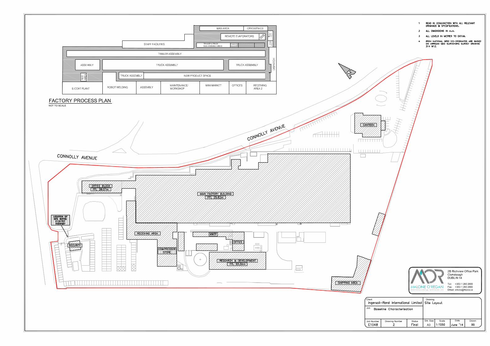
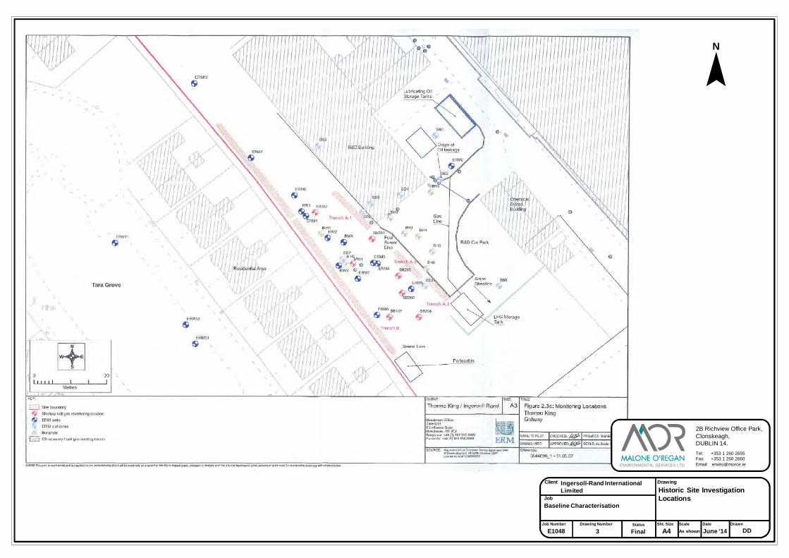
Client
Job
Job Number Drawing Number Sht. Size
A4Scale Date Drawn
Drawing
ENVIRONMENTAL SERVICES LTD
2B Richview Office Park,Clonskeagh,DUBLIN 14.
Tel: +353 1 260 2655Fax: +353 1 260 2660Email: [email protected]
3E1048 As shown June ‘14 DD
Baseline Characterisation
Ingersoll-Rand International Limited Historic Site Investigation
Locations
Status
Final
N
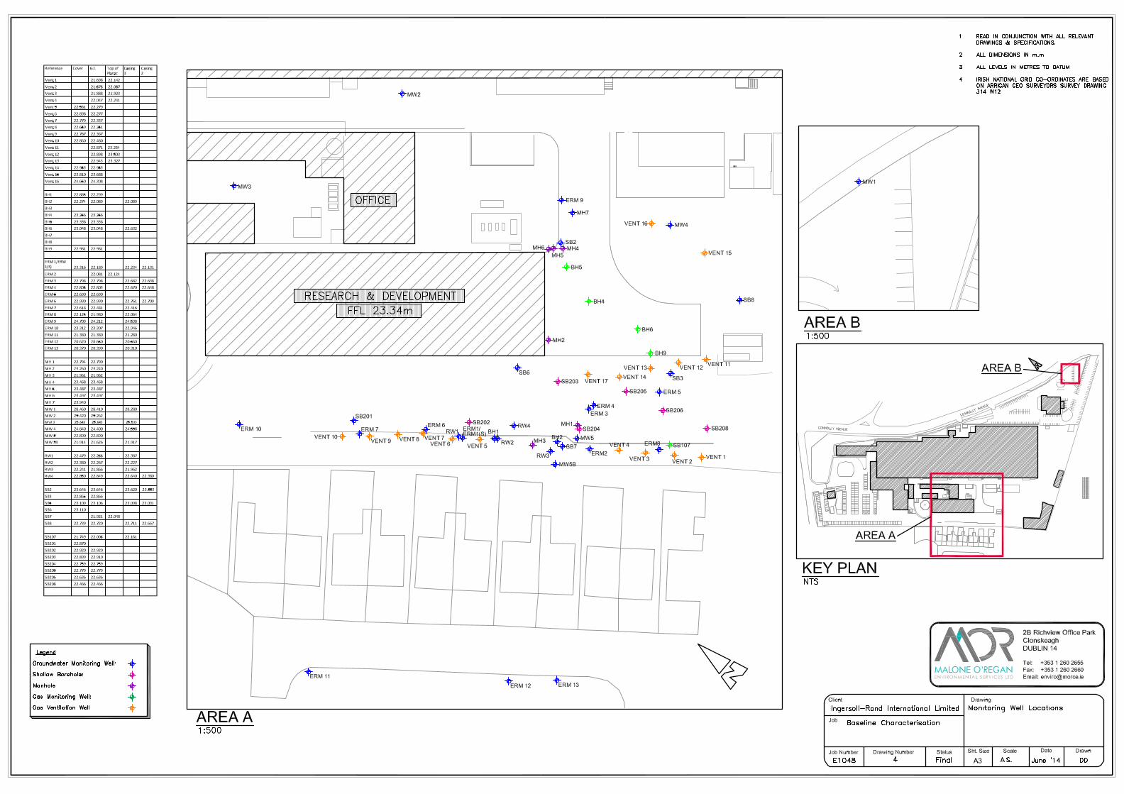
R ef ere nc e Co ve r G. l. To p of Pl as tic
C asi ng 1 C asi ng 2
V en t 1 21. 69 8 22. 14 2V en t 2 21. 57 5 22. 05 7V en t 3 21. 88 8 21. 92 3V en t 4 22. 04 7 22. 24 1
V en t 5 2 2. 58 1 22. 27 9V en t 6 2 2. 89 8 22. 27 7V en t 7 2 2. 77 9 22. 33 7V en t 8 2 2. 65 9 22. 25 1
V en t 9 2 2. 78 7 22. 36 7V en t 1 0 2 2. 86 0 22. 48 0V en t 1 1 22. 87 1 23. 28 4V en t 1 2 22. 89 8 23. 50 3
V en t 1 3 22. 94 3 23. 32 7V en t 1 4 2 2. 95 3 22. 95 3V en t 1 5 2 3. 81 0 23. 68 8V en t 1 6 2 4. 65 0 24. 30 8
B H1 2 2. 88 5 22. 29 9B H2 2 2. 27 4 22. 08 9 22 .08 9B H3B H4 2 3. 25 6 23. 25 6
B H5 2 3. 33 8 23. 33 8B H6 2 3. 04 8 23. 04 8 22 .63 2B H7B H8
B H9 2 2. 98 1 22. 98 1
E RM 1 /ER M 1( S) 2 3. 31 6 22. 18 9 22 .23 4 22 .13 1E RM 2 22. 08 1 22. 12 4
E RM 3 2 2. 79 8 22. 79 8 22 .68 2 22 .63 8E RM 4 2 2. 80 5 22. 80 3 22 .67 0 22 .64 8E RM 5 2 2. 69 0 22. 69 0E RM 6 2 2. 99 0 22. 99 0 22 .76 1 22 .70 9
E RM 7 2 2. 61 8 22. 48 1 22 .41 6E RM 8 2 2. 12 5 21. 98 0 22 .06 4E RM 9 2 4. 70 9 24. 21 2 24 .53 8E RM 1 0 2 3. 31 2 23. 30 7 22 .94 6E RM 1 1 2 1. 38 0 21. 38 0 21 .28 0
E RM 1 2 2 0. 62 0 20. 65 0 20 .56 0E RM 1 3 2 0. 37 0 20. 39 0 20 .31 0
M H 1 2 2. 79 4 22. 79 0
M H 2 2 3. 26 0 23. 24 0M H 3 2 1. 96 1 21. 96 2M H 4 2 3. 46 8 23. 46 8M H 5 2 3. 48 7 23. 48 7
M H 6 2 3. 49 7 23. 49 7M H 7 2 3. 94 0
M W 1 2 8. 46 0 28. 41 0 28 .28 0
M W 2 2 5. 42 0 25. 26 2M W 3 25. 64 3 25. 64 3 25 .53 3
M W 4 2 4. 84 0 24. 40 0 24 .55 8
M W 5 2 2. 89 0 22. 89 0
M W 5B 2 1. 91 4 21. 62 6 21 .91 7
R W 1 2 2. 47 9 22. 25 5 22 .38 7
R W 2 2 2. 38 0 22. 26 7 22 .22 7
R W 3 2 2. 24 1 21. 86 6 21 .96 2
R W 4 2 2. 85 0 22. 84 9 22 .64 0 22 .38 0
S B2 2 3. 64 6 23. 64 6 23 .62 0 23 .55 3
S B5 2 3. 10 9 23. 10 6 23 .09 8 23 .03 1
S B7 21. 92 1 22. 04 8
S B8 2 2. 73 9 22. 72 0 22 .71 1 22 .66 7
S B1 07 2 1. 74 9 22. 00 5 22 .16 1
S B2 01 2 2. 87 0
S B2 02 2 2. 92 0 22. 92 0
S B2 03 2 2. 89 9 22. 91 0
S B2 04 2 2. 75 9 22. 75 9
S B2 05 2 2. 77 9 22. 77 9
S B2 06 2 2. 63 6 22. 63 6

Client
Job
Job Number Drawing Number Sht. Size
A4Scale Date Drawn
Drawing
ENVIRONMENTAL SERVICES LTD
2B Richview Office Park,Clonskeagh,DUBLIN 14.
Tel: +353 1 260 2655Fax: +353 1 260 2660Email: [email protected]
5E1048 As shown June ‘14 DD
Baseline Characterisation
Ingersoll-Rand International Limited Subsoil Map
Status
Final
N
Ordnance Survey Ireland No. EN0002514© Ordnance Survey Ireland and Government of Ireland
Site Boundary
Legend
Site Location
0m 500m 1000m

Client
Job
Job Number Drawing Number Sht. Size
A4Scale Date Drawn
Drawing
ENVIRONMENTAL SERVICES LTD
2B Richview Office Park,Clonskeagh,DUBLIN 14.
Tel: +353 1 260 2655Fax: +353 1 260 2660Email: [email protected]
6E1048 As shown June ‘14 DD
Baseline Characterisation
Ingersoll-Rand International Limited Bedrock Geology
Status
Final
N
Ordnance Survey Ireland No. EN0002514© Ordnance Survey Ireland and Government of Ireland
Site Boundary
Legend
Site Location
0m 500m 1000m
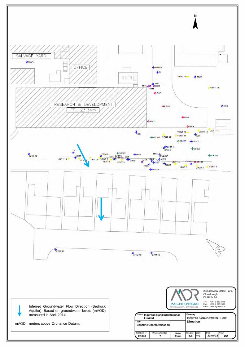
Client
Job
Job Number Drawing Number Sht. Size
A4Scale Date Drawn
Drawing
ENVIRONMENTAL SERVICES LTD
2B Richview Office Park,Clonskeagh,DUBLIN 14.
Tel: +353 1 260 2655Fax: +353 1 260 2660Email: [email protected]
7E1048 NTS June ‘14 DD
Baseline Characterisation
Ingersoll-Rand International Limited Inferred Groundwater Flow
Direction
Status
Final
N
Inferred Groundwater Flow Direction (BedrockAquifer). Based on groundwater levels (mAOD)measured in April 2014.
meters above Ordnance Datum.mAOD
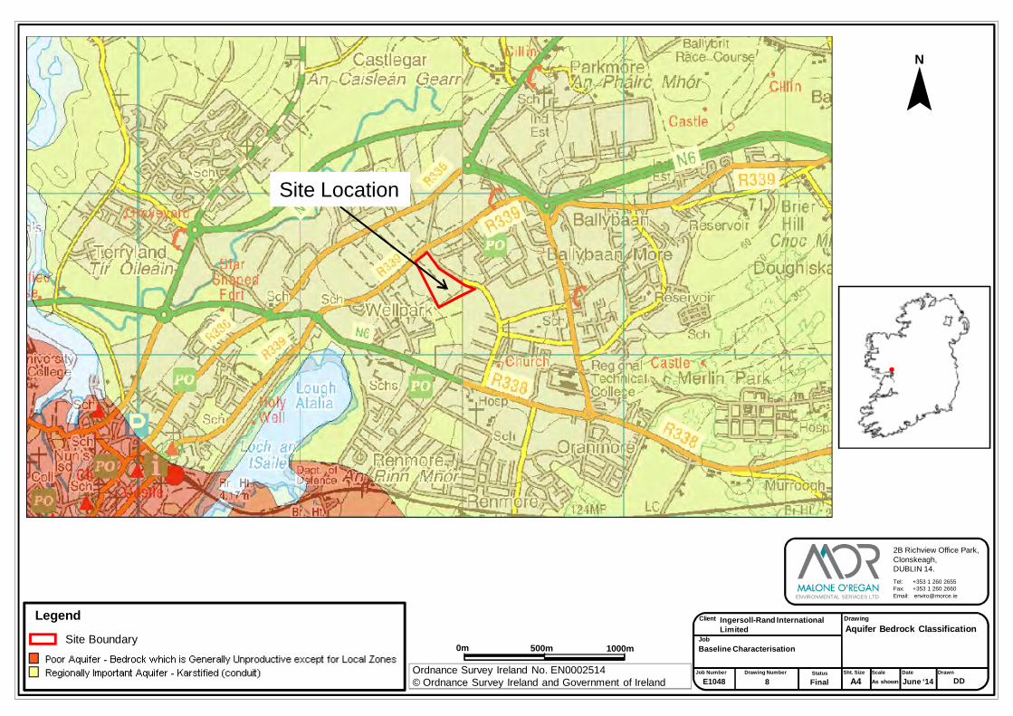
Client
Job
Job Number Drawing Number Sht. Size
A4Scale Date Drawn
Drawing
ENVIRONMENTAL SERVICES LTD
2B Richview Office Park,Clonskeagh,DUBLIN 14.
Tel: +353 1 260 2655Fax: +353 1 260 2660Email: [email protected]
8E1048 As shown June ‘14 DD
Baseline Characterisation
Ingersoll-Rand InternationalLimited Aquifer Bedrock Classification
Status
Final
N
Ordnance Survey Ireland No. EN0002514© Ordnance Survey Ireland and Government of Ireland
Site Boundary
Legend
Site Location
0m 500m 1000m

Client
Job
Job Number Drawing Number Sht. Size
A4Scale Date Drawn
Drawing
ENVIRONMENTAL SERVICES LTD
2B Richview Office Park,Clonskeagh,DUBLIN 14.
Tel: +353 1 260 2655Fax: +353 1 260 2660Email: [email protected]
9E1048 As shown June ‘14 DD
Baseline Characterisation
Ingersoll-Rand International Limited Aquifer Vulnerability
Status
Final
N
Ordnance Survey Ireland No. EN0002514© Ordnance Survey Ireland and Government of Ireland
Site Boundary
Legend
Site Location
0m 500m 1000m

Client
Job
Job Number Drawing Number Sht. Size
A4Scale Date Drawn
Drawing
ENVIRONMENTAL SERVICES LTD
2B Richview Office Park,Clonskeagh,DUBLIN 14.
Tel: +353 1 260 2655Fax: +353 1 260 2660Email: [email protected]
10E1048 As shown June ‘14 DD
Baseline Characterisation
Ingersoll-Rand International Limited Wells Within 2Km Radius
Status
Final
N
Ordnance Survey Ireland No. EN0002514© Ordnance Survey Ireland and Government of Ireland
Site Boundary
Legend
Site Location
0m 500m 1000m
2km Radius

Client
Job
Job Number Drawing Number Sht. Size
A4Scale Date Drawn
Drawing
ENVIRONMENTAL SERVICES LTD
2B Richview Office Park,Clonskeagh,DUBLIN 14.
Tel: +353 1 260 2655Fax: +353 1 260 2660Email: [email protected]
11E1048 As shown June ‘14 DD
Baseline Characterisation
Ingersoll-Rand International Limited Natura 2000 Sites within
2km of Site
Status
Final
N
Ordnance Survey Ireland No. EN0002514© Ordnance Survey Ireland and Government of Ireland
Site Boundary
Legend
2km Radius
Site Location
0m 500m 1000m

TABLES

BH2 RW1 RW2 RW3 RW 4 MW 1 MW 2 MW5B ERM 1 ERM 1(S) ERM 3 ERM 4 ERM 6 ERM 8 ERM 9 ERM 11 ERM 12 ERM 13 SB 2 SB 3 SB 8 QC (100)
Jones 14/5298 Jones 14/5336
Jones 14/5336 Jones 14/5336 Jones 14/5298 Jones 14/5375 Jones 14/5375 Jones 14/4571 Jones 14/4571 Jones 14/5424 Jones 14/5336 Jones 14/5375 Jones 14/5336 Jones 14/5375 Jones 14/5375 Jones 14/5424 Jones 14/5298 Jones 14/5375Jones 14-
4571Jones 14/5375 Jones 14/5336 Jones 14/5336 Jones 14/5375 Jones 14/5375 Jones 14/5375 Jones 14/5375 Jones 14/5486
Unit MDL
FIELD MEASURED PARAMETERS pH units ♦ ~ ~ 6.5-9.5 7.14 7.07 6.89 10.9 6.95 6.91 6.82 7.1 7.16 8.2 6.99 7.06 11.14 8.48 7.26 6.9 6.78 7.3 7.32 6.85 7.12 6.95 7.09 - - -
Electrical Conductivity µS/cm ♦ 1,875 ~ 2500 662.7 651.6 581.8 895.2 651.4 673.3 851.0 741.5 757.0 599.4 642.5 736.9 376.2 333.7 600.8 874.7 830.8 524.9 513.4 575.9 490.7 525.9 577.4 - - -Dissolved Oxygen % ♦ ~ NAC ~ 31.1 48.0 7.8 68.0 22.6 45.3 - - 51.1 7.1 11.5 40.2 51.4 92.5 22.1 32.6 33.6 - 64.9 67.1 70.0 83.2 31.4 - - -Dissolved Oxygen mg/l ~ ~ 3.2 5.0 0.8 8.4 2.4 4.9 - - 5.1 0.8 1.2 4.1 5.2 9.1 2.3 3.1 3.5 - 6.8 7.0 6.8 8.8 3.2 - - -
ºC ♦ ~ 25 ~ 13.9 13.0 12.5 13.2 13.3 11.8 13.5 13.2 15.5 12.4 14.1 13.8 14.7 15.8 13.5 16.9 13.5 12.4 13.0 12.3 16.3 12.3 13.4 - - -Oxidation Reduction Potential mV ♦ ~ ~ ATC & NAC -118.9 -79.8 -160.9 -33.2 -106.6 67.8 191.7 198.9 36.4 -128.4 -88.9 -26.9 -111.2 33.1 -99.8 -18.9 -107 -76.2 33.2 95.4 83.6 77.4 -145.1 - - -
N/A ♦ ~ ~ ATC & NAC Cloudy ClearVery Slightly
CloudySlightly Cloudy Clear Clear - - Silty Slightly Silty Grey Dark Clear Silty
Light Grey Colour
Cloudy Clear - Sheen Slightly Silty Very Silty Very Silty Clear - - -
N/A ♦ ~ ~ ATC & NAC Slight HCO Slight HCO HCO No Odour Strong HCO No Odour - - No Odour HCO HCO Slight HCO HCO HCO HCO Slight HCO HCO - Slight HCO No Odour No Odour No Odour HCO - - -
Other observations N/A ♦ ~ ~ ~ - - Sheen No Sheen HC Sheen NEC NECRed
iron/manganese colour
NEC Sheen - Slight Sheen - - Slight Sheen Well gone dry Slight Sheen Light Sheen - NEC NEC NEC No Product Well went dry Well went dry -
Analytical ParametersMPN/100ml <1 ~ 0 0 - - - - - - <1 <1 - - - - - - - - - <1 - - - - - - - -MPN/100ml <1 ~ 0 ~ - - - - - - 52 9.8 - - - - - - - - - <1 - - - - - - - -
LABORATORY ANALYSED PARAMETERS
µg/l <20 150 ~ ~ <20 <20 <20 845 56 <20 <20 <20 <20 351 39 27 66 65 <20 <20 <20 <20 <20 <20 <20 48 <20 <20 - -Arsenic (As) dissolved µg/l 2.5 7.5 ~ ~ <2.5 5.4 <2.5 <2.5 4 <2.5 <2.5 <2.5 <2.5 <2.5 16.5 <2.5 <2.5 <2.5 9.4 15.6 10.3 <2.5 <2.5 <2.5 2.7 <2.5 <2.5 <2.5 - -
µg/l <3 ~ 100 ~ 10 10 13 <3 30 9 46 37 48 23 20 38 836 87 21 7 58 70 60 10 39 17 54 116 - -µg/l 12 750 ~ ~ 18 22 <12 15 24 <12 158 <12 76 <12 14 21 <12 <12 41 32 104 43 27 <12 <12 <12 35 <12 - -
Cadmium (Cd) dissolved µg/l 0.5 3.75 ~ ~ <0.5 <0.5 <0.5 <0.5 <0.5 <0.5 <0.5 <0.5 <0.5 <0.5 <0.5 <0.5 <0.5 <0.5 1.1 <0.5 1 <0.5 <0.5 <0.5 <0.5 <0.5 <0.5 <0.5 - -mg/l <0.2 ~ 200 ~ 80 142 134.7 46.1 127.8 146.5 155 131.5 129 34.1 147.2 175 123 14 118.1 156.2 183 103.9 100.2 115.1 120.1 121.7 114.9 169.1 - -
Chromium (Cr) dissolved µg/l 1.5 37.5 ~ ~ <1.5 <1.5 3 1.5 2 <1.5 <1.5 <1.5 14 3.5 <1.5 <1.5 8 <1.5 <1.5 <1.5 <1.5 <1.5 <1.5 <1.5 <1.5 <1.5 <1.5 <1.5 - -Copper (Cu) dissolved µg/l 7 1500 ~ ~ <7 <7 <7 <7 <7 <7 22 14 11 <7 <7 <7 <7 <7 <7 <7 <7 <7 <7 <7 <7 <7 <7 <7 - -Iron (Fe) dissolved µg/l <20 ~ 200 ~ 63 5916 3504 <20 4177 <20 26 <20 608 24 6402 998 25 103 7354 1262 11350 20 <20 28 <20 92 1665 <20 - -Lead (Pb) dissolved µg/l <5 18.75 ~ ~ <5 <5 <5 <5 <5 <5 <5 <5 <5 <5 <5 <5 <5 <5 <5 <5 <5 <5 <5 <5 <5 <5 <5 <5 - -
mg/l <0.1 ~ - ~ 1.6 6.2 4 <0.1 5.2 9.7 6.1 5.9 6 0.6 5.9 5.6 0.1 1 8.7 7 9.4 4.2 4 5 3.6 3.8 4.2 7.7 - -Manganese (Mn) dissolved µg/l <2 - ~ ~ 4 562 220 <2 487 <2 44 47 424 <2 430 330 <2 5 559 369 652 71 <2 <2 <2 35 260 <2 - -Mercury (Hg) dissolved µg/l <1 0.75 ~ ~ <1 <1 <1 <1 <1 <1 <1 <1 <1 <1 <1 <1 <1 <1 <1 <1 <1 <1 <1 <1 <1 <1 <1 <1 - -Nickel (Ni) dissolved µg/l <2 15 ~ ~ <2 <2 <2 <2 <2 <2 11 13 23 <2 <2 <2 4 <2 <2 <2 <2 <2 <2 <2 <2 <2 <2 <2 - -Potassium (K) dissolved mg/L <0.1 ~ ~ ~ 1.9 1.8 2.7 3.5 5.5 0.9 33.2 25.7 22 3.5 2.3 1.9 11.4 46.1 1.6 3.2 7.8 5.6 4 2.9 2.2 1.7 5.2 4.4 - -Selenium (Se) dissolved µg/l <3 ~ ~ ~ <3 <3 <3 <3 <3 <3 <3 <3 <3 <3 <3 <3 <3 <3 <3 <3 <3 <3 <3 <3 <3 <3 <3 <3 - -
µg/l <5 ~ ~ ~ <5 <5 <5 <5 <5 <5 <5 <5 <5 <5 <5 <5 <5 <5 <5 <5 <5 <5 <5 <5 <5 <5 <5 <5 - -Sodium (Na) dissolved mg/l <0.1 150 ~ ~ 19 36.6 31.2 436.8 53.7 25.8 73.4 64.7 58.7 34.2 39.8 36.9 58.6 61.9 30 44.2 37.1 43.5 36.3 35.3 15.1 17.6 43.6 43.1 - -Zinc (Zn) dissolved µg/l <3 ~ - ~ <3 <3 <3 <3 4 7 12 25 60 <3 <3 4 <3 3 3 3 5 <3 <3 <3 <3 <3 6 <3 - -
µg/l <20 ~ 200 200 375 1962 333 950 579 803 2802 103900 9698 490500 3907 14370 1002 8274 4678 3598 895 15300 1884 - 241500 10370 524 13200 - -µg/l <2.5 ~ 10 10 2.8 7.1 <2.5 7.9 10.3 <2.5 <2.5 <2.5 4 226.1 24.3 22.1 2.6 15.1 9.4 23.2 10.3 3.4 <2.5 - 171.4 10.4 <2.5 8.9 - -µg/l <3 ~ 100 ~ 22 11 13 5 36 16 117 13930 552 52500 40 136 1004 1283 74 20 58 339 184 - 1184 68 54 369 - -µg/l <12 ~ 1000 ~ 26 24 13 18 24 <12 158 <12 87 854 21 21 <12 <12 63 50 108 71 31 - <12 <12 40 18 - -
Cadmium (Cd) total µg/l <0.5 ~ 5 5 <0.5 0.8 0.6 <0.5 1.3 <0.5 0.8 127.3 16.3 43.2 2.1 2.9 <0.5 7.1 1.1 1 1 4.8 <0.5 - 51.8 2.7 <0.5 3 - -mg/l <0.2 ~ 200 ~ 125.9 176.6 135.1 168.2 191.4 207.8 179.5 2924 755.3 4742 233.3 345.8 197.3 264.1 173.3 328.6 183 1733 224.9 - 576.6 464.4 139 541 - -
Chromium (Cr) total µg/l <1.5 ~ 30 50 3.6 4.4 14.9 6.5 2 <1.5 6.2 792.2 84.2 613.9 7.3 16.8 8 49 16.3 9.1 1.5 42.7 5.3 - 522.7 26.1 1.9 33.3 - -µg/l <7 ~ 30 2000 <7 <7 13 <7 9 <7 30 4140 329 604 12 21 7 372 10 21 <7 36 <7 - 493 27 <7 67 - -µg/l <20 ~ 200 200 83 8055 3504 400 18740 1014 3186 1024000 96620 465400 19260 31440 3747 62040 7354 8632 11350 29680 2957 - 422500 20600 3269 21130 - -µg/l <5 ~ 10 10 <5 6 <5 <5 6 <5 15 1633 191 920 11 20 <5 100 20 16 <5 37 <5 - 276 20 <5 32 - -mg/l <0.1 ~ 50 ~ 3 7.2 4 0.1 5.6 10.5 6.5 67 17.2 322.7 6.9 8.1 4.4 4.6 11.5 7.2 9.4 15.8 4.9 - 14.1 6.5 4.3 15.1 - -
Manganese (Mn) total µg/l <2 ~ 50 50 21 565 221 6 502 29 145 8240 767 11240 505 563 193 1080 833 376 652 807 104 - 2718 404 285 3508 - -µg/l <1 ~ 1 1 <1 <1 <1 <1 <1 <1 <1 <1 <1 <1 <1 <1 <1 <1 <1 <1 <1 <1 <1 - <1 <1 <1 <1 - -µg/l <2 ~ 20 20 <2 5 <2 <2 4 2 17 1727 167 511 19 19 13 91 5 9 2 46 6 - 616 32 4 52 - -
Potassium (K) total mg/L <0.1 ~ 5 ~ 4.1 2.5 2.7 18.5 5.5 1 33.50 38.9 22 22.4 3 2.8 11.4 46.1 3.8 3.9 7.8 8.4 4.5 - 14.7 3.5 5.2 6.3 - -Selenium (Se) total µg/l <3 ~ ~ 10 <3 <3 <3 <3 <3 <3 <3 <3 <3 <3 <3 <3 <3 <3 5 <3 <3 <3 3 - <3 <3 <3 <3 - -
µg/l <5 ~ ~ ~ <5 <5 <5 <5 <5 <5 <5 <5 10 6 <5 <5 <5 <5 <5 <5 6 <5 <5 - 8 5 <5 <5 - -mg/l <0.1 ~ 150 200 75.6 36.7 31.4 437 53.7 26.3 73.8 76.7 58.7 91.4 39.8 36.9 63.2 61.9 30 63.4 37.1 44.3 37.8 - 16.2 16.9 45.2 45.3 - -µg/l <3 ~ 100 ~ 6 56 34 5 39 11 46 37470 2113 2043 52 89 57 644 20 67 12 181 26 - 890 70 82 94 - -
mg/l 2 ~ ~ NAC 7 11 8 8 - - 4 6 - 57 - 22 - - - 6 - 4 - - - - - - - -mg/l 0.05 187.5 200 250 29.45 5.22 21.56 26.55 7.77 76.29 41.68 38.51 39.74 89.44 13.53 43.87 0.44 9.87 1.04 34.27 7.64 23.51 33.09 - 33.34 38.78 71.17 12.96 - -mg/l 0.3 187.5 30 250 40.7 54 43 138.9 - - 113.8 116.3 - 123 - 55.4 - - - 110 - 67.4 - - - - - - - -mg/l 0.2 50 ~ 50 1.8 <0.2 <0.2 2 <0.2 12.4 14.2 7 8.9 0.4 <0.2 <0.2 <0.2 <0.2 <0.2 0.5 <0.2 0.4 2.7 4.1 2 1.2 <0.2 58.6 - -mg/l 0.02 0.375 ~ 0.5 <0.02 <0.02 <0.02 0.08 <0.02 <0.02 <0.02 0.3 <0.02 <0.02 <0.02 <0.02 <0.02 <0.02 <0.02 <0.02 <0.02 0.19 <0.02 <0.02 0.11 <0.02 <0.02 <0.02 - -mg/l 1 ~ ~ ~ 1 13 11 3 1 <1 - - <1 5 2 26 2 7 22 6 10 - <1 - - <1 2 - - -mg/l <7 ~ ~ ~ <7 22 16 8 39 <7 - - 36 17 21 95 55 9 31 <7 40 - <7 27 <7 1380 29 <7 135 -mg/l <0.2 ~ 0.2 ~ 1.7 0.9 0.7 <0.2 0.7 0.6 - - 1 1.5 1.4 1 3.9 0.9 1.3 0.7 0.8 - 1.1 1.1 0.9 0.8 - 1.3 - -mg/l <0.3 ~ 1 0.8 <0.3 <0.3 <0.3 <0.3 - - - - - <0.3 - <0.3 - - - 0.3 - <0.3 - - - - - - - -mg/l <0.06 0.11 ~ ~ <0.06 <0.06 <0.06 <0.06 <0.06 <0.06 0.47 <0.06 0.31 <0.06 <0.06 <0.06 <0.06 <0.06 <0.06 <0.06 <0.06 <0.06 <0.06 - <0.06 <0.06 <0.06 <0.06 - -mg/l <0.2 ~ ~ ~ 0.4 <0.2 <0.2 0.5 <0.2 2.8 3.2 1.7 2 <0.2 <0.2 <0.2 <0.2 <0.2 <0.2 <0.2 <0.2 <0.2 0.6 - 0.5 0.3 <0.2 13.2 - -mg/l <0.06 0.11 ~ ~ <0.06 <0.06 <0.06 <0.06 - - - - - <0.06 - <0.06 - - - <0.06 - <0.06 - - - - - - - -mg/l <0.01 0.0375 ~ 0.05 <0.01 <0.01 0.01 <0.01 0.01 <0.01 0.02 <0.01 <0.01 <0.01 0.01 <0.01 <0.01 <0.01 <0.01 <0.01 0.01 0.01 <0.01 <0.01 <0.01 <0.01 0.01 <0.01 - -mg/l <0.03 0.065-0.175 0.12 0.23 0.03 0.07 0.23 0.07 0.75 0.03 0.05 0.36 0.03 2.17 0.08 0.09 1.23 0.25 0.14 0.29 0.21 0.13 0.03 0.03 0.05 0.03 1.46 0.05 - -mg/l <1 ~ NAC ~ 238 448 356 124 - - 384 5102 - 6652 - 352 - - - 582 - 1448 - - - - - - - -mg/l <5 ~ ~ ~ 422 766 509 496 - - 802 7049 - 19202 - 1274 - - - 1264 - 3692 - - - - - - - -
µg/l 2 ~ 30 ~ <5 - - <5 - - <5 <5 - - - - - - - <5 - <5 - - - - - - - -µg/l 1 0.75 1 1 <5 - - <5 - - <5 <5 - - - - - - - <5 - <5 - - - - - - - -µg/l 2 ~ 10 ~ <5 - - <5 - - <5 <5 - - - - - - - <5 - <5 - - - - - - - -µg/l 2 ~ 10 ~ <5 - - <5 - - <5 <5 - - - - - - - <5 - <5 - - - - - - - -µg/l 3 ~ 10 ~ <5 - - <5 - - <5 <5 - - - - - - - <5 - <5 - - - - - - - -µg/l 3 ~ 10 ~ <5 - - <5 - - <5 <5 - - - - - - - <5 - <5 - - - - - - - -
µg/l 5 ~ ~ ~ <5 <5 <5 <5 <5 <5 <5 <5 <5 <5 <5 <5 <5 <5 <5 <5 <5 <5 <5 <5 <5 <5 <5 - <5 -µg/l 5 ~ ~ ~ <5 <5 <5 <5 <5 <5 <5 <5 <5 <5 <5 <5 <5 <5 <5 <5 <5 <5 <5 <5 <5 <5 <5 - <5 -µg/l 5 ~ ~ ~ <5 <5 <5 <5 <5 <5 <5 <5 <5 <5 <5 <5 <5 <5 <5 <5 <5 <5 <5 <5 <5 <5 <5 - <5 -µg/l 10 ~ ~ ~ <5 <5 <5 <5 <5 <5 <5 <5 <5 <5 <5 <5 92 <5 <5 <5 <5 <5 <5 <5 <5 <5 <5 - <5 -µg/l 10 ~ ~ ~ <10 <10 <10 <10 <10 <10 <10 <10 <10 <10 <10 <10 420 <10 <10 <10 <10 <10 <10 <10 <10 <10 <10 - <10 -µg/l 10 ~ ~ ~ <10 <10 <10 <10 80 <10 <10 <10 <10 <10 <10 20 890 20 <10 <10 <10 120 <10 <10 <10 <10 60 - <10 -µg/l 10 ~ ~ ~ <10 <10 6590 <10 7110 <10 <10 <10 <10 4050 2500 10180 12900 3010 2360 <10 <10 12030 1220 <10 <10 <10 4110 - <10 -µg/l 10 ~ ~ ~ <10 <10 6590 <10 7190 <10 <10 <10 <10 4050 2500 10200 14302 3030 2360 <10 <10 12150 1220 <10 <10 <10 4170 - <10 -
µg/l 5 ~ ~ ~ <5 <5 <5 <5 <5 <5 <5 <5 <5 <5 <5 <5 <5 <5 <5 <5 <5 <5 <5 <5 <5 <5 <5 - <5 -µg/l 5 ~ ~ ~ <5 <5 <5 <5 <5 <5 <5 <5 <5 <5 <5 <5 <5 <5 <5 <5 <5 <5 <5 <5 <5 <5 <5 - <5 -µg/l 5 ~ ~ ~ <5 <5 <5 <5 <5 <5 <5 <5 <5 <5 <5 <5 <5 <5 <5 <5 <5 <5 <5 <5 <5 <5 <5 - <5 -µg/l 10 ~ ~ ~ <5 <5 <5 <5 <5 <5 <5 <5 <5 <5 <5 <5 30 <5 <5 <5 <5 <5 <5 <5 <5 <5 <5 - <5 -µg/l 10 ~ ~ ~ <10 <10 <10 <10 <10 <10 <10 <10 <10 <10 <10 <10 250 <10 <10 <10 <10 <10 <10 <10 <10 <10 <10 - <10 -µg/l 10 ~ ~ ~ <10 <10 <10 <10 <10 <10 <10 <10 <10 <10 <10 <10 530 <10 <10 <10 <10 140 <10 <10 <10 <10 20 - <10 -µg/l 10 ~ ~ ~ <10 <10 2090 <10 2190 <10 <10 <10 <10 1070 720 3510 4220 1100 900 <10 <10 5610 310 <10 <10 <10 1450 - <10 -µg/l 10 ~ ~ ~ <10 <10 2090 <10 2190 <10 <10 <10 <10 1070 720 3510 5030 1100 900 <10 <10 5750 310 <10 <10 <10 1470 - <10 -
Total aliphatics and aromatics (C5-35) µg/l 10 ~ 10 ~ <10 <10 8680 <10 9380 <10 <10 <10 <11 5120 3220 13710 19332 4130 3260 <10 <10 17900 1530 <10 <10 <10 5640 - <10 -
EPH/ DRO Interpretations N/A ♦ ~ ~ ~ NIP - Lubericating oil NIP Lubericating oil NIP - - NIP Lubericating oil Lubericating oil Lubericating oil Degraded diesel &Lubercating oil Lubericating oil Lubericating oil NIP NIP - Lubericating oil NIP NIP NIP Lubericating oil - NIP -
Speciated Phenols (MS - SVOC)µg/l 10 ~ 200 ~ - <1 <1 - <1 <1 - - <1 <1 <1 <1 <1 <1 <1 - <1 - <1 <1 <1 <1 <1 - - -µg/l 10 ~ ~ ~ - <0.5 <0.5 - <0.5 <0.5 - - <0.5 <0.5 <0.5 <0.5 <0.5 <0.5 <0.5 - <0.5 - <0.5 <0.5 <0.5 <0.5 <0.5 - - -µg/l 10 ~ ~ ~ - <0.5 <0.5 - <0.5 <0.5 - - <0.5 <0.5 <0.5 <0.5 <0.5 <0.5 <0.5 - <0.5 - <0.5 <0.5 <0.5 <0.5 <0.5 - - -µg/l 10 ~ ~ ~ - <0.5 <0.5 - <0.5 <0.5 - - <0.5 <0.5 <0.5 <0.5 <0.5 <0.5 <0.5 - <0.5 - <0.5 <0.5 <0.5 <0.5 <0.5 - - -µg/l 10 ~ ~ ~ - <1 <1 - <1 <1 - - <1 <1 <1 <1 <1 <1 <1 - <1 - <1 <1 <1 <1 <1 - - -µg/l 10 ~ ~ ~ - <0.5 <0.5 - <0.5 <0.5 - - <0.5 <0.5 <0.5 <0.5 <0.5 <0.5 <0.5 - <0.5 - <0.5 <0.5 <0.5 <0.5 <0.5 - - -µg/l 10 ~ 200 ~ - <1 <1 - <1 <1 - - <1 <1 <1 <1 <1 <1 <1 - <1 - <1 <1 <1 <1 <1 - - -µg/l 10 ~ ~ ~ - <0.5 <0.5 - <0.5 <0.5 - - <0.5 <0.5 <0.5 <0.5 <0.5 <0.5 <0.5 - <0.5 - <0.5 <0.5 <0.5 <0.5 <0.5 - - -µg/l 10 ~ ~ ~ - <1 <1 - <1 <1 - - <1 <1 <1 <1 <1 <1 <1 - <1 - <1 <1 <1 <1 <1 - - -µg/l 10 ~ ~ ~ - <10 <10 - <10 <10 - - <10 <10 <10 <10 <10 <10 <10 - <10 - <10 <10 <10 <10 <10 - - -µg/l 10 ~ 2 ~ - <1 <1 - <1 <1 - - <1 <1 <1 <1 <1 <1 <1 - <1 - <1 <1 <1 <1 <1 - - -µg/l 10 ~ ~ ~ - <1 <1 - <1 <1 - - <1 <1 <1 <1 <1 <1 <1 - <1 - <1 <1 <1 <1 <1 - - -mg/l ~ 0.005 ~ <0.1 <0.1 <0.1 <0.1 - - <0.1 <0.1 - <0.1 - <0.1 - - - <0.1 - <0.1 - <0.1 <0.1 - - - - -
Bis(2-ethylhexyl) phthalate µg/l 10 ~ 8 ~ - <5 <5 - <5 <5 - - <5 <5 <5 <5 <5 <5 <5 - <5 - <5 <5 <5 <5 <5 - - -Butylbenzyl phthalate µg/l 10 ~ 5 ~ - <1 <1 - <1 <1 - - <1 <1 <1 <1 <1 <1 <1 - <1 - <1 <1 <1 <1 <1 - - -Di-n-butyl phthalate µg/l 10 ~ 2 ~ - <1.5 <1.5 - <1.5 <1.5 - - <1.5 <1.5 <1.5 <1.5 <1.5 <1.5 <1.5 - <1.5 - <1.5 <1.5 <1.5 <1.5 <1.5 - - -Di-n-Octyl phthalate µg/l 10 ~ 5 ~ - <1 <1 - <1 <1 - - <1 <1 <1 <1 <1 <1 <1 - <1 - <1 <1 <1 <1 <1 - - -
µg/l 10 ~ 5 ~ - <1 <1 - <1 <1 - - <1 <1 <1 <1 <1 <1 <1 - <1 - <1 <1 <1 <1 <1 - - -µg/l 10 ~ 5 ~ - <1 <1 - <1 <1 - - <1 <1 <1 <1 <1 <1 <1 - <1 - <1 <1 <1 <1 <1 - - -µg/l 60 ~ 5 ~ - - - - - - - - - - - - - - - - - - - - - - - - - -
2-Chlorophenol#
2-Methylphenol#
2-Nitrophenol
2,4-Dichlorophenol#
2,4-Dimethylphenol
EPH Interpretation
Phenol
4-Chloro-3-methylphenol4-Methylphenol
Phthalates
Diethyl phthalateDimethyl phthalateTotal Phthalates
4-NitrophenolPentachlorophenol
Total Phenols HPLC
>C5-EC7>EC7-EC8>EC8-EC10>EC10-EC12>EC12-EC16>EC16-EC21
2,4,5-Trichlorophenol2,4,6-Trichlorophenol
>EC21-EC35Total aromatics C5-35
Total aliphatics C5-35
TPH CWG - Aromatics
PETROLEUM HYDROCARBONSBTEX/MTBE
>C6-C8>C8-C10>C10-C12>C12-C16>C16-C21>C21-C35
TPH CWG - Aliphatics>C5-C6
Total Oxidised Nitrogen as N #MRP Ortho Phosphate as PO4Total Cyanide #
Total Alkalinity as CaCO3 #Total Solids
o-Xylene
MTBEBenzene
Nitrate (NO3)Nitrite (NO2)BOD
Ortho Phosphate as PO4 #Fluoride
TolueneEthylbenzenem/p-Xylene
Silver Dissolved
Aluminium total
Nickel (Ni) total
Zinc (Zn) total
Indicators Total Organic Carbon
Boron (B) total
Calcium (Ca) total
Copper (Cu) totalIron (Fe) total
Chloride
Lead (Pb) totalMagnesium total
Mercury (Hg) total
Sulphate
Ammoniacal Nitrogen as N #
ERM 10
Laboratory Report No. Groundwater Regulations
2010 (S.I. No. 9 of 2010)1
EPA Interim Guideline Value
(IGV) for Groundwater2
Drinking Water Regulations 2007
(S.I. No. 278 of 2007) 3
Sample Identity Groundwater Quality Standards MW3
30/04/201428/04/201430/04/201429/04/201429/04/201428/04/201429/04/201428/04/2014 29/04/2014
30/04/201430/04/201429/04/201430/04/201430/04/201429/04/201429/04/201429/04/201402/04/201428/04/201430/04/201428/04/201428/04/2014 28/04/2014 02/04/201402/04/201430/04/201429/04/2014
MetalsAluminium dissolved
CODAnionic Surfactants
Ingersoll-Rand International Limited
pH
Temperature
Barium DissolvedBoron (B) dissolved
Calcium (Ca) dissolved
Table 2: Groundwater Analytical Results
Sample Date
Parameters
Silver TotalSodium (Na) total
Arsenic (As) totalBarium Total
Magnesium dissolved
Colour
Odour
Faecal ColiformsColiforms
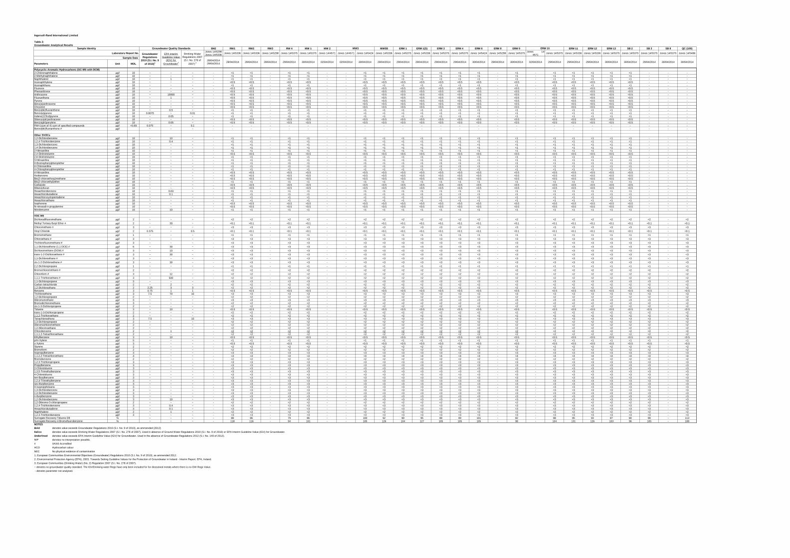
BH2 RW1 RW2 RW3 RW 4 MW 1 MW 2 MW5B ERM 1 ERM 1(S) ERM 3 ERM 4 ERM 6 ERM 8 ERM 9 ERM 11 ERM 12 ERM 13 SB 2 SB 3 SB 8 QC (100)
Jones 14/5298 Jones 14/5336
Jones 14/5336 Jones 14/5336 Jones 14/5298 Jones 14/5375 Jones 14/5375 Jones 14/4571 Jones 14/4571 Jones 14/5424 Jones 14/5336 Jones 14/5375 Jones 14/5336 Jones 14/5375 Jones 14/5375 Jones 14/5424 Jones 14/5298 Jones 14/5375Jones 14-
4571Jones 14/5375 Jones 14/5336 Jones 14/5336 Jones 14/5375 Jones 14/5375 Jones 14/5375 Jones 14/5375 Jones 14/5486
Unit MDL
ERM 10
Laboratory Report No. Groundwater Regulations
2010 (S.I. No. 9 of 2010)1
EPA Interim Guideline Value
(IGV) for Groundwater2
Drinking Water Regulations 2007
(S.I. No. 278 of 2007) 3
Sample Identity Groundwater Quality Standards MW3
30/04/201428/04/201430/04/201429/04/201429/04/201428/04/201429/04/201428/04/2014 29/04/2014
30/04/201430/04/201429/04/201430/04/201430/04/201429/04/201429/04/201429/04/201402/04/201428/04/201430/04/201428/04/201428/04/2014 28/04/2014 02/04/201402/04/201430/04/201429/04/2014
Ingersoll-Rand International Limited
Table 2: Groundwater Analytical Results
Sample Date
Parameters
Polycyclic Aromatic Hydrocarbons (GC-MS with DCM)2-Chloronaphthalene µg/l 10 ~ ~ ~ - <1 <1 - <1 <1 - - <1 <1 <1 <1 <1 <1 <1 - <1 - <1 <1 <1 <1 <1 - - -2-Methylnaphthalene µg/l 10 ~ ~ ~ - <1 <1 - <1 <1 - - <1 <1 <1 <1 <1 <1 <1 - <1 - <1 <1 <1 <1 <1 - - -
µg/l 10 ~ 1 ~ - <1 <1 - <1 <1 - - <1 <1 <1 <1 <1 <1 <1 - <1 - <1 <1 <1 <1 <1 - - -µg/l 10 ~ ~ ~ - <0.5 <0.5 - <0.5 <0.5 - - <0.5 <0.5 <0.5 <0.5 <0.5 <0.5 <0.5 - <0.5 - <0.5 <0.5 <0.5 <0.5 <0.5 - - -µg/l 10 ~ ~ ~ - <1 <1 - <1 <1 - - <1 <1 <1 <1 <1 <1 <1 - <1 - <1 <1 <1 <1 <1 - - -µg/l 10 ~ ~ ~ - <0.5 <0.5 - <0.5 <0.5 - - <0.5 <0.5 <0.5 <0.5 <0.5 <0.5 <0.5 - <0.5 - <0.5 <0.5 <0.5 <0.5 <0.5 - - -µg/l 10 ~ ~ ~ - <0.5 <0.5 - <0.5 <0.5 - - <0.5 <0.5 <0.5 <0.5 <0.5 <0.5 <0.5 - <0.5 - <0.5 <0.5 <0.5 <0.5 <0.5 - - -µg/l 10 ~ 10000 ~ - <0.5 <0.5 - <0.5 <0.5 - - <0.5 <0.5 <0.5 <0.5 <0.5 <0.5 <0.5 - <0.5 - <0.5 <0.5 <0.5 <0.5 <0.5 - - -µg/l 10 ~ 1 ~ - <0.5 <0.5 - <0.5 <0.5 - - <0.5 <0.5 <0.5 <0.5 <0.5 <0.5 <0.5 - <0.5 - <0.5 <0.5 <0.5 <0.5 <0.5 - - -µg/l 10 ~ ~ ~ - <0.5 <0.5 - <0.5 <0.5 - - <0.5 <0.5 <0.5 <0.5 <0.5 <0.5 <0.5 - <0.5 - <0.5 <0.5 <0.5 <0.5 <0.5 - - -
Benz(a)anthracene µg/l 10 ~ ~ ~ - <0.5 <0.5 - <0.5 <0.5 - - <0.5 <0.5 <0.5 <0.5 <0.5 <0.5 <0.5 - <0.5 - <0.5 <0.5 <0.5 <0.5 <0.5 - - -µg/l 10 ~ ~ ~ - <0.5 <0.5 - <0.5 <0.5 - - <0.5 <0.5 <0.5 <0.5 <0.5 <0.5 <0.5 - <0.5 - <0.5 <0.5 <0.5 <0.5 <0.5 - - -µg/l 10 ~ 0.5 ~ - <1 <1 - <1 <1 - - <1 <1 <1 <1 <1 <1 <1 - <1 - <1 <1 <1 <1 <1 - - -µg/l 10 0.0075 ~ 0.01 - <1 <1 - <1 <1 - - <1 <1 <1 <1 <1 <1 <1 - <1 - <1 <1 <1 <1 <1 - - -µg/l 10 ~ 0.05 ~ - <1 <1 - <1 <1 - - <1 <1 <1 <1 <1 <1 <1 - <1 - <1 <1 <1 <1 <1 - - -
Dibenzo(ah)anthracene µg/l 10 ~ ~ ~ - <0.5 <0.5 - <0.5 <0.5 - - <0.5 <0.5 <0.5 <0.5 <0.5 <0.5 <0.5 - <0.5 - <0.5 <0.5 <0.5 <0.5 <0.5 - - -Benzo(ghi)perylene µg/l 10 ~ 0.05 ~ - <0.5 <0.5 - <0.5 <0.5 - - <0.5 <0.5 <0.5 <0.5 <0.5 <0.5 <0.5 - <0.5 - <0.5 <0.5 <0.5 <0.5 <0.5 - - -PAH (sum of 4) sum of specified compounds µg/l <0.69 0.075 ~ 0.1 - - - - - - - - - - - - - - - - - - - - - - - - - -
µg/l ~ ~ ~ - - - - - - - - - - - - - - - - - - - - - - - - - -
µg/l 10 ~ 10 ~ - <1 <1 - <1 <1 - - <1 <1 <1 <1 <1 <1 <1 - <1 - <1 <1 <1 <1 <1 - - -µg/l 10 ~ 0.4 ~ - <1 <1 - <1 <1 - - <1 <1 <1 <1 <1 <1 <1 - <1 - <1 <1 <1 <1 <1 - - -µg/l 10 ~ ~ ~ - <1 <1 - <1 <1 - - <1 <1 <1 <1 <1 <1 <1 - <1 - <1 <1 <1 <1 <1 - - -µg/l 10 ~ ~ ~ - <1 <1 - <1 <1 - - <1 <1 <1 <1 <1 <1 <1 - <1 - <1 <1 <1 <1 <1 - - -µg/l 10 ~ ~ ~ - <1 <1 - <1 <1 - - <1 <1 <1 <1 <1 <1 <1 - <1 - <1 <1 <1 <1 <1 - - -µg/l 10 ~ ~ ~ - <0.5 <0.5 - <0.5 <0.5 - - <0.5 <0.5 <0.5 <0.5 <0.5 <0.5 <0.5 - <0.5 - <0.5 <0.5 <0.5 <0.5 <0.5 - - -µg/l 10 ~ ~ ~ - <1 <1 - <1 <1 - - <1 <1 <1 <1 <1 <1 <1 - <1 - <1 <1 <1 <1 <1 - - -µg/l 10 ~ ~ ~ - <1 <1 - <1 <1 - - <1 <1 <1 <1 <1 <1 <1 - <1 - <1 <1 <1 <1 <1 - - -µg/l 10 ~ ~ ~ - <1 <1 - <1 <1 - - <1 <1 <1 <1 <1 <1 <1 - <1 - <1 <1 <1 <1 <1 - - -µg/l 10 ~ ~ ~ - <1 <1 - <1 <1 - - <1 <1 <1 <1 <1 <1 <1 - <1 - <1 <1 <1 <1 <1 - - -µg/l 10 ~ ~ ~ - <1 <1 - <1 <1 - - <1 <1 <1 <1 <1 <1 <1 - <1 - <1 <1 <1 <1 <1 - - -µg/l 10 ~ ~ ~ - <0.5 <0.5 - <0.5 <0.5 - - <0.5 <0.5 <0.5 <0.5 <0.5 <0.5 <0.5 - <0.5 - <0.5 <0.5 <0.5 <0.5 <0.5 - - -µg/l 10 ~ ~ ~ - <0.5 <0.5 - <0.5 <0.5 - - <0.5 <0.5 <0.5 <0.5 <0.5 <0.5 <0.5 - <0.5 - <0.5 <0.5 <0.5 <0.5 <0.5 - - -µg/l 10 ~ ~ ~ - <0.5 <0.5 - <0.5 <0.5 - - <0.5 <0.5 <0.5 <0.5 <0.5 <0.5 <0.5 - <0.5 - <0.5 <0.5 <0.5 <0.5 <0.5 - - -µg/l 10 ~ ~ ~ - <1 <1 - <1 <1 - - <1 <1 <1 <1 <1 <1 <1 - <1 - <1 <1 <1 <1 <1 - - -µg/l 10 ~ ~ ~ - <0.5 <0.5 - <0.5 <0.5 - - <0.5 <0.5 <0.5 <0.5 <0.5 <0.5 <0.5 - <0.5 - <0.5 <0.5 <0.5 <0.5 <0.5 - - -µg/l 10 ~ ~ ~ - <0.5 <0.5 - <0.5 <0.5 - - <0.5 <0.5 <0.5 <0.5 <0.5 <0.5 <0.5 - <0.5 - <0.5 <0.5 <0.5 <0.5 <0.5 - - -µg/l 10 ~ 0.03 ~ - <1 <1 - <1 <1 - - <1 <1 <1 <1 <1 <1 <1 - <1 - <1 <1 <1 <1 <1 - - -µg/l 10 ~ 0.1 ~ - <1 <1 - <1 <1 - - <1 <1 <1 <1 <1 <1 <1 - <1 - <1 <1 <1 <1 <1 - - -µg/l 10 ~ ~ ~ - <1 <1 - <1 <1 - - <1 <1 <1 <1 <1 <1 <1 - <1 - <1 <1 <1 <1 <1 - - -µg/l 10 ~ ~ ~ - <1 <1 - <1 <1 - - <1 <1 <1 <1 <1 <1 <1 - <1 - <1 <1 <1 <1 <1 - - -µg/l 10 ~ ~ ~ - <0.5 <0.5 - <0.5 <0.5 - - <0.5 <0.5 <0.5 <0.5 <0.5 <0.5 <0.5 - <0.5 - <0.5 <0.5 <0.5 <0.5 <0.5 - - -µg/l 10 ~ ~ ~ - <0.5 <0.5 - <0.5 <0.5 - - <0.5 <0.5 <0.5 <0.5 <0.5 <0.5 <0.5 - <0.5 - <0.5 <0.5 <0.5 <0.5 <0.5 - - -µg/l 10 ~ 10 ~ - <1 <1 - <1 <1 - - <1 <1 <1 <1 <1 <1 <1 - <1 - <1 <1 <1 <1 <1 - - -
µg/l 2 ~ ~ ~ - <2 <2 - <2 <2 - - <2 <2 <2 <2 <2 <2 <2 - <2 - <2 <2 <2 <2 <2 <2 - <2
µg/l 2 ~ 30 ~ - <0.1 <0.1 - <0.1 <0.1 - - <0.1 <0.1 <0.1 <0.1 <0.1 <0.1 <0.1 - <0.1 - <0.1 <0.1 <0.1 <0.1 <0.1 <0.1 - <0.1
µg/l 3 ~ ~ ~ - <3 <3 - <3 <3 - - <3 <3 <3 <3 <3 <3 <3 - <3 - <3 <3 <3 <3 <3 <3 - <3
µg/l 2 0.375 ~ 0.5 - <0.1 <0.1 - <0.1 <0.1 - - <0.1 <0.1 <0.1 <0.1 <0.1 <0.1 <0.1 - <0.1 - <0.1 <0.1 <0.1 <0.1 <0.1 <0.1 - <0.1
µg/l 1 ~ ~ ~ - <1 <1 - <1 <1 - - <1 <1 <1 <1 <1 <1 <1 - <1 - <1 <1 <1 <1 <1 <1 - <1
µg/l 3 ~ ~ ~ - <3 <3 - <3 <3 - - <3 <3 <3 <3 <3 <3 <3 - <3 - <3 <3 <3 <3 <3 <3 - <3
µg/l 3 ~ ~ ~ - <3 <3 - <3 <3 - - <3 <3 <3 <3 <3 <3 <3 - <3 - <3 <3 <3 <3 <3 <3 - <3
µg/l 6 ~ 30 ~ - <3 <3 - <3 <3 - - <3 <3 <3 <3 <3 <3 <3 - <3 - <3 <3 <3 <3 <3 <3 - <3
µg/l 3 ~ 10 ~ - <3 <3 - <3 <3 - - <3 <3 <3 <3 <3 <3 <3 - <3 - <3 <3 <3 <3 <3 <3 - <3
µg/l 3 ~ 30 ~ - <3 <3 - <3 <3 - - <3 <3 <3 <3 <3 <3 <3 - <3 - <3 <3 <3 <3 <3 <3 - <3
µg/l 3 ~ ~ ~ - <3 <3 - <3 <3 - - <3 <3 <3 <3 <3 <3 <3 - <3 - <3 <3 <3 <3 <3 <3 - <3
µg/l 3 ~ 30 ~ - <3 <3 - <3 <3 - - <3 <3 <3 <3 <3 <3 <3 - <3 - <3 <3 <3 <3 <3 <3 - <3
µg/l 1 ~ ~ ~ - <1 <1 - <1 <1 - - <1 <1 <1 <1 <1 <1 <1 - <1 - <1 <1 <1 <1 <1 <1 - <1
µg/l 2 ~ ~ ~ - <2 <2 - <2 <2 - - <2 <2 <2 <2 <2 <2 <2 - <2 - <2 <2 <2 <2 <2 <2 - <2
µg/l 3 ~ 12 ~ - <2 <2 - <2 <2 - - <2 <2 <2 <2 <2 <2 <2 - <2 - <2 <2 <2 <2 <2 <2 - <2
µg/l 3 ~ 500 ~ - <2 <2 - <2 <2 - - <2 <2 <2 <2 <2 <2 <2 - <2 - <2 <2 <2 <2 <2 <2 - <21,1-Dichloropropene µg/l 3 ~ ~ ~ - <3 <3 - <3 <3 - - <3 <3 <3 <3 <3 <3 <3 - <3 - <3 <3 <3 <3 <3 <3 - <3Carbon tetrachloride µg/l 2 ~ 2 ~ - <2 <2 - <2 <2 - - <2 <2 <2 <2 <2 <2 <2 - <2 - <2 <2 <2 <2 <2 <2 - <21,2-Dichloroethane µg/l 2 2.25 3 3 - <2 <2 - <2 <2 - - <2 <2 <2 <2 <2 <2 <2 - <2 - <2 <2 <2 <2 <2 <2 - <2
µg/l 3 0.75 1 1 - <0.5 <0.5 - <0.5 <0.5 - - <0.5 <0.5 <0.5 <0.5 <0.5 <0.5 <0.5 - <0.5 - <0.5 <0.5 <0.5 <0.5 <0.5 <0.5 - <0.5µg/l 3 7.5 70 10 - <3 <3 - <3 <3 - - <3 <3 <3 <3 <3 <3 <3 - <3 - <3 <3 <3 <3 <3 <3 - <3
1,2-Dichloropropane µg/l 2 ~ ~ ~ - <2 <2 - <2 <2 - - <2 <2 <2 <2 <2 <2 <2 - <2 - <2 <2 <2 <2 <2 <2 - <2µg/l 3 ~ ~ ~ - <3 <3 - <3 <3 - - <3 <3 <3 <3 <3 <3 <3 - <3 - <3 <3 <3 <3 <3 <3 - <3µg/l 3 ~ ~ ~ - <2 <2 - <2 <2 - - <2 <2 <2 <2 <2 <2 <2 - <2 - <2 <2 <2 <2 <2 <2 - <2
cis-1-3-Dichloropropene µg/l 2 ~ ~ ~ - <2 <2 - <2 <2 - - <2 <2 <2 <2 <2 <2 <2 - <2 - <2 <2 <2 <2 <2 <2 - <2µg/l 3 ~ 10 ~ - <0.5 <0.5 - <0.5 <0.5 - - <0.5 <0.5 <0.5 <0.5 <0.5 <0.5 <0.5 - <0.5 - <0.5 <0.5 <0.5 <0.5 <0.5 <0.5 - <0.5
trans-1-3-Dichloropropene µg/l 2 ~ ~ ~ - <2 <2 - <2 <2 - - <2 <2 <2 <2 <2 <2 <2 - <2 - <2 <2 <2 <2 <2 <2 - <21,1,2-Trichloroethane µg/l 2 ~ ~ ~ - <2 <2 - <2 <2 - - <2 <2 <2 <2 <2 <2 <2 - <2 - <2 <2 <2 <2 <2 <2 - <2Tetrachloroethene µg/l 3 7.5 ~ 10 - <3 <3 - <3 <3 - - <3 <3 <3 <3 <3 <3 <3 - <3 - <3 <3 <3 <3 <3 <3 - <31,3-Dichloropropane µg/l 2 ~ ~ ~ - <2 <2 - <2 <2 - - <2 <2 <2 <2 <2 <2 <2 - <2 - <2 <2 <2 <2 <2 <2 - <2
µg/l 2 ~ ~ ~ - <2 <2 - <2 <2 - - <2 <2 <2 <2 <2 <2 <2 - <2 - <2 <2 <2 <2 <2 <2 - <21,2-Dibromoethane µg/l 2 ~ ~ ~ - <2 <2 - <2 <2 - - <2 <2 <2 <2 <2 <2 <2 - <2 - <2 <2 <2 <2 <2 <2 - <2
µg/l 2 ~ 1 ~ - <2 <2 - <2 <2 - - <2 <2 <2 <2 <2 <2 <2 - <2 - <2 <2 <2 <2 <2 <2 - <2µg/l 2 ~ ~ ~ - <2 <2 - <2 <2 - - <2 <2 <2 <2 <2 <2 <2 - <2 - <2 <2 <2 <2 <2 <2 - <2µg/l 3 ~ 10 ~ - <0.5 <0.5 - <0.5 <0.5 - - <0.5 <0.5 <0.5 <0.5 <0.5 <0.5 <0.5 - <0.5 - <0.5 <0.5 <0.5 <0.5 <0.5 <0.5 - <0.5µg/l 5 ~ ~ ~ - <1 <1 - <1 <1 - - <1 <1 <1 <1 <1 <1 <1 - <1 - <1 <1 <1 <1 <1 <1 - <1µg/l 3 ~ ~ ~ - <0.5 <0.5 - <0.5 <0.5 - - <0.5 <0.5 <0.5 <0.5 <0.5 <0.5 <0.5 - <0.5 - <0.5 <0.5 <0.5 <0.5 <0.5 <0.5 - <0.5µg/l 2 ~ ~ ~ - <2 <2 - <2 <2 - - <2 <2 <2 <2 <2 <2 <2 - <2 - <2 <2 <2 <2 <2 <2 - <2µg/l 2 ~ ~ ~ - <2 <2 - <2 <2 - - <2 <2 <2 <2 <2 <2 <2 - <2 - <2 <2 <2 <2 <2 <2 - <2µg/l 3 ~ ~ ~ - <3 <3 - <3 <3 - - <3 <3 <3 <3 <3 <3 <3 - <3 - <3 <3 <3 <3 <3 <3 - <3µg/l 4 ~ ~ ~ - <4 <4 - <4 <4 - - <4 <4 <4 <4 <4 <4 <4 - <4 - <4 <4 <4 <4 <4 <4 - <4µg/l 2 ~ ~ ~ - <2 <2 - <2 <2 - - <2 <2 <2 <2 <2 <2 <2 - <2 - <2 <2 <2 <2 <2 <2 - <2µg/l 3 ~ ~ ~ - <3 <3 - <3 <3 - - <3 <3 <3 <3 <3 <3 <3 - <3 - <3 <3 <3 <3 <3 <3 - <3µg/l 3 ~ ~ ~ - <3 <3 - <3 <3 - - <3 <3 <3 <3 <3 <3 <3 - <3 - <3 <3 <3 <3 <3 <3 - <3µg/l 3 ~ ~ ~ - <3 <3 - <3 <3 - - <3 <3 <3 <3 <3 <3 <3 - <3 - <3 <3 <3 <3 <3 <3 - <3µg/l 3 ~ ~ ~ - <3 <3 - <3 <3 - - <3 <3 <3 <3 <3 <3 <3 - <3 - <3 <3 <3 <3 <3 <3 - <3µg/l 3 ~ ~ ~ - <3 <3 - <3 <3 - - <3 <3 <3 <3 <3 <3 <3 - <3 - <3 <3 <3 <3 <3 <3 - <3µg/l 3 ~ ~ ~ - <3 <3 - <3 <3 - - <3 <3 <3 <3 <3 <3 <3 - <3 - <3 <3 <3 <3 <3 <3 - <3µg/l 3 ~ ~ ~ - <3 <3 - <3 <3 - - <3 <3 <3 <3 <3 <3 <3 - <3 - <3 <3 <3 <3 <3 <3 - <3µg/l 3 ~ ~ ~ - <3 <3 - <3 <3 - - <3 <3 <3 <3 <3 <3 <3 - <3 - <3 <3 <3 <3 <3 <3 - <3µg/l 3 ~ ~ ~ - <3 <3 - <3 <3 - - <3 <3 <3 <3 <3 <3 <3 - <3 - <3 <3 <3 <3 <3 <3 - <3µg/l 3 ~ ~ ~ - <3 <3 - <3 <3 - - <3 <3 <3 <3 <3 <3 <3 - <3 - <3 <3 <3 <3 <3 <3 - <3µg/l 3 ~ ~ ~ - <3 <3 - <3 <3 - - <3 <3 <3 <3 <3 <3 <3 - <3 - <3 <3 <3 <3 <3 <3 - <3µg/l 3 ~ ~ ~ - <3 <3 - <3 <3 - - <3 <3 <3 <3 <3 <3 <3 - <3 - <3 <3 <3 <3 <3 <3 - <3µg/l 3 ~ 10 ~ - <3 <3 - <3 <3 - - <3 <3 <3 <3 <3 <3 <3 - <3 - <3 <3 <3 <3 <3 <3 - <3µg/l 2 ~ ~ ~ - <2 <2 - <2 <2 - - <2 <2 <2 <2 <2 <2 <2 - <2 - <2 <2 <2 <2 <2 <2 - <2µg/l 3 ~ 0.4 ~ - <3 <3 - <3 <3 - - <3 <3 <3 <3 <3 <3 <3 - <3 - <3 <3 <3 <3 <3 <3 - <3µg/l 3 ~ 0.1 ~ - <3 <3 - <3 <3 - - <3 <3 <3 <3 <3 <3 <3 - <3 - <3 <3 <3 <3 <3 <3 - <3µg/l 2 ~ 1 ~ - <2 <2 - <2 <2 - - <2 <2 <2 <2 <2 <2 <2 - <2 - <2 <2 <2 <2 <2 <2 - <2µg/l 3 ~ ~ ~ - <3 <3 - <3 <3 - - <3 <3 <3 <3 <3 <3 <3 - <3 - <3 <3 <3 <3 <3 <3 - <3% ~ ~ ~ - 88 86 - 79 86 - - 100 92 90 95 88 89 101 - 82 - 88 95 93 87 80 89 - 113% ~ ~ ~ - 118 116 - 94 101 - - 105 126 104 127 105 105 105 - 98 - 104 131 126 103 96 105 - 108
NOTESBold denotes value exceeds Groundwater Regulations 2010 (S.I. No. 9 of 2010), as ammended (2012)
Italics denotes value exceeds Drinking Water Regulations 2007 (S.I. No. 278 of 2007). Used in absence of Ground Water Regulations 2010 (S.I. No. 9 of 2010) or EPA Interim Guideline Value (IGV) for Groundwater.
Underlined denotes value exceeds EPA Interim Guideline Value (IGV) for Groundwater. Used in the absence of Groundwater Regulations 2012 (S.I. No. 149 of 2012).
NIP denotes no interpretation possible.
# UKAS Accredited
HCO Hydrocarbon odour
NEC No physical evidence of contamination
1; European Communities Environmental Objectives (Groundwater) Regulations 2010 (S.I. No. 9 of 2010), as ammended 2012.
2; Environmental Protection Agency (EPA), 2003. Towards Setting Guideline Values for the Protection of Groundwater in Ireland - Interim Report. EPA, Ireland.
3; European Communities (Drinking Water) (No. 2) Regulation 2007 (S.I. No. 278 of 2007).
~ denotes no groundwater quality standard. The IGV/Drinking water Regs have only been included for for disssolved metals where there is no GW Regs Value.
- denotes parameter not analysed.
2,2-Dichloropropane
Bromochloromethane #
Chloroform #
1,1,1-Trichloroethane #
Vinyl Chloride
Bromomethane
Chloroethane #
Trichlorofluoromethane #
1,1-Dichloroethene (1,1 DCE) #
Dichloromethane (DCM) #
trans-1-2-Dichloroethene #
1,1-Dichloroethane #
cis-1-2-Dichloroethene #
VOC MSDichlorodifluoromethane
Methyl Tertiary Butyl Ether #
Chloromethane #
Surrogate Recovery 4-BromofluorobenzeneSurrogate Recovery Toluene D8
1,2,4-TrichlorobenzeneHexachlorobutadieneNaphthalene1,2,3-Trichlorobenzene
4-Isopropyltoluene1,3-Dichlorobenzene1,4-Dichlorobenzenen-Butylbenzene1,2-Dichlorobenzene1,2-Dibromo-3-chloropropane
2-Chlorotoluene1,3,5-Trimethylbenzene4-Chlorotoluenetert-Butylbenzene1,2,4-Trimethylbenzenesec-Butylbenzene
BromoformIsopropylbenzene1,1,2,2-TetrachloroethaneBromobenzene1,2,3-TrichloropropanePropylbenzene
Chlorobenzene1,1,1,2-TetrachloroethaneEthylbenzenep/m-Xyleneo-XyleneStyrene
BenzeneTrichloroethene
DibromomethaneBromodichloromethane
Toluene
Dibromochloromethane
4-Chlorophenylphenylether4-NitroanilineAzobenzeneBis(2-chloroethoxy)methaneBis(2-chloroethyl)etherCarbazole
1,2,4-Trichlorobenzene1,3-Dichlorobenzene1,4-Dichlorobenzene2-Nitroaniline2,4-Dinitrotoluene2,6-Dinitrotoluene
N-nitrosodi-n-propylamineNitrobenzene
DibenzofuranHexachlorobenzeneHexachlorobutadieneHexachlorocyclopentadieneHexachloroethaneIsophorone
3-Nitroaniline4-Bromophenylphenylether4-Chloroaniline
Indeno(123cd)pyrene
Benzo(bk)fluoranthene #
Other SVOCs1,2-Dichlorobenzene
Fluorene PhenanthreneAnthraceneFluoranthenePyrene
Benzo(a)pyrene
ChryseneBenzo(bk)fluoranthene
NaphthaleneAcenaphthyleneAcenaphthene
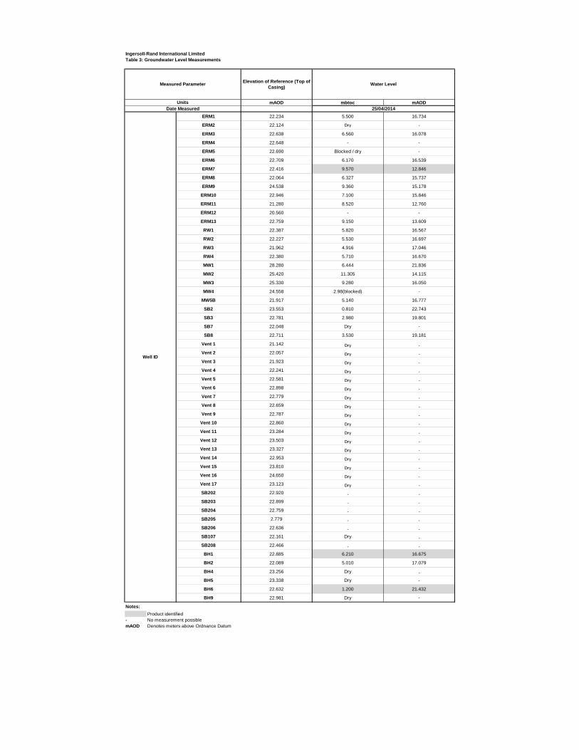
Elevation of Reference (Top of Casing)
mAOD mbtoc mAOD
ERM1 22.234 5.500 16.734
ERM2 22.124 Dry -ERM3 22.638 6.560 16.078
ERM4 22.648 - -
ERM5 22.690 Blocked / dry -
ERM6 22.709 6.170 16.539
ERM7 22.416 9.570 12.846
ERM8 22.064 6.327 15.737
ERM9 24.538 9.360 15.178
ERM10 22.946 7.100 15.846
ERM11 21.280 8.520 12.760
ERM12 20.560 - -
ERM13 22.759 9.150 13.609
RW1 22.387 5.820 16.567
RW2 22.227 5.530 16.697
RW3 21.962 4.916 17.046
RW4 22.380 5.710 16.670
MW1 28.280 6.444 21.836
MW2 25.420 11.305 14.115
MW3 25.330 9.280 16.050
MW4 24.558 2.98(blocked) -MW5B 21.917 5.140 16.777
SB2 23.553 0.810 22.743
SB3 22.781 2.980 19.801
SB7 22.048 Dry -SB8 22.711 3.530 19.181
Vent 1 21.142 Dry -Vent 2 22.057 Dry -Vent 3 21.923 Dry -Vent 4 22.241 Dry -Vent 5 22.581 Dry -Vent 6 22.898 Dry -Vent 7 22.779 Dry -Vent 8 22.659 Dry -Vent 9 22.787 Dry -
Vent 10 22.860 Dry -Vent 11 23.284 Dry -Vent 12 23.503 Dry -Vent 13 23.327 Dry -Vent 14 22.953 Dry -Vent 15 23.810 Dry -Vent 16 24.650 Dry -Vent 17 23.123 Dry -SB202 22.920 - -SB203 22.899 - -SB204 22.759 - -SB205 2.779 - -SB206 22.636 - -SB107 22.161 Dry -SB208 22.466 - -BH1 22.885 6.210 16.675
BH2 22.089 5.010 17.079
BH4 23.256 Dry -BH5 23.338 Dry -
BH6 22.632 1.200 21.432
BH9 22.981 Dry -
Notes:
Product identified- No measurement possiblemAOD Denotes meters above Ordnance Datum
Water Level
Units Date Measured 25/04/2014
Ingersoll-Rand International LimitedTable 3: Groundwater Level Measurements
Measured Parameter
Well ID
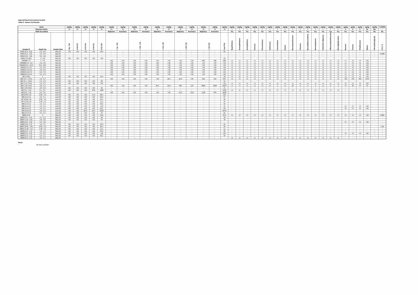
Table 4: Historic Soil Results
mg/kg mg/kg mg/kg mg/kg mg/kg mg/kg mg/kg mg/kg mg/kg mg/kg mg/kg mg/kg mg/kg mg/kg mg/kg mg/kg mg/kg mg/kg mg/kg mg/kg mg/kg mg/kg mg/kg mg/kg mg/kg mg/kg mg/kg mg/kg mg/kg mg/kg mg/kg ug/kg ug/kg ug/kg ug/kg mg/kg % M/M10 10 10 10 10 10 10 10 10 10 10 10 10 10 10 10 1 1 1 1 1 1 1 1 1 1 1 1 1 1 1 5 5 5 10 No -
Aliphatics Aromatics Aliphatics Aromatics Aliphatics Aromatics Aliphatics Aromatics Aliphatics Aromatics Yes Yes Yes Yes Yes Yes Yes Yes Yes Yes Yes Yes Yes Yes Yes Yes Yes Yes Yes No No
Sample ID Depth (m) Sample Date >C8 -
C10
>C10
-C12
>C12
-C16
>C16
-C21
>C21
-C35
Total
TPH
Naph
thale
ne
Acen
apht
hylen
e
Acen
apht
hene
Fluor
ene
Phen
anth
rene
Anth
racen
e
Fluor
anth
ene
Pyren
e
Benz
o(a)an
thrac
ene
Chrys
ene
Benz
o(b)flu
oran
then
e
Benz
o(a)py
rene
Indeo
(123-c
d)pyre
ne
Diben
zo(ah
)anth
racen
e
Benz
o(ghi)
peryl
ene
Benz
ene
Tolue
ne
Ethylb
enze
ne
Xylen
e
TPH G
CFID
(AR)
(Si)
F.O.C.
%
ERM1 (5.0 - 6.0) 5.0 - 6.0 May 05 <10 <10 <10 <10 59.4 - - - - - - - - - - 64 - - - - - - - - - - - - - - - - - - - - -ERM2 (1.0 - 2.0) 1.0 - 2.0 May 05 - - - - - - - - - - - - - - - - - - - - - - - - - - - - - - - - - - - - 0.608ERM2 (3.0 - 3.8) 3.0 - 3.8 May 05 - - - - - - - - - - - - - - - - - - - - - - - - - - - - - - - - - - - - -ERM2 (3-3.8m) 3 - 3.8 May 05 <10 <10 <10 <10 <10 10 -
ERM007 7.5 7 - 7.5 Nov-03 - - - - - <10 <10 <10 <10 <10 <10 <10 <10 400 189 589 <1 <1 <1 <1 <1 <1 <1 <1 <1 <1 <1 <1 <1 <1 <1 <1 <5 <5 <10 -ERM008 2.0 - 3.0 2.0 - 3.0 Nov-03 - - - - - <10 <10 <10 <10 <10 <10 <10 <10 <10 <10 <10 <1 <1 <1 <1 <1 <1 <1 <1 <1 <1 <1 <1 <1 <1 <1 <1 <5 <5 <10 -
ERM009 9.6 - 10.6 9.6 - 10.6 Nov-03 - - - - - <10 <10 <10 <10 <10 <10 <10 <10 <10 <10 <10 <1 <1 <1 <1 <1 <1 <1 <1 <1 <1 <1 <1 <1 <1 <1 <1 <5 <5 <10 -ERM10 1.5 -2.5 1.5 - 2.5 Nov-03 - - - - - <10 <10 <10 <10 <10 <10 <10 <10 <10 <10 <10 <1 <1 <1 <1 <1 <1 <1 <1 <1 <1 <1 <1 <1 <1 <1 <1 <5 <5 <10 -ERM012 2.0-3.0 2.0 - 3.0 Nov-03 - - - - - <10 <10 <10 <10 <10 <10 <10 <10 <10 <10 <10 <1 <1 <1 <1 <1 <1 <1 <1 <1 <1 <1 <1 <1 <1 <1 <1 <5 <5 <10 -ERM012 6.0-7.0 6.0 - 7.0 Nov-03 - - - - - <10 <10 <10 <10 <10 <10 <10 <10 <10 <10 <10 <1 <1 <1 <1 <1 <1 <1 <1 <1 <1 <1 <1 <1 <1 <1 <1 <5 <5 <10 -ERM013 3.2-4.5 3.2 - 4.5 Nov-03 - - - - - <10 <10 <10 <10 <10 <10 <10 <10 <10 <10 <10 <1 <1 <1 <1 <1 <1 <1 <1 <1 <1 <1 <1 <1 <1 <1 <1 <5 <5 <10 -
SB1 (5.0m) 5 June 03 <10 <10 <10 <10 23.6 26 <1 <1 <1 <1 <1 <1 <1 <1 <1 <1 <1 <1 <1 <1 <1 <5 <5 <5 <10 -SB2 (1.4 - 1.7m) 1.4 - 1.7 June 03 - - - - - <10 <10 <10 <10 <10 18.2 10.6 <10 226 152 407 <1 <1 <1 <1 <1 <1 <1 <1 <1 <1 <1 <1 <1 <1 <1 <50 <50 362 1375 -SB2 (3.1 - 3.2m) 3.1 - 3.2 June 03 <10 <10 <10 <10 28 31 -SB3 ( 2.4- 2.7m) 2.4 - 2.7 June 03 <10 <10 <10 <10 <10 <10 <1 <1 <1 <1 <1 <1 <1 <1 <1 <1 <1 <1 <1 <1 <1 <5 <5 <5 <10 -SB4 ( 1.6-1.7m) 1.6 - 1.7 June 03 - - - - - <50 <10 <50 <10 84.2 32.8 300 110 8690 2660 11877 <1 <1 <1 <1 <1 <1 2 <1 16 6 6 3 <1 4 2 <5 29 <5 15 -SB4 ( 2.8-3.0m) 2.8 - 3.0 June 03 <10 <10 <10 <10 18 - - - - - - - - - - 21 - - - - - - - - - - - - - - - - - - - -SB5 (2.1 - 2.3) 2.1 - 2.3 June 03 <10 <10 <10 25.8 1200 - - - - - - - - - - 1230 <1 <1 <1 <1 <1 <1 <1 <1 <1 <1 <1 <1 <1 <1 <1 - - - - -SB5 (2.9 - 3.1) 2.9 - 3.1 June 03 - - - - - <10 <10 <10 <10 <10 <10 22.5 12.8 1120 674 1829 - - - - - - - - - - - - - - - - - - - -SB6 (0.95-1.0) 0.95 - 1.0 June 03 <10 <10 <10 11.9 88.5 - - - - - - - - - - 105 - - - - - - - - - - - - - - - - - - - -SB6 (2.0-2.1) 2.0 - 2.1 June 03 <10 <10 <10 <10 42.4 - - - - - - - - - - 47 - - - - - - - - - - - - - - - - - - - -
SB7 (0.95-1.0) 0.95 - 1.0 June 03 <10 <10 <10 <10 26.1 - - - - - - - - - - 30 - - - - - - - - - - - - - - - - - - - -SB7 (1.95-2.1) 1.95 - 2.1 June 03 <10 <10 <10 <10 11.1 - - - - - - - - - - 14 - - - - - - - - - - - - - - - - - - - -SB8 (1.0-1.2) 1.0 - 1.2 June 03 <10 <10 <10 <10 43.5 - - - - - - - - - - 54 - - - - - - - - - - - - - - - - - - - -SB8 (2.3-2.5) 2.3 - 2.5 June 03 <10 <10 <10 <10 <10 - - - - - - - - - - 15 - - - - - - - - - - - - - - - <5 <5 <5 <10 -SB9 (1.0-1.1) 1.0 - 1.1 June 03 <10 <10 <10 <10 56.1 - - - - - - - - - - 59 - - - - - - - - - - - - - - - <5 <5 <5 <10 -SB9 (2.8-2.9) 2.8 - 2.9 June 03 <10 <10 85.4 56.2 6320 - - - - - - - - - - 6470 - - - - - - - - - - - - - - - - - - - -SB9 (3.5-3.7) 3.5 - 3.7 June 03 <10 <10 <10 <10 14 - - - - - - - - - - 64 - - - - - - - - - - - - - - - - - - - -SB001 (5.0) 5 May 03 <10 <10 <10 <10 23.6 - - - - - - - - - - 23.6 <1 <1 <1 <1 <1 <1 <1 <1 <1 <1 <1 <1 <1 <1 <1 <5 <5 <5 <10 0.869
SB002 (3.1 - 3.2) 3.1 - 3.2 May 03 <10 <10 <10 <10 28 - - - - - - - - - - 28 - - - - - - - - - - - - - - - - - - - -SB004 ( 2.8 - 3.0) 2.8 - 3.0 May 03 <10 <10 <10 <10 18 - - - - - - - - - - 18 - - - - - - - - - - - - - - - - - - - - -SB005 (2.4 - 2.6) 2.4 - 2.6 May 03 - - - - - - - - - - - - - - - - - - - - - - - - - - - - - - <5 <5 <5 <10 -SB006 (3.0 - 3.1) 3.0 - 3.1 May 03 <10 <10 <10 <10 42.4 - - - - - - - - - - 42 - - - - - - - - - - - - - - - - - - - -
SB007 (0.95 - 1.0) 0.95 - 1.0 May 03 <10 <10 <10 <10 26.1 - - - - - - - - - - 26 - - - - - - - - - - - - - - - - - - - 1.29SB007 (1.95 - 2.1) 1.95 - 2.1 May 03 <10 <10 <10 <10 11.1 - - - - - - - - - - 11 - - - - - - - - - - - - - - - - - - - - -SB008 (1.0 - 1.2) 1.0 - 1.2 May 03 <10 <10 <10 <10 43.5 - - - - - - - - - - 44 - - - - - - - - - - - - - - - - - - - - -SB008 (2.3 - 2.5) 2.3 - 2.5 May 03 <10 <10 <10 <10 <10 - - - - - - - - - - <10 - - - - - - - - - - - - - - - <5 <5 <5 <10 - -SB009 (1.0 - 1.1) 1.0 - 1.1 May 03 <10 <10 <10 <10 56.1 - - - - - - - - - - 56 - - - - - - - - - - - - - - - - - - - - -SB009 (3.5 - 3.7) 3.5 - 3.7 May 03 - - - - - - - - - - - - - - - - <1 <1 <1 <1 <1 <1 <1 <1 <1 <1 <1 <1 <1 <1 <1 - - - - -
Notes- No data available
> C21
-C35
UKAS Accredited
> C8 -
C10
> C10
- C12
> C12
-C16
Detection limits:Units:
Ingersoll-Rand International Limited
> C16
-C21

AP
PE
ND
IX A
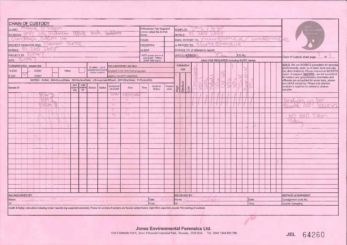
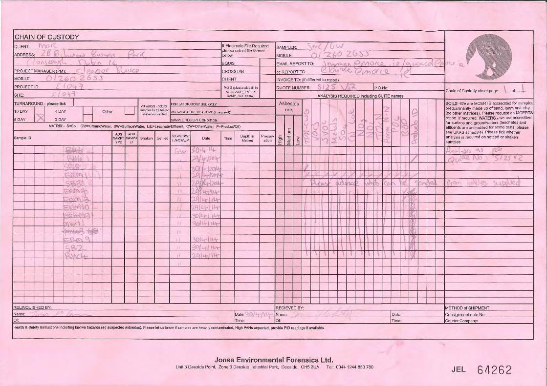


AP
PE
ND
IX B

Unit 3 Deeside Point
Zone 3
Deeside Industrial Park
Deeside
Malone O'Regan
Attention :
Date :
Your reference :
Our reference :
Location :
Date samples received :
Status :
Issue :
Bob Millward BSc FRSC
Principal Chemist
Three samples were received for analysis on 29th April, 2014. Please find attached our Test Report which should be read with notes at the end of
the report and should include all sections if reproduced. Interpretations and opinions are outside the scope of any accreditation, and all results relate
only to samples supplied.
All analysis is carried out on as received samples and reported on a dry weight basis unless stated otherwise. Results are not surrogate corrected.
Bruce Leslie
Project Co-ordinator
8th May, 2014
E1048
E1048
29th April, 2014
Final report
Compiled By:
Test Report 14/5298 Batch 1
1
Jones Environmental Laboratory
CH5 2UA
Tel: +44 (0) 1244 833780
Fax: +44 (0) 1244 833781
Eleanor Burke
2b Richview Office Park
Clonskeagh
Dublin 14
Ireland
Registered Address : Unit 3 Deeside Point, Zone 3, Deeside Industrial Park, Deeside, CH5 2UA. UK
QF-PM 3.1.1 v15Please include all sections of this report if it is reproduced
All solid results are expressed on a dry weight basis unless stated otherwise. 1 of 10
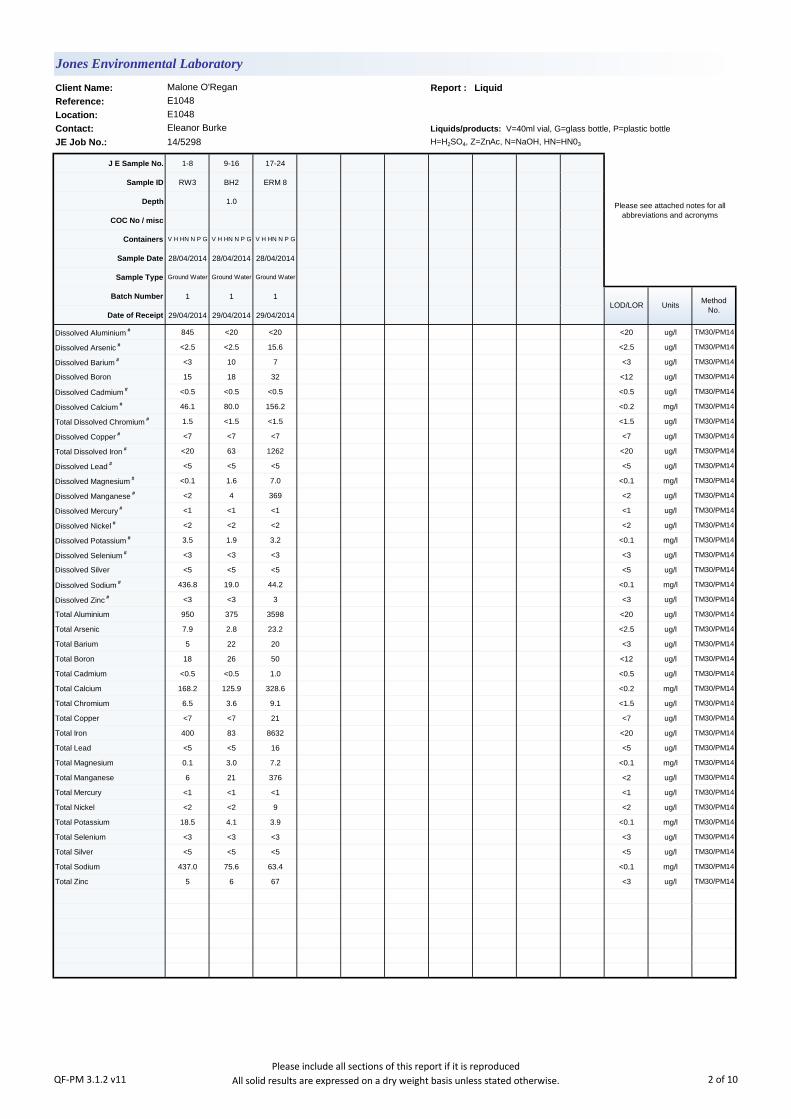
Client Name: Report : Liquid
Reference:
Location:
Contact: Liquids/products: V=40ml vial, G=glass bottle, P=plastic bottle
JE Job No.: 14/5298 H=H2SO4, Z=ZnAc, N=NaOH, HN=HN03
J E Sample No. 1-8 9-16 17-24
Sample ID RW3 BH2 ERM 8
Depth 1.0
COC No / misc
Containers V H HN N P G V H HN N P G V H HN N P G
Sample Date 28/04/2014 28/04/2014 28/04/2014
Sample Type Ground Water Ground Water Ground Water
Batch Number 1 1 1
Date of Receipt 29/04/2014 29/04/2014 29/04/2014
Dissolved Aluminium # 845 <20 <20 <20 ug/l TM30/PM14
Dissolved Arsenic # <2.5 <2.5 15.6 <2.5 ug/l TM30/PM14
Dissolved Barium # <3 10 7 <3 ug/l TM30/PM14
Dissolved Boron 15 18 32 <12 ug/l TM30/PM14
Dissolved Cadmium # <0.5 <0.5 <0.5 <0.5 ug/l TM30/PM14
Dissolved Calcium # 46.1 80.0 156.2 <0.2 mg/l TM30/PM14
Total Dissolved Chromium # 1.5 <1.5 <1.5 <1.5 ug/l TM30/PM14
Dissolved Copper # <7 <7 <7 <7 ug/l TM30/PM14
Total Dissolved Iron # <20 63 1262 <20 ug/l TM30/PM14
Dissolved Lead # <5 <5 <5 <5 ug/l TM30/PM14
Dissolved Magnesium # <0.1 1.6 7.0 <0.1 mg/l TM30/PM14
Dissolved Manganese # <2 4 369 <2 ug/l TM30/PM14
Dissolved Mercury # <1 <1 <1 <1 ug/l TM30/PM14
Dissolved Nickel # <2 <2 <2 <2 ug/l TM30/PM14
Dissolved Potassium # 3.5 1.9 3.2 <0.1 mg/l TM30/PM14
Dissolved Selenium # <3 <3 <3 <3 ug/l TM30/PM14
Dissolved Silver <5 <5 <5 <5 ug/l TM30/PM14
Dissolved Sodium # 436.8 19.0 44.2 <0.1 mg/l TM30/PM14
Dissolved Zinc # <3 <3 3 <3 ug/l TM30/PM14
Total Aluminium 950 375 3598 <20 ug/l TM30/PM14
Total Arsenic 7.9 2.8 23.2 <2.5 ug/l TM30/PM14
Total Barium 5 22 20 <3 ug/l TM30/PM14
Total Boron 18 26 50 <12 ug/l TM30/PM14
Total Cadmium <0.5 <0.5 1.0 <0.5 ug/l TM30/PM14
Total Calcium 168.2 125.9 328.6 <0.2 mg/l TM30/PM14
Total Chromium 6.5 3.6 9.1 <1.5 ug/l TM30/PM14
Total Copper <7 <7 21 <7 ug/l TM30/PM14
Total Iron 400 83 8632 <20 ug/l TM30/PM14
Total Lead <5 <5 16 <5 ug/l TM30/PM14
Total Magnesium 0.1 3.0 7.2 <0.1 mg/l TM30/PM14
Total Manganese 6 21 376 <2 ug/l TM30/PM14
Total Mercury <1 <1 <1 <1 ug/l TM30/PM14
Total Nickel <2 <2 9 <2 ug/l TM30/PM14
Total Potassium 18.5 4.1 3.9 <0.1 mg/l TM30/PM14
Total Selenium <3 <3 <3 <3 ug/l TM30/PM14
Total Silver <5 <5 <5 <5 ug/l TM30/PM14
Total Sodium 437.0 75.6 63.4 <0.1 mg/l TM30/PM14
Total Zinc 5 6 67 <3 ug/l TM30/PM14
E1048
Eleanor Burke
Please see attached notes for all
abbreviations and acronyms
LOD/LOR UnitsMethod
No.
Jones Environmental Laboratory
Malone O'Regan
E1048
QF-PM 3.1.2 v11Please include all sections of this report if it is reproduced
All solid results are expressed on a dry weight basis unless stated otherwise. 2 of 10

Client Name: Report : Liquid
Reference:
Location:
Contact: Liquids/products: V=40ml vial, G=glass bottle, P=plastic bottle
JE Job No.: 14/5298 H=H2SO4, Z=ZnAc, N=NaOH, HN=HN03
J E Sample No. 1-8 9-16 17-24
Sample ID RW3 BH2 ERM 8
Depth 1.0
COC No / misc
Containers V H HN N P G V H HN N P G V H HN N P G
Sample Date 28/04/2014 28/04/2014 28/04/2014
Sample Type Ground Water Ground Water Ground Water
Batch Number 1 1 1
Date of Receipt 29/04/2014 29/04/2014 29/04/2014
TPH CWG
Aliphatics
>C5-C6 # <5 <5 <5 <5 ug/l TM36/PM12
>C6-C8 # <5 <5 <5 <5 ug/l TM36/PM12
>C8-C10 # <5 <5 <5 <5 ug/l TM36/PM12
>C10-C12 # <5 <5 <5 <5 ug/l TM5/PM30
>C12-C16 # <10 <10 <10 <10 ug/l TM5/PM30
>C16-C21 # <10 <10 <10 <10 ug/l TM5/PM30
>C21-C35 # <10 <10 <10 <10 ug/l TM5/PM30
Total aliphatics C5-35 # <10 <10 <10 <10 ug/l TM5/TM36/PM30
Aromatics
>C5-EC7 # <5 <5 <5 <5 ug/l TM36/PM12
>EC7-EC8 # <5 <5 <5 <5 ug/l TM36/PM12
>EC8-EC10 # <5 <5 <5 <5 ug/l TM36/PM12
>EC10-EC12 # <5 <5 <5 <5 ug/l TM5/PM30
>EC12-EC16 # <10 <10 <10 <10 ug/l TM5/PM30
>EC16-EC21 # <10 <10 <10 <10 ug/l TM5/PM30
>EC21-EC35 # <10 <10 <10 <10 ug/l TM5/PM30
Total aromatics C5-35 # <10 <10 <10 <10 ug/l TM5/PM30
Total aliphatics and aromatics(C5-35) # <10 <10 <10 <10 ug/l TM5/TM36/PM30
MTBE # <5 <5 <5 <5 ug/l TM36/PM12
Benzene # <5 <5 <5 <5 ug/l TM36/PM12
Toluene # <5 <5 <5 <5 ug/l TM36/PM12
Ethylbenzene # <5 <5 <5 <5 ug/l TM36/PM12
m/p-Xylene # <5 <5 <5 <5 ug/l TM36/PM12
o-Xylene # <5 <5 <5 <5 ug/l TM36/PM12
Total Phenols HPLC <0.1 <0.1 <0.1 <0.1 mg/l TM26/PM0
Fluoride <0.3 <0.3 0.3 <0.3 mg/l TM27/PM0
Sulphate # 26.55 29.45 34.27 <0.05 mg/l TM38/PM0
Chloride # 138.9 40.7 110.0 <0.3 mg/l TM38/PM0
Nitrate as NO3 # 2.0 1.8 0.5 <0.2 mg/l TM38/PM0
Nitrite as NO2 # 0.08 <0.02 <0.02 <0.02 mg/l TM38/PM0
Ortho Phosphate as PO4 # <0.06 <0.06 <0.06 <0.06 mg/l TM38/PM0
Total Oxidised Nitrogen as N # 0.5 0.4 <0.2 <0.2 mg/l TM38/PM0
MRP Ortho Phosphate as PO4 <0.06 <0.06 <0.06 <0.06 mg/l TM38/PM0
Total Cyanide # <0.01 <0.01 <0.01 <0.01 mg/l TM89/PM0
Ammoniacal Nitrogen as N # 0.07 <0.03 0.29 <0.03 mg/l TM38/PM0
LOD/LOR UnitsMethod
No.
Jones Environmental Laboratory
Malone O'Regan
E1048
E1048
Eleanor Burke
Please see attached notes for all
abbreviations and acronyms
QF-PM 3.1.2 v11Please include all sections of this report if it is reproduced
All solid results are expressed on a dry weight basis unless stated otherwise. 3 of 10

Client Name: Report : Liquid
Reference:
Location:
Contact: Liquids/products: V=40ml vial, G=glass bottle, P=plastic bottle
JE Job No.: 14/5298 H=H2SO4, Z=ZnAc, N=NaOH, HN=HN03
J E Sample No. 1-8 9-16 17-24
Sample ID RW3 BH2 ERM 8
Depth 1.0
COC No / misc
Containers V H HN N P G V H HN N P G V H HN N P G
Sample Date 28/04/2014 28/04/2014 28/04/2014
Sample Type Ground Water Ground Water Ground Water
Batch Number 1 1 1
Date of Receipt 29/04/2014 29/04/2014 29/04/2014
Total Alkalinity as CaCO3 # 124 238 582 <1 mg/l TM75/PM0
Total Organic Carbon # 8 7 6 <2 mg/l TM60/PM0
Total Solids # 496 422 1264 <5 mg/l TM20/PM0
E1048
Eleanor Burke
Please see attached notes for all
abbreviations and acronyms
LOD/LOR UnitsMethod
No.
Jones Environmental Laboratory
Malone O'Regan
E1048
QF-PM 3.1.2 v11Please include all sections of this report if it is reproduced
All solid results are expressed on a dry weight basis unless stated otherwise. 4 of 10
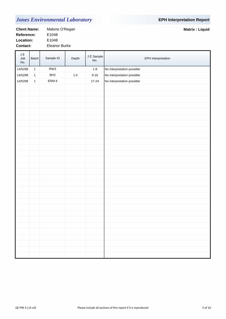
EPH Interpretation Report
Matrix : Liquid
J E
Job
No.
Batch Depth J E Sample
No.EPH Interpretation
14/5298 1 1-8 No interpretation possible
14/5298 1 1.0 9-16 No interpretation possible
14/5298 1 17-24 No interpretation possible
Contact: Eleanor Burke
Sample ID
RW3
BH2
ERM 8
Client Name: Malone O'Regan
Reference: E1048
Location: E1048
Jones Environmental Laboratory
QF-PM 3.1.8 v10 Please include all sections of this report if it is reproduced 5 of 10

Notification of Deviating Samples
J E
Job
No.
Batch Depth J E Sample
No.Analysis Reason
Please note that only samples that are deviating are mentioned in this report. If no samples are listed it is because none were deviating.
Only analyses which are accredited are recorded as deviating if set criteria are not met.
Contact:
Sample ID
Client Name: Malone O'Regan
Reference:
Location:
No deviating sample report results for job 14/5298
Jones Environmental Laboratory
E1048
E1048
Eleanor Burke
QF-PM 3.1.11 v3 Please include all sections of this report if it is reproduced 6 of 10

JE Job No.:
SOILS
DEVIATING SAMPLES
SURROGATES
NOTE
NOTES TO ACCOMPANY ALL SCHEDULES AND REPORTS
Please note we are only MCERTS accredited for sand, loam and clay and any other matrix is outside our scope of accreditation.
Where Mineral Oil or Fats, Oils and Grease is quoted, this refers to Total Aliphatics C10-C40.
14/5298
WATERS
Where an MCERTS report has been requested, you will be notified within 48 hours of any samples that have been identified as being outside our
MCERTS scope. As validation has been performed on clay, sand and loam, only samples that are predominantly these matrices, or combinations
of them will be within our MCERTS scope. If samples are not one of a combination of the above matrices they will not be marked as MCERTS
accredited.
All samples will be discarded one month after the date of reporting, unless we are instructed to the contrary. If we are instructed to keep samples, a
storage charge of £1 (1.5 Euros) per sample per month will be applied until we are asked to dispose of them.
It is assumed that you have taken representative samples on site and require analysis on a representative subsample. Stones will generally be
included unless we are requested to remove them.
UKAS accreditation applies to surface water and groundwater and one other matrix which is analysis specific, any other liquids are outside our
scope of accreditation
As surface waters require different sample preparation to groundwaters the laboratory must be informed of the water type when submitting samples.
Samples must be received in a condition appropriate to the requested analyses. All samples should be submitted to the laboratory in suitable
containers with sufficient ice packs to sustain an appropriate temperature for the requested analysis. If this is not the case you will be informed and
any test results that may be compromised highlighted on your deviating samples report.
Where appropriate please make sure that our detection limits are suitable for your needs, if they are not, please notify us immediately.
Please note we are not a Drinking Water Inspectorate (DWI) Approved Laboratory . It is important that detection limits are carefully considered
when requesting water analysis.
If you have not already done so, please send us a purchase order if this is required by your company.
All analysis is reported on a dry weight basis unless stated otherwise. Results are not surrogate corrected. Samples are dried at 35°C ±5°C unless
otherwise stated. Moisture content for CEN Leachate tests are dried at 105°C ±5°C.
Where Mineral Oil or Fats, Oils and Grease is quoted, this refers to Total Aliphatics C10-C40.
Where a CEN 10:1 ZERO Headspace VOC test has been carried out, a 10:1 ratio of water to wet (as received) soil has been used.
Data is only reported if the laboratory is confident that the data is a true reflection of the samples analysed. Data is only reported as accredited when
all the requirements of our Quality System have been met. In certain circumstances where all the requirements of the Quality System have not been
met, for instance if the associated AQC has failed, the reason is fully investigated and documented. The sample data is then evaluated alongside
the other quality control checks performed during analysis to determine its suitability. Following this evaluation, provided the sample results have not
been effected, the data is reported but accreditation is removed. It is a UKAS requirement for data not reported as accredited to be considered
indicative only, but this does not mean the data is not valid.
Where possible, and if requested, samples will be re-extracted and a revised report issued with accredited results. Please do not hesitate to contact
the laboratory if further details are required of the circumstances which have led to the removal of accreditation.
Surrogate compounds are added during the preparation process to monitor recovery of analytes. However low recovery in soils is often due to peat,
clay or other organic rich matrices. For waters this can be due to oxidants, surfactants, organic rich sediments or remediation fluids. Acceptable
limits for most organic methods are 70 - 130% and for VOCs are 50 - 150%. When surrogate recoveries are outside the performance criteria but
the associated AQC passes this is assumed to be due to matrix effect. Results are not surrogate corrected.
QF-PM 3.1.9 v27Please include all sections of this report if it is reproduced
All solid results are expressed on a dry weight basis unless stated otherwise. 7 of 10

JE Job No.:
#
B
DR
M
NA
NAD
ND
NDP
SS
SV
W
+
++
*
CO
LOD/LOR
ME
NFD
OC
Matrix Effect
No Fibres Detected
Limit of Detection (Limit of Reporting) in line with ISO 17025 and MCERTS
Suspected carry over
14/5298
Outside Calibration Range
Result outside calibration range, results should be considered as indicative only and are not accredited.
Results expressed on as received basis.
Surrogate recovery outside performance criteria. This may be due to a matrix effect.
Dilution required.
Indicates analyte found in associated method blank.
Not applicable
MCERTS accredited.
AQC failure, accreditation has been removed from this result, if appropriate, see 'Note' on previous page.
Analysis subcontracted to a Jones Environmental approved laboratory.
Calibrated against a single substance
No Determination Possible
ABBREVIATIONS and ACRONYMS USED
No Asbestos Detected.
None Detected (usually refers to VOC and/SVOC TICs).
UKAS accredited.
QF-PM 3.1.9 v27Please include all sections of this report if it is reproduced
All solid results are expressed on a dry weight basis unless stated otherwise. 8 of 10
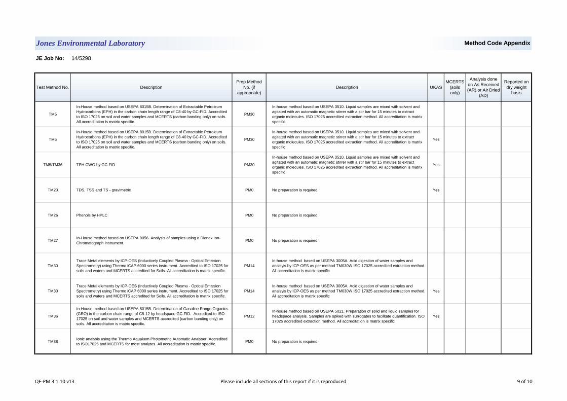
JE Job No: 14/5298
Test Method No. Description
Prep Method
No. (if
appropriate)
Description UKAS
MCERTS
(soils
only)
Analysis done
on As Received
(AR) or Air Dried
(AD)
Reported on
dry weight
basis
TM5
In-House method based on USEPA 8015B. Determination of Extractable Petroleum
Hydrocarbons (EPH) in the carbon chain length range of C8-40 by GC-FID. Accredited
to ISO 17025 on soil and water samples and MCERTS (carbon banding only) on soils.
All accreditation is matrix specific.
PM30
In-house method based on USEPA 3510. Liquid samples are mixed with solvent and
agitated with an automatic magnetic stirrer with a stir bar for 15 minutes to extract
organic molecules. ISO 17025 accredited extraction method. All accreditation is matrix
specific
Yes
TM5/TM36 TPH CWG by GC-FID PM30
In-house method based on USEPA 3510. Liquid samples are mixed with solvent and
agitated with an automatic magnetic stirrer with a stir bar for 15 minutes to extract
organic molecules. ISO 17025 accredited extraction method. All accreditation is matrix
specific
Yes
TM20 TDS, TSS and TS - gravimetric PM0 No preparation is required. Yes
TM26 Phenols by HPLC PM0 No preparation is required.
TM27In-House method based on USEPA 9056. Analysis of samples using a Dionex Ion-
Chromatograph instrument.PM0 No preparation is required.
TM30
Trace Metal elements by ICP-OES (Inductively Coupled Plasma - Optical Emission
Spectrometry) using Thermo iCAP 6000 series instrument. Accredited to ISO 17025 for
soils and waters and MCERTS accredited for Soils. All accreditation is matrix specific.
PM14
In-house method based on USEPA 3005A. Acid digestion of water samples and
analsyis by ICP-OES as per method TM030W.ISO 17025 accredited extraction method.
All accreditation is matrix specific
Yes
TM36
In-House method based on USEPA 8015B. Determination of Gasoline Range Organics
(GRO) in the carbon chain range of C5-12 by headspace GC-FID. Accredited to ISO
17025 on soil and water samples and MCERTS accredited (carbon banding only) on
soils. All accreditation is matrix specific.
PM12
In-house method based on USEPA 5021. Preparation of solid and liquid samples for
headspace analysis. Samples are spiked with surrogates to facilitate quantification. ISO
17025 accredited extraction method. All accreditation is matrix specific
Yes
TM38Ionic analysis using the Thermo Aquakem Photometric Automatic Analyser. Accredited
to ISO17025 and MCERTS for most analytes. All accreditation is matrix specific.PM0 No preparation is required.
Jones Environmental Laboratory Method Code Appendix
QF-PM 3.1.10 v13 Please include all sections of this report if it is reproduced 9 of 10
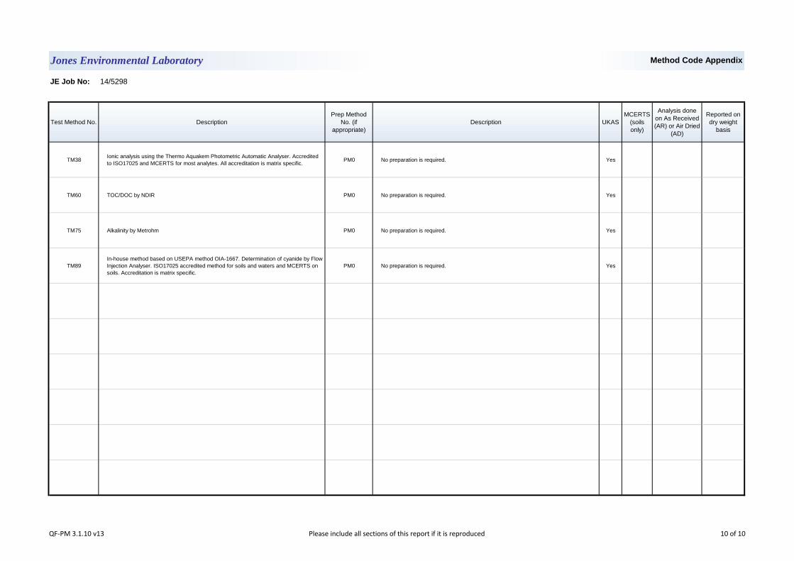
JE Job No: 14/5298
Test Method No. Description
Prep Method
No. (if
appropriate)
Description UKAS
MCERTS
(soils
only)
Analysis done
on As Received
(AR) or Air Dried
(AD)
Reported on
dry weight
basis
TM38Ionic analysis using the Thermo Aquakem Photometric Automatic Analyser. Accredited
to ISO17025 and MCERTS for most analytes. All accreditation is matrix specific.PM0 No preparation is required. Yes
TM60 TOC/DOC by NDIR PM0 No preparation is required. Yes
TM75 Alkalinity by Metrohm PM0 No preparation is required. Yes
TM89
In-house method based on USEPA method OIA-1667. Determination of cyanide by Flow
Injection Analyser. ISO17025 accredited method for soils and waters and MCERTS on
soils. Accreditation is matrix specific.
PM0 No preparation is required. Yes
Jones Environmental Laboratory Method Code Appendix
QF-PM 3.1.10 v13 Please include all sections of this report if it is reproduced 10 of 10

Unit 3 Deeside Point
Zone 3
Deeside Industrial Park
Deeside
Malone O'Regan
Attention :
Date :
Your reference :
Our reference :
Location :
Date samples received :
Status :
Issue :
Bob Millward BSc FRSC
Principal Chemist
1
Jones Environmental Laboratory
CH5 2UA
Tel: +44 (0) 1244 833780
Fax: +44 (0) 1244 833781
Eleanor Burke
2b Richview Office Park
Clonskeagh
Dublin 14
Ireland
Registered Address : Unit 3 Deeside Point, Zone 3, Deeside Industrial Park, Deeside, CH5 2UA. UK
Eleven samples were received for analysis on 30th April, 2014. Please find attached our Test Report which should be read with notes at the end of
the report and should include all sections if reproduced. Interpretations and opinions are outside the scope of any accreditation, and all results relate
only to samples supplied.
All analysis is carried out on as received samples and reported on a dry weight basis unless stated otherwise. Results are not surrogate corrected.
Bruce Leslie
Project Co-ordinator
8th May, 2014
E1048
E1048
30th April, 2014
Final report
Compiled By:
Test Report 14/5336 Batch 1
QF-PM 3.1.1 v15Please include all sections of this report if it is reproduced
All solid results are expressed on a dry weight basis unless stated otherwise. 1 of 11

Client Name: Report : Liquid
Reference:
Location:
Contact: Liquids/products: V=40ml vial, G=glass bottle, P=plastic bottle
JE Job No.: 14/5336 H=H2SO4, Z=ZnAc, N=NaOH, HN=HN03
J E Sample No. 1-9 10-18 19-27 28-36 37 38 39 40-41 42-43
Sample ID RW2 RW1 MW5B ERM1(S) ERM8 RW3 BH2 ERM12 ERM11
Depth
COC No / misc
Containers V H HN N P BOD G V H HN N P BOD G V H HN N P BOD G V H HN N P BOD G BOD BOD BOD N G H G
Sample Date 28/04/2014 28/04/2014 28/04/2014 28/04/2014 29/04/2014 29/04/2014 29/04/2014 29/04/2014 29/04/2014
Sample Type Ground Water Ground Water Ground Water Ground Water Ground Water Ground Water Ground Water Ground Water Ground Water
Batch Number 1 1 1 1 1 1 1 1 1
Date of Receipt 30/04/2014 30/04/2014 30/04/2014 30/04/2014 30/04/2014 30/04/2014 30/04/2014 30/04/2014 30/04/2014
Dissolved Aluminium # <20 <20 351 27 - - - - - <20 ug/l TM30/PM14
Dissolved Arsenic # <2.5 5.4 <2.5 <2.5 - - - - - <2.5 ug/l TM30/PM14
Dissolved Barium # 13 10 23 38 - - - - - <3 ug/l TM30/PM14
Dissolved Boron <12 22 <12 21 - - - - - <12 ug/l TM30/PM14
Dissolved Cadmium # <0.5 <0.5 <0.5 <0.5 - - - - - <0.5 ug/l TM30/PM14
Dissolved Calcium # 134.7 142.0 34.1 175.0 - - - - - <0.2 mg/l TM30/PM14
Total Dissolved Chromium # 3.0 <1.5 3.5 <1.5 - - - - - <1.5 ug/l TM30/PM14
Dissolved Copper # <7 <7 <7 <7 - - - - - <7 ug/l TM30/PM14
Total Dissolved Iron # 3504 5916 24 998 - - - - - <20 ug/l TM30/PM14
Dissolved Lead # <5 <5 <5 <5 - - - - - <5 ug/l TM30/PM14
Dissolved Magnesium # 4.0 6.2 0.6 5.6 - - - - - <0.1 mg/l TM30/PM14
Dissolved Manganese # 220 562 <2 330 - - - - - <2 ug/l TM30/PM14
Dissolved Mercury # <1 <1 <1 <1 - - - - - <1 ug/l TM30/PM14
Dissolved Nickel # <2 <2 <2 <2 - - - - - <2 ug/l TM30/PM14
Dissolved Potassium # 2.7 1.8 3.5 1.9 - - - - - <0.1 mg/l TM30/PM14
Dissolved Selenium # <3 <3 <3 <3 - - - - - <3 ug/l TM30/PM14
Dissolved Silver <5 <5 <5 <5 - - - - - <5 ug/l TM30/PM14
Dissolved Sodium # 31.2 36.6 34.2 36.9 - - - - - <0.1 mg/l TM30/PM14
Dissolved Zinc # <3 <3 <3 4 - - - - - <3 ug/l TM30/PM14
Total Aluminium 333 1962 490500 14370 - - - - - <20 ug/l TM30/PM14
Total Arsenic <2.5 7.1 226.1 22.1 - - - - - <2.5 ug/l TM30/PM14
Total Barium 13 11 52500 136 - - - - - <3 ug/l TM30/PM14
Total Boron 13 24 854 21 - - - - - <12 ug/l TM30/PM14
Total Cadmium 0.6 0.8 43.2 2.9 - - - - - <0.5 ug/l TM30/PM14
Total Calcium 135.1 176.6 4742.0 345.8 - - - - - <0.2 mg/l TM30/PM14
Total Chromium 14.9 4.4 613.9 16.8 - - - - - <1.5 ug/l TM30/PM14
Total Copper 13 <7 604 21 - - - - - <7 ug/l TM30/PM14
Total Iron 3504 8055 465400 31440 - - - - - <20 ug/l TM30/PM14
Total Lead <5 6 920 20 - - - - - <5 ug/l TM30/PM14
Total Magnesium 4.0 7.2 322.7 8.1 - - - - - <0.1 mg/l TM30/PM14
Total Manganese 221 565 11240 563 - - - - - <2 ug/l TM30/PM14
Total Mercury <1 <1 <1 <1 - - - - - <1 ug/l TM30/PM14
Total Nickel <2 5 511 19 - - - - - <2 ug/l TM30/PM14
Total Potassium 2.7 2.5 22.4 2.8 - - - - - <0.1 mg/l TM30/PM14
Total Selenium <3 <3 <3 <3 - - - - - <3 ug/l TM30/PM14
Total Silver <5 <5 6 <5 - - - - - <5 ug/l TM30/PM14
Total Sodium 31.4 36.7 91.4 36.9 - - - - - <0.1 mg/l TM30/PM14
Total Zinc 34 56 2043 89 - - - - - <3 ug/l TM30/PM14
Methyl Tertiary Butyl Ether # <0.1 <0.1 <0.1 <0.1 - - - - - <0.1 ug/l TM15/PM10
Benzene # <0.5 <0.5 <0.5 <0.5 - - - - - <0.5 ug/l TM15/PM10
Toluene # <0.5 <0.5 <0.5 <0.5 - - - - - <0.5 ug/l TM15/PM10
Ethylbenzene # <0.5 <0.5 <0.5 <0.5 - - - - - <0.5 ug/l TM15/PM10
p/m-Xylene # <1 <1 <1 <1 - - - - - <1 ug/l TM15/PM10
Jones Environmental Laboratory
Malone O'Regan
E1048
E1048
Eleanor Burke
Please see attached notes for all
abbreviations and acronyms
LOD/LOR UnitsMethod
No.
QF-PM 3.1.2 v11Please include all sections of this report if it is reproduced
All solid results are expressed on a dry weight basis unless stated otherwise. 2 of 11

Client Name: Report : Liquid
Reference:
Location:
Contact: Liquids/products: V=40ml vial, G=glass bottle, P=plastic bottle
JE Job No.: 14/5336 H=H2SO4, Z=ZnAc, N=NaOH, HN=HN03
J E Sample No. 1-9 10-18 19-27 28-36 37 38 39 40-41 42-43
Sample ID RW2 RW1 MW5B ERM1(S) ERM8 RW3 BH2 ERM12 ERM11
Depth
COC No / misc
Containers V H HN N P BOD G V H HN N P BOD G V H HN N P BOD G V H HN N P BOD G BOD BOD BOD N G H G
Sample Date 28/04/2014 28/04/2014 28/04/2014 28/04/2014 29/04/2014 29/04/2014 29/04/2014 29/04/2014 29/04/2014
Sample Type Ground Water Ground Water Ground Water Ground Water Ground Water Ground Water Ground Water Ground Water Ground Water
Batch Number 1 1 1 1 1 1 1 1 1
Date of Receipt 30/04/2014 30/04/2014 30/04/2014 30/04/2014 30/04/2014 30/04/2014 30/04/2014 30/04/2014 30/04/2014
o-Xylene # <0.5 <0.5 <0.5 <0.5 - - - - - <0.5 ug/l TM15/PM10
Surrogate Recovery Toluene D8 86 88 92 95 - - - - - <0 % TM15/PM10
Surrogate Recovery 4-Bromofluorobenzene 116 118 126 127 - - - - - <0 % TM15/PM10
TPH CWG
Aliphatics
>C5-C6 # <5 <5 <5 <5 - - - <5 <5 <5 ug/l TM36/PM12
>C6-C8 # <5 <5 <5 <5 - - - <5 <5 <5 ug/l TM36/PM12
>C8-C10 # <5 <5 <5 <5 - - - <5 <5 <5 ug/l TM36/PM12
>C10-C12 # <5 <5 <5 <5 - - - <5 <5 <5 ug/l TM5/PM30
>C12-C16 # <10 <10 <10 <10 - - - <10 <10 <10 ug/l TM5/PM30
>C16-C21 # <10 <10 <10 20 - - - <10 <10 <10 ug/l TM5/PM30
>C21-C35 # 6590 <10 4050 10180 - - - <10 <10 <10 ug/l TM5/PM30
Total aliphatics C5-35 # 6590 <10 4050 10200 - - - <10 <10 <10 ug/l TM5/TM36/PM30
Aromatics
>C5-EC7 # <5 <5 <5 <5 - - - <5 <5 <5 ug/l TM36/PM12
>EC7-EC8 # <5 <5 <5 <5 - - - <5 <5 <5 ug/l TM36/PM12
>EC8-EC10 # <5 <5 <5 <5 - - - <5 <5 <5 ug/l TM36/PM12
>EC10-EC12 # <5 <5 <5 <5 - - - <5 <5 <5 ug/l TM5/PM30
>EC12-EC16 # <10 <10 <10 <10 - - - <10 <10 <10 ug/l TM5/PM30
>EC16-EC21 # <10 <10 <10 <10 - - - <10 <10 <10 ug/l TM5/PM30
>EC21-EC35 # 2090 <10 1070 3510 - - - <10 <10 <10 ug/l TM5/PM30
Total aromatics C5-35 # 2090 <10 1070 3510 - - - <10 <10 <10 ug/l TM5/PM30
Total aliphatics and aromatics(C5-35) # 8680 <10 5120 13710 - - - <10 <10 <10 ug/l TM5/TM36/PM30
Total Phenols HPLC <0.1 <0.1 <0.1 <0.1 - - - <0.1 <0.1 <0.1 mg/l TM26/PM0
Fluoride <0.3 <0.3 <0.3 <0.3 - - - - - <0.3 mg/l TM27/PM0
Sulphate # 21.56 5.22 89.44 43.87 - - - - - <0.05 mg/l TM38/PM0
Chloride # 43.0 54.0 123.0 55.4 - - - - - <0.3 mg/l TM38/PM0
Nitrate as NO3 # <0.2 <0.2 0.4 <0.2 - - - - 4.1 <0.2 mg/l TM38/PM0
Nitrite as NO2 # <0.02 <0.02 <0.02 <0.02 - - - - <0.02 <0.02 mg/l TM38/PM0
Ortho Phosphate as PO4 # <0.06 <0.06 <0.06 <0.06 - - - - - <0.06 mg/l TM38/PM0
Total Oxidised Nitrogen as N # <0.2 <0.2 <0.2 <0.2 - - - - - <0.2 mg/l TM38/PM0
MRP Ortho Phosphate as PO4 <0.06 <0.06 <0.06 <0.06 - - - - - <0.06 mg/l TM38/PM0
Total Cyanide # 0.01 <0.01 <0.01 <0.01 - - - - - <0.01 mg/l TM89/PM0
Ammoniacal Nitrogen as N # 0.23 0.07 2.17 0.09 - - - - <0.03 <0.03 mg/l TM38/PM0
Total Alkalinity as CaCO3 # 356 448 6652 352 - - - - - <1 mg/l TM75/PM0
BOD (Settled) 11 13 5 26 6 3 1 - - <1 mg/l TM121/PM0
Jones Environmental Laboratory
Malone O'Regan
E1048
E1048
Eleanor Burke
Please see attached notes for all
abbreviations and acronyms
LOD/LOR UnitsMethod
No.
QF-PM 3.1.2 v11Please include all sections of this report if it is reproduced
All solid results are expressed on a dry weight basis unless stated otherwise. 3 of 11
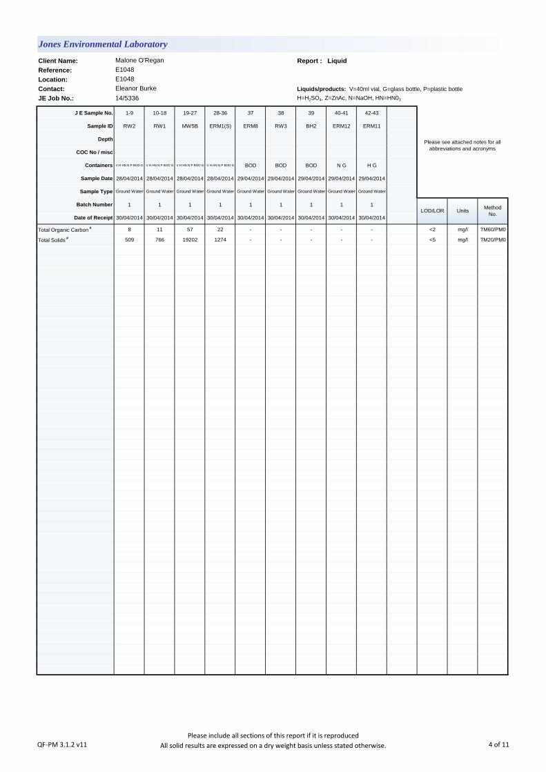
Client Name: Report : Liquid
Reference:
Location:
Contact: Liquids/products: V=40ml vial, G=glass bottle, P=plastic bottle
JE Job No.: 14/5336 H=H2SO4, Z=ZnAc, N=NaOH, HN=HN03
J E Sample No. 1-9 10-18 19-27 28-36 37 38 39 40-41 42-43
Sample ID RW2 RW1 MW5B ERM1(S) ERM8 RW3 BH2 ERM12 ERM11
Depth
COC No / misc
Containers V H HN N P BOD G V H HN N P BOD G V H HN N P BOD G V H HN N P BOD G BOD BOD BOD N G H G
Sample Date 28/04/2014 28/04/2014 28/04/2014 28/04/2014 29/04/2014 29/04/2014 29/04/2014 29/04/2014 29/04/2014
Sample Type Ground Water Ground Water Ground Water Ground Water Ground Water Ground Water Ground Water Ground Water Ground Water
Batch Number 1 1 1 1 1 1 1 1 1
Date of Receipt 30/04/2014 30/04/2014 30/04/2014 30/04/2014 30/04/2014 30/04/2014 30/04/2014 30/04/2014 30/04/2014
Total Organic Carbon # 8 11 57 22 - - - - - <2 mg/l TM60/PM0
Total Solids # 509 766 19202 1274 - - - - - <5 mg/l TM20/PM0
Jones Environmental Laboratory
Malone O'Regan
E1048
E1048
Eleanor Burke
Please see attached notes for all
abbreviations and acronyms
LOD/LOR UnitsMethod
No.
QF-PM 3.1.2 v11Please include all sections of this report if it is reproduced
All solid results are expressed on a dry weight basis unless stated otherwise. 4 of 11
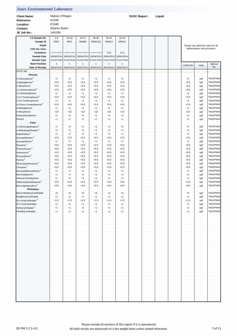
Client Name: SVOC Report : Liquid
Reference:
Location:
Contact:
JE Job No.: 14/5336
J E Sample No. 1-9 10-18 19-27 28-36 40-41 42-43
Sample ID RW2 RW1 MW5B ERM1(S) ERM12 ERM11
Depth
COC No / misc
Containers V H HN N P BOD G V H HN N P BOD G V H HN N P BOD G V H HN N P BOD G N G H G
Sample Date 28/04/2014 28/04/2014 28/04/2014 28/04/2014 29/04/2014 29/04/2014
Sample Type Ground Water Ground Water Ground Water Ground Water Ground Water Ground Water
Batch Number 1 1 1 1 1 1
Date of Receipt 30/04/2014 30/04/2014 30/04/2014 30/04/2014 30/04/2014 30/04/2014
SVOC MS
Phenols
2-Chlorophenol # <1 <1 <1 <1 <1 <1 <1 ug/l TM16/PM30
2-Methylphenol # <0.5 <0.5 <0.5 <0.5 <0.5 <0.5 <0.5 ug/l TM16/PM30
2-Nitrophenol <0.5 <0.5 <0.5 <0.5 <0.5 <0.5 <0.5 ug/l TM16/PM30
2,4-Dichlorophenol # <0.5 <0.5 <0.5 <0.5 <0.5 <0.5 <0.5 ug/l TM16/PM30
2,4-Dimethylphenol <1 <1 <1 <1 <1 <1 <1 ug/l TM16/PM30
2,4,5-Trichlorophenol # <0.5 <0.5 <0.5 <0.5 <0.5 <0.5 <0.5 ug/l TM16/PM30
2,4,6-Trichlorophenol <1 <1 <1 <1 <1 <1 <1 ug/l TM16/PM30
4-Chloro-3-methylphenol # <0.5 <0.5 <0.5 <0.5 <0.5 <0.5 <0.5 ug/l TM16/PM30
4-Methylphenol <1 <1 <1 <1 <1 <1 <1 ug/l TM16/PM30
4-Nitrophenol <10 <10 <10 <10 <10 <10 <10 ug/l TM16/PM30
Pentachlorophenol <1 <1 <1 <1 <1 <1 <1 ug/l TM16/PM30
Phenol <1 <1 <1 <1 <1 <1 <1 ug/l TM16/PM30
PAHs
2-Chloronaphthalene # <1 <1 <1 <1 <1 <1 <1 ug/l TM16/PM30
2-Methylnaphthalene # <1 <1 <1 <1 <1 <1 <1 ug/l TM16/PM30
Naphthalene # <1 <1 <1 <1 <1 <1 <1 ug/l TM16/PM30
Acenaphthylene # <0.5 <0.5 <0.5 <0.5 <0.5 <0.5 <0.5 ug/l TM16/PM30
Acenaphthene # <1 <1 <1 <1 <1 <1 <1 ug/l TM16/PM30
Fluorene # <0.5 <0.5 <0.5 <0.5 <0.5 <0.5 <0.5 ug/l TM16/PM30
Phenanthrene # <0.5 <0.5 <0.5 <0.5 <0.5 <0.5 <0.5 ug/l TM16/PM30
Anthracene # <0.5 <0.5 <0.5 <0.5 <0.5 <0.5 <0.5 ug/l TM16/PM30
Fluoranthene # <0.5 <0.5 <0.5 <0.5 <0.5 <0.5 <0.5 ug/l TM16/PM30
Pyrene # <0.5 <0.5 <0.5 <0.5 <0.5 <0.5 <0.5 ug/l TM16/PM30
Benzo(a)anthracene # <0.5 <0.5 <0.5 <0.5 <0.5 <0.5 <0.5 ug/l TM16/PM30
Chrysene # <0.5 <0.5 <0.5 <0.5 <0.5 <0.5 <0.5 ug/l TM16/PM30
Benzo(bk)fluoranthene # <1 <1 <1 <1 <1 <1 <1 ug/l TM16/PM30
Benzo(a)pyrene <1 <1 <1 <1 <1 <1 <1 ug/l TM16/PM30
Indeno(123cd)pyrene <1 <1 <1 <1 <1 <1 <1 ug/l TM16/PM30
Dibenzo(ah)anthracene # <0.5 <0.5 <0.5 <0.5 <0.5 <0.5 <0.5 ug/l TM16/PM30
Benzo(ghi)perylene # <0.5 <0.5 <0.5 <0.5 <0.5 <0.5 <0.5 ug/l TM16/PM30
Phthalates
Bis(2-ethylhexyl) phthalate <5 <5 <5 <5 <5 <5 <5 ug/l TM16/PM30
Butylbenzyl phthalate <1 <1 <1 <1 <1 <1 <1 ug/l TM16/PM30
Di-n-butyl phthalate # <1.5 <1.5 <1.5 <1.5 <1.5 <1.5 <1.5 ug/l TM16/PM30
Di-n-Octyl phthalate <1 <1 <1 <1 <1 <1 <1 ug/l TM16/PM30
Diethyl phthalate # <1 <1 <1 <1 <1 <1 <1 ug/l TM16/PM30
Dimethyl phthalate <1 <1 <1 <1 <1 <1 <1 ug/l TM16/PM30
Jones Environmental Laboratory
Malone O'Regan
E1048
E1048
Eleanor Burke
Please see attached notes for all
abbreviations and acronyms
LOD/LOR UnitsMethod
No.
QF-PM 3.1.3 v11Please include all sections of this report if it is reproduced
All solid results are expressed on a dry weight basis unless stated otherwise. 5 of 11

Client Name: SVOC Report : Liquid
Reference:
Location:
Contact:
JE Job No.: 14/5336
J E Sample No. 1-9 10-18 19-27 28-36 40-41 42-43
Sample ID RW2 RW1 MW5B ERM1(S) ERM12 ERM11
Depth
COC No / misc
Containers V H HN N P BOD G V H HN N P BOD G V H HN N P BOD G V H HN N P BOD G N G H G
Sample Date 28/04/2014 28/04/2014 28/04/2014 28/04/2014 29/04/2014 29/04/2014
Sample Type Ground Water Ground Water Ground Water Ground Water Ground Water Ground Water
Batch Number 1 1 1 1 1 1
Date of Receipt 30/04/2014 30/04/2014 30/04/2014 30/04/2014 30/04/2014 30/04/2014
SVOC MS
Other SVOCs
1,2-Dichlorobenzene # <1 <1 <1 <1 <1 <1 <1 ug/l TM16/PM30
1,2,4-Trichlorobenzene # <1 <1 <1 <1 <1 <1 <1 ug/l TM16/PM30
1,3-Dichlorobenzene # <1 <1 <1 <1 <1 <1 <1 ug/l TM16/PM30
1,4-Dichlorobenzene # <1 <1 <1 <1 <1 <1 <1 ug/l TM16/PM30
2-Nitroaniline <1 <1 <1 <1 <1 <1 <1 ug/l TM16/PM30
2,4-Dinitrotoluene # <0.5 <0.5 <0.5 <0.5 <0.5 <0.5 <0.5 ug/l TM16/PM30
2,6-Dinitrotoluene <1 <1 <1 <1 <1 <1 <1 ug/l TM16/PM30
3-Nitroaniline <1 <1 <1 <1 <1 <1 <1 ug/l TM16/PM30
4-Bromophenylphenylether # <1 <1 <1 <1 <1 <1 <1 ug/l TM16/PM30
4-Chloroaniline <1 <1 <1 <1 <1 <1 <1 ug/l TM16/PM30
4-Chlorophenylphenylether # <1 <1 <1 <1 <1 <1 <1 ug/l TM16/PM30
4-Nitroaniline <0.5 <0.5 <0.5 <0.5 <0.5 <0.5 <0.5 ug/l TM16/PM30
Azobenzene # <0.5 <0.5 <0.5 <0.5 <0.5 <0.5 <0.5 ug/l TM16/PM30
Bis(2-chloroethoxy)methane # <0.5 <0.5 <0.5 <0.5 <0.5 <0.5 <0.5 ug/l TM16/PM30
Bis(2-chloroethyl)ether # <1 <1 <1 <1 <1 <1 <1 ug/l TM16/PM30
Carbazole # <0.5 <0.5 <0.5 <0.5 <0.5 <0.5 <0.5 ug/l TM16/PM30
Dibenzofuran # <0.5 <0.5 <0.5 <0.5 <0.5 <0.5 <0.5 ug/l TM16/PM30
Hexachlorobenzene # <1 <1 <1 <1 <1 <1 <1 ug/l TM16/PM30
Hexachlorobutadiene # <1 <1 <1 <1 <1 <1 <1 ug/l TM16/PM30
Hexachlorocyclopentadiene <1 <1 <1 <1 <1 <1 <1 ug/l TM16/PM30
Hexachloroethane # <1 <1 <1 <1 <1 <1 <1 ug/l TM16/PM30
Isophorone # <0.5 <0.5 <0.5 <0.5 <0.5 <0.5 <0.5 ug/l TM16/PM30
N-nitrosodi-n-propylamine # <0.5 <0.5 <0.5 <0.5 <0.5 <0.5 <0.5 ug/l TM16/PM30
Nitrobenzene # <1 <1 <1 <1 <1 <1 <1 ug/l TM16/PM30
LOD/LOR UnitsMethod
No.
Jones Environmental Laboratory
Malone O'Regan
E1048
E1048
Eleanor Burke
Please see attached notes for all
abbreviations and acronyms
QF-PM 3.1.3 v11Please include all sections of this report if it is reproduced
All solid results are expressed on a dry weight basis unless stated otherwise. 6 of 11
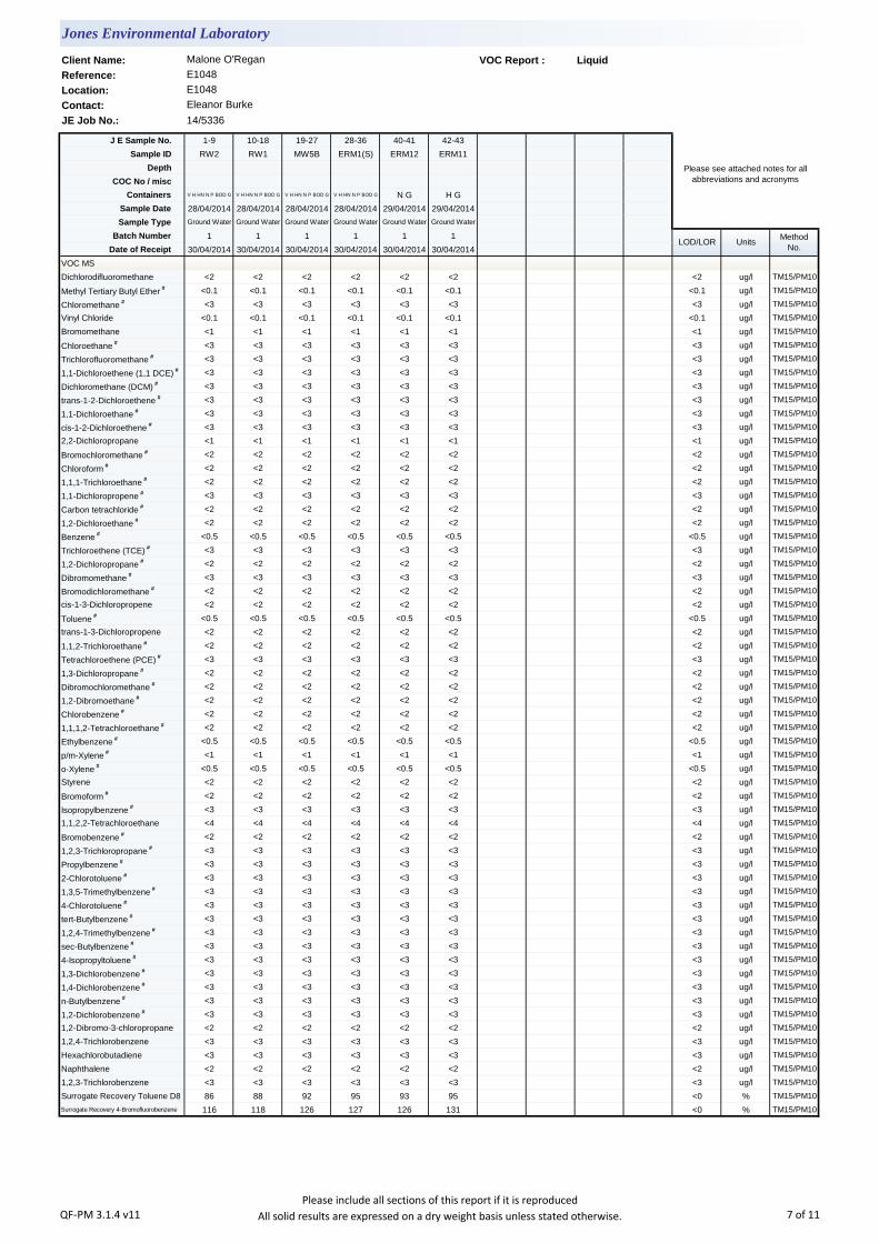
Client Name: VOC Report : Liquid
Reference:
Location:
Contact:
JE Job No.: 14/5336
J E Sample No. 1-9 10-18 19-27 28-36 40-41 42-43
Sample ID RW2 RW1 MW5B ERM1(S) ERM12 ERM11
Depth
COC No / misc
Containers V H HN N P BOD G V H HN N P BOD G V H HN N P BOD G V H HN N P BOD G N G H G
Sample Date 28/04/2014 28/04/2014 28/04/2014 28/04/2014 29/04/2014 29/04/2014
Sample Type Ground Water Ground Water Ground Water Ground Water Ground Water Ground Water
Batch Number 1 1 1 1 1 1
Date of Receipt 30/04/2014 30/04/2014 30/04/2014 30/04/2014 30/04/2014 30/04/2014
VOC MS
Dichlorodifluoromethane <2 <2 <2 <2 <2 <2 <2 ug/l TM15/PM10
Methyl Tertiary Butyl Ether # <0.1 <0.1 <0.1 <0.1 <0.1 <0.1 <0.1 ug/l TM15/PM10
Chloromethane # <3 <3 <3 <3 <3 <3 <3 ug/l TM15/PM10
Vinyl Chloride <0.1 <0.1 <0.1 <0.1 <0.1 <0.1 <0.1 ug/l TM15/PM10
Bromomethane <1 <1 <1 <1 <1 <1 <1 ug/l TM15/PM10
Chloroethane # <3 <3 <3 <3 <3 <3 <3 ug/l TM15/PM10
Trichlorofluoromethane # <3 <3 <3 <3 <3 <3 <3 ug/l TM15/PM10
1,1-Dichloroethene (1,1 DCE) # <3 <3 <3 <3 <3 <3 <3 ug/l TM15/PM10
Dichloromethane (DCM) # <3 <3 <3 <3 <3 <3 <3 ug/l TM15/PM10
trans-1-2-Dichloroethene # <3 <3 <3 <3 <3 <3 <3 ug/l TM15/PM10
1,1-Dichloroethane # <3 <3 <3 <3 <3 <3 <3 ug/l TM15/PM10
cis-1-2-Dichloroethene # <3 <3 <3 <3 <3 <3 <3 ug/l TM15/PM10
2,2-Dichloropropane <1 <1 <1 <1 <1 <1 <1 ug/l TM15/PM10
Bromochloromethane # <2 <2 <2 <2 <2 <2 <2 ug/l TM15/PM10
Chloroform # <2 <2 <2 <2 <2 <2 <2 ug/l TM15/PM10
1,1,1-Trichloroethane # <2 <2 <2 <2 <2 <2 <2 ug/l TM15/PM10
1,1-Dichloropropene # <3 <3 <3 <3 <3 <3 <3 ug/l TM15/PM10
Carbon tetrachloride # <2 <2 <2 <2 <2 <2 <2 ug/l TM15/PM10
1,2-Dichloroethane # <2 <2 <2 <2 <2 <2 <2 ug/l TM15/PM10
Benzene # <0.5 <0.5 <0.5 <0.5 <0.5 <0.5 <0.5 ug/l TM15/PM10
Trichloroethene (TCE) # <3 <3 <3 <3 <3 <3 <3 ug/l TM15/PM10
1,2-Dichloropropane # <2 <2 <2 <2 <2 <2 <2 ug/l TM15/PM10
Dibromomethane # <3 <3 <3 <3 <3 <3 <3 ug/l TM15/PM10
Bromodichloromethane # <2 <2 <2 <2 <2 <2 <2 ug/l TM15/PM10
cis-1-3-Dichloropropene <2 <2 <2 <2 <2 <2 <2 ug/l TM15/PM10
Toluene # <0.5 <0.5 <0.5 <0.5 <0.5 <0.5 <0.5 ug/l TM15/PM10
trans-1-3-Dichloropropene <2 <2 <2 <2 <2 <2 <2 ug/l TM15/PM10
1,1,2-Trichloroethane # <2 <2 <2 <2 <2 <2 <2 ug/l TM15/PM10
Tetrachloroethene (PCE) # <3 <3 <3 <3 <3 <3 <3 ug/l TM15/PM10
1,3-Dichloropropane # <2 <2 <2 <2 <2 <2 <2 ug/l TM15/PM10
Dibromochloromethane # <2 <2 <2 <2 <2 <2 <2 ug/l TM15/PM10
1,2-Dibromoethane # <2 <2 <2 <2 <2 <2 <2 ug/l TM15/PM10
Chlorobenzene # <2 <2 <2 <2 <2 <2 <2 ug/l TM15/PM10
1,1,1,2-Tetrachloroethane # <2 <2 <2 <2 <2 <2 <2 ug/l TM15/PM10
Ethylbenzene # <0.5 <0.5 <0.5 <0.5 <0.5 <0.5 <0.5 ug/l TM15/PM10
p/m-Xylene # <1 <1 <1 <1 <1 <1 <1 ug/l TM15/PM10
o-Xylene # <0.5 <0.5 <0.5 <0.5 <0.5 <0.5 <0.5 ug/l TM15/PM10
Styrene <2 <2 <2 <2 <2 <2 <2 ug/l TM15/PM10
Bromoform # <2 <2 <2 <2 <2 <2 <2 ug/l TM15/PM10
Isopropylbenzene # <3 <3 <3 <3 <3 <3 <3 ug/l TM15/PM10
1,1,2,2-Tetrachloroethane <4 <4 <4 <4 <4 <4 <4 ug/l TM15/PM10
Bromobenzene # <2 <2 <2 <2 <2 <2 <2 ug/l TM15/PM10
1,2,3-Trichloropropane # <3 <3 <3 <3 <3 <3 <3 ug/l TM15/PM10
Propylbenzene # <3 <3 <3 <3 <3 <3 <3 ug/l TM15/PM10
2-Chlorotoluene # <3 <3 <3 <3 <3 <3 <3 ug/l TM15/PM10
1,3,5-Trimethylbenzene # <3 <3 <3 <3 <3 <3 <3 ug/l TM15/PM10
4-Chlorotoluene # <3 <3 <3 <3 <3 <3 <3 ug/l TM15/PM10
tert-Butylbenzene # <3 <3 <3 <3 <3 <3 <3 ug/l TM15/PM10
1,2,4-Trimethylbenzene # <3 <3 <3 <3 <3 <3 <3 ug/l TM15/PM10
sec-Butylbenzene # <3 <3 <3 <3 <3 <3 <3 ug/l TM15/PM10
4-Isopropyltoluene # <3 <3 <3 <3 <3 <3 <3 ug/l TM15/PM10
1,3-Dichlorobenzene # <3 <3 <3 <3 <3 <3 <3 ug/l TM15/PM10
1,4-Dichlorobenzene # <3 <3 <3 <3 <3 <3 <3 ug/l TM15/PM10
n-Butylbenzene # <3 <3 <3 <3 <3 <3 <3 ug/l TM15/PM10
1,2-Dichlorobenzene # <3 <3 <3 <3 <3 <3 <3 ug/l TM15/PM10
1,2-Dibromo-3-chloropropane <2 <2 <2 <2 <2 <2 <2 ug/l TM15/PM10
1,2,4-Trichlorobenzene <3 <3 <3 <3 <3 <3 <3 ug/l TM15/PM10
Hexachlorobutadiene <3 <3 <3 <3 <3 <3 <3 ug/l TM15/PM10
Naphthalene <2 <2 <2 <2 <2 <2 <2 ug/l TM15/PM10
1,2,3-Trichlorobenzene <3 <3 <3 <3 <3 <3 <3 ug/l TM15/PM10
Surrogate Recovery Toluene D8 86 88 92 95 93 95 <0 % TM15/PM10
Surrogate Recovery 4-Bromofluorobenzene 116 118 126 127 126 131 <0 % TM15/PM10
Jones Environmental Laboratory
Malone O'Regan
E1048
E1048
Eleanor Burke
Please see attached notes for all
abbreviations and acronyms
LOD/LOR UnitsMethod
No.
QF-PM 3.1.4 v11Please include all sections of this report if it is reproduced
All solid results are expressed on a dry weight basis unless stated otherwise. 7 of 11

EPH Interpretation Report
Matrix : Liquid
J E
Job
No.
Batch Depth J E Sample
No.EPH Interpretation
14/5336 1 1-9 Lubricating oil
14/5336 1 10-18 No interpretation possible
14/5336 1 19-27 Lubricating oil
14/5336 1 28-36 Lubricating oil
14/5336 1 40-41 No interpretation possible
14/5336 1 42-43 No interpretation possible
Jones Environmental Laboratory
Client Name: Malone O'Regan
Reference: E1048
Location: E1048
Contact: Eleanor Burke
Sample ID
RW2
RW1
MW5B
ERM1(S)
ERM12
ERM11
QF-PM 3.1.8 v10 Please include all sections of this report if it is reproduced 8 of 11

Notification of Deviating Samples
J E
Job
No.
Batch Depth J E Sample
No.Analysis Reason
Please note that only samples that are deviating are mentioned in this report. If no samples are listed it is because none were deviating.
Only analyses which are accredited are recorded as deviating if set criteria are not met.
Location: E1048
Contact: Eleanor Burke
Sample ID
Jones Environmental Laboratory
Client Name: Malone O'Regan
Reference: E1048
No deviating sample report results for job 14/5336
QF-PM 3.1.11 v3 Please include all sections of this report if it is reproduced 9 of 11

JE Job No: 14/5336
Test Method No. Description
Prep Method
No. (if
appropriate)
Description UKAS
MCERTS
(soils
only)
Analysis done
on As Received
(AR) or Air Dried
(AD)
Reported on
dry weight
basis
TM1In house method based on USEPA 8015B. Determination of carbon banding in oil and
product samples by GC-FID. ISO 17025 accredited. Accreditation is matrix specific.PM0 No preparation is required. AR
TM5
In-House method based on USEPA 8015B. Determination of Extractable Petroleum
Hydrocarbons (EPH) in the carbon chain length range of C8-40 by GC-FID. Accredited
to ISO 17025 on soil and water samples and MCERTS (carbon banding only) on soils.
All accreditation is matrix specific.
PM30
In-house method based on USEPA 3510. Liquid samples are mixed with solvent and
agitated with an automatic magnetic stirrer with a stir bar for 15 minutes to extract
organic molecules. ISO 17025 accredited extraction method. All accreditation is matrix
specific
Yes
TM5/TM36 TPH CWG by GC-FID PM30
In-house method based on USEPA 3510. Liquid samples are mixed with solvent and
agitated with an automatic magnetic stirrer with a stir bar for 15 minutes to extract
organic molecules. ISO 17025 accredited extraction method. All accreditation is matrix
specific
Yes
TM15
In-House method based on USEPA 8260. Determination of Volatile Organic compounds
(VOCs) by Headspace GC-MS. Accredited to ISO 17025 for soils and waters and
MCERTS for Soils. All accreditation is matrix specific. Quantification by Internal Standard
method.
PM10
In-house method based on USEPA 5021. Preparation of solid and liquid samples for
headspace analysis. Samples are spiked with surrogates to facilitate quantification. ISO
17025 accredited extraction method. All accreditation is matrix specific
Yes
TM16
In-House method based on USEPA 8270. Determination of Semi-Volatile Organic
compounds (SVOCs) by GC-MS. Accredited to ISO 17025 for waters. All accreditation is
matrix specific. Quantification by Internal Standard method.
PM30
In-house method based on USEPA 3510. Liquid samples are mixed with solvent and
agitated with an automatic magnetic stirrer with a stir bar for 15 minutes to extract
organic molecules. ISO 17025 accredited extraction method. All accreditation is matrix
specific
Yes
TM20 TDS, TSS and TS - gravimetric PM0 No preparation is required. Yes
TM26 Phenols by HPLC PM0 No preparation is required.
Jones Environmental Laboratory Method Code Appendix
QF-PM 3.1.10 v13 Please include all sections of this report if it is reproduced 10 of 11

JE Job No: 14/5336
Test Method No. Description
Prep Method
No. (if
appropriate)
Description UKAS
MCERTS
(soils
only)
Analysis done
on As Received
(AR) or Air Dried
(AD)
Reported on
dry weight
basis
TM27In-House method based on USEPA 9056. Analysis of samples using a Dionex Ion-
Chromatograph instrument.PM0 No preparation is required.
TM30
Trace Metal elements by ICP-OES (Inductively Coupled Plasma - Optical Emission
Spectrometry) using Thermo iCAP 6000 series instrument. Accredited to ISO 17025 for
soils and waters and MCERTS accredited for Soils. All accreditation is matrix specific.
PM14
In-house method based on USEPA 3005A. Acid digestion of water samples and
analsyis by ICP-OES as per method TM030W.ISO 17025 accredited extraction method.
All accreditation is matrix specific
TM30
Trace Metal elements by ICP-OES (Inductively Coupled Plasma - Optical Emission
Spectrometry) using Thermo iCAP 6000 series instrument. Accredited to ISO 17025 for
soils and waters and MCERTS accredited for Soils. All accreditation is matrix specific.
PM14
In-house method based on USEPA 3005A. Acid digestion of water samples and
analsyis by ICP-OES as per method TM030W.ISO 17025 accredited extraction method.
All accreditation is matrix specific
Yes
TM36
In-House method based on USEPA 8015B. Determination of Gasoline Range Organics
(GRO) in the carbon chain range of C5-12 by headspace GC-FID. Accredited to ISO
17025 on soil and water samples and MCERTS accredited (carbon banding only) on
soils. All accreditation is matrix specific.
PM12
In-house method based on USEPA 5021. Preparation of solid and liquid samples for
headspace analysis. Samples are spiked with surrogates to facilitate quantification. ISO
17025 accredited extraction method. All accreditation is matrix specific
Yes
TM38Ionic analysis using the Thermo Aquakem Photometric Automatic Analyser. Accredited
to ISO17025 and MCERTS for most analytes. All accreditation is matrix specific.PM0 No preparation is required.
TM38Ionic analysis using the Thermo Aquakem Photometric Automatic Analyser. Accredited
to ISO17025 and MCERTS for most analytes. All accreditation is matrix specific.PM0 No preparation is required. Yes
TM60 TOC/DOC by NDIR PM0 No preparation is required. Yes
TM75 Alkalinity by Metrohm PM0 No preparation is required. Yes
TM89
In-house method based on USEPA method OIA-1667. Determination of cyanide by Flow
Injection Analyser. ISO17025 accredited method for soils and waters and MCERTS on
soils. Accreditation is matrix specific.
PM0 No preparation is required. Yes
TM121 BOD by direct manometric detection PM0 No preparation is required.
Jones Environmental Laboratory Method Code Appendix
QF-PM 3.1.10 v13 Please include all sections of this report if it is reproduced 11 of 11
Unit 3 Deeside Point
Zone 3
Deeside Industrial Park
Deeside
Malone O'Regan
Attention :
Date :
Your reference :
Our reference :
Location :
Date samples received :
Status :
Issue :
Bob Millward BSc FRSC
Principal Chemist
1
Jones Environmental Laboratory
CH5 2UA
Tel: +44 (0) 1244 833780
Fax: +44 (0) 1244 833781
Eleanor Burke
2b Richview Office Park
Clonskeagh
Dublin 14
Ireland
Registered Address : Unit 3 Deeside Point, Zone 3, Deeside Industrial Park, Deeside, CH5 2UA. UK
Fifteen samples were received for analysis on 1st May, 2014. Please find attached our Test Report which should be read with notes at the end of
the report and should include all sections if reproduced. Interpretations and opinions are outside the scope of any accreditation, and all results relate
only to samples supplied.
All analysis is carried out on as received samples and reported on a dry weight basis unless stated otherwise. Results are not surrogate corrected.
Bruce Leslie
Project Co-ordinator
9th May, 2014
E1048
E1048
1st May, 2014
Final report
Compiled By:
Test Report 14/5375 Batch 1
QF-PM 3.1.1 v15Please include all sections of this report if it is reproduced
All solid results are expressed on a dry weight basis unless stated otherwise. 1 of 14

Client Name: Report : Liquid
Reference:
Location:
Contact: Liquids/products: V=40ml vial, G=glass bottle, P=plastic bottle
JE Job No.: 14/5375 H=H2SO4, Z=ZnAc, N=NaOH, HN=HN03
J E Sample No. 3 4-12 13-17 18-26 27-35 36-44 45-53 54-62 63-71 72-80
Sample ID SB8 ERM1 SB3 ERM4 ERM3 ERM10 ERM13 MW1 ERM9 SB2
Depth
COC No / misc
Containers G V H HN N P BOD G V H P V H HN N P BOD G V H HN N P BOD G V H HN N P BOD G V H HN N P BOD G V H HN N P BOD G V H HN N P BOD G V H HN N P BOD G
Sample Date 30/04/2014 29/04/2014 29/04/2014 29/04/2014 29/04/2014 29/04/2014 30/04/2014 30/04/2014 30/04/2014 30/04/2014
Sample Type Ground Water Ground Water Ground Water Ground Water Ground Water Ground Water Ground Water Ground Water Ground Water Ground Water
Batch Number 1 1 1 1 1 1 1 1 1 1
Date of Receipt 01/05/2014 01/05/2014 01/05/2014 01/05/2014 01/05/2014 01/05/2014 01/05/2014 01/05/2014 01/05/2014 01/05/2014
Dissolved Aluminium # - 39 <20 65 66 <20 - <20 <20 <20 <20 ug/l TM30/PM14
Dissolved Arsenic # - 16.5 <2.5 <2.5 <2.5 <2.5 - <2.5 10.3 <2.5 <2.5 ug/l TM30/PM14
Dissolved Barium # - 20 116 87 836 60 - 9 58 54 <3 ug/l TM30/PM14
Dissolved Boron - 14 <12 <12 <12 27 - <12 104 35 <12 ug/l TM30/PM14
Dissolved Cadmium # - <0.5 <0.5 <0.5 <0.5 <0.5 - <0.5 1.0 <0.5 <0.5 ug/l TM30/PM14
Dissolved Calcium # - 147.2 169.1 14.0 123.0 100.2 - 146.5 183.0 114.9 <0.2 mg/l TM30/PM14
Total Dissolved Chromium # - <1.5 <1.5 <1.5 8.0 <1.5 - <1.5 <1.5 <1.5 <1.5 ug/l TM30/PM14
Dissolved Copper # - <7 <7 <7 <7 <7 - <7 <7 <7 <7 ug/l TM30/PM14
Total Dissolved Iron # - 6402 <20 103 25 <20 - <20 11350 1665 <20 ug/l TM30/PM14
Dissolved Lead # - <5 <5 <5 <5 <5 - <5 <5 <5 <5 ug/l TM30/PM14
Dissolved Magnesium # - 5.9 7.7 1.0 0.1 4.0 - 9.7 9.4 4.2 <0.1 mg/l TM30/PM14
Dissolved Manganese # - 430 <2 5 <2 <2 - <2 652 260 <2 ug/l TM30/PM14
Dissolved Mercury # - <1 <1 <1 <1 <1 - <1 <1 <1 <1 ug/l TM30/PM14
Dissolved Nickel # - <2 <2 <2 4 <2 - <2 <2 <2 <2 ug/l TM30/PM14
Dissolved Potassium # - 2.3 4.4 46.1 11.4 4.0 - 0.9 7.8 5.2 <0.1 mg/l TM30/PM14
Dissolved Selenium # - <3 <3 <3 <3 <3 - <3 <3 <3 <3 ug/l TM30/PM14
Dissolved Silver - <5 <5 <5 <5 <5 - <5 <5 <5 <5 ug/l TM30/PM14
Dissolved Sodium # - 39.8 43.1 61.9 58.6 36.3 - 25.8 37.1 43.6 <0.1 mg/l TM30/PM14
Dissolved Zinc # - <3 <3 3 <3 <3 - 7 5 6 <3 ug/l TM30/PM14
Total Aluminium - 3907 13200 8274 1002 1884 10370 803 895 524 <20 ug/l TM30/PM14
Total Arsenic - 24.3 8.9 15.1 2.6 <2.5 10.4 <2.5 10.3 <2.5 <2.5 ug/l TM30/PM14
Total Barium - 40 369 1283 1004 184 68 16 58 54 <3 ug/l TM30/PM14
Total Boron - 21 18 <12 <12 31 <12 <12 108 40 <12 ug/l TM30/PM14
Total Cadmium - 2.1 3.0 7.1 <0.5 <0.5 2.7 <0.5 1.0 <0.5 <0.5 ug/l TM30/PM14
Total Calcium - 233.3 541.0 264.1 197.3 224.9 464.4 207.8 183.0 139.0 <0.2 mg/l TM30/PM14
Total Chromium - 7.3 33.3 49.0 8.0 5.3 26.1 <1.5 1.5 1.9 <1.5 ug/l TM30/PM14
Total Copper - 12 67 372 7 <7 27 <7 <7 <7 <7 ug/l TM30/PM14
Total Iron - 19260 21130 62040 3747 2957 20600 1014 11350 3269 <20 ug/l TM30/PM14
Total Lead - 11 32 100 <5 <5 20 <5 <5 <5 <5 ug/l TM30/PM14
Total Magnesium - 6.9 15.1 4.6 4.4 4.9 6.5 10.5 9.4 4.3 <0.1 mg/l TM30/PM14
Total Manganese - 505 3508 1080 193 104 404 29 652 285 <2 ug/l TM30/PM14
Total Mercury - <1 <1 <1 <1 <1 <1 <1 <1 <1 <1 ug/l TM30/PM14
Total Nickel - 19 52 91 13 6 32 2 2 4 <2 ug/l TM30/PM14
Total Potassium - 3.0 6.3 46.1 11.4 4.5 3.5 1.0 7.8 5.2 <0.1 mg/l TM30/PM14
Total Selenium - <3 <3 <3 <3 3 <3 <3 <3 <3 <3 ug/l TM30/PM14
Total Silver - <5 <5 <5 <5 <5 5 <5 6 <5 <5 ug/l TM30/PM14
Total Sodium - 39.8 45.3 61.9 63.2 37.8 16.9 26.3 37.1 45.2 <0.1 mg/l TM30/PM14
Total Zinc - 52 94 644 57 26 70 11 12 82 <3 ug/l TM30/PM14
Methyl Tertiary Butyl Ether # <0.1 <0.1 - <0.1 <0.1 <0.1 <0.1 <0.1 <0.1 <0.1 <0.1 ug/l TM15/PM10
Benzene # <0.5 <0.5 - <0.5 <0.5 <0.5 <0.5 <0.5 <0.5 <0.5 <0.5 ug/l TM15/PM10
Toluene # <0.5 <0.5 - <0.5 <0.5 <0.5 <0.5 <0.5 <0.5 <0.5 <0.5 ug/l TM15/PM10
Ethylbenzene # <0.5 <0.5 - <0.5 <0.5 <0.5 <0.5 <0.5 <0.5 <0.5 <0.5 ug/l TM15/PM10
p/m-Xylene # <1 <1 - <1 <1 <1 <1 <1 <1 <1 <1 ug/l TM15/PM10
Jones Environmental Laboratory
Malone O'Regan
E1048
E1048
Eleanor Burke
Please see attached notes for all
abbreviations and acronyms
LOD/LOR UnitsMethod
No.
QF-PM 3.1.2 v11Please include all sections of this report if it is reproduced
All solid results are expressed on a dry weight basis unless stated otherwise. 2 of 14
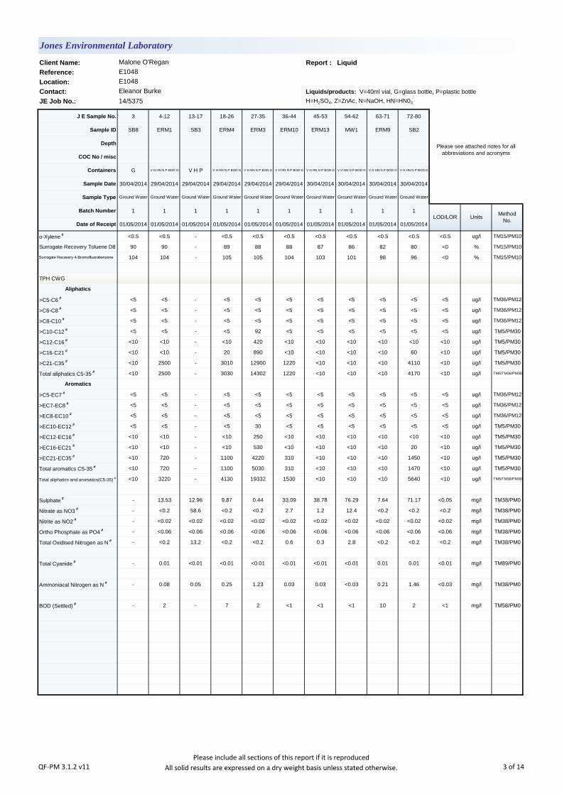
Client Name: Report : Liquid
Reference:
Location:
Contact: Liquids/products: V=40ml vial, G=glass bottle, P=plastic bottle
JE Job No.: 14/5375 H=H2SO4, Z=ZnAc, N=NaOH, HN=HN03
J E Sample No. 3 4-12 13-17 18-26 27-35 36-44 45-53 54-62 63-71 72-80
Sample ID SB8 ERM1 SB3 ERM4 ERM3 ERM10 ERM13 MW1 ERM9 SB2
Depth
COC No / misc
Containers G V H HN N P BOD G V H P V H HN N P BOD G V H HN N P BOD G V H HN N P BOD G V H HN N P BOD G V H HN N P BOD G V H HN N P BOD G V H HN N P BOD G
Sample Date 30/04/2014 29/04/2014 29/04/2014 29/04/2014 29/04/2014 29/04/2014 30/04/2014 30/04/2014 30/04/2014 30/04/2014
Sample Type Ground Water Ground Water Ground Water Ground Water Ground Water Ground Water Ground Water Ground Water Ground Water Ground Water
Batch Number 1 1 1 1 1 1 1 1 1 1
Date of Receipt 01/05/2014 01/05/2014 01/05/2014 01/05/2014 01/05/2014 01/05/2014 01/05/2014 01/05/2014 01/05/2014 01/05/2014
o-Xylene # <0.5 <0.5 - <0.5 <0.5 <0.5 <0.5 <0.5 <0.5 <0.5 <0.5 ug/l TM15/PM10
Surrogate Recovery Toluene D8 90 90 - 89 88 88 87 86 82 80 <0 % TM15/PM10
Surrogate Recovery 4-Bromofluorobenzene 104 104 - 105 105 104 103 101 98 96 <0 % TM15/PM10
TPH CWG
Aliphatics
>C5-C6 # <5 <5 - <5 <5 <5 <5 <5 <5 <5 <5 ug/l TM36/PM12
>C6-C8 # <5 <5 - <5 <5 <5 <5 <5 <5 <5 <5 ug/l TM36/PM12
>C8-C10 # <5 <5 - <5 <5 <5 <5 <5 <5 <5 <5 ug/l TM36/PM12
>C10-C12 # <5 <5 - <5 92 <5 <5 <5 <5 <5 <5 ug/l TM5/PM30
>C12-C16 # <10 <10 - <10 420 <10 <10 <10 <10 <10 <10 ug/l TM5/PM30
>C16-C21 # <10 <10 - 20 890 <10 <10 <10 <10 60 <10 ug/l TM5/PM30
>C21-C35 # <10 2500 - 3010 12900 1220 <10 <10 <10 4110 <10 ug/l TM5/PM30
Total aliphatics C5-35 # <10 2500 - 3030 14302 1220 <10 <10 <10 4170 <10 ug/l TM5/TM36/PM30
Aromatics
>C5-EC7 # <5 <5 - <5 <5 <5 <5 <5 <5 <5 <5 ug/l TM36/PM12
>EC7-EC8 # <5 <5 - <5 <5 <5 <5 <5 <5 <5 <5 ug/l TM36/PM12
>EC8-EC10 # <5 <5 - <5 <5 <5 <5 <5 <5 <5 <5 ug/l TM36/PM12
>EC10-EC12 # <5 <5 - <5 30 <5 <5 <5 <5 <5 <5 ug/l TM5/PM30
>EC12-EC16 # <10 <10 - <10 250 <10 <10 <10 <10 <10 <10 ug/l TM5/PM30
>EC16-EC21 # <10 <10 - <10 530 <10 <10 <10 <10 20 <10 ug/l TM5/PM30
>EC21-EC35 # <10 720 - 1100 4220 310 <10 <10 <10 1450 <10 ug/l TM5/PM30
Total aromatics C5-35 # <10 720 - 1100 5030 310 <10 <10 <10 1470 <10 ug/l TM5/PM30
Total aliphatics and aromatics(C5-35) # <10 3220 - 4130 19332 1530 <10 <10 <10 5640 <10 ug/l TM5/TM36/PM30
Sulphate # - 13.53 12.96 9.87 0.44 33.09 38.78 76.29 7.64 71.17 <0.05 mg/l TM38/PM0
Nitrate as NO3 # - <0.2 58.6 <0.2 <0.2 2.7 1.2 12.4 <0.2 <0.2 <0.2 mg/l TM38/PM0
Nitrite as NO2 # - <0.02 <0.02 <0.02 <0.02 <0.02 <0.02 <0.02 <0.02 <0.02 <0.02 mg/l TM38/PM0
Ortho Phosphate as PO4 # - <0.06 <0.06 <0.06 <0.06 <0.06 <0.06 <0.06 <0.06 <0.06 <0.06 mg/l TM38/PM0
Total Oxidised Nitrogen as N # - <0.2 13.2 <0.2 <0.2 0.6 0.3 2.8 <0.2 <0.2 <0.2 mg/l TM38/PM0
Total Cyanide # - 0.01 <0.01 <0.01 <0.01 <0.01 <0.01 <0.01 0.01 0.01 <0.01 mg/l TM89/PM0
Ammoniacal Nitrogen as N # - 0.08 0.05 0.25 1.23 0.03 0.03 <0.03 0.21 1.46 <0.03 mg/l TM38/PM0
BOD (Settled) # - 2 - 7 2 <1 <1 <1 10 2 <1 mg/l TM58/PM0
Jones Environmental Laboratory
Malone O'Regan
E1048
E1048
Eleanor Burke
Please see attached notes for all
abbreviations and acronyms
LOD/LOR UnitsMethod
No.
QF-PM 3.1.2 v11Please include all sections of this report if it is reproduced
All solid results are expressed on a dry weight basis unless stated otherwise. 3 of 14

Client Name: Report : Liquid
Reference:
Location:
Contact: Liquids/products: V=40ml vial, G=glass bottle, P=plastic bottle
JE Job No.: 14/5375 H=H2SO4, Z=ZnAc, N=NaOH, HN=HN03
J E Sample No. 81-89 90-94 95-100 101
Sample ID RW4 ERM11 ERM12 ERM13
Depth 1.0
COC No / misc
Containers V H HN N P BOD G V N HN V H N P HN
Sample Date 29/04/2014 29/04/2014 29/04/2014 29/04/2014
Sample Type Ground Water Ground Water Ground Water Ground Water
Batch Number 1 1 1 1
Date of Receipt 01/05/2014 01/05/2014 01/05/2014 01/05/2014
Dissolved Aluminium # 56 <20 <20 48 <20 ug/l TM30/PM14
Dissolved Arsenic # 4.0 <2.5 2.7 <2.5 <2.5 ug/l TM30/PM14
Dissolved Barium # 30 10 39 17 <3 ug/l TM30/PM14
Dissolved Boron 24 <12 <12 <12 <12 ug/l TM30/PM14
Dissolved Cadmium # <0.5 <0.5 <0.5 <0.5 <0.5 ug/l TM30/PM14
Dissolved Calcium # 127.8 115.1 120.1 121.7 <0.2 mg/l TM30/PM14
Total Dissolved Chromium # 2.0 <1.5 <1.5 <1.5 <1.5 ug/l TM30/PM14
Dissolved Copper # <7 <7 <7 <7 <7 ug/l TM30/PM14
Total Dissolved Iron # 4177 28 <20 92 <20 ug/l TM30/PM14
Dissolved Lead # <5 <5 <5 <5 <5 ug/l TM30/PM14
Dissolved Magnesium # 5.2 5.0 3.6 3.8 <0.1 mg/l TM30/PM14
Dissolved Manganese # 487 <2 <2 35 <2 ug/l TM30/PM14
Dissolved Mercury # <1 <1 <1 <1 <1 ug/l TM30/PM14
Dissolved Nickel # <2 <2 <2 <2 <2 ug/l TM30/PM14
Dissolved Potassium # 5.5 2.9 2.2 1.7 <0.1 mg/l TM30/PM14
Dissolved Selenium # <3 <3 <3 <3 <3 ug/l TM30/PM14
Dissolved Silver <5 <5 <5 <5 <5 ug/l TM30/PM14
Dissolved Sodium # 53.7 35.3 15.1 17.6 <0.1 mg/l TM30/PM14
Dissolved Zinc # 4 <3 <3 <3 <3 ug/l TM30/PM14
Total Aluminium 579 - 241500 - <20 ug/l TM30/PM14
Total Arsenic 10.3 - 171.4 - <2.5 ug/l TM30/PM14
Total Barium 36 - 1184 - <3 ug/l TM30/PM14
Total Boron 24 - <12 - <12 ug/l TM30/PM14
Total Cadmium 1.3 - 51.8 - <0.5 ug/l TM30/PM14
Total Calcium 191.4 - 576.6 - <0.2 mg/l TM30/PM14
Total Chromium 2.0 - 522.7 - <1.5 ug/l TM30/PM14
Total Copper 9 - 493 - <7 ug/l TM30/PM14
Total Iron 18740 - 422500 - <20 ug/l TM30/PM14
Total Lead 6 - 276 - <5 ug/l TM30/PM14
Total Magnesium 5.6 - 14.1 - <0.1 mg/l TM30/PM14
Total Manganese 502 - 2718 - <2 ug/l TM30/PM14
Total Mercury <1 - <1 - <1 ug/l TM30/PM14
Total Nickel 4 - 616 - <2 ug/l TM30/PM14
Total Potassium 5.5 - 14.7 - <0.1 mg/l TM30/PM14
Total Selenium <3 - <3 - <3 ug/l TM30/PM14
Total Silver <5 - 8 - <5 ug/l TM30/PM14
Total Sodium 53.7 - 16.2 - <0.1 mg/l TM30/PM14
Total Zinc 39 - 890 - <3 ug/l TM30/PM14
Methyl Tertiary Butyl Ether # <0.1 - - - <0.1 ug/l TM15/PM10
Benzene # <0.5 - - - <0.5 ug/l TM15/PM10
Toluene # <0.5 - - - <0.5 ug/l TM15/PM10
Ethylbenzene # <0.5 - - - <0.5 ug/l TM15/PM10
p/m-Xylene # <1 - - - <1 ug/l TM15/PM10
Jones Environmental Laboratory
Malone O'Regan
E1048
E1048
Eleanor Burke
Please see attached notes for all
abbreviations and acronyms
LOD/LOR UnitsMethod
No.
QF-PM 3.1.2 v11Please include all sections of this report if it is reproduced
All solid results are expressed on a dry weight basis unless stated otherwise. 4 of 14

Client Name: Report : Liquid
Reference:
Location:
Contact: Liquids/products: V=40ml vial, G=glass bottle, P=plastic bottle
JE Job No.: 14/5375 H=H2SO4, Z=ZnAc, N=NaOH, HN=HN03
J E Sample No. 81-89 90-94 95-100 101
Sample ID RW4 ERM11 ERM12 ERM13
Depth 1.0
COC No / misc
Containers V H HN N P BOD G V N HN V H N P HN
Sample Date 29/04/2014 29/04/2014 29/04/2014 29/04/2014
Sample Type Ground Water Ground Water Ground Water Ground Water
Batch Number 1 1 1 1
Date of Receipt 01/05/2014 01/05/2014 01/05/2014 01/05/2014
o-Xylene # <0.5 - - - <0.5 ug/l TM15/PM10
Surrogate Recovery Toluene D8 79 - - - <0 % TM15/PM10
Surrogate Recovery 4-Bromofluorobenzene 94 - - - <0 % TM15/PM10
TPH CWG
Aliphatics
>C5-C6 # <5 - - - <5 ug/l TM36/PM12
>C6-C8 # <5 - - - <5 ug/l TM36/PM12
>C8-C10 # <5 - - - <5 ug/l TM36/PM12
>C10-C12 # <5 - - - <5 ug/l TM5/PM30
>C12-C16 # <10 - - - <10 ug/l TM5/PM30
>C16-C21 # 80 - - - <10 ug/l TM5/PM30
>C21-C35 # 7110 - - - <10 ug/l TM5/PM30
Total aliphatics C5-35 # 7190 - - - <10 ug/l TM5/TM36/PM30
Aromatics
>C5-EC7 # <5 - - - <5 ug/l TM36/PM12
>EC7-EC8 # <5 - - - <5 ug/l TM36/PM12
>EC8-EC10 # <5 - - - <5 ug/l TM36/PM12
>EC10-EC12 # <5 - - - <5 ug/l TM5/PM30
>EC12-EC16 # <10 - - - <10 ug/l TM5/PM30
>EC16-EC21 # <10 - - - <10 ug/l TM5/PM30
>EC21-EC35 # 2190 - - - <10 ug/l TM5/PM30
Total aromatics C5-35 # 2190 - - - <10 ug/l TM5/PM30
Total aliphatics and aromatics(C5-35) # 9380 - - - <10 ug/l TM5/TM36/PM30
Sulphate # 7.77 - 33.34 - <0.05 mg/l TM38/PM0
Nitrate as NO3 # <0.2 - 2.0 - <0.2 mg/l TM38/PM0
Nitrite as NO2 # <0.02 - 0.11 - <0.02 mg/l TM38/PM0
Ortho Phosphate as PO4 # <0.06 - <0.06 - <0.06 mg/l TM38/PM0
Total Oxidised Nitrogen as N # <0.2 - 0.5 - <0.2 mg/l TM38/PM0
Total Cyanide # 0.01 <0.01 <0.01 - <0.01 mg/l TM89/PM0
Ammoniacal Nitrogen as N # 0.75 - 0.05 - <0.03 mg/l TM38/PM0
BOD (Settled) # 1 - - - <1 mg/l TM58/PM0
LOD/LOR UnitsMethod
No.
Jones Environmental Laboratory
Malone O'Regan
E1048
E1048
Eleanor Burke
Please see attached notes for all
abbreviations and acronyms
QF-PM 3.1.2 v11Please include all sections of this report if it is reproduced
All solid results are expressed on a dry weight basis unless stated otherwise. 5 of 14
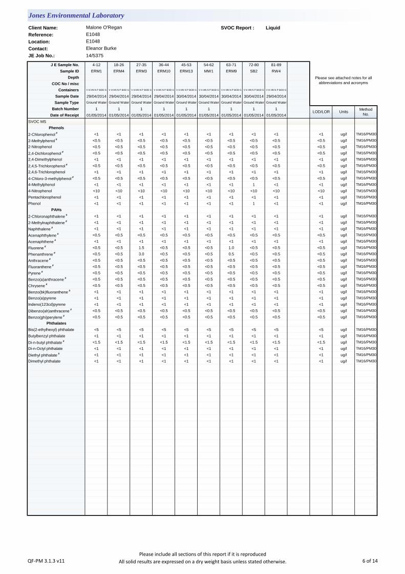
Client Name: SVOC Report : Liquid
Reference:
Location:
Contact:
JE Job No.: 14/5375
J E Sample No. 4-12 18-26 27-35 36-44 45-53 54-62 63-71 72-80 81-89
Sample ID ERM1 ERM4 ERM3 ERM10 ERM13 MW1 ERM9 SB2 RW4
Depth
COC No / misc
Containers V H HN N P BOD G V H HN N P BOD G V H HN N P BOD G V H HN N P BOD G V H HN N P BOD G V H HN N P BOD G V H HN N P BOD G V H HN N P BOD G V H HN N P BOD G
Sample Date 29/04/2014 29/04/2014 29/04/2014 29/04/2014 30/04/2014 30/04/2014 30/04/2014 30/04/2014 29/04/2014
Sample Type Ground Water Ground Water Ground Water Ground Water Ground Water Ground Water Ground Water Ground Water Ground Water
Batch Number 1 1 1 1 1 1 1 1 1
Date of Receipt 01/05/2014 01/05/2014 01/05/2014 01/05/2014 01/05/2014 01/05/2014 01/05/2014 01/05/2014 01/05/2014
SVOC MS
Phenols
2-Chlorophenol # <1 <1 <1 <1 <1 <1 <1 <1 <1 <1 ug/l TM16/PM30
2-Methylphenol # <0.5 <0.5 <0.5 <0.5 <0.5 <0.5 <0.5 <0.5 <0.5 <0.5 ug/l TM16/PM30
2-Nitrophenol <0.5 <0.5 <0.5 <0.5 <0.5 <0.5 <0.5 <0.5 <0.5 <0.5 ug/l TM16/PM30
2,4-Dichlorophenol # <0.5 <0.5 <0.5 <0.5 <0.5 <0.5 <0.5 <0.5 <0.5 <0.5 ug/l TM16/PM30
2,4-Dimethylphenol <1 <1 <1 <1 <1 <1 <1 <1 <1 <1 ug/l TM16/PM30
2,4,5-Trichlorophenol # <0.5 <0.5 <0.5 <0.5 <0.5 <0.5 <0.5 <0.5 <0.5 <0.5 ug/l TM16/PM30
2,4,6-Trichlorophenol <1 <1 <1 <1 <1 <1 <1 <1 <1 <1 ug/l TM16/PM30
4-Chloro-3-methylphenol # <0.5 <0.5 <0.5 <0.5 <0.5 <0.5 <0.5 <0.5 <0.5 <0.5 ug/l TM16/PM30
4-Methylphenol <1 <1 <1 <1 <1 <1 <1 1 <1 <1 ug/l TM16/PM30
4-Nitrophenol <10 <10 <10 <10 <10 <10 <10 <10 <10 <10 ug/l TM16/PM30
Pentachlorophenol <1 <1 <1 <1 <1 <1 <1 <1 <1 <1 ug/l TM16/PM30
Phenol <1 <1 <1 <1 <1 <1 <1 1 <1 <1 ug/l TM16/PM30
PAHs
2-Chloronaphthalene # <1 <1 <1 <1 <1 <1 <1 <1 <1 <1 ug/l TM16/PM30
2-Methylnaphthalene # <1 <1 <1 <1 <1 <1 <1 <1 <1 <1 ug/l TM16/PM30
Naphthalene # <1 <1 <1 <1 <1 <1 <1 <1 <1 <1 ug/l TM16/PM30
Acenaphthylene # <0.5 <0.5 <0.5 <0.5 <0.5 <0.5 <0.5 <0.5 <0.5 <0.5 ug/l TM16/PM30
Acenaphthene # <1 <1 <1 <1 <1 <1 <1 <1 <1 <1 ug/l TM16/PM30
Fluorene # <0.5 <0.5 1.5 <0.5 <0.5 <0.5 1.0 <0.5 <0.5 <0.5 ug/l TM16/PM30
Phenanthrene # <0.5 <0.5 3.0 <0.5 <0.5 <0.5 0.5 <0.5 <0.5 <0.5 ug/l TM16/PM30
Anthracene # <0.5 <0.5 <0.5 <0.5 <0.5 <0.5 <0.5 <0.5 <0.5 <0.5 ug/l TM16/PM30
Fluoranthene # <0.5 <0.5 <0.5 <0.5 <0.5 <0.5 <0.5 <0.5 <0.5 <0.5 ug/l TM16/PM30
Pyrene # <0.5 <0.5 <0.5 <0.5 <0.5 <0.5 <0.5 <0.5 <0.5 <0.5 ug/l TM16/PM30
Benzo(a)anthracene # <0.5 <0.5 <0.5 <0.5 <0.5 <0.5 <0.5 <0.5 <0.5 <0.5 ug/l TM16/PM30
Chrysene # <0.5 <0.5 <0.5 <0.5 <0.5 <0.5 <0.5 <0.5 <0.5 <0.5 ug/l TM16/PM30
Benzo(bk)fluoranthene # <1 <1 <1 <1 <1 <1 <1 <1 <1 <1 ug/l TM16/PM30
Benzo(a)pyrene <1 <1 <1 <1 <1 <1 <1 <1 <1 <1 ug/l TM16/PM30
Indeno(123cd)pyrene <1 <1 <1 <1 <1 <1 <1 <1 <1 <1 ug/l TM16/PM30
Dibenzo(ah)anthracene # <0.5 <0.5 <0.5 <0.5 <0.5 <0.5 <0.5 <0.5 <0.5 <0.5 ug/l TM16/PM30
Benzo(ghi)perylene # <0.5 <0.5 <0.5 <0.5 <0.5 <0.5 <0.5 <0.5 <0.5 <0.5 ug/l TM16/PM30
Phthalates
Bis(2-ethylhexyl) phthalate <5 <5 <5 <5 <5 <5 <5 <5 <5 <5 ug/l TM16/PM30
Butylbenzyl phthalate <1 <1 <1 <1 <1 <1 <1 <1 <1 <1 ug/l TM16/PM30
Di-n-butyl phthalate # <1.5 <1.5 <1.5 <1.5 <1.5 <1.5 <1.5 <1.5 <1.5 <1.5 ug/l TM16/PM30
Di-n-Octyl phthalate <1 <1 <1 <1 <1 <1 <1 <1 <1 <1 ug/l TM16/PM30
Diethyl phthalate # <1 <1 <1 <1 <1 <1 <1 <1 <1 <1 ug/l TM16/PM30
Dimethyl phthalate <1 <1 <1 <1 <1 <1 <1 <1 <1 <1 ug/l TM16/PM30
Jones Environmental Laboratory
Malone O'Regan
E1048
E1048
Eleanor Burke
Please see attached notes for all
abbreviations and acronyms
LOD/LOR UnitsMethod
No.
QF-PM 3.1.3 v11Please include all sections of this report if it is reproduced
All solid results are expressed on a dry weight basis unless stated otherwise. 6 of 14
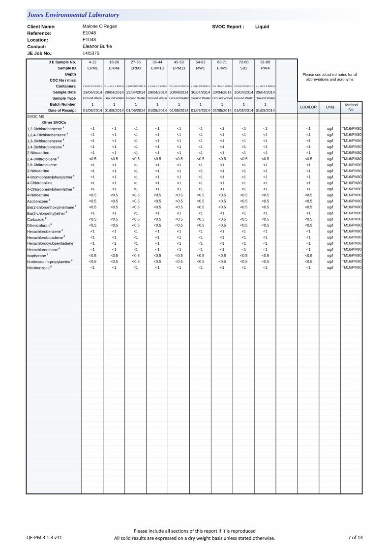
Client Name: SVOC Report : Liquid
Reference:
Location:
Contact:
JE Job No.: 14/5375
J E Sample No. 4-12 18-26 27-35 36-44 45-53 54-62 63-71 72-80 81-89
Sample ID ERM1 ERM4 ERM3 ERM10 ERM13 MW1 ERM9 SB2 RW4
Depth
COC No / misc
Containers V H HN N P BOD G V H HN N P BOD G V H HN N P BOD G V H HN N P BOD G V H HN N P BOD G V H HN N P BOD G V H HN N P BOD G V H HN N P BOD G V H HN N P BOD G
Sample Date 29/04/2014 29/04/2014 29/04/2014 29/04/2014 30/04/2014 30/04/2014 30/04/2014 30/04/2014 29/04/2014
Sample Type Ground Water Ground Water Ground Water Ground Water Ground Water Ground Water Ground Water Ground Water Ground Water
Batch Number 1 1 1 1 1 1 1 1 1
Date of Receipt 01/05/2014 01/05/2014 01/05/2014 01/05/2014 01/05/2014 01/05/2014 01/05/2014 01/05/2014 01/05/2014
SVOC MS
Other SVOCs
1,2-Dichlorobenzene # <1 <1 <1 <1 <1 <1 <1 <1 <1 <1 ug/l TM16/PM30
1,2,4-Trichlorobenzene # <1 <1 <1 <1 <1 <1 <1 <1 <1 <1 ug/l TM16/PM30
1,3-Dichlorobenzene # <1 <1 <1 <1 <1 <1 <1 <1 <1 <1 ug/l TM16/PM30
1,4-Dichlorobenzene # <1 <1 <1 <1 <1 <1 <1 <1 <1 <1 ug/l TM16/PM30
2-Nitroaniline <1 <1 <1 <1 <1 <1 <1 <1 <1 <1 ug/l TM16/PM30
2,4-Dinitrotoluene # <0.5 <0.5 <0.5 <0.5 <0.5 <0.5 <0.5 <0.5 <0.5 <0.5 ug/l TM16/PM30
2,6-Dinitrotoluene <1 <1 <1 <1 <1 <1 <1 <1 <1 <1 ug/l TM16/PM30
3-Nitroaniline <1 <1 <1 <1 <1 <1 <1 <1 <1 <1 ug/l TM16/PM30
4-Bromophenylphenylether # <1 <1 <1 <1 <1 <1 <1 <1 <1 <1 ug/l TM16/PM30
4-Chloroaniline <1 <1 <1 <1 <1 <1 <1 <1 <1 <1 ug/l TM16/PM30
4-Chlorophenylphenylether # <1 <1 <1 <1 <1 <1 <1 <1 <1 <1 ug/l TM16/PM30
4-Nitroaniline <0.5 <0.5 <0.5 <0.5 <0.5 <0.5 <0.5 <0.5 <0.5 <0.5 ug/l TM16/PM30
Azobenzene # <0.5 <0.5 <0.5 <0.5 <0.5 <0.5 <0.5 <0.5 <0.5 <0.5 ug/l TM16/PM30
Bis(2-chloroethoxy)methane # <0.5 <0.5 <0.5 <0.5 <0.5 <0.5 <0.5 <0.5 <0.5 <0.5 ug/l TM16/PM30
Bis(2-chloroethyl)ether # <1 <1 <1 <1 <1 <1 <1 <1 <1 <1 ug/l TM16/PM30
Carbazole # <0.5 <0.5 <0.5 <0.5 <0.5 <0.5 <0.5 <0.5 <0.5 <0.5 ug/l TM16/PM30
Dibenzofuran # <0.5 <0.5 <0.5 <0.5 <0.5 <0.5 <0.5 <0.5 <0.5 <0.5 ug/l TM16/PM30
Hexachlorobenzene # <1 <1 <1 <1 <1 <1 <1 <1 <1 <1 ug/l TM16/PM30
Hexachlorobutadiene # <1 <1 <1 <1 <1 <1 <1 <1 <1 <1 ug/l TM16/PM30
Hexachlorocyclopentadiene <1 <1 <1 <1 <1 <1 <1 <1 <1 <1 ug/l TM16/PM30
Hexachloroethane # <1 <1 <1 <1 <1 <1 <1 <1 <1 <1 ug/l TM16/PM30
Isophorone # <0.5 <0.5 <0.5 <0.5 <0.5 <0.5 <0.5 <0.5 <0.5 <0.5 ug/l TM16/PM30
N-nitrosodi-n-propylamine # <0.5 <0.5 <0.5 <0.5 <0.5 <0.5 <0.5 <0.5 <0.5 <0.5 ug/l TM16/PM30
Nitrobenzene # <1 <1 <1 <1 <1 <1 <1 <1 <1 <1 ug/l TM16/PM30
LOD/LOR UnitsMethod
No.
Jones Environmental Laboratory
Malone O'Regan
E1048
E1048
Eleanor Burke
Please see attached notes for all
abbreviations and acronyms
QF-PM 3.1.3 v11Please include all sections of this report if it is reproduced
All solid results are expressed on a dry weight basis unless stated otherwise. 7 of 14
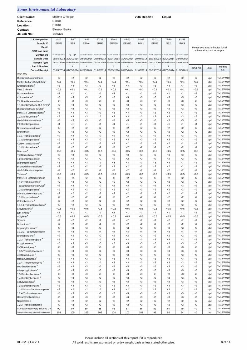
Client Name: VOC Report : Liquid
Reference:
Location:
Contact:
JE Job No.: 14/5375
J E Sample No. 4-12 13-17 18-26 27-35 36-44 45-53 54-62 63-71 72-80 81-89
Sample ID ERM1 SB3 ERM4 ERM3 ERM10 ERM13 MW1 ERM9 SB2 RW4
Depth
COC No / misc
Containers V H HN N P BOD G V H P V H HN N P BOD G V H HN N P BOD G V H HN N P BOD G V H HN N P BOD G V H HN N P BOD G V H HN N P BOD G V H HN N P BOD G V H HN N P BOD G
Sample Date 29/04/2014 29/04/2014 29/04/2014 29/04/2014 29/04/2014 30/04/2014 30/04/2014 30/04/2014 30/04/2014 29/04/2014
Sample Type Ground Water Ground Water Ground Water Ground Water Ground Water Ground Water Ground Water Ground Water Ground Water Ground Water
Batch Number 1 1 1 1 1 1 1 1 1 1
Date of Receipt 01/05/2014 01/05/2014 01/05/2014 01/05/2014 01/05/2014 01/05/2014 01/05/2014 01/05/2014 01/05/2014 01/05/2014
VOC MS
Dichlorodifluoromethane <2 <2 <2 <2 <2 <2 <2 <2 <2 <2 <2 ug/l TM15/PM10
Methyl Tertiary Butyl Ether # <0.1 <0.1 <0.1 <0.1 <0.1 <0.1 <0.1 <0.1 <0.1 <0.1 <0.1 ug/l TM15/PM10
Chloromethane # <3 <3 <3 <3 <3 <3 <3 <3 <3 <3 <3 ug/l TM15/PM10
Vinyl Chloride <0.1 <0.1 <0.1 <0.1 <0.1 <0.1 <0.1 <0.1 <0.1 <0.1 <0.1 ug/l TM15/PM10
Bromomethane <1 <1 <1 <1 <1 <1 <1 <1 <1 <1 <1 ug/l TM15/PM10
Chloroethane # <3 <3 <3 <3 <3 <3 <3 <3 <3 <3 <3 ug/l TM15/PM10
Trichlorofluoromethane # <3 <3 <3 <3 <3 <3 <3 <3 <3 <3 <3 ug/l TM15/PM10
1,1-Dichloroethene (1,1 DCE) # <3 <3 <3 <3 <3 <3 <3 <3 <3 <3 <3 ug/l TM15/PM10
Dichloromethane (DCM) # <3 <3 <3 <3 <3 <3 <3 <3 <3 <3 <3 ug/l TM15/PM10
trans-1-2-Dichloroethene # <3 <3 <3 <3 <3 <3 <3 <3 <3 <3 <3 ug/l TM15/PM10
1,1-Dichloroethane # <3 <3 <3 <3 <3 <3 <3 <3 <3 <3 <3 ug/l TM15/PM10
cis-1-2-Dichloroethene # <3 <3 <3 <3 <3 <3 <3 <3 <3 <3 <3 ug/l TM15/PM10
2,2-Dichloropropane <1 <1 <1 <1 <1 <1 <1 <1 <1 <1 <1 ug/l TM15/PM10
Bromochloromethane # <2 <2 <2 <2 <2 <2 <2 <2 <2 <2 <2 ug/l TM15/PM10
Chloroform # <2 <2 <2 <2 <2 <2 <2 <2 <2 <2 <2 ug/l TM15/PM10
1,1,1-Trichloroethane # <2 <2 <2 <2 <2 <2 <2 <2 <2 <2 <2 ug/l TM15/PM10
1,1-Dichloropropene # <3 <3 <3 <3 <3 <3 <3 <3 <3 <3 <3 ug/l TM15/PM10
Carbon tetrachloride # <2 <2 <2 <2 <2 <2 <2 <2 <2 <2 <2 ug/l TM15/PM10
1,2-Dichloroethane # <2 <2 <2 <2 <2 <2 <2 <2 <2 <2 <2 ug/l TM15/PM10
Benzene # <0.5 <0.5 <0.5 <0.5 <0.5 <0.5 <0.5 <0.5 <0.5 <0.5 <0.5 ug/l TM15/PM10
Trichloroethene (TCE) # <3 <3 <3 <3 <3 <3 <3 <3 <3 <3 <3 ug/l TM15/PM10
1,2-Dichloropropane # <2 <2 <2 <2 <2 <2 <2 <2 <2 <2 <2 ug/l TM15/PM10
Dibromomethane # <3 <3 <3 <3 <3 <3 <3 <3 <3 <3 <3 ug/l TM15/PM10
Bromodichloromethane # <2 <2 <2 <2 <2 <2 <2 <2 <2 <2 <2 ug/l TM15/PM10
cis-1-3-Dichloropropene <2 <2 <2 <2 <2 <2 <2 <2 <2 <2 <2 ug/l TM15/PM10
Toluene # <0.5 <0.5 <0.5 <0.5 <0.5 <0.5 <0.5 <0.5 <0.5 <0.5 <0.5 ug/l TM15/PM10
trans-1-3-Dichloropropene <2 <2 <2 <2 <2 <2 <2 <2 <2 <2 <2 ug/l TM15/PM10
1,1,2-Trichloroethane # <2 <2 <2 <2 <2 <2 <2 <2 <2 <2 <2 ug/l TM15/PM10
Tetrachloroethene (PCE) # <3 <3 <3 <3 <3 <3 <3 <3 <3 <3 <3 ug/l TM15/PM10
1,3-Dichloropropane # <2 <2 <2 <2 <2 <2 <2 <2 <2 <2 <2 ug/l TM15/PM10
Dibromochloromethane # <2 <2 <2 <2 <2 <2 <2 <2 <2 <2 <2 ug/l TM15/PM10
1,2-Dibromoethane # <2 <2 <2 <2 <2 <2 <2 <2 <2 <2 <2 ug/l TM15/PM10
Chlorobenzene # <2 <2 <2 <2 <2 <2 <2 <2 <2 <2 <2 ug/l TM15/PM10
1,1,1,2-Tetrachloroethane # <2 <2 <2 <2 <2 <2 <2 <2 <2 <2 <2 ug/l TM15/PM10
Ethylbenzene # <0.5 <0.5 <0.5 <0.5 <0.5 <0.5 <0.5 <0.5 <0.5 <0.5 <0.5 ug/l TM15/PM10
p/m-Xylene # <1 <1 <1 <1 <1 <1 <1 <1 <1 <1 <1 ug/l TM15/PM10
o-Xylene # <0.5 <0.5 <0.5 <0.5 <0.5 <0.5 <0.5 <0.5 <0.5 <0.5 <0.5 ug/l TM15/PM10
Styrene <2 <2 <2 <2 <2 <2 <2 <2 <2 <2 <2 ug/l TM15/PM10
Bromoform # <2 <2 <2 <2 <2 <2 <2 <2 <2 <2 <2 ug/l TM15/PM10
Isopropylbenzene # <3 <3 <3 <3 <3 <3 <3 <3 <3 <3 <3 ug/l TM15/PM10
1,1,2,2-Tetrachloroethane <4 <4 <4 <4 <4 <4 <4 <4 <4 <4 <4 ug/l TM15/PM10
Bromobenzene # <2 <2 <2 <2 <2 <2 <2 <2 <2 <2 <2 ug/l TM15/PM10
1,2,3-Trichloropropane # <3 <3 <3 <3 <3 <3 <3 <3 <3 <3 <3 ug/l TM15/PM10
Propylbenzene # <3 <3 <3 <3 <3 <3 <3 <3 <3 <3 <3 ug/l TM15/PM10
2-Chlorotoluene # <3 <3 <3 <3 <3 <3 <3 <3 <3 <3 <3 ug/l TM15/PM10
1,3,5-Trimethylbenzene # <3 <3 <3 <3 <3 <3 <3 <3 <3 <3 <3 ug/l TM15/PM10
4-Chlorotoluene # <3 <3 <3 <3 <3 <3 <3 <3 <3 <3 <3 ug/l TM15/PM10
tert-Butylbenzene # <3 <3 <3 <3 <3 <3 <3 <3 <3 <3 <3 ug/l TM15/PM10
1,2,4-Trimethylbenzene # <3 <3 <3 <3 <3 <3 <3 <3 <3 <3 <3 ug/l TM15/PM10
sec-Butylbenzene # <3 <3 <3 <3 <3 <3 <3 <3 <3 <3 <3 ug/l TM15/PM10
4-Isopropyltoluene # <3 <3 <3 <3 <3 <3 <3 <3 <3 <3 <3 ug/l TM15/PM10
1,3-Dichlorobenzene # <3 <3 <3 <3 <3 <3 <3 <3 <3 <3 <3 ug/l TM15/PM10
1,4-Dichlorobenzene # <3 <3 <3 <3 <3 <3 <3 <3 <3 <3 <3 ug/l TM15/PM10
n-Butylbenzene # <3 <3 <3 <3 <3 <3 <3 <3 <3 <3 <3 ug/l TM15/PM10
1,2-Dichlorobenzene # <3 <3 <3 <3 <3 <3 <3 <3 <3 <3 <3 ug/l TM15/PM10
1,2-Dibromo-3-chloropropane <2 <2 <2 <2 <2 <2 <2 <2 <2 <2 <2 ug/l TM15/PM10
1,2,4-Trichlorobenzene <3 <3 <3 <3 <3 <3 <3 <3 <3 <3 <3 ug/l TM15/PM10
Hexachlorobutadiene <3 <3 <3 <3 <3 <3 <3 <3 <3 <3 <3 ug/l TM15/PM10
Naphthalene <2 <2 <2 <2 <2 <2 <2 <2 <2 <2 <2 ug/l TM15/PM10
1,2,3-Trichlorobenzene <3 <3 <3 <3 <3 <3 <3 <3 <3 <3 <3 ug/l TM15/PM10
Surrogate Recovery Toluene D8 90 89 89 88 88 87 86 82 80 79 <0 % TM15/PM10
Surrogate Recovery 4-Bromofluorobenzene 104 105 105 105 104 103 101 98 96 94 <0 % TM15/PM10
Jones Environmental Laboratory
Malone O'Regan
E1048
E1048
Eleanor Burke
Please see attached notes for all
abbreviations and acronyms
LOD/LOR UnitsMethod
No.
QF-PM 3.1.4 v11Please include all sections of this report if it is reproduced
All solid results are expressed on a dry weight basis unless stated otherwise. 8 of 14
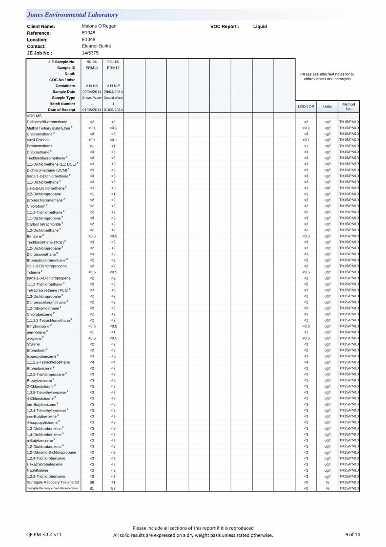
Client Name: VOC Report : Liquid
Reference:
Location:
Contact:
JE Job No.: 14/5375
J E Sample No. 90-94 95-100
Sample ID ERM11 ERM12
Depth
COC No / misc
Containers V N HN V H N P
Sample Date 29/04/2014 29/04/2014
Sample Type Ground Water Ground Water
Batch Number 1 1
Date of Receipt 01/05/2014 01/05/2014
VOC MS
Dichlorodifluoromethane <2 <2 <2 ug/l TM15/PM10
Methyl Tertiary Butyl Ether # <0.1 <0.1 <0.1 ug/l TM15/PM10
Chloromethane # <3 <3 <3 ug/l TM15/PM10
Vinyl Chloride <0.1 <0.1 <0.1 ug/l TM15/PM10
Bromomethane <1 <1 <1 ug/l TM15/PM10
Chloroethane # <3 <3 <3 ug/l TM15/PM10
Trichlorofluoromethane # <3 <3 <3 ug/l TM15/PM10
1,1-Dichloroethene (1,1 DCE) # <3 <3 <3 ug/l TM15/PM10
Dichloromethane (DCM) # <3 <3 <3 ug/l TM15/PM10
trans-1-2-Dichloroethene # <3 <3 <3 ug/l TM15/PM10
1,1-Dichloroethane # <3 <3 <3 ug/l TM15/PM10
cis-1-2-Dichloroethene # <3 <3 <3 ug/l TM15/PM10
2,2-Dichloropropane <1 <1 <1 ug/l TM15/PM10
Bromochloromethane # <2 <2 <2 ug/l TM15/PM10
Chloroform # <2 <2 <2 ug/l TM15/PM10
1,1,1-Trichloroethane # <2 <2 <2 ug/l TM15/PM10
1,1-Dichloropropene # <3 <3 <3 ug/l TM15/PM10
Carbon tetrachloride # <2 <2 <2 ug/l TM15/PM10
1,2-Dichloroethane # <2 <2 <2 ug/l TM15/PM10
Benzene # <0.5 <0.5 <0.5 ug/l TM15/PM10
Trichloroethene (TCE) # <3 <3 <3 ug/l TM15/PM10
1,2-Dichloropropane # <2 <2 <2 ug/l TM15/PM10
Dibromomethane # <3 <3 <3 ug/l TM15/PM10
Bromodichloromethane # <2 <2 <2 ug/l TM15/PM10
cis-1-3-Dichloropropene <2 <2 <2 ug/l TM15/PM10
Toluene # <0.5 <0.5 <0.5 ug/l TM15/PM10
trans-1-3-Dichloropropene <2 <2 <2 ug/l TM15/PM10
1,1,2-Trichloroethane # <2 <2 <2 ug/l TM15/PM10
Tetrachloroethene (PCE) # <3 <3 <3 ug/l TM15/PM10
1,3-Dichloropropane # <2 <2 <2 ug/l TM15/PM10
Dibromochloromethane # <2 <2 <2 ug/l TM15/PM10
1,2-Dibromoethane # <2 <2 <2 ug/l TM15/PM10
Chlorobenzene # <2 <2 <2 ug/l TM15/PM10
1,1,1,2-Tetrachloroethane # <2 <2 <2 ug/l TM15/PM10
Ethylbenzene # <0.5 <0.5 <0.5 ug/l TM15/PM10
p/m-Xylene # <1 <1 <1 ug/l TM15/PM10
o-Xylene # <0.5 <0.5 <0.5 ug/l TM15/PM10
Styrene <2 <2 <2 ug/l TM15/PM10
Bromoform # <2 <2 <2 ug/l TM15/PM10
Isopropylbenzene # <3 <3 <3 ug/l TM15/PM10
1,1,2,2-Tetrachloroethane <4 <4 <4 ug/l TM15/PM10
Bromobenzene # <2 <2 <2 ug/l TM15/PM10
1,2,3-Trichloropropane # <3 <3 <3 ug/l TM15/PM10
Propylbenzene # <3 <3 <3 ug/l TM15/PM10
2-Chlorotoluene # <3 <3 <3 ug/l TM15/PM10
1,3,5-Trimethylbenzene # <3 <3 <3 ug/l TM15/PM10
4-Chlorotoluene # <3 <3 <3 ug/l TM15/PM10
tert-Butylbenzene # <3 <3 <3 ug/l TM15/PM10
1,2,4-Trimethylbenzene # <3 <3 <3 ug/l TM15/PM10
sec-Butylbenzene # <3 <3 <3 ug/l TM15/PM10
4-Isopropyltoluene # <3 <3 <3 ug/l TM15/PM10
1,3-Dichlorobenzene # <3 <3 <3 ug/l TM15/PM10
1,4-Dichlorobenzene # <3 <3 <3 ug/l TM15/PM10
n-Butylbenzene # <3 <3 <3 ug/l TM15/PM10
1,2-Dichlorobenzene # <3 <3 <3 ug/l TM15/PM10
1,2-Dibromo-3-chloropropane <2 <2 <2 ug/l TM15/PM10
1,2,4-Trichlorobenzene <3 <3 <3 ug/l TM15/PM10
Hexachlorobutadiene <3 <3 <3 ug/l TM15/PM10
Naphthalene <2 <2 <2 ug/l TM15/PM10
1,2,3-Trichlorobenzene <3 <3 <3 ug/l TM15/PM10
Surrogate Recovery Toluene D8 68 71 <0 % TM15/PM10
Surrogate Recovery 4-Bromofluorobenzene 81 87 <0 % TM15/PM10
LOD/LOR UnitsMethod
No.
Jones Environmental Laboratory
Malone O'Regan
E1048
E1048
Eleanor Burke
Please see attached notes for all
abbreviations and acronyms
QF-PM 3.1.4 v11Please include all sections of this report if it is reproduced
All solid results are expressed on a dry weight basis unless stated otherwise. 9 of 14

Notification of Deviating Samples
J E
Job
No.
Batch Depth J E Sample
No.Analysis Reason
Please note that only samples that are deviating are mentioned in this report. If no samples are listed it is because none were deviating.
Only analyses which are accredited are recorded as deviating if set criteria are not met.
Location: E1048
Contact: Eleanor Burke
Sample ID
Jones Environmental Laboratory
Client Name: Malone O'Regan
Reference: E1048
No deviating sample report results for job 14/5375
QF-PM 3.1.11 v3 Please include all sections of this report if it is reproduced 10 of 14
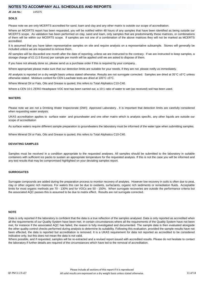
JE Job No.:
SOILS
DEVIATING SAMPLES
SURROGATES
NOTE
Surrogate compounds are added during the preparation process to monitor recovery of analytes. However low recovery in soils is often due to peat,
clay or other organic rich matrices. For waters this can be due to oxidants, surfactants, organic rich sediments or remediation fluids. Acceptable
limits for most organic methods are 70 - 130% and for VOCs are 50 - 150%. When surrogate recoveries are outside the performance criteria but
the associated AQC passes this is assumed to be due to matrix effect. Results are not surrogate corrected.
Where Mineral Oil or Fats, Oils and Grease is quoted, this refers to Total Aliphatics C10-C40.
Where a CEN 10:1 ZERO Headspace VOC test has been carried out, a 10:1 ratio of water to wet (as received) soil has been used.
Data is only reported if the laboratory is confident that the data is a true reflection of the samples analysed. Data is only reported as accredited when
all the requirements of our Quality System have been met. In certain circumstances where all the requirements of the Quality System have not been
met, for instance if the associated AQC has failed, the reason is fully investigated and documented. The sample data is then evaluated alongside
the other quality control checks performed during analysis to determine its suitability. Following this evaluation, provided the sample results have not
been effected, the data is reported but accreditation is removed. It is a UKAS requirement for data not reported as accredited to be considered
indicative only, but this does not mean the data is not valid.
Where possible, and if requested, samples will be re-extracted and a revised report issued with accredited results. Please do not hesitate to contact
the laboratory if further details are required of the circumstances which have led to the removal of accreditation.
Where an MCERTS report has been requested, you will be notified within 48 hours of any samples that have been identified as being outside our
MCERTS scope. As validation has been performed on clay, sand and loam, only samples that are predominantly these matrices, or combinations
of them will be within our MCERTS scope. If samples are not one of a combination of the above matrices they will not be marked as MCERTS
accredited.
All samples will be discarded one month after the date of reporting, unless we are instructed to the contrary. If we are instructed to keep samples, a
storage charge of £1 (1.5 Euros) per sample per month will be applied until we are asked to dispose of them.
It is assumed that you have taken representative samples on site and require analysis on a representative subsample. Stones will generally be
included unless we are requested to remove them.
UKAS accreditation applies to surface water and groundwater and one other matrix which is analysis specific, any other liquids are outside our
scope of accreditation
As surface waters require different sample preparation to groundwaters the laboratory must be informed of the water type when submitting samples.
Samples must be received in a condition appropriate to the requested analyses. All samples should be submitted to the laboratory in suitable
containers with sufficient ice packs to sustain an appropriate temperature for the requested analysis. If this is not the case you will be informed and
any test results that may be compromised highlighted on your deviating samples report.
Where appropriate please make sure that our detection limits are suitable for your needs, if they are not, please notify us immediately.
Please note we are not a Drinking Water Inspectorate (DWI) Approved Laboratory . It is important that detection limits are carefully considered
when requesting water analysis.
If you have not already done so, please send us a purchase order if this is required by your company.
All analysis is reported on a dry weight basis unless stated otherwise. Results are not surrogate corrected. Samples are dried at 35°C ±5°C unless
otherwise stated. Moisture content for CEN Leachate tests are dried at 105°C ±5°C.
NOTES TO ACCOMPANY ALL SCHEDULES AND REPORTS
Please note we are only MCERTS accredited for sand, loam and clay and any other matrix is outside our scope of accreditation.
Where Mineral Oil or Fats, Oils and Grease is quoted, this refers to Total Aliphatics C10-C40.
14/5375
WATERS
QF-PM 3.1.9 v27Please include all sections of this report if it is reproduced
All solid results are expressed on a dry weight basis unless stated otherwise. 11 of 14

JE Job No.:
#
B
DR
M
NA
NAD
ND
NDP
SS
SV
W
+
++
*
CO
LOD/LOR
ME
NFD
OC
MCERTS accredited.
AQC failure, accreditation has been removed from this result, if appropriate, see 'Note' on previous page.
Analysis subcontracted to a Jones Environmental approved laboratory.
Calibrated against a single substance
No Determination Possible
ABBREVIATIONS and ACRONYMS USED
No Asbestos Detected.
None Detected (usually refers to VOC and/SVOC TICs).
UKAS accredited.
Outside Calibration Range
Result outside calibration range, results should be considered as indicative only and are not accredited.
Results expressed on as received basis.
Surrogate recovery outside performance criteria. This may be due to a matrix effect.
Dilution required.
Indicates analyte found in associated method blank.
Not applicable
Matrix Effect
No Fibres Detected
Limit of Detection (Limit of Reporting) in line with ISO 17025 and MCERTS
Suspected carry over
14/5375
QF-PM 3.1.9 v27Please include all sections of this report if it is reproduced
All solid results are expressed on a dry weight basis unless stated otherwise. 12 of 14
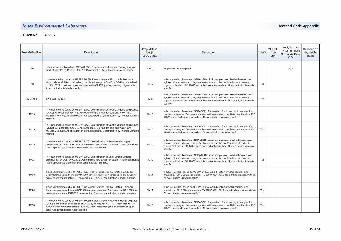
JE Job No: 14/5375
Test Method No. Description
Prep Method
No. (if
appropriate)
Description UKAS
MCERTS
(soils
only)
Analysis done
on As Received
(AR) or Air Dried
(AD)
Reported on
dry weight
basis
TM1In house method based on USEPA 8015B. Determination of carbon banding in oil and
product samples by GC-FID. ISO 17025 accredited. Accreditation is matrix specific.PM0 No preparation is required. AR
TM5
In-House method based on USEPA 8015B. Determination of Extractable Petroleum
Hydrocarbons (EPH) in the carbon chain length range of C8-40 by GC-FID. Accredited
to ISO 17025 on soil and water samples and MCERTS (carbon banding only) on soils.
All accreditation is matrix specific.
PM30
In-house method based on USEPA 3510. Liquid samples are mixed with solvent and
agitated with an automatic magnetic stirrer with a stir bar for 15 minutes to extract
organic molecules. ISO 17025 accredited extraction method. All accreditation is matrix
specific
Yes
TM5/TM36 TPH CWG by GC-FID PM30
In-house method based on USEPA 3510. Liquid samples are mixed with solvent and
agitated with an automatic magnetic stirrer with a stir bar for 15 minutes to extract
organic molecules. ISO 17025 accredited extraction method. All accreditation is matrix
specific
Yes
TM15
In-House method based on USEPA 8260. Determination of Volatile Organic compounds
(VOCs) by Headspace GC-MS. Accredited to ISO 17025 for soils and waters and
MCERTS for Soils. All accreditation is matrix specific. Quantification by Internal Standard
method.
PM10
In-house method based on USEPA 5021. Preparation of solid and liquid samples for
headspace analysis. Samples are spiked with surrogates to facilitate quantification. ISO
17025 accredited extraction method. All accreditation is matrix specific
TM15
In-House method based on USEPA 8260. Determination of Volatile Organic compounds
(VOCs) by Headspace GC-MS. Accredited to ISO 17025 for soils and waters and
MCERTS for Soils. All accreditation is matrix specific. Quantification by Internal Standard
method.
PM10
In-house method based on USEPA 5021. Preparation of solid and liquid samples for
headspace analysis. Samples are spiked with surrogates to facilitate quantification. ISO
17025 accredited extraction method. All accreditation is matrix specific
Yes
TM16
In-House method based on USEPA 8270. Determination of Semi-Volatile Organic
compounds (SVOCs) by GC-MS. Accredited to ISO 17025 for waters. All accreditation is
matrix specific. Quantification by Internal Standard method.
PM30
In-house method based on USEPA 3510. Liquid samples are mixed with solvent and
agitated with an automatic magnetic stirrer with a stir bar for 15 minutes to extract
organic molecules. ISO 17025 accredited extraction method. All accreditation is matrix
specific
TM16
In-House method based on USEPA 8270. Determination of Semi-Volatile Organic
compounds (SVOCs) by GC-MS. Accredited to ISO 17025 for waters. All accreditation is
matrix specific. Quantification by Internal Standard method.
PM30
In-house method based on USEPA 3510. Liquid samples are mixed with solvent and
agitated with an automatic magnetic stirrer with a stir bar for 15 minutes to extract
organic molecules. ISO 17025 accredited extraction method. All accreditation is matrix
specific
Yes
TM30
Trace Metal elements by ICP-OES (Inductively Coupled Plasma - Optical Emission
Spectrometry) using Thermo iCAP 6000 series instrument. Accredited to ISO 17025 for
soils and waters and MCERTS accredited for Soils. All accreditation is matrix specific.
PM14
In-house method based on USEPA 3005A. Acid digestion of water samples and
analsyis by ICP-OES as per method TM030W.ISO 17025 accredited extraction method.
All accreditation is matrix specific
Yes
TM36
In-House method based on USEPA 8015B. Determination of Gasoline Range Organics
(GRO) in the carbon chain range of C5-12 by headspace GC-FID. Accredited to ISO
17025 on soil and water samples and MCERTS accredited (carbon banding only) on
soils. All accreditation is matrix specific.
PM12
In-house method based on USEPA 5021. Preparation of solid and liquid samples for
headspace analysis. Samples are spiked with surrogates to facilitate quantification. ISO
17025 accredited extraction method. All accreditation is matrix specific
Yes
Jones Environmental Laboratory Method Code Appendix
QF-PM 3.1.10 v13 Please include all sections of this report if it is reproduced 13 of 14

JE Job No: 14/5375
Test Method No. Description
Prep Method
No. (if
appropriate)
Description UKAS
MCERTS
(soils
only)
Analysis done
on As Received
(AR) or Air Dried
(AD)
Reported on
dry weight
basis
TM38Ionic analysis using the Thermo Aquakem Photometric Automatic Analyser. Accredited
to ISO17025 and MCERTS for most analytes. All accreditation is matrix specific.PM0 No preparation is required. Yes
TM58
In-house method based on USEPA 405.1 and BS 5667-3. Meausremnet of Biochemical
Oxygen Demand by oxygen probe. ISO 17025 accredited. Accreditation is matrix
specific.
PM0 No preparation is required. Yes
TM89
In-house method based on USEPA method OIA-1667. Determination of cyanide by Flow
Injection Analyser. ISO17025 accredited method for soils and waters and MCERTS on
soils. Accreditation is matrix specific.
PM0 No preparation is required. Yes
Jones Environmental Laboratory Method Code Appendix
QF-PM 3.1.10 v13 Please include all sections of this report if it is reproduced 14 of 14

Unit 3 Deeside Point
Zone 3
Deeside Industrial Park
Deeside
Malone O'Regan
Attention :
Date :
Your reference :
Our reference :
Location :
Date samples received :
Status :
Issue :
Bob Millward BSc FRSC
Principal Chemist
1
Jones Environmental Laboratory
CH5 2UA
Tel: +44 (0) 1244 833780
Fax: +44 (0) 1244 833781
Eleanor Burke
2b Richview Office Park
Clonskeagh
Dublin 14
Ireland
Registered Address : Unit 3 Deeside Point, Zone 3, Deeside Industrial Park, Deeside, CH5 2UA. UK
Three samples were received for analysis on 2nd May, 2014. Please find attached our Test Report which should be read with notes at the end of
the report and should include all sections if reproduced. Interpretations and opinions are outside the scope of any accreditation, and all results relate
only to samples supplied.
All analysis is carried out on as received samples and reported on a dry weight basis unless stated otherwise. Results are not surrogate corrected.
Bruce Leslie
Project Co-ordinator
9th May, 2014
E1048
E1048
2nd May, 2014
Final report
Compiled By:
Test Report 14/5424 Batch 1
QF-PM 3.1.1 v15Please include all sections of this report if it is reproduced
All solid results are expressed on a dry weight basis unless stated otherwise. 1 of 11
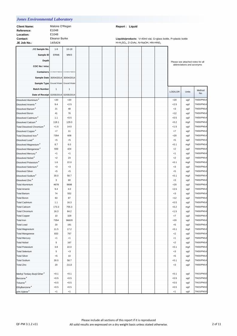
Client Name: Report : Liquid
Reference:
Location:
Contact: Liquids/products: V=40ml vial, G=glass bottle, P=plastic bottle
JE Job No.: 14/5424 H=H2SO4, Z=ZnAc, N=NaOH, HN=HN03
J E Sample No. 1-9 10-18
Sample ID ERM6 MW3
Depth
COC No / misc
Containers V H HN N P BOD G V H HN N P BOD G
Sample Date 30/04/2014 30/04/2014
Sample Type Ground Water Ground Water
Batch Number 1 1
Date of Receipt 02/05/2014 02/05/2014
Dissolved Aluminium # <20 <20 <20 ug/l TM30/PM14
Dissolved Arsenic # 9.4 <2.5 <2.5 ug/l TM30/PM14
Dissolved Barium # 21 48 <3 ug/l TM30/PM14
Dissolved Boron 41 76 <12 ug/l TM30/PM14
Dissolved Cadmium # 1.1 <0.5 <0.5 ug/l TM30/PM14
Dissolved Calcium # 118.1 129.0 <0.2 mg/l TM30/PM14
Total Dissolved Chromium # <1.5 14.0 <1.5 ug/l TM30/PM14
Dissolved Copper # <7 11 <7 ug/l TM30/PM14
Total Dissolved Iron # 7354 608 <20 ug/l TM30/PM14
Dissolved Lead # <5 <5 <5 ug/l TM30/PM14
Dissolved Magnesium # 8.7 6.0 <0.1 mg/l TM30/PM14
Dissolved Manganese # 559 424 <2 ug/l TM30/PM14
Dissolved Mercury # <1 <1 <1 ug/l TM30/PM14
Dissolved Nickel # <2 23 <2 ug/l TM30/PM14
Dissolved Potassium # 1.6 22.0 <0.1 mg/l TM30/PM14
Dissolved Selenium # <3 <3 <3 ug/l TM30/PM14
Dissolved Silver <5 <5 <5 ug/l TM30/PM14
Dissolved Sodium # 30.0 58.7 <0.1 mg/l TM30/PM14
Dissolved Zinc # 3 60 <3 ug/l TM30/PM14
Total Aluminium 4678 9698 <20 ug/l TM30/PM14
Total Arsenic 9.4 4.0 <2.5 ug/l TM30/PM14
Total Barium 74 552 <3 ug/l TM30/PM14
Total Boron 63 87 <12 ug/l TM30/PM14
Total Cadmium 1.1 16.3 <0.5 ug/l TM30/PM14
Total Calcium 173.3 755.3 <0.2 mg/l TM30/PM14
Total Chromium 16.3 84.2 <1.5 ug/l TM30/PM14
Total Copper 10 329 <7 ug/l TM30/PM14
Total Iron 7354 96620 <20 ug/l TM30/PM14
Total Lead 20 191 <5 ug/l TM30/PM14
Total Magnesium 11.5 17.2 <0.1 mg/l TM30/PM14
Total Manganese 833 767 <2 ug/l TM30/PM14
Total Mercury <1 <1 <1 ug/l TM30/PM14
Total Nickel 5 167 <2 ug/l TM30/PM14
Total Potassium 3.8 22.0 <0.1 mg/l TM30/PM14
Total Selenium 5 <3 <3 ug/l TM30/PM14
Total Silver <5 10 <5 ug/l TM30/PM14
Total Sodium 30.0 58.7 <0.1 mg/l TM30/PM14
Total Zinc 20 2113 <3 ug/l TM30/PM14
Methyl Tertiary Butyl Ether # <0.1 <0.1 <0.1 ug/l TM15/PM10
Benzene # <0.5 <0.5 <0.5 ug/l TM15/PM10
Toluene # <0.5 <0.5 <0.5 ug/l TM15/PM10
Ethylbenzene # <0.5 <0.5 <0.5 ug/l TM15/PM10
p/m-Xylene # <1 <1 <1 ug/l TM15/PM10
Jones Environmental Laboratory
Malone O'Regan
E1048
E1048
Eleanor Burke
Please see attached notes for all
abbreviations and acronyms
LOD/LOR UnitsMethod
No.
QF-PM 3.1.2 v11Please include all sections of this report if it is reproduced
All solid results are expressed on a dry weight basis unless stated otherwise. 2 of 11
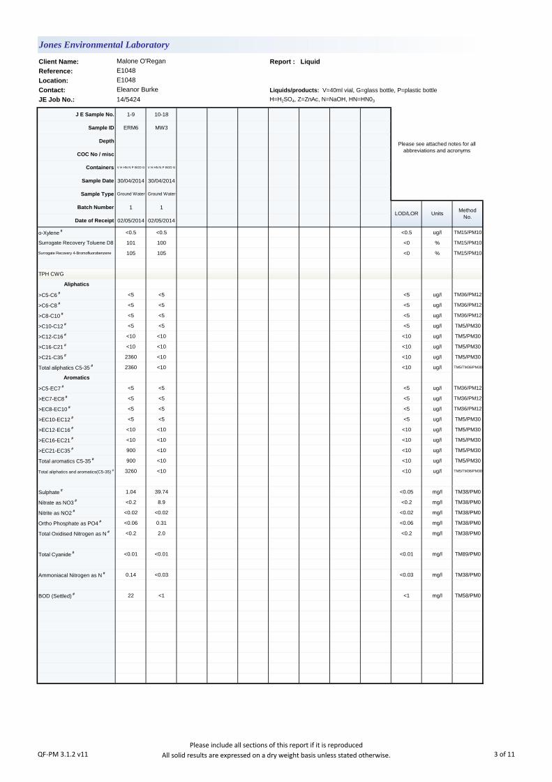
Client Name: Report : Liquid
Reference:
Location:
Contact: Liquids/products: V=40ml vial, G=glass bottle, P=plastic bottle
JE Job No.: 14/5424 H=H2SO4, Z=ZnAc, N=NaOH, HN=HN03
J E Sample No. 1-9 10-18
Sample ID ERM6 MW3
Depth
COC No / misc
Containers V H HN N P BOD G V H HN N P BOD G
Sample Date 30/04/2014 30/04/2014
Sample Type Ground Water Ground Water
Batch Number 1 1
Date of Receipt 02/05/2014 02/05/2014
o-Xylene # <0.5 <0.5 <0.5 ug/l TM15/PM10
Surrogate Recovery Toluene D8 101 100 <0 % TM15/PM10
Surrogate Recovery 4-Bromofluorobenzene 105 105 <0 % TM15/PM10
TPH CWG
Aliphatics
>C5-C6 # <5 <5 <5 ug/l TM36/PM12
>C6-C8 # <5 <5 <5 ug/l TM36/PM12
>C8-C10 # <5 <5 <5 ug/l TM36/PM12
>C10-C12 # <5 <5 <5 ug/l TM5/PM30
>C12-C16 # <10 <10 <10 ug/l TM5/PM30
>C16-C21 # <10 <10 <10 ug/l TM5/PM30
>C21-C35 # 2360 <10 <10 ug/l TM5/PM30
Total aliphatics C5-35 # 2360 <10 <10 ug/l TM5/TM36/PM30
Aromatics
>C5-EC7 # <5 <5 <5 ug/l TM36/PM12
>EC7-EC8 # <5 <5 <5 ug/l TM36/PM12
>EC8-EC10 # <5 <5 <5 ug/l TM36/PM12
>EC10-EC12 # <5 <5 <5 ug/l TM5/PM30
>EC12-EC16 # <10 <10 <10 ug/l TM5/PM30
>EC16-EC21 # <10 <10 <10 ug/l TM5/PM30
>EC21-EC35 # 900 <10 <10 ug/l TM5/PM30
Total aromatics C5-35 # 900 <10 <10 ug/l TM5/PM30
Total aliphatics and aromatics(C5-35) # 3260 <10 <10 ug/l TM5/TM36/PM30
Sulphate # 1.04 39.74 <0.05 mg/l TM38/PM0
Nitrate as NO3 # <0.2 8.9 <0.2 mg/l TM38/PM0
Nitrite as NO2 # <0.02 <0.02 <0.02 mg/l TM38/PM0
Ortho Phosphate as PO4 # <0.06 0.31 <0.06 mg/l TM38/PM0
Total Oxidised Nitrogen as N # <0.2 2.0 <0.2 mg/l TM38/PM0
Total Cyanide # <0.01 <0.01 <0.01 mg/l TM89/PM0
Ammoniacal Nitrogen as N # 0.14 <0.03 <0.03 mg/l TM38/PM0
BOD (Settled) # 22 <1 <1 mg/l TM58/PM0
LOD/LOR UnitsMethod
No.
Jones Environmental Laboratory
Malone O'Regan
E1048
E1048
Eleanor Burke
Please see attached notes for all
abbreviations and acronyms
QF-PM 3.1.2 v11Please include all sections of this report if it is reproduced
All solid results are expressed on a dry weight basis unless stated otherwise. 3 of 11

Client Name: SVOC Report : Liquid
Reference:
Location:
Contact:
JE Job No.: 14/5424
J E Sample No. 1-9 10-18
Sample ID ERM6 MW3
Depth
COC No / misc
Containers V H HN N P BOD G V H HN N P BOD G
Sample Date 30/04/2014 30/04/2014
Sample Type Ground Water Ground Water
Batch Number 1 1
Date of Receipt 02/05/2014 02/05/2014
SVOC MS
Phenols
2-Chlorophenol # <1 <1 <1 ug/l TM16/PM30
2-Methylphenol # <0.5 <0.5 <0.5 ug/l TM16/PM30
2-Nitrophenol <0.5 <0.5 <0.5 ug/l TM16/PM30
2,4-Dichlorophenol # <0.5 <0.5 <0.5 ug/l TM16/PM30
2,4-Dimethylphenol <1 <1 <1 ug/l TM16/PM30
2,4,5-Trichlorophenol # <0.5 <0.5 <0.5 ug/l TM16/PM30
2,4,6-Trichlorophenol <1 <1 <1 ug/l TM16/PM30
4-Chloro-3-methylphenol # <0.5 <0.5 <0.5 ug/l TM16/PM30
4-Methylphenol <1 <1 <1 ug/l TM16/PM30
4-Nitrophenol <10 <10 <10 ug/l TM16/PM30
Pentachlorophenol <1 <1 <1 ug/l TM16/PM30
Phenol <1 <1 <1 ug/l TM16/PM30
PAHs
2-Chloronaphthalene # <1 <1 <1 ug/l TM16/PM30
2-Methylnaphthalene # <1 <1 <1 ug/l TM16/PM30
Naphthalene # <1 <1 <1 ug/l TM16/PM30
Acenaphthylene # <0.5 <0.5 <0.5 ug/l TM16/PM30
Acenaphthene # <1 <1 <1 ug/l TM16/PM30
Fluorene # <0.5 <0.5 <0.5 ug/l TM16/PM30
Phenanthrene # <0.5 <0.5 <0.5 ug/l TM16/PM30
Anthracene # <0.5 <0.5 <0.5 ug/l TM16/PM30
Fluoranthene # <0.5 <0.5 <0.5 ug/l TM16/PM30
Pyrene # <0.5 <0.5 <0.5 ug/l TM16/PM30
Benzo(a)anthracene # <0.5 <0.5 <0.5 ug/l TM16/PM30
Chrysene # <0.5 <0.5 <0.5 ug/l TM16/PM30
Benzo(bk)fluoranthene # <1 <1 <1 ug/l TM16/PM30
Benzo(a)pyrene <1 <1 <1 ug/l TM16/PM30
Indeno(123cd)pyrene <1 <1 <1 ug/l TM16/PM30
Dibenzo(ah)anthracene # <0.5 <0.5 <0.5 ug/l TM16/PM30
Benzo(ghi)perylene # <0.5 <0.5 <0.5 ug/l TM16/PM30
Phthalates
Bis(2-ethylhexyl) phthalate <5 <5 <5 ug/l TM16/PM30
Butylbenzyl phthalate <1 <1 <1 ug/l TM16/PM30
Di-n-butyl phthalate # <1.5 <1.5 <1.5 ug/l TM16/PM30
Di-n-Octyl phthalate <1 <1 <1 ug/l TM16/PM30
Diethyl phthalate # <1 <1 <1 ug/l TM16/PM30
Dimethyl phthalate <1 <1 <1 ug/l TM16/PM30
Jones Environmental Laboratory
Malone O'Regan
E1048
E1048
Eleanor Burke
Please see attached notes for all
abbreviations and acronyms
LOD/LOR UnitsMethod
No.
QF-PM 3.1.3 v11Please include all sections of this report if it is reproduced
All solid results are expressed on a dry weight basis unless stated otherwise. 4 of 11
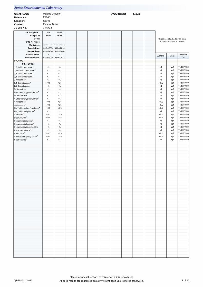
Client Name: SVOC Report : Liquid
Reference:
Location:
Contact:
JE Job No.: 14/5424
J E Sample No. 1-9 10-18
Sample ID ERM6 MW3
Depth
COC No / misc
Containers V H HN N P BOD G V H HN N P BOD G
Sample Date 30/04/2014 30/04/2014
Sample Type Ground Water Ground Water
Batch Number 1 1
Date of Receipt 02/05/2014 02/05/2014
SVOC MS
Other SVOCs
1,2-Dichlorobenzene # <1 <1 <1 ug/l TM16/PM30
1,2,4-Trichlorobenzene # <1 <1 <1 ug/l TM16/PM30
1,3-Dichlorobenzene # <1 <1 <1 ug/l TM16/PM30
1,4-Dichlorobenzene # <1 <1 <1 ug/l TM16/PM30
2-Nitroaniline <1 <1 <1 ug/l TM16/PM30
2,4-Dinitrotoluene # <0.5 <0.5 <0.5 ug/l TM16/PM30
2,6-Dinitrotoluene <1 <1 <1 ug/l TM16/PM30
3-Nitroaniline <1 <1 <1 ug/l TM16/PM30
4-Bromophenylphenylether # <1 <1 <1 ug/l TM16/PM30
4-Chloroaniline <1 <1 <1 ug/l TM16/PM30
4-Chlorophenylphenylether # <1 <1 <1 ug/l TM16/PM30
4-Nitroaniline <0.5 <0.5 <0.5 ug/l TM16/PM30
Azobenzene # <0.5 <0.5 <0.5 ug/l TM16/PM30
Bis(2-chloroethoxy)methane # <0.5 <0.5 <0.5 ug/l TM16/PM30
Bis(2-chloroethyl)ether # <1 <1 <1 ug/l TM16/PM30
Carbazole # <0.5 <0.5 <0.5 ug/l TM16/PM30
Dibenzofuran # <0.5 <0.5 <0.5 ug/l TM16/PM30
Hexachlorobenzene # <1 <1 <1 ug/l TM16/PM30
Hexachlorobutadiene # <1 <1 <1 ug/l TM16/PM30
Hexachlorocyclopentadiene <1 <1 <1 ug/l TM16/PM30
Hexachloroethane # <1 <1 <1 ug/l TM16/PM30
Isophorone # <0.5 <0.5 <0.5 ug/l TM16/PM30
N-nitrosodi-n-propylamine # <0.5 <0.5 <0.5 ug/l TM16/PM30
Nitrobenzene # <1 <1 <1 ug/l TM16/PM30
LOD/LOR UnitsMethod
No.
Jones Environmental Laboratory
Malone O'Regan
E1048
E1048
Eleanor Burke
Please see attached notes for all
abbreviations and acronyms
QF-PM 3.1.3 v11Please include all sections of this report if it is reproduced
All solid results are expressed on a dry weight basis unless stated otherwise. 5 of 11
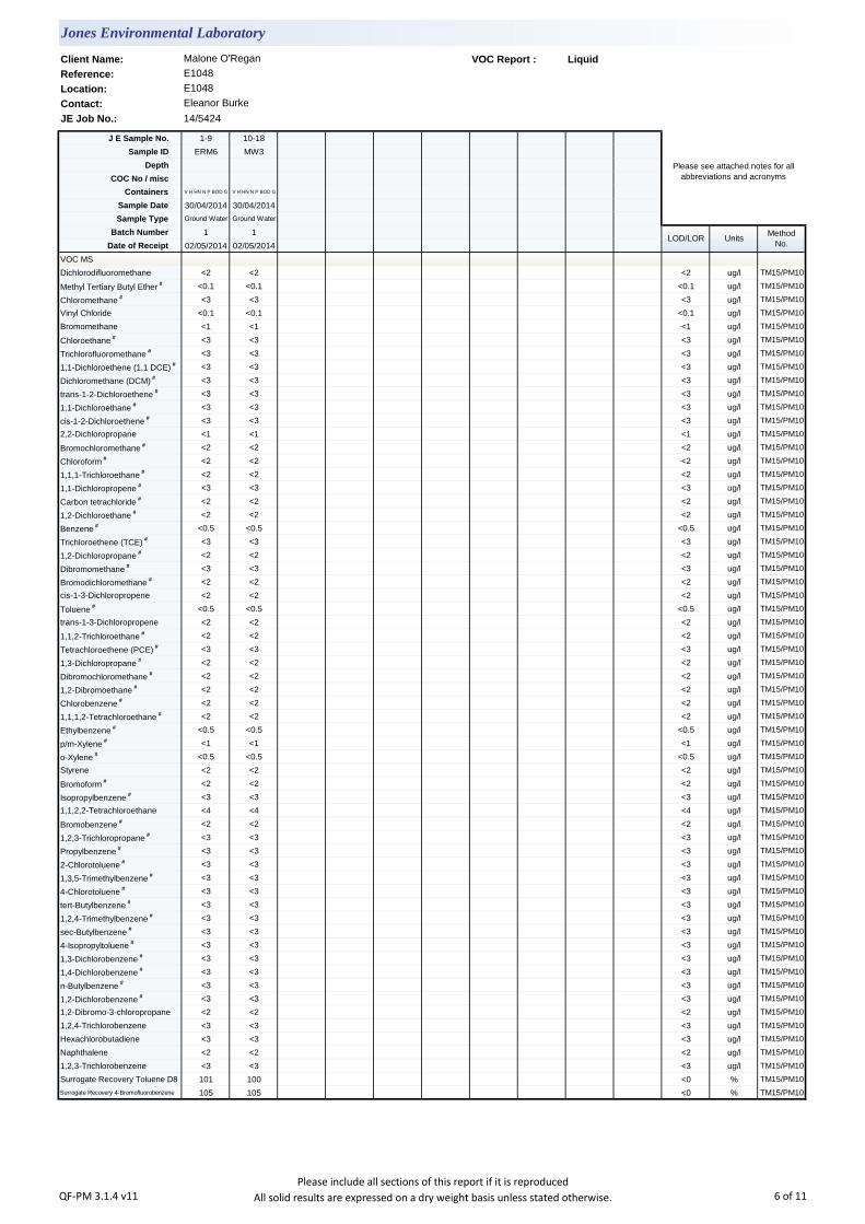
Client Name: VOC Report : Liquid
Reference:
Location:
Contact:
JE Job No.: 14/5424
J E Sample No. 1-9 10-18
Sample ID ERM6 MW3
Depth
COC No / misc
Containers V H HN N P BOD G V H HN N P BOD G
Sample Date 30/04/2014 30/04/2014
Sample Type Ground Water Ground Water
Batch Number 1 1
Date of Receipt 02/05/2014 02/05/2014
VOC MS
Dichlorodifluoromethane <2 <2 <2 ug/l TM15/PM10
Methyl Tertiary Butyl Ether # <0.1 <0.1 <0.1 ug/l TM15/PM10
Chloromethane # <3 <3 <3 ug/l TM15/PM10
Vinyl Chloride <0.1 <0.1 <0.1 ug/l TM15/PM10
Bromomethane <1 <1 <1 ug/l TM15/PM10
Chloroethane # <3 <3 <3 ug/l TM15/PM10
Trichlorofluoromethane # <3 <3 <3 ug/l TM15/PM10
1,1-Dichloroethene (1,1 DCE) # <3 <3 <3 ug/l TM15/PM10
Dichloromethane (DCM) # <3 <3 <3 ug/l TM15/PM10
trans-1-2-Dichloroethene # <3 <3 <3 ug/l TM15/PM10
1,1-Dichloroethane # <3 <3 <3 ug/l TM15/PM10
cis-1-2-Dichloroethene # <3 <3 <3 ug/l TM15/PM10
2,2-Dichloropropane <1 <1 <1 ug/l TM15/PM10
Bromochloromethane # <2 <2 <2 ug/l TM15/PM10
Chloroform # <2 <2 <2 ug/l TM15/PM10
1,1,1-Trichloroethane # <2 <2 <2 ug/l TM15/PM10
1,1-Dichloropropene # <3 <3 <3 ug/l TM15/PM10
Carbon tetrachloride # <2 <2 <2 ug/l TM15/PM10
1,2-Dichloroethane # <2 <2 <2 ug/l TM15/PM10
Benzene # <0.5 <0.5 <0.5 ug/l TM15/PM10
Trichloroethene (TCE) # <3 <3 <3 ug/l TM15/PM10
1,2-Dichloropropane # <2 <2 <2 ug/l TM15/PM10
Dibromomethane # <3 <3 <3 ug/l TM15/PM10
Bromodichloromethane # <2 <2 <2 ug/l TM15/PM10
cis-1-3-Dichloropropene <2 <2 <2 ug/l TM15/PM10
Toluene # <0.5 <0.5 <0.5 ug/l TM15/PM10
trans-1-3-Dichloropropene <2 <2 <2 ug/l TM15/PM10
1,1,2-Trichloroethane # <2 <2 <2 ug/l TM15/PM10
Tetrachloroethene (PCE) # <3 <3 <3 ug/l TM15/PM10
1,3-Dichloropropane # <2 <2 <2 ug/l TM15/PM10
Dibromochloromethane # <2 <2 <2 ug/l TM15/PM10
1,2-Dibromoethane # <2 <2 <2 ug/l TM15/PM10
Chlorobenzene # <2 <2 <2 ug/l TM15/PM10
1,1,1,2-Tetrachloroethane # <2 <2 <2 ug/l TM15/PM10
Ethylbenzene # <0.5 <0.5 <0.5 ug/l TM15/PM10
p/m-Xylene # <1 <1 <1 ug/l TM15/PM10
o-Xylene # <0.5 <0.5 <0.5 ug/l TM15/PM10
Styrene <2 <2 <2 ug/l TM15/PM10
Bromoform # <2 <2 <2 ug/l TM15/PM10
Isopropylbenzene # <3 <3 <3 ug/l TM15/PM10
1,1,2,2-Tetrachloroethane <4 <4 <4 ug/l TM15/PM10
Bromobenzene # <2 <2 <2 ug/l TM15/PM10
1,2,3-Trichloropropane # <3 <3 <3 ug/l TM15/PM10
Propylbenzene # <3 <3 <3 ug/l TM15/PM10
2-Chlorotoluene # <3 <3 <3 ug/l TM15/PM10
1,3,5-Trimethylbenzene # <3 <3 <3 ug/l TM15/PM10
4-Chlorotoluene # <3 <3 <3 ug/l TM15/PM10
tert-Butylbenzene # <3 <3 <3 ug/l TM15/PM10
1,2,4-Trimethylbenzene # <3 <3 <3 ug/l TM15/PM10
sec-Butylbenzene # <3 <3 <3 ug/l TM15/PM10
4-Isopropyltoluene # <3 <3 <3 ug/l TM15/PM10
1,3-Dichlorobenzene # <3 <3 <3 ug/l TM15/PM10
1,4-Dichlorobenzene # <3 <3 <3 ug/l TM15/PM10
n-Butylbenzene # <3 <3 <3 ug/l TM15/PM10
1,2-Dichlorobenzene # <3 <3 <3 ug/l TM15/PM10
1,2-Dibromo-3-chloropropane <2 <2 <2 ug/l TM15/PM10
1,2,4-Trichlorobenzene <3 <3 <3 ug/l TM15/PM10
Hexachlorobutadiene <3 <3 <3 ug/l TM15/PM10
Naphthalene <2 <2 <2 ug/l TM15/PM10
1,2,3-Trichlorobenzene <3 <3 <3 ug/l TM15/PM10
Surrogate Recovery Toluene D8 101 100 <0 % TM15/PM10
Surrogate Recovery 4-Bromofluorobenzene 105 105 <0 % TM15/PM10
Jones Environmental Laboratory
Malone O'Regan
E1048
E1048
Eleanor Burke
Please see attached notes for all
abbreviations and acronyms
LOD/LOR UnitsMethod
No.
QF-PM 3.1.4 v11Please include all sections of this report if it is reproduced
All solid results are expressed on a dry weight basis unless stated otherwise. 6 of 11

Notification of Deviating Samples
J E
Job
No.
Batch Depth J E Sample
No.Analysis Reason
Please note that only samples that are deviating are mentioned in this report. If no samples are listed it is because none were deviating.
Only analyses which are accredited are recorded as deviating if set criteria are not met.
Location: E1048
Contact: Eleanor Burke
Sample ID
Jones Environmental Laboratory
Client Name: Malone O'Regan
Reference: E1048
No deviating sample report results for job 14/5424
QF-PM 3.1.11 v3 Please include all sections of this report if it is reproduced 7 of 11

JE Job No.:
SOILS
DEVIATING SAMPLES
SURROGATES
NOTE
Surrogate compounds are added during the preparation process to monitor recovery of analytes. However low recovery in soils is often due to peat,
clay or other organic rich matrices. For waters this can be due to oxidants, surfactants, organic rich sediments or remediation fluids. Acceptable
limits for most organic methods are 70 - 130% and for VOCs are 50 - 150%. When surrogate recoveries are outside the performance criteria but
the associated AQC passes this is assumed to be due to matrix effect. Results are not surrogate corrected.
Where Mineral Oil or Fats, Oils and Grease is quoted, this refers to Total Aliphatics C10-C40.
Where a CEN 10:1 ZERO Headspace VOC test has been carried out, a 10:1 ratio of water to wet (as received) soil has been used.
Data is only reported if the laboratory is confident that the data is a true reflection of the samples analysed. Data is only reported as accredited when
all the requirements of our Quality System have been met. In certain circumstances where all the requirements of the Quality System have not been
met, for instance if the associated AQC has failed, the reason is fully investigated and documented. The sample data is then evaluated alongside
the other quality control checks performed during analysis to determine its suitability. Following this evaluation, provided the sample results have not
been effected, the data is reported but accreditation is removed. It is a UKAS requirement for data not reported as accredited to be considered
indicative only, but this does not mean the data is not valid.
Where possible, and if requested, samples will be re-extracted and a revised report issued with accredited results. Please do not hesitate to contact
the laboratory if further details are required of the circumstances which have led to the removal of accreditation.
Where an MCERTS report has been requested, you will be notified within 48 hours of any samples that have been identified as being outside our
MCERTS scope. As validation has been performed on clay, sand and loam, only samples that are predominantly these matrices, or combinations
of them will be within our MCERTS scope. If samples are not one of a combination of the above matrices they will not be marked as MCERTS
accredited.
All samples will be discarded one month after the date of reporting, unless we are instructed to the contrary. If we are instructed to keep samples, a
storage charge of £1 (1.5 Euros) per sample per month will be applied until we are asked to dispose of them.
It is assumed that you have taken representative samples on site and require analysis on a representative subsample. Stones will generally be
included unless we are requested to remove them.
UKAS accreditation applies to surface water and groundwater and one other matrix which is analysis specific, any other liquids are outside our
scope of accreditation
As surface waters require different sample preparation to groundwaters the laboratory must be informed of the water type when submitting samples.
Samples must be received in a condition appropriate to the requested analyses. All samples should be submitted to the laboratory in suitable
containers with sufficient ice packs to sustain an appropriate temperature for the requested analysis. If this is not the case you will be informed and
any test results that may be compromised highlighted on your deviating samples report.
Where appropriate please make sure that our detection limits are suitable for your needs, if they are not, please notify us immediately.
Please note we are not a Drinking Water Inspectorate (DWI) Approved Laboratory . It is important that detection limits are carefully considered
when requesting water analysis.
If you have not already done so, please send us a purchase order if this is required by your company.
All analysis is reported on a dry weight basis unless stated otherwise. Results are not surrogate corrected. Samples are dried at 35°C ±5°C unless
otherwise stated. Moisture content for CEN Leachate tests are dried at 105°C ±5°C.
NOTES TO ACCOMPANY ALL SCHEDULES AND REPORTS
Please note we are only MCERTS accredited for sand, loam and clay and any other matrix is outside our scope of accreditation.
Where Mineral Oil or Fats, Oils and Grease is quoted, this refers to Total Aliphatics C10-C40.
14/5424
WATERS
QF-PM 3.1.9 v27Please include all sections of this report if it is reproduced
All solid results are expressed on a dry weight basis unless stated otherwise. 8 of 11
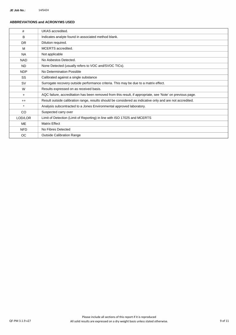
JE Job No.:
#
B
DR
M
NA
NAD
ND
NDP
SS
SV
W
+
++
*
CO
LOD/LOR
ME
NFD
OC
MCERTS accredited.
AQC failure, accreditation has been removed from this result, if appropriate, see 'Note' on previous page.
Analysis subcontracted to a Jones Environmental approved laboratory.
Calibrated against a single substance
No Determination Possible
ABBREVIATIONS and ACRONYMS USED
No Asbestos Detected.
None Detected (usually refers to VOC and/SVOC TICs).
UKAS accredited.
Outside Calibration Range
Result outside calibration range, results should be considered as indicative only and are not accredited.
Results expressed on as received basis.
Surrogate recovery outside performance criteria. This may be due to a matrix effect.
Dilution required.
Indicates analyte found in associated method blank.
Not applicable
Matrix Effect
No Fibres Detected
Limit of Detection (Limit of Reporting) in line with ISO 17025 and MCERTS
Suspected carry over
14/5424
QF-PM 3.1.9 v27Please include all sections of this report if it is reproduced
All solid results are expressed on a dry weight basis unless stated otherwise. 9 of 11

JE Job No: 14/5424
Test Method No. Description
Prep Method
No. (if
appropriate)
Description UKAS
MCERTS
(soils
only)
Analysis done
on As Received
(AR) or Air Dried
(AD)
Reported on
dry weight
basis
TM5
In-House method based on USEPA 8015B. Determination of Extractable Petroleum
Hydrocarbons (EPH) in the carbon chain length range of C8-40 by GC-FID. Accredited
to ISO 17025 on soil and water samples and MCERTS (carbon banding only) on soils.
All accreditation is matrix specific.
PM30
In-house method based on USEPA 3510. Liquid samples are mixed with solvent and
agitated with an automatic magnetic stirrer with a stir bar for 15 minutes to extract
organic molecules. ISO 17025 accredited extraction method. All accreditation is matrix
specific
Yes
TM5/TM36 TPH CWG by GC-FID PM30
In-house method based on USEPA 3510. Liquid samples are mixed with solvent and
agitated with an automatic magnetic stirrer with a stir bar for 15 minutes to extract
organic molecules. ISO 17025 accredited extraction method. All accreditation is matrix
specific
Yes
TM15
In-House method based on USEPA 8260. Determination of Volatile Organic compounds
(VOCs) by Headspace GC-MS. Accredited to ISO 17025 for soils and waters and
MCERTS for Soils. All accreditation is matrix specific. Quantification by Internal Standard
method.
PM10
In-house method based on USEPA 5021. Preparation of solid and liquid samples for
headspace analysis. Samples are spiked with surrogates to facilitate quantification. ISO
17025 accredited extraction method. All accreditation is matrix specific
TM15
In-House method based on USEPA 8260. Determination of Volatile Organic compounds
(VOCs) by Headspace GC-MS. Accredited to ISO 17025 for soils and waters and
MCERTS for Soils. All accreditation is matrix specific. Quantification by Internal Standard
method.
PM10
In-house method based on USEPA 5021. Preparation of solid and liquid samples for
headspace analysis. Samples are spiked with surrogates to facilitate quantification. ISO
17025 accredited extraction method. All accreditation is matrix specific
Yes
TM16
In-House method based on USEPA 8270. Determination of Semi-Volatile Organic
compounds (SVOCs) by GC-MS. Accredited to ISO 17025 for waters. All accreditation is
matrix specific. Quantification by Internal Standard method.
PM30
In-house method based on USEPA 3510. Liquid samples are mixed with solvent and
agitated with an automatic magnetic stirrer with a stir bar for 15 minutes to extract
organic molecules. ISO 17025 accredited extraction method. All accreditation is matrix
specific
TM16
In-House method based on USEPA 8270. Determination of Semi-Volatile Organic
compounds (SVOCs) by GC-MS. Accredited to ISO 17025 for waters. All accreditation is
matrix specific. Quantification by Internal Standard method.
PM30
In-house method based on USEPA 3510. Liquid samples are mixed with solvent and
agitated with an automatic magnetic stirrer with a stir bar for 15 minutes to extract
organic molecules. ISO 17025 accredited extraction method. All accreditation is matrix
specific
Yes
TM30
Trace Metal elements by ICP-OES (Inductively Coupled Plasma - Optical Emission
Spectrometry) using Thermo iCAP 6000 series instrument. Accredited to ISO 17025 for
soils and waters and MCERTS accredited for Soils. All accreditation is matrix specific.
PM14
In-house method based on USEPA 3005A. Acid digestion of water samples and
analsyis by ICP-OES as per method TM030W.ISO 17025 accredited extraction method.
All accreditation is matrix specific
TM30
Trace Metal elements by ICP-OES (Inductively Coupled Plasma - Optical Emission
Spectrometry) using Thermo iCAP 6000 series instrument. Accredited to ISO 17025 for
soils and waters and MCERTS accredited for Soils. All accreditation is matrix specific.
PM14
In-house method based on USEPA 3005A. Acid digestion of water samples and
analsyis by ICP-OES as per method TM030W.ISO 17025 accredited extraction method.
All accreditation is matrix specific
Yes
TM36
In-House method based on USEPA 8015B. Determination of Gasoline Range Organics
(GRO) in the carbon chain range of C5-12 by headspace GC-FID. Accredited to ISO
17025 on soil and water samples and MCERTS accredited (carbon banding only) on
soils. All accreditation is matrix specific.
PM12
In-house method based on USEPA 5021. Preparation of solid and liquid samples for
headspace analysis. Samples are spiked with surrogates to facilitate quantification. ISO
17025 accredited extraction method. All accreditation is matrix specific
Yes
TM38Ionic analysis using the Thermo Aquakem Photometric Automatic Analyser. Accredited
to ISO17025 and MCERTS for most analytes. All accreditation is matrix specific.PM0 No preparation is required. Yes
Jones Environmental Laboratory Method Code Appendix
QF-PM 3.1.10 v13 Please include all sections of this report if it is reproduced 10 of 11
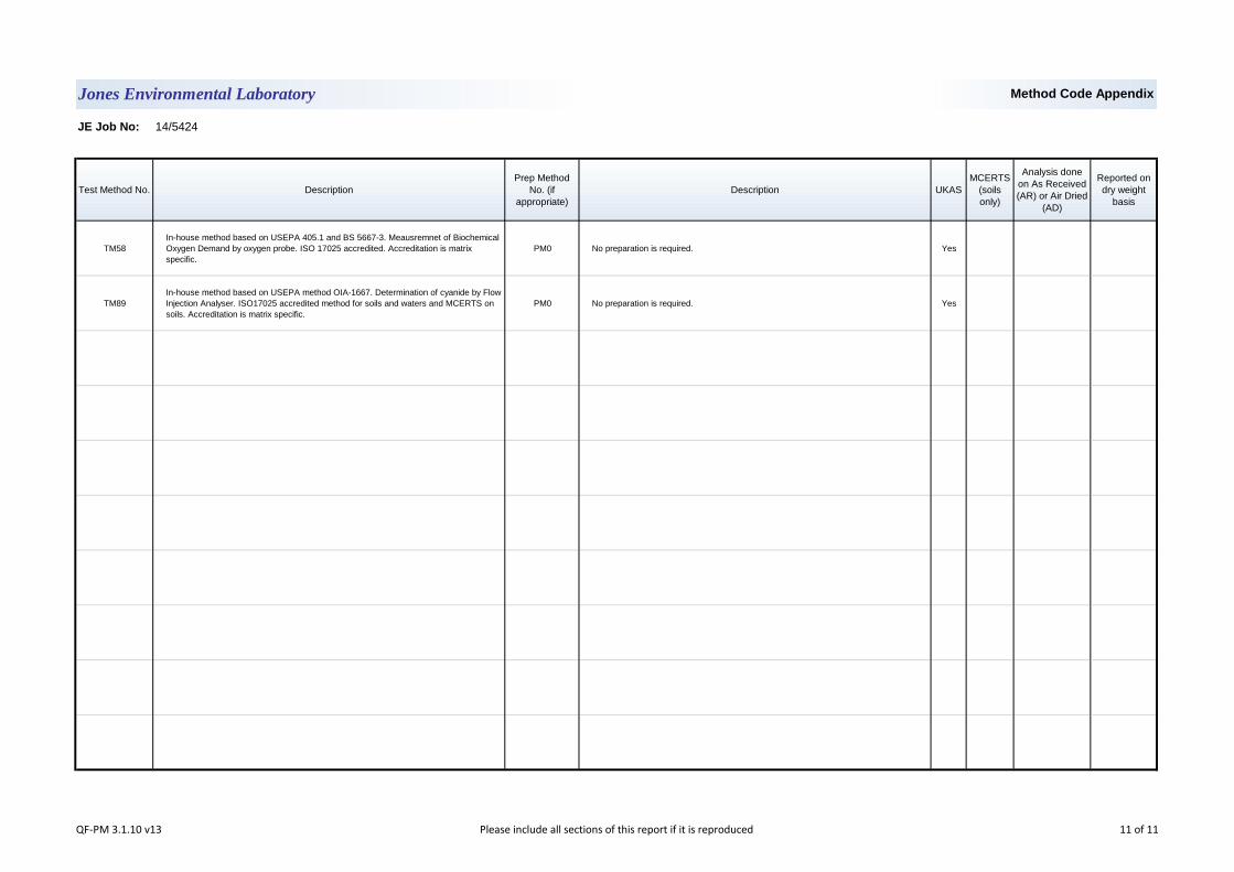
JE Job No: 14/5424
Test Method No. Description
Prep Method
No. (if
appropriate)
Description UKAS
MCERTS
(soils
only)
Analysis done
on As Received
(AR) or Air Dried
(AD)
Reported on
dry weight
basis
TM58
In-house method based on USEPA 405.1 and BS 5667-3. Meausremnet of Biochemical
Oxygen Demand by oxygen probe. ISO 17025 accredited. Accreditation is matrix
specific.
PM0 No preparation is required. Yes
TM89
In-house method based on USEPA method OIA-1667. Determination of cyanide by Flow
Injection Analyser. ISO17025 accredited method for soils and waters and MCERTS on
soils. Accreditation is matrix specific.
PM0 No preparation is required. Yes
Jones Environmental Laboratory Method Code Appendix
QF-PM 3.1.10 v13 Please include all sections of this report if it is reproduced 11 of 11
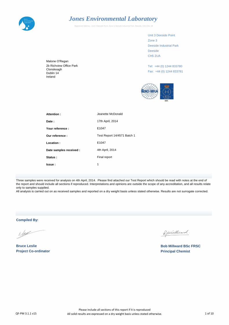
Unit 3 Deeside Point
Zone 3
Deeside Industrial Park
Deeside
Malone O'Regan
Attention :
Date :
Your reference :
Our reference :
Location :
Date samples received :
Status :
Issue :
Bob Millward BSc FRSC
Principal Chemist
1
Jones Environmental Laboratory
CH5 2UA
Tel: +44 (0) 1244 833780
Fax: +44 (0) 1244 833781
Jeanette McDonald
2b Richview Office Park
Clonskeagh
Dublin 14
Ireland
Registered Address : Unit 3 Deeside Point, Zone 3, Deeside Industrial Park, Deeside, CH5 2UA. UK
Three samples were received for analysis on 4th April, 2014. Please find attached our Test Report which should be read with notes at the end of
the report and should include all sections if reproduced. Interpretations and opinions are outside the scope of any accreditation, and all results relate
only to samples supplied.
All analysis is carried out on as received samples and reported on a dry weight basis unless stated otherwise. Results are not surrogate corrected.
Bruce Leslie
Project Co-ordinator
17th April, 2014
E1047
E1047
4th April, 2014
Final report
Compiled By:
Test Report 14/4571 Batch 1
QF-PM 3.1.1 v15Please include all sections of this report if it is reproduced
All solid results are expressed on a dry weight basis unless stated otherwise. 1 of 10

Client Name: Report : Liquid
Reference:
Location:
Contact: Liquids/products: V=40ml vial, G=glass bottle, P=plastic bottle
JE Job No.: 14/4571 H=H2SO4, Z=ZnAc, N=NaOH, HN=HN03
J E Sample No. 1-7 8-14 15-21
Sample ID MW2 ERM10 MW3
Depth
COC No / misc
Containers V H HN N P G V H HN N P G V H HN N P G
Sample Date 02/04/2014 02/04/2014 02/04/2014
Sample Type Ground Water Ground Water Ground Water
Batch Number 1 1 1
Date of Receipt 04/04/2014 04/04/2014 04/04/2014
Dissolved Aluminium # <20 <20 <20 <20 ug/l TM30/PM14
Dissolved Arsenic # <2.5 <2.5 <2.5 <2.5 ug/l TM30/PM14
Dissolved Barium # 46 70 37 <3 ug/l TM30/PM14
Dissolved Boron 158 43 <12 <12 ug/l TM30/PM14
Dissolved Cadmium # <0.5 <0.5 <0.5 <0.5 ug/l TM30/PM14
Dissolved Calcium # 155.0 103.9 131.5 <0.2 mg/l TM30/PM14
Total Dissolved Chromium # <1.5 <1.5 <1.5 <1.5 ug/l TM30/PM14
Dissolved Copper # 22 <7 14 <7 ug/l TM30/PM14
Total Dissolved Iron # 26 20 <20 <20 ug/l TM30/PM14
Dissolved Lead # <5 <5 <5 <5 ug/l TM30/PM14
Dissolved Magnesium # 6.1 4.2 5.9 <0.1 mg/l TM30/PM14
Dissolved Manganese # 44 71 47 <2 ug/l TM30/PM14
Dissolved Mercury # <1 <1 <1 <1 ug/l TM30/PM14
Dissolved Nickel # 11 <2 13 <2 ug/l TM30/PM14
Dissolved Potassium # 33.2 5.6 25.7 <0.1 mg/l TM30/PM14
Dissolved Selenium # <3 <3 <3 <3 ug/l TM30/PM14
Dissolved Silver <5 <5 <5 <5 ug/l TM30/PM14
Dissolved Sodium # 73.4 43.5 64.7 <0.1 mg/l TM30/PM14
Dissolved Zinc # 12 <3 25 <3 ug/l TM30/PM14
Total Aluminium 2802 15300 103900 <20 ug/l TM30/PM14
Total Arsenic <2.5 3.4 <2.5 <2.5 ug/l TM30/PM14
Total Barium 117 339 13930 <3 ug/l TM30/PM14
Total Boron 158 71 <12 <12 ug/l TM30/PM14
Total Cadmium 0.8 4.8 127.3 <0.5 ug/l TM30/PM14
Total Calcium 179.5 1733.0 2924.0 <0.2 mg/l TM30/PM14
Total Chromium 6.2 42.7 792.2 <1.5 ug/l TM30/PM14
Total Copper 30 36 4140 <7 ug/l TM30/PM14
Total Iron 3186 29680 1024000 <20 ug/l TM30/PM14
Total Lead 15 37 1633 <5 ug/l TM30/PM14
Total Magnesium 6.5 15.8 67.0 <0.1 mg/l TM30/PM14
Total Manganese 145 807 8240 <2 ug/l TM30/PM14
Total Mercury <1 <1 <1 <1 ug/l TM30/PM14
Total Nickel 17 46 1727 <2 ug/l TM30/PM14
Total Potassium 33.5 8.4 38.9 <0.1 mg/l TM30/PM14
Total Selenium <3 <3 <3 <3 ug/l TM30/PM14
Total Silver <5 <5 <5 <5 ug/l TM30/PM14
Total Sodium 73.8 44.3 76.7 <0.1 mg/l TM30/PM14
Total Zinc 46 181 37470 <3 ug/l TM30/PM14
E1047
Jeanette McDonald
Please see attached notes for all
abbreviations and acronyms
LOD/LOR UnitsMethod
No.
Jones Environmental Laboratory
Malone O'Regan
E1047
QF-PM 3.1.2 v11Please include all sections of this report if it is reproduced
All solid results are expressed on a dry weight basis unless stated otherwise. 2 of 10
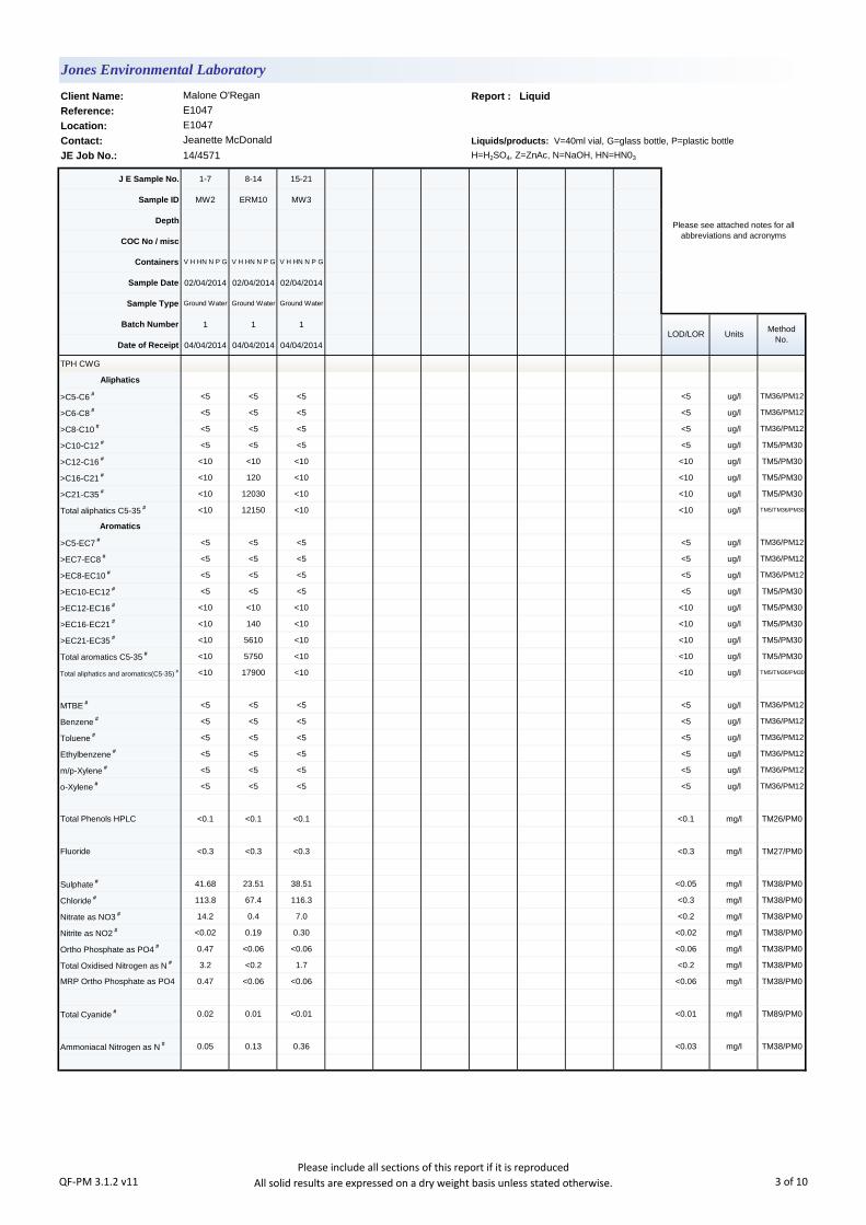
Client Name: Report : Liquid
Reference:
Location:
Contact: Liquids/products: V=40ml vial, G=glass bottle, P=plastic bottle
JE Job No.: 14/4571 H=H2SO4, Z=ZnAc, N=NaOH, HN=HN03
J E Sample No. 1-7 8-14 15-21
Sample ID MW2 ERM10 MW3
Depth
COC No / misc
Containers V H HN N P G V H HN N P G V H HN N P G
Sample Date 02/04/2014 02/04/2014 02/04/2014
Sample Type Ground Water Ground Water Ground Water
Batch Number 1 1 1
Date of Receipt 04/04/2014 04/04/2014 04/04/2014
TPH CWG
Aliphatics
>C5-C6 # <5 <5 <5 <5 ug/l TM36/PM12
>C6-C8 # <5 <5 <5 <5 ug/l TM36/PM12
>C8-C10 # <5 <5 <5 <5 ug/l TM36/PM12
>C10-C12 # <5 <5 <5 <5 ug/l TM5/PM30
>C12-C16 # <10 <10 <10 <10 ug/l TM5/PM30
>C16-C21 # <10 120 <10 <10 ug/l TM5/PM30
>C21-C35 # <10 12030 <10 <10 ug/l TM5/PM30
Total aliphatics C5-35 # <10 12150 <10 <10 ug/l TM5/TM36/PM30
Aromatics
>C5-EC7 # <5 <5 <5 <5 ug/l TM36/PM12
>EC7-EC8 # <5 <5 <5 <5 ug/l TM36/PM12
>EC8-EC10 # <5 <5 <5 <5 ug/l TM36/PM12
>EC10-EC12 # <5 <5 <5 <5 ug/l TM5/PM30
>EC12-EC16 # <10 <10 <10 <10 ug/l TM5/PM30
>EC16-EC21 # <10 140 <10 <10 ug/l TM5/PM30
>EC21-EC35 # <10 5610 <10 <10 ug/l TM5/PM30
Total aromatics C5-35 # <10 5750 <10 <10 ug/l TM5/PM30
Total aliphatics and aromatics(C5-35) # <10 17900 <10 <10 ug/l TM5/TM36/PM30
MTBE # <5 <5 <5 <5 ug/l TM36/PM12
Benzene # <5 <5 <5 <5 ug/l TM36/PM12
Toluene # <5 <5 <5 <5 ug/l TM36/PM12
Ethylbenzene # <5 <5 <5 <5 ug/l TM36/PM12
m/p-Xylene # <5 <5 <5 <5 ug/l TM36/PM12
o-Xylene # <5 <5 <5 <5 ug/l TM36/PM12
Total Phenols HPLC <0.1 <0.1 <0.1 <0.1 mg/l TM26/PM0
Fluoride <0.3 <0.3 <0.3 <0.3 mg/l TM27/PM0
Sulphate # 41.68 23.51 38.51 <0.05 mg/l TM38/PM0
Chloride # 113.8 67.4 116.3 <0.3 mg/l TM38/PM0
Nitrate as NO3 # 14.2 0.4 7.0 <0.2 mg/l TM38/PM0
Nitrite as NO2 # <0.02 0.19 0.30 <0.02 mg/l TM38/PM0
Ortho Phosphate as PO4 # 0.47 <0.06 <0.06 <0.06 mg/l TM38/PM0
Total Oxidised Nitrogen as N # 3.2 <0.2 1.7 <0.2 mg/l TM38/PM0
MRP Ortho Phosphate as PO4 0.47 <0.06 <0.06 <0.06 mg/l TM38/PM0
Total Cyanide # 0.02 0.01 <0.01 <0.01 mg/l TM89/PM0
Ammoniacal Nitrogen as N # 0.05 0.13 0.36 <0.03 mg/l TM38/PM0
LOD/LOR UnitsMethod
No.
Jones Environmental Laboratory
Malone O'Regan
E1047
E1047
Jeanette McDonald
Please see attached notes for all
abbreviations and acronyms
QF-PM 3.1.2 v11Please include all sections of this report if it is reproduced
All solid results are expressed on a dry weight basis unless stated otherwise. 3 of 10
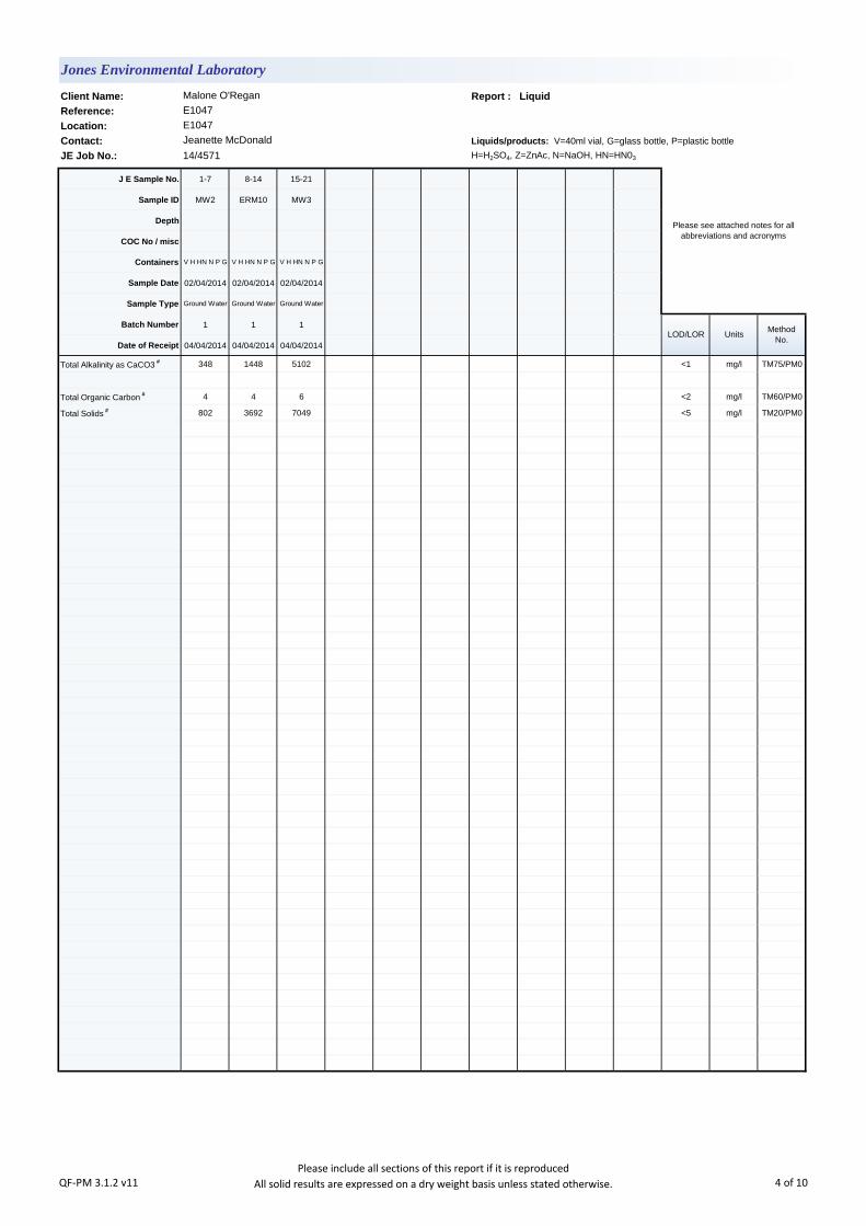
Client Name: Report : Liquid
Reference:
Location:
Contact: Liquids/products: V=40ml vial, G=glass bottle, P=plastic bottle
JE Job No.: 14/4571 H=H2SO4, Z=ZnAc, N=NaOH, HN=HN03
J E Sample No. 1-7 8-14 15-21
Sample ID MW2 ERM10 MW3
Depth
COC No / misc
Containers V H HN N P G V H HN N P G V H HN N P G
Sample Date 02/04/2014 02/04/2014 02/04/2014
Sample Type Ground Water Ground Water Ground Water
Batch Number 1 1 1
Date of Receipt 04/04/2014 04/04/2014 04/04/2014
Total Alkalinity as CaCO3 # 348 1448 5102 <1 mg/l TM75/PM0
Total Organic Carbon # 4 4 6 <2 mg/l TM60/PM0
Total Solids # 802 3692 7049 <5 mg/l TM20/PM0
E1047
Jeanette McDonald
Please see attached notes for all
abbreviations and acronyms
LOD/LOR UnitsMethod
No.
Jones Environmental Laboratory
Malone O'Regan
E1047
QF-PM 3.1.2 v11Please include all sections of this report if it is reproduced
All solid results are expressed on a dry weight basis unless stated otherwise. 4 of 10
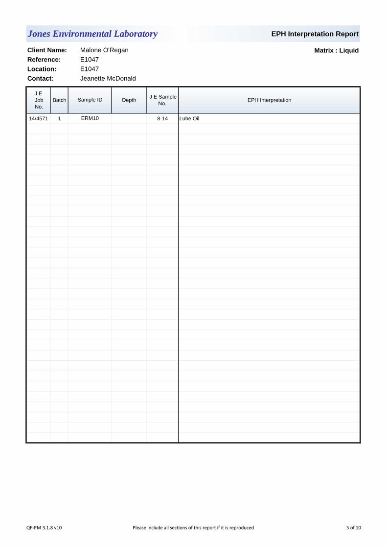
EPH Interpretation Report
Matrix : Liquid
J E
Job
No.
Batch Depth J E Sample
No.EPH Interpretation
14/4571 1 8-14 Lube Oil
Contact: Jeanette McDonald
Sample ID
ERM10
Client Name: Malone O'Regan
Reference: E1047
Location: E1047
Jones Environmental Laboratory
QF-PM 3.1.8 v10 Please include all sections of this report if it is reproduced 5 of 10
Notification of Deviating Samples
J E
Job
No.
Batch Depth J E Sample
No.Analysis Reason
Please note that only samples that are deviating are mentioned in this report. If no samples are listed it is because none were deviating.
Only analyses which are accredited are recorded as deviating if set criteria are not met.
No deviating sample report results for job 14/4571
Location: E1047
Contact: Jeanette McDonald
Sample ID
Jones Environmental Laboratory
Client Name: Malone O'Regan
Reference: E1047
QF-PM 3.1.11 v3 Please include all sections of this report if it is reproduced 6 of 10

JE Job No.:
SOILS
DEVIATING SAMPLES
SURROGATES
NOTE
Surrogate compounds are added during the preparation process to monitor recovery of analytes. However low recovery in soils is often due to peat,
clay or other organic rich matrices. For waters this can be due to oxidants, surfactants, organic rich sediments or remediation fluids. Acceptable
limits for most organic methods are 70 - 130% and for VOCs are 50 - 150%. When surrogate recoveries are outside the performance criteria but
the associated AQC passes this is assumed to be due to matrix effect. Results are not surrogate corrected.
Where a CEN 10:1 ZERO Headspace VOC test has been carried out, a 10:1 ratio of water to wet (as received) soil has been used.
Data is only reported if the laboratory is confident that the data is a true reflection of the samples analysed. Data is only reported as accredited when
all the requirements of our Quality System have been met. In certain circumstances where all the requirements of the Quality System have not been
met, for instance if the associated AQC has failed, the reason is fully investigated and documented. The sample data is then evaluated alongside
the other quality control checks performed during analysis to determine its suitability. Following this evaluation, provided the sample results have not
been effected, the data is reported but accreditation is removed. It is a UKAS requirement for data not reported as accredited to be considered
indicative only, but this does not mean the data is not valid.
Where possible, and if requested, samples will be re-extracted and a revised report issued with accredited results. Please do not hesitate to contact
the laboratory if further details are required of the circumstances which have led to the removal of accreditation.
All samples will be discarded one month after the date of reporting, unless we are instructed to the contrary. If we are instructed to keep samples, a
storage charge of £1 (1.5 Euros) per sample per month will be applied until we are asked to dispose of them.
It is assumed that you have taken representative samples on site and require analysis on a representative subsample. Stones will generally be
included unless we are requested to remove them.
UKAS accreditation applies to surface water and groundwater and one other matrix which is analysis specific, any other liquids are outside our
scope of accreditation
As surface waters require different sample preparation to groundwaters the laboratory must be informed of the water type when submitting samples.
Samples must be received in a condition appropriate to the requested analyses. All samples should be submitted to the laboratory in suitable
containers with sufficient ice packs to sustain an appropriate temperature for the requested analysis. If this is not the case you will be informed and
any test results that may be compromised highlighted on your deviating samples report.
Where appropriate please make sure that our detection limits are suitable for your needs, if they are not, please notify us immediately.
Please note we are not a Drinking Water Inspectorate (DWI) Approved Laboratory . It is important that detection limits are carefully considered
when requesting water analysis.
If you have not already done so, please send us a purchase order if this is required by your company.
All analysis is reported on a dry weight basis unless stated otherwise. Results are not surrogate corrected. Samples are dried at 35°C ±5°C unless
otherwise stated. Moisture content for CEN Leachate tests are dried at 105°C ±5°C.
Where Mineral Oil or Fats, Oils and Grease is quoted, this refers to Total Aliphatics C10-C40.
NOTES TO ACCOMPANY ALL SCHEDULES AND REPORTS
Please note we are only MCERTS accredited for sand, loam and clay and any other matrix is outside our scope of accreditation.
Where Mineral Oil or Fats, Oils and Grease is quoted, this refers to Total Aliphatics C10-C40.
14/4571
WATERS
Where an MCERTS report has been requested, you will be notified within 48 hours of any samples that have been identified as being outside our
MCERTS scope. As validation has been performed on clay, sand and loam, only samples that are predominantly these matrices, or combinations
of them will be within our MCERTS scope. If samples are not one of a combination of the above matrices they will not be marked as MCERTS
accredited.
QF-PM 3.1.9 v26Please include all sections of this report if it is reproduced
All solid results are expressed on a dry weight basis unless stated otherwise. 7 of 10
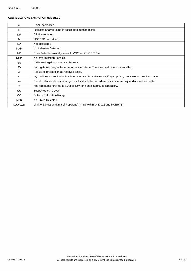
JE Job No.:
#
B
DR
M
NA
NAD
ND
NDP
SS
SV
W
+
++
*
CO
OC
NFD
LOD/LOR
AQC failure, accreditation has been removed from this result, if appropriate, see 'Note' on previous page.
Analysis subcontracted to a Jones Environmental approved laboratory.
Calibrated against a single substance.
No Determination Possible
ABBREVIATIONS and ACRONYMS USED
No Asbestos Detected.
None Detected (usually refers to VOC and/SVOC TICs).
UKAS accredited.
Limit of Detection (Limit of Reporting) in line with ISO 17025 and MCERTS
Result outside calibration range, results should be considered as indicative only and are not accredited.
Results expressed on as received basis.
Surrogate recovery outside performance criteria. This may be due to a matrix effect.
Dilution required.
Indicates analyte found in associated method blank.
Not applicable
MCERTS accredited.
No Fibres Detected
Outside Calibration Range
Suspected carry over
14/4571
QF-PM 3.1.9 v26Please include all sections of this report if it is reproduced
All solid results are expressed on a dry weight basis unless stated otherwise. 8 of 10

JE Job No: 14/4571
Test Method No. Description
Prep Method
No. (if
appropriate)
Description UKAS
MCERTS
(soils
only)
Analysis done
on As Received
(AR) or Air Dried
(AD)
Reported on
dry weight
basis
TM5
In-House method based on USEPA 8015B. Determination of Extractable Petroleum
Hydrocarbons (EPH) in the carbon chain length range of C8-40 by GC-FID. Accredited
to ISO 17025 on soil and water samples and MCERTS (carbon banding only) on soils.
All accreditation is matrix specific.
PM30
In-house method based on USEPA 3510. Liquid samples are mixed with solvent and
agitated with an automatic magnetic stirrer with a stir bar for 15 minutes to extract
organic molecules. ISO 17025 accredited extraction method. All accreditation is matrix
specific
Yes
TM5/TM36 TPH CWG by GC-FID PM30
In-house method based on USEPA 3510. Liquid samples are mixed with solvent and
agitated with an automatic magnetic stirrer with a stir bar for 15 minutes to extract
organic molecules. ISO 17025 accredited extraction method. All accreditation is matrix
specific
Yes
TM20 TDS, TSS and TS - gravimetric PM0 No preparation is required. Yes
TM26 Phenols by HPLC PM0 No preparation is required.
TM27In-House method based on USEPA 9056. Analysis of samples using a Dionex Ion-
Chromatograph instrument.PM0 No preparation is required.
TM30
Trace Metal elements by ICP-OES (Inductively Coupled Plasma - Optical Emission
Spectrometry) using Thermo iCAP 6000 series instrument. Accredited to ISO 17025 for
soils and waters and MCERTS accredited for Soils. All accreditation is matrix specific.
PM14
In-house method based on USEPA 3005A. Acid digestion of water samples and
analsyis by ICP-OES as per method TM030W.ISO 17025 accredited extraction method.
All accreditation is matrix specific
TM30
Trace Metal elements by ICP-OES (Inductively Coupled Plasma - Optical Emission
Spectrometry) using Thermo iCAP 6000 series instrument. Accredited to ISO 17025 for
soils and waters and MCERTS accredited for Soils. All accreditation is matrix specific.
PM14
In-house method based on USEPA 3005A. Acid digestion of water samples and
analsyis by ICP-OES as per method TM030W.ISO 17025 accredited extraction method.
All accreditation is matrix specific
Yes
TM36
In-House method based on USEPA 8015B. Determination of Gasoline Range Organics
(GRO) in the carbon chain range of C5-12 by headspace GC-FID. Accredited to ISO
17025 on soil and water samples and MCERTS accredited (carbon banding only) on
soils. All accreditation is matrix specific.
PM12
In-house method based on USEPA 5021. Preparation of solid and liquid samples for
headspace analysis. Samples are spiked with surrogates to facilitate quantification. ISO
17025 accredited extraction method. All accreditation is matrix specific
Yes
TM38Ionic analysis using the Thermo Aquakem Photometric Automatic Analyser. Accredited
to ISO17025 and MCERTS for most analytes. All accreditation is matrix specific.PM0 No preparation is required.
Jones Environmental Laboratory Method Code Appendix
QF-PM 3.1.10 v13 Please include all sections of this report if it is reproduced 9 of 10

JE Job No: 14/4571
Test Method No. Description
Prep Method
No. (if
appropriate)
Description UKAS
MCERTS
(soils
only)
Analysis done
on As Received
(AR) or Air Dried
(AD)
Reported on
dry weight
basis
TM38Ionic analysis using the Thermo Aquakem Photometric Automatic Analyser. Accredited
to ISO17025 and MCERTS for most analytes. All accreditation is matrix specific.PM0 No preparation is required. Yes
TM60 TOC/DOC by NDIR PM0 No preparation is required. Yes
TM75 Alkalinity by Metrohm PM0 No preparation is required. Yes
TM89
In-house method based on USEPA method OIA-1667. Determination of cyanide by Flow
Injection Analyser. ISO17025 accredited method for soils and waters and MCERTS on
soils. Accreditation is matrix specific.
PM0 No preparation is required. Yes
Jones Environmental Laboratory Method Code Appendix
QF-PM 3.1.10 v13 Please include all sections of this report if it is reproduced 10 of 10

Unit 3 Deeside Point
Zone 3
Deeside Industrial Park
Deeside
Malone O'Regan
Attention :
Date :
Your reference :
Our reference :
Location :
Date samples received :
Status :
Issue :
Bob Millward BSc FRSC
Principal Chemist
Three samples were received for analysis on 29th April, 2014. Please find attached our Test Report which should be read with notes at the end of
the report and should include all sections if reproduced. Interpretations and opinions are outside the scope of any accreditation, and all results relate
only to samples supplied.
All analysis is carried out on as received samples and reported on a dry weight basis unless stated otherwise. Results are not surrogate corrected.
Phil Sommerton BSc
Project Manager
22nd May, 2014
E1048
E1048
29th April, 2014
Final report
Compiled By:
Test Report 14/5298 Batch 1 Schedule C
1
Jones Environmental Laboratory
CH5 2UA
Tel: +44 (0) 1244 833780
Fax: +44 (0) 1244 833781
Eleanor Burke
2b Richview Office Park
Clonskeagh
Dublin 14
Ireland
Registered Address : Unit 3 Deeside Point, Zone 3, Deeside Industrial Park, Deeside, CH5 2UA. UK
QF-PM 3.1.1 v15Please include all sections of this report if it is reproduced
All solid results are expressed on a dry weight basis unless stated otherwise. 1 of 6

Client Name: Report : Liquid
Reference:
Location:
Contact: Liquids/products: V=40ml vial, G=glass bottle, P=plastic bottle
JE Job No.: 14/5298 H=H2SO4, Z=ZnAc, N=NaOH, HN=HN03
J E Sample No. 1-8 9-16 17-24
Sample ID RW3 BH2 ERM 8
Depth 1.0
COC No / misc
Containers V H HN N P G V H HN N P G V H HN N P G
Sample Date 28/04/2014 28/04/2014 28/04/2014
Sample Type Ground Water Ground Water Ground Water
Batch Number 1 1 1
Date of Receipt 29/04/2014 29/04/2014 29/04/2014
Anionic Surfactants <0.2 1.7 0.7 <0.2 mg/l TM33/PM0
E1048
Eleanor Burke
Please see attached notes for all
abbreviations and acronyms
LOD/LOR UnitsMethod
No.
Jones Environmental Laboratory
Malone O'Regan
E1048
QF-PM 3.1.2 v11Please include all sections of this report if it is reproduced
All solid results are expressed on a dry weight basis unless stated otherwise. 2 of 6
Notification of Deviating Samples
J E
Job
No.
Batch Depth J E Sample
No.Analysis Reason
Please note that only samples that are deviating are mentioned in this report. If no samples are listed it is because none were deviating.
Only analyses which are accredited are recorded as deviating if set criteria are not met.
Contact:
Sample ID
Client Name: Malone O'Regan
Reference:
Location:
No deviating sample report results for job 14/5298
Jones Environmental Laboratory
E1048
E1048
Eleanor Burke
QF-PM 3.1.11 v3 Please include all sections of this report if it is reproduced 3 of 6
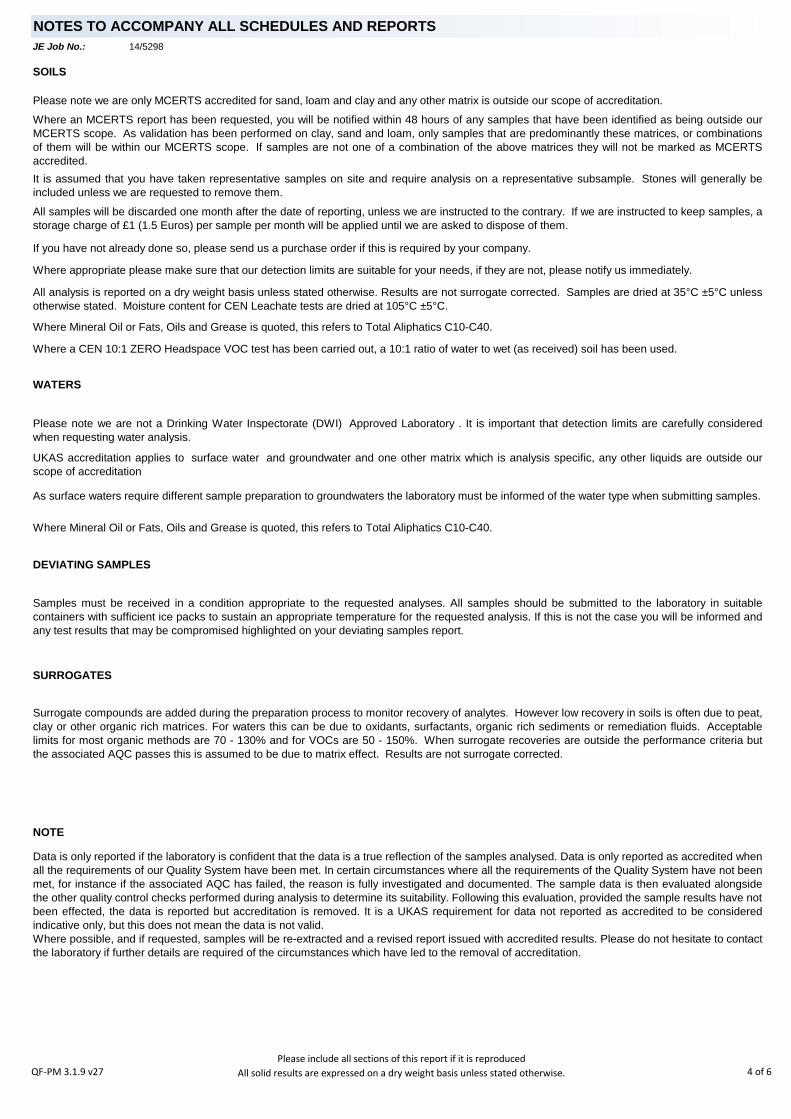
JE Job No.:
SOILS
DEVIATING SAMPLES
SURROGATES
NOTE
NOTES TO ACCOMPANY ALL SCHEDULES AND REPORTS
Please note we are only MCERTS accredited for sand, loam and clay and any other matrix is outside our scope of accreditation.
Where Mineral Oil or Fats, Oils and Grease is quoted, this refers to Total Aliphatics C10-C40.
14/5298
WATERS
Where an MCERTS report has been requested, you will be notified within 48 hours of any samples that have been identified as being outside our
MCERTS scope. As validation has been performed on clay, sand and loam, only samples that are predominantly these matrices, or combinations
of them will be within our MCERTS scope. If samples are not one of a combination of the above matrices they will not be marked as MCERTS
accredited.
All samples will be discarded one month after the date of reporting, unless we are instructed to the contrary. If we are instructed to keep samples, a
storage charge of £1 (1.5 Euros) per sample per month will be applied until we are asked to dispose of them.
It is assumed that you have taken representative samples on site and require analysis on a representative subsample. Stones will generally be
included unless we are requested to remove them.
UKAS accreditation applies to surface water and groundwater and one other matrix which is analysis specific, any other liquids are outside our
scope of accreditation
As surface waters require different sample preparation to groundwaters the laboratory must be informed of the water type when submitting samples.
Samples must be received in a condition appropriate to the requested analyses. All samples should be submitted to the laboratory in suitable
containers with sufficient ice packs to sustain an appropriate temperature for the requested analysis. If this is not the case you will be informed and
any test results that may be compromised highlighted on your deviating samples report.
Where appropriate please make sure that our detection limits are suitable for your needs, if they are not, please notify us immediately.
Please note we are not a Drinking Water Inspectorate (DWI) Approved Laboratory . It is important that detection limits are carefully considered
when requesting water analysis.
If you have not already done so, please send us a purchase order if this is required by your company.
All analysis is reported on a dry weight basis unless stated otherwise. Results are not surrogate corrected. Samples are dried at 35°C ±5°C unless
otherwise stated. Moisture content for CEN Leachate tests are dried at 105°C ±5°C.
Where Mineral Oil or Fats, Oils and Grease is quoted, this refers to Total Aliphatics C10-C40.
Where a CEN 10:1 ZERO Headspace VOC test has been carried out, a 10:1 ratio of water to wet (as received) soil has been used.
Data is only reported if the laboratory is confident that the data is a true reflection of the samples analysed. Data is only reported as accredited when
all the requirements of our Quality System have been met. In certain circumstances where all the requirements of the Quality System have not been
met, for instance if the associated AQC has failed, the reason is fully investigated and documented. The sample data is then evaluated alongside
the other quality control checks performed during analysis to determine its suitability. Following this evaluation, provided the sample results have not
been effected, the data is reported but accreditation is removed. It is a UKAS requirement for data not reported as accredited to be considered
indicative only, but this does not mean the data is not valid.
Where possible, and if requested, samples will be re-extracted and a revised report issued with accredited results. Please do not hesitate to contact
the laboratory if further details are required of the circumstances which have led to the removal of accreditation.
Surrogate compounds are added during the preparation process to monitor recovery of analytes. However low recovery in soils is often due to peat,
clay or other organic rich matrices. For waters this can be due to oxidants, surfactants, organic rich sediments or remediation fluids. Acceptable
limits for most organic methods are 70 - 130% and for VOCs are 50 - 150%. When surrogate recoveries are outside the performance criteria but
the associated AQC passes this is assumed to be due to matrix effect. Results are not surrogate corrected.
QF-PM 3.1.9 v27Please include all sections of this report if it is reproduced
All solid results are expressed on a dry weight basis unless stated otherwise. 4 of 6
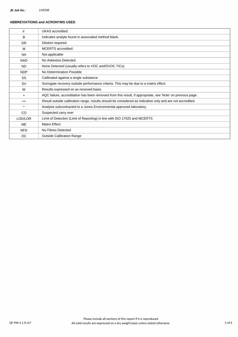
JE Job No.:
#
B
DR
M
NA
NAD
ND
NDP
SS
SV
W
+
++
*
CO
LOD/LOR
ME
NFD
OC
Matrix Effect
No Fibres Detected
Limit of Detection (Limit of Reporting) in line with ISO 17025 and MCERTS
Suspected carry over
14/5298
Outside Calibration Range
Result outside calibration range, results should be considered as indicative only and are not accredited.
Results expressed on as received basis.
Surrogate recovery outside performance criteria. This may be due to a matrix effect.
Dilution required.
Indicates analyte found in associated method blank.
Not applicable
MCERTS accredited.
AQC failure, accreditation has been removed from this result, if appropriate, see 'Note' on previous page.
Analysis subcontracted to a Jones Environmental approved laboratory.
Calibrated against a single substance
No Determination Possible
ABBREVIATIONS and ACRONYMS USED
No Asbestos Detected.
None Detected (usually refers to VOC and/SVOC TICs).
UKAS accredited.
QF-PM 3.1.9 v27Please include all sections of this report if it is reproduced
All solid results are expressed on a dry weight basis unless stated otherwise. 5 of 6
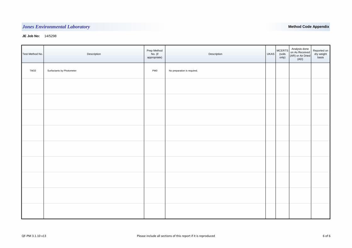
JE Job No: 14/5298
Test Method No. Description
Prep Method
No. (if
appropriate)
Description UKAS
MCERTS
(soils
only)
Analysis done
on As Received
(AR) or Air Dried
(AD)
Reported on
dry weight
basis
TM33 Surfactants by Photometer PM0 No preparation is required.
Jones Environmental Laboratory Method Code Appendix
QF-PM 3.1.10 v13 Please include all sections of this report if it is reproduced 6 of 6
Unit 3 Deeside Point
Zone 3
Deeside Industrial Park
Deeside
Malone O'Regan
Attention :
Date :
Your reference :
Our reference :
Location :
Date samples received :
Status :
Issue :
Bob Millward BSc FRSC
Principal Chemist
1
Jones Environmental Laboratory
CH5 2UA
Tel: +44 (0) 1244 833780
Fax: +44 (0) 1244 833781
Eleanor Burke
2b Richview Office Park
Clonskeagh
Dublin 14
Ireland
Registered Address : Unit 3 Deeside Point, Zone 3, Deeside Industrial Park, Deeside, CH5 2UA. UK
Thirteen samples were received for analysis on 30th April, 2014. Please find attached our Test Report which should be read with notes at the end
of the report and should include all sections if reproduced. Interpretations and opinions are outside the scope of any accreditation, and all results
relate only to samples supplied.
All analysis is carried out on as received samples and reported on a dry weight basis unless stated otherwise. Results are not surrogate corrected.
Phil Sommerton BSc
Project Manager
23rd May, 2014
E1048
E1048
30th April, 2014
Final report
Compiled By:
Test Report 14/5336 Batch 1 Schedule F
QF-PM 3.1.1 v15Please include all sections of this report if it is reproduced
All solid results are expressed on a dry weight basis unless stated otherwise. 1 of 6
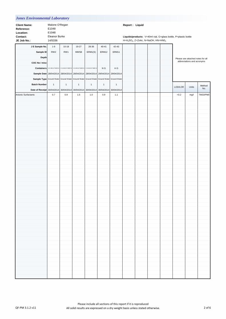
Client Name: Report : Liquid
Reference:
Location:
Contact: Liquids/products: V=40ml vial, G=glass bottle, P=plastic bottle
JE Job No.: 14/5336 H=H2SO4, Z=ZnAc, N=NaOH, HN=HN03
J E Sample No. 1-9 10-18 19-27 28-36 40-41 42-43
Sample ID RW2 RW1 MW5B ERM1(S) ERM12 ERM11
Depth
COC No / misc
Containers V H HN N P BOD G V H HN N P BOD G V H HN N P BOD G V H HN N P BOD G N G H G
Sample Date 28/04/2014 28/04/2014 28/04/2014 28/04/2014 29/04/2014 29/04/2014
Sample Type Ground Water Ground Water Ground Water Ground Water Ground Water Ground Water
Batch Number 1 1 1 1 1 1
Date of Receipt 30/04/2014 30/04/2014 30/04/2014 30/04/2014 30/04/2014 30/04/2014
Anionic Surfactants 0.7 0.9 1.5 1.0 0.9 1.1 <0.2 mg/l TM33/PM0
E1048
Eleanor Burke
Please see attached notes for all
abbreviations and acronyms
LOD/LOR UnitsMethod
No.
Jones Environmental Laboratory
Malone O'Regan
E1048
QF-PM 3.1.2 v11Please include all sections of this report if it is reproduced
All solid results are expressed on a dry weight basis unless stated otherwise. 2 of 6

Notification of Deviating Samples
J E
Job
No.
Batch Depth J E Sample
No.Analysis Reason
Please note that only samples that are deviating are mentioned in this report. If no samples are listed it is because none were deviating.
Only analyses which are accredited are recorded as deviating if set criteria are not met.
Jones Environmental Laboratory
E1048
E1048
Eleanor BurkeContact:
Sample ID
Client Name: Malone O'Regan
Reference:
Location:
No deviating sample report results for job 14/5336
QF-PM 3.1.11 v3 Please include all sections of this report if it is reproduced 3 of 6
JE Job No.:
SOILS
DEVIATING SAMPLES
SURROGATES
NOTE
Surrogate compounds are added during the preparation process to monitor recovery of analytes. However low recovery in soils is often due to peat,
clay or other organic rich matrices. For waters this can be due to oxidants, surfactants, organic rich sediments or remediation fluids. Acceptable
limits for most organic methods are 70 - 130% and for VOCs are 50 - 150%. When surrogate recoveries are outside the performance criteria but
the associated AQC passes this is assumed to be due to matrix effect. Results are not surrogate corrected.
All analysis is reported on a dry weight basis unless stated otherwise. Results are not surrogate corrected. Samples are dried at 35°C ±5°C unless
otherwise stated. Moisture content for CEN Leachate tests are dried at 105°C ±5°C.
Where Mineral Oil or Fats, Oils and Grease is quoted, this refers to Total Aliphatics C10-C40.
Where a CEN 10:1 ZERO Headspace VOC test has been carried out, a 10:1 ratio of water to wet (as received) soil has been used.
Data is only reported if the laboratory is confident that the data is a true reflection of the samples analysed. Data is only reported as accredited when
all the requirements of our Quality System have been met. In certain circumstances where all the requirements of the Quality System have not been
met, for instance if the associated AQC has failed, the reason is fully investigated and documented. The sample data is then evaluated alongside
the other quality control checks performed during analysis to determine its suitability. Following this evaluation, provided the sample results have not
been effected, the data is reported but accreditation is removed. It is a UKAS requirement for data not reported as accredited to be considered
indicative only, but this does not mean the data is not valid.
Where possible, and if requested, samples will be re-extracted and a revised report issued with accredited results. Please do not hesitate to contact
the laboratory if further details are required of the circumstances which have led to the removal of accreditation.
Where an MCERTS report has been requested, you will be notified within 48 hours of any samples that have been identified as being outside our
MCERTS scope. As validation has been performed on clay, sand and loam, only samples that are predominantly these matrices, or combinations
of them will be within our MCERTS scope. If samples are not one of a combination of the above matrices they will not be marked as MCERTS
accredited.
All samples will be discarded one month after the date of reporting, unless we are instructed to the contrary. If we are instructed to keep samples, a
storage charge of £1 (1.5 Euros) per sample per month will be applied until we are asked to dispose of them.
It is assumed that you have taken representative samples on site and require analysis on a representative subsample. Stones will generally be
included unless we are requested to remove them.
UKAS accreditation applies to surface water and groundwater and one other matrix which is analysis specific, any other liquids are outside our
scope of accreditation
As surface waters require different sample preparation to groundwaters the laboratory must be informed of the water type when submitting samples.
Samples must be received in a condition appropriate to the requested analyses. All samples should be submitted to the laboratory in suitable
containers with sufficient ice packs to sustain an appropriate temperature for the requested analysis. If this is not the case you will be informed and
any test results that may be compromised highlighted on your deviating samples report.
Where appropriate please make sure that our detection limits are suitable for your needs, if they are not, please notify us immediately.
Please note we are not a Drinking Water Inspectorate (DWI) Approved Laboratory . It is important that detection limits are carefully considered
when requesting water analysis.
If you have not already done so, please send us a purchase order if this is required by your company.
% Asbestos in Asbestos Containing Materials (ACMs) is determined by reference to HSG 264 The Survey Guide - Appendix 2 : ACMs in buildings
listed in order of ease of fibre release.
NOTES TO ACCOMPANY ALL SCHEDULES AND REPORTS
Please note we are only MCERTS accredited for sand, loam and clay and any other matrix is outside our scope of accreditation.
Where Mineral Oil or Fats, Oils and Grease is quoted, this refers to Total Aliphatics C10-C40.
14/5336
WATERS
QF-PM 3.1.9 v28Please include all sections of this report if it is reproduced
All solid results are expressed on a dry weight basis unless stated otherwise. 4 of 6

JE Job No.:
#
B
DR
M
NA
NAD
ND
NDP
SS
SV
W
+
++
*
CO
LOD/LOR
ME
NFD
OC
UKAS accredited.
Not applicable
MCERTS accredited.
AQC failure, accreditation has been removed from this result, if appropriate, see 'Note' on previous page.
Analysis subcontracted to a Jones Environmental approved laboratory.
Calibrated against a single substance
No Determination Possible
ABBREVIATIONS and ACRONYMS USED
No Asbestos Detected.
None Detected (usually refers to VOC and/SVOC TICs).
Outside Calibration Range
Result outside calibration range, results should be considered as indicative only and are not accredited.
Results expressed on as received basis.
Surrogate recovery outside performance criteria. This may be due to a matrix effect.
Dilution required.
Indicates analyte found in associated method blank.
14/5336
Matrix Effect
No Fibres Detected
Limit of Detection (Limit of Reporting) in line with ISO 17025 and MCERTS
Suspected carry over
QF-PM 3.1.9 v28Please include all sections of this report if it is reproduced
All solid results are expressed on a dry weight basis unless stated otherwise. 5 of 6

JE Job No: 14/5336
Test Method No. Description
Prep Method
No. (if
appropriate)
Description UKAS
MCERTS
(soils
only)
Analysis done
on As Received
(AR) or Air Dried
(AD)
Reported on
dry weight
basis
TM33 Surfactants by Photometer PM0 No preparation is required.
Jones Environmental Laboratory Method Code Appendix
QF-PM 3.1.10 v13 Please include all sections of this report if it is reproduced 6 of 6
2 B Richview Office Park
Malone O Regan
Clonskeagh
Dublin 14
Should you have any queries regarding the report or require any further services, we would be happy to discuss your
requirements. For additional information about the company please log-on to our web site at the above address.
Customer:
Customer Address:
Customer Contact:
Report Reference:
Report Date:
Deidre Larkin
Page 1 of 4
07/04/2014
Analysis of 3 sample(s) submitted on 03/04/2014 is now complete.
We have the pleasure of enclosing your certificate of analysis.
Template 1146
Revision 017Note: Results relate only to the items tested.
Test report shall not be reproduced except in full or with written approval of City Analysts Ltd .
Thank you for choosing City Analysts Limited. We look forward to assisting you again.
14-01712-
Certificate Of Analysis
Reason for report re-issue: Revised Report
Authorised By: Date:
Note: Information on methods of analysis and performance characteristics is available on request.
Customer PO No.:
Chain of Custody No.:
07/04/2014
City Analysts Limited,
Pigeon House Road,
Ringsend,
Dublin 4.
Tel:(01) 613 6003 /6 /9
Fax:(01) 613 6008
Email:[email protected]
www.cityanalysts.ie
2Report Version:
Laura Walsh
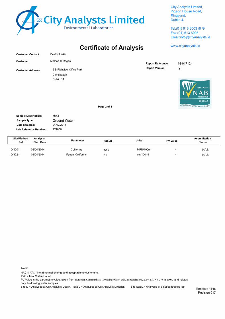
Certificate of AnalysisDeidre LarkinCustomer Contact:
Dublin 14
Clonskeagh
2 B Richview Office ParkCustomer Address:
Malone O ReganCustomer:Report Reference: 14-01712-
Sample Description:
Sample Type:
Date Sampled:
Lab Reference Number:
Site/Method
Ref.
Analysis
Start DateParameter Result Units PV Value
Accreditation
Status
Page 2 of 4
MW2
174066
04/02/2014
City Analysts Limited,
Pigeon House Road,
Ringsend,
Dublin 4.
Tel:(01) 613 6003 /6 /9
Fax:(01) 613 6008
Email:[email protected]
www.cityanalysts.ie
Report Version: 2
Ground Water
D/1201 03/04/2014 52.0 MPN/100ml -Coliforms INAB
D/3221 03/04/2014 <1 cfu/100ml -Faecal Coliforms INAB
Template 1146
Revision 017
NAC & ATC - No abnormal change and acceptable to customers.
TVC - Total Viable Count
PV Value is the parametric value, taken from European Communities, (Drinking Water) (No. 2) Regulations, 2007. S.I. No. 278 of 2007, and relates
only to drinking water samples.
Site D = Analysed at City Analysts Dublin. Site L = Analysed at City Analysts Limerick. Site SUBC= Analysed at a subcontracted lab
Note:

Certificate of AnalysisDeidre LarkinCustomer Contact:
Dublin 14
Clonskeagh
2 B Richview Office ParkCustomer Address:
Malone O ReganCustomer:Report Reference: 14-01712-
Sample Description:
Sample Type:
Date Sampled:
Lab Reference Number:
Site/Method
Ref.
Analysis
Start DateParameter Result Units PV Value
Accreditation
Status
Page 3 of 4
ERM10
174067
04/02/2014
City Analysts Limited,
Pigeon House Road,
Ringsend,
Dublin 4.
Tel:(01) 613 6003 /6 /9
Fax:(01) 613 6008
Email:[email protected]
www.cityanalysts.ie
Report Version: 2
Ground Water
D/3221 03/04/2014 <1 cfu/100ml -Faecal Coliforms INAB
D/1201 03/04/2014 <1 MPN/100ml -Coliforms INAB
Template 1146
Revision 017
NAC & ATC - No abnormal change and acceptable to customers.
TVC - Total Viable Count
PV Value is the parametric value, taken from European Communities, (Drinking Water) (No. 2) Regulations, 2007. S.I. No. 278 of 2007, and relates
only to drinking water samples.
Site D = Analysed at City Analysts Dublin. Site L = Analysed at City Analysts Limerick. Site SUBC= Analysed at a subcontracted lab
Note:

Certificate of AnalysisDeidre LarkinCustomer Contact:
Dublin 14
Clonskeagh
2 B Richview Office ParkCustomer Address:
Malone O ReganCustomer:Report Reference: 14-01712-
Sample Description:
Sample Type:
Date Sampled:
Lab Reference Number:
Site/Method
Ref.
Analysis
Start DateParameter Result Units PV Value
Accreditation
Status
Page 4 of 4
MW3
174068
04/02/2014
City Analysts Limited,
Pigeon House Road,
Ringsend,
Dublin 4.
Tel:(01) 613 6003 /6 /9
Fax:(01) 613 6008
Email:[email protected]
www.cityanalysts.ie
Report Version: 2
Ground Water
D/1201 03/04/2014 9.8 MPN/100ml -Coliforms INAB
D/3221 03/04/2014 <1 cfu/100ml -Faecal Coliforms INAB
Template 1146
Revision 017
NAC & ATC - No abnormal change and acceptable to customers.
TVC - Total Viable Count
PV Value is the parametric value, taken from European Communities, (Drinking Water) (No. 2) Regulations, 2007. S.I. No. 278 of 2007, and relates
only to drinking water samples.
Site D = Analysed at City Analysts Dublin. Site L = Analysed at City Analysts Limerick. Site SUBC= Analysed at a subcontracted lab
Note:

Attachmment J.1

THERMOKING IRELAND EMERGENCY RESPONSE PLAN
NB:WhenPrintedthisdocumentisanuncontrolledcopy.ForacontrolledsoftcopyseeTKGalwayBusinessProcessSharepoint. MAINT-I-03
Page | 1
THERMOKING IRELAND
EMERGENCY REPONSE PLAN
CONTENTS
1.0 AIM AND INTRODUCTION .................................................................................. 2 2.0 RESPONSIBILITES ................................................................................................. 2 3.0 STRUCTURE OF THE EMERGENCY RESPONSE TEAM ................................. 3 4.0 TYPES OF EMERGENCIES ................................................................................... 4 5.0 PERT - TEAM OVERVIEW .................................................................................... 4 6.0 PLAN INITIATION ................................................................................................. 5 7.0 CHEMICAL SPILLS ................................................................................................ 5 8.0 EMERGENCY EVACUATION .............................................................................. 6 9.0 RESCUE OF PERSONNEL ..................................................................................... 7 10.0 TRAINING OF THE EMERGENCY RESPONSE TEAMS ................................. 8 11.0 REVIEW AND REVISIONS ................................................................................. 8
APPENDICES
APPENDIX 1 – PERT DUTIES ................................................................................. 9 APPENDIX 2 - PERT Leader DUTIES ................................................................... 10 APPENDIX 3 – Duties of Headcount Officer .......................................................... 11 APPENDIX 4 – Emergency Response Action Checklist ......................................... 11 APPENDIX 5 – Duties of the Fire Pump Operator .................................................. 11 APPENDIX 6 – Duties of the Sprinkler Valve Operator ......................................... 12 APPENDIX 7 – Duties of the Fitter/ Electrician ...................................................... 12 APPENDIX 8 – Duties of the Environmental Control Officer ................................. 12 APPENDIX 9 – Duties of the Security Officer ........................................................ 14 APPENDIX 10 – Duties of Reception ...................................................................... 15 APPENDIX 11 – PERT Emergency Equipment ...................................................... 15 APPENDIX 12 – ACTIONS TO BE TAKEN IN THE EVENT OF ....................... 16 AN ENVIRONMENTAL INCIDENT ..................................................................... 16 APPENDIX 13 – ASSEMBLY POINT LOCATIONS ............................................ 18

THERMOKING IRELAND EMERGENCY RESPONSE PLAN
NB:WhenPrintedthisdocumentisanuncontrolledcopy.ForacontrolledsoftcopyseeTKGalwayBusinessProcessSharepoint. MAINT-I-03
Page | 2
EMERGENCY RESPONSE PLAN 1.0 AIM AND INTRODUCTION 1.1 The primary aim of the emergency response plan is to protect human life at risk from any emergency and to prevent injury. The plan also aims to protect the environment from pollution and the plant and its contents. Our aim in all cases is to prevent emergencies arising by good preventative measures and in cases of an emergency to direct efforts at prevention of escalation of emergency. 1.2 The basis of the plan is to provide a rapid response to the incident by the Plant Emergency Response Team (PERT). 1.3 This plan outlines the emergency response system at Thermo King, Galway. It contains checklists for use by the PERT during an emergency, as well as a general description of the system. 1.4 In the event of an emergency, the PERT ensure a proper evacuation is taking place, that emergency response services have been alerted if required and that other essential tasks and protection of life, environment and plant risk containment are carried out. 1.5 This plan does not cover damage assessment or alternative business arrangements following an emergency. 2.0 RESPONSIBILITES It is the responsibility of the: 2.1 EHS Manager, to ensure that emergency plans are developed, implemented and tested. 2.2 EHS Manager, in conjunction with the Facilities Coordinator to maintain PERT stations and manage all emergency Personal Protective Equipment (PPE). 2.3 EHS Manager, to ensure that PERT training is developed and carried out in accordance with current legislation and best practice. 2.4 Area Managers to nominate Headcount Officers (and deputies) for their area to maintain the evacuation list of personnel in their area, to ensure their area is evacuated during an emergency and to ensure the Headcount officers complete their duties. 2.5 Human Resources manager to ensure the PERT personnel changes are tracked and notified to the PERT leader to ensure that replacement cover is automatically provided.

THERMOKING IRELAND EMERGENCY RESPONSE PLAN
NB:WhenPrintedthisdocumentisanuncontrolledcopy.ForacontrolledsoftcopyseeTKGalwayBusinessProcessSharepoint. MAINT-I-03
Page | 3
3.0 STRUCTURE OF THE EMERGENCY RESPONSE TEAM 3.1 PERT Leader: EHS Manager who maintains overall charge of the event. 3.2 PERT Facilitator: Facilities Coordinator who manages operational issues. Assumes the role of PERT Leader in the absence of the EHS Manager. 3.3 PERT Member: Employees from various departments. Each attends the PERT meetings and are assigned roles in the event of an emergency. 3.4 Fire Team: These team members take the lead in investigating Fire alarms 3.5 First Aid Officer: On site Nurse or Health and Safety Officer who manages all medical issues. 3.6 Time and events coordinator: Member of PERT Team who accurately times and records all events as they unfold. 3.7 Security and Traffic Officer: Security officer at front gate who ensures there is clear access for all emergency vehicles entering and leaving site and controls all vehicle movement onto or off site. 3.8 Headcount Officer: Assigned in each area by Area manager, they ensure that headcounts have been completed and pass on information on missing persons. They also ensure the roll call sheets are up to date for their department and ensure the effective evacuation of the department occurs. Roll call sheets are located at the assembly points and should be checked weekly. 3.9 Fire Pump Operator: Member of PERT that goes to Sprinkler pump house to ensure that the pumps are running. This only applies in the event of a fire where the sprinkler system is required. The PERT member switches on the pumps manually if they have not started and ensures they are operating correctly. 3.10 Sprinkler Valve Operator: Member of PERT that checks the sprinkler valve in the area of the fire. If the valve is not opened the PERT member opens it and then continues with other duties. 3.11 Fitter/ Electrician: The PERT team includes a Fitter and an Electrician. The PERT leader will instruct them to isolate the Electrical, Gas and Fuel supplies to the plant in the event of the Fire Brigade coming on site.

THERMOKING IRELAND EMERGENCY RESPONSE PLAN
NB:WhenPrintedthisdocumentisanuncontrolledcopy.ForacontrolledsoftcopyseeTKGalwayBusinessProcessSharepoint. MAINT-I-03
Page | 4
4.0 TYPES OF EMERGENCIES 4.1 An incident involving a fire where the alarm has been triggered or PERT determine that evacuation of all or part of the plant is necessary. 4.2 Incident involving a chemical release or chemical spill. Spillage or loss of containment, where harm can be prevented by employees using locally available equipment and materials (spill kits etc.). 4.3 An environmental incident as described later in this document. 4.4 An explosion on site 4.5 Medical emergency 4.6 Natural disaster 4.7 Bomb threat 4.8 Sabotage 4.9 Security threat 4.10 Gas leak 5.0 PERT - TEAM OVERVIEW 5.1 PERT has overall control of the emergency on site. 5.2 On receiving pager notification or hearing the fire alarm, PERT assemble immediately at PERT station which is located in the maintenance canteen. 5.3 The PERT Leader assumes overall control of the incident. Two way radios, PPE and hi-vis clothing are distributed as required. Each PERT member assumes their role within the team and carries out their assigned actions unless instructed otherwise by the PERT Leader. The communication line via two way radio is maintained for the duration of the emergency. 5.4 The Time and Events Coordinator completes a head count of the PERT members and logs the information at the PERT station. NOTE: The duties of the individuals are clearly displayed at the PERT station
THERMOKING IRELAND EMERGENCY RESPONSE PLAN
NB:WhenPrintedthisdocumentisanuncontrolledcopy.ForacontrolledsoftcopyseeTKGalwayBusinessProcessSharepoint. MAINT-I-03
Page | 5
6.0 PLAN INITIATION 6.1 Initiation can occur as a result of any of the following (non exhaustive list)
• Activation of an internal alarm as a result of a fire, chemical spill or other potential emergency.
• Notification from an internal source, external source or emergency service indicating a potential risk to Thermo King employees, plant or product.
• Identification of a suspect package. 6.2 The actions required vary in detail, the important items to remember are:
1. Try to remain as calm as possible. 2. Follow the instructions of the Plant Emergency Response Team or other
specified individuals who have assigned specific tasks 3. Do not take risks with your own safety 4. Always err on the cautious side when approaching an incident 5. The priority order is Human Life, Environmental and Property
7.0 CHEMICAL SPILLS 7.1 Spillage’s of any chemical substance shall be immediately reported to the relevant departmental manager or supervisor. There is an up to date list of all chemicals on site, this list is available from the Feeder Department (Tony Coppinger 703344). Safety Data Sheets (SDS) for all chemicals on site are available at F:\private\Business Processes\SDS (Safety Data Sheets)\MSDS MASTER FILE. A spillage of less than 1 litre can normally be dealt with by local management if the SDS states it is safe to do so. A spillage of 1 litre or more requires a response from the emergency response team. Dial 703100 to alert reception/ security who will in turn alert PERT. Security can be contacted directly at ext 306 or 087 2770469. 7.2 PERT will respond to the incident as outlined in 5.0 above. The Team shall:
• Verify the identity and quantity of the spilled/released material. • Use the SDS to determine the nature of incident and on the need for evacuation. • Recommend material handling procedures (for spills only) • Put on any personal protective equipment required to handle the incident. • Remove sources of ignition if the material is flammable and to stop or reduce the
spill or release as quickly as possible. • Contain any spill and to absorb spilled material and prepare for safe disposal. • Decontaminate spill area, personnel and equipment. • Priority objective: maintain the safety of emergency team and then stop/reduce
spill/release as quickly as possible. 7.3 The PERT Leader will ensure that the relevant public authorities are informed of all significant incidents. 7.4 The Plant Manager shall be informed of all significant incidents.
THERMOKING IRELAND EMERGENCY RESPONSE PLAN
NB:WhenPrintedthisdocumentisanuncontrolledcopy.ForacontrolledsoftcopyseeTKGalwayBusinessProcessSharepoint. MAINT-I-03
Page | 6
7.5 A member of the PERT is usually on site during evening and weekend shifts, emergency management call out procedures shall be followed if a PERT member is not available. 7.6 Chemical spill drills are held annually to ensure that staff are familiar with the procedure and to ensure that PERT members are familiar with their responsibilities. 7.7 Isocyanate and Polyol are supplied by Dow Chemicals in separate tanks. When combined they produce foam which is safe to handle. However Isocyanate on its own is hazardous and should only be handled by trained personnel. In the event of a spill evacuate the area immediately. Only trained and properly protected personnel should be involved in any cleanup. Self contained breathing apparatus and appropriate PPE must be worn as outlined in the SDS. 7.8 Havoline XLC (Ethylene Glycol or Anti-Freeze) is stored outside the plant. If a spill occurs in a poorly ventilated area or confined space self contained breathing apparatus must be used during clean up as outlined on SDS. 7.8 Novaclean is a caustic alkali used in the dip pre-treatment system, protective gloves and goggles should be worn as detailed in the SDS 8.0 EMERGENCY EVACUATION 8.1 On hearing the fire alarm, all personnel shall shut down machines safely and leave buildings immediately through the nearest safest exit and go to their designated assembly areas. 8.2 PERT: On receiving pager notification or hearing the fire alarm, PERT assemble immediately at the PERT station which is located in the maintenance canteen. 8.3 The Area Manager in each section of the plant in conjunction with their assigned Headcount officers responsible for evacuating their own areas. The Headcount officers are responsible for completing a headcount at their assigned assembly area using the departmental role-call list. The results of the headcount are reported to PERT. 8.4 Anyone discovering a fire or other major incident should immediately raise the alarm by operating the nearest safely accessible break glass unit or by dialing 703100, 306 or 087 2770469. A person may then respond to the fire using available hand fire extinguishers but only if safe to do so. 8.5 In the event of poor weather conditions, the PERT Leader may authorise the use of building areas (i.e. canteen, shipping shed) remote from the scene of the incident as holding areas for evacuated staff, provided that all fire doors in the plant have been closed and that such temporary use of buildings is clearly safe.

THERMOKING IRELAND EMERGENCY RESPONSE PLAN
NB:WhenPrintedthisdocumentisanuncontrolledcopy.ForacontrolledsoftcopyseeTKGalwayBusinessProcessSharepoint. MAINT-I-03
Page | 7
8.6 Evacuation drills are held biannually to ensure that staff are familiar with the evacuation procedure and with the exit routes and to ensure that PERT members are familiar with their responsibilities. 8.7 Fire alarms are tested monthly by activating a Break glass. 9.0 RESCUE OF PERSONNEL 9.1 Do not attempt rescue ALONE. 9.2 Verify that there is potentially someone unaccounted for. Try to narrow the search by ascertaining where that person was last seen or was working. The PERT Leader will assess the situation and decide if a rescue is possible without serious risk to the rescue personnel. In making this decision they will consider: (i) The location of the casualty and his/her condition; (ii) The imminent danger to the casualty; (iii) The risk to rescue personnel; (iv) The possibility of escalation of the incident; (v) The available resources to recover the casualty without further injury to the casualty or rescue personnel. Following this assessment the Fire Brigade, Ambulance and Medical Assistance must be summoned before commencing the rescue operation. PERT members are nominated by the PERT leader to be the Rescue Team Leader and the Rescue Support. The Rescue Team Leader will enter the area only if there is reasonable visibility to assess the situation, access the casualty and allow withdrawal. The Rescue Support Team Member will enter behind the Lead Member and keep him/her in view but at a safe distance to be able to withdraw and raise the alarm. If required it may be necessary to link the two rescuers by rope. This will be needed if visibility is poor. The remaining Team Members will remain outside the rescue area. The Time and events coordinator will note the time of each rescue start. Twenty minutes rescue time will be permitted. In the event that twenty minutes have elapsed before withdrawal the PERT leader will contact the Rescue Team and request withdrawal. The Lead Rescue Team Member will assess the casualty and determine: 1. Is there immediate danger to the casualty? 2. Is the casualty conscious? 3. Is the casualty breathing? 4. Is there a pulse? 5. Is the casualty trapped? 6. Are there any obvious injuries? If there is no immediate danger DO NOT move the casualty if unconscious. If there is immediate danger quickly move the casualty and with minimum distress to a safer area. Commence resuscitation if required.

THERMOKING IRELAND EMERGENCY RESPONSE PLAN
NB:WhenPrintedthisdocumentisanuncontrolledcopy.ForacontrolledsoftcopyseeTKGalwayBusinessProcessSharepoint. MAINT-I-03
Page | 8
Summon assistance to complete the rescue by stretcher if required. Otherwise await the arrival of first aid/medical personnel. This procedure is not intended to limit the action of co-workers coming to the assistance of employees requiring assistance where it is obvious there is no danger to the would-be rescuer. Only Thermo King employees trained in rescue activities should attempt to perform a rescue. 10.0 TRAINING OF THE EMERGENCY RESPONSE TEAMS 10.1 A training plan for PERT, Headcount officers, Security officers and Area Managers to be agreed annually. Details of this training to be found in the EHS training plan. All training to be documented and training records are maintained by EHS and HR department. 11.0 REVIEW AND REVISIONS 11.1 The Emergency Response Plan will be reviewed at least annually and revised whenever a significant change has been made to the systems, facility, procedures or emergency personnel.
THERMOKING IRELAND EMERGENCY RESPONSE PLAN
NB:WhenPrintedthisdocumentisanuncontrolledcopy.ForacontrolledsoftcopyseeTKGalwayBusinessProcessSharepoint. MAINT-I-03
Page | 9
APPENDIX 1 – PERT DUTIES PERT ORIENTATION TRAINING: This briefing must be included in orientation training for all new PERT Staff, and included as refresher training at PERT Training Programs. Functions of PERT: The functions of PERT are to co-ordinate and ensure all arrangements related to emergency action including direct actions at mitigating the incident. The key aspects related to the above include:
• ensuring the arrival of the fire brigade to the incident scene if required • In the event of a fire ensuring the sprinkler pumps are running and all valves are
open • determining missing persons by headcount • providing for the safety of evacuated persons • ensuring the arrival of appropriate medical help • notifying appropriate bodies and persons, together with appropriate follow- up. • arrangement for provision of other resources as may be required to deal with the
emergency. • recording of time & events and collection of evidence to allow later accident
investigation. • Ensure the electrical, gas and fuel supply is isolated before the fire brigade arrives
on site. The LPG gas supply and Acetylene gas supply should be isolated automatically buy shutoff valves on the supply pipework. These shutoff valves are activated by the alarm panel in the event of an alarm.
These duties will include the following tasks: 1. Make and maintain contact with the PERT members. To use 2-way radio: - Switch on and adjust volume if necessary. - To speak, depress flat button on side of radio. - Signal ‘over’ at end of speak; then release button. - After use, switch off and leave recharging. 2. Contact the Fire Brigade as required 3. Co-ordinate a headcount to determine missing persons. Call for Ambulance/ Doctor if reports of people injured. Arrange for them to be directed to appropriate points. The list of Emergency Response Numbers is posted in the PERT meeting point and at Security (091 703306, 087 2770469). 4. Traffic control on the site to allow unobstructed entry of emergency services, access to incident site/ first aid points and firefighting appliances, including hydrants. 5. Call Gardai if major emergency is involved, or if potential traffic control problems or risk of danger to those outside the plant. Millstreet Gardai: - 091 538000
THERMOKING IRELAND EMERGENCY RESPONSE PLAN
NB:WhenPrintedthisdocumentisanuncontrolledcopy.ForacontrolledsoftcopyseeTKGalwayBusinessProcessSharepoint. MAINT-I-03
Page | 10
6. Call in additional Management support as required. Notify HR Manager of serious incidents (i.e. where families, neighbours, corporate or the media need to be involved) immediately. 7. Make arrangements to prevent environmental damage or dangerous occurrence, and arrange for environmental sampling and notification of Co. Co., HSA and Local Authorities. 8. Advise Insurance Company and others as appropriate. 9. Prepare information for media to be issued by Media representative. Give speedy, clear, brief and accurate information. The HR Director / Designate will coordinate media aspects.
APPENDIX 2 - PERT Leader DUTIES
1. Take charge of the incident management. Assign PERT Roles. 2. Open communications with PERT members via 2 way radio 3. In the event of a fire dispatch a team member to ensure the sprinkler pumps (Diesel & Electric) are running. Ensure all valves are open. 4. Call Fire Brigade if required – prepare to meet them when they arrive. 5. Determine from Headcount or sweep if persons are unaccounted for. 6. Call for Ambulance/ Doctor if reports of people injured. 7. Arrange for them to be directed to first-aid points. Ambulance: 999 First Aider: 444 7. Determine appropriate Plant Responses to prevent escalation & make incident/ plant safe, and deploy resources to action this. Prepare to brief the Emergency Services on Incident Details on their arrival. Call Gardai if major emergency is involved, or if potential traffic control problems or risk of danger to those outside the plant. Millstreet Gardai: - 091 538000 8. Make arrangements to prevent environmental damage, and arrange for environmental sampling & notification of environmental authorities (Local Authorities) as relevant. 9. Consider the Welfare of evacuated personnel, as appropriate. If primary evacuation points are not safe or weather conditions are bad, then determine alternative assembly points. 10. Call stand down and direct employees to return to the plant once the emergency situation has been addressed. If the emergency is significant then determine if employees need to be sent home. Before staff may be sent home, assign personnel to take statements from any persons with information pertaining to the incident area immediately before and at the time of the incident. 13. Employee briefing: Instruct employees not to speak to the media but to direct media enquiries to the PERT Leader. 14. NOTIFICATIONS AND COMMUNICATIONS made as appropriate (Corporate/ Irish Authorities/ Families of Injured etc). 16. Consult Gardai on notification/ evacuation of neighboring facilities/ homes, if risk warrants it.
THERMOKING IRELAND EMERGENCY RESPONSE PLAN
NB:WhenPrintedthisdocumentisanuncontrolledcopy.ForacontrolledsoftcopyseeTKGalwayBusinessProcessSharepoint. MAINT-I-03
Page | 11
17. Prepare information for media, to be issued by Media Representative. (Must be SPEEDY, CLEAR, BRIEF AND ACCURATE).
APPENDIX 3 – Duties of Headcount Officer
1. Ensure that employees in your area have evacuated the plant. 2. Carry out the headcount at your assembly point 3. Headcount officers with completed roll calls will report to PERT highlighting any missing personnel. Check for the Following: 1. Report on MISSING persons/ last seen location & possible whereabouts. 2. Ensure that all assembly points have been checked 3. Maintain order at all points and keep access clear for Emergency Services. 4. Ensure that personnel remain at assembly point until given the all clear by a member of PERT. 5. Notify PERT of any injured personnel. 6. Feedback any relevant information to PERT to allow improvement.
APPENDIX 4 – Emergency Response Action Checklist
TIME AND EVENT RECORDER Prime responsibility: • Record the events as they unfold, together with the time, at which they occurred, for later reference. Assist PERT Leader by drawing attention to sequences and time periods which have elapsed since key events, should that information be required. • Conduct a roll-call of PERT members to ensure all PERT members are accounted for. • Record events and time at which they occurred on the attached sheet. Listen carefully to PERT communications for events; record all these together with the time. • Specifically, record the time of evacuation of buildings and of headcount being conducted and finalized and key decisions taken.
APPENDIX 5 – Duties of the Fire Pump Operator
Prime responsibilities:
• In the event of a fire, go to the sprinkler pump house and ensure that the sprinkler pumps (both diesel and electric) are running.
• If the pumps are not running switch them on as outlined in your training • Ensure the pumps are both running correctly – fuel supply is on, cooling water is
flowing, gauges show the correct pressure). • Confirm with the PERT leader that all is in order.

THERMOKING IRELAND EMERGENCY RESPONSE PLAN
NB:WhenPrintedthisdocumentisanuncontrolledcopy.ForacontrolledsoftcopyseeTKGalwayBusinessProcessSharepoint. MAINT-I-03
Page | 12
APPENDIX 6 – Duties of the Sprinkler Valve Operator
Prime responsibilities: • In the event of a Fire go to the sprinkler valve located in the area of the alarm
activation and ensure the valve is open. • If the valve is closed open it fully. Use the key provided to open and close the
padlock attached to the valve. Lock the valve in the open position when complete. • Confirm with the PERT leader that all is in order.
APPENDIX 7 – Duties of the Fitter/ Electrician
Prime responsibilities: • If the Fire Brigade has been called, all electrical, gas and fuel supplies to the
affected area must be isolated before their arrival • Confirm with the PERT leader when complete
APPENDIX 8 – Duties of the Environmental Control Officer
Main Function of the Environmental Control Officer: The key aspects of environmental control are: To feedback information relating to chemical properties & contamination to PERT to allow for the safety of ER personnel, evacuated personnel and neighbourhood/ community. To secure the protection of the Environment (air, water & land) from chemical contamination, by containment of chemical contaminating substances. To obtain information (including samples) relating to extent and details of chemical contamination to help in the deployment of Emergency Response services and to allow accurate characterisation and reporting to the environmental authorities. Potential Sources of Chemical Contamination are as follows: 1. Chemical Store - Spill/ Leak/ Fire 2. Effluent Storage Tanks - Spill 3. Oil Tanks - Spill 4. Firewater from any area, but particularly related to any of the above 5. Gas Leak – from Refrigerant tank, Natural Gas tanks or from gas Cylinders. 6. Anti freeze tanks – Spill 7. Isocynate/ Polyol – Spill. In the event of a small spillage of Isocynate (less than 2sqm), the local area should be evacuated. A larger spillage of Isocynate requires plant

THERMOKING IRELAND EMERGENCY RESPONSE PLAN
NB:WhenPrintedthisdocumentisanuncontrolledcopy.ForacontrolledsoftcopyseeTKGalwayBusinessProcessSharepoint. MAINT-I-03
Page | 13
evacuation. Appropriate PPE is available in the area, this must be worn when attempting a cleanup. Only trained personnel should be involved. In the event of a fire in the area, evacuate all personnel and notify the fire brigade. 8. Battery liquid – Spill. Ensure area is well ventilated before entering. Appropriate PPE and clean up material is available in the charging areas and must be used. Only trained personnel should be involved. Spill kits available to help contain the above, locations marked on site map. Requirement for Environmental Control Officer: The Environmental Control Officer is required to be familiar with the properties of the key chemicals on site (a summary sheet is attached). Relevant SDS’s are maintained at the PERT station. To ensure the above happens you will have to ensure the following: You are readily identifiable as part of the Emergency team (wear a Hi Vis top marked environmental officer), and have adequate visibility. Ensure you have all required keys before you leave the PERT station. Ensure you have adequate help to complete the task efficiently. Muster as much help as is required to complete the tasks following. Determine the source and extent of the chemical contamination and the potential risks to personal safety, fire chemistry and environment that they represent. Determine the actions required to protect evacuating personnel, ER staff and the Community: - Routes to avoid - Shutoff of ventilation - Personal protective equipment required. - Information relating to windspeed and direction. - Off-site evacuation considerations. Determine the actions required to prevent chemical involvement in fire/ explosion - -area ventilation -shutoff of gas/ electrical services - isolation /removal/ cooling of nearby chemical containers/ other materials as may be required to prevent their involvement in the emergency and worsening of the situation. - monitoring of chemical storage areas for deteriorating conditions. Determine the actions required to contain the chemical/ contaminant & prevent environmental contamination. - Use of chemical spillage equipment/ sandbags/ soil to contain the spill/ leakage. - Blocking (dyking) of relevant doorways and internal drains to prevent surface water contamination by chemicals or firewater (snakes available in spill kits).
- Protect surface water by covering surface water drains.
THERMOKING IRELAND EMERGENCY RESPONSE PLAN
NB:WhenPrintedthisdocumentisanuncontrolledcopy.ForacontrolledsoftcopyseeTKGalwayBusinessProcessSharepoint. MAINT-I-03
Page | 14
Determine sampling requirements to allow determination of extent of contamination either at the time of the event or at a later stage. Sample spilled substance and affected environmental media upstream and downstream of emission point Send samples for analysis. Notify the required parties including Corporate EHS, and Environmental/ Safety authorities, Co. Co. and/ or HAS, Fisheries Board. Meet with above authorities on arrival to brief them and determine if any further measures are required. Determine decontamination and disposal considerations relating to chemicals/ contaminated materials resulting from the incident. In the case of a drill, determine feedback/ details for improvement as may be appropriate to environmental control functions.
APPENDIX 9 – Duties of the Security Officer
When the fire alarm activates the Security Guard should contact the PERT team leader. • In the event of an emergency when there is no PERT on site the Security Guard will provide basic assistance. In addition to these duties, the following general points apply: 1. If emergency such as fire has been reported to you, and no alarm has been raised then: • Activate the PERT by activating the paging system, or calling the PERT leader or calling the numbers on the emergency list. • Activating the fire alarm located in Security office or break nearest breakglass. 2. Take the Contractors Log to the Contractors Assembly point, complete a roll call and report results to PERT. 3. If the incident occurs outside reception hours (8am to5pm), ensure that the Visitors Log held in Reception is taken to the Visitors Assembly Point and a roll call is completed. Report the results to PERT.

THERMOKING IRELAND EMERGENCY RESPONSE PLAN
NB:WhenPrintedthisdocumentisanuncontrolledcopy.ForacontrolledsoftcopyseeTKGalwayBusinessProcessSharepoint. MAINT-I-03
Page | 15
APPENDIX 10 – Duties of Reception This briefing to be included in induction training for all new Reception staff, and to be included as refresher training at Departmental Training. These duties must be clearly displayed in the area. Function of Reception in relation to Emergency Response: The function of Reception in relation to Emergency Response is to immediately raise the alarm and call for help if an incident is reported, and to ensure that Visitors attend their correct assembly point and are accounted for in headcount. To ensure this takes place you will have to do the following: 1. If an emergency is reported to Reception and no alarm has been raised, then determine the following: - Who is reporting the emergency - The location of the emergency - The extent of the emergency Alert PERT by contacting the PERT leader directly, contacting Security or using the emergency number list, pass on any relevant information. 2. In the event that a fire or other event requiring evacuation has been reported, alert PERT by contacting the PERT leader directly, contacting Security, using the emergency number list or break the nearest Break Glass Alarm Unit. 3. Remove the Visitors Log and exit the building to your assigned Assembly Point, make the Headcount Officer aware of your presence. 4. Once the Headcount Officer is aware of your presence take the Visitors Log to the Visitors Assembly Point and complete a roll call. Report any missing visitors to PERT.
APPENDIX 11 – PERT Emergency Equipment
The following will be held at the PERT station Emergency kits shall include the following items: • A list of team members • Plastic covered checklists: - Environmental Control Officer’s Checklist • Site data: - Site Drawings. • Emergency telephone numbers including senior management personal numbers. • Writing materials and forms: - Clipboards, pads and pens including spares. • Equipment and personal gear: - Large torches and spares; spare torch batteries - Wet gear - Hi Vis Clothing - Radio equipment. • Communications equipment available to PERT shall include the following:
THERMOKING IRELAND EMERGENCY RESPONSE PLAN
NB:WhenPrintedthisdocumentisanuncontrolledcopy.ForacontrolledsoftcopyseeTKGalwayBusinessProcessSharepoint. MAINT-I-03
Page | 16
- Radio equipment, for communication with team members. - In addition to radio equipment, a permanent telephone line provided at the PERT station. - Portable spill kit.
APPENDIX 12 – ACTIONS TO BE TAKEN IN THE EVENT OF AN ENVIRONMENTAL INCIDENT
1. Category of Accident There are three classes of environmental incidents: Category 1, 2 and 3. A Category 1 incident, which is causing, has caused or which could have caused significant environmental damage or significant environmental risk or hazard to the public or to the general environment. - Significant effects on water quality - Significant impact of fish population - Damage to agriculture or commerce - Impact on local residents or communications A Category 2 incident is a minor incident with typical impacts. - Local limited impact to water or land. - Effect on air quality. A Category 3 incident is an environmental incident where there was never at any time any damage injury or significant risk or exposure to hazard to the public or the general environment. 2. Notification of the incident to the Local Authority and other bodies The licensee is required to communicate the details of the incident by telephone and by fax to the Co. Co. or EPA as required. All Category 1 and Category 2 incident notifications should be recorded as an urgent environmental pollution incident to ensure that the message is accessed and assessed by the appropriate body. Category 3 notifications if required by the licence should be recorded as a non-urgent environmental incident. During Office Hours The licensee is required to communicate the details of the incident by telephone and by fax. Outside Office Hours The licensee is required to communicate the details of the incident by telephone and by fax. Notifications of environmental incidents outside normal works can be made by telephone to the Co. Co. or EPA headquarters on telephone number 053 9160600, or by telephoning the Regional Inspectorate at 094 9048400. The details required to be communicated to the EPA by the Licensee in the event of an incident are as follows: 1. Name, Address and Reg Number 2. The time and date of the incident notification
THERMOKING IRELAND EMERGENCY RESPONSE PLAN
NB:WhenPrintedthisdocumentisanuncontrolledcopy.ForacontrolledsoftcopyseeTKGalwayBusinessProcessSharepoint. MAINT-I-03
Page | 17
3. What is the type of incident i.e. fire, explosion, spillage, gas leak 4. Category of incident 5. Confirm whether the incident is still occurring (when was it first noticed? Present or past) 6. What is the pollution (appearance, smell, effect on surrounding environment, amount/volume) 7. The pollution source. 8. The pollution pathway (air, water or land). 9. The pollution receptor (name of river, bay). 10. What action has been taken to prevent the continuation or reoccurrence of the environmental incident? 11. Determine the likelihood of a reoccurrence. 12. What emergency response agencies or local authorities have been notified? 13. Provide name address and telephone number of notifier. 3. Emergency Response Procedure in the event of an environmental incident In the event of an environmental emergency the following actions must be taken in the event of an emergency occurring on-site: - Contact all Emergency Response Agencies and the EPA to communicate the incident details. - Be available to take calls regarding the emergency - Keep appraised of the on-going situation in order to determine the appropriate level of response from staff. - Provide and support the technical response to the emergency. - Ensure that suitable safety precautions are in place regarding any on-site response. - Provide and support the monitoring and analytical response.
- Advice on notification to the public and other Agencies. - Advice on remedial action necessary including preventative action i.e. potable water supplies.
- Ensure compliance with the incident notification conditions of the licence. - Also notify The Western Regional Fisheries Board (Tel. +353 (0) 91
563118) in the event of an incident resulting in a discharge of water.

THERMOKING IRELAND EMERGENCY RESPONSE PLAN
NB:WhenPrintedthisdocumentisanuncontrolledcopy.ForacontrolledsoftcopyseeTKGalwayBusinessProcessSharepoint. MAINT-I-03
Page | 18
APPENDIX 13 – ASSEMBLY POINT LOCATIONS
Date Revision Reason for update Updated By
Jan 10 A Added to central control log Vincent Moran May10 B Chemical spill update Vincent Moran Mar 11 C Update Chemical Spills with SDS Vincent Moran Nov 11 D Include reference to Pagers to alert PERT Vincent Moran Jul 12 E Add detail on 2 way radio use Vincent Moran Jul 13 F Add section on Assembly points including
map Vincent Moran
Oct 13 G Added reference to Gas shut off valve which istriggered by alarm. Removed reference to SCBA. Added more detail on Isocynate and battery spills.
Vincent Moran
Jun 2014
H Responsibilities and telephone numbers changed.
Tim Folan

Attachmment K.1
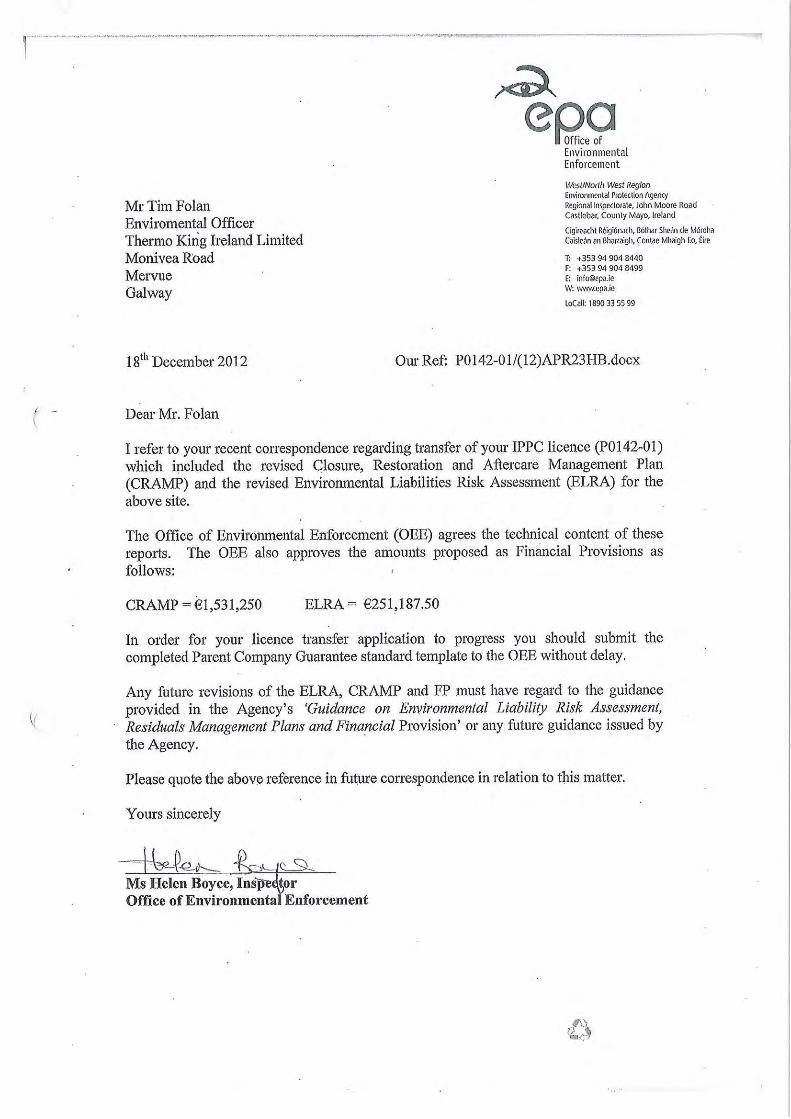

Attachmment K.2
MA
LO
NE
O’R
EG
AN
June 2014
13, Mill Street, Galway.
Tel: +353 91 531069 Fax :+353 91 564644
e-mail: [email protected]
St. Catherine’s House, Catherine Street,
Waterford.
Tel: +353 51 876855 Fax :+353 51 876828
e-mail: [email protected]
2B Richview Office Park, Clonskeagh, Dublin 14.
Tel: +353 01 2602655 Fax: +353 01 2602660
e-mail: [email protected]
Ingersoll-Rand International Limited,
Monivea Road Mervue Galway
Environmental Liabilities Risk Assessment

Environmental Liabilities Risk Assessment June2014 Ingersoll-Rand International Limited IE Licence Application
Malone O’Regan Contents
Environmental Liabilities Risk Assessment (ELRA)
Ingersoll-Rand International Limited
Monivea Road Mervue Galway
Table of Contents Summary ...................................................................................................................... 1 1.0 Introduction ....................................................................................................... 2 1.1 Methodology .................................................................................................... 2 2.0 Scoping ............................................................................................................. 3 3.0 Risk Identification ............................................................................................. 3 3.1 Site Operation.................................................................................................. 3 3.2 Overview of Operations ................................................................................... 4 3.2 Operator Performance ..................................................................................... 4 3.4 Environmental Sensitivity ................................................................................. 4 4.0 Risk Assessment .............................................................................................. 7 4.1 Risk identification ............................................................................................. 7 4.2 Risk Analysis ................................................................................................. 10 4.3 Ranking of Risks ............................................................................................ 20 5.0 Risk Treatment ................................................................................................ 22 6.0 Identification of Plausible Worst Case Scenario .......................................... 24 7.0 Quantification and Costing ............................................................................ 25 8.0 Review of Risk Assessment/ Financial Provision ........................................ 26 9.0 Conclusions .................................................................................................... 26 10.0 References ...................................................................................................... 27 Figures Figure 101 Site Layout
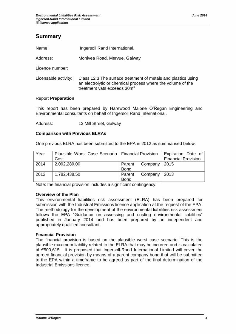
Environmental Liabilities Risk Assessment June 2014 Ingersoll-Rand International Limited IE licence application
Malone O’Regan 1
Summary Name: Ingersoll Rand International. Address: Monivea Road, Mervue, Galway Licence number: Licensable activity: Class 12.3 The surface treatment of metals and plastics using an electrolytic or chemical process where the volume of the treatment vats exceeds 30m3
Report Preparation This report has been prepared by Harewood Malone O’Regan Engineering and Environmental consultants on behalf of Ingersoll Rand International. Address: 13 Mill Street, Galway Comparison with Previous ELRAs One previous ELRA has been submitted to the EPA in 2012 as summarised below:
Year Plausible Worst Case Scenario Cost
Financial Provision Expiration Date of Financial Provision
2014 2,092,289.00 Parent Company Bond
2015
2012 1,782,438.50 Parent Company Bond
2013
Note: the financial provision includes a significant contingency. Overview of the Plan This environmental liabilities risk assessment (ELRA) has been prepared for submission with the Industrial Emissions licence application at the request of the EPA. The methodology for the development of the environmental liabilities risk assessment follows the EPA “Guidance on assessing and costing environmental liabilities” published in January 2014 and has been prepared by an independent and appropriately qualified consultant. Financial Provision The financial provision is based on the plausible worst case scenario. This is the plausible maximum liability related to the ELRA that may be incurred and is calculated at €500,615. It is proposed that Ingersoll-Rand International Limited will cover the agreed financial provision by means of a parent company bond that will be submitted to the EPA within a timeframe to be agreed as part of the final determination of the Industrial Emissions licence.
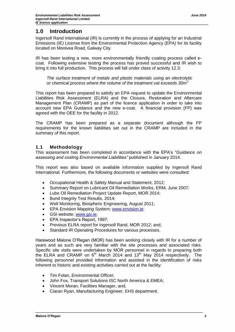
Environmental Liabilities Risk Assessment June 2014 Ingersoll-Rand International Limited IE licence application
Malone O’Regan 2
1.0 Introduction Ingersoll Rand International (IR) is currently in the process of applying for an Industrial Emissions (IE) License from the Environmental Protection Agency (EPA) for its facility located on Monivea Road, Galway City. IR has been testing a new, more environmentally friendly coating process called e-coat. Following extensive testing the process has proved successful and IR wish to bring it into full production. This process will fall under class of activity 12.3:
The surface treatment of metals and plastic materials using an electrolytic or chemical process where the volume of the treatment vat exceeds 30m3
This report has been prepared to satisfy an EPA request to update the Environmental Liabilities Risk Assessment (ELRA) and the Closure, Restoration and Aftercare Management Plan (CRAMP) as part of the licence application in order to take into account new EPA Guidance and the new e-coat. A financial provision (FP) was agreed with the OEE for the facility in 2012. The CRAMP has been prepared as a separate document although the FP requirements for the known liabilities set out in the CRAMP are included in the summary of this report.
1.1 Methodology This assessment has been completed in accordance with the EPA’s “Guidance on assessing and costing Environmental Liabilities” published in January 2014. This report was also based on available information supplied by Ingersoll Rand International. Furthermore, the following documents or websites were consulted:
Occupational Health & Safety Manual and Statement, 2012;
Summary Report on Lubricant Oil Remediation Works, ERM, June 2007;
Lube Oil Remediation Project Update Report, MOR 2014;
Bund Integrity Test Results, 2014;
Well Monitoring, Biospheric Engineering, August 2011;
EPA Envision Mapping System; www.envision.ie;
GSI website; www.gsi.ie;
EPA Inspector’s Report, 1997;
Previous ELRA report for Ingersoll Rand, MOR 2012; and,
Standard IR Operating Procedures for various processes. Harewood Malone O’Regan (MOR) has been working closely with IR for a number of years and as such are very familiar with the site processes and associated risks. Specific site visits were undertaken by MOR personnel in regards to preparing both the ELRA and CRAMP on 6th March 2014 and 13th May 2014 respectively. The following personnel provided information and assisted in the identification of risks inherent to historic and existing activities carried out at the facility:
Tim Folan, Environmental Officer;
John Fox, Transport Solutions ISC North America & EMEA;
Vincent Moran, Facilities Manager, and,
Ciaran Ryan, Manufacturing Engineer, EHS department.
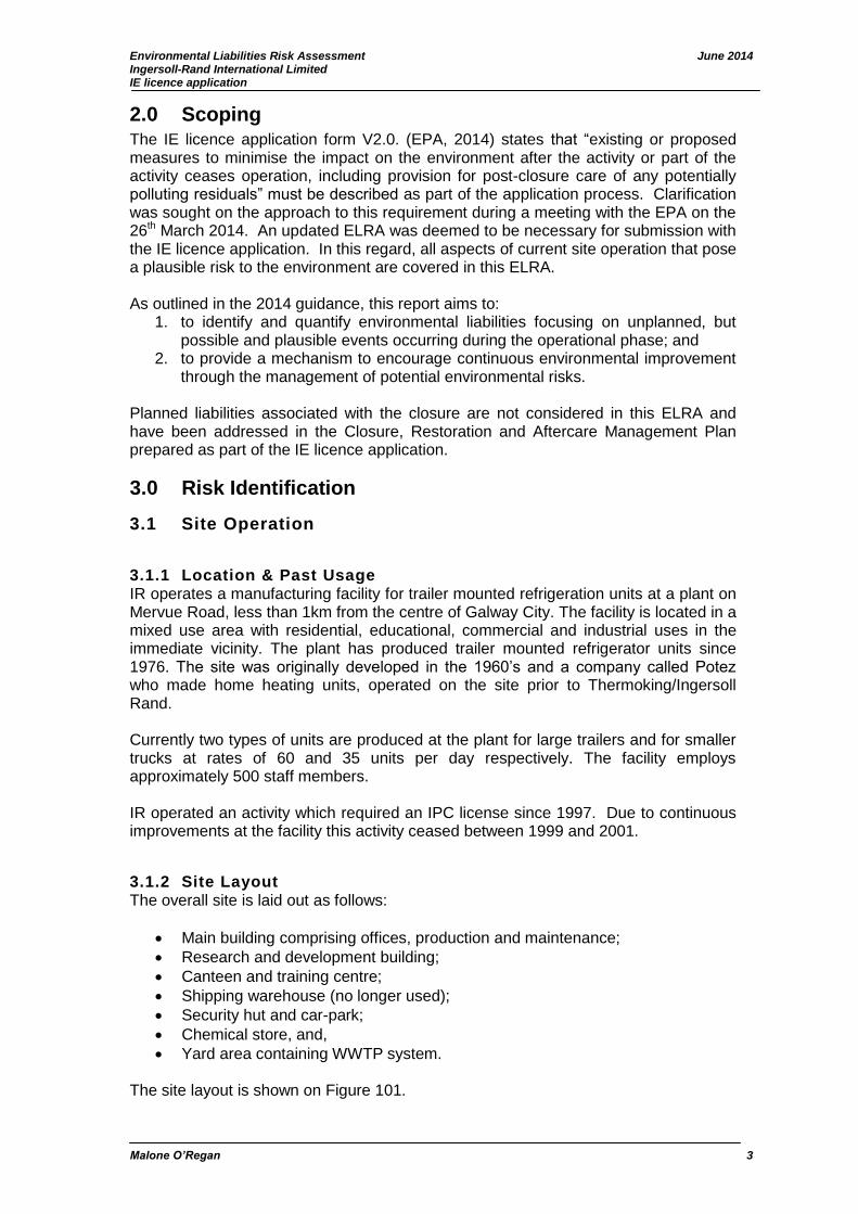
Environmental Liabilities Risk Assessment June 2014 Ingersoll-Rand International Limited IE licence application
Malone O’Regan 3
2.0 Scoping The IE licence application form V2.0. (EPA, 2014) states that “existing or proposed measures to minimise the impact on the environment after the activity or part of the activity ceases operation, including provision for post-closure care of any potentially polluting residuals” must be described as part of the application process. Clarification was sought on the approach to this requirement during a meeting with the EPA on the 26th March 2014. An updated ELRA was deemed to be necessary for submission with the IE licence application. In this regard, all aspects of current site operation that pose a plausible risk to the environment are covered in this ELRA. As outlined in the 2014 guidance, this report aims to:
1. to identify and quantify environmental liabilities focusing on unplanned, but possible and plausible events occurring during the operational phase; and
2. to provide a mechanism to encourage continuous environmental improvement through the management of potential environmental risks.
Planned liabilities associated with the closure are not considered in this ELRA and have been addressed in the Closure, Restoration and Aftercare Management Plan prepared as part of the IE licence application.
3.0 Risk Identification
3.1 Site Operation
3.1.1 Location & Past Usage IR operates a manufacturing facility for trailer mounted refrigeration units at a plant on Mervue Road, less than 1km from the centre of Galway City. The facility is located in a mixed use area with residential, educational, commercial and industrial uses in the immediate vicinity. The plant has produced trailer mounted refrigerator units since 1976. The site was originally developed in the 1960’s and a company called Potez who made home heating units, operated on the site prior to Thermoking/Ingersoll Rand. Currently two types of units are produced at the plant for large trailers and for smaller trucks at rates of 60 and 35 units per day respectively. The facility employs approximately 500 staff members. IR operated an activity which required an IPC license since 1997. Due to continuous improvements at the facility this activity ceased between 1999 and 2001.
3.1.2 Site Layout The overall site is laid out as follows:
Main building comprising offices, production and maintenance;
Research and development building;
Canteen and training centre;
Shipping warehouse (no longer used);
Security hut and car-park;
Chemical store, and,
Yard area containing WWTP system. The site layout is shown on Figure 101.

Environmental Liabilities Risk Assessment June 2014 Ingersoll-Rand International Limited IE licence application
Malone O’Regan 4
3.2 Overview of Operations The main manufacturing operations currently carried out at the facility are described briefly below. Main Manufacturing Processes The process begins with the delivery of steel and aluminium parts. These are placed on a conveyer which transports them to the new e-coat process. The e-coat process is an automated electro coating painting process. It involves cleaning, rinsing, zinc coating, sealing, e-coating and drying steps. The components then go to the assembly line where they are fitted with various components. Compressors are then pressurised and units insulated. Components such as engines, compressors, electrical switchgear, wiring and hardware are purchased from many suppliers including a number in Ireland. Returnable crates and stillages to point-of-use are employed as much as possible for suppliers as far away as Japan. The completed units are tested on site before shipping. Most units are shipped with refrigerant sealed in the unit but some more complex units are evacuated of refrigerant prior to shipping. The recovered refrigerant is returned to the storage tank for re-use. Auxiliary Processes The main auxiliary processes include maintenance activities, process water softening, heating of the premises, storage of bulk liquids and gases, chemical storage and treatment of aqueous effluent arising from the e-coat process prior to discharge to the public sewer.
3.2 Operator Performance IR operates a strict environmental management system (EMS) which is ISO 14001 accredited. The facility has not had any recent OEE inspections resulting in non-compliances. Furthermore, no non-compliances have been recorded regarding emissions from the facility during 2013 or the first quarter of 2014. A remediation project has been on-going on site since 2002 as described below. Historic activities which took place on the site since the 1960’s, when the site was developed from a greenfield site, may also have impacted on soil and groundwater although there is no evidence as such from records held by the company. Ingersoll Rand completed a due diligence prior to purchasing the site. Remediation Programme A groundwater remediation project is currently ongoing at the site that is addressing a historic lube oil spill that was first identified in 2002. It is understood that a release of lubricating oil first became apparent in February 2002 when lube oil was observed at the base of the LPG storage tank in the R&D area of the site. Subsequent investigations confirmed that the source of this leak was a lubricating oil junction pipe that had leaked at the corner of the R&D building near the footpath. It is reported that the source of the oil leak was stopped on the 7th February 2002.
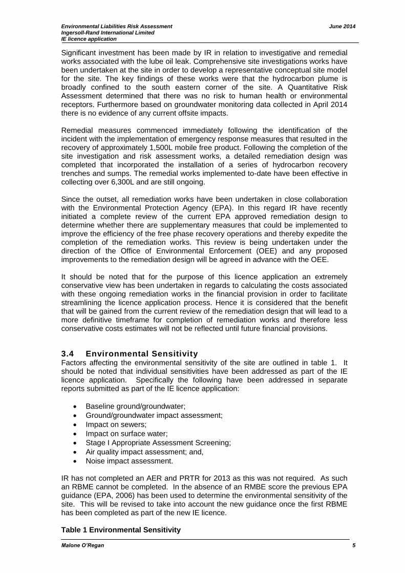
Environmental Liabilities Risk Assessment June 2014 Ingersoll-Rand International Limited IE licence application
Malone O’Regan 5
Significant investment has been made by IR in relation to investigative and remedial works associated with the lube oil leak. Comprehensive site investigations works have been undertaken at the site in order to develop a representative conceptual site model for the site. The key findings of these works were that the hydrocarbon plume is broadly confined to the south eastern corner of the site. A Quantitative Risk Assessment determined that there was no risk to human health or environmental receptors. Furthermore based on groundwater monitoring data collected in April 2014 there is no evidence of any current offsite impacts. Remedial measures commenced immediately following the identification of the incident with the implementation of emergency response measures that resulted in the recovery of approximately 1,500L mobile free product. Following the completion of the site investigation and risk assessment works, a detailed remediation design was completed that incorporated the installation of a series of hydrocarbon recovery trenches and sumps. The remedial works implemented to-date have been effective in collecting over 6,300L and are still ongoing. Since the outset, all remediation works have been undertaken in close collaboration with the Environmental Protection Agency (EPA). In this regard IR have recently initiated a complete review of the current EPA approved remediation design to determine whether there are supplementary measures that could be implemented to improve the efficiency of the free phase recovery operations and thereby expedite the completion of the remediation works. This review is being undertaken under the direction of the Office of Environmental Enforcement (OEE) and any proposed improvements to the remediation design will be agreed in advance with the OEE. It should be noted that for the purpose of this licence application an extremely conservative view has been undertaken in regards to calculating the costs associated with these ongoing remediation works in the financial provision in order to facilitate streamlining the licence application process. Hence it is considered that the benefit that will be gained from the current review of the remediation design that will lead to a more definitive timeframe for completion of remediation works and therefore less conservative costs estimates will not be reflected until future financial provisions.
3.4 Environmental Sensitivity Factors affecting the environmental sensitivity of the site are outlined in table 1. It should be noted that individual sensitivities have been addressed as part of the IE licence application. Specifically the following have been addressed in separate reports submitted as part of the IE licence application:
Baseline ground/groundwater;
Ground/groundwater impact assessment;
Impact on sewers;
Impact on surface water;
Stage I Appropriate Assessment Screening;
Air quality impact assessment; and,
Noise impact assessment.
IR has not completed an AER and PRTR for 2013 as this was not required. As such an RBME cannot be completed. In the absence of an RMBE score the previous EPA guidance (EPA, 2006) has been used to determine the environmental sensitivity of the site. This will be revised to take into account the new guidance once the first RBME has been completed as part of the new IE licence. Table 1 Environmental Sensitivity
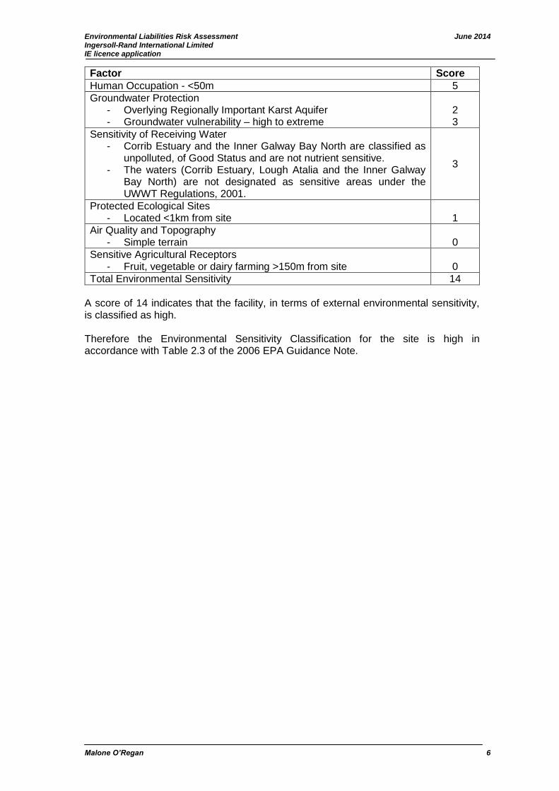
Environmental Liabilities Risk Assessment June 2014 Ingersoll-Rand International Limited IE licence application
Malone O’Regan 6
Factor Score
Human Occupation - <50m 5
Groundwater Protection - Overlying Regionally Important Karst Aquifer - Groundwater vulnerability – high to extreme
2 3
Sensitivity of Receiving Water - Corrib Estuary and the Inner Galway Bay North are classified as
unpolluted, of Good Status and are not nutrient sensitive. - The waters (Corrib Estuary, Lough Atalia and the Inner Galway
Bay North) are not designated as sensitive areas under the UWWT Regulations, 2001.
3
Protected Ecological Sites - Located <1km from site
1
Air Quality and Topography - Simple terrain
0
Sensitive Agricultural Receptors - Fruit, vegetable or dairy farming >150m from site
0
Total Environmental Sensitivity 14
A score of 14 indicates that the facility, in terms of external environmental sensitivity, is classified as high. Therefore the Environmental Sensitivity Classification for the site is high in accordance with Table 2.3 of the 2006 EPA Guidance Note.

Environmental Liabilities Risk Assessment June 2014 Ingersoll-Rand International Limited IE licence application
Malone O’Regan 7
4.0 Risk Assessment
4.1 Risk identification The next stage in preparing the ELRA is to identify potential risk to environment receptors related to past and present operations on-site. The environmental receptors considered include soil and groundwater, surface water, human beings, and air quality. These receptors are used as a starting point to ensure that all significant risks are identified and all major aspects of the environment are taken into account. During the site visit, all of the processes and facilities on site were identified and the hazards associated with each process were discussed. Abnormal operating conditions were considered and potential causes of failure and prevention of risk were identified through discussion and review of existing documents prepared by the company. If any effect to the environment could be perceived from a potential failure then this was identified as a risk and included in the Risk Register. Site specific risks identified are presented in table 2.

Environmental Liabilities Risk Assessment June 2014 Ingersoll-Rand International Limited IE licence application
Malone O’Regan 8
Table 2: Risk Identification
Risk ID Process Potential Hazards Environmental Effect
1 Bulk fuel delivery Accidental spills during deliveries Potential contamination of surface and groundwater
2 Existing fuel distribution Accidental leakage of fuel pipelines Potential contamination of surface and groundwater
3 Existing fuel storage Leakage from storage facilities Potential contamination of surface and groundwater
4 Liquefied gas refrigerant delivery
Accidental gas release. Refrigerants are stored as liquefied gases. If a leak occurs the compounds will revert to the gaseous phase.
Potential depletion of the ozone layer
5 Liquefied gas refrigerant distribution
Accidental gas release Potential depletion of the ozone layer
6 Refrigerant charging Accidental gas release Potential depletion of the ozone layer
7 Liquefied gas refrigerant reclaim
Accidental gas release Potential depletion of the ozone layer
8 Liquefied gas refrigerant storage
Accidental gas release Potential depletion of the ozone layer
9 Chemical Delivery and Distribution ≤ IBC volume
Spillage as a result of unbalancing of containers during delivery and movement around the site by forklift
Potential contamination of soil and groundwater
10 Chemical and Hazardous Waste Storage ≤ IBC volume
Spillage/leak of chemicals from store Potential contamination of soil and groundwater
11 Coolant (ethylene glycol) Delivery
Accidental spills during deliveries Potential contamination of surface and groundwater
12 Coolant Distribution and Coolant Charge of Units
Accidental leakage of coolant pipelines Potential contamination of surface and groundwater
13 Past Coolant Storage Leakage from storage facilities Potential contamination of surface and groundwater
14 Foam Chemical Storage and Distribution
Polyol and isocyanate are stored under pressure therefore any release would be gaseous
Potential emission to air
15 e-coat process Rupture of tanks Potential contamination of surface and groundwater
16 e-coat process Spillage during filling or emptying Potential contamination of surface and groundwater
17 e-coat ovens Abnormal operation resulting in higher than normal emissions to air
Potential impact on ambient air quality and non-compliance with AQSs at the nearest.
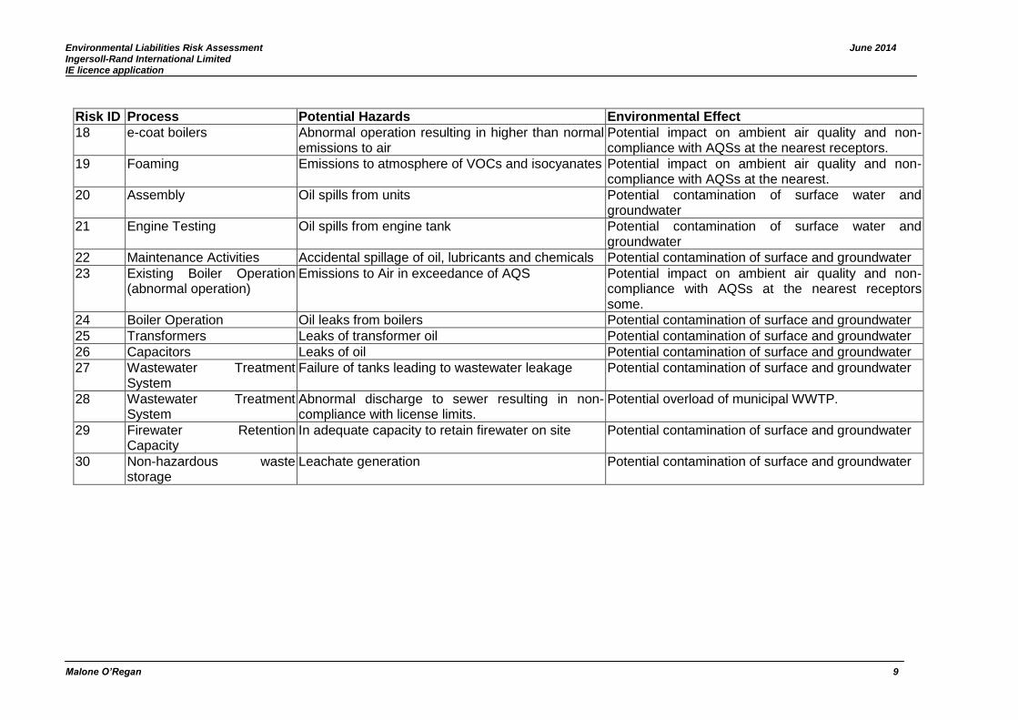
Environmental Liabilities Risk Assessment June 2014 Ingersoll-Rand International Limited IE licence application
Malone O’Regan 9
Risk ID Process Potential Hazards Environmental Effect
18 e-coat boilers Abnormal operation resulting in higher than normal emissions to air
Potential impact on ambient air quality and non-compliance with AQSs at the nearest receptors.
19 Foaming Emissions to atmosphere of VOCs and isocyanates Potential impact on ambient air quality and non-compliance with AQSs at the nearest.
20 Assembly Oil spills from units Potential contamination of surface water and groundwater
21 Engine Testing Oil spills from engine tank Potential contamination of surface water and groundwater
22 Maintenance Activities Accidental spillage of oil, lubricants and chemicals Potential contamination of surface and groundwater
23 Existing Boiler Operation (abnormal operation)
Emissions to Air in exceedance of AQS Potential impact on ambient air quality and non-compliance with AQSs at the nearest receptors some.
24 Boiler Operation Oil leaks from boilers Potential contamination of surface and groundwater
25 Transformers Leaks of transformer oil Potential contamination of surface and groundwater
26 Capacitors Leaks of oil Potential contamination of surface and groundwater
27 Wastewater Treatment System
Failure of tanks leading to wastewater leakage Potential contamination of surface and groundwater
28 Wastewater Treatment System
Abnormal discharge to sewer resulting in non-compliance with license limits.
Potential overload of municipal WWTP.
29 Firewater Retention Capacity
In adequate capacity to retain firewater on site Potential contamination of surface and groundwater
30 Non-hazardous waste storage
Leachate generation Potential contamination of surface and groundwater

Environmental Liabilities Risk Assessment June 2014 Ingersoll-Rand International Limited IE licence application
Malone O’Regan 10
4.2 Risk Analysis Table 3 illustrates how the risks are assessed and classified whilst Table 4 provides details on the rating of risks identified in table 2 and rationale for classification. Table 4 takes account of mitigation measures already in place which can reduce the likelihood of occurrence and/or in some cases the consequence of the effect. Table 3: Risk Classification
Rating Likelihood* Consequence¥
1 Very low Trivial: no damage/ negligible change to the environment
2 Low Minor: Localised impact/ nuisance
3 Medium Moderate: Moderate impact to environment
4 High Major: Severe impact to environment
5 Very high Massive: Massive damage to a large area, irreversible in the medium term
* The assessment of the environmental liabilities has been limited to a 30 year period in accordance with Article 10 of Council Directive 1999/31/EC and article 17 of 2004/35/CE. ¥ Impact/ Damage to the local environment.
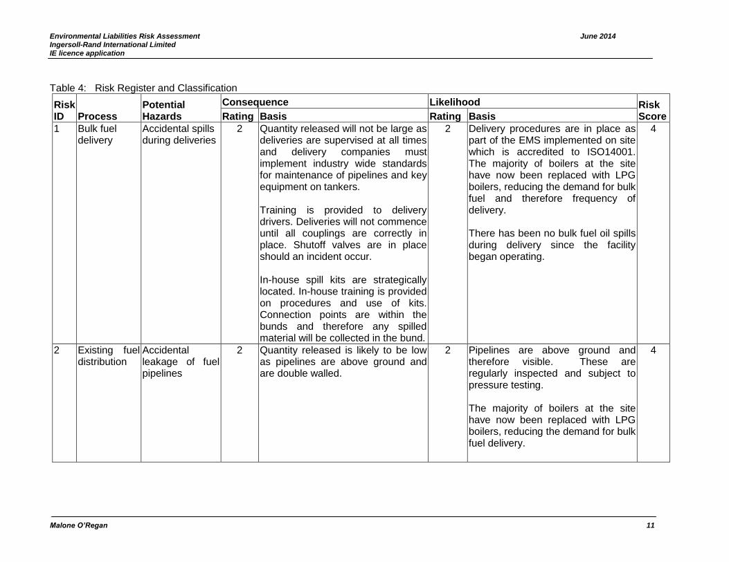
Environmental Liabilities Risk Assessment June 2014 Ingersoll-Rand International Limited IE licence application
Malone O’Regan 11
Table 4: Risk Register and Classification
Risk ID Process
Potential Hazards
Consequence Likelihood Risk Score Rating Basis Rating Basis
1 Bulk fuel delivery
Accidental spills during deliveries
2 Quantity released will not be large as deliveries are supervised at all times and delivery companies must implement industry wide standards for maintenance of pipelines and key equipment on tankers. Training is provided to delivery drivers. Deliveries will not commence until all couplings are correctly in place. Shutoff valves are in place should an incident occur. In-house spill kits are strategically located. In-house training is provided on procedures and use of kits. Connection points are within the bunds and therefore any spilled material will be collected in the bund.
2 Delivery procedures are in place as part of the EMS implemented on site which is accredited to ISO14001. The majority of boilers at the site have now been replaced with LPG boilers, reducing the demand for bulk fuel and therefore frequency of delivery. There has been no bulk fuel oil spills during delivery since the facility began operating.
4
2 Existing fuel distribution
Accidental leakage of fuel pipelines
2 Quantity released is likely to be low as pipelines are above ground and are double walled.
2 Pipelines are above ground and therefore visible. These are regularly inspected and subject to pressure testing. The majority of boilers at the site have now been replaced with LPG boilers, reducing the demand for bulk fuel delivery.
4
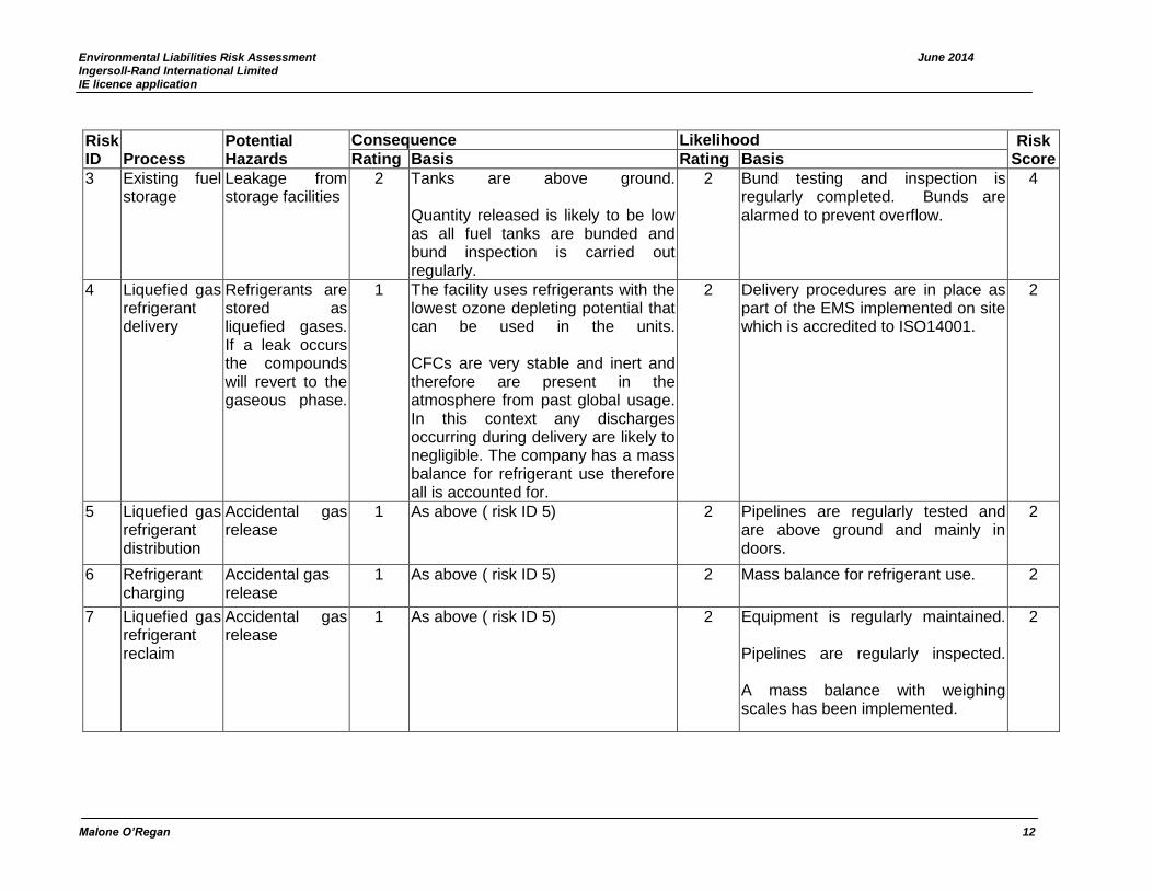
Environmental Liabilities Risk Assessment June 2014 Ingersoll-Rand International Limited IE licence application
Malone O’Regan 12
Risk ID Process
Potential Hazards
Consequence Likelihood Risk Score Rating Basis Rating Basis
3 Existing fuel storage
Leakage from storage facilities
2 Tanks are above ground. Quantity released is likely to be low as all fuel tanks are bunded and bund inspection is carried out regularly.
2 Bund testing and inspection is regularly completed. Bunds are alarmed to prevent overflow.
4
4 Liquefied gas refrigerant delivery
Refrigerants are stored as liquefied gases. If a leak occurs the compounds will revert to the gaseous phase.
1 The facility uses refrigerants with the lowest ozone depleting potential that can be used in the units. CFCs are very stable and inert and therefore are present in the atmosphere from past global usage. In this context any discharges occurring during delivery are likely to negligible. The company has a mass balance for refrigerant use therefore all is accounted for.
2 Delivery procedures are in place as part of the EMS implemented on site which is accredited to ISO14001.
2
5 Liquefied gas refrigerant distribution
Accidental gas release
1 As above ( risk ID 5) 2 Pipelines are regularly tested and are above ground and mainly in doors.
2
6 Refrigerant charging
Accidental gas release
1 As above ( risk ID 5) 2 Mass balance for refrigerant use. 2
7 Liquefied gas refrigerant reclaim
Accidental gas release
1 As above ( risk ID 5) 2 Equipment is regularly maintained. Pipelines are regularly inspected. A mass balance with weighing scales has been implemented.
2
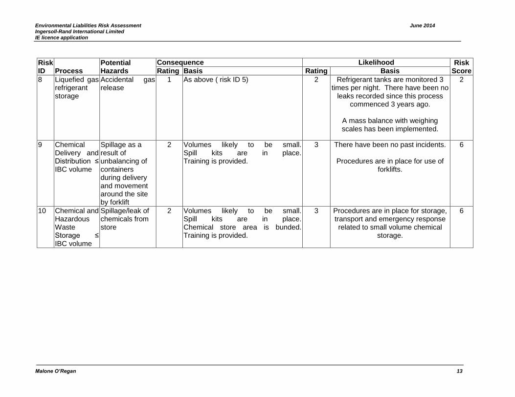
Environmental Liabilities Risk Assessment June 2014 Ingersoll-Rand International Limited IE licence application
Malone O’Regan 13
Risk ID Process
Potential Hazards
Consequence Likelihood Risk Score Rating Basis Rating Basis
8 Liquefied gas refrigerant storage
Accidental gas release
1 As above ( risk ID 5) 2 Refrigerant tanks are monitored 3 times per night. There have been no
leaks recorded since this process commenced 3 years ago.
A mass balance with weighing scales has been implemented.
2
9 Chemical Delivery and Distribution ≤ IBC volume
Spillage as a result of unbalancing of containers during delivery and movement around the site by forklift
2 Volumes likely to be small. Spill kits are in place. Training is provided.
3 There have been no past incidents.
Procedures are in place for use of forklifts.
6
10 Chemical and Hazardous Waste Storage ≤ IBC volume
Spillage/leak of chemicals from store
2 Volumes likely to be small. Spill kits are in place. Chemical store area is bunded. Training is provided.
3 Procedures are in place for storage, transport and emergency response related to small volume chemical
storage.
6
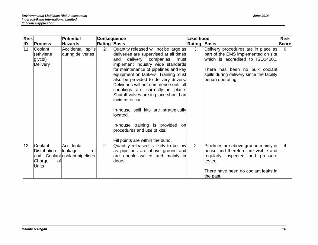
Environmental Liabilities Risk Assessment June 2014 Ingersoll-Rand International Limited IE licence application
Malone O’Regan 14
Risk ID Process
Potential Hazards
Consequence Likelihood Risk Score Rating Basis Rating Basis
11 Coolant (ethylene glycol) Delivery
Accidental spills during deliveries
2 Quantity released will not be large as deliveries are supervised at all times and delivery companies must implement industry wide standards for maintenance of pipelines and key equipment on tankers. Training must also be provided to delivery drivers. Deliveries will not commence until all couplings are correctly in place. Shutoff valves are in place should an incident occur. In-house spill kits are strategically located. In-house training is provided on procedures and use of kits. Fill points are within the bund.
3 Delivery procedures are in place as part of the EMS implemented on site which is accredited to ISO14001. There has been no bulk coolant spills during delivery since the facility began operating.
6
12 Coolant Distribution and Coolant Charge of Units
Accidental leakage of coolant pipelines
2 Quantity released is likely to be low as pipelines are above ground and are double walled and mainly in doors.
2 Pipelines are above ground mainly in house and therefore are visible and regularly inspected and pressure tested. There have been no coolant leaks in the past.
4
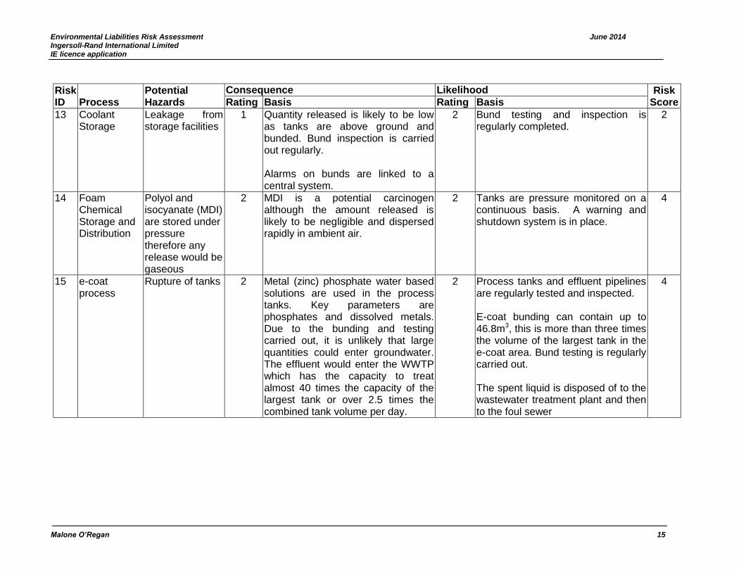
Environmental Liabilities Risk Assessment June 2014 Ingersoll-Rand International Limited IE licence application
Malone O’Regan 15
Risk ID Process
Potential Hazards
Consequence Likelihood Risk Score Rating Basis Rating Basis
13 Coolant Storage
Leakage from storage facilities
1 Quantity released is likely to be low as tanks are above ground and bunded. Bund inspection is carried out regularly. Alarms on bunds are linked to a central system.
2 Bund testing and inspection is regularly completed.
2
14 Foam Chemical Storage and Distribution
Polyol and isocyanate (MDI) are stored under pressure therefore any release would be gaseous
2 MDI is a potential carcinogen although the amount released is likely to be negligible and dispersed rapidly in ambient air.
2 Tanks are pressure monitored on a continuous basis. A warning and shutdown system is in place.
4
15 e-coat process
Rupture of tanks 2 Metal (zinc) phosphate water based solutions are used in the process tanks. Key parameters are phosphates and dissolved metals. Due to the bunding and testing carried out, it is unlikely that large quantities could enter groundwater. The effluent would enter the WWTP which has the capacity to treat almost 40 times the capacity of the largest tank or over 2.5 times the combined tank volume per day.
2 Process tanks and effluent pipelines are regularly tested and inspected. E-coat bunding can contain up to 46.8m3, this is more than three times the volume of the largest tank in the e-coat area. Bund testing is regularly carried out. The spent liquid is disposed of to the wastewater treatment plant and then to the foul sewer
4

Environmental Liabilities Risk Assessment June 2014 Ingersoll-Rand International Limited IE licence application
Malone O’Regan 16
Risk ID Process
Potential Hazards
Consequence Likelihood Risk Score Rating Basis Rating Basis
16 e-coat process
Spillage during filling and/or emptying of tanks.
2 The quantities which could potentially enter the surface or groundwater are low based on the controls in place as described above (risk Id 17). All pipelines are double walled and above ground for easy inspection.
2 Process tanks and effluent pipelines are regularly tested and inspected. E-coat bunding can contain up to 46.8m3, this is more than three times the volume of the largest tank in the e-coat area. Bund testing is regularly carried out.
4
17 e-coat ovens Abnormal operation resulting in higher than normal emissions to air
1 Exceedances likely to be negligible once diluted by ambient air.
2 Stack monitoring has shown that emissions are low. The ovens are monitored on a continuous basis with emergency procedures in place.
2
18 e-coat boilers Abnormal operation resulting in higher than normal emissions to air
1 Exceedances likely to be negligible once diluted by ambient air.
2 Stack monitoring has shown that emissions are low. The ovens are monitored on a continuous basis with emergency procedures in place.
2
19 Foaming Emissions to atmosphere of VOCs and isocyanates (MDI) in excess of AQS
2 MDI is a potential carcinogen although quantities released are likely to be very small. Emissions are considered minor and have been confirmed with stack monitoring data.
2 Emissions are vented to atmosphere. Tanks are constantly pressure monitored and alarmed.
4
20 Assembly Oil spills from units
1 Quantities likely to be small. Spill kits and training in use provided. Spills would be contained within the building.
3 Operational controls in place, it is unlikely that a spill from this area would escape containment measures.
3
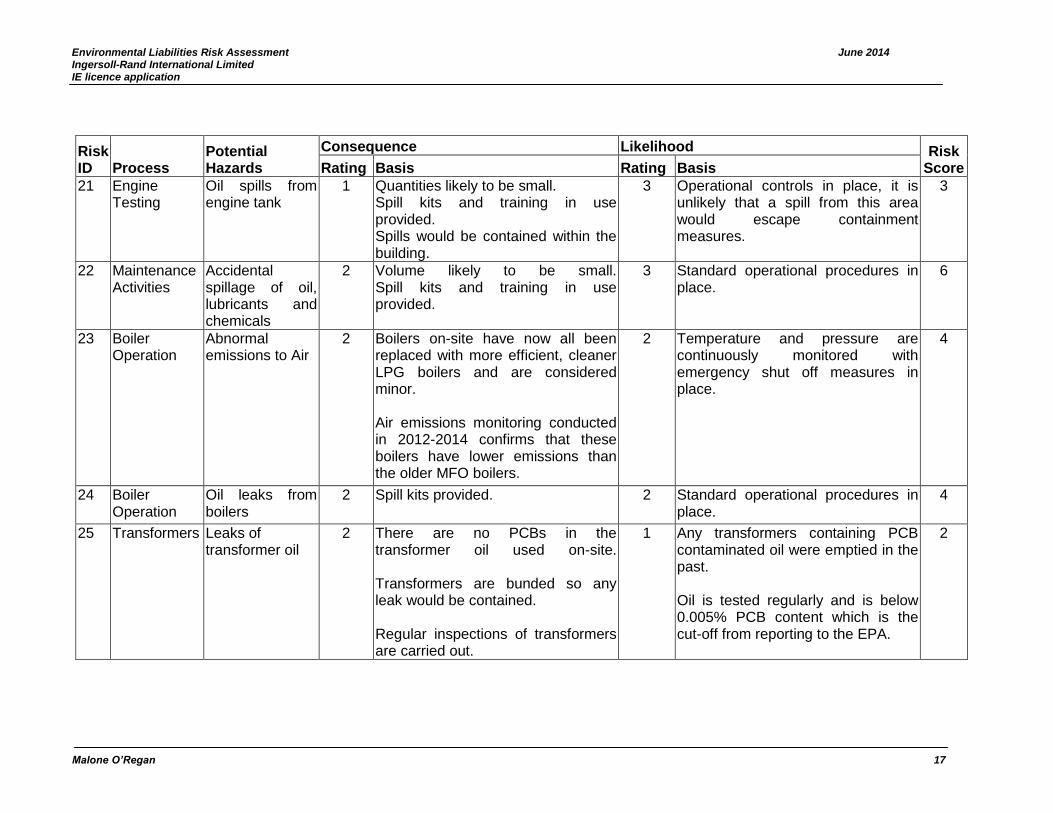
Environmental Liabilities Risk Assessment June 2014 Ingersoll-Rand International Limited IE licence application
Malone O’Regan 17
Risk ID Process
Potential Hazards
Consequence Likelihood Risk Score Rating Basis Rating Basis
21 Engine Testing
Oil spills from engine tank
1 Quantities likely to be small. Spill kits and training in use provided. Spills would be contained within the building.
3 Operational controls in place, it is unlikely that a spill from this area would escape containment measures.
3
22 Maintenance Activities
Accidental spillage of oil, lubricants and chemicals
2 Volume likely to be small. Spill kits and training in use provided.
3 Standard operational procedures in place.
6
23 Boiler Operation
Abnormal emissions to Air
2 Boilers on-site have now all been replaced with more efficient, cleaner LPG boilers and are considered minor. Air emissions monitoring conducted in 2012-2014 confirms that these boilers have lower emissions than the older MFO boilers.
2 Temperature and pressure are continuously monitored with emergency shut off measures in place.
4
24 Boiler Operation
Oil leaks from boilers
2 Spill kits provided. 2 Standard operational procedures in place.
4
25 Transformers Leaks of transformer oil
2 There are no PCBs in the transformer oil used on-site. Transformers are bunded so any leak would be contained. Regular inspections of transformers are carried out.
1 Any transformers containing PCB contaminated oil were emptied in the past. Oil is tested regularly and is below 0.005% PCB content which is the cut-off from reporting to the EPA.
2

Environmental Liabilities Risk Assessment June 2014 Ingersoll-Rand International Limited IE licence application
Malone O’Regan 18
Risk ID Process
Potential Hazards
Consequence Likelihood Risk Score Rating Basis Rating Basis
26 Capacitors Leaks of oil 2 There are no PCBs in the oil so no effect can occur. Volumes would be very small. All capacitors are regularly inspected and maintained.
1 All capacitors are regularly inspected and maintained.
2
27 Wastewater Treatment System
Failure of tanks leading to wastewater leakage
4 Wastewater toxicity is low. Effluent is treated on a batch basis enabling greater control of the process.
3 Tanks are bunded. Bunds are regularly tested. Operational controls in place to prevent overspill.
12
28 Wastewater Treatment System
Abnormal discharge to sewer resulting in non-compliance with license limits.
2 Damage is likely to be negligible due to nature of wastewater and small volumes which could be released. No direct discharge to surface or groundwater occurs.
1 Operational controls in place to ensure wastewater pH is adjusted. Effluent is sampled and analysed prior to discharge. Continuous monitoring probes in place which are regularly maintained and calibrated. There have been no exceedances in recent years.
2

Environmental Liabilities Risk Assessment June 2014 Ingersoll-Rand International Limited IE licence application
Malone O’Regan 19
Risk ID Process
Potential Hazards
Consequence Likelihood Risk Score Rating Basis Rating Basis
29 Firewater Retention Capacity
In adequate capacity to retain firewater on site
4 In the event of a fire, firewater could be contained on the site within the bunded areas. If any firewater entered the surface water drains automatic shut-off valves would be activated. The site slopes to the west southwest, firewater which escapes primary containment is likely to pool on site within the lipped car-park however this is not impermeable therefore contaminated water could seep into groundwater although volumes would be low based on the controls in place. The main chemical store, bulk tanks etc are bunded therefore firewater is unlikely to contain significant levels of contaminants.
2 The likelihood of inadequate capacity is low due to the fire controls in place which would prevent a large fire and hence a large quantity of firewater generation in the first instance These include a fire prevention plan including a sprinkler system, extinguishers etc. There have been no major fires on site. A firewater risk assessment will be completed in 2014 and the likelihood associated with this risk will be re-examined.
8
30 Non-hazardous waste storage
Leachate generation
2 Volume insignificant due to controls in place.
2 Waste is stored in closed containers to prevent rainfall ingress.
4
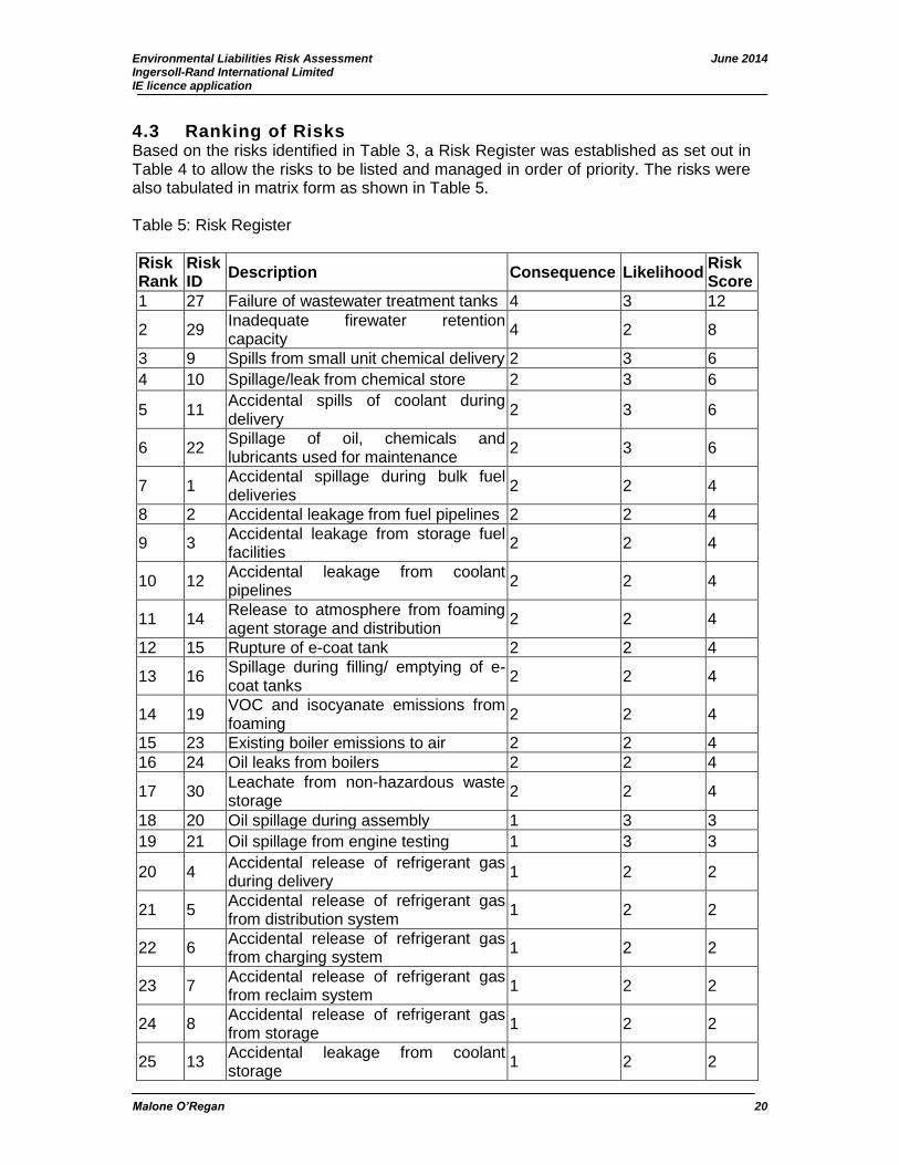
Environmental Liabilities Risk Assessment June 2014 Ingersoll-Rand International Limited IE licence application
Malone O’Regan 20
4.3 Ranking of Risks Based on the risks identified in Table 3, a Risk Register was established as set out in Table 4 to allow the risks to be listed and managed in order of priority. The risks were also tabulated in matrix form as shown in Table 5. Table 5: Risk Register
Risk Rank
Risk ID
Description Consequence Likelihood Risk Score
1 27 Failure of wastewater treatment tanks 4 3 12
2 29 Inadequate firewater retention capacity
4 2 8
3 9 Spills from small unit chemical delivery 2 3 6
4 10 Spillage/leak from chemical store 2 3 6
5 11 Accidental spills of coolant during delivery
2 3 6
6 22 Spillage of oil, chemicals and lubricants used for maintenance
2 3 6
7 1 Accidental spillage during bulk fuel deliveries
2 2 4
8 2 Accidental leakage from fuel pipelines 2 2 4
9 3 Accidental leakage from storage fuel facilities
2 2 4
10 12 Accidental leakage from coolant pipelines
2 2 4
11 14 Release to atmosphere from foaming agent storage and distribution
2 2 4
12 15 Rupture of e-coat tank 2 2 4
13 16 Spillage during filling/ emptying of e-coat tanks
2 2 4
14 19 VOC and isocyanate emissions from foaming
2 2 4
15 23 Existing boiler emissions to air 2 2 4
16 24 Oil leaks from boilers 2 2 4
17 30 Leachate from non-hazardous waste storage
2 2 4
18 20 Oil spillage during assembly 1 3 3
19 21 Oil spillage from engine testing 1 3 3
20 4 Accidental release of refrigerant gas during delivery
1 2 2
21 5 Accidental release of refrigerant gas from distribution system
1 2 2
22 6 Accidental release of refrigerant gas from charging system
1 2 2
23 7 Accidental release of refrigerant gas from reclaim system
1 2 2
24 8 Accidental release of refrigerant gas from storage
1 2 2
25 13 Accidental leakage from coolant storage
1 2 2
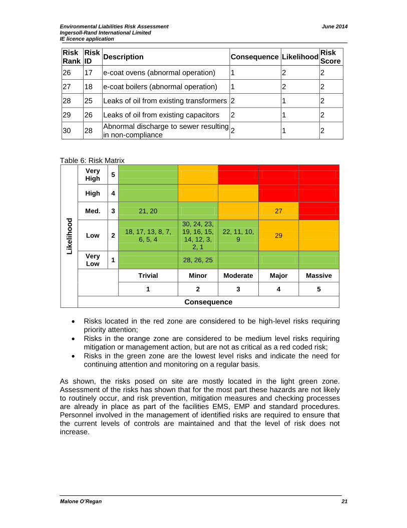
Environmental Liabilities Risk Assessment June 2014 Ingersoll-Rand International Limited IE licence application
Malone O’Regan 21
Risk Rank
Risk ID
Description Consequence Likelihood Risk Score
26 17 e-coat ovens (abnormal operation) 1 2 2
27 18 e-coat boilers (abnormal operation) 1 2 2
28 25 Leaks of oil from existing transformers 2 1 2
29 26 Leaks of oil from existing capacitors 2 1 2
30 28 Abnormal discharge to sewer resulting in non-compliance
2 1 2
Table 6: Risk Matrix
Lik
elih
oo
d
Very High
5
High 4
Med. 3 21, 20 27
Low 2 18, 17, 13, 8, 7,
6, 5, 4
30, 24, 23, 19, 16, 15, 14, 12, 3,
2, 1
22, 11, 10, 9
29
Very Low
1 28, 26, 25
Trivial Minor Moderate Major Massive
1 2 3 4 5
Consequence
Risks located in the red zone are considered to be high-level risks requiring priority attention;
Risks in the orange zone are considered to be medium level risks requiring mitigation or management action, but are not as critical as a red coded risk;
Risks in the green zone are the lowest level risks and indicate the need for continuing attention and monitoring on a regular basis.
As shown, the risks posed on site are mostly located in the light green zone. Assessment of the risks has shown that for the most part these hazards are not likely to routinely occur, and risk prevention, mitigation measures and checking processes are already in place as part of the facilities EMS, EMP and standard procedures. Personnel involved in the management of identified risks are required to ensure that the current levels of controls are maintained and that the level of risk does not increase.

Environmental Liabilities Risk Assessment June 2014 Ingersoll-Rand International Limited IE licence application
Malone O’Regan 22
5.0 Risk Treatment Risk treatment evaluation aims to set out actions for the minimisation of risks and continuous improvement on-site. The output is a statement of mitigation measures to be implemented to reduce environmental risk at the site. Mitigation measures along with actions, timeframes and the responsible party are presented in Table 7 below. It should be noted that IR operates a strict EMS and continuous improvement program. This has resulted in the minimisation of environmental risks on-site. As a result further mitigation measures for some risks would be considered unnecessary. Risks shown in the green zone of table 6 have been excluded from risk treatment evaluation as they are very low risk to the environment. Measures already in place for reducing the risk related to these will continue to be maintained and updated where necessary. Therefore mitigation measures for those risks with a risk rating greater than 6 have been assessed in Table 7 below.
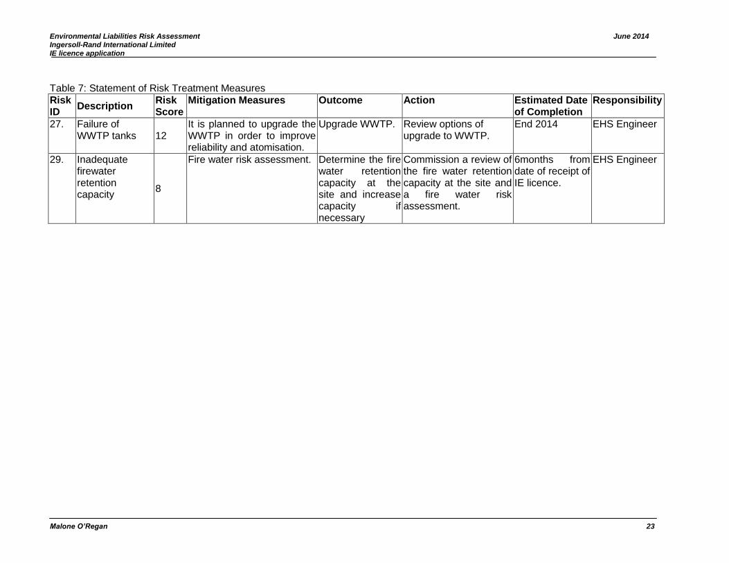
Environmental Liabilities Risk Assessment June 2014 Ingersoll-Rand International Limited IE licence application
Malone O’Regan 23
Table 7: Statement of Risk Treatment Measures
Risk ID
Description Risk Score
Mitigation Measures Outcome Action Estimated Date of Completion
Responsibility
27. Failure of WWTP tanks 12
It is planned to upgrade the WWTP in order to improve reliability and atomisation.
Upgrade WWTP. Review options of upgrade to WWTP.
End 2014 EHS Engineer
29. Inadequate firewater retention capacity
8
Fire water risk assessment. Determine the fire water retention capacity at the site and increase capacity if necessary
Commission a review of the fire water retention capacity at the site and a fire water risk assessment.
6months from date of receipt of IE licence.
EHS Engineer
Environmental Liabilities Risk Assessment June 2014 Ingersoll-Rand International Limited IE licence application
Malone O’Regan 24
6.0 Identification of Plausible Worst Case Scenario It has been determined that the most plausible worst case scenario for environmental risk at the IR site is the occurrence of a fire which could result in exceedance of the fire water retention capacity at the site (Risk 29) resulting in the release of contaminated fire water to ground. However, due to the following mitigation measures which have been put in place the likelihood of this scenario occurring is low:
• Fire risk management procedures are in place including the provision of a sprinkler system, fire extinguishers, fire hydrants and training in how to use them;
• A strict policy on smoking in designated smoking sheltered only is in place. These are separated from sources of ignition;
• Shut off valves are in place should an incident occur; and, • Emergency response procedures are in place including the mobilisation of a
plant emergency response team (PERT). Regardless of these mitigation measures such a scenario could result in localised contamination requiring remediation as well as damage to the infrastructure at the site. This plausible worst case scenario would involve the following:
• Production of 948m3 of contaminated fire water which would be recycled during the course of the fire fighting;
• 230m3 of fire water could be stored in the WWTP and spare storage tank, 46.89m3 could temporally be held in the e-coat bund and 83.13m3 within the on-site drainage network by shutting off the outlet valve and within the e-coat bund giving a total storage capacity of 360 m3;
• The remaining 588m3 of fire water would be recycled back to the 948m3 fire water tank for re use.
This would result in fire water storage capacity being strained and small volumes of firewater could escape containment measures in place through small spillages. However, the majority of water would be contained. This water could be treated in the on-site WWTP pending testing of the water and emergency agreement with the EPA and Irish Water. The following cost could be incurred as a result of this worst case scenario event:
• Costs related to demolition of damaged building and related waste disposal; • Fire fighting cost; • Other emergency response costs; • Site investigation; • Risk assessment; • Remediation; • Validation; • Reinstatement; and, • Consultancy fees.
The fire water risk assessment for the site will be conducted within 6 months of receipt of the new IE licence to take into account recent changes at the site. This will enable the risk of exceeding fire water retention capacity to be fully quantified.
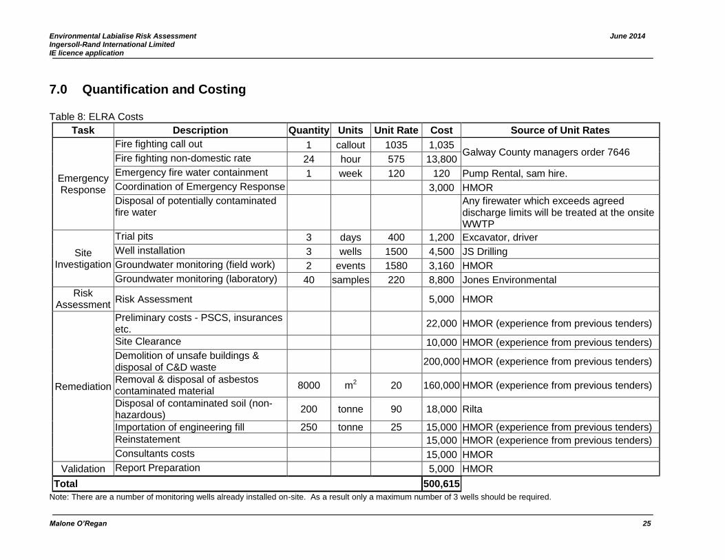
Environmental Labialise Risk Assessment June 2014 Ingersoll-Rand International Limited IE licence application
Malone O’Regan 25
7.0 Quantification and Costing Table 8: ELRA Costs
Task Description Quantity Units Unit Rate Cost Source of Unit Rates
Emergency Response
Fire fighting call out 1 callout 1035 1,035 Galway County managers order 7646
Fire fighting non-domestic rate 24 hour 575 13,800
Emergency fire water containment 1 week 120 120 Pump Rental, sam hire.
Coordination of Emergency Response 3,000 HMOR
Disposal of potentially contaminated fire water
Any firewater which exceeds agreed discharge limits will be treated at the onsite WWTP
Site Investigation
Trial pits 3 days 400 1,200 Excavator, driver
Well installation 3 wells 1500 4,500 JS Drilling
Groundwater monitoring (field work) 2 events 1580 3,160 HMOR
Groundwater monitoring (laboratory) 40 samples 220 8,800 Jones Environmental
Risk Assessment
Risk Assessment 5,000 HMOR
Remediation
Preliminary costs - PSCS, insurances etc.
22,000 HMOR (experience from previous tenders)
Site Clearance 10,000 HMOR (experience from previous tenders)
Demolition of unsafe buildings & disposal of C&D waste
200,000 HMOR (experience from previous tenders)
Removal & disposal of asbestos contaminated material
8000 m2 20 160,000 HMOR (experience from previous tenders)
Disposal of contaminated soil (non-hazardous)
200 tonne 90 18,000 Rilta
Importation of engineering fill 250 tonne 25 15,000 HMOR (experience from previous tenders)
Reinstatement 15,000 HMOR (experience from previous tenders)
Consultants costs 15,000 HMOR
Validation Report Preparation 5,000 HMOR
Total 500,615
Note: There are a number of monitoring wells already installed on-site. As a result only a maximum number of 3 wells should be required.
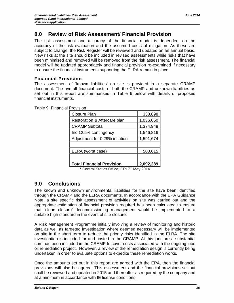
Environmental Liabilities Risk Assessment June 2014 Ingersoll-Rand International Limited IE licence application
Malone O’Regan 26
8.0 Review of Risk Assessment/ Financial Provision The risk assessment and accuracy of the financial model is dependent on the accuracy of the risk evaluation and the assumed costs of mitigation. As these are subject to change, the Risk Register will be reviewed and updated on an annual basis. New risks at the site should be included in revised assessments while risks that have been minimised and removed will be removed from the risk assessment. The financial model will be updated appropriately and financial provision re-examined if necessary to ensure the financial instruments supporting the ELRA remain in place.
Financial Provision The assessment of ‘known liabilities’ on site is provided in a separate CRAMP document. The overall financial costs of both the CRAMP and unknown liabilities as set out in this report are summarised in Table 9 below with details of proposed financial instruments. Table 9: Financial Provision
Closure Plan 338,898
Restoration & Aftercare plan 1,036,050
CRAMP Subtotal 1,374,948
Inc 12.5% contingency 1,546,816
Adjustment for 0.29% inflation 1,591,674
ELRA (worst case) 500,615
Total Financial Provision 2,092,289 * Central Statics Office, CPI 7
th May 2014
9.0 Conclusions The known and unknown environmental liabilities for the site have been identified through the CRAMP and the ELRA documents. In accordance with the EPA Guidance Note, a site specific risk assessment of activities on site was carried out and the appropriate estimation of financial provision required has been calculated to ensure that ‘clean closure’ decommissioning management would be implemented to a suitable high standard in the event of site closure. A Risk Management Programme initially involving a review of monitoring and historic data as well as targeted investigation where deemed necessary will be implemented on site in the short term to reduce the priority risks identified in the ELRA. The site investigation is included for and costed in the CRAMP. At this juncture a substantial sum has been included in the CRAMP to cover costs associated with the ongoing lube oil remediation project. However, a review of the remediation design is currently being undertaken in order to evaluate options to expedite these remediation works. Once the amounts set out in this report are agreed with the EPA, then the financial provisions will also be agreed. This assessment and the financial provisions set out shall be reviewed and updated in 2015 and thereafter as required by the company and at a minimum in accordance with IE license conditions.
Environmental Liabilities Risk Assessment June 2014 Ingersoll-Rand International Limited IE licence application
Malone O’Regan 27
10.0 References Environmental Protection Agency (EPA) 2006. Guidance on Environmental Liability Risk Assessment, Residuals Management Plans and Financial Provision. Environmental Protection Agency (EPA) 2014. Guidance On Assessing And Costing Environmental Liabilities. Environmental Protection Agency (EPA) 2014. EPA Maps. Online [available at: www.envision.ie] accessed 08/04/2014. Geological Survey of Ireland (GSI) 2014. GSI Groundwater Data Viewer. Online [available at: http://spatial.dcenr.gov.ie/GeologicalSurvey/Groundwater/index.html] accessed 08/04/2014.

FIGURES
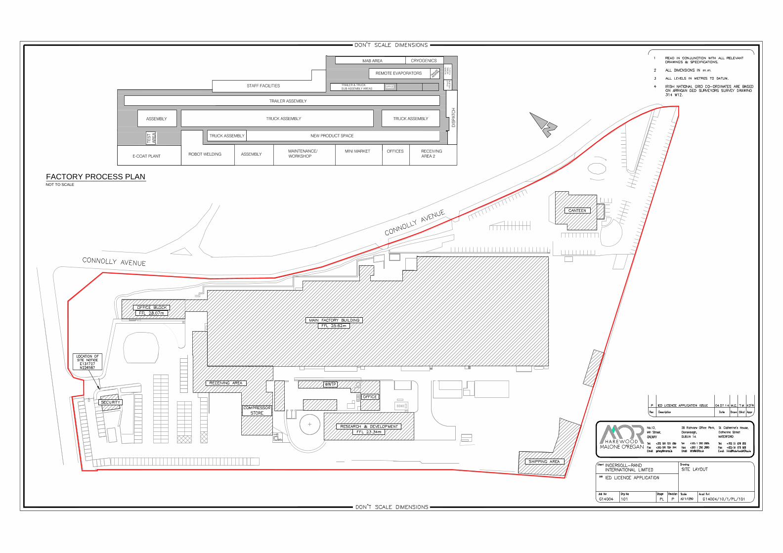
MAINTENANCE/WORKSHOP
TRAILER & TRUCKSUB ASSEMBLY AREAS
FACTORY PROCESS PLANNOT TO SCALE

Attachmment K.3
MA
LO
NE
O’R
EG
AN
June 2014
13, Mill Street, Galway.
Tel: +353 91 531069 Fax :+353 91 564644
e-mail: [email protected]
St. Catherine’s House, Catherine Street,
Waterford.
Tel: +353 51 876855 Fax :+353 51 876828
e-mail: [email protected]
2B Richview Office Park, Clonskeagh, Dublin 14.
Tel: +353 01 2602655 Fax: +353 01 2602660
e-mail: [email protected]
Ingersoll-Rand International Limited,
Monivea Road Mervue Galway
Closure, Restoration and Aftercare Management Plan
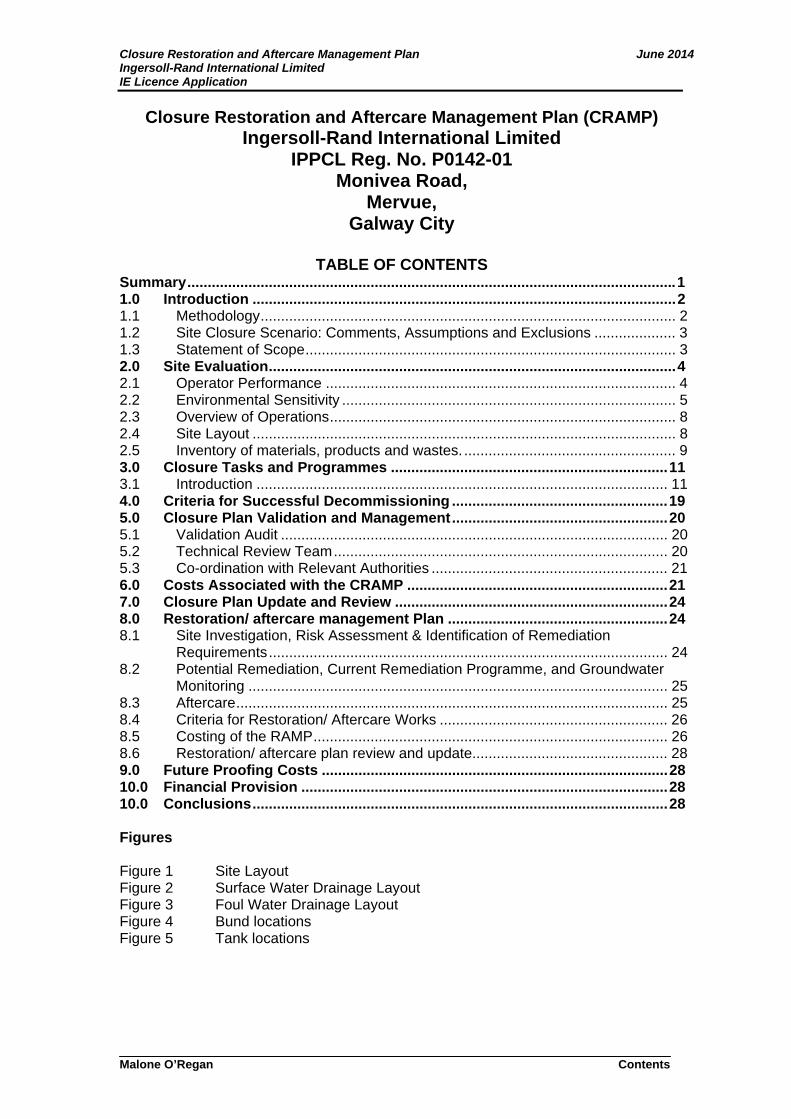
Closure Restoration and Aftercare Management Plan June 2014 Ingersoll-Rand International Limited IE Licence Application
Malone O’Regan Contents
Closure Restoration and Aftercare Management Plan (CRAMP) Ingersoll-Rand International Limited
IPPCL Reg. No. P0142-01 Monivea Road,
Mervue, Galway City
TABLE OF CONTENTS
Summary ........................................................................................................................ 1 1.0 Introduction ........................................................................................................ 2 1.1 Methodology ...................................................................................................... 2 1.2 Site Closure Scenario: Comments, Assumptions and Exclusions .................... 3 1.3 Statement of Scope ........................................................................................... 3 2.0 Site Evaluation .................................................................................................... 4 2.1 Operator Performance ...................................................................................... 4 2.2 Environmental Sensitivity .................................................................................. 5 2.3 Overview of Operations ..................................................................................... 8 2.4 Site Layout ........................................................................................................ 8 2.5 Inventory of materials, products and wastes. .................................................... 9 3.0 Closure Tasks and Programmes .................................................................... 11 3.1 Introduction ..................................................................................................... 11 4.0 Criteria for Successful Decommissioning ..................................................... 19 5.0 Closure Plan Validation and Management ..................................................... 20 5.1 Validation Audit ............................................................................................... 20 5.2 Technical Review Team .................................................................................. 20 5.3 Co-ordination with Relevant Authorities .......................................................... 21 6.0 Costs Associated with the CRAMP ................................................................ 21 7.0 Closure Plan Update and Review ................................................................... 24 8.0 Restoration/ aftercare management Plan ...................................................... 24 8.1 Site Investigation, Risk Assessment & Identification of Remediation
Requirements .................................................................................................. 24 8.2 Potential Remediation, Current Remediation Programme, and Groundwater
Monitoring ....................................................................................................... 25 8.3 Aftercare .......................................................................................................... 25 8.4 Criteria for Restoration/ Aftercare Works ........................................................ 26 8.5 Costing of the RAMP ....................................................................................... 26 8.6 Restoration/ aftercare plan review and update................................................ 28 9.0 Future Proofing Costs ..................................................................................... 28 10.0 Financial Provision .......................................................................................... 28 10.0 Conclusions ...................................................................................................... 28 Figures Figure 1 Site Layout Figure 2 Surface Water Drainage Layout Figure 3 Foul Water Drainage Layout Figure 4 Bund locations Figure 5 Tank locations
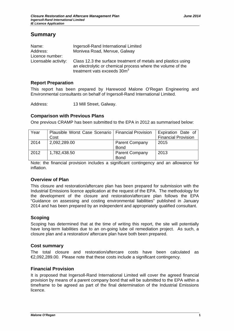
Closure Restoration and Aftercare Management Plan June 2014 Ingersoll-Rand International Limited IE Licence Application
Malone O’Regan 1
Summary Name: Ingersoll-Rand International Limited Address: Monivea Road, Mervue, Galway Licence number: Licensable activity: Class 12.3 the surface treatment of metals and plastics using an electrolytic or chemical process where the volume of the treatment vats exceeds 30m3
Report Preparation This report has been prepared by Harewood Malone O’Regan Engineering and Environmental consultants on behalf of Ingersoll-Rand International Limited. Address: 13 Mill Street, Galway. Comparison with Previous Plans One previous CRAMP has been submitted to the EPA in 2012 as summarised below: Year Plausible Worst Case Scenario
Cost Financial Provision Expiration Date of
Financial Provision 2014 2,092,289.00 Parent Company
Bond 2015
2012 1,782,438.50 Parent Company Bond
2013
Note: the financial provision includes a significant contingency and an allowance for inflation. Overview of Plan This closure and restoration/aftercare plan has been prepared for submission with the Industrial Emissions licence application at the request of the EPA. The methodology for the development of the closure and restoration/aftercare plan follows the EPA “Guidance on assessing and costing environmental liabilities” published in January 2014 and has been prepared by an independent and appropriately qualified consultant. Scoping Scoping has determined that at the time of writing this report, the site will potentially have long-term liabilities due to an on-going lube oil remediation project. As such, a closure plan and a restoration/ aftercare plan have both been prepared. Cost summary The total closure and restoration/aftercare costs have been calculated as €2,092,289.00. Please note that these costs include a significant contingency. Financial Provision It is proposed that Ingersoll-Rand International Limited will cover the agreed financial provision by means of a parent company bond that will be submitted to the EPA within a timeframe to be agreed as part of the final determination of the Industrial Emissions licence.

Closure Restoration and Aftercare Management Plan June 2014 Ingersoll-Rand International Limited IE Licence Application
Malone O’Regan 2
1.0 Introduction Ingersoll-Rand International Limited (IR) is currently in the process of applying for an Industrial Emissions (IE) License from the Environmental Protection Agency (EPA) for its facility located on Monivea Road, Galway City. IR have been testing a new, more environmentally friendly coating process called e-coat. Following extensive testing the process has proved successful and IR wish to bring it into full production. This process will fall under class of activity 12.3:
The surface treatment of metals and plastic materials using an electrolytic or chemical process where the volume of the treatment vat exceeds 30m3
This report has been prepared to satisfy an EPA request to update both the Environmental Liabilities Risk Assessment (ELRA) and the Closure, Restoration and Aftercare Management Plan (CRAMP) as part of the licence application in order to take into account new EPA Guidance and the new e-coat process. A financial provision (FP) was agreed with the OEE for the facility in 2012. The ELRA has been prepared as a separate document although the FP requirements for the known liabilities set out in the ELRA are included in the summary of this report.
1.1 Methodology This assessment has been completed in accordance with the EPA’s “Guidance on assessing and costing Environmental Liabilities” published in January 2014. This report was also based on available information supplied by IR. Furthermore, the following documents or websites were consulted:
• Occupational Health & Safety Manual and Statement, 2012; • Summary Report on Lubricant Oil Remediation Works, ERM, June 2007; • Lube Oil Remediation Project Update Report, MOR 2014; • Bund Integrity Test Results, 2014; • Well Monitoring, Biospheric Engineering, August 2011; • EPA Envision Mapping System; www.envision.ie; • GSI website; www.gsi.ie; • EPA Inspector’s Report, 1997; • Previous CRAMP report for IR, MOR 2012; and, • Standard IR Operating Procedures for various processes.
Harewood Malone O’Regan (MOR) have been working closely with IR for a number of years and as such are very familiar with the site processes and associated risks. Specific site visits were undertaken by MOR personnel in regards to the ELRA and CRAMP on 6th March 2014 and 13th May 2014 respectively. The following personnel provided information and assisted in the identification of risks inherent to historic and existing activities carried out at the facility:
• Tim Folan, Environmental Officer; • John Fox, Transport Solutions ISC North America & EMEA; • Vincent Moran, Facilities Manager, and, • Ciaran Ryan, Manufacturing Engineer, EHS department.
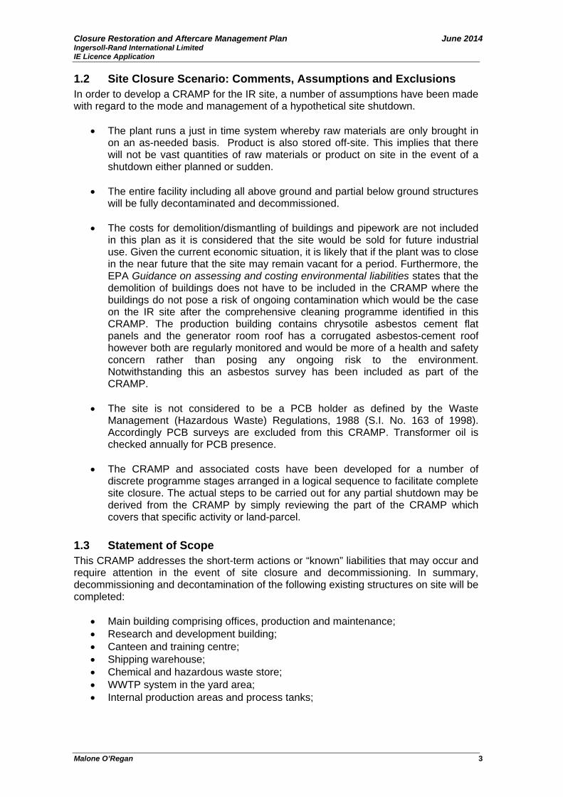
Closure Restoration and Aftercare Management Plan June 2014 Ingersoll-Rand International Limited IE Licence Application
Malone O’Regan 3
1.2 Site Closure Scenario: Comments, Assumptions and Exclusions In order to develop a CRAMP for the IR site, a number of assumptions have been made with regard to the mode and management of a hypothetical site shutdown.
• The plant runs a just in time system whereby raw materials are only brought in on an as-needed basis. Product is also stored off-site. This implies that there will not be vast quantities of raw materials or product on site in the event of a shutdown either planned or sudden.
• The entire facility including all above ground and partial below ground structures will be fully decontaminated and decommissioned.
• The costs for demolition/dismantling of buildings and pipework are not included
in this plan as it is considered that the site would be sold for future industrial use. Given the current economic situation, it is likely that if the plant was to close in the near future that the site may remain vacant for a period. Furthermore, the EPA Guidance on assessing and costing environmental liabilities states that the demolition of buildings does not have to be included in the CRAMP where the buildings do not pose a risk of ongoing contamination which would be the case on the IR site after the comprehensive cleaning programme identified in this CRAMP. The production building contains chrysotile asbestos cement flat panels and the generator room roof has a corrugated asbestos-cement roof however both are regularly monitored and would be more of a health and safety concern rather than posing any ongoing risk to the environment. Notwithstanding this an asbestos survey has been included as part of the CRAMP.
• The site is not considered to be a PCB holder as defined by the Waste
Management (Hazardous Waste) Regulations, 1988 (S.I. No. 163 of 1998). Accordingly PCB surveys are excluded from this CRAMP. Transformer oil is checked annually for PCB presence.
• The CRAMP and associated costs have been developed for a number of
discrete programme stages arranged in a logical sequence to facilitate complete site closure. The actual steps to be carried out for any partial shutdown may be derived from the CRAMP by simply reviewing the part of the CRAMP which covers that specific activity or land-parcel.
1.3 Statement of Scope This CRAMP addresses the short-term actions or “known” liabilities that may occur and require attention in the event of site closure and decommissioning. In summary, decommissioning and decontamination of the following existing structures on site will be completed:
• Main building comprising offices, production and maintenance; • Research and development building; • Canteen and training centre; • Shipping warehouse; • Chemical and hazardous waste store; • WWTP system in the yard area; • Internal production areas and process tanks;

Closure Restoration and Aftercare Management Plan June 2014 Ingersoll-Rand International Limited IE Licence Application
Malone O’Regan 4
• Refrigerant Tanks, Mark Gas Oil (MGO) Tanks, Light Fuel Oil (LFO) Tank, Lube Oil Tank Liquefied Petroleum Gas (LPG) Tanks, Argon Tank and Ethylene Glycol Tank;
• Pipelines, sumps and bunds; and, • Auxiliary equipment including boilers, generators process water softening,
transformers, fire sprinkler system and maintenance equipment. The CRAMP includes a conservative provision of additional operation of the existing (or an alternative) remediation programme.
2.0 Site Evaluation Location & Past Usage IR operates a manufacturing facility for trailer mounted refrigeration units at a plant on Mervue Road, less than 1km from the centre of Galway City. The facility is located in a mixed use area with residential, educational, commercial and industrial uses in the immediate vicinity. The plant has produced trailer mounted refrigerator units on-site since 1976. Currently two types of units are produced at the plant for large trailers and secondly for smaller trucks at rates of 60 and 35 units per day respectively. The facility employs approximately 500 staff members. Prior to 1976, the site was occupied by Potez from the 1960’s when it was first developed from a Greenfield site. This company produced home heating units on the site. 2.1 Operator Performance IR operated a strict environmental management system (EMS) which is ISO 14001 accredited. Compliance The facility has not had any recent OEE inspections resulting in non-compliances. Furthermore, no non-compliances have been recorded regarding emissions from the facility during 2013 or the first quarter of 2014. A remediation project has been on-going on site since 2002 as described below. Historic activities on the site since the 1960’s when the site was developed from a greenfield site may also have impacted on soil and groundwater although there is no evidence as such from records held by the company. IR completed a due diligence prior to purchasing the site. Remediation Programme A groundwater remediation project is currently ongoing at the site that is addressing a historic lube oil spill that was first identified in 2002. It is understood that a release of lubricating oil first became apparent in February 2002 when lube oil was observed at the base of the LPG storage tank in the R&D area of the site. Subsequent investigations confirmed that the source of this leak was a lubricating oil junction pipe that had leaked at the corner of the R&D building near the footpath. It is reported that the source of the oil leak was stopped on the 7th February 2002. Significant investment has been made by IR in relation to investigative and remedial works associated with the lube oil leak. Comprehensive site investigations works have

Closure Restoration and Aftercare Management Plan June 2014 Ingersoll-Rand International Limited IE Licence Application
Malone O’Regan 5
been undertaken at the site in order to develop a representative conceptual site model for the site. The key findings of these works were that the hydrocarbon plume is broadly confined to the south eastern corner of the site. A Quantitative Risk Assessment determined that there was no risk to human health or environmental receptors. Furthermore based on groundwater monitoring data collected in April 2014 there is no evidence of any current offsite impacts. Remedial measures commenced immediately following the identification of the incident with the implementation of emergency response measures that resulted in the recovery of approximately 1,500L mobile free product. Following the completion of the site investigation and risk assessment works, a detailed remediation design was completed that incorporated the installation of a series of hydrocarbon recovery trenches and sumps. The remedial works implemented to-date have been effective in collecting over 6,300L and are still ongoing. Since the outset, all remediation works have been undertaken in close collaboration with the Environmental Protection Agency (EPA). In this regard IR have recently initiated a complete review of the current EPA approved remediation design to determine whether there are supplementary measures that could be implemented to improve the efficiency of the free phase recovery operations and thereby expedite the completion of the remediation works. This review is being undertaken under the direction of the Office of Environmental Enforcement (OEE) and any proposed improvements to the remediation design will be agreed in advance with the OEE. It should be noted that for the purpose of this licence application an extremely conservative view has been undertaken in regards to calculating the costs associated with these ongoing remediation works in the financial provision in order to facilitate streamlining the licence application process. Hence it is considered that the benefit that will be gained from the current review of the remediation design will lead to a more definitive timeframe for the completion of remediation works. 2.2 Environmental Sensitivity Factors affecting the environmental sensitivity of the site are outlined in Table 1. It should be noted that individual sensitivities have been addressed as part of the IE licence application. Specifically the following have been addressed in more detail as part of the IE licence application:
• Baseline ground/groundwater; • Ground/groundwater impact assessment; • Impact on sewers; • Impact on surface water; • Stage I Appropriate Assessment Screening; • Air quality impact assessment; and, • Noise impact assessment.
IR has not completed an AER and PRTR for 2013 as this was not required. As such an RBME cannot be completed. In the absence of an RMBE score the previous EPA guidance (EPA, 2006) has been used to determine the environmental sensitivity of the site. This will be revised to take into account the new guidance once the first RBME has been completed as part of the new IE licence.

Closure Restoration and Aftercare Management Plan June 2014 Ingersoll-Rand International Limited IE Licence Application
Malone O’Regan 6
Table 1 Environmental Sensitivity Factor Score Human Occupation - <50m 5 Groundwater Protection
- Overlying Regionally Important Karst Aquifer - Groundwater vulnerability – high to extreme
2 3
Sensitivity of Receiving Water - Corrib Estuary and the Inner Galway Bay North are classified as
unpolluted, of Good Status and are not nutrient sensitive. - The waters (Corrib Estuary, Lough Atalia and the Inner Galway
Bay North) are not designated as sensitive areas under the UWWT Regulations, 2001.
3
Protected Ecological Sites - Located <1km from site
1
Air Quality and Topography - Simple terrain
0
Sensitive Agricultural Receptors - Fruit, vegetable or dairy farming >150m from site
0
Total Environmental Sensitivity 14 A score of 14 indicates that the facility, in terms of external environmental sensitivity, is classified as high. Therefore the Environmental Sensitivity Classification for the site is high in accordance with Table 2.3 of the 2006 EPA Guidance Note. An inventory of licensed emission points on the site has been compiled. These are listed in Table 2 and Table 3 below: Table 2 Emissions to Sewer
ID Description Easting Northing SE1 Surface water discharge to sewer to the south 131883 226310 SE2 Wastewater discharge to sewer 131827 226475 SE3 Surface water discharge to sewer to the north 131687 226565
The locations and main drainage layouts of these discharge points are shown in drawings 2 and 3. Foul water discharges at SE2 includes industrial wastewater which is pre-treated at the on-site WWTP to comply with ELVs.

Closure Restoration and Aftercare Management Plan June 2014 Ingersoll-Rand International Limited IE Licence Application
Malone O’Regan 7
Table 3 Emissions to Air ID Description Easting Northing A3-1 Foam Hoods 131840 226564 A3-2 Soldering 131912 226472 A3-3 Soldering 131892 226440 A3-4 Touch Up Booth (South) 131941 226422 A3-5 Combined Engine Test 1319921 226446 A3-6 New Truck Test 131916 226435 A3-7 Old Truck Test 131949 226425 A3-8 Varnish Touch Up Booth - Truck Line 1319430 226416 A1-5 Main Canteen Boiler 132027 226428 A1-6 Office Boiler 131803 226577 A3-9 SLX Line Extraction – Evacuation of moisture 131888 226485 A3-10 SLX rework area 131983 226411 A3-11 Soldering on EVAP line 131906 226443 A3-16 Robot No 5 131840 226515 A3-17 Robot No 1 131838 226506 A3-18 Main Robot 131833 226498 A3-19 Manual Weld Booth 131837 226492 A1-12 Chappe Boiler 2 Service Offices 131829 226448 A1-13 E Coat Stage 1 & 2 Burners 131816 226518 A1-14 E Coat Stage 5 Burner 131818 226525 A1-15 E Coat Water Heater 131813 226524 A1-17 New Gas Boiler 1 131930 226480 A1-18 New Gas Boiler 2 131930 226479 A1-19 New Gas Boiler 3 131929 226479 A1-20 New Gas Boiler 4 131928 226478 A1-21 New Gas Boiler 5 131928 226478 A1-22 New Gas Boiler 6 131927 226477 A3-20 E Coat Tank Exhaust # 1 131809 226528 A3-21 E Coat Tank Exhaust # 2 131809 226532 A3-22 E Coat Oven Entrance Exhaust 131796 226542 A1-16 E Coat Oven Exhaust 131796 226533 A3-23 E Coat Oven Exit Air Seal 131807 226527 A3-24 E Coat Booth Exhaust 131825 226515 A3-25 Truck Line Extraction 131912 226448 A3-26 Trailer Test 131929 226446 A3-27 Trailer Test 131916 226452 A3-28 Trailer Touch Up (North) 131945 226427 A3-30 Combined Engine Test 131931 226430 A3-31 Truck Unit Test Exhaust Extraction 131931 226430 A3-33 Truck Unit Test Exhaust Extraction 131916 226435

Closure Restoration and Aftercare Management Plan June 2014 Ingersoll-Rand International Limited IE Licence Application
Malone O’Regan 8
2.3 Overview of Operations The main manufacturing operations currently carried out at the facility are described briefly below. Main Manufacturing Processes The process begins with the delivery of steel and aluminum parts. Fabricated sub components are sent for chemical pre-treatment in an automated spray tunnel which removes any grease or oil residues and treats the metal surfaces to inhibit corrosion damage and prepare for painting. Moisture is removed by ‘dry-off’ oven and the welded chassis are sent to the e-coat process. The e-coat process is an automated electro coating painting process. It involves cleaning, rinsing, zinc coating, sealing, e-coating and drying steps. The components then go to the assembly line where they are fitted with various components. Compressors are then pressurised and units insulated. Components such as engines, compressors, electrical switchgear, wiring and hardware are purchased from many suppliers including a number in Ireland. Returnable crates and stillages to point-of-use are employed as much as possible for suppliers as far away as Japan. The completed units are tested on site before shipping. Most units are shipped with refrigerant sealed in the unit but some more complex units are evacuated of refrigerant prior to shipping. The recovered refrigerant is returned to a storage tank for re-use. Auxiliary Processes The main auxiliary processes include maintenance activities, process water softening, heating of the premises, storage of bulk liquids and gases, chemical storage and treatment of aqueous effluent arising from the e-coat process prior to discharge to the public sewer. 2.4 Site Layout The overall site is laid out into a number of key buildings as follows:
• Main building comprising offices, production and maintenance; • Research and development building; • Canteen and training centre; • Shipping warehouse (no longer used); • Security hut and car-park; • Chemical store, and, • Yard area containing WWTP system.
The site layout is shown on Figure 1.
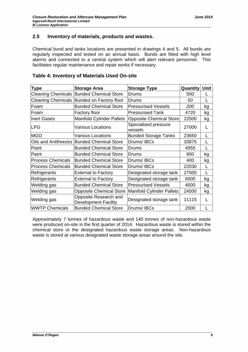
Closure Restoration and Aftercare Management Plan June 2014 Ingersoll-Rand International Limited IE Licence Application
Malone O’Regan 9
2.5 Inventory of materials, products and wastes. Chemical bund and tanks locations are presented in drawings 4 and 5. All bunds are regularly inspected and tested on an annual basis. Bunds are fitted with high level alarms and connected to a central system which will alert relevant personnel. This facilitates regular maintenance and repair works if necessary. Table 4: Inventory of Materials Used On-site
Type Storage Area Storage Type Quantity UnitCleaning Chemicals Bunded Chemical Store Drums 500 L Cleaning Chemicals Bunded on Factory floor Drums 50 L Foam Bunded Chemical Store Pressurised Vessels 200 kg Foam Factory floor Pressurised Tank 4720 kg Inert Gases Manifold Cylinder Pallets Opposite Chemical Store 22500 kg
LPG Various Locations Specialised pressure vessels 27000 L
MGO Various Locations Bunded Storage Tanks 23650 L Oils and Antifreezes Bunded Chemical Store Drums/ IBCs 33875 L Paint Bunded Chemical Store Drums 4955 L Paint Bunded Chemical Store Drums 800 kg Process Chemicals Bunded Chemical Store Drums/ IBCs 400 kg Process Chemicals Bunded Chemical Store Drums/ IBCs 22030 L Refrigerants External to Factory Designated storage tank 27500 L Refrigerants External to Factory Designated storage tank 6000 kg Welding gas Bunded Chemical Store Pressurised Vessels 4000 kg Welding gas Opposite Chemical Store Manifold Cylinder Pallets 24500 kg
Welding gas Opposite Research and Development Facility Designated storage tank 11115 L
WWTP Chemicals Bunded Chemical Store Drums/ IBCs 2000 L Approximately 7 tonnes of hazardous waste and 140 tonnes of non-hazardous waste were produced on-site in the first quarter of 2014. Hazardous waste is stored within the chemical store or the designated hazardous waste storage areas. Non-hazardous waste is stored at various designated waste storage areas around the site.

Closure Restoration and Aftercare Management Plan June 2014 Ingersoll-Rand International Limited IE Licence Application
Malone O’Regan 10
Table 5: Inventory of Hazardous Wastes Produced On-site Waste EWC Waste EWC Containers (Matiflux, Loctite, Lube) 150110Mixture of Paints 80111Absorbent Material 150202Zinc Phosphate Solution 110108Waste Oil 130208Waste Compressor Oil 130208Aerosols 160504Waste Oily Sludge 130208Paint thinners 80111 Liquid Aqueous Waste 161001Filter Cake (e-coat) 110109Zinc Phosphate Solution 110108Filter Cake (Salvage Yard) 110109Oil Filters 160107Fluorescent Fibre Glass 200121Antifreeze 130308Medical Waste (Initial Waste) 180103Mixture of Paints 80111Test Kits containing nickel/copper/phosphorus 160506<10% Solution of Sulphuric Acid
and Phosphoric Acid 60106
Waste Compressor Oil 130208 Table 6: Inventory of Non-Hazardous Wastes Produced On-site
Waste EWC Code Waste oil 200125 Food 200108 Refuse Recycling 200301 Office Paper 200101 Cardboard 150101 Mixed Plastic 150102 Shoes 200110 Rubber 150102 SRF (Refuse derived fuel) 191210 Metals 200140 Timber 150103
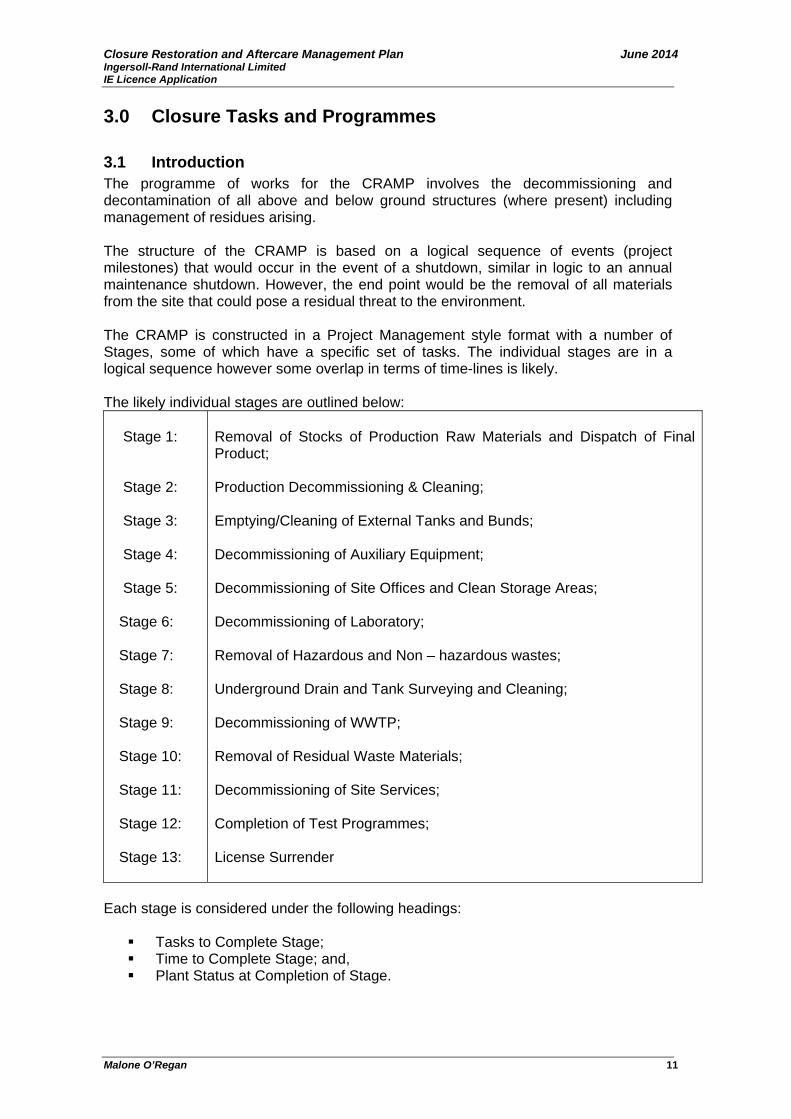
Closure Restoration and Aftercare Management Plan June 2014 Ingersoll-Rand International Limited IE Licence Application
Malone O’Regan 11
3.0 Closure Tasks and Programmes 3.1 Introduction The programme of works for the CRAMP involves the decommissioning and decontamination of all above and below ground structures (where present) including management of residues arising. The structure of the CRAMP is based on a logical sequence of events (project milestones) that would occur in the event of a shutdown, similar in logic to an annual maintenance shutdown. However, the end point would be the removal of all materials from the site that could pose a residual threat to the environment. The CRAMP is constructed in a Project Management style format with a number of Stages, some of which have a specific set of tasks. The individual stages are in a logical sequence however some overlap in terms of time-lines is likely. The likely individual stages are outlined below:
Stage 1:
Stage 2:
Stage 3: Stage 4: Stage 5:
Stage 6:
Stage 7:
Stage 8:
Stage 9: Stage 10: Stage 11: Stage 12: Stage 13:
Removal of Stocks of Production Raw Materials and Dispatch of Final Product; Production Decommissioning & Cleaning; Emptying/Cleaning of External Tanks and Bunds; Decommissioning of Auxiliary Equipment; Decommissioning of Site Offices and Clean Storage Areas; Decommissioning of Laboratory; Removal of Hazardous and Non – hazardous wastes; Underground Drain and Tank Surveying and Cleaning; Decommissioning of WWTP; Removal of Residual Waste Materials; Decommissioning of Site Services; Completion of Test Programmes; License Surrender
Each stage is considered under the following headings:
Tasks to Complete Stage; Time to Complete Stage; and, Plant Status at Completion of Stage.
Closure Restoration and Aftercare Management Plan June 2014 Ingersoll-Rand International Limited IE Licence Application
Malone O’Regan 12
Stage 1: Removal of Stocks of Production Raw Materials and Dispatch of Final Product Where possible, production and ancillary raw materials and product will be run down to minimise the requirement for waste disposal. In order to achieve this however, the rundown of the plant would have to be pre-planned. However in the unlikely event of sudden closure there still would be low levels of production raw material and product on site due to the “just in time” stock control measures in place. Task 1 Dispatch of finished product from final production runs In the event of a known closure all products will be dispatched as it is produced in line with normal production scheduling. In the event of a sudden closure, only product produced in one day will remain on-site. This could easily be shipped to the distributor. Task 2 Production Raw Materials Production raw material purchase is already planned on a schedule directly related to the production schedule. In the event of a planned shutdown, incoming stocks of raw materials including chemicals, paints and gases used in production processes can be reduced accordingly and any stock remaining will be transferred to the plant as a raw material. Any remaining raw materials in stock after the plant has ceased production or in the event of a sudden closure will be sent back to the supplier or sold within the industry for appropriate reuse. Task 3 Laboratory Chemicals The onsite laboratory is used for quality control purposes. Only small amounts of chemicals are stored in the lab. Where possible, any remaining chemicals in stock (if any) after the plant has ceased production will be sent back to the supplier. Any remaining quantities will be transferred to UN-approved containers, labelled and removed by an approved licensed contractor. Time to Complete A period of 6 weeks to document, compile inventory lists and arrange transport from the site is estimated. Plant Status at Completion of Stage 1 All production raw materials and finished products will be removed off site at the end of Stage 1. Stage 2: Production Decommissioning & Cleaning This stage may be applied to the following main unit operations that occur within the production building. Task 1: Production Process Shutdown Completion of the production process steps will be carried out where possible and all equipment isolated from power supply. All pumps which drive chemicals/paint from one process area to the other will be disabled to ensure that process lines/pipelines are no longer conveying materials.
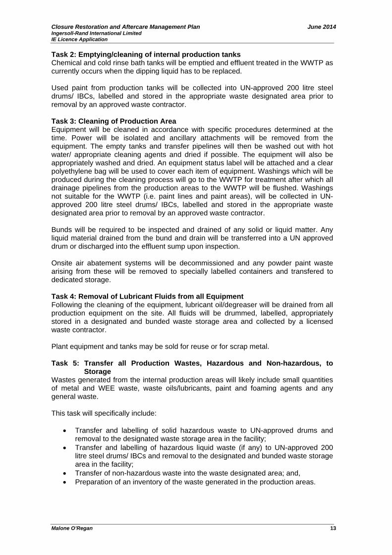
Closure Restoration and Aftercare Management Plan June 2014 Ingersoll-Rand International Limited IE Licence Application
Malone O’Regan 13
Task 2: Emptying/cleaning of internal production tanks Chemical and cold rinse bath tanks will be emptied and effluent treated in the WWTP as currently occurs when the dipping liquid has to be replaced. Used paint from production tanks will be collected into UN-approved 200 litre steel drums/ IBCs, labelled and stored in the appropriate waste designated area prior to removal by an approved waste contractor. Task 3: Cleaning of Production Area Equipment will be cleaned in accordance with specific procedures determined at the time. Power will be isolated and ancillary attachments will be removed from the equipment. The empty tanks and transfer pipelines will then be washed out with hot water/ appropriate cleaning agents and dried if possible. The equipment will also be appropriately washed and dried. An equipment status label will be attached and a clear polyethylene bag will be used to cover each item of equipment. Washings which will be produced during the cleaning process will go to the WWTP for treatment after which all drainage pipelines from the production areas to the WWTP will be flushed. Washings not suitable for the WWTP (i.e. paint lines and paint areas), will be collected in UN-approved 200 litre steel drums/ IBCs, labelled and stored in the appropriate waste designated area prior to removal by an approved waste contractor. Bunds will be required to be inspected and drained of any solid or liquid matter. Any liquid material drained from the bund and drain will be transferred into a UN approved drum or discharged into the effluent sump upon inspection. Onsite air abatement systems will be decommissioned and any powder paint waste arising from these will be removed to specially labelled containers and transfered to dedicated storage. Task 4: Removal of Lubricant Fluids from all Equipment Following the cleaning of the equipment, lubricant oil/degreaser will be drained from all production equipment on the site. All fluids will be drummed, labelled, appropriately stored in a designated and bunded waste storage area and collected by a licensed waste contractor. Plant equipment and tanks may be sold for reuse or for scrap metal. Task 5: Transfer all Production Wastes, Hazardous and Non-hazardous, to
Storage Wastes generated from the internal production areas will likely include small quantities of metal and WEE waste, waste oils/lubricants, paint and foaming agents and any general waste. This task will specifically include:
• Transfer and labelling of solid hazardous waste to UN-approved drums and removal to the designated waste storage area in the facility;
• Transfer and labelling of hazardous liquid waste (if any) to UN-approved 200 litre steel drums/ IBCs and removal to the designated and bunded waste storage area in the facility;
• Transfer of non-hazardous waste into the waste designated area; and, • Preparation of an inventory of the waste generated in the production areas.
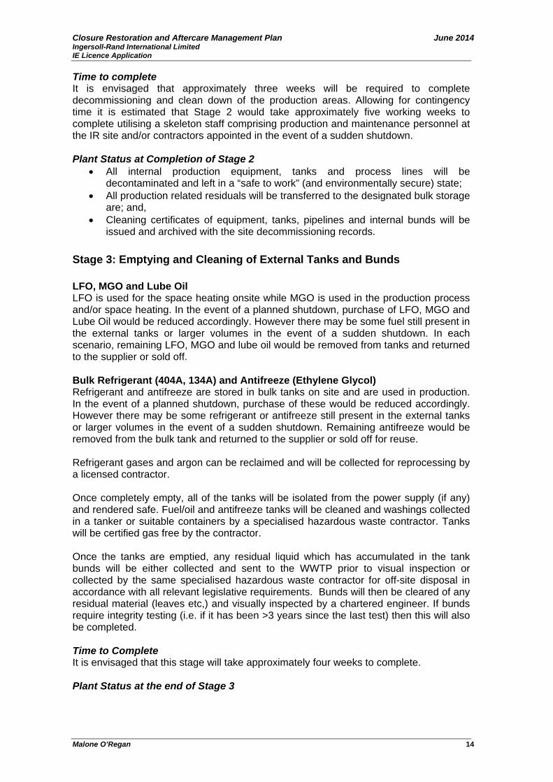
Closure Restoration and Aftercare Management Plan June 2014 Ingersoll-Rand International Limited IE Licence Application
Malone O’Regan 14
Time to complete It is envisaged that approximately three weeks will be required to complete decommissioning and clean down of the production areas. Allowing for contingency time it is estimated that Stage 2 would take approximately five working weeks to complete utilising a skeleton staff comprising production and maintenance personnel at the IR site and/or contractors appointed in the event of a sudden shutdown. Plant Status at Completion of Stage 2
• All internal production equipment, tanks and process lines will be decontaminated and left in a “safe to work” (and environmentally secure) state;
• All production related residuals will be transferred to the designated bulk storage are; and,
• Cleaning certificates of equipment, tanks, pipelines and internal bunds will be issued and archived with the site decommissioning records.
Stage 3: Emptying and Cleaning of External Tanks and Bunds LFO, MGO and Lube Oil LFO is used for the space heating onsite while MGO is used in the production process and/or space heating. In the event of a planned shutdown, purchase of LFO, MGO and Lube Oil would be reduced accordingly. However there may be some fuel still present in the external tanks or larger volumes in the event of a sudden shutdown. In each scenario, remaining LFO, MGO and lube oil would be removed from tanks and returned to the supplier or sold off. Bulk Refrigerant (404A, 134A) and Antifreeze (Ethylene Glycol) Refrigerant and antifreeze are stored in bulk tanks on site and are used in production. In the event of a planned shutdown, purchase of these would be reduced accordingly. However there may be some refrigerant or antifreeze still present in the external tanks or larger volumes in the event of a sudden shutdown. Remaining antifreeze would be removed from the bulk tank and returned to the supplier or sold off for reuse. Refrigerant gases and argon can be reclaimed and will be collected for reprocessing by a licensed contractor. Once completely empty, all of the tanks will be isolated from the power supply (if any) and rendered safe. Fuel/oil and antifreeze tanks will be cleaned and washings collected in a tanker or suitable containers by a specialised hazardous waste contractor. Tanks will be certified gas free by the contractor. Once the tanks are emptied, any residual liquid which has accumulated in the tank bunds will be either collected and sent to the WWTP prior to visual inspection or collected by the same specialised hazardous waste contractor for off-site disposal in accordance with all relevant legislative requirements. Bunds will then be cleared of any residual material (leaves etc,) and visually inspected by a chartered engineer. If bunds require integrity testing (i.e. if it has been >3 years since the last test) then this will also be completed. Time to Complete It is envisaged that this stage will take approximately four weeks to complete. Plant Status at the end of Stage 3
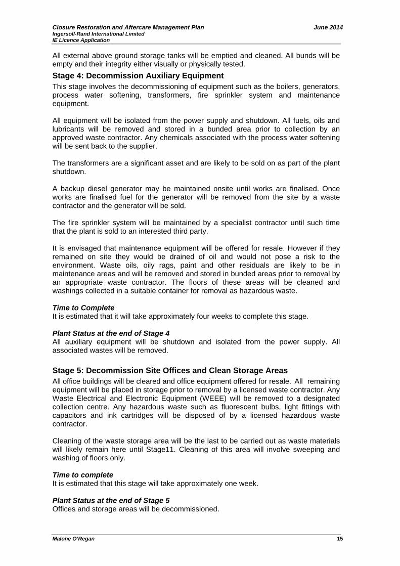
Closure Restoration and Aftercare Management Plan June 2014 Ingersoll-Rand International Limited IE Licence Application
Malone O’Regan 15
All external above ground storage tanks will be emptied and cleaned. All bunds will be empty and their integrity either visually or physically tested. Stage 4: Decommission Auxiliary Equipment This stage involves the decommissioning of equipment such as the boilers, generators, process water softening, transformers, fire sprinkler system and maintenance equipment. All equipment will be isolated from the power supply and shutdown. All fuels, oils and lubricants will be removed and stored in a bunded area prior to collection by an approved waste contractor. Any chemicals associated with the process water softening will be sent back to the supplier. The transformers are a significant asset and are likely to be sold on as part of the plant shutdown. A backup diesel generator may be maintained onsite until works are finalised. Once works are finalised fuel for the generator will be removed from the site by a waste contractor and the generator will be sold. The fire sprinkler system will be maintained by a specialist contractor until such time that the plant is sold to an interested third party. It is envisaged that maintenance equipment will be offered for resale. However if they remained on site they would be drained of oil and would not pose a risk to the environment. Waste oils, oily rags, paint and other residuals are likely to be in maintenance areas and will be removed and stored in bunded areas prior to removal by an appropriate waste contractor. The floors of these areas will be cleaned and washings collected in a suitable container for removal as hazardous waste. Time to Complete It is estimated that it will take approximately four weeks to complete this stage. Plant Status at the end of Stage 4 All auxiliary equipment will be shutdown and isolated from the power supply. All associated wastes will be removed. Stage 5: Decommission Site Offices and Clean Storage Areas All office buildings will be cleared and office equipment offered for resale. All remaining equipment will be placed in storage prior to removal by a licensed waste contractor. Any Waste Electrical and Electronic Equipment (WEEE) will be removed to a designated collection centre. Any hazardous waste such as fluorescent bulbs, light fittings with capacitors and ink cartridges will be disposed of by a licensed hazardous waste contractor. Cleaning of the waste storage area will be the last to be carried out as waste materials will likely remain here until Stage11. Cleaning of this area will involve sweeping and washing of floors only. Time to complete It is estimated that this stage will take approximately one week. Plant Status at the end of Stage 5 Offices and storage areas will be decommissioned.
Closure Restoration and Aftercare Management Plan June 2014 Ingersoll-Rand International Limited IE Licence Application
Malone O’Regan 16
Stage 6: Decommissioning of Laboratory All equipment in the laboratories will be cleaned with reagent grade water and decontaminated in accordance with laboratory cleaning procedures. The laboratories will be cleared and equipment offered for sale. Any remaining equipment which is classed as waste will be placed in storage prior to removal by a licensed waste contractor. Unused chemicals will be returned to the supplier. Any electrical equipment which is not offered for resale will be disposed as WEEE at a designated collection centre. Time to Complete This stage is estimated to take 2-3 days. Plant status at the end of Stage 6 The laboratories will be decommissioned and any remaining chemicals returned to the supplier. Stage 7: Removal of Hazardous and Non – hazardous Wastes All materials considered waste, either hazardous or non hazardous, will have been stored in a designated storage area during the decommissioning process. Waste materials present may include raw materials that cannot be returned to the supplier, used in the facility or sold to a third party. All requirements of relevant Waste Management legislation will be considered and all waste contractors will be agreed with the EPA. Stage 7 will include the following tasks:
• Administrative organisation of shipments; • Removal of the waste in accordance with appropriate National and EU
Legislation; and, • Administrative organisation of relevant paper work. All waste shipments during
this period will be documented according to EPA Guidelines.
This will facilitate the requirements of the stated criteria for proper decommissioning in Section 4.0 above. Time to Complete This stage will be carried out in parallel to the decommissioning stages. As the storage areas receive waste to be disposed, licensed waste disposal contractors shall remove waste for reuse, recycling, recovery or disposal. Plant status at the end of Stage 7 All hazardous and non hazardous waste stored on site will be removed. Stage 8: Underground Drain Surveying and Cleaning In order to return the site to the required standard, there is a requirement to clean the on-site drainage system. This will involve the use of a specialist contractor who will utilise mobile CCTV cameras to survey the underground foul pipeline system. It is recommended that cleaning and surveying run in parallel, so that any blockages detected by the camera can be cleared promptly. Any residual material present in the foul drains will be conveyed to the WWTP. The drain survey will also identify any
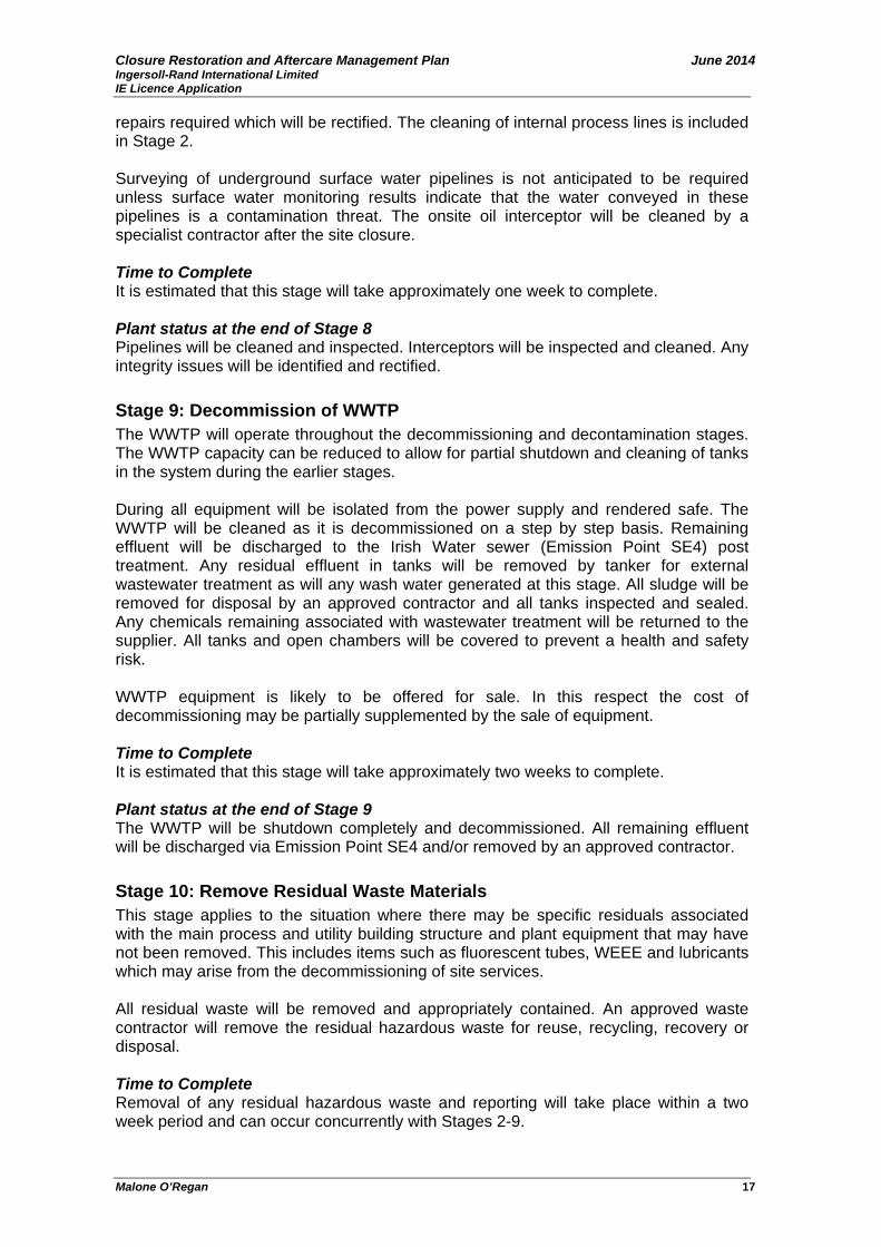
Closure Restoration and Aftercare Management Plan June 2014 Ingersoll-Rand International Limited IE Licence Application
Malone O’Regan 17
repairs required which will be rectified. The cleaning of internal process lines is included in Stage 2. Surveying of underground surface water pipelines is not anticipated to be required unless surface water monitoring results indicate that the water conveyed in these pipelines is a contamination threat. The onsite oil interceptor will be cleaned by a specialist contractor after the site closure. Time to Complete It is estimated that this stage will take approximately one week to complete. Plant status at the end of Stage 8 Pipelines will be cleaned and inspected. Interceptors will be inspected and cleaned. Any integrity issues will be identified and rectified. Stage 9: Decommission of WWTP The WWTP will operate throughout the decommissioning and decontamination stages. The WWTP capacity can be reduced to allow for partial shutdown and cleaning of tanks in the system during the earlier stages. During all equipment will be isolated from the power supply and rendered safe. The WWTP will be cleaned as it is decommissioned on a step by step basis. Remaining effluent will be discharged to the Irish Water sewer (Emission Point SE4) post treatment. Any residual effluent in tanks will be removed by tanker for external wastewater treatment as will any wash water generated at this stage. All sludge will be removed for disposal by an approved contractor and all tanks inspected and sealed. Any chemicals remaining associated with wastewater treatment will be returned to the supplier. All tanks and open chambers will be covered to prevent a health and safety risk. WWTP equipment is likely to be offered for sale. In this respect the cost of decommissioning may be partially supplemented by the sale of equipment. Time to Complete It is estimated that this stage will take approximately two weeks to complete. Plant status at the end of Stage 9 The WWTP will be shutdown completely and decommissioned. All remaining effluent will be discharged via Emission Point SE4 and/or removed by an approved contractor. Stage 10: Remove Residual Waste Materials This stage applies to the situation where there may be specific residuals associated with the main process and utility building structure and plant equipment that may have not been removed. This includes items such as fluorescent tubes, WEEE and lubricants which may arise from the decommissioning of site services. All residual waste will be removed and appropriately contained. An approved waste contractor will remove the residual hazardous waste for reuse, recycling, recovery or disposal. Time to Complete Removal of any residual hazardous waste and reporting will take place within a two week period and can occur concurrently with Stages 2-9.

Closure Restoration and Aftercare Management Plan June 2014 Ingersoll-Rand International Limited IE Licence Application
Malone O’Regan 18
Plant status at the end of Stage 10 No residual hazardous waste will remain on site after completion of Stage 10. Stage 11: Decommissioning of Site Services Disconnection of all site services will be carried out when all the required maintenance and decommissioning works are completed. Time to Complete Utility decommissioning will not start until cleaning of the site and drains has been completed. This stage is estimated to take approximately one week. Plant status at the end of Stage 11 All site utilities, with the exception of limited electrical supply will be effectively decommissioned. Stage 12: Completion of Test Programmes To ensure the decommissioning and cleaning processes are successfully carried out, it is proposed to implement test programmes for the decommissioning of WWTP tanks. Sampling of the final cleaning water from the decommissioning of the wastewater treatment plant tanks will be carried out. Samples will be tested for the parameters specified in the IPPC Licence, i.e. BOD, COD, Fats, Oils and Greases (FOGs), pH, suspended solids, sulphates, nitrates, detergents as MBAS, Total phosphorous, chloride, aluminium, cyanides, tin, copper, nickel, zinc, chromium and total heavy metals. An asbestos survey and air monitoring will also be carried out at this stage. Time to Complete This stage will be carried out during stages 3 and 11. Plant status at the end of Stage 12 At the end of Stage 12 the test programmes for the WWTP will be completed. Stage 13: License Surrender Throughout the implementation of the CRAMP, documentation will be prepared and completed at the end of each stage to track the progress of the ‘clean closure’ of the site. All residues removed from the site will be recorded and final disposal certificates will be prepared. Once the aftercare programme, as outlined in section 8.0, has been completed to the satisfaction of the EPA, an application will be made for surrender of the license.
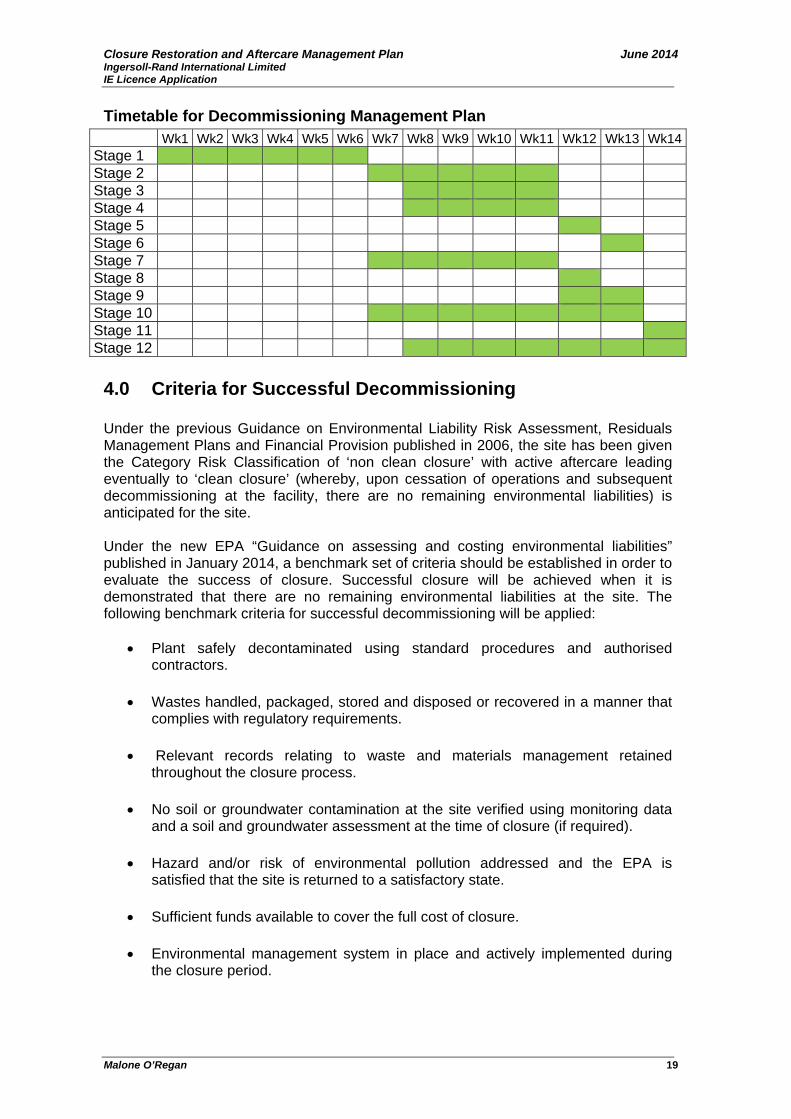
Closure Restoration and Aftercare Management Plan June 2014 Ingersoll-Rand International Limited IE Licence Application
Malone O’Regan 19
Timetable for Decommissioning Management Plan Wk1 Wk2 Wk3 Wk4 Wk5 Wk6 Wk7 Wk8 Wk9 Wk10 Wk11 Wk12 Wk13 Wk14Stage 1 Stage 2 Stage 3 Stage 4 Stage 5 Stage 6 Stage 7 Stage 8 Stage 9 Stage 10 Stage 11 Stage 12
4.0 Criteria for Successful Decommissioning
Under the previous Guidance on Environmental Liability Risk Assessment, Residuals Management Plans and Financial Provision published in 2006, the site has been given the Category Risk Classification of ‘non clean closure’ with active aftercare leading eventually to ‘clean closure’ (whereby, upon cessation of operations and subsequent decommissioning at the facility, there are no remaining environmental liabilities) is anticipated for the site. Under the new EPA “Guidance on assessing and costing environmental liabilities” published in January 2014, a benchmark set of criteria should be established in order to evaluate the success of closure. Successful closure will be achieved when it is demonstrated that there are no remaining environmental liabilities at the site. The following benchmark criteria for successful decommissioning will be applied:
• Plant safely decontaminated using standard procedures and authorised contractors.
• Wastes handled, packaged, stored and disposed or recovered in a manner that
complies with regulatory requirements.
• Relevant records relating to waste and materials management retained throughout the closure process.
• No soil or groundwater contamination at the site verified using monitoring data and a soil and groundwater assessment at the time of closure (if required).
• Hazard and/or risk of environmental pollution addressed and the EPA is
satisfied that the site is returned to a satisfactory state.
• Sufficient funds available to cover the full cost of closure.
• Environmental management system in place and actively implemented during the closure period.
Closure Restoration and Aftercare Management Plan June 2014 Ingersoll-Rand International Limited IE Licence Application
Malone O’Regan 20
5.0 Closure Plan Validation and Management To ensure comprehensive management of the CRAMP as it progresses, it is envisaged that a technical review team will co-ordinate, supervise and manage the CRAMP and be responsible for its implementation. 5.1 Validation Audit Upon completion of the implementation of the closure plan, the operator will conduct a validation audit to demonstrate to the EPA that the closure plan has been successfully implemented. The qualification and experience of the independent auditor will be provided and agreed with the EPA prior to the validation audit commencing. In addition, the scope of the validation audit will be agreed in advance with the EPA and following approval, the chosen independent auditor will complete the validation audit. The completed validation audit report will be submitted to the EPA for approval. 5.2 Technical Review Team This team will include personnel who will oversee various significant aspects of the CRAMP and will most likely include:
• An environmental management team comprised of contracted environmental specialists who will oversee technical aspects of implementing the CRAMP;
• A financial management team who will oversee costs associated with implementation; and
• An operational management team who have a working knowledge of facility infrastructure and processes.
The selection of team personnel will be conducted by all interested parties prior to the implementation of this CRAMP. The results of the Technical Review Team selection will be supplied to the EPA for approval prior to commencement of the CRAMP. It is envisaged that specialists such as licensed waste disposal companies and drain cleaning and inspection services will be employed for specific tasks. As the CRAMP proceeds to the later stages, it is likely that the team required will reduce to key financial and environmental staff onsite and environmental consultancy service providers. It is expected that in the unlikely event of receivership a similar team would be required.

Closure Restoration and Aftercare Management Plan June 2014 Ingersoll-Rand International Limited IE Licence Application
Malone O’Regan 21
5.3 Co-ordination with Relevant Authorities Prior to commencement of decommissioning, all necessary communications related to the CRAMP implementation will be conducted with the relevant authorities listed below: Environmental Regional Inspectorate Galway City Council, John Moore Road Environment Dept. Castlebar Áras an Chontae Co. Mayo Prospect Hill, Galway, T: 094 9048400 Co. Galway T: 091 476402 Galway City Council Irish Water, Fire Services Breaffy Road, Áras an Chontae Castlebar, Prospect Hill, Galway Co Mayo Co. Galway T: 094 9043318 T: 091 570900
6.0 Costs Associated with the CRAMP The costs associated with the CRAMP are estimated and outlined in Table 7 below.
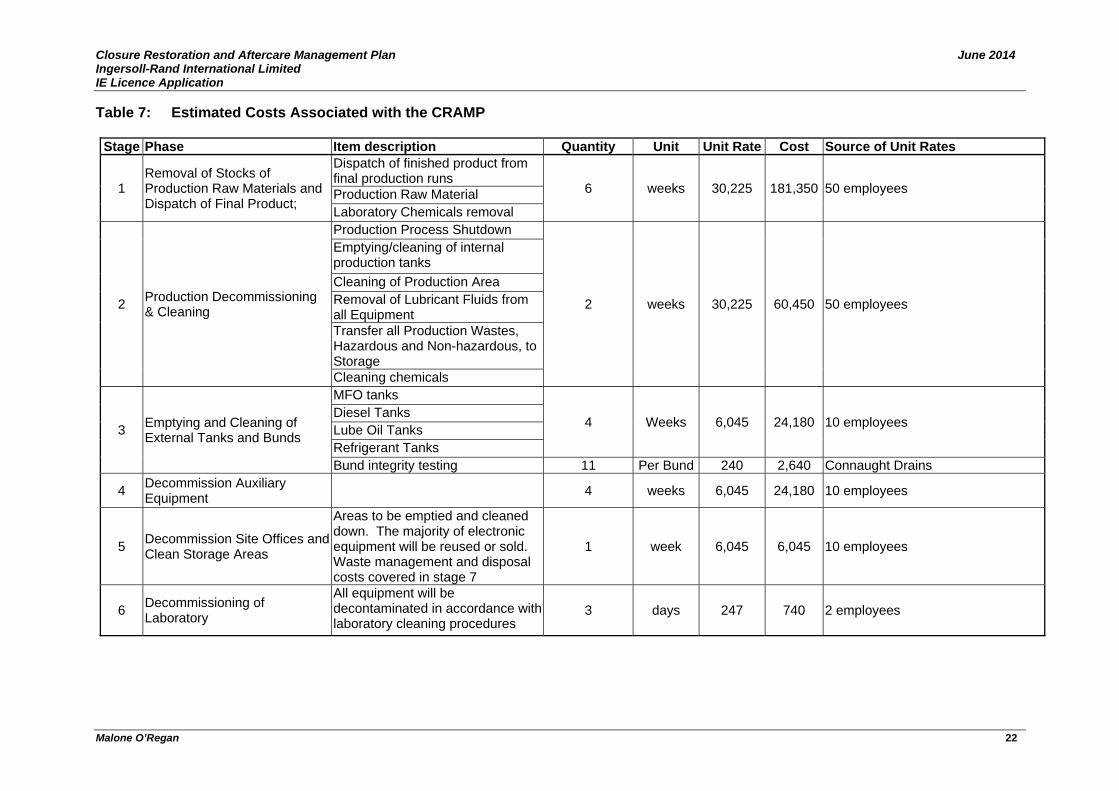
Closure Restoration and Aftercare Management Plan June 2014 Ingersoll-Rand International Limited IE Licence Application
Malone O’Regan 22
Table 7: Estimated Costs Associated with the CRAMP
Stage Phase Item description Quantity Unit Unit Rate Cost Source of Unit Rates
1 Removal of Stocks of Production Raw Materials and Dispatch of Final Product;
Dispatch of finished product from final production runs
6 weeks 30,225 181,350 50 employees Production Raw Material Laboratory Chemicals removal
2 Production Decommissioning & Cleaning
Production Process Shutdown
2 weeks 30,225 60,450 50 employees
Emptying/cleaning of internal production tanks Cleaning of Production Area Removal of Lubricant Fluids from all Equipment Transfer all Production Wastes, Hazardous and Non-hazardous, to Storage Cleaning chemicals
3 Emptying and Cleaning of External Tanks and Bunds
MFO tanks
4 Weeks 6,045 24,180 10 employees Diesel Tanks Lube Oil Tanks Refrigerant Tanks Bund integrity testing 11 Per Bund 240 2,640 Connaught Drains
4 Decommission Auxiliary Equipment
4 weeks 6,045 24,180 10 employees
5 Decommission Site Offices and Clean Storage Areas
Areas to be emptied and cleaned down. The majority of electronic equipment will be reused or sold. Waste management and disposal costs covered in stage 7
1 week 6,045 6,045 10 employees
6 Decommissioning of Laboratory
All equipment will be decontaminated in accordance with laboratory cleaning procedures
3 days 247 740 2 employees
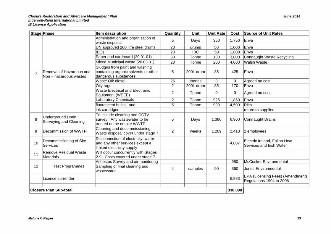
Closure Restoration and Aftercare Management Plan June 2014 Ingersoll-Rand International Limited IE Licence Application
Malone O’Regan 23
Stage Phase Item description Quantity Unit Unit Rate Cost Source of Unit Rates
7 Removal of Hazardous and Non – hazardous wastes
Administration and organisation of waste disposal. 5 Days 350 1,750 Enva
UN approved 200 litre steel drums 20 drums 50 1,000 Enva IBCs 20 IBC 50 1,000 Enva Paper and cardboard (20 01 01) 30 Tonne 100 3,000 Connaught Waste Recycling Mixed Municipal waste (20 03 01) 20 Tonne 200 4,000 Walsh Waste Sludges from paint and washing containing organic solvents or other dangerous substances
5 200L drum 85 425 Enva
Waste Oil/ diesel 25 tonnes 0 0 Agreed no cost Oily rags 2 200L drum 85 170 Enva Waste Electrical and Electronic Equipment (WEEE) 2 Tonne 0 0 Agreed no cost
Laboratory Chemicals 2 Tonne 925 1,850 Enva fluorescent bulbs, and 5 Tonne 900 4,500 Rilta ink cartridges return to supplier
8 Underground Drain Surveying and Cleaning
To include cleaning and CCTV survey. Any wastewater to be treated at the on-site WWTP
5 Days 1,380 6,900 Connaught Drains
9 Decommission of WWTP Cleaning and decommissioning. Waste disposal cover under stage 7. 2 weeks 1,209 2,418 2 employees
10 Decommissioning of Site Services
Disconnection of electricity, water and any other services except a limited electricity supply
4,007 Electric Ireland, Fallon Heat Services and Irish Water
11 Remove Residual Waste Materials
Will occur concurrently with Stages 2-9. Costs covered under stage 7.
12 Test Programmes Asbestos Survey and air monitoring 950 McCusker Environmental Sampling of final cleaning and wastewater 4 samples 90 360 Jones Environmental
Licence surrender
6,983 EPA (Licensing Fees) (Amendment) Regulations 1994 to 2006
Closure Plan Sub-total 338,898

Closure Restoration and Aftercare Management Plan June 2014 Ingersoll-Rand International Limited IE Licence Application
Malone O’Regan 24
These costs included in Table 7 are best estimates based on current knowledge of existing site conditions and costs of such work at the present time. Exclusions It is envisaged that the quantities of chemicals in the lab will be very small and therefore the potential cost for cleaning/ removal is incorporated within the removal/ disposal of any potential excess materials generated from the rundown of the plant. It is envisaged that computers and lab equipment will be reused and therefore potential Waste Electrical and Electronic Equipment (WEEE) generated from these items are excluded from the CRAMP. It is also envisaged that onsite forklifts will be resold or reuse.
7.0 Closure Plan Update and Review In accordance with the EPA guidelines (2014), the closure plan will “be reviewed annually and proposed amendments ... notified to the EPA for agreement.” The operator commits to reviewing the closure plan following the completion of the AER and PRTR following receipt of the new licence and on an annual basis thereafter. It will be updated to reflect any significant alterations on site.
8.0 Restoration/ aftercare management Plan A restoration/ aftercare management plan is required by the EPA if:
a) The is soil and/ or groundwater contamination of the site; b) Landform changes e.g. in the case of landfills, mines etc.
Due to the presence of on-site lube oil contamination, a restoration/aftercare plan is considered necessary. 8.1 Site Investigation, Risk Assessment & Identification of Remediation
Requirements Extensive site investigation has already been carried out at the IR site. There is also additional site investigation works and quantitative risk assessment (QRA) are proposed for 2014. This work has been done as part of the on-going lube oil remediation program. Regardless, an additional targeted site investigation and QRA will be carried out as part of any closure plan. This will be done in accordance with the requirements of the EPA’s Framework for the Management of Contaminated Land and Groundwater at EPA licensed facilities, 2012 (EPA 2012). A site investigation proposal will be submitted to the EPA for approval prior to works commencing. Some of the existing wells on site are likely to be utilised although additional boreholes and the excavation of trial pits may be required to target areas not previously evaluated on site including existing above ground storage tank areas and potential areas identified during the underground pipeline surveys (stage 8 of DMP). 5 No. partially underground storage tanks were decommissioned in 1992 and filled with sand. These remain on site and are located against a semi porous stone and mortar wall. A light fuel oil storage tank that was decommissioned in 2013 also remains on-site. IR did a due diligence assessment in the past and it is not considered that there has been any leaks in the area however this will be further investigated to confirm that no localised oil residues exist.

Closure Restoration and Aftercare Management Plan June 2014 Ingersoll-Rand International Limited IE Licence Application
Malone O’Regan 25
In the unlikely event unknown contamination is identified beneath the site, the source will be investigated and the extent delineated. A quantified risk assessment (QRA) will be completed at the time and, on the basis of the findings of the QRA, a remediation plan will be prepared where necessary. Time to Complete The site investigation and reporting will be carried out over an eight week period approximately. However, the progress of the investigation will depend on the extent of contamination if any found on site. Preparation of a remediation plan (excluding the existing lube oil remediation programme) will be completed at this stage if necessary for EPA approval. 8.2 Potential Remediation, Current Remediation Programme, and
Groundwater Monitoring Pending the findings of the site investigation and risk assessment, further remediation or monitored attenuation and/or further provisions for the restoration, aftercare and management of the site may be required. However, it is not expected that there will be significant findings or remediation requirements because IR did a due diligence assessment on past activities prior to purchasing the site, the company has been proactive in dealing with a past incident, namely the lube oil incident and has also implemented environmental procedures and programmes on the site to prevent a reoccurrence of a similar incident. Notwithstanding this, a conservative sum has been included in this CRAMP to account for the potential requirement for the excavation of any localised contaminated soils pending the findings of the site investigation and risk assessment. Contaminated soils will be disposed by an approved waste contractor in accordance with the relevant waste legislation at the time. As noted earlier in this report, the existing remediation programme is being reviewed in 2014. For the purposes of preparing this CRAMP, it is assumed that the existing or an alternative remediation programme will continue following closure. Time to Complete As above, any changes to the remediation plan will be agreed with the EPA. 8.3 Aftercare Following the site closure a period of ongoing groundwater monitoring may be required to validate the findings of any risk assessments completed. For the purposes of costing this CRAMP, it is assumed in the cost that biannual groundwater monitoring will be carried out onsite over a period of five years at selected up and downgradient wells. A monitoring programme will be agreed in advance with the EPA. Following successful completion of the restoration and aftercare plan (or to run concurrently), decommissioning of some of the existing wells will be carried out with prior agreement with the EPA. Any monitoring wells required for potential future monitoring, as agreed with the EPA will be left onsite. These monitoring locations will be clearly labelled and protected from vandals. Time to Complete

Closure Restoration and Aftercare Management Plan June 2014 Ingersoll-Rand International Limited IE Licence Application
Malone O’Regan 26
As above, routine monitoring will be agreed with the EPA. 8.4 Criteria for Restoration/ Aftercare Works At the end of the execution of the restoration/ aftercare remediation plan, the environmental risk assessment will be updated and the EPA will need to be satisfied that there no continuing risk to the environment from soil/groundwater contamination onsite. The following 3 criteria will need to be achieved:
1. An overall downward trend in pollutant concentrations;
2. No risk to the classification status of the regionally important bedrock aquifer; and,
3. No risk to human or environmental off-site receptors. 8.5 Costing of the RAMP Estimated costs associated with the restoration / aftercare management plan are presented in table 8.
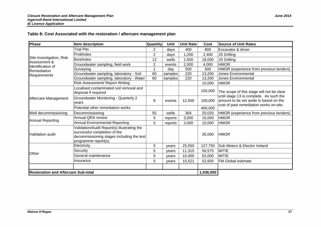
Closure Restoration and Aftercare Management Plan June 2014 Ingersoll-Rand International Limited IE Licence Application
Malone O’Regan 27
Table 8: Cost Associated with the restoration / aftercare management plan Phase Item description Quantity Unit Unit Rate Cost Source of Unit Rates
Site Investigation, Risk Assessment & Identification of Remediation Requirements
Trial Pits 2 days 400 800 Excavator & driver Probholes 2 days 1,200 2,400 JS Drilling Boreholes 12 wells 1,500 18,000 JS Drilling Groundwater sampling, field work 2 events 2,000 4,000 HMOR Surveying 1 day 500 500 HMOR (experience from previous tenders) Groundwater sampling, laboratory - Soil 60 samples 220 13,200 Jones Environmental Groundwater sampling, laboratory - Water 60 samples 220 13,200 Jones Environmental Risk Assessment/ Report Writing 10,000 HMOR
Aftercare Management
Localised contaminated soil removal and disposal if required 100,000 The scope of this stage will not be clear
until stage 13 is complete. As such the amount to be set aside is based on the cost of past remediation works on-site.
Groundwater Monitoring - Quarterly 2 years 8 events 12,500 100,000
Potential other remediation works 400,000 Well decommissioning Decommissioning 55 wells 364 20,020 HMOR (experience from previous tenders)
Annual Reporting Annual QRA review 5 reports 3,000 15,000 HMOR Annual Environmental Reporting 5 reports 3,000 15,000 HMOR
Validation audit
Validation/Audit Report(s) illustrating the successful completion of the decommissioning stages including the test programme report(s).
35,000 HMOR
Other
Electricity 5 years 25,550 127,750 Sub Meters & Electric Ireland Security 5 years 11,315 56,575 MITIE General maintenance 5 years 10,400 52,000 MITIE Insurance 5 years 10,521 52,605 FM Global estimate
Restoration and Aftercare Sub-total 1,036,050
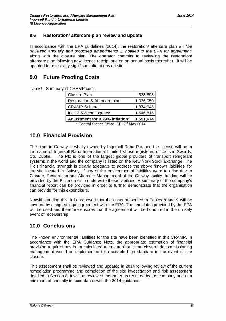
Closure Restoration and Aftercare Management Plan June 2014 Ingersoll-Rand International Limited IE Licence Application
Malone O’Regan 28
8.6 Restoration/ aftercare plan review and update In accordance with the EPA guidelines (2014), the restoration/ aftercare plan will “be reviewed annually and proposed amendments ... notified to the EPA for agreement” along with the closure plan. The operator commits to reviewing the restoration/ aftercare plan following new licence receipt and on an annual basis thereafter. It will be updated to reflect any significant alterations on site.
9.0 Future Proofing Costs Table 9: Summary of CRAMP costs
Closure Plan 338,898Restoration & Aftercare plan 1,036,050CRAMP Subtotal 1,374,948Inc 12.5% contingency 1,546,816Adjustment for 0.29% inflation* 1,591,674
* Central Statics Office, CPI 7th May 2014
10.0 Financial Provision The plant in Galway is wholly owned by Ingersoll-Rand Plc. and the license will be in the name of Ingersoll-Rand International Limited whose registered office is in Swords, Co. Dublin. The Plc is one of the largest global providers of transport refrigerant systems in the world and the company is listed on the New York Stock Exchange. The Plc’s financial strength is clearly adequate to address the above ‘known liabilities’ for the site located in Galway. If any of the environmental liabilities were to arise due to Closure, Restoration and Aftercare Management at the Galway facility, funding will be provided by the Plc in order to underwrite these liabilities. A summary of the company’s financial report can be provided in order to further demonstrate that the organisation can provide for this expenditure. Notwithstanding this, it is proposed that the costs presented in Tables 8 and 9 will be covered by a signed legal agreement with the EPA. The templates provided by the EPA will be used and therefore ensures that the agreement will be honoured in the unlikely event of receivership.
10.0 Conclusions The known environmental liabilities for the site have been identified in this CRAMP. In accordance with the EPA Guidance Note, the appropriate estimation of financial provision required has been calculated to ensure that ‘clean closure’ decommissioning management would be implemented to a suitable high standard in the event of site closure. This assessment shall be reviewed and updated in 2014 following review of the current remediation programme and completion of the site investigation and risk assessment detailed in Section 8. It will be reviewed thereafter as required by the company and at a minimum of annually in accordance with the 2014 guidance.

FIGURES
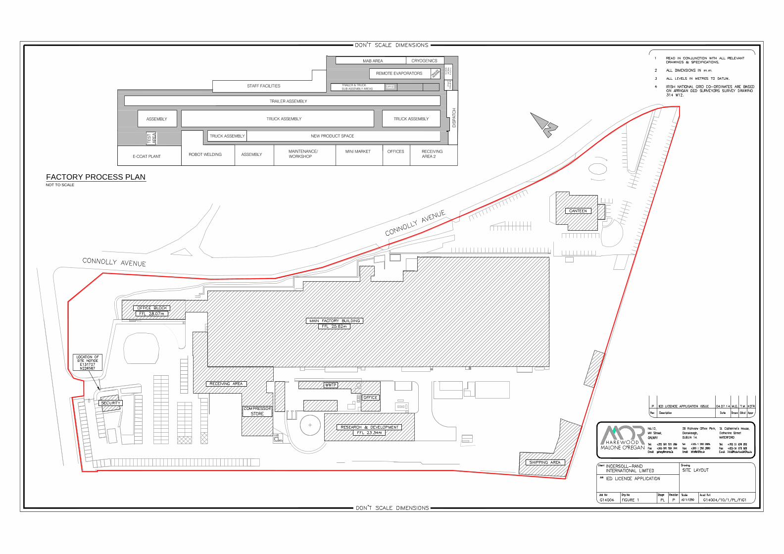
MAINTENANCE/WORKSHOP
TRAILER & TRUCKSUB ASSEMBLY AREAS
FACTORY PROCESS PLANNOT TO SCALE
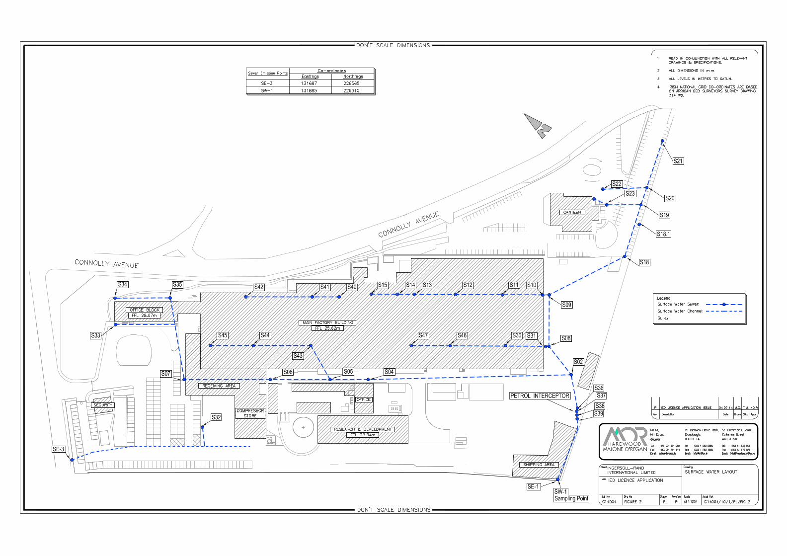


FB-10
FB-6
FB-5
FB-1
FB-12
FB-9 FB-8
FB-2
FB-7
FB-3
FB-2
FB-4FB-11
Legend
Bund Location Points:
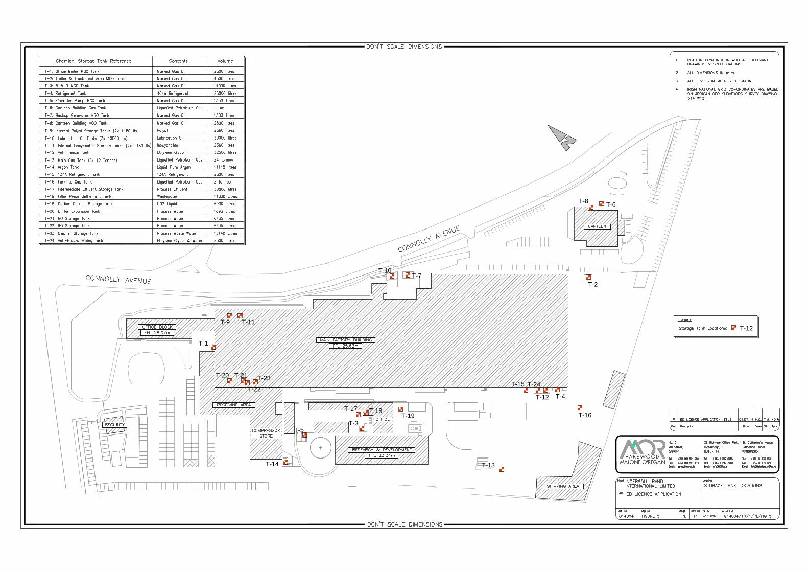
T-15
T-13T-14
T-5T-3
T-1
T-10T-7
T-2
T-8 T-6
T-12 T-4
T-12
T-16
T-9 T-11
T-17 T-18T-19
T-20 T-21 T-23
T-22T-24

Industrial Emissions, Application Form, V.2.0, March 2014
ANNEX 2: CHECKLIST FOR Regulation 9 COMPLIANCE
Regulation 9 of the Environmental Protection Agency (Industrial Emissions)(Licensing) Regulations, 2013 sets out the statutory requirements for information to accompany a licence application. The Application Form is designed in such a way as to set out these questions in a structured manner and not necessarily in the order presented in Regulation 9. In order to ensure a legally valid application in respect of Regulation 9 requirements, all Applicants should complete the following checklist and submit it with the completed Application Form.
Regulation 9(2)
Section in Application
Checked by Applicant
(a) Give:
(i) the name, address and telephone number of the applicant and, if different, any address to which correspondence relating to the application should be sent and, if the applicant is a body corporate, the address of its registered or principal office,
(ii) The location or postal address (including, where appropriate, the name of the relevant townland or townlands) of the premises to which the activity relates,
(iii) The name of the planning authority in whose functional area the activity is or will be carried on, and
(iv) In the case of a discharge of any trade effluent or other matter (other than domestic sewage or storm water) to a sewer of a sanitary authority, give the name of the sanitary authority in which the sewer is vested or b which it is controlled
(b) give -
(i) in the case of an established activity, the number of employees and other persons working or engaged in connection with the activity on the date after which a licence is required and during normal levels of operation, or
(ii) in any other case, the gross capital cost of the activity to which the application relates,

Industrial Emissions, Application Form, V.2.0, March 2014
Regulation 9(2)
Section in Application
Checked by Applicant
(c) specify the relevant class or classes in the First Schedule to the Act to which the industrial emissions directive activity relates,
(d) In accordance with Section 87(1B)(a) of the EPA Acts of 1992 to 2013 in the case where an application for permission for the development comprising or for the purposes of the industrial emissions directive activity to which the application for the licence relates is currently under consideration by the planning authority concerned or An Bord Pleanála, a written confirmation from the planning authority or An Bord Pleanála, as appropriate, of that fact together with either:
(i) a copy of the environmental impact statement, 2 hard copies and 2 electronic copies or in such form as may be specified by the Agency, that was required to be submitted with the application for planning permission, or
(ii) a written confirmation from the planning authority or An Bord Pleanála that an environmental impact assessment is not required by or under the Act of 2000,
(e) In accordance with section 87(1B)(b) of the EPA Acts of 1992 to 2013 in the case where permission for the development comprising or for the purposes of the industrial emissions directive activity to which the application for the licence relates has been granted, a copy of the grant of permission together with either:
(i) a copy of the environmental impact statement, 2 hard copies and 2 electronic copies or in such form as may be specified by the Agency, that was required to be submitted with the application for permission, or
(ii) a written confirmation from the planning authority or An Bord Pleanála that an environmental impact assessment was not required by or under the Act of 2000,
(f) specify the raw and ancillary materials, substances, preparations, fuels and energy which will be produced by or utilised in the activity,
(g) describe the plant, methods, processes, ancillary processes, abatement, recovery and treatment systems, and operating procedures for the activity,
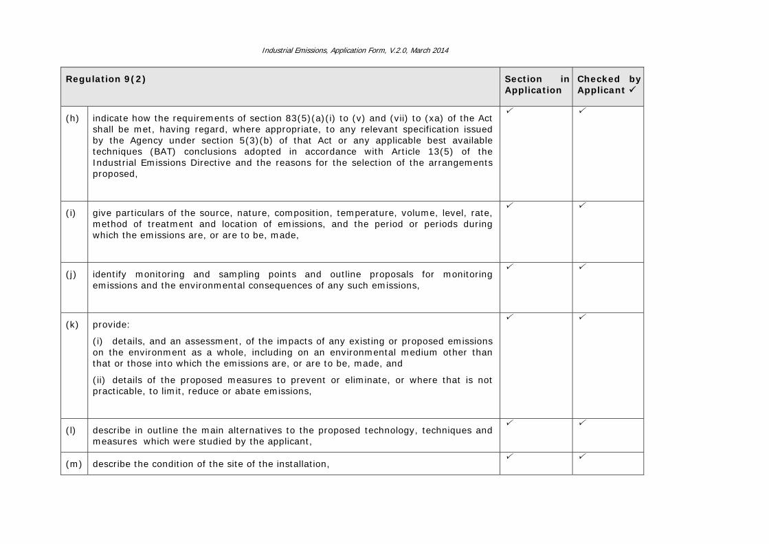
Industrial Emissions, Application Form, V.2.0, March 2014
Regulation 9(2)
Section in Application
Checked by Applicant
(h) indicate how the requirements of section 83(5)(a)(i) to (v) and (vii) to (xa) of the Act shall be met, having regard, where appropriate, to any relevant specification issued by the Agency under section 5(3)(b) of that Act or any applicable best available techniques (BAT) conclusions adopted in accordance with Article 13(5) of the Industrial Emissions Directive and the reasons for the selection of the arrangements proposed,
(i) give particulars of the source, nature, composition, temperature, volume, level, rate, method of treatment and location of emissions, and the period or periods during which the emissions are, or are to be, made,
(j) identify monitoring and sampling points and outline proposals for monitoring emissions and the environmental consequences of any such emissions,
(k) provide:
(i) details, and an assessment, of the impacts of any existing or proposed emissions on the environment as a whole, including on an environmental medium other than that or those into which the emissions are, or are to be, made, and
(ii) details of the proposed measures to prevent or eliminate, or where that is not practicable, to limit, reduce or abate emissions,
(l) describe in outline the main alternatives to the proposed technology, techniques and measures which were studied by the applicant,
(m) describe the condition of the site of the installation,

Industrial Emissions, Application Form, V.2.0, March 2014
Regulation 9(2)
Section in Application
Checked by Applicant
(n) Provide, when requested by the Agency, in the case of an activity that involves the use, production or release of relevant hazardous substances (as defined in section 3 of the Act of 1992) and having regard to the possibility of soil and groundwater contamination at the site of the installation, a baseline report in accordance with section 86B of the Act of 1992,
(o) specify the measures to be taken to comply with an environmental quality standard where such a standard requires stricter conditions to be attached to a licence than would otherwise be determined by reference to best available techniques,
(p) describe the measures to be taken for minimising pollution over long distances or in the territory of other states,
(q) describe the measures to be taken under abnormal operating conditions, including start-up, shutdown, leaks, malfunctions, breakdowns and momentary stoppages,
(r) describe the measures to be taken on and following the permanent cessation of the activity or part of the activity to avoid any risk of environmental pollution and to return the site of the activity to a satisfactory state or the state established in the baseline report if such is required under section 86B of the Act of 1992,
(s) describe the arrangements for the prevention of waste in accordance with Part III of the Act of 1996, and where waste is generated by the installation, how it will be in order of priority in accordance with section 21A the Act of 1996, prepared for re-use, recycling, recovery or where that is not technically or economically possible, disposed of in a manner which will prevent or minimise any impact on the environment,
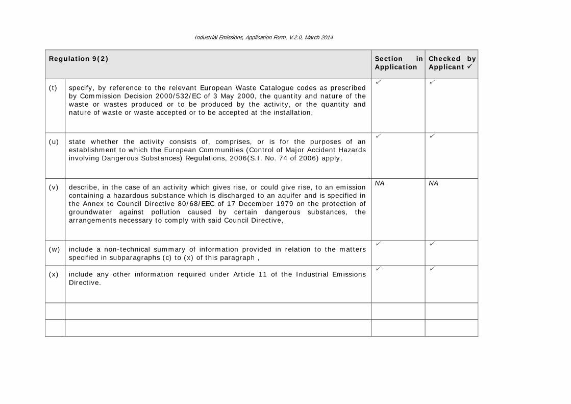
Industrial Emissions, Application Form, V.2.0, March 2014
Regulation 9(2)
Section in Application
Checked by Applicant
(t) specify, by reference to the relevant European Waste Catalogue codes as prescribed by Commission Decision 2000/532/EC of 3 May 2000, the quantity and nature of the waste or wastes produced or to be produced by the activity, or the quantity and nature of waste or waste accepted or to be accepted at the installation,
(u) state whether the activity consists of, comprises, or is for the purposes of an establishment to which the European Communities (Control of Major Accident Hazards involving Dangerous Substances) Regulations, 2006(S.I. No. 74 of 2006) apply,
(v) describe, in the case of an activity which gives rise, or could give rise, to an emission containing a hazardous substance which is discharged to an aquifer and is specified in the Annex to Council Directive 80/68/EEC of 17 December 1979 on the protection of groundwater against pollution caused by certain dangerous substances, the arrangements necessary to comply with said Council Directive,
NA NA
(w) include a non-technical summary of information provided in relation to the matters specified in subparagraphs (c) to (x) of this paragraph ,
(x) include any other information required under Article 11 of the Industrial Emissions Directive.
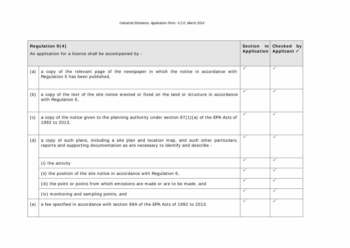
Industrial Emissions, Application Form, V.2.0, March 2014
Regulation 9(4)
An application for a licence shall be accompanied by -
Section in Application
Checked by Applicant
(a) a copy of the relevant page of the newspaper in which the notice in accordance with Regulation 5 has been published,
(b) a copy of the text of the site notice erected or fixed on the land or structure in accordance with Regulation 6,
(c) a copy of the notice given to the planning authority under section 87(1)(a) of the EPA Acts of 1992 to 2013,
(d) a copy of such plans, including a site plan and location map, and such other particulars, reports and supporting documentation as are necessary to identify and describe -
(i) the activity
(ii) the position of the site notice in accordance with Regulation 6,
(iii) the point or points from which emissions are made or are to be made, and
(iv) monitoring and sampling points, and
(e) a fee specified in accordance with section 99A of the EPA Acts of 1992 to 2013.

Industrial Emissions, Application Form, V.2.0, March 2014
Regulation 9(5)
Checked by Applicant
A signed original and 1 hardcopy and 2 electronic copies of the application as required under paragraphs (1) and (2) or under paragraphs (1) and (3), where the application concerns a review of a licence, and the accompanying documents and particulars as required under paragraph (4) shall be submitted to the headquarters of the Agency. The 2 electronic copies of all application documentation and particulars must be in searchable PDF format on CD Rom.
Hardcopies submitted.
CD version submitted.
Related Documents