´ Akos Kiss (Ed.) 13th Symposium on Programming Languages and Software Tools SPLST’13 Szeged, Hungary, August 26–27, 2013 Proceedings University of Szeged

Welcome message from author
This document is posted to help you gain knowledge. Please leave a comment to let me know what you think about it! Share it to your friends and learn new things together.
Transcript
Akos Kiss (Ed.)
13th Symposium onProgramming Languages andSoftware Tools
SPLST’13
Szeged, Hungary, August 26–27, 2013
Proceedings
University of Szeged
13th Symposium on Programming Languages and Software ToolsSPLST’13Szeged, Hungary, August 26–27, 2013Proceedings
Edited by Akos Kiss
University of SzegedFaculty of Science and InformaticsInstitute of InformaticsArpad ter 2., H-6720 Szeged, Hungary
ISBN 978-963-306-228-9 (printed)ISBN 978-963-482-716-0 (PDF)
Copyright c© 2013 The editor and the authors
Preface
On behalf of the steering and program committees, welcome to the 13th Sym-posium on Programming Languages and Software Tools (SPLST’13). The seriesstarted in 1989 in Szeged, Hungary, and since then, by tradition, it has been or-ganized every second year in Hungary, Finland, and Estonia, with participantscoming from all over Europe. This year, the thirteenth edition of the symposiumis back again in Szeged on August 26–27, 2013.
The purpose of the Symposium on Programming Languages and SoftwareTools is to provide a forum for software scientists to present and discuss recentresearches and developments in computer science. The scope of the symposiumcovers ongoing research related to programming languages, software tools, andmethods for software development.
This volume contains the 20 full papers that were accepted by the programcommittee based on an anonymous peer review process. We hope that the di-versity of the papers will lead to stimulating discussions.
As the organizers of the symposium, we would like to thank all the authorsand reviewers for bringing together an interesting program for this year’s SPLST.
Akos KissGeneral Chair
III
Organization
SPLST’13 was organized by the Department of Software Engineering, Universityof Szeged.
General Chair
Akos Kiss (University of Szeged, Hungary)
Steering Committee
Zoltan Horvath (Eotvos Lorand University, Hungary)Kai Koskimies (Tampere University of Technology, Finland)Jaan Penjam (Institute of Cybernetics, Estonia)
Program Committee
Hassan Charaf (Budapest University of Technology and Economics, Hungary)Tibor Gyimothy (University of Szeged, Hungary)Zoltan Horvath (Eotvos Lorand University, Hungary)Pekka Kilpelainen (University of Eastern Finland, Finland)
Akos Kiss (University of Szeged, Hungary)Kai Koskimies (Tampere University of Technology, Finland)Tamas Kozsik (Eotvos Lorand University, Hungary)Peeter Laud (Cybernetica, Institute of Information Security, Estonia)Erkki Makinen (University of Tampere, Finland)Jyrki Nummenmaa (University of Tampere, Finland)Jukka Paakki (University of Helsinki, Finland)Andras Pataricza (Budapest University of Technology and Economics, Hungary)Jari Peltonen (Tampere University of Technology, Finland)Jaan Penjam (Institute of Cybernetics, Estonia)Attila Petho (University of Debrecen, Hungary)Margus Veanes (Microsoft Research, Redmond, USA)
Additional Referees
Zoltan Alexin, Mark Asztalos, Vilmos Bilicki, Istvan Bozo, Dimitrij Csetverikov,Peter Ekler, Rudolf Ferenc, Zsolt Gazdag, Ferenc Havasi, Zoltan Herczeg, JuditJasz, Robert Kitlei, Tamas Meszaros, Zoltan Micskei, Akos Szoke, Zalan Szugyi,Zoltan Ujhelyi, Andras Voros
IV
Table of Contents
Monitoring Evolution of Code Complexity in Agile/Lean SoftwareDevelopment . . . . . . . . . . . . . . . . . . . . . . . . . . . . . . . . . . . . . . . . . . . . . . . . . . . . . 1
Vard Antinyan, Miroslaw Staron, Wilhelm Meding, Per Osterstrom,Henric Bergenwall, Johan Wranker, Jorgen Hansson, AndersHenriksson
Configuring Software for Reuse with VCL . . . . . . . . . . . . . . . . . . . . . . . . . . . . 16
Dan Daniel, Stan Jarzabek, Rudolf Ferenc
Identifying Code Clones with RefactorErl . . . . . . . . . . . . . . . . . . . . . . . . . . . . 31
Viktoria Fordos, Melinda Toth
Code Coverage Measurement Framework for Android Devices . . . . . . . . . . 46
Szabolcs Bognar, Tamas Gergely, Robert Racz, Arpad Beszedes,Vladimir Marinkovic
The Role of Dependency Propagation in the Accumulation of TechnicalDebt for Software Implementations . . . . . . . . . . . . . . . . . . . . . . . . . . . . . . . . . . 61
Johannes Holvitie, Mikko-Jussi Laakso, Teemu Rajala, Erkki Kaila,Ville Leppanen
A Regression Test Selection Technique for Magic Systems . . . . . . . . . . . . . . 76
Gabor Novak, Csaba Nagy, Rudolf Ferenc
VOSD: A General-Purpose Virtual Observatory over Semantic Databases 90
Gergo Gombos, Tamas Matuszka, Balazs Pinczel, Gabor Racz,Attila Kiss
Service Composition for End-Users . . . . . . . . . . . . . . . . . . . . . . . . . . . . . . . . . . 100
Otto Hylli, Samuel Lahtinen, Anna Ruokonen, Kari Systa
Towards a Reference Architecture for Server-Side Mashup Ecosystem . . . . 114
Heikki Peltola, Arto Salminen
Code Oriented Approach to 3D Widgets . . . . . . . . . . . . . . . . . . . . . . . . . . . . . 126
Anna-Liisa Mattila
The Browser as a Host Environment for Visually Rich Applications . . . . . 141
Jari-Pekka Voutilainen, Tommi Mikkonen
Random number generator for C++ template metaprograms . . . . . . . . . . . 156
Zalan Szugyi, Tamas Cseri, Zoltan Porkolab
V
The Asymptotic Behaviour of the Proportion of Hard Instances of theHalting Problem . . . . . . . . . . . . . . . . . . . . . . . . . . . . . . . . . . . . . . . . . . . . . . . . . . 170
Antti Valmari
Implementation of Natural Language Semantic Wildcards using Prolog . . 185Zsolt Zsigmondi, Attila Kiss
Designing and Implementing Control Flow Graph for Magic 4thGeneration Language . . . . . . . . . . . . . . . . . . . . . . . . . . . . . . . . . . . . . . . . . . . . . . 200
Richard Devai, Judit Jasz, Csaba Nagy, Rudolf Ferenc
Runtime Exception Detection in Java Programs Using Symbolic Execution 215Istvan Kadar, Peter Hegedus, Rudolf Ferenc
Composable hierarchical synchronization support for REPLICA . . . . . . . . . 230Jari-Matti Makela, Ville Leppanen, Martti Forsell
Checking visual data flow programs with finite process models . . . . . . . . . . 245Jyrki Nummenmaa, Maija Marttila-Kontio, Timo Nummenmaa
Efficient Saturation-based Bounded Model Checking of AsynchronousSystems . . . . . . . . . . . . . . . . . . . . . . . . . . . . . . . . . . . . . . . . . . . . . . . . . . . . . . . . . 259
Daniel Darvas, Andras Voros, Tamas Bartha
Extensions to the CEGAR Approach on Petri Nets . . . . . . . . . . . . . . . . . . . . 274Akos Hajdu, Andras Voros, Tamas Bartha, Zoltan Martonka
VI
Monitoring Evolution of Code Complexity in Agile/Lean Software Development
A Case Study at Two Companies
Vard Antinyan1), Miroslaw Staron1), Wilhelm Meding2), Per Österström3), Henric Bergenwall3), Johan Wranker3), Jörgen Hansson4) Anders Henriksson4)
Computer Science and Engineering 2) Chalmers | 1) University of Gothenburg
3) Ericsson AB, Sweden4) AB Volvo, Sweden SE 412 96 Gothenburg
Abstract. One of the distinguishing characteristics of Agile and Lean software development is that software products “grow” with new functionality with relatively small increments. Contin-uous customer demands of new features and the companies’ abilities to deliver on those de-mands are the two driving forces behind this kind of software evolution. Despite the numerous benefits there are a number of risks associated with this kind of growth. One of the main risks is the fact that the complexity of the software product grows slowly, but over time reaches scales which makes the product hard to maintain or evolve. The goal of this paper is to present a measurement system for monitoring the growth of complexity and drawing attention when it becomes problematic. The measurement system was developed during a case study at Ericsson and Volvo Group Truck Technology. During the case study we explored the evolution of size, complexity, revisions and number of designers of two large software products from the telecom and automotive domains. The results show that two measures needed to be monitored to keep the complexity development under control - McCabe’s complexity and number of revisions.
Keywords: complexity; metrics; risk; Lean and Agile software development; code; potentially problematic; correlation; measurement systems;
1 Introduction Actively managing software complexity has become an important aspect of continu-ous software development in large software products. It is generally believed that software products developed in a continuous manner are getting more and more com-plex over time, and evidence shows that the rising complexity drives to decreasing quality of software [1-3]. The continuous increase of code base and incremental in-crease of complexity can lead to large, virtually unmaintainable source code if left unmanaged.
A number of methods have been suggested to measure various aspects of soft-ware complexity, e.g. [4-10], accompanied with a number of studies indicating how adequately the proposed methods can relate to software quality. One of the well-known complexity measures, McCabe’s cyclomatic complexity has been shown to be a good quality indicator although it does not reveal all aspects of complexity [11-14].
Despite the considerable amount of research conducted about the influence of complexity on software quality, little results can be found on how complexity influ-ences on a continuously developed software product and how to effectively monitor small yet continuous increments of complexity in growing products. Therefore a ques-
1
tion remains how the previously established methods can be as efficiently used for software quality evaluation:
How to monitor complexity changes effectively when delivering feature incre-ments to the main code branch in the product codebase? The aim of this research is to develop methods and tool support for actively mon-
itoring increments of complexity and drawing the attention of product managers, pro-ject leaders, quality responsible and the teams to the potentially problematic trends of growing complexity. In this paper we focus on the level of self-organized software development teams who often deliver code to the main branch for further testing, integration with hardware and ultimate deployment to end customers.
We address this question by conducting a case study at two companies which develop software according to Agile and Lean principles. The studied companies are Ericsson AB in Sweden which develops telecom products and Volvo Group Truck Technology which develops trucks under four brands – Volvo, Renault, Mack and UD Trucks.
Our results show that using a number of complementary measures of complexity and development velocity – McCabe’s complexity and number of revisions per week – support teams in decision making, when delivering potentially problematic code to the main branch. By saying potentially problematic we mean that there is a tangible chance that the delivered code is fault prone or difficult to understand and maintain. Monitoring trends in these variables effectively draws attention of the self-organized Agile teams to a handful of functions and files which are potentially problematic. The handful of functions are manually assessed, and before the delivery the team formu-lates the decision whether they indeed might cause problems. The initial evaluation in two ongoing software development projects shows that using the two measures indeed draws attention to the most problematic functions.
2 Related Work
2.1 Continuous Software Evolution A set of measures useful in the context of continuous deployment can be found in the work of Fritz [15] in the context of market driven software development organization. The metrics presented by Fritz measure such aspects as continuous integration pace or the pace of delivery of features to the customers. These metrics complement the two indicators presented in this paper with a different perspective important for product management.
The delivery strategy, which is an extension of the concept of continuous de-ployment, has been found as one of the three key aspects important for Agile software development organizations in a survey of 109 companies by Chow and Cao [16]. The indicator presented in this paper is a means of supporting organizations in their transi-tion towards achieving efficient delivery processes.
Ericsson’s realization of the Lean principles combined with Agile development was not the only one recognized in literature. Perera and Fernando [17] presented another approach. In their work they show the difference between the traditional and Lean-Agile way of working. Based on our observations, the measures and their trends at Ericsson were similar to those observed by Perera and Fernando.
2
2.2 Related Complexity Studies Gill and Kemerer [8] propose another kind of cyclomatic complexity metric – cy-clomatic complexity density and they show its usefulness as a software quality indica-tor. Zhang and Zhang [18] developed a method based on lines of code measure, cy-clomatic complexity number and Halstead’s volume to predict the defects of a soft-ware component. Two other studies provided evidence that files having large number of revisions are defect prone and hard to maintain [19], [20].
2.3 Measurement Systems The concept of an early warning measurement system is not new in engineering. Measurement instruments are one of the cornerstones of engineering. In this paper we only consider computerized measurement systems – i.e. software products used as measurement systems. The reasons for this are: the flexibility of measurement sys-tems, the fact that we work in the software field, and similarity of the problems – e.g. concept of measurement errors, automation, etc. An example of a similar measure-ment system is presented by Wisell [21] where the concept of using multiple meas-urement instruments to define a measurement system is also used. Although differing in domains of applications these measurement systems show that concepts which we adopt from the international standards (like [22]) are successfully used in other engi-neering disciplines. We use the existing methods from the ISO standard to develop the measurement systems for monitoring complexity evolution.
Lowler and Kitchenham [23] present a generic way of modeling measures and building more advanced measures from less complex ones. Their work is linked to the TychoMetric [24] tool. The tool is a very powerful measurement system framework, which has many advanced features not present in our framework (e.g. advanced ways of combining metrics). A similar approach to the TychoMetric’s way of using metrics was presented by Garcia et al. [25]. Despite their complexity, both the TychoMetric tool and Garcia’s approach can be seen as alternatives in the context of advanced data presentation or advanced statistical analysis over time.
Meyer [26, pp. 99-122] claims that the need for customized measurement sys-tems for teams is one of the most important aspects in the adoption of metrics at the lowest levels in the organization. Meyer’s claims were also supported by the require-ments that the customization of measurement systems and development of new ones should be simple and efficient in order to avoid unnecessary costs in development projects. In our research we simplify the ways of developing Key Performance Indica-tors exemplified by a 12-step model of Parmenter [27] in the domain of software de-velopment projects.
3 Design of the Case Study This case study was conducted using action research approach [28-30] where the re-searchers were part of the company’s operations and worked directly with product development units of the companies. The role of Ericsson in the study was the devel-opment of the method and its initial evaluation, whereas the role of Volvo Group Truck Technology was to evaluate the method in a new context.
3
3.1 Ericsson The organization and the project within Ericsson, which we worked closely with, developed large products for the mobile telephony network. The number of the devel-opers in the projects was up to a few hundreds1. Projects were executed according to the principles of Agile software development and Lean production system, referred to as Streamline development (SD) within Ericsson [31]. In this environment, different development teams were responsible for larger parts of the development process compared to traditional processes: design teams (cross-functional teams responsible for complete analysis, design, implementation, and testing of particular features of the product), network verification and integration testing, etc.
The needs of the organization had evolved from metric calculations and presen-tations (ca. 7 years before the writing of this paper) to using predictions, simulations, early warning systems and handling of vast quantities of data to steer organizations at different levels and providing information from teams to management.
3.2 Volvo Group Truck Technology (GTT) The organization which we worked with at Volvo Group developed Electronic Con-trol Unit (ECU) software for trucks for such brands like Volvo, Renault, UD Trucks and Mack. The collaborating unit developed software for two ECUs and consisted of over 40 designers, business analysts and testers at different levels. The process was iterative, agile, involving cross functional teams.
The company used measures to control the progress of its projects, to monitor quality of the products and to collect data semi-automatically, i.e. automatically gath-ering of data from tools with the manual analysis of the data. The metrics collected at the studied unit fall into the categories of contract management, quality monitoring and control, predictions and project planning. The intention of the unit was to build a measurement system to provide stakeholders (like project leaders, product and line managers or the team) with the information about the current and predicted status of their products.
3.3 Process According to the principles of action research we adjusted the process of our research with the operations of the company. We worked closely with project teams with dedi-cated designers, architects and managers being part of the research team. We conduct-ed the study according to the following pre-defined process: • Obtaining access to the source code of the products and their different releases • Calculate complexity of all functions in the code • Identify functions which changed complexity through 4 main releases • Identify functions which changed complexity in 5 service releases between the two
main releases • Identify drivers for complexity changes in a subset of these functions • Add new measures to the study:
─ Complexity per file ─ # revisions – to explore files which were changed often ─ # designers – to explore files which were changed by many designers in parallel
1 The exact size of the unit cannot be provided due to confidentiality reasons.
4
─ # Number of lines of code (size) – to explore large files and functions • Correlate measures to explore their dependencies • Develop a measurement system (according to ISO 15939) to monitor the potential-
ly problematic files. • Monitor and evaluate the product during two releases
The above process was used during the development of the method at Ericsson and replicated at Volvo Group Truck Technology.
3.4 Units of Analysis During our study we analyzed two different products – software for a telecom product at Ericsson and software for one electronic control unit from Volvo GTT from the automotive domain.
Ericsson: The product was a large telecommunication product composed by over one million lines of code with several tens of thousands C/C++ functions. Most of the source code was developed using C. The product had a few releases per year with a number of service releases in-between them. All versions of the source code of the product including the main and service releases were stored in version control system, IBM/Rational ClearCase. The product was a mature telecommunication product with a stable customer base. The product has been in development for a number of years.
The measures specified in the previous section were collected from different baseline revisions of the source code in ClearCase. In order to increase the internal validity of data collection and the quality of data we communicated closely with a reference group during bi-weekly meetings over a period of 8 months. The reference group consisted of 2 senior designers, one operational architect, one research engineer from the company, one manager and one metric team leader. The discussions consid-ered the suitability of measures, measurement methods and functions (according to ISO/IEC 15939), validity of results and effectiveness of our measurement system.
Volvo GTT: The product was an embedded software system serving as one of the main computer nodes for a product line of trucks. It consisted of a few hundred thou-sand lines of code and several thousand C functions. The version control system is ClearCase. The software product had tight releases every 6-8 weeks. The analyses that were conducted were replications of the case study at Ericsson under the same condi-tions and using the same tools. The results were communicated with designers of the software product after the data was analyzed.
At both companies we developed measurement systems for monitoring the files and functions that can be risk driving when merging new code into the main branch. We defined the risk of merging a newly developed or a maintained function to main code base as a chance that the merged code would introduce new faults or would be noticeably more difficult to understand and maintain.
3.5 Measures in the Study
Table 1 presents the measures which we used in our study and their definitions: Table 1. Metrics and their definitions
Name of measure Abbre-viation
Definition
Number of non-commented lines of code
NCLOC The lines of non-blank, non-comment source code in a function
5

McCabe’s cy-clomatic complexi-ty of a function
M The number of linearly independent paths in the control flow graph of a function, measured by calculating the number of 'if', 'while', 'for', 'switch', 'break', '&&', '||' tokens
McCabe’s cy-clomatic complexi-ty of a file
File M The sum of all functions’ M in a file
McCabe’s cy-clomatic complexi-ty delta of a func-tion
ΔM The increase or decrease of M of a function during a specified time interval. We register the file name, class name (if available) and function name in order to identify the same function and calculate its complexity change in different releases.
McCabe’s cy-clomatic complexi-ty delta of a file
File ΔM The increase or decrease of File M during a specified time inter-val
Number of revi-sions of a file
NR The number of check-ins of files in a specified ClearCase branch and its all sub-branches in a specified time interval
Number of design-ers of a file
ND The number of developers that do check-in of a file on a speci-fied ClearCase branch and all of its sub-branches during a speci-fied time interval
Complexity of the most complex func-tion in a file
Max M f The complexity number M of the most complex function in a file
3.6 Focus Group During this study we had the opportunity to work with a reference group at Ericsson and a designer at Volvo GTT. The aim of the reference group was to support the re-search team with expertise in the product domain and to validate the intermediate findings as prescribed by the principles of Action research. The group interacted with researchers on a bi-weekly meeting basis for over 8 months. At Ericsson the reference group consisted of: • One product manager with over 10 years of experience and over 5 years of experi-
ence with Agile/Lean software development • One measurement program/team leader with over 10 years of experience with
software development and over 5 years of experience with Agile/Lean at Ericsson • Two designers with over 6 years of experience in telecom product development. • One operational architect with over 6 years of experience • One research engineer with over 20 years of experience in telecom product devel-
opment At Volvo GTT we worked with one designer who had the knowledge about the prod-uct and over 10 years of experience with software development at the company. 4 Results and analysis
4.1 Evolution of the Studied Measures Over Time We measured M for 4 main and 5 service releases at Ericsson and for 4 releases for the product at Volvo GTT. The results showed there are many new complex functions introduced as part of service releases. We observed that a large number of functions change the argument list during development. Many functions had long list of argu-ments which meant that the designers need to add or remove an argument or change the argument name to resolve a specific task. Thus the majority of the functions that
6
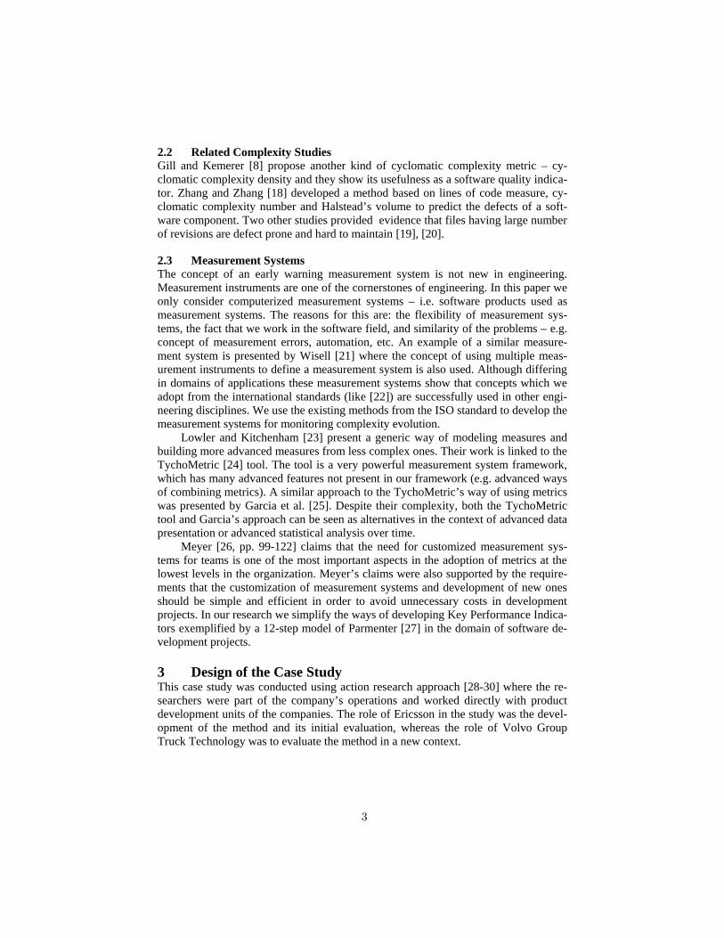
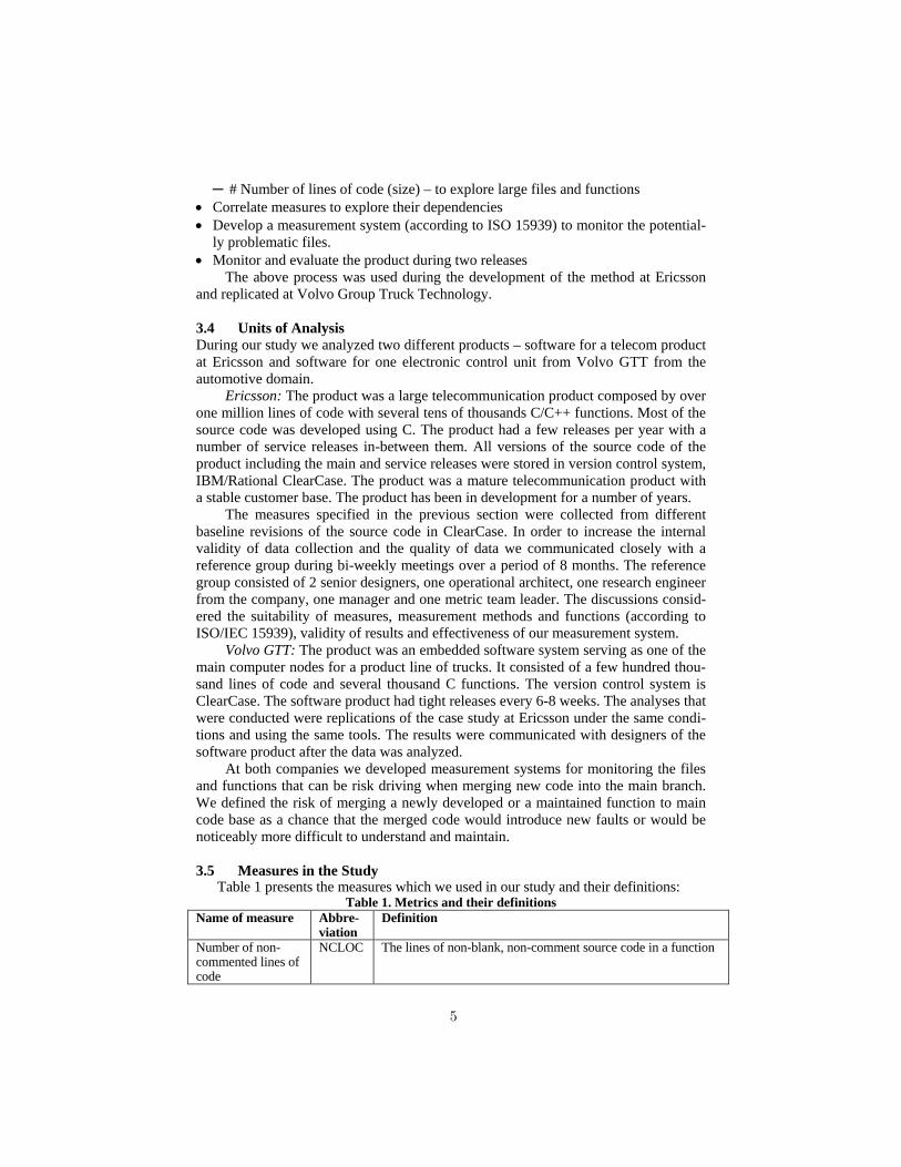
has been included as “new” in the statistics were actually old functions, which have changed argument’s list. The designers agreed that these functions may introduce risks but with considerably less exposure than if these functions were indeed newly developed. Hence we disregarded the argument’s list of functions in our measure-ment. Figure 1 shows the complexity evolution of functions in 5 service releases of the telecom product. Each line on the figure represents a C/C++ function.
Figure 1. Evolution of complexity for functions with large complexity delta for one release
and subsequent service releases in Telecom product Measuring the evolution of McCabe’s complexity M through releases in this manner resulted in: • Observation that it is the newly developed functions which drive complexity in-
crease between two major releases, as shows in Table 2. • Observation that the majority of functions that are created complex keep the com-
plexity at the same level over many releases – e.g. see Figure 1.
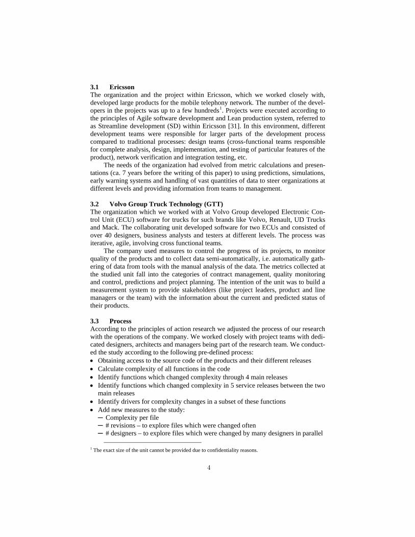
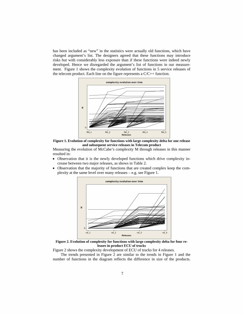
Figure 2. Evolution of complexity for functions with large complexity delta for four re-
leases in product ECU of trucks Figure 2 shows the complexity development of ECU of trucks for 4 releases.
The trends presented in Figure 2 are similar to the trends in Figure 1 and the number of functions in the diagram reflects the difference in size of the products.
Rel_5Rel_4Rel_3Rel_2Rel_1
0
Releases
Mcomplexity evolution over time
rel_4rel_3rel_2rel_1
0
Releases
M
complexity evolution over time
7
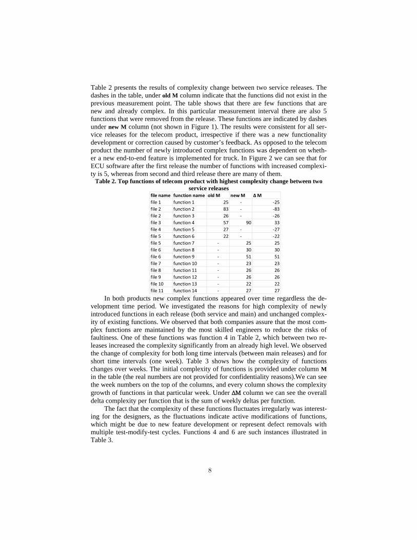
Table 2 presents the results of complexity change between two service releases. The dashes in the table, under old M column indicate that the functions did not exist in the previous measurement point. The table shows that there are few functions that are new and already complex. In this particular measurement interval there are also 5 functions that were removed from the release. These functions are indicated by dashes under new M column (not shown in Figure 1). The results were consistent for all ser-vice releases for the telecom product, irrespective if there was a new functionality development or correction caused by customer’s feedback. As opposed to the telecom product the number of newly introduced complex functions was dependent on wheth-er a new end-to-end feature is implemented for truck. In Figure 2 we can see that for ECU software after the first release the number of functions with increased complexi-ty is 5, whereas from second and third release there are many of them.
Table 2. Top functions of telecom product with highest complexity change between two service releases
In both products new complex functions appeared over time regardless the de-
velopment time period. We investigated the reasons for high complexity of newly introduced functions in each release (both service and main) and unchanged complex-ity of existing functions. We observed that both companies assure that the most com-plex functions are maintained by the most skilled engineers to reduce the risks of faultiness. One of these functions was function 4 in Table 2, which between two re-leases increased the complexity significantly from an already high level. We observed the change of complexity for both long time intervals (between main releases) and for short time intervals (one week). Table 3 shows how the complexity of functions changes over weeks. The initial complexity of functions is provided under column M in the table (the real numbers are not provided for confidentiality reasons).We can see the week numbers on the top of the columns, and every column shows the complexity growth of functions in that particular week. Under ΔΜ column we can see the overall delta complexity per function that is the sum of weekly deltas per function.
The fact that the complexity of these functions fluctuates irregularly was interest-ing for the designers, as the fluctuations indicate active modifications of functions, which might be due to new feature development or represent defect removals with multiple test-modify-test cycles. Functions 4 and 6 are such instances illustrated in Table 3.
file name function name old M new M Δ Μfile 1 function 1 25 - -25file 2 function 2 83 - -83file 2 function 3 26 - -26file 3 function 4 57 90 33file 4 function 5 27 - -27file 5 function 6 22 - -22file 5 function 7 - 25 25file 6 function 8 - 30 30file 6 function 9 - 51 51file 7 function 10 - 23 23file 8 function 11 - 26 26file 9 function 12 - 26 26file 10 function 13 - 22 22file 11 function 14 - 27 27
8
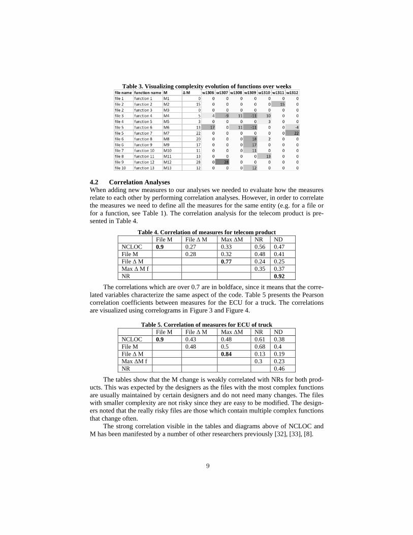
Table 3. Visualizing complexity evolution of functions over weeks
4.2 Correlation Analyses When adding new measures to our analyses we needed to evaluate how the measures relate to each other by performing correlation analyses. However, in order to correlate the measures we need to define all the measures for the same entity (e.g. for a file or for a function, see Table 1). The correlation analysis for the telecom product is pre-sented in Table 4.
Table 4. Correlation of measures for telecom product File M File Δ Μ Max ΔΜ NR ND NCLOC 0.9 0.27 0.33 0.56 0.47 File M 0.28 0.32 0.48 0.41 File Δ Μ 0.77 0.24 0.25 Μax Δ Μ f 0.35 0.37 NR 0.92
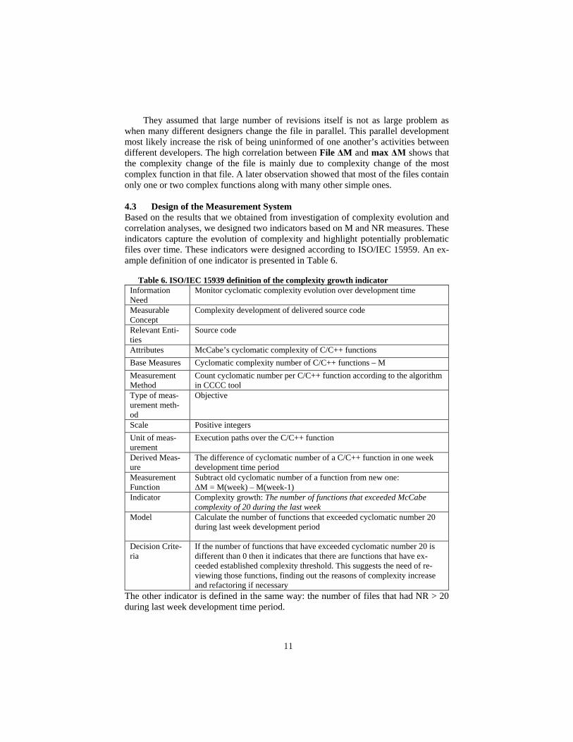
The correlations which are over 0.7 are in boldface, since it means that the corre-lated variables characterize the same aspect of the code. Table 5 presents the Pearson correlation coefficients between measures for the ECU for a truck. The correlations are visualized using correlograms in Figure 3 and Figure 4.
Table 5. Correlation of measures for ECU of truck File M File Δ Μ Max ΔΜ NR ND NCLOC 0.9 0.43 0.48 0.61 0.38 File M 0.48 0.5 0.68 0.4 File Δ Μ 0.84 0.13 0.19 Μax ΔΜ f 0.3 0.23 NR 0.46
The tables show that the M change is weakly correlated with NRs for both prod-ucts. This was expected by the designers as the files with the most complex functions are usually maintained by certain designers and do not need many changes. The files with smaller complexity are not risky since they are easy to be modified. The design-ers noted that the really risky files are those which contain multiple complex functions that change often.
The strong correlation visible in the tables and diagrams above of NCLOC and M has been manifested by a number of other researchers previously [32], [33], [8].
9
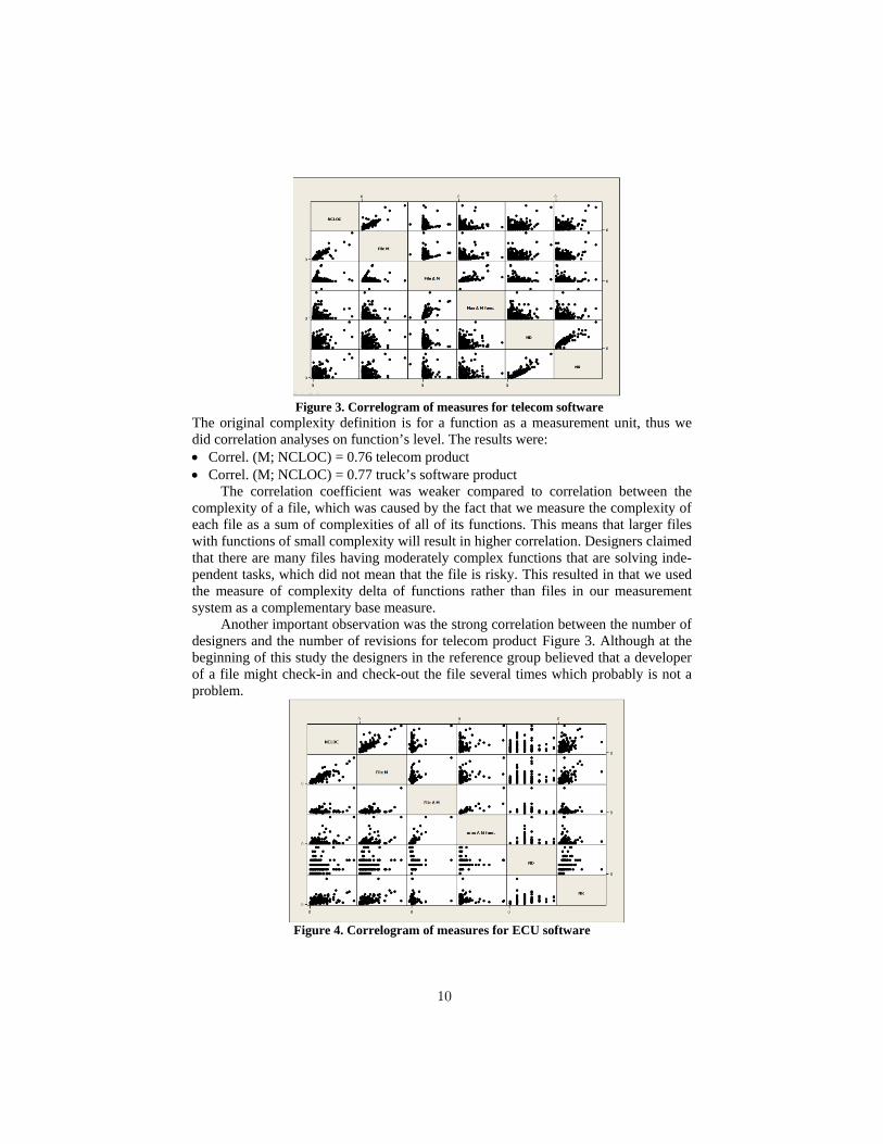
Figure 3. Correlogram of measures for telecom software The original complexity definition is for a function as a measurement unit, thus we did correlation analyses on function’s level. The results were: • Correl. (M; NCLOC) = 0.76 telecom product • Correl. (M; NCLOC) = 0.77 truck’s software product
The correlation coefficient was weaker compared to correlation between the complexity of a file, which was caused by the fact that we measure the complexity of each file as a sum of complexities of all of its functions. This means that larger files with functions of small complexity will result in higher correlation. Designers claimed that there are many files having moderately complex functions that are solving inde-pendent tasks, which did not mean that the file is risky. This resulted in that we used the measure of complexity delta of functions rather than files in our measurement system as a complementary base measure.
Another important observation was the strong correlation between the number of designers and the number of revisions for telecom product Figure 3. Although at the beginning of this study the designers in the reference group believed that a developer of a file might check-in and check-out the file several times which probably is not a problem.
Figure 4. Correlogram of measures for ECU software
10
They assumed that large number of revisions itself is not as large problem as when many different designers change the file in parallel. This parallel development most likely increase the risk of being uninformed of one another’s activities between different developers. The high correlation between File ΔM and max ΔΜ shows that the complexity change of the file is mainly due to complexity change of the most complex function in that file. A later observation showed that most of the files contain only one or two complex functions along with many other simple ones.
4.3 Design of the Measurement System Based on the results that we obtained from investigation of complexity evolution and correlation analyses, we designed two indicators based on M and NR measures. These indicators capture the evolution of complexity and highlight potentially problematic files over time. These indicators were designed according to ISO/IEC 15959. An ex-ample definition of one indicator is presented in Table 6.
Table 6. ISO/IEC 15939 definition of the complexity growth indicator
Information Need
Monitor cyclomatic complexity evolution over development time
Measurable Concept
Complexity development of delivered source code
Relevant Enti-ties
Source code
Attributes McCabe’s cyclomatic complexity of C/C++ functions Base Measures Cyclomatic complexity number of C/C++ functions – M Measurement Method
Count cyclomatic number per C/C++ function according to the algorithm in CCCC tool
Type of meas-urement meth-od
Objective
Scale Positive integers Unit of meas-urement
Execution paths over the C/C++ function
Derived Meas-ure
The difference of cyclomatic number of a C/C++ function in one week development time period
Measurement Function
Subtract old cyclomatic number of a function from new one: ΔM = M(week) – M(week-1)
Indicator Complexity growth: The number of functions that exceeded McCabe complexity of 20 during the last week
Model Calculate the number of functions that exceeded cyclomatic number 20 during last week development period
Decision Crite-ria
If the number of functions that have exceeded cyclomatic number 20 is different than 0 then it indicates that there are functions that have ex-ceeded established complexity threshold. This suggests the need of re-viewing those functions, finding out the reasons of complexity increase and refactoring if necessary
The other indicator is defined in the same way: the number of files that had NR > 20 during last week development time period.
11
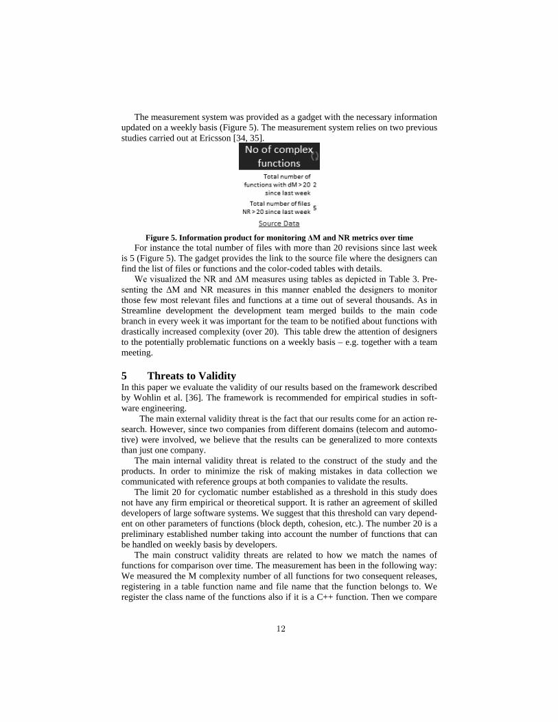
The measurement system was provided as a gadget with the necessary information updated on a weekly basis (Figure 5). The measurement system relies on two previous studies carried out at Ericsson [34, 35].
Figure 5. Information product for monitoring ΔM and NR metrics over time
For instance the total number of files with more than 20 revisions since last week is 5 (Figure 5). The gadget provides the link to the source file where the designers can find the list of files or functions and the color-coded tables with details.
We visualized the NR and ΔM measures using tables as depicted in Table 3. Pre-senting the ΔM and NR measures in this manner enabled the designers to monitor those few most relevant files and functions at a time out of several thousands. As in Streamline development the development team merged builds to the main code branch in every week it was important for the team to be notified about functions with drastically increased complexity (over 20). This table drew the attention of designers to the potentially problematic functions on a weekly basis – e.g. together with a team meeting.
5 Threats to Validity In this paper we evaluate the validity of our results based on the framework described by Wohlin et al. [36]. The framework is recommended for empirical studies in soft-ware engineering.
The main external validity threat is the fact that our results come for an action re-search. However, since two companies from different domains (telecom and automo-tive) were involved, we believe that the results can be generalized to more contexts than just one company.
The main internal validity threat is related to the construct of the study and the products. In order to minimize the risk of making mistakes in data collection we communicated with reference groups at both companies to validate the results.
The limit 20 for cyclomatic number established as a threshold in this study does not have any firm empirical or theoretical support. It is rather an agreement of skilled developers of large software systems. We suggest that this threshold can vary depend-ent on other parameters of functions (block depth, cohesion, etc.). The number 20 is a preliminary established number taking into account the number of functions that can be handled on weekly basis by developers.
The main construct validity threats are related to how we match the names of functions for comparison over time. The measurement has been in the following way: We measured the M complexity number of all functions for two consequent releases, registering in a table function name and file name that the function belongs to. We register the class name of the functions also if it is a C++ function. Then we compare
12
the function’s, file’s and class’ names of registered functions for two releases. If there is a function that has the same registered names in both releases we consider that they are the same functions and calculate the complexity number variance for them.
Finally the main threat to conclusion validity is the fact that we do not use inferen-tial statistics to monitor relation between the code characteristics and project proper-ties, e.g. number of defects. This was attempted during the study but the data in defect reports could not be mapped to individual files, this jeopardizing the reliability of such an analysis. Therefore we chose to rely on the most skilled designers’ perception of how fault-prone and unmaintainable code is delivered.
6 Conclusions In Agile and Lean software development quick feedbacks on developed code and its complexity is crucial. With small software increments there is a risk that the complex-ity of units of code or their size can grow to unmanageable extensions through small increments.
In this paper we explored how complexity changes by studying two software products – one telecom product at Ericsson and one software for electronic control unit at Volvo GTT. We identified that in short periods of time a few out of tens of thousands functions have significant complexity increase. In large products software development teams need automated tools to identify these potentially problematic functions. We also identified that the self-organized teams should be able to make the final assessment whether the “potentially” problematic is indeed problematic.
By analyzing correlations we found that it is enough to use two measures – McCabe complexity and number of revisions – to draw attention of the teams and to designate files as “potentially” problematic.
The automated support for the teams was provided in form of a MS Sidebar gadg-et with the indicators and links to statistics and trends with detailed complexity devel-opment. The method was validated on a set of historical releases.
In our further work we intend to extend our validation to products under devel-opment and evaluate which decisions are triggered by the measurement systems. We also intend to study how the teams formulate the decisions and monitor their imple-mentation.
Acknowledgment The authors thank the companies for their support in the study. This research has been carried out in the Software Centre, Chalmers, University of Gothenburg and Ericsson AB, Volvo Group Truck Technology.
References [1] B. Boehm, "A view of 20th and 21st century software engineering," in Proceedings of the
28th international conference on Software engineering, 2006, pp. 12-29. [2] T. Little, "Context-adaptive agility: managing complexity and uncertainty," Software, IEEE,
vol. 22, pp. 28-35, 2005. [3] J. Bosch and P. Bosch-Sijtsema, "From integration to composition: On the impact of
software product lines, global development and ecosystems," Journal of Systems and Software, vol. 83, pp. 67-76, 1// 2010.
13
[4] S. Henry and D. Kafura, "Software structure metrics based on information flow," Software Engineering, IEEE Transactions on, pp. 510-518, 1981.
[5] T. J. McCabe, "A complexity measure," Software Engineering, IEEE Transactions on, pp. 308-320, 1976.
[6] B. Curtis, "Measuring the psychological complexity of software maintenance tasks with the Halstead and McCabe metrics," IEEE Transactions on Software Engineering, vol. SE-5, p. 96.
[7] M. H. Halstead, Elements of software science vol. 19: Elsevier New York, 1977. [8] G. K. Gill and C. F. Kemerer, "Cyclomatic complexity density and software maintenance
productivity," Software Engineering, IEEE Transactions on, vol. 17, pp. 1284-1288, 1991. [9] R. P. L. Buse and W. R. Weimer, "A metric for software readability," in Proceedings of the
2008 international symposium on Software testing and analysis, 2008, pp. 121-130. [10] Y. Wang, "On the Cognitive Complexity of Software and its Quantification and Formal
Measurement," International Journal of Software Science and Computational Intelligence (IJSSCI), vol. 1, pp. 31-53, 2009.
[11] N. Nagappan, T. Ball, and A. Zeller, "Mining metrics to predict component failures," in Proceedings of the 28th international conference on Software engineering, 2006, pp. 452-461.
[12] T. M. Khoshgoftaar, E. B. Allen, K. S. Kalaichelvan, and N. Goel, "Early quality prediction: A case study in telecommunications," Software, IEEE, vol. 13, pp. 65-71, 1996.
[13] B. Ramamurthy and A. Melton, "A synthesis of software science measures and the cyclomatic number," Software Engineering, IEEE Transactions on, vol. 14, pp. 1116-1121, 1988.
[14] M. Shepperd and D. C. Ince, "A critique of three metrics," Journal of Systems and Software, vol. 26, pp. 197-210, 9// 1994.
[15] T. Fitz. (2009). Continuous Deployment at IMVU: Doing the impossible fifty times a day. Available: http://timothyfitz.wordpress.com/2009/02/10/continuous-deployment-at-imvu-doing-the-impossible-fifty-times-a-day/
[16] T. Chow and D.-B. Cao, "A survey study of critical success factors in agile software projects," Journal of Systems and Software, vol. 81, pp. 961-971, 2008.
[17] G. I. U. S. Perera and M. S. D. Fernando, "Enhanced agile software development - hybrid paradigm with LEAN practice," in International Conference on Industrial and Information Systems (ICIIS), 2007, pp. 239-244.
[18] H. Zhang, X. Zhang, and M. Gu, "Predicting defective software components from code complexity measures," in Dependable Computing, 2007. PRDC 2007. 13th Pacific Rim International Symposium on, 2007, pp. 93-96.
[19] A. Monden, D. Nakae, T. Kamiya, S. Sato, and K. Matsumoto, "Software quality analysis by code clones in industrial legacy software," in Software Metrics, 2002. Proceedings. Eighth IEEE Symposium on, 2002, pp. 87-94.
[20] R. Moser, W. Pedrycz, and G. Succi, "A comparative analysis of the efficiency of change metrics and static code attributes for defect prediction," in Software Engineering, 2008. ICSE'08. ACM/IEEE 30th International Conference on, 2008, pp. 181-190.
[21] D. Wisell, P. Stenvard, A. Hansebacke, and N. Keskitalo, "Considerations when Designing and Using Virtual Instruments as Building Blocks in Flexible Measurement System
14
Solutions," in IEEE Instrumentation and Measurement Technology Conference, 2007, pp. 1-5.
[22] International Bureau of Weights and Measures., International vocabulary of basic and general terms in metrology = Vocabulaire international des termes fondamentaux et généraux de métrologie, 2nd ed. Genève, Switzerland: International Organization for Standardization, 1993.
[23] J. Lawler and B. Kitchenham, "Measurement modeling technology," IEEE Software, vol. 20, pp. 68-75, 2003.
[24] Predicate Logic. (2007, 2008-06-30). TychoMetrics. Available: http://www.predicatelogic.com
[25] F. Garcia, M. Serrano, J. Cruz-Lemus, F. Ruiz, M. Pattini, and ALARACOS Research Group, "Managing Software Process Measurement: A Meta-model Based Approach," Information Sciences, vol. 177, pp. 2570-2586, 2007.
[26] Harvard Business School, Harvard business review on measuring corporate performance. Boston, MA: Harvard Business School Press, 1998.
[27] D. Parmenter, Key performance indicators : developing, implementing, and using winning KPIs. Hoboken, N.J.: John Wiley & Sons, 2007.
[28] A. Sandberg, L. Pareto, and T. Arts, "Agile Collaborative Research: Action Principles for Industry-Academia Collaboration," IEEE Software, vol. 28, pp. 74-83, Jun-Aug 2011 2011.
[29] R. L. Baskerville and A. T. Wood-Harper, "A Critical Perspective on Action Research as a Method for Information Systems Research," Journal of Information Technology, vol. 1996, pp. 235-246, 1996.
[30] G. I. Susman and R. D. Evered, "An Assessment of the Scientific Merits of Action Research," Administrative Science Quarterly, vol. 1978, pp. 582-603, 1978.
[31] P. Tomaszewski, P. Berander, and L.-O. Damm, "From Traditional to Streamline Development - Opportunities and Challenges," Software Process Improvement and Practice, vol. 2007, pp. 1-20, 2007.
[32] G. Jay, J. E. Hale, R. K. Smith, D. Hale, N. A. Kraft, and C. Ward, "Cyclomatic complexity and lines of code: empirical evidence of a stable linear relationship," Journal of Software Engineering and Applications (JSEA), 2009.
[33]M. Shepperd, "A critique of cyclomatic complexity as a software metric," Software Engineering Journal, vol. 3, pp. 30-36, 1988.
[34] M. Staron, W. Meding, G. Karlsson, and C. Nilsson, "Developing measurement systems: an industrial case study," Journal of Software Maintenance and Evolution: Research and Practice, vol. 23, pp. 89-107, 2011.
[35] M. Staron and W. Meding, "Ensuring reliability of information provided by measurement systems," in Software Process and Product Measurement, ed: Springer, 2009, pp. 1-16.
[36] C. Wohlin, P. Runeson, M. Höst, M. C. Ohlsson, B. Regnell, and A. Wesslèn, Experimentation in Software Engineering: An Introduction. Boston MA: Kluwer Academic Publisher, 2000.
15
Con�guring Software for Reuse with VCL
Dan Daniel1,∗, Stan Jarzabek2, and Rudolf Ferenc1
1Department of Software EngineeringUniversity of Szeged, Hungary
{danield,ferenc}@inf.u-szeged.hu2School of Computing
National University of Singapore, [email protected]
Abstract. Preprocessors such as cpp are often used to manage familiesof programs from a common code base. The approach is simple, but codeinstrumented with preprocessing commands may become unreadable anddi�cult to work with. We describe a system called VCL (variant con�g-uration language) that enhances cpp to provide a better solution to thesame problem. The main extensions have to do with propagation of pa-rameters across source �les during VCL processing, the ability to adaptsource �les for reuse depending on the reuse context, and the ability toform general templates to represent any group of similar program struc-tures (methods, functions, classes, �les, directories) in generic, adaptableform. In the paper, we describe salient features of VCL, explain how theyalleviate some of the problems of cpp, and illustrate reuse capabilities ofVCL with an example.
1 Introduction
Preprocessors are often used to manage families of programs from a common codebase. In the paper, we focus on cpp which is a most commonly used preprocessor.Variant code relevant to some but not all family members appears in the codebase under commands such as #ifdef for selective inclusion into family membersthat need that code. preprocessor parameters (#define) control the process ofcon�guring the code base to build a speci�c family member.
There are well-known problems involved in managing large number of con-�guration options in the code base with cpp [10,16,12,11]. As the number ofcon�guration options grows, programs instrumented with cpp macros becomedi�cult to understand, test, maintain and reuse. It is di�cult to �gure outwhich code is related to which options, and to understand or change programin general. Managing con�guration options with #ifdefs is technically feasible,but is error-prone and does not scale. Karhinen et al. observed that manage-ment of con�guration options at the implementation level only is bound to be
∗ This work was done during author's internship at National University of Singapore.
16
complex [10]. They described problems from Nokia projects in which preprocess-ing and �le-level con�guration management were used to manage con�gurationoptions. They proposed to address variability at the higher level of program de-sign to overcome these problems. Similar problems with preprocessing were alsoreported in a research project FAME-DBMS [12,6].
Today's mainstream approach to reuse is motivated by the above experiences.Much emphasis is placed on architectural design as means to manage productvariants in reuse-based way [11,5]. Still, mappings between features, reusablecomponents and speci�c variation points in components a�ected by featuresare often complex. Problems magnify in the presence of feature dependencies,when the presence or absence of one feature a�ects the way other features areimplemented [4]. Feature dependencies lead to overly complex conditions under#if, or many nesting levels under #ifdef macros.
Despite many bene�ts of architecture- and component-based approaches toreuse, managing features that have �ne-grained impact on many reusable com-ponents requires extensive manual, error-prone customizations during productderivation [13]. Therefore, it is common to use variation mechanisms such as pre-processing, con�guration �les or wizards, in addition to component/architecturedesign, to manage features at the level of the component code.
We describe a system called VCL (variant con�guration language) that en-hances cpp to provide a better solution to con�guring a code base for reuse.The main extensions have to do with propagation of parameters across source�les during VCL processing, the ability to adapt code for reuse depending inthe reuse context, and the ability to represent any group of similar programstructures (methods, functions, classes, �les, directories) in generic, adaptableform.
This paper describes how VCL works. In Section 2, we describe salient fea-tures of VCL and comment on how our extensions alleviate some of the problemsof cpp. In Section 3 we describe the most commonly used VCL commands, andhow the VCL processor works. In Section 4, we lead the reader through an ex-ample that illustrates reuse capabilities of VCL. Concluding remarks close thepaper.
2 An Overview of VCL
VCL is an improved and enhanced version of XVCL [17]. Like XVCL, VCLis based on Bassett's Frame Technology [3]. XVCL is a dialect of XML anduses XML trees and parser for processing. VCL parts with XML syntax andprocessing, and o�ers a �exible, user-de�ned syntax. VCL syntax is based oncpp, just because cpp is so widely used and we see many good reasons andbene�ts for cpp users to try VCL.
The overall scheme of VCL operation is similar to that of cpp: The goal isto manage a family of program variants from a common code base. Programvariants are similar, but also di�er one from another in variant features. VCLorganizes and instruments the source �les for ease of con�guring variant features
17
into the base. VCL commands appear at distinct variation points in the codebase at which con�guring occurs.
As compared to cpp, VCL leads to more generic, more reusable code base,giving programmers better control over the process of con�guring variant fea-tures into the code. VCL's ability to organize code base in a way that replacesany signi�cant pattern of repetition with a generic, adaptable VCL represen-tation, leads to much smaller code base and simpler to work with. The maindi�erences between VCL and cpp are the following:
� VCL #adapt �le command is like cpp #include, except that with#adapt the same source �le can be customized di�erently in di�erent con-texts in which it is reused (i.e., adapted). Any kind of di�erences amongthose custom versions of a �le can be handled by VCL. There are no tech-nical limits of when and how to reuse source �les. However, for reuse to becost-e�ective, it is wise to reuse only if speci�cations of �le customizationsare reasonably simple.
� VCL variables assigned values in #set commands are like cpp variables as-signed values in #define commands, except that VCL variable values propa-gate to all adapted source �les (along #adapt links). In addition, the variablepropagation mechanism is subject to overriding rules that are supportive toe�ective reuse of source �les in multiple contexts.
� VCL #while command allows us to de�ne code generation loops. Supposewe have 20 similar source code structures fi in our system (where fi can bea function, class method, class, �le, or directory). If the di�erences among fiare not too extreme, it pays o� to de�ne a generic code structure F in VCLrepresentation. Then we set up a #while loop to generate 20 instances fiby adapting F. Generated code can be conveniently placed in the directoriesand �les of our choice.
Each XVCL command has a direct counterpart in VCL with the same mean-ing. Based on XVCL usage experience, besides simpli�ed and more readablesyntax we introduced the following enhancements:
� Expanding the customization options under #adapt command: InXVCL, the only command that can be placed under #adapt is #insert. InVCL, it is possible to use any other VCL command here. Using #set, #whileand #select commands under #adapt proved to be particularly useful.
� Speci�cation of output �les: Rather than specifying output �le per#adapt or per �le as it was the case in XVCL, we introduced a separatecommand to control where VCL Processor is to emit output. Details about#output command can be found in section 3.4
� Robust structure instead of unreadable loops: while loops using manymulti-value variables can be quite confusing. We introduced a structurecalled set-loop which gives us the possibility to store and use more multi-value variables together as one loop descriptor data structure.
� Flexible syntax: It is possible that VCL command words con�ict withreserved words in the target language. For this case, we introduced the ability
18
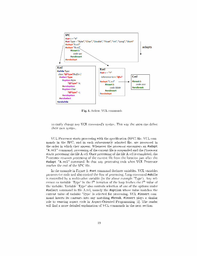
Fig. 1. Salient VCL commands
to easily change any VCL command's syntax. This way the users can de�netheir own syntax.
VCL Processor starts processing with the speci�cation (SPC) �le. VCL com-mands in the SPC, and in each subsequently adapted �le, are processed inthe order in which they appear. Whenever the processor encounters an #adapt"A.vcl" command, processing of the current �le is suspended and the Processorstarts processing the �le A.vcl. Once processing of the �le A.vcl is completed, theProcessor resumes processing of the current �le from the location just after the#adapt "A.vcl" command. In that way processing ends when VCL Processorreaches the end of the SPC �le.
In the example in Figure 1, #set command declares variables. VCL variablesparametrize code and also control the �ow of processing. Loop command #whileis controlled by a multi-value variable (in the above example 'Type'). Any ref-erence to variable 'Type' in the ith iteration of the loop fetches the ith value ofthe variable. Variable 'Type' also controls selection of one of the options under#select command in �le A.vcl, namely the #option whose value matches thecurrent value of variable 'Type' is selected for processing. VCL #insert com-mand inserts its contents into any matching #break. #insert plays a similarrole to weaving aspect code in Aspect-Oriented Programming [1]. The readerwill �nd a more detailed explanation of VCL commands in the next section.
19
3 VCL Commands
3.1 #adapt Command
Figure 2 shows how #adapt commands control the processing �ow of the source�les instrumented with VCL. VCL Processor starts at the �rst line of the SPC.
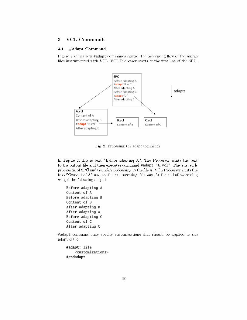
Fig. 2. Processing the adapt commands
In Figure 2, this is text "Before adapting A". The Processor emits the textto the output �le and then executes command #adapt "A.vcl". This suspendsprocessing of SPC and transfers processing to the �le A. VCL Processor emits thetext "Content of A" and continues processing this way. At the end of processingwe get the following output:
Before adapting AContent of ABefore adapting BContent of BAfter adapting BAfter adapting ABefore adapting CContent of CAfter adapting C
#adapt command may specify customizations that should be applied to theadapted �le.
#adapt: file<customizations>
#endadapt
20
Customizations may include any VCL commands. VCL applies customizationsto a designated �le and proceeds to processing it.
3.2 #set Command
#set command declares a VCL variable and sets its value. #set command issimilar to cpp's #define except that VCL variable values propagate across the�les along #adapt links. With the #set command, we can declare single andmulti-value variables. A variable value can be an integer, string or expression.For example:
#set x = 5 %assign integer 5 to x#set y = x %assign value of x to y#set z = y + 2 %assign 7 to z#set a = “text” %string must be enclosed in double-quotes
The value of a multi-value variable is a list of values, for example:
#set X = 1,2,2+1#set Y = ”one”, ”two”, ”three”
In the #set command, a direct reference to variable x can be written ?@x? orsimply x. There are three types of expressions in VCL, namely name, string andarithmetic expressions. Expressions can be used in #set commands to assign avalue to a new variable, and they may also appear anywhere in the source �les.
Name ExpressionA name expression can contain variable references (like ?@x?), and combina-tions of variable references (like ?@x@y@z? or ?@@x?). The value of a nameexpression is computed by applying the '@' operator from right to left. Ateach step, the result of application of '@' is concatenated with the rest ofthe expression. Example 1:
#set a = “b”#set b = 20?@a? %value of a?@@a? %value of (value of a)
Output of the example:
b20
Example 2:
#set x = “y”#set y = “z”#set z = “w”#set yw = “u”
21
#set xu = “q”?@x@y@z?
%Evaluation steps:%1: replace @z with its value "w"%2: replace @yw with its value "u"%3: replace @xu with its value "q"
Output of the example:
q
String ExpressionA string expression can contain any number of name expressions intermixedwith character strings. To evaluate a string expression, we evaluate its com-ponent name expressions from the left to the right replacing them with theirrespective values and concatenating with character strings. Example:
#set x = “y”#set y = “z”#set z = “w”#set yw = “u”#set xu = “q”?@x@y@z?”String”?@xu?
%Evaluation steps:%1: eval ?@x@y@z? -> “q”%2: concat ”String”%3: eval ?@xu? -> “q”
Output of the example:
qStringq
Arithmetic ExpressionIf an expression is a well-formed arithmetic expression, VCL Processor recog-nizes it as such and evaluates its value. An arithmetic expression can contain`+', `-', `*', `/' operators and nested parenthesis can be used. An arithmeticexpression used in #set command must yield to integer. In arithmetic ex-pressions variables can be used by simple reference i.e.:
#set b = a * (c + 2)
3.3 Propagation of VLC Variable Values
Having executed #set x = 10, VCL Processor propagates value of x to all �lesreached along #adapt links. The �rst executed #set x overrides any subse-quently found #set x commands in adapted �les. An exception from the aboverule is the situation where two #set commands assign values to the same variablein the same �le. Example:
22
SPC:#set x = 1#adapt "A.vcl"#set x = 2 %overriding in the same file#adapt "A.vcl"
File A.vcl:#set x = 3 %this command will be ignoredValue of x is: ?@x?
Output of the example:
Value of x is: 1Value of x is: 2
3.4 #output Command
VCL Processor interprets VCL commands and emits any source code found in thevisited �les. VCL #output <path> command speci�es the output �le where thesource code should be placed. The <path> can be absolute or relative path. If theoutput �le is not speci�ed, then VCL Processor emits code to an automaticallygenerated default �le named defaultOutput in the main folder of the installedVCL Processor. It is recommended to use the #output command.
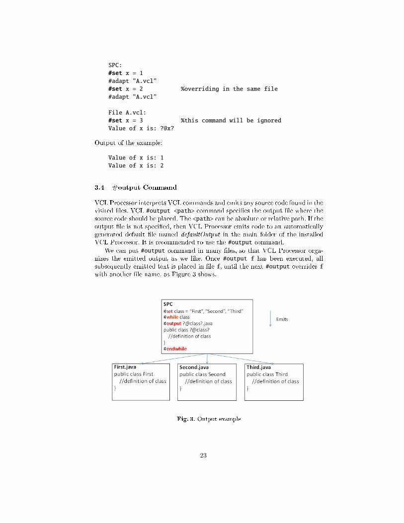
We can put #output command in many �les, so that VCL Processor orga-nizes the emitted output as we like. Once #output f has been executed, allsubsequently emitted text is placed in �le f, until the next #output overrides fwith another �le name, as Figure 3 shows.
Fig. 3. Output example
23
When VCL Processor executes #output <path> and the path does not exist,VCL Processor creates relevant folders and �le. The �rst #output f in a givenprocessing sequence command deletes any existing f and creates a new one. Anysubsequent #output f command in the same processing sequence appends thenew content to the �le.
3.5 #while Command
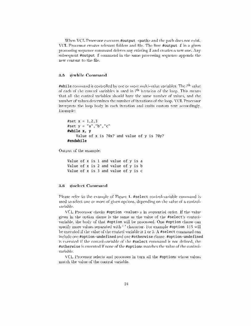
#while command is controlled by one or more multi-value variables. The ith valueof each of the control variables is used in ith iteration of the loop. This meansthat all the control variables should have the same number of values, and thenumber of values determines the number of iterations of the loop. VCL Processorinterprets the loop body in each iteration and emits custom text accordingly.Example:
#set x = 1,2,3#set y = "a","b","c"#while x, y
Value of x is ?@x? and value of y is ?@y?#endwhile
Output of the example:
Value of x is 1 and value of y is aValue of x is 2 and value of y is bValue of x is 3 and value of y is c
3.6 #select Command
Please refer to the example of Figure 1. #select control-variable command isused to select one or more of given options, depending on the value of a control-variable.
VCL Processor checks #option <value>-s in sequential order. If the valuegiven in the option clause is the same as the value of the #select`s control-variable, the body of that #option will be processed. One #option clause canspecify more values separated with `|' character. For example #option 1|5 willbe executed if the value of the control variable is 1 or 5. A #select command caninclude one #option-undefined and one #otherwise clause. #option-undefinedis executed if the control-variable of the #select command is not de�ned, the#otherwise is executed if none of the #options matches the value of the control-variable.
VCL Processor selects and processes in turn all the #options whose valuesmatch the value of the control variable.
24
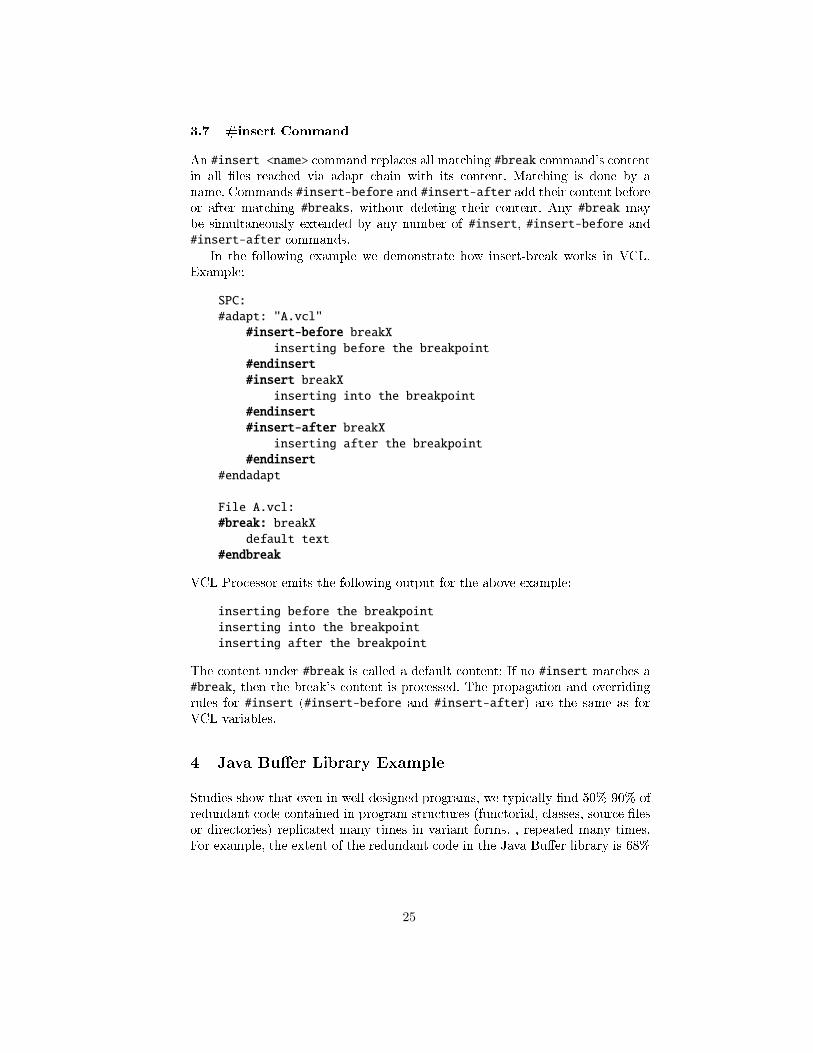
3.7 #insert Command
An #insert <name> command replaces all matching #break command's contentin all �les reached via adapt chain with its content. Matching is done by aname. Commands #insert-before and #insert-after add their content beforeor after matching #breaks, without deleting their content. Any #break maybe simultaneously extended by any number of #insert, #insert-before and#insert-after commands.
In the following example we demonstrate how insert-break works in VCL.Example:
SPC:#adapt: "A.vcl"
#insert-before breakXinserting before the breakpoint
#endinsert#insert breakX
inserting into the breakpoint#endinsert#insert-after breakX
inserting after the breakpoint#endinsert
#endadapt
File A.vcl:#break: breakX
default text#endbreak
VCL Processor emits the following output for the above example:
inserting before the breakpointinserting into the breakpointinserting after the breakpoint
The content under #break is called a default content: If no #insert matches a#break, then the break's content is processed. The propagation and overridingrules for #insert (#insert-before and #insert-after) are the same as forVCL variables.
4 Java Bu�er Library Example
Studies show that even in well-designed programs, we typically �nd 50%-90% ofredundant code contained in program structures (functorial, classes, source �lesor directories) replicated many times in variant forms. , repeated many times.For example, the extent of the redundant code in the Java Bu�er library is 68%
25
[9], in parts of STL (C++) - over 50% [2], in J2EE Web Portals � 61% [18], andin certain ASP Web portal modules � up to 90% [15].
Redundant code obstructs program understanding during software mainte-nance. The engineering bene�ts of non-redundancy become evident especiallyif we pay attention to large granularity clones. In this section we demonstrateVCL's potential to reduce program complexity by eliminating redundant codes.
4.1 An Overview of the Original Bu�er Library
A bu�er contains data in a linear sequence for reading and writing [14]. Bu�erclasses di�er in features such as a bu�er element type, memory allocation scheme,byte ordering and access mode, as described in [8]. Bu�er classes can be foundin java.nio package. Each legal combination of features yields a unique bu�erclass. That is why, even though all the bu�er classes play essentially the samerole, there are 74 classes in the Java Bu�er library.
Bu�er classes di�er one from another in bu�er element type (byte, char,int, �oat, double, long,short), memeory allocation scheme (direct, indirect), byteordering(native, non-native, big endian, little endian) and access mode (writable,read-only). Classes that di�er in certain features are similar one to another.Earlier studies showed that it is di�cult to eliminate these redundancies withconventional techniques such as generics and refactorings.
4.2 Bu�er Classes in VCL
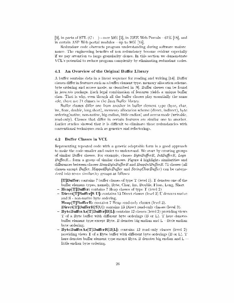
Representing repeated code with a generic adaptable form is a good approachto make the code smaller and easier to understand. We start by creating groupsof similar Bu�er classes. For example, classes ByteBu�erR, IntBu�erR, Logn-Bu�erR... form a group of similar classes. Figure 4 highlights similarities anddi�erences between classes HeapByteBu�erR and HeapIntBu�erR. 71 classes (allclasses except Bu�er, MappedByteBu�er and StringCharBu�er) can be catego-rized into seven similartity groups as follows:
� [T]Bu�er: contains 7 bu�er classes of type T (level 1). T denotes one of thebu�er element types, namely, Byte, Char, Int, Double, Float, Long, Short
� Heap[T]Bu�er: contains 7 Heap classes of type T (level 2)� Direct[T]Bu�er[S|U]: contains 13 Direct classes (level 2) U denotes nativeand S - non-native byte ordering.
� Heap[T]Bu�erR: contains 7 Heap read-only classes (level 3).� Direct[T]Bu�erR[S|U]: contains 13 Direct read-only classes (level 3).� ByteBu�erAs[T]Bu�er[B|L]: contains 12 classes (level 2) providing viewsT of a Byte bu�er with di�erent byte orderings (B or L). T here denotesbu�er element type except Byte. B denotes big endian and L � little endianbyte ordering.
� ByteBu�erAs[T]Bu�erR[B|L]: contains 12 read-only classes (level 2)providing views T of a Byte bu�er with di�erent byte orderings (B or L). There denotes bu�er element type except Byte. B denotes big endian and L �little endian byte ordering.
26
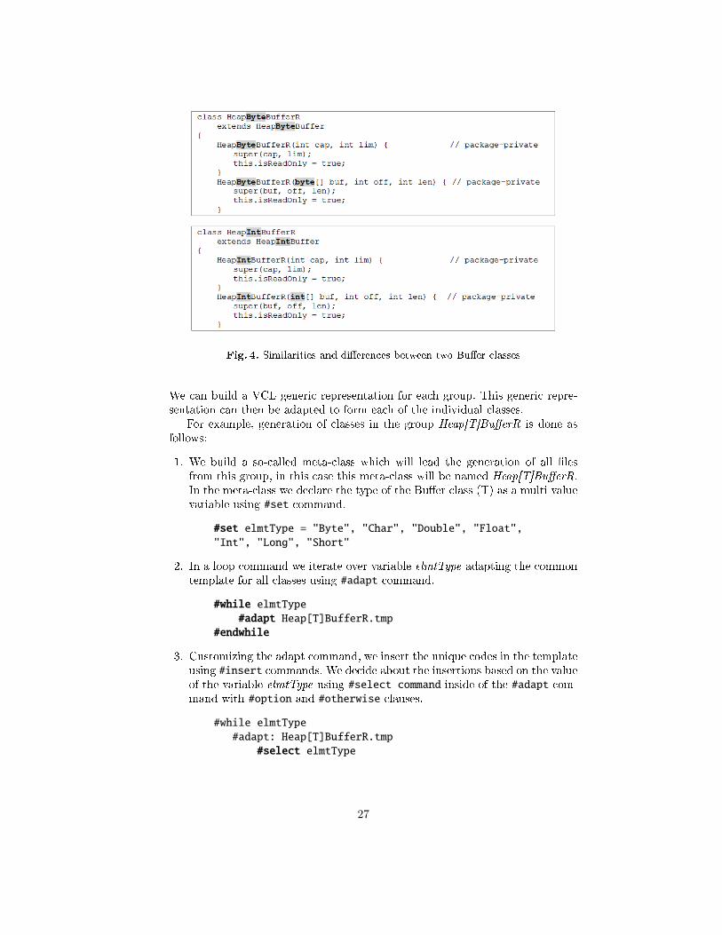
Fig. 4. Similarities and di�erences between two Bu�er classes
We can build a VCL generic representation for each group. This generic repre-sentation can then be adapted to form each of the individual classes.
For example, generation of classes in the group Heap[T]Bu�erR is done asfollows:
1. We build a so-called meta-class which will lead the generation of all �lesfrom this group, in this case this meta-class will be named Heap[T]Bu�erR.In the meta-class we declare the type of the Bu�er class (T) as a multi valuevariable using #set command.
#set elmtType = "Byte", "Char", "Double", "Float","Int", "Long", "Short"
2. In a loop command we iterate over variable elmtType adapting the commontemplate for all classes using #adapt command.
#while elmtType#adapt Heap[T]BufferR.tmp
#endwhile
3. Customizing the adapt command, we insert the unique codes in the templateusing #insert commands. We decide about the insertions based on the valueof the variable elmtType using #select command inside of the #adapt com-mand with #option and #otherwise clauses.
#while elmtType#adapt: Heap[T]BufferR.tmp
#select elmtType
27
#option Byte#insert-after moreMethods
#adapt byteMoreMethods#endinsert
#endoption#option Char
#insert-after moreMethods#adapt charMoreMethods
#endinsert#insert toString
#adapt chartoString#endinsert
#endoption#otherwise
#insert-after moreMethods#adapt otherMethods
#endinsert#endotherwise
#endselect#endadapt
#endwhile
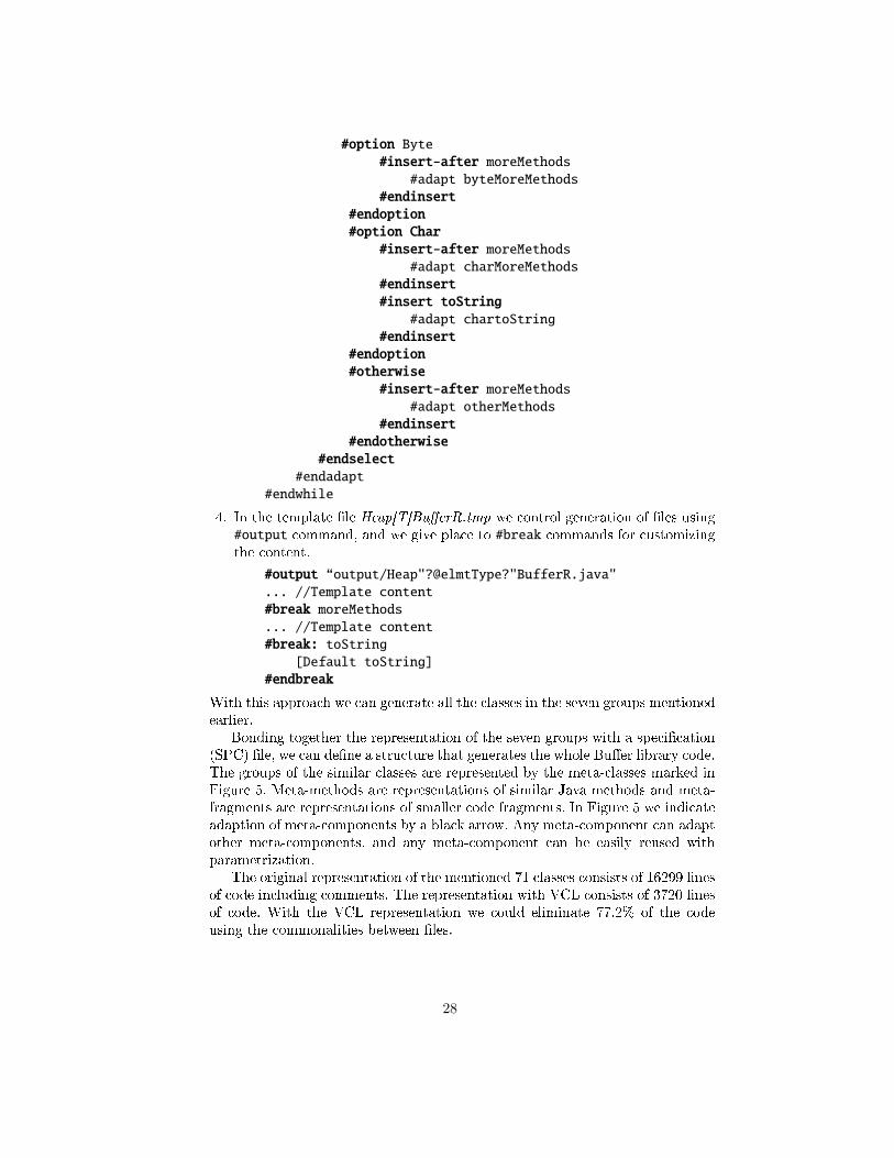
4. In the template �le Heap[T]Bu�erR.tmp we control generation of �les using#output command, and we give place to #break commands for customizingthe content.
#output “output/Heap"?@elmtType?"BufferR.java"... //Template content#break moreMethods... //Template content#break: toString
[Default toString]#endbreak
With this approach we can generate all the classes in the seven groups mentionedearlier.
Bonding together the representation of the seven groups with a speci�cation(SPC) �le, we can de�ne a structure that generates the whole Bu�er library code.The groups of the similar classes are represented by the meta-classes marked inFigure 5. Meta-methods are representations of similar Java methods and meta-fragments are representations of smaller code fragments. In Figure 5 we indicateadaption of meta-components by a black arrow. Any meta-component can adaptother meta-components, and any meta-component can be easily reused withparametrization.
The original representation of the mentioned 71 classes consists of 16299 linesof code including comments. The representation with VCL consists of 3720 linesof code. With the VCL representation we could eliminate 77.2% of the codeusing the commonalities between �les.
28
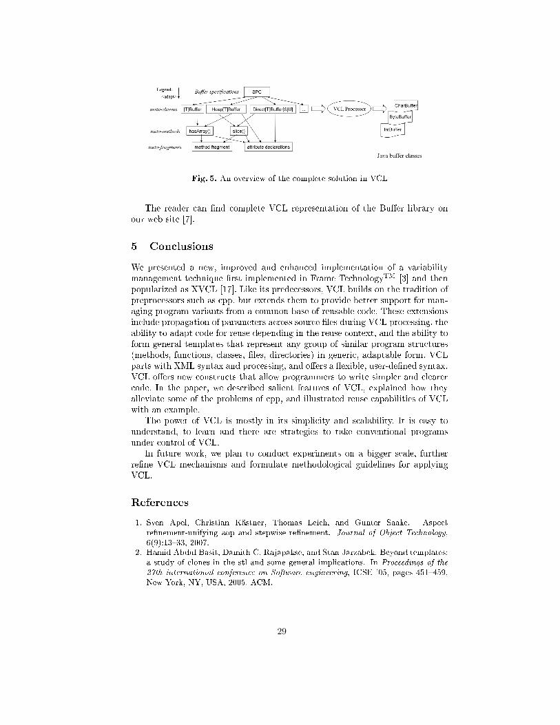
Fig. 5. An overview of the complete solution in VCL
The reader can �nd complete VCL representation of the Bu�er library onour web site [7].
5 Conclusions
We presented a new, improved and enhanced implementation of a variabilitymanagement technique �rst implemented in Frame TechnologyTM [3] and thenpopularized as XVCL [17]. Like its predecessors, VCL builds on the tradition ofpreprocessors such as cpp, but extends them to provide better support for man-aging program variants from a common base of reusable code. These extensionsinclude propagation of parameters across source �les during VCL processing, theability to adapt code for reuse depending in the reuse context, and the ability toform general templates that represent any group of similar program structures(methods, functions, classes, �les, directories) in generic, adaptable form. VCLparts with XML syntax and processing, and o�ers a �exible, user-de�ned syntax.VCL o�ers new constructs that allow programmers to write simpler and clearercode. In the paper, we described salient features of VCL, explained how theyalleviate some of the problems of cpp, and illustrated reuse capabilities of VCLwith an example.
The power of VCL is mostly in its simplicity and scalability. It is easy tounderstand, to learn and there are strategies to take conventional programsunder control of VCL.
In future work, we plan to conduct experiments on a bigger scale, furtherre�ne VCL mechanisms and formulate methodological guidelines for applyingVCL.
References
1. Sven Apel, Christian Kästner, Thomas Leich, and Gunter Saake. Aspectre�nement-unifying aop and stepwise re�nement. Journal of Object Technology,6(9):13�33, 2007.
2. Hamid Abdul Basit, Damith C. Rajapakse, and Stan Jarzabek. Beyond templates:a study of clones in the stl and some general implications. In Proceedings of the
27th international conference on Software engineering, ICSE '05, pages 451�459,New York, NY, USA, 2005. ACM.
29
3. P. Bassett. Framing software reuse - lessons from real world, 1997.4. P. Clements and D. Muthig. Proc. workshop on variability management � working
with variation mechanisms, 2006.5. Paul Clements and Linda Northrop. Software product lines. Addison-Wesley
Boston, 2002.6. S. Jarzabek. E�ective software maintenance and evolution: Reuse-based approach,
2007.7. S. Jarzabek and D. Daniel. Variant con�guration language. http://vcl.comp.nus.edu.sg, 2013.
8. S. Jarzabek and S Li. Unifying clones with a generative programming technique:a case study. J. Softw. Maint. Evol.: Res. Pract., pages 267�-292, 2006.
9. Stan Jarzabek and Li Shubiao. Eliminating redundancies with a "compositionwith adaptation" meta-programming technique. SIGSOFT Softw. Eng. Notes,28(5):237�246, September 2003.
10. Anssi Karhinen, Alexander Ran, and Tapio Tallgren. Con�guring designs for reuse.In Proceedings of the 19th international conference on Software engineering, ICSE'97, pages 701�710, New York, NY, USA, 1997. ACM.
11. C. Kastner, S. Apel, and D. Batory. A case study implementing features using as-pectj. In Software Product Line Conference, 2007. SPLC 2007. 11th International,pages 223�232, 2007.
12. Christian Kästner, Sven Apel, and Martin Kuhlemann. Granularity in softwareproduct lines. In Proceedings of the 30th international conference on Software
engineering, ICSE '08, pages 311�320, New York, NY, USA, 2008. ACM.13. Gregor Kiczales, John Lamping, Anurag Mendhekar, Chris Maeda, Cristina Lopes,
Jean-Marc Loingtier, and John Irwin. Aspect-oriented programming. Springer,1997.
14. Oracle. Bu�er javadoc. http://docs.oracle.com/javase/6/docs/api/java/nio/Buffer.html, 2011.
15. Ulf Pettersson and Stan Jarzabek. An industrial application of a reuse techniqueto a web portal product line. submitted for publication, 2005.
16. Henry Spencer and Geo� Collyer. Ifdef considered harmful, or portability experi-ence with c news, 1992.
17. National University of Singapore (XVCL) Team. Xml-based variant con�gurationlanguage. http://xvcl.comp.nus.edu.sg, 2011.
18. J. Yang and S. Jarzabek. Applying a generative technique for enhanced reuseon jee platform. Conf. on Generative Programming and Component Engineering,(4):237�255, September 2005.
30
Identifying Code Clones with RefactorErl ?
Viktoria Fordos, Melinda Toth
ELTE-Soft Ltd., Eotvos Lorand University, Budapest, Hungary{f-viktoria,tothmelinda}@elte.hu
Abstract. Code clones, the results of “copy&paste programming”, havea negative impact on software maintenance. Therefore several tools andtechniques have been developed to identify them in the source code.However most of them concentrate on imperative, well known languages.In this paper we give an AST/metric based clone detection algorithm forthe functional programming language Erlang and evaluate it on an opensource project.
1 Introduction
Duplicated code detectors are software [2, 5, 13, 16], which help in the identifica-tion of duplicates. Various approaches have been proposed, including the analysisof code tokens [11], the syntax tree built up using the tokens [7], and using dif-ferent metrics [14]. The majority of these methods and algorithms have beenconstructed specifically for the most common programming paradigm today,that is imperative programming, and for the leading imperative programminglanguages.
Imperative programming languages have several duplicates detector algo-rithms and software, whilst in functional programming only a few exist, such as[9] developed for the Haskell language, and [12] for the Erlang [1] language.
Most duplicated code detection software do not work directly on the sourcecode, but rather on a transformed representation. Such representations includethe series of tokens and the abstract syntax tree, from which crucial informationfor the analysis can be retrieved faster and more efficiently. RefactorErl [4, 8, 18]is a static source code analyser and transformer tool for Erlang, that provides arepresentation that contains more information about the source beyond that ofthe abstract syntax tree.
In this paper we show an AST/metric based algorithm for duplicated codedetection in Erlang programs. The implementation of this work uses the Refac-torErl framework. A short test run is also presented to show the results of thealgorithm on open source projects.
? Supported by Ericsson–ELTE-Soft–ELTE Software Technology Lab
31
2 Erlang & RefactorErl
2.1 Erlang
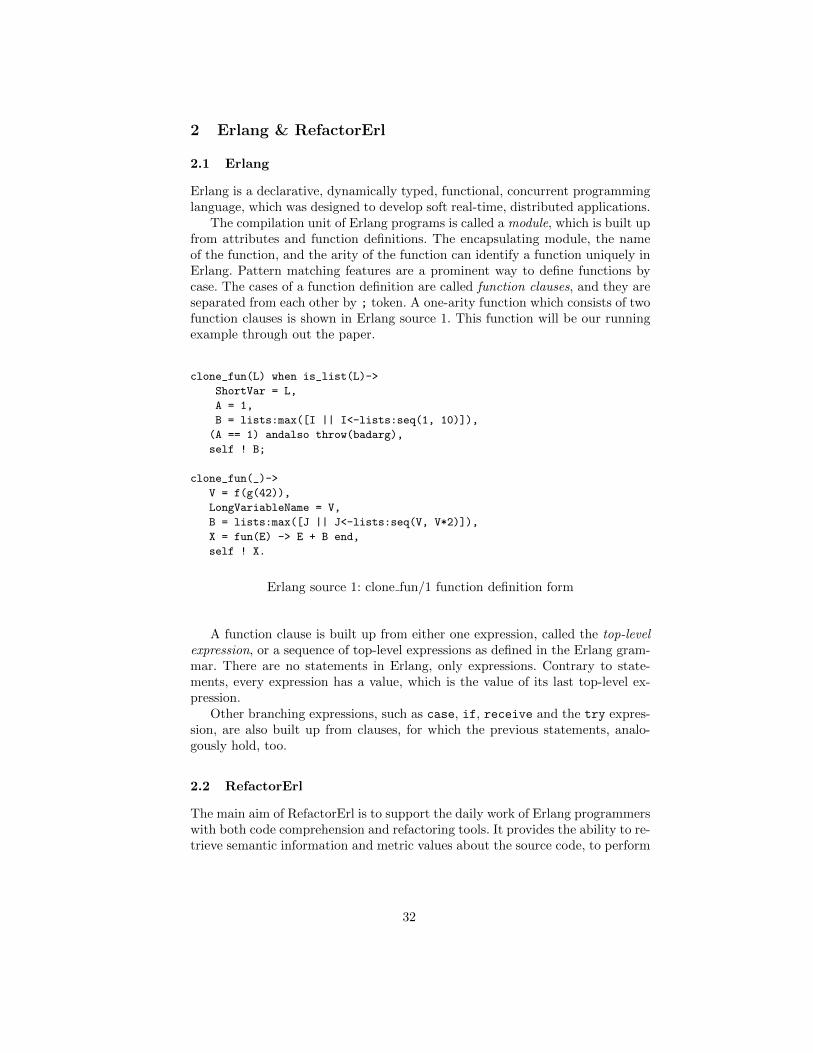
Erlang is a declarative, dynamically typed, functional, concurrent programminglanguage, which was designed to develop soft real-time, distributed applications.
The compilation unit of Erlang programs is called a module, which is built upfrom attributes and function definitions. The encapsulating module, the nameof the function, and the arity of the function can identify a function uniquely inErlang. Pattern matching features are a prominent way to define functions bycase. The cases of a function definition are called function clauses, and they areseparated from each other by ; token. A one-arity function which consists of twofunction clauses is shown in Erlang source 1. This function will be our runningexample through out the paper.
clone_fun(L) when is_list(L)->
ShortVar = L,
A = 1,
B = lists:max([I || I<-lists:seq(1, 10)]),
(A == 1) andalso throw(badarg),
self ! B;
clone_fun(_)->
V = f(g(42)),
LongVariableName = V,
B = lists:max([J || J<-lists:seq(V, V*2)]),
X = fun(E) -> E + B end,
self ! X.
Erlang source 1: clone fun/1 function definition form
A function clause is built up from either one expression, called the top-levelexpression, or a sequence of top-level expressions as defined in the Erlang gram-mar. There are no statements in Erlang, only expressions. Contrary to state-ments, every expression has a value, which is the value of its last top-level ex-pression.
Other branching expressions, such as case, if, receive and the try expres-sion, are also built up from clauses, for which the previous statements, analo-gously hold, too.
2.2 RefactorErl
The main aim of RefactorErl is to support the daily work of Erlang programmerswith both code comprehension and refactoring tools. It provides the ability to re-trieve semantic information and metric values about the source code, to perform
32
dependency analysis and to visualise the results of the analysis. It facilitatescode reorganisation with clustering algorithms and several refactoring methods.The incremental and asynchronous analyser architecture allows the programmerto track source code changes. The tool has multiple user interfaces to choosefrom. These include a web-based interface, an interactive console or one can useEmacs or Vim with RefactorErl plugins.
The source code has to be loaded into RefactorErl in order to be analysed.The code is first transformed into a series of tokens using whitespace- and layout-preserving lexical analysis, and is then passed on to the RefactorErl preprocessor.After preprocessing, the abstract syntax tree is constructed from the token seriesbased on Erlang syntactical rules. Next, semantic analysers decorate the ASTwith attributes and links, resulting in a graph, called Semantic Program Graph,which is the internal data model of RefactorErl.
The labelled vertices of the Semantic Program Graph are the lexical, syntac-tic and semantic units of the source code, while the directed edges between themrepresent the lexical, syntactic and semantic relations between the entities. Infor-mation from the Semantic Program Graph is gathered by the evaluation of pathexpressions and traversal of the graph. For this purpose, RefactorErl provides acomplete, high-level API.
The algorithm presented in this paper uses information from the SemanticProgram Graph and metrics of RefactorErl.
3 Clone IdentifiErl
In this section, we present a new algorithm for clone detection. Our algorithmcombines a number of existing techniques, but introduces a novel filtering com-ponent, as described in Section 3.4. As to our current knowledge these techniqueshave never been used specifically in Erlang.
What does clone detection mean intuitively? One may try to compare ev-ery code fragment to every other. The original representation of a code is tooparticular, thus generalisation is needed and the generalised form of code needsto be used. The similarity of each pair of code fragments can be representedby a matrix. The first component of our algorithm produces this matrix, whichis detailed in Section 3.2. From this matrix, the initial clones can be extractedalong diagonals. This is what the second component of our algorithm does, whichis described in Section 3.3. Irrelevant clones can be found among these clones,which are removed by evaluating filters which are described in Section 3.4. Theideas behind each filter have been based on case studies using Mnesia[3].
3.1 Unit
The generalisation part of the first component of the algorithm is described inthis section.
33
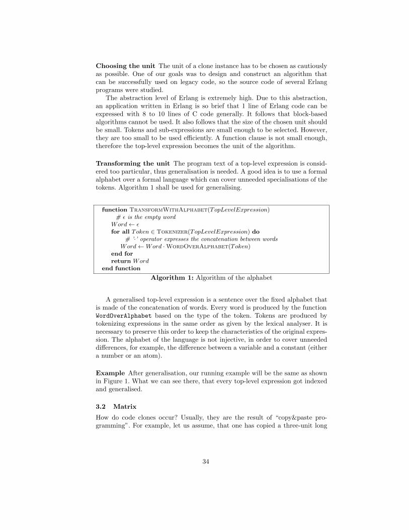
Choosing the unit The unit of a clone instance has to be chosen as cautiouslyas possible. One of our goals was to design and construct an algorithm thatcan be successfully used on legacy code, so the source code of several Erlangprograms were studied.
The abstraction level of Erlang is extremely high. Due to this abstraction,an application written in Erlang is so brief that 1 line of Erlang code can beexpressed with 8 to 10 lines of C code generally. It follows that block-basedalgorithms cannot be used. It also follows that the size of the chosen unit shouldbe small. Tokens and sub-expressions are small enough to be selected. However,they are too small to be used efficiently. A function clause is not small enough,therefore the top-level expression becomes the unit of the algorithm.
Transforming the unit The program text of a top-level expression is consid-ered too particular, thus generalisation is needed. A good idea is to use a formalalphabet over a formal language which can cover unneeded specialisations of thetokens. Algorithm 1 shall be used for generalising.
function TransformWithAlphabet(TopLevelExpression)# ε is the empty word
Word← εfor all Token ∈ Tokenizer(TopLevelExpression) do
# ’·’ operator expresses the concatenation between wordsWord←Word ·WordOverAlphabet(Token)
end forreturn Word
end function
Algorithm 1: Algorithm of the alphabet
A generalised top-level expression is a sentence over the fixed alphabet thatis made of the concatenation of words. Every word is produced by the functionWordOverAlphabet based on the type of the token. Tokens are produced bytokenizing expressions in the same order as given by the lexical analyser. It isnecessary to preserve this order to keep the characteristics of the original expres-sion. The alphabet of the language is not injective, in order to cover unneededdifferences, for example, the difference between a variable and a constant (eithera number or an atom).
Example After generalisation, our running example will be the same as shownin Figure 1. What we can see there, that every top-level expression got indexedand generalised.
3.2 Matrix
How do code clones occur? Usually, they are the result of “copy&paste pro-gramming”. For example, let us assume, that one has copied a three-unit long
34
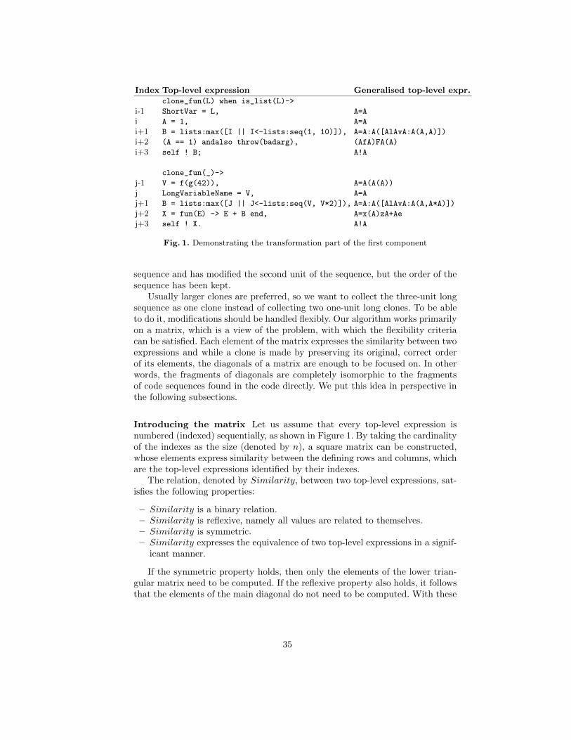
Index Top-level expression Generalised top-level expr.
clone_fun(L) when is_list(L)->
i-1 ShortVar = L, A=A
i A = 1, A=A
i+1 B = lists:max([I || I<-lists:seq(1, 10)]), A=A:A([AlAvA:A(A,A)])
i+2 (A == 1) andalso throw(badarg), (AfA)FA(A)
i+3 self ! B; A!A
clone_fun(_)->
j-1 V = f(g(42)), A=A(A(A))
j LongVariableName = V, A=A
j+1 B = lists:max([J || J<-lists:seq(V, V*2)]), A=A:A([AlAvA:A(A,A*A)])
j+2 X = fun(E) -> E + B end, A=x(A)zA+Ae
j+3 self ! X. A!A
Fig. 1. Demonstrating the transformation part of the first component
sequence and has modified the second unit of the sequence, but the order of thesequence has been kept.
Usually larger clones are preferred, so we want to collect the three-unit longsequence as one clone instead of collecting two one-unit long clones. To be ableto do it, modifications should be handled flexibly. Our algorithm works primarilyon a matrix, which is a view of the problem, with which the flexibility criteriacan be satisfied. Each element of the matrix expresses the similarity between twoexpressions and while a clone is made by preserving its original, correct orderof its elements, the diagonals of a matrix are enough to be focused on. In otherwords, the fragments of diagonals are completely isomorphic to the fragmentsof code sequences found in the code directly. We put this idea in perspective inthe following subsections.
Introducing the matrix Let us assume that every top-level expression isnumbered (indexed) sequentially, as shown in Figure 1. By taking the cardinalityof the indexes as the size (denoted by n), a square matrix can be constructed,whose elements express similarity between the defining rows and columns, whichare the top-level expressions identified by their indexes.
The relation, denoted by Similarity, between two top-level expressions, sat-isfies the following properties:
– Similarity is a binary relation.– Similarity is reflexive, namely all values are related to themselves.– Similarity is symmetric.– Similarity expresses the equivalence of two top-level expressions in a signif-
icant manner.
If the symmetric property holds, then only the elements of the lower trian-gular matrix need to be computed. If the reflexive property also holds, it followsthat the elements of the main diagonal do not need to be computed. With these
35
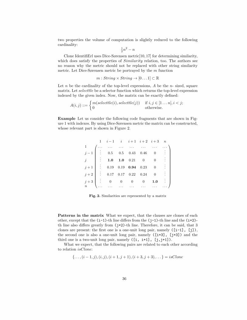
two properties the volume of computation is slightly reduced to the followingcardinality:
12n
2 − n
Clone IdentifiErl uses Dice-Sørensen metric[10, 17] for determining similarity,which does satisfy the properties of Similarity relation, too. The authors seeno reason why the metric should not be replaced with other string similaritymetric. Let Dice-Sørensen metric be portrayed by the m function
m : String × String → [0 . . . 1] ⊂ R
Let n be the cardinality of the top-level expressions, A be the n- sized, squarematrix. Let selecttle be a selector function which returns the top-level expressionindexed by the given index. Now, the matrix can be exactly defined:
A(i, j) ::=
{m(selecttle(i), selecttle(j)) if i, j ∈ [1 . . . n], i < j;0 otherwise.
Example Let us consider the following code fragments that are shown in Fig-ure 1 with indexes. By using Dice-Sørensen metric the matrix can be constructed,whose relevant part is shown in Figure 2.
1 i− 1 i i+ 1 i+ 2 i+ 3 n
1 . . . . . . . . . . . . . . . . . . . . .
j − 1... 0.5 0.5 0.43 0.46 0
...
j... 1.0 1.0 0.21 0 0
...
j + 1... 0.19 0.19 0.94 0.23 0
...
j + 2... 0.17 0.17 0.22 0.24 0
...
j + 3... 0 0 0 0 1.0
...n . . . . . . . . . . . . . . . . . . . . .
Fig. 2. Similarities are represented by a matrix
Patterns in the matrix What we expect, that the clauses are clones of eachother, except that the (i-1)-th line differs from the (j-1)-th line and the (i+2)-th line also differs greatly from (j+2)-th line. Therefore, it can be said, that 3clones are present: the first one is a one-unit long pair, namely ([i-1], [j]),the second one is also a one-unit long pair, namely ([i+3], [j+3]) and thethird one is a two-unit long pair, namely ([i, i+1], [j,j+1]).
What we expect, that the following pairs are related to each other accordingto relation isClone:
{. . . , (i− 1, j), (i, j), (i + 1, j + 1), (i + 3, j + 3), . . . } = isClone
36
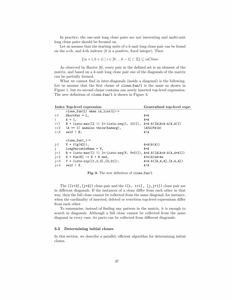
In practice, the one-unit long clone pairs are not interesting and multi-unitlong clone pairs should be focused on.
Let us assume that the starting units of a k-unit long clone pair can be foundon the a-th, and b-th indexes (k is a positive, fixed integer). Then
{(a + i, b + i) | i ∈ [0 . . . k − 1] ⊂ Z} ⊆ isClone
As observed by Baxter [6], every pair in the defined set is an element of thematrix, and based on a k-unit long clone pair one of the diagonals of the matrixcan be partially formed.
What we cannot find in inter-diagonals (inside a diagonal) is the following.Let us assume that the first clause of clone fun/1 is the same as shown inFigure 1, but its second clause contains one newly inserted top-level expression.The new definition of clone fun/1 is shown in Figure 3.
Index Top-level expression Generalised top-level expr.
clone_fun(L) when is_list(L)->
i-1 ShortVar = L, A=A
i A = 1, A=A
i+1 B = lists:max([I || I<-lists:seq(1, 10)]), A=A:A([AlAvA:A(A,A)])
i+2 (A == 1) andalso throw(badarg), (AfA)FA(A)
i+3 self ! B; A!A
clone_fun(_)->
j-1 V = f(g(42)), A=A(A(A))
j LongVariableName = V, A=A
j+1 B = lists:max([J || J<-lists:seq(V, V*2)]), A=A:A([AlAvA:A(A,A*A)])
j+2 X = fun(E) -> E + B end, A=x(A)zA+Ae
j+3 Y = lists:zip([1,2,3],[3,21]), A=A:A([A,A,A],[A,A,A])
j+4 self ! X. A!A
Fig. 3. The new definition of clone fun/1
The ([i+3],[j+4]) clone pair and the ([i, i+1], [j,j+1]) clone pair arein different diagonals. If the instances of a clone differ from each other in thatway, then the full clone cannot be collected from the same diagonal, for instance,when the cardinality of inserted, deleted or rewritten top-level expressions differfrom each other.
To summarise, instead of finding any pattern in the matrix, it is enough tosearch in diagonals. Although a full clone cannot be collected from the samediagonal in every case, its parts can be collected from different diagonals.
3.3 Determining initial clones
In this section, we describe a parallel, efficient algorithm for determining initialclones.
37
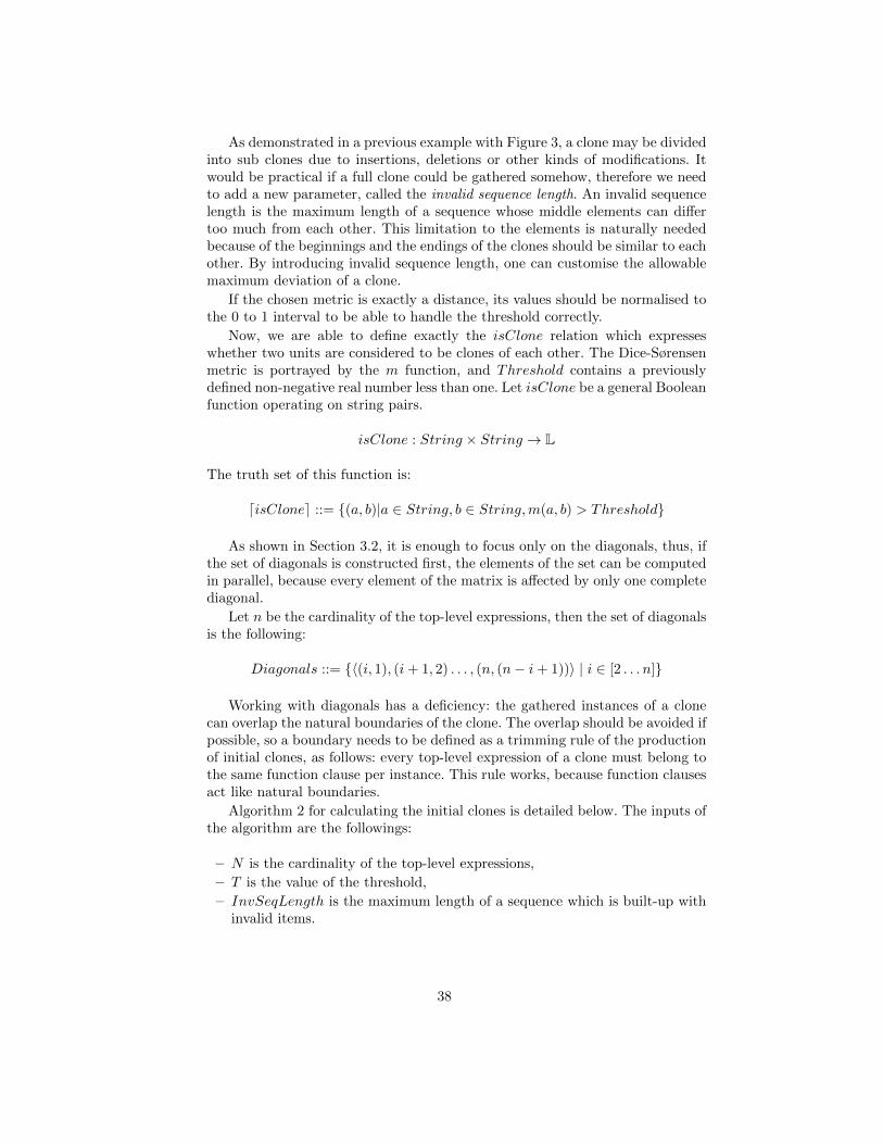
As demonstrated in a previous example with Figure 3, a clone may be dividedinto sub clones due to insertions, deletions or other kinds of modifications. Itwould be practical if a full clone could be gathered somehow, therefore we needto add a new parameter, called the invalid sequence length. An invalid sequencelength is the maximum length of a sequence whose middle elements can differtoo much from each other. This limitation to the elements is naturally neededbecause of the beginnings and the endings of the clones should be similar to eachother. By introducing invalid sequence length, one can customise the allowablemaximum deviation of a clone.
If the chosen metric is exactly a distance, its values should be normalised tothe 0 to 1 interval to be able to handle the threshold correctly.
Now, we are able to define exactly the isClone relation which expresseswhether two units are considered to be clones of each other. The Dice-Sørensenmetric is portrayed by the m function, and Threshold contains a previouslydefined non-negative real number less than one. Let isClone be a general Booleanfunction operating on string pairs.
isClone : String × String → L
The truth set of this function is:
disClonee ::= {(a, b)|a ∈ String, b ∈ String,m(a, b) > Threshold}
As shown in Section 3.2, it is enough to focus only on the diagonals, thus, ifthe set of diagonals is constructed first, the elements of the set can be computedin parallel, because every element of the matrix is affected by only one completediagonal.
Let n be the cardinality of the top-level expressions, then the set of diagonalsis the following:
Diagonals ::= {〈(i, 1), (i + 1, 2) . . . , (n, (n− i + 1))〉 | i ∈ [2 . . . n]}
Working with diagonals has a deficiency: the gathered instances of a clonecan overlap the natural boundaries of the clone. The overlap should be avoided ifpossible, so a boundary needs to be defined as a trimming rule of the productionof initial clones, as follows: every top-level expression of a clone must belong tothe same function clause per instance. This rule works, because function clausesact like natural boundaries.
Algorithm 2 for calculating the initial clones is detailed below. The inputs ofthe algorithm are the followings:
– N is the cardinality of the top-level expressions,
– T is the value of the threshold,
– InvSeqLength is the maximum length of a sequence which is built-up withinvalid items.
38
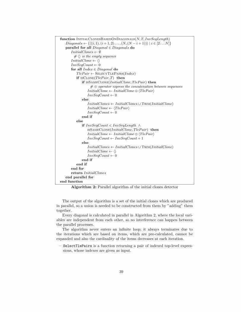
function InitialClonesBasedOnDiagonals(N,T, InvSeqLength)Diagonals← {〈(i, 1), (i+ 1, 2) . . . , (N, (N − i+ 1))〉 | i ∈ [2 . . . N ]}parallel for all Diagonal ∈ Diagonals do
InitialClones← ∅# 〈〉 is the empty sequence
InitialClone← 〈〉InvSeqCount← 0for all Index ∈ Diagonal do
T lePair ← SelectTlePairs(Index)if isClone(T lePair, T ) then
if isSameClone(InitialClone, T lePair) then# ⊕ operator express the concatenation between sequences
InitialClone← InitialClone⊕ 〈T lePair〉InvSeqCount← 0
elseInitialClones← InitialClones ∪Trim(InitialClone)InitialClone← 〈T lePair〉InvSeqCount← 0
end ifelse
if InvSeqCount < InvSeqLength ∧isSameClone(InitialClone, T lePair) thenInitialClone← InitialClone⊕ 〈T lePair〉InvSeqCount← InvSeqCount+ 1
elseInitialClones← InitialClones ∪Trim(InitialClone)InitialClone← 〈〉InvSeqCount← 0
end ifend if
end forreturn InitialClones
end parallel forend function
Algorithm 2: Parallel algorithm of the initial clones detector
The output of the algorithm is a set of the initial clones which are producedin parallel, so a union is needed to be constructed from them by ”adding” themtogether.
Every diagonal is calculated in parallel in Algorithm 2, where the local vari-ables are independent from each other, so no interference can happen betweenthe parallel processes.
The algorithm never enters an infinite loop; it always terminates due tothe iterations which are based on items, which are pre-calculated, cannot beexpanded and also the cardinality of the items decreases at each iteration.
– SelectTlePairs is a function returning a pair of indexed top-level expres-sions, whose indexes are given as input.
39
– isClone is a function which determines if the given pair can form a clone byexamining whether the calculated metric is greater then the given threshold.
– isSameClone is a function which determines if the given pair can be ap-pended to the actual clone (InitialClone). A pair can be appended to thegiven clone only if the top-level expressions of the resulting clone belong tothe same function clause per instance. This limitation is needed, because asmentioned above, overlapping must be avoided.
– Trim is a function which trims the beginnings and endings of the given pair.It is needed because invalid items may occur in the forming sequence ofa clone. Invalid items are only allowed in the middle of the sequence, asdescribed above, so the beginnings and endings of a pair must be cut out.
Example The three initial clones which are detected by the described algorithmwith using 1 for invalid sequence length are shown below:
1. LongVariableName = Var and ShortVar = L
2. A = 1,
B = lists:max([I || I<-lists:seq(1, 10)]),
(A == 1) andalso throw(badarg),
self ! B andLongVariableName = Var,
B = lists:max([J || J<-lists:seq(Var, Var*2)]),
X = fun(E) -> E + B end,
self ! X
3. A = 1 and ShortVar = L
Alternative method A more efficient way might be to exploit transitivity incalculating the elements of the matrix. In order to do so, we need to replace thestring similarity metric with a transitive relation.
Let us assume that isClone is a binary relation between duplicates. Twoitems are duplicates of each other if the value of the Dice-Sørensen metric (DC)computed for them is greater then 0.3. The relation isClone is not transitivebecause of the intransitivity of the string similarity metric, consider the followingexample:
DC(”aabb”, ”bbcc”) = 0.33 > 0.3 =⇒ (”aabb”, ”bbcc”) ∈ isClone,
DC(”bbcc”, ”ccdd”) = 0.33 > 0.3 =⇒ (”bbcc”, ”ccdd”) ∈ isClone,
DC(”aabb”, ”ccdd”) = 0.0 < 0.3 =⇒ (”bbcc”, ”ccdd”) /∈ isClone.
3.4 Filtering and trimming unit
A parallel algorithm for a new filtering system is detailed in this section.In practice, the set of initial clones is too large and contains many false
positive or irrelevant clones, therefore further operations are needed to narrow
40
down the result set. An example for an irrelevant clone can be A = 1 and X =
5.First of all, note the difference between one-unit long, and multi-unit long
clones. Due to the high abstraction level of the alphabet and the usage of thesimilarity metrics, lots of false positive clones appear in the result set of theproduction of initial clones, if only the one-unit long clones are taken into con-sideration. It follows that the filters on one-unit long clones need to be strongerthan the filters on the multi-unit long clones.
In Section 3.3, invalid sequence length is used as a new parameter of thealgorithm. This parameter is also used in the filtering unit to process the multi-unit long clones. During the filtering, it can happen that a multi-unit long cloneis split into a one-unit long clone and the rest of a multi-unit long clone. Inthis case, the one-unit long clone has to be also processed by the filters that arerelevant for one-unit long clones.
As mentioned in Section 2.2, RefactorErl provides ready-to-use source codemetrics and a Semantic Program Graph which is rich in information and easyto query. Thus every filter concentrates only on one characteristic of the code,computed by using the libraries of RefactorErl.
A clone appears in the result set of the algorithm only if it meets all therequirements which are stated in the corresponding filters. For all clone inInitialClones, we have:
∧
Filter∈Filters
Filter(clone) =⇒ clone ∈ ResultClones
If only one clone is examined in each iteration, a parallel algorithm, calledFilteringAndTrimmingUnit, can be constructed along initial clones. If the cur-rently examined clone is a one-unit long clone, then the FiltersForOneLongs
function is responsible for dealing with it, otherwise the FiltersForMultiLongsfunction is the one in charge.
The FiltersForOneLongs function forms the conjunction of the results ofevaluated filters, which are dedicated for one-unit long clones. If the conjunctionis true, then the examined clone is returned, otherwise an empty set is returned.
The FiltersForMultiLongs function, which focuses only on the multi-unitlong clones, is detailed in Algorithm 3.
The input of the FilteringAndTrimmingUnit algorithm is the set of theinitial clones and the invalid sequence length.
The algorithm always terminates, because the cardinality of the unprocesseditems decreases at each iteration.
The output of the algorithm is a set of clones which are produced in parallel,so a union is needed to be constructed from them.
A bit more explanation is needed for the FurtherTrim function. This functionis responsible for trimming invalid items from the beginnings and endings of thegiven clone. The result of a trimming is a set, whose one-unit long elementsare further filtered by the FiltersForOneLongs to check whether the examinedclone fulfils the stronger filters.
41
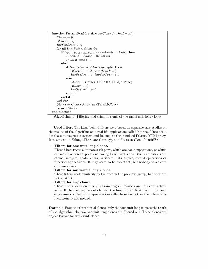
function FiltersForMultiLongs(Clone, InvSeqLength)Clones← ∅AClone← 〈〉InvSeqCount← 0for all UnitPair ∈ Clone do
if ∧FilterFun∈FilterFuns∗FilterFun(UnitPair) thenAClone← AClone⊕ 〈UnitPair〉InvSeqCount← 0
elseif InvSeqCount < InvSeqLength then
AClone← AClone⊕ 〈UnitPair〉InvSeqCount← InvSeqCount+ 1
elseClones← Clones ∪ FurtherTrim(AClone)AClone← 〈〉InvSeqCount← 0
end ifend if
end forClones← Clones ∪ FurtherTrim(AClone)return Clones
end function
Algorithm 3: Filtering and trimming unit of the multi-unit long clones
Used filters The ideas behind filters were based on separate case studies onthe results of the algorithm on a real life application, called Mnesia. Mnesia is adatabase management system and belongs to the standard Erlang/OTP library.It is written in Erlang. There are three types of filters in Clone IdentifiErl:
– Filters for one-unit long clones.These filters try to eliminate such pairs, which are basic expressions, or whichare match or send expressions having basic right sides. Basic expressions areatoms, integers, floats, chars, variables, lists, tuples, record operations orfunction applications. It may seem to be too strict, but nobody takes careof these clones.
– Filters for multi-unit long clones.These filters work similarily to the ones in the previous group, but they arenot so strict.
– Filters for any clones.These filters focus on different branching expressions and list comprehen-sions. If the cardinalities of clauses, the function applications or the headexpressions of the list comprehensions differ from each other then the exam-ined clone is not needed.
Example From the three initial clones, only the four-unit long clone is the resultof the algorithm, the two one-unit long clones are filtered out. These clones areobject-lessons for irrelevant clones.
42
3.5 Short test run on Mnesia
Clone IdentifiErl has been implemented to the best of our knowledge, it is alsoextremely specialised on Erlang.
Clone IdentifiErl was tried out on Mnesia, which has 22594 effective lines ofcode. (The number of empty lines is not included in the sum.) It consists of 31modules, 1687 functions, 5393 top-level expressions.
Clone IdentifiErl detected 801 clone pairs in Mnesia around 120 seconds.Neither irrelevant nor false positive clones were found. The main types of theclones are duplicated configurations, handler branchings, debugging sequences,constructions of validator functions and message processings. A non-trivial ex-ample is shown below.
Left one (found in mnesia_loader):
case ?catch_val(send_compressed) of
{’EXIT’, _} ->
mnesia_lib:set(send_compressed, NoCompression),
NoCompression;
Val -> Val
end
Right one (found in mnesia_controller):
case ?catch_val(no_table_loaders) of
{’EXIT’, _} ->
mnesia_lib:set(no_table_loaders,1),
1;
Val -> Val
end
3.6 Comparison with Wrangler
Wrangler is a refactoring tool for Erlang which introduces a duplicated codedetection algorithm [12]. They build a suffix tree, and calculate the code clonesbased on this representation.
It is hard to compare our result to the result of Wrangler, because the toolswork on different granularity of the source code. Wrangler can identify codeclones inside top-level expressions, while the smallest unit of the analysis ofRefactorErl is a top-level expression. Thus Wrangler can identify smaller clones.However Clone IdentifiErl can identify larger code clones because of the invalidsequence length and filter out the non-relevant clones.
4 Related work
Usually, duplicated code detectors consist of two phases: the first phase is re-sponsible for making the internal representation and the second phase collectsclones from this representation. The techniques used by duplicated code detec-tion software are the concrete realisation of these components. The techniquesfor each component can be chosen independently as long as their composition iswell typed.
43
The simplest approach to the first phase is line-based detection. It occurswhen the selected unit is the line of the source code. This method is infrequentin practice, therefore further discussion is disregarded.
The most commonly used techniques are the token and AST based methods.Token-based detection [11] uses lexical units of the source code as base units.Tokens are transformed according to their characteristics over an abstract al-phabet over a formal language. Clone detection algorithms can be performed onthis representation, or an extended suffix tree can be constructed from the trans-formed token resulting in the suffix tree becoming the set of clone candidates,where all the occurrences of every duplicate can be gathered as a sub-suffix tree.This technique is used by Wrangler [12] and the previous, unstable, unfinishedprototype within RefactorErl.
Syntax/metric based detection [7] usually comes in two variants. Block-basedmethods use program blocks as unit of the instance, whilst function-based meth-ods use function bodies. The source code is partitioned and transformed accord-ing to the chosen unit. Usually the transformation results in a hash value orfingerprint. Even a sequence database can be constructed from the transformedunits. The algorithm described in [15] operates on the blocks created from the se-quence of statements, and uses fingerprints and sequence database for detectionof clones.
Another possibility is the transformation of the sub-trees into simple val-ues, thereby flattening the syntax tree, and using composition to produce thecandidates. In the case, that the syntactical structure chosen for the units istoo large, it is suggested to pair every unit with every other to form the clonecandidates. The constructed abstract syntax tree should also be preserved, asthe information inside may be used by the detection algorithm to provide moreprecise results. This technique is used by [14] by having functions as base units.
5 Conclusions
Duplicated code detection is a special static analysis, where code clones (eitheridentical, or similar) are identified in the source code. Code clones can resultseveral bugs and inconsistency during software maintenance.
In this paper we have described and evaluated an own duplicated code de-tection algorithm to identify code clones in Erlang programs. We have shownthe three main parts of the algorithm: candidate production, initial clone detec-tion, trimming and filtering possibilities. We use the representation of Erlangprograms defined by RefactorErl (a static analyser and transformer tool) tobuild the internal representation and to calculate metric values. We have alsoevaluated our technique on open source projects.
Acknowledgement
The authors would like to thank Julia Lawall and Christian Rinderknecht fortheir useful advices.
44
References
1. Erlang Programming Language. http://erlang.org.2. Finding Duplicate Code by using Code Clone Detection.
http://msdn.microsoft.com/en-us/library/hh205279.aspx.3. Mnesia Reference Manual. http://www.erlang.org/doc/apps/mnesia/.4. RefactorErl Homepage. http://plc.inf.elte.hu/erlang.5. Simian - Similarity Analyser. http://www.harukizaemon.com/simian/.6. B. S. Baker. A program for identifying duplicated code. In Computer Science and
Statistics: Proc. Symp. on the Interface, pages 49–57, March 1992.7. I. Baxter, A. Yahin, L. Moura, M. Sant’Anna, and L. Bier. Clone detection using
abstract syntax trees. In Software Maintenance, 1998. Proceedings., InternationalConference on, pages 368–377, 1998.
8. I. Bozo, D. Horpacsi, Z. Horvath, R. Kitlei, J. Koszegi, T. M., and M. Toth.RefactorErl - Source Code Analysis and Refactoring in Erlang. In Proceedings ofthe 12th Symposium on Programming Languages and Software Tools, ISBN 978-9949-23-178-2, pages 138–148, Tallin, Estonia, October 2011.
9. C. Brown and S. Thompson. Clone Detection and Elimination for Haskell. InJ. Gallagher and J. Voigtlander, editors, PEPM’10: Proceedings of the 2010 ACMSIGPLAN Workshop on Partial Evaluation and Program Manipulation, pages 111–120. ACM Press, January 2010.
10. L. R. Dice. Measures of the amount of ecologic association between species. Ecology,26(3):297–302, July 1945.
11. T. Kamiya, S. Kusumoto, and K. Inoue. Ccfinder: a multilinguistic token-basedcode clone detection system for large scale source code. Software Engineering,IEEE Transactions on, 28(7):654–670, 2002.
12. H. Li and S. Thompson. Clone detection and removal for erlang/otp within arefactoring environment. In Proceedings of the 2009 ACM SIGPLAN workshopon Partial evaluation and program manipulation, PEPM ’09, pages 169–178, NewYork, NY, USA, 2009. ACM.
13. Z. Li, S. Lu, S. Myagmar, and Y. Zhou. Cp-miner: a tool for finding copy-pasteand related bugs in operating system code. In Proceedings of the 6th conference onSymposium on Opearting Systems Design & Implementation - Volume 6, OSDI’04,pages 20–20, Berkeley, CA, USA, 2004. USENIX Association.
14. J. Mayrand, C. Leblanc, and E. Merlo. Experiment on the automatic detection offunction clones in a software system using metrics. In Software Maintenance 1996,Proceedings., International Conference on, pages 244–253, 1996.
15. S. H. Randy Smith. Detecting and Measuring Similarity in Code Clones. IWSC,2009.
16. S. Schleimer, D. S. Wilkerson, and A. Aiken. Winnowing: local algorithms fordocument fingerprinting. In Proceedings of the 2003 ACM SIGMOD internationalconference on Management of data, SIGMOD ’03, pages 76–85, New York, NY,USA, 2003. ACM.
17. T. Sørensen. A method of establishing groups of equal amplitude in plant sociologybased on similarity of species and its application to analyses of the vegetation onDanish commons. Biol. Skr., 5:1–34, 1948.
18. M. Toth and I. Bozo. Static analysis of complex software systems implementedin Erlang. In Proceedings of the 4th Summer School conference on Central Euro-pean Functional Programming School, CEFP’11, pages 440–498, Berlin, Heidelberg,2012. Springer-Verlag.
45
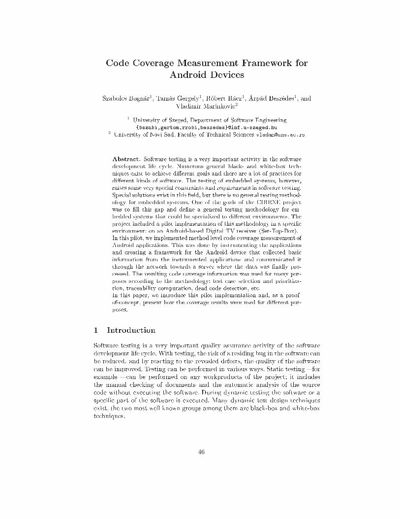
Code Coverage Measurement Framework for
Android Devi es
Szabol s Bognár
1, Tamás Gergely
1, Róbert Rá z
1, Árpád Beszédes
1, and
Vladimir Marinkovi
2
1University of Szeged, Department of Software Engineering
{bszabi,gertom,rrobi,beszedes}�inf.u-szeged.hu
2University of Novi Sad, Fa ulty of Te hni al S ien es vladam�uns.a .rs
Abstra t. Software testing is a very important a tivity in the software
development life y le. Numerous general bla k- and white-box te h-
niques exist to a hieve di�erent goals and there are a lot of pra ti es for
di�erent kinds of software. The testing of embedded systems, however,
raises some very spe ial onstraints and requirements in software testing.
Spe ial solutions exist in this �eld, but there is no general testing method-
ology for embedded systems. One of the goals of the CIRENE proje t
was to �ll this gap and de�ne a general testing methodology for em-
bedded systems that ould be spe ialized to di�erent environments. The
proje t in luded a pilot implementation of this methodology in a spe i�
environment: on an Android-based Digital TV re eiver (Set-Top-Box).
In this pilot, we implemented method level ode overage measurement of
Android appli ations. This was done by instrumenting the appli ations
and reating a framework for the Android devi e that olle ted basi
information from the instrumented appli ations and ommuni ated it
through the network towards a server where the data was �nally pro-
essed. The resulting ode overage information was used for many pur-
poses a ording to the methodology: test ase sele tion and prioritiza-
tion, tra eability omputation, dead ode dete tion, et .
In this paper, we introdu e this pilot implementation and, as a proof-
of- on ept, present how the overage results were used for di�erent pur-
poses.
1 Introdu tion
Software testing is a very important quality assuran e a tivity of the software
development life y le. With testing, the risk of a residing bug in the software an
be redu ed, and by rea ting to the revealed defe ts, the quality of the software
an be improved. Testing an be performed in various ways. Stati testing � for
example � an be performed on any workprodu ts of the proje t; it in ludes
the manual he king of do uments and the automati analysis of the sour e
ode without exe uting the software. During dynami testing the software or a
spe i� part of the software is exe uted. Many dynami test design te hniques
exist, the two most well known groups among them are bla k-box and white-box
te hniques.
46
Bla k-box test design te hniques on entrate on testing fun tionalities and
requirements by systemati ally he king whether the software works as intended
and produ es the expe ted output for a spe i� input. The te hniques take the
software as a bla k box, examine �what� the program does without having any
knowledge on the stru ture of the program, and they are not intrerested in the
question �how?�.
On the other hand, white-box testing examines the question �How does the
program do that?�, and tries to exhaustively examine the ode from several
aspe ts. This exhaustive examination is given by a so- alled overage riterion
whi h de�nes the onditions to be ful�lled by the set of instru tion sequen es
exe uted during the tests. (E.g. 100% instru tion overage riterion is ful�lled if
all instru tions of the program are exe uted during the tests.) Coverage measures
give a feedba k on the quality of the tests themselves.
The reliability of the test an be improved, by ombining bla k-box and
white-box te hniques. During the exe ution of test ases generated from the
spe i� ations using bla k-box te hniques, white-box te hniques an be used to
measure how ompletely the a tual implementation is he ked. If ne essary, re-
liability of the tests an be improved by generating new test ases for the not
veri�ed ode fragments.
1.1 Spe i� problems with embedded system testing
Testing in embedded environments has spe ial attributes and hara teristi s.
Embedded systems are neither uniform nor general-purpose. Ea h embedded
system has its own hardware and software on�guration typi ally designed and
optimized for a spe i� task, whi h a�e ts the development a tivities on the
spe i� system. Development, debugging, and testing are more di� ult sin e
di�erent tools are required for di�erent platforms.
However, high produ t quality and testing that ensures this high quality
is very important as the orre tion of residual bugs an be very di� ult for
these systems. For example, the software of a digital TV with play-from-USB
apabilities fails to re over after opening a spe i� media �le format and this
bug an only be repaired by repla ing the ROM of the TV. On e the TVs are
produ ed and sold, it might be impossible to orre t this bug without spending
a huge amount of money on logisti issues. Although there are some solutions
aiming at the uniformisation of the software layers of embedded systems (e.g. the
Android platform [1℄), there has not been a uniform methodology for embedded
systems testing.
1.2 The CIRENE proje t
One of the goals of the CIRENE proje t [2℄ is to �ll this gap and de�ne a
general testing methodology for embedded systems that opes with the above
mentioned spe ialities and whose parts an be implemented on spe i� systems.
The methodology ombines bla k-box tests responsible for the quality assesment
of the system under test and white-box tests responsible for the quality assesment
47
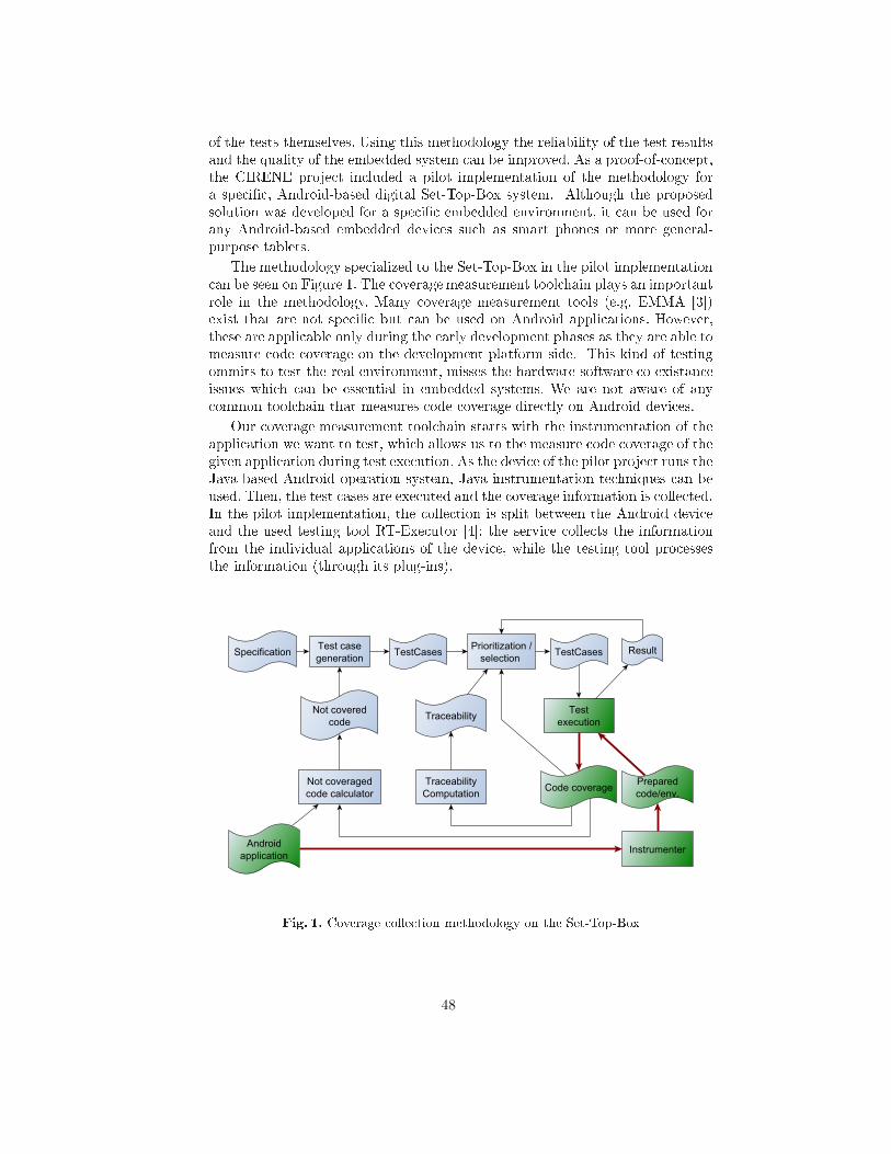
of the tests themselves. Using this methodology the reliability of the test results
and the quality of the embedded system an be improved. As a proof-of- on ept,
the CIRENE proje t in luded a pilot implementation of the methodology for
a spe i� , Android-based digital Set-Top-Box system. Although the proposed
solution was developed for a spe i� embedded environment, it an be used for
any Android-based embedded devi es su h as smart phones or more general-
purpose tablets.
The methodology spe ialized to the Set-Top-Box in the pilot implementation
an be seen on Figure 1. The overagemeasurement tool hain plays an important
role in the methodology. Many overage measurement tools (e.g. EMMA [3℄)
exist that are not spe i� but an be used on Android appli ations. However,
these are appli able only during the early development phases as they are able to
measure ode overage on the development platform side. This kind of testing
ommits to test the real environment, misses the hardware-software o-existan e
issues whi h an be essential in embedded systems. We are not aware of any
ommon tool hain that measures ode overage dire tly on Android devi es.
Our overage measurement tool hain starts with the instrumentation of the
appli ation we want to test, whi h allows us to the measure ode overage of the
given appli ation during test exe ution. As the devi e of the pilot proje t runs the
Java-based Android operation system, Java instrumentation te hniques an be
used. Then, the test ases are exe uted and the overage information is olle ted.
In the pilot implementation, the olle tion is split between the Android devi e
and the used testing tool RT-Exe utor [4℄: the servi e olle ts the information
from the individual appli ations of the devi e, while the testing tool pro esses
the information (through its plug-ins).
Fig. 1. Coverage olle tion methodology on the Set-Top-Box
48
The overage information gathered with the help of the overage framework
an be utilized by many appli ations in the testing methodology. They an be
used for sele ting and prioritizing test ases for further test exe utions, or for
helping to generate additional test ases if the overage is not su� ient. It is
also useful for dead ode dete tion or tra eability links omputation.
The rest of the paper is organized as follows. In Se tion 2, we give an overview
on the related work. In Se tion 3, the implementation of the overage measure-
ment framework is presented. In Se tion 4, some use ases are presented to
demonstrate the usefulness of overage information. In Se tion 5, we summarize
our a hievements and elaborate on some possible future works.
2 Related Work
Software testing is a very important a tivity during the software development
pro ess. It helps redu ing the risk of residual bugs and so ontributes to the
quality of the released software. Di�erent testing te hniques an be ategorized
by many riteria. One of these ategories ontain the dynami testing meth-
ods where testing in ludes the exe ution of the program under test. There are
two well known groups of dynami testing te hniques: bla k-box and white-box
testing te hniques. While bla k-box te hniques help to assess the quality of the
software under test, white-box te hniques rather assess the quality of the exe-
uted test sets. A good test in ludes a wide range of testing te hniques, ombines
them to lessen the weaknesses of the individual methods, and utilizes the advan-
tages of the ombination. For example, tests prepared using bla k-box te hniques
are usually measured for ode overage (a white-box te hnique), whi h helps to
estimate the remaining risks more a urately.
In the CIRENE proje t, one of our �rst tasks was to assess the state-of-the-art
in embedded systems testing te hniques with spe ial attention to the ombined
use of bla k and white-box te hniques. We prepared a te hni al report on it [5℄.
In this paper, we report only a few number of ombined testing te hniques that
have been spe ialized and implemented in the embedded environment.
Gotlieb and Petit presented a path-based test ase generation method [6℄.
They used symboli program exe ution and did not exe ute the software on
the embedded devi e prior to the test ase de�nitions. We use ode overage
measurement of real exe utions to determine information that an be used in
test ase generation.
José et al. de�ned a new overage metri for embedded systems to indi ate
instru tions that had no e�e t on the output of the program [7℄. Their im-
plementation used sour e ode instrumentation and worked for C programs at
instru tion level, and had a great in�uen e on the performan e of the program.
Biswas et al. also utilized C ode instrumentation in embedded environment
to gather pro�ling information for model-based test ase prioritization [8℄. We
use binary ode instrumentation at method level, use traditional metri that
indi ates whether the method is exe uted during the test ase or not, and our
49
solution has a minimal overhead on exe ution time. The resulting overage in-
formation an also be used for test ase sele tion and prioritization.
Hazelwood and Klauser worked on binary ode instrumentation for ARM-
based embedded systems [9℄. They reported the design, implementation and
appli ations of the ARM port of the Pin, a dynami binary rewriting framework.
However, we are working with Android systems that hides the on rete hardware
ar hite ture but provides a Java-based one.
There are many solutions for Java ode overage measurement. For example,
EMMA [3℄ provides a omplete solution for tra ing and reporting ode overage
of Java appli ations. However, it is, as well as others are general solutions not
on erning the spe ialities of Android or any embedded systems.
Most of the overage measurement tools utilize ode instrumentation. In
Java-based systems, byte ode instrumentation is more popular than sour e ode
instrumentation. There are many frameworks providing instrumenting fun tion-
alities (e.g. DiSL [10℄, InsECT [11,12℄, jCello [13℄, BCEL [14℄, et .) for Java.
These are very similar to ea h other regarding their provided fun tionalities. We
hose Javassist [15℄ to be our instrumentation framework in the pilot proje t.
3 Coverage Measurement Tool hain
The implemented overage measurement tool hain onsists of several parts.
First, the appli ations sele ted for measurement have to be prepared. The prepa-
ration pro ess in ludes program instrumentation that inserts extra ode in the
appli ation so that the appli ation an produ e the information ne essary for
tra ing its exe ution path during the test exe utions. The modi�ed appli ations
and the environment that helps olle t the results must be installed on the devi e
under test.
Next, tests are exe uted using this measurement environment and the pre-
pared appli ations, and overage information is produ ed. In general, test exe-
ution an be either manual or automated. In the urrent implementation, we
use the RT-Exe utor [4℄ for test automation. The RT-Exe utor is a bla k-box
test automation tool developed for testing multimedia devi es by RT-RK orpo-
ration in Novi Sad [16℄. During the exe ution of the test ases, the instrumented
appli ations produ e their tra es whi h are olle ted, and overage information
is sent ba k to the automation tool.
Third, the overage information resulted from the previous test exe utions
is pro essed and used for di�erent purposes e.g. for test sele tion and prioriti-
zation, additional test ase generation, tra eability omputation, and dead ode
dete tion.
In the rest of this se tion, we des ribe the te hni al details of the overage
measurement tool hain.
3.1 Preparation
In order to measure ode overage, we have to prepare the environment and/or
the programs under test to produ e the ne essary information on the exe uted
50
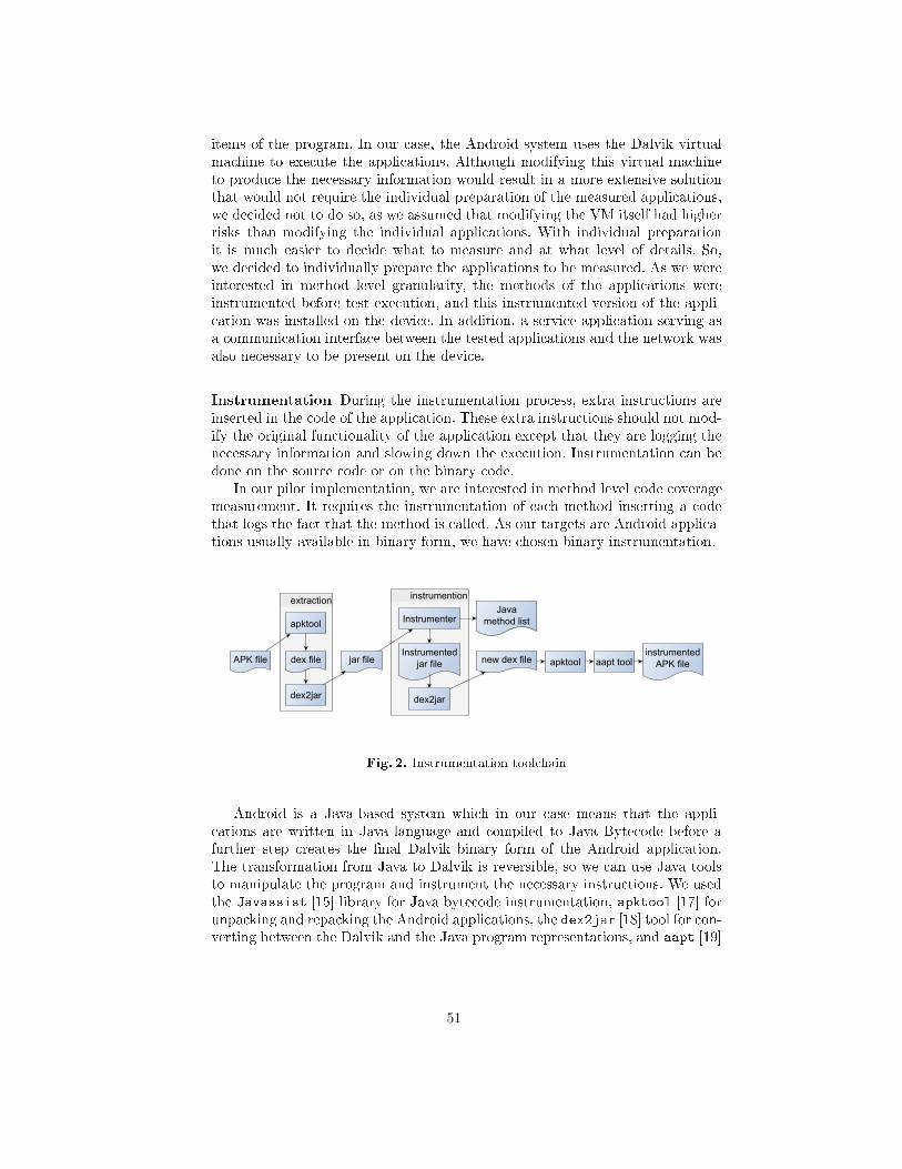
items of the program. In our ase, the Android system uses the Dalvik virtual
ma hine to exe ute the appli ations. Although modifying this virtual ma hine
to produ e the ne essary information would result in a more extensive solution
that would not require the individual preparation of the measured appli ations,
we de ided not to do so, as we assumed that modifying the VM itself had higher
risks than modifying the individual appli ations. With individual preparation
it is mu h easier to de ide what to measure and at what level of details. So,
we de ided to individually prepare the appli ations to be measured. As we were
interested in method level granularity, the methods of the appli ations were
instrumented before test exe ution, and this instrumented version of the appli-
ation was installed on the devi e. In addition, a servi e appli ation serving as
a ommuni ation interfa e between the tested appli ations and the network was
also ne essary to be present on the devi e.
Instrumentation During the instrumentation pro ess, extra instru tions are
inserted in the ode of the appli ation. These extra instru tions should not mod-
ify the original fun tionality of the appli ation ex ept that they are logging the
ne essary information and slowing down the exe ution. Instrumentation an be
done on the sour e ode or on the binary ode.
In our pilot implementation, we are interested in method level ode overage
measurement. It requires the instrumentation of ea h method inserting a ode
that logs the fa t that the method is alled. As our targets are Android appli a-
tions usually available in binary form, we have hosen binary instrumentation.
Fig. 2. Instrumentation tool hain
Android is a Java-based system whi h in our ase means that the appli-
ations are written in Java language and ompiled to Java Byte ode before a
further step reates the �nal Dalvik binary form of the Android appli ation.
The transformation from Java to Dalvik is reversible, so we an use Java tools
to manipulate the program and instrument the ne essary instru tions. We used
the Javassist [15℄ library for Java byte ode instrumentation, apktool [17℄ for
unpa king and repa king the Android appli ations, the dex2jar [18℄ tool for on-
verting between the Dalvik and the Java program representations, and aapt [19℄
51
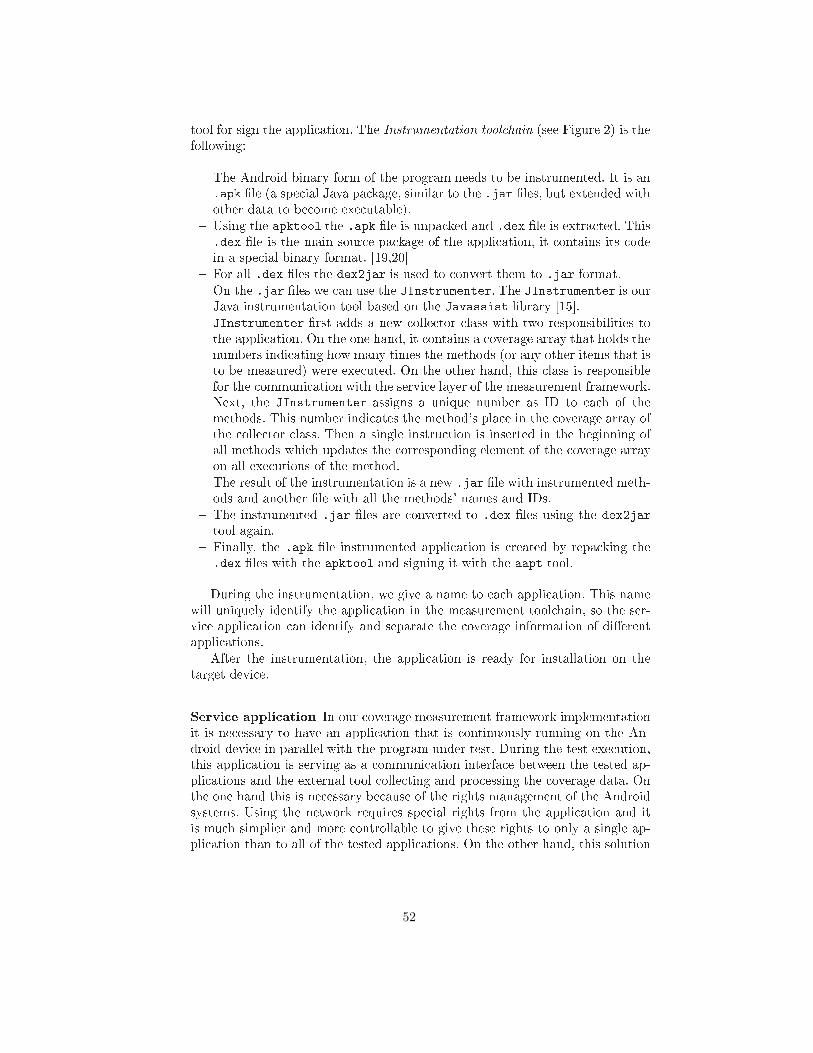
tool for sign the appli ation. The Instrumentation tool hain (see Figure 2) is the
following:
� The Android binary form of the program needs to be instrumented. It is an
.apk �le (a spe ial Java pa kage, similar to the .jar �les, but extended with
other data to be ome exe utable).
� Using the apktool the .apk �le is unpa ked and .dex �le is extra ted. This
.dex �le is the main sour e pa kage of the appli ation, it ontains its ode
in a spe ial binary format. [19,20℄
� For all .dex �les the dex2jar is used to onvert them to .jar format.
� On the .jar �les we an use the JInstrumenter. The JInstrumenter is our
Java instrumentation tool based on the Javassist library [15℄.
JInstrumenter �rst adds a new olle tor lass with two responsibilities to
the appli ation. On the one hand, it ontains a overage array that holds the
numbers indi ating how many times the methods (or any other items that is
to be measured) were exe uted. On the other hand, this lass is responsible
for the ommuni ation with the servi e layer of the measurement framework.
Next, the JInstrumenter assigns a unique number as ID to ea h of the
methods. This number indi ates the method's pla e in the overage array of
the olle tor lass. Then a single instru tion is inserted in the beginning of
all methods whi h updates the orresponding element of the overage array
on all exe utions of the method.
The result of the instrumentation is a new .jar �le with instrumented meth-
ods and another �le with all the methods' names and IDs.
� The instrumented .jar �les are onverted to .dex �les using the dex2jar
tool again.
� Finally, the .apk �le instrumented appli ation is reated by repa king the
.dex �les with the apktool and signing it with the aapt tool.
During the instrumentation, we give a name to ea h appli ation. This name
will uniquely identify the appli ation in the measurement tool hain, so the ser-
vi e appli ation an identify and separate the overage information of di�erent
appli ations.
After the instrumentation, the appli ation is ready for installation on the
target devi e.
Servi e appli ation In our overage measurement framework implementation
it is ne essary to have an appli ation that is ontinuously running on the An-
droid devi e in parallel with the program under test. During the test exe ution,
this appli ation is serving as a ommuni ation interfa e between the tested ap-
pli ations and the external tool olle ting and pro essing the overage data. On
the one hand this is ne essary be ause of the rights management of the Android
systems. Using the network requires spe ial rights from the appli ation and it
is mu h simplier and more ontrollable to give these rights to only a single ap-
pli ation than to all of the tested appli ations. On the other hand, this solution
52
provides a single interfa e to query the overage data even if there are more
appli ations tested and measured simultaneously.
In Android systems, there are two types of appli ations: �normal� and �ser-
vi e�. Normal appli ations start, do something while they are visible on the
s reen, and are destroyed on losing. Servi es are running in the ba kground
ontinuously and are not destroyed on losing. So, we had to implement this
interfa e appli ation as a servi e. It serves as a bridge between the Android
appli ations under test and the �external world� as it an be seen on Figure 3.
The tested appli ations are measuring their own overage and the servi e queries
these data on-demand. As the ommuni ation is usually initiated before the start
and after the end of the test ases, this means no regular ommuni ation over-
head in the system during the test ase exe utions.
Fig. 3. Servi e Layer
Messages are a epted from and sent to the external overage measurement
tools. The ommuni ation uses JSON [21℄ obje ts (type-value pairs) over the
TCP/IP proto ol. Implemented messages are:
NEWTC The testing tool sends this message to the servi e to sign that there
is a new test ase to be exe uted and asks it to perform the required a tions.
ASK The testing tool sends this message to query the a tual overage informa-
tion.
COVERAGE DATA The servi e sends this message to the testing tool in
response to the ASK message. The message ontains overage information.
Internally, the servi e also uses JSON obje ts to ommuni ate with the in-
strumented appli ations. Implemented messages are:
reset The servi e sends this message to the appli ation to reset the stored ov-
erage values.
53
ask The servi e sends this message to query the a tual overage information.
overage data The appli ation sends this message to the servi e in response
to the ask message. The message ontains overage information.
Installation To measure overage on the Android system, two things need to
be installed: the parti ular appli ation we want to test and the ommon servi e
appli ation that olle ts overage information from any instrumented appli ation
and provides a ommuni ation interfa e for querying the data from the devi e.
The servi e appli ation needs to be installed on a devi e only on e; this single
entity an handle the ommuni ation of all tested appli ations.
The instrumented version of ea h appli ation that is going to be measured
must be installed on the Android devi e. The original version of su h an ap-
pli ation (if there was one) must be removed before the instrumented version
an be installed. It is ne essary be ause Android ideti�es the appli ations by
their spe ial android-name and pa kage, and our instrtumentation pro ess does
not hange these attributes of the appli ations; it only inserts the appropriate
instru tions into the ode. Our tool hain uses the adb tool ( an be found in
Android Development Kit) to remove and install pa kages.
3.2 Exe ution
During test exe ution, the Android devi e exe utes the program under test and
the servi e appli ation simultaneously. The program under test ounts its own
overage information and sends this information when the servi e layer appli-
ation asks for it. The overage information an be queried from this servi e
layer appli ation through network onne tion. We implemented a simple query
interfa e in Java for manual testing and a plugin for the RT-Exe utor [4℄ (a
bla k-box test automation tool we used in this proje t) for automated testing.
In our pilot proje t, we used two possible modes of test exe ution: manual and
automatized. Either mode is used, the servi e layer appli ation must be started
prior to the beginning of the exe ution of the test ases. It is done automati ally
by the instrumented appli ations if the servi e is not running already.
In the ase of automated testing, the RT-Exe utor reads the test ase s ripts
and exe utes the test ases. The lient side of the measurement framework is
ontained in a plug-in of the automation tool, and this plug-in must be ontrolled
from the test ase itself. Thus, the test ase s ripts must be prepared in order
to measure the ode overage of the exe uted appli ations.
The plug-in an indi ate the beginning and the end of the parti ular test ases
to the servi e, so the servi e an distinguish the test ases and an separate the
olle ted information. In order to measure the test ase overages individually,
one instru tion must be inserted in the beginning of the test s ript to reset the
overage values and one instru tion must be inserted in the end instru ting the
plug-in to olle t and store overage information belonging to the test ase.
During test exe ution the following steps are taken:
� Start the program under test.
54
� The start of the program triggers the start of the measurement servi e if
ne essary. Then the program under test onne ts to the servi e and registers
itself by its unique name given to it in instrumetnation pro ess.
� The test automation system starts a test ase. The test ase for es the au-
tomation system plug-in to send a NEWTC message to the servi e. The
servi e sends the reset message to the program under test. The PUT resets
the overage array in its olle tor lass. The servi e returns the a tual time
to the plug-in.
� The test automation system performs the test steps. The PUT olle ts the
overage data.
� The test ase ends. The automation tool plug-in sends the ASK signal to
the servi e. The servi e sends the ask signal to the PUT. The PUT sends
ba k the overage data to the servi e. The servi e sends ba k the overage
data and the a tual time to the automation tool plug-in.
� The plug-in al ulates the ne essary information from the overage data and
stores it in the lo al �les. The stored data are: exe ution time, tra e length,
overage value, lists of overed and not overed methods. Another plug-in
de ides if the test ase was passed or failed and stores this information in
other lo al �les.
These steps are repeated during the whole test suite exe ution. At the end,
the overage information of all the exe uted test ases are stored in lo al �les
and are ready to be pro essed by di�erent stages of the testing methodology.
3.3 Pro essing the Data
As we mentioned above, the lient side of the overage measurement system is
realized as a plug-in of the RT-Exe utor tool.
The plug-in is ontrolled from the test ases. It indi ates the beginning and
the end of a test ases to the servi e layer appli ation. The servi e replies to
these signals by sending the valuable data ba k. When the measurement lient
indi ates the start of a test ase (by sending the NEWTC message to the
servi e), the servi e replies with the urrent time whi h is stored by the lient.
At the end of a test ase (when the ASK signal is sent by the lient), the
servi e replies with the urrent time and the olle ted overage information of
the methods.
When the overage data is re eived, the measurement lient omputes the
exe ution time, tra e length (the number of method alls), and the list of overed
and not overed methods' IDs. Then, the lient stores these data in a result �le
for further use. The lient makes other �les, the tra e �les, separately for ea h
test ase. Su h a tra e �le stores the identi�ers of the methods overed during
the exe ution of the test ase.
As an alternative lient, we implemented a simple standalone java appli a-
tion that is able to onne t to the measurement servi e (and this way it repla es
the RT-Exe utor plug-in). This lient is able to visualize the ode overage in-
formation online, and is useful during the manual testing a tivities (e.g. during
exploratory tests).
55
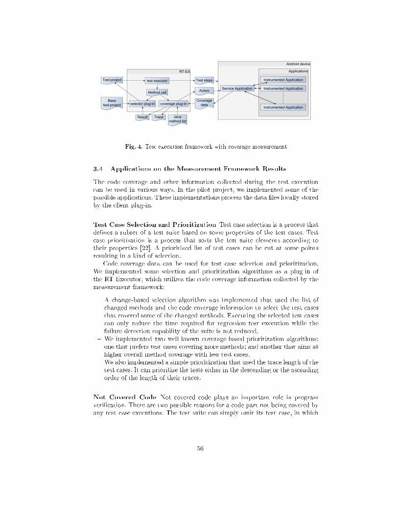
Fig. 4. Test exe ution framework with overage measurement
3.4 Appli ations on the Measurement Framework Results
The ode overage and other information olle ted during the test exe ution
an be used in various ways. In the pilot proje t, we implemented some of the
possible appli ations. These implementations pro ess the data �les lo ally stored
by the lient plug-in.
Test Case Sele tion and Prioritization Test ase sele tion is a pro ess that
de�nes a subset of a test suite based on some properties of the test ases. Test
ase prioritization is a pro ess that sorts the test suite elements a ording to
their properties [22℄. A prioritized list of test ases an be ut at some points
resulting in a kind of sele tion.
Code overage data an be used for test ase sele tion and prioritization.
We implemented some sele tion and prioritization algorithms as a plug-in of
the RT-Exe utor, whi h utilizes the ode overage information olle ted by the
measurement framework:
� A hange-based sele tion algorithm was implemented that used the list of
hanged methods and the ode overage information to sele t the test ases
that overed some of the hanged methods. Exe uting the sele ted test ases
an only redu e the time required for regression test exe ution while the
failure dete tion apability of the suite is not redu ed.
� We implemented two well-known overage-based prioritization algorithms:
one that prefers test ases overing more methods; and another that aims at
higher overall method overage with less test ases.
� We also implemented a simple prioritization that used the tra e length of the
test ases. It an prioritize the tests either in the des ending or the as ending
order of the length of their tra es.
Not Covered Code Not overed ode plays an important role in program
veri� ation. There are two possible reasons for a ode part not being overed by
any test ase exe utions. The test suite an simply omit its test ase, in whi h
56
ase we have to de�ne some new test ases exe uting the missed ode. It an also
happen that the not overed ode annot be exe uted by any test ases, whi h
means that it is a dead ode. In the latter ase, the ode an be dropped from
the odebase.
In our pilot implementation, automati test ase generation is not imple-
mented. We simply al ulate the lists of methods overed and not overed during
the tests. These lists an be used by the testers and the developers to examine
the methods in question and generate new test ases to over the methods, or
to simply eliminate the methods from the ode.
Tra eability Cal ulation Tra eability links between di�erent software devel-
opment artifa ts play a very important role in the hange management pro esses.
For example, tra eability information an be used to estimate the required re-
sour es to perform a spe i� hange or to sele t the test ases related to the
hange of the spe i� ation. Relationship exists between di�erent types of de-
velopment artifa ts. Some of them an simply be re orded when the artifa t is
reated, some of them must be determined later.
We implemented a very simple tra eability al ulator that omputes the or-
relation between the requirements and the methods, based on the pre-de�ned
relationships between the requirements and the test ases and between the test
ases and the methods ( ode overage). If a requirement-method pair is assigned
with high orrelation, we an assume that the required fun tionality is imple-
mented in the method. This information an be used to asses the number of
methods to be hanged if the parti ular requirement hanges.
4 Usage and Evaluation
In this se tion, we present and evaluate some use ases to demonstrate the
usability of the measurement tool hain.
4.1 Additional Test Case Generation
In the pilot proje t our target embedded hardware was an Android-based Set-
Top-Box. We had this devi e with di�erent pre-installed appli ations and test
ases for some of these apps. A media-settings appli ation was sele ted for testing
our methodology and implementation. After exe uting the tests of this appli a-
tion with overage measurement, we found that the pre-de�ned tests overed
only 54% of the methods. We examined the methods and de�ned new test ases.
Although the sour e ode of this appli ations was not available, based on the not
overed method names and the GUI, we were able to de�ne new test ases that
raised the number of overed methods to 69%. This is still less than the required
100% method level overage, but shows that the feedba k on ode overage an
be used to improve the quality of the test suite.
57
4.2 Tra eability Cal ulation
In the pilot proje t a simple implementation that is able to determine the orre-
lation between the ode segments and the requirements was made. We did not
ondu t detailed experimentation in this topi , but we did test the tool. Instead
of the requirements, we de�ned 12 fun tionalities performed by three media ap-
pli ations (players) on our target Set-Top-Box devi e. Then, we assigned these
fun tionalities to 15 omplex bla k-box test ases of the media appli ations and
exe uted the test ases with overage measurement. The tra eability tool om-
puted orrelations between the 12 fun tionalities and 608 methods, and was able
to separate the methods relevant in implementing a fun tionality from the not
relevant methods.
5 Con lusions and Future Work
In this paper, we presented a methodology for method level ode overage mea-
surement on Android-based embedded systems. Although there were more solu-
tions allowing the measure of the ode overage of Android appli ations on the
developers' omputers, no ommon methods were known to us that performed
overage measurement on the devi es. We also reported the implementation of
this methodology on a digital Set-Top-Box running Android. The overage mea-
surement was integrated in the test automation pro ess of this devi e allowing
the use of the olle ted overage data in di�erent appli ations like test ase sele -
tion and prioritization of the automated tests, or additional test ase generation.
There are many improvement possibilities of this work. Regarding the imple-
mentation of ode overagemeasurement on Android devi es, we wish to examine
if the granularity of tra ing ould be �ned to sub-method level (e.g. to basi blo k
or instru tion levels) without signi� antly a�e ting the runtime behaviour of the
appli ations. This would allow us to extra t instru tion and bran h level over-
ages that would result in more reliable tests. We are also thinking of improving
the instrumentation in order to build dynami all trees for further use. The ur-
rent implementation (simple overage measurement) does not need to deal with
timing, threads and ex eption handling, both of whi h are ne essary for building
the more detailed all trees. It would also be interesting to help the integration
of this overage measurement in ommonly used ontinuous integration and test
exe ution tools.
We are also examining the utilization possibilities of the resulting overage
data. For example, tra eability information between ode and the visible graph-
i al elements ould be established, and this information might help to partially
automate olle ting data for usability tests and to establish usability models.
The implemented ode overage measurement and the testing pro ess that uti-
lizes this information are a good base for measuring the e�e t of using overage
measurement data on the e� ien y and reliability of testing. We are planning
to ondu t resear hes in these topi s.
58
A knowledgement
This work was done in the Cross-border ICT Resear h Network (CIRENE)
proje t (proje t number is HUSRB1002/214/044) supported by the Hungary-
Serbia IPA Cross-border Co-operation Programme, o-�nan ed by the
European Union.
Referen es
1. Google: Android homepage.
https://www.android. om/ (June 2013)
2. Kukolj, S., Marinkovi¢, V., Popovi¢, M., Bognár, Sz.: Sele tion and prioritization of
test ases by ombining white-box and bla k-box testing methods. In: Pro eedings
of the 3
rdEastern European Regional Conferen e on the Engineering of Computer
Based Systems (ECBS-EERC 2013). (2013)
3. Vlad Roubtsov: EMMA: a free java ode overage tool.
http://emma.sour eforge.net/ (June 2013)
4. RT-RK Institute: RT-Exe utor.
http://bbt.rt-rk. om/software/rt-exe utor/ (May 2013)
5. Beszédes, Á., Gergely, T., Papp, I., Marinkovi¢, V., Zlokoli a, V.: Survey on test-
ing embedded systems. Te hni al report, Department of Software Engineering,
University of Szeged and Fa ulty of Te hni al S ien es, University of Novi Sad
(2012)
6. Gotlieb, A., Petit, M.: Path-oriented random testing. In: Pro eedings of the 1st
international workshop on Random testing. RT '06, New York, NY, USA, ACM
(2006) 28�35
7. Costa, J.C., Devadas, S., Monteiro, J.C.: Observability analysis of embedded soft-
ware for overage-dire ted validation. In: In Pro eedings of the International Con-
feren e on Computer Aided Design. (2000) 27�32
8. Biswas, S., Mall, R., Satpathy, M., Sukumaran, S.: A model-based regression test
sele tion approa h for embedded appli ations. SIGSOFT Softw. Eng. Notes 34(4)
(July 2009) 1�9
9. Hazelwood, K., Klauser, A.: A dynami binary instrumentation engine for the arm
ar hite ture. In: Pro eedings of the 2006 international onferen e on Compilers,
ar hite ture and synthesis for embedded systems. CASES '06, New York, NY, USA,
ACM (2006) 261�270
10. Marek, L., Zheng, Y., Ansaloni, D., Sarimbekov, A., Binder, W., T·ma, P., Qi,
Z.: Java byte ode instrumentation made easy: The disl framework for dynami
program analysis. In Jhala, R., Igarashi, A., eds.: Programming Languages and
Systems. Volume 7705 of Le ture Notes in Computer S ien e. Springer Berlin
Heidelberg (2012) 256�263
11. Chawla, A., Orso, A.: A generi instrumentation framework for olle ting dynami
information. In: Online Pro eedings of the ISSTAWorkshop on Empiri al Resear h
in Software Testing (WERST 2004), Boston, MA, USA (july 2004)
12. Seesing, A., Orso, A.: InsECTJ: A Generi Instrumentation Framework for Colle t-
ing Dynami Information within E lipse. In: Pro eedings of the e lipse Te hnology
eX hange (eTX) Workshop at OOPSLA 2005, San Diego, CA, USA (o tober 2005)
49�53
13. Slife, D., Chesney, M.: jCello. http://j ello.sour eforge.net/ (June 2013)
59
14. Apa he Commons: BCEL homepage.
http:// ommons.apa he.org/proper/ ommons-b el/ (June 2013)
15. Chiba, Shigeru: Javassist homepage.
http://www. sg. i.i.u-tokyo.a .jp/� hiba/javassist/ (May 2013)
16. RT-RK Institute: Homepage.
http://rt-rk. om/ orporate-profile/ (May 2013)
17. Google: apktool homepage.
https:// ode.google. om/p/android-apktool/ (May 2013)
18. Google: dex2jar.
https:// ode.google. om/p/dex2jar/ (May 2013)
19. Google Android Developers: Building and running an android appli ation.
http://developer.android. om/tools/building/index.html (May 2013)
20. Bornstein, D.: Presentation of Dalvik VM internals (2008)
21. Developers: JSON.
http://www.json.org/ (June 2013)
22. Yoo, S., Harman, M.: Regression testing minimization, sele tion and prioritization:
a survey. Software Testing, Veri� ation and Reliability 22(2) (2012) 67�120
60
The Role of Dependency Propagation in theAccumulation of Technical Debt for Software
Implementations
Johannes Holvitie, Mikko-Jussi Laakso, Teemu Rajala, Erkki Kaila, and VilleLeppanen
TUCS - Turku Centre for Computer Science, Turku, Finland&
University of Turku, Department of Information Technology, Turku, Finland{jjholv, milaak, temira, ertaka, ville.leppanen}@utu.fi
Abstract. Technical debt management requires means to identify, track,and resolve technical debt in the various software project artifacts. Thereare several approaches for identifying technical debt from the softwareimplementation but they all have their shortcomings in maintaining thisinformation. This paper presents a case study that explores the role ofdependency propagation in the accumulation of technical debt for a soft-ware implementation. A clear relation between the two is identified inaddition to some differentiating characteristics. We conclude that formal-ization of this relation can lead to solutions for the maintenance problem.As such, we use this case study to improve the propagation method im-plemented in our DebtFlag tool.
Keywords: technical debt, technical debt propagation modeling, soft-ware implementation assessment, refactoring
1 Introduction
Technical debt is a metaphor that describes how various trade-offs in design de-cisions affect the future development of the software project. Trade-offs are madebetween development driving aspects - for example meeting a delivery date byrelaxing some quality requirements - and they incur the project’s technical debtwhile providing the organization with a short-term gain. Similarly to its financialcounterpart, technical debt - for example through reuse in software implemen-tations - accumulates interest over a principal until it has been paid back infull. Inability to manage the projects technical debt results to increased interestpayments in the form of additional resources being consumed when implement-ing new requirements and ultimately to exceeding development resources andpremature ending of the project. [1]
Technical debt management is a software development component and anactively researched area of software engineering [2]. It is interested in providingprojects with means to identify, track, and payback technical debt in order to
61
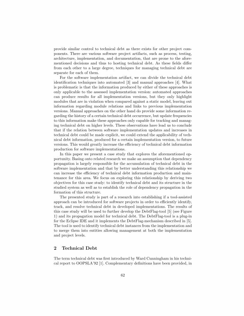
provide similar control to technical debt as there exists for other project com-ponents. There are various software project artifacts, such as process, testing,architecture, implementation, and documentation, that are prone to the afore-mentioned decisions and thus to hosting technical debt. As these fields differfrom each other to a large degree, techniques for managing technical debt areseparate for each of them.
For the software implementation artifact, we can divide the technical debtidentification techniques into automated [3] and manual approaches [4]. Whatis problematic is that the information produced by either of these approaches isonly applicable to the assessed implementation version: automated approachescan produce results for all implementation versions, but they only highlightmodules that are in violation when compared against a static model, leaving outinformation regarding module relations and links to previous implementationversions. Manual approaches on the other hand do provide some information re-garding the history of a certain technical debt occurrence, but update frequenciesto this information make these approaches only capable for tracking and manag-ing technical debt on higher levels. These observations have lead us to concludethat if the relation between software implementation updates and increases intechnical debt could be made explicit, we could extend the applicability of tech-nical debt information, produced for a certain implementation version, to futureversions. This would greatly increase the efficiency of technical debt informationproduction for software implementations.
In this paper we present a case study that explores the aforementioned op-portunity. Basing onto related research we make an assumption that dependencypropagation is largely responsible for the accumulation of technical debt in thesoftware implementation and that by better understanding this relationship wecan increase the efficiency of technical debt information production and main-tenance for this area. We focus on exploring this relationship by deriving twoobjectives for this case study: to identify technical debt and its structure in thestudied system as well as to establish the role of dependency propagation in theformation of this structure.
The presented study is part of a research into establishing if a tool-assistedapproach can be introduced for software projects in order to efficiently identify,track, and resolve technical debt in developed implementations. The results ofthis case study will be used to further develop the DebtFlag-tool [5] (see Figure1) and its propagation model for technical debt. The DebtFlag-tool is a plug-infor the Eclipse IDE and it implements the DebtFlag-mechanism described in [5].The tool is used to identify technical debt instances from the implementation andto merge them into entities allowing management at both the implementationand project levels.
2 Technical Debt
The term technical debt was first introduced by Ward Cunningham in his techni-cal report to OOPSLA’92 [1]. Complementary definitions have been provided, in
62
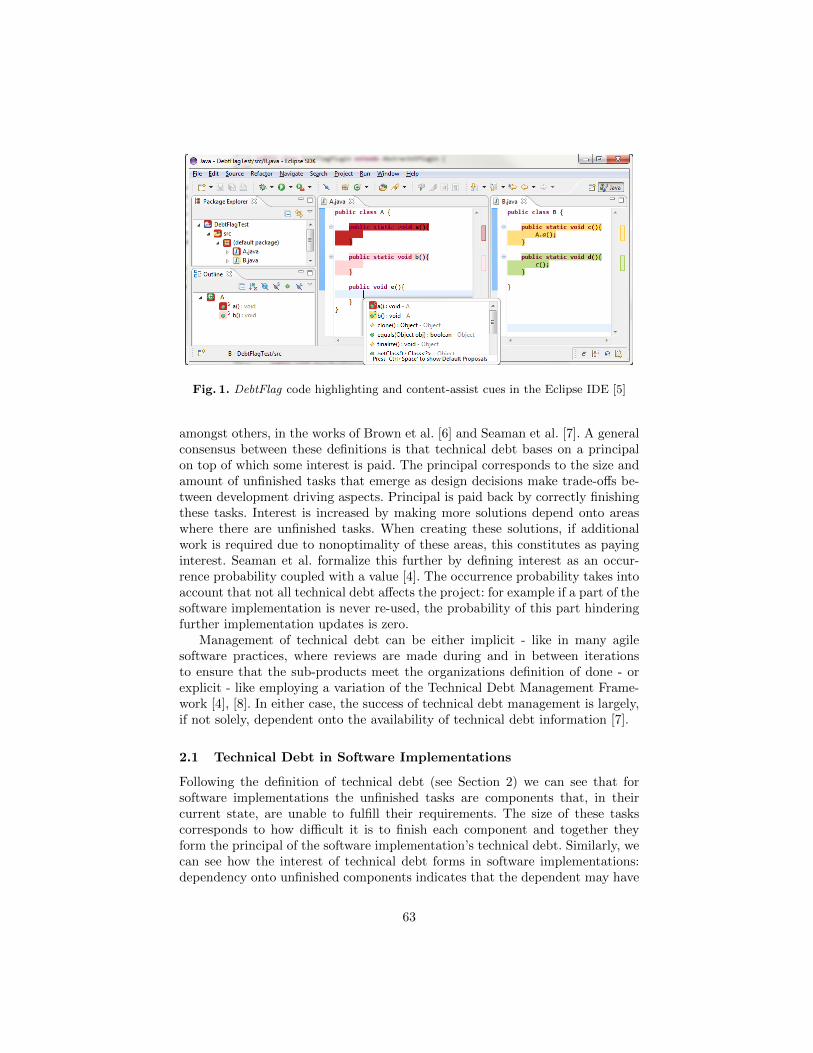
Fig. 1. DebtFlag code highlighting and content-assist cues in the Eclipse IDE [5]
amongst others, in the works of Brown et al. [6] and Seaman et al. [7]. A generalconsensus between these definitions is that technical debt bases on a principalon top of which some interest is paid. The principal corresponds to the size andamount of unfinished tasks that emerge as design decisions make trade-offs be-tween development driving aspects. Principal is paid back by correctly finishingthese tasks. Interest is increased by making more solutions depend onto areaswhere there are unfinished tasks. When creating these solutions, if additionalwork is required due to nonoptimality of these areas, this constitutes as payinginterest. Seaman et al. formalize this further by defining interest as an occur-rence probability coupled with a value [4]. The occurrence probability takes intoaccount that not all technical debt affects the project: for example if a part of thesoftware implementation is never re-used, the probability of this part hinderingfurther implementation updates is zero.
Management of technical debt can be either implicit - like in many agilesoftware practices, where reviews are made during and in between iterationsto ensure that the sub-products meet the organizations definition of done - orexplicit - like employing a variation of the Technical Debt Management Frame-work [4], [8]. In either case, the success of technical debt management is largely,if not solely, dependent onto the availability of technical debt information [7].
2.1 Technical Debt in Software Implementations
Following the definition of technical debt (see Section 2) we can see that forsoftware implementations the unfinished tasks are components that, in theircurrent state, are unable to fulfill their requirements. The size of these taskscorresponds to how difficult it is to finish each component and together theyform the principal of the software implementation’s technical debt. Similarly, wecan see how the interest of technical debt forms in software implementations:dependency onto unfinished components indicates that the dependent may have
63
had to accommodate this in some manner. This accommodation accounts as in-creased interest for the depended upon component’s principal and if the amountof work required to implement the dependent is increased then this correspondsto paying interest.
To clarify, in the previous paragraph, a software implementation componentrefers to an entity that is defined by the used programming paradigm and tech-nique and is capable of forming dependencies. The target system of this casestudy is implemented using the Java programming language. Here, like in manyobject oriented languages, direct references and inheritances create dependenciesto public interfaces formed out of variables and methods [9].
In order to maintain the technical debt information produced either by meansof automatic or manual identification, there needs to exist a model explaininghow technical debt propagates in the software implementation. A theory on thepropagation of technical debt in ecosystems by McGregor et al. [10] acknowl-edges some of the issues relating to this, which will be discussed in the nextsection. Additionally, certain implementation technique and paradigm specificcharacteristics need to be taken into account when identifying possible propaga-tion routes for technical debt. Especially interfaces which can hide partitions oftechnical debt or decouple dependents from refactorizations.
Software implementation technical debt is paid back through refactoring thesoftware product. Fowler et al. [11] define refactoring as “changes made to theinternal structure of software to make it easier to understand and cheaper tomodify without changing its observable behavior”. In the following, we use thisdefinition to identify which software components where affected by technicaldebt.
2.2 Related Work on Debt Propagation
Previously referenced work by McGregor et al. [10] is an important motivatorfor our research. In this, they hypothesize that technical debt has the abilityto aggregate within elements of the software implementation and provide twoconcurrent mechanisms for it. In the first one “technical debt for a newly createdasset is the sum of the technical debt incurred by the decisions during develop-ment of the asset and some amount based on the quality of the assets integratedinto its implementation”. In respect of this, they note that technical debt maydiminish as a result of increased implementation layer nesting. The second mech-anism providing another possibility in that “the technical debt of an asset is notdirectly incurred by integrating an asset in object code form, but there is an in-direct effect on the user of the asset”. For a software implementation this canmean for example that the implementation of a new element does not necessar-ily increase the technical debt quota but deficiencies in the documentation stillresult into more consumed resources.
Research is scarce in relating technical debt accumulation with the mechan-ics of software dependency propagation. Thus, we refer to research on softwareevolution and change impact analysis to gain insight into dependency propa-gation and its characteristics. Avellis discusses the implementation of a change
64
impact function in [12] and notes that for domain-specific areas the informa-tion encoded into the domain models can be used to parameterize the changepropagation rules while monitoring the ripple-effect of a change requires deepknowledge about the modification’s implications. It is also concluded that theuse of more specialized information in the definition of the propagation paths,results into a more specific and accurate impact set.
In Bianchi et al. [13] the authors note that the number of outgoing depen-dencies from a component is related to the number of paths through which theeffects of a change may propagate. Robillard [14] presents an algorithm for pro-viding an interest ranking for directly dependent change candidates. The rankingof elements is based onto specificity and reinforcement, where the former rulesthat structural neighbors that have few structural dependencies are more likelyto be interesting because their relation to an element of interest is more uniqueand the latter that structural neighbors that are part of a cluster that containsmany elements already in the set of interest are more likely to be interestingbecause . . . [they] probably share some structural property that associates them tothe code of interest.
3 ViLLE
The system on which we will conduct this case study is called ViLLE (see Figure2). It is a collaborative education platform that is being developed and researchedat the University of Turku [15,16]. The system specializes in enabling the creationand to being host to various exercises with education enhancing features suchas rich visualizations and immediate feedback [17, 18]. To date, the system hasforegone 8 years of development, comprises circa 150k physical lines of code,serves over 1.5M immediate feedbacks annually, has circa 300 registered teachersand 6500 students, is being employed in over 20 countries and in its currentstate of robustness, trialled to become the selected system for providing electricmatriculation examinations for the Finnish education ministry.
During its eight years of development ViLLE has gone over several smallerand two larger revamps. The first major revamp unified the platform into a singleJava Applet and introduced automatically assessable exercises. Conversion toa Java Applet allowed the system to be run from the TRAKLA server whichmade the system accessible through the Internet and enabled its integration intodistance teaching. The second major revamp enhanced this further: in orderto reduce requirements to the end user to a bare minimum the system wasconverted into a SaaS (Software as a Service) by way of utilizing the Vaadinframework [19]. [16]
As the SaaS conversion made the system available to a larger audience, theresearch and development team simultaneously wanted to serve a broader spec-trum of education subjects through extending the set of available exercise types.The old legacy exercise system was found to be too rigid for this purpose andit was decided that this part of the system was to be refactored. The authorshave taken part in this process and it has also been the focus of a thesis [20].
65
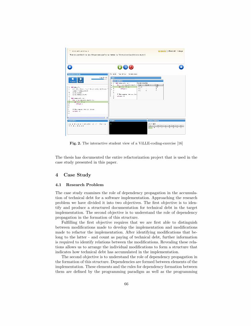
Fig. 2. The interactive student view of a ViLLE-coding-exercise [16]
The thesis has documented the entire refactorization project that is used in thecase study presented in this paper.
4 Case Study
4.1 Research Problem
The case study examines the role of dependency propagation in the accumula-tion of technical debt for a software implementation. Approaching the researchproblem we have divided it into two objectives. The first objective is to iden-tify and produce a structured documentation for technical debt in the targetimplementation. The second objective is to understand the role of dependencypropagation in the formation of this structure.
Fulfilling the first objective requires that we are first able to distinguishbetween modifications made to develop the implementation and modificationsmade to refactor the implementation. After identifying modifications that be-long to the latter - and count as paying of technical debt, further informationis required to identify relations between the modifications. Revealing these rela-tions allows us to arrange the individual modifications to form a structure thatindicates how technical debt has accumulated in the implementation.
The second objective is to understand the role of dependency propagation inthe formation of this structure. Dependencies are formed between elements of theimplementation. These elements and the rules for dependency formation betweenthem are defined by the programming paradigm as well as the programming
66
language. As each identified modification operates on a set of implementationelements we can utilize the dependency formation rules to identify all elementsthat are dependent onto this set. Comparing the revealed dependencies to theconnections in the technical debt accumulation structure is used in this casestudy to examine the role of dependency propagation in the accumulation oftechnical debt for the software implementation.
4.2 Case Selection
The case study is conducted on the results of the ViLLE refactorization project(see Section 3). This case selection is made to expand on earlier research de-scribed in [20]. We consult this research to establish what parts of the systemwere targeted in the refactorization, what are the tools and practices used forthe refactorization, what are the motivations as well as the requirements for therefactorization and finally access to the version control system which is queriedfor information regarding the conduction of this refactorization.
The ViLLE system is a web-application that is implemented using the Vaadinweb-application framework. The used development language is Java. At the timeof the refactoring the running configuration of the ViLLE system was comprisedout of 122k physical lines of code organized into a hierarchy of 26 Java packagesencompassing a total of 460 Java classes.
The thesis [20] documented that the motivation for the refactorization wasthat the development team perceived the exercise system to be too rigid toaccommodate efficient development in the future. Further analysis in [20] pin-pointed this problem to four Java classes. These core system classes were respon-sible for the execution, modification, storing and retrieving, as well as modelingof interactive exercises in ViLLE. For each of these [20] documented a set ofproblems as well as a set of reparative actions, which were used as the startingpoint for the refactorization.
The refactorization used a well defined refactorization process - adapted fromThe Rhythm of Refactoring by Fowler et al. [11] and The Legacy Code ChangeAlgorithm by Feathers et al. [21] - as well as a library of best practices - compiledfrom the Design Patterns by Martin et al. [22], Refactorizations by Fowler et al.[11], and Dependency-Breaking-Techniques by Feathers et al. [21] - to implementthe suggested reparations. [20]
An example of the refactorization process and the resulting refactorizationsis the abstraction of the exercise execution class via decoupling it from exercisetype specific information. Applying this five step process first called for identi-fying change points. In this case, all references to specific exercises. The nextstep of finding test points consisted from identifying change routes and under-standing how the system could be shielded from unintended changes by way ofconstraining these routes with tests. The third step called for breaking depen-dencies in order to get the tests in place. The end result of this was a set ofunit tests adhering to the JUnit framework. The last, fifth, step was to makechanges and refactor. An example of a singular refactoring here was the removalof specific exercise information from the constructor of the exercise executor.
67
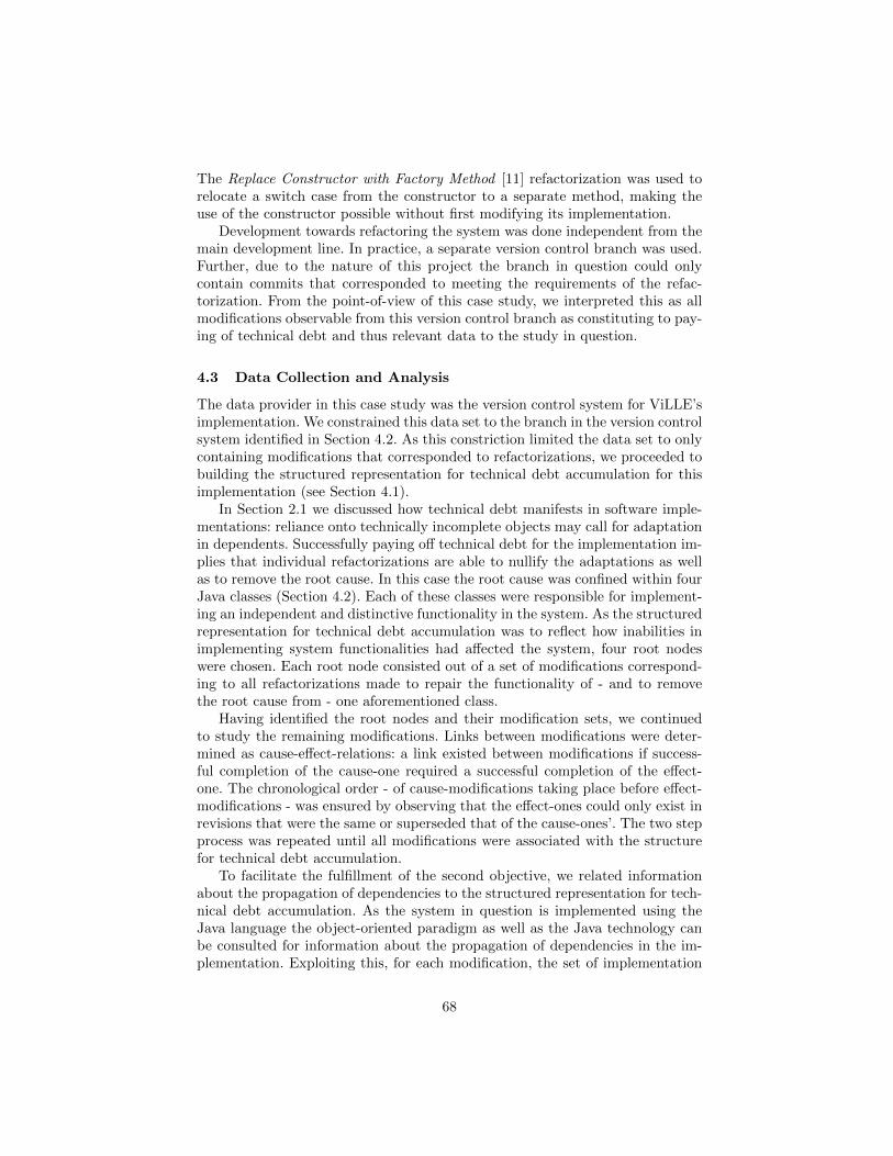
The Replace Constructor with Factory Method [11] refactorization was used torelocate a switch case from the constructor to a separate method, making theuse of the constructor possible without first modifying its implementation.
Development towards refactoring the system was done independent from themain development line. In practice, a separate version control branch was used.Further, due to the nature of this project the branch in question could onlycontain commits that corresponded to meeting the requirements of the refac-torization. From the point-of-view of this case study, we interpreted this as allmodifications observable from this version control branch as constituting to pay-ing of technical debt and thus relevant data to the study in question.
4.3 Data Collection and Analysis
The data provider in this case study was the version control system for ViLLE’simplementation. We constrained this data set to the branch in the version controlsystem identified in Section 4.2. As this constriction limited the data set to onlycontaining modifications that corresponded to refactorizations, we proceeded tobuilding the structured representation for technical debt accumulation for thisimplementation (see Section 4.1).
In Section 2.1 we discussed how technical debt manifests in software imple-mentations: reliance onto technically incomplete objects may call for adaptationin dependents. Successfully paying off technical debt for the implementation im-plies that individual refactorizations are able to nullify the adaptations as wellas to remove the root cause. In this case the root cause was confined within fourJava classes (Section 4.2). Each of these classes were responsible for implement-ing an independent and distinctive functionality in the system. As the structuredrepresentation for technical debt accumulation was to reflect how inabilities inimplementing system functionalities had affected the system, four root nodeswere chosen. Each root node consisted out of a set of modifications correspond-ing to all refactorizations made to repair the functionality of - and to removethe root cause from - one aforementioned class.
Having identified the root nodes and their modification sets, we continuedto study the remaining modifications. Links between modifications were deter-mined as cause-effect-relations: a link existed between modifications if success-ful completion of the cause-one required a successful completion of the effect-one. The chronological order - of cause-modifications taking place before effect-modifications - was ensured by observing that the effect-ones could only exist inrevisions that were the same or superseded that of the cause-ones’. The two stepprocess was repeated until all modifications were associated with the structurefor technical debt accumulation.
To facilitate the fulfillment of the second objective, we related informationabout the propagation of dependencies to the structured representation for tech-nical debt accumulation. As the system in question is implemented using theJava language the object-oriented paradigm as well as the Java technology canbe consulted for information about the propagation of dependencies in the im-plementation. Exploiting this, for each modification, the set of implementation
68
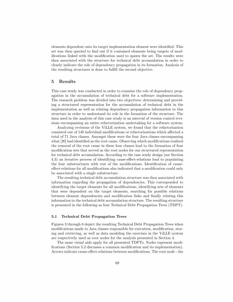
elements dependent onto its target implementation element were identified. Thisset was then queried to find out if it contained elements being targets of mod-ifications linked with the modification used to spawn the set. The results werethen associated with the structure for technical debt accumulation in order toclearly indicate the role of dependency propagation in its formation. Analysis ofthe resulting structures is done to fulfill the second objective.
5 Results
This case study was conducted in order to examine the role of dependency prop-agation in the accumulation of technical debt for a software implementation.The research problem was divided into two objectives: determining and provid-ing a structured representation for the accumulation of technical debt in theimplementation as well as relating dependency propagation information to thisstructure in order to understand its role in the formation of the structure. Thedata used in the analysis of this case study is an interval of version control revi-sions encompassing an entire refactorization undertaking for a software system.
Analyzing revisions of the ViLLE system, we found that the refactorizationconsisted out of 140 individual modifications or refactorizations which affected atotal of 71 Java classes. Amongst these were the four Java classes encompassingwhat [20] had identified as the root cause. Observing which modifications realizedthe removal of the root cause in these four classes lead to the formation of fourmodification sets that served as the root nodes for our structured representationfor technical debt accumulation. According to the case study design (see Section4.3) an iterative process of identifying cause-effect-relations lead to populatingthe four substructures with rest of the modifications. Identification of cause-effect-relations for all modifications also indicated that a modification could onlybe associated with a single substructure.
The resulting technical debt accumulation structure was then associated withinformation regarding the propagation of dependencies. This corresponded toidentifying the target elements for all modifications, identifying sets of elementsthat were dependent on the target elements, searching for possible relationsbetween element dependencies and modification links and finally relating thisinformation to the technical debt accumulation structure. The resulting structureis presented in the following as four Technical Debt Propagation Trees (TDPT).
5.1 Technical Debt Propagation Trees
Figures 3 through 6 depict the resulting Technical Debt Propagation Trees whenmodifications made to Java classes responsible for execution, modification, stor-ing and retrieving, as well as data modeling the exercises in the ViLLE systemare respectively used as root nodes for the analysis presented in Section 4.
The same visual aids apply for all presented TDPTs. Nodes represent modi-fications (Section 5.2 discusses a common modification and its implementation).Arrows indicate cause-effect-relations between modifications. The root node - the
69
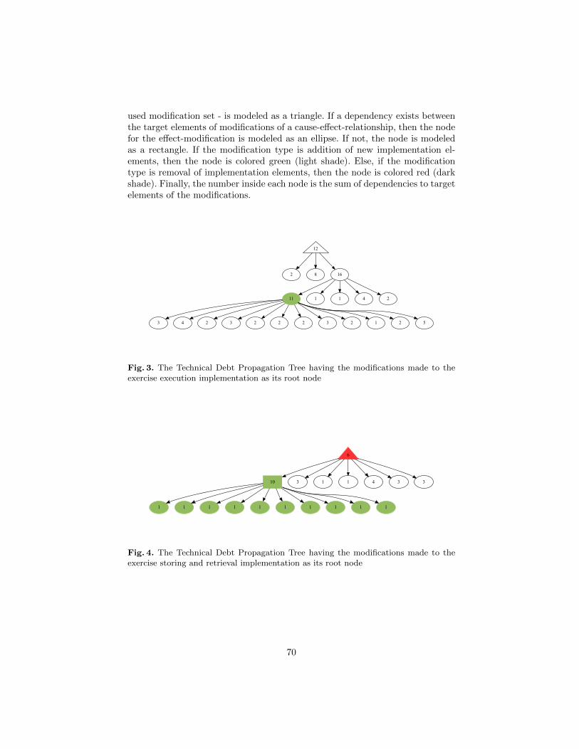
used modification set - is modeled as a triangle. If a dependency exists betweenthe target elements of modifications of a cause-effect-relationship, then the nodefor the effect-modification is modeled as an ellipse. If not, the node is modeledas a rectangle. If the modification type is addition of new implementation el-ements, then the node is colored green (light shade). Else, if the modificationtype is removal of implementation elements, then the node is colored red (darkshade). Finally, the number inside each node is the sum of dependencies to targetelements of the modifications.
12
2 8 16
11 1 1 4 2
3 4 2 3 2 2 2 3 2 1 2 5
Fig. 3. The Technical Debt Propagation Tree having the modifications made to theexercise execution implementation as its root node
6
10 3 1 1 4 3 3
1 1 1 1 1 1 1 1 1 1
Fig. 4. The Technical Debt Propagation Tree having the modifications made to theexercise storing and retrieval implementation as its root node
70
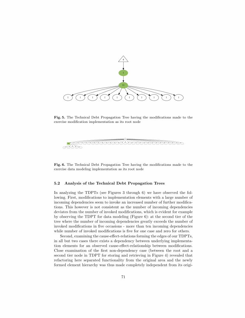
4
1
11
1 1 1 1 1 1 1 1 1 1
Fig. 5. The Technical Debt Propagation Tree having the modifications made to theexercise modification implementation as its root node
71
44 50 55 1 1 1 12 2 1 1 3 3 1 2 1 1 1 1 1 1 3 1 2 2 1 4 8 18 3
4 2 3 2 2
Fig. 6. The Technical Debt Propagation Tree having the modifications made to theexercise data modeling implementation as its root node
5.2 Analysis of the Technical Debt Propagation Trees
In analyzing the TDPTs (see Figures 3 through 6) we have observed the fol-lowing. First, modifications to implementation elements with a large number ofincoming dependencies seem to invoke an increased number of further modifica-tions. This however is not consistent as the number of incoming dependenciesdeviates from the number of invoked modifications, which is evident for exampleby observing the TDPT for data modeling (Figure 6): at the second tier of thetree where the number of incoming dependencies greatly exceeds the number ofinvoked modifications in five occasions - more than ten incoming dependencieswhile number of invoked modifications is five for one case and zero for others.
Second, examining the cause-effect-relations forming the edges of our TDPTs,in all but two cases there exists a dependency between underlying implementa-tion elements for an observed cause-effect-relationship between modifications.Close examination of the first non-dependency case (between the root and asecond tier node in TDPT for storing and retrieving in Figure 4) revealed thatrefactoring here separated functionality from the original area and the newlyformed element hierarchy was thus made completely independent from its origi-
71
nal element leading to non-dependency between modifications’ target elements.In the second non-dependency case (between the root and a second tier nodein TDPT for data modeling in Figure 6) similar motivation could be observed.Exercise type declarations were separated here from the generic exercise datamodel and placed into their own containing class. Hence, it seemed that in al-most all cases dependency propagation was the evident cause for technical debtaccumulation.
Third, examining the depths of the TDPTs we can observe the following. Inthe case of TDPTs for storing and retrieval as well as data modeling the treedepth is three, while for TDPTs for execution and modification the tree depthis four (see Figures 4, 6, 3, and 5 respectively). Further, for all leaf modificationsthe number of dependencies incoming to their target elements is rather low -under ten. Except for the few cases mentioned in the previous paragraph.
Fourth, an observation made from the evident differences in the tree struc-tures. In the case studied system modifying a component that is responsible forproviding a data model in the implementation (see TDPT for data modelingin Figure 6) seemed to invoke a series of modifications that could be describedas shallow but wide. While, modifications responsible for implementing specificfeatures of the system seemed to invoke a series of modifications that were morenarrow and focused than the former (see TDPTs for execution, modifying, andstoring and retrieval in Figures 3, 5, and 4 respectively). This seems to indicatethat for refactored-to-be elements of the implementation, their role in the systemcould be used to postulate the course of the refactorization undertaking in thispart of the system.
6 Conclusions and Validity
This case study has examined the role of dependency propagation in the accu-mulation of technical debt for a software implementation. The research problemwas divided into two objectives and an approach was derived to fulfill them.Applying this approach to case study data resulted into the successful formationof four Technical Debt Propagation Trees. Analysis of these trees lead to thefollowing observations.
The number of incoming dependencies correlates with the number of propa-gation paths for technical debt with the exception of a small number of eventswhich does not adhere to this. Secondly, dependency propagation can be seento drive the accumulation of technical debt in this software implementation, ex-cept for two cases where this can not be observed. Thirdly, examination of theTDPTs supports what has been earlier hypothesized about technical debt di-minishing due to dependency propagation. Finally, as an additional observation,the role of a system component could be used to explain how technical debt hadpropagated in the system.
Concluding onto these observations: it is evident that dependency propaga-tion plays a significant role in the accumulation of technical debt for a softwareimplementation. The propagation of dependencies, which are possible to explic-
72
itly indicate for a software implementation, can be used to predict the size anddistribution of technical debt. If differences between the propagation paths fortechnical debt and implementation dependencies can be taken into account, thisinformation could be automatically generated for indicated sources of technicaldebt providing a mean to forecast the state of the software implementation aswell as a tool to estimating the size and urgency of reparative efforts. Finally,these conclusions indicate that the approach derived for this case study is vi-able for examining the role of dependency propagation in the accumulation oftechnical debt.
6.1 Validity
As this case study examines a unique phenomenon in a specific context, appli-cability of the results requires that certain threats to validity are discussed. Amatter affecting the validity of the case study’s construct is the definition usedfor an acceptable modification. In this case study all observed modifications wereaccepted as paying off technical debt. This acceptance criteria was based firstlyon to the provided definition of a refactorization in Section 2.1 as well as thelimitation of the data set discussed in Section 4. It can be argued that the usedacceptance criteria was too loose, and the resulting TDPTs were over popu-lated. However, it can also be counterclaimed that as the case study specificallytargeted a refactorization project with the foremost intend of not altering thesystem’s behavior this bias will be small in size.
The results of this case study required that we identified a causal relation be-tween the propagation of dependencies and the accumulation of technical debt.Matters distorting the identification affect the case study’s internal validity. Sec-tion 4 explained the processes used for determining both cause-effect-relationsbetween modifications as well as the propagation of dependencies between im-plementation elements. Here, the latter is determined based on static rules andconfirmed in the ability for the program to function. However, determining ofcause-effect-relations was based on the researchers’ ability to distinguish if twomodifications shared a context. While most information in the contexts - forexample close chronological ordering and linkage between affected implemen-tation areas - lead to a strong conclusion, the possibility of making a wrongdecision can not be excluded. However, issue-free and successful association ofall modifications indicates that uncertainty played a small role in this step.
7 Future Work
Research following this case study will build on the conclusions in Section 6.Firstly, we intend to employ the approach derived and used in this case studyfor additional data sets. We expect this to provide more details on the intrin-sics of technical debt accumulation in software implementations in addition tofurther examining the role of dependency propagation in this process. We are
73
especially interested in identifying if certain dependency types accumulate tech-nical debt differently, if the role of system components can be used to furtherexplain the size and distribution of technical debt, and if other mechanisms canbe established for the non-dependency driven accumulation of technical debt.
Further, the results of this and following analyses will be used to build andassess the propagation model used by the DebtFlag-tool [5]. As the tool relieson the ability to maintain technical debt notions through this model, explicitlypresenting the differences in the propagation paths of technical debt and depen-dencies between implementation elements will allow for further enhancements.As such, our ongoing research is focused on assessing and evaluating possiblemodels to identify viable solutions. A strong candidate is the link structure al-gorithm PageRank by Page et al. [23]. Initial analyses with the data providedin this paper has yielded promising results especially in accommodating thediminishment characteristic of technical debt.
References
1. Cunningham, W.: The WyCash portfolio management system. In: Addendum tothe proceedings on Object-oriented programming systems, languages, and appli-cations (OOPSLA). Volume 18. (1992) 29–30
2. Ozkaya, I., Kruchten, P., Nord, R.L., Brown, N.: Managing technical debt in soft-ware development: report on the 2nd international workshop on managing technicaldebt, held at icse 2011. SIGSOFT Softw. Eng. Notes 36(5) (September 2011) 33–35
3. Izurieta, C., Vetro, A., Zazworka, N., Cai, Y., Seaman, C., Shull, F.: Organizingthe technical debt landscape. In: Managing Technical Debt (MTD), 2012 ThirdInternational Workshop on, IEEE (2012) 23–26
4. Seaman, C., Guo, Y.: Measuring and monitoring technical debt. Advances inComputers 82 (2011) 25–46
5. Holvitie, J., Leppanen, V.: DebtFlag: Technical Debt Management with a Devel-opment Environment Integrated Tool. In: Managing Technical Debt (MTD), 2013Fourth International Workshop on, IEEE (2013)
6. Brown, N., Cai, Y., Guo, Y., Kazman, R., Kim, M., Kruchten, P., Lim, E., MacCor-mack, A., Nord, R., Ozkaya, I., et al.: Managing technical debt in software-reliantsystems. In: Proceedings of the FSE/SDP workshop on Future of software engi-neering research, ACM (2010) 47–52
7. Seaman, C., Guo, Y., Izurieta, C., Cai, Y., Zazworka, N., Shull, F., Vetro, A.:Using technical debt data in decision making: Potential decision approaches. In:Managing Technical Debt (MTD), 2012 Third International Workshop on, IEEE(2012) 45–48
8. Guo, Y., Seaman, C., Gomes, R., Cavalcanti, A., Tonin, G., Da Silva, F., Santos,A., Siebra, C.: Tracking technical debtan exploratory case study. In: SoftwareMaintenance (ICSM), 2011 27th IEEE International Conference on, IEEE (2011)528–531
9. Barowski, L.A., Cross, J., et al.: Extraction and use of class dependency informa-tion for java. In: Reverse Engineering, 2002. Proceedings. Ninth Working Confer-ence on, IEEE (2002) 309–315
10. McGregor, J., Monteith, J., Zhang, J.: Technical debt aggregation in ecosystems.In: Managing Technical Debt (MTD), 2012 Third International Workshop on,IEEE (2012) 27–30
74

11. Fowler, M., Beck, K.: Refactoring: improving the design of existing code. Addison-Wesley Professional (1999)
12. Avellis, G.: Case support for software evolution: A dependency approach to controlthe change process. In: Computer-Aided Software Engineering, 1992. Proceedings.,Fifth International Workshop on, IEEE (1992) 62–73
13. Bianchi, A., Caivano, D., Lanubile, F., Visaggio, G.: Evaluating software degra-dation through entropy. In: Software Metrics Symposium, 2001. METRICS 2001.Proceedings. Seventh International, IEEE (2001) 210–219
14. Robillard, M.P.: Topology analysis of software dependencies. ACM Transactionson Software Engineering and Methodology (TOSEM) 17(4) (2008) 18
15. Rajala, T., Laakso, M.J., Kaila, E., Salakoski, T.: Ville: a language-independentprogram visualization tool. In: Proceedings of the Seventh Baltic Sea Conferenceon Computing Education Research-Volume 88, Australian Computer Society, Inc.(2007) 151–159
16. Rajala, T., Kaila, E., Laakso, M.J.: ViLLE. http://ville.cs.utu.fi/ (2013)17. Laakso, M.J.: Promoting Programming Learning: Engagement, Automatic Assess-
ment with Immediate Feedback in Visualizations. PhD thesis, Turku Centre forComputer Science (2010)
18. Kaila, E., Rajala, T., Laakso, M., Salakoski, T.: Important features in programvisualization. In: Appeared in ICEE: An International Conference on EngineeringEducation. (2011) 21–26
19. Gronroos, M., et al.: Book of Vaadin. Vaadin Limited (2011)20. Holvitie, J.: Code level agility and future development of software products. Mas-
ter’s thesis, Department of Information Technology, University of Turku (2012)21. Feathers, M.: Working effectively with legacy code. Prentice Hall (2004)22. Martin, R.C.: Agile software development: principles, patterns, and practices.
Prentice Hall PTR (2003)23. Page, L., Brin, S., Motwani, R., Winograd, T.: The pagerank citation ranking:
bringing order to the web. (1999)
75
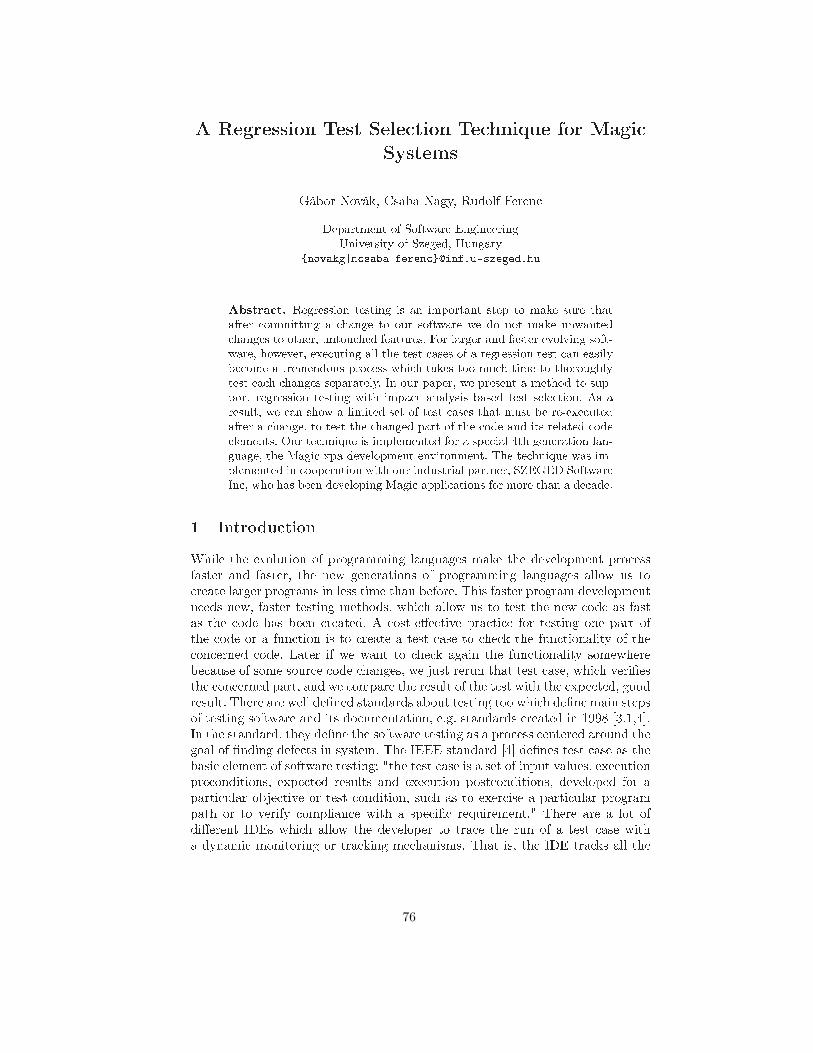
A Regression Test Sele tion Te hnique for Magi
Systems
Gábor Novák, Csaba Nagy, Rudolf Feren
Department of Software Engineering
University of Szeged, Hungary
{novakg|n saba|feren }�inf.u-szeged.hu
Abstra t. Regression testing is an important step to make sure that
after ommitting a hange to our software we do not make unwanted
hanges to other, untou hed features. For larger and faster evolving soft-
ware, however, exe uting all the test ases of a regression test an easily
be ome a tremendous pro ess whi h takes too mu h time to thoroughly
test ea h hanges separately. In our paper, we present a method to sup-
port regression testing with impa t analysis based test sele tion. As a
result, we an show a limited set of test ases that must be re-exe uted
after a hange, to test the hanged part of the ode and its related ode
elements. Our te hnique is implemented for a spe ial 4th generation lan-
guage, the Magi xpa development environment. The te hnique was im-
plemented in ooperation with our industrial partner, SZEGED Software
In , who has been developing Magi appli ations for more than a de ade.
1 Introdu tion
While the evolution of programming languages make the development pro ess
faster and faster, the new generations of programming languages allow us to
reate larger programs in less time than before. This faster program development
needs new, faster testing methods, whi h allow us to test the new ode as fast
as the ode has been reated. A ost-e�e tive pra ti e for testing one part of
the ode or a fun tion is to reate a test ase to he k the fun tionality of the
on erned ode. Later if we want to he k again the fun tionality somewhere
be ause of some sour e ode hanges, we just rerun that test ase, whi h veri�es
the on erned part, and we ompare the result of the test with the expe ted, good
result. There are well de�ned standards about testing too whi h de�ne main steps
of testing software and its do umentation, e.g. standards reated in 1998 [3,1,4℄.
In the standard, they de�ne the software testing as a pro ess entered around the
goal of �nding defe ts in system. The IEEE standard [4℄ de�nes test ase as the
basi element of software testing: "the test ase is a set of input values, exe ution
pre onditions, expe ted results and exe ution post onditions, developed for a
parti ular obje tive or test ondition, su h as to exer ise a parti ular program
path or to verify omplian e with a spe i� requirement." There are a lot of
di�erent IDEs whi h allow the developer to tra e the run of a test ase with
a dynami monitoring or tra king me hanisms. That is, the IDE tra ks all the
76
events performed by the user during the test run of the test ase, and with this
event log we know every little detail about the test run.
While the sour e ode is ontinuously hanging, developers need to re-run
these test ases time to time to make sure the hanged sour e ode still gives the
appropriate result on the test ases. To make sure that we did not introdu e a
new bug, or unwanted hanges of existing features, one must always re-run all the
existing test ases. However, in most ases one hange does not a�e t all the test
ases, but only those one, whi h are losely related to the hanged sour e ode
elements. These hanges does not require to re-run the whole test ase set, but
it is hard to �nd the smallest set of related test ases. Test sele tion [4℄ ta kles
solutions to this problem. Its main purpose is to sele t the a�e ted test ases.
This problem usually emerges in regression test sele tion [4℄. In regression tests
the goal is to hose those test ases whi h are the most a�e ted by modi� ations
in the sour e ode, and re-run these ases. In most ases this works stati ally,
and requires only the sour e ode of the system. Furthermore we are able to
measure the per entage of the overed ode ( overed by the urrent test ase),
this method is the test overage [4℄.
There are a number of tools implemented for regression tests or measuring
test overage for popular 3rd generation programming languages (E.g.: Squish
[10℄, Appperfe t [8℄), but in the ontext of 4th generation languages (4GLs),
there are no universal solutions for these problems.
Impa t analysis [7,13℄ an be a great support in regression test sele tion. The
aim of impa t analysis is to get the transitive a�e ted part of a ertain hange
in the sour e ode. A simple hange (e.g. renaming a method) might impa t a
larger part of the ode, even though we wanted to hange only small part of
it. This impa ted ode set is alled the impa t set. In this paper we represent a
on eptual ba kground of a regression test sele tion me hanism, that is based on
impa t analysis, and an implementation of this me hanism, to solve presented
problems in Magi xpa, as a spe ial 4 GL programming language.
Test sele tion and espe ially regression test sele tion is useful when the test
rerun demands a lot of resour es. We an save time, and money with the fast
test rerun. Our presented te hnique is based on al ulating the test overage (for
every single test ase) in the same time, while exe uting the regression test and
then, next time, use the previously olle ted overage data for sele ting a subset
of test ases that must be rerun to test the modi�ed ode.
In Se tion 2 we introdu e the reader to the world of the Magi programming
language, and the main stru tures of a Magi appli ation. Then, in Se tion 3 we
show the on eptual ba kground of the presented test sele tion te hnique, after
that we present some results a hieved in Se tion 4 and �nally we on lude our
paper in Se tion 6.
2 Stru ture of Magi Appli ations
Higher level, so alled 4th generation programming languages (4GLs) do not
use sour e ode in the traditional way. The ode is not dire tly written by the
77
developer, but it is generated automati ally by an appli ation development en-
vironment, and in most ases the generated underlying ode is hidden from
the developer. The developer develops the appli ation at a higher, on eptual
level, and he uses ready solutions of the development environment. Usually the
programmer de�ne the expe ted me hanism in a well de�ned UI, and the de-
velopment environment generates the ode whi h represent that me hanism. In
ase of Magi the generated program runs on the Magi Runtime Engine. In
the development environment, Magi xpa, we de�ne the program, the expe ted
me hanisms, and when we want to run it, the Magi xpa starts the generated
ode on the engine.
The "sour e ode" of a Magi appli ation is a set of XML �les. In fa t this
sour e ode of a Magi appli ation is an XML snapshot of the a tual state of
the appli ation loaded into the development environment. This XML format
is appropriate for stati analysis as it des ribes the whole appli ation. Magi
is based on a spe ial way of development with spe ial oding elements. The
two most important elements for us in Magi are the Tasks (or Programs), and
the Data Obje ts. A Task is onstru ted of Logi Units and one or more other
Tasks, so- alled Sub Tasks. None of them are ne essary, but the most important
fun tion in a Task, is the Task all me hanism. There are 2 di�erent kinds of
Tasks in Magi , the Bat h Task and the Online Task. Every single Task is able to
all another Task, whether it is Sub Task or an other, independent Program (a
top level Task). A Data Obje t is a persistent obje t, whi h allows the program
to use di�erent data sour es with the same me hanism, hide the spe i� ation of
the data sour e (The data sour e an be database, XML �le ...).
Analysing a program is usually ondu ted by stati analysis, sin e analysing
the program during runtime an be really di� ult task. The stati analysis
methods is usually based on Abstra t Semanti Graph (ASG) [15℄. The XML
based sour e of a Magi appli ation is not signi� antly di�erent from this ASG
format, this is due to the XML stru ture, whi h is also a graph representation
of the system in a way.
Magix xpa allows us to reate dynami runtime tra es, while the program
under test is running on the appli ation engine. This tra e �le is a text �le where
every line is an entry about one event in the program. The level of the re orded
events an be also spe i�ed, but �ner granularities have greater in�uen e on the
exe ution time of the program under test. The log level is enough for our test
sele tion purposes, but it might not be enough to get information for deeper
analysis. For example Magi does not log the entered text in a text �eld or a
text area. There is one very important log entry in the tra e �le for the regression
test sele tion, and this re ord is a task start entry.
<253693576794033600> 13:50:58.406 [A tion ℄ - >>Starts load Bat h
Task - 'Main Program (Cal ulator)' in Query mode (Task Instan e: 1)
78
3 Test Sele tion in Magi
In the system developing pro ess reating the test ases is one of the most
important steps. The developer needs to rethink on e more the a tual part of
the program what she or he wants to test with that test ase, be ause if the
program will hange, this test ase ensures, that fun tion works as it was spe i�ed
before the modi� ation. This idea leads us to the Test Driven Development
(TDD) model [6℄. In TDD, the main on ept is to reate the test ase before
writing the a tual program, or fun tion. This method en ourages the developer
to rethink the me hanism and reate a better test ase before the a tual program
or fun tion is ompleted.
Regardless of the development model that we urrently use in our develop-
ment methods, over the time we need to re-run the ompleted test ases more
often then reating new ones. From that point the regression test sele tion pro-
grams have many advantages. A regression test sele tion tool is responsible to
hoose the most a�e ted test ases with a sour e ode hange, but this task is
not easy at all. After the tool hooses the test ases, just rerun the hosen ones,
or maybe the tool do this for us. If we have tons of test ases, we an save a
lot of resour e with this te hnique. We need to keep in mind, the best way is to
always rerun every test ase, but there are many situations when we are not able
to rerun every single test ase after every hange of the ode. We reate a new
method to hose the most on erned test ases for a Magi appli ation, whi h
of ourse depend on a sour e ode hange. Before we des ribe the te hnique we
need to know whi h inputs are ne essary for the test sele tion. Figure 1. shows
the required inputs and the generated outputs of the test sele tion methods.
There are 3 essential inputs for the test sele tion. In the appli ation whi h
implement this method we use a test manager [5℄ tool and an SVN repository
to give the input to the test sele tion tool. These are the required inputs for the
method:
� Test ases: First of all, the program needs to identify every test ases, so
the �rst important information about a test ase is its unique identi�er. In
our ase this information ame from the test manager tool [5℄. This test
manager tool was reated to manage test ases for Magi appli ations. The
other important information, whi h ame from this test manager tool is the
tra e �les for every test ase. This tra e �le, as mentioned earlier, is the test
ase run log. It ontains every important information, about the user, and
the program a tivities (For example: Task alls, mouse li k events). Every
test ase has at least one tra e �le in the test manager, and we get these
tra e �les for the test sele tion.
� The sour e of the Magi proje t: The tool needs to know the stru ture
of the Magi program. That is, the tool performs a stati analysis on the
ode to olle t all the ne essary information. In Magi the sour e ode of
a program is a set of XML �les. In the implementation of the program we
ask for an SVN repository, whi h ontains a Magi program's sour e ode.
Basi ally the tool looking for 2 important information from the sour e ode.
79

Changes
(from SVN)
Source of the
system
(from SVN)
Test cases (from the Test Manager)
Test case #1 Test case #2
Test case #3 …
Magic Regression Test Selection ToolSystem
analysis
Test cases to rerun
Test case #1 Test case #2
Test case #3 …
Result of
the system
analysis.
Test coverage
Test case #1 – 12%
Test case #2 – 25%
…
Fig. 1. The inputs and the outputs of the regression test sele tion method.
The �rst is the data obje t des riptions from the DataSour e.xml �le. This
information important be ause be ause the task des riptions ontains data
obje t referen es and before pro essing tasks, the tool needs to know the data
obje ts of the program. The se ond essential information is the task hierar-
hy. The tool reates a dire ted graph from the tasks and data obje ts whi h
is required for the test sele tion. The task des riptions is in the Progs.xml
�le, this �le ontains the basi informations about the root tasks, the de-
tailed information and the sub task des riptions are in the Prog_{i}.xml
�les. Where i is between 1 and the highest task id in the Progs.xml.
� Sour e ode hanges: Another required input for the algorithm is the
hanged sour e ode parts. The method needs to know whi h task was mod-
i�ed, be ause if there were no hanges in the ode, there is nothing to rerun.
In the implementation we give this information to the tool in the guise of two
SVN revision number. The program in the prepro essing part analyzes the
diff informations between this two revisions, and olle ts the modi�ed task
set. Be ause of the task's hierar hi al stru ture the tool always hooses just
the dire tly a�e ted tasks into the modi�ed task set. The algorithm needs
a task list, whi h ontains the modi�ed tasks, nothing else. If we reate a
new prepro essor to analyze Magi appli ation version ontrolled in GIT or
Mer urial we an still use the method.
The operations in the algorithm:
� Pro essing test ases: As mentioned earlier every test ase has a unique
identi�er, and at least one tra e �le. In this step we pro ess the tra e �les
80
for the test ases. We pro ess every tra e �le's every line and look for spe ial
entries. The entries, what we look for are the "task su essfully started"
entries. There are two kinds of tasks in Magi , the bat h and the online tasks.
Every kind of task has a spe ial unique entry in the tra e �le, whi h ontains
the unique identi�er of the task. We olle t every alled task identi�er from
every tra e �le for every test ase. When we �nish this step we have a set of
a�e ted task identi�ers for every test ase. This is the pseudo ode of this
pro ess:
pro essTestCases ():
tasks = ∅For every test ase
For every test ase's tra e file
For every line in the tra e file
If it's a su essful task all entry
tasks = tasks ∪ new alled task
End if
End for
End for
End for
End
� The system sour e ode pro essing: In this step we pro ess the des rip-
tor �les of data obje ts and tasks from the SVN repository and ompute a
spe ial graph from those informations. First of all, we need to pro ess the
data obje t information in the DataSour e.xml �le. The tasks refer to the
data obje t with its unique identi�er (a number), so we need to olle t the
available data obje t names and identi�er numbers before we analyze the
tasks. After this step we have this set:
D = {d1, . . . , dm}, di = The i. data obje t (1)
In the next step we need to pro ess every Prg_{i}.xml �le, and extra t
the ne essary informations about the tasks. While we pro ess the �les we
reate a spe ial tree or if there are more than one Prg_{i}.xml �les then
we reate a forest hierar hy from the tasks. Every Prg_{i}.xml represent a
tree, where the root vertex is the main task, and the parent- hild onne tions
represented with the task-subtask onne tions. When we �nish this step we
have the following F (Vf , Ef ) forest:
F = {f1, . . . , fn}, fi = A tree, represent the Prg_{i}.xml (1 ≤ i ≤ n) (2)
After this step, we reate a graph from the data obje t set and the forest of
the tasks. The �nal G(Vg, Eg) graph reated with the following rules:
∀v ∈ Vg, v ∈ D ∨ v ∈ Vf (fi)(∃fi ∈ F )
∀e(vi, vj) ∈ Eg, (vi,j ∈ Vf (fk) ∧ e ∈ Ef (fk)) ∨(vi ∈ Vf (fk) ∧ vj ∈ D ∧ vi task use vj data obje t ) , where fk ∈ F
(3)
81
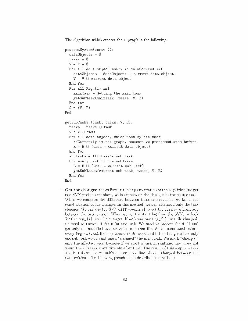
The algorithm whi h reates the G graph is the following:
pro essSystemSour e ():
dataObje ts = ∅tasks = ∅V = E = ∅For all data obje t entry in dataSoru es.xml
dataObje ts = dataObje ts ∪ urrent data obje t
V = V ∪ urrent data obje t
End for
For all Prg_{i}.xml
mainTask = Getting the main task
getSubTask(mainTask, tasks, V, E)
End for
G = (V, E)
End
getSubTasks (task, tasks, V, E):
tasks = tasks ∪ task
V = V ∪ task
For all data obje t, whi h used by the task
//Currently in the graph, be ause we pro essed on e before
E = E ∪ (task � urrent data obje t)
End for
subTasks = All task's sub task
For every task in the subTasks
E = E ∪ (task � urrent sub task)
getSubTasks( urrent sub task, tasks, V, E)
End for
End
� Get the hanged tasks list: In the implementation of the algorithm, we get
two SVN revision numbers, whi h represent the hanges in the sour e ode.
When we ompare the di�eren e between these two revisions we know the
exa t lo ation of the hanges. In this method, we pay attention only the task
hanges. We an use the SVN diff ommand to get the hange information
between the two revision. When we get the diff log from the SVN, we look
for the Prg_{i}.xml �le hanges. If we know one Prg_{i}.xml �le hanged,
we need to narrow it down for one task. We need to pro ess the diff and
get only the modi�ed task or tasks from that �le. As we mentioned before,
every Prg_{i}.xml �le may ontain sub-tasks, and if the hanges a�e t only
one sub-task we an not mark " hanged" the main task. We mark " hanged"
only the a�e ted task, be ause if we start a task in runtime, that does not
mean the sub-task start dire tly after that. The result of this step is a task
set. In this set every task's one or more line of ode hanged between the
two revision. The following pseudo ode des ribe this method:
82

pro essChanges ():
tasks = ∅Every diff entry in svn
If Prg_{i}.xml modified
task = Get the task whi h modified by the diff
tasks = tasks ∪ task
End if
End for
End
� Test overage de�nition: The test overage de�nition or al ulation in
this ase is a per entage value for every test ase. This per entage is derived
from the number of a�e ted tasks by the test ase divided by the number of
tasks in the appli ation. This rate shows us what per entage overed with
the test ase, of the whole system.
� The system's dependen ies: In this step we al ulate a per entage for
every data obje t in the Magi system. This per entage des ribes a ratio
between the urrent data obje t and the related tasks of the system. In this
al ulation we spe ify for every data obje t the number of tasks, whi h use
this data obje t.
� Test ases to rerun: This is the most important part of the algorithm.
In this step, we give the information, whi h test ase is ne essary to rerun.
It depends on the previously extra ted information: the hanged tasks set
and the G(Vg, Eg) graph. The method uses 2 di�erent steps to get this in-
formation. In the �rst step the algorithm omputes the dire tly a�e ted test
ases, whi h means this test ases are the most important ones. This is a
fast step, be ause we already have every ne essary information. For ea h
test ase, the algorithm interse ts the urrent test ase's set of tasks and the
set of hanged tasks. If the interse tion is not empty, then the a�e ted test
ases are those whi h belong to tasks in the interse tion. These test ases
are dire tly a�e ted, so we sele t them for re-run. Figure 2. shows this step.
Modified tasks
Task A
Task C
Task A : Task B
Task D
Task A : Task B Task E
Test Case #1
Task G
Task D : Task F
Task A : Task B
Fig. 2. The dire tly a�e ted test ases has a not empty interse tion with the hanged
tasks.
During the se ond step the method al ulates the transitive dependen ies,
reate the impa t set of the a�e ted odes, and hose the indire tly a�e ted
test ases. For this, we need to reate a new graph from the existingG(Vg, Eg)
83
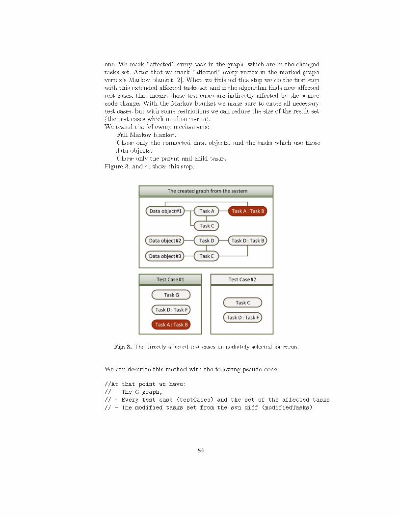
one. We mark "a�e ted" every task in the graph, whi h are in the hanged
tasks set. After that we mark "a�e ted" every vertex in the marked graph
vertex's Markov blanket [2℄. When we �nished this step we do the �rst step
with this extended a�e ted tasks set and if the algorithm �nds new a�e ted
test ases, that means those test ases are indire tly a�e ted by the sour e
ode hange. With the Markov blanket we make sure to hose all ne essary
test ases, but with some restri tions we an redu e the size of the result set
(the test ases whi h need to re-run).
We tested the following me hanisms:
� Full Markov blanket.
� Chose only the onne ted data obje ts, and the tasks whi h use those
data obje ts.
� Chose only the parent and hild tasks.
Figure 3. and 4. show this step.
The created graph from the system
Data object #1
Data object #2
Task A : Task BTask A
Data object #3
Task C
Test Case #1
Task G
Task D : Task F
Task A : Task B
Test Case #2
Task C
Task D : Task F
Task D : Task BTask D
Task E
Fig. 3. The dire tly a�e ted test ases immediately sele ted for rerun.
We an des ribe this method with the following pseudo ode:
//At that point we have:
// - The G graph,
// - Every test ase (testCases) and the set of the affe ted tasks
// - The modified tasks set from the svn diff (modifiedTasks)
84
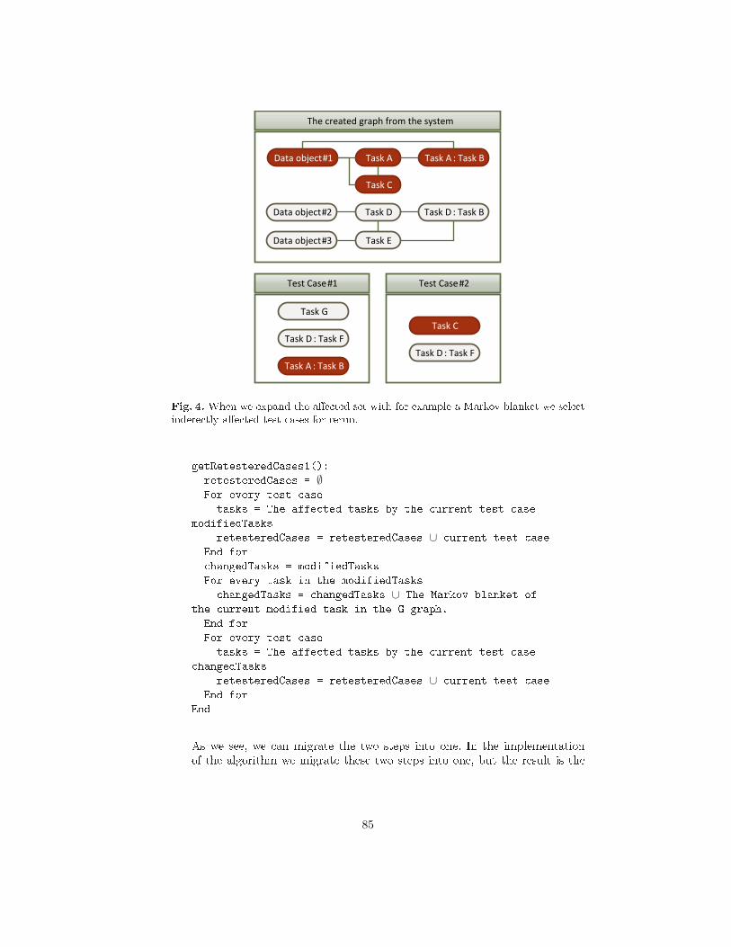
The created graph from the system
Data object #1
Data object #2
Task A : Task BTask A
Data object #3
Task C
Test Case #1
Task G
Task D : Task F
Task A : Task B
Test Case #2
Task C
Task D : Task F
Task D : Task BTask D
Task E
Fig. 4. When we expand the a�e ted set with for example a Markov blanket we sele t
indere tly a�e ted test ases for rerun.
getRetesteredCases1():
retesteredCases = ∅For every test ase
tasks = The affe ted tasks by the urrent test ase \modifiedTasks
retesteredCases = retesteredCases ∪ urrent test ase
End for
hangedTasks = modifiedTasks
For every task in the modifiedTasks
hangedTasks = hangedTasks ∪ The Markov blanket of
the urrent modified task in the G graph.
End for
For every test ase
tasks = The affe ted tasks by the urrent test ase \ hangedTasks
retesteredCases = retesteredCases ∪ urrent test ase
End for
End
As we see, we an migrate the two steps into one. In the implementation
of the algorithm we migrate these two steps into one, but the result is the
85
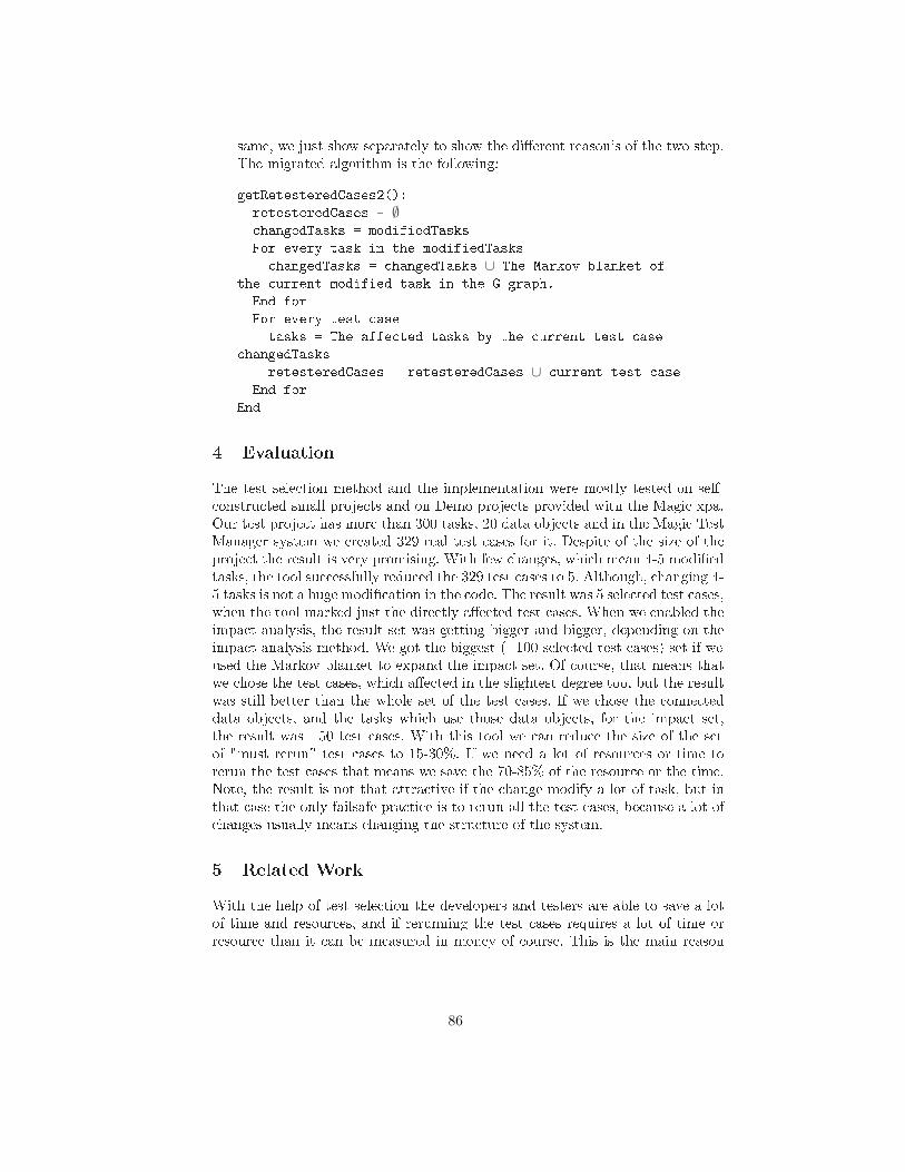
same, we just show separately to show the di�erent reason's of the two step.
The migrated algorithm is the following:
getRetesteredCases2():
retesteredCases = ∅ hangedTasks = modifiedTasks
For every task in the modifiedTasks
hangedTasks = hangedTasks ∪ The Markov blanket of
the urrent modified task in the G graph.
End for
For every test ase
tasks = The affe ted tasks by the urrent test ase \ hangedTasks
retesteredCases = retesteredCases ∪ urrent test ase
End for
End
4 Evaluation
The test sele tion method and the implementation were mostly tested on self-
onstru ted small proje ts and on Demo proje ts provided with the Magi xpa.
Our test proje t has more than 300 tasks, 20 data obje ts and in the Magi Test
Manager system we reated 329 real test ases for it. Despite of the size of the
proje t the result is very promising. With few hanges, whi h mean 4-5 modi�ed
tasks, the tool su essfully redu ed the 329 test ases to 5. Although, hanging 4-
5 tasks is not a huge modi� ation in the ode. The result was 5 sele ted test ases,
when the tool marked just the dire tly a�e ted test ases. When we enabled the
impa t analysis, the result set was getting bigger and bigger, depending on the
impa t analysis method. We got the biggest (� 100 sele ted test ases) set if we
used the Markov blanket to expand the impa t set. Of ourse, that means that
we hose the test ases, whi h a�e ted in the slightest degree too, but the result
was still better than the whole set of the test ases. If we hose the onne ted
data obje ts, and the tasks whi h use those data obje ts, for the impa t set,
the result was � 50 test ases. With this tool we an redu e the size of the set
of "must rerun" test ases to 15-30%. If we need a lot of resour es or time to
rerun the test ases that means we save the 70-85% of the resour e or the time.
Note, the result is not that attra tive if the hange modify a lot of task, but in
that ase the only failsafe pra ti e is to rerun all the test ases, be ause a lot of
hanges usually means hanging the stru ture of the system.
5 Related Work
With the help of test sele tion the developers and testers are able to save a lot
of time and resour es, and if rerunning the test ases requires a lot of time or
resour e than it an be measured in money of ourse. This is the main reason
86
why this topi is so popular. There are plenty of books and papers in this �eld,
but espe ially for Magi language (and in general about the 4 GL languages)
there are only a few available in the s ope of regression testing. A omprehensive,
mostly pra ti al study on methods about software testing is olle ted in the The
Art of Software Testing [14℄ book. In this book authors olle t and des ribe the
most useful methods, in the aspe t of resour e requirement. Emelie Engström's
et al. [9℄ systemati ally olle t information about the empiri al evaluations of
regression test sele tion te hniques. They olle t 28 di�erent methods for regres-
sion test sele tion evaluations. They on lude that they an not make a �nal
de ision, about whi h method is the best, be ause every method depends on a
di�erent aspe ts and fa tors. Mary Jean Harrold et al. [11℄ wrote a paper about
a new regression test sele tion te hnique for the Java programming language.
This method is usable when the Java program's sour e ode is not ompletely
�nished or the program uses 3rd party libraries. This RETEST te hnique su -
essfully redu ed the size of the test environment. This te hnique is similar to
our method, but RETEST works on Java, a 3rd generation programming lan-
guage. Gregg Rothermel et al. [16℄ des ribe a method, whi h uses the system's
Control Flow Graph (CFG [17℄) for regression test sele tion. The bene�t of the
CFG usage is that they are able to use this method in every 3 GL. This method
has a lot of bene�ts, but it works on 3GLs.
In ase of 4 GLs existing regression test sele tion te hniques annot be applied
expli itly, they must be adopted to the spe i� language, be ause ea h language
has a di�erent stru ture. This di�erent stru ture is the result of the di�erent
purpose of the 4GLs. A book, entitled Testing SAP Solutions [12℄ olle t and
des ribe the available methods for testing an SAP ABAP appli ation, whi h
are also popular 4GLs. For Magi appli ations there is no urrently available
solution for the regression test sele tion.
6 Con lusions and Future Work
The method whi h we presented in this paper, su essfully redu es the resour e
and time requirement of the regression test sele tion method of Magi develop-
ment pro esses. This method has learly bene�ts in regression testing. Besides,
the developers an easily use the system analysis results and the test ase ov-
erage informations to make better test ases or �lter out the most useless test
ases, or refa toring the system. With those extra fun tions this test sele tion
method and the program implementing it, are very powerful tools, whi h an be
used in the whole software development phase. Be ause the tool does not need
a lot of input for the analysis and the test sele tion, and most of them auto-
mati ally extra ted from other tools (Magi Test Manager, SVN), this is a good
hoi e for almost every time in a Magi appli ation development. The prototype
of the implementation is urrently able to use only SVN to identify hanges in
the sour e ode, but it is easy to expand it for other version ontrol systems
too. One drawba k is that the developers need to frequently use the tool to have
up-to-date overage data for test ases. Also, when the hange set is so large that
87
it a�e ts too many test ases the result might simply ontain almost every test
ases. In the future plans we want to test this method and the implementation
on bigger Magi appli ations, and we want to generalize this method for more
programming languages, not just Magi .
A knowledgements
This resear h was supported by the Hungarian national grant GOP-1.1.1-11-
2011-0039.
Referen es
1. Standard for Software Component Testing. British Computer So iety Spe ialist
Interest Group in Software Testing (BCS SIGIST).
2. Probabilisti Reasoning in Intelligent Systems: Networks of Plausible Inferen e.
Morgan Kaufmann, 1988.
3. IEEE Standard for Software Test Do umentation IEEE Std 829-1998. 1998.
4. Standard glossary of terms used in Software Testing, ISTQB Glossary - version
2.1. `Glossary Working Party' International Software Testing Quali� ations Board,
2010.
5. A layout independent gui test automation tool for appli ations developed in
magi /unipaas. In Pro eedings of the 12th Symposium on Programming Languages
and Software Tools, 2011.
6. Kent Be k. Test driven development: By example. Addison-Wesley Professional,
2003.
7. Shawn A. Bohner. Software hange impa t analysis. IEEE Computer So iety Press,
1996.
8. AppPerfe t Corp. Appperfe t software test tools. http://www.appperfe t. om/.
9. Emelie Engström, Per Runeson, and Mats Skoglund. A systemati review on
regression test sele tion te hniques. Information and Software Te hnology, 52(1):14
� 30, 2010.
10. froglogi . Squish gui testing tool. http://www.froglogi . om/squish/
gui-testing/.
11. Mary Jean Harrold, James A Jones, Tongyu Li, Donglin Liang, Alessandro Orso,
Maikel Pennings, Saurabh Sinha, S Alexander Spoon, and Ashish Gujarathi. Re-
gression test sele tion for java software. In ACM SIGPLAN Noti es, volume 36,
pages 312�326. ACM, 2001.
12. Markus Helfen, Mi hael Lauer, and Hans Martin Trauthwein. Testing SAP solu-
tions. Galileo Press, 2007.
13. MS Kilpinen. The emergen e of hange at the systems engineering and software
design interfa e: an investigation of impa t analysis. PhD thesis, 2008.
14. Glenford J Myers, Corey Sandler, and Tom Badgett. The art of software testing.
Wiley, 2011.
15. Shruti Raghavan, Rosanne Rohana, David Leon, Andy Podgurski, and Vinay Au-
gustine. Dex: A Semanti -Graph Di�eren ing Tool for Studying Changes in Large
Code Bases. Software Maintenan e, IEEE International Conferen e on, 0:188�197,
2004.
88

16. Gregg Rothermel and Mary Jean Harrold. A safe, e� ient regression test sele -
tion te hnique. ACM TRANSACTIONS ON SOFTWARE ENGINEERING AND
METHODOLOGY, 6:173�210, 1997.
17. O. Shivers. Control �ow analysis in s heme. SIGPLAN Not., 23(7):164�174, June
1988.
89
VOSD: A General-Purpose Virtual Observatoryover Semantic Databases
Gergo Gombos, Tamas Matuszka, Balazs Pinczel, Gabor Racz, and Attila Kiss
Eotvos Lorand University, Budapest, Hungary{ggombos,tomintt,vic,gabee33,kiss}@inf.elte.hu
Abstract. E-Science relies heavily on manipulating massive amountsof data for research purposes. Researchers should be able to contributetheir own data and methods, thus making their results accessible and re-producible by others worldwide. They need an environment which theycan use anytime and anywhere to perform data-intensive computations.Virtual observatories serve this purpose. With the advance of the Se-mantic Web, more and more data is available in RDF databases. It isoften desirable to have the ability to link local data sets to these publicdata sets. We present a prototype system, which satisfies the require-ments of a virtual observatory over semantic databases, such as userroles, data import, query execution, visualization, exporting result, etc.The system has special features which facilitate working with semanticdata: visual query editor, use of ontologies, knowledge inference, query-ing remote endpoints, linking remote data with local data, extractingdata from web pages.
Keywords: Virtual Observatory, Semantic Web, e-Science, Data Shar-ing, Linked Data
1 Introduction
E-Science is based on the interconnection of enormous amounts of data collectedfrom various scientific fields. These massive data sets can be used for conductingresearches, during which it is often desirable that researchers can share theirown data and methods, thus making the results of the research accessible andreproducible by anyone. The idea of virtual observatories coming from Jim Grayand Alex S. Szalay serves this purpose [1]. A system like this expands the pos-sibilities of combining data coming from various different instruments. Virtualobservatories can also be used to teach and demonstrate the basic research prin-ciples of various scientific fields (for example, astronomy or computer science).The researchers must have access to these constantly growing amounts of data,in order to be able to use them in various research projects. Another impor-tant requirement is to be able to publish the results. The Internet provides anexcellent opportunity to satisfy the criteria mentioned above [1]. The primarymotivation for creating virtual observatories is to facilitate making new discov-eries, and to provide a solution for carrying out data-intensive computationsremotely. To access remote data, web services can be used [2].
90
The basic principles of science have been extended with a fourth paradigm.A thousand years ago, experimental results and observations defined science. Inthe last few hundred years, it shifted towards a theoretical approach, focusingon creating and generalizing models. During the last few decades, simulatingcomplex phenomena with computers were becoming more and more common.Nowadays, researchers have to deal with large amounts of data, usually comingfrom sensors, telescopes, particle accelerators, etc. The data is processed usingsoftware solutions, and the extracted knowledge is stored in databases. Analyzingor visualizing the results needs further software support [3, 4].
A possible way to manage the data available on the Internet is to use theSemantic Web [5]. The Semantic Web aims for creating a“web of data”: a largedistributed knowledge base, which contains the information of the World WideWeb in a format which is directly interpretable by computers. The goal of thisweb of linked data is to allow better, more sensible methods for informationsearch, and knowledge inference. To achieve this, the Semantic Web providesa data model and its query language. The data model called the ResourceDescription Framework (RDF) [6] uses a simple conceptual description of theinformation: we represent our knowledge as statements in the form of subject-predicate-object (or entity-attribute-value). This way our data can be seen as adirected graph, where a statement is an edge labeled with the predicate, point-ing from the subjects node to the objects node. The query language calledSPARQL [7] formulates the queries as graph patterns, thus the query resultscan be calculated by matching the pattern against the data graph. Furthermore,there are numerous databases which contain theoretical and experimental re-sults of various scientific experiments in the field of computer science, biology,chemistry, etc. There is a quite complex collection of these kinds of data main-tained by the Linked Data Community [8]. This collection contains datasets andontologies which are at least 1000 lines in length, and which contain links toeach other.
In this paper, we present a prototype system, which fulfills the standardrequirements of a virtual observatory, such as handling user roles, bulk load-ing data , answering queries, visualization, and storing results. In addition, weextended the system with special semantic technologies. We use the SPARQLlanguage to formulate queries, aided by a visual SPARQL editor. Ontologies canbe used to describe the hierarchy of complex conceptual systems, and to carryout knowledge inference. The system implements a tool, which helps its users toconvert the data found on the web to the formats of the Semantic Web. We alsoprovide a SPARQL endpoint to enable remote querying of the knowledge base.The query results can be exported to various common semantic data formats.We demonstrated the flexibility of the system by implementing two differentdatabase backends.
The structure of the paper is as follows. After the introductory Section 1, wepresent the high-level architecture of our virtual observatory in Section 2. Then,in Section 3, we describe the main functionality of the system. Section 4 writesabout the functions supporting the collaboration of researchers. Then, we show
91
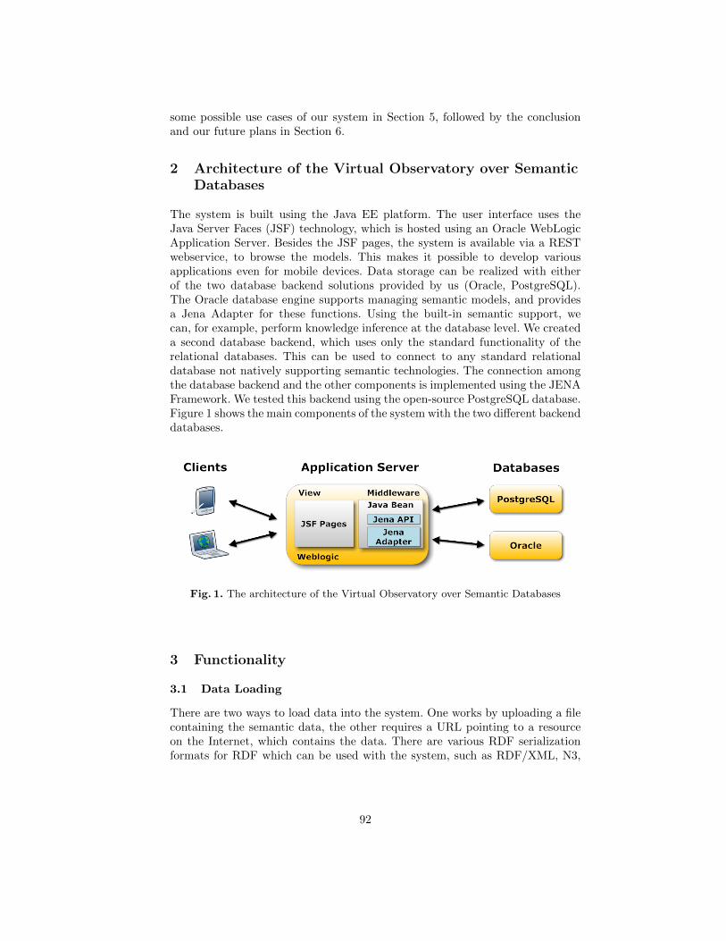
some possible use cases of our system in Section 5, followed by the conclusionand our future plans in Section 6.
2 Architecture of the Virtual Observatory over SemanticDatabases
The system is built using the Java EE platform. The user interface uses theJava Server Faces (JSF) technology, which is hosted using an Oracle WebLogicApplication Server. Besides the JSF pages, the system is available via a RESTwebservice, to browse the models. This makes it possible to develop variousapplications even for mobile devices. Data storage can be realized with eitherof the two database backend solutions provided by us (Oracle, PostgreSQL).The Oracle database engine supports managing semantic models, and providesa Jena Adapter for these functions. Using the built-in semantic support, wecan, for example, perform knowledge inference at the database level. We createda second database backend, which uses only the standard functionality of therelational databases. This can be used to connect to any standard relationaldatabase not natively supporting semantic technologies. The connection amongthe database backend and the other components is implemented using the JENAFramework. We tested this backend using the open-source PostgreSQL database.Figure 1 shows the main components of the system with the two different backenddatabases.
Fig. 1. The architecture of the Virtual Observatory over Semantic Databases
3 Functionality
3.1 Data Loading
There are two ways to load data into the system. One works by uploading a filecontaining the semantic data, the other requires a URL pointing to a resourceon the Internet, which contains the data. There are various RDF serializationformats for RDF which can be used with the system, such as RDF/XML, N3,
92
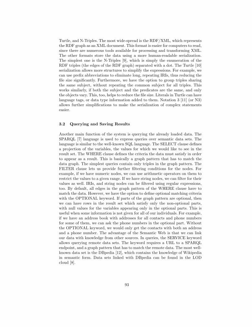
Turtle, and N-Triples. The most wide-spread is the RDF/XML, which representsthe RDF graph as an XML document. This format is easier for computers to read,since there are numerous tools available for processing and transforming XML.The other formats store the data using a more human-readable serialization.The simplest one is the N-Triples [9], which is simply the enumeration of theRDF triples (the edges of the RDF graph) separated with a dot. The Turtle [10]serialization allows more structures to simplify the expressions. For example, wecan use prefix abbreviations to eliminate long, repeating IRIs, thus reducing thefile size significantly. Furthermore, we have the option to group triples sharingthe same subject, without repeating the common subject for all triples. Thisworks similarly, if both the subject and the predicates are the same, and onlythe objects vary. This, too, helps to reduce the file size. Literals in Turtle can havelanguage tags, or data type information added to them. Notation 3 [11] (or N3)allows further simplifications to make the serialization of complex statementseasier.
3.2 Querying and Saving Results
Another main function of the system is querying the already loaded data. TheSPARQL [7] language is used to express queries over semantic data sets. Thelanguage is similar to the well-known SQL language. The SELECT clause definesa projection of the variables, the values for which we would like to see in theresult set. The WHERE clause defines the criteria the data must satisfy in orderto appear as a result. This is basically a graph pattern that has to match thedata graph. The simplest queries contain only triples in the graph pattern. TheFILTER clause lets us provide further filtering conditions for the nodes. Forexample, if we have numeric nodes, we can use arithmetic operators on them torestrict the values to a given range. If we have string nodes, we can filter for theirvalues as well. IRIs, and string nodes can be filtered using regular expressions,too. By default, all edges in the graph pattern of the WHERE clause have tomatch the data. However, we have the option to define optional matching criteriawith the OPTIONAL keyword. If parts of the graph pattern are optional, thenwe can have rows in the result set which satisfy only the non-optional parts,with null values for the variables appearing only in the optional parts. This isuseful when some information is not given for all of our individuals. For example,if we have an address book with addresses for all contacts and phone numbersfor some of them, we can ask the phone numbers in the optional part. Withoutthe OPTIONAL keyword, we would only get the contacts with both an addressand a phone number. The advantage of the Semantic Web is that we can linkour data with knowledge from other sources. In queries, the SERVICE keywordallows querying remote data sets. The keyword requires a URL to a SPARQLendpoint, and a graph pattern that has to match the remote data. The most well-known data set is the DBpedia [12], which contains the knowledge of Wikipediain semantic form. Data sets linked with DBpedia can be found in the LODcloud [8].
93
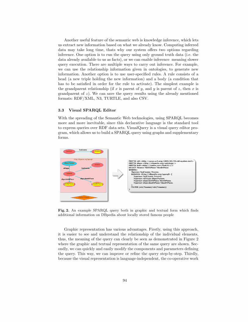
Another useful feature of the semantic web is knowledge inference, which letsus extract new information based on what we already know. Computing inferreddata may take long time, thats why our system offers two options regardinginference. One option is to run the query using only ground truth data (i.e. thedata already available to us as facts), or we can enable inference meaning slowerquery execution. There are multiple ways to carry out inference. For example,we can use the relationship information given in ontologies, to generate newinformation. Another option is to use user-specified rules. A rule consists of ahead (a new triple holding the new information) and a body (a condition thathas to be satisfied in order for the rule to activate). The simplest example isthe grandparent relationship (if x is parent of y, and y is parent of z, then x isgrandparent of z). We can save the query results using the already mentionedformats: RDF/XML, N3, TURTLE, and also CSV.
3.3 Visual SPARQL Editor
With the spreading of the Semantic Web technologies, using SPARQL becomesmore and more inevitable, since this declarative language is the standard toolto express queries over RDF data sets. VisualQuery is a visual query editor pro-gram, which allows us to build a SPARQL query using graphs and supplementaryforms.
Fig. 2. An example SPARQL query both in graphic and textual form which findsadditional information on DBpedia about locally stored famous people
Graphic representation has various advantages. Firstly, using this approach,it is easier to see and understand the relationship of the individual elements,thus, the meaning of the query can clearly be seen as demonstrated in Figure 2where the graphic and textual representation of the same query are shown. Sec-ondly, we can quickly and easily modify the components and parameters definingthe query. This way, we can improve or refine the query step-by-step. Thirdly,because the visual representation is language-independent, the co-operative work
94
of researchers speaking different languages is supported. Another advantage ofthe program is that it performs various checks during editing, which helps pre-venting syntactical errors, for example:
– literal nodes can not have outgoing edges – they can not be subjects in atriple,
– only variables or IRI nodes can be edges – blank nodes and literals can not,– variables in the head of a CONSTRUCT-type query must appear at least
once in the WHERE clause.
What makes this solution different from similar programs – like iSparql [13]or LuposDate [14] – is the distinction of visual elements by type, and the built-inchecks based on this distinction.
3.4 Visualizations
Visualizing semantic data helps us interpret them. We integrated into the sys-tem other, third-party visualizer tools. One of them is Cytoscape Web [?], whichallows us to display the semantic graph of locally stored models using variousbuilt-in layouts, such as tree or circle. The application uses JavaScript, so ren-dering happens on the clients computer.
Another visualization tool integrated into the system is RelFinder [16], whichsearches connections among IRIs. To find connections, it runs SPARQL querieson an endpoint. The relations among the IRIs can be paths via common pred-icates. We can specify the depth of the search. The program uses ActionScriptfor the display that provides various tools to create animations.
3.5 Extracting Semantic Data from the Web
Nowadays, we can easily find all kinds of information using the web. There arenumerous sites, which specialize in collecting and organizing knowledge aboutone specific topic. For example, we can find websites collecting information abouthardware components, reviews about movies, historical weather data, recipe col-lection, etc. These websites usually operate using a database of their own, and theweb pages displayed to us are generated based on the data from that database.However, the databases are usually not using semantic technologies, moreover,they are often not public, so the only way for us to access their data is to visitthe web pages containing them. Fortunately, extracting the data from the webpages does not always require complex text processing and text mining, becausethe structure of the document can be used to extract the pieces of informationthat we are interested in. The structure is almost always consistent on all pagesof a web site. For example, on a site collecting recipes, the structure can be thefollowing: the name of the recipe is always the title of the document, and it isfollowed by some meta information (always in the same order), such as the nameof the uploader, the difficulty and the required time to cook the dish. After this,we have an unordered list of the ingredients, and finally, there is an ordered list
95
of the steps of preparing the meal. If we know this structure, we can use it toextract the mentioned information from all pages containing recipes on this site.
To help users in extracting data from sites like these, we created a tool thatallows them to define the structure using one example page from a web site, andbased on the structure, our virtual observatory is capable to extract the requiredinformation from all pages that use the same document structure. The tool comesin the form of a browser extension, which the user can download and install fromthe web front end of our virtual observatory. After installation, if the user viewsone example page of the website using his browser, he can select the parts of thewebsite that contain information he would like to extract. The browser extensionmarks the selected parts during the process. If a structure is repeating within thedocument, we have the opportunity to extract all occurrences of the repeatingstructure. For example, if we have a hundred-row table, with each row containinginformation about one item, we do not have to mark all rows, only the first one.The repeating structures can be nested to arbitrary depths, i.e. we can have,for example, ordered lists within a table within a table. After the user finishedmarking the example document, the extension saves the structure informationto a file. To do the actual extraction, the user has to visit the web front end ofthe virtual observatory, where he can upload the structure file, and the systemwill then extract the information from the specified sub-pages of the site, andload the extracted data into a standard semantic model.
4 Collaboration of Researchers
One of the most important purposes for virtual observatories is to collect infor-mation originating from various different sources, and to support their integra-tion. Our system allows users to upload their own data and share it with others.We applied a multi-level permission system based on user groups. Every usercan create groups, and invite other users to them. This way, research groups canbe organized. Then, we have two possibilities to share the models containing ourdata. We can make the model publicly available to every other user, or we cangive right to one or more groups to access our model. While the first possibil-ity gives read-only access, in the latter case the group members can have writerights, too. In this case, they can load their own data into the model.
It is also possible to publish queries. This can be useful in several cases: ifother researchers would like to use our data, we can help their work by providingexample queries, which illustrate the inner structure and relationships of thedata. We can formulate basic queries, which can be further refined or specializedlater.
5 Use Cases
5.1 OCR Application
The first application is useful in the field of tourism. The main function ofthe program is to recognize text on street signs with OCR methods, based on
96
pictures taken with mobile phones. Its purpose is to provide extra informationabout the famous people whose name can be found in the extracted texts. Theextra information comes from various data sources converted to semantic format(Hungarian Electronic Library, various online encyclopedias [17]), joined withother public data sets (DBpedia, GeoNames). A user group created for thispurpose allows the collaboration between the users. The group has access to thedata sets described above. One member of the group was given the task to collectinformation about the famous people appearing in street names, and then uploadthem to a model. He then shared the model inside the group. Another memberhad the same task, but he had to use an online encyclopedia as the data source.He added his data to the shared model. Meanwhile, a third member workedon linking the data in the model to data available in DBPedia, using SPARQLqueries. He stored the results in a new, local model, to make it faster to access.(His work was not influenced by the fact that in the meantime, new data hasbeen added to the model.) He also published the queries and the new model tothe group. The members of the group created a virtual model over the modelsmentioned. (A virtual model is not materialized, but it contains the union of thedata found in other models, and it is supported by an index structure.) This stepwas important, because it allowed us to access the data as a single model. Then,using the REST API of our virtual observatory, we were able to run queries froma mobile application.
5.2 Use in Education
We use the virtual observatory during teaching the basic principles of the Se-mantic Web, within the Modern Databases course. The students of the courseare added to a new group, and we share previously loaded models and querieswith them. The models contain small data sets, so they could be viewed withthe visualization tools, and the students could easily understand their structure.From week to week, they are introduced to the features of the SPARQL language,by solving typical tasks together. The new features can easily be demonstratedwith the visual SPARQL editor, since the graphical representation speaks for it-self. In some cases, the results of the exercises can be used in practical scenarios.For example, the family tree of a royal family can be created, if each studentcreates a model with the family tree of a selected king. During their work, theyget to know the basic semantic serialization formats (RDF/XML, N3, etc.) andthe results can be published to a common group.
6 Conclusion and Future Work
In the paper, we presented a prototype system, which fulfills the requirementsof a virtual observatory, and helps the collaboration of researchers by lettingthem work using the same, shared data and queries. We used the data model ofthe Semantic Web, thus, the data sets in the virtual observatory can easily belinked to each other and to public data sets. We provided several features which
97
can facilitate the use of the system, such as advanced data and query sharing,visual query building and editing, data visualization, and web data extraction.The system can run on top of any standard relational database system, but ifthe underlying database has some support for storing and handling semanticdata (like Oracle databases), it can make use of those functions as well. We alsopresented real world use cases, where the existence of the system helped ourwork on other projects and in education. During further work, we would liketo extend the system to be able to work using a Hadoop cluster as backend. Inthis solution, data storage and query execution would be distributed, thus theefficiency of the data-intensive computations would increase. Our other plansinclude enhanced visualization, such as the ability to plot geographic locationson a map, and to create charts and diagrams to help the better understandingof the data.
Acknowledgments. This work was partially supported by the European Unionand the European Social Fund through project FuturICT.hu (grant no.: TAMOP-4.2.2.C-11/1/KONV-2012-0013). We are grateful to Zsofia Meszaros and ZoltanVinceller for helpful discussion and comments.
References
1. Gray, J., Szalay., A.: The world-wide telescope. Communications of the ACM 45 11,50–55 (2002)
2. Szalay, A. S., Budavari, T., Malik, T., Gray, J., Thakar, A. R.: Web services for thevirtual observatory. In: Astronomical Telescopes and Instrumentation, pp. 124–132.International Society for Optics and Photonics (2002).
3. Brase, J., Blumel., I.: Information supply beyond text: non-textual information atthe German National Library of Science and Technology (TIB) – challenges andplanning. Interlending & Document Supply 38 2, 108–117 (2010)
4. Hey, AJG.: The fourth paradigm: data-intensive scientific discovery. In: StewartTansley, S., Tolle, K. M. (eds.) Microsoft Research, Redmond (2009)
5. Berners-Lee, T., Hendler, J., Lassila, O.: The semantic web. Scientific American 2845, 28–37 (2001)
6. Lassila, O., Swick, R. R.: Resource Description Framework (RDF) Schema Specifi-cation, http://www.w3.org/TR/rdf-schema
7. Prud’hommeaux, E., Seaborne, A.: SPARQL Query Language for RDF, http://www.w3.org/TR/rdf-sparql-query/
8. Bizer, C., Jentzsch, A., Cyganiak, R.: State of the LOD Cloud, http://wifo5-03.informatik.uni-mannheim.de/lodcloud/state/
9. N-triples, http://www.w3.org/2001/sw/RDFCore/ntriples/
10. Turtle, http://www.w3.org/TR/2012/WD-turtle-20120710/
11. Notation3, http://www.w3.org/TeamSubmission/n3/
12. Bizer, C., Lehmann, J., Kobilarov, G., Auer, S., Becker, C., Cyganiak, R., Hell-mann, S.: DBpedia – A crystallization point for the Web of Data. Web Semantics:Science, Services and Agents on the World Wide Web 7 3, 154–165 (2009)
13. iSparql, http://oat.openlinksw.com/isparql/index.html
98

14. Groppe, J., Groppe, S., Schleifer, A., Linnemann, V.: LuposDate: A semantic webdatabase system. In: Proceedings of the 18th ACM conference on Information andknowledge management, pp. 2083–2084. ACM (2009)
15. Shannon, P., Markiel, A., Ozier, O., Baliga, N. S., Wang, J. T., Ramage, D.,Ideker, T.: Cytoscape: a software environment for integrated models of biomolecularinteraction networks. Genome research, 13 11, pp. 2498–2504. (2003)
16. Heim, P., Hellmann, S., Lehmann, J., Lohmann, S., Stegemann, T. (2009).Relfinder: Revealing relationships in rdf knowledge bases. In: Semantic Multime-dia, pp. 182–187. Springer (2009)
17. Hungarian Electronic Library, http://mek.oszk.hu/indexeng.phtml
99
Service Composition for End-Users
Otto Hylli, Samuel Lahtinen, Anna Ruokonen, and Kari Systa
Department of Pervasive ComputingTampere University of Technology
P.O. Box 553, FIN-33101 Tampere, Finlandotto.hylli, samuel.lahtinen, anna.ruokonen, [email protected]
Abstract. RESTful services are becoming a popular technology for providingand consuming cloud services. The idea of cloud computing is based on on-demand services and their agile usage. This implies that also personal servicecompositions and workflows should be supported. Some approaches for REST-ful service compositions have been proposed. In practice, such compositions typ-ically present mashup applications, which are composed in an ad-hoc manner. Inaddition, such approaches and tools are mainly targeted for programmers ratherthan end-users. In this paper, a user-driven approach for reusable RESTful servicecompositions is presented. Such compositions can be executed once or they canbe configured to be executed repeatedly, for example, to get newest updates froma service once a week.
1 Introduction
In service-oriented approaches, the focus is on the definition of service interfaces andservice behavior. Service-oriented architecture (SOA) aims at loosely coupled, reusable,and composable services provided for a service consumer. SOA can be implemented byWeb services, which is a technology enabling application integration. Web services canbe used for composing high level composite services and business processes. Businessprocesses are often realized as a service orchestrations implemented, for example, asWS-BPEL based processes [1]. WS-BPEL is targeted for composing operation-centricWeb services utilizing WSDL and SOAP [2, 3]. WS-BPEL is close to a programminglanguage defining the logic for a service orchestration. Thus, it is mostly used by ITdevelopers.
In cloud computing, resources are provided to the user as services via the Internet.Cloud computing and SOA share similar interests on service reuse and service compo-sition. Moreover, cloud computing emphasis on-demand services, which impose morerequirements on flexible service and workflow configurations.
Compared to business processes, typical on-demand processes are personal, sim-pler, and their lifetime is shorter. Thus, on-demand processes are often characterized asinstant service compositions and service configurations. Such processes are typicallydefined by the end-user instead of the developer of the cloud services. Due to instantnature of the on-demand processes, their usage and specification should be as simple aspossible and require no installation of process development and management tools.
An end-user driven approach for WS-BPEL-based business process developmenthas been proposed in [4]. The approach is targeted for providing a method for easy
100
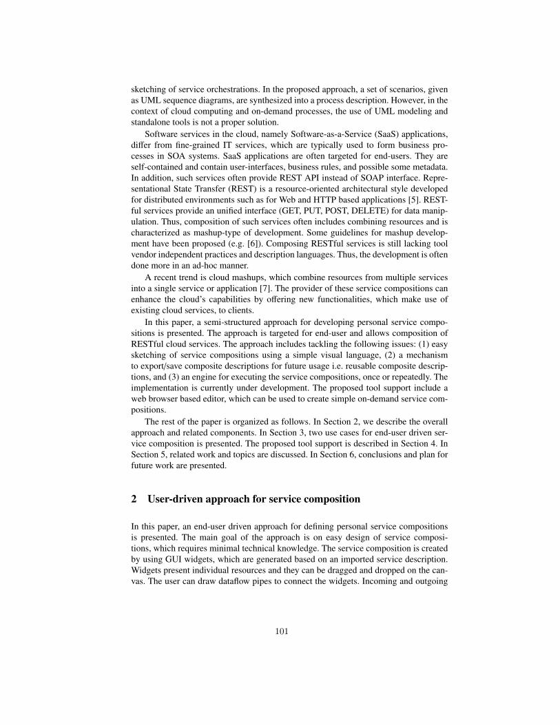
sketching of service orchestrations. In the proposed approach, a set of scenarios, givenas UML sequence diagrams, are synthesized into a process description. However, in thecontext of cloud computing and on-demand processes, the use of UML modeling andstandalone tools is not a proper solution.
Software services in the cloud, namely Software-as-a-Service (SaaS) applications,differ from fine-grained IT services, which are typically used to form business pro-cesses in SOA systems. SaaS applications are often targeted for end-users. They areself-contained and contain user-interfaces, business rules, and possible some metadata.In addition, such services often provide REST API instead of SOAP interface. Repre-sentational State Transfer (REST) is a resource-oriented architectural style developedfor distributed environments such as for Web and HTTP based applications [5]. REST-ful services provide an unified interface (GET, PUT, POST, DELETE) for data manip-ulation. Thus, composition of such services often includes combining resources and ischaracterized as mashup-type of development. Some guidelines for mashup develop-ment have been proposed (e.g. [6]). Composing RESTful services is still lacking toolvendor independent practices and description languages. Thus, the development is oftendone more in an ad-hoc manner.
A recent trend is cloud mashups, which combine resources from multiple servicesinto a single service or application [7]. The provider of these service compositions canenhance the cloud’s capabilities by offering new functionalities, which make use ofexisting cloud services, to clients.
In this paper, a semi-structured approach for developing personal service compo-sitions is presented. The approach is targeted for end-user and allows composition ofRESTful cloud services. The approach includes tackling the following issues: (1) easysketching of service compositions using a simple visual language, (2) a mechanismto export/save composite descriptions for future usage i.e. reusable composite descrip-tions, and (3) an engine for executing the service compositions, once or repeatedly. Theimplementation is currently under development. The proposed tool support include aweb browser based editor, which can be used to create simple on-demand service com-positions.
The rest of the paper is organized as follows. In Section 2, we describe the overallapproach and related components. In Section 3, two use cases for end-user driven ser-vice composition is presented. The proposed tool support is described in Section 4. InSection 5, related work and topics are discussed. In Section 6, conclusions and plan forfuture work are presented.
2 User-driven approach for service composition
In this paper, an end-user driven approach for defining personal service compositionsis presented. The main goal of the approach is on easy design of service composi-tions, which requires minimal technical knowledge. The service composition is createdby using GUI widgets, which are generated based on an imported service description.Widgets present individual resources and they can be dragged and dropped on the can-vas. The user can draw dataflow pipes to connect the widgets. Incoming and outgoing
101
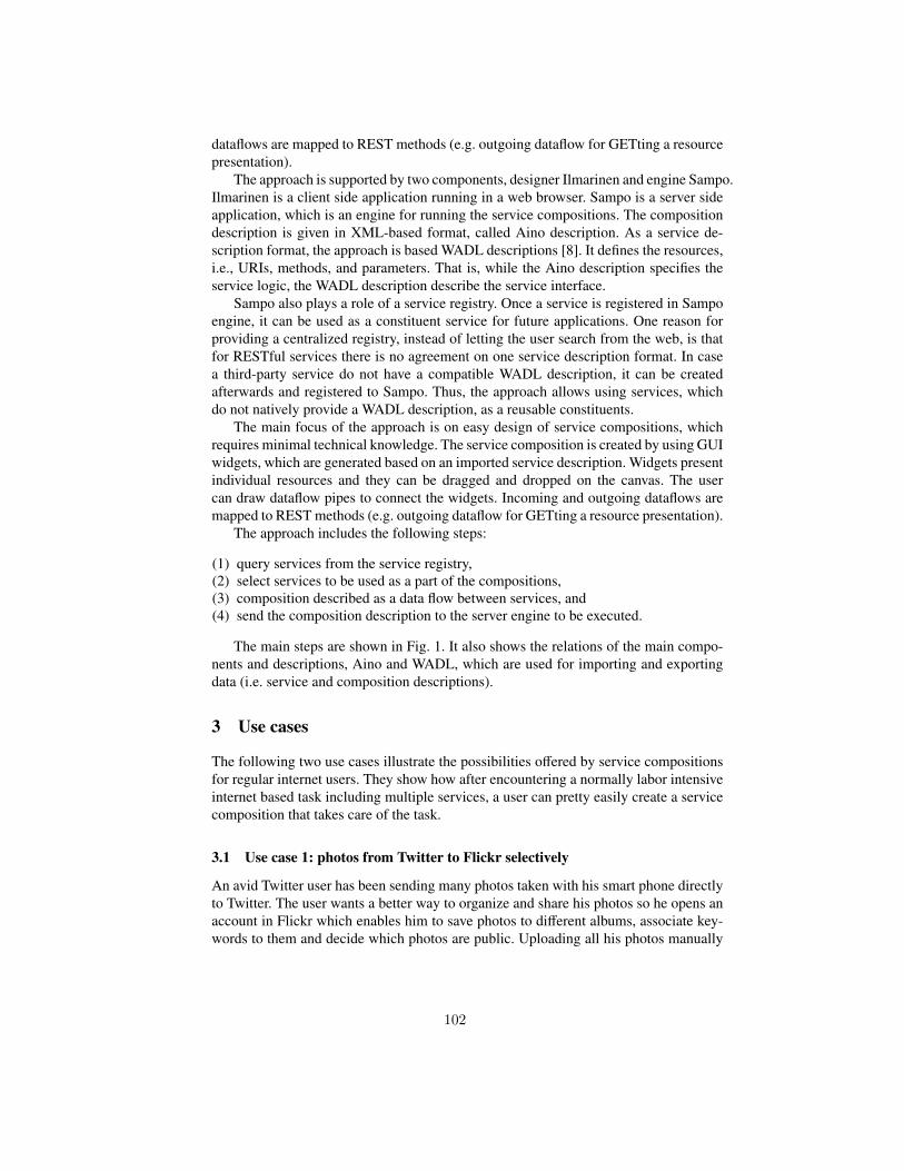
dataflows are mapped to REST methods (e.g. outgoing dataflow for GETting a resourcepresentation).
The approach is supported by two components, designer Ilmarinen and engine Sampo.Ilmarinen is a client side application running in a web browser. Sampo is a server sideapplication, which is an engine for running the service compositions. The compositiondescription is given in XML-based format, called Aino description. As a service de-scription format, the approach is based WADL descriptions [8]. It defines the resources,i.e., URIs, methods, and parameters. That is, while the Aino description specifies theservice logic, the WADL description describe the service interface.
Sampo also plays a role of a service registry. Once a service is registered in Sampoengine, it can be used as a constituent service for future applications. One reason forproviding a centralized registry, instead of letting the user search from the web, is thatfor RESTful services there is no agreement on one service description format. In casea third-party service do not have a compatible WADL description, it can be createdafterwards and registered to Sampo. Thus, the approach allows using services, whichdo not natively provide a WADL description, as a reusable constituents.
The main focus of the approach is on easy design of service compositions, whichrequires minimal technical knowledge. The service composition is created by using GUIwidgets, which are generated based on an imported service description. Widgets presentindividual resources and they can be dragged and dropped on the canvas. The usercan draw dataflow pipes to connect the widgets. Incoming and outgoing dataflows aremapped to REST methods (e.g. outgoing dataflow for GETting a resource presentation).
The approach includes the following steps:
(1) query services from the service registry,(2) select services to be used as a part of the compositions,(3) composition described as a data flow between services, and(4) send the composition description to the server engine to be executed.
The main steps are shown in Fig. 1. It also shows the relations of the main compo-nents and descriptions, Aino and WADL, which are used for importing and exportingdata (i.e. service and composition descriptions).
3 Use cases
The following two use cases illustrate the possibilities offered by service compositionsfor regular internet users. They show how after encountering a normally labor intensiveinternet based task including multiple services, a user can pretty easily create a servicecomposition that takes care of the task.
3.1 Use case 1: photos from Twitter to Flickr selectively
An avid Twitter user has been sending many photos taken with his smart phone directlyto Twitter. The user wants a better way to organize and share his photos so he opens anaccount in Flickr which enables him to save photos to different albums, associate key-words to them and decide which photos are public. Uploading all his photos manually
102
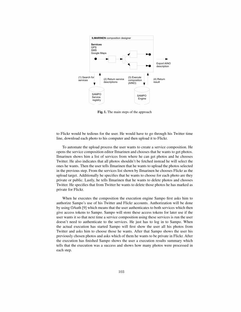
Fig. 1. The main steps of the approach
to Flickr would be tedious for the user. He would have to go through his Twitter timeline, download each photo to his computer and then upload it to Flickr.
To automate the upload process the user wants to create a service composition. Heopens the service composition editor Ilmarinen and chooses that he wants to get photos.Ilmarinen shows him a list of services from where he can get photos and he choosesTwitter. He also indicates that all photos shouldn’t be fetched instead he will select theones he wants. Then the user tells Ilmarinen that he wants to upload the photos selectedin the previous step. From the services list shown by Ilmarinen he chooses Flickr as theupload target. Additionally he specifies that he wants to choose for each photo are theyprivate or public. Lastly, he tells Ilmarinen that he wants to delete photos and choosesTwitter. He specifies that from Twitter he wants to delete those photos he has marked asprivate for Flickr.
When he executes the composition the execution engine Sampo first asks him toauthorize Sampo’s use of his Twitter and Flickr accounts. Authorization will be doneby using OAuth [9] which means that the user authenticates to both services which thengive access tokens to Sampo. Sampo will store these access tokens for later use if theuser wants it so that next time a service composition using these services is run the userdoesn’t need to authenticate to the services. He just has to log in to Sampo. Whenthe actual execution has started Sampo will first show the user all his photos fromTwitter and asks him to choose those he wants. After that Sampo shows the user hispreviously chosen photos and asks which of them he wants to be private in Flickr. Afterthe execution has finished Sampo shows the user a execution results summary whichtells that the execution was a success and shows how many photos were processed ineach step.
103
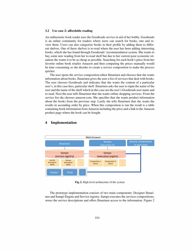
3.2 Use case 2: affordable reading
An enthusiastic book reader uses the Goodreads service in aid of her hobby. Goodreadsis an online community for readers where users can search for books, rate and re-view them. Users can also categorize books in their profile by adding them to differ-ent shelves. One of these shelves is to-read where the user has been adding interestingbooks, which she has found through Goodreads’ recommendation system. She wants tobuy some new reading from her to-read shelf but due to her current poor economic sit-uation she wants it to be as cheap as possible. Searching for each book’s price from herfavorite online book retailer Amazon and then comparing the prices manually wouldbe time consuming so she decides to create a service composition to make the processquicker.
The user opens the service composition editor Ilmarinen and chooses that she wantsinformation about books. Ilmarinen gives the user a list of services that deal with books.The user chooses Goodreads and indicates that she wants the content of a particularuser’s, in this case hers, particular shelf. Ilmarinen asks the user to input the name of theuser and the name of the shelf which in this case are the user’s Goodreads user name andto-read. Next the user tells Ilmarinen that she wants online shopping services. From theservice list she chooses amazon.com. She specifies that she wants product informationabout the books from the previous step. Lastly she tells Ilmarinen that she wants theresults in ascending order by price. When this composition is run the result is a tablecontaining book information from Amazon including the price and a link to the Amazonproduct page where the book can be bought.
4 Implementation
Fig. 2. High level architecture of the system
The prototype implementation consists of two main components: Designer Ilmari-nen and Sampo Engine and Service registry. Sampo executes the services compositions,stores the service descriptions and offers Ilmarinen access to the information. Figure 2
104
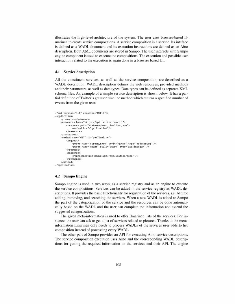
illustrates the high-level architecture of the system. The user uses browser-based Il-marinen to create service compositions. A service composition is a service. Its intefaceis defined as a WADL document and its execution instructions are defined as an Ainodescription. Both XML documents are stored in Sampo. The user interacts with Sampoengine component is used to execute the compositions. The execution and possible userinteraction related to the execution is again done in a browser based UI.
4.1 Service description
All the constituent services, as well as the service composition, are described as aWADL description. WADL description defines the web resources, provided methodsand their parameters, as well as data types. Data types can be defined as separate XMLschema files. An example of a simple service description is shown below. It has a par-tial definition of Twitter’s get user timeline method which returns a specified number oftweets from the given user.
<?xml version="1.0" encoding="UTF-8"?><application>
<grammars></grammars><resources base="https://api.twitter.com/1.1">
<resource path="statuses/user_timeline.json"><method href="getTimeline"/>
</resource></resources><method name="GET" id="getTimeline">
<request><param name="screen_name" style="query" type="xsd:string" /><param name="count" style="query" type="xsd:integer" />
</request><response>
<representation mediaType="application/json" /></response>
</method></application>
4.2 Sampo Engine
Sampo engine is used in two ways, as a service registry and as an engine to executethe service compositions. Services can be added in the service registry as WADL de-scriptions. It provides the basic functionality for registration of the services, i.e. API foradding, removing, and searching the services. When a new WADL is added to Sampothe part of the categorization of the service and the resources can be done automati-cally based on the WADL and the user can complete the information and extend thesuggested categorizations.
The given meta-information is used to offer Ilmarinen lists of the services. For in-stance, the user can ask to get a list of services related to pictures. Thanks to the meta-information Ilmarinen only needs to process WADLs of the services user adds to hercomposition instead of processing every WADL.
The other part of Sampo provides an API for executing Aino service descriptions.The service composition execution uses Aino and the corresponding WADL descrip-tions for getting the required information on the services and their API. The engine
105
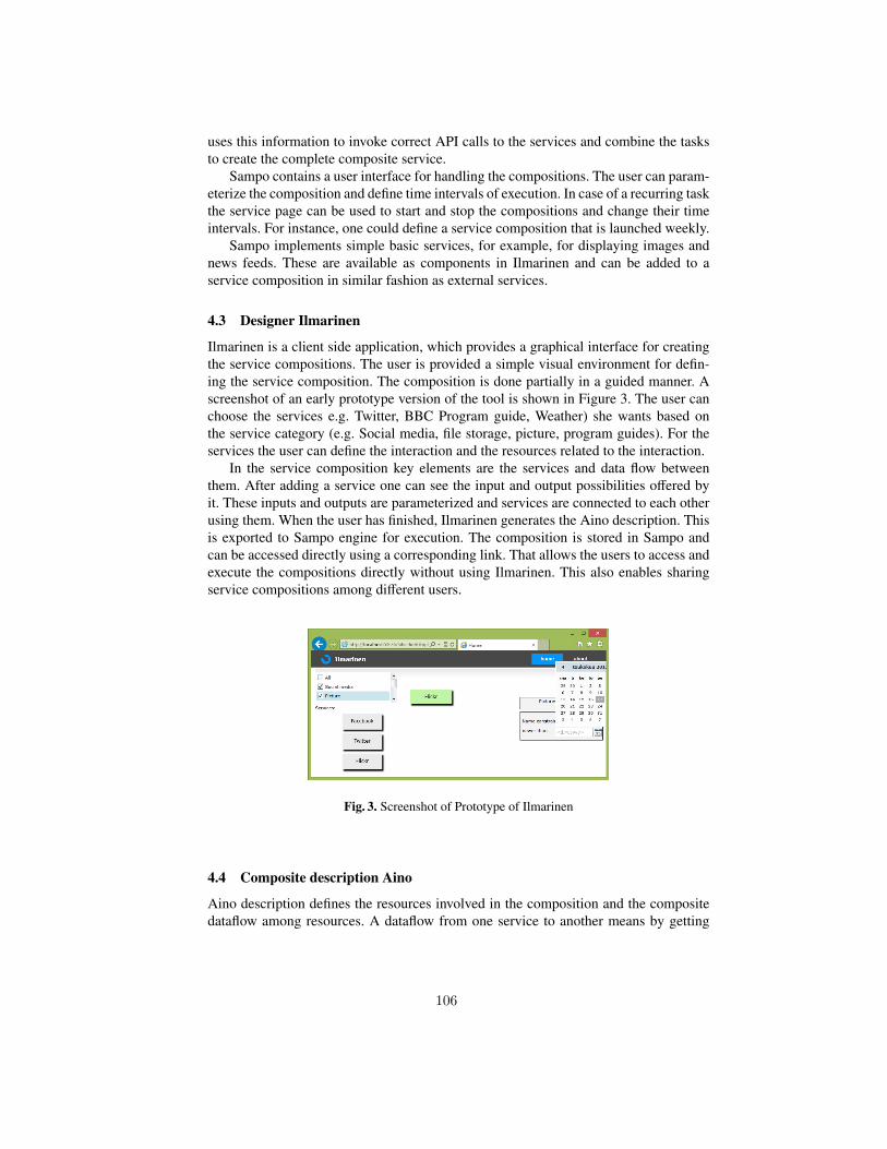
uses this information to invoke correct API calls to the services and combine the tasksto create the complete composite service.
Sampo contains a user interface for handling the compositions. The user can param-eterize the composition and define time intervals of execution. In case of a recurring taskthe service page can be used to start and stop the compositions and change their timeintervals. For instance, one could define a service composition that is launched weekly.
Sampo implements simple basic services, for example, for displaying images andnews feeds. These are available as components in Ilmarinen and can be added to aservice composition in similar fashion as external services.
4.3 Designer Ilmarinen
Ilmarinen is a client side application, which provides a graphical interface for creatingthe service compositions. The user is provided a simple visual environment for defin-ing the service composition. The composition is done partially in a guided manner. Ascreenshot of an early prototype version of the tool is shown in Figure 3. The user canchoose the services e.g. Twitter, BBC Program guide, Weather) she wants based onthe service category (e.g. Social media, file storage, picture, program guides). For theservices the user can define the interaction and the resources related to the interaction.
In the service composition key elements are the services and data flow betweenthem. After adding a service one can see the input and output possibilities offered byit. These inputs and outputs are parameterized and services are connected to each otherusing them. When the user has finished, Ilmarinen generates the Aino description. Thisis exported to Sampo engine for execution. The composition is stored in Sampo andcan be accessed directly using a corresponding link. That allows the users to access andexecute the compositions directly without using Ilmarinen. This also enables sharingservice compositions among different users.
Fig. 3. Screenshot of Prototype of Ilmarinen
4.4 Composite description Aino
Aino description defines the resources involved in the composition and the compositedataflow among resources. A dataflow from one service to another means by getting
106
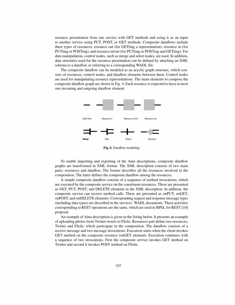
resource presentation from one service with GET methods and using it as an inputto another service using PUT, POST, or GET methods. Composite dataflows includethree types of resources: resource out (for GETting a representation), resource in (forPUTting or POSTing), and resource in/out (for PUTting or POSTing and GETting). Fordata manipulation, control nodes, such as merge and select nodes, are used. In addition,data structures used for the resource presentation can be defined by attaching an XMLschema to a dataflow or referring to a corresponding WADL file.
The composite dataflow can be modeled as an acyclic graph structure, which con-sists of resources, control nodes, and dataflow elements between them. Control nodesare used for manipulating resource representations. The main elements to compose thecomposite dataflow graph are shown in Fig. 4. Each resource is expected to have at mostone incoming and outgoing dataflow element.
Fig. 4. Dataflow modeling
To enable importing and exporting of the Aino descriptions, composite dataflowgraphs are transformed in XML format. The XML description consists of two mainparts: resources and dataflow. The former describes all the resources involved in thecomposition. The latter defines the composite dataflow among the resources.
A simple composite dataflow consists of a sequence of method invocations, whichare executed by the composite service on the constituent resources. These are presentedas GET, PUT, POST, and DELETE elements in the XML description. In addition, thecomposite service can receive method calls. These are presented as onPUT, onGET,onPOST, and onDELETE elements. Corresponding request and response message types(including data types) are described in the services’ WADL documents. These activitiescorresponding to REST operations are the same, which are used in BPEL for REST [10]proposal.
An example of Aino description is given in the listing below. It presents an exampleof uploading photos from Twitter tweets to Flickr. Resources part define two resources,Twitter and Flickr, which participate in the composition. The dataflow consists of areceive message and two message invocations. Execution starts when the client invokesGET method on the composite resource (onGET element). Execution continues witha sequence of two invocations. First the composite service invokes GET method onTwitter and second it invokes POST method on Flickr.
107
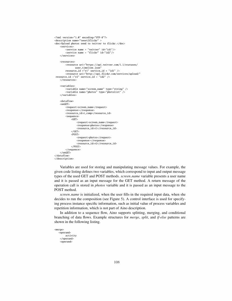
<?xml version="1.0" encoding="UTF-8"?><description name="tweet2flickr" ><doc>Upload photos send to twitter to flickr.</doc>
<services><service name = "twitter" id="id1"/><service name = "flickr" id="id2"/>
</services>
<resources><resource uri="https://api.twitter.com/1.1/statuses/
user_timeline.json"resource_id ="r1" service_id = "id1" /><resource uri="http://api.flickr.com/services/upload/"
resource_id ="r2" service_id = "id2" /></resources>
<variables><variable name="screen_name" type="string" /><variable name="photos" type="photolist" />
</variables>
<dataflow><onGET>
<request>screen_name</request><response></response><resource_id>r_comp</resource_id><sequence>
<GET><request>screen_name</request><response>photos</response><resource_id>r1</resource_id>
</GET><POST>
<request>photos</request><response></response><resource_id>r2</resource_id>
</POST></sequence>
</onGET></dataflow></description>
Variables are used for storing and manipulating message values. For example, thegiven code listing defines two variables, which correspond to input and output messagetypes of the used GET and POST methods. screen name variable presents a user nameand it is passed as an input message for the GET method. A return message of theoperation call is stored in photos variable and it is passed as an input message to thePOST method.
screen name is initialized, when the user fills-in the required input data, when shedecides to run the composition (see Figure 5). A control interface is used for specify-ing process instance specific information, such as initial value of process variables andrepetition information, which is not part of Aino description.
In addition to a sequence flow, Aino supports splitting, merging, and conditionalbranching of data flows. Example structures for merge, split, and if-else patterns areshown in the following listing.
<merge><operand>
activity</operand><operand>
108
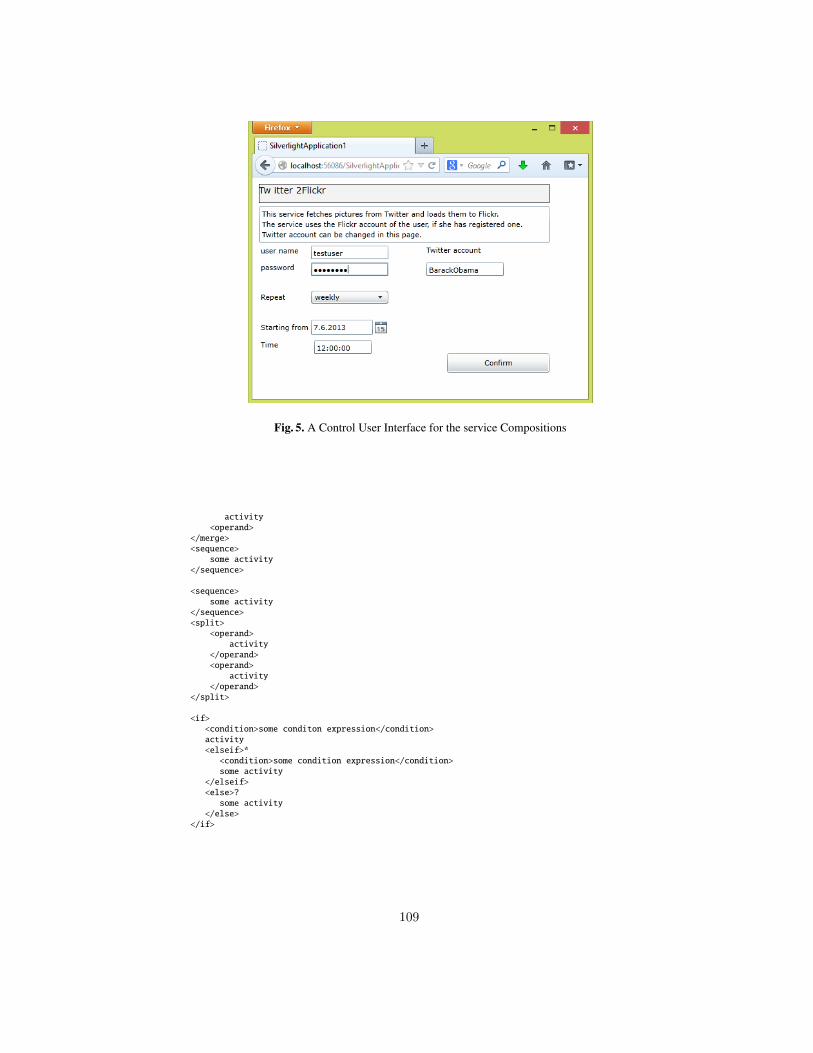
Fig. 5. A Control User Interface for the service Compositions
activity<operand>
</merge><sequence>
some activity</sequence>
<sequence>some activity
</sequence><split>
<operand>activity
</operand><operand>
activity</operand>
</split>
<if><condition>some conditon expression</condition>activity<elseif>*<condition>some condition expression</condition>some activity
</elseif><else>?some activity
</else></if>
109
5 Related work
The idea of cloud computing is based on on-demand services, which are provided asSaaS applications. In the cloud, traditional business process management tools are al-ready available as SaaS. However, they are targeted for design and management ofstructured business processes. Requirements for on-demand processes differ from tra-ditional BPM. The ideal situation is to provide easy and instant mechanism to supportexecution of personal and dynamic processes, which utilize existing SaaS applicationsavailable on the cloud.
5.1 Tools for mashup development
Ad-hoc processes are often expected to live only a short time. The lack of documenta-tion and proper design might make them single-use only. Thus, they may not be reusableand flexible, but they always need to be recomposed.
JOpera [11] is an Eclipse-based tool build for composing SOAP/WSDL and REST-ful Web services. For software developers it provides many useful features such asprocess modeling, debugging and execution. For composing RESTful services JOperauses BPEL for REST [10]. BPEL for REST is an extension to WS-BPEL to supportcompositions of RESTful Web services. The approach does not rely on usage of WSDLor other service descriptions. Resources are defined in the BPEL for REST descriptionas a resource construct, which defines the resource URI and supported operations.
In [12], Marino et al. present HTML5-based prototype tool support for mashup de-velopment. They present a visual language for service composition. However, the paperis missing details on the user interface and tool usage. Also, details on the compositiondescription are not given.
In [13], Aghee et al. discuss different types of mashups enabled by HTML5. A caseexample includes a location sensitive mobile mashup. The mashup runs natively in amobile device and uses GPS sensor build-in the device. In addition, it uses external WebAPIs. Location data is sent to a server, which executes API calls to external services.This enables sharing the application between several uses. Mobile mashups enable useof real-time data gathered from the sensors in a mobile phone, e.g. real-time navigation.
Bottaro et al. present a simple visual language for composing location-based ser-vices [14]. The user uses a repository of web widgets. Widgets are dragged and droppedto build UI for the application. The application logic is defined by drawing connectionsbetween data widgets.
In [15], Gronvall et al. present ongoing work on user-centric service composition.GUI elements are prototypes of service invocations, which can be chained to com-pose data flows among services. They present a lightweight tool support for composingsimple dynamic workflows, such as for combining SMS, email, and calendar services.Instead of modeling complicated workflows, the emphasis is on the user experience.
In EzWeb project [16, 17], a service-oriented platform for end-user mashups de-velopment have been built. The idea is to provide gadgets (e.g. Twitter, Flickr) the usercould add to her ”‘application page”‘ creating a set of different applications and web ser-vices. The user can also define dataflow between the gadgets by connecting ”‘events”’the gadgets could give, e.g., an image url could be connected to another image displayer
110
gadget that is able to show the picture. All these gadgets are implemented for EzWebenvironment. That is, implementation of their user interface, way of communicate withservers, their events and event slots, are specific for the EzWeb environment. In ourapproach, the aim is to provide means to compose existing services together and exe-cute these compositions. Thus, our target is to support composition of any third partyservices by introducing their service descriptions to our system.
5.2 Describing service compositions
Some approaches for modeling and describing RESTful service compositions have beenproposed. Guidelines for UML modeling of RESTful service compositions is presentedin [18] by Rauf et al. The static resource structure is modeled using class diagrams. Thebehavioral specification of the composite service is given using state chart diagrams.
In [19,20], Zhao et al. discuss formal describing of RESTful services and resourcesas well as RESTful composite services. Their main interests is on supporting automaticservice compositions. For service compositions they present a logic-based synthesisapproach utilizing linear-logic and pii-calculus.
In [21], Alarcon et al. state that many of the recent service composition approachesrely on operation-based models and neglect hypermedia characteristics of REST. As asolution for composing RESTful services, they present a hypermedia-driven approachrealized by using resource linking language (ReLL) for service description. The ap-proach aims to support machine-clients by enabling automatic retrieving of resourcesfrom a web site. For describing the composite resources PetriNets are used. As an ex-ample of a composite resource, a social network application was presented.
6 Conclusions
Cloud computing is based on on-demand services, which should be available as needed.Similarly, it should also enable on-demand service compositions. In this paper, end-userdriven approach for personal service composition have been presented. The proposedtool support includes an editor running in a web browser and a server-side engine forstoring and executing service compositions. The editor is designed for the end-users andit is used for sketching personal service compositions. It focuses on end-user conceptsand aims to hide complicated and unnecessary information, e.g. service descriptions,which are handled by the engine. Instead of handling data types, the user is allowed touse concepts such as a picture or a photo gallery. The presented use cases concentrateon combining social media services into a composite service. Also, the user is allowedto define repeatable executions for checking updates from the services.
To characterize the approach, it is designed for cloud environment providing abrowser-based tool for building service compositions. It is based on WADL descrip-tions, which are also used for generating GUI widgets for the end-user. In addition, itenables defining RESTful workflows as a composite services.
Our future work includes finalizing the implementation and conducting case studieson applying the approach utilizing the developed tool support. Our future plans alsoinclude experimenting the tool usage with novice users.
111
References
1. Tony Andrews, Francisco Curbera, Hitesh Dholakia, Yaron Goland, Johannes Klein, FrankLeymann, Kevin Liu, Dieter Roller, Doug Smith, Satish Thatte, Ivana Trickovic, and SanjivaWeerawarana. Business Process Execution Language for Web Services Version 1.1, May2003. http://www.ibm.com/developerworks/.
2. W3C, http://www.w3.org/TR/wsdl. Web Services Description Language (WSDL) 1.1, 2001.3. W3C, http://www.w3.org/. Simple Object Access Protocol (SOAP) 1.2, 2007. Last visited
December 2011.4. Anna Ruokonen, Lasse Pajunen, and Tarja Systa. Scenario-driven approach for business
process modeling. Web Services, IEEE International Conference on, 0:123–130, 2009.5. Roy Thomas Fielding. REST: Architectural Styles and the Design of Network-based Software
Architectures. Doctoral dissertation, University of California, Irvine, 2000.6. Tommi Mikkonen and Arto Salminen. Towards a reference architecture for mashups. In Pro-
ceedings of the 2011th Confederated international conference on On the move to meaningfulinternet systems, OTM’11, pages 647–656, Berlin, Heidelberg, 2011. Springer-Verlag.
7. Mukesh Singhal, Santosh Chandrasekhar, Tingjian Ge, Ravi Sandhu, Ram Krishnan, Gail-Joon Ahn, and Elisa Bertino. Collaboration in multicloud computing environments: Frame-work and security issues. Computer, 46(2):76–84, 2013.
8. W3C, http://www.w3.org/Submission/wadl/. Web Application Description Language(WADL), 2009.
9. Internet Engineering Task Force (IETF), http://tools.ietf.org/html/rfc6749. The OAuth 2.0Authorization Framework, 2012.
10. Cesare Pautasso. RESTful web service composition with BPEL for REST. Data Knowl.Eng., 68(9):851–866, September 2009.
11. Cesare Pautasso. Composing RESTful services with JOpera. In International Conference onSoftware Composition 2009, volume 5634, pages 142–159, Zurich, Switzerland, July 2009.Springer.
12. Enrico Marino, Federico Spini, Fabrizio Minuti, Maurizio Rosina, Antonio Bottaro, and Al-berto Paoluzzi. HTML5 visual composition of rest-like web services. In 4th IEEE Interna-tional Conference on Software Engineering and Service Science (ICSESS 2013), 2013. Toappear.
13. Saeed Aghaee and Cesare Pautasso. Mashup development with HTML5. In Proceedingsof the 3rd and 4th International Workshop on Web APIs and Services Mashups, Mashups’09/’10, pages 10:1–10:8, New York, NY, USA, 2010. ACM.
14. Antonio Bottaro, Enrico Marino, Franco Milicchio, Alberto Paoluzzi, Maurizio Rosina, andFederico Spini. Visual programming of location-based services. In Proceedings of the 2011international conference on Human interface and the management of information - VolumePart I, HI’11, pages 3–12, Berlin, Heidelberg, 2011. Springer-Verlag.
15. Erik Gronvall, Mads Ingstrup, Morten Pløger, and Morten Rasmussen. Rest based ser-vice composition: Exemplified in a care network scenario. In Gennaro Costagliola, An-drew Jensen Ko, Allen Cypher, Jeffrey Nichols, Christopher Scaffidi, Caitlin Kelleher, andBrad A. Myers, editors, VL/HCC, pages 251–252. IEEE, 2011.
16. D. Lizcano, J. Soriano, M. Reyes, and J.J. Hierro. EzWeb/FAST: Reporting on a successfulmashup-based solution for developing and deploying composite applications in the ”upcom-ing ubiquitous SOA”. In Mobile Ubiquitous Computing, Systems, Services and Technologies,2008. UBICOMM ’08. The Second International Conference on, pages 488–495, 2008.
17. David Lizcano, Javier Soriano, Marcos Reyes, and Juan J. Hierro. EzWeb/FAST: reportingon a successful mashup-based solution for developing and deploying composite applicationsin the upcoming web of services. In Proceedings of the 10th International Conference on
112
Information Integration and Web-based Applications & Services, iiWAS ’08, pages 15–24,New York, NY, USA, 2008. ACM.
18. Irum Rauf, Anna Ruokonen, Tarja Systa, and Ivan Porres. Modeling a composite RESTfulweb service with UML. In Proceedings of the Fourth European Conference on SoftwareArchitecture: Companion Volume, ECSA ’10, pages 253–260, New York, NY, USA, 2010.ACM.
19. Xia Zhao, Enjie Liu, G.J. Clapworthy, Na Ye, and Yueming Lu. RESTful web service com-position: Extracting a process model from linear logic theorem proving. In Next GenerationWeb Services Practices (NWeSP), 2011 7th International Conference on, pages 398–403,Oct.
20. Haibo Zhao and P. Doshi. Towards automated RESTful web service composition. In WebServices, 2009. ICWS 2009. IEEE International Conference on, pages 189–196, July.
21. Rosa Alarcon, Erik Wilde, and Jesus Bellido. Hypermedia-driven RESTful service compo-sition. In Proceedings of the 2010 international conference on Service-oriented computing,ICSOC’10, pages 111–120, Berlin, Heidelberg, 2011. Springer-Verlag.
113
Towards a Reference Architecture forServer-Side Mashup Ecosystem
Heikki Peltola and Arto Salminen
Tampere University of Technology,Korkeakoulunkatu 10, 33720,
Tampere, Finland{heikki.peltola, arto.salminen}@tut.fi
Abstract. The Web has more and more services providing resources– data, code, and processing – with possibility to reuse them in othercontexts instantly. Many of these services offer an interface that allowsother services to access the data or use the provided processing capabil-ities. Mashups are web applications that act as content aggregates thatleverage the power of the Web to support instant, worldwide sharing ofcontent. However, quality and other attributes of the service interfacesused by mashups are diverse. Accessing data from multiple services andtransforming the data to a desired format is laborious for the softwaredeveloper and slow on the client-side. To avoid combining the same dataseveral times, it would be wise to do the combining once and store theresult for later use. Server-side mashup offers credential management toexternal services, preformatted data storage, and interface for retrievingthe data with minimal delay. This paper discusses requirements for aserver-side mashup and presents a reference architecture for server-sidemashup ecosystem. Additionally, an implementation for wellness servicesbased on the reference architecture is presented.
Keywords: Mashup, architecture, server-side.
1 Introduction
Despite its origins in sharing static documents, the Web has become a softwareplatform. Today, majority of new applications intended for desktop computersare released as web-based software. This development has its disadvantages, butnumerous benefits as well. The web-based software is available all over the worldinstantly after the online release. It can be used and updated without the needto install anything. Applications can support user collaboration, i.e., allow usersto interact and share the same applications over the Web. In addition, numerousweb services allowing users to upload, download, store, and modify private andpublic resources have emerged. These resources can include private resources,such as personal images, texts, videos, e-mails, etc. as well as public data suchas stock quotes, weather data, and news feeds. Typically accessing the personal
114
content is restricted because of privacy reasons in contrast to public data thatcan be used without such limitations.
An important realization is that applications built on top of the Web do nothave to live by the same constraints that have characterized the evolution ofconventional desktop software. The ability to dynamically combine content fromnumerous web sites and local resources, and the ability to instantly publishservices worldwide has opened up entirely new possibilities for software devel-opment. In general, such systems are referred to as mashups, which are contentaggregates that leverage the power of the Web to support instant, worldwidesharing of content. By connecting to multiple source services a mashup becomesa node in so called mashup ecosystem [1].
As expressed by Bosch, ”a software ecosystem consists of the set of softwaresolutions that enable, support and automate the activities and transactions bythe actors in the associated social or business ecosystem and the organizationsthat provide these solutions” [2]. Since mashups by definition combine data frommultiple sources, the stakeholders that provide this data form an ecosystem, i.e.a set of entities that act as a single unit instead of each participating businessacting separately [3]. In [2] mashups are categorized as ”End-User ProgrammingSoftware Ecosystems” and two example ecosystems, Yahoo! Pipes and MicrosoftPopFly, are mentioned.
Managing a mashup ecosystem is not trivial. Many of the services offer aninterface that allows other services to access the information. However, qualityand other attributes of these interfaces are varying. The information may comein different formats, therefore comparing and combining the information is notstraightforward. While some of the content is public and can be accessed in aliberal fashion, other resources are accessed through a restricted interface withper-user credentials. Therefore, credential management becomes an issue as well.
Despite the popularity of creating mashups, the current approach towardsmashup architecting has been described as ”hacking, mashing, and gluing” [4].It is difficult to find general-purpose tools or uniform development guidelines formashups. However, there are commonalities in goals of different mashup systems.Important quality attributes, such as security, performance, availability, andmodifiability should not be overlooked. To solve these issues, we propose a plug-in based mashup ecosystem architecture where credential management, as wellas formatting, converting, and analysing data are the primary design goals. Thearchitecture hides the complexity of accessing multiple services with diverse dataformats. It is used as a backend for other services, for instance other mashupsacting as clients from the point of view of this system.
Our research approach was Action Design Research method [5]. It empha-sizes the organizational context and its impact on the studied artifact duringdevelopment and use. The research process contains inseparable and interwovenactivities of building the artifact, intervening in the organization, and evalu-ating it concurrently. Our research consists of research cycles with studying aphenomenon, applying acquired information and deriving architecture, as wellas implementation. These cycles are repeated to achieve the required results.
115
This paper presents a reference architecture for a server-side mashup ecosys-tem. Requirements for the architecture are derived and design decisions arediscussed. Additionally, an implementation for wellness services based on thereference architecture is presented. The structure of the paper is as follows, inSection 2 we describe requirements for a server-side mashup architecture. Section3 presents a reference architecture for server-side mashup. Our implementationbased on the reference architecture is described in Section 4. Section 5 discussesthe presented architecture and Section 6 presents related work. Finally, we drawconclusions in Section 7.
2 Deriving Requirements for Server-Side MashupArchitecture
While our proposed architecture does not enable end-user programming in thecurrent implementation, it forms a software ecosystem, which consists of in-frastructure, data producers, processors, and consumers. Infrastructure includessensors and other hardware that is used to collect data. Producers are the datasource services that act as inputs to the system. The data is further processedto increase its value and to derive emergent information, if possible. Consumersare using the data and visualizing it to the users. For example in the wellnessdomain there are numerous devices used to collect data including activity track-ers, weight scales, and sleep analysers, to name a few. People are using thesedevices to measure themselves. The created data is stored in the device man-ufacturers’ web services. These web services offer the data through their APIsand act as data producers. The provided data is analysed by the data processorsand consumed by the client programs that are offering the data for the users.
Mashups are combining information from multiple sources to offer a newexperience to the user. Combining the data can be done either on the client-sideor the server-side. Retrieving and combining data from multiple sources on theclient-side may add delays in the user interface. To avoid combining the samedata several times, it would be wise to do the combining once and store it forlater use. With server-side data aggregation, we are moving processing from theclient to the server and gain a faster service, with clients depending on responsesonly from the mashup server. Server-side mashup can get new data from otherservices as soon as it is available and store it for later use. The clients must havea good connection only to the mashup server to offer a fluent user experience.Furthermore, a deeper analysis with a large dataset cannot be done on the flyon the client-side.
We aim at offering a reference architecture that allows users to get theirdata, no matter what service their data is located at. The architecture mustbe extensible and able to combine information from multiple sources. In thefollowing, we discuss requirements for a server-side mashup architecture andthings that should be taken into consideration.
Accessing data. Mashups are very dependant on the services that are pro-viding the data. Some data sources are open to all, such as news or weather
116
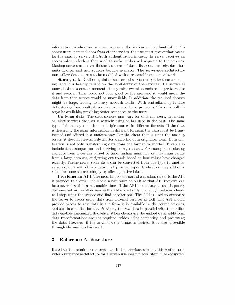
information, while other sources require authorization and authentication. Toaccess users’ personal data from other services, the user must give authorizationfor the mashup server. If OAuth authentication is used, the server receives anaccess token, which is then used to make authorized requests to the services.Mashup servers are never finished: sources of data disappear entirely, data for-mats change, and new sources become available. The server-side architecturemust allow data sources to be modified with a reasonable amount of work.
Storing data. Gathering data from several services might be time consum-ing, and it is heavily reliant on the availability of the services. If a service isunavailable at a certain moment, it may take several seconds or longer to realiseit and recover. This would not look good to the user and it would mean thedata from that service would be unavailable. In addition, the required datasetmight be large, leading to heavy network traffic. With centralized up-to-datedata storing from multiple services, we avoid these problems. The data will al-ways be available, providing faster responses to the users.
Unifying data. The data sources may vary for different users, dependingon what services the user is actively using or has used in the past. The sametype of data may come from multiple sources in different formats. If the datais describing the same information in different formats, the data must be trans-formed and offered in a uniform way. For the client that is using the mashupserver, it does not necessarily matter where the data originates from. Data uni-fication is not only transforming data from one format to another. It can alsoinclude data comparison and deriving emergent data. For example calculatingaverages from a certain period of time, finding minimum or maximum valuesfrom a large data-set, or figuring out trends based on how values have changedrecently. Furthermore, some data can be converted from one type to anotheras services are not offering data in all possible types. Unification may add datavalue for some sources simply by offering derived data.
Providing an API. The most important part of a mashup server is the APIit provides to clients. The whole server must be built so that API requests canbe answered within a reasonable time. If the API is not easy to use, is poorlydocumented, or has other serious flaws like constantly changing interfaces, clientswill stop using the service and find another one. The API is used to authorizethe server to access users’ data from external services as well. The API shouldprovide access to raw data in the form it is available in the source services,and also in a unified format. Providing the raw data in parallel with the unifieddata enables maximized flexibility. When clients use the unified data, additionaldata transformations are not required, which helps comparing and presentingthe data. However, if the original data format is desired, it is also accessiblethrough the mashup back-end.
3 Reference Architecture
Based on the requirements presented in the previous section, this section pro-vides a reference architecture for a server-side mashup ecosystem. The ecosystem
117
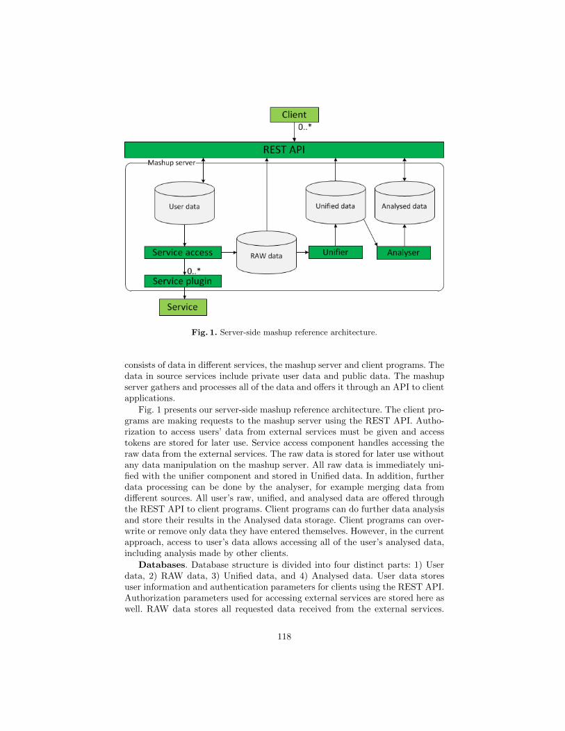
Fig. 1. Server-side mashup reference architecture.
consists of data in different services, the mashup server and client programs. Thedata in source services include private user data and public data. The mashupserver gathers and processes all of the data and offers it through an API to clientapplications.
Fig. 1 presents our server-side mashup reference architecture. The client pro-grams are making requests to the mashup server using the REST API. Autho-rization to access users’ data from external services must be given and accesstokens are stored for later use. Service access component handles accessing theraw data from the external services. The raw data is stored for later use withoutany data manipulation on the mashup server. All raw data is immediately uni-fied with the unifier component and stored in Unified data. In addition, furtherdata processing can be done by the analyser, for example merging data fromdifferent sources. All user’s raw, unified, and analysed data are offered throughthe REST API to client programs. Client programs can do further data analysisand store their results in the Analysed data storage. Client programs can over-write or remove only data they have entered themselves. However, in the currentapproach, access to user’s data allows accessing all of the user’s analysed data,including analysis made by other clients.
Databases. Database structure is divided into four distinct parts: 1) Userdata, 2) RAW data, 3) Unified data, and 4) Analysed data. User data storesuser information and authentication parameters for clients using the REST API.Authorization parameters used for accessing external services are stored here aswell. RAW data stores all requested data received from the external services.
118
It acts as a cache, allowing fast and reliable access to all of the unmodifieddata. Unified data stores and offers the raw data transformed to a commonrepresentation. Analysed data has even further processed data that can haveadditional input from the users, such as questionnaires.
Database schema for the User data is static, since we know beforehand whatkind of information we are expecting, a relational database is well suited forthis. The raw data is by nature large amounts of data chunks, which is idealfor NoSQL databases. A relational model is not needed, the focus is on storinggreat quantities of data using key-value pairs in associative arrays. The datacan be stored for example in JSON format, just as it is retrieved from thesource services. The database for analyzed data may get new and unexpectedfields as the service progresses over time. This suggests that the use of NoSQLdatabase is appropriate for the analysed data as well. Additionally, MapReduceframework [6] is implemented by most of the NoSQL databases and can beused in analysing large volumes of data [7]. Using NoSQL database for the raw,unified, and analysed data gives more freedom on how the data is stored. Asnoted in [8], NoSQL databases trade consistency and security for performanceand scalability. This leads to adding more responsibility on the developers. Evenif the database does not have a predefined schema, it must not be used as abucket that you can throw your data to and expect it to stay organised.
New data. New data is constantly added and available in the data sourceservices. To keep the mashup server data up to date, new data must be fetchedand stored on the mashup server whenever it is available. Some services offerPublish-Subscribe functionality (PubSubHubbub) [9], with the service sendingnotifications whenever there is new data available. When the services do not offersubscribing for notifications, we are forced to use polling. Background workerscan be used to handle the polling. To keep the databases coherent, new datais unified immediately. This allows faster responses to the users and removesunnecessary inconsistency with some data unified and some not.
Fig. 2 illustrates data flow from data source service to the user client. Serviceaccess subscribes each user for new data notifications (steps 1-2). When new datais available, data source service sends a notification to service access (step 3).Service access requests the new data and stores it to the RAW data-database(steps 4-6). The raw data is unified, analysed and stored (steps 7-10). User clientcan request unified and analysed data (steps 11-14).
Expendability. Mashups gather information from numerous different sour-ces. The source services may change or disappear, and we may also want toadd new services. The server-side implementation must be done so that it iseasy to fix issues that emerge related to changing APIs. Further, adding newservices and removing used services must be possible. Adding new services isalways laborious, due to the fact that all services are different. Services offerdifferent kinds of data, through different kinds of APIs. Access to services ismanaged using a plug-in architecture. A plug-in is required for each service thatis linked to the system. Each plug-in is responsible for handling communicationto one service. A plug-in must describe the raw data, so that it can be offered
119
Fig. 2. Data flow from data source service.
through the REST API, and additionally specify how to unify the raw data intoa predefined format.
4 Architecture Implementation for Wellness Services
In this section, we present our implementation based on the presented referencearchitecture. The domain of the implementation is wellness services, with userskeeping track of information about their well-being such as activity, weight,blood pressure, and quality of sleep. The aim of the implementation is to providean API for client programs with centralized access to all of the users’ wellnessinformation. The API should provide access to raw data from a wide range ofwellness services, and also unified data that is not dependant on the origin ofthe data. For example, it does not matter where user’s activity data is from,the important thing is that it can be shown in a unified way with other relevantinformation. Fig. 3 presents our server-side architecture for a wellness mashup.
The current implementation concentrates on services that offer an open APIand have licenses that allows us to modify and store the provided user data. Theservices that we selected for the first phase of the implementation are Beddit(http://beddit.com), Withings (http://withings.com), Fitbit (http://fitbit.com),and a weather service (http://wunderground.com). Beddit offers sleep trackingand analysis. Withings provides blood pressure monitors, body scales, and ac-tivity trackers. Fitbit offers body scales and activity trackers. The body scalesmeasure weight and body fat, and also calculate the body mass index (BMI).
120
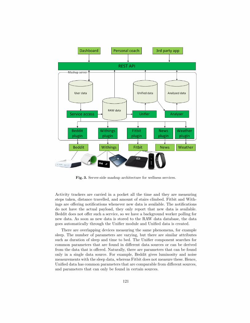
Fig. 3. Server-side mashup architecture for wellness services.
Activity trackers are carried in a pocket all the time and they are measuringsteps taken, distance travelled, and amount of stairs climbed. Fitbit and With-ings are offering notifications whenever new data is available. The notificationsdo not have the actual payload, they only report that new data is available.Beddit does not offer such a service, so we have a background worker polling fornew data. As soon as new data is stored to the RAW data database, the datagoes automatically through the Unifier module and Unified data is created.
There are overlapping devices measuring the same phenomena, for examplesleep. The number of parameters are varying, but there are similar attributessuch as duration of sleep and time to bed. The Unifier component searches forcommon parameters that are found in different data sources or can be derivedfrom the data that is offered. Naturally, there are parameters that can be foundonly in a single data source. For example, Beddit gives luminosity and noisemeasurements with the sleep data, whereas Fitbit does not measure these. Hence,Unified data has common parameters that are comparable from different sources,and parameters that can only be found in certain sources.
121
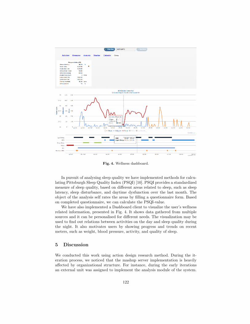
Fig. 4. Wellness dashboard.
In pursuit of analysing sleep quality we have implemented methods for calcu-lating Pittsburgh Sleep Quality Index (PSQI) [10]. PSQI provides a standardizedmeasure of sleep quality, based on different areas related to sleep, such as sleeplatency, sleep disturbance, and daytime dysfunction over the last month. Theobject of the analysis self rates the areas by filling a questionnaire form. Basedon completed questionnaire, we can calculate the PSQI-value.
We have also implemented a Dashboard client to visualize the user’s wellnessrelated information, presented in Fig. 4. It shows data gathered from multiplesources and it can be personalised for different needs. The visualization may beused to find out relations between activities on the day and sleep quality duringthe night. It also motivates users by showing progress and trends on recentmeters, such as weight, blood pressure, activity, and quality of sleep.
5 Discussion
We conducted this work using action design research method. During the it-eration process, we noticed that the mashup server implementation is heavilyaffected by organizational structure. For instance, during the early iterationsan external unit was assigned to implement the analysis module of the system.
122
Therefore we designed this part of the system to be separated from the rest andan API to communicate with the analysis module was introduced. However, theanalysis was later decided to be implemented as an integrated part, and havinga full-fledged API for this purpose was unnecessary. Consequently, the currentimplementation now includes a method for clients to send analyzed data backto our server, but in restricted fashion.
Forcing users to perform ”OAuth dance” at the time of first use setup orwhen new services are connected to user accounts is not good practice in theuser experience point of view. Utilizing so called ”two-legged OAuth” approachdoes not require user action, and it allows a service to access some data withapplication specific credentials. Typically sensitive user data is not accessiblewith this approach. Our view is that two-legged OAuth should be used if it en-ables accessing the relevant data to promote maximized convenience for the user.Another way to avoid bad user experience in service authentication is to pro-mote OpenID (http://openid.net/) and other credential federation approaches.Sometimes this might require partnering with data source service providers.
The most relevant way to compose a mashup is not always obvious for ap-plication developers. One indication of this is the fact that mashup creation isoften regarded as end-user activity which is supported by dedicated, sometimesdomain specific tools. The wellness domain is not an exception. It is difficult to”guess” the end-user’s personal desires in his or her physical well-being. There-fore enabling end-users themselves or domain experts, such as personal coachesor other professionals, to determine how the data is processed might be benefi-cial.
6 Related Work
In general, mashup development has gained a lot of research interest recently.Different patterns and trends in mashup development can be identified. Forexample, Wong et al. have categorized mashups into five different groups: aggre-gation, alternate UI & in-situ use, personalization, and focused view of data andreal time monitoring [11]. Another paper by Lee et al. presents seven mashuppatterns: data source, process, consumer, enterprise, client-side, server-side anddeveloper assembly mashups [12]. In addition, a number of challenges relatedto mashup development have been pointed out. As stated by Zang et al. [13],mashup developers encounter problems mainly in three areas: API functionality,documentation and coding details. Issues related to API functionality in theirresearch were, for example, authentication and performance problems. Somedevelopers were concerned about the lack of proper documentation at all lev-els, including API reference, tutorials and examples. The programming skillsneeded for creating compelling mashups in JavaScript were also identified ashard to learn. Finally, the relation of disciplined software engineering princi-ples and mashup development or, even more generally, the development of webapplications remains vague [14].
123
Our previous research efforts include design of a specialized mobile multi-media mashup ecosystem [15]. The architecture was heavily based on existingbackend server, and therefore the approach used is not ideal for a reference ar-chitecture. However, the study in [15] clearly shows the benefits of having aserver-side backend, especially when there is a desire to analyse user’s past ac-tions. In another paper, we have proposed a reference architecture for client-sidemashups[16].
Server-side mashup tool architecture based on layers has been studied byLopez et al. [17]. Their architecture consists of four layers: source access (accessesweb resources), data mashup (creates structural presentation of the data), widget(holds all widgets available in the system) and widget assembly (creates a userinterface) layer. In addition to the layers, the architecture includes commonservices that provide general functionalities and can be used from any layer.The result mashup created with this architecture is similar to a web portal withthe exception that the widgets are connected.
7 Conclusion
This paper discusses problems and pitfalls in creating a server-side mashup andderived requirements for a reference architecture. A reference architecture waspresented, as well as an implementation based on the reference architecture.The reference architecture is focusing on fast and reliable data access for clientprograms. The data is offered in raw, unified, and analysed formats to serve abroad range of clients with different requirements.
Building a system that gathers data from multiple sources may be time con-suming, due to many details that must be taken into consideration when access-ing the data. A service that is gathering all of the data from different sourcesand offering it in a unified format allows developers using the mashup service tofocus on other important aspects, such as analysing data and presenting data tothe end-users.
Future work of the implementation is to widen the range of data sourceservices, for example Twitter messages and news. We hope to find new andunexpected correlations with data from different sources, for example with news,weather, activity, or sleep. In addition, more elaborate data analysis is planned.The analysis can be based purely on the data from the external services, inaddition to information about user’s mood and subjective opinions that canbe acquired using simple voting systems or questionnaire forms, for example.Furthermore, support for end-user programming with tool support is in thescope of our future research. Finally, we plan to create more client programsthat can benefit from the server-side mashup.
References
1. Yu, S., Woodard, C.J.: Innovation in the programmable web: Characterizingthe mashup ecosystem. In: Service-Oriented Computing–ICSOC 2008 Workshops,Springer (2009) 136–147
124
2. Bosch, J.: From software product lines to software ecosystems. In: Proceedings ofthe 13th International Software Product Line Conference, Carnegie Mellon Uni-versity (2009) 111–119
3. Messerschmitt, D.G., Szyperski, C.: Software ecosystem: understanding an indis-pensable technology and industry. MIT Press Books 1 (2003)
4. Hartmann, B., Doorley, S., Klemmer, S.R.: Hacking, mashing, gluing: Understand-ing opportunistic design. Pervasive Computing, IEEE 7(3) (2008) 46–54
5. Sein, M., Henfridsson, O., Purao, S., Rossi, M., Lindgren, R.: Action design re-search. MIS Quarterly 35(1) (2011) 37–56
6. Dean, J., Ghemawat, S.: MapReduce: simplified data processing on large clusters.Communications of the ACM 51(1) (2008) 107–113
7. Bonnet, L., Laurent, A., Sala, M., Laurent, B., Sicard, N.: Reduce, you say: WhatNoSQL can do for data aggregation and BI in large repositories. In: Databaseand Expert Systems Applications (DEXA), 2011 22nd International Workshop on,IEEE (2011) 483–488
8. Okman, L., Gal-Oz, N., Gonen, Y., Gudes, E., Abramov, J.: Security issues inNoSQL databases. In: Trust, Security and Privacy in Computing and Communi-cations (TrustCom), 2011 IEEE 10th International Conference on, IEEE (2011)541–547
9. Fitzpatrick, B., Slatkin, B., Atkins, M.: Pubsubhubbub core 0.3.http://pubsubhubbub.googlecode.com/svn/trunk/pubsubhubbub-core-0.3.html(2010)
10. Buysse, D.J., Reynolds, C.F., Monk, T.H., Berman, S.R., Kupfer, D.J.: The Pitts-burgh sleep quality index: a new instrument for psychiatric practice and research.Psychiatry research 28(2) (1989) 193–213
11. Wong, J., Hong, J.: What do we mashup when we make mashups? In: Proceedingsof the 4th international workshop on End-user software engineering, ACM (2008)35–39
12. Lee, C.J., Tang, S.M., Tsai, C.C., Chen, Y.C.: Toward a new paradigm: Mashuppatterns in web 2.0. WSEAS Transactions on Information Science and Applications6(10) (2009) 1675–1686
13. Zang, N., Rosson, M.B., Nasser, V.: Mashups: who? what? why? In: CHI’08extended abstracts on Human factors in computing systems, ACM (2008) 3171–3176
14. Mikkonen, T., Taivalsaari, A.: The mashware challenge: bridging the gap betweenweb development and software engineering. In: Proceedings of the FSE/SDP work-shop on Future of software engineering research, ACM (2010) 245–250
15. Hartikainen, M., Salminen, A., Kallio, J.: Towards mobile multimedia mashuparchitecture. In: Software Engineering and Advanced Applications (SEAA), 201238th EUROMICRO Conference on, IEEE (2012) 439–445
16. Mikkonen, T., Salminen, A.: Towards a reference architecture for mashups. In: Onthe Move to Meaningful Internet Systems: OTM 2011 Workshops, Springer (2011)647–656
17. Lopez, J., Pan, A., Bellas, F., Montoto, P.: Towards a reference architecture forenterprise mashups. Actas de los Talleres de las Jornadas de Ingenierıa del Softwarey Bases de Datos 2(2) (2008)
125
Code Oriented Approach to 3D Widgets
Anna-Liisa Mattila
Department of Pervasive Computing,Tampere University of Technology,
Korkeakoulunkatu 1, FI-33720 Tampere, [email protected]
Abstract. With newly introduced standards, it has become increasinglyfeasible to develop interactive 3D applications even with web technolo-gies only. Unfortunately many of the available 3D graphics libraries arebuilt on low-level facilities, which, while well-suited for demos, complicatethe design of true applications. The research of interactive 3D applica-tions has mainly focused on developing interaction techniques, input-and output devices and figuring out what would be right metaphors andparadigms to develop usable and still highly interactive 3D user inter-faces. Little consideration is put on how to actually ease the programmingof an interactive 3D application. In this paper, we explore the current3D research and tools used for developing interactive 3D applicationsaddressing the missing abstraction of code oriented 3D widgets.
Keywords: Widgets, 3D, 3DUI, WebGL
1 Introduction
As 3D technologies have become more common, it has become increasingly fea-sible to develop interactive applications even with web technologies only, withno vendor-specific plugins that would require separate installation. However pro-gramming 3D applications is still difficult task.
The research of interactive 3D applications has mainly focused on developinginteraction techniques, input and output devices and figuring out what wouldbe right metaphors and paradigms to develop usable and still highly interac-tive 3D user interfaces. Little consideration is put on how to actually ease theprogramming of an interactive 3D application. Programming of interactive 3Dapplications is mainly done with low level facilities like 3D engines and modelingtools. [1]
The 3D engines used are well suited for simplifying rendering operationsbut they do not include functionality for user interaction. When there is nobuilt-in support for user interaction an application developer has to implementnot just event handlers but also the event system from the scratch for everyapplication. This takes plenty of work and might risk reusability, maintainabilityand scalability of the application.
In 2D application development widget libraries and managed graphics toolsare used by daily basis, and when building a user interface the WIMP (windows,
126
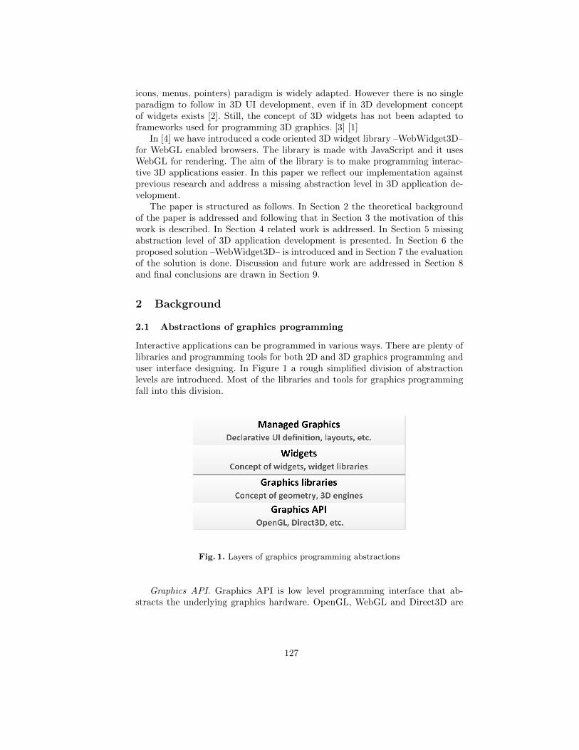
icons, menus, pointers) paradigm is widely adapted. However there is no singleparadigm to follow in 3D UI development, even if in 3D development conceptof widgets exists [2]. Still, the concept of 3D widgets has not been adapted toframeworks used for programming 3D graphics. [3] [1]
In [4] we have introduced a code oriented 3D widget library –WebWidget3D–for WebGL enabled browsers. The library is made with JavaScript and it usesWebGL for rendering. The aim of the library is to make programming interac-tive 3D applications easier. In this paper we reflect our implementation againstprevious research and address a missing abstraction level in 3D application de-velopment.
The paper is structured as follows. In Section 2 the theoretical backgroundof the paper is addressed and following that in Section 3 the motivation of thiswork is described. In Section 4 related work is addressed. In Section 5 missingabstraction level of 3D application development is presented. In Section 6 theproposed solution –WebWidget3D– is introduced and in Section 7 the evaluationof the solution is done. Discussion and future work are addressed in Section 8and final conclusions are drawn in Section 9.
2 Background
2.1 Abstractions of graphics programming
Interactive applications can be programmed in various ways. There are plenty oflibraries and programming tools for both 2D and 3D graphics programming anduser interface designing. In Figure 1 a rough simplified division of abstractionlevels are introduced. Most of the libraries and tools for graphics programmingfall into this division.
Fig. 1. Layers of graphics programming abstractions
Graphics API. Graphics API is low level programming interface that ab-stracts the underlying graphics hardware. OpenGL, WebGL and Direct3D are
127
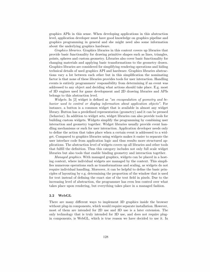
graphics APIs in this sense. When developing applications in this abstractionlevel, application developer must have good knowledge on graphics pipeline andgraphics programming in general and she might need also some informationabout the underlying graphics hardware.
Graphics libraries. Graphics libraries in this context covers up libraries thatprovide basic functionality for drawing primitive shapes such as lines, triangles,points, spheres and custom geometry. Libraries also cover basic functionality forchanging materials and applying basic transformations to the geometry drawn.Graphics libraries are considered for simplifying rendering operations and hidingtechnical details of used graphics API and hardware. Graphics libraries abstrac-tions vary a lot between each other but in this simplification the nominatingfactor is that none of these libraries provides tools for user interaction. Handlingevents is entirely programmers’ responsibility from determining if an event wasaddressed to any object and deciding what actions should take place. E.g. mostof 3D engines used for game development and 2D drawing libraries and APIsbelongs to this abstraction level.
Widgets. In [2] widget is defined as ”an encapsulation of geometry and be-havior used to control or display information about application objects”. Forinstance, a button is a common widget that is available in almost any widgetlibrary. Button has a predefined representation (geometry) and it can be pressed(behavior). In addition to widget sets, widget libraries can also provide tools forbuilding custom widgets. Widgets simplify the programming by combining userinteraction and geometry together. Widget libraries usually provide event han-dling mechanisms or such for user interaction. Application developer needs onlyto define the action that takes place when a certain event is addressed to a wid-get. Compared to graphics libraries using widgets makes it easier to separate theuser interface code from application logic and thus results more structured ap-plications. The abstraction level of widgets covers up all libraries and other toolsthat fulfill the definition. Thus this category includes not only full scale widgetlibraries but also tools that enable binding geometry and interaction together.
Managed graphics. With managed graphics, widgets can be placed in a host-ing context, where individual widgets are managed by the context. This simpli-fies numerous operations such as transformations and scaling, as widgets do notrequire individual handling. Moreover, it can be helpful to define the basic prin-ciples of layouting by e.g. determining the proportion of the window that is usedfor text instead of defining the exact size of the text field in pixels. Due to theincreasing level of abstraction, the programmer has even less control over whattakes place upon rendering, but everything takes place in a managed fashion.
2.2 WebGL
There are many different ways to implement 3D graphics inside the browserwithout plug-in components, which would require separate installation. However,most of them are intended for 2D use and 3D use is a later extension. Theonly technology that is truly intended for 3D use, and does not require plug-in components, is WebGL, which is true reason we have decided to use it. In
128
the following, we give a brief overview to WebGL, the technology used in theimplementation of the WebWidget3D.
WebGL is a standard being developed by Mozilla, Khronos Group, and aconsortium of additional companies. The standard is based on OpenGL ES 2.0[5], and it uses OpenGL shading language GLSL. WebGL runs in the HTML5’scanvas element. [6]
For practical purposes, WebGL means that a comprehensive JavaScript APIis provided to open up OpenGL programming capabilities to JavaScript pro-grammers, although it is meant for low-level rendering operations. To makeit easier and faster to use WebGL, several additional JavaScript frameworksand APIs have been introduced, including Copperlicht1, C3DL2, GLGE3, andthree.js4, to name a few commonly used systems. All these frameworks have theirown JavaScript API through which the actual WebGL API is used. In general,the goal of these libraries is to hide the majority of technical details and thusmake it simpler to write applications using the framework APIs. Furthermore,these WebGL frameworks provide functions for performing basic 2D and 3Drendering operations such as drawing a rotating cube on the canvas. The moreadvanced libraries also include functions for performing animations, adding light-ing and shadows, calculating the level of detail, collision detection, and so forth.Such rich capabilities enable the creation of more compelling effects relativelyeasily. However, all these libraries are intended for rendering level operations,and support for more abstract needs of applications are not addressed.
3 Motivation
Widget libraries like WxWidgets and tools for managed graphics are commonlyused in 2D application development. However programming of interactive 3Dapplications is still made with the facilities of rendering level 3D engines andmodeling software. 3D models are first made with the 3D modeling tool after thatthe functionality is programmed using a 3D engine, a physics engine and otherapplication-specific tools. Even if the concept of 3D widgets was first introducedin 1992 by Conner et al [2] the concept is not widely adapted in 3D graphicslibraries.
The 3D engines used are well suited for simplifying rendering operations butdo not include functionality for user interaction. Binding mouse event handlersor corresponding interaction mechanism to objects using 2D widget libraries orsimilar tools is pretty simple. Application developer defines the action that takesplace in certain event for certain object. However when developing 3D applica-tions using just 3D engines facilities the situation is more complicated. Applica-tion developer is responsible also for defining the logic that detects whether anobject was e.g. clicked and what actions should take place.
1 http://www.ambiera.com/copperlicht/2 http://www.c3dl.org/3 http://www.glge.org/4 http://threejs.org/
129
Detecting whether an object was clicked in 3D environment application de-veloper must typically do the following steps:
1. Determine if the mouse hit a 3D object.– Transform the mouse position coordinates into the 3D world’s coordinate
system.– Do ray casting from the mouse’s 3D world coordinates.– Run collision detection between the ray and objects in 3D world.
2. If a 3D object was hit, deduce the type of the object that was hit.– Deduce the action that take place for the object hit when it was clicked
with a mouse.
Applying the interaction logic and actions separately for every applicationallows highly customized and application-specific user interfaces but the code ofthe user interface is tightly bound to the application and therefore code reuse canbe difficult. Also designing a highly interactive 3D application can be complicatedwhen support of higher level of abstraction concepts are missing. Designing anapplication where every object can be interacted with same manners (e.g. clickedor dragged with mouse) is quite simple even if we do not have any support forinteraction. However when designing complicated applications, where differentobjects can have different actions and where actions can be dependent fromother actions, the designing gets quickly very complex. In worst case, developinginteractive 3D applications with low abstraction level tools result to spaghetticode that does not scale up and is hard to maintain. [2] [7] [8]
When designing a 3D widget library there are several things that have tobe noted. First of all, interactive 3D applications are not similar to most ofthe 2D applications. 3D is most used for immersive games and virtual realityapplications which are graphically intense but also for data visualization. Thelook and feel of a 3D application is usually dependent on the application. Thereis no standardized 3D user interface paradigm like WIMP to follow and theremay never be [1]. When in 2D environments WIMP metaphor is proven to beeffective, it is not applicable in 3D environments. Applying WIMP metaphor to3D environments as is would limit look and feel of applications and it mightrestrict degrees of freedom that can be applied on 3D objects in 3D space [1] [3][7].
In 2D user interface design separation of user interface definition and ap-plication logic is considered preferable [7] [2]. However in no WIMP interfaceswhich 3D user interfaces mainly are it is stated that tight separation betweenapplication logic code and user interface code is not necessarily desirable becauseit might limit interaction techniques that can be used in the interface [3] [7] [2].Therefore the development of 3D applications is significantly different from 2Dapplications.
4 Related work
The research of interactive 3D applications has mainly focused on developinginteraction techniques, input and output devices and figuring out what would
130
be right metaphors and paradigms to develop usable and still highly interac-tive 3D user interfaces. Little consideration is put on how to actually ease theprogramming of an interactive 3D application. [1]
The basic concept of 3D widgets as first-class objects is presented in [2]. Weagree on the introduced approach at the principal level. However the researchis focused on solving problems in 3D interaction and constructing 3D widgetswhereas our work’s aim is to study how programming of 3D applications could bemade easier. The 3D widget system UGA, built as a research artifact, introducesa new scripting language for 3D widgets construction and provides toolkit forconstructing widgets [9].
In [7] a concept-oriented design (COD) approach to 3D user interface devel-opment and Chasm tool as an implementation of the approach are introduced.Chasm is an executable user interface description language (UIDL) for 3D userinterface development. The presented approach reduces the complexity of 3Duser interface development. Chasm has been shown to be useful for creatingcomplex full scale 3D system user interfaces. However it does not targets tosimplify the programming of 3D applications.
Declarative technologies are commonly used for creating virtual environ-ments. Virtual Reality Modeling Language, VRML, is a file format for repre-senting interactive 3D graphics in web. Concept of VRML was introduced in1994 in [10]. In VRML the 3D world is defined in declarative manner and ac-tions, such as user interaction and animations, are scripted. Most of 3D modelingsoftware can export models in VRML format. X3D [11] is a XMl based successorof VRML. To view VRML and X3D scenes, additional software, i.e. BS Contact,is needed.
X3DOM [12] is a webGL based implementation of X3D which can run inweb browser without plug-in components. The goal of the X3DOM is to embed3D content into DOM and thus enable the use of 3D content in web applica-tions in same manner as 2D content. XML3D [13] is another implementation ofdeclarative 3D graphics based on WebGL. XML3D also integrates 3D contentinto DOM but in difference to X3DOM, XML3D is not based on X3D. X3DOMand XML3D are in development state at the moment.
CONTIGRA is X3D based widget library, which offers high level of separationbetween 3D widget declaration and application logic. CONTRIGRA also hashigh support on component reuse and it provides tools for widget distribution.[14] [15] [8]
BEHAVIOR3D, introduced in [16], is a X3D framework for designing 3Dgraphics behavior. It is used for implementing and designing behavior to 3Dobjects. BEHAVIOR3D is designed to be used with CONTIGRA. While in X3Dand in CONTIGRA behavior of 3D objects are implemented using scripts, withBEHAVIOR3D behavior can be implemented by declarative way using XML.
A benefit for VRML and X3D is that those are widely used, established,technologies for creating virtual environments. X3DOM and XML3D are alsopromising new technologies in development of 3D web applications. CONTIGRAand BEHAVIOR3D introduce a strong declarative toolset for 3D widget creation
131
and distribution. However all these tools and technologies stand for declarativeapproach to 3D development while our interest is on code oriented approach.
While declarative technologies are used for creating virtual environments, aswell code oriented approaches, e.g. 3D engines and other graphics libraries, arewidely used. 3D engines are mainly focused on abstracting rendering operationsand support for user interaction is lacking. We have reviewed a number of 3Dengines including Unity5, OGRE6, three.js7, Copperlicht8, C3DL9, GLGE10 andSpiderGL11. Unlike X3D or X3DOM, none of these 3D engines have supportfor binding user interaction directly to 3D objects which makes programminginteractive 3D applications more difficult. Our interest in particular is to developthe code oriented approach further by extending 3D engines facilities to supportconcept of 3D widgets.
5 Missing Abstraction
In [14] it is stated that X3D and VRML are declarative counterpart for 3Dengines which are code oriented. This means that in [14] the abstraction level ofX3D and 3D engines is stated to be same. The definition of widget, introducedearlier in Section 2.1 is: ”Widget is an encapsulation of geometry and behaviorused to control or display information about application objects” [2]. Hence X3Dand VRML have support for binding user interaction to 3D objects and 3Dengines do not have that support, abstraction level of these tools are not same.3D engines operates in Graphics libraries abstraction level introduced previouslyin Figure 1 while X3D and VRML operates actually in Widgets abstraction levelalbeit those are not exactly thought to be widget libraries.
One level of abstraction is missing. There is no support for code orientedway to do 3D widgets. When figuring out which tools to use for implementinginteractive 3D applications, the application developer can choose between codeoriented and declarative approaches. If she chooses code oriented approach, thereis no support for interaction. We claim that this is one of the reasons whyprogramming interactive 3D applications is still difficult.
Declarative XML based tool always has to have a program that executes it[17]. If programming tools do not support the same abstraction level conceptsthat the intended declarative tool does, development of the underlying softwareis more difficult and can cause problems if the software needs to be ported toother technology.
In [8] difficulties in making the widget toolkit portable for other 3D tech-nologies were reported. We state that these difficulties were due bypassing code
5 http://unity3d.com/6 http://www.ogre3d.org/7 http://threejs.org/8 http://www.ambiera.com/copperlicht/9 http://www.c3dl.org/
10 http://www.glge.org/11 http://spidergl.org/
132
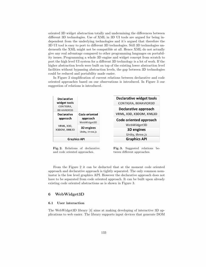
oriented 3D widget abstraction totally and undermining the differences betweendifferent 3D technologies. Use of XML in 3D UI tools are argued for being in-dependent from the underlying technologies and it’s argued that therefore the3D UI tool is easy to port to different 3D technologies. Still 3D technologies un-derneath the XML might not be compatible at all. Hence XML do not actuallygive any real advantage compared to other programming languages on portabil-ity issues. Programming a whole 3D engine and widget concept from scratch toport the high level UI system for a different 3D technology is a lot of work. If thehigher abstraction levels were built on top of the existing lower abstraction levelfacilities without bypassing abstraction levels, the gap between 3D technologiescould be reduced and portability made easier.
In Figure 2 simplification of current relations between declarative and codeoriented approaches based on our observations is introduced. In Figure 3 oursuggestion of relations is introduced.
Fig. 2. Relations of declarativeand code oriented approaches.
Fig. 3. Suggested relations be-tween different approaches.
From the Figure 2 it can be deducted that at the moment code orientedapproach and declarative approach is tightly separated. The only common nom-inator is the low level graphics API. However the declarative approach does nothave to be separated from code oriented approach. It can be built upon alreadyexisting code oriented abstractions as is shown in Figure 3.
6 WebWidget3D
6.1 User interaction
The WebWidget3D library [4] aims at making developing of interactive 3D ap-plications to web easier. The library supports input devices that generate DOM
133
events. At this point these input devices are commonly mouse, keyboard andtouch screen.
In traditional web applications, DOM event handlers are usually bound toHTML elements, such as buttons and text boxes, for instance. In a WebGL based3D world, however, binding events to a certain 3D widget is more complicated.The whole 3D world is rendered into a single canvas element. Therefore, whenusing the traditional approach, DOM events can be bind to the canvas but notdirectly to 3D objects inside the canvas, as one would most commonly prefer.Instead, handling events in a WebGL based 3D world is more complicated thanin ordinary web applications.
To handle events in WebGL 3D world the first part is to bind the wantedhandlers to the canvas element. When a mouse event is triggered we need toknow the point where the mouse hits to determine if the mouse event hits a3D object or not. Consequently, we need to perform the steps of mouse clickdetection described before in Section 3. Interaction can be done also with otherthan pointing devices, e.g. with keyboard. For keyboard event handling, mainevent handlers an additional logic for deducing the right actions is also needed.
The WebWidget3D provides an event system which enables the applicationdeveloper to attach event handlers directly to the 3D objects trough an API thatis similar to the API for binding DOM event handlers to HTML elements. Theapplication developer can also define her own events, trigger events and passevents to designated widgets using the event system.
In WebWidget3D there are three main types of events which are supported:
1. Pointing device events
2. Keyboard events
3. Custom events / messages
Pointing device event objects must contain coordinate data in window co-ordinate system. The WebWidget3D event system handles the ray casting andpassing the event to right widgets. Keyboard events are passed to all widgetsthat are focused and have the listener for the event. Custom events are eventsthat are not pointing device events or keyboard events. Also other DOM eventsthan pointing device events and keyboard events are custom events. Customevents are passed to all widgets that have the listener for the event. Customevents can be used e.g. for passing messages between widgets. In WebWidget3Dall types of events can also be bind to the application. The application’s eventhandler is called always when the event occurs. The amount of event handlersfor one event for one object is not limited.
To simplify application developers work WebWidget3D introduces also somepredefined controls that can be applied to widgets. These predefined controlsare a set of event handlers that perform e.g. object drag functionality. At themoment WebWidget3D has only two predefined controls which are roll- anddrag controls. With roll control a widget can be rotated around its x- and y-axisby mouse. With drag control widget can be dragged around the 3D world withmouse. The drag is done always coaxial to the camera so that the object moves
134
as in 2D space. This is most intuitive drag control when the input device isregular mouse. More controls are under consideration but not yet implemented.
The controls are designed for regular 2D mouse and keyboard which producessome complexity for combining controls. Drag and roll are done with same mousegestures and if there is no information from where system could deduce whichaction the user would prefer, both actions take place simultaneously. For com-bining controls application developer can define parameters for example to rollonly if shift key is pressed or disabling unwanted controls in certain situations.
6.2 Concept of 3D widgets
The WebWidget3D library applies the concept of 3D widgets by providing widgetbuilding blocks that can be instantiated, specialized, refined and composite tocreate a desired 3D widget. The widget building blocks have different roles andresponsibilities in the design. Common for all building blocks is the capabilityof receiving events and the predefined controls can be applied to them. Noneof the building blocks include a concrete graphical representation. Graphicalrepresentation of a widget can be designed with modeling tools to ensure desiredlook that is suitable for the application.
The building blocks offered are: Basic, Text, Group and CameraGroup. Ba-sic is the base for all widgets. Basic can receive events and a 3D model can beattached to it. It has no special features and it is the simplest building blockin the set. Text includes simple string handling functionality so that it can beused to store dynamic text, e.g. users input from keyboard. Group can host childcomponents of any type. Group provides also some utilities to manage its childcomponents i.e. focusing and hiding all children. Also rotations, translations andchanges in visibility are always propagated to Group’s children. With Camera-Group widgets can be attached to camera so that the widgets orientation anddistance to the camera doesn’t change when the camera is moved.
These widget building blocks and the event system form the core of the Web-Widget3D. The core of the library is designed so that it can be used with anyJavaScript 3D engine. There is a specialized adapter component that is usedbetween the 3D engine and the WebWidget3D core. The proof-of-concept im-plementation done uses three.js 3D engine for rendering. WebWidget3D does nothide the API of 3D engine from application developer so application developercan use all the functionality and visual effects 3D engine has to offer.
6.3 Predefined Widgets
To prove that WebWidget3D can be used for creating concrete reusable 3D wid-gets, a set of ready-to-use widgets were made. These widgets are built usingthe widget building blocks described previously and facilities of three.js 3D en-gine. The widgets follow closely WIMP paradigm and are designed mainly forLively3D 3D desktop environment, which is introduced in [4].
135
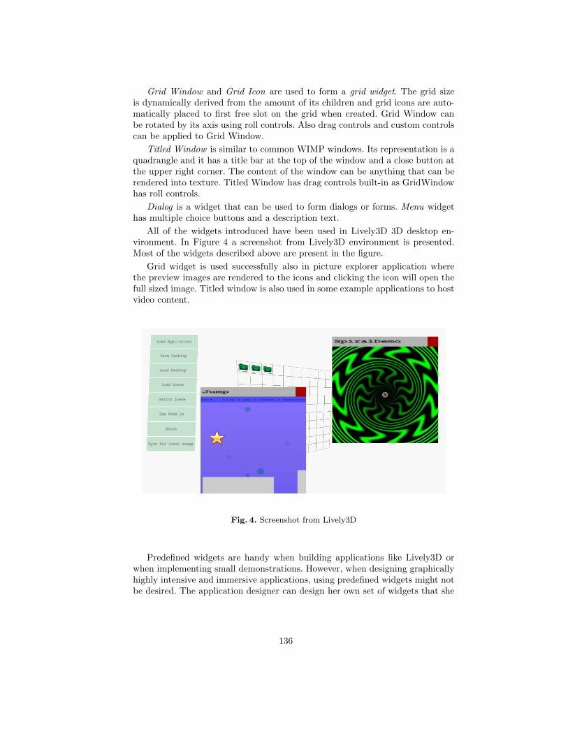
Grid Window and Grid Icon are used to form a grid widget. The grid sizeis dynamically derived from the amount of its children and grid icons are auto-matically placed to first free slot on the grid when created. Grid Window canbe rotated by its axis using roll controls. Also drag controls and custom controlscan be applied to Grid Window.
Titled Window is similar to common WIMP windows. Its representation is aquadrangle and it has a title bar at the top of the window and a close button atthe upper right corner. The content of the window can be anything that can berendered into texture. Titled Window has drag controls built-in as GridWindowhas roll controls.
Dialog is a widget that can be used to form dialogs or forms. Menu widgethas multiple choice buttons and a description text.
All of the widgets introduced have been used in Lively3D 3D desktop en-vironment. In Figure 4 a screenshot from Lively3D environment is presented.Most of the widgets described above are present in the figure.
Grid widget is used successfully also in picture explorer application wherethe preview images are rendered to the icons and clicking the icon will open thefull sized image. Titled window is also used in some example applications to hostvideo content.
Fig. 4. Screenshot from Lively3D
Predefined widgets are handy when building applications like Lively3D orwhen implementing small demonstrations. However, when designing graphicallyhighly intensive and immersive applications, using predefined widgets might notbe desired. The application designer can design her own set of widgets that she
136
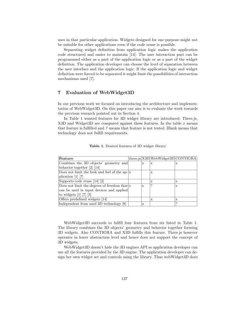
uses in that particular application. Widgets designed for one purpose might notbe suitable for other applications even if the code reuse is possible.
Separating widget definition from application logic makes the applicationcode structured and easier to maintain [14]. The user interaction part can beprogrammed either as a part of the application logic or as a part of the widgetdefinition. The application developer can choose the level of separation betweenthe user interface and the application logic. If the application logic and widgetdefinition were forced to be separated it might limit the possibilities of interactionmechanisms used [7].
7 Evaluation of WebWidget3D
In our previous work we focused on introducing the architecture and implemen-tation of WebWidget3D. On this paper our aim is to evaluate the work towardsthe previous research pointed out in Section 4.
In Table 1 wanted features for 3D widget library are introduced. Three.js,X3D and Widget3D are compared against these features. In the table x meansthat feature is fulfilled and ? means that feature is not tested. Blank means thattechnology does not fulfill requirements.
Table 1. Desired features of 3D widget library
Feature three.js X3D WebWidget3D CONTIGRA
Combines the 3D objects’ geometry andbehavior together [2] [14]
x x x
Does not limit the look and feel of the ap-plication [1] [7]
x x
Supports code reuse [14] [2] x x
Does not limit the degrees of freedom thatcan be used in input devices and appliedto widgets [1] [7] [3]
x x ? x
Offers predefined widgets [14] x x
Independent from used 3D technology [8] x ?
WebWidget3D succeeds to fulfill four features from six listed in Table 1.The library combines the 3D objects’ geometry and behavior together forming3D widgets. Also CONTIGRA and X3D fulfills this feature. Three.js howeveroperates in lower abstraction level and hence does not support the concept of3D widgets.
WebWidget3D doesn’t hide the 3D engines API so application developer canuse all the features provided by the 3D engine. The application developer can de-sign her own widget set and controls using the library. Thus webWidget3D does
137
not limit the look and feel of application. WebWidget3D enables code reuse butapplication logic and user interface code can also be combined if it is necessary.
In X3D available visual effects are dependent from the implementation ofX3D used. This is why using X3D might limit capabilities of underlying 3Dtechnology and also the look of the application. CONTIGRA separates the userinterface definition from application logic tightly and thus supports code reusebut might limit the look and feel of the application [7] [3]. CONTIGRA is alsobased on X3D.
WebWidget3D does not necessary limit the degrees of freedom that can beused in input devices but at the moment library is used and tested only withstandard 2D input devices which are mouse and keyboard. The library can beused with other kind of input devices as data glove or 3D mouse if the devicecan fire DOM events and the input of the device can be read from the DOMevent object in the format which WebWidget3D’s event system can understand.
Using WebWidget3D with other than web technologies is not possible withoutlots of work because the built-in event system is based on DOM. Neverthelessthe concept of 3D widget library that can use already existing 3D engine forrendering is applicable in other environments too. At the moment WebWidget3Ddoes not fulfill the requirement of being independent from 3D technology used.
Also three.js is designed on top of WebGL and web technologies so it is notportable to other 3D technologies as is. However, corresponding 3D engines existson other platforms too. X3D is portable to other 3D technologies as X3DOM,webGL based implementation of X3D shows. However porting X3D can alsodemand lots of work. CONTIGRA is designed so that it can be ported to othertechnologies than X3D. According to [8] this feature was never tested because itrequired more work than planned.
WebWidget3D’s goal is to make programming of interactive 3D applicationseasier. It is not a 3D widget design tool or 3D UI creator. At this state Web-Widget3D is just a research artifact that needs to be refined. However even inits current state the WebWidget3D can be used for programming interactive 3Dapplications. In [4] we made measurements with WebWidget3D that clearly ad-vocates the widget approach over the use of only 3D engines facilities. Conceptof 3D widgets is powerful even if it wouldn’t result high code and widget reusebetween applications.
8 Discussion and Future Work
In [1] it is stated that in 3D user interface research the discussion is kept on a highabstraction level on purpose because of instability of underlying 3D technology.This might be one of the reasons why code oriented approach to 3D widgets isnot studied. On 2D application development the programming tools and alsoUI tools are highly developed and of course it would be fantastic to have 3Dapplication development in the same level. When approaching the issue fromthe higher abstraction levels we might think that the lower levels actually existsand forget to consider gaps between used technologies.
138
Also 3D engines have developed a lot in a couple of years. Before program-ming 3D applications was even harder than it is now. Application developerswho are used to develop applications with low abstraction level facilities mightnot see why the widget abstraction is needed.
For a future work we are building more adapters to WebWidget3D to val-idate its use with different 3D engines. Also implementing similar architectureto desktop environments is planned. Portability issues of 3D tools are studiedfurther. Code camp where students test programming 3D applications with Web-Widget3D is under consideration. Also further research on which tools are mostcommonly used in 3D development will be done.
9 Conclusions
In this paper we have addressed a missing abstraction of 3D programming andmade literature based evaluation of WebWidget3D.
It is evident that for developing complex interactive 3D applications betterprogramming tools are needed. The widget level of abstraction programmingtools are still lacking and we state that this is one of the reasons why program-ming of interactive 3D applications is still difficult.
The research about 3D environments and tools has long been considered onthe higher abstraction level issues undermining the importance of decent pro-gramming tools for 3D applications. This has led the 3D application develop-ment into a state where application developer must choose between declarative3D tools and 3D graphics libraries, which have no support for interaction. Thisis a generic area where improvement is expected to happen.
References
1. Bowman, D., Kruijff, A., Jr., J.L.: 3D User Interfaces: Theory and Practice. Ad-dison Wesley (2005)
2. Conner, B.D., Snibbe, S.S., Herndon, K.P., Robbins, D.C., Zeleznik, R.C.,Van Dam, A.: Three-dimensional widgets. In: Proceedings of the 1992 sympo-sium on Interactive 3D graphics, ACM (1992) 183–188
3. Green, M., Jacob, R.: SIGGRAPH’90 Workshop report: software architectures andmetaphors for non-WIMP user interfaces. ACM SIGGRAPH Computer Graphics25 (1991) 229–235
4. Mattila, A.L., Mikkonen, T.: Designing a 3d widget library for webgl enabledbrowsers. In: In proceedings of the 28th Symposium On Applied Computing.Volume 1., ACM (March 2013) 757–760
5. : OpenGL ES Common Profile Specification. Technical report, Khronos Group(2010) http://www.khronos.org/registry/gles/specs/2.0/es full spec 2.0.25.pdf/.
6. : WebGL Specification. Technical report, Khronos Group (2011)http://www.khronos.org/registry/webgl/specs/1.0/.
7. Wingrave, C.A., Laviola Jr, J.J., Bowman, D.A.: A natural, tiered and executableuidl for 3d user interfaces based on concept-oriented design. ACM Transactionson Computer-Human Interaction (TOCHI) 16(4) (2009) 21
139
8. Dachselt, R., Hinz, M., Meißner, K.: Contigra: an xml-based architecture forcomponent-oriented 3d applications. In: Proceedings of the seventh internationalconference on 3D Web technology, ACM (2002) 155–163
9. Zeleznik, R.C., Herndon, K.P., Robbins, D.C., Huang, N., Meyer, T., Parker, N.,Hughes, J.F.: An interactive 3d toolkit for constructing 3d widgets. In: Proceedingsof the 20th annual conference on Computer graphics and interactive techniques,ACM (1993) 81–84
10. Raggett, D., et al.: Extending www to support platform independent virtual reality.In: Proc. Internet Society/European Networking. (1994) 242
11. Brutzman, D., Daly, L.: X3D: extensible 3D graphics for Web authors. MorganKaufmann (2010)
12. Behr, J., Jung, Y., Drevensek, T., Aderhold, A.: Dynamic and interactive as-pects of x3dom. In: Proceedings of the 16th International Conference on 3D WebTechnology, ACM (2011) 81–87
13. Sons, K., Klein, F., Rubinstein, D., Byelozyorov, S., Slusallek, P.: Xml3d: interac-tive 3d graphics for the web. In: Proceedings of the 15th International Conferenceon Web 3D Technology, ACM (2010) 175–184
14. Dachselt, R.: Contigra towards a document-based approach to 3d components. In:Workshop’Structured Design of Virtual Environments and 3D-Components’ at theACM Web3D 2001 Symposium, Citeseer (2001)
15. Dachselt, R.: Contigra: A high-level xml-based approach to interactive 3d compo-nents. In: SIGGRAPH 2001 Conference Abstracts and Applications. Volume 163.(2001)
16. Dachselt, R., Rukzio, E.: Behavior3d: an xml-based framework for 3d graphicsbehavior. In: Proceedings of the eighth international conference on 3D Web tech-nology, ACM (2003) 101–ff
17. : Extensible Markup Language (XML) 1.1 (Second Edition). Technical report,W3C (2006) http://www.w3.org/TR/2006/REC-xml11-20060816/.
140
The Browser as a Host Environmentfor Visually Rich Applications
Jari-Pekka Voutilainen and Tommi Mikkonen
Department of Pervasive Computing, Tampere University of TechnologyP.O. Box 553, FI-33101 Tampere, Finland
{jari-pekka.voutilainen,tommi.mikkonen}@tut.fi
Abstract. The World Wide Web has rapidly evolved from a simpledocument browsing and distribution environment into a rich softwareplatform where desktop-style applications are treated as first class citi-zens. Despite the technical difficulties and limitations, it is not unusualfor complex applications to use the web as their only platform, withno traditional installable application for the desktop environment – thesystem is simply accessed via a web page that is downloaded inside thebrowser. With the recent standardization efforts, such as HTML5 in par-ticular, applications are increasingly being supported by the facilities ofthe browser. In this paper, we demonstrate the new facilities of the webas an visualization tool, going beyond what is expected of browser basedapplications. In particular, we demonstrate that with mashup technolo-gies, which enable combining already existing content from various sitesinto an integrated experience, the new graphics facilities unleashes un-foreseen potential for visualizations.
Keywords: Web applications, visualization, scene graph, window man-agement
1 Introduction
Over the past years, the World Wide Web has evolved from a simple docu-ment browsing and distribution environment into a rich software platform wheredesktop-style applications are increasingly often treated as first class citizens.However, the document-centric origins of the Web are still visible in many areas,though, and traditionally it has been difficult to compose truly interactive webapplications without using plug-in components or browser extensions such asAdobe Flash or Microsoft Silverlight, to name two examples. Despite the tech-nical difficulties and limitations, it is not unusual for complex applications touse the web as their only platform, with no traditional installable applicationfor the desktop environment – the system is simply accessed via a web page thatis downloaded inside the browser, whose runtime resources are then used by theapplication. We believe that the transition of applications from the desktop com-puter to the web has only started, and the variety, number, and importance ofweb applications will be constantly rising during the next several years to come.
141
In comparison to desktop applications, the benefits of web applications aremany. Web applications are easy to adopt, because they need neither installationnor updating - one simply enters the URL into the browser and the latest ver-sion is always run. Furthermore, web applications are easy and cheap to publishand maintain; there is no need for intermediates like shops or distributors. Fur-thermore, in comparison to conventional desktop applications, web applicationshave a whole new set of features available, like online collaboration, user createdcontent, shared data, and distributed workspace. Finally, with the whole con-tent of the web acting as the data repository, the new application developmentopportunities, unleashed by the newly introduced facilities of the web technolo-gies that make the browser increasingly capable platform for running interactiveapplications, are increasing the potential of the web as an application platform.
In this paper, we demonstrate the new facilities of the web as an informationvisualization tool, going beyond what is expected of browser based applications.In particular, we demonstrate that together with mashup technologies, whichenable combining already existing content from various sites into an integrated,usually more compelling experience, the new graphics facilities results in unfore-seen potential for visualization of conceptual data.
The rest of the paper is structured as follows. In Section 2, we discuss theevolution of the web and the main phases that can be identified in the process,and briefly address two important web standards - HTML5 and WebGL - andtheir role in the development of new types of web applications, building onalready available resources. In Section 3, we introduce our technical contribution,a host environment that is capable of intregating multiple applications withinsingle 3D-scene and visualize the environment in three different ways. In Section4, we discuss the lessons learned from the design and experimentation of thecomposed system. Finally, in Section 5 we draw some conclusions and directionsfor future work.
2 Background
The World Wide Web has undergone a number of evolutionary phases. Initially,web pages were little more than simple textual documents with limited userinteraction capabilities. Soon, graphics support and form-based data entry wereadded. Gradually, with the introduction of DHTML, it became possible to createincreasingly interactive web pages with built-in support for advanced graphicsand animation. Today, the browser is increasingly used as a platform for realapplications, with services such as Google Docs paving the way towards morecomplex systems. One way to categorize the evaluation of the web is presentedin the following, based on [4].
2.1 Evolution of the Web
In the first phase, web pages were truly pages, that is, page-structured documentsprimarily including text with some interspersed static images, without animation
142
or any interactive content. Navigation between pages was based on hyperlinks,and a new web page was fully loaded from the web server each time the userclicked on a link. Some pages were presented as forms, with simple textual fieldsand the possibility to use basic widgets such as buttons, radio buttons or pull-down menus.
In the second phase, web pages became increasingly interactive, with ani-mated graphics and plug-in components that allowed richer content to be dis-played. This phase coincided with the commercial takeoff of the Web, whencompanies realized that they could create commercially valuable web sites bydisplaying advertisements or by selling merchandise or services over the Web.Navigation was no longer based solely on links, and communication between thebrowser and the server became increasingly advanced. The JavaScript script-ing language, introduced in Netscape Navigator version 2.0B in December 1995,made it possible to build animated, interactive content more easily. The use ofplug-in components such as Flash, Quicktime, RealPlayer and Shockwave spreadrapidly, allowing advanced animations, movie clips and audio tracks to be in-serted in web pages. In this phase, the Web started moving in directions thatwere unforeseen by its designers, with web sites behaving more like multimediapresentations rather than conventional pages. However, these systems are com-monly based with proprietary presentations, and linking information from dif-ferent origins was still difficult. Consequently, creating a mashup system, wheredata from a set of available services was used as basis for an animation, forexample, remained superfluously complex.
Today, we are in the middle of another major evolutionary step towardsdesktop-style web applications, also known as Rich Internet Applications orsimply as web applications. The technologies intended for the creation of suchapplications are also often referred to collectively as ”Web 2.0” technologies.Fundamentally, Web 2.0 technologies combine two important characteristics orfeatures: collaboration and interaction. By collaboration, we refer to the ”social”aspects that allow a vast number of people to collaborate and share the samedata, applications and services over the Web. However, an equally important,but publicly less noted aspect of Web 2.0 technologies is interaction. Web 2.0technologies make it possible to build web sites that behave much like desktopapplications, for example, by allowing web pages to be updated one user interfaceelement at a time, rather than requiring the entire page to be updated each timesomething changes. Web 2.0 systems often eschew link-based navigation andutilize direct manipulation techniques familiar from desktop-style applications.
We expect that as more and more data becomes available online, the capa-bilities of the browser will be increasingly often harnessed to filter and furtherprocess the data into a form that can be more easily consumed. In this context,two recent initiatives form an important perspective. These are the open web,perhaps best manifested in Mozilla Manifesto1, which centers around the ideathat the web that is a global public resource that must remain open, accessible,
1 http://www.mozilla.org/about/manifesto.html
143
interoperable and secure, and open data, which according to Wikipedia2, buildson the idea that certain data should be freely available to everyone to use andrepublish as they wish, without restrictions from copyrights, patents, or othermechanisms of control.
To support the above initiatives, the need to use plugins is being seriouslychallenged by two recently introduced technologies, HTML5 and WebGL, asalready pointed out in [5]. These new technologies provide support for creatingdesktop-like applications that run inside the browser (HTML5) and enable directaccess to graphics facilities from web pages (WebGL). This, together with alreadywell-known techniques for mashupping, are paving the way towards the nextgeneration of web applications, with increasing capabilities for modeling andvisualizing data and conceptual information.
2.2 HTML5
The forthcoming HTML5 standard3 complements the capabilities of the existingHTML standard with numerous new features. Although HTML5 is a general-purpose web standard, many of the new features are aimed squarely at makingthe Web a better place for desktop-style web applications. There are numerousadditions when compared to the earlier versions of the HTML specification. Tobegin with, the new standard will extend the set of available markup tags withimportant new elements. These new elements make it possible, e.g., to embedaudio and video directly into web pages. This will eliminate the need to use plug-in components such as Flash for such types of media. The HTML5 standardwill also introduce various new interfaces and APIs that will be available forJavaScript applications. Some of the new features are listed in the following,based on [1].
– Browser history management. In order to manage browsing history in webapplications, the traditional mechanism is clearly inadequate. HTML5 intro-duces an API that can be used for manipulating the history.
– Canvas element and API. A procedural (as opposed to declarative) 2D graph-ics API for defining shapes and bitmaps that are rendered directly in theweb browser.
– ContentEditable attribute. The attribute makes it possible to create editableweb documents.
– Drag-and-drop. Drag and drop capabilities that are commonly needed innumerous applications.
– Geolocation. The Geolocation API defines a set of operations and data el-ements for accessing geographical location (such as GPS positioning) infor-mation.
– Indexed hierarchical key-value store (formerly WebSimpleDB).– MIME type and protocol handler registration.
2 http://en.wikipedia.org/wiki/Open data3 http://www.w3.org/TR/html5/
144
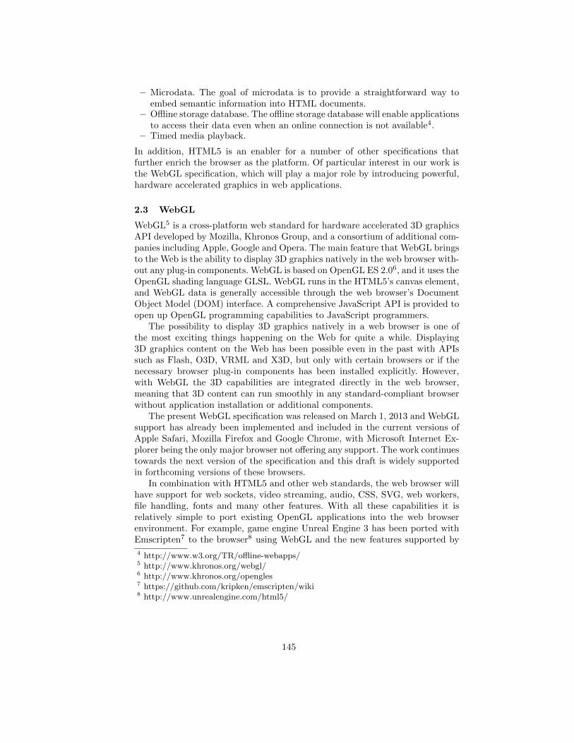
– Microdata. The goal of microdata is to provide a straightforward way toembed semantic information into HTML documents.
– Offline storage database. The offline storage database will enable applicationsto access their data even when an online connection is not available4.
– Timed media playback.
In addition, HTML5 is an enabler for a number of other specifications thatfurther enrich the browser as the platform. Of particular interest in our work isthe WebGL specification, which will play a major role by introducing powerful,hardware accelerated graphics in web applications.
2.3 WebGL
WebGL5 is a cross-platform web standard for hardware accelerated 3D graphicsAPI developed by Mozilla, Khronos Group, and a consortium of additional com-panies including Apple, Google and Opera. The main feature that WebGL bringsto the Web is the ability to display 3D graphics natively in the web browser with-out any plug-in components. WebGL is based on OpenGL ES 2.06, and it uses theOpenGL shading language GLSL. WebGL runs in the HTML5’s canvas element,and WebGL data is generally accessible through the web browser’s DocumentObject Model (DOM) interface. A comprehensive JavaScript API is provided toopen up OpenGL programming capabilities to JavaScript programmers.
The possibility to display 3D graphics natively in a web browser is one ofthe most exciting things happening on the Web for quite a while. Displaying3D graphics content on the Web has been possible even in the past with APIssuch as Flash, O3D, VRML and X3D, but only with certain browsers or if thenecessary browser plug-in components has been installed explicitly. However,with WebGL the 3D capabilities are integrated directly in the web browser,meaning that 3D content can run smoothly in any standard-compliant browserwithout application installation or additional components.
The present WebGL specification was released on March 1, 2013 and WebGLsupport has already been implemented and included in the current versions ofApple Safari, Mozilla Firefox and Google Chrome, with Microsoft Internet Ex-plorer being the only major browser not offering any support. The work continuestowards the next version of the specification and this draft is widely supportedin forthcoming versions of these browsers.
In combination with HTML5 and other web standards, the web browser willhave support for web sockets, video streaming, audio, CSS, SVG, web workers,file handling, fonts and many other features. With all these capabilities it isrelatively simple to port existing OpenGL applications into the web browserenvironment. For example, game engine Unreal Engine 3 has been ported withEmscripten7 to the browser8 using WebGL and the new features supported by
4 http://www.w3.org/TR/offline-webapps/5 http://www.khronos.org/webgl/6 http://www.khronos.org/opengles7 https://github.com/kripken/emscripten/wiki8 http://www.unrealengine.com/html5/
145
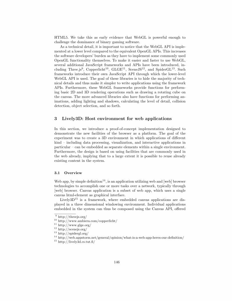
HTML5. We take this as early evidence that WebGL is powerful enough tochallenge the dominance of binary gaming software.
As a technical detail, it is important to notice that the WebGL API is imple-mented at a lower level compared to the equivalent OpenGL APIs. This increasesthe software developers’ burden as they have to implement some commonly usedOpenGL functionality themselves. To make it easier and faster to use WebGL,several additional JavaScript frameworks and APIs have been introduced, in-cluding Three.js9, Copperlicht10, GLGE11, SceneJS12, and SpiderGL13. Suchframeworks introduce their own JavaScript API through which the lower-levelWebGL API is used. The goal of these libraries is to hide the majority of tech-nical details and thus make it simpler to write applications using the frameworkAPIs. Furthermore, these WebGL frameworks provide functions for perform-ing basic 2D and 3D rendering operations such as drawing a rotating cube onthe canvas. The more advanced libraries also have functions for performing an-imations, adding lighting and shadows, calculating the level of detail, collisiondetection, object selection, and so forth.
3 Lively3D: Host environment for web applications
In this section, we introduce a proof-of-concept implementation designed todemonstrate the new facilities of the browser as a platform. The goal of theexperiment was to create a 3D environment in which applications of differentkind – including data processing, visualization, and interactive applications inparticular – can be embedded as separate elements within a single environment.Furthermore, the design is based on using facilities that are commonly used inthe web already, implying that to a large extent it is possible to reuse alreadyexisting content in the system.
3.1 Overview
Web app, by simple definition14, is an application utilizing web and [web] browsertechnologies to accomplish one or more tasks over a network, typically through[web] browser. Canvas application is a subset of web app, which uses a singlecanvas html-element as graphical interface.
Lively3D15 is a framework, where embedded canvas applications are dis-played in a three dimensional windowing environment. Individual applicationsembedded in the system can thus be composed using the Canvas API, offered
9 http://threejs.org/10 http://www.ambiera.com/copperlicht/11 http://www.glge.org/12 http://scenejs.org/13 http://spidergl.org/14 http://web.appstorm.net/general/opinion/what-is-a-web-app-heres-our-definition/15 http://lively3d.cs.tut.fi/
146
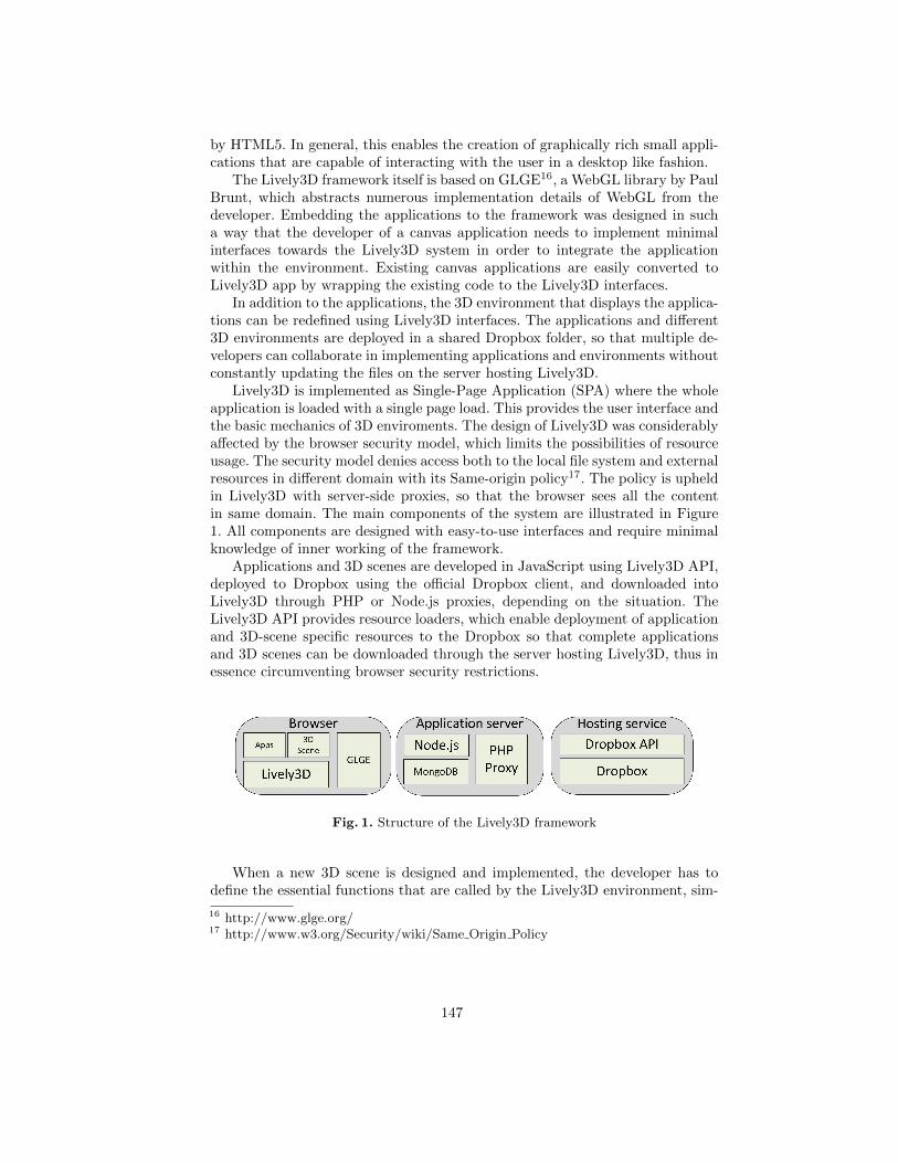
by HTML5. In general, this enables the creation of graphically rich small appli-cations that are capable of interacting with the user in a desktop like fashion.
The Lively3D framework itself is based on GLGE16, a WebGL library by PaulBrunt, which abstracts numerous implementation details of WebGL from thedeveloper. Embedding the applications to the framework was designed in sucha way that the developer of a canvas application needs to implement minimalinterfaces towards the Lively3D system in order to integrate the applicationwithin the environment. Existing canvas applications are easily converted toLively3D app by wrapping the existing code to the Lively3D interfaces.
In addition to the applications, the 3D environment that displays the applica-tions can be redefined using Lively3D interfaces. The applications and different3D environments are deployed in a shared Dropbox folder, so that multiple de-velopers can collaborate in implementing applications and environments withoutconstantly updating the files on the server hosting Lively3D.
Lively3D is implemented as Single-Page Application (SPA) where the wholeapplication is loaded with a single page load. This provides the user interface andthe basic mechanics of 3D enviroments. The design of Lively3D was considerablyaffected by the browser security model, which limits the possibilities of resourceusage. The security model denies access both to the local file system and externalresources in different domain with its Same-origin policy17. The policy is upheldin Lively3D with server-side proxies, so that the browser sees all the contentin same domain. The main components of the system are illustrated in Figure1. All components are designed with easy-to-use interfaces and require minimalknowledge of inner working of the framework.
Applications and 3D scenes are developed in JavaScript using Lively3D API,deployed to Dropbox using the official Dropbox client, and downloaded intoLively3D through PHP or Node.js proxies, depending on the situation. TheLively3D API provides resource loaders, which enable deployment of applicationand 3D-scene specific resources to the Dropbox so that complete applicationsand 3D scenes can be downloaded through the server hosting Lively3D, thus inessence circumventing browser security restrictions.
Fig. 1. Structure of the Lively3D framework
When a new 3D scene is designed and implemented, the developer has todefine the essential functions that are called by the Lively3D environment, sim-
16 http://www.glge.org/17 http://www.w3.org/Security/wiki/Same Origin Policy
147
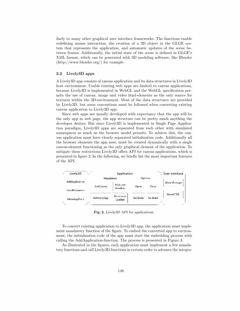
ilarly to many other graphical user interface frameworks. The functions enableredefining mouse interaction, the creation of a 3D object in the GLGE sys-tem that represents the application, and automatic updates of the scene be-tween frames. Additionally, the initial state of the scene is defined in GLGE’sXML format, which can be generated with 3D modeling software, like Blender(http://www.blender.org/) for example.
3.2 Lively3D apps
A Lively3D app consists of canvas application and its data structures in Lively3Dhost environment. Usable existing web apps are limited to canvas applications,because Lively3D is implemented in WebGL and the WebGL specification per-mits the use of canvas, image and video html-elements as the only source fortextures within the 3D-environment. Most of the data structures are providedby Lively3D, but some conventions must be followed when converting existingcanvas application to Lively3D app.
Since web apps are usually developed with expectancy that the app will bethe only app in web page, the app structure can be pretty much anything thedeveloper desires. But since Lively3D is implemented in Single Page Applica-tion paradigm, Lively3D apps are separated from each other with simulatednamespaces as much as the browser model permits. To achieve this, the can-vas application must have clearly separated initialization code. Additionally allthe browser elements the app uses, must be created dynamically with a singlecanvas-element functioning as the only graphical element of the application. Tomitigate these restrictions Lively3D offers API for canvas applications, which ispresented in figure 2. In the following, we briefly list the most important featuresof the API.
Fig. 2. Lively3D API for applications.
To convert existing application to Lively3D app, the application must imple-ment mandatory function of the figure. To embed the converted app to environ-ment, the initialization code of the app must start the embedding process withcalling the AddApplication-function. The process is presented in Figure 3.
As illustrated in the figures, each application must implement a few manda-tory functions and call Lively3D functions in certain order to advance the integra-
148
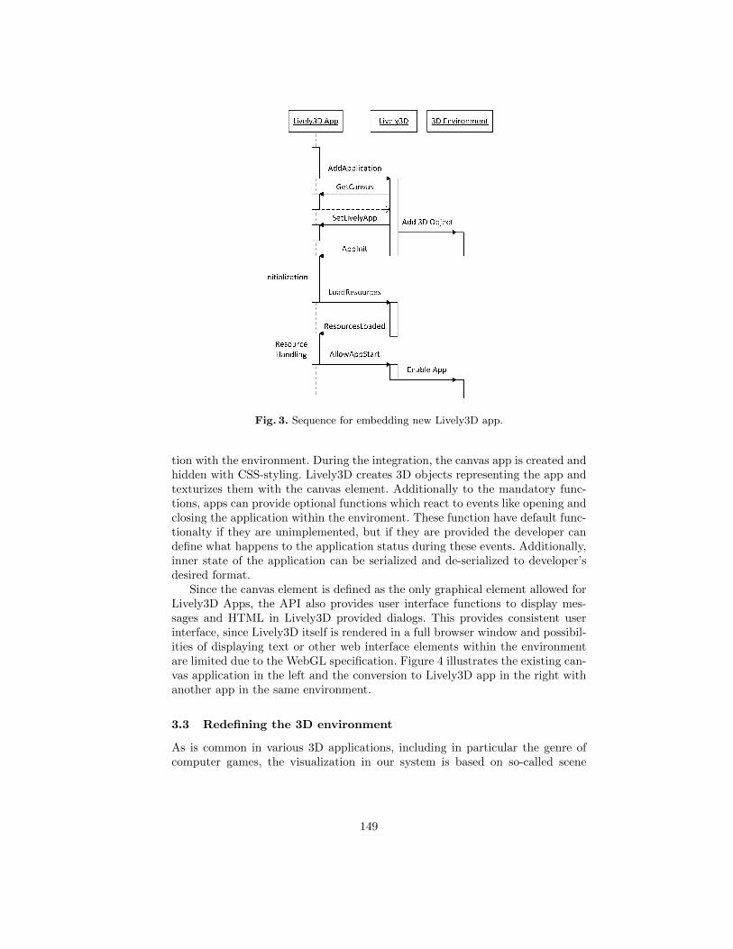
Fig. 3. Sequence for embedding new Lively3D app.
tion with the environment. During the integration, the canvas app is created andhidden with CSS-styling. Lively3D creates 3D objects representing the app andtexturizes them with the canvas element. Additionally to the mandatory func-tions, apps can provide optional functions which react to events like opening andclosing the application within the enviroment. These function have default func-tionalty if they are unimplemented, but if they are provided the developer candefine what happens to the application status during these events. Additionally,inner state of the application can be serialized and de-serialized to developer’sdesired format.
Since the canvas element is defined as the only graphical element allowed forLively3D Apps, the API also provides user interface functions to display mes-sages and HTML in Lively3D provided dialogs. This provides consistent userinterface, since Lively3D itself is rendered in a full browser window and possibil-ities of displaying text or other web interface elements within the environmentare limited due to the WebGL specification. Figure 4 illustrates the existing can-vas application in the left and the conversion to Lively3D app in the right withanother app in the same environment.
3.3 Redefining the 3D environment
As is common in various 3D applications, including in particular the genre ofcomputer games, the visualization in our system is based on so-called scene
149
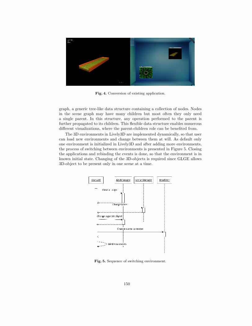
Fig. 4. Conversion of existing application.
graph, a generic tree-like data structure containing a collection of nodes. Nodesin the scene graph may have many children but most often they only needa single parent. In this structure, any operation performed to the parent isfurther propagated to its children. This flexible data structure enables numerousdifferent visualizations, where the parent-children role can be benefited from.
The 3D environments in Lively3D are implemented dynamically, so that usercan load new environments and change between them at will. As default onlyone environment is initialized in Lively3D and after adding more environments,the process of switching between environments is presented in Figure 5. Closingthe applications and rebinding the events is done, so that the environment is inknown initial state. Changing of the 3D-objects is required since GLGE allows3D-object to be present only in one scene at a time.
Fig. 5. Sequence of switching environment.
150
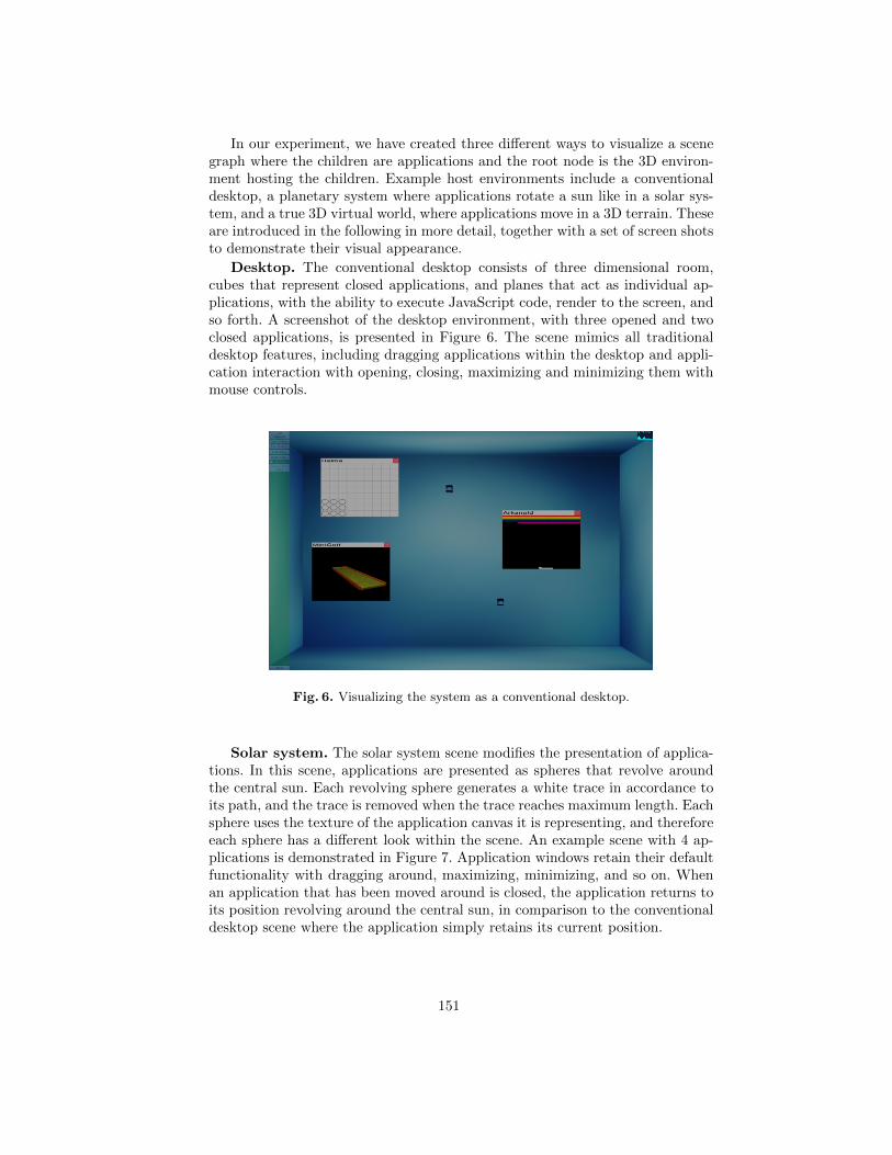
In our experiment, we have created three different ways to visualize a scenegraph where the children are applications and the root node is the 3D environ-ment hosting the children. Example host environments include a conventionaldesktop, a planetary system where applications rotate a sun like in a solar sys-tem, and a true 3D virtual world, where applications move in a 3D terrain. Theseare introduced in the following in more detail, together with a set of screen shotsto demonstrate their visual appearance.
Desktop. The conventional desktop consists of three dimensional room,cubes that represent closed applications, and planes that act as individual ap-plications, with the ability to execute JavaScript code, render to the screen, andso forth. A screenshot of the desktop environment, with three opened and twoclosed applications, is presented in Figure 6. The scene mimics all traditionaldesktop features, including dragging applications within the desktop and appli-cation interaction with opening, closing, maximizing and minimizing them withmouse controls.
Fig. 6. Visualizing the system as a conventional desktop.
Solar system. The solar system scene modifies the presentation of applica-tions. In this scene, applications are presented as spheres that revolve aroundthe central sun. Each revolving sphere generates a white trace in accordance toits path, and the trace is removed when the trace reaches maximum length. Eachsphere uses the texture of the application canvas it is representing, and thereforeeach sphere has a different look within the scene. An example scene with 4 ap-plications is demonstrated in Figure 7. Application windows retain their defaultfunctionality with dragging around, maximizing, minimizing, and so on. Whenan application that has been moved around is closed, the application returns toits position revolving around the central sun, in comparison to the conventionaldesktop scene where the application simply retains its current position.
151
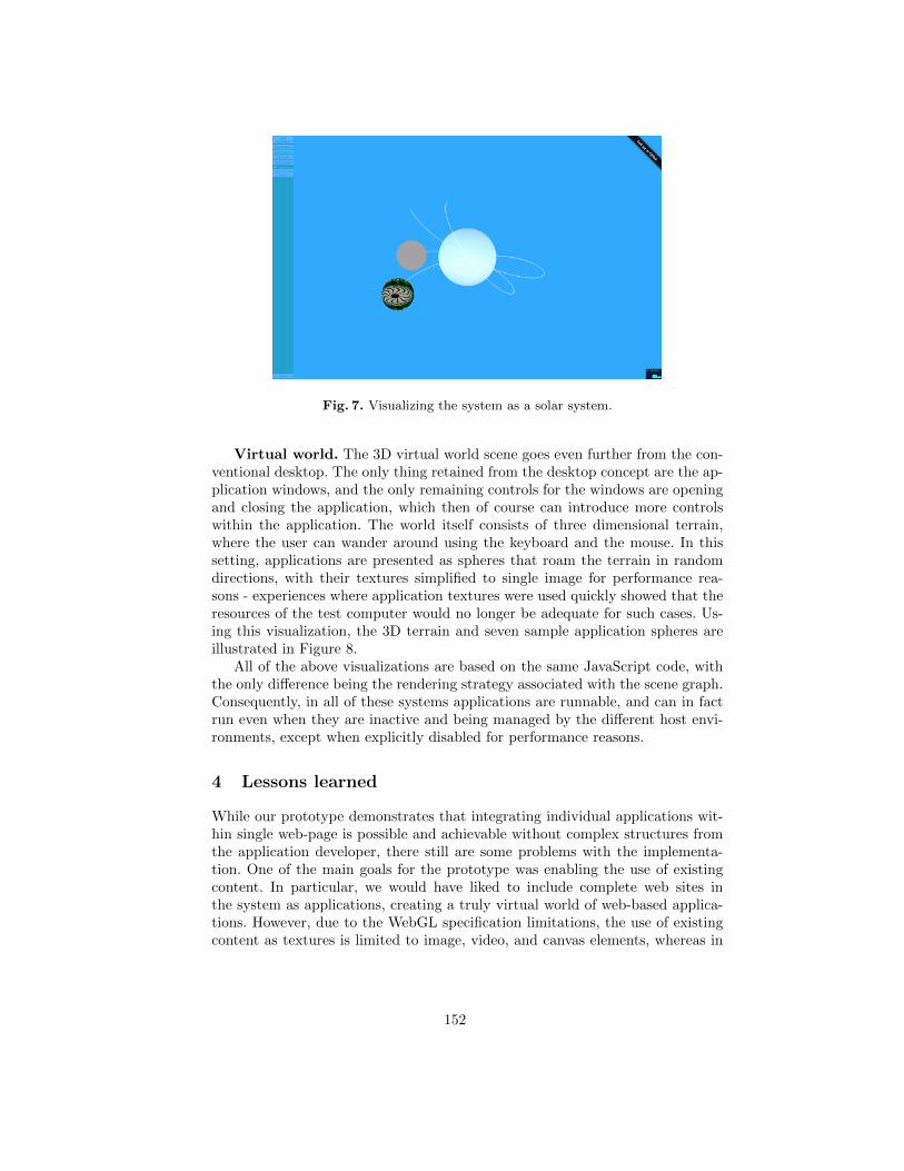
Fig. 7. Visualizing the system as a solar system.
Virtual world. The 3D virtual world scene goes even further from the con-ventional desktop. The only thing retained from the desktop concept are the ap-plication windows, and the only remaining controls for the windows are openingand closing the application, which then of course can introduce more controlswithin the application. The world itself consists of three dimensional terrain,where the user can wander around using the keyboard and the mouse. In thissetting, applications are presented as spheres that roam the terrain in randomdirections, with their textures simplified to single image for performance rea-sons - experiences where application textures were used quickly showed that theresources of the test computer would no longer be adequate for such cases. Us-ing this visualization, the 3D terrain and seven sample application spheres areillustrated in Figure 8.
All of the above visualizations are based on the same JavaScript code, withthe only difference being the rendering strategy associated with the scene graph.Consequently, in all of these systems applications are runnable, and can in factrun even when they are inactive and being managed by the different host envi-ronments, except when explicitly disabled for performance reasons.
4 Lessons learned
While our prototype demonstrates that integrating individual applications wit-hin single web-page is possible and achievable without complex structures fromthe application developer, there still are some problems with the implementa-tion. One of the main goals for the prototype was enabling the use of existingcontent. In particular, we would have liked to include complete web sites inthe system as applications, creating a truly virtual world of web-based applica-tions. However, due to the WebGL specification limitations, the use of existingcontent as textures is limited to image, video, and canvas elements, whereas in
152
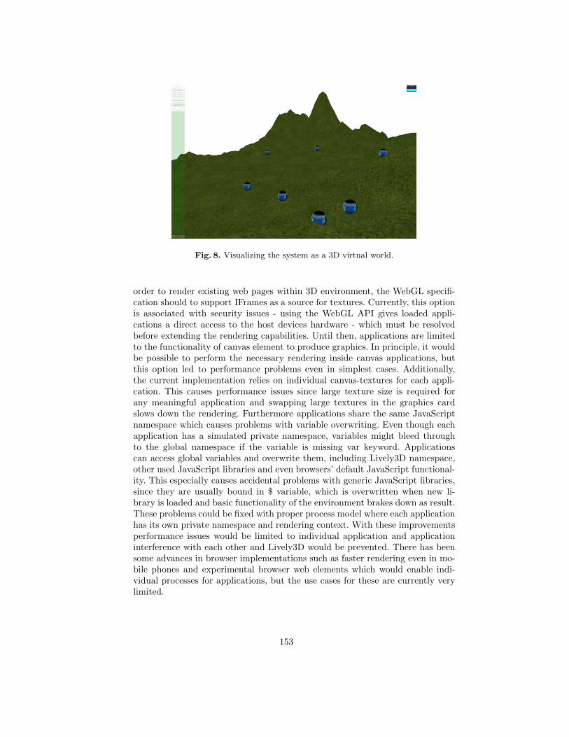
Fig. 8. Visualizing the system as a 3D virtual world.
order to render existing web pages within 3D environment, the WebGL specifi-cation should to support IFrames as a source for textures. Currently, this optionis associated with security issues - using the WebGL API gives loaded appli-cations a direct access to the host devices hardware - which must be resolvedbefore extending the rendering capabilities. Until then, applications are limitedto the functionality of canvas element to produce graphics. In principle, it wouldbe possible to perform the necessary rendering inside canvas applications, butthis option led to performance problems even in simplest cases. Additionally,the current implementation relies on individual canvas-textures for each appli-cation. This causes performance issues since large texture size is required forany meaningful application and swapping large textures in the graphics cardslows down the rendering. Furthermore applications share the same JavaScriptnamespace which causes problems with variable overwriting. Even though eachapplication has a simulated private namespace, variables might bleed throughto the global namespace if the variable is missing var keyword. Applicationscan access global variables and overwrite them, including Lively3D namespace,other used JavaScript libraries and even browsers’ default JavaScript functional-ity. This especially causes accidental problems with generic JavaScript libraries,since they are usually bound in $ variable, which is overwritten when new li-brary is loaded and basic functionality of the environment brakes down as result.These problems could be fixed with proper process model where each applicationhas its own private namespace and rendering context. With these improvementsperformance issues would be limited to individual application and applicationinterference with each other and Lively3D would be prevented. There has beensome advances in browser implementations such as faster rendering even in mo-bile phones and experimental browser web elements which would enable indi-vidual processes for applications, but the use cases for these are currently verylimited.
153
One of the goals of Lively3D was minimal overhead code while embeddingexisting applications. We consider that this requirement was achieved quite well,although comprehensive analysis between converted applications is useless sinceamount of overhead code depends on coding conventions. In Lively3D most ofthe application initialization must be done dynamically in JavaScript code, asopposed to convential browser where HTML-tags can handle some of the resourcedownloading. The minimal overhead code amounts to about 50 lines of extracode, which is quite well for the goal.
In the course of the design, we were alarmed by the fact that the circumven-tion of security restrictions became one of the key design drivers in the experi-ment. In this field, the problems arise from the combination of the current ”onesize fits all” browser security model and the general document-oriented natureof the web browser. Decisions about security are determined primarily by thesite (origin) from which the web document is loaded, not by the specific needs ofthe document or application. Such problems could be alleviated by introducinga more fine-grained security model, e.g., a model similar to the comprehensivesecurity model of the Java SE platform [2] or the more lightweight, permission-based, certificate-based security model introduced by the MIDP 2.0 Specificationfor the Java Platform, Micro Edition (Java ME) [3]. As already pointed out in[4], the biggest challenges in this area are related to standardization, as it isdifficult to define a security solution that would be satisfactory to everybodywhile retaining backwards compatibility. Also, any security model that dependson application signing and/or security certificates involves complicated businessissues, e.g., related to who has the authority to issue security certificates, whichfurther contribute complications. Therefore, it is likely that any resolutions inthis area will still take years. Meanwhile, a large number of security groups andcommunities, including the Open Web Application Security Project (OWASP),the Web Application Security Consortium (WASC), and the W3C Web SecurityContext Working Group, are working on the problem.
Finally, there are numerous new methodological issues associated with thetransition. The transition from conventional applications to web applications willresult in a shift away from static programming languages such as C, C++ or C#towards dynamic programming languages. Since mainstream software developersare often unaware of the fundamental development style differences betweenstatic and dynamic programming languages, they need to be educated about theevolutionary, exploratory programming style associated with dynamic languages.Furthermore, techniques associated with dealing with big data - datasets thatare too large to work with using on-hand database management tools - datamining, and mashup development will be increasingly important.
5 Conclusions
Considering the humble beginnings of the web browser as a simple documentviewing and distribution environment, and the fact that programmatic capabil-ities on the Web were largely an afterthought rather than a carefully designed
154
feature, the transformation of the Web into an extremely popular software de-ployment platform is amazing. This transformation is one of the most profoundchanges in the modern history of computing and software engineering. In thispaper, we are demonstrating the effect of new ways to visualize content in a fash-ion where the browser’s new extensions are based on new web protocols ratherthan plugins, which has been the traditional way to create richer media insidethe browser. Since no plugins that commonly introduce restrictions associatedwith their proprietary origins, the new technologies are manifesting the open weband open data. This, together with open data that is be available to everyoneto freely use and republish as they wish without mechanisms of control, in turnliberates the developers to create increasingly compelling applications, buildingon the facilities that already exist in the web as well as their own innovativeideas.
References
1. Anttonen, M., Salminen, A., Mikkonen, and Taivalsaari, A. Transforming the webinto a real application platform: New technologies, emerging trends, and miss-ing pieces. In Proceedings of the 26th ACM Symposium on Applied Computing(SAC’2011, TaiChung, Taiwan, March 21-25, 2011), ACM Press, Proceedings Vol1, pp.800-807.
2. Gong, L., Ellison, G., Dageforde, M., Inside Java 2 Platform Security: Architecture,API Design, and Implementation, 2nd Edition. Addison-Wesley (Java Series), 2003.
3. Riggs, R., Taivalsaari, A., Van Peursem, J., Huopaniemi, J., Patel, M., Uotila, A.,Programming Wireless Devices with the Java 2 Platform, Micro Edition (2nd Edi-tion). Addison-Wesley (Java Series), 2003.
4. Taivalsaari, A., Mikkonen, T., Ingalls, D., and Palacz, K. Web browser as an applica-tion platform. 293-302, Proceedings of the 34th EuroMicro Conference on SoftwareEngineering and Advanced Applications, IEEE Computer Society, 2008.
5. Taivalsaari, A., Mikkonen, T., Anttonen, M., Salminen, A. The death of binarysoftware: End user software moves to the web. In Proceedings of the 9th Interna-tional Conference on Creating, Connecting and Collaborating through Computing(C5’2011, Kyoto, Japan, January 18-20, 2011), IEEE Computer Society, pp.17-23.
155
Random number generator
for C++ template metaprograms?
Zalán Sz¶gyi, Tamás Cséri, and Zoltán Porkoláb
Department of Programming Languages and Compilers, Eötvös Loránd UniversityPázmány Péter sétány 1/C H-1117 Budapest, Hungary
{lupin, cseri, gsd}@caesar.elte.hu
Abstract. Template metaprogramming is a widely used programmingparadigm to develop libraries in C++. With the help of cleverly de�nedtemplates the programmer can execute algorithms at compilation time.C++ template metaprograms are proven to be Turing-complete, thuswide scale of algorithms can be executed in compilation time. Applyingrandomized algorithms and data structures is, however, troublesome dueto the deterministic nature of template metaprograms. In this paper wedescribe a C++ template metaprogram library that generates pseudoran-dom numbers at compile time. Random number engines are responsibleto generate pseudorandom integer sequences with a uniform distribution.Random number distributions transform the generated pseudorandomnumbers into di�erent statistical distributions. Our goal was to providesimilar functionality to the run-time random generator module of theStandard Template Library, thus programmers familiar with STL caneasily adopt our library.
1 Introduction
Template metaprogramming is a modern, still developing programming paradigmin C++. It utilizes the instantiation technique of the C++ templates and makesthe C++ compiler execute algorithms in compilation time. Template metapro-grams were proven to be a Turing-complete sublanguage of C++ [4], whichmeans that a wide set of algorithms can be executed at compile time within thelimits of the C++ compiler resources.
We write template metaprograms for various reasons, like expression tem-
plates [23] replacing runtime computations with compile-time activities to en-hance runtime performance, static interface checking, which increases the abilityof the compile-time to check the requirements against template parameters, i.e.they form constraints on template parameters [11,19], active libraries [24], actingdynamically during compile-time, making decisions based on programming con-texts and making optimizations. The Ararat system [5], boost::xpressive[13], andboost::proto[14] libraries provide metaprogramming solutions to embed DSLs intoC++. Another approach to embed DSLs is to reimplement the Haskell's parsergenerators library with C++ template metaprograms [17].
? The project was supported by Ericsson Hungary.
156
Boost metaprogram library (MPL) [6] provides basic containers, algorithmsand iterators to help in basic programmer tasks, similarly to their runtime cor-respondents in the Standard Template Library (STL). Fundamental types, likestring are also exists in MPL, and can be extended with more complex function-ality [22]. Since C++ template metaprograms follow the functional paradigma,non-STL-like approaches exists in metaprogram development too: functional pro-gramming idioms, like nested lambda and let expressions are also introduced inpaper [20].
Not only libraries, but C++11, the new standard of the C++ programminglanguage also supports template metaprogramming. There are new keywords andlanguage structures such as constant expressions, decltype, variadic templates
which makes writing metaprograms easier.
It is common in all the methods, techniques and libraries we discussed thatC++ template metaprograms are inheritably deterministic. Algorithms, datatypes are fully speci�ed by the source code and do not depend on any kind ofexternal input. This means that the same metaprogram will always be executedthe same way and will produce the same results (generated code, data types,compiler warnings, etc.) every time.
Therefore, it is very di�cult to implement randomized algorithms and datastructures with C++ template metaprograms, due to the deterministic behaviordescribed above. Nevertheless, undeterministic algorithms and data structuresare important in a certain class of tasks as they are often simpler, and moree�cient than their deterministic correspondents.
Finding a minimal cut on an undirected graph is a fundamental algorithmin network theory for partitioning elements in a database, or identifying clustersof related documents. The deterministic algorithm is very complex and di�cult[9], a much smaller and easier algorithm can be written using random choice [8].A skip list [18] is an alternative to search trees. The rotation methods in searchtrees are algorithmically complex. Based on random numbers, skip list providessimpler way to reorganize the data structure, which is essential in templatemetaprograms due to their complex syntax and burdensome debug possibilities.Algorithms that selects pivot elements to partition their input sequence such asthe quick sort algorithm and the similar kth minimal element selection algorithmprovides better worst case scenarios if we select the pivot element randomly.
In this paper we describe our C++ template metaprogram library that gen-erates pseudorandom numbers at compile time. Random number engines areresponsible to generate pseudorandom integer sequences with a uniform distri-bution. Random number distributions transform the generated pseudorandomnumbers into di�erent statistical distributions. Engines and distributions can beused together to generate random values. The engines are created using userde�ned seeds, allowing to generate repeatable random number sequences.
Our goal was to design our library similar to the runtime random libraryprovided by the STL. Thus a programmer familiar with the STL can easilyadopt our library to their metaprograms.
157
Our paper organizes as follows: In Section 2 we discuss those C++ tem-plate metaprogramming constructs which form the implementation base of ourlibrary. Section 3 introduces our compile time random number generator librarywith implementational details. In Section 4 we show how our library can beapplied for real life problems and we evaluate the results. Section 5 mentions aproject related to code obfuscation using some randomization in C++ templatemetaprograms. Future works are discussed in Section 6. Our paper concludes inSection 7.
2 Template metaprogramming
The template facilities of C++ allow writing algorithms and data structuresparametrized by types. This abstraction is useful for designing general algorithmslike �nding an element in a list. The operations on lists of integers, characters oreven user de�ned classes are essentially the same. The only di�erence betweenthem is the stored type. With templates we can parametrize these list operationsby abstract type, thus, we need to write the abstract algorithm only once. Thecompiler will generate the integer, double, character or user de�ned class versionof the list by replacing the abstract type with a concrete one. This method iscalled instantiation.
The template mechanism of C++ enables the de�nition of partial and fullspecializations. Let us suppose that we would like to create a more space e�cienttype-speci�c implementation of the list template for bool type. We may de�nethe following specialization:
template<typename T>
struct list
{
void insert(const T& e);
/* ... */
};
template<>
struct list<bool>
{
//type-specific implementation
void insert(bool e);
/* ... */
};
Programs that are evaluated at compilation time are called metaprograms.C++ supports metaprogramming via preprocessor macros and templates. Pre-processor macros run before the C++ compilation and therefore they are un-aware of the C++ language semantics. However, template metaprograms areevaluated during the C++ compilation phase, therefore the type safety of thelanguage is enforced.
158
Template specialization is essential practice for template metaprogramming[1]. In template metaprograms templates usually refer to themselves with di�er-ent type arguments. Such chains of recursive instantiations can be terminated bya template specialization. See the following example of calculating the factorialvalue of 5:
template<int N>
struct factorial
{
enum { value = N * factorial<N-1>::value };
};
template<>
struct factorial<0>
{
enum { value = 1 };
};
int main()
{
int result = factorial<5>::value;
}
To initialize the variable result, the expression factorial<5>::value has tobe evaluated. As the template argument is not zero, the compiler instantiates thegeneral version of the factorial template with 5. The de�nition of value is N *
factorial<N-1>::value, hence the compiler has to instantiate the factorial
again with 4. This chain continues until the concrete value becomes 0. Then, thecompiler choses the special version of factorial where the value is 1. Thus,the instantiation chain is stopped and the factorial of 5 is calculated and usedas initial value of the result variable in main. This metaprogram �runs" whilethe compiler compiles the code.
Template metaprograms therefore consist of a collection of templates, theirinstantiations and specializations, and perform operations at compilation time.Basic control structures like iterations and conditions are represented in a func-tional way [21]. As we can see in the previous example, iterations in metapro-grams are applied by recursion. Besides, the condition is implemented by a tem-plate structure and its specialization.
template<bool cond_, typename then_, typename else_>
struct if_
{
typedef then_ type;
};
template<typename then_, typename else_>
159
struct if_<false, then_, else_>
{
typedef else_ type;
};
The if_ structure has three template arguments: a boolean and two abstracttypes. If the cond_ is false, then the partly-specialized version of if_ will beinstantiated, thus the type will be bound by the else_. Otherwise the generalversion of if_ will be instantiated and type will be bound by then_.
Complex data structures are also available for metaprograms. Recursive tem-plates store information in various forms, most frequently as tree structures, orsequences. Tree structures are the most common forms of implementation of ex-pression templates [23]. The canonical examples for sequential data structuresare Typelist [2] and the elements of the boost::mpl library [6].
We de�ne a type list with the following recursive template:
class NullType {};
struct EmptyType {}; // could be instantiated
template <typename H, typename T>
struct Typelist
{
typedef H head;
typedef T tail;
};
typedef Typelist< char, Typelist<signed char,
Typelist<unsigned char, NullType> > > Charlist;
In the example we store the three character types in our Typelist. We can usehelper macro de�nitions to make the syntax more readable.
#define TYPELIST_1(x) Typelist< x, NullType>
#define TYPELIST_2(x, y) Typelist< x, TYPELIST_1(y)>
#define TYPELIST_3(x, y, z) Typelist< x, TYPELIST_2(y,z)>
// ...
typedef TYPELIST_3(char, signed char, unsigned char) Charlist;
Essential helper functions � like Length, which computes the size of a list atcompilation time � have been de�ned in Alexandrescu's Loki library[2] in purefunctional programming style. Similar data structures and algorithms can befound in the boost::mpl metaprogramming library. The Boost Metaprogram-ming Library [6] is a general-purpose, high-level C++ template metaprogram-ming framework of algorithms, sequences and metafunctions. The architectureis similar to the Standard Template Library (STL) of C++ with containers, al-gorithms and iterators but boost::mpl o�ers this functionality in compilationtime.
160
3 Compile-time random number generation
Our random number generator library for template metaprograms is designed tobe similar to the runtime random number library provided by Standard TemplateLibrary (STL) of the new standard of C++. Our library provides:
� random number engines, that generate pseudorandom integer sequences withuniform distribution.
� random number distributions, that transform the output of the random num-ber engines into di�erent statistical distributions.
Engines and distributions can be used together to generate random values. Theengines are created using user de�ned seeds, allowing to generate repeatablerandom number sequences.
3.1 Basic metafunctions
Before we detail our engines and distributions, we present some basic metafunc-tions which are commonly used in our implementation. The Randommetafunctioninitializes a random engine or distribution, and returns with the �rst randomnumber in a sequence. See the code below:
template<typename Engine>
struct Random
{
typedef typename init<Engine>::type type;
static const decltype(type::value) value = type::value;
};
The initialization is done by the init metafunction, which is partially spe-cialized for all engines and distributions. The �rst random number is stored instatic �eld value.
The Next metafunction computes the next random number in a sequence.See its code below:
template<typename R>
struct Next
{
typedef typename eval<R>::type type;
static const decltype(type::value) value = type::value;
};
The next element is computed by the eval metafunction, which is, similarlyto init, partially specialized for all engines and distributions. The return valueof this metafunction is stored in static �eld value.
161
3.2 Random number engines
Similarly to STL, we implemented three random number engines:
� linear congruential engine [15], which requires very small space to store itsstate, and moderately fast.
� subtract with carry engine [3], which produces a better random sequence,very fast, but requires more state storage.
� Mersenne twister engine [10], which is slower and has even more state stor-age requirements but with the right parameters provides the longest non-repeating sequence of random numbers.
The implementation of these engines contain three major entities. The �rstone is a metatype, that contains the state of the engine. This metatype is theargument of the partially specialized init and eval metafunctions, which dosome initialization steps and evaluate the next random number, respectively.For the linear congruential engine, these entities de�ned as below:
template<typename UIntType,
UIntType seed = defaultseed,
UIntType a = 16807,
UIntType c = 0,
UIntType m = 2147483647>
struct linear_congruential_engine
{
static const UIntType value = seed;
static const UIntType maxvalue = m-1;
};
The �rst template argument speci�es the type of the random numbers. Thetype can be any unsigned integer type. The second argument is the randomseed. This is an optional parameter. If the programmer does not specify it,an automatically generated random seed is applied for each compilation. SeeSubsection 3.4 for more details. The other arguments are parameters of thelinear congruential equation.
The init and eval metafunctions can be seen below:
template<typename UIntType,
UIntType seed,
UIntType a,
UIntType c,
UIntType m>
struct init<linear_congruential_engine<UIntType, seed, a, c, m>>
{
typedef typename eval<linear_congruential_engine<
UIntType,seed,a,c,m>>::type type;
static const UIntType value = type::value;
};
162
template<typename UIntType, UIntType seed,
UIntType a, UIntType c, UIntType m>
struct eval<linear_congruential_engine<UIntType, seed, a, c, m>>
{
static const UIntType value = (a * seed + c) % m;
typedef linear_congruential_engine<
UIntType,
(a * seed + c) % m,
a,
c,
m
> type;
};
The metafunction eval computes the next random number, stores it in thestatic �eld value and modi�es the state of the linear congruential engine. Meta-function init just invokes eval to compute the �rst random number.
3.3 Random number distributions
A random number distribution transforms the uniformly distributed output of arandom number engine into a speci�c statistical distribution. Although the STLde�nes discrete and continuous distributions, we implement only the discreteones in our library, because of the lack of support of �oating point numbers inthe template facility of C++. However, we plan to extend the template systemwith rational and �oating point number types that we can use to implementcontinuous distributions. Our library implements the following discrete prob-ability distributions: uniform integer distribution, Bernoulli-distribution, bino-mial distribution, negative binomial distribution, geometric distribution, Poisson-distribution, discrete distribution [7]. Several distributions require a real numberas argument. As the template system in C++ does not accept �oating pointnumbers, our library deals with these parameters as rational numbers: receivesthe numerator and the denominator as integers. The compiler can approximatethe quotient inside the metafunctions. See the implementation of Bernoulli dis-tribution below:
template<typename Engine, int N, int D, bool val = false>
struct Bernoulli
{
static const bool value = val;
};
template<typename Engine, int N, int D, bool b>
struct eval<Bernoulli<Engine, N, D, b>>
{
163
typedef typename Next<Engine>::type tmptype;
static const bool value =
(static_cast<double>(tmptype::value) / tmptype::maxvalue)
<
(static_cast<double>(N) / D);
typedef Bernoulli<tmptype, N, D, value> type;
};
The template parameter Engine refers to any kind of random number en-gine. The integers N and D represent the parameter of Bernoulli distributions,and val stores the computed result. The partially specialized eval metafunctiontransforms the result of the engine to a boolean value according to the param-eter and sets the new state of the Bernoulli class. The other distributions areimplemented in similar way.
3.4 Random seed
Pseudorandom number generators require an initial state, called random seed.The random seed determines the generated random sequence. The random num-ber engines in our library optionally accept seed. Specifying the seed results inreproducible sequences of random numbers. However, if the seed is omitted, thelibrary will generate a random seed based on the current time of the system. Thetime is received using the __TIME__macro, which is preprocessed to a constexprcharacter array. Our library will compute a seed using the elements of this array.See the code below:
constexpr char inits[] = __TIME__;
const int defaultseed = (inits[0]-'0')*100000+(inits[1]-'0')*10000 +
(inits[3]-'0')*1000+(inits[4]-'0')*100+
(inits[6]-'0')*10+inits[7]-'0';
The C++ standard de�nes that the preprocessor of C++ should translate the__TIME__ macro to a character string literal in �hh:mm:ss� form. We transformit into a six-digit integer, excluding the colons.
3.5 Example
In this subsection we show a basic usage of our library. We print ten booleanvalues having Bernoulli distribution with parameter 0.1. We use the linear con-
gruential engine to generate the random sequence.
164
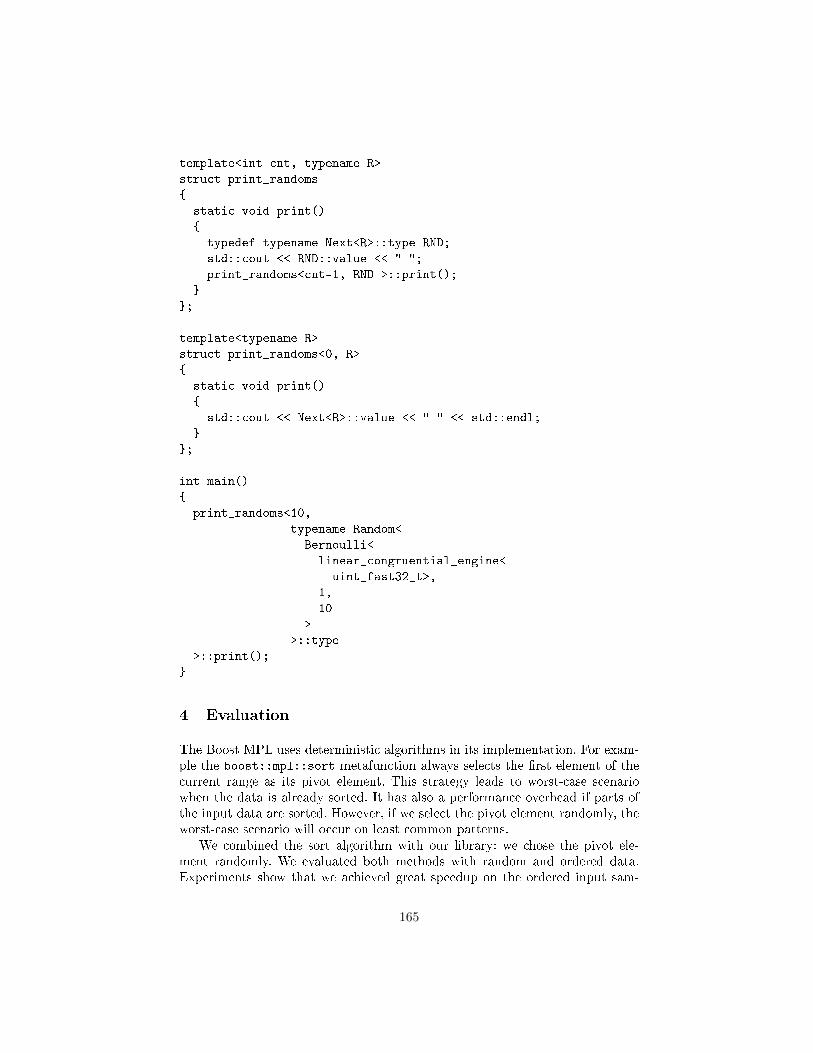
template<int cnt, typename R>
struct print_randoms
{
static void print()
{
typedef typename Next<R>::type RND;
std::cout << RND::value << " ";
print_randoms<cnt-1, RND >::print();
}
};
template<typename R>
struct print_randoms<0, R>
{
static void print()
{
std::cout << Next<R>::value << " " << std::endl;
}
};
int main()
{
print_randoms<10,
typename Random<
Bernoulli<
linear_congruential_engine<
uint_fast32_t>,
1,
10
>
>::type
>::print();
}
4 Evaluation
The Boost MPL uses deterministic algorithms in its implementation. For exam-ple the boost::mpl::sort metafunction always selects the �rst element of thecurrent range as its pivot element. This strategy leads to worst-case scenariowhen the data is already sorted. It has also a performance overhead if parts ofthe input data are sorted. However, if we select the pivot element randomly, theworst-case scenario will occur on least common patterns.
We combined the sort algorithm with our library: we chose the pivot ele-ment randomly. We evaluated both methods with random and ordered data.Experiments show that we achieved great speedup on the ordered input sam-
165
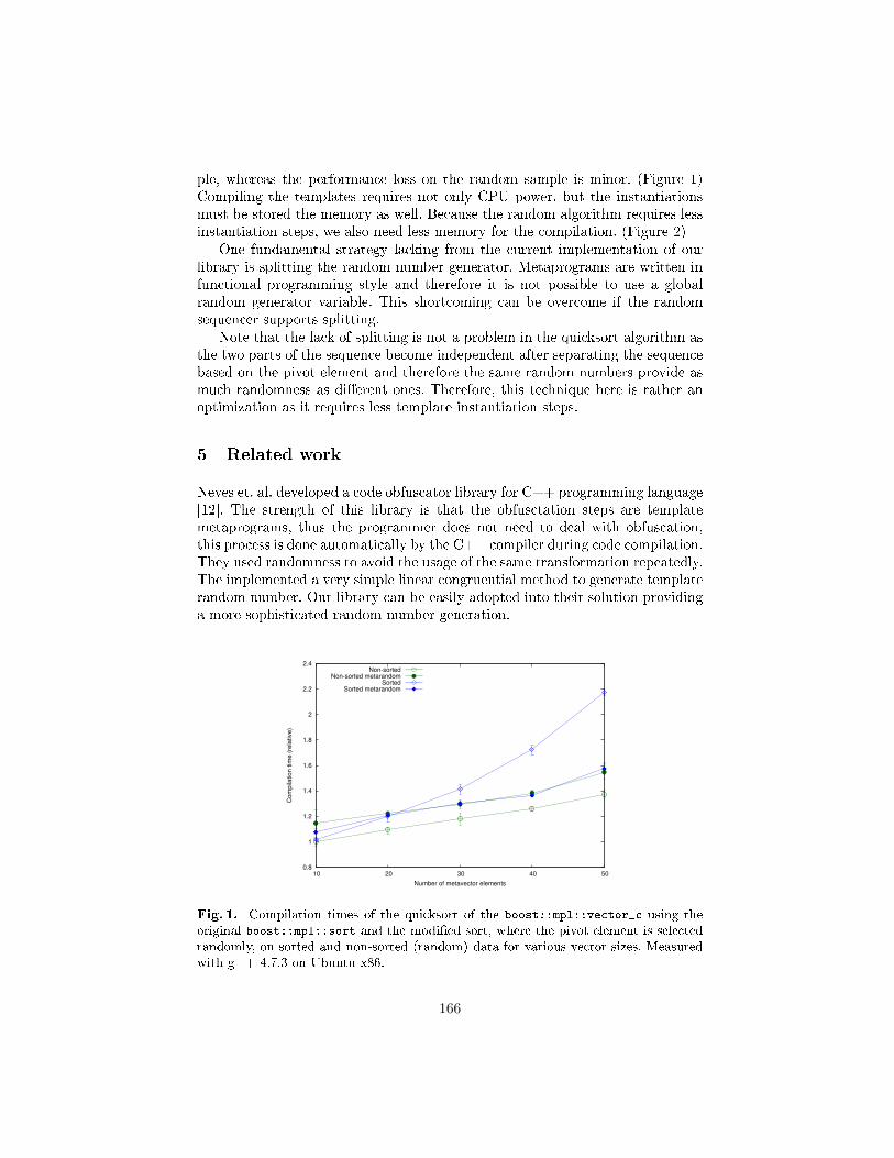
ple, whereas the performance loss on the random sample is minor. (Figure 1)Compiling the templates requires not only CPU power, but the instantiationsmust be stored the memory as well. Because the random algorithm requires lessinstantiation steps, we also need less memory for the compilation. (Figure 2)
One fundamental strategy lacking from the current implementation of ourlibrary is splitting the random number generator. Metaprograms are written infunctional programming style and therefore it is not possible to use a globalrandom generator variable. This shortcoming can be overcome if the randomsequencer supports splitting.
Note that the lack of splitting is not a problem in the quicksort algorithm asthe two parts of the sequence become independent after separating the sequencebased on the pivot element and therefore the same random numbers provide asmuch randomness as di�erent ones. Therefore, this technique here is rather anoptimization as it requires less template instantiation steps.
5 Related work
Neves et. al. developed a code obfuscator library for C++ programming language[12]. The strength of this library is that the obfusctation steps are templatemetaprograms, thus the programmer does not need to deal with obfuscation,this process is done automatically by the C++ compiler during code compilation.They used randomness to avoid the usage of the same transformation repeatedly.The implemented a very simple linear congruential method to generate templaterandom number. Our library can be easily adopted into their solution providinga more sophisticated random number generation.
0.8
1
1.2
1.4
1.6
1.8
2
2.2
2.4
10 20 30 40 50
Com
pila
tion tim
e (
rela
tive)
Number of metavector elements
Non-sortedNon-sorted metarandom
SortedSorted metarandom
Fig. 1. Compilation times of the quicksort of the boost::mpl::vector_c using theoriginal boost::mpl::sort and the modi�ed sort, where the pivot element is selectedrandomly, on sorted and non-sorted (random) data for various vector sizes. Measuredwith g++ 4.7.3 on Ubuntu x86.
166
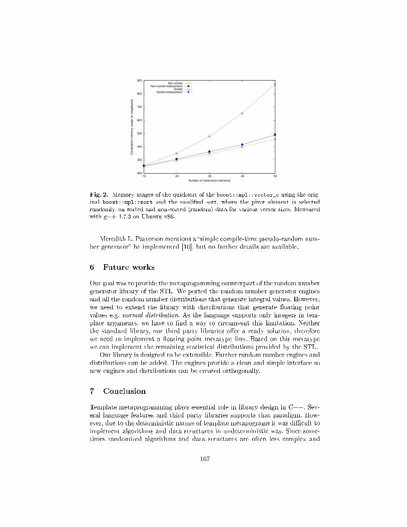
200
300
400
500
600
700
800
900
10 20 30 40 50
Com
pila
tion m
em
ory
usage (
in m
egabyte
s)
Number of metavector elements
Non-sortedNon-sorted metarandom
SortedSorted metarandom
Fig. 2. Memory usages of the quicksort of the boost::mpl::vector_c using the orig-inal boost::mpl::sort and the modi�ed sort, where the pivot element is selectedrandomly, on sorted and non-sorted (random) data for various vector sizes. Measuredwith g++ 4.7.3 on Ubuntu x86.
Meredith L. Patterson mentions a �simple compile-time pseudo-random num-ber generator� he implemented [16], but no further details are available.
6 Future works
Our goal was to provide the metaprogamming counterpart of the random numbergenerator library of the STL. We ported the random number generator enginesand all the random number distributions that generate integral values. However,we need to extend the library with distributions that generate �oating pointvalues e.g. normal distribution. As the language supports only integers in tem-plate arguments, we have to �nd a way to circumvent this limitation. Neitherthe standard library, nor third party libraries o�er a ready solution, thereforewe need to implement a �oating point metatype �rst. Based on this metatypewe can implement the remaining statistical distributions provided by the STL.
Our library is designed to be extensible. Further random number engines anddistributions can be added. The engines provide a clean and simple interface sonew engines and distributions can be created orthogonally.
7 Conclusion
Template metaprogramming plays essential role in library design in C++. Sev-eral language features and third party libraries supports that paradigm. How-ever, due to the deterministic nature of template metapograms it was di�cult toimplement algorithms and data structures in undeterministic way. Since some-times randomized algorithms and data structures are often less complex and
167
more e�cient than their deterministic correspondents, it is important to gener-ate (pseudo-)random numbers in a maintainable and e�ective way for templatemetaprograms.
We implemented random number engines that generate pseudorandom inte-ger sequences with a uniform distribution and random number distributions thattransform the generated pseudo-numbers into di�erent statistical distributions.The library has a similar, but compile-time interface like the run-time randomnumber generator of the STL to reduce the learning curve.
In this paper we presented our library and discussed its applicability withan example using boost::mpl. Besides, our library is designed to be extensible,thus one can easily add further engines and distributions to our library.
References
1. Abrahams, D., Gurtovoy, A.: C++ Template Metaprogramming: Concepts, Tools,and Techniques from Boost and Beyond (C++ in Depth Series). Addison-WesleyProfessional (2004)
2. Alexandrescu, A.: Modern C++ design: generic programming and design patternsapplied. Addison-Wesley Longman Publishing Co., Inc., Boston, MA, USA (2001)
3. Brent, R.P.: Uniform random number generators for supercomputers. In: Proc.Fifth Australian Supercomputer Conference. pp. 95�104 (1992)
4. Czarnecki, K., Eisenecker, U.W.: Generative programming: methods, tools, andapplications. ACM Press/Addison-Wesley Publishing Co., New York, NY, USA(2000)
5. Gil, J.Y., Lenz, K.: Simple and safe sql queries with C++ templates. Sci. Comput.Program. 75, 573�595 (July 2010), http://dx.doi.org/10.1016/j.scico.2010.01.004
6. Gurtovoy, A., Abrahams, D.: Boost.mpl (2004), http://
www.boost.org/doc/libs/1_53_0/libs/mpl/doc/index.html,http://www.boost.org/doc/libs/1_53_0/libs/mpl/doc/index.html
7. Johnson, N.L., Kemp, A.W., Kotz, S.: Univariate discrete distributions, vol. 444.Wiley-Interscience (2005)
8. Kleinberg, J., Tardos, É.: Algorithm Design. Alternative Etext For-mats, Pearson/Addison-Wesley (2006), http://books.google.hu/books?id=
OiGhQgAACAAJ
9. Lawler, E.: Combinatorial Optimization: Networks and Matroids. Dover Books onMathematics Series, DOVER PUBN Incorporated (1976), http://books.google.hu/books?id=m4MvtFenVjEC
10. Matsumoto, M., Nishimura, T.: Mersenne twister: a 623-dimensionally equidis-tributed uniform pseudo-random number generator. ACM Trans. Model. Comput.Simul. 8(1), 3�30 (Jan 1998), http://doi.acm.org/10.1145/272991.272995
11. McNamara, B., Smaragdakis, Y.: Static interfaces in C++. In: C++ TemplateProgramming Workshop (Oct 2000)
12. Neves, S., Araujo, F.: Binary code obfuscation through C++ template metapro-gramming. In: Lopes, A., Pereira, J.O. (eds.) INForum 2012. pp. 28�40. Uni-versidade Nova de Lisboa, Portugal (September 2012), http://eden.dei.uc.pt/~sneves/pubs/2012-snfa2.pdf
168
13. Niebler, E.: Boost.xpressive (2007), http://www.
boost.org/doc/libs/1_53_0/doc/html/xpressive.html,http://www.boost.org/doc/libs/1_53_0/doc/html/xpressive.html
14. Niebler, E.: The boost proto library (2011), http:
//www.boost.org/doc/libs/1_53_0/doc/html/proto.html,http://www.boost.org/doc/libs/1_53_0/doc/html/proto.html
15. Park, S.K., Miller, K.W.: Random number generators: good ones are hard to �nd.Commun. ACM 31(10), 1192�1201 (Oct 1988), http://doi.acm.org/10.1145/
63039.63042
16. Patterson, Meredith, L.: Patterson's remark instackover�ow, http://stackoverflow.com/questions/
1224306/template-metaprogramming-i-still-dont-get-it,http://stackover�ow.com/questions/1224306/template-metaprogramming-i-still-dont-get-it
17. Porkoláb, Z., Sinkovics, Á.: Domain-speci�c language integration with compile-time parser generator library. In: Visser, E., Järvi, J. (eds.) GPCE. pp. 137�146.ACM (2010)
18. Pugh, W.: Skip lists: a probabilistic alternative to balanced trees. Commun. ACM33(6), 668�676 (Jun 1990), http://doi.acm.org/10.1145/78973.78977
19. Siek, J.G., Lumsdaine, A.: Concept checking: Binding parametric polymorphismin C++. In: Proceedings of the First Workshop on C++ Template Programming.Erfurt, Germany (Oct 2000), citeseer.nj.nec.com/siek00concept.html
20. Sinkovics, Á.: Nested lamda expressions with let expressions in C++ templatemetaprorgams. In: Porkoláb, Z., Pataki, N. (eds.) WGT'11. WGT Proceedings,vol. III, pp. 63�76. Zolix (2011)
21. Ádám Sipos, Porkoláb, Z., Zsók, V.: Meta<fun> - towards a functional-style in-terface for C++ template metaprograms. Studia Universitatis Babes-Bolyai Infor-matica LIII(2008/2), 55�66 (2008)
22. Sz¶gyi, Z., Sinkovics, Á., Pataki, N., Porkoláb, Z.: C++ metastring library and itsapplications. In: Fernandes, J.M., Lämmel, R., Visser, J., Saraiva, J. (eds.) GTTSE.Lecture Notes in Computer Science, vol. 6491, pp. 461�480. Springer (2009)
23. Veldhuizen, T.: Expression templates. C++ Report 7, 26�31 (1995)24. Veldhuizen, T.L., Gannon, D.: Active libraries: Rethinking the roles of compilers
and libraries. In: In Proceedings of the SIAM Workshop on Object Oriented Meth-ods for Inter-operable Scienti�c and Engineering Computing OO'98. SIAM Press(1998)
169
The Asymptotic Behaviour of the Proportion of
Hard Instances of the Halting Problem
Antti Valmari
Tampere University of Technology, Department of MathematicsPO Box 553, FI-33101 Tampere, FINLAND
Abstract. Although the halting problem is undecidable, imperfecttesters that fail on some instances are possible. Such instances are calledhard for the tester. One variant of imperfect testers replies “I don’t know”on hard instances, another variant fails to halt, and yet another repliesincorrectly “yes” or “no”. Also the halting problem has three variants.The failure rate of a tester for some size is the proportion of hard in-stances among all instances of that size. This publication investigatesthe behaviour of the failure rate as the size grows without limit. Earlierresults are surveyed and new results are proven. Some of them use C++on Linux as the computational model. It turns out that the behaviour issensitive to the details of the programming language or computationalmodel, but in many cases it is possible to prove that the proportion ofhard instances does not vanish.
ACM Computing Classification System 1998: F.1.1 Models of Computation–Computability theory
Mathematics Subject Classification 2010: 68Q17 Computational difficulty of
problems
1 Introduction
Turing proved in 1936 that undecidability exists by showing that the haltingproblem is undecidable [10]. Rice extended the set of known undecidable prob-lems to cover all questions of the form “does the (partial) function computed bythe given program have property X”, where X is any property that at least onecomputable partial function has and at least one does not have [7]. For instance,X could be “returns 1 for all syntactically correct C++ programs and 0 for allremaining inputs.” In other words, it may be impossible to find out whether agiven weird-looking program is a correct C++ syntax checker. These results arebasic material in such textbooks as [3].
On the other hand, imperfect halting testers are possible. For any instanceof the halting problem, a three-way tester eventually answers “yes”, “no”, or “Idon’t know”. If it answers “yes” or “no”, then it must be correct. We say thatthe “I don’t know” instances are hard instances for the tester. Also other kindsof imperfect testers have been introduced, as will be discussed in Section 2.1.Each tester has its own set of hard instances. No instance is hard for all testers.
170
A useless three-way tester answers “I don’t know” for every program andinput. A much more careful tester simulates the program at most 99
n
steps,where n is the joint size of the program and its input. If the program stops bythen, then the tester answers “yes”. If the program repeats a configuration (thatis, a complete description of the values of variables, the program counter, etc.)by then, then the tester answers “no”. Otherwise it answers “I don’t know”.
The proofs by Turing and Rice may leave the hope that only rare artificialcontrived programs yield hard instances. One could dream of a three-way testerthat answers very seldom “I don’t know”. This publication analyses this issue,by surveying and proving results that tell how the proportion of hard instancesbehaves when the size of the instance grows without limit.
Section 2 presents the variants of the halting problem and imperfect testerssurveyed, together with some basic results and notation. Earlier research is dis-cussed in Section 3. The section contains some proofs to bring results into theframework of this publication. Section 4 presents some new results in the casethat information can be packed densely inside the program without assumingthat the program has access to it. A natural example of such information is deadcode. In Section 5, results are derived for C++ programs with inputs from files.Section 6 briefly concludes this publication.
To meet the page limit, three proofs have been left out. A longer versionof this publication with the missing proofs and some other additional materialcan be found in the Cornell University arXiv Computing Research Repositoryopen-access e-print service http://arxiv.org/corr/home.
2 Concepts and Notation
2.1 Variants of the Halting Problem
The literature on hard instances of the halting problem considers at least threevariants of the halting problem:
(A) does the given program halt on the empty input [2],(B) does the given program halt when given itself as its input [6, 8], and(C) does the given program halt on the given input [1, 4, 9].
Each variant is undecidable. Variant C has a different notion of instances fromothers: program–input pairs instead of just programs.
The literature also varies on what the tester does when it fails. Three-waytesters, that is, the “I don’t know” answer is used implicitly by [6], as it discussesthe union of two decidable sets, one being a subset of the halting and the other ofthe non-halting instances. In generic-case decidability [8], instead of the “I don’tknow” answer, the tester itself fails to halt. Yet another idea is to always givea “yes” or “no” answer, but let the answer be incorrect for some instances [4,9]. Such a tester is called approximating. One-sided results, where the answer iseither “yes” or “I don’t know”, were presented in [1, 2]. For a tester of any ofthe three variants, we say that an instance is easy if the tester correctly answers“yes” or “no” on it, otherwise the instance is hard.
171
These yield altogether nine different sets of testers, which we will denote withthree-way(X), generic(X), and approx(X), where X is A, B, or C. Some simplefacts facilitate carrying some results from one variant of testers to another.
Proposition 1. For any three-way tester there is a generic-case tester that hasprecisely the same easy “yes”-instances, easy “no”-instances, hard halting in-stances, and hard non-halting instances. There also is an approximating testerthat has precisely the same easy “yes”-instances, at least the same easy “no”-instances, precisely the same hard halting instances, and no hard non-haltinginstances.
Proof. A three-way tester can be trivially converted to the promised tester byreplacing the “I don’t know” answer with an eternal loop or the reply “no”. ⊓⊔
Proposition 2. For any generic-case tester there is a generic-case tester thathas at least the same “yes”-instances, precisely the same “no”-instances, no hardhalting instances, and precisely the same hard non-halting instances.
Proof. In parallel with the original tester, the instance is simulated. (In Turingmachine terminology, parallel simulation is called “dovetailing”.) If the originaltester replies something, the simulation is aborted. If the simulation halts, theoriginal tester is aborted and the reply “yes” is returned. ⊓⊔
Proposition 3. For any i ∈ N and tester T , there is a tester Ti that answerscorrectly “yes” or “no” for all instances of size at most i, and similarly to T forbigger instances.
Proof. Because there are only finitely many instances of size at most i, thereis a finite bit string that lists the correct answers for them. If n ≤ i, Ti picksthe answer from it and otherwise calls T . (We do not necessarily know what bitstring is the right one, but that does not rule out its existence.) ⊓⊔
2.2 Notation
We use Σ to denote the set of characters that are used for writing programs andtheir inputs. It is finite and has at least two elements. There are |Σ|n characterstrings of size n. If α ∈ Σ∗ and β ∈ Σ∗, then α ⊑ β denotes that α is a prefixof β, and α ⊏ β denotes proper prefix. A set A of finite character strings isself-delimiting if and only if membership in A is decidable and α 6⊏ β wheneverα ∈ A and β ∈ A. The shortlex ordering of any set of finite character strings isobtained by sorting the strings in the set primarily according to their sizes andstrings of the same size in the lexicographic order.
Not necessarily all elements of Σ∗ are programs. The set of programs isdenoted with Π , and the set of all (not necessarily proper) prefixes of programswith Γ . So Π ⊆ Γ . For tester variants A and B, we use p(n) to denote thenumber of programs of size n. Then p(n) = |Σn ∩ Π |. For tester variant C,p(n) denotes the number of program–input pairs of joint size n. The numbers of
172
halting and non-halting (a.k.a. diverging) instances of size n are denoted withh(n) and d(n), respectively. We have p(n) = h(n) + d(n).
If T is a tester, then hT (n), hT (n), dT (n), and dT (n) denote the number of itseasy halting, hard halting, easy non-halting, and hard non-halting instances ofsize n, respectively. Obviously hT (n)+hT (n) = h(n) and dT (n)+ dT (n) = d(n).The smaller hT (n) and dT (n) are, the better the tester is.
When referring to all instances of size at most n, we use capital letters. So,for example, P (n) =
∑ni=0 p(i) and DT (n) =
∑ni=0 dT (i).
3 Related Work
3.1 Early Results by Lynch
Nancy Lynch [6] used Godel numberings for discussing programs. In essence, itmeans that each program has at least one index number (which is a naturalnumber) from which the program can be constructed, and each natural numberis the index of some program.
Although the index of an individual program may be smaller than the indexof some shorter program, the overall trend is that indices grow as the size ofthe programs grows, because otherwise we run out of small numbers. On theother hand, if the mapping between the programs and indices is 1–1, then thegrowth cannot be faster than exponential. This is because p(n) ≤ |Σ|n. Withreal-life programming languages, the growth is exponential, but (as we will seein Section 5.2) the base of the exponent may be smaller than |Σ|.
To avoid confusion, we refrain from using the notation HT , etc., when dis-cussing results in [6], because they use indices instead of sizes of programs, andtheir relationship is not entirely straightforward. Fortunately, some results of [6]can be immediately applied to programming languages by using the shortlexGodel numbering. The shortlex Godel number of a program is its index in theshortlex ordering of all programs.
The first group of results of [6] reveals that a wide variety of situations maybe obtained by spreading the indices of all programs sparsely enough and thenfilling the gaps in a suitable way. For instance, with one Godel numbering, foreach three-way tester, the proportion of hard instances among the first i indicesapproaches 1 as i grows. With another Godel numbering, there is a three-waytester such that the proportion approaches 0 as i grows. There even is a Godelnumbering such that as i grows, the proportion oscillates in the following sense:for some three-way tester, it comes arbitrarily close to 0 infinitely often and foreach three-way tester, it comes arbitrarily close to 1 infinitely often.
In its simplest form, spreading the indices is analogous to defining a newlanguage SpaciousC++ whose syntax is identical to that of C++ but the se-mantics is different. If the first ⌊n/2⌋ characters of a SpaciousC++ program ofsize n are space characters, then the program is executed like a C++ program,otherwise it halts immediately. This does not restrict the expressiveness of thelanguage, because any C++ program can be converted to a similarly behav-ing SpaciousC++ program by adding sufficiently many space characters to its
173
front. However, it makes the proportion of easily recognizable trivially haltinginstances overwhelm. A program that replies “yes” if there are fewer than ⌊n/2⌋space characters at the front and “I don’t know” otherwise, is a three-way tester.Its proportion of hard instances vanishes as the size of the program grows.
As a consequence of this and Proposition 3, one may choose any failure rateabove zero and there is a three-way halting tester for SpaciousC++ programswith at most that failure rate. Of course, this result does not tell anything abouthow hard it is to test the halting of interesting programs. This is the first examplein this publication of what we call an anomaly stealing the result. That is, a proofof a theorem goes through for a reason that has little to do with the phenomenonwe are interested in.
Indeed, the first results of [6] depend on using unnatural Godel numberings.They do not tell what happens with untampered programming languages. Evenso, they rule out the possibility of a simple and powerful general theorem thatapplies to all models of computation. They also make it necessary to be carefulwith the assumptions that are made about the programming language.
To get sharper results, optimal Godel numberings were discussed in [6]. Theydo not allow distributing programs arbitrarily. A Godel numbering is optimal ifand only if for any Godel numbering, there is a computable function that mapsit to the former such that the index never grows more than by a constant factor.1
The most interesting sharper results are opposite to what was obtained withoutthe optimality assumption. We now apply them to programming languages.
We say that a programming language is end-of-file data segment, if and onlyif each program consists of two parts in the following way. The first part is theactual program written in a self-delimiting language, so its end can be detected.The second part, called the data segment, is an arbitrary character string thatextends to the end of the file. The language has a construct via which the actualprogram can read the contents of the data segment. The data segment is thusa data literal in the program, packed with maximum density. It is not the samething as the input to the program.
Corollary 4. For each end-of-file data segment language,
∃c > 0 : ∃T ∈ three-way(B) : ∀n ∈ N :HT (n) +DT (n)
P (n)≥ c and
∃c > 0 : ∀T ∈ three-way(B) : ∃nT ∈ N : ∀n ≥ nT :HT (n) +DT (n)
P (n)≥ c .
Proof. Let a and d be the sizes of the actual program and data segment. Givenany Godel numbering, let the actual program read the data segment, interpret
its content as a number i in the range from |Σ|d−1|Σ|−1 +1 to |Σ|d+1−1
|Σ|−1 , and simulate
the corresponding program. The shortlex index of this program is at most i′ =
1 The definition in [6] seems to say that the function must be a bijection. We believethat this is a misprint, because each proof in [6] that uses optimal Godel numberingsobviously violates it.
174
∑a+dj=0 |Σ|j ≤ |Σ|a+d+1. We have d ≤ log|Σ| i + 1, so i′ ≤ |Σ|a+2i. The shortlex
numbering of the language is thus an optimal Godel numbering. From this,Proposition 6 in [6] gives the claims. ⊓⊔
A remarkable feature of the latter result compared to many others in this pub-lication is that c is chosen before T . That is, there is a positive constant thatonly depends on the programming language (and not on the choice of the tester)such that all testers have at least that proportion of hard instances, for any bigenough n. On the other hand, the proof depends on the programming languageallowing to pack raw data very densely. Real-life programming languages do notsatisfy this assumption. For instance, C++ string literals "..." cannot packdata densely enough, because the representation of " inside the literal (e.g., \"or \042) requires more than one character.
The result cannot be generalized to hT , dT , and p, because the followinganomaly steals it. We can first add 1 or 01 to the beginning of each programπ and then declare that if the size of 1π or 01π is odd, then it halts immedi-ately, otherwise it behaves like π. This trick does not invalidate optimality butintroduces infinitely many sizes for which the proportion of hard instances is 0.
3.2 Results on Domain-Frequent Programming Languages
In [4], the halting problem was analyzed in the context of programming languagesthat are frequent in the following sense:
Definition 5. A programming language is (a) frequent (b) domain-frequent, ifand only if for every program π, there are nπ ∈ N and cπ > 0 such that for everyn ≥ nπ, at least cπp(n) programs of size n (a) compute the same partial functionas π (b) halt on precisely the same inputs as π.
Instead of “frequent”, the word “dense” was used in [4], but we renamed theconcept because we felt “dense” a bit misleading. The definition says that pro-grams that compute the same partial function are common. However, the morecommon they are, the less room there is for programs that compute other partialfunctions, implying that the smallest programs for each distinct partial functionmust be distributed more sparsely. “Dense” was used for domain-frequent in [9].
Any frequent programming language is obviously domain-frequent but notnecessarily vice versa. On the other hand, even if a theorem in this field men-tions frequency as an assumption, the odds are that its proof goes through withdomain-frequency. Whether a real-life programming language such as C++ is(domain-)frequent, is surprisingly difficult to find out. We will discuss this ques-tion briefly in Section 4.
As an example of a frequent programming language, BF was mentioned in [4].Its full name starts with “brain” and then contains a word that is widely con-sidered inappropriate language, so we follow the convention of [4] and call itBF. Information on it can be found on Wikipedia under its real name. It is anexceptionally simple programming language suitable for recreational and illus-trational but not for real-life programming purposes. In essence, BF programs
175
describe Turing machines with a read-only input tape, write-only output tape,and one work tape. The alphabet of each tape is the set of 8-bit bytes. However,BF programs only use eight characters.
As a side issue, a non-trivial proof was given in [4] that only a vanishingproportion of character strings over the eight characters are BF programs. Thatis, limn→∞ p(n)/8n exists and is 0. It trivially follows that if failure to compileis considered as non-halting, then the proportion of hard instances vanishes asn grows.
The only possible compile-time error in BF is that the square brackets [ and] do not match. Most, if not all, real-life programming languages have paren-theses or brackets that must match. So it seems likely that compile-time errorsdominate also in the case of most, if not all, real-life programming languages.Unfortunately, this is difficult to check rigorously, because the syntax and othercompile-time rules of real-life programming languages are complicated. Usinganother, simpler line of argument, we will prove the result for both C++ andBF in Section 5.1.
In any event, if the proportion of hard instances among all character stringsvanishes because the proportion of programs vanishes, that is yet another exam-ple of an anomaly stealing the result. It is uninteresting in itself, but it rules outthe possibility of interesting results about the proportion of hard instances ofsize n among all character strings of size n. Therefore, from now on, excludingSection 5.1, we focus on the proportion of hard instances among all programs orprogram–input pairs.
In the case of program–input pairs, the results may be sensitive to how theprogram and its input are combined into a single string that is used as theinput of the tester. To avoid anomalous results, it was assumed in [4, 9] that this“pairing function” has a certain property called “pair-fair”. The commonly usedfunction x+(x+ y)(x+ y+1)/2 is pair-fair. To use this pairing function, stringsare mapped to numbers and back via their indices in the shortlex ordering of allfinite character strings.
A proof was sketched in [9] that, with domain-frequency and pair-fairness,
∀T ∈ approx(C) : ∃cT > 0 : ∃nT ∈ N : ∀n ≥ nT :hT (n) + dT (n)
p(n)≥ cT .
That is, the proportion of wrong answers does not vanish. However, this leavesopen the possibility that for any failure rate c > 0, there is a tester that faresbetter than that for all big enough n. This possibility was ruled out in [4], as-suming frequency and pair-fairness. (It is probably not important that frequencyinstead of domain-frequency was assumed.) That is, there is a positive constantsuch that for any tester, the proportion of wrong answers exceeds the constantfor infinitely many sizes of instances.
∃c > 0 : ∀T ∈ approx(C) : ∀n0 ∈ N : ∃n ≥ n0 :hT (n) + dT (n)
p(n)≥ c (1)
176
The third main result in [4], adapted and generalized to the present setting, is thefollowing. We present its proof in the arXiv CoRR version of this publication,to obtain the generalization and to add a detail that the proof in [4] lacks,that is, how Ti,j is made to halt for “wrong sizes”. Generic-case testers are notmentioned, because Proposition 2 gave a related result for them.
Theorem 6. For each programming model and variant A, B, C of the haltingproblem,
∀c > 0 : ∃T ∈ approx(X) : ∀n0 ∈ N : ∃n ≥ n0 :hT (n)
p(n)≤ c ∧ dT (n)
p(n)= 0 and
∀c > 0 : ∃T ∈ three-way(X) : ∀n0 ∈ N : ∃n ≥ n0 :hT (n)
p(n)≤ c .
For a small enough c and the approximating tester T in Theorem 6, (1) impliesthat the failure rate of T oscillates.
3.3 Results on Turing Machines
For Turing machines with one-way infinite tape and randomly chosen transitionfunction, the probability of falling off the left end of the tape before halting orrepeating a local state approaches 1 as the number of local states grows [2]. (Alocal state is a state of the finite automaton component of the Turing machine,and not the configuration consisting of a local state, the contents of the tape,and the location of the head on the tape.) The tester simulates the machine untilit falls off the left end, halts, or repeats a local state. If falling off the left endis considered as halting, then the proportion of hard instances vanishes as thesize of the machine grows. This can be thought of as yet another example of ananomaly stealing the result.
Formally, ∃T ∈ three-way(X) : limn→∞(hT (n) + dT (n))/p(n) = 0, that is,
∃T ∈ three-way(X) : ∀c > 0 : ∃nc ∈ N : ∀n ≥ nc :hT (n) + dT (n)
p(n)≤ c .
Here X may be A, B, or C. Although A was considered in [2], the proof alsoapplies to B and C. Comparing the result to Theorem 7 in Section 4 reveals thatthe representation of programs as transition functions of Turing machines is notdomain-frequent.
On the other hand, independently of the tape model, the proportion doesnot vanish exponentially fast [8]. There, too, the proportion is computed on thetransition functions, and not on some textual representations of the programs.The proof relies on the fact that any Turing machine has many obviously sim-ilarly behaving copies of bigger and bigger sizes. They are obtained by addingnew states and transitions while keeping the original states and transitions in-tact. So the new states are unreachable. These copies are not common enoughto satisfy Definition 5, but they are common enough to rule out exponentially
177
fast vanishing. Generic-case decidability was used in [8], but the result appliesalso to three-way testers by Proposition 1.
The results in [1] are based on using weighted running times. For every pos-itive integer k, the proportion of halting programs that do not halt within timek+c is less than 2−k, simply because the proportion of times greater than k+c isless than 2−k. The publication presents such a weighting that c is a computableconstant.
Assume that programs are represented as self-delimiting bit strings on theinput tape of a universal Turing machine. The smallest three-way tester on theempty input that answers “yes” or “no” up to size n and “I don’t know” forbigger programs, is of size n±O(1) [11].
4 More on Domain-Frequent Programming Languages
The assumption that the programming language is domain-frequent (Defini-tion 5) makes it possible to use a small variation of the standard proof of thenon-existence of halting testers, to prove that each halting tester of variant B hasa non-vanishing set of hard instances. For three-way and generic-case testers, onecan also say something about whether the hard instances are halting or not. De-spite its simplicity, as far as we know, the following result has not been presentedin the literature. However, see the comment on [9] in Section 3.2.
Theorem 7. If the programming language is domain-frequent, then
∀T ∈ three-way(B) : ∃cT > 0 : ∃nT ∈ N : ∀n ≥ nT :hT (n)
p(n)≥ cT ∧ dT (n)
p(n)≥ cT ,
∀T ∈ generic(B) : ∃cT > 0 : ∃nT ∈ N : ∀n ≥ nT :dT (n)
p(n)≥ cT , and
∀T ∈ approx(B) : ∃cT > 0 : ∃nT ∈ N : ∀n ≥ nT :hT (n) + dT (n)
p(n)≥ cT .
(The proof is in the arXiv CoRR version of this publication.)The second claim of Theorem 7 lacks a hT (n) part. Indeed, Proposition 2
says that with generic-case testers, hT (n) can be made 0. With approximatingtesters, hT (n) can be made 0 at the cost of dT (n) becoming d(n), by alwaysreplying “yes”. Similarly, dT (n) can be made 0 by always replying “no”.
The next theorem applies to testers of variant A and presents some resultssimilar to Theorem 7. To our knowledge, it is the first theorem of its kind thatapplies to the halting problem on the empty input. It makes a somewhat strongerassumption than Theorem 7. We say that a programming language is computablydomain-frequent if and only if there is a decidable equivalence relation “≈”between programs such that for each programs π and π′, if π ≈ π′, then π andπ′ halt on precisely the same inputs, and there are cπ > 0 and nπ ∈ N suchthat for every n ≥ nπ, at least cπp(n) programs of size n are equivalent to π. Ifπ ≈ π′, we say that π′ is a cousin of π. It can be easily seen from [4] that BF iscomputably domain-frequent.
178
Theorem 8. If the programming language is computably domain-frequent, then
∀T ∈ three-way(A) : ∃cT > 0 : ∃nT ∈ N : ∀n ≥ nT :dT (n)
p(n)≥ cT .
The result also holds for generic-case testers but not for approximating testers.
Proof. Given any three-way tester T , consider a program PT that behaves asfollows. First it constructs its own code and stores it in a string variable. Hard-wiring the code of a program inside the program is somewhat tricky, but it is wellknown that it can be done. With Godel numberings, the same can be obtainedwith Kleene’s second recursion theorem.
Then PT starts constructing its cousins of all sizes and tests each of themwith T . By the assumption, there are cT > 0 and nT ∈ N such that for everyn ≥ nT , PT has at least cT p(n) cousins of size n. If T ever replies “yes”, then PT
jumps into an eternal loop and thus does not continue testing its cousins. If Tever replies “no”, then PT halts immediately. If T replies “I don’t know”, thenPT tries the next cousin.
If T ever replies “yes”, then PT fails to halt on the empty input. The testedcousin halts on the same inputs as PT , implying that also it fails to halt on theempty input. So the answer “yes” would be incorrect. Similarly, if T ever replies“no”, that would be incorrect. So T must reply “I don’t know” for all its cousins.They are thus hard instances for T . Because there are infinitely many of them,PT does not halt, so they are non-halting.
To prove the result for generic-case testers, it suffices to run the tests ofthe cousins in parallel, that is, go around a loop where each test that has beenstarted is executed one step and the next test is started. If any test ever replies“yes” or “no”, PT aborts all tests that it has started and then does the oppositeof the reply.
A program that always replies “no” is an approximating tester with dT (n) =0 for every n ∈ N. ⊓⊔
The results in this section and Section 3.2 motivate the question: are real-life pro-gramming languages domain-frequent? For instance, is C++ domain-frequent?Unfortunately, we have not been able to answer it. We try now to illustrate whyit is difficult.
Given any C++ program, it is easy to construct many longer programs thatbehave in precisely the same way, by adding space characters, line feeds (denotedwith ), comments, or dead code such as if(0!=0){. . . }. It is, however, hard toverify that many enough programs are obtained in this way.
For instance, any program of size n can be converted to (|Σ|−3)k identicallybehaving programs of size n+k+12 by adding {char*s="σ";} to the beginningof some function, where σ ∈ (Σ \ {", \, })k. More programs are obtained byincluding escape codes such as \" to σ. However, it seems that this is a vanishinginstead of at least a positive constant proportion when k → ∞. In the absenceof escape codes, it certainly is a vanishing proportion. This is because one canadd {char*s="σ",*t="ρ";} instead, where |σ| + |ρ| = k − 6. Without escape
179
codes, this yields (k − 5)(|Σ| − 3)k−6 programs. The crucial issue here is thatinformation can be encoded into the size of σ, while keeping σρ intact. Countingthe programs in the presence of escape codes is too difficult, but it seems likelythat the phenomenon remains the same.
We conclude this section by showing that if dead information can be addedextensively enough, a tester with an arbitrarily small positive failure rate exists.An end-of-file dead segment language is defined otherwise like end-of-file datasegment language, but the actual program cannot read the data segment. Thisis the situation with any self-delimiting real-life programming language, whosecompiler stops reading its input when it has read a complete program.
Theorem 9. For each end-of-file dead segment language when X is A or B,
∀c > 0 : ∃T ∈ three-way(X) : ∀n ∈ N :hT (n) + dT (n)
p(n)≤ c .
The result also holds with approximating and generic testers.
Proof. Let r(n) denote the number of programs whose data segment is not empty.For each n ∈ N, r(n + 1) = |Σ|p(n) ≥ |Σ|r(n). So r(n)|Σ|−n grows as n grows.On the other hand, it cannot grow beyond 1, because r(n) ≤ p(n) ≤ |Σ|n. So ithas a limit. We call it ℓ. Because programs exist, ℓ > 0. For every c > 0 we haveℓc > 0, so there is nc ∈ N such that r(nc)|Σ|−nc ≥ ℓ − ℓc. On the other hand,p(n) = r(n+ 1)/|Σ| ≤ ℓ|Σ|n.
These imply p(nc − 1)|Σ|n−nc+1/p(n) = r(nc)|Σ|n−nc/p(n) ≥ 1 − c. Let na
be the size of the actual program. Consider a three-way tester that looks theanswer from a look-up table if na < nc and replies “I don’t know” if na ≥ nc
(cf. Proposition 3). It has (hT (n) + dT (n))/p(n) ≥ 1− c, implying the claim.Proposition 1 generalizes the result to approximating and generic testers. ⊓⊔
5 Results on C++ without Comments and with Input
5.1 The Effect of Compile-Time Errors
We first show that among all character strings of size n, those that are notC++ programs — that is, those that yield a compile-time error — dominateoverwhelmingly, as n grows. In other words, a random character string is not aC++ program except with vanishing probability. The result may seem obviousuntil one realizes that a C++ program may contain comments and string literalswhich may contain almost anything. Therefore, it is worth the effort to provethe result rigorously, in particular because the effort is small. We prove it in aform that also applies to BF.
C++ is not self-delimiting. After a complete C++ program, there may be,for instance, definitions of new functions that are not used by the program. Thisis because a C++ program can be compiled in several units, and the compilerdoes not check whether the extra functions are needed by another compilationunit. Even so, if π is a C++ program, then π0 is definitely not. If π is a BFprogram, then π] is not.
180
Proposition 10. If for every π ∈ Π there is c ∈ Σ such that πc /∈ Π, then
limn→∞
p(n)
|Σ|n = 0 .
Proof. Let q(n) = |Σn ∩ Γ |. Obviously 0 ≤ p(n) ≤ q(n) ≤ |Σ|n.Assume first that for every ε > 0, there is nε ∈ N such that p(n)/q(n) < ε for
every n ≥ nε. Because p(n)/|Σ|n ≤ p(n)/q(n), we get p(n)/|Σ|n → 0 as n → ∞.In the opposite case there is ε > 0 such that p(n)/q(n) ≥ ε for infinitely
many values of n. Let they be n1 < n2 < . . .. By the assumption, q(ni + 1) ≤|Σ|q(ni) − p(ni) ≤ (|Σ| − ε)q(ni). For the remaining values of n, obviouslyq(n + 1) ≤ |Σ|q(n). These imply that when n > ni, p(n)/|Σ|n ≤ q(n)/|Σ|n ≤q(ni)/|Σ|ni ≤ (1 − ε/|Σ|)i → 0 when i → ∞, which happens when n → ∞. ⊓⊔
Consider a tester T that replies “no” if the compilation fails and “I don’t know”otherwise. If compile-time error is considered as non-halting, then Proposition 10implies that hT (n) → 0, hT (n) → 0, dT (n) → 1, and dT (n) → 0 when n → ∞.As we pointed out in Section 3.2, this is yet another instance of an anomalystealing the result.
5.2 The C++ Language Model
The model of computation we study in this section is program–input pairs, wherethe programs are written in the widely used programming language C++, andthe inputs obey the rules stated by the Linux operating system. Furthermore,Σ is the set of all 8-bit bytes. To make firm claims about details, it is necessaryto fix some language and operating system. The validity of the details belowhas been checked with C++ and Linux. Most likely many other programminglanguages and operating systems could have been used instead.
There are two deviations from the real everyday programming situation.First, of course, it must be assumed that unbounded memory is available. Oth-erwise everything would be decidable. (However, at any instant of time, only afinite number of bits are in use.) Second, it is assumed that the programs do notcontain comments. This assumption needs a discussion.
Comments are information that is inside the program but ignored by thecompiler. They have no effect to the behaviour of the compiled program. Withthem, programmers can write notes inside the program that help understandthe program code, etc. We show next that most long C++ programs consist ofa shorter C++ program and one or more comments.
Lemma 11. At most (|Σ| − 1)n comment-less C++ programs are of size n.
Proof. Everywhere inside a C++ program excluding comments, it is either thecase that @ or the case that cannot occur next. That is, for every characterstring α, either α@ or α is not a prefix of any comment-less C++ program. ⊓⊔
Lemma 12. If n ≥ 16, then there are at least ((|Σ| − 1)4 + 1)(n−19)/4 C++programs of size n.
181
Proof. Let A = Σ \ {*}, and let m = ⌊n/4 − 4⌋ = ⌈(n− 19)/4⌉. Consider thecharacter strings of the form int main(){/*αβ*/} , where α consists of atmost three space characters and β is any string of the form β1β2 · · ·βm, whereβi ∈ A4 ∪{*//*} for 1 ≤ i ≤ m. Each such string is a syntactically correct C++program. Their number is ((|Σ| − 1)4 + 1)m ≥ ((|Σ| − 1)4 + 1)(n−19)/4. ⊓⊔Corollary 13. The proportion of comment-less C++ programs among all C++programs of size n approaches 0, when n → ∞.
Proof. Let s = |Σ| − 1. By Lemmas 11 and 12, the proportion is at mostsn/(s4 + 1)(n−19)/4 = s19(s4/(s4 + 1))(n−19)/4 → 0, when n → ∞. ⊓⊔As a consequence, although comments are irrelevant for the behaviour of pro-grams, they have a significant effect on the distribution of long C++ programs.To avoid the risk that they cause yet another anomaly stealing the result, werestrict ourselves to C++ programs without comments. This assumption doesnot restrict the expressive power of the programming language, but reduces thenumber of superficially different instances of the same program.
The input may be any finite string of bytes. This is how it is in Linux.Although not all such inputs can be given directly via the keyboard, they canbe given by directing the so-called standard input to come from a file. There isa separate test construct in C++ for detecting the end of the input, so the endof the input need not be distinguished by the contents of the input. There are256n different inputs of size n.
The sizes of a program and input are the number of bytes in the programand the number of bytes in the input file. This is what Linux reports. The sizeof an instance is their sum. Analogously to Section 4, the size of a program isadditional information to the concatenation of the program and the input. This isignored by our notion of size. However, the notion is precisely what programmersmean with the word. Furthermore, the convention is similar to the conventionin ordinary (as opposed to self-delimiting) Kolmogorov complexity theory [5].
Lemma 14. With the programming model in Section 5.2, p(n) < |Σ|n+1.
Proof. By Lemma 11, the number of different pairs of size n is at most
n∑
i=0
(|Σ| − 1)i|Σ|n−i = |Σ|nn∑
i=0
( |Σ| − 1
|Σ|)i
< |Σ|n∞∑
i=0
( |Σ| − 1
|Σ|)i
= |Σ|n+1 .
⊓⊔
5.3 The Proportions of Hard Instances
The next theorem says that with halting testers of variant C and comment-lessC++, the proportions of hard halting and hard non-halting instances do notvanish.
Theorem 15. With the programming model in Section 5.2,
∀T ∈ three-way(C) : ∃cT > 0 : ∃nT ∈ N : ∀n ≥ nT :hT (n)
p(n)≥ cT ∧ dT (n)
p(n)≥ cT .
182
Proof. We prove first the hT (n)/p(n) ≥ cT part and then the dT (n)/p(n) ≥ cTpart. The results are combined by picking the bigger nT and the smaller cT .
There is a program PT that behaves as follows. First, it gets its own sizenp from a constant in its program code. The constant uses some characters andthus affects the size of PT . However, the size of a natural number constant m isΘ(logm) and grows in steps of zero or one as m grows. Therefore, by startingwith m = 1 and incrementing it by steps of one, it eventually catches the size ofthe program, although also the latter may grow.
Then PT reads the input, counting the number of the characters that it getswith ni and interpreting the string of characters as a natural number x in base|Σ|. We have 0 ≤ x < |Σ|ni , and any natural number in this range is possible.Let n = np + ni.
Next PT constructs every program–input pair of size n and tests it with T .In this way PT gets the number hT (n) of easy halting pairs of size n.
Then PT constructs again every pair of size n. This time it simulates eachof them in parallel until hT (n) + x of them have halted. Then it aborts the restand halts. It halts if and only if hT (n) + x ≤ h(n). (It may be helpful to thinkof x as a guess of the number of hard halting pairs.)
Among the pairs of size n is PT itself with the string that represents x asthe input. We denote it with (PT , x). The time consumption of any simulatedexecution is at least the same as the time consumption of the corresponding gen-uine execution. So the execution of (PT , x) cannot contain properly a simulatedexecution of (PT , x). Therefore, either (PT , x) does not halt, or the simulatedexecution of (PT , x) is still continuing when (PT , x) halts. In the former case,h(n) < hT (n) + x. In the latter case (PT , x) is a halting pair but not counted inhT (n) + x, so h(n) > hT (n) + x. In both cases, x 6= h(n)− hT (n).
As a consequence, no natural number less than |Σ|ni is hT (n). So hT (n) ≥|Σ|ni = |Σ|n−np . By Lemma 14, p(n) < |Σ|n+1. So for any n ≥ np, we havehT (n)/p(n) > |Σ|−np−1.
The proof of the dT (n)/p(n) ≥ cT part is otherwise similar, except that PT
continues simulation until p(n)− dT (n)− x pairs have halted. (Now x is a guessof dT (n), yielding a guess of h(n) by subtraction.) The program PT gets p(n) bycounting the pairs of size n whose program part is compilable. It turns out thatp(n)− dT (n)− x 6= h(n), so x cannot be dT (n), yielding dT (n) ≥ |Σ|ni . ⊓⊔
Next we adapt the second main result in [4] to our present setting, with a some-what simplified proof (see the arXiv CoRR version of this publication) and ob-taining the result separately for hard halting and hard non-halting instances.
Theorem 16. With the programming model of Section 5.2,
∃c > 0 : ∀T ∈ three-way(C) : ∀n0 ∈ N : ∃n ≥ n0 :hT (n)
p(n)≥ c ∧ dT (n)
p(n)≥ c and
∃c > 0 : ∀T ∈ generic(C) : ∀n0 ∈ N : ∃n ≥ n0 :dT (n)
p(n)≥ c .
183
6 Conclusions
This study did not cover all combinations of a programming model, variantof the halting problem, and variant of the tester. So there is a lot of roomfor future work. The results highlight what was already known since [6]: theprogramming model has a significant role. With some programming models,a phenomenon of secondary interest dominates the distribution of programs,making hard instances rare. Such phenomena include compile-time errors andfalling off the left end of the tape of a Turing machine.
Many results were derived using the assumption that information can bepacked very densely in the program or the input file. Often it was not even nec-essary to assume that the program could use the information. Intuition suggeststhat if the program can access it, testing halting is harder than in the oppositecase. A comparison of Corollary 4 to Theorem 9 seems to support this intuition.
Acknowledgements
I thank professor Keijo Ruohonen for helpful discussions, and the anonymousreviewers for their comments.
References
1. Calude, C.S., Stay, M.A.: Most Programs Stop Quickly or Never Halt. Advancesin Applied Mathematics 40, 295–308 (2008)
2. Hamkins, J.D., Miasnikov, A.: The Halting Problem is Decidable on a Set ofAsymptotic Probability One. Notre Dame Journal of Formal Logic 47(4), 515–524(2006)
3. Hopcroft, J.E., Ullman, J.D.: Introduction to Automata Theory, Languages, andComputation. Addison-Wesley (1979)
4. Kohler, S., Schindelhauer, C., Ziegler, M.: On Approximating Real-World HaltingProblems. In: Liskiewicz, M., Reischuk, R. (eds.): Proc. 15th Fundamentals ofComputation Theory, Lecture Notes in Computer Science 3623, 454–466 (2005)
5. Li, M., Vitanyi, P.: An Introduction to Kolmogorov Complexity and Its Applica-tions. Springer-Verlag (2008)
6. Lynch, N.: Approximations to the Halting Problem. Journal of Computer andSystem Sciences 9, 143–150 (1974)
7. Rice, H.G.: Classes of Recursively Enumerable Sets and Their Decision Problems.Trans. AMS 89, 25–59 (1953)
8. Rybalov, A.: On the Strongly Generic Undecidability of the Halting Problem.Theoretical Computer Science 377, 268–270 (2007)
9. Schindelhauer, C., Jakoby, A.: The Non-recursive Power of Erroneous Computa-tion. In: Pandu Rangan, C., Raman, V., Ramanujam, R. (eds.): Proc. 19th Foun-dations of Software Technology and Theoretical Computer Science, Lecture Notesin Computer Science 1738, 394–406 (1999)
10. Turing, A.M.: On Computable Numbers with an Application to the Entschei-dungsproblem. Proc. London Math. Soc. 2: 42, 230–265 (1936)
11. Valmari, A.: Sizes of Up-to-n Halting Testers. In: Halava, V., Karhumaki, J.,Matiyasevich, Y. (eds.): Proceedings of the Second Russian Finnish Symposium onDiscrete Mathematics, TUCS Lecture Notes 17, Turku, Finland, 176–183 (2012)
184
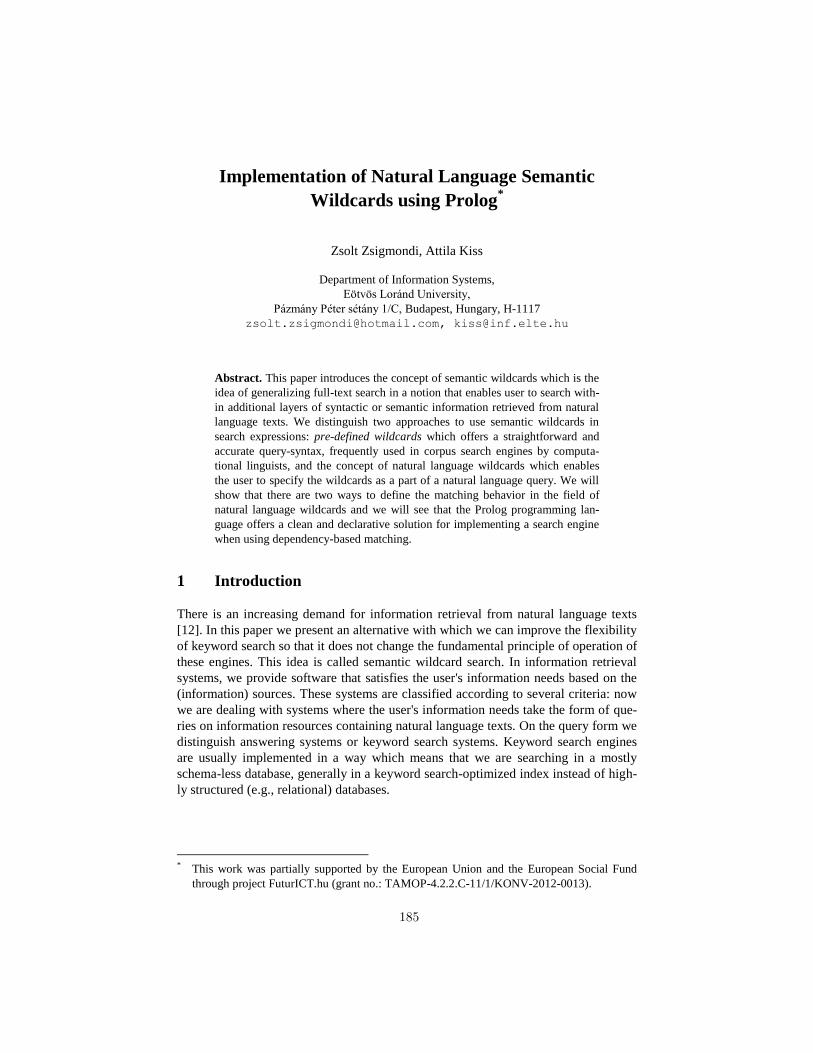
Implementation of Natural Language Semantic
Wildcards using Prolog*
Zsolt Zsigmondi, Attila Kiss
Department of Information Systems,
Eötvös Loránd University,
Pázmány Péter sétány 1/C, Budapest, Hungary, H-1117
[email protected], [email protected]
Abstract. This paper introduces the concept of semantic wildcards which is the
idea of generalizing full-text search in a notion that enables user to search with-
in additional layers of syntactic or semantic information retrieved from natural
language texts. We distinguish two approaches to use semantic wildcards in
search expressions: pre-defined wildcards which offers a straightforward and
accurate query-syntax, frequently used in corpus search engines by computa-
tional linguists, and the concept of natural language wildcards which enables
the user to specify the wildcards as a part of a natural language query. We will
show that there are two ways to define the matching behavior in the field of
natural language wildcards and we will see that the Prolog programming lan-
guage offers a clean and declarative solution for implementing a search engine
when using dependency-based matching.
1 Introduction
There is an increasing demand for information retrieval from natural language texts
[12]. In this paper we present an alternative with which we can improve the flexibility
of keyword search so that it does not change the fundamental principle of operation of
these engines. This idea is called semantic wildcard search. In information retrieval
systems, we provide software that satisfies the user's information needs based on the
(information) sources. These systems are classified according to several criteria: now
we are dealing with systems where the user's information needs take the form of que-
ries on information resources containing natural language texts. On the query form we
distinguish answering systems or keyword search systems. Keyword search engines
are usually implemented in a way which means that we are searching in a mostly
schema-less database, generally in a keyword search-optimized index instead of high-
ly structured (e.g., relational) databases.
* This work was partially supported by the European Union and the European Social Fund
through project FuturICT.hu (grant no.: TAMOP-4.2.2.C-11/1/KONV-2012-0013).
185
2 Concepts and motivations
From user's perspective, the operating principles of a keyword search are easy to
understand, intuitive to use - but the lack of appropriate search terms often imply an
unsatisfactory result set.
The problem of incomplete search terms can be treated with so-called wildcard char-
acters. Wildcard characters appear in various forms in different search engines: syntax
and semantics vary depending on the specifications of the search engine, on the math-
ematical basis of the search engine and on the model representation. For example, in
regular expressions, the dot (.) character represents any single character. Such regular
expressions based on wildcards are used by several corpus search engines, such as the
WebCorp [1] or KwiCFinder [2]. With their help one can search for different forms of
a word (the search term play* substitutes all forms of the verb play). The concept of
wildcards does not necessarily have to exist on the level of abstraction of characters.
The semantic vectors package [3], based on the Apache Lucene, for example, allows
the construction of permutation indices and wildcard searches in them. The support of
wildcard search functions in the semantic vectors package is unfortunately limited
because it is currently only possible to use only a single wildcard in a search expres-
sion.
The concept of semantic wildcard generalizes the notion of wildcard [11]. The seman-
tic vectors package is a good example of using of wildcards and adequate representa-
tion we may be able to reveal the hidden semantic relationships between certain texts.
After that comes a logical generalization direction: expanding the number of possible
wildcards so that different wildcards can convey various types of semantic infor-
mation. The discussion of the search task can be specified in several ways, you can
reach from a less general definition to a flexible user search terms. But before turning
to this, we summarize the key concepts.
The basic unit of information retrieval is the document. Documents consist of natural
language fields. The goal of the search engine is to determine the list of relevant doc-
uments on the basis of the user's query. The relevance expresses the extent that the
document meets the information needs of the users. Quantitative measure of a docu-
ment is its relevance level - this can be binary (relevant / irrelevant), or expressed in a
continuous scale. For example, in the interval , 0 represents the total irrelevancy
and 1 is the entirely relevant level. Relevance is an elusive concept, as it is difficult to
determine exactly what kind of documents satisfy an information need.
The users (or experts) are responsible for the determination of levels of relevance.
The search system estimates the relevance level of each document during the opera-
tion. This process is called scoring, during which the search engine assigns score val-
ues to the retrieved documents.
2.1 Pattern search with pre-defined wildcards
The idea of semantic wildcards allows the user to specify wildcards having meaning-
ful semantic information in the search expression. Formally, this means the following.
186
If T is the set of possible words in a natural language (e.g., English), then a natural
language sentence of n+1 words is
where .
A query is
, where
where W is the set of the possible semantic wildcards. The set W determines only the
possible syntax of the search expressions (the grammar is unambiguous, provided that
W ∩ T = ∅), but not the semantics.
The elements of the set W specify when a semantic wildcard matches by a part of a
natural language sentence, and how this might affect the document's score. The
definition of matching we have great freedom depending on which type of semantic
content we want to be recognized for the analysis of natural language texts. As an
example, consider a case where only automatic named entity recognition (NER) is
performed. Now is a rational
choice, where each element in the set matches the words in the original sentence,
which are recognized as that type of entity by the language processing module of the
indexer of the search engine. This simple example also shows that one may want to
define relations between the elements of W: in our example entity is the most general
semantic wildcard - the matching of the others implies the matching of entity as well.
In corpus search systems it is more reasonable to recognize syntax units, word
structures instead of NER. In this case W contains the wildcards which obey the word
structures. For example, in the GloWbE [4] corpus we can apply Part Of Speech
(POS) tags as wildcards, which are defined by the Penn Treebank II. The drawback of
these approaches is that the set W is pre-defined, and the number of the available
semantic wildcards is often too big. For example, the Penn Treebank II label format
[5] defines 21 different types of phrases. Another disadvantage is that the users (in the
absence of linguistic skills) are often unable to determine the exact structure type of
the query, which leads to the use of incorrectly formulated search terms, reducing
precision and recall of the system.
2.2 Natural language semantic wildcards
As described above, the usage of wildcards from a pre-defined set can be
cumbersome, so we further generalize the notion of semantic wildcards. The main
idea of the generalization is that natural language expressions can be used as patterns.
The query is now
, where , but
The * denotes the language which contains a single word *. In the case of natural
language semantic wildcards the matching can be defined in two ways. On the one
187
hand we can stay the above approach, that is, using NLP techniques we can analyze
the syntactic structure of the query term. For example, consider the query the cat in
*the hat*. The following information can be obtained from the text by analyzing the
query.
Thus, the above query can be reduced to the search with pre-defined wildcards cat in
NP or cat in DT NN. For example, the strings cat in the hat or cat in the rain will
match the search term, but the string cat in the freezing rain fits only the more general
cat in NP, so the score for this match could be reduced. Another approach is to
represent the semantic information with dependency-graphs where the nodes are the
words, and the edges are the semantic dependencies between them. In this case, a test
for matching means checking the edges. If the word order is indifferent, then the
search term matching test is equivalent to a similarity test between the semantic
graphs.
3 Implementation options for natural language semantic
wildcards
For the implementation of search engine with the pre-defined wildcards there are
effective solutions. Data structures called Parallel Suffix Arrays [6, 7] offer a time-
efficient solution to serve queries of a much richer query language than the above
defined. In the case of natural language wildcards the implementation depends on the
definition of matching. If matching is based purely on comparing dependency graphs,
then we found it’s reasonable to represent these graphs in a Prolog database. For
matching test on the grammatical constituent level the Apache Lucene full-text search
system can be used. We will briefly show what problems we encountered during the
different approaches and then describe experimental results. Figure 1 depicts the
general approach.
188
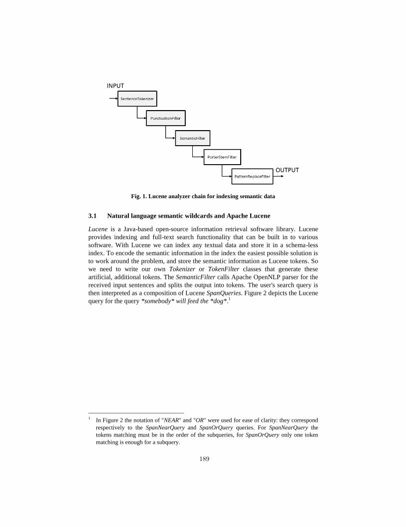
Fig. 1. Lucene analyzer chain for indexing semantic data
3.1 Natural language semantic wildcards and Apache Lucene
Lucene is a Java-based open-source information retrieval software library. Lucene
provides indexing and full-text search functionality that can be built in to various
software. With Lucene we can index any textual data and store it in a schema-less
index. To encode the semantic information in the index the easiest possible solution is
to work around the problem, and store the semantic information as Lucene tokens. So
we need to write our own Tokenizer or TokenFilter classes that generate these
artificial, additional tokens. The SemanticFilter calls Apache OpenNLP parser for the
received input sentences and splits the output into tokens. The user's search query is
then interpreted as a composition of Lucene SpanQueries. Figure 2 depicts the Lucene
query for the query *somebody* will feed the *dog*.1
1 In Figure 2 the notation of "NEAR" and "OR" were used for ease of clarity: they correspond
respectively to the SpanNearQuery and SpanOrQuery queries. For SpanNearQuery the
tokens matching must be in the order of the subqueries, for SpanOrQuery only one token
matching is enough for a subquery.
189
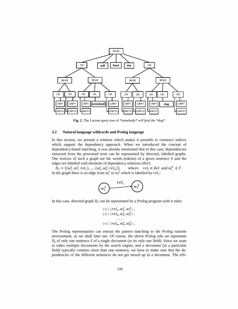
Fig. 2. The Lucene query tree of *somebody* will feed the *dog*
3.2 Natural language wildcards and Prolog language
In this section, we present a solution which makes it possible to construct indices
which support the dependency approach. When we introduced the concept of
dependency-based matching, it was already mentioned that in this case, dependencies
extracted from the processed texts can be represented by directed, labelled graphs.
The vertices of such a graph are the words (tokens) of a given sentence S and the
edges are labelled with elements of dependency relations ( ): (
) (
)
In the graph there is an edge from
to which is labelled by :
In this case, directed graph can be represented by a Prolog program with rules:
rel(
).
rel(
).
...
rel(
).
The Prolog representation can entrust the pattern matching to the Prolog runtime
environment, as we shall later see. Of course, the above Prolog rule set represents
of only one sentence of a single document (or its only one field). Since we want
to index multiple documents by the search engine, and a document (in a particular
field) typically contains more than one sentence, we have to make sure that the de-
pendencies of the different sentences do not get mixed up in a document. The effi-
190
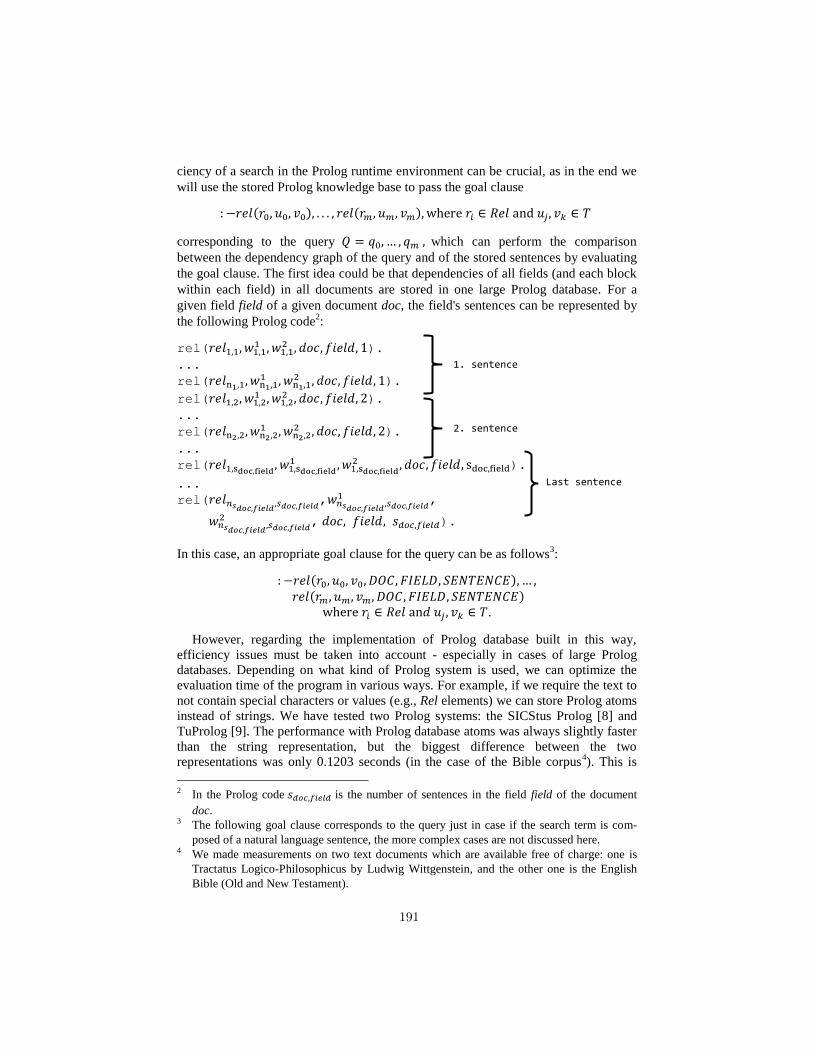
ciency of a search in the Prolog runtime environment can be crucial, as in the end we
will use the stored Prolog knowledge base to pass the goal clause
( ) ( )
corresponding to the query which can perform the comparison
between the dependency graph of the query and of the stored sentences by evaluating
the goal clause. The first idea could be that dependencies of all fields (and each block
within each field) in all documents are stored in one large Prolog database. For a
given field field of a given document doc, the field's sentences can be represented by
the following Prolog code2:
rel(
).
...
rel(
).
rel(
). ...
rel(
).
...
rel(
).
...
rel(
,
,
, ).
In this case, an appropriate goal clause for the query can be as follows3:
( ) ( )
.
However, regarding the implementation of Prolog database built in this way,
efficiency issues must be taken into account - especially in cases of large Prolog
databases. Depending on what kind of Prolog system is used, we can optimize the
evaluation time of the program in various ways. For example, if we require the text to
not contain special characters or values (e.g., Rel elements) we can store Prolog atoms
instead of strings. We have tested two Prolog systems: the SICStus Prolog [8] and
TuProlog [9]. The performance with Prolog database atoms was always slightly faster
than the string representation, but the biggest difference between the two
representations was only 0.1203 seconds (in the case of the Bible corpus4). This is
2 In the Prolog code is the number of sentences in the field field of the document
doc. 3 The following goal clause corresponds to the query just in case if the search term is com-
posed of a natural language sentence, the more complex cases are not discussed here. 4 We made measurements on two text documents which are available free of charge: one is
Tractatus Logico-Philosophicus by Ludwig Wittgenstein, and the other one is the English
Bible (Old and New Testament).
1. sentence
2. sentence
Last sentence
191
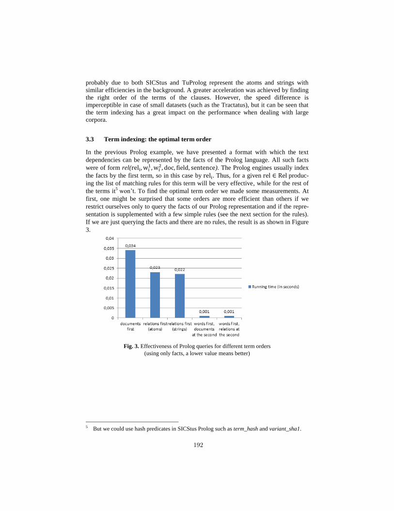
probably due to both SICStus and TuProlog represent the atoms and strings with
similar efficiencies in the background. A greater acceleration was achieved by finding
the right order of the terms of the clauses. However, the speed difference is
imperceptible in case of small datasets (such as the Tractatus), but it can be seen that
the term indexing has a great impact on the performance when dealing with large
corpora.
3.3 Term indexing: the optimal term order
In the previous Prolog example, we have presented a format with which the text
dependencies can be represented by the facts of the Prolog language. All such facts
were of form rel(
). The Prolog engines usually index
the facts by the first term, so in this case by . Thus, for a given produc-
ing the list of matching rules for this term will be very effective, while for the rest of
the terms it5 won’t. To find the optimal term order we made some measurements. At
first, one might be surprised that some orders are more efficient than others if we
restrict ourselves only to query the facts of our Prolog representation and if the repre-
sentation is supplemented with a few simple rules (see the next section for the rules).
If we are just querying the facts and there are no rules, the result is as shown in Figure
3.
Fig. 3. Effectiveness of Prolog queries for different term orders
(using only facts, a lower value means better)
5 But we could use hash predicates in SICStus Prolog such as term_hash and variant_sha1.
192
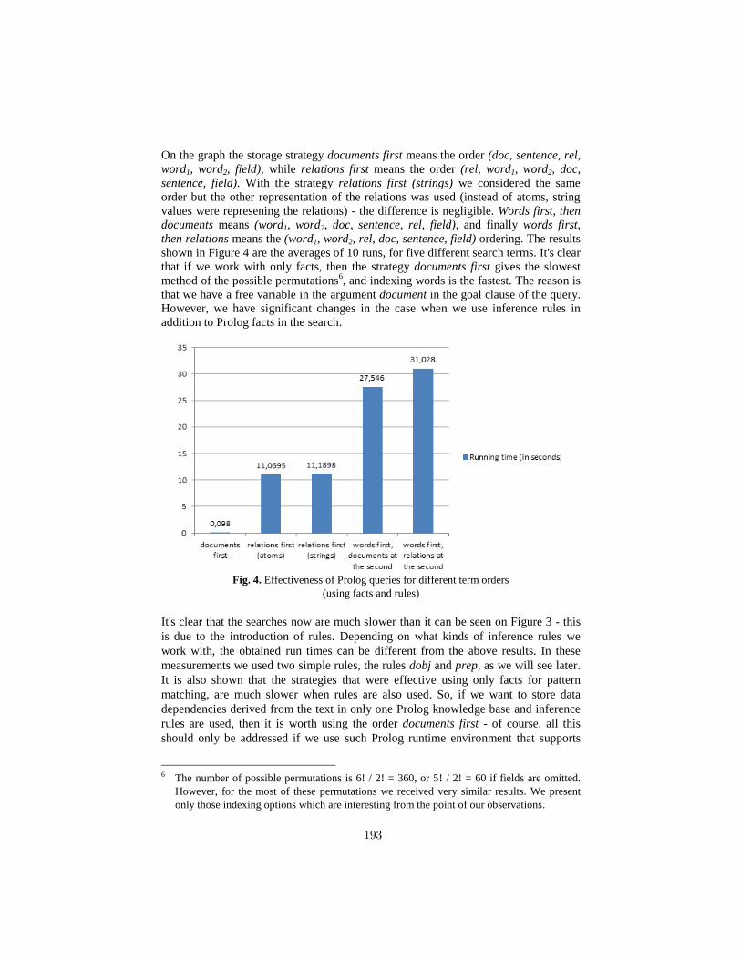
On the graph the storage strategy documents first means the order (doc, sentence, rel,
word1, word2, field), while relations first means the order (rel, word1, word2, doc,
sentence, field). With the strategy relations first (strings) we considered the same
order but the other representation of the relations was used (instead of atoms, string
values were represening the relations) - the difference is negligible. Words first, then
documents means (word1, word2, doc, sentence, rel, field), and finally words first,
then relations means the (word1, word2, rel, doc, sentence, field) ordering. The results
shown in Figure 4 are the averages of 10 runs, for five different search terms. It's clear
that if we work with only facts, then the strategy documents first gives the slowest
method of the possible permutations6, and indexing words is the fastest. The reason is
that we have a free variable in the argument document in the goal clause of the query.
However, we have significant changes in the case when we use inference rules in
addition to Prolog facts in the search.
Fig. 4. Effectiveness of Prolog queries for different term orders
(using facts and rules)
It's clear that the searches now are much slower than it can be seen on Figure 3 - this
is due to the introduction of rules. Depending on what kinds of inference rules we
work with, the obtained run times can be different from the above results. In these
measurements we used two simple rules, the rules dobj and prep, as we will see later.
It is also shown that the strategies that were effective using only facts for pattern
matching, are much slower when rules are also used. So, if we want to store data
dependencies derived from the text in only one Prolog knowledge base and inference
rules are used, then it is worth using the order documents first - of course, all this
should only be addressed if we use such Prolog runtime environment that supports
6 The number of possible permutations is 6! / 2! = 360, or 5! / 2! = 60 if fields are omitted.
However, for the most of these permutations we received very similar results. We present
only those indexing options which are interesting from the point of our observations.
193
term indexing. Based on the measurements we can be satisfied with the effectiveness
of SICStus Prolog. However, these results are given after a compilation step. The
compilation is computationally rather intensive operation, for the Bible corpus it takes
an average of 86 seconds (keep in mind that the Prolog representation in this case is a
24-megabyte source file). However, once that's done, then we can run fast and
efficient queries on the index. The speed of queries, of course, depends not only on
the term order, but the order of the terms (edges of the dependency graph to be
matched) in the goal clause of the query.
Evaluation of the goal clause is sequential on its terms, so if the first term in the goal
clause is too general (it means that the term matches a number of facts and left sides
of rules), then the surplus calculation is accumulated for matching of the complete
query, thereby matching the rest of the terms. However, if we are lucky, the first term
of the goal clause corresponding to the query is as
:-rel(DOC,S,'mahalalel','years',conj),
rel(DOC,S,'day','that',det).
This is a favorable case, because 'mahalalel' and 'years' are certainly less
frequently together in the English Bible than 'that day'. Therefore, in addition to
the term indexing (or in its absence) also a possibility raised that with some metadata
we can further increase efficiency: for example, with automatic reordering of goal
clauses (because we know that in our case it will not change the operation of search),
or with specifying our own preprocessing algorithms, which in the first step filters the
list of the applicable Prolog rules by different, domain-specific meta-information.
As a kind of metadata-based filter, we implemented a simple in-memory inverted
index in Java programming language to store the Prolog representation. For seamless
integration with the Java platform, we chose TuProlog, which is a Prolog engine
implemented in pure Java. The advantage is that it is available for free, and we can
use our search engine without installing any Prolog runtime environment. Java inte-
gration was also necessary because we use NLP tools which are based on Java.
4 Prolog goal clauses
We have already discussed in detail the generation of Prolog codes from dependency
graphs. However, it has not been presented yet, how we can construct goal clauses
transferable to the Prolog runtime environment from the user queries. Of course, the
first step here is to clean the search terms from the syntax of the semantic wildcards,
that is, if the search query is as follows:
Russell *is wrong*, because *he did* when *doing something*.
Then the next string is extracted from the text:
Russell is wrong, because he did when doing something.
194
The extracted string has been stripped from the special wildcard syntax so we can
pass it to the dependency parser. Next, the dependency parser from the above string
generates the dependency graph of the text, thus we received n dependencies of the
form ( ), where type is the type of the dependency, are the words
which are in that dependency relationship. Note that from each of these we can
generate a Prolog term in the same form, where we substitute and with free
Prolog variables and , if and were a part of a semantic wildcard before
stripping the query string. In the previous example the output of the parser on the
cleaned search term will be the following dependency graph:
nsubj(wrong:3,Russell:1)
cop(wrong:3,is:2)
root(ROOT:0,wrong:3)
mark(did:7,because:5)
nsubj(did:7,he:6)
advcl(wrong:3,did:7)
advmod(doing:9,when:8)
advcl(did:7,doing:9)
dobj(doing:9,something:10).
Since the root relationship is only a virtual dependency, we can ignore that. In the
remaining dependencies on the next step we replace the word belonging to semantic
wildcards with variables. If these steps are carried out then we obtain the next graph7:
nsubj(WRONG,Russell:1)
cop(WRONG,IS)
mark(DID,because:5)
nsubj(DID,he:6)
advcl(WRONG,DID)
advmod(DOING,when:8)
advcl(DID,DOING)
dobj(DOING,SOMETHING).
From which the corresponding Prolog goal clause can be easily prepared:
:- rel(nsubj, WRONG, ”russell” ),
rel(cop, WRONG, IS ),
rel(mark, DID, ”because” ),
rel(nsubj, DID, ”he” ),
rel(advcl, WRONG, DID ),
rel(advmod, DOING, ”when” ),
rel(advcl, DID, DOING ),
rel(dobj, DOING, SOMETHING ).
7 The names of the variables are written in capital letters for the sake of clarity.
195
But it does not solve all the problems. Indeed, in this case our too simple
graph-matching test would not recognize a number of dependencies which are present
in the text. Consider the following example:
The meaning *should play* a role in syntax.
Following the above, from the search expression we would get the following goal
clause.
:- rel(nsubj, PLAY, ”meaning” ),
rel(aux, PLAY, ”should” ),
rel(dobj, PLAY, ”role” ),
rel(prep, ”role”, ”syntax” ).
Unfortunately the following sentence does not match the above goal clause:
In logical syntax the meaning of a sign should never play a
role.
Since Prolog representation of the above sentence is the following:
rel(amod,"syntax","logical",1).
rel(prep,"play","syntax",1).
rel(det,"meaning","the",1).
rel(nsubj,"play","meaning",1).
rel(det,"sign","a",1).
rel(prep,"meaning","sign",1).
rel(aux,"play","should",1).
rel(neg,"play","never",1).
rel(root,"root","play",1).
rel(det,"role","a",1).
rel(dobj,"play","role",1).
The terms filling into the terms of above goal clause are written in bold - the error is
in the underlined row. The parser recognizes the prepositional structure, but assigns it
to the verb “play”, which is a reasonable choice, but we do know, however, that if
there is a direct object of a verb, then the prepositional relation can be extended to this
object as well. This is expressed by the following Prolog rule:
rel(prep, X, Y, S):- rel(dobj, Z, X, SCORE1),
rel(prep, Z, Y, SCORE2),
S is SCORE1*SCORE2*0.5.
Now we can see how the scoring is done in the Prolog representation: the score of the
document (or more properly, the score of a given sentence in the given field of the
document) is calculated by Prolog facts and rules. Each application of the above rule
reduces the total score results with a factor λ (which has the value 0.5). This prevents
196
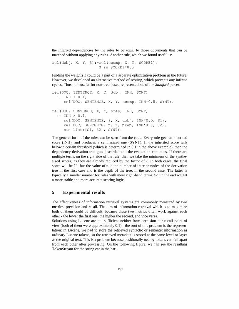
the inferred dependencies by the rules to be equal to those documents that can be
matched without applying any rules. Another rule, which we found useful is:
rel(dobj, X, Y, S):-rel(ccomp, X, Y, SCORE1),
S is SCORE1*0.5.
Finding the weights λ could be a part of a separate optimization problem in the future.
However, we developed an alternative method of scoring, which prevents any infinite
cycles. Thus, it is useful for non-tree-based representations of the Stanford parser:
rel(DOC, SENTENCE, X, Y, dobj, INH, SYNT)
:- INH > 0.1,
rel(DOC, SENTENCE, X, Y, ccomp, INH*0.5, SYNT).
rel(DOC, SENTENCE, X, Y, prep, INH, SYNT)
:- INH > 0.1,
rel(DOC, SENTENCE, Z, X, dobj, INH*0.5, S1),
rel(DOC, SENTENCE, Z, Y, prep, INH*0.5, S2),
min_list([S1, S2], SYNT).
The general form of the rules can be seen from the code. Every rule gets an inherited
score (INH), and produces a synthesized one (SYNT). If the inherited score falls
below a certain threshold (which is determined in 0.1 in the above example), then the
dependency derivation tree gets discarded and the evaluation continues. If there are
multiple terms on the right side of the rule, then we take the minimum of the synthe-
sized scores, as they are already reduced by the factor of λ. In both cases, the final
score will be , but the value of is the number of interior nodes of the derivation
tree in the first case and is the depth of the tree, in the second case. The latter is
typically a smaller number for rules with more right-hand terms. So, in the end we get
a more stable and more accurate scoring logic.
5 Experimental results
The effectiveness of information retrieval systems are commonly measured by two
metrics: precision and recall. The aim of information retrieval which is to maximize
both of them could be difficult, because these two metrics often work against each
other - the lower the first one, the higher the second, and vice versa.
Solutions using Lucene are not sufficient neither from precision nor recall point of
view (both of them were approximately 0.1) - the root of this problem is the represen-
tation: in Lucene, we had to store the retrieved syntactic or semantic information as
ordinary Lucene tokens, so the retrieved metadata is stored at the same level or layer
as the original text. This is a problem because positionally nearby tokens can fall apart
from each other after processing. On the following figure, we can see the resulting
TokenStream for the string cat in the hat:
197
<NP> <NP> <NN> cat </NN> </NP> <PP> <IN> in </IN> <NP>
<DT> the </DT> <NN> hat </NN> </NP> </PP> </NP>.
In the original text, the distance between the cat and the hat words were only two
tokens. After processing, it is increased to 11. And because of the distance is directly
proportional to the depth of the parse tree, it is impossible to determine an upper limit
on Lucene SpanNearQuery's slop parameters.
Unlike the Lucene-based solution, the implementation in Prolog produced really good
results: on the same dataset we can achieve 0.8 precision and recall, not to mention
the fact that the TuProlog-based engine was also faster than the Lucene solution, as
shown in Figure 5.
Fig. 5. Average running times of the Lucene-based and the TuProlog-based solution
The reason of the relatively high execution time (as compared to the results of
SICStus Prolog) is that the parser model (a file with a several-megabyte size) must be
loaded into the memory in each case at the beginning of the program. If we analyze
the distribution of the execution time of the TuProlog-based solution, the bottlenecks
can be seen in Figure 6.
Fig. 6. The average distribution of the execution time of the TuProlog-based solution
6 Conclusions
We have presented two implementation plan for the semantic wildcard search. The
implementation has shed some light on practical problems. Namely, it turned out that
198
in the current version of Lucene (4.3, at the time of the writing) is not possible to store
complex meta-information in a parallel layer without clumsy workarounds, so this
means that implementing a semantic wildcard search engine in Lucene would be in-
herently sub-optimal and the outcome would be unsatisfactory. However, the next
version of Lucene can make a positive difference in this topic: as we can read in [10],
the Lucene attribute API already contains an attribute named PositionLength, which is
in principle could make Lucene capable to store word lattices. However, the overall
infrastructure of the Lucene has not support this attribute yet, however this may
change in the future, enabling Lucene to support complex wildcard searches and to be
a viable alternative for implementation of a semantic wildcard search engine.
It was surprising to see that the Prolog environments are capable to store large amount
of linguistic data (e.g., the Bible corpus), and to be a basis of a full-text search appli-
cation.
The rearrangement of terms in the auto-generated goal-clauses would be an interest-
ing goal for further development, as well as the optimization of the λ vector or the
development of additional document scoring methods or the complete integration
with the SICStus Prolog.
7 References
1. Barry Morley, Antoinette Renouf, Andrew Kehoe: Linguistic Research with the
XML/RDF aware WebCorp Tool, WWW2003 Conference, Budapest, 2003.
2. KWiCFinder: http://www.kwicfinder.com/KWiCFinder.html, 2013. 06. 08.
3. The Semantic Vectors package: https://code.google.com/p/semanticvectors/,
2013. 06. 08.
4. GloWbE : Corpus of Global, Web-based English:http://corpus2.byu.edu/glowbe/,
2013. 06. 08.
5. Penn Treebank II: http://www.cis.upenn.edu/~treebank/, 2013. 06. 08.
6. Johannes Goller: Parallel Suffix Arrays for Corpus Exploration. (2010).
7. Johannes Goller: Parallel Suffix Arrays for Linguistic Pattern Search -
http://www.aclweb.org/anthology-new/R/R11/R11-1068.pdf 2013. 06. 08.
8. SICStus Prolog: http://sicstus.sics.se/, 2013. 06. 08.
9. TuProlog: http://tuprolog.alice.unibo.it , 2013. 06. 08.
10. Michael McCandless: Lucene's TokenStreams are actually graphs,
http://blog.mikemccandless.com/2012/04/lucenes-tokenstreams-are-actually.html,
2013. 06. 08.
11. Rada Mihalcea: The semantic wildcard. Proceedings of the LREC Workshop on
Creating and Using Semantics for Information Retrieval and Filtering State of the
Art and Future Research. 2002.
12. Tony Veale: Creative language retrieval: A robust hybrid of information retrieval
and linguistic creativity. Proceedings of ACL. 2011.
199
Designing and Implementing Control Flow Graph
for Magic 4th Generation Language
Richárd Dévai, Judit Jász, Csaba Nagy, Rudolf Ferenc
Department of Software EngineeringUniversity of Szeged, Hungary
[email protected], {jasy|ncsaba|ferenc}@inf.u-szeged.hu
Abstract. A good compiler which implements many optimizations dur-ing its compilation phases must be able to perform several static analysistechniques such as control �ow or data �ow analysis. Besides compilers,these techniques are common for static analyzers to retrieve informationfrom the code for example code auditing, quality assurance, or testingpurposes. Implementing control �ow analysis requires handling manyspecial structures of the target language. In our paper we present ourexperiences in implementing control �ow graph (CFG) construction fora special 4th generation language called Magic. During designing and im-plementing the CFG for this language we identi�ed di�erences comparedto 3rd generation languages because the special programming techniqueof this language (e.g. data access, parallel task execution, events). Ourwork was motivated by our industrial partner who needed precise staticanalysis tools (e.g. for quality assurance or testing purposes) for this lan-guage. We believe that our experiences for Magic, as a representative of4GLs might be generalized for other languages too.
1 Introduction
Control �ow analysis is a common technique to determine the control �ow of aprogram via static analysis. The outcome of this analysis is the Control FlowGraph (CFG), which describes the control relations between certain source codeelements of the application. The CFG is a directed graph: its nodes are usuallybasic blocks representing statements of the code that are executed after eachother without any jumps. These basic blocks are connected with directed edgesrepresenting the jumps in the control �ow. CFG is a useful tool for code opti-mization techniques (e.g. unreachable code elimination, loop optimization, deadcode elimination). The �rst publications of using control �ow analysis goes backto the 70s [1] and 80s [4,11,24], but since then most of the compilers have imple-mented this technique to construct a CFG and implement optimization phasesbased on it.
Although the basic structure of the CFG is quite common, the methodsconstructing it for applications are very much language dependent. Identifyingcontrol dependencies in special structures of the target language may result spe-cial algorithms. Moreover, special program elements or applications may requireminor modi�cations of the structure of the CFG (e.g. nodes like entry nodes).
200
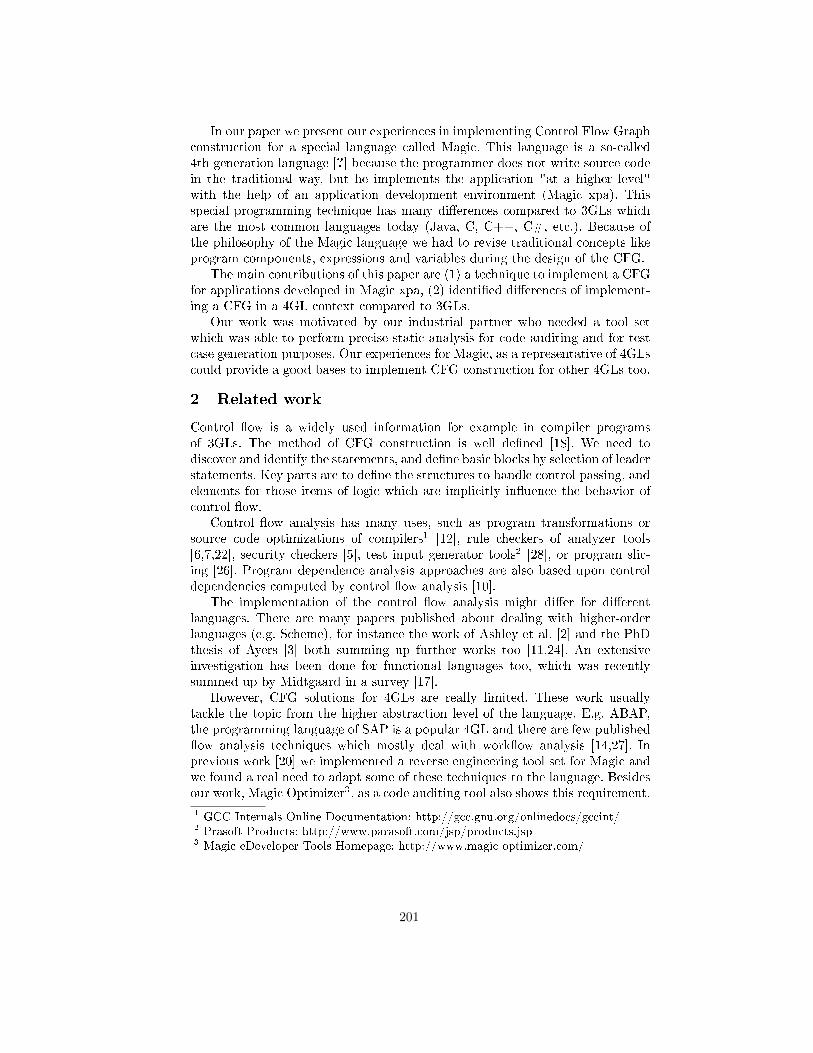
In our paper we present our experiences in implementing Control Flow Graphconstruction for a special language called Magic. This language is a so-called4th generation language [?] because the programmer does not write source codein the traditional way, but he implements the application "at a higher level"with the help of an application development environment (Magic xpa). Thisspecial programming technique has many di�erences compared to 3GLs whichare the most common languages today (Java, C, C++, C#, etc.). Because ofthe philosophy of the Magic language we had to revise traditional concepts likeprogram components, expressions and variables during the design of the CFG.
The main contributions of this paper are (1) a technique to implement a CFGfor applications developed in Magic xpa, (2) identi�ed di�erences of implement-ing a CFG in a 4GL context compared to 3GLs.
Our work was motivated by our industrial partner who needed a tool setwhich was able to perform precise static analysis for code auditing and for testcase generation purposes. Our experiences for Magic, as a representative of 4GLscould provide a good bases to implement CFG construction for other 4GLs too.
2 Related work
Control �ow is a widely used information for example in compiler programsof 3GLs. The method of CFG construction is well de�ned [18]. We need todiscover and identify the statements, and de�ne basic blocks by selection of leaderstatements. Key parts are to de�ne the structures to handle control passing, andelements for those items of logic which are implicitly in�uence the behavior ofcontrol �ow.
Control �ow analysis has many uses, such as program transformations orsource code optimizations of compilers1 [12], rule checkers of analyzer tools[6,7,22], security checkers [5], test input generator tools2 [28], or program slic-ing [26]. Program dependence analysis approaches are also based upon controldependencies computed by control �ow analysis [10].
The implementation of the control �ow analysis might di�er for di�erentlanguages. There are many papers published about dealing with higher-orderlanguages (e.g. Scheme), for instance the work of Ashley et al. [2] and the PhDthesis of Ayers [3] both summing up further works too [11,24]. An extensiveinvestigation has been done for functional languages too, which was recentlysummed up by Midtgaard in a survey [17].
However, CFG solutions for 4GLs are really limited. These work usuallytackle the topic from the higher abstraction level of the language. E.g. ABAP,the programming language of SAP is a popular 4GL and there are few published�ow analysis techniques which mostly deal with work�ow analysis [14,27]. Inprevious work [20] we implemented a reverse engineering tool set for Magic andwe found a real need to adapt some of these techniques to the language. Besidesour work, Magic Optimizer3, as a code auditing tool also shows this requirement.
1 GCC Internals Online Documentation: http://gcc.gnu.org/onlinedocs/gccint/2 Prasoft Products: http://www.parasoft.com/jsp/products.jsp3 Magic eDeveloper Tools Homepage: http://www.magic-optimizer.com/
201
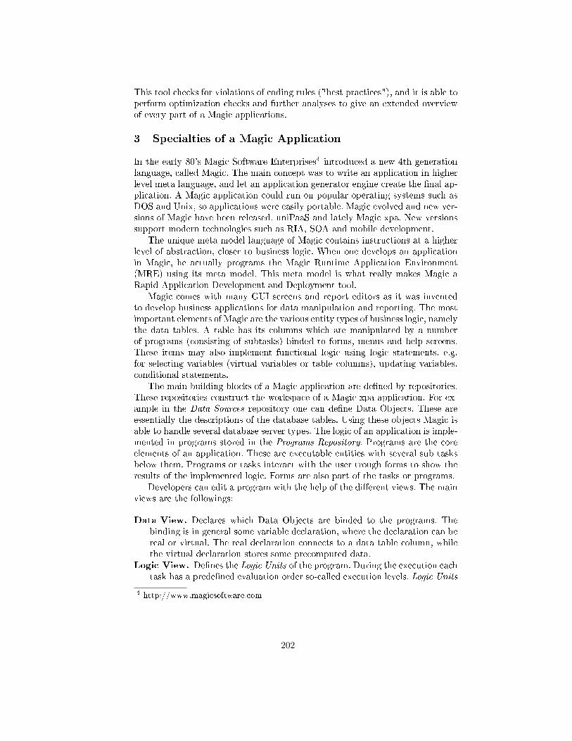
This tool checks for violations of coding rules ("best practices"), and it is able toperform optimization checks and further analyses to give an extended overviewof every part of a Magic applications.
3 Specialties of a Magic Application
In the early 80's Magic Software Enterprises4 introduced a new 4th generationlanguage, called Magic. The main concept was to write an application in higherlevel meta language, and let an application generator engine create the �nal ap-plication. A Magic application could run on popular operating systems such asDOS and Unix, so applications were easily portable. Magic evolved and new ver-sions of Magic have been released, uniPaaS and lately Magic xpa. New versionssupport modern technologies such as RIA, SOA and mobile development.
The unique meta model language of Magic contains instructions at a higherlevel of abstraction, closer to business logic. When one develops an applicationin Magic, he actually programs the Magic Runtime Application Environment(MRE) using its meta model. This meta model is what really makes Magic aRapid Application Development and Deployment tool.
Magic comes with many GUI screens and report editors as it was inventedto develop business applications for data manipulation and reporting. The mostimportant elements of Magic are the various entity types of business logic, namelythe data tables. A table has its columns which are manipulated by a numberof programs (consisting of subtasks) binded to forms, menus and help screens.These items may also implement functional logic using logic statements, e.g.for selecting variables (virtual variables or table columns), updating variables,conditional statements.
The main building blocks of a Magic application are de�ned by repositories.These repositories construct the workspace of a Magic xpa application. For ex-ample in the Data Sources repository one can de�ne Data Objects. These areessentially the descriptions of the database tables. Using these objects Magic isable to handle several database server types. The logic of an application is imple-mented in programs stored in the Programs Repository. Programs are the coreelements of an application. These are executable entities with several sub tasksbelow them. Programs or tasks interact with the user trough forms to show theresults of the implemented logic. Forms are also part of the tasks or programs.
Developers can edit a program with the help of the di�erent views. The mainviews are the followings:
Data View. Declares which Data Objects are binded to the programs. Thebinding is in general some variable declaration, where the declaration can bereal or virtual. The real declaration connects to a data table column, whilethe virtual declaration stores some precomputed data.
Logic View. De�nes the Logic Units of the program. During the execution eachtask has a prede�ned evaluation order so-called execution levels. Logic Units
4 http://www.magicsoftware.com
202
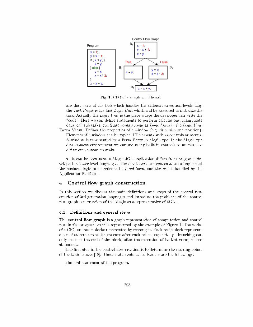
Fig. 1. CFG of a simple conditional.
are that parts of the task which handles the di�erent execution levels. E.g.the Task Pre�x is the �rst Logic Unit which will be executed to initialize thetask. Actually the Logic Unit is the place where the developer can write the"code". Here we can de�ne statements to perform calculations, manipulatedata, call sub tasks, etc. Statements appear as Logic Lines in the Logic Unit.
Form View. De�nes the properties of a window (e.g. title, size and position).Elements of a window can be typical UI elements such as controls or menus.A window is represented by a Form Entry in Magic xpa. In the Magic xpadevelopment environment we can use many built-in controls or we can alsode�ne our custom controls.
As it can be seen now, a Magic 4GL application di�ers from programs de-veloped in lower level languages. The developers can concentrate to implementthe business logic in a prede�ned layered form, and the rest is handled by theApplication Platform.
4 Control �ow graph construction
In this section we discuss the main de�nitions and steps of the control �owcreation of 3rd generation languages and introduce the problems of the control�ow graph construction of the Magic as a representative of 4GLs.
4.1 De�nitions and general steps
The control �ow graph is a graph representation of computation and control�ow in the program, as it is represented by the example of Figure 1. The nodesof a CFG are basic blocks represented by rectangles. Each basic block representsa set of statements which execute after each other sequentially. Branching canonly exist at the end of the block, after the execution of its last encapsulatedstatement.
The �rst step in the control �ow creation is to determine the starting pointsof the basic blocks [18]. These statements called leaders are the followings:
� the �rst statement of the program,
203
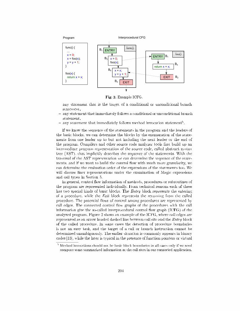
Fig. 2. Example ICFG.
� any statement that is the target of a conditional or unconditional branchstatement,
� any statement that immediately follows a conditional or unconditional branchstatement,
� any statement that immediately follows method invocation statement5.
If we know the sequence of the statements in the program and the leaders ofthe basic blocks, we can determine the blocks by the enumeration of the state-ments from one leader up to but not including the next leader or the end ofthe program. Compilers and other source code analyzer tools �rst build up anintermediate program representation of the source code, called abstract syntaxtree (AST), that implicitly describes the sequence of the statements. With thetraversal of the AST representation we can determine the sequence of the state-ments, and if we want to build the control �ow with much more granularity, wecan determine the evaluation order of the expressions of the statements too. Wewill discuss �ner representations under the examination of Magic expressionsand call types in Section 5.
In general, control �ow information of methods, procedures or subroutines ofthe program are represented individually. From technical reasons each of thesehas two special kinds of basic blocks. The Entry block represents the enteringof a procedure, while the Exit block represents the returning from the calledprocedure. The potential �ows of control among procedures are represented bycall edges. The connected control �ow graphs of the procedures with the callinformation give the so-called interprocedural control �ow graph (ICFG) of theanalyzed program. Figure 2 shows an example of the ICFG, where call edges arerepresented as an arrow headed dashed line between call site and the Entry blockof the called procedure. In some cases the detection of procedure boundariesis not an easy task, and the target of a call or branch instruction cannot bedetermined unambiguously. The earlier situation is commonly appears in binarycodes [13], while the later is typical in the presence of function pointers or virtual
5 Method invocations should not be basic block boundaries in all cases only if we needcompute some summarized information at the call sites in our connected application.
204
function calls at higher level languages. The problems appeared in 4th GLs arediscussed in the rest of this section.
4.2 Challenges in Magic
Like compiler programs or other software analyzer tools, our �rst step is to createan intermediate representation of a Magic applications, called Magic AbstractSyntax Graph (ASG), which is suitable to describe all necessary informationfor our purpose. Information extracted and stored in the ASG is de�ned by theMagic Schema [19]. This format allows us to traverse and process every requiredelements of the Magic application in a well-de�ned hierarchical graph formatthrough an API to determine the execution order of the Magic statements. ASGcontains not only the nodes of the code, but every needed attributes that cana�ect the control �ow. E.g. it contains the propagation information of Event
Handlers, which can terminate the execution of other event handlers, or thewait attribute of Raise Event, which attribute determines the execution pointof the given event.
Developing an application in Magic requires a special way of thinking sincethe programming language is special itself. However this special programminglanguage preserves some main characteristics of procedural languages. Mostly,the main logic of an application can be programmed in a procedural way via con-trol statements in programs and their subtasks. Programs can call each other andthey can call their subtasks. Also, tasks can use variables for their computations,and they can have branches within their statements. These structures of the lan-guage make it possible to adapt the CFG construction of 3GLs to Magic 4GL.For example for every potential target of call sites of Magic (task, event handler,developer function) we make an intraprocedural control �ow graph and we con-nect these graphs by call edges to get the ICFG. However, there are a numberof structures in the language which make harder to construct the CFG of anapplication. Here we discuss these challenges which we are going to elaborate inlater sections.
Tasks architecture is a special event based execution level system. Thereare di�erent task types for di�erent operations. For example online tasks tointeract with user, or batch tasks running without any user interaction. Eachtask type has its own levels (e.g. task, record) and the developer can operatewith these by the so-called Logic Units. A user action or a state change in theprogram can trigger prede�ned events that are also handled by Logic Units oftasks. So statements (Logic Lines) of these Logic Units get executed if a certainevent triggers them. The most challenging thing to construct the CFG of aMagic program is to discover every circumstances that can change the �ow ofthe control between Logic Units and between Logic Lines. We have to understandand represent the e�ect of property changes which can in�uence the behavior ofthe execution, and represent it in a well describing form.
Raise Event logic lines and Event logic units are components of Magiclogic to raise an event during the execution of the program and to handle theraised event. A raised event could be handled with special logic units called Event
205
Logic Unit in a special prede�ned reverse order in tasks. When an event raised,the MRE immediately looks for the last available handler in the given task, andgives the control to the handler. This is the simplest case, the synchronous case.However, we could raise events asynchronously; or set the scope of handlers asthey could be handled by parent tasks too, or only by the task which raised it;or every matching handler could terminate the chain of handlers if propagateproperty is set to no; etc. Describing the proper event handler chains within theCFG requires a complex traverse of logic units in task hierarchy with respect tothe in�uencing attributes. Our model is limited those events which are raised bya code element or a form item.
Data access is supported with a rich toolset in Magic to access databases fore�ciency. Magic provides gateway to wide scale of RDBMS systems by handlingconnection, transactions and generation of SQL queries, beside we could createour own queries. In general we can select from two alternatives to perform ourtransactions. In Physical mode other DB users see our changes in RDBMS log,and we use the lock system of the DB server. In Deferred mode the Magic xpais responsible to store our changes and commit them when we have assembledour transaction within a running task. Beside transactional modes we have toselect the method of update process for the records we use in the transactions.Di�erent strategies give us opportunity to handle concurrency and integrity onrecord updates. At the creation of the CFG we have to handle the di�erent eventhandlers dependent from the selected transaction mode and update strategy.
Parallel task executionmakes it possible to execute more programs in par-allel. Parallel programs are running in an isolated context where every loadedcomponents of main application are reloaded within the new context. In sucha context a parallel program has its own copy of memory tables, own databaseconnections with some limitations (e.g. it cannot store data in main programor communicate directly with other running programs). Tasks can raise asyn-chronous events in the context of another program to communicate, or they canuse shared variables through proper functions in expressions. Parallel processescan run in Single or Multiple instance modes. In Single mode the context is thesame for every instance of the task, while Multiple mode uses di�erent contextfor each task. At the CFG construction we have to simulate all hidden data basecopying and the parallel execution of statements.
Forms has many uses during a program execution. In each case we have tobuild the CFG according the current use of the forms. On the forms the user canmanipulate variable data, which appear in the running program as assignmentinstructions, or the user can a�ect the running program behavior too.
5 Implementation details
As we seen the process of CFG building is aggregated from several phases. Firstby the traversal of the ASG we determine the sequence of statements and theevaluation order of expressions. During evaluation we collect information aboutcalls. After we determine basic block leaders and �nally we build up the basic
206
blocks for later processes. In our representation each call site will be a blockboundary.
To determine the execution order of the contained statements of an analyzedcode, we traverse its ASG from the root node step by step on the tree hierarchyand we re�ne the control �ow information among the sub components. In everysteps we de�ne the execution order of the composed nodes of an investigatedASG node and we augment the execution sequence with additional expressionsor statements, if it is needed. We do this since many semantic elements of a pro-gramming language is not appear explicitly in the source code and so in its ASGrepresentation. Due to the hierarchical traversal, the control �ow information ofdescendant nodes are re�ned after the traversal of their ancestors.
Rectangles of �gures of this section represents nodes, or groups of ASG nodes.Parallelograms denote branches where the possible �ow of control depends onan attribute of Logic Units, Logic Lines, controls, variables, etc. Black ar-rows denote control edges of the CFG, while dashed lines represent call edgesamong the intraprocedural CFG components. Since in our representation callinstructions are basic block boundaries we represent each call with two virtualnodes called Call Site and Return Site. In some cases we introduce solutionsof alternative program versions with the help of one �gure. To distinguish thedi�erences of these versions we use black branching points on the paths wherethe behavior of the di�erent versions are di�er.
In the following we discuss cases where we could create general algorithmsto process group of nodes with the same base type. Finally we introduce somespecial solutions where general algorithms are not able to describe precisely thereal evaluation order of the analyzed ASG node descendants.
5.1 General algorithms
Tasks in the ASG represent either programs or their sub tasks. The �nal repre-sentation of a Task is in�uenced by the implementations of the contained Logic
Units, and the used variables, but we have to concentrate only the skeleton ofthe tasks, since the �ner control �ows of Logic Units are determined in latersteps of the traversal.
When we reach a Task node in the traversal �rst we create an intraproce-dural CFG context for the Task node. Our second step is to collect the orderedsequence of logic units that take part of the execution progress of the task. Thesenodes are the child nodes of the Task node in the ASG. Task, Group, Record aresubtypes of the Logic Unit, but of course the existence of these elements areonly optional in each Task. Prefix and Suffix are sub categories of previousLogic Unit subtypes controlled by an attribute. The subtype and the selectedattribute value determine the exact execution point and order of these Logic
Units. So we nominate the distinct Logic Units with di�erent types and at-tributes di�erently as in Figure 3.
We does not connect every Logic Unit subtypes in this step, only the Task,Group and Record. For the Event and Function subtypes of Logic Unit weassociate a distinct intraprocedural CFG and handle them separately since thiskind of Logic Units can be triggered several times from distinct points.
207
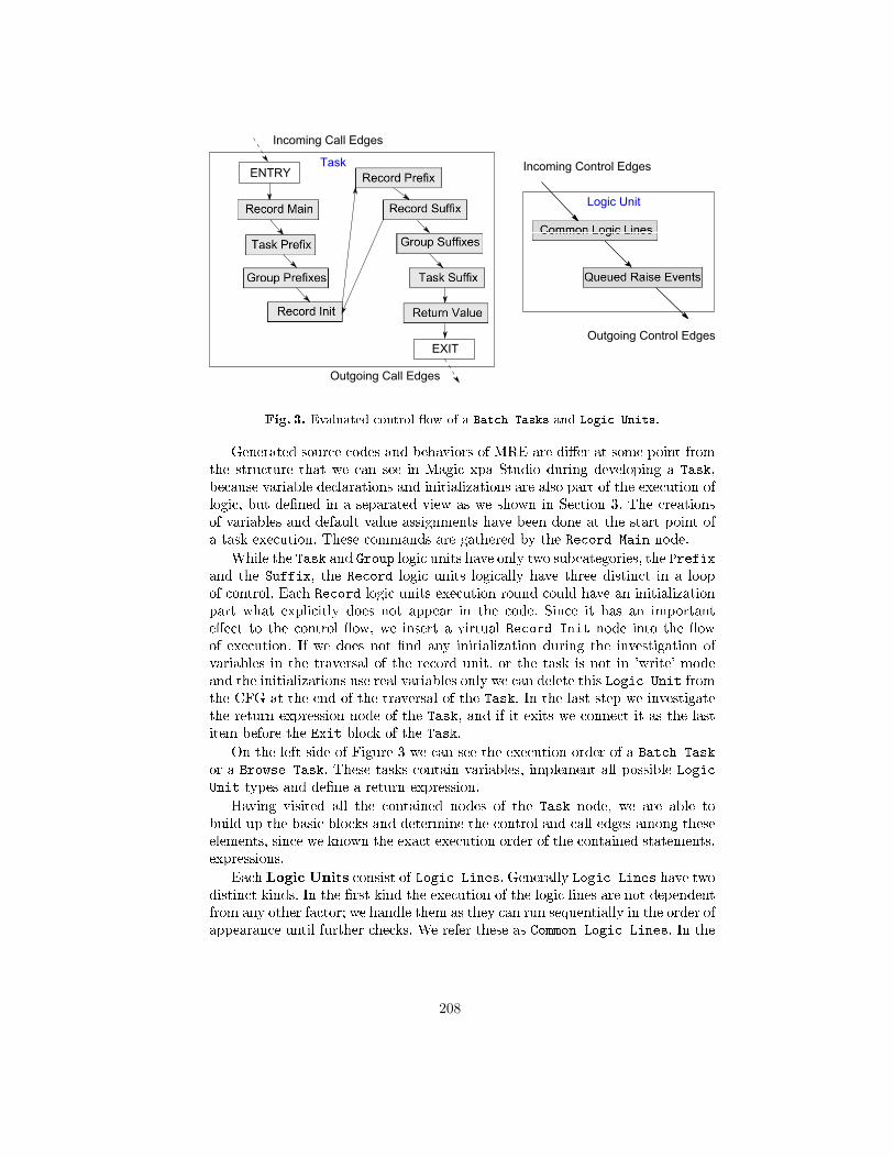
Fig. 3. Evaluated control �ow of a Batch Tasks and Logic Units.
Generated source codes and behaviors of MRE are di�er at some point fromthe structure that we can see in Magic xpa Studio during developing a Task,because variable declarations and initializations are also part of the execution oflogic, but de�ned in a separated view as we shown in Section 3. The creationsof variables and default value assignments have been done at the start point ofa task execution. These commands are gathered by the Record Main node.
While the Task and Group logic units have only two subcategories, the Prefixand the Suffix, the Record logic units logically have three distinct in a loopof control. Each Record logic units execution round could have an initializationpart what explicitly does not appear in the code. Since it has an importante�ect to the control �ow, we insert a virtual Record Init node into the �owof execution. If we does not �nd any initialization during the investigation ofvariables in the traversal of the record unit, or the task is not in 'write' modeand the initializations use real variables only we can delete this Logic Unit fromthe CFG at the end of the traversal of the Task. In the last step we investigatethe return expression node of the Task, and if it exits we connect it as the lastitem before the Exit block of the Task.
On the left side of Figure 3 we can see the execution order of a Batch Task
or a Browse Task. These tasks contain variables, implement all possible Logic
Unit types and de�ne a return expression.
Having visited all the contained nodes of the Task node, we are able tobuild up the basic blocks and determine the control and call edges among theseelements, since we known the exact execution order of the contained statements,expressions.
Each Logic Units consist of Logic Lines. Generally Logic Lines have twodistinct kinds. In the �rst kind the execution of the logic lines are not dependentfrom any other factor; we handle them as they can run sequentially in the order ofappearance until further checks. We refer these as Common Logic Lines. In the
208
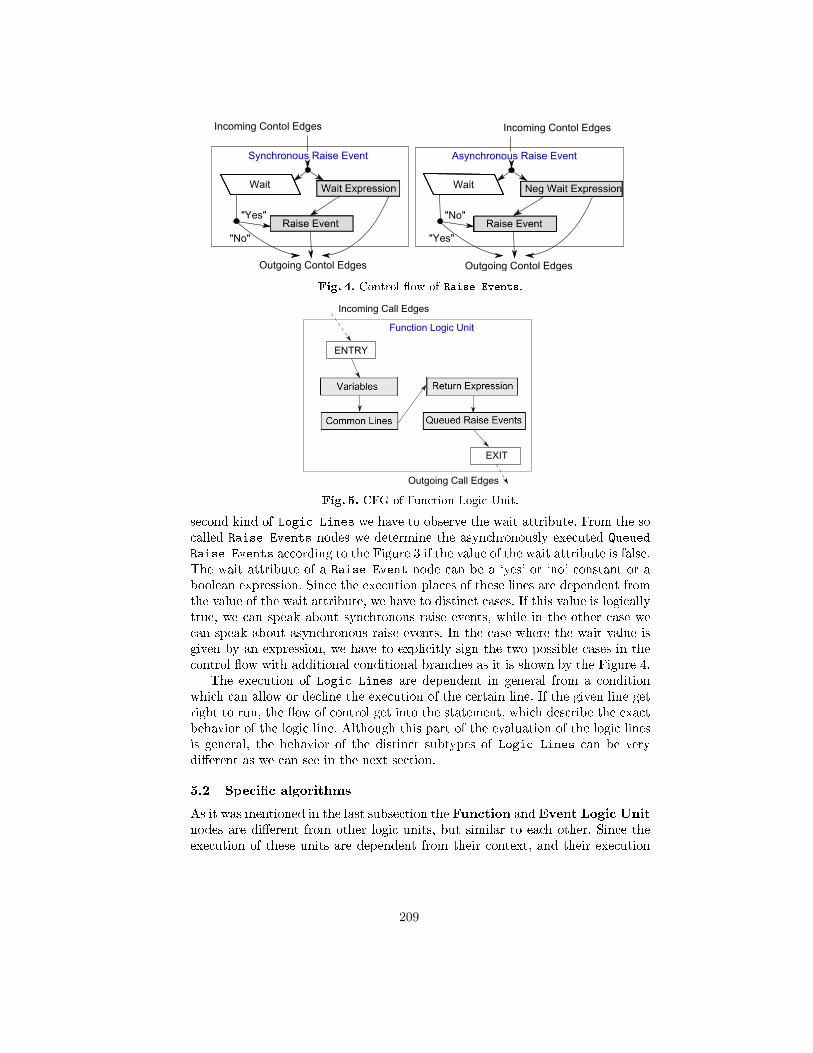
Fig. 4. Control �ow of Raise Events.
Fig. 5. CFG of Function Logic Unit.
second kind of Logic Lines we have to observe the wait attribute. From the socalled Raise Events nodes we determine the asynchronously executed Queued
Raise Events according to the Figure 3 if the value of the wait attribute is false.The wait attribute of a Raise Event node can be a `yes' or `no' constant or aboolean expression. Since the execution places of these lines are dependent fromthe value of the wait attribute, we have to distinct cases. If this value is logicallytrue, we can speak about synchronous raise events, while in the other case wecan speak about asynchronous raise events. In the case where the wait value isgiven by an expression, we have to explicitly sign the two possible cases in thecontrol �ow with additional conditional branches as it is shown by the Figure 4.
The execution of Logic Lines are dependent in general from a conditionwhich can allow or decline the execution of the certain line. If the given line getright to run, the �ow of control get into the statement, which describe the exactbehavior of the logic line. Although this part of the evaluation of the logic linesis general, the behavior of the distinct subtypes of Logic Lines can be verydi�erent as we can see in the next section.
5.2 Speci�c algorithms
As it was mentioned in the last subsection the Function and Event Logic Unitnodes are di�erent from other logic units, but similar to each other. Since theexecution of these units are dependent from their context, and their execution
209
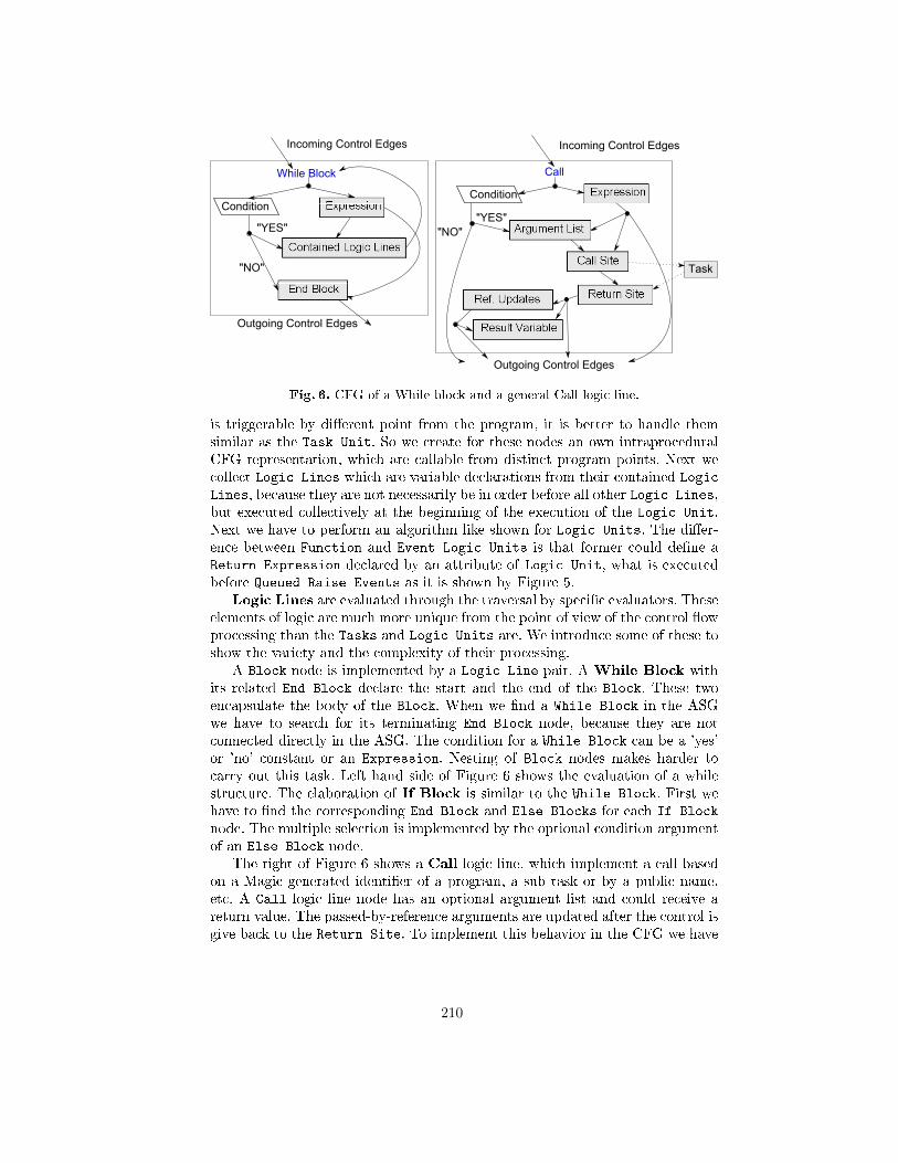
While Block
Incoming Control Edges
Outgoing Control Edges
Condition
"YES"
"NO"
Call
Incoming Control Edges
Outgoing Control Edges
Condition
"YES"
Result Variable
"NO"
Task
Fig. 6. CFG of a While block and a general Call logic line.
is triggerable by di�erent point from the program, it is better to handle themsimilar as the Task Unit. So we create for these nodes an own intraproceduralCFG representation, which are callable from distinct program points. Next wecollect Logic Lines which are variable declarations from their contained Logic
Lines, because they are not necessarily be in order before all other Logic Lines,but executed collectively at the beginning of the execution of the Logic Unit.Next we have to perform an algorithm like shown for Logic Units. The di�er-ence between Function and Event Logic Units is that former could de�ne aReturn Expression declared by an attribute of Logic Unit, what is executedbefore Queued Raise Events as it is shown by Figure 5.
Logic Lines are evaluated through the traversal by speci�c evaluators. Theseelements of logic are much more unique from the point of view of the control �owprocessing than the Tasks and Logic Units are. We introduce some of these toshow the variety and the complexity of their processing.
A Block node is implemented by a Logic Line pair. A While Block withits related End Block declare the start and the end of the Block. These twoencapsulate the body of the Block. When we �nd a While Block in the ASGwe have to search for its terminating End Block node, because they are notconnected directly in the ASG. The condition for a While Block can be a 'yes'or 'no' constant or an Expression. Nesting of Block nodes makes harder tocarry out this task. Left hand side of Figure 6 shows the evaluation of a whilestructure. The elaboration of If Block is similar to the While Block. First wehave to �nd the corresponding End Block and Else Blocks for each If Block
node. The multiple selection is implemented by the optional condition argumentof an Else Block node.
The right of Figure 6 shows a Call logic line, which implement a call basedon a Magic generated identi�er of a program, a sub task or by a public name,etc. A Call logic line node has an optional argument list and could receive areturn value. The passed-by-reference arguments are updated after the control isgive back to the Return Site. To implement this behavior in the CFG we have
210
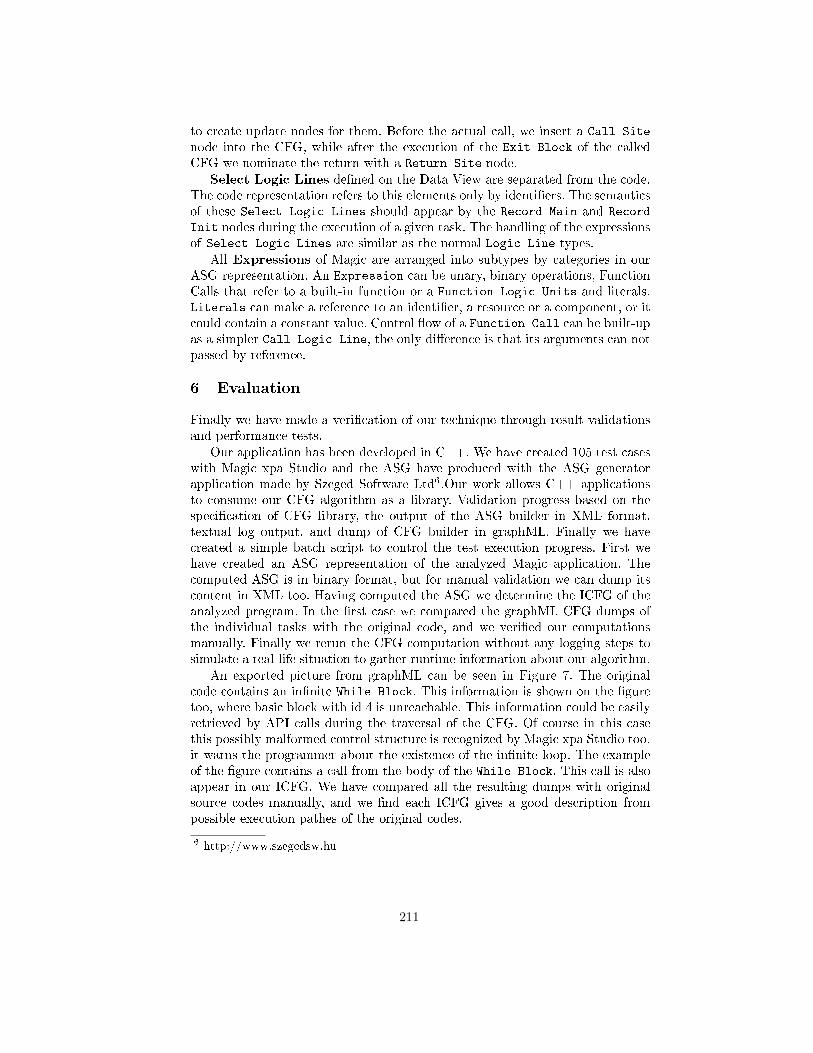
to create update nodes for them. Before the actual call, we insert a Call Site
node into the CFG, while after the execution of the Exit Block of the calledCFG we nominate the return with a Return Site node.
Select Logic Lines de�ned on the Data View are separated from the code.The code representation refers to this elements only by identi�ers. The semanticsof these Select Logic Lines should appear by the Record Main and Record
Init nodes during the execution of a given task. The handling of the expressionsof Select Logic Lines are similar as the normal Logic Line types.
All Expressions of Magic are arranged into subtypes by categories in ourASG representation. An Expression can be unary, binary operations, FunctionCalls that refer to a built-in function or a Function Logic Units and literals.Literals can make a reference to an identi�er, a resource or a component, or itcould contain a constant value. Control �ow of a Function Call can be built-upas a simpler Call Logic Line, the only di�erence is that its arguments can notpassed by reference.
6 Evaluation
Finally we have made a veri�cation of our technique through result validationsand performance tests.
Our application has been developed in C++. We have created 105 test caseswith Magic xpa Studio and the ASG have produced with the ASG generatorapplication made by Szeged Software Ltd6.Our work allows C++ applicationsto consume our CFG algorithm as a library. Validation progress based on thespeci�cation of CFG library, the output of the ASG builder in XML format,textual log output, and dump of CFG builder in graphML. Finally we havecreated a simple batch script to control the test execution progress. First wehave created an ASG representation of the analyzed Magic application. Thecomputed ASG is in binary format, but for manual validation we can dump itscontent in XML too. Having computed the ASG we determine the ICFG of theanalyzed program. In the �rst case we compared the graphML CFG dumps ofthe individual tasks with the original code, and we veri�ed our computationsmanually. Finally we rerun the CFG computation without any logging steps tosimulate a real-life situation to gather runtime information about our algorithm.
An exported picture from graphML can be seen in Figure 7. The originalcode contains an in�nite While Block. This information is shown on the �guretoo, where basic block with id 4 is unreachable. This information could be easilyretrieved by API calls during the traversal of the CFG. Of course in this casethis possibly malformed control structure is recognized by Magic xpa Studio too,it warns the programmer about the existence of the in�nite loop. The exampleof the �gure contains a call from the body of the While Block. This call is alsoappear in our ICFG. We have compared all the resulting dumps with originalsource codes manually, and we �nd each ICFG gives a good description frompossible execution pathes of the original codes.
6 http://www.szegedsw.hu
211
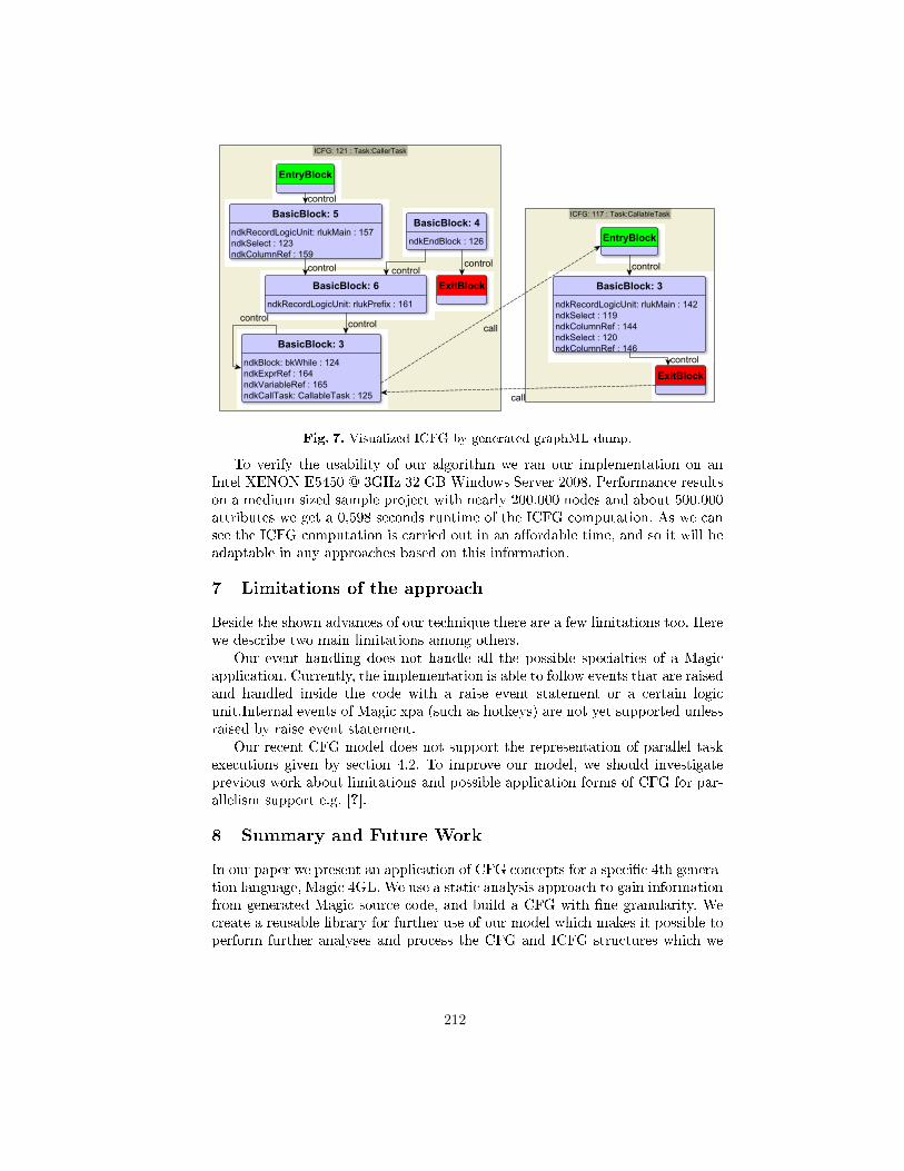
Fig. 7. Visualized ICFG by generated graphML dump.
To verify the usability of our algorithm we ran our implementation on anIntel XENON E5450 @ 3GHz 32 GB Windows Server 2008. Performance resultson a medium sized sample project with nearly 200.000 nodes and about 500.000attributes we get a 0,598 seconds runtime of the ICFG computation. As we cansee the ICFG computation is carried out in an a�ordable time, and so it will beadaptable in any approaches based on this information.
7 Limitations of the approach
Beside the shown advances of our technique there are a few limitations too. Herewe describe two main limitations among others.
Our event handling does not handle all the possible specialties of a Magicapplication. Currently, the implementation is able to follow events that are raisedand handled inside the code with a raise event statement or a certain logicunit.Internal events of Magic xpa (such as hotkeys) are not yet supported unlessraised by raise event statement.
Our recent CFG model does not support the representation of parallel taskexecutions given by section 4.2. To improve our model, we should investigateprevious work about limitations and possible application forms of CFG for par-allelism support e.g. [?].
8 Summary and Future Work
In our paper we present an application of CFG concepts for a speci�c 4th genera-tion language, Magic 4GL. We use a static analysis approach to gain informationfrom generated Magic source code, and build a CFG with �ne granularity. Wecreate a reusable library for further use of our model which makes it possible toperform further analyses and process the CFG and ICFG structures which we
212
created. We created a textual and an XML based graphML dump to make iteasy to get an overview of the processed information.
Our evaluation shows that the implemented approach is applicable for middle-sized Magic applications. The presented method has an a�ordable space require-ment and it constructs the CFG fast enough to analyze large projects too.
Besides, we show that implementing control �ow analysis for a higher-levellanguage, such as Magic, is possible via adapting 3GL techniques, but specialstructures of the language may result in special methods and special structures inthe CFG. For example, the special use of Events enables us to gather more preciseinformation compared to 3GLs where these structures are mostly dynamic.
Conceptually, the presented technique can be applied to other 4GLs too. Thecore elements of the CFG should be the same in a language independent way, butspecial constructs of the language should require special solutions. Particularlyfor other, higher level languages such as 5GLs.
Control �ow analysis is just one step for us towards a more complex approach,where we plan to gather information about the available control paths, andgenerate automatic test cases to support testing and maximize the test coverageof Magic applications [8].
Although we have not yet implemented a speci�c application which is basedon our CFG model, the presented approach and results with our cost measure-ments are already promising, hence useful for further analyses techniques.
Acknowledgements
This research was supported by the Hungarian national grant GOP-1.1.1-11-2011-0039.
References
1. Frances E. Allen. Control �ow analysis. SIGPLAN Not., 5(7):1�19, July 1970.2. J. M. Ashley and R. K. Dybvig. A practical and �exible �ow analysis for higher-
order languages. ACM Trans. Program. Lang. Syst., 20(4):845�868, July 1998.3. Andrew Edward Ayers. Abstract analysis and optimization of Scheme. PhD thesis,
Cambridge, MA, USA, 1993. UMI Order No. not available.4. P. Cousot. Semantic foundations of program analysis. In S.S. Muchnick and N.D.
Jones, editors, Program Flow Analysis: Theory and Applications, chapter 10, pages303�342. Prentice-Hall, Inc., Englewood Cli�s, New Jersey, 1981.
5. Anupam D., Somesh J., Ninghui L., D. Melski, and T. Reps. Analysis techniquesfor information security. Synthesis Lectures on Information Security, Privacy, andTrust, 2(1):1�164, 2010.
6. Rudolf Ferenc, Árpád Beszédes, and Tibor Gyimóthy. Fact Extraction and CodeAuditing with Columbus and SourceAudit. In Proceedings of the 20th InternationalConference on Software Maintenance (ICSM 2004), page 513. IEEE ComputerSociety, September 2004.
7. Rudolf Ferenc, Árpád Beszédes, Mikko Tarkiainen, and Tibor Gyimóthy. Columbus� Reverse Engineering Tool and Schema for C++. In Proceedings of the 18thInternational Conference on Software Maintenance (ICSM 2002), pages 172�181.IEEE Computer Society, October 2002.
213
8. Dániel Fritsi, Csaba Nagy, Rudolf Ferenc, and Tibor Gyimóthy. A layout inde-pendent GUI test automation tool for applications developed in Magic/uniPaaS.In Proceedings of the 12th Symposium on Programming Languages and SoftwareTools (SPLST 2011), pages 248�259, 2011.
9. S. Horwitz, P. Pfei�er, and T. Reps. Dependence analysis for pointer variables.SIGPLAN Not., 24(7):28�40, June 1989.
10. Neil D. Jones. Flow analysis of lambda expressions (preliminary version). InProceedings of the 8th Colloquium on Automata, Languages and Programming,pages 114�128, London, UK, UK, 1981. Springer-Verlag.
11. K. Kennedy and J. R. Allen. Optimizing compilers for modern architectures: adependence-based approach. Morgan Kaufmann Publishers Inc., San Francisco,CA, USA, 2002.
12. Ákos Kiss, Judit Jász, Gábor Lehotai, and Tibor Gyimóthy. Interprocedural staticslicing of binary executables. In Proc. Third IEEE International Workshop onSource Code Analysis and Manipulation, pages 118�127, September 2003.
13. M. Kowalkiewicz, R. Lu, S. Bäuerle, M. Krümpelmann, and S. Lippe. Weak de-pendencies in business process models. In Witold Abramowicz and Dieter Fensel,editors, Business Information Systems, volume 7 of Lecture Notes in Business In-formation Processing, pages 177�188. Springer Berlin Heidelberg, 2008.
14. M. S. Lam and R. P. Wilson. Limits of control �ow on parallelism. SIGARCHComput. Archit. News, 20(2):46�57, April 1992.
15. Jan Midtgaard. Control-�ow analysis of functional programs. ACM Comput. Surv.,44(3):10:1�10:33, June 2012.
16. Steven S. Muchnick. Advanced Compiler Design and Implementation. MorganKaufmann, 1997.
17. Csaba Nagy, László Vidács, Rudolf Ferenc, Tibor Gyimóthy, Ferenc Kocsis, andIstván Kovács. Complexity measures in 4GL environment. In Proceedings of the2011 international conference on Computational science and Its applications - Vol-ume Part V, pages 293�309. Springer-Verlag, 2011.
18. Csaba Nagy, László Vidács, Rudolf Ferenc, Tibor Gyimóthy, Ferenc Kocsis, andIstván Kovács. Solutions for reverse engineering 4GL applications, recovering thedesign of a logistical wholesale system. In Proceedings of the 15th European Confer-ence on Software Maintenance and Reengineering (CSMR), pages 343 �346, 2011.
19. J. Rech and W. Schäfer. Visual support of software engineers during developmentand maintenance. SIGSOFT Softw. Eng. Notes, 32(2):1�3, March 2007.
20. O. Shivers. Control �ow analysis in scheme. SIGPLAN Not., 23(7):164�174, June1988.
21. The Institute of Electrical and Eletronics Engineers. Ieee standard glossary ofsoftware engineering terminology. IEEE Standard, September 1990.
22. Frank Tip. A survey of program slicing techniques. Journal of ProgrammingLanguages, 3(3):121�189, September 1995.
23. Jussi Vanhatalo, Hagen Völzer, and Frank Leymann. Faster and more focusedcontrol-�ow analysis for business process models through sese decomposition. InBerndJ. Krämer, Kwei-Jay Lin, and Priya Narasimhan, editors, Service-OrientedComputing � ICSOC 2007, volume 4749 of Lecture Notes in Computer Science,pages 43�55. Springer Berlin Heidelberg, 2007.
24. Visser, W. and P�as�areanu, C. S. and Khurshid, S. Test Input Generation withJava PathFinder. SIGSOFT Softw. Eng. Notes, 29(4):97�107, July 2004.
214
Runtime Exception Detection in Java ProgramsUsing Symbolic Execution?
Istvan Kadar, Peter Hegedus, and Rudolf Ferenc
University of Szeged, Department of Software EngineeringArpad ter 2. H-6720 Szeged, Hungary
{ikadar|hpeter|ferenc}@inf.u-szeged.hu
Abstract. Most of the runtime failures of a software system can be re-vealed during test execution only, which has a very high cost. In Javaprograms, runtime failures are manifested as unhandled runtime excep-tions.In this paper we present an approach and tool for detecting runtimeexceptions in Java programs without having to execute tests on the soft-ware. We use the symbolic execution technique to implement the ap-proach. By executing the methods of the program symbolically we candetermine those execution branches that throw exceptions. Our algo-rithm is able to generate concrete test inputs also that cause the programto fail in runtime.We used the Symbolic PathFinder extension of the Java PathFinder asthe symbolic execution engine. Besides small example codes we evaluatedour algorithm on three open source systems: jEdit, ArgoUML, and log4j.We found multiple errors in the log4j system that were also reported asreal bugs in its bug tracking system.
Keywords: Java Runtime Exception, Symbolic Execution, Rule Check-ing, Java Virtual Machine
1 Introduction
Nowadays, it is a big challenge of the software engineering to produce great,reliable and robust software systems. About 40% of the total development costsgo for testing [1], and the maintenance activities, particularly bug fixing of thesystem also require a considerable amount of resources [2]. Our purpose is todevelop a new method and tool, which supports this phase of the software engi-neering lifecycle with detecting runtime exceptions in Java programs, and findingdangerous parts in the source code, that could behave as time-bombs during fur-ther development. The analysis will be done without executing the program ina real environment.
Runtime exceptions in the Java programming language are the instances ofclass java.lang.RuntimeException, which represent a sort of runtime error, forexample an invalid type cast, an array over indexing, or division by zero. Theseexceptions are dangerous because they can cause a sudden stop of the program,as they do not have to be handled by the programmer explicitly.
Exploration of these exceptions is done by using a technique called symbolicexecution [3]. When a program is executed symbolically, it is not executed on
? This research was supported by the Hungarian national grant GOP-1.1.1-11-2011-0038 and the TAMOP 4.2.4. A/2-11-1-2012-0001 European grant.
215
concrete input data but input data is handled as symbolic variables. When theexecution reaches a branching condition containing a symbolic variable, the ex-ecution continues on both branches. This way, all of the possible branches ofthe program will be executed in theory. Java PathFinder (JPF) [4] is a softwaremodel checker which is developed at NASA Ames Research Center. In fact, JavaPathFinder is a Java virtual machine that executes Java bytecode in a specialway. Symbolic PathFinder (SPF) [5] is an extension of JPF, which can performsymbolic execution of Java bytecodes. The presented work is based on thesetools.
The paper explains how the detection of runtime exceptions of the Java pro-gramming language was implemented using Java PathFinder and symbolic exe-cution. Concrete input parameters of the method resulting a runtime exceptionare also determined. It is also described how the number of execution branches,and the state space have been reduced to achieve a better performance. Theimplemented tool called Jpf Checker has been tested on real life projects, thelog4j, ArgoUML, and jEdit open source systems. We found multiple errors inthe log4j system that were also reported as real bugs in its bug tracking system.The performance of the tool is acceptable since the analysis was finished in acouple of hours even for the biggest system.
The remainder of the paper is organized as follows. We give a brief intro-duction to symbolic execution in Section 2. After that in Section 3 we presentour approach for detecting runtime exceptions. Section 4 discusses the results ofthe implemented algorithm on different small examples and real life open sourceprojects. Section 5 collects the works that related to ours. Finally, we concludethe paper and present some future work in Section 6.
2 Symbolic Execution
During its execution, every program performs operations on the input data ina defined order. Symbolic execution [3] is based on the idea that the programis operated on symbolic variables instead of specific input data, and the outputwill be a function of these symbolic variables. A symbolic variable is a set of thepossible values of a concrete variable in the program, thus a symbolic state is aset of concrete states. When the execution reaches a selection control structure(e.g. an if statement) where the logical expression contains a symbolic variable,it cannot be evaluated, its value might be also true and false. The executioncontinues on both branches accordingly. This way we can simulate all the possibleexecution branches of the program.
During symbolic execution we maintain a so-called path condition (PC). Thepath condition is a quantifier-free logical formula with the initial value of true,and its variables are the symbolic variables of the program. If the executionreaches a branching condition that depends on one or more symbolic variables,the condition will be appended to the current PC with the logical operator ANDto indicate the true branch, and the negation of the condition to indicate the falsebranch. With such an extension of the PC, each execution branch will be linkedto a unique formula over the symbolic variables. In addition to maintaining the
216
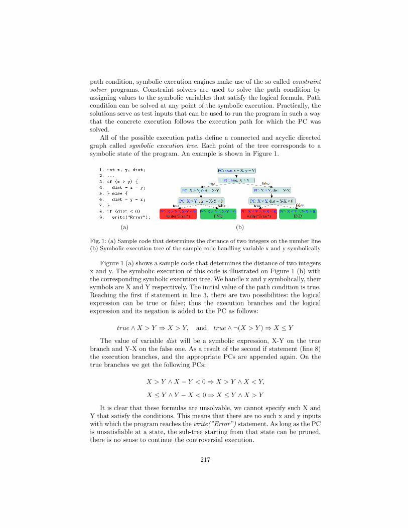
path condition, symbolic execution engines make use of the so called constraintsolver programs. Constraint solvers are used to solve the path condition byassigning values to the symbolic variables that satisfy the logical formula. Pathcondition can be solved at any point of the symbolic execution. Practically, thesolutions serve as test inputs that can be used to run the program in such a waythat the concrete execution follows the execution path for which the PC wassolved.
All of the possible execution paths define a connected and acyclic directedgraph called symbolic execution tree. Each point of the tree corresponds to asymbolic state of the program. An example is shown in Figure 1.
(a) (b)
Fig. 1: (a) Sample code that determines the distance of two integers on the number line(b) Symbolic execution tree of the sample code handling variable x and y symbolically
Figure 1 (a) shows a sample code that determines the distance of two integersx and y. The symbolic execution of this code is illustrated on Figure 1 (b) withthe corresponding symbolic execution tree. We handle x and y symbolically, theirsymbols are X and Y respectively. The initial value of the path condition is true.Reaching the first if statement in line 3, there are two possibilities: the logicalexpression can be true or false; thus the execution branches and the logicalexpression and its negation is added to the PC as follows:
true ∧X > Y ⇒ X > Y, and true ∧ ¬(X > Y )⇒ X ≤ Y
The value of variable dist will be a symbolic expression, X-Y on the truebranch and Y-X on the false one. As a result of the second if statement (line 8)the execution branches, and the appropriate PCs are appended again. On thetrue branches we get the following PCs:
X > Y ∧X − Y < 0⇒ X > Y ∧X < Y,
X ≤ Y ∧ Y −X < 0⇒ X ≤ Y ∧X > Y
It is clear that these formulas are unsolvable, we cannot specify such X andY that satisfy the conditions. This means that there are no such x and y inputswith which the program reaches the write(”Error”) statement. As long as the PCis unsatisfiable at a state, the sub-tree starting from that state can be pruned,there is no sense to continue the controversial execution.
217
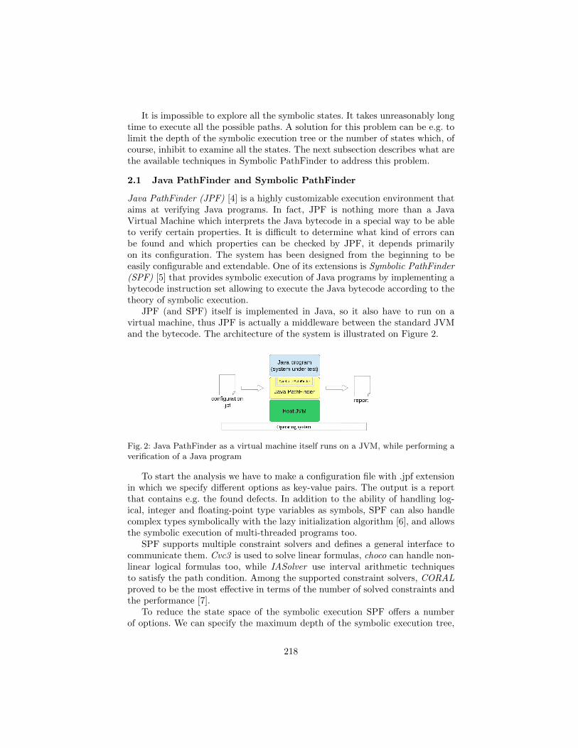
It is impossible to explore all the symbolic states. It takes unreasonably longtime to execute all the possible paths. A solution for this problem can be e.g. tolimit the depth of the symbolic execution tree or the number of states which, ofcourse, inhibit to examine all the states. The next subsection describes what arethe available techniques in Symbolic PathFinder to address this problem.
2.1 Java PathFinder and Symbolic PathFinder
Java PathFinder (JPF) [4] is a highly customizable execution environment thataims at verifying Java programs. In fact, JPF is nothing more than a JavaVirtual Machine which interprets the Java bytecode in a special way to be ableto verify certain properties. It is difficult to determine what kind of errors canbe found and which properties can be checked by JPF, it depends primarilyon its configuration. The system has been designed from the beginning to beeasily configurable and extendable. One of its extensions is Symbolic PathFinder(SPF) [5] that provides symbolic execution of Java programs by implementing abytecode instruction set allowing to execute the Java bytecode according to thetheory of symbolic execution.
JPF (and SPF) itself is implemented in Java, so it also have to run on avirtual machine, thus JPF is actually a middleware between the standard JVMand the bytecode. The architecture of the system is illustrated on Figure 2.
Fig. 2: Java PathFinder as a virtual machine itself runs on a JVM, while performing averification of a Java program
To start the analysis we have to make a configuration file with .jpf extensionin which we specify different options as key-value pairs. The output is a reportthat contains e.g. the found defects. In addition to the ability of handling log-ical, integer and floating-point type variables as symbols, SPF can also handlecomplex types symbolically with the lazy initialization algorithm [6], and allowsthe symbolic execution of multi-threaded programs too.
SPF supports multiple constraint solvers and defines a general interface tocommunicate them. Cvc3 is used to solve linear formulas, choco can handle non-linear logical formulas too, while IASolver use interval arithmetic techniquesto satisfy the path condition. Among the supported constraint solvers, CORALproved to be the most effective in terms of the number of solved constraints andthe performance [7].
To reduce the state space of the symbolic execution SPF offers a numberof options. We can specify the maximum depth of the symbolic execution tree,
218
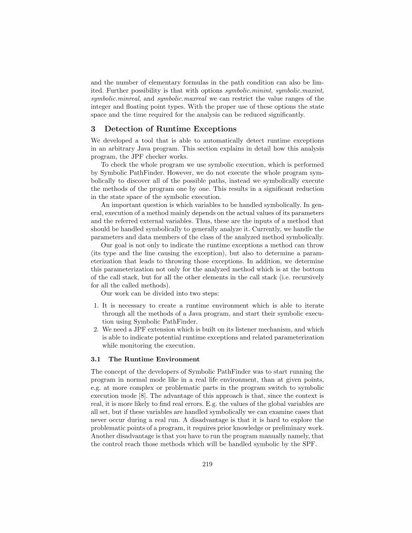
and the number of elementary formulas in the path condition can also be lim-ited. Further possibility is that with options symbolic.minint, symbolic.maxint,symbolic.minreal, and symbolic.maxreal we can restrict the value ranges of theinteger and floating point types. With the proper use of these options the statespace and the time required for the analysis can be reduced significantly.
3 Detection of Runtime Exceptions
We developed a tool that is able to automatically detect runtime exceptionsin an arbitrary Java program. This section explains in detail how this analysisprogram, the JPF checker works.
To check the whole program we use symbolic execution, which is performedby Symbolic PathFinder. However, we do not execute the whole program sym-bolically to discover all of the possible paths, instead we symbolically executethe methods of the program one by one. This results in a significant reductionin the state space of the symbolic execution.
An important question is which variables to be handled symbolically. In gen-eral, execution of a method mainly depends on the actual values of its parametersand the referred external variables. Thus, these are the inputs of a method thatshould be handled symbolically to generally analyze it. Currently, we handle theparameters and data members of the class of the analyzed method symbolically.
Our goal is not only to indicate the runtime exceptions a method can throw(its type and the line causing the exception), but also to determine a param-eterization that leads to throwing those exceptions. In addition, we determinethis parameterization not only for the analyzed method which is at the bottomof the call stack, but for all the other elements in the call stack (i.e. recursivelyfor all the called methods).
Our work can be divided into two steps:
1. It is necessary to create a runtime environment which is able to iteratethrough all the methods of a Java program, and start their symbolic execu-tion using Symbolic PathFinder.
2. We need a JPF extension which is built on its listener mechanism, and whichis able to indicate potential runtime exceptions and related parameterizationwhile monitoring the execution.
3.1 The Runtime Environment
The concept of the developers of Symbolic PathFinder was to start running theprogram in normal mode like in a real life environment, than at given points,e.g. at more complex or problematic parts in the program switch to symbolicexecution mode [8]. The advantage of this approach is that, since the context isreal, it is more likely to find real errors. E.g. the values of the global variables areall set, but if these variables are handled symbolically we can examine cases thatnever occur during a real run. A disadvantage is that it is hard to explore theproblematic points of a program, it requires prior knowledge or preliminary work.Another disadvantage is that you have to run the program manually namely, thatthe control reach those methods which will be handled symbolic by the SPF.
219
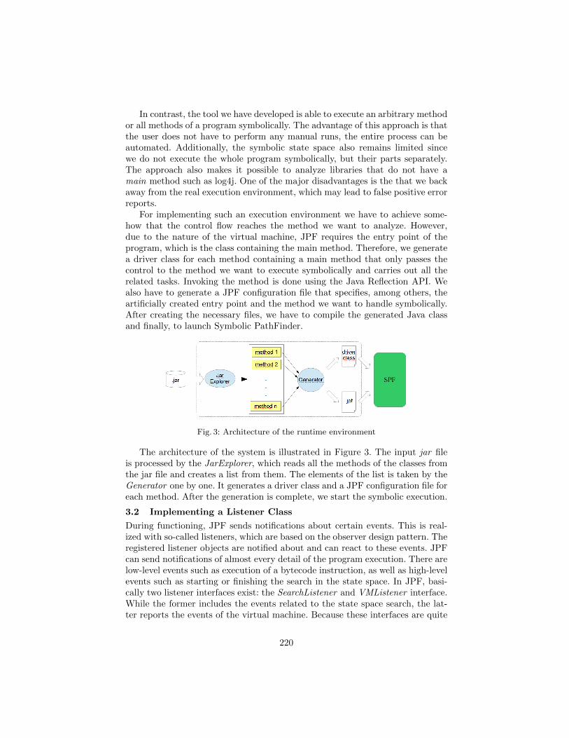
In contrast, the tool we have developed is able to execute an arbitrary methodor all methods of a program symbolically. The advantage of this approach is thatthe user does not have to perform any manual runs, the entire process can beautomated. Additionally, the symbolic state space also remains limited sincewe do not execute the whole program symbolically, but their parts separately.The approach also makes it possible to analyze libraries that do not have amain method such as log4j. One of the major disadvantages is the that we backaway from the real execution environment, which may lead to false positive errorreports.
For implementing such an execution environment we have to achieve some-how that the control flow reaches the method we want to analyze. However,due to the nature of the virtual machine, JPF requires the entry point of theprogram, which is the class containing the main method. Therefore, we generatea driver class for each method containing a main method that only passes thecontrol to the method we want to execute symbolically and carries out all therelated tasks. Invoking the method is done using the Java Reflection API. Wealso have to generate a JPF configuration file that specifies, among others, theartificially created entry point and the method we want to handle symbolically.After creating the necessary files, we have to compile the generated Java classand finally, to launch Symbolic PathFinder.
Fig. 3: Architecture of the runtime environment
The architecture of the system is illustrated in Figure 3. The input jar fileis processed by the JarExplorer, which reads all the methods of the classes fromthe jar file and creates a list from them. The elements of the list is taken by theGenerator one by one. It generates a driver class and a JPF configuration file foreach method. After the generation is complete, we start the symbolic execution.
3.2 Implementing a Listener Class
During functioning, JPF sends notifications about certain events. This is real-ized with so-called listeners, which are based on the observer design pattern. Theregistered listener objects are notified about and can react to these events. JPFcan send notifications of almost every detail of the program execution. There arelow-level events such as execution of a bytecode instruction, as well as high-levelevents such as starting or finishing the search in the state space. In JPF, basi-cally two listener interfaces exist: the SearchListener and VMListener interface.While the former includes the events related to the state space search, the lat-ter reports the events of the virtual machine. Because these interfaces are quite
220
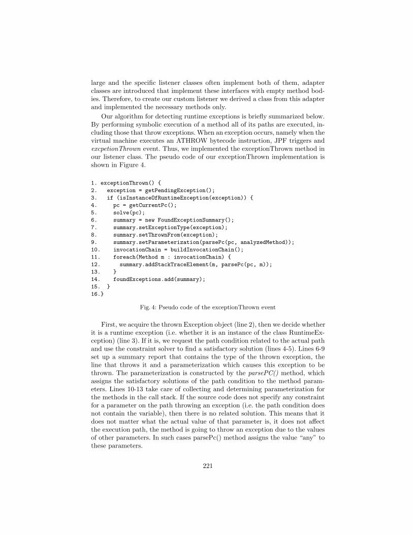
large and the specific listener classes often implement both of them, adapterclasses are introduced that implement these interfaces with empty method bod-ies. Therefore, to create our custom listener we derived a class from this adapterand implemented the necessary methods only.
Our algorithm for detecting runtime exceptions is briefly summarized below.By performing symbolic execution of a method all of its paths are executed, in-cluding those that throw exceptions. When an exception occurs, namely when thevirtual machine executes an ATHROW bytecode instruction, JPF triggers andexcpetionThrown event. Thus, we implemented the exceptionThrown method inour listener class. The pseudo code of our exceptionThrown implementation isshown in Figure 4.
1. exceptionThrown() {
2. exception = getPendingException();
3. if (isInstanceOfRuntimeException(exception)) {
4. pc = getCurrentPc();
5. solve(pc);
6. summary = new FoundExceptionSummary();
7. summary.setExceptionType(exception);
8. summary.setThrownFrom(exception);
9. summary.setParameterization(parsePc(pc, analyzedMethod));
10. invocationChain = buildInvocationChain();
11. foreach(Method m : invocationChain) {
12. summary.addStackTraceElement(m, parsePc(pc, m));
13. }
14. foundExceptions.add(summary);
15. }
16.}
Fig. 4: Pseudo code of the exceptionThrown event
First, we acquire the thrown Exception object (line 2), then we decide whetherit is a runtime exception (i.e. whether it is an instance of the class RuntimeEx-ception) (line 3). If it is, we request the path condition related to the actual pathand use the constraint solver to find a satisfactory solution (lines 4-5). Lines 6-9set up a summary report that contains the type of the thrown exception, theline that throws it and a parameterization which causes this exception to bethrown. The parameterization is constructed by the parsePC() method, whichassigns the satisfactory solutions of the path condition to the method param-eters. Lines 10-13 take care of collecting and determining parameterization forthe methods in the call stack. If the source code does not specify any constraintfor a parameter on the path throwing an exception (i.e. the path condition doesnot contain the variable), then there is no related solution. This means that itdoes not matter what the actual value of that parameter is, it does not affectthe execution path, the method is going to throw an exception due to the valuesof other parameters. In such cases parsePc() method assigns the value “any” tothese parameters.
221
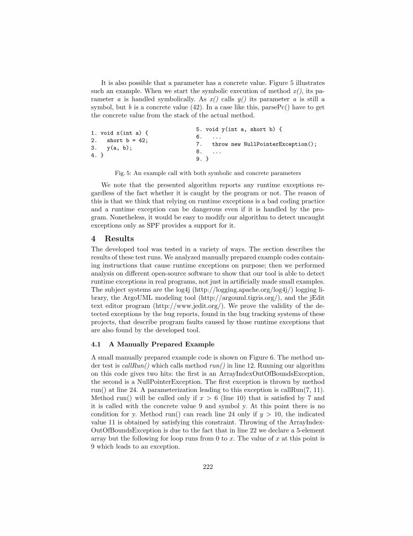
It is also possible that a parameter has a concrete value. Figure 5 illustratessuch an example. When we start the symbolic execution of method x(), its pa-rameter a is handled symbolically. As x() calls y() its parameter a is still asymbol, but b is a concrete value (42). In a case like this, parsePc() have to getthe concrete value from the stack of the actual method.
1. void x(int a) {
2. short b = 42;
3. y(a, b);
4. }
5. void y(int a, short b) {
6. ...
7. throw new NullPointerException();
8. ...
9. }
Fig. 5: An example call with both symbolic and concrete parameters
We note that the presented algorithm reports any runtime exceptions re-gardless of the fact whether it is caught by the program or not. The reason ofthis is that we think that relying on runtime exceptions is a bad coding practiceand a runtime exception can be dangerous even if it is handled by the pro-gram. Nonetheless, it would be easy to modify our algorithm to detect uncaughtexceptions only as SPF provides a support for it.
4 Results
The developed tool was tested in a variety of ways. The section describes theresults of these test runs. We analyzed manually prepared example codes contain-ing instructions that cause runtime exceptions on purpose; then we performedanalysis on different open-source software to show that our tool is able to detectruntime exceptions in real programs, not just in artificially made small examples.The subject systems are the log4j (http://logging.apache.org/log4j/) logging li-brary, the ArgoUML modeling tool (http://argouml.tigris.org/), and the jEdittext editor program (http://www.jedit.org/). We prove the validity of the de-tected exceptions by the bug reports, found in the bug tracking systems of theseprojects, that describe program faults caused by those runtime exceptions thatare also found by the developed tool.
4.1 A Manually Prepared Example
A small manually prepared example code is shown on Figure 6. The method un-der test is callRun() which calls method run() in line 12. Running our algorithmon this code gives two hits: the first is an ArrayIndexOutOfBoundsException,the second is a NullPointerException. The first exception is thrown by methodrun() at line 24. A parameterization leading to this exception is callRun(7, 11).Method run() will be called only if x > 6 (line 10) that is satisfied by 7 andit is called with the concrete value 9 and symbol y. At this point there is nocondition for y. Method run() can reach line 24 only if y > 10, the indicatedvalue 11 is obtained by satisfying this constraint. Throwing of the ArrayIndex-OutOfBoundsException is due to the fact that in line 22 we declare a 5-elementarray but the following for loop runs from 0 to x. The value of x at this point is9 which leads to an exception.
222
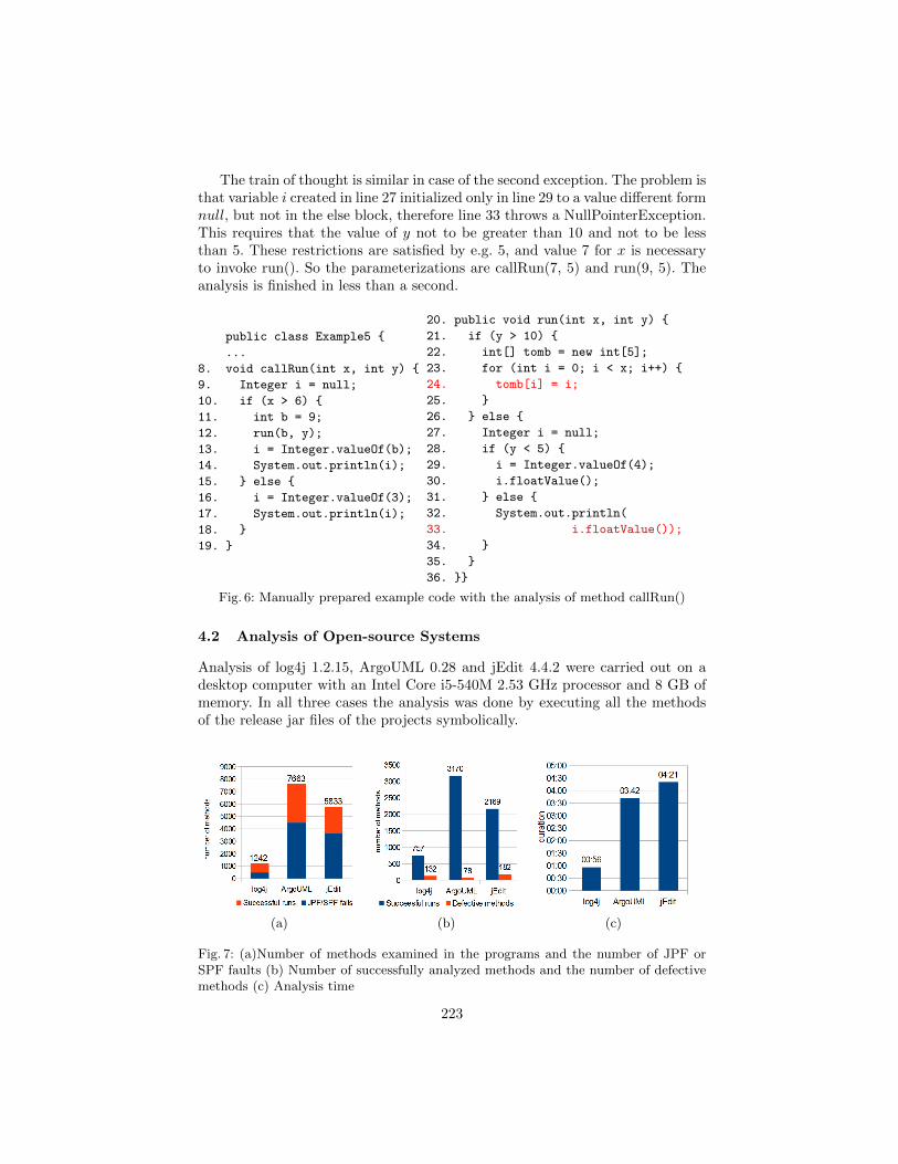
The train of thought is similar in case of the second exception. The problem isthat variable i created in line 27 initialized only in line 29 to a value different formnull, but not in the else block, therefore line 33 throws a NullPointerException.This requires that the value of y not to be greater than 10 and not to be lessthan 5. These restrictions are satisfied by e.g. 5, and value 7 for x is necessaryto invoke run(). So the parameterizations are callRun(7, 5) and run(9, 5). Theanalysis is finished in less than a second.
public class Example5 {
...
8. void callRun(int x, int y) {
9. Integer i = null;
10. if (x > 6) {
11. int b = 9;
12. run(b, y);
13. i = Integer.valueOf(b);
14. System.out.println(i);
15. } else {
16. i = Integer.valueOf(3);
17. System.out.println(i);
18. }
19. }
20. public void run(int x, int y) {
21. if (y > 10) {
22. int[] tomb = new int[5];
23. for (int i = 0; i < x; i++) {
24. tomb[i] = i;
25. }
26. } else {
27. Integer i = null;
28. if (y < 5) {
29. i = Integer.valueOf(4);
30. i.floatValue();
31. } else {
32. System.out.println(
33. i.floatValue());
34. }
35. }
36. }}
Fig. 6: Manually prepared example code with the analysis of method callRun()
4.2 Analysis of Open-source Systems
Analysis of log4j 1.2.15, ArgoUML 0.28 and jEdit 4.4.2 were carried out on adesktop computer with an Intel Core i5-540M 2.53 GHz processor and 8 GB ofmemory. In all three cases the analysis was done by executing all the methodsof the release jar files of the projects symbolically.
(a) (b) (c)
Fig. 7: (a)Number of methods examined in the programs and the number of JPF orSPF faults (b) Number of successfully analyzed methods and the number of defectivemethods (c) Analysis time
223
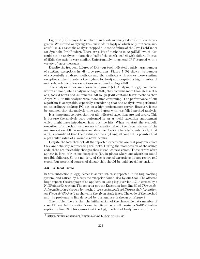
Figure 7 (a) displays the number of methods we analyzed in the different pro-grams. We started analyzing 1242 methods in log4j of which only 757 were suc-cessful, in 474 cases the analysis stopped due to the failure of the Java PathFinder(or Symbolic PathFinder). There are a lot of methods in ArgoUML which alsocould not be analyzed, more than half of the checks ended with failure. In caseof jEdit the ratio is very similar. Unfortunately, in general JPF stopped with avariety of error messages.
Despite the frequent failures of JPF, our tool indicated a fairly large numberof runtime exceptions in all three programs. Figure 7 (b) shows the numberof successfully analyzed methods and the methods with one or more runtimeexceptions. The hit rate is the highest for log4j and despite its high number ofmethods, relatively few exceptions were found in ArgoUML.
The analysis times are shown in Figure 7 (c). Analysis of log4j completedwithin an hour, while analysis of ArgoUML, that contains more than 7500 meth-ods, took 3 hours and 42 minutes. Although jEdit contains fewer methods thanArgoUML, its full analysis were more time-consuming. The performance of ouralgorithm is acceptable, especially considering that the analysis was performedon an ordinary desktop PC not on a high-performance server. However, it canbe assumed that the analysis time would grow with less failed method analysis.
It is important to note, that not all indicated exceptions are real errors. Thisis because the analysis were performed in an artificial execution environmentwhich might have introduced false positive hits. When we start the symbolicexecution of a method we have no information about the circumstances of thereal invocation. All parameters and data members are handled symbolically, thatis, it is considered that their value can be anything although it is possible thata particular value of a variable never occurs.
Despite the fact that not all the reported exceptions are real program errorsthey are definitely representing real risks. During the modification of the sourcecode there are inevitably changes that introduce new errors. These errors oftenappear in form of runtime exceptions (i.e. in places where our algorithm foundpossible failures). So the majority of the reported exceptions do not report realerrors, but potential sources of danger that should be paid special attention.
4.3 A Real Error
In this subsection a log4j defect is shown which is reported in its bug trackingsystem, and caused by a runtime exception found also by our tool. The affectedbug 1 reports the stoppage of an application using log4j version 1.2.14 caused by aNullPointerException. The reporter got the Exception from line 59 of Throwable-Information.java thrown by method org.apache.log4j.spi.ThrowableInformation.getThrowableStrRep() as shown in the given stack trace. The code of the methodand the problematic line detected by our analysis is shown on Figure 8.
The problem here is that the initialization of the throwable data member ofclass ThrowableInformation is omitted, its value is null causing a NullPointerEx-ception in line 59. This causes that the log() method of log4j can also throw an
1 https://issues.apache.org/bugzilla/show bug.cgi?id=44038
224
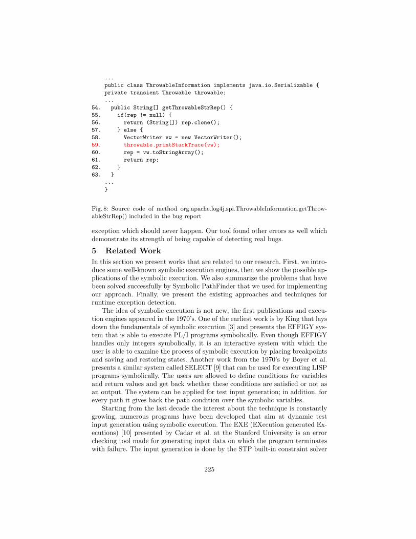
...
public class ThrowableInformation implements java.io.Serializable {
private transient Throwable throwable;
...
54. public String[] getThrowableStrRep() {
55. if(rep != null) {
56. return (String[]) rep.clone();
57. } else {
58. VectorWriter vw = new VectorWriter();
59. throwable.printStackTrace(vw);
60. rep = vw.toStringArray();
61. return rep;
62. }
63. }
...
}
Fig. 8: Source code of method org.apache.log4j.spi.ThrowableInformation.getThrow-ableStrRep() included in the bug report
exception which should never happen. Our tool found other errors as well whichdemonstrate its strength of being capable of detecting real bugs.
5 Related Work
In this section we present works that are related to our research. First, we intro-duce some well-known symbolic execution engines, then we show the possible ap-plications of the symbolic execution. We also summarize the problems that havebeen solved successfully by Symbolic PathFinder that we used for implementingour approach. Finally, we present the existing approaches and techniques forruntime exception detection.
The idea of symbolic execution is not new, the first publications and execu-tion engines appeared in the 1970’s. One of the earliest work is by King that laysdown the fundamentals of symbolic execution [3] and presents the EFFIGY sys-tem that is able to execute PL/I programs symbolically. Even though EFFIGYhandles only integers symbolically, it is an interactive system with which theuser is able to examine the process of symbolic execution by placing breakpointsand saving and restoring states. Another work from the 1970’s by Boyer et al.presents a similar system called SELECT [9] that can be used for executing LISPprograms symbolically. The users are allowed to define conditions for variablesand return values and get back whether these conditions are satisfied or not asan output. The system can be applied for test input generation; in addition, forevery path it gives back the path condition over the symbolic variables.
Starting from the last decade the interest about the technique is constantlygrowing, numerous programs have been developed that aim at dynamic testinput generation using symbolic execution. The EXE (EXecution generated Ex-ecutions) [10] presented by Cadar et al. at the Stanford University is an errorchecking tool made for generating input data on which the program terminateswith failure. The input generation is done by the STP built-in constraint solver
225
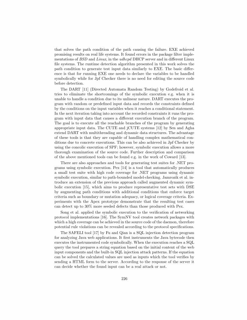
that solves the path condition of the path causing the failure. EXE achievedpromising results on real life systems. It found errors in the package filter imple-mentations of BSD and Linux, in the udhcpd DHCP server and in different Linuxfile systems. The runtime detection algorithm presented in this work solves thepath condition to generate test input data similarly to EXE. The basic differ-ence is that for running EXE one needs to declare the variables to be handledsymbolically while for Jpf Checker there is no need for editing the source codebefore detection.
The DART [11] (Directed Automata Random Testing) by Godefroid et al.tries to eliminate the shortcomings of the symbolic execution e.g. when it isunable to handle a condition due to its unlinear nature. DART executes the pro-gram with random or predefined input data and records the constraints definedby the conditions on the input variables when it reaches a conditional statement.In the next iteration taking into account the recorded constraints it runs the pro-gram with input data that causes a different execution branch of the program.The goal is to execute all the reachable branches of the program by generatingappropriate input data. The CUTE and jCUTE systems [12] by Sen and Aghaextend DART with multithreading and dynamic data structures. The advantageof these tools is that they are capable of handling complex mathematical con-ditions due to concrete executions. This can be also achieved in Jpf Checker byusing the concolic execution of SPF; however, symbolic execution allows a morethorough examination of the source code. Further description and comparisonof the above mentioned tools can be found e.g. in the work of Coward [13].
There are also approaches and tools for generating test suites for .NET pro-grams using symbolic execution. Pex [14] is a tool that automatically producesa small test suite with high code coverage for .NET programs using dynamicsymbolic execution, similar to path-bounded model-checking. Jamrozik et al. in-troduce an extension of the previous approach called augmented dynamic sym-bolic execution [15], which aims to produce representative test sets with DSEby augmenting path conditions with additional conditions that enforce targetcriteria such as boundary or mutation adequacy, or logical coverage criteria. Ex-periments with the Apex prototype demonstrate that the resulting test casescan detect up to 30% more seeded defects than those produced with Pex.
Song et al. applied the symbolic execution to the verification of networkingprotocol implementations [16]. The SymNV tool creates network packages withwhich a high coverage can be achieved in the source code of the daemon, thereforepotential rule violations can be revealed according to the protocol specifications.
The SAFELI tool [17] by Fu and Qian is a SQL injection detection programfor analyzing Java web applications. It first instruments the Java bytecode thenexecutes the instrumented code symbolically. When the execution reaches a SQLquery the tool prepares a string equation based on the initial content of the webinput components and the built-in SQL injection attack patterns. If the equationcan be solved the calculated values are used as inputs which the tool verifies bysending a HTML form to the server. According to the response of the server itcan decide whether the found input can be a real attack or not.
226
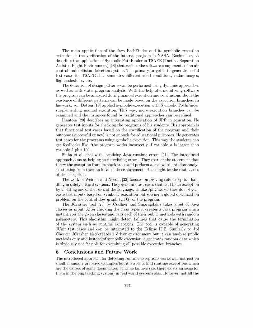
The main application of the Java PathFinder and its symbolic executionextension is the verification of the internal projects in NASA. Bushnell et al.describes the application of Symbolic PathFinder in TSAFE (Tactical SeparationAssisted Flight Environment) [18] that verifies the software components of an aircontrol and collision detection system. The primary target is to generate usefultest cases for TSAFE that simulates different wind conditions, radar images,flight schedules, etc.
The detection of design patterns can be performed using dynamic approachesas well as with static program analysis. With the help of a monitoring softwarethe program can be analyzed during manual execution and conclusions about theexistence of different patterns can be made based on the execution branches. Inhis work, von Detten [19] applied symbolic execution with Symbolic PathFindersupplementing manual execution. This way, more execution branches can beexamined and the instances found by traditional approaches can be refined.
Ihantola [20] describes an interesting application of JPF in education. Hegenerates test inputs for checking the programs of his students. His approach isthat functional test cases based on the specification of the program and theiroutcome (successful or not) is not enough for educational purposes. He generatestest cases for the programs using symbolic execution. This way the students canget feedbacks like “the program works incorrectly if variable a is larger thanvariable b plus 10”.
Sinha et al. deal with localizing Java runtime errors [21]. The introducedapproach aims at helping to fix existing errors. They extract the statement thatthrew the exception from its stack trace and perform a backward dataflow analy-sis starting from there to localize those statements that might be the root causesof the exception.
The work of Weimer and Necula [22] focuses on proving safe exception han-dling in safety critical systems. They generate test cases that lead to an exceptionby violating one of the rules of the language. Unlike Jpf Checker they do not gen-erate test inputs based on symbolic execution but solving a global optimizationproblem on the control flow graph (CFG) of the program.
The JCrasher tool [23] by Csallner and Smaragdakis takes a set of Javaclasses as input. After checking the class types it creates a Java program whichinstantiates the given classes and calls each of their public methods with randomparameters. This algorithm might detect failures that cause the terminationof the system such as runtime exceptions. The tool is capable of generatingJUnit test cases and can be integrated to the Eclipse IDE. Similarly to JpfChecker JCrasher also creates a driver environment but it can analyze publicmethods only and instead of symbolic execution it generates random data whichis obviously not feasible for examining all possible execution branches.
6 Conclusions and Future WorkThe introduced approach for detecting runtime exceptions works well not just onsmall, manually prepared examples but it is able to find runtime exceptions whichare the causes of some documented runtime failures (i.e. there exists an issue forthem in the bug tracking system) in real world systems also. However, not all the
227
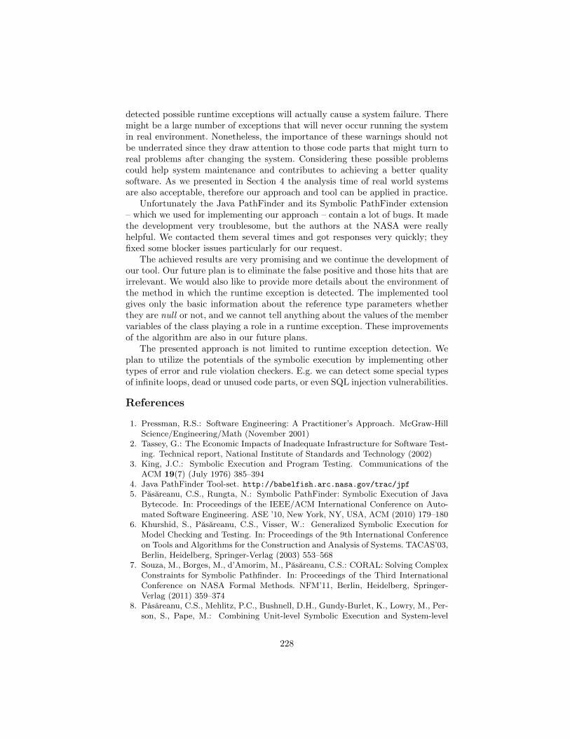
detected possible runtime exceptions will actually cause a system failure. Theremight be a large number of exceptions that will never occur running the systemin real environment. Nonetheless, the importance of these warnings should notbe underrated since they draw attention to those code parts that might turn toreal problems after changing the system. Considering these possible problemscould help system maintenance and contributes to achieving a better qualitysoftware. As we presented in Section 4 the analysis time of real world systemsare also acceptable, therefore our approach and tool can be applied in practice.
Unfortunately the Java PathFinder and its Symbolic PathFinder extension– which we used for implementing our approach – contain a lot of bugs. It madethe development very troublesome, but the authors at the NASA were reallyhelpful. We contacted them several times and got responses very quickly; theyfixed some blocker issues particularly for our request.
The achieved results are very promising and we continue the development ofour tool. Our future plan is to eliminate the false positive and those hits that areirrelevant. We would also like to provide more details about the environment ofthe method in which the runtime exception is detected. The implemented toolgives only the basic information about the reference type parameters whetherthey are null or not, and we cannot tell anything about the values of the membervariables of the class playing a role in a runtime exception. These improvementsof the algorithm are also in our future plans.
The presented approach is not limited to runtime exception detection. Weplan to utilize the potentials of the symbolic execution by implementing othertypes of error and rule violation checkers. E.g. we can detect some special typesof infinite loops, dead or unused code parts, or even SQL injection vulnerabilities.
References
1. Pressman, R.S.: Software Engineering: A Practitioner’s Approach. McGraw-HillScience/Engineering/Math (November 2001)
2. Tassey, G.: The Economic Impacts of Inadequate Infrastructure for Software Test-ing. Technical report, National Institute of Standards and Technology (2002)
3. King, J.C.: Symbolic Execution and Program Testing. Communications of theACM 19(7) (July 1976) 385–394
4. Java PathFinder Tool-set. http://babelfish.arc.nasa.gov/trac/jpf
5. Pasareanu, C.S., Rungta, N.: Symbolic PathFinder: Symbolic Execution of JavaBytecode. In: Proceedings of the IEEE/ACM International Conference on Auto-mated Software Engineering. ASE ’10, New York, NY, USA, ACM (2010) 179–180
6. Khurshid, S., Pasareanu, C.S., Visser, W.: Generalized Symbolic Execution forModel Checking and Testing. In: Proceedings of the 9th International Conferenceon Tools and Algorithms for the Construction and Analysis of Systems. TACAS’03,Berlin, Heidelberg, Springer-Verlag (2003) 553–568
7. Souza, M., Borges, M., d’Amorim, M., Pasareanu, C.S.: CORAL: Solving ComplexConstraints for Symbolic Pathfinder. In: Proceedings of the Third InternationalConference on NASA Formal Methods. NFM’11, Berlin, Heidelberg, Springer-Verlag (2011) 359–374
8. Pasareanu, C.S., Mehlitz, P.C., Bushnell, D.H., Gundy-Burlet, K., Lowry, M., Per-son, S., Pape, M.: Combining Unit-level Symbolic Execution and System-level
228
Concrete Execution for Testing NASA Software. In: Proceedings of the 2008 In-ternational Symposium on Software Testing and Analysis. ISSTA ’08, New York,NY, USA, ACM (2008) 15–26
9. Boyer, R.S., Elspas, B., Levitt, K.N.: SELECT – a Formal System for Testing andDebugging Programs by Symbolic Execution. In: Proceedings of the InternationalConference on Reliable Software, New York, NY, USA, ACM (1975) 234–245
10. Cadar, C., Ganesh, V., Pawlowski, P.M., Dill, D.L., Engler, D.R.: EXE: Automat-ically Generating Inputs of Death. In: Proceedings of the 13th ACM Conferenceon Computer and Communications Security. CCS ’06, New York, NY, USA, ACM(2006) 322–335
11. Godefroid, P., Klarlund, N., Sen, K.: DART: Directed Automated Random Testing.In: Proceedings of the 2005 ACM SIGPLAN Conference on Programming LanguageDesign and Implementation. PLDI ’05, New York, NY, USA, ACM (2005) 213–223
12. Sen, K., Agha, G.: CUTE and jCUTE: Concolic Unit Testing and Explicit PathModel-checking Tools. In: Proceedings of the 18th International Conference onComputer Aided Verification. CAV’06, Berlin, Springer-Verlag (2006) 419–423
13. Coward, P.D.: Symbolic Execution Systems – a Review. Software EngineeringJournal 3(6) (November 1988) 229–239
14. Tillmann, N., De Halleux, J.: Pex: White Box Test Generation for .NET. In:Proceedings of the 2nd International Conference on Tests and Proofs. TAP’08,Berlin, Heidelberg, Springer-Verlag (2008) 134–153
15. Jamrozik, K., Fraser, G., Tillman, N., Halleux, J.: Generating Test Suites withAugmented Dynamic Symbolic Execution. In: Tests and Proofs. Volume 7942 ofLecture Notes in Computer Science., Springer Berlin Heidelberg (2013) 152–167
16. Song, J., Ma, T., Cadar, C., Pietzuch, P.: Rule-Based Verification of NetworkProtocol Implementations Using Symbolic Execution. In: Proceedings of the 20thIEEE International Conference on Computer Communications and Networks (IC-CCN’11). (2011) 1–8
17. Fu, X., Qian, K.: SAFELI: SQL Injection Scanner Using Symbolic Execution. In:Proceedings of the 2008 Workshop on Testing, Analysis, and Verification of WebServices and Applications. TAV-WEB ’08, New York, ACM (2008) 34–39
18. Bushnell, D., Giannakopoulou, D., Mehlitz, P., Paielli, R., Pasareanu, C.S.: Veri-fication and Validation of Air Traffic Systems: Tactical Separation Assurance. In:Aerospace Conference, 2009 IEEE. (2009) 1–10
19. von Detten, M.: Towards Systematic, Comprehensive Trace Generation for Behav-ioral Pattern Detection Through Symbolic Execution. In: Proceedings of the 10thACM SIGPLAN-SIGSOFT Workshop on Program Analysis for Software Tools.PASTE ’11, New York, NY, USA, ACM (2011) 17–20
20. Ihantola, P.: Test Data Generation for Programming Exercises with SymbolicExecution in Java PathFinder. In: Proceedings of the 6th Baltic Sea Conferenceon Computing Education Research. Baltic Sea ’06, New York, ACM (2006) 87–94
21. Sinha, S., Shah, H., Gorg, C., Jiang, S., Kim, M., Harrold, M.J.: Fault Localizationand Repair for Java Runtime Exceptions. In: Proceedings of the 18th InternationalSymposium on Software Testing and Analysis. ISSTA ’09, New York, NY, USA,ACM (2009) 153–164
22. Weimer, W., Necula, G.C.: Finding and Preventing Run-time Error HandlingMistakes. In: Proceedings of the 19th Annual ACM SIGPLAN Conference onObject-oriented Programming, Systems, Languages, and Applications. OOPSLA’04, New York, NY, USA, ACM (2004) 419–431
23. Csallner, C., Smaragdakis, Y.: JCrasher: an Automatic Robustness Tester for Java.Software Practice and Experience 34(11) (September 2004) 1025–1050
229
Composable hierarchical synchronization supportfor REPLICA
Jari-Matti Mäkelä1, Ville Leppänen1, and Martti Forsell2
1 University of TurkuDept. of Information Technology
[email protected], [email protected] VTT
Oulu, [email protected]
Abstract. Synchronization is a key concept in parallel programming.General purpose languages and architectures often assume a restrictedform of synchronicity with the focus on asynchronous execution. Themost notable trend during the recent years against asynchrony has beenthe raise of GPGPU devices with support of tightly synchronous regionsin programs. Our REPLICA architecture continues this trend for chipmulti-processors with the aim to provide an execution platform for therich algorithm theory of synchronous shared memory algorithms.In a simplified multi-threaded computational model with unit time amor-tized instruction execution cost, step-wise inter-thread synchronicity canbe realized. However, the synchronicity does not trivially extend to higherlevel abstractions. A procedural language Fork introduces means formaintaining hierarchical synchronicity on block basis. The block levelsynchronicity invariant is maintained with explicit annotations. Controlstatements for synchronicity mode transitions are explicit.We focus on a new chip multi-processor architecture REPLICA, em-ploying step-wise synchronization along with fine-grained requirementsfor special thread group based parallel operations. A new hierarchical,composable, control flow synchronization analysis method is proposed.Our annotations capture the intent better and can be partly inferred.We demonstrate the method’s potential with comparisons to existingsystems. Our Replica compiler contains an initial implementation.
Keywords: parallel programming, synchronization, threads
1 Introduction
Synchronization is one of the key concepts in parallel programming. In generalpurpose programming languages and architectures, it is a common approach toassume the synchronicity of some core features, but consider the programmingmodel asynchronous as a whole [1,2]. Whenever synchronous execution is re-quired, it is achieved by applying expensive explicit synchronization on limited
230
regions. This trend has become the norm as architectures and programming en-vironments depend more on out-of-order execution and dynamically scheduledpre-emptive multitasking for speed-ups and as the cost of synchronization hasincreased with relaxation of synchronization and consistency models [3].
MPI-style and typical OO-language style solutions to specify several con-currently running threads are not very fruitful in the large scale, because bydefault the threads’ execution proceeds asynchronously resulting vagueness incomputation’s state, and the correctness of multithreaded program is hard toguarantee. Extensive use of locks removes vagueness but leads to poor paral-lel performance. [4] puts this as “Programming parallel applications with basicconcurrency primitives, be it on shared or distributed memory models, breaksall rules of software composition. This leads to non-determinism, unexplainedperformance issues, debugging and testing mightmares, and does not allow forarchitectural optimizations. Even specialists struggle to comprehend . . . ”
The concept of computation’s state gets promoted when one aims at havingthread-wise synchronously proceeding control flows. The concept of state hasbeen in a central role in achieving correctness in SW engineering of sequentialprograms as it is heavily related to algorithmic design, specification and testing.
The REPLICA architecture [5,6,7] is a very different approach to parallelismcompared to the current mainstream. It has an execution mode for maintainingthe synchronicity property implicitly at the instruction level. This is achievedwith synchronization wave technique embedded into the whole architecture. Asinstructions have a unit time amortized cost in terms of cycles in relation to otherthreads, it is possible to reason about the time cost of a sequence of instructionsassuming no branching happens, but even REPLICA’s strong synchronizationguarantees do not automatically extend to high level abstractions.
The Replica language [7,8] introduces a way to extend the same style ofsynchronicity to the level of high level language abstractions, expressions, state-ments, and declarations using a hierarchical concept of thread groups. The Fork[9] language adopts a similar approach for maintaining synchronicity on blockand function level, but does it explicitly with annotated regions. Our approachis a novel new synchronization analysis which is similar but orthogonal to thelanguage’s type system. The system can be used for checking the program cor-rectness via constraints related to synchronicity conditions, but it also givesrise to a possibility to infer the synchronicity properties, mitigating the need toannotate large bodies of code.
The proposed synchronization analysis uses conservative structural inductionto build up a view of the program, starting from basic language features, andextending seamlessly to user defined abstractions. As the analysis is conservative,programs violating the synchronicity assumption will not be accepted, but thesynchronicity inference is not optimal and can be improved or manually guidedwith annotations. While only core language is considered in this paper, theanalysis is generic enough to be further extended with the language.
The scope and main contribution of this paper is to present the new synchro-nization model and the algorithms for using the model and discuss its applica-
231
bility in practice. The treatment of the system focuses on its expressiveness andcomparing the computational capabilities and behavior to existing languages de-signed for similar architectures such as E [10] and Fork. A full analysis of themodel’s effect on execution performance requires further tuning of the inferencealgorithm and is listed as a future work.
The rest of the paper is outlined as follows: Section 2 discusses modeling thesynchronicity in a parallel language and considers the feasibility of using them forparallel programming on an architecture such as REPLICA. Section 3 introducesthe new synchronization model and gives a description of the semantics for corelanguage constructs. In Section 4 we demonstrate the use of languages to solvea parallel programming kernel using different features of the language. Finallyin Section 5 we draw conclusions and discuss future work.
2 Modeling synchronicity
Modern computational platforms employ varying models of synchronicity, mem-ory consistency models and granularity of parallelism. The motivation for suchcomplex core semantics arise from the hardware and programming models andthe effort of efficiently translating programs to the machine architecture. Ad-ditionally, general purpose programming languages can provide different formsof synchronicity for different kinds of tasks involving concurrency as all tasksdo not require or benefit from strictly synchronous execution. To list a few, ex-amples of such tasks are fully independent background tasks with no need forsynchronization, asynchronous interaction with I/O devices, exclusive concur-rent access to a resource, and propagating the results of a parallel computationbetween worker threads. Some architectures have special parallel operations [11]that require synchronized state for each thread participating in the operation.
Many attempts to speed up sequential performance by relaxing synchronic-ity on hardware and operating system level have had a negative impact on thecomplexity of building well performing and behaving parallel programs [3]. Ex-amples of such issues are the overhead of starting new concurrent tasks and thecost of propagating the result of a computation inside a concurrent program.
Recently a door to significant performance speed-ups opened in the form ofgeneral purpose GPUs with a tighter, group-oriented synchronicity and execu-tion model [12]. We argue that more and different forms of parallel computationalpower can still be harnessed from a similar kind of inherently synchronous model.Our aim is a structured, tighter form of synchronicity, similar to one providedby the Fork language. A practical aspect to this work comes from our implemen-tation and design of a systems programming language Replica employing thesetechniques on the new architecture prototype called REPLICA.
The semantics of our synchronization model is based on the idea of taggingthe control flow and executable language operations with synchronization re-lated conditions and compile-time verification of the condition constraints. Theassortment of supported conditions is based on the work of evaluating previouslanguage techniques and computational kernels and extracting their patterns.
232
2.1 Previous work on strong hierarchical synchronicity
Keller et al. [13] carried out a similar survey on potential languages for a MIMDstyle, exactly synchronous shared memory architecture and found that there isonly little interest in that particular area. Moreover, while traditional researchparadigms such as functional languages are gaining traction in practice, we be-lieve that a traditional procedural language with specially crafted extensions stillhits the sweet spot in the near future, when it comes to practicality in terms ofexecution overhead and interacting with hardware on this abstraction level.
Widely known standard solutions for asynchronous shared memory program-ming (POSIX threads, OpenMP [2]), data-parallel (variants of Fortran) and mes-sage passing (MPI [14]) exist, but are all suboptimal for a hardware architecturewith strong (lock-step) synchronicity and no special emphasis on massive dataparallelism (e.g. vector registers, XMT [15] style on-demand thread creation).Thus, we found the E and Fork languages to be closest to our goals. In the nextsections we take a brief look at both languages and their synchronization models.
However, worth noting is that while this style of parallel programming greatlybenefits from the hardware feature set of architectures such as REPLICA, we donot believe a strong synchronicity model fits all purposes. One of our goals is tocombine together several compatible techniques such as task parallelism [16] andhigh level parallel skeleton frameworks [17]. From this perspective, the role of astrongly synchronous model is to provide a safer, easier, and more refined modelfor taking advantage of fine-grained parallelism and the architecture dependentaccelerated multi-operations.
2.2 Fork language
Fork assumes a hardware model with lock-step execution semantics and P in-dependent, concurrently running threads, each carrying local data such as theirthread id. The execution mode for a group of threads can be asynchronous orsynchronous. In the former, all threads work independently, in the latter thethreads work in groups. A synchronicity invariant holds for each group. The ma-chine starts with all threads in a single group, but the groups can be recursivelysplit to subgroups, forming a hierarchical tree-like model. Split groups can laterbe joined together into the parent group. It is also possible to step outside thehierarchy tree and form a new group from any existing set of threads, but careneeds to be taken when manually maintaining the synchronicity invariant.
Fork provides a control primitives for synchronicity (start, seq, farm, andjoin) and three modes of execution (async, sync, straight) for blocks andfunctions. Fork enforces synchronicity constraints by prohibiting certain callsstatically on block basis. Synchronous code cannot call asynchronous functions,asynchronous code cannot call synchronous functions and straight code can onlycall straight functions. The control primitives extend the rules by allowing asyn-chronous statements inside synchronous blocks (farm, seq), and synchronousstatements inside the other two blocks (start, join). In addition, heap objectallocation is prohibited in asynchronous and continue in synchronous mode.
233
The difference between farm and seq is that farm lets all threads participatein asynchronous execution while in seq only one thread is active. Start switchesto a synchronous mode by performing a barrier with all the threads from thegroup whose member the thread last was. Join is a more flexible way of formingsynchronous groups, based on a dynamic condition expressions.
Fork also adds code related to synchronicity in certain cases: short-circuitexpressions, conditionals and loops generate subgroups if a condition dependson thread private state (a conservative heuristic is used). Farm, seq, and startadd barriers to enforce synchronicity. Statements break and return also addbarriers in the synchronous mode.
The downside of Fork is that mixing asynchronous and synchronous coderequires explicit notation also on the calling side. Both modes support differentfunctionality and the transitions between the modes have an overhead. Thismakes the programming effort of switching between the modes cumbersome.The default mode is asynchronous, but the programmer has to explicitly realizee.g. when a helper function is also usable by synchronous code. Subgroups arealso created conservatively, which may affect performance. Instead of prohibitingcertain cases of bad behavior, Fork only warns e.g. if farm is used in asynchronousmode. These rationale behind the loopholes is most likely that the compiler’sconstraints would otherwise also prohibit certain cases of correct, useful code.
2.3 E language
Compared to Fork, E seems like a poor man’s version with similar type of goals. Itassumes similar hardware model with lock-step execution semantics and thread-ing model. The language is rather built as a macro extension for C and cannotenforce e.g. region based synchronization modes. While its model is easier toimplement in terms of compilation techniques, it provides a rich set of intrinsicsand constructs for manipulating the machine state – for example, functions forexperimental fast versions of parallel operations under special assumptions.
E provides alternative parallel versions of standard C control structures (se-lection, loops) that either create similar subgroups for diverging control flowslike Fork or end with a synchronization or do both. In addition, other hardwareprovided features such are barriers and multi(prefix)-operations are available viamacros. The programmer can easily construct parallel programs using diverse setof hardware features. However, the machine conditions are only enforced in triv-ial cases where the code used is surrounded with the parallel control structuresand a correct version structure is selected.
While E’s design is less inspiring as a starting point for compilation algo-rithms, E’s functionality and lightweight style contributed to the list of require-ments for refining the Replica language, which is treated in the next section.
2.4 Replica language
The original goal in the REPLICA project was to implement language changesrequired by the new parallel architecture on top of plain C, extended in Fork or E
234
style. Notable new hardware level requirements were e.g. the step-wise synchro-nized execution, fast synchronization and parallel aggregate instructions, andthe bunch/NUMA hybrid modes for accelerating "legacy" code, which are un-fortunately out of the scope of this paper. A low-overhead support for improvedparallel library construction in generic or object oriented style was also planned,along with improvements in the analysis of synchronicity, data ownership andnew parallel code optimizations.
The complexity of integrating all the features lead to the introduction ofReplica language [7,8]. Replica implements a strongly typed, simplified subset ofC. It includes the basic data types (integral, composite structs, functions, globaland local variables) and imperative operations (if-else, while, do-while,switch). The distinction between statements and expressions is more strict. Forexample, assignments only work as statements. Expresions with immediate sideeffects are disallowed (e.g. post- and pre-increments). As an exception, functioncalls still work both as statements and expressions.
In Replica, the control flow operations are extended to automatically supportthread subgroup creation when the control flow may diverge. A split constructis introduced for explicitly splitting the thread group into subgroups. Replica alsoprovides similar access to thread/group id variables as Fork and E. In addition,a type-class [18] based generics implementation was adopted for implementinglow-overhead parallel libraries.
Although Replica is a simplified version of C, in this paper we consider alanguage subset with decreased redundancy (e.g. only do-while, no while).The EBNF representation of the relevant grammatical part is given in Figure 1.
3 Control flow and state invariants
The base of our model is the notion of synchronicity. For simplicity, we startbuilding the model from a synchronized subset of language features. We assumecore execution semantics from REPLICA, i.e. an amortized unit time instructionexecution cost with respect to other threads (distinct from wall-clock time) anda global lockstep synchronization between all threads. Synchronicity is definedpair-wise as an inter-thread relation of having the same program counter value ata given point of time. Thus, at any point of time, threads can be partitioned intogroups of one or more according to their synchronicity. If the threads in a groupof size n each have a unique id between 0 and n− 1, the group is enumerated.
Due to the global lock-step synchronization, threads maintain synchronicitybetween any two points in their execution path unless explicit branching basedon a thread-local condition is used. However, in a high level language, it becomeshard to keep track of synchronicity on machine instruction level as the execu-tion costs of operations on a certain abstraction level can be both variable anddynamic. On high level, we statically model the execution with the concept ofconcurrent control flows, which can be used to piece-wise define sections of codewith a certain property with respect to synchronicity.
235
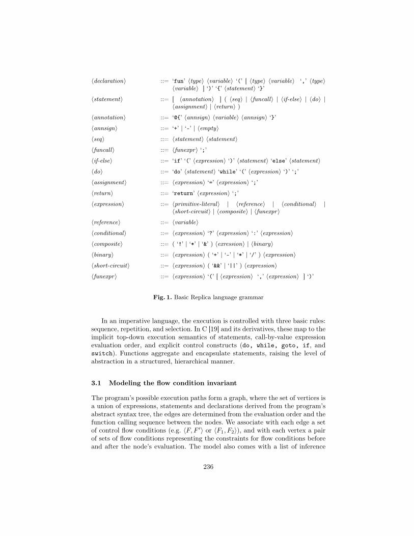
〈declaration〉 ::= ‘fun’ 〈type〉 〈variable〉 ‘(’ [ 〈type〉 〈variable〉 ‘,’ 〈type〉〈variable〉 ] ‘)’ ‘{’ 〈statement〉 ‘}’
〈statement〉 ::= [ 〈annotation〉 ] ( 〈seq〉 | 〈funcall〉 | 〈if-else〉 | 〈do〉 |〈assignment〉 | 〈return〉 )
〈annotation〉 ::= ‘@{’ 〈annsign〉 〈variable〉 〈annsign〉 ‘}’〈annsign〉 ::= ‘+’ | ‘-’ | 〈empty〉〈seq〉 ::= 〈statement〉 〈statement〉〈funcall〉 ::= 〈funexpr〉 ‘;’〈if-else〉 ::= ‘if’ ‘(’ 〈expression〉 ‘)’ 〈statement〉 ‘else’ 〈statement〉〈do〉 ::= ‘do’ 〈statement〉 ‘while’ ‘(’ 〈expression〉 ‘)’ ‘;’〈assignment〉 ::= 〈expression〉 ‘=’ 〈expression〉 ‘;’〈return〉 ::= ‘return’ 〈expression〉 ‘;’〈expression〉 ::= 〈primitive-literal〉 | 〈reference〉 | 〈conditional〉 |
〈short-circuit〉 | 〈composite〉 | 〈funexpr〉〈reference〉 ::= 〈variable〉〈conditional〉 ::= 〈expression〉 ‘?’ 〈expression〉 ‘:’ 〈expression〉〈composite〉 ::= ( ‘!’ | ‘*’ | ‘&’ ) 〈exression〉 | 〈binary〉〈binary〉 ::= 〈expression〉 ( ‘+’ | ‘-’ | ‘*’ | ‘/’ ) 〈expression〉〈short-circuit〉 ::= 〈expression〉 ( ‘&&’ | ‘||’ ) 〈expression〉〈funexpr〉 ::= 〈expression〉 ‘(’ [ 〈expression〉 ‘,’ 〈expression〉 ] ‘)’
Fig. 1. Basic Replica language grammar
In an imperative language, the execution is controlled with three basic rules:sequence, repetition, and selection. In C [19] and its derivatives, these map to theimplicit top-down execution semantics of statements, call-by-value expressionevaluation order, and explicit control constructs (do, while, goto, if, andswitch). Functions aggregate and encapsulate statements, raising the level ofabstraction in a structured, hierarchical manner.
3.1 Modeling the flow condition invariant
The program’s possible execution paths form a graph, where the set of vertices isa union of expressions, statements and declarations derived from the program’sabstract syntax tree, the edges are determined from the evaluation order and thefunction calling sequence between the nodes. We associate with each edge a setof control flow conditions (e.g. 〈F, F ′〉 or 〈F1, F2〉), and with each vertex a pairof sets of flow conditions representing the constraints for flow conditions beforeand after the node’s evaluation. The model also comes with a list of inference
236
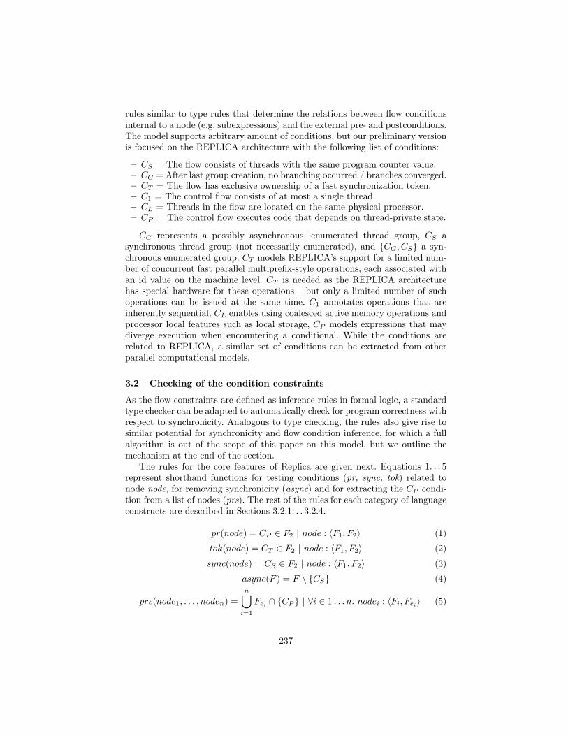
rules similar to type rules that determine the relations between flow conditionsinternal to a node (e.g. subexpressions) and the external pre- and postconditions.The model supports arbitrary amount of conditions, but our preliminary versionis focused on the REPLICA architecture with the following list of conditions:
– CS = The flow consists of threads with the same program counter value.– CG = After last group creation, no branching occurred / branches converged.– CT = The flow has exclusive ownership of a fast synchronization token.– C1 = The control flow consists of at most a single thread.– CL = Threads in the flow are located on the same physical processor.– CP = The control flow executes code that depends on thread-private state.
CG represents a possibly asynchronous, enumerated thread group, CS asynchronous thread group (not necessarily enumerated), and {CG, CS} a syn-chronous enumerated group. CT models REPLICA’s support for a limited num-ber of concurrent fast parallel multiprefix-style operations, each associated withan id value on the machine level. CT is needed as the REPLICA architecturehas special hardware for these operations – but only a limited number of suchoperations can be issued at the same time. C1 annotates operations that areinherently sequential, CL enables using coalesced active memory operations andprocessor local features such as local storage, CP models expressions that maydiverge execution when encountering a conditional. While the conditions arerelated to REPLICA, a similar set of conditions can be extracted from otherparallel computational models.
3.2 Checking of the condition constraints
As the flow constraints are defined as inference rules in formal logic, a standardtype checker can be adapted to automatically check for program correctness withrespect to synchronicity. Analogous to type checking, the rules also give rise tosimilar potential for synchronicity and flow condition inference, for which a fullalgorithm is out of the scope of this paper on this model, but we outline themechanism at the end of the section.
The rules for the core features of Replica are given next. Equations 1. . . 5represent shorthand functions for testing conditions (pr, sync, tok) related tonode node, for removing synchronicity (async) and for extracting the CP condi-tion from a list of nodes (prs). The rest of the rules for each category of languageconstructs are described in Sections 3.2.1. . . 3.2.4.
pr(node) = CP ∈ F2 | node : 〈F1, F2〉 (1)
tok(node) = CT ∈ F2 | node : 〈F1, F2〉 (2)
sync(node) = CS ∈ F2 | node : 〈F1, F2〉 (3)
async(F ) = F \ {CS} (4)
prs(node1, . . . , noden) =
n⋃
i=1
Fei ∩ {CP } | ∀i ∈ 1 . . . n. nodei : 〈Fi, Fei〉 (5)
237
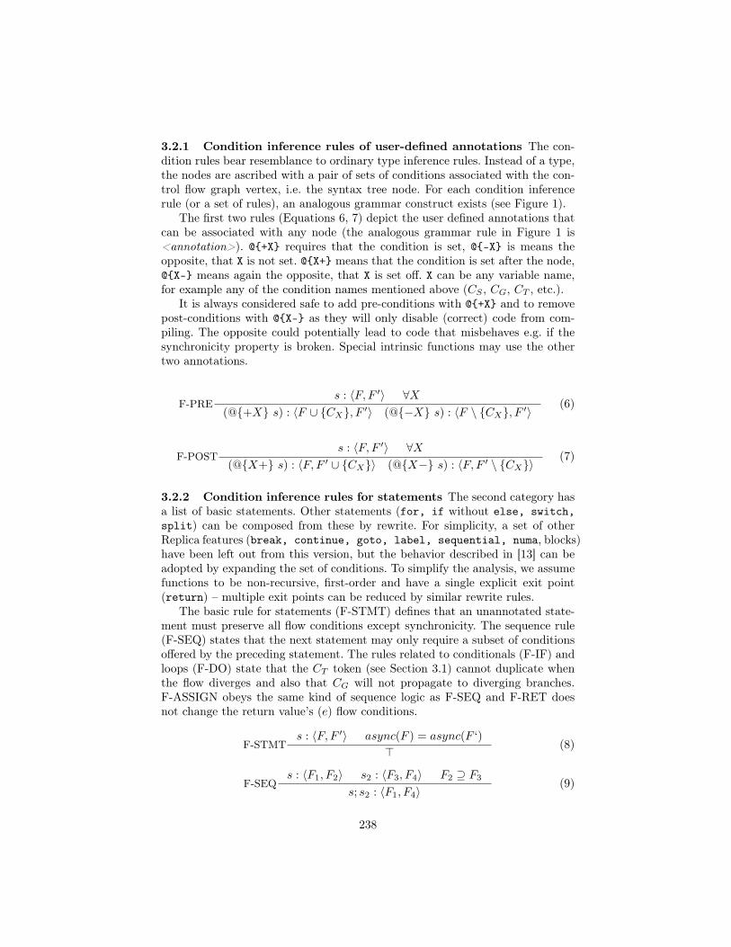
3.2.1 Condition inference rules of user-defined annotations The con-dition rules bear resemblance to ordinary type inference rules. Instead of a type,the nodes are ascribed with a pair of sets of conditions associated with the con-trol flow graph vertex, i.e. the syntax tree node. For each condition inferencerule (or a set of rules), an analogous grammar construct exists (see Figure 1).
The first two rules (Equations 6, 7) depict the user defined annotations thatcan be associated with any node (the analogous grammar rule in Figure 1 is<annotation>). @{+X} requires that the condition is set, @{-X} is means theopposite, that X is not set. @{X+} means that the condition is set after the node,@{X-} means again the opposite, that X is set off. X can be any variable name,for example any of the condition names mentioned above (CS , CG, CT , etc.).
It is always considered safe to add pre-conditions with @{+X} and to removepost-conditions with @{X-} as they will only disable (correct) code from com-piling. The opposite could potentially lead to code that misbehaves e.g. if thesynchronicity property is broken. Special intrinsic functions may use the othertwo annotations.
F-PREs : 〈F, F ′〉 ∀X
(@{+X} s) : 〈F ∪ {CX}, F ′〉 (@{−X} s) : 〈F \ {CX}, F ′〉 (6)
F-POSTs : 〈F, F ′〉 ∀X
(@{X+} s) : 〈F, F ′ ∪ {CX}〉 (@{X−} s) : 〈F, F ′ \ {CX}〉(7)
3.2.2 Condition inference rules for statements The second category hasa list of basic statements. Other statements (for, if without else, switch,split) can be composed from these by rewrite. For simplicity, a set of otherReplica features (break, continue, goto, label, sequential, numa, blocks)have been left out from this version, but the behavior described in [13] can beadopted by expanding the set of conditions. To simplify the analysis, we assumefunctions to be non-recursive, first-order and have a single explicit exit point(return) – multiple exit points can be reduced by similar rewrite rules.
The basic rule for statements (F-STMT) defines that an unannotated state-ment must preserve all flow conditions except synchronicity. The sequence rule(F-SEQ) states that the next statement may only require a subset of conditionsoffered by the preceding statement. The rules related to conditionals (F-IF) andloops (F-DO) state that the CT token (see Section 3.1) cannot duplicate whenthe flow diverges and also that CG will not propagate to diverging branches.F-ASSIGN obeys the same kind of sequence logic as F-SEQ and F-RET doesnot change the return value’s (e) flow conditions.
F-STMTs : 〈F, F ′〉 async(F ) = async(F ‘)
> (8)
F-SEQs : 〈F1, F2〉 s2 : 〈F3, F4〉 F2 ⊇ F3
s; s2 : 〈F1, F4〉(9)
238
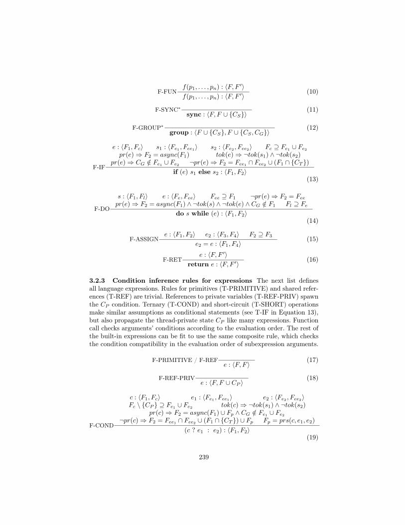
F-FUNf(p1, . . . , pn) : 〈F, F ′〉f(p1, . . . , pn) : 〈F, F ′〉 (10)
F-SYNC∗sync : 〈F, F ∪ {CS}〉
(11)
F-GROUP∗group : 〈F ∪ {CS}, F ∪ {CS , CG}〉
(12)
F-IF
e : 〈F1, Fc〉 s1 : 〈Fe1 , Fee1〉 s2 : 〈Fe2 , Fee2〉 Fc ⊇ Fe1 ∪ Fe2
pr(e)⇒ F2 = async(F1) tok(e)⇒ ¬tok(s1) ∧ ¬tok(s2)pr(e)⇒ CG /∈ Fe1 ∪ Fe2 ¬pr(e)⇒ F2 = Fee1 ∩ Fee2 ∪ (F1 ∩ {CT })
if (e) s1 else s2 : 〈F1, F2〉(13)
F-DO
s : 〈F1, Fl〉 e : 〈Fe, Fee〉 Fee ⊇ F1 ¬pr(e)⇒ F2 = Fee
pr(e)⇒ F2 = async(F1) ∧ ¬tok(s) ∧ ¬tok(e) ∧ CG /∈ F1 Fl ⊇ Fe
do s while (e) : 〈F1, F2〉(14)
F-ASSIGNe : 〈F1, F2〉 e2 : 〈F3, F4〉 F2 ⊇ F3
e2 = e : 〈F1, F4〉(15)
F-RETe : 〈F, F ′〉
return e : 〈F, F ′〉 (16)
3.2.3 Condition inference rules for expressions The next list definesall language expressions. Rules for primitives (T-PRIMITIVE) and shared refer-ences (T-REF) are trivial. References to private variables (T-REF-PRIV) spawnthe CP condition. Ternary (T-COND) and short-circuit (T-SHORT) operationsmake similar assumptions as conditional statements (see T-IF in Equation 13),but also propagate the thread-private state CP like many expressions. Functioncall checks arguments’ conditions according to the evaluation order. The rest ofthe built-in expressions can be fit to use the same composite rule, which checksthe condition compatibility in the evaluation order of subexpression arguments.
F-PRIMITIVE / F-REFe : 〈F, F 〉 (17)
F-REF-PRIVe : 〈F, F ∪ CP 〉
(18)
F-COND
c : 〈F1, Fc〉 e1 : 〈Fe1 , Fee1〉 e2 : 〈Fe2 , Fee2〉Fc \ {CP } ⊇ Fe1 ∪ Fe2 tok(c)⇒ ¬tok(s1) ∧ ¬tok(s2)
pr(c)⇒ F2 = async(F1) ∪ Fp ∧ CG /∈ Fe1 ∪ Fe2
¬pr(c)⇒ F2 = Fee1 ∩ Fee2 ∪ (F1 ∩ {CT }) ∪ Fp Fp = prs(c, e1, e2)
(c ? e1 : e2) : 〈F1, F2〉(19)
239
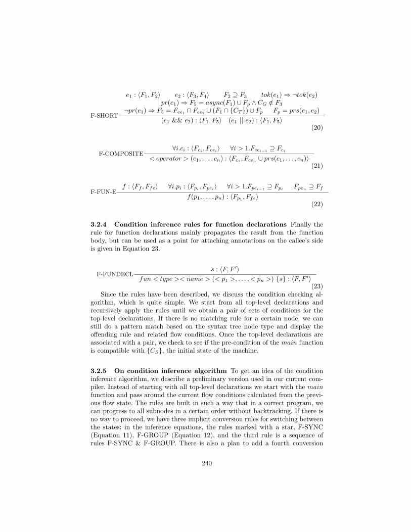
F-SHORT
e1 : 〈F1, F2〉 e2 : 〈F3, F4〉 F2 ⊇ F3 tok(e1)⇒ ¬tok(e2)pr(e1)⇒ F5 = async(F1) ∪ Fp ∧ CG /∈ F3
¬pr(e1)⇒ F5 = Fee1 ∩ Fee2 ∪ (F1 ∩ {CT }) ∪ Fp Fp = prs(e1, e2)
(e1 && e2) : 〈F1, F5〉 (e1 || e2) : 〈F1, F5〉(20)
F-COMPOSITE∀i.ci : 〈Fci , Fcei〉 ∀i > 1.Fcei−1 ⊇ Fci
< operator > (c1, . . . , cn) : 〈Fc1 , Fcen ∪ prs(c1, . . . , cn)〉(21)
F-FUN-Ef : 〈Ff , Ffe〉 ∀i.pi : 〈Fpi
, Fpei〉 ∀i > 1.Fpei−1⊇ Fpi
Fpen ⊇ Ff
f(p1, . . . , pn) : 〈Fp1 , Ffe〉(22)
3.2.4 Condition inference rules for function declarations Finally therule for function declarations mainly propagates the result from the functionbody, but can be used as a point for attaching annotations on the callee’s sideis given in Equation 23.
F-FUNDECLs : 〈F, F ′〉
fun < type >< name > (< p1 >, . . . , < pn >) {s} : 〈F, F ′〉(23)
Since the rules have been described, we discuss the condition checking al-gorithm, which is quite simple. We start from all top-level declarations andrecursively apply the rules until we obtain a pair of sets of conditions for thetop-level declarations. If there is no matching rule for a certain node, we canstill do a pattern match based on the syntax tree node type and display theoffending rule and related flow conditions. Once the top-level declarations areassociated with a pair, we check to see if the pre-condition of the main functionis compatible with {CS}, the initial state of the machine.
3.2.5 On condition inference algorithm To get an idea of the conditioninference algorithm, we describe a preliminary version used in our current com-piler. Instead of starting with all top-level declarations we start with the mainfunction and pass around the current flow conditions calculated from the previ-ous flow state. The rules are built in such a way that in a correct program, wecan progress to all subnodes in a certain order without backtracking. If there isno way to proceed, we have three implicit conversion rules for switching betweenthe states: in the inference equations, the rules marked with a star, F-SYNC(Equation 11), F-GROUP (Equation 12), and the third rule is a sequence ofrules F-SYNC & F-GROUP. There is also a plan to add a fourth conversion
240
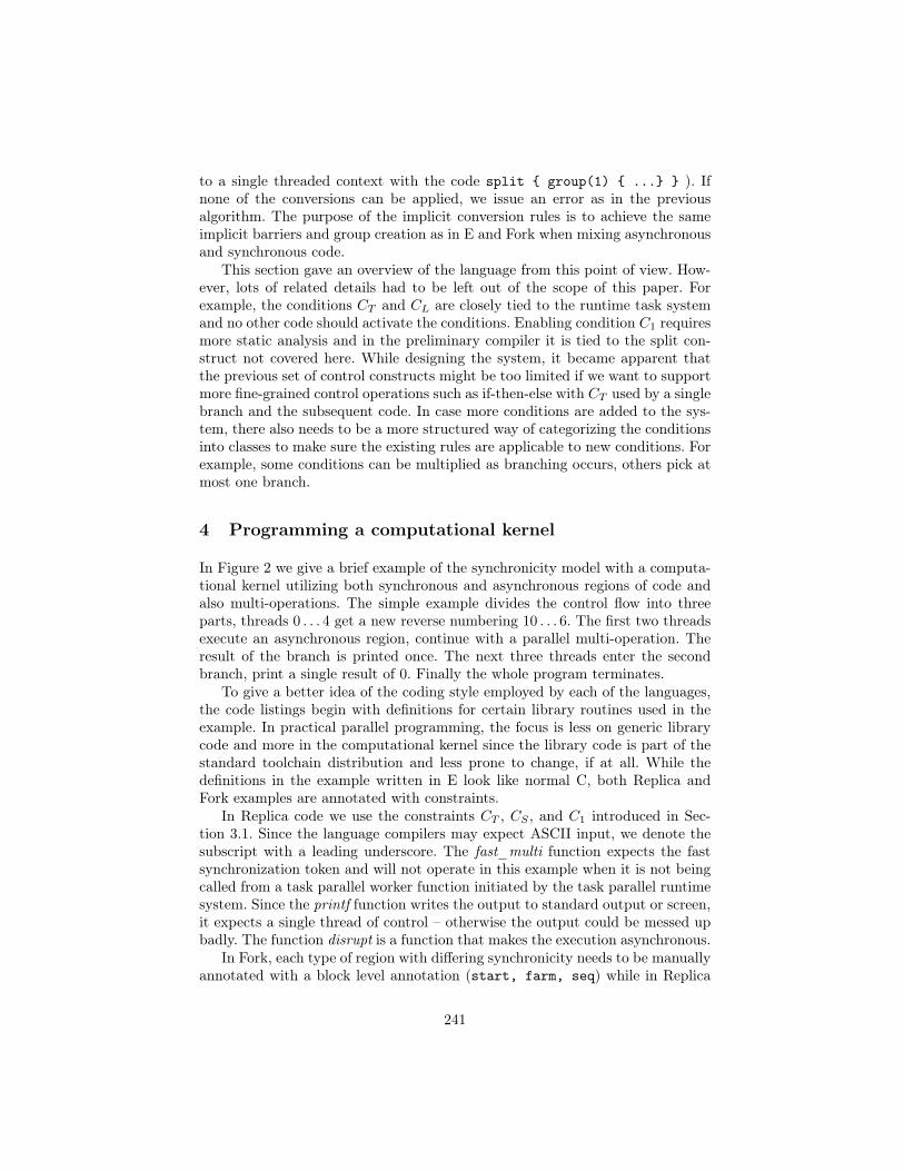
to a single threaded context with the code split { group(1) { ...} } ). Ifnone of the conversions can be applied, we issue an error as in the previousalgorithm. The purpose of the implicit conversion rules is to achieve the sameimplicit barriers and group creation as in E and Fork when mixing asynchronousand synchronous code.
This section gave an overview of the language from this point of view. How-ever, lots of related details had to be left out of the scope of this paper. Forexample, the conditions CT and CL are closely tied to the runtime task systemand no other code should activate the conditions. Enabling condition C1 requiresmore static analysis and in the preliminary compiler it is tied to the split con-struct not covered here. While designing the system, it became apparent thatthe previous set of control constructs might be too limited if we want to supportmore fine-grained control operations such as if-then-else with CT used by a singlebranch and the subsequent code. In case more conditions are added to the sys-tem, there also needs to be a more structured way of categorizing the conditionsinto classes to make sure the existing rules are applicable to new conditions. Forexample, some conditions can be multiplied as branching occurs, others pick atmost one branch.
4 Programming a computational kernel
In Figure 2 we give a brief example of the synchronicity model with a computa-tional kernel utilizing both synchronous and asynchronous regions of code andalso multi-operations. The simple example divides the control flow into threeparts, threads 0 . . . 4 get a new reverse numbering 10 . . . 6. The first two threadsexecute an asynchronous region, continue with a parallel multi-operation. Theresult of the branch is printed once. The next three threads enter the secondbranch, print a single result of 0. Finally the whole program terminates.
To give a better idea of the coding style employed by each of the languages,the code listings begin with definitions for certain library routines used in theexample. In practical parallel programming, the focus is less on generic librarycode and more in the computational kernel since the library code is part of thestandard toolchain distribution and less prone to change, if at all. While thedefinitions in the example written in E look like normal C, both Replica andFork examples are annotated with constraints.
In Replica code we use the constraints CT , CS , and C1 introduced in Sec-tion 3.1. Since the language compilers may expect ASCII input, we denote thesubscript with a leading underscore. The fast_multi function expects the fastsynchronization token and will not operate in this example when it is not beingcalled from a task parallel worker function initiated by the task parallel runtimesystem. Since the printf function writes the output to standard output or screen,it expects a single thread of control – otherwise the output could be messed upbadly. The function disrupt is a function that makes the execution asynchronous.
In Fork, each type of region with differing synchronicity needs to be manuallyannotated with a block level annotation (start, farm, seq) while in Replica
241
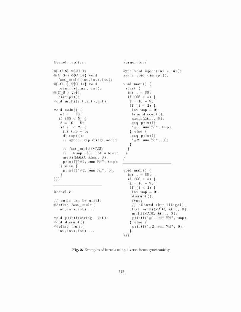
ke rne l . r e p l i c a :
@{+C_S} @{+C_T}@{C_S+} @{C_T+} void
fast_mult i ( int , i n t ∗ , i n t ) ;@{+C_1} @{C_1+} void
p r i n t f ( s t r i ng , i n t ) ;@{C_S−} void
d i s rupt ( ) ;void mult i ( int , i n t ∗ , i n t ) ;
void main ( ) {i n t i = $$ ;i f ( $$ < 5) {$ = 10 − $ ;i f ( i < 2) {i n t tmp = 0 ;d i s rupt ( ) ;// sync ; imp l i c i t l y added
// fast_mult i (MADD,// &tmp , $ ) ; not a l lowedmult i (MADD, &tmp , $ ) ;p r i n t f ("#1 , sum %d" , tmp ) ;
} e l s e {p r i n t f ("#2 , sum %d" , 0 ) ;
}}}}______________________
kerne l . e :
// c a l l s can be unsa fe#de f i n e fast_mult i (
int , i n t ∗ , i n t ) . . .
void p r i n t f ( s t r i ng , i n t ) ;void d i s rupt ( ) ;#de f i n e mult i (
int , i n t ∗ , i n t ) . . .
k e rne l . f o rk :
sync void mpadd( i n t ∗ , i n t ) ;async void d i s rupt ( ) ;
void main ( ) {s t a r t {i n t i = $$ ;i f ( $$ < 5) {$ = 10 − $ ;i f ( i < 2) {i n t tmp = 0 ;farm d i s rupt ( ) ;mpadd(&tmp , $ ) ;seq p r i n t f ("#1, sum %d" , tmp ) ;
} e l s e {seq p r i n t f ("#2, sum %d" , 0 ) ;
}}
}}______________________
void main ( ) {i n t i = $$ ;i f ( $$ < 5) {$ = 10 − $ ;i f ( i < 2) {i n t tmp = 0 ;d i s rupt ( ) ;sync ;// a l lowed ( but i l l e g a l )fast_mult i (MADD, &tmp , $ ) ;mult i (MADD, &tmp , $ ) ;p r i n t f ("#1 , sum %d" , tmp ) ;
} e l s e {p r i n t f ("#2 , sum %d" , 0 ) ;
}}}}
Fig. 2. Examples of kernels using diverse forms synchronicity.
242
the region type is checked and inferred from the library function signatures.In E checking is omitted and even illegal fast multi-operations can be calledwithout a special synchronicity token. Subgroup creation is carried out manuallyby renumbering the threads, but the implicit subgroup creation semantics leaveuntested in this example. In addition, performance considerations related tosuch implicit boilerplate code generation are unrealistic with simple examplesdemonstrating the language semantics and require a thorough analysis in thecontext of computational kernels once the Replica’s inference system is optimizedfor code efficiency.
In this example, Replica’s control flow model checks equal amount or moreconditions than the two existing languages without opening new possibilities forevident synchronicity errors. It also enables moving verbose annotations fromuser code to the library, which supports our goals of designing a more expressive,generic and easy to use language for parallel programming. A thorough analysiswith a larger set of real world benchmarks is still needed to validate our claimsin a practical setting and clearly defined semantics for flow conditions in caseslike recursion is still needed for parallel algorithms such as quick sort.
5 Conclusions and future work
In this paper, we presented a new framework for composable, hierarchical, syn-chronization support on REPLICA and other architectures with a similar kindof execution model. The preliminary framework and its implementation in ourReplica language compiler consists of a definition of synchronicity using parallelcontrol flows, a partially formal description of the rules for correctness, a simplechecking algorithm, and ideas for doing preliminary condition inference.
We demonstrated the resulting language by comparing example code againstequal, ported implementations in previous languages E and Fork. The examplemainly focused on demonstrating the new programming model with each systemand, for now, omitted necessary performance evaluation needed when dealingwith practical HPC kernels. In the next version of the system, strong emphasiswill be put on practical implementation aspects.
While the preliminary work on the model can be already used to check pro-grams, as future work, we suggest extending the rules to cover the whole lan-guage and (task) parallel runtime system, studying and extending the inferencealgorithm to work in a wider set of cases, opening possibilities for program per-formance tuning. The set of useful parallel control abstractions may also be farfrom complete. Examples of possibly useful fine-grained abstractions were given.
Acknowledgment
This work was funded by VTT.
243
References
1. Garcia, F., Fernandez, J.: Posix thread libraries. Linux Journal 2000(70es) (2000)36
2. Dagum, L., Menon, R.: OpenMP: An Industry Standard API for Shared-MemoryProgramming. Computational Science & Engineering, IEEE 5(1) (1998) 46–55
3. Adve, S.V., Gharachorloo, K.: Shared Memory Consistency Models: A Tutorial.computer 29(12) (1996) 66–76
4. Duranton, M., Black-Schaffer, D., Yehia, S., De Bosschere, K.: Computing systems:Reseach challenges ahead – the hipeac vision 2011/2012 (2012)
5. Forsell, M.: A PRAM-NUMA Model of Computation for Addressing Low-TLPWorkloads. Int. Journal of Networking and Computing 1(1) (2011) 21–35
6. Forsell, M.: TOTAL ECLIPSE – An Efficient Architectural Realization of TheParallel Random Access Machine. Parallel and Distributed Comput., Ed. A. Ros,IN-TECH, Wien (2010) 39–64
7. Mäkelä, J.M., Hansson, E., Forsell, M., Kessler, C., Leppänen, V.: Design Princi-ples of the Programming Language Replica for Hybrid PRAM-NUMA Many-CoreArchitectures. In: Proceedings of 4th Swedish Workshop on Multi-Core Comput-ing, Linköping University (2011) 136
8. Mäkelä, J.M., Hansson, E., Åkeson, D., Forsell, M., Kessler, C., Leppänen, V.:Design of the Language Replica for Hybrid PRAM-NUMA Many-Core Architec-tures. In Werner, B., ed.: 10th IEEE International Symposium on Parallel andDistributed Processing with Applications, ISPA 2012, IEEE (2012) 697–704
9. Kessler, C., Seidl, H.: The Fork95 Parallel Programming Language: Design, Im-plementation, Application. Int. Journal of parallel programming (1997)
10. Forsell, M.: E – A Language for Thread-Level Parallel Programming on Syn-chronous Shared Memory NOCs. WSEAS Trans. on Computers 3(3) (jul 2004)807–812
11. Forsell, M., Roivainen, J.: Supporting Ordered Multiprefix Operations in EmulatedShared Memory CMPs. In: Proceedings of the 2011 International Conference onParallel and Distributed Processing Techniques and Applications (PDPTA’11). LasVegas, USA. (2011)
12. Nickolls, J., Buck, I., Garland, M., Skadron, K.: Scalable Parallel Programmingwith CUDA. Queue 6(2) (2008) 40–53
13. Keller, J., Kessler, C., Träff, J.: Practical PRAM Programming. Wiley (2001)14. Forum, M.P.: MPI: A Message-Passing Interface Standard. Technical report,
Knoxville, TN, USA (1994)15. Vishkin, U., Dascal, S., Berkovich, E., Nuzman, J.: Explicit Multi-threaded (XMT)
Bridging Models for Instruction Parallelism. In: Proc. 10th ACM Symposium onParallel Algorithms and Architectures (SPAA). (1998) 140–151
16. Kessler, C., Hansson, E.: Flexible Scheduling and Thread Allocation for Syn-chronous Parallel Tasks. In: Proc. of 10th Workshop on Parallel Systems andAlgorithms (PASA’12). (2012)
17. Darlington, J., Field, A., Harrison, P., Kelly, P., Sharp, D., Wu, Q., While, R.: Par-allel Programming Using Skeleton Functions. In: PARLE’93 Parallel Architecturesand Languages Europe, Springer (1993) 146–160
18. Wadler, P., Blott, S.: How To Make Ad-Hoc Polymorphism Less Ad Hoc. In:Proceedings of the 16th ACM SIGPLAN-SIGACT Symposium on Principles ofProgramming Languages. POPL ’89, New York, NY, USA, ACM (1989) 60–76
19. Kernighan, B., Ritchie, D.: The C Programming Language",(\ ANSI C"). PrenticeHall,(ISBN: 0-13-110362-8) (1988)
244
Checking visual data flow programs with finiteprocess models
Jyrki Nummenmaa1, Maija Marttila-Kontio2, and Timo Nummenmaa1
1 School of Information Sciences, University of Tampere, Finland2 School of Computing, University of Eastern Finland, Finland
[email protected], [email protected], [email protected]
Abstract. A visual data flow language (VDFL) allows graphical pre-sentation of a computer program in the form of a directed graph, wheredata tokens travel through the arcs of the graph, and the vertices presente.g. the input token streams, calculations, comparisons, and condition-als. Amongst their benefits, VDFLs allow parallel computing and theyare presumed to improve the quality of programming due to their intu-itive readability. Thus, they are also suitable for computing education.However, the token-based computational model allowing parallel pro-cessing may make the programs more complicated than what they look.We propose a method for checking properties of VDFL programs usingfinite state processes (FSPs) using a commonly available labelled transi-tion system analyser (LTSA) tool. The method can also be used to studydifferent VDFL programming constructs for development or re-design ofVDFLs. For our method, we have implemented a compiler that compilesa textual representation of a VDFL into FSPs.
1 Introduction
In computing studies, programs are often visualized with flow-charts or similar,demonstrating the program flow and giving a visual representation for the ba-sic concepts of programming, such as choice, iteration, and input introduction.Visual data flow languages (VDFLs) are special visual programming languages[7]. The programs are presented in the form of directed graphs. The verticespresent such functionalities as e.g. calculations, comparisons, and conditionals.The data flow in the form of data tokens in the arcs from functionalities to otherfunctionalities.
The visual nature of the VDFL programs makes them intuitive and is sup-posed to increase their understandability [4] [7] [13]. This is an important factor,when the quality of software is a crucial factor. Furthermore, a system based onthe data flow execution paradigm has advantages such as easier program ver-ification, better modularity and extendability of hardware, reduced protectionproblems and superior confinement of software errors [1].
The computational model, based on the function application, allows paralleland concurrent execution strategies for the programs [2] [11]. Even though this
245
is an important and desired feature, at the same time this increases the com-plexity of the program, as it may be hard for the programmer to understand andanticipate the different execution sequences allowed by the VDFL program.
A formal method is a set of tools and notations (with a formal semantics)used to specify unambiguously the requirements of a computer system, support-ing the proof of properties of that specification and proofs of correctness of aneventual implementation with respect to that specification [8]. Formal methodsare commonly used to study the properties of computational systems allowingconcurrent or parallel processing. However, to our knowledge there has beenlittle interest to apply formal methods to study the properties of VDLF pro-grams. The work of Marttila-Kontio et al. [10] established a mapping betweenVDFL programs and actions systems. This mapping provides a possible path forreasoning on VDFL programs.
When applying formal methods, a formal specification can be created. Theformal specification should precisely state what the piece of software being spec-ified is supposed to do [6]. In this work, we propose to use finite state processesas formal specifications to represent and analyse the processing of VDFL pro-grams. In our work, we limit our attention to a basic VDFL language, whichallows the definition of basic constructs: inputs, outputs, conditionalities andbasic computations, and iteration, which comes by the cyclic structure of theprograms. Even though VDFL programs are visual by nature, for the analysisof the programs, only non-visual information is needed. We have implementeda simple compiler, which compiles a textual representation of a VDFL programinto finite state processes (FSPs). The FSPs can then be automatically analysedby a labelled transition system analyser (LTSA) tool for certain safety proper-ties, such as deadlocks, and certain reachability properties, such as terminal sets.It is also possible to state explicit progress properties about the FSP model, andto check those using the LTSA tool. The book by Magee and Kramer [9] explainsthe usage of the tool and formalism we use for the analysis and modeling of theFSPs.
There is some previous work in the area, where formal approach has been usedto study visual programing or modeling languages. E.g. Zhang et al. [14] havestudied the visual language semantics specification using grammatical treatmentof the programming language structures, and Gostagliola et al. [3] have studiedthe use of grammars in the development of visual modeling languages. Eventhough we utilize grammars and parsing in our work, our goal is different: We aimfor a formal model that can be used as an input for a tool that can automaticallycheck certain formal properties of the program.
The content of the rest of the paper is as follows. Section 2 presents ourVDFL model. Section 3 describes how FSPs are compiled out of the VDFLmodel. Section 4 discusses the applicability of our work in the context of acommercial VDFL system, LabView [13]. Section 5 explains how our approachcan be utilized in the context of visual language development. Section 6 containsconcluding remarks.
246
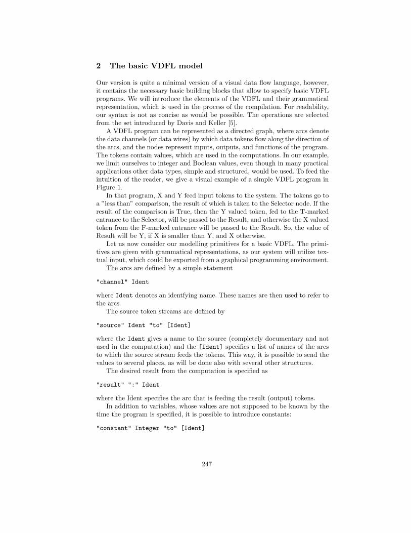
2 The basic VDFL model
Our version is quite a minimal version of a visual data flow language, however,it contains the necessary basic building blocks that allow to specify basic VDFLprograms. We will introduce the elements of the VDFL and their grammaticalrepresentation, which is used in the process of the compilation. For readability,our syntax is not as concise as would be possible. The operations are selectedfrom the set introduced by Davis and Keller [5].
A VDFL program can be represented as a directed graph, where arcs denotethe data channels (or data wires) by which data tokens flow along the direction ofthe arcs, and the nodes represent inputs, outputs, and functions of the program.The tokens contain values, which are used in the computations. In our example,we limit ourselves to integer and Boolean values, even though in many practicalapplications other data types, simple and structured, would be used. To feed theintuition of the reader, we give a visual example of a simple VDFL program inFigure 1.
In that program, X and Y feed input tokens to the system. The tokens go toa ”less than” comparison, the result of which is taken to the Selector node. If theresult of the comparison is True, then the Y valued token, fed to the T-markedentrance to the Selector, will be passed to the Result, and otherwise the X valuedtoken from the F-marked entrance will be passed to the Result. So, the value ofResult will be Y, if X is smaller than Y, and X otherwise.
Let us now consider our modelling primitives for a basic VDFL. The primi-tives are given with grammatical representations, as our system will utilize tex-tual input, which could be exported from a graphical programming environment.
The arcs are defined by a simple statement
"channel" Ident
where Ident denotes an identfying name. These names are then used to refer tothe arcs.
The source token streams are defined by
"source" Ident "to" [Ident]
where the Ident gives a name to the source (completely documentary and notused in the computation) and the [Ident] specifies a list of names of the arcsto which the source stream feeds the tokens. This way, it is possible to send thevalues to several places, as will be done also with several other structures.
The desired result from the computation is specified as
"result" ":" Ident
where the Ident specifies the arc that is feeding the result (output) tokens.In addition to variables, whose values are not supposed to be known by the
time the program is specified, it is possible to introduce constants:
"constant" Integer "to" [Ident]
247
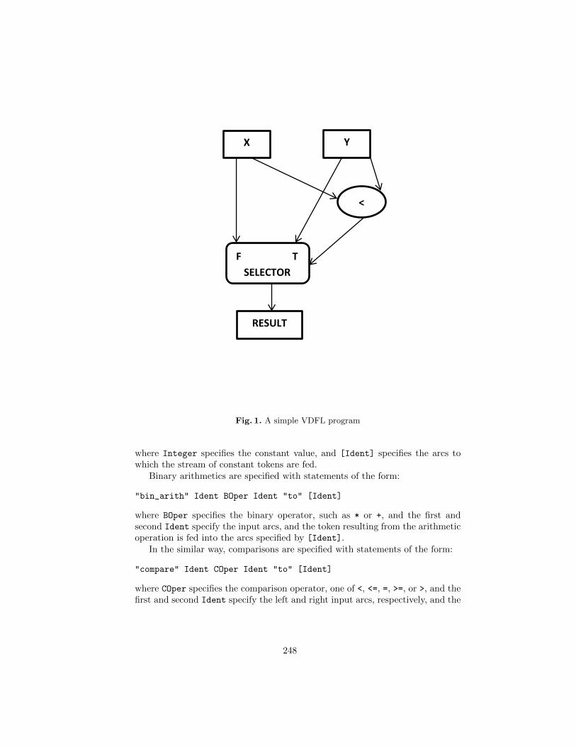
X Y
<
F T
SELECTOR
RESULT
Fig. 1. A simple VDFL program
where Integer specifies the constant value, and [Ident] specifies the arcs towhich the stream of constant tokens are fed.
Binary arithmetics are specified with statements of the form:
"bin_arith" Ident BOper Ident "to" [Ident]
where BOper specifies the binary operator, such as * or +, and the first andsecond Ident specify the input arcs, and the token resulting from the arithmeticoperation is fed into the arcs specified by [Ident].
In the similar way, comparisons are specified with statements of the form:
"compare" Ident COper Ident "to" [Ident]
where COper specifies the comparison operator, one of <, <=, =, >=, or >, and thefirst and second Ident specify the left and right input arcs, respectively, and the
248
token resulting from the arithmetic operation is fed into the channel specifiedby the third Ident. It should be noted that in the visual representation, theinput arcs are read from left to right, and this needs to be converted into textrespectively.
According to the standard computational model, once there are input tokensin the incoming arcs, the function of an edge can be performed and the result canbe passed on. In this work, we assume that only one token fits into one arc, thatis, if the outgoing arc is still occupied by a previously produced token, a functionis not going to output more tokens to the arc. The same assumption was madeby Davis and Keller. As for the source/input tokens, we just assume that whenthere is space in the arc and input is available, a token will be positioned in thearc. As for the result/output, we assume that the user or the process using theprogram will need to explicitly consume the result/output tokens before a nextresult is produced.
The structures introduced this far are just data flow based counterpartsof standard computational operations. However, VDFL programming includessome features that are specific to the computational model. The selector has twostandard incoming arcs (of course in our case limited to integers and Booleans),one input arc that brings in Boolean (selector) tokens, and a set of outgoing arcs.The two standard inputs are labeled by True and False. If the selector value isTrue, then a token from the True-labelled input stream is passed to the outgoingarcs, and if the selector value is False, then a token from the False-labelled inputstream is passed to the outgoing arcs. The selector is specified as follows, whereit should be evident how True-labelled and False-labelled arcs map to the Identelements.
"selector" "if" Ident "then" Ident "else" Ident "to" [Ident]
The selector is a bit more complicated structure for the computational model.First of all, it is in principle capable of executing even if it does not have tokensin all input arcs, that is, if the selector input is False, then the True input is notneeded, and vice versa. Also, it could only consume a token from one input, thusleaving one token in its arc. Both of these assumptions imply some complications,so we abandon them and in our work the assumption is that the selector onlyexecutes, when all inputs are present, and they are all consumed.
Let us now reconsider the program of Figure 1. There are two sources, Xand Y. Due to the computational model, once X and Y produce tokens, theywill go to the Selector and the comparison (smaller than) node. However, theselector can only execute once the comparison is done. If X is smaller than Y, theresult will be Y, and otherwise X. Notably, the figure contains graphical layoutinformation about the parameters, the smaller than comparison is read fromleft to right, and the True and False incoming arcs in the Selector are placedat the T and F symbols. The graphical layout information is, of course, codedin the textual representation that we use. This needs some bookkeeping in theVDFL development environment. The program, expressed in textual form, isgiven below. The first line has a program name, which would also be extractedfrom the VDFL environment.
249
program comp :
channel ch1
channel ch2
channel ch3
channel ch4
channel ch5
channel ch6
source X to ch1, ch2
source Y to ch3, ch4
compare ch1 < ch3 to ch5
selector if ch5 then ch4 else ch2 to ch6
result : ch6
3 Compilation of VDFL programs into FSPs
This section explains the FSP structures used to represent the VDFL programs,introduces the implementation technology used in VDFL compilation, and dis-cusses the choices done in the implementation.
Before discussing how we have mapped the VDFL programs into FSPs, wegive a very short introduction to FSPs. FSPs are composed of actions using se-quentiality (-> ), choice (|), guards (when (boolean cond)), the if-else struc-ture (if (boolean cond) then else), parallel composition (||) and other op-erations, not used here. The process names start with uppercase and the actionnames with lowercase. The action names can be indexed, e.g. with values thatare related to the action. When we use integer indexing and a new value is in-troduced, a range for the possible values needs to be given. The generated codedefines a range MaxInt = 0..1 which, of course, can be changed by the user.This way, we can define e.g. the process CHANNEL = (in chan1[i:MaxInt]->
out chan2[i] -> CHANNEL) to say that the channel can produce an alterna-tion of taking in a token with index from the given range and once i is thus fixed,it will produce an out action that has the now fixed index, and after that it canstart again and a new index can be chosen.
Parallel composition is used to combine processes, e.g. we combine processCONSTANT = (in chan1[1] -> CONSTANT) with CHANNEL, given above:
||CHANNEL_WITH_CONSTANT = (CONSTANT || CHANNEL).
and now the common actions can only be executed when both CHANNEL andCONSTANT can execute them. This generally limits the possible execution traces,and may lead to deadlock ie. a situation where there are no actions availabe forexecution. In this case, the process CONSTANT is limited to execute in chan 1[1]
only when CHANNEL is also ready to execute it. Notably, since this is the only valueavailable, the parameter in CHANNEL = (in chan1[i:MaxInt]-> out chan2[i]
-> CHANNEL) is always bound to 1.Even though the VDFL programs we used as examples seem limited for their
data types, only including an integer and Boolean datatype, in practice general
250
integers lead into state-space explosion, and their values need to be stronglylimited. In this work, we will only include binary integer values in the models.Even though slightly bigger values would in practice be feasible, this choice willsimplify our models and processing, still giving a possibility to analyze certainpart of the behavior of the programs.
This way, a channel / arc of the program is implemented as a process, whereIdent stands for the channel identifying name.
CHANNEL_Ident = (in_Ident[i:MaxInt] -> out_Ident[i]
-> CHANNEL_Ident).
With this process definition, the channel admits a token with a value from rangeMaxInt and then the same token value needs to go out of the channel beforethe next token can enter. This is exactly how the arcs should work under theassumption that the arc can hold at most one value at all times.
The source simply needs to input a token into a list channels. This is achievedby:
SOURCE_Ident = (value_Ident[i:MaxInt] -> in_Ident1[i]
->... -> in_Identk[i] -> SOURCE_Ident).
In this FSP Ident is the identifying name of the channel into which the sourceoutputs tokens, and Ident1, ..., Identk are the identifying names of thechannels to which the token will be put. This way the action of the sourcesynchronizes with the related channels actions to take in tokens. CONSTANTis just like SOURCE apart from the index value for the in-action is fixed. Eventhough this means that the channels need to take in the values in the orderspecified by the identifiers, this makes no difference in practice.
Comparisons take two input values and produce an output value, either 0 or1, representing False and True. Here, we use the simple if-then-else structureof the FSPs that allows to define conditional behavior. Since the assumptionis that both input values need to exist, it does not matter in which order thecomparison takes them in.
COMP_Ident1_Ident2 = (out_Ident1[i:MaxInt] -> out_Ident2[j:MaxInt]
-> if (i COper j) then (in_Ident3[1] -> COMP_Ident1_Ident2)
else (in_Ident3[0] -> COMP_Ident1_Ident2)).
Binary arithmetic is even simpler than comparison, it takes the two inputvalue tokens and passes on the result of the arithmetic expression, which is easyto generate.
BOPER_Ident1_Ident2 = (out_Ident1[i:MaxInt] -> out_Ident2[j:MaxInt]
-> in_Ident3[i BOper j] -> BOper_Ident1_Ident2).
Finally, the selector process takes in the Boolean (0 or 1) token and thetokens from which to select, and then puts the appropriate token in the outputchannel:
251
SELECTOR_Ident1 = (out_Ident1[i:0..1] -> out_Ident2[j:MaxInt]
-> out_Ident3[k:MaxInt] ->
if (i==1) then (in_Ident4[j] -> SELECTOR_Ident1)
else (in_Ident4[k] -> SELECTOR_Ident1).
Our compiler implementation is based on the use of the BNF Converter(BNFC) [12], a compiler construction tool that is given a labelled BNF grammar,produces various useful artefacts. Our compiler is implemented using the Haskellprogramming language, so we use the following files, generated by BNFC.
– A parser generator file for Happy. The file can directly be used to generatea Happy parser. Happy is a parser generator that comes as a part of theHaskell Platform environment.
– A lexer generator file for Alex . The file can directly be used to generate anAlex lexer. Alex is a lexical analyser generator that comes as a part of theHaskell Platform environment.
– A test program to parse source language inputs and to pretty-print outthe parse tree. Since the actual compilation needed is very simple, we havemanaged to create a compiler just by modifying these source files to eliminatesome debug output and to generate the necessary code.
Since we are basically developing a method that would use output from aVDFL development environment, the error management is not a central issuein the compiler. We may assume that these environments print out the programinformation in the correct form. The top level of the labelled BNF grammar islargely introduced in the grammar snippets we have given. The whole labelledBNF grammar is given below.
Prog. Program ::= "program" Ident ":" [Stm] ;
Chan. Stm ::= "channel" Ident ;
Sour. Stm ::= "source" Ident "to" [Ident] ;
Cons. Stm ::= "constant" Integer "to" [Ident] ;
BAri. Stm ::= "bin_arith" Ident BOper Ident "to" [Ident] ;
UAri. Stm ::= "un_arith" UOper Ident "to" [Ident] ;
Comp. Stm ::= "compare" Ident COper Ident "to" [Ident] ;
Sel. Stm ::= "selector" "if" Ident "then" Ident
"else" Ident "to" [Ident] ;
Dist. Stm ::= "distributor" "if" Ident "then" Ident "to" Ident
"else" "to" [Ident] ;
Res. Stm ::= "result" ":" Ident ;
separator Stm "" ;
separator Ident "," ;
EEq. COPer ::= "==" ;
ENeq. COper ::= "!=" ;
ELeq. COper ::= "<=" ;
ELt. COper ::= "<" ;
EGeq. COper ::= ">=" ;
252
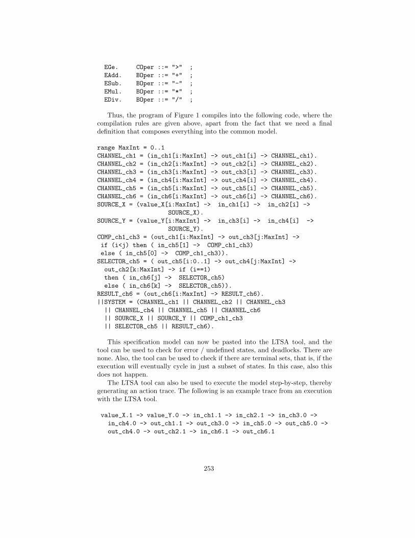
EGe. COper ::= ">" ;
EAdd. BOper ::= "+" ;
ESub. BOper ::= "-" ;
EMul. BOper ::= "*" ;
EDiv. BOper ::= "/" ;
Thus, the program of Figure 1 compiles into the following code, where thecompilation rules are given above, apart from the fact that we need a finaldefinition that composes everything into the common model.
range MaxInt = 0..1
CHANNEL_ch1 = (in_ch1[i:MaxInt] -> out_ch1[i] -> CHANNEL_ch1).
CHANNEL_ch2 = (in_ch2[i:MaxInt] -> out_ch2[i] -> CHANNEL_ch2).
CHANNEL_ch3 = (in_ch3[i:MaxInt] -> out_ch3[i] -> CHANNEL_ch3).
CHANNEL_ch4 = (in_ch4[i:MaxInt] -> out_ch4[i] -> CHANNEL_ch4).
CHANNEL_ch5 = (in_ch5[i:MaxInt] -> out_ch5[i] -> CHANNEL_ch5).
CHANNEL_ch6 = (in_ch6[i:MaxInt] -> out_ch6[i] -> CHANNEL_ch6).
SOURCE_X = (value_X[i:MaxInt] -> in_ch1[i] -> in_ch2[i] ->
SOURCE_X).
SOURCE_Y = (value_Y[i:MaxInt] -> in_ch3[i] -> in_ch4[i] ->
SOURCE_Y).
COMP_ch1_ch3 = (out_ch1[i:MaxInt] -> out_ch3[j:MaxInt] ->
if (i<j) then ( in_ch5[1] -> COMP_ch1_ch3)
else ( in_ch5[0] -> COMP_ch1_ch3)).
SELECTOR_ch5 = ( out_ch5[i:0..1] -> out_ch4[j:MaxInt] ->
out_ch2[k:MaxInt] -> if (i==1)
then ( in_ch6[j] -> SELECTOR_ch5)
else ( in_ch6[k] -> SELECTOR_ch5)).
RESULT_ch6 = (out_ch6[i:MaxInt] -> RESULT_ch6).
||SYSTEM = (CHANNEL_ch1 || CHANNEL_ch2 || CHANNEL_ch3
|| CHANNEL_ch4 || CHANNEL_ch5 || CHANNEL_ch6
|| SOURCE_X || SOURCE_Y || COMP_ch1_ch3
|| SELECTOR_ch5 || RESULT_ch6).
This specification model can now be pasted into the LTSA tool, and thetool can be used to check for error / undefined states, and deadlocks. There arenone. Also, the tool can be used to check if there are terminal sets, that is, if theexecution will eventually cycle in just a subset of states. In this case, also thisdoes not happen.
The LTSA tool can also be used to execute the model step-by-step, therebygenerating an action trace. The following is an example trace from an executionwith the LTSA tool.
value_X.1 -> value_Y.0 -> in_ch1.1 -> in_ch2.1 -> in_ch3.0 ->
in_ch4.0 -> out_ch1.1 -> out_ch3.0 -> in_ch5.0 -> out_ch5.0 ->
out_ch4.0 -> out_ch2.1 -> in_ch6.1 -> out_ch6.1
253
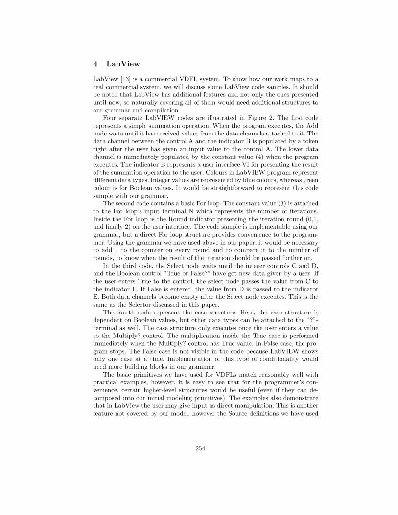
4 LabView
LabView [13] is a commercial VDFL system. To show how our work maps to areal commercial system, we will discuss some LabView code samples. It shouldbe noted that LabView has additional features and not only the ones presenteduntil now, so naturally covering all of them would need additional structures toour grammar and compilation.
Four separate LabVIEW codes are illustrated in Figure 2. The first coderepresents a simple summation operation. When the program executes, the Addnode waits until it has received values from the data channels attached to it. Thedata channel between the control A and the indicator B is populated by a tokenright after the user has given an input value to the control A. The lower datachannel is immediately populated by the constant value (4) when the programexecutes. The indicator B represents a user interface VI for presenting the resultof the summation operation to the user. Colours in LabVIEW program representdifferent data types. Integer values are represented by blue colours, whereas greencolour is for Boolean values. It would be straightforward to represent this codesample with our grammar.
The second code contains a basic For loop. The constant value (3) is attachedto the For loop’s input terminal N which represents the number of iterations.Inside the For loop is the Round indicator presenting the iteration round (0,1,and finally 2) on the user interface. The code sample is implementable using ourgrammar, but a direct For loop structure provides convenience to the program-mer. Using the grammar we have used above in our paper, it would be necessaryto add 1 to the counter on every round and to compare it to the number ofrounds, to know when the result of the iteration should be passed further on.
In the third code, the Select node waits until the integer controls C and D,and the Boolean control ”True or False?” have got new data given by a user. Ifthe user enters True to the control, the select node passes the value from C tothe indicator E. If False is entered, the value from D is passed to the indicatorE. Both data channels become empty after the Select node executes. This is thesame as the Selector discussed in this paper.
The fourth code represent the case structure. Here, the case structure isdependent on Boolean values, but other data types can be attached to the ”?”-terminal as well. The case structure only executes once the user enters a valueto the Multiply? control. The multiplication inside the True case is performedimmediately when the Multiply? control has True value. In False case, the pro-gram stops. The False case is not visible in the code because LabVIEW showsonly one case at a time. Implementation of this type of conditionality wouldneed more building blocks in our grammar.
The basic primitives we have used for VDFLs match reasonably well withpractical examples, however, it is easy to see that for the programmer’s con-venience, certain higher-level structures would be useful (even if they can de-composed into our initial modeling primitives). The examples also demonstratethat in LabView the user may give input as direct manipulation. This is anotherfeature not covered by our model, however the Source definitions we have used
254
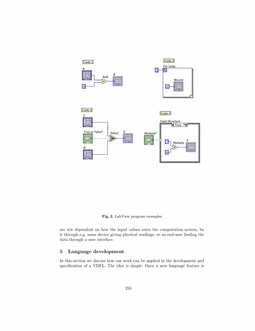
Fig. 2. LabView program examples
are not dependent on how the input values enter the computation system, beit through e.g. some device giving physical readings, or an end-user feeding thedata through a user interface.
5 Language development
In this section we discuss how our work can be applied in the development andspecification of a VDFL. The idea is simple: Once a new language feature is
255
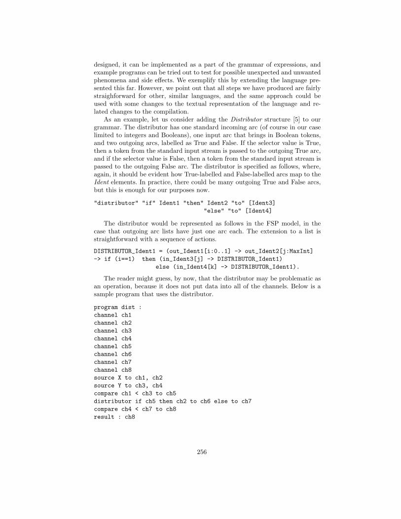
designed, it can be implemented as a part of the grammar of expressions, andexample programs can be tried out to test for possible unexpected and unwantedphenomena and side effects. We exemplify this by extending the language pre-sented this far. However, we point out that all steps we have produced are fairlystraighforward for other, similar languages, and the same approach could beused with some changes to the textual representation of the language and re-lated changes to the compilation.
As an example, let us consider adding the Distributor structure [5] to ourgrammar. The distributor has one standard incoming arc (of course in our caselimited to integers and Booleans), one input arc that brings in Boolean tokens,and two outgoing arcs, labelled as True and False. If the selector value is True,then a token from the standard input stream is passed to the outgoing True arc,and if the selector value is False, then a token from the standard input stream ispassed to the outgoing False arc. The distributor is specified as follows, where,again, it should be evident how True-labelled and False-labelled arcs map to theIdent elements. In practice, there could be many outgoing True and False arcs,but this is enough for our purposes now.
"distributor" "if" Ident1 "then" Ident2 "to" [Ident3]
"else" "to" [Ident4]
The distributor would be represented as follows in the FSP model, in thecase that outgoing arc lists have just one arc each. The extension to a list isstraightforward with a sequence of actions.
DISTRIBUTOR_Ident1 = (out_Ident1[i:0..1] -> out_Ident2[j:MaxInt]
-> if (i==1) then (in_Ident3[j] -> DISTRIBUTOR_Ident1)
else (in_Ident4[k] -> DISTRIBUTOR_Ident1).
The reader might guess, by now, that the distributor may be problematic asan operation, because it does not put data into all of the channels. Below is asample program that uses the distributor.
program dist :
channel ch1
channel ch2
channel ch3
channel ch4
channel ch5
channel ch6
channel ch7
channel ch8
source X to ch1, ch2
source Y to ch3, ch4
compare ch1 < ch3 to ch5
distributor if ch5 then ch2 to ch6 else to ch7
compare ch4 < ch7 to ch8
result : ch8
256
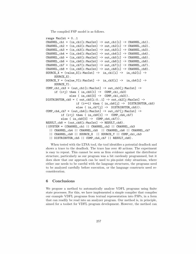
The compiled FSP model is as follows.
range MaxInt = 0..1
CHANNEL_ch1 = (in_ch1[i:MaxInt] -> out_ch1[i] -> CHANNEL_ch1).
CHANNEL_ch2 = (in_ch2[i:MaxInt] -> out_ch2[i] -> CHANNEL_ch2).
CHANNEL_ch3 = (in_ch3[i:MaxInt] -> out_ch3[i] -> CHANNEL_ch3).
CHANNEL_ch4 = (in_ch4[i:MaxInt] -> out_ch4[i] -> CHANNEL_ch4).
CHANNEL_ch5 = (in_ch5[i:MaxInt] -> out_ch5[i] -> CHANNEL_ch5).
CHANNEL_ch6 = (in_ch6[i:MaxInt] -> out_ch6[i] -> CHANNEL_ch6).
CHANNEL_ch7 = (in_ch7[i:MaxInt] -> out_ch7[i] -> CHANNEL_ch7).
CHANNEL_ch8 = (in_ch8[i:MaxInt] -> out_ch8[i] -> CHANNEL_ch8).
SOURCE_X = (value_X[i:MaxInt] -> in_ch1[i] -> in_ch2[i] ->
SOURCE_X).
SOURCE_Y = (value_Y[i:MaxInt] -> in_ch3[i] -> in_ch4[i] ->
SOURCE_Y).
COMP_ch1_ch3 = (out_ch1[i:MaxInt] -> out_ch3[j:MaxInt] ->
if (i<j) then ( in_ch5[1] -> COMP_ch1_ch3)
else ( in_ch5[0] -> COMP_ch1_ch3)).
DISTRIBUTOR_ch5 = ( out_ch5[i:0..1] -> out_ch2[j:MaxInt] ->
if (i==1) then ( in_ch6[j] -> DISTRIBUTOR_ch5)
else ( in_ch7[j] -> DISTRIBUTOR_ch5)).
COMP_ch4_ch7 = (out_ch4[i:MaxInt] -> out_ch7[j:MaxInt] ->
if (i<j) then ( in_ch8[1] -> COMP_ch4_ch7)
else ( in_ch8[0] -> COMP_ch4_ch7)).
RESULT_ch8 = (out_ch8[i:MaxInt] -> RESULT_ch8).
||SYSTEM = (CHANNEL_ch1 || CHANNEL_ch2 || CHANNEL_ch3
|| CHANNEL_ch4 || CHANNEL_ch5 || CHANNEL_ch6 || CHANNEL_ch7
|| CHANNEL_ch8 || SOURCE_X || SOURCE_Y || COMP_ch1_ch3
|| DISTRIBUTOR_ch5 || COMP_ch4_ch7 || RESULT_ch8).
When tested with the LTSA tool, the tool identifies a potential deadlock andshows a trace to the deadlock. The trace has over 40 actions. The experimentis easy to repeat. This cannot be seen as firm evidence against the distributorstructure, particularly as our program was a bit carelessly programmed, but itdoes show that our approach can be used to pin-point risky situations, whereeither one needs to be careful with the language structures, the programs needto be analyzed carefully before execution, or the language constructs need re-consideration.
6 Conclusions
We propose a method to automatically analyze VDFL programs using finitestate processes. For this, we have implemented a simple compiler that compilesour example VDFL programs from textual representation into FSPs, in a formthat can readily be read into an analyzer program. Our method is, in principle,aimed for a toolset for VDFL program development. However, the method can
257
also be used in new language design. By first implementing the new languagefeatures in our system, programs utilizing the new features can be analyzed.
Due to potential state-space explotion, one needs to be careful about theinteger value ranges used in the analysis models. In practice, they usually needto be very small.
References
1. T. Agerwala and Arvind. Data flow systems: Guest editors’ introduction. Com-puter, 15(2):10–13, February 1982.
2. John Backus. Acm turing award lectures. chapter Can programming be liberatedfrom the von Neumann style?: a functional style and its algebra of programs. ACM,New York, NY, USA, 2007.
3. Gennaro Costagliola, Vincenzo Deufemia, and Giuseppe Polese. A framework formodeling and implementing visual notations with applications to software engi-neering. ACM Trans. Softw. Eng. Methodol., 13(4):431–487, October 2004.
4. Lorrie Cranor and Ajay Apte. Programs worth one thousand words: visual lan-guages bring programming to the masses. Crossroads, 1(2):16–18, December 1994.
5. A. L. Davis and R. M. Keller. Data flow program graphs. Computer, 15(2):26–41,February 1982.
6. Antoni Diller. Z - An introduction to formal methods. John Wiley & Sons, 1990.7. Daniel D. Hils. Visual languages and computing survey: Data flow visual program-
ming languages. Journal of Visual Languages & Computing, 3:69–101, 1992.8. M.G. Hinchey and J.P. Bowen. Applications of formal methods. Prentice-Hall
international series in computer science. Prentice Hall, 1995.9. Jeff Magee and Jeff Kramer. Concurrency: State Models & Java Programs. John
Wiley & Sons, Inc., New York, NY, USA, 2006.10. M. Marttila-Kontio, M. Ronkko, and P. Toivanen. Visual data flow languages with
action systems. In Computer Science and Information Technology, 2009. IMCSIT’09. International Multiconference on, pages 589–594, 2009.
11. Walid A. Najjar, Edward A. Lee, and Guang R. Gao. Advances in the dataflowcomputational model. Parallel Computing, 25:1907–1929, 1999.
12. Aarne Ranta. Implementing Programming Languages - An Introduction to Com-pilers and Interpreters. Texts in Computing. College Publications, 2012.
13. Kirsten N. Whitley, Laura R. Novick, and Doug Fisher. Evidence in favor ofvisual representation for the dataflow paradigm: An experiment testing labview’scomprehensibility. Int. J. Hum.-Comput. Stud., 64(4):281–303, April 2006.
14. Ke-Bing Zhang, Mehmet A. Orgun, and Kang Zhang. Visual language semanticsspecification in the vispro system. In Selected papers from the 2002 Pan-Sydneyworkshop on Visualisation - Volume 22, VIP ’02, pages 121–127, Darlinghurst,Australia, Australia, 2002. Australian Computer Society, Inc.
258
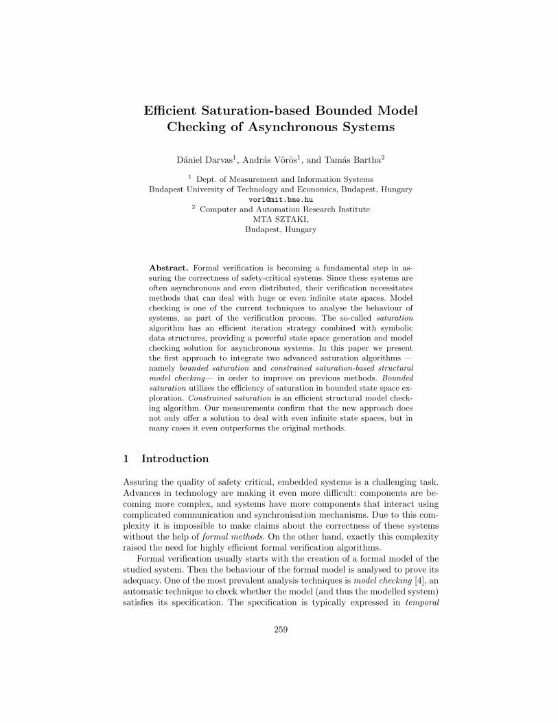
Efficient Saturation-based Bounded ModelChecking of Asynchronous Systems
Daniel Darvas1, Andras Voros1, and Tamas Bartha2
1 Dept. of Measurement and Information SystemsBudapest University of Technology and Economics, Budapest, Hungary
[email protected] Computer and Automation Research Institute
MTA SZTAKI,Budapest, Hungary
Abstract. Formal verification is becoming a fundamental step in as-suring the correctness of safety-critical systems. Since these systems areoften asynchronous and even distributed, their verification necessitatesmethods that can deal with huge or even infinite state spaces. Modelchecking is one of the current techniques to analyse the behaviour ofsystems, as part of the verification process. The so-called saturationalgorithm has an efficient iteration strategy combined with symbolicdata structures, providing a powerful state space generation and modelchecking solution for asynchronous systems. In this paper we presentthe first approach to integrate two advanced saturation algorithms —namely bounded saturation and constrained saturation-based structuralmodel checking— in order to improve on previous methods. Boundedsaturation utilizes the efficiency of saturation in bounded state space ex-ploration. Constrained saturation is an efficient structural model check-ing algorithm. Our measurements confirm that the new approach doesnot only offer a solution to deal with even infinite state spaces, but inmany cases it even outperforms the original methods.
1 Introduction
Assuring the quality of safety critical, embedded systems is a challenging task.Advances in technology are making it even more difficult: components are be-coming more complex, and systems have more components that interact usingcomplicated communication and synchronisation mechanisms. Due to this com-plexity it is impossible to make claims about the correctness of these systemswithout the help of formal methods. On the other hand, exactly this complexityraised the need for highly efficient formal verification algorithms.
Formal verification usually starts with the creation of a formal model of thestudied system. Then the behaviour of the formal model is analysed to prove itsadequacy. One of the most prevalent analysis techniques is model checking [4], anautomatic technique to check whether the model (and thus the modelled system)satisfies its specification. The specification is typically expressed in temporal
259
logic. Computation Tree Logic (CTL) is a popular temporal logic language dueto the efficient and relatively simple analysis algorithms supporting it.
Model checking traverses the state space of the model being analysed. Safetycritical systems are often asynchronous, even distributed, so the composite statespace of their asynchronous subsystems can be as large as the Cartesian productof the local components’ state spaces, i.e., the state space of the whole system ex-plodes. Symbolic methods [4] are advanced techniques to handle huge state spacesof synchronous systems. Instead of storing states explicitly, symbolic techniquesrely on an encoded representation of the state space such as decision diagrams.These are compact graph representations of discrete functions. Ordinary sym-bolic methods, however, usually perform poorly for asynchronous systems.
Saturation [1] is considered as one of the most effective state space gen-eration and model checking algorithms for asynchronous systems It combinesthe efficiency of symbolic methods with a special iteration strategy. Saturation-based state space exploration computes the set of reachable states. The so-calledsaturation-based structural model checking algorithm can analyse temporal logicproperties. Nowadays, the so-called constrained saturation-based structural modelchecking algorithm is one of the most efficient algorithms for model checking [12].
However, many complex models still have a state space, which is either toolarge to be represented even symbolically, or it is infinite. In these cases boundedmodel checking can be a solution, as it explores and examines the prescribedproperties on a bounded part of the state space. Bounded saturation-based statespace exploration was introduced in [11], where the authors described a newsaturation algorithm that explores the state space only to some bounded depth.
1.1 Motivation
Former approaches solved only one of the problems: they could either be usedfor structural model checking over the entire state space; or they could traversethe state space up to a given bound, but without being able to check complexproperties on it. In this paper we introduce a new saturation-based boundedmodel checking algorithm that integrates both approaches. Our algorithm in-crementally explores the state space and performs structural model checking onthe uncovered bounded part. To our best knowledge, this is the first attemptto combine bounded saturation-based state space exploration with constrainedsaturation-based CTL model checking, in order to gain the advantages of bothtechniques.
Furthermore, bounded model checkers usually do not support full CTL. Eventhough there were theoretical results in this area, former bounded model checkingapproaches did not work well with CTL due to its branching characteristics.Our work is a step towards efficient bounded CTL model checking with manydirections to be explored in the future.
This paper extends our former work [8] described in 3.1 with an efficientiteration strategy (namely constrained saturation) to traverse the bounded statespace. This is the first time where the efficiency of constrained saturation basedstate space traversal is utilized for bounded model checking.
260
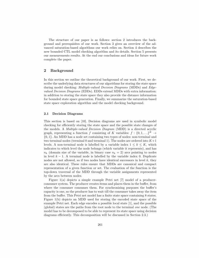
The structure of our paper is as follows: section 2 introduces the back-ground and prerequisites of our work. Section 3 gives an overview of the ad-vanced saturation-based algorithms our work relies on. Section 4 describes thenew bounded CTL model checking algorithm and its details. Section 5 presentsour measurements results. At the end our conclusions and ideas for future workcomplete the paper.
2 Background
In this section we outline the theoretical background of our work. First, we de-scribe the underlying data structures of our algorithms for storing the state spaceduring model checking: Multiple-valued Decision Diagrams (MDDs) and Edge-valued Decision Diagrams (EDDs). EDDs extend MDDs with extra information:in addition to storing the state space they also provide the distance informationfor bounded state space generation. Finally, we summarize the saturation-basedstate space exploration algorithm and the model checking background.
2.1 Decision Diagrams
This section is based on [10]. Decision diagrams are used in symbolic modelchecking for efficiently storing the state space and the possible state changes ofthe models. A Multiple-valued Decision Diagram (MDD) is a directed acyclicgraph, representing a function f consisting of K variables: f : {0, 1, . . .}K →{0, 1}. An MDD has a node set containing two types of nodes: non-terminal andtwo terminal nodes (terminal 0 and terminal 1). The nodes are ordered into K+1levels. A non-terminal node is labelled by a variable index 1 ≤ k ≤ K, whichindicates to which level the node belongs (which variable it represents), and hasnk (domain size of the variable, in binary case nk = 2) arcs pointing to nodesin level k − 1. A terminal node is labelled by the variable index 0. Duplicatenodes are not allowed, so if two nodes have identical successors in level k, theyare also identical. These rules ensure that MDDs are canonical and compactrepresentation of a given function or set. The evaluation of the function is thetop-down traversal of the MDD through the variable assignments representedby the arcs between nodes.
Figure 1(a) depicts a simple example Petri net [7] model of a producer-consumer system. The producer creates items and places them in the buffer, fromwhere the consumer consumes them. For synchronizing purposes the buffer’scapacity is one, so the producer has to wait till the consumer takes away the itemfrom the buffer. This Petri net model has a finite state space containing 8 states.Figure 1(b) depicts an MDD used for storing the encoded state space of theexample Petri net. Each edge encodes a possible local state [1], and the possible(global) states are the paths from the root node to the terminal one node. (Themodel has to be decomposed to be able to represent its state space using decisiondiagrams efficiently. This decomposition will be discussed in Section 2.3.)
261
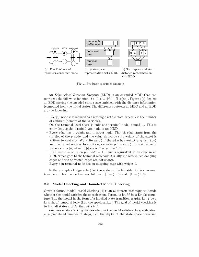
producer buffer consumer
(a) The Petri net ofproducer-consumer model
terminallevel
consumerlevel
producer &buffer level
11
(b) State spacerepresentation with MDD
(c) State space and statedistance representationwith EDD
Fig. 1. Producer-consumer example
An Edge-valued Decision Diagram (EDD) is an extended MDD that canrepresent the following function: f : {0, 1, . . .}K → N∪{∞}. Figure 1(c) depictsan EDD storing the encoded state space enriched with the distance information(computed from the initial state). The differences between an MDD and an EDDare the following:
– Every p node is visualized as a rectangle with k slots, where k is the numberof children (domain of the variable).
– On the terminal level there is only one terminal node, named ⊥. This isequivalent to the terminal one node in an MDD.
– Every edge has a weight and a target node. The ith edge starts from theith slot of the p node, and the value p[i].value (the weight of the edge) iswritten to that slot. We write 〈n,w〉 if the edge has weight w ∈ N ∪ {∞}and has target node n. In addition, we write p[i] = 〈n,w〉 if the ith edge ofthe node p is 〈n,w〉 and p[i].value ≡ w, p[i].node ≡ n.
– If p[i].value = ∞, then p[i].node = ⊥. This is equivalent to an edge in anMDD which goes to the terminal zero node. Usually the zero valued danglingedges and the ∞ valued edges are not shown.
– Every non-terminal node has an outgoing edge with weight 0.
In the example of Figure 1(c) let the node on the left side of the consumerlevel be x. This x node has two children: x[0] = 〈⊥, 0〉 and x[1] = 〈⊥, 3〉.
2.2 Model Checking and Bounded Model Checking
Given a formal model, model checking [4] is an automatic technique to decidewhether the model satisfies the specification. Formally: let M be a Kripke struc-ture (i.e., the model in the form of a labelled state-transition graph). Let f be aformula of temporal logic (i.e., the specification). The goal of model checking isto find all states s of M that M, s � f .
Bounded model checking decides whether the model satisfies the specificationin a predefined number of steps, i.e., the depth of the state space traversal.
262
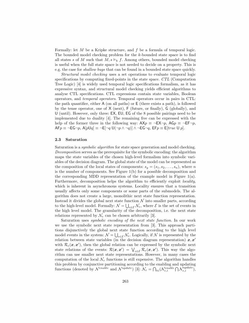
Formally: let M be a Kripke structure, and f be a formula of temporal logic.The bounded model checking problem for the k-bounded state space is to findall states s of M such that M, s �k f . Among others, bounded model checkingis useful when the full state space is not needed to decide on a property. This ise.g. the case for shallow bugs that can be found in a bounded state space quickly.
Structural model checking uses a set operations to evaluate temporal logicspecifications by computing fixed-points in the state space. CTL (ComputationTree Logic) [4] is widely used temporal logic specifications formalism, as it hasexpressive syntax, and structural model checking yields efficient algorithms toanalyse CTL specifications. CTL expressions contain state variables, Booleanoperators, and temporal operators. Temporal operators occur in pairs in CTL:the path quantifier, either A (on all paths) or E (there exists a path), is followedby the tense operator, one of X (next), F (future, or finally), G (globally), andU (until). However, only three: EX, EU, EG of the 8 possible pairings need to beimplemented due to duality [4]. The remaining five can be expressed with thehelp of the former three in the following way: AXp ≡ ¬EX¬p, AGp ≡ ¬EF¬p,AFp ≡ ¬EG¬p, A[pUq] ≡ ¬E[¬q U(¬p ∧ ¬q)] ∧ ¬EG¬q, EFp ≡ E[true U p].
2.3 Saturation
Saturation is a symbolic algorithm for state space generation and model checking.Decomposition serves as the prerequisite for the symbolic encoding: the algorithmmaps the state variables of the chosen high-level formalism into symbolic vari-ables of the decision diagram. The global state of the model can be represented asthe composition of the local states of components: sg = (s1, s2, . . . , sn), where nis the number of components. See Figure 1(b) for a possible decomposition andthe corresponding MDD representation of the example model in Figure 1(a).Furthermore, decomposition helps the algorithm to efficiently exploit locality,which is inherent in asynchronous systems. Locality ensures that a transitionusually affects only some components or some parts of the submodels. The al-gorithm does not create a large, monolithic next state function representation.Instead it divides the global next state function N into smaller parts, accordingto the high-level model. Formally: N =
⋃e∈E Ne, where E is the set of events in
the high level model. The granularity of the decomposition, i.e. the next staterelations represented by Ne can be chosen arbitrarily [3].
Saturation uses symbolic encoding of the next state function. In our workwe use the symbolic next state representation from [3]. This approach parti-tions disjunctively the global next state function according to the high levelmodel events in the system: N =
⋃e∈E Ne. Logically, if N is represented by the
relation between state variables (in the decision diagram representation) x,x′
with Re(x,x′), then the global relation can be expressed by the symbolic next
state relations of the events: R(x,x′) =∨
e∈E Re(x,x′). This way the algo-
rithm can use smaller next state representations. However, in many cases thecomputation of the local Ne functions is still expensive. The algorithm handlesthis problem by conjunctive partitioning according to the enabling and updatingfunctions (denoted by N enable and N update) [3]: Ne =
⋂∀i(N enable
e,i
⋂N updatee,i ),
263
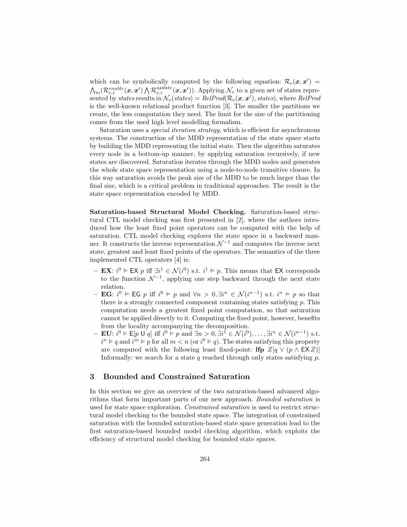
which can be symbolically computed by the following equation: Re(x,x′) =∧
∀i(Renablee,i (x,x′)
∧Rupdatee,i (x,x′)). Applying Ne to a given set of states repre-
sented by states results inNe(states) = RelProd(Re(x,x′), states), where RelProd
is the well-known relational product function [3]. The smaller the partitions wecreate, the less computation they need. The limit for the size of the partitioningcomes from the used high level modelling formalism.
Saturation uses a special iteration strategy, which is efficient for asynchronoussystems. The construction of the MDD representation of the state space startsby building the MDD representing the initial state. Then the algorithm saturatesevery node in a bottom-up manner, by applying saturation recursively, if newstates are discovered. Saturation iterates through the MDD nodes and generatesthe whole state space representation using a node-to-node transitive closure. Inthis way saturation avoids the peak size of the MDD to be much larger than thefinal size, which is a critical problem in traditional approaches. The result is thestate space representation encoded by MDD.
Saturation-based Structural Model Checking. Saturation-based struc-tural CTL model checking was first presented in [2], where the authors intro-duced how the least fixed point operators can be computed with the help ofsaturation. CTL model checking explores the state space in a backward man-ner. It constructs the inverse representation N−1 and computes the inverse nextstate, greatest and least fixed points of the operators. The semantics of the threeimplemented CTL operators [4] is:
– EX: i0 � EX p iff ∃i1 ∈ N (i0) s.t. i1 � p. This means that EX correspondsto the function N−1, applying one step backward through the next staterelation.
– EG: i0 � EG p iff i0 � p and ∀n > 0,∃in ∈ N (in−1) s.t. in � p so thatthere is a strongly connected component containing states satisfying p. Thiscomputation needs a greatest fixed point computation, so that saturationcannot be applied directly to it. Computing the fixed point, however, benefitsfrom the locality accompanying the decomposition.
– EU: i0 � E[p U q] iff i0 � p and ∃n > 0,∃i1 ∈ N (i0), . . . ,∃in ∈ N (in−1) s.t.in � q and im � p for all m < n (or i0 � q). The states satisfying this propertyare computed with the following least fixed-point: lfp Z[q ∨ (p ∧ EXZ)]Informally: we search for a state q reached through only states satisfying p.
3 Bounded and Constrained Saturation
In this section we give an overview of the two saturation-based advanced algo-rithms that form important parts of our new approach. Bounded saturation isused for state space exploration. Constrained saturation is used to restrict struc-tural model checking to the bounded state space. The integration of constrainedsaturation with the bounded saturation-based state space generation lead to thefirst saturation-based bounded model checking algorithm, which exploits theefficiency of structural model checking for bounded state spaces.
264
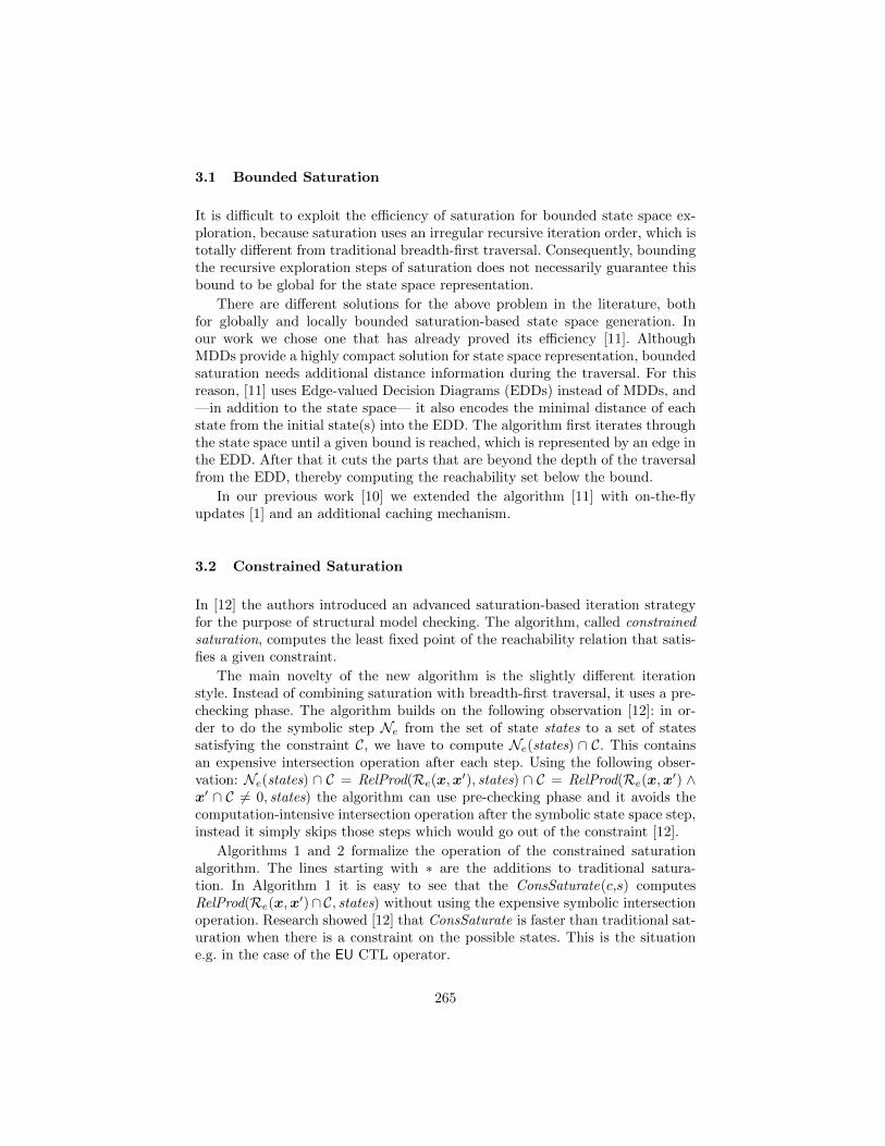
3.1 Bounded Saturation
It is difficult to exploit the efficiency of saturation for bounded state space ex-ploration, because saturation uses an irregular recursive iteration order, which istotally different from traditional breadth-first traversal. Consequently, boundingthe recursive exploration steps of saturation does not necessarily guarantee thisbound to be global for the state space representation.
There are different solutions for the above problem in the literature, bothfor globally and locally bounded saturation-based state space generation. Inour work we chose one that has already proved its efficiency [11]. AlthoughMDDs provide a highly compact solution for state space representation, boundedsaturation needs additional distance information during the traversal. For thisreason, [11] uses Edge-valued Decision Diagrams (EDDs) instead of MDDs, and—in addition to the state space— it also encodes the minimal distance of eachstate from the initial state(s) into the EDD. The algorithm first iterates throughthe state space until a given bound is reached, which is represented by an edge inthe EDD. After that it cuts the parts that are beyond the depth of the traversalfrom the EDD, thereby computing the reachability set below the bound.
In our previous work [10] we extended the algorithm [11] with on-the-flyupdates [1] and an additional caching mechanism.
3.2 Constrained Saturation
In [12] the authors introduced an advanced saturation-based iteration strategyfor the purpose of structural model checking. The algorithm, called constrainedsaturation, computes the least fixed point of the reachability relation that satis-fies a given constraint.
The main novelty of the new algorithm is the slightly different iterationstyle. Instead of combining saturation with breadth-first traversal, it uses a pre-checking phase. The algorithm builds on the following observation [12]: in or-der to do the symbolic step Ne from the set of state states to a set of statessatisfying the constraint C, we have to compute Ne(states) ∩ C. This containsan expensive intersection operation after each step. Using the following obser-vation: Ne(states) ∩ C = RelProd(Re(x,x
′), states) ∩ C = RelProd(Re(x,x′) ∧
x′ ∩ C 6= 0, states) the algorithm can use pre-checking phase and it avoids thecomputation-intensive intersection operation after the symbolic state space step,instead it simply skips those steps which would go out of the constraint [12].
Algorithms 1 and 2 formalize the operation of the constrained saturationalgorithm. The lines starting with ∗ are the additions to traditional satura-tion. In Algorithm 1 it is easy to see that the ConsSaturate(c,s) computesRelProd(Re(x,x
′)∩C, states) without using the expensive symbolic intersectionoperation. Research showed [12] that ConsSaturate is faster than traditional sat-uration when there is a constraint on the possible states. This is the situatione.g. in the case of the EU CTL operator.
265
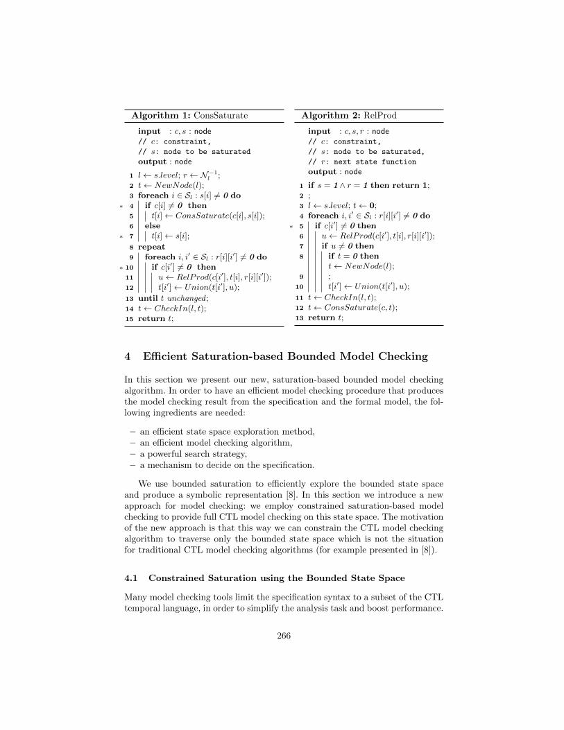
Algorithm 1: ConsSaturate
input : c, s : node// c: constraint,
// s: node to be saturated
output : node
1 l← s.level; r ← N−1l ;
2 t← NewNode(l);3 foreach i ∈ Sl : s[i] 6= 0 do4∗ if c[i] 6= 0 then5 t[i]← ConsSaturate(c[i], s[i]);6 else7∗ t[i]← s[i];
8 repeat9 foreach i, i′ ∈ Sl : r[i][i′] 6= 0 do
10∗ if c[i′] 6= 0 then11 u← RelProd(c[i′], t[i], r[i][i′]);12 t[i′]← Union(t[i′], u);
13 until t unchanged ;14 t← CheckIn(l, t);15 return t;
Algorithm 2: RelProd
input : c, s, r : node// c: constraint,
// s: node to be saturated,
// r: next state function
output : node
1 if s = 1 ∧ r = 1 then return 1;2 ;3 l← s.level; t← 0;4 foreach i, i′ ∈ Sl : r[i][i′] 6= 0 do5∗ if c[i′] 6= 0 then6 u← RelProd(c[i′], t[i], r[i][i′]);7 if u 6= 0 then8 if t = 0 then
t← NewNode(l);9 ;
10 t[i′]← Union(t[i′], u);
11 t← CheckIn(l, t);12 t← ConsSaturate(c, t);13 return t;
4 Efficient Saturation-based Bounded Model Checking
In this section we present our new, saturation-based bounded model checkingalgorithm. In order to have an efficient model checking procedure that producesthe model checking result from the specification and the formal model, the fol-lowing ingredients are needed:
– an efficient state space exploration method,– an efficient model checking algorithm,– a powerful search strategy,– a mechanism to decide on the specification.
We use bounded saturation to efficiently explore the bounded state spaceand produce a symbolic representation [8]. In this section we introduce a newapproach for model checking: we employ constrained saturation-based modelchecking to provide full CTL model checking on this state space. The motivationof the new approach is that this way we can constrain the CTL model checkingalgorithm to traverse only the bounded state space which is not the situationfor traditional CTL model checking algorithms (for example presented in [8]).
4.1 Constrained Saturation using the Bounded State Space
Many model checking tools limit the specification syntax to a subset of the CTLtemporal language, in order to simplify the analysis task and boost performance.
266
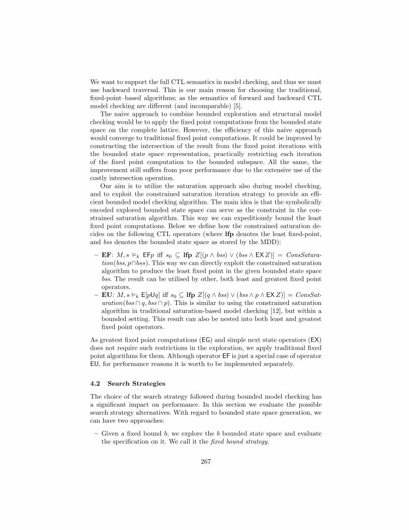
We want to support the full CTL semantics in model checking, and thus we mustuse backward traversal. This is our main reason for choosing the traditional,fixed-point–based algorithms; as the semantics of forward and backward CTLmodel checking are different (and incomparable) [5].
The naive approach to combine bounded exploration and structural modelchecking would be to apply the fixed point computations from the bounded statespace on the complete lattice. However, the efficiency of this naive approachwould converge to traditional fixed point computations. It could be improved byconstructing the intersection of the result from the fixed point iterations withthe bounded state space representation, practically restricting each iterationof the fixed point computation to the bounded subspace. All the same, theimprovement still suffers from poor performance due to the extensive use of thecostly intersection operation.
Our aim is to utilize the saturation approach also during model checking,and to exploit the constrained saturation iteration strategy to provide an effi-cient bounded model checking algorithm. The main idea is that the symbolicallyencoded explored bounded state space can serve as the constraint in the con-strained saturation algorithm. This way we can expeditiously bound the leastfixed point computations. Below we define how the constrained saturation de-cides on the following CTL operators (where lfp denotes the least fixed-point,and bss denotes the bounded state space as stored by the MDD):
– EF: M, s �k EFp iff s0 ⊆ lfp Z[(p ∧ bss) ∨ (bss ∧ EXZ)] = ConsSatura-tion(bss, p∩bss). This way we can directly exploit the constrained saturationalgorithm to produce the least fixed point in the given bounded state spacebss. The result can be utilised by other, both least and greatest fixed pointoperators.
– EU: M, s �k E[pUq] iff s0 ⊆ lfp Z[(q ∧ bss) ∨ (bss ∧ p ∧ EXZ)] = ConsSat-uration(bss ∩ q, bss ∩ p). This is similar to using the constrained saturationalgorithm in traditional saturation-based model checking [12], but within abounded setting. This result can also be nested into both least and greatestfixed point operators.
As greatest fixed point computations (EG) and simple next state operators (EX)does not require such restrictions in the exploration, we apply traditional fixedpoint algorithms for them. Although operator EF is just a special case of operatorEU, for performance reasons it is worth to be implemented separately.
4.2 Search Strategies
The choice of the search strategy followed during bounded model checking hasa significant impact on performance. In this section we evaluate the possiblesearch strategy alternatives. With regard to bounded state space generation, wecan have two approaches:
– Given a fixed bound b, we explore the b bounded state space and evaluatethe specification on it. We call it the fixed bound strategy.
267
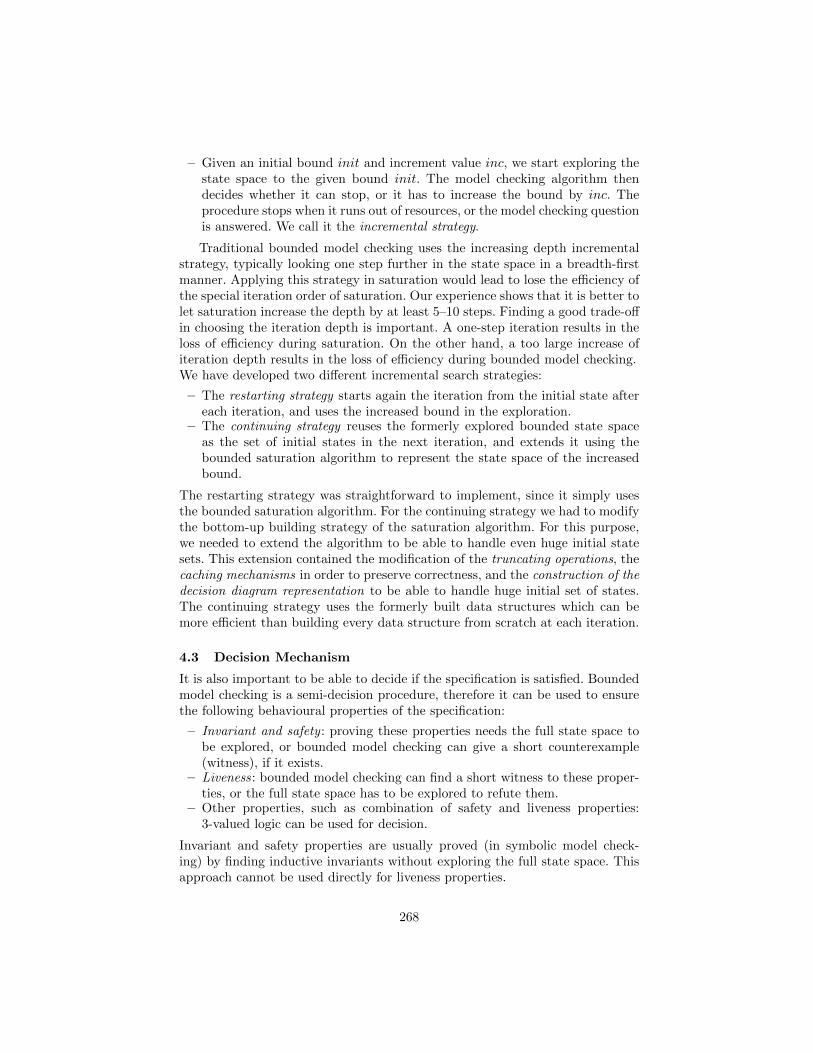
– Given an initial bound init and increment value inc, we start exploring thestate space to the given bound init. The model checking algorithm thendecides whether it can stop, or it has to increase the bound by inc. Theprocedure stops when it runs out of resources, or the model checking questionis answered. We call it the incremental strategy.
Traditional bounded model checking uses the increasing depth incrementalstrategy, typically looking one step further in the state space in a breadth-firstmanner. Applying this strategy in saturation would lead to lose the efficiency ofthe special iteration order of saturation. Our experience shows that it is better tolet saturation increase the depth by at least 5–10 steps. Finding a good trade-offin choosing the iteration depth is important. A one-step iteration results in theloss of efficiency during saturation. On the other hand, a too large increase ofiteration depth results in the loss of efficiency during bounded model checking.We have developed two different incremental search strategies:
– The restarting strategy starts again the iteration from the initial state aftereach iteration, and uses the increased bound in the exploration.
– The continuing strategy reuses the formerly explored bounded state spaceas the set of initial states in the next iteration, and extends it using thebounded saturation algorithm to represent the state space of the increasedbound.
The restarting strategy was straightforward to implement, since it simply usesthe bounded saturation algorithm. For the continuing strategy we had to modifythe bottom-up building strategy of the saturation algorithm. For this purpose,we needed to extend the algorithm to be able to handle even huge initial statesets. This extension contained the modification of the truncating operations, thecaching mechanisms in order to preserve correctness, and the construction of thedecision diagram representation to be able to handle huge initial set of states.The continuing strategy uses the formerly built data structures which can bemore efficient than building every data structure from scratch at each iteration.
4.3 Decision Mechanism
It is also important to be able to decide if the specification is satisfied. Boundedmodel checking is a semi-decision procedure, therefore it can be used to ensurethe following behavioural properties of the specification:
– Invariant and safety : proving these properties needs the full state space tobe explored, or bounded model checking can give a short counterexample(witness), if it exists.
– Liveness: bounded model checking can find a short witness to these proper-ties, or the full state space has to be explored to refute them.
– Other properties, such as combination of safety and liveness properties:3-valued logic can be used for decision.
Invariant and safety properties are usually proved (in symbolic model check-ing) by finding inductive invariants without exploring the full state space. Thisapproach cannot be used directly for liveness properties.
268
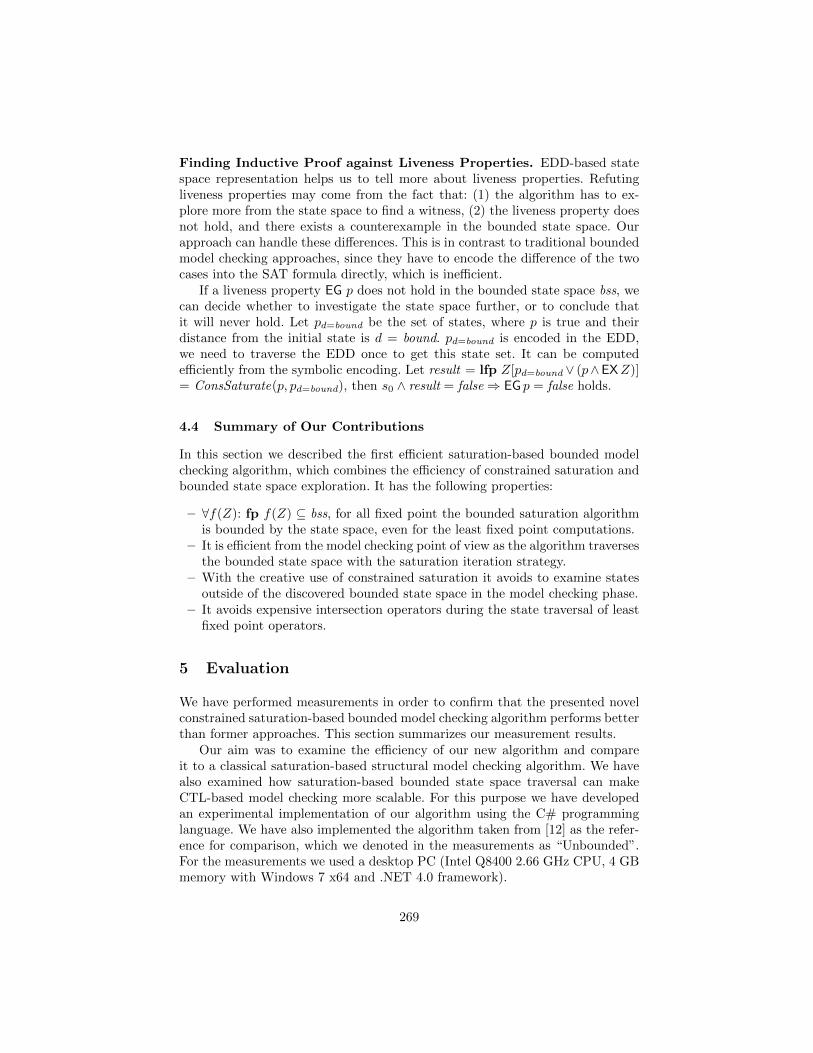
Finding Inductive Proof against Liveness Properties. EDD-based statespace representation helps us to tell more about liveness properties. Refutingliveness properties may come from the fact that: (1) the algorithm has to ex-plore more from the state space to find a witness, (2) the liveness property doesnot hold, and there exists a counterexample in the bounded state space. Ourapproach can handle these differences. This is in contrast to traditional boundedmodel checking approaches, since they have to encode the difference of the twocases into the SAT formula directly, which is inefficient.
If a liveness property EG p does not hold in the bounded state space bss, wecan decide whether to investigate the state space further, or to conclude thatit will never hold. Let pd=bound be the set of states, where p is true and theirdistance from the initial state is d = bound. pd=bound is encoded in the EDD,we need to traverse the EDD once to get this state set. It can be computedefficiently from the symbolic encoding. Let result = lfp Z[pd=bound ∨ (p∧EXZ)]= ConsSaturate(p, pd=bound), then s0 ∧ result = false⇒ EG p = false holds.
4.4 Summary of Our Contributions
In this section we described the first efficient saturation-based bounded modelchecking algorithm, which combines the efficiency of constrained saturation andbounded state space exploration. It has the following properties:
– ∀f(Z): fp f(Z) ⊆ bss, for all fixed point the bounded saturation algorithmis bounded by the state space, even for the least fixed point computations.
– It is efficient from the model checking point of view as the algorithm traversesthe bounded state space with the saturation iteration strategy.
– With the creative use of constrained saturation it avoids to examine statesoutside of the discovered bounded state space in the model checking phase.
– It avoids expensive intersection operators during the state traversal of leastfixed point operators.
5 Evaluation
We have performed measurements in order to confirm that the presented novelconstrained saturation-based bounded model checking algorithm performs betterthan former approaches. This section summarizes our measurement results.
Our aim was to examine the efficiency of our new algorithm and compareit to a classical saturation-based structural model checking algorithm. We havealso examined how saturation-based bounded state space traversal can makeCTL-based model checking more scalable. For this purpose we have developedan experimental implementation of our algorithm using the C# programminglanguage. We have also implemented the algorithm taken from [12] as the refer-ence for comparison, which we denoted in the measurements as “Unbounded”.For the measurements we used a desktop PC (Intel Q8400 2.66 GHz CPU, 4 GBmemory with Windows 7 x64 and .NET 4.0 framework).
269
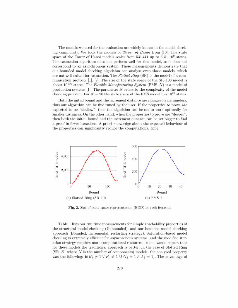
The models we used for the evaluation are widely known in the model check-ing community. We took the models of Tower of Hanoi from [10]. The statespace of the Tower of Hanoi models scales from 531 441 up to 3, 5 · 109 states.The saturation algorithm does not perform well for this model, as it does notcorrespond to an asynchronous system. These measurements demonstrate thatour bounded model checking algorithm can analyse even those models, whichare not well suited for saturation. The Slotted Ring (SR) is the model of a com-munication protocol [1], [9]. The size of the state space of the SR–100 model isabout 10100 states. The Flexible Manufacturing System (FMS–N) is a model ofproduction systems [1]. The parameter N refers to the complexity of the modelchecking problem. For N = 20 the state space of the FMS model has 1020 states.
Both the initial bound and the increment distance are changeable parameters,thus our algorithm can be fine tuned by the user. If the properties to prove areexpected to be “shallow”, then the algorithm can be set to work optimally forsmaller distances. On the other hand, when the properties to prove are “deeper”,then both the initial bound and the increment distance can be set bigger to finda proof in fewer iterations. A priori knowledge about the expected behaviour ofthe properties can significantly reduce the computational time.
0 50 1000
2,000
4,000
Bound
Use
dE
DD
nodes
(a) Slotted Ring (SR–10)
0 10 20 30 400
200
400
600
Bound
Use
dE
DD
nodes
(b) FMS–3
Fig. 2. Size of state space representation (EDD) at each iteration
Table 1 lists our run time measurements for simple reachability properties ofthe structural model checking (Unbounded), and our bounded model checkingapproach (Bounded, incremental, restarting strategy). Saturation-based modelchecking is extremely efficient for asynchronous systems, and the modified iter-ation strategy requires more computational resources, so one would expect thatfor these models the traditional approach is better. In the case of Slotted Ring(SR–N , where N is the number of components) models, the analysed propertywas the following: E(B1 6= 1 ∨ F1 6= 1 U G2 = 1 ∧ A2 = 1). The advantage of
270
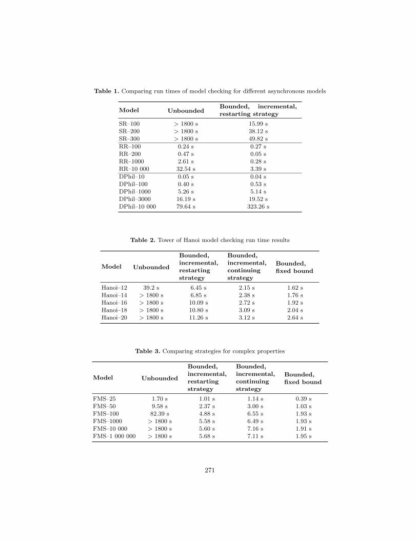
Table 1. Comparing run times of model checking for different asynchronous models
Model UnboundedBounded, incremental,restarting strategy
SR–100 > 1800 s 15.99 sSR–200 > 1800 s 38.12 sSR–300 > 1800 s 49.82 s
RR–100 0.24 s 0.27 sRR–200 0.47 s 0.05 sRR–1000 2.61 s 0.28 sRR–10 000 32.54 s 3.39 s
DPhil–10 0.05 s 0.04 sDPhil–100 0.40 s 0.53 sDPhil–1000 5.26 s 5.14 sDPhil–3000 16.19 s 19.52 sDPhil–10 000 79.64 s 323.26 s
Table 2. Tower of Hanoi model checking run time results
Model Unbounded
Bounded,incremental,restartingstrategy
Bounded,incremental,continuingstrategy
Bounded,fixed bound
Hanoi–12 39.2 s 6.45 s 2.15 s 1.62 sHanoi–14 > 1800 s 6.85 s 2.38 s 1.76 sHanoi–16 > 1800 s 10.09 s 2.72 s 1.92 sHanoi–18 > 1800 s 10.80 s 3.09 s 2.04 sHanoi–20 > 1800 s 11.26 s 3.12 s 2.64 s
Table 3. Comparing strategies for complex properties
Model Unbounded
Bounded,incremental,restartingstrategy
Bounded,incremental,continuingstrategy
Bounded,fixed bound
FMS–25 1.70 s 1.01 s 1.14 s 0.39 sFMS–50 9.58 s 2.37 s 3.00 s 1.03 sFMS–100 82.39 s 4.88 s 6.55 s 1.93 sFMS–1000 > 1800 s 5.58 s 6.49 s 1.93 sFMS–10 000 > 1800 s 5.60 s 7.16 s 1.91 sFMS–1 000 000 > 1800 s 5.68 s 7.11 s 1.95 s
271
bounded model checking is revealed by the model, as traditional model checkingruns out of resources even for such a simple property.
We have also examined Round-Robin models (RR–N , where N is the numberof components), which are quite efficiently handled by the traditional saturationbased model checking approach. We chose the following property to be checked:E(pload1 = 0 U psend0 = 1). This property is shallow, so the advantage of ourbounded model checking approach is well reflected in the results.
The model of the Dining Philosophers (DPhil–N , where N is the numberof philosophers) revealed that for those models, where the saturation algorithmanswers the model checking question (in this case: E(¬eating2 U eating1)) ex-tremely fast, bounded model checking is slower. The reason for this is that theoverhead of bounded model checking simply does not pay off.
In Table 2 and Table 3 we compare the different approaches for complexproperties. Table 2 contains the measurements of the Tower of Hanoi models.We have examined a combined safety-liveness property (EG(EF(B↓8 > 0)), whereB↓8 > 0 denotes the placement of the 8th disk to the 2nd rod). The traditionalstructural model checking approach (Unbounded) runs out of resources early.Knowing the exact bound can help the algorithm to answer the model checkingquestion as fast as possible (Bounded, fixed bound). Comparing the two differentbounded model checking strategies, the continuing strategy has advantage as ituses up the formerly computed results during the model checking.
In Table 3 the run time results for the property EG(E(M1 > 0 U (P1s = P2s =P3s = 8))) of the model FMS are depicted. This property is also a combinedsafety-liveness property that represents the existence of a circle in a certain set ofstates satisfying some safety requirements (based on [2]). The structural modelchecking algorithm time-outs for big parameters. By setting an adequate bound,the bounded model checking approach answers the model checking question veryfast (Bounded, fixed bound). When we compare the two bounded model check-ing strategies, the result is surprising: the restarting strategy solves the modelchecking problem for every parameter faster than the continuing strategy. Weinvestigated the reason for this. It can be seen in Figure 2 that for asynchronoussystems (like FMS) the state space representation grows steeply up to a givenvalue, but after that it starts decreasing (resembling a bell curve). The contin-uing strategy uses these intermediate state space representations as the initialstate, which is a large computational overhead compared to starting the iterationfrom the initial state. By beginning model checking from scratch (i.e., using therestarting strategy) we can exploit the efficiency of saturation for building thestate space representation. By starting to modify an intermediate representation(i.e., using the continuing strategy) the algorithm has to do more computations,especially if the intermediate representation is larger than the final one.
6 Conclusion and future work
We have presented in this paper an advanced bounded model checking approachbased on the saturation algorithm. Our work exploits the efficiency of saturation
272
and enables us to verify complex, or even infinite-state models. Our approachalso extends the set of asynchronous systems that can be analysed with the helpof symbolic methods. We have proved the efficiency of the new approach withmeasurements.
We intend to develop our solution further. We will investigate the use offorward model checking [6] instead of the classical backward fixed point compu-tation, as we believe this can further improve the performance of our algorithm.We also plan to use the constrained saturation algorithm in a different way, inorder to avoid redundant computations more efficiently.
References
1. Ciardo, G., Marmorstein, R., Siminiceanu, R.: Saturation unbound. In: TACAS2003. pp. 379–393. Springer (2003)
2. Ciardo, G., Siminiceanu, R.: Structural symbolic CTL model checking of asyn-chronous systems. In: Computer Aided Verification (CAV’03), LNCS 2725. pp.40–53. Springer-Verlag (2003)
3. Ciardo, G., Yu, A.: Saturation-based symbolic reachability analysis using conjunc-tive and disjunctive partitioning. Correct Hardware Design and Verification Meth-ods 3725, 146–161 (2005)
4. Clarke, E., Grumberg, O., Peled, D.A.: Model Checking. The MIT Press (1999)5. Henzinger, T., Kupferman, O., Qadeer, S.: From pre-historic to post-modern sym-
bolic model checking. In: Computer Aided Verification. pp. 195–206 (1998)6. Iwashita, H., Nakata, T.: Forward model checking techniques oriented to buggy
designs. ICCAD-97 pp. 400–404 (1997)7. Murata, T.: Petri nets: Properties, analysis and applications. Proceedings of the
IEEE 77(4), 541–580 (1989)8. Penjam, J. (ed.): Proc. of the 12th Symposium on Programming Languages and
Software Tools, SPLST’11. Tallinn, Estonia (2011)9. Voros, A., Bartha, T., Darvas, D., Szabo, T., Jambor, A., Horvath, A.: Parallel
saturation based model checking. In: ISPDC11. IEEE Computer Society (2011)10. Voros, A., Darvas, D., Bartha, T.: Bounded Saturation Based CTL Model Check-
ing. In: Penjam [8], pp. 149–16011. Yu, A., Ciardo, G., Luttgen, G.: Decision-diagram-based techniques for bounded
reachability checking of asynchronous systems. Int. J. Softw. Tools Technol. Transf.11, 117–131 (2009)
12. Zhao, Y., Ciardo, G.: Symbolic CTL model checking of asynchronous systems usingconstrained saturation. pp. 368–381. ATVA ’09, Springer-Verlag, Berlin, Heidelberg
Acknowledgement
This work was partially supported by the ARTEMIS JU and the HungarianNational Development Agency (NFU) in framework of the R3-COP project.The authors would like to thank Prof. Gianfranco Ciardo for his valuable adviceand suggestions.
273
Extensions to the CEGAR Approach on PetriNets?
Akos Hajdu1, Andras Voros1, Tamas Bartha2, and Zoltan Martonka1
1 Dept. of Measurement and Information SystemsBudapest University of Technology and Economics, Budapest, Hungary
[email protected] Computer and Automation Research Institute
MTA SZTAKI,Budapest, Hungary
Abstract. Formal verification is becoming more prevalent and oftencompulsory in the safety-critical system and software development pro-cesses. Reachability analysis can provide information about safety and in-variant properties of the developed system. However, checking the reach-ability is a computationally hard problem, especially in the case of asyn-chronous or infinite state systems. Petri nets are widely used for the mod-eling and verification of such systems. In this paper we examine a recentlypublished approach for the reachability checking of Petri net markings.We give proofs concerning the completeness and the correctness proper-ties of the algorithm, and we introduce algorithmic improvements. Wealso extend the algorithm to handle new classes of problems: submarkingcoverability and reachability of Petri nets with inhibitor arcs.
1 Introduction
The development of complex, distributed systems, and safety-critical systemsin particular, require mathematically precise verification techniques in order toprove the suitability and faultlessness of the design. Formal modeling and anal-ysis methods provide such tools. However, one of the major drawbacks of formalmethods is their computation and memory-intensive nature: even for relativelysimple distributed, asynchronous systems the state space and the set of possiblebehaviors can become unmanageably large and complex, or even infinite.
This problem also appears in one of the most popular modeling formalisms,Petri nets. Petri nets have a simple structure, which makes it possible to usestrong structural analysis techniques based on the so-called state equation. Asstructural analysis is independent of the initial state, it can handle even infi-nite state problems. Unfortunately, its pertinence to practical problems, such
? This work was partially supported by the European Union and the European SocialFund through the project FuturICT.hu (grant no. TAMOP-4.2.2.C-11/1/KONV-2012-0013) of VIKING Zrt Balatonfured.
274
as reachability analysis, has been limited. Recently, a new algorithm [12] us-ing Counter-Example Guided Abstraction Refinement (CEGAR) extended theapplicability of state equation based reachability analysis.
Our paper improves this new algorithm in several important ways. The au-thors of the original CEGAR algorithm have not published proofs for the com-pleteness of their algorithm and the correctness of a heuristic used in the algo-rithm. In this paper we analyze the correctness and completeness of their workas well as our extensions. We prove the lack of correctness in certain situationsby a counterexample, and provide corrections to overcome this problem. Wealso prove that the algorithm is incomplete, due to its iteration strategy. Wedescribe algorithmic improvements that extend the set of decidable problems,and that effectively reduce the search space. We extend the applicability of theapproach even further: we provide solutions to handle Petri nets with inhibitorarcs, and the so-called submarking coverability problem. At the end of our paperwe demonstrate the efficiency of our improvements by measurements.
2 Background
In this section we introduce the background of our work. First, we present Petrinets (Section 2.1) as the modeling formalism used in our work. Section 2.2 in-troduces the counterexample guided abstraction refinement method and its ap-plication for the Petri net reachability problem.
2.1 Petri nets
Petri nets are graphical models for concurrent and asynchronous systems, pro-viding both structural and dynamical analysis. A discrete ordinary Petri net is atuple PN = (P, T,E,W ), where P is the set of places, T is the set of transitions,with P 6= T 6= ∅ and P ∩ T = ∅, E ⊆ (P × T ) ∪ (T × P ) is the set of arcs andW : E → Z+ is the weight function assigning weights w−(pj , ti) to the edge(pj , ti) ∈ E and w+(pj , ti) to the edge (ti, pj) ∈ E [9].
A marking of a Petri net is a mapping m : P → N. A place p contains ktokens in a marking m if m(p) = k. The initial marking is denoted by m0.
Dynamic behavior. A transition ti ∈ T is enabled in a marking m, if m(pj) ≥w−(pj , ti) holds for each pj ∈ P with (pj , ti) ∈ E. An enabled transition ti canfire, consuming w−(pj , ti) tokens from places pj ∈ P if (pj , ti) ∈ E and producingw+(pj , ti) tokens on places pj ∈ P if (ti, pj) ∈ E. The firing of a transition ti ina marking m is denoted by m[ti〉m′ where m′ is the marking after firing ti.
A word σ ∈ T ∗ is a firing sequence. A firing sequence is realizable in amarking m and leads to m′, m[σ〉m′, if either m = m′ and σ is an empty word,or there exists a w ∈ T ∗ realizable firing sequence, a ti ∈ T , and an m′′ such thatm[w〉m′′[ti〉m′. The Parikh image of a firing sequence σ is a vector ℘(σ) : T → N,where ℘(σ)(ti) is the number of the occurrences of ti in σ.
275
Petri nets can be extended with inhibitor arcs to become a tuple PNI =(PN, I), where I ⊆ (P × T ) is the set of inhibitor arcs. There is an extracondition for a transition ti ∈ T with inhibitor arcs to be enabled: for eachpj ∈ P , if (pj , ti) ∈ I, then m(pj) = 0 must hold. A Petri net extended withinhibitor arcs is Turing complete.
Reachability problem. A marking m′ is reachable from m if there existsa realizable firing sequence σ ∈ T ∗, for which m[σ〉m′ holds. The set of allreachable markings from the initial marking m0 of a Petri net PN is denoted byR(PN,m0). The aim of the reachability problem is to check if m′ ∈ R(PN,m0)holds for a given marking m′.
We define a predicate as a linear inequality on markings of the form Am ≥ b,where A is a matrix and b is a vector of coefficients [6]. The aim of the submarkingcoverability problem is to find a reachable marking m′ ∈ R(PN,m0) for which agiven predicate Am′ ≥ b holds.
The reachability problem is decidable [8], but it is at least EXPSPACE-hard[7]. Using inhibitor arcs, the reachability problem in general is undecidable [3].
State equation. The incidence matrix of a Petri net is a matrix C|P |×|T |,where C(i, j) = w+(pi, tj)− w−(pi, tj). Let m and m′ be markings of the Petrinet, then the state equation takes the form m + Cx = m′. Any vector x ∈ N|T |fulfilling the state equation is called a solution. Note that for any realizablefiring sequence σ leading from m to m′, the Parikh image of the firing sequencefulfills the equation m + C℘(σ) = m′. On the other hand, not all solutions ofthe state equation are Parikh images of a realizable firing sequence. Therefore,the existence of a solution for the state equation is a necessary but not sufficientcriterion for the reachability. A solution x is called realizable if there exists arealizable firing sequence σ, with ℘(σ) = x.
T-invariants. A vector x ∈ N|T | is called a T-invariant if Cx = 0 holds. A real-izable T-invariant represents the possibility of a cyclic behavior in the modeledsystem, since its complete occurrence does not change the marking. However,during firing the transitions of the T-invariant, some intermediate markings canbe interesting for us later.
Solution space. Each solution x of the state equation m + Cx = m′, can bewritten as the sum of a base vector and the linear combination of T-invariants[12], which can formally be written as x = b+
∑i niyi, where b is the base vector
and ni is the coefficient of the T-invariant yi.
2.2 The CEGAR approach
The counterexample guided abstraction refinement (CEGAR) is a general ap-proach for analyzing systems with large or infinite state space. The CEGAR
276

method works on an abstraction of the original model, which has fewer restric-tions. During the iteration steps, the CEGAR method refines the abstractionusing the information from the explored part of the state space. When applyingCEGAR on the Petri net reachability problem [12], the initial abstraction is thestate equation. Solving the state equation is an integer linear programming prob-lem [5], for which the ILP solver tool can yield one solution, minimizing a targetfunction of the variables. Since the algorithm seeks the shortest firing sequencesleading to the target marking, it minimizes the function f(x) =
∑t∈T x(t). When
solving the ILP problem, the following situations are possible:
– If the state equation is infeasible, the necessary criterion does not hold, thusthe target marking is not reachable.
– If the state equation has a realizable solution, the target marking is reachable.– If the state equation has an unrealizable solution, it is a counterexample and
the abstraction has to be refined.
The purpose of the abstraction refinement is to exclude counterexamples fromthe solution space, without losing any realizable solution. For this purpose, theCEGAR approach uses linear inequalities over transitions, called constraints.
Constraints. Two types of constraints were defined by Wimmel and Wolf [12]:
– Jump constraints have the form |ti| < n, where n ∈ N, ti ∈ T and |ti|represents the firing count of the transition ti. Jump constraints can be usedto switch between base vectors, exploiting their pairwise incomparability.
– Increment constraints have the form∑k
i=1 ni|ti| ≥ n, where ni ∈ Z, n ∈ N,and ti ∈ T . Increment constraints can be used to reach non-base solutions.
Partial solutions. For a given Petri net PN = (P, T,E,W ) and a reachabilityproblem m′ ∈ R(PN,m0), a partial solution is a tuple (C, x, σ, r), where:
– C is the set of jump and increment constraints, together with the state equa-tion they define the ILP problem
– x is the minimal solution satisfying the state equation and the constraintsin C,
– σ ∈ T ∗ is a maximal realizable firing sequence, with ℘(σ) ≤ x, i.e., eachtransition can fire as many times as it is included in the solution vector x,
– r = x− ℘(σ) is the remainder vector.
Generating partial solutions. Partial solutions can be produced from a so-lution vector x (and a constraint set C) by firing as many transitions as possible.For this purpose, the algorithm uses a “brute force” method. The algorithmbuilds a tree with markings as nodes and occurrences of transitions as edges.The root of the tree is the initial marking m0, and there is an edge labeled byt between nodes m1 and m2 if m1[t〉m2 holds. On each path leading from the
277
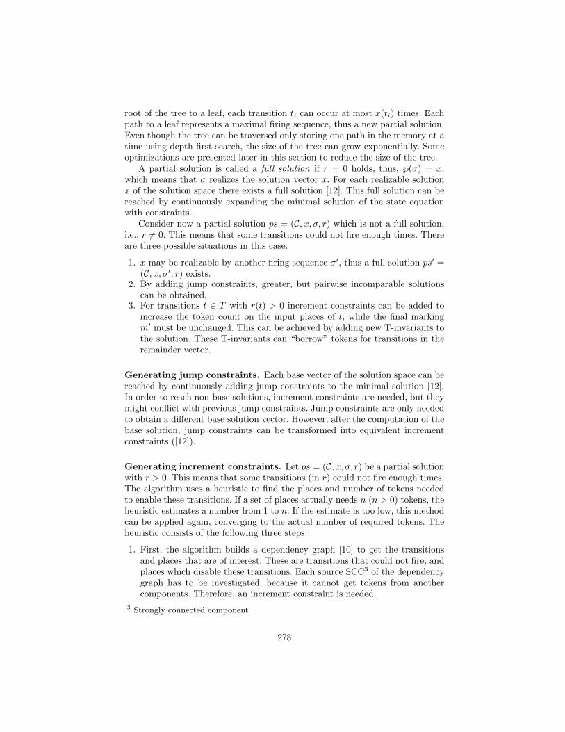
root of the tree to a leaf, each transition ti can occur at most x(ti) times. Eachpath to a leaf represents a maximal firing sequence, thus a new partial solution.Even though the tree can be traversed only storing one path in the memory at atime using depth first search, the size of the tree can grow exponentially. Someoptimizations are presented later in this section to reduce the size of the tree.
A partial solution is called a full solution if r = 0 holds, thus, ℘(σ) = x,which means that σ realizes the solution vector x. For each realizable solutionx of the solution space there exists a full solution [12]. This full solution can bereached by continuously expanding the minimal solution of the state equationwith constraints.
Consider now a partial solution ps = (C, x, σ, r) which is not a full solution,i.e., r 6= 0. This means that some transitions could not fire enough times. Thereare three possible situations in this case:
1. x may be realizable by another firing sequence σ′, thus a full solution ps′ =(C, x, σ′, r) exists.
2. By adding jump constraints, greater, but pairwise incomparable solutionscan be obtained.
3. For transitions t ∈ T with r(t) > 0 increment constraints can be added toincrease the token count on the input places of t, while the final markingm′ must be unchanged. This can be achieved by adding new T-invariants tothe solution. These T-invariants can “borrow” tokens for transitions in theremainder vector.
Generating jump constraints. Each base vector of the solution space can bereached by continuously adding jump constraints to the minimal solution [12].In order to reach non-base solutions, increment constraints are needed, but theymight conflict with previous jump constraints. Jump constraints are only neededto obtain a different base solution vector. However, after the computation of thebase solution, jump constraints can be transformed into equivalent incrementconstraints ([12]).
Generating increment constraints. Let ps = (C, x, σ, r) be a partial solutionwith r > 0. This means that some transitions (in r) could not fire enough times.The algorithm uses a heuristic to find the places and number of tokens neededto enable these transitions. If a set of places actually needs n (n > 0) tokens, theheuristic estimates a number from 1 to n. If the estimate is too low, this methodcan be applied again, converging to the actual number of required tokens. Theheuristic consists of the following three steps:
1. First, the algorithm builds a dependency graph [10] to get the transitionsand places that are of interest. These are transitions that could not fire, andplaces which disable these transitions. Each source SCC3 of the dependencygraph has to be investigated, because it cannot get tokens from anothercomponents. Therefore, an increment constraint is needed.
3 Strongly connected component
278
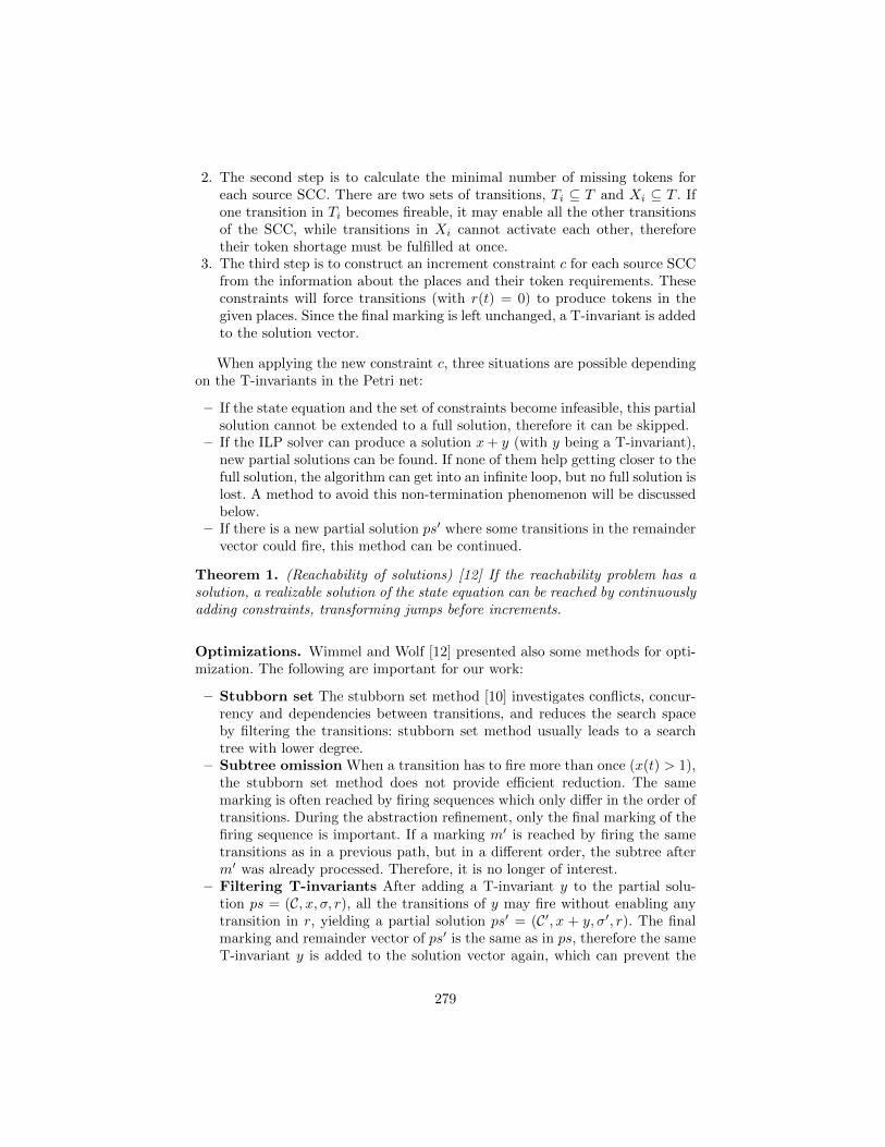
2. The second step is to calculate the minimal number of missing tokens foreach source SCC. There are two sets of transitions, Ti ⊆ T and Xi ⊆ T . Ifone transition in Ti becomes fireable, it may enable all the other transitionsof the SCC, while transitions in Xi cannot activate each other, thereforetheir token shortage must be fulfilled at once.
3. The third step is to construct an increment constraint c for each source SCCfrom the information about the places and their token requirements. Theseconstraints will force transitions (with r(t) = 0) to produce tokens in thegiven places. Since the final marking is left unchanged, a T-invariant is addedto the solution vector.
When applying the new constraint c, three situations are possible dependingon the T-invariants in the Petri net:
– If the state equation and the set of constraints become infeasible, this partialsolution cannot be extended to a full solution, therefore it can be skipped.
– If the ILP solver can produce a solution x+ y (with y being a T-invariant),new partial solutions can be found. If none of them help getting closer to thefull solution, the algorithm can get into an infinite loop, but no full solution islost. A method to avoid this non-termination phenomenon will be discussedbelow.
– If there is a new partial solution ps′ where some transitions in the remaindervector could fire, this method can be continued.
Theorem 1. (Reachability of solutions) [12] If the reachability problem has asolution, a realizable solution of the state equation can be reached by continuouslyadding constraints, transforming jumps before increments.
Optimizations. Wimmel and Wolf [12] presented also some methods for opti-mization. The following are important for our work:
– Stubborn set The stubborn set method [10] investigates conflicts, concur-rency and dependencies between transitions, and reduces the search spaceby filtering the transitions: stubborn set method usually leads to a searchtree with lower degree.
– Subtree omission When a transition has to fire more than once (x(t) > 1),the stubborn set method does not provide efficient reduction. The samemarking is often reached by firing sequences which only differ in the order oftransitions. During the abstraction refinement, only the final marking of thefiring sequence is important. If a marking m′ is reached by firing the sametransitions as in a previous path, but in a different order, the subtree afterm′ was already processed. Therefore, it is no longer of interest.
– Filtering T-invariants After adding a T-invariant y to the partial solu-tion ps = (C, x, σ, r), all the transitions of y may fire without enabling anytransition in r, yielding a partial solution ps′ = (C′, x + y, σ′, r). The finalmarking and remainder vector of ps′ is the same as in ps, therefore the sameT-invariant y is added to the solution vector again, which can prevent the
279
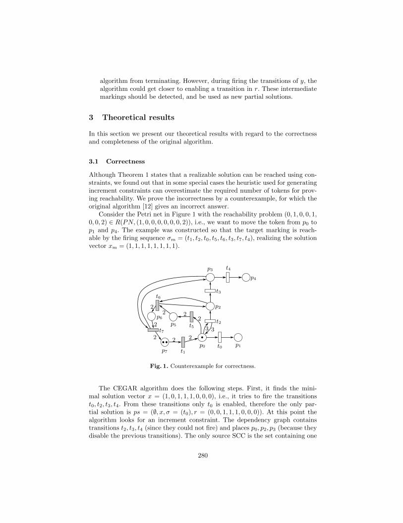
algorithm from terminating. However, during firing the transitions of y, thealgorithm could get closer to enabling a transition in r. These intermediatemarkings should be detected, and be used as new partial solutions.
3 Theoretical results
In this section we present our theoretical results with regard to the correctnessand completeness of the original algorithm.
3.1 Correctness
Although Theorem 1 states that a realizable solution can be reached using con-straints, we found out that in some special cases the heuristic used for generatingincrement constraints can overestimate the required number of tokens for prov-ing reachability. We prove the incorrectness by a counterexample, for which theoriginal algorithm [12] gives an incorrect answer.
Consider the Petri net in Figure 1 with the reachability problem (0, 1, 0, 0, 1,0, 0, 2) ∈ R(PN, (1, 0, 0, 0, 0, 0, 0, 2)), i.e., we want to move the token from p0 top1 and p4. The example was constructed so that the target marking is reach-able by the firing sequence σm = (t1, t2, t0, t5, t6, t3, t7, t4), realizing the solutionvector xm = (1, 1, 1, 1, 1, 1, 1, 1).
p0 t0
2
p1
p2
p3
p4
p5
p6
p7 t1
t2
t3
t4
t5
t6
t7
222
2
2 2 2
3 3
Fig. 1. Counterexample for correctness.
The CEGAR algorithm does the following steps. First, it finds the mini-mal solution vector x = (1, 0, 1, 1, 1, 0, 0, 0), i.e., it tries to fire the transitionst0, t2, t3, t4. From these transitions only t0 is enabled, therefore the only par-tial solution is ps = (∅, x, σ = (t0), r = (0, 0, 1, 1, 1, 0, 0, 0)). At this point thealgorithm looks for an increment constraint. The dependency graph containstransitions t2, t3, t4 (since they could not fire) and places p0, p2, p3 (because theydisable the previous transitions). The only source SCC is the set containing one
280
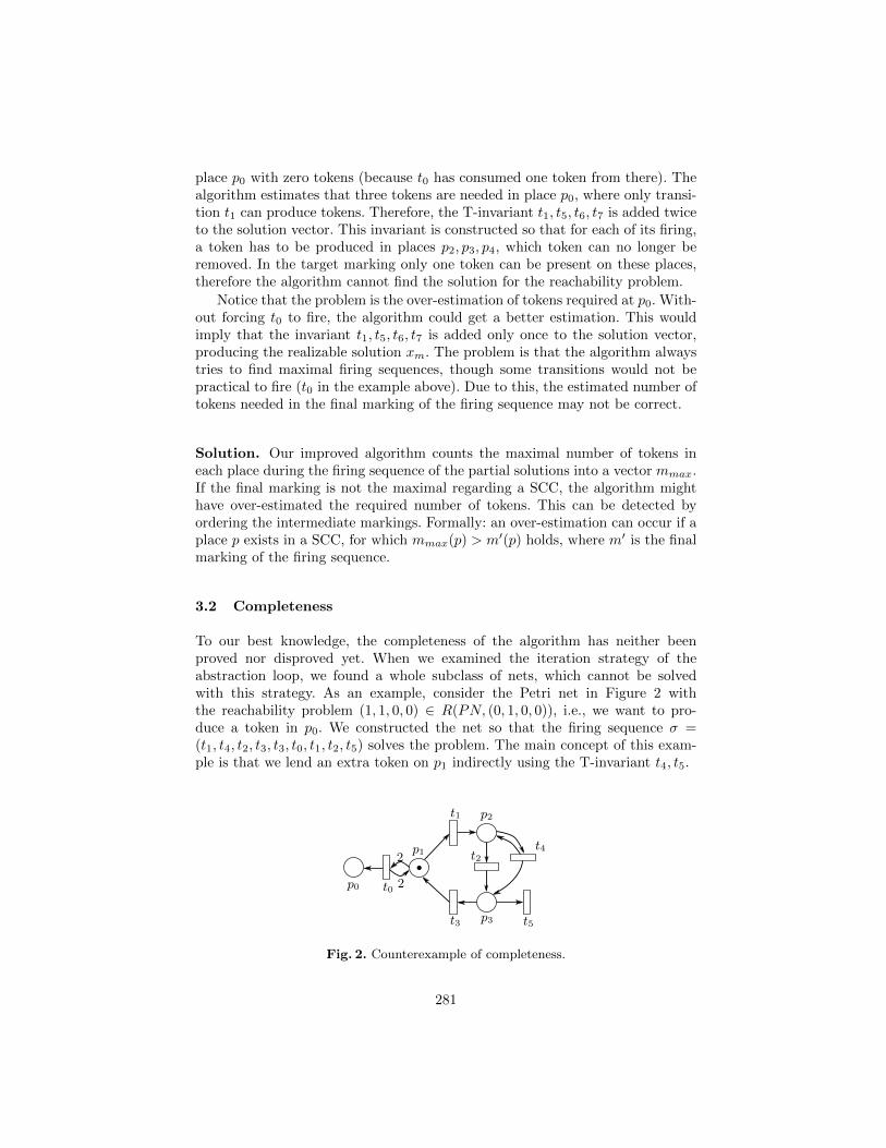
place p0 with zero tokens (because t0 has consumed one token from there). Thealgorithm estimates that three tokens are needed in place p0, where only transi-tion t1 can produce tokens. Therefore, the T-invariant t1, t5, t6, t7 is added twiceto the solution vector. This invariant is constructed so that for each of its firing,a token has to be produced in places p2, p3, p4, which token can no longer beremoved. In the target marking only one token can be present on these places,therefore the algorithm cannot find the solution for the reachability problem.
Notice that the problem is the over-estimation of tokens required at p0. With-out forcing t0 to fire, the algorithm could get a better estimation. This wouldimply that the invariant t1, t5, t6, t7 is added only once to the solution vector,producing the realizable solution xm. The problem is that the algorithm alwaystries to find maximal firing sequences, though some transitions would not bepractical to fire (t0 in the example above). Due to this, the estimated number oftokens needed in the final marking of the firing sequence may not be correct.
Solution. Our improved algorithm counts the maximal number of tokens ineach place during the firing sequence of the partial solutions into a vector mmax.If the final marking is not the maximal regarding a SCC, the algorithm mighthave over-estimated the required number of tokens. This can be detected byordering the intermediate markings. Formally: an over-estimation can occur if aplace p exists in a SCC, for which mmax(p) > m′(p) holds, where m′ is the finalmarking of the firing sequence.
3.2 Completeness
To our best knowledge, the completeness of the algorithm has neither beenproved nor disproved yet. When we examined the iteration strategy of theabstraction loop, we found a whole subclass of nets, which cannot be solvedwith this strategy. As an example, consider the Petri net in Figure 2 withthe reachability problem (1, 1, 0, 0) ∈ R(PN, (0, 1, 0, 0)), i.e., we want to pro-duce a token in p0. We constructed the net so that the firing sequence σ =(t1, t4, t2, t3, t3, t0, t1, t2, t5) solves the problem. The main concept of this exam-ple is that we lend an extra token on p1 indirectly using the T-invariant t4, t5.
p0
p1
p2
p3
t0
t1
t2
t3
t4
t5
2
2
Fig. 2. Counterexample of completeness.
281
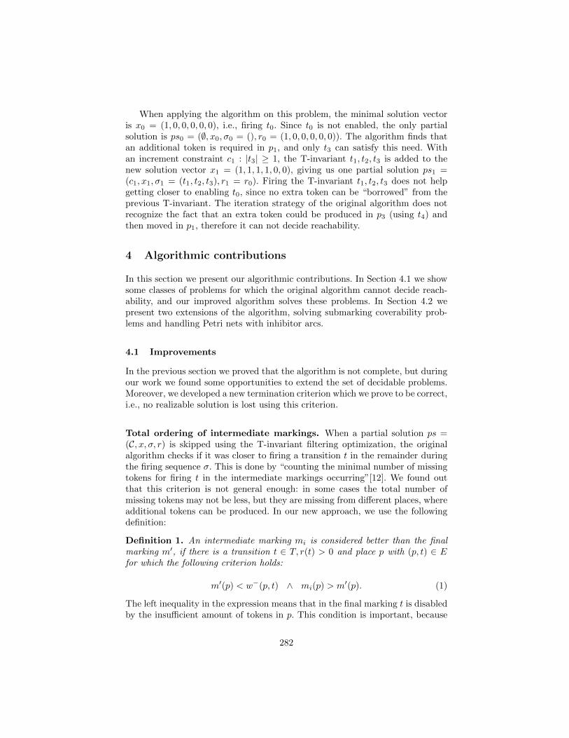
When applying the algorithm on this problem, the minimal solution vectoris x0 = (1, 0, 0, 0, 0, 0), i.e., firing t0. Since t0 is not enabled, the only partialsolution is ps0 = (∅, x0, σ0 = (), r0 = (1, 0, 0, 0, 0, 0)). The algorithm finds thatan additional token is required in p1, and only t3 can satisfy this need. Withan increment constraint c1 : |t3| ≥ 1, the T-invariant t1, t2, t3 is added to thenew solution vector x1 = (1, 1, 1, 1, 0, 0), giving us one partial solution ps1 =(c1, x1, σ1 = (t1, t2, t3), r1 = r0). Firing the T-invariant t1, t2, t3 does not helpgetting closer to enabling t0, since no extra token can be “borrowed” from theprevious T-invariant. The iteration strategy of the original algorithm does notrecognize the fact that an extra token could be produced in p3 (using t4) andthen moved in p1, therefore it can not decide reachability.
4 Algorithmic contributions
In this section we present our algorithmic contributions. In Section 4.1 we showsome classes of problems for which the original algorithm cannot decide reach-ability, and our improved algorithm solves these problems. In Section 4.2 wepresent two extensions of the algorithm, solving submarking coverability prob-lems and handling Petri nets with inhibitor arcs.
4.1 Improvements
In the previous section we proved that the algorithm is not complete, but duringour work we found some opportunities to extend the set of decidable problems.Moreover, we developed a new termination criterion which we prove to be correct,i.e., no realizable solution is lost using this criterion.
Total ordering of intermediate markings. When a partial solution ps =(C, x, σ, r) is skipped using the T-invariant filtering optimization, the originalalgorithm checks if it was closer to firing a transition t in the remainder duringthe firing sequence σ. This is done by “counting the minimal number of missingtokens for firing t in the intermediate markings occurring”[12]. We found outthat this criterion is not general enough: in some cases the total number ofmissing tokens may not be less, but they are missing from different places, whereadditional tokens can be produced. In our new approach, we use the followingdefinition:
Definition 1. An intermediate marking mi is considered better than the finalmarking m′, if there is a transition t ∈ T, r(t) > 0 and place p with (p, t) ∈ Efor which the following criterion holds:
m′(p) < w−(p, t) ∧ mi(p) > m′(p). (1)
The left inequality in the expression means that in the final marking t is disabledby the insufficient amount of tokens in p. This condition is important, because
282
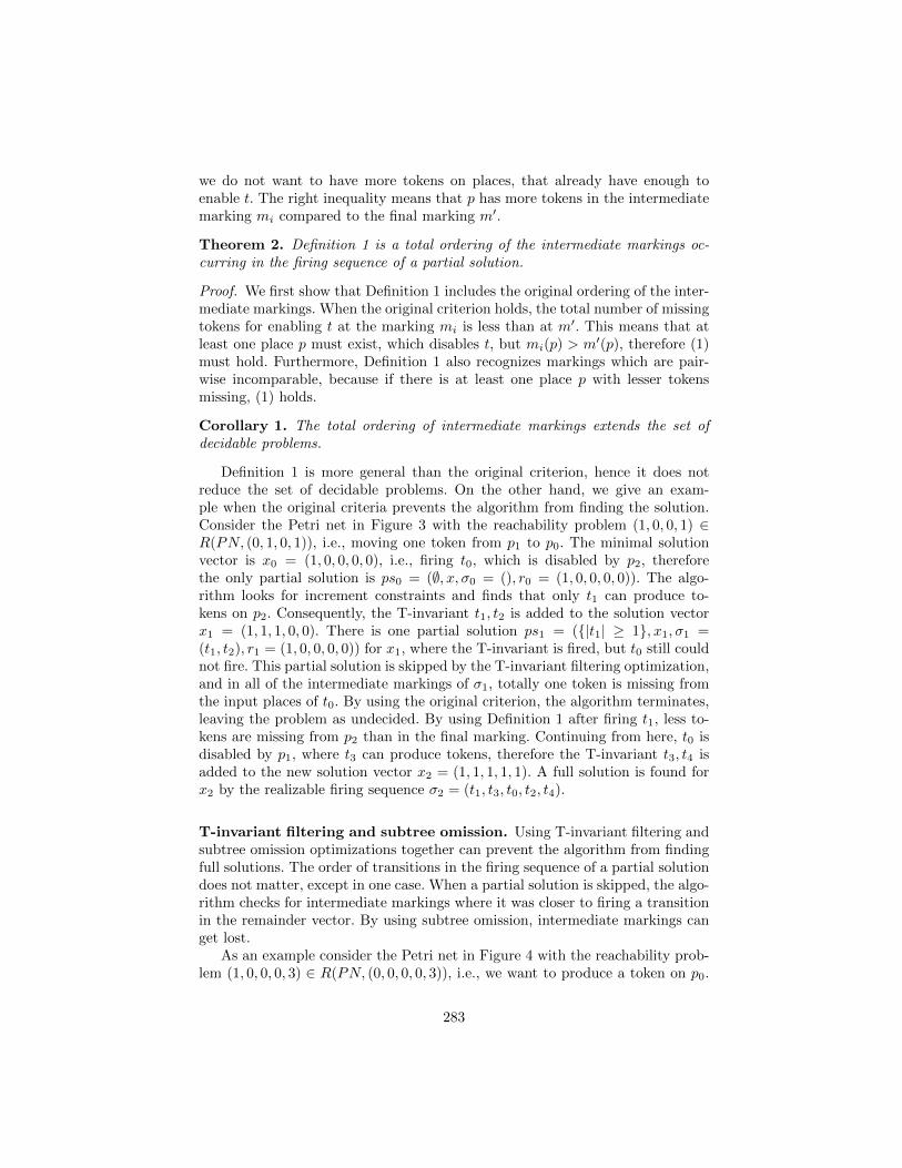
we do not want to have more tokens on places, that already have enough toenable t. The right inequality means that p has more tokens in the intermediatemarking mi compared to the final marking m′.
Theorem 2. Definition 1 is a total ordering of the intermediate markings oc-curring in the firing sequence of a partial solution.
Proof. We first show that Definition 1 includes the original ordering of the inter-mediate markings. When the original criterion holds, the total number of missingtokens for enabling t at the marking mi is less than at m′. This means that atleast one place p must exist, which disables t, but mi(p) > m′(p), therefore (1)must hold. Furthermore, Definition 1 also recognizes markings which are pair-wise incomparable, because if there is at least one place p with lesser tokensmissing, (1) holds.
Corollary 1. The total ordering of intermediate markings extends the set ofdecidable problems.
Definition 1 is more general than the original criterion, hence it does notreduce the set of decidable problems. On the other hand, we give an exam-ple when the original criteria prevents the algorithm from finding the solution.Consider the Petri net in Figure 3 with the reachability problem (1, 0, 0, 1) ∈R(PN, (0, 1, 0, 1)), i.e., moving one token from p1 to p0. The minimal solutionvector is x0 = (1, 0, 0, 0, 0), i.e., firing t0, which is disabled by p2, thereforethe only partial solution is ps0 = (∅, x, σ0 = (), r0 = (1, 0, 0, 0, 0)). The algo-rithm looks for increment constraints and finds that only t1 can produce to-kens on p2. Consequently, the T-invariant t1, t2 is added to the solution vectorx1 = (1, 1, 1, 0, 0). There is one partial solution ps1 = ({|t1| ≥ 1}, x1, σ1 =(t1, t2), r1 = (1, 0, 0, 0, 0)) for x1, where the T-invariant is fired, but t0 still couldnot fire. This partial solution is skipped by the T-invariant filtering optimization,and in all of the intermediate markings of σ1, totally one token is missing fromthe input places of t0. By using the original criterion, the algorithm terminates,leaving the problem as undecided. By using Definition 1 after firing t1, less to-kens are missing from p2 than in the final marking. Continuing from here, t0 isdisabled by p1, where t3 can produce tokens, therefore the T-invariant t3, t4 isadded to the new solution vector x2 = (1, 1, 1, 1, 1). A full solution is found forx2 by the realizable firing sequence σ2 = (t1, t3, t0, t2, t4).
T-invariant filtering and subtree omission. Using T-invariant filtering andsubtree omission optimizations together can prevent the algorithm from findingfull solutions. The order of transitions in the firing sequence of a partial solutiondoes not matter, except in one case. When a partial solution is skipped, the algo-rithm checks for intermediate markings where it was closer to firing a transitionin the remainder vector. By using subtree omission, intermediate markings canget lost.
As an example consider the Petri net in Figure 4 with the reachability prob-lem (1, 0, 0, 0, 3) ∈ R(PN, (0, 0, 0, 0, 3)), i.e., we want to produce a token on p0.
283
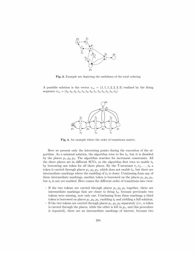
p3 t3
p1
p0
p2
t4
t1t0
t2
Fig. 3. Example net depicting the usefulness of the total ordering
A possible solution is the vector xm = (1, 1, 1, 2, 2, 3, 3) realized by the firingsequence σm = (t6, t6, t6, t4, t4, t2, t0, t1, t3, t3, t5, t5, t5).
p4 p3t5
t6
p2t3
t4
p1t1
t2
t0
p0
Fig. 4. An example where the order of transitions matter.
Here we present only the interesting points during the execution of the al-gorithm. As a minimal solution, the algorithm tries to fire t0, but it is disabledby the places p1, p2, p3. The algorithm searches for increment constraints. Allthe three places are in different SCCs, so the algorithm first tries to enable t0by borrowing one token for all three places. By the T-invariant t1, t2, . . . , t6 atoken is carried through places p1, p2, p3, which does not enable t0, but there areintermediate markings where the enabling of t0 is closer. Continuing from any ofthese intermediate markings, another token is borrowed on the places p1, p2, p3,but t0 is not yet enabled. Here comes the different order of transitions into view:
– If the two tokens are carried through places p1, p2, p3 together, there areintermediate markings that are closer to firing t0, because previously twotokens were missing, now only one. Continuing from these markings a thirdtoken is borrowed on places p1, p2, p3, enabling t0 and yielding a full solution.
– If the two tokens are carried through places p1, p2, p3 separately (i.e., a tokenis carried through the places, while the other is left in p4, and this procedureis repeated), there are no intermediate markings of interest, because two
284
tokens are still missing to enable t0. In this case the algorithm will not findthe full solution.
The order of transitions is non-deterministic, thus it is unknown which or-der will be omitted. Therefore, in our approach we reproduce all the possiblefiring sequences without subtree omission when a partial solution is skipped,and check for intermediate markings in the full tree. Although this may yield acomputational overhead in some cases, we might lose full solutions otherwise.
New termination criterion. We have developed a new termination criterion,which can efficiently cut the search space without losing any full solutions. Whengenerating increment constraints for a partial solution ps, as a first step thealgorithm finds the set of places P ′ ⊆ P where tokens are needed. Then itestimates the number of tokens required (n). At this point, our new criterionchecks if there exists a marking m′ for which the following inequalities hold:
∑
pi∈P ′
m′(pi) ≥ n
∀pj ∈ P : m′(pj) ≥ 0.(2)
The first inequality ensures that at least n tokens are present on the placesof P ′ while the others guarantee that the number of tokens on each place is non-negative. These inequalities define a submarking coverability problem. Using theILP solver, we can check if the modified form of the state equation (which wediscuss in Section 4.2) holds for this problem. If the state equation does not hold,it is a proof that no such marking exists where we have the required number oftokens on the places of P ′. Thus, ps can be omitted without losing full solutions.
This approach can also extend the set of decidable problems compared tothe former approach. Consider the Petri net on Figure 5 with the reachabilityproblem (1, 1, 0) ∈ R(PN, (1, 0, 0)), i.e., firing t0 to produce a token on p1. Thealgorithm would add the T-invariant t1, t2 again and again to enable t0. UsingT-invariant filtering we cannot decide whether there is no full solution or welost it. Using our new approach we can prove that no marking exist where twotokens are present on p0, therefore no full solution exists.
p1p0
p2 t1
t0t2
2
2
Fig. 5. Example net for the new filtering criterion
285
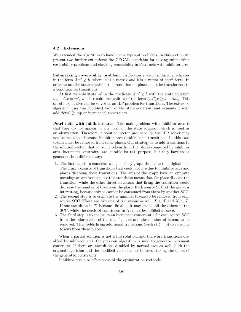
4.2 Extensions
We extended the algorithm to handle new types of problems. In this section wepresent two further extensions: the CEGAR algorithm for solving submarkingcoverability problems and checking reachability in Petri nets with inhibitor arcs.
Submarking coverability problem. In Section 2 we introduced predicatesin the form Am′ ≥ b, where A is a matrix and b is a vector of coefficients. Inorder to use the state equation, this condition on places must be transformed toa condition on transitions.
At first we substitute m′ in the predicate Am′ ≥ b with the state equationm0 + Cx = m′, which results inequalities of the form (AC)x ≥ b − Am0. Thisset of inequalities can be solved as an ILP problem for transitions. The extendedalgorithm uses this modified form of the state equation, and expands it withadditional (jump or increment) constraints.
Petri nets with inhibitor arcs. The main problem with inhibitor arcs isthat they do not appear in any form in the state equation which is used asan abstraction. Therefore, a solution vector produced by the ILP solver maynot be realizable because inhibitor arcs disable some transitions. In this casetokens must be removed from some places. Our strategy is to add transitions tothe solution vector, that consume tokens from the places connected by inhibitorarcs. Increment constraints are suitable for this purpose, but they have to begenerated in a different way:
1. The first step is to construct a dependency graph similar to the original one.The graph consists of transitions that could not fire due to inhibitor arcs andplaces disabling these transitions. The arcs of the graph have an oppositemeaning: an arc from a place to a transition means that the place disables thetransition, while the other direction means that firing the transition woulddecrease the number of tokens on the place. Each source SCC of the graph isinteresting, because tokens cannot be consumed from them by another SCC.
2. The second step is to estimate the minimal tokens to be removed from eachsource SCC. There are two sets of transitions as well, Ti ⊆ T and Xi ⊆ T .If one transition in Ti becomes fireable, it may enable all the others in theSCC, while the needs of transitions in Xi must be fulfilled at once.
3. The third step is to construct an increment constraint c for each source SCCfrom the information of the set of places and the number of tokens to beremoved. This yields firing additional transitions (with r(t) = 0) to consumetokens from these places.
When a partial solution is not a full solution, and there are transitions dis-abled by inhibitor arcs, the previous algorithm is used to generate incrementconstraint. If there are transitions disabled by normal arcs as well, both theoriginal algorithm and the modified version must be used, taking the union ofthe generated constraints.
Inhibitor arcs also affect some of the optimization methods:
286
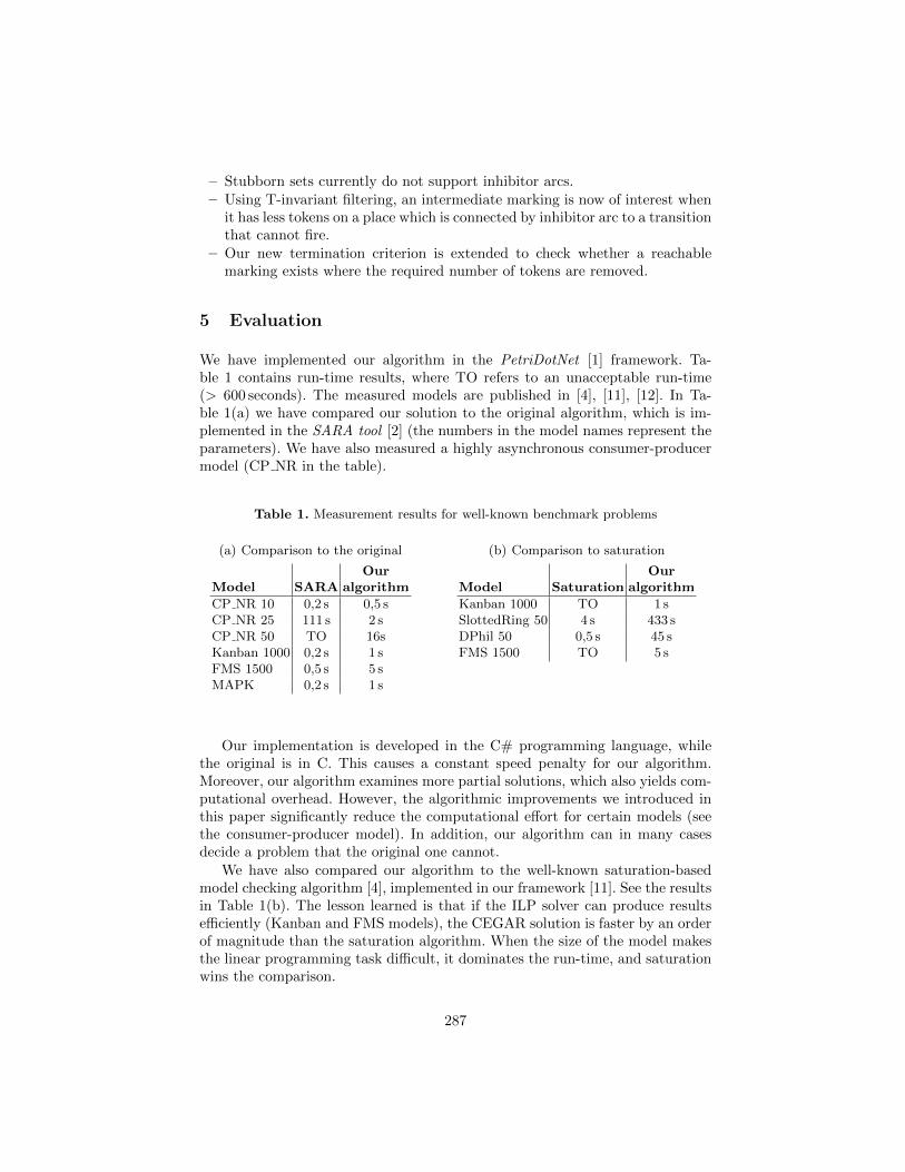
– Stubborn sets currently do not support inhibitor arcs.– Using T-invariant filtering, an intermediate marking is now of interest when
it has less tokens on a place which is connected by inhibitor arc to a transitionthat cannot fire.
– Our new termination criterion is extended to check whether a reachablemarking exists where the required number of tokens are removed.
5 Evaluation
We have implemented our algorithm in the PetriDotNet [1] framework. Ta-ble 1 contains run-time results, where TO refers to an unacceptable run-time(> 600 seconds). The measured models are published in [4], [11], [12]. In Ta-ble 1(a) we have compared our solution to the original algorithm, which is im-plemented in the SARA tool [2] (the numbers in the model names represent theparameters). We have also measured a highly asynchronous consumer-producermodel (CP NR in the table).
Table 1. Measurement results for well-known benchmark problems
(a) Comparison to the original
OurModel SARA algorithm
CP NR 10 0,2 s 0,5 sCP NR 25 111 s 2 sCP NR 50 TO 16sKanban 1000 0,2 s 1 sFMS 1500 0,5 s 5 sMAPK 0,2 s 1 s
(b) Comparison to saturation
OurModel Saturation algorithm
Kanban 1000 TO 1 sSlottedRing 50 4 s 433 sDPhil 50 0,5 s 45 sFMS 1500 TO 5 s
Our implementation is developed in the C# programming language, whilethe original is in C. This causes a constant speed penalty for our algorithm.Moreover, our algorithm examines more partial solutions, which also yields com-putational overhead. However, the algorithmic improvements we introduced inthis paper significantly reduce the computational effort for certain models (seethe consumer-producer model). In addition, our algorithm can in many casesdecide a problem that the original one cannot.
We have also compared our algorithm to the well-known saturation-basedmodel checking algorithm [4], implemented in our framework [11]. See the resultsin Table 1(b). The lesson learned is that if the ILP solver can produce resultsefficiently (Kanban and FMS models), the CEGAR solution is faster by an orderof magnitude than the saturation algorithm. When the size of the model makesthe linear programming task difficult, it dominates the run-time, and saturationwins the comparison.
287
6 Conclusions
The theoretical results presented in this paper are twofold. On one hand, weproved the incompleteness of the iteration strategy of the original CEGAR ap-proach by constructing a counterexample. We also constructed a counterexamplethat proved the incorrectness of a heuristic used in the original algorithm. Wecorrected this deficiency by improving the algorithm to detect such situations.On the other hand, our algorithmic improvements reduce the search space, andenable the algorithm to solve the reachability problem for certain, previouslyunsupported classes of Petri nets. In addition, we extended the algorithm tosolve two new classes of problems, namely submarking coverability and handlingPetri nets with inhibitor arcs. We demonstrated the efficiency of our improve-ments with measurements.
References
1. Homepage of the PetriDotNet framework., http://petridotnet.inf.mit.bme.
hu/, [Online; accessed 10-May-2013]2. Homepage of the Sara model checker., http://service-technology.org/tools/
index.html, [Online; accessed 06-Apr-2013]3. Chrzastowski-Wachtel, P.: Testing undecidability of the reachability in Petri nets
with the help of 10th hilbert problem. In: Donatelli, S., Kleijn, J. (eds.) Applicationand Theory of Petri Nets 1999, Lecture Notes in Computer Science, vol. 1639, pp.690–690. Springer (1999)
4. Ciardo, G., Marmorstein, R., Siminiceanu, R.: Saturation unbound. In: Proc. Toolsand Algorithms for the Construction and Analysis of Systems (TACAS). pp. 379–393. Springer (2003)
5. Dantzig, G.B., Thapa, M.N.: Linear programming 1: introduction. Springer-VerlagNew York, Inc., Secaucus, NJ, USA (1997)
6. Esparza, J., Melzer, S., Sifakis, J.: Verification of safety properties using integerprogramming: Beyond the state equation (1997)
7. Lipton, R.: The Reachability Problem Requires Exponential Space. Research re-port, Yale University, Dept. of Computer Science (1976)
8. Mayr, E.W.: An algorithm for the general Petri net reachability problem. In: Pro-ceedings of the Thirteenth Annual ACM Symposium on Theory of Computing. pp.238–246. STOC ’81, ACM, New York, NY, USA (1981)
9. Murata, T.: Petri nets: Properties, analysis and applications. Proceedings of theIEEE 77(4), 541–580 (April 1989)
10. Valmari, A., Hansen, H.: Can stubborn sets be optimal? In: Lilius, J., Penczek, W.(eds.) Applications and Theory of Petri Nets, Lecture Notes in Computer Science,vol. 6128, pp. 43–62. Springer (2010)
11. Voros, A., Bartha, T., Darvas, D., Szabo, T., Jambor, A., Horvath, A.: Parallelsaturation based model checking. In: ISPDC. IEEE Computer Society, Cluj Napoca(2011)
12. Wimmel, H., Wolf, K.: Applying CEGAR to the Petri net state equation. In:Abdulla, P.A., Leino, K.R.M. (eds.) Tools and Algorithms for the Constructionand Analysis of Systems, 17th International Conference, TACAS 2010 Proceedings.Lecture Notes in Computer Science, vol. 6605, pp. 224–238. Springer (2011)
288
Related Documents