GASOLINE DIRECT INJECTION (GDI) Click on the applicable bookmark to selected the required model year

Welcome message from author
This document is posted to help you gain knowledge. Please leave a comment to let me know what you think about it! Share it to your friends and learn new things together.
Transcript

8/19/2019 13a Gasoline Direct Injection (Gdi) (1)
http://slidepdf.com/reader/full/13a-gasoline-direct-injection-gdi-1 1/269
GASOLINE DIRECTINJECTION (GDI)Click on the applicable bookmark to selected the required model year

8/19/2019 13a Gasoline Direct Injection (Gdi) (1)
http://slidepdf.com/reader/full/13a-gasoline-direct-injection-gdi-1 2/269
13A-2
GASOLINE DIRECTINJECTION (GDI)
CONTENTS
GENERAL INFORMATION 3. . . . . . . . . . . . . . . . . .
SERVICE SPECIFICATIONS 7. . . . . . . . . . . . . . . . .
SEALANT 7. . . . . . . . . . . . . . . . . . . . . . . . . . . . . . . . . .
SPECIAL TOOLS 8. . . . . . . . . . . . . . . . . . . . . . . . . . .
TROUBLESHOOTING 10. . . . . . . . . . . . . . . . . . . . . .
ON-VEHICLE SERVICE 92. . . . . . . . . . . . . . . . . . . .
Throttle Body (Throttle Valve Area) Cleaning 92. .
Throttle Position Sensor Adjustment 92. . . . . . . . . .Accelerator Pedal Position SensorAdjustment 94. . . . . . . . . . . . . . . . . . . . . . . . . . . . . . . . .
Fuel Pressure Test 95. . . . . . . . . . . . . . . . . . . . . . . . . .
Fuel Leak Check 99. . . . . . . . . . . . . . . . . . . . . . . . . . .
Fuel Pump Connector Disconnection (How toReduce Fuel Pressure) 99. . . . . . . . . . . . . . . . . . . . . .
Fuel Pump Operation Check 100. . . . . . . . . . . . . . . .
Component Location 101. . . . . . . . . . . . . . . . . . . . . . .
Engine Control Relay, Fuel Pump Relay, InjectorDriver Relay and Throttle Valve Control Servo
Relay Continuity Check 102. . . . . . . . . . . . . . . . . . . . .Intake Air Temperature Sensor Check 102. . . . . . .
Engine Coolant Temperature Sensor Check 102. .Throttle Position Sensor Check 103. . . . . . . . . . . . .
Accelerator Pedal Position Sensor (1st channel)Check 104. . . . . . . . . . . . . . . . . . . . . . . . . . . . . . . . . . . .
Accelerator Pedal Position Sensor (2nd channel)Check 104. . . . . . . . . . . . . . . . . . . . . . . . . . . . . . . . . . . .
Accelerator Pedal Position Switch Check 105. . . .
Oxygen Sensor Check 105. . . . . . . . . . . . . . . . . . . . .
Injector Check 106. . . . . . . . . . . . . . . . . . . . . . . . . . . . .
Throttle Valve Control Servo Check 107. . . . . . . . .
Purge Control Solenoid Valve Check 107. . . . . . . .
EGR Valve Check 107. . . . . . . . . . . . . . . . . . . . . . . . .
FUEL PUMP (HIGH PRESSURE) AND FUELPRESSURE REGULATOR (HIGHPRESSURE) 108. . . . . . . . . . . . . . . . . . . . . . . . . . . . .
INJECTOR 111. . . . . . . . . . . . . . . . . . . . . . . . . . . . . .
THROTTLE BODY 114. . . . . . . . . . . . . . . . . . . . . . . .
INJECTOR DRIVER 116. . . . . . . . . . . . . . . . . . . . . .
THROTTLE VALVE CONTROLLER 117. . . . . . . .

8/19/2019 13a Gasoline Direct Injection (Gdi) (1)
http://slidepdf.com/reader/full/13a-gasoline-direct-injection-gdi-1 3/269
GDI – General Information 13A-3
GENERAL INFORMATION
The Gasoline Direct Injection System consistsof sensors which detect the engine conditions,the engine-ECU which controls the systembased on signals from these sensors, andactuators which operate under the control ofthe engine-ECU. The engine-ECU carries out
activities such as fuel injection control, idlespeed control and ignition timing control. Inaddition, the engine-ECU is equipped withseveral diagnosis modes which simplifytroubleshooting when a problem develops.
FUEL INJECTION CONTROL
The injector drive times and injector timing arecontrolled so that the optimum air/fuel mixtureis supplied to the engine to correspond to thecontinually-changing engine operation condi-tions.A single injector for each cylinder is mountedat the cylinder head. The fuel is sent underpressure from the fuel tank to the fuel pressureregulator (low pressure) by the fuel pump (lowpressure). The pressure is regulated by the fuelpressure regulator (low pressure) and the fuel
regulated is then sent to the fuel pump (highpressure). The fuel under increased pressuregenerated by the fuel pump (high pressure) isthen regulated by the fuel pressure regulator(high pressure) and is then distributed to eachof the injectors via the delivery pipes.
Fuel injection is normally carried out once foreach cylinder for every two rotations of thecrankshaft. The firing order is 1-3-4-2. This iscalled sequential fuel injection.When the engine is cold or under a severe load,the “open-loop” control keeps the air/fuel ratioat a richer than usual level to maintaindriveability. When the engine is under low ormedium loads, the air/fuel ratio becomes leanerto reduce fuel consumption. When the engineis running at medium or high loads after having
warmed up, the “closed-loop” control uses thesignal from the oxygen sensor to keep theair/fuel ratio at the optimum theoretical level.
THROTTLE VALVE OPENING ANGLE CONTROL
This system controls throttle valve openingangle electronically. The engine-ECU deter-mines how deeply the accelerator pedal isdepressed by means of the accelerator positionsensor (APS). Then the engine-ECU sends a
target value of the throttle valve opening angleto the throttle valve controller. The throttle valvecontrol servo operates the throttle valve so thatit reaches the target opening angle.
IDLE SPEED CONTROL
This system maintains engine idle speed at apredetermined condition by controlling the airflow that passes through the throttle valveaccording to engine idling condition and engineloads at idling.The engine-ECU operates the throttle valvecontrol servo so that engine speed is maintained
within a map value. The map value ispredetermined according to engine coolanttemperature and air-conditioning load. Inaddition, if the A/C switch is turned on or offduring engine idling, the engine-ECUcompensates the engine speed by operatingthe throttle valve control servo as necessary.
IGNITION TIMING CONTROL
The power transistor located in the ignitionprimary circuit turns ON and OFF to controlthe primary current flow to the ignition coil. Thiscontrols the ignition timing in order to providethe optimum ignition timing with respect to theengine operating conditions. The ignition timing
is determined by the engine-ECU from theengine speed, intake air volume, engine coolanttemperature, atmospheric pressure andinjection timing (intake stroke or compressionstroke).

8/19/2019 13a Gasoline Direct Injection (Gdi) (1)
http://slidepdf.com/reader/full/13a-gasoline-direct-injection-gdi-1 4/269
GDI – General Information13A-4
SELF-DIAGNOSIS FUNCTION
When an abnormality is detected in oneof the sensors or actuators related toemission control, the engine warning lamp(check engine lamp) illuminates as awarning to the driver.
When an abnormality is detected in oneof the sensors or actuators, a diagnosis
code corresponding to the abnormality isoutput.
The RAM data inside the engine-ECU thatis related to the sensors and actuators canbe read by means of the MUT-II. In addition,the actuators can be force-driven undercertain circumstances.
OTHER CONTROL FUNCTIONS
1. Fuel Pump ControlTurns the fuel pump relay ON so that currentis supplied to the fuel pump while the engineis cranking or running.
2. A/C Relay ControlTurns the compressor clutch of the A/C ONand OFF.
3. Fan Motor ControlThe revolutions of the radiator fan and
condenser fan are controlled in responseto the engine coolant temperature andvehicle speed.
4. Purge Control Solenoid Valve ControlRefer to GROUP 17.
5. EGR Control Servo ControlRefer to GROUP 17.
GENERAL SPECIFICATIONS
Items Specifications
Throttle body Throttle bore mm 60
Throttle position sensor Variable resistor type
Throttle valve control servo Torque motor type
Engine-ECU Identification model No. E2T71575
Sensors Air flow sensor Karman vortex type
Barometric pressure sensor Semiconductor type
Intake air temperature sensor Thermistor type
Engine coolant temperature sensor Thermistor type
Oxygen sensor Zirconia type
Accelerator pedal position sensor Variable resistor type
Accelerator pedal position switch Rotary contact type, within accelerator pedal positionsensor
Vehicle speed sensor Magnetic resistive element type
Inhibitor switch Contact switch type
Camshaft position sensor Magnetic resistive element type
Crank angle sensor Hall element type
Detonation sensor Piezoelectric type
Fuel pressure sensor Metallic membrane type
Power steering fluid pressure switch Contact switch type

8/19/2019 13a Gasoline Direct Injection (Gdi) (1)
http://slidepdf.com/reader/full/13a-gasoline-direct-injection-gdi-1 5/269
GDI – General Information 13A-5
Items Specifications
Actuators Engine control relay type Contact switch type
Fuel pump relay type Contact switch type
Injector driver control relay Contact switch type
Injector type and number Electromagnetic type, 4
Injector identification mark DIM 100G
Throttle valve control servo relay Contact switch type
Throttle valve control servo Torque motor type
EGR control servo Stepper motor type
Purge control solenoid valve Duty cycle type solenoid valve
Fuel pressureregulator (lowpressure)
Regulator pressure kPa 324
Fuel pressureregulator(high pres-sure)
Regulator pressure MPa 5

8/19/2019 13a Gasoline Direct Injection (Gdi) (1)
http://slidepdf.com/reader/full/13a-gasoline-direct-injection-gdi-1 6/269
GDI – General Information13A-6
GASOLINE DIRECT INJECTION SYSTEM DIAGRAM
*1 Oxygen sensor*2 Air flow sensor*3 Intake air temper-
ature senor*4 Throttle position
sensor (2nd chan-nel)
*5 Camshaft position
sensor*6 Crank angle sen-
sor*7 Barometric pres-
sure sensor*8 Engine coolant
temperature sen-sor
*9 Detonation sensor*10 Fuel pressure sen-
sor
*11 Throttle position
sensor (1st chan-nel)
Power supply Ignition switch – IG Ignition switch – ST Accelerator pedal posi-
tion sensor (1stchannel)
Accelerator pedal posi-tion switch
Vehicle speed sensor A/C switch A/C thermo sensor Inhibitor switch Power steering fluid
pressure switch Alternator FR terminal Stop lamp switch Small lamp switch Injector wire open circuit
check signal Throttle valve controller A/T-ECU
Power supply
Ignition switch – IG Accelerator pedal posi-
tion sensor (2nd chan-nel)
Engine-ECU
Engine-ECU
From fuel pump(low pressure)
To fuel tank
*10 Fuel pressuresensor
*5 Camshaft positionsensor
*4 Throttle position sensor(2nd channel)
*11 Throttle position sensor(1st channel)
4 Throttle valvecontrol servo
*3 Intake air temperaturesensor
*2 Air flow sensor
*7 Barometricpressure sensor
2 EGR valve(Steppermotor)
High-pressure fuelregulator assembly[integrated in fuelpressure regulator(high pressure)]
Fuel pump(high pressure)
Injector1 Injector
driver
*8 Engine coolanttemperature sensor
*9 Detonation sensor
*1 Oxygen sensor
*6 Crank angle sensor
Canister
3 Purge controlsolenoid valve
1 Injector driver (In- jector)
2 EGR valve (Step-per motor)
3 Purge control sole-noid valve
4 Throttle valve con-
trol servo
Engine control relay Fuel pump relay Injector driver relay Throttle valve control
servo relay A/C relay Ignition coil Fan controller
GDI ECO indicator lamp Engine warning lamp Diagnosis output Alternator G terminal Throttle valve controller A/T-ECU
Engine-ECU
Throttlevalvecontrol-ler

8/19/2019 13a Gasoline Direct Injection (Gdi) (1)
http://slidepdf.com/reader/full/13a-gasoline-direct-injection-gdi-1 7/269
GDI – Service Specifications/Sealant 13A-7
SERVICE SPECIFICATIONS
Item Standard value
Adjustment voltage of throttle position sensor(1st channel) V
0.4 – 0.6
Adjustment voltage of throttle position sensor
(2nd channel) V
4.2 – 4.8
Resistance of throttle position sensor kΩ 3.5 – 6.5
Adjustment voltages (1st channel) and (2nd channel) ofaccelerator pedal position sensor V
0.935 – 1.135
Resistance (1st channel) and (2nd channel) of acceleratorpedal position sensor kΩ
3.5 – 6.5
Intake air temperature sensor at 20C 2.3 – 3.0res s ance Ω
at 80C 0.30 – 0.42
Engine coolant temperature at 20C 2.1 – 2.7
sensor res s ance Ωat 80C 0.26 – 0.36
Fuel pressure High-pressure side MPa 4 – 6.9
Low-pressure side kPa Approximately 324
Injector coil resistance Ω 0.9 – 1.1
Oxygen sensor output voltage (at racing) V 0.6 – 1.0
Oxygen sensor heater resistance Ω 11 – 18
Throttle valve control servo resistance Ω 1.35 – 1.65
SEALANT
Item Specified sealant Remark
Engine coolant temperature sensorthreaded portion
3M Nut Locking Part No. 4171 or equivalent Drying sealant

8/19/2019 13a Gasoline Direct Injection (Gdi) (1)
http://slidepdf.com/reader/full/13a-gasoline-direct-injection-gdi-1 8/269
GDI – Special Tools13A-8
SPECIAL TOOLS
Tool Number Name Use
B
A
C
D
MB991223
A: MB991219
B: MB991220
C: MB991221
D: MB991222
Harness set
A: Test harness
B: LED harness
C: LED harness
adapterD: Probe
Fuel gauge simple inspectionA: Connector pin contact pressure inspectionB: Power circuit inspectionC: Power circuit inspection
D: Commercial tester connection
MB991502 MUT-II subassembly
Reading diagnosis code GDI system inspection
MB991348 Test harness set Measurement of voltage during trouble-shooting
Inspection using an analyzer
MB991709 Test harness
MB991519 Alternator harnessconnector
Measurement of voltage duringtroubleshooting
MB991536 TPS adjustment
harness
Adjustment of throttle position sensor
MB991658 Test harness Measurement of voltage duringtroubleshooting
Inspection using an analyzer Adjustment of accelerator pedal position
sensor

8/19/2019 13a Gasoline Direct Injection (Gdi) (1)
http://slidepdf.com/reader/full/13a-gasoline-direct-injection-gdi-1 9/269
GDI – Special Tools 13A-9
Tool UseNameNumber
MD998464 Test harness(4-pin, square)
Oxygen sensor inspection
MD998478 Test harness(3-pin, triangle)
Measurement of voltage during trouble-shooting
Inspection using an analyzer
MB991529 Diagnosis codecheck harness
Reading diagnosis code
MD998709 Adaptor hose Measurement of fuel pressure
MD998742 Hose adaptor
MB991637 Fuel pressuregauge set

8/19/2019 13a Gasoline Direct Injection (Gdi) (1)
http://slidepdf.com/reader/full/13a-gasoline-direct-injection-gdi-1 10/269

8/19/2019 13a Gasoline Direct Injection (Gdi) (1)
http://slidepdf.com/reader/full/13a-gasoline-direct-injection-gdi-1 11/269
GDI – Troubleshooting 13A-11
Throttle valve position feedback
Throttle valve control servo motor (1st motor)
Throttle valve control servo motor (2nd motor)
Communication line system with throttle valve controller
Engine-ECU
NOTEWhen the electronic-controlled throttle valve system is stopped,the engine warning lamp flashes.
METHOD OF READING AND ERASING DIAGNOSISCODES
Refer to GROUP 00 – How to Use Troubleshooting/InspectionService Points.
INSPECTION USING MUT-II DATA LIST ANDACTUATOR TESTING
1. Carry out inspection by means of the data list and theactuator test function.If there is an abnormality, check and repair the chassis
harnesses and components.2. After repairing, re-check using the MUT-II and check thatthe abnormal input and output have returned to normalas a result of the repairs.
3. Erase the diagnosis code memory.4. Remove the MUT-II.5. Start the engine again and carry out a road test to confirm
that the problem has disappeared.

8/19/2019 13a Gasoline Direct Injection (Gdi) (1)
http://slidepdf.com/reader/full/13a-gasoline-direct-injection-gdi-1 12/269
GDI – Troubleshooting13A-12
FAIL-SAFE FUNCTION REFERENCE TABLE
If the diagnosis system detects any sensor malfunction, the vehicle can be driven safely by using a defaultcontrol logic instead of the faulty sensors.
Defective part orfunction
What to do when a sensor is defective
Air flow sensor (1) Disables lean-mixture combustion.(2) Determines injector basic operating time and basic ignition timing according to mapvalue, which has been predetermined by throttle position sensor and crank anglesensor signals.
Intake air temperaturesensor
Controls as the intake air temperature is 25C.
Throttle positionsensor (1st channel)
(1) Disables lean-mixture combustion.(2) Controls throttle valve opening angle by closed loop control by using the throttle position
sensor (2nd channel) signal.(3) Disables the throttle valve opening angle control when the throttle position sensor
(2nd channel) signal is also defective.
Throttle position
sensor (2nd channel)
(1) Disables lean-mixture combustion.
(2) Controls throttle valve opening angle by closed loop control by using the throttle positionsensor (1st channel) signal.
(3) Disables the throttle valve opening angle control when the throttle position sensor(1st channel) signal is also defective.
Engine coolanttemperature sensor
Controls as if the engine coolant temperature is 80C. (Note that this control will continueuntil the ignition switch is turned off even if the sensor signal return to normal.)
Camshaft positionsensor
Controls according to the conditions before a failure is detected.
Vehicle speed sensor (1) Disables lean-mixture combustion. However, if a predetermined time elapses at anengine speed of 1,500 r/min or more, the lean-mixture combustion will return to normal.
(2) Disables lean-mixture combustion during engine idling.
Barometric pressuresensor
Controls as if the barometric pressure is 101 kPa.
Detonation sensor Holds the ignition timing at that for standard petrol.
Injector (1) Disables lean-mixture combustion.(2) Shuts down exhaust gas recirculation.
Abnormal combustion Disables lean-mixture combustion.
Communication linewith A/T-ECU
Disables ignition timing retard control (engine and transmission total control) during shiftchange.
Alternator FR terminal Disables inhibition control of the alternator output according to electrical load (treats the
alternator as if it is conventional one).
Fuel pressure sensor (1) Controls as if the fuel pressure is 5 MPa (if there is open or short circuit).(2) Turns off the fuel pump relay (if the fuel pressure is excessively high).(3) Shuts off the fuel injection (If an excessively low pressure is detected or the engine
speed exceeds 3,000 r/min).

8/19/2019 13a Gasoline Direct Injection (Gdi) (1)
http://slidepdf.com/reader/full/13a-gasoline-direct-injection-gdi-1 13/269
GDI – Troubleshooting 13A-13
Defective part orfunction
What to do when a sensor is defective
Accelerator pedalposition sensor (1stchannel)
(1) Disables lean-mixture combustion.(2) Controls the throttle valve position by using the accelerator pedal position sensor
(2nd channel) signal.(3) Disables the electronic-controlled throttle valve system if the accelerator pedal position
sensor (2nd channel) signal is also defective.
Accelerator pedalposition sensor (2ndchannel)
(1) Disables lean-mixture combustion.(2) Controls the throttle valve position by using the accelerator pedal position sensor
(1st channel) signal.(3) Disables the electronic-controlled throttle valve system if the accelerator pedal position
sensor (1st channel) signal is also defective.
Electronic-controlledthrottle valve system
(1) Disables the electronic-controlled throttle valve system.(2) Disables lean-mixture combustion.(3) Disables engine speed feedback control.
Throttle valve positionfeedback
(1) Disables the electronic-controlled throttle valve system.(2) Disables lean-mixture combustion.(3) Disables engine speed feedback control.However, if the throttle valve opening is great, controls as follows:
(1) Carries out lean-mixture combustion continuously.(2) Shuts off fuel supply for 2 cylinders continuously.(3) Shuts off fuel supply when engine speed exceeds 3,000 r/min.
Throttle valve controlservo motor (1stmotor) malfunction
Disables lean-mixture combustion.
Throttle valve controlservo motor (2ndmotor) malfunction
(1) Disables the electronic-controlled throttle valve system.(2) Disables lean-mixture combustion.(3) Disables engine speed feedback control.
Communication linewith the throttle valvecontroller
(1) Error in communication from the throttle valve controller to engine-ECU Disables lean-mixture combustion. Shuts off fuel supply when engine speed exceeds 3,000 r/min.
(2) Error in communication from the engine-ECU to throttle valve controller Disables lean-mixture combustion. Shuts off fuel supply when engine speed exceeds 3,000 r/min. The throttle valve controller controls the throttle valve opening angle by using
the accelerator pedal position sensor (2nd channel) signal.
NOTEWhen the electronic-controlled throttle valve system is stopped, the engine warning lamp flashes.

8/19/2019 13a Gasoline Direct Injection (Gdi) (1)
http://slidepdf.com/reader/full/13a-gasoline-direct-injection-gdi-1 14/269
GDI – Troubleshooting13A-14
INSPECTION CHART FOR DIAGNOSIS CODES
Code No. Diagnosis item Reference page
11 Oxygen sensor system 13A-15
12 Air flow sensor system 13A-16
13 Intake air temperature sensor system 13A-17
14 Throttle position sensor (2nd channel) system 13A-18
21 Engine coolant temperature sensor system 13A-19
22 Crank angle sensor system 13A-20
23 Camshaft position sensor system 13A-21
24 Vehicle speed sensor system 13A-22
25 Barometric pressure sensor system 13A-23
31 Detonation sensor system 13A-24
41 Injector system 13A-25
44 Abnormal combustion 13A-27
54 Immobilizer system 13A-28
56 Abnormal fuel pressure system 13A-29
61 Communication line with A/T-ECU system 13A-31
64 Alternator FR terminal system 13A-31
66 Brake vacuum sensor system 13A-32
77 Accelerator pedal position sensor (2nd channel) system 13A-33
78 Accelerator pedal position sensor (1st channel) system 13A-34
79 Throttle position sensor (1st channel) system 13A-35
89 Abnormality in fuel pressure system 13A-36
91 Electronic-controlled throttle valve system 13A-36
92 Throttle valve position feedback system 13A-37
94 Communication line system with throttle valve controller 13A-37
95 Malfunction in throttle valve control servo motor (1st motor) system 13A-38
99 Malfunction in throttle valve control servo motor (2nd motor) system 13A-38
NOTECode No. 56 may be also output when air is sucked in high-pressure fuel line due to no fuel supply.
8/19/2019 13a Gasoline Direct Injection (Gdi) (1)
http://slidepdf.com/reader/full/13a-gasoline-direct-injection-gdi-1 15/269
GDI – Troubleshooting 13A-15
INSPECTION PROCEDURE FOR DIAGNOSIS CODES
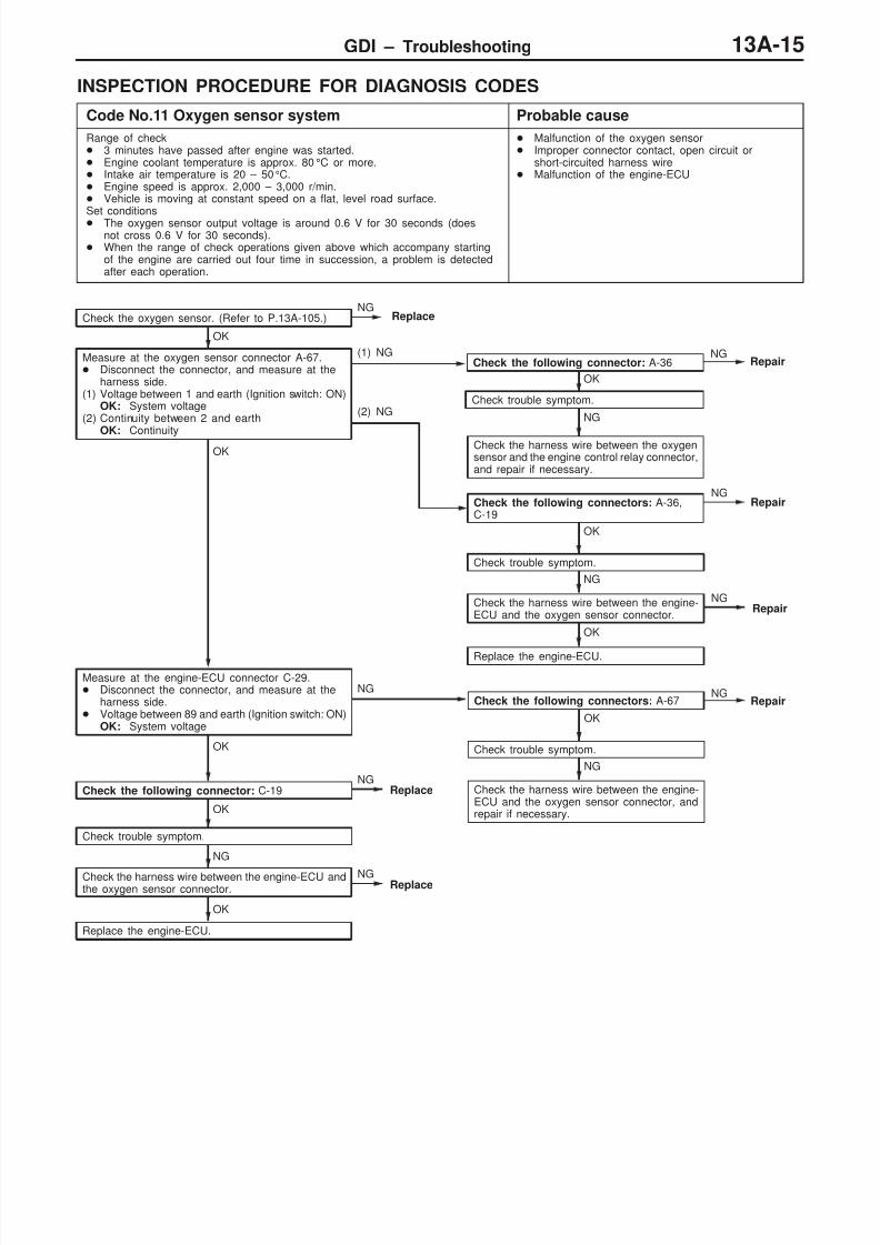
Code No.11 Oxygen sensor system Probable cause
Range of check 3 minutes have passed after engine was started. Engine coolant temperature is approx. 80°C or more. Intake air temperature is 20 – 50°C. Engine speed is approx. 2,000 – 3,000 r/min. Vehicle is moving at constant speed on a flat, level road surface.Set conditions The oxygen sensor output voltage is around 0.6 V for 30 seconds (does
not cross 0.6 V for 30 seconds). When the range of check operations given above which accompany starting
of the engine are carried out four time in succession, a problem is detectedafter each operation.
Malfunction of the oxygen sensor Improper connector contact, open circuit or
short-circuited harness wire Malfunction of the engine-ECU
NG
Repair
OK
Replace the engine-ECU.
NG
OK
Check trouble symptom.
OK
Check the following connector: C-19
NG
Check the harness wire between the engine-ECU and the oxygen sensor connector.
OK
Check trouble symptom.
OK
Measure at the oxygen sensor connector A-67. Disconnect the connector, and measure at the
harness side.(1) Voltage between 1 and earth (Ignition switch: ON)
OK: System voltage(2) Continuity between 2 and earth
OK: Continuity
(1) NG
Check the following connectors: A-36,C-19
Check the oxygen sensor. (Refer to P.13A-105.)NG
Replace
(2) NG
Check the harness wire between the oxygensensor and the engine control relay connector,and repair if necessary.
NG
Repair
Measure at the engine-ECU connector C-29. Disconnect the connector, and measure at the
harness side. Voltage between 89 and earth (Ignition switch: ON)
OK: System voltage
Repair
NG
Check the harness wire between the engine-ECU and the oxygen sensor connector, andrepair if necessary.
OK
Check trouble symptom.
Check the following connectors: A-67
OK
NGReplace
Check the harness wire between the engine-ECU andthe oxygen sensor connector.
Replace the engine-ECU.
NG
OK
NGReplace
NG
NG
Check trouble symptom.
NG
OK
Check the following connector: A-36
Repair
8/19/2019 13a Gasoline Direct Injection (Gdi) (1)
http://slidepdf.com/reader/full/13a-gasoline-direct-injection-gdi-1 16/269
GDI – Troubleshooting13A-16
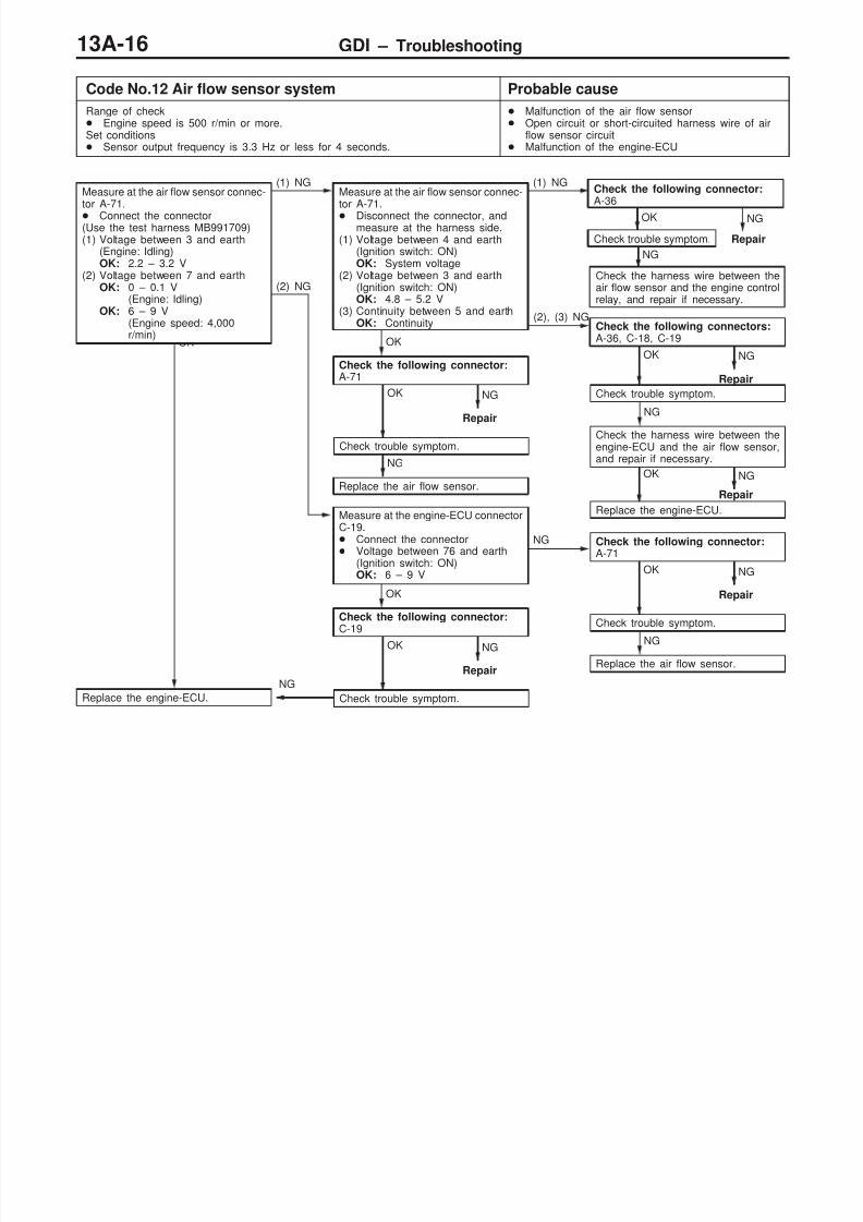
Code No.12 Air flow sensor system Probable cause
Range of check Engine speed is 500 r/min or more.Set conditions Sensor output frequency is 3.3 Hz or less for 4 seconds.
Malfunction of the air flow sensor Open circuit or short-circuited harness wire of air
flow sensor circuit Malfunction of the engine-ECU
NG
Repair
NG
Repair
OK
Replace the engine-ECU.
NG
Repair
NG
Replace the air flow sensor.
NG
Repair
NG
Replace the air flow sensor.
NG
Repair
OK
Replace the engine-ECU.
NG
OK
Check trouble symptom.
OK
Check the following connector:C-19
OK
Check trouble symptom.
(2) NG
Measure at the engine-ECU connectorC-19. Connect the connector Voltage between 76 and earth
(Ignition switch: ON)OK: 6 – 9 V
NG Check the following connector:A-71
OK
Check trouble symptom.
OK
Check the following connector:A-71
NG
Check the harness wire between theengine-ECU and the air flow sensor,and repair if necessary.
OK
Check trouble symptom.
(2), (3) NGCheck the following connectors:A-36, C-18, C-19
Measure at the air flow sensor connec-tor A-71. Connect the connector(Use the test harness MB991709)(1) Voltage between 3 and earth
(Engine: Idling)OK: 2.2 – 3.2 V
(2) Voltage between 7 and earthOK: 0 – 0.1 V
(Engine: Idling)OK: 6 – 9 V
(Engine speed: 4,000r/min)
(1) NGMeasure at the air flow sensor connec-tor A-71. Disconnect the connector, and
measure at the harness side.(1) Voltage between 4 and earth
(Ignition switch: ON)OK: System voltage
(2) Voltage between 3 and earth(Ignition switch: ON)OK: 4.8 – 5.2 V
(3) Continuity between 5 and earthOK: Continuity
(1) NG
Check the harness wire between theair flow sensor and the engine controlrelay, and repair if necessary.
NG
Repair
OK
Check trouble symptom.
Check the following connector:A-36
NG

8/19/2019 13a Gasoline Direct Injection (Gdi) (1)
http://slidepdf.com/reader/full/13a-gasoline-direct-injection-gdi-1 17/269
GDI – Troubleshooting 13A-17
Code No.13 Intake air temperature sensor system Probable cause
Range of check After 60 seconds have passed since the engine have startedSet conditions Sensor resistance is 0.14 kΩ or less for 4 seconds.or Sensor resistance is 50 kΩ or more for 4 seconds.
Malfunction of the intake air temperature sensor Open circuit or short-circuited harness wire of the
intake air temperature sensor circuit Malfunction of the engine-ECU
NG
Repair
NG
Repair
OK
Replace the engine-ECU.
NG
Repair
NG
OK
Check trouble symptom.
OK
Check the following connector: A-71
NG
Check the harness wire between the engine-ECU and the intakeair temperature sensor.
OK
Check trouble symptom.
OK
Measure at the air flow sensor connector A-71. Disconnect the connector, and measure at the harness
side. Voltage between 6 and earth
(Ignition switch: ON)OK: 4.5 – 4.9 V
Continuity between 5 and earthOK: Continuity
NGCheck the following connectors: A-36, C-18, C-19
Check the intake air temperature sensor. (Refer to P.13A-102.)NG
Replace the air flow sensor.
8/19/2019 13a Gasoline Direct Injection (Gdi) (1)
http://slidepdf.com/reader/full/13a-gasoline-direct-injection-gdi-1 18/269
GDI – Troubleshooting13A-18
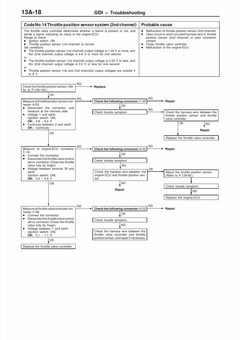
Code No.14 Throttle position sensor system (2nd channel) Probable cause
The throttle valve controller determines whether a failure is present or not, andsends a signal indicating its result to the engine-ECU.Range of check Ignition switch: ON Throttle position sensor (1st channel) is normalSet conditions The throttle position sensor (1st channel) output voltage is 1.24 V or more, and
the (2nd channel) output voltage is 4.6 V or more for one second.or The throttle position sensor (1st channel) output voltage is 3.53 V or less, and
the (2nd channel) output voltage is 0.2 V or less for one second.or Throttle position sensor (1st and 2nd channels) output voltages are outside 4
to 6 V.
Malfunction of throttle position sensor (2nd channel) Open circuit or short-circuited harness wire in throttle
position sensor (2nd channel) or poor connectorcontact
Faulty throttle valve controller Malfunction of the engine-ECU
Check trouble symptom.
NG
Replace the engine-ECU.
NG
Repair
OK
Replace the throttle valve controller.
Check the throttle position sensor. (Re-fer to P.13A-103.)
NGReplace
OK
Measure at throttle position sensor con-nector A-03. Disconnect the connector, and
measure at the harness side. Voltage 1 and earth
(Ignition switch: ON)OK: 4.8 – 5.2 V Continuity between 3 and earth
OK: Continuity
NGCheck the following connector:C-48
NGRepair
OK
Check trouble symptom.NG
Check the harness wire between thethrottle position sensor and throttle
valve controller.
OK
NGCheck the following connector:A-03
NGRepair
OK
Check trouble symptom.
NG
Check the harness wire between theengine-ECU and throttle position sen-
sor.
OKAdjust the throttle position sensor.(Refer to P.13A-92.)
NG
Repair
OK
Measure at throttle valve controller con-nector C-48. Connect the connector. Disconnect the throttle valve control
servo connector (Close the throttlevalve fully by finger).
Voltage between 7 and earth(Ignition switch: ON)OK: 0.1 – 1.1 V
NGCheck the following connector:A-03
NGRepair
OK
Check trouble symptom.
NG
Check the harness wire between thethrottle valve controller and throttle
position sensor, and repair if necessary.OK
Replace the throttle valve controller.
Measure at engine-ECU connectorC-19. Connect the connector. Disconnect the throttle valve control
servo connector (Close the throttlevalve fully by finger).
Voltage between terminal 78 andearth(Ignition switch: ON)
OK: 4.0 – 4.8 V

8/19/2019 13a Gasoline Direct Injection (Gdi) (1)
http://slidepdf.com/reader/full/13a-gasoline-direct-injection-gdi-1 19/269
GDI – Troubleshooting 13A-19
Code No.21 Engine coolant temperature sensor system Probable cause
Range of check After 60 seconds have passed since the engine have startedSet conditions Sensor resistance is 50 Ω or less for 4 seconds.or Sensor resistance is 72 kΩ or more for 4 seconds.
Malfunction of the engine coolant temperaturesensor
Open circuit or short-circuited harness wire of theengine coolant temperature sensor circuit
Malfunction of the engine-ECU
Range of check After engine starts
Set conditions After 5 minutes or more have passed since the engine coolant temperature
after filtering has dropped from 40C or more to less than this temperature
NG
Repair
NG
Repair
OK
Replace the engine-ECU.
NG
Repair
NG
OK
Check trouble symptom.
OK
Check the following connector: A-69
NG
Check the harness wire between the engine-ECU and the enginecoolant temperature sensor.
OK
Check trouble symptom.
OK
Measure at the engine coolant temperature sensor connector A-69. Disconnect the connector, and measure at the harness
side. Voltage between 1 and earth
(Ignition switch: ON)OK: 4.5 – 4.9 V
Continuity between 2 and earth
OK: Continuity
NGCheck the following connectors: A-36, C-18, C-19
Check the engine coolant temperature sensor. (Refer toP.13A-102.)
NGReplace

8/19/2019 13a Gasoline Direct Injection (Gdi) (1)
http://slidepdf.com/reader/full/13a-gasoline-direct-injection-gdi-1 20/269
GDI – Troubleshooting13A-20
Code No.22 Crank angle sensor system Probable cause
Range of check Engine: During crankingSet conditions Sensor output voltage does not change for 4 seconds (no pulse signal is
being input).
Malfunction of the crank angle sensor Open circuit or short-circuited harness wire of the
crank angle sensor circuit Malfunction of the engine-ECU
NG
Repair
NG
Repair
OK
Replace the engine-ECU.
(3) NG
Check the harness wire between the
crank angle sensor and the earth, andrepair if necessary.
NG
Repair
NG
Replace the crank angle sensor.
OK
Replace the engine-ECU.
OK
Check trouble symptom.
NG
Check the harness wire between theengine-ECU and the crank angle sen-sor.
OK
Check trouble symptom.
(2) NG
Check the following connector:C-18
OK
Check the following connector:A-77
NGMeasure at the crank angle sensor con-
nector A-77. Disconnect the connector, and
measure at the harness side.(1) Voltage between 2 and earth
(Ignition switch: ON)OK: System voltage
(2) Voltage between 3 and earth(Ignition switch: ON)OK: 4.8 – 5.2 V
(3) Continuity between 1 and earthOK: Continuity
(1) NG
Check the harness wire between thecrank angle sensor and the engine con-trol relay, and repair if necessary.
Check the following connector:
A-36
OK
Repair
NG
Check trouble symptom.
NG
Measure at the crank angle sensor con-
nector A-77. Connect the connector
(Use the test harnessMB991658)
Voltage between 3 (black clip)and earth(Engine: Cranking)OK: 0.4 – 4.0 V
Voltage between 3 (black clip)and earth(Engine: Idling)OK: 1.5 – 2.5 V
8/19/2019 13a Gasoline Direct Injection (Gdi) (1)
http://slidepdf.com/reader/full/13a-gasoline-direct-injection-gdi-1 21/269
GDI – Troubleshooting 13A-21
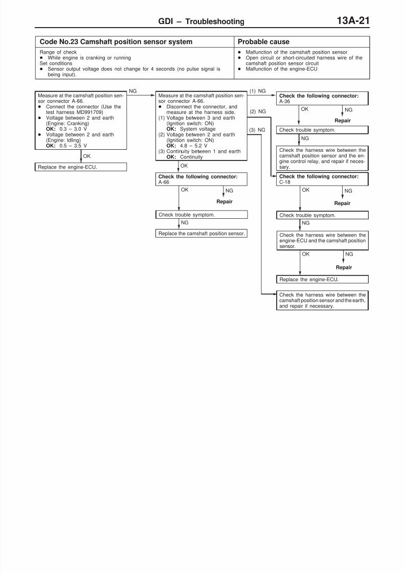
Code No.23 Camshaft position sensor system Probable cause
Range of check While engine is cranking or runningSet conditions Sensor output voltage does not change for 4 seconds (no pulse signal is
being input).
Malfunction of the camshaft position sensor Open circuit or short-circuited harness wire of the
camshaft position sensor circuit Malfunction of the engine-ECU
OK
Replace the engine-ECU.
NG
Repair
NG
Repair
OK
Replace the engine-ECU.
(3) NG
Check the harness wire between the
camshaft position sensor and the earth,and repair if necessary.
NG
Repair
NG
Replace the camshaft position sensor.
OK
Check trouble symptom.
NG
Check the harness wire between theengine-ECU and the camshaft positionsensor.
OK
Check trouble symptom.
(2) NG
Check the following connector:C-18
OK
Check the following connector:A-66
Measure at the camshaft position sen-
sor connector A-66. Connect the connector (Use the
test harness MD991709) Voltage between 2 and earth
(Engine: Cranking)OK: 0.3 – 3.0 V
Voltage between 2 and earth(Engine: Idling)OK: 0.5 – 3.5 V
NGMeasure at the camshaft position sen-
sor connector A-66. Disconnect the connector, and
measure at the harness side.(1) Voltage between 3 and earth
(Ignition switch: ON)OK: System voltage
(2) Voltage between 2 and earth(Ignition switch: ON)OK: 4.8 – 5.2 V
(3) Continuity between 1 and earthOK: Continuity
(1) NG
Check the harness wire between thecamshaft position sensor and the en-gine control relay, and repair if neces-sary.
Check the following connector:
A-36
OK
Repair
NG
Check trouble symptom.
NG
8/19/2019 13a Gasoline Direct Injection (Gdi) (1)
http://slidepdf.com/reader/full/13a-gasoline-direct-injection-gdi-1 22/269
GDI – Troubleshooting13A-22
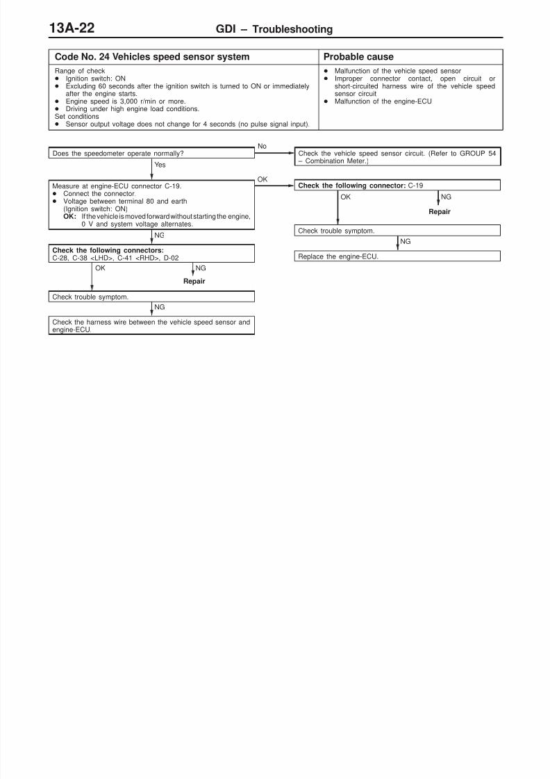
Code No. 24 Vehicles speed sensor system Probable cause
Range of check Ignition switch: ON Excluding 60 seconds after the ignition switch is turned to ON or immediately
after the engine starts. Engine speed is 3,000 r/min or more. Driving under high engine load conditions.Set conditions Sensor output voltage does not change for 4 seconds (no pulse signal input).
Malfunction of the vehicle speed sensor Improper connector contact, open circuit or
short-circuited harness wire of the vehicle speedsensor circuit
Malfunction of the engine-ECU
Does the speedometer operate normally?No
Check the vehicle speed sensor circuit. (Refer to GROUP 54 – Combination Meter.)
Yes
Measure at engine-ECU connector C-19. Connect the connector. Voltage between terminal 80 and earth
(Ignition switch: ON)OK: If the vehicle is moved forward without starting the engine,
0 V and system voltage alternates.
OKCheck the following connector: C-19
NG
Repair
OK
Check trouble symptom.
NG
Replace the engine-ECU.
NG
Check the following connectors:C-28, C-38 <LHD>, C-41 <RHD>, D-02
NG
Repair
OK
Check trouble symptom.
NG
Check the harness wire between the vehicle speed sensor andengine-ECU.
8/19/2019 13a Gasoline Direct Injection (Gdi) (1)
http://slidepdf.com/reader/full/13a-gasoline-direct-injection-gdi-1 23/269
GDI – Troubleshooting 13A-23
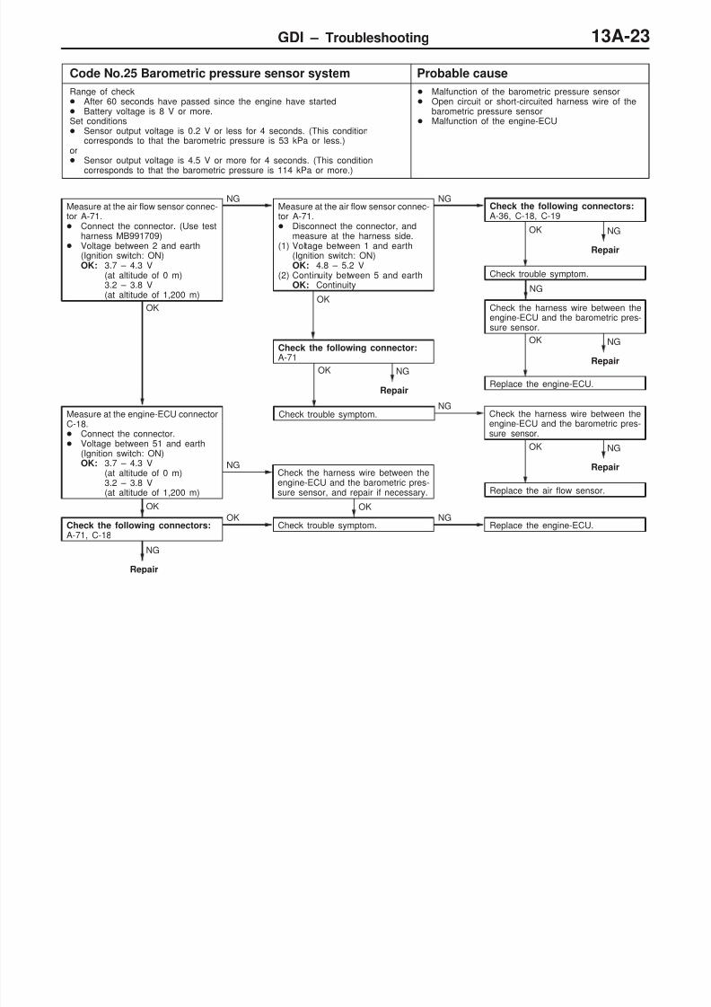
Code No.25 Barometric pressure sensor system Probable cause
Range of check After 60 seconds have passed since the engine have started Battery voltage is 8 V or more.Set conditions Sensor output voltage is 0.2 V or less for 4 seconds. (This condition
corresponds to that the barometric pressure is 53 kPa or less.)or Sensor output voltage is 4.5 V or more for 4 seconds. (This condition
corresponds to that the barometric pressure is 114 kPa or more.)
Malfunction of the barometric pressure sensor Open circuit or short-circuited harness wire of the
barometric pressure sensor Malfunction of the engine-ECU
NG
Repair
NG
Repair
OK
Replace the engine-ECU.
NG
Repair
NG
Repair
OK
Replace the air flow sensor.
OK
NG
Repair
OK
Check the following connectors:A-71, C-18
OK
Check trouble symptom.
NG
Replace the engine-ECU.
OK
Measure at the engine-ECU connectorC-18. Connect the connector. Voltage between 51 and earth
(Ignition switch: ON)OK: 3.7 – 4.3 V
(at altitude of 0 m)3.2 – 3.8 V(at altitude of 1,200 m)
NGCheck the harness wire between theengine-ECU and the barometric pres-sure sensor, and repair if necessary.
NGCheck the harness wire between theengine-ECU and the barometric pres-sure sensor.
OK
Check trouble symptom.
OK
Check the following connector:A-71
NG
Check the harness wire between theengine-ECU and the barometric pres-sure sensor.
OK
Check trouble symptom.
Measure at the air flow sensor connec-tor A-71. Connect the connector. (Use test
harness MB991709) Voltage between 2 and earth
(Ignition switch: ON)OK: 3.7 – 4.3 V
(at altitude of 0 m)3.2 – 3.8 V(at altitude of 1,200 m)
NGMeasure at the air flow sensor connec-tor A-71. Disconnect the connector, and
measure at the harness side.(1) Voltage between 1 and earth
(Ignition switch: ON)OK: 4.8 – 5.2 V
(2) Continuity between 5 and earthOK: Continuity
NGCheck the following connectors:A-36, C-18, C-19

8/19/2019 13a Gasoline Direct Injection (Gdi) (1)
http://slidepdf.com/reader/full/13a-gasoline-direct-injection-gdi-1 24/269
GDI – Troubleshooting13A-24
Code No.31 Detonation sensor system Probable cause
Range of check After 60 seconds have passed since the engine have startedSet conditions Amount of change in the sensor output voltage (detonation sensor peak
voltage for each half rotation of the crankshaft) is 0.06 V or less for 200continuous times.
Malfunction of the detonation sensor Open circuit or short-circuited harness wire of the
detonation sensor Malfunction of the engine-ECU
NG
Repair
NG
Replace the engine-ECU.
NG
Check the harness wire between thedetonation sensor and the earth, andrepair if necessary.
Check trouble symptom.
OK
Replace the detonation sensor.
OK
Check trouble symptom.NG
Check the harness wire between theengine-ECU and the detonation sensor.
Measure at the detonation sensor con-nector A-81. Disconnect the connector, and
measure at the harness side. Continuity between 2 and earth
OK: Continuity
OKCheck the following connector:C-19
NGRepair

8/19/2019 13a Gasoline Direct Injection (Gdi) (1)
http://slidepdf.com/reader/full/13a-gasoline-direct-injection-gdi-1 25/269
GDI – Troubleshooting 13A-25
Code No.41 Injector system Probable cause
Range of check Engine: while cranking, or running Engine speed: 4,000 r/min or less System voltage: 10 V or more Fuel shut off, or while forcible activating of injector (actuator test) is in operation.Set conditions Injector open circuit check signal is not output from the injector predetermined
time(s).
Malfunction of the injector Faulty injector driver relay Faulty injector driver Open circuit or short-circuited harness wire in the
injector drive circuit, or poor connector contact Malfunction of the engine-ECU
(2) NGCheck the following connector:A-36
OKCheck trouble symptom.
(2) NGCheck the harness wire between theinjector driver and earth, and repair ifnecessary.
(3) NGCheck the following connectors:A-61, A-62, A-63, A-64, A-78
OKCheck trouble symptom.
Check the injector. (Refer toP.13A-106.)
NGReplace
OK
(1) NGCheck the following connectors:C-72, C-74
OKCheck trouble symptom.
NG
Check the harness wire between theinjector driver relay and ignition switch,and repair if necessary.
NG
Repair
NG
Check the harness wire between theinjector driver relay and battery, andrepair if necessary.
NG
RepairOK
Measure at engine-ECU connectorC-18. Disconnect the connector, and
measure at the harness side. Voltage between terminal 55 and
earth (Ignition switch: ON)OK: System voltage
NGCheck the following connector:A-44X
OKCheck trouble symptom.
NG
Check the harness wire between theinjector driver relay and engine-ECU,and repair if necessary.
NG
Repair
OK
Measure at injector driver connectorA-55. Disconnect the connector, and
measure at the harness side.(1) Voltage between 12, 21 and earth
(Ignition switch: ON)OK: System voltage
(2) Continuity between 13, 22 and earthOK: Continuity
(3) Resistance between terminals 14and 23Resistance between terminals 15and 24Resistance between terminals 16and 25Resistance between terminals 17and 26OK: 0.9 – 1.1 Ω
(1) NGCheck the following connector:A-44X
OKCheck trouble symptom.
NG
Check the harness wire between theinjector driver and injector driver relay,and repair if necessary.
NG
Repair
NG
Check the harness wire between theinjector driver and injector, and repairif necessary.
NG
RepairOK
To the next page
Measure at injector driver relay connec-tor A-44X. Disconnect the connector, and
measure at the harness side.(1) Voltage between terminal 4 and
earth(Ignition switch: ON)OK: System voltage
(2) Voltage between terminal 3 andearthOK: System voltage

8/19/2019 13a Gasoline Direct Injection (Gdi) (1)
http://slidepdf.com/reader/full/13a-gasoline-direct-injection-gdi-1 26/269
GDI – Troubleshooting13A-26
From the previous page
OK
Measure at engine-ECU connectorC-17,19. Connect the connector. Voltage between terminal 51 and
earth (Ignition switch: ON)OK: 4.0 – 5.0 V
Voltage between terminal 1 and
earthVoltage between terminal 24 andearthVoltage between terminal 9 andearthVoltage between terminal 2 andearth(Ignition switch: ON)OK: 8 – 11 V
OKCheck the following connectors:C-17, C-19
NGRepair
OK
Check trouble symptom.
NG
Replace the injector driver.
Check trouble symptom.NG
Replace the engine-ECU.
NG
Check the following connector:A-55OK
Check trouble symptom.NG
Check the harness wire between theinjector driver and engine-ECU, andrepair if necessary.
NG
Repair

8/19/2019 13a Gasoline Direct Injection (Gdi) (1)
http://slidepdf.com/reader/full/13a-gasoline-direct-injection-gdi-1 27/269
GDI – Troubleshooting 13A-27
Code No.44 Abnormal combustion Probable cause
Range of check While engine is running during lean fuel combustionSet conditions Abnormal engine speed due to mis-firing is detected by the crank angle
sensor
Malfunction of the ignition coil Malfunction of the spark plug Malfunction of the EGR valve Open circuit or short-circuit in ignition primary
circuit Malfunction of the engine-ECU
NG
Repair
NG
Check the harness wire between the ignition coil and the ignitionswitch, and repair if necessary.
(2) NG
NG
Repair
NG
Repair
OK
Replace the engine-ECU.
(3) NG
Check the harness wire between the ignition coil and the
earth, and repair if necessary.
NG
Repair
OK
Check for air leaking into the air intake system.
Damaged intake manifold gasket Damaged vacuum hose Damaged air intake hose Malfunction of the EGR valve
OK
Check the injector system (Refer to P.13A-25, INSPECTION PRO-CEDURE FOR DIAGNOSIS CODE No.41)
NG
Check the following items in the order given. Spark plugs Compression pressure
OK
Check trouble symptom.
NG
Check the harness wire between the engine-ECU and the ignitioncoil.
OK
Check trouble symptom.
OK
Check the following connectors:A-09, A-10, A-11, A-12
OK
Check trouble symptom.
Check the following connector: C-17
OK
Measure at the ignition coil connectors A -09, A-10, A-11, A-12. Disconnect the connector, and measure at the harness
side.(1) Voltage between 1 and earth (Ignition switch: ON)
OK: System voltage(2) Voltage between 3 and earth (Engine: Cranking)
OK: 0.5 – 4.0 V(3) Continuity between 2 and earth
OK: Continuity
(1) NGCheck the following connector: C-72, C-74
Check the ignition coil (Refer to GROUP 16 – Ignition System).
NG
Replace

8/19/2019 13a Gasoline Direct Injection (Gdi) (1)
http://slidepdf.com/reader/full/13a-gasoline-direct-injection-gdi-1 28/269
GDI – Troubleshooting13A-28
Code No.54 Immobilizer system Probable cause
Range of check Ignition switch: ONSet conditions Improper communication between the engine-ECU and immobilizer-ECU
Radio interference of ID codes Incorrect ID code Malfunction of harness or connector Malfunction of immobilizer-ECU Malfunction of engine-ECU
NOTE
(1) If the ignition switches are close each other when starting the engine, radio interference may causethis code to be displayed.(2) This code may be displayed when registering the key ID code.
Replace the engine-ECU.
Check trouble symptom.
No
Check the following connector:C-19, C–29, C-62, 1
Check the immobilizer system. (Refer to GROUP 54 – IgnitionSwitch and Immobilizer System.)
Check trouble symptom.OK
Is a diagnosis code output from the immobilizer-ECU?
NG
YesRemove the extra ignition key.
OK
Replace
Check the harness wire between the engine-ECU and theimmobilizer-ECU.
NG
No
NG
Replace
OK
Yes
NG
Is there another ignition key near the ignition key that is insertedin the ignition switch?

8/19/2019 13a Gasoline Direct Injection (Gdi) (1)
http://slidepdf.com/reader/full/13a-gasoline-direct-injection-gdi-1 29/269
GDI – Troubleshooting 13A-29
Code No.56 Abnormal fuel pressure Probable cause
Range of check Ignition switch: ONSet conditions Sensor output voltage is 4.8 V or more for four seconds.or Sensor output voltage is 0.2 V or less for four seconds.Range of check After the engine is started, the following condition has been detected:
(1) Engine speed: 1,000 r/min or more(2) Fuel pressure: 2 MPa or more
While engine is runningSet conditions Fuel pressure is 6.9 MPa or more for four seconds.or Fuel pressure is 2 MPa or less for four seconds.
Malfunction of the fuel pressure sensor Open circuit or short-circuited harness wire of the
fuel pressure sensor Malfunction of the engine-ECU Malfunction of the fuel pump (high pressure) Malfunction of the fuel pressure regulator (high
pressure) Clogged high-pressure fuel line
This diagnosis code is also output when air is sucked in high-pressure fuel linedue to no fuel supply.In this case, air can be bled by letting the engine run at 2,000 r/min for atleast fifteen seconds. After the air bleeding, the diagnosis code must be erasedby the MUT-II.
Air sucking due to no fuel supply
OKNG
Replace the fuel pump (highpressure) (poor pump dischargepressure)
Replace the high-pressure regula-tor (fuel leakage at the return side).
Check trouble symptom. NG Check if input voltage from the fuelpressure sensor to engine-ECUchanges suddenly by performing anintermittent malfunction simulation test.(Refer to GROUP 00 – Points to Notefor Intermittent Malfunction.)
OK
Normal
NG
To the next page
MUT-II Data list74 Fuel pressure sensor
(Refer to P.13A-75.) Ignition switch: ON
OK: 0 – 8 MPa
OKMUT-II Data list74 Fuel pressure sensor
(Refer to P.13A-75.) Maintain the engine speed at 2,000
r/min for at least fifteen seconds.OK: 6.9 MPa or less
NG Replace the high-pressure fuel
regulator (seized regulator).
Replace the high-pressure returnpipe (seized pipe).
MUT-II Data list74 Fuel pressure sensor(Refer to P.13A-75.) Engine: Idle running for at least
three minutesOK: 4 MPa or more
OK
Erase diagnosis code No.56. (Thisdiagnosis code has been output dueto air sucking into high-pressure fuel
line. But that problem has been re-solved by revving the engine at 2,000r/min.)

8/19/2019 13a Gasoline Direct Injection (Gdi) (1)
http://slidepdf.com/reader/full/13a-gasoline-direct-injection-gdi-1 30/269
GDI – Troubleshooting13A-30
NG
Repair
NG
Repair
OK
Replace the engine-ECU.
NG
Repair
NG
Repair
OK
Replace the fuel pressure sensor.
NG
Replace the engine-ECU.
OK
Check trouble symptom.
OK
Check the following connectors:A-59, C-19
NGRepair
OK
Measure at the engine-ECU connectorC-19. Connect the connector. Voltage between 92 and earth
(Engine: idling)OK: 0.3 – 4.7 V
NG
Check the harness wire between theengine-ECU and the fuel pressure sen-sor, and repair if necessary.
NGCheck the harness wire between theengine-ECU and the fuel pressure sen-sor.
OK
Check trouble symptom.
NG
Check the harness wire between theengine-ECU and the fuel pressure sen-sor.
OK
Check trouble symptom.
OK
Check the following connectors:A-59, A-82, C-19
Measure at the fuel pressure sensorconnector A-59. Connect the connector. (Use test
harness MB991348) Voltage between 2 and earth
OK: 3 V or less(Engine: Cranking)
0.3 – 4.7 V (Engine: Idling)
NG
Measure at the fuel pressure sensorconnector A-59. Disconnect the connector, and
measure at the harness side. Voltage between 1 and earth
(Ignition switch: ON)OK: 4.8 – 5.2 V
Continuity between 3 and earthOK: Continuity
NGCheck the following connectors:A-36, A-82, C-18, C-19
From the previos page

8/19/2019 13a Gasoline Direct Injection (Gdi) (1)
http://slidepdf.com/reader/full/13a-gasoline-direct-injection-gdi-1 31/269
GDI – TroubleshootingGDI – Troubleshooting 13A-31
Code No.61 Communication wire with A/T-ECU system Probable cause
Range of check After 60 seconds have passed since the engine have startedSet conditions Torque reduction request signal from A/T-ECU is input continuously for 1.5
seconds or more.
Short circuit in ECU communication circuit Malfunction of the engine-ECU Malfunction of the A/T-ECU
NG
Replace the A/T-ECU.
NG
Repair Check trouble symptom.
NG
Check the harness wire between the engine-ECU and theA/T-ECU.
OKReplace the engine-ECU.
OK
Check trouble symptom.
Check the following connectors:
C-19, C-25<LHD>, C-26<RHD>, D-04, D-34
NGRepair
Code No.64 Alternator FR terminal system Probable cause
Range of check Engine speed is 50 r/min or more.Set conditions Input voltage from the alternator FR terminal is system voltage for 20
seconds.
Open circuit in alternator FR terminal circuit Malfunction of the engine-ECU
NG
Repair
NG
Repair
OK
Replace the engine-ECU.
NG
Repair
NG
Repair
OK
Replace the alternator.
OK
Replace the engine-ECU.
NG
Check the harness wire between theengine-ECU and the alternator.
OK
Check trouble symptom.
OK
Check the following connector:A-79
NG
Check the harness wire between theengine-ECU and the alternator.
OK
Check trouble symptom.
Measure at the alternator connectorA-79. Connect the connector. (Use test
harness MB991519) Voltage between 4 (blue clip)
and earth(Engine: Idling)
(Radiator fan: Not operating)(Headlamp: OFF → ON)(Stop lamp: OFF → ON)(Rear defogger switch: OFF →
ON)OK: Voltage decreases.
NGMeasure at the alternator connectorA-79. Disconnect the connector, and
measure at the harness side. Voltage between 4 and earth
(Ignition switch: ON)OK: System voltage
NGCheck the following connectors:A-86, C-18

8/19/2019 13a Gasoline Direct Injection (Gdi) (1)
http://slidepdf.com/reader/full/13a-gasoline-direct-injection-gdi-1 32/269
GDI – Troubleshooting13A-32
Code No.66 Brake vacuum sensor system Probable cause
Range of check Ignition switch: ONSet conditions Sensor output voltage is 4.8 V or more.or Sensor output voltage is 0.2 V or less.
Malfunction of the brake vacuum sensor Improper connector contact, open circuit or
short-circuited harness wire of the brake vacuumsensor
Malfunction of the engine-ECU
NG
Repair
NG
Repair
OK
Replace the engine-ECU.
NG
Repair
NG
Repair
Replace the brake vacuum sensor.
OK
OK
Check trouble symptom.
Check the following connectors:A-56, C-19
OK
NG
Replace the engine-ECU.
OK
NGCheck the harness wire between theengine-ECU and the brake vacuumsensor.
OK
Check trouble symptom.
NG
Check the harness wire between theengine-ECU and the brake vacuumsensor.
OK
Check the following connector:A-56
OK
Check trouble symptom.
Measure at the brake vacuum sensorconnector A-56. Connect the connector. (Use test
harness MB991348) Voltage between 1 and earth
OK: Voltage increases whendepressing the brake pedalseveral times after thewarmed engine is turnedoff from idle speed and theignition switch is turned on.
NGMeasure at the brake vacuum sensorconnector A-56. Disconnect the connector, and
measure at the harness side. Voltage between 3 and earth
(Ignition switch: ON)OK: 4.8 – 5.2 V
Continuity between 2 and earthOK: Continuity
NGCheck the following connectors:A-36, C-18, C-19
Measure at the engine-ECU connectorC-19. Connect the connector. Voltage between 74 and earth
OK: Voltage increases whendepressing the brake pedalseveral times after thewarmed engine is turnedoff from idle speed and theignition switch is turned on.
Check the harness wire between theengine-ECU and the brake vacuumsensor, and repair if necessary.
Repair
NG
NG
8/19/2019 13a Gasoline Direct Injection (Gdi) (1)
http://slidepdf.com/reader/full/13a-gasoline-direct-injection-gdi-1 33/269
GDI – Troubleshooting 13A-33
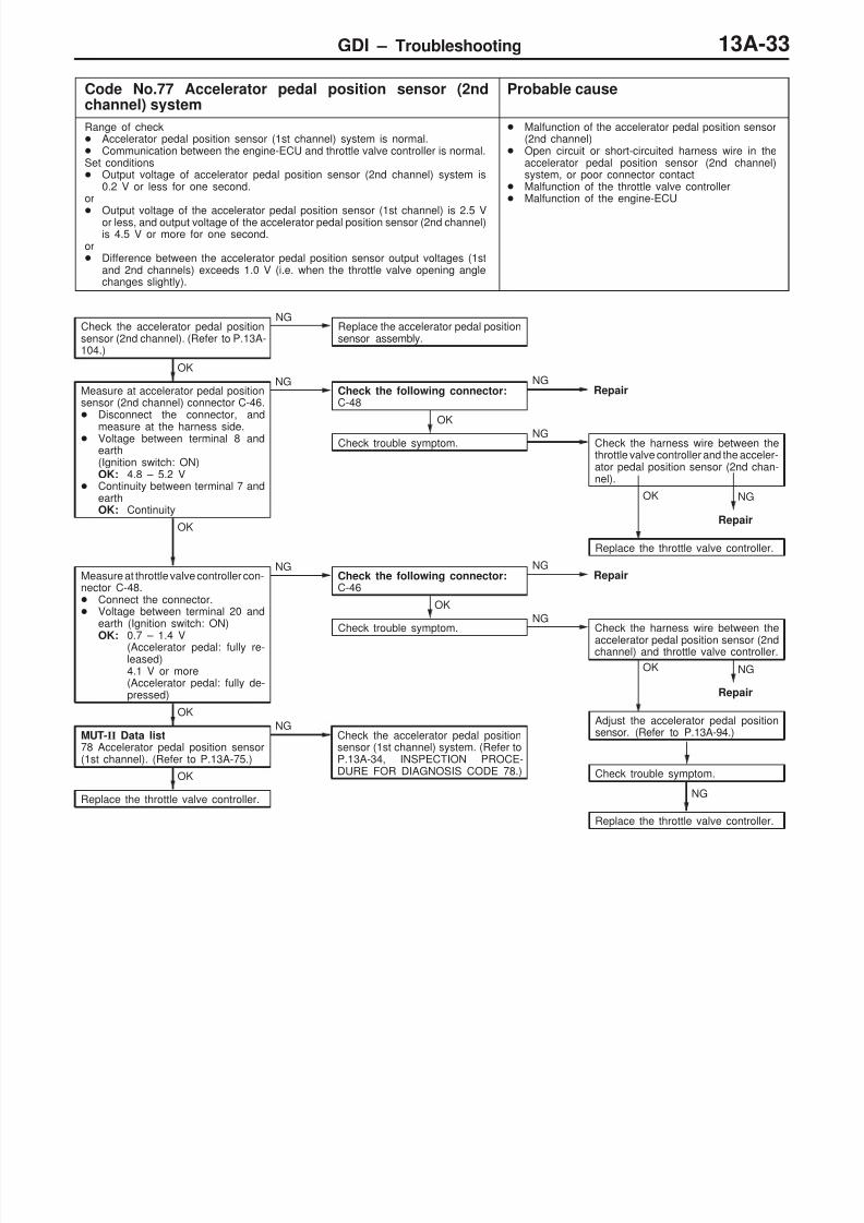
Code No.77 Accelerator pedal position sensor (2ndchannel) system
Probable cause
Range of check Accelerator pedal position sensor (1st channel) system is normal. Communication between the engine-ECU and throttle valve controller is normal.Set conditions Output voltage of accelerator pedal position sensor (2nd channel) system is
0.2 V or less for one second.or
Output voltage of the accelerator pedal position sensor (1st channel) is 2.5 Vor less, and output voltage of the accelerator pedal position sensor (2nd channel)is 4.5 V or more for one second.
or Difference between the accelerator pedal position sensor output voltages (1st
and 2nd channels) exceeds 1.0 V (i.e. when the throttle valve opening anglechanges slightly).
Malfunction of the accelerator pedal position sensor(2nd channel)
Open circuit or short-circuited harness wire in theaccelerator pedal position sensor (2nd channel)system, or poor connector contact
Malfunction of the throttle valve controller Malfunction of the engine-ECU
Check the harness wire between thethrottle valve controller and the acceler-ator pedal position sensor (2nd chan-nel).
NG
Repair
OK
Replace the throttle valve controller.
NG
Repair
OK
Adjust the accelerator pedal positionsensor. (Refer to P.13A-94.)
Check the accelerator pedal positionsensor (2nd channel). (Refer to P.13A-104.)
NGReplace the accelerator pedal positionsensor assembly.
OK
Measure at accelerator pedal positionsensor (2nd channel) connector C-46. Disconnect the connector, and
measure at the harness side. Voltage between terminal 8 and
earth(Ignition switch: ON)OK: 4.8 – 5.2 V
Continuity between terminal 7 andearthOK: Continuity
NG NGRepair
OK
Check trouble symptom.NG
OK
Measure at throttle valve controller con-nector C-48. Connect the connector. Voltage between terminal 20 and
earth (Ignition switch: ON)OK: 0.7 – 1.4 V
(Accelerator pedal: fully re-leased)4.1 V or more(Accelerator pedal: fully de-pressed)
NGCheck the following connector:C-46
NGRepair
OK
Check trouble symptom.NG
Check the harness wire between the
accelerator pedal position sensor (2ndchannel) and throttle valve controller.
Check trouble symptom.
NG
Replace the throttle valve controller.
OK
MUT-II Data list78 Accelerator pedal position sensor(1st channel). (Refer to P.13A-75.)
NGCheck the accelerator pedal positionsensor (1st channel) system. (Refer toP.13A-34, INSPECTION PROCE-DURE FOR DIAGNOSIS CODE 78.)OK
Replace the throttle valve controller.
Check the following connector:C-48

8/19/2019 13a Gasoline Direct Injection (Gdi) (1)
http://slidepdf.com/reader/full/13a-gasoline-direct-injection-gdi-1 34/269
GDI – Troubleshooting13A-34
Code No.78 Accelerator pedal position sensor (1stchannel) system
Probable cause
Range of check Accelerator pedal position sensor (2nd channel) system is normal. Communication between the engine-ECU and throttle valve controller is normal.Set conditions Output voltage of accelerator position sensor (1st channel) system is 0.2 V or
less for one second.or
Output voltage of the accelerator pedal position sensor (2nd channel) is 2.5V or less, and (1st channel) output voltage of the accelerator pedal positionsensor is 4.5 V or more for one second.
or Difference between the accelerator pedal position sensor (1st and 2nd channels)
output voltages exceeds 1.0 V (i.e. when the throttle valve opening angle changesslightly).
or Although the accelerator pedal position switch is on, 1st-channel output voltage
of the accelerator pedal position sensor exceeds 1.1 V for one second.
Malfunction of the accelerator pedal position sensor(1st channel)
Open circuit or short-circuited harness wire in theaccelerator pedal position sensor (1st channel)system, or poor connector contact
ON-seizure of the accelerator pedal position switch Malfunction of the throttle valve controller
Malfunction of the engine-ECU
NG
Repair
OK
Adjust the accelerator pedal positionsensor. (Refer to P.13A-94.)
NG
Repair
OK
Replace the engine-ECU.
MUT-II Data list26 Accelerator pedal position switch(P.13A-73.)
NGCheck the accelerator pedal positionswitch system. (Refer to P.13A-65.),INSPECTION PROCEDURE 27.)
OK
Check the accelerator pedal positionsensor (1st channel). (Refer to P.13A-104.)
NG
Replace the accelerator pedal positionsensor assembly.
OK
Measure at the accelerator pedal posi-tion sensor (1st channel) connectorC-46. Disconnect the connector, and
measure at the harness side. Voltage between terminal 2 and
earth (Ignition switch: ON)OK: 4.8 – 5.2 V
Continuity between terminal 5 andearthOK: Continuity
NGCheck the following connectors:A-36, C-18, C-19
NGRepair
OK
Check trouble symptom.NG
Check the harness wire between theaccelerator pedal position sensor (1stchannel) and engine-ECU.
OK
Measure at the engine-ECU C-19. Connect the connector. Voltage between terminal 94 and
earth(Ignition switch: ON)OK: 0.935 – 1.135 V
(Accelerator pedal: fully re-leased)4.1 V or more(Accelerator pedal: fully de-pressed)
NGCheck the following connector:C-46
NGRepair
OK
Check trouble symptom.NG
Check the harness wire between theaccelerator pedal position sensor (1stchannel) and engine-ECU.
Check trouble symptom.
NG
Replace the engine-ECU.
OK
MUT-II Data list77 Accelerator pedal position sensor
(2nd channel). (Refer to P.13A-75.)
NGCheck the accelerator pedal positionsensor (2nd channel) system. (Refer
to P.13A-33, INSPECTION PROCE-DURE FOR DIAGNOSIS CODE 77.)
OK
Replace the engine-ECU.

8/19/2019 13a Gasoline Direct Injection (Gdi) (1)
http://slidepdf.com/reader/full/13a-gasoline-direct-injection-gdi-1 35/269
GDI – Troubleshooting 13A-35
Code No.79 Throttle position sensor (1st channel) system Probable cause
The throttle valve controller determines a failure, and sends it result to the engine-ECU.Range of check Ignition switch: ON System voltage: 8 V or moreSet conditions Output voltage of the sensor remains 0.2 V for one second.or Output voltage of the sensor remains 4.9 V for one second.or Output voltage of the throttle position sensor (1st and 2nd channels) remains
outside 4 – 6 V for four seconds.
Malfunction of the throttle position sensor (1st channel) Open circuit or short-circuited harness wire in the
throttle position sensor (1st channel), or poorconnector contact
Malfunction of the throttle valve controller Malfunction of the engine-ECU
NG
Repair
OK
Replace the throttle valve controller.
MUT-II Data listIs code No. 14, 91 or 92 output?
YesFollow INSPECTION PROCEDUREFOR DIAGNOSIS CODE.
No
Check the throttle position sensor. (Re-fer to P.13A-103.)
NGReplace
OK
Measure at throttle position sensor con-nector A-03. Disconnect the connector, and
measure at the harness side.
Voltage between terminal 1 andearth(Ignition switch: ON)OK: 4.8 – 5.2 V
Continuity between terminal 3 andearthOK: Continuity
NGCheck the following connector:C-48
NGRepair
OK
Check trouble symptom.NG
Check the harness wire between thethrottle valve controller and throttleposition sensor.
OK
Measure at throttle valve controller con-nector C-48. Connect the connector. Disconnect the throttle control servo
connector (Close the throttle valvefully by finger).
Voltage between terminal 7 andearth(Ignition switch: ON)OK: 0.4 – 0.6 V
NGCheck the following connector:A-03
NGRepair
OK
Check trouble symptom.
NG
Check the harness between the throttleposition sensor and throttle valve con-troller.
OKAdjust the throttle position sensor. (Re-fer to P.13A-92.)
Check trouble symptom.
NG
Replace the throttle valve controller.
NG
Repair
OK
Measure at engine-ECU connectorC-19. Connect the connector. Disconnect the throttle control servo
connector (Close the throttle valvefully by finger).
Voltage between terminal 78 andearth (Ignition switch: ON)OK: 3.9 – 4.9 V
NGCheck the following connector:A-03
NGRepair
OK
Check trouble symptom.NG
Check the harness wire between the
throttle position sensor and engine-ECU, and repair if necessary.
OK
Replace the engine-ECU.

8/19/2019 13a Gasoline Direct Injection (Gdi) (1)
http://slidepdf.com/reader/full/13a-gasoline-direct-injection-gdi-1 36/269
GDI – Troubleshooting13A-36
Code No.89 Abnormal fuel pressure system Probable cause
Range of check Engine: Idling (during stoichio-feedback operation)Set conditions Fuel injection correction value remains excessively low for ten seconds or more.or Fuel injection correction value remains excessively high for ten seconds or more.
Malfunction of the fuel pump (high pressure) Malfunction of the intake air temperature sensor Malfunction of the barometric pressure sensor Malfunction of the air flow sensor Malfunction of the engine-ECU
MUT-II Data list13 Intake air temperature sensor. (Refer to P.13A-71.)
NGCheck the intake air temperature sensor system. (Refer to P.13A-17, INSPECTION PROCEDURE FOR DIAGNOSIS CODE No.13.)
OK
MUT-II Data list25 Barometric air temperature sensor. (Refer to P.13A-73.)
NGCheck the barometric pressure sensor system. (Refer to P.13A-23,INSPECTION PROCEDURE FOR DIAGNOSIS CODE No.25.)
OK
MUT-II Data list12 Air flow sensor. (Refer to P.13A-71.)
NGCheck the air flow sensor system. (Refer to P.13A-16, INSPEC-TION PROCEDURE FOR DIAGNOSIS CODE No.12.)
OK
Replace the fuel pump (high pressure).
Code No.91 Electronic-controlled throttle valve system Probable cause
Range of check Ignition switch: ON Error in communication from the engine-ECU to throttle valve controllerSet conditions Output voltage of the throttle position sensor (2nd channel) fluctuates significantly
(approx. 1 V or more) from an expected value.Range of check Ignition switch: ON Error in communication from the throttle valve controller to engine-ECUSet conditions The throttle valve opening angle (voltage) which the engine-ECU requested of
the throttle valve controller is significantly different from output voltage of the(2nd channel) throttle position sensor (approx. one volt).
Short in communication line Malfunction of the engine-ECU Malfunction of the throttle valve controller
MUT-II Self-Diag codeIs any other diagnosis code than No.94 output?
YesFollow INSPECTION PROCEDURE FOR DIAGNOSIS CODE.
No
Check the harness wire between the throttle valve controller andengine-ECU.
NGRepair
OK
Replace the throttle valve controller.

8/19/2019 13a Gasoline Direct Injection (Gdi) (1)
http://slidepdf.com/reader/full/13a-gasoline-direct-injection-gdi-1 37/269
GDI – Troubleshooting 13A-37
Code No.92 Throttle valve position feedback system Probable cause
The throttle valve controller determines if a failure is present, and sends its resultto the engine-ECU.Range of check Ignition switch: ON System voltage: 8 V or moreSet condition Motor position feedback system is defective (System detects a motor overcurrent,
or that actual and projected opening angles of the throttle position sensor (1stchannel) are different by 1.0 V or more.
Malfunction of the throttle position sensor (1st channel) Open circuit or short-circuited harness wire in the
throttle position sensor system (1st channel), or poorconnector contact
Malfunction of the throttle valve controller
Check the throttle valve control servo. (Refer to P.13A-107.)NG
Replace
OK
Check the following connectors:A-05, C-48NG
Repair
OK
Check trouble symptom.
NG
Check the harness wire between the throttle control servo andthrottle valve controller.
NGRepair
OK
Replace the throttle body.
Check trouble symptom.
NG
Replace the throttle valve controller.
Code No.94 Communication line system with throttle valvecontroller
Probable cause
Range of check
Ignition switch: ON System voltage: 8 V or more Engine: not crankingSet condition System detects an error in communication line between the engine-ECU and
throttle valve controller.
Short circuit in communication line
Malfunction of the engine-ECU Malfunction of the throttle valve controller
Check the following connectors: C-19, C-48NG
Repair
OK
Check trouble symptom.
NG
Check the harness wire between the engine-ECU and throttlevalve controller.
OKReplace the throttle valve controller.
Check trouble symptom.
NG
Replace the engine-ECU.
NG
Repair
8/19/2019 13a Gasoline Direct Injection (Gdi) (1)
http://slidepdf.com/reader/full/13a-gasoline-direct-injection-gdi-1 38/269
GDI – Troubleshooting13A-38
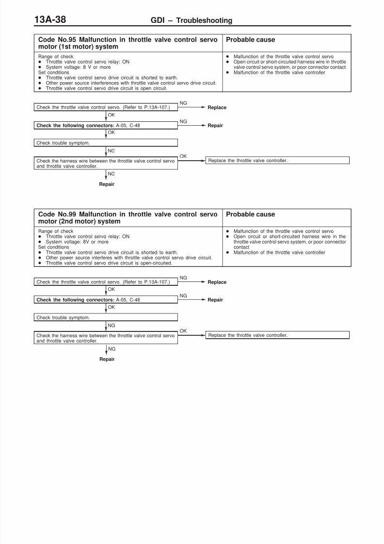
Code No.95 Malfunction in throttle valve control servomotor (1st motor) system
Probable cause
Range of check Throttle valve control servo relay: ON System voltage: 8 V or moreSet conditions Throttle valve control servo drive circuit is shorted to earth. Other power source interferences with throttle valve control servo drive circuit. Throttle valve control servo drive circuit is open circuit.
Malfunction of the throttle valve control servo Open circuit or short-circuited harness wire in throttle
valve control servo system, or poor connector contact Malfunction of the throttle valve controller
Check the throttle valve control servo. (Refer to P.13A-107.)NG
Replace
OK
Check the following connectors: A-05, C-48NG
Repair
OK
Check trouble symptom.
NG
Check the harness wire between the throttle valve control servoand throttle valve controller.
OKReplace the throttle valve controller.
NG
Repair
Code No.99 Malfunction in throttle valve control servomotor (2nd motor) system
Probable cause
Range of check Throttle valve control servo relay: ON System voltage: 8V or moreSet conditions Throttle valve control servo drive circuit is shorted to earth. Other power source interferes with throttle valve control servo drive circuit. Throttle valve control servo drive circuit is open-circuited.
Malfunction of the throttle valve control servo Open circuit or short-circuited harness wire in the
throttle valve control servo system, or poor connectorcontact
Malfunction of the throttle valve controller
Check the throttle valve control servo. (Refer to P.13A-107.)NG
Replace
OK
Check the following connectors: A-05, C-48NG
Repair
OK
Check trouble symptom.
NG
Check the harness wire between the throttle valve control servoand throttle valve controller.
OKReplace the throttle valve controller.
NG
Repair

8/19/2019 13a Gasoline Direct Injection (Gdi) (1)
http://slidepdf.com/reader/full/13a-gasoline-direct-injection-gdi-1 39/269
GDI – Troubleshooting 13A-39
INSPECTION CHART FOR TROUBLE SYMPTOMS
Trouble symptom InspectionprocedureNo.
Reference page
Communication-
Communication with all systems is not possible. 1 13A-41w - simpossible. Communication with engine-ECU only is not possible. 2 13A-42
Engine warninglamp and
p
The engine warning lamp does not illuminate right after theignition switch is turned to the ON position.
3 13A-42
re a e par sThe engine warning lamp remains illuminating and never goesout.
4 13A-43
Starting No initial combustion (starting impossible) 5 13A-43
Initial combustion but no complete combustion(starting impossible)
6 13A-45
Long time to start (improper starting)
Idling stabilityp p Unstable idling (Rough idling, hunting) 7 13A-47mproper ngIdling speed is high. (Improper idling speed) 8 13A-49
Idling speed is low. (Improper idling speed)
Idling stability When the engine is cold, it stalls at idling. (Die out) 9 13A-50ng ne s a s
When the engine is hot, it stalls at idling. (Die out) 10 13A-51
The engine stalls when starting the car. (Pass out) 11 13A-53
The engine stalls when decelerating. 12 13A-54
Driving Hesitation, sag or stumble 13 13A-55
Poor acceleration
Surge
The feeling of impact or vibration when accelerating 14 13A-56
The feeling of impact or vibration when decelerating 15 13A-57
Knocking 16 13A-57
Dieseling 17 13A-57
Too high CO and HC concentration when idling 18 13A-58
Low alternator output voltage (approx. 12.3 V) 19 13A-59
Fans (radiator fan, A/C condenser fan) are inoperative 20 13A-60
GDI ECOp
GDI ECO indicator lamp does not illuminate. 21 13A-61n ca or amp
GDI ECO indicator lamp remains illuminated and does not gooff.
22 13A-61

8/19/2019 13a Gasoline Direct Injection (Gdi) (1)
http://slidepdf.com/reader/full/13a-gasoline-direct-injection-gdi-1 40/269
GDI – Troubleshooting13A-40
PROBLEM SYMPTOMS TABLE (FOR YOUR INFORMATION)
Items Symptom
Starting Won’t start The starter is used to crank the engine, but there is no combustion within thecylinders, and the engine won’t start.
Fires up and dies There is combustion within the cylinders, but then the engine soon stalls.
Hard starting Engine starts after cranking a while.
Idling Hunting Engine speed doesn’t remain constant; changes at idle.s a y
Rough idle Usually, a judgement can be based upon the movement of the tachometerpointer, and the vibration transmitted to the steering wheel, shift lever, body, etc.This is called rough idle.
Incorrect idle speed The engine doesn’t idle at the usual correct speed.
Engine stall(Die out)
The engine stalls when the foot is taken from the accelerator pedal, regardlessof whether the vehicles is moving or not.
Engine stall
(Pass out)
The engine stalls when the accelerator pedal is depressed or while it is being
used.
Driving Hesitation, Sag “Hesitation” is the delay in responseof the vehicle speed (engine speed)that occurs when the accelerator isdepressed in order to acceleratefrom the speed at which the vehicleis now traveling, or a temporary dropin vehicle speed (engine speed)during such acceleration.Serious hesitation is called “sag”.
Vehiclespeed
Initial ac-celeratorpedal de-pression
NormalHesitation
Sag
Time
Poor acceleration Poor acceleration is inability to obtain an acceleration corresponding to thedegree of throttle opening, even though acceleration is smooth, or the inabilityto reach maximum speed.
Stumble Engine speed increase is delayedwhen the accelerator pedal isinitially depressed for accelera-tion. Normal
Initial ac-celeratorpedal de-pression
Idling Stumble
Time
Vehiclespeed
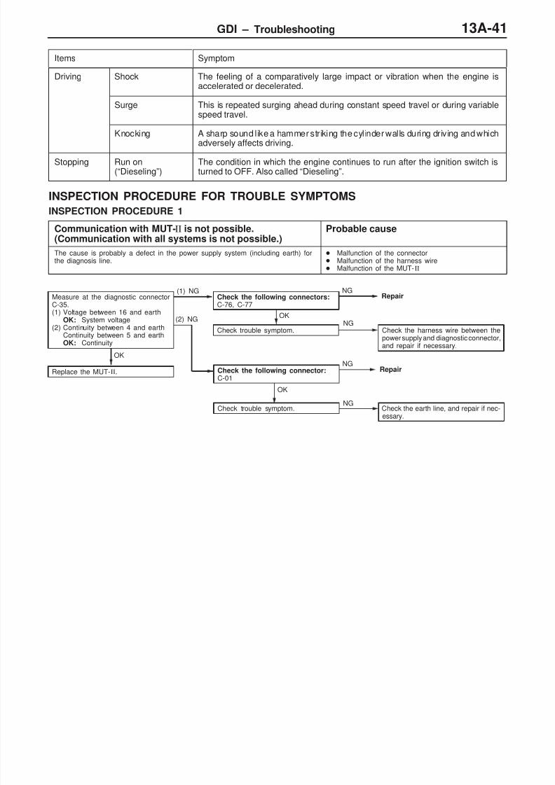
8/19/2019 13a Gasoline Direct Injection (Gdi) (1)
http://slidepdf.com/reader/full/13a-gasoline-direct-injection-gdi-1 41/269
GDI – Troubleshooting 13A-41
Items Symptom
Driving Shock The feeling of a comparatively large impact or vibration when the engine isaccelerated or decelerated.
Surge This is repeated surging ahead during constant speed travel or during variablespeed travel.
Knocking A sharp sound like a hammer striking the cylinder walls during driving and whichadversely affects driving.
Stopping Run on(“Dieseling”)
The condition in which the engine continues to run after the ignition switch isturned to OFF. Also called “Dieseling”.
INSPECTION PROCEDURE FOR TROUBLE SYMPTOMS
INSPECTION PROCEDURE 1
Communication with MUT-II is not possible.(Communication with all systems is not possible.)
Probable cause
The cause is probably a defect in the power supply system (including earth) forthe diagnosis line.
Malfunction of the connector Malfunction of the harness wire Malfunction of the MUT-II
Measure at the diagnostic connectorC-35.(1) Voltage between 16 and earth
OK: System voltage(2) Continuity between 4 and earth
Continuity between 5 and earthOK: Continuity
(1) NGCheck the following connectors:C-76, C-77
NGRepair
OK
Check trouble symptom.NG
Check the harness wire between thepower supply and diagnostic connector,and repair if necessary.
OK
OK
Replace the MUT-II. Check the following connector:C-01
Repair
Check trouble symptom. Check the earth line, and repair if nec-essary.
NG
NG
(2) NG

8/19/2019 13a Gasoline Direct Injection (Gdi) (1)
http://slidepdf.com/reader/full/13a-gasoline-direct-injection-gdi-1 42/269
GDI – Troubleshooting13A-42
INSPECTION PROCEDURE 2
MUT-II communication with engine-ECU is impossible. Probable cause
This may be caused by malfunction of engine-ECU power supply circuit and earthcircuit.
Malfunction of engine-ECU power supply circuit Malfunction of engine-ECU Open circuit between the engine-ECU and diagnosis
connector
NG
Check the harness wire between engine-ECU and diagnosis con-nector.
NGRepair
OK
Check trouble symptom.
Check the following connectors:C-53 <Vehicles with multi center display>, C-19, C-28, C-35,C-70
NG
Repair
OK
Check the engine-ECU power supply and earth circuit system. (Referto P.13A-62, INSPECTION PROCEDURE 23.)
NOTE
On vehicles with multi center display, if a malfunction cannot be resolved after the procedure above, checkthe multi center display and replace if necessary. (Refer to GROUP 54 – Multi center display.)
INSPECTION PROCEDURE 3
The engine warning lamp does not illuminate right afterthe ignition switch is turned to the ON position.
Probable cause
Because there is a burnt-out bulb, the engine-ECU causes the engine warning lampto illuminate for five seconds immediately after the ignition switch is turned to ON.If the engine warning lamp does not illuminate immediately after the ignition switchis turned to ON, one of the malfunctions listed at right has probably occurred.
Burnt-out bulb Defective warning lamp circuit Malfunction of the engine-ECU
MUT-II Data list16 Engine-ECU power supply voltage (Refer to P.13A-72.)
NGCheck the engine-ECU power supply and earth circuit system.(Refer to P.13A-62, INSPECTION PROCEDURE 23.)
OK
Measure at the engine-ECU connector C-17. Disconnect the connector, and measure at the harness side. Earth the terminal No. 31.
OK: The engine warning lamp illuminates.
OKCheck the followingconnector: C-17
NGRepair
OK
Check trouble symptom.
NG
Replace the engine-ECU.
NG
Check a burnt-out bulb.NG
Replace
OK
Measure at the combination meter connector C-06. Disconnect the connector, and measure at the harness side. Voltage between 1 and earth (Ignition switch: ON)
OK: System voltage
NGCheck the engine warning lamp power supply circuit, and repairif necessary.
OK
Check the following connectors:C-06, C-07, C-17, C-28
NGRepair
OK
Check trouble symptom.NG
Check the harness wire between combination meter and engine-ECU, and repair if necessary.

8/19/2019 13a Gasoline Direct Injection (Gdi) (1)
http://slidepdf.com/reader/full/13a-gasoline-direct-injection-gdi-1 43/269
GDI – Troubleshooting 13A-43
INSPECTION PROCEDURE 4
The engine warning lamp remains illuminating and nevergoes out.
Probable cause
In cases such as the above, the cause is probably that the engine-ECU is detectinga problem in a sensor or actuator, or that one of the malfunctions listed at righthas occurred.
Short-circuit between the engine warning lamp andengine-ECU
Malfunction of the engine-ECU
MUT-II Self-Diag codeAre diagnosis codes displayed?
YesRefer to P.13A-14, INSPECTION CHART FOR DIAGNOSISCODES
No
Measure at the combination meter connector C-07. Disconnect the connector, and measure at the harness side. Disconnect the engine-ECU connector Continuity between 46 and earth
OK: No continuity
NGCheck the harness wire between combination meter and engine-ECU connector, and repair if necessary.
OK
Replace the engine-ECU.
INSPECTION PROCEDURE 5
No initial combustion (starting impossible) Probable cause
This is caused by incorrect fuel supply into the combustion chamber, and improperignition circuit. Besides that, foreign material may be contaminated in fuel.
Malfunction of the fuel supply system Malfunction of the ignition system Malfunction of the engine-ECU
Check system voltage while the engine is cranking.OK: 8 V or more
NGCheck the battery. (Refer to GROUP 55 – Battery.)
OK
MUT-II Self-Diag codeIs a diagnosis code displayed?
YesRefer to P.13A-14, INSPECTION CHART FOR DIAGNOSISCODES.
No
MUT-II Data list16 System voltage (Refer to P.13A-72.)
NGCheck the engine control relay and ignition switch-IG system.(Refer to P.13A-62, INSPECTION PROCEDURE 24.)
OK
Does the camshaft rotate when the engine is cranking?No
Check if the timing belt is broken or damaged.
Yes
MUT-II Actuator test07 Fuel pump (low pressure) (Refer to P.13A-76.)
NGCheck the fuel pump (low pressure) system. (Refer to P.13A-66,INSPECTION PROCEDURE 28.)
OK
MUT-II Data list22 Crank angle sensor (Refer to P.13A-72.)
NGCheck the crank angle sensor system. (Refer to P.13A-20, IN-SPECTION PROCEDURE FOR DIAGNOSIS CODE 22.)
OK
MUT-II Data list21 Engine coolant temperature sensor (Refer to P.13A-72.)
NGCheck the engine coolant temperature sensor system. (Refer toP.13A-19, INSPECTION PROCEDURE FOR DIAGNOSIS CODE21.)OK
To the next page

8/19/2019 13a Gasoline Direct Injection (Gdi) (1)
http://slidepdf.com/reader/full/13a-gasoline-direct-injection-gdi-1 44/269
GDI – Troubleshooting13A-44
NG
OK
MUT-II Data list14 Throttle position sensor (2nd channel) (Refer to P.13A-72.)
NGCheck the throttle position sensor (2nd channel) system. (Referto P.13A-18, INSPECTION PROCEDURE FOR DIAGNOSISCODE 14.)
OK
Inspect engine start ability by cranking the engine while the acceler-ator pedal is slightly depressed.
OKClean around the throttle valve. (Refer to P.13A-92.)
Check fuel leakage. (Refer to P.13A-99.)NG
Repair
OK
Measure low fuel pressure between the fuel pump (low pressure)and fuel pump (high pressure). (Refer to P.13A-95.)
NGRepair
OK
Measure at ignition coil connectors A-09, A-10, A-11, A-12. Connect the connector. Connect a timing light to the No.1 terminal of each connector
in turn.(Engine cranking)OK: The timing light flashes.
NGCheck abnormal fuel combustion system. (Refer to P.13A-27, IN-SPECTION PROCEDURE FOR DIAGNOSIS CODE 44.)
OK
Check ignition timing while the engine is cranking.
OK: Approx. 5 BTDC
NGCheck that the crank angle sensor and timing belt cover are proper-
ly installed.
From the previous page
OK
Check ignition coil spark for each cylinder.(1) Remove the ignition coil.(2) Install a new spark plug to the removed ignition coil.(3) Disconnect the injector intermediate connector.
CautionNever touch the connector terminal as approx. 100 V isapplied to the injector, or you are seriously injured.
(4) Earth the spark plug electrode securely.(5) Check that the spark plug ignites when the engine is cranked.
NG
OK
Check all the following items: Spark plug
Compression pressure Foreign material (such as water or kerosine) entered the fuellines
Check trouble symptom.
OKNG
Replace the ignition coil.
Replace the injector.

8/19/2019 13a Gasoline Direct Injection (Gdi) (1)
http://slidepdf.com/reader/full/13a-gasoline-direct-injection-gdi-1 45/269
GDI – Troubleshooting 13A-45
INSPECTION PROCEDURE 6
Initial combustion takes place, but does not complete(start impossible), too long time to start (poor start)
Probable cause
This may be caused by improper spark plug ignition (poor spark), improper mixtureduring engine cranking, improper fuel pressure.
Malfunction of the fuel supply system Malfunction of the fuel pressure sensor Malfunction of the ignition system Malfunction of the electronic-controlled throttle vale
system
Malfunction of the engine-ECU
NG
Check system voltage while the engine is cranking.OK: 8 V or more
NGCheck the battery. (Refer to GROUP 55 – Battery.)
OK
MUT-II Self-Diag codeIs a diagnosis code displayed?
YesRefer to P.13A-14, INSPECTION CHART FOR DIAGNOSISCODES.
No
MUT-II Actuator test07 Fuel pump (low pressure) (Refer to P.13A-76.)
NGCheck the fuel pump (low pressure) system. (Refer to P.13A-66,INSPECTION PROCEDURE 28.)
OK
MUT-II Data list21 Engine coolant temperature sensor (Refer to P.13A-72.)
NGCheck the engine coolant temperature system. (Refer to P.13A-19, INSPECTION PROCEDURE FOR DIAGNOSIS CODE 21.)
OK
MUT-II Data list18 Cranking signal (Refer to P.13A-72.)
NGCheck the ignition switch-ST system <M/T>. (Refer to P.13A-63,INSPECTION PROCEDURE 25.)Check the ignition switch-ST system and inhibitor switch<A/T>.(Refer to P.13A-64, INSPECTION PROCEDURE 26.)
OK
MUT-II Data list74 Fuel pressure sensor (Refer to P.13A-75.)
NGCheck an abnormal fuel pressure system. (Refer to P.13A-29,INSPECTION PROCEDURE FOR DIAGNOSIS CODE 56.)
Check fuel leakage. (Refer to P.13A-99.)NG
Repair
OK
Is the engine started normally when it is cranked with the accelera-tor pedal depressed slightly?
YesClean around the throttle valve. (Refer to P.13A-92.)
No
MUT-II Data list14 Throttle position sensor (2nd channel) (Refer to P.13A-72.)
NG Check the throttle position sensor (2nd channel) system. (Referto P.13A-18, INSPECTION PROCEDURE FOR DIAGNOSISCODE 14.)OK
Check ignition timing when the engine is cranked.OK: approx. 5 BTDC
NG Check that the crank angle sensor and timing belt cover are proper-ly installed.
OK
To the next page

8/19/2019 13a Gasoline Direct Injection (Gdi) (1)
http://slidepdf.com/reader/full/13a-gasoline-direct-injection-gdi-1 46/269
GDI – Troubleshooting13A-46
From the previous page
OK
Check ignition coil spark for each cylinder.(1) Remove the ignition coil.(2) Install a new spark plug to the removed ignition coil.(3) Disconnect the injector intermediate connector.
CautionNever touch the connector terminal as approx. 100 V isapplied to the injector, or you are seriously injured.
(4) Earth the spark plug electrode securely.(5) Check that the spark plug ignites when the engine is cranked.
NGReplace the ignition coil.
OK
Check all the following items: Spark plug Compression pressure Foreign material (such as water or kerosine) entered the fuel
lines
Check trouble symptom.
OKNG
Replace the injector.

8/19/2019 13a Gasoline Direct Injection (Gdi) (1)
http://slidepdf.com/reader/full/13a-gasoline-direct-injection-gdi-1 47/269
GDI – Troubleshooting 13A-47
INSPECTION PROCEDURE 7
Unstable idling (rough idle, hunting) Probable cause
This malfunction is probably caused by a faulty ignition system, improper air/fuelratio, a faulty electronic-controlled throttle valve system, improper compressionpressure, etc. As many causes can be suspected, diagnose from easier items.
Malfunction of the ignition system Malfunction of the air/fuel ratio control system Malfunction of the electronic-control throttle valve
system Improper compression pressure Air sucking into the air intake system
Has the battery been disconnected recently?Yes
Warm up the engine, and then let it run at idle for approx. tenminutes.
No
MUT-II Self-Diag codeIs a diagnosis code displayed?
YesRefer to P.13A-14, INSPECTION CHART FOR DIAGNOSISCODES.
No
Does the engine idle speed fluctuates excessively (excessivehunting)?
YesClean around the throttle valve. (Refer to P.13A-92.)
No
MUT-II Data list14 Throttle position sensor (2nd channel) (Refer to P.13A-72.)
NGCheck the throttle position sensor (2nd channel) system. (Referto P.13A-18, INSPECTION PROCEDURE FOR DIAGNOSISCODE 14.)
OK
MUT-II Data list79 Throttle position sensor (1st channel) (Refer to P.13A-75.)
NGCheck the throttle valve position feedback system. (Refer toP.13A-37, INSPECTION PROCEDURE FOR DIAGNOSIS CODE92.)
OK
MUT-II Data list26 Accelerator pedal position switch (Refer to P.13A-73.)
NGCheck the accelerator pedal position switch system. (Refer toP.13A-65, INSPECTION PROCEDURE 27.)
OK
MUT-II Data list13 Intake air temperature sensor (Refer to P.13A-71.)
NGCheck the intake air temperature sensor system. (Refer toP.13A-17, INSPECTION PROCEDURE FOR DIAGNOSIS CODE13.)
OK
MUT-II Data list
25 Barometric pressure sensor (Refer to P.13A-73.)
NGCheck the barometric pressure sensor system. (Refer to P.13A-23,INSPECTION PROCEDURE FOR DIAGNOSIS CODE 25.)
OK
MUT-II Data list21 Engine coolant temperature sensor (Refer to P.13A-72.)
NGCheck the engine coolant temperature sensor. (Refer to P.13A-19,INSPECTION PROCEDURE FOR DIAGNOSIS CODE 21.)
OK
MUT-II Actuator test08 Purge control solenoid valve (Refer to P.13A-76.)
NGCheck the purge control solenoid valve system. (Refer to P.13A-68,INSPECTION PROCEDURE 30.)
MUT-II Data list11 Oxygen sensor
OK: 600 – 1,000 mV when the engine is suddenly raced
NG Check the oxygen sensor system. (Refer to P.13A-15, INSPEC-TION PROCEDURE FOR DIAGNOSIS CODE 11.)
OK
OK
To the next page

8/19/2019 13a Gasoline Direct Injection (Gdi) (1)
http://slidepdf.com/reader/full/13a-gasoline-direct-injection-gdi-1 48/269
GDI – Troubleshooting13A-48
OK
Check that air is sucked in the air intake system. Broken intake manifold gasket Damaged vacuum hose Damaged air intake hose
From the previous page
OK
MUT-II Data list27 Power steering fluid pressure switch (Refer to P.13A-73.)
NGCheck the power steering fluid pressure switch system. (Referto P.13A-69, INSPECTION PROCEDURE 31.)
OK
MUT-II Data list28 A/C switch (Refer to P.13A-73.)
NGCheck the A/C switch and A/C relay system. (Refer to P.13A-69,INSPECTION PROCEDURE 32.)
OK
MUT-II
Data list67 Stop lamp switch (Refer to P.13A-74.)
NGCheck the stop lamp switch. (Refer to P.13A-70, INSPECTIONPROCEDURE 33.)
OK
MUT-II Data list31 Small lamp switch (Refer to P.13A-73.)
NGCheck the small lamp switch system. (Refer to P.13A-70, INSPEC-TION PROCEDURE 34.)
OK
MUT-II Data list68 EGR valve (Refer to P.13A-74.)
NGCheck the EGR valve. (Refer to P.13A-67, INSPECTION PROCE-DURE 29.)
OK
Check ignition timing. (Refer to GROUP 11A – Engine Adjustment.)NG
Check that the crank angle sensor and timing belt cover are proper-ly installed.
OK
Check ignition coil spark for each cylinder.
(1) Remove the ignition coil.(2) Install a new spark plug to the removed ignition coil.(3) Disconnect the injector intermediate connector.
CautionNever touch the connector terminal as approx. 100 V isapplied to the injector, or you are seriously injured.
(4) Earth the spark plug electrode securely.(5) Check that the spark plug ignites when the engine is cranked.
NGReplace the ignition coil.
OK
Check trouble symptom.
NG
Check all the following items in that order.
(1) Spark plugs(2) Exhaust gas emission control system(3) EGR system(4) Compression pressure(5) Foreign material (such as water or kerosine)entered the fuel
line.(6) Air is sucked in the air intake system, or EGR gas leaks.
Damaged intake manifold gasket Damaged air intake hose Damaged vacuum hose Faulty EGR valve seat
OK
MUT-II Data list11 Oxygen sensor
OK: 0 – 400 mV and 600 – 1,000 mV alternates when theengine is idling (wait for four minutes after the enginestarted).
NG
NG
Repair
OK
MUT-II Data list29 Inhibitor switch (Refer to P.13A-73.)
NGCheck the ignition switch-ST and inhibitor switch. <A/T> (Referto P.13A-64, INSPECTION PROCEDURE 26.)
Measure fuel high-pressure between the fuel pump (high pressure)and injector. (Refer to P.13A-97.)
Clean around the throttle valve. (Refer to P.13A-92.)

8/19/2019 13a Gasoline Direct Injection (Gdi) (1)
http://slidepdf.com/reader/full/13a-gasoline-direct-injection-gdi-1 49/269
GDI – Troubleshooting 13A-49
INSPECTION PROCEDURE 8
Idle speed is high or low (Improper idling) Probable cause
The cause is probably that the intake air amount during idling is too great or toosmall.
Malfunction of the electronic-controlled throttle valvesystem
Malfunction of the throttle body
MUT-II Self-Diag code
Is a diagnosis code displayed?
YesRefer to P.13A-14, INSPECTION CHART FOR DIAGNOSIS
CODES.
No
MUT-II Data list14 Throttle position sensor (2nd channel) (Refer to P.13A-72.)
NGCheck the throttle position sensor (2nd channel). (Refer toP.13A-18, INSPECTION PROCEDURE FOR DIAGNOSIS CODE14.)
OK
MUT-II Actuator test08 Purge control solenoid valve (Refer to P.13A-76.)
NGCheck the purge control solenoid valve. (Refer to P.13A-68, IN-SPECTION PROCEDURE 30.)
OK
MUT-II Data list26 Accelerator pedal position switch (Refer to P.13A-73.)
NGCheck the accelerator pedal position switch system. (Refer toP.13A-65, INSPECTION PROCEDURE 27.)
OK
MUT-II Data list21 Engine coolant temperature sensor (Refer to P.13A-72.)
NGCheck the engine coolant temperature sensor. (Refer to P.13A-19,INSPECTION PROCEDURE FOR DIAGNOSIS CODE 21.)
OK
MUT-II Data list28 A/C switch (Refer to P.13A-73.)
NGCheck the A/C switch and A/C relay system. (Refer to P.13A-69,INSPECTION PROCEDURE 32.)
OK
OK
MUT-II Data list67 Stop lamp switch (Refer to P.13A-74.)
NGCheck the stop lamp switch system. (Refer to P.13A-70, INSPEC-TION PROCEDURE 33.)
OK
Clean around the throttle valve. (Refer to P.13A-92.) Adjust the throttle position sensor. (Refer to P.13A-92.)
MUT-II Data list29 Inhibitor switch (Refer to P.13A-73.)
Check the ignition switch-ST and inhibitor switch <A/T>. (Referto P.13A-64, INSPECTION PROCEDURE 26.)
NG

8/19/2019 13a Gasoline Direct Injection (Gdi) (1)
http://slidepdf.com/reader/full/13a-gasoline-direct-injection-gdi-1 50/269
GDI – Troubleshooting13A-50
INSPECTION PROCEDURE 9
When the engine is cold, it stalls at idling. (Die out) Probable cause
The cause is probably an incorrect air/fuel ratio or poor intake air amount whenthe engine is cold.
Malfunction of the electronic-control throttle valvesystem
Malfunction of the throttle body
Have the battery terminals been disconnected recently?Yes
Warm up the engine, and then let it run at idle for approx. ten
minutes.No
MUT-II Self-Diag codeIs a diagnosis code displayed?
YesRefer to P.13A-14, INSPECTION CHART FOR DIAGNOSISCODES.
No
Is the engine idling correct after the engine has been warmedup?
YesRefer to “Unstable idling (rough idle, hunting).” (Refer to P.13A-47,INSPECTION PROCEDURE 7.)
No
MUT-II Data list22 Crank angle sensor (Refer to P.13A-72.)
Check idling speed when the engine is cold.
NGCheck the throttle valve position feedback system. (Refer toP.13A-37, INSPECTION PROCEDURE FOR DIAGNOSIS CODE92.)
OK
MUT-II Data list
26 Accelerator pedal position switch (Refer to P.13A-73.)
NGCheck the accelerator position switch. (Refer to P.13A-65, IN-SPECTION PROCEDURE 27.)
OK
MUT-II Data list21 Engine coolant temperature sensor (Refer to P.13A-72.)
NGCheck the engine coolant temperature sensor. (Refer to P.13A-19,INSPECTION PROCEDURE FOR DIAGNOSIS CODE 21.)
OK
MUT-II Data list68 EGR valve (Refer to P.13A-74.)
NGCheck the EGR valve system. (Refer to P.13A-67, INSPECTIONPROCEDURE 29.)
OK
Does the engine stall immediately after the accelerator pedal isreleased?
YesClean around the throttle valve. (Refer to P.13A-92.)
No
Measure fuel high pressure between the fuel pump (high pressure)
and injector. (Refer to P.13A-97.)
NGRepair
OK
Check ignition timing. (Refer to GROUP 11A – Engine Adjustment.)
NG
Check that the crank angle sensor and timing belt cover are proper-ly installed.OK
Check ignition coil spark for each cylinder.(1) Remove the ignition coil.(2) Install a new spark plug to the removed ignition coil.(3) Disconnect the injector intermediate connector.
CautionNever touch the connector terminal as approx. 100 V isapplied to the injector, or you are seriously injured.
(4) Earth the spark plug electrode securely.(5) Check that the spark plug ignites when the engine is cranked.
NGReplace the ignition coil.
OK
Check all the following items: Spark plugs Compression pressure Engine oil viscosity
NG
Check trouble symptom.OK
Replace the injector.

8/19/2019 13a Gasoline Direct Injection (Gdi) (1)
http://slidepdf.com/reader/full/13a-gasoline-direct-injection-gdi-1 51/269
GDI – Troubleshooting 13A-51
INSPECTION PROCEDURE 10
When the engine is hot, it stalls at idling. (Die out) Probable cause
The cause is probably an improper air/fuel ratio, faulty electronic-controlled throttlevalve system, compression pressure. In addition, if the engine stalls suddenly, anotherpossible cause might be a poor connector contact.
Malfunction of the ignition system Malfunction of air/fuel ratio control system Malfunction of electronic-controlled throttle valve
system Malfunction of the throttle body Poor connector contact Improper compression pressure Air stuck in the air intake system
NG
Repair
Have the battery terminals been disconnected recently?Yes
Warm up the engine, and then let it run at idle for approx. tenminutes.
No
MUT-II Self-Diag codeIs a diagnosis code displayed?
YesRefer to P.13A-14, INSPECTION CHART FOR DIAGNOSISCODES.
No
MUT-II Data list79 Throttle position sensor (1st channel) (Refer to P.13A-75.)
NGCheck the throttle position sensor (1st channel) system. (Referto P.13A-35, INSPECTION PROCEDURE FOR DIAGNOSISCODE 79.)
OK
Is it easy to reproduce the engine stall?No
While carrying out an intermittent malfunction simulation test. (Re-
fer to GROUP 00 – Points to Note for Intermittent Malfunction.),check for sudden changes in the following signals. Crank angle sensor signal Injector drive signal Fuel pump (low pressure) drive signal Air flow sensor Primary ignition signal Power supply to the engine-ECU
Yes
MUT-II Data list26 Accelerator pedal position switch (Refer to P.13A-73.)
NGCheck the accelerator pedal position switch. (Refer to P.13A-65,INSPECTION PROCEDURE 27.)
OK
MUT-II Data list13 Intake air temperature sensor (Refer to P.13A-71.)
NGCheck the intake air temperature sensor. (Refer to P.13A-17, IN-SPECTION PROCEDURE FOR DIAGNOSIS CODE 13.)
OK
MUT-II Data list25 Barometric pressure sensor (Refer to P.13A-73.)
NGCheck the barometric pressure sensor. (Refer to P.13A-23, IN-SPECTION PROCEDURE FOR DIAGNOSIS CODE 25.)
OK
MUT-II Data list21 Engine coolant temperature sensor (Refer to P.13A-72.)
NGCheck the engine coolant temperature sensor. (Refer to P.13A-19,INSPECTION PROCEDURE FOR DIAGNOSIS CODE 21.)
MUT-II Data list11 Oxygen sensorOK: 600 – 1,000 mV when the engine is suddenly raced
NGCheck the oxygen sensor system. (Refer to P.13A-15, INSPEC-TION PROCEDURE FOR DIAGNOSIS CODE 11.)
OK
MUT-II Data list11 Oxygen sensor
OK: 0 – 400 mV and 600 – 1,000 mV alternates when theengine is idling (wait for four minutes after the enginestarted).
NGMeasure fuel high-pressure between the fuel pump (high pressure)and injector. (Refer to P.13A-97.)
OK
Check that air is sucked in the air intake system. Broken intake manifold gasket Damaged vacuum hose Damaged air intake hose
OK
To the next page
OK

8/19/2019 13a Gasoline Direct Injection (Gdi) (1)
http://slidepdf.com/reader/full/13a-gasoline-direct-injection-gdi-1 52/269
GDI – Troubleshooting13A-52
From the previous page
OK
MUT-II Data list27 Power steering fluid pressure switch (Refer to P.13A-73.)
NGCheck the power steering fluid pressure switch system. (Referto P.13A-69, INSPECTION PROCEDURE 31.)
OK
MUT-II Data list28 A/C switch (Refer to P.13A-73.)
NGCheck the A/C switch and A/C relay system. (Refer to P.13A-69,INSPECTION PROCEDURE 32.)
MUT-II Data list29 Inhibitor switch (Refer to P.13A-73.)
NG Check the ignition switch-ST and inhibitor switch <A/T>. (Referto P.13A-64, INSPECTION PROCEDURE 26.)
OK
MUT-II Data list34 Air flow sensor reset signal (Refer to P.13A-73.)
NGCheck the air flow sensor system. (Refer to P.13A-16, INSPEC-TION PROCEDURE FOR DIAGNOSIS CODE 12.)
OK
MUT-II Data list68 EGR valve (Refer to P.13A-74.)
NGCheck the EGR valve system. (Refer to P.13A-67, INSPECTIONPROCEDURE 29.)
OK
YesClean around the throttle valve. (Refer to P.13A-92.)
No
NGCheck that the crank angle sensor and timing belt cover are proper-ly installed.OK
Check ignition coil spark for each cylinder.(1) Remove the ignition coil.(2) Install a new spark plug to the removed ignition coil.(3) Disconnect the injector intermediate connector.
CautionNever touch the connector terminal as approx. 100 V isapplied to the injector, or you are seriously injured.
(4) Earth the spark plug electrode securely.
(5) Check that the spark plug ignites when the engine is cranked.
NGReplace the ignition coil.
OK
Check all the following items: Spark plugs Compression pressure Foreign material (such as water or kerosine) entered the fuel
lines
MUT-II Data list31 Small lamp switch (Refer to P.13A-73.)
Check the small lamp switch system. (Refer to P.13A-70, INSPEC-TION PROCEDURE 34.)
OK
OK
NG
Check ignition timing. (Refer to GROUP 11A – Engine Adjustment.)
Does the engine stall immediately after the accelerator pedal isreleased?

8/19/2019 13a Gasoline Direct Injection (Gdi) (1)
http://slidepdf.com/reader/full/13a-gasoline-direct-injection-gdi-1 53/269
GDI – Troubleshooting 13A-53
INSPECTION PROCEDURE 11
The engine stalls when starting the car. (Pass out) Probable cause
The cause is probably poor ignition due to a malfunctioning spark plug (weak spark),or an incorrect air/fuel ratio when the accelerator is depressed.
Malfunction of the ignition system Malfunction of the EGR valve Air stuck in the air intake system
MUT-II Self-Diag code
Is a diagnosis code displayed?
YesRefer to P.13A-14, INSPECTION CHART FOR DIAGNOSIS
CODES.No
MUT-II Data list68 EGR valve (Refer to P.13A-74.)
NGCheck the EGR valve system. (Refer to P.13A-67, INSPECTIONPROCEDURE 29.)
OK
MUT-II Actuator test08 Purge control solenoid valve (Refer to P.13A-76.)
NGCheck the purge control solenoid valve system. (Refer to P.13A-68,INSPECTION PROCEDURE 30.)
OK
Check ignition coil spark for each cylinder.(1) Remove the ignition coil.(2) Install a new spark plug to the removed ignition coil.(3) Disconnect the injector intermediate connector.
CautionNever touch the connector terminal as approx. 100 V isapplied to the injector, or you are seriously injured.
(4) Earth the spark plug electrode securely.(5) Check that the spark plug ignites when the engine is cranked.
NGReplace the ignition coil.
OK
Check all the following items:(1) Spark plug(2) Check if air is stuck in the air intake system.
Damage intake manifold gasket Damaged or disconnected vacuum hose Damaged air intake hose

8/19/2019 13a Gasoline Direct Injection (Gdi) (1)
http://slidepdf.com/reader/full/13a-gasoline-direct-injection-gdi-1 54/269
GDI – Troubleshooting13A-54
INSPECTION PROCEDURE 12
The engine stalls when decelerating. Probable cause
The cause is probably an improper air/fuel ratio due to a faulty EGR system, orpoor intake air volume due to a faulty electronic-controlled throttle valve system.
Malfunction of the electronic-controlled throttle valvesystem
Malfunction of the EGR valve
Have the battery terminals been disconnected recently?Yes
Warm up the engine, and then let it run at idle for approx. ten
minutes.No
MUT-II Self-Diag codeIs a diagnosis code displayed?
YesRefer to P.13A-14, INSPECTION CHART FOR DIAGNOSISCODES.
No
MUT-II Data list26 Accelerator pedal position switch (Refer to P.13A-73.)
NGCheck the accelerator pedal position switch. (Refer to P.13A-65,INSPECTION PROCEDURE 27.)
OK
MUT-II Data list79 Throttle position sensor (1st channel) (Refer to P.13A-75.)
NGCheck the throttle valve position feedback system. (Refer toP.13A-37, INSPECTION PROCEDURE FOR DIAGNOSIS CODE92.)
OK
MUT-II Data list68 EGR valve (Refer to P.13A-74.)
NGCheck the EGR valve system. (Refer to P.13A-67, INSPECTIONPROCEDURE 29.)
OK
Check ignition coil spark for each cylinder.(1) Remove the ignition coil.(2) Install a new spark plug to the removed ignition coil.(3) Disconnect the injector intermediate connector.
CautionNever touch the connector terminal as approx. 100 V isapplied to the injector, or you are seriously injured.
(4) Earth the spark plug electrode securely.(5) Check that the spark plug ignites when the engine is cranked.
NGReplace the ignition coil.
OK
Check all the following items: Spark plug Clean around the throttle valve (Refer to P.13A-92.)

8/19/2019 13a Gasoline Direct Injection (Gdi) (1)
http://slidepdf.com/reader/full/13a-gasoline-direct-injection-gdi-1 55/269
GDI – Troubleshooting 13A-55
INSPECTION PROCEDURE 13
Hesitation, sag, stumble, poor acceleration or surge Probable cause
The cause is probably a malfunction of the ignition system, electronic-controlledthrottle valve system, compression pressure, etc.
Malfunction of the ignition system Malfunction of the air/fuel ratio control system Malfunction of the electronic-controlled throttle valve
system Improper compression pressure Air stuck in the air intake system
MUT-II Self-Diag codeIs a diagnosis code displayed?
YesRefer to P.13A-14, INSPECTION CHART FOR DIAGNOSISCODES.
NO
NGCheck the accelerator pedal position switch. (Refer to P.13A-65,INSPECTION PROCEDURE 27.)
OK
MUT-II Data list13 Intake air temperature sensor (Refer to P.13A-71.)
NGCheck the intake air temperature sensor. (Refer to P.13A-17, IN-SPECTION PROCEDURE FOR DIAGNOSIS CODE 13.)
OK
MUT-II Data list25 Barometric pressure sensor (Refer to P.13A-73.)
NGCheck the barometric pressure sensor. (Refer to P.13A-23, IN-SPECTION PROCEDURE FOR DIAGNOSIS CODE 25.)
OK
MUT-II Data list21 Engine coolant temperature sensor (Refer to P.13A-72.)
NGCheck the engine coolant temperature sensor. (Refer to P.13A-19,INSPECTION PROCEDURE FOR DIAGNOSIS CODE 21.)
OK
MUT-II Data list79 Throttle position sensor (1st channel) (Refer to P.13A-75.)
NGCheck the throttle valve position feedback system. (Refer toP.13A-38, INSPECTION PROCEDURE FOR DIAGNOSIS CODE99.)
OK
MUT-II Data list11 Oxygen sensor
OK: 0 – 400 mV and 600 – 1,000 mV alternates when theengine is idling (wait for four minutes after the enginestarted).
NG
Measure fuel high-pressure between the fuel pump (high pressure)and injector. (Refer to P.13A-97.)
OK
MUT-II Data list11 Oxygen sensor
OK: 600 – 1,000 mV when the engine is suddenly raced
NGCheck the oxygen sensor system. (Refer to P.13A-15, INSPEC-TION PROCEDURE FOR DIAGNOSIS CODE 11.)
OK
Check that air is sucked in the air intake system. Broken intake manifold gasket Damaged vacuum hose Damaged air intake hose
OK
MUT-II Data list68 EGR valve (Refer to P.13A-74.)
NG
Check the EGR valve system. (Refer to P.13A-67, INSPECTIONPROCEDURE 29.)
OK
MUT-II Actuator test08 Purge control solenoid valve (Refer to P.13A-76.)
NG
Check the purge control solenoid valve. (Refer to P.13A-68, IN-SPECTION PROCEDURE 30.)
OK
To the next page
MUT-II Data list26 Accelerator pedal position switch (Refer to P.13A-73.)
Check ignition timing. (Refer to GROUP 11A – Engine Adjustment.) Check that the crank angle sensor and timing belt cover areproperly installed.
NG
OK

8/19/2019 13a Gasoline Direct Injection (Gdi) (1)
http://slidepdf.com/reader/full/13a-gasoline-direct-injection-gdi-1 56/269
GDI – Troubleshooting13A-56
From the previous page
OK
Measure high fuel pressure between the fuel pump (high pressure)and injector. (Refer to P.13A-97.)
NGRepair
OK
Check ignition coil spark for each cylinder.(1) Remove the ignition coil.(2) Install a new spark plug to the removed ignition coil.
(3) Disconnect the injector intermediate connector.CautionNever touch the connector terminal as approx. 100 V isapplied to the injector, or you are seriously injured.
(4) Earth the spark plug electrode securely.(5) Check that the spark plug ignites when the engine is cranked.
NGReplace the ignition coil.
OK
Check all the following items: Spark plug EGR system Compression pressure Clogged fuel filter, fuel line
NG
Check trouble symptom.
Replace the injector.
OK
INSPECTION PROCEDURE 14
The feeling of impact when accelerating Probable cause
The cause is probably an ignition leak being generated in line with an increasein the spark plug request voltage during acceleration.
Malfunction of the ignition system
NGReplace the ignition coil.
MUT-II Self-Diag codeIs a diagnosis code displayed?
Yes(Refer to P.13A-14, INSPECTION CHART FOR DIAGNOSISCODES.)
No
MUT-II Data list79 Throttle position sensor (1st channel) (Refer to P.13A-75.)
NGCheck the throttle valve position feedback system. (Refer toP.13A-37, INSPECTION PROCEDURE FOR DIAGNOSIS CODE92.)
OK
Check ignition coil spark for each cylinder.(1) Remove the ignition coil.(2) Install a new spark plug to the removed ignition coil.(3) Disconnect the injector intermediate connector.
CautionNever touch the connector terminal as approx. 100 V isapplied to the injector, or you are seriously injured.
(4) Earth the spark plug electrode securely.(5) Check that the spark plug ignites when the engine is cranked.
OK Check all the following items: Spark plug Ignition current leak

8/19/2019 13a Gasoline Direct Injection (Gdi) (1)
http://slidepdf.com/reader/full/13a-gasoline-direct-injection-gdi-1 57/269
GDI – Troubleshooting 13A-57
INSPECTION PROCEDURE 15
The feeling of impact when decelerating Probable cause
The cause is probably insufficient intake air due to a faulty electronic-controlledthrottle valve system.
Malfunction of the electronic-controlled throttle valvesystem
MUT-II Self-Diag codeIs a diagnosis code displayed?
YesRefer to P.13A-14, INSPECTION CHART FOR DIAGNOSISCODES.
No
MUT-II Data list79 Throttle position sensor (1st channel) (Refer to P.13A-75.)
NGCheck the throttle valve position feedback system. (Refer toP.13A-37, INSPECTION PROCEDURE FOR DIAGNOSIS CODE92.)
OK
MUT-II Data list26 Accelerator pedal position switch (Refer to P.13A-73.)
NGCheck the accelerator pedal position switch system. (Refer toP.13A-65, INSPECTION PROCEDURE 27.)
OK
Clean around the throttle valve. (Refer to P.13A-92.)
INSPECTION PROCEDURE 16
Knocking Probable cause
The cause is probably incorrect detonation control or improper heat range of thespark plugs.
Malfunction of the detonation sensor Improper heat range of the spark plugs
MUT-II Self-Diag codeIs a diagnosis code displayed?
YesRefer to P.13A-14, INSPECTION CHART FOR DIAGNOSISCODES.
No
Does knocking occur when the vehicle is driven with the detonationsensor disconnected?
(At this time, use the MUT-II to check whether the ignition timingis retarded from when the detonation sensor connector is con-nected.)
NoCheck the detonation sensor system. (Refer to P.13A-24, INSPEC-TION PROCEDURE FOR DIAGNOSIS CODE 31.)
Yes
Check all the following items: Spark plug Foreign material (such as water or kerosine) entered the fuel
lines
INSPECTION PROCEDURE 17
Run-on (dieseling) Probable cause
The cause is probably fuel leak from injector(s) Malfunction of the injector
Replace the injector.
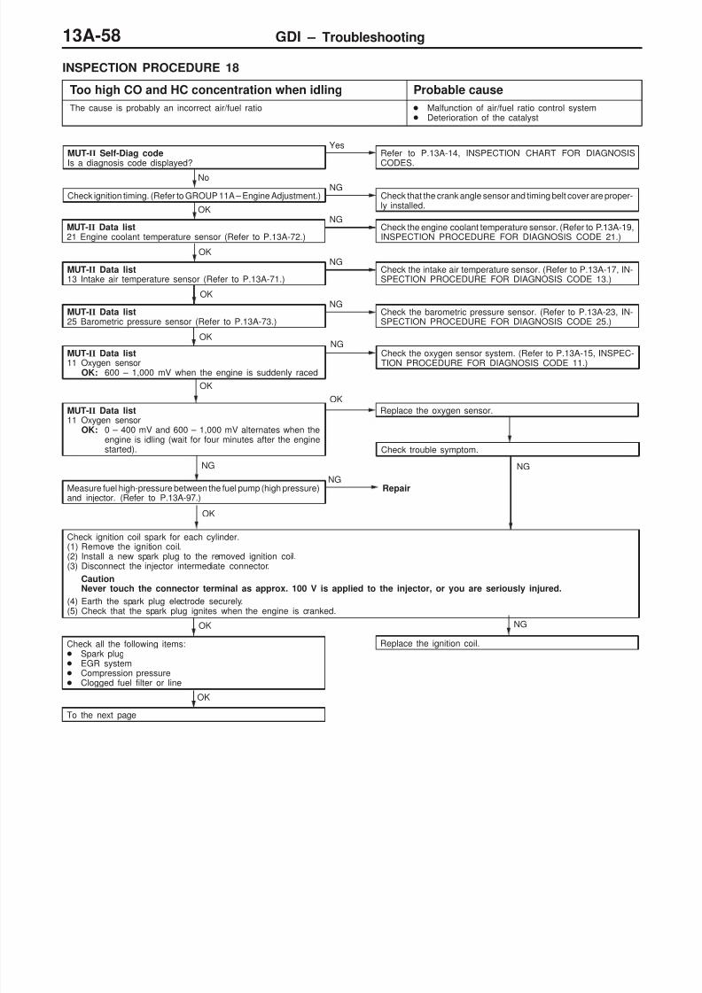
8/19/2019 13a Gasoline Direct Injection (Gdi) (1)
http://slidepdf.com/reader/full/13a-gasoline-direct-injection-gdi-1 58/269
GDI – Troubleshooting13A-58
INSPECTION PROCEDURE 18
Too high CO and HC concentration when idling Probable cause
The cause is probably an incorrect air/fuel ratio Malfunction of air/fuel ratio control system Deterioration of the catalyst
MUT-II Self-Diag codeIs a diagnosis code displayed?
YesRefer to P.13A-14, INSPECTION CHART FOR DIAGNOSISCODES.
No
Check ignition timing. (Refer to GROUP 11A – Engine Adjustment.)NG
Check that the crank angle sensor and timing belt cover are proper-ly installed.OK
MUT-II Data list21 Engine coolant temperature sensor (Refer to P.13A-72.)
NGCheck the engine coolant temperature sensor. (Refer to P.13A-19,INSPECTION PROCEDURE FOR DIAGNOSIS CODE 21.)
OK
MUT-II Data list13 Intake air temperature sensor (Refer to P.13A-71.)
NGCheck the intake air temperature sensor. (Refer to P.13A-17, IN-SPECTION PROCEDURE FOR DIAGNOSIS CODE 13.)
OK
MUT-II Data list25 Barometric pressure sensor (Refer to P.13A-73.)
NGCheck the barometric pressure sensor. (Refer to P.13A-23, IN-SPECTION PROCEDURE FOR DIAGNOSIS CODE 25.)
NG Check the oxygen sensor system. (Refer to P.13A-15, INSPEC-TION PROCEDURE FOR DIAGNOSIS CODE 11.)
OK
MUT-II Data list11 Oxygen sensor
OK: 0 – 400 mV and 600 – 1,000 mV alternates when theengine is idling (wait for four minutes after the enginestarted).
OK
Replace the oxygen sensor.
Check trouble symptom.
NGNG
Measure fuel high-pressure between the fuel pump (high pressure)and injector. (Refer to P.13A-97.)
NGRepair
OK
Check ignition coil spark for each cylinder.(1) Remove the ignition coil.(2) Install a new spark plug to the removed ignition coil.(3) Disconnect the injector intermediate connector.
CautionNever touch the connector terminal as approx. 100 V is applied to the injector, or you are seriously injured.
(4) Earth the spark plug electrode securely.(5) Check that the spark plug ignites when the engine is cranked.
NG
Replace the ignition coil.
OK
Check all the following items: Spark plug EGR system Compression pressure Clogged fuel filter or line
OK
To the next page
OK
MUT-II Data list11 Oxygen sensor
OK: 600 – 1,000 mV when the engine is suddenly raced

8/19/2019 13a Gasoline Direct Injection (Gdi) (1)
http://slidepdf.com/reader/full/13a-gasoline-direct-injection-gdi-1 59/269
GDI – Troubleshooting 13A-59
From the previous page
OK
MUT-II Data list68 EGR valve (Refer to P.13A-74.)
NGCheck the EGR valve system. (Refer to P.13A-67, INSPECTIONPROCEDURE 29.)
OK
MUT-II Actuator test08 Purge control solenoid valve (Refer to P.13A-76.)
NGCheck purge control solenoid valve system. (Refer to P.13A-68,INSPECTION PROCEDURE 30.)
OK
Check trouble symptom.NG
Replace the injector.
Check trouble symptom.
NG
Replace the three-way catalytic converter.
INSPECTION PROCEDURE 19
Low alternator output voltage (approx. 12.3 V) Probable cause
The cause is probably a malfunction of the alternator or one of the problemslisted at right.
Malfunction of the charging system Open circuit between the alternator G terminal
and the engine-ECU
Malfunction of the engine-ECU
NGRepair
OK
Check trouble symptom.OK
Check the alternator. (Refer to GROUP16 – Charging System.)
OK
Check the following connectors:A-86, C-17
Measure at the alternator connectorA-79. Connect the connector. (Use the
test harness MB991519) Voltage between 1 (black clip)
and earth(Engine: Idling)(Radiator fan: Not operating)(Headlamp: OFF → ON)(Stop lamp: OFF → ON)(Rear defogger switch: OFF →
ON)OK: Voltage increased by
0.2 – 3.5 V.
NGMeasure at the alternator connectorA-79. Disconnect the connector, and
measure at the harness side. Disconnect the engine-ECU
connector. Continuity between 1 and earth
OK: No continuity
NGCheck the harness wire betweenthe alternator and the engine-ECU,and repair if necessary.
Replace the engine-ECU.
NGCheck the harness wire betweenthe alternator and the engine-ECU.
OK
Repair
NG

8/19/2019 13a Gasoline Direct Injection (Gdi) (1)
http://slidepdf.com/reader/full/13a-gasoline-direct-injection-gdi-1 60/269
GDI – Troubleshooting13A-60
INSPECTION PROCEDURE 20
Fans (radiator fan, A/C condenser fan) are inoperative. Probable cause
The engine-ECU sends a duty signal to the fan controller according to engine coolanttemperature, vehicle speed, or A/C switch.The fan controller controls radiator fan and condenser fan speeds, based on thissignal. (The closer the terminal voltage comes to 5 V, the higher the fan speedbecomes.)
Malfunction of the fan motor relay Malfunction of the fan motor Malfunction of the fan controller Open or short circuit, or poor connector contact Malfunction of the engine-ECU
NG
Repair
NG
Repair
NG
Repair
Measure at engine-ECU connector C-17. Disconnect the connector, measure at the harness side. Voltage between terminal 18 and earth
(Ignition switch: ON)OK: 4.8 – 5.2 V (The fan runs at high speed.)
Earth terminal 21.(Ignition switch: ON)OK: The fan stops.
NGCheck the following connector: A-29
OK
Check trouble symptom.
NG
Check the harness wire between the engine-ECU and fan control-ler.
OK
Check the radiator fan and condenser fan circuit. (Refer to GROUP14 – Troubleshooting.)
OK
Check the following connector: C-17
OK
Check trouble symptom.
NG
MUT-II Data list21 Engine coolant temperature sensorOK: After the engine has been warmed up, the engine coolant
temperature during idling is identical to the MUT-II reading.
NGCheck the engine coolant temperature sensor system. (Refer toP.13A-19, INSPECTION PROCEDURE FOR DIAGNOSIS CODE21.)
OK
Check the thermostat.NG
Replace
OK
Replace the engine-ECU.

8/19/2019 13a Gasoline Direct Injection (Gdi) (1)
http://slidepdf.com/reader/full/13a-gasoline-direct-injection-gdi-1 61/269
GDI – Troubleshooting 13A-61
INSPECTION PROCEDURE 21
GDI ECO indicator lamp does not illuminate. Probable cause
If the GDI ECO indicator lamp does not illuminate after turning switch, the causeslisted in the right column are suspected.
Burned-out GDI ECO indicator lamp bulb Open circuit or short-circuited harness wire in the
GDI ECO indicator lamp circuit Malfunction of the engine-ECU Malfunction of the GDI ECO indicator lamp ECU
NG
Repair
OK
NG
NG
Repair
Measure at engine-ECU connector C-17. Disconnect the connector, and measure at the harness side. Earth terminal 14. (Ignition switch: ON)
OK: The GDI ECO indicator lamp illuminates.
OKCheck the following connector: C-17
OK
Check trouble symptom.
NG
Replace the engine-ECU.
OK
Check the relative circuits of GDI ECO indication lamp.(Refer to GROUP 54A-Troubleshooting.)
Check trouble symptom.
Check the following connectors: C-29, C-55
Check the harness wire between the GDI-ECO Indication lamp-
ECU and engine-ECU.
NG
NG
Repair
INSPECTION PROCEDURE 22
GDI ECO indicator lamp remains illuminated and does notgo off.
Probable cause
If the GDI ECO indicator lamp does not go off during high load operation, the causeslisted in the right column are suspected.
Short circuit between the GDI ECO indicator lampand engine-ECU
Malfunction of the engine-ECU Malfunction of the GDI ECO indicator lamp ECU
Measure at GDI ECO indicator lamp ECU connector C-55. Disconnect the connector, and measure at the harness side. Disconnect the engine-ECU connector. Continuity between terminal 3 and earth
OK: No continuity
NGCheck the harness wire between the GDI ECO indication lamp-ECU and engine-ECU, and repair if necessary.
OK
Replace the engine-ECU.
Check the relative circuits of GDI ECO indication lamp.(Refer to GROUP 54A-Troubleshooting.)
OK

8/19/2019 13a Gasoline Direct Injection (Gdi) (1)
http://slidepdf.com/reader/full/13a-gasoline-direct-injection-gdi-1 62/269
GDI – Troubleshooting13A-62
INSPECTION PROCEDURE 23
Engine-ECU power supply and earth circuit system Probable cause
The cause is probably a malfunction of the engine-ECU or one of the problemslisted at right.
Open circuit or short-circuited harness wire in theengine-ECU power supply circuit
Open circuit or short-circuited harness wire in theengine-ECU earth circuit
Malfunction of the engine-ECU
NG
Repair
OK
Check the ignition switch. (Refer toGROUP 54.)
(2),(3) NG
Check the harness wire between the
engine-ECU and engine control relay,and repair if necessary.
(4) NG
Check the harness wire between theengine-ECU and earth, and repair ifnecessary.
(5) NG
NGRepair
OK
Check the trouble symptoms.
NG
Check the harness wire between theengine-ECU and the battery, and repairif necessary.
NG
Repair
NG
Replace the engine-ECU.
OK
Check the trouble symptoms.
OK
Check the following connectors:B-18, C-19
Check the following connector:A-36
OK
Check the trouble symptoms.NG
Check the harness wire between theengine-ECU and ignition switch, andrepair if necessary.
Measure at the engine-ECU connectorsC-18, C-19. Disconnect the connector, and
measure at the harness side.(1) Voltage between 99 and earth
(Ignition switch: ON)OK: System voltage
(2) Voltage between 57 and earthOK: System voltage
(3) Voltage between 47, 59 andearth (Ignition switch: ON)OK: System voltage (When ter-
minal 57 is shorted toearth)
(4) Continuity between 46, 58 andearthOK: Continuity
(5) Voltage between 60 and earthOK: System voltage
(1) NGCheck the following connectors:C-72, C-74
NGRepair
INSPECTION PROCEDURE 24
Engine control relay and ignition switch-IG system Probable cause
When the ignition switch ON signal is input to the engine-ECU, theengine-ECU turns on the engine control relay.This causes system voltage to be supplied to the engine-ECU and to thesensors and actuators.
Malfunction of the ignition switch Malfunction of the engine control relay Open circuit or short-circuited harness wire of the
engine control relay circuit Malfunction of the engine-ECU
OK
Check the trouble symptoms.NG
Check the harness wire between thebattery and the engine control relay,and repair if necessary.OK
Check the engine-ECU power supplyand earth circuit system. (Refer toP.13A-62, INSPECTION PROCE-DURE 23.)
OK
Measure at the engine control relayconnector A-43X. Disconnect the connector, and
measure at the harness side. Voltage between 3, 4 and earth
OK: System voltage
NGCheck the following connector:A-36
NGRepair
Check the engine control relay. (Referto P.13A-102.)
NGReplace

8/19/2019 13a Gasoline Direct Injection (Gdi) (1)
http://slidepdf.com/reader/full/13a-gasoline-direct-injection-gdi-1 63/269
GDI – Troubleshooting 13A-63
INSPECTION PROCEDURE 25
Ignition switch-ST system <M/T> Probable cause
The ignition switch-ST outputs a HIGH signal to the engine-ECU while theengine is cranking, and the engine-ECU uses this signal to carry out functionssuch as fuel injection control during starting.
Malfunction of the ignition switch Open circuit or short-circuited harness wire
between ignition switch Malfunction of the engine-ECU
(2) NG
NGRepair
OK
Check the ignition switch. (Refer toGROUP 54.)NG
Repair
Replace the engine-ECU.
NG
OK
Check the trouble symptoms.
NG
Check the harness wire between theinhibitor switch and the ignition switchconnector.
NGRepair
OK
Check the trouble symptoms.
Check the following connector:C-27
OK
Check the following connector:C-18
Measure at the engine-ECU connectorC-18. Disconnect the connector, and
measure at the harness side.(1) Voltage between 68 and earth
(Ignition switch: START)OK: System voltage
(2) Continuity between 67 and earthOK: Continuity
(1) NG
Check the harness wire between the
engine-ECU connector (terminalNo.91) and the earth, repair if neces-sary.

8/19/2019 13a Gasoline Direct Injection (Gdi) (1)
http://slidepdf.com/reader/full/13a-gasoline-direct-injection-gdi-1 64/269
GDI – Troubleshooting13A-64
INSPECTION PROCEDURE 26
Ignition switch-ST and inhibitor switch system <A/T> Probable cause
The ignition switch-ST outputs a HIGH signal to the engine-ECU while theengine is cranking, and the engine-ECU uses this signal to carry out functionssuch as fuel injection control during starting.The inhibitor switch inputs the position of the selector lever to the engine-ECU.The engine-ECU uses this signal to carry out idle speed control.
Malfunction of the ignition switch Malfunction of the inhibitor switch Open circuit or short-circuited harness wire
between ignition switch and inhibitor switch Malfunction of the engine-ECU
OK
Check the trouble symptoms.
(2) NG
NG
Repair
OK
Check the trouble symptoms.NG
Check the harness wire between theinhibitor switch connector and the start-er S terminal, and repair if necessary.
(3) NG
NGRepair
OK
Check the ignition switch. (Refer toGROUP 54.)
NG
Repair
NG
Repair
OK
Replace the engine-ECU.
NG
Check the harness wire between theengine-ECU and the inhibitor switch.
OK
Check the trouble symptoms.
NG
Check the harness wire between theinhibitor switch and the ignition switchconnector.
NGRepair
OK
Check the trouble symptoms.
Check the following connector:C-39, D-02
OK
Check the following connector:B-04
Check the following connectors:A-83, B-01
OK
Measure at the inhibitor switch connec-tor B-04. Disconnect the connector, and
measure at the harness side.(1) Voltage between 4 and earth
(Ignition switch: ON)OK: System voltage
(2) Continuity between 1 and earthOK: Continuity
(3) Voltage between 4 and earth(Ignition switch: START)Disconnect the engine-ECUconnector.OK: System voltage
(1) NGCheck the following connectors:C-18, C-24, D-02
NGRepair
Check the inhibitor switch (Refer toGROUP 23 – On-vehicle Service.)
NGReplace
Check the harness wire betweenthe engine-ECU and the inhibitorswitch connector.
NG
OK NG
Replace the engine-ECU.
Repair

8/19/2019 13a Gasoline Direct Injection (Gdi) (1)
http://slidepdf.com/reader/full/13a-gasoline-direct-injection-gdi-1 65/269
GDI – Troubleshooting 13A-65
INSPECTION PROCEDURE 27
Accelerator pedal position switch system Probable cause
The accelerator pedal position switch detects that the accelerator pedal is fully closed,and sends a signal to the engine-ECU. The engine-ECU controls idle speed, basedon this signal.
Maladjustment of the accelerator cable Maladjustment of the accelerator pedal position switch Open circuit or short-circuited harness wire in the
accelerator pedal position switch system, or poorconnector contact
Malfunction of the engine-ECU
NG
Repair
NG
Repair
Check the accelerator pedal position switch. (Refer to P.13A-105.)NG
Replace the accelerator pedal position sensor assembly.
OK
Measure at accelerator pedal position sensor (1st channel) connec-tor C-46. Disconnect the connector, and measure at the harness side. Voltage between terminal 4 and earth
(Ignition switch: ON)OK: 4 V or more
Continuity between terminal 1 and earthOK: Continuity
NGCheck the following connectors: C-18, C-19
OK
Check trouble symptom.
NG
Check the harness wire between the engine-ECU and acceleratorpedal position sensor 1 (1st channel).
OK
Check the following connector: C-46NG
Repair
OK
Check trouble symptom.NG
Replace the engine-ECU.
OK
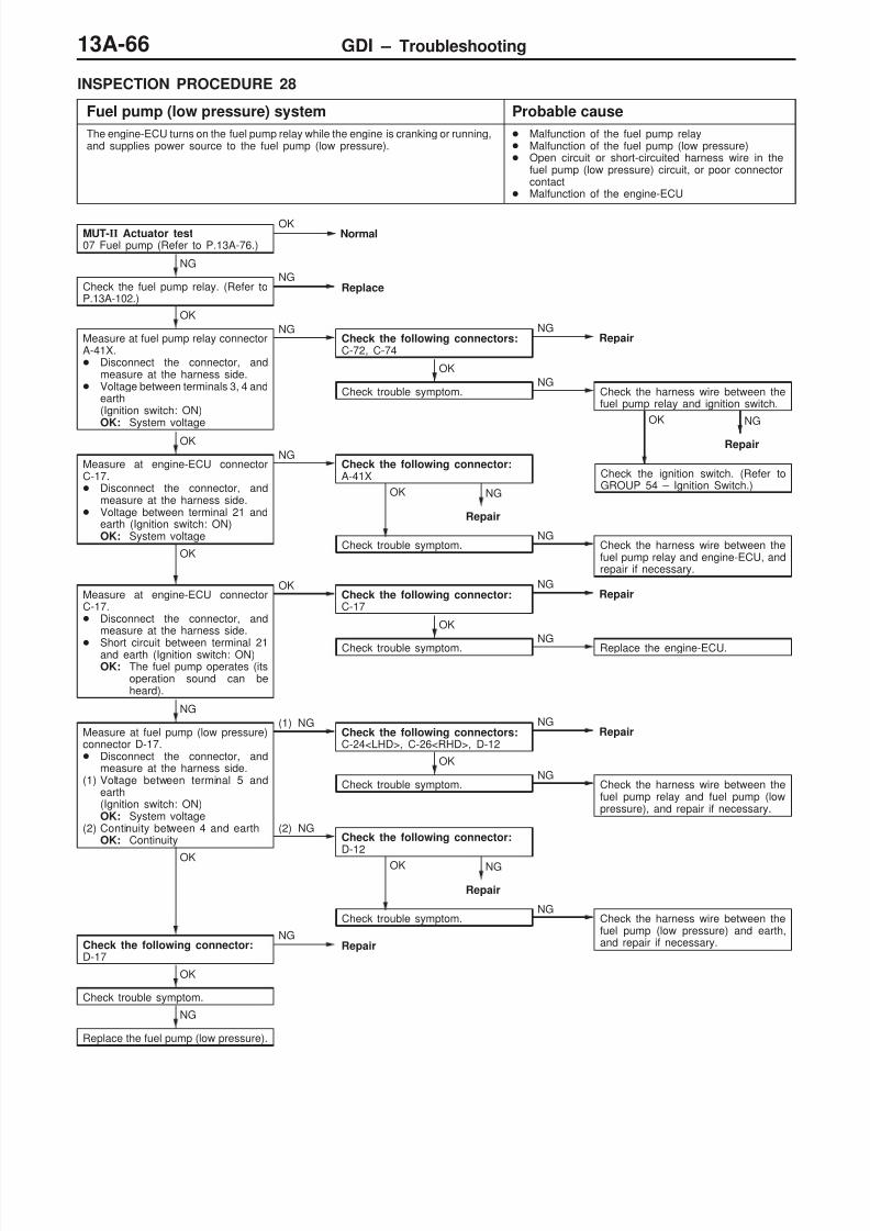
8/19/2019 13a Gasoline Direct Injection (Gdi) (1)
http://slidepdf.com/reader/full/13a-gasoline-direct-injection-gdi-1 66/269
GDI – Troubleshooting13A-66
INSPECTION PROCEDURE 28
Fuel pump (low pressure) system Probable cause
The engine-ECU turns on the fuel pump relay while the engine is cranking or running,and supplies power source to the fuel pump (low pressure).
Malfunction of the fuel pump relay Malfunction of the fuel pump (low pressure) Open circuit or short-circuited harness wire in the
fuel pump (low pressure) circuit, or poor connectorcontact
Malfunction of the engine-ECU
Check trouble symptom.NG
Check the harness wire between thefuel pump (low pressure) and earth,and repair if necessary.
NG
Repair
OK
Check trouble symptom.NG
Check the harness wire between thefuel pump relay and engine-ECU, andrepair if necessary.
NG
Repair
OK
NG
Repair
OK
Check the ignition switch. (Refer toGROUP 54 – Ignition Switch.)
(2) NGCheck the following connector:D-12
MUT-II Actuator test07 Fuel pump (Refer to P.13A-76.)
OKNormal
NG
Check the fuel pump relay. (Refer toP.13A-102.)
NGReplace
OK
Measure at fuel pump relay connectorA-41X. Disconnect the connector, and
measure at the harness side. Voltage between terminals 3, 4 and
earth(Ignition switch: ON)OK: System voltage
NGCheck the following connectors:C-72, C-74
NGRepair
OK
Check trouble symptom.NG
Check the harness wire between thefuel pump relay and ignition switch.
OK
Measure at engine-ECU connectorC-17. Disconnect the connector, and
measure at the harness side. Voltage between terminal 21 and
earth (Ignition switch: ON)OK: System voltage
NGCheck the following connector:A-41X
OK
Measure at engine-ECU connectorC-17. Disconnect the connector, and
measure at the harness side.
Short circuit between terminal 21and earth (Ignition switch: ON)OK: The fuel pump operates (its
operation sound can beheard).
OKCheck the following connector:C-17
NGRepair
OK
Check trouble symptom.NG
Replace the engine-ECU.
NG
Measure at fuel pump (low pressure)connector D-17. Disconnect the connector, and
measure at the harness side.(1) Voltage between terminal 5 and
earth(Ignition switch: ON)OK: System voltage
(2) Continuity between 4 and earthOK: Continuity
(1) NGCheck the following connectors:C-24<LHD>, C-26<RHD>, D-12
NGRepair
OK
Check trouble symptom.NG
Check the harness wire between thefuel pump relay and fuel pump (lowpressure), and repair if necessary.
OK
Check the following connector:D-17
NGRepair
OK
Check trouble symptom.
NG
Replace the fuel pump (low pressure).

8/19/2019 13a Gasoline Direct Injection (Gdi) (1)
http://slidepdf.com/reader/full/13a-gasoline-direct-injection-gdi-1 67/269

8/19/2019 13a Gasoline Direct Injection (Gdi) (1)
http://slidepdf.com/reader/full/13a-gasoline-direct-injection-gdi-1 68/269
GDI – Troubleshooting13A-68
INSPECTION PROCEDURE 30
Purge control solenoid valve system Probable cause
The engine-ECU controls the purge control solenoid valve in order to controlthe purge air coming from the canister.
Malfunction of the purge control solenoid valve Open circuit or short-circuited harness wire in the
purge control solenoid valve circuit Malfunction of the engine-ECU
OK
Check the trouble symptoms.NG
Check the harness wire between theengine-ECU and the purge control sole-noid valve, and repair if necessary.
OK
Check the trouble symptoms.NG
Replace the engine-ECU.
OK
Check the following connector:C-17
NGRepair
OK
Measure at the engine-ECU connectorC-17. Disconnect the connector, and
measure at the harness side. Voltage between 16 and earth(Ignition switch: ON)OK: System voltage
NGCheck the following connector:A-02
NGRepair
OK
Measure at the purge control solenoidvalve connector A-02. Disconnect the connector, and
measure at the harness side. Voltage between 2 and earth
(Ignition switch: ON)OK: System voltage
NG
Check the purge control solenoid valve.(Refer to GROUP 17 – On-vehicle Ser-vice.)
NG
OK
Check the trouble symptoms.NG
Check the harness wire between theengine control relay and the purgecontrol solenoid valve, and repair ifnecessary.
Check the following connector:A-36
NGRepair
Replace

8/19/2019 13a Gasoline Direct Injection (Gdi) (1)
http://slidepdf.com/reader/full/13a-gasoline-direct-injection-gdi-1 69/269
GDI – Troubleshooting 13A-69
INSPECTION PROCEDURE 31
Power steering fluid pressure switch system Probable cause
The power steering fluid pressure switch sends a signal to the engine-ECU accordingto power steering load.Based on this signal, the engine-ECU controls the throttle control servo so thatidle speed increases when the power steering is in operation.
Malfunction of the power steering fluid pressure switch Open circuit or short-circuited harness wire in the
power steering fluid pressure switch circuit, or poorconnector contact
Malfunction of the engine-ECU
NG
NG
Repair
OK
Replace the engine-ECU.
NG
Repair
Check the power steering fluid pressure switch. (Refer to GROUP37A – On-vehicle Service.)
NGReplace
OK
Measure at power steering fluid pressure switch connector A-76. Disconnect the connector, and measure at the harness side. Voltage between terminal 1 and earth
(Ignition switch: ON)OK: System voltage
NGCheck the following connector: C-18
OK
Check trouble symptom.
Check the harness wire between the engine-ECU and power steer-ing fluid pressure switch.
NG
Repair
OK
OK
Check the following connector: A-76
Check trouble symptom.NG
INSPECTION PROCEDURE 32
A/C switch and A/C relay system Probable cause
If the engine-ECU receives a ‘A/C on’ signal, it operates the throttle control servoand A/C compressor magnetic clutch so that idle speed increases.
Malfunction of the A/C control system Malfunction of the A/C switch Open circuit or short-circuited harness wire in the
A/C switch circuit, or poor connector contact Malfunction of the engine-ECU
NG
NG
Repair
OK
Check trouble symptom.
NG
Replace the engine-ECU.
Service the A/C compressor relay. (Refer to GROUP 55 – On-ve-hicle Service.)
NGReplace
OK
Measure at engine-ECU connectors C-17, C-19. Disconnect the connector, and measure at the harness side. Voltage between terminals 20, 83 and earth
(Ignition switch: ON)OK: 0 – 3 V
(A/C switch: OFF)System voltage(A/C switch: ON)
Connect terminal 20 to earth.(Ignition switch: ON, A/C switch: ON)OK: A/C compressor clutch turns on.
OKCheck the following connectors: C-17, C-19
Check the A/C system. (Refer to GROUP 55 – On-vehicle Service.)

8/19/2019 13a Gasoline Direct Injection (Gdi) (1)
http://slidepdf.com/reader/full/13a-gasoline-direct-injection-gdi-1 70/269
GDI – Troubleshooting13A-70
INSPECTION PROCEDURE 33
Stop lamp switch system Probable cause
The engine-ECU determines whether the brake pedal is depressed or not, by meansof the stop lamp switch input signal.
Malfunction of the stop lamp switch Open circuit or short-circuited harness wire in the
stop lamp circuit, or poor connector contact Malfunction of the engine-ECU
NG
NG
NG
Repair
Check the stop lamp switch. (Refer to GROUP 35 – Brake Pedal.)
NG
Replace
OK
Measure at stop lamp switch connector C-04. Disconnect the connector, and measure at the harness side. Voltage between terminal 2 and earth
OK: System voltage
NGCheck the following connector: C-29
OK
Check trouble symptom.
Check the harness wire between the battery and stop lamp switch.
NG
Repair
OK
Measure at engine-ECU connector C-18. Disconnect the connector, and measure at the harness side. Voltage between terminal 63 and earth
(Ignition switch: ON)OK: 0 – 3 V (when the brake pedal is not depressed)
System voltage (when the brake pedal is depressed)
NGCheck the following connectors: C-02, C-04, C-28
OK
Check trouble symptom.
Check the harness wire between the engine-ECU and stop lamp,and repair if necessary.
OK
Check the following connector: C-18NG
Repair
OK
Check trouble symptom.
NG
Replace the engine-ECU.
INSPECTION PROCEDURE 34
Small lamp switch Probable cause
The engine-ECU determines whether the small lamp switch is on or off.According to that information, the engine-ECU controlsalternator output current when the vehicle is started.
Improper connector contact, open circuit orshort-circuited harness wire in the taillamp relaycircuit
Malfunction of the engine-ECU
NGReplace the engine-ECU.
OK
Check the trouble symptoms.
OK
Check the following connector: C-19NG
Repair
Measure at the engine-ECU connector C-19. Disconnect the connector, and measure at the harness
side. Voltage between 88 and earth
(Lighting switch: ON)OK: System voltage
NGCheck the taillamp relay circuit. (Refer to ELECTRICAL WIRING.)

8/19/2019 13a Gasoline Direct Injection (Gdi) (1)
http://slidepdf.com/reader/full/13a-gasoline-direct-injection-gdi-1 71/269
GDI – Troubleshooting 13A-71
DATA LIST REFERENCE TABLE
CautionWhen shifting the select lever to D range, the brakes should be applied so that the vehicle doesnot move forward.
NOTE*1: Within four minutes after starting the engine*2: In a new vehicle [driven approximately 500 km or less], the injector drive time is sometimes 10% longer
than the standard time.*3: The accelerator pedal position switch normally turns off when the voltage of the accelerator pedal
position sensor (1st channel) is 250 – 550 mV higher than the voltage at the idle position. If the acceleratorpedal position switch turns back on after the accelerator pedal position sensor voltage has risen by100 mV and the throttle valve has opened, the accelerator pedal position switch and the acceleratorpedal position sensor (1st channel) need to be adjusted.
ItemNo.
Check items Requirements Normal condition InspectionprocedureNo.
Refer-encepage
11 Oxygen sensor Engine: After warm-p
Idling 0 mV*1 Code 13A-15up
Sudden racing 600 – 1,000 mVo.
2,500 r/min 400 mV or less ↔600 – 1,000 mV(alternates)
12 Air flow sensor Engine coolanttemperature: 80
–
Idling 20 – 55 Hz CodeNo.12
13A-16
– Lamps, electric
cooling fan and2,500 r/min 65 – 85 Hz
a accessor es:OFF
Transmission:Neutral (A/T: Prange)
Racing Frequency in-creases in re-sponse to racing.
13 Intake air tem-perature sen-
Ignition switch: ON Intake air tempera-ture: –20C
–20C CodeNo.13
13A-17
sorIntake air tempera-ture: 0C
0C
Intake air tempera-ture: 20C
20C
Intake air tempera-ture: 40C
40C
Intake air tempera-
ture: 80C
80C

8/19/2019 13a Gasoline Direct Injection (Gdi) (1)
http://slidepdf.com/reader/full/13a-gasoline-direct-injection-gdi-1 72/269
GDI – Troubleshooting13A-72
ItemNo.
Refer-encepage
InspectionprocedureNo.
Normal conditionRequirementsCheck items
14 Throttle posi-tion sensor
Engine coolanttemperature: 80
–
Release the accel-erator pedal.
4,000 – 4,800 mV CodeNo.14
13A-18
n c anne – Ignition switch:
ON (Enginestopped)
Depress the accel-
erator pedal gradu-ally.
Voltage decreases
in response to thepedal depression.
Depress the accel-erator pedal fully.
100 – 1,100 mV
16 Power supplyvoltage
Ignition switch: ON System voltage ProcedureNo.23
13A-62
18 Cranking sig-nal (Ignitionswitch – ST)
Transmission: Neu-tral (A/T: P range)
Engine: Stopped OFF ProcedureNo.25<M/T>
13A-63<M/T>
13A-64
Engine: Cranking ON ProcedureNo.26<A/T>
<A/T>
21 Engine coolanttemperature
Ignition switch: ON Engine coolant tem-perature: –20C
–20C CodeNo.21
13A-19
sensorEngine coolant tem-perature: 0C
0C
Engine coolant tem-perature: 20C
20C
Engine coolant tem-perature: 40C
40C
Engine coolant tem-
perature: 80C
80C
22 Crank anglesensor
Engine: crank-ing
Tachometer:Connected
Compare the enginespeed readings onthe tachometer andthe MUT-II.
Accord CodeNo.22
13A-20
Engine: Idling Accelerator
p p
Engine coolant tem-perature: –20C
1,200 – 1,400 r/min
pe a pos onswitch: ON
Transmission:Engine coolant tem-perature: 0C
1,100 – 1,300 r/min
eu ra :range) Engine coolant tem-
perature: 20C1,000 – 1,200 r/min
Engine coolant tem-perature: 50C
750 – 950 r/min
Engine coolant tem-perature: 80C
550 – 850 r/min*1

8/19/2019 13a Gasoline Direct Injection (Gdi) (1)
http://slidepdf.com/reader/full/13a-gasoline-direct-injection-gdi-1 73/269
GDI – Troubleshooting 13A-73
ItemNo.
Refer-encepage
InspectionprocedureNo.
Normal conditionRequirementsCheck items
25 Barometricp -
Ignition switch: ON Altitude: 0 m 101 kPa Code 13A-23pressure sen-sor Altitude: 600 m 95 kPa
o.
Altitude: 1,200 m 88 kPaAltitude: 1,800 m 81 kPa
26 Acceleratorpedal position
Ignition switch: ON(Depress and re-
-
Release the accel-erator pedal.
ON ProcedureNo.27
13A-65
sw c ease e acce era-tor pedal severaltimes)
Depress the accel-erator pedal slightly.
OFF
27 Power steeringfluid pressure
Engine: Idling Steering wheel sta-tionary
OFF ProcedureNo.31
13A-69
sw cSteering wheelturning
ON
28 A/C switch Engine: Idling (TheA/C compressor is
A/C switch: OFF OFF ProcedureNo.32
13A-69
running when theA/C switch is on.)
A/C switch: ON ON
29 Inhibitor switch<A/T>
Ignition switch: ON Selector lever: P orN
P, N ProcedureNo.26
13A-64
Selector lever: D, 2,L or R
D, 2, L, R
31 Small lampswitch
Engine: Idling Lighting switch:OFF
OFF ProcedureNo.34
13A-70
Lighting switch: ON ON
34 Air flow sensor Engine: After hav-p
Engine is idling ON Code 13A-16rese s gna ng warme up
3,000 r/min OFFo.
37 Volumetric effi-ciency
Engine coolanttemperature: 80
–
Engine is idling 30 – 50% – –
– Lamps, electric
cooling fan and2,500 r/min 30 – 50%
a accessor es:OFF
Transmission:
Neutral(A/T: P range)
Engine is suddenlyraced
Volumetric effi-ciency increases in
response to racing
38 Crank anglesensor
Engine: Cranking [reading is possibleat 2,000 r/min or less]
Tachometer: Connected
Engine speeds dis-played on theMUT-II andtachometer areidentical.
– –

8/19/2019 13a Gasoline Direct Injection (Gdi) (1)
http://slidepdf.com/reader/full/13a-gasoline-direct-injection-gdi-1 74/269
GDI – Troubleshooting13A-74
ItemNo.
Refer-encepage
InspectionprocedureNo.
Normal conditionRequirementsCheck items
41 Injector drivetime *2
Engine coolanttemperature: 80
– 95C
Idling 0.5 – 0.7 ms*1 CodeNo.41
13A-25
Lamps, electric
cooling fan andall accessories:OFF
2,500 r/min 0.4 – 0.8 ms
Transmission:Neutral (A/T: Prange)
Sudden racing Increases
44 Ignitionadvance
Engine: Afterwarm-up
Idling 12 – 20BTDC *2 CodeNo.44
13A-27
Set a timinglight.
2,500 r/min 20 – 40BTDC
49 A/C relay Engine: After warm-up, idling
A/C switch: OFF OFF (compressorclutch is not oper-ating)
ProcedureNo.32
13A-69
A/C switch: ON ON (compressorclutch is operating)
66 Brake vacuumsensor
Engine coolanttemperature: 80
– 95C Lamps, electric
cooling fan andall accessories:OFF
Transmission:Neutral(A/T: P range)
Stop the enginefrom idling speed,and then depressthe brake pedalseveral times withthe ignition switchon.
Displayed pres-sure increases.
CodeNo.66
13A-32
67 Stop lampswitch
Ignition switch: ON Brake pedal:Depressed
OFF ProcedureNo.33
13A-70
Brake pedal:Released
ON
68 EGR valve Engine coolanttemperature: 80
– 95C Lamps, electric
cooling fan and
Idling 0 – 15 STEP ProcedureNo.29
13A-67
all accessories:OFF
Transmission:
Neutral(A/T: P range)
2,500 r/min 0 – 10 STEP

8/19/2019 13a Gasoline Direct Injection (Gdi) (1)
http://slidepdf.com/reader/full/13a-gasoline-direct-injection-gdi-1 75/269
GDI – Troubleshooting 13A-75
ItemNo.
Refer-encepage
InspectionprocedureNo.
Normal conditionRequirementsCheck items
74 Fuel pressuresensor
Engine coolanttemperature: 80
– 95C Lamps, electric
cooling fan andall accessories:OFF
Transmission:Neutral(A/T: P range)
After 3 minuteshave passed atidling condition
4 – 6.9 MPa CodeNo.56
13A-29
77 Acceleratorpedal position
Ignition switch: ON Release the accel-erator pedal.
700 – 1,400 mV CodeNo.77
13A-33
sensor nchannel) Depress the accel-
erator pedal gradu-ally.
Increases in re-sponse to the ped-al depressionstroke.
Depress the accel-erator pedal fully.
4,100 mV or more
78 Acceleratorpedal position
Ignition switch: ON Release the accel-erator pedal.
935 – 1,135 mV CodeNo.78
13A-34
sensor(1st channel)*3 Depress the accel-
erator pedal gradu-ally.
Increases in re-sponse to pedaldepression stroke.
Depress the accel-erator pedal fully.
4,100 mV or more
79 Throttle posi-
tion sensor (1st
Engine coolant
temperature: 80 –
Release the accel-
erator pedal.
450 – 800 mV Code
No.79
13A-35
c anne – Ignition switch:
ON (Enginestopped)
Depress the accel-erator pedal gradu-ally.
Increases in re-sponse to pedaldepression stroke.
Depress the accel-erator pedal fully.
3,900 – 4,900 mV
Engine: After warm-p
No load 450 – 1,000 mVup, ng
A/C switch: OFF →ON
Increases by 100 – 600 mV.
Selector lever: N →
D range
Increases by 0 –
200 mV.
99 Fuel injectionmode
Engine: After warmup
Idling (for severalminutes after en-gine start)
Lean compression – –
2,500 r/min Stoichio metricfeedback
Sudden racing afteridle position
Open loop

8/19/2019 13a Gasoline Direct Injection (Gdi) (1)
http://slidepdf.com/reader/full/13a-gasoline-direct-injection-gdi-1 76/269

8/19/2019 13a Gasoline Direct Injection (Gdi) (1)
http://slidepdf.com/reader/full/13a-gasoline-direct-injection-gdi-1 77/269
GDI – TroubleshootingGDI – Troubleshooting 13A-77
CHECK AT THE ENGINE-ECU TERMINALS
TERMINAL VOLTAGE CHECK CHART
Engine-ECU Connector Terminal Arrangement
TerminalNo.
Check item Check requirements (engine condition) Normal condition
1 No.1 injector Engine: Warm up, and then depress thep p
Decreases slightly for –
9 No.2 injectoracce era or pe a su en y rom e e spee . s or me rom – .
24 No.3 injector
2 No.4 injector
3 No.1 ignition coil Engine: 3,000 r/min 0.1 – 2.0 V
13 No.2 ignition coil
12 No.3 ignition coil
4 No.4 ignition coil
6 EGR valve (C) Ignition switch: Immediately after turning ON 5 – 8 V (fluctuates forpp
5 EGR valve (D)approx. ree secon s
34 EGR valve (A)
32 EGR valve (B)
8 Alternator G terminal Engine: Warm up, and then idling Radiator fan: not operating Headlamp: OFF → ON Stop lamp: OFF → ON Rear defogger switch: OFF → ON
Voltage increases by0.2 – 3.5 V
14 GDI ECO indicatorp
Engine: idling 0 – 3 Vamp
Engine: Depress the accelerator pedal suddenlyfrom the idle speed.
System voltage
16 Purge control solenoid Engine coolant tem-
p
Engine: stopped System voltage
va ve pera ure:80 – 95°C Ignition switch:
ON
Engine: Start theengine, and thenincrease engine speedup to 3,500 r/min.
Voltage decreases.
18 Fan controller Radiator and condenser fans are not operating. 0 – 0.3 V
Radiator and condenser fans are operating. 0.7 V or more
20 A/C relay Engine: idling A/C switch: OFF → ON
(Compressor is operating)
System voltage, orchanges from momentari-ly 6 V or more to 0 – 3 V

8/19/2019 13a Gasoline Direct Injection (Gdi) (1)
http://slidepdf.com/reader/full/13a-gasoline-direct-injection-gdi-1 78/269
GDI – Troubleshooting13A-78
TerminalNo.
Normal conditionCheck requirements (engine condition)Check item
21 Fuel pump relay Ignition switch: ON Engine: stopped System voltage
Engine: Idling 0 – 3 V
31 Engine warning lamp Ignition switch: OFF → ON 0 – 3 V → System
voltage (after severalseconds)
41 Sensor power supply Ignition switch: ON 4.5 – 5.5 V
42 Power supply toaccelerator pedalposition sensor
Ignition switch: ON 4.5 – 5.5 V
43 Crank angle sensor Engine: Cranking 0.4 – 4.0 V
Engine: Idling 1.5 – 2.5 V
44 Engine coolanttemperature sensor
Ignition switch: ON Engine coolanttemperature: 0C
3.2 – 3.8 V
Engine coolanttemperature: 20C
2.3 – 2.9 V
Engine coolanttemperature: 40C
1.3 – 1.9 V
Engine coolanttemperature: 80C
0.3 – 0.9 V
45 Tachometer output Engine: 3,000 r/min 2.0 – 9.0 V
47 Power supply Ignition switch: ON System voltage
59
50 Camshaft position Engine: Cranking 0.3 – 3.0 Vsensor
Engine: Idling 0.5 – 3.5 V
51 Barometric pressure Ignition switch: ON Altitude: 0 m 3.7 – 4.3 Vsensor
Altitude: 1,200 m 3.2 – 3.8 V
52 Alternator FR terminal Engine: Warm up, and then idling Radiator fan: not operating Headlamp: OFF → ON Stop lamp: OFF → ON Rear defogger switch: OFF → ON
Voltage decrease
54 Power steering fluidpressure switch
Engine: Warm up, andthen idling
Steering wheelstationary
System voltage
Steering wheel turning 0 – 3 V
55 Injector driver relay Ignition switch: OFF 0 – 0.1 V
Ignition switch: ON 0.5 – 1.0 V
56 Throttle valve control Ignition switch: OFF 0 – 0.3 Vservo re ay
Ignition switch: ON 0.5 – 1.0 V

8/19/2019 13a Gasoline Direct Injection (Gdi) (1)
http://slidepdf.com/reader/full/13a-gasoline-direct-injection-gdi-1 79/269
GDI – Troubleshooting 13A-79
TerminalNo.
Normal conditionCheck requirements (engine condition)Check item
57 Engine control relay Ignition switch: OFF System voltage
Ignition switch: ON 0 – 3 V
60 Back-up power source Ignition switch: OFF System voltage
61 Air flow sensor Engine: Idling 2.2 – 3.2 V
Engine: 2,500 r/min
62 Intake air temperaturesensor
Ignition switch: ON Intake air temperature:0C
3.2 – 3.8 V
Intake air temperature:20C
2.3 – 2.9 V
Intake air temperature:40C
1.5 – 2.1 V
Intake air temperature:
80C
0.4 – 1.0 V
63 Stop lamp switch Depress the brake pedal. System voltage
Release the brake pedal. 0 – 3 V
67 Inhibitor switch <A/T> Ignition switch: ON Selector lever: P or Nrange
0 – 3 V
Selector lever: Otherthan P or N range
8 – 14 V
68 Ignition switch – ST Engine: Cranking 8 V or more
71 Oxygen sensor Engine: Warm up, and then hold the engine
speed at 2,500 r/min (Use a digital voltmeter).
0 V↔ 0.8 V alternates
74 Brake vacuum sensor Engine: Stop the engine from idle speed, turnthe ignition switch ON, and then depress thebrake pedal several times.
Voltage increases
76 Air flow sensor reset Engine: Idling 0 – 1 Vs gna
Engine: 3,000 r/min 6 – 9 V
78 Throttle positionsensor (2nd channel)
Ignition switch: ON Release the accelera-tor pedal.
4.0 – 4.8 V
Depress the accelera-
tor pedal fully.
0.1 – 1.1 V
79 Accelerator pedalposition switch
Ignition switch: ON Release the accelera-tor pedal.
0 – 1 V
Depress the accelera-tor pedal slightly.
4 V or more
80 Vehicle speed sensor Ignition switch: ON Move the vehicle forward.
0 V↔ Battery voltage(alternates repeatedly)
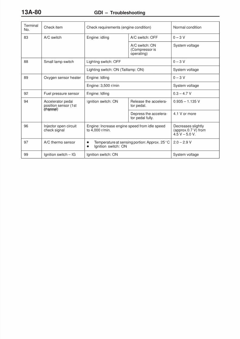
8/19/2019 13a Gasoline Direct Injection (Gdi) (1)
http://slidepdf.com/reader/full/13a-gasoline-direct-injection-gdi-1 80/269
GDI – Troubleshooting13A-80
TerminalNo.
Normal conditionCheck requirements (engine condition)Check item
83 A/C switch Engine: idling A/C switch: OFF 0 – 3 V
A/C switch: ON(Compressor isoperating)
System voltage
88 Small lamp switch Lighting switch: OFF 0 – 3 V
Lighting switch: ON (Taillamp: ON) System voltage
89 Oxygen sensor heater Engine: Idling 0 – 3 V
Engine: 3,500 r/min System voltage
92 Fuel pressure sensor Engine: Idling 0.3 – 4.7 V
94 Accelerator pedalposition sensor (1st
Ignition switch: ON Release the accelera-tor pedal.
0.935 – 1.135 V
c anneDepress the accelera-
tor pedal fully.
4.1 V or more
96 Injector open circuitcheck signal
Engine: Increase engine speed from idle speedto 4,000 r/min.
Decreases slightly(approx.0.7 V) from4.5 V – 5.0 V.
97 A/C thermo sensor Temperature at sensing portion: Approx. 25C Ignition switch: ON
2.0 – 2.9 V
99 Ignition switch – IG Ignition switch: ON System voltage

8/19/2019 13a Gasoline Direct Injection (Gdi) (1)
http://slidepdf.com/reader/full/13a-gasoline-direct-injection-gdi-1 81/269
GDI – Troubleshooting 13A-81
CHECK CHART FOR RESISTANCE AND CONTINUITYBETWEEN TERMINALS
1. Turn the ignition switch to OFF.2. Disconnect the engine-ECU connector.3. Measure the resistance and check for continuity between
the terminals of the engine-ECU harness-side connectorwhile referring to the check chart.
NOTE(1) When measuring resistance and checking continuity,a harness for checking contact pin pressure shouldbe used instead of inserting a test probe.
(2) Checking need not be carried out in the order givenin the chart.
CautionIf the terminals that should be checked are mistaken,or if connector terminals are not correctly shortedto earth, damage may be caused to the vehicle wiring,sensors, engine-ECU and/or ohmmeter.Be careful to prevent this!
4. If the ohmmeter shows any deviation from the standardvalue, check the corresponding sensor, actuator andrelated electrical wiring, and then repair or replace.
5. After repair or replacement, recheck with the ohmmeterto confirm that the repair or replacement has correctedthe problem.

8/19/2019 13a Gasoline Direct Injection (Gdi) (1)
http://slidepdf.com/reader/full/13a-gasoline-direct-injection-gdi-1 82/269
GDI – Troubleshooting13A-82
Engine-ECU Harness Side Connector Terminal Arrangement
Terminal No. Check item Standard value, normal condition (check requirements)
6 – 47 EGR valve (C) 15 – 20 Ω (at 20C)
5 – 47 EGR valve (D)
34 – 47 EGR valve (A)
32 – 47 EGR valve (B)
16 – 47 Purge control solenoid valve 36 – 44 Ω (at 20C)
44 – 72 Engine coolant temperature sensor 5.1 – 6.5 kΩ (when engine coolant temperature is 0C)
2.1 – 2.7 kΩ (when engine coolant temperature is 20C)
0.9 – 1.3 kΩ (when engine coolant temperature is 40C)
0.26 – 0.36 kΩ (when engine coolant temperature is80C)
46 – Body earth Earth Continuity (0 Ω)
58 – Body earth
62 – 72 Intake air temperature sensor 5.3 – 6.7 kΩ (when intake air temperature is 0C)
2.3 – 3.0 kΩ (when intake air temperature is 20C)
1.0 – 1.5 kΩ (when intake air temperature is 40C)
0.30 – 0.42 kΩ (when intake air temperature is 80C)
67 – Body earth Inhibitor switch <A/T> Continuity (when the selector lever is at P or N range)
No continuity (when the selector lever is at a range otherthan P or N)
79 – 72 Accelerator pedal position switch Continuity (when the accelerator pedal is released)No continuity (when the accelerator pedal is slightlydepressed)
89 – 47 Oxygen sensor heater control 11 – 18 Ω (at 20C)

8/19/2019 13a Gasoline Direct Injection (Gdi) (1)
http://slidepdf.com/reader/full/13a-gasoline-direct-injection-gdi-1 83/269
GDI – Troubleshooting 13A-83
CHECK AT THE THROTTLE VALVE CONTROLLER TERMINALS
TERMINAL VOLTAGE CHECK CHART
Throttle Valve Controller Terminal Arrangement
TerminalNo.
Check items Requirements Normal value
1 Throttle valve control servo(A+)
Ignition switch: ON Accelerator pedal: Fully opened →
Decreases slightly fromsystem voltage.
9 Throttle valve control servo(B+)
u y c ose
14 Throttle valve control servo(A–)
Ignition switch: ON Accelerator pedal: Fully closed →
p
Decreases slightly (approx.2 V) from system voltage.
15 Throttle valve control servo(B–)
u y opene
2 Power supply to throttlevalve control servo
Ignition switch: ON System voltage
5 Power supply Ignition switch: ON System voltage
6 Sensor voltage Ignition switch: ON 4.5 – 5.5 V
7 Throttle position sensor (1stchannel)
Ignition switch:ON
Release theaccelerator pedal.
0.45 – 0.8 V
Depress theaccelerator pedalfully.
3.9 – 4.9 V
20 Accelerator pedal positionsensor (2nd channel)
Ignition switch:ON
Release theaccelerator pedal.
0.7 – 1.4 V
Depress theaccelerator pedalfully.
4 V or more
22 Ignition switch – IG Ignition switch: ON System voltage

8/19/2019 13a Gasoline Direct Injection (Gdi) (1)
http://slidepdf.com/reader/full/13a-gasoline-direct-injection-gdi-1 84/269
GDI – Troubleshooting13A-84
INSPECTION PROCEDURE USING AN ANALYZER
AIR FLOW SENSOR (AFS)
Measurement Method
1. Disconnect the air flow sensor connector, and connectthe special tool (test harness: MB991709) in between.(All terminals should be connected.)
2. Connect the analyzer special patterns pickup to air flow
sensor connector terminal 3.
Alternate Method (Test harness not available)
1. Connect the analyzer special patterns pickup toengine-ECU terminal 61.
Standard Wave Pattern
Observation conditions
Function Special patterns
Pattern height Low
Pattern selector Display
Engine r/min Idle speed
Standard wave pattern
(V)
10
0
The time (cycle time) T is reduced whenthe amount of intake air increases.
Times T1 and T2 are equal.
Time
T
T1 T2
Observation conditions (from conditions above engine speed is increased by racing.)
Time
(V)
10
0
T
Wave Pattern Observation Points
Check that cycle time T becomes shorter and the frequency increases when the engine speed is increased.
Analyzer
Specialpatternspickup

8/19/2019 13a Gasoline Direct Injection (Gdi) (1)
http://slidepdf.com/reader/full/13a-gasoline-direct-injection-gdi-1 85/269
GDI – Troubleshooting 13A-85
Examples of Abnormal Wave Patterns
Example 1
Cause of problem
Sensor interface malfunction
Wave pattern characteristics
Rectangular wave pattern is output even when the engine
is not started. Example 2
Cause of problem
Damaged rectifier or vortex generation column
Wave pattern characteristics
Unstable wave pattern with non-uniform frequency.However, when an ignition leak occurs during acceleration,the wave pattern will be distorted temporarily, even if theair flow sensor is normal.
CAMSHAFT POSITION SENSOR AND CRANK ANGLESENSOR
Measurement Method
1. Disconnect the camshaft position sensor connector andconnect the special tool (test harness: MB991709) inbetween. (All terminals should be connected.)
2. Connect the analyzer special patterns pickup to camshaftposition sensor terminal 2.
3. Disconnect the crank angle sensor connector and connect
the special tool (test harness: MB991658) in between.4. Connect the analyzer special patterns pickup to crankangle sensor terminal 2.
Alternate Method (Test harness not available)
1. Connect the analyzer special patterns pickup toengine-ECU terminal 50. (When checking the camshaftposition sensor signal wave pattern.)
2. Connect the analyzer special patterns pickup toengine-ECU terminal 43. (When checking the crank anglesensor signal wave pattern.)
Standard Wave Pattern
Observation conditions
Function Special patterns
Pattern height Low
Pattern selector Display
Engine r/min Idle speed
Crankanglesensor connector
Camshaft position sensor connector Analyzer
Special patternspick-up

8/19/2019 13a Gasoline Direct Injection (Gdi) (1)
http://slidepdf.com/reader/full/13a-gasoline-direct-injection-gdi-1 86/269
GDI – Troubleshooting13A-86
Standard wave pattern
Crank anglesensor outputwave pattern
(V)75BTDC
2 engine revolutions(1 camshaft revolution)
5BTDC The time (cycle time) T isreduced when the engine
speed increases
0
Camshaft posi-tion sensor out-put wave pat-tern
TDC: Top dead centre
No. 1TDC
No. 3 TDC No. 4TDC
No. 2TDC
Time0
T
4
4
Wave Pattern Observation Points
Check that cycle time T becomes shorter when the engine speed increases.
Examples of Abnormal Wave Patterns
Example 1
Cause of problem
Sensor interface malfunction
Wave pattern characteristics
Rectangular wave pattern is output even when the engineis not started.
Example 2
Cause of problem
Loose timing beltAbnormality in sensor disk
Wave pattern characteristics
Wave pattern is displaced to the left or right.

8/19/2019 13a Gasoline Direct Injection (Gdi) (1)
http://slidepdf.com/reader/full/13a-gasoline-direct-injection-gdi-1 87/269
GDI – Troubleshooting 13A-87
INJECTORS AND INJECTOR OPEN CIRCUIT CHECKSIGNAL
Measurement Method
1. Connect the analyzer special patterns pickup to terminal1 (No.1 injector) of the engine-ECU connector.
2. Connect the analyzer special patterns pickup to terminal96 (injector open circuit check signal) of the engine-ECU
connector.3. After checking terminal 1, check terminal 9 (No.2 injector),terminal 24 (No.3 injector) and terminal 2 (No.4 injector).
Standard Wave Pattern
Observation conditions
Function Special pattern
Pattern height Low
Pattern selector Display
Engine r/min Idle speed
Standard wave pattern
4
0
8
4
0
(V)
Injectoropen circuitcheck+signal
Injectordrive signal
(ms)
Wave Pattern Observation Points
Check that the injector drive time is identical to the timedisplayed on the MUT-II.
Check that the injector signals become greatly extendedbut soon return to their normal wave length when theengine is suddenly raced.
Check that the injector open circuit check signal issynchronized with each rising portion of the injector drivesignal.
Special patternspickup
Analyzer
Normal wavepattern

8/19/2019 13a Gasoline Direct Injection (Gdi) (1)
http://slidepdf.com/reader/full/13a-gasoline-direct-injection-gdi-1 88/269
GDI – Troubleshooting13A-88
IGNITION COIL AND POWER TRANSISTOR
Power transistor control signal
Measurement Method
1. Disconnect the ignition coil connector, and connect thespecial tool (test harness: MB991658) in between. (Allterminals should be connected.)
2. Connect the analyzer special patterns pickup to terminal
3 of each ignition coil connector in turn.Alternate Method (Test harness not available)
1. Connect the analyzer special patterns pickup toengine-ECU terminal 3 (No. 1 ignition coil), terminal 13(No. 2 ignition coil), terminal 12(No. 3 ignition coil), terminal4 (No. 4 ignition coil) respectively.
Standard Wave Pattern
Observation condition
Function Special patterns
Pattern height Low
Pattern selector DisplayEngine r/min Approx. 1,200 r/min
Standard wave pattern
Crank anglesensor outputwave pattern
Power transistorcontrol signalwave pattern
(V)
Compression top dead center
θ: Spark advance angleIgnition period
OFF
Dwell sectionTime
θ
T
4
0
0
T: Crank angle
T1
ON
T1: Time calculated by engine-ECU
Special
patternspickup
Analyzer

8/19/2019 13a Gasoline Direct Injection (Gdi) (1)
http://slidepdf.com/reader/full/13a-gasoline-direct-injection-gdi-1 89/269
GDI – Troubleshooting 13A-89
Wave Pattern Observation Points
Point: Condition of wave pattern build-up section and maximum voltage (Refer to abnormal wave patternexamples 1 and 2.)
Condition of wave pattern build-up section and maximum voltage Probable cause
Rises from approx. 2V to approx. 4.5V at the top-right Normal
2V rectangular wave Open-circuit in ignition primary circuit
Rectangular wave at power voltage Power transistor malfunction
Examples of Abnormal Wave Patterns
Example 1
Wave pattern during engine cranking
Cause of problem
Open-circuit in ignition primary circuit
Wave pattern characteristics
Top-right part of the build-up section cannot be seen, andvoltage value is approximately 2V too low.
Example 2
Wave pattern during engine cranking
Cause of problem
Malfunction in power transistor
Wave pattern characteristics
Power voltage results when the power transistor is ON.
--- Normal wave pattern
2V
VB
--- Normal wave pattern

8/19/2019 13a Gasoline Direct Injection (Gdi) (1)
http://slidepdf.com/reader/full/13a-gasoline-direct-injection-gdi-1 90/269
GDI – Troubleshooting13A-90
EGR VALVE (STEPPER MOTOR)
Measurement Method
1. Disconnect the EGR valve connector, and connect thespecial tool (test harness: MB991658) in between.
2. Connect the analyzer special patterns pickup to the EGRvalve-side connector terminal 1, terminal 3, terminal 4and terminal 6 respectively.
Alternate Method (Test harness not available)
1. Connect the analyzer special patterns pickup toengine-ECU terminal 34, connection terminal 32,connection terminal 6, and connection terminal 5respectively.
Standard Wave Pattern
Observation conditions
Function Special patterns
Pattern height High
Pattern selector Display
Engine condition Racing
Standard wave pattern
(V)
30
20
10
The wave patternappears for aninstant, but soon
disappears.
Point BCoil reverse electromo-tive force (Approx. 3 ×
10V)
Point AInduced electromotive force
from the motor turning
Time
EGRvalvecontrolsignalwavepattern
Special
patternspickup
Analyzer

8/19/2019 13a Gasoline Direct Injection (Gdi) (1)
http://slidepdf.com/reader/full/13a-gasoline-direct-injection-gdi-1 91/269
GDI – Troubleshooting 13A-91
Wave Pattern Observation Points
Check that the standard wave pattern appears when the EGR control servo is operating.Point A: Presence or absence of induced electromotive force from the motor turning. (Refer to the abnormalwave pattern.)
Contrast with standard wave pattern Probable cause
Induced electromotive force does not appear or is extremely small. Motor is malfunctioning
Point B: Height of coil reverse electromotive force
Contrast with standard wave pattern Probable cause
Coil reverse electromotive force does not appear or is extremely small. Short in the coil
Examples of Abnormal Wave Pattern
Example 1
Cause of problem
Motor is malfunctioning. (Motor is not operating.)
Wave pattern characteristics
Induced electromotive force from the motor turning doesnot appear.
Example 2
Cause of problem
Open circuit in the line between the EGR valve and theengine-ECU
Wave pattern characteristics
Current is not supplied to the motor coil on the open circuitside. (Voltage does not drop to 0 V.)Furthermore, the induced electromotive force waveformat the normal side is slightly different from the normalwaveform.
Opencircuitside
Nor-malside

8/19/2019 13a Gasoline Direct Injection (Gdi) (1)
http://slidepdf.com/reader/full/13a-gasoline-direct-injection-gdi-1 92/269
GDI – On-vehicle Service13A-92
ON-VEHICLE SERVICE
Caution(1) Never attempt to tamper the fixed SAS. The fixed SAS
is precisely adjusted at factory.(2) Should it be tampered, the full closed position of the
throttle valve will be changed. This causes theengine-ECU to learn a wrong position of the throttle
valve.
THROTTLE BODY (THROTTLE VALVE ARE)CLEANING
1. Start the engine, and warm it up until engine coolanttemperature reaches 80C. Then stop the engine.
2. Remove the air intake hose at the throttle body side.3. Apply cleaning agent to the throttle valve through the intake
port of the throttle valve, and then leave it for approx.five minutes.
4. Start the engine, race it several times, and then let it run
at idle for approx. one minute.5. If carbon deposits are not removed from the throttle vale
area, repeat steps 3 and 4.6. Install the air intake hose.7. Use the MUT-II or disconnect the negative battery cable
from the battery terminal in order to erase a diagnosiscode. Wait for at least ten seconds, and then let the enginerun at idle again for approx. ten minutes.
THROTTLE POSITION SENSOR ADJUSTMENT
1. Connect the MUT-II to the diagnosis connector.When not using the MUT-II, proceed as follows:
(1) Disconnect the throttle position sensor connector, andconnect the special tool (test harness: MB991536)between the disconnected connector taking care notto confuse the terminal to be connected.
(2) Connect digital voltmeter between the terminal No.2(sensor output: blue clip of special tool) and theterminal No.3 (sensor earth: white clip of special tool)of the throttle position sensor connector.
Fixed SAS
Equipment side connector
Throttlepositionsensor
MB991536 Throttle posi-tion sensor

8/19/2019 13a Gasoline Direct Injection (Gdi) (1)
http://slidepdf.com/reader/full/13a-gasoline-direct-injection-gdi-1 93/269
GDI – On-vehicle Service 13A-93
2. Disconnect the throttle valve control servo connector.3. Turn the ignition switch to ON (but do not start the engine).4. Check the output voltage of the throttle position sensor
(1st channel) when the throttle valve is fully closed byyour finger.
Standard value: 0.4 – 0.6 V
5. If not within the standard value, loosen the throttle positionsensor mounting bolts. Then rotate the sensor body toadjust.
6. Check the output voltage of the throttle position sensor (2ndchannel) when the throttle valve is fully closed by yourfinger. When not using the MUT-II, connect digital voltmeterbetween the terminal No.4 (sensor output: black clip ofspecial tool) and the terminal No.3 (sensor earth: white clipof special tool) of the throttle position sensor connector.
Standard value: 4.2 – 4.8 V
7. If not within the standard value, replace the throttle positionsensor.
8. Turn the ignition switch to OFF.9. Reconnect the throttle valve control servo connector.10. Remove the MUT-II. If the MUT-II is not used, remove
the special tool, and then connect the throttle positionsensor connector.
11. If a diagnosis code is displayed, erase the diagnosis codeby using the MUT-II or disconnect the negative batterycable from the battery terminal and then leave it for atleast ten seconds. After that, reconnect the battery cable.
12. Turn the ignition switch to ON and return it to OFF, andthen leave it for at least ten seconds. In addition, if thebattery cable is disconnected at step 11, let the enginerun at idle for approx. ten minutes.

8/19/2019 13a Gasoline Direct Injection (Gdi) (1)
http://slidepdf.com/reader/full/13a-gasoline-direct-injection-gdi-1 94/269
GDI – On-vehicle Service13A-94
ACCELERATOR PEDAL POSITION SENSORADJUSTMENT
Caution(1) Never attempt to tamper the accelerator pedal position
sensor. The sensor position is precisely adjusted atfactory.
(2) Should it be tampered, follow the procedure below:
1. Connect the MUT-II to the diagnosis connector.When not using the MUT-II, proceed as follows:(1) Disconnect the accelerator pedal position sensor
connector. Connect the special tool (test harness:MB991658) between the disconnected connectors,and then connect the digital voltmeter to the terminalNo.3 [output terminal of accelerator pedal positionsensor (1st channel)] and to the terminal No.1 [earthterminal of accelerator pedal position sensor (1stchannel)].
2. Loosen the accelerator pedal position sensor installationbolts.
3. Contact the accelerator pedal arm to the stopper.4. Turn the ignition switch to the ON position (but do not
start the engine).
5. Rotate the accelerator pedal position sensor with the knockpin as the centre, and adjust the output voltage of theaccelerator pedal position sensor (1st channel) to thestandard value.
Standard value: 0.935 – 1.135 V
6. Tighten the accelerator pedal position sensor installationbolts fully.
Equipmentside connector
Accelerator pedalposition sensor
Accelerator
pedal arm
MB991658
Accelerator pedalposition sensor
Stopper
Acceleratorpedal arm
Acceleratorpedal assembly
Accelerator pedalposition sensor
Knock pin

8/19/2019 13a Gasoline Direct Injection (Gdi) (1)
http://slidepdf.com/reader/full/13a-gasoline-direct-injection-gdi-1 95/269
GDI – On-vehicle Service 13A-95
FUEL PRESSURE TEST
MEASUREMENT OF FUEL LOW PRESSURE BETWEENFUEL PUMP (LOW PRESSURE) AND FUEL PUMP(HIGH PRESSURE)
1. Release residual pressure from the fuel pipe line to preventfuel gush out. (Refer to P.13A-99.)
2. Disconnect the high-pressure fuel hose at the fuel pump
(high pressure) side.CautionCover the hose connection with rags to prevent splashof fuel that could be caused by some residual pressurein the fuel pipe line.
3. Remove the union joint and bolt from the special tool(adapter hose) and instead attach the special tool (hoseadapter) to the adapter hose.
4. Install the special tool (for measuring the fuel pressure)that was set up in step 3.
<When using the fuel pressure gauge set (special tool)>(1) Install the special tool (for measuring the fuel pressure)
between the high-pressure fuel hose and the fuel pump(high pressure).
(2) Install the fuel pressure gauge set (special tool) on
the special tool (for measuring the fuel pressure)putting the gasket between them.
(3) Connect the lead wire of the fuel pressure gauge set(special tool) to the power supply (cigarette lightersocket) and to the MUT-II.
<When using the fuel pressure gauge>(1) Install the fuel pressure gauge on the special tool
(for measuring the fuel pressure) putting a suitableO-ring or gasket between them.
(2) Install the special tool which was set up in step (1)between the high-pressure fuel hose and the fuel pump(high pressure).
Fuel pump(high pressure)
High-pressurefuel hose
MD998709
MD998742
Fuelpump(highpressure)
Gasket
High-pressurefuel hose
MB991637
Fuel pressure gauge
O-ring or gasket
MD998709
MD998742
High-pressurefuel hose
Fuel pump(highpressure)

8/19/2019 13a Gasoline Direct Injection (Gdi) (1)
http://slidepdf.com/reader/full/13a-gasoline-direct-injection-gdi-1 96/269
GDI – On-vehicle Service13A-96
5. Connect the MUT-II to the diagnosis connector.6. Turn the ignition switch to ON. (But do not start the engine.)7. Select “Item No.07” from the MUT-II Actuator test to drive
the fuel pump (low pressure) at the fuel tank side. Checkthat there are no fuel leaks from any parts.
8. Finish the actuator test or turn the ignition switch to OFF.9. Start the engine and run at idle.10. Measure fuel pressure while the engine is running at idle.
Standard value: approximately 328 kPa
11. Check to see that fuel pressure at idle does not dropeven after the engine has been raced several times.
12. If fuel pressure is out of the standard value, troubleshootand repair according to the table below.
Symptom Probable cause Remedy
Fuel pressure too lowp p
Clogged fuel filter Replace fuel filter ue pressure rops a er rac ng
Fuel leaking to return side due to poorfuel pressure regulator (low pressure)valve seating or settled spring
Replace fuel pressure regulator(low pressure)
Low fuel pump (low pressure) deliverypressure
Replace the fuel pump (low pressure)
Fuel pressure too high Binding valve in fuel pressure regula-tor (low pressure)
Replace fuel pressure regulator(low pressure)
Clogged fuel return hose or pipe Clean or replace hose or pipe
13. Stop the engine and check change of fuel pressure gaugereading. Normal if the reading does not drop within 2minutes. If it does, observe the rate of drop andtroubleshoot and repair according to the table below.
Symptom Probable cause Remedy
Fuel pressure drops gradually afterengine is stopped
Leaky fuel pressure regulator (lowpressure) valve seat
Replace fuel pressure regulator(low pressure)
Fuel pressure drops sharplyimmediately after engine is stopped
Check valve in fuel pump (lowpressure) is held open
Replace the fuel pump (low pressure)

8/19/2019 13a Gasoline Direct Injection (Gdi) (1)
http://slidepdf.com/reader/full/13a-gasoline-direct-injection-gdi-1 97/269
GDI – On-vehicle ServiceGDI – On-vehicle Service 13A-97
14. Release residual pressure from the fuel pipe line. (Refer toP.13A-99.)
15. Remove the fuel pressure gauge and special tools from thefuel pump (high pressure).
CautionCover the hose connection with rags to prevent splashof fuel that could be caused by some residual pressurein the fuel pipe line.
16. Replace the O-ring at the end of the high-pressure fuelhose with a new one. Furthermore, apply engine oil tothe new O-ring before replacement.
17. Fit the high-pressure fuel hose to the fuel pump (highpressure) and tighten the mounting bolt to specified torque.
18. Check for any fuel leaks by following the procedure instep 7.
19. Disconnect the MUT-II.
MEASUREMENT OF FUEL HIGH PRESSURE BETWEENFUEL PUMP (HIGH PRESSURE) AND INJECTORS
NOTEMeasurement of the fuel pressure between the fuel pump(high pressure) and the injectors should be carried out afterchecking that the fuel pressure between the fuel pump (lowpressure) and the fuel pump (high pressure) is normal.
1. Connect the MUT-II to the diagnosis connector.2. Disconnect the injector intermediate harness connector.3. Turn the ignition switch to ON.
4. Select “Item No.74” from the MUT-II Data list.5. Crank the engine continuously for 2 seconds or more,and visually check that there are no fuel leaks from anyparts.
CautionIf any fuel leaks appear, stop cranking immediatelyand repair the source of the leak.
6. Crank the engine, and then measure the fuel pressureimmediately after 20 seconds.
Limit: Minimum 1 MPa
CautionIf the fuel pressure is less than 1 MPa, there may
be a partial fuel leak in the high-pressure fuel system.
7. Turn the ignition switch to OFF.8. Connect the injector intermediate harness connector.
Injectorintermediateharnessconnector

8/19/2019 13a Gasoline Direct Injection (Gdi) (1)
http://slidepdf.com/reader/full/13a-gasoline-direct-injection-gdi-1 98/269
GDI – On-vehicle Service13A-98
9. Start the engine and run at idle.10. Measure fuel pressure while the engine is running at idle.
Standard value: approximately 4 – 6.9 MPa
11. Check to see that fuel pressure at idle does not dropeven after the engine has been raced several times.
12. If fuel pressure is out of the standard value, troubleshootand repair according to the table below.
Symptom Probable cause Remedy
Fuel pressure too low Fuel pressure drops after racing
Fuel leaking to return side due to poorfuel pressure regulator (high pres-sure) valve seating or settled spring
Replace fuel pressure regulator(high pressure)
Low fuel pump (high pressure)delivery pressure
Replace the fuel pump(high pressure)
Fuel pressure too high Binding valve in fuel pressure regula-tor (high pressure)
Replace fuel pressure regulator(high pressure)
Clogged fuel return hose or pipe Clean or replace hose or pipe
13. Stop the engine and turn the ignition switch to OFF.14. Disconnect the MUT-II.

8/19/2019 13a Gasoline Direct Injection (Gdi) (1)
http://slidepdf.com/reader/full/13a-gasoline-direct-injection-gdi-1 99/269
GDI – On-vehicle Service 13A-99
FUEL LEAK CHECK
1. Connect the MUT-II to the diagnosis connector.2. Disconnect the injector intermediate harness connector.3. Turn the ignition switch to ON.4. Select “Item No.74” from the MUT-II Data list.5. Crank the engine continuously for two seconds or more,
and visually check that there are no fuel leaks from anyparts.
CautionIf any fuel leaks appear, stop cranking immediatelyand repair the source of the leak.
6. Crank the engine, and then measure fuel pressureimmediately after 20 seconds.
Limit: Minimum 1 MPa
CautionIf the fuel pressure is less than 1 MPa, there maybe a partial fuel leak in the high-pressure fuel system.
7. Turn off the ignition switch.8. Reconnect the injector intermediate connector.9. Remove the MUT-II.
FUEL PUMP CONNECTOR DISCONNECTION(HOW TO REDUCE FUEL PRESSURE)
When removing the fuel pipe, hose, etc., since fuel pressurein the fuel pipe line is high, do the following operation soas to release fuel pressure in the line and prevent fuel fromrunning out.1. Remove the fuel filler cap to release pressure in the fuel
tank.2. Remove the fuel pump relay.3. Connect the MUT-II to the diagnosis connector.
CautionTurn off the ignition switch before disconnecting orconnecting the MUT-II.
4. Turn off the ignition switch.5. Select “Item No.74” from the MUT-II Data list.6. Crank the engine for at least two seconds.7. If the engine is not be started, use the MUT-II to make
sure that the fuel pressure is 0.5 MPa or less. Then turnoff the ignition switch.
Injectorintermediateharnessconnector
Fuel pump relay

8/19/2019 13a Gasoline Direct Injection (Gdi) (1)
http://slidepdf.com/reader/full/13a-gasoline-direct-injection-gdi-1 100/269
GDI – On-vehicle Service13A-100
8. If the engine is started, release fuel pressure by thefollowing procedure:(1) Turn off the ignition switch, and then stop the engine.(2) Disconnect one of the ignition coil connectors.(3) Crank the engine for at least two seconds.(4) If the engine is not be started, use the MUT-II to make
sure that the fuel pressure is 0.5 MPa or less. Thenturn off the ignition switch.
(5) If the engine is started, stop it by racing and use theMUT-II to make sure that the fuel pressure is 0.5MPa or less. Then turn off the ignition switch.
(6) Reconnect the ignition coil connector.
CautionClean the spark plug which corresponds to thedisconnected ignition coil connector.
9. Remove the MUT-II.10. Install the fuel pump relay.
FUEL PUMP OPERATION CHECK
1. Check the operation of the fuel pump by using the MUT-IIto force-drive the fuel pump.
2. If the fuel pump will not operate, check by using thefollowing procedure, and if it is normal, check the drivecircuit.(1) Turn off the ignition switch.(2) Remove the fuel pump relay. Connect the terminal
No.1 of the harness-side connector to the battery.Check if the fuel pump operation sound can be heardat this time.
NOTEAs the fuel pump is an in-tank type, the fuel pumpsound is hard to hear, so remove the fuel filler capand check from the tank inlet.
(3) Check the fuel pressure by pinching the fuel hosewith the fingertips.
Fuel pump relay connector

8/19/2019 13a Gasoline Direct Injection (Gdi) (1)
http://slidepdf.com/reader/full/13a-gasoline-direct-injection-gdi-1 101/269
GDI – On-vehicle Service 13A-101
COMPONENT LOCATION
Name Symbol Name Symbol
A/C relay A Fuel pressure sensor F
A/C switch P Fuel pump relay A
Accelerator pedal position sensor (1st and 2nd Q Ignition coil I
channels Inhibitor switch <A/T> J
Air flow sensor (with intake air temperaturep
N Injectors Gsensor and barometric pressure sensor)
Injector driver B
Camshaft position sensor H Injector driver relay A
Crank angle sensor E Oxygen sensor U
Detonation sensor K Power steering fluid pressure switch M
Diagnosis connector R Purge control solenoid valve C
EGR valve F Throttle position sensor D
Engine control relay A Throttle valve controller S
Engine coolant temperature sensor L Throttle valve control servo D
Engine-ECU S Throttle valve control servo relay T
Engine warning lamp (CHECK ENGINE lamp) O Vehicle speed sensor J
A
O P
QR S
U
B C D E F G H I J K L M N
T
Q R S T
O P
<RHD>
<LHD>
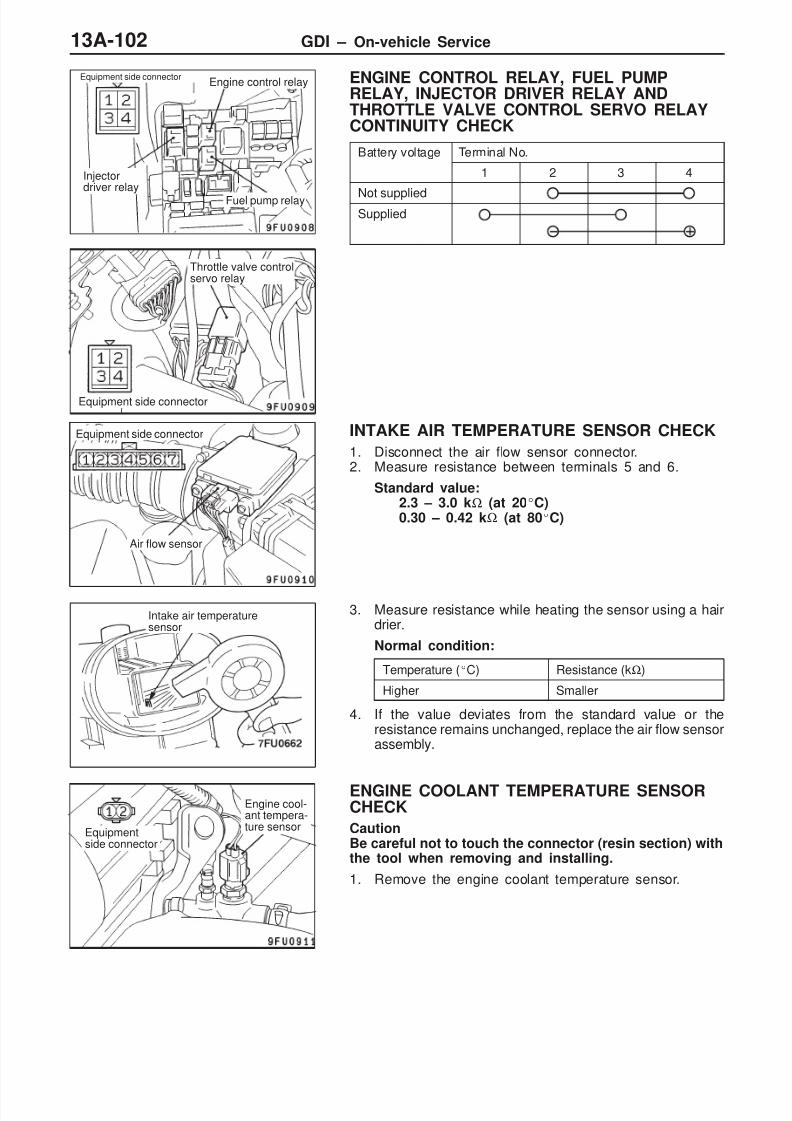
8/19/2019 13a Gasoline Direct Injection (Gdi) (1)
http://slidepdf.com/reader/full/13a-gasoline-direct-injection-gdi-1 102/269
GDI – On-vehicle Service13A-102
ENGINE CONTROL RELAY, FUEL PUMPRELAY, INJECTOR DRIVER RELAY ANDTHROTTLE VALVE CONTROL SERVO RELAYCONTINUITY CHECK
Battery voltage Terminal No.
1 2 3 4
Not suppliedSupplied
INTAKE AIR TEMPERATURE SENSOR CHECK
1. Disconnect the air flow sensor connector.2. Measure resistance between terminals 5 and 6.
Standard value:2.3 – 3.0 kΩ (at 20C)0.30 – 0.42 kΩ (at 80C)
3. Measure resistance while heating the sensor using a hairdrier.
Normal condition:
Temperature (C) Resistance (kΩ)
Higher Smaller
4. If the value deviates from the standard value or theresistance remains unchanged, replace the air flow sensorassembly.
ENGINE COOLANT TEMPERATURE SENSORCHECK
CautionBe careful not to touch the connector (resin section) withthe tool when removing and installing.
1. Remove the engine coolant temperature sensor.
Engine control relay
Fuel pump relay
Injectordriver relay
Equipment side connector
Equipment side connector
Throttle valve controlservo relay
Air flow sensor
Equipment side connector
Intake air temperaturesensor
Equipmentside connector
Engine cool-ant tempera-ture sensor
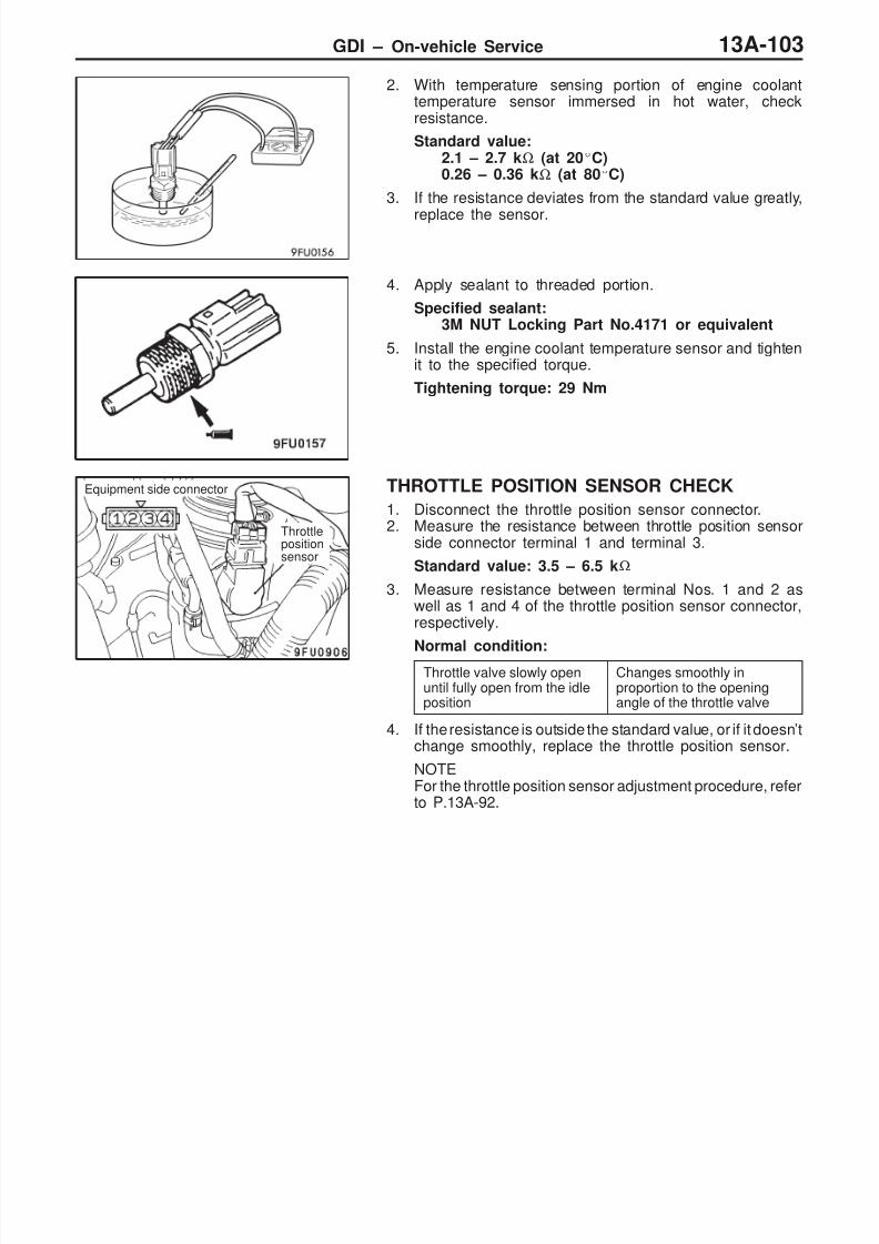
8/19/2019 13a Gasoline Direct Injection (Gdi) (1)
http://slidepdf.com/reader/full/13a-gasoline-direct-injection-gdi-1 103/269
GDI – On-vehicle Service 13A-103
2. With temperature sensing portion of engine coolanttemperature sensor immersed in hot water, checkresistance.
Standard value:2.1 – 2.7 kΩ (at 20C)0.26 – 0.36 kΩ (at 80C)
3. If the resistance deviates from the standard value greatly,
replace the sensor.
4. Apply sealant to threaded portion.
Specified sealant:3M NUT Locking Part No.4171 or equivalent
5. Install the engine coolant temperature sensor and tightenit to the specified torque.
Tightening torque: 29 Nm
THROTTLE POSITION SENSOR CHECK
1. Disconnect the throttle position sensor connector.2. Measure the resistance between throttle position sensor
side connector terminal 1 and terminal 3.
Standard value: 3.5 – 6.5 kΩ
3. Measure resistance between terminal Nos. 1 and 2 aswell as 1 and 4 of the throttle position sensor connector,respectively.
Normal condition:Throttle valve slowly openuntil fully open from the idleposition
Changes smoothly inproportion to the openingangle of the throttle valve
4. If the resistance is outside the standard value, or if it doesn’tchange smoothly, replace the throttle position sensor.
NOTEFor the throttle position sensor adjustment procedure, referto P.13A-92.
Equipment side connector
Throttlepositionsensor

8/19/2019 13a Gasoline Direct Injection (Gdi) (1)
http://slidepdf.com/reader/full/13a-gasoline-direct-injection-gdi-1 104/269
GDI – On-vehicle Service13A-104
ACCELERATOR PEDAL POSITION SENSOR(1ST CHANNEL) CHECK
1. Disconnect the accelerator pedal position sensorconnector.
2. Measure resistance between terminal No.2 (sensor powersupply) and 1 (sensor earth) of the sensor connector.
Standard value: 3.5 – 6.5 kΩ
3. Measure resistance between terminal No.2 (sensor powersupply) and 3 (sensor output) of the connector.
Normal condition:
Depress the acceleratorpedal slowly.
Resistance value changes inaccordance with theaccelerator pedaldepression smoothly.
4. If not within the standard value, or resistance value doesnot change smoothly, replace the accelerator pedal positionsensor assembly.
NOTE
After replacement, adjust the accelerator pedal positionsensor. (Refer to P.13A-94.)
ACCELERATOR PEDAL POSITION SENSOR(2ND CHANNEL) CHECK
1. Disconnect the accelerator pedal position sensorconnector.
2. Measure resistance between terminal No.8 (sensor powersupply) and 7 (sensor earth) of the sensor connector.
Standard value: 3.5 – 6.5 kΩ
3. Measure resistance between terminal No.8 (sensor powersupply) and 6 (sensor output) of the connector.
Normal condition:
Depress the acceleratorpedal slowly.
Resistance value changes inaccordance with theaccelerator pedaldepression smoothly.
4. If not within the standard value, or resistance value doesnot change smoothly, replace the accelerator pedal positionsensor assembly.
NOTEAfter replacement, adjust the accelerator pedal positionsensor. (Refer to P.13A-94.)
Equipmentside connector
Accelerator pedalposition sensor
Accelerator
pedal arm
Equipmentside connector
Accelerator pedalposition sensor
Acceleratorpedal arm
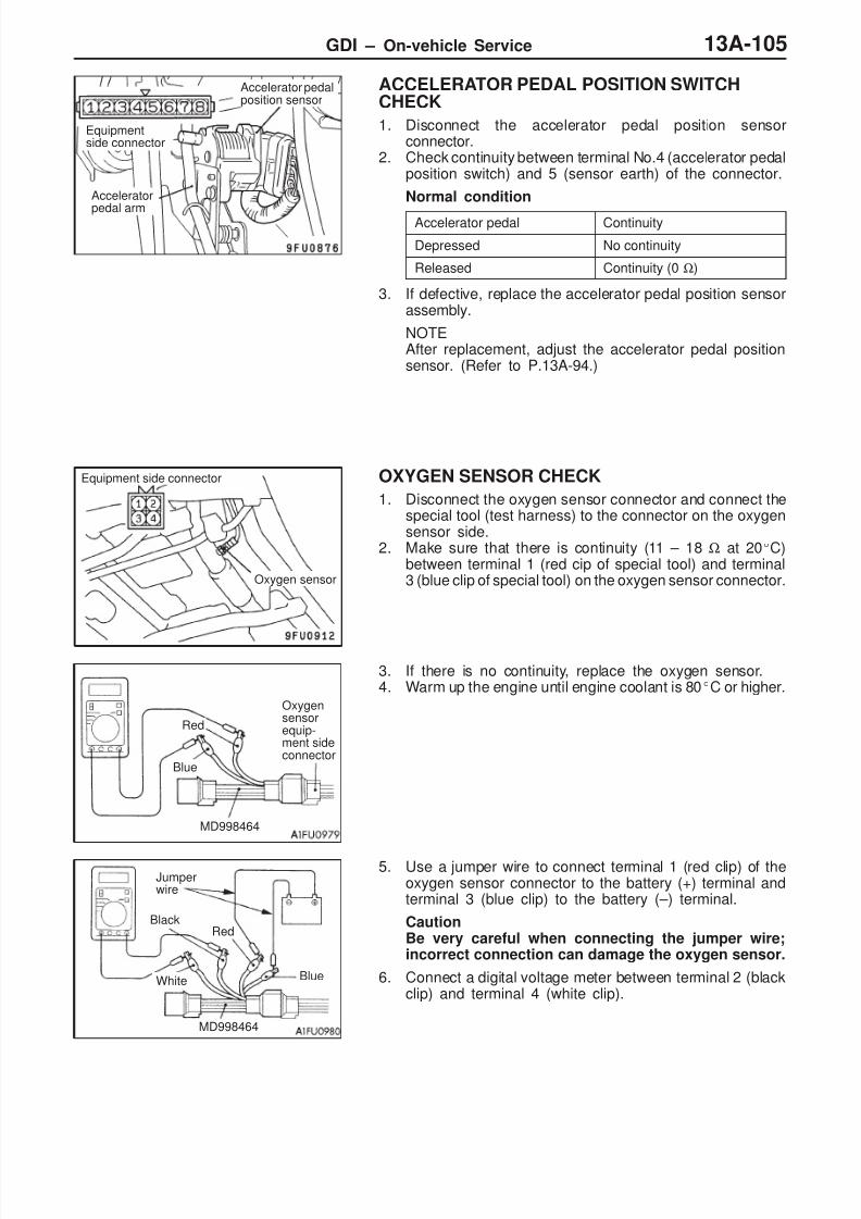
8/19/2019 13a Gasoline Direct Injection (Gdi) (1)
http://slidepdf.com/reader/full/13a-gasoline-direct-injection-gdi-1 105/269
GDI – On-vehicle Service 13A-105
ACCELERATOR PEDAL POSITION SWITCHCHECK
1. Disconnect the accelerator pedal position sensorconnector.
2. Check continuity between terminal No.4 (accelerator pedalposition switch) and 5 (sensor earth) of the connector.
Normal condition
Accelerator pedal Continuity
Depressed No continuity
Released Continuity (0 Ω)
3. If defective, replace the accelerator pedal position sensorassembly.
NOTEAfter replacement, adjust the accelerator pedal positionsensor. (Refer to P.13A-94.)
OXYGEN SENSOR CHECK
1. Disconnect the oxygen sensor connector and connect thespecial tool (test harness) to the connector on the oxygensensor side.
2. Make sure that there is continuity (11 – 18 Ω at 20C)between terminal 1 (red cip of special tool) and terminal3 (blue clip of special tool) on the oxygen sensor connector.
3. If there is no continuity, replace the oxygen sensor.4. Warm up the engine until engine coolant is 80C or higher.
5. Use a jumper wire to connect terminal 1 (red clip) of theoxygen sensor connector to the battery (+) terminal andterminal 3 (blue clip) to the battery (–) terminal.
CautionBe very careful when connecting the jumper wire;incorrect connection can damage the oxygen sensor.
6. Connect a digital voltage meter between terminal 2 (blackclip) and terminal 4 (white clip).
Equipmentside connector
Accelerator pedalposition sensor
Accelerator
pedal arm
Equipment side connector
Oxygen sensor
Blue
Red
MD998464
Oxygensensorequip-ment sideconnector
Jumperwire
BlackRed
White
MD998464
Blue

8/19/2019 13a Gasoline Direct Injection (Gdi) (1)
http://slidepdf.com/reader/full/13a-gasoline-direct-injection-gdi-1 106/269
GDI – On-vehicle Service13A-106
7. While repeatedly racing the engine, measure the oxygensensor output voltage.
Standard value:
Engine Oxygen sensoroutput voltage
Remarks
Whenracing the
engine
0.6 – 1.0 V If you make the air/fuel ratiorich by racing the engine
repeatedly, a normal oxy-gen sensor will output avoltage of 0.6 – 1.0 V.
8. If the sensor is defective, replace the oxygen sensor.
NOTEFor removal and installation of the oxygen sensor, referto GROUP 15 – Exhaust Pipe and Main Muffler.
INJECTOR CHECK
1. Disconnect the injector intermediate harness connector.2. Measure the resistance between each of the terminals.
Standard value: 0.9 – 1.1 Ω (at 20C)
Injector Measurement terminal
No.1 cylinder 1 – 2
No.2 cylinder 3 – 4
No.3 cylinder 5 – 6
No.4 cylinder 7 – 8
3. Connect the injector intermediate harness connector.
Injector side connec-tor
Injectorintermediateharnessconnector
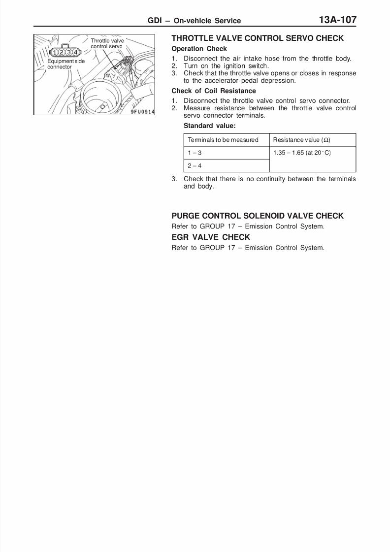
8/19/2019 13a Gasoline Direct Injection (Gdi) (1)
http://slidepdf.com/reader/full/13a-gasoline-direct-injection-gdi-1 107/269
GDI – On-vehicle Service 13A-107
THROTTLE VALVE CONTROL SERVO CHECK
Operation Check
1. Disconnect the air intake hose from the throttle body.2. Turn on the ignition switch.3. Check that the throttle valve opens or closes in response
to the accelerator pedal depression.
Check of Coil Resistance
1. Disconnect the throttle valve control servo connector.2. Measure resistance between the throttle valve control
servo connector terminals.
Standard value:
Terminals to be measured Resistance value (Ω)
1 – 3 1.35 – 1.65 (at 20C)
2 – 4
3. Check that there is no continuity between the terminalsand body.
PURGE CONTROL SOLENOID VALVE CHECK
Refer to GROUP 17 – Emission Control System.
EGR VALVE CHECK
Refer to GROUP 17 – Emission Control System.
Throttle valvecontrol servo
Equipment sideconnector

8/19/2019 13a Gasoline Direct Injection (Gdi) (1)
http://slidepdf.com/reader/full/13a-gasoline-direct-injection-gdi-1 108/269
GDI – Fuel Pump (High Pressure) and Fuel Pressure Regulator (High Pressure)13A-108
FUEL PUMP (HIGH PRESSURE) AND FUEL PRESSUREREGULATOR (HIGH PRESSURE)
REMOVAL AND INSTALLATION
Pre-removal and Post-installation Operation Fuel Discharge Prevention <before removal only>
(Refer to P.13A-98.)
Engine Cover Removal and Installation Resonance Tank Removal and Installation (Refer toGROUP 15.)
Fuel Leak Check <after installation only> (Refer toP.13A-98.)
O-ring
Engine oil
4
6
10
12
13
14
18
15
1617 19
8
7
9
19 Nm
19 Nm
9 Nm
19 Nm
5 Nm
5 Nm → 17Nm
10 – 13Nm
10 – 13Nm
9 Nm
2, 7, 12,18, 25
3
51
2 10 – 13Nm
24 Nm
4
53
11
22
24
25
2623
21
20

8/19/2019 13a Gasoline Direct Injection (Gdi) (1)
http://slidepdf.com/reader/full/13a-gasoline-direct-injection-gdi-1 109/269
GDI – Fuel Pump (High Pressure) and Fuel Pressure Regulator (High Pressure) 13A-109
Fuel pump (High pressure) removalsteps
F Fuel pump (high pressure) air bleeding Throttle body removal (Refer to
P.13A-113.)A 1. Fuel pump protector
C 2. Fuel feed pipeB 3. Back-up ring AB 4. O-ring
B 5. Back-up ring B6. Fuel pressure hose clampC 7. Fuel pressure hose connection
8. O-ring9. Fuel return hose connection
E 10. Fuel pump (high pressure)11. O-ring12. Fuel pump return nipple13. O-ring
Fuel pressure regulator (Highpressure) removal steps
Intake manifold assembly removal(Refer to GROUP 15.)
14. Fuel pressure sensor connectorconnection
15. Fuel pressure sensorD 16. O-ringD 17. Back-up ring
C 18. Fuel return pipeB 19. Back-up ring AB 20. O-ringB 21. Back-up ring B
22. Fuel return hose connectionA 23. Fuel pressure regulator (high
pressure)24. Spacer25. Fuel nipple26. O-ring
REMOVAL SERVICE POINT
A FUEL PUMP PROTECTOR REMOVAL
Lift up the transmission with a jack to create clearance between
the engine and front deck, and then remove the fuel pumpprotector.
INSTALLATION SERVICE POINTS
A FUEL PRESSURE REGULATOR (HIGHPRESSURE) INSTALLATION
1. Install provisionally the fuel pressure regulator (highpressure) to the spacer.
2. Install the fuel return pipe, and then tighten the fuel pressureregulator (high pressure) to the specified torque.
B BACK-UP RING B/O-RING/BACK-UP RING AINSTALLATION
Install the back-up rings and the O-ring as shown in theillustration.
Caution1. Install the back-up ring B facing its cutaway surface
toward the opposite side of the O-ring as shown inthe illustration.
2. Confirm the outer diameter of the back-up ring A. Takecare not to install the back-up ring for the fuel pressure
sensor by mistake. (Outer diameter of the back-upring A: 14.8 mm)
Cutawaysurface
Back-up ring AO-ring
Back-up ring B
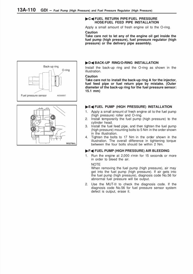
8/19/2019 13a Gasoline Direct Injection (Gdi) (1)
http://slidepdf.com/reader/full/13a-gasoline-direct-injection-gdi-1 110/269
GDI – Fuel Pump (High Pressure) and Fuel Pressure Regulator (High Pressure)13A-110
C FUEL RETURN PIPE/FUEL PRESSUREHOSE/FUEL FEED PIPE INSTALLATION
Apply a small amount of fresh engine oil to the O-ring.
CautionTake care not to let any of the engine oil get inside thefuel pump (high pressure), fuel pressure regulator (highpressure) or the delivery pipe assembly.
D BACK-UP RING/O-RING INSTALLATION
Install the back-up ring and the O-ring as shown in theillustration.
CautionTake care not to install the back-up ring A for the injector,fuel feed pipe or fuel return pipe by mistake. (Outerdiameter of the back-up ring for the fuel pressure sensor:15.1 mm)
E FUEL PUMP (HIGH PRESSURE) INSTALLATION
1. Apply a small amount of fresh engine oil to the fuel pump(high pressure) roller and O-ring.
2. Install temporarily the fuel pump (high pressure) to thecylinder head.
3. Install the fuel feed pipe, and then tighten the fuel pump(high pressure) mounting bolts to 5 Nm in the order shownin the illustration.
4. Tighten the bolts to 17 Nm in the order shown in theillustration. The overall difference in tightening torque
between the four bolts should be within 2 Nm.
F FUEL PUMP (HIGH PRESSURE) AIR BLEEDING
1. Run the engine at 2,000 r/min for 15 seconds or morein order to bleed the air.
NOTEWhen removing the fuel pump (high pressure), air mayget into the fuel pump (high pressure). If air gets intothe fuel pump (high pressure), diagnosis code No.56 forabnormal fuel pressure will be output.
2. Use the MUT-II to check the diagnosis code. If thediagnosis code No.56 for fuel pressure sensor system
defect is output, erase it.
Back-up ring
O-ring
Fuel pressure sensor
1
2
3
4
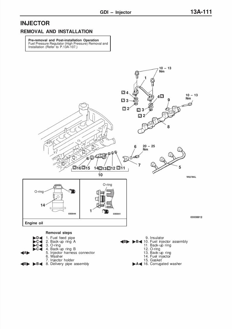
8/19/2019 13a Gasoline Direct Injection (Gdi) (1)
http://slidepdf.com/reader/full/13a-gasoline-direct-injection-gdi-1 111/269
GDI – Injector 13A-111
INJECTOR
REMOVAL AND INSTALLATION
Pre-removal and Post-installation OperationFuel Pressure Regulator (High Pressure) Removal andInstallation (Refer to P.13A-107.)
O-ring
Engine oil
1
2
3
4
5
6
11
20 – 25Nm
10 – 13Nm
7
8
9
10
12
10 – 13Nm
13141516
14
1
2
3
4
O-ring
Removal steps
D 1. Fuel feed pipeC 2. Back-up ring AC 3. O-ringC 4. Back-up ring B
A 5. Injector harness connector6. Washer7. Injector holder
B B 8. Delivery pipe assembly
9. InsulatorB B 10. Fuel injector assembly
11. Back-up ring12. O-ring13. Back-up ring14. Fuel injector15. Gasket
A 16. Corrugated washer

8/19/2019 13a Gasoline Direct Injection (Gdi) (1)
http://slidepdf.com/reader/full/13a-gasoline-direct-injection-gdi-1 112/269
GDI – InjectorGDI – Injector13A-112
REMOVAL SERVICE POINTS
A INJECTOR HARNESS CONNECTORDISCONNECTION
CautionDisconnect the battery (–) cable from its terminal beforecarrying out this operation.
B DELIVERY PIPE ASSEMBLY/FUEL INJECTORASSEMBLY REMOVAL
Remove the delivery pipe assembly with the fuel injectorassembly still attached.
CautionBe careful not to drop the fuel injector assembly whenremoving the delivery pipe assembly.
INSTALLATION SERVICE POINTS
A CORRUGATED WASHER INSTALLATION
CautionThe corrugated washer should always be replaced witha new part.
B FUEL INJECTOR ASSEMBLY/DELIVERY PIPEASSEMBLY INSTALLATION
1. Apply a small amount of fresh engine oil to the O-ring.
CautionTake care not to let any of the engine oil get insidethe delivery pipe assembly.
2. While being careful not to damage the O-ring, turn thefuel injector assembly to the left and right and connectit to the delivery pipe assembly. After connecting, checkthat the fuel injector turns smoothly.
3. If the fuel injector does not turn smoothly, the cause may be
that the O-ring is getting caught. Remove the fuel injector,check the O-ring for damage and re-connect the fuelinjector to the delivery pipe assembly and then re-check.
Corrugated washer

8/19/2019 13a Gasoline Direct Injection (Gdi) (1)
http://slidepdf.com/reader/full/13a-gasoline-direct-injection-gdi-1 113/269
GDI – Injector 13A-113
4. Align the mating marks on the delivery pipe assemblyand the fuel injector, and then install the delivery pipeassembly with the injector assembly still attached.
5. Install the delivery pipe and fuel injectors to the cylinderhead, and then tighten them provisionally.
6. Install the injector holders and washers, and then tightenthem to the specified torque.
CautionObserve the tightening torque.
7. Tighten the delivery pipe and fuel injectors to the specifiedtorque in the order shown in the illustration.
C BACK-UP RING B/O-RING/BACK-UP RING AINSTALLATION
Install the back-up rings and the O-ring as shown in theillustration.
CautionInstall the back-up ring B facing its cutaway surface towardthe opposite side of the O-ring as shown in the illustration.
D FUEL FEED PIPE INSTALLATIONApply a small amount of fresh engine oil to the O-ring.
CautionTake care not to let any of the engine oil get inside thefuel pump (high pressure), fuel pressure regulator (highpressure) and delivery pipe.
Mat-ingmarks
Fuel injector
Delivery pipeassembly
3 1 2 4
Cutawaysurface
Back-up ring AO-ring
Back-up ring B

8/19/2019 13a Gasoline Direct Injection (Gdi) (1)
http://slidepdf.com/reader/full/13a-gasoline-direct-injection-gdi-1 114/269
GDI – Throttle Body13A-114
THROTTLE BODY
REMOVAL AND INSTALLATION
Pre-removal and Post-installation Operation Engine Coolant Draining and Supplying (Refer to
GROUP 14 – On-vehicle Service.) Resonance Tank Removal and Installation (Refer
to GROUP 15.)
1
2
3
4
5
19 Nm
3
Removal steps
1. Throttle position sensor connectorconnection
2. Throttle control servo connector con-nection
3. Water hose connectionA 4. Throttle body assembly
5. Throttle body gasket
INSTALLATION SERVICE POINTA THROTTLE BODY INSTALLATION
If the throttle body is replaced, initialize the electronic-controlledthrottle valve system.
Initialization
Turn on the ignition switch, and turn it to LOCK (OFF) positionwithin one second. Then leave it for at least ten secondswith the ignition switch in LOCK (OFF) position.

8/19/2019 13a Gasoline Direct Injection (Gdi) (1)
http://slidepdf.com/reader/full/13a-gasoline-direct-injection-gdi-1 115/269
GDI – Throttle Body 13A-115
DISASSEMBLY AND REASSEMBLY
1
2
Disassembly steps
A 1. Throttle position sensor2. Throttle body
REASSEMBLY SERVICE POINTS
A THROTTLE POSITION SENSOR
1. Position the throttle position sensor on the throttle bodyalong the dotted line as shown in the illustration.
2. Rotate the throttle position sensor anticlockwise as shownin the illustration, and then tighten the screws.
3. Measure resistance value between terminal Nos. 1(sensorpower supply) and 2 (throttle position sensor 1st-channeloutput) as well as 1 (sensor power supply) and 4 (throttleposition sensor 2nd-channel output).
Normal condition
Open the throttle valve slowlyfrom the idle position tofull-open position.
Resistance value changessmoothly in response tothrottle valve opening angle.
4. If the resistance value does not change smoothly, replacethe throttle position sensor.
Sensor powersupply
EarthThrottle posi-tion sensor(2nd channel)output
Throttle position sensor(1st channel) output

8/19/2019 13a Gasoline Direct Injection (Gdi) (1)
http://slidepdf.com/reader/full/13a-gasoline-direct-injection-gdi-1 116/269
GDI – Injector Driver13A-116
INJECTOR DRIVER
REMOVAL AND INSTALLATION5 Nm
1
2
5 Nm
Removal steps
A 1. Injector driver2. Bracket
REMOVAL SERVICE POINT
A INJECTOR DRIVER REMOVAL
Press the injector driver connector in the place shown in theillustration to disconnect the injector driver connector.
Caution1. Disconnect the battery (–) cable from its terminal
before carrying out this operation.2. High-tension current is flowing in the harness between
the injector driver and the injector while engine isrunning, and the injector driver will become hot after
the vehicle has been driven, so take care whenhandling it.
Lock

8/19/2019 13a Gasoline Direct Injection (Gdi) (1)
http://slidepdf.com/reader/full/13a-gasoline-direct-injection-gdi-1 117/269
GDI – Throttle Valve Controller 13A-117
THROTTLE VALVE CONTROLLER
INSTALLATION SERVICE POINT
If the throttle valve controller is replaced, initialize theelectronic-controlled throttle valve system.
Initialization
Turn on the ignition switch, and turn it to LOCK (OFF) position
within one second. Then leave it for at least ten secondswith the ignition switch in LOCK (OFF) position.
Throttle valve controller
Accelerator cable

8/19/2019 13a Gasoline Direct Injection (Gdi) (1)
http://slidepdf.com/reader/full/13a-gasoline-direct-injection-gdi-1 118/269
NOTES

8/19/2019 13a Gasoline Direct Injection (Gdi) (1)
http://slidepdf.com/reader/full/13a-gasoline-direct-injection-gdi-1 119/269
13A-2
GASOLINE DIRECTINJECTION (GDI)
CONTENTS
GENERAL 3. . . . . . . . . . . . . . . . . . . . . . . . . . . . . . . . .Outline of Changes 3. . . . . . . . . . . . . . . . . . . . . . . . . . .
GENERAL INFORMATION 3. . . . . . . . . . . . . . . . . .
SERVICE SPECIFICATIONS 5. . . . . . . . . . . . . . . . .
TROUBLESHOOTING 6. . . . . . . . . . . . . . . . . . . . . . .
ON-VEHICLE SERVICE 108. . . . . . . . . . . . . . . . . . .
Fuel Pressure Test 108. . . . . . . . . . . . . . . . . . . . . . . . .Component Location 112. . . . . . . . . . . . . . . . . . . . . . .
Oxygen Sensor Check 112. . . . . . . . . . . . . . . . . . . . .
FUEL PUMP (HIGH PRESSURE) 114. . . . . . . . . .
INJECTOR 117. . . . . . . . . . . . . . . . . . . . . . . . . . . . . .
THROTTLE BODY 121. . . . . . . . . . . . . . . . . . . . . . . .

8/19/2019 13a Gasoline Direct Injection (Gdi) (1)
http://slidepdf.com/reader/full/13a-gasoline-direct-injection-gdi-1 120/269
GDI – General/General Information 13A-3
GENERAL
OUTLINE OF CHANGES
Due to the changes shown below, the service procedures regarding the different description from theprevious version have been established. On-board Diagnostics System has been adopted to expand the diagnostic items and to change diagnosis
code numbering system.
Fuel pressure regulator (high-pressure) incorporate fuel pump (high-pressure) has been adopted. An oxygen sensor (rear) has been added. A ignition failure sensor has been added.
GENERAL INFORMATION
SELF-DIAGNOSIS FUNCTION
Following functions have been added. The engine-ECU records the engine operating condition when the diagnosis code is set.
This data is called “freeze frame” data.This data can be read by using the MUT-II, are can then be used in simulation tests for troubleshooting.
GENERAL SPECIFICATION
Items Specification
Engine-ECU Identification No. E2T71582

8/19/2019 13a Gasoline Direct Injection (Gdi) (1)
http://slidepdf.com/reader/full/13a-gasoline-direct-injection-gdi-1 121/269

8/19/2019 13a Gasoline Direct Injection (Gdi) (1)
http://slidepdf.com/reader/full/13a-gasoline-direct-injection-gdi-1 122/269
GDI – Service Specifications 13A-5
SERVICE SPECIFICATIONS
Items Standard value
Fuel pressure High-pressure side MPa 4 – 6.9
Low-pressure side kPa Approximately 324
Oxygen sensor output voltage (during revving) V 0.6– 1.0
Oxygen sensor heater resistance (at 20C) Ω Front 4.5 – 8.0
Rear 11 – 18

8/19/2019 13a Gasoline Direct Injection (Gdi) (1)
http://slidepdf.com/reader/full/13a-gasoline-direct-injection-gdi-1 123/269
GDI – Troubleshooting13A-6
TROUBLESHOOTING
DIAGNOSIS FUNCTION
ENGINE WARNING LAMP (CHECK ENGINE LAMP)
If an abnormality occurs in any of the following items relatedto the GDI system, the engine warning lamp will illuminateor flash. If the lamp remains illuminated or if the lamp illuminates
while the engine is running, check the diagnosis code output.However, the warning lamp will illuminate as bulb check forfive seconds whenever the ignition switch is turned to theON position.
Engine warning lamp inspection items
Code No. Diagnosis item
– Engine-ECU
P0100 Air flow sensor system
P0105 Barometric pressure sensor system
P0110 Intake air temperature sensor system
P0115 Engine coolant temperature sensor system
P0120 Throttle position sensor (1st channel) system
P0125 Feedback system
P0130 Oxygen sensor (front) system <sensor 1>
P0135 Oxygen sensor heater (front) system <sensor 1>
P0136 Oxygen sensor (rear) system <sensor 2>
P0141 Oxygen sensor heater (rear) system <sensor 2>
P0170 Abnormal fuel system
P0190 Abnormal fuel pressure
P0201 No. 1 injector system
P0202 No. 2 injector system
P0203 No. 3 injector system
P0204 No. 4 injector system
P0220 Accelerator pedal position sensor (1st channel) system
P0225 Throttle position sensor (2nd channel) system
P0300 Ignition coil (power transistor) system
P0301 No. 1 cylinder misfire detected
P0302 No. 2 cylinder misfire detected
P0303 No. 3 cylinder misfire detected
P0304 No. 4 cylinder misfire detected
Engine warning lamp(check engine lamp)

8/19/2019 13a Gasoline Direct Injection (Gdi) (1)
http://slidepdf.com/reader/full/13a-gasoline-direct-injection-gdi-1 124/269
GDI – Troubleshooting 13A-7
Code No. Diagnosis item
P0335 Crank angle sensor system
P0340 Camshaft position sensor system
P0403 EGR valve system
P0420 Catalyst malfunction
P0443 Purge control solenoid valve system
P1200 Injector driver system
P1220 Electronic-controlled throttle valve system
P1221 Throttle valve position feedback system
P1223 Communication line with throttle valve controller
P1224 Throttle valve control servo motor (motor 1st phase malfunction) system
P1225 Accelerator pedal position sensor (2nd channel) system
P1228 Throttle valve control servo motor (motor 2nd phase malfunction) system
P1515 Brake vacuum sensor system
NOTE1. If the engine warning lamp illuminates because of a malfunction of the engine-ECU, communication
between MUT-II and the engine-ECU is impossible. In this case, the diagnosis code cannot be read.2. After the engine-ECU has detected a malfunction, the engine warning lamp illuminates when the engine
is next turned on and the same malfunction is re-detected. However, for items marked with a “”
in the diagnosis code number column, the engine warning lamp illuminates only on the first detectionof the malfunction.As for P1220, P1221, P1223, P1224, and P1228, the engine warning lamp flashes. If malfunctions
are detected at the throttle position sensor (1st channel) and the throttle position sensor (2nd channel)at the same time, or malfunctions are detected at the accelerator pedal position sensor (1st channel)and the accelerator pedal position sensor (2nd channel) at the same time, the engine warning lampwill flash.
3. After the engine warning lamp illuminates, it will be switched off under the following conditions.(1) When the engine-ECU monitored the power train malfunction three times* and met set condition
requirements, it detected no malfunction.*: In this case, “one time” indicates from engine start to stop.
(2) For misfiring malfunction, when driving conditions (engine speed, engine coolant temperature, etc.)are similar to those when the malfunction was first recorded.
4. Sensor 1 indicates the sensor mounted at a position closest to the engine, and sensor 2 indicatesthe sensor mounted at the position second closest to the engine.

8/19/2019 13a Gasoline Direct Injection (Gdi) (1)
http://slidepdf.com/reader/full/13a-gasoline-direct-injection-gdi-1 125/269
GDI – Troubleshooting13A-8
METHOD OF READING AND ERASING DIAGNOSISCODES
Refer to GROUP 00 – How to Use Troubleshooting/InspectionService Points.
DIAGNOSIS USING DIAGNOSIS 2 MODE
1. Switch the diagnosis mode of the engine control unit to
DIAGNOSIS 2 mode using the MUT-II.2. Carry out a road test.3. Take a reading of the diagnosis code and repair the problem
location.4. Turn the ignition switch to OFF and then back to ON again.
NOTEBy turning the ignition switch to OFF, the engine-ECUwill switch the diagnosis mode from DIAGNOSIS 2 modeto DIAGNOSIS 1 mode.
5. Erase the diagnosis codes.
INSPECTION USING MUT-II DATA LIST ANDACTUATOR TESTING
1. Carry out inspection by means of the data list and theactuator test function. If there is an abnormality, checkand repair the chassis harnesses and components.
2. After repairing, re-check using the MUT-II and check thatthe abnormal input and output have returned to normalas a result of the repairs.
3. Erase the diagnosis code memory.4. Remove the MUT-II, and then start the engine again and
carry out a road test to confirm that the problem hasdisappeared.

8/19/2019 13a Gasoline Direct Injection (Gdi) (1)
http://slidepdf.com/reader/full/13a-gasoline-direct-injection-gdi-1 126/269
GDI – Troubleshooting 13A-9
FREEZE FRAME DATA
When the engine-ECU detects a malfunction and stores adiagnosis code, it also stores a current status of the engine.This function is called “Freeze frame data.” By analyzingthis “freeze frame” data with the MUT-II, an effectivetroubleshooting can be performed.The display items of freeze frame data are shown below.Display item list
Data item Unit
Engine coolant temperature sensor C
Engine speed r/min
Vehicle speed km/h
Long-term fuel compensation (long-termfuel trim)
%
Short-term fuel compensation (short-termfuel trim)
%
Fuel control condi- Open loop OLon
Closed loop CL
Open loop owing todrive condition
OL-DRV.
Open loop owing tosystem malfunction
OL-SYS.
Closed loop basedon one oxygen sen-sor
CL-H02S
Calculation load value %Diagnosis code during data recording –
NOTEIf malfunctions have been detected in multiple systems, storeone malfunction only, which has been detected first.
READINESS TEST STATUS
The engine-ECU monitors the following main diagnosis items, judges if these items are in good condition or not, and thestores its history. This history can be read out by using MUT-II.(If the ECU has judged a item before, the MUT-II displays“Complete.
”)In addition, if diagnosis codes are erased or the battery cable
is disconnected, this history will also be erased (the memorywill be reset). Catalyst: P0420 Oxygen sensor: P0130 Oxygen sensor heater: P0135, P0141

8/19/2019 13a Gasoline Direct Injection (Gdi) (1)
http://slidepdf.com/reader/full/13a-gasoline-direct-injection-gdi-1 127/269
GDI – Troubleshooting13A-10
FAIL-SAFE FUNCTION REFERENCE TABLE
When the main sensor malfunctions are detected by the diagnosis function, the vehicle is controlled bymeans of the pre-set control logic to maintain safe conditions for driving.
Malfunctioning item Control contents during malfunction
Air flow sensor 1. Suspends lean burn operation.2. Uses the throttle position sensor signal and engine speed signal (crank angle
sensor signal) to take reading of the basic injector drive time and basic ignitiontiming from the pre-set mapping.
Intake air temperature sensor Controls as if the intake air temperature is 25C.
Throttle position sensor (2ndchannel)
1. Suspends lean burn operation.2. Controls the throttle opening angle feedback (half as much as the opening
rate in the normal condition) by using signals from the throttle position sensor(1st channel). However, this controlling system is not applied if the throttleposition sensor (1st channel) and throttle position sensor (2nd channel)combination output voltage is outside 4 – 6 V.
3. Refrains from controlling the throttle opening angle feedback if the throttleposition sensor (1st channel) is also defective.
Engine coolant temperature
sensor
Controls as if the engine coolant temperature is 80C. (Moreover, the control system
is working until the ignition switch is turned OFF if the sensor signal returns to normal.)
Camshaft position sensor Controls maintaining the condition before determined as failure.Fuel will be cut-off 4 seconds after a malfunction is detected. (However, only ifNo. 1 cylinder TDC has never been detected after the ignition switch is turnedto the ON position)
Vehicle speed sensor 1. Suspends lean burn operation. However, the control is cancelled as a certaintime passes by with the engine speed of 1,500 r/min or more.
2. Suspends lean burn operation during the engine idling.
Barometric pressure sensor Controls as if the barometric pressure is 101 kPa.
Detonation sensor Fixes the ignition timing as that for standard petrol.
Injector 1. Suspends lean burn operation.2. Suspends the exhaust gas recirculation.
Communication line withA/T-ECU
Disable ignition timing retard control (engine and transmission total control) duringshift change.
Ignition coil (incorporating pow-er transistor)
1. Suspends lean burn operation.2. Cuts off the fuel supply to cylinders with an abnormal ignition signal.
Fuel pressure sensor 1. Controls as if the fuel pressure is 5 MPa. (In case of open/short circuit)2. Turns the fuel pump relay off. (In case of abnomality in high pressure)3. Suspends fuel injection. (when the low pressure is detected and the engine
speed is more than 3,000 r/min)
Alternator FR terminal Refrains from controlling to suppress the alternator output to electrical load.(Operated as a normal alternator)
Accelerator pedal position sen-sor (2nd channel)
1. Suspends lean burn operation.2. Controls the throttle valve position by using signals from the accelerator pedal
position sensor (1st channel). (However, the control system is not applicableif the difference from the accelerator pedal position sensor (1st channel) outputvoltage is 1.0 V or higher.)
3. Suspends the electronic controlled throttle valve system if accelerator pedalposition sensor (1st channel) is also defective.

8/19/2019 13a Gasoline Direct Injection (Gdi) (1)
http://slidepdf.com/reader/full/13a-gasoline-direct-injection-gdi-1 128/269
GDI – Troubleshooting 13A-11
Malfunctioning item Control contents during malfunction
Accelerator pedal position sen-sor (1st channel)
1. Suspends lean burn operation.2. Controls the throttle valve position by using signals from the accelerator pedal
position sensor (2nd channel). (However, this control is not applicable if thevoltage difference between the accelerator pedal position sensor (1st channel)and accelerator pedal position sensor (2nd channel) is 1.0 V or higher.)
3. Also suspends the electronic-controlled throttle valve system when the
accelerator pedal position sensor (2nd channel) is defective.
Throttle position sensor (1stchannel)
1. Suspends lean burn operation.2. Controls throttle opening angle feedback by using signals from throttle position
sensor (2nd channel). (However, the controlling system is not applied whenthe throttle position sensor (1st channel) and throttle position sensor (2ndchannel) combination output voltage is outside 4 – 6 V.)
3. Refrains from controlling the throttle opening angle feedback when throttleposition sensor (2nd channel) is also defective.
Electronic-controlled throttlevalve system
1. Suspends the electronic controlled throttle valve system.2. Suspends lean burn operation.3. Suspends the idle speed feedback control.
Throttle valve position feed-
back
1. Suspends the electronic controlled throttle valve system.
2. Suspends lean burn operation.3. Suspends the engine speed feedback control.
Communication line betweenthe throttle valve controller andthe engine-ECU
1. Communication error between the throttle valve controller and the engine-ECU Suspends lean burn operation. Cuts the fuel supply when the engine speed reaches 3,000 r/min or more. Suspends the cruise-control.
2. Communication error between the throttle valve controller and the engine-ECU Suspends lean burn operation. Cuts the fuel supply when the engine speed reaches 3,000 r/min or more. Suspends the cruise-control. The throttle valve controller controls the throttle valve opening angle by
using signals from accelerator pedal position sensor (2nd channel).
Throttle control servo motor 1st
phase malfunction
Bans lean burn operation.
Throttle control servo motor2nd phase malfunction
1. Suspends electronic control throttle valve system.2. Bans lean burn operation.3. Bans engine speed feed back control.
Misfiring If the detected misfiring causes damage to the catalyst, the misfiring cylinder will beshut down.
NOTEIf the electronic-controlled throttle valve system is suspended, the engine warning lamp will illuminate.

8/19/2019 13a Gasoline Direct Injection (Gdi) (1)
http://slidepdf.com/reader/full/13a-gasoline-direct-injection-gdi-1 129/269
GDI – Troubleshooting13A-12
INSPECTION CHART FOR DIAGNOSIS CODES
Code No. Diagnosis item Reference page
P0100 Air flow sensor system 13A-14
P0105 Barometric pressure sensor system 13A-16
P0110 Intake air temperature sensor system 13A-18
P0115 Engine coolant temperature sensor system 13A-19
P0120 Throttle position sensor 1 (1st channel) system 13A-22
P0125 Feedback system 13A-24
P0130 Oxygen sensor (front) system <sensor 1> 13A-25
P0135 Oxygen sensor heater (front) system <sensor 1> 13A-27
P0136 Oxygen sensor (rear) system <sensor 2> 13A-28
P0141 Oxygen sensor heater (rear) system <sensor 2> 13A-30
P0170 Abnormal fuel system 13A-31
P0190 Abnormal fuel pressure 13A-33
P0201 No. 1 injector system 13A-34
P0202 No. 2 injector system 13A-36
P0203 No. 3 injector system 13A-37
P0204 No. 4 injector system 13A-38
P0220 Accelerator pedal position sensor (1st channel) system 13A-40
P0225 Throttle position sensor (2nd channel) system 13A-43
P0300 Ignition coil (power transistor) system 13A-44
P0301 No. 1 cylinder misfire detected 13A-46
P0302 No. 2 cylinder misfire detected 13A-46
P0303 No. 3 cylinder misfire detected 13A-46
P0304 No. 4 cylinder misfire detected 13A-46
P0325 Detonation sensor system 13A-47
P0335 Crank angle sensor system 13A-47
P0340 Camshaft position sensor system 13A-59
P0403 EGR valve system 13A-50
P0420 Catalyst malfunction 13A-51
P0443 Purge control solenoid valve system 13A-52
P0500 Vehicle speed sensor system 13A-53
P1200 Injector driver system 13A-53
P1220 Electronic-controlled throttle valve system 13A-54

8/19/2019 13a Gasoline Direct Injection (Gdi) (1)
http://slidepdf.com/reader/full/13a-gasoline-direct-injection-gdi-1 130/269
GDI – Troubleshooting 13A-13
Code No. Reference pageDiagnosis item
P1221 Throttle valve position feedback system 13A-55
P1223 Communication line with throttle valve controller 13A-56
P1224 Throttle valve control servo motor (motor 1st phase malfunction) system 13A-57
P1225 Accelerator pedal position sensor (2nd channel) system 13A-58
P1228 Throttle valve control servo motor (motor 2nd phase malfunction) system 13A-60
P1500 Alternator FR terminal system 13A-61
P1515 Brake vacuum sensor system 13A-62
P1600 Communication wire with A/T-ECU system 13A-64
P1610 Immobilizer system 13A-64
NOTE1. Do not replace the engine-ECU until a through terminal check reveals there are no short/open circuit.
2. Check that the engine-ECU earth circuit is normal before checking for the cause of the problem.3. After the engine-ECU has detected a malfunction, a diagnosis code is recorded the next time theengine is started and the same malfunction is re-detected. However, for items marked with a “”,the diagnosis code is recorded on the first detection of the malfunction.
4. Sensor 1 indicates the sensor mounted at a position closest to the engine, and sensor 2 indicatesthe sensor mounted at the position second closest to the engine.

8/19/2019 13a Gasoline Direct Injection (Gdi) (1)
http://slidepdf.com/reader/full/13a-gasoline-direct-injection-gdi-1 131/269
GDI – Troubleshooting13A-14
INSPECTION PROCEDURE CLASSIFIED BY DIAGNOSIS CODE
Code No. P0100 Air flow sensor system Probable cause
Range of Check Engine speed: 500 r/min or moreSet Conditions The sensor output frequency is 3.3 Hz or less for four seconds.
Malfunction of air flow sensor Open or short circuit in air flow sensor circuit or
loose connector contact Malfunction of engine-ECU
OK
(3) NGCheck the following connectors:A-36, C-19
NGRepair
(2) NGCheck the following connector:A-36
NGRepair
OK
Check the harness between the airflow sensor and the engine-ECU,and repair if necessary.
MUT-II Data list12 Air flow sensor (Refer toP.13A-94, DATA LIST REFERENCETABLE.)
OKTransient malfunction(Refer to GROUP 00 – Points toNote for Intermittent Malfunctions.)
NG
Check the following connector:A-71
NGRepair
OK
Measure at air flow sensorconnector A-71. Disconnect the connector and
measure at the harness side.(1) Voltage between terminal 3 and
earth (Ignition switch: ON)
OK: 4.8–
5.2 V(2) Voltage between terminal 4 andearth (Ignition switch: ON)OK: System voltage
(3) Resistance between terminal 5and earthOK: 2 Ω or less
(1) NGMeasure at engine-ECU connectorC-18. Measure the voltage at the
engine-ECU terminal Ignition switch: ON Voltage between terminal 61 and
earthOK: 4.8 – 5.2 V
OK
NGRepair
NG
Check the following connector:C-18
NGRepair
OK
Check the harness between the airflow sensor and the engine-ECU.
NGRepair
Check the trouble symptoms.NG
Replace the engine-ECU.
OK
Check the harness between the airflow sensor and the engine controlrelay, and repair if necessary.
OK
Check the harness between the airflow sensor and the engine-ECU.
NGRepair
OK
Check the trouble symptoms.NG
Replace the engine-ECU.
OK
To the next page
Check the following connector:C-18

8/19/2019 13a Gasoline Direct Injection (Gdi) (1)
http://slidepdf.com/reader/full/13a-gasoline-direct-injection-gdi-1 132/269
GDI – Troubleshooting 13A-15
OK
Check the harness between the airflow sensor and the engine-ECU.
NGRepair
Check the harnesses between theair flow sensor and the engine-ECUand between the air flow sensor
and the engine control relay, andrepair if necessary.
OK
Measure at air flow sensorconnector A-71. Use test harness (MB991709) to
connect the connector, andmeasure at the pick-up harness.
Selector lever position: P Voltage between terminal 7 and
earthOK: Engine: Idling
0 – 1 VEngine speed: 3,000 r/min6 – 9 V
NGCheck the following connector:C-19
NGRepair
OK
Check the trouble symptoms.
NG
Replace the engine-ECU.
Check the trouble symptoms.
NG
Check the following connector:C-18
NGRepair
OK
Measure the output wave form atair flow sensor connector A-71 (byusing an analyzer). Use test harness (MB991709) to
connect the connector, andmeasure at the pick-up harness.
Engine: Idling Voltage between terminal 3 and
earthOK: Waveforms should be dis-
played on P.13A-84* (In-spection Procedure Usingan Analyzer) and noiseshould not be displayed in
the waveform.
NGReplace the air flow sensor.
OK
Check the trouble symptoms.
NG
Replace the engine-ECU .
OK
OK
Replace the air flow sensor.
OK
Measure at air flow sensorconnector A-71. Use test harness (MB991709) to
connect the connector, andmeasure at the pick-up harness.
Ignition switch: ON Voltage between terminal 7 and
earthOK: 7 – 8 V
NGCheck the following connector:C-19
NGRepair
OK
Check the harness between the airflow sensor and the engine-ECU.
NG Repair
From the previous page
NOTE*: Refer to the ’00 PAJERO PININ Workshop Manual (Pub. No. CKRE00E1).

8/19/2019 13a Gasoline Direct Injection (Gdi) (1)
http://slidepdf.com/reader/full/13a-gasoline-direct-injection-gdi-1 133/269
GDI – Troubleshooting13A-16
Code No. P0105 Barometric pressure sensor system Probable cause
Range of Check Two seconds have passed since the ignition switch is turned ON or the
engine starting process is completed. Battery voltage: 8 V or moreSet Conditions The sensor output voltage is 4.5 V or more for four seconds (equivalent to
114 kPa of barometric pressure)or The sensor output voltage is 0.2 V or less (equivalent to 53 kPa of
barometric pressure)
Malfunction of barometric pressure sensor Open or short circuit in barometric pressure
sensor circuit or loose connector contact Malfunction of engine-ECU
(2) NGCheck the following connector:A-36, C-19
NGRepair
OK
Check the harness between the airflow sensor and the engine-ECU,and repair if necessary.
MUT-II Data list25 Barometric pressure sensor
(Refer to P.13A-94, DATA LISTREFERENCE TABLE.)
OKTransient malfunction(Refer to GROUP 00 – Points toNote for Intermittent Malfunctions.)
NG
NGRepair
OK(1) NG
Measure at engine-ECU connectorC-18. Measure the voltage at the
engine-ECU terminal. Ignition switch: ON
Voltage between terminal 41 andearthOK: 4.8 – 5.2 V
OK Check the following connector:C-18
NGRepair
NG
Check the following connector:C-18
NGRepair
OK
Check the harness between the airflow sensor and the engine-ECU.
NGRepair
OK
Check the trouble symptoms.NG
Replace the engine-ECU.
OK
To the next page
OK
Check the harness between the airflow sensor and the engine-ECU.
NG Repair
OK
Check the trouble symptoms.NG
Replace the engine-ECU.
Check the following connector:A-71
Measure at air flow sensorconnector A-71. Disconnect the connector and
measure at the harness side.(1) Voltage between terminal 1 and
earth (Ignition switch: ON)OK: 4.8 – 5.2 V
(2) Resistance between terminal 5and earthOK: 2 Ω or less

8/19/2019 13a Gasoline Direct Injection (Gdi) (1)
http://slidepdf.com/reader/full/13a-gasoline-direct-injection-gdi-1 134/269
GDI – Troubleshooting 13A-17
OK
Check the harness between the airflow sensor and the engine-ECU,and repair if necessary.
From the previous page
OK
Measure at engine-ECU connectorC-18. Measure the voltage at the
engine-ECU terminal. Ignition switch: ON Voltage between terminal 51 and
earthOK: Altitude 0 m: 3.7 – 4.3 V
Altitude 1,200 m:3.2 – 3.8 V
NGCheck the following connector:C-18
NGRepair
OK
Check the trouble symptoms.
OKCheck the following connector:C-18
NGRepair
NG
Replace the engine-ECU.
OK
Measure at air flow sensorconnector A-71. Connect connector terminals No.
1, No. 2 and No. 5 only by usingtest harness (MB991709), andmeasure at the pick-up harness.
Ignition switch: ON(1) Voltage between terminal 1 andearthOK: 4.8 – 5.2 V
(2) Voltage between terminal 2 andearthOK: Altitude 0 m: 3.7 – 4.3 V
Altitude 1,200 m:3.2 – 3.8 V
(3) Voltage between terminal 5 andearthOK: 0.5 V or less
(1) NGCheck the following connector:C-18
NGRepair
OK
Check the harness between the airflow sensor and the engine-ECU,
and repair if necessary.
(3) NG
(2) NGReplace the air flow sensor.
NG
Check the following connectors:A-36, C-18, C-19
NGRepair
OK
Check the harness between the airflow sensor and the engine-ECU,and repair if necessary.
Check the trouble symptoms.
Check the following connectors:A-36, C-19
NGRepair
OK
Check the harness between the airflow sensor and the engine-ECU,and repair if necessary.

8/19/2019 13a Gasoline Direct Injection (Gdi) (1)
http://slidepdf.com/reader/full/13a-gasoline-direct-injection-gdi-1 135/269
GDI – Troubleshooting13A-18
Code No. P0110 Intake air temperature sensor system Probable cause
Range of Check Two seconds have passed since the ignition switch is turned ON or the
engine starting process is completed.Set Conditions The sensor output voltage is 4.6 V or more for four seconds (equivalent to
–45C of intake air temperature)or The sensor output voltage is 0.2 V or more for four seconds (equivalent to
125C of intake air temperature)
Malfunction of intake air temperature sensor Open or short circuit in intake air temperature
sensor or loose connector contact Malfunction of engine-ECU
OK
Check the harness between the airflow sensor and the engine-ECU,and repair if necessary.
MUT-II Data list13 Intake air temperature sensor
OK: Roughly the same as am-bient temperature.
OK Transient malfunction(Refer to GROUP 00 – Points toNote for Intermittent Malfunctions.)
NG
Check the intake air temperaturesensor itself.(Refer to P.13A-102*.)
NGRepair
OK
Measure at air flow sensorconnector A-71. Disconnect the connector and
measure at the harness side.(1) Resistance between terminal 5
and earthOK: 2 Ω or less
(2) Voltage between terminal 6 andearth(Ignition switch: ON)OK: 4.8 – 5.2 V
(1) NG NG
Repair
NG
Repair
NG
Check the following connector:C-18
NGRepair
OK
Check the harness between the airflow sensor and the engine-ECU.
NGRepair
OK
Check the trouble symptoms.NG
Replace the engine-ECU.
OK
Check following connector: A-71NG
Repair
(2) NGMeasure at engine-ECU connectorC-18. Measure the voltage at the
engine-ECU terminal. Disconnect connector A-71.
Ignition switch: ON Voltage between terminal 62 and
earthOK: 4.8 – 5.2 V
OKCheck the following connector:C-18
OK
Check the harness between the airflow sensor and the engine-ECU.
NGRepair
OK
Check the trouble symptoms.NG
Replace the engine-ECU.
OK
To the next page
Check the following connectors:A-36, C-19
NOTE*: Refer to the ’00 PAJERO PININ Workshop Manual (Pub. No. CKRE00E1).

8/19/2019 13a Gasoline Direct Injection (Gdi) (1)
http://slidepdf.com/reader/full/13a-gasoline-direct-injection-gdi-1 136/269
GDI – Troubleshooting 13A-19
OK
Measure at air flow sensorconnector A-71. Use the test harness
(MB991709) to connect onlyterminals 5 and 6, and thenmeasure at the pick-up harness.
Ignition switch: ON
Voltage between terminal 6 andearthOK: Ambient temperature 0C:
3.2 – 3.8 VAmbient temperature 20C:2.3 – 2.9 VAmbient temperature 40C:1.5 – 2.1 VAmbient temperature 80C:0.4 – 1.0 V
NGCheck the following connectors:A-36, C-18, C-19
NGRepair
OK
Check the harness between the airflow sensor and the engine-ECU,and repair if necessary.
OK
Check the trouble symptoms.NG
Replace the engine-ECU.
From the previous page
Code No. P0115 Engine coolant temperature sensorsystem
Probable cause
Range of Check Engine: Two seconds after the engine has been startedSet Conditions The sensor output voltage is 4.6 V or more for four seconds (equivalent to
–45C of engine coolant temperature)or The sensor output voltage is 0.1 V or less for four seconds (equivalent to
140C of engine coolant temperature)
Malfunction of engine coolant temperature sensor Open or short circuit in the engine coolant
temperature sensor circuit or loose connectorcontact
Malfunction of engine-ECU
Range of Check Engine: After startingSet Conditions The engine coolant temperature has reduced from over 40 C to less than
40C, and that condition has lasted for five minutes or more.

8/19/2019 13a Gasoline Direct Injection (Gdi) (1)
http://slidepdf.com/reader/full/13a-gasoline-direct-injection-gdi-1 137/269
GDI – Troubleshooting13A-20
OK
Check the harness wire betweenthe engine coolant temperaturesensor and the engine-ECU, andrepair if necessary.
MUT-II Data list21 Engine coolant temperature
sensorOK: When the engine is cold,
the temperature is roughlythe same as ambient tem-perature. If warm, it is 80– 120C.
OKTransient malfunction(Refer to GROUP 00 – Points toNote for Intermittent Malfunctions.)
NGNG
Replace
OK
(1) NGMeasure at engine-ECU connectorC-18. Measure the voltage at the
engine-ECU terminal. Disconnect connector A-69. Ignition switch: ON Voltage between terminal 44 and
earthOK: 4.8 – 5.2 V
OKCheck the following connector:C-18
NGRepair
NG
NGRepair
OK
Check the trouble symptoms.NG
Replace the engine-ECU.
OK
Check the following connector:A-69
NGRepair
(2) NG
OK
Repair
OK
Check the harness wire between
the engine coolant temperaturesensor and the engine-ECU.
NG Repair
NG
Check the harness wire betweenthe engine coolant temperaturesensor and the engine-ECU.
NGRepair
OK
Check the trouble symptoms.NG
Replace the engine-ECU.
OK
To the next page
Measure at engine coolanttemperature sensor connector A-69. Disconnect the connector and
measure at the harness side. Resistance between terminals 1
and 2OK: At 20C of engine coolant
temperature: 2.1 – 2.7 kΩAt 80C of engine coolanttemperature: 0.26 – 0.36kΩ
Check the following connector:C-18
Check the following connectors:A-36, C-19
Measure at engine coolanttemperature sensor connector A-69. Disconnect the connector and
measure at the harness side.(1) Voltage between terminal 1 and
earth(Ignition switch: ON)OK: 4.8 – 5.2 V
(2) Resistance between terminal 2and earthOK: 2 Ω or less

8/19/2019 13a Gasoline Direct Injection (Gdi) (1)
http://slidepdf.com/reader/full/13a-gasoline-direct-injection-gdi-1 138/269

8/19/2019 13a Gasoline Direct Injection (Gdi) (1)
http://slidepdf.com/reader/full/13a-gasoline-direct-injection-gdi-1 139/269
GDI – Troubleshooting13A-22
Code No. P0120 Throttle position sensor (1st channel)system
Probable cause
The throttle valve controller judges a malfunction, and then transmit the resultto the engine-ECU.Range of Check Ignition switch: ONSet Conditions The sensor output voltage is 0.2 V or less.or The sensor output voltage is 4.9 V or more.or The throttle position sensor (1st channel) and throttle position sensor (2nd
channel) combination output voltage is outside 4 – 6 V.or The output voltage of the throttle position sensor (1st channel) is
significantly different (approx. 1V) from the throttle valve opening angle(voltage), which the engine-ECU request the throttle valve controller.
Malfunction of throttle position sensor Open or short circuit in the throttle position
sensor (1st channel) circuit or loose connectorcontact
Malfunction of throttle valve controller Malfunction of engine-ECU
OK
Check the harness wire betweenthe throttle position sensor and thethrottle valve controller, and repair ifnecessary.
MUT-II Data list79 Throttle position sensor (1st
channel) (Refer to P.13A-94,DATA LIST REFERENCETABLE.)
OKTransient malfunction(Refer to GROUP 00 – Points toNote for Intermittent Malfunctions.)
NG
Check the throttle position sensor.
(Refer to P.13A-103*.)
NGReplace
OK
Measure at throttle position sensorconnector A-06. Disconnect the connector and
measure at the harness side.(1) Voltage between terminal 1 and
earth(Ignition switch: ON)OK: 4.8 – 5.2 V
(2) Resistance between terminal 3and earth
OK: 2 Ω or less
(1) NGMeasure at throttle valve controllerconnector C-48. Measure voltage at the throttle
valve controller connectorterminals.
Ignition switch: ON Voltage between terminal 6 and
earthOK: 4.8 – 5.2 V
OKCheck the following connector:C-48
NGRepair
NG
Check the following connector:C-48
NGRepair
OK
Check the trouble symptoms.
NGReplace the throttle valve controller.
OK
Check the following connector:A-06
NGRepair
(2) NGCheck the following connector:C-48
NGRepair
OK
Check the harness wire betweenthe throttle position sensor and thethrottle valve controller.
NGRepair
OK
Check the harness wire betweenthe throttle position sensor and thethrottle valve controller.
NG
Repair
OK
Check the trouble symptoms.NG
Replace the throttle valve controller.
OK
To the next page
NOTE*: Refer to the ’00 PAJERO PININ Workshop Manual (Pub. No. CKPE00E1)

8/19/2019 13a Gasoline Direct Injection (Gdi) (1)
http://slidepdf.com/reader/full/13a-gasoline-direct-injection-gdi-1 140/269
GDI – Troubleshooting 13A-23
OK
Measure at throttle valve controller
connector C-48. Measure voltage at the throttle
valve controller connectorterminals.
Ignition switch: ON Voltage between terminal 7 and
earthOK: Accelerator pedal fully re-
leased: 0.45 – 0.8 VAccelerator pedal fully de-pressed: 3.9 – 4.9 V
NG Check the following connector:
C-48
NGRepair
OK
Check the harness wire betweenthe throttle position sensor and thethrottle valve controller, and repair ifnecessary.
OKCheck the following connector:C-48
OK
Check the trouble symptoms.
NG
Replace the throttle valve controller.
From the previous page
NGRepair
OK
Measure at throttle position sensorconnector A-66. Use test harness (MB991536) to
connect the connector, andmeasure at the pick-up harness.
Ignition switch: ON(1) Voltage between terminal 1 and
earthOK: 4.8 – 5.2 V(2) Voltage between terminal 2 and
earthOK: Accelerator pedal fully re-
leased: 0.45 – 0.8 VAccelerator pedal fully de-pressed: 3.9 – 4.9 V
(3) Voltage between terminal 3 andearthOK: 0.5 V or less
(1) NGCheck the following connector:C-48
NGRepair
(3) NG
OK
Check the harness wire betweenthe throttle position sensor and thethrottle valve controller, and repair ifnecessary.
(2) NGAdjust the throttle position sensor.(Refer to P.13A-92*.)
Check the following connector:C-48
NGRepair
OK
Check the harness wire betweenthe throttle position sensor and thethrottle valve controller, and repair ifnecessary.
NOTE*: Refer to the ’00 PAJERO PININ Workshop Manual (Pub. No. CKRE00E1)

8/19/2019 13a Gasoline Direct Injection (Gdi) (1)
http://slidepdf.com/reader/full/13a-gasoline-direct-injection-gdi-1 141/269
GDI – TroubleshootingGDI – Troubleshooting13A-24
Code No. P0125 Feedback system Probable cause
Range of Check The engine coolant temperature is approx. 80C or more. During stoichiometric feedback control The vehicle is not being decelerated.Set Conditions Oxygen sensor (front) output voltage has been higher or lower than 0.5 V
for at least thirty seconds.
Malfunction of oxygen sensor (front) Open or short circuit in the oxygen sensor (front)
circuit or loose connector contact Malfunction of engine-ECU
Repair
OK
Measure at oxygen sensor (front)connector A-67. Disconnect the connector and
measure at the harness side. Resistance between terminal 2
and earthOK: 2 Ω or less
NGCheck the following connectors:A-36, C-19
NG
OK
Check the trouble symptoms.
Check the following connector:A-67
NG Repair
(2) NGCheck the oxygen sensor (front).(Refer to P.13A-112.)
NGReplace
OK
Check the harness wire betweenthe oxygen sensor (front) and theengine-ECU
NGRepair
NG
Replace the engine-ECU.
Repair
OK
Measure at oxygen sensor (front)connector A-67. Use the test harness
(MD998464) to connect theconnector, and measure at thepick-up harness side.
Engine: 2,500 r/min (afterwarming up)
(1) Voltage between terminal 2 andearthOK: 0.5 V or less
(2) Voltage between terminal 4 andearthOK: 0 V and 0.8 V alternate.
(1) NGCheck the following connectors:A-36, C-19
NG
OK
Check the harness wire betweenthe oxygen sensor (front) and theengine-ECU, and repair if necessary.
OK
NGRepair
OK
Check the harness wire betweenthe oxygen sensor (front) and theengine-ECU, and repair if necessary.
OK
NGCheck the following connector:C-19
NG
OK
Check the harness wire betweenthe oxygen sensor (front) and theengine-ECU, and repair if necessary.
OK
Check the following connector:C-19
OK
RepairNG
Check the trouble symptoms.OK
Transient malfunction(Refer to GROUP 00 – Points toNote for Intermittent Malfunctions.)NG
Replace the engine-ECU.
Repair
Check the following connector:C-19
Measure at engine-ECU connectorC-19. Measure the voltage at the
engine-ECU terminal. Engine: 2,500 r/min (after
warming up) Voltage between terminal 71 and
earthOK: 0 V and 0.8 V alternate.

8/19/2019 13a Gasoline Direct Injection (Gdi) (1)
http://slidepdf.com/reader/full/13a-gasoline-direct-injection-gdi-1 142/269
GDI – Troubleshooting 13A-25
Code No. P0130 Oxygen sensor (front) system<sensor 1>
Probable cause
Range of Check Three minutes have been passed since the engine has been started. The engine coolant temperature is approx. 80C or more. Intake air temperature is 20 – 50C Engine speed is 1,200 r/min or more Driving on a level surface at constant speed.Set Conditions The oxygen sensor (front) output voltage is 4.5 V or more when the sensor
output voltage is 0.2 V or less and a voltage of 5 V is applied to theoxygen sensor (front) inside the engine-ECU.
Malfunction of oxygen sensor (front) Open or short circuit in the oxygen sensor (front)
circuit or loose connector contact Malfunction of engine-ECU
Range of Check Engine speed is 3,000 r/min or less During driving During air/fuel ratio feedback controlSet Conditions The oxygen sensor (front) output frequency is five or less per 12 seconds
on average.

8/19/2019 13a Gasoline Direct Injection (Gdi) (1)
http://slidepdf.com/reader/full/13a-gasoline-direct-injection-gdi-1 143/269
GDI – Troubleshooting13A-26
Repair
OK
Measure at oxygen sensor (front)connector A-67. Disconnect the connector and
measure at the harness side. Resistance between terminal 2
and earthOK: 2 Ω or less
NGCheck the following connectors:A-36, C–19
NG
OK
Check the trouble symptoms.
Check the following connector:A-55
NGRepair
(2) NGCheck the oxygen sensor (front).(Refer to P.13A-112.)
NGReplace
OK
Check the harness wire between
the oxygen sensor (front) and theengine-ECU.
NGRepair
NG
Replace the engine-ECU.
Repair
OK
(1) NGCheck the following connectors:A-36, C-19
NG
OK
Check the harness wire betweenthe oxygen sensor (front) and theengine-ECU, and repair if necessary.
OKNG
Repair
OK
Check the harness wire betweenthe oxygen sensor (front) and theengine-ECU, and repair if necessary.
OK
NGCheck the following connector:C-19
NG
OK
Check the harness wire betweenthe oxygen sensor (front) and theengine-ECU, and repair if necessary.
OK
Check the following connector:C-19
OK
RepairNG
Check the trouble symptoms.OK
Transient malfunction(Refer to GROUP 00 – Points toNote for Intermittent Malfunctions.)
NG
Replace the engine-ECU.
Repair
Check the following connector:C-19
Measure at engine-ECU connectorC-19. Measure the voltage at the
engine-ECU terminal. Engine: 2,500 r/min (after
warming up) Voltage between terminal 71 and
earthOK: 0 V and 0.8 V alternate.
Measure at oxygen sensor (front)connector A-67. Use the test harness
(MD998464) to connect theconnector, and measure at thepick-up harness side.
Engine: 2,500 r/min (afterwarming up)
(1) Voltage between terminal 2 andearthOK: 0.5 V or less
(2) Voltage between terminal 4 andearthOK: 0 V and 0.8 V alternate.

8/19/2019 13a Gasoline Direct Injection (Gdi) (1)
http://slidepdf.com/reader/full/13a-gasoline-direct-injection-gdi-1 144/269
GDI – Troubleshooting 13A-27
Code No. P0135 Oxygen sensor heater (front) system<sensor 1>
Probable cause
Range of Check The engine coolant temperature is approx. 20C or more. The oxygen sensor heater (front) remains on. The engine speed is 50 r/min or more. Battery voltage is 11 – 16 V.Set Conditions The current, which flows through the oxygen sensor heater (front), is 0.2 A
or less or 3.5 A or more for six seconds.
Malfunction of oxygen sensor heater (front) Open or short circuit in the oxygen sensor heater
(front) circuit or loose connector contact Malfunction of engine-ECU
OK
Repair
OK
Measure at engine-ECU connectorC-19. Measure the voltage at the
engine-ECU terminal. Ignition switch: ON Voltage between terminal 89 and
earthOK: System voltage
NGCheck the following connector:C-19
NG
OK
Check the harness wires betweenthe oxygen sensor (front) and theengine control relay, and repair ifnecessary.
Measure at oxygen sensor (front)connector A-67. Disconnect the connector and
measure at the harness side. Resistance between terminals 1
and 3OK: 4.5 – 8.0 Ω
NGReplace
Repair
OK
Measure at oxygen sensor (front)
connector A-67. Disconnect the connector and
measure at the harness side. Ignition switch: ON Voltage between terminal 1 and
earthOK: System voltage
NGCheck the following connectors:
A-36, A-43X
NG
OK
Check the following connector:A-67
NGRepair
OK
Check the trouble symptoms.OK
Transient malfunction
(Refer to GROUP 00–
Points toNote for Intermittent Malfunctions.)NG
Replace the engine-ECU.
OK
Check the following connectors:A-36, A-43X, C-19
NGRepair
OK
Check the harness wires betweenthe oxygen sensor (front) and theengine-ECU and between theoxygen sensor (front) and theengine control relay.
NGRepair
RepairNG
OK
Check the harness wire betweenthe oxygen sensor (front) and theengine-ECU.
Replace the engine-ECU.

8/19/2019 13a Gasoline Direct Injection (Gdi) (1)
http://slidepdf.com/reader/full/13a-gasoline-direct-injection-gdi-1 145/269

8/19/2019 13a Gasoline Direct Injection (Gdi) (1)
http://slidepdf.com/reader/full/13a-gasoline-direct-injection-gdi-1 146/269
GDI – Troubleshooting 13A-29
Repair
OK
Measure at oxygen sensor (rear)connector B-11. Disconnect the connector and
measure at the harness side. Resistance between terminal 2
and earthOK: 2 Ω or less
NGCheck the following connectors:A-36, C-19
NG
OK
Check the trouble symptoms.
Check the following connector:B-11
NGRepair
(2) NGCheck the oxygen sensor (rear).(Refer to P.13A-113.)
NGReplace
OK
Check the harness wire between
the oxygen sensor (rear) and theengine-ECU.
NGRepair
NG
Replace the engine-ECU.
Repair
OK
(1) NGCheck the following connectors:A-36, C-19
NG
OK
Check the harness wire betweenthe oxygen sensor (rear) and theengine-ECU, and repair if necessary.
OKNG
Repair
OK
Check the harness wire betweenthe oxygen sensor (rear) and theengine-ECU, and repair if necessary.
OK
NG Check the following connector:C-18
NG
OK
Check the harness wire betweenthe oxygen sensor (rear) and theengine-ECU, and repair if necessary.
OK
Check the following connectors:A-36, C-18, C-19
OK
RepairNG
Check the trouble symptoms.
OK
Transient malfunction(Refer to GROUP 00 – Points toNote for Intermittent Malfunctions.)
NG
Replace the engine-ECU.
Repair
Check the following connector:C-18
Measure at engine-ECU connectorC-18. Measure the voltage at the
engine-ECU terminal. Engine: 2,500 r/min (after
warming up) Voltage between terminal 53 and
earthOK: 0 V and 0.8 V alternate.
Measure at oxygen sensor (rear)connector B-11. Use the test harness (MB998464)
to connect the connector, andmeasure at the pick-up harnessside.
Engine: 2,500 r/min (afterwarming up)
(1) Voltage between terminal 2 andearthOK: 0.5 V or less
(2) Voltage between terminal 4 andearthOK: 0 V and 0.8 V alternate.

8/19/2019 13a Gasoline Direct Injection (Gdi) (1)
http://slidepdf.com/reader/full/13a-gasoline-direct-injection-gdi-1 147/269
GDI – Troubleshooting13A-30
Code No. P0141 Oxygen sensor heater (rear) system<sensor 2>
Probable cause
Range of Check The engine coolant temperature is approx. 20C or more. The oxygen sensor heater (rear) remains on. The engine speed is 50 r/min or more. Battery voltage is 11 – 16 V.Set Conditions The current, which flows through the oxygen sensor heater (rear), is 0.2 A
or less or 3.5 A or more for six seconds.
Malfunction of oxygen sensor heater (rear) Open or short circuit in the oxygen sensor heater
(rear) circuit or loose connector contact Malfunction of engine-ECU
OK
Repair
OK
Measure at engine-ECU connectorC-19. Measure the voltage at the
engine-ECU terminal. Ignition switch: ON Voltage between terminal 90 and
earthOK: System voltage
NGCheck the following connector:C-19
NG
OK
Check the harness wires betweenthe oxygen sensor (rear) and theengine control relay, and repair ifnecessary.
Measure at oxygen sensor (rear)connector B-11. Disconnect the connector and
measure at the harness side. Resistance between terminals 1
and 3OK: 11 – 18 Ω
NGReplace
Repair
OK
Measure at oxygen sensor (rear)connector B-11. Disconnect the connector and
measure at the harness side. Ignition switch: ON Voltage between terminal 1 and
earthOK: System voltage
NGCheck the following connectors:A-36, A-43X
NG
OK
Check the following connector:B-11
NGRepair
OK
Check the trouble symptoms.
OK
Transient malfunction(Refer to GROUP 00 – Points toNote for Intermittent Malfunctions.)NG
Replace the engine-ECU .
OK
Check the following connectors:A-36, A-43X, C-19
NGRepair
OK
Check the harness wires betweenthe oxygen sensor (rear) and theengine-ECU and between theoxygen sensor (rear) and the enginecontrol relay.
NGRepair
Replace the engine-ECU.
OK
RepairNGCheck the harness wire between
the oxygen sensor (rear) and theengine-ECU.

8/19/2019 13a Gasoline Direct Injection (Gdi) (1)
http://slidepdf.com/reader/full/13a-gasoline-direct-injection-gdi-1 148/269

8/19/2019 13a Gasoline Direct Injection (Gdi) (1)
http://slidepdf.com/reader/full/13a-gasoline-direct-injection-gdi-1 149/269
GDI – Troubleshooting13A-32
OK
Check the injectors for clogging orleaks.
NGRepair
OK
Check the fuel lines for fuel leaks.NG
Repair
OK
Check the fuel pressure betweenthe fuel pump (low-pressure) andthe fuel pump (high-pressure) (Referto P.13A-108.)
NG
From the previous page
OK
Check the trouble symptoms.OK
Transient malfunction(Refer to GROUP 00 – Points toNote for Intermittent Malfunctions.)
NG
Replace the engine-ECU.
OK
Check the EGR valve (Refer toGROUP 17 – Emission Control.)
NGReplace
Repair

8/19/2019 13a Gasoline Direct Injection (Gdi) (1)
http://slidepdf.com/reader/full/13a-gasoline-direct-injection-gdi-1 150/269
GDI – Troubleshooting 13A-33
Code No. P0190 Abnormal fuel pressure Probable cause
Range of Check Ignition switch: ONSet Conditions The sensor output voltage is 4.8 V or more, or 0.2 V or less for four
seconds.
Malfunction of of fuel pressure sensor Open or short circuit in the fuel pressure sensor
circuit or loose connector contact Malfunction of engine-ECU
Range of Check The following conditions are detected temporarily after the engine has been
started.
(1) Engine speed: 1,000 r/min or more(2) Fuel pressure: 2 MPa or more Engine runningSet Conditions The fuel pressure is 6.9 MPa or more, or 2 MPa or less for four seconds.
Malfunction of high-pressure fuel pump Clogging of high-pressure fuel lines
This diagnosis code will also be output when air is trapped into thehigh-pressure fuel lines (such as poor fuel level). In that case, the air can beevacuated by operating the engine for at least 15 seconds at 2,000 r/min. Afterthe repair, use the MUT-II to erase the diagnosis code.
Air trapped due to poor fuel level
(2) NG NGRepair
OK
Check the harness wire betweenthe fuel pressure sensor connectorand the engine-ECU, and repair ifnecessary.
OKTransient malfunction(Refer to GROUP 00 – Points toNote for Intermittent Malfunctions.)
NGNG
Repair
OK
Measure at fuel pressure sensorconnector A-59. Disconnect the connector, and
measure at the harness side.(1) Voltage between terminal 1 and
earth (Ignition switch: ON)OK: 4.8 – 5.2 V
(2) Resistance between terminal 3and earthOK: 2 Ω or less
(1) NG OKCheck the following connector:C-18
NGRepair
NG
Check the following connector:C-18
NGRepair
OK
Check the harness wire between thefuel pressure sensor connector andthe engine-ECU.
NGRepair
OK
Check the trouble symptoms.NG
Replace the engine-ECU.
OK
Check the trouble symptoms.NG
Replace the engine-ECU.
OK
To the next page
OK
Check the harness wire between the
fuel pressure sensor connector andthe engine-ECU.
NGRepair
Check the following connector:A-59
Measure at engine-ECU connectorC-18. Measure the voltage at the
engine-ECU terminal. Ignition switch: ON Voltage between terminal 41 and
earthOK: 4.8 – 5.2 V
Check the following connectors:A-36, C-19
MUT-II Data list74 Fuel pressure sensor (Refer to
13A-94, DATA LISTREFERENCE TABLE.)

8/19/2019 13a Gasoline Direct Injection (Gdi) (1)
http://slidepdf.com/reader/full/13a-gasoline-direct-injection-gdi-1 151/269
GDI – Troubleshooting13A-34
NG
(2) NG
OK(1) NG
Check the following connector:C-18
From the previous page
OK
Check the harness wire betweenthe fuel pressure sensor connectorand the engine-ECU, and repair if
necessary.
Replace the fuel pressure sensor.
Check the trouble symptoms.
Check the following connector:C-19
NGRepair
NG
Check the harness wire betweenthe fuel pressure sensor connectorand the engine-ECU, and repair ifnecessary.
OK
Measure at engine-ECU connectorC-19. Measure the voltage at the
engine-ECU terminal.
Engine: Idling Voltage between terminal 92 andearthOK: 0.3 – 4.7 V
NGCheck the following connector:C-19
NGRepair
OK
Check the harness wire betweenthe fuel pressure sensor connectorand the engine-ECU, and repair ifnecessary.
OKCheck the following connector:C-19
NGRepair
OK
Check the trouble symptoms.
OK
Replace the engine-ECU.
OK
Repair
NG(3) NGCheck the following connectors:A-36, C-19
OK
Check the harness wire betweenthe fuel pressure sensor connectorand the engine-ECU, and repair ifnecessary.
Repair
Measure at fuel pressure sensorconnector A-59. Use test harness (MB991658) to
connect the connector, andmeasure at the pick-up harness.
Engine: Idling(1) Voltage between terminal 1 and
earthOK: 4.8 – 5.2 V(2) Voltage between terminal 2 and
earthOK: 0.3 – 4.7 V
(3) Voltage between terminal 3 andearthOK: 0.5 V or less
Code No. P0201 No. 1 injector system Probable cause
Range of Check The engine speed is 4,000 r/min or less. The battery voltage is 10 V or more. The fuel cut operation or the injector operation (by carrying out the Actuator
Test) is not in progress.Set Conditions The injector driver is not transmitting a injector open circuit check signal
for four seconds.
Malfunction of No. 1 injector Open or short circuit in the No. 1 injector circuit
or loose connector contact Malfunction of engine-ECU

8/19/2019 13a Gasoline Direct Injection (Gdi) (1)
http://slidepdf.com/reader/full/13a-gasoline-direct-injection-gdi-1 152/269
GDI – Troubleshooting 13A-35
NG
Check the following connector:A-78
NG
Repair
OKNG
Repair
MUT-II Actuator Test01 No. 1 injector
OK: The idling condition shouldchange.
OKCheck the trouble symptoms.
OKTransient malfunction(Refer to GROUP 00 – Points toNote for Intermittent Malfunctions.)
NG
Replace the injector driver.
Check the trouble symptoms.NG
Replace the engine-ECU.
OK
Measure at intermediate connectorA-78. Disconnect the connector and
measure at the harness side. Resistance between terminals 1
and 2OK: 0.9 – 1.1 Ω
NGCheck the following connector:A-61
NGRepair
OK
Replace the No. 1 injector.
OK
Check the following connector:A-55
NGRepair
OK
Check the harness wire betweenthe injector driver and theintermediate connector.
NGRepair
OK
Check the following connector:C-17
NGRepair
OK
Check the harness wire between theinjector driver and the engine-ECU.
NGRepair
OK
Use an analyzer to measure thesignal waveform at engine-ECUconnectors C-17 and C-19. Engine: Idling Voltage between terminal 1 and
earthOK: A normal waveform should
be displayed as describedon P.13A-84* (INSPEC-TION PROCEDURE US-ING AN ANALYZER).
NG Check the following connector:A-61
OK
Check the following connector:A-61
NGRepair
NG
OK
OK
Check the harness wire betweenthe No. 1 injector and theintermediate connector.
NG
Replace the engine-ECU.
Repair
Repair
Check the harness wire betweenNo. 1 injector and the intermediateconnector.
OK
Check the harness wire between
No. 1 injector and the intermediateconnector.
NGRepair
OK
Check the trouble symptoms.NG
Replace the injector driver.
Replace the No. 1 injector.
NOTE*: Refer to the ’00 PAJERO PININ Workshop Manual (Pub. No. CKRE00E1)

8/19/2019 13a Gasoline Direct Injection (Gdi) (1)
http://slidepdf.com/reader/full/13a-gasoline-direct-injection-gdi-1 153/269
GDI – Troubleshooting13A-36
Code No. P0202 No. 2 injector system Probable cause
Range of Check The engine speed is 4,000 r/min or less. The battery voltage is 10 V or more. The fuel cut operation or the injector operation (by carrying out the Actuator
Test) is not in progress.Set Conditions The injector driver is not transmitting a injector open circuit check signal
for four seconds.
Malfunction of No. 2 injector Open or short circuit in the No. 2 injector circuit
or loose connector contact Malfunction of engine-ECU
NG
Check the following connector:A-78
NGRepair
OKNG
Repair
MUT-II Actuator Test02 No. 2 injector
OK: The idling condition shouldchange.
OKCheck the trouble symptoms.
OKTransient malfunction(Refer to GROUP 00 – Points toNote for Intermittent Malfunctions.)
NG
Replace the injector driver.
Check the trouble symptoms.NG
Replace the engine-ECU.
OK
Measure at intermediate connectorA-78 Disconnect the connector and
measure at the harness side. Resistance between terminals 3
and 4OK: 0.9 – 1.1 Ω
NGCheck the following connector:A-62
NGRepair
OK
Replace the No. 2 injector.
OK
Check the following connector:A-55
NGRepair
OK
Check the harness wire betweenthe injector driver and theintermediate connector.
NGRepair
OK
Check the following connector:B-17
NG
Repair
OK
Check the harness wire between theinjector driver and the engine-ECU.
NGRepair
OK
Use an analyzer to measure thesignal waveform at engine-ECUconnectors C-17 and C-19. Engine: Idling Voltage between terminal 9 and
earthOK: A normal waveform should
be displayed as describedon P.13A-84* (INSPEC-TION PROCEDURE US-ING AN ANALYZER).
NG Check the following connector:A-62
OK
Check the following connector:A-62
NGRepair
OK
To the next page
NG
OK
OK
Check the harness wire betweenthe No. 2 injector and theintermediate connector.
NG
Replace the engine-ECU.
Repair
Repair
Check the harness wire betweenNo. 2 injector and the intermediateconnector.
NOTE*: Refer to the ’00 PAJERO PININ Workshop Manual (Pub. No. CKRE00E1)

8/19/2019 13a Gasoline Direct Injection (Gdi) (1)
http://slidepdf.com/reader/full/13a-gasoline-direct-injection-gdi-1 154/269
GDI – TroubleshootingGDI – Troubleshooting 13A-37
OK
Check the harness wire betweenNo. 2 injector and the intermediateconnector.
NGRepair
From the previous page
OK
Check the trouble symptoms.NG
Replace the injector driver.
Replace the No. 2 injector.
Code No. P0203 No. 3 injector system Probable cause
Range of Check The engine speed is 4,000 r/min or less. The battery voltage is 10 V or more. The fuel cut operation or the injector operation (by carrying out the Actuator
Test) is not in progress.Set Conditions The injector driver is not transmitting a injector open circuit check signal
for four seconds.
Malfunction of No. 3 injector Open or short circuit in the No. 3 injector circuit
or loose connector contact Malfunction of engine-ECU
NG
NGRepair
OKNG
Repair
MUT-II Actuator Test03 No. 3 injector
OK: The idling condition shouldchange.
OK OKTransient malfunction(Refer to GROUP 00 – Points toNote for Intermittent Malfunctions.)
NG
Check the trouble symptoms.NG
Replace the engine-ECU.
OK
Measure at intermediate connectorA-78.
Disconnect the connector andmeasure at the harness side. Resistance between terminals 5
and 6OK: 0.9 – 1.1 Ω
NGCheck the following connector:A-63
NGRepair
OK
Replace the No. 3 injector.
OK
Check the following connector:A-55
NGRepair
OK
Check the harness wire betweenthe injector driver and theintermediate connector.
NGRepair
OK
Check the following connector:C-17
NG Repair
OK
Check the harness wire between theinjector driver and the engine-ECU.
NGRepair
OK
To the next page
Check the harness wire betweenNo. 3 injector and the intermediateconnector.
Check the following connector:A-78
Check the trouble symptoms.
Replace the injector driver.

8/19/2019 13a Gasoline Direct Injection (Gdi) (1)
http://slidepdf.com/reader/full/13a-gasoline-direct-injection-gdi-1 155/269
GDI – Troubleshooting13A-38
OK
Check the harness wire betweenNo. 3 injector and the intermediateconnector.
NGRepair
From the previous page
OK
Check the trouble symptoms.NG
Replace the injector driver.
Replace the No. 3 injector.
OK
Check the following connector:A-63
NGRepair
OK
Use an analyzer to measure thesignal waveform at engine-ECUconnectors C-17 and C-19. Engine: Idling Voltage between terminal 24 and
earthOK: A normal waveform should
be displayed as describedon P.13A-84* (INSPEC-TION PROCEDURE US-ING AN ANALYZER).
NG Check the following connector:A-63
NG
OK
OK
Check the harness wire betweenthe No. 3 injector and theintermediate connector.
NG
Replace the engine-ECU.
Repair
Repair
NOTE*: Refer to the ’00 PAJERO PININ Workshop Manual (Pub. No. CKRE00E1)
Code No. P0204 No. 4 injector system Probable cause
Range of Check The engine speed is 4,000 r/min or less. The battery voltage is 10 V or more. The fuel cut operation or the injector operation (by carrying out the Actuator
Test) is not in progress.Set Conditions The injector driver is not transmitting a injector open circuit check signal
for four seconds.
Malfunction of No. 4 injector Open or short circuit in the No. 4 injector circuit
or loose connector contact Malfunction of engine-ECU

8/19/2019 13a Gasoline Direct Injection (Gdi) (1)
http://slidepdf.com/reader/full/13a-gasoline-direct-injection-gdi-1 156/269
GDI – Troubleshooting 13A-39
NG
NG
Repair
OKNG
Repair
MUT-II Actuator Test04 No. 4 injector
OK: The idling condition shouldchange.
OK OKTransient malfunction(Refer to GROUP 00 – Points toNote for Intermittent Malfunctions.)
NG
Check the trouble symptoms.NG
Replace the engine-ECU.
OK
NGCheck the following connector:A-64
NGRepair
OK
Replace the No. 4 injector.
OK
Check the following connector:A-55
NGRepair
OK
Check the harness wire betweenthe injector driver and theintermediate connector.
NGRepair
OK
Check the following connector:C-17
NGRepair
OK
Check the harness wire between theinjector driver and the engine-ECU.
NGRepair
OK
Use an analyzer to measure the
signal waveform at engine-ECUconnectors C-17 and C-19. Engine: Idling Voltage between terminal 2 and
earthOK: A normal waveform should
be displayed as describedon P.13A-84* (INSPEC-TION PROCEDURE US-ING AN ANALYZER).
NG
OK
Check the following connector:A-64
NGRepair
NG
OK
OK
Check the harness wire betweenthe No. 4 injector and theintermediate connector.
NG
Replace the engine-ECU.
Repair
Repair
Check the harness wire betweenNo. 4 injector and the intermediateconnector.
OK
Check the harness wire betweenNo. 4 injector and the intermediateconnector.
NGRepair
OK
Check the trouble symptoms.NG
Replace the injector driver.
Replace the No. 4 injector.
Check the following connector:
A-64
Measure at intermediate connectorA-78. Disconnect the connector and
measure at the harness side. Resistance between terminals 7
and 8OK: 0.9 – 1.1 Ω
Check the following connector:A-78
Check the trouble symptoms.
Replace the injector driver.
NOTE*: Refer to the ’00 PAJERO PININ Workshop Manual (Pub. No. CKRE00E1)
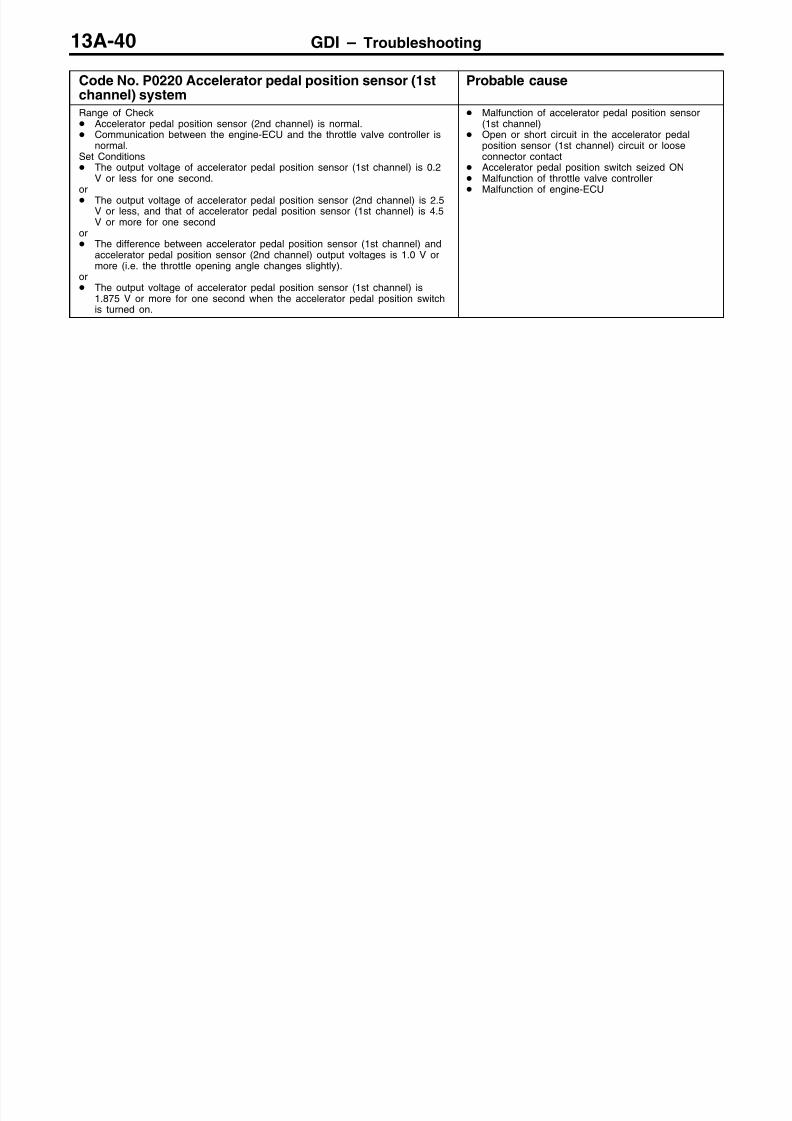
8/19/2019 13a Gasoline Direct Injection (Gdi) (1)
http://slidepdf.com/reader/full/13a-gasoline-direct-injection-gdi-1 157/269
GDI – Troubleshooting13A-40
Code No. P0220 Accelerator pedal position sensor (1stchannel) system
Probable cause
Range of Check Accelerator pedal position sensor (2nd channel) is normal. Communication between the engine-ECU and the throttle valve controller is
normal.Set Conditions The output voltage of accelerator pedal position sensor (1st channel) is 0.2
V or less for one second.or The output voltage of accelerator pedal position sensor (2nd channel) is 2.5
V or less, and that of accelerator pedal position sensor (1st channel) is 4.5V or more for one second
or The difference between accelerator pedal position sensor (1st channel) and
accelerator pedal position sensor (2nd channel) output voltages is 1.0 V ormore (i.e. the throttle opening angle changes slightly).
or The output voltage of accelerator pedal position sensor (1st channel) is
1.875 V or more for one second when the accelerator pedal position switchis turned on.
Malfunction of accelerator pedal position sensor(1st channel)
Open or short circuit in the accelerator pedalposition sensor (1st channel) circuit or looseconnector contact
Accelerator pedal position switch seized ON Malfunction of throttle valve controller Malfunction of engine-ECU
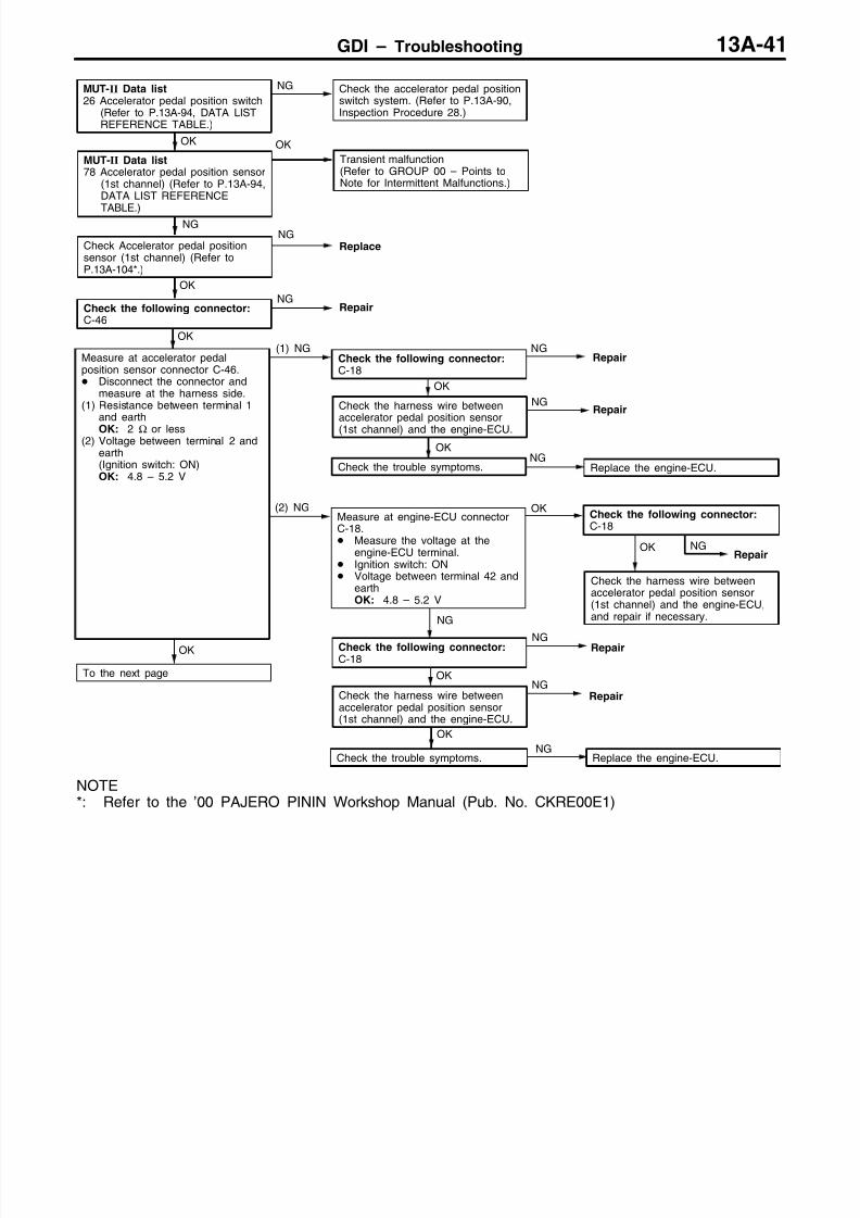
8/19/2019 13a Gasoline Direct Injection (Gdi) (1)
http://slidepdf.com/reader/full/13a-gasoline-direct-injection-gdi-1 158/269
GDI – Troubleshooting 13A-41
Check the harness wire betweenaccelerator pedal position sensor
(1st channel) and the engine-ECU.
OK
Check the following connector:C-46
NGRepair
OK
To the next page
NG
Check Accelerator pedal positionsensor (1st channel) (Refer toP.13A-104*.)
NGReplace
OK
MUT-II Data list78 Accelerator pedal position sensor
(1st channel) (Refer to P.13A-94,DATA LIST REFERENCE
TABLE.)
OK
Transient malfunction(Refer to GROUP 00 – Points toNote for Intermittent Malfunctions.)
MUT-II Data list26 Accelerator pedal position switch
(Refer to P.13A-94, DATA LISTREFERENCE TABLE.)
NG Check the accelerator pedal positionswitch system. (Refer to P.13A-90,Inspection Procedure 28.)
OK
Check the trouble symptoms.NG
Replace the engine-ECU.
OK
Check the harness wire betweenaccelerator pedal position sensor(1st channel) and the engine-ECU.
NGRepair
OK
Check the harness wire betweenaccelerator pedal position sensor(1st channel) and the engine-ECU,and repair if necessary.
OK
Check the trouble symptoms.NG
Replace the engine-ECU.
(2) NG OK
OK
Measure at accelerator pedalposition sensor connector C-46. Disconnect the connector and
measure at the harness side.(1) Resistance between terminal 1
and earth
OK: 2 Ω or less(2) Voltage between terminal 2 and
earth(Ignition switch: ON)OK: 4.8 – 5.2 V
(1) NG NGRepair
NGRepair
NG
Check the following connector:C-18
NG Repair
OK
NGRepair
Check the following connector:C-18
Check the following connector:C-18
Measure at engine-ECU connectorC-18. Measure the voltage at the
engine-ECU terminal. Ignition switch: ON Voltage between terminal 42 and
earthOK: 4.8 – 5.2 V
NOTE*: Refer to the ’00 PAJERO PININ Workshop Manual (Pub. No. CKRE00E1)

8/19/2019 13a Gasoline Direct Injection (Gdi) (1)
http://slidepdf.com/reader/full/13a-gasoline-direct-injection-gdi-1 159/269
GDI – Troubleshooting13A-42
OK
Measure at engine-ECU connectorC-19. Measure the voltage at the
engine-ECU termina. Ignition switch: ON Voltage between terminal 94 and
earthOK: Accelerator pedal fully re-
leased: 0.935 – 1.135 VAccelerator pedal fully de-pressed: 4.1 V or higher
NG
Check the following connector:C-19
NG
Repair
OKCheck the following connector:C-19
NG
OK
Check the trouble symptoms.
NG
Replace the engine-ECU.
Repair
OK
Measure at accelerator pedalposition sensor connector C-46. Connect connector terminals No.
1, No. 2 and No. 3 only by usingtest harness (MB991658), andmeasure at the pick-up harness.
Ignition switch: ON
(1) Voltage between terminal 1 andearthOK: 0.5 V or less
(2) Voltage between terminal 2 andearthOK: 4.8 – 5.2 V
(3) Voltage between terminal 3 andearthOK: Accelerator pedal fully re-
leased: 0.935 – 1.135 VAccelerator pedal fully de-pressed: 4.1 V or higher
(1), (2) NG
Check the following connector:C-18
NG
Check the following connector:C-19
NGRepair
OK
Check the harness wire betweenaccelerator pedal position sensor
(1st channel) and the engine-ECU,and repair if necessary.
From the previous page
(3) NGAdjust the accelerator pedal positionsensor. (Refer to P.13A-104.)
OK
Check the harness wire betweenaccelerator pedal position sensor(1st channel) and the engine-ECU,and repair if necessary.
OK
Check the harness wire betweenaccelerator pedal position sensor(1st channel) and the engine-ECU,and repair if necessary.
Repair
NOTE*: Refer to the ’00 PAJERO PININ Workshop Manual (Pub. No. CKRE00E1)

8/19/2019 13a Gasoline Direct Injection (Gdi) (1)
http://slidepdf.com/reader/full/13a-gasoline-direct-injection-gdi-1 160/269
GDI – Troubleshooting 13A-43
Code No. 0225 Throttle position sensor (2nd channel)system
Probable cause
The throttle valve controller judges a malfunction, and then transmit the resultto the engine-ECURange of Check Ignition switch: ON The throttle position sensor (1st channel) is normal.Set Conditions The sensor output voltage is 0.2 V or less for four seconds.or The sensor output voltage is 4.85 V or more for four seconds, and the
output voltage of the throttle position sensor (1st channel) is 1.2 V or more.or The throttle position sensor (1st channel) and throttle position sensor (2nd
channel) combination output voltage is outside 4 – 6 V.
Malfunction of throttle position sensor (2ndchannel)
Open or short circuit in the throttle positionsensor (2nd channel) circuit or loose connectorcontact
Malfunction of the throttle valve controller Malfunction of the engine-ECU
OK
Check the harness wire betweenthe throttle position sensor and thethrottle valve controller, and repair ifnecessary.
NG
Check throttle position sensor (2ndchannel). (Refer to P.13A-102*.)
NGReplace
NGRepair
NGNG
Repair
OK
Check the trouble symptoms.
NGReplace the throttle valve controller.
OKCheck the following connector:A-06
NGRepair
OK
Check the harness wire betweenthe throttle position sensor and thethrottle valve controller.
NGRepair
OK
Check the harness wire betweenthe throttle position sensor and the
throttle valve controller.
NGRepair
MUT-II Data list14 Throttle position sensor (2nd
channel)OK: Refer to P.13A-94, DATA
LIST REFERENCE TABLE.
OKIntermittent malfunction(Refer to GROUP 00 – Points toNote for Intermittent Malfunctions.)
OK
To the next page
OK
Measure at throttle position sensorconnector A-06. Disconnect the connector and
measure at the harness side.(1) The voltage between terminal 1
and earth(Ignition switch: ON)OK: 4.8 – 5.2 V
(2) Resistance between terminal 3and earthOK: 2 Ω or less
(1) NGMeasure at throttle valve controllerconnector C-48. Measure the voltage at the
throttle valve controller connectorterminals.
Ignition switch: ON The voltage between terminal 6
and earthOK: 4.8 – 5.2 V
OKCheck the following connector:C-48
(2) NGCheck the following connector:C-48
NGRepair
OK
Check the trouble symptoms.NG
Replace the throttle valve controller.
Check the following connector:
C-48
NOTE*: Refer to the ’00 PAJERO PININ Workshop Manual (Pub. No. CKRE00E1)

8/19/2019 13a Gasoline Direct Injection (Gdi) (1)
http://slidepdf.com/reader/full/13a-gasoline-direct-injection-gdi-1 161/269
GDI – Troubleshooting13A-44
OK
Measure at engine-ECU connectorC-19. Measure the voltage at the
engine-ECU terminal. Ignition switch: ON The voltage between terminal 78
and earthOK: Accelerator pedal fully re-
leased: 4.0 – 4.8 VAccelerator pedal fully de-pressed: 0.1 – 1.1 V
NG NGRepair
OK
Check the harness wire betweenthrottle position sensor (2ndchannel) and the engine-ECU, andrepair if necessary.
OK NGRepair
OK
NG
Replace the engine-ECU.
OK
Measure at throttle position sensorconnector A-06. Use test harness (MB991536) to
connect the connector, andmeasure at the pick-up harness.
Ignition switch: ON(1) The voltage between terminal 1
and earthOK: 4.8 – 5.2 V(2) The voltage between terminal 3
and earthOK: 0.5 V or less
(3) The voltage between terminal 4and earthOK: Accelerator pedal fully re-
leased: 4.0 – 4.8 VAccelerator pedal fully de-pressed: 0.1 – 1.1 V
(1), (2) NG NGRepair
NGRepair
OK
Check the harness wire betweenthrottle position sensor (2nd channel)and the throttle valve controller.
From the previous page
(3) NGAdjust the throttle position sensor.(Refer to P.13A-92*.)
OK
Check the harness wire betweenthrottle position sensor (2ndchannel) and the engine-ECU, andrepair if necessary.
Check the following connector:C-48
Check the following connector:C-19
Check the following connector:C-19
Check the trouble symptoms.
Check the following connector:C-19
NOTE*: Refer to the ’00 PAJERO PININ Workshop Manual (Pub. No. CKRE00E1)
Code No. P0300 Ignition coil (power transistor) system Probable cause
Range of Check Engine speed is approx. 50 – 4,000 r/min. Engine is not cranking.Set Conditions The ignition failure sensor does not send a signal about a certain cylinder
for four seconds.
Malfunction of the ignition coil Malfunction of the ignition failure sensor Malfunction of spark plug Open or short circuit in the primary ignition
circuit or loose connector contact Malfunction of engine-ECU
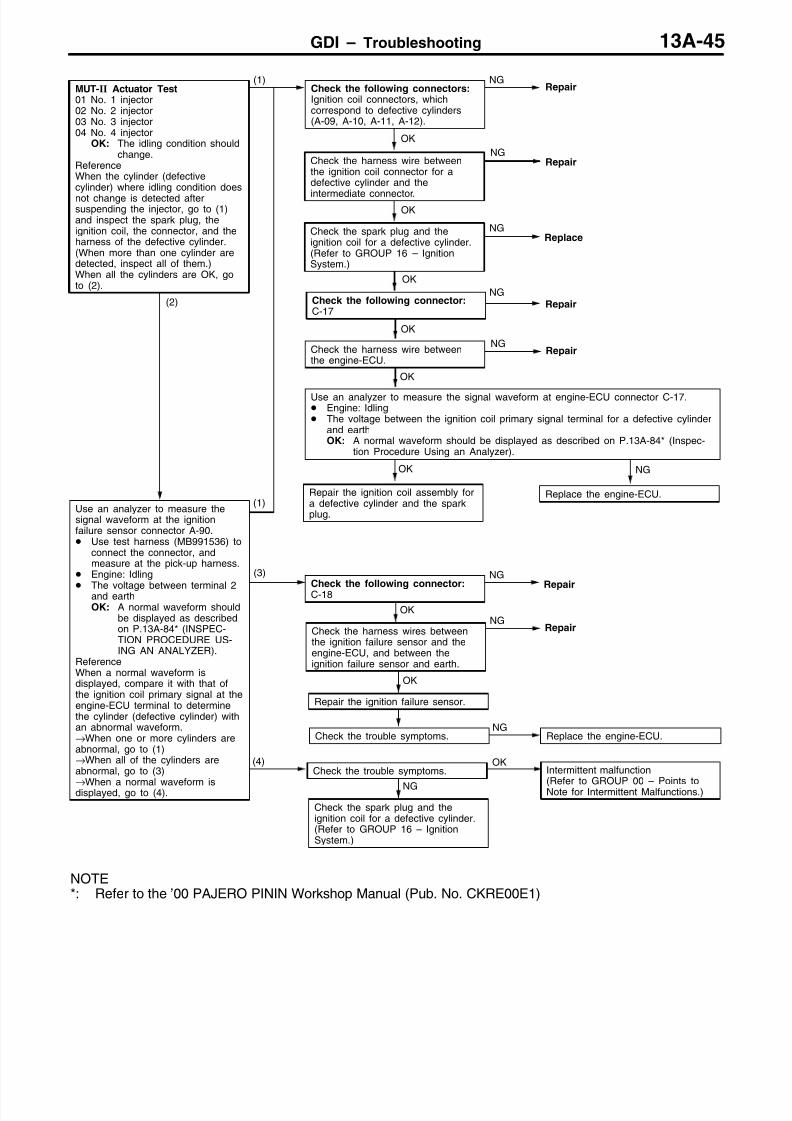
8/19/2019 13a Gasoline Direct Injection (Gdi) (1)
http://slidepdf.com/reader/full/13a-gasoline-direct-injection-gdi-1 162/269
GDI – Troubleshooting 13A-45
NGRepair
OK
NG
Check the spark plug and theignition coil for a defective cylinder.(Refer to GROUP 16 – IgnitionSystem.)
Check the trouble symptoms.NG
Replace the engine-ECU.
OK
Check the harness wire betweenthe engine-ECU.
NGRepair
OK
Check the following connector:C-17
NGRepair
OK
MUT-II Actuator Test01 No. 1 injector02 No. 2 injector03 No. 3 injector04 No. 4 injector
OK: The idling condition shouldchange.
ReferenceWhen the cylinder (defectivecylinder) where idling condition does
not change is detected aftersuspending the injector, go to (1)and inspect the spark plug, theignition coil, the connector, and theharness of the defective cylinder.(When more than one cylinder aredetected, inspect all of them.)When all the cylinders are OK, goto (2).
(1)Check the following connectors:Ignition coil connectors, whichcorrespond to defective cylinders(A-09, A-10, A-11, A-12).
NGRepair
Check the spark plug and theignition coil for a defective cylinder.(Refer to GROUP 16 – IgnitionSystem.)
NGReplace
OK
Use an analyzer to measure the signal waveform at engine-ECU connector C-17. Engine: Idling The voltage between the ignition coil primary signal terminal for a defective cylinder
and earthOK: A normal waveform should be displayed as described on P.13A-84* (Inspec-
tion Procedure Using an Analyzer).
OK
Repair the ignition coil assembly fora defective cylinder and the sparkplug.
NG
Replace the engine-ECU.
(2)
Use an analyzer to measure thesignal waveform at the ignitionfailure sensor connector A-90. Use test harness (MB991536) to
connect the connector, andmeasure at the pick-up harness.
Engine: Idling
The voltage between terminal 2and earthOK: A normal waveform should
be displayed as describedon P.13A-84* (INSPEC-TION PROCEDURE US-ING AN ANALYZER).
ReferenceWhen a normal waveform isdisplayed, compare it with that ofthe ignition coil primary signal at theengine-ECU terminal to determinethe cylinder (defective cylinder) withan abnormal waveform.→When one or more cylinders areabnormal, go to (1)→When all of the cylinders areabnormal, go to (3)
→When a normal waveform isdisplayed, go to (4).
(3) NG
Repair
OKNG
Repair
OK
Repair the ignition failure sensor.
(4)Check the trouble symptoms.
OKIntermittent malfunction
(Refer to GROUP 00–
Points toNote for Intermittent Malfunctions.)
(1)
Check the following connector:C-18
Check the harness wires betweenthe ignition failure sensor and theengine-ECU, and between theignition failure sensor and earth.
Check the harness wire betweenthe ignition coil connector for adefective cylinder and the
intermediate connector.
NOTE*: Refer to the ’00 PAJERO PININ Workshop Manual (Pub. No. CKRE00E1)

8/19/2019 13a Gasoline Direct Injection (Gdi) (1)
http://slidepdf.com/reader/full/13a-gasoline-direct-injection-gdi-1 163/269
GDI – Troubleshooting13A-46
Code No. P0301 No. 1 cylinder misfire detected
Code No. P0302 No. 2 cylinder misfire detected
Code No. P0303 No. 3 cylinder misfire detected
Code No. P0304 No. 4 cylinder misfire detected
Probable cause
Range of Check The engine speed is 500 – 4,500 r/min. While the engine is running except deceleration and sudden acceleration.Set Conditions The number of misfires exceeds a predetermined number per 200 engine
revolutions (Misfire has occurred in only one cylinder).or The number of misfires exceeds a predetermined number per 100 engine
revolutions (Misfire has occurred in only one cylinder).
Malfunction of the ignition system Abnormal compression Malfunction of injector Malfunction of engine-ECU
NG
Check the harness wire between theignition coil and the engine-ECU.
NG
Replace
NGRepair
(2) NG
OK
Check the ignition failure sensor
(Refer to GROUP 16–
IgnitionSystem.)
OK
Check the harness wire betweenthe ignition coil and the earth, andrepair if necessary.
(3) NG
OK
Measure at ignition coil connectorsA-09, A-10, A-11, A-12. Disconnect the connector and
measure at the harness side.(1) The voltage between terminal 1
and earth
(Ignition switch: ON)OK: System voltage
(2) The voltage between terminal 3and earth(Engine: Cranking)OK: 0.5 – 4.0 V
(3) The resistance between terminal2 and earthOK: 2 Ω or less
(1) NGCheck the following connectors:A-90, C-72, C-74
NGRepair
Check the ignition coil (Refer toGROUP 16 – Ignition System.)
Check the compression pressure.(Refer to GROUP 11A – On-vehicleService.)
Repair
Replace the engine-ECU.
OK
Check the harness wire between theignition coil and the ignition failuresensor, and between the ignitionswitch and the ignition failure sensor.
NGRepair
OK
NG
NGRepair
OK
Replace
NG
Check the spark plugs.
Check the trouble symptoms.
OK
Check the trouble symptoms. NG Replace the engine-ECU.
Check the following connectors:A-09, A-10, A-11, A-12
Check the following connector:C-17
OK
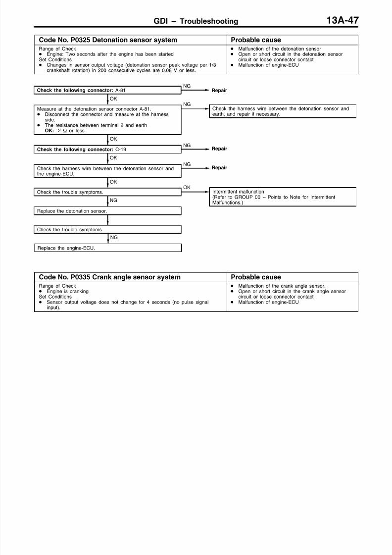
8/19/2019 13a Gasoline Direct Injection (Gdi) (1)
http://slidepdf.com/reader/full/13a-gasoline-direct-injection-gdi-1 164/269
GDI – Troubleshooting 13A-47
Code No. P0325 Detonation sensor system Probable cause
Range of Check Engine: Two seconds after the engine has been startedSet Conditions Changes in sensor output voltage (detonation sensor peak voltage per 1/3
crankshaft rotation) in 200 consecutive cycles are 0.08 V or less.
Malfunction of the detonation sensor Open or short circuit in the detonation sensor
circuit or loose connector contact Malfunction of engine-ECU
OK
Check the trouble symptoms.
OK
Intermittent malfunction(Refer to GROUP 00 – Points to Note for IntermittentMalfunctions.)
Check the following connector: A-81NG
Repair
OK
Measure at the detonation sensor connector A-81. Disconnect the connector and measure at the harness
side. The resistance between terminal 2 and earth
OK: 2 Ω or less
NGCheck the harness wire between the detonation sensor andearth, and repair if necessary.
OK
Check the following connector: C-19NG
Repair
OK
Check the harness wire between the detonation sensor andthe engine-ECU.
NGRepair
NG
Replace the detonation sensor.
Check the trouble symptoms.
NG
Replace the engine-ECU.
Code No. P0335 Crank angle sensor system Probable cause
Range of Check
Engine is crankingSet Conditions Sensor output voltage does not change for 4 seconds (no pulse signal
input).
Malfunction of the crank angle sensor.
Open or short circuit in the crank angle sensorcircuit or loose connector contact.
Malfunction of engine-ECU

8/19/2019 13a Gasoline Direct Injection (Gdi) (1)
http://slidepdf.com/reader/full/13a-gasoline-direct-injection-gdi-1 165/269
GDI – Troubleshooting13A-48
OK
Check the trouble symptoms.
OK
Check the harness wire between thecrank angle sensor and the enginecontrol relay, and repair if necessary.
OK
Check the harness wire betweenthe crank angle sensor and theengine-ECU, and repair if necessary.
OKIntermittent malfunction(Refer to GROUP 00 – Points toNote for Intermittent Malfunctions.)
OK
Measure at the crank angle sensorconnector A-77. Disconnect the connector and
measure at the harness side.(1) The resistance between terminal
1 and earthOK: 2 Ω or less
(2) The voltage between terminal 3and earth(Ignition switch: ON)OK: 4.8 – 5.2 V
(3) The voltage between terminal 2and earth(Ignition switch: ON)OK: System voltage
(1) NG Check the harness between thecrank angle sensor and earth, andrepair if necessary.
NGRepair
NG
Check the following connector:
C-18
NGRepair
NG
Check the following connector:A-77
NGRepair
(2) NGMeasure at engine-ECU connectorC-18. Measure the voltage at the
engine-ECU terminal. Disconnect the connector A-77 Ignition switch: ON The voltage between terminal 43
and earth.OK: 4.8 – 5.2 V
OKCheck the following connector:C-18
Check the following connector:A-36
NGRepair
OK
Check the harness wire betweenthe crank angle sensor and theengine-ECU.
NGRepair
OK
Check the trouble symptoms.NG
Replace the engine-ECU.
(3) NG
OK
Use an analyzer to measure theoutput waveform at the crank anglesensor connector A-77. Use the test harness
(MB991658) to connect theconnector, and measure at thepick-up harness side.
Engine: Idling The voltage between terminal 3
and earthOK: A normal waveform should
be displayed as described
on P.13A-84* (InspectionProcedure Using an Ana-lyzer). Its maximum valueshould be 4.8 V or more,and its minimum valueshould be 0.6 V or lesswith no noise in waveform.
NGCheck the crank angle sensor vane.
NGReplace
OK
Replace the crank angle sensor.
Check the trouble symptoms.
NG
Check the following connectors:A-36, C-18
NGRepair
OK
Check the harness wires betweenthe crank angle sensor and theengine-ECU, crank angle sensorand the engine control relay, andthe crank angle sensor and earth.Then, repair if necessary.
NG
Replace the engine-ECU.
MUT-II Data list22 Crank angle sensor
OK: Refer to P.13A-94, DATALIST REFERENCE TABLE.

8/19/2019 13a Gasoline Direct Injection (Gdi) (1)
http://slidepdf.com/reader/full/13a-gasoline-direct-injection-gdi-1 166/269
GDI – TroubleshootingGDI – Troubleshooting 13A-49
Code No. P0340 Camshaft position sensor system Probable causeRange of Check After the engine was startedSet Conditions The sensor output voltage does not change for 4 seconds (no pulse signal
input).
Malfunction of the camshaft position sensor Open or short circuit in the camshaft position
sensor circuit or loose connector contact. Malfunction of engine-ECU
OK
Check the trouble symptoms.Intermittent malfunction(Refer to GROUP 00 – Points to Note for Intermittent Malfunctions.)
OK
Check the harness wire between thecamshaft position sensor connectorand earth, and repair if necessary.
(3) NG
OK
Check the harness wire between thecamshaft position sensor connector
and the engine-ECU, and repair ifnecessary.
NGRepair
NGNG
Repair
NGRepair
(2) NGMeasure at engine-ECU connectorC-18. Measure the voltage at the
engine-ECU terminal. Disconnect connector A-66. Ignition switch: ON
The voltage between terminal 50and earthOK: 4.8 – 5.2 V
OKCheck the following connector:C-18
OK
Check the harness wire betweenthe camshaft position sensorconnector and the engine controlrelay, and repair if necessary.
OK
Measure at camshaft positionsensor connector A-66. Disconnect the connector and
measure at the harness side.(1) The voltage between terminal 3
and earth(Ignition switch: ON)OK: System voltage
(2) The voltage between terminal 2and earth(Ignition switch: ON)OK: 4.8 – 5.2 V
(3) The resistance between terminal1 and earthOK: 2 Ω or less
(1) NGCheck the following connector:A-36
NGRepair
Replace the camshaft positionsensor.
Check the trouble symptoms.
OK
NGRepair
OK
Check the harness wires between the camshaft position sensor connector and theengine-ECU, the camshaft position sensor connector and the engine control relay, andthe camshaft position sensor connector and earth. Then, repair if necessary.
NGReplace the engine-ECU.
OK
Check the harness wire betweenthe intermediate connector and theengine-ECU.
NGRepair
OK
Use an analyzer to measure theoutput waveform at camshaftposition sensor connector A-66. Use test harness (MB991709) to
connect the connector, andmeasure at the pick-up harness.
Engine: Idling The voltage between terminal 2
and earthOK: A normal waveform should
be displayed as describedon P.13A-84* (InspectionProcedure Using an Ana-lyzer), its maximum valueshould be 4.8 V or more,and its minimum valueshould be 0.6 V or lesswith no noise in waveform.
NG
NG
Check the camshaft position sensingcylinder.
NG
OK
Check the trouble symptoms.NG
Replace the engine-ECU.
Replace
Check the following connector:A-66
Check the following connector:C-18
Check the following connectors:A-36, C-18
NOTE*: Refer to the ’00 PAJERO PININ Workshop Manual (Pub. No. CKRE00E1)

8/19/2019 13a Gasoline Direct Injection (Gdi) (1)
http://slidepdf.com/reader/full/13a-gasoline-direct-injection-gdi-1 167/269
GDI – TroubleshootingGDI – Troubleshooting13A-50
Code No. P0403 EGR valve system Probable cause
Range of Check Ignition switch: OFF to ON EGR valve is in operation after the engine starting process is complete.Set Conditions Off–surge voltage is not generated from the motor coil while the EGR valve
control motor is running.
Malfunction of the EGR valve Open or short circuit in the EGR valve circuit or
loose connector contact Malfunction of engine-ECU
OKNG
Repair
Measure at EGR valve connectorA-60. Disconnect the connector, and
measure at the EGR valve side. The resistance between terminals
1 and 2 The resistance between terminals
2 and 3 The resistance between terminals
4 and 5 The resistance between terminals
5 and 6OK: 10 – 20 Ω
NG
Replace
OK
Check the harness wire between theEGR valve and the engine controlrelay, and repair if necessary.
NG
Replace the engine-ECU.
OK
NGCheck the following connector: A-36
NG Repair
OK
Measure at engine-ECU connectorC-17. Measure the voltage at the
engine-ECU terminal.
The voltage between terminal 5and earth. The voltage between terminal 6
and earth. The voltage between terminal 32
and earth. The voltage between terminal 34
and earth.OK: The voltage changes as follows
for three seconds when theignition switch is turned ON.(When using a circuit tester)5 V and 8 V alternates(When using an analyzer)1 V or less and system voltagealternates
NGCheck the following connectors:A-82, C-17
NGRepair
OK
Check the harness wire between theEGR valve and the engine-ECU.
OK
Check the following connectors:A-36, A-82, C-17
NG
Repair
OK
Check the harness wires betweenthe EGR valve and the enginecontrol relay, and between the EGRvalve and the engine-ECU.
NGRepair
OK
Check the trouble symptoms.OK Intermittent malfunction
(Refer to GROUP 00 – Points toNote for Intermittent Malfunctions.)
NG
Repair
OK
Replace the engine-ECU.
Measure at EGR valve connectorA-60. Disconnect the connector and
measure at the harness side. Ignition switch: ON The voltage between terminal 2
and earth The voltage between terminal 5
and earthOK: System voltage
Check the following connector:A-60
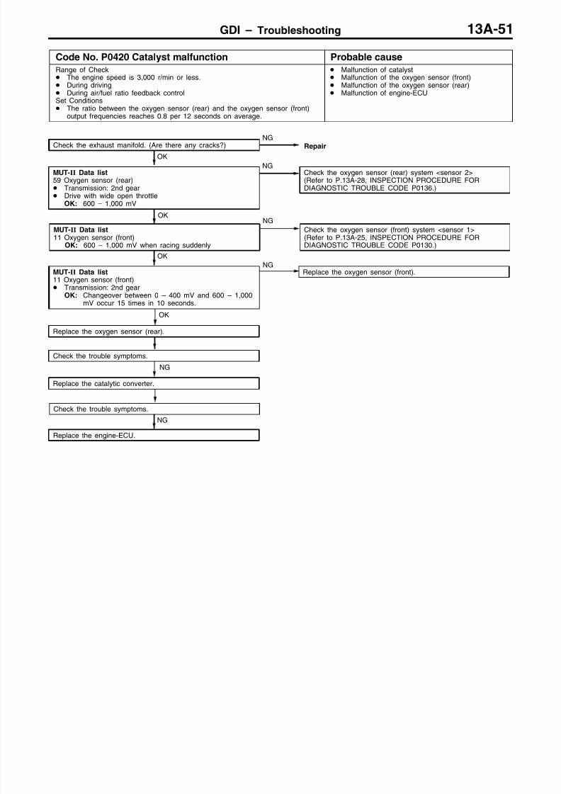
8/19/2019 13a Gasoline Direct Injection (Gdi) (1)
http://slidepdf.com/reader/full/13a-gasoline-direct-injection-gdi-1 168/269
GDI – Troubleshooting 13A-51
Code No. P0420 Catalyst malfunction Probable cause
Range of Check The engine speed is 3,000 r/min or less. During driving During air/fuel ratio feedback controlSet Conditions The ratio between the oxygen sensor (rear) and the oxygen sensor (front)
output frequencies reaches 0.8 per 12 seconds on average.
Malfunction of catalyst Malfunction of the oxygen sensor (front) Malfunction of the oxygen sensor (rear) Malfunction of engine-ECU
Check the trouble symptoms.
NG
Replace the catalytic converter.
Check the trouble symptoms.
OK
Replace the oxygen sensor (rear).
OK
MUT-II Data list
11 Oxygen sensor (front) Transmission: 2nd gear
OK: Changeover between 0 – 400 mV and 600 – 1,000mV occur 15 times in 10 seconds.
Replace the oxygen sensor (front).NG
MUT-II Data list11 Oxygen sensor (front)
OK: 600 – 1,000 mV when racing suddenly
OKNG
Check the oxygen sensor (front) system <sensor 1>(Refer to P.13A-25, INSPECTION PROCEDURE FORDIAGNOSTIC TROUBLE CODE P0130.)
OK
MUT-II Data list59 Oxygen sensor (rear) Transmission: 2nd gear Drive with wide open throttle
OK: 600 – 1,000 mV
NGCheck the oxygen sensor (rear) system <sensor 2>(Refer to P.13A-28, INSPECTION PROCEDURE FORDIAGNOSTIC TROUBLE CODE P0136.)
Check the exhaust manifold. (Are there any cracks?)NG
NG
Replace the engine-ECU.
Repair

8/19/2019 13a Gasoline Direct Injection (Gdi) (1)
http://slidepdf.com/reader/full/13a-gasoline-direct-injection-gdi-1 169/269
GDI – Troubleshooting13A-52
Code No. P0443 Purge control solenoid valve system Probable cause
Range of Check Ignition switch: ON Battery voltage is 10 V or more.Set Conditions The solenoid coil surge voltage (battery voltage + 2 V) is not detected
when the purge control solenoid valve is turned from on to off.
Malfunction of the purge control solenoid valve Open or short circuit in the purge control solenoid
valve circuit or loose connector contact Malfunction of engine-ECU
NG
Replace the engine-ECU.
OK
Check the trouble symptoms.
OKNG
RepairCheck the harness wires betweenthe purge control solenoid valve andthe engine control relay, andbetween the purge control solenoidvalve and the engine-ECU.
OK
Check the following connectors:A-36, C-17
NGRepair
NG
Check the harness wire betweenthe purge control solenoid valve andthe engine control relay, and repairif necessary.
NGCheck the following connector:A-36
NGRepair
OK
OK
Check the following connector:A-02
NGRepair
NG
Measure at the purge controlsolenoid valve connector A-02. Disconnect the connector, and
measure at the solenoid valveside.
The resistance betweenterminals 1 and 2OK: 28 – 36 Ω (at 20C)
NGReplace
Repair
MUT-II Actuator Test08 Purge control solenoid valveOK: Operating sound can be
heard and the valve vibrates.
OK
Intermittent malfunction(Refer to GROUP 00 – Points toNote for Intermittent Malfunctions.)
OK
OK
Measure at engine-ECU connectorC-17. Measure the voltage at the
engine-ECU terminal. Ignition switch: ON
The voltage between terminal 16and earthOK: System voltage
NGCheck the following connector:C-17
NGRepair
OK
NG
Replace the engine-ECU.
Check the harness wire betweenthe purge control solenoid valve andthe engine-ECU.
Measure at the purge controlsolenoid valve connector A-02. Disconnect the connector and
measure at the harness side. Ignition switch: ON The voltage between terminal 2
and earthOK: System voltage

8/19/2019 13a Gasoline Direct Injection (Gdi) (1)
http://slidepdf.com/reader/full/13a-gasoline-direct-injection-gdi-1 170/269
GDI – Troubleshooting 13A-53
Code No. P0500 Vehicle speed sensor system Probable cause
Range of Check Engine: Two seconds after the engine was started Idle switch: OFF Engine speed: 2,500 r/min or more During high engine loadSet Conditions The sensor output voltage does not change for 4 seconds (no pulse signal
input).
Malfunction of the vehicle speed sensor Open or short circuit in the vehicle speed sensor
circuit or loose connector contact Malfunction of engine-ECU
NOCheck the vehicle speed sensor(Refer to GROUP 54 – Combination Meter.)
YES
Use an analyzer to measure the output waveform of thevehicle speed sensor at engine-ECU connector C-19. Driving the vehicle The voltage between terminal 80 and earth
OK: A normal waveform should be displayed as de-scribed in OSCILLOSCOPE INSPECTION PROCE-DURE, and noise should not be displayed in thewaveform. (Refer to GROUP 23 – Troubleshooting.)
NG
NG
Repair
OK
Check the harness wire between vehicle speed sensor andthe engine-ECU, and repair if necessary.
OK
Check the following connector: C-19NG
Repair
OK
Check the trouble symptoms.
NG
Replace the engine-ECU.
Does the speedometer operate normally?
Check the following connectors:B-08, C-19, C-28, C-38 <LHD>, C-41 <RHD>, D-02
Code No. P1200 Injector driver system Probable cause
Range of Check Engine speed: 4,000 r/mimn or less Battery voltage: 10 V or more The fuel cut operation and the injector operation (by carrying out the
Actuator test) are not in progress. During high engine loadSet Conditions
Injector open circuit check signal is not output from the injector driver.
Malfunction of the injector driver Open or short circuit, or loose connector contact Malfunction of engine-ECU
OK
Use an analyzer to measure the signal waveform atengine-ECU connectors C-17, C-19. Engine: Idling The voltage between terminal 96 and earth, terminal 1
and earthOK: A normal waveform should be displayed as de-
scribed on P.13A-84* (INSPECTION PROCEDURE
USING AN ANALYZER).
NGReplace the injector driver.
OK
Check the harness wire between the injector driver and theengine-ECU
NGRepair
NG
Replace the engine-ECU.
Check the following connector: C-19NG
Repair
OK
Check the trouble symptoms.OK
Intermittent malfunction(Refer to GROUP 00 – Points to Note for IntermittentMalfunctions.)
NOTE*: Refer to the ’00 PAJERO PININ Workshop Manual (Pub. No. CKRE00E1)

8/19/2019 13a Gasoline Direct Injection (Gdi) (1)
http://slidepdf.com/reader/full/13a-gasoline-direct-injection-gdi-1 171/269
GDI – Troubleshooting13A-54
Code No. P1220 Electronic-controlled throttle valvesystem
Probable cause
Range of Check Ignition switch: ON Error in communication between the engine-ECU and the throttle valve
controllerSet Conditions Output voltage of throttle position sensor (2nd channel) fluctuates
significantly (approx. 1 V or more) from an expected value, based on thatof the accelerator pedal position sensor (2nd channel).
Range of Check Ignition switch: ON Error in communication between the throttle valve controller and the
engine-ECUSet Conditions The output voltage of the throttle position sensor (2nd channel) is
significantly different (approx. 1 V) from the throttle valve opening angle(voltage), which the engine-ECU request the throttle valve controller.
Short in communication line Malfunction of the engine-ECU Malfunction of the throttle valve controller
NG
Replace the engine-ECU.
Check the trouble symptoms.
NG
Replace the throttle valve controller.
OK
Check the trouble symptoms.
OK
Check the harness wire between the throttle valve controllerand the engine-ECU.
NGRepair
Check the following connectors:C-19, C-48
NGRepair

8/19/2019 13a Gasoline Direct Injection (Gdi) (1)
http://slidepdf.com/reader/full/13a-gasoline-direct-injection-gdi-1 172/269

8/19/2019 13a Gasoline Direct Injection (Gdi) (1)
http://slidepdf.com/reader/full/13a-gasoline-direct-injection-gdi-1 173/269
GDI – Troubleshooting13A-56
Code No. P1223 Communication line system with thethrottle valve controller
Probable cause
Range of Check Ignition switch: ON Battery voltage: 8 V or more. Engine: Not crankingSet Conditions System detects an error in communication line between the engine-ECU
and the throttle valve controller, and between the throttle valve controllerand the engine-ECU.
Short in communication line Malfunction of engine-ECU Malfunction of throttle valve controller
NG
Replace the throttle valve controller.
OK
OK
Check the harness wire between
the throttle valve controller and theengine-ECU.
NGRepair
Check the harness wire between thethrottle valve controller and earth, andrepair if necessary.
YESRefer to Code No. P1220,Electronic-controlled throttle valve system(Refer to P13A-54.)
NO
NGRepair
OK
Measure at throttle valve controllerconnector C-48. Measure voltage at the throttle
valve controller connectorterminals.
Ignition switch: ON(1) The voltage between terminal 5
and earthOK: System voltage
(2) The voltage between terminal 3and earthThe voltage between terminal 4and earthThe voltage between terminal 16and earthOK: 0.5 V or less
(1) NGCheck the following connector:A-36
NGRepair
OK
Check the harness wire between thethrottle valve controller and the enginecontrol relay, and repair if necessary.
NG
Replace the engine-ECU.
(2) NG
OK
Check the following connector:C-19
NGRepair
Check the following connector:C-48
Check the trouble symptoms.
Check the trouble symptoms.
MUT-II Self-Diag CodeIs Code No. P1220 output?
Check the following connector:A-36
NGRepair
OK

8/19/2019 13a Gasoline Direct Injection (Gdi) (1)
http://slidepdf.com/reader/full/13a-gasoline-direct-injection-gdi-1 174/269
GDI – Troubleshooting 13A-57
Code No. P1224 Throttle valve control servo motor(Motor 1st phase malfunction) system
Probable cause
Range of Check Throttle valve control servo relay: ON System voltage: 8 V or more.Set Conditions Throttle valve control servo drive circuit is shorted to earth. Other power source interferences with throttle valve control servo drive
circuit. Throttle valve control servo drive circuit is open circuit.
Malfunction of the throttle valve control servo Open circuit or short-circuited harness wire in
throttle valve control servo system, or poorconnector contact
Malfunction of the throttle valve controller
NGRepair
OK
Check the trouble symptoms.
NG
Replace the throttle valve controller.
NGReplace the throttle body assembly.
OKNG
Repair
OK
Measure at throttle valve controllerconnector C-48. Measure voltage at the throttle
valve controller connectorterminals.
Ignition switch: ON
The voltage between terminal 1,9 and earth(Accelerator pedal: Fully open tofully closed)OK: The battery voltage tempo-
rarily shows a slight de-crease.
The voltage between terminal14, 15 and earth(Accelerator pedal: Fully closedto fully open)OK: The battery voltage show a
slight (approximately 2 V)decrease.
NGCheck the following connector: A-05
NGRepair
OK
Check the harness wire between thethrottle valve control servo and the
throttle valve controller.
NG
Replace the engine-ECU.
OK
Check the trouble symptoms
Check the following connector:C-48
Check the throttle valve controlservo (Refer to P.13A-107*.)
NOTE*: Refer to the ’00 PAJERO PININ Workshop Manual (Pub. No. CKRE00E1)

8/19/2019 13a Gasoline Direct Injection (Gdi) (1)
http://slidepdf.com/reader/full/13a-gasoline-direct-injection-gdi-1 175/269
GDI – Troubleshooting13A-58
Code No. P1225 Accelerator pedal position sensor (2ndchannel) system
Probable cause
Range of Check Accelerator pedal position sensor (2nd channel) is normal. Communication between the engine-ECU and the throttle valve controller is
normal.Set Conditions Output voltage of the accelerator pedal position sensor (2nd channel) is 0.2
V or less for one secondor Output voltage of the accelerator pedal position sensor (1st channel) is 2.5
V or less, and output voltage of the accelerator pedal position sensor (2ndchannel) is 4.5 V or more for one second.
or Difference between the accelerator pedal position sensor (1st and 2nd
channels) output voltages exceeds 1.0 V (i.e. when the throttle valveopening angle changes slightly).
Malfunction of accelerator pedal position sensor(2nd channel)
Open or short circuit in accelerator pedal positionsensor (2nd channel) circuit or loose connectorcontact
Malfunction of the throttle valve controller Malfunction of engine-ECU
Check the harness wire betweenaccelerator pedal position sensor(2nd channel) and the throttle valvecontroller.
NGRepair
OK
OKIntermittent malfunction(Refer to GROUP 00 – Points toNote for Intermittent Malfunctions.)
NGNG
Replace
OK
(1) NGCheck the following connector:C-48
NGRepair
OK
Check the following connector:B-94
NGRepair
OK
Check the trouble symptoms.NG
Replace the throttle valve controller.
(2) NG OK
OK
Check the harness wire betweenaccelerator pedal position sensor(2nd channel) and the throttle valvecontroller, and repair if necessary.
NGRepair
NGNG
Repair
OK
Check the harness wire betweenaccelerator pedal position sensor(2nd channel) and the throttle valvecontroller.
NG Repair
OK
To the next page
OK
Check the trouble symptoms.NG
Replace the throttle valve controller.
MUT-II Data list77 Accelerator pedal position sensor
(2nd channel) (Refer toP.13A-94, DATA LISTREFERENCE TABLE.)
Check the following connector:C-48
Check the accelerator pedal position
sensor (Refer to P.13A-104*.)
Measure at throttle valve controllerconnector C-48. Measure voltage at the throttle
valve controller connectorterminals.
Ignition switch: ON The voltage between terminal 6
and earthOK: 4.8 – 5.2 V
Check the following connector:C-48
Measure at accelerator pedalposition sensor connector C-46. Disconnect the connector and
measure at the harness side.(1) The resistance between terminal
7 and earthOK: 2 Ω or less
(2) The voltage between terminal 8and earth(Ignition switch: ON)
OK: 4.8–
5.2 V
NOTE*: Refer to the ’00 PAJERO PININ Workshop Manual (Pub. No. CKRE00E1)

8/19/2019 13a Gasoline Direct Injection (Gdi) (1)
http://slidepdf.com/reader/full/13a-gasoline-direct-injection-gdi-1 176/269
GDI – Troubleshooting 13A-59
OK
Check the harness wire betweenaccelerator pedal position sensor (2ndchannel) and the throttle valve controller,and repair if necessary.
OK
Check the harness wire betweenaccelerator pedal position sensor (2ndchannel) and the throttle valve controller,and repair if necessary.
OK
Measure at throttle valve controllerconnector C-48. Measure voltage at the throttle
valve controller connectorterminals.
Ignition switch: ON The resistance between 20 and
earthOK: Accelerator pedal fully re-
leased: 0.7 – 1.4 VAccelerator pedal fully de-pressed: 4.1 V or higher
NGCheck the following connector: C-48
NGRepair
NGRepair
OK
Check the trouble symptoms.
OK
Measure at accelerator pedalposition sensor connector C-46. Use test harness (MB991658) to
connect terminals No. 6, No. 7,No. 8 only, and measure at thepick-up harness side.
Ignition switch: ON
(1) The voltage between terminal 6and earthOK: Accelerator pedal fully re-
leased: 0.7 – 1.4 VAccelerator pedal fully de-pressed: 4.1 V or higher
(2) The voltage between terminal 7and earthOK: 0.5 V or more
(3) The voltage between terminal 8and earthOK: 4.8 – 5.2 V
(1) NGAdjust the accelerator pedal positionsensor (Refer to P.13A-94*).
From the previous page
OK
Check the harness wire betweenaccelerator pedal position sensor (2ndchannel) and the throttle valve controller,and repair if necessary.
(2), (3) NGCheck the following connector: C-48
NGRepair
OKCheck the following connector: C-48
NGRepair
NG
Replace the throttle valve controller.
Check the following connector: C-48

8/19/2019 13a Gasoline Direct Injection (Gdi) (1)
http://slidepdf.com/reader/full/13a-gasoline-direct-injection-gdi-1 177/269
GDI – Troubleshooting13A-60
Code No. P1228 Throttle valve control servo motor(Motor 2nd phase malfunction) system
Probable cause
Range of Check Throttle valve control servo relay: ON System voltage: 8 V or moreSet Conditions Throttle valve control servo drive circuit is shorted to earth. Other power source interferes with throttle valve control servo drive circuit. Throttle valve control servo drive circuit is open-circuit.
Malfunction of the throttle valve control servo Open circuit or short-circuited harness wire in
throttle valve control servo system, or poorconnector contact
Malfunction of the throttle valve controller
NGRepair
OK
Check the trouble symptoms.
NG
Replace the throttle valve controller.
Check the throttle valve controlservo (Refer to P.13A-107*).
NGReplace the throttle body assembly.
OKNG
Repair
OK
Measure at throttle valve controllerconnector C-48. Measure voltage at the throttle
valve controller connectorterminals.
Ignition switch: ON The voltage between terminal 1,
9 and earth(Accelerator pedal: Fully open tofully closed)OK: The battery voltage tempo-
rarily shows a slight de-crease.
The voltage between terminal14, 15 and earth(Accelerator pedal: Fully closedto fully open)OK: The battery voltage show a
slight (approximately 2 V)decrease.
NGCheck the following connector: A-05
NGRepair
OK
NG
Replace the engine-ECU.
OK
Check the trouble symptoms.
Check the following connector:C-48
Check the harness wire between thethrottle valve control servo and thethrottle valve controller.
NOTE*: Refer to the ’00 PAJERO PININ Workshop Manual (Pub. No. CKRE00E1)
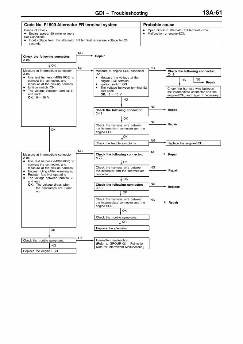
8/19/2019 13a Gasoline Direct Injection (Gdi) (1)
http://slidepdf.com/reader/full/13a-gasoline-direct-injection-gdi-1 178/269
GDI – Troubleshooting 13A-61
Code No. P1500 Alternator FR terminal system Probable cause
Range of Check Engine speed: 50 r/min or moreSet Conditions Input voltage from the alternator FR terminal is system voltage for 20
seconds.
Open circuit in alternator FR terminal circuit Malfunction of engine-ECU
OK
OK
Intermittent malfunction(Refer to GROUP 00 – Points toNote for Intermittent Malfunctions.)
NG
Replace the alternator.
OK
Check the trouble symptoms.
OK
Check the harness wire betweenthe intermediate connector and theengine-ECU.
NGRepair
OK
Check the trouble symptoms.NG
Replace the engine-ECU.
OK
Check the harness wire betweenthe intermediate connector and theengine-ECU.
NGRepair
OK
Check the harness wire betweenthe intermediate connector and theengine-ECU, and repair if necessary.
NGRepair
NG
Check the following connector:C-18
NGRepair
Check the following connector:
A-86
NGRepair
OK
Measure at intermediate connectorA-86. Use test harness (MB991658) to
connect the connector, andmeasure at the pick-up harness.
Engine: Idling (After warming up) Radiator fan: Not operating The voltage between terminal 2
and earthOK: The voltage drops when
the headlamps are turnedon.
NGCheck the following connector:A-79
NGRepair
Replace the engine-ECU.
OK
Measure at intermediate connectorA-86. Use test harness (MB991658) to
connect the connector, andmeasure at the pick-up harness.
Ignition switch: ON The voltage between terminal 6
and earthOK: 9 – 10 V
NGMeasure at engine-ECU connectorC-18. Measure the voltage at the
engine-ECU terminal. Ignition switch: ON The voltage between terminal 52
and earthOK: 9 – 10 V
NGCheck the following connector:C-18
OK
NGRepair
OK
Check the following connector:C-18
NGReplace
Check the harness wire betweenthe alternator and the intermediateconnector.
NGCheck the trouble symptoms.

8/19/2019 13a Gasoline Direct Injection (Gdi) (1)
http://slidepdf.com/reader/full/13a-gasoline-direct-injection-gdi-1 179/269
GDI – Troubleshooting13A-62
Code No. P1515 Brake vacuum sensor system Probable cause
Range of Check Ignition switch: ONSet Conditions Sensor output voltage is 4.8 V or more.or Sensor output voltage is 0.2 V or less.
Malfunction of the brake vacuum sensor Improper connector contact, open circuit or
short-circuited harness wire of the brake vacuumsensor
Malfunction of the engine-ECU
To the next page.
OK
OK
Check the trouble symptoms.NG
Replace the engine-ECU.
OK
Check the harness wire betweenthe brake vacuum sensor and theengine-ECU.
NGRepair
Check the following connectors:A-36, C-19
NG
Repair
(2) NG
OK
Check the trouble symptoms.NG
Replace the engine-ECU.
OK
Check the harness wire betweenthe brake vacuum sensor and theengine-ECU.
NGRepair
OK
Check the harness wire betweenthe brake vacuum sensor and the
engine-ECU, and repair if necessary.
NGRepair
OK
Check the following connector:C-18
NGRepair
Check the following connector:A-70
NGRepair
OK
Measure at brake vacuum sensorconnector A-56 Disconnect the connector and
measure at the harness side.(1) The voltage between terminal 3
and earth(Ignition switch: ON)
OK: 4.8–
5.2 V(2) Continuity between terminal 2and earthOK: 2Ω or less
(1) NGMeasure at engine-ECU connectorC-18. Measure the voltage at the
engine-ECU terminals. Ignition switch: ON The voltage between terminal 41
and earth
OK: 4.8–
5.2 V
NGCheck the following connector:C-18
MUT-II
Data list66 Brake vacuum sensorOK: (Refer to P.13A-94, DATA
LIST REFERENCE TABLE.)
OK
Intermittent malfunction (Refer toGROUP 00 – Points to Note forintermittent Malfunctions.)
NG

8/19/2019 13a Gasoline Direct Injection (Gdi) (1)
http://slidepdf.com/reader/full/13a-gasoline-direct-injection-gdi-1 180/269
GDI – Troubleshooting 13A-63
NG
Replace the engine-ECU.
OK
Check the trouble symptom.
OK
NGRepair
NG
NGRepair
OK
Check the trouble symptoms.
(2) NGReplace the brake vacuum sensor.
OK
Measure at engine-ECU connectorC-19. Measure the voltage at the
engine-ECU terminal. Engine: Idling The voltage between 74 and
earthOK: 0.9 – 1.5 V
NG Check the following connector:C-19
OK(1) NG
Check the following connector:C-18
NGRepair
OK
Check the following connectors:A-36, C-18, C-19
OK
Check the harness wire betweenthe brake vacuum sensor and theengine-ECU, and repair if necessary.
From the previous page
Check the harness wire betweenthe brake vacuum sensor and theengine-ECU, and repair if necessary.
Check the harness wire betweenthe brake vacuum sensor and theengine-ECU, and repair if necessary.
(3) NG
OK
Check the harness wire betweenthe brake vacuum sensor and theengine-ECU, and repair if necessary.
RepairNG
Measure at brake vacuum sensorconnector A-56. Use test harness (MB991348) to
connect terminals, and measure atthe pick-up harness side.
Engine: Idling(1) The voltage between 3 and earth
OK: 4.8–
5.2 V(2) The voltage between 1 and earthOK: 0.9 – 1.5 V
(3) The continuity between 2 andearthOK: 2 Ω or less
Check the following connector:C-19
Check the following connectors:
A-36, C-19

8/19/2019 13a Gasoline Direct Injection (Gdi) (1)
http://slidepdf.com/reader/full/13a-gasoline-direct-injection-gdi-1 181/269
GDI – TroubleshootingGDI – Troubleshooting13A-64
Cord No. P1600 Communication wire with A/T-ECUsystem
Probable cause
Range of Check After 60 seconds have passed since the engine have startedSet Conditions Torque reduction request signal from A/T-ECU is input continuously for 1.5
seconds or more.
Short circuit in ECU communication circuit Malfunction of the engine-ECU Malfunction of the A/T-ECU
Replace
NG
RepairCheck the following connectors:C-19, C-25<LHD>, C-26<RHD>, D-34, D-45
OK
Check trouble symptom.
NGOK
Replace the engine-ECU.
Check trouble symptom.
NG
Replace the A/T-ECU.
Check the harness wire between the engine-ECU and the A/T-ECU.
NG
Cord No. P1610 Immobilizer system Probable cause
Range of Check Ignition switch: ONSet Conditions Improper communication between the engine-ECU and the immobilizer-ECU
Open or short circuit, or loose connector contact Malfunction of the immobilizer-ECU Malfunction of the engine-ECU
NOTE(1) If the registered ignition keys are close each other when starting the engine, radio interference may
cause this code to be displayed.(2) This code may be displayed when registering the key ID code.
NG
Replace the engine-ECU.
Check the trouble symptoms.
NG
Replace the immobilizer-ECU.
OK
Check the trouble symptoms.
OK
Check the harness wire betweenthe immobilizer-ECU and theengine-ECU.
NG Replace
Check the following connectors:1, C-19, C-29, C-62
NGRepair

8/19/2019 13a Gasoline Direct Injection (Gdi) (1)
http://slidepdf.com/reader/full/13a-gasoline-direct-injection-gdi-1 182/269
GDI – Troubleshooting 13A-65
INSPECTION CHART FOR TROUBLE SYMPTOMS
Trouble symptom InspectionprocedureNo.
Reference page
Communication-
Communication with all systems is not possible. 1 13A-66w - simpossible. Communication with engine-ECU only is not possible. 2 13A-66
Engine warninglamp and
p
The engine warning lamp does not illuminate right after theignition switch is turned to the ON position.
3 13A-67
re a e par sThe engine warning lamp remains illuminating and never goesout.
4 13A-67
Starting No initial combustion (starting impossible) 5 13A-78
Initial combustion but no complete combustion(starting impossible)
6 13A-70
Long time to start (improper starting)
Idling stabilityp p
Unstable idling (Rough idling, hunting) 7 13A-71mproper ng
Idling speed is high. (Improper idling speed) 8 13A-73
Idling speed is low. (Improper idling speed)
Idling stability When the engine is cold, it stalls at idling. (Die out) 9 13A-74ng ne s a s
When the engine is hot, it stalls at idling. (Die out) 10 13A-75
The engine stalls when starting the car. (Pass out) 11 13A-77
The engine stalls when decelerating. 12 13A-78
Driving Hesitation, sag or stumble 13 13A-79
Poor acceleration
Surge
The feeling of impact or vibration when accelerating 14 13A-80
The feeling of impact or vibration when decelerating 15 13A-81
Knocking 16 13A-81
Dieseling 17 13A-81
Too high CO and HC concentration when idling 18 13A-82
Low alternator output voltage (approx. 12.3 V) 19 13A-83
Fans (radiator fan, A/C condenser fan) are inoperative 20 13A-84
GDI ECO indi-p -
GDI ECO indicator lamp does not illuminate. 21 13A-85ca or amp sys-tem GDI ECO indicator lamp remains illuminated and does not go off. 22 13A-85

8/19/2019 13a Gasoline Direct Injection (Gdi) (1)
http://slidepdf.com/reader/full/13a-gasoline-direct-injection-gdi-1 183/269

8/19/2019 13a Gasoline Direct Injection (Gdi) (1)
http://slidepdf.com/reader/full/13a-gasoline-direct-injection-gdi-1 184/269
GDI – Troubleshooting 13A-67
INSPECTION PROCEDURE 3
The engine warning lamp does not illuminate right afterthe ignition switch is turned to the ON position.
Probable cause
Because there is a burnt-out bulb, the engine-ECU <M/T> or engine-A/T-ECU <A/T>causes the engine warning lamp to illuminate for five seconds immediately afterthe ignition switch is turned to ON. If the engine warning lamp does not illuminateimmediately after the ignition switch is turned to ON, one of the malfunctions listedat right has probably occurred.
Burnt-out bulb Defective warning lamp circuit Malfunction of the engine-ECU <M/T> Malfunction of the engine-A/T-ECU <A/T>
MUT-II Data list16 engine-ECU (engine-A/T-ECU) power supply voltage (Referto P.13A-94.)
NGCheck the engine-ECU (engine-A/T-ECU) power supply and earthcircuit system.(Refer to P.13A-86, INSPECTION PROCEDURE 23.)
OK
Measure at the engine-ECU connector C-17. Disconnect the connector, and measure at the harness side. Earth the terminal No. 31.
OK: The engine warning lamp illuminates.
OKCheck the followingconnector: C-17
NGRepair
OK
Check trouble symptom.
NG
Replace the engine-ECU
NG
Check a burnt-out bulb.NG
Replace
OK
Measure at the combination meter connector C-06. Disconnect the connector, and measure at the harness side. Voltage between 1 and earth (Ignition switch: ON)
OK: System voltage
NGCheck the engine warning lamp power supply circuit, and repairif necessary.
OK
Check the following connectors:C-07, C-17, C-28
NGRepair
OK
Check trouble symptom.NG
Check the harness wire between combination meter and engine-ECU, and repair if necessary.
INSPECTION PROCEDURE 4
The engine warning lamp remains illuminating and nevergoes out.
Probable cause
In cases such as the above, the cause is probably that the engine-ECU is detectinga problem in a sensor or actuator, or that one of the malfunctions listed at righthas occurred.
Short-circuit between the engine warning lamp andengine-ECU
Malfunction of the engine-ECU
MUT-II Self-Diag codeAre diagnosis codes displayed?
YesRefer to P.13A-12, INSPECTION CHART FOR DIAGNOSISCODES.
No
Measure at the combination meter connector C-07. Disconnect the connector, and measure at the harness side. Disconnect the engine-ECU connector
Continuity between 46 and earthOK: No continuity
NGCheck the harness wire between combination meter and engine-ECU connector, and repair if necessary.
OK
Replace the engine-ECU
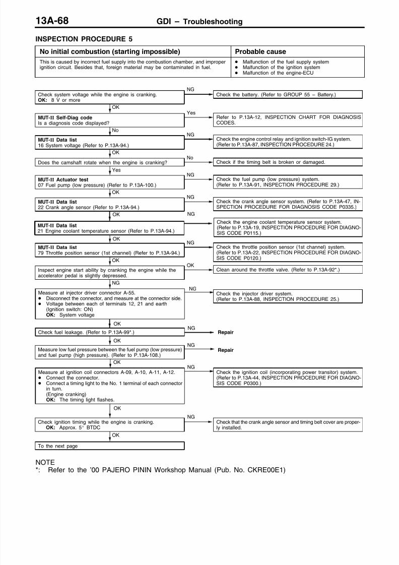
8/19/2019 13a Gasoline Direct Injection (Gdi) (1)
http://slidepdf.com/reader/full/13a-gasoline-direct-injection-gdi-1 185/269

8/19/2019 13a Gasoline Direct Injection (Gdi) (1)
http://slidepdf.com/reader/full/13a-gasoline-direct-injection-gdi-1 186/269
GDI – Troubleshooting 13A-69
Check trouble symptom.
OK
NGReplace the injector.
OK
Check ignition coil spark for each cylinder.(1) Remove the ignition coil.(2) Install a new spark plug to the removed ignition coil.(3) Disconnect the injector intermediate connector.
CautionNever touch the connector terminal as approx. 100 V isapplied to the injector, or you are seriously injured.
(4) Earth the spark plug electrode securely.(5) Check that the spark plug ignites when the engine is cranked.
NGReplace the ignition coil.
OK
Check all the following items: Spark plug Compression pressure Foreign material (such as water or kerosine) entered the fuel
lines
From the previous page

8/19/2019 13a Gasoline Direct Injection (Gdi) (1)
http://slidepdf.com/reader/full/13a-gasoline-direct-injection-gdi-1 187/269
GDI – Troubleshooting13A-70
INSPECTION PROCEDURE 6
Initial combustion takes place, but does not complete(start impossible), too long time to start (poor start)
Probable cause
This may be caused by improper spark plug ignition (poor spark), improper mixtureduring engine cranking, improper fuel pressure.
Malfunction of the fuel supply system Malfunction of the fuel pressure sensor Malfunction of the ignition system Malfunction of the electronic-controlled throttle valve
system
Malfunction of the engine-ECU <M/T> Malfunction of the engine-A/T-ECU <A/T>
Check trouble symptom.
OKNG
Replace the injector.
OK
Check all the following items: Spark plug Compression pressure Foreign material (such as water or kerosine) entered the fuel
lines
OK
Check ignition coil spark for each cylinder.(1) Remove the ignition coil.(2) Install a new spark plug to the removed ignition coil.(3) Disconnect the injector intermediate connector.
CautionNever touch the connector terminal as approx. 100 V isapplied to the injector, or you are seriously injured.
(4) Earth the spark plug electrode securely.(5) Check that the spark plug ignites when the engine is cranked.
NGReplace the ignition coil.
OK
Check ignition timing when the engine is cranked.OK: approx. 5 BTDC
NGCheck that the crank angle sensor and timing belt cover are proper-ly installed.
No
MUT-II Data list79 Throttle position sensor (1st channel) (Refer to P.13A-94.)
NGCheck the throttle valve position feedback system.(Refer to P.13A-55, INSPECTION PROCEDURE FOR DIAGNO-SIS CODE P1221.)
OK
Is the engine started normally when it is cranked with the accelera-tor pedal depressed slightly?
YesClean around the throttle valve. (Refer to P.13A-92*.)
Check fuel leakage. (Refer to P.13A-99*.)NG
Repair
OK
OK
MUT-II Data list74 Fuel pressure sensor (Refer to P.13A-94.)
NGCheck an abnormal fuel pressure system. (Refer to P.13A-33,INSPECTION PROCEDURE FOR DIAGNOSIS CODE P0190.)
OK
MUT-II Data list18 Cranking signal (Refer to P.13A-94.)
NG Check the ignition switch-ST system. <M/T>(Refer to P.13A-89, INSPECTION PROCEDURE 26.)Check the ignition switch-ST system and inhibitor switch sytem.<A/T> (Refer to P.13A-89, INSPECTION PROCEDURE 27.)
OK
MUT-II Data list
21 Engine coolant temperature sensor (Refer to P.13A-94.)
NGCheck the engine coolant temperature system. (Refer to P.13A-19,
INSPECTION PROCEDURE FOR DIAGNOSIS CODE P0115.)
No
MUT-II Actuator test07 Fuel pump (low pressure) (Refer to P.13A-100.)
NGCheck the fuel pump (low pressure) system.(Refer to P.13A-91, INSPECTION PROCEDURE 29.)
OK
MUT-II Self-Diag codeIs a diagnosis code displayed?
YesRefer to P.13A-12, INSPECTION CHART FOR DIAGNOSISCODES.
Check system voltage while the engine is cranking.OK: 8 V or more
NGCheck the battery. (Refer to GROUP 55 – Battery.)
NOTE*: Refer to the ’00 PAJERO PININ Workshop Manual (Pub. No. CKRE00E1)

8/19/2019 13a Gasoline Direct Injection (Gdi) (1)
http://slidepdf.com/reader/full/13a-gasoline-direct-injection-gdi-1 188/269
GDI – Troubleshooting 13A-71
INSPECTION PROCEDURE 7
Unstable idling (rough idle, hunting) Probable cause
This malfunction is probably caused by a faulty ignition system, improper air/fuelratio, a faulty electronic-controlled throttle valve system, improper compressionpressure, etc. As many causes can be suspected, diagnose from easier items.
Malfunction of the ignition system Malfunction of the air/fuel ratio control system Malfunction of the electronic-control throttle valve
system Improper compression pressure Air sucking into the air intake system
OK
MUT-II Data list11 Oxygen sensor (front)
OK: 600 – 1,000 mV when the engine is suddenly raced
NGCheck the oxygen sensor (front) system. (Refer to P.13A-25, IN-SPECTION PROCEDURE FOR DIAGNOSIS CODE P0130.)
OK
MUT-II Data list59 Oxygen sensor (rear) Transmission: 2nd gear <M/T>, L range <A/T> Driving with throttle widely open
OK: 600 – 1,000 mV
NGCheck the oxygen sensor (rear) system. (Refer to P.13A-28, IN-SPECTION PROCEDURE FOR DIAGNOSIS CODE P0136.)
OK
MUT-II Actuator test08 Purge control solenoid valve (Refer to P.13A-100.)
NG
Check the purge control solenoid valve system. (Refer to P.13A-52,INSPECTION PROCEDURE FOR DIAGNOSIS CODE P0443.)
OK
MUT-II Data list21 Engine coolant temperature sensor (Refer to P.13A-94.)
NGCheck the engine coolant temperature sensor. (Refer to P.13A-19,INSPECTION PROCEDURE FOR DIAGNOSIS CODE P0115.)
OK
MUT-II Data list25 Barometric pressure sensor (Refer to P.13A-94.)
NGCheck the barometric pressure sensor system. (Refer to P.13A-16,INSPECTION PROCEDURE FOR DIAGNOSIS CODE P0105.)
OK
MUT-II Data list13 Intake air temperature sensor (Refer to P.13A-94.)
NGCheck the intake air temperature sensor system.(Refer to P.13A-18, INSPECTION PROCEDURE FOR DIAGNO-SIS CODE P0110.)
OK
MUT-II Data list26 Accelerator pedal position switch (Refer to P.13A-94.)
NGCheck the accelerator pedal position switch system. (Refer toP.13A-90, INSPECTION PROCEDURE 28.)
No
MUT-II Data list79 Throttle position sensor (1st channel) (Refer to P.13A-94.)
NGCheck the throttle valve position feedback system.(Refer to P.13A-55, INSPECTION PROCEDURE FOR DIAGNO-SIS CODE P1221.)
No
Does the engine idle speed fluctuates excessively (excessivehunting)?
YesClean around the throttle valve. (Refer to P.13A-92*.)
No
MUT-II Self-Diag codeIs a diagnosis code displayed?
YesRefer to P.13A-12, INSPECTION CHART FOR DIAGNOSISCODES.
Has the battery been disconnected recently?
Yes
Warm up the engine, and then let it run at idle for approx. tenminutes.
OK
To the next page
NOTE*: Refer to the ’00 PAJERO PININ Workshop Manual (Pub. No. CKRE00E1)

8/19/2019 13a Gasoline Direct Injection (Gdi) (1)
http://slidepdf.com/reader/full/13a-gasoline-direct-injection-gdi-1 189/269
GDI – Troubleshooting13A-72
OK
Check all the following items in that order.(1) Spark plugs(2) Exhaust gas emission control system(3) EGR system(4) Compression pressure(5) Foreign material (such as water or kerosine) entered the fuel
line.
(6) Air is sucked in the air intake system, or EGR gas leaks. Damaged intake manifold gasket Damaged air intake hose Damaged vacuum hose Faulty EGR valve seat
Check ignition coil spark for each cylinder.
(1) Remove the ignition coil.(2) Install a new spark plug to the removed ignition coil.(3) Disconnect the injector intermediate connector.
CautionNever touch the connector terminal as approx. 100 V isapplied to the injector, or you are seriously injured.
(4) Earth the spark plug electrode securely.(5) Check that the spark plug ignites when the engine is cranked.
NGReplace the ignition coil.
NG
Check trouble symptom.
OK
Clean around the throttle valve. (Refer to P.13A-92*.)
OK
NGCheck that the crank angle sensor and timing belt cover are proper-ly installed.
Check ignition timing. (Refer to GROUP 11A – Engine Adjustment.)
OK
MUT-II Data list68 EGR valve (Refer to P.13A-94.)
NGCheck the EGR valve. (Refer to P.13A-50, INSPECTION PROCE-DURE FOR DIAGNOSIS CODE P0403.)
OK
MUT-II Data list31 Small lamp switch (Refer to P.13A-94.)
NG Check the small lamp switch system. (Refer to P.13A-93, INSPEC-TION PROCEDURE 33.)
MUT-II Data list67 Stop lamp switch (Refer to P.13A-94.)
NGCheck the stop lamp switch. (Refer to P.13A-93, INSPECTIONPROCEDURE 32.)
OK
OK
MUT-II Data list28 A/C switch (Refer to P.13A-94.)
NG Check the A/C switch and A/C relay system. (Refer to P.13A-92,INSPECTION PROCEDURE 31.)
MUT-II Data list27 Power steering fluid pressure switch (Refer to P.13A-94.)
NGCheck the power steering fluid pressure switch system. (Referto P.13A-92, INSPECTION PROCEDURE 30.)
OK
OK
Check that air is sucked in the air intake system. Broken intake manifold gasket
Damaged vacuum hose Damaged air intake hose
NG
Repair
OK
MUT-II Data list11 Oxygen sensor (front)
OK: 0 – 400 mV and 600 – 1,000 mV alternates when theengine is idling (wait for four minutes after the enginestarted).
NGMeasure fuel high-pressure between the fuel pump (high pressure)and injector. (Refer to P.13A-108.)
From the previous page
NOTE*: Refer to the ’00 PAJERO PININ Workshop Manual (Pub. No. CKRE00E1)
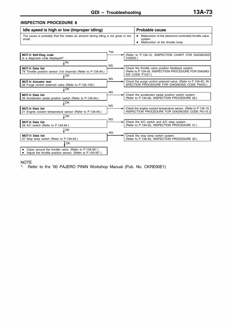
8/19/2019 13a Gasoline Direct Injection (Gdi) (1)
http://slidepdf.com/reader/full/13a-gasoline-direct-injection-gdi-1 190/269
GDI – Troubleshooting 13A-73
INSPECTION PROCEDURE 8
Idle speed is high or low (Improper idling) Probable cause
The cause is probably that the intake air amount during idling is too great or toosmall.
Malfunction of the electronic-controlled throttle valvesystem
Malfunction of the throttle body
OK
Clean around the throttle valve. (Refer to P.13A-92*.) Adjust the throttle position sensor. (Refer to P.13A-92*.)
MUT-II Data list67 Stop lamp switch (Refer to P.13A-94.)
NGCheck the stop lamp switch system.(Refer to P.13A-93, INSPECTION PROCEDURE 32.)
OK
OK
MUT-II Data list28 A/C switch (Refer to P.13A-94.)
NGCheck the A/C switch and A/C relay system.(Refer to P.13A-92, INSPECTION PROCEDURE 31.)
OK
MUT-II Data list21 Engine coolant temperature sensor (Refer to P.13A-94.)
NGCheck the engine coolant temperature sensor. (Refer to P.13A-19,INSPECTION PROCEDURE FOR DIAGNOSIS CODE P0115.)
OK
MUT-II Data list26 Accelerator pedal position switch (Refer to P.13A-94.)
NGCheck the accelerator pedal position switch system.(Refer to P.13A-90, INSPECTION PROCEDURE 28.)
OK
MUT-II Actuator test08 Purge control solenoid valve (Refer to P.13A-100.)
NGCheck the purge control solenoid valve. (Refer to P.13A-52, IN-SPECTION PROCEDURE FOR DIAGNOSIS CODE P0443.)
No
MUT-II Data list79 Throttle position sensor (1st channel) (Refer to P.13A-94.)
NGCheck the throttle valve position feedback system.(Refer to P.13A-55, INSPECTION PROCEDURE FOR DIAGNO-SIS CODE P1221.)
MUT-II Self-Diag code
Is a diagnosis code displayed?
Yes(Refer to P.13A-12, INSPECTION CHART FOR DIAGNOSIS
CODES.)
NOTE*: Refer to the ’00 PAJERO PININ Workshop Manual (Pub. No. CKRE00E1)

8/19/2019 13a Gasoline Direct Injection (Gdi) (1)
http://slidepdf.com/reader/full/13a-gasoline-direct-injection-gdi-1 191/269
GDI – Troubleshooting13A-74
INSPECTION PROCEDURE 9
When the engine is cold, it stalls at idling. (Die out) Probable cause
The cause is probably an incorrect air/fuel ratio or poor intake air amount whenthe engine is cold.
Malfunction of the electronic-control throttle valvesystem
Malfunction of the throttle body
NG
Replace the injector.
OK
Check ignition coil spark for each cylinder.(1) Remove the ignition coil.(2) Install a new spark plug to the removed ignition coil.(3) Disconnect the injector intermediate connector.
CautionNever touch the connector terminal as approx. 100 V isapplied to the injector, or you are seriously injured.
(4) Earth the spark plug electrode securely.(5) Check that the spark plug ignites when the engine is cranked.
NGReplace the ignition coil.
OK
Check ignition timing. (Refer to GROUP 11A – Engine Adjustment.)NG
Check that the crank angle sensor and timing belt cover are proper-ly installed.
No
Measure fuel high pressure between the fuel pump (high pressure)and injector. (Refer to P.13A-108.)
NGRepair
OK
Does the engine stall immediately after the accelerator pedal isreleased?
YesClean around the throttle valve.(Refer to P.13A-91*.)
OK
MUT-II Data list68 EGR valve (Refer to P.13A-94.)
NGCheck the EGR valve system. (Refer to P.13A-50, INSPECTIONPROCEDURE FOR DIAGNOSIS CODE P0403.)
OK
MUT-II Data list21 Engine coolant temperature sensor (Refer to P.13A-94.)
NGCheck the engine coolant temperature sensor. (Refer to P.13A-19,INSPECTION PROCEDURE FOR DIAGNOSIS CODE P0115.)
OK
MUT-II Data list26 Accelerator pedal position switch (Refer to P.13A-94.)
NGCheck the accelerator position switch.(Refer to P.13A-90, INSPECTION PROCEDURE 28.)
No
MUT-II Data list22 Crank angle sensor (Refer to P.13A-94.)
Check idling speed when the engine is cold.
NGCheck the throttle valve position feedback system.(Refer to P.13A-55, INSPECTION PROCEDURE FOR DIAGNO-SIS CODE P1221.)
No
Is the engine idling correct after the engine has been warmed up?Yes
Refer to “Unstable idling (rough idle, hunting).(Refer to P.13A-71, INSPECTION PROCEDURE 7.)
No
MUT-II Self-Diag codeIs a diagnosis code displayed?
Yes(Refer to P.13A-12, INSPECTION CHART FOR DIAGNOSISCODES.)
Have the battery terminals been disconnected recently?Yes
Warm up the engine, and then let it run at idle for approx. ten
minutes.
OK
Check all the following items: Spark plugs
Compression pressure Engine oil viscosity
Check trouble symptom.OK
NOTE*: Refer to the ’00 PAJERO PININ Workshop Manual (Pub. No. CKRE00E1)

8/19/2019 13a Gasoline Direct Injection (Gdi) (1)
http://slidepdf.com/reader/full/13a-gasoline-direct-injection-gdi-1 192/269
GDI – Troubleshooting 13A-75
INSPECTION PROCEDURE 10
When the engine is hot, it stalls at idling. (Die out) Probable cause
The cause is probably an improper air/fuel ratio, faulty electronic-controlled throttlevalve system, compression pressure. In addition, if the engine stalls suddenly, anotherpossible cause might be a poor connector contact.
Malfunction of the ignition system Malfunction of air/fuel ratio control system Malfunction of electronic-controlled throttle valve
system Malfunction of the throttle body Poor connector contact Improper compression pressure
Air stuck in the air intake system
OK
Check that air is sucked in the air intake system. Broken intake manifold gasket Damaged vacuum hose Damaged air intake hose
OK
To the next page
OK
MUT-II Data list11 Oxygen sensor (front)
OK: 0 – 400 mV and 600 – 1,000 mV alternates when theengine is idling (wait for four minutes after the enginestarted).
NGMeasure fuel high-pressure between the fuel pump (high pressure)and injector. (Refer to P.13A-108.)
OK
MUT-II Data list59 Oxygen sensor (rear) Transmission: 2nd gear <M/T>, L range <A/T> Driving with throttle widely open
OK: 600 – 1,000 mV
NGCheck the oxygen sensor (rear) system. (Refer to P.13A-28, IN-SPECTION PROCEDURE FOR DIAGNOSIS CODE P0136.)
OK
MUT-II Data list21 Engine coolant temperature sensor (Refer to P.13A-94.)
NGCheck the engine coolant temperature sensor. (Refer to P.13A-19,INSPECTION PROCEDURE FOR DIAGNOSIS CODE P0115.)
Yes
MUT-II Data list26 Accelerator pedal position switch (Refer to P.13A-94.)
NGCheck the accelerator pedal position switch.(Refer to P.13A-90, INSPECTION PROCEDURE 28.)
OK
Is it easy to reproduce the engine stall?No
While carrying out an intermittent malfunction simulation test. (Re-fer to GROUP 00 – Points to Note for Intermittent Malfunction.),
check for sudden changes in the following signals. Crank angle sensor signal Injector drive signal Fuel pump (low pressure) drive signal Air flow sensor Primary ignition signal Power supply to the engine-ECU
No
MUT-II Data list79 Throttle position sensor (1st channel) (Refer to P.13A-94.)
NGCheck the throttle valve position feedback system.(Refer to P.13A-55, INSPECTION PROCEDURE FOR DIAGNO-SIS CODE P1221.)
No
MUT-II Self-Diag codeIs a diagnosis code displayed?
YesRefer to P.13A-12, INSPECTION CHART FOR DIAGNOSISCODES.
NG
Repair
Have the battery terminals been disconnected recently?Yes
Warm up the engine, and then let it run at idle for approx. tenminutes.
OK
MUT-II Data list13 Intake air temperature sensor (Refer to P.13A-94.)
NGCheck the intake air temperature sensor. (Refer to P.13A-18, IN-SPECTION PROCEDURE FOR DIAGNOSIS CODE P0110.)
OK
MUT-II
Data list25 Barometric pressure sensor (Refer to P.13A-94.)
NG
Check the barometric pressure sensor. (Refer to P.13A-16, IN-SPECTION PROCEDURE FOR DIAGNOSIS CODE P0105.)
OK
MUT-II Data list11 Oxygen sensor (front)
OK: 600 – 1,000 mV when the engine is suddenly raced
NGCheck the oxygen sensor (front) system. (Refer to P.13A-25, IN-SPECTION PROCEDURE FOR DIAGNOSIS CODE P0130.)
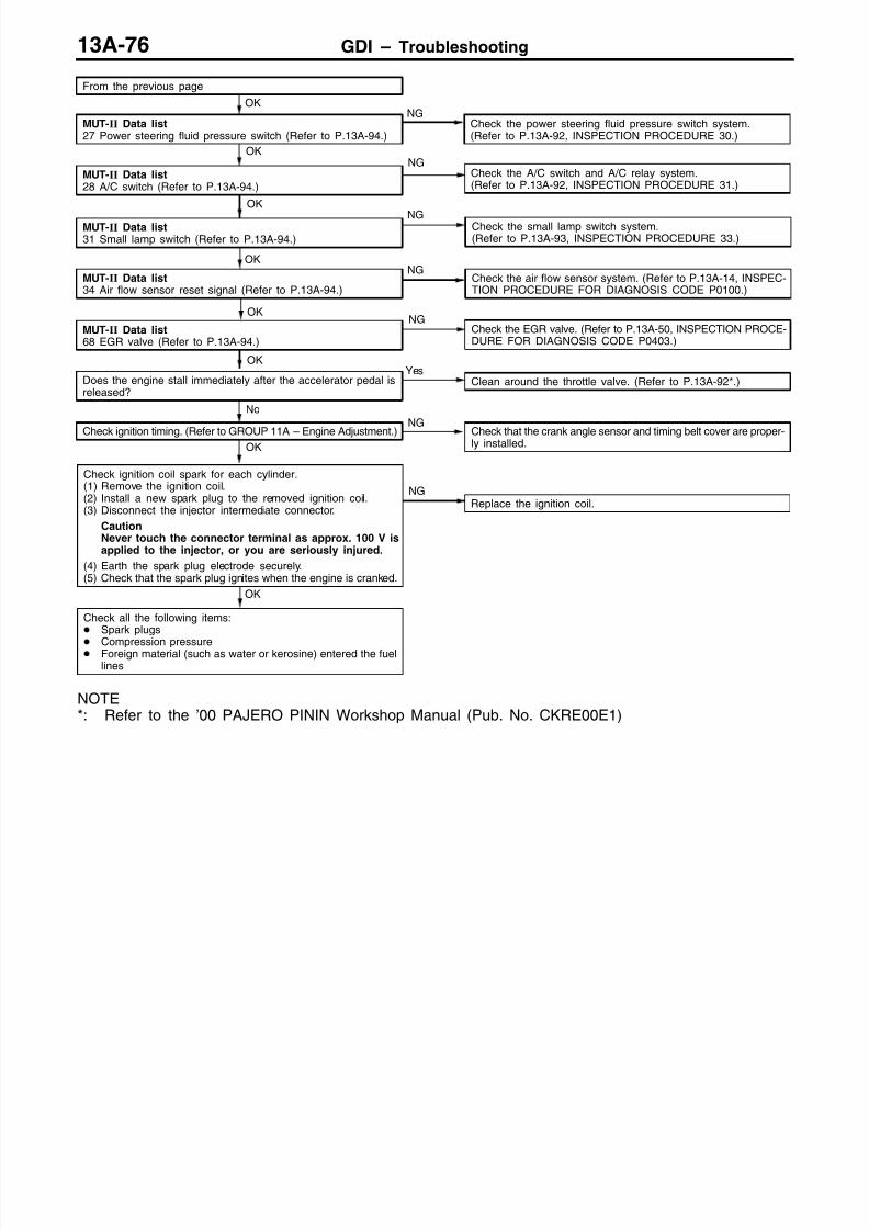
8/19/2019 13a Gasoline Direct Injection (Gdi) (1)
http://slidepdf.com/reader/full/13a-gasoline-direct-injection-gdi-1 193/269
GDI – Troubleshooting13A-76
OK
Check all the following items: Spark plugs
Compression pressure Foreign material (such as water or kerosine) entered the fuellines
OK
Check ignition coil spark for each cylinder.(1) Remove the ignition coil.(2) Install a new spark plug to the removed ignition coil.(3) Disconnect the injector intermediate connector.
CautionNever touch the connector terminal as approx. 100 V isapplied to the injector, or you are seriously injured.
(4) Earth the spark plug electrode securely.(5) Check that the spark plug ignites when the engine is cranked.
NGReplace the ignition coil.
No
NGCheck that the crank angle sensor and timing belt cover are proper-ly installed.
Check ignition timing. (Refer to GROUP 11A – Engine Adjustment.)
OKYes
Clean around the throttle valve. (Refer to P.13A-92*.)Does the engine stall immediately after the accelerator pedal isreleased?
OK
MUT-II Data list68 EGR valve (Refer to P.13A-94.)
NGCheck the EGR valve. (Refer to P.13A-50, INSPECTION PROCE-DURE FOR DIAGNOSIS CODE P0403.)
MUT-II Data list34 Air flow sensor reset signal (Refer to P.13A-94.)
NGCheck the air flow sensor system. (Refer to P.13A-14, INSPEC-TION PROCEDURE FOR DIAGNOSIS CODE P0100.)
OK
MUT-II Data list31 Small lamp switch (Refer to P.13A-94.)
NGCheck the small lamp switch system.(Refer to P.13A-93, INSPECTION PROCEDURE 33.)
OK
OK
MUT-II Data list28 A/C switch (Refer to P.13A-94.)
NGCheck the A/C switch and A/C relay system.(Refer to P.13A-92, INSPECTION PROCEDURE 31.)
OK
MUT-II Data list27 Power steering fluid pressure switch (Refer to P.13A-94.)
NGCheck the power steering fluid pressure switch system.(Refer to P.13A-92, INSPECTION PROCEDURE 30.)
From the previous page
NOTE*: Refer to the ’00 PAJERO PININ Workshop Manual (Pub. No. CKRE00E1)

8/19/2019 13a Gasoline Direct Injection (Gdi) (1)
http://slidepdf.com/reader/full/13a-gasoline-direct-injection-gdi-1 194/269
GDI – Troubleshooting 13A-77
INSPECTION PROCEDURE 11
The engine stalls when starting the car. (Pass out) Probable cause
The cause is probably poor ignition due to a malfunctioning spark plug (weak spark),or an incorrect air/fuel ratio when the accelerator is depressed.
Malfunction of the ignition system Malfunction of the EGR valve Air stuck in the air intake system
OK
MUT-II Actuator test08 Purge control solenoid valve (Refer to P.13A-100.)
NGCheck the purge control solenoid valve system. (Refer to P.13A-52,INSPECTION PROCEDURE FOR DIAGNOSIS CODE P0443.)
No
MUT-II Data list68 EGR valve (Refer to P.13A-94.)
NGCheck the EGR valve. (Refer to P.13A-50, INSPECTION PROCE-DURE FOR DIAGNOSIS CODE P0403.)
MUT-II Self-Diag code
Is a diagnosis code displayed?
Yes(Refer to P.13A-12, INSPECTION CHART FOR DIAGNOSIS
CODES.)
OK
Check ignition coil spark for each cylinder.(1) Remove the ignition coil.(2) Install a new spark plug to the removed ignition coil.(3) Disconnect the injector intermediate connector.
CautionNever touch the connector terminal as approx. 100 V is
applied to the injector, or you are seriously injured.
(4) Earth the spark plug electrode securely.(5) Check that the spark plug ignites when the engine is cranked.
NGReplace the ignition coil.
OK
Check all the following items:(1) Spark plug(2) Check if air is stuck in the air intake system.
Damage intake manifold gasket Damaged or disconnected vacuum hose Damaged air intake hose

8/19/2019 13a Gasoline Direct Injection (Gdi) (1)
http://slidepdf.com/reader/full/13a-gasoline-direct-injection-gdi-1 195/269

8/19/2019 13a Gasoline Direct Injection (Gdi) (1)
http://slidepdf.com/reader/full/13a-gasoline-direct-injection-gdi-1 196/269
GDI – Troubleshooting 13A-79
INSPECTION PROCEDURE 13
Hesitation, sag, stumble, poor acceleration or surge Probable cause
The cause is probably a malfunction of the ignition system, electronic-controlledthrottle valve system, compression pressure, etc.
Malfunction of the ignition system Malfunction of the air/fuel ratio control system Malfunction of the electronic-controlled throttle valve
system Improper compression pressure Air stuck in the air intake system
OK
To the next page
OK
MUT-II Actuator test08 Purge control solenoid valve (Refer to P.13A-100.)
NGCheck the purge control solenoid valve. (Refer to P.13A-52, IN-SPECTION PROCEDURE FOR DIAGNOSIS CODE P0443.)
OK
MUT-II Data list68 EGR valve (Refer to P.13A-94.)
NG Check the EGR valve. (Refer to P.13A-50, INSPECTION PROCE-DURE FOR DIAGNOSIS CODE P0403.)
OK
Check that air is sucked in the air intake system. Broken intake manifold gasket Damaged vacuum hose Damaged air intake hose
OK
MUT-II Data list11 Oxygen sensor (front)
OK: 0 – 400 mV and 600 – 1,000 mV alternates when theengine is idling (wait for four minutes after the enginestarted).
NGMeasure fuel high-pressure between the fuel pump (high pressure)and injector. (Refer to P.13A-108.)
OK
MUT-II Data list11 Oxygen sensor (front)
OK: 600 – 1,000 mV when the engine is suddenly raced
NGCheck the oxygen sensor (front) system. (Refer to P.13A-25, IN-SPECTION PROCEDURE FOR DIAGNOSIS CODE P0130.)
OK
MUT-II Data list59 Oxygen sensor (rear) Transmission: 2nd gear <M/T>, L range <A/T> Driving with throttle widely open
OK: 600 – 1,000 mV
NGCheck the oxygen sensor (rear) system. (Refer to P.13A-28, IN-SPECTION PROCEDURE FOR DIAGNOSIS CODE P0136.)
OK
MUT-II Data list79 Throttle position sensor (1st channel) (Refer to P.13A-94.)
NGCheck the throttle valve position feedback system.(Refer to P.13A-55, INSPECTION PROCEDURE FOR DIAGNO-SIS CODE P1221.)
OK
MUT-II Data list21 Engine coolant temperature sensor (Refer to P.13A-94.)
NGCheck the engine coolant temperature sensor. (Refer to P.13A-19,INSPECTION PROCEDURE FOR DIAGNOSIS CODE P0115.)
OK
MUT-II Data list25 Barometric pressure sensor (Refer to P.13A-94.)
NGCheck the barometric pressure sensor. (Refer to P.13A-16, IN-SPECTION PROCEDURE FOR DIAGNOSIS CODE P0105.)
OK
MUT-II Data list13 Intake air temperature sensor (Refer to P.13A-94.)
NGCheck the intake air temperature sensor. (Refer to P.13A-18, IN-SPECTION PROCEDURE FOR DIAGNOSIS CODE P0110.)
OK
NGCheck the accelerator pedal position switch.(Refer to P.13A-90, INSPECTION PROCEDURE 28.)
MUT-II Data list26 Accelerator pedal position switch (Refer to P.13A-94.)
No
Check ignition timing. (Refer to GROUP 11A – Engine Adjustment.)NG
Check that the crank angle sensor and timing belt cover are proper-ly installed.
MUT-II Self-Diag codeIs a diagnosis code displayed?
Yes(Refer to P.13A-12, INSPECTION CHART FOR DIAGNOSISCODES.)

8/19/2019 13a Gasoline Direct Injection (Gdi) (1)
http://slidepdf.com/reader/full/13a-gasoline-direct-injection-gdi-1 197/269
GDI – Troubleshooting13A-80
NG
Replace the injector.
OK
Check all the following items: Spark plug EGR system Compression pressure Clogged fuel filter, fuel line
Check trouble symptom.OK
OK
Check ignition coil spark for each cylinder.(1) Remove the ignition coil.(2) Install a new spark plug to the removed ignition coil.
(3) Disconnect the injector intermediate connector.CautionNever touch the connector terminal as approx. 100 V isapplied to the injector, or you are seriously injured.
(4) Earth the spark plug electrode securely.(5) Check that the spark plug ignites when the engine is cranked.
NGReplace the ignition coil.
OK
Measure high fuel pressure between the fuel pump (high pressure)and injector. (Refer to P.13A-108.)
NGRepair
From the previous page
INSPECTION PROCEDURE 14
The feeling of impact when accelerating Probable causeThe cause is probably an ignition leak being generated in line with an increasein the spark plug request voltage during acceleration.
Malfunction of the ignition system
NGReplace the ignition coil.
OK
Check ignition coil spark for each cylinder.(1) Remove the ignition coil.(2) Install a new spark plug to the removed ignition coil.(3) Disconnect the injector intermediate connector.
CautionNever touch the connector terminal as approx. 100 V isapplied to the injector, or you are seriously injured.
(4) Earth the spark plug electrode securely.(5) Check that the spark plug ignites when the engine is cranked.
OKCheck all the following items: Spark plug Ignition current leak
No
MUT-II Data list79 Throttle position sensor (1st channel) (Refer to P.13A-94.)
NGCheck the throttle valve position feedback system.(Refer to P.13A-55, INSPECTION PROCEDURE FOR DIAGNO-SIS CODE P1221.)
MUT-II Self-Diag codeIs a diagnosis code displayed?
Yes(Refer to P.13A-12, INSPECTION CHART FOR DIAGNOSISCODES.)

8/19/2019 13a Gasoline Direct Injection (Gdi) (1)
http://slidepdf.com/reader/full/13a-gasoline-direct-injection-gdi-1 198/269
GDI – Troubleshooting 13A-81
INSPECTION PROCEDURE 15
The feeling of impact when decelerating Probable cause
The cause is probably insufficient intake air due to a faulty electronic-controlledthrottle valve system.
Malfunction of the electronic-controlled throttle valvesystem
OK
MUT-II Data list26 Accelerator pedal position switch (Refer to P.13A-94.)
NGCheck the accelerator pedal position switch system.(Refer to P.13A-90, INSPECTION PROCEDURE 28.)
No
MUT-II Data list79 Throttle position sensor (1st channel) (Refer to P.13A-94.)
NGCheck the throttle valve position feedback system.(Refer to P.13A-55, INSPECTION PROCEDURE FOR DIAGNO-SIS CODE P1221.)
MUT-II Self-Diag codeIs a diagnosis code displayed?
Yes(Refer to P.13A-12, INSPECTION CHART FOR DIAGNOSISCODES.)
OK
Clean around the throttle valve. (Refer to P.13A-92*.)
NOTE*: Refer to the ’00 PAJERO PININ Workshop Manual (Pub. No. CKRE00E1)
INSPECTION PROCEDURE 16
Knocking Probable cause
The cause is probably incorrect detonation control or improper heat range of thespark plugs.
Malfunction of the detonation sensor Improper heat range of the spark plugs
Yes
Check all the following items: Spark plug Foreign material (such as water or kerosine) entered the fuel
lines
No
Does knocking occur when the vehicle is driven with the detonationsensor disconnected?(At this time, use the MUT-II to check whether the ignition timing
is retarded from when the detonation sensor connector is con-nected.)
NoCheck the detonation sensor system. (Refer to P.13A-47, INSPEC-TION PROCEDURE FOR DIAGNOSIS CODE P0325.)
MUT-II Self-Diag codeIs a diagnosis code displayed?
Yes(Refer to P.13A-12, INSPECTION CHART FOR DIAGNOSISCODES.)
INSPECTION PROCEDURE 17
Run-on (dieseling) Probable causeThe cause is probably fuel leak from injector(s) Malfunction of the injector
Replace the injector.

8/19/2019 13a Gasoline Direct Injection (Gdi) (1)
http://slidepdf.com/reader/full/13a-gasoline-direct-injection-gdi-1 199/269
GDI – Troubleshooting13A-82
INSPECTION PROCEDURE 18
Too high CO and HC concentration when idling Probable cause
The cause is probably an incorrect air/fuel ratio Malfunction of air/fuel ratio control system Deterioration of the catalyst
OK
To the next page
OK
Check all the following items: Spark plug EGR system Compression pressure Clogged fuel filter or line
NG
Replace the ignition coil.
NG
OK
Check ignition coil spark for each cylinder.(1) Remove the ignition coil.(2) Install a new spark plug to the removed ignition coil.(3) Disconnect the injector intermediate connector.
CautionNever touch the connector terminal as approx. 100 V is applied to the injector, or you are seriously injured.
(4) Earth the spark plug electrode securely.(5) Check that the spark plug ignites when the engine is cranked.
NG
Measure fuel high-pressure between the fuel pump (high pressure)and injector. (Refer to P.13A-108.)
NGRepair
Check trouble symptom.
OK
MUT-II Data list11 Oxygen sensor (front)
OK: 0 – 400 mV and 600 – 1,000 mV alternates when theengine is idling (wait for four minutes after the enginestarted).
OKReplace the oxygen sensor (front).
OK
NGCheck the oxygen sensor (front) system. (Refer to P.13A-25, IN-SPECTION PROCEDURE FOR DIAGNOSIS CODE P0130.)
MUT-II Data list11 Oxygen sensor (front)
OK: 600 – 1,000 mV when the engine is suddenly raced
OK
MUT-II Data list59 Oxygen sensor (rear) Transmission: 2nd gear <M/T>, L range <A/T> Driving with throttle widely open
OK: 600 – 1,000 mV
NGCheck the oxygen sensor (rear) system. (Refer to P.13A-28, IN-SPECTION PROCEDURE FOR DIAGNOSIS CODE P0136.)
OK
MUT-II Data list25 Barometric pressure sensor (Refer to P.13A-94.)
NGCheck the barometric pressure sensor. (Refer to P.13A-16, IN-SPECTION PROCEDURE FOR DIAGNOSIS CODE P0105.)
OK
MUT-II Data list13 Intake air temperature sensor (Refer to P.13A-94.)
NGCheck the intake air temperature sensor. (Refer to P.13A-18, IN-SPECTION PROCEDURE FOR DIAGNOSIS CODE P0110.)
OK
MUT-II Data list21 Engine coolant temperature sensor (Refer to P.13A-94.)
NGCheck the engine coolant temperature sensor. (Refer to P.13A-19,INSPECTION PROCEDURE FOR DIAGNOSIS CODE P0115.)
No
Check ignition timing. (Refer to GROUP 11A – Engine Adjustment.)NG
Check that the crank angle sensor and timing belt cover are proper-ly installed.
MUT-II Self-Diag codeIs a diagnosis code displayed?
Yes(Refer to P.13A-12, INSPECTION CHART FOR DIAGNOSISCODES.)

8/19/2019 13a Gasoline Direct Injection (Gdi) (1)
http://slidepdf.com/reader/full/13a-gasoline-direct-injection-gdi-1 200/269
GDI – Troubleshooting 13A-83
NG
Replace the three-way catalytic converter.
Check trouble symptom.
NGReplace the injector.
OK
Check trouble symptom.
OK
MUT-II Actuator test08 Purge control solenoid valve (Refer to P.13A-100.)
NGCheck purge control solenoid valve system. (Refer to P.13A-52,INSPECTION PROCEDURE FOR DIAGNOSIS CODE P0443.)
OK
MUT-II Data list68 EGR valve (Refer to P.13A-94.)
NGCheck the EGR valve system. (Refer to P.13A-50, code No.P0403.)
From the previous page
INSPECTION PROCEDURE 19
Low alternator output voltage (approx. 12.3 V) Probable cause
The cause is probably a malfunction of the alternator or one of the problemslisted at right.
Malfunction of the charging system Open circuit between the alternator G terminal
and the engine-ECU
Malfunction of the engine-ECU
NGRepair
OK
Replace the engine-ECU.OK
Check the alternator. (Refer to GROUP16 – Charging System.)
OK
Check the following connectors:A-79, A-86, C-17
Measure at the alternator connectorA-79. Connect the connector. (Use the
test harness MB991519) Voltage between 1 (black clip)
and earth(Engine: Idling)(Radiator fan: Not operating)(Headlamp: OFF → ON)(Stop lamp: OFF → ON)(Rear defogger switch: OFF →ON)OK: Voltage increased by
0.2 – 3.5 V.
NGMeasure at the alternator connectorA-79. Disconnect the connector, and
measure at the harness side. Disconnect engine-ECU
connector C-17. Continuity between 1 and earth
OK: No continuity
NGCheck the harness wire betweenthe alternator and the engine-ECU,and repair if necessary.

8/19/2019 13a Gasoline Direct Injection (Gdi) (1)
http://slidepdf.com/reader/full/13a-gasoline-direct-injection-gdi-1 201/269
GDI – Troubleshooting13A-84
INSPECTION PROCEDURE 20
Fans (radiator fan, A/C condenser fan) are inoperative. Probable cause
The engine-ECU sends a duty signal to the fan controller according to engine coolanttemperature, vehicle speed, or A/C switch load.The fan controller controls radiator fan and condenser fan speeds, based on thissignal. (The closer the terminal voltage comes to 5 V, the higher the fan speedbecomes.)
Malfunction of the fan motor relay Malfunction of the fan motor Malfunction of the fan controller Open or short circuit, or poor connector contact Malfunction of the engine-ECU
OK
Replace the engine-ECU.
OK
Check the thermostat.NG
Replace
NG
MUT-II Data list21 Engine coolant temperature sensorOK: After the engine has been warmed up, the engine coolant
temperature during idling is identical to the MUT-II reading.
NGCheck the engine coolant temperature sensor system. (Refer toP.13A-19, INSPECTION PROCEDURE FOR DIAGNOSIS CODE0115.)
NG
Repair
OK
Check trouble symptom.
OK
Check the following connector: C-17 NG
Repair
OK
Check the radiator fan and condenser fan circuit. (Refer to GROUP14 – Troubleshooting.)
NG
Check the harness wire between the engine-ECU and fan controller.
NG
Repair
OK
Check trouble symptom.
Measure at engine-ECU connector C-17. Disconnect the connector, measure at the harness side. Voltage between terminal 18 and earth
(Ignition switch: ON)OK: 4.8 – 5.2 V (The fan runs at high speed.)
Earth terminal 18.(Ignition switch: ON)OK: The fan stops.
NGCheck the following connectors: A-29, C-17

8/19/2019 13a Gasoline Direct Injection (Gdi) (1)
http://slidepdf.com/reader/full/13a-gasoline-direct-injection-gdi-1 202/269
GDI – TroubleshootingGDI – Troubleshooting 13A-85
INSPECTION PROCEDURE 21
GDI ECO indicator lamp does not illuminate. Probable cause
If the GDI ECO indicator lamp does not illuminate after turning switch, the causeslisted in the right column are suspected.
Burned-out GDI ECO indicator lamp bulb Open circuit or short-circuited harness wire in the
GDI ECO indicator lamp circuit Malfunction of the engine-ECU Malfunction of the GDI ECO indicator lamp ECU
NG
Replace the engine-ECU.
NG
Repair
OK
Check trouble symptom.
Measure at the engine-ECU connector C-17. Disconnect the connector, and measure at the harness side. Earth terminal 14. (Ignition switch: ON)
OK: The GDI ECO indicator lamp illuminates.
OKCheck the following connector: C-17
NG
Check trouble symptom.
Check the following connector: C-29, C-55
Repair
NGOK
NG
Check the harness wire between the GDI-ECO Indication lamp-
ECU and engine-ECU.
INSPECTION PROCEDURE 22
GDI ECO indicator lamp remains illuminated and does notgo off.
Probable cause
If the GDI ECO indicator lamp does not gooff during high load operation, the causeslisted in the right column are suspected.
Short circuit between the GDI ECO indicator lampand engine-ECU
Malfunction of the engine-ECU Malfunction of the GDI ECO indicator lamp ECU
OK
Replace the engine-ECU.
Check the relative circuits of GDI ECO indication lamp.(Refer to GROUP 54A-Troubleshooting.)
OK
Check trouble harness wire between the GDI ECO indication lamp-ECU and engine-ECU, and repair if necessary.
Measure at GDI ECO indicator lamp ECU connector C-55. Disconnect the connector, and measure at the harness side. Disconnect the engine-ECU connector. Continuity between terminal 3 and earth
OK: No continuity
NG

8/19/2019 13a Gasoline Direct Injection (Gdi) (1)
http://slidepdf.com/reader/full/13a-gasoline-direct-injection-gdi-1 203/269
GDI – Troubleshooting13A-86
INSPECTION PROCEDURE 23
Engine-ECU power supply and earth circuit system Probable cause
The cause is probably a malfunction of the engine-ECU or one of the problemslisted at right.
Open circuit or short-circuited harness wire in theengine-ECU power supply circuit
Open circuit or short-circuited harness wire in theengine-ECU earth circuit
Malfunction of the engine-ECU
NG
Repair
NG
Repair
OK
Check the ignition switch. (Refer toGROUP 54.)
(2), (3) NG
Check the harness wire between theengine-ECU and engine control relay,and repair if necessary.
(4) NG Check the harness wire between theengine-ECU and earth, and repair ifnecessary.
(5) NG
OK
Check the trouble symptoms.
Check the harness wire between theengine-ECU and the battery, and repairif necessary.
NG
Repair
NG
Replace the engine-ECU.
OK
Check the trouble symptoms.
OK
Check the following connectors:C-18, C-19
Check the following connector:A-36
OK
Check the trouble symptoms.NG
Check the harness wire between theengine-ECU and ignition switch, andrepair if necessary.
Measure at the engine-ECU connectorsC-18, C-19. Disconnect the connector, and
measure at the harness side.(1) Voltage between 99 and earth
(Ignition switch: ON)OK: System voltage
(2) Voltage between 57 and earthOK: System voltage
(3) Voltage between 47, 59 andearth (Ignition switch: ON)OK: System voltage (When ter-
minal 57 is shorted toearth)
(4) Continuity between 46, 58 andearthOK: Continuity
(5) Voltage between 60 and earthOK: System voltage
(1) NGCheck the following connectors:C-72, C-74
NGRepair
NG
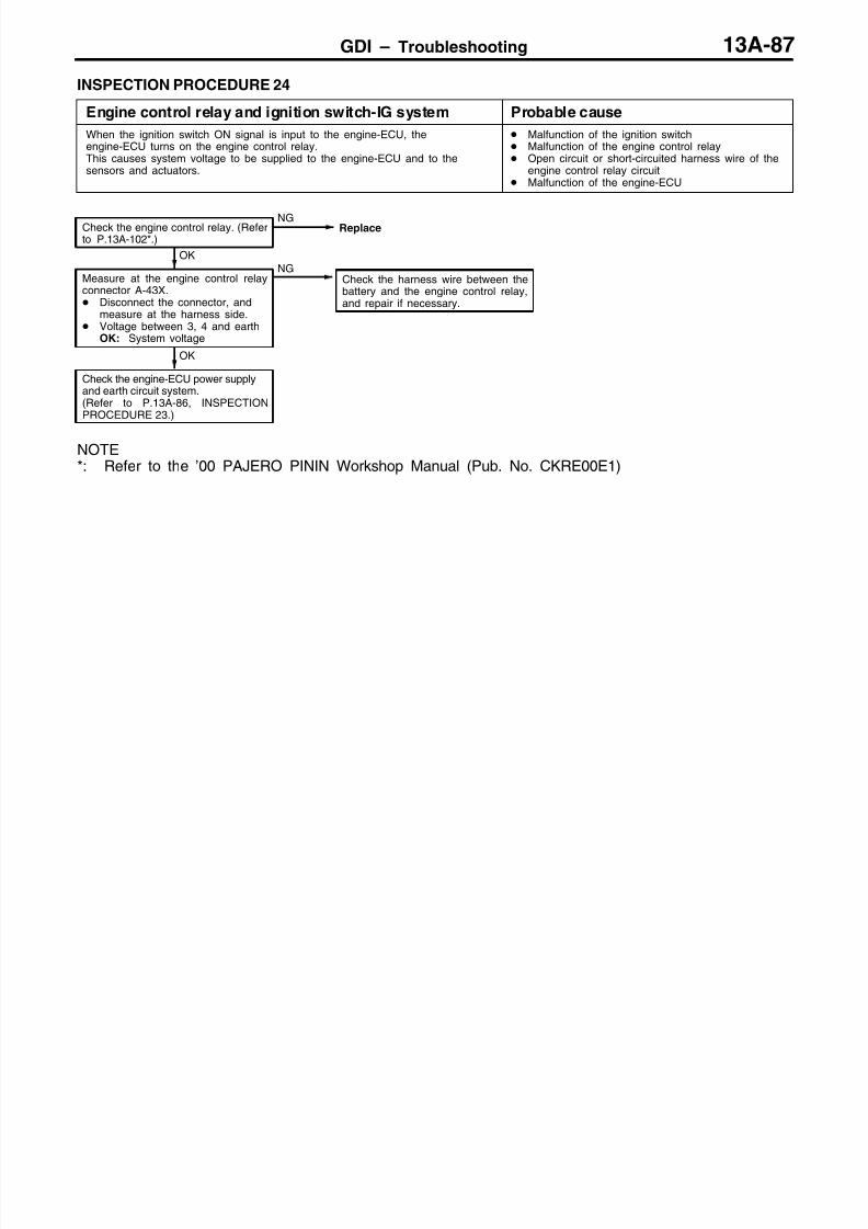
8/19/2019 13a Gasoline Direct Injection (Gdi) (1)
http://slidepdf.com/reader/full/13a-gasoline-direct-injection-gdi-1 204/269
GDI – Troubleshooting 13A-87
INSPECTION PROCEDURE 24
Engine control relay and ignition switch-IG system Probable cause
When the ignition switch ON signal is input to the engine-ECU, theengine-ECU turns on the engine control relay.This causes system voltage to be supplied to the engine-ECU and to thesensors and actuators.
Malfunction of the ignition switch Malfunction of the engine control relay Open circuit or short-circuited harness wire of the
engine control relay circuit Malfunction of the engine-ECU
Check the harness wire between thebattery and the engine control relay,and repair if necessary.
OK
Check the engine-ECU power supplyand earth circuit system.(Refer to P.13A-86, INSPECTIONPROCEDURE 23.)
OK
Measure at the engine control relayconnector A-43X. Disconnect the connector, and
measure at the harness side. Voltage between 3, 4 and earth
OK: System voltage
NG
Check the engine control relay. (Referto P.13A-102*.)
NGReplace
NOTE*: Refer to the ’00 PAJERO PININ Workshop Manual (Pub. No. CKRE00E1)

8/19/2019 13a Gasoline Direct Injection (Gdi) (1)
http://slidepdf.com/reader/full/13a-gasoline-direct-injection-gdi-1 205/269
GDI – Troubleshooting13A-88
INSPECTION PROCEDURE 25
Injector driver relay system Probable cause
When the ignition switch ON signal is input to the engine-ECU, engine-ECUturns on the injector driver relay.This causes system voltage to be supplied to the injector driver.
Malfunction of the injector driver relay Improper connector contact, open circuit or
short-circuited harness wire Malfunction of the engine-ECU
NG
Check the harness wire between the injector driver relay andthe injector driver, repair if necessary.
Check the injector driver system.(Refer to P.13A-53, INSPECTION PROCEDURE FORDIAGNOSIS CODE P1200.)
OK
OK NG
Repair
Check the trouble symptoms.
NGCheck the following connector: A-44X
NG
Measure at the injector driver connector A-55. Connect the connector. Voltage between 12, 21 and earth (Ignition switch: ON)
OK: System voltage
OK NG
Repair
Check the trouble symptoms.
OK
Check the following connector: C-18
NG
Check the harness wire between the injector driver relay andthe engine-ECU, and repair if necessary.
OK NG
Repair
Check the trouble symptoms.
NGCheck the following connector: A-44X
OK
Measure at the engine-ECU connector C-18. Disconnect the connector, and measure at the harness side. Voltage between 55 and earth
(Ignition switch: ON)OK: System voltage
OK
NG
Check the harness wire between the injector driver relay andthe ignition switch, repair if necessary.
OK NG
Repair
Check the trouble symptoms.
(2) NGCheck the following connectors: C-72, C-74
(1) NG
Check the harness wire between the injector driver relay andthe battery, repair if necessary.
Measure at the injector driver relay connector A-44X. Disconnect the connector, and measure at the harness side.(1) Voltage between 3 and earth
OK: System voltage(2) Voltage between 4 and earth (Ignition switch: ON)
OK: System voltage
Check the injector driver relay. (Refer to P.13A-102*.)
NG
Replace
Check the following connector: A-36
NG
Repair
OK
Check the trouble symptoms.
NG
NOTE*: Refer to the ’00 PAJERO PININ Workshop Manual (Pub. No. CKRE99E1)

8/19/2019 13a Gasoline Direct Injection (Gdi) (1)
http://slidepdf.com/reader/full/13a-gasoline-direct-injection-gdi-1 206/269
GDI – Troubleshooting 13A-89
INSPECTION PROCEDURE 26
Ignition switch-ST system <M/T> Probable cause
The ignition switch-ST outputs a HIGH signal to the engine-ECU while theengine is cranking.The engine-ECU uses this signal to carry out functions such as fuel injectioncontrol during starting.
Malfunction of the ignition switch Open circuit or short-circuited harness wire of the
ignition switch circuit Malfunction of the engine-ECU
NG
Repair
OK
Check the ignition switch. (Refer toGROUP 54.)
NG
Replace the engine-ECU.
OK
Check the trouble symptoms.
OK
Check the following connector:C-18
NGRepair
OK
Check the trouble symptoms.NG
Check the harness wire between theengine-ECU and the ignition switch.
(1) NG
Check the following connector:C-27
NG
Repair
Check the harness wire between theengine-ECU connector (terminalNo.91) and the earth, repair it neces-sary.
(2) NG
Measure at the engine-ECU connectorC-18. Disconnect the connector, and
measure at the harness side.(1) Voltage between 68 and earth
(Ignition switch: START)OK: 8 V or more
(2) Continuity between 67 and earthOK: Continuity
INSPECTION PROCEDURE 27
Ignition switch-ST and inhibitor switch system <A/T> Probable cause
The ignition switch-ST outputs a HIGH signal to the engine-ECU while theengine is cranking, and the engine-ECU uses this signal to carry out functionssuch as fuel injection control during starting.The inhibitor switch inputs the position of the selector lever to the engine-ECU.The engine-ECU uses this signal to carry out idle speed control.
Malfunction of the ignition switch Malfunction of the inhibitor switch Open circuit or short-circuited harness wire
between ignition switch and inhibitor switch Malfunction of the engine-ECU

8/19/2019 13a Gasoline Direct Injection (Gdi) (1)
http://slidepdf.com/reader/full/13a-gasoline-direct-injection-gdi-1 207/269
GDI – Troubleshooting13A-90
NG
Repair
OK
Replace the engine-ECU
NG
Replace the engine-ECU.
OK
Check the trouble symptoms.
OK
NGRepair
OK
Check the trouble symptoms.
NG Check the harness wire between the
engine-ECU and the inhibitor switchconnector.
(1) NGCheck the following connectors:C-18, C-24 <LHD>, C-26 <RHD>,D-02
NGRepair
Check the harness wire between theinhibitor switch connector and the start-er S terminal, and repair if necessary.
(2) NG
Measure at the inhibitor switch connec-tor B-04. Disconnect the connector, and
measure at the harness side.(1) Voltage between 4 and earth
(Ignition switch: ON)OK: System voltage
(2) Continuity between 1 and earthOK: Continuity
(3) Voltage between 4 and earth(Ignition switch: START)Disconnect the engine-ECU con-nector.OK: System voltage
OK
Check the inhibitor switch (Refer toGROUP 23 – On-vehicle Service).
NG
Repair
OK
Check the following connectors:A-83, B-01
NGCheck the trouble symptoms.
NG
Check the following connector:B-04
Repair
NG
Repair
OK
Check the harness wire between theengine-ECU and the inhibitor switch.
OK
Check the following connectors:C-39, D-02
NG
Check the trouble symptoms.
Check the ignition switch (Refer toGROUP 54.)
OK
Check the harness wire between theinhibitor switch and the ignition switchconnector.
(3) NG
NGReplace
NGRepair
INSPECTION PROCEDURE 28
Accelerator pedal position switch system Probable cause
The accelerator pedal position switch detects that the accelerator pedal is fully closed,and sends a signal to the engine-ECU. The engine-ECU controls idle speed, based
on this signal.
Maladjustment of the accelerator cable Maladjustment of the accelerator pedal position switch
Open circuit or short-circuited harness wire in theaccelerator pedal position switch system, or poorconnector contact
Malfunction of the engine-ECU
NG
Repair
NGReplace the engine-ECU.
OK
NG
Repair
Check the accelerator pedal position switch. (Refer to P.13A-105*.)NG
Replace the accelerator pedal position sensor assembly.
OK
Measure at accelerator pedal position sensor connector C-46. Disconnect the connector, and measure at the harness side. Voltage between terminal 4 and earth
(Ignition switch: ON)OK: 4 V or more
Continuity between terminal 5 and earthOK: Continuity
NGCheck the following connectors: A-36, C-19
OK
Check trouble symptom.
NG
Check the harness wire between the engine-ECU and acceleratorpedal position sensor.
OK
Check the following connector: C-46NG
Repair
OK
Check trouble symptom.
NOTE*: Refer to the ’00 PAJERO PININ Workshop Manual (Pub. No. CKRE99E1)

8/19/2019 13a Gasoline Direct Injection (Gdi) (1)
http://slidepdf.com/reader/full/13a-gasoline-direct-injection-gdi-1 208/269
GDI – Troubleshooting 13A-91
INSPECTION PROCEDURE 29
Fuel pump (low pressure) system Probable cause
The engine-ECU turns on the fuel pump relay while the engine is cranking or running,and supplies power source to the fuel pump (low pressure).
Malfunction of the fuel pump relay Malfunction of the fuel pump (low pressure) Open circuit or short-circuited harness wire in the
fuel pump (low pressure) circuit, or poor connectorcontact
Malfunction of the engine-ECU
NG
Replace the fuel pump (low pressure).
OK
Check trouble symptom.
OK
Check the following connector:D-17
NGRepair
Check trouble symptom.NG
Check the harness wire between thefuel pump (low pressure) and earth,and repair if necessary.
NG
Repair
OK
(2) NGCheck the following connector:D-12
OK
Check trouble symptom.NG
Check the harness wire between thefuel pump relay and fuel pump (lowpressure), and repair if necessary.
(1) NGCheck the following connectors:C-24 <LHD>, C-26 <RHD>, D-12
NGRepair
NG
Measure at fuel pump (low pressure)connector D-17. Disconnect the connector, and
measure at the harness side.(1) Voltage between terminal 5 and
earth (Ignition switch: ON)OK: System voltage
(2) Continuity between 4 and earthOK: Continuity
OK
Check trouble symptom.NG
Replace the engine-ECU.
OKCheck the following connector:C-17
NGRepair
OK
Measure at engine-ECU connectorC-17. Disconnect the connector, and
measure at the harness side. Short circuit between terminal 21
and earth (Ignition switch: ON)
OK: The fuel pump operates (itsoperation sound can beheard).
Check trouble symptom.NG
Check the harness wire between thefuel pump relay and engine-ECU, andrepair if necessary.
NG
Repair
OK
OK
Measure at engine-ECU connectorC-17. Disconnect the connector, and
measure at the harness side. Voltage between terminal 21 and
earth (Ignition switch: ON)OK: System voltage
NGCheck the following connector:A-41X
NG
Repair
OK
Check the ignition switch. (Refer toGROUP 54 – Ignition Switch.)
OK
Check trouble symptom.NG
Check the harness wire between thefuel pump relay and ignition switch.
NGCheck the following connectors:C-72, C-74
NGRepair
OK
Measure at fuel pump relay connectorA-41X. Disconnect the connector, and
measure at the harness side. Voltage between terminals 3, 4 and
earth (Ignition switch: ON)OK: System voltage
NG
Check the fuel pump relay. (Refer toP.13A-102*.)
NGReplace
MUT-II Actuator test07 Fuel pump (Refer to P.13A-100.)
OKNormal
NOTE*: Refer to the ’00 PAJERO PININ Workshop Manual (Pub. No. CKRE00E1)

8/19/2019 13a Gasoline Direct Injection (Gdi) (1)
http://slidepdf.com/reader/full/13a-gasoline-direct-injection-gdi-1 209/269
GDI – Troubleshooting13A-92
INSPECTION PROCEDURE 30
Power steering fluid pressure switch system Probable cause
The power steering fluid pressure switch sends a signal to the engine-ECU accordingto power steering load.Based on this signal, the engine-ECU controls the throttle control servo so thatidle speed increases when the power steering is in operation.
Malfunction of the power steering fluid pressure switch Open circuit or short-circuited harness wire in the
power steering fluid pressure switch circuit, or poorconnector contact
Malfunction of the engine-ECU
NG
Repair
OK
Replace the engine-ECUNG
NG
Check the harness wire between the engine-ECU and power steer-ing fluid pressure switch.
NG
Repair
OK
Check trouble symptom.
NGReplace
OKNG
Check the following connector: C-18
NG
Repair
OK
OK
Check the following connector: A-76
Check trouble symptom.
Check the power steering fluid pressure switch. (Refer to GROUP37A – On-vehicle Service.)
Measure at power steering fluid pressure switch connector A-76. Disconnect the connector, and measure at the harness side. Voltage between terminal 1 and earth
(Ignition switch: ON)OK: System voltage
INSPECTION PROCEDURE 31
A/C switch and A/C relay system Probable cause
If the engine-ECU receives a ‘A/C on’ signal, it operates the throttle control servoand A/C compressor magnetic clutch so that idle speed increases.
Malfunction of the A/C control system Malfunction of the A/C switch Open circuit or short-circuited harness wire in the
A/C switch circuit, or poor connector contact Malfunction of the engine-ECU
NG
NG
Repair
OK
Check trouble symptom.
NG
Replace the engine-ECU.
Service the A/C compressor relay. (Refer to GROUP 55 – On-ve-hicle Service.)
NG Replace
OK
Measure at engine-ECU connectors C-17, C-19. Disconnect the connector, and measure at the harness side. Voltage between terminals 20, 83 and earth
(Ignition switch: ON)OK: 0 – 3 V
(A/C switch: OFF)System voltage(A/C switch: ON)
Connect terminal 20 to earth.(Ignition switch: ON, A/C switch: ON)OK: A/C compressor clutch turns on.
OKCheck the following connectors:C-17, C-19
Check the A/C system. (Refer to GROUP 55 – On-vehicle Service.)

8/19/2019 13a Gasoline Direct Injection (Gdi) (1)
http://slidepdf.com/reader/full/13a-gasoline-direct-injection-gdi-1 210/269
GDI – Troubleshooting 13A-93
INSPECTION PROCEDURE 32
Stop lamp switch system Probable cause
The engine-ECU determines whether the brake pedal is depressed or not, by meansof the stop lamp switch input signal.
Malfunction of the stop lamp switch Open circuit or short-circuited harness wire in the
stop lamp circuit, or poor connector contact Malfunction of the engine-ECU
NG
Replace the engine-ECU.
OK
Check trouble symptom.
OK
Check the following connector: C-18NG
Repair
NG
Check the harness wire between the engine-ECU and stop lamp,and repair if necessary.
NG
Repair
OK
Check trouble symptom.
NGCheck the following connectors: C-02, C-04, C-28
OK
Measure at engine-ECU connector C-18. Disconnect the connector, and measure at the harness side. Voltage between terminal 63 and earth
(Ignition switch: ON)OK: 0 – 3 V (when the brake pedal is not depressed)System voltage (when the brake pedal is depressed)
NG
Check the harness wire between the battery and stop lamp switch.
NG
Repair
OK
Check trouble symptom.
NGCheck the following connector: C-29
OK
Measure at stop lamp switch connector C-04. Disconnect the connector, and measure at the harness side. Voltage between terminal 2 and earth
OK: System voltage
Check the stop lamp switch. (Refer to GROUP 35 – Brake Pedal.)
NG
Replace
INSPECTION PROCEDURE 33
Small lamp switch system Probable cause
The engine-ECU determines whether the small lamp switch is on or off.According to that information, the engine-ECU controls alternator output currentwhen the vehicle is started.
Improper connector contact, open circuit orshort-circuited harness wire in the taillamp circuit
Malfunction of the engine-ECU
NG
Replace the engine-ECU.
OK
Check the trouble symptoms.
OK
Check the following connector: C-19NG
Repair
Measure at the engine-ECU connector C-19. Disconnect the connector, and measure at the harness
side. Voltage between 88 and earth
(Lighting switch: ON)OK: System voltage
NGCheck the taillamp circuit. (Refer to ELECTRICAL WIRING.)

8/19/2019 13a Gasoline Direct Injection (Gdi) (1)
http://slidepdf.com/reader/full/13a-gasoline-direct-injection-gdi-1 211/269
GDI – Troubleshooting13A-94
DATA LIST REFERENCE TABLE
CautionWhen shifting the select lever to D range, the brakes should be applied so that the vehicle doesnot move forward.
NOTE*1: Within four minutes after starting the engine*2: In a new vehicle [driven approximately 500 km or less], the injector drive time is sometimes 10 %
longer than the standard time.*3: The accelerator pedal position switch normally turns off when the voltage of the accelerator pedal
position sensor (1st channel) is 200 – 600 mV higher than the voltage at the idle position. If the acceleratorpedal position switch turns back on after the accelerator pedal position sensor voltage has risen by100 mV and the throttle valve has opened, the accelerator pedal position switch and the acceleratorpedal position sensor (1st channel) need to be adjusted.
ItemNo.
Check items Requirements Normal condition InspectionprocedureNo.
Referencepage
11 Oxygen sensor Engine: After- p
Idling 0 mV*1 Code No. 13A-25ron warm-up
Sudden racing 600 – 1,000 mV
2,500 r/min 400 mV or less and600 – 1,000 mValternates.
12 Air flow sensor Engine coolanttemperature:
–
Idling 24 – 50 Hz Code No.P0100
13A-14
– Lamps, electric
cooling fan and2,500 r/min 70 – 90 Hz
a accessor es:OFF
Transmission:Neutral
(A/T: P range)
Racing Frequency in-creases in re-sponse to racing.
13 Intake air tem-perature sen-
Ignition switch: ON Intake air tempera-ture: –20C
–20C Code No.P0110
13A-18
sorIntake air tempera-ture: 0C
0C
Intake air tempera-ture: 20C
20C
Intake air tempera-ture: 40C
40C
Intake air tempera-
ture: 80C
80C

8/19/2019 13a Gasoline Direct Injection (Gdi) (1)
http://slidepdf.com/reader/full/13a-gasoline-direct-injection-gdi-1 212/269
GDI – Troubleshooting 13A-95
ItemNo.
Referencepage
InspectionprocedureNo.
Normal conditionRequirementsCheck items
14 Throttle posi-tion sensor
Engine coolanttemperature:
Release the accel-erator pedal.
4,000 – 4,800 Code No.P0225
13A-43
n c anne – Ignition switch:
ON (Enginestopped)
Depress the accel-
erator pedal gradu-ally.
Voltage decreases
in response to thepedal depression.
Depress the accel-erator pedal fully.
100 – 1,100 mV
16 Power supplyvoltage
Ignition switch: ON System voltage ProcedureNo. 23
13A-86
18 Cranking sig-nal (Ignitionswitch – ST)
Transmission:Neutral(A/T: P range)
Engine: Stopped OFF ProcedureNo.26<M/T>
13A-89<M/T>
13A-89
Engine: Cranking ONroce ure
No.27<A/T>
< >
21 Engine coolanttemperaturesensor
Ignition switch: ON Engine coolanttemperature:–20C
–20C Code No.P0115
13A-19
Engine coolanttemperature: 0C
0C
Engine coolanttemperature: 20C
20C
Engine coolanttemperature: 40C
40C
Engine coolanttemperature: 80C
80C
22 Crank anglesensor
Engine: Crank-ing
Tachometer:Connected
Compare the enginespeed readings onthe tachometer andthe MUT-II.
Accord Code No.P0335
13A-47
Engine: Idling Accelerator
pedal position
Engine coolanttemperature:–20C
1,200 – 1,400 r/min
sw tc :Engine coolanttemperature: 0C
1,100 – 1,300 r/min
Engine coolanttemperature: 20C
1,000 – 1,200 r/min
Engine coolanttemperature: 40C
850 – 1,050 r/min
Engine coolanttemperature: 80C
550 – 750 r/min*1
24 Vehicle speedsensor
Drive at 40 km/h Approximately40 km/h
Code No.P0500
13A-53

8/19/2019 13a Gasoline Direct Injection (Gdi) (1)
http://slidepdf.com/reader/full/13a-gasoline-direct-injection-gdi-1 213/269
GDI – Troubleshooting13A-96
ItemNo.
Referencepage
InspectionprocedureNo.
Normal conditionRequirementsCheck items
25 Barometricp -
Ignition switch: ON Altitude: 0 m 101 kPa Code No. 13A-16pressure sen-sor Altitude: 600 m 95 kPa
Altitude: 1,200 m 88 kPaAltitude: 1,800 m 81 kPa
26 Acceleratorpedal position
Ignition switch: ON(Depress and re-
-
Release the accel-erator pedal.
ON ProcedureNo. 28
13A-90
sw c ease e acce era-tor pedal severaltimes)
Depress the accel-erator pedal slight-ly.
OFF
27 Power steeringfluid pressure
Engine: Idling Steering wheel sta-tionary
OFF ProcedureNo. 30
13A-92
swtcSteering wheel
turning
ON
28 A/C switch Engine: Idling (TheA/C compressor is
A/C switch: OFF OFF ProcedureNo. 31
13A-92
running when theA/C switch is on.)
A/C switch: ON ON
29 Inhibitor switch<A/T>
Ignition switch: ON Selector lever: P orN
P, N ProcedureNo. 27
13A-89
Selector lever: D, 2,L or R
D, 2, L, R
31 Small lampswitch
Engine: Idling Lighting switch:OFF
OFF ProcedureNo. 33
13A-93
Lighting switch: ON ON
34 Air flow sensor Engine: After hav-p
Engine is idling ON Code No. 13A-14rese s gna ng warme up
3,000 r/min OFF
37 Volumetric effi-ciency
Engine coolanttemperature:
–
Engine is idling 30 – 50 % – –
– Lamps, electric
cooling fan and2,500 r/min 10 – 30 %
a accessor es:OFF
Transmission:
Neutral(A/T: P range)
Engine is suddenlyraced
Volumetric effi-ciency increases in
response to racing
38 Crank anglesensor
Engine: Cranking [reading is possibleat 2,000 r/min or less]
Tachometer: Connected
Engine speeds dis-played on theMUT-II andtachometer areidentical.
– –

8/19/2019 13a Gasoline Direct Injection (Gdi) (1)
http://slidepdf.com/reader/full/13a-gasoline-direct-injection-gdi-1 214/269
GDI – Troubleshooting 13A-97
ItemNo.
Referencepage
InspectionprocedureNo.
Normal conditionRequirementsCheck items
41 Injector drivetime*2
Engine coolanttemperature:80 – 95C
Idling 0.35 – 0.55 ms*1 – –
Lamps, electric
cooling fan andall accessories:OFF
2,500 r/min 0.4 – 0.6 ms
Transmission:Neutral(A/T: P range)
Sudden racing Increases
44 Ignitionadvance
Engine: Afterwarm-up
Idling 8 – 24BTDC*1 Code No.P0300
13A-44
Set a timinglight.
2,500 r/min 15 – 35BTDC
49 A/C relay Engine: Afterwarm-up, idling
A/C switch: OFF OFF (compressorclutch is not oper-ating)
ProcedureNo. 31
13A-92
A/C switch: ON ON (compressorclutch is operating)
59 Oxygen sensor(rear)
Transmission:2nd gear(A/T: L range)
Drive withthrottle widelyopen
3,500 r/min 600 – 1,000 mV Code No.P0136
13A-28
66 Brake vacuumsensor
Engine coolanttemperature:80 – 95C
Lamps, electric
cooling fan andall accessories:OFF
Transmission:Neutral(A/T: P range)
Stop the enginefrom idling speed,and then depressthe brake pedal
several times withthe ignition switchon.
Displayed pres-sure increases.
Code No.P1515
13A-62
67 Stop lampswitch
Ignition switch: ON Brake pedal: De-pressed
OFF ProcedureNo. 32
13A-93
Brake pedal: Re-leased
ON
68 EGR valve Engine coolanttemperature:80 – 95C
Lamps, electriccooling fan and
Idling 2 – 17 STEP Code No.P0403
13A-50
all accessories:OFF
Transmission:Neutral(A/T: P range)
2,500 r/min 0 – 9 STEP
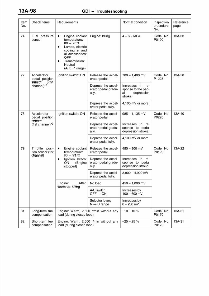
8/19/2019 13a Gasoline Direct Injection (Gdi) (1)
http://slidepdf.com/reader/full/13a-gasoline-direct-injection-gdi-1 215/269
GDI – Troubleshooting13A-98
ItemNo.
Referencepage
InspectionprocedureNo.
Normal conditionRequirementsCheck items
74 Fuel pressuresensor
Engine coolanttemperature:80 – 95C
Lamps, electric
cooling fan andall accessories:OFF
Transmission:Neutral(A/T: P range)
Engine: Idling 4 – 6.9 MPa Code No.P0190
13A-33
77 Acceleratorpedal position
Ignition switch: ON Release the accel-erator pedal.
700 – 1,400 mV Code No.P1225
13A-58
sensor nchannel)*3 Depress the accel-
erator pedal gradu-ally.
Increases in re-sponse to the ped-al depressionstroke.
Depress the accel-erator pedal fully.
4,100 mV or more
78 Acceleratorpedal position
Ignition switch: ON Release the accel-erator pedal.
985 – 1,135 mV Code No.P0220
13A-40
sensor(1st channel)*3 Depress the accel-
erator pedal gradu-ally.
Increases in re-sponse to pedaldepression stroke.
Depress the accel-erator pedal fully.
4,100 mV or more
79 Throttle posi-tion sensor (1st
Engine coolanttemperature:
Release the accel-erator pedal.
450 – 800 mV Code No.P0120
13A-22
c anne – 5 Ignition switch:
ON (Enginestopped)
Depress the accel-erator pedal gradu-ally.
Increases in re-sponse to pedaldepression stroke.
Depress the accel-erator pedal fully.
3,900 – 4,900 mV
Engine: After- p
No load 450 – 1,000 mVwarm-up, ng
A/C switch:OFF→ ON
Increases by100 – 600 mV.
Selector lever:N → D range
Increases by0 – 200 mV.
81 Long-term fuelcompensation
Engine: Warm, 2,500 r/min without anyload (during closed loop)
–10 – 10 % Code No.P0170
13A-31
82 Short-term fuelcompensation
Engine: Warm, 2,500 r/min without anyload (during closed loop)
–25 – 25 % Code No.P0170
13A-31

8/19/2019 13a Gasoline Direct Injection (Gdi) (1)
http://slidepdf.com/reader/full/13a-gasoline-direct-injection-gdi-1 216/269
GDI – Troubleshooting 13A-99
ItemNo.
Referencepage
InspectionprocedureNo.
Normal conditionRequirementsCheck items
85 Fuel pressuresensor
Engine coolanttemperature:80 – 95C
Lamps, electric
cooling fan andall accessories:OFF
Transmission:Neutral(A/T: P range)
Engine: Idling 4,000 – 6,900 kPa CodeNo.P0190
13A-33
87 Calculation Engine: Warm Engine: Idling 15 – 35 % – –
oa va ue2,500 r/min 15 – 35 %
88 Fuel control Engine: Warm 2,500 r/min Closed loop Code No. 13A-24con on
When engine issuddenly raced
Open loop – drivecondition
99 Fuel injectionmode
Engine: After warmup
Idling (after fourminutes or morehave passed sinceengine start)
Lean compression – –
2,500 r/min Stoichiometricmetric feedback
Sudden racing afteridle position
Open loop
A1 Oxygen sensor Engine:- p
Idling 0 V Code No. 13A-25ron er warm-up
Sudden racing 0.6 – 1.0 V
2,500 r/min 0.4 V or less and0.6 – 1.0 V alter-nates
A2 Oxygen sensor(rear)
Transmission:2nd gear<M/T>, L range<A/T>
Drive withthrottle widelyopen
3,500 r/min 0.6 – 1.0 V Code No.P0136
13A-28
8A Throttle posi-tion sensor (1st
Engine coolanttemperature:
Release the accel-erator pedal.
8 – 16 % Code No.P0120
13A-22
c anne(Throttle valveopening angle)
– 5 Ignition switch:
ON (Engine:stopped)
Depress the accel-erator pedal gradu-ally.
Increase in re-sponse to pedaldepression stroke.
Depress the accel-erator pedal fully.
80 – 100 %
Engine: After- p
No load 8 – 18 %warm-up, ng
A/C switch:OFF→ ON
Rises by 2 – 10 %

8/19/2019 13a Gasoline Direct Injection (Gdi) (1)
http://slidepdf.com/reader/full/13a-gasoline-direct-injection-gdi-1 217/269
GDI – Troubleshooting13A-100
ACTUATOR TEST REFERENCE TABLE
ItemNo.
Inspectionitem
Drive contents Inspection contents Normal condition InspectionprocedureNo.
Referencepage
01 Injectors Cut fuel to No. 1injector
Engine:After having
p
Idling conditionbecomes different
Code No.P0201
13A-34
02 Cut fuel to No. 2injector
warme up ng ne
is idling(Cut the fuel supply
ecomes unsta-
ble). Code No.P0202
13A-36
03 Cut fuel to No. 3injector
to each injector inturn and checkcylinders which
Code No.P0203
13A-37
04 Cut fuel to No. 4injector
don’t affect idling.)Code No.P0204
13A-38
07 Fuel pump(low pressure)
Fuel pumpoperates andfuel is recirculated.
Ignition switch: ON Sound of opera-tion is heard.
ProcedureNo. 29
13A-91
08 Purgecontrolsolenoid valve
Solenoid valveturns from OFF toON.
Ignition switch: ON Sound of opera-tion can be heardwhen solenoidvalve isdriven.
Code No.P0443
13A-52
17 Basic ignitiontiming
Set the engine-ECU to ignitiontiming adjustmentmode
Idling after enginewarm up
5BTDC – –
21 Fan controller Drive the fan motor Ignition switch: ON The fan motoroperates
ProcedureNo. 20
13A-84
34 Electronic-controlled
throttle valvesystem
Stop the throttlecontrol servo.
Ignition switch: ON Throttle valve isopened slightly.
Code No.P1220
13A-54

8/19/2019 13a Gasoline Direct Injection (Gdi) (1)
http://slidepdf.com/reader/full/13a-gasoline-direct-injection-gdi-1 218/269
GDI – Troubleshooting 13A-101
CHECK AT THE ENGINE-ECU TERMINALS
TERMINAL VOLTAGE CHECK CHART
Engine-ECU Connector Terminal Arrangement
Terminal No. Check item Check requirements (engine condition) Normal condition
1 No. 1 injector Engine: Warm up, and then depressp
Decreases slightly for short–
9 No. 2 injectore acce era or pe a su en y rom
the idle speed.me rom –
24 No. 3 injector
2 No. 4 injector
3 No. 1 ignition coil Engine: 3,000 r/min 0.3 – 3.0 V
13 No. 2 ignition coil
12 No. 3 ignition coil
4 No. 4 ignition coil
5 EGR valve (D) Ignition switch: Immediately after 5 – 8 V (fluctuates forpp
6 EGR valve (C)urn ng approx. ree secon s
32 EGR valve (B)
va ve
8 Alternator G terminal Engine: Warm up, and then idling Radiator fan: Not operating Headlamp: OFF → ON Stop lamp: OFF → ON Rear defogger switch: OFF → ON
Voltage increases by 0.2 – 3.5 V
14 GDI ECO indication lamp Ignition switch: OFF → ON 0 – 3 V (System voltageafter five seconds)
Engine: When the accelerator pedal issuddenly depressed while the engineis idling
System voltage
16 Purge control solenoid Engine cool-p -
Engine: Stopped System voltageva ve an empera-
ture:80 – 95C
Ignitionswitch: ON
Engine: Start theengine, and thenincrease enginespeed up to 3,500r/min.
Voltage decreases

8/19/2019 13a Gasoline Direct Injection (Gdi) (1)
http://slidepdf.com/reader/full/13a-gasoline-direct-injection-gdi-1 219/269
GDI – Troubleshooting13A-102
Terminal No. Normal conditionCheck requirements (engine condition)Check item
18 Fan controller Radiator and condenser fans are notoperating.
0 – 0.3 V
Radiator and condenser fans areoperating.
0.7 V or more
20 A/C relay
Engine: Idling A/C switch: OFF → ON(Compressor is operating)
System voltage, or changesfrom momentarily 6 V ormore to 0 → 3 V
21 Fuel pump relay Ignition switch: Engine: Stopped System voltage
Engine: Idling 0 – 3 V
31 Engine warning lamp Ignition switch: OFF → ON 0 – 3 V→ System voltage(after several seconds)
41 Sensor power supply Ignition switch: ON 4.5 – 5.5 V
42 Power supply toaccelerator pedal position
sensor (1st channel)
Ignition switch: ON 4.5 – 5.5 V
43 Crank angle sensor Engine: Cranking 0.4 – 4.0 V
Engine: Idling 1.5 – 2.5 V
44 Engine coolant tempera-ture sensor
Ignition switch:ON
Engine coolanttemperature: 0C
3.2 – 3.5 V
Engine coolanttemperature: 20C
2.3 – 2.9 V
Engine coolanttemperature: 40C
1.5 – 2.1 V
Engine coolanttemperature:80C
0.4 – 1.0 V
45 Engine ignition signal Engine: 3,000 r/min 0.3 – 3.0 V
47 Power supply Ignition switch: ON System voltage
59
50 Camshaft position sensor Engine: Cranking 0.4 – 3.0 V
Engine: Idling 0.5 – 2.0 V
51 Barometric pressure Ignition switch: Altitude: 0 m 3.7 – 4.3 Vsensor
Altitude: 1,200 m 3.2 – 3.8 V
52 Alternator FR terminal Engine: Warm up, and then idling Radiator fan: Not operating Headlamp: OFF → ON Stop lamp: OFF → ON Rear defogger: OFF → ON
Voltage decreases

8/19/2019 13a Gasoline Direct Injection (Gdi) (1)
http://slidepdf.com/reader/full/13a-gasoline-direct-injection-gdi-1 220/269
GDI – Troubleshooting 13A-103
Terminal No. Normal conditionCheck requirements (engine condition)Check item
53 Oxygen sensor (rear) Transmission: 2nd gear Engine speed: 3,500 r/min or more Driving with the throttle valve widely
open
0.6 – 1.0 V
54 Power steering fluid
pressure switch
Engine: Warm
up, and then
Steering wheel
stationary
System voltage
ngSteering wheelturning
0 – 3 V
55 Injector driver relay Ignition switch: OFF 0 – 0.1 V
Ignition switch: ON 0.5 – 1.0 V
56 Throttle valve control Ignition switch: OFF 0 – 0.3 Vservo reay
Ignition switch: ON 0.5 – 1.0 V
57 Engine control relay Ignition switch: OFF 0 – 3 V
Ignition switch: ON System voltage
60 Back-up power source Ignition switch: OFF System voltage
61 Air flow sensor Engine: Idling 2.2 – 3.2 V
Engine: 2,500 r/min
62 Intake air temperaturesensor
Ignition switch:ON
Intake air temper-ature: 0C
3.2 – 3.8 V
Intake air temper-ature: 20C
2.3 – 2.9 V
Intake air temper-
ature: 40C
1.5 – 2.1 V
Intake air temper-ature: 80C
0.4 – 1.0 V
63 Stop lamp switch Depress the brake pedal. System voltage
Release the brake pedal. 0 – 3 V
68 Ignition switch-ST Engine: Cranking 8 V or more
71 Oxygen sensor (front) Engine: Warm up, and then hold theengine speed at 2,500 r/min (Use adigital voltmeter).
0↔ 0.8 V alternates.
74 Brake vacuum sensor Engine: Stop the engine from idlespeed, turn the ignition switch ON,and then depress the brake pedalseveral times.
Voltage increases
76 Air flow sensor reset Engine: Idling 0 – 1 Vs gna
Engine: 3,000 r/min 6 – 9 V

8/19/2019 13a Gasoline Direct Injection (Gdi) (1)
http://slidepdf.com/reader/full/13a-gasoline-direct-injection-gdi-1 221/269
GDI – Troubleshooting13A-104
Terminal No. Normal conditionCheck requirements (engine condition)Check item
78 Throttle position sensor(2nd channel)
Ignition switch:ON
Release theaccelerator pedal.
4.0 – 4.8 V
Depress theaccelerator pedalfully.
0.1 – 1.1 V
79 Accelerator pedal positionswitch
Ignition switch:ON
Release theaccelerator pedal.
0 – 1 V
Depress theaccelerator pedalfully.
4 V or more
80 Vehicle speed sensor Ignition switch: ON Move the vehicle forward.
0 ↔ system voltagealternates.
83 A/C switch Engine: Idling A/C switch: OFF 0 – 3 V
A/C switch: ON(Compressor is
operating)
System voltage
88 Small lamp switch Lighting switch: OFF 0 – 3 V
Lighting switch: ON (Taillamp: ON) System voltage
89 Oxygen sensor heater Engine: Idling 0 – 3 Vron
Engine: 3,500 r/min System voltage
90 Oxygen sensor heater Engine: Idling 0 – 3 Vrear
Engine: 3,500 r/min System voltage
92 Fuel pressure sensor Engine: Idling 0.3 – 4.7 V
94 Accelerator pedal positionsensor (1st channel)
Ignition switch:ON
Release the acceler-ator pedal.
0.935 – 1.135 V*1
Depress theaccelerator pedalfully.
4.1 V or more*2
96 Injector open circuit checksignal
Engine: Increase engine speed fromidle speed to 4,000 r/min.
Decreases slightly (approx.0.7 V) from 4.5 V – 5.0 V.
97 A/C thermo sensor Temperature at sensing portion:Approx 25°C
Ignition switch: ON
2.0 – 2.9 V
99 Ignition switch-IG Ignition switch: ON System voltage
NOTECheck if the difference in output between *1 and *2 is 4 V or more.

8/19/2019 13a Gasoline Direct Injection (Gdi) (1)
http://slidepdf.com/reader/full/13a-gasoline-direct-injection-gdi-1 222/269
GDI – Troubleshooting 13A-105
CHECK CHART FOR RESISTANCE AND CONTINUITYBETWEEN TERMINALS
1. Turn the ignition switch to OFF.2. Disconnect the engine-ECU connector.3. Measure the resistance and check for continuity between
the terminals of the engine-ECU harness-side connectorwhile referring to the check chart.
NOTE(1) When measuring resistance and checking continuity,a harness for checking contact pin pressure shouldbe used instead of inserting a test probe.
(2) Checking need not be carried out in the order givenin the chart.
CautionIf the terminals that should be checked are mistaken,or if connector terminals are not correctly shortedto earth, damage may be caused to the vehicle wiring,sensors, engine-ECU and/or ohmmeter.Be careful to prevent this!
4. If the ohmmeter shows any deviation from the standardvalue, check the corresponding sensor, actuator andrelated electrical wiring, and then repair or replace.
5. After repair or replacement, recheck with the ohmmeterto confirm that the repair or replacement has correctedthe problem.
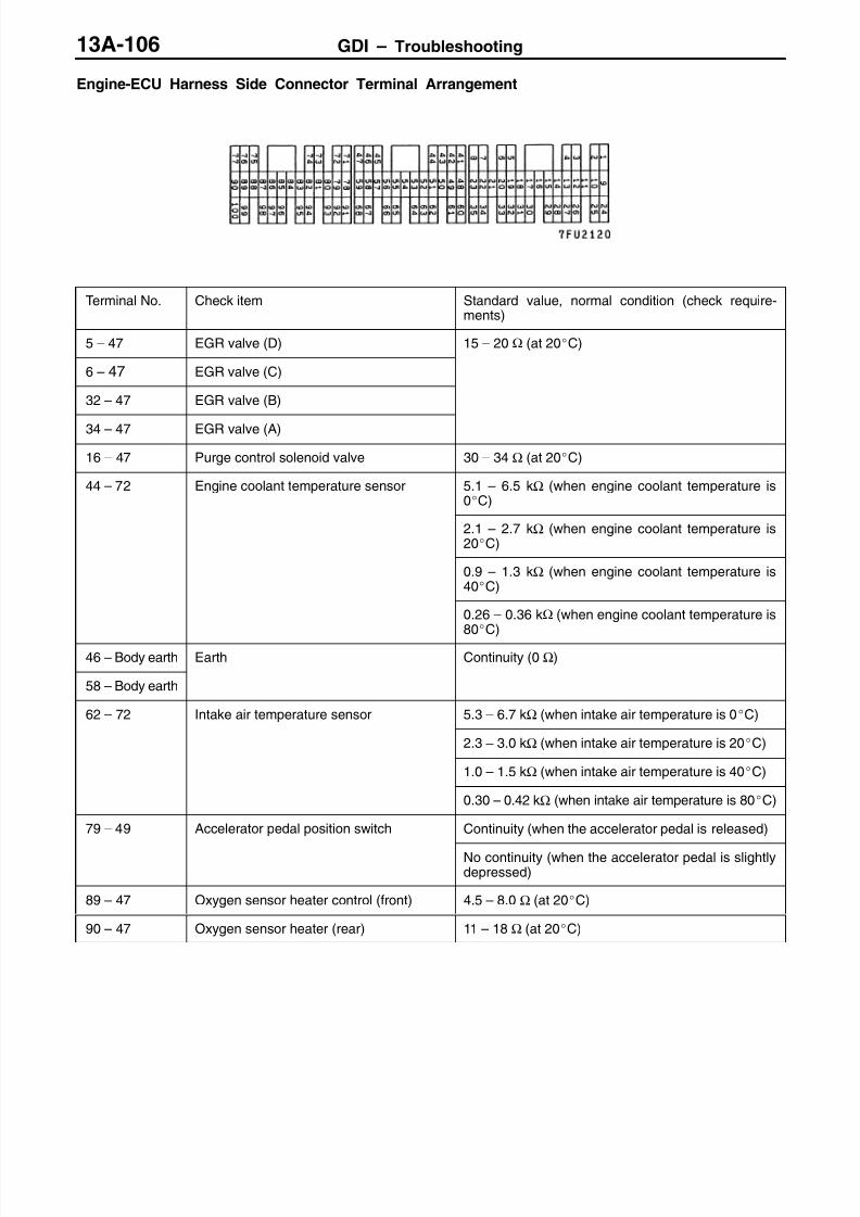
8/19/2019 13a Gasoline Direct Injection (Gdi) (1)
http://slidepdf.com/reader/full/13a-gasoline-direct-injection-gdi-1 223/269

8/19/2019 13a Gasoline Direct Injection (Gdi) (1)
http://slidepdf.com/reader/full/13a-gasoline-direct-injection-gdi-1 224/269
GDI – Troubleshooting 13A-107
CHECK AT THE THROTTLE VALVE CONTROLLER TERMINALS
TERMINAL VOLTAGE CHECK CHART
Throttle Valve Controller Terminal Arrangement
TerminalNo.
Check items Requirements Normal value
1 Throttle valve control servo(A+)
Ignition switch: ON Accelerator pedal: Fully opened →
Decreases slightly fromsystem voltage.
9 Throttle valve control servo(B+)
u y c ose
14 Throttle valve control servo(A–)
Ignition switch: ON Accelerator pedal: Fully closed →
p
Decreases slightly (approx.2 V) from system voltage.
15 Throttle valve control servo(B–)
u y opene
2 Power supply to throttle Ignition switch: ON System voltage
19va ve con ro servo
5 Power supply Ignition switch: ON System voltage
6 Sensor voltage Ignition switch: ON 4.5 – 5.5 V
7 Throttle position sensor (1stchannel)
Ignition switch:ON
Release theaccelerator pedal.
0.45 – 0.8 V
Depress theaccelerator pedalfully.
3.9 – 4.9 V
20 Accelerator pedal positionsensor (2nd channel)
Ignition switch:ON
Release theaccelerator pedal.
0.7 – 1.4 V*1
Depress theaccelerator pedal
fully.
4.1 V or more*1
NOTE:Check that the voltage difference between *1 and *2 is 4 V or more.

8/19/2019 13a Gasoline Direct Injection (Gdi) (1)
http://slidepdf.com/reader/full/13a-gasoline-direct-injection-gdi-1 225/269
GDI – On-vehicle ServiceGDI – On-vehicle ServiceGDI – On-vehicle Service13A-108
ON-VEHICLE SERVICE
Caution(1) Never attempt to tamper the fixed SAS. The fixed SAS
is precisely adjusted at factory.(2) Should it be tampered, the full closed position of the
throttle valve will be changed. This causes theengine-ECU to learn a wrong position of the throttlevalve.
FUEL PRESSURE TEST
MEASUREMENT OF FUEL LOW PRESSURE BETWEENFUEL PUMP (LOW PRESSURE) AND FUEL PUMP(HIGH PRESSURE)
1. Release residual pressure from the fuel pipe line to preventfuel gush out.
NOTERefer to the ’00 PAJERO PININ Workshop Manual (Pub.
No. CKRE00E1) GROUP 13A – On-vehicle Service.
2. Disconnect the high-pressure fuel hose at the fuel pump(high pressure) side.
CautionCover the hose connection with rags to prevent splashof fuel that could be caused by some residual pressurein the fuel pipe line.
3. Remove the union joint and bolt from the special tool(adapter hose) and instead attach the special tool (hoseadapter) to the adapter hose.
4. Install the special tool (for measuring the fuel pressure)that was set up in step 3.
<When using the fuel pressure gauge set (special tool)>(1) Install the special tool (for measuring the fuel pressure)
between the high-pressure fuel hose and the fuel pump(high pressure).
(2) Install the fuel pressure gauge set (special tool) onthe special tool (for measuring the fuel pressure)
putting the gasket between them.(3) Connect the lead wire of the fuel pressure gauge set
(special tool) to the power supply (cigarette lightersocket) and to the MUT-II.
Fixed SAS
High-pressurefuel hose
Fuel pump(high-pressure)
MD998709
MD998742
Fuelpump(highpressure)
Gasket
High-pressurefuel hose
MB991637
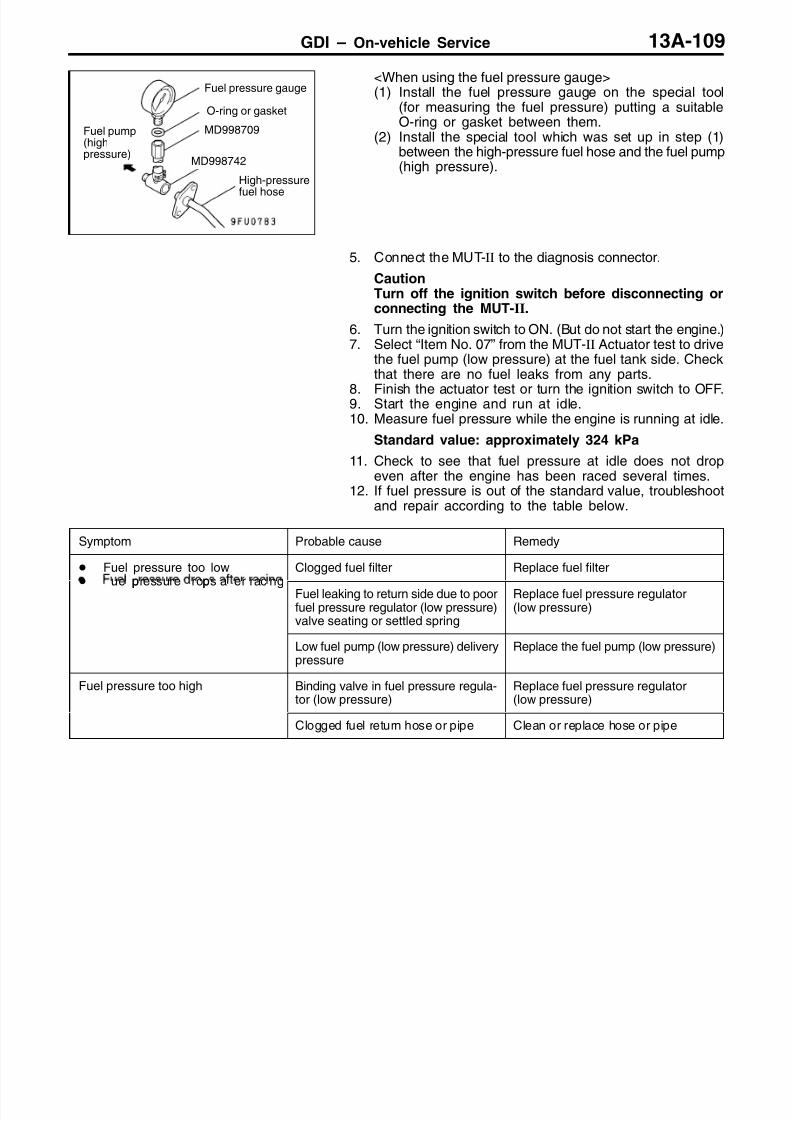
8/19/2019 13a Gasoline Direct Injection (Gdi) (1)
http://slidepdf.com/reader/full/13a-gasoline-direct-injection-gdi-1 226/269
GDI – On-vehicle Service 13A-109
<When using the fuel pressure gauge>(1) Install the fuel pressure gauge on the special tool
(for measuring the fuel pressure) putting a suitableO-ring or gasket between them.
(2) Install the special tool which was set up in step (1)between the high-pressure fuel hose and the fuel pump(high pressure).
5. Connect the MUT-II to the diagnosis connector.
CautionTurn off the ignition switch before disconnecting orconnecting the MUT-II.
6. Turn the ignition switch to ON. (But do not start the engine.)7. Select “Item No. 07” from the MUT-II Actuator test to drive
the fuel pump (low pressure) at the fuel tank side. Checkthat there are no fuel leaks from any parts.
8. Finish the actuator test or turn the ignition switch to OFF.9. Start the engine and run at idle.10. Measure fuel pressure while the engine is running at idle.
Standard value: approximately 324 kPa
11. Check to see that fuel pressure at idle does not dropeven after the engine has been raced several times.
12. If fuel pressure is out of the standard value, troubleshootand repair according to the table below.
Symptom Probable cause Remedy
Fuel pressure too lowp p
Clogged fuel filter Replace fuel filter ue pressure rops a er rac ng
Fuel leaking to return side due to poorfuel pressure regulator (low pressure)valve seating or settled spring
Replace fuel pressure regulator(low pressure)
Low fuel pump (low pressure) deliverypressure
Replace the fuel pump (low pressure)
Fuel pressure too high Binding valve in fuel pressure regula-tor (low pressure)
Replace fuel pressure regulator(low pressure)
Clogged fuel return hose or pipe Clean or replace hose or pipe
Fuel pressure gauge
O-ring or gasket
MD998709
MD998742
High-pressure
fuel hose
Fuel pump(highpressure)

8/19/2019 13a Gasoline Direct Injection (Gdi) (1)
http://slidepdf.com/reader/full/13a-gasoline-direct-injection-gdi-1 227/269
GDI – On-vehicle Service13A-110
13. Stop the engine and check change of fuel pressure gaugereading. Normal if the reading does not drop within 2minutes. If it does, observe the rate of drop andtroubleshoot and repair according to the table below.
Symptom Probable cause Remedy
Fuel pressure drops gradually after
engine is stopped
Leaky fuel pressure regulator (low
pressure) valve seat
Replace fuel pressure regulator
(low pressure)Fuel pressure drops sharplyimmediately after engine is stopped
Check valve in fuel pump (lowpressure) is held open
Replace the fuel pump (low pressure)
14. Release residual pressure from the fuel pipe line.
NOTERefer to the ’00 PAJERO PININ Workshop Manual (Pub.No. CKRE00E1) GROUP 13A – On-vehicle Service.
15. Remove the fuel pressure gauge and special tools from thefuel pump (high pressure).
Caution
Cover the hose connection with rags to prevent splashof fuel that could be caused by some residual pressurein the fuel pipe line.
16. Replace the O-ring at the end of the high-pressure fuelhose with a new one. Furthermore, apply engine oil tothe new O-ring before replacement.
17. Fit the high-pressure fuel hose to the fuel pump (highpressure) and tighten the mounting bolt to specified torque.
18. Check for any fuel leaks by following the procedure instep 7.
19. Disconnect the MUT-II.
MEASUREMENT OF FUEL HIGH PRESSURE BETWEENFUEL PUMP (HIGH PRESSURE) AND INJECTORS
NOTEMeasurement of the fuel pressure between the fuel pump(high pressure) and the injectors should be carried out afterchecking that the fuel pressure between the fuel pump (lowpressure) and the fuel pump (high pressure) is normal.
1. Connect the MUT-II to the diagnosis connector.2. Disconnect the injector intermediate harness connector.3. Turn the ignition switch to ON.4. Select “Item No. 74” from the MUT-II Data list.
5. Crank the engine continuously for 2 seconds or more,and visually check that there are no fuel leaks from anyparts.
CautionIf any fuel leaks appear, stop cranking immediatelyand repair the source of the leak.
6. Check if the fuel pressure is more than 1 MPa immediatelyafter 20 seconds have passed since cranking was finished.
7. If the fuel pressure is lower than 1 MPa, it means thatthere is likely to be a leak in the high-pressure fuel system,so this system should be checked.
Injector inter-mediate harnessconnector
8/19/2019 13a Gasoline Direct Injection (Gdi) (1)
http://slidepdf.com/reader/full/13a-gasoline-direct-injection-gdi-1 228/269
GDI – On-vehicle Service 13A-111
8. Turn the ignition switch to OFF.9. Connect the injector intermediate harness connector.10. Start the engine and run at idle.11. Measure fuel pressure while the engine is running at idle.
Standard value: 4 – 6.9 MPa
12. Check to see that fuel pressure at idle does not drop evenafter the engine has been raced several times.
13. If fuel pressure is out of the standard value, troubleshootand repair according to the table below.
Symptom Probable cause Remedy
Fuel pressure too low Fuel pressure drops after racing
Fuel leaking to return side due to poorfuel pressure regulator valve seatingor settled spring in the fuel pump (highpressure).
Replace the fuel pump (high pres-sure)
Low fuel pump (high pressure)delivery pressure Replace the fuel pump(high pressure)
Fuel pressure too high Clogged fuel pressure regulator valvein the fuel pump (high pressure)
Replace the fuel pump (high pres-sure)
Clogged fuel return hose or pipe Clean or replace hose or pipe
14. Stop the engine and turn the ignition switch to OFF.15. Disconnect the MUT-II.

8/19/2019 13a Gasoline Direct Injection (Gdi) (1)
http://slidepdf.com/reader/full/13a-gasoline-direct-injection-gdi-1 229/269
GDI – On-vehicle ServiceGDI – On-vehicle Service13A-112
COMPONENT LOCATION
Name Symbol Name Symbol
Fuel pressure sensor C Oxygen sensor (front) B
Ignition failure sensor A Oxygen sensor (rear) D
A B
CD
OXYGEN SENSOR CHECK
<Oxygen sensor (front)>
1. Disconnect the oxygen sensor connector and connect thespecial tool (test harness) to the connector on the oxygensensor side.
2. Make sure that there is continuity (4.5 – 8.0 Ω at 20C)between terminal 1 (red clip of special tool) and terminal3 (blue clip of special tool) on the oxygen sensor connector.
3. If there is no continuity, replace the oxygen sensor.4. Warm up the engine until engine coolant is 80C or higher.
Oxygen sensor(front)
Equipment sideconnector
Red
MD998464
Blue

8/19/2019 13a Gasoline Direct Injection (Gdi) (1)
http://slidepdf.com/reader/full/13a-gasoline-direct-injection-gdi-1 230/269
GDI – On-vehicle Service 13A-113
5. Use a jumper wire to connect terminal 1 (red clip) of theoxygen sensor connector to the battery (+) terminal andterminal 3 (blue clip) to the battery (–) terminal.
CautionBe very careful when connecting the jumper wire;incorrect connection can damage the oxygen sensor.
6. Connect a digital voltage meter between terminal 2 (black
clip) and terminal 4 (white clip).7. While repeatedly racing the engine, measure the oxygen
sensor output voltage.
Standard value:
Engine Oxygen sensoroutput voltage
Remarks
When racingthe engine
0.6 – 1.0 V If you make the air/fuelratio rich by racing theengine repeatedly, a nor-mal oxygen sensor willoutput a voltage of 0.6 –
1.0 V.
8. If the sensor is defective, replace the oxygen sensor.
NOTEFor removal and installation of the oxygen sensor, referto GROUP 15 – Exhaust Pipe and Main Muffler.
<Oxygen sensor (rear)>
1. Disconnect the oxygen sensor connector and connect thespecial tool (test harness set) to the connector on theoxygen sensor side.
2. Make sure that there is continuity (11 – 18 Ω at 20C)between terminal 1 (red clip of special tool) and terminal3 (blue clip of special tool) on the oxygen sensor connector.
3. If there is no continuity, replace the oxygen sensor.
NOTE(1) If the MUT-II does not display the standard value
although no abnormality is found by the abovementioned continuity test and harness check, replacethe oxygen sensor (rear).
(2) For removal and installation of the oxygen sensor,refer to GROUP 15 – Exhaust Pipe and Main Muffler.
White Black
Red
Blue
MD9998464
Oxygen sensor (rear)
Equipment side connector
Red
MD998464
Blue

8/19/2019 13a Gasoline Direct Injection (Gdi) (1)
http://slidepdf.com/reader/full/13a-gasoline-direct-injection-gdi-1 231/269
GDI – Fuel Pump (High Pressure)13A-114
FUEL PUMP (HIGH PRESSURE)
REMOVAL AND INSTALLATION
Pre-removal and Post-installation Operation Engine Cover Removal and Installation (Refer to
GROUP 11A – Camshaft and Camshaft Oil Seal.) Prevention of Fuel Discharge <before removal only> Fuel Leak Check <after installation only>
High-pressure Fuel Line Air Bleeding<after installation only> (P.13A-116.)
Resonance Tank Removal and Installation
2
3
1
23 Nm
5
6
4
7
8
9
10
10 – 12 Nm
5.0 Nm → 17 Nm
10 – 13 Nm
Apply engine oil to allO-rings during installation.
5.0 Nm
10 – 13 Nm
Removal steps
A 1. Fuel pump protector2. Furl return hose connection
C 3. Fuel pressure hose connection
C 4. O-ringB 5. Fuel pipe
B 6. Back-up ring AB 7. O-ringB 8. Back-up ring B
A 9. Fuel pump (high-pressure)10. O-ring

8/19/2019 13a Gasoline Direct Injection (Gdi) (1)
http://slidepdf.com/reader/full/13a-gasoline-direct-injection-gdi-1 232/269
GDI – Fuel Pump (High Pressure) 13A-115
REMOVAL SERVICE POINT
A FUEL PUMP PROTECTOR REMOVAL
Jack up the transmission, and create sufficient clearancebetween the engine and the front deck. Then remove thefuel pump protector.
INSTALLATION SERVICE POINTS
A FUEL PUMP (HIGH-PRESSURE) INSTALLATION
1. Apply clean engine oil to the O-ring and the roller of thefuel pump (high-pressure).
2. Insert the fuel pump (high-pressure) into the cylinder headmounting hole squarely, and finger-tighten the mountingbolts. The mounting bolts should be tightened securelyat step B.
B BACK-UP RING B/O-RING/BACK-UP RING A/FUELPIPE INSTALLATION
1. Install the back-up rings and the O-ring as shown in theillustration.
Caution(1) Install the back-up ring B facing its cutaway
surface toward the opposite side of the O-ringas shown in the illustration.
(2) Confirm the outer diameter of the back-up ring
A. Take care not to install the back-up ring forthe fuel pressure sensor by mistake. (Outerdiameter of the back-up ring A: 14.8 mm)
2. Apply a small amount of fresh engine oil to the O-ring.
CautionTake care not to let any of the engine oil get insidethe fuel pump (high-pressure) or the delivery pipeassembly.
3. Install the fuel pipe into the fuel pump (high pressure) andthe delivery pipe ports squarely. Insert the pipe securely,being careful not to twisting it, and then tighten the mountingbolts to the specified torque.
Tightening torque: 10– 13 Nm
A
ACutawaysurface
Back-up ring A(either side)
O-ring
Back-upring B Section A – A

8/19/2019 13a Gasoline Direct Injection (Gdi) (1)
http://slidepdf.com/reader/full/13a-gasoline-direct-injection-gdi-1 233/269
GDI – Fuel Pump (High Pressure)13A-116
4. Tighten the fuel pump (high-pressure) mounting bolts to5.0 Nm in the order shown.
5. Tighten the mounting bolts to 17 Nm in the sequenceshown as second stage. The final tightening torques shouldnot vary more than 2.0 Nm.
C O-RING/FUEL PRESSURE HOSE INSTALLATION
1. Apply a small amount of fresh engine oil to the O-ring.
CautionTake care not to let any of the engine oil get insidethe fuel pump (high pressure).
2. While being careful not to damage the O-ring, turn thefuel pressure hose to the left and right and connect itto the fuel pump (high pressure). After connecting, check
that the hose turns smoothly.3. If the hose does not turn smoothly, the cause may be
that the O-ring is getting caught. Disconnect the hose,check the O-ring for damage and re-connect the hoseto the fuel pump (high pressure) and then re-check.
4. Tighten the fuel pressure hose mounting bolts to thespecified toque.
Tightening torque: 5.0 Nm
AIR-BLEEDING HIGH-PRESSURE FUEL LINE
1. Run the engine at 2000 r/min for at least 15 secondsin order to bleed air from the high-pressure fuel line.
NOTEIf air is trapped in the high-pressure fuel line due to theremoval of fuel pipe, diagnosis code No. P.0190 will beset as abnormal fuel pressure.
2. Finally confirm diagnosis code by using the MUT-II. Ifdiagnosis code, which indicates defective fuel pressuresensor system, has been set, erase the code.
1 3
4 2

8/19/2019 13a Gasoline Direct Injection (Gdi) (1)
http://slidepdf.com/reader/full/13a-gasoline-direct-injection-gdi-1 234/269
GDI – Injector 13A-117
INJECTOR
REMOVAL AND INSTALLATION
Caution1. Disconnect the negative battery cable prior to the service work.2. The injector driver may be hot immediately after each operation, and high voltage and current
flows between the injector driver and the injectors while the engine is running. Handle the
injector driver carefully.
Pre-removal and Post-installation Operation Engine Cover Removal and Installation (Refer to
GROUP 11A – Camshaft and Camshaft Oil Seal.) Prevention of Fuel Discharge <before removal only>
Fuel Leak Check <after installation only> High-pressure Fuel Line Air Bleeding
<after installation only> (P.13A-116.)
23
1
5
6
4
7
8
20
10
22 – 26 Nm
10 – 13 Nm
10 – 13 Nm
Apply engine oil to allO-rings during installation.
21
18
9
13
1617
11
1219
14
15
8
109
20– 25 Nm
Fuel pressure sensor removal steps
1. Fuel pressure sensor connectorA E 2. Flange
E 3. Fuel pressure sensorD 4. O-ringD 5. Back-up ring
Injector removal steps
Intake manifold (Refer to GROUP 15.)6. Injector connector
C 7. Fuel pipeC 8. Back-up ring AC 9. O-ring
C 10. Back-up ring BB 11. Injector washerB 12. Injector holder
B B 13. Delivery pipe assemblyB 14. InsulatorB 15. Injector gasket
B B 16. Injector assemblyA 17. Corrugated washerA 18. Back-up ring AA 19. O-ringA 20. Back-up ring B
21. Injector

8/19/2019 13a Gasoline Direct Injection (Gdi) (1)
http://slidepdf.com/reader/full/13a-gasoline-direct-injection-gdi-1 235/269
GDI – Injector13A-118
REMOVAL SERVICE POINT
A FLANGE REMOVAL
If the fuel pressure sensor is reused, make mating markson the sensor and the flange before removal.
NOTEThe sealing performance and the installation rigidity of thefuel pressure sensor can be secured by deforming the flangewhen the sensor is installed. Therefore, the flange must bereinstalled on the same side and phase as it is removed.In addition, if the fuel pressure sensor is replaced, it shouldbe always replaced together with the flange.
B DELIVERY PIPE ASSEMBLY/INJECTORASSEMBLY REMOVAL
Remove the delivery pipe assembly with the injector assemblystill attached.
CautionBe careful not to drop the injector assembly whenremoving the delivery pipe assembly.
INSTALLATION SERVICE POINTS
A BACK-UP RING B/O-RING/BACK-UP RING A /CORRUGATED WASHER INSTALLATION
1. Install the back-up rings and the O-ring as shown in theillustration.
Caution(1) Install the back-up ring B facing its cutaway
surface toward the opposite side of the O-ringas shown in the illustration.
(2) Confirm the outer diameter of the back-up ringA. Take care not to install the back-up ring forthe fuel pressure sensor by mistake. (Outerdiameter of the back-up ring A: 14.8 mm)
2. Apply petroleum jelly to the corrugated washer to preventit from falling off, and install it in the direction shown.
CautionThe corrugated washer should always be replacedwith a new part. If the corrugated washer is reused,fuel or gas leak may occur.
B FUEL INJECTOR ASSEMBLY/INJECTORGASKET/INSULATOR/DELIVERY PIPEASSEMBLY/INJECTOR HOLDER/INJECTORWASHER INSTALLATION
1. Apply a small amount of fresh engine oil to the O-ring.
CautionTake care not to let any of the engine oil get insidethe delivery pipe assembly.
Flange
Fuel pressuresensor
Mating mark
Cutawaysurface
Back-up ring A(either side)
O-ring
Back-upring B
A
A
Section A – A
Corrugatedwasher

8/19/2019 13a Gasoline Direct Injection (Gdi) (1)
http://slidepdf.com/reader/full/13a-gasoline-direct-injection-gdi-1 236/269
GDI – InjectorGDI – Injector 13A-119
2. Insert the injector assembly into the mounting hole on thedelivery pipe squarely. Then check that the fuel injectorturns smoothly.
3. If the injector does not turn smoothly, the cause may be thatthe O-ring is getting caught. Remove the fuel injector, checkthe O-ring for damage and re-connect the injector to thedelivery pipe assembly and then re-check.
4. Align the injector assembly mating mark with the delivery
pipe mating mark.5. Install the injector gasket and the insulator to the cylinder
head.6. Assemble the delivery pipe and injector assembly to the
cylinder head, then finger-tighten the mounting bolts.7. Assemble the injector holder and the injector washer, then
tighten the mounting bolts to the specified torque.
Tightening torque: 20 – 25 Nm
8. Tighten the delivery pipe and injector assembly mountingbolts to the specified torque in the order shown.
Tightening torque: 10 – 13 Nm
C BACK-UP RING B/O-RING/BACK-UP RING A/FUELPIPE INSTALLATION
1. Install the back-up rings and the O-ring as shown in theillustration.Caution(1) Install the back-up ring B facing its cutaway
surface toward the opposite side of the O-ringas shown in the illustration.
(2) Confirm the outer diameter of the back-up ringA. Take care not to install the back-up ring for
the fuel pressure sensor by mistake. (Outerdiameter of the back-up ring A: 14.8 mm)
2. Apply a small amount of fresh engine oil to the O-ring.
CautionTake care not to let any of the engine oil get insidethe fuel pump (high-pressure) or the delivery pipeassembly.
3. Install the fuel pipe into the fuel pump (high pressure) andthe delivery pipe ports squarely. Insert the pipe securely,being careful not to twisting it, and then tighten the mountingbolts to the specified torque.
Tightening torque: 10–
13 NmD BACK-UP RING/O-RING INSTALLATION
Assemble the back-up ring and the O-ring as shown.
CautionBe careful not to confuse this back-up ring with back-upring A for the injector or the fuel pipe. (Back-up ring outerdiameter: 15.1 mm)
Matingmark
13 42
A
ACutawaysurface
Back-up ring A(either side)
O-ring
Back-upring B Section A – A
Back-up ring(either side)
O-ring
Section A – A

8/19/2019 13a Gasoline Direct Injection (Gdi) (1)
http://slidepdf.com/reader/full/13a-gasoline-direct-injection-gdi-1 237/269
GDI – Injector13A-120
E FUEL PRESSURE SENSOR/FLANGEINSTALLATION
1. Apply a small amount of fresh engine oil to the O-ring.
CautionBe careful not to allow the engine oil to enter thedelivery pipe.
2. Make the part number on the fuel pressure sensor faceas shown.If the fuel pressure sensor is reused, align the matingmarks to install it to the delivery pipe.
CautionIf the fuel pressure sensor is replaced, always replaceit together with the flange.
Fuel pressure sensor
Parts number

8/19/2019 13a Gasoline Direct Injection (Gdi) (1)
http://slidepdf.com/reader/full/13a-gasoline-direct-injection-gdi-1 238/269
GDI – Throttle Body 13A-121
THROTTLE BODY
REMOVAL AND INSTALLATION
Pre-removal and Post-installation Operation Engine Coolant Draining and Supplying Resonance Tank Removal and Installation
1
2
3
4
5
19 Nm
3
7
6
19 Nm
19 Nm
Removal steps
1. Throttle position sensor connector2. Throttle control servo connector
3. Water hose connection4. Brake booster vacuum hose
connection
5. Throttle body stayB 6. Throttle body assembly
A 7. Throttle body gasket

8/19/2019 13a Gasoline Direct Injection (Gdi) (1)
http://slidepdf.com/reader/full/13a-gasoline-direct-injection-gdi-1 239/269
GDI – Throttle Body13A-122
INSTALLATION SERVICE POINTS
A THROTTLE BODY GASKET INSTALLATION
Install the throttle body gasket with its projection facing asshown in the illustration.
B THROTTLE BODY ASSEMBLY INSTALLATION
If the throttle body assembly is replaced, initialize theelectronic-controlled throttle valve system.
Initialization
Turn on the ignition switch, and turn it to LOCK (OFF) positionwithin one second. Then leave it for at least ten secondswith the ignition switch in LOCK (OFF) position.
Projection

8/19/2019 13a Gasoline Direct Injection (Gdi) (1)
http://slidepdf.com/reader/full/13a-gasoline-direct-injection-gdi-1 240/269
GDI – Throttle Body 13A-123
DISASSEMBLY AND REASSEMBLY
1
2
Disassembly steps
A 1. Throttle position sensor2. Throttle body
REASSEMBLY SERVICE POINT
A THROTTLE POSITION SENSOR INSTALLATION
1. Position the throttle position sensor on the throttle bodyalong the dotted line as shown in the illustration.
2. Rotate the throttle position sensor anticlockwise as shownin the illustration, and then tighten the screws.
3. Measure resistance value between terminal Nos. 1 (sensorpower supply) and 2 (throttle position sensor 1st-channeloutput) as well as 1 (sensor power supply) and 4 (throttleposition sensor 2nd-channel output).
Normal condition
Open the throttle valve slowlyfrom the idle position tofull-open position.
Resistance value changessmoothly in response tothrottle valve opening angle.
4. If the resistance value does not change smoothly, replacethe throttle position sensor.
Sensor powersupply
EarthThrottle posi-tion sensor(2nd channel)output
Throttle position sensor(1st channel) output

8/19/2019 13a Gasoline Direct Injection (Gdi) (1)
http://slidepdf.com/reader/full/13a-gasoline-direct-injection-gdi-1 241/269
SERVICE BULLETINQUALITY INFORMATION ANALYSIS
OVERSEAS SERVICE DEPT. MITSUBISHI MOTORS CORPORATION
SERVICE BULLETIN No.: MSB-00E13-001
Date: 2001-06-03 <Model> <M/Y>Subject: AVAILABILITY OF DRIVE CYCLE PATTERNS
FOR 2001 MODEL CARS01-10
Group: FUEL Draft No.: 00AL602317
INFORMATION INTERNATIONAL
CARADMINISTRATIONOFFICE
T.MASAKI-MANAGERTECHNICAL SERVICE PLANNING
(EC)GALANT(EA0)(EC)SPACE STAR(EC) SPACERUNNER/SPACEWAGON(N80, N90)(EC)PAJEROSPORT(K80W,K90W)(EC)PAJERO/ MONTERO
(V60, V70)(EC)CARISMA(EC)PAJERO PININ(H60,H70)
1. Description:
On the 2001 model cars equipped with the on-board diagnostics system, the drive cycle patternshave been made available.Performing the running test of the car using these drive cycle patterns makes it possible tomonitor all the diagnosis codes that are required for operation of the car in order to determine ifthe applicable system is operating properly or not.

8/19/2019 13a Gasoline Direct Injection (Gdi) (1)
http://slidepdf.com/reader/full/13a-gasoline-direct-injection-gdi-1 242/269
2
2. Applicable Manuals:
Manual Pub. No. Language Page(s)
2001 GALANT PWDE9611-B (English) 4G64-GDI:13I-8
Workshop Manual Supplement PWDS9612-B (Spanish) 4G63-MPI:13A-7
PWDF9613-B (French) 6A13-MPI:13A-97PWDG9614-B (German)
PWDD9615-B (Dutch)PWDW9616-B (Swedish)
2001 SPACE RUNNER/ SPACE WAGON PWDE9803-C (English) 4G64-GDI:13A-9
Workshop Manual Supplement PWDS9804-C (Spanish) 4G63-MPI:13D-12
PWDF9805-C (French)
PWDG9806-C (German)
PWDD9807-C (Dutch)PWDW9808-C (Swedish)
2001 CARISMA PWDE9502-E (English) 4G93-GDI:13J-8
Workshop Manual Supplement PWDS9503-E (Spanish) 4G92-MPI:13A-7
PWDF9504-E (French)
PWDG9505-E (German)
PWDD9506-E (Dutch)
PWDW9507-E (Swedish)2001 SPACE STARWorkshop Manual Supplement
CMXE99E1-A (English) 4G93-GDI:13A-94G13-MPI:13B-7
2001 COLT PWME9511-C (English) 4G13-MPI:13A-7
Workshop Manual Supplement PWMS9512-C (Spanish) 4G93-MPI:13A-88
PWMF9513-C (French)
PWMG9514-C (German)
PWMD9515-C (Dutch)
PWMW9516-C (Swedish)2001 PAJEROWorkshop Manual VOL1
PWJE0001(1/2) (English)
2001 MONTEROWorkshop Manual VOL1
PWJS0002(1/2) (Spanish)
2001 PAJERO/MONTERO (English)
Workshop Manual CD-ROM (Spanish)
(French)
PWJT0008R
(German)
6G74-GDI:13A-12
2001 PAJERO SPORT PWJE9812-B (English) 6G72-MPI:13A-8
Workshop Manual Supplement PWJS9813-B (Spanish)
PWJF9814-B (French)PWJG9815-B (German)2001 PAJERO PININWorkshop Manual Supplement
CKRE99E1-A (English) 4G93-GDI: 13A-9
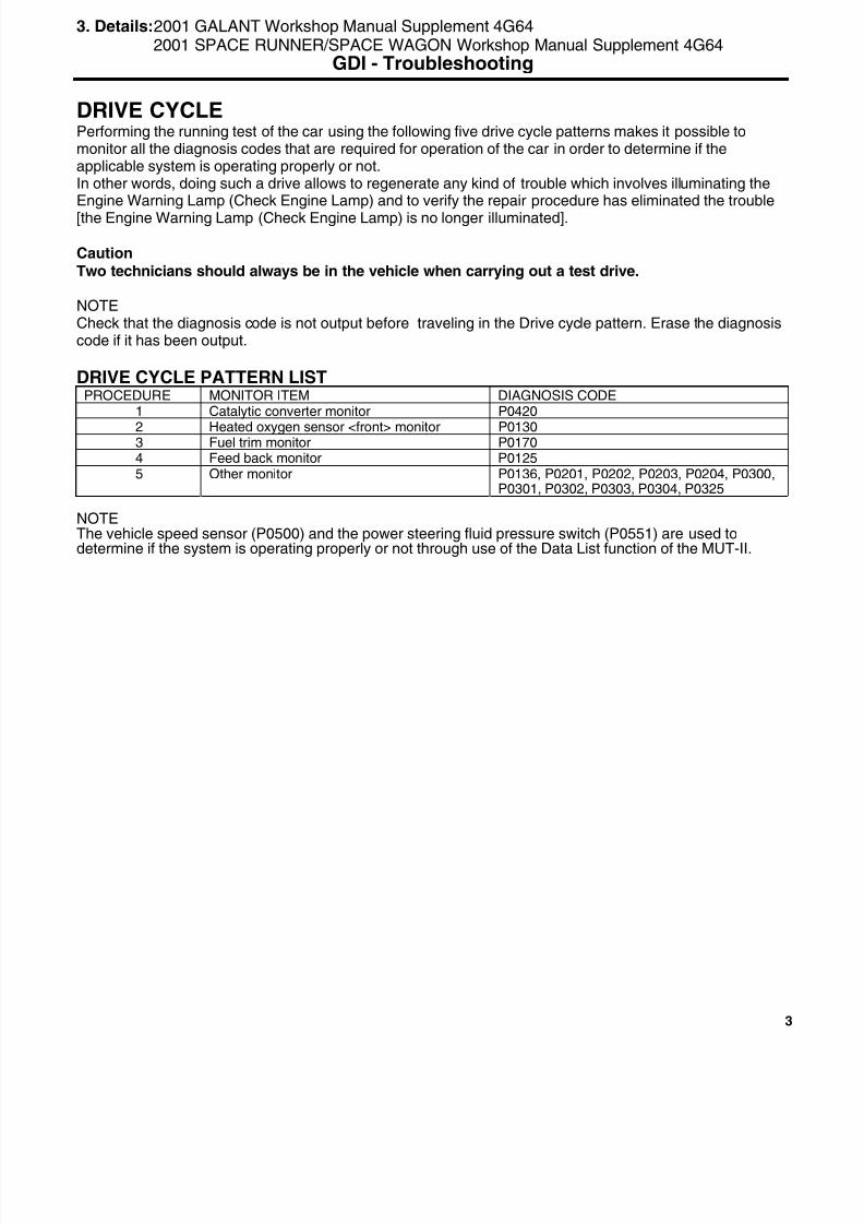
8/19/2019 13a Gasoline Direct Injection (Gdi) (1)
http://slidepdf.com/reader/full/13a-gasoline-direct-injection-gdi-1 243/269
3
DRIVE CYCLEPerforming the running test of the car using the following five drive cycle patterns makes it possible tomonitor all the diagnosis codes that are required for operation of the car in order to determine if theapplicable system is operating properly or not.In other words, doing such a drive allows to regenerate any kind of trouble which involves illuminating theEngine Warning Lamp (Check Engine Lamp) and to verify the repair procedure has eliminated the trouble
[the Engine Warning Lamp (Check Engine Lamp) is no longer illuminated].
CautionTwo technicians should always be in the vehicle when carrying out a test drive.
NOTECheck that the diagnosis code is not output before traveling in the Drive cycle pattern. Erase the diagnosiscode if it has been output.
DRIVE CYCLE PATTERN LISTPROCEDURE MONITOR ITEM DIAGNOSIS CODE
1 Catalytic converter monitor P0420
2 Heated oxygen sensor <front> monitor P01303 Fuel trim monitor P01704 Feed back monitor P01255 Other monitor P0136, P0201, P0202, P0203, P0204, P0300,
P0301, P0302, P0303, P0304, P0325
NOTEThe vehicle speed sensor (P0500) and the power steering fluid pressure switch (P0551) are used todetermine if the system is operating properly or not through use of the Data List function of the MUT-II.
3. Details:2001 GALANT Workshop Manual Supplement 4G642001 SPACE RUNNER/SPACE WAGON Workshop Manual Supplement 4G64
GDI - Troubleshooting

8/19/2019 13a Gasoline Direct Injection (Gdi) (1)
http://slidepdf.com/reader/full/13a-gasoline-direct-injection-gdi-1 244/269
4
PROCEDURE 1Monitor item CATALYTIC CONVERTER MONITOR (P0420)
One trip monitor [from start to ignition switch to “LOCK” (OFF) position] will be completed whiletraveling with the following drive cycle pattern. It will take 10 minutes or more.
Drive cyclepattern
Inspectionconditions
• Atmospheric temperature :-10 °C or more• Condition of A/T :Selector lever D range, overdrive switch “ON” position
Testprocedure
1. Engine : start2. Accelerate until the vehicle speed is 100 km/h or more.3. Travel for 5 minutes or more while keeping the vehicle speed is 100 km/h or more.4. Decelerate until the vehicle speed is 100 – 120 km/h or less.5. While keeping the accelerator pedal opening degree constant, keep the vehicle speed at 100 –
120 km/h and travel for 5 minutes or more.• Stopping and braking during this operation are permitted.
6. Return the vehicle to the shop, then turn the ignition switch “LOCK” (OFF) position.
2001 GALANT Workshop Manual Supplement 4G642001 SPACE RUNNER/SPACE WAGON Workshop Manual Supplement 4G64
GDI - Troubleshooting
Y6005BY
100 – 120 km/h
Vehiclespeed
5 minutes or more
100 km/h or more
Engine start
Stopping andbraking permitted
Ignition switch ”LOCK”(OFF) position
Time
5 minutes or more

8/19/2019 13a Gasoline Direct Injection (Gdi) (1)
http://slidepdf.com/reader/full/13a-gasoline-direct-injection-gdi-1 245/269
5
PROCEDURE 2
OXYGEN SENSOR <FRONT> MONITOR (P0130)One trip monitor [from start to ignition switch to “LOCK” (OFF) position] will be completed whiletraveling with the following drive cycle pattern. It will take 5 minutes or more.
Drive cyclepattern
Inspectionconditions
• Engine coolant temperature : 85 °C or more• Atmospheric temperature : -10 °C or more• Condition of A/T :Selector lever D range, overdrive switch “ON” position
Testprocedure
1. Engine : start2. Accelerate until the vehicle speed is 80 – 100 km/h.3. While keeping the accelerator pedal opening degree constant, keep the vehicle speed at 80 –
100 km/h and travel for 5 minutes or more.• Stopping and braking during this operation are permitted. Keep the accelerator pedal
opening degree constant for 1 minute or more after each acceleration.4. Return the vehicle to the shop, then turn the ignition switch “LOCK” (OFF) position.
2001 GALANT Workshop Manual Supplement 4G642001 SPACE RUNNER/SPACE WAGON Workshop Manual Supplement 4G64
GDI - Troubleshooting
Y6002BY
Vehiclespeed
5 minutes or more
80 – 100 km/h
Engine start
Stopping andbraking permitted
Ignition switch ”LOCK”(OFF) position
Time

8/19/2019 13a Gasoline Direct Injection (Gdi) (1)
http://slidepdf.com/reader/full/13a-gasoline-direct-injection-gdi-1 246/269
6
PROCEDURE 3monitor item FUEL TRIM MONITOR (P0170)
One trip monitor [from start to ignition switch to “LOCK” (OFF) position] will be completed whiletraveling with the following drive cycle pattern. It will take 15 minutes or more.
Drive cyclepattern
Inspectionconditions
• Engine coolant temperature : 85 °C or more• Atmospheric temperature : -10 °C or more• Condition of A/T :Selector lever D range, overdrive switch “ON” position
Testprocedure
1. Engine : start2. Accelerate until the vehicle speed is 80 – 110 km/h.3. While keeping the accelerator pedal opening degree constant, keep the vehicle speed at 80 –
110 km/h and travel for 15 minutes or more.4. Return the vehicle to the shop, then turn the ignition switch “LOCK” (OFF) position.
2001 GALANT Workshop Manual Supplement 4G642001 SPACE RUNNER/SPACE WAGON Workshop Manual Supplement 4G64
GDI - Troubleshooting
Y6002BY
Vehiclespeed
15 minutes or more
80 – 110 km/h
Engine start
Stopping andbraking permitted
Ignition switch ”LOCK”
(OFF) position
Time
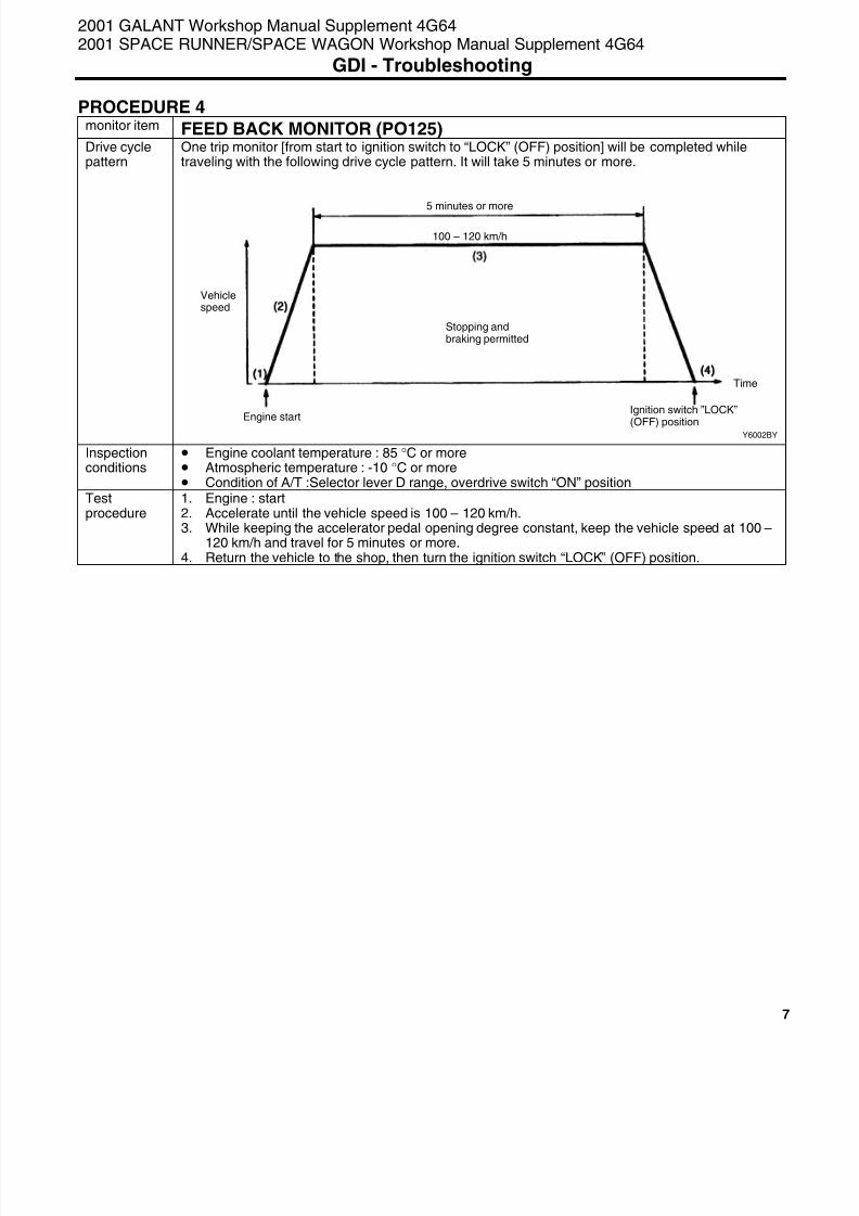
8/19/2019 13a Gasoline Direct Injection (Gdi) (1)
http://slidepdf.com/reader/full/13a-gasoline-direct-injection-gdi-1 247/269
7
PROCEDURE 4monitor item FEED BACK MONITOR (PO125)
One trip monitor [from start to ignition switch to “LOCK” (OFF) position] will be completed whiletraveling with the following drive cycle pattern. It will take 5 minutes or more.
Drive cyclepattern
Inspectionconditions
• Engine coolant temperature : 85 °C or more• Atmospheric temperature : -10 °C or more• Condition of A/T :Selector lever D range, overdrive switch “ON” position
Testprocedure
1. Engine : start2. Accelerate until the vehicle speed is 100 – 120 km/h.3. While keeping the accelerator pedal opening degree constant, keep the vehicle speed at 100 –
120 km/h and travel for 5 minutes or more.4. Return the vehicle to the shop, then turn the ignition switch “LOCK” (OFF) position.
2001 GALANT Workshop Manual Supplement 4G642001 SPACE RUNNER/SPACE WAGON Workshop Manual Supplement 4G64
GDI - Troubleshooting
Y6002BY
Vehiclespeed
5 minutes or more
100 – 120 km/h
Engine start
Stopping andbraking permitted
Ignition switch ”LOCK”
(OFF) position
Time

8/19/2019 13a Gasoline Direct Injection (Gdi) (1)
http://slidepdf.com/reader/full/13a-gasoline-direct-injection-gdi-1 248/269
8
PROCEDURE 5monitor item OTHER MONITORDiagnosiscode No.
P0136, P0201, P0202, P0203, P0204, P0300, P0301, P0302, P0303, P0304, P0325
One trip monitor [from start to ignition switch to “LOCK” (OFF) position] will be completed whiletraveling with the following drive cycle pattern. It will take 6 minutes or more.
Drive cyclepattern
Inspectionconditions
• Engine coolant temperature : 85 °C or more• Atmospheric temperature : -10 °C or more• Condition of A/T :Selector lever D range, overdrive switch “ON” position
Testprocedure
1. Engine : start2. Accelerate until the vehicle speed is 60 km/h.3. While keeping the accelerator pedal opening degree constant, keep the vehicle speed at
60km/h or more and travel for 5 minutes or more.4. Return the vehicle to the shop5. After stopping the vehicle, continue idling for 30 seconds, and then turn the ignition switch to
”LOCK” (OFF) position.
• A/C switch : OFF• Light and all accessories : OFF• Transmission : Neutral
2001 GALANT Workshop Manual Supplement 4G642001 SPACE RUNNER/SPACE WAGON Workshop Manual Supplement 4G64
GDI - Troubleshooting
Y6009BY
Vehiclespeed
5 minutes or more
60 km/h or more
Engine start
30 seconds or moreEngine: IdlingTransmission: Neutral
Ignition switch ”LOCK”(OFF) position
Time

8/19/2019 13a Gasoline Direct Injection (Gdi) (1)
http://slidepdf.com/reader/full/13a-gasoline-direct-injection-gdi-1 249/269
9
DRIVE CYCLEPerforming the running test of the car using the following five drive cycle patterns makes it possible tomonitor all the diagnosis codes that are required for operation of the car in order to determine if theapplicable system is operating properly or not.In other words, doing such a drive allows to regenerate any kind of trouble which involves illuminating theEngine Warning Lamp (Check Engine Lamp) and to verify the repair procedure has eliminated the trouble[the Engine Warning Lamp (Check Engine Lamp) is no longer illuminated].
CautionTwo technicians should always be in the vehicle when carrying out a test drive.
NOTECheck that the diagnosis code is not output before traveling in the Drive cycle pattern. Erase the diagnosiscode if it has been output.
DRIVE CYCLE PATTERN LISTPROCEDURE MONITOR ITEM DIAGNOSIS CODE
Catalytic converter monitor P04201
Catalyst temperature sensor <M/T> monitor(DX only)
P0425
2 Heated oxygen sensor <front> monitor P01303 Fuel trim monitor P01704 Feed back monitor P01255 Other monitor P0136, P0201, P0202, P0203, P0204, P0300,
P0301, P0302, P0303, P0304, P0325
NOTEThe vehicle speed sensor (P0500) and the power steering fluid pressure switch (P0551) are used todetermine if the system is operating properly or not through use of the Data List function of the MUT-II.
2001 CARISMA Workshop Manual Supplement 4G932001 SPACE STAR Workshop Manual Supplement 4G93
GDI - Troubleshooting

8/19/2019 13a Gasoline Direct Injection (Gdi) (1)
http://slidepdf.com/reader/full/13a-gasoline-direct-injection-gdi-1 250/269
10
PROCEDURE 1
CATALYTIC CONVERTER MONITOR (P0420)monitor item
CATALYTIC TEMPERATURE SENSOR <M/T> MONITOR (P0425)One trip monitor [from start to ignition switch to “LOCK” (OFF) position] will be completed whiletraveling with the following drive cycle pattern. It will take 12 minutes or more.
Drive cyclepattern
Inspectionconditions
• Engine coolant temperature : 85 °C or more• Atmospheric temperature : -10 °C or more• Condition of A/T :Selector lever D range, overdrive switch “ON” position
Testprocedure
1. Engine : start2. Accelerate until the vehicle speed is 100 km/h.3. Travel for 5 minutes or more while keeping the vehicle speed is 100 km/h or more.4. Decelerate until the vehicle speed is 0 km/h within 1 minute and stop for 25 – 30 seconds.5. Accelerate until the vehicle speed at 100 – 120 km/h within 1 minute.6. While keeping the accelerator pedal opening degree constant, keep the vehicle speed at
100 - 120 km/h and travel for 3 minutes or more.
7. Repeat the above procedure 4 – 6.8. Return the vehicle to the shop, then turn the ignition switch ”LOCK” (OFF) position.
2001 CARISMA Workshop Manual Supplement 4G932001 SPACE STAR Workshop Manual Supplement 4G93
GDI - Troubleshooting
Y6004BY
Vehiclespeed 5 minutes or more
100 km/h or more
Engine startIgnition switch
”LOCK” (OFF)position
Time
*: 1 minute or less
3 minutes or more 3 minutes or more
100 – 120 km/h 100 – 120 km/h
Stop: 25 – 30 seconds Stop: 25 – 30 seconds

8/19/2019 13a Gasoline Direct Injection (Gdi) (1)
http://slidepdf.com/reader/full/13a-gasoline-direct-injection-gdi-1 251/269
11
PROCEDURE 2monitor item OXYGEN SENSOR <FRONT> MONITOR (P0130)
One trip monitor [from start to ignition switch to “LOCK” (OFF) position] will be completed whiletraveling with the following drive cycle pattern. It will take 7 minutes or more.
Drive cyclepattern
Inspectionconditions
• Engine coolant temperature : 85 °C or more• Atmospheric temperature : -10 °C or more• Condition of A/T :Selector lever D range, overdrive switch “ON” position
Testprocedure
1. Engine : start2. Accelerate until the vehicle speed is 100 – 120 km/h within 1 minute.3. While keeping the accelerator pedal opening degree constant, keep the vehicle speed at 100 –
120 km/h and travel for 3 minutes or more.4. Decelerate until the vehicle speed is 0 km/h within 1 minute and stop for 25 – 30 seconds.5. Repeat the above procedure 2 – 3.6. Return the vehicle to the shop, then turn the ignition switch “LOCK” (OFF) position.
2001 CARISMA Workshop Manual Supplement 4G932001 SPACE STAR Workshop Manual Supplement 4G93
GDI - Troubleshooting
Y6006BY
Vehiclespeed
3 minutes or more
100 – 120 km/h
Engine start
Stop: 25 – 30 seconds
Ignition switch”LOCK” (OFF)position
Time
*: 1 minute or less
3 minutes or more
100 – 120 km/h

8/19/2019 13a Gasoline Direct Injection (Gdi) (1)
http://slidepdf.com/reader/full/13a-gasoline-direct-injection-gdi-1 252/269
12
PROCEDURE 3monitor item FUEL TRIM MONITOR (P0170)
One trip monitor [from start to ignition switch to “LOCK” (OFF) position] will be completed whiletraveling with the following drive cycle pattern. It will take 13 minutes or more.
Drive cyclepattern
Inspectionconditions
• Engine coolant temperature : 85 °C or more• Atmospheric temperature : -10 °C or more• Condition of A/T :Selector lever D range, overdrive switch “ON” position
Testprocedure
1. Engine : start2. Accelerate until the vehicle speed is 100 – 120 km/h within 1 minute.3. While keeping the accelerator pedal opening degree constant, keep the vehicle speed at 100 –
120 km/h and travel for 3 minutes or more.4. Decelerate until the vehicle speed is 0 km/h within 1 minute and stop for 25 – 30 seconds.5. Repeat the above procedure 2 - 4 two times and 2 - 3 one time.6. Return the vehicle to the shop, then turn the ignition switch “LOCK” (OFF) position.
2001 CARISMA Workshop Manual Supplement 4G932001 SPACE STAR Workshop Manual Supplement 4G93
GDI - Troubleshooting
Y6007BY
Vehiclespeed
3 minutes or more
100 – 120 km/h
Engine startStop: 25 – 30 seconds
Ignition switch”LOCK” (OFF)
position
Time
*: 1 minute or less
3 minutes or more
100 – 120 km/h 100 – 120 km/h 100 – 120 km/h
3 minutes or more 3 minutes or more
Stop: 25 – 30 seconds Stop: 25 – 30 seconds

8/19/2019 13a Gasoline Direct Injection (Gdi) (1)
http://slidepdf.com/reader/full/13a-gasoline-direct-injection-gdi-1 253/269
13
PROCEDURE 4monitor item FEED BACK MONITOR (P0125)
One trip monitor [from start to ignition switch to “LOCK” (OFF) position] will be completed whiletraveling with the following drive cycle pattern. It will take 5 minutes or more.
Drive cyclepattern
Inspectionconditions
• Engine coolant temperature : 85 °C or more• Atmospheric temperature : -10 °C or more• Condition of A/T :Selector lever D range, overdrive switch “ON” position
Testprocedure
1. Engine : start2. Accelerate until the vehicle speed is 90 – 110 km/h within 1 minute.3. While keeping the accelerator pedal opening degree constant, keep the vehicle speed at 90 –
110 km/h and travel for 5 minutes or more.4. Return the vehicle to the shop, then turn the ignition switch “LOCK” (OFF) position.
2001 CARISMA Workshop Manual Supplement 4G932001 SPACE STAR Workshop Manual Supplement 4G93
GDI - Troubleshooting
Y6008BY
Vehiclespeed
90 – 110 km/h
Engine start Ignition switch”LOCK” (OFF)position
Time
1 minuteor less
5 minutes or more
Stopping andbraking permitted

8/19/2019 13a Gasoline Direct Injection (Gdi) (1)
http://slidepdf.com/reader/full/13a-gasoline-direct-injection-gdi-1 254/269
14
PROCEDURE 5
OTHER MONITORDiagnosiscode No.
P0136, P0201, P0202, P0203, P0204, P0300, P0301, P0302, P0303, P0304, P0325
One trip monitor [from start to ignition switch to “LOCK” (OFF) position] will be completed whiletraveling with the following drive cycle pattern. It will take 6 minutes or more.
Drive cyclepattern
Inspectionconditions
• Engine coolant temperature : 85 °C or more• Atmospheric temperature : -10 °C or more• Condition of A/T :Selector lever D range, overdrive switch “ON” position
Testprocedure
1. Engine : start2. Accelerate until the vehicle speed is 60 km/h.3. While keeping the accelerator pedal opening degree constant, keep the vehicle speed at
60km/h or more and travel for 5 minutes or more.4. Return the vehicle to the shop5. After stopping the vehicle, continue idling for 30 seconds, and then turn the ignition switch to
”LOCK” (OFF) position.
• A/C switch : OFF• Light and all accessories : OFF• Transmission : Neutral
2001 CARISMA Workshop Manual Supplement 4G932001 SPACE STAR Workshop Manual Supplement 4G93
GDI - Troubleshooting
Y6009BY
Vehiclespeed
5 minutes or more
60 km/h or more
Engine start
30 seconds or moreEngine: IdlingTransmission: Neutral
Ignition switch ”LOCK”(OFF) position
Time

8/19/2019 13a Gasoline Direct Injection (Gdi) (1)
http://slidepdf.com/reader/full/13a-gasoline-direct-injection-gdi-1 255/269
15
DRIVE CYCLEPerforming the running test of the car using the following five drive cycle patterns makes it possible tomonitor all the diagnosis codes that are required for operation of the car in order to determine if theapplicable system is operating properly or not.In other words, doing such a drive allows to regenerate any kind of trouble which involves illuminating theEngine Warning Lamp (Check Engine Lamp) and to verify the repair procedure has eliminated the trouble
[the Engine Warning Lamp (Check Engine Lamp) is no longer illuminated].
CautionTwo technicians should always be in the vehicle when carrying out a test drive.
NOTECheck that the diagnosis code is not output before traveling in the Drive cycle pattern. Erase the diagnosiscode if it has been output.
DRIVE CYCLE PATTERN LISTPROCEDURE MONITOR ITEM DIAGNOSIS CODE
Catalytic converter monitor P04201
Heated oxygen sensor <front> monitor P01302 Fuel trim monitor P01703 Feed back monitor P01254 Other monitor P0136, P0201, P0202, P0203, P0204, P0205,
P0206, P0300, P0301, P0302, P0303, P0304,P0305, P0306, P0325
NOTEThe vehicle speed sensor (P0500) and the power steering fluid pressure switch (P0551) are used todetermine if the system is operating properly or not through use of the Data List function of the MUT-II.
2001 PAJERO/MONTERO WAGON Workshop Manual 6G74GDI - Troubleshooting

8/19/2019 13a Gasoline Direct Injection (Gdi) (1)
http://slidepdf.com/reader/full/13a-gasoline-direct-injection-gdi-1 256/269
16
PROCEDURE 1
CATALYTIC CONVERTER MONITOR (P0420)monitor item
OXYGEN SENSOR <FRONT> MONITOR (P0130)One trip monitor [from start to ignition switch to “LOCK” (OFF) position] will be completed whiletraveling with the following drive cycle pattern. It will take 10 minutes or more.
Drive cyclepattern
Inspectionconditions
• Atmospheric temperature : -10 °C or more• Condition of A/T :Selector lever D range, overdrive switch “ON” position
Testprocedure
1. Engine : start2. Accelerate until the vehicle speed is 100 km/h or more.3. Travel for 5 minutes or more while keeping the vehicle speed is 100 km/h or more.4. Decelerate until the vehicle speed is 60 - 80 km/h or less.5. While keeping the accelerator pedal opening degree constant, keep the vehicle speed at 60 - 80
km/h and travel for 5 minutes or more.
• Stopping and braking during this operation are permitted.6. Return the vehicle to the shop, then turn the ignition switch ”LOCK” (OFF) position.
2001 PAJERO/MONTERO Workshop Manual 6G74GDI - Troubleshooting
Y6005BY
Vehiclespeed
5 minutes or more
100 km/h or more
Engine start
Stopping and brakingpermitted
Ignition switch”LOCK” (OFF)position
Time
5 minutes or more
60 – 80 km/h
100 – 120 km/h

8/19/2019 13a Gasoline Direct Injection (Gdi) (1)
http://slidepdf.com/reader/full/13a-gasoline-direct-injection-gdi-1 257/269
17
PROCEDURE 2monitor item FUEL TRIM MONITOR (P0170)
One trip monitor [from start to ignition switch to “LOCK” (OFF) position] will be completed whiletraveling with the following drive cycle pattern. It will take 15 minutes or more.
Drive cyclepattern
Inspectionconditions
• Engine coolant temperature : 85 °C or more• Atmospheric temperature : -10 °C or more• Condition of A/T :Selector lever D range, overdrive switch “ON” position
Testprocedure
1. Engine : start2. Accelerate until the vehicle speed is 80 – 110 km/h.3. While keeping the accelerator pedal opening degree constant, keep the vehicle speed at 80 –
110 km/h and travel for 15 minutes or more.4. Return the vehicle to the shop, then turn the ignition switch “LOCK” (OFF) position.
2001 PAJERO/MONTERO Workshop Manual 6G74GDI - Troubleshooting
Y6002BY
Vehiclespeed
15 minutes or more
80 – 110 km/h
Engine start
Stopping andbraking permitted
Ignition switch ”LOCK”(OFF) position
Time

8/19/2019 13a Gasoline Direct Injection (Gdi) (1)
http://slidepdf.com/reader/full/13a-gasoline-direct-injection-gdi-1 258/269
18
PROCEDURE 3monitor item FEED BACKK MONITOR (P0125)
One trip monitor [from start to ignition switch to “LOCK” (OFF) position] will be completed whiletraveling with the following drive cycle pattern. It will take 5 minutes or more.
Drive cyclepattern
Inspectionconditions
• Engine coolant temperature : 85 °C or more• Atmospheric temperature : -10 °C or more• Condition of A/T :Selector lever D range, overdrive switch “ON” position
Testprocedure
1. Engine : start2. Accelerate until the vehicle speed is 100 – 120 km/h.3. While keeping the accelerator pedal opening degree constant, keep the vehicle speed at 100 –
120 km/h and travel for 5 minutes or more.4. Return the vehicle to the shop, then turn the ignition switch “LOCK” (OFF) position.
2001 PAJERO/MONTERO Workshop Manual 6G74GDI - Troubleshooting
Y6002BY
Vehiclespeed
5 minutes or more
100 – 120 km/h
Engine start
Stopping andbraking permitted
Ignition switch ”LOCK”(OFF) position
Time

8/19/2019 13a Gasoline Direct Injection (Gdi) (1)
http://slidepdf.com/reader/full/13a-gasoline-direct-injection-gdi-1 259/269
19
PROCEDURE 4monitor item OTHER MONITORDiagnosiscode No.
P0136, P0201, P0202, P0203, P0204, P0205, P0206, P0300, P0301, P0302, P0303, P0304,P0305, P0306, P0325One trip monitor [from start to ignition switch to “LOCK” (OFF) position] will be completed whiletraveling with the following drive cycle pattern. It will take 6 minutes or more.
Drive cyclepattern
Inspectionconditions
• Engine coolant temperature : 85 °C or more• Atmospheric temperature : -10 °C or more• Condition of A/T :Selector lever D range, overdrive switch “ON” position
Testprocedure
1. Engine : start2. Accelerate until the vehicle speed is 60 km/h.3. While keeping the accelerator pedal opening degree constant, keep the vehicle speed at 60
km/h or more and travel for 5 minutes or more.4. Return the vehicle to the shop5. After stopping the vehicle, continue idling for 30 seconds, and then turn the ignition switch to
”LOCK” (OFF) position.
• A/C switch : OFF• Light and all accessories: OFF• Transmission : Neutral
2001 PAJERO/MONTERO Workshop Manual 6G74GDI - Troubleshooting
Y6009BY
Vehiclespeed
5 minutes or more
60 km/h or more
Engine start
30 seconds or moreEngine: IdlingTransmission: Neutral
Ignition switch ”LOCK”(OFF) position
Time

8/19/2019 13a Gasoline Direct Injection (Gdi) (1)
http://slidepdf.com/reader/full/13a-gasoline-direct-injection-gdi-1 260/269

8/19/2019 13a Gasoline Direct Injection (Gdi) (1)
http://slidepdf.com/reader/full/13a-gasoline-direct-injection-gdi-1 261/269
21
PROCEDURE 1monitor item CATALYTIC CONVERTER MONITOR (P0420)
One trip monitor [from start to ignition switch to “LOCK” (OFF) position] will be completed whiletraveling with the following drive cycle pattern. It will take 10 minutes or more.
Drive cyclepattern
Inspectionconditions
• Atmospheric temperature : -10 °C or more• Condition of A/T :Selector lever D range, overdrive switch “ON” position
Testprocedure
1. Engine : start2. Accelerate until the vehicle speed is 100 km/h or more.3. Travel for 5 minutes or more while keeping the vehicle speed is 100 km/h or more.4. Decelerate until the vehicle speed is 90 –110 km/h or less.5. While keeping the accelerator pedal opening degree constant, keep the vehicle speed at 90 -
110 km/h and travel for 5 minutes or more.• Stopping and braking during this operation are permitted.
6. Return the vehicle to the shop, then turn the ignition switch ”LOCK” (OFF) position.
2000 PAJERO/PININ Workshop Manual Supplement 4G93GDI - Troubleshooting
Y6005BY
Vehiclespeed
5 minutes or more
100 km/h or more
Engine start
Stopping and brakingpermitted
Ignition switch”LOCK” (OFF)position
Time
5 minutes or more
90 – 110 km/h
100 – 120 km/h
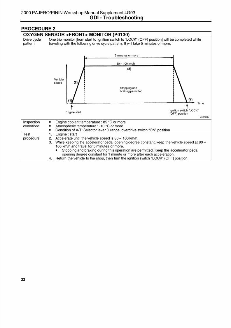
8/19/2019 13a Gasoline Direct Injection (Gdi) (1)
http://slidepdf.com/reader/full/13a-gasoline-direct-injection-gdi-1 262/269

8/19/2019 13a Gasoline Direct Injection (Gdi) (1)
http://slidepdf.com/reader/full/13a-gasoline-direct-injection-gdi-1 263/269
23
PROCEDURE 3Monitor item FUEL TRIM MONITOR (P0170)
One trip monitor [from start to ignition switch to “LOCK” (OFF) position] will be completed whiletraveling with the following drive cycle pattern. It will take 15 minutes or more.
Drive cyclepattern
Inspectionconditions
• Engine coolant temperature : 85 °C or more• Atmospheric temperature : -10 °C or more• Condition of A/T :Selector lever D range, overdrive switch “ON” position
Testprocedure
1. Engine : start2. Accelerate until the vehicle speed is 80 – 100 km/h.3. While keeping the accelerator pedal opening degree constant, keep the vehicle speed at 80 –
110 km/h and travel for 15 minutes or more.4. Return the vehicle to the shop, then turn the ignition switch “LOCK” (OFF) position.
2000 PAJERO/PININ Workshop Manual Supplement 4G93GDI - Troubleshooting
Y6002BY
Vehiclespeed
15 minutes or more
80 – 110 km/h
Engine start
Stopping andbraking permitted
Ignition switch ”LOCK”
(OFF) position
Time

8/19/2019 13a Gasoline Direct Injection (Gdi) (1)
http://slidepdf.com/reader/full/13a-gasoline-direct-injection-gdi-1 264/269
24
PROCEDURE 4Monitor item FEED BACK MONITOR (P0125)
One trip monitor [from start to ignition switch to “LOCK” (OFF) position] will be completed whiletraveling with the following drive cycle pattern. It will take 5 minutes or more.
Drive cyclepattern
Inspectionconditions
• Engine coolant temperature : 85 °C or more• Atmospheric temperature : -10 °C or more• Condition of A/T :Selector lever D range, overdrive switch “ON” position
Testprocedure
1. Engine : start2. Accelerate until the vehicle speed is 100 – 120 km/h.3. While keeping the accelerator pedal opening degree constant, keep the vehicle speed at 100 –
120 km/h and travel for 15 minutes or more.4. Return the vehicle to the shop, then turn the ignition switch “LOCK” (OFF) position.
2000 PAJERO/PININ Workshop Manual Supplement 4G93GDI - Troubleshooting
Y6002BY
Vehiclespeed
5 minutes or more
100 – 120 km/h
Engine start
Stopping andbraking permitted
Ignition switch ”LOCK”
(OFF) position
Time

8/19/2019 13a Gasoline Direct Injection (Gdi) (1)
http://slidepdf.com/reader/full/13a-gasoline-direct-injection-gdi-1 265/269
25
PROCEDURE 5monitor item OTHER MONITORDiagnosiscode No.
P0136, P0201, P0202, P0203, P0204, P0300, P0301, P0302, P0303, P0304, P0325
One trip monitor [from start to ignition switch to “LOCK” (OFF) position] will be completed whiletraveling with the following drive cycle pattern. It will take 6 minutes or more.
Drive cyclepattern
Inspectionconditions
• Engine coolant temperature : 85 °C or more• Atmospheric temperature : -10 °C or more• Condition of A/T :Selector lever D range, overdrive switch “ON” position
Testprocedure
1. Engine : start2. Accelerate until the vehicle speed is 60 km/h.3. While keeping the accelerator pedal opening degree constant, keep the vehicle speed at 60
km/h or more and travel for 5 minutes or more.4. Return the vehicle to the shop5. After stopping the vehicle, continue idling for 30 seconds, and then turn the ignition switch to
”LOCK” (OFF) position.
• A/C switch : OFF• Light and all accessories: OFF• Transmission : Neutral
2000 PAJERO/PININ Workshop Manual Supplement 4G93GDI - Troubleshooting
Y6009BY
Vehiclespeed
5 minutes or more
60 km/h or more
Engine start
30 seconds or moreEngine: IdlingTransmission: Neutral
Ignition switch ”LOCK”(OFF) position
Time

8/19/2019 13a Gasoline Direct Injection (Gdi) (1)
http://slidepdf.com/reader/full/13a-gasoline-direct-injection-gdi-1 266/269
26
DRIVE CYCLEPerforming the running test of the car using the following five drive cycle patterns makes it possible to
monitor all the diagnosis codes that are required for operation of the car in order to determine if theapplicable system is operating properly or not.In other words, doing such a drive allows to regenerate any kind of trouble which involves illuminating theEngine Warning Lamp (Check Engine Lamp) and to verify the repair procedure has eliminated the trouble[the Engine Warning Lamp (Check Engine Lamp) is no longer illuminated].
CautionTwo technicians should always be in the vehicle when carrying out a test drive.
NOTECheck that the diagnosis code is not output before traveling in the Drive cycle pattern. Erase the diagnosiscode if it has been output.
DRIVE CYCLE PATTERN LISTPROCEDURE MONITOR ITEM DIAGNOSIS CODE (DTC)
1 Catalytic converter monitor P0420*1, P0421*
2, P0431*
3,
2 Heated oxygen sensor <front> monitor P01303 Other monitor P0136, P0201, P0202, P0203, P0204,
P0205*3, P0300, P0301, P0302, P0303,
P0304, P0305*3, P0306*
3, P0325*
4
NOTE*1: 4G63*2: 4G13, 4G92, 4G93, 6A13, 6G72*3: 6A13, 6G72*4: 4G13, 4G63, 4G92, 4G93, 6A13
2001 GALANT Workshop Manual Supplement 4G63, 6A132001 SPACE RUNNER/SPACE WAGON Workshop Manual Supplement 4G632001 CARISMA Workshop Manual Supplement 4G922001 SPACE STAR Workshop Manual Supplement 4G132001 COLT Workshop Manual Supplement 4G13, 4G932001 PAJERO SPORT Workshop Manual Supplement 6G72
GDI - Troubleshooting

8/19/2019 13a Gasoline Direct Injection (Gdi) (1)
http://slidepdf.com/reader/full/13a-gasoline-direct-injection-gdi-1 267/269
27
PROCEDURE 1
CATALYTIC CONVERTER MONITOR
Diagnosiscode No.
P0420, P0421, P0431
One trip monitor [from start to ignition switch to “LOCK” (OFF) position] will be completed whiletraveling with the following drive cycle pattern. It will take 16 minutes or more.
Drive cyclepattern
Inspectionconditions
• Atmospheric temperature : -10 °C or more• Condition of A/T :Selector lever D range, overdrive switch “ON” position
Testprocedure
1. Engine : start2. Accelerate until the vehicle speed is 90 km/h or more.
3. Travel for 6 minutes or more while keeping the vehicle speed is 90 km/h or more.4. Decelerate until the vehicle speed is 80 km/h or less.5. While traveling at 55 – 80 km/h for 10 minutes or more, fully close the throttle at least once in 2
minutes and decelerate for 10 seconds or more.• Do not repeat deceleration too often.• Vehicle speed may go below 55 km/h after the deceleration.• Stopping and braking during this operation are permitted.
(If stopped or drive at 55 km/h or less for more than 5 minutes the monitoring may bestopped. In this case please restart monitoring from the beginning.)
6. After completing the above deceleration, bring the vehicle speed back to 55 – 80 km/h and keepit in the range until starting the deceleration again.• Repeat the above deceleration at least 5 times.
7. Return the vehicle to the shop, the turn the ignition switch ”LOCK” (OFF) position.
2001 GALANT Workshop Manual Supplement 4G63, 6A132001 SPACE RUNNER/SPACE WAGON Workshop Manual Supplement 4G632001 CARISMA Workshop Manual Supplement 4G922001 SPACE STAR Workshop Manual Supplement 4G132001 COLT Workshop Manual Supplement 4G13, 4G932001 PAJERO SPORT Workshop Manual Supplement 6G72
GDI - Troubleshooting
Y6001BY
Vehiclespeed
6 minutes or more
90 km/h or more
Engine start
Stopping and brakingpermitted
Ignition switch”LOCK” (OFF)position
Time
10 minutes or more
55 – 80 km/h

8/19/2019 13a Gasoline Direct Injection (Gdi) (1)
http://slidepdf.com/reader/full/13a-gasoline-direct-injection-gdi-1 268/269
28
PROCEDURE 2
OXYGEN SENSOR <FRONT> MONITOR
Diagnosiscode No.
P0130
One trip monitor [from start to ignition switch to “LOCK” (OFF) position] will be completed whiletraveling with the following drive cycle pattern. It will take 16 minutes or more.
Drive cyclepattern
Inspectionconditions
• Engine coolant temperature : After engine warm up.• Atmospheric temperature : -10 °C or more• Condition of A/T :Selector lever D range, overdrive switch “ON” position
Testprocedure
1. Engine : start2. Accelerate until the vehicle speed is 55 – 80 km/h.3. While keeping the accelerator pedal opening degree constant, keep the vehicle speed at 55 –80
km/h and travel for 16 minutes or more.• Stopping and braking during this operation are permitted.
4. Return the vehicle to the shop, then turn the ignition switch “LOCK” (OFF) position.
2001 GALANT Workshop Manual Supplement 4G63, 6A132001 SPACE RUNNER/SPACE WAGON Workshop Manual Supplement 4G632001 CARISMA Workshop Manual Supplement 4G922001 SPACE STAR Workshop Manual Supplement 4G132001 COLT Workshop Manual Supplement 4G13, 4G932001 PAJERO SPORT Workshop Manual Supplement 6G72
GDI - Troubleshooting
Y6002BY
Vehiclespeed
16 minutes or more
55 – 80 km/h
Engine start
Stopping andbraking permitted
Ignition switch ”LOCK”(OFF) position
Time

8/19/2019 13a Gasoline Direct Injection (Gdi) (1)
http://slidepdf.com/reader/full/13a-gasoline-direct-injection-gdi-1 269/269
PROCEDURE 3
2001 GALANT Workshop Manual Supplement 4G63, 6A132001 SPACE RUNNER/SPACE WAGON Workshop Manual Supplement 4G632001 CARISMA Workshop Manual Supplement 4G922001 SPACE STAR Workshop Manual Supplement 4G132001 COLT Workshop Manual Supplement 4G13, 4G932001 PAJERO SPORT Workshop Manual Supplement 6G72
GDI - Troubleshooting
Related Documents