GEAR TYPES Angular Bevel Gears These are bevel gears whose shafts are set at an angle other than 90 degrees. They are useful when the direction of a shaft's rotation needs to be changed. Using gears of differing numbers of teeth can change the speed of rotation. These gears permit minor adjustment of gears during assembly and allow for some displacement due to deflection under operating loads without concentrating the load on the end of the tooth. For reliable performance, Gears must be pinned to shaft with a dowel or taper pin. The bevel gears find its application in locomotives, marine applications, automobiles, printing presses, cooling towers, power plants, steel plants, defence and also in railway track inspection machine. They are important components on all current rotorcraft drive system.

Welcome message from author
This document is posted to help you gain knowledge. Please leave a comment to let me know what you think about it! Share it to your friends and learn new things together.
Transcript

8/7/2019 13767430-Gears
http://slidepdf.com/reader/full/13767430-gears 1/20
GEAR TYPES
Angular Bevel Gears These are bevel gears whose shafts are set at an angle other than 90 degrees. They are usefulwhen the direction of a shaft's rotation needs to be changed. Using gears of differing numbers ofteeth can change the speed of rotation.
These gears permit minor adjustment of gears during assembly and allow for somedisplacement due to deflection under operating loads without concentrating the load on the endof the tooth. For reliable performance, Gears must be pinned to shaft with a dowel or taper pin.
The bevel gears find its application in locomotives, marine applications, automobiles, printingpresses, cooling towers, power plants, steel plants, defence and also in railway track inspectionmachine. They are important components on all current rotorcraft drive system.

8/7/2019 13767430-Gears
http://slidepdf.com/reader/full/13767430-gears 2/20
Bevel Gears
They connect intersecting axes and come in several types. The pitch surface of bevel gears is acone. They are useful when the direction of a shaft's rotation needs to be changed. Using gearsof differing numbers of teeth can change the speed of rotation. They are usually mounted onshafts that are 90 degrees apart, but can be designed to work at other angles as well.
These gears permit minor adjustment during assembly and allow for some displacement due todeflection under operating loads without concentrating the load on the end of the tooth. Forreliable performance, Gears must be pinned to shaft with a dowel or taper pin. Bevel gear setsconsist of two gears of different pitch diameter that yield ratios greater than 1:1.
Types The teeth on bevel gears can be straight, spiral or bevel. In straight bevel gears teeth have nohelix angles. They either have equal size gears with 90 degrees shaft angle or a shaft angle otherthan 90 degrees. Straight bevel angle can also be with one gear flat with a pitch angle of 90degrees. In straight when each tooth engages it impacts the corresponding tooth and simplycurving the gear teeth can solve the problem. Spiral bevel gears have spiral angles, which givesperformance improvements. The contact between the teeth starts at one end of the gear andthen spreads across the whole tooth. In both the bevel types of gears the shaft must beperpendicular to each other and must be in the same plane. The hypoid bevel gears can engagewith the axes in different planes. This is used in many car differentials. The ring gear of thedifferential and the input pinion gear are both hypoid. This allows input pinion to be mountedlower than the axis of the ring gear. Hypoid gears are stronger, operate more quietly and can beused for higher reduction ratios. They also have sliding action along the teeth, potentiallyreducing efficiency.
Applications
A good example of bevel gears is seen as the main mechanism for a hand drill. As the handle ofthe drill is turned in a vertical direction, the bevel gears change the rotation of the chuck to a
horizontal rotation. The bevel gears in a hand drill have the added advantage of increasing thespeed of rotation of the chuck and this makes it possible to drill a range of materials.
The bevel gears find its application in locomotives, marine applications, automobiles, printingpresses, cooling towers, power plants, steel plants, defence and also in railway track inspectionmachine. They are important components on all current rotorcraft drive system.
Spiral bevel gears are important components on all current rotorcraft drive systems. Thesecomponents are required to operate at high speeds, high loads, and for an extremely largenumber of load cycles. In this application, spiral bevel gears are used to redirect the shaft fromthe horizontal gas turbine engine to the vertical rotor.

8/7/2019 13767430-Gears
http://slidepdf.com/reader/full/13767430-gears 3/20
Crown Wheel and Pinion
A crown wheel is a wheel with cogs or teeth set at right angles to its plane and the pinion is asmall cogwheel that meshes with the crown wheel. Crown wheel and pinion have excellent heatdistortion control, high strength, wear resistance property and noiseless and vibration freeoperation. They are made of fine-grained steel billet.
The pinion thread is specially made on the thread grinder to ensure proper fitting. Tooth contactof a crown pinion is inspected on a Gleason machine at regular intervals of time for uniformhardness and adequate case depth. They are checked thoroughly for high spots because thisensures premature failure and noise-free operation. The crown wheel & pinion are paired andchecked for centralized tooth bearing and desired proximity. An elliptoid contact pattern isensured between the crown wheel and pinion.
In a machine, when any torque is applied to the drive unit, the tendency is for the crown wheeland pinion to be forced into or out of mesh by the sliding contact. The amount of pre-load on thebearings determines how much torque can be transmitted without allowing end float, whichcause the meshing of the gears to become incorrect.
Application
Crown wheel & pinion are used widely in automotive industries. They are one of the most stressprone parts of a vehicle. They are used in automobiles to maintain forward motion. To maintainforward motion both output drive shaft sides covers are removed and the pinion and crownwheel are swapped completely with differential.
8/7/2019 13767430-Gears
http://slidepdf.com/reader/full/13767430-gears 4/20
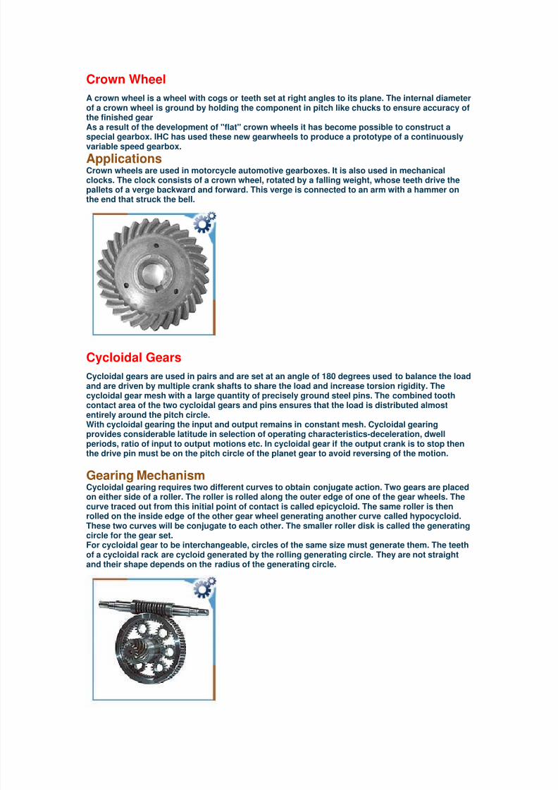
Crown Wheel
A crown wheel is a wheel with cogs or teeth set at right angles to its plane. The internal diameterof a crown wheel is ground by holding the component in pitch like chucks to ensure accuracy ofthe finished gear As a result of the development of "flat" crown wheels it has become possible to construct a
special gearbox. IHC has used these new gearwheels to produce a prototype of a continuouslyvariable speed gearbox.
Applications
Crown wheels are used in motorcycle automotive gearboxes. It is also used in mechanicalclocks. The clock consists of a crown wheel, rotated by a falling weight, whose teeth drive thepallets of a verge backward and forward. This verge is connected to an arm with a hammer onthe end that struck the bell.
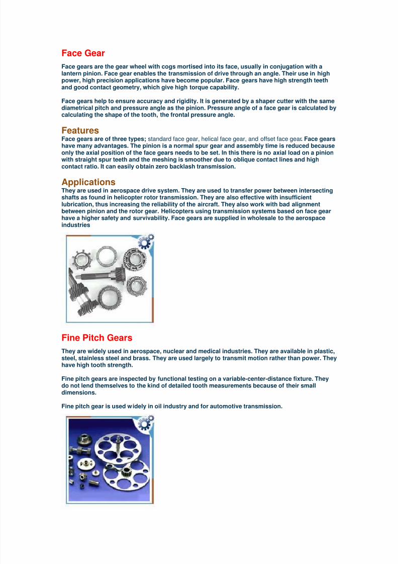
Cycloidal Gears
Cycloidal gears are used in pairs and are set at an angle of 180 degrees used to balance the loadand are driven by multiple crank shafts to share the load and increase torsion rigidity. Thecycloidal gear mesh with a large quantity of precisely ground steel pins. The combined toothcontact area of the two cycloidal gears and pins ensures that the load is distributed almost
entirely around the pitch circle.With cycloidal gearing the input and output remains in constant mesh. Cycloidal gearingprovides considerable latitude in selection of operating characteristics-deceleration, dwellperiods, ratio of input to output motions etc. In cycloidal gear if the output crank is to stop thenthe drive pin must be on the pitch circle of the planet gear to avoid reversing of the motion.
Gearing Mechanism
Cycloidal gearing requires two different curves to obtain conjugate action. Two gears are placedon either side of a roller. The roller is rolled along the outer edge of one of the gear wheels. Thecurve traced out from this initial point of contact is called epicycloid. The same roller is thenrolled on the inside edge of the other gear wheel generating another curve called hypocycloid.These two curves will be conjugate to each other. The smaller roller disk is called the generatingcircle for the gear set.For cycloidal gear to be interchangeable, circles of the same size must generate them. The teeth
of a cycloidal rack are cycloid generated by the rolling generating circle. They are not straightand their shape depends on the radius of the generating circle.

8/7/2019 13767430-Gears
http://slidepdf.com/reader/full/13767430-gears 5/20
Differential Gears
Differential gears link two shafts with a covering, forcing the total of the rotational angles of the
shafts to be the same as the rotational angles of the covering. Arrangement of the system is
done in such a way that one axle turns faster than the other.
When a differential gear is meshed with the other gear then the highly efficient torque is applied
from the differential side gears to the axle shaft. When torque level decreases then the gear
separating forces also decreases allowing the axle shaft to rotate independently. Differential
gears can add or subtract the movement of two inputs. In practical terms, they will turn the
number of revolutions proportional to the movements of both inputs. They are used to convert
the lengthwise flow of power from the engine through the clutches, transmissions, and propeller
shafts into a right-angle direction. This change allows the engine power to turn the wheels.
In the differential gears there are two coaxial gears, the pinions and the turntable. Pinions are
mounted on intermediate shafts and these shafts are connected to a fixed carrier called the
turntable. The differential gears are lubricated with a fluid that absorbs heat and increases the
life and performance of the gears as well as the wheel. Regular driving subjects the fluid to high
heat that breaks the fluid at a later stage. This results in the contact of two metals, which
eventually increases the heat and prevents the gear from turning the car's wheel. So, the fluid
should be properly checked in regular intervals.
Types of Differential Gears
There are two designs of differential gears, hypoid and spiral.
Spiral Differential - In spiral differential the pinion gears contacts the ring gears at its centerline .
Hypoid Gear - In the hypoid the pinion gear contacts the ring gear below the centerline. The size
of pinion gear in hypoid differential is much smaller and the contact ratio is high, comparatively
hypoid differential is much stronger than the spiral differential.
Applications
Differential gears in automobiles are the most common application of these gears. When the car
is moving in a straight line, there is no movement of the differential gear with respect to its axis
but when the car takes a turn then these gears help two wheels of the car to rotate differentially
with respect to each other. When one wheel is stationary then the counterpart wheel rotates at
twice of its expected speed.

8/7/2019 13767430-Gears
http://slidepdf.com/reader/full/13767430-gears 6/20
External Gear These are the most often used and the simplest gear system with cylindrical gears with straight
teeth parallel to the axis. They are used for transmitting rotary motion between parallel shafts.
When a smaller gear called the pinion, drives the larger gear called the wheel, also havingexternal teeth, the corresponding driving and driven shafts rotate in opposite direction. The two
gear surfaces come into contact once and so they are noisy at high speed.
External gears are generated with a tool moving forward towards the component axis. Internal
gear cutter with very small diameter and few teeth is used for the production of external gear.
External gears are widely used in various industrial sectors like coal industry, mining, steel
plant, paper industry, and many more
8/7/2019 13767430-Gears
http://slidepdf.com/reader/full/13767430-gears 7/20
8/7/2019 13767430-Gears
http://slidepdf.com/reader/full/13767430-gears 8/20
Girth Gears
The girth gear has been preferred over the gearless drives due to their lower initial cost,simplicity to install, operate and maintain. In the past many years girth gears have gone throughenormous improvements.
They have high efficiency and the overall life of these gears depends upon proper lubricationand alignment. They are high quality, high precision component. The capital cost of girth gearsis lower than others and they take less time to install. They are physically big and due to thisthey are unable to store for longer periods of time.
Girth gear materials have made several changes on their own. Casting is enhanced using fullring risering techniques. Simulation programs are installed for verification of propersolidification. New materials are used with an added advantage of increase in hardness andtherefore increased ratings.
The girth gear is the heart of most mills and kiln drive system. They can't be used in spare partsinventory. They are also used in steel industry, sugar industry, paper and pulp industry.
Hardened and Ground Gears
Hardened and ground gear has two types of shaft arrangements. They can be parallel shaft typeor hollow shaft type. Hardened and ground gear delivers a maximum hob rotation and tablerotation with excellent machining accuracy. Hardened ground gear provide a noise free and longterm operation. They are characterized by high output, easy operation and precise machining.They offer rigidity, strength and high resistance to shock load. They are available in a wide rangeof sizes and gear ratios.
Hardened gears are used in several essential machine tools like wheels, bedways, etc. and arewidely used in the aerospace industry.

8/7/2019 13767430-Gears
http://slidepdf.com/reader/full/13767430-gears 9/20
Helical Gears
Helical gears connect parallel shifts but the involute teeth are cut at an angle to the axis ofrotation. Two mating helical gears must have equal helix angle but opposite hand. They runsmoother and more quietly. They have higher load capacity, are more expensive to manufactureand create axial thrust.
Helical gears can be used to mesh two shafts that are not parallel and can also be used in acrossed gear mesh connecting two perpendicular shafts. They have longer and strong teeth.They can carry heavy load because of the greater surface contact with the teeth. The efficiencyis also reduced because of longer surface contact. The gearing is quieter with less vibration.
Gear Configuration
They can be manufactured in both right-handed and left-handed configurations with a helixangle to transmit motion and power between non-intersecting shafts that are parallel or at 90degrees to each other. For shaft at 90 degrees, the same helix angles are used and the toothcontact area of the gear is very small. If the angle of gear teeth is correct, they can be mountedon perpendicular shaft by adjusting the rotating angle by 90 degrees. The inclination of the teethgenerates an axial force. As the angle of inclination increases the axial force also increases.Thrust bearings can counter these forces.
Applications
These are highly used in transmission because they are quieter even at higher speed and aredurable. The other possible applications of helical gears are in textile industry, blowers, feeders,rubber and plastic industry, sand mullers, screen, sugar industry, rolling mills, food industry,elevators, conveyors, cutters, clay working machinery, compressors, cane knives and in oilindustry.
Disadvantage
A disadvantage of helical gear is the resultant thrust along the axis of the gear, which needs tobe accomodated by appropriate thrust bearings. This can be overcome by the use of double
helical gears by having teeth with a 'v' shape.

8/7/2019 13767430-Gears
http://slidepdf.com/reader/full/13767430-gears 10/20
Helical Bevel Gears
Helical bevel gear is a toothed gear in angular design. The input side is provided with a motorflange or a free input shaft and the output side are provided with a free shaft end or a hollowshaft. Helical bevel gears are fitted with flanges of various sizes. Reciprocating tools cuts them.
The advantages of helical bevel gears are high efficiency and low reduction rate. The use ofhelical bevel gear saves energy and cost. Helical bevel gears are manufactured by an alloyedcase hardening steel. The gear material is given an extremely strong, homogeneous structure.
They can replace worm gears in a variety of applications, particularly in modular machinery.They are also used as storage and retrieval unit. They are commonly used in moderndifferentials.
Herringbone Gears
They conduct power and motion between non-intersecting, parallel axis that may or may nothave center groove with each group making two opposite helices. The two helix angle cometogether in the center of the gear face to form a 'V'. in these gears the end thrust forces cancel
themselves out. Its difficult to cut this type of gear but its made easier by machining a groove inthe face at the point of the apex of the 'V' creating a break in the middle of the herringbone gearteeth. They do not have any separating groove between the mirrored halves.
Action is equal in force and friction on both gears and all bearings. Herringbone gear also allowfor the use of larger diameter shaft for the same volumetric displacement and higher differentialpressure capability.
The most common application is in power transmission. They utilize curved teeth for efficient,high capacity power transmission. This offers reduced pulsation due to which they are highlyused for extrusion and polymerization. Herringbone gears are mostly used on heavy machinery.

8/7/2019 13767430-Gears
http://slidepdf.com/reader/full/13767430-gears 11/20
Idler Gear
A gear wheel placed between two other gears to transmit motion from one to the other. It doesnot alter the speed of the output, but it does alter the direction it turns. It is used to ensure thatthe rotation of two gears is the same. An idler gear is placed between two gears. The idler gearrotates in the opposite direction as the driver gear, and the follower gear rotates in the oppositedirection of the idler, the same direction of the driver. It is also used to change the spacingbetween the input and output axles. It does not change the gear ratio between the input andoutput gears.All the gears and wheels that turn inside the treads of a battle tank are all idler gears thattransfer power from the input gear to the output gear to move the tread and move the tankforward.The power take off mechanism includes a gear train with an input idler gear, a first intermediateidler gear, a second intermediate idler gear and an output gear. The input idler gear receives arotary input and the first intermediate idler gear meshes with the input gear and the secondintermediate idler gear. The output gears transmit rotary power to one of the first and secondaxles.
Internal Gears
Internal gears have cylindrical pith surface with teeth parallel to the axis. Gears make an internal
contact with these gears. They have the teeth cut on the inside of the rim rather than the outside.When they are used with the pinion more teeth carry the load and are evenly distributed. Thiseven distribution decreases the pressure intensity and increases the life of the gear. The centerdistance of a given velocity is shorter.Internal gears are hollow. The properties and teeth shape is similar as of external gears exceptthat the internal gear had different addendum and dedendum values modified to preventinterference in internal meshes. They are designed to accommodate a wide range of equipment.These are ideal and cost effective. The teeth are cut into the inside diameter while the outsidediameter is smooth. These gears are available only in brass. Internal gear offers low sliding andhigh stress loading. They are used in planetary gears to produce large reduction ratios.When choosing a mating gear the difference between the number of teeth of girth gear and thepinion should not be less than 15. Their non-binding tooth design ensures smooth, quietoperation. They are used to transmit rotary motion between parallel shafts, the shaft rotating inthe same direction as the arrangement.
The main applications of internal gears are in rollers, indexing, timing and other light dutyapplications. They are used as tools for creating solid models of drive components.

8/7/2019 13767430-Gears
http://slidepdf.com/reader/full/13767430-gears 12/20
Involute Gears
Involute gears have a tooth shape that is tolerant of variations in the distance between the axes,to ensure smooth running of the gears. The velocity ratio of the gears does not depend on theexact spacing of the axes, but is fixed by the number of teeth or by pitch diameters. Increasingthe distance above its theoretical value makes the gears run easier, since the clearances arelarger. This also increases the backlash. Rack type cutters generate involute gears.
Operation of the Gear
On an involute gear tooth, the contact point starts closer to one gear, and as the gear spins, thecontact point moves away from that gear and towards the other. The pitch diameter is theeffective contact diameter. As the gear turns, the contact point slides up onto the thicker part ofthe top gear tooth. Thus, pushes the top gear ahead. As the teeth continues to rotate, the contactpoint moves further away going outside the pitch diameter. Then the contact point starts to slideonto the skinny part of the bottom tooth, subtracting a little bit of velocity from the top gear tocompensate for the increased diameter of contact. Thus, the involute gear tooth produces aconstant ratio of rotational speed.
Involute spur gears have the invaluable ability of providing conjugate action when the gears'center distance is varied either deliberately or involuntarily due to manufacturing or mountingerrors.
Non-Involute Gears
Non-involute gears have reduced specific sliding. Reduced gear sliding has an affecton low speed meshes, where sliding losses predominate. The efficiency of these gearsis also increased by the use of less viscous oil.
The tooth profile geometry is uniquely defined by the arc shaped path of contact. Thegears manufactured by the same rack cutter have the concave convex mesh. Theresult of enlarged reduced radius of curvature has as a consequence reduced pressureand better lubrication conditions. The geometry of non-involute gear tooth providessubstantially higher capacity than any other gearing.
The disadvantages of the non-involute gearing are lower transverse contact ratio andgreat sensitivity to the center distance accuracy.

8/7/2019 13767430-Gears
http://slidepdf.com/reader/full/13767430-gears 13/20
Miter Gears
Miter gears are bevel gears put together with equal numbers of teeth and axes that are usually atright angles. Miter is the surface forming the beveled end or edge of a piece where a miter jointis made.
Miter gears are cut with a generated tooth form that has a localized lengthwise tooth bearing.They are offered in various modules, number of teeth, speed ratio, materials and designs. Mitergears are made of steel, brass, bronze, aluminum, nylon and duracon.
Features They are known for efficient power transfer and durability. They can carry heavy loads and caneliminate secondary operations that are useless during the process. They are used in drilling airholes in vacuum molds, drilling radial ports in door closers, milling oil grooves and act as a lowcost spindle for dedicated machines.
They are designed for the efficient transmission of power and motion between intersectingshafts at right angles. They can be of two types, ground spiral miter gear and spiral miter gear.They give smoother, quieter operation. They handle higher speeds and greater torque loads.They provide a steady ratio.
Applications
Miter gears are also used in printing, agriculture, bottling, and material handling and steering.They are used in various industrial sectors including-coal and mining, oil exploration, papermining, chemical industry. They are used as important parts of conveyors, elevators and kilns.
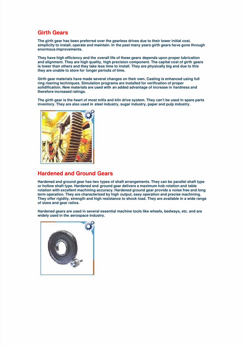
Pinion Gears
It is a small cogwheel. The teeth fit into a larger gear wheel. Rotational motion isconverted into linear motion when the pinion turns and moves the rack. Pinion gearsare engineered to be the best gears.
Pinion gear system involves the use of a small round gear called pinion and a large flatgear called rack, more the number of teeth in the pinion gear, more is the speed ofrotation. Pinion with smaller number of teeth produces more torque. Pinion is attachedto the motor shaft with glue. Rotation of pinion is done by rotation of pinion about afixed center that helps the rack to move in the straight line. If the rack is moved and thepinion rotates then the center of the pinion moves taking along the pinion with it.

8/7/2019 13767430-Gears
http://slidepdf.com/reader/full/13767430-gears 14/20
Rack Gears
Rack gear is a toothed bar into which a pinion meshes. Racks are gears of infinite pitchradius. They are used to translate rotary motion to linear motion or vice versa. Theywill mesh with pinions of the same pitch.Racks are made of various materials. The commonly used materials for racks are
stainless steel, brass, and plastic.They are widely used in automobiles. The steering wheel of a car rotates the gear thatengages the rack. The rack slides right or left, when the gear turns, depending on theway we turn the wheel. Windshield wipers in cars are powered by a rack and pinionmechanism. They are also used in some scales to turn the dial that displays weight.
Ring Gear and Pinion
It is one of the most commonly used spiral bevel gears, used largely in automotiveindustry. In order to enable the axle ratio setting a vehicle must be must be equippedwith a racing gearbox, also known as ring and pinion gears.A ring and pinion gear set is expensive to buy and install, requiring highly skilledtechnicians. This gear is hypoid, it not only rotates against each other but also wipe
across the drive surfaces, creating the shearing force that cuts the lubricants changingits viscosity. Gear oil used here is heavy and the thickness of the oil changes with thetemperature. There are bearings in the final drive, among which two support the drivepinion and two support the case that holds the ring gear and one on each axle nearestthe wheel.To compute a new gear ratio, one needs to enter the stock ring pinion gears ratio alongwith the old and new tier size. It is also used in calculating the tier width and the speedof wheels.
Applications It is used in heavy truck differentials. It is also used in tire rotation, wheel alignmentand tire balance. It is one of the greatest masterpieces in automotive mechanism. Itworks for higher driving and loading capacity in the drive line from transmission towheels. It is also used to compensate for discrepancies in the respective rotation rate
of the drive wheels between inside and outside wheels during cornering for limitedeffective torque to the wheels with lower coefficient of friction.

8/7/2019 13767430-Gears
http://slidepdf.com/reader/full/13767430-gears 15/20
Spiral Bevel Gears
Spiral bevel gears have spiral angles, which gives performance improvements. Theyare designed for an angle change of 90 degrees, where the two axes are concurrentand in the same plane. These gears have a double function of being helical andbeveled at the same time. The contact between the teeth starts at one end of the gear
and then spreads across the whole tooth. In this type of gears the shaft must beperpendicular to each other and must be in the same plane.
They are the most complex forms of bevel gears. The teeth are curved by cutting themobliquely, resulting in higher overall contact ratios. Because of higher contact ratio,these have better load carrying capacity an this allows them to be smaller in size for agiven load capacity than an equivalent gear. Thus they can transmit more power withsmaller gears.
Methods of Manufacturing
Face milled and face hobbed are two methods of manufacturing for spiral bevel gears.In the method of face milled, the grinding of the contacting surface is the last step.
Whereas, in the face hobbed method, hard cutting is the final step. The same machineis used to rough cut and finish cut the gears. The desirable design of the gear is tominimize the weight of the gear and it is done by reducing the material in the gear'srim.
Applications Spiral bevel gears are important components on all current rotorcraft drive systems.These components are required to operate at high speeds, high loads, and for anextremely large number of load cycles. In this application, spiral bevel gears are usedto redirect the shaft from the horizontal gas turbine engine to the vertical rotor. Theyare also used in power windows and power seats. They are used where speed and
strength are desirable along with the change in angle of power flow.

8/7/2019 13767430-Gears
http://slidepdf.com/reader/full/13767430-gears 16/20
Sprockets
Sprockets are teeth like projections arranged on a wheel rim to engage the links of achain. They engage chains in many different power transmission and conveyorsystems. They are mainly made of cast iron, sintered metal, and carbon steel. Insertedsprockets are also designed to reduce noise and operation. They are often an
economic, reliable drive system for long running, continuous drive applications withmaximum absorption of shock and minimum torque loads.
Geometry and Maintenance Two sprockets are connected to each other with a chain. On one end of the chain is asmall sprocket located on the engine that rotates due to the force of the engine. On theother end of the chain is a larger sprocket located attached to the rear axle. Thisprovides both forward and reverse momentum. The amount of rotation of eachsprocket depends on the rotation speed of the driving sprockets, the number of teethof the driving sprockets and the number of teeth of the driven sprockets.
The sprocket must be inspected once a month for wear and if the teeth are worn down
or are broken they should be replaced. The sprockets and the chain must be lubricatedwith chain lube such as bell ray.
Applications
Sprockets are most commonly used in bicycles. In a cycle, a chain runs between twosprockets. When the paddle is pushed, the front gear is turned and that meshes withthe links in the chain. The chain moves and meshes with the links in the rear gear thatis attached to the rear wheel. This enables the bicycle to move.
8/7/2019 13767430-Gears
http://slidepdf.com/reader/full/13767430-gears 17/20
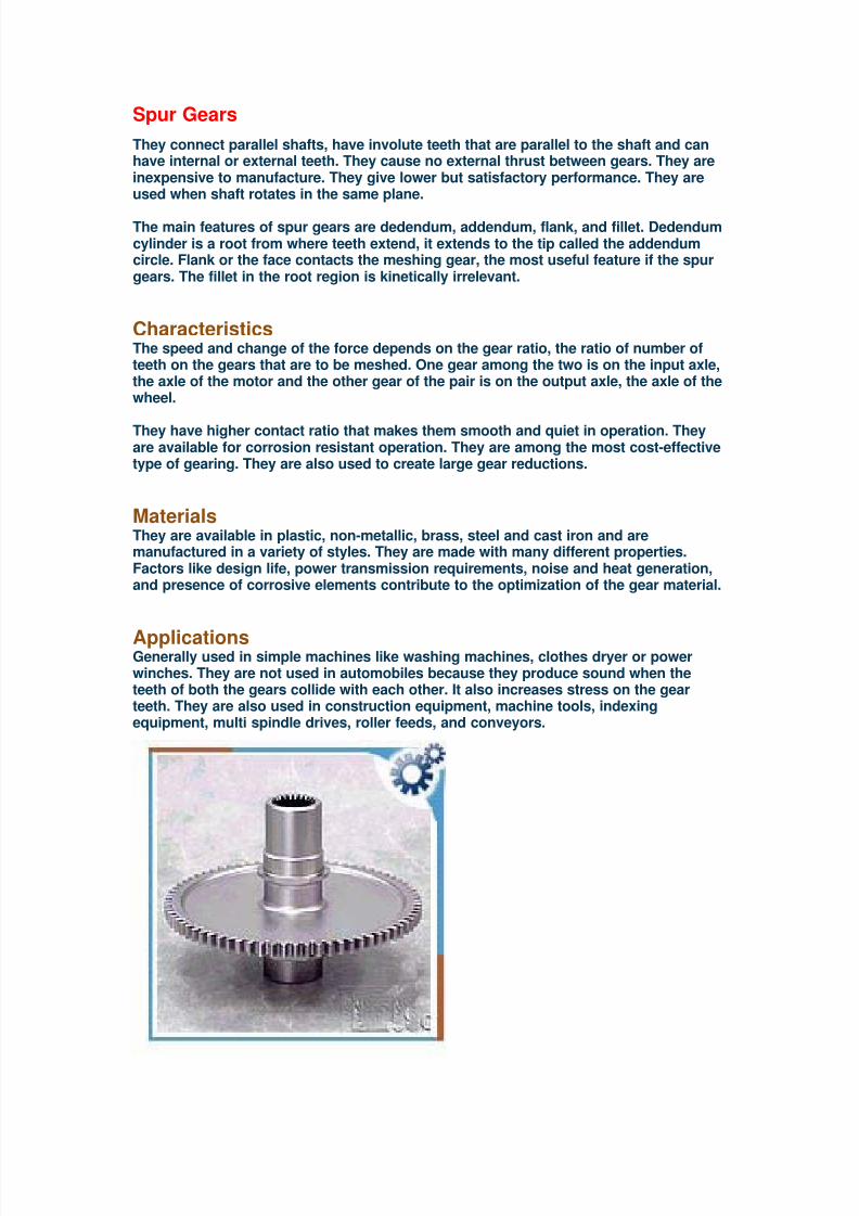
Spur Gears
They connect parallel shafts, have involute teeth that are parallel to the shaft and canhave internal or external teeth. They cause no external thrust between gears. They areinexpensive to manufacture. They give lower but satisfactory performance. They areused when shaft rotates in the same plane.
The main features of spur gears are dedendum, addendum, flank, and fillet. Dedendumcylinder is a root from where teeth extend, it extends to the tip called the addendumcircle. Flank or the face contacts the meshing gear, the most useful feature if the spurgears. The fillet in the root region is kinetically irrelevant.
Characteristics
The speed and change of the force depends on the gear ratio, the ratio of number ofteeth on the gears that are to be meshed. One gear among the two is on the input axle,the axle of the motor and the other gear of the pair is on the output axle, the axle of thewheel.
They have higher contact ratio that makes them smooth and quiet in operation. Theyare available for corrosion resistant operation. They are among the most cost-effectivetype of gearing. They are also used to create large gear reductions.
Materials
They are available in plastic, non-metallic, brass, steel and cast iron and aremanufactured in a variety of styles. They are made with many different properties.Factors like design life, power transmission requirements, noise and heat generation,and presence of corrosive elements contribute to the optimization of the gear material.
Applications Generally used in simple machines like washing machines, clothes dryer or powerwinches. They are not used in automobiles because they produce sound when theteeth of both the gears collide with each other. It also increases stress on the gearteeth. They are also used in construction equipment, machine tools, indexingequipment, multi spindle drives, roller feeds, and conveyors.
8/7/2019 13767430-Gears
http://slidepdf.com/reader/full/13767430-gears 18/20
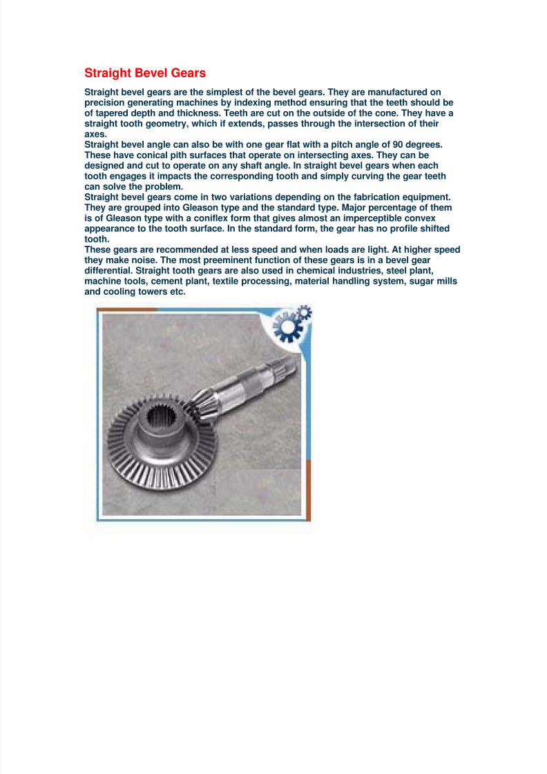
Straight Bevel Gears
Straight bevel gears are the simplest of the bevel gears. They are manufactured onprecision generating machines by indexing method ensuring that the teeth should beof tapered depth and thickness. Teeth are cut on the outside of the cone. They have astraight tooth geometry, which if extends, passes through the intersection of their
axes.Straight bevel angle can also be with one gear flat with a pitch angle of 90 degrees.These have conical pith surfaces that operate on intersecting axes. They can bedesigned and cut to operate on any shaft angle. In straight bevel gears when eachtooth engages it impacts the corresponding tooth and simply curving the gear teethcan solve the problem.Straight bevel gears come in two variations depending on the fabrication equipment.They are grouped into Gleason type and the standard type. Major percentage of themis of Gleason type with a coniflex form that gives almost an imperceptible convexappearance to the tooth surface. In the standard form, the gear has no profile shiftedtooth.These gears are recommended at less speed and when loads are light. At higher speedthey make noise. The most preeminent function of these gears is in a bevel gear
differential. Straight tooth gears are also used in chemical industries, steel plant,machine tools, cement plant, textile processing, material handling system, sugar millsand cooling towers etc.

8/7/2019 13767430-Gears
http://slidepdf.com/reader/full/13767430-gears 19/20
Winch Gears
Winch gears are used to convert the high speed, low force input of the handle into lowspeed, high torque output at the drum. These are quite highly developed and use toothforms that are significantly different from those found in other gear applications suchas car gearboxes and power transmission.
The loads on winch gears are actually high while the speeds they turn at are relativelyvery low. This results in thick strong teeth that resist high loads as well. The winchgears are not long lasting and have low efficiency. The winches turn few thousandtimes in their entire lives and they never go fast enough to get hot.
Applications Winch gear is commonly used in boats and fleets. Before every operation winch gearshould be lubricated. The ratchet should not be engaged when the winch gear isturning. They get worn out easily; overloading them and deforming the teeth causesmajority of damage to the gears. For long term safety and security the damaged partshould be replaced and full analysis of the cause of damage should be done.

8/7/2019 13767430-Gears
http://slidepdf.com/reader/full/13767430-gears 20/20
Worm Gears
A worm gear is an inclined plane wrapped around a central axle. It is a gear with one ormore teeth in the form of screwed threads.Worm gears are made of two parts: the pinion and the worm gear. The pinion has smallnumber of teeth and they wrap around the pitch cylinder. The worm gear has concave
faces to fit the curvature of the worm in order to provide line of contact instead of pointof contact. They are cut helically for better mating Worm gears can provide a highangular velocity between non-intersecting shafts at right angles. They are capable oftransmitting high tooth loads, the only disadvantage is the high sliding velocitiesacross the teeth. They provide ultimate power ratio.
Features The efficiency of worm gear depends on the lead angle, sliding speed, and lubricant,surface quality and installation conditions. They offer smoothest, quietest form ofgearing. They provide high-ratio speed reduction in minimal spaces.Worm gears are used when large gear reductions are required. Worm gear has aunique property of easily turning the gear. The gear cannot turn the worm because theangle on the worm is shallow and when the gear tries to spin the worm, the friction
between the two holds the worm in place.Worm gears work under difficult conditions, presenting unique lubrication demands.The types of oils most commonly used to lubricate worm gears are compoundedmineral oils, EP mineral gear oils and synthetics. Operation of the Gear Worm gear is always used as the input gear. For the operation of worm gear, torque isapplied to the input end of the worm shaft by a driven sprocket or electric motor. Theworm and the worm shaft are supported by anti-friction roller bearings. Because ofhigh friction worm gears are very inefficient. There is lot of friction between a wormgear and the gear being driven by the worm gear. When used in high torqueapplications, the friction causes the wear on the gear teeth and erosion of restrainingsurface.
Types
There are three types of worm gears:Non throated- a helical gear with a straight worm. Tooth contact is a single movingpoint on the worm drive.Single throated- has concave helical teeth wrap around the worm. This leads to linecontact.Double throated- called a cone or hourglass. It has concave teeth both on the worm andhelical gear.
Applications Worm gears are widely used in packaging machinery, material handling, machinetools, indexing and food processing. They are used widely in conveyor systems. Theyare also used in torsen differential, used on some high-performance cars and trucks.They serve as speed reducers in many different industries.
Related Documents